 the ureïde of glycollic acid, may be obtained by heating allantoin
or alloxan with hydriodic acid, or by heating bromacetyl urea
with alcoholic ammonia. It crystallizes in needles, melting
at 216° C.
the ureïde of glycollic acid, may be obtained by heating allantoin
or alloxan with hydriodic acid, or by heating bromacetyl urea
with alcoholic ammonia. It crystallizes in needles, melting
at 216° C.| Transcriber’s note: |
A few typographical errors have been corrected. They
appear in the text like this, and the
explanation will appear when the mouse pointer is moved over the marked
passage. Sections in Greek will yield a transliteration
when the pointer is moved over them, and words using diacritic characters in the
Latin Extended Additional block, which may not display in some fonts or browsers, will
display an unaccented version. Links to other EB articles: Links to articles residing in other EB volumes will be made available when the respective volumes are introduced online. |
THE
ENCYCLOPÆDIA BRITANNICA
ELEVENTH EDITION
| FIRST | edition, | published in | three | volumes, | 1768-1771. |
| SECOND | ” | ” | ten | ” | 1777-1784. |
| THIRD | ” | ” | eighteen | ” | 1788-1797. |
| FOURTH | ” | ” | twenty | ” | 1801-1810. |
| FIFTH | ” | ” | twenty | ” | 1815-1817. |
| SIXTH | ” | ” | twenty | ” | 1823-1824. |
| SEVENTH | ” | ” | twenty-one | ” | 1830-1842. |
| EIGHTH | ” | ” | twenty-two | ” | 1853-1860. |
| NINTH | ” | ” | twenty-five | ” | 1875-1889. |
| TENTH | ” | ninth edition and eleven supplementary volumes, | 1902-1903. | ||
| ELEVENTH | ” | published in twenty-nine volumes, | 1910-1911. | ||
COPYRIGHT
in all countries subscribing to the
Bern Convention
by
THE CHANCELLOR, MASTERS AND SCHOLARS
of the
UNIVERSITY OF CAMBRIDGE
All rights reserved
THE
ENCYCLOPÆDIA BRITANNICA
A
DICTIONARY
OF
ARTS, SCIENCES, LITERATURE AND GENERAL
INFORMATION
ELEVENTH EDITION
VOLUME XIV
HUSBAND to ITALIC
New York
Encyclopædia Britannica, Inc.
342 Madison Avenue
Copyright, in the United States of America, 1910,
by
The Encyclopædia Britannica Company.
Articles in This Slice
INITIALS USED IN VOLUME XII. TO IDENTIFY INDIVIDUAL
CONTRIBUTORS,1 WITH THE HEADINGS OF THE
ARTICLES IN THIS VOLUME SO SIGNED.
| A. Ba. | Adolfo Bartoli (1833-1894). Formerly Professor of Literature at the Istituto di studi superiori at Florence. Author of Storia della letteratura Italiana; &c. |
Italian Literature (in part). |
| A. Bo.* | Auguste Boudinhon, D.D., D.C.L. Professor of Canon Law at the Catholic University of Paris. Honorary Canon of Paris. Editor of the Canoniste contemporain. |
Index Librorum Prohibitorum; Infallibility. |
| A. Cy. | Arthur Ernest Cowley, M.A., Litt.D. Sub-Librarian of the Bodleian Library, Oxford. Fellow of Magdalen College. |
Ibn Gabirol; Inscriptions: Semitic. |
| A. C. G. | Albert Charles Lewis Gotthilf Günther, M.A., M.D., Ph.D., F.R.S. Keeper of Zoological Department, British Museum, 1875-1895. Gold Medallist, Royal Society, 1878. Author of Catalogues of Colubrine Snakes, Batrachia Salientia, and Fishes in the British Museum; Reptiles of British India; Fishes of Zanzibar; Reports on the “Challenger” Fishes; &c. |
Ichthyology (in part). |
| A. E. G.* | Rev. Alfred Ernest Garvie, M.A., D.D. Principal of New College, Hampstead. Member of the Board of Theology and the Board of Philosophy, London University. Author of Studies in the inner Life of Jesus; &c. |
Immortality; Inspiration. |
| A. E. H. L. | Augustus Edward Hough Love, M.A., D.Sc., F.R.S. Sedleian Professor of Natural Philosophy in the University of Oxford. Hon. Fellow of Queen’s College, Oxford; formerly Fellow of St John’s College, Cambridge. Secretary to the London Mathematical Society. |
Infinitesimal Calculus. |
| A. F. C. | Alexander Francis Chamberlain, A.M., Ph.D. Assistant Professor of Anthropology, Clark University, Worcester, Massachusetts. Member of American Antiquarian Society; Hon. Member of American Folk-lore Society. Author of The Child and Childhood in Folk Thought. |
Indians, North American. |
| A. G. | Major Arthur George Frederick Griffiths (d. 1908). H.M. Inspector of Prisons, 1878-1896. Author of The Chronicles of Newgate; Secrets of the Prison House; &c. |
Identification. |
| A. Ge. | Sir Archibald Geikie, LL.D. See the biographical article, Geikie, Sir A. |
Hutton, James. |
| A. Go.* | Rev. Alexander Gordon, M.A. Lecturer on Church History in the University of Manchester. |
Illuminati. |
| A. G. G. | Sir Alfred George Greenhill, M.A., F.R.S. Formerly Professor of Mathematics in the Ordnance College, Woolwich. Author of Differential and Integral Calculus with Applications; Hydrostatics; Notes on Dynamics; &c. |
Hydromechanics. |
| A. H.-S. | Sir A. Houtum-Schindler, C.I.E. General in the Persian Army. Author of Eastern Persian Irak. |
Isfahān (in part). |
| A. M. C. | Agnes Mary Clerke. See the biographical article, Clerke, A. M. |
Huygens, Christiaan. |
| A. N. | Alfred Newton, F.R.S. See the biographical article, Newton, Alfred. |
Ibis; Icterus. |
| A. So. | Albrecht Socin, Ph.D. (1844-1899). Formerly Professor of Semitic Philology in the Universities of Leipzig and Tübingen. Author of Arabische Grammatik; &c. |
Irak-Arabi (in part). |
| A. S. Wo. | Arthur Smith Woodward, LL.D., F.R.S. Keeper of Geology, Natural History Museum, South Kensington. Secretary of the Geological Society, London. |
Ichthyosaurus; Iguanodon. |
| A. W. H.* | Arthur William Holland. Formerly Scholar of St John’s College, Oxford. Bacon Scholar of Gray’s Inn, 1900. |
Imperial Cities; Instrument of Government. |
| A. W. Po. | Alfred William Pollard, M.A. Assistant Keeper of Printed Books, British Museum. Fellow of King’s College, London. Hon. Secretary Bibliographical Society. Editor of Books about Books and Bibliographica. Joint-editor of The Library. Chief Editor of the “Globe” Chaucer. |
Incunabula. |
| A. W. R. | Alexander Wood Renton, M.A., LL.B. Puisne judge of the Supreme Court of Ceylon. Editor of Encyclopaedia of the Laws of England. |
Inebriety, Law of; Insanity: Law. |
| C. F. A. | Charles Francis Atkinson. Formerly Scholar of Queen’s College, Oxford. Captain, 1st City of London (Royal Fusiliers). Author of The Wilderness and Cold Harbour. |
Infantry; Italian Wars. |
| C. G. | Colonel Charles Grant. Formerly Inspector of Military Education in India. |
India: Costume. |
| C. H. Ha. | Carlton Huntley Hayes, A.M., Ph.D. Assistant Professor of History at Columbia University, New York City. Member of the American Historical Association. |
Innocent V., VIII. |
| C. Ll. M. | Conway Lloyd Morgan, LL.D., F.R.S. Professor of Psychology at the University of Bristol. Principal of University College, Bristol, 1887-1909. Author of Animal Life and Intelligence; Habit and Instinct. |
Instinct; Intelligence in Animals. |
| C. R. B. | Charles Raymond Beazley, M.A., D.Litt., F.R.G.S., F.R.Hist.S. Professor of Modern History in the University of Birmingham. Formerly Fellow of Merton College, Oxford; and University Lecturer in the History of Geography. Lothian Prizeman, Oxford, 1889. Lowell Lecturer, Boston, 1908. Author of Henry the Navigator; The Dawn of Modern Geography; &c. |
Ibn Batuta (in part); Idrisi. |
| C. S.* | Carlo Salvioni. Professor of Classical and Romance Languages, University of Milan. |
Italian Language (in part). |
| C. T. L. | Charlton Thomas Lewis, Ph.D. (1834-1904). Formerly Lecturer on Life Insurance, Harvard and Columbia Universities, and on Principles of Insurance, Cornell University. Author of History of Germany; Essays; Addresses; &c. |
Insurance (in part). |
| C. We. | Cecil Weatherly. Formerly Scholar of Queen’s College, Oxford. Barrister-at-Law, Inner Temple. |
Infant Schools. |
| D. B. Ma. | Duncan Black MacDonald, M.A., D.D. Professor of Semitic Languages, Hartford Theological Seminary, U.S.A. Author of Development of Muslim Theology, Jurisprudence and Constitutional Theory; Selection from Ibn Khaldum; Religious Attitude and Life in Islam; &c. |
Imām. |
| D. G. H. | David George Hogarth, M.A. Keeper of the Ashmolean Museum, Oxford. Fellow of Magdalen College, Oxford. Fellow of the British Academy. Excavated at Paphos, 1888; Naucratis, 1899 and 1903; Ephesus, 1904-1905; Assiut, 1906-1907; Director, British School at Athens, 1897-1900; Director, Cretan Exploration Fund, 1899. |
Ionia (in part); Isauria. |
| D. H. | David Hannay. Formerly British Vice-Consul at Barcelona. Author of Short History of Royal Navy, 1217-1688; Life of Emilio Castelar; &c. |
Impressment. |
| D. F. T. | Donald Francis Tovey. Author of Essays in Musical Analysis; comprising The Classical Concerto, The Goldberg Variations, and analyses of many other classical works. |
Instrumentation. |
| D. S. M. | Dugald Sutherland MacColl, M.A., LL.D. Keeper of the National Gallery of British Art (Tate Gallery). Lecturer on the History of Art, University College, London; Fellow of University College, London. Author of Nineteenth Century Art; &c. |
Impressionism. |
| E. A. M. | Edward Alfred Minchin, M.A., F.Z.S. Professor of Protozoology in the University of London. Formerly Fellow of Merton College, Oxford; and Lecturer on Comparative Anatomy in the University of Oxford. Author of “Sponges and Sporozoa” in Lankester’s Treatise on Zoology; &c. |
Hydromedusae; Hydrozoa. |
| E. Br. | Ernest Barker, M.A. Fellow and Lecturer in Modern History, St John’s College, Oxford. Formerly Fellow and Tutor of Merton College. Craven Scholar, 1895. |
Imperial Chamber. |
| E. Bra. | Edwin Bramwell, M.B., F.R.C.P., F.R.S. (Edin.). Assistant Physician, Royal Infirmary, Edinburgh. |
Hysteria (in part). |
| E. C. B. | Right Rev. Edward Cuthbert Butler, O.S.B., D.Litt. Abbot of Downside Abbey, Bath. Author of “The Lausiac History of Palladius” in Cambridge Texts and Studies. |
Imitation of Christ. |
| E. C. Q. | Edmund Crosby Quiggin, M.A. Fellow, Lecturer in Modern History, and Monro Lecturer in Celtic, Gonville and Caius College, Cambridge. |
Ireland: Early History. |
| E. F. S. | Edward Fairbrother Strange. Assistant Keeper, Victoria and Albert Museum, South Kensington. Member of Council, Japan Society. Author of numerous works on art subjects. Joint-editor of Bell’s “Cathedral” Series. |
Illustration: Technical Developments. |
| E. F. S. D. | Lady Dilke. See the biographical article: Dilke, Sir C. W., Bart. |
Ingres. |
| E. G. | Edmund Gosse, LL.D. See the biographical article, Gosse, Edmund. |
Huygens, Sir Constantijn; Ibsen; Idyl. |
| E. Hü. | Emil Hübner. See the biographical article, Hübner, Emil. |
Inscriptions: Latin (in part). |
| E. H. B. | Sir Edward Herbert Bunbury, Bart., M.A., F.R.G.S. (d. 1895). M.P. for Bury St Edmunds, 1847-1852. Author of a History of Ancient Geography; &c. |
Ionia (in part). |
| E. H. M. | Ellis Hovell Minns, M.A. Lecturer and Assistant Librarian, and formerly Fellow, Pembroke College, Cambridge University Lecturer in Palaeography. |
Iazyges; Issedones. |
| E. H. P. | Edward Henry Palmer, M.A. See the biographical article, Palmer, E. H. |
Ibn Khaldun (in part). |
| E. K. | Edmund Knecht, Ph.D., M.Sc.Tech.(Manchester), F.I.C. Professor of Technological Chemistry, Manchester University. Head of Chemical Department, Municipal School of Technology, Manchester. Examiner in Dyeing, City and Guilds of London Institute. Author of A Manual of Dyeing; &c. Editor of Journal of the Society of Dyers and Colourists. |
Indigo. |
| E. L. H. | The Right Rev. the Bishop of Lincoln (Edward Lee Hicks). Honorary Fellow of Corpus Christi College, Oxford. Formerly Canon Residentiary of Manchester. Fellow and Tutor of Corpus Christi College. Author of Manual of Greek Historical Inscriptions; &c. |
Inscriptions: Greek (in part). |
| Ed. M. | Eduard Meyer, Ph.D., D.Litt.(Oxon.), LL.D. Professor of Ancient History in the University of Berlin. Author of Geschichte des Alterthums; Geschichte des alten Aegyptens; Die Israeliten und ihre Nachbarstämme. |
Hystaspes; Iran. |
| E. M. T. | Sir Edward Maunde Thompson, G.C.B., I.S.O., D.C.L., Litt.D., LL.D. Director and Principal Librarian, British Museum, 1898-1909. Sandars Reader in Bibliography, Cambridge, 1895-1896. Hon. Fellow of University College, Oxford. Correspondent of the Institute of France and of the Royal Prussian Academy of Sciences. Author of Handbook of Greek and Latin Palaeography. Editor of Chronicon Angliae. Joint-editor of publications of the Palaeographical Society, the New Palaeographical Society, and of the Facsimile of the Laurentian Sophocles. |
Illuminated MSS. |
| E. O.* | Edmund Owen, M.B., F.R.C.S., LL.D., D.Sc. Consulting Surgeon to St Mary’s Hospital, London, and to the Children’s Hospital, Great Ormond Street; late Examiner in Surgery at the Universities of Cambridge, Durham and London. Author of A Manual of Anatomy for Senior Students. |
Hydrocephalus. |
| F. A. F. | Frank Albert Fetter, Ph.D. Professor of Political Economy and Finance, Cornell University. Member of the State Board of Charities. Author of The Principles of Economics; &c. |
Interstate Commerce. |
| F. C. C. | Frederick Cornwallis Conybeare, M.A., D.Th.(Giessen). Fellow of the British Academy. Formerly Fellow of University College, Oxford. Author of The Ancient Armenian Texts of Aristotle; Myth, Magic and Morals; &c. |
Iconoclasts; Image Worship. |
| F. G. M. B. | Frederick George Meeson Beck, M.A. Fellow and Lecturer in Classics, Clare College, Cambridge. |
Hwicce. |
| F. J. H. | Francis John Haverfield, M.A., LL.D., F.S.A. Camden Professor of Ancient History in the University of Oxford. Fellow of Brasenose College. Fellow of the British Academy. Formerly Censor, Student, Tutor and Librarian of Christ Church, Oxford. Ford’s Lecturer, 1906-1907. Author of Monographs on Roman History, especially Roman Britain; &c. |
Icknield Street. |
| F. Ll. G. | Francis Llewellyn Griffith, M.A., Ph.D., F.S.A. Reader in Egyptology, Oxford University. Editor of the Archaeological Survey and Archaeological Reports of the Egypt Exploration Fund. Fellow of Imperial German Archaeological Institute. |
Hyksos; Isis. |
| F. P.* | Frederick Peterson, M.D., Ph.D. Professor of Psychiatry, Columbia University. President of New York State Commission in Lunacy, 1902-1906. Author of Mental Diseases; &c. |
Insanity: Hospital Treatment. |
| F. S. P. | Francis Samuel Philbrick, A.M., Ph.D. Formerly Fellow of Nebraska State University, and Scholar and Resident Fellow of Harvard University. Member of American Historical Association. |
Independence, Declaration of. |
| F. Wa. | Francis Watt, M.A. Barrister-at-Law, Middle Temple. Author of Law’s Lumber Room. |
Inn and Innkeeper. |
| F. W. R.* | Frederick William Rudler, I.S.O., F.G.S. Curator and Librarian of the Museum of Practical Geology, London, 1879-1902. President of the Geologists’ Association, 1887-1889. |
Hyacinth; Iolite. |
| F. Y. P. | Frederick York Powell, D.C.L., LL.D. See the biographical article, Powell, Frederick York. |
Iceland: History, and Ancient Literature. |
| G. A. B. | George A. Boulenger, F.R.S., D.Sc., Ph.D. In charge of the collections of Reptiles and Fishes, Department of Zoology, British Museum. Vice-President of the Zoological Society of London. |
Ichthyology (in part). |
| G. A. Gr. | George Abraham Grierson, C.I.E., Ph.D., D.Litt.(Dublin). Member of the Indian Civil Service, 1873-1903. In charge of Linguistic Survey of India, 1898-1902. Gold Medallist, Royal Asiatic Society, 1909. Vice-President of the Royal Asiatic Society. Formerly Fellow of Calcutta University. Author of The Languages of India; &c. |
Indo-Aryan Languages. |
| G. A. J. C. | Grenville Arthur James Cole. Director of the Geological Survey of Ireland. Professor of Geology, Royal College of Science for Ireland, Dublin. Author of Aids in Practical Geology; &c. |
Ireland: Geology. |
| G. B. | Sir George Christopher Molesworth Birdwood, K.C.I.E. See the biographical article, Birdwood, Sir G. C. M. |
Incense. |
| G. F. H.* | George Francis Hill, M.A. Assistant in Department of Coins and Medals, British Museum. Author of Sources for Greek History 478-431 B.C.; Handbook of Greek and Roman Coins; &c. |
Inscriptions: Greek (in part). |
| G. G. Co. | George Gordon Coulton, M.A. Birkbeck Lecturer in Ecclesiastical History, Trinity College, Cambridge. Author of Medieval Studies; Chaucer and his England; &c. |
Indulgence. |
| G. H. C. | George Herbert Carpenter, B.Sc. (Lond.). Professor of Zoology in the Royal College of Science, Dublin. Author of Insects: their Structure and Life. |
Hymenoptera; Ichneumon-Fly; Insect. |
| G. I. A. | Graziadio I. Ascoli. Senator of the Kingdom of Italy. Professor of Comparative Grammar at the University of Milan. Author of Codice Islandese; &c. |
Italian Language (in part). |
| G. J. | George Jamieson, C.M.G., M.A. Formerly Consul-General at Shanghai, and Consul and Judge of the Supreme Court, Shanghai. |
Hwang Ho. |
| G. K. | Gustav Krüger, Ph.D. Professor of Church History in the University of Giessen. Author of Das Papstthum; &c. |
Irenaeus. |
| G. P. M. | George Percival Mudge, A.R.C.S., F.Z.S. Lecturer on Biology, London Hospital Medical College, and London School of Medicine for Women, University of London. Author of A Text Book of Zoology; &c. |
Incubation and Incubators. |
| G. W. K. | Very Rev. George William Kitchin, M.A., D.D., F.S.A. Dean of Durham, and Warden of the University of Durham. Hon. Student of Christ Church, Oxford. Fellow of King’s College, London. Dean of Winchester, 1883-1894. Author of A History of France; &c. |
Hutten, Ulrich von. |
| G. W. T. | Rev. Griffithes Wheeler Thatcher, M.A., B.D. Warden of Camden College, Sydney, N.S.W. Formerly Tutor in Hebrew and Old Testament History at Mansfield College, Oxford. Author of a Commentary on Judges; An Arabic Grammar; &c. |
Ibn ‘Abd Rabbihi; Ibn ‘Arabi; Ibn Athīr; Ibn Duraid; Ibn Faradī; Ibn Fārid; Ibn Hazm; Ibn Hisham; Ibn Isḥaq; Ibn Jubair; Ibn Khaldūn (in part); Ibn Khallikān; Ibn Qutaiba; Ibn Ṣa‘d; Ibn Ṭufail; Ibn Usaibi‘a; Ibrahīm Al-Mauṣilī. |
| H. Ch. | Hugh Chisholm, M.A. Formerly Scholar of Corpus Christi College, Oxford. Editor the 11th edition of the Encyclopaedia Britannica; Co-editor of the 10th edition. |
Iron Mask; Ismail. |
| H. C. R. | Sir Henry Creswicke Rawlinson, Bart., K.C.B. See the biographical article, Rawlinson, Sir Henry Creswicke. |
Isfahan: History. |
| H. L. H. | Harriet L. Hennessy, M.D., (Brux.) L.R.C.P.I., L.R.C.S.I. | Infancy; Intestinal Obstruction. |
| H. M. H. | Henry Marion Howe, A.M., LL.D. Professor of Metallurgy, Columbia University. Author of Metallurgy of Steel; &c. |
Iron and Steel. |
| H. N. D. | Henry Newton Dickson, M.A., D.Sc., F.R.G.S. Professor of Geography, University College, Reading. Author of Elementary Meteorology; Papers on Oceanography; &c. |
Indian Ocean. |
| H. O. | Hermann Oelsner, M.A., Ph.D. Taylorian Professor of the Romance Languages in University of Oxford. Member of Council of the Philological Society. Author of A History of Provencal Literature; &c. |
Italian Literature (in part). |
| H. St. | Henry Sturt, M.A. Author of Idola Theatri; The Idea of a Free Church; and Personal Idealism. |
Induction. |
| H. T. A. | Rev. Herbert Thomas Andrews. Professor of New Testament Exegesis, New College, London. Author of the “Commentary on Acts” in the Westminster New Testament; Handbook on the Apocryphal Books in the “Century Bible.” |
Ignatius. |
| H. Y. | Sir Henry Yule, K.C.S.I., C.B. See the biographical article, Yule, Sir Henry. |
Ibn Batuta (in part). |
| I. A. | Israel Abrahams, M.A. Reader in Talmudic and Rabbinic Literature in the University of Cambridge. Formerly President, Jewish Historical Society in England. Author of A Short History of Jewish Literature; Jewish Life in the Middle Ages; &c. |
Ibn Tibbon; Immanuel Ben Solomon. |
| J. A. F. | John Ambrose Fleming, M.A., F.R.S., D.Sc. Pender Professor of Electrical Engineering in the University of London. Fellow of University College, London. Formerly Fellow of St John’s College, Cambridge, and Lecturer on Applied Mechanics in the University. Author of Magnets and Electric Currents. |
Induction Coil. |
| J. Bs. | James Burgess, C.I.E., LL.D., F.R.S.(Edin.), F.R.G.S., Hon.A.R.I.B.A. Formerly Director General of Archaeological Survey of India. Author of Archaeological Survey of Western India. Editor of Fergusson’s History of Indian Architecture. |
Indian Architecture. |
| J. B. T. | Sir John Batty Tuke, Kt., M.D., F.R.S.(Edin.), D.Sc., LL.D. President of the Neurological Society of the United Kingdom. Medical Director of New Saughton Hall Asylum, Edinburgh. M.P. for the Universities of Edinburgh and St Andrews, 1900-1910. |
Hysteria (in part); Insanity: Medical. |
| J. C. H. | Right Rev. John Cuthbert Hedley, O.S.B., D.D. R.C. Bishop of Newport. Author of The Holy Eucharist; &c. |
Immaculate Conception. |
| J. C. Van D. | John Charles Van Dyke. Professor of the History of Art, Rutgers College, New Brunswick, N.J. Formerly Editor of The Studio and Art Review. Author of Art for Art’s Sake; History of Painting; Old English Masters; &c. |
Inness, George. |
| J. C. W. | James Claude Webster. Barrister-at-Law, Middle Temple. |
Inns of Court. |
| J. D. B. | James David Bourchier, M.A., F.R.G.S. King’s College, Cambridge. Correspondent of The Times in South-Eastern Europe. Commander of the Orders of Prince Danilo of Montenegro and of the Saviour of Greece, and Officer of the Order of St Alexander of Bulgaria. |
Ionian Islands. |
| J. F. F. | John Faithfull Fleet, C.I.E., Ph.D. Commissioner of Central and Southern Divisions of Bombay, 1891-1897. Author of Inscriptions of the Early Gupta Kings; &c. |
Inscriptions: Indian. |
| J. F.-K. | James Fitzmaurice-Kelly, Litt.D., F.R.Hist.S. Gilmour Professor of Spanish Language and Literature, Liverpool University. Norman McColl Lecturer, Cambridge University. Fellow of the British Academy. Member of the Royal Spanish Academy. Knight Commander of the Order of Alphonso XII. Author of A History of Spanish Literature; &c. |
Isla, J. F. de. |
| J. G. K. | John Graham Kerr, M.A., F.R.S. Regius Professor of Zoology in the University of Glasgow. Formerly Demonstrator in Animal Morphology in the University of Cambridge. Fellow of Christ’s College, Cambridge, 1898-1904. Walsingham Medallist, 1898. Neill Prizeman, Royal Society of Edinburgh, 1904. |
Ichthyology (in part). |
| J. G. Sc. | Sir James George Scott, K.C.I.E. Superintendent and Political Officer, Southern Shan States. Author of Burma, a Handbook; The Upper Burma Gazetteer; &c. |
Irrawaddy. |
| J. H. A. H. | John Henry Arthur Hart, M.A. Fellow, Theological Lecturer and Librarian, St John’s College, Cambridge. |
Hyrcanus. |
| J. H. Mu. | John Henry Muirhead, M.A., LL.D. Professor of Philosophy in the University of Birmingham. Author of Elements of Ethics; Philosophy and Life; &c. Editor of Library of Philosophy. |
Idealism. |
| J. H. Be. | Very Rev. John Henry Bernard, M.A., D.D., D.C.L. Dean of St Patrick’s Cathedral, Dublin. Archbishop King’s Professor of Divinity and formerly Fellow of Trinity College, Dublin. Joint-editor of the Irish Liber Hymnorum; &c. |
Ireland, Church of. |
| J. H. van’t H. | Jacobus Henricus van’t Hoff, LL.D., D.Sc., D.M. See the biographical article van’t Hoff, Jacobus Henricus. |
Isomerism. |
| J. L. M. | John Lynton Myres, M.A., F.S.A., F.R.G.S. Wykeham Professor of Ancient History in the University of Oxford. Formerly Gladstone Professor of Greek and Lecturer in Ancient Geography, University of Liverpool. Lecturer in Classical Archaeology in University of Oxford. |
Iberians; Ionians. |
| J. Mn. | John Macpherson, M.D. Formerly Inspector-General of Hospitals, Bengal. |
Insanity: Medical (in part). |
| J. M. A. de L. | Jean Marie Antoine de Lanessan. See the biographical article, Lanessan, J. M. A. de. |
Indo-China, French (in part). |
| J. M. M. | John Malcolm Mitchell. Sometime Scholar of Queen’s College, Oxford. Lecturer in Classics, East London College (University of London). Joint-editor of Grote’s History of Greece. |
Hyacinthus. |
| J. P. E. | Jean Paul Hippolyte Emmanuel Adhémar Esmein. Professor of Law in the University of Paris. Officer of the Legion of Honour. Member of the Institute of France. Author of Cours élémentaire d’histoire du droit français; &c. |
Intendant. |
| J. P. Pe. | Rev. John Punnett Peters, Ph.D., D.D. Canon Residentiary, Cathedral of New York. Formerly Professor of Hebrew in the University of Pennsylvania. Director of the University Expedition to Babylonia, 1888-1895. Author of Nippur, or Explorations and Adventures on the Euphrates. |
Irak-Arabi (in part). |
| J. S. Bl. | John Sutherland Black, M.A., LL.D. Assistant Editor of the 9th edition of the Encyclopaedia Britannica. Joint-editor of the Encyclopaedia Biblica. |
Huss, John. |
| J. S. Co. | James Sutherland Cotton, M.A. Editor of the Imperial Gazetteer of India. Hon. Secretary of the Egyptian Exploration Fund. Formerly Fellow and Lecturer of Queen’s College, Oxford. Author of India; &c. |
India: Geography and Statistics (in part); History (in part); Indore. |
| J. S. F. | John Smith Flett, D.Sc., F.G.S. Petrographer to the Geological Survey. Formerly Lecturer on Petrology in Edinburgh University. Neill Medallist of the Royal Society of Edinburgh. Bigsby Medallist of the Geological Society of London. |
Itacolumite. |
| J. T. Be. | John Thomas Bealby. Joint-author of Stanford’s Europe. Formerly Editor of the Scottish Geographical Magazine. Translator of Sven Hedin’s Through Asia, Central Asia and Tibet; &c. |
Irkutsk (in part). |
| J. V.* | Jules Viard. Archivist at the National Archives, Paris. Officer of Public Instruction. Author of La France sous Philippe VI. de Valois; &c. |
Isabella of Bavaria. |
| Jno. W. | John Westlake, K.C., LL.D. Professor of International Law, Cambridge, 1888-1908. One of the Members for the United Kingdom of International Court of Arbitration under the Hague Convention, 1900-1906. Bencher of Lincoln’s Inn. Author of A Treatise on Private International Law, or the Conflict of Laws: Chapters on the Principles of International Law, pt. i. “Peace,” pt. ii. “War.” |
International Law: Private. |
| L. | Count Lützow, Litt.D. (Oxon.), Ph.D. (Prague), F.R.G.S. Chamberlain of H.M. the Emperor of Austria, King of Bohemia. Hon. Member of the Royal Society of Literature. Member of the Bohemian Academy; &c. Author of Bohemia, a Historical Sketch; The Historians of Bohemia (Ilchester Lecture, Oxford, 1904); The Life and Times of John Hus; &c. |
Hussites. |
| L. C. B. | Lewis Campbell Bruce, M.D., F.R.C.P. Author of Studies in Clinical Psychiatry. |
Insanity: Medical (in part). |
| L. Ho. | Laurence Housman. See the biographical article, Housman, L. |
Illustration (in part). |
| L. J. S. | Leonard James Spencer, M.A. Assistant in Department of Mineralogy, British Museum. Formerly Scholar of Sidney Sussex College, Cambridge, and Harkness Scholar. Editor of the Mineralogical Magazine. |
Hypersthene; Ilmenite. |
| L. T. D. | Sir Lewis Tonna Dibdin, M.A., D.C.L., F.S.A. Dean of the Arches; Master of the Faculties; and First Church Estates Commissioner. Bencher of Lincoln’s Inn. Author of Monasticism in England; &c. |
Incense: Ritual Use. |
| M. Ha. | Marcus Hartog, M.A., D.Sc., F.L.S. Professor of Zoology, University College, Cork. Author of “Protozoa” in Cambridge Natural History; and papers for various scientific journals. |
Infusoria. |
| M. Ja. | Morris Jastrow, Jun., Ph.D. Professor of Semitic Languages, University of Pennsylvania, U.S.A. Author of Religion of the Babylonians and Assyrians; &c. |
Ishtar. |
| M. O. B. C. | Maximilian Otto Bismarck Caspari, M.A. Reader in Ancient History at London University. Lecturer in Greek at Birmingham University, 1905-1908. |
Irene (752-803). |
| N. M. | Norman McLean, M.A. Fellow, Lecturer and Librarian of Christ’s College, Cambridge. University Lecturer in Aramaic. Examiner for the Oriental Languages Tripos and the Theological Tripos at Cambridge. |
Isaac of Antioch. |
| O. J. R. H. | Osbert John Radcliffe Howarth, M.A. Christ Church, Oxford. Geographical Scholar, 1901. Assistant Secretary of the British Association. |
Ireland: Geography. |
| P. A. | Paul Daniel Alphandéry. Professor of the History of Dogma, École pratique des hautes études, Sorbonne, Paris. Author of Les Idées morales chez les hétérodoxes latines au début du XIIIe. siècle. |
Inquisition. |
| P. A. K. | Prince Peter Alexeivitch Kropotkin. See the biographical article, Kropotkin, Prince P. A. |
Irkutsk (in part). |
| P. C. M. | Peter Chalmers Mitchell, M.A., F.R.S., F.Z.S., D.Sc., LL.D. Secretary to the Zoological Society of London. University Demonstrator in Comparative Anatomy and Assistant to Linacre Professor at Oxford, 1888-1891. Examiner in Zoology to the University of London, 1903. Author of Outlines of Biology; &c. |
Hybridism. |
| P. Gi. | Peter Giles, M.A., LL.D., Litt.D. Fellow and Classical Lecturer of Emmanuel College, Cambridge, and University Reader in Comparative Philology. Formerly Secretary of the Cambridge Philological Society. Author of Manual of Comparative Philology; &c. |
I; Indo-European Languages. |
| P. Sm. | Preserved Smith, Ph.D. Rufus B. Kellogg Fellow, Amherst College, Amherst, Mass. |
Innocent I., II. |
| R. | The Right Hon. Lord Rayleigh. See the biographical article, Rayleigh, 3rd Baron. |
Interference of Light. |
| R. A. S. M. | Robert Alexander Stewart Macalister, M.A., F.S.A. St John’s College, Cambridge. Director of Excavations for the Palestine Exploration Fund. |
Idumaea. |
| R. Ba. | Richard Bagwell, M.A., LL.D. Commissioner of National Education for Ireland. Author of Ireland under the Tudors; Ireland under the Stuarts. |
Ireland: Modern History. |
| R. C. J. | Sir Richard Claverhouse Jebb, D.C.L., LL.D. See the biographical article, Jebb, Sir Richard Claverhouse. |
Isaeus; Isocrates. |
| R. G. | Richard Garnett. LL.D. See the biographical article, Garnett, Richard. |
Irving, Washington. |
| R. H. C. | Rev. Robert Henry Charles, M.A., D.D., D.Litt. Grinfield Lecturer, and Lecturer in Biblical Studies, Oxford. Fellow of the British Academy. Formerly Professor of Biblical Greek, Trinity College, Dublin. Author of Critical History of the Doctrine of a Future Life; Book of Jubilees; &c. |
Isaiah, Ascension of. |
| R. L.* | Richard Lydekker, F.R.S., F.Z.S., F.G.S. Member of the Staff of the Geological Survey of India 1874-1882. Author of Catalogues of Fossil Mammals, Reptiles and Birds in the British Museum; The Deer of all Lands; &c. |
Hyracoidea; Ibex (in part); Indri; Insectivora. |
| R. P. S. | R. Phené Spiers, F.S.A., F.R.I.B.A. Formerly Master of the Architectural School, Royal Academy, London. Past President of Architectural Association. Associate and Fellow of King’s College, London. Corresponding Member of the Institute of France. Editor of Fergusson’s History of Architecture. Author of Architecture; East and West; &c. |
Hypaethros. |
| R. S. C. | Robert Seymour Conway, M.A., D.Litt.(Cantab.). Professor of Latin and Indo-European Philology in the University of Manchester. Formerly Professor of Latin in University College, Cardiff; and Fellow of Gonville and Caius College, Cambridge. Author of The Italic Dialects. |
Iguvium; Iovilae. |
| S. | The Right Hon. the Earl of Selborne. See the biographical article, Selborne, 1st Earl of. |
Hymns. |
| R. Tr. | Roland Truslove, M.A. Formerly Scholar of Christ Church, Oxford. Dean, Fellow and Lecturer in Classics at Worcester College, Oxford. |
Indo-China, French (in part). |
| S. A. C. | Stanley Arthur Cook, M.A. Lecturer in Hebrew and Syriac, and formerly Fellow, Gonville and Caius College, Cambridge. Editor for Palestine Exploration Fund. Author of Glossary of Aramaic Inscriptions; The Laws of Moses and the Code of Hammurabi; Critical Notes on Old Testament History; Religion of Ancient Palestine; &c. |
Ishmael. |
| S. Bl. | Sigfus Blöndal. Librarian of the University of Copenhagen. |
Iceland: Recent Literature. |
| T. As. | Thomas Ashby, M.A., D.Litt. (Oxon.). Director of British School of Archaeology at Rome. Formerly Scholar of Christ Church, Oxford. Craven Fellow, 1897. Conington Prizeman, 1906. Member of the Imperial German Archaeological Institute. |
Interamna Lirenas; Ischia. |
| T. A. I. | Thomas Allan Ingram, M.A., LL.D. Trinity College, Dublin. |
Illegitimacy; Insurance (in part). |
| T. Ba. | Sir Thomas Barclay, M.P. Member of the Institute of International Law. Member of the Supreme Council of the Congo Free State. Officer of the Legion of Honour. Author of Problems of International Practice and Diplomacy; &c. M.P. for Blackburn, 1910. |
Immunity; International Law. |
| T. F. | Rev. Thomas Fowler, M.A., D.D., LL.D. (1832-1904). President of Corpus Christi College, Oxford, 1881-1904. Honorary Fellow of Lincoln College. Professor of Logic, 1873-1888. Vice-Chancellor of the University of Oxford, 1899-1901. Author of Elements of Deductive Logic; Elements of Inductive Logic; Locke (“English Men of Letters”); Shaftesbury and Hutcheson (“English Philosophers”); &c. |
Hutcheson, Francis (in part). |
| T. F. C. | Theodore Freylinghuysen Collier, Ph.D. Assistant Professor of History, Williams College, Williamstown, Mass., U.S.A. |
Innocent IX.-XIII. |
| T. H. H.* | Colonel Sir Thomas Hungerford Holdich, K.C.M.G., K.C.I.E., Hon.D.Sc. Superintendent, Frontier Surveys, India, 1892-1898. Gold Medallist, R.G.S., London, 1887. Author of The Indian Borderland; The Countries of the King’s Award; India; Tibet; &c. |
Indus. |
| T. K. C. | Rev. Thomas Kelly Cheyne, D.D. See the biographical article, Cheyne, T. K. |
Isaiah. |
| Th. T. | Thorvaldur Thoroddsen. Icelandic Expert and Explorer. Honorary Professor in the University of Copenhagen. Author of History of Icelandic Geography; Geological Map of Iceland; &c. |
Iceland: Geography and Statistics. |
| W. A. B. C. | Rev. William Augustus Brevoort Coolidge, M.A., F.R.G.S., Ph.D.(Bern). Fellow of Magdalen College, Oxford. Professor of English History, St David’s College, Lampeter, 1880-1881. Author of Guide du Haut Dauphiné; The Range of the Tödi; Guide to Grindelwald; Guide to Switzerland; The Alps in Nature and in History; &c. Editor of The Alpine Journal, 1880-1881; &c. |
Hyères; Innsbruck; Interlaken; Iseo, Lake of; Isère (River); Isère (Department). |
| W. A. P. | Walter Alison Phillips, M.A. Formerly Exhibitioner of Merton College and Senior Scholar of St John’s College, Oxford. Author of Modern Europe; &c. |
Innocent III., IV. |
| W. C. U. | William Cawthorne Unwin, LL.D., F.R.S., M.Inst.C.E., M.Inst.M.E.,
A.R.I.B.A. Emeritus Professor, Central Technical College, City and Guilds of London Institute. Author of Wrought Iron Bridges and Roofs; Treatise on Hydraulics; &c. |
Hydraulics. |
| W. F. C. | William Feilden Craies, M.A. Barrister-at-Law, Inner Temple. Lecturer on Criminal Law, King’s College, London. Editor of Archbold’s Criminal Pleading (23rd edition). |
Indictment. |
| W. F. Sh. | William Fleetwood Sheppard, M.A. Senior Examiner in the Board of Education, London. Formerly Fellow of Trinity College, Cambridge. Senior Wrangler, 1884. |
Interpolation. |
| W. G. | William Garnett, M.A., D.C.L. Educational Adviser to the London County Council. Formerly Fellow and Lecturer of St John’s College, Cambridge. Principal and Professor of Mathematics, Durham College of Science, Newcastle-on-Tyne. Author of Elementary Dynamics; &c. |
Hydrometer. |
| W. Go. | William Gow, M.A., Ph.D. Secretary of the British and Foreign Marine Insurance Co. Ltd., Liverpool. Lecturer on Marine Insurance at University College, Liverpool. Author of Marine Insurance; &c. |
Insurance: Marine. |
| W. H. F. | Sir William Henry Flower, F.R.S. See the biographical article, Flower, Sir W. H. |
Ibex (in part). |
| W. H. Po. | W. Haldane Porter. Barrister-at-Law, Middle Temple. |
Ireland: Statistics and Administration. |
| W. Ma. | Sir William Markby, K.C.I.E. See the biographical article, Markby, Sir William. |
Indian Law. |
| W. McD. | William McDougall, M.A. Wilde Reader in Mental Philosophy in the University of Oxford. Formerly Fellow of St John’s College, Cambridge. |
Hypnotism. |
| W. M. L. | Wallace Martin Lindsay, M.A., Litt.D., LL.D. Professor of Humanity, University of St Andrews. Fellow of the British Academy. Formerly Fellow of Jesus College, Oxford. Author of Handbook of Latin Inscriptions; The Latin Language; &c. |
Inscriptions; Latin (in part). |
| W. M. Ra. | Sir William Mitchell Ramsay, Litt.D., D.C.L. See the biographical article, Ramsay, Sir W. Mitchell. |
Iconium. |
| W. R. So. | William Ritchie Sorley, M.A., Litt.D., LL.D. Professor of Moral Philosophy in the University of Cambridge. Fellow of King’s College, Cambridge. Fellow of the British Academy. Formerly Fellow of Trinity College. Author of The Ethics of Naturalism; The Interpretation of Evolution; &c. |
Iamblichus. |
| W. T. T.-D. | Sir William Turner Thiselton-Dyer, F.R.S., K.C.M.G., C.I.E., D.Sc., LL.D.,
Ph.D., F.L.S. Hon. Student of Christ Church, Oxford. Director, Royal Botanic Gardens, Kew, 1885-1905. Botanical Adviser to Secretary of State for Colonies, 1902-1906. Joint-author of Flora of Middlesex. Editor of Flora Capenses and Flora of Tropical Africa. |
Huxley. |
| W. Wn. | William Watson, D.Sc., F.R.S., A.R.C.S. Assistant Professor of Physics, Royal College of Science, London. Vice-President of the Physical Society. Author of A Text Book of Practical Physics; &c. |
Inclinometer. |
| W. W. H. | Sir William Wilson Hunter. See the biographical article. Hunter, Sir William Wilson. |
India: History (in part); Geography and Statistics (in part). |
1 A complete list, showing all individual contributors, appears in the final volume.
PRINCIPAL UNSIGNED ARTICLES
|
Husband and Wife. Hyacinth. Hyderabad. Hydrogen. Hydropathy. Hydrophobia. Ice. Ice-Yachting. Idaho. Illinois. Illumination. Illyria. |
Image. Impeachment. Income Tax. Indiana. Indian Mutiny. Indicator. Infant. Infanticide. Infinite. Influenza. Inheritance. Injunction. |
Ink. Inkerman. International, The. Intestacy. Inverness-shire. Investiture. Iodine. Iowa. Ipecacuanha. Iris. Iron. Irrigation. |
HUSBAND, properly the “head of a household,” but now chiefly used in the sense of a man legally joined by marriage to a woman, his “wife”; the legal relations between them are treated below under Husband and Wife. The word appears in O. Eng. as húsbonda, answering to the Old Norwegian húsbóndi, and means the owner or freeholder of a hus, or house. The last part of the word still survives in “bondage” and “bondman,” and is derived from bua, to dwell, which, like Lat. colere, means also to till or cultivate, and to have a household. “Wife,” in O. Eng. wif, appears in all Teutonic languages except Gothic; cf. Ger. Weib, Dutch wijf, &c., and meant originally simply a female, “woman” itself being derived from wifman, the pronunciation of the plural wimmen still preserving the original i. Many derivations of “wife” have been given; thus it has been connected with the root of “weave,” with the Gothic waibjan, to fold or wrap up, referring to the entangling clothes worn by a woman, and also with the root of vibrare, to tremble. These are all merely guesses, and the ultimate history of the word is lost. It does not appear outside Teutonic languages. Parallel to “husband” is “housewife,” the woman managing a household. The earlier húswif was pronounced hussif, and this pronunciation survives in the application of the word to a small case containing scissors, needles and pins, cottons, &c. From this form also derives “hussy,” now only used in a depreciatory sense of a light, impertinent girl. Beyond the meaning of a husband as a married man, the word appears in connexion with agriculture, in “husbandry” and “husbandman.” According to some authorities “husbandman” meant originally in the north of England a holder of a “husbandland,” a manorial tenant who held two ox-gangs or virgates, and ranked next below the yeoman (see J. C. Atkinson in Notes and Queries, 6th series, vol. xii., and E. Bateson, History of Northumberland, ii., 1893). From the idea of the manager of a household, “husband” was in use transferred to the manager of an estate, and the title was held by certain officials, especially in the great trading companies. Thus the “husband” of the East India Company looked after the interests of the company at the custom-house. The word in this sense is practically obsolete, but it still appears in “ship’s husband,” an agent of the owners of a ship who looks to the proper equipping of the vessel, and her repairs, procures and adjusts freights, keeps the accounts, makes charter-parties and acts generally as manager of the ship’s employment. Where such an agent is himself one of the owners of the vessel, the name of “managing owner” is used. The “ship’s husband” or “managing owner” must register his name and address at the port of registry (Merchant Shipping Act 1894, § 59). From the use of “husband” for a good and thrifty manager of a household, the verb “to husband” means to economize, to lay up a store, to save.
HUSBAND AND WIFE, Law relating to. For the modes in which the relation of husband and wife may be constituted and dissolved, see Marriage and Divorce. The present article will deal only with the effect of marriage on the legal position of the spouses. The person chiefly affected is the wife, who probably in all political systems becomes subject, in consequence of marriage, to some kind of disability. The most favourable system scarcely leaves her as free as an unmarried woman; and the most unfavourable subjects her absolutely to the authority of her husband. In modern times the effect of marriage on property is perhaps the most important of its consequences, and on this point the laws of different states show wide diversity of principles.
The history of Roman law exhibits a transition from an extreme theory to its opposite. The position of the wife in the earliest Roman household was regulated by the law of Manus. She fell under the “hand” of her husband,—became one of his family, along with his sons and daughters, natural or adopted, and his slaves. The dominion which, so far as the children was concerned, was known as the patria potestas, was, with reference to the wife, called the manus. The subject members of the family, whether wife or children, had, broadly speaking, no rights of their own. If this institution implied the complete subjection of the wife to the husband, it also implied a much closer bond of union between them than we find in the later Roman law. The wife on her husband’s death succeeded, like the children, to freedom and a share of the inheritance. Manus, however, was not essential to a legal marriage; its restraints were irksome and unpopular, and in course of time it ceased to exist, leaving no equivalent protection of the stability of family life. The later Roman marriage left the spouses comparatively independent of each other. The distance between the two modes of marriage may be estimated by the fact that, 2 while under the former the wife was one of the husband’s immediate heirs, under the latter she was called to the inheritance only after his kith and kin had been exhausted, and only in preference to the treasury. It seems doubtful how far she had, during the continuance of marriage, a legal right to enforce aliment from her husband, although if he neglected her she had the unsatisfactory remedy of an easy divorce. The law, in fact, preferred to leave the parties to arrange their mutual rights and obligations by private contracts. Hence the importance of the law of settlements (Dotes). The Dos and the Donatio ante nuptias were settlements by or on behalf of the husband or wife, during the continuance of the marriage, and the law seems to have looked with some jealousy on gifts made by one to the other in any less formal way, as possibly tainted with undue influence. During the marriage the husband had the administration of the property.
The manus of the Roman law appears to be only one instance of an institution common to all primitive societies. On the continent of Europe after many centuries, during which local usages were brought under the influence of principles derived from the Roman law, a theory of marriage became established, the leading feature of which is the community of goods between husband and wife. Describing the principle as it prevails in France, Story (Conflict of Laws, § 130) says: “This community or nuptial partnership (in the absence of any special contract) generally extends to all the movable property of the husband and wife, and to the fruits, income and revenue thereof.... It extends also to all immovable property of the husband and wife acquired during the marriage, but not to such immovable property as either possessed at the time of the marriage, or which came to them afterwards by title of succession or by gift. The property thus acquired by this nuptial partnership is liable to the debts of the parties existing at the time of the marriage; to the debts contracted by the husband during the community, or by the wife during the community with the consent of the husband; and to debts contracted for the maintenance of the family.... The husband alone is entitled to administer the property of the community, and he may alien, sell or mortgage it without the concurrence of the wife.” But he cannot dispose by will of more than his share of the common property, nor can he part with it gratuitously inter vivos. The community is dissolved by death (natural or civil), divorce, separation of body or separation of property. On separation of body or of property the wife is entitled to the full control of her movable property, but cannot alien her immovable property, without her husband’s consent or legal authority. On the death of either party the property is divided in equal moieties between the survivor and the heirs of the deceased.
Law of England.—The English common law as usual followed its own course in dealing with this subject, and in no department were its rules more entirely insular and independent. The text writers all assumed two fundamental principles, which between them established a system of rights totally unlike that just described. Husband and wife were said to be one person in the eye of the law—unica persona, quia caro una et sanguis unus. Hence a man could not grant or give anything to his wife, because she was himself, and if there were any compacts between them before marriage they were dissolved by the union of persons. Hence, too, the old rule of law, now greatly modified, that husband and wife could not be allowed to give evidence against each other, in any trial, civil or criminal. The unity, however, was one-sided only; it was the wife who was merged in the husband, not the husband in the wife. And when the theory did not apply, the disabilities of “coverture” suspended the active exercise of the wife’s legal faculties. The old technical phraseology described husband and wife as baron and feme; the rights of the husband were baronial rights. From one point of view the wife was merged in the husband, from another she was as one of his vassals. A curious example is the immunity of the wife in certain cases from punishment for crime committed in the presence and on the presumed coercion of the husband. “So great a favourite,” says Blackstone, “is the female sex of the laws of England.”
The application of these principles with reference to the property of the wife, and her capacity to contract, may now be briefly traced.
The freehold property of the wife became vested in the husband and herself during the coverture, and he had the management and the profits. If the wife had been in actual possession at any time during the marriage of an estate of inheritance, and if there had been a child of the marriage capable of inheriting, then the husband became entitled on his wife’s death to hold the estate for his own life as tenant by the curtesy of England (curialitas).1 Beyond this, however, the husband’s rights did not extend, and the wife’s heir at last succeeded to the inheritance. The wife could not part with her real estate without the concurrence of the husband; and even so she must be examined apart from her husband, to ascertain whether she freely and voluntarily consented to the deed.
With regard to personal property, it passed absolutely at common law to the husband. Specific things in the possession of the wife (choses in possession) became the property of the husband at once; things not in possession, but due and recoverable from others (choses in action), might be recovered by the husband. A chose in action not reduced into actual possession, when the marriage was dissolved by death, reverted to the wife if she was the survivor; if the husband survived he could obtain possession by taking out letters of administration. A chose in action was to be distinguished from a specific thing which, although the property of the wife, was for the time being in the hands of another. In the latter case the property was in the wife, and passed at once to the husband; in the former the wife had a mere jus in personam, which the husband might enforce if he chose, but which was still capable of reverting to the wife if the husband died without enforcing it.
The chattels real of the wife (i.e., personal property, dependent on, and partaking of, the nature of realty, such as leaseholds) passed to the husband, subject to the wife’s right of survivorship, unless barred by the husband by some act done during his life. A disposition by will did not bar the wife’s interest; but any disposition inter vivos by the husband was valid and effective.
The courts of equity, however, greatly modified the rules of the common law by the introduction of the wife’s separate estate, i.e. property settled to the wife for her separate use, independently of her husband. The principle seems to have been originally admitted in a case of actual separation, when a fund was given for the maintenance of the wife while living apart from her husband. And the conditions under which separate estate might be enjoyed had taken the Court of Chancery many generations to develop. No particular form of words was necessary to create a separate estate, and the intervention of trustees, though common, was not necessary. A clear intention to deprive the husband of his common law rights was sufficient to do so. In such a case a married woman was entitled to deal with her property as if she was unmarried, although the earlier decisions were in favour of requiring her binding engagements to be in writing or under seal. But it was afterwards held that any engagements, clearly made with reference to the separate estate, would bind that estate, exactly as if the woman had been a feme sole. Connected with the doctrine of separate use was the equitable contrivance of restraint on anticipation with which later legislation has not interfered, whereby property might be so settled to the separate use of a married woman that she could not, during coverture, alienate it or anticipate the income. No such restraint is recognized in the ease of a man or of a feme sole, and it depends entirely on the separate estate; and the separate estate has its existence only during coverture, so that a woman to whom such an estate is given may dispose of it so long as she is unmarried, but becomes bound by the restraint as soon as she is married. In yet another way the court of Chancery interfered to protect the interests of married women. When a 3 husband sought the aid of that court to get possession of his wife’s choses in action, he was required to make a provision for her and her children out of the fund sought to be recovered. This is called the wife’s equity to a settlement, and is said to be based on the original maxim of Chancery jurisprudence, that “he who seeks equity must do equity.” Two other property interests of minor importance are recognised. The wife’s pin-money is a provision for the purchase of clothes and ornaments suitable to her husband’s station, but it is not an absolute gift to the separate use of the wife; and a wife surviving her husband cannot claim for more than one year’s arrears of pin-money. Paraphernalia are jewels and other ornaments given to the wife by her husband for the purpose of being worn by her, but not as her separate property. The husband may dispose of them by act inter vivos but not by will, unless the will confers other benefits on the wife, in which case she must elect between the will and the paraphernalia. She may also on the death of the husband claim paraphernalia, provided all creditors have been satisfied, her right being superior to that of any legatee.
The corresponding interest of the wife in the property of the husband is much more meagre and illusory. Besides a general right to maintenance at her husband’s expense, she has at common law a right to dower (q.v.) in her husband’s lands, and to a pars rationabilis (third) of his personal estate, if he dies intestate. The former, which originally was a solid provision for widows, has by the ingenuity of conveyancers, as well as by positive enactment, been reduced to very slender dimensions. It may be destroyed by a mere declaration to that effect on the part of the husband, as well as by his conveyance of the land or by his will.
The common practice of regulating the rights of husband, wife and children by marriage settlements obviates the hardships of the common law—at least for the women of the wealthier classes. The legislature by the Married Women’s Property Acts of 1870, 1874, 1882 (which repealed and consolidated the acts of 1870 and 1874), 1893 and 1907 introduced very considerable changes. The chief provisions of the Married Women’s Property Act 1882, which enormously improved the position of women unprotected by marriage settlement, are, shortly, that a married woman is capable of acquiring, holding and disposing of by will or otherwise, any real and personal property, in the same manner as if she were a feme sole, without the intervention of any trustee. The property of a woman married after the beginning of the act, whether belonging to her at the time of marriage or acquired after marriage, is held by her as a feme sole. The same is the case with property acquired after the beginning of the act by a woman married before the act. After marriage a woman remains liable for antenuptial debts and liabilities, and as between her and her husband, in the absence of contract to the contrary, her separate property is deemed primarily liable. The husband is only liable to the extent of property acquired from or through his wife. The act also contained provisions as to stock, investment, insurance, evidence and other matters. The effect of the act was to render obsolete the law as to what created a separate use or a reduction into possession of choses in action, as to equity to a settlement, as to fraud on the husband’s marital rights, and as to the inability of one of two married persons to give a gift to the other. Also, in the case of a gift to a husband and wife in terms which would make them joint tenants if unmarried, they no longer take as one person but as two. The act contained a special saving of existing and future settlements; a settlement being still necessary where it is desired to secure only the enjoyment of the income to the wife and to provide for children. The act by itself would enable the wife, without regard to family claims, instantly to part with the whole of any property which might come to her. Restraint on anticipation was preserved by the act, subject to the liability of such property for antenuptial debts, and to the power given by the Conveyancing Act 1881 to bind a married woman’s interest notwithstanding a clause of restraint. The Married Women’s Property Act of 1893 repealed two clauses in the act of 1882, the exact bearing of which had been a matter of controversy. It provided specifically that every contract thereinafter entered into by a married woman, otherwise than as an agent, should be deemed to be a contract entered into by her with respect to and be binding upon her separate property, whether she was or was not in fact possessed of or entitled to any separate property at the time when she entered into such contract, that it should bind all separate property which she might at any time or thereafter be possessed of or entitled to, and that it should be enforceable by process of law against all property which she might thereafter, while discovert, be possessed of or entitled to. The act of 1907 enabled a married woman, without her husband, to dispose of or join in disposing of, real or personal property held by her solely or jointly as trustee or personal representative, in like manner as if she were a feme sole. It also provided that a settlement or agreement for settlement whether before or after marriage, respecting the property of the woman, should not be valid unless executed by her if she was of full age or confirmed by her after she attained full age. The Married Women’s Property Act 1908 removed a curious anomaly by enacting that a married woman having separate property should be equally liable with single women and widows for the maintenance of parents who are in receipt of poor relief.
The British colonies generally have adopted the principles of the English acts of 1882 and 1893.
Law of Scotland.—The law of Scotland differs less from English law than the use of a very different terminology would lead us to suppose. The phrase communio bonorum has been employed to express the interest which the spouses have in the movable property of both, but its use has been severely censured as essentially inaccurate and misleading. It has been contended that there was no real community of goods, and no partnership or societas between the spouses. The wife’s movable property, with certain exceptions, and subject to special agreements, became as absolutely the property of the husband as it did in English law. The notion of a communio was, however, favoured by the peculiar rights of the wife and children on the dissolution of the marriage. Previous to the Intestate Movable Succession (Scotland) Act 1855 the law stood as follows. The fund formed by the movable property of both spouses may be dealt with by the husband as he pleases during life; it is increased by his acquisitions and diminished by his debts. The respective shares contributed by husband and wife return on the dissolution of the marriage to them or their representatives if the marriage be dissolved within a year and a day, and without a living child. Otherwise the division is into two or three shares, according as children are existing or not at the dissolution of the marriage. On the death of the husband, his children take one-third (called legitim), the widow takes one-third (jus relictae), and the remaining one-third (the dead part) goes according to his will or to his next of kin. If there be no children, the jus relictae and the dead’s part are each one-half. If the wife die before the husband, her representatives, whether children or not, are creditors for the value of her share. The statute above-mentioned, however, enacts that “where a wife shall predecease her husband, the next of kin, executors or other representatives of such wife, whether testate or intestate, shall have no right to any share of the goods in communion; nor shall any legacy or bequest or testamentary disposition thereof by such wife, affect or attach to the said goods or any portion thereof.” It also abolishes the rule by which the shares revert if the marriage does not subsist for a year and a day. Several later acts apply to Scotland some of the principles of the English Married Women’s Property Acts. These are the Married Women’s Property (Scotland) Act 1877, which protects the earnings, &c., of wives, and limits the husband’s liability for antenuptial debts of the wife, the Married Women’s Policies of Assurance (Scotland) Act 1880, which enables a woman to contract for a policy of assurance for her separate use, and the Married Women’s Property (Scotland) Act 1881, which abolished the jus mariti.
A wife’s heritable property does not pass to the husband on marriage, but he acquires a right to the administration and profits. His courtesy, as in English law, is also recognized. On the other hand, a widow has a terce or life-rent of a third part of the husband’s heritable estate, unless she has accepted a conventional provision.
Continental Europe.—Since 1882 English legislation in the matter of married women’s property has progressed from perhaps the most backward to the foremost place in Europe. By a curious contrast, the only two European countries where, in the absence of a settlement to the contrary, independence of the wife’s property was recognized, were Russia and Italy. But there is now a marked tendency towards contractual emancipation. Sweden adopted a law on this subject in 1874, Denmark in 1880, Norway in 1888. Germany followed, the Civil Code which came into operation in 1900 (Art. 1367) providing that the wife’s wages or earnings shall form part of her Vorbehaltsgut or separate property, which a previous article 4 (1365) placed beyond the husband’s control. As regards property accruing to the wife in Germany by succession, will or gift inter vivos, it is only separate property where the donor has deliberately stipulated exclusion of the husband’s right.
In France it seemed as if the system of community of property was ingrained in the institutions of the country. But a law of 1907 has brought France into line with other countries. This law gives a married woman sole control over earnings from her personal work and savings therefrom. She can with such money acquire personalty or realty, over the former of which she has absolute control. But if she abuses her rights by squandering her money or administering her property badly or imprudently the husband may apply to the court to have her freedom restricted.
American Law.—In the United States, the revolt against the common law theory of husband and wife was carried farther than in England, and legislation early tended in the direction of absolute equality between the sexes. Each state has, however, taken its own way and selected its own time for introducing modifications of the existing law, so that the legislation on this subject is now exceedingly complicated and difficult. James Schouler (Law of Domestic Relations) gives an account of the general result in the different states to which reference may be made. The peculiar system of Homestead Laws in many of the states (see Homestead and Exemption Laws) constitutes an inalienable provision for the wife and family of the householder.
1 Curtesy or courtesy has been explained by legal writers as “arising by favour of the law of England.” The word has nothing to do with courtesy in the sense of complaisance.
HUSHI (Rumanian Huşi), the capital of the department of Falciu, Rumania; on a branch of the Jassy-Galatz railway, 9 m. W. of the river Pruth and the Russian frontier. Pop. (1900) 15,404, about one-fourth being Jews. Hushi is an episcopal see. The cathedral was built in 1491 by Stephen the Great of Moldavia. There are no important manufactures, but a large fair is held annually in September for the sale of live-stock, and wine is produced in considerable quantities. Hushi is said to have been founded in the 15th century by a colony of Hussites, from whom its name is derived. The treaty of the Pruth between Russia and Turkey was signed here in 1711.
HUSKISSON, WILLIAM (1770-1830), English statesman and financier, was descended from an old Staffordshire family of moderate fortune, and was born at Birch Moreton, Worcestershire, on the 11th of March 1770. Having been placed in his fourteenth year under the charge of his maternal great-uncle Dr Gem, physician to the English embassy at Paris, in 1783 he passed his early years amidst a political fermentation which led him to take a deep interest in politics. Though he approved of the French Revolution, his sympathies were with the more moderate party, and he became a member of the “club of 1789,” instituted to support the new form of constitutional monarchy in opposition to the anarchical attempts of the Jacobins. He early displayed his mastery of the principles of finance by a Discours delivered in August 1790 before this society, in regard to the issue of assignats by the government. The Discours gained him considerable reputation, but as it failed in its purpose he withdrew from the society. In January 1793 he was appointed by Dundas to an office created to direct the execution of the Aliens Act; and in the discharge of his delicate duties he manifested such ability that in 1795 he was appointed under-secretary at war. In the following year he entered parliament as member for Morpeth, but for a considerable period he took scarcely any part in the debates. In 1800 he inherited a fortune from Dr Gem. On the retirement of Pitt in 1801 he resigned office, and after contesting Dover unsuccessfully he withdrew for a time into private life. Having in 1804 been chosen to represent Liskeard, he was on the restoration of the Pitt ministry appointed secretary of the treasury, holding office till the dissolution of the ministry after the death of Pitt in January 1806. After being elected for Harwich in 1807, he accepted the same office under the duke of Portland, but he withdrew from the ministry along with Canning in 1809. In the following year he published a pamphlet on the currency system, which confirmed his reputation as the ablest financier of his time; but his free-trade principles did not accord with those of his party. In 1812 he was returned for Chichester. When in 1814 he re-entered the public service, it was only as chief commissioner of woods and forests, but his influence was from this time very great in the commercial and financial legislation of the country. He took a prominent part in the corn-law debates of 1814 and 1815; and in 1819 he presented a memorandum to Lord Liverpool advocating a large reduction in the unfunded debt, and explaining a method for the resumption of cash payments, which was embodied in the act passed the same year. In 1821 he was a member of the committee appointed to inquire into the causes of the agricultural distress then prevailing, and the proposed relaxation of the corn laws embodied in the report was understood to have been chiefly due to his strenuous advocacy. In 1823 he was appointed president of the board of trade and treasurer of the navy, and shortly afterwards he received a seat in the cabinet. In the same year he was returned for Liverpool as successor to Canning, and as the only man who could reconcile the Tory merchants to a free trade policy. Among the more important legislative changes with which he was principally connected were a reform of the Navigation Acts, admitting other nations to a full equality and reciprocity of shipping duties; the repeal of the labour laws; the introduction of a new sinking fund; the reduction of the duties on manufactures and on the importation of foreign goods, and the repeal of the quarantine duties. In accordance with his suggestion Canning in 1827 introduced a measure on the corn laws proposing the adoption of a sliding scale to regulate the amount of duty. A misapprehension between Huskisson and the duke of Wellington led to the duke proposing an amendment, the success of which caused the abandonment of the measure by the government. After the death of Canning in the same year Huskisson accepted the secretaryship of the colonies under Lord Goderich, an office which he continued to hold in the new cabinet formed by the duke of Wellington in the following year. After succeeding with great difficulty in inducing the cabinet to agree to a compromise on the corn laws, Huskisson finally resigned office in May 1829 on account of a difference with his colleagues in regard to the disfranchisement of East Retford. On the 15th of September of the following year he was accidentally killed by a locomotive engine while present at the opening of the Liverpool and Manchester railway.
See the Life of Huskisson, by J. Wright (London, 1831).
HUSS (or Hus), JOHN (c. 1373-1415), Bohemian reformer and martyr, was born at Hussinecz,1 a market village at the foot of the Böhmerwald, and not far from the Bavarian frontier, between 1373 and 1375, the exact date being uncertain. His parents appear to have been well-to-do Czechs of the peasant class. Of his early life nothing is recorded except that, notwithstanding the early loss of his father, he obtained a good elementary education, first at Hussinecz, and afterwards at the neighbouring town of Prachaticz. At, or only a very little beyond, the usual age he entered the recently (1348) founded university of Prague, where he became bachelor of arts in 1393, bachelor of theology in 1394, and master of arts in 1396. In 1398 he was chosen by the Bohemian “nation” of the university to an examinership for the bachelor’s degree; in the same year he began to lecture also, and there is reason to believe that the philosophical writings of Wycliffe, with which he had been for some years acquainted, were his text-books. In October 1401 he was made dean of the philosophical faculty, and for the half-yearly period from October 1402 to April 1403 he held the office of rector of the university. In 1402 also he was made rector or curate (capellarius) of the Bethlehem chapel, which had in 1391 been erected and endowed by some zealous citizens of Prague for the purpose of providing good popular preaching in the Bohemian tongue. This appointment had a deep influence on the already vigorous religious life of Huss himself; and one of the effects of the earnest and independent study of Scripture into which it led him was a profound conviction of the great value not only of the philosophical but also of the theological writings of Wycliffe.
This newly-formed sympathy with the English reformer did not, in the first instance at least, involve Huss in any conscious opposition to the established doctrines of Catholicism, or in any direct conflict with the authorities of the church; and for 5 several years he continued to act in full accord with his archbishop (Sbynjek, or Sbynko, of Hasenburg). Thus in 1405 he, with other two masters, was commissioned to examine into certain reputed miracles at Wilsnack, near Wittenberg, which had caused that church to be made a resort of pilgrims from all parts of Europe. The result of their report was that all pilgrimage thither from the province of Bohemia was prohibited by the archbishop on pain of excommunication, while Huss, with the full sanction of his superior, gave to the world his first published writing, entitled De Omni Sanguine Christi Glorificato, in which he declaimed in no measured terms against forged miracles and ecclesiastical greed, urging Christians at the same time to desist from looking for sensible signs of Christ’s presence, but rather to seek Him in His enduring word. More than once also Huss, together with his friend Stanislaus of Znaim, was appointed to be synod preacher, and in this capacity he delivered at the provincial councils of Bohemia many faithful admonitions. As early as the 28th of May 1403, it is true, there had been held a university disputation about the new doctrines of Wycliffe, which had resulted in the condemnation of certain propositions presumed to be his; five years later (May 20, 1408) this decision had been refined into a declaration that these, forty-five in number, were not to be taught in any heretical, erroneous or offensive sense. But it was only slowly that the growing sympathy of Huss with Wycliffe unfavourably affected his relations with his colleagues in the priesthood. In 1408, however, the clergy of the city and archiepiscopal diocese of Prague laid before the archbishop a formal complaint against Huss, arising out of strong expressions with regard to clerical abuses of which he had made use in his public discourses; and the result was that, having been first deprived of his appointment as synodal preacher, he was, after a vain attempt to defend himself in writing, publicly forbidden the exercise of any priestly function throughout the diocese. Simultaneously with these proceedings in Bohemia, negotiations had been going on for the removal of the long-continued papal schism, and it had become apparent that a satisfactory solution could only be secured if, as seemed not impossible, the supporters of the rival popes, Benedict XIII. and Gregory XII., could be induced, in view of the approaching council of Pisa, to pledge themselves to a strict neutrality. With this end King Wenceslaus of Bohemia had requested the co-operation of the archbishop and his clergy, and also the support of the university, in both instances unsuccessfully, although in the case of the latter the Bohemian “nation,” with Huss at its head, had only been overborne by the votes of the Bavarians, Saxons and Poles. There followed an expression of nationalist and particularistic as opposed to ultramontane and also to German feeling, which undoubtedly was of supreme importance for the whole of the subsequent career of Huss. In compliance with this feeling a royal edict (January 18, 1409) was issued, by which, in alleged conformity with Paris usage, and with the original charter of the university, the Bohemian “nation” received three votes, while only one was allotted to the other three “nations” combined; whereupon all the foreigners, to the number of several thousands, almost immediately withdrew from Prague, an occurrence which led to the formation shortly afterwards of the university of Leipzig.
It was a dangerous triumph for Huss; for his popularity at court and in the general community had been secured only at the price of clerical antipathy everywhere and of much German ill-will. Among the first results of the changed order of things were on the one hand the election of Huss (October 1409) to be again rector of the university, but on the other hand the appointment by the archbishop of an inquisitor to inquire into charges of heretical teaching and inflammatory preaching brought against him. He had spoken disrespectfully of the church, it was said, had even hinted that Antichrist might be found to be in Rome, had fomented in his preaching the quarrel between Bohemians and Germans, and had, notwithstanding all that had passed, continued to speak of Wycliffe as both a pious man and an orthodox teacher. The direct result of this investigation is not known, but it is impossible to disconnect from it the promulgation by Pope Alexander V., on the 20th of December 1409, of a bull which ordered the abjuration of all Wycliffite heresies and the surrender of all his books, while at the same time—a measure specially levelled at the pulpit of Bethlehem chapel—all preaching was prohibited except in localities which had been by long usage set apart for that use. This decree, as soon as it was published in Prague (March 9, 1410), led to much popular agitation, and provoked an appeal by Huss to the pope’s better informed judgment; the archbishop, however, resolutely insisted on carrying out his instructions, and in the following July caused to be publicly burned, in the courtyard of his own palace, upwards of 200 volumes of the writings of Wycliffe, while he pronounced solemn sentence of excommunication against Huss and certain of his friends, who had in the meantime again protested and appealed to the new pope (John XXIII.). Again the populace rose on behalf of their hero, who, in his turn, strong in the conscientious conviction that “in the things which pertain to salvation God is to be obeyed rather than man,” continued uninterruptedly to preach in the Bethlehem chapel, and in the university began publicly to defend the so-called heretical treatises of Wycliffe, while from king and queen, nobles and burghers, a petition was sent to Rome praying that the condemnation and prohibition in the bull of Alexander V. might be quashed. Negotiations were carried on for some months, but in vain; in March 1411 the ban was anew pronounced upon Huss as a disobedient son of the church, while the magistrates and councillors of Prague who had favoured him were threatened with a similar penalty in ease of their giving him a contumacious support. Ultimately the whole city, which continued to harbour him, was laid under interdict; yet he went on preaching, and masses were celebrated as usual, so that at the date of Archbishop Sbynko’s death in September 1411, it seemed as if the efforts of ecclesiastical authority had resulted in absolute failure.
The struggle, however, entered on a new phase with the appearance at Prague in May 1412 of the papal emissary charged with the proclamation of the papal bulls by which a religious war was decreed against the excommunicated King Ladislaus of Naples, and indulgence was promised to all who should take part in it, on terms similar to those which had been enjoyed by the earlier crusaders to the Holy Land. By his bold and thorough-going opposition to this mode of procedure against Ladislaus, and still more by his doctrine that indulgence could never be sold without simony, and could not be lawfully granted by the church except on condition of genuine contrition and repentance, Huss at last isolated himself, not only from the archiepiscopal party under Albik of Unitschow, but also from the theological faculty of the university, and especially from such men as Stanislaus of Znaim and Stephen Paletz, who until then had been his chief supporters. A popular demonstration, in which the papal bulls had been paraded through the streets with circumstances of peculiar ignominy and finally burnt, led to intervention by Wenceslaus on behalf of public order; three young men, for having openly asserted the unlawfulness of the papal indulgence after silence had been enjoined, were sentenced to death (June 1412); the excommunication against Huss was renewed, and the interdict again laid on all places which should give him shelter—a measure which now began to be more strictly regarded by the clergy, so that in the following December Huss had no alternative but to yield to the express wish of the king by temporarily withdrawing from Prague. A provincial synod, held at the instance of Wenceslaus in February 1413, broke up without having reached any practical result; and a commission appointed shortly afterwards also failed to bring about a reconciliation between Huss and his adversaries. The so-called heretic meanwhile spent his time partly at Kozihradek, some 45 m. south of Prague, and partly at Krakowitz in the immediate neighbourhood of the capital, occasionally giving a course of open-air preaching, but finding his chief employment in maintaining that copious correspondence of which some precious fragments still are extant, and in the composition of the treatise, De Ecclesia, which subsequently furnished most of the material for the capital charges brought 6 against him, and was formerly considered the most important of his works, though it is mainly a transcript of Wycliffe’s work of the same name.
During the year 1413 the arrangements for the meeting of a general council at Constance were agreed upon between Sigismund and Pope John XXIII. The objects originally contemplated had been the restoration of the unity of the church and its reform in head and members; but so great had become the prominence of Bohemian affairs that to these also a first place in the programme of the approaching oecumenical assembly required to be assigned, and for their satisfactory settlement the presence of Huss was necessary. His attendance was accordingly requested, and the invitation was willingly accepted as giving him a long-wished-for opportunity both of publicly vindicating himself from charges which he felt to be grievous, and of loyally making confession for Christ. He set out from Bohemia on the 14th of October 1414, not, however, until he had carefully ordered all his private affairs, with a presentiment, which he did not conceal, that in all probability he was going to his death. The journey, which appears to have been undertaken with the usual passport, and under the protection of several powerful Bohemian friends (John of Chlum, Wenceslaus of Duba, Henry of Chlum) who accompanied him, was a very prosperous one; and at almost all the halting-places he was received with a consideration and enthusiastic sympathy which he had hardly expected to meet with anywhere in Germany. On the 3rd of November he arrived at Constance; shortly afterwards there was put into his hands the famous imperial “safe conduct,” the promise of which had been one of his inducements to quit the comparative security he had enjoyed in Bohemia. This safe conduct, which had been frequently printed, stated that Huss should, whatever judgment might be passed on him, be allowed to return freely to Bohemia. This by no means provided for his immunity from punishment. If faith to him had not been broken he would have been sent back to Bohemia to be punished by his sovereign, the king of Bohemia. The treachery of King Sigismund is undeniable, and was indeed admitted by the king himself. The safe conduct was probably indeed given by him to entice Huss to Constance. On the 4th of December the pope appointed a commission of three bishops to investigate the case against the heretic, and to procure witnesses; to the demand of Huss that he might be permitted to employ an agent in his defence a favourable answer was at first given, but afterwards even this concession to the forms of justice was denied. While the commission was engaged in the prosecution of its enquiries, the flight of Pope John XXIII. took place on the 20th of March, an event which furnished a pretext for the removal of Huss from the Dominican convent to a more secure and more severe place of confinement under the charge of the bishop of Constance at Gottlieben on the Rhine. On the 4th of May the temper of the council on the doctrinal questions in dispute was fully revealed in its unanimous condemnation of Wycliffe, especially of the so-called “forty-five articles” as erroneous, heretical, revolutionary. It was not, however, until the 5th of June that the case of Huss came up for hearing; the meeting, which was an exceptionally full one, took place in the refectory of the Franciscan cloister. Autograph copies of his work De Ecclesia and of the controversial tracts which he had written against Paletz and Stanislaus of Znaim having been acknowledged by him, the extracted propositions on which the prosecution based their charge of heresy were read; but as soon as the accused began to enter upon his defence, he was assailed by violent outcries, amidst which it was impossible for him to be heard, so that he was compelled to bring his speech to an abrupt close, which he did with the calm remark: “In such a council as this I had expected to find more propriety, piety and order.” It was found necessary to adjourn the sitting until the 7th of June, on which occasion the outward decencies were better observed, partly no doubt from the circumstance that Sigismund was present in person. The propositions which had been extracted from the De Ecclesia were again brought up, and the relations between Wycliffe and Huss were discussed, the object of the prosecution being to fasten upon the latter the charge of having entirely adopted the doctrinal system of the former, including especially a denial of the doctrine of transubstantiation. The accused repudiated the charge of having abandoned the Catholic doctrine, while expressing hearty admiration and respect for the memory of Wycliffe. Being next asked to make an unqualified submission to the council, he expressed himself as unable to do so, while stating his willingness to amend his teaching wherever it had been shown to be false. With this the proceedings of the day were brought to a close. On the 8th of June the propositions extracted from the De Ecclesia were again taken up with some fulness of detail; some of these he repudiated as incorrectly given, others he defended; but when asked to make a general recantation he steadfastly declined, on the ground that to do so would be a dishonest admission of previous guilt. Among the propositions he could heartily abjure was that relating to transubstantiation; among those he felt constrained unflinchingly to maintain was one which had given great offence, to the effect that Christ, not Peter, is the head of the church to whom ultimate appeal must be made. The council, however, showed itself inaccessible to all his arguments and explanations, and its final resolution, as announced by Pierre d’Ailly, was threefold: first, that Huss should humbly declare that he had erred in all the articles cited against him; secondly, that he should promise on oath neither to hold nor teach them in the future; thirdly, that he should publicly recant them. On his declining to make this submission he was removed from the bar. Sigismund himself gave it as his opinion that it had been clearly proved by many witnesses that the accused had taught many pernicious heresies, and that even should he recant he ought never to be allowed to preach or teach again or to return to Bohemia, but that should he refuse recantation there was no remedy but the stake. During the next four weeks no effort was spared to shake the determination of Huss; but he steadfastly refused to swerve from the path which conscience had once made clear. “I write this,” says he, in a letter to his friends at Prague, “in prison and in chains, expecting to-morrow to receive sentence of death, full of hope in God that I shall not swerve from the truth, nor abjure errors imputed to me by false witnesses.” The sentence he expected was pronounced on the 6th of July in the presence of Sigismund and a full sitting of the council; once and again he attempted to remonstrate, but in vain, and finally he betook himself to silent prayer. After he had undergone the ceremony of degradation with all the childish formalities usual on such occasions, his soul was formally consigned by all those present to the devil, while he himself with clasped hands and uplifted eyes reverently committed it to Christ. He was then handed over to the secular arm, and immediately led to the place of execution, the council meanwhile proceeding unconcernedly with the rest of its business for the day. Many incidents recorded in the histories make manifest the meekness, fortitude and even cheerfulness with which he went to his death. After he had been tied to the stake and the faggots had been piled, he was for the last time urged to recant, but his only reply was: “God is my witness that I have never taught or preached that which false witnesses have testified against me. He knows that the great object of all my preaching and writing was to convert men from sin. In the truth of that gospel which hitherto I have written, taught and preached, I now joyfully die.” The fire was then kindled, and his voice as it audibly prayed in the words of the “Kyrie Eleison” was soon stifled in the smoke. When the flames had done their office, the ashes that were left and even the soil on which they lay were carefully removed and thrown into the Rhine.
Not many words are needed to convey a tolerably adequate estimate of the character and work of the “pale thin man in mean attire,” who in sickness and poverty thus completed the forty-sixth year of a busy life at the stake. The value of Huss as a scholar was formerly underrated. The publication of his Super IV. Sententiarum has proved that he was a man of profound learning. Yet his principal glory will always be founded on his 7 spiritual teaching. It might not be easy to formulate precisely the doctrines for which he died, and certainly some of them, as, for example, that regarding the church, were such as many Protestants even would regard as unguarded and difficult to harmonize with the maintenance of external church order; but his is undoubtedly the honour of having been the chief intermediary in handing on from Wycliffe to Luther the torch which kindled the Reformation, and of having been one of the bravest of the martyrs who have died in the cause of honesty and freedom, of progress and of growth towards the light.
The works of Huss are usually classed under four heads: the dogmatical and polemical, the homiletical, the exegetical and the epistolary. In the earlier editions of his works sufficient care was not taken to distinguish between his own writings and those of Wycliffe and others who were associated with him. In connexion with his sermons it is worthy of note that by means of them and by his public teaching generally Huss exercised a considerable influence not only on the religious life of his time, but on the literary development of his native tongue. The earliest collected edition of his works, Historia et monumenta Joannis Hus et Hieronymi Pragensis, was published at Nuremberg in 1558 and was reprinted with a considerable quantity of new matter at Frankfort in 1715. A Bohemian edition of the works has been edited by K. J. Erben (Prague, 1865-1868), and the Documenta J. Hus vitam, doctrinam, causam in Constantiensi concilio (1869), edited by F. Palacky, is very valuable. More recently Joannis Hus. Opera omnia have been edited by W. Flojšhaus (Prague, 1904 fol.). The De Ecclesia was published by Ulrich von Hutten in 1520; other controversial writings by Otto Brumfels in 1524; and Luther wrote an interesting preface to Epistolae Quaedam, which were published in 1537. These Epistolae have been translated into French by E. de Bonnechose (1846), and the letters written during his imprisonment have been edited by C. von Kügelgen (Leipzig, 1902).
The best and most easily accessible information for the English reader on Huss is found in J. A. W. Neander’s Allgemeine Geschichte der christlichen Religion und Kirche, translated by J. Torrey (1850-1858); in G. von Lechler’s Wiclif und die Vorgeschichte der Reformation, translated by P. Lorimer (1878); in H. H. Milman’s History of Latin Christianity, vol. viii. (1867); and in M. Creighton’s History of the Papacy (1897). Among the earlier authorities is the Historia Bohemica of Aeneas Sylvius (1475). The Acta of the council of Constance (published by P. Labbe in his Concilia, vol. xvi., 1731; by H. von der Haardt in his Magnum Constantiense concilium, vol. vi., 1700; and by H. Finke in his Acta concilii Constantiensis, 1896); and J. Lenfant’s Histoire de la guerre des Hussites (1731) and the same writer’s Histoire du concile de Constance (1714) should be consulted. F. Palacky’s Geschichte Böhmens (1864-1867) is also very useful. Monographs on Huss are very numerous. Among them may be mentioned J. A. von Helfert, Studien über Hus und Hieronymus (1853; this work is ultramontane in its sympathies); C. von Höfler, Hus und der Abzug der deutschen Professoren und Studenten aus Prag (1864); W. Berger, Johannes Hus und König Sigmund (1871); E. Denis, Huss et la guerre des Hussites (1878); P. Uhlmann, König Sigmunds Geleit für Hus (1894); J. Loserth, Hus und Wiclif (1884), translated into English by M. J. Evans (1884); A. Jeep, Gerson, Wiclefus, Hussus, inter se comparati (1857); and G. von Lechler, Johannes Hus (1889). See also Count Lützow, The Life and Times of John Hus (London, 1909).
1 From which the name Huss, or more properly Hus, an abbreviation adopted by himself about 1396, is derived. Prior to that date he was invariably known as Johann Hussynecz, Hussinecz, Hussenicz or de Hussynecz.
HUSSAR, originally the name of a soldier belonging to a corps of light horse raised by Matthias Corvinus, king of Hungary, in 1458, to fight against the Turks. The Magyar huszar, from which the word is derived, was formerly connected with the Magyar husz, twenty, and was explained by a supposed raising of the troops by the taking of each twentieth man. According to the New English Dictionary the word is an adaptation of the Italian corsaro, corsair, a robber, and is found in 15th-century documents coupled with praedones. The hussar was the typical Hungarian cavalry soldier, and, in the absence of good light cavalry in the regular armies of central and western Europe, the name and character of the hussars gradually spread into Prussia, France, &c. Frederick the Great sent Major H. J. von Zieten to study the work of this type of cavalry in the Austrian service, and Zieten so far improved on the Austrian model that he defeated his old teacher, General Baranyai, in an encounter between the Prussian and Austrian hussars at Rothschloss in 1741. The typical uniform of the Hungarian hussar was followed with modifications in other European armies. It consisted of a busby or a high cylindrical cloth cap, jacket with heavy braiding, and a dolman or pelisse, a loose coat worn hanging from the left shoulder. The hussar regiments of the British army were converted from light dragoons at the following dates: 7th (1805), 10th and 15th (1806), 18th (1807, and again on revival after disbandment, 1858), 8th (1822), 11th (1840), 20th (late 2nd Bengal European Cavalry) (1860), 13th, 14th, and 19th (late 1st Bengal European Cavalry) (1861). The 21st Lancers were hussars from 1862 to 1897.
HUSSITES, the name given to the followers of John Huss (1369-1415), the Bohemian reformer. They were at first often called Wycliffites, as the theological theories of Huss were largely founded on the teachings of Wycliffe. Huss indeed laid more stress on church reform than on theological controversy. On such matters he always writes as a disciple of Wycliffe. The Hussite movement may be said to have sprung from three sources, which are however closely connected. Bohemia, which had first received Christianity from the East, was from geographical and other causes long but very loosely connected with the Church of Rome. The connexion became closer at the time when the schism with its violent controversies between the rival pontiffs, waged with the coarse invective customary to medieval theologians, had brought great discredit on the papacy. The terrible rapacity of its representatives in Bohemia, which increased in proportion as it became more difficult to obtain money from western countries such as England and France, caused general indignation; and this was still further intensified by the gross immorality of the Roman priests. The Hussite movement was also a democratic one, an uprising of the peasantry against the landowners at a period when a third of the soil belonged to the clergy. Finally national enthusiasm for the Slavic race contributed largely to its importance. The towns, in most cases creations of the rulers of Bohemia who had called in German immigrants, were, with the exception of the “new town” of Prague, mainly German; and in consequence of the regulations of the university, Germans also held almost all the more important ecclesiastical offices—a condition of things greatly resented by the natives of Bohemia, which at this period had reached a high degree of intellectual development.
The Hussite movement assumed a revolutionary character as soon as the news of the death of Huss reached Prague. The knights and nobles of Bohemia and Moravia, who were in favour of church reform, sent to the council at Constance (September 2nd, 1415) a protest, known as the “protestatio Bohemorum” which condemned the execution of Huss in the strongest language. The attitude of Sigismund, king of the Romans, who sent threatening letters to Bohemia declaring that he would shortly “drown all Wycliffites and Hussites,” greatly incensed the people. Troubles broke out in various parts of Bohemia, and many Romanist priests were driven from their parishes. Almost from the first the Hussites were divided into two sections, though many minor divisions also arose among them. Shortly before his death Huss had accepted a doctrine preached during his absence by his adherents at Prague, namely that of “utraquism,” i.e. the obligation of the faithful to receive communion in both kinds (sub utraque specie). This doctrine became the watchword of the moderate Hussites who were known as the Utraquists or Calixtines (calix, the chalice), in Bohemian, podoboji; while the more advanced Hussites were soon known as the Taborites, from the city of Tabor that became their centre.
Under the influence of his brother Sigismund, king of the Romans, King Wenceslaus endeavoured to stem the Hussite movement. A certain number of Hussites lead by Nicolas of Hus—no relation of John Huss—left Prague. They held meetings in various parts of Bohemia, particularly at Usti, near the spot where the town of Tabor was founded soon afterwards. At these meetings Sigismund was violently denounced, and the people everywhere prepared for war. In spite of the departure of many prominent Hussites the troubles at Prague continued. On the 30th of July 1419, when a Hussite procession headed by the priest John of Želivo (in Ger. Selau) marched through the streets of Prague, stones were thrown at the Hussites from the windows of the town-hall of the “new town.” The people, headed by John Žižka (1376-1424), threw the burgomaster and several town-councillors, who were the instigators of this outrage, from the windows and they were immediately killed by the 8 crowd. On hearing this news King Wenceslaus was seized with an apoplectic fit, and died a few days afterwards. The death of the king resulted in renewed troubles in Prague and in almost all parts of Bohemia. Many Romanists, mostly Germans—for they had almost all remained faithful to the papal cause—were expelled from the Bohemian cities. In Prague, in November 1419, severe fighting took place between the Hussites and the mercenaries whom Queen Sophia (widow of Wenceslaus and regent after the death of her husband) had hurriedly collected. After a considerable part of the city had been destroyed a truce was concluded on the 13th of November. The nobles, who though favourable to the Hussite cause yet supported the regent, promised to act as mediators with Sigismund; while the citizens of Prague consented to restore to the royal forces the castle of Vyšehrad, which had fallen into their hands. Žižka, who disapproved of this compromise, left Prague and retired to Plzeň (Pilsen). Unable to maintain himself there he marched to southern Bohemia, and after defeating the Romanists at Sudoměř—the first pitched battle of the Hussite wars—he arrived at Usti, one of the earliest meeting-places of the Hussites. Not considering its situation sufficiently strong, he moved to the neighbouring new settlement of the Hussites, to which the biblical name of Tabor was given. Tabor soon became the centre of the advanced Hussites, who differed from the Utraquists by recognizing only two sacraments—Baptism and Communion—and by rejecting most of the ceremonial of the Roman Church. The ecclesiastical organization of Tabor had a somewhat puritanic character, and the government was established on a thoroughly democratic basis. Four captains of the people (hejtmane) were elected, one of whom was Žižka; and a very strictly military discipline was instituted.
Sigismund, king of the Romans, had, by the death of his brother Wenceslaus without issue, acquired a claim on the Bohemian crown; though it was then, and remained till much later, doubtful whether Bohemia was an hereditary or an elective monarchy. A firm adherent of the Church of Rome, Sigismund was successful in obtaining aid from the pope. Martin V. issued a bull on the 17th of March 1420 which proclaimed a crusade “for the destruction of the Wycliffites, Hussites and all other heretics in Bohemia.” The vast army of crusaders, with which were Sigismund and many German princes, and which consisted of adventurers attracted by the hope of pillage from all parts of Europe, arrived before Prague on the 30th of June and immediately began the siege of the city, which had, however, soon to be abandoned (see Žižka, John). Negotiations took place for a settlement of the religious differences. The united Hussites formulated their demands in a statement known as the “articles of Prague.” This document, the most important of the Hussite period, runs thus in the wording of the contemporary chronicler, Laurence of Brezova:—
I. The word of God shall be preached and made known in the kingdom of Bohemia freely and in an orderly manner by the priests of the Lord....
II. The sacrament of the most Holy Eucharist shall be freely administered in the two kinds, that is bread and wine, to all the faithful in Christ who are not precluded by mortal sin—according to the word and disposition of Our Saviour.
III. The secular power over riches and worldly goods which the clergy possesses in contradiction to Christ’s precept, to the prejudice of its office and to the detriment of the secular arm, shall be taken and withdrawn from it, and the clergy itself shall be brought back to the evangelical rule and an apostolic life such as that which Christ and his apostles led....
IV. All mortal sins, and in particular all public and other disorders, which are contrary to God’s law shall in every rank of life be duly and judiciously prohibited and destroyed by those whose office it is.
These articles, which contain the essence of the Hussite doctrine, were rejected by Sigismund, mainly through the influence of the papal legates, who considered them prejudicial to the authority of the Roman see. Hostilities therefore continued. Though Sigismund had retired from Prague, the castles of Vyšehrad and Hradčany remained in possession of his troops. The citizens of Prague laid siege to the Vyšehrad, and towards the end of October (1420) the garrison was on the point of capitulating through famine. Sigismund attempted to relieve the fortress, but was decisively defeated by the Hussites on the 1st of November near the village of Pankrác. The castles of Vyšehrad and Hradčany now capitulated, and shortly afterwards almost all Bohemia fell into the hands of the Hussites. Internal troubles prevented them from availing themselves completely of their victory. At Prague a demagogue, the priest John of Želivo, for a time obtained almost unlimited authority over the lower classes of the townsmen; and at Tabor a communistic movement (that of the so-called Adamites) was sternly suppressed by Žižka. Shortly afterwards a new crusade against the Hussites was undertaken. A large German army entered Bohemia, and in August 1421 laid siege to the town of Zatec (Saaz). The crusaders hoped to be joined in Bohemia by King Sigismund, but that prince was detained in Hungary. After an unsuccessful attempt to storm Zatec the crusaders retreated somewhat ingloriously, on hearing that the Hussite troops were approaching. Sigismund only arrived in Bohemia at the end of the year 1421. He took possession of the town of Kutna Hora (Kuttenberg), but was decisively defeated by Žižka at Německy Brod (Deutschbrod) on the 6th of January 1422. Bohemia was now again for a time free from foreign intervention, but internal discord again broke out caused partly by theological strife, partly by the ambition of agitators. John of Želivo was on the 9th of March 1422 arrested by the town council of Prague and decapitated. There were troubles at Tabor also, where a more advanced party opposed Žižka’s authority. Bohemia obtained a temporary respite when, in 1422, Prince Sigismund Korybutovič of Poland became for a short time ruler of the country. His authority was recognized by the Utraquist nobles, the citizens of Prague, and the more moderate Taborites, including Žižka. Korybutovič, however, remained but a short time in Bohemia; after his departure civil war broke out, the Taborites opposing in arms the more moderate Utraquists, who at this period are also called by the chroniclers the “Praguers,” as Prague was their principal stronghold. On the 27th of April 1423, Žižka now again leading, the Taborites defeated at Horic the Utraquist army under Čenek of Wartemberg; shortly afterwards an armistice was concluded at Konopišt.
Papal influence had meanwhile succeeded in calling forth a new crusade against Bohemia, but it resulted in complete failure. In spite of the endeavours of their rulers, the Slavs of Poland and Lithuania did not wish to attack the kindred Bohemians; the Germans were prevented by internal discord from taking joint action against the Hussites; and the king of Denmark, who had landed in Germany with a large force intending to take part in the crusade, soon returned to his own country. Free for a time from foreign aggression, the Hussites invaded Moravia, where a large part of the population favoured their creed; but, again paralysed by dissensions, soon returned to Bohemia. The city of Königgrätz (Králové Hradec), which had been under Utraquist rule, espoused the doctrine of Tabor, and called Žižka to its aid. After several military successes gained by Žižka (q.v.) in 1423 and the following year, a treaty of peace between the Hussites was concluded on the 13th of September 1424 at Liben, a village near Prague, now part of that city.
In 1426 the Hussites were again attacked by foreign enemies. In June of that year their forces, led by Prokop the Great—who took the command of the Taborites shortly after Žižka’s death in October 1424—and Sigismund Korybutovič, who had returned to Bohemia, signally defeated the Germans at Aussig (Usti nad Labem). After this great victory, and another at Tachau in 1427, the Hussites repeatedly invaded Germany, though they made no attempt to occupy permanently any part of the country.
The almost uninterrupted series of victories of the Hussites now rendered vain all hope of subduing them by force of arms. Moreover, the conspicuously democratic character of the Hussite movement caused the German princes, who were afraid that 9 such views might extend to their own countries, to desire peace. Many Hussites, particularly the Utraquist clergy, were also in favour of peace. Negotiations for this purpose were to take place at the oecumenical council which had been summoned to meet at Basel on the 3rd of March 1431. The Roman see reluctantly consented to the presence of heretics at this council, but indignantly rejected the suggestion of the Hussites that members of the Greek Church, and representatives of all Christian creeds, should also be present. Before definitely giving its consent to peace negotiations, the Roman Church determined on making a last effort to reduce the Hussites to subjection. On the 1st of August 1431 a large army of crusaders, under Frederick, margrave of Brandenburg, whom Cardinal Cesarini accompanied as papal legate, crossed the Bohemian frontier; on the 14th of August it reached the town of Domažlice (Tauss); but on the arrival of the Hussite army under Prokop the crusaders immediately took to flight, almost without offering resistance.
On the 15th of October the members of the council, who had already assembled at Basel, issued a formal invitation to the Hussites to take part in its deliberations. Prolonged negotiations ensued; but finally a Hussite embassy, led by Prokop and including John of Rokycan, the Taborite bishop Nicolas of Pelhřimov, the “English Hussite,” Peter Payne and many others, arrived at Basel on the 4th of January 1433. It was found impossible to arrive at an agreement. Negotiations were not, however, broken off; and a change in the political situation of Bohemia finally resulted in a settlement. In 1434 war again broke out between the Utraquists and the Taborites. On the 30th of May of that year the Taborite army, led by Prokop the Great and Prokop the Less, who both fell in the battle, was totally defeated and almost annihilated at Lipan. The moderate party thus obtained the upper hand; and it formulated its demands in a document which was finally accepted by the Church of Rome in a slightly modified form, and which is known as “the compacts.” The compacts, mainly founded on the articles of Prague, declare that:—
1. The Holy Sacrament is to be given freely in both kinds to all Christians in Bohemia and Moravia, and to those elsewhere who adhere to the faith of these two countries.
2. All mortal sins shall be punished and extirpated by those whose office it is so to do.
3. The word of God is to be freely and truthfully preached by the priests of the Lord, and by worthy deacons.
4. The priests in the time of the law of grace shall claim no ownership of worldly possessions.
On the 5th of July 1436 the compacts were formally accepted and signed at Iglau, in Moravia, by King Sigismund, by the Hussite delegates, and by the representatives of the Roman Church. The last-named, however, refused to recognize as archbishop of Prague, John of Rokycan, who had been elected to that dignity by the estates of Bohemia. The Utraquist creed, frequently varying in its details, continued to be that of the established church of Bohemia till all non-Roman religious services were prohibited shortly after the battle of the White Mountain in 1620. The Taborite party never recovered from its defeat at Lipan, and after the town of Tabor had been captured by George of Poděbrad in 1452 Utraquist religious worship was established there. The Bohemian brethren, whose intellectual originator was Peter Chelčicky, but whose actual founders were Brother Gregory, a nephew of Archbishop Rokycan, and Michael, curate of Zamberk, to a certain extent continued the Taborite traditions, and in the 15th and 16th centuries included most of the strongest opponents of Rome in Bohemia. J. A. Komensky (Comenius), a member of the brotherhood, claimed for the members of his church that they were the genuine inheritors of the doctrines of Hus. After the beginning of the German Reformation many Utraquists adopted to a large extent the doctrines of Luther and Calvin; and in 1567 obtained the repeal of the compacts, which no longer seemed sufficiently far-reaching. From the end of the 16th century the inheritors of the Hussite tradition in Bohemia were included in the more general name of “Protestants” borne by the adherents of the Reformation.
All histories of Bohemia devote a large amount of space to the Hussite movement. See Count Lützow, Bohemia; an Historical Sketch (London, 1896); Palacky, Geschichte von Böhmen; Bachmann, Geschichte Böhmens; L. Krummel, Geschichte der böhmischen Reformation (Gotha, 1866) and Utraquisten und Taboriten (Gotha, 1871); Ernest Denis, Huss et la guerre des Hussites (Paris, 1878); H. Toman, Husitské Válečnictvi (Prague, 1898).
HUSTING (O. Eng. hústing, from Old Norwegian hústhing), the “thing” or “ting,” i.e. assembly, of the household of personal followers or retainers of a king, earl or chief, contrasted with the “folkmoot,” the assembly of the whole people. “Thing” meant an inanimate object, the ordinary meaning at the present day, also a cause or suit, and an assembly; a similar development of meaning is found in the Latin res. The word still appears in the names of the legislative assemblies of Norway, the Storthing and of Iceland, the Althing. “Husting,” or more usually in the plural “hustings,” was the name of a court of the city of London. This court was formerly the county court for the city and was held before the lord mayor, the sheriffs and aldermen, for pleas of land, common pleas and appeals from the sheriffs. It had probate jurisdiction and wills were registered. All this jurisdiction has long been obsolete, but the court still sits occasionally for registering gifts made to the city. The charter of Canute (1032) contains a reference to “hustings” weights, which points to the early establishment of the court. It is doubtful whether courts of this name were held in other towns, but John Cowell (1554-1611) in his Interpreter (1601) s.v., “Hustings,” says that according to Fleta there were such courts at Winchester, York, Lincoln, Sheppey and elsewhere, but the passage from Fleta, as the New English Dictionary points out, does not necessarily imply this (11. lv. Habet etiam Rex curiam in civitatibus ... et in locis ... sicut in Hustingis London, Winton, &c.). The ordinary use of “hustings” at the present day for the platform from which a candidate speaks at a parliamentary or other election, or more widely for a political candidate’s election campaign, is derived from the application of the word, first to the platform in the Guildhall on which the London court was held, and next to that from which the public nomination of candidates for a parliamentary election was formerly made, and from which the candidate addressed the electors. The Ballot Act of 1872 did away with this public declaration of the nomination.
HUSUM, a town in the Prussian province of Schleswig-Holstein, in a fertile district 21⁄2 m. inland from the North Sea, on the canalized Husumer Au, which forms its harbour and roadstead, 99 m. N.W. from Hamburg on a branch line from Tönning. Pop. (1900) 8268. It has steam communication with the North Frisian Islands (Nordstrand, Föhr and Sylt), and is a port for the cattle trade with England. Besides a ducal palace and park, it possesses an Evangelical church and a gymnasium. Cattle markets are held weekly, and in them, as also in cereals, a lively export trade is done. There are also extensive oyster fisheries, the property of the state, the yield during the season being very considerable. Husum is the birthplace of Johann Georg Forchhammer (1794-1865), the mineralogist, Peter Wilhelm Forchhammer (1801-1894), the archaeologist, and Theodore Storm (1817-1888), the poet, to the last of whom a monument has been erected here.
Husum is first mentioned in 1252, and its first church was built in 1431. Wisby rights were granted it in 1582, and in 1603 it received municipal privileges from the duke of Holstein. It suffered greatly from inundations in 1634 and 1717.
See Christiansen, Die Geschichte Husums (Husum, 1903); and Henningsen, Das Stiftungsbuch der Stadt Husum (Husum, 1904).
HUTCHESON, FRANCIS (1694-1746), English philosopher, was born on the 8th of August 1694. His birthplace was probably the townland of Drumalig, in the parish of Saintfield and county of Down, Ireland.1 Though the family had sprung from Ayrshire, in Scotland, both his father and grandfather were ministers of dissenting congregations in the north of Ireland. Hutcheson was educated partly by his grandfather, partly at an academy, where according to his biographer, Dr Leechman, he was taught 10 “the ordinary scholastic philosophy which was in vogue in those days.” In 1710 he entered the university of Glasgow, where he spent six years, at first in the study of philosophy, classics and general literature, and afterwards in the study of theology. On quitting the university, he returned to the north of Ireland, and received a licence to preach. When, however, he was about to enter upon the pastorate of a small dissenting congregation he changed his plans on the advice of a friend and opened a private academy in Dublin. In Dublin his literary attainments gained him the friendship of many prominent inhabitants. Among these was Archbishop King (author of the De origine mali), who resisted all attempts to prosecute Hutcheson in the archbishop’s court for keeping a school without the episcopal licence. Hutcheson’s relations with the clergy of the Established Church, especially with the archbishops of Armagh and Dublin, Hugh Boulter (1672-1742) and William King (1650-1729), seem to have been most cordial, and his biographer, in speaking of “the inclination of his friends to serve him, the schemes proposed to him for obtaining promotion,” &c., probably refers to some offers of preferment, on condition of his accepting episcopal ordination. These offers, however, were unavailing.
While residing in Dublin, Hutcheson published anonymously the four essays by which he is best known, namely, the Inquiry concerning Beauty, Order, Harmony and Design, the Inquiry concerning Moral Good and Evil, in 1725, the Essay on the Nature and Conduct of the Passions and Affections and Illustrations upon the Moral Sense, in 1728. The alterations and additions made in the second edition of these Essays were published in a separate form in 1726. To the period of his Dublin residence are also to be referred the Thoughts on Laughter (a criticism of Hobbes) and the Observations on the Fable of the Bees, being in all six letters contributed to Hibernicus’ Letters, a periodical which appeared, in Dublin (1725-1727, 2nd ed. 1734). At the end of the same period occurred the controversy in the London Journal with Gilbert Burnet (probably the second son of Dr Gilbert Burnet, bishop of Salisbury); on the “True Foundation of Virtue or Moral Goodness.” All these letters were collected in one volume (Glasgow, 1772).
In 1729 Hutcheson succeeded his old master, Gershom Carmichael, in the chair of moral philosophy in the university of Glasgow. It is curious that up to this time all his essays and letters had been published anonymously, though their authorship appears to have been well known. In 1730 he entered on the duties of his office, delivering an inaugural lecture (afterwards published), De naturali hominum socialitate. It was a great relief to him after the drudgery of school work to secure leisure for his favourite studies; “non levi igitur laetitia commovebar cum almam matrem Academiam me, suum olim alumnum, in libertatem asseruisse audiveram.” Yet the works on which Hutcheson’s reputation rests had already been published.
The remainder of his life he devoted to his professorial duties. His reputation as a teacher attracted many young men, belonging to dissenting families, from England and Ireland, and he enjoyed a well-deserved popularity among both his pupils and his colleagues. Though somewhat quick-tempered, he was remarkable for his warm feelings and generous impulses. He was accused in 1738 before the Glasgow presbytery for “following two false and dangerous doctrines: first, that the standard of moral goodness was the promotion of the happiness of others; and second, that we could have a knowledge of good and evil without and prior to a knowledge of God” (Rae, Life of Adam Smith, 1895). The accusation seems to have had no result.
In addition to the works named, the following were published during Hutcheson’s lifetime: a pamphlet entitled Considerations on Patronage (1735); Philosophiae moralis institutio compendiaria, ethices et jurisprudentiae naturalis elementa continens, lib. iii. (Glasgow, 1742); Metaphysicae synopsis ontologiam et pneumatologiam complectens (Glasgow, 1742). The last work was published anonymously. After his death, his son, Francis Hutcheson (c. 1722-1773), author of a number of popular songs (e.g. “As Colin one evening,” “Jolly Bacchus,” “Where Weeping Yews”), published much the longest, though by no means the most interesting, of his works, A System of Moral Philosophy, in Three Books (2 vols., London, 1755). To this is prefixed a life of the author, by Dr William Leechman (1706-1785), professor of divinity in the university of Glasgow. The only remaining work assigned to Hutcheson is a small treatise on Logic (Glasgow, 1764). This compendium, together with the Compendium of Metaphysics, was republished at Strassburg in 1722.
Thus Hutcheson dealt with metaphysics, logic and ethics. His importance is, however, due almost entirely to his ethical writings, and among these primarily to the four essays and the letters published during his residence in Dublin. His standpoint has a negative and a positive aspect; he is in strong opposition to Thomas Hobbes and Bernard de Mandeville, and in fundamental agreement with Shaftesbury (Anthony Ashley Cooper, 3rd earl of Shaftesbury), whose name he very properly coupled with his own on the title-page of the first two essays. There are no two names, perhaps, in the history of English moral philosophy, which stand in a closer connexion. The analogy drawn between beauty and virtue, the functions assigned to the moral sense, the position that the benevolent feelings form an original and irreducible part of our nature, and the unhesitating adoption of the principle that the test of virtuous action is its tendency to promote the general welfare are obvious and fundamental points of agreement between the two authors.
I. Ethics.—According to Hutcheson, man has a variety of senses, internal as well as external, reflex as well as direct, the general definition of a sense being “any determination of our minds to receive ideas independently on our will, and to have perceptions of pleasure and pain” (Essay on the Nature and Conduct of the Passions, sect. 1). He does not attempt to give an exhaustive enumeration of these “senses,” but, in various parts of his works, he specifies, besides the five external senses commonly recognized (which, he rightly hints, might be added to),—(1) consciousness, by which each man has a perception of himself and of all that is going on in his own mind (Metaph. Syn. pars i. cap. 2); (2) the sense of beauty (sometimes called specifically “an internal sense”); (3) a public sense, or sensus communis, “a determination to be pleased with the happiness of others and to be uneasy at their misery”; (4) the moral sense, or “moral sense of beauty in actions and affections, by which we perceive virtue or vice, in ourselves or others”; (5) a sense of honour, or praise and blame, “which makes the approbation or gratitude of others the necessary occasion of pleasure, and their dislike, condemnation or resentment of injuries done by us the occasion of that uneasy sensation called shame”; (6) a sense of the ridiculous. It is plain, as the author confesses, that there may be “other perceptions, distinct from all these classes,” and, in fact, there seems to be no limit to the number of “senses” in which a psychological division of this kind might result.
Of these “senses” that which plays the most important part in Hutcheson’s ethical system is the “moral sense.” It is this which pronounces immediately on the character of actions and affections, approving those which are virtuous, and disapproving those which are vicious. “His principal design,” he says in the preface to the two first treatises, “is to show that human nature was not left quite indifferent in the affair of virtue, to form to itself observations concerning the advantage or disadvantage of actions, and accordingly to regulate its conduct. The weakness of our reason, and the avocations arising from the infirmity and necessities of our nature, are so great that very few men could ever have formed those long deductions of reasons which show some actions to be in the whole advantageous to the agent, and their contraries pernicious. The Author of nature has much better furnished us for a virtuous conduct than our moralists seem to imagine, by almost as quick and powerful instructions as we have for the preservation of our bodies. He has made virtue a lovely form, to excite our pursuit of it, and has given us strong affections to be the springs of each virtuous action.” Passing over the appeal to final causes involved in this and similar passages, as well as the assumption that the “moral sense” has had no growth or history, but was “implanted” in man exactly in the condition in which it is now to be found among the more civilized races, an assumption common to the systems of both Hutcheson and Butler, it may be remarked that this use of the term “sense” has a tendency to obscure the real nature of the process which goes on in an act of moral judgment. For, as is so clearly established by Hume, this act really consists of two parts: one an act of deliberation, more or less prolonged, resulting in an intellectual judgment; the other a reflex feeling, probably instantaneous, of satisfaction at actions which we denominate good, of dissatisfaction at those which we denominate bad. By the intellectual part of this process we refer the action or habit to a certain class; but no sooner is the intellectual process completed 11 than there is excited in us a feeling similar to that which myriads of actions and habits of the same class, or deemed to be of the same class, have excited in us on former occasions. Now, supposing the latter part of this process to be instantaneous, uniform and exempt from error, the former certainly is not. All mankind may, apart from their selfish interests, approve that which is virtuous or makes for the general good, but surely they entertain the most widely divergent opinions, and, in fact, frequently arrive at directly opposite conclusions as to particular actions and habits. This obvious distinction is undoubtedly recognized by Hutcheson in his analysis of the mental process preceding moral action, nor does he invariably ignore it, even when treating of the moral approbation or disapprobation which is subsequent on action. None the less, it remains true that Hutcheson, both by his phraseology, and by the language in which he describes the process of moral approbation, has done much to favour that loose, popular view of morality which, ignoring the necessity of deliberation and reflection, encourages hasty resolves and unpremeditated judgments. The term “moral sense” (which, it may be noticed, had already been employed by Shaftesbury, not only, as Dr Whewell appears to intimate, in the margin, but also in the text of his Inquiry), if invariably coupled with the term “moral judgment,” would be open to little objection; but, taken alone, as designating the complex process of moral approbation, it is liable to lead not only to serious misapprehension but to grave practical errors. For, if each man’s decisions are solely the result of an immediate intuition of the moral sense, why be at any pains to test, correct or review them? Or why educate a faculty whose decisions are infallible? And how do we account for differences in the moral decisions of different societies, and the observable changes in a man’s own views? The expression has, in fact, the fault of most metaphorical terms: it leads to an exaggeration of the truth which it is intended to suggest.
But though Hutcheson usually describes the moral faculty as acting instinctively and immediately, he does not, like Butler, confound the moral faculty with the moral standard. The test or criterion of right action is with Hutcheson, as with Shaftesbury, its tendency to promote the general welfare of mankind. He thus anticipates the utilitarianism of Bentham—and not only in principle, but even in the use of the phrase “the greatest happiness for the greatest number” (Inquiry concerning Moral Good and Evil, sect. 3).
It is curious that Hutcheson did not realize the inconsistency of this external criterion with his fundamental ethical principle. Intuition has no possible connexion with an empirical calculation of results, and Hutcheson in adopting such a criterion practically denies his fundamental assumption.
As connected with Hutcheson’s virtual adoption of the utilitarian standard may be noticed a kind of moral algebra, proposed for the purpose of “computing the morality of actions.” This calculus occurs in the Inquiry concerning Moral Good and Evil, sect. 3.
The most distinctive of Hutcheson’s ethical doctrines still remaining to be noticed is what has been called the “benevolent theory” of morals. Hobbes had maintained that all our actions, however disguised under apparent sympathy, have their roots in Benevolence. self-love. Hutcheson not only maintains that benevolence is the sole and direct source of many of our actions, but, by a not unnatural recoil, that it is the only source of those actions of which, on reflection, we approve. Consistently with this position, actions which flow from self-love only are pronounced to be morally indifferent. But surely, by the common consent of civilized men, prudence, temperance, cleanliness, industry, self-respect and, in general, the “personal virtues,” are regarded, and rightly regarded, as fitting objects of moral approbation. This consideration could hardly escape any author, however wedded to his own system, and Hutcheson attempts to extricate himself from the difficulty by laying down the position that a man may justly regard himself as a part of the rational system, and may thus “be, in part, an object of his own benevolence” (Ibid.),—a curious abuse of terms, which really concedes the question at issue. Moreover, he acknowledges that, though self-love does not merit approbation, neither, except in its extreme forms, does it merit condemnation, indeed the satisfaction of the dictates of self-love is one of the very conditions of the preservation of society. To press home the inconsistencies involved in these various statements would be a superfluous task.
The vexed question of liberty and necessity appears to be carefully avoided in Hutcheson’s professedly ethical works. But, in the Synopsis metaphysicae, he touches on it in three places, briefly stating both sides of the question, but evidently inclining to that which he designates as the opinion of the Stoics in opposition to what he designates as the opinion of the Peripatetics. This is substantially the same as the doctrine propounded by Hobbes and Locke (to the latter of whom Hutcheson refers in a note), namely, that our will is determined by motives in conjunction with our general character and habit of mind, and that the only true liberty is the liberty of acting as we will, not the liberty of willing as we will. Though, however, his leaning is clear, he carefully avoids dogmatizing, and deprecates the angry controversies to which the speculations on this subject had given rise.
It is easy to trace the influence of Hutcheson’s ethical theories on the systems of Hume and Adam Smith. The prominence given by these writers to the analysis of moral action and moral approbation, with the attempt to discriminate the respective provinces of the reason and the emotions in these processes, is undoubtedly due to the influence of Hutcheson. To a study of the writings of Shaftesbury and Hutcheson we might, probably, in large measure, attribute the unequivocal adoption of the utilitarian standard by Hume, and, if this be the case, the name of Hutcheson connects itself, through Hume, with the names of Priestley, Paley and Bentham. Butler’s Sermons appeared in 1726, the year after the publication of Hutcheson’s two first essays, and the parallelism between the “conscience” of the one writer and the “moral sense” of the other is, at least, worthy of remark.
II. Mental Philosophy.—In the sphere of mental philosophy and logic Hutcheson’s contributions are by no means so important or original as in that of moral philosophy. They are interesting mainly as a link between Locke and the Scottish school. In the former subject the influence of Locke is apparent throughout. All the main outlines of Locke’s philosophy seem, at first sight, to be accepted as a matter of course. Thus, in stating his theory of the moral sense, Hutcheson is peculiarly careful to repudiate the doctrine of innate ideas (see, for instance, Inquiry concerning Moral Good and Evil, sect. 1 ad fin., and sect. 4; and compare Synopsis Metaphysicae, pars i. cap. 2). At the same time he shows more discrimination than does Locke in distinguishing between the two uses of this expression, and between the legitimate and illegitimate form of the doctrine (Syn. Metaph. pars i. cap. 2). All our ideas are, as by Locke, referred to external or internal sense, or, in other words, to sensation and reflection (see, for instance, Syn. Metaph. pars i. cap. 1; Logicae Compend. pars i. cap. 1; System of Moral Philosophy, bk. i. ch. 1). It is, however, a most important modification of Locke’s doctrine, and one which connects Hutcheson’s mental philosophy with that of Reid, when he states that the ideas of extension, figure, motion and rest “are more properly ideas accompanying the sensations of sight and touch than the sensations of either of these senses”; that the idea of self accompanies every thought, and that the ideas of number, duration and existence accompany every other idea whatsoever (see Essay on the Nature and Conduct of the Passions, sect. i. art. 1; Syn. Metaph. pars i. cap. 1, pars ii. cap. 1; Hamilton on Reid, p. 124, note). Other important points in which Hutcheson follows the lead of Locke are his depreciation of the importance of the so-called laws of thought, his distinction between the primary and secondary qualities of bodies, the position that we cannot know the inmost essences of things (“intimae rerum naturae sive essentiae”), though they excite various ideas in us, and the assumption that external things are known only through the medium of ideas (Syn. Metaph. pars i. cap. 1), though, at the same time, we are assured of the existence of an external world corresponding to these ideas. Hutcheson attempts to account for our assurance of the reality of an external world by referring it to a natural instinct (Syn. Metaph. pars i. cap. 1). Of the correspondence or similitude between our ideas of the primary qualities of things and the things themselves God alone can be assigned as the cause. This similitude has been effected by Him through a law of nature. “Haec prima qualitatum primariarum perceptio, sive mentis actio quaedam sive passio dicatur, non alia similitudinis aut convenientiae inter ejusmodi ideas et res ipsas causa assignari posse videtur, quam ipse Deus, qui certa naturae lege hoc efficit, ut notiones, quae rebus praesentibus excitantur, sint ipsis similes, aut saltem earum habitudines, si non veras quantitates, depingant” (pars ii. cap. 1). Locke does speak of God “annexing” certain ideas to certain motions of bodies; but nowhere does he propound a theory so definite as that here propounded by Hutcheson, which reminds us at least as much of the speculations of Malebranche as of those of Locke.
Amongst the more important points in which Hutcheson diverges from Locke is his account of the idea of personal identity, which he appears to have regarded as made known to us directly by consciousness. The distinction between body and mind, corpus or materia and res cogitans, is more emphatically accentuated by Hutcheson than by Locke. Generally, he speaks as if we had a direct consciousness of mind as distinct from body (see, for instance, Syn. Metaph. pars ii. cap. 3), though, in the posthumous work on Moral Philosophy, he expressly states that we know mind as we know body “by qualities immediately perceived though the substance of both be unknown” (bk. i. ch. 1). The distinction between perception proper and sensation proper, which occurs by implication though it is not explicitly worked out (see Hamilton’s Lectures on Metaphysics, Lect. 24; Hamilton’s edition of Dugald Stewart’s Works, v. 420), the imperfection of the ordinary division of the external senses into five classes, the limitation of consciousness to a special mental faculty (severely criticized in Sir W. Hamilton’s Lectures on Metaphysics, Lect. xii.) and the disposition to refer on disputed questions of philosophy not so much to formal arguments as to the testimony of consciousness and our natural instincts are also amongst the points in which Hutcheson supplemented or departed from the philosophy of Locke. The last point can hardly fail to suggest the “common-sense philosophy” of Reid.
Thus, in estimating Hutcheson’s position, we find that in particular questions he stands nearer to Locke, but in the general spirit of his philosophy he seems to approach more closely to his Scottish successors.
The short Compendium of Logic, which is more original than such 12 works usually are, is remarkable chiefly for the large proportion of psychological matter which it contains. In these parts of the book Hutcheson mainly follows Locke. The technicalities of the subject are passed lightly over, and the book is readable. It may be specially noticed that he distinguishes between the mental result and its verbal expression [idea—term; judgment—proposition], that he constantly employs the word “idea,” and that he defines logical truth as “convenientia signorum cum rebus significatis” (or “propositionis convenientia cum rebus ipsis,” Syn. Metaph. pars i. cap 3), thus implicitly repudiating a merely formal view of logic.
III. Aesthetics.—Hutcheson may further be regarded as one of the earliest modern writers on aesthetics. His speculations on this subject are contained in the Inquiry concerning Beauty, Order, Harmony and Design, the first of the two treatises published in 1725. He maintains that we are endowed with a special sense by which we perceive beauty, harmony and proportion. This is a reflex sense, because it presupposes the action of the external senses of sight and hearing. It may be called an internal sense, both in order to distinguish its perceptions from the mere perceptions of sight and hearing, and because “in some other affairs, where our external senses are not much concerned, we discern a sort of beauty, very like in many respects to that observed in sensible objects, and accompanied with like pleasure” (Inquiry, &c., sect. 1). The latter reason leads him to call attention to the beauty perceived in universal truths, in the operations of general causes and in moral principles and actions. Thus, the analogy between beauty and virtue, which was so favourite a topic with Shaftesbury, is prominent in the writings of Hutcheson also. Scattered up and down the treatise there are many important and interesting observations which our limits prevent us from noticing. But to the student of mental philosophy it may be specially interesting to remark that Hutcheson both applies the principle of association to explain our ideas of beauty and also sets limits to its application, insisting on there being “a natural power of perception or sense of beauty in objects, antecedent to all custom, education or example” (see Inquiry, &c., sects. 6, 7; Hamilton’s Lectures on Metaphysics, Lect. 44 ad fin.).
Hutcheson’s writings naturally gave rise to much controversy. To say nothing of minor opponents, such as “Philaretus” (Gilbert Burnet, already alluded to), Dr John Balguy (1686-1748), prebendary of Salisbury, the author of two tracts on “The Foundation of Moral Goodness,” and Dr John Taylor (1694-1761) of Norwich, a minister of considerable reputation in his time (author of An Examination of the Scheme of Morality advanced by Dr Hutcheson), the essays appear to have suggested, by antagonism, at least two works which hold a permanent place in the literature of English ethics—Butler’s Dissertation on the Nature of Virtue, and Richard Price’s Treatise of Moral Good and Evil (1757). In this latter work the author maintains, in opposition to Hutcheson, that actions are in themselves right or wrong, that right and wrong are simple ideas incapable of analysis, and that these ideas are perceived immediately by the understanding. We thus see that, not only directly but also through the replies which it called forth, the system of Hutcheson, or at least the system of Hutcheson combined with that of Shaftesbury, contributed, in large measure, to the formation and development of some of the most important of the modern schools of ethics (see especially art. Ethics).
Authorities.—Notices of Hutcheson occur in most histories, both of general philosophy and of moral philosophy, as, for instance, in pt. vii. of Adam Smith’s Theory of Moral Sentiments; Mackintosh’s Progress of Ethical Philosophy; Cousin, Cours d’histoire de la philosophie morale du XVIIIe siècle; Whewell’s Lectures on the History of Moral Philosophy in England; A. Bain’s Mental and Moral Science; Noah Porter’s Appendix to the English translation of Ueberweg’s History of Philosophy; Sir Leslie Stephen’s History of English Thought in the Eighteenth Century, &c. See also Martineau, Types of Ethical Theory (London, 1902); W. R. Scott, Francis Hutcheson (Cambridge, 1900); Albee, History of English Utilitarianism (London, 1902); T. Fowler, Shaftesbury and Hutcheson (London, 1882); J. McCosh, Scottish Philosophy (New York, 1874). Of Dr Leechman’s Biography of Hutcheson we have already spoken. J. Veitch gives an interesting account of his professorial work in Glasgow, Mind, ii. 209-212.
1 See Belfast Magazine for August 1813.
HUTCHINSON, ANNE (c. 1600-1643), American religious enthusiast, leader of the “Antinomians” in New England, was born in Lincolnshire, England, about 1600. She was the daughter of a clergyman named Francis Marbury, and, according to tradition, was a cousin of John Dryden. She married William Hutchinson, and in 1634 emigrated to Boston, Massachusetts, as a follower and admirer of the Rev. John Cotton. Her orthodoxy was suspected and for a time she was not admitted to the church, but soon she organized meetings among the Boston women, among whom her exceptional ability and her services as a nurse had given her great influence; and at these meetings she discussed and commented upon recent sermons and gave expression to her own theological views. The meetings became increasingly popular, and were soon attended not only by the women but even by some of the ministers and magistrates, including Governor Henry Vane. At these meetings she asserted that she, Cotton and her brother-in-law, the Rev. John Wheelwright—whom she was trying to make second “teacher” in the Boston church—were under a “covenant of grace,” that they had a special inspiration, a “peculiar indwelling of the Holy Ghost,” whereas the Rev. John Wilson, the pastor of the Boston church, and the other ministers of the colony were under a “covenant of works.” Anne Hutchinson was, in fact, voicing a protest against the legalism of the Massachusetts Puritans, and was also striking at the authority of the clergy in an intensely theocratic community. In such a community a theological controversy inevitably was carried into secular politics, and the entire colony was divided into factions. Mrs Hutchinson was supported by Governor Vane, Cotton, Wheelwright and the great majority of the Boston church; opposed to her were Deputy-Governor John Winthrop, Wilson and all of the country magistrates and churches. At a general fast, held late in January 1637, Wheelwright preached a sermon which was taken as a criticism of Wilson and his friends. The strength of the parties was tested at the General Court of Election of May 1637, when Winthrop defeated Vane for the governorship. Cotton recanted, Vane returned to England in disgust, Wheelwright was tried and banished and the rank and file either followed Cotton in making submission or suffered various minor punishments. Mrs Hutchinson was tried (November 1637) by the General Court chiefly for “traducing the ministers,” and was sentenced to banishment; later, in March 1638, she was tried before the Boston church and was formally excommunicated. With William Coddington (d. 1678), John Clarke and others, she established a settlement on the island of Aquidneck (now Rhode Island) in 1638. Four years later, after the death of her husband, she settled on Long Island Sound near what is now New Rochelle, Westchester county, New York, and was killed in an Indian rising in August 1643, an event regarded in Massachusetts as a manifestation of Divine Providence. Anne Hutchinson and her followers were called “Antinomians,” probably more as a term of reproach than with any special reference to her doctrinal theories; and the controversy in which she was involved is known as the “Antinomian Controversy.”
See C. F. Adams, Antinomianism in the Colony of Massachusetts Bay, vol. xiv. of the Prince Society Publications (Boston, 1894); and Three Episodes of Massachusetts History (Boston and New York, 1896).
HUTCHINSON, JOHN (1615-1664), Puritan soldier, son of Sir Thomas Hutchinson of Owthorpe, Nottinghamshire, and of Margaret, daughter of Sir John Byron of Newstead, was baptized on the 18th of September 1615. He was educated at Nottingham and Lincoln schools and at Peterhouse, Cambridge, and in 1637 he entered Lincoln’s Inn. On the outbreak of the great Rebellion he took the side of the Parliament, and was made in 1643 governor of Nottingham Castle, which he defended against external attacks and internal divisions, till the triumph of the parliamentary cause. He was chosen member for Nottinghamshire in March 1646, took the side of the Independents, opposed the offers of the king at Newport, and signed the death-warrant. Though a member at first of the council of state, he disapproved of the subsequent political conduct of Cromwell and took no further part in politics during the lifetime of the protector. He resumed his seat in the recalled Long Parliament in May 1659, and followed Monk in opposing Lambert, believing that the former intended to maintain the commonwealth. He was returned to the Convention Parliament for Nottingham but expelled on the 9th of June 1660, and while not excepted from the Act of Indemnity was declared incapable of holding public office. In October 1663, however, he was arrested upon suspicion of being concerned in the Yorkshire plot, and after a rigorous confinement in the Tower of London, of which he published an account (reprinted in the Harleian Miscellany, vol. iii.), and in Sandown Castle, Kent, he died on the 11th of September 1664. His career draws its chief interest from the Life by his wife, Lucy, daughter of Sir Allen Apsley, written 13 after the death of her husband but not published till 1806 (since often reprinted), a work not only valuable for the picture which it gives of the man and of the time in which he lived, but for the simple beauty of its style, and the naïveté with which the writer records her sentiments and opinions, and details the incidents of her private life.
See the edition of Lucy Hutchinson’s Memoirs of the Life of Colonel Hutchinson by C. H. Firth (1885); Brit. Mus. Add. MSS. 25,901 (a fragment of the Life), also Add. MSS. 19, 333, 36,247 f. 51; Notes and Queries, 7, ser. iii. 25, viii. 422; Monk’s Contemporaries, by Guizot.
HUTCHINSON, JOHN (1674-1737), English theological writer, was born at Spennithorne, Yorkshire, in 1674. He served as steward in several families of position, latterly in that of the duke of Somerset, who ultimately obtained for him the post of riding purveyor to the master of the horse, a sinecure worth about £200 a year. In 1700 he became acquainted with Dr John Woodward (1665-1728) physician to the duke and author of a work entitled The Natural History of the Earth, to whom he entrusted a large number of fossils of his own collecting, along with a mass of manuscript notes, for arrangement and publication. A misunderstanding as to the manner in which these should be dealt with was the immediate occasion of the publication by Hutchinson in 1724 of Moses’s Principia, part i., in which Woodward’s Natural History was bitterly ridiculed, his conduct with regard to the mineralogical specimens not obscurely characterized, and a refutation of the Newtonian doctrine of gravitation seriously attempted. It was followed by part ii. in 1727, and by various other works, including Moses’s Sine Principio, 1730; The Confusion of Tongues and Trinity of the Gentiles, 1731; Power Essential and Mechanical, or what power belongs to God and what to his creatures, in which the design of Sir I. Newton and Dr Samuel Clarke is laid open, 1732; Glory or Gravity, 1733; The Religion of Satan, or Antichrist Delineated, 1736. He taught that the Bible contained the elements not only of true religion but also of all rational philosophy. He held that the Hebrew must be read without points, and his interpretation rested largely on fanciful symbolism. Bishop George Home of Norwich was during some of his earlier years an avowed Hutchinsonian; and William Jones of Nayland continued to be so to the end of his life.
A complete edition of his publications, edited by Robert Spearman and Julius Bate, appeared in 1748 (12 vols.); an Abstract of these followed in 1753; and a Supplement, with Life by Spearman prefixed, in 1765.
HUTCHINSON, SIR JONATHAN (1828- ), English surgeon and pathologist, was born on the 23rd of July 1828 at Selby, Yorkshire, his parents belonging to the Society of Friends. He entered St Bartholomew’s Hospital, became a member of the Royal College of Surgeons in 1850 (F.R.C.S. 1862), and rapidly gained reputation as a skilful operator and a scientific inquirer. He was president of the Hunterian Society in 1869 and 1870, professor of surgery and pathology at the College of Surgeons from 1877 to 1882, president of the Pathological Society, 1879-1880, of the Ophthalmological Society, 1883, of the Neurological Society, 1887, of the Medical Society, 1890, and of the Royal Medical and Chirurgical in 1894-1896. In 1889 he was president of the Royal College of Surgeons. He was a member of two Royal Commissions, that of 1881 to inquire into the provision for smallpox and fever cases in the London hospitals, and that of 1889-1896 on vaccination and leprosy. He also acted as honorary secretary to the Sydenham Society. His activity in the cause of scientific surgery and in advancing the study of the natural sciences was unwearying. His lectures on neuro-pathogenesis, gout, leprosy, diseases of the tongue, &c., were full of original observation; but his principal work was connected with the study of syphilis, on which he became the first living authority. He was the founder of the London Polyclinic or Postgraduate School of Medicine; and both in his native town of Selby and at Haslemere, Surrey, he started (about 1890) educational museums for popular instruction in natural history. He published several volumes on his own subjects, was editor of the quarterly Archives of Surgery, and was given the Hon. LL.D. degree by both Glasgow and Cambridge. After his retirement from active consultative work he continued to take great interest in the question of leprosy, asserting the existence of a definite connexion between this disease and the eating of salted fish. He received a knighthood in 1908.
HUTCHINSON, THOMAS (1711-1780), the last royal governor of the province of Massachusetts, son of a wealthy merchant of Boston, Mass., was born there on the 9th of September 1711. He graduated at Harvard in 1727, then became an apprentice in his father’s counting-room, and for several years devoted himself to business. In 1737 he began his public career as a member of the Boston Board of Selectmen, and a few weeks later he was elected to the General Court of Massachusetts Bay, of which he was a member until 1740 and again from 1742 to 1749, serving as speaker in 1747, 1748 and 1749. He consistently contended for a sound financial system, and vigorously opposed the operations of the “Land Bank” and the issue of pernicious bills of credit. In 1748 he carried through the General Court a bill providing for the cancellation and redemption of the outstanding paper currency. Hutchinson went to England in 1740 as the representative of Massachusetts in a boundary dispute with New Hampshire. He was a member of the Massachusetts Council from 1749 to 1756, was appointed judge of probate in 1752 and was chief justice of the superior court of the province from 1761 to 1769, was lieutenant-governor from 1758 to 1771, acting as governor in the latter two years, and from 1771 to 1774 was governor. In 1754 he was a delegate from Massachusetts to the Albany Convention, and, with Franklin, was a member of the committee appointed to draw up a plan of union. Though he recognized the legality of the Stamp Act of 1765, he considered the measure inexpedient and impolitic and urged its repeal, but his attitude was misunderstood; he was considered by many to have instigated the passage of the Act, and in August 1765 a mob sacked his Boston residence and destroyed many valuable manuscripts and documents. He was acting governor at the time of the “Boston Massacre” in 1770, and was virtually forced by the citizens of Boston, under the leadership of Samuel Adams, to order the removal of the British troops from the town. Throughout the pre-Revolutionary disturbances in Massachusetts he was the representative of the British ministry, and though he disapproved of some of the ministerial measures he felt impelled to enforce them and necessarily incurred the hostility of the Whig or Patriot element. In 1774, upon the appointment of General Thomas Gage as military governor he went to England, and acted as an adviser to George III. and the British ministry on American affairs, uniformly counselling moderation. He died at Brompton, now part of London, on the 3rd of June 1780.
He wrote A Brief Statement of the Claim of the Colonies (1764); a Collection of Original Papers relative to the History of Massachusetts Bay (1769), reprinted as The Hutchinson Papers by the Prince Society in 1865; and a judicious, accurate and very valuable History of the Province of Massachusetts Bay (vol. i., 1764, vol. ii., 1767, and vol. iii., 1828). His Diary and Letters, with an Account of his Administration, was published at Boston in 1884-1886.
See James K. Hosmer’s Life of Thomas Hutchinson (Boston, 1896), and a biographical chapter in John Fiske’s Essays Historical and Literary (New York, 1902). For an estimate of Hutchinson as an historian, see M. C. Tyler’s Literary History of the American Revolution (New York, 1897).
HUTCHINSON, a city and the county-seat of Reno county, Kansas, U.S.A., in the broad bottom-land on the N. side of the Arkansas river. Pop. (1900) 9379, of whom 414 were foreign-born and 442 negroes; (1910 census) 16,364. It is served by the Atchison, Topeka & Santa Fé, the Missouri Pacific and the Chicago, Rock Island & Pacific railways. The principal public buildings are the Federal building and the county court house. The city has a public library, and an industrial reformatory is maintained here by the state. Hutchinson is situated in a stock-raising, fruit-growing and farming region (the principal products of which are wheat, Indian corn and fodder), with which it has a considerable wholesale trade. An enormous deposit of rock salt underlies the city and its vicinity, 14 and Hutchinson’s principal industry is the manufacture (by the open-pan and grainer processes) and the shipping of salt; the city has one of the largest salt plants in the world. Among the other manufactures are flour, creamery products, soda-ash, straw-board, planing-mill products and packed meats. Natural gas is largely used as a factory fuel. The city’s factory product was valued at $2,031,048 in 1905, an increase of 31.8% since 1900. Hutchinson was chartered as a city In 1871.
HUTTEN, PHILIPP VON (c. 1511-1546), German knight, was a relative of Ulrich von Hutten and passed some of his early years at the court of the emperor Charles V. Later he joined the band of adventurers which under Georg Hohermuth, or George of Spires, sailed to Venezuela, or Venosala as Hutten calls it, with the object of conquering and exploiting this land in the interests of the Augsburg family of Welser. The party landed at Coro in February 1535 and Hutten accompanied Hohermuth on his long and toilsome expedition into the interior in search of treasure. After the death of Hohermuth in December 1540 he became captain-general of Venezuela. Soon after this event he vanished into the interior, returning after five years of wandering to find that a Spaniard, Juan de Caravazil, or Caravajil, had been appointed governor in his absence. With his travelling companion, Bartholomew Welser the younger, he was seized by Caravazil in April 1546 and the two were afterwards put to death.
Hutten left some letters, and also a narrative of the earlier part of his adventures, this Zeitung aus India Junkher Philipps von Hutten being published in 1785.
HUTTEN, ULRICH VON (1488-1523), was born on the 21st of April 1488, at the castle of Steckelberg, near Fulda, in Hesse. Like Erasmus or Pirckheimer, he was one of those men who form the bridge between Humanists and Reformers. He lived with both, sympathized with both, though he died before the Reformation had time fully to develop. His life may be divided into four parts:—his youth and cloister-life (1488-1504); his wanderings in pursuit of knowledge (1504-1515); his strife with Ulrich of Württemberg (1515-1519); and his connexion with the Reformation (1519-1523). Each of these periods had its own special antagonism, which coloured Hutten’s career: in the first, his horror of dull monastic routine; in the second, the ill-treatment he met with at Greifswald; in the third, the crime of Duke Ulrich; in the fourth, his disgust with Rome and with Erasmus. He was the eldest son of a poor and not undistinguished knightly family. As he was mean of stature and sickly his father destined him for the cloister, and he was sent to the Benedictine house at Fulda; the thirst for learning there seized on him, and in 1505 he fled from the monastic life, and won his freedom with the sacrifice of his worldly prospects, and at the cost of incurring his father’s undying anger. From the Fulda cloister he went first to Cologne, next to Erfurt, and then to Frankfort-on-Oder on the opening in 1506 of the new university of that town. For a time he was in Leipzig, and in 1508 we find him a shipwrecked beggar on the Pomeranian coast. In 1509 the university of Greifswald welcomed him, but here too those who at first received him kindly became his foes; the sensitive ill-regulated youth, who took the liberties of genius, wearied his burgher patrons; they could not brook the poet’s airs and vanity, and ill-timed assertions of his higher rank. Wherefore he left Greifswald, and as he went was robbed of clothes and books, his only baggage, by the servants of his late friends; in the dead of winter, half starved, frozen, penniless, he reached Rostock. Here again the Humanists received him gladly, and under their protection he wrote against his Greifswald patrons, thus beginning the long list of his satires and fierce attacks on personal or public foes. Rostock could not hold him long; he wandered on to Wittenberg and Leipzig, and thence to Vienna, where he hoped to win the emperor Maximilian’s favour by an elaborate national poem on the war with Venice. But neither Maximilian nor the university of Vienna would lift a hand for him, and he passed into Italy, where, at Pavia, he sojourned throughout 1511 and part of 1512. In the latter year his studies were interrupted by war; in the siege of Pavia by papal troops and Swiss, he was plundered by both sides, and escaped, sick and penniless, to Bologna; on his recovery he even took service as a private soldier in the emperor’s army.
This dark period lasted no long time; in 1514 he was again in Germany, where, thanks to his poetic gifts and the friendship of Eitelwolf von Stein (d. 1515), he won the favour of the elector of Mainz, Archbishop Albert of Brandenburg. Here high dreams of a learned career rose on him; Mainz should be made the metropolis of a grand Humanist movement, the centre of good style and literary form. But the murder in 1515 of his relative Hans von Hutten by Ulrich, duke of Württemberg, changed the whole course of his life; satire, chief refuge of the weak, became Hutten’s weapon; with one hand he took his part in the famous Epistolae obscurorum virorum, and with the other launched scathing letters, eloquent Ciceronian orations, or biting satires against the duke. Though the emperor was too lazy and indifferent to smite a great prince, he took Hutten under his protection and bestowed on him the honour of a laureate crown in 1517. Hutten, who had meanwhile revisited Italy, again attached himself to the electoral court at Mainz; and he was there when in 1518 his friend Pirckheimer wrote, urging him to abandon the court and dedicate himself to letters. We have the poet’s long reply, in an epistle on his “way of life,” an amusing mixture of earnestness and vanity, self-satisfaction and satire; he tells his friend that his career is just begun, that he has had twelve years of wandering, and will now enjoy himself a while in patriotic literary work; that he has by no means deserted the humaner studies, but carries with him a little library of standard books. Pirckheimer in his burgher life may have ease and even luxury; he, a knight of the empire, how can he condescend to obscurity? He must abide where he can shine.
In 1519 he issued in one volume his attacks on Duke Ulrich, and then, drawing sword, took part in the private war which overthrew that prince; in this affair he became intimate with Franz von Sickingen, the champion of the knightly order (Ritterstand). Hutten now warmly and openly espoused the Lutheran cause, but he was at the same time mixed up in the attempt of the “Ritterstand” to assert itself as the militia of the empire against the independence of the German princes. Soon after this time he discovered at Fulda a copy of the manifesto of the emperor Henry IV. against Hildebrand, and published it with comments as an attack on the papal claims over Germany. He hoped thereby to interest the new emperor Charles V., and the higher orders in the empire, in behalf of German liberties; but the appeal failed. What Luther had achieved by speaking to cities and common folk in homely phrase, because he touched heart and conscience, that the far finer weapons of Hutten failed to effect, because he tried to touch the more cultivated sympathies and dormant patriotism of princes and bishops, nobles and knights. And so he at once gained an undying name in the republic of letters and ruined his own career. He showed that the artificial verse-making of the Humanists could be connected with the new outburst of genuine German poetry. The Minnesinger was gone; the new national singer, a Luther or a Hans Sachs, was heralded by the stirring lines of Hutten’s pen. These have in them a splendid natural swing and ring, strong and patriotic, though unfortunately addressed to knight and landsknecht rather than to the German people.
The poet’s high dream of a knightly national regeneration had a rude awakening. The attack on the papacy, and Luther’s vast and sudden popularity, frightened Elector Albert, who dismissed Hutten from his court. Hoping for imperial favour, he betook himself to Charles V.; but that young prince would have none of him. So he returned to his friends, and they rejoiced greatly to see him still alive; for Pope Leo X. had ordered him to be arrested and sent to Rome, and assassins dogged his steps. He now attached himself more closely to Franz von Sickingen and the knightly movement. This also came to a disastrous end in the capture of the Ebernberg, and Sickingen’s death; the higher nobles had triumphed; the archbishops avenged themselves on Lutheranism as interpreted 15 by the knightly order. With Sickingen Hutten also finally fell. He fled to Basel, where Erasmus refused to see him, both for fear of his loathsome diseases, and also because the beggared knight was sure to borrow money from him. A paper war consequently broke out between the two Humanists, which embittered Hutten’s last days, and stained the memory of Erasmus. From Basel Ulrich dragged himself to Mülhausen; and when the vengeance of Erasmus drove him thence, he went to Zurich. There the large heart of Zwingli welcomed him; he helped him with money, and found him a quiet refuge with the pastor of the little isle of Ufnau on the Zurich lake. There the frail and worn-out poet, writing swift satire to the end, died at the end of August or beginning of September 1523 at the age of thirty-five. He left behind him some debts due to compassionate friends; he did not even own a single book, and all his goods amounted to the clothes on his back, a bundle of letters, and that valiant pen which had fought so many a sharp battle, and had won for the poor knight-errant a sure place in the annals of literature.
Ulrich von Hutten is one of those men of genius at whom propriety is shocked, and whom the mean-spirited avoid. Yet through his short and buffeted life he was befriended, with wonderful charity and patience, by the chief leaders of the Humanist movement. For, in spite of his irritable vanity, his immoral life and habits, his odious diseases, his painful restlessness, Hutten had much in him that strong men could love. He passionately loved the truth, and was ever open to all good influences. He was a patriot, whose soul soared to ideal schemes and a grand utopian restoration of his country. In spite of all, his was a frank and noble nature; his faults chiefly the faults of genius ill-controlled, and of a life cast in the eventful changes of an age of novelty. A swarm of writings issued from his pen; at first the smooth elegance of his Latin prose and verse seemed strangely to miss his real character; he was the Cicero and Ovid of Germany before he became its Lucian.
His chief works were his Ars versificandi (1511); the Nemo (1518); a work on the Morbus Gallicus (1519); the volume of Steckelberg complaints against Duke Ulrich (including his four Ciceronian Orations, his Letters and the Phalarismus) also in 1519; the Vadismus (1520); and the controversy with Erasmus at the end of his life. Besides these were many admirable poems in Latin and German. It is not known with certainty how far Hutten was the parent of the celebrated Epistolae obscurorum virorum, that famous satire on monastic ignorance as represented by the theologians of Cologne with which the friends of Reuchlin defended him. At first the cloister-world, not discerning its irony, welcomed the work as a defence of their position; though their eyes were soon opened by the favour with which the learned world received it. The Epistolae were eagerly bought up; the first part (41 letters) appeared at the end of 1515; early in 1516 there was a second edition; later in 1516 a third, with an appendix of seven letters; in 1517 appeared the second part (62 letters), to which a fresh appendix of eight letters was subjoined soon after. In 1909 the Latin text of the Epistolae with an English translation was published by F. G. Stokes. Hutten, in a letter addressed to Robert Crocus, denied that he was the author of the book, but there is no doubt as to his connexion with it. Erasmus was of opinion that there were three authors, of whom Crotus Rubianus was the originator of the idea, and Hutten a chief contributor. D. F. Strauss, who dedicates to the subject a chapter of his admirable work on Hutten, concludes that he had no share in the first part, but that his hand is clearly visible in the second part, which he attributes in the main to him. To him is due the more serious and severe tone of that bitter portion of the satire. See W. Brecht, Die Verfasser der Epistolae obscurorum virorum (1904).
For a complete catalogue of the writings of Hutten, see E. Böcking’s Index Bibliographicus Huttenianus (1858). Böcking is also the editor of the complete edition of Hutten’s works (7 vols., 1859-1862). A selection of Hutten’s German writings, edited by G. Balke, appeared in 1891. Cp. S. Szamatolski, Huttens deutsche Schriften (1891). The best biography (though it is also somewhat of a political pamphlet) is that of D. F. Strauss (Ulrich von Hutten, 1857; 4th ed., 1878; English translation by G. Sturge, 1874), with which may be compared the older monographs by A. Wagenseil (1823), A. Bürck (1846) and J. Zeller (Paris, 1849). See also J. Deckert, Ulrich von Huttens Leben und Wirken. Eine historische Skizze (1901).
HUTTER, LEONHARD (1563-1616), German Lutheran theologian, was born at Nellingen near Ulm in January 1563. From 1581 he studied at the universities of Strassburg, Leipzig, Heidelberg and Jena. In 1594 he began to give theological lectures at Jena, and in 1596 accepted a call as professor of theology at Wittenberg, where he died on the 23rd of October 1616. Hutter was a stern champion of Lutheran orthodoxy, as set down in the confessions and embodied in his own Compendium locorum theologicorum (1610; reprinted 1863), being so faithful to his master as to win the title of “Luther redonatus.”
In reply to Rudolf Hospinian’s Concordia discors (1607), he wrote a work, rich in historical material but one-sided in its apologetics, Concordia concors (1614), defending the formula of Concord, which he regarded as inspired. His Irenicum vere christianum is directed against David Pareus (1548-1622), professor primarius at Heidelberg, who in Irenicum sive de unione et synodo Evangelicorum (1614) had pleaded for a reconciliation of Lutheranism and Calvinism; his Calvinista aulopoliticus (1610) was written against the “damnable Calvinism” which was becoming prevalent in Holstein and Brandenburg. Another work, based on the formula of Concord, was entitled Loci communes theologici.
HUTTON, CHARLES (1737-1823), English mathematician, was born at Newcastle-on-Tyne on the 14th of August 1737. He was educated in a school at Jesmond, kept by Mr Ivison, a clergyman of the church of England. There is reason to believe, on the evidence of two pay-bills, that for a short time in 1755 and 1756 Hutton worked in Old Long Benton colliery; at any rate, on Ivison’s promotion to a living, Hutton succeeded to the Jesmond school, whence, in consequence of increasing pupils, he removed to Stote’s Hall. While he taught during the day at Stote’s Hall, he studied mathematics in the evening at a school in Newcastle. In 1760 he married, and began tuition on a larger scale in Newcastle, where he had among his pupils John Scott, afterwards Lord Eldon, chancellor of England. In 1764 he published his first work, The Schoolmaster’s Guide, or a Complete System of Practical Arithmetic, which in 1770 was followed by his Treatise on Mensuration both in Theory and Practice. In 1772 appeared a tract on The Principles of Bridges, suggested by the destruction of Newcastle bridge by a high flood on the 17th of November 1771. In 1773 he was appointed professor of mathematics at the Royal Military Academy, Woolwich, and in the following year he was elected F.R.S. and reported on Nevil Maskelyne’s determination of the mean density and mass of the earth from measurements taken in 1774-1776 at Mount Schiehallion in Perthshire. This account appeared in the Philosophical Transactions for 1778, was afterwards reprinted in the second volume of his Tracts on Mathematical and Philosophical Subjects, and procured for Hutton the degree of LL.D. from the university of Edinburgh. He was elected foreign secretary to the Royal Society in 1779, but his resignation in 1783 was brought about by the president Sir Joseph Banks, whose behaviour to the mathematical section of the society was somewhat high-handed (see Kippis’s Observations on the late Contests in the Royal Society, London, 1784). After his Tables of the Products and Powers of Numbers, 1781, and his Mathematical Tables, 1785, he issued, for the use of the Royal Military Academy, in 1787 Elements of Conic Sections, and in 1798 his Course of Mathematics. His Mathematical and Philosophical Dictionary, a valuable contribution to scientific biography, was published in 1795 (2nd ed., 1815), and the four volumes of Recreations in Mathematics and Natural Philosophy, mostly a translation from the French, in 1803. One of the most laborious of his works was the abridgment, in conjunction with G. Shaw and R. Pearson, of the Philosophical Transactions. This undertaking, the mathematical and scientific parts of which fell to Hutton’s share, was completed in 1809, and filled eighteen volumes quarto. His name first appears in the Ladies’ Diary (a poetical and mathematical almanac which was begun in 1704, and lasted till 1871) in 1764; ten years later he was appointed editor of the almanac, a post which he retained till 1817. Previously he had begun a small periodical, Miscellanea Mathematica, which extended only to thirteen numbers; subsequently he published in five volumes The Diarian Miscellany, which contained large extracts from the Diary. He resigned his professorship in 1807, and died on the 27th of January 1823.
See John Bruce, Charles Hutton (Newcastle, 1823).
HUTTON, JAMES (1726-1797), Scottish geologist, was born in Edinburgh on the 3rd of June 1726. Educated at the high school and university of his native city, he acquired while a student a passionate love of scientific inquiry. He was apprenticed to a lawyer, but his employer advised that a more congenial profession should be chosen for him. The young apprentice chose medicine as being nearest akin to his favourite pursuit of chemistry. He studied for three years at Edinburgh, and completed his medical education in Paris, returning by the Low Countries, and taking his degree of doctor of medicine at Leiden in 1749. Finding, however, that there seemed hardly any opening for him, he abandoned the medical profession, and, having inherited a small property in Berwickshire from his father, resolved to devote himself to agriculture. He then went to Norfolk to learn the practical work of farming, and subsequently travelled in Holland, Belgium and the north of France. During these years he began to study the surface of the earth, gradually shaping in his mind the problem to which he afterwards devoted his energies. In the summer of 1754 he established himself on his own farm in Berwickshire, where he resided for fourteen years, and where he introduced the most improved forms of husbandry. As the farm was brought into excellent order, and as its management, becoming more easy, grew less interesting, he was induced to let it, and establish himself for the rest of his life in Edinburgh. This took place about the year 1768. He was unmarried, and from this period until his death in 1797 he lived with his three sisters. Surrounded by congenial literary and scientific friends he devoted himself to research.
At that time geology in any proper sense of the term did not exist. Mineralogy, however, had made considerable progress. But Hutton had conceived larger ideas than were entertained by the mineralogists of his day. He desired to trace back the origin of the various minerals and rocks, and thus to arrive at some clear understanding of the history of the earth. For many years he continued to study the subject. At last, in the spring of the year 1785, he communicated his views to the recently established Royal Society of Edinburgh in a paper entitled Theory of the Earth, or an Investigation of the Laws Observable in the Composition, Dissolution and Restoration of Land upon the Globe. In this remarkable work the doctrine is expounded that geology is not cosmogony, but must confine itself to the study of the materials of the earth; that everywhere evidence may be seen that the present rocks of the earth’s surface have been in great part formed out of the waste of older rocks; that these materials having been laid down under the sea were there consolidated under great pressure, and were subsequently disrupted and upheaved by the expansive power of subterranean heat; that during these convulsions veins and masses of molten rock were injected into the rents of the dislocated strata; that every portion of the upraised land, as soon as exposed to the atmosphere, is subject to decay; and that this decay must tend to advance until the whole of the land has been worn away and laid down on the sea-floor, whence future upheavals will once more raise the consolidated sediments into new land. In some of these broad and bold generalizations Hutton was anticipated by the Italian geologists; but to him belongs the credit of having first perceived their mutual relations, and combined them in a luminous coherent theory based upon observation.
It was not merely the earth to which Hutton directed his attention. He had long studied the changes of the atmosphere. The same volume in which his Theory of the Earth appeared contained also a Theory of Rain, which was read to the Royal Society of Edinburgh in 1784. He contended that the amount of moisture which the air can retain in solution increases with augmentation of temperature, and, therefore, that on the mixture of two masses of air of different temperatures a portion of the moisture must be condensed and appear in visible form. He investigated the available data regarding rainfall and climate in different regions of the globe, and came to the conclusion that the rainfall is everywhere regulated by the humidity of the air on the one hand, and the causes which promote mixtures of different aerial currents in the higher atmosphere on the other.
The vigour and versatility of his genius may be understood from the variety of works which, during his thirty years’ residence in Edinburgh, he gave to the world. In 1792 he published a quarto volume entitled Dissertations on different Subjects in Natural Philosophy, in which he discussed the nature of matter, fluidity, cohesion, light, heat and electricity. Some of these subjects were further illustrated by him in papers read before the Royal Society of Edinburgh. He did not restrain himself within the domain of physics, but boldly marched into that of metaphysics, publishing three quarto volumes with the title An Investigation of the Principles of Knowledge, and of the Progress of Reason—from Sense to Science and Philosophy. In this work he developed the idea that the external world, as conceived by us, is the creation of our own minds influenced by impressions from without, that there is no resemblance between our picture of the outer world and the reality, yet that the impressions produced upon our minds, being constant and consistent, become as much realities to us as if they precisely resembled things actually existing, and, therefore, that our moral conduct must remain the same as if our ideas perfectly corresponded to the causes producing them. His closing years were devoted to the extension and republication of his Theory of the Earth, of which two volumes appeared in 1795. A third volume, necessary to complete the work, was left by him in manuscript, and is referred to by his biographer John Playfair. A portion of the MS. of this volume, which had been given to the Geological Society of London by Leonard Horner, was published by the Society in 1899, under the editorship of Sir A. Geikie. The rest of the manuscript appears to be lost. Soon afterwards Hutton set to work to collect and systematize his numerous writings on husbandry, which he proposed to publish under the title of Elements of Agriculture. He had nearly completed this labour when an incurable disease brought his active career to a close on the 26th of March 1797.
It is by his Theory of the Earth that Hutton will be remembered with reverence while geology continues to be cultivated. The author’s style, however, being somewhat heavy and obscure, the book did not attract during his lifetime so much attention as it deserved. Happily for science Hutton numbered among his friends John Playfair (q.v.), professor of mathematics in the university of Edinburgh, whose enthusiasm for the spread of Hutton’s doctrine was combined with a rare gift of graceful and luminous exposition. Five years after Hutton’s death he published a volume, Illustrations of the Huttonian Theory of the Earth, in which he gave an admirable summary of that theory, with numerous additional illustrations and arguments. This work is justly regarded as one of the classical contributions to geological literature. To its influence much of the sound progress of British geology must be ascribed. In the year 1805 a biographical account of Hutton, written by Playfair, was published in vol. v. of the Transactions of the Royal Society of Edinburgh.
HUTTON, RICHARD HOLT (1826-1897), English writer and theologian, son of Joseph Hutton, Unitarian minister at Leeds, was born at Leeds on the 2nd of June 1826. His family removed to London in 1835, and he was educated at University College School and University College, where he began a lifelong friendship with Walter Bagehot, of whose works he afterwards was the editor; he took the degree in 1845, being awarded the gold medal for philosophy. Meanwhile he had also studied for short periods at Heidelberg and Berlin, and in 1847 he entered Manchester New College with the idea of becoming a minister like his father, and studied there under James Martineau. He did not, however, succeed in obtaining a call to any church, and for some little time his future was unsettled. He married in 1851 his cousin, Anne Roscoe, and became joint-editor with J. L. Sanford of the Inquirer, the principal Unitarian organ. But his innovations and his unconventional views about stereotyped Unitarian doctrines caused alarm, and in 1853 he resigned. His health had broken down, and he visited the West Indies, where his wife died of yellow fever. In 1855 Hutton and Bagehot became joint-editors of the National Review, a new monthly, and conducted it for ten years. During this time Hutton’s theological views, influenced largely by Coleridge, and more 17 directly by F. W. Robertson and F. D. Maurice, gradually approached more and more to those of the Church of England, which he ultimately joined. His interest in theology was profound, and he brought to it a spirituality of outlook and an aptitude for metaphysical inquiry and exposition which added a singular attraction to his writings. In 1861 he joined Meredith Townsend as joint-editor and part proprietor of the Spectator, then a well-known liberal weekly, which, however, was not remunerative from the business point of view. Hutton took charge of the literary side of the paper, and by degrees his own articles became and remained up to the last one of the best-known features of serious and thoughtful English journalism. The Spectator, which gradually became a prosperous property, was his pulpit, in which unwearyingly he gave expression to his views, particularly on literary, religious and philosophical subjects, in opposition to the agnostic and rationalistic opinions then current in intellectual circles, as popularized by Huxley. A man of fearless honesty, quick and catholic sympathies, broad culture, and many friends in intellectual and religious circles, he became one of the most influential journalists of the day, his fine character and conscience earning universal respect and confidence. He was an original member of the Metaphysical Society (1869). He was an anti-vivisectionist, and a member of the royal commission (1875) on that subject. In 1858 he had married Eliza Roscoe, a cousin of his first wife; she died early in 1897, and Hutton’s own death followed on the 9th of September of the same year.
Among his other publications may be mentioned Essays, Theological and Literary (1871; revised 1888), and Criticisms on Contemporary Thought and Thinkers (1894); and his opinions may be studied compendiously in the selections from his Spectator articles published in 1899 under the title of Aspects of Religious and Scientific Thought.
HUXLEY, THOMAS HENRY (1825-1895), English biologist, was born on the 4th of May 1825 at Ealing, where his father, George Huxley, was senior assistant-master in the school of Dr Nicholas. This was an establishment of repute, and is at any rate remarkable for having produced two men with so little in common in after life as Huxley and Cardinal Newman. The cardinal’s brother, Francis William, had been “captain” of the school in 1821. Huxley was a seventh child (as his father had also been), and the youngest who survived infancy. Of Huxley’s ancestry no more is ascertainable than in the case of most middle-class families. He himself thought it sprang from the Cheshire Huxleys of Huxley Hall. Different branches migrated south, one, now extinct, reaching London, where its members were apparently engaged in commerce. They established themselves for four generations at Wyre Hall, near Edmonton, and one was knighted by Charles II. Huxley describes his paternal race as “mainly Iberian mongrels, with a good dash of Norman and a little Saxon.”1 From his father he thought he derived little except a quick temper and the artistic faculty which proved of great service to him and reappeared in an even more striking degree in his daughter, the Hon. Mrs Collier. “Mentally and physically,” he wrote, “I am a piece of my mother.” Her maiden name was Rachel Withers. “She came of Wiltshire people,” he adds, and describes her as “a typical example of the Iberian variety.” He tells us that “her most distinguishing characteristic was rapidity of thought.... That peculiarity has been passed on to me in full strength” (Essays, i. 4). One of the not least striking facts in Huxley’s life is that of education in the formal sense he received none. “I had two years of a pandemonium of a school (between eight and ten), and after that neither help nor sympathy in any intellectual direction till I reached manhood” (Life, ii. 145). After the death of Dr Nicholas the Ealing school broke up, and Huxley’s father returned about 1835 to his native town, Coventry, where he had obtained a small appointment. Huxley was left to his own devices; few histories of boyhood could offer any parallel. At twelve he was sitting up in bed to read Hutton’s Geology. His great desire was to be a mechanical engineer; it ended in his devotion to “the mechanical engineering of living machines.” His curiosity in this direction was nearly fatal; a post-mortem he was taken to between thirteen and fourteen was followed by an illness which seems to have been the starting-point of the ill-health which pursued him all through life. At fifteen he devoured Sir William Hamilton’s Logic, and thus acquired the taste for metaphysics, which he cultivated to the end. At seventeen he came under the influence of Thomas Carlyle’s writings. Fifty years later he wrote: “To make things clear and get rid of cant and shows of all sorts. This was the lesson I learnt from Carlyle’s books when I was a boy, and it has stuck by me all my life” (Life, ii. 268). Incidentally they led him to begin to learn German; he had already acquired French. At seventeen Huxley, with his elder brother James, commenced regular medical studies at Charing Cross Hospital, where they had both obtained scholarships. He studied under Wharton Jones, a physiologist who never seems to have attained the reputation he deserved. Huxley said of him: “I do not know that I ever felt so much respect for a teacher before or since” (Life, i. 20). At twenty he passed his first M.B. examination at the University of London, winning the gold medal for anatomy and physiology; W. H. Ransom, the well-known Nottingham physician, obtaining the exhibition. In 1845 he published, at the suggestion of Wharton Jones, his first scientific paper, demonstrating the existence of a hitherto unrecognized layer in the inner sheath of hairs, a layer that has been known since as “Huxley’s layer.”
Something had to be done for a livelihood, and at the suggestion of a fellow-student, Mr (afterwards Sir Joseph) Fayrer, he applied for an appointment in the navy. He passed the necessary examination, and at the same time obtained the qualification of the Royal College of Surgeons. He was “entered on the books of Nelson’s old ship, the ‘Victory,’ for duty at Haslar Hospital.” Its chief, Sir John Richardson, who was a well-known Arctic explorer and naturalist, recognized Huxley’s ability, and procured for him the post of surgeon to H.M.S. “Rattlesnake,” about to start for surveying work in Torres Strait. The commander, Captain Owen Stanley, was a son of the bishop of Norwich and brother of Dean Stanley, and wished for an officer with some scientific knowledge. Besides Huxley the “Rattlesnake” also carried a naturalist by profession, John Macgillivray, who, however, beyond a dull narrative of the expedition, accomplished nothing. The “Rattlesnake” left England on the 3rd of December 1846, and was ordered home after the lamented death of Captain Stanley at Sydney, to be paid off at Chatham on the 9th of November 1850. The tropical seas teem with delicate surface-life, and to the study of this Huxley devoted himself with unremitting devotion. At that time no known methods existed by which it could be preserved for study in museums at home. He gathered a magnificent harvest in the almost unreaped field, and the conclusions he drew from it were the beginning of the revolution in zoological science which he lived to see accomplished.
Baron Cuvier (1769-1832), whose classification still held its ground, had divided the animal kingdom into four great embranchements. Each of these corresponded to an independent archetype, of which the “idea” had existed in the mind of the Creator. There was no other connexion between these classes, and the “ideas” which animated them were, as far as one can see, arbitrary. Cuvier’s groups, without their theoretical basis, were accepted by K. E. von Baer (1792-1876). The “idea” of the group, or archetype, admitted of endless variation within it; but this was subordinate to essential conformity with the archetype, and hence Cuvier deduced the important principle of the “correlation of parts,” of which he made such conspicuous use in palaeontological reconstruction. Meanwhile the “Naturphilosophen,” with J. W. Goethe (1749-1832) and L. Oken (1779-1851), had in effect grasped the underlying principle of correlation, and so far anticipated evolution by asserting the possibility of deriving specialized from simpler structures. Though they were still hampered by idealistic conceptions, they established morphology. Cuvier’s four great groups were Vertebrata, Mollusca, Articulata and Radiata. 18 It was amongst the members of the last class that Huxley found most material ready to his hand in the seas of the tropics. It included organisms of the most varied kind, with nothing more in common than that their parts were more or less distributed round a centre. Huxley sent home “communication after communication to the Linnean Society,” then a somewhat somnolent body, “with the same result as that obtained by Noah when he sent the raven out of the ark” (Essays, i. 13). His important paper, On the Anatomy and the Affinities of the Family of Medusae, met with a better fate. It was communicated by the bishop of Norwich to the Royal Society, and printed by it in the Philosophical Transactions in 1849. Huxley united, with the Medusae, the Hydroid and Sertularian polyps, to form a class to which he subsequently gave the name of Hydrozoa. This alone was no inconsiderable feat for a young surgeon who had only had the training of the medical school. But the ground on which it was done has led to far-reaching theoretical developments. Huxley realized that something more than superficial characters were necessary in determining the affinities of animal organisms. He found that all the members of the class consisted of two membranes enclosing a central cavity or stomach. This is characteristic of what are now called the Coelenterata. All animals higher than these have been termed Coelomata; they possess a distinct body-cavity in addition to the stomach. Huxley went further than this, and the most profound suggestion in his paper is the comparison of the two layers with those which appear in the germ of the higher animals. The consequences which have flowed from this prophetic generalization of the ectoderm and endoderm are familiar to every student of evolution. The conclusion was the more remarkable as at the time he was not merely free from any evolutionary belief, but actually rejected it. The value of Huxley’s work was immediately recognized. On returning to England in 1850 he was elected a Fellow of the Royal Society. In the following year, at the age of twenty-six, he not merely received the Royal medal, but was elected on the council. With absolutely no aid from any one he had placed himself in the front rank of English scientific men. He secured the friendship of Sir J. D. Hooker and John Tyndall, who remained his lifelong friends. The Admiralty retained him as a nominal assistant-surgeon, in order that he might work up the observations he had made during the voyage of the “Rattlesnake.” He was thus enabled to produce various important memoirs, especially those on certain Ascidians, in which he solved the problem of Appendicularia—an organism whose place in the animal kingdom Johannes Müller had found himself wholly unable to assign—and on the morphology of the Cephalous Mollusca.
Richard Owen, then the leading comparative anatomist in Great Britain, was a disciple of Cuvier, and adopted largely from him the deductive explanation of anatomical fact from idealistic conceptions. He superadded the evolutionary theories of Oken, which were equally idealistic, but were altogether repugnant to Cuvier. Huxley would have none of either. Imbued with the methods of von Baer and Johannes Müller, his methods were purely inductive. He would not hazard any statement beyond what the facts revealed. He retained, however, as has been done by his successors, the use of archetypes, though they no longer represented fundamental “ideas” but generalizations of the essential points of structure common to the individuals of each class. He had not wholly freed himself, however, from archetypal trammels. “The doctrine,” he says, “that every natural group is organized after a definite archetype ... seems to me as important for zoology as the doctrine of definite proportions for chemistry.” This was in 1853. He further stated: “There is no progression from a lower to a higher type, but merely a more or less complete evolution of one type” (Phil. Trans., 1853, p. 63). As Chalmers Mitchell points out, this statement is of great historical interest. Huxley definitely uses the word “evolution,” and admits its existence within the great groups. He had not, however, rid himself of the notion that the archetype was a property inherent in the group. Herbert Spencer, whose acquaintance he made in 1852, was unable to convert him to evolution in its widest sense (Life, i. 168). He could not bring himself to acceptance of the theory—owing, no doubt, to his rooted aversion from à priori reasoning—without a mechanical conception of its mode of operation. In his first interview with Darwin, which seems to have been about the same time, he expressed his belief “in the sharpness of the lines of demarcation between natural groups,” and was received with a humorous smile (Life, i. 169).
The naval medical service exists for practical purposes. It is not surprising, therefore, that after his three years’ nominal employment Huxley was ordered on active service. Though without private means of any kind, he resigned. The navy, however, retains the credit of having started his scientific career as well as that of Hooker and Darwin. Huxley was now thrown on his own resources, the immediate prospects of which were slender enough. As a matter of fact, he had not to wait many months. His friend, Edward Forbes, was appointed to the chair of natural history in Edinburgh, and in July 1854 he succeeded him as lecturer at the School of Mines and as naturalist to the Geological Survey in the following year. The latter post he hesitated at first to accept, as he “did not care for fossils” (Essays, i. 15). In 1855 he married Miss H. A. Heathorn, whose acquaintance he had made in Sydney. They were engaged when Huxley could offer nothing but the future promise of his ability. The confidence of his devoted helpmate was not misplaced, and her affection sustained him to the end, after she had seen him the recipient of every honour which English science could bestow. His most important research belonging to this period was the Croonian Lecture delivered before the Royal Society in 1858 on “The Theory of the Vertebrate Skull.” In this he completely and finally demolished, by applying as before the inductive method, the idealistic, if in some degree evolutionary, views of its origin which Owen had derived from Goethe and Oken. This finally disposed of the “archetype,” and may be said once for all to have liberated the English anatomical school from the deductive method.
In 1859 The Origin of Species was published. This was a momentous event in the history of science, and not least for Huxley. Hitherto he had turned a deaf ear to evolution. “I took my stand,” he says, “upon two grounds: firstly, that ... the evidence in favour of transmutation was wholly insufficient; and secondly, that no suggestion respecting the causes of the transmutation assumed, which had been made, was in any way adequate to explain the phenomena” (Life, i. 168). Huxley had studied Lamarck “attentively,” but to no purpose. Sir Charles Lyell “was the chief agent in smoothing the road for Darwin. For consistent uniformitarianism postulates evolution as much in the organic as in the inorganic world” (l.c.); and Huxley found in Darwin what he had failed to find in Lamarck, an intelligible hypothesis good enough as a working basis. Yet with the transparent candour which was characteristic of him, he never to the end of his life concealed the fact that he thought it wanting in rigorous proof. Darwin, however, was a naturalist; Huxley was not. He says: “I am afraid there is very little of the genuine naturalist in me. I never collected anything, and species-work was always a burden to me; what I cared for was the architectural and engineering part of the business” (Essays, i. 7). But the solution of the problem of organic evolution must work upwards from the initial stages, and it is precisely for the study of these that “species-work” is necessary. Darwin, by observing the peculiarities in the distribution of the plants which he had collected in the Galapagos, was started on the path that led to his theory. Anatomical research had only so far led to transcendental hypothesis, though in Huxley’s hands it had cleared the decks of that lumber. He quotes with approval Darwin’s remark that “no one has a right to examine the question of species who has not minutely described many” (Essays, ii. 283). The rigorous proof which Huxley demanded was the production of species sterile to one another by selective breeding (Life, i. 193). But this was a misconception of the question. Sterility is a physiological character, and the specific differences which the theory undertook to account for are 19 morphological; there is no necessary nexus between the two. Huxley, however, felt that he had at last a secure grip of evolution. He warned Darwin: “I will stop at no point as long as clear reasoning will carry me further” (Life, i. 172). Owen, who had some evolutionary tendencies, was at first favourably disposed to Darwin’s theory, and even claimed that he had to some extent anticipated it in his own writings. But Darwin, though he did not thrust it into the foreground, never flinched from recognizing that man could not be excluded from his theory. “Light will be thrown on the origin of man and his history” (Origin, ed. i. 488). Owen could not face the wrath of fashionable orthodoxy. In his Rede Lecture he endeavoured to save the position by asserting that man was clearly marked off from all other animals by the anatomical structure of his brain. This was actually inconsistent with known facts, and was effectually refuted by Huxley in various papers and lectures, summed up in 1863 in Man’s Place in Nature. This “monkey damnification” of mankind was too much even for the “veracity” of Carlyle, who is said to have never forgiven it. Huxley had not the smallest respect for authority as a basis for belief, scientific or otherwise. He held that scientific men were morally bound “to try all things and hold fast to that which is good” (Life, ii. 161). Called upon in 1862, in the absence of the president, to deliver the presidential address to the Geological Society, he disposed once for all of one of the principles accepted by geologists, that similar fossils in distinct regions indicated that the strata containing them were contemporary. All that could be concluded, he pointed out, was that the general order of succession was the same. In 1854 Huxley had refused the post of palaeontologist to the Geological Survey; but the fossils for which he then said that he “did not care” soon acquired importance in his eyes, as supplying evidence for the support of the evolutionary theory. The thirty-one years during which he occupied the chair of natural history at the School of Mines were largely occupied with palaeontological research. Numerous memoirs on fossil fishes established many far-reaching morphological facts. The study of fossil reptiles led to his demonstrating, in the course of lectures on birds, delivered at the College of Surgeons in 1867, the fundamental affinity of the two groups which he united under the title of Sauropsida. An incidental result of the same course was his proposed rearrangement of the zoological regions into which P. L. Sclater had divided the world in 1857. Huxley anticipated, to a large extent, the results at which botanists have since arrived: he proposed as primary divisions, Arctogaea—to include the land areas of the northern hemisphere—and Notogaea for the remainder. Successive waves of life originated in and spread from the northern area, the survivors of the more ancient types finding successively a refuge in the south. Though Huxley had accepted the Darwinian theory as a working hypothesis, he never succeeded in firmly grasping it in detail. He thought “evolution might conceivably have taken place without the development of groups possessing the characters of species” (Essays, v. 41). His palaeontological researches ultimately led him to dispense with Darwin. In 1892 he wrote: “The doctrine of evolution is no speculation, but a generalization of certain facts ... classed by biologists under the heads of Embryology and of Palaeontology” (Essays, v. 42). Earlier in 1881 he had asserted even more emphatically that if the hypothesis of evolution “had not existed, the palaeontologist would have had to invent it” (Essays, iv. 44).
From 1870 onwards he was more and more drawn away from scientific research by the claims of public duty. Some men yield the more readily to such demands, as their fulfilment is not unaccompanied by public esteem. But he felt, as he himself said of Joseph Priestley, “that he was a man and a citizen before he was a philosopher, and that the duties of the two former positions are at least as imperative as those of the latter” (Essays, iii. 13). From 1862 to 1884 he served on no less than ten Royal Commissions, dealing in every case with subjects of great importance, and in many with matters of the gravest moment to the community. He held and filled with invariable dignity and distinction more public positions than have perhaps ever fallen to the lot of a scientific man in England. From 1871 to 1880 he was a secretary of the Royal Society. From 1881 to 1885 he was president. For honours he cared little, though they were within his reach; it is said that he might have received a peerage. He accepted, however, in 1892, a Privy Councillorship, at once the most democratic and the most aristocratic honour accessible to an English citizen. In 1870 he was president of the British Association at Liverpool, and in the same year was elected a member of the newly constituted London School Board. He resigned the latter position in 1872, but in the brief period during which he acted, probably more than any man, he left his mark on the foundations of national elementary education. He made war on the scholastic methods which wearied the mind in merely taxing the memory; the children were to be prepared to take their place worthily in the community. Physical training was the basis; domestic economy, at any rate for girls, was insisted upon, and for all some development of the aesthetic sense by means of drawing and singing. Reading, writing and arithmetic were the indispensable tools for acquiring knowledge, and intellectual discipline was to be gained through the rudiments of physical science. He insisted on the teaching of the Bible partly as a great literary heritage, partly because he was “seriously perplexed to know by what practical measures the religious feeling, which is the essential basis of conduct, was to be kept up, in the present utterly chaotic state of opinion in these matters, without its use” (Essays, iii. 397). In 1872 the School of Mines was moved to South Kensington, and Huxley had, for the first time after eighteen years, those appliances for teaching beyond the lecture room, which to the lasting injury of the interests of biological science in Great Britain had been withheld from him by the short-sightedness of government. Huxley had only been able to bring his influence to bear upon his pupils by oral teaching, and had had no opportunity by personal intercourse in the laboratory of forming a school. He was now able to organize a system of instruction for classes of elementary teachers in the general principles of biology, which indirectly affected the teaching of the subject throughout the country.
The first symptoms of physical failure to meet the strain of the scientific and public duties demanded of him made some rest imperative, and he took a long holiday in Egypt. He still continued for some years to occupy himself mainly with vertebrate morphology. But he seemed to find more interest and the necessary mental stimulus to exertion in lectures, public addresses and more or less controversial writings. His health, which had for a time been fairly restored, completely broke down again in 1885. In 1890 he removed from London to Eastbourne, where after a painful illness he died on the 29th of June 1895.
The latter years of Huxley’s life were mainly occupied with contributions to periodical literature on subjects connected with philosophy and theology. The effect produced by these on popular opinion was profound. This was partly due to his position as a man of science, partly to his obvious earnestness and sincerity, but in the main to his strenuous and attractive method of exposition. Such studies were not wholly new to him, as they had more or less engaged his thoughts from his earliest days. That his views exhibit some process of development and are not wholly consistent was, therefore, to be expected, and for this reason it is not easy to summarize them as a connected body of teaching. They may be found perhaps in their most systematic form in the volume on Hume published in 1879.
Huxley’s general attitude to the problems of theology and philosophy was technically that of scepticism. “I am,” he wrote, “too much of a sceptic to deny the possibility of anything” (Life, ii. 127). “Doubt is a beneficent demon” (Essays, ix. 56). He was anxious, nevertheless, to avoid the accusation of Pyrrhonism (Life, ii. 280), but the Agnosticism which he defined to express his position in 1869 suggests the Pyrrhonist Aphasia. The only approach to certainty which he admitted lay in the order of nature. “The conception of the constancy of the order of nature has become the dominant idea of modern thought.... Whatever may be man’s speculative doctrines, it is quite certain that every intelligent person guides his life and risks his fortune upon the belief that the order of nature is constant, and that the chain of natural causation is never broken.” He adds, however, that “it by no means necessarily follows that we are justified in expanding this generalization into the infinite past” (Essays, iv. 47, 48). This was little more than a pious 20 reservation, as evolution implies the principle of continuity (l.c. p. 55). Later he stated his belief even more absolutely: “If there is anything in the world which I do firmly believe in, it is the universal validity of the law of causation, but that universality cannot be proved by any amount of experience” (Essays, ix. 121). The assertion that “There is only one method by which intellectual truth can be reached, whether the subject-matter of investigation belongs to the world of physics or to the world of consciousness” (Essays, ix. 126) laid him open to the charge of materialism, which he vigorously repelled. His defence, when he rested it on the imperfection of the physical analysis of matter and force (l.c. p. 131), was irrelevant; he was on sounder ground when he contended with Berkeley “that our certain knowledge does not extend beyond our states of consciousness” (l.c. p. 130). “Legitimate materialism, that is, the extension of the conceptions and of the methods of physical science to the highest as well as to the lowest phenomena of vitality, is neither more nor less than a sort of shorthand idealism” (Essays, i. 194). While “the substance of matter is a metaphysical unknown quality of the existence of which there is no proof ... the non-existence of a substance of mind is equally arguable; ... the result ... is the reduction of the All to co-existences and sequences of phenomena beneath and beyond which there is nothing cognoscible” (Essays, ix. 66). Hume had defined a miracle as a “violation of the laws of nature.” Huxley refused to accept this. While, on the one hand, he insists that “the whole fabric of practical life is built upon our faith in its continuity” (Hume, p. 129), on the other “nobody can presume to say what the order of nature must be”; this “knocks the bottom out of all a priori objections either to ordinary ‘miracles’ or to the efficacy of prayer” (Essays, v. 133). “If by the term miracles we mean only extremely wonderful events, there can be no just ground for denying the possibility of their occurrence” (Hume, p. 134). Assuming the chemical elements to be aggregates of uniform primitive matter, he saw no more theoretical difficulty in water being turned into alcohol in the miracle at Cana, than in sugar undergoing a similar conversion (Essays, v. 81). The credibility of miracles with Huxley is a question of evidence. It may be remarked that a scientific explanation is destructive of the supernatural character of a miracle, and that the demand for evidence may be so framed as to preclude the credibility of any historical event. Throughout his life theology had a strong attraction, not without elements of repulsion, for Huxley. The circumstances of his early training, when Paley was the “most interesting Sunday reading allowed him when a boy” (Life, ii. 57), probably had something to do with both. In 1860 his beliefs were apparently theistic: “Science seems to me to teach in the highest and strongest manner the great truth which is embodied in the Christian conception of entire surrender to the will of God” (Life, i. 219). In 1885 he formulates “the perfect ideal of religion” in a passage which has become almost famous: “In the 8th century B.C. in the heart of a world of idolatrous polytheists, the Hebrew prophets put forth a conception of religion which appears to be as wonderful an inspiration of genius as the art of Pheidias or the science of Aristotle. ‘And what doth the Lord require of thee, but to do justly, and to love mercy, and to walk humbly with thy God’” (Essays, iv. 161). Two years later he was writing: “That there is no evidence of the existence of such a being as the God of the theologians is true enough” (Life, ii. 162). He insisted, however, that “atheism is on purely philosophical grounds untenable” (l.c.). His theism never really advanced beyond the recognition of “the passionless impersonality of the unknown and unknowable, which science shows everywhere underlying the thin veil of phenomena” (Life, i. 239). In other respects his personal creed was a kind of scientific Calvinism. There is an interesting passage in an essay written in 1892, “An Apologetic Eirenicon,” which has not been republished, which illustrates this: “It is the secret of the superiority of the best theological teachers to the majority of their opponents that they substantially recognize these realities of things, however strange the forms in which they clothe their conceptions. The doctrines of predestination, of original sin, of the innate depravity of man and the evil fate of the greater part of the race, of the primacy of Satan in this world, of the essential vileness of matter, of a malevolent Demiurgus subordinate to a benevolent Almighty, who has only lately revealed himself, faulty as they are, appear to me to be vastly nearer the truth than the ‘liberal’ popular illusions that babies are all born good, and that the example of a corrupt society is responsible for their failure to remain so; that it is given to everybody to reach the ethical ideal if he will only try; that all partial evil is universal good, and other optimistic figments, such as that which represents ‘Providence’ under the guise of a paternal philanthropist, and bids us believe that everything will come right (according to our notions) at last.” But his “slender definite creed,” R. H. Hutton, who was associated with him in the Metaphysical Society, thought—and no doubt rightly—in no respect “represented the cravings of his larger nature.”
From 1880 onwards till the very end of his life, Huxley was continuously occupied in a controversial campaign against orthodox beliefs. As Professor W. F. R. Weldon justly said of his earlier polemics: “They were certainly among the principal agents in winning a larger measure of toleration for the critical examination of fundamental beliefs, and for the free expression of honest reverent doubt.” He threw Christianity overboard bodily and with little appreciation of its historic effect as a civilizing agency. He thought that “the exact nature of the teachings and the convictions of Jesus is extremely uncertain” (Essays, v. 348). “What we are usually pleased to call religion nowadays is, for the most part, Hellenized Judaism” (Essays, iv. 162). His final analysis of what “since the second century, has assumed to itself the title of Orthodox Christianity” is a “varying compound of some of the best and some of the worst elements of Paganism and Judaism, moulded in practice by the innate character of certain people of the Western world” (Essays, v. 142). He concludes “That this Christianity is doomed to fall is, to my mind, beyond a doubt; but its fall will neither be sudden nor speedy” (l.c.). He did not omit, however, to do justice to “the bright side of Christianity,” and was deeply impressed with the life of Catherine of Siena. Failing Christianity, he thought that some other “hypostasis of men’s hopes” will arise (Essays, v. 254). His latest speculations on ethical problems are perhaps the least satisfactory of his writings. In 1892 he wrote: “The moral sense is a very complex affair—dependent in part upon associations of pleasure and pain, approbation and disapprobation, formed by education in early youth, but in part also on an innate sense of moral beauty and ugliness (how originated need not be discussed), which is possessed by some people in great strength, while some are totally devoid of it” (Life, ii. 305). This is an intuitional theory, and he compares the moral with the aesthetic sense, which he repeatedly declares to be intuitive; thus: “All the understanding in the world will neither increase nor diminish the force of the intuition that this is beautiful and this is ugly” (Essays, ix. 80). In the Romanes Lecture delivered in 1894, in which this passage occurs, he defines “law and morals” to be “restraints upon the struggle for existence between men in society.” It follows that “the ethical process is in opposition to the cosmic process,” to which the struggle for existence belongs (Essays, ix. 31). Apparently he thought that the moral sense in its origin was intuitional and in its development utilitarian. “Morality commenced with society” (Essays, v. 52). The “ethical process” is the “gradual strengthening of the social bond” (Essays, ix. 35). “The cosmic process has no sort of relation to moral ends” (l.c. p. 83); “of moral purpose I see no trace in nature. That is an article of exclusive human manufacture” (Life, ii. 268). The cosmic process Huxley identified with evil, and the ethical process with good; the two are in necessary conflict. “The reality at the bottom of the doctrine of original sin” is the “innate tendency to self-assertion” inherited by man from the cosmic order (Essays, ix. 27). “The actions we call sinful are part and parcel of the struggle for existence” (Life, ii. 282). “The prospect of attaining untroubled happiness” is “an illusion” (Essays, ix. 44), and the cosmic process in the long run will get the best of the contest, and “resume its sway” when evolution enters on its downward course (l.c. p. 45). This approaches pure pessimism, and though in Huxley’s view the “pessimism of Schopenhauer is a nightmare” (Essays, ix. 200), his own philosophy of life is not distinguishable, and is often expressed in the same language. The cosmic order is obviously non-moral (Essays, ix. 197). That it is, as has been said, immoral is really meaningless. Pain and suffering are affections which imply a complex nervous organization, and we are not justified in projecting them into nature external to ourselves. Darwin and A. R. Wallace disagreed with Huxley in seeing rather the joyous than the suffering side of nature. Nor can it be assumed that the descending scale of evolution will reproduce the ascent, or that man will ever be conscious of his doom.
As has been said, Huxley never thoroughly grasped the Darwinian principle. He thought “transmutation may take place without transition” (Life, i. 173). In other words, that evolution is accomplished by leaps and not by the accumulation of small variations. He recognized the “struggle for existence” but not the gradual adjustment of the organism to its environment which is implied in “natural selection.” In highly civilized societies he thought that the former was at an end (Essays, ix. 36) and had been replaced by the “struggle for enjoyment” (l.c. p. 40). But a consideration of the stationary population of France might have shown him that the effect in the one case may be as restrictive as in the other. So far from natural selection being in abeyance under modern social conditions, “it is,” as Professor Karl Pearson points out, “something we run up against at once, almost as soon as we examine a mortality table” (Biometrika, i. 76). The inevitable conclusion, whether we like it or not, is that the future evolution of humanity is as much a part of the cosmic process as its past history, and Huxley’s attempt to shut the door on it cannot be maintained scientifically.
Authorities.—Life and Letters of Thomas Henry Huxley, by his son Leonard Huxley (2 vols., 1900); Scientific Memoirs of T. H. Huxley (4 vols., 1898-1901); Collected Essays by T. H. Huxley (9 vols., 1898); Thomas Henry Huxley, a Sketch of his Life and Work, by P. Chalmers Mitchell, M.A. (Oxon., 1900); a critical study founded on careful research and of great value.
1 Nature, lxiii. 127.
HUY (Lat. Hoium, and Flem. Hoey), a town of Belgium, on the right bank of the Meuse, at the point where it is joined by the Hoyoux. Pop. (1904), 14,164. It is 19 m. E. of Namur and a trifle less west of Liége. Huy certainly dates from the 7th century, and, according to some, was founded by the emperor 21 Antoninus in A.D. 148. Its situation is striking, with its grey citadel crowning a grey rock, and the fine collegiate church (with a 13th-century gateway) of Notre Dame built against it. The citadel is now used partly as a depot of military equipment and partly as a prison. The ruins are still shown of the abbey of Neumoustier founded by Peter the Hermit on his return from the first crusade. He was buried there in 1115, and a statue was erected to his memory in the abbey grounds in 1858. Neumoustier was one of seventeen abbeys in this town alone dependent on the bishopric of Liége. Huy is surrounded by vineyards, and the bridge which crosses the Meuse at this point connects the fertile Hesbaye north of the river with the rocky and barren Condroz south of it.
HUYGENS, CHRISTIAAN (1629-1695), Dutch mathematician, mechanician, astronomer and physicist, was born at the Hague on the 14th of April 1629. He was the second son of Sir Constantijn Huygens. From his father he received the rudiments of his education, which was continued at Leiden under A. Vinnius and F. van Schooten, and completed in the juridical school of Breda. His mathematical bent, however, soon diverted him from legal studies, and the perusal of some of his earliest theorems enabled Descartes to predict his future greatness. In 1649 he accompanied the mission of Henry, count of Nassau, to Denmark, and in 1651 entered the lists of science as an assailant of the unsound system of quadratures adopted by Gregory of St Vincent. This first essay (Exetasis quadraturae circuli, Leiden, 1651) was quickly succeeded by his Theoremata de quadratura hyperboles, ellipsis, et circuli; while, in a treatise entitled De circuli magnitudine inventa, he made, three years later, the closest approximation so far obtained to the ratio of the circumference to the diameter of a circle.
Another class of subjects was now to engage his attention. The improvement of the telescope was justly regarded as a sine qua non for the advancement of astronomical knowledge. But the difficulties interposed by spherical and chromatic aberration had arrested progress in that direction until, in 1655, Huygens, working with his brother Constantijn, hit upon a new method of grinding and polishing lenses. The immediate results of the clearer definition obtained were the detection of a satellite to Saturn (the sixth in order of distance from its primary), and the resolution into their true form of the abnormal appendages to that planet. Each discovery in turn was, according to the prevailing custom, announced to the learned world under the veil of an anagram—removed, in the case of the first, by the publication, early in 1656, of the little tract De Saturni luna observatio nova; but retained, as regards the second, until 1659, when in the Systema Saturnium the varying appearances of the so-called “triple planet” were clearly explained as the phases of a ring inclined at an angle of 28° to the ecliptic. Huygens was also in 1656 the first effective observer of the Orion nebula; he delineated the bright region still known by his name, and detected the multiple character of its nuclear star. His application of the pendulum to regulate the movement of clocks sprang from his experience of the need for an exact measure of time in observing the heavens. The invention dates from 1656; on the 16th of June 1657 Huygens presented his first “pendulum-clock” to the states-general; and the Horologium, containing a description of the requisite mechanism, was published in 1658.
His reputation now became cosmopolitan. As early as 1655 the university of Angers had distinguished him with an honorary degree of doctor of laws. In 1663, on the occasion of his second visit to England, he was elected a fellow of the Royal Society, and imparted to that body in January 1669 a clear and concise statement of the laws governing the collision of elastic bodies. Although these conclusions were arrived at independently, and, as it would seem, several years previous to their publication, they were in great measure anticipated by the communications on the same subject of John Wallis and Christopher Wren, made respectively in November and December 1668.
Huygens had before this time fixed his abode in France. In 1665 Colbert made to him on behalf of Louis XIV. an offer too tempting to be refused, and between the following year and 1681 his residence in the philosophic seclusion of the Bibliothèque du Roi was only interrupted by two short visits to his native country. His magnum opus dates from this period. The Horologium oscillatorium, published with a dedication to his royal patron in 1673, contained original discoveries sufficient to have furnished materials for half a dozen striking disquisitions. His solution of the celebrated problem of the “centre of oscillation” formed in itself an important event in the history of mechanics. Assuming as an axiom that the centre of gravity of any number of interdependent bodies cannot rise higher than the point from which it fell, he arrived, by anticipating in the particular case the general principle of the conservation of vis viva, at correct although not strictly demonstrated conclusions. His treatment of the subject was the first successful attempt to deal with the dynamics of a system. The determination of the true relation between the length of a pendulum and the time of its oscillation; the invention of the theory of evolutes; the discovery, hence ensuing, that the cycloid is its own evolute, and is strictly isochronous; the ingenious although practically inoperative idea of correcting the “circular error” of the pendulum by applying cycloidal cheeks to clocks—were all contained in this remarkable treatise. The theorems on the composition of forces in circular motion with which it concluded formed the true prelude to Newton’s Principia, and would alone suffice to establish the claim of Huygens to the highest rank among mechanical inventors.
In 1681 he finally severed his French connexions, and returned to Holland. The harsher measures which about that time began to be adopted towards his co-religionists in France are usually assigned as the motive of this step. He now devoted himself during six years to the production of lenses of enormous focal distance, which, mounted on high poles, and connected with the eye-piece by means of a cord, formed what were called “aerial telescopes.” Three of his object-glasses, of respectively 123, 180 and 210 ft. focal length, are in the possession of the Royal Society. He also succeeded in constructing an almost perfectly achromatic eye-piece, still known by his name. But his researches in physical optics constitute his chief title-deed to immortality. Although Robert Hooke in 1668 and Ignace Pardies in 1672 had adopted a vibratory hypothesis of light, the conception was a mere floating possibility until Huygens provided it with a sure foundation. His powerful scientific imagination enabled him to realize that all the points of a wave-front originate partial waves, the aggregate effect of which is to reconstitute the primary disturbance at the subsequent stages of its advance, thus accomplishing its propagation; so that each primary undulation is the envelope of an indefinite number of secondary undulations. This resolution of the original wave is the well-known “Principle of Huygens,” and by its means he was enabled to prove the fundamental laws of optics, and to assign the correct construction for the direction of the extraordinary ray in uniaxial crystals. These investigations, together with his discovery of the “wonderful phenomenon” of polarization, are recorded in his Traité de la lumière, published at Leiden in 1690, but composed in 1678. In the appended treatise Sur la Cause de la pesanteur, he rejected gravitation as a universal quality of matter, although admitting the Newtonian theory of the planetary revolutions. From his views on centrifugal force he deduced the oblate figure of the earth, estimating its compression, however, at little more than one-half its actual amount.
Huygens never married. He died at the Hague on the 8th of June 1695, bequeathing his manuscripts to the university of Leiden, and his considerable property to the sons of his younger brother. In character he was as estimable as he was brilliant in intellect. Although, like most men of strong originative power, he assimilated with difficulty the ideas of others, his tardiness sprang rather from inability to depart from the track of his own methods than from reluctance to acknowledge the merits of his competitors.
In addition to the works already mentioned, his Cosmotheoros—a 22 speculation concerning the inhabitants of the planets—was printed posthumously at the Hague in 1698, and appeared almost simultaneously in an English translation. A volume entitled Opera posthuma (Leiden, 1703) contained his “Dioptrica,” in which the ratio between the respective focal lengths of object-glass and eye-glass is given as the measure of magnifying power, together with the shorter essays De vitris figurandis, De corona et parheliis, &c. An early tract De ratiociniis in ludo aleae, printed in 1657 with Schooten’s Exercitationes mathematicae, is notable as one of the first formal treatises on the theory of probabilities; nor should his investigations of the properties of the cissoid, logarithmic and catenary curves be left unnoticed. His invention of the spiral watch-spring was explained in the Journal des savants (Feb. 25, 1675). An edition of his works was published by G. J.’s Gravesande, in four quarto volumes entitled Opera varia (Leiden, 1724) and Opera reliqua (Amsterdam, 1728). His scientific correspondence was edited by P. J. Uylenbroek from manuscripts preserved at Leiden, with the title Christiani Hugenii aliorumque seculi XVII. virorum celebrium exercitationes mathematicae et philosophicae (the Hague, 1833).
The publication of a monumental edition of the letters and works of Huygens was undertaken at the Hague by the Société Hollandaise des Sciences, with the heading Œuvres de Christian Huygens (1888), &c. Ten quarto volumes, comprising the whole of his correspondence, had already been issued in 1905. A biography of Huygens was prefixed to his Opera varia (1724); his Éloge in the character of a French academician was printed by J. A. N. Condorcet in 1773. Consult further: P. J. Uylenbroek, Oratio de fratribus Christiano atque Constantino Hugenio (Groningen, 1838); P. Harting, Christiaan Huygens in zijn Leven en Werken geschetzt (Groningen, 1868); J. B. J. Delambre, Hist. de l’astronomie moderne (ii. 549); J. E. Montucla, Hist. des mathématiques (ii. 84, 412, 549); M. Chasles, Aperçu historique sur l’origine des méthodes en géometrie, pp. 101-109; E. Dühring, Kritische Geschichte der allgemeinen Principien der Mechanik, Abschnitt (ii. 120, 163, iii. 227); A. Berry, A Short History of Astronomy, p. 200; R. Wolf, Geschichte der Astronomie, passim; Houzeau, Bibliographie astronomique (ii. 169); F. Kaiser, Astr. Nach. (xxv. 245, 1847); Tijdschrift voor de Wetenschappen (i. 7, 1848); Allgemeine deutsche Biographie (M. B. Cantor); J. C. Poggendorff, Biog. lit. Handwörterbuch.
HUYGENS, SIR CONSTANTIJN (1596-1687), Dutch poet and diplomatist, was born at the Hague on the 4th of September 1596. His father, Christiaan Huygens, was secretary to the state council, and a man of great political importance. At the baptism of the child, the city of Breda was one of his sponsors, and the admiral Justinus van Nassau the other. He was trained in every polite accomplishment, and before he was seven could speak French with fluency. He was taught Latin by Johannes Dedelus, and soon became a master of classic versification. He developed not only extraordinary intellectual gifts but great physical beauty and strength, and was one of the most accomplished athletes and gymnasts of his age; his skill in playing the lute and in the arts of painting and engraving attracted general attention before he began to develop his genius as a writer. In 1616 he proceeded, with his elder brother, to the university of Leiden. He stayed there only one year, and in 1618 went to London with the English ambassador Dudley Carleton; he remained in London for some months, and then went to Oxford, where he studied for some time in the Bodleian Library, and to Woodstock, Windsor and Cambridge; he was introduced at the English court, and played the lute before James I. The most interesting feature of this visit was the intimacy which sprang up between the young Dutch poet and Dr Donne, for whose genius Huygens preserved through life an unbounded admiration. He returned to Holland in company with the English contingent of the synod of Dort, and in 1619 he proceeded to Venice in the diplomatic service of his country; on his return he nearly lost his life by a foolhardy exploit, namely, the scaling of the topmost spire of Strassburg cathedral. In 1621 he published one of his most weighty and popular poems, his Batava Tempe, and in the same year he proceeded again to London, as secretary to the ambassador, Wijngaerdan, but returned in three months. His third diplomatic visit to England lasted longer, from the 5th of December 1621 to the 1st of March 1623. During his absence, his volume of satires, ’t Costelick Mal, dedicated to Jacob Cats, appeared at the Hague. In the autumn of 1622 he was knighted by James I. He published a large volume of miscellaneous poems in 1625 under the title of Otiorum libri sex; and in the same year he was appointed private secretary to the stadholder. In 1627 Huygens married Susanna van Baerle, and settled at the Hague; four sons and a daughter were born to them. In 1630 Huygens was called to a seat in the privy council, and he continued to exercise political power with wisdom and vigour for many years, under the title of the lord of Zuylichem. In 1634 he is supposed to have completed his long-talked-of version of the poems of Donne, fragments of which exist. In 1637 his wife died, and he immediately began to celebrate the virtues and pleasures of their married life in the remarkable didactic poem called Dagwerck, which was not published till long afterwards. From 1639 to 1641 he occupied himself by building a magnificent house and garden outside the Hague, and by celebrating their beauties in a poem entitled Hofwijck, which was published in 1653. In 1647 he wrote his beautiful poem of Oogentroost or “Eye Consolation,” to gratify his blind friend Lucretia van Trollo. He made his solitary effort in the dramatic line in 1657, when he brought out his comedy of Trijntje Cornelis Klacht, which deals, in rather broad humour, with the adventures of the wife of a ship’s captain at Zaandam. In 1658 he rearranged his poems, and issued them with many additions, under the title of Corn Flowers. He proposed to the government that the present highway from the Hague to the sea at Scheveningen should be constructed, and during his absence on a diplomatic mission to the French court in 1666 the road was made as a compliment to the venerable statesman, who expressed his gratitude in a descriptive poem entitled Zeestraet. Huygens edited his poems for the last time in 1672, and died in his ninety-first year, on the 28th of March 1687. He was buried, with the pomp of a national funeral, in the church of St Jacob, on the 4th of April. His second son, Christiaan, the eminent astronomer, is noticed separately.
Constantijn Huygens is the most brilliant figure in Dutch literary history. Other statesmen surpassed him in political influence, and at least two other poets surpassed him in the value and originality of their writings. But his figure was more dignified and splendid, his talents were more varied, and his general accomplishments more remarkable than those of any other person of his age, the greatest age in the history of the Netherlands. Huygens is the grand seigneur of the republic, the type of aristocratic oligarchy, the jewel and ornament of Dutch liberty. When we consider his imposing character and the positive value of his writings, we may well be surprised that he has not found a modern editor. It is a disgrace to Dutch scholarship that no complete collection of the writings of Huygens exists. His autobiography, De vita propria sermonum libri duo, did not see the light until 1817, and his remarkable poem, Cluyswerck, was not printed until 1841. As a poet Huygens shows a finer sense of form than any other early Dutch writer; the language, in his hands, becomes as flexible as Italian. His epistles and lighter pieces, in particular, display his metrical ease and facility to perfection.
HUYSMANS, the name of four Flemish painters who matriculated in the Antwerp gild in the 17th century. Cornelis the elder, apprenticed in 1633, passed for a mastership in 1636, and remained obscure. Jacob, apprenticed to Frans Wouters in 1650, wandered to England towards the close of the reign of Charles II., and competed with Lely as a fashionable portrait painter. He executed a portrait of the queen, Catherine of Braganza, now in the national portrait gallery, and Horace Walpole assigns to him the likeness of Lady Bellasys, catalogued at Hampton Court as a work of Lely. His portrait of Izaak Walton in the National Gallery shows a disposition to imitate the styles of Rubens and Van Dyke. According to most accounts he died in London in 1696. Jan Baptist Huysmans, born at Antwerp in 1654, matriculated in 1676-1677, and died there in 1715-1716. He was younger brother to Cornelis Huysmans the second, who was born at Antwerp in 1648, and educated by Gaspar de Wit and Jacob van Artois. Of Jan Baptist little or nothing has been preserved, except that he registered numerous apprentices at Antwerp, and painted a landscape dated 1697 now in the Brussels museum. Cornelis the second is the only master of the name of Huysmans whose talent was largely acknowledged. He received lessons from two artists, one of whom was familiar with the Roman art of the Poussins, whilst the other inherited the scenic style of the school of Rubens. He combined the two in a rich, highly coloured, and usually effective style, which, however, was not free from monotony. 23 Seldom attempting anything but woodside views with fancy backgrounds, half Italian, half Flemish, he painted with great facility, and left numerous examples behind. At the outset of his career he practised at Malines, where he married in 1682, and there too he entered into some business connexion with van der Meulen, for whom he painted some backgrounds. In 1706 he withdrew to Antwerp, where he resided till 1717, returning then to Malines, where he died on the 1st of June 1727.
Though most of his pictures were composed for cabinets rather than churches, he sometimes emulated van Artois in the production of large sacred pieces, and for many years his “Christ on the Road to Emmaus” adorned the choir of Notre Dame of Malines. In the gallery of Nantes, where three of his small landscapes are preserved, there hangs an “Investment of Luxembourg,” by van der Meulen, of which he is known to have laid in the background. The national galleries of London and Edinburgh contain each one example of his skill. Blenheim, too, and other private galleries in England, possess one or more of his pictures. But most of his works are on the European continent.
HUYSMANS, JORIS KARL (1848-1907), French novelist, was born at Paris on the 5th of February 1848. He belonged to a family of artists of Dutch extraction; he entered the ministry of the interior, and was pensioned after thirty years’ service. His earliest venture in literature, Le Drageoir à épices (1874), contained stories and short prose poems showing the influence of Baudelaire. Marthe (1876), the life of a courtesan, was published in Brussels, and Huysmans contributed a story, “Sac au dos,” to Les Soirées de Médan, the collection of stories of the Franco-German war published by Zola. He then produced a series of novels of everyday life, including Les Sœurs Vatard (1879), En Ménage (1881), and À vau-l’eau (1882), in which he outdid Zola in minute and uncompromising realism. He was influenced, however, more directly by Flaubert and the brothers de Goncourt than by Zola. In L’Art moderne (1883) he gave a careful study of impressionism and in Certains (1889) a series of studies of contemporary artists, À Rebours (1884), the history of the morbid tastes of a decadent aristocrat, des Esseintes, created a literary sensation, its caricature of literary and artistic symbolism covering much of the real beliefs of the leaders of the aesthetic revolt. In Là-Bas Huysmans’s most characteristic hero, Durtal, makes his appearance. Durtal is occupied in writing the life of Gilles de Rais; the insight he gains into Satanism is supplemented by modern Parisian students of the black art; but already there are signs of a leaning to religion in the sympathetic figures of the religious bell-ringer of Saint Sulpice and his wife. En Route (1895) relates the strange conversion of Durtal to mysticism and Catholicism in his retreat to La Trappe. In La Cathédrale (1898), Huysmans’s symbolistic interpretation of the cathedral of Chartres, he develops his enthusiasm for the purity of Catholic ritual. The life of Sainte Lydwine de Schiedam (1901), an exposition of the value of suffering, gives further proof of his conversion; and L’Oblat (1903) describes Durtal’s retreat to the Val des Saints, where he is attached as an oblate to a Benedictine monastery. Huysmans was nominated by Edmond de Goncourt as a member of the Académie des Goncourt. He died as a devout Catholic, after a long illness of cancer in the palate on the 13th of May 1907. Before his death he destroyed his unpublished MSS. His last book was Les Foules de Lourdes (1906).
See Arthur Symons, Studies in two Literatures (1897) and The Symbolist Movement in Literature (1899); Jean Lionnet in L’Évolution des idées (1903); Eugène Gilbert in France et Belgique (1905); J. Sargeret in Les Grands convertis (1906).
HUYSUM, JAN VAN (1682-1749), Dutch painter, was born at Amsterdam in 1682, and died in his native city on the 8th of February 1749. He was the son of Justus van Huysum, who is said to have been expeditious in decorating doorways, screens and vases. A picture by this artist is preserved in the gallery of Brunswick, representing Orpheus and the Beasts in a wooded landscape, and here we have some explanation of his son’s fondness for landscapes of a conventional and Arcadian kind; for Jan van Huysum, though skilled as a painter of still life, believed himself to possess the genius of a landscape painter. Half his pictures in public galleries are landscapes, views of imaginary lakes and harbours with impossible ruins and classic edifices, and woods of tall and motionless trees—the whole very glossy and smooth, and entirely lifeless. The earliest dated work of this kind is that of 1717, in the Louvre, a grove with maidens culling flowers near a tomb, ruins of a portico, and a distant palace on the shores of a lake bounded by mountains.
It is doubtful whether any artist ever surpassed van Huysum in representing fruit and flowers. It has been said that his fruit has no savour and his flowers have no perfume—in other words, that they are hard and artificial—but this is scarcely true. In substance fruit and flower are delicate and finished imitations of nature in its more subtle varieties of matter. The fruit has an incomparable blush of down, the flowers have a perfect delicacy of tissue. Van Huysum, too, shows supreme art in relieving flowers of various colours against each other, and often against a light and transparent background. He is always bright, sometimes even gaudy. Great taste and much grace and elegance are apparent in the arrangement of bouquets and fruit in vases adorned with bas reliefs or in baskets on marble tables. There is exquisite and faultless finish everywhere. But what van Huysum has not is the breadth, the bold effectiveness, and the depth of thought of de Heem, from whom he descends through Abraham Mignon.
Some of the finest of van Huysum’s fruit and flower pieces have been in English private collections: those of 1723 in the earl of Ellesmere’s gallery, others of 1730-1732 in the collections of Hope and Ashburton. One of the best examples is now in the National Gallery (1736-1737). No public museum has finer and more numerous specimens than the Louvre, which boasts of four landscapes and six panels with still life; then come Berlin and Amsterdam with four fruit and flower pieces; then St Petersburg, Munich, Hanover, Dresden, the Hague, Brunswick, Vienna, Carlsruhe and Copenhagen.
HWANG HO [Hoang Ho], the second largest river in China. It is known to foreigners as the Yellow river—a name which is a literal translation of the Chinese. It rises among the Kuenlun mountains in central Asia, its head-waters being in close proximity to those of the Yangtsze-Kiang. It has a total length of about 2400 m. and drains an area of approximately 400,000 sq. m. The main stream has its source in two lakes named Tsaring-nor and Oring-nor, lying about 35° N., 97° E., and after flowing with a south-easterly course it bends sharply to the north-west and north, entering China in the province of Kansuh in lat. 36°. After passing Lanchow-fu, the capital of this province, the river takes an immense sweep to the north and north-east, until it encounters the rugged barrier ranges that here run north and south through the provinces of Shansi and Chihli. By these ranges it is forced due south for 500 m., forming the boundary between the provinces of Shansi and Shensi, until it finds an outlet eastwards at Tung Kwan—a pass which for centuries has been renowned as the gate of Asia, being indeed the sole commercial passage between central China and the West. At Tung Kwan the river is joined by its only considerable affluent in China proper, the Wei (Wei-ho), which drains the large province of Shensi, and the combined volume of water continues its way at first east and then north-east across the great plain to the sea. At low water in the winter season the discharge is only about 36,000 cub. ft. per second, whereas during the summer flood it reaches 116,000 ft. or more. The amount of sediment carried down is very large, though no accurate observations have been made. In the account of Lord Macartney’s embassy, which crossed the Yellow river in 1792, it was calculated to be 17,520 million cub. ft. a year, but this is considered very much over the mark. Two reasons, however, combine to render it probable that the sedimentary matter is very large in proportion to the volume of water: the first being the great fall, and the consequently rapid current over two-thirds of the river’s course; the second that the drainage area is nearly all covered with deposits of loess, which, being very friable, readily gives way before the rainfall and is washed down in large quantity. The ubiquity of this loess or yellow earth, as the Chinese call it, has in fact given its name both to the river which carries it in solution and to the sea (the Yellow Sea) into which it is discharged. It is calculated 24 by Dr Guppy (Journal of China Branch of Royal Asiatic Society, vol. xvi.) that the sediment brought down by the three northern rivers of China, viz., the Yangtsze, the Hwang-ho and the Peiho, is 24,000 million cub. ft. per annum, and is sufficient to fill up the whole of the Yellow Sea and the Gulf of Pechili in the space of about 36,000 years.
Unlike the Yangtsze, the Hwang-ho is of no practical value for navigation. The silt and sand form banks and bars at the mouth, the water is too shallow in winter and the current is too strong in summer, and, further, the bed of the river is continually shifting. It is this last feature which has earned for the river the name “China’s sorrow.” As the silt-laden waters debouch from the rocky bed of the upper reaches on to the plains, the current slackens, and the coarser detritus settles on the bottom. By degrees the bed rises, and the people build embankments to prevent the river from overflowing. As the bed rises the embankments must be raised too, until the stream is flowing many feet above the level of the surrounding country. As time goes on the situation becomes more and more dangerous; finally, a breach occurs, and the whole river pours over the country, carrying destruction and ruin with it. If the breach cannot be repaired the river leaves its old channel entirely and finds a new exit to the sea along the line of least resistance. Such in brief has been the story of the river since the dawn of Chinese history. At various times it has discharged its waters alternately on one side or the other of the great mass of mountains forming the promontory of Shantung, and by mouths as far apart from each other as 500 m. At each change it has worked havoc and disaster by covering the cultivated fields with 2 or 3 ft. of sand and mud.
A great change in the river’s course occurred in 1851, when a breach was made in the north embankment near Kaifengfu in Honan. At this point the river bed was some 25 ft. above the plain; the water consequently forsook the old channel entirely and poured over the level country, finally seizing on the bed of a small river called the Tsing, and thereby finding an exit to the sea. Since that time the new channel thus carved out has remained the proper course of the river, the old or southerly channel being left quite dry. It required some fifteen or more years to repair damages from this outbreak, and to confine the stream by new embankments. After that there was for a time comparative immunity from inundations, but in 1882 fresh outbursts again began. The most serious of all took place in 1887, when it appeared probable that there would be again a permanent change in the river’s course. By dint of great exertions, however, the government succeeded in closing the breach, though not till January 1889, and not until there had been immense destruction of life and property. The outbreak on this occasion occurred, as all the more serious outbreaks have done, in Honan, a few miles west of the city of Kaifengfu. The stream poured itself over the level and fertile country to the southwards, sweeping whole villages before it, and converting the plain into one vast lake. The area affected was not less than 50,000 sq. m. and the loss of life was computed at over one million. Since 1887 there have been a series of smaller outbreaks, mostly at points lower down and in the neighbourhood of Chinanfu, the capital of Shantung. These perpetually occurring disasters entail a heavy expense on the government; and from the mere pecuniary point of view it would well repay them to call in the best foreign engineering skill available, an expedient, however, which has not commended itself to the Chinese authorities.
HWICCE, one of the kingdoms of Anglo-Saxon Britain. Its exact dimensions are unknown; they probably coincided with those of the old diocese of Worcester, the early bishops of which bore the title “Episcopus Hwicciorum.” It would therefore include Worcestershire, Gloucestershire except the Forest of Dean, the southern half of Warwickshire, and the neighbourhood of Bath. The name Hwicce survives in Wychwood in Oxfordshire and Whichford in Warwickshire. These districts, or at all events the southern portion of them, were according to the Anglo-Saxon Chronicle, s.a. 577, originally conquered by the West Saxons under Ceawlin. In later times, however, the kingdom of the Hwicce appears to have been always subject to Mercian supremacy, and possibly it was separated from Wessex in the time of Edwin. The first kings of whom we read were two brothers, Eanhere and Eanfrith, probably contemporaries of Wulfhere. They were followed by a king named Osric, a contemporary of Æthelred, and he by a king Oshere. Oshere had three sons who reigned after him, Æthelheard, Æthelweard and Æthelric. The two last named appear to have been reigning in the year 706. At the beginning of Offa’s reign we again find the kingdom ruled by three brothers, named Eanberht, Uhtred and Aldred, the two latter of whom lived until about 780. After them the title of king seems to have been given up. Their successor Æthelmund, who was killed in a campaign against Wessex in 802, is described only as an earl. The district remained in possession of the rulers of Mercia until the fall of that kingdom. Together with the rest of English Mercia it submitted to King Alfred about 877-883 under Earl Æthelred, who possibly himself belonged to the Hwicce. No genealogy or list of kings has been preserved, and we do not know whether the dynasty was connected with that of Wessex or Mercia.
See Bede, Historia eccles. (edited by C. Plummer) iv. 13 (Oxford, 1896); W. de G. Birch, Cartularium Saxonicum, 43, 51, 76, 85, 116, 117, 122, 163, 187, 232, 233, 238 (Oxford, 1885-1889).
HYACINTH (Gr. hyakinthos), also called Jacinth (through Ital. giacinto), one of the most popular of spring garden flowers. It was in cultivation prior to 1597, at which date it is mentioned by Gerard. Rea in 1665 mentions several single and double varieties as being then in English gardens, and Justice in 1754 describes upwards of fifty single-flowered varieties, and nearly one hundred double-flowered ones, as a selection of the best from the catalogues of two then celebrated Dutch growers. One of the Dutch sorts, called La Reine de Femmes, a single white, is said to have produced from thirty-four to thirty-eight flowers in a spike, and on its first appearance to have sold for 50 guilders a bulb; while one called Overwinnaar, or Conqueror, a double blue, sold at first for 100 guilders, Gloria Mundi for 500 guilders, and Koning Saloman for 600 guilders. Several sorts are at that date mentioned as blooming well in water-glasses. Justice relates that he himself raised several very valuable double-flowered kinds from seeds, which many of the sorts he describes are noted for producing freely.
The original of the cultivated hyacinth, Hyacinthus orientalis, a native of Greece and Asia Minor, is by comparison an insignificant plant, bearing on a spike only a few small, narrow-lobed, washy blue flowers, resembling in form those of our common blue-bell. So great has been the improvement effected by the florists, and chiefly by the Dutch, that the modern hyacinth would scarcely be recognized as the descendant of the type above referred to, the spikes being long and dense, composed of a large number of flowers; the spikes produced by strong bulbs not unfrequently measure 6 to 9 in. in length and from 7 to 9 in. in circumference, with the flowers closely set on from bottom to top. Of late years much improvement has been effected in the size of the individual flowers and the breadth of their recurving lobes, as well as in securing increased brilliancy and depth of colour.
The peculiarities of the soil and climate of Holland are so very favourable to their production that Dutch florists have made a specialty of the growth of those and other bulbous-rooted flowers. Hundreds of acres are devoted to the growth of hyacinths in the vicinity of Haarlem, and bring in a revenue of several hundreds of thousands of pounds. Some notion of the vast number imported into England annually may be formed from the fact that, for the supply of flowering plants to Covent Garden, one market grower alone produces from 60,000 to 70,000 in pots under glass, their blooming period being accelerated by artificial heat, and extending from Christmas onwards until they bloom naturally in the open ground.
In the spring flower garden few plants make a more effective display than the hyacinth. Dotted in clumps in the flower borders, and arranged in masses of well-contrasted colours In beds in the flower garden, there are no flowers which impart during their season—March and April—a gayer tone to the parterre. The bulbs are rarely grown a second time, either for indoor or outdoor culture, though with care they might be utilized for the latter purpose; and hence the enormous numbers which are procured each recurring year from Holland.
The first hyacinths were single-flowered, but towards the close of the 17th century double-flowered ones began to appear, and till a recent period these bulbs were the most esteemed. At the present time, however, the single-flowered sorts are in the ascendant, as they produce more regular and symmetrical spikes of blossom, the flowers being closely set and more or less horizontal in direction, while most of the double sorts have the bells distant and dependent, so that the spike is loose and by comparison 25 ineffective. For pot culture, and for growth in water-glasses especially, the single-flowered sorts are greatly to be preferred. Few if any of the original kinds are now in cultivation, a succession of new and improved varieties having been raised, the demand for which is regulated in some respects by fashion.
The hyacinth delights in a rich light sandy soil. The Dutch incorporate freely with their naturally light soil a compost consisting of one-third coarse sea or river sand, one-third rotten cow dung without litter and one-third leaf-mould. The soil thus renovated retains its qualities for six or seven years, but hyacinths are not planted upon the same place for two years successively, intermediary crops of narcissus, crocus or tulips being taken. A good compost for hyacinths is sandy loam, decayed leaf-mould, rotten cow dung and sharp sand in equal parts, the whole being collected and laid up in a heap and turned over occasionally. Well-drained beds made up of this soil, and refreshed with a portion of new compost annually, would grow the hyacinth to perfection. The best time to plant the bulbs is towards the end of September and during October; they should be arranged in rows, 6 to 8 in. asunder, there being four rows in each bed. The bulbs should be sunk about 4 to 6 in. deep, with a small quantity of clean sand placed below and around each of them. The beds should be covered with decayed tan-bark, coco-nut fibre or half-rotten dung litter. As the flower-stems appear, they are tied to rigid but slender stakes to preserve them from accident. If the bulbs are at all prized, the stems should be broken off as soon as the flowering is over, so as not to exhaust the bulbs; the leaves, however, must be allowed to grow on till matured, but as soon as they assume a yellow colour, the bulbs are taken up, the leaves cut off near their base, and the bulbs laid out in a dry, airy, shady place to ripen, after which they are cleaned of loose earth and skin, ready for storing. It is the practice in Holland, about a month after the bloom, or when the tips of the leaves assume a withered appearance, to take up the bulbs, and to lay them sideways on the ground, covering them with an inch or two of earth. About three weeks later they are again taken up and cleaned. In the store-room they should be kept dry, well-aired and apart from each other.
Few plants are better adapted than the hyacinth for pot culture as greenhouse decorative plants; and by the aid of forcing they may be had in bloom as early as Christmas. They flower fairly well in 5-in. pots, the stronger bulbs in 6-in. pots. To bloom at Christmas, they should be potted early in September, in a compost resembling that already recommended for the open-air beds; and, to keep up a succession of bloom, others should be potted at intervals of a few weeks till the middle or end of November. The tops of the bulbs should be about level with the soil, and if a little sand is put immediately around them so much the better. The pots should be set in an open place on a dry hard bed of ashes, and be covered over to a depth of 6 or 8 in. with the same material or with fibre or soil; and when the roots are well developed, which will take from six to eight weeks, they may be removed to a frame, and gradually exposed to light, and then placed in a forcing pit in a heat of from 60 to 70°. When the flowers are fairly open, they may be removed to the greenhouse or conservatory.
The hyacinth may be very successfully grown in glasses for ornament in dwelling-houses. The glasses are filled to the neck with rain or even tap water, a few lumps of charcoal being dropped into them. The bulbs are placed in the hollow provided for them, so that their base just touches the water. This may be done in September or October. They are then set in a dark cupboard for a few weeks till roots are freely produced, and then gradually exposed to light. The early-flowering single white Roman hyacinth, a small-growing pure white variety, remarkable for its fragrance, is well adapted for forcing, as it can be had in bloom if required by November. For windows it grows well in the small glasses commonly used for crocuses; and for decorative purposes should be planted about five bulbs in a 5-in. pot, or in pans holding a dozen each. If grown for cut flowers it can be planted thickly in boxes of any convenient size. It is highly esteemed during the winter months by florists.
The Spanish hyacinth (H. amethystinus) and H. azureus are charming little bulbs for growing in masses in the rock garden or front of the flower border. The older botanists included in the genus Hyacinthus species of Muscari, Scilla and other genera of bulbous Liliaceae, and the name of hyacinth is still popularly applied to several other bulbous plants. Thus Muscari botryoides is the grape hyacinth, 6 in., blue or white, the handsomest; M. moschatum, the musk hyacinth, 10 in., has peculiar livid greenish-yellow flowers and a strong musky odour; M. comosum var. monstrosum, the feather hyacinth, bears sterile flowers broken up into a featherlike mass; M. racemosum, the starch hyacinth, is a native with deep blue plum-scented flowers. The Cape hyacinth is Galtonia candicans, a magnificent border plant, 3-4 ft. high, with large drooping white bell-shaped flowers; the star hyacinth, Scilla amoena; the Peruvian hyacinth or Cuban lily, S. peruviana, a native of the Mediterranean region, to which Linnaeus gave the species name peruviana on a mistaken assumption of its origin; the wild hyacinth or blue-bell, known variously as Endymion nonscriptum, Hyacinthus nonscriptus or Scilla nutans; the wild hyacinth of western North America, Camassia esculenta. They all flourish in good garden soil of a gritty nature.
HYACINTH, or Jacinth, in mineralogy, a variety of zircon (q.v.) of yellowish red colour, used as a gem-stone. The hyacinthus of ancient writers must have been our sapphire, or blue corundum, while the hyacinth of modern mineralogists may have been the stone known as lyncurium (λυγκούριον). The Hebrew word leshem, translated ligure in the Authorized Version (Ex. xxviii. 19), from the λιγύριον of the Septuagint, appears in the Revised Version as jacinth, but with a marginal alternative of amber. Both jacinth and amber may be reddish yellow, but their identification is doubtful. As our jacinth (zircon) is not known in ancient Egyptian work, Professor Flinders Petrie has suggested that the leshem may have been a yellow quartz, or perhaps agate. Some old English writers describe the jacinth as yellow, whilst others refer to it as a blue stone, and the hyacinthus of some authorities seems undoubtedly to have been our sapphire. In Rev. xx. 20 the Revised Version retains the word jacinth, but gives sapphire as an alternative.
Most of the gems known in trade as hyacinth are only garnets—generally the deep orange-brown hessonite or cinnamon-stone—and many of the antique engraved stones reputed to be hyacinth are probably garnets. The difference may be detected optically, since the garnet is singly and the hyacinth doubly refracting; moreover the specific gravity affords a simple means of diagnosis, that of garnet being only about 3.7, whilst hyacinth may have a density as high as 4.7. Again, it was shown many years ago by Sir A. H. Church that most hyacinths, when examined by the spectroscope, show a series of dark absorption bands, due perhaps to the presence of some rare element such as uranium or erbium.
Hyacinth is not a common mineral. It occurs, with other zircons, in the gem-gravels of Ceylon, and very fine stones have been found as pebbles at Mudgee in New South Wales. Crystals of zircon, with all the typical characters of hyacinth, occur at Expailly, Le Puy-en-Velay, in Central France, but they are not large enough for cutting. The stones which have been called Compostella hyacinths are simply ferruginous quartz from Santiago de Compostella in Spain.
HYACINTHUS,1 in Greek mythology, the youngest son of the Spartan king Amyclas, who reigned at Amyclae (so Pausanias iii. 1. 3, iii. 19. 5; and Apollodorus i. 3. 3, iii. 10. 3). Other stories make him son of Oebalus, of Eurotas, or of Pierus and the nymph Clio (see Hyginus, Fabulae, 271; Lucian, De saltatione, 45, and Dial. deor. 14). According to the general story, which is probably late and composite, his great beauty attracted the love of Apollo, who killed him accidentally when teaching him to throw the discus (quoit); others say that Zephyrus (or Boreas) out of jealousy deflected the quoit so that it hit Hyacinthus on the head and killed him. According to the representation on the tomb at Amyclae (Pausanias, loc. cit.) Hyacinthus was translated into heaven with his virgin sister Polyboea. Out of his blood there grew the flower known as the hyacinth, the petals of which were marked with the mournful exclamation AI, AI, “alas” (cf. “that sanguine flower inscribed with woe”). This Greek hyacinth cannot have been the flower which now bears the name: it has been identified with a species of iris and with the larkspur (Delphinium Aiacis), which appear to have the markings described. The Greek hyacinth was also said to have sprung from the blood of Ajax. Evidently the Greek authorities confused both the flowers and the traditions.
The death of Hyacinthus was celebrated at Amyclae by the second most important of Spartan festivals, the Hyacinthia, which took place in the Spartan month Hecatombeus. What month this was is not certain. Arguing from Xenophon (Hell. iv. 5) we get May; assuming that the Spartan Hecatombeus is the Attic Hecatombaion, we get July; or again it may be the Attic Scirophorion, June. At all events the Hyacinthia was an early summer festival. It lasted three days, and the rites gradually passed from mourning for Hyacinthus to rejoicings 26 in the majesty of Apollo, the god of light and warmth, and giver of the ripe fruits of the earth (see a passage from Polycrates, Laconica, quoted by Athenaeus 139 d; criticized by L. R. Farnell, Cults of the Greek States, iv. 266 foll.). This festival is clearly connected with vegetation, and marks the passage from the youthful verdure of spring to the dry heat of summer and the ripening of the corn.
The precise relation which Apollo bears to Hyacinthus is obscure. The fact that at Tarentum a Hyacinthus tomb is ascribed by Polybius to Apollo Hyacinthus (not Hyacinthius) has led some to think that the personalities are one, and that the hero is merely an emanation from the god; confirmation is sought in the Apolline appellation τετράχειρ, alleged by Hesychius to have been used in Laconia, and assumed to describe a composite figure of Apollo-Hyacinthus. Against this theory is the essential difference between the two figures. Hyacinthus is a chthonian vegetation god whose worshippers are afflicted and sorrowful; Apollo, though interested in vegetation, is never regarded as inhabiting the lower world, his death is not celebrated in any ritual, his worship is joyous and triumphant, and finally the Amyclean Apollo is specifically the god of war and song. Moreover, Pausanias describes the monument at Amyclae as consisting of a rude figure of Apollo standing on an altar-shaped base which formed the tomb of Hyacinthus. Into the latter offerings were put for the hero before gifts were made to the god.
On the whole it is probable that Hyacinthus belongs originally to the pre-Dorian period, and that his story was appropriated and woven into their own Apollo myth by the conquering Dorians. Possibly he may be the apotheosis of a pre-Dorian king of Amyclae. J. G. Frazer further suggests that he may have been regarded as spending the winter months in the underworld and returning to earth in the spring when the “hyacinth” blooms. In this case his festival represents perhaps both the Dorian conquest of Amyclae and the death of spring before the ardent heat of the summer sun, typified as usual by the discus (quoit) with which Apollo is said to have slain him. With the growth of the hyacinth from his blood should be compared the oriental stories of violets springing from the blood of Attis, and roses and anemones from that of Adonis. As a youthful vegetation god, Hyacinthus may be compared with Linus and Scephrus, both of whom are connected with Apollo Agyieus.
See L. R. Farnell, Cults of the Greek States, vol. iv. (1907), pp. 125 foll., 264 foll.; J. G. Frazer, Adonis, Attis, Osiris (1906), bk. ii. ch. 7; S. Wide, Lakonische Kulte, p. 290; E. Rhode, Psyche, 3rd ed. i. 137 foll.; Roscher, Lexikon d. griech. u. röm. Myth., s.v. “Hyakinthos” (Greve); L. Preller, Griechische Mythol. 4th ed. i. 248 foll.
1 The word is probably derived from an Indo-European root, meaning “youthful,” found in Latin, Greek, English and Sanskrit. Some have suggested that the first two letters are from ὕειν, to rain, (cf. Hyades).
HYADES (“the rainy ones”), in Greek mythology, the daughters of Atlas and Aethra; their number varies between two and seven. As a reward for having brought up Zeus at Dodona and taken care of the infant Dionysus Hyes, whom they conveyed to Ino (sister of his mother Semele) at Thebes when his life was threatened by Lycurgus, they were translated to heaven and placed among the stars (Hyginus, Poët. astron. ii. 21). Another form of the story combines them with the Pleiades. According to this they were twelve (or fifteen) sisters, whose brother Hyas was killed by a snake while hunting in Libya (Ovid, Fasti, v. 165; Hyginus, Fab. 192). They lamented him so bitterly that Zeus, out of compassion, changed them into stars—five into the Hyades, at the head of the constellation of the Bull, the remainder into the Pleiades. Their name is derived from the fact that the rainy season commenced when they rose at the same time as the sun (May 7-21); the original conception of them is that of the fertilizing principle of moisture. The Romans derived the name from ὗς (pig), and translated it by Suculae (Cicero, De nat. deorum, ii. 43).
HYATT, ALPHEUS (1838-1902), American naturalist, was born at Washington, D.C., on the 5th of April 1838. From 1858 to 1862 he studied at Harvard, where he had Louis Agassiz for his master, and in 1863 he served as a volunteer in the Civil War, attaining the rank of captain. In 1867 he was appointed curator of the Essex Institute at Salem, and in 1870 became professor of zoology and palaeontology at the Massachusetts Institute of Technology (resigned 1888), and custodian of the Boston Society of Natural History (curator in 1881). In 1886 he was appointed assistant for palaeontology in the Cambridge museum of comparative anatomy, and in 1889 was attached to the United States Geological Survey as palaeontologist for the Trias and Jura. He was the chief founder of the American Society of Naturalists, of which he acted as first president in 1883, and he also took a leading part in establishing the marine biological laboratories at Annisquam and Woods Hole, Mass. He died at Cambridge on the 15th of January 1902.
His works include Observations on Fresh-water Polyzoa (1866); Fossil Cephalopods of the Museum of Comparative Zoology (1872); Revision of North American Porifera (1875-1877); Genera of Fossil Cephalopoda (1883); Larval Theory of the Origin of Cellular Tissue (1884); Genesis of the Arietidae (1889); and Phylogeny of an acquired characteristic (1894). He wrote the section on Cephalopoda in Karl von Zittel’s Paläontologie (1900), and his well-known study on the fossil pond snails of Steinheim (“The Genesis of the Tertiary Species of Planorbis at Steinheim”) appeared in the Memoirs of the Boston Natural History Society in 1880. He was one of the founders and editors of the American Naturalist.
HYBLA, the name of several cities In Sicily. The best known historically, though its exact site is uncertain, is Hybla Major, near (or by some supposed to be identical with) Megara Hyblaea (q.v.): another Hybla, known as Hybla Minor or Galeatis, is represented by the modern Paternò; while the site of Hybla Heraea is to be sought near Ragusa.
HYBRIDISM. The Latin word hybrida, hibrida or ibrida has been assumed to be derived from the Greek ὕβρις, an insult or outrage, and a hybrid or mongrel has been supposed to be an outrage on nature, an unnatural product. As a general rule animals and plants belonging to distinct species do not produce offspring when crossed with each other, and the term hybrid has been employed for the result of a fertile cross between individuals of different species, the word mongrel for the more common result of the crossing of distinct varieties. A closer scrutiny of the facts, however, makes the term hybridism less isolated and more vague. The words species and genus, and still more subspecies and variety, do not correspond with clearly marked and sharply defined zoological categories, and no exact line can be drawn between the various kinds of crossings from those between individuals apparently identical to those belonging to genera universally recognized as distinct. Hybridism therefore grades into mongrelism, mongrelism into cross-breeding, and cross-breeding into normal pairing, and we can say little more than that the success of the union is the more unlikely or more unnatural the further apart the parents are in natural affinity.
The interest in hybridism was for a long time chiefly of a practical nature, and was due to the fact that hybrids are often found to present characters somewhat different from those of either parent. The leading facts have been known in the case of the horse and ass from time immemorial. The earliest recorded observation of a hybrid plant is by J. G. Gmelin towards the end of the 17th century; the next is that of Thomas Fairchild, who in the second decade of the 18th century, produced the cross which is still grown in gardens under the name of “Fairchild’s Sweet William.” Linnaeus made many experiments in the cross-fertilization of plants and produced several hybrids, but Joseph Gottlieb Kölreuter (1733-1806) laid the first real foundation of our scientific knowledge of the subject. Later on Thomas Andrew Knight, a celebrated English horticulturist, devoted much successful labour to the improvement of fruit trees and vegetables by crossing. In the second quarter of the 19th century C. F. Gärtner made and published the results of a number of experiments that had not been equalled by any earlier worker. Next came Charles Darwin, who first in the Origin of Species, and later in Cross and Self-Fertilization of Plants, subjected the whole question to a critical examination, reviewed the known facts and added many to them.
Darwin’s conclusions were summed up by G. J. Romanes in the 9th edition of this Encyclopaedia as follows:—
1. The laws governing the production of hybrids are identical, or nearly identical, in the animal and vegetable kingdoms.
2. The sterility which so generally attends the crossing of two specific forms is to be distinguished as of two kinds, which, although 27 often confounded by naturalists, are in reality quite distinct. For the sterility may obtain between the two parent species when first crossed, or it may first assert itself in their hybrid progeny. In the latter case the hybrids, although possibly produced without any appearance of infertility on the part of their parent species, nevertheless prove more or less infertile among themselves, and also with members of either parent species.
3. The degree of both kinds of infertility varies in the case of different species, and in that of their hybrid progeny, from absolute sterility up to complete fertility. Thus, to take the case of plants, “when pollen from a plant of one family is placed on the stigma of a plant of a distinct family, it exerts no more influence than so much inorganic dust. From this absolute zero of fertility, the pollen of different species, applied to the stigma of some one species of the same genus, yields a perfect gradation in the number of seeds produced, up to nearly complete, or even quite complete, fertility; so, in hybrids themselves, there are some which never have produced, and probably never would produce, even with the pollen of the pure parents, a single fertile seed; but in some of these cases a first trace of fertility may be detected, by the pollen of one of the pure parent species causing the flower of the hybrid to wither earlier than it otherwise would have done; and the early withering of the flower is well known to be a sign of incipient fertilization. From this extreme degree of sterility we have self-fertilized hybrids producing a greater and greater number of seeds up to perfect fertility.”
4. Although there is, as a rule, a certain parallelism, there is no fixed relation between the degree of sterility manifested by the parent species when crossed and that which is manifested by their hybrid progeny. There are many cases in which two pure species can be crossed with unusual facility, while the resulting hybrids are remarkably sterile; and, contrariwise, there are species which can only be crossed with extreme difficulty, though the hybrids, when produced, are very fertile. Even within the limits of the same genus, these two opposite cases may occur.
5. When two species are reciprocally crossed, i.e. male A with female B, and male B with female A, the degree of sterility often differs greatly in the two cases. The sterility of the resulting hybrids may differ likewise.
6. The degree of sterility of first crosses and of hybrids runs, to a certain extent, parallel with the systematic affinity of the forms which are united. “For species belonging to distinct genera can rarely, and those belonging to distinct families can never, be crossed. The parallelism, however, is far from complete; for a multitude of closely allied species will not unite, or unite with extreme difficulty, whilst other species, widely different from each other, can be crossed with perfect facility. Nor does the difficulty depend on ordinary constitutional differences; for annual and perennial plants, deciduous and evergreen trees, plants flowering at different seasons, inhabiting different stations, and naturally living under the most opposite climates, can often be crossed with ease. The difficulty or facility apparently depends exclusively on the sexual constitution of the species which are crossed, or on their sexual elective affinity.”
There are many new records as to the production of hybrids. Horticulturists have been extremely active and successful in their attempts to produce new flowers or new varieties of vegetables by seminal or graft-hybrids, and any florist’s catalogue or the account of any special plant, such as is to be found in Foster-Melliar’s Book of the Rose, is in great part a history of successful hybridization. Much special experimental work has been done by botanists, notably by de Vries, to the results of whose experiments we shall recur. Experiments show clearly that the obtaining of hybrids is in many cases merely a matter of taking sufficient trouble, and the successful crossing of genera is not infrequent.
Focke, for instance, cites cases where hybrids were obtained between Brassica and Raphanus, Galium and Asperula, Campanula and Phyteuma, Verbascum and Celsia. Among animals, new records and new experiments are almost equally numerous. Boveri has crossed Echinus microtuberculatus with Sphaerechinus granularis. Thomas Hunt Morgan even obtained hybrids between Asterias, a starfish, and Arbacia, a sea-urchin, a cross as remote as would be that between a fish and a mammal. Vernon got many hybrids by fertilizing the eggs of Strongylocentrotus lividus with the sperm of Sphaerechinus granularis. Standfuss has carried on an enormous series of experiments with Lepidopterous insects, and has obtained a very large series of hybrids, of which he has kept careful record. Lepidopterists generally begin to suspect that many curious forms offered by dealers as new species are products got by crossing known species. Apellö has succeeded with Teleostean fish; Gebhardt and others with Amphibia. Elliot and Suchetet have studied carefully the question of hybridization occurring normally among birds, and have got together a very large body of evidence. Among the cases cited by Elliot the most striking are that of the hybrid between Colaptes cafer and C. auratus, which occurs over a very wide area of North America and is known as C. hybridus, and the hybrid between Euplocamus lineatus and E. horsfieldi, which appears to be common in Assam. St M. Podmore has produced successful crosses between the wood-pigeon (Columba palumbus) and a domesticated variety of the rock pigeon (C. livia). Among mammals noteworthy results have been obtained by Professor Cossar Ewart, who has bred nine zebra hybrids by crossing mares of various sizes with a zebra stallion, and who has studied in addition three hybrids out of zebra mares, one sired by a donkey, the others by ponies. Crosses have been made between the common rabbit (Lepus cuniculus) and the guinea-pig (Cavia cobaya), and examples of the results have been exhibited in the Zoological Gardens of Sydney, New South Wales. The Carnivora generally are very easy to hybridize, and many successful experiments have been made with animals in captivity. Karl Hagenbeck of Hamburg has produced crosses between the lion (Felis leo) and the tiger (F. tigris). What was probably a “tri-hybrid” in which lion, leopard and jaguar were mingled was exhibited by a London showman in 1908. Crosses between various species of the smaller cats have been fertile on many occasions. The black bear (Ursus americanus) and the European brown bear (U. arctos) bred in the London Zoological Gardens in 1859, but the three cubs did not reach maturity. Hybrids between the brown bear and the grizzly-bear (U. horribilis) have been produced in Cologne, whilst at Halle since 1874 a series of successful matings of polar (U. maritimus) and brown bears have been made. Examples of these hybrid bears have been exhibited by the London Zoological Society. The London Zoological Society has also successfully mated several species of antelopes, for instance, the water-bucks Kobus ellipsiprymnus and K. unctuosus, and Selous’s antelope Limnotragus selousi with L. gratus.
The causes militating against the production of hybrids have also received considerable attention. Delage, discussing the question, states that there is a general proportion between sexual attraction and zoological affinity, and in many cases hybrids are not naturally produced simply from absence of the stimulus to sexual mating, or because of preferential mating within the species or variety. In addition to differences of habit, temperament, time of maturity, and so forth, gross structural differences may make mating impossible. Thus Escherick contends that among insects the peculiar structure of the genital appendages makes cross-impregnation impossible, and there is reason to believe that the specific peculiarities of the modified sexual palps in male spiders have a similar result.
The difficulties, however, may not exist, or may be overcome by experiment, and frequently it is only careful management that is required to produce crossing. Thus it has been found that when the pollen of one species does not succeed in fertilizing the ovules of another species, yet the reciprocal cross may be successful; that is to say, the pollen of the second species may fertilize the ovules of the first. H. M. Vernon, working with sea-urchins, found that the obtaining of hybrids depended on the relative maturity of the sexual products. The difficulties in crossing apparently may extend to the chemiotaxic processes of the actual sexual cells. Thus when the spermatozoa of an urchin were placed in a drop of seawater containing ripe eggs of an urchin and of a starfish, the former eggs became surrounded by clusters of the male cells, while the latter appeared to exert little attraction for the alien germ-cells. Finally, when the actual impregnation of the egg is possible naturally, or has been secured by artificial means, the development of the hybrid may stop at an early stage. Thus hybrids between the urchin and the starfish, animals belonging to different classes, reached only the stage of the pluteus larva. A. D. Apellö, experimenting with Teleostean fish, found that very often impregnation and segmentation occurred, but that the development broke down immediately afterwards. W. Gebhardt, crossing Rana esculenta with R. arvalis, found that the cleavage of the ovum was normal, but that abnormality began with the gastrula, and that development soon stopped. In a very general fashion there appears to be a parallel between the zoological affinity and the extent to which the incomplete development of the hybrid proceeds.
As to the sterility of hybrids inter se, or with either of the parent forms, information is still wanted. Delage, summing up the evidence in a general way, states that mongrels are more fertile and stronger than their parents, while hybrids are at least equally hardy but less fertile. While many of the hybrid products of horticulturists are certainly infertile, others appear to be indefinitely fertile.
Focke, it is true, states that the hybrids between Primula auricula and P. hirsuta are fertile for many generations, but not indefinitely so; but, while this may be true for the particular case, there seems no reason to doubt that many plant hybrids are quite fertile. In the case of animals the evidence is rather against fertility. Standfuss, who has made experiments lasting over many years, and who has dealt with many genera of Lepidoptera, obtained no fertile hybrid females, although he found that hybrid males paired readily and successfully with pure-bred females of the parent races. Elliot, 28 dealing with birds, concluded that no hybrids were fertile with one another beyond the second generation, but thought that they were fertile with members of the parent races. Wallace, on the other hand, cites from Quatrefages the case of hybrids between the moths Bombyx cynthia and B. arrindia, which were stated to be fertile inter se for eight generations. He also states that hybrids between the sheep and goat have a limited fertility inter se. Charles Darwin, however, had evidence that some hybrid pheasants were completely fertile, and he himself interbred the progeny of crosses between the common and Chinese geese, whilst there appears to be no doubt as to the complete fertility of the crosses between many species of ducks, J. L. Bonhote having interbred in various crosses for several generations the mallard (Anas boschas), the Indian spot-bill duck (A. poecilorhyncha), the New Zealand grey duck (A. superciliosa) and the pin-tail (Dafila acuta). Podmore’s pigeon hybrids were fertile inter se, a specimen having been exhibited at the London Zoological Gardens. The hybrids between the brown and polar bears bred at Halle proved to be fertile, both with one of the parent species and with one another.
Cornevin and Lesbre state that in 1873 an Arab mule was fertilized in Africa by a stallion, and gave birth to female offspring which she suckled. All three were brought to the Jardin d’Acclimatation in Paris, and there the mule had a second female colt to the same father, and subsequently two male colts in succession to an ass and to a stallion. The female progeny were fertilized, but their offspring were feeble and died at birth. Cossar Ewart gives an account of a recent Indian case in which a female mule gave birth to a male colt. He points out, however, that many mistakes have been made about the breeding of hybrids, and is not altogether inclined to accept this supposed case. Very little has been published with regard to the most important question, as to the actual condition of the sexual organs and cells in hybrids. There does not appear to be gross anatomical defect to account for the infertility of hybrids, but microscopical examination in a large number of cases is wanted. Cossar Ewart, to whom indeed much of the most interesting recent work on hybrids is due, states that in male zebra-hybrids the sexual cells were immature, the tails of the spermatozoa being much shorter than those of the similar cells in stallions and zebras. He adds, however, that the male hybrids he examined were young, and might not have been sexually mature. He examined microscopically the ovary of a female zebra-hybrid and found one large and several small Graafian follicles, in all respects similar to those in a normal mare or female zebra. A careful study of the sexual organs in animal and plant hybrids is very much to be desired, but it may be said that so far as our present knowledge goes there is not to be expected any obvious microscopical cause of the relative infertility of hybrids.
The relative variability of hybrids has received considerable attention from many writers. Horticulturists, as Bateson has written, are “aware of the great and striking variations which occur in so many orders of plants when hybridization is effected.” The phrase has been used “breaking the constitution of a plant” to indicate the effect produced in the offspring of a hybrid union, and the device is frequently used by those who are seeking for novelties to introduce on the market. It may be said generally that hybrids are variable, and that the products of hybrids are still more variable. J. L. Bonhote found extreme variations amongst his hybrid ducks. Y. Delage states that in reciprocal crosses there is always a marked tendency for the offspring to resemble the male parents; he quotes from Huxley that the mule, whose male parent is an ass, is more like the ass, and that the hinny, whose male parent is a horse, is more like the horse. Standfuss found among Lepidoptera that males were produced much more often than females, and that these males paired readily. The freshly hatched larvae closely resembled the larvae of the female parent, but in the course of growth the resemblance to the male increased, the extent of the final approximation to the male depending on the relative phylogenetic age of the two parents, the parent of the older species being prepotent. In reciprocal pairing, he found that the male was able to transmit the characters of the parents in a higher degree. Cossar Ewart, in relation to zebra hybrids, has discussed the matter of resemblance to parents in very great detail, and fuller information must be sought in his writings. He shows that the wild parent is not necessarily prepotent, although many writers have urged that view. He described three hybrids bred out of a zebra mare by different horses, and found in all cases that the resemblance to the male or horse parent was more profound. Similarly, zebra-donkey hybrids out of zebra mares bred in France and in Australia were in characters and disposition far more like the donkey parents. The results which he obtained in the hybrids which he bred from a zebra stallion and different mothers were more variable, but there was rather a balance in favour of zebra disposition and against zebra shape and marking.
“Of the nine zebra-horse hybrids I have bred,” he says, “only two in their make and disposition take decidedly after the wild parent. As explained fully below, all the hybrids differ profoundly in the plan of their markings from the zebra, while in their ground colour they take after their respective dams or the ancestors of their dams far more than after the zebra—the hybrid out of the yellow and white Iceland pony, e.g. instead of being light in colour, as I anticipated, is for the most part of a dark dun colour, with but indistinct stripes. The hoofs, mane and tail of the hybrids are at the most intermediate, but this is perhaps partly owing to reversion towards the ancestors of these respective dams. In their disposition and habits they all undoubtedly agree more with the wild sire.”
Ewart’s experiments and his discussion of them also throw important light on the general relation of hybrids to their parents. He found that the coloration and pattern of his zebra hybrids resembled far more those of the Somali or Grévy’s zebra than those of their sire—a Burchell’s zebra. In a general discussion of the stripings of horses, asses and zebras, he came to the conclusion that the Somali zebra represented the older type, and that therefore his zebra hybrids furnished important evidence of the effect of crossing in producing reversion to ancestral type. The same subject has of course been discussed at length by Darwin, in relation to the cross-breeding of varieties of pigeons; but the modern experimentalists who are following the work of Mendel interpret reversion differently (see Mendelism).
Graft-Hybridism.—It is well known that, when two varieties or allied species are grafted together, each retains its distinctive characters. But to this general, if not universal, rule there are on record several alleged exceptions, in which either the scion is said to have partaken of the qualities of the stock, the stock of the scion, or each to have affected the other. Supposing any of these influences to have been exerted, the resulting product would deserve to be called a graft-hybrid. It is clearly a matter of great interest to ascertain whether such formation of hybrids by grafting is really possible; for, if even one instance of such formation could be unequivocally proved, it would show that sexual and asexual reproduction are essentially identical.
The cases of alleged graft-hybridism are exceedingly few, considering the enormous number of grafts that are made every year by horticulturists, and have been so made for centuries. Of these cases the most celebrated are those of Adam’s laburnum (Cytisus Adami) and the bizzarria orange. Adam’s laburnum is now flourishing in numerous places throughout Europe, all the trees having been raised as cuttings from the original graft, which was made by inserting a bud of the purple laburnum into a stock of the yellow. M. Adam, who made the graft, has left on record that from it there sprang the existing hybrid. There can be no question as to the truly hybrid character of the latter—all the peculiarities of both parent species being often blended in the same raceme, flower or even petal; but until the experiment shall have been successfully repeated there must always remain a strong suspicion that, notwithstanding the assertion and doubtless the belief of M. Adam, the hybrid arose as a cross in the ordinary way of seminal reproduction. Similarly, the bizzarria orange, which is unquestionably a hybrid between the bitter orange and the citron—since it presents the remarkable spectacle of these two different fruits blended into one—is stated by the gardener who first succeeded in producing it to have arisen as a graft-hybrid; but here again a similar doubt, similarly due to the need of corroboration, attaches to the statement. And the same remark applies to the still more wonderful case of the so-called trifacial orange, which blends three distinct kinds of fruit in one, and which is said to have been produced by artificially splitting and uniting the seeds taken from the three distinct species, the fruits of which now occur blended in the triple hybrid.
The other instances of alleged graft-hybridism are too numerous to be here noticed in detail; they refer to jessamine, ash, hazel, vine, hyacinth, potato, beet and rose. Of these the cases of the vine, beet and rose are the strongest as evidence of graft-hybridization, from the fact that some of them were produced 29 as the result of careful experiments made by very competent experimentalists. On the whole, the results of some of these experiments, although so few in number, must be regarded as making out a strong case in favour of the possibility of graft-hybridism. For it must always be remembered that, in experiments of this kind, negative evidence, however great in amount, may be logically dissipated by a single positive result.
Theory of Hybridism.—Charles Darwin was interested in hybridism as an experimental side of biology, but still more from the bearing of the facts on the theory of the origin of species. It is obvious that although hybridism is occasionally possible as an exception to the general infertility of species inter se, the exception is still more minimized when it is remembered that the hybrid progeny usually display some degree of sterility. The main facts of hybridism appear to lend support to the old doctrine that there are placed between all species the barriers of mutual sterility. The argument for the fixity of species appears still stronger when the general infertility of species crossing is contrasted with the general fertility of the crossing of natural and artificial varieties. Darwin himself, and afterwards G. J. Romanes, showed, however, that the theory of natural selection did not require the possibility of the commingling of specific types, and that there was no reason to suppose that the mutation of species should depend upon their mutual crossing. There existed more than enough evidence, and this has been added to since, to show that infertility with other species is no criterion of a species, and that there is no exact parallel between the degree of affinity between forms and their readiness to cross. The problem of hybridism is no more than the explanation of the generally reduced fertility of remoter crosses as compared with the generally increased fertility of crosses between organisms slightly different. Darwin considered and rejected the view that the inter-sterility of species could have been the result of natural selection.
“At one time it appeared to me probable,” he wrote (Origin of Species, 6th ed. p. 247), “as it has to others, that the sterility of first crosses and of hybrids might have been slowly acquired through the natural selection of slightly lessened degrees of fertility, which, like any other variation, spontaneously appeared in certain individuals of one variety when crossed with those of another variety. For it would clearly be advantageous to two varieties or incipient species if they could be kept from blending, on the same principle that, when man is selecting at the same time two varieties, it is necessary that he should keep them separate. In the first place, it may be remarked that species inhabiting distinct regions are often sterile when crossed; now it could clearly have been of no advantage to such separated species to have been rendered mutually sterile and, consequently, this could not have been effected through natural selection; but it may perhaps be argued that, if a species were rendered sterile with some one compatriot, sterility with other species would follow as a necessary contingency. In the second place, it is almost as much opposed to the theory of natural selection as to that of special creation, that in reciprocal crosses the male element of one form should have been rendered utterly impotent on a second form, whilst at the same time the male element of this second form is enabled freely to fertilize the first form; for this peculiar state of the reproductive system could hardly have been advantageous to either species.”
Darwin came to the conclusion that the sterility of crossed species must be due to some principle quite independent of natural selection. In his search for such a principle he brought together much evidence as to the instability of the reproductive system, pointing out in particular how frequently wild animals in captivity fail to breed, whereas some domesticated races have been so modified by confinement as to be fertile together although they are descended from species probably mutually infertile. He was disposed to regard the phenomena of differential sterility as, so to speak, by-products of the process of evolution. G. J. Romanes afterwards developed his theory of physiological selection, in which he supposed that the appearance of differential fertility within a species was the starting-point of new species; certain individuals by becoming fertile only inter se proceeded along lines of modification diverging from the lines followed by other members of the species. Physiological selection in fact would operate in the same fashion as geographical isolation; if a portion of a species separated on an island tends to become a new species, so also a portion separated by infertility with the others would tend to form a new species. According to Romanes, therefore, mutual infertility was the starting-point, not the result, of specific modification. Romanes, however, did not associate his interesting theory with a sufficient number of facts, and it has left little mark on the history of the subject. A. R. Wallace, on the other hand, has argued that sterility between incipient species may have been increased by natural selection in the same fashion as other favourable variations are supposed to have been accumulated. He thought that “some slight degree of infertility was a not infrequent accompaniment of the external differences which always arise in a state of nature between varieties and incipient species.”
Weismann concluded, from an examination of a series of plant hybrids, that from the same cross hybrids of different character may be obtained, but that the characters are determined at the moment of fertilization; for he found that all the flowers on the same hybrid plant resembled one another in the minutest details of colour and pattern. Darwin already had pointed to the act of fertilization as the determining point, and it is in this direction that the theory of hybridism has made the greatest advance.
The starting-point of the modern views comes from the experiments and conclusions on plant hybrids made by Gregor Mendel and published in 1865. It is uncertain if Darwin had paid attention to this work; Romanes, writing in the 9th edition of this Encyclopaedia, cited it without comment. First H. de Vries, then W. Bateson and a series of observers returned to the work of Mendel (see Mendelism), and made it the foundation of much experimental work and still more theory. It is still too soon to decide if the confident predictions of the Mendelians are justified, but it seems clear that a combination of Mendel’s numerical results with Weismann’s (see Heredity) conception of the particulate character of the germ-plasm, or hereditary material, is at the root of the phenomena of hybridism, and that Darwin was justified in supposing it to lie outside the sphere of natural selection and to be a fundamental fact of living matter.
Authorities.—Apellö, “Über einige Resultate der Kreuzbefruchtung bei Knochenfischen,” Bergens mus. aarbog (1894); Bateson, “Hybridization and Cross-breeding,” Journal of the Royal Horticultural Society (1900); J. L. Bonhote, “Hybrid Ducks,” Proc. Zool. Soc. of London (1905), p. 147; Boveri, article “Befruchtung,” in Ergebnisse der Anatomie und Entwickelungsgeschichte von Merkel und Bonnet, i. 385-485; Cornevin et Lesbre, “Étude sur un hybride issu d’une mule féconde et d’un cheval,” Rev. Sci. li. 144; Charles Darwin, Origin of Species (1859), The Effects of Cross and Self-Fertilization in the Vegetable Kingdom (1878); Delage, La Structure du protoplasma et les théories sur l’hérédité (1895, with a literature); de Vries, “The Law of Disjunction of Hybrids,” Comptes rendus (1900), p. 845; Elliot, Hybridism; Escherick, “Die biologische Bedeutung der Genitalabhänge der Insecten,” Verh. z. B. Wien, xlii. 225; Ewart, The Penycuik Experiments (1899); Focke, Die Pflanzen-Mischlinge (1881); Foster-Melliar, The Book of the Rose (1894); C. F. Gaertner, various papers in Flora, 1828, 1831, 1832, 1833, 1836, 1847, on “Bastard-Pflanzen”; Gebhardt, “Über die Bastardirung von Rana esculenta mit R. arvalis,” Inaug. Dissert. (Breslau, 1894); G. Mendel, “Versuche über Pflanzen-Hybriden,” Verh. Natur. Vereins in Brünn (1865), pp. 1-52; Morgan, “Experimental Studies,” Anat. Anz. (1893), p. 141; id. p. 803; G. J. Romanes, “Physiological Selection,” Jour. Linn. Soc. xix. 337; H. Scherren, “Notes on Hybrid Bears,” Proc. Zool. Soc. of London (1907), p. 431; Saunders, Proc. Roy. Soc. (1897), lxii. 11; Standfuss, “Études de zoologie expérimentale,” Arch. Sci. Nat. vi. 495; Suchetet, “Les Oiseaux hybrides rencontrés à l’état sauvage,” Mém. Soc. Zool. v. 253-525, and vi. 26-45; Vernon, “The Relation between the Hybrid and Parent Forms of Echinoid Larvae,” Proc. Roy. Soc. lxv. 350; Wallace, Darwinism (1889); Weismann, The Germ-Plasm (1893).
HYDANTOIN (glycolyl urea),
C3H4N2O2 or
the ureïde of glycollic acid, may be obtained by heating allantoin
or alloxan with hydriodic acid, or by heating bromacetyl urea
with alcoholic ammonia. It crystallizes in needles, melting
at 216° C.
When hydrolysed with baryta water yields hydantoic 30 (glycoluric)acid, H2N·CO·NH·CH2·CO2H, which is readily soluble in hot water, and on heating with hydriodic acid decomposes into ammonia, carbon dioxide and glycocoll, CH2·NH2·CO2·H. Many substituted hydantoins are known; the α-alkyl hydantoins are formed on fusion of aldehyde- or ketone-cyanhydrins with urea, the β-alkyl hydantoins from the fusion of mono-alkyl glycocolls with urea, and the γ-alkyl hydantoins from the action of alkalis and alkyl iodides on the α-compounds. γ-Methyl hydantoin has been obtained as a splitting product of caffeine (E. Fischer, Ann., 1882, 215, p. 253).
HYDE, the name of an English family distinguished in the 17th century. Robert Hyde of Norbury, Cheshire, had several sons, of whom the third was Lawrence Hyde of Gussage St Michael, Dorsetshire. Lawrence’s son Henry was father of Edward Hyde, earl of Clarendon (q.v.), whose second son by his second wife was Lawrence, earl of Rochester (q.v.); another son was Sir Lawrence Hyde, attorney-general to Anne of Denmark, James I.’s consort; and a third son was Sir Nicholas Hyde (d. 1631), chief-justice of England. Sir Nicholas entered parliament in 1601 and soon became prominent as an opponent of the court, though he does not appear to have distinguished himself in the law. Before long, however, he deserted the popular party, and in 1626 he was employed by the duke of Buckingham in his defence to impeachment by the Commons; and in the following year he was appointed chief-justice of the king’s bench, in which office it fell to him to give judgment in the celebrated case of Sir Thomas Darnell and others who had been committed to prison on warrants signed by members of the privy council, which contained no statement of the nature of the charge against the prisoners. In answer to the writ of habeas corpus the attorney-general relied on the prerogative of the crown, supported by a precedent of Queen Elizabeth’s reign. Hyde, three other judges concurring, decided in favour of the crown, but without going so far as to declare the right of the crown to refuse indefinitely to show cause against the discharge of the prisoners. In 1629 Hyde was one of the judges who condemned Eliot, Holles and Valentine for conspiracy in parliament to resist the king’s orders; refusing to admit their plea that they could not be called upon to answer out of parliament for acts done in parliament. Sir Nicholas Hyde died in August 1631.
Sir Lawrence Hyde, attorney-general to Anne of Denmark, had eleven sons, four of whom were men of some mark. Henry was an ardent royalist who accompanied Charles II. to the continent, and returning to England was beheaded in 1650; Alexander (1598-1667) became bishop of Salisbury in 1665; Edward (1607-1659) was a royalist divine who was nominated dean of Windsor in 1658, but died before taking up the appointment, and who was the author of many controversial works in Anglican theology; and Robert (1595-1665) became recorder of Salisbury and represented that borough in the Long Parliament, in which he professed royalist principles, voting against the attainder of Strafford. Having been imprisoned and deprived of his recordership by the parliament in 1645/6, Robert Hyde gave refuge to Charles II. on his flight from Worcester in 1651, and on the Restoration he was knighted and made a judge of the common pleas. He died in 1665. Henry Hyde (1672-1753), only son of Lawrence, earl of Rochester, became 4th earl of Clarendon and 2nd earl of Rochester, both of which titles became extinct at his death. He was in no way distinguished, but his wife Jane Hyde, countess of Clarendon and Rochester (d. 1725), was a famous beauty celebrated by the homage of Swift, Prior and Pope, and by the groundless scandal of Lady Mary Wortley Montagu. Two of her daughters, Jane, countess of Essex, and Catherine, duchess of Queensberry, were also famous beauties of the reign of Queen Anne. Her son, Henry Hyde (1710-1753), known as Viscount Cornbury, was a Tory and Jacobite member of parliament, and an intimate friend of Bolingbroke, who addressed to him his Letters on the Study and Use of History, and On the Spirit of Patriotism. In 1750 Lord Cornbury was created Baron Hyde of Hindon, but, as he predeceased his father, this title reverted to the latter and became extinct at his death. Lord Cornbury was celebrated as a wit and a conversationalist. By his will he bequeathed the papers of his great-grandfather, Lord Clarendon, the historian, to the Bodleian Library at Oxford.
See Lord Clarendon, The Life of Edward, Earl of Clarendon (3 vols., Oxford, 1827); Edward Foss, The Judges of England (London, 1848-1864); Anthony à Wood, Athenae oxonienses (London, 1813-1820); Samuel Pepys, Diary and Correspondence, edited by Lord Braybrooke (4 vols., London, 1854).
HYDE, THOMAS (1636-1703), English Orientalist, was born at Billingsley, near Bridgnorth, in Shropshire, on the 29th of June 1636. He inherited his taste for linguistic studies, and received his first lessons in some of the Eastern tongues, from his father, who was rector of the parish. In his sixteenth year Hyde entered King’s College, Cambridge, where, under Wheelock, professor of Arabic, he made rapid progress in Oriental languages, so that, after only one year of residence, he was invited to London to assist Brian Walton in his edition of the Polyglott Bible. Besides correcting the Arabic, Persic and Syriac texts for that work, Hyde transcribed into Persic characters the Persian translation of the Pentateuch, which had been printed in Hebrew letters at Constantinople in 1546. To this work, which Archbishop Ussher had thought well-nigh impossible even for a native of Persia, Hyde appended the Latin version which accompanies it in the Polyglott. In 1658 he was chosen Hebrew reader at Queen’s College, Oxford, and in 1659, in consideration of his erudition in Oriental tongues, he was admitted to the degree of M.A. In the same year he was appointed under-keeper of the Bodleian Library, and in 1665 librarian-in-chief. Next year he was collated to a prebend at Salisbury, and in 1673 to the archdeaconry of Gloucester, receiving the degree of D.D. shortly afterwards. In 1691 the death of Edward Pococke opened up to Hyde the Laudian professorship of Arabic; and in 1697, on the deprivation of Roger Altham, he succeeded to the regius chair of Hebrew and a canonry of Christ Church. Under Charles II., James II. and William III. Hyde discharged the duties of Eastern interpreter to the court. Worn out by his unremitting labours, he resigned his librarianship in 1701, and died at Oxford on the 18th of February 1703. Hyde, who was one of the first to direct attention to the vast treasures of Oriental antiquity, was an excellent classical scholar, and there was hardly an Eastern tongue accessible to foreigners with which he was not familiar. He had even acquired Chinese, while his writings are the best testimony to his mastery of Turkish, Arabic, Syriac, Persian, Hebrew and Malay.
In his chief work, Historia religionis veterum Persarum (1700), he made the first attempt to correct from Oriental sources the errors of the Greek and Roman historians who had described the religion of the ancient Persians. His other writings and translations comprise Tabulae longitudinum et latitudinum stellarum fixarum ex observatione principis Ulugh Beighi (1665), to which his notes have given additional value; Quatuor evangelia et acta apostolorum lingua Malaica, caracteribus Europaeis (1677); Epistola de mensuris et ponderibus serum sive sinensium (1688), appended to Bernard’s De mensuris et ponderibus antiquis; Abraham Peritsol itinera mundi (1691); and De ludis orientalibus libri II. (1694).
With the exception of the Historia religionis, which was republished by Hunt and Costard in 1760, the writings of Hyde, including some unpublished MSS., were collected and printed by Dr Gregory Sharpe in 1767 under the title Syntagma dissertationum quas olim ... Thomas Hyde separatim edidit. There is a life of the author prefixed. Hyde also published a catalogue of the Bodleian Library in 1674.
HYDE, a market town and municipal borough in the Hyde parliamentary division of Cheshire, England, 71⁄2 m. E. of Manchester, by the Great Central railway. Pop. (1901) 32,766. It lies in the densely populated district in the north-east of the county, on the river Tame, which here forms the boundary of Cheshire with Lancashire. To the east the outlying hills of the Peak district of Derbyshire rise abruptly. The town has cotton weaving factories, spinning mills, print-works, iron foundries and machine works; also manufactures of hats and margarine. There are extensive coal mines in the vicinity. Hyde is wholly of modern growth, though it contains a few ancient houses, such 31 as Newton Hall, in the part of the town so called. The old family of Hyde held possession of the manor as early as the reign of John. The borough, incorporated in 1881, is under a mayor, 6 aldermen and 18 councillors. Area, 3081 acres.
HYDE DE NEUVILLE, JEAN GUILLAUME, Baron (1776-1857), French politician, was born at La Charité-sur-Loire (Nièvre) on the 24th of January 1776, the son of Guillaume Hyde, who belonged to an English family which had emigrated with the Stuarts after the rebellion of 1745. He was only seventeen when he successfully defended a man denounced by Fouché before the revolutionary tribunal of Nevers. From 1793 onwards he was an active agent of the exiled princes; he took part in the Royalist rising in Berry in 1796, and after the coup d’état of the 18th Brumaire (November 9, 1799) tried to persuade Bonaparte to recall the Bourbons. An accusation of complicity in the infernal machine conspiracy of 1800-1801 was speedily retracted, but Hyde de Neuville retired to the United States, only to return after the Restoration. He was sent by Louis XVIII. to London to endeavour to persuade the British government to transfer Napoleon to a remoter and safer place of exile than the isle of Elba, but the negotiations were cut short by the emperor’s return to France in March 1815. In January 1816 de Neuville became French ambassador at Washington, where he negotiated a commercial treaty. On his return in 1821 he declined the Constantinople embassy, and in November 1822 was elected deputy for Cosne. Shortly afterwards he was appointed French ambassador at Lisbon, where his efforts to oust British influence culminated, in connexion with the coup d’état of Dom Miguel (April 30, 1824), in his suggestion to the Portuguese minister to invite the armed intervention of Great Britain. It was assumed that this would be refused, in view of the loudly proclaimed British principle of non-intervention, and that France would then be in a position to undertake a duty that Great Britain had declined. The scheme broke down, however, owing to the attitude of the reactionary party in the government of Paris, which disapproved of the Portuguese constitution. This destroyed his influence at Lisbon, and he returned to Paris to take his seat in the Chamber of Deputies. In spite of his pronounced Royalism, he now showed Liberal tendencies, opposed the policy of Villèle’s cabinet, and in 1828 became a member of the moderate administration of Martignac as minister of marine. In this capacity he showed active sympathy with the cause of Greek independence. During the Polignac ministry (1829-1830) he was again in opposition, being a firm upholder of the charter; but after the revolution of July 1830 he entered an all but solitary protest against the exclusion of the legitimate line of the Bourbons from the throne, and resigned his seat. He died in Paris on the 28th of May 1857.
His Mémoires et souvenirs (3 vols., 1888), compiled from his notes by his nieces, the vicomtesse de Bardonnet and the baronne Laurenceau, are of great interest for the Revolution and the Restoration.
HYDE PARK, a small township of Norfolk county, Massachusetts, U.S.A., about 8 m. S.W. of the business centre of Boston. Pop. (1890) 10,193; (1900) 13,244, of whom 3805 were foreign-born; (1910 census) 15,507. Its area is about 41⁄2 sq. m. It is traversed by the New York, New Haven & Hartford railway, which has large repair shops here, and by the Neponset river and smaller streams. The township contains the villages of Hyde Park, Readville (in which there is the famous “Weil” trotting-track), Fairmount, Hazelwood and Clarendon Hills. Until about 1856 Hyde Park was a farmstead. The value of the total factory product increased from $4,383,959 in 1900 to $6,739,307 in 1905, or 53.7%. In 1868 Hyde Park was incorporated as a township, being formed of territory taken from Dorchester, Dedham and Milton.
HYDERABAD, or Haidarabad, a city and district of British India, in the Sind province of Bombay. The city stands on a hill about 3 m. from the left bank of the Indus, and had a population in 1901 of 69,378. Upon the site of the present fort is supposed to have stood the ancient town of Nerankot, which in the 8th century submitted to Mahommed bin Kasim. In 1768 the present city was founded by Ghulam Shah Kalhora; and it remained the capital of Sind until 1843, when, after the battle of Meeanee, it was surrendered to the British, and the capital transferred to Karachi. The city is built on the most northerly hills of the Ganga range, a site of great natural strength. In the fort, which covers an area of 36 acres, is the arsenal of the province, transferred thither from Karachi in 1861, and the palaces of the ex-mirs of Sind. An excellent water supply is derived from the Indus. In addition to manufactures of silk, gold and silver embroidery, lacquered ware and pottery, there are three factories for ginning cotton. There are three high schools, training colleges for masters and mistresses, a medical school, an agricultural school for village officials, and a technical school. The city suffered from plague in 1896-1897.
The District of Hyderabad has an area of 8291 sq. m., with a population in 1901 of 989,030, showing an increase of 15% in the decade. It consists of a vast alluvial plain, on the left bank of the Indus, 216 m. long and 48 broad. Fertile along the course of the river, it degenerates towards the east into sandy wastes, sparsely populated, and defying cultivation. The monotony is relieved by the fringe of forest which marks the course of the river, and by the avenues of trees that line the irrigation channels branching eastward from this stream. The south of the district has a special feature in its large natural water-courses (called dhoras) and basin-like shallows (chhaus), which retain the rains for a long time. A limestone range called the Ganga and the pleasant frequency of garden lands break the monotonous landscape. The principal crops are millets, rice, oil-seeds, cotton and wheat, which are dependent on irrigation, mostly from government canals. There is a special manufacture at Hala of glazed pottery and striped cotton cloth. Three railways traverse the district: (1) one of the main lines of the North-Western system, following the Indus valley and crossing the river near Hyderabad; (2) a broad-gauge branch running south to Badin, which will ultimately be extended to Bombay; and (3) a metre-gauge line from Hyderabad city into Rajputana.
HYDERABAD, Haidarabad, also known as the Nizam’s Dominions, the principal native state of India in extent, population and political importance; area, 82,698 sq. m.; pop. (1901) 11,141,142, showing a decrease of 3.4% in the decade; estimated revenue 41⁄2 crores of Hyderabad rupees (£2,500,000). The state occupies a large portion of the eastern plateau of the Deccan. It is bounded on the north and north-east by Berar, on the south and south-east by Madras, and on the west by Bombay. The country presents much variety of surface and feature; but it may be broadly divided into two tracts, distinguished from one another geologically and ethnically, which are locally known from the languages spoken as Telingana and Marathwara. In some parts it is mountainous, wooded and picturesque, in others flat and undulating. The open country includes lands of all descriptions, including many rich and fertile plains, much good land not yet brought under cultivation, and numerous tracts too sterile ever to be cultivated. In the north-west the geological formations are volcanic, consisting principally of trap, but in some parts of basalt; in the middle, southern and south-western parts the country is overlaid with gneissic formations. The territory is well watered, rivers being numerous, and tanks or artificial pieces of water abundant, especially in Telingana. The principal rivers are the Godavari, with its tributaries the Dudna, Manjira and Pranhita; the Wardha, with its tributary the Penganga; and the Kistna, with its tributary the Tungabhadra. The climate may be considered in general good; and as there are no arid bare deserts, hot winds are little felt.
More than half the revenue of the state is derived from the land, and the development of the country by irrigation and railways has caused considerable expansion in this revenue, though the rate of increase in the decade 1891-1901 was retarded by a succession of unfavourable seasons. The soil is generally fertile, though in some parts it consists of chilka, a red and gritty mould little fitted for purposes of agriculture. The principal crops are millets of various kinds, rice, wheat, oil-seeds, cotton, 32 tobacco, sugar-cane, and fruits and garden produce in great variety. Silk, known as tussur, the produce of a wild species of worm, is utilized on a large scale. Lac, suitable for use as a resin or dye, gums and oils are found in great quantities. Hides, raw and tanned, are articles of some importance in commerce. The principal exports are cotton, oil-seeds, country-clothes and hides; the imports are salt, grain, timber, European piece-goods and hardware. The mineral wealth of the state consists of coal, copper, iron, diamonds and gold; but the development of these resources has not hitherto been very successful. The only coal mine now worked is the large one at Singareni, with an annual out-turn of nearly half a million tons. This coal has enabled the nizam’s guaranteed state railway to be worked so cheaply that it now returns a handsome profit to the state. It also gives encouragement to much-needed schemes of railway extension, and to the erection of cotton presses and of spinning and weaving mills. The Hyderabad-Godavari railway (opened in 1901) traverses a rich cotton country, and cotton presses have been erected along the line. The currency of the state is based on the hali sikka, which contains approximately the same weight of silver as the British rupee, but its exchange value fell heavily after 1893, when free coinage ceased in the mint. In 1904, however, a new coin (the Mahbubia rupee) was minted; the supply was regulated, and the rate of exchange became about 115 = 100 British rupees. The state suffered from famine during 1900, the total number of persons in receipt of relief rising to nearly 500,000 in June of that year. The nizam met the demands for relief with great liberality.
The nizam of Hyderabad is the principal Mahommedan ruler in India. The family was founded by Asaf Jah, a distinguished Turkoman soldier of the emperor Aurangzeb, who in 1713 was appointed subahdar of the Deccan, with the title of nizam-ul-mulk (regulator of the state), but eventually threw off the control of the Delhi court. Azaf Jah’s death in 1748 was followed by an internecine struggle for the throne among his descendants, in which the British and the French took part. At one time the French nominee, Salabat Jang, established himself with the help of Bussy. But finally, in 1761, when the British had secured their predominance throughout southern India, Nizam Ali took his place and ruled till 1803. It was he who confirmed the grant of the Northern Circars in 1766, and joined in the two wars against Tippoo Sultan in 1792 and 1799. The additions of territory which he acquired by these wars was afterwards (1800) ceded to the British, as payment for the subsidiary force which he had undertaken to maintain. By a later treaty in 1853, the districts known as Berar were “assigned” to defray the cost of the Hyderabad contingent. In 1857 when the Mutiny broke out, the attitude of Hyderabad as the premier native state and the cynosure of the Mahommedans in India became a matter of extreme importance; but Afzul-ud-Dowla, the father of the present ruler, and his famous minister, Sir Salar Jang, remained loyal to the British. An attack on the residency was repulsed, and the Hyderabad contingent displayed their loyalty in the field against the rebels. In 1902 by a treaty made by Lord Curzon, Berar was leased in perpetuity to the British government, and the Hyderabad contingent was merged in the Indian army. The nizam Mir Mahbub Ali Khan Bahadur, Asaf Jah, a direct descendant of the famous nizam-ul-mulk, was born on the 18th of August 1866. On the death of his father in 1869 he succeeded to the throne as a minor, and was invested with full powers in 1884. He is notable as the originator of the Imperial Service Troops, which now form the contribution of the native chiefs to the defence of India. On the occasion of the Panjdeh incident in 1885 he made an offer of money and men, and subsequently on the occasion of Queen Victoria’s Jubilee in 1887 he offered 20 lakhs (£130,000) annually for three years for the purpose of frontier defence. It was finally decided that the native chiefs should maintain small but well-equipped bodies of infantry and cavalry for imperial defence. For many years past the Hyderabad finances were in a very unhealthy condition, the expenditure consistently outran the revenue, and the nobles, who held their tenure under an obsolete feudal system, vied with each other in ostentatious extravagance. But in 1902, on the revision of the Berar agreement, the nizam received 25 lakhs (£167,000) a year for the rent of Berar, thus substituting a fixed for a fluctuating source of income, and a British financial adviser was appointed for the purpose of reorganizing the resources of the state.
See S. H. Bilgrami and C. Willmott, Historical and Descriptive Sketch of the Nizam’s Dominions (Bombay, 1883-1884).
HYDERABAD or Haidarabad, capital of the above state, is situated on the right bank of the river Musi, a tributary of the Kistna, with Golconda to the west, and the residency and its bazaars and the British cantonment of Secunderabad to the north-east. It is the fourth largest city in India; pop. (1901) 448,466, including suburbs and cantonment. The city itself is in shape a parallelogram, with an area of more than 2 sq. m. It was founded in 1589 by Mahommed Kuli, fifth of the Kutb Shahi kings, of whose period several important buildings remain as monuments. The principal of these is the Char Minar or Four Minarets (1591). The minarets rise from arches facing the cardinal points, and stand in the centre of the city, with four roads radiating from their base. The Ashur Khana (1594), a ceremonial building, the hospital, the Gosha Mahal palace and the Mecca mosque, a sombre building designed after a mosque at Mecca, surrounding a paved quadrangle 360 ft. square, were the other principal buildings of the Kutb Shahi period, though the mosque was only completed in the time of Aurangzeb. The city proper is surrounded by a stone wall with thirteen gates, completed in the time of the first nizam, who made Hyderabad his capital. The suburbs, of which the most important is Chadarghat, extend over an additional area of 9 sq. m. There are several fine palaces built by various nizams, and the British residency is an imposing building in a large park on the left bank of the Musi, N.E. of the city. The bazaars surrounding it, and under its jurisdiction, are extremely picturesque and are thronged with natives from all parts of India. Four bridges crossed the Musi, the most notable of which was the Purana Pul, of 23 arches, built in 1593. On the 27th and 28th of September 1908, however, the Musi, swollen by torrential rainfall (during which 15 in. fell in 36 hours), rose in flood to a height of 12 ft. above the bridges and swept them away. The damage done was widespread; several important buildings were involved, including the palace of Salar Jang and the Victoria zenana hospital, while the beautiful grounds of the residency were destroyed. A large and densely populated part of the city was wrecked, and thousands of lives were lost. The principal educational establishments are the Nizam college (first grade), engineering, law, medical, normal, industrial and Sanskrit schools, and a number of schools for Europeans and Eurasians. Hyderabad is an important centre of general trade, and there is a cotton mill in its vicinity. The city is supplied with water from two notable works, the Husain Sagar and the Mir Alam, both large lakes retained by great dams. Secunderabad, the British military cantonment, is situated 51⁄2 m. N. of the residency; it includes Bolaram, the former headquarters of the Hyderabad contingent.
HYDER ALI, or Haidar ’Ali (c. 1722-1782), Indian ruler and commander. This Mahommedan soldier-adventurer, who, followed by his son Tippoo, became the most formidable Asiatic rival the British ever encountered in India, was the great-grandson of a fakir or wandering ascetic of Islam, who had found his way from the Punjab to Gulburga in the Deccan, and the second son of a naik or chief constable at Budikota, near Kolar in Mysore. He was born in 1722, or according to other authorities 1717. An elder brother, who like himself was early turned out into the world to seek his own fortune, rose to command a brigade in the Mysore army, while Hyder, who never learned to read or write, passed the first years of his life aimlessly in sport and sensuality, sometimes, however, acting as the agent of his brother, and meanwhile acquiring a useful familiarity with the tactics of the French when at the height of their reputation under Dupleix. He is said to have induced his brother to employ a Parsee to purchase artillery and small arms from the Bombay 33 government, and to enrol some thirty sailors of different European nations as gunners, and is thus credited with having been “the first Indian who formed a corps of sepoys armed with firelocks and bayonets, and who had a train of artillery served by Europeans.” At the siege of Devanhalli (1749) Hyder’s services attracted the attention of Nanjiraj, the minister of the raja of Mysore, and he at once received an independent command; within the next twelve years his energy and ability had made him completely master of minister and raja alike, and in everything but in name he was ruler of the kingdom. In 1763 the conquest of Kanara gave him possession of the treasures of Bednor, which he resolved to make the most splendid capital in India, under his own name, thenceforth changed from Hyder Naik into Hyder Ali Khan Bahadur; and in 1765 he retrieved previous defeat at the hands of the Mahrattas by the destruction of the Nairs or military caste of the Malabar coast, and the conquest of Calicut. Hyder Ali now began to occupy the serious attention of the Madras government, which in 1766 entered into an agreement with the nizam to furnish him with troops to be used against the common foe. But hardly had this alliance been formed when a secret arrangement was come to between the two Indian powers, the result of which was that Colonel Smith’s small force was met with a united army of 80,000 men and 100 guns. British dash and sepoy fidelity, however, prevailed, first in the battle of Chengam (September 3rd, 1767), and again still more remarkably in that of Tiruvannamalai (Trinomalai). On the loss of his recently made fleet and forts on the western coast, Hyder Ali now offered overtures for peace; on the rejection of these, bringing all his resources and strategy into play, he forced Colonel Smith to raise the siege of Bangalore, and brought his army within 5 m. of Madras. The result was the treaty of April 1769, providing for the mutual restitution of all conquests, and for mutual aid and alliance in defensive war; it was followed by a commercial treaty in 1770 with the authorities of Bombay. Under these arrangements Hyder Ali, when defeated by the Mahrattas in 1772, claimed British assistance, but in vain; this breach of faith stung him to fury, and thenceforward he and his son did not cease to thirst for vengeance. His time came when in 1778 the British, on the declaration of war with France, resolved to drive the French out of India. The capture of Mahé on the coast of Malabar in 1779, followed by the annexation of lands belonging to a dependent of his own, gave him the needed pretext. Again master of all that the Mahrattas had taken from him, and with empire extended to the Kistna, he descended through the passes of the Ghats amid burning villages, reaching Conjeeveram, only 45 m. from Madras, unopposed. Not till the smoke was seen from St Thomas’s Mount, where Sir Hector Munro commanded some 5200 troops, was any movement made; then, however, the British general sought to effect a junction with a smaller body under Colonel Baillie recalled from Guntur. The incapacity of these officers, notwithstanding the splendid courage of their men, resulted in the total destruction of Baillie’s force of 2800 (September the 10th, 1780). Warren Hastings sent from Bengal Sir Eyre Coote, who, though repulsed at Chidambaram, defeated Hyder thrice successively in the battles of Porto Novo, Pollilur and Sholingarh, while Tippoo was forced to raise the siege of Wandiwash, and Vellore was provisioned. On the arrival of Lord Macartney as governor of Madras, the British fleet captured Negapatam, and forced Hyder Ali to confess that he could never ruin a power which had command of the sea. He had sent his son Tippoo to the west coast, to seek the assistance of the French fleet, when his death took place suddenly at Chittur in December 1782.
See L. B. Bowring, Haidar Ali and Tipu Sultan, “Rulers of India” series (1893). For the personal character and administration of Hyder Ali see the History of Hyder Naik, written by Mir Hussein Ali Khan Kirmani (translated from the Persian by Colonel Miles, and published by the Oriental Translation Fund), and the curious work written by M. Le Maître de La Tour, commandant of his artillery (Histoire d’Hayder-Ali Khan, Paris, 1783). For the whole life and times see Wilks, Historical Sketches of the South of India (1810-1817); Aitchison’s Treaties, vol. v. (2nd ed., 1876); and Pearson, Memoirs of Schwartz (1834).
HYDRA (or Sidra, Nidra, Idero, &c.; anc. Hydrea), an island of Greece, lying about 4 m. off the S.E. coast of Argolis in the Peloponnesus, and forming along with the neighbouring island of Dokos (Dhoko) the Bay of Hydra. Pop. about 6200. The greatest length from south-west to north-east is about 11 m., and the area is about 21 sq. mi.; but it is little better than a rocky and treeless ridge with hardly a patch or two of arable soil. Hence the epigram of Antonios Kriezes to the queen of Greece: “The island produces prickly pears in abundance, splendid sea captains and excellent prime ministers.” The highest point, Mount Ere, so called (according to Miaoules) from the Albanian word for wind, is 1958 ft. high. The next in importance is known as the Prophet Elias, from the large convent of that name on its summit. It was there that the patriot Theodorus Kolokotrones was imprisoned, and a large pine tree is still called after him. The fact that in former times the island was richly clad with woods is indicated by the name still employed by the Turks, Tchamliza, the place of pines; but it is only in some favoured spots that a few trees are now to be found. Tradition also has it that it was once a well-watered island (hence the designation Hydrea), but the inhabitants are now wholly dependent on the rain supply, and they have sometimes had to bring water from the mainland. This lack of fountains is probably to be ascribed in part to the effect of earthquakes, which are not infrequent; that of 1769 continued for six whole days. Hydra, the chief town, is built near the middle of the northern coast, on a very irregular site, consisting of three hills and the intervening ravines. From the sea its white and handsome houses present a picturesque appearance, and its streets though narrow are clean and attractive. Besides the principal harbour, round which the town is built, there are three other ports on the north coast—Mandraki, Molo, Panagia, but none of them is sufficiently sheltered. Almost all the population of the island is collected in the chief town, which is the seat of a bishop, and has a local court, numerous churches and a high school. Cotton and silk weaving, tanning and shipbuilding are carried on, and there is a fairly active trade.
Hydra was of no importance in ancient times. The only fact in its history is that the people of Hermione (a city on the neighbouring mainland now known by the common name of Kastri) surrendered it to Samian refugees, and that from these the people of Troezen received it in trust. It appears to be completely ignored by the Byzantine chroniclers. In 1580 it was chosen as a refuge by a body of Albanians from Kokkinyas in Troezenia; and other emigrants followed in 1590, 1628, 1635, 1640, &c. At the close of the 17th century the Hydriotes took part in the reviving commerce of the Peloponnesus; and in course of time they extended their range. About 1716 they began to build sakturia (of from 10 to 15 tons burden), and to visit the islands of the Aegean; not long after they introduced the latinadika (40-50 tons), and sailed as far as Alexandria, Constantinople, Trieste and Venice; and by and by they ventured to France and even America. From the grain trade of south Russia more especially they derived great wealth. In 1813 there were about 22,000 people in the island, and of these 10,000 were seafarers. At the time of the outbreak of the war of Greek independence the total population was 28,190, of whom 16,460 were natives and the rest foreigners. One of their chief families, the Konduriotti, was worth £2,000,000. Into the struggle the Hydriotes flung themselves with rare enthusiasm and devotion, and the final deliverance of Greece was mainly due to the service rendered by their fleets.
See Pouqueville, Voy. de la Grèce, vol. vi.; Antonios Miaoules, Ὑπόμνημα περὶ τῆς νήσου Ὕδρας (Munich, 1834); Id. Συνοπτικὴ ἱστορία τῶν ναυμαχιῶν διὰ τῶν πλοίων τῶν τρίων νήσων, Ὕδρας, Πέτσων καὶ Ψαρῶν (Nauplia, 1833); Id. Ἱστορία τῆς νήσου Ὕδρας (Athens, 1874); G. D. Kriezes, Ἱστρία τῆς νήσου Ὕδρας (Patras, 1860).
HYDRA (watersnake), in Greek legend, the offspring of Typhon and Echidna, a gigantic monster with nine heads (the number is variously given), the centre one being immortal. Its haunt was a hill beneath a plane tree near the river Amymone, in the marshes of Lerna by Argos. The destruction of this Lernaean 34 hydra was one of the twelve “labours” of Heracles, which he accomplished with the assistance of Iolaus. Finding that as soon as one head was cut off two grew up in its place, they burnt out the roots with firebrands, and at last severed the immortal head from the body, and buried it under a mighty block of rock. The arrows dipped by Heracles in the poisonous blood or gall of the monster ever afterwards inflicted fatal wounds. The generally accepted interpretation of the legend is that “the hydra denotes the damp, swampy ground of Lerna with its numerous springs (κεφαλαί, heads); its poison the miasmic vapours rising from the stagnant water; its death at the hands of Heracles the introduction of the culture and consequent purification of the soil” (Preller). A euhemeristic explanation is given by Palaephatus (39). An ancient king named Lernus occupied a small citadel named Hydra, which was defended by 50 bowmen. Heracles besieged the citadel and hurled firebrands at the garrison. As often as one of the defenders fell, two others at once stepped into his place. The citadel was finally taken with the assistance of the army of Iolaus and the garrison slain.
See Hesiod, Theog., 313; Euripides, Hercules furens, 419; Pausanias ii. 37; Apollodorus ii. 5, 2; Diod. Sic. iv. 11; Roscher’s Lexikon der Mythologie. In the article Greek Art, fig. 20 represents the slaying of the Lernaean hydra by Heracles.
HYDRA, in astronomy, a constellation of the southern hemisphere, mentioned by Eudoxus (4th century B.C.) and Aratus (3rd century B.C.), and catalogued by Ptolemy (27 stars), Tycho Brahe (19) and Hevelius (31). Interesting objects are: the nebula H. IV. 27 Hydrae, a planetary nebula, gaseous and whose light is about equal to an 8th magnitude star; ε Hydrae, a beautiful triple star, composed of two yellow stars of the 4th and 6th magnitudes, and a blue star of the 7th magnitude; R. Hydrae, a long period (425 days) variable, the range in magnitude being from 4 to 9.7; and U. Hydrae, an irregularly variable, the range in magnitude being 4.5 to 6.
HYDRACRYLIC ACID (ethylene lactic acid), CH2OH·CH2·CO2H. an organic oxyacid prepared by acting with silver oxide and water on β-iodopropionic acid, or from ethylene by the addition of hypochlorous acid, the addition product being then treated with potassium cyanide and hydrolysed by an acid. It may also be prepared by oxidizing the trimethylene glycol obtained by the action of hydrobromic acid on allylbromide. It is a syrupy liquid, which on distillation is resolved into water and the unsaturated acrylic acid, CH2:CH·CO2H. Chromic and nitric acids oxidize it to oxalic acid and carbon dioxide. Hydracrylic aldehyde, CH2OH·CH2·CHO, was obtained in 1904 by J. U. Nef (Ann. 335, p. 219) as a colourless oil by heating acrolein with water. Dilute alkalis convert it into crotonaldehyde, CH3·CH:CH·CHO.
HYDRANGEA, a popular flower, the plant to which the name is most commonly applied being Hydrangea Hortensia, a low deciduous shrub, producing rather large oval strongly-veined leaves in opposite pairs along the stem. It is terminated by a massive globular corymbose head of flowers, which remain a long period in an ornamental condition. The normal colour of the flowers, the majority of which have neither stamens nor pistil, is pink; but by the influence of sundry agents in the soil, such as alum or iron, they become changed to blue. There are numerous varieties, one of the most noteworthy being “Thomas Hogg” with pure white flowers. The part of the inflorescence which appears to be the flower is an exaggerated expansion of the sepals, the other parts being generally abortive. The perfect flowers are small, rarely produced in the species above referred to, but well illustrated by others, in which they occupy the inner parts of the corymb, the larger showy neuter flowers being produced at the circumference.
There are upwards of thirty species, found chiefly in Japan, in the mountains of India, and in North America, and many of them are familiar in gardens. H. Hortensia (a species long known in cultivation In China and Japan) is the most useful for decoration, as the head of flowers lasts long in a fresh state, and by the aid of forcing can be had for a considerable period for the ornamentation of the greenhouse and conservatory. Their natural flowering season is towards the end of the summer, but they may be had earlier by means of forcing. H. japonica is another fine conservatory plant, with foliage and habit much resembling the last named, but this has flat corymbs of flowers, the central ones small and perfect, and the outer ones only enlarged and neuter. This also produces pink or blue flowers under the influence of different soils.
The Japanese species of hydrangea are sufficiently hardy to grow in any tolerably favourable situation, but except in the most sheltered localities they seldom blossom to any degree of perfection in the open air, the head of blossom depending on the uninjured development of a well-ripened terminal bud, and this growth being frequently affected by late spring frosts. They are much more useful for pot-culture indoors, and should be reared from cuttings of shoots having the terminal bud plump and prominent, put in during summer, these developing a single head of flowers the succeeding summer. Somewhat larger plants may be had by nipping out the terminal bud and inducing three or four shoots to start in its place, and these, being steadily developed and well ripened, should each yield its inflorescence in the following summer, that is, when two years old. Large plants grown in tubs and vases are fine subjects for large conservatories, and useful for decorating terrace walks and similar places during summer, being housed in winter, and started under glass in spring.
Hydrangea paniculata var. grandiflora is a very handsome plant; the branched inflorescence under favourable circumstances is a yard or more in length, and consists of large spreading masses of crowded white neuter flowers which completely conceal the few inconspicuous fertile ones. The plant attains a height of 8 to 10 ft. and when in flower late in summer and in autumn is a very attractive object in the shrubbery.
The Indian and American species, especially the latter, are quite hardy, and some of them are extremely effective.
HYDRASTINE, C21H21NO6, an alkaloid found with berberine in the root of golden seal, Hydrastis canadensis, a plant indigenous to North America. It was discovered by Durand in 1851, and its chemistry formed the subject of numerous communications by E. Schmidt and M. Freund (see Ann., 1892, 271, p. 311) who, aided by P. Fritsch (Ann., 1895, 286, p. 1), established its constitution. It is related to narcotine, which is methoxy hydrastine. The root of golden seal is used in medicine under the name hydrastis rhizome, as a stomachic and nervine stimulant.
HYDRATE, in chemistry, a compound containing the elements of water in combination; more specifically, a compound containing the monovalent hydroxyl or OH group. The first and more general definition includes substances containing water of crystallization; such salts are said to be hydrated, and when deprived of their water to be dehydrated or anhydrous. Compounds embraced by the second definition are more usually termed hydroxides, since at one time they were regarded as combinations of an oxide with water, for example, calcium oxide or lime when slaked with water yielded calcium hydroxide, written formerly as CaO·H20. The general formulae of hydroxides are: MiOH, Mii(OH)2, Miii(OH)3, Miv(OH)4, &c., corresponding to the oxides M2iO, MiiO, M2iiiO3, MivO2, &c., the Roman index denoting the valency of the element. There is an important difference between non-metallic and metallic hydroxides; the former are invariably acids (oxyacids), the latter are more usually basic, although acidic metallic oxides yield acidic hydroxides. Elements exhibiting strong basigenic or oxygenic characters yield the most, stable hydroxides; in other words, stable hydroxides are associated with elements belonging to the extreme groups of the periodic system, and unstable hydroxides with the central members. The most stable basic hydroxides are those of the alkali metals, viz. lithium, sodium, potassium, rubidium and caesium, and of the alkaline earth metals, viz. calcium, barium and strontium; the most stable acidic hydroxides are those of the elements placed in groups VB, VIB and VIIB of the periodic table.
HYDRAULICS (Gr. ὕδωρ, water, and αὐλός, a pipe), the branch of engineering science which deals with the practical applications of the laws of hydromechanics.
I. THE DATA OF HYDRAULICS1
§ 1. Properties of Fluids.—The fluids to which the laws of practical hydraulics relate are substances the parts of which possess very great mobility, or which offer a very small resistance to distortion independently of inertia. Under the general heading Hydromechanics a fluid is defined to be a substance which yields continually to the slightest tangential stress, and hence in a fluid at rest there can be no tangential stress. But, further, in fluids such as water, air, steam, &c., to which the present division of the article relates, the tangential stresses that are called into action between contiguous portions during distortion or change of figure are always small compared with the weight, inertia, pressure, &c., which produce the visible motions it is the object of hydraulics to estimate. On the other hand, while a fluid passes easily from one form to another, it opposes considerable resistance to change of volume.
It is easily deduced from the absence or smallness of the tangential stress that contiguous portions of fluid act on each other with a pressure which is exactly or very nearly normal to the interface which separates them. The stress must be a pressure, not a tension, or the parts would separate. Further, at any point in a fluid the pressure in all directions must be the same; or, in other words, the pressure on any small element of surface is independent of the orientation of the surface.
§ 2. Fluids are divided into liquids, or incompressible fluids, and gases, or compressible fluids. Very great changes of pressure change the volume of liquids only by a small amount, and if the pressure on them is reduced to zero they do not sensibly dilate. In gases or compressible fluids the volume alters sensibly for small changes of pressure, and if the pressure is indefinitely diminished they dilate without limit.
In ordinary hydraulics, liquids are treated as absolutely incompressible. In dealing with gases the changes of volume which accompany changes of pressure must be taken into account.
§ 3. Viscous fluids are those in which change of form under a continued stress proceeds gradually and increases indefinitely. A very viscous fluid opposes great resistance to change of form in a short time, and yet may be deformed considerably by a small stress acting for a long period. A block of pitch is more easily splintered than indented by a hammer, but under the action of the mere weight of its parts acting for a long enough time it flattens out and flows like a liquid.
 |
| Fig. 1. |
All actual fluids are viscous. They oppose a resistance to the relative motion of their parts. This resistance diminishes with the velocity of the relative motion, and becomes zero in a fluid the parts of which are relatively at rest. When the relative motion of different parts of a fluid is small, the viscosity may be neglected without introducing important errors. On the other hand, where there is considerable relative motion, the viscosity may be expected to have an influence too great to be neglected.
Measurement of Viscosity. Coefficient of Viscosity.—Suppose the plane ab, fig. 1 of area ω, to move with the velocity V relatively to the surface cd and parallel to it. Let the space between be filled with liquid. The layers of liquid in contact with ab and cd adhere to them. The intermediate layers all offering an equal resistance to shearing or distortion, the rectangle of fluid abcd will take the form of the parallelogram a′b′cd. Further, the resistance to the motion of ab may be expressed in the form
R = κωV,
where κ is a coefficient the nature of which remains to be determined.
If we suppose the liquid between ab and cd divided into layers as shown in fig. 2, it will be clear that the stress R acts, at each dividing face, forwards in the direction of motion if we consider the upper layer, backwards if we consider the lower layer. Now suppose the original thickness of the layer T increased to nT; if the bounding plane in its new position has the velocity nV, the shearing at each dividing face will be exactly the same as before, and the resistance must therefore be the same. Hence,
R = κ′ω (nV).
But equations (1) and (2) may both be expressed in one equation if κ and κ′ are replaced by a constant varying inversely as the thickness of the layer. Putting κ = μ/T, κ′ = μ/nT,
R = μωV/T;
or, for an indefinitely thin layer,
R = μωdV/dt,
an expression first proposed by L. M. H. Navier. The coefficient μ is termed the coefficient of viscosity.
According to J. Clerk Maxwell, the value of μ for air at θ° Fahr. in pounds, when the velocities are expressed in feet per second, is
μ = 0.000 000 025 6 (461° + θ);
that is, the coefficient of viscosity is proportional to the absolute temperature and independent of the pressure.
The value of μ for water at 77° Fahr. is, according to H. von Helmholtz and G. Piotrowski,
μ = 0.000 018 8,
the units being the same as before. For water μ decreases rapidly with increase of temperature.
 |
| Fig. 2. |
§ 4. When a fluid flows in a very regular manner, as for instance when It flows in a capillary tube, the velocities vary gradually at any moment from one point of the fluid to a neighbouring point. The layer adjacent to the sides of the tube adheres to it and is at rest. The layers more interior than this slide on each other. But the resistance developed by these regular movements is very small. If in large pipes and open channels there were a similar regularity of movement, the neighbouring filaments would acquire, especially near the sides, very great relative velocities. V. J. Boussinesq has shown that the central filament in a semicircular canal of 1 metre radius, and inclined at a slope of only 0.0001, would have a velocity of 187 metres per second,2 the layer next the boundary remaining at rest. But before such a difference of velocity can arise, the motion of the fluid becomes much more complicated. Volumes of fluid are detached continually from the boundaries, and, revolving, form eddies traversing the fluid in all directions, and sliding with finite relative velocities against those surrounding them. These slidings develop resistances incomparably greater than the viscous resistance due to movements varying continuously from point to point. The movements which produce the phenomena commonly ascribed to fluid friction must be regarded as rapidly or even suddenly varying from one point to another. The internal resistances to the motion of the fluid do not depend merely on the general velocities of translation at different points of the fluid (or what Boussinesq terms the mean local velocities), but rather on the intensity at each point of the eddying agitation. The problems of hydraulics are therefore much more complicated than problems in which a regular motion of the fluid is assumed, hindered by the viscosity of the fluid.
Relation of Pressure, Density, and Temperature of Liquids
§ 5. Units of Volume.—In practical calculations the cubic foot and gallon are largely used, and in metric countries the litre and cubic metre (= 1000 litres). The imperial gallon is now exclusively used in England, but the United States have retained the old English wine gallon.
| 1 cub. ft. | = 6.236 imp. gallons | = 7.481 U.S. gallons. |
| 1 imp. gallon | = 0.1605 cub. ft. | = 1.200 U.S. gallons. |
| 1 U.S. gallon | = 0.1337 cub. ft. | = 0.8333 imp. gallon. |
| 1 litre | = 0.2201 imp. gallon | = 0.2641 U.S. gallon. |
Density of Water.—Water at 53° F. and ordinary pressure contains 62.4 ℔ per cub. ft., or 10 ℔ per imperial gallon at 62° F. The litre contains one kilogram of water at 4° C. or 1000 kilograms per cubic metre. River and spring water is not sensibly denser than pure water. But average sea water weighs 64 ℔ per cub. ft. at 53° F. The weight of water per cubic unit will be denoted by G. Ice free from air weighs 57.28 ℔ per cub. ft. (Leduc).
§ 6. Compressibility of Liquids.—The most accurate experiments show that liquids are sensibly compressed by very great pressures, and that up to a pressure of 65 atmospheres, or about 1000 ℔ per sq. in., the compression is proportional to the pressure. The chief results of experiment are given in the following table. Let V1 be the volume of a liquid in cubic feet under a pressure p1 ℔ per sq. ft., and V2 its volume under a pressure p2. Then the cubical compression is (V2 − V1)/V1, and the ratio of the increase of pressure p2 − p1 to the cubical compression is sensibly constant. That is, k = (p2 − p1)V1/(V2 − V1) is constant. This constant is termed the elasticity of volume. With the notation of the differential calculus,
| k = dp / ( − | dV | ) = − V | dp | . |
| V | dV |
Elasticity of Volume of Liquids.
| Canton. | Oersted. | Colladon and Sturm. | Regnault. | |
| Water | 45,990,000 | 45,900,000 | 42,660,000 | 44,000,000 |
| Sea water | 52,900,000 | ·· | ·· | ·· |
| Mercury | 705,300,000 | ·· | 626,100,000 | 604,500,000 |
| Oil | 44,090,000 | ·· | ·· | ·· |
| Alcohol | 32,060,000 | ·· | 23,100,000 | ·· |
According to the experiments of Grassi, the compressibility of water diminishes as the temperature increases, while that of ether, alcohol and chloroform is increased.
§ 7. Change of Volume and Density of Water with Change of Temperature.—Although the change of volume of water with change of temperature is so small that it may generally be neglected in ordinary hydraulic calculations, yet it should be noted that there is a change of volume which should be allowed for in very exact calculations. The values of ρ in the following short table, which gives data enough for hydraulic purposes, are taken from Professor Everett’s System of Units.
Density of Water at Different Temperatures.
| Temperature. | ρ Density of Water. | G Weight of 1 cub. ft. in ℔. | |
| Cent. | Fahr. | ||
| 0 | 32.0 | .999884 | 62.417 |
| 1 | 33.8 | .999941 | 62.420 |
| 2 | 35.6 | .999982 | 62.423 |
| 3 | 37.4 | 1.000004 | 62.424 |
| 4 | 39.2 | 1.000013 | 62.425 |
| 5 | 41.0 | 1.000003 | 62.424 |
| 6 | 42.8 | .999983 | 62.423 |
| 7 | 44.6 | .999946 | 62.421 |
| 8 | 46.4 | .999899 | 62.418 |
| 9 | 48.2 | .999837 | 62.414 |
| 10 | 50.0 | .999760 | 62.409 |
| 11 | 51.8 | .999668 | 62.403 |
| 12 | 53.6 | .999562 | 62.397 |
| 13 | 55.4 | .999443 | 62.389 |
| 14 | 57.2 | .999312 | 62.381 |
| 15 | 59.0 | .999173 | 62.373 |
| 16 | 60.8 | .999015 | 62.363 |
| 17 | 62.6 | .998854 | 62.353 |
| 18 | 64.4 | .998667 | 62.341 |
| 19 | 66.2 | .998473 | 62.329 |
| 20 | 68.0 | .998272 | 62.316 |
| 22 | 71.6 | .997839 | 62.289 |
| 24 | 75.2 | .997380 | 62.261 |
| 26 | 78.8 | .996879 | 62.229 |
| 28 | 82.4 | .996344 | 62.196 |
| 30 | 86 | .995778 | 62.161 |
| 35 | 95 | .99469 | 62.093 |
| 40 | 104 | .99236 | 61.947 |
| 45 | 113 | .99038 | 61.823 |
| 50 | 122 | .98821 | 61.688 |
| 55 | 131 | .98583 | 61.540 |
| 60 | 140 | .98339 | 61.387 |
| 65 | 149 | .98075 | 61.222 |
| 70 | 158 | .97795 | 61.048 |
| 75 | 167 | .97499 | 60.863 |
| 80 | 176 | .97195 | 60.674 |
| 85 | 185 | .96880 | 60.477 |
| 90 | 194 | .96557 | 60.275 |
| 100 | 212 | .95866 | 59.844 |
The weight per cubic foot has been calculated from the values of ρ, on the assumption that 1 cub. ft. of water at 39.2° Fahr. is 62.425 ℔. For ordinary calculations in hydraulics, the density of water (which will in future be designated by the symbol G) will be taken at 62.4 ℔ per cub. ft., which is its density at 53° Fahr. It may be noted also that ice at 32° Fahr. contains 57.3 ℔ per cub. ft. The values of ρ are the densities in grammes per cubic centimetre.
§ 8. Pressure Column. Free Surface Level.—Suppose a small vertical pipe introduced into a liquid at any point P (fig. 3). Then the liquid will rise in the pipe to a level OO, such that the pressure due to the column in the pipe exactly balances the pressure on its mouth. If the fluid is in motion the mouth of the pipe must be supposed accurately parallel to the direction of motion, or the impact of the liquid at the mouth of the pipe will have an influence on the height of the column. If this condition is complied with, the height h of the column is a measure of the pressure at the point P. Let ω be the area of section of the pipe, h the height of the pressure column, p the intensity of pressure at P; then
pω = Ghω ℔,
p/G = h;
that is, h is the height due to the pressure at p. The level OO will be termed the free surface level corresponding to the pressure at P.
Relation of Pressure, Temperature, and Density of Gases
 |
| Fig. 3. |
§ 9. Relation of Pressure, Volume, Temperature and Density in Compressible Fluids.—Certain problems on the flow of air and steam are so similar to those relating to the flow of water that they are conveniently treated together. It is necessary, therefore, to state as briefly as possible the properties of compressible fluids so far as knowledge of them is requisite in the solution of these problems. Air may be taken as a type of these fluids, and the numerical data here given will relate to air.
Relation of Pressure and Volume at Constant Temperature.—At constant temperature the product of the pressure p and volume V of a given quantity of air is a constant (Boyle’s law).
Let p0 be mean atmospheric pressure (2116.8 ℔ per sq. ft.), V0 the volume of 1 ℔ of air at 32° Fahr. under the pressure p0. Then
p0V0 = 26214.
If G0 is the weight per cubic foot of air in the same conditions,
G0 = 1/V0 = 2116.8/26214 = .08075.
For any other pressure p, at which the volume of 1 ℔ is V and the weight per cubic foot is G, the temperature being 32° Fahr.,
pV = p/G = 26214; or G = p/26214.
Change of Pressure or Volume by Change of Temperature.—Let p0, V0, G0, as before be the pressure, the volume of a pound in cubic feet, and the weight of a cubic foot in pounds, at 32° Fahr. Let p, V, G be the same quantities at a temperature t (measured strictly by the air thermometer, the degrees of which differ a little from those of a mercurial thermometer). Then, by experiment,
pV = p0V0 (460.6 + t) / (460.6 + 32) = p0V0τ/τ0,
where τ, τ0 are the temperatures t and 32° reckoned from the absolute zero, which is −460.6° Fahr.;
p/G = p0τ/G0τ0;
G = pτ0G0/p0τ.
If p0 = 2116.8, G0 = .08075, τ0 = 460.6 + 32 = 492.6, then
p/G = 53.2τ.
Or quite generally p/G = Rτ for all gases, if R is a constant varying inversely as the density of the gas at 32° F. For steam R = 85.5.
II. KINEMATICS OF FLUIDS
§ 10. Moving fluids as commonly observed are conveniently classified thus:
(1) Streams are moving masses of indefinite length, completely or incompletely bounded laterally by solid boundaries. When the solid boundaries are complete, the flow is said to take place in a pipe. When the solid boundary is incomplete and leaves the upper surface of the fluid free, it is termed a stream bed or channel or canal.
(2) A stream bounded laterally by differently moving fluid of the same kind is termed a current.
(3) A jet is a stream bounded by fluid of a different kind.
(4) An eddy, vortex or whirlpool is a mass of fluid the particles of which are moving circularly or spirally.
(5) In a stream we may often regard the particles as flowing along definite paths in space. A chain of particles following each other along such a constant path may be termed a fluid filament or elementary stream.
§ 11. Steady and Unsteady, Uniform and Varying, Motion.—There are two quite distinct ways of treating hydrodynamical questions. We may either fix attention on a given mass of fluid and consider its changes of position and energy under the action of the stresses to which it is subjected, or we may have regard to a given fixed portion of space, and consider the volume and energy of the fluid entering and leaving that space.
 |
| Fig. 4. |
If, in following a given path ab (fig. 4), a mass of water a has a constant velocity, the motion is said to be uniform. The kinetic energy of the mass a remains unchanged. If the velocity varies from point to point of the path, the motion is called varying motion. If at a given point a in space, the particles of water always arrive with the same velocity and in the same direction, during any given time, then the motion is termed steady motion. On the contrary, if at the point a the velocity or direction varies from moment to moment the motion is termed unsteady. A river which excavates its own bed is in unsteady motion so long as the slope and form of the bed is changing. It, however, tends always towards a condition in which the bed ceases to change, and it is then said to have reached a condition of permanent regime. No river probably is in absolutely permanent regime, except perhaps in rocky channels. In other cases the bed is scoured more or less during the rise of a flood, and silted again during the subsidence of the flood. But while many streams of a torrential character change the condition of their bed often and to a large extent, in others the changes are comparatively small and not easily observed.
As a stream approaches a condition of steady motion, its regime becomes permanent. Hence steady motion and permanent regime are sometimes used as meaning the same thing. The one, however, is a definite term applicable to the motion of the water, the other a less definite term applicable in strictness only to the condition of the stream bed.
§ 12. Theoretical Notions on the Motion of Water.—The actual motion of the particles of water is in most cases very complex. To simplify hydrodynamic problems, simpler modes of motion are assumed, and the results of theory so obtained are compared experimentally with the actual motions.
 |
| Fig. 5. |
Motion in Plane Layers.—The simplest kind of motion in a stream is one in which the particles initially situated in any plane cross section of the stream continue to be found in plane cross sections during the subsequent motion. Thus, if the particles in a thin plane layer ab (fig. 5) are found again in a thin plane layer a′b′ after any interval of time, the motion is said to be motion in plane layers. In such motion the internal work in deforming the layer may usually be disregarded, and the resistance to the motion is confined to the circumference.
Laminar Motion.—In the case of streams having solid boundaries, it is observed that the central parts move faster than the lateral parts. To take account of these differences of velocity, the stream may be conceived to be divided into thin laminae, having cross sections somewhat similar to the solid boundary of the stream, and sliding on each other. The different laminae can then be treated as having differing velocities according to any law either observed or deduced from their mutual friction. A much closer approximation to the real motion of ordinary streams is thus obtained.
Stream Line Motion.—In the preceding hypothesis, all the particles in each lamina have the same velocity at any given cross section of the stream. If this assumption is abandoned, the cross section of the stream must be supposed divided into indefinitely small areas, each representing the section of a fluid filament. Then these filaments may have any law of variation of velocity assigned to them. If the motion is steady motion these fluid filaments (or as they are then termed stream lines) will have fixed positions in space.
 |
| Fig. 6. |
Periodic Unsteady Motion.—In ordinary streams with rough boundaries, it is observed that at any given point the velocity varies from moment to moment in magnitude and direction, but that the average velocity for a sensible period (say for 5 or 10 minutes) varies very little either in magnitude or velocity. It has hence been conceived that the variations of direction and magnitude of the velocity are periodic, and that, if for each point of the stream the mean velocity and direction of motion were substituted for the actual more or less varying motions, the motion of the stream might be treated as steady stream line or steady laminar motion.
§ 13. Volume of Flow.—Let A (fig. 6) be any ideal plane surface, of area ω, in a stream, normal to the direction of motion, and let V be the velocity of the fluid. Then the volume flowing through the surface A in unit time is
Q = ωV.
Thus, if the motion is rectilinear, all the particles at any instant in the surface A will be found after one second in a similar surface A′, at a distance V, and as each particle is followed by a continuous thread of other particles, the volume of flow is the right prism AA′ having a base ω and length V.
If the direction of motion makes an angle θ with the normal to the surface, the volume of flow is represented by an oblique prism AA′ (fig. 7), and in that case
Q = ωV cos θ.
 |
| Fig. 7. |
If the velocity varies at different points of the surface, let the surface be divided into very small portions, for each of which the velocity may be regarded as constant. If dω is the area and v, or v cos θ, the normal velocity for this element of the surface, the volume of flow is
Q = ∫ v dω, or ∫ v cos θ dω,
as the case may be.
§ 14. Principle of Continuity.—If we consider any completely bounded fixed space in a moving liquid initially and finally filled continuously with liquid, the inflow must be equal to the outflow. Expressing the inflow with a positive and the outflow with a negative sign, and estimating the volume of flow Q for all the boundaries,
ΣQ = 0.
In general the space will remain filled with fluid if the pressure at every point remains positive. There will be a break of continuity, if at any point the pressure becomes negative, indicating that the stress at that point is tensile. In the case of ordinary water this statement requires modification. Water contains a variable amount of air in solution, often about one-twentieth of its volume. This air is disengaged and breaks the continuity of the liquid, if the pressure falls below a point corresponding to its tension. It is for this reason that pumps will not draw water to the full height due to atmospheric pressure.
Application of the Principle of Continuity to the case of a Stream.—If A1, A2 are the areas of two normal cross sections of a stream, and V1, V2 are the velocities of the stream at those sections, then from the principle of continuity,
V1A1 = V2A2;
V1/V2 = A2/A1
that is, the normal velocities are inversely as the areas of the cross sections. This is true of the mean velocities, if at each section the velocity of the stream varies. In a river of varying slope the velocity varies with the slope. It is easy therefore to see that in parts of large cross section the slope is smaller than in parts of small cross section.
If we conceive a space in a liquid bounded by normal sections at A1, A2 and between A1, A2 by stream lines (fig. 8), then, as there is no flow across the stream lines,
V1/V2 = A2/A1,
as in a stream with rigid boundaries.
 |
| Fig. 8. |
In the case of compressible fluids the variation of volume due to the difference of pressure at the two sections must be taken into account. If the motion is steady the weight of fluid between two cross sections of a stream must remain constant. Hence the weight flowing in must be the same as the weight flowing out. Let p1, p2 be the pressures, v1, v2 the velocities, G1, G2 the weight per cubic foot of fluid, at cross sections of a stream of areas A1, A2. The volumes of inflow and outflow are
A1v1 and A2v2,
and, if the weights of these are the same,
G1A1v1 = G2A2v2;
and hence, from (5a) § 9, if the temperature is constant,
p1A1v1 = p2A2v2.
 |
| Fig. 9. |
 | ||
| Fig. 10. | Fig. 11. | Fig. 12. |
 |
| Fig. 13. |
§ 15. Stream Lines.—The characteristic of a perfect fluid, that is, a fluid free from viscosity, is that the pressure between any two parts into which it is divided by a plane must be normal to the plane. One consequence of this is that the particles can have no rotation impressed upon them, and the motion of such a fluid is irrotational. A stream line is the line, straight or curved, traced by a particle in a current of fluid in irrotational movement. In a steady current each stream line preserves its figure and position unchanged, and marks the track of a stream of particles forming a fluid filament or elementary stream. A current in steady irrotational movement may be conceived to be divided by insensibly thin partitions following the course of the stream lines into a number of elementary streams. If the positions of these partitions are so adjusted that the volumes of flow in all the elementary streams are equal, they represent to the mind the velocity as well as the direction of motion of the particles in different parts of the current, for the velocities are inversely proportional to the cross sections of the elementary streams. No actual fluid is devoid of viscosity, and the effect of viscosity is to render the motion of a fluid sinuous, or rotational or eddying under most ordinary conditions. At very low velocities in a tube of moderate size the motion of water may be nearly pure stream line motion. But at some velocity, smaller as the diameter of the tube is greater, the motion suddenly becomes tumultuous. The laws of simple stream line motion have hitherto been investigated theoretically, and from mathematical difficulties have only been determined for certain simple cases. Professor H. S. Hele Shaw has found means of exhibiting stream line motion in a number of very interesting cases experimentally. Generally in these experiments a thin sheet of fluid is caused to flow between two parallel plates of glass. In the earlier experiments streams of very small air bubbles introduced into the water current rendered visible the motions of the water. By the use of a lantern the image of a portion of the current can be shown on a screen or photographed. In later experiments streams of coloured liquid at regular distances were introduced into the sheet and these much more clearly marked out the forms of the stream lines. With a fluid sheet 0.02 in. thick, the stream lines were found to be stable at almost any required velocity. For certain simple cases Professor Hele Shaw has shown that the experimental stream lines of a viscous fluid are so far as can be measured identical with the calculated stream lines of a perfect fluid. Sir G. G. Stokes pointed out that in this case, either from the thinness of the stream between its glass walls, or the slowness of the motion, or the high viscosity of the liquid, or from a combination of all these, the flow is regular, and the effects of inertia disappear, the viscosity dominating everything. Glycerine gives the stream lines very satisfactorily.
Fig. 9 shows the stream lines of a sheet of fluid passing a fairly shipshape body such as a screwshaft strut. The arrow shows the direction of motion of the fluid. Fig. 10 shows the stream lines for a very thin glycerine sheet passing a non-shipshape body, the stream lines being practically perfect. Fig. 11 shows one of the earlier air-bubble experiments with a thicker sheet of water. In this case the stream lines break up behind the obstruction, forming an eddying wake. Fig. 12 shows the stream lines of a fluid passing a sudden contraction or sudden enlargement of a pipe. Lastly, fig. 13 shows the stream lines of a current passing an oblique plane. H. S. Hele Shaw, “Experiments on the Nature of the Surface Resistance in Pipes and on Ships,” Trans. Inst. Naval Arch. (1897). “Investigation of Stream Line Motion under certain Experimental Conditions,” Trans. Inst. Naval Arch. (1898); “Stream Line Motion of a Viscous Fluid,” Report of British Association (1898).
III. PHENOMENA OF THE DISCHARGE OF LIQUIDS FROM ORIFICES AS ASCERTAINABLE BY EXPERIMENTS
 |
| Fig. 14. |
§ 16. When a liquid issues vertically from a small orifice, it forms a jet which rises nearly to the level of the free surface of the liquid in the vessel from which it flows. The difference of level hr (fig. 14) is so small that it may be at once suspected to be due either to air resistance on the surface of the jet or to the viscosity of the liquid or to friction against the sides of the orifice. Neglecting for the moment this small quantity, we may infer, from the elevation of the jet, that each molecule on leaving the orifice possessed the velocity required to lift it against gravity to the height h. From ordinary dynamics, the relation between the velocity and height of projection is given by the equation
v = √2gh.
As this velocity is nearly reached in the flow from well-formed orifices, it is sometimes called the theoretical velocity of discharge. This relation was first obtained by Torricelli.
If the orifice is of a suitable conoidal form, the water issues in filaments normal to the plane of the orifice. Let ω be the area of the orifice, then the discharge per second must be, from eq. (1),
Q = ωv = ω√2gh nearly.
This is sometimes quite improperly called the theoretical discharge for any kind of orifice. Except for a well-formed conoidal orifice the result is not approximate even, so that if it is supposed to be based on a theory the theory is a false one.
Use of the term Head in Hydraulics.—The term head is an old millwright’s term, and meant primarily the height through which a mass of water descended in actuating a hydraulic machine. Since the water in fig. 14 descends through a height h to the orifice, we may say there are h ft. of head above the orifice. Still more generally any mass of liquid h ft. above a horizontal plane may be said to have h ft. of elevation head relatively to that datum plane. Further, since the pressure p at the orifice which produces outflow is connected with h by the relation p/G = h, the quantity p/G may be termed the pressure head at the orifice. Lastly, the velocity v is connected with h by the relation v2/2g = h, so that v2/2g may be termed the head due to the velocity v.
§ 17. Coefficients of Velocity and Resistance.—As the actual velocity of discharge differs from √2gh by a small quantity, let the actual velocity
= va = cv √2gh,
where cv is a coefficient to be determined by experiment, called the coefficient of velocity. This coefficient is found to be tolerably constant for different heads with well-formed simple orifices, and it very often has the value 0.97.
The difference between the velocity of discharge and the velocity due to the head may be reckoned in another way. The total height h causing outflow consists of two parts—one part he expended effectively in producing the velocity of outflow, another hr in overcoming the resistances due to viscosity and friction. Let
hr = crhe,
where cr is a coefficient determined by experiment, and called the coefficient of resistance of the orifice. It is tolerably constant for different heads with well-formed orifices. Then
va = √2ghe = √ { 2gh / (1 + cr) }.
The relation between cv and cr for any orifice is easily found:—
va = cv√2gh = √ { 2gh / (1 + cr) }
cv = √ { 1 / (1 + cr) }
cr = 1 / cv2 − 1.
Thus if cv = 0.97, then cr = 0.0628. That is, for such an orifice about 61⁄4% of the head is expended in overcoming frictional resistances to flow.
 |
| Fig. 15. |
Coefficient of Contraction—Sharp-edged Orifices in Plane Surfaces.—When a jet issues from an aperture in a vessel, it may either spring clear from the inner edge of the orifice as at a or b (fig. 15), or it may adhere to the sides of the orifice as at c. The former condition will be found if the orifice is bevelled outwards as at a, so as to be sharp edged, and it will also occur generally for a prismatic aperture like b, provided the thickness of the plate in which the aperture is formed is less than the diameter of the jet. But if the thickness is greater the condition shown at c will occur.
When the discharge occurs as at a or b, the filaments converging towards the orifice continue to converge beyond it, so that the section of the jet where the filaments have become parallel is smaller than the section of the orifice. The inertia of the filaments opposes sudden change of direction of motion at the edge of the orifice, and the convergence continues for a distance of about half the diameter of the orifice beyond it. Let ω be the area of the orifice, and ccω the area of the jet at the point where convergence ceases; then cc is a coefficient to be determined experimentally for each kind of orifice, called the coefficient of contraction. When the orifice is a sharp-edged orifice in a plane surface, the value of cc is on the average 0.64, or the section of the jet is very nearly five-eighths of the area of the orifice.
 |
| Fig. 16. |
Coefficient of Discharge.—In applying the general formula Q = ωv to a stream, it is assumed that the filaments have a common velocity v normal to the section ω. But if the jet contracts, it is at the contracted section of the jet that the direction of motion is normal to a transverse section of the jet. Hence the actual discharge when contraction occurs is
Qa = cvv × ccω = cccvω √(2gh),
or simply, if c = cvcc,
Qa = cω √(2gh),
where c is called the coefficient of discharge. Thus for a sharp-edged plane orifice c = 0.97 × 0.64 = 0.62.
§ 18. Experimental Determination of cv, cc, and c.—The coefficient of contraction cc is directly determined by measuring the dimensions of the jet. For this purpose fixed screws of fine pitch (fig. 16) are convenient. These are set to touch the jet, and then the distance between them can be measured at leisure.
The coefficient of velocity is determined directly by measuring the parabolic path of a horizontal jet.
Let OX, OY (fig. 17) be horizontal and vertical axes, the origin being at the orifice. Let h be the head, and x, y the coordinates of a point A on the parabolic path of the jet. If va is the velocity at the orifice, and t the time in which a particle moves from O to A, then
x = vat; y = 1⁄2 gt2.
Eliminating t,
va = √ (gx2/2y).
Then
cv = va √ (2gh) = √ (x2/4yh).
In the case of large orifices such as weirs, the velocity can be directly determined by using a Pitot tube (§ 144).
 |
| Fig. 17. |
The coefficient of discharge, which for practical purposes is the most important of the three coefficients, is best determined by tank measurement of the flow from the given orifice in a suitable time. If Q is the discharge measured in the tank per second, then
c = Q/ω √ (2gh).
Measurements of this kind though simple in principle are not free from some practical difficulties, and require much care. In fig. 18 is shown an arrangement of measuring tank. The orifice is fixed in the wall of the cistern A and discharges either into the waste channel BB, or into the measuring tank. There is a short trough on rollers C which when run under the jet directs the discharge into the tank, and when run back again allows the discharge to drop into the waste channel. D is a stilling screen to prevent agitation of the surface at the measuring point, E, and F is a discharge valve for emptying the measuring tank. The rise of level in the tank, the time of the flow and the head over the orifice at that time must be exactly observed.
 |
| Fig. 18. |
For well made sharp-edged orifices, small relatively to the water surface in the supply reservoir, the coefficients under different conditions of head are pretty exactly known. Suppose the same quantity of water is made to flow in succession through such an orifice and through another orifice of which the coefficient is required, and when the rate of flow is constant the heads over each orifice are noted. Let h1, h2 be the heads, ω1, ω2 the areas of the orifices, c1, c2 the coefficients. Then since the flow through each orifice is the same
Q = c1ω1 √ (2gh1) = c2ω2 √ (2gh2).
c2 = c1 (ω1/ω2) √ (h1/h2).
 |
| Fig. 19. |
§ 19. Coefficients for Bellmouths and Bellmouthed Orifices.—If an orifice is furnished with a mouthpiece exactly of the form of the contracted vein, then the whole of the contraction occurs within the mouthpiece, and if the area of the orifice is measured at the smaller end, cc must be put = 1. It is often desirable to bellmouth the ends of pipes, to avoid the loss of head which occurs if this is 40 not done; and such a bellmouth may also have the form of the contracted jet. Fig. 19 shows the proportions of such a bellmouth or bell-mouthed orifice, which approximates to the form of the contracted jet sufficiently for any practical purpose.
For such an orifice L. J. Weisbach found the following values of the coefficients with different heads.
| Head over orifice, in ft. = h | .66 | 1.64 | 11.48 | 55.77 | 337.93 |
| Coefficient of velocity = cv | .959 | .967 | .975 | .994 | .994 |
| Coefficient of resistance = cr | .087 | .069 | .052 | .012 | .012 |
As there is no contraction after the jet issues from the orifice, cc = 1, c = cv; and therefore
Q = cvω √ (2gh) = ω √ { 2gh / (1 + cr }.
§ 20. Coefficients for Sharp-edged or virtually Sharp-edged Orifices.—There are a very large number of measurements of discharge from sharp-edged orifices under different conditions of head. An account of these and a very careful tabulation of the average values of the coefficients will be found in the Hydraulics of the late Hamilton Smith (Wiley & Sons, New York, 1886). The following short table abstracted from a larger one will give a fair notion of how the coefficient varies according to the most trustworthy of the experiments.
Coefficient of Discharge for Vertical Circular Orifices, Sharp-edged, with free Discharge into the Air. Q = cω √ (2gh).
| Head measured to Centre of Orifice. | Diameters of Orifice. | ||||||
| .02 | .04 | .10 | .20 | .40 | .60 | 1.0 | |
| Values of C. | |||||||
| 0.3 | .. | .. | .621 | .. | .. | .. | .. |
| 0.4 | .. | .637 | .618 | .. | .. | .. | .. |
| 0.6 | .655 | .630 | .613 | .601 | .596 | .588 | .. |
| 0.8 | .648 | .626 | .610 | .601 | .597 | .594 | .583 |
| 1.0 | .644 | .623 | .608 | .600 | .598 | .595 | .591 |
| 2.0 | .632 | .614 | .604 | .599 | .599 | .597 | .595 |
| 4.0 | .623 | .609 | .602 | .599 | .598 | .597 | .596 |
| 8.0 | .614 | .605 | .600 | .598 | .597 | .596 | .596 |
| 20.0 | .601 | .599 | .596 | .596 | .596 | .596 | .594 |
At the same time it must be observed that differences of sharpness in the edge of the orifice and some other circumstances affect the results, so that the values found by different careful experimenters are not a little discrepant. When exact measurement of flow has to be made by a sharp-edged orifice it is desirable that the coefficient for the particular orifice should be directly determined.
The following results were obtained by Dr H. T. Bovey in the laboratory of McGill University.
Coefficient of Discharge for Sharp-edged Orifices.
| Head in ft. | Form of Orifice. | |||||||
| Circular. | Square. | Rectangular Ratio of Sides 4:1 | Rectangular Ratio of Sides 16:1 | Tri- angular. | ||||
| Sides Vertical. | Diagonal Vertical. | Long Sides Vertical. | Long Sides hori- zontal. | Long Sides Vertical. | Long Sides Hori- zontal. | |||
| 1 | .620 | .627 | .628 | .642 | .643 | .663 | .664 | .636 |
| 2 | .613 | .620 | .628 | .634 | .636 | .650 | .651 | .628 |
| 4 | .608 | .616 | .618 | .628 | .629 | .641 | .642 | .623 |
| 6 | .607 | .614 | .616 | .626 | .627 | .637 | .637 | .620 |
| 8 | .606 | .613 | .614 | .623 | .625 | .634 | .635 | .619 |
| 10 | .605 | .612 | .613 | .622 | .624 | .632 | .633 | .618 |
| 12 | .604 | .611 | .612 | .622 | .623 | .631 | .631 | .618 |
| 14 | .604 | .610 | .612 | .621 | .622 | .630 | .630 | .618 |
| 16 | .603 | .610 | .611 | .620 | .622 | .630 | .630 | .617 |
| 18 | .603 | .610 | .611 | .620 | .621 | .630 | .629 | .616 |
| 20 | .603 | .609 | .611 | .620 | .621 | .629 | .628 | .616 |
The orifice was 0.196 sq. in. area and the reductions were made with g = 32.176 the value for Montreal. The value of the coefficient appears to increase as (perimeter) / (area) increases. It decreases as the head increases. It decreases a little as the size of the orifice is greater.
Very careful experiments by J. G. Mair (Proc. Inst. Civ. Eng. lxxxiv.) on the discharge from circular orifices gave the results shown on top of next column.
The edges of the orifices were got up with scrapers to a sharp square edge. The coefficients generally fall as the head increases and as the diameter increases. Professor W. C. Unwin found that the results agree with the formula
c = 0.6075 + 0.0098 / √ h − 0.0037d,
where h is in feet and d in inches.
Coefficients of Discharge from Circular Orifices. Temperature 51° to 55°.
| Head in feet h. | Diameters of Orifices in Inches (d). | ||||||||
| 1 | 11⁄4 | 11⁄2 | 13⁄4 | 2 | 21⁄4 | 21⁄2 | 23⁄4 | 3 | |
| Coefficients (c). | |||||||||
| .75 | .616 | .614 | .616 | .610 | .616 | .612 | .607 | .607 | .609 |
| 1.0 | .613 | .612 | .612 | .611 | .612 | .611 | .604 | .608 | .609 |
| 1.25 | .613 | .614 | .610 | .608 | .612 | .608 | .605 | .605 | .606 |
| 1.50 | .610 | .612 | .611 | .606 | .610 | .607 | .603 | .607 | .605 |
| 1.75 | .612 | .611 | .611 | .605 | .611 | .605 | .604 | .607 | .605 |
| 2.00 | .609 | .613 | .609 | .606 | .609 | .606 | .604 | .604 | .605 |
The following table, compiled by J. T. Fanning (Treatise on Water Supply Engineering), gives values for rectangular orifices in vertical plane surfaces, the head being measured, not immediately over the orifice, where the surface is depressed, but to the still-water surface at some distance from the orifice. The values were obtained by graphic interpolation, all the most reliable experiments being plotted and curves drawn so as to average the discrepancies.
Coefficients of Discharge for Rectangular Orifices, Sharp-edged, in Vertical Plane Surfaces.
| Head to Centre of Orifice. | Ratio of Height to Width. | |||||||
| 4 | 2 | 11⁄2 | 1 | 3⁄4 | 1⁄2 | 1⁄4 | 1⁄8 | |
| Feet. | 4 ft. high. 1 ft. wide. | 2 ft. high. 1 ft. wide. | 11⁄2 ft. high. 1 ft. wide. | 1 ft. high. 1 ft. wide. | 0.75 ft. high. 1 ft. wide. |
0.50 ft. high. 1 ft. wide. | 0.25 ft. high. 1 ft. wide. | 0.125 ft. high. 1 ft. wide. |
| 0.2 | .. | .. | .. | .. | .. | .. | .. | .6333 |
| .3 | .. | .. | .. | .. | .. | .. | .6293 | .6334 |
| .4 | .. | .. | .. | .. | .. | .6140 | .6306 | .6334 |
| .5 | .. | .. | .. | .. | .6050 | .6150 | .6313 | .6333 |
| .6 | .. | .. | .. | .5984 | .6063 | .6156 | .6317 | .6332 |
| .7 | .. | .. | .. | .5994 | .6074 | .6162 | .6319 | .6328 |
| .8 | .. | .. | .6130 | .6000 | .6082 | .6165 | .6322 | .6326 |
| .9 | .. | .. | .6134 | .6006 | .6086 | .6168 | .6323 | .6324 |
| 1.0 | .. | .. | .6135 | .6010 | .6090 | .6172 | .6320 | .6320 |
| 1.25 | .. | .6188 | .6140 | .6018 | .6095 | .6173 | .6317 | .6312 |
| 1.50 | .. | .6187 | .6144 | .6026 | .6100 | .6172 | .6313 | .6303 |
| 1.75 | .. | .6186 | .6145 | .6033 | .6103 | .6168 | .6307 | .6296 |
| 2 | .. | .6183 | .6144 | .6036 | .6104 | .6166 | .6302 | .6291 |
| 2.25 | .. | .6180 | .6143 | .6029 | .6103 | .6163 | .6293 | .6286 |
| 2.50 | .6290 | .6176 | .6139 | .6043 | .6102 | .6157 | .6282 | .6278 |
| 2.75 | .6280 | .6173 | .6136 | .6046 | .6101 | .6155 | .6274 | .6273 |
| 3 | .6273 | .6170 | .6132 | .6048 | .6100 | .6153 | .6267 | .6267 |
| 3.5 | .6250 | .6160 | .6123 | .6050 | .6094 | .6146 | .6254 | .6254 |
| 4 | .6245 | .6150 | .6110 | .6047 | .6085 | .6136 | .6236 | .6236 |
| 4.5 | .6226 | .6138 | .6100 | .6044 | .6074 | .6125 | .6222 | .6222 |
| 5 | .6208 | .6124 | .6088 | .6038 | .6063 | .6114 | .6202 | .6202 |
| 6 | .6158 | .6094 | .6063 | .6020 | .6044 | .6087 | .6154 | .6154 |
| 7 | .6124 | .6064 | .6038 | .6011 | .6032 | .6058 | .6110 | .6114 |
| 8 | .6090 | .6036 | .6022 | .6010 | .6022 | .6033 | .6073 | .6087 |
| 9 | .6060 | .6020 | .6014 | .6010 | .6015 | .6020 | .6045 | .6070 |
| 10 | .6035 | .6015 | .6010 | .6010 | .6010 | .6010 | .6030 | .6060 |
| 15 | .6040 | .6018 | .6010 | .6011 | .6012 | .6013 | .6033 | .6066 |
| 20 | .6045 | .6024 | .6012 | .6012 | .6014 | .6018 | .6036 | .6074 |
| 25 | .6048 | .6028 | .6014 | .6012 | .6016 | .6022 | .6040 | .6083 |
| 30 | .6054 | .6034 | .6017 | .6013 | .6018 | .6027 | .6044 | .6092 |
| 35 | .6060 | .6039 | .6021 | .6014 | .6022 | .6032 | .6049 | .6103 |
| 40 | .6066 | .6045 | .6025 | .6015 | .6026 | .6037 | .6055 | .6114 |
| 45 | .6054 | .6052 | .6029 | .6016 | .6030 | .6043 | .6062 | .6125 |
| 50 | .6086 | .6060 | .6034 | .6018 | .6035 | .6050 | .6070 | .6140 |
§ 21. Orifices with Edges of Sensible Thickness.—When the edges of the orifice are not bevelled outwards, but have a sensible thickness, the coefficient of discharge is somewhat altered. The following table gives values of the coefficient of discharge for the arrangements of the orifice shown in vertical section at P, Q, R (fig. 20). The plan of all the orifices is shown at S. The planks forming the orifice and sluice were each 2 in. thick, and the orifices were all 24 in. wide. The heads were measured immediately over the orifice. In this case,
Q = cb (H − h) √ { 2g(H + h)/2 }.
§ 22. Partially Suppressed Contraction.—Since the contraction of the jet is due to the convergence towards the orifice of the issuing streams, it will be diminished if for any portion of the edge of the orifice the convergence is prevented. Thus, if an internal rim or border is applied to part of the edge of the orifice (fig. 21), the convergence for so much of the edge is suppressed. For such cases G. Bidone found the following empirical formulae applicable:—
Table of Coefficients of Discharge for Rectangular Vertical Orifices in Fig. 20.
| Head h above upper edge of Orifice in feet. | Height of Orifice, H − h, in feet. | |||||||||||
| 1.31 | 0.66 | 0.16 | 0.10 | |||||||||
| P | Q | R | P | Q | R | P | Q | R | P | Q | R | |
| 0.328 | 0.598 | 0.644 | 0.648 | 0.634 | 0.665 | 0.668 | 0.691 | 0.664 | 0.666 | 0.710 | 0.694 | 0.696 |
| .656 | 0.609 | 0.653 | 0.657 | 0.640 | 0.672 | 0.675 | 0.685 | 0.687 | 0.688 | 0.696 | 0.704 | 0.706 |
| .787 | 0.612 | 0.655 | 0.659 | 0.641 | 0.674 | 0.677 | 0.684 | 0.690 | 0.692 | 0.694 | 0.706 | 0.708 |
| .984 | 0.616 | 0.656 | 0.660 | 0.641 | 0.675 | 0.678 | 0.683 | 0.693 | 0.695 | 0.692 | 0.709 | 0.711 |
| 1.968 | 0.618 | 0.649 | 0.653 | 0.640 | 0.676 | 0.679 | 0.678 | 0.695 | 0.697 | 0.688 | 0.710 | 0.712 |
| 3.28 | 0.608 | 0.632 | 0.634 | 0.638 | 0.674 | 0.676 | 0.673 | 0.694 | 0.695 | 0.680 | 0.704 | 0.705 |
| 4.27 | 0.602 | 0.624 | 0.626 | 0.637 | 0.673 | 0.675 | 0.672 | 0.693 | 0.694 | 0.678 | 0.701 | 0.702 |
| 4.92 | 0.598 | 0.620 | 0.622 | 0.637 | 0.673 | 0.674 | 0.672 | 0.692 | 0.693 | 0.676 | 0.699 | 0.699 |
| 5.58 | 0.596 | 0.618 | 0.620 | 0.637 | 0.672 | 0.673 | 0.672 | 0.692 | 0.693 | 0.676 | 0.698 | 0.698 |
| 6.56 | 0.595 | 0.615 | 0.617 | 0.636 | 0.671 | 0.672 | 0.671 | 0.691 | 0.692 | 0.675 | 0.696 | 0.696 |
| 9.84 | 0.592 | 0.611 | 0.612 | 0.634 | 0.669 | 0.670 | 0.668 | 0.689 | 0.690 | 0.672 | 0.693 | 0.693 |
For rectangular orifices,
Cc = 0.62 (1 + 0.152 n/p);
and for circular orifices,
Cc = 0.62 (1 + 0.128 n/p);
when n is the length of the edge of the orifice over which the border extends, and p is the whole length of edge or perimeter of the orifice. The following are the values of cc, when the border extends over 1⁄4, 1⁄2, or 3⁄4 of the whole perimeter:—
| n/p | Cc Rectangular Orifices | Cc Circular Orifices |
| 0.25 | 0.643 | .640 |
| 0.50 | 0.667 | .660 |
| 0.75 | 0.691 | .680 |
 |
 |
| Fig. 20. | Fig. 21. |
For larger values of n/p the formulae are not applicable. C. R. Bornemann has shown, however, that these formulae for suppressed contraction are not reliable.
§ 23. Imperfect Contraction.—If the sides of the vessel approach near to the edge of the orifice, they interfere with the convergence of the streams to which the contraction is due, and the contraction is then modified. It is generally stated that the influence of the sides begins to be felt if their distance from the edge of the orifice is less than 2.7 times the corresponding width of the orifice. The coefficients of contraction for this case are imperfectly known.
 |
| Fig. 22. |
§ 24. Orifices Furnished with Channels of Discharge.—These external borders to an orifice also modify the contraction.
The following coefficients of discharge were obtained with openings 8 in. wide, and small in proportion to the channel of approach (fig. 22, A, B, C).
| h2 − h1 in feet | h1 in feet. | |||||||||
| .0656 | .164 | .328 | .656 | 1.640 | 3.28 | 4.92 | 6.56 | 9.84 | ||
| A | 0.656 | .480 | .511 | .542 | .574 | .599 | .601 | .601 | .601 | .601 |
| B | .480 | .510 | .538 | .506 | .592 | .600 | .602 | .602 | .601 | |
| C | .527 | .553 | .574 | .592 | .607 | .610 | .610 | .609 | .608 | |
| A | 0.164 | .488 | .577 | .624 | .631 | .625 | .624 | .619 | .613 | .606 |
| B | .487 | .571 | .606 | .617 | .626 | .628 | .627 | .623 | .618 | |
| C | .585 | .614 | .633 | .645 | .652 | .651 | .650 | .650 | .649 | |
 |
| Fig. 23. |
§ 25. Inversion of the Jet.—When a jet issues from a horizontal orifice, or is of small size compared with the head, it presents no marked peculiarity of form. But if the orifice is in a vertical surface, and if its dimensions are not small compared with the head, 42 it undergoes a series of singular changes of form after leaving the orifice. These were first investigated by G. Bidone (1781-1839); subsequently H. G. Magnus (1802-1870) measured jets from different orifices; and later Lord Rayleigh (Proc. Roy. Soc. xxix. 71) investigated them anew.
Fig. 23 shows some forms, the upper figure giving the shape of the orifices, and the others sections of the jet. The jet first contracts as described above, in consequence of the convergence of the fluid streams within the vessel, retaining, however, a form similar to that of the orifice. Afterwards it expands into sheets in planes perpendicular to the sides of the orifice. Thus the jet from a triangular orifice expands into three sheets, in planes bisecting at right angles the three sides of the triangle. Generally a jet from an orifice, in the form of a regular polygon of n sides, forms n sheets in planes perpendicular to the sides of the polygon.
Bidone explains this by reference to the simpler case of meeting streams. If two equal streams having the same axis, but moving in opposite directions, meet, they spread out into a thin disk normal to the common axis of the streams. If the directions of two streams intersect obliquely they spread into a symmetrical sheet perpendicular to the plane of the streams.
 |
| Fig. 24. |
Let a1, a2 (fig. 24) be two points in an orifice at depths h1, h2 from the free surface. The filaments issuing at a1, a2 will have the different velocities √ 2gh1 and √ 2gh2. Consequently they will tend to describe parabolic paths a1cb1 and a2cb2 of different horizontal range, and intersecting in the point c. But since two filaments cannot simultaneously flow through the same point, they must exercise mutual pressure, and will be deflected out of the paths they tend to describe. It is this mutual pressure which causes the expansion of the jet into sheets.
Lord Rayleigh pointed out that, when the orifices are small and the head is not great, the expansion of the sheets in directions perpendicular to the direction of flow reaches a limit. Sections taken at greater distance from the orifice show a contraction of the sheets until a compact form is reached similar to that at the first contraction. Beyond this point, if the jet retains its coherence, sheets are thrown out again, but in directions bisecting the angles between the previous sheets. Lord Rayleigh accepts an explanation of this contraction first suggested by H. Buff (1805-1878), namely, that it is due to surface tension.
§ 26. Influence of Temperature on Discharge of Orifices.—Professor VV. C. Unwin found (Phil. Mag., October 1878, p. 281) that for sharp-edged orifices temperature has a very small influence on the discharge. For an orifice 1 cm. in diameter with heads of about 1 to 11⁄2 ft. the coefficients were:—
| Temperature F. | C. |
| 205° | .594 |
| 62° | .598 |
For a conoidal or bell-mouthed orifice 1 cm. diameter the effect of temperature was greater:—
| Temperature F. | C. |
| 190° | 0.987 |
| 130° | 0.974 |
| 60° | 0.942 |
an increase in velocity of discharge of 4% when the temperature increased 130°.
J. G. Mair repeated these experiments on a much larger scale (Proc. Inst. Civ. Eng. lxxxiv.). For a sharp-edged orifice 21⁄2 in. diameter, with a head of 1.75 ft., the coefficient was 0.604 at 57° and 0.607 at 179° F., a very small difference. With a conoidal orifice the coefficient was 0.961 at 55° and 0.98l at 170° F. The corresponding coefficients of resistance are 0.0828 and 0.0391, showing that the resistance decreases to about half at the higher temperature.
§ 27. Fire Hose Nozzles.—Experiments have been made by J. R. Freeman on the coefficient of discharge from smooth cone nozzles used for fire purposes. The coefficient was found to be 0.983 for 3⁄4-in. nozzle; 0.982 for 7⁄8 in.; 0.972 for 1 in.; 0.976 for 11⁄8 in.; and 0.971 for 11⁄4 in. The nozzles were fixed on a taper play-pipe, and the coefficient includes the resistance of this pipe (Amer. Soc. Civ. Eng. xxi., 1889). Other forms of nozzle were tried such as ring nozzles for which the coefficient was smaller.
IV. THEORY OF THE STEADY MOTION OF FLUIDS.
§ 28. The general equation of the steady motion of a fluid given under Hydrodynamics furnishes immediately three results as to the distribution of pressure in a stream which may here be assumed.
(a) If the motion is rectilinear and uniform, the variation of pressure is the same as in a fluid at rest. In a stream flowing in an open channel, for instance, when the effect of eddies produced by the roughness of the sides is neglected, the pressure at each point is simply the hydrostatic pressure due to the depth below the free surface.
(b) If the velocity of the fluid is very small, the distribution of pressure is approximately the same as in a fluid at rest.
(c) If the fluid molecules take precisely the accelerations which they would have if independent and submitted only to the external forces, the pressure is uniform. Thus in a jet falling freely in the air the pressure throughout any cross section is uniform and equal to the atmospheric pressure.
(d) In any bounded plane section traversed normally by streams which are rectilinear for a certain distance on either side of the section, the distribution of pressure is the same as in a fluid at rest.
Distribution of Energy in Incompressible Fluids.
§ 29. Application of the Principle of the Conservation of Energy to Cases of Stream Line Motion.—The external and internal work done on a mass is equal to the change of kinetic energy produced. In many hydraulic questions this principle is difficult to apply, because from the complicated nature of the motion produced it is difficult to estimate the total kinetic energy generated, and because in some cases the internal work done in overcoming frictional or viscous resistances cannot be ascertained; but in the case of stream line motion it furnishes a simple and important result known as Bernoulli’s theorem.
 |
| Fig. 25. |
Let AB (fig. 25) be any one elementary stream, in a steadily moving fluid mass. Then, from the steadiness of the motion, AB is a fixed path in space through which a stream of fluid is constantly flowing. Let OO be the free surface and XX any horizontal datum line. Let ω be the area of a normal cross section, v the velocity, p the intensity of pressure, and z the elevation above XX, of the elementary stream AB at A, and ω1, p1, v1, z1 the same quantities at B. Suppose that in a short time t the mass of fluid initially occupying AB comes to A′B′. Then AA′, BB′ are equal to vt, v1t, and the volumes of fluid AA′, BB′ are the equal inflow and outflow = Qt = ωvt = ω1v1t, in the given time. If we suppose the filament AB surrounded by other filaments moving with not very different velocities, the frictional or viscous resistance on its surface will be small enough to be neglected, and if the fluid is incompressible no internal work is done in change of volume. Then the work done by external forces will be equal to the kinetic energy produced in the time considered.
The normal pressures on the surface of the mass (excluding the ends A, B) are at each point normal to the direction of motion, and do no work. Hence the only external forces to be reckoned are gravity and the pressures on the ends of the stream.
The work of gravity when AB falls to A′B′ is the same as that of transferring AA′ to BB′; that is, GQt (z − z1). The work of the pressures on the ends, reckoning that at B negative, because it is opposite to the direction of motion, is (pω × vt) − (p1ω1 × v1t) = Qt(p − p1). The change of kinetic energy in the time t is the difference of the kinetic energy originally possessed by AA′ and that finally acquired by BB′, for in the intermediate part A′B there is no change of kinetic energy, in consequence of the steadiness of the motion. But the mass of AA′ and BB′ is GQt/g, and the change of kinetic energy is therefore (GQt/g) (v12/2 − v2/2). Equating this to the work done on the mass AB,
GQt (z − z1) + Qt (p − p1) = (GQt/g) (v12/2 − v2/2).
Dividing by GQt and rearranging the terms,
v2/2g + p/G + z = v12/2g + p1/G + z1;
or, as A and B are any two points,
v2/2g + p/G + z = constant = H.
Now v2/2g is the head due to the velocity v, p/G is the head equivalent to the pressure, and z is the elevation above the datum (see § 16). Hence the terms on the left are the total head due to velocity, pressure, and elevation at a given cross section of the filament, z is easily seen to be the work in foot-pounds which would be done by 1 ℔ of fluid falling to the datum line, and similarly p/G and v2/2g are the quantities of work which would be done by 1 ℔ of fluid due to the pressure p and velocity v. The expression on the left of the equation is, therefore, the total energy of the stream at the section considered, per ℔ of fluid, estimated with reference to the 43 datum line XX. Hence we see that in stream line motion, under the restrictions named above, the total energy per ℔ of fluid is uniformly distributed along the stream line. If the free surface of the fluid OO is taken as the datum, and −h, −h1 are the depths of A and B measured down from the free surface, the equation takes the form
v2/2g + p/G − h = v12/2g + p1/G − h1;
or generally
v2/2g + p/G − h = constant.
 |
| Fig. 26. |
§ 30. Second Form of the Theorem of Bernoulli.—Suppose at the two sections A, B (fig. 26) of an elementary stream small vertical pipes are introduced, which may be termed pressure columns (§ 8), having their lower ends accurately parallel to the direction of flow. In such tubes the water will rise to heights corresponding to the pressures at A and B. Hence b = p/G, and b′ = p1/G. Consequently the tops of the pressure columns A′ and B′ will be at total heights b + c = p/G + z and b′ + c′ = p1/G + z1 above the datum line XX. The difference of level of the pressure column tops, or the fall of free surface level between A and B, is therefore
ξ = (p − p1) / G + (z − z1);
and this by equation (1), § 29 is (v12 − v2)/2g. That is, the fall of free, surface level between two sections is equal to the difference of the heights due to the velocities at the sections. The line A′B′ is sometimes called the line of hydraulic gradient, though this term is also used in cases where friction needs to be taken into account. It is the line the height of which above datum is the sum of the elevation and pressure head at that point, and it falls below a horizontal line A″B″ drawn at H ft. above XX by the quantities a = v2/2g and a′ = v12/2g, when friction is absent.
§ 31. Illustrations of the Theorem of Bernoulli. In a lecture to the mechanical section of the British Association in 1875, W. Froude gave some experimental illustrations of the principle of Bernoulli. He remarked that it was a common but erroneous impression that a fluid exercises in a contracting pipe A (fig. 27) an excess of pressure against the entire converging surface which it meets, and that, conversely, as it enters an enlargement B, a relief of pressure is experienced by the entire diverging surface of the pipe. Further it is commonly assumed that when passing through a contraction C, there is in the narrow neck an excess of pressure due to the squeezing together of the liquid at that point. These impressions are in no respect correct; the pressure is smaller as the section of the pipe is smaller and conversely.
 |
| Fig. 27. |
Fig. 28 shows a pipe so formed that a contraction is followed by an enlargement, and fig. 29 one in which an enlargement is followed by a contraction. The vertical pressure columns show the decrease of pressure at the contraction and increase of pressure at the enlargement. The line abc in both figures shows the variation of free surface level, supposing the pipe frictionless. In actual pipes, however, work is expended in friction against the pipe; the total head diminishes in proceeding along the pipe, and the free surface level is a line such as ab1c1, falling below abc.
Froude further pointed out that, if a pipe contracts and enlarges again to the same size, the resultant pressure on the converging part exactly balances the resultant pressure on the diverging part so that there is no tendency to move the pipe bodily when water flows through it. Thus the conical part AB (fig. 30) presents the same projected surface as HI, and the pressures parallel to the axis of the pipe, normal to these projected surfaces, balance each other. Similarly the pressures on BC, CD balance those on GH, EG. In the same way, in any combination of enlargements and contractions, a balance of pressures, due to the flow of liquid parallel to the axis of the pipe, will be found, provided the sectional area and direction of the ends are the same.
 |
| Fig. 28. |
 |
| Fig. 29. |
The following experiment is interesting. Two cisterns provided with converging pipes were placed so that the jet from one was exactly opposite the entrance to the other. The cisterns being filled very nearly to the same level, the jet from the left-hand cistern A entered the right-hand cistern B (fig. 31), shooting across the free space between them without any waste, except that due to indirectness of aim and want of exact correspondence in the form of the orifices. In the actual experiment there was 18 in. of head in the right and 201⁄2 in. of head in the left-hand cistern, so that about 21⁄2 in. were wasted in friction. It will be seen that in the open space between the orifices there was no pressure, except the atmospheric pressure acting uniformly throughout the system.
 |
| Fig. 30. |
 |
| Fig. 31. |
§ 32. Venturi Meter.—An ingenious application of the variation of pressure and velocity in a converging and diverging pipe has been made by Clemens Herschel in the construction of what he terms a Venturi Meter for measuring the flow in water mains. Suppose that, as in fig. 32, a contraction is made in a water main, the change of section being gradual to avoid the production of eddies. The ratio ρ 44 of the cross sections at A and B, that is at inlet and throat, is in actual meters 5 to 1 to 20 to 1, and is very carefully determined by the maker of the meter. Then, if v and u are the velocities at A and B, u = ρv. Let pressure pipes be introduced at A, B and C, and let H1, H, H2 be the pressure heads at those points. Since the velocity at B is greater than at A the pressure will be less. Neglecting friction
H1 + v2/2g = H + u2/2g,
H1 − H = (u2 − v2) / 2g = (ρ2 − 1) v2 2g.
Let h = H1 − H be termed the Venturi head, then
u = √ { ρ2.2gh / (ρ2 − 1) },
from which the velocity through the throat and the discharge of the main can be calculated if the areas at A and B are known and h observed. Thus if the diameters at A and B are 4 and 12 in., the areas are 12.57 and 113.1 sq. in., and ρ = 9,
u = √ 81/80 √ (2gh) = 1.007 √ (2gh).
If the observed Venturi head is 12 ft.,
u = 28 ft. per sec.,
and the discharge of the main is
28 × 12.57 = 351 cub. ft. per sec.
 |
| Fig. 32. |
 |
| Fig. 33. |
Hence by a simple observation of pressure difference, the flow in the main at any moment can be determined. Notice that the pressure height at C will be the same as at A except for a small loss hf due to friction and eddying between A and B. To get the pressure at the throat very exactly Herschel surrounds it by an annular passage communicating with the throat by several small holes, sometimes formed in vulcanite to prevent corrosion. Though constructed to prevent eddying as much as possible there is some eddy loss. The main effect of this is to cause a loss of head between A and C which may vary from a fraction of a foot to perhaps 5 ft. at the highest velocities at which a meter can be used. The eddying also affects a little the Venturi head h. Consequently an experimental coefficient must be determined for each meter by tank measurement. The range of this coefficient is, however, surprisingly small. If to allow for friction, u = k √ {ρ2/(ρ2 − 1)} √(2gh), then Herschel found values of k from 0.97 to 1.0 for throat velocities varying from 8 to 28 ft. per sec. The meter is extremely convenient. At Staines reservoirs there are two meters of this type on mains 94 in. in diameter. Herschel contrived a recording arrangement which records the variation of flow from hour to hour and also the total flow in any given time. In Great Britain the meter is constructed by G. Kent, who has made improvements in the recording arrangement.
In the Deacon Waste Water Meter (fig. 33) a different principle is used. A disk D, partly counter-balanced by a weight, is suspended in the water flowing through the main in a conical chamber. The unbalanced weight of the disk is supported by the impact of the water. If the discharge of the main increases the disk rises, but as it rises its position in the chamber is such that in consequence of the larger area the velocity is less. It finds, therefore, a new position of equilibrium. A pencil P records on a drum moved by clockwork the position of the disk, and from this the variation of flow is inferred.
§ 33. Pressure, Velocity and Energy in Different Stream Lines.—The equation of Bernoulli gives the variation of pressure and velocity from point to point along a stream line, and shows that the total energy of the flow across any two sections is the same. Two other directions may be defined, one normal to the stream line and in the plane containing its radius of curvature at any point, the other normal to the stream line and the radius of curvature. For the problems most practically useful it will be sufficient to consider the stream lines as parallel to a vertical or horizontal plane. If the motion is in a vertical plane, the action of gravity must be taken into the reckoning; if the motion is in a horizontal plane, the terms expressing variation of elevation of the filament will disappear.3
 |
| Fig. 34. |
Let AB, CD (fig. 34) be two consecutive stream lines, at present assumed to be in a vertical plane, and PQ a normal to these lines making an angle φ with the vertical. Let P, Q be two particles moving along these lines at a distance PQ = ds, and let z be the height of Q above the horizontal plane with reference to which the energy is measured, v its velocity, and p its pressure. Then, if H is the total energy at Q per unit of weight of fluid,
H = z + p/G + v2/2g.
Differentiating, we get
dH = dz + dp/G + v dv/g,
for the increment of energy between Q and P. But
dz = PQ cos φ = ds cos φ;
∴ dH = dp/G + v dv/g + ds cos φ,
where the last term disappears if the motion is in a horizontal plane.
Now imagine a small cylinder of section ω described round PQ as an axis. This will be in equilibrium under the action of its centrifugal force, its weight and the pressure on its ends. But its volume is ωds and its weight Gω ds. Hence, taking the components of the forces parallel to PQ—
ω dp = Gv2ω ds/gρ − Gω cos φ ds,
where ρ is the radius of curvature of the stream line at Q. Consequently, introducing these values in (1),
dH = v2 ds/gρ + v dv/g = (v/g) (v/ρ + dv/ds) ds.
Currents
§ 34. Rectilinear Current.—Suppose the motion is in parallel straight stream lines (fig. 35) in a vertical plane. Then ρ is infinite, and from eq. (2), § 33,
dH = v dv/g.
Comparing this with (1) we see that
dz + dp/G = 0;
∴ z + p/G = constant;
 |
| Fig. 35. |
or the pressure varies hydrostatically as in a fluid at rest. For two stream lines in a horizontal plane, z is constant, and therefore p is constant.
Radiating Current.—Suppose water flowing radially between horizontal parallel planes, at a distance apart = δ. Conceive two cylindrical sections of the current at radii r1 and r2, where the velocities are v1 and v2, and the pressures p1 and p2. Since the flow across each cylindrical section of the current is the same,
Q = 2πr1 δv1 = 2πr2 δv2
r1v1 = r2v2
r1/r2 = v2/v1.
The velocity would be infinite at radius 0, if the current could be conceived to extend to the axis. Now, if the motion is steady,
H = p1/G + v12/2g = p2/G + v22/2g;
= p2/G + r12 + v12 / r222g;
(p2 − p1) / G = v12 (1 − r12/r22) / 2g;
p2/G = H − r12v12 / r222g.
Hence the pressure increases from the interior outwards, in a way indicated by the pressure columns in fig. 36, the curve through the free surfaces of the pressure columns being, in a radial section, the quasi-hyperbola of the form xy2 = c3. This curve is asymptotic to a horizontal line, H ft. above the line from which the pressures are measured, and to the axis of the current.
 |
| Fig. 36. |
Free Circular Vortex.—A free circular vortex is a revolving mass of water, in which the stream lines are concentric circles, and in which the total head for each stream line is the same. Hence, if by any slow radial motion portions of the water strayed from one stream line to another, they would take freely the velocities proper to their new positions under the action of the existing fluid pressures only.
For such a current, the motion being horizontal, we have for all the circular elementary streams
H = p/G + v2/2g = constant;
∴ dH = dp/G + v dv/g = 0.
Consider two stream lines at radii r and r + dr (fig. 36). Then in (2), § 33, ρ = r and ds = dr,
v2 dr/gr + v dv/g = 0,
dv/v = −dr/r,
v ∞ 1/r,
precisely as in a radiating current; and hence the distribution of pressure is the same, and formulae 5 and 6 are applicable to this case.
Free Spiral Vortex.—As in a radiating and circular current the equations of motion are the same, they will also apply to a vortex in which the motion is compounded of these motions in any proportions, provided the radial component of the motion varies inversely as the radius as in a radial current, and the tangential component varies inversely as the radius as in a free vortex. Then the whole velocity at any point will be inversely proportional to the radius of the point, and the fluid will describe stream lines having a constant inclination to the radius drawn to the axis of the current. That is, the stream lines will be logarithmic spirals. When water is delivered from the circumference of a centrifugal pump or turbine into a chamber, it forms a free vortex of this kind. The water flows spirally outwards, its velocity diminishing and its pressure increasing according to the law stated above, and the head along each spiral stream line is constant.
§ 35. Forced Vortex.—If the law of motion in a rotating current is different from that in a free vortex, some force must be applied to cause the variation of velocity. The simplest case is that of a rotating current in which all the particles have equal angular velocity, as for instance when they are driven round by radiating paddles revolving uniformly. Then in equation (2), § 33, considering two circular stream lines of radii r and r + dr (fig. 37), we have ρ = r, ds = dr. If the angular velocity is α, then v = αr and dv = αdr. Hence
dH = α2r dr/g + α2r dr/g = 2α2r dr/g.
Comparing this with (1), § 33, and putting dz = 0, because the motion is horizontal,
dp/G + α2r dr/g = 2α2r dr/g,
dp/G = α2r dr/g,
p/G = α2/2g + constant.
Let p1, r1, v1 be the pressure, radius and velocity of one cylindrical section, p2, r2, v2 those of another; then
p1/G − α2r12 / 2g = p2/G − α2r22/2g;
(p2 − p1) / G = α2 (r22 − r12) / 2g = (v22 − v12) / 2g.
That is, the pressure increases from within outwards in a curve which in radial sections is a parabola, and surfaces of equal pressure are paraboloids of revolution (fig. 37).
 |
| Fig. 37. |
Dissipation of Head in Shock
§ 36. Relation of Pressure and Velocity in a Stream in Steady Motion when the Changes of Section of the Stream are Abrupt.—When a stream changes section abruptly, rotating eddies are formed which dissipate energy. The energy absorbed in producing rotation is at once abstracted from that effective in causing the flow, and sooner or later it is wasted by frictional resistances due to the rapid relative motion of the eddying parts of the fluid. In such cases the work thus expended internally in the fluid is too important to be neglected, and the energy thus lost is commonly termed energy lost in shock. Suppose fig. 38 to represent a stream having such an abrupt change of section. Let AB, CD be normal sections at points where ordinary stream line motion has not been disturbed and where it has been re-established. Let ω, p, v be the area of section, pressure and velocity at AB, and ω1, p1, v1 corresponding quantities at CD. Then if no work were expended internally, and assuming the stream horizontal, we should have
p/G + v2/2g = p1/G + v12/2g.
But if work is expended in producing irregular eddying motion, the head at the section CD will be diminished.
Suppose the mass ABCD comes in a short time t to A′B′C′D′. The resultant force parallel to the axis of the stream is
pω + p0 (ω1 − ω) − p1ω1,
where p0 is put for the unknown pressure on the annular space between AB and EF. The impulse of that force is
{ pω + p0 (ω1 − ω) − p1ω1 } t.
 |
| Fig. 38. |
The horizontal change of momentum in the same time is the difference of the momenta of CDC′D′ and ABA′B′, because the amount of momentum between A′B′ and CD remains unchanged if the motion is steady. The volume of ABA′B′ or CDC′D′, being the inflow and outflow in the time t, is Qt = ωvt = ω1v1t, and the momentum of these masses is (G/g) Qvt and (G/g) Qv1t. The change of momentum is therefore (G/g) Qt (v1 − v). Equating this to the impulse,
{ pω + p0 (ω1 − ω) − p1ω1 } t = (G/g) Qt (v1 − v).
Assume that p0 = p, the pressure at AB extending unchanged through the portions of fluid in contact with AE, BF which lie out of the path of the stream. Then (since Q = ω1v1)
(p − p1) = (G/g) v1 (v1 − v);
p/G − p1/G = v1 (v1 − v) / g;
p/G + v2/2g = p1/G + v12/2g + (v − v1)2 / 2g.
This differs from the expression (1), § 29, obtained for cases where no sensible internal work is done, by the last term on the right. That is, (v − v1)2 / 2g has to be added to the total head at CD, which is p1/G + v12/2g, to make it equal to the total head at AB, or (v − v1)2 / 2g is the head lost in shock at the abrupt change of section. But (v − v1) is the relative velocity of the two parts of the stream. Hence, when an abrupt change of section occurs, the head due to the relative velocity is lost in shock, or (v − v1)2/2g foot-pounds of energy is wasted for each pound of fluid. Experiment verifies this result, so that the assumption that p0 = p appears to be admissible.
If there is no shock,
p1/G = p/G + (v2 − v12) / 2g.
If there is shock,
p1/G = p/G − v1 (v1 − v) / g.
Hence the pressure head at CD in the second case is less than in the former by the quantity (v − v1)2 / 2g, or, putting ω1v1 = ωv, by the quantity
(v2/2g) (1 − ω/ω1)2.
V. THEORY OF THE DISCHARGE FROM ORIFICES AND MOUTHPIECES
 |
| Fig. 39. |
§ 37. Minimum Coefficient of Contraction. Re-entrant Mouthpiece of Borda.—In one special case the coefficient of contraction can be determined theoretically, and, as it is the case where the convergence of the streams approaching the orifice takes place through the greatest possible angle, the coefficient thus determined is the minimum coefficient.
Let fig. 39 represent a vessel with vertical sides, OO being the free water surface, at which the pressure is pa. Suppose the liquid issues by a horizontal mouthpiece, which is re-entrant and of the greatest length which permits the jet to spring clear from the inner end of the orifice, without adhering to its sides. With such an orifice the velocity near the points CD is negligible, and the pressure at those points may be taken equal to the hydrostatic pressure due to the depth from the free surface. Let Ω be the area of the mouthpiece AB, ω that of the contracted jet aa Suppose that in a short time t, the mass OOaa comes to the position O′O′ a′a′; the impulse of the horizontal external forces acting on the mass during that time is equal to the horizontal change of momentum.
The pressure on the side OC of the mass will be balanced by the pressure on the opposite side OE, and so for all other portions of the vertical surfaces of the mass, excepting the portion EF opposite the mouthpiece and the surface AaaB of the jet. On EF the pressure is simply the hydrostatic pressure due to the depth, that is, (pa + Gh). On the surface and section AaaB of the jet, the horizontal resultant of the pressure is equal to the atmospheric pressure pa acting on the vertical projection AB of the jet; that is, the resultant pressure is −paΩ. Hence the resultant horizontal force for the whole mass OOaa is (pa + Gh) Ω − paΩ = GhΩ. Its impulse in the time t is GhΩt. Since the motion is steady there is no change of momentum between O′O′ and aa. The change of horizontal momentum is, therefore, the difference of the horizontal momentum lost in the space OOO′O′ and gained in the space aaa′a′. In the former space there is no horizontal momentum.
The volume of the space aaa′a′ is ωvt; the mass of liquid in that space is (G/g)ωvt; its momentum is (G/g)ωv2t. Equating impulse to momentum gained,
GhΩt = (G/g) ωv2t;
∴ ω/Ω = gh/v2
But
v2 = 2gh, and ω/Ω = cc;
∴ ω/Ω = 1⁄2 = cc;
a result confirmed by experiment with mouthpieces of this kind. A similar theoretical investigation is not possible for orifices in plane surfaces, because the velocity along the sides of the vessel in the neighbourhood of the orifice is not so small that it can be neglected. The resultant horizontal pressure is therefore greater than GhΩ, and the contraction is less. The experimental values of the coefficient of discharge for a re-entrant mouthpiece are 0.5149 (Borda), 0.5547 (Bidone), 0.5324 (Weisbach), values which differ little from the theoretical value, 0.5, given above.
 |
 |
| Fig. 40. | Fig. 41. |
§ 38. Velocity of Filaments issuing in a Jet.—A jet is composed of fluid filaments or elementary streams, which start into motion at some point in the interior of the vessel from which the fluid is discharged, and gradually acquire the velocity of the jet. Let Mm, fig. 40 be such a filament, the point M being taken where the velocity is insensibly small, and m at the most contracted section of the jet, where the filaments have become parallel and exercise uniform mutual pressure. Take the free surface AB for datum line, and let p1, v1, h1, be the pressure, velocity and depth below datum at M; p, v, h, the corresponding quantities at m. Then § 29, eq. (3a),
v12/2g + p1/G − h1 = v2/2g + p/G − h
But at M, since the velocity is insensible, the pressure is the hydrostatic pressure due to the depth; that is v1 = 0, p1 = pa + Gh1. At m, p = pa, the atmospheric pressure round the jet. Hence, inserting these values,
0 + pa/G + h1 − h1 = v2/2g + pa / G − h;
v2/2g = h;
or
v = √ (2gh) = 8.025V √ h.
That is, neglecting the viscosity of the fluid, the velocity of filaments at the contracted section of the jet is simply the velocity due to the difference of level of the free surface in the reservoir and the orifice. If the orifice is small in dimensions compared with h, the filaments will all have nearly the same velocity, and if h is measured to the centre of the orifice, the equation above gives the mean velocity of the jet.
Case of a Submerged Orifice.—Let the orifice discharge below the level of the tail water. Then using the notation shown in fig. 41, we have at M, v1 = 0, p1 = Gh; + pa at m, p = Gh3 + pa. Inserting these values in (3), § 29,
0 + h1 + pa/G − h1 = v2/2g + h3 − h22 + pa/G;
v2/2g = h2 − h3 = h,
where h is the difference of level of the head and tail water, and may be termed the effective head producing flow.
 |
| Fig. 42. |
Case where the Pressures are different on the Free Surface and at the Orifice.—Let the fluid flow from a vessel in which the pressure is p0 into a vessel in which the pressure is p, fig. 42. The pressure p0 will produce the same effect as a layer of fluid of thickness p0/G added to the head water; and the pressure p, will produce the same effect as a layer of thickness p/G added to the tail water. Hence the effective difference of level, or effective head producing flow, will be
h = h0 + p0/G − p/G;
and the velocity of discharge will be
v = √ [ 2g { h0 + (p0 − p) / G } ].
We may express this result by saying that differences of pressure at the free surface and at the orifice are to be reckoned as part of the effective head.
Hence in all cases thus far treated the velocity of the jet is the velocity due to the effective head, and the discharge, allowing for contraction of the jet, is
Q = cωv = cω √ (2gh),
where ω is the area of the orifice, cω the area of the contracted section of the jet, and h the effective head measured to the centre of the orifice. If h and ω are taken in feet, Q is in cubic feet per second.
It is obvious, however, that this formula assumes that all the filaments have sensibly the same velocity. That will be true for horizontal orifices, and very approximately true in other cases, if the dimensions of the orifice are not large compared with the head h. In large orifices in say a vertical surface, the value of h is different for different filaments, and then the velocity of different filaments is not sensibly the same.
Simple Orifices—Head Constant
 |
| Fig. 43. |
§ 39. Large Rectangular Jets from Orifices in Vertical Plane Surfaces.—Let an orifice in a vertical plane surface be so formed that it produces a jet having a rectangular contracted section with vertical and horizontal sides. Let b (fig. 43) be the breadth of the jet, h1 and h2 the depths below the free surface of its upper and lower surfaces. Consider a lamina of the jet between the depths h and h + dh. Its normal section is bdh, and the velocity of discharge √2gh. The discharge per second in this lamina is therefore b√2gh dh, and that of the whole jet is therefore
Q = ∫h2h1 b √ (2gh) dh
= 2⁄3 b √2g { h23/2 − h13/2 },
where the first factor on the right is a coefficient depending on the form of the orifice.
Now an orifice producing a rectangular jet must itself be very approximately rectangular. Let B be the breadth, H1, H2, the depths to the upper and lower edges of the orifice. Put
b (h23/2 − h13/2) / B (H23/2 − H13/2) = c.
Then the discharge, in terms of the dimensions of the orifice, instead of those of the jet, is
Q = 2⁄3 cB √2g (H23/2 − H13/2),
the formula commonly given for the discharge of rectangular orifices. The coefficient c is not, however, simply the coefficient of contraction, the value of which is
b (h2 − h1) / B (H2 − H1),
and not that given in (7). It cannot be assumed, therefore, that c in equation (8) is constant, and in fact it is found to vary for different values of B/H2 and B/H1, and must be ascertained experimentally.
Relation between the Expressions (5) and (8).—For a rectangular orifice the area of the orifice is ω = B(H2 − H1), and the depth measured to its centre is 1⁄2 (H2 + H1). Putting these values in (5),
Q1 = cB (H2 − H1) √ {g (H2 + H1) }.
From (8) the discharge is
Q2 = 2⁄3 cB √2g (H23/2 − H13/2).
Hence, for the same value of c in the two cases,
Q2/Q1 = 2⁄3 (H23/2 − H13/2) / [ (H2 − H1) √ { (H2 + H1)/2} ].
Let H1/H2 = σ, then
Q2/Q1 = 0.9427 (1 − σ3/2) / {1 − σ √ (1 + σ) }.
If H1 varies from 0 to ∞, σ( = H1/H2) varies from 0 to 1. The following table gives values of the two estimates of the discharge for different values of σ:—
| H1/H2 = σ. | Q2/Q1. | H1/H2 = σ. | Q2/Q1. |
| 0.0 | .943 | 0.8 | .999 |
| 0.2 | .979 | 0.9 | .999 |
| 0.5 | .995 | 1.0 | 1.000 |
| 0.7 | .998 |
Hence it is obvious that, except for very small values of σ, the simpler equation (5) gives values sensibly identical with those of (8). When σ < 0.5 it is better to use equation (8) with values of c determined experimentally for the particular proportions of orifice which are in question.
 |
| Fig. 44. |
§ 40. Large Jets having a Circular Section from Orifices in a Vertical Plane Surface.—Let fig. 44 represent the section of the jet, OO being the free surface level in the reservoir. The discharge through the horizontal strip aabb, of breadth aa = b, between the depths h1 + y and h1 + y + dy, is
dQ = b √ {2g (h1 + y) } dy.
The whole discharge of the jet is
Q = ∫d0 b √ { 2g (h1 + y) } dy.
But b = d sin φ; y = 1⁄2d (1 − cos φ); dy = 1⁄2d sin φ dφ. Let ε = d/(2h1 + d), then
Q = 1⁄2d2 √ { 2g (h1 + d/2) } ∫π0 sin2 φ √1 − ε cos φ dφ.
From eq. (5), putting ω = πd2/4, h = h1 + d/2, c = 1 when d is the diameter of the jet and not that of the orifice,
Q1 = 1⁄4πd2 √ {2g (h1 + d/2) },
Q/Q1 = 2/π ∫π0 sin2 φ √ {1 − ε cos φ} dφ.
For
h1 = ∞, ε = 0 and Q/Q1 = 1;
and for
h1 = 0, ε = 1 and Q/Q1 = 0.96.
So that in this case also the difference between the simple formula (5) and the formula above, in which the variation of head at different parts of the orifice is taken into account, is very small.
Notches and Weirs
§ 41. Notches, Weirs and Byewashes.—A notch is an orifice extending up to the free surface level in the reservoir from which the discharge takes place. A weir is a structure over which the water flows, the discharge being in the same conditions as for a notch. The formula of discharge for an orifice of this kind is ordinarily deduced by putting H1 = 0 in the formula for the corresponding orifice, obtained as in the preceding section. Thus for a rectangular notch, put H1 = 0 in (8). Then
Q = 2⁄3 cB √(2g) H3/2,
where H is put for the depth to the crest of the weir or the bottom of the notch. Fig. 45 shows the mode in which the discharge occurs in the case of a rectangular notch or weir with a level crest. As, the free surface level falls very sensibly near the notch, the head H should be measured at some distance back from the notch, at a point where the velocity of the water is very small.
Since the area of the notch opening is BH, the above formula is of the form
Q = c × BH × k √(2gH),
where k is a factor depending on the form of the notch and expressing the ratio of the mean velocity of discharge to the velocity due to the depth H.
 |
| Fig. 45. |
§ 42. Francis’s Formula for Rectangular Notches.—The jet discharged through a rectangular notch has a section smaller than BH, (a) because of the fall of the water surface from the point where H 48 is measured towards the weir, (b) in consequence of the crest contraction, (c) in consequence of the end contractions. It may be pointed out that while the diminution of the section of the jet due to the surface fall and to the crest contraction is proportional to the length of the weir, the end contractions have nearly the same effect whether the weir is wide or narrow.
J. B. Francis’s experiments showed that a perfect end contraction, when the heads varied from 3 to 24 in., and the length of the weir was not less than three times the head, diminished the effective length of the weir by an amount approximately equal to one-tenth of the head. Hence, if l is the length of the notch or weir, and H the head measured behind the weir where the water is nearly still, then the width of the jet passing through the notch would be l − 0.2H, allowing for two end contractions. In a weir divided by posts there may be more than two end contractions. Hence, generally, the width of the jet is l − 0.1nH, where n is the number of end contractions of the stream. The contractions due to the fall of surface and to the crest contraction are proportional to the width of the jet. Hence, if cH is the thickness of the stream over the weir, measured at the contracted section, the section of the jet will be c(l − 0.1nH)H and (§ 41) the mean velocity will be 2⁄3 √(2gH). Consequently the discharge will be given by an equation of the form
Q = 2⁄3 c (l − 0.1nH) H √2gH
= 5.35c (l − 0.1nH) H3/2.
This is Francis’s formula, in which the coefficient of discharge c is much more nearly constant for different values of l and h than in the ordinary formula. Francis found for c the mean value 0.622, the weir being sharp-edged.
§ 43. Triangular Notch (fig. 46).—Consider a lamina issuing between the depths h and h + dh. Its area, neglecting contraction, will be bdh, and the velocity at that depth is √(2gh). Hence the discharge for this lamina is
b√2gh dh.
But
B/b = H / (H − h); b = B (H − h) / H.
Hence discharge of lamina
= B(H − h) √(2gh) dh/H;
and total discharge of notch
= Q = B √(2g) ∫H0 (H − h) h1/2 dh/H
= 4⁄15 B √(2g) H3/2.
or, introducing a coefficient to allow for contraction,
Q = 4⁄15 cB √(2g) H1/2,
 |
| Fig. 46. |
When a notch is used to gauge a stream of varying flow, the ratio B/H varies if the notch is rectangular, but is constant if the notch is triangular. This led Professor James Thomson to suspect that the coefficient of discharge, c, would be much more constant with different values of H in a triangular than in a rectangular notch, and this has been experimentally shown to be the case. Hence a triangular notch is more suitable for accurate gaugings than a rectangular notch. For a sharp-edged triangular notch Professor J. Thomson found c = 0.617. It will be seen, as in § 41, that since 1⁄2BH is the area of section of the stream through the notch, the formula is again of the form
Q = c × 1⁄2BH × k √(2gH),
where k = 8⁄15 is the ratio of the mean velocity in the notch to the velocity at the depth H. It may easily be shown that for all notches the discharge can be expressed in this form.
Coefficients for the Discharge over Weirs, derived from the Experiments of T. E. Blackwell. When more than one experiment was made with the same head, and the results were pretty uniform, the resulting coefficients are marked with an (*). The effect of the converging wing-boards is very strongly marked.
| Heads in inches measured from still Water in Reservoir. | Sharp Edge. | Planks 2 in. thick, square on Crest. | Crests 3 ft. wide. | |||||||||
| 3 ft. long. | 10 ft. long. | 3 ft. long. | 6 ft. long. | 10 ft. long. | 10 ft. long, wing-boards making an angle of 60°. |
3 ft. long. level. | 3 ft. long, fall 1 in 18. |
3 ft. long, fall 1 in 12. | 6 ft. long. level. |
10 ft. long. level. | 10 ft. long, fall 1 in 18. | |
| 1 | .677 | .809 | .467 | .459 | .4354 | .754 | .452 | .545 | .467 | .. | .381 | .467 |
| 2 | .675 | .803 | .509* | .561 | .585* | .675 | .482 | .546 | .533 | .. | .479* | .495* |
| 3 | .630 | .642* | .563* | .597* | .569* | .. | .441 | .537 | .539 | .492* | .. | .. |
| 4 | .617 | .656 | .549 | .575 | .602* | .656 | .419 | .431 | .455 | .497* | .. | .515 |
| 5 | .602 | .650* | .588 | .601* | .609* | .671 | .479 | .516 | .. | .. | .518 | .. |
| 6 | .593 | .. | .593* | .608* | .576* | .. | .501* | .. | .531 | .507 | .513 | .543 |
| 7 | .. | .. | .617* | .608* | .576* | .. | .488 | .513 | .527 | .497 | .. | .. |
| 8 | .. | .581 | .606* | .590* | .548* | .. | .470 | .491 | .. | .. | .468 | .507 |
| 9 | .. | .530 | .600 | .569* | .558* | .. | .476 | .492* | .498 | .480* | .486 | .. |
| 10 | .. | .. | .614* | .539 | .534* | .. | .. | .. | .. | .465* | .455 | .. |
| 12 | .. | .. | .. | .525 | .534* | .. | .. | .. | .. | .467* | .. | .. |
| 14 | .. | .. | .. | .549* | .. | .. | .. | .. | .. | .. | .. | .. |
 |
| Fig. 47. |
§ 44. Weir with a Broad Sloping Crest.—Suppose a weir formed with a broad crest so sloped that the streams flowing over it have a movement sensibly rectilinear and uniform (fig. 47). Let the inner edge be so rounded as to prevent a crest contraction. Consider a filament aa′, the point a being so far back from the weir that the velocity of approach is negligible. Let OO be the surface level in the reservoir, and let a be at a height h″ below OO, and h′ above a′. Let h be the distance from OO to the weir crest and e the thickness of the stream upon it. Neglecting atmospheric pressure, which has no influence, the pressure at a is Gh″; at a′ it is Gz. If v be the velocity at a′,
v2/2g = h′ + h″ − z = h − e;
Q = be √2g (h − e).
Theory does not furnish a value for e, but Q = 0 for e = 0 and for e = h. Q has therefore a maximum for a value of e between 0 and h, obtained by equating dQ/de to zero. This gives e = 2⁄3h, and, inserting this value,
Q = 0.385 bh √2gh,
as a maximum value of the discharge with the conditions assigned. Experiment shows that the actual discharge is very approximately equal to this maximum, and the formula is more legitimately applicable to the discharge over broad-crested weirs and to cases such as the discharge with free upper surface through large masonry 49 sluice openings than the ordinary weir formula for sharp-edged weirs. It should be remembered, however, that the friction on the sides and crest of the weir has been neglected, and that this tends to reduce a little the discharge. The formula is equivalent to the ordinary weir formula with c = 0.577.
Special Cases of Discharge from Orifices
§ 45. Cases in which the Velocity of Approach needs to be taken into Account. Rectangular Orifices and Notches.—In finding the velocity at the orifice in the preceding investigations, it has been assumed that the head h has been measured from the free surface of still water above the orifice. In many cases which occur in practice the channel of approach to an orifice or notch is not so large, relatively to the stream through the orifice or notch, that the velocity in it can be disregarded.
 |
| Fig. 48. |
Let h1, h2 (fig. 48) be the heads measured from the free surface to the top and bottom edges of a rectangular orifice, at a point in the channel of approach where the velocity is u. It is obvious that a fall of the free surface,
ɧ = u2/2g
has been somewhere expended in producing the velocity u, and hence the true heads measured in still water would have been h1 + ɧ and h2 + ɧ. Consequently the discharge, allowing for the velocity of approach, is
Q = 2⁄3 cb √2g { (h2 + ɧ)3/2 − (h1 + ɧ)3/2 }.
And for a rectangular notch for which h1 = 0, the discharge is
Q = 2⁄3 cb √2g { (h2 + ɧ)3/2 − ɧ3/2 }.
In cases where u can be directly determined, these formulae give the discharge quite simply. When, however, u is only known as a function of the section of the stream in the channel of approach, they become complicated. Let Ω be the sectional area of the channel where h1 and h2 are measured. Then u = Q/Ω and ɧ = Q2/2g Ω2.
This value introduced in the equations above would render them excessively cumbrous. In cases therefore where Ω only is known, it is best to proceed by approximation. Calculate an approximate value Q′ of Q by the equation
Q′ = 2⁄3 cb √2g {h23/2 − h13/2 }.
Then ɧ = Q′2/2gΩ2 nearly. This value of ɧ introduced in the equations above will give a second and much more approximate value of Q.
 |
| Fig. 49. |
§ 46. Partially Submerged Rectangular Orifices and Notches.—When the tail water is above the lower but below the upper edge of the orifice, the flow in the two parts of the orifice, into which it is divided by the surface of the tail water, takes place under different conditions. A filament M1m1 (fig. 49) in the upper part of the orifice issues with a head h′ which may have any value between h1 and h. But a filament M2m2 issuing in the lower part of the orifice has a velocity due to h″ − h″′, or h, simply. In the upper part of the orifice the head is variable, in the lower constant. If Q1, Q2 are the discharges from the upper and lower parts of the orifice, b the width of the orifice, then
Q1 = 2⁄3 cb √2g { h3/2 − h13/2 }
Q2 = cb (h2 − h) √2gh.
In the case of a rectangular notch or weir, h1 = 0. Inserting this value, and adding the two portions of the discharge together, we get for a drowned weir
Q = cb √2gh (h2 − h/3),
where h is the difference of level of the head and tail water, and h2 is the head from the free surface above the weir to the weir crest (fig. 50).
From some experiments by Messrs A. Fteley and F.P. Stearns (Trans. Am. Soc. C.E., 1883, p. 102) some values of the coefficient c can be reduced
| h3/h2 | c | h3/h2 | c |
| 0.1 | 0.629 | 0.7 | 0.578 |
| 0.2 | 0.614 | 0.8 | 0.583 |
| 0.3 | 0.600 | 0.9 | 0.596 |
| 0.4 | 0.590 | 0.95 | 0.607 |
| 0.5 | 0.582 | 1.00 | 0.628 |
| 0.6 | 0.578 |
If velocity of approach is taken into account, let ɧ be the head due to that velocity; then, adding ɧ to each of the heads in the equations (3), and reducing, we get for a weir
Q = cb √2g [ (h2 + ɧ) (h + ɧ)1/2 − 1⁄3 (h + ɧ)3/2 − 2⁄3 ɧ3/2 ];
an equation which may be useful in estimating flood discharges.
 |
| Fig. 50. |
Bridge Piers and other Obstructions in Streams.—When the piers of a bridge are erected in a stream they create an obstruction to the flow of the stream, which causes a difference of surface-level above and below the pier (fig. 51). If it is necessary to estimate this difference of level, the flow between the piers may be treated as if it occurred over a drowned weir. But the value of c in this case is imperfectly known.
§ 47. Bazin’s Researches on Weirs.—H. Bazin has executed a long series of researches on the flow over weirs, so systematic and complete that they almost supersede other observations. The account of them is contained in a series of papers in the Annales des Ponts et Chaussées (October 1888, January 1890, November 1891, February 1894, December 1896, 2nd trimestre 1898). Only a very abbreviated account can be given here. The general plan of the experiments was to establish first the coefficients of discharge for a standard weir without end contractions; next to establish weirs of other types in series with the standard weir on a channel with steady flow, to compare the observed heads on the different weirs and to determine their coefficients from the discharge computed at the standard weir. A channel was constructed parallel to the Canal de Bourgogne, taking water from it through three sluices 0.3 × 1.0 metres. The water enters a masonry chamber 15 metres long by 4 metres wide where it is stilled and passes into the canal at the end of which is the standard weir. The canal has a length of 15 metres, a width of 2 metres and a depth of 0.6 metres. From this extends a channel 200 metres in length with a slope of 1 mm. per metre. The channel is 2 metres wide with vertical sides. The channels were constructed of concrete rendered with cement. The water levels were taken in chambers constructed near the canal, by floats actuating an index on a dial. Hook gauges were used in determining the heads on the weirs.
 |
| Fig. 51. |
Standard Weir.—The weir crest was 3.72 ft. above the bottom of the canal and formed by a plate 1⁄4 in. thick. It was sharp-edged with free overfall. It was as wide as the canal so that end contractions were suppressed, and enlargements were formed below the crest to admit air under the water sheet. The channel below the weir was used as a gauging tank. Gaugings were made with the weir 2 metres in length and afterwards with the weir reduced to 1 metre and 0.5 metre in length, the end contractions being suppressed in all cases. Assuming the general formula
Q = mlh √(2gh),
Bazin arrives at the following values of m:—
Coefficients of Discharge of Standard Weir.
| Head h metres. | Head h feet. | m |
| 0.05 | .164 | 0.4485 |
| 0.10 | .328 | 0.4336 |
| 0.15 | .492 | 0.4284 |
| 0.20 | .656 | 0.4262 |
| 0.25 | .820 | 0.4259 |
| 0.30 | .984 | 0.4266 |
| 0.35 | 1.148 | 0.4275 |
| 0.40 | 1.312 | 0.4286 |
| 0.45 | 1.476 | 0.4299 |
| 0.50 | 1.640 | 0.4313 |
| 0.55 | 1.804 | 0.4327 |
| 0.60 | 1.968 | 0.4341 |
Bazin compares his results with those of Fteley and Stearns in 1877 and 1879, correcting for a different velocity of approach, and finds a close agreement.
Influence of Velocity of Approach.—To take account of the velocity of approach u it is usual to replace h in the formula by h + au2/2g where α is a coefficient not very well ascertained. Then
Q = μl (h + αu2/2g) √ { 2g (h + αu2/2g) }
= μlh √(2gh) (1 + αu2/2gh)3/2.
The original simple equation can be used if
m = μ (1 + αu2/2gh)3/2
or very approximately, since u2/2gh is small,
m = μ (1 + 3⁄2αu2/2gh).
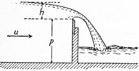 |
| Fig. 52. |
Now if p is the height of the weir crest above the bottom of the canal (fig. 52), u = Q/l(p + h). Replacing Q by its value in (1)
u2/2gh = Q2 / {2ghl2(p + h)2} = m2 {h/(p + h) }2,
so that (3) may be written
m = μ [1 + k {h/(p + h)}2 ].
Gaugings were made with weirs of 0.75, 0.50, 0.35, and 0.24 metres height above the canal bottom and the results compared with those of the standard weir taken at the same time. The discussion of the results leads to the following values of m in the general equation (1):—
m = μ (1 + 2.5u2/2gh)
= μ [1 + 0.55 {h/(p + h)}2 ].
Values of μ—
| Head h metres. | Head h feet. | μ |
| 0.05 | .164 | 0.4481 |
| 0.10 | .328 | 0.4322 |
| 0.20 | .656 | 0.4215 |
| 0.30 | .984 | 0.4174 |
| 0.40 | 1.312 | 0.4144 |
| 0.50 | 1.640 | 0.4118 |
| 0.60 | 1.968 | 0.4092 |
An approximate formula for μ is:
μ = 0.405 + 0.003/h (h in metres)
μ = 0.405 + 0.01/h (h in feet).
Inclined Weirs.—-Experiments were made in which the plank weir was inclined up or down stream, the crest being sharp and the end contraction suppressed. The following are coefficients by which the discharge of a vertical weir should be multiplied to obtain the discharge of the inclined weir.
| Coefficient. | |||
| Inclination | up stream | 1 to 1 | 0.93 |
| ” | ” | 3 to 2 | 0.94 |
| ” | ” | 3 to 1 | 0.96 |
| Vertical weir | .. | 1.00 | |
| Inclination | down stream | 3 to 1 | 1.04 |
| ” | ” | 3 to 2 | 1.07 |
| ” | ” | 1 to 1 | 1.10 |
| ” | ” | 1 to 2 | 1.12 |
| ” | ” | 1 to 4 | 1.09 |
The coefficient varies appreciably, if h/p approaches unity, which case should be avoided.
 |
| Fig. 53. |
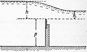 |
| Fig. 54. |
In all the preceding cases the sheet passing over the weir is detached completely from the weir and its under-surface is subject to atmospheric pressure. These conditions permit the most exact determination of the coefficient of discharge. If the sides of the canal below the weir are not so arranged as to permit the access of air under the sheet, the phenomena are more complicated. So long as the head does not exceed a certain limit the sheet is detached from the weir, but encloses a volume of air which is at less than atmospheric pressure, and the tail water rises under the sheet. The discharge is a little greater than for free overfall. At greater head the air disappears from below the sheet and the sheet is said to be “drowned.” The drowned sheet may be independent of the tail water level or influenced by it. In the former case the fall is followed by a rapid, terminating in a standing wave. In the latter case when the foot of the sheet is drowned the level of the tail water influences the discharge even if it is below the weir crest.
Weirs with Flat Crests.—The water sheet may spring clear from the upstream edge or may adhere to the flat crest falling free beyond the down-stream edge. In the former case the condition is that of a sharp-edged weir and it is realized when the head is at least double the width of crest. It may arise if the head is at least 11⁄2 the width of crest. Between these limits the condition of the sheet is unstable. When the sheet is adherent the coefficient m depends on the ratio of the head h to the width of crest c (fig. 53), and is given by the equation m = m1 [0.70 + 0.185h/c], where m1 is the coefficient for a sharp-edged weir in similar conditions. Rounding the upstream edge even to a small extent modifies the discharge. If R is the radius of the rounding the coefficient m is increased in the ratio 1 to 1 + R/h nearly. The results are limited to R less than 1⁄2 in.
Drowned Weirs.—Let h (fig. 54) be the height of head water and h1 that of tail water above the weir crest. Then Bazin obtains as the approximate formula for the coefficient of discharge
m = 1.05m1 [1 + 1⁄5 h1/p] 3√ { (h − h1) / h },
 |
| Fig. 55. |
where as before m1 is the coefficient for a sharp-edged weir in similar conditions, that is, when the sheet is free and the weir of the same height.
§ 48. Separating Weirs.—Many towns derive their water-supply from streams in high moorland districts, in which the flow is extremely variable. The water is collected in large storage reservoirs, from which an uniform supply can be sent to the town. In such cases it is desirable to separate the coloured water which comes down the streams in high floods from the purer water of ordinary flow. The latter is sent into the reservoirs; the former is allowed 51 to flow away down the original stream channel, or is stored in separate reservoirs and used as compensation water. To accomplish the separation of the flood and ordinary water, advantage is taken of the different horizontal range of the parabolic path of the water falling over a weir, as the depth on the weir and, consequently, the velocity change. Fig. 55 shows one of these separating weirs in the form in which they were first introduced on the Manchester Waterworks; fig. 56 a more modern weir of the same kind designed by Sir A. Binnie for the Bradford Waterworks. When the quantity of water coming down the stream is not excessive, it drops over the weir into a transverse channel leading to the reservoirs. In flood, the water springs over the mouth of this channel and is led into a waste channel.
 |
| Fig. 56. |
It may be assumed, probably with accuracy enough for practical purposes, that the particles describe the parabolas due to the mean velocity of the water passing over the weir, that is, to a velocity
2⁄3 √(2gh),
where h is the head above the crest of the weir.
Let cb = x be the width of the orifice and ac = y the difference of level of its edges (fig. 57). Then, if a particle passes from a to b in t seconds,
y = 1⁄2 gt2, x = 2⁄3 √(2gh)t;
∴ y = 9⁄16 x2/h,
which gives the width x for any given difference of level y and head h, which the jet will just pass over the orifice. Set off ad vertically and equal to 1⁄2g on any scale; af horizontally and equal to 2⁄3 √(gh). Divide af, fe into an equal number of equal parts. Join a with the divisions on ef. The intersections of these lines with verticals from the divisions on af give the parabolic path of the jet.
 |
| Fig. 57. |
Mouthpieces—Head Constant
§ 49. Cylindrical Mouthpieces.—When water issues from a short cylindrical pipe or mouthpiece of a length at least equal to l1⁄2 times its smallest transverse dimension, the stream, after contraction within the mouthpiece, expands to fill it and issues full bore, or without contraction, at the point of discharge. The discharge is found to be about one-third greater than that from a simple orifice of the same size. On the other hand, the energy of the fluid per unit of weight is less than that of the stream from a simple orifice with the same head, because part of the energy is wasted in eddies produced at the point where the stream expands to fill the mouthpiece, the action being something like that which occurs at an abrupt change of section.
Let fig. 58 represent a vessel discharging through a cylindrical mouthpiece at the depth h from the free surface, and let the axis of the jet XX be taken as the datum with reference to which the head is estimated. Let Ω be the area of the mouthpiece, ω the area of the stream at the contracted section EF. Let v, p be the velocity and pressure at EF, and v1, p1 the same quantities at GH. If the discharge is into the air, p1 is equal to the atmospheric pressure pa.
The total head of any filament which goes to form the jet, taken at a point where its velocity is sensibly zero, is h + pa/G; at EF the total head is v2/2g + p/G; at GH it is v12/2g + p1/G.
Between EF and GH there is a loss of head due to abrupt change of velocity, which from eq. (3), § 36, may have the value
(v − v1)2/2g.
Adding this head lost to the head at GH, before equating it to the heads at EF and at the point where the filaments start into motion,—
h + pa/G = v2/2g + p/G = v12/2g + p1/G + (v − v1)2/2g.
But ωv = Ωv1, and ω = ccΩ, if cc is the coefficient of contraction within the mouthpiece. Hence
v = Ωv1/ω = v1/cc.
Supposing the discharge into the air, so that p1 = pa,
h + pa/G = v12/2g + pa/G + (v12/2g) (1/cc − 1)2;
(v1/2g) {1 + (1/cc − 1)2} = h;
∴ v1 = √(2gh) / √ {1 + (1/cc − 1)2 };
 |
| Fig. 58. |
where the coefficient on the right is evidently the coefficient of velocity for the cylindrical mouthpiece in terms of the coefficient of contraction at EF. Let cc = 0.64, the value for simple orifices, then the coefficient of velocity is
cv = 1/√ {1 + (1/cc − 1)2 } = 0.87
The actual value of cv, found by experiment is 0.82, which does not differ more from the theoretical value than might be expected if the friction of the mouthpiece is allowed for. Hence, for mouthpieces of this kind, and for the section at GH,
cv = 0.82 cc = 1.00 c = 0.82,
Q = 0.82Ω √(2gh).
It is easy to see from the equations that the pressure p at EF is less than atmospheric pressure. Eliminating v1, we get
(pa − p)/G = 3⁄4 h nearly;
or
p = pa − 3⁄4 Gh ℔ per sq. ft.
If a pipe connected with a reservoir on a lower level is introduced into the mouthpiece at the part where the contraction is formed (fig. 59), the water will rise in this pipe to a height
KL = (pa − p) / G = 3⁄4 h nearly.
If the distance X is less than this, the water from the lower reservoir will be forced continuously into the jet by the atmospheric pressure, and discharged with it. This is the crudest form of a kind of pump known as the jet pump.
§ 50. Convergent Mouthpieces.—With convergent mouthpieces there is a contraction within the mouthpiece causing a loss of head, and a diminution of the velocity of discharge, as with cylindrical mouthpieces. There is also a second contraction of the stream outside the mouthpiece. Hence the discharge is given by an equation of the form
Q = cvccΩ √(2gh),
where Ω is the area of the external end of the mouthpiece, and ccΩ the section of the contracted jet beyond the mouthpiece.
Convergent Mouthpieces (Castel’s Experiments).—Smallest diameter of orifice = 0.05085 ft. Length of mouthpiece = 2.6 Diameters.
| Angle of Convergence. | Coefficient of Contraction, cc | Coefficient of Velocity, cv | Coefficient of Discharge, c |
| 0° 0′ | .999 | .830 | .829 |
| 1° 36′ | 1.000 | .866 | .866 |
| 3° 10′ | 1.001 | .894 | .895 |
| 4° 10′ | 1.002 | .910 | .912 |
| 5° 26′ | 1.004 | .920 | .924 |
| 7° 52′ | .998 | .931 | .929 |
| 8° 58′ | .992 | .942 | .934 |
| 10° 20′ | .987 | .950 | .938 |
| 12° 4′ | .986 | .955 | .942 |
| 13° 24′ | .983 | .962 | .946 |
| 14° 28′ | .979 | .966 | .941 |
| 16° 36′ | .969 | .971 | .938 |
| 19° 28′ | .953 | .970 | .924 |
| 21° 0′ | .945 | .971 | .918 |
| 23° 0′ | .937 | .974 | .913 |
| 29° 58′ | .919 | .975 | .896 |
| 40° 20′ | .887 | .980 | .869 |
| 48° 50′ | .861 | .984 | .847 |
The maximum coefficient of discharge is that for a mouthpiece with a convergence of 13°24′.
 |
 |
| Fig. 59. | Fig. 60. |
The values of cv and cc must here be determined by experiment. The above table gives values sufficient for practical purposes. Since the contraction beyond the mouthpiece increases with the convergence, or, what is the same thing, cc diminishes, and on the other hand the loss of energy diminishes, so that cv increases with the convergence, there is an angle for which the product cc cv, and consequently the discharge, is a maximum.
§ 51. Divergent Conoidal Mouthpiece.—Suppose a mouthpiece so designed that there is no abrupt change in the section or velocity of the stream passing through it. It may have a form at the inner end approximately the same as that of a simple contracted vein, and may then enlarge gradually, as shown in fig. 60. Suppose that at EF it becomes cylindrical, so that the jet may be taken to be of the diameter EF. Let ω, v, p be the section, velocity and pressure at CD, and Ω, v1, p1 the same quantities at EF, pa being as usual the atmospheric pressure, or pressure on the free surface AB. Then, since there is no loss of energy, except the small frictional resistance of the surface of the mouthpiece,
h + pa/G = v2/2g + p/G = v12/2g + p1/G.
If the jet discharges into the air, p1 = pa; and
v12/2g = h;
v1 = √(2gh);
or, if a coefficient is introduced to allow for friction,
v1 = cv √(2gh);
where cv is about 0.97 if the mouthpiece is smooth and well formed.
Q = Ω v1 = cv Ω √(2gh).
 |
| Fig. 61. |
Hence the discharge depends on the area of the stream at EF, and not at all on that at CD, and the latter may be made as small as we please without affecting the amount of water discharged.
There is, however, a limit to this. As the velocity at CD is greater than at EF the pressure is less, and therefore less than atmospheric pressure, if the discharge is into the air. If CD is so contracted that p = 0, the continuity of flow is impossible. In fact the stream disengages itself from the mouthpiece for some value of p greater than 0 (fig. 61).
From the equations,
p/G = pa/G − (v2 − v12) / 2g.
Let Ω/ω = m. Then
v = v1m;
p/G = pa/G − v12 (m2 − 1) / 2g
= pa/G − (m2 − 1) h;
whence we find that p/G will become zero or negative if
Ω/ω ≥ √ {(h + pa/G) / h } = √ {1 + pa/Gh};
or, putting pa/G = 34 ft., if
Ω/ω ≥ √ { (h + 34)/h}.
In practice there will be an interruption of the full bore flow with a less ratio of Ω/ω, because of the disengagement of air from the water. But, supposing this does not occur, the maximum discharge of a mouthpiece of this kind is
Q = ω √ {2g (h + pa/G) };
that is, the discharge is the same as for a well-bell-mouthed mouthpiece of area ω, and without the expanding part, discharging into a vacuum.
§ 52. Jet Pump.—A divergent mouthpiece may be arranged to act as a pump, as shown in fig. 62. The water which supplies the energy required for pumping enters at A. The water to be pumped enters at B. The streams combine at DD where the velocity is greatest and the pressure least. Beyond DD the stream enlarges in section, and its pressure increases, till it is sufficient to balance the head due to the height of the lift, and the water flows away by the discharge pipe C.
 |
| Fig. 62. |
Fig. 63 shows the whole arrangement in a diagrammatic way. A is the reservoir which supplies the water that effects the pumping; B is the reservoir of water to be pumped; C is the reservoir into which the water is pumped.
 |
| Fig. 63. |
Discharge with Varying Head
§ 53. Flow from a Vessel when the Effective Head varies with the Time.—Various useful problems arise relating to the time of emptying and filling vessels, reservoirs, lock chambers, &c., where the flow is dependent on a head which increases or diminishes during the operation. The simplest of these problems is the case of filling or emptying a vessel of constant horizontal section.
 |
| Fig. 64. |
Time of Emptying or Filling a Vertical-sided Lock Chamber.—Suppose the lock chamber, which has a water surface of Ω square ft., is emptied through a sluice in the tail gates, of area ω, placed below the tail-water level. Then the effective head producing flow through the sluice is the difference of level in the chamber and tail bay. Let H (fig. 64) be the initial difference of level, h the difference of level after t seconds. Let −dh be the fall of level in the chamber during an interval dt. Then in the time dt the volume in the chamber is altered by the amount −Ωdh, and the outflow from the sluice in the same time is cω √(2gh) dt. Hence the differential equation connecting h and t is
cω √(2gh) dt + Ωh = 0.
For the time t, during which the initial head H diminishes to any other value h,
−{Ω/(cω √2g) } ∫hH dh/√h = ∫0t dt.
∴ t = 2Ω (√H − √h) / {cω √(2g)}
= (Ω/cω) {√(2H/g) − √(2h/g) }.
For the whole time of emptying, during which h diminishes from H to 0,
T = (Ω/cω) √(2H/g).
Comparing this with the equation for flow under a constant head, it will be seen that the time is double that required for the discharge of an equal volume under a constant head.
The time of filling the lock through a sluice in the head gates is exactly the same, if the sluice is below the tail-water level. But if the sluice is above the tail-water level, then the head is constant till the level of the sluice is reached, and afterwards it diminishes with the time.
Practical Use of Orifices in Gauging Water
§ 54. If the water to be measured is passed through a known orifice under an arrangement by which the constancy of the head is ensured, the amount which passes in a given time can be ascertained by the formulae already given. It will obviously be best to make the orifices of the forms for which the coefficients are most accurately determined; hence sharp-edged orifices or notches are most commonly used.
Water Inch.—For measuring small quantities of water circular sharp-edged orifices have been used. The discharge from a circular orifice one French inch in diameter, with a head of one line above the top edge, was termed by the older hydraulic writers a water-inch. A common estimate of its value was 14 pints per minute, or 677 English cub. ft. in 24 hours. An experiment by C. Bossut gave 634 cub. ft. in 24 hours (see Navier’s edition of Belidor’s Arch. Hydr., p. 212).
L. J. Weisbach points out that measurements of this kind would be made more accurately with a greater head over the orifice, and he proposes that the head should be equal to the diameter of the orifice. Several equal orifices may be used for larger discharges.
 |
| Fig. 65. |
Pin Ferrules or Measuring Cocks.—To give a tolerably definite supply of water to houses, without the expense of a meter, a ferrule with an orifice of a definite size, or a cock, is introduced in the service-pipe. If the head in the water main is constant, then a definite quantity of water would be delivered in a given time. The arrangement is not a very satisfactory one, and acts chiefly as a check on extravagant use of water. It is interesting here chiefly as an example of regulation of discharge by means of an orifice. Fig. 65 shows a cock of this kind used at Zurich. It consists of three cocks, the middle one having the orifice of the predetermined size in a small circular plate, protected by wire gauze from stoppage by impurities in the water. The cock on the right hand can be used by the consumer for emptying the pipes. The one on the left and the measuring cock are connected by a key which can be locked by a padlock, which is under the control of the water company.
§ 55. Measurement of the Flow in Streams.—To determine the quantity of water flowing off the ground in small streams, which is available for water supply or for obtaining water power, small temporary weirs are often used. These may be formed of planks supported by piles and puddled to prevent leakage. The measurement of the head may be made by a thin-edged scale at a short distance behind the weir, where the water surface has not begun to slope down to the weir and where the velocity of approach is not high. The measurements are conveniently made from a short pile driven into the bed of the river, accurately level with the crest of the weir (fig. 66). Then if at any moment the head is h, the discharge is, for a rectangular notch of breadth b,
Q = 2⁄3 cbh √2gh
where c = 0.62; or, better, the formula in § 42 may be used.
Gauging weirs are most commonly in the form of rectangular notches; and care should be taken that the crest is accurately horizontal, and that the weir is normal to the direction of flow of the stream. If the planks are thick, they should be bevelled (fig. 67), and then the edge may be protected by a metal plate about 1⁄10th in. thick to secure the requisite accuracy of form and sharpness of edge. In permanent gauging weirs, a cast steel plate is sometimes used to form the edge of the weir crest. The weir should be large enough to discharge the maximum volume flowing in the stream, and at the same time it is desirable that the minimum head should not be too small (say half a foot) to decrease the effects of errors of measurement. The section of the jet over the weir should not exceed one-fifth the section of the stream behind the weir, or the velocity of approach will need to be taken into account. A triangular notch is very suitable for measurements of this kind.
 |
| Fig. 66. |
If the flow is variable, the head h must be recorded at equidistant intervals of time, say twice daily, and then for each 12-hour period the discharge must be calculated for the mean of the heads at the beginning and end of the time. As this involves a good deal of troublesome calculation, E. Sang proposed to use a scale so graduated as to read off the discharge in cubic feet per second. The lengths of the principal graduations of such a scale are easily calculated by putting Q = 1, 2, 3 ... in the ordinary formulae for notches; the intermediate graduations may be taken accurately enough by subdividing equally the distances between the principal graduations.
 |
| Fig. 67. |
 |
| Fig. 68. |
The accurate measurement of the discharge of a stream by means of a weir is, however, in practice, rather more difficult than might be inferred from the simplicity of the principle of the operation. Apart from the difficulty of selecting a suitable coefficient of discharge, which need not be serious if the form of the weir and the nature of its crest are properly attended to, other difficulties of measurement arise. The length of the weir should be very accurately determined, and if the weir is rectangular its deviations from exactness of level should be tested. Then the agitation of the water, the ripple on its surface, and the adhesion of the water to the scale on which the head is measured, are liable to introduce errors. Upon a weir 10 ft. long, with 1 ft. depth of water flowing over, an error of 1-1000th of a foot in measuring the head, or an error of 1-100th of a foot in measuring the length of the weir, would cause an error in computing the discharge of 2 cub. ft. per minute.
Hook Gauge.—For the determination of the surface level of water, the most accurate instrument is the hook gauge used first by U. Boyden of Boston, in 1840. It consists of a fixed frame with scale and vernier. In the instrument in fig. 68 the vernier is fixed to the frame, and the scale slides vertically. The scale carries at its lower end a hook with a fine point, and the scale can be raised or lowered by a fine pitched screw. If the hook is depressed below the water surface and then raised by the screw, the moment of its reaching the water surface will be very distinctly marked, by the reflection from a small capillary elevation of the water surface over the point of the hook. In ordinary light, differences of level of the water of .001 of a foot are easily detected by the hook gauge. If such a gauge is used to determine the heads at a weir, the hook should 54 first be set accurately level with the weir crest, and a reading taken. Then the difference of the reading at the water surface and that for the weir crest will be the head at the weir.
§ 56. Modules used in Irrigation.—In distributing water for irrigation, the charge for the water may be simply assessed on the area of the land irrigated for each consumer, a method followed in India; or a regulated quantity of water may be given to each consumer, and the charge may be made proportional to the quantity of water supplied, a method employed for a long time in Italy and other parts of Europe. To deliver a regulated quantity of water from the irrigation channel, arrangements termed modules are used. These are constructions intended to maintain a constant or approximately constant head above an orifice of fixed size, or to regulate the size of the orifice so as to give a constant discharge, notwithstanding the variation of level in the irrigating channel.
 |
| Fig. 69. |
§ 57. Italian Module.—The Italian modules are masonry constructions, consisting of a regulating chamber, to which water is admitted by an adjustable sluice from the canal. At the other end of the chamber is an orifice in a thin flagstone of fixed size. By means of the adjustable sluice a tolerably constant head above the fixed orifice is maintained, and therefore there is a nearly constant discharge of ascertainable amount through the orifice, into the channel leading to the fields which are to be irrigated.
 |
| Fig. 70.—Scale 1⁄100. |
In fig. 69, A is the adjustable sluice by which water is admitted to the regulating chamber, B is the fixed orifice through which the water is discharged. The sluice A is adjusted from time to time by the canal officers, so as to bring the level of the water in the regulating chamber to a fixed level marked on the wall of the chamber. When adjusted it is locked. Let ω1 be the area of the orifice through the sluice at A, and ω2 that of the fixed orifice at B; let h1 be the difference of level between the surface of the water in the canal and regulating chamber; h2 the head above the centre of the discharging orifice, when the sluice has been adjusted and the flow has become steady; Q the normal discharge in cubic feet per second. Then, since the flow through the orifices at A and B is the same,
Q = c1ω1 √(2gh1) = c2ω2 √(2gh2),
where c1 and c2 are the coefficients of discharge suitable for the two orifices. Hence
c1ω1 / c2ω2 = √(h2/h1).
If the orifice at B opened directly into the canal without any intermediate regulating chamber, the discharge would increase for a given change of level in the canal in exactly the same ratio. Consequently the Italian module in no way moderates the fluctuations of discharge, except so far as it affords means of easy adjustment from time to time. It has further the advantage that the cultivator, by observing the level of the water in the chamber, can always see whether or not he is receiving the proper quantity of water.
On each canal the orifices are of the same height, and intended to work with the same normal head, the width of the orifices being varied to suit the demand for water. The unit of discharge varies on different canals, being fixed in each case by legal arrangements. Thus on the Canal Lodi the unit of discharge or one module of water is the discharge through an orifice 1.12 ft. high, 0.12416 ft. wide, with a head of 0.32 ft. above the top edge of the orifice, or .88 ft. above the centre. This corresponds to a discharge of about 0.6165 cub. ft. per second.
 |
| Fig. 71. |
In the most elaborate Italian modules the regulating chamber is arched over, and its dimensions are very exactly prescribed. Thus in the modules of the Naviglio Grande of Milan, shown in fig. 70, the measuring orifice is cut in a thin stone slab, and so placed that the discharge is into the air with free contraction on all sides. The adjusting sluice is placed with its sill flush with the bottom of the canal, and is provided with a rack and lever and locking arrangement. The covered regulating chamber is about 20 ft. long, with a breadth 1.64 ft. greater than that of the discharging orifice. At precisely the normal level of the water in the regulating chamber, there is a ceiling of planks intended to still the agitation of the water. A block of stone serves to indicate the normal level of the water in the chamber. The water is discharged into an open channel 0.655 ft. wider than the orifice, splaying out till it is 1.637 ft. wider than the orifice, and about 18 ft. in length.
§ 58. Spanish Module.—On the canal of Isabella II., which supplies water to Madrid, a module much more perfect in principle than the Italian module is employed. Part of the water is supplied for irrigation, and as it is very valuable its strict measurement is essential. The module (fig. 72) consists of two chambers one above the other, the upper chamber being in free communication with the irrigation canal, and the lower chamber discharging by a culvert to the fields. In the arched roof between the chambers there is a circular sharp-edged orifice in a bronze plate. Hanging in this there is a bronze plug of variable diameter suspended from a hollow brass float. If the water level in the canal lowers, the plug descends and gives an enlarged opening, and conversely. Thus a perfectly constant discharge with a varying head can be obtained, provided no clogging or silting of the chambers prevents the free discharge of the water or the rise and fall of the float. The theory of the module is very simple. Let R (fig. 71) be the radius of the fixed opening, r the radius of the plug at a distance h from the plane of flotation of the float, and Q the required discharge of the module. Then
Q = cπ (R2 − r2) √(2gh).
Taking c = 0.63,
Q = 15.88 (R2 − r2) √h;
r = √ {R2 − Q/15.88 √h}.
Choosing a value for R, successive values of r can be found for different values of h, and from these the curve of the plug can be drawn. The module shown in fig. 72 will discharge 1 cubic metre per second. The fixed opening is 0.2 metre diameter, and the greatest head above the fixed orifice is 1 metre. The use of this module involves a great sacrifice of level between the canal and the fields. The module is described in Sir C. Scott-Moncrieff’s Irrigation in Southern Europe.
§ 59. Reservoir Gauging Basins.—In obtaining the power to store the water of streams in reservoirs, it is usual to concede to riparian 55 owners below the reservoirs a right to a regulated supply throughout the year. This compensation water requires to be measured in such a way that the millowners and others interested in the matter can assure themselves that they are receiving a proper quantity, and they are generally allowed a certain amount of control as to the times during which the daily supply is discharged into the stream.
 |
| Fig. 72. |
Fig. 74 shows an arrangement designed for the Manchester water works. The water enters from the reservoir at chamber A, the object of which is to still the irregular motion of the water. The admission is regulated by sluices at b, b, b. The water is discharged by orifices or notches at a, a, over which a tolerably constant head is maintained by adjusting the sluices at b, b, b. At any time the millowners can see whether the discharge is given and whether the proper head is maintained over the orifices. To test at any time the discharge of the orifices, a gauging basin B is provided. The water ordinarily flows over this, without entering it, on a floor of cast-iron plates. If the discharge is to be tested, the water is turned for a definite time into the gauging basin, by suddenly opening and closing a sluice at c. The volume of flow can be ascertained from the depth in the gauging chamber. A mechanical arrangement (fig. 73) was designed for securing an absolutely constant head over the orifices at a, a. The orifices were formed in a cast-iron plate capable of sliding up and down, without sensible leakage, on the face of the wall of the chamber. The orifice plate was attached by a link to a lever, one end of which rested on the wall and the other on floats f in the chamber A. The floats rose and fell with the changes of level in the chamber, and raised and lowered the orifice plate at the same time. This mechanical arrangement was not finally adopted, careful watching of the sluices at b, b, b, being sufficient to secure a regular discharge. The arrangement is then equivalent to an Italian module, but on a large scale.
 |
| Fig. 73.—Scale 1⁄120. |
 |
| Fig. 74.—Scale 1⁄500. |
§ 60. Professor Fleeming Jenkin’s Constant Flow Valve.—In the modules thus far described constant discharge is obtained by varying the area of the orifice through which the water flows. Professor F. Jenkin has contrived a valve in which a constant pressure head is obtained, so that the orifice need not be varied (Roy. Scot. Society 56 of Arts, 1876). Fig. 75 shows a valve of this kind suitable for a 6-in. water main. The water arriving by the main C passes through an equilibrium valve D into the chamber A, and thence through a sluice O, which can be set for any required area of opening, into the discharging main B. The object of the arrangement is to secure a constant difference of pressure between the chambers A and B, so that a constant discharge flows through the stop valve O. The equilibrium valve D is rigidly connected with a plunger P loosely fitted in a diaphragm, separating A from a chamber B2 connected by a pipe B1 with the discharging main B. Any increase of the difference of pressure in A and B will drive the plunger up and close the equilibrium valve, and conversely a decrease of the difference of pressure will cause the descent of the plunger and open the equilibrium valve wider. Thus a constant difference of pressure is obtained in the chambers A and B. Let ω be the area of the plunger in square feet, p the difference of pressure in the chambers A and B in pounds per square foot, w the weight of the plunger and valve. Then if at any moment pω exceeds w the plunger will rise, and if it is less than w the plunger will descend. Apart from friction, and assuming the valve D to be strictly an equilibrium valve, since ω and w are constant, p must be constant also, and equal to w/ω. By making w small and ω large, the difference of pressure required to ensure the working of the apparatus may be made very small. Valves working with a difference of pressure of 1⁄2 in. of water have been constructed.
 |
| Fig. 75.—Scale 1⁄24. |
VI. STEADY FLOW OF COMPRESSIBLE FLUIDS.
 |
| Fig. 76. |
§ 61. External Work during the Expansion of Air.—If air expands without doing any external work, its temperature remains constant. This result was first experimentally demonstrated by J. P. Joule. It leads to the conclusion that, however air changes its state, the internal work done is proportional to the change of temperature. When, in expanding, air does work against an external resistance, either heat must be supplied or the temperature falls.
To fix the conditions, suppose 1 ℔ of air confined behind a piston of 1 sq. ft. area (fig. 76). Let the initial pressure be p1 and the volume of the air v1, and suppose this to expand to the pressure p2 and volume v2. If p and v are the corresponding pressure and volume at any intermediate point in the expansion, the work done on the piston during the expansion from v to v + dv is pdv, and the whole work during the expansion from v1 to v2, represented by the area abcd, is
∫v2v1 p dv.
Amongst possible cases two may be selected.
Case 1.—So much heat is supplied to the air during expansion that the temperature remains constant. Hyperbolic expansion.
Then
pv = p1v1.
Work done during expansion per pound of air
= ∫v2v1 p dv = p1v1 ∫v2v1 dv/v
= p1v1 logε v2 / v1 = p1v1 logε p1 / p2.
Since the weight per cubic foot is the reciprocal of the volume per pound, this may be written
(p1/G1) logε G1/G2.
Then the expansion curve ab is a common hyperbola.
Case 2.—No heat is supplied to the air during expansion. Then the air loses an amount of heat equivalent to the external work done and the temperature falls. Adiabatic expansion.
In this case it can be shown that
pvγ = p1v1γ,
where γ is the ratio of the specific heats of air at constant pressure and volume. Its value for air is 1.408, and for dry steam 1.135.
Work done during expansion per pound of air.
= ∫v2v1 p dv = p1v1γ ∫v2v1 dv/vγ
| = −{p1v1γ / (γ − 1)} {1/v2γ−1 − 1/v1γ−1} = {p1v1γ / (γ − 1)} {1/v1γ−1 − 1/v2γ−1} = {p1v1 / (γ − 1)} {1 − (v1/v2) γ−1}. |
The value of p1v1 for any given temperature can be found from the data already given.
As before, substituting the weights G1, G2 per cubic foot for the volumes per pound, we get for the work of expansion
(p1/G1) {1/(γ − 1)} {1 − (G2/G1) γ−1},
= p1v1 {1/(γ − 1)} {1 − (p2/p1) γ−1/γ}.
 |
| Fig. 77. |
§ 62. Modification of the Theorem of Bernoulli for the Case of a Compressible Fluid.—In the application of the principle of work to a filament of compressible fluid, the internal work done by the expansion of the fluid, or absorbed in its compression, must be taken into account. Suppose, as before, that AB (fig. 77) comes to A′B′ in a short time t. Let p1, ω1, v1, G1 be the pressure, sectional area of stream, velocity and weight of a cubic foot at A, and p2, ω2, v2, G2 the same quantities at B. Then, from the steadiness of motion, the weight of fluid passing A in any given time must be equal to the weight passing B:
G1ω1v1t = G2ω2v2t.
Let z1, z2 be the heights of the sections A and B above any given datum. Then the work of gravity on the mass AB in t seconds is
G1ω1v1t (z1 − z2) = W (z1 − z2) t,
where W is the weight of gas passing A or B per second. As in the case of an incompressible fluid, the work of the pressures on the ends of the mass AB is
p1ω1v1t − p2ω2v2t,
= (p1/G1 − p2/G2) Wt.
The work done by expansion of Wt ℔ of fluid between A and B is ∫v2v1 The change of kinetic energy as before is (W/2g) (v22 − v12) t. Hence, equating work to change of kinetic energy,
W (z1 − z2) t + (p1/G1 − p2/G2)Wt + Wt ∫v2v1 p dv = (W/2g) (v22 − v12) t;
∴ z1 + p1/G1 + v12/2g = z2 + p2/G2 + v22/2g − ∫v2v1 p dv.
Now the work of expansion per pound of fluid has already been given. If the temperature is constant, we get (eq. 1a, § 61)
Z1 + P1/G1 + v12/2g = z2 + p2/G2 + v22/2g − (p1/G1) logε (G1/G2).
But at constant temperature p1/G1 = p2/G2;
∴ z1 + v12/2g = z2 + v22/2g − (p1/G1) logε (p1/p2),
or, neglecting the difference of level,
(v22 − v12) / 2g = (p1/G1) logε (p1/p2).
Similarly, if the expansion is adiabatic (eq. 2a, § 61),
z1 + p1/G1 + v12/2g = z2 + p2/G2 + v22/2g − (p1/G1) {1/(γ − 1) } {1 − (p2/p1)(γ−1)/γ};
or, neglecting the difference of level,
(v22 − v12)/2g = (p1/G1) [1 + 1/(γ − 1) {1 − (p2/p1)(γ−1)/γ)} ] − p2/G2.
It will be seen hereafter that there is a limit in the ratio p1/p2 beyond which these expressions cease to be true.
§ 63. Discharge of Air from an Orifice.—The form of the equation of work for a steady stream of compressible fluid is
z1 + p1/G1 + v12/2g = z2 + p2/G2 + v22/2g − (p1/G1) {1/(γ − 1)} {1 − (p2/p1(γ−1)/γ},
the expansion being adiabatic, because in the flow of the streams of air through an orifice no sensible amount of heat can be communicated from outside.
Suppose the air flows from a vessel, where the pressure is p1 and the velocity sensibly zero, through an orifice, into a space where the pressure is p2. Let v2 be the velocity of the jet at a point where the convergence of the streams has ceased, so that the pressure in the jet is also p2. As air is light, the work of gravity will be small compared with that of the pressures and expansion, so that z1z2 may be neglected. Putting these values in the equation above—
p1/G1 = p2/G2 + v22/2g − (p1/G1) {1/(γ − 1)} {1 − (p2/p1)(γ−1)/γ;
v22/2g = p1/G1 − p2/G2 + (p1/G1) {1/(γ − 1)} {1 − (p2/p1)(γ−1)/γ}
= (p1/G1) {γ/(γ − 1) − (p2/p1)γ−1 /γ / (γ − 1)} − p2/G2.
But
p1/G1γ = p2/G2γ ∴ p2/G2 = (p1/G1) (p2/p1)(γ−1)/γ
v22/2g = (p1/G1) {γ/(γ − 1)} {1 − (p2/p1)(γ−1)/γ};
or
v22/2g = {γ/(γ − 1)} {(p1/G1) − (p2/G2)};
an equation commonly ascribed to L. J. Weisbach (Civilingenieur, 1856), though it appears to have been given earlier by A. J. C. Barre de Saint Venant and L. Wantzel.
It has already (§ 9, eq. 4a) been seen that
p1/G1 = (p0/G0) (τ1/τ0)
where for air p0 = 2116.8, G0 = .08075 and τ0 = 492.6.
v22/2g = {p0τ1γ / G0τ0 (γ − 1)} {1 − (p2/p1)(γ−1)/γ};
or, inserting numerical values,
v22/2g = 183.6τ1 {1 − (p2/p1)0.29};
which gives the velocity of discharge v2 in terms of the pressure and absolute temperature, p1, τ1, in the vessel from which the air flows, and the pressure p2 in the vessel into which it flows.
Proceeding now as for liquids, and putting ω for the area of the orifice and c for the coefficient of discharge, the volume of air discharged per second at the pressure p2 and temperature τ2 is
Q2 = cωv2 = cω √ [(2gγp1 / (γ − 1) G1) (1 − (p2/p1)(γ−1)/γ)]
= 108.7cω √ [τ1 {1 − (p2/p1)0.29}].
If the volume discharged is measured at the pressure p1 and absolute temperature τ1 in the vessel from which the air flows, let Q1 be that volume; then
p1Q1γ = p2Q2γ;
Q1 = (p2/p1)1/γ Q2;
Q1 = cω √ [ {2gγp1 / (γ − 1) G1} {(p2/p1)2/γ − (p2/p1)(γ+1)/γ}].
Let
(p2/p1)2/γ − (p2/p1)(γ−1)/γ = (p2/p1)1.41 − (p2/p1)1.7 = ψ; then
Q1 = cω √ [2gγp1ψ / (γ − 1) G1]
= 108.7cω √ (τ1ψ).
The weight of air at pressure p1 and temperature τ1 is
G1 = p1/53.2τ1 ℔ per cubic foot.
Hence the weight of air discharged is
W = G1Q1 = cω √ [2gγp1G1ψ / (γ − 1)]
= 2.043cωp1 √ (ψ/τ1).
Weisbach found the following values of the coefficient of discharge c:—
| Conoidal mouthpieces of the form of the | |||
| contracted vein with effective pressures | c = | ||
| of .23 to 1.1 atmosphere | 0.97 | to | 0.99 |
| Circular sharp-edged orifices | 0.563 | ” | 0.788 |
| Short cylindrical mouthpieces | 0.81 | ” | 0.84 |
| The same rounded at the inner end | 0.92 | ” | 0.93 |
| Conical converging mouthpieces | 0.90 | ” | 0.99 |
§ 64. Limit to the Application of the above Formulae.—In the formulae above it is assumed that the fluid issuing from the orifice expands from the pressure p1 to the pressure p2, while passing from the vessel to the section of the jet considered in estimating the area ω. Hence p2 is strictly the pressure in the jet at the plane of the external orifice in the case of mouthpieces, or at the plane of the contracted section in the case of simple orifices. Till recently it was tacitly assumed that this pressure p2 was identical with the general pressure external to the orifice. R. D. Napier first discovered that, when the ratio p2/p1 exceeded a value which does not greatly differ from 0.5, this was no longer true. In that case the expansion of the fluid down to the external pressure is not completed at the time it reaches the plane of the contracted section, and the pressure there is greater than the general external pressure; or, what amounts to the same thing, the section of the jet where the expansion is completed is a section which is greater than the area ccω of the contracted section of the jet, and may be greater than the area ω of the orifice. Napier made experiments with steam which showed that, so long as p2/p1 > 0.5, the formulae above were trustworthy, when p2 was taken to be the general external pressure, but that, if p2/p1 < 0.5, then the pressure at the contracted section was independent of the external pressure and equal to 0.5p1. Hence in such cases the constant value 0.5 should be substituted in the formulae for the ratio of the internal and external pressures p2/p1.
It is easily deduced from Weisbach’s theory that, if the pressure external to an orifice is gradually diminished, the weight of air discharged per second increases to a maximum for a value of the ratio
| p2/p1 = {2/(γ + 1)}γ−1/γ = 0.527 for air = 0.58 for dry steam. |
For a further decrease of external pressure the discharge diminishes,—a result no doubt improbable. The new view of Weisbach’s formula is that from the point where the maximum is reached, or not greatly differing from it, the pressure at the contracted section ceases to diminish.
A. F. Fliegner showed (Civilingenieur xx., 1874) that for air flowing from well-rounded mouthpieces there is no discontinuity of the law of flow, as Napier’s hypothesis implies, but the curve of flow bends so sharply that Napier’s rule may be taken to be a good approximation to the true law. The limiting value of the ratio p2/p1, for which Weisbach’s formula, as originally understood, ceases to apply, is for air 0.5767; and this is the number to be substituted for p2/p1 in the formulae when p2/p1 falls below that value. For later researches on the flow of air, reference may be made to G. A. Zeuner’s paper (Civilingenieur, 1871), and Fliegner’s papers (ibid., 1877, 1878).
VII. FRICTION OF LIQUIDS.
§ 65. When a stream of fluid flows over a solid surface, or conversely when a solid moves in still fluid, a resistance to the motion is generated, commonly termed fluid friction. It is due to the viscosity of the fluid, but generally the laws of fluid friction are very different from those of simple viscous resistance. It would appear that at all speeds, except the slowest, rotating eddies are formed by the roughness of the solid surface, or by abrupt changes of velocity distributed throughout the fluid; and the energy expended in producing these eddying motions is gradually lost in overcoming the viscosity of the fluid in regions more or less distant from that where they are first produced.
The laws of fluid friction are generally stated thus:—
1. The frictional resistance is independent of the pressure between the fluid and the solid against which it flows. This may be verified by a simple direct experiment. C. H. Coulomb, for instance, oscillated a disk under water, first with atmospheric pressure acting on the water surface, afterwards with the atmospheric pressure removed. No difference in the rate of decrease of the oscillations was observed. The chief proof that the friction is independent of the pressure is that no difference of resistance has been observed in water mains and in other cases, where water flows over solid surfaces under widely different pressures.
2. The frictional resistance of large surfaces is proportional to the area of the surface.
3. At low velocities of not more than 1 in. per second for water, the frictional resistance increases directly as the relative velocity of the fluid and the surface against which it flows. At velocities of 1⁄2 ft. per second and greater velocities, the frictional resistance is more nearly proportional to the square of the relative velocity.
In many treatises on hydraulics it is stated that the frictional resistance is independent of the nature of the solid surface. The explanation of this was supposed to be that a film of fluid remained attached to the solid surface, the resistance being generated between this fluid layer and layers more distant from the surface. At extremely low velocities the solid surface does not seem to have much influence on the friction. In Coulomb’s experiments a metal surface covered with tallow, and oscillated in water, had exactly the same resistance as a clean metal surface, and when sand was scattered over the tallow the resistance was only very slightly increased. The earlier calculations of the resistance of water at higher velocities in iron and wood pipes and earthen channels seemed to give a similar result. These, however, were erroneous, and it is now well understood that differences of roughness of the solid surface very greatly influence the friction, at such velocities as are common in engineering practice. H. P. G. Darcy’s experiments, for instance, showed that in old and incrusted water mains the resistance was twice or sometimes thrice as great as in new and clean mains.
§ 66. Ordinary Expressions for Fluid Friction at Velocities not Extremely Small.—Let f be the frictional resistance estimated in pounds per square foot of surface at a velocity of 1 ft. per second; ω the area of the surface in square feet; and v its velocity in feet per second relatively to the water in which it is immersed. Then, in accordance with the laws stated above, the total resistance of the surface is
R = fωv2
where f is a quantity approximately constant for any given surface. If
ξ = 2gf/G,
R = ξGωv2/2g,
where ξ is, like f, nearly constant for a given surface, and is termed the coefficient of friction.
The following are average values of the coefficient of friction for water, obtained from experiments on large plane surfaces, moved in an indefinitely large mass of water.
| Coefficient of Friction, ξ | Frictional Resistance in ℔ per sq. ft. f | |
| New well-painted iron plate | .00489 | .00473 |
| Painted and planed plank (Beaufoy) | .00350 | .00339 |
| Surface of iron ships (Rankine) | .00362 | .00351 |
| Varnished surface (Froude) | .00258 | .00250 |
| Fine sand surface (Froude) | .00418 | .00405 |
| Coarser sand surface (Froude) | .00503 | .00488 |
The distance through which the frictional resistance is overcome is v ft. per second. The work expended in fluid friction is therefore given by the equation—
Work expended = fωv3 foot-pounds per second
= ξGωv3/2g ” ”
The coefficient of friction and the friction per square foot of surface can be indirectly obtained from observations of the discharge of pipes and canals. In obtaining them, however, some assumptions as to the motion of the water must be made, and it will be better therefore to discuss these values in connexion with the cases to which they are related.
Many attempts have been made to express the coefficient of friction in a form applicable to low as well as high velocities. The older hydraulic writers considered the resistance termed fluid friction to be made up of two parts,—a part due directly to the distortion of the mass of water and proportional to the velocity of the water relatively to the solid surface, and another part due to kinetic energy imparted to the water striking the roughnesses of the solid surface and proportional to the square of the velocity. Hence they proposed to take
ξ = α + β/v
in which expression the second term is of greatest importance at very low velocities, and of comparatively little importance at velocities over about 1⁄2 ft. per second. Values of ξ expressed in this and similar forms will be given in connexion with pipes and canals.
All these expressions must at present be regarded as merely empirical expressions serving practical purposes.
The frictional resistance will be seen to vary through wider limits than these expressions allow, and to depend on circumstances of which they do not take account.
§ 67. Coulomb’s Experiments.—The first direct experiments on fluid friction were made by Coulomb, who employed a circular disk suspended by a thin brass wire and oscillated in its own plane. His experiments were chiefly made at very low velocities. When the disk is rotated to any given angle, it oscillates under the action of its inertia and the torsion of the wire. The oscillations diminish gradually in consequence of the work done in overcoming the friction of the disk. The diminution furnishes a means of determining the friction.
 |
| Fig. 78. |
Fig. 78 shows Coulomb’s apparatus. LK supports the wire and disk: ag is the brass wire, the torsion of which causes the oscillations; DS is a graduated disk serving to measure the angles through which the apparatus oscillates. To this the friction disk is rigidly attached hanging in a vessel of water. The friction disks were from 4.7 to 7.7 in. diameter, and they generally made one oscillation in from 20 to 30 seconds, through angles varying from 360° to 6°. When the velocity of the circumference of the disk was less than 6 in. per second, the resistance was sensibly proportional to the velocity.
Beaufoy’s Experiments.—Towards the end of the 18th century Colonel Mark Beaufoy (1764-1827) made an immense mass of experiments on the resistance of bodies moved through water (Nautical and Hydraulic Experiments, London, 1834). Of these the only ones directly bearing on surface friction were some made in 1796 and 1798. Smooth painted planks were drawn through water and the resistance measured. For two planks differing in area by 46 sq. ft., at a velocity of 10 ft. per second, the difference of resistance, measured on the difference of area, was 0.339 ℔ per square foot. Also the resistance varied as the 1.949th power of the velocity.
§ 68. Froude’s Experiments.—The most important direct experiments on fluid friction at ordinary velocities are those made by William Froude (1810-1879) at Torquay. The method adopted in these experiments was to tow a board in a still water canal, the velocity and the resistance being registered by very ingenious recording arrangements. The general arrangement of the apparatus is shown in fig. 79. AA is the board the resistance of which is to be determined. B is a cutwater giving a fine entrance to the plane surfaces of the board. CC is a bar to which the board AA is attached, and which is suspended by a parallel motion from a carriage running on rails above the still water canal. G is a link by which the resistance of the board is transmitted to a spiral spring H. A bar I rigidly connects the other end of the spring to the carriage. The dotted lines K, L indicate the position of a couple of levers by which the extension of the spring is caused to move a pen M, which records the extension on a greatly increased scale, by a line drawn on the paper cylinder N. This cylinder revolves at a speed proportionate to that of the carriage, its motion being obtained from the axle of the carriage wheels. A second pen O, receiving jerks at every second and a quarter from a clock P, records time on the paper cylinder. The scale for the line of resistance is ascertained by stretching the spiral spring by known weights. The boards used for the experiment were 3⁄16 in. thick, 19 in. deep, and from 1 to 50 ft. in length, cutwater included. A lead keel counteracted the buoyancy of the board. The boards were covered with various substances, such as paint, varnish, Hay’s composition, tinfoil, &c., so as to try the effect of different degrees of roughness of surface. The results obtained by Froude may be summarized as follows:—
 |
| Fig. 79. |
1. The friction per square foot of surface varies very greatly for different surfaces, being generally greater as the sensible roughness of the surface is greater. Thus, when the surface of the board was covered as mentioned below, the resistance for boards 50 ft. long, at 10 ft. per second, was—
| Tinfoil or varnish | 0.25 | ℔ per | sq. ft. |
| Calico | 0.47 | ” | ” |
| Fine sand | 0.405 | ” | ” |
| Coarser sand | 0.488 | ” | ” |
2. The power of the velocity to which the friction is proportional varies for different surfaces. Thus, with short boards 2 ft. long,
| For tinfoil the resistance varied as v2.16. For other surfaces the resistance varied as v2.00. |
With boards 50 ft. long,
| For varnish or tinfoil the resistance varied as v1.83. For sand the resistance varied as v2.00. |
3. The average resistance per square foot of surface was much greater for short than for long boards; or, what is the same thing, the resistance per square foot at the forward part of the board was greater than the friction per square foot of portions more sternward. Thus,
| Mean Resistance in ℔ per sq. ft. | |||
| Varnished surface | 2 | ft. long | 0.41 |
| 50 | ” | 0.25 | |
| Fine sand surface | 2 | ” | 0.81 |
| 50 | ” | 0.405 | |
This remarkable result is explained thus by Froude: “The portion of surface that goes first in the line of motion, in experiencing resistance from the water, must in turn communicate motion to the water, in the direction in which it is itself travelling. Consequently 59 the portion of surface which succeeds the first will be rubbing, not against stationary water, but against water partially moving in its own direction, and cannot therefore experience so much resistance from it.”
§ 69. The following table gives a general statement of Froude’s results. In all the experiments in this table, the boards had a fine cutwater and a fine stern end or run, so that the resistance was entirely due to the surface. The table gives the resistances per square foot in pounds, at the standard speed of 600 feet per minute, and the power of the speed to which the friction is proportional, so that the resistance at other speeds is easily calculated.
| Length of Surface, or Distance from Cutwater, in feet. | ||||||||||||
| 2 ft. | 8 ft. | 20 ft. | 50 ft. | |||||||||
| A | B | C | A | B | C | A | B | C | A | B | C | |
| Varnish | 2.00 | .41 | .390 | 1.85 | .325 | .264 | 1.85 | .278 | .240 | 1.83 | .250 | .226 |
| Paraffin | .. | .38 | .370 | 1.94 | .314 | .260 | 1.93 | .271 | .237 | .. | .. | .. |
| Tinfoil | 2.16 | .30 | .295 | 1.99 | .278 | .263 | 1.90 | .262 | .244 | 1.83 | .246 | .232 |
| Calico | 1.93 | .87 | .725 | 1.92 | .626 | .504 | 1.89 | .531 | .447 | 1.87 | .474 | .423 |
| Fine sand | 2.00 | .81 | .690 | 2.00 | .583 | .450 | 2.00 | .480 | .384 | 2.06 | .405 | .337 |
| Medium sand | 2.00 | .90 | .730 | 2.00 | .625 | .488 | 2.00 | .534 | .465 | 2.00 | .488 | .456 |
| Coarse sand | 2.00 | 1.10 | .880 | 2.00 | .714 | .520 | 2.00 | .588 | .490 | .. | .. | .. |
Columns A give the power of the speed to which the resistance is approximately proportional.
Columns B give the mean resistance per square foot of the whole surface of a board of the lengths stated in the table.
Columns C give the resistance in pounds of a square foot of surface at the distance sternward from the cutwater stated in the heading.
Although these experiments do not directly deal with surfaces of greater length than 50 ft., they indicate what would be the resistances of longer surfaces. For at 50 ft. the decrease of resistance for an increase of length is so small that it will make no very great difference in the estimate of the friction whether we suppose it to continue to diminish at the same rate or not to diminish at all. For a varnished surface the friction at 10 ft. per second diminishes from 0.41 to 0.32 ℔ per square foot when the length is increased from 2 to 8 ft., but it only diminishes from 0.278 to 0.250 ℔ per square foot for an increase from 20 ft. to 50 ft.
If the decrease of friction sternwards is due to the generation of a current accompanying the moving plane, there is not at first sight any reason why the decrease should not be greater than that shown by the experiments. The current accompanying the board might be assumed to gain in volume and velocity sternwards, till the velocity was nearly the same as that of the moving plane and the friction per square foot nearly zero. That this does not happen appears to be due to the mixing up of the current with the still water surrounding it. Part of the water in contact with the board at any point, and receiving energy of motion from it, passes afterwards to distant regions of still water, and portions of still water are fed in towards the board to take its place. In the forward part of the board more kinetic energy is given to the current than is diffused into surrounding space, and the current gains in velocity. At a greater distance back there is an approximate balance between the energy communicated to the water and that diffused. The velocity of the current accompanying the board becomes constant or nearly constant, and the friction per square foot is therefore nearly constant also.
§ 70. Friction of Rotating Disks.—A rotating disk is virtually a surface of unlimited extent and it is convenient for experiments on friction with different surfaces at different speeds. Experiments carried out by Professor W. C. Unwin (Proc. Inst. Civ. Eng. lxxx.) are useful both as illustrating the laws of fluid friction and as giving data for calculating the resistance of the disks of turbines and centrifugal pumps. Disks of 10, 15 and 20 in. diameter fixed on a vertical shaft were rotated by a belt driven by an engine. They were enclosed in a cistern of water between parallel top and bottom fixed surfaces. The cistern was suspended by three fine wires. The friction of the disk is equal to the tendency of the cistern to rotate, and this was measured by balancing the cistern by a fine silk cord passing over a pulley and carrying a scale pan in which weights could be placed.
If ω is an element of area on the disk moving with the velocity v, the friction on this element is fωvn, where f and n are constant for any given kind of surface. Let α be the angular velocity of rotation, R the radius of the disk. Consider a ring of the surface between r and r + dr. Its area is 2πrdr, its velocity αr and the friction of this ring is f2πrdrαnrn. The moment of the friction about the axis of rotation is 2παnfrn+2 dr, and the total moment of friction for the two sides of the disk is
M = 4παnf ∫R0 rn+2 dr = {4παn/(n + 3) } fRn+3.
If N is the number of revolutions per sec.,
M = {2n+2 πn+1 Nn/(n + 3) } fRn+3,
and the work expended in rotating the disk is
Mα = {2n+3 πn+2 Nn+1/(n + 3) } fRn+3 foot ℔ per sec.
The experiments give directly the values of M for the disks corresponding to any speed N. From these the values of f and n can be deduced, f being the friction per square foot at unit velocity. For comparison with Froude’s results it is convenient to calculate the resistance at 10 ft. per second, which is F = f10n.
The disks were rotated in chambers 22 in. diameter and 3, 6 and 12 in. deep. In all cases the friction of the disks increased a little as the chamber was made larger. This is probably due to the stilling of the eddies against the surface of the chamber and the feeding back of the stilled water to the disk. Hence the friction depends not only on the surface of the disk but to some extent on the surface of the chamber in which it rotates. If the surface of the chamber is made rougher by covering with coarse sand there is also an increase of resistance.
For the smoother surfaces the friction varied as the 1.85th power of the velocity. For the rougher surfaces the power of the velocity to which the resistance was proportional varied from 1.9 to 2.1. This is in agreement with Froude’s results.
Experiments with a bright brass disk showed that the friction decreased with increase of temperature. The diminution between 41° and 130° F. amounted to 18%. In the general equation M = cNn for any given disk,
ct = 0.1328 (1 − 0.0021t),
where ct is the value of c for a bright brass disk 0.85 ft. in diameter at a temperature t° F.
The disks used were either polished or made rougher by varnish or by varnish and sand. The following table gives a comparison of the results obtained with the disks and Froude’s results on planks 50 ft. long. The values given are the resistances per square foot at 10 ft. per sec.
| Froude’s Experiments. | Disk Experiments. | ||
| Tinfoil surface | 0.232 | Bright brass | 0.202 to 0.229 |
| Varnish | 0.226 | Varnish | 0.220 to 0.233 |
| Fine sand | 0.337 | Fine sand | 0.339 |
| Medium sand | 0.456 | Very coarse sand | 0.587 to 0.715 |
VIII. STEADY FLOW OF WATER IN PIPES OF UNIFORM SECTION.
§ 71. The ordinary theory of the flow of water in pipes, on which all practical formulae are based, assumes that the variation of velocity at different points of any cross section may be neglected. The water is considered as moving in plane layers, which are driven through the pipe against the frictional resistance, by the difference of pressure at or elevation of the ends of the pipe. If the motion is steady the velocity at each cross section remains the same from moment to moment, and if the cross sectional area is constant the velocity at all sections must be the same. Hence the motion is uniform. The most important resistance to the motion of the water is the surface friction of the pipe, and it is convenient to estimate this independently of some smaller resistances which will be accounted for presently.
 |
| Fig. 80. |
In any portion of a uniform pipe, excluding for the present the ends of the pipe, the water enters and leaves at the same velocity. For that portion therefore the work of the external forces and of the surface friction must be equal. Let fig. 80 represent a very short portion of the pipe, of length dl, between cross sections at z and z + dz ft. above any horizontal datum line xx, the pressures at the cross sections being p and p + dp ℔ per square foot. Further, let Q be the volume of flow or discharge of the pipe per second, Ω the area of a normal cross section, and χ the perimeter of the pipe. The Q cubic feet, which flow through the space considered per second, weigh GQ ℔, and fall through a height −dz ft. The work done by gravity is then
−GQ dz;
a positive quantity if dz is negative, and vice versa. The resultant pressure parallel to the axis of the pipe is p − (p + dp) = −dp ℔ per square foot of the cross section. The work of this pressure on the volume Q is
−Q dp.
The only remaining force doing work on the system is the friction against the surface of the pipe. The area of that surface is χdl.
The work expended in overcoming the frictional resistance per second is (see § 66, eq. 3)
−ζGχ dl v3/2g,
or, since Q = Ωv,
−ζG (χ/Ω) Q (v2/2g) dl;
the negative sign being taken because the work is done against a resistance. Adding all these portions of work, and equating the result to zero, since the motion is uniform,—
−GQ dz − Q dp − ζG (χ/Ω) Q (v2/2g) dl = 0.
Dividing by GQ,
dz + dp/G + ζ (χ/Ω) (v2/2g) dl = 0.
Integrating,
z + p/G + ζ (χ/Ω) (v2/2g) l = constant.
§ 72. Let A and B (fig. 81) be any two sections of the pipe for which p, z, l have the values p1, z1, l1, and p2, z2, l2, respectively. Then
z1 + p1/G + ζ (χ/Ω) (v2/2g) l1 = z2 + p2/G + ζ (χ/Ω) (v2/2g) l2;
or, if l2 − l1 = L, rearranging the terms,
ζv2/2g = (1/L) {(z1 + p1/G) − (z2 + p2/G)} Ω/χ.
 |
| Fig. 81. |
Suppose pressure columns introduced at A and B. The water will rise in those columns to the heights p1/G and p2/G due to the pressures p1 and p2 at A and B. Hence (z1 + p1/G) − (z2 + p2/G) is the quantity represented in the figure by DE, the fall of level of the pressure columns, or virtual fall of the pipe. If there were no friction in the pipe, then by Bernoulli’s equation there would be no fall of level of the pressure columns, the velocity being the same at A and B. Hence DE or h is the head lost in friction in the distance AB. The quantity DE/AB = h/L is termed the virtual slope of the pipe or virtual fall per foot of length. It is sometimes termed very conveniently the relative fall. It will be denoted by the symbol i.
The quantity Ω/χ which appears in many hydraulic equations is called the hydraulic mean radius of the pipe. It will be denoted by m.
Introducing these values,
ζv2/2g = mh/L = mi.
For pipes of circular section, and diameter d,
m = Ω/χ = 1⁄4πd2/πd = 1⁄4d.
Then
ζv2/2g = 1⁄4dh/L = 1⁄4 di;
or
h = ζ (4L/d) (v2/2g);
which shows that the head lost in friction is proportional to the head due to the velocity, and is found by multiplying that head by the coefficient 4ζL/d. It is assumed above that the atmospheric pressure at C and D is the same, and this is usually nearly the case. But if C and D are at greatly different levels the excess of barometric pressure at C, in feet of water, must be added to p2/G.
§ 73. Hydraulic Gradient or Line of Virtual Slope.—Join CD. Since the head lost in friction is proportional to L, any intermediate pressure column between A and B will have its free surface on the line CD, and the vertical distance between CD and the pipe at any point measures the pressure, exclusive of atmospheric pressure, in the pipe at that point. If the pipe were laid along the line CD instead of AB, the water would flow at the same velocity by gravity without any change of pressure from section to section. Hence CD is termed the virtual slope or hydraulic gradient of the pipe. It is the line of free surface level for each point of the pipe.
If an ordinary pipe, connecting reservoirs open to the air, rises at any joint above the line of virtual slope, the pressure at that point is less than the atmospheric pressure transmitted through the pipe. At such a point there is a liability that air may be disengaged from the water, and the flow stopped or impeded by the accumulation of air. If the pipe rises more than 34 ft. above the line of virtual slope, the pressure is negative. But as this is impossible, the continuity of the flow will be broken.
If the pipe is not straight, the line of virtual slope becomes a curved line, but since in actual pipes the vertical alterations of level are generally small, compared with the length of the pipe, distances measured along the pipe are sensibly proportional to distances measured along the horizontal projection of the pipe. Hence the line of hydraulic gradient may be taken to be a straight line without error of practical importance.
 |
| Fig. 82. |
§ 74. Case of a Uniform Pipe connecting two Reservoirs, when all the Resistances are taken into account.—Let h (fig. 82) be the difference of level of the reservoirs, and v the velocity, in a pipe of length L and diameter d. The whole work done per second is virtually the removal of Q cub. ft. of water from the surface of the upper reservoir to the surface of the lower reservoir, that is GQh foot-pounds. This is expended in three ways. (1) The head v2/2g, corresponding to an expenditure of GQv2/2g foot-pounds of work, is employed in giving energy of motion to the water. This is ultimately wasted in eddying motions in the lower reservoir. (2) A portion of head, which experience shows may be expressed in the form ζ0v2/2g, corresponding to an expenditure of GQζ0v2/2g foot-pounds of work, is employed in overcoming the resistance at the entrance to the pipe. (3) As already shown the head expended in overcoming the surface friction of the pipe is ζ(4L/d) (v2/2g) corresponding to GQζ (4L/d) (v2/2g) foot-pounds of work. Hence
GQh = GQv2/2g + GQζ0v2/2g + GQζ·4L·v2/d·2g;
| h = (1 + ζ0 + ζ·4L/d) v2/2g. v = 8.025 √ [hd / {(1 + ζ0)d + 4ζL} ]. |
If the pipe is bell-mouthed, ζ0 is about = .08. If the entrance to the pipe is cylindrical, ζ0 = 0.505. Hence 1 + ζ0 = 1.08 to 1.505. In general this is so small compared with ζ4L/d that, for practical calculations, it may be neglected; that is, the losses of head other than the loss in surface friction are left out of the reckoning. It is only in short pipes and at high velocities that it is necessary to take account of the first two terms in the bracket, as well as the third. For instance, in pipes for the supply of turbines, v is usually limited to 2 ft. per second, and the pipe is bellmouthed. Then 1.08v2/2g = 0.067 ft. In pipes for towns’ supply v may range from 2 to 41⁄2 ft. per second, and then 1.5v2/2g = 0.1 to 0.5 ft. In either case this amount of head is small compared with the whole virtual fall in the cases which most commonly occur.
When d and v or d and h are given, the equations above are solved quite simply. When v and h are given and d is required, it is better to proceed by approximation. Find an approximate value of d by assuming a probable value for ζ as mentioned below. Then from that value of d find a corrected value for ζ and repeat the calculation.
The equation above may be put in the form
h = (4ζ/d) [{ (1 + ζ0) d/4ζ} + L] v2/2g;
from which it is clear that the head expended at the mouthpiece is equivalent to that of a length
(1 + ζ0) d/4ζ
of the pipe. Putting 1 + ζ0 = 1.505 and ζ = 0.01, the length of pipe equivalent to the mouthpiece is 37.6d nearly. This may be added to the actual length of the pipe to allow for mouthpiece resistance in approximate calculations.
§ 75. Coefficient of Friction for Pipes discharging Water.—From the average of a large number of experiments, the value of ζ for ordinary iron pipes is
ζ = 0.007567.
But practical experience shows that no single value can be taken applicable to very different cases. The earlier hydraulicians occupied themselves chiefly with the dependence of ζ on the velocity. Having regard to the difference of the law of resistance at very low and at ordinary velocities, they assumed that ζ might be expressed in the form
ζ = a + β/v.
The following are the best numerical values obtained for ζ so expressed:—
| α | β | |
| R. de Prony (from 51 experiments) | 0.006836 | 0.001116 |
| J. F. d’Aubuisson de Voisins | 0.00673 | 0.001211 |
| J. A. Eytelwein | 0.005493 | 0.00143 |
Weisbach proposed the formula
4ζ = α + β/√v = 0.003598 + 0.004289/√v.
§ 76. Darcy’s Experiments on Friction in Pipes.—All previous experiments on the resistance of pipes were superseded by the remarkable researches carried out by H. P. G. Darcy (1803-1858), the Inspector-General of the Paris water works. His experiments were carried out on a scale, under a variation of conditions, and with a degree of accuracy which leaves little to be desired, and the results obtained are of very great practical importance. These results may be stated thus:—
1. For new and clean pipes the friction varies considerably with the nature and polish of the surface of the pipe. For clean cast iron it is about 11⁄2 times as great as for cast iron covered with pitch.
2. The nature of the surface has less influence when the pipes are old and incrusted with deposits, due to the action of the water. Thus old and incrusted pipes give twice as great a frictional resistance as new and clean pipes. Darcy’s coefficients were chiefly determined from experiments on new pipes. He doubles these coefficients for old and incrusted pipes, in accordance with the results of a very limited number of experiments on pipes containing incrustations and deposits.
3. The coefficient of friction may be expressed in the form ζ = α + β/v; but in pipes which have been some time in use it is sufficiently accurate to take ζ = α1 simply, where α1 depends on the diameter of the pipe alone, but α and β on the other hand depend both on the diameter of the pipe and the nature of its surface. The following are the values of the constants.
For pipes which have been some time in use, neglecting the term depending on the velocity;
ζ = α (1 + β/d).
| α | β | |
| For drawn wrought-iron or smooth cast-iron pipes | .004973 | .084 |
| For pipes altered by light incrustations | .00996 | .084 |
These coefficients may be put in the following very simple form, without sensibly altering their value:—
| For clean pipes | ζ = .005 (1 + 1/12d) |
| For slightly incrusted pipes | ζ = .01 (1 + 1/12d) |
Darcy’s Value of the Coefficient of Friction ζ for Velocities not less than 4 in. per second.
| Diameter of Pipe in Inches. | ζ | Diameter of Pipe in Inches. | ζ | ||
| New Pipes. | Incrusted Pipes. | New Pipes. | Incrusted Pipes. | ||
| 2 | 0.00750 | 0.01500 | 18 | .00528 | .01056 |
| 3 | .00667 | .01333 | 21 | .00524 | .01048 |
| 4 | .00625 | .01250 | 24 | .00521 | .01042 |
| 5 | .00600 | .01200 | 27 | .00519 | .01037 |
| 6 | .00583 | .01167 | 30 | .00517 | .01033 |
| 7 | .00571 | .01143 | 36 | .00514 | .01028 |
| 8 | .00563 | .01125 | 42 | .00512 | .01024 |
| 9 | .00556 | .01111 | 54 | .00509 | .01019 |
| 15 | .00533 | .01067 | |||
These values of ζ are, however, not exact for widely differing velocities. To embrace all cases Darcy proposed the expression
ζ = (α + α1/d) + (β + β1/d2) / v;
which is a modification of Coulomb’s, including terms expressing the influence of the diameter and of the velocity. For clean pipes Darcy found these values
| α = .004346 α1 = .0003992 β = .0010182 β1 = .000005205. |
It has become not uncommon to calculate the discharge of pipes by the formula of E. Ganguillet and W. R. Kutter, which will be discussed under the head of channels. For the value of c in the relation v = c √(mi), Ganguillet and Kutter take
| c = | 41.6 + 1.811/n + .00281/i |
| 1 + [ (41.6 + .00281/i) (n/√m) ] |
where n is a coefficient depending only on the roughness of the pipe. For pipes uncoated as ordinarily laid n = 0.013. The formula is very cumbrous, its form is not rationally justifiable and it is not at all clear that it gives more accurate values of the discharge than simpler formulae.
§ 77. Later Investigations on Flow in Pipes.—The foregoing statement gives the theory of flow in pipes so far as it can be put in a simple rational form. But the conditions of flow are really more complicated than can be expressed in any rational form. Taking even selected experiments the values of the empirical coefficient ζ range from 0.16 to 0.0028 in different cases. Hence means of discriminating the probable value of ζ are necessary in using the equations for practical purposes. To a certain extent the knowledge that ζ decreases with the size of the pipe and increases very much with the roughness of its surface is a guide, and Darcy’s method of dealing with these causes of variation is very helpful. But a further difficulty arises from the discordance of the results of different experiments. For instance F. P. Stearns and J. M. Gale both experimented on clean asphalted cast-iron pipes, 4 ft. in diameter. According to one set of gaugings ζ = .0051, and according to the other ζ = .0031. It is impossible in such cases not to suspect some error in the observations or some difference in the condition of the pipes not noticed by the observers.
It is not likely that any formula can be found which will give exactly the discharge of any given pipe. For one of the chief factors in any such formula must express the exact roughness of the pipe surface, and there is no scientific measure of roughness. The most that can be done is to limit the choice of the coefficient for a pipe within certain comparatively narrow limits. The experiments on fluid friction show that the power of the velocity to which the resistance is proportional is not exactly the square. Also in determining the form of his equation for ζ Darcy used only eight out of his seventeen series of experiments, and there is reason to think that some of these were exceptional. Barré de Saint-Venant was the first to propose a formula with two constants,
dh/4l = mVn,
where m and n are experimental constants. If this is written in the form
log m + n log v = log (dh/4l),
we have, as Saint-Venant pointed out, the equation to a straight line, of which m is the ordinate at the origin and n the ratio of the slope. If a series of experimental values are plotted logarithmically the determination of the constants is reduced to finding the straight line which most nearly passes through the plotted points. Saint-Venant found for n the value of 1.71. In a memoir on the influence of temperature on the movement of water in pipes (Berlin, 1854) by G. H. L. Hagen (1797-1884) another modification of the Saint-Venant formula was given. This is h/l = mvn/dx, which involves three experimental coefficients. Hagen found n = 1.75; x = 1.25; and m was then nearly independent of variations of v and d. But the range of cases examined was small. In a remarkable paper in the Trans. Roy. Soc., 1883, Professor Osborne Reynolds made much clearer the change from regular stream line motion at low velocities to the eddying motion, which occurs in almost all the cases with which the engineer has to deal. Partly by reasoning, partly by induction from the form of logarithmically plotted curves of experimental results, he arrived at the general equation h/l = c (vn/d3−n) P2−n, where n = l for low velocities and n = 1.7 to 2 for ordinary velocities. P is a function of the temperature. Neglecting variations of temperature Reynold’s formula is identical with Hagen’s if x = 3 − n. For practical purposes Hagen’s form is the more convenient.
Values of Index of Velocity.
| Surface of Pipe. | Authority. | Diameter of Pipe in Metres. | Values of n. | |
| Tin plate | Bossut | .036 | 1.697 | 1.72 |
| .054 | 1.730 | |||
| Wrought iron (gas pipe) | Hamilton Smith | .0159 | 1.756 | 1.75 |
| .0267 | 1.770 | |||
| Lead | Darcy | .014 | 1.866 | 1.77 |
| .027 | 1.755 | |||
| .041 | 1.760 | |||
| Clean brass | Mair | .036 | 1.795 | 1.795 |
| Asphalted | Hamilton Smith | .0266 | 1.760 | 1.85 |
| Lampe. | .4185 | 1.850 | ||
| W. W. Bonn | .306 | 1.582 | ||
| Stearns | 1.219 | 1.880 | ||
| Riveted wrought iron | Hamilton Smith | .2776 | 1.804 | 1.87 |
| .3219 | 1.892 | |||
| .3749 | 1.852 | |||
| Wrought iron (gas pipe) | Darcy | .0122 | 1.900 | 1.87 |
| .0266 | 1.899 | |||
| .0395 | 1.838 | |||
| New cast iron | Darcy | .0819 | 1.950 | 1.95 |
| .137 | 1.923 | |||
| .188 | 1.957 | |||
| .50 | 1.950 | |||
| Cleaned cast iron | Darcy | .0364 | 1.835 | 2.00 |
| .0801 | 2.000 | |||
| .2447 | 2.000 | |||
| .397 | 2.07 | |||
| Incrusted cast iron | Darcy | .0359 | 1.980 | 2.00 |
| .0795 | 1.990 | |||
| .2432 | 1.990 | |||
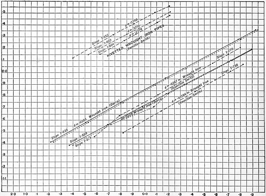 |
| Fig. 83. |
In 1886, Professor W. C. Unwin plotted logarithmically all the most trustworthy experiments on flow in pipes then available.5 Fig. 83 gives one such plotting. The results of measuring the slopes of the lines drawn through the plotted points are given in the table.
It will be seen that the values of the index n range from 1.72 for the smoothest and cleanest surface, to 2.00 for the roughest. The numbers after the brackets are rounded off numbers.
The value of n having been thus determined, values of m/dx were next found and averaged for each pipe. These were again plotted logarithmically in order to find a value for x. The lines were not very regular, but in all cases the slope was greater than 1 to 1, so that the value of x must be greater than unity. The following table gives the results and a comparison of the value of x and Reynolds’s value 3 − n.
| Kind of Pipe. | n | 3 − n | x |
| Tin plate | 1.72 | 1.28 | 1.100 |
| Wrought iron (Smith) | 1.75 | 1.25 | 1.210 |
| Asphalted pipes | 1.85 | 1.15 | 1.127 |
| Wrought iron (Darcy) | 1.87 | 1.13 | 1.680 |
| Riveted wrought iron | 1.87 | 1.13 | 1.390 |
| New cast iron | 1.95 | 1.05 | 1.168 |
| Cleaned cast iron | 2.00 | 1.00 | 1.168 |
| Incrusted cast iron | 2.00 | 1.00 | 1.160 |
With the exception of the anomalous values for Darcy’s wrought-iron pipes, there is no great discrepancy between the values of x and 3 − n, but there is no appearance of relation in the two quantities. For the present it appears preferable to assume that x is independent of n.
It is now possible to obtain values of the third constant m, using the values found for n and x. The following table gives the results, the values of m being for metric measures.
Here, considering the great range of diameters and velocities in the experiments, the constancy of m is very satisfactorily close. The asphalted pipes give rather variable values. But, as some of these were new and some old, the variation is, perhaps, not surprising. The incrusted pipes give a value of m quite double that for new pipes but that is perfectly consistent with what is known of fluid friction in other cases.
| Kind of Pipe. | Diameter in Metres. | Value of m. | Mean Value of m. | Authority. |
| Tin plate | 0.036 | .01697 | .01686 | Bossut |
| 0.054 | .01676 | |||
| Wrought iron | 0.016 | .01302 | .01310 | Hamilton Smith |
| 0.027 | .01319 | |||
| Asphalted pipes | 0.027 | .01749 | .01831 | Hamilton Smith |
| 0.306 | .02058 | W. W. Bonn | ||
| 0.306 | .02107 | W. W. Bonn | ||
| 0.419 | .01650 | Lampe | ||
| 1.219 | .01317 | Stearns | ||
| 1.219 | .02107 | Gale | ||
| Riveted wrought iron | 0.278 | .01370 | .01403 | Hamilton Smith |
| 0.322 | .01440 | |||
| 0.375 | .01390 | |||
| 0.432 | .01368 | |||
| 0.657 | .01448 | |||
| New cast iron | 0.082 | .01725 | .01658 | Darcy |
| 0.137 | .01427 | |||
| 0.188 | .01734 | |||
| 0.500 | .01745 | |||
| Cleaned cast iron | 0.080 | .01979 | .01994 | Darcy |
| 0.245 | .02091 | |||
| 0.297 | .01913 | |||
| Incrusted cast iron | 0.036 | .03693 | .03643 | Darcy |
| 0.080 | .03530 | |||
| 0.243 | .03706 |
General Mean Values of Constants.
The general formula (Hagen’s)—h/l = mvn/dx·2g—can therefore be taken to fit the results with convenient closeness, if the following mean values of the coefficients are taken, the unit being a metre:—
| Kind of Pipe. | m | x | n |
| Tin plate | .0169 | 1.10 | 1.72 |
| Wrought iron | .0131 | 1.21 | 1.75 |
| Asphalted iron | .0183 | 1.127 | 1.85 |
| Riveted wrought iron | .0140 | 1.390 | 1.87 |
| New cast iron | .0166 | 1.168 | 1.95 |
| Cleaned cast iron | .0199 | 1.168 | 2.0 |
| Incrusted cast iron | .0364 | 1.160 | 2.0 |
The variation of each of these coefficients is within a comparatively narrow range, and the selection of the proper coefficient for any given case presents no difficulty, if the character of the surface of the pipe is known.
It only remains to give the values of these coefficients when the quantities are expressed in English feet. For English measures the following are the values of the coefficients:—
| Kind of Pipe. | m | x | n |
| Tin plate | .0265 | 1.10 | 1.72 |
| Wrought iron | .0226 | 1.21 | 1.75 |
| Asphalted iron | .0254 | 1.127 | 1.85 |
| Riveted wrought iron | .0260 | 1.390 | 1.87 |
| New cast iron | .0215 | 1.168 | 1.95 |
| Cleaned cast iron | .0243 | 1.168 | 2.0 |
| Incrusted cast iron | .0440 | 1.160 | 2.0 |
§ 78. Distribution of Velocity in the Cross Section of a Pipe.—Darcy made experiments with a Pitot tube in 1850 on the velocity at different points in the cross section of a pipe. He deduced the relation
V − v = 11.3 (r3/2/R) √i,
where V is the velocity at the centre and v the velocity at radius r in a pipe of radius R with a hydraulic gradient i. Later Bazin repeated the experiments and extended them (Mém. de l’Académie des Sciences, xxxii. No. 6). The most important result was the ratio of mean to central velocity. Let b = Ri/U2, where U is the mean velocity in the pipe; then V/U = 1 + 9.03 √b. A very useful result for practical purposes is that at 0.74 of the radius of the pipe the velocity is equal to the mean velocity. Fig. 84 gives the velocities at different radii as determined by Bazin.
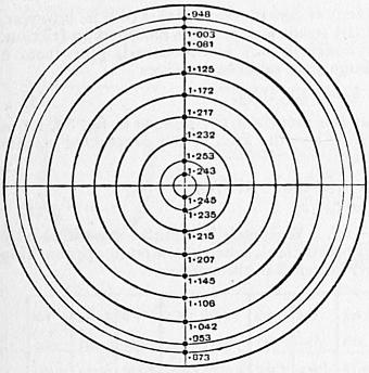 |
| Fig. 84. |
§ 79. Influence of Temperature on the Flow through Pipes.—Very careful experiments on the flow through a pipe 0.1236 ft. in diameter and 25 ft. long, with water at different temperatures, have been made by J. G. Mair (Proc. Inst. Civ. Eng. lxxxiv.). The loss of head was measured from a point 1 ft. from the inlet, so that the loss at entry was eliminated. The 11⁄2 in. pipe was made smooth inside and to gauge, by drawing a mandril through it. Plotting the results logarithmically, it was found that the resistance for all temperatures varied very exactly as v1.795, the index being less than 2 as in other experiments with very smooth surfaces. Taking the ordinary equation of flow h = ζ (4L/D) (v2/2g), then for heads varying from 1 ft. to nearly 4 ft., and velocities in the pipe varying from 4 ft. to 9 ft. per second, the values of ζ were as follows:—
| Temp. F. | ζ | Temp. F. | ζ |
| 57 | .0044 to .0052 | 100 | .0039 to .0042 |
| 70 | .0042 to .0045 | 110 | .0037 to .0041 |
| 80 | .0041 to .0045 | 120 | .0037 to .0041 |
| 90 | .0040 to .0045 | 130 | .0035 to .0039 |
| 160 | .0035 to .0038 |
This shows a marked decrease of resistance as the temperature rises. If Professor Osborne Reynolds’s equation is assumed h = mLVn/d3−n, and n is taken 1.795, then values of m at each temperature are practically constant—
| Temp. F. | m. | Temp. F. | m. |
| 57 | 0.000276 | 100 | 0.000244 |
| 70 | 0.000263 | 110 | 0.000235 |
| 80 | 0.000257 | 120 | 0.000229 |
| 90 | 0.000250 | 130 | 0.000225 |
| 160 | 0.000206 |
where again a regular decrease of the coefficient occurs as the temperature rises. In experiments on the friction of disks at different temperatures Professor W. C. Unwin found that the resistance was proportional to constant × (1 − 0.0021t) and the values of m given above are expressed almost exactly by the relation
m = 0.000311 (1 − 0.00215 t).
In tank experiments on ship models for small ordinary variations of temperature, it is usual to allow a decrease of 3% of resistance for 10° F. increase of temperature.
§ 80. Influence of Deposits in Pipes on the Discharge. Scraping Water Mains.—The influence of the condition of the surface of a pipe on the friction is shown by various facts known to the engineers of waterworks. In pipes which convey certain kinds of water, oxidation proceeds rapidly and the discharge is considerably diminished. A main laid at Torquay in 1858, 14 m. in length, consists of 10-in., 9-in. and 8-in. pipes. It was not protected from corrosion by any coating. But it was found to the surprise of the engineer that in eight years the discharge had diminished to 51% of the original discharge. J. G. Appold suggested an apparatus for scraping the interior of the pipe, and this was constructed and used under the direction of William Froude (see “Incrustation of Iron Pipes,” by W. Ingham, Proc. Inst. Mech. Eng., 1899). It was found that by scraping the interior of the pipe the discharge was increased 56%. The scraping requires to be repeated at intervals. After each scraping the discharge diminishes rather rapidly to 10% and afterwards more slowly, the diminution in a year being about 25%.
Fig. 85 shows a scraper for water mains, similar to Appold’s but modified in details, as constructed by the Glenfield Company, at Kilmarnock. A is a longitudinal section of the pipe, showing the scraper in place; B is an end view of the plungers, and C, D sections of the boxes placed at intervals on the main for introducing or withdrawing the scraper. The apparatus consists of two plungers, packed with leather so as to fit the main pretty closely. On the spindle of these plungers are fixed eight steel scraping blades, with curved scraping edges fitting the surface of the main. The apparatus is placed in the main by removing the cover from one of the boxes shown at C, D. The cover is then replaced, water pressure is admitted behind the plungers, and the apparatus driven through the main. At Lancaster after twice scraping the discharge was increased 561⁄2%, at Oswestry 541⁄2%. The increased discharge is due to the diminution of the friction of the pipe by removing the roughnesses due to oxidation. The scraper can be easily followed when the mains are about 3 ft. deep by the noise it makes. The average speed of the scraper at Torquay is 21⁄3 m. per hour. At Torquay 49% of the deposit is iron rust, the rest being silica, lime and organic matter.
 |
| Fig. 85. Scale 1⁄25. |
In the opinion of some engineers it is inadvisable to use the scraper. The incrustation is only temporarily removed, and if the use of the scraper is continued the life of the pipe is reduced. The only treatment effective in preventing or retarding the incrustation due to corrosion is to coat the pipes when hot with a smooth and perfect layer of pitch. With certain waters such as those derived from the chalk the incrustation is of a different character, consisting of nearly pure calcium carbonate. A deposit of another character which has led to trouble in some mains is a black slime containing a good deal of iron not derived from the pipes. It appears to be an 64 organic growth. Filtration of the water appears to prevent the growth of the slime, and its temporary removal may be effected by a kind of brush scraper devised by G. F. Deacon (see “Deposits in Pipes,” by Professor J. C. Campbell Brown, Proc. Inst. Civ. Eng., 1903-1904).
§ 81. Flow of Water through Fire Hose.—The hose pipes used for fire purposes are of very varied character, and the roughness of the surface varies. Very careful experiments have been made by J. R. Freeman (Am. Soc. Civ. Eng. xxi., 1889). It was noted that under pressure the diameter of the hose increased sufficiently to have a marked influence on the discharge. In reducing the results the true diameter has been taken. Let v = mean velocity in ft. per sec.; r = hydraulic mean radius or one-fourth the diameter in feet; i = hydraulic gradient. Then v = n √(ri).
| Diameter in Inches. | Gallons (United States) per min. | i | v | n | |
| Solid rubber hose | 2.65 | 215 | .1863 | 12.50 | 123.3 |
| ” | 344 | .4714 | 20.00 | 124.0 | |
| Woven cotton, rubber lined | 2.47 | 200 | .2464 | 13.40 | 119.1 |
| ” | 299 | .5269 | 20.00 | 121.5 | |
| Woven cotton, rubber lined | 2.49 | 200 | .2427 | 13.20 | 117.7 |
| ” | 319 | .5708 | 21.00 | 122.1 | |
| Knit cotton, rubber lined | 2.68 | 132 | .0809 | 7.50 | 111.6 |
| ” | 299 | .3931 | 17.00 | 114.8 | |
| Knit cotton, rubber lined | 2.69 | 204 | .2357 | 11.50 | 100.1 |
| ” | 319 | .5165 | 18.00 | 105.8 | |
| Woven cotton, rubber lined | 2.12 | 154 | .3448 | 14.00 | 113.4 |
| ” | 240 | .7673 | 21.81 | 118.4 | |
| Woven cotton, rubber lined | 2.53 | 54.8 | .0261 | 3.50 | 94.3 |
| ” | 298 | .8264 | 19.00 | 91.0 | |
| Unlined linen hose | 2.60 | 57.9 | .0414 | 3.50 | 73.9 |
| ” | 331 | 1.1624 | 20.00 | 79.6 |
§ 82. Reduction of a Long Pipe of Varying Diameter to an Equivalent Pipe of Uniform Diameter. Dupuit’s Equation.—Water mains for the supply of towns often consist of a series of lengths, the diameter being the same for each length, but differing from length to length. In approximate calculations of the head lost in such mains, it is generally accurate enough to neglect the smaller losses of head and to have regard to the pipe friction only, and then the calculations may be facilitated by reducing the main to a main of uniform diameter, in which there would be the same loss of head. Such a uniform main will be termed an equivalent main.
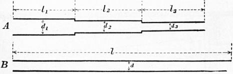 |
| Fig. 86. |
In fig. 86 let A be the main of variable diameter, and B the equivalent uniform main. In the given main of variable diameter A, let
| l1, l2 | be the lengths, |
| d1, d2 | the diameters, |
| v1, v2 | the velocities, |
| i1, i2 | the slopes, |
for the successive portions, and let l, d, v and i be corresponding quantities for the equivalent uniform main B. The total loss of head in A due to friction is
| h = i1l1 + i2l2 + ... = ζ (v12 · 4l1/2gd1) + ζ (v22 · 4l2/2gd2) + ... |
and in the uniform main
il = ζ (v2 · 4l/2gd).
If the mains are equivalent, as defined above,
ζ (v2 · 4l/2gd) = ζ (v12 · 4l1/2gd1) + ζ (v22 · 4l2/2gd2) + ...
But, since the discharge is the same for all portions,
| 1⁄4πd2v = 1⁄4πd12v1 = 1⁄4πd22v2 = ... v1 = vd2/d12; v2 = vd2/d22 ... |
Also suppose that ζ may be treated as constant for all the pipes. Then
| l/d = (d4/d14) (l1/d1) + (d4/d24) (l2/d2) + ... l = (d5/d15) l1 + (d5/d25) l2 + ... |
which gives the length of the equivalent uniform main which would have the same total loss of head for any given discharge.
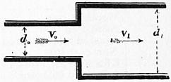 |
| Fig. 87. |
§ 83. Other Losses of Head in Pipes.—Most of the losses of head in pipes, other than that due to surface friction against the pipe, are due to abrupt changes in the velocity of the stream producing eddies. The kinetic energy of these is deducted from the general energy of translation, and practically wasted.
Sudden Enlargement of Section.—Suppose a pipe enlarges in section from an area ω0 to an area ω1 (fig. 87); then
v1/v0 = ω0/ω1;
or, if the section is circular,
v1/v0 = (d0/d1)2.
The head lost at the abrupt change of velocity has already been shown to be the head due to the relative velocity of the two parts of the stream. Hence head lost
ɧe = (v0 − v1)2/2g = (ω1/ω0 − 1)2 v12/2g = {(d1/d0)2 − 1}2 v12/2g
or
ɧe = ζev12/2g,
if ζe is put for the expression in brackets.
| ω1/ω0 = | 1.1 | 1.2 | 1.5 | 1.7 | 1.8 | 1.9 | 2.0 | 2.5 | 3.0 | 3.5 | 4.0 | 5.0 | 6.0 | 7.0 | 8.0 |
| d1/d0 = | 1.05 | 1.10 | 1.22 | 1.30 | 1.34 | 1.38 | 1.41 | 1.58 | 1.73 | 1.87 | 2.00 | 2.24 | 2.45 | 2.65 | 2.83 |
| ζe = | .01 | .04 | .25 | .49 | .64 | .81 | 1.00 | 2.25 | 4.00 | 6.25 | 9.00 | 16.00 | 25.00 | 36.0 | 49.0 |
 |
 |
| Fig. 88. | Fig. 89. |
Abrupt Contraction of Section.—When water passes from a larger to a smaller section, as in figs. 88, 89, a contraction is formed, and the contracted stream abruptly expands to fill the section of the pipe. Let ω be the section and v the velocity of the stream at bb. At aa the section will be ccω, and the velocity (ω/ccω) v = v/c1, where cc is the coefficient of contraction. Then the head lost is
ɧm = (v/cc − v)2 / 2g = (1/cc − 1)2 v2/2g;
and, if cc is taken 0.64,
ɧm = 0.316 v2/2g.
The value of the coefficient of contraction for this case is, however, not well ascertained, and the result is somewhat modified by friction. For water entering a cylindrical, not bell-mouthed, pipe from a reservoir of indefinitely large size, experiment gives
ɧa = 0.505 v2/2g.
If there is a diaphragm at the mouth of the pipe as in fig. 89, let ω1 be the area of this orifice. Then the area of the contracted stream is ccω1, and the head lost is
| ɧc = {(ω/ccω1) − 1}2 v2/2g = ζcv2 / 2g |
if ζ, is put for {(ω/ccω1) − 1}2. Weisbach has found experimentally the following values of the coefficient, when the stream approaching the orifice was considerably larger than the orifice:—
| ω1/ω = | 0.1 | 0.2 | 0.3 | 0.4 | 0.5 | 0.6 | 0.7 | 0.8 | 0.9 | 1.0 |
| cc = | .616 | .614 | .612 | .610 | .617 | .605 | .603 | .601 | .598 | .596 |
| ζc = | 231.7 | 50.99 | 19.78 | 9.612 | 5.256 | 3.077 | 1.876 | 1.169 | 0.734 | 0.480 |
 |
| Fig. 90. |
When a diaphragm was placed in a tube of uniform section (fig. 90) the following values were obtained, ω1 being the area of the orifice and ω that of the pipe:—
| ω1/ω = | 0.1 | 0.2 | 0.3 | 0.4 | 0.5 | 0.6 | 0.7 | 0.8 | 0.9 | 1.0 |
| ce = | .624 | .632 | .643 | .659 | .681 | .712 | .755 | .813 | .892 | 1.00 |
| ξc = | 225.9 | 47.77 | 30.83 | 7.801 | 1.753 | 1.796 | .797 | .290 | .060 | .000 |
Elbows.—Weisbach considers the loss of head at elbows (fig. 91) to be due to a contraction formed by the stream. From experiments with a pipe 11⁄4 in. diameter, he found the loss of head
ɧe = ζεv2 / 2g;
ζe = 0.9457 sin2 1⁄2φ + 2.047 sin4 1⁄2φ.
| φ = | 20° | 40° | 60° | 80° | 90° | 100° | 110° | 120° | 130° | 140° |
| ζε = | 0.046 | 0.139 | 0.364 | 0.740 | 0.984 | 1.260 | 1.556 | 1.861 | 2.158 | 2.431 |
Hence at a right-angled elbow the whole head due to the velocity very nearly is lost.
 |
| Fig. 91. |
 |
| Fig. 92. |
Bends.—Weisbach traces the loss of head at curved bends to a similar cause to that at elbows, but the coefficients for bends are not very satisfactorily ascertained. Weisbach obtained for the loss of head at a bend in a pipe of circular section
ɧb = ζbv2 / 2g;
ζb = 0.131 + 1.847 (d/2ρ)7/2,
where d is the diameter of the pipe and ρ the radius of curvature of the bend. The resistance at bends is small and at present very ill determined.
Valves, Cocks and Sluices.—These produce a contraction of the water-stream, similar to that for an abrupt diminution of section already discussed. The loss of head may be taken as before to be
ɧv = ζvv2 / 2g;
where v is the velocity in the pipe beyond the valve and ζv a coefficient determined by experiment. The following are Weisbach’s results.
Sluice in Pipe of Rectangular Section (fig. 92). Section at sluice = ω1 in pipe = ω.
| ω1/ω = | 1.0 | 0.9 | 0.8 | 0.7 | 0.6 | 0.5 | 0.4 | 0.3 | 0.2 | 0.1 |
| ζv = | 0.00 | .09 | .39 | .95 | 2.08 | 4.02 | 8.12 | 17.8 | 44.5 | 193 |
Sluice in Cylindrical Pipe (fig. 93).
| Ratio of height of opening to diameter of pipe | 1.0 | 7⁄8 | 3⁄4 | 5⁄8 | 1⁄2 | 3⁄8 | 1⁄4 | 1⁄5 |
| ω1/ω = | 1.00 | 0.948 | .856 | .740 | .609 | .466 | .315 | .159 |
| ζv = | 0.00 | 0.07 | 0.26 | 0.81 | 2.06 | 5.52 | 17.0 | 97.8 |
 |
 |
| Fig. 93. | Fig. 94. |
Cock in a Cylindrical Pipe (fig. 94). Angle through which cock is turned = θ.
| θ = | 5° | 10° | 15° | 20° | 25° | 30° | 35° |
| Ratio of cross sections | .926 | .850 | .772 | .692 | .613 | .535 | .458 |
| ζv = | .05 | .29 | .75 | 1.56 | 3.10 | 5.47 | 9.68 |
| θ = | 40° | 45° | 50° | 55° | 60° | 65° | 82° |
| Ratio of cross sections | .385 | .315 | .250 | .190 | .137 | .091 | 0 |
| ζv = | 17.3 | 31.2 | 52.6 | 106 | 206 | 486 | ∞ |
Throttle Valve in a Cylindrical Pipe (fig. 95)
| θ = | 5° | 10° | 15° | 20° | 25° | 30° | 35° | 40° |
| ζv = | .24 | .52 | .90 | 1.54 | 2.51 | 3.91 | 6.22 | 10.8 |
| θ = | 45° | 50° | 55° | 60° | 65° | 70° | 90° |
| ζv = | 18.7 | 32.6 | 58.8 | 118 | 256 | 751 | ∞ |
 |
| Fig. 95. |
§ 84. Practical Calculations on the Flow of Water in Pipes.—In the following explanations it will be assumed that the pipe is of so great a length that only the loss of head in friction against the surface of the pipe needs to be considered. In general it is one of the four quantities d, i, v or Q which requires to be determined. For since the loss of head h is given by the relation h = il, this need not be separately considered.
There are then three equations (see eq. 4, § 72, and 9a, § 76) for the solution of such problems as arise:—
ζ = α (1 + 1/12d);
where α = 0.005 for new and = 0.01 for incrusted pipes.
ζv2 / 2g = 1⁄4di.
Q = 1⁄4πd2v.
Problem 1. Given the diameter of the pipe and its virtual slope, to find the discharge and velocity of flow. Here d and i are given, and Q and v are required. Find ζ from (1); then v from (2); lastly Q from (3). This case presents no difficulty.
By combining equations (1) and (2), v is obtained directly:—
v = √ (gdi/2ζ) = √ (g/2α) √ [di / {1 + 1/12d}].
| For new pipes | √ (g/2α) = 56.72 |
| For incrusted pipes | = 40.13 |
For pipes not less than 1, or more than 4 ft. in diameter, the mean values of ζ are
| For new pipes | 0.00526 |
| For incrusted pipes | 0.01052. |
Using these values we get the very simple expressions—
| v = 55.31 √ (di) for new pipes = 39.11 √ (di) for incrusted pipes. |
Within the limits stated, these are accurate enough for practical purposes, especially as the precise value of the coefficient ζ cannot be known for each special case.
Problem 2. Given the diameter of a pipe and the velocity of flow, to find the virtual slope and discharge. The discharge is given by (3); the proper value of ζ by (1); and the virtual slope by (2). This also presents no special difficulty.
Problem 3. Given the diameter of the pipe and the discharge, to find the virtual slope and velocity. Find v from (3); ζ from (1); lastly i from (2). If we combine (1) and (2) we get
i = ζ (v2/2g) (4/d) = 2a {1 + 1/12d} v2/gd;
and, taking the mean values of ζ for pipes from 1 to 4 ft. diameter, given above, the approximate formulae are
| i = 0.0003268 v2/d for new pipes = 0.0006536 v2/d for incrusted pipes. |
Problem 4. Given the virtual slope and the velocity, to find the diameter of the pipe and the discharge. The diameter is obtained from equations (2) and (1), which give the quadratic expression
d2 − d (2αv2/gi) − αv2/6gi = 0.
∴ d = αv2/gi + √ {(αv2/gi) (αv2/gi + 1/6)}.
For practical purposes, the approximate equations
| d = 2αv2/gi + 1/12 = 0.00031 v2/i + .083 for new pipes = 0.00062 v2/i + .083 for incrusted pipes |
are sufficiently accurate.
Problem 5. Given the virtual slope and the discharge, to find the diameter of the pipe and velocity of flow. This case, which often occurs in designing, is the one which is least easy of direct solution. From equations (2) and (3) we get—
d5 = 32ζQ2 / gπ2i.
If now the value of ζ in (1) is introduced, the equation becomes very cumbrous. Various approximate methods of meeting the difficulty may be used.
(a) Taking the mean values of ζ given above for pipes of 1 to 4 ft. diameter we get
| d = 5√ (32ζ/gπ2) 5√ (Q2/i) = 0.2216 5√ (Q2/i) for new pipes = 0.2541 5√ (Q2/i) for incrusted pipes; |
equations which are interesting as showing that when the value of ζ is doubled the diameter of pipe for a given discharge is only increased by 13%.
(b) A second method is to obtain a rough value of d by assuming ζ = α. This value is
d′ = 5√ (32Q2 / gπ2i) 5√ α = 0.6319 5√ (Q2/i) 5√ α.
Then a very approximate value of ζ is
ζ′ = α (1 + 1/12d′);
and a revised value of d, not sensibly differing from the exact value, is
d″ = 5√ (32Q2 / gπ2i) 5√ ζ′ = 0.6319 5√ (Q2/i) 5√ ζ′.
(c) Equation 7 may be put in the form
d = 5√ (32αQ2 / gπ2i) 5√ (1 + 1/12d).
Expanding the term in brackets,
5√ (1 + 1/12d) = 1 + 1/60d − 1/1800d2 ...
Neglecting the terms after the second,
| d = 5√ (32α / gπ2) 5√ (Q2/i) · {1 + 1/60d} = 5√ (32α / gπ2) 5√ (Q2/i) + 0.01667; |
and
| 5√ (32α / gπ2) = 0.219 for new pipes = 0.252 for incrusted pipes. |
 |
| Fig. 96. |
 |
| Fig. 97. |
§ 85. Arrangement of Water Mains for Towns’ Supply.—Town mains are usually supplied oy gravitation from a service reservoir, which in turn is supplied by gravitation from a storage reservoir or by pumping from a lower level. The service reservoir should contain three days’ supply or in important cases much more. Its elevation should be such that water is delivered at a pressure of at least about 100 ft. to the highest parts of the district. The greatest pressure in the mains is usually about 200 ft., the pressure for which ordinary pipes and fittings are designed. Hence if the district supplied has great variations of level it must be divided into zones of higher and lower pressure. Fig. 96 shows a district of two zones each with its service reservoir and a range of pressure in the lower district from 100 to 200 ft. The total supply required is in England about 25 gallons per head per day. But in many towns, and especially in America, the supply is considerably greater, but also in many cases a good deal of the supply is lost by leakage of the mains. The supply through the branch mains of a distributing system is calculated from the population supplied. But in determining the capacity of the mains the fluctuation of the demand must be allowed for. It is usual to take the maximum demand at twice the average demand. Hence if the average demand is 25 gallons per head per day, the mains should be calculated for 50 gallons per head per day.
 |
| Fig. 98. |
§ 86. Determination of the Diameters of Different Parts of a Water Main.—When the plan of the arrangement of mains is determined upon, and the supply to each locality and the pressure required is ascertained, it remains to determine the diameters of the pipes. Let fig. 97 show an elevation of a main ABCD ..., R being the reservoir from which the supply is derived. Let NN be the datum line of the levelling operations, and Ha, Hb ... the heights of the main above the datum line, Hr being the height of the water surface in the reservoir from the same datum. Set up next heights AA1, BB1, ... representing the minimum pressure height necessary for the adequate supply of each locality. Then A1B1C1D1 ... is a line which should form a lower limit to the line of virtual slope. Then if heights ɧa, ɧb, ɧc ... are taken representing the actual losses of head in each length la, lb, lc ... of the main, A0B0C0 will be the line of virtual slope, and it will be obvious at what points such as D0 and E0, the pressure is deficient, and a different choice of diameter of main is required. For any point z in the length of the main, we have
Pressure height = Hr − Hz − (ɧa + ɧb + ... ɧz).
Where no other circumstance limits the loss of head to be assigned to a given length of main, a consideration of the safety of the main from fracture by hydraulic shock leads to a limitation of the velocity of flow. Generally the velocity in water mains lies between 11⁄2 and 41⁄2 ft. per second. Occasionally the velocity in pipes reaches 10 ft. per second, and in hydraulic machinery working under enormous pressures even 20 ft. per second. Usually the velocity diminishes along the main as the discharge diminishes, so as to reduce somewhat the total loss of head which is liable to render the pressure insufficient at the end of the main.
J. T. Fanning gives the following velocities as suitable in pipes for towns’ supply:—
| Diameter in inches | 4 | 8 | 12 | 18 | 24 | 30 | 36 |
| Velocity in feet per sec. | 2.5 | 3.0 | 3.5 | 4.5 | 5.3 | 6.2 | 7.0 |
§ 87. Branched Pipe connecting Reservoirs at Different Levels.—Let A, B, C (fig. 98) be three reservoirs connected by the arrangement of pipes shown,—l1, d1, Q1, v1; l2, d2, Q2, v2; h3, d3, Q3, v3 being the length, diameter, discharge and velocity in the three portions of the main pipe. Suppose the dimensions and positions of the pipes known and the discharges required.
If a pressure column is introduced at X, the water will rise to a height XR, measuring the pressure at X, and aR, Rb, Rc will be the lines of virtual slope. If the free surface level at R is above b, the reservoir A supplies B and C, and if R is below b, A and B supply C. Consequently there are three cases:—
| I. | R above b; Q1 = Q2 + Q3. |
| II. | R level with b; Q1 = Q3; Q2 = 0 |
| III. | R below b; Q1 + Q2 = Q3. |
To determine which case has to be dealt with in the given conditions, suppose the pipe from X to B closed by a sluice. Then there is a simple main, and the height of free surface h′ at X can be determined. For this condition
ha − h′ = ζ (v12/2g) (4l1/d1) = 32ζQ′2l1 / gπ2d15;
h′ − hc = ζ (v32/2g) (4l3/d3) = 32ζQ′2l3 / gπ2d35;
where Q′ is the common discharge of the two portions of the pipe. Hence
(ha − h′) / (h′ − hc) = l1d35 / l3d15,
from which h′ is easily obtained. If then h′ is greater than hb, opening the sluice between X and B will allow flow towards B, and the case in hand is case I. If h′ is less than hb, opening the sluice will allow flow from B, and the case is case III. If h′ = hb, the case is case II., and is already completely solved.
The true value of h must lie between h′ and hb. Choose a new value of h, and recalculate Q1, Q2, Q3. Then if
Q1 > Q2 + Q3 in case I.,
or
Q1 + Q2 > Q3 in case III.,
the value chosen for h is too small, and a new value must be chosen.
If
Q1 < Q2 + Q3 in case I.,
or
Q1 + Q2 < Q3 in case III.,
the value of h is too great.
Since the limits between which h can vary are in practical cases not very distant, it is easy to approximate to values sufficiently accurate.
§ 88. Water Hammer.—If in a pipe through which water is flowing a sluice is suddenly closed so as to arrest the forward movement of the water, there is a rise of pressure which in some cases is serious enough to burst the pipe. This action is termed water hammer or water ram. The fluctuation of pressure is an oscillating one and gradually dies out. Care is usually taken that sluices should only be closed gradually and then the effect is inappreciable. Very careful experiments on water hammer were made by N. J. Joukowsky at Moscow in 1898 (Stoss in Wasserleitungen, St Petersburg, 1900), and the results are generally confirmed by experiments made by E. B. Weston and R. C. Carpenter in America. Joukowsky used pipes, 2, 4 and 6 in. diameter, from 1000 to 2500 ft. in length. The sluice closed in 0.03 second, and the fluctuations of pressure were automatically registered. The maximum excess pressure due to water-hammer action was as follows:—
| Pipe 4-in. diameter. | Pipe 6-in. diameter. | ||
| Velocity ft. per sec. | Excess Pressure. ℔ per sq. in. |
Velocity ft. per sec. | Excess Pressure. ℔ per sq. in. |
| 0.5 | 31 | 0.6 | 43 |
| 2.9 | 168 | 3.0 | 173 |
| 4.1 | 232 | 5.6 | 369 |
| 9.2 | 519 | 7.5 | 426 |
In some cases, in fixing the thickness of water mains, 100 ℔ per sq. in. excess pressure is allowed to cover the effect of water hammer. With the velocities usual in water mains, especially as no valves can be quite suddenly closed, this appears to be a reasonable allowance (see also Carpenter, Am. Soc. Mech. Eng., 1893).
IX. FLOW OF COMPRESSIBLE FLUIDS IN PIPES
§ 89. Flow of Air in Long Pipes.—When air flows through a long pipe, by far the greater part of the work expended is used in overcoming frictional resistances due to the surface of the pipe. The work expended in friction generates heat, which for the most part must be developed in and given back to the air. Some heat may be transmitted through the sides of the pipe to surrounding materials, but in experiments hitherto made the amount so conducted away appears to be very small, and if no heat is transmitted the air in the tube must remain sensibly at the same temperature during expansion. In other words, the expansion may be regarded as isothermal expansion, the heat generated by friction exactly neutralizing the cooling due to the work done. Experiments on the pneumatic tubes used for the transmission of messages, by R. S. Culley and R. Sabine (Proc. Inst. Civ. Eng. xliii.), show that the change of temperature of the air flowing along the tube is much less than it would be in adiabatic expansion.
§ 90. Differential Equation of the Steady Motion of Air Flowing in a Long Pipe of Uniform Section.—When air expands at a constant absolute temperature τ, the relation between the pressure p in pounds per square foot and the density or weight per cubic foot G is given by the equation
p/G = cτ,
where c = 53.15. Taking τ = 521, corresponding to a temperature of 60° Fahr.,
cτ = 27690 foot-pounds.
 |
| Fig. 99. |
The equation of continuity, which expresses the condition that in steady motion the same weight of fluid, W, must pass through each cross section of the stream in the unit of time, is
GΩu = W = constant,
where Ω is the section of the pipe and u the velocity of the air. Combining (1) and (3),
Ωup/W = cτ = constant.
Since the work done by gravity on the air during its flow through a pipe due to variations of its level is generally small compared with the work done by changes of pressure, the former may in many cases be neglected.
Consider a short length dl of the pipe limited by sections A0, A1 at a distance dl (fig. 99). Let p, u be the pressure and velocity at A0, p + dp and u + du those at A1. Further, suppose that in a very short time dt the mass of air between A0A1 comes to A′0A′1 so that A0A′0 = udt and A1A′1 = (u + du) dt1. Let Ω be the section, and m the hydraulic mean radius of the pipe, and W the weight of air flowing through the pipe per second.
From the steadiness of the motion the weight of air between the sections A0A′0, and A1A′1 is the same. That is,
W dt = GΩu dt = GΩ (u + du) dt.
By analogy with liquids the head lost in friction is, for the length dl (see § 72, eq. 3), ζ (u2/2g) (dl/m). Let H = u2/2g. Then the head lost is ζ(H/m)dl; and, since Wdt ℔ of air flow through the pipe in the time considered, the work expended in friction is −ζ (H/m)W dl dt. The change of kinetic energy in dt seconds is the difference of the kinetic energy of A0A′0 and A1A′1, that is,
(W/g) dt {(u + du)2 − u2} / 2 = (W/g) u du dt = W dH dt.
The work of expansion when Ωudt cub. ft. of air at a pressure p expand to Ω(u + du) dt cub. ft. is Ωp du dt. But from (3a) u = cτW/Ωp, and therefore
du / dp = −cτW / Ωp2.
And the work done by expansion is −(cτW/p) dp dt.
The work done by gravity on the mass between A0 and A1 is zero if the pipe is horizontal, and may in other cases be neglected without great error. The work of the pressures at the sections A0A1 is
pΩu dt − (p + dp) Ω (u + du) dt
= −(p du + u dp) Ω dt
But from (3a)
pu = constant,
p du + u dp = 0,
and the work of the pressures is zero. Adding together the quantities of work, and equating them to the change of kinetic energy,
W dH dt = −(cτW/p) dp dt − ζ (H/m) W dl dt
dH + (cτ/p) dp + ζ (H/m) dl = 0,
dH/H + (cτ/Hp) dp + ζdl / m = 0
But
u = cτW / Ωp,
and
H = u2/2g = c2τ2W2 / 2gΩ2p2,
∴ dH/H + (2gΩ2p / cτW2) dp + ζdl / m = 0.
For tubes of uniform section m is constant; for steady motion W is constant; and for isothermal expansion τ is constant. Integrating,
log H + gΩ2p2 / W2cτ + ζ l / m = constant;
for
l = 0, let H = H0, and p = p0;
and for
l = l, let H = H1, and p = p1.
log (H1/H0) + (gΩ2 / W2cτ) (p12 − p02) + ζ l / m = 0.
where p0 is the greater pressure and p1 the less, and the flow is from A0 towards A1.
By replacing W and H,
log (p0/p1) + (gcτ / u02p02) (p12 − p02 + ζ l/m = 0
Hence the initial velocity in the pipe is
u0 = √ [{gcτ (p02 − p12)} / {p02 (ζ l/m + log (p0 / p1) }].
When l is great, log p0/p1 is comparatively small, and then
u0 = √ [ (gcτm/ζ l) {(p02 − p12) / p02} ],
a very simple and easily used expression. For pipes of circular section m = d/4, where d is the diameter:—
u0 = √ [ (gcτd / 4ζ l) {(p02 − p12) / p02} ];
or approximately
u0 = (1.1319 − 0.7264 p1/p0) √ (gcτd / 4ζ l).
§ 91. Coefficient of Friction for Air.—A discussion by Professor Unwin of the experiments by Culley and Sabine on the rate of transmission of light carriers through pneumatic tubes, in which there is steady flow of air not sensibly affected by any resistances other than surface friction, furnished the value ζ = .007. The pipes were lead pipes, slightly moist, 21⁄4 in. (0.187 ft.) in diameter, and in lengths of 2000 to nearly 6000 ft.
In some experiments on the flow of air through cast-iron pipes A. Arson found the coefficient of friction to vary with the velocity and diameter of the pipe. Putting
ζ = α/v + β,
he obtained the following values—
| Diameter of Pipe in feet. | α | β | ζ for 100 ft. per second. |
| 1.64 | .00129 | .00483 | .00484 |
| 1.07 | .00972 | .00640 | .00650 |
| .83 | .01525 | .00704 | .00719 |
| .338 | .03604 | .00941 | .00977 |
| .266 | .03790 | .00959 | .00997 |
| .164 | .04518 | .01167 | .01212 |
It is worth while to try if these numbers can be expressed in the form proposed by Darcy for water. For a velocity of 100 ft. per second, and without much error for higher velocities, these numbers agree fairly with the formula
ζ = 0.005 (1 + 3/10d),
which only differs from Darcy’s value for water in that the second term, which is always small except for very small pipes, is larger.
Some later experiments on a very large scale, by E. Stockalper at the St Gotthard Tunnel, agree better with the value
ζ = 0.0028 (1 + 3/10d).
These pipes were probably less rough than Arson’s.
When the variation of pressure is very small, it is no longer safe to neglect the variation of level of the pipe. For that case we may neglect the work done by expansion, and then
z0 − z1 − p0/G0 − p1/G1 − ζ (v2/2g) (l/m) = 0,
precisely equivalent to the equation for the flow of water, z0 and z1 being the elevations of the two ends of the pipe above any datum, p0 and p1 the pressures, G0 and G1 the densities, and v the mean velocity in the pipe. This equation may be used for the flow of coal gas.
§ 92. Distribution of Pressure in a Pipe in which Air is Flowing.—From equation (7a) it results that the pressure p, at l ft. from that end of the pipe where the pressure is p0, is
p = p0 √ (1 − ζ lu02 / mgcτ);
which is of the form
p = √ (al + b)
for any given pipe with given end pressures. The curve of free surface level for the pipe is, therefore, a parabola with horizontal axis. Fig. 100 shows calculated curves of pressure for two of Sabine’s experiments, in one of which the pressure was greater than atmospheric pressure, and in the other less than atmospheric pressure. The observed pressures are given in brackets and the calculated pressures without brackets. The pipe was the pneumatic tube between Fenchurch Street and the Central Station, 2818 yds. in length. The pressures are given in inches of mercury.
 |
| Fig. 100. |
Variation of Velocity in the Pipe.—Let p0, u0 be the pressure and velocity at a given section of the pipe; p, u, the pressure and velocity at any other section. From equation (3a)
up = cτW / Ω = constant;
so that, for any given uniform pipe,
| up = u0p0, u = u0p0 / p; |
which gives the velocity at any section in terms of the pressure, which has already been determined. Fig. 101 gives the velocity curves for the two experiments of Culley and Sabine, for which the pressure curves have already been drawn. It will be seen that the velocity increases considerably towards that end of the pipe where the pressure is least.
 |
| Fig. 101. |
§ 93. Weight of Air Flowing per Second.—The weight of air discharged per second is (equation 3a)—
W = Ωu0p0 / cτ.
From equation (7b), for a pipe of circular section and diameter d,
| W = 1⁄4π √ (gd5 (p02 − p12) / ζ lcτ), = .611 √ (d5 (p02 − p12) / ζ lτ). |
Approximately
W = (.6916p0 − .4438p1) (d5 / ζ lτ)1/2.
§ 94. Application to the Case of Pneumatic Tubes for the Transmission of Messages.—In Paris, Berlin, London, and other towns, it has been found cheaper to transmit messages in pneumatic tubes than to telegraph by electricity. The tubes are laid underground with easy curves; the messages are made into a roll and placed in a light felt carrier, the resistance of which in the tubes in London is only 3⁄4 oz. A current of air forced into the tube or drawn through it propels the carrier. In most systems the current of air is steady and continuous, and the carriers are introduced or removed without materially altering the flow of air.
Time of Transit through the Tube.—Putting t for the time of transit from 0 to l,
t = ∫l0 dl/u,
From (4a) neglecting dH/H, and putting m = d/4,
dl = gdΩ2p dp / 2ζW2cr.
From (1) and (3)
u = Wcτ / pΩ;
dl/u = gdΩ3p2 dp / 2ζW3c2τ2;
t = ∫p0p1 g dΩ3 p2 dp / 2ζW3c2τ2,
= g dΩ3 (p03 − p13) / 6ζW3c2τ2.
But
W = p0u0Ω / cτ;
∴ t = gdcτ (p03 − p13) / 6ζp03u03,
= ζ1/2 l3/2 (p03 − p13) / 6(gcτd)1/2 (p02 − p12)3/2;
If τ = 521°, corresponding to 60° F.,
t = .001412 ζ1/2 l3/2 (p03 − p13) / d1/2 (p02 − p12)3/2;
which gives the time of transmission in terms of the initial and final pressures and the dimensions of the tube.
Mean Velocity of Transmission.—The mean velocity is l/t; or, for τ = 521°,
umean = 0.708 √ {d (p02 − p12)3/2 / ζ l (p03 − p13)}.
The following table gives some results:—
| Absolute Pressures in ℔ per sq. in. | Mean Velocities for Tubes of a length in feet. | ||||||
| p0 | p1 | 1000 | 2000 | 3000 | 4000 | 5000 | |
| Vacuum Working | 15 | 5 | 99.4 | 70.3 | 57.4 | 49.7 | 44.5 |
| 15 | 10 | 67.2 | 47.5 | 38.8 | 34.4 | 30.1 | |
| Pressure Working | 20 | 15 | 57.2 | 40.5 | 33.0 | 28.6 | 25.6 |
| 25 | 15 | 74.6 | 52.7 | 43.1 | 37.3 | 33.3 | |
| 30 | 15 | 84.7 | 60.0 | 49.0 | 42.4 | 37.9 | |
Limiting Velocity in the Pipe when the Pressure at one End is diminished indefinitely.—If in the last equation there be put p1 = 0, then
u′mean = 0.708 √ (d / ζ l);
where the velocity is independent of the pressure p0 at the other end, a result which apparently must be absurd. Probably for long pipes, as for orifices, there is a limit to the ratio of the initial and terminal pressures for which the formula is applicable.
X. FLOW IN RIVERS AND CANALS
§ 95. Flow of Water in Open Canals and Rivers.—When water flows in a pipe the section at any point is determined by the form of the boundary. When it flows in an open channel with free upper surface, the section depends on the velocity due to the dynamical conditions.
Suppose water admitted to an unfilled canal. The channel will gradually fill, the section and velocity at each point gradually changing. But if the inflow to the canal at its head is constant, the increase of cross section and diminution of velocity at each point attain after a time a limit. Thenceforward the section and velocity at each point are constant, and the motion is steady, or permanent regime is established.
If when the motion is steady the sections of the stream are all equal, the motion is uniform. By hypothesis, the inflow Ωv is constant for all sections, and Ω is constant; therefore v must be constant also from section to section. The case is then one of uniform steady motion. In most artificial channels the form of section is constant, and the bed has a uniform slope. In that case the motion is uniform, the depth is constant, and the stream surface is parallel to the bed. If when steady motion is established the sections are unequal, the motion is steady motion with varying velocity from section to section. Ordinary rivers are in this condition, especially where the flow is modified by weirs or obstructions. Short unobstructed lengths of a river may be treated as of uniform section without great error, the mean section in the length being put for the actual sections.
 |
| Fig. 102. |
In all actual streams the different fluid filaments have different velocities, those near the surface and centre moving faster than those near the bottom and sides. The ordinary formulae for the flow of streams rest on a hypothesis that this variation of velocity may be neglected, and that all the filaments may be treated as having a common velocity equal to the mean velocity of the stream. On this hypothesis, a plane layer abab (fig. 102) between sections normal 69 to the direction of motion is treated as sliding down the channel to a′a′b′b′ without deformation. The component of the weight parallel to the channel bed balances the friction against the channel, and in estimating the friction the velocity of rubbing is taken to be the mean velocity of the stream. In actual streams, however, the velocity of rubbing on which the friction depends is not the mean velocity of the stream, and is not in any simple relation with it, for channels of different forms. The theory is therefore obviously based on an imperfect hypothesis. However, by taking variable values for the coefficient of friction, the errors of the ordinary formulae are to a great extent neutralized, and they may be used without leading to practical errors. Formulae have been obtained based on less restricted hypotheses, but at present they are not practically so reliable, and are more complicated than the formulae obtained in the manner described above.
§ 96. Steady Flow of Water with Uniform Velocity in Channels of Constant Section.—Let aa′, bb′ (fig. 103) be two cross sections normal to the direction of motion at a distance dl. Since the mass aa′bb′ moves uniformly, the external forces acting on it are in equilibrium. Let Ω be the area of the cross sections, χ the wetted perimeter, pq + qr + rs, of a section. Then the quantity m = Ω/χ is termed the hydraulic mean depth of the section. Let v be the mean velocity of the stream, which is taken as the common velocity of all the particles, i, the slope or fall of the stream in feet, per foot, being the ratio bc/ab.
 |
| Fig. 103. |
The external forces acting on aa′bb′ parallel to the direction of motion are three:—(a) The pressures on aa′ and bb′, which are equal and opposite since the sections are equal and similar, and the mean pressures on each are the same. (b) The component of the weight W of the mass in the direction of motion, acting at its centre of gravity g. The weight of the mass aa′bb′ is GΩ dl, and the component of the weight in the direction of motion is GΩdl × the cosine of the angle between Wg and ab, that is, GΩdl cos abc = GΩ dl bc/ab = GΩidl. (c) There is the friction of the stream on the sides and bottom of the channel. This is proportional to the area χdl of rubbing surface and to a function of the velocity which may be written ƒ(v); ƒ(v) being the friction per sq. ft. at a velocity v. Hence the friction is −χ dl ƒ(v). Equating the sum of the forces to zero,
GΩi dl − χ dl ƒ(v) = 0,
ƒ(v) / G = Ωi / χ = mi.
But it has been already shown (§ 66) that ƒ(v) = ζGv2/2g,
∴ ζv2 / 2g = mi.
This may be put in the form
v = √ (2g/ζ) √ (mi) = c √ (mi);
where c is a coefficient depending on the roughness and form of the channel.
The coefficient of friction ζ varies greatly with the degree of roughness of the channel sides, and somewhat also with the velocity. It must also be made to depend on the absolute dimensions of the section, to eliminate the error of neglecting the variations of velocity in the cross section. A common mean value assumed for ζ is 0.00757. The range of values will be discussed presently.
It is often convenient to estimate the fall of the stream in feet per mile, instead of in feet per foot. If f is the fall in feet per mile,
f = 5280 i.
Putting this and the above value of ζ in (2a), we get the very simple and long-known approximate formula for the mean velocity of a stream—
v = 1⁄4 1⁄2 √ (2mf).
The flow down the stream per second, or discharge of the stream, is
Q = Ωv = Ωc √ (mi).
§ 97. Coefficient of Friction for Open Channels.—Various expressions have been proposed for the coefficient of friction for channels as for pipes. Weisbach, giving attention chiefly to the variation of the coefficient of friction with the velocity, proposed an expression of the form
ζ = α (1 + β/v),
and from 255 experiments obtained for the constants the values
α = 0.007409; β = 0.1920.
This gives the following values at different velocities:—
| v = | 0.3 | 0.5 | 0.7 | 1 | 11⁄2 | 2 | 3 | 5 | 7 | 10 | 15 |
| ζ = | 0.01215 | 0.01025 | 0.00944 | 0.00883 | 0.00836 | 0.00812 | 0.90788 | 0.00769 | 0.00761 | 0.00755 | 0.00750 |
In using this value of ζ when v is not known, it is best to proceed by approximation.
§ 98. Darcy and Bazin’s Expression for the Coefficient of Friction.—Darcy and Bazin’s researches have shown that ζ varies very greatly for different degrees of roughness of the channel bed, and that it also varies with the dimensions of the channel. They give for ζ an empirical expression (similar to that for pipes) of the form
ζ = α (1 + β / m);
where m is the hydraulic mean depth. For different kinds of channels they give the following values of the coefficient of friction:—
| Kind of Channel. | α | β |
| I. Very smooth channels, sides of smooth cement or planed timber | .00294 | 0.10 |
| II. Smooth channels, sides of ashlar, brickwork, planks | .00373 | 0.23 |
| III. Rough channels, sides of rubble masonry or pitched with stone | .00471 | 0.82 |
| IV. Very rough canals in earth | .00549 | 4.10 |
| V. Torrential streams encumbered with detritus | .00785 | 5.74 |
The last values (Class V.) are not Darcy and Bazin’s, but are taken from experiments by Ganguillet and Kutter on Swiss streams.
The following table very much facilitates the calculation of the mean velocity and discharge of channels, when Darcy and Bazin’s value of the coefficient of friction is used. Taking the general formula for the mean velocity already given in equation (2a) above,
v = c √ (mi),
where c = √ (2g/ζ), the following table gives values of c for channels of different degrees of roughness, and for such values of the hydraulic mean depths as are likely to occur in practical calculations:—
Values of c in v = c √ (mi), deduced from Darcy and Bazin’s Values.
| Hydraulic Mean. Depth = m. | Very Smooth Channels. Cement. | Smooth Channels. Ashlar or Brickwork. | Rough Channels. Rubble Masonry. | Very Rough Channels. Canals in Earth. | Excessively Rough Channels encumbered with Detritus. |
| .25 | 125 | 95 | 57 | 26 | 18.5 |
| .5 | 135 | 110 | 72 | 36 | 25.6 |
| .75 | 139 | 116 | 81 | 42 | 30.8 |
| 1.0 | 141 | 119 | 87 | 48 | 34.9 |
| 1.5 | 143 | 122 | 94 | 56 | 41.2 |
| 2.0 | 144 | 124 | 98 | 62 | 46.0 |
| 2.5 | 145 | 126 | 101 | 67 | .. |
| 3.0 | 145 | 126 | 104 | 70 | 53 |
| 3.5 | 146 | 127 | 105 | 73 | .. |
| 4.0 | 146 | 128 | 106 | 76 | 58 |
| 4.5 | 146 | 128 | 107 | 78 | .. |
| 5.0 | 146 | 128 | 108 | 80 | 62 |
| 5.5 | 146 | 129 | 109 | 82 | .. |
| 6.0 | 147 | 129 | 110 | 84 | 65 |
| 6.5 | 147 | 129 | 110 | 85 | .. |
| 7.0 | 147 | 129 | 110 | 86 | 67 |
| 7.5 | 147 | 129 | 111 | 87 | .. |
| 8.0 | 147 | 130 | 111 | 88 | 69 |
| 8.5 | 147 | 130 | 112 | 89 | .. |
| 9.0 | 147 | 130 | 112 | 90 | 71 |
| 9.5 | 147 | 130 | 112 | 90 | .. |
| 10.0 | 147 | 130 | 112 | 91 | 72 |
| 11 | 147 | 130 | 113 | 92 | .. |
| 12 | 147 | 130 | 113 | 93 | 74 |
| 13 | 147 | 130 | 113 | 94 | .. |
| 14 | 147 | 130 | 113 | 95 | .. |
| 15 | 147 | 130 | 114 | 96 | 77 |
| 16 | 147 | 130 | 114 | 97 | .. |
| 17 | 147 | 130 | 114 | 97 | .. |
| 18 | 147 | 130 | 114 | 98 | .. |
| 20 | 147 | 131 | 114 | 98 | 80 |
| 25 | 148 | 131 | 115 | 100 | .. |
| 30 | 148 | 131 | 115 | 102 | 83 |
| 40 | 148 | 131 | 116 | 103 | 85 |
| 50 | 148 | 131 | 116 | 104 | 86 |
| ∞ | 148 | 131 | 117 | 108 | 91 |
§ 99. Ganguillet and Kutter’s Modified Darcy Formula.—Starting from the general expression v = c√mi, Ganguillet and Kutter examined the variations of c for a wider variety of cases than those discussed by Darcy and Bazin. Darcy and Bazin’s experiments were confined to channels of moderate section, and to a limited variation of slope. Ganguillet and Kutter brought into the discussion two very distinct and important additional series of results. The gaugings of the Mississippi by A. A. Humphreys and H. L. Abbot afford data of discharge for the case of a stream of exceptionally large section and or very low slope. On the other hand, their own measurements of the flow in the regulated channels of some 70 Swiss torrents gave data for cases in which the inclination and roughness of the channels were exceptionally great. Darcy and Bazin’s experiments alone were conclusive as to the dependence of the coefficient c on the dimensions of the channel and on its roughness of surface. Plotting values of c for channels of different inclination appeared to indicate that it also depended on the slope of the stream. Taking the Mississippi data only, they found
| c = 256 for an inclination of | 0.0034 per thousand, |
| = 154 ” ” | 0.02 ” |
so that for very low inclinations no constant value of c independent of the slope would furnish good values of the discharge. In small rivers, on the other hand, the values of c vary little with the slope. As regards the influence of roughness of the sides of the channel a different law holds. For very small channels differences of roughness have a great influence on the discharge, but for very large channels different degrees of roughness have but little influence, and for indefinitely large channels the influence of different degrees of roughness must be assumed to vanish. The coefficients given by Darcy and Bazin are different for each of the classes of channels of different roughness, even when the dimensions of the channel are infinite. But, as it is much more probable that the influence of the nature of the sides diminishes indefinitely as the channel is larger, this must be regarded as a defect in their formula.
Comparing their own measurements in torrential streams in Switzerland with those of Darcy and Bazin, Ganguillet and Kutter found that the four classes of coefficients proposed by Darcy and Bazin were insufficient to cover all cases. Some of the Swiss streams gave results which showed that the roughness of the bed was markedly greater than in any of the channels tried by the French engineers. It was necessary therefore in adopting the plan of arranging the different channels in classes of approximately similar roughness to increase the number of classes. Especially an additional class was required for channels obstructed by detritus.
To obtain a new expression for the coefficient in the formula
v = √ (2g / ζ) √ (mi) = c √ (mi),
Ganguillet and Kutter proceeded in a purely empirical way. They found that an expression of the form
c = α / (1 + β/√ m)
could be made to fit the experiments somewhat better than Darcy’s expression. Inverting this, we get
1/c = 1/α + β/α √ m,
an equation to a straight line having 1/√m for abscissa, 1/c for ordinate, and inclined to the axis of abscissae at an angle the tangent of which is β/α.
Plotting the experimental values of 1/c and 1/√ m, the points so found indicated a curved rather than a straight line, so that β must depend on α. After much comparison the following form was arrived at—
c = (A + l/n) / (1 + An / √ m),
where n is a coefficient depending only on the roughness of the sides of the channel, and A and l are new coefficients, the value of which remains to be determined. From what has been already stated, the coefficient c depends on the inclination of the stream, decreasing as the slope i increases.
Let
A = a + p/i.
Then
c = (a + l/n + p/i) / {1 + (a + p/i) n/√ m},
the form of the expression for c ultimately adopted by Ganguillet and Kutter.
For the constants a, l, p Ganguillet and Kutter obtain the values 23, 1 and 0.00155 for metrical measures, or 41.6, 1.811 and 0.00281 for English feet. The coefficient of roughness n is found to vary from 0.008 to 0.050 for either metrical or English measures.
The most practically useful values of the coefficient of roughness n are given in the following table:—
| Nature of Sides of Channel. | Coefficient of Roughness n. |
| Well-planed timber | 0.009 |
| Cement plaster | 0.010 |
| Plaster of cement with one-third sand | 0.011 |
| Unplaned planks | 0.012 |
| Ashlar and brickwork | 0.013 |
| Canvas on frames | 0.015 |
| Rubble masonry | 0.017 |
| Canals in very firm gravel | 0.020 |
| Rivers and canals in perfect order, free from stones or weeds | 0.025 |
| Rivers and canals in moderately good order, not quite free from stones and weeds | 0.030 |
| Rivers and canals in bad order, with weeds and detritus | 0.035 |
| Torrential streams encumbered with detritus | 0.050 |
Ganguillet and Kutter’s formula is so cumbrous that it is difficult to use without the aid of tables.
Lowis D’A. Jackson published complete and extensive tables for facilitating the use of the Ganguillet and Kutter formula (Canal and Culvert Tables, London, 1878). To lessen calculation he puts the formula in this form:—
M = n (41.6 + 0.00281/i);
v = (√ m/n) {(M + 1.811) / (M + √m)} √ (mi).
The following table gives a selection of values of M, taken from Jackson’s tables:—
| i | Values of M for n = | ||||||
| 0.010 | 0.012 | 0.015 | 0.017 | 0.020 | 0.025 | 0.030 | |
| .00001 | 3.2260 | 3.8712 | 4.8390 | 5.4842 | 6.4520 | 8.0650 | 9.6780 |
| .00002 | 1.8210 | 2.1852 | 2.7315 | 3.0957 | 3.6420 | 4.5525 | 5.4630 |
| .00004 | 1.1185 | 1.3422 | 1.6777 | 1.9014 | 2.2370 | 2.7962 | 3.3555 |
| .00006 | 0.8843 | 1.0612 | 1.3264 | 1.5033 | 1.7686 | 2.2107 | 2.6529 |
| .00008 | 0.7672 | 0.9206 | 1.1508 | 1.3042 | 1.5344 | 1.9180 | 2.3016 |
| .00010 | 0.6970 | 0.8364 | 1.0455 | 1.1849 | 1.3940 | 1.7425 | 2.0910 |
| .00025 | 0.5284 | 0.6341 | 0.7926 | 0.8983 | 1.0568 | 1.3210 | 1.5852 |
| .00050 | 0.4722 | 0.5666 | 0.7083 | 0.8027 | 0.9444 | 1.1805 | 1.4166 |
| .00075 | 0.4535 | 0.5442 | 0.6802 | 0.7709 | 0.9070 | 1.1337 | 1.3605 |
| .00100 | 0.4441 | 0.5329 | 0.6661 | 0.7550 | 0.8882 | 1.1102 | 1.3323 |
| .00200 | 0.4300 | 0.5160 | 0.6450 | 0.7310 | 0.8600 | 1.0750 | 1.2900 |
| .00300 | 0.4254 | 0.5105 | 0.6381 | 0.7232 | 0.8508 | 1.0635 | 1.2762 |
A difficulty in the use of this formula is the selection of the coefficient of roughness. The difficulty is one which no theory will overcome, because no absolute measure of the roughness of stream beds is possible. For channels lined with timber or masonry the difficulty is not so great. The constants in that case are few and sufficiently defined. But in the case of ordinary canals and rivers the case is different, the coefficients having a much greater range. For artificial canals in rammed earth or gravel n varies from 0.0163 to 0.0301. For natural channels or rivers n varies from 0.020 to 0.035.
In Jackson’s opinion even Kutter’s numerous classes of channels seem inadequately graduated, and he proposes for artificial canals the following classification:—
| I. | Canals in very firm gravel, in perfect order | n = 0.02 |
| II. | Canals in earth, above the average in order | n = 0.0225 |
| III. | Canals in earth, in fair order | n = 0.025 |
| IV. | Canals in earth, below the average in order | n = 0.0275 |
| V. | Canals in earth, in rather bad order, partially overgrown with weeds and obstructed by detritus. | n = 0.03 |
Ganguillet and Kutter’s formula has been considerably used partly from its adoption in calculating tables for irrigation work in India. But it is an empirical formula of an unsatisfactory form. Some engineers apparently have assumed that because it is complicated it must be more accurate than simpler formulae. Comparison with the results of gaugings shows that this is not the case. The term involving the slope was introduced to secure agreement with some early experiments on the Mississippi, and there is strong reason for doubting the accuracy of these results.
§ 100. Bazin’s New Formula.—Bazin subsequently re-examined all the trustworthy gaugings of flow in channels and proposed a modification of the original Darcy formula which appears to be more satisfactory than any hitherto suggested (Étude d’une nouvelle formule, Paris, 1898). He points out that Darcy’s original formula, which is of the form mi/v2 = α + β/m, does not agree with experiments on channels as well as with experiments on pipes. It is an objection to it that if m increases indefinitely the limit towards which mi/v2 tends is different for different values of the roughness. It would seem that if the dimensions of a canal are indefinitely increased the variation of resistance due to differing roughness should vanish. This objection is met if it is assumed that √ (mi/v2) = α + β/√ m, so that if a is a constant mi/v2 tends to the limit a when m increases. A very careful discussion of the results of gaugings shows that they can be expressed more satisfactorily by this new formula than by Ganguillet and Kutter’s. Putting the equation in the form ζv2/2g = mi, ζ = 0.002594 (1 + γ/√ m), where γ has the following values:—
| I. | Very smooth sides, cement, planed plank, γ = | 0.109 |
| II. | Smooth sides, planks, brickwork | 0.290 |
| III. | Rubble masonry sides | 0.833 |
| IV. | Sides of very smooth earth, or pitching | 1.539 |
| V. | Canals in earth in ordinary condition | 2.353 |
| VI. | Canals in earth exceptionally rough | 3.168 |
§ 101. The Vertical Velocity Curve.—If at each point along a vertical representing the depth of a stream, the velocity at that point is plotted horizontally, the curve obtained is the vertical velocity curve and it has been shown by many observations that it approximates to a parabola with horizontal axis. The vertex of the parabola is at the level of the greatest velocity. Thus in fig. 104 OA is the vertical at which velocities are observed; v0 is the surface; vz the maximum and vd the bottom velocity. B C D is the vertical velocity curve which corresponds with a parabola having its vertex at C. The mean velocity at the vertical is
vm = 1⁄3 [2vz + vd + (dz/d) (v0 − vd)].
 |
| Fig. 104. |
The Horizontal Velocity Curve.—Similarly if at each point along a horizontal representing the width of the stream the velocities are 71 plotted, a curve is obtained called the horizontal velocity curve. In streams of symmetrical section this is a curve symmetrical about the centre line of the stream. The velocity varies little near the centre of the stream, but very rapidly near the banks. In unsymmetrical sections the greatest velocity is at the point where the stream is deepest, and the general form of the horizontal velocity curve is roughly similar to the section of the stream.
§ 102. Curves or Contours of Equal Velocity.—If velocities are observed at a number of points at different widths and depths in a stream, it is possible to draw curves on the cross section through points at which the velocity is the same. These represent contours of a solid, the volume of which is the discharge of the stream per second. Fig. 105 shows the vertical and horizontal velocity curves and the contours of equal velocity in a rectangular channel, from one of Bazin’s gaugings.
§ 103. Experimental Observations on the Vertical Velocity Curve.—A preliminary difficulty arises in observing the velocity at a given point in a stream because the velocity rapidly varies, the motion not being strictly steady. If an average of several velocities at the same point is taken, or the average velocity for a sensible period of time, this average is found to be constant. It may be inferred that though the velocity at a point fluctuates about a mean value, the fluctuations being due to eddying motions superposed on the general motion of the stream, yet these fluctuations produce effects which disappear in the mean of a series of observations and, in calculating the volume of flow, may be disregarded.
 |
| Fig. 105. |
In the next place it is found that in most of the best observations on the velocity in streams, the greatest velocity at any vertical is found not at the surface but at some distance below it. In various river gaugings the depth dz at the centre of the stream has been found to vary from 0 to 0.3d.
§ 104. Influence of the Wind.—In the experiments on the Mississippi the vertical velocity curve in calm weather was found to agree fairly with a parabola, the greatest velocity being at 3⁄10ths of the depth of the stream from the surface. With a wind blowing down stream the surface velocity is increased, and the axis of the parabola approaches the surface. On the contrary, with a wind blowing up stream the surface velocity is diminished, and the axis of the parabola is lowered, sometimes to half the depth of the stream. The American observers drew from their observations the conclusion that there was an energetic retarding action at the surface of a stream like that due to the bottom and sides. If there were such a retarding action the position of the filament of maximum velocity below the surface would be explained.
It is not difficult to understand that a wind acting on surface ripples or waves should accelerate or retard the surface motion of the stream, and the Mississippi results may be accepted so far as showing that the surface velocity of a stream is variable when the mean velocity of the stream is constant. Hence observations of surface velocity by floats or otherwise should only be made in very calm weather. But it is very difficult to suppose that, in still air, there is a resistance at the free surface of the stream at all analogous to that at the sides and bottom. Further, in very careful experiments, P. P. Boileau found the maximum velocity, though raised a little above its position for calm weather, still at a considerable distance below the surface, even when the wind was blowing down stream with a velocity greater than that of the stream, and when the action of the air must have been an accelerating and not a retarding action. A much more probable explanation of the diminution of the velocity at and near the free surface is that portions of water, with a diminished velocity from retardation by the sides or bottom, are thrown off in eddying masses and mingle with the rest of the stream. These eddying masses modify the velocity in all parts of the stream, but have their greatest influence at the free surface. Reaching the free surface they spread out and remain there, mingling with the water at that level and diminishing the velocity which would otherwise be found there.
Influence of the Wind on the Depth at which the Maximum Velocity is found.—In the gaugings of the Mississippi the vertical velocity curve was found to agree well with a parabola having a horizontal axis at some distance below the water surface, the ordinate of the parabola at the axis being the maximum velocity of the section. During the gaugings the force of the wind was registered on a scale ranging from 0 for a calm to 10 for a hurricane. Arranging the velocity curves in three sets—(1) with the wind blowing up stream, (2) with the wind blowing down stream, (3) calm or wind blowing across stream—it was found that an upstream wind lowered, and a down-stream wind raised, the axis of the parabolic velocity curve. In calm weather the axis was at 3⁄10ths of the total depth from the surface for all conditions of the stream.
Let h′ be the depth of the axis of the parabola, m the hydraulic mean depth, f the number expressing the force of the wind, which may range from +10 to −10, positive if the wind is up stream, negative if it is down stream. Then Humphreys and Abbot find their results agree with the expression
h′ / m = 0.317 ± 0.06f.
Fig. 106 shows the parabolic velocity curves according to the American observers for calm weather, and for an up- or down-stream wind of a force represented by 4.
 |
| Fig. 106. |
It is impossible at present to give a theoretical rule for the vertical velocity curve, but in very many gaugings it has been found that a parabola with horizontal axis fits the observed results fairly well. The mean velocity on any vertical in a stream varies from 0.85 to 0.92 of the surface velocity at that vertical, and on the average if v0 is the surface and vm the mean velocity at a vertical vm = 6⁄7v0, a result useful in float gauging. On any vertical there is a point at which the velocity is equal to the mean velocity, and if this point were known it would be useful in gauging. Humphreys and Abbot in the Mississippi found the mean velocity at 0.66 of the depth; G. H. L. Hagen and H. Heinemann at 0.56 to 0.58 of the depth. The mean of observations by various observers gave the mean velocity at from 0.587 to 0.62 of the depth, the average of all being almost exactly 0.6 of the depth. The mid-depth velocity is therefore nearly equal to, but a little greater than, the mean velocity on a vertical. If vmd is the mid-depth velocity, then on the average vm = 0.98vmd.
§ 105. Mean Velocity on a Vertical from Two Velocity Observations.—A. J. C. Cunningham, in gaugings on the Ganges canal, found the following useful results. Let v0 be the surface, vm the mean, and vxd the velocity at the depth xd; then
vm = 1⁄4 (v0 + 3v2/3d )
= 1⁄2 (v.211d + v.789d ).
§ 106. Ratio of Mean to Greatest Surface Velocity, for the whole Cross Section in Trapezoidal Channels.—It is often very important to be able to deduce the mean velocity, and thence the discharge, from observation of the greatest surface velocity. The simplest method of gauging small streams and channels is to observe the greatest surface velocity by floats, and thence to deduce the mean velocity. In general in streams of fairly regular section the mean velocity for the whole section varies from 0.7 to 0.85 of the greatest surface velocity. For channels not widely differing from those experimented on by Bazin, the expression obtained by him for the ratio of surface to mean velocity may be relied on as at least a good approximation to the truth. Let v0 be the greatest surface velocity, vm the mean velocity of the stream. Then, according to Bazin,
vm = v0 − 25.4 √ (mi).
But
vm = c √ (mi),
where c is a coefficient, the values of which have been already given in the table in § 98. Hence
vm = cv0 / (c + 25.4).
Values of Coefficient c/(c + 25.4) in the Formula vm = cv0/(c + 25.4).
| Hydraulic Mean Depth = m. | Very Smooth Channels. Cement. | Smooth Channels. Ashlar or Brickwork. | Rough Channels. Rubble Masonry. | Very Rough Channels. Canals in Earth. | Channels encumbered with Detritus. |
| 0.25 | .83 | .79 | .69 | .51 | .42 |
| 0.5 | .84 | .81 | .74 | .58 | .50 |
| 0.75 | .84 | .82 | .76 | .63 | .55 |
| 1.0 | .85 | .. | .77 | .65 | .58 |
| 2.0 | .. | .83 | .79 | .71 | .64 |
| 3.0 | .. | .. | .80 | .73 | .67 |
| 4.0 | .. | .. | .81 | .75 | .70 |
| 5.0 | .. | .. | .. | .76 | .71 |
| 6.0 | .. | .84 | .. | .77 | .72 |
| 7.0 | .. | .. | .. | .78 | .73 |
| 8.0 | .. | .. | .. | .. | .. |
| 9.0 | .. | .. | .82 | .. | .74 |
| 10.0 | .. | .. | .. | .. | .. |
| 15.0 | .. | .. | .. | .79 | .75 |
| 20.0 | .. | .. | .. | .80 | .76 |
| 30.0 | .. | .. | .82 | .. | .77 |
| 40.0 | .. | .. | .. | .. | .. |
| 50.0 | .. | .. | .. | .. | .. |
| ∞ | .. | .. | .. | .. | .79 |
 |
| Fig. 107. |
§ 107. River Bends.—In rivers flowing in alluvial plains, the windings which already exist tend to increase in curvature by the scouring away of material from the outer bank and the deposition of detritus along the inner bank. The sinuosities sometimes increase till a loop is formed with only a narrow strip of land between the two encroaching branches of the river. Finally a “cut off” may occur, a waterway being opened through the strip of land and the loop left separated from the stream, forming a horseshoe shaped lagoon or marsh. Professor James Thomson pointed out (Proc. Roy. Soc., 1877, p. 356; Proc. Inst. of Mech. Eng., 1879, p. 456) that the usual supposition is that the water tending to go forwards in a straight line rushes against the outer bank and scours it, at the same time creating deposits at the inner bank. That view is very far from a complete account of the matter, and Professor Thomson gave a much more ingenious account of the action at the bend, which he completely confirmed by experiment.
 |
| Fig. 108. |
When water moves round a circular curve under the action of gravity only, it takes a motion like that in a free vortex. Its velocity is greater parallel to the axis of the stream at the inner than at the outer side of the bend. Hence the scouring at the outer side and the deposit at the inner side of the bend are not due to mere difference of velocity of flow in the general direction of the stream; but, in virtue of the centrifugal force, the water passing round the bend presses outwards, and the free surface in a radial cross section has a slope from the inner side upwards to the outer side (fig. 108). For the greater part of the water flowing in curved paths, this difference of pressure produces no tendency to transverse motion. But the water immediately in contact with the rough bottom and sides of the channel is retarded, and its centrifugal force is insufficient to balance the pressure due to the greater depth at the outside of the bend. It therefore flows inwards towards the inner side of the bend, carrying with it detritus which is deposited at the inner bank. Conjointly with this flow inwards along the bottom and sides, the general mass of water must flow outwards to take its place. Fig. 107 shows the directions of flow as observed in a small artificial stream, by means of light seeds and specks of aniline dye. The lines CC show the directions of flow immediately in contact with the sides and bottom. The dotted line AB shows the direction of motion of floating particles on the surface of the stream.
§ 108. Discharge of a River when flowing at different Depths.—When frequent observations must be made on the flow of a river or canal, the depth of which varies at different times, it is very convenient to have to observe the depth only. A formula can be established giving the flow in terms of the depth. Let Q be the discharge in cubic feet per second; H the depth of the river in some straight and uniform part. Then Q = aH + bH2, where the constants a and b must be found by preliminary gaugings in different conditions of the river. M. C. Moquerey found for part of the upper Saône, Q = 64.7H + 8.2H2 in metric measures, or Q = 696H + 26.8H2 in English measures.
§ 109. Forms of Section of Channels.—The simplest form of section for channels is the semicircular or nearly semicircular channel (fig. 109), a form now often adopted from the facility with which it can be executed in concrete. It has the advantage that the rubbing surface is less in proportion to the area than in any other form.
 |
| Fig. 109. |
Wooden channels or flumes, of which there are examples on a large scale in America, are rectangular in section, and the same form is adopted for wrought and cast-iron aqueducts. Channels built with brickwork or masonry may be also rectangular, but they are often trapezoidal, and are always so if the sides are pitched with masonry laid dry. In a trapezoidal channel, let b (fig. 110) be the bottom breadth, b0 the top breadth, d the depth, and let the slope of the sides be n horizontal to 1 vertical. Then the area of section is Ω = (b + nd) d = (b0 − nd) d, and the wetted perimeter χ = b + 2d √ (n2 + 1).
 |
| Fig. 110. |
When a channel is simply excavated in earth it is always originally trapezoidal, though it becomes more or less rounded in course of time. The slope of the sides then depends on the stability of the earth, a slope of 2 to 1 being the one most commonly adopted.
Figs. 111, 112 show the form of canals excavated in earth, the former being the section of a navigation canal and the latter the section of an irrigation canal.
§ 110. Channels of Circular Section.—The following short table facilitates calculations of the discharge with different depths of water in the channel. Let r be the radius of the channel section; then for a depth of water = κr, the hydraulic mean radius is μr and the area of section of the waterway νr2, where κ, μ, and ν have the following values:—
| Depth of water in terms of radius | κ = | .01 | .05 | .10 | .15 | .20 | .25 | .30 | .35 | .40 | .45 | .50 | .55 | .60 | .65 | .70 | .75 | .80 | .85 | .90 | .95 | 1.0 |
| Hydraulic mean depth in terms of radius | μ = | .00668 | .0321 | .0523 | .0963 | .1278 | .1574 | .1852 | .2142 | .242 | .269 | .293 | .320 | .343 | .365 | .387 | .408 | .429 | .449 | .466 | .484 | .500 |
| Waterway in terms of square of radius | ν = | .00189 | .0211 | .0598 | .1067 | .1651 | .228 | .294 | .370 | .450 | .532 | .614 | .709 | .795 | .885 | .979 | 1.075 | 1.175 | 1.276 | 1.371 | 1.470 | 1.571 |
 |
| Fig. 111.—Scale 20 ft. = 1 in. |
 |
| Fig. 112.—Scale 80 ft. = 1 in. |
 |
| Fig. 113. |
§ 111. Egg-Shaped Channels or Sewers.—In sewers for discharging storm water and house drainage the volume of flow is extremely variable; and there is a great liability for deposits to be left when the flow is small, which are not removed during the short periods when the flow is large. The sewer in consequence becomes choked. To obtain uniform scouring action, the velocity of flow should be constant or nearly so; a complete uniformity of velocity cannot be obtained with any form of section suitable for sewers, but an approximation to uniform velocity is obtained by making the sewers of oval section. Various forms of oval have been suggested, the simplest being one in which the radius of the crown is double the radius of the invert, and the greatest width is two-thirds the height. The section of such a sewer is shown in fig. 113, the numbers marked on the figure being proportional numbers.
§ 112. Problems on Channels in which the Flow is Steady and at Uniform Velocity.—The general equations given in §§ 96, 98 are
ζ = α(1 + β/m);
ζv2/2g = mi;
Q = Ωv.
Problem I.—Given the transverse section of stream and discharge, to find the slope. From the dimensions of the section find Ω and m; from (1) find ζ, from (3) find v, and lastly from (2) find i.
Problem II.—Given the transverse section and slope, to find the discharge. Find v from (2), then Q from (3).
Problem III.—Given the discharge and slope, and either the breadth, depth, or general form of the section of the channel, to determine its remaining dimensions. This must generally be solved by approximations. A breadth or depth or both are chosen, and the discharge calculated. If this is greater than the given discharge, the dimensions are reduced and the discharge recalculated.
 |
| Fig. 114. |
Since m lies generally between the limits m = d and m = 1⁄2d, where d is the depth of the stream, and since, moreover, the velocity varies as √ (m) so that an error in the value of m leads only to a much less error in the value of the velocity calculated from it, we may proceed thus. Assume a value for m, and calculate v from it. Let v1 be this first approximation to v. Then Q/v1 is a first approximation to Ω, say Ω1. With this value of Ω design the section of the channel; calculate a second value for m; calculate from it a second value of v, and from that a second value for Ω. Repeat the process till the successive values of m approximately coincide.
§ 113. Problem IV. Most Economical Form of Channel for given Side Slopes.—Suppose the channel is to be trapezoidal in section (fig. 114), and that the sides are to have a given slope. Let the longitudinal slope of the stream be given, and also the mean velocity. An infinite number of channels could be found satisfying the foregoing conditions. To render the problem determinate, let it be remembered that, since for a given discharge Ω∞ √χ, other things being the same, the amount of excavation will be least for that channel which has the least wetted perimeter. Let d be the depth and b the bottom width of the channel, and let the sides slope n horizontal to 1 vertical (fig. 114), then
Ω = (b + nd) d;
χ = b + 2d √ (n2 + 1).
Both Ω and χ are to be minima. Differentiating, and equating to zero.
(db/dd + n) d + b + nd = 0,
db/dd + 2 √ (n2 + 1) = 0;
eliminating db/dd,
{n − 2√ (n2 + 1)} d + b + nd = 0;
b = 2 {√ (n2 + 1) − n} d.
But
Ω / χ = (b + nd) d / {b + 2d √ (n2 + 1)}.
Inserting the value of b,
m = Ω/χ = {2d √ (n2 + 1) − nd} / {4d √ (n2 + 1) − 2nd} = 1⁄2 d.
That is, with given side slopes, the section is least for a given discharge when the hydraulic mean depth is half the actual depth.
A simple construction gives the form of the channel which fulfils this condition, for it can be shown that when m = 1⁄2d the sides of the channel are tangential to a semicircle drawn on the water line.
Since
Ω / χ = 1⁄2 d,
therefore
Ω = 1⁄2 χd.
Let ABCD be the channel (fig. 115); from E the centre of AD drop perpendiculars EF, EG, EH on the sides.
Let
AB = CD = a; BC = b; EF = EH = c; and EG = d.
Ω = area AEB + BEC + CED,
= ac + 1⁄2 bd.
χ = 2a + b.
Putting these values in (1),
ac + 1⁄2 bd = (a + 1⁄2 b) d; and hence c = d.
 |
| Fig. 115. |
 |
| Fig. 116. |
That is, EF, EG, EH are all equal, hence a semicircle struck from E with radius equal to the depth of the stream will pass through F and H and be tangential to the sides of the channel.
To draw the channel, describe a semicircle on a horizontal line with radius = depth of channel. The bottom will be a horizontal tangent of that semicircle, and the sides tangents drawn at the required side slopes.
The above result may be obtained thus (fig. 116):—
χ = b + 2d / sin β.
Ω = d (b + d cot β);
Ω/d = b + d cot β;
Ω/d2 = b/d + cot β.
From (1) and (2),
χ = Ω / d − d cot β + 2d / sin β.
This will be a minimum for
dχ / dd = Ω / d2 + cot β − 2 / sin β = 0,
or
Ω/d2 = 2 cosec. β − cot β.
or
d = √ {Ω sin β / (2 − cos β)}.
From (3) and (4),
b/d = 2 (1 − cos β) / sin β = 2 tan 1⁄2 β.
Proportions of Channels of Maximum Discharge for given Area and Side Slopes. Depth of channel = d; Hydraulic mean depth = 1⁄2d; Area of section = Ω.
| Inclination of Sides to Horizon. | Ratio of Side Slopes. | Area of Section Ω. | Bottom Width. | Top width = twice length of each Side Slope. | |
| Semicircle | .. | .. | 1.571d2 | 0 | 2d |
| Semi-hexagon | 60° 0′ | 3 : 5 | 1.732d2 | 1.155d | 2.310d |
| Semi-square | 90° 0′ | 0 : 1 | 2d2 | 2d | 2d |
| 75° 58′ | 1 : 4 | 1.812d2 | 1.562d | 2.062d | |
| 63° 26′ | 1 : 2 | 1.736d2 | 1.236d | 2.236d | |
| 53° 8′ | 3 : 4 | 1.750d2 | d | 2.500d | |
| 45° 0′ | 1 : 1 | 1.828d2 | 0.828d | 2.828d | |
| 38° 40′ | 11⁄4 : 1 | 1.952d2 | 0.702d | 3.202d | |
| 33° 42′ | 11⁄2 : 1 | 2.106d2 | 0.606d | 3.606d | |
| 29° 44′ | 13⁄4 : 1 | 2.282d2 | 0.532d | 4.032d | |
| 26° 34′ | 2 : 1 | 2.472d2 | 0.472d | 4.472d | |
| 23° 58′ | 21⁄4 : 1 | 2.674d2 | 0.424d | 4.924d | |
| 21° 48′ | 21⁄2 : 1 | 2.885d2 | 0.385d | 5.385d | |
| 19° 58′ | 23⁄4 : 1 | 3.104d2 | 0.354d | 5.854d | |
| 18° 26′ | 3 : 1 | 3.325d2 | 0.325d | 6.325d | |
| Half the top width is the length of each side slope. The wetted perimeter is the sum of the top and bottom widths. | |||||
§ 114. Form of Cross Section of Channel in which the Mean Velocity is Constant with Varying Discharge.—In designing waste channels from canals, and in some other cases, it is desirable that the mean velocity should be restricted within narrow limits with very different volumes of discharge. In channels of trapezoidal form the velocity increases and diminishes with the discharge. Hence when the discharge is large there is danger of erosion, and when it is small of silting or obstruction by weeds. A theoretical form of section for which the mean velocity would be constant can be found, and, although this is not very suitable for practical purposes, it can be more or less approximated to in actual channels.
 |
| Fig. 117. |
Let fig. 117 represent the cross section of the channel. From the symmetry of the section, only half the channel need be considered. Let obac be any section suitable for the minimum flow, and let it be required to find the curve beg for the upper part of the channel so that the mean velocity shall be constant. Take o as origin of coordinates, and let de, fg be two levels of the water above ob.
Let ob = b/2; de = y, fg = y + dy, od = x, of = x + dx; eg = ds.
The condition to be satisfied is that
v = c √ (mi)
should be constant, whether the water-level is at ob, de, or fg. Consequently
m = constant = k
for all three sections, and can be found from the section obac. Hence also
| Increment of section | = | y dx | = k. |
| Increment of perimeter | ds |
y2 dx2 = k2 ds2 = k2 (dx2 + dy2) and dx = k dy / √ (y2 − k2).
Integrating,
x = k logε {y + √ (y2 − k2)} + constant;
and, since y = b/2 when x = 0,
x = k logε [{y + √ (y2 − k2)} / {1⁄2 b + √ (1⁄4 b2 − k2) }].
Assuming values for y, the values of x can be found and the curve drawn.
The figure has been drawn for a channel the minimum section of which is a half hexagon of 4 ft. depth. Hence k = 2; b = 9.2; the rapid flattening of the side slopes is remarkable.
Steady Motion of Water in Open Channels of Varying Cross Section and Slope
§ 115. In every stream the discharge of which is constant, or may be regarded as constant for the time considered, the velocity at different places depends on the slope of the bed. Except at certain exceptional points the velocity will be greater as the slope of the bed is greater, and, as the velocity and cross section of the stream vary inversely, the section of the stream will be least where the velocity and slope are greatest. If in a stream of tolerably uniform slope an obstruction such as a weir is built, that will cause an alteration of flow similar to that of an alteration of the slope of the bed for a greater or less distance above the weir, and the originally uniform cross section of the stream will become a varied one. In such cases it is often of much practical importance to determine the longitudinal section of the stream.
The cases now considered will be those in which the changes of velocity and cross section are gradual and not abrupt, and in which the only internal work which needs to be taken into account is that due to the friction of the stream bed, as in cases of uniform motion. Further, the motion will be supposed to be steady, the mean velocity at each given cross section remaining constant, though it varies from section to section along the course of the stream.
 |
| Fig. 118. |
Let fig. 118 represent a longitudinal section of the stream, A0A1 being the water surface, B0B1 the stream bed. Let A0B0, A1B1 be cross sections normal to the direction of flow. Suppose the mass of water A0B0A1B1 comes in a short time θ to C0D0C1D1, and let the work done on the mass be equated to its change of kinetic energy during that period. Let l be the length A0A1 of the portion of the stream considered, and z the fall, of surface level in that distance. Let Q be the discharge of the stream per second.
 |
| Fig. 119. |
Change of Kinetic Energy.—At the end of the time θ there are as many particles possessing the same velocities in the space C0D0A1B1 as at the beginning. The change of kinetic energy is therefore the difference of the kinetic energies of A0B0C0D0 and A1B1C1D1.
Let fig. 119 represent the cross section A0B0, and let ω be a small element of its area at a point where the velocity is v. Let Ω0 be the whole area of the cross section and u0 the mean velocity for the whole cross section. From the definition of mean velocity we have
u0 = Σ ωv / Ω0.
Let v = u0 + w, where w is the difference between the velocity at the small element ω and the mean velocity. For the whole cross section, Σωw = 0.
The mass of fluid passing through the element of section ω, in θ seconds, is (G/g) ωvθ, and its kinetic energy is (G/2g) ωv3θ. For the whole section, the kinetic energy of the mass A0B0C0D0 passing in θ seconds is
(Gθ / 2g) Σωv3 = (Gθ/2g) Σω (u03 + 3u02w + 3u02 + w3),
= (Gθ / 2g) {u03Ω + Σωw2 (3u0 + w)}.
The factor 3u0 + w is equal to 2u0 + v, a quantity necessarily positive. Consequently Σωv3 > Ω0u03, and consequently the kinetic energy of A0B0C0D0 is greater than
(Gθ / 2g) Ω0u03 or (Gθ) / 2g) Qu02,
which would be its value if all the particles passing the section had the same velocity u0. Let the kinetic energy be taken at
α (Gθ / 2g) Ω0u03 = α (Gθ / 2g) Qu02,
where α is a corrective factor, the value of which was estimated by J. B. C. J. Bélanger at 1.1.6 Its precise value is not of great importance.
In a similar way we should obtain for the kinetic energy of A1B1C1D1 the expression
α (Gθ / 2g) Ω1u13 = α (Gθ / 2g) Qu12,
where Ω1, u1 are the section and mean velocity at A1B1, and where a may be taken to have the same value as before without any important error.
Hence the change of kinetic energy in the whole mass A0B0A1B1 in θ seconds is
α (Gθ / 2g) Q (u12 − u02).
Motive Work of the Weight and Pressures.—Consider a small filament a0a1 which comes in θ seconds to c0c1. The work done by gravity during that movement is the same as if the portion a0c0 were carried to a1c1. Let dQ θ be the volume of a0c0 or a1c1, and y0, y1 the depths of a0, a1 from the surface of the stream. Then the volume 75 dQ θ or G dQ θ pounds falls through a vertical height z + y1 − y0, and the work done by gravity is
G dQ θ (z + y1 − y0).
Putting pa for atmospheric pressure, the whole pressure per unit of area at a0 is Gy0 + pa, and that at a1 is −(Gy1 + pa). The work of these pressures is
G (y0 + pa/G − y1 − pa/G) dQ θ = G (y0 − y1) dQ θ.
Adding this to the work of gravity, the whole work is GzdQθ; or, for the whole cross section,
GzQθ.
Work expended in Overcoming the Friction of the Stream Bed.—Let A′B′, A″B″ be two cross sections at distances s and s + ds from A0B0. Between these sections the velocity may be treated as uniform, because by hypothesis the changes of velocity from section to section are gradual. Hence, to this short length of stream the equation for uniform motion is applicable. But in that case the work in overcoming the friction of the stream bed between A′B′ and A″B″ is
GQθζ (u2 / 2g) (χ / Ω) ds,
where u, χ, Ω are the mean velocity, wetted perimeter, and section at A′B′. Hence the whole work lost in friction from A0B0 to A1B1 will be
GQθ ∫10 ζ (u2 / 2g) (χ / Ω) ds.
Equating the work given in (2) and (3) to the change of kinetic energy given in (1),
α (GQθ / 2g) (u12 − u02) = GQzθ − GQθ ∫10 ζ (u2 / 2g) (χ / Ω) ds;
∴ z = α (u12 − u02) / 2g + ∫10 ζ (u2 / 2g) (χ / Ω) ds.
 |
| Fig. 120. |
§ 116. Fundamental Differential Equation of Steady Varied Motion.—Suppose the equation just found to be applied to an indefinitely short length ds of the stream, limited by the end sections ab, a1b1, taken for simplicity normal to the stream bed (fig. 120). For that short length of stream the fall of surface level, or difference of level of a and a1, may be written dz. Also, if we write u for u0, and u + du for u1, the term (u02 − u12)/2g becomes udu/g. Hence the equation applicable to an indefinitely short length of the stream is
dz = u du/g + (χ/Ω) ζ (u2/2g) ds.
From this equation some general conclusions may be arrived at as to the form of the longitudinal section of the stream, but, as the investigation is somewhat complicated, it is convenient to simplify it by restricting the conditions of the problem.
Modification of the Formula for the Restricted Case of a Stream flowing in a Prismatic Stream Bed of Constant Slope.—Let i be the constant slope of the bed. Draw ad parallel to the bed, and ac horizontal. Then dz is sensibly equal to a′c. The depths of the stream, h and h + dh, are sensibly equal to ab and a′b′, and therefore dh = a′d. Also cd is the fall of the bed in the distance ds, and is equal to ids. Hence
dz = a′c = cd − a′d = i ds − dh.
Since the motion is steady—
Q = Ωu = constant.
Differentiating,
Ω du + u dΩ = 0;
∴ du = −u dΩ/Ω.
Let x be the width of the stream, then dΩ = xdh very nearly. Inserting this value,
du = −(ux / Ω) dh.
Putting the values of du and dz found in (2) and (3) in equation (1),
i ds − dh = −(u2x / gΩ) dh + (χ / Ω) ζ (u2 / 2g) ds.
dh/ds = {i − (χ/Ω) ζ (u2/2g)} / {1 − (u2/g) (x/Ω)}.
Further Restriction to the Case of a Stream of Rectangular Section and of Indefinite Width.—The equation might be discussed in the form just given, but it becomes a little simpler if restricted in the way just stated. For, if the stream is rectangular, χh = Ω, and if χ is large compared with h, Ω/χ = xh/x = h nearly. Then equation (4) becomes
dh/ds = i (1 − ζu2 / 2gih) / (1 − u2/gh).
§ 117. General Indications as to the Form of Water Surface furnished by Equation (5).—Let A0A1 (fig. 121) be the water surface, B0B1 the bed in a longitudinal section of the stream, and ab any section at a distance s from B0, the depth ab being h. Suppose B0B1, B0A0 taken as rectangular coordinate axes, then dh/ds is the trigonometric tangent of the angle which the surface of the stream at a makes with the axis B0B1. This tangent dh/ds will be positive, if the stream is increasing in depth in the direction B0B1; negative, if the stream is diminishing in depth from B0 towards B1. If dh/ds = 0, the surface of the stream is parallel to the bed, as in cases of uniform motion. But from equation (4)
dh/ds = 0, if i − (χ/Ω) ζ (u2/2g) = 0;
∴ ζ (u2/2g) = (Ω/χ) i = mi,
which is the well-known general equation for uniform motion, based on the same assumptions as the equation for varied steady motion now being considered. The case of uniform motion is therefore a limiting case between two different kinds of varied motion.
 |
| Fig. 121. |
Consider the possible changes of value of the fraction
(1 − ζu2 / 2gih) / (1 − u2 / gh).
As h tends towards the limit 0, and consequently u is large, the numerator tends to the limit −∞. On the other hand if h = ∞, in which case u is small, the numerator becomes equal to 1. For a value H of h given by the equation
1 − ζu2 / 2giH = 0,
H = ζu2 / 2gi,
we fall upon the case of uniform motion. The results just stated may be tabulated thus:—
For h = 0, H, > H, ∞,
the numerator has the value −∞, 0, > 0, 1.
Next consider the denominator. If h becomes very small, in which case u must be very large, the denominator tends to the limit −∞. As h becomes very large and u consequently very small, the denominator tends to the limit 1. For h = u2/g, or u = √ (gh), the denominator becomes zero. Hence, tabulating these results as before:—
For h = 0, u2/g, > u2/g, ∞,
the denominator becomes −∞, 0, > 0, 1.
 |
| Fig. 122. |
§ 118. Case 1.—Suppose h > u2/g, and also h > H, or the depth greater than that corresponding to uniform motion. In this case dh/ds is positive, and the stream increases in depth in the direction of flow. In fig. 122 let B0B1 be the bed, C0C1 a line parallel to the bed and at a height above it equal to H. By hypothesis, the surface A0A1 of the stream is above C0C1, and it has just been shown that the depth of the stream increases from B0 towards B1. But going up stream h approaches more and more nearly the value H, and therefore dh/ds approaches the limit 0, or the surface of the stream is asymptotic to C0C1. Going down stream h increases and u diminishes, the numerator and denominator of the fraction (1 − ζu2/2gih) / (1 − u2/gh) both tend towards the limit 1, and dh/ds to the limit i. That is, the surface of the stream tends to become asymptotic to a horizontal line D0D1.
The form of water surface here discussed is produced when the flow of a stream originally uniform is altered by the construction of a weir. The raising of the water surface above the level C0C1 is termed the backwater due to the weir.
 |
| Fig. 123. |
 |
| Fig. 124. |
§ 119. Case 2.—Suppose h > u2/g, and also h < H. Then dh/ds is 76 negative, and the stream is diminishing in depth in the direction of flow. In fig. 123 let B0B1 be the stream bed as before; C0C1 a line drawn parallel to B0B1 at a height above it equal to H. By hypothesis the surface A0A1 of the stream is below C0C1, and the depth has just been shown to diminish from B0 towards B1. Going up stream h approaches the limit H, and dh/ds tends to the limit zero. That is, up stream A0A1 is asymptotic to C0C1. Going down stream h diminishes and u increases; the inequality h > u2/g diminishes; the denominator of the fraction (1 − ζu2/2gih) / (1 − u2/gh) tends to the limit zero, and consequently dh/ds tends to ∞. That is, down stream A0A1 tends to a direction perpendicular to the bed. Before, however, this limit was reached the assumptions on which the general equation is based would cease to be even approximately true, and the equation would cease to be applicable. The filaments would have a relative motion, which would make the influence of internal friction in the fluid too important to be neglected. A stream surface of this form may be produced if there is an abrupt fall in the bed of the stream (fig. 124).
On the Ganges canal, as originally constructed, there were abrupt falls precisely of this kind, and it appears that the lowering of the water surface and increase of velocity which such falls occasion, for a distance of some miles up stream, was not foreseen. The result was that, the velocity above the falls being greater than was intended, the bed was scoured and considerable damage was done to the works. “When the canal was first opened the water was allowed to pass freely over the crests of the overfalls, which were laid on the level of the bed of the earthen channel; erosion of bed and sides for some miles up rapidly followed, and it soon became apparent that means must be adopted for raising the surface of the stream at those points (that is, the crests of the falls). Planks were accordingly fixed in the grooves above the bridge arches, or temporary weirs were formed over which the water was allowed to fall; in some cases the surface of the water was thus raised above its normal height, causing a backwater in the channel above” (Crofton’s Report on the Ganges Canal, p. 14). Fig. 125 represents in an exaggerated form what probably occurred, the diagram being intended to represent some miles’ length of the canal bed above the fall. AA parallel to the canal bed is the level corresponding to uniform motion with the intended velocity of the canal. In consequence of the presence of the ogee fall, however, the water surface would take some such form as BB, corresponding to Case 2 above, and the velocity would be greater than the intended velocity, nearly in the inverse ratio of the actual to the intended depth. By constructing a weir on the crest of the fall, as shown by dotted lines, a new water surface CC corresponding to Case 1 would be produced, and by suitably choosing the height of the weir this might be made to agree approximately with the intended level AA.
 |
| Fig. 125. |
§ 120. Case 3.—Suppose a stream flowing uniformly with a depth h < u2/g. For a stream in uniform motion ζu2/2g = mi, or if the stream is of indefinitely great width, so that m = H, then ζu2/2g = iH, and H = ζu2/2gi. Consequently the condition stated above involves that
ζu2 / 2gi < u2 / g, or that i > ζ/2.
If such a stream is interfered with by the construction of a weir which raises its level, so that its depth at the weir becomes h1 > u2/g, then for a portion of the stream the depth h will satisfy the conditions h < u2/g and h > H, which are not the same as those assumed in the two previous cases. At some point of the stream above the weir the depth h becomes equal to u2/g, and at that point dh/ds becomes infinite, or the surface of the stream is normal to the bed. It is obvious that at that point the influence of internal friction will be too great to be neglected, and the general equation will cease to represent the true conditions of the motion of the water. It is known that, in cases such as this, there occurs an abrupt rise of the free surface of the stream, or a standing wave is formed, the conditions of motion in which will be examined presently.
It appears that the condition necessary to give rise to a standing wave is that i > ζ/2. Now ζ depends for different channels on the roughness of the channel and its hydraulic mean depth. Bazin calculated the values of ζ for channels of different degrees of roughness and different depths given in the following table, and the corresponding minimum values of i for which the exceptional case of the production of a standing wave may occur.
| Nature of Bed of Stream. | Slope below which a Standing Wave is impossible in feet peer foot. | Standing Wave Formed. | |
| Slope in feet per foot. | Least Depth in feet. | ||
| Very smooth cemented surface | 0.00147 | 0.002 | 0.262 |
| 0.003 | .098 | ||
| 0.004 | .065 | ||
| Ashlar or brickwork | 0.00186 | 0.003 | .394 |
| 0.004 | .197 | ||
| 0.006 | .098 | ||
| Rubble masonry | 0.00235 | 0.004 | 1.181 |
| 0.006 | .525 | ||
| 0.010 | .262 | ||
| Earth | 0.00275 | 0.006 | 3.478 |
| 0.010 | 1.542 | ||
| 0.015 | .919 | ||
Standing Waves
§ 121. The formation of a standing wave was first observed by Bidone. Into a small rectangular masonry channel, having a slope of 0.023 ft. per foot, he admitted water till it flowed uniformly with a depth of 0.2 ft. He then placed a plank across the stream which raised the level just above the obstruction to 0.95 ft. He found that the stream above the obstruction was sensibly unaffected up to a point 15 ft. from it. At that point the depth suddenly increased from 0.2 ft. to 0.56 ft. The velocity of the stream in the part unaffected by the obstruction was 5.54 ft. per second. Above the point where the abrupt change of depth occurred u2 = 5.542 = 30.7, and gh = 32.2 × 0.2 = 6.44; hence u2 was > gh. Just below the abrupt change of depth u = 5.54 × 0.2/0.56 = 1.97; u2 = 3.88; and gh = 32.2 × 0.56 = 18.03; hence at this point u2 < gh. Between these two points, therefore, u2 = gh; and the condition for the production of a standing wave occurred.
 |
| Fig. 126. |
The change of level at a standing wave may be found thus. Let fig. 126 represent the longitudinal section of a stream and ab, cd cross sections normal to the bed, which for the short distance considered may be assumed horizontal. Suppose the mass of water abcd to come to a′b′c′d′ in a short time t; and let u0, u1 be the velocities at ab and cd, Ω0, Ω1 the areas of the cross sections. The force causing change of momentum in the mass abcd estimated horizontally is simply the difference of the pressures on ab and cd. Putting h0, h1 for the depths of the centres of gravity of ab and cd measured down from the free water surface, the force is G (h0Ω0 − h1Ω1) pounds, and the impulse in t seconds is G (h0Ω0 − h1Ω1) t second pounds. The horizontal change of momentum is the difference of the momenta of cdc′d′ and aba′b′; that is,
(G/g) (Ω1u12 − Ω0u02) t.
Hence, equating impulse and change of momentum,
G (h0Ω0 − h1Ω1) t = (G/g) (Ω1u12 − Ω0u02) t;
∴ h0Ω0 − h1Ω1 = (Ω1u12 − Ω0u02) / g.
For simplicity let the section be rectangular, of breadth B and depths H0 and H1, at the two cross sections considered; then h0 = 1⁄2H0, and h1 = 1⁄2H1. Hence
H02 − H12 = (2/g) (H1u12 − H0u02).
But, since Ω0u0 = Ω1u1, we have
u12 = u02H02 / H12,
H02 − H12 = (2u02/g) (H02/H1 − H0).
This equation is satisfied if H0 = H1, which corresponds to the case of uniform motion. Dividing by H0 − H1, the equation becomes
(H1/H0) (H0 + H1) = 2u02 / g;
∴ H1 = √ (2u02H0 / g + 1⁄4 H02) − 1⁄2 H0.
In Bidone’s experiment u0 = 5.54, and H0 = 0.2. Hence H1 = 0.52, which agrees very well with the observed height.
 |
| Fig. 127. |
§ 122. A standing wave is frequently produced at the foot of a weir. Thus in the ogee falls originally constructed on the Ganges canal a standing wave was observed as shown in fig. 127. The water falling over the weir crest A acquired a very high velocity on the steep slope AB, and the section of the stream at B became very small. It easily happened, therefore, that at B the depth h < u2/g. In flowing along the rough apron of the weir the velocity u diminished and the depth h increased. At a point C, where h became equal to u2/g, the conditions for producing the standing wave occurred. Beyond C the free surface abruptly rose to the level corresponding to uniform motion with the assigned slope of the lower reach of the canal.
 |
| Fig. 128. |
A standing wave is sometimes formed on the down stream side of bridges the piers of which obstruct the flow of the water. Some interesting cases of this kind are described in a paper on the “Floods in the Nerbudda Valley” in the Proc. Inst. Civ. Eng. vol. xxvii. p. 222, by A. C. Howden. Fig. 128 is compiled from the data given in that paper. It represents the section of the stream at pier 8 of the Towah Viaduct, during the flood of 1865. The ground level is not exactly given by Howden, but has been inferred from data given on another drawing. The velocity of the stream was not observed, but the author states it was probably the same as at the Gunjal river during a similar flood, that is 16.58 ft. per second. Now, taking the depth on the down stream face of the pier at 26 ft., the velocity necessary for the production of a standing wave would be u = √ (gh) = √ (32.2 × 26) = 29 ft. per second nearly. But the velocity at this point was probably from Howden’s statements 16.58 × 40⁄26 = 25.5 ft. per second, an agreement as close as the approximate character of the data would lead us to expect.
XI. ON STREAMS AND RIVERS
§ 123. Catchment Basin.—A stream or river is the channel for the discharge of the available rainfall of a district, termed its catchment basin. The catchment basin is surrounded by a ridge or watershed line, continuous except at the point where the river finds an outlet. The area of the catchment basin may be determined from a suitable contoured map on a scale of at least 1 in 100,000. Of the whole rainfall on the catchment basin, a part only finds its way to the stream. Part is directly re-evaporated, part is absorbed by vegetation, part may escape by percolation into neighbouring districts. The following table gives the relation of the average stream discharge to the average rainfall on the catchment basin (Tiefenbacher).
| Ratio of average Discharge to average Rainfall. | Loss by Evaporation, &c., in per cent of total Rainfall. | |
| Cultivated land and spring-forming declivities. | 3 to .33 | 67 to 70 |
| Wooded hilly slopes. | .35 to .45 | 55 to 65 |
| Naked unfissured mountains | .55 to .60 | 40 to 45 |
§ 124. Flood Discharge.—The flood discharge can generally only be determined by examining the greatest height to which floods have been known to rise. To produce a flood the rainfall must be heavy and widely distributed, and to produce a flood of exceptional height the duration of the rainfall must be so great that the flood waters of the most distant affluents reach the point considered, simultaneously with those from nearer points. The larger the catchment basin the less probable is it that all the conditions tending to produce a maximum discharge should simultaneously occur. Further, lakes and the river bed itself act as storage reservoirs during the rise of water level and diminish the rate of discharge, or serve as flood moderators. The influence of these is often important, because very heavy rain storms are in most countries of comparatively short duration. Tiefenbacher gives the following estimate of the flood discharge of streams in Europe:—
| Flood discharge of Streams per Second per Square Mile of Catchment Basin. | ||
| In flat country | 8.7 to 12.5 | cub. ft. |
| In hilly districts | 17.5 to 22.5 | ” |
| In moderately mountainous districts | 36.2 to 45.0 | ” |
| In very mountainous districts | 50.0 to 75.0 | ” |
It has been attempted to express the decrease of the rate of flood discharge with the increase of extent of the catchment basin by empirical formulae. Thus Colonel P. P. L. O’Connell proposed the formula y = M √ x, where M is a constant called the modulus of the river, the value of which depends on the amount of rainfall, the physical characters of the basin, and the extent to which the floods are moderated by storage of the water. If M is small for any given river, it shows that the rainfall is small, or that the permeability or slope of the sides of the valley is such that the water does not drain rapidly to the river, or that lakes and river bed moderate the rise of the floods. If values of M are known for a number of rivers, they may be used in inferring the probable discharge of other similar rivers. For British rivers M varies from 0.43 for a small stream draining meadow land to 37 for the Tyne. Generally it is about 15 or 20. For large European rivers M varies from 16 for the Seine to 67.5 for the Danube. For the Nile M = 11, a low value which results from the immense length of the Nile throughout which it receives no affluent, and probably also from the influence of lakes. For different tributaries of the Mississippi M varies from 13 to 56. For various Indian rivers it varies from 40 to 303, this variation being due to the great variations of rainfall, slope and character of Indian rivers.
In some of the tank projects in India, the flood discharge has been calculated from the formula D = C3√ n2, where D is the discharge in cubic yards per hour from n square miles of basin. The constant C was taken = 61,523 in the designs for the Ekrooka tank, = 75,000 on Ganges and Godavery works, and = 10,000 on Madras works.
 |
| Fig. 129. |
 |
| Fig. 130. |
§ 125. Action of a Stream on its Bed.—If the velocity of a stream exceeds a certain limit, depending on its size, and on the size, heaviness, form and coherence of the material of which its bed is composed, it scours its bed and carries forward the materials. The quantity of material which a given stream can carry in suspension depends on the size and density of the particles in suspension, and is greater as the velocity of the stream is greater. If in one part of its course the velocity of a stream is great enough to scour the bed and the water becomes loaded with silt, and in a subsequent part of the river’s course the velocity is diminished, then part of the transported material must be deposited. Probably deposit and scour go on simultaneously over the whole river bed, but in some parts the rate of scour is in excess of the rate of deposit, and in other parts the rate of deposit is in excess of the rate of scour. Deep streams appear to have the greatest scouring power at any given velocity. It is possible that the difference is strictly a difference of transporting, not of scouring action. Let fig. 129 represent a section of a stream. The material lifted at a will be diffused through the mass of the stream and deposited at different distances down stream. The average path of a particle lifted at a will be some such curve as abc, and the average distance of transport each time a particle is lifted 78 will be represented by ac. In a deeper stream such as that in fig. 130, the average height to which particles are lifted, and, since the rate of vertical fall through the water may be assumed the same as before, the average distance a′c′ of transport will be greater. Consequently, although the scouring action may be identical in the two streams, the velocity of transport of material down stream is greater as the depth of the stream is greater. The effect is that the deep stream excavates its bed more rapidly than the shallow stream.
§ 126. Bottom Velocity at which Scour commences.—The following bottom velocities were determined by P. L. G. Dubuat to be the maximum velocities consistent with stability of the stream bed for different materials.
Darcy and Bazin give, for the relation of the mean velocity vm and bottom velocity vb.
vm = vb + 10.87 √ (mi).
But
√ mi = vm √ (ζ / 2g);
∴ vm = vb / (1 − 10.87 √ (ζ / 2g)).
Taking a mean value for ζ, we get
vm = 1.312 vb,
and from this the following values of the mean velocity are obtained:—
| Bottom Velocity = vb. | Mean Velocity = vm. | |
| 1. Soft earth | 0.25 | .33 |
| 2. Loam | 0.50 | .65 |
| 3. Sand | 1.00 | 1.30 |
| 4. Gravel | 2.00 | 2.62 |
| 5. Pebbles | 3.40 | 4.46 |
| 6. Broken stone, flint | 4.00 | 5.25 |
| 7. Chalk, soft shale | 5.00 | 6.56 |
| 8. Rock in beds | 6.00 | 7.87 |
| 9. Hard rock. | 10.00 | 13.12 |
The following table of velocities which should not be exceeded in channels is given in the Ingenieurs Taschenbuch of the Verein “Hütte”:—
| Surface Velocity. | Mean Velocity. | Bottom Velocity. | |
| Slimy earth or brown clay | .49 | .36 | .26 |
| Clay | .98 | .75 | .52 |
| Firm sand | 1.97 | 1.51 | 1.02 |
| Pebbly bed | 4.00 | 3.15 | 2.30 |
| Boulder bed | 5.00 | 4.03 | 3.08 |
| Conglomerate of slaty fragments | 7.28 | 6.10 | 4.90 |
| Stratified rocks | 8.00 | 7.45 | 6.00 |
| Hard rocks | 14.00 | 12.15 | 10.36 |
§ 127. Regime of a River Channel.—A river channel is said to be in a state of regime, or stability, when it changes little in draught or form in a series of years. In some rivers the deepest part of the channel changes its position perpetually, and is seldom found in the same place in two successive years. The sinuousness of the river also changes by the erosion of the banks, so that in time the position of the river is completely altered. In other rivers the change from year to year is very small, but probably the regime is never perfectly stable except where the rivers flow over a rocky bed.
 |
| Fig. 131. |
If a river had a constant discharge it would gradually modify its bed till a permanent regime was established. But as the volume discharged is constantly changing, and therefore the velocity, silt is deposited when the velocity decreases, and scour goes on when the velocity increases in the same place. When the scouring and silting are considerable, a perfect balance between the two is rarely established, and hence continual variations occur in the form of the river and the direction of its currents. In other cases, where the action is less violent, a tolerable balance may be established, and the deepening of the bed by scour at one time is compensated by the silting at another. In that case the general regime is permanent, though alteration is constantly going on. This is more likely to happen if by artificial means the erosion of the banks is prevented. If a river flows in soil incapable of resisting its tendency to scour it is necessarily sinuous (§ 107), for the slightest deflection of the current to either side begins an erosion which increases progressively till a considerable bend is formed. If such a river is straightened it becomes sinuous again unless its banks are protected from scour.
§ 128. Longitudinal Section of River Bed.—The declivity of rivers decreases from source to mouth. In their higher parts rapid and torrential, flowing over beds of gravel or boulders, they enlarge in volume by receiving affluent streams, their slope diminishes, their bed consists of smaller materials, and finally they reach the sea. Fig. 131 shows the length in miles, and the surface fall in feet per mile, of the Tyne and its tributaries.
The decrease of the slope is due to two causes. (1) The action of the transporting power of the water, carrying the smallest debris the greatest distance, causes the bed to be less stable near the mouth than in the higher parts of the river; and, as the river adjusts its slope to the stability of the bed by scouring or increasing its sinuousness when the slope is too great, and by silting or straightening its course if the slope is too small, the decreasing stability of the bed would coincide with a decreasing slope. (2) The increase of volume and section of the river leads to a decrease of slope; for the larger the section the less slope is necessary to ensure a given velocity.
 |
| Fig. 132. |
The following investigation, though it relates to a purely arbitrary case, is not without interest. Let it be assumed, to make the conditions definite—(1) that a river flows over a bed of uniform resistance to scour, and let it be further assumed that to maintain stability the velocity of the river in these circumstances is constant from source to mouth; (2) suppose the sections of the river at all points are similar, so that, b being the breadth of the river at any point, its hydraulic mean depth is ab and its section is cb2, where a and c are constants applicable to all parts of the river; (3) let us further assume that the discharge increases uniformly in consequence of the supply from affluents, so that, if l is the length of the river from its source to any given point, the discharge there will be kl, where k is another constant applicable to all points in the course of the river.
Let AB (fig. 132) be the longitudinal section of the river, whose source is at A; and take A for the origin of vertical and horizontal coordinates. Let C be a point whose ordinates are x and y, and let the river at C have the breadth b, the slope i, and the velocity v.
Since velocity × area of section = discharge, vcb2 = kl, or b = √ (kl/cv).
Hydraulic mean depth = ab = a √ (kl/cv).
But, by the ordinary formula for the flow of rivers, mi = ζv2;
∴ i = ζv2 / m = (ζv5/2 / a) √ (c / kl).
But i is the tangent of the angle which the curve at C makes with the axis of X, and is therefore = dy/dx. Also, as the slope is small, l = AC = AD = x nearly.
∴ dy/dx = (ζv5/2 / a) √ (c / kx);
and, remembering that v is constant,
y = (2ζv5/2 / a) √ (cx / k);
or
y2 = constant × x;
so that the curve is a common parabola, of which the axis is horizontal and the vertex at the source. This may be considered an ideal longitudinal section, to which actual rivers approximate more or less, with exceptions due to the varying hardness of their beds, and the irregular manner in which their volume increases.
§ 129. Surface Level of River.—The surface level of a river is a plane changing constantly in position from changes in the volume of water discharged, and more slowly from changes in the river bed, and the circumstances affecting the drainage into the river.
For the purposes of the engineer, it is important to determine (1) the extreme low water level, (2) the extreme high water or flood level, and (3) the highest navigable level.
1. Low Water Level cannot be absolutely known, because a river reaches its lowest level only at rare intervals, and because alterations in the cultivation of the land, the drainage, the removal of forests, the removal or erection of obstructions in the river bed, &c., gradually alter the conditions of discharge. The lowest level of which records can be found is taken as the conventional or approximate low water level, and allowance is made for possible changes.
2. High Water or Flood Level.—The engineer assumes as the highest flood level the highest level of which records can be obtained. In forming a judgment of the data available, it must be remembered that the highest level at one point of a river is not always simultaneous 79 with the attainment of the highest level at other points, and that the rise of a river in flood is very different in different parts of its course. In temperate regions, the floods of rivers seldom rise more than 20 ft. above low-water level, but in the tropics the rise of floods is greater.
3. Highest Navigable Level.—When the river rises above a certain level, navigation becomes difficult from the increase of the velocity of the current, or from submersion of the tow paths, or from the headway under bridges becoming insufficient. Ordinarily the highest navigable level may be taken to be that at which the river begins to overflow its banks.
§ 130. Relative Value of Different Materials for Submerged Works.—That the power of water to remove and transport different materials depends on their density has an important bearing on the selection of materials for submerged works. In many cases, as in the aprons or floorings beneath bridges, or in front of locks or falls, and in the formation of training walls and breakwaters by pierres perdus, which have to resist a violent current, the materials of which the structures are composed should be of such a size and weight as to be able individually to resist the scouring action of the water. The heaviest materials will therefore be the best; and the different value of materials in this respect will appear much more striking, if it is remembered that all materials lose part of their weight in water. A block whose volume is V cubic feet, and whose density in air is w ℔ per cubic foot, weighs in air wV ℔, but in water only (w—62.4) V ℔.
| Weight of a Cub. Ft. in ℔. | ||
| In Air. | In Water. | |
| Basalt | 187.3 | 124.9 |
| Brick | 130.0 | 67.6 |
| Brickwork | 112.0 | 49.6 |
| Granite and limestone | 170.0 | 107.6 |
| Sandstone | 144.0 | 81.6 |
| Masonry | 116-144 | 53.6-81.6 |
§ 131. Inundation Deposits from a River.—When a river carrying silt periodically overflows its banks, it deposits silt over the area flooded, and gradually raises the surface of the country. The silt is deposited in greatest abundance where the water first leaves the river. It hence results that the section of the country assumes a peculiar form, the river flowing in a trough along the crest of a ridge, from which the land slopes downwards on both sides. The silt deposited from the water forms two wedges, having their thick ends towards the river (fig. 133).
 |
| Fig. 133. |
This is strikingly the case with the Mississippi, and that river is now kept from flooding immense areas by artificial embankments or levees. In India, the term deltaic segment is sometimes applied to that portion of a river running through deposits formed by inundation, and having this characteristic section. The irrigation of the country in this case is very easy; a comparatively slight raising of the river surface by a weir or annicut gives a command of level which permits the water to be conveyed to any part of the district.
§ 132. Deltas.—The name delta was originally given to the Δ-shaped portion of Lower Egypt, included between seven branches of the Nile. It is now given to the whole of the alluvial tracts round river mouths formed by deposition of sediment from the river, where its velocity is checked on its entrance to the sea. The characteristic feature of these alluvial deltas is that the river traverses them, not in a single channel, but in two or many bifurcating branches. Each branch has a tract of the delta under its influence, and gradually raises the surface of that tract, and extends it seaward. As the delta extends itself seaward, the conditions of discharge through the different branches change. The water finds the passage through one of the branches less obstructed than through the others; the velocity and scouring action in that branch are increased; in the others they diminish. The one channel gradually absorbs the whole of the water supply, while the other branches silt up. But as the mouth of the new main channel extends seaward the resistance increases both from the greater length of the channel and the formation of shoals at its mouth, and the river tends to form new bifurcations AC or AD (fig. 134), and one of these may in time become the main channel of the river.
§ 133. Field Operations preliminary to a Study of River Improvement.—There are required (1) a plan of the river, on which the positions of lines of levelling and cross sections are marked; (2) a longitudinal section and numerous cross sections of the river; (3) a series of gaugings of the discharge at different points and in different conditions of the river.
Longitudinal Section.—This requires to be carried out with great accuracy. A line of stakes is planted, following the sinuosities of the river, and chained and levelled. The cross sections are referred to the line of stakes, both as to position and direction. The determination of the surface slope is very difficult, partly from its extreme smallness, partly from oscillation of the water. Cunningham recommends that the slope be taken in a length of 2000 ft. by four simultaneous observations, two on each side of the river.
 |
| Fig. 134. |
§ 134. Cross Sections—A stake is planted flush with the water, and its level relatively to some point on the line of levels is determined. Then the depth of the water is determined at a series of points (if possible at uniform distances) in a line starting from the stake and perpendicular to the thread of the stream. To obtain these, a wire may be stretched across with equal distances marked on it by hanging tags. The depth at each of these tags may be obtained by a light wooden staff, with a disk-shaped shoe 4 to 6 in. in diameter. If the depth is great, soundings may be taken by a chain and weight. To ensure the wire being perpendicular to the thread of the stream, it is desirable to stretch two other wires similarly graduated, one above and the other below, at a distance of 20 to 40 yds. A number of floats being then thrown in, it is observed whether they pass the same graduation on each wire.
 |
| Fig. 135. |
For large and rapid rivers the cross section is obtained by sounding in the following way. Let AC (fig. 135) be the line on which soundings are required. A base line AB is measured out at right angles to AC, and ranging staves are set up at AB and at D in line with AC. A boat is allowed to drop down stream, and, at the moment it comes in line with AD, the lead is dropped, and an observer in the boat takes, with a box sextant, the angle AEB subtended by AB. The sounding line may have a weight of 14 ℔ of lead, and, if the boat drops down stream slowly, it may hang near the bottom, so that the observation is made instantly. In extensive surveys of the Mississippi observers with theodolites were stationed at A and B. The theodolite at A was directed towards C, that at B was kept on the boat. When the boat came on the line AC, the observer at A signalled, the sounding line was dropped, and the observer at B read off the angle ABE. By repeating observations a number of soundings are obtained, which can be plotted in their proper position, and the form of the river bed drawn by connecting the extremities of the lines. From the section can be measured the sectional area of the stream Ω and its wetted perimeter χ; and from these the hydraulic mean depth m can be calculated.
§ 135. Measurement of the Discharge of Rivers.—The area of cross section multiplied by the mean velocity gives the discharge of the stream. The height of the river with reference to some fixed mark should be noted whenever the velocity is observed, as the velocity and area of cross section are different in different states of the river. To determine the mean velocity various methods may be adopted; and, since no method is free from liability to error, either from the difficulty of the observations or from uncertainty as to the ratio of the mean velocity to the velocity observed, it is desirable that more than one method should be used.
Instruments for Measuring the Velocity of Water
§ 136. Surface Floats are convenient for determining the surface velocities of a stream, though their use is difficult near the banks. The floats may be small balls of wood, of wax or of hollow metal, so loaded as to float nearly flush with the water surface. To render 80 them visible they may have a vertical painted stem. In experiments on the Seine, cork balls 13⁄4 in. diameter were used, loaded to float flush with the water, and provided with a stem. In A. J. C. Cunningham’s observations at Roorkee, the floats were thin circular disks of English deal, 3 in. diameter and 1⁄4 in. thick. For observations near the banks, floats 1 in. diameter and 1⁄8 in. thick were used. To render them visible a tuft of cotton wool was used loosely fixed in a hole at the centre.
The velocity is obtained by allowing the float to be carried down, and noting the time of passage over a measured length of the stream. If v is the velocity of any float, t the time of passing over a length l, then v = l/t. To mark out distinctly the length of stream over which the floats pass, two ropes may be stretched across the stream at a distance apart, which varies usually from 50 to 250 ft., according to the size and rapidity of the river. In the Roorkee experiments a length of run of 50 ft. was found best for the central two-fifths of the width, and 25 ft. for the remainder, except very close to the banks, where the run was made 121⁄2 ft. only. The longer the run the less is the proportionate error of the time observations, but on the other hand the greater the deviation of the floats from a straight course parallel to the axis of the stream. To mark the precise position at which the floats cross the ropes, Cunningham used short white rope pendants, hanging so as nearly to touch the surface of the water. In this case the streams were 80 to 180 ft. in width. In wider streams the use of ropes to mark the length of run is impossible, and recourse must be had to box sextants or theodolites to mark the path of the floats.
 |
| Fig. 136. |
Let AB (fig. 136) be a measured base line strictly parallel to the thread of the stream, and AA1, BB1 lines at right angles to AB marked out by ranging rods at A1 and B1. Suppose observers stationed at A and B with sextants or theodolites, and let CD be the path of any float down stream. As the float approaches AA1, the observer at B keeps it on the cross wire of his instrument. The observer at A observes the instant of the float reaching the line AA1, and signals to B who then reads off the angle ABC. Similarly, as the float approaches BB1, the observer at A keeps it in sight, and when signalled to by B reads the angle BAD. The data so obtained are sufficient for plotting the path of the float and determining the distances AC, BD.
The time taken by the float in passing over the measured distance may be observed by a chronograph, started as the float passes the upper rope or line, and stopped when it passes the lower. In Cunningham’s observations two chronometers were sometimes used, the time of passing one end of the run being noted on one, and that of passing the other end of the run being noted on the other. The chronometers were compared immediately before the observations. In other cases a single chronometer was used placed midway of the run. The moment of the floats passing the ends of the run was signalled to a time-keeper at the chronometer by shouting. It was found quite possible to count the chronometer beats to the nearest half second, and in some cases to the nearest quarter second.
 |
| Fig. 137. |
§ 137. Sub-surface Floats.—The velocity at different depths below the surface of a stream may be obtained by sub-surface floats, used precisely in the same way as surface floats. The most usual arrangement is to have a large float, of slightly greater density than water, connected with a small and very light surface float. The motion of the combined arrangement is not sensibly different from that of the large float, and the small surface float enables an observer to note the path and velocity of the sub-surface float. The instrument is, however, not free from objection. If the large submerged float is made of very nearly the same density as water, then it is liable to be thrown upwards by very slight eddies in the water, and it does not maintain its position at the depth at which it is intended to float. On the other hand, if the large float is made sensibly heavier than water, the indicating or surface float must be made rather large, and then it to some extent influences the motion of the submerged float. Fig. 137 shows one form of sub-surface float. It consists of a couple of tin plates bent at a right angle and soldered together at the angle. This is connected with a wooden ball at the surface by a very thin wire or cord. As the tin alone makes a heavy submerged float, it is better to attach to the tin float some pieces of wood to diminish its weight in water. Fig. 138 shows the form of submerged float used by Cunningham. It consists of a hollow metal ball connected to a slice of cork, which serves as the surface float.
 |
 |
| Fig. 138. | Fig. 139. |
§ 138. Twin Floats.—Suppose two equal and similar floats (fig. 139) connected by a wire. Let one float be a little lighter and the other a little heavier than water. Then the velocity of the combined floats will be the mean of the surface velocity and the velocity at the depth at which the heavier float swims, which is determined by the length of the connecting wire. Thus if vs is the surface velocity and vd the velocity at the depth to which the lower float is sunk, the velocity of the combined floats will be
v = 1⁄2 (vs + vd).
Consequently, if v is observed, and vs determined by an experiment with a single float,
vd = 2v − vs
According to Cunningham, the twin float gives better results than the sub-surface float.
 |
| Fig. 140. |
§ 139. Velocity Rods.—Another form of float is shown in fig. 140. This consists of a cylindrical rod loaded at the lower end so as to float nearly vertical in water. A wooden rod, with a metal cap at the bottom in which shot can be placed, answers better than anything else, and sometimes the wooden rod is made in lengths, which can be screwed together so as to suit streams of different depths. A tuft of cotton wool at the top serves to make the float more easily visible. Such a rod, so adjusted in length that it sinks nearly to the bed of the stream, gives directly the mean velocity of the whole vertical section in which it floats.
§ 140. Revy’s Current Meter.—No instrument has been so much used in directly determining the velocity of a stream at a given point as the screw current meter. Of this there are a dozen varieties at least. As an example of the instrument in its simplest form, Revy’s meter may be selected. This is an ordinary screw meter of a larger size than usual, more carefully made, and with its details carefully studied (figs. 141, 142). It was designed after experience in gauging the great South American rivers. The screw, which is actuated by the water, is 6 in. in diameter, and is of the type of the Griffiths screw used in ships. The hollow spherical boss serves to make the weight of the screw sensibly equal to its displacement, so that friction is much reduced. On the axis aa of the screw is a worm which drives the counter. This consists of two worm wheels g and h fixed on a common axis. The worm wheels are carried on a frame attached to the pin l. By means of a string attached to l they can be pulled into gear with the worm, or dropped out of gear and stopped at any instant. A nut m can be screwed up, if necessary, to keep the counter permanently in gear. The worm is two-threaded, and the worm wheel g has 200 teeth. Consequently it makes one rotation for 100 rotations of the screw, and the number of rotations up to 100 is marked by the passage of the graduations on its edge in front of a fixed index. The second worm wheel has 196 teeth, and its edge is divided into 49 divisions. Hence it falls behind the first wheel one division for a complete rotation of the latter. The number of hundreds of rotations of the screw are therefore shown by the number of divisions on h passed over by an index fixed to g. One difficulty in the use of the ordinary screw meter is that particles of grit, getting into the working parts, very sensibly alter the friction, and therefore the speed of the meter. Revy obviates this by enclosing the counter in a brass box with a glass face. This box is filled with pure water, which ensures a constant coefficient of friction for the rubbing parts, and prevents any mud or grit finding its way in. In order that the meter may place itself with the axis parallel to the current, it is pivoted on a vertical axis and directed by a large vane shown in fig. 142. To give the vane 81 more directing power the vertical axis is nearer the screw than in ordinary meters, and the vane is larger. A second horizontal vane is attached by the screws x, x, the object of which is to allow the meter to rest on the ground without the motion of the screw being interfered with. The string or wire for starting and stopping the meter is carried through the centre of the vertical axis, so that the strain on it may not tend to pull the meter oblique to the current. The pitch of the screw is about 9 in. The screws at x serve for filling the meter with water. The whole apparatus is fixed to a rod (fig. 142), of a length proportionate to the depth, or for very great depths it is fixed to a weighted bar lowered by ropes, a plan invented by Revy. The instrument is generally used thus. The reading of the counter is noted, and it is put out of gear. The meter is then lowered into the water to the required position from a platform between two boats, or better from a temporary bridge. Then the counter is put into gear for one, two or five minutes. Lastly, the instrument is raised and the counter again read. The velocity is deduced from the number of rotations in unit time by the formulae given below. For surface velocities the counter may be kept permanently in gear, the screw being started and stopped by hand.
 |
| Fig. 141. |
 |
| Fig. 142. |
§ 141. The Harlacher Current Meter.—In this the ordinary counting apparatus is abandoned. A worm drives a worm wheel, which makes an electrical contact once for each 100 rotations of the worm. This contact gives a signal above water. With this arrangement, a series of velocity observations can be made, without removing the instrument from the water, and a number of practical difficulties attending the accurate starting and stopping of the ordinary counter are entirely got rid of. Fig. 143 shows the meter. The worm wheel z makes one rotation for 100 of the screw. A pin moving the lever x makes the electrical contact. The wires b, c are led through a gas pipe B; this also serves to adjust the meter to any required position on the wooden rod dd. The rudder or vane is shown at WH. The galvanic current acts on the electromagnet m, which is fixed in a small metal box containing also the battery. The magnet exposes and withdraws a coloured disk at an opening in the cover of the box.
§ 142. Amsler Laffon Current Meter.—A very convenient and accurate current meter is constructed by Amsler Laffon of Schaffhausen. This can be used on a rod, and put into and out of gear by a ratchet. The peculiarity in this case is that there is a double ratchet, so that one pull on the string puts the counter into gear and a second puts it out of gear. The string may be slack during the action of the meter, and there is less uncertainty than when the counter has to be held in gear. For deep streams the meter A is suspended by a wire with a heavy lenticular weight below (fig. 144). The wire is payed out from a small winch D, with an index showing the depth of the meter, and passes over a pulley B. The meter is in gimbals and is directed by a conical rudder which keeps it facing the stream with its axis horizontal. There is an electric circuit from a battery C through the meter, and a contact is made closing the circuit every 100 revolutions. The moment the circuit closes a bell rings. By a subsidiary arrangement, when the foot of the instrument, 0.3 metres below the axis of the meter, touches the ground the circuit is also closed and the bell rings. It is easy to distinguish the continuous ring when the ground is reached from the short ring when the counter signals. A convenient winch for the wire is so graduated that if set when the axis of the meter is at the water surface it indicates at any moment the depth of the meter below the surface. Fig. 144 shows the meter as used on a boat. It is a very convenient instrument for obtaining the velocity at different depths and can also be used as a sounding instrument.
 |
| Fig. 143. |
§ 143. Determination of the Coefficients of the Current Meter.—Suppose a series of observations has been made by towing the meter in still water at different speeds, and that it is required to ascertain from these the constants of the meter. If v is the velocity of the water and n the observed number of rotations per second, let
v = α + βn
where α and β are constants. Now let the meter be towed over a measured distance L, and let N be the revolutions of the meter and t the time of transit. Then the speed of the meter relatively to the water is L/t = v feet per second, and the number of revolutions per second is N/t = n. Suppose m observations have been made in this way, furnishing corresponding values of v and n, the speed in each trial being as uniform as possible,
| Σn = | n1 + n2 + ... |
| Σv = | v1 + v2 + ... |
| Σnv = | n1v1 + n2v2 + ... |
| Σn2 = | n12 + n22 + ... |
| [Σn]2 = | [n1 + n2 + ...]2 |
Then for the determination of the constants α and β in (1), by the method of least squares—
| α = | Σn2Σv − ΣnΣnv | , |
| mΣn2 − [Σn]2 |
| β = | mΣnv − ΣvΣn | . |
| mΣn2 − [Σn]2 |
 |
| Fig. 144. |
In a few cases the constants for screw current meters have been determined by towing them in R. E. Froude’s experimental tank in which the resistance of ship models is ascertained. In that case the data are found with exceptional accuracy.
§ 144. Darcy Gauge or modified Pitot Tube.—A very old instrument for measuring velocities, invented by Henri Pitot in 1730 (Histoire de l’Académie des Sciences, 1732, p. 376), consisted simply of a vertical glass tube with a right-angled bend, placed so that its mouth was normal to the direction of flow (fig. 145).
 |
| Fig. 145. |
The impact of the stream on the mouth of the tube balances a column in the tube, the height of which is approximately h = v2/2g, where v is the velocity at the depth x. Placed with its mouth parallel to the stream the water inside the tube is nearly at the same level as the surface of the stream, and turned with the mouth down stream, the fluid sinks a depth h′ = v2/2g nearly, though the tube in that case interferes with the free flow of the liquid and somewhat modifies the result. Pitot expanded the mouth of the tube so as to form a funnel or bell mouth. In that case he found by experiment
h = 1.5v2 / 2g.
But there is more disturbance of the stream. Darcy preferred to make the mouth of the tube very small to avoid interference with the stream and to check oscillations of the water column. Let the difference of level of a pair of tubes A and B (fig. 145) be taken to be h = kv2/2g, then k may be taken to be a corrective coefficient whose value in well-shaped instruments is very nearly unity. By placing his instrument in front of a boat towed through water Darcy found k = 1.034; by placing the instrument in a stream the velocity of which had been ascertained by floats, he found k = 1.006; by readings taken in different parts of the section of a canal in which a known volume of water was flowing, he found k = 0.993. He believed the first value to be too high in consequence of the disturbance caused by the boat. The mean of the other two values is almost exactly unity (Recherches hydrauliques, Darcy and Bazin, 1865, p. 63). W. B. Gregory used somewhat differently formed Pitot tubes for which the k = 1 (Am. Soc. Mech. Eng., 1903, 25). T. E. Stanton used a Pitot tube in determining the velocity of an air current, and for his instrument he found k = 1.030 to k = 1.032 (“On the Resistance of Plane Surfaces in a Current of Air,” Proc. Inst. Civ. Eng., 1904, 156).
One objection to the Pitot tube in its original form was the great difficulty and inconvenience of reading the height h in the immediate neighbourhood of the stream surface. This is obviated in the Darcy gauge, which can be removed from the stream to be read.
Fig. 146 shows a Darcy gauge. It consists of two Pitot tubes having their mouths at right angles. In the instrument shown, the two tubes, formed of copper in the lower part, are united into one for strength, and the mouths of the tubes open vertically and horizontally. The upper part of the tubes is of glass, and they are provided with a brass scale and two verniers b, b. The whole instrument is supported on a vertical rod or small pile AA, the fixing at B permitting the instrument to be adjusted to any height on the rod, and at the same time allowing free rotation, so that it can be held parallel to the current. At c is a two-way cock, which can be opened or closed by cords. If this is shut, the instrument can be lifted out of the stream for reading. The glass tubes are connected at top by a brass fixing, with a stop cock a, and a flexible tube and mouthpiece m. The use of this is as follows. If the velocity is required at a point near the surface of the stream, one at least of the water columns would be below the level at which it could be read. It would be in the copper part of the instrument. Suppose then a little air is sucked out by the tube m, and the cock a closed, the two columns will be forced up an amount corresponding to the difference between atmospheric pressure and that in the tubes. But the difference of level will remain unaltered.
When the velocities to be measured are not very small, this instrument is an admirable one. It requires observation only of a single linear quantity, and does not require any time observation. The law connecting the velocity and the observed height is a rational one, and it is not absolutely necessary to make any experiments on the coefficient of the instrument. If we take v = k√(2gh), then it appears from Darcy’s experiments that for a well-formed instrument k does not sensibly differ from unity. It gives the velocity at a definite point in the stream. The chief difficulty arises from the fact that at any given point in a stream the velocity is not absolutely constant, but varies a little from moment to moment. Darcy in some of his experiments took several readings, and deduced the velocity from the mean of the highest and lowest.
§ 145. Perrodil Hydrodynamometer.—This consists of a frame abcd (fig. 147) placed vertically in the stream, and of a height not less than the stream’s depth. The two vertical members of this frame are connected by cross bars, and united above water by a circular bar, situated in the vertical plane and carrying a horizontal graduated circle ef. This whole system is movable round its axis, being suspended on a pivot at g connected with the fixed support mn. Other horizontal arms serve as guides. The central vertical rod gr forms a torsion rod, being fixed at r to the frame abcd, and, passing freely upwards through the guides, it carries a horizontal 83 needle moving over the graduated circle ef. The support g, which carries the apparatus, also receives in a tubular guide the end of the torsion rod gr and a set screw for fixing the upper end of the torsion rod when necessary. The impulse of the stream of water is received on a circular disk x, in the plane of the torsion rod and the frame abcd. To raise and lower the apparatus easily, it is not fixed directly to the rod mn, but to a tube kl sliding on mn.
 |
| Fig. 146. |
 |
| Fig. 147. |
Suppose the apparatus arranged so that the disk x is at that level in the stream where the velocity is to be determined. The plane abcd is placed parallel to the direction of motion of the water. Then the disk x (acting as a rudder) will place itself parallel to the stream on the down stream side of the frame. The torsion rod will be unstrained, and the needle will be at zero on the graduated circle. If, then, the instrument is turned by pressing the needle, till the plane abcd of the disk and the zero of the graduated circle is at right angles to the stream, the torsion rod will be twisted through an angle which measures the normal impulse of the stream on the disk x. That angle will be given by the distance of the needle from zero. Observation shows that the velocity of the water at a given point is not constant. It varies between limits more or less wide. When the apparatus is nearly in its right position, the set screw at g is made to clamp the torsion spring. Then the needle is fixed, and the apparatus carrying the graduated circle oscillates. It is not, then, difficult to note the mean angle marked by the needle.
Let r be the radius of the torsion rod, l its length from the needle over ef to r, and α the observed torsion angle. Then the moment of the couple due to the molecular forces in the torsion rod is
M = EtIα / l;
where Et is the modulus of elasticity for torsion, and I the polar moment of inertia of the section of the rod. If the rod is of circular section, I = 1⁄2πr4. Let R be the radius of the disk, and b its leverage, or the distance of its centre from the axis of the torsion rod. The moment of the pressure of the water on the disk is
Fb = kb (G / 2g) πR2v2,
where G is the heaviness of water and k an experimental coefficient. Then
EtIα / l = kb (G / 2g) πR2v2.
For any given instrument,
v = c √ α,
where c is a constant coefficient for the instrument.
The instrument as constructed had three disks which could be used at will. Their radii and leverages were in feet
| R = | b = | |
| 1st disk | 0.052 | 0.16 |
| 2nd ” | 0.105 | 0.32 |
| 3rd ” | 0.210 | 0.66 |
For a thin circular plate, the coefficient k = 1.12. In the actual instrument the torsion rod was a brass wire 0.06 in. diameter and 61⁄2 ft. long. Supposing α measured in degrees, we get by calculation
v = 0.335 √ α; 0.115 √ α; 0.042 √ α.
Very careful experiments were made with the instrument. It was fixed to a wooden turning bridge, revolving over a circular channel of 2 ft. width, and about 76 ft. circumferential length. An allowance was made for the slight current produced in the channel. These experiments gave for the coefficient c, in the formula v = c√α,
| 1st disk, c = 0.3126 for velocities of 3 to 16 ft. 2nd disk, c = 0.1177 for velocities of 11⁄4 to 31⁄4 ft. 3rd disk, c = 0.0349 for velocities of less than 11⁄4 ft. |
The instrument is preferable to the current meter in giving the velocity in terms of a single observed quantity, the angle of torsion, while the current meter involves the observation of two quantities, the number of rotations and the time. The current meter, except in some improved forms, must be withdrawn from the water to read the result of each experiment, and the law connecting the velocity and number of rotations of a current meter is less well-determined than that connecting the pressure on a disk and the torsion of the wire of a hydrodynamometer.
The Pitot tube, like the hydrodynamometer, does not require a time observation. But, where the velocity is a varying one, and consequently the columns of water in the Pitot tube are oscillating, there is room for doubt as to whether, at any given moment of closing the cock, the difference of level exactly measures the impulse of the stream at the moment. The Pitot tube also fails to give measurable indications of very low velocities.
Processes for Gauging Streams
§ 146. Gauging by Observation of the Maximum Surface Velocity.—The method of gauging which involves the least trouble is to determine the surface velocity at the thread of the stream, and to deduce from it the mean velocity of the whole cross section. The maximum surface velocity may be determined by floats or by a current meter. Unfortunately the ratio of the maximum surface to the mean velocity is extremely variable. Thus putting v0 for the surface velocity at the thread of the stream, and vm for the mean velocity of the whole cross section, vm/v0 has been found to have the following values:—
| vm/v0 | |
| De Prony, experiments on small wooden channels | 0.8164 |
| Experiments on the Seine | 0.62 |
| Destrem and De Prony, experiments on the Neva | 0.78 |
| Boileau, experiments on canals | 0.82 |
| Baumgartner, experiments on the Garonne | 0.80 |
| Brünings (mean) | 0.85 |
| Cunningham, Solani aqueduct | 0.823 |
Various formulae, either empirical or based on some theory of the vertical and horizontal velocity curves, have been proposed for determining the ratio vm/v0. Bazin found from his experiments the empirical expression
vm = v0 − 25.4 √ (mi);
where m is the hydraulic mean depth and i the slope of the stream.
In the case of irrigation canals and rivers, it is often important to determine the discharge either daily or at other intervals of time, while the depth and consequently the mean velocity is varying. Cunningham (Roorkee Prof. Papers, iv. 47), has shown that, for a given part of such a stream, where the bed is regular and of permanent section, a simple formula may be found for the variation of the central surface velocity with the depth. When once the constants of this formula have been determined by measuring the central surface velocity and depth, in different conditions of the stream, the surface velocity can be obtained by simply observing the depth of the stream, and from this the mean velocity and discharge can be calculated. Let z be the depth of the stream, and v0 the surface velocity, both measured at the thread of the stream. Then v02 = cz; where c is a constant which for the Solani aqueduct had the values 1.9 to 2, the depths being 6 to 10 ft., and the velocities 31⁄2 to 41⁄2 ft. Without any assumption of a formula, however, the surface velocities, or still better the mean velocities, for different conditions of the stream may be plotted on a diagram in which the abscissae are depths and the ordinates velocities. The continuous curve through points so found would then always give the velocity for any observed depth of the stream, without the need of making any new float or current meter observations.
§ 147. Mean Velocity determined by observing a Series of Surface Velocities.—The ratio of the mean velocity to the surface velocity in one longitudinal section is better ascertained than the ratio of the central surface velocity to the mean velocity of the whole cross section. Suppose the river divided into a number of compartments by equidistant longitudinal planes, and the surface velocity observed in each compartment. From this the mean velocity in each compartment and the discharge can be calculated. The sum of the partial discharges will be the total discharge of the stream. When wires or ropes can be stretched across the stream, the compartments can be marked out by tags attached to them. Suppose two such ropes stretched across the stream, and floats dropped in above the upper rope. By observing within which compartment the path of the float lies, and noting the time of transit between the ropes, the surface velocity in each compartment can be ascertained. The mean velocity in each compartment is 0.85 to 0.91 of the surface velocity in that compartment. Putting k for this ratio, and v1, v2 ... for the observed velocities, in compartments of area Ω1, Ω2 ... then the total discharge is
Q = k (Ω1v1 + Ω2v2 + ... ).
If several floats are allowed to pass over each compartment, the mean of all those corresponding to one compartment is to be taken as the surface velocity of that compartment.
 |
| Fig. 148. |
This method is very applicable in the case of large streams or rivers too wide to stretch a rope across. The paths of the floats are then ascertained in this way. Let fig. 148 represent a portion of the river, which should be straight and free from obstructions. Suppose a base line AB measured parallel to the thread of the stream, and let the mean cross section of the stream be ascertained either by sounding the terminal cross sections AE, BF, or by sounding a series of equidistant cross sections. The cross sections are taken at right angles to the base line. Observers are placed at A and B with theodolites or box sextants. The floats are dropped in from a boat above AE, and picked up by another boat below BF. An observer with a chronograph or watch notes the time in which each float passes from AE to BF. The method of proceeding is this. The observer A sets his theodolite in the direction AE, and gives a signal to drop a float. B keeps his instrument on the float as it comes down. At the moment the float arrives at C in the line AE, the observer at A calls out. B clamps his instrument and reads off the angle ABC, and the time observer begins to note the time of transit. B now points his instrument in the direction BF, and A keeps the float on the cross wire of his instrument. At the moment the float arrives at D in the line BF, the observer B calls out, A clamps his instrument and reads off the angle BAD, and the time observer notes the time of transit from C to D. Thus all the data are determined for plotting the path CD of the float and determining its velocity. By dropping in a series of floats, a number of surface velocities can be determined. When all these have been plotted, the river can be divided into convenient compartments. The observations belonging to each compartment are then averaged, and the mean velocity and discharge calculated. It is obvious that, as the surface velocity is greatly altered by wind, experiments of this kind should be made in very calm weather.
The ratio of the surface velocity to the mean velocity in the same vertical can be ascertained from the formulae for the vertical velocity curve already given (§ 101). Exner, in Erbkam’s Zeitschrift for 1875, gave the following convenient formula. Let v be the mean and V the surface velocity in any given vertical longitudinal section, the depth of which is h
v / V = (1 + 0.1478 √ h) / (1 + 0.2216 √ h).
If vertical velocity rods are used instead of common floats, the mean velocity is directly determined for the vertical section in which the rod floats. No formula of reduction is then necessary. The observed velocity has simply to be multiplied by the area of the compartment to which it belongs.
§ 148. Mean Velocity of the Stream from a Series of Mid Depth Velocities.—In the gaugings of the Mississippi it was found that the mid depth velocity differed by only a very small quantity from the mean velocity in the vertical section, and it was uninfluenced by wind. If therefore a series of mid depth velocities are determined by double floats or by a current meter, they may be taken to be the mean velocities of the compartments in which they occur, and no formula of reduction is necessary. If floats are used, the method is precisely the same as that described in the last paragraph for surface floats. The paths of the double floats are observed and plotted, and the mean taken of those corresponding to each of the compartments into which the river is divided. The discharge is the sum of the products of the observed mean mid depth velocities and the areas of the compartments.
§ 149. P. P. Boileau’s Process for Gauging Streams.—Let U be the mean velocity at a given section of a stream, V the maximum velocity, or that of the principal filament, which is generally a little below the surface, W and w the greatest and least velocities at the surface. The distance of the principal filament from the surface is generally less than one-fourth of the depth of the stream; W is a little less than V; and U lies between W and w. As the surface velocities change continuously from the centre towards the sides there are at the surface two filaments having a velocity equal to U. The determination of the position of these filaments, which Boileau terms the gauging filaments, cannot be effected entirely by theory. But, for sections of a stream in which there are no abrupt changes of depth, their position can be very approximately assigned. Let Δ and l be the horizontal distances of the surface filament, having the velocity W, from the gauging filament, which has the velocity U, and from the bank on one side. Then
Δ / l = c4 √ {(W + 2w) / 7 (W − w)},
c being a numerical constant. From gaugings by Humphreys and Abbot, Bazin and Baumgarten, the values c = 0.919, 0.922 and 0.925 are obtained. Boileau adopts as a mean value 0.922. Hence, if W and w are determined by float gauging or otherwise, Δ can be found, and then a single velocity observation at Δ ft. from the filament of maximum velocity gives, without need of any reduction, the mean velocity of the stream. More conveniently W, w, and U can be measured from a horizontal surface velocity curve, obtained from a series of float observations.
§ 150. Direct Determination of the Mean Velocity by a Current Meter or Darcy Gauge.—The only method of determining the mean velocity at a cross section of a stream which involves no assumption of the ratio of the mean velocity to other quantities is this—a plank bridge is fixed across the stream near its surface. From this, velocities are observed at a sufficient number of points in the cross section of the stream, evenly distributed over its area. The mean of these is the true mean velocity of the stream. In Darcy and Bazin’s experiments on small streams, the velocity was thus observed at 36 points in the cross section.
When the stream is too large to fix a bridge across it, the observations may be taken from a boat, or from a couple of boats with a gangway between them, anchored successively at a series of points across the width of the stream. The position of the boat for each series of observations is fixed by angular observations to a base line on shore.
 |
| Fig. 149. |
 |
| Fig. 150. |
§ 151. A. R. Harlacher’s Graphic Method of determining the Discharge from a Series of Current Meter Observations.—Let ABC (fig. 149) be the cross section of a river at which a complete series of current meter observations have been taken. Let I., II., III., ... be the verticals at different points of which the velocities were measured. 85 Suppose the depths at I., II., III., ... (fig. 149), set off as vertical ordinates in fig. 150, and on these vertical ordinates suppose the velocities set off horizontally at their proper depths. Thus, if v is the measured velocity at the depth h from the surface in fig. 149, on vertical marked III., then at III. in fig. 150 take cd = h and ac = v. Then d is a point in the vertical velocity curve for the vertical III., and, all the velocities for that ordinate being similarly set off, the curve can be drawn. Suppose all the vertical velocity curves I.... V. (fig. 150), thus drawn. On each of these figures draw verticals corresponding to velocities of x, 2x, 3x ... ft. per second. Then for instance cd at III. (fig. 150) is the depth at which a velocity of 2x ft. per second existed on the vertical III. in fig. 149 and if cd is set off at III. in fig. 149 it gives a point in a curve passing through points of the section where the velocity was 2x ft. per second. Set off on each of the verticals in fig. 149 all the depths thus found in the corresponding diagram in fig. 150. Curves drawn through the corresponding points on the verticals are curves of equal velocity.
The discharge of the stream per second may be regarded as a solid having the cross section of the river (fig. 149) as a base, and cross sections normal to the plane of fig. 149 given by the diagrams in fig. 150. The curves of equal velocity may therefore be considered as contour lines of the solid whose volume is the discharge of the stream per second. Let Ω0 be the area of the cross section of the river, Ω1, Ω2 ... the areas contained by the successive curves of equal velocity, or, if these cut the surface of the stream, by the curves and that surface. Let x be the difference of velocity for which the successive curves are drawn, assumed above for simplicity at 1 ft. per second. Then the volume of the successive layers of the solid body whose volume represents the discharge, limited by successive planes passing through the contour curves, will be
1⁄2 x (Ω0 + Ω1), 1⁄2 x (Ω1 + Ω2), and so on.
Consequently the discharge is
Q = x {1⁄2 (Ω0 + Ωn) + Ω1 = Ω2 + ... + Ωn−1}.
The areas Ω0, Ω1 ... are easily ascertained by means of the polar planimeter. A slight difficulty arises in the part of the solid lying above the last contour curve. This will have generally a height which is not exactly x, and a form more rounded than the other layers and less like a conical frustum. The volume of this may be estimated separately, and taken to be the area of its base (the area Ωn) multiplied by 1⁄3 to 1⁄2 its height.
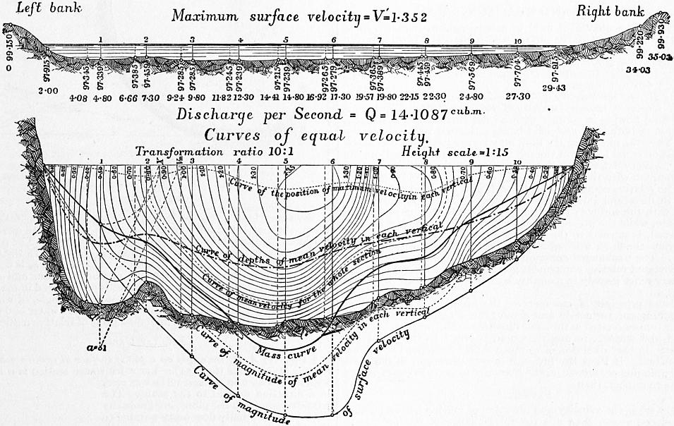 |
| Fig. 151. |
Fig. 151 shows the results of one of Harlacher’s gaugings worked out in this way. The upper figure shows the section of the river and the positions of the verticals at which the soundings and gaugings were taken. The lower gives the curves of equal velocity, worked out from the current meter observations, by the aid of vertical velocity curves. The vertical scale in this figure is ten times as great as in the other. The discharge calculated from the contour curves is 14.1087 cubic metres per second. In the lower figure some other interesting curves are drawn. Thus, the uppermost dotted curve is the curve through points at which the maximum velocity was found; it shows that the maximum velocity was always a little below the surface, and at a greater depth at the centre than at the sides. The next curve shows the depth at which the mean velocity for each vertical was found. The next is the curve of equal velocity corresponding to the mean velocity of the stream; that is, it passes through points in the cross section where the velocity was identical with the mean velocity of the stream.
Hydraulic Machines
§ 152. Hydraulic machines may be broadly divided into two classes: (1) Motors, in which water descending from a higher to a lower level, or from a higher to a lower pressure, gives up energy which is available for mechanical operations; (2) Pumps, in which the energy of a steam engine or other motor is expended in raising water from a lower to a higher level. A few machines such as the ram and jet pump combine the functions of motor and pump. It may be noted that constructively pumps are essentially reversed motors. The reciprocating pump is a reversed pressure engine, and the centrifugal pump a reversed turbine. Hydraulic machine tools are in principle motors combined with tools, and they now form an important special class.
Water under pressure conveyed in pipes is a convenient and economical means of transmitting energy and distributing it to many scattered working points. Hence large and important hydraulic systems are adopted in which at a central station water is pumped at high pressure into distributing mains, which convey it to various points where it actuates hydraulic motors operating cranes, lifts, dock gates, and in some cases riveting and shearing machines. In this case the head driving the hydraulic machinery is artificially created, and it is the convenience of distributing power in an easily applied form to distant points which makes the system advantageous. As there is some unavoidable loss in creating an artificial head this system is most suitable for driving machines which work intermittently 86 (see Power Transmission). The development of electrical methods of transmitting and distributing energy has led to the utilization of many natural waterfalls so situated as to be useless without such a means of transferring the power to points where it can be conveniently applied. In some cases, as at Niagara, the hydraulic power can only be economically developed in very large units, and it can be most conveniently subdivided and distributed by transformation into electrical energy. Partly from the development of new industries such as paper-making from wood pulp and electro-metallurgical processes, which require large amounts of cheap power, partly from the facility with which energy can now be transmitted to great distances electrically, there has been a great increase in the utilization of water-power in countries having natural waterfalls. According to the twelfth census of the United States the total amount of water-power reported as used in manufacturing establishments in that country was 1,130,431 h.p. in 1870; 1,263,343 h.p. in 1890; and 1,727,258 h.p. in 1900. The increase was 8.4% in the decade 1870-1880, 3.1% in 1880-1890, and no less than 36.7% in 1890-1900. The increase is the more striking because in this census the large amounts of hydraulic power which are transmitted electrically are not included.
XII. IMPACT AND REACTION OF WATER
§ 153. When a stream of fluid in steady motion impinges on a solid surface, it presses on the surface with a force equal and opposite to that by which the velocity and direction of motion of the fluid are changed. Generally, in problems on the impact of fluids, it is necessary to neglect the effect of friction between the fluid and the surface on which it moves.
During Impact the Velocity of the Fluid relatively to the Surface on which it impinges remains unchanged in Magnitude.—Consider a mass of fluid flowing in contact with a solid surface also in motion, the motion of both fluid and solid being estimated relatively to the earth. Then the motion of the fluid may be resolved into two parts, one a motion equal to that of the solid, and in the same direction, the other a motion relatively to the solid. The motion which the fluid has in common with the solid cannot at all be influenced by the contact. The relative component of the motion of the fluid can only be altered in direction, but not in magnitude. The fluid moving in contact with the surface can only have a relative motion parallel to the surface, while the pressure between the fluid and solid, if friction is neglected, is normal to the surface. The pressure therefore can only deviate the fluid, without altering the magnitude of the relative velocity. The unchanged common component and, combined with it, the deviated relative component give the resultant final velocity, which may differ greatly in magnitude and direction from the initial velocity.
From the principle of momentum, the impulse of any mass of fluid reaching the surface in any given time is equal to the change of momentum estimated in the same direction. The pressure between the fluid and surface, in any direction, is equal to the change of momentum in that direction of so much fluid as reaches the surface in one second. If Pa is the pressure in any direction, m the mass of fluid impinging per second, va the change of velocity in the direction of Pa due to impact, then
Pa = mva.
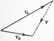 |
| Fig. 152. |
If v1 (fig. 152) is the velocity and direction of motion before impact, v2 that after impact, then v is the total change of motion due to impact. The resultant pressure of the fluid on the surface is in the direction of v, and is equal to v multiplied by the mass impinging per second. That is, putting P for the resultant pressure,
P = mv.
Let P be resolved into two components, N and T, normal and tangential to the direction of motion of the solid on which the fluid impinges. Then N is a lateral force producing a pressure on the supports of the solid, T is an effort which does work on the solid. If u is the velocity of the solid, Tu is the work done per second by the fluid in moving the solid surface.
Let Q be the volume, and GQ the weight of the fluid impinging per second, and let v1 be the initial velocity of the fluid before striking the surface. Then GQv12/2g is the original kinetic energy of Q cub. ft. of fluid, and the efficiency of the stream considered as an arrangement for moving the solid surface is
η = Tu / (GQv12 / 2g).
§ 154. Jet deviated entirely in one Direction.—Geometrical Solution (fig. 153).—Suppose a jet of water impinges on a surface ac with a velocity ab, and let it be wholly deviated in planes parallel to the figure. Also let ae be the velocity and direction of motion of the surface. Join eb; then the water moves with respect to the surface in the direction and with the velocity eb. As this relative velocity is unaltered by contact with the surface, take cd = eb, tangent to the surface at c, then cd is the relative motion of the water with respect to the surface at c. Take df equal and parallel to ae. Then fc (obtained by compounding the relative motion of water to surface and common velocity of water and surface) is the absolute velocity and direction of the water leaving the surface. Take ag equal and parallel to fc. Then, since ab is the initial and ag the final velocity and direction of motion, gb is the total change of motion of the water. The resultant pressure on the plane is in the direction gb. Join eg. In the triangle gae, ae is equal and parallel to df, and ag to fc. Hence eg is equal and parallel to cd. But cd = eb = relative motion of water and surface. Hence the change of motion of the water is represented in magnitude and direction by the third side of an isosceles triangle, of which the other sides are equal to the relative velocity of the water and surface, and parallel to the initial and final directions of relative motion.
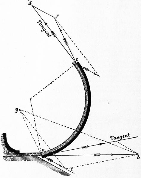 |
| Fig. 153. |
Special Cases
 |
| Fig. 154. |
§ 155. (1) A Jet impinges on a plane surface at rest, in a direction normal to the plane (fig. 154).—Let a jet whose section is ω impinge with a velocity v on a plane surface at rest, in a direction normal to the plane. The particles approach the plane, are gradually deviated, and finally flow away parallel to the plane, having then no velocity in the original direction of the jet. The quantity of water impinging per second is ωv. The pressure on the plane, which is equal to the change of momentum per second, is P = (G/g) ωv2.
(2) If the plane is moving in the direction of the jet with the velocity ±u, the quantity impinging per second is ω(v ± u). The momentum of this quantity before impact is (G/g)ω(v ± u)v. After impact, the water still possesses the velocity ±u in the direction of the jet; and the momentum, in that direction, of so much water as impinges in one second, after impact, is ±(G/g) ω (v ± u)u. The pressure on the plane, which is the change of momentum per second, is the difference of these quantities or P = (G/g) ω (v ± u)2. This differs from the expression obtained in the previous case, in that the relative velocity of the water and plane v ± u is substituted for v. The expression may be written P = 2 × G × ω (v ± u)2/2g, where the last two terms are the volume of a prism of water whose section is the area of the jet and whose length is the head due to the relative velocity. The pressure on the plane is twice the weight of that prism of water. The work done when the plane 87 is moving in the same direction as the jet is Pu = (G/g) ω (v − u)2u foot-pounds per second. There issue from the jet ωv cub. ft. per second, and the energy of this quantity before impact is (G/2g) ωv3. The efficiency of the jet is therefore η = 2(v − u)2u/v3. The value of u which makes this a maximum is found by differentiating and equating the differential coefficient to zero:—
dη / du = 2 (v2 − 4vu + 3u2) / v3 = 0;
∴ u = v or 1⁄3 v.
The former gives a minimum, the latter a maximum efficiency.
Putting u = 1⁄3v in the expression above,
η max. = 8⁄27.
(3) If, instead of one plane moving before the jet, a series of planes are introduced at short intervals at the same point, the quantity of water impinging on the series will be ωv instead of ω(v − u), and the whole pressure = (G/g) ωv (v − u). The work done is (G/g)ωvu (v − u). The efficiency η = (G/g) ωvu (v − u) ÷ (G/2g) ωv3 = 2u(v-u)/v2. This becomes a maximum for dη/du = 2(v − 2u) = 0, or u = 1⁄2v, and the η = 1⁄2. This result is often used as an approximate expression for the velocity of greatest efficiency when a jet of water strikes the floats of a water wheel. The work wasted in this case is half the whole energy of the jet when the floats run at the best speed.
§ 156. (4) Case of a Jet impinging on a Concave Cup Vane, velocity of water v, velocity of vane in the same direction u (fig. 155), weight impinging per second = Gw (v − u).
 |
| Fig. 155. |
If the cup is hemispherical, the water leaves the cup in a direction parallel to the jet. Its relative velocity is v − u when approaching the cup, and −(v − u) when leaving it. Hence its absolute velocity when leaving the cup is u − (v − u) = 2u − v. The change of momentum per second = (G/g) ω (v − u) {v − (2u − v)} = 2(G/g) ω (v − u)2. Comparing this with case 2, it is seen that the pressure on a hemispherical cup is double that on a flat plane. The work done on the cup = 2(G/g) ω (v − u) 2u foot-pounds per second. The efficiency of the jet is greatest when v = 3u; in that case the efficiency = 16⁄27.
If a series of cup vanes are introduced in front of the jet, so that the quantity of water acted upon is ωv instead of ω(v − u), then the whole pressure on the chain of cups is (G/g) ωv {v − (2u − v)} = 2(G/g)ωv (v − u). In this case the efficiency is greatest when v = 2u, and the maximum efficiency is unity, or all the energy of the water is expended on the cups.
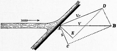 |
| Fig. 156. |
§ 157. (5) Case of a Flat Vane oblique to the Jet (fig. 156).—This case presents some difficulty. The water spreading on the plane in all directions from the point of impact, different particles leave the plane with different absolute velocities. Let AB = v = velocity of water, AC = u = velocity of plane. Then, completing the parallelogram, AD represents in magnitude and direction the relative velocity of water and plane. Draw AE normal to the plane and DE parallel to the plane. Then the relative velocity AD may be regarded as consisting of two components, one AE normal, the other DE parallel to the plane. On the assumption that friction is insensible, DE is unaffected by impact, but AE is destroyed. Hence AE represents the entire change of velocity due to impact and the direction of that change. The pressure on the plane is in the direction AE, and its amount is = mass of water impinging per second × AE.
Let DAE = θ, and let AD = vr. Then AE = vr cos θ; DE = vr sin θ. If Q is the volume of water impinging on the plane per second, the change of momentum is (G/g) Qvr cos θ. Let AC = u = velocity of the plane, and let AC make the angle CAE = δ with the normal to the plane. The velocity of the plane in the direction AE = u cos δ. The work of the jet on the plane = (G/g) Qvr cos θ u cos δ. The same problem may be thus treated algebraically (fig. 157). Let BAF = α, and CAF = δ. The velocity v of the water may be decomposed into AF = v cos α normal to the plane, and FB = v sin α parallel to the plane. Similarly the velocity of the plane = u = AC = BD can be decomposed into BG = FE = u cos δ normal to the plane, and DG = u sin δ parallel to the plane. As friction is neglected, the velocity of the water parallel to the plane is unaffected by the impact, but its component v cos α normal to the plane becomes after impact the same as that of the plane, that is, u cos δ. Hence the change of velocity during impact = AE = v cos α − u cos δ. The change of momentum per second, and consequently the normal pressure on the plane is N = (G/g) Q(v cos α − u cos δ). The pressure in the direction in which the plane is moving is P = N cos δ = (G/g)Q (v cos α − u cos δ) cos δ, and the work done on the plane is Pu = (G/g)Q(v cos α − u cos δ) u cos δ, which is the same expression as before, since AE = vr cos θ = v cos α − u cos δ.
 |
| Fig. 157. |
 |
| Fig. 158. |
In one second the plane moves so that the point A (fig. 158) comes to C, or from the position shown in full lines to the position shown in dotted lines. If the plane remained stationary, a length AB = v of the jet would impinge on the plane, but, since the plane moves in the same direction as the jet, only the length HB = AB − AH impinges on the plane.
But AH = AC cos δ / cos α = u cos δ / cos α, and therefore HB = v − u cos δ / cos α. Let ω = sectional area of jet; volume impinging on plane per second = Q = ω(v − u cos δ / cos α) = ω (v cos α − u cos δ) / cos α. Inserting this in the formulae above, we get
| N = | G | ω | (v cos α − u cos δ)2; | |
| g | cos α |
| P = | G | ω cos δ | (v cos α − u cos δ)2; | |
| g | cos α |
| Pu = | G | ωu | cos δ | (v cos α − u cos δ)2; |
| g | cos α |
Three cases may be distinguished:—
(a) The plane is at rest. Then u = 0, N = (G/g) ωv2cos α; and the work done on the plane and the efficiency of the jet are zero.
(b) The plane moves parallel to the jet. Then δ = α, and Pu = (G/g)ωu cos2 α (v − u)2, which is a maximum when u = 1⁄3v.
When u = 1⁄3v then Pu max. = 4⁄27(G/g)ωv3 cos2α, and the efficiency = η = 4⁄9cos2α.
(c) The plane moves perpendicularly to the jet. Then δ = 90° − α; cos δ = sin α; and Pu = G/g ωu (sin α / cos α) (v cos α − u sin α)2. This is a maximum when u = 1⁄3v cos α.
When u = 1⁄3v cos α, the maximum work and the efficiency are the same as in the last case.
 |
| Fig. 159. |
§ 158. Best Form of Vane to receive Water.—When water impinges normally or obliquely on a plane, it is scattered in all directions after impact, and the work carried away by the water is then generally lost, from the impossibility of dealing afterwards with streams of water deviated in so many directions. By suitably forming the vane, however, the water may be entirely deviated in one direction, and the loss of energy from agitation of the water is entirely avoided.
Let AB (fig. 159) be a vane, on which a jet of water impinges at the point A and in the direction AC. Take AC = v = velocity of 88 water, and let AD represent in magnitude and direction the velocity of the vane. Completing the parallelogram, DC or AE represents the direction in which the water is moving relatively to the vane. If the lip of the vane at A is tangential to AE, the water will not have its direction suddenly changed when it impinges on the vane, and will therefore have no tendency to spread laterally. On the contrary it will be so gradually deviated that it will glide up the vane in the direction AB. This is sometimes expressed by saying that the vane receives the water without shock.
 |
| Fig. 160. |
§ 159. Floats of Poncelet Water Wheels.—Let AC (fig. 160) represent the direction of a thin horizontal stream of water having the velocity v. Let AB be a curved float moving horizontally with velocity u. The relative motion of water and float is then initially horizontal, and equal to v − u.
In order that the float may receive the water without shock, it is necessary and sufficient that the lip of the float at A should be tangential to the direction AC of relative motion. At the end of (v − u)/g seconds the float moving with the velocity u comes to the position A1B1, and during this time a particle of water received at A and gliding up the float with the relative velocity v − u, attains a height DE = (v − u)2/2g. At E the water comes to relative rest. It then descends along the float, and when after 2(v − u)/g seconds the float has come to A2B2 the water will again have reached the lip at A2 and will quit it tangentially, that is, in the direction CA2, with a relative velocity −(v − u) = −√ (2gDE) acquired under the influence of gravity. The absolute velocity of the water leaving the float is therefore u − (v − u) = 2u − v. If u = 1⁄2v, the water will drop off the bucket deprived of all energy of motion. The whole of the work of the jet must therefore have been expended in driving the float. The water will have been received without shock and discharged without velocity. This is the principle of the Poncelet wheel, but in that case the floats move over an arc of a large circle; the stream of water has considerable thickness (about 8 in.); in order to get the water into and out of the wheel, it is then necessary that the lip of the float should make a small angle (about 15°) with the direction of its motion. The water quits the wheel with a little of its energy of motion remaining.
§ 160. Pressure on a Curved Surface when the Water is deviated wholly in one Direction.—When a jet of water impinges on a curved surface in such a direction that it is received without shock, the pressure on the surface is due to its gradual deviation from its first direction. On any portion of the area the pressure is equal and opposite to the force required to cause the deviation of so much water as rests on that surface. In common language, it is equal to the centrifugal force of that quantity of water.
 |
| Fig. 161. |
Case 1. Surface Cylindrical and Stationary.—Let AB (fig. 161) be the surface, having its axis at O and its radius = r. Let the water impinge at A tangentially, and quit the surface tangentially at B. Since the surface is at rest, v is both the absolute velocity of the water and the velocity relatively to the surface, and this remains unchanged during contact with the surface, because the deviating force is at each point perpendicular to the direction of motion. The water is deviated through an angle BCD = AOB = φ. Each particle of water of weight p exerts radially a centrifugal force pv2/rg. Let the thickness of the stream = t ft. Then the weight of water resting on unit of surface = Gt ℔; and the normal pressure per unit of surface = n = Gtv2/gr. The resultant of the radial pressures uniformly distributed from A to B will be a force acting in the direction OC bisecting AOB, and its magnitude will equal that of a force of intensity = n, acting on the projection of AB on a plane perpendicular to the direction OC. The length of the chord AB = 2r sin 1⁄2φ; let b = breadth of the surface perpendicular to the plane of the figure. The resultant pressure on surface
| = R = 2rb sin | φ | × | Gt | · | v2 | = 2 | G | btv2 sin | φ | , |
| 2 | g | r | g | 2 |
which is independent of the radius of curvature. It may be inferred that the resultant pressure is the same for any curved surface of the same projected area, which deviates the water through the same angle.
Case 2. Cylindrical Surface moving in the Direction AC with Velocity u.—The relative velocity = v − u. The final velocity BF (fig. 162) is found by combining the relative velocity BD = v − u tangential to the surface with the velocity BE = u of the surface. The intensity of normal pressure, as in the last case, is (G/g) t (v − u)2/r. The resultant normal pressure R = 2(G/g) bt (v − u)2 sin 1⁄2φ. This resultant pressure may be resolved into two components P and L, one parallel and the other perpendicular to the direction of the vane’s motion. The former is an effort doing work on the vane. The latter is a lateral force which does no work.
P = R sin 1⁄2φ = (G/g) bt (v − u)2 (1 − cos φ);
L = R cos 1⁄2φ = (G/g) bt (v − u)2 sin φ.
 |
| Fig. 162. |
 |
| Fig. 163. |
The work done by the jet on the vane is Pu = (G/g) btu (v − u)2(1 − cos φ), which is a maximum when u = 1⁄3v. This result can also be obtained by considering that the work done on the plane must be equal to the energy lost by the water, when friction is neglected.
If φ = 180°, cos φ = −1, 1 − cos φ = 2; then P = 2(G/g) bt (v − u)2, the same result as for a concave cup.
§ 161. Position which a Movable Plane takes in Flowing Water.—When a rectangular plane, movable about an axis parallel to one of its sides, is placed in an indefinite current of fluid, it takes a position such that the resultant of the normal pressures on the two sides of the axis passes through the axis. If, therefore, planes pivoted so that the ratio a/b (fig. 163) is varied are placed in water, and the angle they make with the direction of the stream is observed, the position of the resultant of the pressures on the plane is determined for different angular positions. Experiments of this kind have been made by Hagen. Some of his results are given in the following table:—
| Larger plane. | Smaller Plane. | |
| a/b = 1.0 | φ = ... | φ = 90° |
| 0.9 | 75° | 721⁄2° |
| 0.8 | 60° | 57° |
| 0.7 | 48° | 43° |
| 0.6 | 25° | 29° |
| 0.5 | 13° | 13° |
| 0.4 | 8° | 61⁄2° |
| 0.3 | 6° | .. |
| 0.2 | 4° | .. |
§ 162. Direct Action distinguished from Reaction (Rankine, Steam Engine, § 147).
The pressure which a jet exerts on a vane can be distinguished into two parts, viz∴—
(1) The pressure arising from changing the direct component of the velocity of the water into the velocity of the vane. In fig. 153, § 154, ab cos bae is the direct component of the water’s velocity, or component in the direction of motion of vane. This is changed into the velocity ae of the vane. The pressure due to direct impulse is then
P1 = GQ (ab cos bae − ae) / g.
For a flat vane moving normally, this direct action is the only action producing pressure on the vane.
(2) The term reaction is applied to the additional action due to the direction and velocity with which the water glances off the vane. It is this which is diminished by the friction between the water and the vane. In Case 2, § 160, the direct pressure is
P1 = Gbt (v − u)2 / g.
That due to reaction is
P2 = −Gbt (v − u)2 cos φ / g.
If φ < 90°, the direct component of the water’s motion is not wholly converted into the velocity of the vane, and the whole 89 pressure due to direct impulse is not obtained. If φ > 90°, cos φ is negative and an additional pressure due to reaction is obtained.
 |
| Fig. 164. |
§ 163. Jet Propeller.—In the case of vessels propelled by a jet of water (fig. 164), driven sternwards from orifices at the side of the vessel, the water, originally at rest outside the vessel, is drawn into the ship and caused to move with the forward velocity V of the ship. Afterwards it is projected sternwards from the jets with a velocity v relatively to the ship, or v − V relatively to the earth. If Ω is the total sectional area of the jets, Ωv is the quantity of water discharged per second. The momentum generated per second in a sternward direction is (G/g) Ωv (v − V), and this is equal to the forward acting reaction P which propels the ship.
The energy carried away by the water
= 1⁄2 (G/g) Ωv (v − V)2.
The useful work done on the ship
PV = (G/g) Ωv (v − V) V.
Adding (1) and (2), we get the whole work expended on the water, neglecting friction:—
W = 1⁄2 (G/g) Ωv (v2 − V2).
Hence the efficiency of the jet propeller is
PV/W = 2V / (v + V).
This increases towards unity as v approaches V. In other words, the less the velocity of the jets exceeds that of the ship, and therefore the greater the area of the orifice of discharge, the greater is the efficiency of the propeller.
In the “Waterwitch” v was about twice V. Hence in this case the theoretical efficiency of the propeller, friction neglected, was about 2⁄3.
 |
| Fig. 165. |
§ 164. Pressure of a Steady Stream in a Uniform Pipe on a Plane normal to the Direction of Motion.—Let CD (fig. 165) be a plane placed normally to the stream which, for simplicity, may be supposed to flow horizontally. The fluid filaments are deviated in front of the plane, form a contraction at A1A1, and converge again, leaving a mass of eddying water behind the plane. Suppose the section A0A0 taken at a point where the parallel motion has not begun to be disturbed, and A2A2 where the parallel motion is re-established. Then since the same quantity of water with the same velocity passes A0A0, A2A2 in any given time, the external forces produce no change of momentum on the mass A0A0A2A2, and must therefore be in equilibrium. If Ω is the section of the stream at A0A0 or A2A2, and ω the area of the plate CD, the area of the contracted section of the stream at A1A1 will be cc(Ω − ω), where cc is the coefficient of contraction. Hence, if v is the velocity at A0A0 or A2A2, and v1 the velocity at A1A1,
vΩ = ccv (Ω − ω);
∴ v1 = vΩ / cc (Ω − ω).
Let p0, p1, p2 be the pressures at the three sections. Applying Bernoulli’s theorem to the sections A0A0 and A1A1,
| p0 | + | v2 | = | p1 | + | v12 | . |
| G | 2g | G | 2g |
Also, for the sections A1A1 and A2A2, allowing that the head due to the relative velocity v1 − v is lost in shock:—
| p1 | + | v12 | = | p2 | + | v2 | + | (v1 − v)2 | ; |
| G | 2g | G | 2g | 2g |
∴ p0 − p2 = G (v1 − v)2 / 2g;
or, introducing the value in (1),
| p0 − p2 = | G | ( | Ω | − 1 ) | 2 | v2 |
| 2g | cc (Ω − ω) |
Now the external forces in the direction of motion acting on the mass A0A0A2A2 are the pressures p0Ω1 − p2Ω at the ends, and the reaction −R of the plane on the water, which is equal and opposite to the pressure of the water on the plane. As these are in equilibrium,
(p0 − p2) Ω − R = 0;
| ∴ R = GΩ ( | Ω | − 1 ) | 2 | v2 | ; | |
| cc (Ω − ω) | 2g |
an expression like that for the pressure of an isolated jet on an indefinitely extended plane, with the addition of the term in brackets, which depends only on the areas of the stream and the plane. For a given plane the expression in brackets diminishes as Ω increases. If Ω/ω = ρ, the equation (4) becomes
| R = Gω | v2 | { ρ ( | ρ | − 1 ) | 2 | }, |
| 2g | cc (ρ − 1) |
which is of the form
R = Gω (v2/2g) K,
where K depends only on the ratio of the sections of the stream and plane.
For example, let cc = 0.85, a value which is probable, if we allow that the sides of the pipe act as internal borders to an orifice. Then
| K = ρ ( 1.176 | ρ | − 1 ) | 2 | . |
| ρ − 1 |
| ρ = | K = |
| 1 | ∞ |
| 2 | 3.66 |
| 3 | 1.75 |
| 4 | 1.29 |
| 5 | 1.10 |
| 10 | .94 |
| 50 | 2.00 |
| 100 | 3.50 |
The assumption that the coefficient of contraction cc is constant for different values of ρ is probably only true when ρ is not very large. Further, the increase of K for large values of ρ is contrary to experience, and hence it may be inferred that the assumption that all the filaments have a common velocity v1 at the section A1A1 and a common velocity v at the section A2A2 is not true when the stream is very much larger than the plane. Hence, in the expression
R = KGωv2 / 2g,
K must be determined by experiment in each special case. For a cylindrical body putting ω for the section, cc for the coefficient of contraction, cc (Ω − ω) for the area of the stream at A1A1,
v1 = vΩ / cc (Ω − ω); v2 = vΩ / (Ω −ω);
or, putting ρ = Ω/ω,
v1 = vρ / cc (ρ − 1), v2 = vρ / (ρ − 1).
Then
R = K1Gωv2 / 2g,
where
| K1 = ρ { ( | ρ | ) | 2 | ( | 1 | − 1 ) | 2 | + ( | ρ | − 1 ) | 2 | }. |
| ρ − 1 | cc | ρ − 1 |
Taking cc = 0.85 and ρ = 4, K1 = 0.467, a value less than before. Hence there is less pressure on the cylinder than on the thin plane.
 |
| Fig. 166. |
§ 165. Distribution of Pressure on a Surface on which a Jet impinges normally.—The principle of momentum gives readily enough the total or resultant pressure of a jet impinging on a plane surface, but in some cases it is useful to know the distribution of the pressure. The problem in the case in which the plane is struck normally, and the jet spreads in all directions, is one of great complexity, but even in that case the maximum intensity of the pressure is easily assigned. Each layer of water flowing from an orifice is gradually deviated (fig. 166) by contact with the surface, and during deviation exercises a centrifugal pressure towards the axis of the jet. The force exerted by each small mass of water is normal to its path and inversely as the radius of curvature of the path. Hence the greatest pressure on the plane must be at the axis of the jet, and the pressure must decrease from the axis outwards, in some such way as is shown by the curve of pressure in fig. 167, the branches of the curve being probably asymptotic to the plane.
For simplicity suppose the jet is a vertical one. Let h1 (fig. 167) be the depth of the orifice from the free surface, and v1 the velocity of discharge. Then, if ω is the area of the orifice, the quantity of water impinging on the plane is obviously
Q = ωv1 = ω √ (2gh1);
that is, supposing the orifice rounded, and neglecting the coefficient of discharge.
The velocity with which the fluid reaches the plane is, however, greater than this, and may reach the value
v = √ (2gh);
where h is the depth of the plane below the free surface. The external layers of fluid subjected throughout, after leaving the orifice, to the atmospheric pressure will attain the velocity v, and will flow away with this velocity unchanged except by friction. The layers towards the interior of the jet, being subjected to a pressure greater than atmospheric pressure, will attain a less velocity, and so much less as they are nearer the centre of the jet. But the pressure 90 can in no case exceed the pressure v2/2g or h measured in feet of water, or the direction of motion of the water would be reversed, and there would be reflux. Hence the maximum intensity of the pressure of the jet on the plane is h ft. of water. If the pressure curve is drawn with pressures represented by feet of water, it will touch the free water surface at the centre of the jet.
 |
| Fig. 167. |
Suppose the pressure curve rotated so as to form a solid of revolution. The weight of water contained in that solid is the total pressure of the jet on the surface, which has already been determined. Let V = volume of this solid, then GV is its weight in pounds. Consequently
GV = (G/g) ωv1v;
V = 2ω √ (hh1).
We have already, therefore, two conditions to be satisfied by the pressure curve.
 |
| Fig. 168.—Curves of Pressure of Jets impinging normally on a Plane. |
Some very interesting experiments on the distribution of pressure on a surface struck by a jet have been made by J. S. Beresford (Prof. Papers on Indian Engineering, No. cccxxii.), with a view to afford information as to the forces acting on the aprons of weirs. Cylindrical jets 1⁄2 in. to 2 in. diameter, issuing from a vessel in which the water level was constant, were allowed to fall vertically on a brass plate 9 in. in diameter. A small hole in the brass plate communicated by a flexible tube with a vertical pressure column. Arrangements were made by which this aperture could be moved 1⁄20 in. at a time across the area struck by the jet. The height of the pressure column, for each position of the aperture, gave the pressure at that point of the area struck by the jet. When the aperture was exactly in the axis of the jet, the pressure column was very nearly level with the free surface in the reservoir supplying the jet; that is, the pressure was very nearly v2/2g. As the aperture moved away from the axis of the jet, the pressure diminished, and it became insensibly small at a distance from the axis of the jet about equal to the diameter of the jet. Hence, roughly, the pressure due to the jet extends over an area about four times the area of section of the jet.
Fig. 168 shows the pressure curves obtained in three experiments with three jets of the sizes shown, and with the free surface level in the reservoir at the heights marked.
| Height from Free Surface to Brass Plate in inches. | Distance from Axis of Jet in inches. | Pressure in inches of Water. |
| Experiment 1. Jet .475 in. diameter. | ||
| 43 | 0 | 40.5 |
| ” | .05 | 39.40 |
| ” | .1 | 37.5-39.5 |
| ” | .15 | 35 |
| ” | .2 | 33.5-37 |
| ” | .25 | 31 |
| ” | .3 | 21-27 |
| ” | .35 | 21 |
| ” | .4 | 14 |
| ” | .45 | 8 |
| ” | .5 | 3.5 |
| ” | .55 | 1 |
| ” | .6 | 0.5 |
| ” | .65 | 0 |
| Experiment 2. Jet .988 in. diameter. | ||
| 42.15 | 0 | 42 |
| ” | .05 | 41.9 |
| ” | .1 | 41.5-41.8 |
| ” | .15 | 41 |
| ” | .2 | 40.3 |
| ” | .25 | 39.2 |
| ” | .3 | 37.5 |
| ” | .35 | 34.8 |
| ” | .45 | 27 |
| 42.25 | .5 | 23 |
| ” | .55 | 18.5 |
| ” | .6 | 13 |
| ” | .65 | 8.3 |
| ” | .7 | 5 |
| ” | .75 | 3 |
| ” | .8 | 2.2 |
| 42.15 | .85 | 1.6 |
| ” | .95 | 1 |
| Experiment 3. Jet 19.5 in. diameter. | ||
| 27.15 | 0 | 26.9 |
| ” | .08 | 26.9 |
| ” | .13 | 26.8 |
| ” | .18 | 26.5-26.6 |
| ” | .23 | 26.4-26.5 |
| ” | .28 | 26.3-26.6 |
| 27 | .33 | 26.2 |
| ” | .38 | 25.9 |
| ” | .43 | 25.5 |
| ” | .48 | 25 |
| ” | .53 | 24.5 |
| ” | .58 | 24 |
| ” | .63 | 23.3 |
| ” | .68 | 22.5 |
| ” | .73 | 21.8 |
| ” | .78 | 21 |
| ” | .83 | 20.3 |
| ” | .88 | 19.3 |
| ” | .93 | 18 |
| ” | .98 | 17 |
| 26.5 | 1.13 | 13.5 |
| ” | 1.18 | 12.5 |
| ” | 1.23 | 10.8 |
| ” | 1.28 | 9.5 |
| ” | 1.33 | 8 |
| ” | 1.38 | 7 |
| ” | 1.43 | 6.3 |
| ” | 1.48 | 5 |
| ” | 1.53 | 4.3 |
| ” | 1.58 | 3.5 |
| ” | 1.9 | 2 |
As the general form of the pressure curve has been already indicated, it may be assumed that its equation is of the form
y = ab−x2.
But it has already been shown that for x = 0, y = h, hence a = h. To determine the remaining constant, the other condition may be used, that the solid formed by rotating the pressure curve represents the total pressure on the plane. The volume of the solid is
V = ∫∞0 2πxy dx
= 2πh ∫∞0 b−x2x dx
= (πh / loge b) [ −b−x2 ]∞0
= πh / loge b.
Using the condition already stated,
2ω √ (hh1) = πh / loge b,
logε b = (π/2ω) √ (h/h1).
Putting the value of b in (2) in eq. (1), and also r for the radius of the jet at the orifice, so that ω = πr2, the equation to the pressure curve is
y = hε−1/2 √(h / h1) (x2 / r2).
§ 166. Resistance of a Plane moving through a Fluid, or Pressure of a Current on a Plane.—When a thin plate moves through the air, or through an indefinitely large mass of still water, in a direction normal to its surface, there is an excess of pressure on the anterior face and a diminution of pressure on the posterior face. Let v be the relative velocity of the plate and fluid, Ω the area of the plate, G the density of the fluid, h the height due to the velocity, then the total resistance is expressed by the equation
R = fGΩv2 / 2g pounds = fGΩh;
where f is a coefficient having about the value 1.3 for a plate moving in still fluid, and 1.8 for a current impinging on a fixed plane, whether the fluid is air or water. The difference in the value of the coefficient in the two cases is perhaps due to errors of experiment. There is a similar resistance to motion in the case of all bodies of “unfair“ form, that is, in which the surfaces over which the water slides are not of gradual and continuous curvature.
The stress between the fluid and plate arises chiefly in this way. 91 The streams of fluid deviated in front of the plate, supposed for definiteness to be moving through the fluid, receive from it forward momentum. Portions of this forward moving water are thrown off laterally at the edges of the plate, and diffused through the surrounding fluid, instead of falling to their original position behind the plate. Other portions of comparatively still water are dragged into motion to fill the space left behind the plate; and there is thus a pressure less than hydrostatic pressure at the back of the plate. The whole resistance to the motion of the plate is the sum of the excess of pressure in front and deficiency of pressure behind. This resistance is independent of any friction or viscosity in the fluid, and is due simply to its inertia resisting a sudden change of direction at the edge of the plate.
Experiments made by a whirling machine, in which the plate is fixed on a long arm and moved circularly, gave the following values of the coefficient f. The method is not free from objection, as the centrifugal force causes a flow outwards across the plate.
| Approximate Area of Plate in sq. ft. | Values of f. | ||
| Borda. | Hutton. | Thibault. | |
| 0.13 | 1.39 | 1.24 | .. |
| 0.25 | 1.49 | 1.43 | 1.525 |
| 0.63 | 1.64 | .. | .. |
| 1.11 | .. | .. | 1.784 |
There is a steady increase of resistance with the size of the plate, in part or wholly due to centrifugal action.
P. L. G. Dubuat (1734-1809) made experiments on a plane 1 ft. square, moved in a straight line in water at 3 to 61⁄2 ft. per second. Calling m the coefficient of excess of pressure in front, and n the coefficient of deficiency of pressure behind, so that f = m + n, he found the following values:—
m = 1; n = 0.433; f = 1.433.
The pressures were measured by pressure columns. Experiments by A. J. Morin (1795-1880), G. Piobert (1793-1871) and I. Didion (1798-1878) on plates of 0.3 to 2.7 sq. ft. area, drawn vertically through water, gave f = 2.18; but the experiments were made in a reservoir of comparatively small depth. For similar plates moved through air they found f = 1.36, a result more in accordance with those which precede.
For a fixed plane in a moving current of water E. Mariotte found f = 1.25. Dubuat, in experiments in a current of water like those mentioned above, obtained the values m = 1.186; n = 0.670; f = 1.856. Thibault exposed to wind pressure planes of 1.17 and 2.5 sq. ft. area, and found f to vary from 1.568 to 2.125, the mean value being f = 1.834, a result agreeing well with Dubuat.
 |
| Fig. 169. |
§ 167. Stanton’s Experiments on the Pressure of Air on Surfaces.—At the National Physical Laboratory, London, T. E. Stanton carried out a series of experiments on the distribution of pressure on surfaces in a current of air passing through an air trunk. These were on a small scale but with exceptionally accurate means of measurement. These experiments differ from those already given in that the plane is small relatively to the cross section of the current (Proc. Inst. Civ. Eng. clvi., 1904). Fig. 169 shows the distribution of pressure on a square plate. ab is the plate in vertical section. acb the distribution of pressure on the windward and adb that on the leeward side of the central section. Similarly aeb is the distribution of pressure on the windward and afb on the leeward side of a diagonal section. The intensity of pressure at the centre of the plate on the windward side was in all cases p = Gv2/2g ℔ per sq. ft., where G is the weight of a cubic foot of air and v the velocity of the current in ft. per sec. On the leeward side the negative pressure is uniform except near the edges, and its value depends on the form of the plate. For a circular plate the pressure on the leeward side was 0.48 Gv2/2g and for a rectangular plate 0.66 Gv2/2g. For circular or square plates the resultant pressure on the plate was P = 0.00126 v2 ℔ per sq. ft. where v is the velocity of the current in ft. per sec. On a long narrow rectangular plate the resultant pressure was nearly 60% greater than on a circular plate. In later tests on larger planes in free air, Stanton found resistances 18% greater than those observed with small planes in the air trunk.
§ 168. Case when the Direction of Motion is oblique to the Plane.—The determination of the pressure between a fluid and surface in this case is of importance in many practical questions, for instance, in assigning the load due to wind pressure on sloping and curved roofs, and experiments have been made by Hutton, Vince, and Thibault on planes moved circularly through air and water on a whirling machine.
 |
| Fig. 170. |
Let AB (fig. 170) be a plane moving in the direction R making an angle φ with the plane. The resultant pressure between the fluid and the plane will be a normal pressure N. The component R of this normal pressure is the resistance to the motion of the plane and the other component L is a lateral force resisted by the guides which support the plane. Obviously
R = N sin φ;
L = N cos φ.
In the case of wind pressure on a sloping roof surface, R is the horizontal and L the vertical component of the normal pressure.
In experiments with the whirling machine it is the resistance to motion, R, which is directly measured. Let P be the pressure on a plane moved normally through a fluid. Then, for the same plane inclined at an angle φ to its direction of motion, the resistance was found by Hutton to be
R = P (sin φ)1.842 cos φ.
A simpler and more convenient expression given by Colonel Duchemin is
R = 2P sin2 φ / (1 + sin2 φ).
Consequently, the total pressure between the fluid and plane is
N = 2P sin φ / (1 + sin2 φ) = 2P / (cosec φ + sin φ),
and the lateral force is
L = 2P sin φ cos φ / (1 + sin2 φ).
In 1872 some experiments were made for the Aeronautical Society on the pressure of air on oblique planes. These plates, of 1 to 2 ft. square, were balanced by ingenious mechanism designed by F. H. Wenham and Spencer Browning, in such a manner that both the pressure in the direction of the air current and the lateral force were separately measured. These planes were placed opposite a blast from a fan issuing from a wooden pipe 18 in. square. The pressure of the blast varied from 6⁄10 to 1 in. of water pressure. The following are the results given in pounds per square foot of the plane, and a comparison of the experimental results with the pressures given by Duchemin’s rule. These last values are obtained by taking P = 3.31, the observed pressure on a normal surface:—
| Angle between Plane and Direction of Blast | 15° | 20° | 60° | 90° |
| Horizontal pressure R | 0.4 | 0.61 | 2.73 | 3.31 |
| Lateral pressure L | 1.6 | 1.96 | 1.26 | .. |
| Normal pressure √ (L2 + R2) | 1.65 | 2.05 | 3.01 | 3.31 |
| Normal pressure by Duchemin’s rule | 1.605 | 2.027 | 3.276 | 3.31 |
Water Motors
In every system of machinery deriving energy from a natural waterfall there exist the following parts:—
1. A supply channel or head race, leading the water from the highest accessible level to the site of the machine. This may be an open channel of earth, masonry or wood, laid at as small a slope as is consistent with the delivery of the necessary supply of water, or it may be a closed cast or wrought-iron pipe, laid at the natural slope of the ground, and about 3 ft. below the surface. In some cases part of the head race is an open channel, part a closed pipe. The channel often starts from a small storage reservoir, constructed near the stream supplying the water motor, in which the water accumulates when the motor is not working. There are sluices or penstocks by which the supply can be cut off when necessary.
2. Leading from the motor there is a tail race, culvert, or discharge pipe delivering the water after it has done its work at the lowest convenient level.
3. A waste channel, weir, or bye-wash is placed at the origin of the head race, by which surplus water, in floods, escapes.
4. The motor itself, of one of the kinds to be described presently, which either overcomes a useful resistance directly, as in the case of a ram acting on a lift or crane chain, or indirectly by actuating transmissive machinery, as when a turbine drives the shafting, belting and gearing of a mill. With the motor is usually combined regulating machinery for adjusting the power and speed to the work done. This may be controlled in some cases by automatic governing machinery.
§ 169. Water Motors with Artificial Sources of Energy.—The great convenience and simplicity of water motors has led to their adoption in certain cases, where no natural source of water power is available. In these cases, an artificial source of water power is created by using a steam-engine to pump water to a reservoir at a great elevation, or to pump water into a closed reservoir in which there is great pressure. The water flowing from the reservoir through hydraulic engines gives back the energy expended, less so much as has been wasted by friction. Such arrangements are most useful where a continuously acting steam engine stores up energy by pumping the water, while the work done by the hydraulic engines is done intermittently.
§ 170. Energy of a Water-fall.—Let Ht be the total fall of level from the point where the water is taken from a natural stream to the point where it is discharged into it again. Of this total fall a portion, which can be estimated independently, is expended in overcoming the resistances of the head and tail races or the supply and discharge pipes. Let this portion of head wasted be ɧr. Then the available head to work the motor is H = Ht − ɧr. It is this available head which should be used in all calculations of the proportions of the motor. Let Q be the supply of water per second. Then GQH foot-pounds per second is the gross available work of the fall. The power of the fall may be utilized in three ways. (a) The GQ pounds of water may be placed on a machine at the highest level, and descending in contact with it a distance of H ft., the work done will be (neglecting losses from friction or leakage) GQH foot-pounds per second. (b) Or the water may descend in a closed pipe from the higher to the lower level, in which case, with the same reservation as before, the pressure at the foot of the pipe will be p = GH pounds per square foot. If the water with this pressure acts on a movable piston like that of a steam engine, it will drive the piston so that the volume described is Q cubic feet per second. Then the work done will be pQ = GHQ foot-pounds per second as before. (c) Or lastly, the water may be allowed to acquire the velocity v = √2gH by its descent. The kinetic energy of Q cubic feet will then be 1⁄2GQv2/g = GQH, and if the water is allowed to impinge on surfaces suitably curved which bring it finally to rest, it will impart to these the same energy as in the previous cases. Motors which receive energy mainly in the three ways described in (a), (b), (c) may be termed gravity, pressure and inertia motors respectively. Generally, if Q ft. per second of water act by weight through a distance h1, at a pressure p due to h2 ft. of fall, and with a velocity v due to h3 ft. of fall, so that h1 + h2 + h3 = H, then, apart from energy wasted by friction or leakage or imperfection of the machine, the work done will be
GQh1 + pQ + (G/g) Q (v2/2g) = GQH foot pounds,
the same as if the water acted simply by its weight while descending H ft.
§ 171. Site for Water Motor.—Wherever a stream flows from a higher to a lower level it is possible to erect a water motor. The amount of power obtainable depends on the available head and the supply of water. In choosing a site the engineer will select a portion of the stream where there is an abrupt natural fall, or at least a considerable slope of the bed. He will have regard to the facility of constructing the channels which are to convey the water, and will take advantage of any bend in the river which enables him to shorten them. He will have accurate measurements made of the quantity of water flowing in the stream, and he will endeavour to ascertain the average quantity available throughout the year, the minimum quantity in dry seasons, and the maximum for which bye-wash channels must be provided. In many cases the natural fall can be increased by a dam or weir thrown across the stream. The engineer will also examine to what extent the head will vary in different seasons, and whether it is necessary to sacrifice part of the fall and give a steep slope to the tail race to prevent the motor being drowned by backwater in floods. Streams fed from lakes which form natural reservoirs or fed from glaciers are less variable than streams depending directly on rainfall, and are therefore advantageous for water-power purposes.
§ 172. Water Power at Holyoke, U.S.A.—About 85 m. from the mouth of the Connecticut river there was a fall of about 60 ft. in a short distance, forming what were called the Grand Rapids, below which the river turned sharply, forming a kind of peninsula on which the city of Holyoke is built. In 1845 the magnitude of the water-power available attracted attention, and it was decided to build a dam across the river. The ordinary flow of the river is 6000 cub. ft. per sec., giving a gross power of 30,000 h.p. In dry seasons the power is 20,000 h.p., or occasionally less. From above the dam a system of canals takes the water to mills on three levels. The first canal starts with a width of 140 ft. and depth of 22 ft., and supplies the highest range of mills. A second canal takes the water which has driven turbines in the highest mills and supplies it to a second series of mills. There is a third canal on a still lower level supplying the lowest mills. The water then finds its way back to the river. With the grant of a mill site is also leased the right to use the water-power. A mill-power is defined as 38 cub. ft. of water per sec. during 16 hours per day on a fall of 20 ft. This gives about 60 h.p. effective. The charge for the power water is at the rate of 20s. per h.p. per annum.
§ 173. Action of Water in a Water Motor.—Water motors may be divided into water-pressure engines, water-wheels and turbines.
Water-pressure engines are machines with a cylinder and piston or ram, in principle identical with the corresponding part of a steam-engine. The water is alternately admitted to and discharged from the cylinder, causing a reciprocating action of the piston or plunger. It is admitted at a high pressure and discharged at a low one, and consequently work is done on the piston. The water in these machines never acquires a high velocity, and for the most part the kinetic energy of the water is wasted. The useful work is due to the difference of the pressure of admission and discharge, whether that pressure is due to the weight of a column of water of more or less considerable height, or is artificially produced in ways to be described presently.
Water-wheels are large vertical wheels driven by water falling from a higher to a lower level. In most water-wheels, the water acts directly by its weight loading one side of the wheel and so causing rotation. But in all water-wheels a portion, and in some a considerable portion, of the work due to gravity is first employed to generate kinetic energy in the water; during its action on the water-wheel the velocity of the water diminishes, and the wheel is therefore in part driven by the impulse due to the change of the water’s momentum. Water-wheels are therefore motors on which the water acts, partly by weight, partly by impulse.
Turbines are wheels, generally of small size compared with water wheels, driven chiefly by the impulse of the water. Before entering the moving part of the turbine, the water is allowed to acquire a considerable velocity; during its action on the turbine this velocity is diminished, and the impulse due to the change of momentum drives the turbine.
In designing or selecting a water motor it is not sufficient to consider only its efficiency in normal conditions of working. It is generally quite as important to know how it will act with a scanty water supply or a diminished head. The greatest difference in water motors is in their adaptability to varying conditions of working.
Water-pressure Engines.
§ 174. In these the water acts by pressure either due to the height of the column in a supply pipe descending from a high-level reservoir, or created by pumping. Pressure engines were first used in mine-pumping on waterfalls of greater height than could at that time be utilized by water wheels. Usually they were single acting, the water-pressure lifting the heavy pump rods which then made the return or pumping stroke by their own weight. To avoid losses by fluid friction and shock the velocity of the water in the pipes and passages was restricted to from 3 to 10 ft. per second, and the mean speed of plunger to 1 ft. per second. The stroke was long and the number of strokes 3 to 6 per minute. The pumping lift being constant, such engines worked practically always at full load, and the efficiency was high, about 84%. But they were cumbrous machines. They are described in Weisbach’s Mechanics of Engineering.
The convenience of distributing energy from a central station to scattered working-points by pressure water conveyed in pipes—a system invented by Lord Armstrong—has already been mentioned. This system has led to the development of a great variety of hydraulic pressure engines of very various types. The cost of pumping the pressure water to some extent restricts its use to intermittent operations, such as working lifts and cranes, punching, shearing and riveting machines, forging and flanging presses. To keep down the cost of the distributing 93 mains very high pressures are adopted, generally 700 ℔ per sq. in. or 1600 ft. of head or more.
In a large number of hydraulic machines worked by water at high pressure, especially lifting machines, the motor consists of a direct, single acting ram and cylinder. In a few cases double-acting pistons and cylinders are used; but they involve a water-tight packing of the piston not easily accessible. In some cases pressure engines are used to obtain rotative movement, and then two double-acting cylinders or three single-acting cylinders are used, driving a crank shaft. Some double-acting cylinders have a piston rod half the area of the piston. The pressure water acts continuously on the annular area in front of the piston. During the forward stroke the pressure on the front of the piston balances half the pressure on the back. During the return stroke the pressure on the front is unopposed. The water in front of the piston is not exhausted, but returns to the supply pipe. As the frictional losses in a fluid are independent of the pressure, and the work done increases directly as the pressure, the percentage loss decreases for given velocities of flow as the pressure increases. Hence for high-pressure machines somewhat greater velocities are permitted in the passages than for low-pressure machines. In supply mains the velocity is from 3 to 6 ft. per second, in valve passages 5 to 10 ft. per second, or in extreme cases 20 ft. per second, where there is less object in economizing energy. As the water is incompressible, slide valves must have neither lap nor lead, and piston valves are preferable to ordinary slide valves. To prevent injurious compression from exhaust valves closing too soon in rotative engines with a fixed stroke, small self-acting relief valves are fitted to the cylinder ends, opening outwards against the pressure into the valve chest. Imprisoned water can then escape without over-straining the machines.
In direct single-acting lift machines, in which the stroke is fixed, and in rotative machines at constant speed it is obvious that the cylinder must be filled at each stroke irrespective of the amount of work to be done. The same amount of water is used whether much or little work is done, or whether great or small weights are lifted. Hence while pressure engines are very efficient at full load, their efficiency decreases as the load decreases. Various arrangements have been adopted to diminish this defect in engines working with a variable load. In lifting machinery there is sometimes a double ram, a hollow ram enclosing a solid ram. By simple arrangements the solid ram only is used for small loads, but for large loads the hollow ram is locked to the solid ram, and the two act as a ram of larger area. In rotative engines the case is more difficult. In Hastie’s and Rigg’s engines the stroke is automatically varied with the load, increasing when the load is large and decreasing when it is small. But such engines are complicated and have not achieved much success. Where pressure engines are used simplicity is generally a first consideration, and economy is of less importance.
§ 175. Efficiency of Pressure Engines.—It is hardly possible to form a theoretical expression for the efficiency of pressure engines, but some general considerations are useful. Consider the case of a long stroke hydraulic ram, which has a fairly constant velocity v during the stroke, and valves which are fairly wide open during most of the stroke. Let r be the ratio of area of ram to area of valve passage, a ratio which may vary in ordinary cases from 4 to 12. Then the loss in shock of the water entering the cylinder will be (r − 1)2v2/2g in ft. of head. The friction in the supply pipe is also proportional to v2. The energy carried away in exhaust will be proportional to v2. Hence the total hydraulic losses may be taken to be approximately ζv2/2g ft., where ζ is a coefficient depending on the proportions of the machine. Let f be the friction of the ram packing and mechanism reckoned in ℔ per sq. ft. of ram area. Then if the supply-pipe pressure driving the machine is p ℔ per sq. ft., the effective working pressure will be
p − Gζv2 / 2g − f ℔ per sq. ft.
Let A be the area of the ram in sq. ft., v its velocity in ft. per sec. The useful work done will be
(p − Gζv2 / 2g − f) Av ft. ℔ per sec.,
and the efficiency of the machine will be
η = (p − Gζv2 / 2g − f) / p.
 |
| Fig. 171. |
This shows that the efficiency increases with the pressure p, and diminishes with the speed v, other things being the same. If in regulating the engine for varying load the pressure is throttled, part of the available head is destroyed at the throttle valve, and p in the bracket above is reduced. Direct-acting hydraulic lifts, without intermediate gearing, may have an efficiency of 95% during the working stroke. If a hydraulic jigger is used with ropes and sheaves to change the speed of the ram to the speed of the lift, the efficiency may be only 50%. E. B. Ellington has given the efficiency of lifts with hydraulic balance at 85% during the working stroke. Large pressure engines have an efficiency of 85%, but small rotative engines probably not more than 50% and that only when fully loaded.
§ 176. Direct-Acting Hydraulic Lift (fig. 171).—This is the simplest of all kinds of hydraulic motor. A cage W is lifted directly by water pressure acting in a cylinder C, the length of which is a little greater than the lift. A ram or plunger R of the same length is attached to the cage. The water-pressure admitted by a cock to the cylinder forces up the ram, and when the supply valve is closed and the discharge valve opened, the ram descends. In this case the ram is 9 in. diameter, with a stroke of 49 ft. It consists of lengths of wrought-iron pipe screwed together perfectly water-tight, the lower end being closed by a cast-iron plug. The ram works in a cylinder 11 in. diameter of 9 ft. lengths of flanged cast-iron pipe. The ram passes water-tight through the cylinder cover, which is provided with double hat leathers to prevent leakage outwards or inwards. As the weight of the ram and cage is much more than sufficient to cause a descent of the cage, part of the weight is balanced. A chain attached to the cage passes over a pulley at the top of the lift, and carries at its free end a balance weight B, working in T iron guides. Water is admitted to the cylinder from a 4-in. supply pipe through a two-way slide, worked by a rack, spindle and endless rope. The lift works under 73 ft. of head, and lifts 1350 lb at 2 ft. per second. The efficiency is from 75 to 80%.
The principal prejudicial resistance to the motion of a ram of this kind is the friction of the cup leathers, which make the joint between the cylinder and ram. Some experiments by John Hick give for the friction of these leathers the following formula. Let F = the total friction in pounds; 94 d = diameter of ram in ft.; p = water-pressure in pounds per sq. ft.; k a coefficient.
F = k p d
k = 0.00393 if the leathers are new or badly lubricated;
= 0.00262 if the leathers are in good condition and well lubricated.
Since the total pressure on the ram is P = 1⁄4πd2p, the fraction of the total pressure expended in overcoming the friction of the leathers is F/P = .005/d to .0033/d, d being in feet.
Let H be the height of the pressure column measured from the free surface of the supply reservoir to the bottom of the ram in its lowest position, Hb the height from the discharge reservoir to the same point, h the height of the ram above its lowest point at any moment, S the length of stroke, Ω the area of the ram, W the weight of cage, R the weight of ram, B the weight of balance weight, w the weight of balance chain per foot run, F the friction of the cup leather and slides. Then, neglecting fluid friction, if the ram is rising the accelerating force is
P1 = G (H − h) Ω − R − W + B − w (S − h) + wh − F,
and if the ram is descending
P2 = G (Hb − h) Ω + W + R − B + w (S − h) − wh − F.
If w = 1⁄2 GΩ, P1 and P2 are constant throughout the stroke; and the moving force in ascending and descending is the same, if
B = W + R + wS − GΩ (H + Hb) / 2.
Using the values just found for w and B,
P1 = P2 = 1⁄2 GΩ (H − Hb) − F.
Let W + R + wS + B = U, and let P be the constant accelerating force acting on the system, then the acceleration is (P/U)g. The velocity at the end of the stroke is (assuming the friction to be constant)
v = √ (2PgS / U);
and the mean velocity of ascent is 1⁄2v.
 |
| Fig. 172. |
§ 177. Armstrong’s Hydraulic Jigger.—This is simply a single-acting hydraulic cylinder and ram, provided with sheaves so as to give motion to a wire rope or chain. It is used in various forms of lift and crane. Fig. 172 shows the arrangement. A hydraulic ram or plunger B works in a stationary cylinder A. Ram and cylinder carry sets of sheaves over which passes a chain or rope, fixed at one end to the cylinder, and at the other connected over guide pulleys to a lift or crane. For each pair of pulleys, one on the cylinder and one on the ram, the movement of the free end of the rope is doubled compared with that of the ram. With three pairs of pulleys the free end of the rope has a movement equal to six times the stroke of the ram, the force exerted being in the inverse proportion.
§ 178. Rotative Hydraulic Engines.—Valve-gear mechanism similar in principle to that of steam engines can be applied to actuate the admission and discharge valves, and the pressure engine is then converted into a continuously-acting motor.
Let H be the available fall to work the engine after deducting the loss of head in the supply and discharge pipes, Q the supply of water in cubic feet per second, and η the efficiency of the engine. Then the horse-power of the engine is
H.P. = ηGQH / 550.
The efficiency of large slow-moving pressure engines is η = .66 to .8. In small motors of this kind probably η is not greater than .5. Let v be the mean velocity of the piston, then its diameter d is given by the relation
Q = πd2v/4 in double-acting engines,
= πd2v/8 in single-acting engines.
If there are n cylinders put Q/n for Q in these equations.
Small rotative pressure engines form extremely convenient motors for hoists, capstans or winches, and for driving small machinery. The single-acting engine has the advantage that the pressure of the piston on the crank pin is always in one direction; there is then no knocking as the dead centres are passed. Generally three single-acting cylinders are used, so that the engine will readily start in all positions, and the driving effort on the crank pin is very uniform.
 |
| Fig. 173. |
 |
| Fig. 174. |
 |
| Fig. 175. |
Brotherhood Hydraulic Engine.—Three cylinders at angles of 120° with each other are formed in one casting with the frame. The plungers are hollow trunks, and the connecting rods abut in cylindrical recesses in them and are connected to a common crank pin. A circular valve disk with concentric segmental ports revolves at the same rate as the crank over ports in the valve face common to the three cylinders. Each cylinder is always in communication with either an admission or exhaust port. The blank parts of the circular valve close the admission and exhaust ports alternately. The fixed valve face is of lignum vitae in a metal recess, and the revolving valve of gun-metal. In the case of a small capstan engine the cylinders are 31⁄2 in. diameter and 3 in. stroke. At 40 revs. per minute, the piston speed is 31 ft. per minute. The ports are 1 in. diameter or 1⁄12 of the piston area, and the mean velocity in the ports 6.4 ft. per sec. With 700 ℔ per sq. in. water pressure and an efficiency of 50%, the engine is about 3 h.p. A common arrangement is to have three parallel cylinders acting on a three-throw crank shaft, the cylinders oscillating on trunnions.
Hastie’s Engine.—Fig. 173 shows a similar engine made by Messrs Hastie of Greenock. G, G, G are the three plungers which pass out of the cylinders through cup leathers, and act on the same crank pin. A is the inlet pipe which communicates with the cock B. This cock controls the action of the engine, being so constructed that it acts as a reversing valve when the handle C is in its extreme positions and as a brake when in its middle position. With the handle in its middle position, the ports of the cylinders are in communication with the exhaust. Two passages are formed in the framing leading from the cock B to the ends of the cylinders, one being in communication with the supply pipe A, the other with the discharge pipe Q. These passages end as shown at E. The oscillation of the cylinders puts them alternately in communication with each of these passages, and thus the water is alternately admitted and exhausted.
In any ordinary rotative engine the length of stroke is invariable. Consequently the consumption of water depends simply on the speed of the engine, irrespective of the effort overcome. If the power of the engine must be varied without altering the number of rotations, then the stroke must be made variable. Messrs Hastie have contrived an exceedingly ingenious method of varying the stroke automatically, in proportion to the amount of work to be done (fig. 174). The crank pin I is carried in a slide H moving in a disk M. In this is a double cam K acting on two small steel rollers J, L attached to the slide H. If the cam rotates it moves the slide and increases or decreases the radius of the circle in which the crank pin I rotates. The disk M is keyed on a hollow shaft surrounding the driving shaft P, to which the cams are attached. The hollow shaft N has two snugs to which the chains RR are attached (fig. 175). The shaft P carries the spring case SS to which also are attached the other ends of the chains. When the engine is at rest the springs extend themselves, rotating the hollow shaft N and the frame M, so as to place the crank pin I at its nearest position to the axis of rotation. When a resistance has to be overcome, the shaft N rotates 95 relatively to P, compressing the springs, till their resistance balances the pressure due to the resistance to the rotation of P. The engine then commences to work, the crank pin being in the position in which the turning effort just overcomes the resistance. If the resistance diminishes, the springs force out the chains and shorten the stroke of the plungers, and vice versa. The following experiments, on an engine of this kind working a hoist, show how the automatic arrangement adjusted the water used to the work done. The lift was 22 ft. and the water pressure in the cylinders 80 ℔ per sq. in.
| Weight lifted, in ℔ | Chain only | 427 | 633 | 745 | 857 | 969 | 1081 | 1193 |
| Water used, in gallons | 71⁄2 | 10 | 14 | 16 | 17 | 20 | 21 | 22 |
§ 179. Accumulator Machinery.—It has already been pointed out that it is in some cases convenient to use a steam engine to create an artificial head of water, which is afterwards employed in driving water-pressure machinery. Where power is required intermittently, for short periods, at a number of different points, as, for instance, in moving the cranes, lock gates, &c., of a dockyard, a separate steam engine and boiler at each point is very inconvenient; nor can engines worked from a common boiler be used, because of the great loss of heat and the difficulties which arise out of condensation in the pipes. If a tank, into which water is continuously pumped, can be placed at a great elevation, the water can then be used in hydraulic machinery in a very convenient way. Each hydraulic machine is put in communication with the tank by a pipe, and on opening a valve it commences work, using a quantity of water directly proportional to the work done. No attendance is required when the machine is not working.
 |
| Fig. 176. |
A site for such an elevated tank is, however, seldom available, and in place of it a beautiful arrangement termed an accumulator, invented by Lord Armstrong, is used. This consists of a tall vertical cylinder; into this works a solid ram through cup leathers or hemp packing, and the ram is loaded by fixed weights, so that the pressure in the cylinder is 700 ℔ or 800 ℔ per sq. in. In some cases the ram is fixed and the cylinder moves on it. The pumping engines which supply the energy that is stored in the accumulator should be a pair coupled at right angles, so as to start in any position. The engines pump into the accumulator cylinder till the ram is at the top of its stroke, when by a catch arrangement acting on the engine throttle valve the engines are stopped. If the accumulator ram descends, in consequence of water being taken to work machinery, the engines immediately recommence working. Pipes lead from the accumulator to each of the machines requiring to be driven, and do not require to be of large size, as the pressure is so great.
Fig. 176 shows a diagrammatic way the scheme of a system of accumulator machinery. A is the accumulator, with its ram carrying a cylindrical wrought-iron tank W, in which weights are placed to load the accumulator. At R is one of the pressure engines or jiggers, worked from the accumulator, discharging the water after use into the tank T. In this case the pressure engine is shown working a set of blocks, the fixed block being on the ram cylinder, the running block on the ram. The chain running over these blocks works a lift cage C, the speed of which is as many times greater than that of the ram as there are plies of chain on the block tackle. B is the balance weight of the cage.
 |
| Fig. 177. |
In the use of accumulators on shipboard for working gun gear or steering gear, the accumulator ram is loaded by springs, or by steam pressure acting on a piston much larger than the ram.
R. H. Tweddell has used accumulators with a pressure of 2000 ℔ per sq. in. to work hydraulic riveting machinery.
The amount of energy stored in the accumulator, having a ram d in. in diameter, a stroke of S ft., and delivering at p ℔ pressure per sq. in., is
π/4 p d2S foot-pounds.
Thus, if the ram is 9 in., the stroke 20 ft., and the pressure 800 ℔ per sq. in., the work stored in the accumulator when the ram is at the top of the stroke is 1,017,600 foot-pounds, that is, enough to drive a machine requiring one horse power for about half an hour. As, however, the pumping engine replaces water as soon as it is drawn off, the working capacity of the accumulator is very much greater than this. Tweddell found that an accumulator charged at 1250 ℔ discharged at 1225 ℔ per sq. in. Hence the friction was equivalent to 121⁄2 ℔ per sq. in. and the efficiency 98%.
When a very great pressure is required a differential accumulator (fig. 177) is convenient. The ram is fixed and passes through both ends of the cylinder, but is of different diameters at the two ends, A and B. Hence if d1, d2 are the diameters of the ram in inches and p the required pressure in ℔ per sq. in., the load required is 1⁄4pπ(d12 − d22). An accumulator of this kind used with riveting machines has d1 = 51⁄2 in., d2 = 43⁄4 in. The pressure is 2000 ℔ per sq. in. and the load 5.4 tons.
 |
| Fig. 178. |
Sometimes an accumulator is loaded by water or steam pressure instead of by a dead weight. Fig. 178 shows the arrangement. A piston A is connected to a plunger B of much smaller area. Water pressure, say from town mains, is admitted below A, and the high pressure water is pumped into and discharged from the cylinder C in which B works. If r is the ratio of the areas of A and B, then, neglecting friction, the pressure in the upper cylinder is r times that under the piston A. With a variable rate of supply and demand from the upper cylinder, the piston A rises and falls, maintaining always a constant pressure in the upper cylinder.
Water Wheels.
§ 180. Overshot and High Breast Wheels.—When a water fall ranges between 10 and 70 ft. and the water supply is from 3 to 25 cub. ft. per second, it is possible to construct a bucket wheel on which the water acts chiefly by its weight. If the variation of the head-water level does not exceed 2 ft., an overshot wheel may be used (fig. 179). The water is then projected over the summit of the wheel, and falls in a parabolic path into the buckets. With greater variation of head-water level, a pitch-back or high breast wheel is better. The water falls over the top of a sliding sluice into the wheel, on the same side as the head race channel. By adjusting the height of the sluice, the requisite supply is given to the wheel in all positions of the head-water level.
The wheel consists of a cast-iron or wrought-iron axle C supporting the weight of the wheel. To this are attached two 96 sets of arms A of wood or iron, which support circular segmental plates, B, termed shrouds. A cylindrical sole plate dd extends between the shrouds on the inner side. The buckets are formed by wood planks or curved wrought-iron plates extending from shroud to shroud, the back of the buckets being formed by the sole plate.
 |
| Fig. 179. |
The efficiency may be taken at 0.75. Hence, if h.p. is the effective horse power, H the available fall, and Q the available water supply per second,
h.p. = 0.75 (GQH/550) = 0.085 QH.
If the peripheral velocity of the water wheel is too great, water is thrown out of the buckets before reaching the bottom of the fall. In practice, the circumferential velocity of water wheels of the kind now described is from 41⁄2 to 10 ft. per second, about 6 ft. being the usual velocity of good iron wheels not of very small size. In order that the water may enter the buckets easily, it must have a greater velocity than the wheel. Usually the velocity of the water at the point where it enters the wheel is from 9 to 12 ft. per second, and to produce this it must enter the wheel at a point 16 to 27 in. below the head-water level. Hence the diameter of an overshot wheel may be
D = H − 11⁄3 to H − 21⁄4 ft.
Overshot and high breast wheels work badly in backwater, and hence if the tail-water level varies, it is better to reduce the diameter of the wheel so that its greatest immersion in flood is not more than 1 ft. The depth d of the shrouds is about 10 to 16 in. The number of buckets may be about
N = πD / d.
Let v be the peripheral velocity of the wheel. Then the capacity of that portion of the wheel which passes the sluice in one second is
Q1 = vb (Dd − d2) / D
= v b d nearly,
b being the breadth of the wheel between the shrouds. If, however, this quantity of water were allowed to pass on to the wheel the buckets would begin to spill their contents almost at the top of the fall. To diminish the loss from spilling, it is not only necessary to give the buckets a suitable form, but to restrict the water supply to one-fourth or one-third of the gross bucket capacity. Let m be the value of this ratio; then, Q being the supply of water per second,
Q = mQ1 = mb dv.
This gives the breadth of the wheel if the water supply is known. The form of the buckets should be determined thus. The outer element of the bucket should be in the direction of motion of the water entering relatively to the wheel, so that the water may enter without splashing or shock. The buckets should retain the water as long as possible, and the width of opening of the buckets should be 2 or 3 in. greater than the thickness of the sheet of water entering.
 |
| Fig. 180. |
For a wooden bucket (fig. 180, A), take ab = distance between two buckets on periphery of wheel. Make ed = 1⁄2 eb and bc = 6⁄5 to 5⁄4 ab. Join cd. For an iron bucket (fig. 180, B), take ed = 1⁄3eb; bc = 6⁄5ab. Draw cO making an angle of 10° to 15° with the radius at c. On Oc take a centre giving a circular arc passing near d, and round the curve into the radial part of the bucket de.
There are two ways in which the power of a water wheel is given off to the machinery driven. In wooden wheels and wheels with rigid arms, a spur or bevil wheel keyed on the axle of the turbine will transmit the power to the shafting. It is obvious that the whole turning moment due to the weight of the water is then transmitted through the arms and axle of the water wheel. When the water wheel is an iron one, it usually has light iron suspension arms incapable of resisting the bending action due to the transmission of the turning effort to the axle. In that case spur segments are bolted to one of the shrouds, and the pinion to which the power is transmitted is placed so that the teeth in gear are, as nearly as may be, on the line of action of the resultant of the weight of the water in the loaded arc of the wheel.
The largest high breast wheels ever constructed were probably the four wheels, each 50 ft. in diameter, and of 125 h.p., erected by Sir W. Fairbairn in 1825 at Catrine in Ayrshire. These wheels are still working.
 |
| Fig. 181. |
§ 181. Poncelet Water Wheel.—When the fall does not exceed 6 ft., the best water motor to adopt in many cases is the Poncelet undershot water wheel. In this the water acts very nearly in the same way as in a turbine, and the Poncelet wheel, although slightly less efficient than the best turbines, in normal conditions of working, is superior to most of them when working with a reduced supply of water. A general notion of the action of the water on a Poncelet wheel has already been given in § 159. Fig. 181 shows its construction. The water penned back between the side walls of the wheel pit is allowed to flow to the wheel under a movable sluice, at a velocity nearly equal to the velocity due to the whole fall. The water is guided down a slope of 1 in 10, or a curved race, and enters the wheel without shock. Gliding up the curved floats it comes to rest, falls back, and acquires at the point of discharge a backward velocity relative to the wheel nearly equal to the forward velocity of the wheel. Consequently it leaves the wheel deprived of nearly the whole of its original kinetic energy.
Taking the efficiency at 0.60, and putting H for the available fall, h.p. for the horse-power, and Q for the water supply per second,
h.p. = 0.068 QH.
The diameter D of the wheel may be taken arbitrarily. It should not be less than twice the fall and is more often four times the fall. For ordinary cases the smallest convenient diameter is 14 ft. with a straight, or 10 ft. with a curved, approach channel. The radial 97 depth of bucket should be at least half the fall, and radius of curvature of buckets about half the radius of the wheel. The shrouds are usually of cast iron with flanges to receive the buckets. The buckets may be of iron 1⁄8 in. thick bolted to the flanges with 5⁄16 in. bolts.
Let H′ be the fall measured from the free surface of the head-water to the point F where the mean layer enters the wheel; then the velocity at which the water enters is v = √ (2gH′), and the best circumferential velocity of the wheel is V = 0.55f to 0.6v. The number of rotations of the wheel per second is N = V/πD. The thickness of the sheet of water entering the wheel is very important. The best thickness according to experiment is 8 to 10 in. The maximum thickness should not exceed 12 to 15 in., when there is a surplus water supply. Let e be the thickness of the sheet of water entering the wheel, and b its width; then
bev = Q; or b = Q/ev.
Grashof takes e = 1⁄6H, and then
b = 6Q/H √ (2gH).
Allowing for the contraction of the stream, the area of opening through the sluice may be 1.25 be to 1.3 be. The inside width of the wheel is made about 4 in. greater than b.
Several constructions have been given for the floats of Poncelet wheels. One of the simplest is that shown in figs. 181, 182.
Let OA (fig. 181) be the vertical radius of the wheel. Set off OB, OD making angles of 15° with OA. Then BD may be the length of the close breasting fitted to the wheel. Draw the bottom of the head face BC at a slope of 1 in 10. Parallel to this, at distances 1⁄2e and e, draw EF and GH. Then EF is the mean layer and GH the surface layer entering the wheel. Join OF, and make OFK = 23°. Take FK = 0.5 to 0.7 H. Then K is the centre from which the bucket curve is struck and KF is the radius. The depth of the shrouds must be sufficient to prevent the water from rising over the top of the float. It is 1⁄2H to 2⁄3H. The number of buckets is not very important. They are usually 1 ft. apart on the circumference of the wheel.
The efficiency of a Poncelet wheel has been found in experiments to reach 0.68. It is better to take it at 0.6 in estimating the power of the wheel, so as to allow some margin.
 |
| Fig. 182. |
In fig. 182 vi is the initial and vo the final velocity of the water, vr parallel to the vane the relative velocity of the water and wheel, and V the velocity of the wheel.
Turbines.
§ 182. The name turbine was originally given in France to any water motor which revolved in a horizontal plane, the axis being vertical. The rapid development of this class of motors dates from 1827, when a prize was offered by the Société d’Encouragement for a motor of this kind, which should be an improvement on certain wheels then in use. The prize was ultimately awarded to Benoît Fourneyron (1802-1867), whose turbine, but little modified, is still constructed.
Classification of Turbines.—In some turbines the whole available energy of the water is converted into kinetic energy before the water acts on the moving part of the turbine. Such turbines are termed Impulse or Action Turbines, and they are distinguished by this that the wheel passages are never entirely filled by the water. To ensure this condition they must be placed a little above the tail water and discharge into free air. Turbines in which part only of the available energy is converted into kinetic energy before the water enters the wheel are termed Pressure or Reaction Turbines. In these there is a pressure which in some cases amounts to half the head in the clearance space between the guide vanes and wheel vanes. The velocity with which the water enters the wheel is due to the difference between the pressure due to the head and the pressure in the clearance space. In pressure turbines the wheel passages must be continuously filled with water for good efficiency, and the wheel may be and generally is placed below the tail water level.
Some turbines are designed to act normally as impulse turbines discharging above the tail water level. But the passages are so designed that they are just filled by the water. If the tail water rises and drowns the turbine they become pressure turbines with a small clearance pressure, but the efficiency is not much affected. Such turbines are termed Limit turbines.
Next there is a difference of constructive arrangement of turbines, which does not very essentially alter the mode of action of the water. In axial flow or so-called parallel flow turbines, the water enters and leaves the turbine in a direction parallel to the axis of rotation, and the paths of the molecules lie on cylindrical surfaces concentric with that axis. In radial outward and inward flow turbines, the water enters and leaves the turbine in directions normal to the axis of rotation, and the paths of the molecules lie exactly or nearly in planes normal to the axis of rotation. In outward flow turbines the general direction of flow is away from the axis, and in inward flow turbines towards the axis. There are also mixed flow turbines in which the water enters normally and is discharged parallel to the axis of rotation.
Another difference of construction is this, that the water may be admitted equally to every part of the circumference of the turbine wheel or to a portion of the circumference only. In the former case, the condition of the wheel passages is always the same; they receive water equally in all positions during rotation. In the latter case, they receive water during a part of the rotation only. The former may be termed turbines with complete admission, the latter turbines with partial admission. A reaction turbine should always have complete admission. An impulse turbine may have complete or partial admission.
When two turbine wheels similarly constructed are placed on the same axis, in order to balance the pressures and diminish journal friction, the arrangement may be termed a twin turbine.
If the water, having acted on one turbine wheel, is then passed through a second on the same axis, the arrangement may be termed a compound turbine. The object of such an arrangement would be to diminish the speed of rotation.
Many forms of reaction turbine may be placed at any height not exceeding 30 ft. above the tail water. They then discharge into an air-tight suction pipe. The weight of the column of water in this pipe balances part of the atmospheric pressure, and the difference of pressure, producing the flow through the turbine, is the same as if the turbine were placed at the bottom of the fall.
| I. Impulse Turbines. | II. Reaction Turbines. |
| (Wheel passages not filled, and discharging above | (Wheel passages filled, discharging above or below |
| the tail water.) | the tail water or into a suction-pipe. |
| (a) Complete admission. (Rare.) | Always with complete admission. |
| (b) Partial admission. (Usual.) | |
| Axial flow, outward flow, inward flow, or mixed flow. | |
| Simple turbines; twin turbines; compound turbines. | |
 |
| Fig. 183. |
§ 183. The Simple Reaction Wheel.—It has been shown, in § 162, that, when water issues from a vessel, there is a reaction on the vessel tending to cause motion in a direction opposite to that of the jet. This principle was applied in a rotating water motor at a very early period, and the Scotch turbine, at one time much used, differs in no essential respect from the older form of reaction wheel.
The old reaction wheel consisted of a vertical pipe balanced on a vertical axis, and supplied with water (fig. 183). From the bottom of the vertical pipe two or more hollow horizontal arms extended, at the ends of which were orifices from which the water was discharged. The reaction of the jets caused the rotation of the machine.
Let H be the available fall measured from the level of the water in the vertical pipe to the centres cf the orifices, r the radius from the axis of rotation to the centres of the orifices, v the velocity of discharge through the jets, α the angular velocity of 98 the machine. When the machine is at rest the water issues from the orifices with the velocity √ (2gH) (friction being neglected). But when the machine rotates the water in the arms rotates also, and is in the condition of a forced vortex, all the particles having the same angular velocity. Consequently the pressure in the arms at the orifices is H + α2r2/2g ft. of water, and the velocity of discharge through the orifices is v = √ (2gH + α2r2). If the total area of the orifices is ω, the quantity discharged from the wheel per second is
Q = ωv = ω √ (2gH + α2r2).
While the water passes through the orifices with the velocity v, the orifices are moving in the opposite direction with the velocity αr. The absolute velocity of the water is therefore
v − αr = √ (2gH + α2r2) − αr.
The momentum generated per second is (GQ/g)(v − αr), which is numerically equal to the force driving the motor at the radius r. The work done by the water in rotating the wheel is therefore
(GQ/g) (v − αr) αr foot-pounds per sec.
The work expended by the water fall is GQH foot-pounds per second. Consequently the efficiency of the motor is
| η = | (v − αr) αr | = | {√ (2gH + α2r2) − αr} αr | . |
| gH | gH |
Let
| √ (2gH + α2r2) = αr + | gH | − | g2H2 | ... |
| αr | 2α3r3 |
then
η = 1 − gH / 2αr + ...
which increases towards the limit 1 as αr increases towards infinity. Neglecting friction, therefore, the maximum efficiency is reached when the wheel has an infinitely great velocity of rotation. But this condition is impracticable to realize, and even, at practicable but high velocities of rotation, the friction would considerably reduce the efficiency. Experiment seems to show that the best efficiency is reached when αr = √ (2gH). Then the efficiency apart from friction is
η = {√ (2α2r2) − αr} αr / gH
= 0.414 α2r2 / gH = 0.828,
about 17% of the energy of the fall being carried away by the water discharged. The actual efficiency realized appears to be about 60%, so that about 21% of the energy of the fall is lost in friction, in addition to the energy carried away by the water.
§ 184. General Statement of Hydrodynamical Principles necessary for the Theory of Turbines.
(a) When water flows through any pipe-shaped passage, such as the passage between the vanes of a turbine wheel, the relation between the changes of pressure and velocity is given by Bernoulli’s theorem (§ 29). Suppose that, at a section A of such a passage, h1 is the pressure measured in feet of water, v1 the velocity, and z1 the elevation above any horizontal datum plane, and that at a section B the same quantities are denoted by h2, v2, z2. Then
h1 − h2 = (v22 − v12) / 2g + z2 − z1.
If the flow is horizontal, z2 = z1; and
h1 − h2 = (v22 − v12) / 2g. (la)
(b) When there is an abrupt change of section of the passage, or an abrupt change of section of the stream due to a contraction, then, in applying Bernoulli’s equation allowance must be made for the loss of head in shock (§ 36). Let v1, v2 be the velocities before and after the abrupt change, then a stream of velocity v1 impinges on a stream at a velocity v2, and the relative velocity is v1 − v2. The head lost is (v1 − v2)2/2g. Then equation (1a) becomes
h2 − h1 = (v12 − v22) / 2g − (v1 − v2)2 / 2g = v2 (v1 − v2) / g
 |
| Fig. 184. |
To diminish as much as possible the loss of energy from irregular eddying motions, the change of section in the turbine passages must be very gradual, and the curvature without discontinuity.
(c) Equality of Angular Impulse and Change of Angular Momentum.—Suppose that a couple, the moment of which is M, acts on a body of weight W for t seconds, during which it moves from A1 to A2 (fig. 184). Let v1 be the velocity of the body at A1, v2 its velocity at A2, and let p1, p2 be the perpendiculars from C on v1 and v2. Then Mt is termed the angular impulse of the couple, and the quantity
(W/g) (v2p2 − v1p1)
is the change of angular momentum relatively to C. Then, from the equality of angular impulse and change of angular momentum
Mt = (W/g) (v2p2 − v1p1),
or, if the change of momentum is estimated for one second,
M = (W/g) (v2p2 − v1p1).
Let r1, r2 be the radii drawn from C to A1, A2, and let w1, w2 be the components of v1, v2, perpendicular to these radii, making angles β and α with v1, v2. Then
v1 = w1 sec β; v2 = w2 sec α
p1 = r1 cos β; p2 = r2 cos α,
∴ M = (W/g) (w2r2 − w1r1),
where the moment of the couple is expressed in terms of the radii drawn to the positions of the body at the beginning and end of a second, and the tangential components of its velocity at those points.
Now the water flowing through a turbine enters at the admission surface and leaves at the discharge surface of the wheel, with its angular momentum relatively to the axis of the wheel changed. It therefore exerts a couple −M tending to rotate the wheel, equal and opposite to the couple M which the wheel exerts on the water. Let Q cub. ft. enter and leave the wheel per second, and let w1, w2 be the tangential components of the velocity of the water at the receiving and discharging surfaces of the wheel, r1, r2 the radii of those surfaces. By the principle above,
−M = (GQ/g) (w2r2 − w1r1).
If α is the angular velocity of the wheel, the work done by the water on the wheel is
T = Ma = (GQ/g) (w1r1 − w2r2) α foot-pounds per second.
§ 185. Total and Available Fall.—Let Ht be the total difference of level from the head-water to the tail-water surface. Of this total head a portion is expended in overcoming the resistances of the head race, tail race, supply pipe, or other channel conveying the water. Let ɧp be that loss of head, which varies with the local conditions in which the turbine is placed. Then
H = Ht − ɧp
is the available head for working the turbine, and on this the calculations for the turbine should be based. In some cases it is necessary to place the turbine above the tail-water level, and there is then a fall ɧ from the centre of the outlet surface of the turbine to the tail-water level which is wasted, but which is properly one of the losses belonging to the turbine itself. In that case the velocities of the water in the turbine should be calculated for a head H − ɧ, but the efficiency of the turbine for the head H.
§ 186. Gross Efficiency and Hydraulic Efficiency of a Turbine.—Let Td be the useful work done by the turbine, in foot-pounds per second, Tt the work expended in friction of the turbine shaft, gearing, &c., a quantity which varies with the local conditions in which the turbine is placed. Then the effective work done by the water in the turbine is
T = Td + Tt.
The gross efficiency of the whole arrangement of turbine, races, and transmissive machinery is
ηt = Td / CQHt.
And the hydraulic efficiency of the turbine alone is
η = T / GQH.
It is this last efficiency only with which the theory of turbines is concerned.
From equations (5) and (7) we get
ηGQH = (GQ/g) (w1r1 − w2r2) α;
η = (w1r1 − w2r2) α/gH.
This is the fundamental equation in the theory of turbines. In general,7 w1 and w2, the tangential components of the water’s motion on entering and leaving the wheel, are completely independent. That the efficiency may be as great as possible, it is obviously necessary that w2 = 0. In that case
η = w1r1α / gH.
αr1 is the circumferential velocity of the wheel at the inlet surface. Calling this V1, the equation becomes
η = w1V1 / gH.
This remarkably simple equation is the fundamental equation in the theory of turbines. It was first given by Reiche (Turbinenbaues, 1877).
 |
| Fig. 185. |
 |
| Fig. 186. |
 |
| Fig. 187. |
 |
| Fig. 188. |
 |
| Fig. 189. |
§ 187. General Description of a Reaction Turbine.—Professor James Thomson’s inward flow or vortex turbine has been selected as the type of reaction turbines. It is one of the best in normal conditions of working, and the mode of regulation introduced is decidedly superior to that in most reaction turbines. Figs. 185 and 186 are external views of the turbine case; figs. 187 and 188 are the corresponding sections; fig. 189 is the turbine wheel. The example chosen for illustration has suction pipes, which permit the turbine to be placed above the tail-water level. The water enters the turbine by cast-iron supply pipes at A, and is discharged through two suction pipes S, S. The water 99 on entering the case distributes itself through a rectangular supply chamber SC, from which it finds its way equally to the four guide-blade passages G, G, G, G. In these passages it acquires a velocity about equal to that due to half the fall, and is directed into the wheel at an angle of about 10° or 12° with the tangent to its circumference. The wheel W receives the water in equal proportions from each guide-blade passage. It consists of a centre plate p (fig. 189) keyed on the shaft aa, which passes through stuffing boxes on the suction pipes. On each side of the centre plate are the curved wheel vanes, on which the pressure of the water acts, and the vanes are bounded on each side by dished or conical cover plates c, c. Joint-rings j, j on the cover 100 plates make a sufficiently water-tight joint with the casing, to prevent leakage from the guide-blade chamber into the suction pipes. The pressure near the joint rings is not very great, probably not one-fourth the total head. The wheel vanes receive the water without shock, and deliver it into central spaces, from which it flows on either side to the suction pipes. The mode of regulating the power of the turbine is very simple. The guide-blades are pivoted to the case at their inner ends, and they are connected by a link-work, so that they all open and close simultaneously and equally. In this way the area of opening through the guide-blades is altered without materially altering the angle or the other conditions of the delivery into the wheel. The guide-blade gear may be variously arranged. In this example four spindles, passing through the case, are linked to the guide-blades inside the case, and connected together by the links l, l, l on the outside of the case. A worm wheel on one of the spindles is rotated by a worm d, the motion being thus slow enough to adjust the guide-blades very exactly. These turbines are made by Messrs Gilkes & Co. of Kendal.
 |
| Fig. 190. |
Fig. 190 shows another arrangement of a similar turbine, with some adjuncts not shown in the other drawings. In this case the turbine rotates horizontally, and the turbine case is placed entirely below the tail water. The water is supplied to the turbine by a vertical pipe, over which is a wooden pentrough, containing a strainer, which prevents sticks and other solid bodies getting into the turbine. The turbine rests on three foundation stones, and, the pivot for the vertical shaft being under water, there is a screw and lever arrangement for adjusting it as it wears. The vertical shaft gives motion to the machinery driven by a pair of bevel wheels. On the right are the worm and wheel for working the guide-blade gear.
 |
| Fig. 191. |
§ 188. Hydraulic Power at Niagara.—The largest development of hydraulic power is that at Niagara. The Niagara Falls Power Company have constructed two power houses on the United States side, the first with 10 turbines of 5000 h.p. each, and the second with 10 turbines of 5500 h.p. The effective fall is 136 to 140 ft. In the first power house the turbines are twin outward flow reaction turbines with vertical shafts running at 250 revs. per minute and driving the dynamos direct. In the second power house the turbines are inward flow turbines with draft tubes or suction pipes. Fig. 191 shows a section of one of these turbines. There is a balancing piston keyed on the shaft, to the under side of which the pressure due to the fall is admitted, so that the weight of turbine, vertical shaft and part of the dynamo is water borne. About 70,000 h.p. is daily distributed electrically from these two power houses. The Canadian Niagara Power Company are erecting a power house to contain eleven units of 10,250 h.p. each, the turbines being twin inward flow reaction turbines. The Electrical Development Company of Ontario are erecting a power house to contain 11 units of 12,500 h.p. each. The Ontario Power Company are carrying out another scheme for developing 200,000 h.p. by twin inward flow turbines of 12,000 h.p. each. Lastly the Niagara Falls Power and Manufacturing Company on the United States side have a station giving 35,000 h.p. and are constructing another to furnish 100,000 h.p. The mean flow of the Niagara river is about 222,000 cub. ft. per second with a fall of 160 ft. The works in progress if completed will utilize 650,000 h.p. and require 48,000 cub. ft. per second or 211⁄2% of the mean flow of the river (Unwin, “The Niagara Falls Power Stations,” Proc. Inst. Mech. Eng., 1906).
 |
| Fig. 192. |
§ 189. Different Forms of Turbine Wheel.—The wheel of a turbine or part of the machine on which the water acts is an annular space, furnished with curved vanes dividing it into passages exactly or roughly rectangular in cross section. For radial flow turbines the wheel may have the form A or B, fig. 192, A being most usual with 101 inward, and B with outward flow turbines. In A the wheel vanes are fixed on each side of a centre plate keyed on the turbine shaft. The vanes are limited by slightly-coned annular cover plates. In B the vanes are fixed on one side of a disk, keyed on the shaft, and limited by a cover plate parallel to the disk. Parallel flow or axial flow turbines have the wheel as in C. The vanes are limited by two concentric cylinders.
Theory of Reaction Turbines.
 |
| Fig. 193. |
§ 190. Velocity of Whirl and Velocity of Flow.—Let acb (fig. 193) be the path of the particles of water in a turbine wheel. That path will be in a plane normal to the axis of rotation in radial flow turbines, and on a cylindrical surface in axial flow turbines. At any point c of the path the water will have some velocity v, in the direction of a tangent to the path. That velocity may be resolved into two components, a whirling velocity w in the direction of the wheel’s rotation at the point c, and a component u at right angles to this, radial in radial flow, and parallel to the axis in axial flow turbines. This second component is termed the velocity of flow. Let vo, wo, uo be the velocity of the water, the whirling velocity and velocity of flow at the outlet surface of the wheel, and vi, wi, ui the same quantities at the inlet surface of the wheel. Let α and β be the angles which the water’s direction of motion makes with the direction of motion of the wheel at those surfaces. Then
wo = vo cos β; uo = vo sin β
wi = vi cos α; ui = vi sin α.
The velocities of flow are easily ascertained independently from the dimensions of the wheel. The velocities of flow at the inlet and outlet surfaces of the wheel are normal to those surfaces. Let Ωo, Ωi be the areas of the outlet and inlet surfaces of the wheel, and Q the volume of water passing through the wheel per second; then
v0 = Q/Ωo; vi = Q/Ωi.
Using the notation in fig. 191, we have, for an inward flow turbine (neglecting the space occupied by the vanes),
Ωo = 2πr0d0; Ωi = 2πridi.
Similarly, for an outward flow turbine,
Ωo = 2πrod; Ωi = 2πrid;
and, for an axial flow turbine,
Ωo = Ωi = π (r22 − r12).
 |
| Fig. 194. |
Relative and Common Velocity of the Water and Wheel.—There is another way of resolving the velocity of the water. Let V be the velocity of the wheel at the point c, fig. 194. Then the velocity of the water may be resolved into a component V, which the water has in common with the wheel, and a component vr, which is the velocity of the water relatively to the wheel.
Velocity of Flow.—It is obvious that the frictional losses of head in the wheel passages will increase as the velocity of flow is greater, that is, the smaller the wheel is made. But if the wheel works under water, the skin friction of the wheel cover increases as the diameter of the wheel is made greater, and in any case the weight of the wheel and consequently the journal friction increase as the wheel is made larger. It is therefore desirable to choose, for the velocity of flow, as large a value as is consistent with the condition that the frictional losses in the wheel passages are a small fraction of the total head.
The values most commonly assumed in practice are these:—
| In axial flow turbines, | uo = ui = 0.15 to 0.2 √(2gH); |
| In outward flow turbines, | ui = 0.25 √2g (H − ɧ), |
| uo = 0.21 to 0.17 √2g (H − ɧ); | |
| In inward flow turbines, | uo = ui = 0.125 √(2gH). |
§ 191. Speed of the Wheel.—The best speed of the wheel depends partly on the frictional losses, which the ordinary theory of turbines disregards. It is best, therefore, to assume for Vo and Vi values which experiment has shown to be most advantageous.
In axial flow turbines, the circumferential velocities at the mean radius of the wheel may be taken
Vo = Vi = 0.6 √2gH to 0.66 √2gH.
In a radial outward flow turbine,
Vi = 0.56 √2g(H − ɧ)
Vo = Viro / ri,
where ro, ri are the radii of the outlet and inlet surfaces.
In a radial inward flow turbine,
Vi = 0.66 √2gH,
Vo = Viro / ri.
If the wheel were stationary and the water flowed through it, the water would follow paths parallel to the wheel vane curves, at least when the vanes were so close that irregular motion was prevented. Similarly, when the wheel is in motion, the water follows paths relatively to the wheel, which are curves parallel to the wheel vanes. Hence the relative component, vr, of the water’s motion at c is tangential to a wheel vane curve drawn through the point c. Let vo, Vo, vro be the velocity of the water and its common and relative components at the outlet surface of the wheel, and vi, Vi, vri be the same quantities at the inlet surface; and let θ and φ be the angles the wheel vanes make with the inlet and outlet surfaces; then
vo2 = √ (vro2 + Vo2 − 2Vovro cos φ)
vi = √ (vri2 + Vo2 − 2Vivri cos θ),
equations which may be used to determine φ and θ.
 |
| Fig. 195. |
§ 192. Condition determining the Angle of the Vanes at the Outlet Surface of the Wheel.—It has been shown that, when the water leaves the wheel, it should have no tangential velocity, if the efficiency is to be as great as possible; that is, wo = 0. Hence, from (10), cos β = 0, β = 90°, Uo = Vo, and the direction of the water’s motion is normal to the outlet surface of the wheel, radial in radial flow, and axial in axial flow turbines.
Drawing vo or uo radial or axial as the case may be, and Vo tangential to the direction of motion, vro can be found by the parallelogram of velocities. From fig. 195,
tan φ = vo / Vo = uo / Vo;
but φ is the angle which the wheel vane makes with the outlet surface of the wheel, which is thus determined when the velocity of flow uo and velocity of the wheel Vo are known. When φ is thus determined,
vro = Uo cosec φ = Vo √ (1 + uo2 / Vo2).
Correction of the Angle φ to allow for Thickness of Vanes.—In determining φ, it is most convenient to calculate its value approximately at first, from a value of uo obtained by neglecting the thickness of the vanes. As, however, this angle is the most important angle in the turbine, the value should be afterwards corrected to allow for the vane thickness.
Let
φ′ = tan−1 (uo / Vo) = tan−1 (Q / ΩoVo)
be the first or approximate value of φ, and let t be the thickness, and n the number of wheel vanes which reach the outlet surface of the wheel. As the vanes cut the outlet surface approximately at the angle φ′, their width measured on that surface is t cosec φ′. Hence the space occupied by the vanes on the outlet surface is
| For A, fig. 192, ntdo cosec φ B, fig. 192, ntd cosec φ C, fig. 192, nt (r2 − r1) cosec φ. |
Call this area occupied by the vanes ω. Then the true value of the clear discharging outlet of the wheel is Ωo − ω, and the true value of uo is Q/(Ωo − ω). The corrected value of the angle of the vanes will be
φ = tan [Q / Vo (Ωo − ω) ].
§ 193. Head producing Velocity with which the Water enters the Wheel.—Consider the variation of pressure in a wheel passage, which satisfies the condition that the sections change so gradually that there is no loss of head in shock. When the flow is in a horizontal plane, there is no work done by gravity on the water passing through the wheel. In the case of an axial flow turbine, in which the flow is vertical, the fall d between the inlet and outlet surfaces should be taken into account.
| Let Vi, Vo be the velocities of the wheel at the inlet and outlet surfaces, vi, vo the velocities of the water, ui, uo the velocities of flow, vri, vro the relative velocities, hi, ho the pressures, measured in feet of water, ri, ro the radii of the wheel, α the angular velocity of the wheel. |
At any point in the path of a portion of water, at radius r, the velocity v of the water may be resolved into a component V = αr equal to the velocity at that point of the wheel, and a relative component vr. Hence the motion of the water may be considered to consist of two parts:—(a) a motion identical with that in a forced vortex of constant angular velocity α; (b) a flow along curves parallel to the wheel vane curves. Taking the latter first, and using Bernoulli’s theorem, the change of pressure due to flow through the wheel passages is given by the equation
h′i + vri2 / 2g = h′o + vro2 / 2g;
h′i − h′o = (vro2 − vri2) / 2g.
The variation of pressure due to rotation in a forced vortex is
h″i − h″o = (Vi2 − Vo2) / 2g.
Consequently the whole difference of pressure at the inlet and outlet surfaces of the wheel is
hi − ho = h′i + h″i − h′o − h″o
= (Vi2 − Vo2) / 2g + (vro2 − vri2) / 2g.
Case 1. Axial Flow Turbines.—Vi = Vo; and the first term on the right, in equation 17, disappears. Adding, however, the work of gravity due to a fall of d ft. in passing through the wheel,
hi − ho = (vro2 − vri2) / 2g − d.
Case 2. Outward Flow Turbines.—The inlet radius is less than the outlet radius, and (Vi2 − Vo2)/2g is negative. The centrifugal head diminishes the pressure at the inlet surface, and increases the velocity with which the water enters the wheel. This somewhat increases the frictional loss of head. Further, if the wheel varies in velocity from variations in the useful work done, the quantity (Vi2 − Vo2)/2g increases when the turbine speed increases, and vice versa. Consequently the flow into the turbine increases when the speed increases, and diminishes when the speed diminishes, and this again augments the variation of speed. The action of the centrifugal head in an outward flow turbine is therefore prejudicial to steadiness of motion. For this reason ro : ri is made small, generally about 5 : 4. Even then a governor is sometimes required to regulate the speed of the turbine.
Case 3. Inward Flow Turbines.—The inlet radius is greater than the outlet radius, and the centrifugal head diminishes the velocity of flow into the turbine. This tends to diminish the frictional losses, but it has a more important influence in securing steadiness of motion. Any increase of speed diminishes the flow into the turbine, and vice versa. Hence the variation of speed is less than the variation of resistance overcome. In the so-called centre vent wheels in America, the ratio ri : ro is about 5 : 4, and then the influence of the centrifugal head is not very important. Professor James Thomson first pointed out the advantage of a much greater difference of radii. By making ri : ro = 2 : 1, the centrifugal head balances about half the head in the supply chamber. Then the velocity through the guide-blades does not exceed the velocity due to half the fall, and the action of the centrifugal head in securing steadiness of speed is considerable.
Since the total head producing flow through the turbine is H − ɧ, of this hi − ho is expended in overcoming the pressure in the wheel, the velocity of flow into the wheel is
vi = cv √ {2g (H − ɧ − (Vi2 − Vo2 / 2g + (vro2 − vri2) / 2g) ],
where cv may be taken 0.96.
From (14a),
vro = Vo √ (1 + uo2 / Vo2).
It will be shown immediately that
vri = ui cosec θ;
or, as this is only a small term, and θ is on the average 90°, we may take, for the present purpose, vri = ui nearly.
Inserting these values, and remembering that for an axial flow turbine Vi = Vo, ɧ = 0, and the fall d in the wheel is to be added,
| vi = cv √ { 2g ( H − | Vi2 | ( 1 + | uo2 | ) + | ui2 | − d ) }. |
| 2g | Vo2 | 2g |
For an outward flow turbine,
| vi = cv √ [ 2g { H − ɧ − | Vi2 | ( 1 + | uo2 | ) + | ui2 | } ]. |
| 2g | Vi2 | 2g |
For an inward flow turbine,
| vi = cv √ [ 2g { H − | Vi2 | ( 1 + | uo2 | ) + | ui2 | } ]. |
| 2g | Vi2 | 2g |
§ 194. Angle which the Guide-Blades make with the Circumference of the Wheel.—At the moment the water enters the wheel, the radial component of the velocity is ui, and the velocity is vi. Hence, if γ is the angle between the guide-blades and a tangent to the wheel
γ = sin−1 (ui/vi).
This angle can, if necessary, be corrected to allow for the thickness of the guide-blades.
 |
| Fig. 196. |
§ 195. Condition determining the Angle of the Vanes at the Inlet Surface of the Wheel.—The single condition necessary to be satisfied at the inlet surface of the wheel is that the water should enter the wheel without shock. This condition is satisfied if the direction of relative motion of the water and wheel is parallel to the first element of the wheel vanes.
Let A (fig. 196) be a point on the inlet surface of the wheel, and let vi represent in magnitude and direction the velocity of the water entering the wheel, and Vi the velocity of the wheel. Completing the parallelogram, vri is the direction of relative motion. Hence the angle between vri and Vi is the angle θ which the vanes should make with the inlet surface of the wheel.
§ 196. Example of the Method of designing a Turbine. Professor James Thomson’s Inward Flow Turbine.—
| Let H = the available fall after deducting loss of head in pipes and channels from the gross fall; Q = the supply of water in cubic feet per second; and η = the efficiency of the turbine. |
The work done per second is ηGQH, and the horse-power of the turbine is h.p. = ηGQH/550. If η is taken at 0.75, an allowance will be made for the frictional losses in the turbine, the leakage and the friction of the turbine shaft. Then h.p. = 0.085QH.
The velocity of flow through the turbine (uncorrected for the space occupied by the vanes and guide-blades) may be taken
ui = ui = 0.125 √2gH,
in which case about 1⁄64th of the energy of the fall is carried away by the water discharged.
The areas of the outlet and inlet surface of the wheel are then
2πrodo = 2πridi = Q / 0.125 √ (2gH).
If we take ro, so that the axial velocity of discharge from the central orifices of the wheel is equal to uo, we get
| ro = 0.3984 √ (Q/√H), do = ro. |
If, to obtain considerable steadying action of the centrifugal head, ri = 2ro, then di = 1⁄2do.
Speed of the Wheel.—Let Vi = 0.66 √2gH, or the speed due to half the fall nearly. Then the number of rotations of the turbine per second is
N = Vi / 2πri = 1.0579 √ (H √ H/Q);
also
Vo = Viro / ri = 0.33 √2gH.
Angle of Vanes with Outlet Surface.
Tan φ = uo / Vo = 0.125 / 0.33 = .3788;
φ = 21º nearly.
If this value is revised for the vane thickness it will ordinarily become about 25º.
Velocity with which the Water enters the Wheel.—The head producing the velocity is
| H − (Vi2 / 2g) (1 + uo2 / Vi2) + ui2 / 2g = H {1 − .4356 (1 + 0.0358) + .0156} = 0.5646H. |
Then the velocity is
Vi = .96 √2g (.5646H) = 0.721 √2gH.
Angle of Guide-Blades.
Sin γ = ui / vi = 0.125 / 0.721 = 0.173;
γ = 10° nearly.
Tangential Velocity of Water entering Wheel.
wi = vi cos γ = 0.7101 √2gH.
Angle of Vanes at Inlet Surface.
Cot θ = (wi − Vi) / ui = (.7101 − .66) / .125 = .4008;
θ = 68° nearly.
Hydraulic Efficiency of Wheel.
| η = wiVi / gH = .7101 × .66 × 2 = 0.9373. |
This, however, neglects the friction of wheel covers and leakage. The efficiency from experiment has been found to be 0.75 to 0.80.
Impulse and Partial Admission Turbines.
§ 197. The principal defect of most turbines with complete admission is the imperfection of the arrangements for working with less than the normal supply. With many forms of reaction turbine the efficiency is considerably reduced when the regulating 103 sluices are partially closed, but it is exactly when the supply of water is deficient that it is most important to get out of it the greatest possible amount of work. The imperfection of the regulating arrangements is therefore, from the practical point of view, a serious defect. All turbine makers have sought by various methods to improve the regulating mechanism. B. Fourneyron, by dividing his wheel by horizontal diaphragms, virtually obtained three or more separate radial flow turbines, which could be successively set in action at their full power, but the arrangement is not altogether successful, because of the spreading of the water in the space between the wheel and guide-blades. Fontaine similarly employed two concentric axial flow turbines formed in the same casing. One was worked at full power, the other regulated. By this arrangement the loss of efficiency due to the action of the regulating sluice affected only half the water power. Many makers have adopted the expedient of erecting two or three separate turbines on the same waterfall. Then one or more could be put out of action and the others worked at full power. All these methods are rather palliatives than remedies. The movable guide-blades of Professor James Thomson meet the difficulty directly, but they are not applicable to every form of turbine.
 |
| Fig. 197. |
C. Callon, in 1840, patented an arrangement of sluices for axial or outward flow turbines, which were to be closed successively as the water supply diminished. By preference the sluices were closed by pairs, two diametrically opposite sluices forming a pair. The water was thus admitted to opposite but equal arcs of the wheel, and the forces driving the turbine were symmetrically placed. As soon as this arrangement was adopted, a modification of the mode of action of the water in the turbine became necessary. If the turbine wheel passages remain full of water during the whole rotation, the water contained in each passage must be put into motion each time it passes an open portion of the sluice, and stopped each time it passes a closed portion of the sluice. It is thus put into motion and stopped twice in each rotation. This gives rise to violent eddying motions and great loss of energy in shock. To prevent this, the turbine wheel with partial admission must be placed above the tail water, and the wheel passages be allowed to clear themselves of water, while passing from one open portion of the sluices to the next.
But if the wheel passages are free of water when they arrive at the open guide passages, then there can be no pressure other than atmospheric pressure in the clearance space between guides and wheel. The water must issue from the sluices with the whole velocity due to the head; received on the curved vanes of the wheel, the jets must be gradually deviated and discharged with a small final velocity only, precisely in the same way as when a single jet strikes a curved vane in the free air. Turbines of this kind are therefore termed turbines of free deviation. There is no variation of pressure in the jet during the whole time of its action on the wheel, and the whole energy of the jet is imparted to the wheel, simply by the impulse due to its gradual change of momentum. It is clear that the water may be admitted in exactly the same way to any fraction of the circumference at pleasure, without altering the efficiency of the wheel. The diameter of the wheel may be made as large as convenient, and the water admitted to a small fraction of the circumference only. Then the number of revolutions is independent of the water velocity, and may be kept down to a manageable value.
 |
 |
| Fig. 198. | Fig. 199. |
§ 198. General Description of an Impulse Turbine or Turbine with Free Deviation.—Fig. 197 shows a general sectional elevation of a Girard turbine, in which the flow is axial. The water, admitted above a horizontal floor, passes down through the annular wheel containing the guide-blades G, G, and thence into the revolving wheel WW. The revolving wheel is fixed to a hollow shaft suspended from the pivot p. The solid internal shaft ss is merely a fixed column supporting the pivot. The advantage of this is that the pivot is accessible for lubrication and adjustment. B is the mortise bevel wheel by which the power of the turbine is given off. The sluices are worked by the hand wheel h, which raises them successively, in a way to be described presently. d, d are the sluice rods. Figs. 198, 199 show the sectional form of the guide-blade chamber and wheel and the curves of the wheel vanes and guide-blades, when drawn on a plane development of the cylindrical section of the wheel; a, a, a are the sluices for cutting off the water; b, b, b are apertures by which the entrance or exit of air is facilitated as the buckets empty and fill. Figs. 200, 201 show the guide-blade gear. a, a, a are the sluice rods as before. At the top of each sluice rod is a small block c, having a projecting tongue, which slides in the groove of the circular cam plate d, d. This circular plate is supported on the frame e, and revolves on it by means of the flanged rollers f. Inside, at the top, the cam plate is toothed, and gears into a spur pinion connected with the hand wheel h. At gg is an inclined groove or shunt. When the tongues of the blocks c, c arrive at g, they slide up to a second groove, or the reverse, according as the cam plate is revolved in one direction or in the other. As this operation takes place with each 104 sluice successively, any number of sluices can be opened or closed as desired. The turbine is of 48 horse power on 5.12 ft. fall, and the supply of water varies from 35 to 112 cub. ft. per second. The efficiency in normal working is given as 73%. The mean diameter of the wheel is 6 ft., and the speed 27.4 revolutions per minute.
 |
| Fig. 200. |
 |
| Fig. 201. |
 |
| Fig. 202. |
As an example of a partial admission radial flow impulse turbine, a 100 h.p. turbine at Immenstadt may be taken. The fall varies from 538 to 570 ft. The external diameter of the wheel is 41⁄2 ft., and its internal diameter 3 ft. 10 in. Normal speed 400 revs. per minute. Water is discharged into the wheel by a single nozzle, shown in fig. 202 with its regulating apparatus and some of the vanes. The water enters the wheel at an angle of 22° with the direction of motion, and the final angle of the wheel vanes is 20°. The efficiency on trial was from 75 to 78%.
§ 199. Theory of the Impulse Turbine.—The theory of the impulse turbine does not essentially differ from that of the reaction turbine, except that there is no pressure in the wheel opposing the discharge from the guide-blades. Hence the velocity with which the water enters the wheel is simply
vi = 0.96 √2g (H − ɧ),
where ɧ is the height of the top of the wheel above the tail water. If the hydropneumatic system is used, then ɧ = 0. Let Qm be the maximum supply of water, r1, r2 the internal and external radii of the wheel at the inlet surface; then
ui = Qm / {π(r22 − r12)}.
The value of ui may be about 0.45 √2g (H − ɧ), whence r1, r2 can be determined.
The guide-blade angle is then given by the equation
sin γ = ui / vi = 0.45 / 0.94 = .48;
γ = 29°.
The value of ui should, however, be corrected for the space occupied by the guide-blades.
The tangential velocity of the entering water is
wi = vi cos γ = 0.82 √2g (H − ɧ).
The circumferential velocity of the wheel may be (at mean radius)
Vi = 0.5 √2g (H − ɧ).
Hence the vane angle at inlet surface is given by the equation
cot θ = (wi − Vi) / ui = (0.82 − 0.5) / 0.45 = .71;
θ = 55°.
The relative velocity of the water striking the vane at the inlet edge is vri = ui cosec θ = 1.22ui. This relative velocity remains unchanged during the passage of the water over the vane; consequently the relative velocity at the point of discharge is vro = 1.22ui. Also in an axial flow turbine Vo = Vi.
If the final velocity of the water is axial, then
cos φ = Vo / vro = Vi / vri = 0.5 / (1.22 × 0.45) = cos 24º 23′.
This should be corrected for the vane thickness. Neglecting this, uo = vro sin φ = vri sin φ = ui cosec θ sin φ = 0.5ui. The discharging area of the wheel must therefore be greater than the inlet area in the ratio of at least 2 to 1. In some actual turbines the ratio is 7 to 3. This greater outlet area is obtained by splaying the wheel, as shown in the section (fig. 199).
 |
| Fig. 203. |
§ 200. Pelton Wheel.—In the mining district of California about 1860 simple impulse wheels were used, termed hurdy-gurdy wheels. The wheels rotated in a vertical plane, being supported on a horizontal axis. Round the circumference were fixed flat vanes which were struck normally by a jet from a nozzle of size varying with the head and quantity of water. Such wheels have in fact long been used. They are not efficient, but they are very simply constructed. Then attempts were made to improve the efficiency, first by using hemispherical cup vanes, and then by using a double cup vane with a central dividing ridge, an arrangement invented by Pelton. In this last form the water from the nozzle passes half to each side of the wheel, just escaping clear of the backs of the advancing buckets. Fig. 203 shows a Pelton vane. Some small modifications have been made by other makers, but they are not of any great importance. Fig. 204 shows a complete Pelton wheel with frame and casing, supply pipe and nozzle. Pelton wheels have been very largely used in America and to some extent in Europe. They are extremely simple and easy to construct or repair and on falls of 100 ft. or more are very efficient. The jet strikes tangentially to the mean radius of the buckets, and the face of the buckets is not quite radial but at right angles to the direction of the jet at the point of first impact. For greatest efficiency the peripheral velocity of the wheel at the mean radius of the buckets should be a little less than half the velocity of the jet. As the radius of the wheel can be taken arbitrarily, the number of revolutions per minute can be accommodated to that of the machinery to be driven. Pelton wheels have been made as small as 4 in. diameter, for driving sewing machines, and as large as 24 ft. The efficiency on high falls is about 80%. When large power is required two or three nozzles are used delivering on one wheel. The width of the buckets should be not less than seven times the diameter of the jet.
 |
| Fig. 204. |
At the Comstock mines, Nevada, there is a 36-in. Pelton wheel made of a solid steel disk with phosphor bronze buckets riveted to the rim. The head is 2100 ft. and the wheel makes 1150 revolutions per minute, the peripheral velocity being 180 ft. per sec. With a 1⁄2-in. nozzle the wheel uses 32 cub. ft. of water per minute and develops 100 h.p. At the Chollarshaft, Nevada, there are six Pelton wheels on a fall of 1680 ft. driving electrical generators. With 5⁄8-in. nozzles each develops 125 h.p.
 |
| Fig. 205 |
§ 201. Theory of the Pelton Wheel.—Suppose a jet with a velocity v strikes tangentially a curved vane AB (fig. 205) moving in the same direction with the velocity u. The water will flow over the vane with the relative velocity v − u and at B will have the tangential 105 relative velocity v − u making an angle α with the direction of the vane’s motion. Combining this with the velocity u of the vane, the absolute velocity of the water leaving the vane will be w = Bc. The component of w in the direction of motion of the vane is Ba = Bb − ab = u − (v − u) cos α. Hence if Q is the quantity of water reaching the vane per second the change of momentum per second in the direction of the vane’s motion is (GQ/g) [v − {u − (v − u) cos α}] = (GQ/g) (v − u) (1 + cos α). If a = 0°, cos α = 1, and the change of momentum per second, which is equal to the effort driving the vane, is P = 2(GQ/g) (v − u). The work done on the vane is Pu = 2(GQ/g) (v − u)u. If a series of vanes are interposed in succession, the quantity of water impinging on the vanes per second is the total discharge of the nozzle, and the energy expended at the nozzle is GQv2/2g. Hence the efficiency of the arrangement is, when α = 0°, neglecting friction,
η = 2Pu / GQv2 = 4 (v − u) u/v2,
which is a maximum and equal to unity if u = 1⁄2v. In that case the whole energy of the jet is usefully expended in driving the series of vanes. In practice α cannot be quite zero or the water leaving one vane would strike the back of the next advancing vane. Fig. 203 shows a Pelton vane. The water divides each way, and leaves the vane on each side in a direction nearly parallel to the direction of motion of the vane. The best velocity of the vane is very approximately half the velocity of the jet.
§ 202. Regulation of the Pelton Wheel.—At first Pelton wheels were adjusted to varying loads merely by throttling the supply. This method involves a total loss of part of the head at the sluice or throttle valve. In addition as the working head is reduced, the relation between wheel velocity and jet velocity is no longer that of greatest efficiency. Next a plan was adopted of deflecting the jet so that only part of the water reached the wheel when the load was reduced, the rest going to waste. This involved the use of an equal quantity of water for large and small loads, but it had, what in some cases is an advantage, the effect of preventing any water hammer in the supply pipe due to the action of the regulator. In most cases now regulation is effected by varying the section of the jet. A conical needle in the nozzle can be advanced or withdrawn so as to occupy more or less of the aperture of the nozzle. Such a needle can be controlled by an ordinary governor.
§ 203. General Considerations on the Choice of a Type of Turbine.—The circumferential speed of any turbine is necessarily a fraction of the initial velocity of the water, and therefore is greater as the head is greater. In reaction turbines with complete admission the number of revolutions per minute becomes inconveniently great, for the diameter cannot be increased beyond certain limits without greatly reducing the efficiency. In impulse turbines with partial admission the diameter can be chosen arbitrarily and the number of revolutions kept down on high falls to any desired amount. Hence broadly reaction turbines are better and less costly on low falls, and impulse turbines on high falls. For variable water flow impulse turbines have some advantage, being more efficiently regulated. On the other hand, impulse turbines lose efficiency seriously if their speed varies from the normal speed due to the head. If the head is very variable, as it often is on low falls, and the turbine must run at the same speed whatever the head, the impulse turbine is not suitable. Reaction turbines can be constructed so as to overcome this difficulty to a great extent. Axial flow turbines with vertical shafts have the disadvantage that in addition to the weight of the turbine there is an unbalanced water pressure to be carried by the footstep or collar bearing. In radial flow turbines the hydraulic pressures are balanced. The application of turbines to drive dynamos directly has involved some new conditions. The electrical engineer generally desires a high speed of rotation, and a very constant speed at all times. The reaction turbine is generally more suitable than the impulse turbine. As the diameter of the turbine depends on the quantity of water and cannot be much varied without great inefficiency, a difficulty arises on low falls. This has been met by constructing four independent reaction turbines on the same shaft, each having of course the diameter suitable for one-quarter of the whole discharge, and having a higher speed of rotation than a larger turbine. The turbines at Rheinfelden and Chevres are so constructed. To ensure constant speed of rotation when the head varies considerably without serious inefficiency, an axial flow turbine is generally used. It is constructed of three or four concentric rings of vanes, with independent regulating sluices, forming practically independent turbines of different radii. Any one of these or any combination can be used according to the state of the water. With a high fall the turbine of largest radius only is used, and the speed of rotation is less than with a turbine of smaller radius. On the other hand, as the fall decreases the inner turbines are used either singly or together, according to the power required. At the Zürich waterworks there are turbines of 90 h.p. on a fall varying from 101⁄2 ft. to 43⁄4 ft. The power and speed are kept constant. Each turbine has three concentric rings. The outermost ring gives 90 h.p. with 105 cub. ft. per second and the maximum fall. The outer and middle compartments give the same power with 140 cub. ft. per second and a fall of 7 ft. 10 in. All three compartments working together develop the power with about 250 cub. ft. per second. In some tests the efficiency was 74% with the outer ring working alone, 75.4% with the outer and middle ring working and a fall of 7 ft., and 80.7% with all the rings working.
 |
| Fig. 206. |
§ 204. Speed Governing.—When turbines are used to drive dynamos direct, the question of speed regulation is of great importance. Steam engines using a light elastic fluid can be easily regulated by governors acting on throttle or expansion valves. It is different with water turbines using a fluid of great inertia. In one of the Niagara penstocks there are 400 tons of water flowing at 10 ft. per second, opposing enormous resistance to rapid change of speed of flow. The sluices of water turbines also are necessarily large and heavy. Hence relay governors must be 106 used, and the tendency of relay governors to hunt must be overcome. In the Niagara Falls Power House No. 1, each turbine has a very sensitive centrifugal governor acting on a ratchet relay. The governor puts into gear one or other of two ratchets driven by the turbine itself. According as one or the other ratchet is in gear the sluices are raised or lowered. By a subsidiary arrangement the ratchets are gradually put out of gear unless the governor puts them in gear again, and this prevents the over correction of the speed from the lag in the action of the governor. In the Niagara Power House No. 2, the relay is an hydraulic relay similar in principle, but rather more complicated in arrangement, to that shown in fig. 206, which is a governor used for the 1250 h.p. turbines at Lyons. The sensitive governor G opens a valve and puts into action a plunger driven by oil pressure from an oil reservoir. As the plunger moves forward it gradually closes the oil admission valve by lowering the fulcrum end f of the valve lever which rests on a wedge w attached to the plunger. If the speed is still too high, the governor reopens the valve. In the case of the Niagara turbines the oil pressure is 1200 ℔ per sq. in. One millimetre of movement of the governor sleeve completely opens the relay valve, and the relay plunger exerts a force of 50 tons. The sluices can be completely opened or shut in twelve seconds. The ordinary variation of speed of the turbine with varying load does not exceed 1%. If all the load is thrown off, the momentary variation of speed is not more than 5%. To prevent hydraulic shock in the supply pipes, a relief valve is provided which opens if the pressure is in excess of that due to the head.
 |
| Fig. 207. |
§ 205. The Hydraulic Ram.—The hydraulic ram is an arrangement by which a quantity of water falling a distance h forces a portion of the water to rise to a height h1, greater than h. It consists of a supply reservoir (A, fig. 207), into which the water enters from some natural stream. A pipe s of considerable length conducts the water to a lower level, where it is discharged intermittently through a self-acting pulsating valve at d. The supply pipe s may be fitted with a flap valve for stopping the ram, and this is attached in some cases to a float, so that the ram starts and stops itself automatically, according as the supply cistern fills or empties. The lower float is just sufficient to keep open the flap after it has been raised by the action of the upper float. The length of chain is adjusted so that the upper float opens the flap when the level in the cistern is at the desired height. If the water-level falls below the lower float the flap closes. The pipe s should be as long and as straight as possible, and as it is subjected to considerable pressure from the sudden arrest of the motion of the water, it must be strong and strongly jointed. a is an air vessel, and e the delivery pipe leading to the reservoir at a higher level than A, into which water is to be pumped. Fig. 208 shows in section the construction of the ram itself. d is the pulsating discharge valve already mentioned, which opens inwards and downwards. The stroke of the valve is regulated by the cotter through the spindle, under which are washers by which the amount of fall can be regulated. At o is a delivery valve, opening outwards, which is often a ball-valve but sometimes a flap-valve. The water which is pumped passes through this valve into the air vessel a, from which it flows by the delivery pipe in a regular stream into the cistern to which the water is to be raised. In the vertical chamber behind the outer valve a small air vessel is formed, and into this opens an aperture 1⁄4 in. in diameter, made in a brass screw plug b. The hole is reduced to 1⁄16 in. in diameter at the outer end of the plug and is closed by a small valve opening inwards. Through this, during the rebound after each stroke of the ram, a small quantity of air is sucked in which keeps the air vessel supplied with its elastic cushion of air.
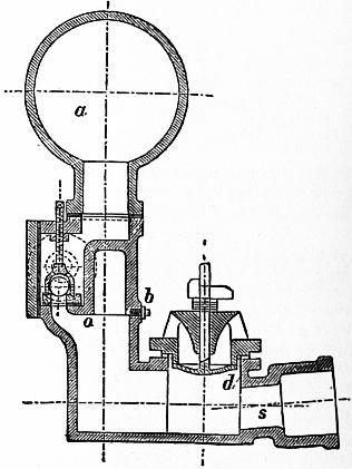 |
| Fig. 208. |
During the recoil after a sudden closing of the valve d, the pressure below it is diminished and the valve opens, permitting outflow. In consequence of the flow through this valve, the water in the supply pipe acquires a gradually increasing velocity. The upward flow of the water, towards the valve d, increases the pressure tending to lift the valve, and at last, if the valve is not too heavy, lifts and closes it. The forward momentum of the column in the supply pipe being destroyed by the stoppage of the flow, the water exerts a pressure at the end of the pipe sufficient to open the delivery valve o, and to cause a portion of the water to flow into the air vessel. As the water in the supply pipe comes to rest and recoils, the valve d opens again and the operation is repeated. Part of the energy of the descending column is employed in compressing the air at the end of the supply pipe and expanding the pipe itself. This causes a recoil of the water which momentarily diminishes the pressure in the pipe below the pressure due to the statical head. This assists in opening the valve d. The recoil of the water is sufficiently great to enable a pump to be attached to the ram body instead of the direct rising pipe. With this arrangement a ram working with muddy water may be employed to raise clear spring water. Instead of lifting the delivery valve as in the ordinary ram, the momentum of the column drives a sliding or elastic piston, and the recoil brings it back. This piston lifts and forces alternately the clear water through ordinary pump valves.
Pumps
§ 206. The different classes of pumps correspond almost exactly to the different classes of water motors, although the mechanical details of the construction are somewhat different. They are properly reversed water motors. Ordinary reciprocating pumps correspond to water-pressure engines. Chain and bucket pumps are in principle similar to water wheels in which the water acts by weight. Scoop wheels are similar to undershot water wheels, and centrifugal pumps to turbines.
Reciprocating Pumps are single or double acting, and differ from water-pressure engines in that the valves are moved by the water instead of by automatic machinery. They may be classed thus:—
1. Lift Pumps.—The water drawn through a foot valve on the ascent of the pump bucket is forced through the bucket valve when it descends, and lifted by the bucket when it reascends. Such pumps give an intermittent discharge.
2. Plunger or Force Pumps, in which the water drawn through the foot valve is displaced by the descent of a solid plunger, and forced through a delivery valve. They have the advantage that 107 the friction is less than that of lift pumps, and the packing round the plunger is easily accessible, whilst that round a lift pump bucket is not. The flow is intermittent.
3. The Double-acting Force Pump is in principle a double plunger pump. The discharge fluctuates from zero to a maximum and back to zero each stroke, but is not arrested for any appreciable time.
4. Bucket and Plunger Pumps consist of a lift pump bucket combined with a plunger of half its area. The flow varies as in a double-acting pump.
5. Diaphragm Pumps have been used, in which the solid plunger is replaced by an elastic diaphragm, alternately depressed into and raised out of a cylinder.
As single-acting pumps give an intermittent discharge three are generally used on cranks at 120°. But with all pumps the variation of velocity of discharge would cause great waste of work in the delivery pipes when they are long, and even danger from the hydraulic ramming action of the long column of water. An air vessel is interposed between the pump and the delivery pipes, of a volume from 5 to 100 times the space described by the plunger per stroke. The air in this must be replenished from time to time, or continuously, by a special air-pump. At low speeds not exceeding 30 ft. per minute the delivery of a pump is about 90 to 95% of the volume described by the plunger or bucket, from 5 to 10% of the discharge being lost by leakage. At high speeds the quantity pumped occasionally exceeds the volume described by the plunger, the momentum of the water keeping the valves open after the turn of the stroke.
The velocity of large mining pumps is about 140 ft. per minute, the indoor or suction stroke being sometimes made at 250 ft. per minute. Rotative pumping engines of large size have a plunger speed of 90 ft. per minute. Small rotative pumps are run faster, but at some loss of efficiency. Fire-engine pumps have a speed of 180 to 220 ft. per minute.
The efficiency of reciprocating pumps varies very greatly. Small reciprocating pumps, with metal valves on lifts of 15 ft., were found by Morin to have an efficiency of 16 to 40%, or on the average 25%. When used to pump water at considerable pressure, through hose pipes, the efficiency rose to from 28 to 57%, or on the average, with 50 to 100 ft. of lift, about 50%. A large pump with barrels 18 in. diameter, at speeds under 60 ft. per minute, gave the following results:—
| Lift in feet | 141⁄2 | 34 | 47 |
| Efficiency | .46 | .66 | .70 |
The very large steam-pumps employed for waterworks, with 150 ft. or more of lift, appear to reach an efficiency of 90%, not including the friction of the discharge pipes. Reckoned on the indicated work of the steam-engine the efficiency may be 80%.
Many small pumps are now driven electrically and are usually three-throw single-acting pumps driven from the electric motor by gearing. It is not convenient to vary the speed of the motor to accommodate it to the varying rate of pumping usually required. Messrs Hayward Tyler have introduced a mechanism for varying the stroke of the pumps (Sinclair’s patent) from full stroke to nil, without stopping the pumps.
§ 207. Centrifugal Pump.—For large volumes of water on lifts not exceeding about 60 ft. the most convenient pump is the centrifugal pump. Recent improvements have made it available also for very high lifts. It consists of a wheel or fan with curved vanes enclosed in an annular chamber. Water flows in at the centre and is discharged at the periphery. The fan may rotate in a vertical or horizontal plane and the water may enter on one or both sides of the fan. In the latter case there is no axial unbalanced pressure. The fan and its casing must be filled with water before it can start, so that if not drowned there must be a foot valve on the suction pipe. When no special attention needs to be paid to efficiency the water may have a velocity of 6 to 7 ft. in the suction and delivery pipes. The fan often has 6 to 12 vanes. For a double-inlet fan of diameter D, the diameter of the inlets is D/2. If Q is the discharge in cub. ft. per second D = about 0.6 √Q in average cases. The peripheral speed is a little greater than the velocity due to the lift. Ordinary centrifugal pumps will have an efficiency of 40 to 60%.
The first pump of this kind which attracted notice was one exhibited by J. G. Appold in 1851, and the special features of his pump have been retained in the best pumps since constructed. Appold’s pump raised continuously a volume of water equal to 1400 times its own capacity per minute. It had no valves, and it permitted the passage of solid bodies, such as walnuts and oranges, without obstruction to its working. Its efficiency was also found to be good.
 |
| Fig. 209. |
Fig. 209 shows the ordinary form of a centrifugal pump. The pump disk and vanes B are cast in one, usually of bronze,
and the disk is keyed on the driving shaft C. The casing A has a spirally enlarging discharge passage into the discharge pipe K. A cover L gives access to the pump. S is the suction pipe which opens into the pump disk on both sides at D.
Fig. 210 shows a centrifugal pump differing from ordinary centrifugal pumps in one feature only. The water rises through a suction pipe S, which divides so as to enter the pump wheel W at the centre on each side. The pump disk or wheel is very similar to a turbine wheel. It is keyed on a shaft driven by a belt on a fast and loose pulley arrangement at P. The water rotating in the pump disk presses outwards, and if the speed is sufficient a continuous flow is maintained through the pump and into the discharge pipe D. The special feature in this pump is that the water, discharged by the pump disk with a whirling velocity of not inconsiderable magnitude, is allowed to continue rotation in a chamber somewhat larger than the pump. The use of this whirlpool chamber was first suggested by Professor James Thomson. It utilizes the energy due to the whirling velocity of the water which in most pumps is wasted in eddies in the discharge pipe. In the pump shown guide-blades are also added which have the direction of the stream lines in a free vortex. They do not therefore interfere with the action of the water when pumping the normal quantity, but only prevent irregular motion. At A is a plug by which the pump case is filled before starting. If the pump is above the water to be pumped, a foot valve is required to permit the pump to be filled. Sometimes instead of the foot valve a delivery valve is used, an air-pump or steam jet pump being employed to exhaust the air from the pump case.
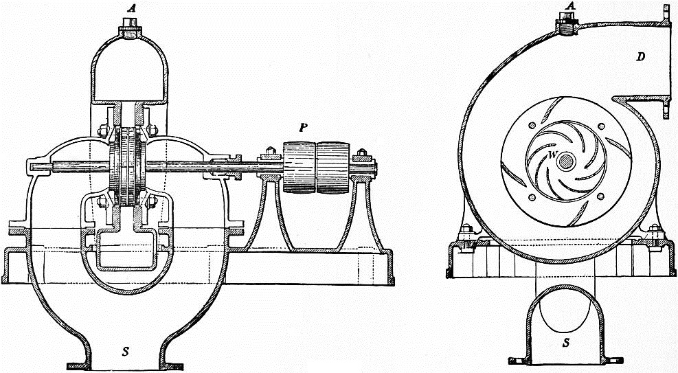 |
| Fig. 210. |
§ 208. Design and Proportions of a Centrifugal Pump.—The design of the pump disk is very simple. Let ri, ro be the radii of the inlet and outlet surfaces of the pump disk, di, do the clear axial width at those radii. The velocity of flow through the pump may be taken 108 the same as for a turbine. If Q is the quantity pumped, and H the lift,
ui = 0.25 √2gH.
2πridi = Q / ui.
Also in practice
di = 1.2 ri ....
Hence,
ri = .2571 √ (Q / √H).
Usually
ro = 2ri,
and
do = di or 1⁄2 di
according as the disk is parallel-sided or coned. The water enters the wheel radially with the velocity ui, and
uo = Q / 2πrodo.
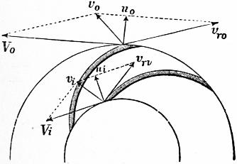 |
| Fig. 211. |
Fig. 211 shows the notation adopted for the velocities. Suppose the water enters the wheel with the velocity vi, while the velocity of the wheel is Vi. Completing the parallelogram, vri is the relative velocity of the water and wheel, and is the proper direction of the wheel vanes. Also, by resolving, ui and wi are the component velocities of flow and velocities of whir of the velocity vi of the water. At the outlet surface, vo is the final velocity of discharge, and the rest of the notation is similar to that for the inlet surface.
Usually the water flows equally in all directions in the eye of the wheel, in that case vi is radial. Then, in normal conditions of working, at the inlet surface,
| vi = ui wi = 0 tan θ = ui / Vi vri = ui cosec θ = √ (ui2 + Vi2). |
If the pump is raising less or more than its proper quantity, θ will not satisfy the last condition, and there is then some loss of head in shock.
At the outer circumference of the wheel or outlet surface,
| vro = uo cosec φ wo = Vo − uo cot φ vo = √ {uo2 + (Vo − uo cot φ)2} |
Variation of Pressure in the Pump Disk.—Precisely as in the case of turbines, it can be shown that the variation of pressure between the inlet and outlet surfaces of the pump is
ho − hi = (Vo2 − Vi2) / 2g − (vro2 − vri2) / 2g.
Inserting the values of vro, vri in (4) and (5), we get for normal conditions of working
ho − hi = (Vo2 − Vi2) / 2g − uo2 cosec2 φ / 2g + (ui2 + Vi2) / 2g
= Vo2 / 2g − uo2 cosec2 φ / 2g + ui2 / 2g.
Hydraulic Efficiency of the Pump.—Neglecting disk friction, journal friction, and leakage, the efficiency of the pump can be found in the same way as that of turbines (§ 186). Let M be the moment of the couple rotating the pump, and α its angular velocity; wo, ro the tangential velocity of the water and radius at the outlet surface; wi, ri the same quantities at the inlet surface. Q being the discharge per second, the change of angular momentum per second is
(GQ/g) (woro − wiri).
Hence
M = (GQ/g) (woro − wiri).
In normal working, wi = 0. Also, multiplying by the angular velocity, the work done per second is
Mα = (GQ/g) woroα.
But the useful work done in pumping is GQH. Therefore the efficiency is
η = GQH / Mα = gH / woroα = gH / woVo.
§ 209. Case 1. Centrifugal Pump with no Whirlpool Chamber.—When no special provision is made to utilize the energy of motion of the water leaving the wheel, and the pump discharges directly into a chamber in which the water is flowing to the discharge pipe, nearly the whole of the energy of the water leaving the disk is wasted. The water leaves the disk with the more or less considerable velocity vo, and impinges on a mass flowing to the discharge pipe at the much slower velocity vs. The radial component of vo is almost necessarily wasted. From the tangential component there is a gain of pressure
(wo2 − vs2) / 2g − (wo − vs)2 / 2g
= vs (wo − vs) / g,
which will be small, if vs is small compared with wo. Its greatest value, if vs = 1⁄2wo, is 1⁄2wo2/2g, which will always be a small part of the whole head. Suppose this neglected. The whole variation of pressure in the pump disk then balances the lift and the head ui2/2g necessary to give the initial velocity of flow in the eye of the wheel.
ui2 / 2g + H = Vo2 / 2g − uo2 cosec2 φ / 2g + ui2 / 2g,
H = Vo2 / 2g − uo2 cosec2 φ / 2g
or
Vo = √ (2gH + uo2 cosec2 φ).
and the efficiency of the pump is, from (7),
η = gH / Vowo = gH / {V (Vo − no cot φ) },
= (Vo2 − uo2 cosec2 φ) / {2Vo (Vo − uo cot φ) },
For φ = 90°,
η = (Vo2 − uo2) / 2Vo2,
which is necessarily less than 1⁄2. That is, half the work expended in driving the pump is wasted. By recurving the vanes, a plan introduced by Appold, the efficiency is increased, because the velocity vo of discharge from the pump is diminished. If φ is very small,
cosec φ = cot φ;
and then
η = (Vo, + uo cosec φ) / 2Vo,
which may approach the value 1, as φ tends towards 0. Equation (8) shows that uo cosec φ cannot be greater than Vo. Putting uo = 0.25 √(2gH) we get the following numerical values of the efficiency and the circumferential velocity of the pump:—
| φ | η | Vo |
| 90° | 0.47 | 1.03 √2gH |
| 45° | 0.56 | 1.06 ” |
| 30° | 0.65 | 1.12 ” |
| 20° | 0.73 | 1.24 ” |
| 10° | 0.84 | 1.75 ” |
φ cannot practically be made less than 20°; and, allowing for the frictional losses neglected, the efficiency of a pump in which φ = 20° is found to be about .60.
§ 210. Case 2. Pump with a Whirlpool Chamber, as in fig. 210.—Professor James Thomson first suggested that the energy of the water after leaving the pump disk might be utilized, if a space were left in which a free vortex could be formed. In such a free vortex the velocity varies inversely as the radius. The gain of pressure in the vortex chamber is, putting ro, rw for the radii to the outlet surface of wheel and to outside of free vortex,
| vo2 | ( 1 − | ro2 | ) = | vo2 | ( 1 − k2 ), |
| 2g | rw2 | 2g |
if
k = ro / rw.
The lift is then, adding this to the lift in the last case,
H = {Vo2 − uo2 cosec2 φ + vo2 (1 − k2)} / 2g.
But
vo2 = Vo2 − 2Vouo cot φ + uo2 cosec2 φ;
∴ H = {(2 − k2) Vo2 − 2kVouo cot φ − k2uo2 cosec2 φ} / 2g.
Putting this in the expression for the efficiency, we find a considerable increase of efficiency. Thus with
| φ = 90° and | k = 1⁄2, | η = 7⁄8 nearly, |
| φ a small angle and | k = 1⁄2, | η = 1 nearly. |
With this arrangement of pump, therefore, the angle at the outer ends of the vanes is of comparatively little importance. A moderate angle of 30° or 40° may very well be adopted. The following numerical values of the velocity of the circumference of the pump have been obtained by taking k = 1⁄2, and uo = 0.25√(2gH).
| φ | Vo |
| 90° | .762 √2gH |
| 45° | .842 ” |
| 30° | .911 ” |
| 20° | 1.023 ” |
The quantity of water to be pumped by a centrifugal pump necessarily varies, and an adjustment for different quantities of water cannot easily be introduced. Hence it is that the average efficiency of pumps of this kind is in practice less than the efficiencies given above. The advantage of a vortex chamber is also generally neglected. The velocity in the supply and discharge pipes is also often made greater than is consistent with a high degree of efficiency. Velocities of 6 or 7 ft. per second in the discharge and suction pipes, when the lift is small, cause a very sensible waste of energy; 3 to 6 ft. would be much better. Centrifugal pumps of very large size have been constructed. Easton and Anderson made pumps for the North Sea canal in Holland to deliver each 670 tons of water per minute on a lift of 5 ft. The pump disks are 8 ft. diameter. J. and H. Gwynne constructed some pumps for draining the Ferrarese Marshes, which together deliver 2000 tons per minute. A pump made under Professor J. Thomson’s direction for drainage works in Barbados had a pump disk 16 ft. in diameter and a whirlpool chamber 32 ft. in diameter. The efficiency of centrifugal pumps when delivering less or more than the normal quantity of water is discussed in a paper in the Proc. Inst. Civ. Eng. vol. 53.
§ 211. High Lift Centrifugal Pumps.—It has long been known that centrifugal pumps could be worked in series, each pump overcoming a part of the lift. This method has been perfected, and centrifugal pumps for very high lifts with great efficiency have been used by Sulzer and others. C. W. Darley (Proc. Inst. Civ. Eng., supplement to vol. 154, p. 156) has described some pumps of this new type driven by Parsons steam turbines for the water supply of Sydney, N.S.W. Each pump was designed to deliver 11⁄2 million gallons per twenty-four hours against a head of 240 ft. at 3300 revs. per minute. Three pumps in series give therefore a lift of 720 ft. The pump consists of a central double-sided impeller 12 in. diameter. The water entering at the bottom divides and enters the runner at each side through a bell-mouthed passage. The shaft is provided with ring and groove glands which on the suction side keep the air out and on the pressure side prevent leakage. Some water from the pressure side leaks through the glands, but beyond the first grooves it passes into a pocket and is returned to the suction side of the pump. For the glands on the suction side water is supplied from a low-pressure service. No packing is used in the glands. During the trials no water was seen at the glands. The following are the results of tests made at Newcastle:—
| I. | II. | III. | IV. | ||
| Duration of test | hours | 2 | 1.54 | 1.2 | 1.55 |
| Steam pressure | ℔ per sq. in. | 57 | 57 | 84 | 55 |
| Weight of steam per water h.p. hour | ℔ | 27.93 | 30.67 | 28.83 | 27.89 |
| Speed in revs, per min. | 3300 | 3330 | 3710 | 3340 | |
| Height of suction | ft. | 11 | 11 | 11 | 11 |
| Total lift | ft. | 762 | 744 | 917 | 756 |
| Million galls. per day pumped— | |||||
| By Ventun meter | 1.573 | 1.499 | 1.689 | 1.503 | |
| By orifice | 1.623 | 1.513 | 1.723 | 1.555 | |
| Water h.p. | 252 | 235 | 326 | 239 | |
In trial IV. the steam was superheated 95° F. From other trials under the same conditions as trial I. the Parsons turbine uses 15.6 ℔ of steam per brake h.p. hour, so that the combined efficiency of turbine and pumps is about 56%, a remarkably good result.
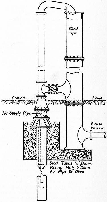 |
| Fig. 212. |
§ 212. Air-Lift Pumps.—An interesting and simple method of pumping by compressed air, invented by Dr J. Pohlé of Arizona, is likely to be very useful in certain cases. Suppose a rising main placed in a deep bore hole in which there is a considerable depth of water. Air compressed to a sufficient pressure is conveyed by an air pipe and introduced at the lower end of the rising main. The air rising In the main diminishes the average density of the contents of the main, and their aggregate weight no longer balances the pressure at the lower end of the main due to its submersion. An upward flow is set up, and if the air supply is sufficient the water in the rising main is lifted to any required height. The higher the lift above the level in the bore hole the deeper must be the point at which air is injected. Fig. 212 shows an airlift pump constructed for W. H. Maxwell at the Tunbridge Wells waterworks. There is a two-stage steam air compressor, compressing air to from 90 to 100 ℔ per sq. in. The bore hole is 350 ft. deep, lined with steel pipes 15 in. diameter for 200 ft. and with perforated pipes 131⁄2 in. diameter for the lower 150 ft. The rest level of the water is 96 ft. from the ground-level, and the level when pumping 32,000 gallons per hour is 120 ft. from the ground-level. The rising main is 7 in. diameter, and is carried nearly to the bottom of the bore hole and to 20 ft. above the ground-level. The air pipe is 21⁄2 in. diameter. In a trial run 31,402 gallons per hour were raised 133 ft. above the level in the well. Trials of the efficiency of the system made at San Francisco with varying conditions will be found in a paper by E. A. Rix (Journ. Amer. Assoc. Eng. Soc. vol. 25, 110 1900). Maxwell found the best results when the ratio of immersion to lift was 3 to 1 at the start and 2.2 to 1 at the end of the trial. In these conditions the efficiency was 37% calculated on the indicated h.p. of the steam-engine, and 46% calculated on the indicated work of the compressor. 2.7 volumes of free air were used to 1 of water lifted. The system is suitable for temporary purposes, especially as the quantity of water raised is much greater than could be pumped by any other system in a bore hole of a given size. It is useful for clearing a boring of sand and may be advantageously used permanently when a boring is in sand or gravel which cannot be kept out of the bore hole. The initial cost is small.
§ 213. Centrifugal Fans.—Centrifugal fans are constructed similarly to centrifugal pumps, and are used for compressing air to pressures not exceeding 10 to 15 in. of water-column. With this small variation of pressure the variation of volume and density of the air may be neglected without sensible error. The conditions of pressure and discharge for fans are generally less accurately known than in the case of pumps, and the design of fans is generally somewhat crude. They seldom have whirlpool chambers, though a large expanding outlet is provided in the case of the important Guibal fans used in mine ventilation.
It is usual to reckon the difference of pressure at the inlet and outlet of a fan in inches of water-column. One inch of water-column = 64.4 ft. of air at average atmospheric pressure = 5.2℔ per sq. ft.
Roughly the pressure-head produced in a fan without means of utilizing the kinetic energy of discharge would be v2/2g ft. of air, or 0.00024 v2 in. of water, where v is the velocity of the tips of the fan blades in feet per second. If d is the diameter of the fan and t the width at the external circumference, then πdt is the discharge area of the fan disk. If Q is the discharge in cub. ft. per sec., u = Q/π dt is the radial velocity of discharge which is numerically equal to the discharge per square foot of outlet in cubic feet per second. As both the losses in the fan and the work done are roughly proportional to u2 in fans of the same type, and are also proportional to the gauge pressure p, then if the losses are to be a constant percentage of the work done u may be taken proportional to √p. In ordinary cases u = about 22 √p. The width t of the fan is generally from 0.35 to 0.45d. Hence if Q is given, the diameter of the fan should be:—
For t = 0.35d, d = 0.20 √ (Q / √p)
For t = 0.45d, d = 0.18 √ (Q / √p)
If p is the pressure difference in the fan in inches of water, and N the revolutions of fan,
| v = πdN/60 | ft. per sec. |
| N = 1230 √ p/d | revs. per min. |
As the pressure difference is small, the work done in compressing the air is almost exactly 5.2pQ foot-pounds per second. Usually, however, the kinetic energy of the air in the discharge pipe is not inconsiderable compared with the work done in compression. If w is the velocity of the air where the discharge pressure is measured, the air carries away w2/2g foot-pounds per ℔ of air as kinetic energy. In Q cubic feet or 0.0807Q ℔ the kinetic energy is 0.00125 Qw2 foot-pounds per second.
The efficiency of fans is reckoned in two ways. If B.H.P. is the effective horse-power applied at the fan shaft, then the efficiency reckoned on the work of compression is
η = 5.2pQ / 550 B.H.P.
On the other hand, if the kinetic energy in the delivery pipe is taken as part of the useful work the efficiency is
η2 = (5.2 pQ + 0.00125 Qw2) / 550 B.H.P.
Although the theory above is a rough one it agrees sufficiently with experiment, with some merely numerical modifications.
An extremely interesting experimental investigation of the action of centrifugal fans has been made by H. Heenan and W. Gilbert (Proc. Inst. Civ. Eng. vol. 123, p. 272). The fans delivered through an air trunk in which different resistances could be obtained by introducing diaphragms with circular apertures of different sizes. Suppose a fan run at constant speed with different resistances and the compression pressure, discharge and brake horse-power measured. The results plot in such a diagram as is shown in fig. 213. The less the resistance to discharge, that is the larger the opening in the air trunk, the greater the quantity of air discharged at the given speed of the fan. On the other hand the compression pressure diminishes. The curve marked total gauge is the compression pressure + the velocity head in the discharge pipe, both in inches of water. This curve falls, but not nearly so much as the compression curve, when the resistance in the air trunk is diminished. The brake horse-power increases as the resistance is diminished because the volume of discharge increases very much. The curve marked efficiency is the efficiency calculated on the work of compression only. It is zero for no discharge, and zero also when there is no resistance and all the energy given to the air is carried away as kinetic energy. There is a discharge for which this efficiency is a maximum; it is about half the discharge which there is when there is no resistance and the delivery pipe is full open. The conditions of speed and discharge corresponding to the greatest efficiency of compression are those ordinarily taken as the best normal conditions of working. The curve marked total efficiency gives the efficiency calculated on the work of compression and kinetic energy of discharge. Messrs Gilbert and Heenan found the efficiencies of ordinary fans calculated on the compression to be 40 to 60% when working at about normal conditions.
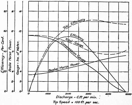 |
| Fig. 213. |
Taking some of Messrs Heenan and Gilbert’s results for ordinary fans in normal conditions, they have been found to agree fairly with the following approximate rules. Let pc be the compression pressure and q the volume discharged per second per square foot of outlet area of fan. Then the total gauge pressure due to pressure of compression and velocity of discharge is approximately: p = pc + 0.0004q2 in. of water, so that if pc is given, p can be found approximately. The pressure p depends on the circumferential speed v of the fan disk—
| p = 0.00025 v2 in. of water v = 63 √p ft. per sec. |
The discharge per square foot of outlet of fan is—
q = 15 to 18 √p cub. ft. per sec.
The total discharge is
Q = π dt q = 47 to 56 dt √p
For
t = .35d, d = 0.22 to 0.25 √(Q / √p) ft.
t = .45d, d = 0.20 to 0.22 √(Q / √p) ft.
N = 1203 √ p/d.
These approximate equations, which are derived purely from experiment, do not differ greatly from those obtained by the rough theory given above. The theory helps to explain the reason for the form of the empirical results.
1 Except where other units are given, the units throughout this article are feet, pounds, pounds per sq. ft., feet per second.
2 Journal de M. Liouville, t. xiii. (1868); Mémoires de l’Académie, des Sciences de l’Institut de France, t. xxiii., xxiv. (1877).
3 The following theorem is taken from a paper by J. H. Cotterill, “On the Distribution of Energy in a Mass of Fluid in Steady Motion,” Phil. Mag., February 1876.
4 The discharge per second varied from .461 to .665 cub. ft. in two experiments. The coefficient .435 is derived from the mean value.
5 “Formulae for the Flow of Water in Pipes,” Industries (Manchester, 1886).
6 Boussinesq has shown that this mode of determining the corrective factor α is not satisfactory.
7 In general, because when the water leaves the turbine wheel it ceases to act on the machine. If deflecting vanes or a whirlpool are added to a turbine at the discharging side, then v1 may in part depend on v2, and the statement above is no longer true.
HYDRAZINE (Diamidogen), N2H4 or H2 N·NH2, a compound of hydrogen and nitrogen, first prepared by Th. Curtius in 1887 from diazo-acetic ester, N2CH·CO2C2H5. This ester, which is obtained by the action of potassium nitrate on the hydrochloride of amidoacetic ester, yields on hydrolysis with hot concentrated potassium hydroxide an acid, which Curtius regarded as C3H3N6(CO2H)3, but which A. Hantzsch and O. Silberrad (Ber., 1900, 33, p. 58) showed to be C2H2N4(CO2H)2, bisdiazoacetic acid. On digestion of its warm aqueous solution with warm dilute sulphuric acid, hydrazine sulphate and oxalic acid are obtained. C. A. Lobry de Bruyn (Ber., 1895, 28, p. 3085) prepared free hydrazine by dissolving its hydrochloride in methyl alcohol and adding sodium methylate; sodium chloride was precipitated and the residual liquid afterwards fractionated under reduced pressure. It can also be prepared by reducing potassium dinitrososulphonate in ice cold water by means of sodium amalgam:—

P. J. Schestakov (J. Russ. Phys. Chem. Soc., 1905, 37, p. 1) obtained hydrazine by oxidizing urea with sodium hypochlorite in the presence of benzaldehyde, which, by combining with the hydrazine, protected it from oxidation. F. Raschig (German Patent 198307, 1908) obtained good yields by oxidizing ammonia with sodium hypochlorite in solutions made viscous with glue. Free hydrazine is a colourless liquid which boils at 113.5° C., and solidifies about 0° C. to colourless crystals; it is heavier than water, in which it dissolves with rise of temperature. It is rapidly oxidized on exposure, is a strong reducing agent, and reacts vigorously with the halogens. Under certain conditions it may be oxidized to azoimide (A. W. Browne and F. F. Shetterly, J. Amer. C.S., 1908, p. 53). By fractional distillation of its aqueous solution hydrazine hydrate N2H4·H2O (or perhaps H2N·NH3OH), a strong base, is obtained, which precipitates the metals from solutions of copper and silver salts at ordinary temperatures. It dissociates completely in a vacuum at 143°, and when heated under atmospheric pressure to 183° it decomposes into ammonia and nitrogen (A. Scott, J. Chem. Soc., 1904, 85, p. 913). The sulphate N2H4·H2SO4, crystallizes in tables which are slightly soluble in cold water and readily soluble in hot water; it is decomposed by heating above 250° C. with explosive evolution of gas and liberation of sulphur. By the addition of barium chloride to the sulphate, a solution of the hydrochloride is obtained, from which the crystallized salt may be obtained on evaporation.
Many organic derivatives of hydrazine are known, the most important being phenylhydrazine, which was discovered by Emil Fischer in 1877. It can be best prepared by V. Meyer and Lecco’s method (Ber., 1883, 16, p. 2976), which consists in reducing phenyldiazonium chloride in concentrated hydrochloric acid solution with stannous chloride also dissolved in concentrated hydrochloric acid. Phenylhydrazine is liberated from the hydrochloride so obtained by adding sodium hydroxide, the solution being then extracted with ether, the ether distilled off, and the residual oil purified by distillation under reduced pressure. Another method is due to E. Bamberger. The diazonium chloride, by the addition of an alkaline sulphite, is converted into a diazosulphonate, which is then reduced by zinc dust and acetic acid to phenylhydrazine potassium sulphite. This salt is then hydrolysed by heating it with hydrochloric acid—
| C6H5N2Cl + K2SO3 = KCl + C6H5N2·SO3K, C6H5N2·SO3K + 2H = C6H5·NH·NH·SO3K, C6H5NH·NH·SO3K + HCl + H2O = C6H5·NH·NH2·HCl + KHSO4. |
Phenylhydrazine is a colourless oily liquid which turns brown on exposure. It boils at 241° C., and melts at 17.5° C. It is slightly soluble in water, and is strongly basic, forming well-defined salts with acids. For the detection of substances containing the carbonyl group (such for example as aldehydes and ketones) phenylhydrazine is a very important reagent, since it combines with them with elimination of water and the formation of well-defined hydrazones (see Aldehydes, Ketones and Sugars). It is a strong reducing agent; it precipitates cuprous oxide when heated with Fehling’s solution, nitrogen and benzene being formed at the same time—C6H5·NH·NH2 + 2CuO = Cu2O + N2 + H2O + C6H5. By energetic reduction of phenylhydrazine (e.g. by use of zinc dust and hydrochloric acid), ammonia and aniline are produced—C6H5NH·NH2 + 2H = C6H5NH2 + NH3. It is also a most important synthetic reagent. It combines with aceto-acetic ester to form phenylmethylpyrazolone, from which antipyrine (q.v.) may be obtained. Indoles (q.v.) are formed by heating certain hydrazones with anhydrous zinc chloride; while semicarbazides, pyrrols (q.v.) and many other types of organic compounds may be synthesized by the use of suitable phenylhydrazine derivatives.
HYDRAZONE, in chemistry, a compound formed by the condensation of a hydrazine with a carbonyl group (see Aldehydes; Ketones).
HYDROCARBON, in chemistry, a compound of carbon and hydrogen. Many occur in nature in the free state: for example, natural gas, petroleum and paraffin are entirely composed of such bodies; other natural sources are india-rubber, turpentine and certain essential oils. They are also revealed by the spectroscope in stars, comets and the sun. Of artificial productions the most fruitful and important is provided by the destructive or dry distillation of many organic substances; familiar examples are the distillation of coal, which yields ordinary lighting gas, composed of gaseous hydrocarbons, and also coal tar, which, on subsequent fractional distillations, yields many liquid and solid hydrocarbons, all of high industrial value. For details reference should be made to the articles wherein the above subjects are treated. From the chemical point of view the hydrocarbons are of fundamental importance, and, on account of their great number, and still greater number of derivatives, they are studied as a separate branch of the science, namely, organic chemistry.
See Chemistry for an account of their classification, &c.
HYDROCELE (Gr. ὕδωρ, water, and κήλη, tumour), the medical term for any collection of fluid other than pus or blood in the neighbourhood of the testis or cord. The fluid is usually serous. Hydrocele may be congenital or arise in the middle-aged without apparent cause, but it is usually associated with chronic orchitis or with tertiary syphilitic enlargements. The hydrocele appears as a rounded, fluctuating translucent swelling in the scrotum, and when greatly distended causes a dragging pain. Palliative treatment consists in tapping aseptically and removing the fluid, the patient afterwards wearing a suspender. The condition frequently recurs and necessitates radical treatment. Various substances may be injected; or the hydrocele is incised, the tunica partly removed and the cavity drained.
HYDROCEPHALUS (Gr. ὕδωρ, water, and κεφαλὴ, head), a term applied to disease of the brain which is attended with excessive effusion of fluid into its cavities. It exists in two forms—acute and chronic hydrocephalus. Acute hydrocephalus is another name for tuberculous meningitis (see Meningitis).
Chronic hydrocephalus, or “water on the brain,” consists in an effusion of fluid into the lateral ventricles of the brain. It is not preceded by tuberculous deposit or acute inflammation, but depends upon congenital malformation or upon chronic inflammatory changes affecting the membranes. When the disease is congenital, its presence in the foetus is apt to be a source of difficulty in parturition. It is however more commonly developed in the first six months of life; but it occasionally arises in older children, or even in adults. The chief symptom is the gradual increase in size of the upper part of the head out of all proportion to the face or the rest of the body. Occurring at an age when as yet the bones of the skull have not become welded together, the enlargement may go on to an enormous extent, the Spaces between the bones becoming more and more expanded. In a well-marked case the deformity is very striking; the upper part of the forehead projects abnormally, and the orbital plates of the frontal bone being inclined forwards give a downward tilt to the eyes, which have also peculiar rolling movements. The face is small, and this, with the enlarged head, gives a remarkable aged expression to the child. The body is ill-nourished, the bones are thin, the hair is scanty and fine and the teeth carious or absent.
The average circumference of the adult head is 22 in., and in the normal child it is of course much less. In chronic hydrocephalus the head of an infant three months old has measured 29 in.; and in the case of the man Cardinal, who died in Guy’s Hospital, the head measured 33 in. In such cases the head cannot be supported by the neck, and the patient has to keep mostly in the recumbent posture. The expansibility of the skull prevents destructive pressure on the brain, yet this organ is materially affected by the presence of the fluid. The cerebral ventricles are distended, and the convolutions are flattened. Occasionally the fluid escapes into the cavity of the cranium, which it fills, pressing down the brain to the base of the skull. As a consequence, the functions of the brain are interfered with, and the mental condition is impaired. The child is dull, listless and irritable, and sometimes imbecile. The special senses become affected as the disease advances; sight is often lost, as is also hearing. Hydrocephalic children generally sink in a few years; nevertheless there have been instances of persons with this disease living to old age. There are, of course, grades of the affection, and children may present many of the symptoms of it in a slight degree, and yet recover, the head ceasing to expand, and becoming in due course firmly ossified.
Various methods of treatment have been employed, but the results are unsatisfactory. Compression of the head by bandages, and the administration of mercury with the view of promoting absorption of the fluid, are now little resorted to. Tapping the fluid from time to time through one of the spaces between the bones, drawing off a little, and thereafter employing gentle pressure, has been tried, but rarely with benefit. Attempts have also been made to establish a permanent drainage between the interior of the lateral ventricle and the sub-dural space, and between the lumbar region of the spine and the abdomen, but without satisfactory results. On the whole, the plan of treatment which aims at maintaining the patient’s nutrition by appropriate food and tonics is the most rational and successful.
 |
| Fig. 1.—Hydrocharis Morsusranae—Frog-bit—male plant. |
1, Female flower. 2, Stamens, enlarged. 3, Barren pistil of male flower, enlarged. 4, Pistil of female flower. 5, Fruit. 6, Fruit cut transversely. 7, Seed. 8, 9, Floral diagrams of male and female flowers respectively. s, Rudimentary stamens. |
HYDROCHARIDEAE, in botany, a natural order of Monocotyledons, belonging to the series Helobieae. They are water-plants, represented in Britain by frog-bit (Hydrocharis Morsusranae) and water-soldier (Stratiotes aloïdes). The order contains about fifty species in fifteen genera, twelve of which occur in fresh water while three are marine: and includes both floating and submerged forms. Hydrocharis floats on the surface of still water, and has rosettes of kidney-shaped leaves, from among which spring the flower-stalks; stolons bearing new leaf-rosettes are sent out on all sides, the plant thus propagating itself on the same way as the strawberry. Stratiotes aloïdes has a rosette of stiff sword-like leaves, which when the plant is in flower project above the surface; it is also stoloniferous, the young rosettes sinking to the bottom at the beginning of winter and rising again to the surface in the spring. Vallisneria (eel-grass) contains two species, one native of tropical Asia, the other inhabiting the warmer parts of both hemispheres and reaching as far north as south Europe. It grows in the mud at the bottom of fresh water, and the short stem bears a cluster of long, narrow grass-like leaves; new plants are formed at the end of horizontal runners. Another type is represented by Elodea canadensis or water-thyme, which has been introduced into the British Isles from North America. It is a small, submerged plant with long, slender branching stems bearing whorls of narrow toothed leaves; the flowers appear at the surface when mature. Halophila, Enhalus and Thalassia are submerged maritime plants found on tropical coasts, mainly in the Indian and Pacific oceans; Halophila has an elongated stem rooting at the nodes; Enhalus a short, thick rhizome, clothed with black threads resembling horse-hair, the persistent hard-bast strands of the leaves; Thalassia has a creeping rooting stem with upright branches bearing crowded strap-shaped leaves in two rows. The flowers spring from, or are enclosed in, a spathe, and are unisexual and regular, with generally a calyx and corolla, each of three members; the stamens are in whorls of three, the inner whorls are often barren; the two to fifteen carpels form an inferior ovary containing generally numerous ovules on often large, produced, parietal placentas. The fruit is leathery or fleshy, opening irregularly. The seeds contain a large embryo and no endosperm. In Hydrocharis (fig. 1), which is dioecious, the flowers are borne above the surface of the water, have conspicuous white petals, contain honey and are pollinated by insects. Stratiotes has similar flowers which come above the surface only for pollination, becoming submerged again during ripening of the fruit. In Vallisneria (fig. 2), which is also dioecious, the small male flowers are borne in large numbers in short-stalked spathes; the petals are minute and scale-like, and only two of the three stamens are fertile; the flowers become detached before opening and rise to the surface, where the sepals expand and form a float bearing the two projecting semi-erect stamens. The female flowers are solitary and are raised to the surface on a long, spiral stalk; the ovary bears three broad styles, on which some of the large, sticky pollen-grains from the floating male flowers get deposited, (fig. 3). After pollination the female flower becomes drawn below the surface by the spiral contraction of the long stalk, and the fruit ripens near the bottom. Elodea has polygamous flowers (that is, male, female and hermaphrodite), solitary, in slender, tubular spathes; the male flowers become detached and rise to the surface; the females are raised to the surface when mature, and receive the floating pollen from the male. The flowers of Halophila are submerged and apetalous.
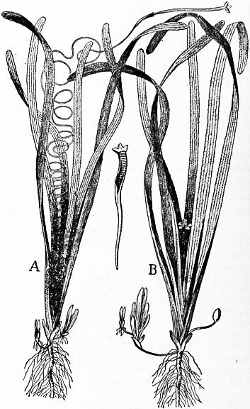 |
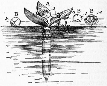 |
| Fig. 2.—Vallisneria spiralis—Eel grass—about 1⁄4 natural size. A, Female plant; B, Male plant. | Fig. 3. |
The order is a widely distributed one; the marine forms are tropical or subtropical, but the fresh-water genera occur also in the temperate zones.
HYDROCHLORIC ACID, also known in commerce as “spirits of salts” and “muriatic acid,” a compound of hydrogen and chlorine. Its chemistry is discussed under Chlorine, and its manufacture under Alkali Manufacture.
HYDRODYNAMICS (Gr. ὕδωρ, water, δύναμις, strength), the branch of hydromechanics which discusses the motion of fluids (see Hydromechanics).
HYDROGEN [symbol H, atomic weight 1.008 (o = 16)], one of the chemical elements. Its name is derived from Gr. ὕδωρ, water, and γεννάειν, to produce, in allusion to the fact that water is produced when the gas burns in air. Hydrogen appears to have been recognized by Paracelsus in the 16th century; the combustibility of the gas was noticed by Turquet de Mayenne in the 17th century, whilst in 1700 N. Lémery showed that a mixture of hydrogen and air detonated on the application of a light. The first definite experiments concerning the nature of hydrogen were made in 1766 by H. Cavendish, who showed that it was formed when various metals were acted upon by dilute sulphuric or hydrochloric acids. Cavendish called it “inflammable air,” and for some time it was confused with other inflammable gases, all of which were supposed to contain the same inflammable principle, “phlogiston,” in combination with varying amounts of other substances. In 1781 Cavendish showed that water was the only substance produced when hydrogen was burned in air or oxygen, it having been thought previously to this date that other substances were formed during the reaction, A. L. Lavoisier making many experiments with the object of finding an acid among the products of combustion.
Hydrogen is found in the free state in some volcanic gases, in fumaroles, in the carnallite of the Stassfurt potash mines (H. Precht, Ber., 1886, 19, p. 2326), in some meteorites, in certain stars and nebulae, and also in the envelopes of the sun. In combination it is found as a constituent of water, of the gases from certain mineral springs, in many minerals, and in most animal and vegetable tissues. It may be prepared by the electrolysis of acidulated water, by the decomposition of water by various metals or metallic hydrides, and by the action of many metals on acids or on bases. The alkali metals and alkaline earth metals decompose water at ordinary temperatures; magnesium begins to react above 70° C., and zinc at a dull red heat. The decomposition of steam by red hot iron has been studied by H. Sainte-Claire Deville (Comptes rendus, 1870, 70, p. 1105) and by H. Debray (ibid., 1879, 88, p. 1341), who found that at about 1500° C. a condition of equilibrium is reached. H. Moissan (Bull. soc. chim., 1902, 27, p. 1141) has shown that potassium hydride decomposes cold water, with evolution of hydrogen, KH + H2O = KOH + H2. Calcium hydride or hydrolite, prepared by passing hydrogen over heated calcium, decomposes water similarly, 1 gram giving 1 litre of gas; it has been proposed as a commercial source (Prats Aymerich, Abst. J.C.S., 1907, ii. p. 543), as has also aluminium turnings moistened with potassium cyanide and mercuric chloride, which decomposes water regularly at 70°, 1 gram giving 1.3 litres of gas (Mauricheau-Beaupré, Comptes rendus, 1908, 147, p. 310). Strontium hydride behaves similarly. In preparing the gas by the action of metals on acids, dilute sulphuric or hydrochloric acid is taken, and the metals commonly used are zinc or iron. So obtained, it contains many impurities, such as carbon dioxide, nitrogen, oxides of nitrogen, phosphoretted hydrogen, arseniuretted hydrogen, &c., the removal of which is a matter of great difficulty (see E. W. Morley, Amer. Chem. Journ., 1890, 12, p. 460). When prepared by the action of metals on bases, zinc or aluminium and caustic soda or caustic potash are used. Hydrogen may also be obtained by the action of zinc on ammonium salts (the nitrate excepted) (Lorin, Comptes rendus, 1865, 60, p. 745) and by heating the alkali formates or oxalates with caustic potash or soda, Na2C2O4 + 2NaOH = H2 + 2Na2CO3. Technically it is prepared by the action of superheated steam on incandescent coke (see F. Hembert and Henry, Comptes rendus, 1885, 101, p. 797; A. Naumann and C. Pistor, Ber., 1885, 18, p. 1647), or by the electrolysis of a dilute solution of caustic soda (C. Winssinger, Chem. Zeit., 1898, 22, p. 609; “Die Elektrizitäts-Aktiengesellschaft,” Zeit. f. Elektrochem., 1901, 7, p. 857). In the latter method a 15% solution of caustic soda is used, and the electrodes are made of iron; the cell is packed in a wooden box, surrounded with sand, so that the temperature is kept at about 70° C.; the solution is replenished, when necessary, with distilled water. The purity of the gas obtained is about 97%.
Pure hydrogen is a tasteless, colourless and odourless gas of specific gravity 0.06947 (air = 1) (Lord Rayleigh, Proc. Roy. Soc., 1893, p. 319). It may be liquefied, the liquid boiling at −252.68° C. to −252.84° C., and it has also been solidified, the solid melting at −264° C. (J. Dewar, Comptes rendus, 1899, 129, p. 451; Chem. News, 1901, 84, p. 49; see also Liquid Gases). The specific heat of gaseous hydrogen (at constant pressure) is 3.4041 (water = 1), and the ratio of the specific heat at constant pressure to the specific heat at constant volume is 1.3852 (W. C. Röntgen, Pogg. Ann., 1873, 148, p. 580). On the spectrum see Spectroscopy. Hydrogen is only very slightly soluble in water. It diffuses very rapidly through a porous membrane, and through some metals at a red heat (T. Graham, Proc. Roy. Soc., 1867, 15, p. 223; H. Sainte-Claire Deville and L. Troost, Comptes rendus, 1863, 56, p. 977). Palladium and some other metals are capable of absorbing large volumes of hydrogen (especially when the metal is used as a cathode in a water electrolysis apparatus). L. Troost and P. Hautefeuille (Ann. chim. phys., 1874, (5) 2, p. 279) considered that a palladium hydride of composition Pd2H was formed, but the investigations of C. Hoitsema (Zeit. phys. Chem., 1895, 17, p. 1), from the standpoint of the phase rule, do not favour this view, Hoitsema being of the opinion that the occlusion of hydrogen by palladium is a process of continuous absorption. Hydrogen burns with a pale blue non-luminous flame, but will not support the combustion of ordinary combustibles. It forms a highly explosive mixture with air or oxygen, especially when in the proportion of two volumes of hydrogen to one volume of oxygen. H. B. Baker (Proc. Chem. Soc., 1902, 18, p. 40) has shown that perfectly dry hydrogen will not unite with perfectly dry oxygen. Hydrogen combines with fluorine, even at very low temperatures, with great violence; it also combines with carbon, at the temperature of the electric arc. The alkali metals when warmed in a current of hydrogen, at about 360° C., form hydrides of composition RH (R = Na, K, Rb, Cs), (H. Moissan, Bull. soc. chim., 1902, 27, p. 1141); calcium and strontium similarly form hydrides CaH2, SrH2 at a dull red heat (A. Guntz, Comptes rendus, 1901, 133, p. 1209). Hydrogen is a very powerful reducing agent; the gas occluded by palladium being very active in this respect, readily reducing ferric salts to ferrous salts, nitrates to nitrites and ammonia, chlorates to chlorides, &c.
For determinations of the volume ratio with which hydrogen and oxygen combine, see J. B. Dumas, Ann. chim. phys., 1843 (3), 8, p. 189; O. Erdmann and R. F. Marchand, ibid., p. 212; E. H. Keiser, Ber., 1887, 20, p. 2323; J. P. Cooke and T. W. Richards, Amer. Chem. Journ., 1888, 10, p. 191; Lord Rayleigh, Chem. News, 1889, 59, p. 147; E. W. Morley, Zeit. phys. Chem., 1890, 20, p. 417; and S. A. Leduc, Comptes rendus, 1899, 128, p. 1158.
Hydrogen combines with oxygen to form two definite compounds, namely, water (q.v.), H2O, and hydrogen peroxide, H2O2, whilst the existence of a third oxide, ozonic acid, has been indicated.
Hydrogen peroxide, H2O2, was discovered by L. J. Thénard in 1818 (Ann. chim. phys., 8, p. 306). It occurs in small quantities in the atmosphere. It may be prepared by passing a current of carbon dioxide through ice-cold water, to which small quantities of barium peroxide are added from time to time (F. Duprey, Comptes rendus, 1862, 55, p. 736; A. J. Balard, ibid., p. 758), BaO2 + CO2 + H2O = H2O2 + BaCO3. E. Merck (Abst. J.C.S., 1907, ii., p. 859) showed that barium percarbonate, BaCO4, is formed when the gas is in excess; this substance readily yields the peroxide with an acid. Or barium peroxide may be decomposed by hydrochloric, hydrofluoric, sulphuric or silicofluoric acids (L. Crismer, Bull. soc. chim., 1891 (3), 6, p. 24; Hanriot, Comptes rendus, 1885, 100, pp. 56, 172), the peroxide being added 114 in small quantities to a cold dilute solution of the acid. It is necessary that it should be as pure as possible since the commercial product usually contains traces of ferric, manganic and aluminium oxides, together with some silica. To purify the oxide, it is dissolved in dilute hydrochloric acid until the acid is neatly neutralized, the solution is cooled, filtered, and baryta water is added until a faint permanent white precipitate of hydrated barium peroxide appears; the solution is now filtered, and a concentrated solution of baryta water is added to the filtrate, when a crystalline precipitate of hydrated barium peroxide, BaO2·H2O, is thrown down. This is filtered off and well washed with water. The above methods give a dilute aqueous solution of hydrogen peroxide, which may be concentrated somewhat by evaporation over sulphuric acid in vacuo. H. P. Talbot and H. R. Moody (Jour. Anal. Chem., 1892, 6, p. 650) prepared a more concentrated solution from the commercial product, by the addition of a 10% solution of alcohol and baryta water. The solution is filtered, and the barium precipitated by sulphuric acid. The alcohol is removed by distillation in vacuo, and by further concentration in vacuo a solution may be obtained which evolves 580 volumes of oxygen. R. Wolffenstein (Ber., 1894, 27, p. 2307) prepared practically anhydrous hydrogen peroxide (containing 99.1% H2O2) by first removing all traces of dust, heavy metals and alkali from the commercial 3% solution. The solution is then concentrated in an open basis on the water-bath until it contains 48% H2O2. The liquid so obtained is extracted with ether and the ethereal solution distilled under diminished pressure, and finally purified by repeated distillations. W. Staedel (Zeit. f. angew. Chem., 1902, 15, p. 642) has described solid hydrogen peroxide, obtained by freezing concentrated solutions.
Hydrogen peroxide is also found as a product in many chemical actions, being formed when carbon monoxide and cyanogen burn in air (H. B. Dixon); by passing air through solutions of strong bases in the presence of such metals as do not react with the bases to liberate hydrogen; by shaking zinc amalgam with alcoholic sulphuric acid and air (M. Traube, Ber., 1882, 15, p. 659); in the oxidation of zinc, lead and copper in presence of water, and in the electrolysis of sulphuric acid of such strength that it contains two molecules of water to one molecule of sulphuric acid (M. Berthelot, Comptes rendus, 1878, 86, p. 71).
The anhydrous hydrogen peroxide obtained by Wolffenstein boils at 84-85°C. (68 mm.); its specific gravity is 1.4996 (1.5° C.). It is very explosive (W. Spring, Zeit. anorg. Chem., 1895, 8, p. 424). The explosion risk seems to be most marked in the preparations which have been extracted with ether previous to distillation, and J. W. Brühl (Ber., 1895, 28, p. 2847) is of opinion that a very unstable, more highly oxidized product is produced in small quantity in the process. The solid variety prepared by Staedel forms colourless, prismatic crystals which melt at −2° C.; it is decomposed with explosive violence by platinum sponge, and traces of manganese dioxide. The dilute aqueous solution is very unstable, giving up oxygen readily, and decomposing with explosive violence at 100° C. An aqueous solution containing more than 1.5% hydrogen peroxide reacts slightly acid. Towards lupetidin [aa′ dimethyl piperidine, C5H9N(CH3)2] hydrogen peroxide acts as a dibasic acid (A. Marcuse and R. Wolffenstein, Ber., 1901, 34, p. 2430; see also G. Bredig, Zeit. Electrochem., 1901, 7, p. 622). Cryoscopic determinations of its molecular weight show that it is H2O2. [G. Carrara, Rend. della Accad. dei Lincei, 1892 (5), 1, ii. p. 19; W. R. Orndorff and J. White, Amer. Chem. Journ., 1893, 15, p. 347.] Hydrogen peroxide behaves very frequently as a powerful oxidizing agent; thus lead sulphide is converted into lead sulphate in presence of a dilute aqueous solution of the peroxide, the hydroxides of the alkaline earth metals are converted into peroxides of the type MO2·8H2O, titanium dioxide is converted into the trioxide, iodine is liberated from potassium iodide, and nitrites (in alkaline solution) are converted into acid-amides (B. Radziszewski, Ber., 1884, 17, p. 355). In many cases it is found that hydrogen peroxide will only act as an oxidant when in the presence of a catalyst; for example, formic, glycollic, lactic, tartaric, malic, benzoic and other organic acids are readily oxidized in the presence of ferrous sulphate (H. J. H. Fenton, Jour. Chem. Soc., 1900, 77, p. 69), and sugars are readily oxidized in the presence of ferric chloride (O. Fischer and M. Busch, Ber., 1891, 24, p. 1871). It is sought to explain these oxidation processes by assuming that the hydrogen peroxide unites with the compound undergoing oxidation to form an addition compound, which subsequently decomposes (J. H. Kastle and A. S. Loevenhart, Amer. Chem. Journ., 1903, 29, pp. 397, 517). Hydrogen peroxide can also react as a reducing agent, thus silver oxide is reduced with a rapid evolution of oxygen. The course of this reaction can scarcely be considered as definitely settled; M. Berthelot considers that a higher oxide of silver is formed, whilst A. Baeyer and V. Villiger are of opinion that reduced silver is obtained [see Comptes rendus, 1901, 133, p. 555; Ann. Chim. Phys., 1897 (7), 11, p. 217, and Ber., 1901, 34, p. 2769]. Potassium permanganate, in the presence of dilute sulphuric acid, is rapidly reduced by hydrogen peroxide, oxygen being given off, 2KMnO4 + 3H2SO4 + 5H2O2 = K2SO4 + 2MnSO4 + 8H2O + 5O2. Lead peroxide is reduced to the monoxide. Hypochlorous acid and its salts, together with the corresponding bromine and iodine compounds, liberate oxygen violently from hydrogen peroxide, giving hydrochloric, hydrobromic and hydriodic acids (S. Tanatar, Ber., 1899, 32, p. 1013).
On the constitution of hydrogen peroxide see C. F. Schönbein, Jour. prak. Chem., 1858-1868; M. Traube, Ber., 1882-1889; J. W. Brühl, Ber., 1895, 28, p. 2847; 1900, 33, p. 1709; S. Tanatar, Ber., 1903, 36, p. 1893.
Hydrogen peroxide finds application as a bleaching agent, as an antiseptic, for the removal of the last traces of chlorine and sulphur dioxide employed in bleaching, and for various quantitative separations in analytical chemistry (P. Jannasch, Ber., 1893, 26, p. 2908). It may be estimated by titration with potassium permanganate in acid solution; with potassium ferricyanide in alkaline solution, 2K3Fe(CN)6 + 2KOH + H2O2 = 2K4Fe(CN)6 + 2H2O + O2; or by oxidizing arsenious acid in alkaline solution with the peroxide and back titration of the excess of arsenious acid with standard iodine (B. Grützner, Arch. der Pharm., 1899, 237, p. 705). It may be recognized by the violet coloration it gives when added to a very dilute solution of potassium bichromate in the presence of hydrochloric acid; by the orange-red colour it gives with a solution of titanium dioxide in concentrated sulphuric acid; and by the precipitate of Prussian blue formed when it is added to a solution containing ferric chloride and potassium ferricyanide.
Ozonic Acid, H2O4. By the action of ozone on a 40% solution of potassium hydroxide, placed in a freezing mixture, an orange-brown substance is obtained, probably K2O4, which A. Baeyer and V. Villiger (Ber., 1902, 35, p. 3038) think is derived from ozonic acid, produced according to the reaction O3 + H2O = H2O4.
HYDROGRAPHY (Gr. ὕδωρ, water, and γράφειν, to write), the science dealing with all the waters of the earth’s surface, including the description of their physical features and conditions; the preparation of charts and maps showing the position of lakes, rivers, seas and oceans, the contour of the sea-bottom, the position of shallows, deeps, reefs and the direction and volume of currents; a scientific description of the position, volume, configuration, motion and condition of all the waters of the earth. See also Surveying (Nautical) and Ocean and Oceanography. The Hydrographic Department of the British Admiralty, established in 1795, undertakes the making of charts for the admiralty, and is under the charge of the hydrographer to the admiralty (see Chart).
HYDROLYSIS (Gr. ὕδωρ, water, λύειν, to loosen), in chemistry, a decomposition brought about by water after the manner shown in the equation R·X + H·OH = R·H + X·OH. Modern research has proved that such reactions are not occasioned by water acting as H2O, but really by its ions (hydrions and hydroxidions), for the velocity is proportional (in accordance with the law of chemical mass action) to the concentration of these ions. This fact explains the so-called “catalytic” action of acids and bases in decomposing such compounds as the esters. The term “saponification” (Lat. sapo, soap) has the same meaning, but it is more properly restricted to the hydrolysis of the fats, i.e. glyceryl esters of organic acids, into glycerin and a soap (see Chemical Action).