
Fig. 1.
Project Gutenberg's Electric Bells and All About Them, by S. R. Bottone

This eBook is for the use of anyone anywhere at no cost and with
almost no restrictions whatsoever.  You may copy it, give it away or
re-use it under the terms of the Project Gutenberg License included
with this eBook or online at www.gutenberg.org


Title: Electric Bells and All About Them
       A Practical Book for Practical Men

Author: S. R. Bottone

Release Date: March 4, 2012 [EBook #39053]

Language: English

Character set encoding: UTF-8

*** START OF THIS PROJECT GUTENBERG EBOOK ELECTRIC BELLS AND ALL ABOUT THEM ***


Produced by Simon Gardner, Chris Curnow and the Online
Distributed Proofreading Team at http://www.pgdp.net (This
file was produced from images generously made available
by The Internet Archive)
Inconsistent spellings (e.g. depolariser & depolarizer) and hyphenation (e.g. guttapercha & gutta-percha) are retained as in the original text. Minor punctuation errors are corrected without comment. Changes which have been made to the text (in the case of typographical errors) are listed at the end of the book.
A Practical Book for Practical Men.
WITH MORE THAN 100 ILLUSTRATIONS.
BY S. R. BOTTONE,
CERTIFICATED BY SOUTH KENSINGTON (LATE OF THE COLLEGIO DEL CARMINE, TURIN, AND OF THE ISTITUTO BELLINO, NOVARA);
Author of "The Dynamo," "Electrical Instruments for Amateurs," &c.
LONDON: WHITTAKER & CO., Paternoster Square, E.C.
1889.
(All rights reserved.)
So rapidly has the use of electric bells and similiar signalling appliances extended, in modern houses, offices, hotels, lifts, and ships, that every bell-fitter must have felt the need of accurate knowledge of the manner in which these instruments act and are made.
In the following pages the author has attempted to supply this need, by giving full details as to the construction of batteries, bells, pushes, detectors, etc., the mode of wiring, testing, connecting up, localizing faults, and, in point of fact, by directing careful attention to every case that can present itself to the electric-bell fitter.
Carshalton, Surrey,
November, 1888.
| chap. | page | ||
| I. | Preliminary Considerations | 1 | |
| II. | On the Choice of Batteries for Electric Bell Work | 18 | |
| III. | On Electric Bells and other Signalling Appliances | 59 | |
| IV. | On Contacts, Pushes, Switches, Keys, Alarms, and Relays | 109 | |
| V. | On Wiring, Connecting up, and Localising Faults | 144 | |
| Fig. | Page | ||
| 1. | Direction of current in cell | 9 | |
| 2. | Direction of current out of cell | 10 | |
| 3. | Bar and horse-shoe magnets | 14 | |
| 4. | The Dynamo | 16 | |
| 5. | The Smee cell | 28 | |
| 6. | The Daniell cell | 30 | |
| 7. | The Gravity cell | 32 | |
| 8. | The Leclanché cell and parts | 34 | |
| 9. | The Agglomerate cell | 40 | |
| 10. | The Judson cell | 42 | |
| 11. | The Battery in box | 43 | |
| 12. | The Gent cell | 44 | |
| 13. | The Bichromate cell | 48 | |
| 14. | The Fuller cell | 50 | |
| 15. | The Cells coupled in series | 54 | |
| 16. | The Cells coupled in Parallel | 57 | |
| 17. | Outline of electric bell | 61 | |
| 18. | Frame of bell | 62 | |
| 19. | E-shaped frame | 63 | |
| 20. | Electro-magnet, old form | 64 | |
| 20A. | Electro-magnet, modern form | 65 | |
| 21. | Magnet frame | 66 | |
| 21A. | Winder | 72 | |
| 22. | Mode of joining electromagnet wires | 73 | |
| 23. | Armature spring | 74 | |
| 24. | Armature spring Another form | 74 | |
| 25. | Platinum tipped screw | 75 | |
| 26. | Platinum tipped spring | 76 | |
| 27. | Binding screws | 77 | |
| 28. | Bell or gong | 78 | |
| 29. | Pillar and nuts | 78 | |
| 30. | Washers | 78 | |
| 31. | Trembling bell | 81 | |
| 32. | Bell action enclosed in case | 88 | |
| 33. | Ordinary trembling bells | 90 | |
| 34. | Single stroke bell | 91 | |
| 35. | Continuous ring bell | 94 | |
| 36. | Release action | 95 | |
| 37. | Continuous ringing with relay | 96 | |
| 38. | Continuous ringing action with indicator | 97 | |
| 39. | Relay and detent lever for indicator | 97 | |
| 40. | Callow's attachment | 99 | |
| 40A. | Thorpe's arrangement | 101 | |
| 41. | Jensen bell, section | 102 | |
| 42. | Jensen bell, exterior | 104 | |
| 43A. | Circular bell | 106 | |
| 43B. | Mining bell | 106 | |
| 44. | Electric trumpet (Binswanger's) | 107 | |
| 45. | Various forms of pushes | 110 | |
| 46. | Pressel | 111 | |
| 47. | Pull | 112 | |
| 48. | Bedroom pull | 113 | |
| 49A. | Bedroom pull Another form | 114[Pg viii] | |
| 49B. | Floor contact, ball form | 114 | |
| 50. | Burglar alarm | 115 | |
| 51. | Burglar alarm Another form | 115 | |
| 52. | Floor contact | 115 | |
| 53. | Door contact | 116 | |
| 54. | Sash contact | 117 | |
| 55. | Shop door contact | 117 | |
| 56A. | Closed circuit system, single | 119 | |
| 56B. | Closed circuit system, double | 119 | |
| 57. | Modified gravity, Daniell | 120 | |
| 58. | Contact for closed circuit | 121 | |
| 59. | Thermometer alarm | 122 | |
| 60. | Fire alarm | 123 | |
| 61A. | Fire alarm Another form | 123 | |
| 61B. | Fire alarm Another form in action | 123 | |
| 62. | Binswanger's "watch alarm" contact | 125 | |
| 63. | Watchman's electric tell-tale clock | 126 | |
| 64. | Lever switch, two-way | 128 | |
| 65. | Morse key, double contact | 133 | |
| 66. | Relay | 134 | |
| 67. | Indicator, drop | 137 | |
| 68. | Indicator, Semaphore | 138 | |
| 69. | Indicator, Fall back | 139 | |
| 70. | Indicator, Pendulum | 140 | |
| 71. | Indicator, Coupled up | 142 | |
| 72. | Indicator, Gent's tripolar | 143 | |
| 73. | Soldering iron and wires | 148 | |
| 74. | Push, interior of | 151 | |
| 75. | Bell, battery and push | 159 | |
| 76. | Bell, battery and push And earth return | 160 | |
| 77. | Bell, and two pushes | 161 | |
| 78. | Bell, two pushes and one pull | 161 | |
| 79. | Two bells in parallel | 162 | |
| 80. | Two bells in parallel Another mode | 162 | |
| 81. | Two bells in parallel with two-way switch | 163 | |
| 82. | Series coupler | 163 | |
| 83. | Bell with local battery and relay | 164 | |
| 84. | Continuous ringing bell with wire return | 165 | |
| 85. | Bells with Morse keys for signalling | 165 | |
| 86. | Bells with double contact pushes for signalling | 166 | |
| 87. | Bells with double contact with one battery only | 167 | |
| 88. | Two-way signalling with one battery only | 168 | |
| 89. | Complete installation of bells, batteries, pushes, etc. | 169 | |
| 90. | Mode of getting out plan or design | 170 | |
| 91. | Lift fitted with bells | 173 | |
| 92. | Magneto bell: generator | 174 | |
| 93. | Magneto bell: Receiver | 175 | |
| 94. | Magneto bell: Combined | 176 | |
| 95. | Detector or galvanometer | 176 | |
§ 1. Electricity.—The primary cause of all the effects which we are about to consider resides in a force known as electricity, from the Greek name of amber (electron), this being the body in which the manifestations were first observed. The ancients were acquainted with a few detached facts, such as the attractive power acquired by amber after friction; the benumbing shocks given by the torpedo; the aurora borealis; the lightning flash; and the sparks or streams of light which, under certain conditions, are seen to issue from the human body. Thales, a Grecian philosopher, who flourished about 600 years B.C., observed the former of these facts, but nearly twenty centuries elapsed before it was suspected that any connection existed between these phenomena.
§ 2. According to the present state of our knowledge,[Pg 2] it would appear that electricity is a mode of motion in the constituent particles (or atoms) of bodies very similar to, if not identical with, heat and light. These, like sound, are known to be dependent on undulatory motion; but, whilst sound is elicited by the vibration of a body as a whole, electricity appears to depend, in its manifestations, upon some motion (whether rotary, oscillatory, or undulatory, it is not known) of the atoms themselves.
However this be, it is certain that whatever tends to set up molecular motion, tends also to call forth a display of electricity. Hence we have several practical means at our disposal for evoking electrical effects. These may be conveniently divided into three classes, viz.:—1st, mechanical; 2nd, chemical; 3rd, changes of temperature. Among the mechanical may be ranged friction, percussion, vibration, trituration, cleavage, etc. Among the chemical we note the action of acids and alkalies upon metals. Every chemical action is accompanied by electrical effects; but not all such actions are convenient sources of electricity. Changes of temperature, whether sudden or gradual, call forth electricity, but the displays are generally more striking in the former than in the latter case, owing to the accumulated effect being presented in a shorter time.
§ 3. We may now proceed to study a few of these methods of evoking electricity, so as to familiarise ourselves with the leading properties.
If we rub any resinous substance (such as amber, copal, resin, sealing-wax, ebonite, etc.) with a piece of[Pg 3] warm, dry flannel, we shall find that it acquires the power of attracting light bodies, such as small pieces of paper, straw, pith, etc. After remaining in contact with the rubbed (or electrified) substance for a short time, the paper, etc., will fly off as if repelled; and this apparent repulsion will be more evident and more quickly produced if the experiment be performed over a metal tray. If a small pith-ball, the size of a pea, be suspended from the ceiling by a piece of fine cotton, previously damped and then approached by an ebonite comb which has been briskly rubbed, it will be vigorously attracted, and never repelled; but if for the cotton there be substituted a thread or fibre of very fine dry silk, the pith-ball will be first attracted and then repelled. This is owing to the fact that the damp cotton allows the electricity to escape along it: id est, damp cotton is a CONDUCTOR of electricity, while silk does not permit its dissipation; or, in other words, silk is a NON-CONDUCTOR. All bodies with which we are acquainted are found, on trial, to fall under one or other of the two heads—viz., conductors and non-conductors. Nature knows no hard lines, so that we find that even the worst conductors will permit the escape of some electricity, while the very best conductors oppose a measurable resistance to its passage. Between the limits of good conductors, on the one hand, and non-conductors (or insulators) on the other, we have bodies possessing varying degrees of conductivity.
§ 4. As a knowledge of which bodies are, and which are not, conductors of electricity is absolutely essential[Pg 4] to every one aspiring to apply electricity to any practical purpose, the following table is subjoined, giving the names of the commoner bodies, beginning with those which most readily transmit electricity, or are good conductors, and ending with those which oppose the highest resistance to its passage, or are insulators, or non-conductors:—
§ 5. TABLE OF CONDUCTORS AND INSULATORS. [Pg 5]
| Quality. | Name of Substance. | Relative Resistance. | ||
|---|---|---|---|---|
| Good Conductors | Silver, annealed | 1. | ||
| Copper, annealed | 1.063 | |||
| Silver, hard drawn | 1.086 | |||
| Copper, hard drawn | 1.086 | |||
| Gold, annealed | 1.369 | |||
| Gold, hard drawn | 1.393 | |||
| Aluminium, annealed | 1.935 | |||
| Zinc, pressed | 3.741 | |||
| Brass (variable) | 5.000 | |||
| Platinum, annealed | 6.022 | |||
| Iron | 6.450 | |||
| Steel, soft | 6.500 | |||
| Gold and silver alloy, 2 to 1 | 7.228 | |||
| Nickel, annealed | 8.285 | |||
| Tin, pressed | 8.784 | |||
| Lead, pressed | 13.050 | |||
| German silver (variable) | 13.920 | |||
| Platinum-silver alloy, 1 to 2 | 16.210 | |||
| Steel, hard | 25.000 | |||
| Antimony, pressed | 23.600 | |||
| Mercury | 62.730 | |||
| Bismuth | 87.230 | |||
| Graphite | 145.000 | |||
| Nitric Acid | 976000.000 | |||
| Imperfect Conductors | Hydrochloric acid | [1] | ||
| Sulphuriacid | 1032020.000 | |||
| Solutions of metallic salts | varies with strength | |||
| Metallic sulphides | [1] | |||
| Distilled water | [1] 6754208.000 | |||
| Inferior Conductors. | Metallic salts, solid | [1] | ||
| Linen | } | and other forms of cellulose | [1] | |
| Cotton | ||||
| Hemp | ||||
| Paper | ||||
| Alcohol | [1] | |||
| Ether | [1] | |||
| Dry Wood | [1] | |||
| Dry Ice | [1] | |||
| Metallic Oxides | [1] | |||
| Non-conductors, or Insulators. | Ice, at 25 c. | [1] | ||
| Fats and oils | [1] | |||
| Caoutchouc | 1000000000000. | |||
| Guttapercha | 1000000000000. | |||
| Dry air, gases, and vapours | [1] | |||
| Wool | [1] | |||
| Ebonite | 1300000000000. | |||
| Diamond | [1] | |||
| Silk | [1] | |||
| Glass | [1] | |||
| Wax | [1] | |||
| Sulphur | [1] | |||
| Resin | [1] | |||
| Amber | [1] | |||
| Shellac | [1] | |||
| Paraffin | 1500000000000. | |||
[1] These have not been accurately measured.
The figures given as indicating the relative resistance of the above bodies to the passage of electricity must be taken as approximate only, since the conductivity of all these bodies varies very largely with their purity, and with the temperature. Metals become worse conductors when heated; liquids and non-metals, on the contrary, become better conductors.
It must be borne in mind that dry air is one of the[Pg 6] best insulators, or worst conductors, with which we are acquainted; while damp air, on the contrary, owing to the facility with which it deposits water on the surface of bodies, is highly conducive to the escape of electricity.
§ 6. If the experiment described at § 3 be repeated, substituting a glass rod for the ebonite comb, it will be found that the pith-ball will be first attracted and then repelled, as in the case with the ebonite; and if of two similar pith-balls, each suspended by a fibre of silk, one be treated with the excited ebonite and the other with the glass rod, until repulsion occurs, and then approached to each other, the two balls will be found to attract each other. This proves that the electrical condition of the excited ebonite and of the excited glass must be different; for had it been the same, the two balls would have repelled one another. Farther, it will be found that the rubber with which the ebonite or the glass rod have been excited has also acquired electrical properties, attracting the pith-ball, previously repelled by the rod. From this we may gather that when one body acting on another, either mechanically or chemically, sets up an electrical condition in one of the two bodies, a similar electrical condition, but in the opposite sense, is produced in the other: in point of fact, that it is impossible to excite any one body without exciting a corresponding but opposite state in the other. (We may take, as a rough mechanical illustration of this, the effect which is produced on the pile of two pieces of plush or fur, on being drawn across one another in opposite directions. On examination we shall find that[Pg 7] both the piles have been laid down, the upper in the one direction, the lower in the other.) For a long time these two electrical states were held to depend upon two distinct electricities, which were called respectively vitreous and resinous, to indicate the nature of the bodies from which they were derived. Later on (when it was found that the theory of a single electricity could be made to account for all the phenomena, provided it was granted that some electrified bodies acquired more, while others acquired less than their natural share of electricity), the two states were known as positive and negative; and these names are still retained, although it is pretty generally conceded that electricity is not an entity in itself, but simply a mode of motion.
§ 7. It is usual, in treatises on electricity, to give a long list of the substances which acquire a positive or a negative condition when rubbed against one another. Such a table is of very little use, since the slightest modification in physical condition will influence very considerably the result. For example: if two similar sheets of glass be rubbed over one another, no change in electrical condition is produced; but if one be roughed while the other is left polished, this latter becomes positively, while the former becomes negatively, electrified. So, also, if one sheet of glass be warmed, while the other be left cold, the colder becomes positively, and the latter negatively, excited. As a general law, that body, the particles of which are more easily displaced, becomes negatively electrified.
§ 8. As, however, the electricity set up by friction[Pg 8] has not hitherto found any practical application in electric bell-ringing or signalling, we need not to go more deeply into this portion of the subject, but pass at once to the electricity elicited by the action of acids, or their salts, on metals.
Here, as might be expected from the law enunciated above, the metal more acted on by the acid becomes negatively electrified, while the one less acted on becomes positive.[2] The following table, copied from Ganot, gives an idea of the electrical condition which the commoner metals and graphite assume when two of them are immersed at the same time in dilute acid:—
| The portion immersed in the acid fluid. | ⎧ | ↓ | Zinc. | ↑ | ⎫ | The portion out of the acid fluid. |
| ⎪ | ↓ | Cadmium. | ↑ | ⎪ | ||
| ⎪ | ↓ | Tin. | ↑ | ⎪ | ||
| ⎪ | ↓ | Lead. | ↑ | ⎪ | ||
| ⎪ | ↓ | Iron. | ↑ | ⎪ | ||
| ⎪ | ↓ | Nickel. | ↑ | ⎪ | ||
| ⎪ | ↓ | Bismuth. | ↑ | ⎪ | ||
| ⎪ | ↓ | Antimony. | ↑ | ⎪ | ||
| ⎪ | ↓ | Copper. | ↑ | ⎪ | ||
| ⎪ | ↓ | Silver. | ↑ | ⎪ | ||
| ⎪ | ↓ | Gold. | ↑ | ⎪ | ||
| ⎪ | ↓ | Platinum. | ↑ | ⎪ | ||
| ⎩ | ↓ | Graphite. | ↑ | ⎭ |
The meaning of the above table is, that if we test the electrical condition of any two of its members when immersed in an acid fluid, we shall find that the ones at the head of the list are positive to those below them, but negative to those above them, if the test have reference to the condition of the parts within the fluid. On the[Pg 9] contrary, we shall find that any member of the list will be found to be negative to any one below it, or positive to any above it, if tested from the portion NOT immersed in the acid fluid.
§ 9. A very simple experiment will make this quite clear. Two strips, one of copper and the other of zinc, 1" wide by 4" long, have a 12" length of copper wire soldered to one extremity of each. A small flat piece of cork, about 1" long by 1" square section, is placed between the two plates, at the end where the wires have been soldered, this portion being then lashed together by a few turns of waxed string. (The plates should not touch each other at any point.) If this combination (which constitutes a very primitive galvanic couple) be[Pg 10] immersed in a tumbler three-parts filled with water, rendered just sour by the addition of a few drops of sulphuric or hydrochloric acid, we shall get a manifestation of electrical effects. If a delicately poised magnetic needle be allowed to take up its natural position of north and south, and then the wires proceeding from the two metal strips twisted in contact, so as to be parallel to and over the needle, as shown in Fig. 1, the needle will be impelled out of its normal position, and be deflected more or less out of the line of[Pg 11] the wire. If the needle be again allowed to come to rest N. and S. (the battery or couple having been removed), and then the tumbler be held close over the needle, as in Fig. 2, so that the needle points from the copper to the zinc strip, the needle will be again impelled or deflected out of its natural position, but in this case in the opposite direction.
§ 10. It is a well-known fact that if a wire, or any other conductor, along which the electric undulation (or, as is usually said, the electric current) is passing, be brought over and parallel to a suspended magnetic needle, pointing north and south, the needle is immediately deflected from this north and south position, and assumes a new direction, more or less east and west, according to the amplitude of the current and the nearness of the conductor to the needle. Moreover, the direction in which the north pole of the needle is impelled is found to be dependent upon the direction in which the electric waves (or current) enter the conducting body or wire. The law which regulates the direction of these deflections, and which is known, from the name of its originator, as Ampère's law, is briefly as follows:—
§ 11. "If a current be caused to flow over and parallel to a freely suspended magnetic needle, previously pointing north and south, the north pole will be impelled to the LEFT of the entering current. If, on the contrary, the wire, or conductor, be placed below the needle, the deflection will, under similar circumstances, be in the opposite direction, viz.: the[Pg 12] north pole will be impelled to the RIGHT of the entering current." In both these cases the observer is supposed to be looking along the needle, with its N. seeking pole pointing at him.
§ 12. From a consideration of the above law, in connection with the experiments performed at § 9, it will be evident that inside the tumbler the zinc is positive to the copper strip; while, viewed from the outside conductor, the copper is positive to the zinc strip.[3]
§ 13. A property of current electricity, which is the fundamental basis of electric bell-ringing, is that of conferring upon iron and steel the power of attracting iron and similar bodies, or, as it is usually said, of rendering iron magnetic. If a soft iron rod, say about 4" long by ½" diameter, be wound evenly from end to end with three or four layers of cotton-covered copper wire, say No. 20 gauge, and placed in proximity to a few iron nails, etc., no attractive power will be evinced; but let the two free ends of the wire be placed in metallic contact with the wires leading from the simple battery described at § 9, and it will be found that the iron has become powerfully magnetic, capable of sustaining several ounces weight of iron and steel, so long as the wires from the battery are in contact with the wire encircling the iron; or, in other words, "the soft iron is a magnet, so long as an electric current flows round it." If contact between the battery wires and the coiled wires[Pg 13] be broken, the iron loses all magnetic power, and the nails, etc., drop off immediately. A piece of soft iron thus coiled with covered or "insulated" wire, no matter what its shape may be, is termed an "electro-magnet." Their chief peculiarities, as compared with the ordinary permanent steel magnets or lodestones, are, first, their great attractive and sustaining power; secondly, the rapidity, nay, instantaneity, with which they lose all attractive force on the cessation of the electric flow around them. It is on these two properties that their usefulness in bell-ringing depends.
§ 14. If, instead of using a soft iron bar in the above experiment, we had substituted one of hard iron, or steel, we should have found two remarkable differences in the results. In the first place, the bar would have been found to retain its magnetism instead of losing it immediately on contact with the battery being broken; and, in the second place, the attractive power elicited would have been much less than in the case of soft iron. It is therefore of the highest importance, in all cases where rapid and powerful magnetisation is desired, that the cores of the electro-magnets should be of the very softest iron. Long annealing and gradual cooling conduce greatly to the softness of iron.
§ 15. There is yet another source of electricity which must be noticed here, as it has already found application in some forms of electric bells and signalling, and which promises to enter into more extended use. If we sprinkle some iron filings over a bar magnet, or a horse-shoe magnet, we shall find that the filings arrange[Pg 14] themselves in a definite position along the lines of greatest attractive force; or, as scientists usually say, the iron filings arrange themselves in the direction of the lines of force. The entire space acted on by the magnet is usually known as its "field." Fig. 3 gives an idea of the distribution of the iron filings, and also of the general direction of the lines of force. It is found that if a body be moved before the poles of a magnet in such a direction as to cut the lines of force, electricity is excited in that body, and also around the magnet. The ordinary magneto-electric machines of the shops are illustrations of the application of this property of magnets. They consist essentially in a horse-shoe[Pg 15] magnet, in front of which is caused to rotate, by means of appropriate gearing, or wheel and band, an iron bobbin, or pair of bobbins, coiled with wire. The ends of the wire on the bobbins are brought out and fastened to insulated portions of the spindle, and revolve with it. Two springs press against the spindle, and pick up the current generated by the motion of the iron bobbins before the poles of the magnet. It is quite indifferent whether we use permanent steel magnets or electro-magnets to produce this effect. If we use the latter, and more especially if we cause a portion of the current set up to circulate round the electro-magnet to maintain its power, we designate the apparatus by the name of Dynamo.
§ 16. Our space will not permit of a very extended description of the dynamo, but the following brief outline of its constructive details will be found useful to the student. A mass of soft iron (shape immaterial) is wound with many turns of insulated copper wire, in such a manner that, were an electrical current sent along the wire, the mass of iron would become strongly north at one extremity, and south at the other. As prolongations of the electro-magnet thus produced are affixed two masses of iron facing one another, and so fashioned or bored out as to allow a ring, or cylinder of soft iron, to rotate between them. This cylinder, or ring of iron, is also wound with insulated wire, two or more ends of which are brought out in a line with the spindle on which it rotates, and fastened down to as many insulated sections of brass cylinder placed around the[Pg 16] circumference of the spindle. Two metallic springs, connected to binding screws which form the "terminals" of the machine, serve to collect the electrical wave set up by the rotation of the coiled cylinder (or "armature") before the poles of the electro-magnet. The annexed cut (Fig. 4) will assist the student in getting a clear idea of the essential portions in a dynamo:—E is the mass of wrought iron wound with insulated wire, and known as the field-magnet. N and S are cast-iron prolongations of the same, and are usually bolted to the field-magnet. When current is passing these become powerfully magnetic. A is the rotating iron ring, or cylinder, known as the armature, which is also wound with insulated wire, B, the ends of which are brought out and connected to the insulated brass segments[Pg 17] known as the commutator, C. Upon this commutator press the two springs D and D', known as the brushes, which serve to collect the electricity set up by the rotation of the armature. These brushes are in electrical connection with the two terminals of the machine F F', whence the electric current is transmitted where required; the latter being also connected with the wire encircling the field-magnet, E.
When the iron mass stands in the direction of the earth's magnetic meridian, even if it have not previously acquired a little magnetism from the hammering, etc., to which it was subjected during fitting, it becomes weakly magnetic. On causing the armature to rotate by connecting up the pulley at the back of the shaft (not shown in cut) with any source of power, a very small current is set up in the wires of the armature, due to the weak magnetism of the iron mass of the field-magnet. As this current (or a portion of it) is caused to circulate around this iron mass, through the coils of wire surrounding the field-magnet, this latter becomes more powerfully magnetic (§ 13), and, being more magnetically active, sets up a more powerful electrical disturbance in the armature.
This increased electrical activity in the armature increases the magnetism of this field-magnet as before, and this again reacts on the armature; and these cumulative effects rapidly increase, until a limit is reached, dependent partly on the speed of rotation, partly on the magnetic saturation of the iron of which the dynamo is built up, and partly on the amount of resistance in the circuit.
[2] This refers, of course, to those portions of the metals which are out of the acid. For reasons which will be explained farther on, the condition of the metals in the acid is just the opposite to this.
[3] From some recent investigations, it would appear that what we usually term the negative is really the point at which the undulation takes its rise.
§ 17. If we immerse a strip of ordinary commercial sheet zinc in dilute acid (say sulphuric acid 1 part by measure, water 16 parts by measure[4]), we shall find that the zinc is immediately acted on by the acid, being rapidly corroded and dissolved, while at the same time a quantity of bubbles of gas are seen to collect around, and finally to be evolved at the surface of the fluid in contact with the plate. Accompanying this chemical action, and varying in a degree proportionate to the intensity of the action of the acid on the zinc, we find a marked development of heat and electricity. If, while the bubbling due to the extrication of gas be still proceeding, we immerse in the same vessel a strip of silver, or copper, or a rod of graphite, taking care that contact does not take place between the two elements, no perceptible change takes place in the[Pg 19] condition of things; but if we cause the two strips to touch, either by inclining the upper extremities so as to bring them in contact out of the fluid like a letter Λ, or by connecting the upper extremities together by means of a piece of wire (or other conductor of electricity), or by causing their lower extremities in the fluid to touch, we notice a very peculiar change. The extrication of bubbles around the zinc strip ceases entirely or almost entirely, while the other strip (silver, copper, or graphite) becomes immediately the seat of the evolution of the gaseous bubbles. Had these experiments been performed with chemically pure metallic zinc, instead of the ordinary impure commercial metal, we should have found some noteworthy differences in behaviour. In the first place, the zinc would have been absolutely unattacked by the acid before the immersion of the other strip; and, secondly, all evolution of gas would entirely cease when contact between the two strips was broken.
As the property which zinc possesses of causing the extrication of gas (under the above circumstances) has a considerable influence on the efficiency of a battery, it is well to understand thoroughly what chemical action takes place which gives rise to this evolution of gas.
§ 18. All acids may be conveniently regarded as being built up of two essential portions, viz.: firstly, a strongly electro-negative portion, which may either be a single body, such as chlorine, iodine, bromine, etc., or a compound radical, such as cyanogen; secondly, the strongly electro-positive body hydrogen.[Pg 20]
Representing, for brevity's sake, hydrogen by the letter H., and chlorine, bromine, iodine, etc., respectively by Cl., Br., and I., the constitution of the acids derived from these bodies may be conveniently represented by:—
| H Cl | H Br | H I |
| ┗━━┛ | ┗━━┛ | ┗━━┛ |
| Hydrochloric Acid[5]. | Hydrobromic Acid. | Hydriodic Acid. |
and the more complex acids, in which the electro-negative component is a compound, such as sulphuric acid (built up of 1 atom of sulphur and 4 atoms of oxygen, united to 2 atoms of hydrogen) or nitric acid (consisting of 1 nitrogen atom, 6 oxygen atoms, and 1 hydrogen atom), may advantageously be retained in memory by the aid of the abbreviations:—
When zinc does act on an acid, it displaces the hydrogen contained in it, and takes its place; the acid losing at the same time its characteristic sourness and corrosiveness, becoming, as chemists say, neutralized. One atom of zinc can replace two atoms of hydrogen, so that one atom of zinc can replace the hydrogen in two equivalents of such acids as contain only one atom of hydrogen.
This power of displacement and replacement possessed by zinc is not peculiar to this metal, but is[Pg 21] possessed also by many other bodies, and is of very common occurrence in chemistry; and may be roughly likened to the substitution of a new brick for an old one in a building, or one girder for another in an arch.
It will be well, therefore, to remember that in all batteries in which acids are used to excite electricity by their behaviour along with zinc, the following chemical action will also take place, according to which acid is employed:—
| Hydrochloric Acid | and | Zinc, | equal | Zinc Chloride | and | Hydrogen Gas. |
| 2HCl | + | Zn | = | ZnCl2 | + | H2 |
or:—
| Sulphuric Acid | and | Zinc, | equal | Zinc Sulphate | and | Hydrogen Gas. |
| H2SO4 | + | Zn | = | ZnSO4 | + | H2 |
Or we may put this statement into a general form, covering all cases in which zinc is acted on by a compound body containing hydrogen, representing the other or electro-negative portion of the compound by X:—
Zn + H2X = ZnX + H2
the final result being in every case the corrosion and solution of the zinc, and the extrication of the hydrogen gas displaced.
§ 19. We learn from the preceding statements that no electricity can be manifested in a battery or cell (as such a combination of zinc acid and metal is called) without consumption of zinc. On the contrary, we may safely say that the more rapidly the useful consumption of zinc takes place, the greater will be the electrical effects produced. But here it must be borne in mind[Pg 22] that if the zinc is being consumed when we are not using the cell or battery, that consumption is sheer waste, quite as much as if we were compelled to burn fuel in an engine whether the latter were doing work or not. For this reason the use of commercial zinc, in its ordinary condition, is not advisable in batteries in which acids are employed, since the zinc is consumed in such, whether the battery is called upon to do electrical work (by placing its plates in connection through some conducting circuit) or not. This serious objection to the employment of commercial zinc could be overcome by the employment of chemically purified zinc, were it not that the price of this latter is so elevated as practically to preclude its use for this purpose. Fortunately, it is possible to confer, on the ordinary crude zinc of commerce, the power of resisting the attacks of the acid (so long as the plates are not metallically connected; or, in other words, so long as the "circuit is broken"), by causing it to absorb superficially a certain amount of mercury (quicksilver). The modes of doing this, which is technically known as amalgamating the zinc, are various, and, as it is an operation which every one who has the care of batteries is frequently called upon to perform, the following working details will be found useful:—
§ 20. To amalgamate zinc, it should first be washed with a strong solution of common washing soda, to remove grease, then rinsed in running water; the zinc plates, or rods, should then be dipped into a vessel containing acidulated water (§ 17), and as soon as[Pg 23] bubbles of hydrogen gas begin to be evolved, transferred to a large flat dish containing water. While here, a few drops of mercury are poured on each plate, and caused to spread quickly over the surface of the zinc by rubbing briskly with an old nail-brush or tooth-brush. Some operators use a kind of mop, made of pieces of rag tied on the end of a stick, and there is no objection to this; others recommend the use of the fingers for rubbing in the mercury. This latter plan, especially if many plates have to be done, is very objectionable: firstly, on the ground of health, since the mercury is slowly but surely absorbed by the system, giving rise to salivation, etc.; and, secondly, because any jewellery, etc., worn by the wearer will be whitened and rendered brittle. When the entire surface of the zinc becomes resplendent like a looking-glass, the rubbing may cease, and the zinc plate be reared up on edge, to allow the superfluous mercury to drain off. This should be collected for future operations. It is important that the mercury used for this purpose should be pure. Much commercial mercury contains lead and tin. These metals can be removed by allowing the mercury to stand for some time in a vessel containing dilute nitric acid, occasional agitation being resorted to, in order to bring the acid into general contact with the mercury. All waste mercury, drainings, brushings from old plates, etc., should be thus treated with nitric acid, and finally kept covered with water. Sprague, in his admirable work on electricity, says:—"Whenever the zinc shows a grey granular surface (or rather before this), brush it[Pg 24] well and re-amalgamate, remembering that a saving of mercury is no economy, and a free use of it no waste; for it may all be recovered with a little care. Keep a convenient sized jar, or vessel, solely for washing zinc in, and brush into this the dirty grey powder which forms, and is an amalgam of mercury with zinc, lead, tin, etc., and forms roughnesses which reduce the protection of the amalgamation. Rolled sheet zinc should always be used in preference to cast. This latter is very hard to amalgamate, and has less electro-motive power[8]; but for rods for use in porous jars, and particularly with saline solutions, cast-zinc is very commonly used. In this case great care should be taken to use good zinc cuttings, removing any parts with solder on them, and using a little nitre as a flux, which will remove a portion of the foreign metals."
§ 21. Another and very convenient mode of amalgamating zinc, specially useful where solid rods or masses of zinc are to be used, consists in weighing up the zinc and setting aside four parts of mercury (by weight) for every hundred of the zinc thus weighed up. The zinc should then be melted in a ladle, with a little tallow or resin over the top as a flux. As soon as melted, the mercury should be added in and the mixture stirred with a stick. It should then be poured into moulds of the desired shape. This is, perhaps, the best mode of amalgamating cast zincs.
§ 22. Some operators recommend the use of mercurial salts (such as mercury nitrate, etc.) as advan[Pg 25]tageous for amalgamating; but, apart from the fact that these salts are generally sold at a higher rate than the mercury itself, the amalgamation resulting, unless a very considerable time be allowed for the mercuric salts to act, is neither so deep nor so satisfactory as in the case of mercury alone. It may here be noted, that although the effect of mercury in protecting the zinc is very marked in those batteries in which acids are used as the exciting fluids, yet this action is not so observable in the cases in which solutions of salts are used as exciters; and in a few, such as the Daniell cell and its congeners, the use of amalgamated zinc is positively a disadvantage.
§ 23. If, having thus amalgamated the zinc plate of the little battery described and figured at § 9, we repeat the experiment therein illustrated, namely, of joining the wires proceeding from the two plates over a suspended magnetic needle, and leave them so united, we shall find that the magnetic needle, which was originally very much deflected out of the line of the magnetic meridian (north and south), will very quickly return near to its old and normal position; and this will be found to take place long before the zinc has been all consumed, or the acid all neutralised. Of course, this points to a rapid falling off in the transmission of the electric disturbance along the united wires; for had that continued of the same intensity, the deflection of the needle would evidently have remained the same likewise. What, then, can have caused this rapid loss of power? On examining (without removing from the[Pg 26] fluid) the surface of the copper plate, we shall find that it is literally covered with a coating of small bubbles of hydrogen gas, and, if we agitate the liquid or the plates, many of them will rise to the surface, while the magnetic needle will at the same time give a larger deflection. If we entirely remove the plates from the acid fluid, and brush over the surface of the copper plate with a feather or small pledget of cotton wool fastened to a stick, we shall find, on again immersing the plates in the acid, that the effect on the needle is almost, if not quite, as great as at first; thus proving that the sudden loss of electrical energy was greatly due to the adhesion of the free hydrogen gas to the copper plate. This peculiar phenomenon, which is generally spoken of as the polarisation of the negative plate, acts in a twofold manner towards checking the electrical energy of the battery. In the first place, the layer of hydrogen (being a bad conductor of electricity) presents a great resistance to the transmission of electrical energy from the zinc plate where it is set up to the copper (or other) plate whence it is transmitted to the wires, or electrodes. Again, the copper or other receiving plate, in order that the electric energy should be duly received and transmitted, should be more electro-negative than the zinc plate; but the hydrogen gas which is evolved, and which thus adheres to the negative plate, is actually very highly electro-positive, and thus renders the copper plate incapable of receiving or transmitting the electric disturbance. This state of things may be roughly likened to that of two exactly equal and level tanks, Z[Pg 27] and C, connected by a straight piece of tubing. If Z be full and C have an outlet, it is very evident that Z can and will discharge itself into C until exhausted; but if C be allowed to fill up to the same level as Z, then no farther flow can take place between the two.
It is, therefore, very evident that to ensure anything like constancy in the working of a battery, at least until all the zinc be consumed or all the acid exhausted, some device for removing the liberated hydrogen must be put into practice. The following are some of the means that have been adopted by practical men:—
§ 24. Roughening the surface of the negative plate, which renders the escape of the hydrogen gas easier. This mode was adopted by Smee in the battery which bears his name. It consists of a sheet of silver, placed between two plates of zinc, standing in a cell containing dilute sulphuric acid, as shown at Fig. 5.
The silver sheet, before being placed in position, is platinised; that is to say, its surface is covered (by electro-deposition) with a coating of platinum, in the form of a fine black powder. This presents innumerable points of escape for the hydrogen gas; and for this reason this battery falls off much less rapidly than the plain zinc and smooth copper form. A modification of Smee's battery which, owing to the large negative surface presented, is very advantageous, is Walker's graphite cell. In this we have a plate of zinc between two plates of gas-carbon ("scurf"), or graphite. The surface of this body is naturally much rougher than metal sheets; and this roughness of surface is further assisted by[Pg 28] coating the surface with platinum, as in the case of the Smee. The chief objection to the use of graphite is its porosity, which causes it to suck up the acid fluid in which the plates stand, and this, of course, corrodes the brass connections, or binding screws.
Other mechanical means of removing the hydrogen have been suggested, such as brushing the surface of the plate, keeping the liquid in a state of agitation by boiling or siphoning; but the only really efficient practical means with which we are at present acquainted are chemical means. Thus, if we can have present at the negative plate some substance which is greedy of hydrogen, and which shall absorb it or combine with it, we shall evidently have solved the problem. This was first effected by Professor Daniell; and the battery[Pg 29] known by his name still retains its position as one of the simplest and best of the "constant" forms of battery. The term "constant," as applied to batteries, does not mean that the battery is a constancy, and will run for ever, but simply that so long as there is in the battery any fuel (zinc, acid, etc.), the electrical output of that battery will be constant. The Daniell cell consists essentially in a rod or plate of zinc immersed in dilute sulphuric acid, and separated from the copper or collecting plate by a porous earthen pot or cell. Around the porous cell, and in contact with the copper plate, is placed a solution of sulphate of copper, which is maintained saturate by keeping crystals of sulphate of copper (blue stone, blue vitriol) in the solution. Sulphate of copper is a compound built up of copper Cu, and of sulphur oxide SO4. When the dilute sulphuric acid acts on the zinc plate or rod (§ 18), sulphate of zinc is formed, which dissolves in the water, and hydrogen is given off:—
| Zn | + | H2SO4 | = | ZnSO4 | + | H2. |
| Zinc | and | sulphuric acid | produce | zinc sulphate | and | free hydrogen. |
Now this free hydrogen, by a series of molecular interchanges, is carried along until it passes through the porous cell, and finds itself in contact with the solution of copper sulphate. Here, as the hydrogen has a greater affinity for, or is more greedy of, the sulphur oxide, SO4, than the copper is, it turns the latter out, takes its place, setting the copper free, and forming, with the sulphur oxide, sulphuric acid. The liberated copper goes, and adheres to the copper plate, and, far from detracting from[Pg 30] its efficacy, as the liberated hydrogen would have done, actually increases its efficiency, as it is deposited in a roughened form, which presents a large surface for the collection of the electricity. The interchange which takes place when the free hydrogen meets the sulphate of copper (outside the porous cells) is shown in the following equation:—
| H2 | + | CuSO4 | = | H2SO4 | + | Cu. |
| Free hydrogen | and | copper sulphate | produce | sulphuric acid | and | free copper. |
§ 25. The original form given to this, the Daniell cell, is shown at Fig. 6, in which Z is the zinc rod standing in the porous pot P, in which is placed the dilute sulphuric acid. A containing vessel, V, of glazed earthenware, provided with a perforated shelf, S, on which are placed the crystals of sulphate of copper, serves[Pg 31] to hold the copper sheet, C, and the solution of sulphate of copper. T and T' are the terminals from which the electricity is led where desired.
In another form, the copper sheet itself takes the form and replaces the containing vessel V; and since the copper is not corroded, but actually increases in thickness during action, this is a decided advantage. A modification, in which the porous cell is replaced by sand or by sawdust, is also constructed, and known as "Minotto's" cell: this, owing to the greater thickness of the porous layer, offers more resistance, and gives, consequently, less current. By taking advantage of the greater specific gravity (weight, bulk for bulk) of the solution of sulphate of copper over that of water or dilute sulphuric acid, it is possible to construct a battery which shall act in a manner precisely similar to a Daniell, without the employment of any porous partition whatsoever. Fig. 7 illustrates the construction of one of these, known as "Gravity Daniells."
In this we have a plate, disc, or spiral of copper, C, connected by an insulated copper wire to the terminal T'. Over this is placed a layer of crystals of copper sulphate; the jar is then filled nearly to the top with dilute sulphuric acid, or with a strong solution of sulphate of zinc (which is more lasting in its effects, but not so energetic as the dilute sulphuric acid), and on the surface of this, connected to the other terminal, T, is allowed to rest a thick disc of zinc, Z. Speaking of these cells, Professor Ayrton, in his invaluable "Practical Electricity," says:—"All gravity cells have the disadvantage that[Pg 32] they cannot be moved about; otherwise the liquids mix, and the copper sulphate solution, coming into contact with the zinc plate, deposits copper on it. This impairs the action, by causing the zinc to act electrically, like a copper one. Indeed, without any shaking, the liquids mix by diffusion, even when a porous pot is employed; hence a Daniell's cell is found to keep in better order if it be always allowed to send a weak current when not in use, since the current uses up the copper sulphate solution, instead of allowing it to diffuse." The use of a solution of zinc sulphate to act on the zinc rod, or plate, is always to be preferred in the Daniell cell, when long duration is of more consequence than energetic action.
§ 26. There are many other bodies which can be used in batteries to absorb the hydrogen set free. Of several of these we need only take a passing notice, as the[Pg 33] batteries furnished by their use are unfit for electric bell work. Of these we may mention nitric acid, which readily parts with a portion of the oxygen (§ 18) and reconverts the free hydrogen into water. This acid is used as the "depolarizer"[9] in the "Grove" and in the "Bunsen" cell. Another very energetic "depolariser" is chromic acid, either in solution, in dilute sulphuric acid, or in the form of potassic dichromate (bichromate of potash: bichrome). As one form of chromic cell has found favour with some bell-fitters, we shall study its peculiarities farther on.
Another class of bodies which readily part with their oxygen, and thus act as depolarisers, are the oxides of lead and manganese. This latter oxide forms the basis of one of the most useful cells for electric bell work, namely: the one known as the "Leclanché." As the battery has been, and will probably remain, long a favourite, the next paragraph will be devoted to its consideration.
§ 27. The Leclanché cell, in its original form, consists in a rod or block of gas carbon (retort scurf: graphite) standing in an upright porous pot. Around this, so as to reach nearly to the top of the porous cell, is tightly packed a mixture of little lumps of graphite and black oxide of manganese (manganic dioxide: black wad), the porous cell itself being placed in an outer containing vessel, which usually takes the form of a square glass bottle. A zinc rod stands in one corner of the bottle,[Pg 34] and is prevented from coming into actual contact with the porous cell by having an indiarubber ring slipped over its upper and lower extremities. The glass containing vessel is then filled to about two-thirds of its height with a solution of ammonium chloride (sal ammoniac) in water, of the strength of about 2 oz. of the salt to each pint of water. This soon permeates the porous cell and reaches the mixture inside. The general appearance of the Leclanché cell is well shown at Fig. 8.
In order to ensure a large surface of contact for the terminal of the carbon rod or plate, it is customary to cast a leaden cap on the top thereof; and, as the porosity[Pg 35] of the graphite, or carbon, is very apt to allow the fluid in the battery to creep up to and corrode the terminal, and thus oppose resistance to the passage of electricity, the upper end of the carbon, before the lead cap is cast on, is soaked for some time in melted paraffin wax, at a temperature of 110° Centigrade: that is somewhat hotter than boiling water heat. This, if left on the outside, would prevent the passage of electricity almost entirely; so lateral holes are drilled into the carbon before the cap is finally cast on. The action that takes place in the Leclanché cell may be summarised as follows:—
When the zinc, Zn, is acted on by the ammonium chloride, 2NH4Cl, the zinc seizes the chlorine and forms with it zinc chloride, ZnCl2, while the ammonium, 2NH4, is liberated. But this ammonium, 2NH4, does not escape. Being electro-positive, it is impelled towards the negative plate, and in its passage thereto meets with another molecule of ammonium chloride, from which it displaces the ammonium, in this wise: 2NH4 + 2NH4Cl = 2NH4Cl + 2NH4; in other words, this electro-positive ammonium is able, by virtue of its electrical charge, to displace the ammonium from the combined chloride. In so doing, it sets the liberated ammonium in an electro-positive condition, as it was itself, losing at the same time its electrical charge. This interchange of molecules goes on (as we saw in the case of the Daniell's cell, § 24) until the surface of the carbon is reached. Here, as there is no more ammonium chloride to decompose, the ammonium 2NH4 immediately splits up into ammonia [Pg 36]2NH3 and free hydrogen H2. The ammonia escapes, and may be detected by its smell; while the hydrogen H2, finding itself in contact with the oxide of manganese, 2MnO2, seizes one atom of its oxygen, O, becoming thereby converted into water H2O; while the manganese dioxide, 2MnO2, by losing one atom of oxygen, is reduced to the form of a lower oxide of manganese, known as manganese sesquioxide, Mn2O3. Expressed in symbols, this action may be formulated as below:—
In the zinc compartment—
Zn + 2NH4Cl = ZnCl2 + 2NH3 + H2
In the peroxide of manganese compartment—
H2 + 2MnO2 = Mn2O3 + H2O.
Ammonia gas therefore slowly escapes while this battery is in action, and this corrodes all the brass work with which it comes into contact, producing a bluish green verdigris. If there be not sufficient ammonium chloride in solution, the water alone acts on the zinc: zinc oxide is produced, which renders the solution milky. Should this be the case, more sal ammoniac must be added. It is found that for every 50 grains of zinc consumed in this battery, about 82 grains of sal ammoniac and 124 grains of manganese dioxide are needed to neutralize the hydrogen set free. It is essential for the efficient working of this battery that both the manganese dioxide and the carbon should be free from powder, otherwise it will cake together, prevent the passage of the liquid, and present a much smaller surface to the electricity, than if in a granular form. For this reason, that manganese dioxide should be preferred which is known as the[Pg 37] "needle" form, and both this and the carbon should be sifted to remove dust.
§ 28. In the admirable series of papers on electric bell fitting which was published in the English Mechanic, Mr. F. C. Allsop, speaking of the Leclanché cell, says:—"A severe and prolonged test, extending over many years, has proved that for general electric bell work the Leclanché has no equal; though, in large hotels, etc., where the work is likely to be very heavy, it may, perhaps, be preferable to employ a form of the Fuller bichromate battery. It is very important that the battery employed should be a thoroughly reliable one and set up in a proper manner, as a failure in the battery causes a breakdown in the communication throughout the whole building, whilst the failure of a push or wire only affects that portion of the building in which the push or wire is fixed. A common fault is that of putting in (with a view to economy) only just enough cells (when first set up) to do the necessary work. This is false economy, as when the cells are but slightly exhausted the battery power becomes insufficient; whereas, if another cell or two had been added, the battery would have run a much longer time without renewal, owing to the fact that each cell could have been reduced to a lower state of exhaustion, yet still the battery would have furnished the necessary power; and the writer has always found that the extra expense of the surplus cells is fully repaid by the increased length of time the battery runs without renewal."
§ 29. Another form of Leclanché, from which great[Pg 38] things were expected at its introduction, is the one known as the "Agglomerate block," from the fact that, instead of simply placing the carbon and manganese together loosely in a porous cell, solid blocks are formed by compressing these materials, under a pressure of several tons, around a central carbon core, to which the terminal is attached in the usual manner. The following are some of the compositions used in the manufacture of agglomerate blocks:—
No. 1.
| Manganese dioxide | 40 | parts. |
| Powdered gas carbon | 55 | parts. |
| Gum lac resin | 5 | parts. |
No. 2.
| Manganese dioxide (pyrolusite) | 40 | parts. |
| Gas carbon (powdered) | 52 | parts. |
| Gum lac resin | 5 | parts. |
| Potassium bisulphate | 3 | parts. |
These are to be thoroughly incorporated, forced into steel moulds (containing the central carbon core) at a temperature of 100° C. (212° Fahr.), under a pressure of 300 atmospheres, say 4,500 lbs. to the square inch.
No. 3.
Barbier and Leclanché's Patent.
| Manganese dioxide | 49 | parts. |
| Graphite | 44 | parts. |
| Pitch ("brai gras") | 9 | parts. |
| Sulphur | ⅗ | parts. |
| Water | ⅖ | parts. |
The materials having been reduced to fine powder, and the proportion of water stated having been added, are intimately mixed together by hand or mechanically. The moist mixture is moulded at the ordinary temperature, either by a simple compressing press, or by a press in which two pistons moving towards each other compress the block on two opposite faces; or the mixture may be compressed by drawing, as in the manufacture of electric light carbon. After compression, the products are sufficiently solid to be manipulated. They are then put in a stove, or oven, the temperature of which is gradually raised to about 350° C. (about 662° Fahr.); a temperature which is insufficient to decompose the depolarising substance (manganese dioxide), but sufficient to drive out first the volatile parts of the agglomerating material, and then to transform its fixed parts in a body unattackable by the ammonia of the cell. During the gradual heating, or baking, which lasts about two hours, what remains of the water in the agglomerate is driven off; then come the more volatile oils contained in the pitch, and finally the sulphur. The sulphur is added to the mixture, not as an agglomerative, but as a chemical re-agent (and this is a characteristic feature in the invention), acting on what remains of the pitch, as it acts on all carbo-hydrides at a high temperature, transforming it partially into volatile sulphuretted compounds, which are expelled by the heat, and partially into a fixed and unattackable body, somewhat similar to vulcanite. The action of the sulphur on the pitch can very well be likened to its[Pg 40] action on caoutchouc (which is likewise a hydro-carbon) during the process of vulcanisation.
These agglomerate blocks, however prepared, are placed in glass or porcelain containing vessels, as shown in Fig. 9, with a rod of zinc, separated from actual contact with the carbon by means of a couple of crossed indiarubber bands, which serve at the same time to hold the zinc rods upright. The exciting solution, as in the case of the ordinary Leclanché consists in a solution of ammonium chloride.
Among the various advantages claimed for the agglomerate form of Leclanché over the ordinary type, may be mentioned the following:—
1st.—The depolarising power of the manganese oxide is used to the best advantage, and that, owing to this, the electro-motive force of the battery is kept at the same point.
2nd.—That, owing to the absence of the porous cell, there is less internal resistance in the battery and therefore more available current.
3rd.—That the resistance of the battery remains pretty constant, whatever work be put upon it.
4th.—That, owing to the fact that the liquid comes into contact with both elements immediately, the battery is ready for use directly on being charged.
5th.—That the renewal or recharging is exceedingly easy, since the elements can be removed together, fresh solution added, or new depolarising blocks substituted.[Pg 41]
But when this battery came to be put to the test of practical work, it was found the block form could not be credited with all these advantages, and that their chief superiority over the old cell consisted rather in their lower internal resistance than in anything else. Even this is not an advantage in the case of bell work, except when several bells are arranged in parallel, so that a large current is required. The blocks certainly polarise more quickly than the old form, and it does not appear that they depolarise any more rapidly. Probably the enormous pressure to which the blocks are subjected, in the first two processes, renders the composition almost impermeable to the passage of the fluid, so that depolarisation cannot take place very rapidly. Another and serious objection to these blocks is that, after a little work, pieces break away from the blocks and settle on the zinc. This sets up a "short circuit," and the zincs are consumed whether the battery is in action or not.
The author has had no opportunity for making any practical tests with the blocks prepared by process No. 3, but he is under the impression that the blocks would be even more friable than those prepared under greater pressure.
§ 30. A third form of Leclanché, and one which has given considerable satisfaction, is the one known as "Judson's Patent." This consists, as shown at Fig. 10, in a cylinder of corrugated carbon encased in an outer coating of an insulating composition. Inside the cell are two or more thin carbon sheets, cemented to the sides of the cell by Prout's elastic glue, or some similar[Pg 42] compound, so as to leave spaces, which are filled in with granular carbon and manganese. The surface of the plates is perforated, so as to allow ready access to the exciting fluid. The zinc rod, which is affixed to the cover, stands in the centre of the cell, touching it at no part. Owing to the very large surface presented by the corrugations in the carbon, and by the perforated carbon plates, the internal resistance of this form of battery is very low; hence the current, if employed against a small outer resistance, is large. But this, except in the case of bells arranged in parallel, is of no great advantage.
§ 31. The ordinary form of Leclanché is found in market in three sizes, viz., No. 1, No. 2, and No. 3. Unfortunately, all makers do not use these numbers in the same manner, so that while some call the smallest, or pint size, No. 1, others give this name to the largest, or three-pint, size. No. 2 is always quart size, and this is the one commonly employed. When several cells are employed to work a number of bells, it is well, in order that they may not receive injury, that they be enclosed in a wooden box. As it is necessary that the batteries should be inspected from time to time, boxes are specially made with doubled hinged top and side, so that when the catch is released these fall flat; thus admitting of easy inspection or removal of any individual cell. This form of battery box is shown at Fig. 11.[Pg 43]
§ 32. There are certain ills to which the Leclanché cells are liable that require notice here. The first is creeping. By creeping is meant the gradual crystallisation of the sal ammonium up the inside and round the outside of the glass containing jar. There are two modes of preventing this. The first consists in filling in the neck with melted pitch, two small funnel-like tubes being previously inserted to admit of the addition of fresh sal ammoniac solution, and for the escape of gas. This mode cannot be recommended, as it is almost impossible to remove the pitch (in case it be required to renew the zinc, etc.) without breaking the glass vessel. The best way to remove the pitch is to[Pg 44] place the cell in a large saucepan of cold water, and set it on a fire until the water boils. The pitch is, by this treatment, so far softened that the elements can be removed and the pitch scraped away with a knife.
By far the better mode is to rub round the inside and outside of the neck of the jar with tallow, or melted paraffin wax, to the depth of an inch or thereabouts. This effectually prevents creeping and the consequent loss of current. Messrs. Gent, of Leicester, have introduced a very neat modification of the Leclanché cell, with a view to obviate altogether the evils deriving from creeping. This cell is illustrated at Fig. 12, and the following is the description supplied by the patentees:—"All who have had experience of batteries in which a solution of salts is used are aware of the difficulty experienced in preventing it creeping over the outside of the jar, causing local loss, and oftentimes emptying the jar of its solution. Many devices have been tried to prevent this, but the only effectual one is our patent insulated jar, in which a recess surrounds the top of the jar, this recess being filled with a material to which the salts will not adhere, thus keeping the outside of the[Pg 45] jar perfectly clean. It is specially adapted for use in hot climates, and is the only cell in which jars may touch each other and yet retain their insulations. We confidently recommend a trial of this cell. Its price is but little in excess of the ordinary Leclanché." The battery should be set up in as cool a place as possible, as heat is very conducive to creeping. It is also important that the battery should be placed as near as convenient to the bell.
Sometimes the zincs are seen to become coated with a black substance, or covered with crystals, rapidly wasting away at the same time, although doing little or no work; a strong smell of ammonia being given off at the same time. When this occurs, it points to an electrical leakage, or short circuit, and this, of course, rapidly exhausts the battery. It is of the utmost importance to the effective working of any battery that not the slightest leakage or local action should be allowed to take place. However slight such loss be, it will eventually ruin the battery. This leakage may be taking place in the battery, as a porous cell may be broken, and carbon may be touching the zinc; or out of the battery, along the conducting wires, by one touching the other, or through partial conductivity of a damp wall, a metallic staple, etc., or by creeping. If loss or local action has taken place, it is best, after discovering and repairing the faults (see also testing wires), to replace the old zincs by new ones, which are not costly.
§ 33. There is yet a modification of the Leclanché[Pg 46] which is sometimes used to ring the large bells in hotels, etc., known as the Leclanché reversed, since the zinc is placed in the porous pot, this latter being stood in the centre of the stoneware jar, the space between the two being packed with broken carbon and manganese dioxide. By this means a very much larger negative surface is obtained. In the Grenet cell, the porous cell is replaced by a canvas bag, which is packed full of lumps of graphite and carbon dioxide, a central rod of carbon being used as the electrode. This may be used in out-of-the-way places where porous cells are not readily obtainable, but I cannot recommend them for durability.
§ 34. The only other type of battery which it will be needful to notice in connection with bell work is one in which the depolariser is either chromic acid or a compound of chromic acid with potash or lime. Chromic acid consists of hydrogen united to the metal chromium and oxygen. Potassic dichromate (bichromate of potash: bichrome) contains potassium, chromium, and oxygen. If we represent potassium by K, chromium by Cr, and oxygen by O, we can get a fair idea of its constitution by expressing it as K2Cr2O7, by which it is shown that one molecule of this body contains two atoms of potassium united to two atoms of chromium and seven atoms of oxygen. Bichromate of potash readily parts with its oxygen; and it is upon this, and upon the relatively large amount of oxygen it contains, that its efficiency as a depolariser depends. Unfortunately, bichromate of potash is not very soluble in water; one pint of water will not take up much more than three[Pg 47] ounces of this salt. Hence, though the solution of potassium bichromate is an excellent depolariser as long as it contains any of the salt, it soon becomes exhausted. When bichromate of potash is used in a cell along with sulphuric acid and water, sulphate of potash and chromic acid are formed, thus:—
| K2Cr2O7 | + | H2SO4 | + | H2O | = | K2SO4 | + | 2H2CrO4 |
| ┗━━━┛ | ┗━━┛ | ┗━┛ | ┗━━┛ | ┗━━━┛ | ||||
| 1 molecule of bichrome. | & | 1 molecule of sulphuric acid. | & | 1 molecule of water. | give | 1 molecule of sulphate of potash. | & | 2 molecules of chromic acid. |
From this we learn that before the potassium bichromate enters into action in the battery, it is resolved into chromic acid. Chromic acid is now prepared cheaply on a large scale, so that potassium bichromate may always be advantageously replaced by chromic acid in these batteries; the more so as chromic acid is extremely soluble in water. In the presence of the hydrogen evolved during the action of the battery (§ 18) chromic acid parts with a portion of its oxygen, forming water and sesquioxide of chromium, Cr2O3, and this, finding itself in contact with the sulphuric acid, always used to increase the conductivity of the liquid, forms sulphate of chromium. The action of the hydrogen upon the chromic acid is shown in the following equation:—
| 2H2CrO4 | + | 3H2 | = | 5H2O | + | Cr2O3 |
| ┗━━━┛ | ┗━┛ | ┗━━┛ | ┗━━┛ | |||
| 2 molecules of chromic acid. | & | 3 molecules of hydrogen. | give | 5 molecules of water. | & | 1 molecule of chromium sesquioxide. |
§ 35. The "bottle" form of the bichromate or chromic acid battery (as illustrated at Fig. 13) is much employed where powerful currents of short duration are required. It consists of a globular bottle with a rather long wide neck, in which are placed two long narrow graphite plates, electrically connected to each other and to one of the binding screws on the top. Between these two plates is a sliding rod, carrying at its lower extremity the plate of zinc. This sliding rod can be lowered and raised, or retained in any position, by means of a set screw. The zinc is in metallic connection with the other binding screw. This battery (which, owing to the facility with which the zinc can be removed from the fluid, is extremely convenient and economical for short experiments) may be charged with either of the following fluids:—
First Recipe.
Bichromate Solution.
Bichromate of potash (finely powdered) 3 oz.
Boiling water 1 pint.
Stir with a glass rod, allow to cool, then add, in a fine stream, with constant stirring,
Strong sulphuric acid (oil of vitriol) 3 fluid oz.
The mixture should be made in a glazed earthern vessel, and allowed to cool before using.[Pg 49]
Second Recipe.
Chromic Acid Solution.
Chromic acid (chromic trioxide) 3 oz.
Water 1 pint.
Stir together till dissolved, then add gradually, with stirring,
Sulphuric acid 3 oz.
This also must not be used till cold.
In either case the bottle must not be more than three parts filled with the exciting fluid, to allow plenty of room for the zinc to be drawn right out of the liquid when not in use.
§ 36. The effects given by the above battery, though very powerful, are too transient to be of any service in continuous bell work. The following modification, known as the "Fuller" cell, is, however, useful where powerful currents are required, and, when carefully set up, may be made to do good service for five or six months at a stretch. The "Fuller" cell consists in an outer glass or glazed earthern vessel, in which stands a porous pot. In the porous pot is placed a large block of amalgamated zinc, that is cast around a stout copper rod, which carries the binding screw. This rod must be carefully protected from the action of the fluid, by being cased in an indiarubber tube. The amalgamation of the zinc must be kept up by putting a small quantity of mercury in the porous cell. The porous cells must be paraffined to within about half an inch of the bottom, to prevent too rapid diffusion of the liquids,[Pg 50] and the cells themselves should be chosen rather thick and close in texture, as otherwise the zinc will be rapidly corroded. Water alone is used as the exciting fluid in the porous cell along with the zinc. Speaking of this form of cell, Mr. Perren-Maycock says:—"The base of the zinc is more acted on (when bichromate crystals are used), because the porous cells rest on the crystals; therefore let it be well paraffined, as also the top edge. Instead of paraffining the pot in strips all round (as many operators do) paraffin the pot all round, except at one strip about half an inch wide, and let this face the carbon plate. If this be done, the difference in internal resistance between the cell with paraffined pot and the same cell with pot unparaffined will be little; but if the portion that is unparaffined be turned away from the carbon, it will make very nearly an additional 1 ohm resistance. It is necessary to have an ounce or so of mercury in each porous cell, covering the foot of the zinc; or the zincs may be cast short, but of large diameter, hollowed out at the top to hold mercury, and suspended in the porous pot. The zinc is less acted on then, for when the bichromate solution diffuses into the porous pot, it obviously does so more at the bottom than at the top."[Pg 51]
Fig. 14 illustrates the form usually given to the modification of the Fuller cell as used for bell and signalling work.
§ 37. Before leaving the subject of batteries, there are certain points in connection therewith that it is absolutely essential that the practical man should understand, in order to be able to execute any work satisfactorily. In the first place, it must be borne in mind that a cell or battery, when at work, is continually setting up electric undulations, somewhat in the same way that an organ pipe, when actuated by a pressure of air, sets up a continuous sound wave. Whatever sets up the electric disturbance, whether it be the action of sulphuric acid on zinc, or caustic potash on iron, etc., is called electromotive force, generally abbreviated E.M.F. Just in the same manner that the organ pipe could give no sound if the pressure of air were alike inside and out, so the cell, or battery, cannot possibly give current, or evidence of electric flow, unless there is some means provided to allow the tension, or increased atomic motion set up by the electromotive force, to distribute itself along some line of conductor or conductors not subjected to the same pressure or E.M.F. In other words, the "current" of electricity will always tend to flow from that body which has the highest tension, towards the body where the strain or tension is less. In a cell in which zinc and carbon, zinc and copper, or zinc and silver are the two elements, with an acid as an excitant, the zinc during the action of the acid becomes of higher "potential" than the other element,[Pg 52] and consequently the undulations take place towards the negative plate (be it carbon, copper, or silver). But by this very action the negative plate immediately reaches a point of equal tension, so that no current is possible. If, however, we now connect the two plates together by means of any conductor, say a copper wire, then the strain to which the carbon plate is subjected finds its exit along the wire and the zinc plate, which is continually losing its strain under the influence of the acid, being thus at a lower potential (electrical level, strain) than the carbon, can and does actually take in and pass on the electric vibrations. It is therefore evident that no true "current" can pass unless the two elements of a battery are connected up by a conductor. When this connection is made, the circuit is called a "closed circuit." If, on the contrary, there is no electrical connection between the negative and positive plates of a cell or battery, the circuit is said to be open, or broken. It may be that the circuit is closed by some means that is not desirable, that is to say, along some line or at some time when and where the flow is not wanted; as, for instance, the outside of a cell may be wet, and one of the wires resting against it, when of course "leakage" will take place as the circuit will be closed, though no useful work will be done. On the other hand, we may actually take advantage of the practically unlimited amount of the earth's surface, and of its cheapness as a conductor to make it act as a portion of the conducting line. It is perfectly true that the earth is a very poor conductor as compared with[Pg 53] metals. Let us say, for the sake of example, that damp earth conducts 100,000 times worse than copper. It will be evident that if a copper wire 1/20 of an inch in section could convey a given electric current, the same length of earth having a section of 5,000 inches would carry the same current equally well, and cost virtually nothing, beyond the cost of a metal plate, or sack of coke, presenting a square surface of a little over 70 inches in the side at each end of the line. This mode of completing the circuit is known as "the earth plate."
§ 38. The next point to be remembered in connection with batteries is, that the electromotive force (E.M.F.) depends on the nature of the elements (zinc and silver, zinc and carbon, etc.) and the excitants used in the cell, and has absolutely nothing whatever to do with their size. This may be likened to difference of temperature in bodies. Thus, whether we have a block of ice as large as an iceberg or an inch square, the temperature will never exceed 32°F. as long as it remains ice; and whether we cause a pint or a thousand gallons of water to boil (under ordinary conditions), its temperature will not exceed 212°F. The only means we have of increasing the E.M.F., or "tension," or "potential," of any given battery, is by connecting up its constituent cells in series; that is to say, connecting the carbon or copper plate of the one cell to the zinc of the next, and so on. By this means we increase the E.M.F. just in the same degree as we add on cells. The accepted standard for the measure of electromotive force is called a VOLT, and 1 volt is practically a trifle less than[Pg 54] the E.M.F. set up by a single Daniell's cell; the exact amount being 1·079 volt, or 1-1/12 volt very nearly. The E.M.F. of the Leclanché is very nearly 1·6 volt, or nearly 1 volt and 2/3. Thus in Fig. 15, which illustrates 3 Leclanché cells set up in series, we should get
| 1·6 | volt |
| 1·6 | " |
| 1·6 | " |
| 4·8 | volts |
as the total electromotive force of the combination.
§ 39. The current, or amplitude of the continuous vibrations kept up in the circuit, depends upon two things: 1st, the electromotive force; 2nd, the resistance in the circuit. There is a certain amount of resemblance between the flow of water under pressure and electricity in this respect. Let us suppose we have a[Pg 55] constant "head" of water at our disposal, and allow it to flow through a tube presenting 1 inch aperture. We get a certain definite flow of water, let us say 100 gallons of water per hour. More we do not get, owing to the resistance opposed by the narrowness of the tube to a greater flow. If now we double the capacity of the exit tube, leaving the pressure or "head" of water the same, we shall double the flow of water. Or we may arrive at the same result by doubling the "head" or pressure of water, which will then cause a double quantity of water to flow out against the same resistance in the tube, or conductor. Just in the same way, if we have a given pressure of electric strain, or E.M.F., we can get a greater or lesser flow or "current" by having less or more resistance in the circuit. The standard of flowing current is called an Ampère; and 1 ampère is that current which, in passing through a solution of sulphate of copper, will deposit 18·35 grains of copper per hour. The unit of resistance is known as an Ohm. The resistance known as 1 ohm is very nearly that of a column of mercury 1 square millimètre (1/25 of an inch) in section, and 41¼ inches in height; or 1 foot of No. 41 gauge pure copper wire, 33/10000 of an inch in diameter, at a temperature of 32° Fahr., or 0° Centigrade.
§ 40. Professor Ohm, who made a special study of the relative effects of the resistance inserted in the circuit, the electromotive force, and the current produced, enunciated the following law, which, after him, has been called "Ohm's Law." It is that if we divide the number of electromotive force units (volts) employed by[Pg 56] the number of resistance units (ohms) in the entire circuit, we get the number of current units (ampères) flowing through the circuit. This, expressed as an equation is shown below:
E/R = C or Electromotive force/Resistance = Current.
Or if we like to use the initials of volts, ampères, and ohms, instead of the general terms, E, R, and C, we may write V/R = A, or Volts/Ohms = Ampères.
From this it appears that 1 volt will send a current of 1 ampère through a total resistance of 1 ohm, since 1 divided by 1 equals 1. So also 1 volt can send a current of 4 ampères through a resistance of ¼ of an ohm, since 1 divided by ¼ is equal to 4. We can therefore always double the current by halving the resistance; or we may obtain the same result by doubling the E.M.F., allowing the resistance to remain the same. In performing this with batteries we must bear in mind that the metals, carbon, and liquids in a battery do themselves set up resistance. This resistance is known as "internal resistance," and must always be reckoned in these calculations. We can halve the internal resistance by doubling the size of the negative plate, or what amounts to the same thing by connecting two similar cells "in parallel;" that is to say, with both their zincs together, to form a positive plate of double size, and both carbons or coppers together to form a single negative of twice the dimensions of that in one cell. Any number[Pg 57] of cells thus coupled together "in parallel" have their resistances reduced just in proportion as their number is increased; hence 8 cells, each having a resistance of 1 ohm if coupled together in parallel would have a joint resistance of ⅛ ohm only. The E.M.F. would remain the same, since this does not depend on the size of the plate (see § 38). The arrangement of cells in parallel is shown at Fig. 16, where three Leclanché cells are illustrated thus coupled. The following little table gives an idea of the E.M.F. in volts, and the internal[Pg 58] resistance in ohms, of the cells mostly used in electric bell work.
TABLE SHOWING E.M.F. AND R. OF BATTERIES.
| Name of Cell. | Capacity of Cell. | Electromotive force in Volts. | Resistance in Ohms. |
|---|---|---|---|
| Daniell | 2 quarts | 1·079 | 1 |
| Daniell Gravity | 2 quarts | 1·079 | 10 |
| Leclanché | 1 pint | 1·60 | 1·13 |
| Leclanché | 2 pints | 1·60 | 1·10 |
| Leclanché | 3 pints | 1·60 | 0·87 |
| Agglomerate | 1 pint | 1·55 | 0·70 |
| Agglomerate | 2 pints | 1·55 | 0·60 |
| Agglomerate | 3 pints | 1·55 | 0·50 |
| Fuller | 1 quart | 1·80 | 0·50 |
From this it is evident that if we joined up the two plates of a Fuller cell with a short wire presenting no appreciable resistance, we should get a current of (1·80 divided by 0·50) 3·6 ampères along the wire; whereas if a gravity Daniell were employed the current flowing in the same wire would only be a little over 1/10 of an ampère, since 1·079/10 = 0·1079. But every wire, no matter how short or how thick, presents some resistance; so we must always take into account both the internal resistance (that of the battery itself) and the external resistance (that of the wires, etc., leading to the bells or indicators) in reckoning for any given current from any cell or cells.
[4] In mixing sulphuric acid with water, the acid should be added in a fine stream, with constant stirring, to the water, and not the water to the acid, lest the great heat evolved should cause the acid to be scattered about.
[5] Spirits of salt.
[6] Oil of vitriol.
[7] Aquafortis.
[8] Power to set up a current of electricity.
[9] Depolarizer is the technical name given to any body which, by absorbing the free hydrogen, removes the false polarity of the negative plate.
§ 41. An electric bell is an arrangement of a cylindrical soft iron core, or cores, surrounded by coils of insulated copper wire. On causing a current of electricity to flow round these coils, the iron becomes, for the time being, powerfully magnetic (see § 13). A piece of soft iron (known as the armature), supported by a spring, faces the magnet thus produced. This armature carries at its free extremity a rod with a bob, clapper or hammer, which strikes a bell, or gong, when the armature, under the influence of the pull of the magnet, is drawn towards it. In connection with the armature and clapper is a device whereby the flow of the current can be rapidly interrupted, so that on the cessation of the current the iron may lose its magnetism, and allow the spring to withdraw the clapper from against the bell. This device is known as the "contact breaker" and varies somewhat in design, according to whether the bell belongs to the trembling, the single stroke, or the continuous ringing class.
§ 42. In order that the electric bell-fitter may have an[Pg 60] intelligent conception of his work, he should make a small electric bell himself. By so doing, he will gain more practical knowledge of what are the requisites of a good bell, and where defects may be expected in any he may be called upon to purchase or examine, than he can obtain from pages of written description. For this reason I reproduce here (with some trifling additions and modifications) Mr. G. Edwinson's directions for making an electric bell:—[10]
How to make a bell.—The old method of doing this was to take a piece of round iron, bend it into the form of a horse-shoe, anneal it (by leaving it for several hours in a bright fire, and allowing it to cool gradually as the fire goes out), wind on the wire, and fix it as a magnet on a stout board of beech or mahogany; a bell was then screwed to another part of the board, a piece of brass holding the hammer and spring being fastened to another part. Many bells made upon this plan are still offered for sale and exchange, but their performance is always liable to variation and obstruction, from the following causes:—To insure a steady, uniform vibratory stroke on the bell, its hammer must be nicely adjusted to move within a strictly defined and limited space; the least fractional departure from this adjustment results in an unsatisfactory performance of the hammer, and often a total failure of the magnet to move it. In bells constructed on the old plan, the wooden base is liable to expansion and contraction, varying with the change of weather and the humidity, temperature, etc., of the room[Pg 61] in which the bells are placed. Thus a damp, foggy night may cause the wood to swell and place the hammer out of range of the bell, while a dry, hot day may alter the adjustment in the opposite direction. Such failures as these, from the above causes alone, have often brought electric bells into disrepute. Best made bells are, therefore, now made with metallic (practically inexpansible) bases, and it is this kind I recommend to my readers.
The Base, to which all the other parts are fastened, is made of ¾ in. mahogany or teak, 6 in. by 4 in., shaped as shown at Fig. 17, with a smooth surface and French polished. To this is attached the metallic base-plate, which may be cut out of sheet-iron, or sheet-brass (this latter is better, as iron disturbs the action of the magnet somewhat), and shaped as shown in Fig. 18; or it may be made of cast-iron, or cast in brass; or a substitute for it may be made in wrought-iron, or brass, as shown in Fig. 19. I present these various forms to suit the varied handicrafts of my readers; for instance, a worker in sheet metal may find it more convenient to[Pg 62] manufacture his bell out of the parts sketched in Figs. 17, 18, 20A, 21, 23, 24A, and 25; but, on the other hand, a smith or engineer might prefer the improved form shown at Fig. 31, and select the parts shown at Figs. 20A, 22, 19, choosing either to forge the horse-shoe magnet, Fig. 20, or to turn up the two cores, as shown at Fig. 21 (A), to screw into the metal base, Fig. 21 B, or to be fastened by nuts, as shown at Fig. 19. The result will be the same in the end, if good workmanship is employed, and the proper care taken in fixing and adjusting the parts. A tin-plate worker may even cut his base-plate out of stout block tin, and get as good results as if the bell were made by an engineer. In some makes, the base-plate is cut or stamped out of thick sheet-iron, in the form shown by the dotted lines on Fig. 18, and when thus made, the part A is turned up at right angles to form a bracket for the magnet cores, the opposite projection is cut off, and a turned brass pillar is inserted at B to hold the contact screw, or contact breaker (§ 41).[Pg 63]
The Magnet may be formed as shown at Fig. 20, or at Fig. 20A. Its essential parts are: 1st. Two soft iron cores (in some forms a single core is now employed); 2nd. An iron base, or yoke, to hold the cores together; 3rd. Two bobbins wound with wire. The old form of magnet is shown at Fig. 20. In this form the cores and yoke are made out of one piece of metal. A length of round Swedish iron is bent round in the shape of a horseshoe; this is rendered thoroughly soft by annealing, as explained further on. It is absolutely essential that the iron be very soft and well annealed, otherwise the iron cores retain a considerable amount of magnetism when the current is not passing, which makes the bell sluggish in action, and necessitates a higher battery power to make it work (see § 14). Two bobbins of insulated wire are fitted on the cores, and the magnet is held in its place by a transverse strip of brass or iron secured by a wood screw passing between the two bobbins. The size of the iron, the wire, the bobbins, and the method of winding is the same as in the form next described, the only difference being that the length of the iron[Pg 64] core, before bending to the horse-shoe form, must be such as to allow of the two straight portions of the legs to be 2 in. in length, and stand 1⅜ apart when bent. We may now consider the construction of a magnet of the form shown at Fig. 20A. To make the cores of such a magnet, to ring a 2½ in. bell, get two 2 inch lengths of 5/16 in. best Swedish round iron, straighten them, smooth them in a lathe, and reduce ¼ in. of one end of each to 4/16 of an in., leaving a sharp shoulder, as shown at Fig. 21 A. Next, get a 2-in. length of angle iron, drill in it two holes 1⅜ apart, of the exact diameter of the turned ends of the cores, and rivet these securely in their places; this may be done by fastening the cores or legs in a vice whilst they are being rivetted.[Pg 65] Two holes should be also bored in the other flange to receive the two screws, which are to hold the magnet to the base, as shown at Fig. 21 B. The magnet is now quite equal to the horse-shoe form, and must be made quite soft by annealing. This is done by heating it in a clear coal fire to a bright red heat, then burying it in hot ashes, and allowing it to cool gradually for a period of from 12 to 24 hours; or perhaps a better guide to the process will be to say, bury the iron in the hot ashes and leave it there until both it and they are quite cold. The iron must be brought to a bright cherry red heat before allowing it to cool, to soften it properly, and on no account must the cooling be hurried, or the metal will be hard. Iron is rendered hard by hammering, by being rapidly cooled, either in cold air or water,[Pg 66] and hard iron retains magnetism for a longer time than soft iron. As we wish to have a magnet that will only act as such when a current of electricity is passing around it, and shall return to the state of a simple piece of unmagnetised iron when the current is broken, we take the precaution of having it of soft iron. Many bells have failed to act properly, because this precaution has been neglected, the "residual" (or remaining) magnetism holding down the armature after contact has been broken. When the magnet has been annealed, its legs should be polished with a piece of emery cloth, and the ends filed up level and smooth. If it is intended to fasten the cores into the base-plate, this also should be annealed, unless it be made of brass, in which case a thin strip of soft iron should connect the back ends of the two legs before they are attached to the brass base (an iron yoke is preferable, as it certainly is conducive to better effects to have a massive iron yoke, than to have a mere strip as the connecting piece). It will also be readily understood and conceded that the cores should be cut longer when they are to be fastened by nuts, to allow a sufficient length for screwing the ends to receive the nuts. The length and size of the legs given above are suitable for a 2½ in. bell only;[Pg 67] for larger bells the size increases 1/16 of an inch, and the length ¼ of an inch, for every ½ in. increase in the diameter of the bell.
The Bobbins, on which the wire that serves to carry the magnetising current is to be wound, next demand our attention. They may be turned out of boxwood, ebony, or ebonite, or out of any hard wood strong enough and dense enough to allow of being turned down thin in the body, a very necessary requirement to bring the convolutions of wire as near the coil as possible without touching it. Some amateurs use the turned ends of cotton reels or spools, and glue them on to a tube of paper formed on the cores themselves. If this tube be afterwards well covered with melted paraffin wax, the plan answers admirably, but of course the bobbins become fixtures on the magnets. There are some persons who are clever enough to make firm bobbins out of brown paper (like rocket cases), with reel ends, that can be slipped off and on the magnet cores. To these I would say, "by all means at your command, do so if you can." The size of the bobbins for a 2½ in. bell should be: length 1¾ in., diameter of heads ¾ of an in., the length increasing ¼ of an in. and the diameter ⅛ of an in. for every additional ½ in. in the diameter of the bell. The holes throughout the bobbins should be of a size to fit the iron cores exactly, and the cores should project ⅛ of an inch above the end of the bobbins when these are fitted on. The wire to be wound on the bobbins is sold by all dealers in electrical apparatus. It is copper wire, covered with cotton or[Pg 68] with silk, to ensure insulation. Mention has already been made of what is meant by insulation at § 3, but, in order to refresh the reader's memory, Mr. G. Edwinson's words are quoted here. "To insulate, as understood by electricians, means to protect from leakage of the electric current, by interposing a bad conductor of electricity between two good conductors, thus insulating[11] or detaching them from electric contact."
The following list will enable my readers to see at a glance the value of the substances mentioned here as conductors or insulators, the best conductors being arranged from the top downwards, and the bad conductors or insulators opposed to them in similar order, viz., the worst conductors or best insulators being at the top:—
| Conductors. | Insulators. |
|---|---|
| Silver. | Paraffin Wax. |
| Copper. | Guttapercha. |
| Iron. | Indiarubber. |
| Brass. | Shellac. |
| All Other Metals. | Varnishes. |
| Metallic Solutions. | Sealing Wax. |
| Metallic Salts. | Silk and Cotton. |
| Wet Stone. | Dry Clothing. |
| Wet Wood. | Dry Wood. |
| Oil, Dirt and Rust. |
See also the more extended list given at § 5 for a more complete and exact classification.[Pg 69]
It will be seen, on reference to the above, that copper is a good conductor, being excelled by silver alone in this respect; and that silk and cotton are bad conductors. When, therefore, a copper wire is bound round with silk or with cotton, even if two or more strands of such a covered wire be superimposed, since these are electrically separated by the non-conducting covering, no escape of electricity from one strand to the other can take place, and the strands are said to be insulated. If the copper wire had been coiled naked round a bobbin, each convolution touching its neighbour, the current would not have circled round the whole length of the coils of wire, but would have leapt across from one coil to the other, and thus the desired effect would not have been obtained. A similar result, differing only in degree, would occur if a badly insulating wire were used, say one in which the covering had been worn in places, or had been badly wound, so as to expose patches of bare copper wire. If the insulation of a wire be suspected, it should be immersed in hot melted paraffin wax, and then hung up to drain and cool. The size of wire to be used on a 2½ in. bell should be No. 24 B. W. G., the size falling two numbers for each ½ in. increase in the diameter of the bell. In these wires the higher the number, the finer the size, No. 6 being 1/5 and No. 40 being 1/200 of an inch in diameter. Silk-covered wire has an advantage over cotton-covered wire, inasmuch as the insulating material occupies less space, hence the convolutions of wire lie closer together. This is important, as the current has less effect on the iron if removed further[Pg 70] from it, the decrease being as the square of the distance that the current is removed from the wire. Magnets coiled with silk-covered wire admit also of better finish, but for most purposes cotton-covered wire will give satisfaction, especially if well paraffined. This wire must be wound on the bobbins, from end to end regularly, with the coils side by side, as a reel of cotton is wound. This may be done on a lathe, but a little practice will be necessary before the inexperienced hand can guide the wire in a regular manner. If, however, the spool of wire have a metal rod passed up its centre, and this be held in the hand at a distance of a foot or more from the bobbin on the lathe, the wire will almost guide itself on, providing the guiding hand be allowed to follow its course. With a little care, the wire for these little magnets may be wound entirely by hand. Before commencing to wind on the bobbins, just measure off 8 in. of the wire (not cutting it off) and coil this length around a pencil, to form a small coil or helix. The pencil may then be withdrawn from the helix thus formed, which serves to connect the wire with one of the points of contact. This free end is to be fastened outside the bobbin by a nick in the head; or the ⅛ in. length, before being formed into a helix, may be pushed through a small hole made on the head of the bobbin, so that 8 in. project outside the bobbin, which projecting piece may be coiled into a helix as above described. The wire should now be wound exactly as a reel of cotton is wound, in close coils from end to end, and then back again, until three layers of[Pg 71] wire have been laid on, so that the coiling finishes at the opposite end to that at which it began. To prevent this uncoiling, it should be fastened by tying down tightly with a turn or two of strong silk. The wire should now be cut from the hank, leaving about 2 in. of free wire projecting at the finishing end of each bobbin. In cases where many bobbins have to be wound, either for bells, for relays, or for indicator coils, a device similar to that illustrated at Fig. 21 A may be employed. This electric bobbin winder consists in a table which can be stood on a lathe or near any other driving wheel. Two carriers, C C, somewhat similar to the back centre and poppet head of a lathe, hollow inside, and furnished with a spring and sliding piston spindle, stand one at each end of this table. The sliding spindle of the one carries at its extremity a pulley, A, by means of which motion can be transmitted from the band of the driving wheel. The sliding spindles, B B, are fitted with recesses and screws, H H H H, by means of which the temporary wooden cores, or the permanent iron cores, of the bobbins can be held while the bobbins are being wound. The bobbin is placed as shown at D; a flat piece of metal, E, hinged at G, presses against the bobbin, owing to the spring F. The centre figure shows details of the carrier, C, in section. At the bottom is shown the spool of wire on a standard L. The wire passes from this spot between the two indiarubber rollers, M M, on to the bobbin D.
When the bobbins have been wound, they may be slipped over the magnet cores. They should fit pretty tightly; if they do not, a roll of paper may be put round[Pg 72] the magnet cores, to ensure their not slipping when the bell is at work. The helix ends of the bobbins should stand uppermost, as shown at Fig. 22 A. A short length of the lower free ends of wire (near the base or yoke) should now be bared of their covering, cleaned[Pg 73] with emery paper, twisted together tightly, as shown at Fig. 22 B, soldered together, and any excess of wire cut off with a sharp pair of pliers. To prevent any chance electrical leakage between this bared portion of the wire and the iron, it should be carefully coated with a little melted guttapercha, or Prout's electric glue.
Of course, if the operator has any skill at winding, he may wind both bobbins with one continuous length of wire, thus avoiding joins, taking care that the direction of the winding in the finished coils be as shown at Fig. 22 B; that is to say, that the wire from the under side of one bobbin, should pass over to the next in the same way as the curls of the letter S.
The part that next claims our consideration is the[Pg 74] armature, with its fittings. The armature is made out of 5/16 square bar iron, of the best quality, soft, and well annealed, and filed up smooth and true. The proportionate length is shown at Figs. 23 and 24; and the size of the iron for other bells is regulated in the same ratio as that of the cores. Two methods of making and attaching the springs and hammers are shown. Fig. 24 shows the section of an armature fitted with back spring and contact spring in one piece. This is cut out of hard sheet-brass, as wide as the armature, filed or hammered down to the desired degree of springiness, then filed up true on the edges. It may be attached to the iron of the armature, either by soldering, by rivetting, or by means[Pg 75] of two small screws. Rivetting is, perhaps, the best mode, as it is not liable to shake loose by the vibration of the hammer. The spring at its shank end may be screwed or rivetted to the bracket. Mr. Edwinson considers this the better form of contact spring. The other form is made in two pieces, as shown at Fig. 23, where two strips of hard brass are cut off, of the width of the armature, and the edges filed. A slot is then cut in the back end of the armature to receive the two brass strips, and these are soldered into it. The top strip is then bent back over the armature to form the contact-spring, the other strip being soldered or rivetted to a small bracket of angle brass. In either case a short rod of stout hard brass wire is rivetted or screwed into the free end of the armature, and to the end of this rod is screwed or soldered the metal bead, or bob, which forms the hammer or "clapper" of the bell. The next portion to be made is the contact pillar, or bracket, with its screw, as shown at Fig. 25. This may either be a short stout pillar of ¼ in. brass rod, about 1 in. high, tapped on one side to receive the screw, which should be fitted with a back nut; or it may, as shown in the figure, be made out of a stout piece of angle brass. The exact size and length of the screw is immaterial; it must, however, be long enough to reach (when put in its place behind the contact spring) the spring itself, and still have a few threads behind the back nut to spare. The screw[Pg 76] should be nicely fitted to the pillar, and the lock nut should clench it well, as when once the adjustment of the parts is found which gives good ringing, it is advisable that no motion should take place, lest the perfection of ringing be interfered with. Some makers use a "set screw" at the side of the pillar wherewith to hold the contact screw; others split the pillar and "spring" it against the contact screw; but, all things considered, the back nut gives the greatest satisfaction. When the bell is in action, a tiny spark is produced at every make and break of contact between the contact spring and this screw. This spark soon corrodes the end of the screw and the back of the spring if brass alone is used, as this latter rusts under the influence of the spark. To prevent this, a piece of platinum must be soldered or rivetted to the spring, at the point where the screw touches, as shown at Fig. 26, and also at the extremity of the contact screw itself. It is better to rivet the platinum than to solder it, as the platinum is very apt to absorb the solder, in which case it rusts quickly, and the goodness of the contact is soon spoiled, when the bell ceases to ring. To rivet the platinum piece on to the spring, as shown at Fig. 26, it is only needful to procure a short length of No. 16 platinum wire, say ⅛ in., then, having drilled a corresponding hole at the desired spot in the contact spring, put the platinum wire half way through the hole, and give it one or two sharp blows on an anvil, with a smooth (pened) hammer.[Pg 77]
This will at once rivet it in its place, and spread it sufficiently to make a good surface for contact. The screw must likewise be tipped with platinum, by having a small hole bored in the centre of its extremity, of the same diameter as the platinum wire, which must then be pushed in, and rivetted by hammering the end, and burring the sides of the screw. Whichever method be adopted, care must be taken that the platinum tip on the screw and the speck on the contact spring are adjusted so as to touch exactly in their centres. It will be hardly worth while for the amateur to cast or even turn up his own bells (which are generally of the class known as clock gongs), as these can now be procured so cheaply already nickelled (see Fig. 28). The bell must be adjusted on its pillar (see Fig. 29A), which is itself screwed into a hole in the base-plate, where it is held by a nut. The adjustment of the bell is effected by placing it over the shoulder of the pillar, and then clenching it down by screwing over it one or other of the nuts shown at Fig. 29. The bell should clear the base, and should be at such a height as to be struck on its edge by the hammer or clapper attached to the armature, Figs. 23 and 24. We still need, to complete our bell, two binding screws, which may take either of the forms shown at Fig. 27; and an insulating washer, or collar, made of ebonite or boxwood, soaked in melted paraffin, to prevent the contact pillar (Fig. 25) making electrical[Pg 78] contact with the metal base. The best shape to be given to these washers is shown at Fig. 30. They consist in two thin circlets of wood or ebonite, that will just not meet when dropped, one on the one side, and one on the other of the hole through which the shank of the contact pillar passes when set up on the base-plate. If a wooden base be used below the metal base-plate, then only one washer, or collar, need be used—that is, the one above—since the screw of the pillar will pass into the wood, and this is not a conductor. If the metal base alone be used, both washers must be employed, and a small nut (not so large as the washer) used to tighten up and hold the pillar firm and immovable in its place opposite the contact spring.
Having now all the parts at hand, we can proceed to fit them together, which is done as follows:—The bell pillar, with its bell attached, is fastened by its shank[Pg 79] into the hole shown near B, Fig. 17, where it is screwed up tight by the square nut shown at Fig. 29 c. In the same manner, we must fasten the contact pillar, or bracket, shown at Fig. 24 A. Whichever form be used, we must take great care that it be insulated from metallic contact with the metal base-plate by washers, as shown at Fig. 30 (similar washers must be used for the two binding screws if the whole base-plate be made in metal). This being done, the metal frame, Fig. 18, is put in position on the wooden base, as shown at Fig. 17, and screwed down thereto by the screws indicated at s s s. The magnet may then be screwed down to the metal frame as shown. The small bracket of angle brass marked B, in Figs. 23 and 24, is next screwed into its place; that is, in such a position that the armature stands squarely facing the poles of the electro-magnet, but not quite touching them (say 1/16 of an inch for a 2½ in. bell). In setting up this and the contact pillar, the greatest care must be taken that the platinum tip of the contact screw, Fig. 25, should touch lightly the centre of the platinum speck at the back of the spring, Figs. 23 and 24, shown full size at Fig. 26.
The free ends of the helically coiled electro-magnet wires should now be inserted into short lengths of small indiarubber tubing (same as used for feeding bottles), the extremities being drawn through and 1 in. of the copper wire bared of its covering for the purpose of making good metallic contact with the connections. One of these ends is to be soldered, or otherwise metallically connected, to the angle brass carrying the armature, spring[Pg 80] and clapper, the other being similarly connected with the left-hand binding-screw, shown at Fig. 17. Another short length of wire (also enclosed in rubber tubing) must be arranged to connect the contact screw pillar Fig. 17, with the right-hand binding-screw. When this has been done, we may proceed to test the working of the bell by connecting up the binding screws with the wires proceeding from a freshly-charged Leclanché cell. If all have been properly done, and the connections duly made, the armature should begin to vibrate at once, causing the "bob," or hammer, to strike the bell rapidly; that is, provided the platinum tipped screw touches the platinum speck on the contact spring. Should this not be the case, the screw must be turned until the platinum tip touches the platinum speck. The armature will now begin to vibrate. It may be that the clapper runs too near the bell, so that it gives a harsh, thuddy buzz instead of a clear, ringing sound; or, possibly, the clapper is "set" too far from the bell to strike it. In either case a little bending of the brass wire carrying the clapper (either from or towards the bell, as the case may dictate) will remedy the defect. It is also possible that the armature itself may have been set too near, or too far from the electro-magnet. In the latter case, the clapper will not vibrate strongly enough, in the former the vibration will be too short, and the clapper may even stick to the poles of the electros, especially if these have not been carefully annealed. A little bending of the spring, to or from the magnets, will remedy these deficiencies, unless the dis[Pg 81]tance be very much too great, in which case the bending of the spring would take the platinum tip out of the centre of the platinum speck.
§ 43. Having thus constructed an efficient electric bell we may proceed to study its action and notice some of the defects to which it may be subject. In the first place, if we connect up the bell with the battery as shown in Fig. 17, viz., the left-hand binding-screw with the wire proceeding from the carbon of the Leclanché, and the right-hand screw with the wire from the zinc, then, if the platinum tipped screw touches the platinum speck, at the back of the contact spring, a current of electricity flows from the left-hand binding-screw all round the coils of the electro-magnets, passes along the contact spring and platinum speck, thence to the platinum tipped screw along the short length of wire to the right-hand binding-screw, whence it returns to the zinc element of the battery, thus completing the circuit. The current, in thus passing around the electro-magnet cores, converts them, pro tem., into a powerful magnet (see § 13); con[Pg 82]sequently, the armature, with its contact spring and hammer, is pulled towards the electro-magnets and at the same time gives a blow to the bell. Now, if instead of having the platinum speck attached to a flexible spring, it had been attached bodily to the rigid iron armature, directly the electro-magnets felt the influence of the current, the platinum speck would have also been pulled out of contact with the platinum screw, therefore the electro-magnet cores would have immediately lost their magnetism (see § 13, last five lines). This would have been disadvantageous, for two reasons: 1st, because the stroke of the hammer would have been very short, and consequently the ring of the bell very weak; and, 2nd, because, as even the softest iron requires some appreciable time for the electric current to flow round it to magnetise it to its full capacity, it would need a much greater battery power to produce a given stroke, if the contact were so very short. The use of an elastic contact spring is, therefore, just to lengthen the time of contact. But the electro-magnets, even when the flexible spring is used, do actually pull the platinum speck out of contact with the platinum screw. When this takes place, the circuit is broken, and no more current can flow round the electro-magnets, the spring reasserts its power, and the contact is again made between the contact screw and contact spring, to be again rapidly broken, each break and make contact being accompanied by a correspondingly rapid vibration of the armature, with its attendant clapper, which thus sets up that characteristic rapid ringing which has earned for these[Pg 83] bells the name of trembling, chattering, or vibrating bells.
§ 44. From a careful consideration of the last two sections it will be evident that the possible defects of electric bells may be classed under four heads: viz., 1st, Bad contacts; 2nd, Bad adjustment of the parts; 3rd, Defective insulation; 4th, Warpage or shrinkage of base. We will consider these in the above order. Firstly, then, as to bad contacts. Many operators are content with simply turning the terminal wires round the base of the binding-screws. Unless the binding-screws are firmly held down on to the wires by means of a back nut, a great loss is sure to occur at these points, as the wires may have been put on with sweaty hands, when a film of oxide soon forms, which greatly lowers the conductivity of the junction. Again, at the junction points of the wires with the contact angle brass and contact pillar, some workmen solder the junctions, using "killed spirits" as a flux. A soldered contact is certainly the best, electrically speaking, but "killed spirits," or chloride of zinc, should never be used as a flux in any apparatus or at any point that cannot be washed in abundance of water, as chloride of zinc is very deliquescent (runs to water), rottens the wire, and spoils the insulation of the adjacent parts. If solder be used at any parts, let resin be used as a flux. Even if any excess of resin remain on the work, it does no harm and does not destroy the insulation of any of the other portions. Another point where bad contact may arise is at the platinum contacts. Platinum is a metal which[Pg 84] does not rust easily, even under the influence of the electric spark given at the point of contact. Therefore, it is preferred to every other metal (except, perhaps, iridium) for contact breakers. Platinum is an expensive metal, the retail price being about 30s. an ounce, and as it is nearly twice as heavy as lead (Lead 11. Platinum 21·5) very little goes to an ounce. For cheap bells, therefore, there is a great temptation to use some other white metal, such as silver, german silver, platinoid, etc.
The tip of the platinum screw may be tested for its being veritably platinum in the following mode: Touch the tip with the stopper of a bottle containing aquafortis, so as to leave a tiny drop on the extreme point of the suspected platinum. If it boils up green, or turns black, it is not platinum; if it remains unaltered, it may be silver or platinum. After it has stood on the tip for a minute, draw it along a piece of white paper, so as to produce a streak of the acid. Expose the paper for a few minutes to sunlight. If the streak turns violet or pinky violet, the metal is silver; if the paper simply shows a slightly yellowish streak, the metal is platinum. The tip of the platinum screw must be carefully dried and cleaned after this trial before being replaced.
Secondly, as to bad adjustment. It is evident that the magnets and the armature must stand at a certain distance apart to give the best effects with a given battery power. The distance varies from 1/24 in. in the very smallest, to ⅛ in. in large bells. Sometimes (but only in very badly made instruments) the armature adheres to the poles of the electro-magnet. This is due to residual[Pg 85] magnetism (see § 14), and points to hard or unannealed iron in the cores or armature. As a make-shift, this defect may be partially remedied by pasting a thin piece of paper over that surface of the armature which faces the poles of the electro-magnets. Another bad adjustment is when the platinum screw does not touch fairly on the centre of the platinum speck, but touches the spring or the solder. Rust is then sure to form, which destroys the goodness of the contact. To adjust the contact spring at the right distance from the platinum screw, hold the hammer against the bell or gong. The armature should now just not touch the poles of the electro-magnet. Now screw up the platinum screw until it clears the contact spring by about the thickness of a sheet of brown paper (say 1/50 of an inch). Let the hammer go, and notice whether the contact spring makes good contact with the platinum screw. This may be tried by the Leclanché cell as well, so as to make sure of the character of the ringing. When this has been satisfactorily adjusted the back-nut or set screw may be tightened, to insure that the vibration of the hammer shall not alter the adjustment. It sometimes happens that the spring that bears the armature is itself either too strong (or set back too far) or too weak. In the former case, the electro-magnet cannot pull the armature with sufficient force to give a good blow; in the latter, the spring cannot return the armature, with its attendant contact spring, back to its place against the platinum screw. To ascertain which of these two defects obtains, it is only necessary, while the bell is in action, to press[Pg 86] the spring lightly with a bit of wire, first towards and then away from the electro-magnets. If the ringing is improved in the first case, the spring is too strong; if improvement takes place in the latter case, the spring is too weak. The third source of inefficient action, defective insulation, is not likely to occur in a newly-made bell, except by gross carelessness. Still, it may be well to point out where electrical leakage is likely to occur, and how its presence may be ascertained, localized, and remedied. If the wire used to wind the electro-magnet be old, badly covered, or bared in several places in winding, it probably will allow the current to "short circuit," instead of traversing the whole length of the coils. If this be the case, the magnet will be very weak: the magnet of a 2½-in. bell should be able to sustain easily a 1 lb. weight attached by a piece of string to a smooth piece of ½-in. square iron placed across its poles, when energized by a single pint Leclanché cell. If it will not do this, the insulation may be suspected. If the wire has been wound on the bare cores (without bobbins), as is sometimes done, bared places in the wire may be touching the iron. This may be ascertained by connecting one pole of a bottle bichromate, or other powerful battery, with one of the wires of the electro-magnet coils, and drawing the other pole of the battery across the clean iron faces of the electro-magnet poles. If there is any leakage, sparks will appear on making and breaking contact. Nothing but unwinding and rewinding with a well covered wire can remedy these defects. The other points where the insulation may[Pg 87] be defective are between the binding screws and the base, if this be all of metal; or between the contact spring block and the base, and the contact pillar. It is also probable (if the connecting wires have not been covered with indiarubber tubing, as recommended) that leakage may be taking place between these wires and some portion of the metal work of the base or frame. This must be carefully examined, and if any point of contact be observed, a little piece of Prout's elastic glue, previously heated, must be inserted at the suspected places. With regard to the binding screws, if they stand on the wooden base, their insulation (unless the base be very damp indeed) will be sufficiently good; but if the base is entirely metallic, then ebonite or boxwood washers must be used to insulate them from contact with the base-plate. With regard to the contact spring block and the platinum screw pillar, it is permissible that one or the other should not be insulated from the base or frame; but one or the other must be insulated by means of ebonite or other insulating washers. Personally, I prefer to insulate both; but in many really good bells only the platinum screw pillar is thus insulated. Any such leakage can be immediately detected by holding one pole of a powerful battery against the suspected binding-screw, or block, or pillar, and while in this position, drawing the other pole across some bare iron portion of the frame or metal base. Sparks will appear if there is any leakage.
The fourth defect—that is, warpage or shrinkage of the base—can only occur in badly-made bells, in which the[Pg 88] entire base is of wood. A cursory examination will show whether the board is warped or swollen, or whether it has shrunk. Warping or swelling will throw the electro-magnet too far from the armature, or "set" the pillar out of place; shrinkage, on the contrary, will bring the parts too close together and jamb the magnets, the armature, and the contact pillar into an unworkable position.
§ 45. Before quitting the subject of the defects of bells, it may not be out of place to mention that no bell that is set to do real work should be fitted up without a cover or case. The dust which is sure to accumulate, not to speak of damp and fumes, etc., will certainly militate against good contacts and good action if this important point be neglected. The cover or case generally takes the form of a shallow box, as shown at Fig. 32, and may be made from ¼-in. teak, mahogany, or walnut, dovetailed together and well polished. It is fastened to the base in the same manner as the sides of a Dutch clock, by means of studs, hooks and eyes. At the bottom of the box is cut a slot, of sufficient width and length to admit the play of the hammer shank.
In the annexed table is given a general idea of the proportion which should be observed in the construction of bells of different sizes. It must be noted that if the bells are to be used at long distances from the[Pg 89] battery, rather more of a finer gauge of wire must be employed to wind the magnets than that herein recommended, unless, indeed, relays be used in conjunction with the bells.
Table
Showing proportions to be observed in the different parts of electric bells.
| Diameter of Bell. | Length of Magnet Cores. | Diameter of Magnet Cores. | Length of Bobbin. | Diameter of Bobbin Head. | B. W. G. of Wire on Bobbin. |
|---|---|---|---|---|---|
| 2½'' | 2'' | 5/16'' | 1¾'' | ¾'' | 24 |
| 3 | 2¼ | ⅜ | 2 | ⅞ | 24 |
| 3½ | 2½ | 7/16 | 2¼ | 1 | 22 |
| 4 | 2¾ | ½ | 2½ | 1⅛ | 22 |
| 4½ | 3 | 9/16 | 2¾ | 1¼ | 20 |
| 5 | 3¼ | ⅝ | 3 | 1⅜ | 18 |
| 5½ | 3½ | 11/16 | 3¼ | 1½ | 16 |
| 6 | 3¾ | ¾ | 3½ | 1⅝ | 16 |
| 6½ | 4 | 13/16 | 3¾ | 1¾ | 16 |
| 7 | 4¼ | ⅞ | 4 | 1⅞ | 16 |
| 7½ | 4½ | 15/16 | 4¼ | 2 | 14 |
| 8 | 4¾ | 1 | 4½ | 2⅛ | 14 |
| 8½ | 5 | 1-1/16 | 4¾ | 2¼ | 14 |
| 9 | 5¼ | 1⅛ | 5 | 2⅜ | 14 |
| 9½ | 5½ | 1-3/16 | 5¼ | 2½ | 14 |
| 10 | 5¾ | 1¼ | 5½ | 2⅝ | 14 |
| 10½ | 6 | 1-5/16 | 5¾ | 2¾ | 12 |
| 11 | 6¼ | 1⅜ | 6 | 2⅞ | 12 |
| 11½ | 6½ | 1-7/16 | 6¼ | 3 | 10 |
| 12 | 6¾ | 1½ | 6½ | 3⅛ | 10 |
§ 47. We can now glance at several modifications in the shape and mode of action of electric bells and their congeners. Taking Figs. 33 A and B as our typical forms of trembling bell, the first notable modification is one by means of which the bell is made to give a single stroke only, for each contact with the battery. This form, which is known as the "single stroke bell," lends itself to those cases in which it may be required to transmit preconcerted signals; as also where it is desired to place many bells in one circuit. Fig. 34 illustrates the construction of the single stroke bell. It differs from the trembling bell in the mode in which the electro-magnet is connected up to the binding screws. In the trembling bell, Fig. 33, the circuit is completed through the platinum screw pillar, to the binding screw marked Z, hence the circuit is rapidly made[Pg 91] and broken as long as by any means contact is made with the battery, and the binding screws L and Z. But in the single stroke bell, Fig. 34, the wires from the electro-magnet are connected directly to the two binding screws L and Z, so that when contact is made with the battery, the armature is drawn to the poles of the electro-magnet, and kept there so long as the battery current passes. By this means, only one stroke or blow is given to the bell for each contact of the battery. Of course, directly the connection with the battery is broken, the spring which carries the armature and clapper flies back ready to be again attracted, should connection again be made with the battery. To regulate the distance of the armature from the poles of the electro-magnets, a set screw Q takes the place of the platinum screw in the ordinary form, while to prevent the hammer remaining in contact with the bell (which would produce a dull thud and stop the clear ring of the bell), a stop (g) is set near the end of the armature, or two studs are fixed on the tips of the poles of the electro-magnets. The mode of adjusting this kind of bell, so as to obtain the best effect, differs a[Pg 92] little from that employed in the case of the trembling bell. The armature must be pressed towards the poles of the electro-magnets, until it rests against the stop or studs. A piece of wood or cork may be placed between the armature and the set screw Q, to retain the armature in this position, while the rod carrying the hammer or clapper is being bent (if required) until the hammer just clears the bell. If it touches the bell, a thud instead of a ring is the result; if it is set off too far, the ring will be too weak. The armature can now be released, by removing the wood or cork, and the set screw Q driven forwards or backwards until the best effect is produced when tested with the battery. The tension of the armature spring must be carefully looked to in these single stroke bells. If it is too strong, the blow will be weak; if too weak, the hammer trembles, so that a clear single stroke is not obtainable, as the spring chatters.
§ 48. The continuous ringing bell is the modification which next demands our attention. In this, the ringing action, when once started by the push,[12] or other contact maker, having been touched, continues either until the battery is exhausted, or until it is stopped by the person in charge. The great use of this arrangement[Pg 93] is self-evident in cases of burglar alarms, watchman's alarms, etc., as the continuous ringing gives notice that the "call" has not received attention. The continuous ringing bell differs but little from the ordinary trembling bell. The chief difference lies in the addition of an automatic device whereby contact is kept up with the battery, even after the "push" contact has ceased. As it is desirable for the person in charge to be able to stop the ringing at will, without proceeding to the place where the "push" stands, so it is not usual to make the continuous ringing arrangement dependent on the "push," though, of course, this could be done, by causing it to engage in a catch, which would keep up the contact, when once made. Continuous ringing bells may be conveniently divided into two classes; viz., 1st, those in which a device is attached to the framework of the bell; which device, when once upset by the first stroke of the bell, places the bell in direct communication with the battery independent of the "push" or usual contact; and 2ndly, those in which a separate device is used, for the same purpose. This latter arrangement admits of the use of an ordinary trembling bell.
Fig. 35 illustrates the action of bells of the first class. In the first place it will be noticed that there are three binding screws instead of two, as in the ordinary pattern, one marked C connected as usual with the carbon element of the battery; another marked L, which connects with line wire, and a third, Z, connected by means of a branch wire (shunt wire),[Pg 94] proceeding from the zinc of the battery. It will be seen, that if the battery current is by means of the push caused to flow through the coils of the electro-magnets, the armature is attracted as usual by them, and in moving towards them, releases and lets fall the lever contact, which, resting on the contact screw, completes the circuit between Z and C, so that the bell is in direct communication with its battery, independently of the push. Hence the bell continues ringing, until the lever is replaced. This can be[Pg 95] done, either by pulling a check string (like a bell-pull) attached to an eye in the lever, or by means of a press-button and counter-spring; as shown in Fig. 36, A and B.
In continuous ringing bells of the second class, a detent similar to that shown at Fig. 35 D is used, but this, instead of being actuated by the electro-magnet belonging to the bell itself, is controlled by a separate and entirely independent electro-magnet, which, as it may be wound with many coils of fine wire, and have a specially light spring for the armature, can be made very sensitive. This second electro-magnet, which[Pg 96] serves only to make contact with a battery, is known as a Relay, and is extensively employed in many cases where it is desired to put one or more batteries into, or out of circuit, from a distance. The relay may be looked upon as an automatic hand, which can be made to repeat at a distant point contacts made or broken by hand at a nearer one. Fig. 37 shows this arrange[Pg 97]ment, attached to the same base board as the bell itself. On contact being made with the push, the current enters at C, circulates round the cores of the relay, thus converting it into a magnet. The armature a is thereby pulled to the magnet, and in so doing releases the detent lever, which falls on the contact screw, thus at one and the same time breaking the circuit through the relay, and making the circuit through the bell magnets B B´, back to the battery by Z. A second modification of this mode of causing an ordinary bell to ring continuously is shown at Fig. 38, the peculiar form of[Pg 98] relay used therewith being illustrated at Fig. 39. Here, the relay is placed on a separate base board of its own, and could, if necessary, be thrown out of circuit altogether, by means of a switch,[13] so that the bell can be used as an ordinary bell or continuous action at will. It will be noticed that the relay has in this sketch only one core. But the delicacy of the action is not impaired thereby, as the armature, by means of the steel spring s, is made to form part and parcel of the magnet, so that it becomes magnetised as well as the core, and is attracted with more force than it would be, if it were magnetically insulated. The battery current enters by the wires C and W, passes round the coils of the electro-magnet, and returns by Z. In so doing it energises the electro-magnet E, which immediately attracts its armature A. The forward movement of the armature A, releases the pivoted arm L, to which is attached a platinum-tipped contact prong P. This, it will be noticed, is in metallic connection with the pillar P', and with the base, and, therefore, through the wire W, with the battery. When the arm L falls, the contact prong completes the circuit to the bell, through the insulated pillar X. The relay is thus thrown out of the circuit at the same time that the bell is thrown in. A device similar to those illustrated at Fig. 36 can be employed to reset the arm L.
A rather more complicated arrangement for continuous bell ringing is shown at Fig. 40. It is known[Pg 99] as Callow's, and is peculiarly adapted to ringing several bells from one attachment, etc. Owing to the relay in this form being wound with two sets of wires, it takes a little more battery power; but this disadvantage is compensated by its many good points. The following description, taken from F. C. Allsop's papers in the English Mechanic, will render the working of Callow's attachment perfectly clear. "When the button of the push P is pressed, the current in the main circuit flows from the positive pole C of the battery D through the relay coil a, and thence by the wire d and push P, to the zinc of the battery. This attracts the armature A of the relay R, closing the local bell circuit, the current flowing from C of the battery to armature A of the relay R, through contact post p, terminal L of the bell, through bell to terminal Z, and thence by the wire g to the zinc of the battery. Part of the current also flows along the wire from the bell terminal L through the relay coil b and switch W, to terminal Z of the bell, thus keeping the armature[Pg 100] of the relay down, after the main circuit (through the push) has been broken; the bell continuing to ring until the shunt circuit is broken by moving the arm of the switch W over to the opposite (or non-contact) side. The bell can also be stopped by short circuiting the relay, which can be effected by an ordinary push. It will be seen that more than one bell can be rung from the same attachment, and the bell can, by moving the arm of the switch W, be made continuous ringing or not, at will. If the arm of the switch is moved over to the opposite side to which it is shown in the figure, the shunt circuit of the bell through the relay is broken, and the bell will ring only so long as the button of the push is kept in. This continuous arrangement is very convenient for front doors, etc., where trouble is experienced in securing immediate attention to the summons. Instead of being taken to the switch, as in Fig. 40, the two wires are taken to a contact piece fixed on the side of the door frame, and so arranged that when the door is opened, it either short circuits or breaks the shunt circuit: thus when the push is pressed, the bell rings until the door is opened, the continual ringing of the bell insuring prompt attention."
Mr. H. Thorpe, of 59, Theobald's Road, London, has devised a very ingenious arrangement for the continuous ringing of one or more bells for a stated period of time. This is shown at Fig. 40 A. It is set in action by pulling the ring outside the bottom of the core. The bell or bells then start ringing, as contact is[Pg 101] established and kept up. The novelty lies in the fact that the duration of the contact, and consequently of the ringing, can be accurately timed from 5 seconds to 30 seconds, by merely inserting a pin at different holes in the rod, as shown. After the bells have rung the required time the instrument automatically resets itself.
§ 49. The modifications we are now about to consider, differ from the ordinary bell, either in the shape or material of the bell itself, the relative disposition of the parts, or some structural detail; but not upon the introduction of any new principle. The most striking is certainly the Jensen bell, which is shown in section at Fig. 41.
According to Mr. Jensen's system of electric bells, the bell may take any desired form, that of the ordinary church bell being preferred, and the electro-magnetic apparatus is placed entirely inside the bell itself. To attain this end the electro-magnetic apparatus must be compact in form. A single electro-magnet has pole pieces at each end opposite to which an armature is suspended from a pivot and balanced by the hammer of the bell. At the back of the armature there may be a make and break arrangement, whereby a continuous succession of strokes is effected, or this may be omitted,[Pg 102] in which case a single stroke is given when the contact with the battery is made, or both may be effected by separate wires, make contact with one wire, and a single stroke is struck; make it with the other and the current passes through the make and break and a succession of strokes is heard. When the contact-breaker is used, it is so arranged that a slight rub is caused at every stroke, so keeping the contact clean. The flexible break, with the ingenious wiping contact, is a great improvement over the ordinary screw, which often becomes disarranged.
The form of the magnet is such that a considerable[Pg 103] degree of magnetic force is caused by a comparatively small battery power. The electro-magnetic apparatus being within the bell the latter forms a very effective and handsome shield for the former. Not only can the bell shield the electro-magnet from wet but the whole of the conducting wires as well.
The bell may be screwed to a tube through which passes the conducting wire, which makes contact with an insulated metallic piece in the centre of the top of the bell. Both the wire and the contact piece are as completely shielded from the weather as if within the bell itself.
The great point of departure is the discarding of the unsightly magnet box, and the hemispherical bell (see Fig. 32), and substituting a bell of the Church type (see Fig. 42), and placing inside it an electro-magnet specially arranged. The inventors use a single solenoidal magnet of a peculiar construction, by which the armature is attracted by both poles simultaneously. By this means less than half the usual quantity of wire is required, thus reducing the external resistance of the circuit one half. Moreover the armature, besides being magnetised by induction, as acted on in the ordinary method of making electric bells, is by Messrs. Jensen's plan directly polarised by being in actual magnetic contact by the connection of the gimbal (which is one piece with the armature) with the core iron of their magnet. It is thus induced to perform the largest amount of work with the smallest electro-motive force. Instead of the armature and clapper being in a[Pg 105][Pg 104] straight line attached to a rigid spring, which necessitates a considerable attractive power to primarily give it momentum, in the Jensen Bell the armature and hammer are in the form of an inverted U, and being perfectly balanced from the point of suspension, the lines of force from a comparatively small magnetic field suffice to set this improved form of armature into instant regular vibration. By using a flexible break and make arrangement instead of the usual armature spring and set screw (at best of most uncertain action), it is found that a much better result is attained, and by this device the armature can be set much nearer the poles of the magnet with sufficient traverse of the hammer. This is in strict accordance with the law of inverse squares, which holds that the force exerted between two magnetic poles is inversely proportionate to the square of the distance between them, or, in other words, that magnets increase proportionately in their power of attraction as they decrease in the square of the distance. It will now be seen why these bells require so little battery power to ring them: firstly, the armature and hammer are so perfectly balanced as to offer but little resistance; secondly, the external resistance to the current is reduced; and thirdly, the best possible use is made of the electro-magnetic force at disposal.
§ 50. The next modification which demands attention is the so-called "Circular bell." This differs from the ordinary form only in having the action entirely covered by the dome. Except, perhaps, in point of appearance,[Pg 106] this presents no advantages to that. The bells known as "Mining bells" resemble somewhat in outward appearance the circular bell; but in these mining bells the action is all enclosed in strong, square teak cases, to protect the movement, as far as possible, from the effects of the damp. All the parts are, for the same reason, made very large and strong; the armature is pivoted instead of being supported on a spring, the hammer shank being long, and furnished with a heavy bob. The domes or bells are from 6 inches to 12 inches in diameter, and are generally fitted with single stroke movement, so as to enable them to be used for signalling. The hammer shank, with its bob, and the dome, which stands in the centre of the case, are the only parts left uncovered, as may be seen on reference to Figs. 43 A and B, where the exterior and interior of such a bell are shown.
§ 51. In the "Electric Trumpet," introduced by Messrs. Binswanger, of the General Electric Company, we have a very novel and effective arrangement of[Pg 107] the parts of an electric bell and telephone together. This instrument, along with its battery, line and push, is illustrated at Fig. 44, where A is a hollow brass cylinder, in which is placed an ordinary electro-magnet similar to Figs. 20 or 20 A. At the front end, near B, is affixed by its edges a thin disc of sheet iron, precisely as in the Bell telephone,[14] and over against it, at B, is an insulated contact screw, as in the ordinary trembling bell. On the disc of sheet iron, at the spot where the screw touches, is soldered a speck of platinum. The wires from the electro-magnet are connected, one to the upper binding screw, the other to the brass case of the instrument itself, which is in metallic communication[Pg 108] with the sheet iron disc. The return wire from the contact screw is shown attached to the insulated piece, and is fastened to another binding screw (not visible) on the base board. When contact is made with the battery, through the press or push, the magnet becomes energised, and pulls the iron disc or diaphragm towards it, causing it to buckle inwards. In doing this, contact is broken with the screw B; consequently the diaphragm again straightens out, as the magnet no longer pulls it. Again contact is made; when of course the same round of performances is continuously repeated. As the plate or diaphragm vibrates many hundreds of times per second, it sets up a distinctly musical and loud sound wave, not unlike the note of a cornet-a-piston, or a loud harmonium reed. With a number of these "trumpets," each diaphragm being duly tuned to its proper pitch, it would be possible to construct a novel musical instrument, working solely by electricity. The "pushes" need only take the form of pianoforte keys to render the instrument within the grasp of any pianoforte or organ player.
§ 52. Sometimes the gong or "dome" of the ordinary bell is replaced by a coil spring, as in the American clocks; sometimes quaint forms are given to the parts covering the "movement," so as to imitate the head of an owl, etc. But bells with these changes in outward form will not present any difficulty, either in fixing or in management, to those who have mastered the structural and working details given in this chapter.
[10] "Amateur Work."
[11] Insula in Latin means an island, hence an electrified body is said to be insulated when surrounded by non-conductors, as an island by the sea.
[12] A "push," of which several forms will hereafter be described and figured, consists essentially in a spring carrying a stud, standing directly over, but not touching, another stud, fixed to a base. The lower stud is connected to one terminal of battery, the spring is connected to the bell. When the spring is pressed down, the two studs come into contact, the current flows, and the bell rings.
[14] See "Electrical Instrument Making for Amateurs." Whittaker & Co. Second edition.
§ 53. All the appliances which have hitherto been described, would be utterly useless for the purposes intended, had we not at hand some means of easily, certainly and rapidly completing and breaking the circuit between the bell or bells, on the one hand, and the battery on the other. This necessary piece of apparatus, which is simply a contact maker, receives different names, dependent on its application. When it is intended to be actuated directly by hand, it is known as a "push," a "pressel," or "pull," according to the mode in which the contact is made. At Fig. 45, A, B, C, D, and E, show the outward forms of various "pushes," in wood and china, as sent out by the leading makers. (The ones figured are from Messrs. Binswanger & Co.) At F is a sectional view of one of these pushes, and G shows the interior when the cover has been removed. From these two latter illustrations it will be easily understood that the "push" consists essentially in two pieces of[Pg 110] metal one or both of which are springs, and one of which is connected with one of the wires from the battery, while the other is attached to the wire proceeding to the bell. When the button is pressed the upper spring comes into contact with the lower metal spring or plate. The circuit is now complete; hence the bell rings. But as soon as the finger is removed from the stud or button of the "push," the spring returns to its old place, contact being thereby broken when the bell ceases to ring, unless it be fitted with a continuous ringing arrangement (see § 48). In fastening the leading wires to these[Pg 111] pushes, care must be taken that the ends of the wires be scraped, and sand papered quite clean and bright, bent into a loop which must be inserted under the head of the screw that holds the wire to the spring pieces; the screws being then tightened up carefully to ensure a good grip and contact with the wires.
§ 54. A "pressel" (Fig. 46) is simply a push which instead of being made a fixture by being fastened in the wall or door, is attached to a metallic wired line, so that it is generally made to resemble somewhat in outward appearance the knob or tassel of the bell-pull of the last generation, the interior arrangement is precisely similar to that of the push; that is to say, the pressel consists in a pear-shaped or acorn-shaped hollow wooden box, with a projecting knob or button below. This button is attached to a spring, the tension of which keeps the knob protruding from the end of the box, and at the same time prevents contacts with the second spring at the bottom of the box. Two insulated wires, one from the battery, the other from the bell, are connected to separate screws at the top of the pressel. One of these screws connects with the lower spring, the other with the upper.
§ 55. The "pull" (Fig. 47), as its name implies, makes contact and rings the bell on being pulled. The[Pg 112] knob has a rather long shank bar, around which is coiled a pretty stiff spring. At the farther extremity is an ebonite or boxwood collar ending in a rather wider metal ring. The wires from the bell and battery are connected respectively to two flat springs, a a', by the screws b b'. When the knob is pulled, the metal collar touches both springs, and the circuit is completed. Closely allied to the "pull" is a form of bedroom contact, which combines pear-push or pressel and pull in one device. This will be readily understood on reference to Fig. 48. Another form of bedroom pull, with ordinary rope and tassel, consists in a box containing a jointed metal lever, standing over a stud, from which it is kept out of contact by a counter spring. To the projecting end of the lever is attached the bell rope. When this is pulled the lever touches the stud, contact is made, and the bell rings. This is clearly shown in Fig. 49 A. In all these contacts, except the door pull (Fig. 47) where the friction of the action of pulling keeps the surfaces[Pg 113] bright, the points of contact should be tipped with platinum. Another form of contact to be let in the floor of the dining-room, within easy reach of the foot of the carver, or other persons at the head of the table, is shown at Fig. 49 B.
Mr. Mackenzie has introduced a very ingenious contrivance whereby the ringer may know whether the bell at the distant end has rung. This is effected by inclosing in the push a device similar to that shown at Fig. 43 A. That is to say, an electro-magnet wound with wire, and surmounted by a thin iron disc, is placed in circuit with the line wires. The ringing of the bell rapidly magnetises and demagnetises the electro-magnet, and causes a humming sound, which clearly indicates whether the bell is ringing or not. As this device can be made very small, compact, and not liable to derangement, it is of easy application.
§ 56. The next form of contact to which our attention must be directed, is that known as the burglar alarm, with its variant of door-contacts, sash-contacts, till-contacts, etc.
The "burglar's pest" (as the contrivance we illustrate is called) is one of the most useful applications of[Pg 114] electricity for the protection of property against thieves. It consists usually, first, of a brass plate (Fig. 50), upon which a platinum contact piece is fixed, and second, of a spring made of hardened brass or steel insulated from the plate; or of a cylindrical box with a spiral spring inside (see Fig. 51). It is so arranged that as long as the stud is kept pressed in, the platinum points of contact are kept apart; this is the position when fixed in the rebate of a closed door or window; but as soon as opened, the stud passes outward through the hole, and the points of contact come together and complete the circuit of the wires in connection with the bell. The bell is best to be a continuous ringing one. It may be[Pg 115] fixed in the master's bedroom, or outside the premises in the street.
Legge's Window Blind contact is an arrangement by which the blind is secured at the bottom by attaching it to a hook or button. A slight pressure against the blind (caused by anyone trying to enter after having broken a window) sets the electric bell in motion unknown to the intruder.
A form of floor contact, which may be placed under a light mat or carpet, illustrated at Fig. 52, serves to give notice if anyone be waiting at the door, or stepping into places which are desired to be kept private. All these arrangements, to be serviceable, should be connected with continuous ringing bells (see § 48). Wherever it is likely that these arrangements may stand a long time[Pg 116] without being called into play, it is better to employ some form of contact in which a rubbing action (which tends to clean the surfaces and then make a good contact) is brought into play, rather than a merely dotting action. For this reason, spring contacts in which the springs connected with the wires are kept apart by an insulating wedge (shown at Fig. 53) as long as the door or window are kept closed, are preferred. In the case of windows, strips of brass let into the frame on each side of the sash, are thrown into contact by the springs a and a' in the sash itself, as shown at Fig. 54. For shop doors and others, where a short contact only is required, and this only when the door is opened, a contact such as shown at Fig. 55 is well adapted. It consists, as will be seen, in a peculiarly shaped pivoted trigger a, which is lifted forwards when the door is opened, so that it makes contact with the spring b. Owing to the curved shape of the arm of the[Pg 117] trigger, the contact is not repeated when the door is closed.
§ 57. In all forms of burglar or thief alarms, the ordinary system of having the circuit broken, until contact is made by the intruder involuntarily making contact at some point, presents one great disadvantage; and that is, that if "notre ami l'ennemi," viz., the thief or burglar, be anything of an electrician (and alas! to what base uses may not even science be perverted) he will begin by cutting all suspicious-looking wires before he[Pg 118] attempts to set about any serious work. This disadvantage may be entirely overcome by the adoption of a simple modification, known as the "closed circuit system" of bell ringing. For this the bells, etc., are continuously in contact with the batteries, but owing to the peculiar connections, do not ring unless the circuit is broken. To render the working of such a system clear to my readers, I quote the description given in the English Mechanic, by one of our leading electricians:—
Writing on the subject of Closed Circuit Bell-ringing, Mr. Perren Maycock says:—"This is principally adopted for alarm purposes. Its superiority over the open circuit system lies in the fact that notice is given on opening (breaking) the circuit, which is the reverse to the usual practice. In the ordinary method it becomes necessary to have a contact maker, differing in form for various purposes and situations, which, along with the leading wires, must be artfully concealed. All this entails great expense; besides which one can never be sure that the contacts and wires are in proper order without actually trying each one. On the other hand, with the "closed circuit" system, one has merely to place the wire in any convenient position, it being better seen than hidden. The very fact that alarm is given on breaking the contact renders the method applicable in circumstances and under conditions which would render the "open" method difficult and expensive, if not impossible. One can always be certain that everything is in order. The modern burglar, electrically educated[Pg 119] as regards common practise in such matters, would naturally make a point of cutting all wires that fall in his path. From these and other obvious considerations, it is evident how simple and yet how perfect a means of protection such a system provides. I will now proceed to explain the manner of application. The bell used differs from the ordinary, only in the arrangement of its external connections.
Fig. 56 A represents a single-alarm circuit. When contact is broken externally, there is a closed circuit in which are the battery and bell magnet coils.[Pg 120] Consequently the armature is drawn away from the contact stud, close up to the electro-magnet, and is held so. When a break occurs, the armature flies back, completes the local circuit, and rings so long as the external circuit remains broken. There is a switch for use when the alarm is not required.
Fig. 56 B represents a case in which notice is given at two places. By insulating a key as shown, reply signalling can be carried on between the points at which the bells are placed. A special gravity Daniell modification (§ 25) is used for this class of work (Fig. 57): a narrow lead cylinder, about 2" in diameter, watertight except at the bottom, where it opens out into an inverted cone, the surface of which is pierced with holes. This stands immersed in dilute sulphuric acid. A saturated solution of copper sulphate is next carefully introduced, so as to displace the acid upwards. Crystals of sulphate of[Pg 121] copper are introduced into the open end at the top of cylinder, to fill the perforated portion at the bottom. From the wooden cover of cell a thick flat ring of amalgamated zinc hangs suspended in the dilute acid. Care should be taken not to introduce the zinc till the two solutions have become well separated. During action this becomes coppered, while in contact with the sulphate of copper, but it is not attacked by the acid. It is, however, preferable to paint that portion of the lead, which is surrounded by the acid. The height of the cell is about 14."
It will be readily understood that if this latter system be employed, special contacts, which break contact when the pressure is removed, must be employed for the door or window contacts. A simple form is shown at Fig. 58.
Contacts similar to Figs. 50, 53 and 54, may be fitted on tills or drawers.
§ 58. Another useful application of "contact" is for the notification of any rise or fall of temperature beyond certain fixed limits. The devices used for this purpose are known as "fire alarms," "frost alarms," and "thermometer alarms." The thermometer alarm is at once the most effective and trustworthy of the forms known, as, besides its delicacy, it has the advantage of being able to give notice of low, as well as of abnormally high temperature. The form usually given to the electric alarm thermometer, is well shown at Fig. 59. It consists in an[Pg 122] ordinary thermometer with a wire projecting into the tube to a certain point, say 100 degrees. The mercury in the bulb being also connected with another wire. When the temperature is within the usual climatic range, the mercury does not reach the upper wire. If by reason of fire or any other abnormal heat, the temperature rises beyond that to which the instrument is set, the mercury rises and touches the upper wire, contact is thus established, and the bell rings.
By giving the thermometer the shape of a letter U, it is possible to notify also a fall below a certain degree, as well as a rise beyond a certain fixed point. These thermometers are specially used by nurserymen and others, to warn them of the too great lowering of temperature, or vice versâ, in the houses under their charge.
Other forms of fire alarms are shown at Fig. 60 and 61. If a strip be built up of two thin layers of dissimilar metals riveted together, as the two metals do not expand at the same rate, the strip will bend to the right if heated, and to the left if cooled. In the instrument shown at Fig. 60, the application of heat causes the flexible strip carrying the contact screw, to bend over till it touches the lower stop, when, of[Pg 123] course, the bell rings. If two stops are employed instead of the lower one only, the bell will ring when a low temperature is reached, which causes the strip to bend in the opposite direction.
At Fig. 61 is illustrated a novel form, in which the expansion of air causes contact to be made. It consists in an air chamber hermetically closed by a corrugated metal plate I, similar to that used in the aneroid barometers. When the temperature rises to a certain point, the expansion of the air in the chamber brings the[Pg 124] metallic plate into contact with the screw, as shown below. This closes the circuit and rings the bell in the usual manner. In all these fire or thermometer alarms, the exact degree of heat at which the bell shall ring, can be pretty accurately adjusted by means of the contact screws.
§ 59. Closely allied to these forms of contacts are the devices whereby an ordinary clock or watch can be made to arouse the over-drowsy sleeper by the ringing of an electric bell, which in this case should be of the continuous type. All these depend in their action upon some arrangement whereby when the hour hand of the clock or watch arrives at a certain given point in its travel, it makes contact between the battery and bell. In general the contact piece is attached bodily to the clock, but in the very ingenious arrangement illustrated at Fig. 62 (devised by Messrs. Binswanger) the contacts are attached to an outer case, and as the case of the watch itself forms one point of contact, any watch that will slip in the case, may be set to ring the bell.
Messrs. Gent, of Leicester, have also perfected an electric watchman's clock, which records the number of places the watchman in charge has visited or missed on his rounds. This we illustrate at Fig. 63. We quote Messrs. Gent's own words, in the following description:—
"It consists of an eight-day clock, to which is attached a disc or table revolving upon a vertical axis and driven by the mechanism of the clock. The disc is covered with a sheet of paper, attached to it by a binding screw[Pg 125] so that it can be removed when used and a clean sheet substituted for it. Each sheet of paper is divided longitudinally into hours and, if necessary, parts of hours, and crosswise into as many divisions as there are places to be visited by the watchman—any number from one to twenty. Each division has a corresponding marker, which indicates, by the impression it makes upon the paper, the time the watchman visits the place connected with that marker. Wires are carried from the terminals of the clock, one to the battery, and one to each press-button fixed at the points intended to be visited by the watchman; another wire is carried from each press-button to the other end of the battery. The action is very simple: when the button is pressed in the current[Pg 126] passes through a coil carrying an armature and contact breaker with a point at the end of a long arm; a hammer-like motion is given to the pointer, and a distinct perforation made in the card. It is usual to have the press-button in a box locked up, of which the watchman only has the key.
"The clock may be in the office or bedroom of the[Pg 127] manager or head of the establishment, who can thus, from time to time, satisfy himself of the watchman's vigilance. The record should be examined in the morning, and replaced by a clean sheet of card.
"This clock received the special mention of Her Majesty's Commissioners in Lunacy, and has been adopted by some of the largest asylums in the country.
"We have recently made an important improvement by adding a relay for every marker, thus enabling a local battery of greater power to be used for actuating the markers. This has made no alteration in the appearance of the clock, as the relays are contained within the cornice at the top of the clock case."
§ 60. By means of a float, it is possible to give notice of the height of water in a tank, a reservoir, or even of the state of the tide. In these cases all that is needed is a float with an arm, having a suitable contact attached, so that when the water rises to the level of the float and lifts it, it causes the contact piece to complete the circuit through a set screw. Or the float may be attached to an arm having a certain play in both directions, i.e., up and down, within which no contact is made, as the arm has a contact piece on either side, which can touch either an upper or a lower contact screw, according to whether the tide is low or high, or whether the lock or tank is nearly empty or too full.
§ 61. Sometimes it is convenient to be able to ring an ordinary trembling bell continuously, as when a master wishes to wake a member of his family or a servant; or again, to cut a given bell or bells out of[Pg 128] circuit altogether. The arrangements by which this can be effected, are known as "switches." Of switches there are two kinds, namely, plugswitches or interruptors, and lever switches. The former consists essentially in two stout plates of brass affixed to a base board of any insulating material. These brass plates are set parallel to each other, a short distance apart, and the centre of the facing edge is hollowed out to take a brass taper plug. A binding or other screw is fixed to each brass plate, to connect up to the leading wires. When the plug is in its socket, the circuit between the two plates (and consequently between the battery and bell, etc.) is complete; when the plug is out, the contact is broken. This form of switch is subject to work out of order, owing to the fact that the taper plug gradually widens the hole, so that the contact becomes uncertain or defective altogether. By far the better form of switch is the lever switch, as shown at Fig. 64. This consists in a movable metal lever or arm, which is held by a strong spring in contact with the upper binding screw. It can be made to slide over to the right or left of the centre, at its lower or free end, as far as the binding screws or studs shown, which act at once as stops and point of connection to wires. When the arm or lever is in the centre no contact is made but if it be pushed over to the right, it slides on a[Pg 129] brass strip let into and lying flush with the base. Contact is thus made between the upper binding screw and the left-hand screw. If there is another brass strip on the left-hand side (as shown in the figure), contact may be made with another bell, etc., by sliding the arm to the left; or again, if no metal strip be placed on the left side the contact may be broken by pushing the arm towards the left-hand stud.
§ 62. A key is another form of contact, by means of which a long or short completion of circuit can be made by simply tapping on the knob. It is particularly useful when it is desired to transmit signals, either by ringing or otherwise. It consists, as may be seen at Fig. 65, of a lever or arm of brass, pivoted at its centre, furnished with a spring which keeps the portion under the knob out of contact with the stud in the front of the base-board. As both the stud and the lever are connected to binding screws communicating with the battery and bell, etc., it is evident that on depressing the key the circuit with the bell will be completed for a longer or shorter period, varying with the duration of the depression. Hence, either by using preconcerted signals of short and long rings to signify certain common words, such as a long ring for No, and a short one for Yes, or by an adaptation of the ordinary Morse code, intelligible conversation can be kept up between house and stable, etc., etc., by means of a key and a bell. As Mr. Edwinson has given much time to the elucidation of this system of bell signalling, I cannot do better[Pg 130] than quote his instructions, as given in Amateur Work:—
"For this purpose preconcerted signals have been agreed upon or invented as required, and these have been found to be irksome and difficult to remember, because constructed without any reference to a definite plan. We may, however, reduce bell signals to a definite system, and use this system or code as a means to carry on conversation at a distance as intelligently as it can be done by a pair of telegraph instruments. In fact, the Morse telegraph code can be easily adopted for use with electric bells of the vibrating or trembling type, and its alphabet, as appended below, easily learnt. The letters of the alphabet are represented by long strokes and short strokes on the bell, as here shown.—
| A | – — |
| B | — – – – |
| C | — – — – |
| D | — – – |
| E | – |
| F | – – — – |
| G | — — – |
| H | – – – – |
| I | – – |
| J | – — — — |
| K | — – — |
| L | – — – – |
| M | — — |
| N | — – |
| O | — — — |
| P | – — — – |
| Q | — — – – – |
| R | – — – |
| S | – – – |
| T | — |
| U | – – — |
| V | – – – — |
| W | – — — |
| X | — – – — |
| Y | — – — — |
| Z | — — – – |
| Ch | — — — |
| Ä (æ) | – — – — |
| Ö (œ) | — — — – |
| Ü (ue) | – – — — |
| 1 | – — — — |
| 2 | – – — — — |
| 3 | – – – — — |
| 4 | – – – – — |
| 5 | – – – – – |
| 6 | — – – – – |
| 7 | — — – – – |
| 8 | — — — – – |
| 9 | — — — – |
| 0 | — — — — |
"It will be noticed that the strokes to represent a letter do not in any case exceed four, and that all the figures are represented by five strokes of varying length to each[Pg 131] figure. Stops, and other marks of punctuation, are represented by six strokes, which are in their combination representations of two or three letters respectively, as shown below:—
| Comma | (,) | by | A A A | or | – — – — – — |
| Full stop | (.) | " | I I I | " | – – – – – – |
| Interrogation | (?) | " | U D | " | – – — — – – |
| Hyphen | (-) | " | B A | " | — – – – – — |
| Apostrophe | (') | " | W G | " | – — — — — – |
| Inverted commas | (") | " | A F | " | – — – – — – |
| Parenthesis | ( ) | " | K K | " | — – — — – — |
| Semi-colon | (;) | " | K Ch | " | – — — — — — |
| Surprise | (!) | " | N Ch | " | — – — — — — |
| Colon | (:) | " | I Ch | " | – – — — — — |
"In sending signals to indicate stops, no regard must be had to the letters which they represent; these are only given as aids to memory, and are not to be represented separately on the bell. Bell signals must be given with a certain amount of regularity as to time; indeed, to carry on a conversation in this way it is necessary to be as punctilious in time as when playing a piece of music on a piano, if the signals are to be understood. The dots of the signal should therefore be represented in time by one, and the dashes by two, whilst the spaces between words and figures where a stop does not intervene should be represented by a pause equal to that taken by a person counting three, the space between a word and a stop being of the same duration. To make this more clear[Pg 132] I give an example. The mistress signals to her coachman:—
| G | E | T | T | H | E | ||
| — — – | – | — | — | – – – – | – | ||
| 2 2 1 | 1 | 2 | 3 | 2 | 1 1 1 1 | 1 | 3 |
| C | A | R | R | I | A | G | E | |
| — – — – | – — | – — – | – — – | – – | – — | — — – | – | |
| 2 1 2 1 | 1 2 | 1 2 1 | 1 2 1 | 1 1 | 1 2 | 2 2 1 | 1 | 3 |
| R | E | A | D | Y |
| – — – | – | – — | — – – | — – — — |
| 1 2 1 | 1 | 1 2 | 2 1 1 | 2 1 2 2 |
"The coachman replies:—
| R | E | A | D | Y |
| – — – | – | – — | — – – | — – — — |
| 1 2 1 | 1 | 1 2 | 2 1 1 | 2 1 2 2 |
"When the mistress is ready she signals:—
| B | R | I | N | G | T | H | E | ||
| — – – – | – — – | – – | — – | — — – | — | – – – – | – | ||
| 2 1 1 1 | 1 2 1 | 1 1 | 2 1 | 2 2 1 | 3 | 2 | 1 1 1 1 | 1 | 3 |
| C | A | R | R | I | A | G | E |
| — – — – | – — | – — – | – — – | – – | – — | — — – | – |
| 2 1 2 1 | 1 2 | 1 2 1 | 1 2 1 | 1 1 | 1 2 | 2 2 1 | 1 |
"And the coachman replies with a single long ring to signify that he understands. It will be found convenient to have an answering signal from the receiving end of the line to each word separately. This must be sent in the pause after each word, and consists of the short signal E – when the word is understood, or the double short signal I – – when the word is not understood. A negative reply to a question may be given by the[Pg 133] signal for N — –, and an affirmative by the signal for Æ – — – —; other abbreviations may be devised and used where desired. The code having been committed to memory, it will be quite easy to transpose the words and send messages in cypher when we wish to make a confidential communication; or the bells may be muffled under a thick cloak, and thus, whilst the measured beats are heard by the person for whom the signal is intended, others outside the room will not be annoyed by them."
§ 63. At § 48, we noticed that a device known as a Relay is a convenient, if not an essential mode of working continuous ringing bells. Here we will direct our attention to its structural arrangement, and to its adaptations. Let us suppose that we had to ring a bell at a considerable distance, so far indeed that a single battery would not energise the electro-magnets of an ordinary bell, sufficiently to produce a distinct ring. It is evident that if we could signal, ever so feebly, to an attendant at the other end of the line to make contact with another battery at the distant end of the line to his bell, by means, say, of a key similar to that shown at Fig. 65, we should get a clear ring, since this second battery, being close to the bell, would send plenty of current to energise the bell's magnets.[Pg 134] But this would require a person constantly in attendance. Now the relay does this automatically; it relays another battery in the circuit. The manner in which it effects this will be rendered clear, on examination of Fig. 66. Here we have an armature A attached to a light spring, which can play between an insulated stop C, and a contact screw B. The play of this armature can be regulated to a nicety by turning the screws B or C. These two screws are both borne by a double bent arm (of metal) affixed to the pillar D. This pillar is separated from the rest of the frame by an insulating collar or washer of ebonite, so that no current can pass from E to D, unless the armature be pulled down so as to make contact with the contact screw B. Just under the armature, stands the electro-magnet G, which when energised can and does pull down the armature A. It will be readily understood that if we connect the wires from the electro-magnet G, to the wires proceeding from the battery and push (or other form of contact) at the distant station, the electro-magnet, being wound with a large quantity of fine wire, will become sufficiently magnetized to pull the armature down through the small space intervening between C and B; so that if the screws D and E are connected respectively to the free terminals of a[Pg 135] battery and bell coupled together at the nearer station, this second battery will be thrown into circuit with the bell, and cause it to ring as well and as exactly as if the most skilful and most trustworthy assistant were in communication with the distant signaller. Every tap, every release of the contact, (be it push, key, or switch) made at the distant end, will be faithfully reproduced at the nearer end, by the motion of the armature A. For this reason we may use a comparatively weak battery to work the relay, which in its turn brings a more powerful and local battery into play, for doing whatever work is required. In cases where a number of calls are required to be made simultaneously from one centre, as in the case of calling assistance from several fire engine stations at once, a relay is fixed at each station, each connected with its own local battery and bell. The current from the sending station passes direct through all the relays, connecting all the local batteries and bells at the same time. This is perhaps the best way of ringing any number of bells from one push or contact, at a distant point. Ordinary trembling bells, unless fitted with an appropriate contrivance, cannot well be rung if connected up in series. This is owing to the fact that the clappers of the bells do not all break or make contact at the same time, so that intermittent ringing and interruptions take place. With single stroke bells, this is not the case, as the pulling down of the armature does not break the contact.
§ 64. We now have to consider those contrivances by means of which it is possible for an attendant to[Pg 136] know when a single bell is actuated by a number of pushes in different rooms, etc., from whence the signal emanates. These contrivances are known as indicators. Indicators may be conveniently divided into 3 classes, viz.:—1st, indicators with mechanical replacements; 2nd, those with electrical replacements; and 3rdly, those which are self replacing. Of the former class we may mention two typical forms, namely, the ordinary "fall back" indicator, and the drop indicator. All indicators depend in their action on the sudden magnetisation of an electro-magnet by the same current that works the electric bell at the time the call is sent. To understand the way in which this may be effected, let the reader turn to the illustration of the Relay (Fig. 66), and let him suppose that the pillar D, with its accompanying rectangle B C, were removed, leaving only the electro-magnet G, with its frame and armature A. If this armature holds up a light tablet or card, on which is marked the number of the room, it is evident that any downward motion of the armature, such as would occur if the electro-magnet were energised by a current passing around it, would let the tablet fall, so as to become visible through a hole cut in the frame containing this contrivance. It is also equally evident that the card or tablet would require replacing by hand, after having once fallen, to render it capable of again notifying a call. Fig. 67 shows the working parts of one of these "drop" indicators, as sent out by Messrs. Binswanger. In another modification, known as Thorpe's "Semaphore Indicator," we have a most[Pg 137] ingenious application of the same principle in a very compact form. In this (Fig. 68), the electro-magnet is placed directly behind a disc-shaped iron armature, on which is painted or marked the number of the room etc. (in this case 4); this armature is attached by a springy shank to the drop bar, shown to the left of the electro-magnet. In front of the armature is a light metal disc, also pivoted on the drop bar. This engages in a catch above, when pushed up so as to cover the number. When pushed up, the spring of the armature retains it in its place so that the number is hidden. When the current passes around the electro-magnet, the armature is pulled toward it, and thus frees the covering disc, which therefore falls, and displays the number. The ordinary form of "fall back" indicator (a misnomer, by the way, since the indicator falls forwards) is well illustrated at Fig 69. Here we have an ordinary electro-magnet A, with its wires w w' standing over an armature B attached to a spring C, which bears on its lower extremity, a toothed projection which serves to hold up the short arm of the bent lever D, which supports the number plate E. When the electro-magnet A is energised by the current, it pulls up the armature B, which releases the detent D from the tooth C; the number plate therefore falls forwards, as[Pg 138] shown by the dotted lines, and shows itself at the aperture E´, which is in front of the indicator frame. To replace the number out of sight, the attendant pushes back the plate E, till it again engages the bent lever D in the tooth C. This replacement of the number plate, which the attendant in charge is obliged to perform, gives rise to confusion, if through carelessness it is not effected at once, as two or more numbers may be left showing at one time. For this reason, indicators which require no extraneous assistance to replace them, are preferred by many. Indicators with electrical replacements meet in part the necessities of the case. This form of indicator consists usually of a permanent bar magnet pivoted near its centre, so that it can hang vertically between the two poles of an electro-magnet placed at its lower extremity. The upper extremity carries the number plate, which shows through the aperture in the frame. This bar magnet is made a trifle heavier at the upper end, so[Pg 139] that it must rest against either the one or other pole of the electro-magnet below. If the north pole of the bar magnet rests against the right hand pole of the electro-magnet when the number does not show, we can cause the bar magnet to cross over to the other pole, and display the number by sending a current through the electro-magnet in such a direction as to make its right hand pole a north pole, and its left hand a south pole. This is because the two north poles will repel each other, while the south will attract the north. On being once tilted over, the bar magnet cannot return to its former position, until the person who used the bell sends a current in the opposite direction (which he can do by means of a reversing switch), when the poles of the electro-magnet being reversed, the bar magnet will be pulled back into its original position. Indicators of this class, owing to the fact that their replacement depends on the polarity of the bar magnet, are also known as "polarised indicators."
§ 65. For general efficiency and trustworthiness, the pendulum indicator; as shown at Fig. 70, is unsurpassed. It consists of an electro-magnet with prolongation[Pg 140] at the free end on which is delicately pivoted a soft iron armature. From the centre of this armature hangs, pendulum fashion, a light brass rod carrying a vane of fluted silver glass, or a card with a number on it, as may be found most convenient. This vane or card hangs just before the aperture in the indicator frame. Stops are usually placed on each side of the pendulum rod to limit the swing. When the electro-magnet is magnetised by the passage of the current, the armature is pulled suddenly on one side, and then the pendulum swings backwards and forwards in front of the aperture for some minutes before it comes to rest. When fitted with silver fluted glass, the motion of the vane is clearly visible even in badly lighted places. As the pendulum, after performing several oscillations, comes to rest by itself in front of the aperture, this indicator requires no setting. Messrs. Binswanger fit these indicators with double core magnets, and have a patented adjustment for regulating the duration of the swings of the pendulum, which may be made to swing for two or three minutes when the circuit is completed by pressing the push; it then returns to its normal position, thus saving the servant the trouble of replacing the "drop."
Messrs. Gent, of Leicester, have also patented a device in connection with this form of indicator, which we give in the patentee's own words:—"The objection so[Pg 141] frequently urged against the use of Electric Bells, that the servants cannot be depended upon to perform the operation of replacing the signals, cannot any longer apply, for the pendulum signals require no attention whatever. It consists of an electro-magnet having forks standing up in which V openings are made. An armature of soft iron, with a piece of thin steel projecting at each end lies suspended at the bottom of the V opening, a brass stem carrying the signal card is screwed into the armature, the action being, that when a current is allowed to pass through the electro-magnet the armature with the pendulum is drawn towards it and held there until the current ceases to pass, when it instantly looses its hold of the armature, which swings away and continues to oscillate for two or three minutes, so that if the servant happens to be out of the way, it may be seen on her return which pendulum has been set in motion. The Pendulum Indicator we have recently patented is entirely self-contained. The magnet has its projecting poles riveted into the brass base which carries the flag. The flag is constructed as Fig. 70, but swings in closed bearings, which prevents its jerking out of its place, and enables us to send it out in position ready for use. It will be seen this patented improvement makes all screws and plates as formerly used for securing the parts unnecessary. It will be seen at once that this is simplicity itself, and has nothing about it which may by any possibility be put out of order, either by warping or shrinking of the case or carelessness of attendants."
There is only one point that needs further notice[Pg 142] with regard to these pendulum indicators, and that is, that since the rapid break and make contact of the ringing bell interferes somewhat with the proper action of the indicator magnet, it is always advisable to work the indicator by means of a relay (fixed in the same frame) and a local battery. This is shown in Fig. 71, where a second pair of wires attached to C and C, to the extreme right of the indicator frame, are brought from the same battery to work the indicator and contained relay. It is not advisable, however, with the pendulum indicator, to use the same battery for the indicator; the relay should throw a local battery into the indicator circuit. In Fig. 71 six pushes are shown to the left of the indicator frame. These, of course, are supposed to be in as many different rooms.[Pg 143]
We close this chapter with an engraving of a very compact and neat form of drop indicator devised by Messrs. Gent, and called by them a "Tripolar Indicator." It consists, as the name implies, of a single magnet, having one end of the iron core as one pole, the other end extending on each side like a V, forming, as it were, three poles. Though but one bobbin is used, the effect is very powerful. There are no springs or other complications, so that the arrangement is adapted for ship use, as are also those represented at Figs. 67 and 68. Pendulum and fall-back indicators, as well as polarised indicators, owing to the delicacy of the adjustments, are unfitted for use on board ship, or in the cabs of lifts, where the sudden jolts and jerks are sure to move the indicators, and falsify the indications. The tripolar indicator is illustrated at Fig. 72.
§ 66. However good may be the bells, indicators, batteries, etc., used in an electric bell installation, if the wiring be in any wise faulty, the system will surely be continually breaking down, and giving rise to dissatisfaction. It is therefore of the highest importance that the workman, if he value his good name, should pay the greatest attention to ensure that this part of his work be well and thoroughly done. This is all the more necessary, since while the bells, batteries, relays, pushes, etc., are easily got at for examination and repair, the wires, when once laid, are not so easily examined, and it entails a great deal of trouble to pull up floor boards, to remove skirtings etc., in order to be able to overhaul and replace defective wires or joints. The first consideration of course, is the kind and size of wire fitted to carry the current for indoor and outdoor work. Now this must evidently depend on three points. 1st, The amount of current (in ampères) required to ring the bell. 2nd, The battery power it is intended to employ. 3rd, The distance to which the lines are to be carried. From[Pg 145] practical experience I have found that it is just possible to ring a 2½" bell with ½ an ampère of current. Let us consider what this would allow us to use, in the way of batteries and wire, to ring such a bell. The electro-motive force of a single Leclanchè cell is, as we have seen at § 38, about 1·6 volt, and the internal resistance of the quart size, about 1·1 ohm. No. 20 gauge copper wire has a resistance of about 1·2 ohm to the pound, and in a pound (of the cotton covered wire) there are about 60 yards. Supposing we were to use 60 yards of this wire, we should have a wire resistance of 1·2 ohm, an internal resistance of 1·1 ohm, and a bell resistance of about 0·1 of an ohm, altogether about 2·4 ohms. Since the E.M.F. of the cell is 1·6 volt, we must divide this by the total resistance to get the amount of current passing. That is to say:—
| Ohms. | Volts. | Ampères. |
| 2·4) | 1·60 | (0·66, |
or about 2/3 of an ampère; just a little over what is absolutely necessary to ring the bell. Now this would allow nothing for the deterioration in the battery, and the increased resistance in the pushes, joints, etc. We may safely say, therefore, that no copper wire, of less diameter than No. 18 gauge (48/1000 of an inch diameter) should be used in wiring up house bells, except only in very short circuits of two or three yards, with one single bell in circuit; and as the difference in price between No. 18 and No. 20 is very[Pg 146] trifling, I should strongly recommend the bell-fitter to adhere to No. 18, as his smallest standard size. It would also be well to so proportion the size and arrangement of the batteries and wires, that, at the time of setting up, a current of at least one ampère should flow through the entire circuit. This will allow margin for the weakening of the battery, which takes place after it has been for some months in use. As a guide as to what resistance a given length of copper wire introduces into any circuit in which it may be employed, I subjoin the following table of the Birmingham wire gauge, diameter in 1,000ths of an inch, yards per lb., and resistance in ohms per lb. or 100 yards, of the wires which the fitter is likely to be called upon to employ:—
Table of Resistance and lengths per lbs. & 100 yards of cotton covered copper wires.
| Birmingham Wire Gauge. | Diameter in 1000th of an inch. | Yards per lb. | Ohms. per lb. | Ohms. per 100 yards. |
|---|---|---|---|---|
| No. 12 | 100 | 9 | 0·0342 | 0·0038 |
| 14 | 80 | 15 | 0·0850 | 0·0094 |
| 16 | 62 | 24 | 0·2239 | 0·0249 |
| 18 | 48 | 41 | 0·6900 | 0·0766 |
| 20 | 41 | 59 | 1·2100 | 0·1333 |
| 22 | 32 | 109 | 3·1000 | 0·3444 |
§ 67. Whatever gauge wire be selected, it must be carefully insulated, to avoid all chance contact with nails, staples, metal pipes or other wires. The best insulation for wires employed indoors is gutta-percha, surrounded with a coating of cotton wound over it, except only in cases when the atmosphere is excessively dry. In these,[Pg 147] as the gutta-percha is apt to crack, india-rubber as the inner coating is preferable. If No. 18 wire be used, the thickness of the entire insulating coating should be thick enough to bring it up to No. 10 gauge, say a little over 1/10th inch in diameter. There is one point that will be found very important in practice, and that is to have the cotton covering on the wires leading to the bells of a different colour from that on the return wires; in other words, the wires starting from the zinc poles of the battery to the bells, indicators, relays, etc., should be of a different colour from that leading from the carbon poles to the bells, etc. Attention to this apparently trifling matter, will save an infinite amount of trouble in connecting up, repairing, or adding on fresh branch circuits. For outdoor work, wire of the same gauge (No. 18) may generally be used, but it must be covered to the thickness of 1/10" with pure gutta-percha, and over this must be wound tape served with Stockholm tar. Wires of this description, either with or without the tarred tape covering, may be obtained from all the leading electricians' sundriesmen. Many firms use copper wire tinned previous to being insulated. This tinning serves two good purposes, 1st, the copper wire does not verdigris so easily; 2ndly, it is more easily soldered. On the other hand, a tinned wire is always a little harder, and presents a little higher resistance. Whenever wires are to be joined together, the ends to be joined must be carefully divested of their covering for a length of about three inches, the copper carefully cleaned by scraping and sand-papering, twisted tightly[Pg 148] and evenly together, as shown in Fig. 73 A, and soldered with ordinary soft solder (without spirits), and a little resin or composite candle as a flux. A heavy plumber's soldering iron, or even a tinman's bit, is not well adapted for this purpose, and the blowpipe is even worse, as the great heat melts and spoils the gutta-percha covering. The best form of bit, is one made out of a stout piece of round copper wire ¼" thick with a nick filed in its upper surface for the wire to lie in (see Fig. 73 B). This may be fastened into a wooden handle, and when required heated over the flame of a spirit lamp. When the soldering has been neatly effected, the waste ends a and b of the wire should be cut off flush. The wire must then be carefully covered with warm Prout's elastic or softened gutta-percha, heated and kneaded round the wire with the fingers (moistened so as not to stick) until the joint is of the same size as the rest of the covered wire. As a further precaution, the joints should be wrapped with a layer of tarred tape. Let me strongly dissuade[Pg 149] the fitter from ever being contented with a simply twisted joint. Although this may and does act while the surfaces are still clean, yet the copper soon oxidises, and a poor non-conducting joint is the final result.
"That'll do" will not do for electric bell-fitting.
§ 68. Whenever possible, the wiring of a house, etc., for bell work, should be done as soon as the walls are up and the roof is on. The shortest and straightest convenient route from bell to battery, etc., should always be chosen where practicable to facilitate drawing the wire through and to avoid the loss of current which the resistance of long lengths of wire inevitably entails. The wires should be run in light zinc tubes nailed to the wall.
In joining up several lengths of tubing, the end of one piece of tube should be opened out considerably of a trumpet shape for the other piece to slip in; and the end of this latter should also be slightly opened out, so as not to catch in the covering of any wire drawn through it. The greatest care must be exercised in drawing the wires through the tubes or otherwise, that the covering be not abraded, or else leakage at this point may take place. In cases where tubes already exist, as in replacing old crank bells by the electric bells, the new wires can be drawn through the tubes, by tying the ends of the new wire to the old wire, and carefully pulling this out, when it brings the new wire with it. Or if the tubes are already empty, some straight stout wire may be run through the tubes, to which the new[Pg 150] wires may be attached, and then drawn through, using, of course, every possible precaution to avoid the abrasion of the insulating covering of the wire, which would surely entail leakage and loss of current. All the old fittings, cranks, levers, etc., must be removed, and the holes left, carefully filled with dowels or plaster. In those cases where it is quite impossible to lay the wires in zinc or wooden tubes (as in putting up wires in furnished rooms already papered, etc.), the wires may be run along the walls, and suspended by staples driven in the least noticeable places; but in no case should the two wires (go and return) lie under the same staple, for fear of a short circuit. It must be borne in mind that each complete circuit will require at least two wires, viz., the one leading from the battery to the bell, and the other back from the bell to the battery; and these until connection is made between them by means of the "contact" (pull, push, or key) must be perfectly insulated from each other. In these cases, as far as possible, the wires should be laid in slots cut in the joists under the floor boards, or, better still, as tending to weaken the joists less, small holes may be bored in the joists and the wires passed through them; or again, the wires may be led along the skirting board, along the side of the doorpost, etc., and when the sight of the wires is objectionable, covered with a light ornamental wood casing. When the wires have been laid and the position of the "pushes," etc., decided upon, the blocks to which these are to be fastened must be bedded in the plaster. These blocks may be either square or circular[Pg 151] pieces of elm, about 3 inches across, and 1 inch thick, bevelled off smaller above, so as to be easily and firmly set in the plaster. They may be fastened to the brickwork by two or three brads, at such a height to lie level with the finished plaster. There must of course be a hole in the centre of the block, through which the wires can pass to the push. When the block has been fixed in place, the zinc tube, if it does not come quite up to the block, should have its orifice stopped with a little paper, to prevent any plaster, etc., getting into the tube. A little care in setting the block will avoid the necessity of this makeshift. A long nail or screw driven into the block will serve to mark its place, and save time in hunting for it after the plastering has been done. When the blocks have been put in their places, and the plastering, papering, etc., done, the wires are drawn through the bottom hole of the push (after the lid or cover has been taken off), Fig. 74, and a very small piece of the covering of the wire having been removed from each wire, and brightened by sand papering, one piece is passed round the shank of the screw connected with the lower spring, shown to the right in Fig. 74, and the other round the shank of the screw connected to the upper spring, shown to the left in the Fig. The screws must be loosened to enable the operator to pass the wire under their heads. The screws must then be tightened up to clench the wire quite firmly. In doing this, we must guard against three[Pg 152] things. Firstly, in pulling the wire through the block, not to pull so tightly as to cut the covering against the edge of the zinc tube. Secondly, not to uncover too much of the wire, so as to make contact between the wires themselves either at the back of the push, or at any other part of the push itself. Thirdly, to secure good contact under the screws, by having the ends of the wires quite clean, and tightly screwed down.
§ 69. In all cases where the wires have to be taken out of doors, such as is necessitated by communication from house to outhouses, stables, greenhouses, etc., over head lines (No. 18 gauge, gutta-percha tape and tar covering) should be used. Where overhead lines are not admissible, either as being eyesores, or otherwise, the wires may be laid in square wooden casings of this section ┗━┛, the open part of which must be covered by a strip of wood laid over it. The wood must have been previously creosoted, in the same manner as railway sleepers. This mode admits of easy examination. Iron pipes must, however, be used if the lines have to pass under roads, etc., where there is any heavy traffic. And it must be borne in mind that however carefully the iron pipes, etc., be cemented at the joints, to make them watertight, there will always be more electrical leakage in underground lines than in overhead ones. In certain rare cases it may be needful to use iron wires for this purpose instead of copper; in this case, as iron is six or seven times a worse conductor than copper, a much heavier wire must be employed to get the same effect. In other[Pg 153] words, where iron wire is used, its section must be not less than seven times that of the copper wire which it replaces.
§ 70. It is always preferable, where great distance (and, consequently, greater expense) do not preclude it, to use wire for the leading as well as for the returning circuit. Still, where for any reason this is not practicable, it is perfectly admissible and possible to make a good return circuit through the earth, that is to make the damp soil carry the return current (see § 37). As recommended at the section just quoted, this earth circuit must have at each extremity a mass of some good conductor plunged into the moist ground. In towns, where there are plenty of water mains and gas mains, this is a matter of no difficulty, the only point being to ensure good contact with these masses of metal. In other places a hole must be dug into the ground until the point of constant moisture is reached; in this must be placed a sheet of lead or copper, not less than five square feet surface, to which the earth wires are soldered, the hole then filled in with ordinary coke, well rammed down to within about six inches of the surface, and then covered up with soil well trodden down. In making contact with water or gas pipes, care must be taken to see that these are main pipes, so that they do lead to earth, and not to a cistern or meter only, as, if there are any white or red lead joints the circuit will be defective. To secure a good contact with an iron pipe, bare it, file its surface clean, rub it over with a bit of blue stone (sulphate of copper) dipped in water; wipe it quite[Pg 154] dry, bind it tightly and evenly round with some bare copper wire (also well cleaned), No. 16 gauge. Bring the two ends of the wire together, and twist them up tightly for a length of three or four inches. Now heat a large soldering bit, put some resin on the copper wire, and solder the wire, binding firmly down to the iron pipe. Do likewise to the projecting twist of wire, and to this twist solder the end of the return wire. On no account should the two opposite earth wires be soldered to water mains and gas mains at the same time, since it has been found that the different conditions in which these pipes find themselves is sufficient to set up a current which might seriously interfere with the working of the battery proper. Sometimes there is no means of getting a good earth except through the gas main: in this case we must be careful to get to the street side of the meter, for the red lead joints will prevent good conductivity being obtained. In out of the way country places, if it is possible to get at the metal pipe leading to the well of a pump, a very good "earth" can be obtained by soldering the wires to that pipe, in the same manner as directed in the case of the water main. The operator should in no case be contented with a merely twisted joint, for the mere contact of the two metals (copper and iron) sets up in the moist earth or air a little electric circuit of its own, and this speedily rusts through and destroys the wires. The following suggestions, by Messrs. Gent, on the subject of wiring, are so good, that we feel that we shall be doing real service to the reader to quote them here in full:[Pg 155]—
"1st.—The description of wire to be used. It is of the utmost importance that all wires used for electric bell purposes be of pure copper and thoroughly well insulated. The materials mostly employed for insulating purposes are indiarubber, gutta-percha, or cotton saturated with paraffin. For ordinary indoor work, in dry places, and for connecting doors and windows with burglar alarms, or for signalling in case of fire, indiarubber and cotton covered wires answer well; but for connecting long distances, part or all underground, or along walls, or in damp cellars or buildings, gutta-percha covered wire is required, but it should be fixed where it will not be exposed to heat or the sun, or in very dry places, as the covering so exposed will perish, crack, and in time fall off. This may be, to some extent, prevented by its being covered with cotton; but we recommend for warm or exposed positions a specially-prepared wire, in which rubber and compound form the insulating materials, the outside being braided or taped.
"For ordinary house work, we refer to lay a wire of No. 18 or 20 copper, covered to No. 14 or 11 with gutta-percha, and an outer covering of cotton, which we called the 'battery' wire, this being the wire which conveys the current from the battery to every push, etc., no matter how many or in what position. The reason for selecting this kind is, that with the gutta-percha wires the joints may be more perfectly covered and made secure against damp. This is of the utmost importance in the case of 'battery wires,' as the current is always[Pg 156] present and ready to take advantage of any defect in the insulation to escape to an adjoining wire, or to 'earth,' and so cause a continuous waste of current. The wires leading from the pushes to the signalling apparatus or bell we call the 'line' wires. In these, and the rest of the house wires, the perfect covering of the joints is important. For line wires we usually prefer No. 18 or 20 copper, covered with indiarubber, and an outer coating of cotton, well varnished. In joining the 'battery wires,' the place where the junction is to be made must be carefully uncovered for the distance of about an inch; the ends of the wire to be joined, well cleaned, and tightly twisted together; with the flame of a spirit lamp or candle the joint must be then heated sufficiently to melt fine solder in strips when held upon it, having first put a little powdered resin on the joint as a flux; the solder should be seen to run well and adhere firmly to the copper wire. A piece of gutta-percha should then be taken and placed upon the joint while warm, and with the aid of the spirit lamp and wet fingers, moulded round until a firm and perfect covering has been formed. On no account use spirits in soldering. With the line wire, it is best, as far as possible, to convey it all the way from the push to the signal box or bell in one continuous length. Of course, when two or more pushes are required to the same wire, a junction is unavoidable. The same process of joining and covering, as given for the battery wire, applies to the line wire. Where many wires are to be brought down to one position, a large tube may be buried in the wall, or a wood[Pg 157] casing fixed flush with the plaster, with a removable front. The latter plan is easiest for fixing and for making alterations and additions. For stapling the wires, in no case should the wires be left naked. When they pass along a damp wall, it is best to fix a board and loosely staple them. In no case allow more than one wire to lie under the same staple, and do not let the staples touch one another. In many cases, electric bells have been an incessant annoyance and complete failure, through driving the staples tight up to the wires, and several wires to the same staple,—this must not be done on any account. A number of wires may be twisted into a cable, and run through a short piece of gutta-percha tube, and fastened with ordinary gas hooks where it is an advantage to do so. In running the wires, avoid hot water pipes, and do not take them along the same way as plumber pipes. Underground wires must be laid between pieces of wood, or in a gas or drain pipe, and not exposed in the bare earth without protection, as sharp pieces of stone are apt to penetrate the covering and cause a loss; in fact, in this, as in every part of fixing wires, the best wire and the best protection is by far the cheapest in the end. The copper wire in this case should not be less than No. 16 B.W.G., covered with gutta-percha, to No. 9 or 10 B.W.G., and preferably an outer covering of tape or braid well tarred. Outside wire, when run along walls and exposed to the weather, should be covered with rubber and compound, and varnished or tarred on an outer covering of tape or braid. Hooks or staples must be well galvanised to prevent[Pg 158] rusting, and fixed loosely. If the wire is contained within an iron pipe, a lighter insulation may be used: but the pipe must be watertight. In a new building, wires must be contained within zinc or copper bell tubes. A ⅜ inch tube will hold two wires comfortably. The tubes should be fixed to terminate in the same positions in the rooms as ordinary crank bell levers,—that is, about three feet from the floor. At the side of the fireplace a block of wood should be fixed in the wall before any plaster is put on, and the end of the tube should terminate in the centre of the same. A large nail or screw may be put in to mark the place, so that the end of the tube may be found easily when the plastering is finished. Bend the tube slightly forward at the end, and insert a short peg of wood to prevent dirt getting into the tube. Do the same at the side of, or over the bed in bedroom. If the tubes are kept clean, the wires may be easily drawn up or down as the case may require. The best way is to get a length of ordinary copper bell wire, No. 16, sufficient to pass through the tube, and having stretched it, pass it through and out at the other end. Here have your coils of insulated wire, viz., one battery wire, which is branched off to every push, and one line wire, which has to go direct to the indicator or bells, and having removed a short portion of the insulation from the end of each, they are tied to the bare copper wire and drawn through. This is repeated wherever a push is to be fixed throughout the building. In making connection with binding screws or metal of any kind, it is of the utmost importance that everything should be perfectly clean[Pg 159]. Joints in wire, whether tinned or untinned, must be soldered and covered. We cannot impress this too earnestly on fixers. Never bury wires in plaster unprotected, and in houses in course of erection, the tubes only should be fixed until the plastering is finished, the wires to be run in at the same time that the other work is completed."
§ 71. The wires having been laid by any of the methods indicated in the preceding five sections, the fixer is now in a position to connect up. No two houses or offices will admit of this being done in exactly the same way; but in the following sections most of the possible cases are described and illustrated, and the intelligent fixer will find no difficulty, when he has once grasped the principle, in making those trifling modifications which the particular requirements may render necessary. The first and simplest form, which engages our attention, is that of a single bell, battery, and push, connected by wire only. This is illustrated at Fig. 75. Here we see that the bell is connected by means of one of the wires to the zinc pole of the battery, the push or other contact being connected to the carbon pole of the same battery. A second wire unites the other screw of the push or contact with the second binding screw of the bell. There is no complete circuit until the push is pressed, when the current circulates from the carbon or positive pole of the battery, through the[Pg 160] contact springs of the push, along the wire to the bell, and then back again through the under wire to the zinc or negative pole of the battery.[15] It must be clearly understood that the exact position of battery, bell, and push is quite immaterial. What is essential is, that the relative connections between battery, bell, and push be maintained unaltered. Fig. 76 shows the next simplest case, viz., that in which a single bell and push are worked by a single cell through an "earth" return (see § 70). Here the current is made to pass from the carbon pole of the battery to the push, thence along the line wire to the bell. After passing through the bell, it goes to the right-hand earth-plate E, passing through the soil till it reaches the left-hand earth-plate E, thence back to the zinc pole of the battery. It is of no consequence to the working of the bell whether the battery be placed between the push and the left-hand earth-plate, or between the bell and the right-hand earth-plate; indeed, some operators prefer to keep the battery as near to the bell as possible. At Fig. 77 is shown the mode by which a single battery and single bell can be made to ring from two (or more) pushes situated in different rooms. Here it is evident that, whichever of the two[Pg 161] pushes be pressed, the current finds its way to the bell by the upper wire, and back home again through the lower wire; and, even if both pushes are down at once, the bell rings just the same, for both pushes lead from the same pole of the battery (the carbon) to the same wire (the line wire).
In Fig. 78, we have a slight modification of the same arrangement, a front-door pull contact being inserted in the circuit; and here, in view of the probably increased resistance of longer distance, two cells are supposed to be employed instead of one, and these are coupled up in series (§ 40), in order to overcome this increased resistance.
The next case which may occur is where it is desired to ring two or more bells from one push. There are two manners of doing this. The first mode is to make the current divide itself between the two bells, which are then said to be "in parallel." This mode is well illustrated both at Figs. 79 and 80. As in these cases the current has to divide itself among the bells, larger cells must be used, to provide for the larger demand; or[Pg 162] several cells may be coupled up in parallel (§ 40). At Fig. 79 is shown the arrangement for two adjoining rooms; at Fig. 80, that to be adopted when the rooms are at some distance apart. If, as shown at Fig. 81, a switch similar to that figured in the cut Fig. 64 be inserted at the point where the line wires converge to meet the push, it is possible for the person using the push to ring both bells at once, or to ring either the right-hand or the left-hand bell at will, according to whether he turns the arm of the switch-lever on to the right-hand or left-hand contact plate.
The second mode of ringing two or more bells from one push is that of connecting one bell to the other, the right-hand binding screw of the one to the left-hand binding screw of the next, and so on, and then connecting up the whole series of bells to the push and battery, as if they were a single bell. This mode of disposing the bells is called the series arrangement. As we have already noticed at § 63, owing to the difference in the times at which[Pg 163] the different contact springs of the various bells make contact, this mode is not very satisfactory. If the bells are single stroke bells, they work very well in series; but, to get trembling bells to work in series, it is best to adopt the form of bell recommended by Mr. F. C. Allsop. He says: "Perhaps the best plan is to use the form of bell shown at Fig. 82, which, as will be seen from the figure, governs its vibrations, not by breaking the circuit, but by shunting its coils. On the current flowing round the electro-magnet, the armature is attracted, and the spring makes contact with the lower screw.[Pg 164] There now exists a path of practically no resistance from end to end. The current is therefore diverted from the magnet coils, and passes by the armature and lower screw to the next bell, the armature falling back against the top screw, and repeating the previous operation so long as the circuit is closed. Thus, no matter how many bells there be in the series, the circuit is never broken. This form of bell, however, does not ring so energetically as the ordinary form, with a corresponding amount of battery power."
Fig. 83 illustrates the mode in which a bell, at a long distance, must be coupled up to work with a local battery and relay. The relay is not shown separately, but is supposed to be enclosed in the bell case. Here, on pressing the push at the external left-hand corner, the battery current passes into the relay at the distant station, and out at the right-hand earth-plate E returning to the left-hand earth-plate E. In doing this, it throws in circuit (just as long as the push is held down) the right-hand local battery, so that the bell rings by the current sent by the local battery, the more delicate relay working by the current sent from the distant battery.[Pg 165]
At Fig. 84, we have illustrated the mode of connecting up a continuous ringing bell, with a wire return. Of course, if the distance is great, or a roadway, etc., intervene, an overhead line and an earth plate may replace the lines shown therein, or both lines may be buried. It is possible, by using a Morse key (Fig. 65) constructed so as to make contact in one direction when not pressed down, and in the other when pressed down, to signal from either end of a circuit, using only one line wire and one return. The mode of connecting up for this purpose is shown at Fig. 85. At each end we have a battery and bell, with a double contact Morse key as shown, the Morse key at each end being connected through the intervention of the line wire through the central stud. The batteries and bells at each[Pg 166] station are connected to earth plates, as shown. Suppose now we depress the Morse key at the right-hand station. Since by so doing, we lift the back end of the lever, we throw our own bell out of circuit, but make contact between our battery and the line wire. Therefore the current traverses the line wire, enters in the left-hand Morse key, and, since this is not depressed, can, and does, pass into the bell, which therefore rings, then descends to the left-hand earth-plate, returning along the ground to the battery from whence it started at the right-hand E. If, on the contrary, the left-hand Morse key be depressed, while the right-hand key is not being manipulated, the current traverses in the opposite direction, and the right-hand bell rings. Instead of Morse keys, double contact pushes (that is, pushes making contact in one direction when not pressed, and in the opposite when pressed) may advantageously be employed. This latter arrangement is shown at Fig. 86.
It is also possible, as shown at Fig. 87, to send signals from two stations, using but one battery (which, if the distance is great, should be of a proportionate number of cells), two bells, and two ordinary pushes. Three[Pg 167] wires, besides the earth-plate or return wire, are required in this case. The whole of the wires, except the return, must be carefully insulated. Suppose in this case we press the right-hand button. The current flows from the battery along the lower wire through this right-hand push and returns to the distant bell along the top wire, down the left-hand dotted wire back to the battery, since it cannot enter by the left-hand press, which, not being pushed, makes no contact. The left-hand bell therefore rings. If, on the other hand, the left-hand push be pressed, the current from the carbon of the battery passes through the left-hand push, traverses the central line wire, passes into the bell, rings it, and descends to the right-hand earth plate E, traverses the earth circuit till it reaches the left-hand earth plate E, whence it returns to the zinc pole of the battery by the lower dotted line.
Fig. 88 shows how the same result (signalling in both directions) may be attained, using only two wires, with earth return, and two Morse keys. The direction of the current is shown by the arrows. Both wires must be insulated and[Pg 168] either carried overhead or underground, buried in tubes. Fig. 89 shows the proper mode of connecting the entire system of bells, pushes, etc., running through a building. The dotted lines are the wires starting from the two poles of the battery (which should consist of more cells in proportion as there is more work to do), the plain lines being the wires between the pushes and the bell and signalling box. In this illustration a door-pull is shown to the extreme left. Pendulum indicators are usually connected up as shown in this figure, except that the bell is generally enclosed in the indicator case. The wire, therefore, has to be carried from the left-hand screw of the indicator case direct to the upper dotted line, which is the wire returning to the zinc pole of the battery. N.B.—When the wires from the press-buttons are connected with the binding-screw, of the top of or inside of the indicator case, the insulating material of the wires, at the point where connection is to be made, must be removed, and the wires carefully cleaned and tightly clamped down.
When it is desired to connect separate bells to ring[Pg 169] in other parts of the building, the quickest way is to take a branch wire out of the nearest battery wire (the wire coming from the carbon pole), and carry it to the push or pull, from thence to the bell, and from the bell back to the zinc of the battery.
§ 72. We should advise the fixer always to draw out a little sketch of the arrangement he intends to adopt in carrying out any plan, as any means of saving useless lengths of wire, etc., will then easily be seen. In doing this, instead of making full sketches of batteries, he may use the conventional signs ▍▏ for each cell of the battery, the thick stroke meaning the carbon, the thin one the zinc. Pushes may be represented by (·), earth-plates by [E] and pulls, switches, &c., as shown in the annexed cut, Fig. 90, which illustrates a mode of connecting up a lodge with a house, continuous bells being used, in such a way that the lodge bell can be made to ring from the lodge pull, the house bell ringing or not, according to the way the switch (shown at top left-hand[Pg 170] corner) is set. As it is set in the engraving, only the lodge bell rings.
§ 73. There are still two cases of electric bell and signal fitting, to which attention must be directed. The first is in the case of ships. Here all the connections can be made exactly as in a house, the only exception to be made being that the indicators must not be of the pendulum, or other easily displaced type; but either of the form shown at Fig. 67 or 68, in which the electro-magnet has to lift a latch to release the fall or drop, against a pretty stiff spring. Besides being thus firmly locking, so as not to be affected by the ship's motion, all the wood work should be soaked in melted paraffin wax, the iron work japanned, and the brass work well lacquered, to protect all parts from damp. The second case requiring notice is that of lifts. Every well-appointed lift should be fitted with electric bells and[Pg 171] indicators. In the cab of the lift itself should be placed an electric bell, with as many double contact pushes and indicators as there are floors to be communicated with. At the top and at the bottom of the left shaft, as near to the landing side as possible, must be set two stout wooden blocks (oak, elm, or other non-perishable wood). From top to bottom of the shaft must then be stretched, in the same manner as a pianoforte is strung, on stout metal pins, with threading holes and square heads, as many No. 12 or 14 bare copper wires as there are floors or landings, and two more for the battery and return wire respectively. Care must be taken that these wires are strung perfectly parallel, and that they are stretched quite taut, but not strained, otherwise they will surely break. To the top of the cab, and in connection in the usual manner by wires with the bell and indicator (which, as in the case of ships, must be of the locking type, lest the jolts of the cab disturb their action) must be attached a number of spoonbill springs, which press against the naked wires running down the shaft. The shape of these springs (which should be of brass) at the part where they press against the bare wires, is similar to that of the spoon break of a bicycle. Some operators use rollers at the end of the spring instead of spoonbills, but these latter rub the wires and keep up good contact, while the rollers slip over the wires and do not keep them clean. By means of these springs, the current from the batteries, which are best placed either at the top of the lift itself, or in one of the adjacent rooms (never at the bottom of the shaft, owing to the damp which always reigns there),[Pg 172] can be taken off and directed where it is desired, precisely as if the batteries were in the cab itself. It is usual (though not obligatory) to use the two wires furthest from the landing as the go and return battery wires, and from these, through the other wires, all desired communication with the landings can be effected. To obtain this end, it will be necessary to furnish every landing with a double contact push and bell, and each bell and push must be connected up to the shaft wires in the following mode:—
A wire must be led from the lower contact spring of the double contact push, to the main battery carbon wire in the shaft. A second wire is led from the upper contact stop of the double contact push to the bell, and thence to the main battery zinc wire on the shaft. Lastly, a third wire is taken from the upper contact spring of the push and connected to that particular wire in the shaft which by means of the spoonbill springs connects the particular push and indicator in the cab, destined to correspond with it. It will be seen that with the exception of using the rubbing spoonbill springs and return wires in the shaft, this arrangement is similar to that illustrated at Fig. 87.
A glance at Fig. 91 will render the whole system of wiring and connecting up with lifts and landing, perfectly clear. In connecting the branch lines to the main bare copper wires in the shaft, in order that the spoonbill springs should not interfere with them, they (the ends of the branch wires) must be bent at right angles, like a letter L, and the upright portion soldered neatly[Pg 173] to the back of the shaft wire. Any solder which may flow over to the front of the wire must be carefully scraped off to prevent any bumps affecting the smooth working of the contact springs. It will be evident on examination of Fig. 91, that if any of the pushes on the landings be pressed, the circuit is completed between the battery at the top, through the two battery wires[Pg 174] to the bell and one of the indicators to the cab, and, on the other hand, that if a push be pressed in the cab, a corresponding bell on the landing will be rung, precisely as in Fig. 87.
Some fitters employ a many-stranded cable to convey the current to and from the battery to the cab and landing, instead of the system of stretched wires herein recommended; but this practice cannot be advocated, as the continual bending and unbending of this cable, repeated so frequently every day, soon breaks the leading wires contained in the cable.
§ 74. In many cases where a "call" bell alone is required, the battery may be entirely dispensed with, and a small dynamo (§ 15) employed instead. The entire apparatus is then known as the "magneto-bell," and consists essentially of two parts, viz., the generator, Fig. 92, and the bell, Fig. 93. The generator or inductor consists of an armature, which by means of a projecting handle and train of wheels can be revolved rapidly between the poles of a powerful magnet; the whole being enclosed in a box. The current produced by the revolution of the armature is led to the two binding screws at the top of the box. By means of two wires, or one wire and an earth circuit, the current is led to the[Pg 175] receiver or bell case, Fig. 93. Here, there are usually two bells, placed very near one another, and the armature attached to the bell clapper is so arranged between the poles of the double-bell magnets, that it strikes alternately the one and the other, so that a clear ringing is kept up as long as the handle is being turned at the generator.
If a combined generator and bell be fitted at each end of a line, it becomes possible to communicate both ways; one terminal of each instrument must be connected to the line, and the other terminal on each to earth. A combined generator and bell is shown at Fig. 94. These instruments are always ready for use, require no battery or press-buttons. The generator, Fig. 92, will ring seven bells simultaneously, if required, so powerful is the current set up; and by using a switch any number of bells, placed in different positions, can be rung, by carrying a separate wire from the switch to the bell.
§ 75. Our work would not be complete unless we pointed out the means necessary to detect faults in our work. In order to localise faults, two things are requisite: first, a means of knowing whether the battery itself is working properly, that is to say, giving the due amount of current of the right pressure, or E.M.F.; secondly, a means of detecting whether there is leakage, or loss of[Pg 176] current, or break of circuit in our lines. Fortunately, the means of ascertaining these data can be all combined in one instrument, known as a linesman's galvanometer or detector, of which we give an illustration at Fig. 95. It will be remembered (§ 10) that if a current be passed over or under a poised magnetic needle, parallel to it, the needle is immediately deflected out of the parallel line, and swings round to the right or left of the current, according to the direction of the current; likewise that the needle is deflected farther from the original position as the current becomes stronger. The deflections, however, are not proportionate to the strength of the current, being fairly so up to about 25 to 30 degrees of arc out of the original position, but being very much less than proportionate to the current strength as the needle gets farther from the line of current; so that a current of infinite strength would be required to send the needle up to 90°. On this principle the detector is constructed. It consists of a lozenge-shaped magnetic needle, suspended vertically on a light spindle, carrying at one end a pointer, which indicates on a card, or metal dial,[Pg 177] the deflection of the needle. Behind the dial is arranged a flat upright coil of wire (or two coils in many cases) parallel to the needle, along which the current to be tested can be sent. The needle lies between the front and back of the flat coil. The whole is enclosed in a neat wooden box, with glazed front to show the dial, and binding screws to connect up to the enclosed coil or coils. If the coil surrounding the needle be of a few turns of coarse wire, since it opposes little resistance to the passage of the current, it will serve to detect the presence of large quantities of electricity (many ampères) at a low pressure; this is called a quantity coil. If, on the other hand, the coil be one of fine wire, in many convolutions, as it requires more pressure, or E.M.F., or "intensity" to force the current through the fine high-resistance wire, the instrument becomes one fitted to measure the voltage or pressure of the current, and the coil is known as the "intensity." If both coils are inserted in the case, so that either can be used at will, the instrument is capable of measuring either the quantity of electricity passing, or the pressure at which it is sent, and is then known as a quantity and intensity detector. No two galvanometers give exactly the same deflection for the same amount of current, or the same pressure; the fitter will therefore do well to run out a little table (which he will soon learn by heart) of the deflection his instrument gives with 1, 2, 3, 4, 5 and 6 Leclanché's coupled in parallel, when connected with the quantity coil. He will find the smaller sizes give less current than the larger ones. In testing the[Pg 178] deflections given by the intensity coil, he must remember to couple his cells in series, as he will get no increase in tension or pressure by coupling up in parallel. In either case the cells should be new, and freshly set up, say, within 24 hours. As some of my readers may like to try their skill at constructing such a detector, I transcribe the directions given in "Amateur work" by Mr. Edwinson:—
§ 76. "Such an instrument, suitable for detecting the currents in an electric bell circuit, may be made up at the cost of a few shillings for material, and by the exercise of a little constructive ability. We shall need, first of all, a magnetised needle; this can be made out of a piece of watch spring. Procure a piece of watch spring two inches long, soften it by heating it to redness, and allowing it to cool gradually in a bed of hot ashes; then file it up to the form of a long lozenge, drill a small hole in the centre to receive the spindle or pivot, see that the needle is quite straight, then harden it by heating it again to a bright red and plunging it at once into cold water. It now has to be magnetised. To do this, rub it on a permanent horse-shoe, or other magnet, until it will attract an ordinary sewing needle strongly, or wrap it up in several turns of insulated line wire, and send many jerky charges of electricity from a strong battery through the wire. When it has been well magnetised, mount it on a spindle of fine hard wire, and secure it by a drop of solder. We will next turn our attention to the case, bobbin, or chamber in which the needle has to work. This may be made out of card[Pg 179]board entirely, or the end pieces may be made of ivory or ebonite, or it may be made out of thin sheet brass; for our purpose we will choose cardboard. Procure a piece of stout cardboard 4¾ inches long by 2 inches wide, double it to the form of a Tãndstickor match-box, and pierce it in exactly opposite sides, and in the centre of those sides with holes for the needle spindle. Now cut another piece of stout, stiff cardboard 2¾ inches long by ¾ inch wide, and cut a slit with a sharp knife to exactly fit the ends of the case or body already prepared. The spindle holes must now be bushed with short lengths of hard brass or glass bugles, or tubing, made to allow the spindle free movement, and these secured in position by a little melted shellac, sealing-wax, or glue. The needle must now be placed in the case, the long end of the spindle first, then the short end in its bearing; then, whilst the case with the needle enclosed is held between the finger and thumb of the left hand, we secure the joint with a little glue or with melted sealing-wax. The end-pieces are now to be put on, glued, or sealed in position, and set aside to get firm, whilst we turn our attention to other parts. The case, 5 inches by 4 inches by 2 inches in depth, may be improvised out of an old cigar-box, but is best made of thin mahogany or teak, nicely polished on the outside, and fitted with a cover sliding in a groove, or hinged to form the back of the instrument. The binding screws should be of the pattern known as the telegraph pattern, fitted with nuts, shown at Fig. 27. A small brass handle to be fitted to the top of the instrument,[Pg 180] will also be handy. A circular piece of smooth cardboard 3¼ inches in diameter, with a graduated arc, marked as shown in Fig. 95, will serve the purpose of a dial, and a piece of thin brass, bent to the form of ┏━┓, will be required as a needle guard. The face of the dial may be a circular piece of glass, held in a brass ogee, or a hole the size of the dial may be cut in a piece of thin wood; this, glazed on the inside with a square of glass, may be made to form the front of the instrument over the dial. An indicating needle will also be required for an outside needle; this is usually made of watch spring, and nicely blued; but it may be made of brass or any other metal, one made of aluminium being probably the best on account of its lightness. It must be pierced with a hole exactly in the centre, so as to balance it as the beam of scales should be balanced, and should one end be heavier than the other it must be filed until they are equal.
We will now turn our attention to the coil.
Procure sixpennyworth of No. 36 silk-covered copper wire and wind three layers of it very evenly on the coil case or bobbin, being careful in passing the needle spindle not to pinch it or throw it out of truth. When this has been wound on, it will be found that one end of the wire points to the left and the other end to the right. These are destined to be connected to the under side of the binding screws shown on the top of Fig. 95. We therefore secure them to their respective sides with a touch of sealing wax, and leave enough wire free at the ends to reach the binding screws—say, about 6 inches.[Pg 181] It is handy to have an additional coil for testing strong currents, and as this may be combined in one instrument at a trifle additional cost, we will get some line wire (No. 22) and wind six or eight turns of it around the coil outside the other wire; one end of this wire will be attached to an additional binding screw placed between the others, and the other end to left binding screw shown. The coil thus prepared may now be mounted in position. Pierce the board dial and the wood at its back with a hole large enough for the needle spindle to pass through from the back to the centre of the dial. See that the thick end of the inside needle hangs downwards, then place the coil in the position it is intended to occupy, and note how far the needle spindle protrudes on the face of the dial. If this is too long, nip off the end and file it up taper and smooth until it will work freely in a hole in the needle guard, with all parts in their proper places. This being satisfactory, secure the coil in its place by sealing wax, or, better still, by two thin straps of brass, held by screws at each end, placed across the coil. Now clean the free ends of the coil wires, insert them under the nuts of the binding screws, fix the indicating needle on the end of the spindle outside, and see that it hangs in a vertical position with the inside needle when the instrument is standing on a level surface. Secure it in this position, screw on the needle guard, fasten on the glass face, and the instrument will be complete.
§ 77. Provided thus with an efficient detector, the fitter may proceed to test his work. In cases of [Pg 182] new installations, take the wire off the carbon binding screw of the battery and attach it to one screw of the galvanometer (on the intensity coil side), next attach a piece of wire from the other binding screw of the galvanometer (the central one) so as to place the galvanometer in circuit. There should be no movement of the needle, and in proportion to the deflection of the needle, so will the loss or waste be. If loss is going on, every means must be used to remedy it. It is of the utmost importance to the effective working of the battery and bells that not the slightest leakage or local action should be allowed to remain. However slight such loss may be, it will eventually ruin the battery. Let damp places be sought out, and the wires removed from near them. Bad or injured coverings must also be looked for, such as may have been caused by roughly drawing the wires across angular walls, treading on them, or driving staples too tightly over them. Two or more staples may be touching, or two or more wires carelessly allowed to lie under one staple. The wire may have been bared in some places in passing over the sharp edges of the zinc tube. The backs of the pushes should be examined to see if too much wire has been bared, and is touching another wire at the back of the push-case itself. Or the same thing may be taking place at the junction with the relays or at the indicator cases. Should the defect not be at any of these places, the indicator should next be examined, and wire by wire detached (not cut) until the particular wire in which the loss is going on has been found. This wire should then be traced until the defect[Pg 183] has been discovered. In testing underground wires for a loss or break, it will be necessary first to uncouple the distant end, then to disconnect the other end from the instruments, and attach the wire going underground to the screw of the galvanometer. A piece of wire must then be taken from the other screw of the detector to the carbon end of the battery, and a second wire from the zinc end of the battery to the earth plate or other connection. Proceeding to that part of the wire where the injury is suspected, the wire is taken up, and a temporary earth connection having been made (water main, gas pipe, etc.), and by means of a sharp knife connected with this latter, the covering of the suspected wire penetrated through to the wire, so as to make a good connection between this suspected wire and the temporary earth plates. If, when this is done, the needle is deflected fully, the injury is farther away from the testing end, and other trials must be made farther on, until the spot is discovered. Wherever the covering of the wire has been pierced for testing, it must be carefully recovered, finished off with Prout's elastic glue, or gutta-percha, and made quite sound. The connections with the earth plates very frequently give trouble, the wires corrode or become detached from the iron pipes etc., and then the circuit is broken.
§ 78. When the fitter is called to localise defects which may have occurred in an installation which has been put up some time, before proceeding to work let him ask questions as to what kind of defect there is, and when and where it evinces itself. If all the[Pg 184] bells have broken down, and will not ring, either the battery or the main go and return wires are at fault. Let him proceed to the battery, examine the binding screws and connected wires for corrosion. If they are all right, let the batteries themselves be tested to see if they are giving the right amount of current. This should be done with the quantity coil of the detector. Should the battery be faulty, it will be well to renew the zincs and recharge the battery, if the porous cell be still in good condition; if not, new cells should be substituted for the old ones. Should the battery be all right, and still none of the bells ring, a break or bad contact, or short circuit in the main wires near the battery may be the cause of the mischief. If some bell rings continuously, there must be a short circuit in the push or pushes somewhere; the upper spring of one of the pushes may have got bent, or have otherwise caught in the lower spring. Pulls are very subject to this defect. By violent manipulations on the part of mischievous butcher or baker boys, the return spring may be broken, or so far weakened as not to return the pull into the "off" position. If, the batteries being in good order, any bell rings feebly, there is either leakage along its line, or else bad contact in the push or in the connections of the wires to and from the push. There should be platinum contacts at the ends of the push springs; if there are not, the springs may have worked dirty at the points of contact, hence the poor current and poor ringing. It is seldom that the bells themselves, unless, indeed, of the lowest quality,[Pg 185] give any serious trouble. Still the set screw may have shaken loose (which must then be adjusted and tightened up), or the platinum speck has got solder on its face and therefore got oxidised. This may be scraped carefully with a penknife until bright. Or, purposely or inadvertently, no platinum is on the speck at all, only the solder. A piece of platinum foil should be soldered on the spot, if this is so. Or again (and this only in very bad bells), the electro-magnets being of hard iron, may have retained a certain amount of permanent magnetism, and pull the armature into permanent contact with itself. This can be remedied by sticking a thin piece of paper (stamp paper will do) over the poles of the magnet, between them and the armature. In no case should the fitter cut or draw up out of tubes, etc., any wire or wires, without having first ascertained that the fault is in that wire; for, however carefully joints are made, it is rare that the jointed places are so thoroughly insulated as they were before the cutting and subsequent joining were undertaken. To avoid as much as possible cutting uselessly, let every binding screw be examined and tightened up, and every length of wire, which it is possible to get at, be tested for continuity before any "slashing" at the wires, or furious onslaughts on the indicator be consummated.
In conclusion, I beg to record my thanks for the very generous assistance which I have received in the compilation of the foregoing pages from the electrical firms of Messrs. Blakey Emmot, Binswanger, Gent, Judson, Jensen, and Thorpe.
[15] It must be borne in mind that the negative element is that to which the positive pole is attached, and vice versâ (see ss. 8 and 9).
Since the compilation of the foregoing pages, a dry battery, known by the above name, has found great favour with electric-bell fitters. Its peculiarity consists in the zinc element forming the outside cell. In this is placed the carbon, which is separated from the zinc by a thick paste or jelly made of gypsum and oxide of zinc. The cell can be placed in any position, works as well on its side as upright, is not subject to creeping, has an E.M.F. of about 1·5 volt, with an internal resistance of only 0·25 ohm in the round form, and 0·6 in the flat form. The Gassner dry battery polarizes much less quickly than the ordinary Leclanché. The only defects at present noticeable, are the flimsy connections, and the fact that the outer cases being metal must be carefully guarded from touching one another. This can be effected by enclosing in a partitioned wooden box.[Pg 187]
A.
B.
C.
D.
E.
F.
G.
I.
J.
K.
L.
M.
N.
O.
P.
R.
S.
T.
U.
V.
W.
Z.
WILLIAM RIDER AND SON, PRINTERS, LONDON.
Small crown 8vo, cloth. With many Illustrations.
MANAGEMENT OF ACCUMULATORS AND PRIVATE ELECTRIC LIGHT INSTALLATIONS.
A Practical Handbook by Sir David Salomons, Bart., M. A.
4th Edition, Revised and Enlarged, with 32 Illustrations. Cloth 3s.
"To say that this book is the best of its kind would be a poor compliment, as it is practically the only work on accumulators that has been written."—Electrical Review.
ELECTRICAL INSTRUMENT-MAKING FOR AMATEURS. A Practical Handbook. By S. R. Bottone, Author of "The Dynamo," &c. With 60 Illustrations. Second Edition. Cloth 3s.
ELECTRIC BELLS. By S. R. Bottone. With numerous Illustrations.
In Preparation.
THE PROTECTION OF BUILDINGS FROM LIGHTNING. A Treatise on the Theory of Lightning Conductors from a Modern Point of View. Being the substance of two lectures delivered before the Society of Arts in March, 1888. By Oliver J. Lodge, LL.D., D.Sc, F.R.S., Professor of Physics in University College, Liverpool.
Published with various amplifications and additions, with the approval of the Society of Arts.
ELECTRICAL INFLUENCE MACHINES: Containing a full account of their historical development, their modern Forms, and their Practical Construction. By J. Gray, B.Sc.
ELECTRICAL ENGINEERING IN OUR WORKSHOPS. A Practical Handbook. By Sydney F. Walker.
[Ready Shortly
Page 12: changed "guage" to "gauge" ( ... cotton-covered copper wire, say No. 20 gauge ...)
Page 35: changed "change" to "charge" ( ... losing at the same time its electrical charge ...)
Page 55: changed "guage" to "gauge" ( ... 1 foot of No. 41 gauge pure copper wire ...)
Page 64: changed "exaet" to "exact" ( ... of the exact diameter of the turned ends of the cores ...)
Page 73: moved comma "Rivetting, is" to "Rivetting is," (Rivetting, is perhaps, the best mode ...)
Page 81: added hyphen ( ... along the short length of wire to the right-hand binding-screw ...)
Page 83: changed "head" to "heads" ( ... the possible defects of electric bells may be classed under four heads: ...)
Page 92: changed "its" to "it" ( ... until it rests against the stop or studs.)
Page 102: changed "contract-breaker" to "contact-breaker" (When the contact-breaker is used, ...)
Page 103: changed "instead" to "Instead" (Instead of the armature and clapper ...)
Page 132: in the Morse code for "BRING THE", the code for "H" has been corrected from two dots to four dots.
Page 136: changed "eletro-magnet" to "electro-magnet" ( ... if the electro-magnet were energised ...)
Page 137: changed "idicator" to "indicator" (since the indicator falls forwards)
Page 146: changed "arrangment" to "arrangement" (the size and arrangement of the batteries and wires)
Page 146: added comma "nails," ( ... chance contact with nails, staples, metal pipes or other wires ...)
Page 179: changed "carboard" to "cardboard" ( ... for our purpose we will choose cardboard.)
Page 179: changed "Tanstickor" to "Tãndstickor" ( ... double it to the form of a Tãndstickor match-box, ...)
Page 185: suspected typo (unchanged) "Emmot" should perhaps be "Emmott" (... the electrical firms of Messrs. Blakey Emmot, ...)
Page 186: changed "Leclanchè" to "Leclanché" ( ... polarizes much less quickly than the ordinary Leclanché.)
Page 187: changed two instances of "Ampére" to "Ampère" in the index (Ampère, 55 / Ampère's law, 11)
End of Project Gutenberg's Electric Bells and All About Them, by S. R. Bottone

*** END OF THIS PROJECT GUTENBERG EBOOK ELECTRIC BELLS AND ALL ABOUT THEM ***

***** This file should be named 39053-h.htm or 39053-h.zip *****
This and all associated files of various formats will be found in:
        http://www.gutenberg.org/3/9/0/5/39053/

Produced by Simon Gardner, Chris Curnow and the Online
Distributed Proofreading Team at http://www.pgdp.net (This
file was produced from images generously made available
by The Internet Archive)


Updated editions will replace the previous one--the old editions
will be renamed.

Creating the works from public domain print editions means that no
one owns a United States copyright in these works, so the Foundation
(and you!) can copy and distribute it in the United States without
permission and without paying copyright royalties.  Special rules,
set forth in the General Terms of Use part of this license, apply to
copying and distributing Project Gutenberg-tm electronic works to
protect the PROJECT GUTENBERG-tm concept and trademark.  Project
Gutenberg is a registered trademark, and may not be used if you
charge for the eBooks, unless you receive specific permission.  If you
do not charge anything for copies of this eBook, complying with the
rules is very easy.  You may use this eBook for nearly any purpose
such as creation of derivative works, reports, performances and
research.  They may be modified and printed and given away--you may do
practically ANYTHING with public domain eBooks.  Redistribution is
subject to the trademark license, especially commercial
redistribution.


*** START: FULL LICENSE ***

THE FULL PROJECT GUTENBERG LICENSE
PLEASE READ THIS BEFORE YOU DISTRIBUTE OR USE THIS WORK

To protect the Project Gutenberg-tm mission of promoting the free
distribution of electronic works, by using or distributing this work
(or any other work associated in any way with the phrase "Project
Gutenberg"), you agree to comply with all the terms of the Full Project
Gutenberg-tm License (available with this file or online at
http://gutenberg.org/license).


Section 1.  General Terms of Use and Redistributing Project Gutenberg-tm
electronic works

1.A.  By reading or using any part of this Project Gutenberg-tm
electronic work, you indicate that you have read, understand, agree to
and accept all the terms of this license and intellectual property
(trademark/copyright) agreement.  If you do not agree to abide by all
the terms of this agreement, you must cease using and return or destroy
all copies of Project Gutenberg-tm electronic works in your possession.
If you paid a fee for obtaining a copy of or access to a Project
Gutenberg-tm electronic work and you do not agree to be bound by the
terms of this agreement, you may obtain a refund from the person or
entity to whom you paid the fee as set forth in paragraph 1.E.8.

1.B.  "Project Gutenberg" is a registered trademark.  It may only be
used on or associated in any way with an electronic work by people who
agree to be bound by the terms of this agreement.  There are a few
things that you can do with most Project Gutenberg-tm electronic works
even without complying with the full terms of this agreement.  See
paragraph 1.C below.  There are a lot of things you can do with Project
Gutenberg-tm electronic works if you follow the terms of this agreement
and help preserve free future access to Project Gutenberg-tm electronic
works.  See paragraph 1.E below.

1.C.  The Project Gutenberg Literary Archive Foundation ("the Foundation"
or PGLAF), owns a compilation copyright in the collection of Project
Gutenberg-tm electronic works.  Nearly all the individual works in the
collection are in the public domain in the United States.  If an
individual work is in the public domain in the United States and you are
located in the United States, we do not claim a right to prevent you from
copying, distributing, performing, displaying or creating derivative
works based on the work as long as all references to Project Gutenberg
are removed.  Of course, we hope that you will support the Project
Gutenberg-tm mission of promoting free access to electronic works by
freely sharing Project Gutenberg-tm works in compliance with the terms of
this agreement for keeping the Project Gutenberg-tm name associated with
the work.  You can easily comply with the terms of this agreement by
keeping this work in the same format with its attached full Project
Gutenberg-tm License when you share it without charge with others.

1.D.  The copyright laws of the place where you are located also govern
what you can do with this work.  Copyright laws in most countries are in
a constant state of change.  If you are outside the United States, check
the laws of your country in addition to the terms of this agreement
before downloading, copying, displaying, performing, distributing or
creating derivative works based on this work or any other Project
Gutenberg-tm work.  The Foundation makes no representations concerning
the copyright status of any work in any country outside the United
States.

1.E.  Unless you have removed all references to Project Gutenberg:

1.E.1.  The following sentence, with active links to, or other immediate
access to, the full Project Gutenberg-tm License must appear prominently
whenever any copy of a Project Gutenberg-tm work (any work on which the
phrase "Project Gutenberg" appears, or with which the phrase "Project
Gutenberg" is associated) is accessed, displayed, performed, viewed,
copied or distributed:

This eBook is for the use of anyone anywhere at no cost and with
almost no restrictions whatsoever.  You may copy it, give it away or
re-use it under the terms of the Project Gutenberg License included
with this eBook or online at www.gutenberg.org

1.E.2.  If an individual Project Gutenberg-tm electronic work is derived
from the public domain (does not contain a notice indicating that it is
posted with permission of the copyright holder), the work can be copied
and distributed to anyone in the United States without paying any fees
or charges.  If you are redistributing or providing access to a work
with the phrase "Project Gutenberg" associated with or appearing on the
work, you must comply either with the requirements of paragraphs 1.E.1
through 1.E.7 or obtain permission for the use of the work and the
Project Gutenberg-tm trademark as set forth in paragraphs 1.E.8 or
1.E.9.

1.E.3.  If an individual Project Gutenberg-tm electronic work is posted
with the permission of the copyright holder, your use and distribution
must comply with both paragraphs 1.E.1 through 1.E.7 and any additional
terms imposed by the copyright holder.  Additional terms will be linked
to the Project Gutenberg-tm License for all works posted with the
permission of the copyright holder found at the beginning of this work.

1.E.4.  Do not unlink or detach or remove the full Project Gutenberg-tm
License terms from this work, or any files containing a part of this
work or any other work associated with Project Gutenberg-tm.

1.E.5.  Do not copy, display, perform, distribute or redistribute this
electronic work, or any part of this electronic work, without
prominently displaying the sentence set forth in paragraph 1.E.1 with
active links or immediate access to the full terms of the Project
Gutenberg-tm License.

1.E.6.  You may convert to and distribute this work in any binary,
compressed, marked up, nonproprietary or proprietary form, including any
word processing or hypertext form.  However, if you provide access to or
distribute copies of a Project Gutenberg-tm work in a format other than
"Plain Vanilla ASCII" or other format used in the official version
posted on the official Project Gutenberg-tm web site (www.gutenberg.org),
you must, at no additional cost, fee or expense to the user, provide a
copy, a means of exporting a copy, or a means of obtaining a copy upon
request, of the work in its original "Plain Vanilla ASCII" or other
form.  Any alternate format must include the full Project Gutenberg-tm
License as specified in paragraph 1.E.1.

1.E.7.  Do not charge a fee for access to, viewing, displaying,
performing, copying or distributing any Project Gutenberg-tm works
unless you comply with paragraph 1.E.8 or 1.E.9.

1.E.8.  You may charge a reasonable fee for copies of or providing
access to or distributing Project Gutenberg-tm electronic works provided
that

- You pay a royalty fee of 20% of the gross profits you derive from
     the use of Project Gutenberg-tm works calculated using the method
     you already use to calculate your applicable taxes.  The fee is
     owed to the owner of the Project Gutenberg-tm trademark, but he
     has agreed to donate royalties under this paragraph to the
     Project Gutenberg Literary Archive Foundation.  Royalty payments
     must be paid within 60 days following each date on which you
     prepare (or are legally required to prepare) your periodic tax
     returns.  Royalty payments should be clearly marked as such and
     sent to the Project Gutenberg Literary Archive Foundation at the
     address specified in Section 4, "Information about donations to
     the Project Gutenberg Literary Archive Foundation."

- You provide a full refund of any money paid by a user who notifies
     you in writing (or by e-mail) within 30 days of receipt that s/he
     does not agree to the terms of the full Project Gutenberg-tm
     License.  You must require such a user to return or
     destroy all copies of the works possessed in a physical medium
     and discontinue all use of and all access to other copies of
     Project Gutenberg-tm works.

- You provide, in accordance with paragraph 1.F.3, a full refund of any
     money paid for a work or a replacement copy, if a defect in the
     electronic work is discovered and reported to you within 90 days
     of receipt of the work.

- You comply with all other terms of this agreement for free
     distribution of Project Gutenberg-tm works.

1.E.9.  If you wish to charge a fee or distribute a Project Gutenberg-tm
electronic work or group of works on different terms than are set
forth in this agreement, you must obtain permission in writing from
both the Project Gutenberg Literary Archive Foundation and Michael
Hart, the owner of the Project Gutenberg-tm trademark.  Contact the
Foundation as set forth in Section 3 below.

1.F.

1.F.1.  Project Gutenberg volunteers and employees expend considerable
effort to identify, do copyright research on, transcribe and proofread
public domain works in creating the Project Gutenberg-tm
collection.  Despite these efforts, Project Gutenberg-tm electronic
works, and the medium on which they may be stored, may contain
"Defects," such as, but not limited to, incomplete, inaccurate or
corrupt data, transcription errors, a copyright or other intellectual
property infringement, a defective or damaged disk or other medium, a
computer virus, or computer codes that damage or cannot be read by
your equipment.

1.F.2.  LIMITED WARRANTY, DISCLAIMER OF DAMAGES - Except for the "Right
of Replacement or Refund" described in paragraph 1.F.3, the Project
Gutenberg Literary Archive Foundation, the owner of the Project
Gutenberg-tm trademark, and any other party distributing a Project
Gutenberg-tm electronic work under this agreement, disclaim all
liability to you for damages, costs and expenses, including legal
fees.  YOU AGREE THAT YOU HAVE NO REMEDIES FOR NEGLIGENCE, STRICT
LIABILITY, BREACH OF WARRANTY OR BREACH OF CONTRACT EXCEPT THOSE
PROVIDED IN PARAGRAPH 1.F.3.  YOU AGREE THAT THE FOUNDATION, THE
TRADEMARK OWNER, AND ANY DISTRIBUTOR UNDER THIS AGREEMENT WILL NOT BE
LIABLE TO YOU FOR ACTUAL, DIRECT, INDIRECT, CONSEQUENTIAL, PUNITIVE OR
INCIDENTAL DAMAGES EVEN IF YOU GIVE NOTICE OF THE POSSIBILITY OF SUCH
DAMAGE.

1.F.3.  LIMITED RIGHT OF REPLACEMENT OR REFUND - If you discover a
defect in this electronic work within 90 days of receiving it, you can
receive a refund of the money (if any) you paid for it by sending a
written explanation to the person you received the work from.  If you
received the work on a physical medium, you must return the medium with
your written explanation.  The person or entity that provided you with
the defective work may elect to provide a replacement copy in lieu of a
refund.  If you received the work electronically, the person or entity
providing it to you may choose to give you a second opportunity to
receive the work electronically in lieu of a refund.  If the second copy
is also defective, you may demand a refund in writing without further
opportunities to fix the problem.

1.F.4.  Except for the limited right of replacement or refund set forth
in paragraph 1.F.3, this work is provided to you 'AS-IS' WITH NO OTHER
WARRANTIES OF ANY KIND, EXPRESS OR IMPLIED, INCLUDING BUT NOT LIMITED TO
WARRANTIES OF MERCHANTIBILITY OR FITNESS FOR ANY PURPOSE.

1.F.5.  Some states do not allow disclaimers of certain implied
warranties or the exclusion or limitation of certain types of damages.
If any disclaimer or limitation set forth in this agreement violates the
law of the state applicable to this agreement, the agreement shall be
interpreted to make the maximum disclaimer or limitation permitted by
the applicable state law.  The invalidity or unenforceability of any
provision of this agreement shall not void the remaining provisions.

1.F.6.  INDEMNITY - You agree to indemnify and hold the Foundation, the
trademark owner, any agent or employee of the Foundation, anyone
providing copies of Project Gutenberg-tm electronic works in accordance
with this agreement, and any volunteers associated with the production,
promotion and distribution of Project Gutenberg-tm electronic works,
harmless from all liability, costs and expenses, including legal fees,
that arise directly or indirectly from any of the following which you do
or cause to occur: (a) distribution of this or any Project Gutenberg-tm
work, (b) alteration, modification, or additions or deletions to any
Project Gutenberg-tm work, and (c) any Defect you cause.


Section  2.  Information about the Mission of Project Gutenberg-tm

Project Gutenberg-tm is synonymous with the free distribution of
electronic works in formats readable by the widest variety of computers
including obsolete, old, middle-aged and new computers.  It exists
because of the efforts of hundreds of volunteers and donations from
people in all walks of life.

Volunteers and financial support to provide volunteers with the
assistance they need are critical to reaching Project Gutenberg-tm's
goals and ensuring that the Project Gutenberg-tm collection will
remain freely available for generations to come.  In 2001, the Project
Gutenberg Literary Archive Foundation was created to provide a secure
and permanent future for Project Gutenberg-tm and future generations.
To learn more about the Project Gutenberg Literary Archive Foundation
and how your efforts and donations can help, see Sections 3 and 4
and the Foundation web page at http://www.pglaf.org.


Section 3.  Information about the Project Gutenberg Literary Archive
Foundation

The Project Gutenberg Literary Archive Foundation is a non profit
501(c)(3) educational corporation organized under the laws of the
state of Mississippi and granted tax exempt status by the Internal
Revenue Service.  The Foundation's EIN or federal tax identification
number is 64-6221541.  Its 501(c)(3) letter is posted at
http://pglaf.org/fundraising.  Contributions to the Project Gutenberg
Literary Archive Foundation are tax deductible to the full extent
permitted by U.S. federal laws and your state's laws.

The Foundation's principal office is located at 4557 Melan Dr. S.
Fairbanks, AK, 99712., but its volunteers and employees are scattered
throughout numerous locations.  Its business office is located at
809 North 1500 West, Salt Lake City, UT 84116, (801) 596-1887, email
business@pglaf.org.  Email contact links and up to date contact
information can be found at the Foundation's web site and official
page at http://pglaf.org

For additional contact information:
     Dr. Gregory B. Newby
     Chief Executive and Director
     gbnewby@pglaf.org


Section 4.  Information about Donations to the Project Gutenberg
Literary Archive Foundation

Project Gutenberg-tm depends upon and cannot survive without wide
spread public support and donations to carry out its mission of
increasing the number of public domain and licensed works that can be
freely distributed in machine readable form accessible by the widest
array of equipment including outdated equipment.  Many small donations
($1 to $5,000) are particularly important to maintaining tax exempt
status with the IRS.

The Foundation is committed to complying with the laws regulating
charities and charitable donations in all 50 states of the United
States.  Compliance requirements are not uniform and it takes a
considerable effort, much paperwork and many fees to meet and keep up
with these requirements.  We do not solicit donations in locations
where we have not received written confirmation of compliance.  To
SEND DONATIONS or determine the status of compliance for any
particular state visit http://pglaf.org

While we cannot and do not solicit contributions from states where we
have not met the solicitation requirements, we know of no prohibition
against accepting unsolicited donations from donors in such states who
approach us with offers to donate.

International donations are gratefully accepted, but we cannot make
any statements concerning tax treatment of donations received from
outside the United States.  U.S. laws alone swamp our small staff.

Please check the Project Gutenberg Web pages for current donation
methods and addresses.  Donations are accepted in a number of other
ways including checks, online payments and credit card donations.
To donate, please visit: http://pglaf.org/donate


Section 5.  General Information About Project Gutenberg-tm electronic
works.

Professor Michael S. Hart is the originator of the Project Gutenberg-tm
concept of a library of electronic works that could be freely shared
with anyone.  For thirty years, he produced and distributed Project
Gutenberg-tm eBooks with only a loose network of volunteer support.


Project Gutenberg-tm eBooks are often created from several printed
editions, all of which are confirmed as Public Domain in the U.S.
unless a copyright notice is included.  Thus, we do not necessarily
keep eBooks in compliance with any particular paper edition.


Most people start at our Web site which has the main PG search facility:

     http://www.gutenberg.org

This Web site includes information about Project Gutenberg-tm,
including how to make donations to the Project Gutenberg Literary
Archive Foundation, how to help produce our new eBooks, and how to
subscribe to our email newsletter to hear about new eBooks.


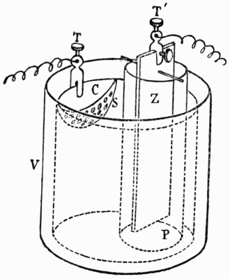
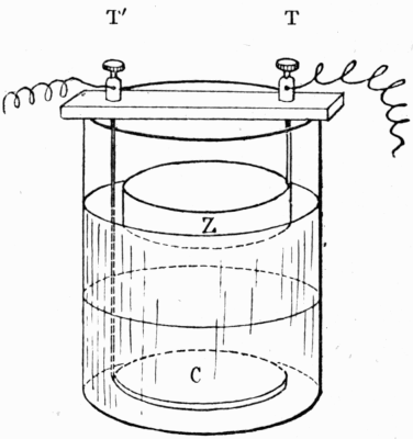


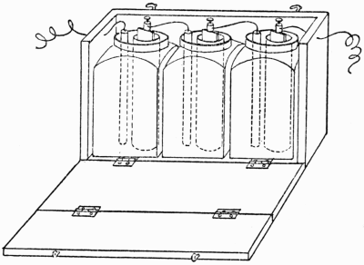


")
")


")


 in action")


![[cover image]](images/i_cover.png)