The Project Gutenberg EBook of An Introduction to Machine Drawing and
Design, by David Allan Low

This eBook is for the use of anyone anywhere at no cost and with
almost no restrictions whatsoever.  You may copy it, give it away or
re-use it under the terms of the Project Gutenberg License included
with this eBook or online at www.gutenberg.org


Title: An Introduction to Machine Drawing and Design

Author: David Allan Low

Release Date: March 4, 2012 [EBook #39033]

Language: English

Character set encoding: ISO-8859-1

*** START OF THIS PROJECT GUTENBERG EBOOK AN INTRODUCTION TO MACHINE ***


Produced by Juliet Sutherland and the Online Distributed
Proofreading Team at http://www.pgdp.net
(WHITWORTH SCHOLAR), M. INST. M.E.
HEAD MASTER OF THE PEOPLE'S PALACE TECHNICAL SCHOOLS, LONDON
AUTHOR OF 'A TEXT-BOOK ON PRACTICAL SOLID OR DESCRIPTIVE GEOMETRY'
'AN ELEMENTARY TEXT-BOOK OF APPLIED MECHANICS' ETC.
PRINTED BY
SPOTTISWOODE AND CO., NEW-STREET SQUARE
LONDON
It is now generally recognised that the old-fashioned method of teaching machine drawing is very unsatisfactory. In teaching by this method an undimensioned scale drawing, often of a very elaborate description, is placed before the student, who is required to copy it. Very often the student succeeds in making a good copy of the drawing placed before him without learning very much about the object represented by it, and this state of matters is sometimes not much improved by the presence of the teacher, who is often simply an art master, knowing nothing about machine design. It is related of one school that a pupil, after making a copy of a particular drawing, had a discussion with his teacher as to whether the object represented was a sewing machine or an electrical machine. Evidently the publisher of the drawing example in this case did not adopt the precaution which a backward student used at an examination in machine design: he put on a full title above his drawing, for the information of his examiner.
Now, if machine drawing is to be of practical use to any one, he must be able to understand the form and arrangement of the parts of a machine from an inspection of suitable drawings of them without seeing the parts themselves. Also he ought to be able to make suitable drawings of a machine or parts of a machine from the machine or the parts themselves.[Pg iv]
In producing this work the author has aimed at placing before young engineers and others, who wish to acquire the skill and knowledge necessary for making the simpler working drawings such as are produced in engineers' drawing offices, a number of good exercises in drawing, sufficient for one session's work, and at the same time a corresponding amount of information on the design of machine details generally.
The exercises set are of various kinds. In the first and simplest certain views of some machine detail are given, generally drawn to a small scale, which the student is asked to reproduce to dimensions marked on these views, and he is expected to keep to these dimensions, and not to measure anything from the given illustrations. In the second kind of exercise the student is asked to reproduce certain views shown to dimensions given in words or in tabular form. In the third kind of exercise the student is required to make, in addition to certain views shown to given dimensions, others which he can only draw correctly if he thoroughly understands the design before him. In the fourth kind of exercise the student is asked to make the necessary working drawings for some part of a machine which has been previously described and illustrated, the dimensions to be calculated by rules given in the text.
The illustrations for this work are all new, and have been specially prepared by the author from working drawings, and he believes that they will be found to represent the best modern practice.
As exercises in drawing, those given in this book are not numbered exactly in their order of difficulty, but unless on the recommendation of a teacher, the student should take them up in the order given, omitting the following:—26, 27, 28, 35, 40, 42, 43, 45, 49, 50, 54, 60, 61, as he comes to them, until he has been right through the book; afterwards he should work out those which he omitted on first going over the book.
In addition to the exercises given in this work the student should practise making freehand sketches of machine details from actual machines or good models of them. Upon these sketches he should put the proper dimensions, got by direct measurement from the machine or model by himself. These sketches should be made in a note-book kept for the purpose, and no opportunity should be lost of inserting a sketch of any design which may be new to the student, always putting on the dimensions if possible. These sketches form excellent examples from which to make working drawings. The student should also note any rules which he may meet with for proportioning machines, taking care, however, in each case to state the source of such information for his future guidance and reference.
As machine drawing is simply the application of the principles of descriptive geometry to the representation of machines, the student of the former subject, if he is not already acquainted with the latter, should commence to study it at once.
D. A. L.
Glasgow: March 1887.
To this edition another chapter has been added, containing a number of miscellaneous exercises, which it is hoped will add to the usefulness of the work as a text-book in science classes. The latest examination paper in machine drawing by the Science and Art Department has also been added to the Appendix.
D. A. L.
London: August 1888.
| PAGE | ||
| I. | INTRODUCTION | 1 |
| II. | RIVETED JOINTS | 6 |
| III. | SCREWS, BOLTS, AND NUTS | 14 |
| IV. | KEYS | 22 |
| V. | SHAFTING | 24 |
| VI. | SHAFT COUPLINGS | 25 |
| VII. | BEARINGS FOR SHAFTS | 30 |
| VIII. | PULLEYS | 36 |
| IX. | TOOTHED WHEELS | 39 |
| X. | CRANKS AND CRANKED SHAFTS | 43 |
| XI. | ECCENTRICS | 47 |
| XII. | CONNECTING RODS | 49 |
| XIII. | CROSS-HEADS | 56 |
| XIV. | PISTONS | 57 |
| XV. | STUFFING-BOXES | 63 |
| XVI. | VALVES | 68 |
| XVII. | MATERIALS USED IN MACHINE CONSTRUCTION | 76 |
| XVIII. | MISCELLANEOUS EXERCISES | 81 |
| APPENDIX A | 99 | |
| APPENDIX B | 102 | |
| INDEX | 113 |
Drawing Instruments.—For working the exercises in this book the student should be provided with the following:—A well-seasoned yellow pine drawing-board, 24 inches long, 17 inches wide, and 3⁄8 inch or 1⁄2 inch thick, provided with cross-bars on the back to give it strength and to prevent warping. A T square, with a blade 24 inches long attached permanently to the stock, but not sunk into it. One 45° and one 60° set square. The short edges of the former may be about 6 inches and the short edge of the latter about 5 inches long. A pair of compasses with pen and pencil attachments, and having legs from 5 inches to 6 inches long. A pair of dividers, with screw adjustment if possible. A pair of small steel spring pencil bows for drawing small circles, and a pair of small steel spring pen bows for inking in the same. A drawing pen for inking in straight lines. All compasses should have round points, and if possible needle points. A piece of india-rubber will also be required, besides two pencils, one marked H or HH and one marked HB or F; the latter to be used for lining in a drawing which is not to be inked in, or for freehand work.
Pencils for mechanical drawing should be sharpened with a chisel point, and those for freehand work with a round point.[Pg 2] Do not wet the pencil, as the lines afterwards made with it are very difficult to rub out.
Drawing-paper for working drawings may be secured to the board by drawing-pins, but the paper for finished drawings or drawings upon which there is to be a large amount of colouring should be stretched upon the board.
The student should get the best instruments he can afford to buy, and he should rather have a few good instruments than a large box of inferior ones.
Drawing-paper.—The names and sizes of the sheets of drawing paper are given in the following table:—
| Inches | |
| Demy | 20 × 15 |
| Medium | 22 × 17 |
| Royal | 24 × 19 |
| Imperial | 30 × 22 |
| Atlas | 34 × 26 |
| Double Elephant | 40 × 27 |
| Antiquarian | 52 × 31 |
The above sizes must not be taken as exact. In practice they will be found to vary in some cases as much as an inch.
Cartridge-paper is made in sheets of various sizes, and also in rolls.
Hand-made paper is the best, but it is expensive. Good cartridge-paper is quite suitable for ordinary drawings.
Centre Lines.—Drawings of most parts of machines will be found to be symmetrical about certain lines called centre lines. These lines should be drawn first with great care. On a pencil drawing centre lines should be thin continuous lines; in this book they are shown thus — - — - —.
After drawing the centre line of any part the dimensions of that part must be marked off from the centre line, so as to insure that it really is the centre line of that part: thus in making a drawing of a rivet, such as is shown at (a) fig. 1, after drawing the centre line, half the diameter of the rivet would be marked off on each side of that line, in order to determine the lines for the sides of the rivet.
Inking.—For inking in drawings the best Indian ink should be used, and not common writing ink. Common ink[Pg 3] does not dry quick enough, and rapidly corrodes the drawing pens. The pen should be filled by means of a brush or a narrow strip of paper, and not by dipping the pen into the ink.
In cases where there are straight lines and arcs of circles touching one another ink in the arcs first, then the straight lines; in this way it is easier to hide the joints.
Colouring.—Camel's-hair or sable brushes should be used; the latter are the best, but are much more expensive than the former. The colour should be rubbed down in a dish, and the tint should be light. The mistake which a beginner invariably makes is in having the colour of too dark a tint.
First go over the part to be coloured with the brush and clean water for the purpose of damping it. Next dry with clean blotting-paper to take off any superfluous water. Then take another brush with the colour, and beginning at the top, work from left to right and downwards. If it is necessary to recolour any part let the first coating dry before beginning.
Engineers have adopted certain colours to represent particular materials; these are given in the following table:—
Table showing Colours used to represent Different Materials.
| Material | Colour |
| Cast iron | Payne's grey or neutral tint. |
| Wrought iron | Prussian blue. |
| Steel | Purple (mixture of Prussian blue and crimson lake). |
| Brass | Gamboge with a little sienna or a very little red added. |
| Copper | A mixture of crimson lake and gamboge, the former colour predominating. |
| Lead | Light Indian ink with a very little indigo added. |
| Brickwork | Crimson lake and burnt sienna. |
| Firebrick | Yellow and Vandyke brown. |
| Greystones | Light sepia or pale Indian ink, with a little Prussian blue added. |
| Brown freestone | Mixture of pale Indian ink, burnt sienna, and carmine. |
| Soft woods | For ground work, pale tint of sienna. |
| Hard woods | For ground work, pale tint of sienna with a little red added. |
| For graining woods use darker tint with a greater proportion of red. |
Printing.—A good drawing should have its title printed, a plain style of letter being used for this purpose, such as the following:—
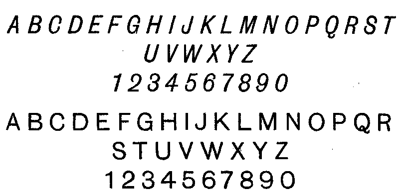
The following letters look well if they are well made, but they are much more difficult to draw.

For remarks on a drawing the following style is most suitable:—

All printing should be done by freehand.
Border lines are seldom put on engineering drawings.
Working Drawings.—A good working drawing should be prepared in the following manner. It must first be carefully outlined in pencil and then inked in. After this all parts cut by planes of section should be coloured, the colours used indicating the materials of which the parts are made. Parts which are round may also be lightly shaded with the brush and colours to suit the materials. The centre lines are now inked in with red or blue ink. The red ink may be prepared by rubbing down the cake of crimson lake, and the blue ink[Pg 5] in like manner from the cake of Prussian blue. Next come the distance or dimension lines, which should be put in with blue or red ink, depending on which colour was used for the centre lines. Dimension lines and centre lines are best put in of different colour. The arrow-heads at the ends of the dimension lines are now put in with black ink, and so are the figures for the dimensions. The arrow-heads and the figures should be made with a common writing pen. The dimensions should be put on neatly. Many a good drawing has its appearance spoiled through being slovenly dimensioned.
We may here point out the importance of putting the dimensions on a working drawing. If the drawing is not dimensioned, the workman must get his sizes from the drawing by applying his rule or a suitable scale. Now this operation takes time, and is very liable to result in error. Time is therefore saved, and the chance of error reduced, by marking the sizes in figures.
In practice it is not usual to send original drawings from the drawing office to the workshop, but copies only. The copies may be produced by various 'processes,' or they may be tracings drawn by hand. Many engineers do not ink in their original drawings, but leave them in pencil; especially is this the case if the drawings are not likely to be much used.
Scales.—The best scales are made of ivory, and are twelve inches long. Boxwood scales are much cheaper, although not so durable as those made of ivory. If the student does not care to go to the expense of ivory or boxwood scales, he can get paper ones very cheap, which will be quite sufficient for his purpose. The divisions of the scale should be marked down to its edge, so that measurements may be made by applying the scale directly to the drawing. For working such exercises as are in this book the student should be provided with the following scales:—
| A scale of | 1, | or | 12 | inches to a foot. | |
| ” | 1⁄2 | ” | 6 | ” | |
| ” | 1⁄3 | ” | 4 | ” | |
| ” | 1⁄4 | ” | 3 | ” | |
| ” | 1⁄6 | ” | 2 | ” |
A scale of 1 is spoken of as 'full size,' and a scale of 1⁄2 as 'half size.'
Engineers in this country state dimensions of machines in feet, inches, and fractions of an inch, the latter being the 1⁄2, 1⁄4, 1⁄8, 1⁄16, &c. In making calculations it is generally more convenient to use decimal fractions, and then substitute for the results the equivalent fractions in eighths, sixteenths, &c. The following table will be found useful for this purpose:—
Decimal Equivalents of Fractions of an Inch.
| Fraction | Decimal Equivalent | Fraction | Decimal Equivalent |
|---|---|---|---|
| 1⁄32 | ·03125 | 17⁄32 | ·53125 |
| 1⁄16 | ·0625 | 9⁄16 | ·5625 |
| 3⁄32 | ·09375 | 19⁄32 | ·59375 |
| 1⁄8 | ·125 | 5⁄8 | ·625 |
| 5⁄32 | ·15625 | 21⁄32 | ·65625 |
| 3⁄16 | ·1875 | 11⁄16 | ·6875 |
| 7⁄32 | ·21875 | 23⁄32 | ·71875 |
| 1⁄4 | ·25 | 3⁄4 | ·75 |
| 9⁄32 | ·28125 | 25⁄32 | ·78125 |
| 5⁄16 | ·3125 | 13⁄16 | ·8125 |
| 11⁄32 | ·34375 | 27⁄32 | ·84375 |
| 3⁄8 | ·375 | 7⁄8 | ·875 |
| 13⁄32 | ·40625 | 29⁄32 | ·90625 |
| 7⁄16 | ·4375 | 15⁄16 | ·9375 |
| 15⁄32 | ·46875 | 31⁄32 | ·96875 |
| 1⁄2 | ·5 | 1 | 1·0 |
Engineers use a single accent (´) to denote feet, and a double accent (´´) to denote inches. Thus 2´ 9´´ reads two feet nine inches.
Two plates or pieces to be riveted together have holes punched or drilled in them in such a manner that one may be made to overlap the other so that the holes in the one may be opposite the holes in the other. The rivets, which are round bars of iron, or steel, or other metal, are heated to redness and inserted in the holes; the head already formed on the rivet, and called the tail, is then held up, and the point is hammered or pressed so as to form another head. This process of[Pg 7] forming the second head on the rivet is known as riveting, and may be done by hand-hammering or by a machine.
Forms of Rivet Heads.—In fig. 1 are shown four different forms of rivet heads: (a) is a snap head, (b) a conical head (c) a pan head, and (d) a countersunk head.
Proportions of Rivet Heads.—The diameter of the snap head is about 1·7 times the diameter of the rivet, and its height about ·6 of the diameter of the rivet. The conical head has a diameter twice and a height three quarters of the rivet diameter. The greatest diameter of the pan head is about 1·6, and its height ·7 of the rivet diameter. The greatest diameter of the countersunk head may be one and a half, and its depth a half of the diameter of the rivet.
 Fig. 1.
In fig. 1 at (a) and (b) are shown geometrical constructions devised by the author for drawing the snap and conical head for any size of rivet, the proportions being nearly the same as those given above.
Geometrical Construction for Proportioning Snap Heads.—With centre A, and radius equal to half diameter of rivet, describe a circle cutting the centre line of the rivet at B and C. With centre B and radius BC describe the arc CD. Make BE equal to AD. With centre E and radius ED describe the arc DFH.
Construction for Conical Head.—With centre K, and radius equal to diameter of rivet, describe the semicircle LMN, cutting the side of the rivet at M. With centre M and radius MN[Pg 8] describe the arc NP to cut the centre line of rivet at P. Join PL and PN.
When a number of rivets of the same diameter have to be shown on the same drawing the above constructions need only be performed on one rivet. After the point E has been discovered the distance AE may be measured off on all the other rivets, and the arcs corresponding to DFH drawn with radii equal to ED. In like manner the height KP of the conical head may be marked off on all rivets of the same diameter with conical heads.
Caulking.—In order to make riveted joints steam- or water-tight the edges of the plates and the edges of the heads of the rivets are burred down by a blunt chisel or caulking tool as shown at Q and R.
 Fig. 2.
 Fig. 3.
Exercise 1: Forms of Rivets.—Draw, full size, the rivets and rivet heads shown in fig. 1. The diameter of the rivet in each case to be 11⁄8 inches, and the thickness of the plates 7⁄8 inch.
Exercise 2: Single Riveted Lap Joint.—Draw, full size, the[Pg 9] plan and sectional elevation of the single riveted lap joint shown in fig. 2.
Table showing the Proportions of Single Riveted Lap Joints for various Thicknesses of Plates. (Plates and Rivets Wrought Iron.)
| Thickness of plates | 1⁄4 | 5⁄16 | 3⁄8 | 7⁄16 | 1⁄2 | 9⁄16 | 5⁄8 | 11⁄16 | 3⁄4 |
|---|---|---|---|---|---|---|---|---|---|
| Diameter of rivets | 9⁄16 | 5⁄8 | 11⁄16 | 3⁄4 | 13⁄16 | 7⁄8 | 15⁄16 | 1 | 11⁄16 |
| Pitch of rivets | 15⁄8 | 1¾ | 17⁄8 | 2 | 21⁄8 | 2¼ | 25⁄16 | 23⁄8 | 2½ |
| Width of lap | 1¾ | 2 | 2¼ | 2½ | 2¾ | 27⁄8 | 3 | 31⁄8 | 3¼ |
All the dimensions are in inches.
 Fig. 4.
Exercise 3.—Draw, half size, a plan and section of a single riveted lap joint for plates 3⁄4´´ thick to the dimensions given in the above table.
Exercise 4: Double Riveted Lap Joint.—Draw, full size, the two views of the double riveted lap joint shown in fig. 3.
Table showing the Proportions of Double Riveted Lap Joints for various Thicknesses of Plates. (Plates and Rivets Wrought Iron.)
| Thickness of plates | 3⁄8 | 7⁄16 | 1⁄2 | 9⁄16 | 5⁄8 | 11⁄16 | 3⁄4 | 13⁄16 | 7⁄8 | 15⁄16 | 1 |
|---|---|---|---|---|---|---|---|---|---|---|---|
| Diameter of rivets | 11⁄16 | 3⁄4 | 13⁄16 | 7⁄8 | 15⁄16 | 1 | 11⁄16 | 11⁄16 | 11⁄8 | 11⁄8 | 13⁄16 |
| Pitch of rivets | 2½ | 25⁄8 | 2¾ | 27⁄8 | 3 | 31⁄8 | 3¼ | 33⁄8 | 3½ | 35⁄8 | 3¾ |
| Distance between rows of rivets | 11⁄8 | 1¼ | 13⁄8 | 17⁄16 | 19⁄16 | 1¾ | 17⁄8 | 17⁄8 | 115⁄16 | 115⁄16 | 2 |
| Width of lap | 3½ | 3¾ | 4 | 4¼ | 4½ | 4¾ | 5 | 5 | 5¼ | 5¼ | 5½ |
 Fig. 5.
Exercise 5.—Draw, half size, a plan and section of a double riveted lap joint for plates 7⁄8 inch thick to the dimensions given in the above table.
Exercise 6: Single Riveted Butt Joints.—In fig. 4 are shown single riveted butt joints. One of the sectional views shows a butt joint with one cover plate or butt strap; the other sectional view[Pg 11] shows the same joint with two cover plates; the third view is a plan of both arrangements. Draw all these views full size.
 Fig. 6.
Exercise 7.—Fig. 5 shows a plan and sectional elevation of the connection of three plates together, which are in the same plane, by means of single riveted butt joints and single cover plates. The butt straps where they overlap are forged so as to fit one another as shown, and thus form a close joint. Draw these views to the scale of 6 inches to a foot.
The plates are 1⁄2 inch thick and the butt straps 9⁄16 inch thick. All other dimensions must be deduced from the table for single riveted lap joints.
Exercise 8.—The connection of three plates by single riveted lap joints is shown in fig. 6. To make the joint close one plate has a portion of its edge thinned out, and the plate above it is set up at this part so as to lie close to the former.
Draw the three views shown in fig. 6 to the same scale as the last exercise.
The plates are 7⁄16 inch thick. All other dimensions to be obtained from table for single riveted lap joints.
Exercise 9: Corner of Wrought-iron Tank.—This exercise is to illustrate the connection of plates which are at right angles to one another by means of angle irons. Fig. 7 is a plan and elevation of the corner of a wrought-iron tank. The sides of the tank are riveted to a vertical angle iron, the cross section of which is clearly shown in the plan. Another angle iron of the same dimensions is used in the same way to connect the sides with the bottom. The sides do not come quite up to the corner of the vertical angle iron, excepting at the bottom where the horizontal angle iron comes in. At this point the vertical plates meet one another, and the edge formed is rounded over to fit the interior of the bend of the horizontal angle iron so as to make the joint tight. Draw half size.
The dimensions are as follows: angle irons 2½ inches × 2½ inches × 3⁄8 inch; plates 3⁄8 inch thick; rivets 11⁄16 inch diameter and 2 inches pitch.
Exercise 10: Gusset Stay.—In order that the flat ends of a steam boiler may not be bulged out by the pressure of the steam they are strengthened by means of stays. One form of boiler stay, called a 'gusset stay,' is shown in fig. 8. This stay consists of a strip of wrought-iron plate which passes in a diagonal direction from the flat end of the boiler to the cylindrical shell. One end of this plate is placed between and riveted to two angle irons which are riveted to the shell of the boiler. A similar arrangement connects the other end of the stay plate to the flat end of the boiler. In this example the stay or gusset plate is ¾ of an inch thick; the angle irons are 4 inches broad and ½ inch thick. The rivets are 1 inch in diameter. The same figure also illustrates the most common method of connecting the ends of a boiler to the shell. The end plates are flanged or bent over at right angles and riveted to the shell as shown. The radius of the inside curve at the angle of the flange is 1¼ inches. Draw this example to a scale of 3 inches to 1 foot.
 Fig. 7.
 Fig. 8.
Screw Threads.—The various forms of screw threads used in machine construction are shown in fig. 9. The Whitworth V thread is shown at (a). This is the standard form of triangular thread used in this country. The angle between the sides of the V is 55°, and one-sixth of the total depth is rounded off both at the top and bottom. At (b) is shown the Sellers V thread, which is the standard triangular thread used by engineers in America. In this form of thread the angle between the sides of the V is 60°, and one-eighth of the total depth is cut square off at the top and bottom. The Square thread is shown at (c). This form is principally used for transmitting motion.
 Fig. 9.
Comparing the triangular and square threads, the former is the stronger of the two; but owing to the normal pressure on the V thread being inclined to the axis of the screw, that pressure must be greater than the pressure which is being transmitted by the screw; and therefore, seeing that the normal pressure on the square thread is parallel, and therefore equal to the pressure transmitted in the direction of the axis of the screw, the friction of the V thread must be greater than the [Pg 15]friction of the square thread. In the case of the triangular thread there is also a tendency of the pressure to burst the nut. The Buttress thread shown at (e) is designed to combine the advantages of the V and square threads, but it only has these advantages when the pressure is transmitted in one direction; if the direction of the pressure be reversed, the friction and bursting action on the nut are even greater than with the V thread, because of the greater inclination of the slant side of the buttress thread. The angles of the square thread are frequently rounded to a greater or less extent to render them less easily damaged. If this rounding is carried to excess we get the Knuckle thread shown at (d). The rounding of the angles increases both the strength and the friction.
Exercise 11: Forms of Screw Threads.—Draw to a scale of three times full size the sections of screw threads as shown in fig. 9. The pitch for the Whitworth, Sellers, and buttress threads to be 3⁄8 inch, and the pitch of the square and knuckle threads to be 1⁄2 inch.
Dimensions of Whitworth Screws.
| Diameter of screw |
Number of threads per inch |
Diameter at bottom of thread |
Diameter of screw |
Number of threads per inch |
Diameter at bottom of thread |
Diameter of screw |
Number of threads per inch |
Diameter at bottom of thread |
|---|---|---|---|---|---|---|---|---|
| 1⁄8 | 40 | ·093 | 1¼ | 7 | 1·067 | 3½ | 3¼ | 3·106 |
| 3⁄16 | 24 | ·134 | 13⁄8 | 6 | 1·162 | 3¾ | 3 | 3·323 |
| 1⁄4 | 20 | ·186 | 1½ | 6 | 1·286 | 4 | 3 | 3·573 |
| 5⁄16 | 18 | ·241 | 15⁄8 | 5 | 1·369 | 4¼ | 27⁄8 | 3·805 |
| 3⁄8 | 16 | ·295 | 1¾ | 5 | 1·494 | 4½ | 27⁄8 | 4·055 |
| 7⁄16 | 14 | ·346 | 17⁄8 | 4½ | 1·590 | 4¾ | 2¾ | 4·284 |
| 1⁄2 | 12 | ·393 | 2 | 4½ | 1·715 | 5 | 2¾ | 4·534 |
| 5⁄8 | 11 | ·508 | 2¼ | 4 | 1·930 | 5¼ | 25⁄8 | 4·762 |
| 3⁄4 | 10 | ·622 | 2½ | 4 | 2·180 | 5½ | 25⁄8 | 5·012 |
| 7⁄8 | 9 | ·733 | 2¾ | 3½ | 2·384 | 5¾ | 2½ | 5·238 |
| 1 | 8 | ·840 | 3 | 3½ | 2·634 | 6 | 2½ | 5·488 |
| 11⁄8 | 7 | ·942 | 3¼ | 3¼ | 2·856 | |||
Gas Threads[1] (Whitworth Standard).
| Diameter of Screw | 1⁄8 | 1⁄4 | 3⁄8 | 1⁄2 | 5⁄8 | 3⁄4 | 1 | 1¼ | 1½ | 1¾ | 2 |
|---|---|---|---|---|---|---|---|---|---|---|---|
| Number of threads per inch | 28 | 19 | 19 | 14 | 14 | 14 | 11 | 11 | 11 | 11 | 11 |
Representation of Screws.—The correct method of representing screw threads involves considerable trouble, and is seldom adopted by engineers for working drawings. For an explanation of the method see the author's Text-book on Practical Solid Geometry, Part II., problem 134. A method very often adopted on working drawings is shown in fig. 15; here the thin lines represent the points, and the thick lines the roots of the threads. At fig. 16 is shown a more complete method. The simplest method is illustrated by figs. 10, 11, 13, and 14.
Here dotted lines are drawn parallel to the axis of the screw as far as it extends, and at a distance from one another equal to the diameter of the screw at the bottom of the thread.

| Fig. 10. | Fig. 11. |
Forms of Nuts.—The most common form of nut is the hexagonal shown in figs. 10, 13, 14, 15, and 16; next to this comes the square nut shown in fig. 11. The method of drawing these nuts will be understood by reference to the figures; the small circles indicate the centres, and the inclined lines passing through them the radii of the curves which represent the chamfered or bevelled edge of the nut. In all the figures but[Pg 17] the first the chamfer is just sufficient to touch the middle points of the sides, and in these cases the drawing of the nut is simpler.
 Fig. 12.

| Fig. 13. | Fig. 14. |
Forms of Bolts.—At (a), fig. 12, is shown a bolt with a square head and a square neck. If this form of bolt is passed through a square hole the square neck prevents the bolt from turning when the nut is being screwed up. Instead of a square neck a snug may be used for the same purpose, as shown on the cup-headed bolt at (b). The snug fits into a short groove cut in the side of the hole through which the bolt[Pg 18] passes. At (a) the diagonal lines are used to distinguish the flat side of the neck from the round part of the bolt above it. At (c) is shown a tee-headed bolt, and at (d) an eye-bolt. Fig. 13 represents a hook bolt. A bolt with a countersunk head is shown in fig. 11. If the countersunk head be lengthened so as to take up the whole of the unscrewed part of the bolt, we get the taper bolt shown in fig. 14, which is often used in the couplings of the screw shafts of steamships. The taper bolt has the advantage of having no projecting head, and it may also be made a tight fit in the hole with less trouble than a parallel bolt. Bolts may also have hexagonal heads.
 Fig. 15.
 Fig. 16.
Studs, or stud bolts, are shown in figs. 15 and 16; that in fig. 15 is a plain stud, while that in fig. 16 has an intermediate collar forged upon it, and is therefore called a collared stud.
Proportions of Nuts and Bolt-heads.—In the hexagonal nut the diameter D across the flats is 1½d + 1⁄8, where d is the diameter of the bolt. The same rule gives the width of a square nut across the flats. A rule very commonly used in making drawings of hexagonal nuts is to make the diameter D, across the angles equal to 2d. H, the height of the nut, is equal to the diameter of the bolt. In square and hexagonal headed bolts the height of the head varies from d to 2⁄3d; the other dimensions are the same as for the corresponding nuts.[Pg 19]
Washers are flat, circular, wrought-iron plates, having holes in their centres of the same diameter as the bolts on which they are used. The object of the washer is to give a smooth bearing surface for the nut to turn upon, and it is used when the surfaces of the pieces to be connected are rough, or when the bolt passes through a hole larger than itself, as shown in fig. 10. The diameter of the washer is a little more than the diameter of the nut across the angles, and its thickness about 1⁄8 of the diameter of the bolt.
Exercise 12.—Draw, full size, the views shown in fig. 10 of an hexagonal nut and washer for a bolt 1¼ inches in diameter. The bolt passes through a hole 1¾ × 1¼. All the dimensions are to be calculated from the rules which have just been given.
Exercise 13.—Draw, full size, the plan and elevation of the square nut and bolt with countersunk head shown in fig. 11, to the dimensions given.
Exercise 14.—Draw, full size, the elevation of the hook bolt with hexagonal nut shown in fig. 13 to the dimensions given, and show also a plan.
Exercise 15.—Draw, to a scale of 4 inches to a foot, the conical bolt for a marine shaft coupling shown in fig. 14. All the parts are of wrought iron.
Exercise 16.—Fig. 15 is a section of the mouth of a small steam-engine cylinder, showing how the cover is attached; draw this full size.
Exercise 17.—Fig. 16 shows the central portion of the india-rubber disc valve which is described on page 68. A is the central boss of the grating, into which is screwed the stud B, upon which is forged the collar C. The upper part of the stud is screwed, and carries the guard D and an hexagonal nut E. F is the india-rubber. The grating and guard are of brass. The stud and nut are of wrought iron. Draw full size the view shown.
Lock Nuts.—In order that a nut may turn freely upon a bolt, there is always a very small clearance space between the threads of the nut and those of the bolt. This clearance is shown exaggerated at (a), fig. 17, where A is a portion of a bolt within a nut B. Suppose that the bolt is stretched by a force W. When the nut B is screwed up, the upper surfaces of the projecting threads of the nut will press on the under surfaces[Pg 20] of the threads of the bolt with a force P equal and opposite to W, as shown at (b), fig. 17. When in this condition the nut has no tendency to slacken back, because of the friction due to the pressure on the nut. Now suppose that the tension W on the bolt is momentarily diminished, then the friction which opposes the turning of the nut may be so much diminished that a vibration may cause it to slacken back through a small angle. If this is repeated a great many times the nut may slacken back so far as to become useless.

| Fig. 17. | Fig. 18. |
 Fig. 19.
A very common arrangement for locking a nut is shown at (a), fig. 18. C is an ordinary nut, and B one having half the thickness of C. B is first screwed up tight so as to act on the bolt, as shown at (b), fig. 17. C is then screwed on top of B. When C is almost as tight as it can be made, it is held by one spanner, while B is turned back through a small angle with another. The action of the nuts upon the bolt and upon one another is now as shown at (b), fig. 18. It will be seen that the nuts are wedged tight on to the bolt, and that this action is independent of the tension W in the bolt. The nuts will, therefore, remain tight after the tension in the bolt is removed.
It is evident that if the nuts are screwed up in the manner explained, the outer nut C will carry the whole load on the bolt; hence C should be the thicker of the two nuts. In practice, the thin nut, called the lock nut, is often placed on the outside, for the reason that ordinary spanners are too thick to act on the thin nut when placed under the other.[Pg 21]
Another very common arrangement for locking a nut is shown in fig. 19. A is the bolt and B the nut, the lower part of which is turned circular. A groove C is also turned on the nut at this part. The circular part of the nut fits into a circular recess in one of the parts connected by the bolt. Through this part passes a set screw D, the point of which can be made to press on the nut at the bottom of the groove C. D is turned back when the nut B is being moved, and when B is tightened up, the set screw is screwed up so as to press hard on the bottom of the groove C. The nut B is thus prevented from slackening back. The screw thread is turned off the set screw at the point where it enters the groove on the nut.
The use of the groove for receiving the point of the set screw is this: The point of the set screw indents the nut and raises a bur which would interfere with the free turning of the nut in the recess if the bur was not at the bottom of a groove. Additional security is obtained by drilling a hole through the point of the bolt, and fitting it with a split pin E.
Locking arrangements for nuts are exceedingly numerous, and many of them are very ingenious, but want of space prevents us describing them. We may point out, however, that many very good locking arrangements have the defect of only locking the nut at certain points of a revolution, say at every 30°. It will be noticed that the two arrangements which we have described are not open to this objection.[Pg 22]
Exercise 18.—Draw, full size, a plan, front elevation, and side elevation of the arrangement of nuts shown in fig. 18, for a bolt 7⁄8 inch diameter.
Exercise 19.—Draw the plan and elevation of the nut and locking arrangement shown in fig. 19. Make also an elevation looking in the direction of the arrow. Scale 6 inches to a foot.
Keys are wedges, generally rectangular in section, but sometimes circular; they are made of wrought iron or steel, and are used for securing wheels, pulleys, cranks, &c., to shafts.
 Fig. 20.
Various sections of keys are shown in fig. 20. At (a) is the hollow or saddle key. With this form of key it is not necessary to cut the shaft in any way, but its holding power is small, and it is therefore only used for light work. At (b) is the key on a flat, sometimes called a flat key. The holding power of this key is much greater than that of the saddle key. At (c) is the sunk key, a very secure and very common form.
The part of the shaft upon which a key rests is called the key bed or key way, and the recess in the boss of the wheel or pulley into which the key fits is called the key way; both are also called key seats. With saddle, flat, and sunk keys the key bed is parallel to the axis of the shaft; but the key way is[Pg 23] deeper at one end than the other to accommodate the taper of the key. The sides of the key are parallel.
The round key or taper pin shown at (d) is in general only used for wheels or cranks which have been previously shrunk on to their shafts or forced on by great pressure. After the wheel or crank has been shrunk on, a hole is drilled, half into the shaft and half into the wheel or crank, to receive the pin.
When the point of a key is inaccessible the other end is provided with a gib head as shown at (e), to enable the key to be withdrawn.
A sliding or feather key secures a piece to a shaft so far as to prevent the one from rotating without the other, but allows of relative motion in the direction of the axis of the shaft. This form of key has no taper, and it is secured to the piece carried by the shaft, but is made a sliding fit in the key way of the shaft. In one form of feather key the part within the piece carried by the shaft is dovetailed as shown at (f). In another form the key has a round projecting pin forged upon it, which enters a corresponding hole as shown at (g). The feather key may also be secured to the piece carried by the shaft by means of one or more screws as shown at (h). The key way in the shaft is made long enough to permit of the necessary sliding motion.
Cone Keys.—These are sometimes fitted to pulleys, and are shown in fig. 32, page 38. In this case the eye of the pulley is tapered and is larger than the shaft. The space between the shaft and the boss of the pulley is filled with three saddle or cone keys. These keys are made of cast iron and are all cast together, and before being divided the casting is bored to fit the shaft and turned to fit the eye of the pulley. By this arrangement of keys the same pulley may be fixed on shafts of different diameters by using keys of different thicknesses; also the pulley may be bored out large enough to pass over any boss which may be forged on the shaft.
Proportions of Keys.—The following rules are taken from Unwin's 'Machine Design,' pp. 142-43.[Pg 24]
| Diameter of eye of wheel, or boss of shaft | = d. |
| Width of key | = 3⁄4d + 1⁄8. |
| Mean thickness of sunk key | = 1⁄8d + 1⁄8. |
| ” key on flat | = 1⁄16d + 1⁄16. |
The following table gives dimensions agreeing with average practice.
Dimensions of Keys.
| D | = | diameter of shaft. |
| B | = | breadth of key. |
| T | = | thickness of sunk key. |
| T1 | = | thickness of flat key, also = thickness of saddle key. Taper of key 1⁄8 inch per foot of length, i.e. 1 in 96. |
| D | ¾ | 1 | 1¼ | 1½ | 1¾ | 2 | 2¼ | 2½ | 2¾ | 3 | 3½ |
|---|---|---|---|---|---|---|---|---|---|---|---|
| B | 5⁄16 | 3⁄8 | 7⁄16 | 1⁄2 | 9⁄16 | 5⁄8 | 11⁄16 | 11⁄16 | 3⁄4 | 7⁄8 | 1 |
| T | 1⁄4 | 1⁄4 | 1⁄4 | 5⁄16 | 5⁄16 | 5⁄16 | 3⁄8 | 3⁄8 | 3⁄8 | 7⁄16 | 1⁄2 |
| T1 | 3⁄16 | 3⁄16 | 3⁄16 | 3⁄16 | 1⁄4 | 1⁄4 | 1⁄4 | 5⁄16 | 5⁄16 | 5⁄16 | 3⁄8 |
| D | 4 | 4½ | 5 | 5½ | 6 | 7 | 8 | 9 | 10 | 11 | 12 |
|---|---|---|---|---|---|---|---|---|---|---|---|
| B | 11⁄8 | 11⁄4 | 13⁄8 | 11⁄2 | 15⁄8 | 17⁄8 | 21⁄8 | 23⁄8 | 25⁄8 | 27⁄8 | 31⁄8 |
| T | 1⁄2 | 9⁄16 | 5⁄8 | 11⁄16 | 3⁄4 | 13⁄16 | 15⁄16 | 1 | 11⁄16 | 13⁄16 | 11⁄4 |
| T1 | 7⁄16 | 1⁄2 | 1⁄2 | 9⁄16 | 5⁄8 | 11⁄16 | 3⁄4 | 7⁄8 | 15⁄16 | 11⁄16 | 11⁄8 |
Shafting is nearly always cylindrical and made of wrought iron or steel. Cast iron is rarely used for shafting.
Axles are shafts which are subjected to bending without twisting.
The parts of a shaft or axle which rest upon the bearings or supports are called journals, pivots, or collars.
In journals the supporting pressure is at right angles to the axis of the shaft, while in pivots and collars the pressure is parallel to that axis.
Shafts may be solid or hollow. Hollow shafts are stronger than solid shafts for the same weight of material. Thus a hollow shaft having an external diameter of 10¼ inches and an internal diameter of 7 inches would have about the same weight[Pg 25] as a solid shaft of the same material 7½ inches in diameter, but the former would have about double the strength of the latter. Hollow shafts are also stiffer and yield less to bending action than solid shafts, which in some cases, as in propeller shafts, is an objection.
For convenience of making and handling, shafts used for transmitting power are generally made in lengths not exceeding 30 feet. These lengths are connected by couplings, of which we give several examples.
 Figs. 21 and 22.
Solid, Box, or Muff Couplings.—One form of box coupling is shown in fig. 21. Here the ends of the shafts to be connected butt against one another, meeting at the centre of the box, which is made of cast iron. The shafts are made to rotate as[Pg 26] one by being secured to the box by two wrought-iron or steel keys, both driven from the same end of the box. A clearance space is left between the head of the forward key and the point of the hind one, to facilitate the driving of them out, as then only one key needs to be started at a time. Sometimes a single key the whole length of the box is used, in which case it is necessary that the key ways in the shafts be of exactly the same depth.
The half-lap coupling, introduced by Sir William Fairbairn, is shown in fig. 22. In this form of box coupling the ends of the shafts overlap within the box. It is evident that one shaft cannot rotate without the other as long as the box remains over the lap. To keep the box in its place it is fitted with a saddle key.
It will be noticed that the lap joint is sloped in such a way as to prevent the two lengths of shaft from being pulled asunder by forces acting in the direction of their length.
Half-lap couplings are not used for shafts above 5 inches in diameter.
It may here be pointed out that the half-lap coupling is expensive to make, and is now not much used.
As shafts are weakened by cutting key ways in them, very often the ends which carry couplings are enlarged in diameter, as shown in fig. 21, by an amount equal to the thickness of the key. An objection to this enlargement is that wheels and pulleys require either that their bosses be bored out large enough to pass over it, or that they be split into halves, which are bolted together after being placed on the shaft.
Dimensions of Box Couplings.
| D | = | diameter of shaft. |
| T | = | thickness of metal in box. |
| L | = | length of box for butt coupling. |
| L1 | = | length of box for lap coupling. |
| l | = | length of lap. |
| D1 | = | diameter of shaft at lap. |
| D | 1½ | 2 | 2½ | 3 | 3½ | 4 | 4½ | 5 | 5½ | 6 |
|---|---|---|---|---|---|---|---|---|---|---|
| T | 11⁄8 | 15⁄16 | 1½ | 1¾ | 115⁄16 | 21⁄8 | 25⁄16 | 2½ | 2¾ | 215⁄16 |
| L | 5¾ | 7 | 8¼ | 9½ | 10¾ | 12 | 13¼ | 14½ | 15¾ | 17 |
| L1 | 41⁄8 | 5¼ | 63⁄8 | 7½ | 85⁄8 | 9¾ | 107⁄8 | 12 | — | — |
| l | 71⁄16 | 17⁄8 | 25⁄16 | 2¾ | 33⁄16 | 35⁄8 | 41⁄16 | 4½ | — | — |
| D2 | 25⁄16 | 3 | 311⁄16 | 43⁄8 | 51⁄16 | 5¾ | 67⁄16 | 71⁄8 | — | — |
Slope of lap 1 in 12.

Exercise 20: Solid Butt Coupling.—From the above table of dimensions make a longitudinal and a transverse section of a solid butt coupling for a shaft 2½ inches in diameter. Scale 6 inches to a foot.
Exercise 21: Fairbairn's Half-Lap Coupling.—Make the same views as in the last exercise of a half-lap coupling for a 3-inch shaft to the dimensions in the above table. Scale 6 inches to a foot.
Flange Couplings.—The form of coupling used for the shafts of marine engines is shown in fig. 23. The ends of the different lengths of shaft have flanges forged on them, which are turned along with the shaft. These flanges butt against one another, and are connected by bolts. These bolts may be parallel or tapered; generally they are tapered. A parallel bolt must have a head, but a tapered bolt will act without one. In fig. 23 the bolts are tapered, and also provided with heads. In fig. 14, page 17, is shown a tapered bolt without a head. The variation of diameter in tapered bolts is 3⁄8 of an inch per foot of length.
Sometimes a projection is formed on the centre of one flange which fits into a corresponding recess in the centre of the other, for the purpose of ensuring the shafts being in line.[Pg 28]
Occasionally a cross-key is fitted in between the flanges, being sunk half into each, for the purpose of diminishing the shearing action on the bolts.
Exercise 22: Marine Coupling.—Draw the elevation and section of the coupling shown in fig. 23; also an elevation looking in the direction of the arrow. Scale 3 inches to a foot.
The following table gives the dimensions of a few marine couplings taken from actual practice.
Examples of Marine Couplings.
| Diameter of shaft | 23⁄8 | 9¾ | 127⁄8 | 16½ | 22½ | 23 |
|---|---|---|---|---|---|---|
| Diameter of flange | 6 | 19 | 24 | 32 | 35 | 38 |
| Thickness of flange | 1 | 2¾ | 31⁄8 | 4¼ | 6 | 5 |
| Diameter of bolts | ¾ | 2¾ | 211⁄16 | 3½ | 4¼ | 4¼ |
| Number of bolts | 3 | 6 | 6 | 8 | 9 | 8 |
| Diameter of bolt circle | 41⁄8 | 141⁄8 | 1813⁄16 | 25 | 28¾ | 303⁄8 |
All the above dimensions are in inches.
Exercise 23.—Select one of the couplings from the above table, and make the necessary working drawings for it to a suitable scale.
The cast-iron flange coupling is shown in fig. 24. In this kind of coupling a cast-iron centre or boss provided with a flange is secured to the end of each shaft by a sunk key driven from the face of the flange. These flanges are then connected by bolts and nuts as in the marine coupling.
To ensure the shafts being in line the end of one projects into the flange of the other.
In order that the face of each flange may be exactly perpendicular to the axis of the shaft they should be 'faced' in the lathe, after being keyed on to the shaft.
If the coupling is in an exposed position, where the nuts and bolt-heads would be liable to catch the clothes of workmen or an idle driving band which might come in the way, the flanges should be made thicker, and be provided with recesses for the nuts and bolt-heads.[Pg 29]
 Fig. 24.
Dimensions of Cast-iron Flange Couplings.
| Diameter of shaft D |
Diameter of flange F |
Thickness of flange T |
Diameter of boss B |
Depth at boss L |
Number of bolts |
Diameter of bolts d |
Diameter of bolt circle C |
|---|---|---|---|---|---|---|---|
| 1½ | 7¼ | 7⁄8 | 3½ | 25⁄8 | 3 | 5⁄8 | 5½ |
| 2 | 87⁄8 | 11⁄16 | 43⁄8 | 33⁄16 | 4 | 3⁄4 | 6¾ |
| 2½ | 105⁄8 | 1¼ | 55⁄16 | 3¾ | 4 | 7⁄8 | 81⁄8 |
| 3 | 123⁄8 | 17⁄16 | 6¼ | 45⁄16 | 4 | 1 | 9½ |
| 3½ | 131⁄8 | 15⁄8 | 71⁄8 | 47⁄8 | 4 | 1 | 105⁄16 |
| 4 | 14 | 1¾ | 8 | 57⁄16 | 6 | 1 | 11¼ |
| 4½ | 155⁄8 | 2 | 87⁄8 | 6 | 6 | 11⁄8 | 12½ |
| 5 | 173⁄8 | 21⁄8 | 913⁄16 | 65⁄8 | 6 | 1¼ | 1313⁄16 |
| 5½ | 18¼ | 25⁄16 | 10¾ | 7¼ | 6 | 1¼ | 14¾ |
| 6 | 197⁄8 | 2½ | 115⁄8 | 7¾ | 6 | 13⁄8 | 16 |
The projection of the shaft p varies from 1⁄4 inch in the small shafts to 1⁄2 inch in the large ones.
Exercise 24: Cast-iron Flange Coupling.—Draw the views shown in fig. 24 of a cast-iron flange coupling, for a shaft 4½ inches in diameter, to the dimensions given in the above table. Scale 4 inches to a foot.

An example of a very simple form of bearing is shown in fig. 25, which represents a brake shaft carrier of a locomotive tender. The bearing in this example is made of cast iron and in one piece. Through the oval-shaped flange two bolts pass for attaching the bearing to the wrought-iron framing of the tender. With this form of bearing there is no adjustment for wear, so that when it becomes worn it must be renewed.
Exercise 25: Brake Shaft Carrier.—Draw the elevation and sectional plan of the bearing shown in fig. 25. Draw also a vertical section through the axis. The latter view to be projected from the first elevation. Scale 6 inches to a foot.
Pillow Block, Plummer Block, or Pedestal.—The ordinary form of plummer block is represented in fig. 26. A is the block proper, B the sole through which pass the holding-down bolts. C is the cap. Between the block and the cap is the brass bush, which is in halves, called brasses or steps. The bed for the steps in this example is cylindrical, and is prepared by the easy process of boring. The steps are not supported throughout their whole length, but at their ends only where fitting strips are provided as shown. As the wear on a step is generally greatest at the bottom, it is made thicker there than at the sides, except where the fitting strips come in. To prevent the steps turning within the block they are generally furnished with lugs, which enter corresponding recesses in the block and cover.[Pg 31]
 Fig. 26.
In the block illustrated the journal is lubricated by a needle lubricator; this consists of an inverted glass bottle fitted with a wood stopper, through a hole in which passes a piece of wire, which has one end in the oil within the bottle, and the other resting on the journal of the shaft. The wire or needle does not fill the hole in the stopper, but if the needle is kept from vibrating the oil does not escape owing to capillary attraction. When, however, the shaft rotates, the needle begins to vibrate, and the oil runs down slowly on to the journal; oil is therefore only used when the shaft is running.
Exercise 26: Pillow Block for a Four-inch Shaft.—Draw the views shown of this block in fig. 26. Make also separate drawings, full size, of one of the steps. Scale 6 inches to a foot.
Proportions of Pillow Blocks.—The following rules may be used for proportioning pillow blocks for shafts up to 8 inches diameter. It should be remembered that the proportions used by different makers vary considerably, but the following rules represent average practice.
| Diameter of journal | = d. |
| Length of journal | = l. |
| Height to centre | = 1·05d + ·5. |
| Length of base | = 3·6d + 5. |
| Width of base | = ·8l. |
| ” block | = ·7l. |
| Thickness of base | = ·3d + ·3. |
| ” cap | = ·3d + ·4. |
| Diameter of bolts | = ·25d + ·25. |
| Distance between centres of cap bolts | = 1·6d + 1·5. |
| ” ” base bolts | = 2·7d + 4·2. |
| Thickness of step at bottom | = t = ·09d + ·15. |
| ” ” sides | = ¾t. |
The length of the journal varies very much in different cases, and depends upon the speed of the shaft, the load which it carries, the workmanship of the journal and bearing, and the method of lubrication. For ordinary shafting one rule is to make l = d + 1. Some makers use the rule l = 1·5d; others make l = 2d.[Pg 33]
 Fig. 27.

Exercise 27: Design for Pillow Block.—Make the necessary working drawings for a pillow block for a shaft 5 inches in diameter, and having a journal 7 inches long.
Brackets.—When a pillow block has to be fixed to a wall or column a bracket such as that shown in figs. 27 and 28 may be used. The pillow block rests between the joggles A A, and is bolted down to the bracket and secured in addition with keys at the ends of the base of the block, in the same[Pg 34] manner as is shown, for the attachment of the bracket to the column.
Exercise 28: Pillar Bracket.—Fig. 27 shows a side elevation and part horizontal section, and fig. 28 shows an end elevation of a pillar bracket for carrying a pillow block for a 3-inch shaft. Draw these views properly projected from one another, showing the pillow block, which is to be proportioned by the rules given on page 32. Draw also a plan of the whole. Scale 4 inches to a foot.
Hangers.—When a shaft is suspended from a ceiling it is carried by hangers, one form of which is shown in fig. 29, and which will be readily understood. The cap of the bearing, it will be noticed, is secured by means of a bolt, and also by a square key.
Exercise 29: Shaft Hanger.—Draw the two elevations shown in fig. 29, and also a sectional plan. The section to be taken at a point 5 inches above the centre of the shaft. Scale 6 inches to a foot.
Wall Boxes.—In passing from one part of a building to another a shaft may have to pass through a wall. In that case a neat appearance is given to the opening and a suitable support obtained for a pillow block by building into the wall a wall box, one form of which is shown in fig. 30.
Exercise 30: Wall Box.—Draw the views of the wall box shown in fig. 30, and also a sectional plan; the plane of section to pass through the box a little above the joggles for the pillow block. Scale 3 inches to a foot.
 Fig. 29.
 Fig. 30.
Velocity Ratio in Belt Gearing.—Let two pulleys A and B be connected by a belt, and let their diameters be D1 and D2; and let their speeds, in revolutions per minute, be N1 and N2 respectively. If there is no slipping, the speeds of the rims of the pulleys will be the same as that of the belt, and will therefore be equal. Now the speed of the rim of A is evidently = D1 × 3·1416 × N1; while the speed of the rim of B is = D2 × 3·1416 × N2. Hence D1 × 3·1416 × N1 = D2 × 3·1416 × N2, and therefore
| N1 —— N2 | = | D2 ——. D1 |
Pulleys for Flat Bands.—In cross section the rim of a pulley for carrying a flat band is generally curved as shown in figs. 31 and 32, but very often the cross section is straight. The curved cross section of the rim tends to keep the band from coming off as long as the pulley is rotating. Sometimes the rim of the pulley is provided with flanges which keep the band from falling off.
Pulleys are generally made entirely of cast iron, but a great many pulleys are now made in which the centre or nave only is of cast iron, the arms being of wrought iron cast into the nave, while the rim is of wrought sheet iron.
The arms of pulleys when made of wrought iron are invariably straight, but when made of cast iron they are very often curved. In fig. 31, which shows an arrangement of two cast-iron pulleys, the arms are straight; while in fig. 32, which shows another cast-iron pulley, the arms are curved. Through unequal cooling, and therefore unequal contraction of a cast-iron, pulley in the mould, the arms are generally in a state of tension or compression; and if the arms are straight they are very unyielding, so that the result of this initial stress is often the breaking of an arm, or of the rim where it joins an arm. With the curved arm, however, its shape permits it to yield, and thus cause a diminution of the stress due to unequal contraction.[Pg 37]
The cross section of the arms of cast-iron pulleys is generally elliptical.
 Fig. 31.
Exercise 31: Fast and Loose Pulleys.—Fig. 31 shows an arrangement of fast and loose pulleys. A is the fast pulley, secured to the shaft C by a sunk key; B is the loose pulley, which turns freely upon the shaft. The loose pulley is prevented from coming off by a collar D, which is secured to the shaft by a tapered pin as shown. The nave or boss of the loose pulley is here fitted with a brass liner, which may be renewed when it becomes too much worn. Draw the elevations shown, completing the left-hand one. Scale 6 inches to a foot.
By the above arrangement of pulleys a machine may be stopped or set in motion at pleasure. When the driving band is on the loose pulley the machine is at rest, and when it is on the fast pulley the machine is in motion. The driving band is shifted from the one pulley to the other by pressing on that side of the band which is advancing towards the pulleys.
 Fig. 32.
Exercise 32: Cast-iron Pulley with Curved Arms and Cone Keys.—Draw a complete side elevation and a complete cross section of the pulley represented in fig. 32 to a scale of 3 inches to a foot. In drawing the side elevation of the arms first draw the centre lines as shown; next draw three circles for each arm, one at each end and one in the middle; the centres of these circles being on the centre line of the arm, and their diameters equal to the widths of the arm at the ends and at the middle respectively. Arcs of circles are then drawn to touch these three circles. The centres and radii of these arcs may be found by trial. The cone keys for securing the pulley to the shaft were described on p. 23.
Pulleys for Ropes.—Ropes made of hemp are now extensively used for transmitting power. These ropes vary in diameter from 1 inch to 2 inches, and are run at a speed of about 4,500 feet per minute. The pulleys for these ropes are made of cast iron, and have their rims grooved as shown in fig. 33, which is a cross section of the rim of a pulley carrying three ropes. The angle of the V is usually 45°, and the rope[Pg 39] rests on the sides of the groove, and not on the bottom, so that it is wedged in, and has therefore a good hold of the pulley. The diameter of the pulley should not be less than 30 times the diameter of the rope. Two pulleys connected by ropes should not be less than thirty feet apart from centre to centre, but this distance may be as much as 100 feet.
 Fig. 33.
Exercise 33: Section of Rim of Rope Pulley.—Draw, half size, the section of the rim of a rope pulley shown in fig. 33.
Pitch Surfaces of Spur Wheels.—Let two smooth rollers be placed in contact with their axes parallel, and let one of them rotate about its axis; then if there is no slipping the other roller will rotate in the opposite direction with the same surface velocity; and if D1, D2 be the diameters of the rollers, and N1, N2 their speeds in revolutions per minute, it follows as in belt gearing that—
| N1 —— N2 | = | D2 ——. D1 |
If there be considerable resistance to the motion of the follower slipping may take place, and it may stop. To prevent this the rollers may be provided with teeth; then they become spur wheels; and if the teeth be so shaped that the ratio of the speeds of the toothed rollers at any instant is the same as[Pg 40] that of the smooth rollers, the surfaces of the latter are called the pitch surfaces of the former.
Pitch Circle.—A section of the pitch surface of a toothed wheel by a plane perpendicular to its axis is a circle, and is called a pitch circle. We may also say that the pitch circle is the edge of the pitch surface. The pitch circle is generally traced on the side of a toothed wheel, and is rather nearer the points of the teeth than the roots.
Pitch of Teeth.—The distance from the centre of one tooth to the centre of the next, or from the front of one to the front of the next, measured at the pitch circle, is called the pitch of the teeth. If D be the diameter of the pitch circle of a wheel, n the number of teeth, and p the pitch of the teeth, then D × 3·1416 = n × p.
 Fig. 34.
By the diameter of a wheel is meant the diameter of its pitch circle.
Form and Proportions of Teeth.—The ordinary form of wheel teeth is shown in fig. 34. The curves of the teeth should be cycloidal curves, although they are generally drawn in as arcs of circles. It does not fall within the scope of this work to discuss the correct forms of wheel teeth. The student will find the theory of the teeth of wheels clearly and fully explained in Goodeve's 'Elements of Mechanism,' and in Unwin's 'Machine Design.'
The following proportions for the teeth of ordinary toothed wheels may be taken as representing average practice:—
| Pitch of teeth | = p = arc a b c (fig. 34). |
| Thickness of tooth | = b c = ·48p. |
| Width of space | = a b = ·52p. |
| [Pg 41]Total height of tooth | = h = ·7p. |
| Height of tooth above pitch line | = k = ·3p. |
| Depth of tooth below pitch line | = l = ·4p. |
| Width of tooth | = 2p to 3p. |
Exercise 34: Spur Wheel.—Fig. 35 shows the elevation and sectional plan of a portion of a cast-iron spur wheel. The diameter of the pitch circle is 237⁄8 inches, and the pitch of the teeth is 1½ inches, so that there will be 50 teeth in the wheel. The wheel has six arms. Draw a complete elevation of the wheel and a half sectional plan, also a half-plan without any section. Draw also a cross section of one arm. Scale 4 inches to a foot.
 Fig. 35.
Mortise Wheels.—When two wheels gearing together run at a high speed the teeth of one are made of wood. These teeth, or cogs, as they are generally called, have tenons formed on them, which fit into mortises in the rim of the wheel. This wheel with the wooden teeth is called a mortise wheel. An example of a mortise wheel is shown in fig. 36.[Pg 42]
 Fig. 36.
Bevil Wheels.—In bevil wheels the pitch surfaces are parts of cones. Bevil wheels are used to connect shafts which are inclined to one another, whereas spur wheels are used to connect parallel shafts. In fig. 36 is shown a pair of bevil wheels in gear, one of them being a mortise wheel. At (a) is a separate drawing, to a smaller scale, of the pitch cones. The pitch cones are shown on the drawing of the complete wheels by dotted lines.
The diameters of bevil wheels are the diameters of the bases of their pitch cones.
Exercise 35: Pair of Bevil Wheels.—Draw the sectional elevation of the bevil wheels shown in gear in fig. 36. Commence by drawing the centre lines of the shafts, which in this example are at right angles to one another; then draw the pitch cones shown by dotted lines. Next put in the teeth which come into the plane of the section, then complete the sections of the wheels. The pinion or smaller wheel has 25 teeth, and the wheel has 50 teeth, which makes the pitch a little over 3 inches. Each tooth of the mortise wheel is secured as shown by an iron pin 5⁄16 inch diameter. Scale 3 inches to a foot.
The most important application of the crank is in the steam-engine, where the reciprocating rectilineal motion of the piston is converted into the rotary motion of the crank-shaft by means of the crank and connecting rod.
At one time steam-engine cranks were largely made of cast iron, now they are always made of wrought iron or steel. The crank is either forged in one piece with the shaft, or it is made separately and then keyed to it.
Overhung Crank.—Fig. 37 shows a wrought-iron overhung crank. A is the crank-shaft, B the crank arm, provided at one end with a boss C, which is bored out to fit the shaft; at the other end of the crank arm is a boss D, which is bored out to receive the crank-pin E, which works in one end of the connecting rod. The crank is secured to the shaft by the[Pg 44] sunk key F. It is also good practice to shrink the crank on to the shaft. The process of shrinking consists of boring out the crank a little smaller than the shaft, and then heating it, which causes it to expand sufficiently to go on to the shaft. As the crank cools, it shrinks and grips the shaft firmly. The crank may also be shrunk on to the crank-pin, the latter being then riveted over as shown in fig. 37.
 Fig. 37.
A good plan to adopt in preference to the shrinking process is to force the parts together by hydraulic pressure. This method is adopted for placing locomotive wheels on their axles, and for putting in crank-pins. As to the amount of pressure to be used, the practice is to allow a force of 10 tons for every inch of diameter of the pin, axle, or shaft.
Instead of being riveted in, the crank pin may be prolonged and screwed, and fitted with a nut. Another plan is to put a cotter through the crank and the crank-pin.
The distance from the centre of the crank-shaft to the centre of the crank-pin is called the radius of the crank. The throw of the crank is twice the radius. In a direct-acting[Pg 45] engine the throw of the crank is equal to the stroke of the piston.
Exercise 36: Wrought-iron Overhung Crank.—Draw the two elevations shown in fig. 37, also a plan. Scale 1½ inches to a foot.
Proportions of Overhung Cranks.
| D = diameter of shaft. | ||
| d = ” crank-pin. | ||
| Length of large boss | = ·9 D. | |
| Diameter ” | = 1·8 D. | |
| Length of small boss | = 1·1 d. | |
| Diameter ” | = 1·8 d. | |
| Width of crank arm at centre of shaft | = 1·3 D. | |
| ” ” crank-pin | = 1·5 d. | |
The thickness of the crank arm may be roughly taken as = ·7 D.
Exercise 37.—Design a wrought-iron crank for an engine having a stroke of 4 feet. The crank-shaft is 9 inches in diameter, and the crank-pin is 4¾ inches in diameter and 6½ inches long.
 Fig. 38.
Locomotive Cranked Axle.—As an example of a cranked shaft we take the cranked axle for a locomotive with inside cylinders shown in fig. 38; here the crank and shaft or axle are forged in one piece. A is the wheel seat, B the journal, C the crank-pin, and D and E the crank arms. Only one half of the axle is shown in fig. 38, but the other half is exactly the same. The cranks on the two halves are, however, at right angles to one another. The ends of the crank arms are turned in the lathe, the crank-pin ends being turned at the same time[Pg 46] as the axle, and the other ends at the same time as the crank-pin. This consideration determines the centres for the arcs shown in the end view.
Exercise 38.—Draw to a scale of 2 inches to a foot the side and end elevations of the locomotive cranked axle partly shown in fig. 38. The distance between the centre lines of the cylinders is 2 feet.
 Fig. 39.
Built-up Cranks.—The form of cranked shaft shown in fig. 38 is largely used for marine engines, but for the very powerful engines now fitted in large ships this design of shaft is very unreliable, the built-up crank shown in fig. 39 being preferred, although it is much heavier than the other. It will be seen from the figure that the shaft, crank arms, and crank-pin are made separately. The arms are shrunk on to the pin and the shaft, and secured to the latter by sunk keys. These heavy shafts and cranks are generally made of steel.
Exercise 39.—Keeping to the dimensions marked in fig. 39, draw the views there shown of a built-up crank-shaft for a marine engine. Scale 3⁄4 inch to a foot.
The eccentric is a particular form of crank, being a crank in which the crank-pin is large enough to embrace the crank-shaft. In the eccentric what corresponds to the crank-pin is called the sheave or pulley. The advantage which an eccentric possesses over a crank is that the shaft does not require to be divided at the point where the eccentric is put on. The crank, however, has this advantage over the eccentric, namely, that it can be used for converting circular into reciprocating motion, or vice versâ, while the eccentric can only be used for converting circular into reciprocating motion. This is owing to the great leverage at which the friction of the eccentric acts.
The chief application of the eccentric is in the steam-engine, where it is used for working the valve gear.
To permit of the sheave being placed on the shaft without going over the end (which could not be done at all in the case of a cranked axle, and would be a troublesome operation in most cases) it is generally made in two pieces, as shown in fig. 40, which represents one of the eccentrics of a locomotive. The two parts of the sheave are connected by two cotter bolts. The part which embraces the sheave is called the eccentric strap, and corresponds to, and is, in fact, a connecting rod end: the rod proceeding from this is called the eccentric rod.
The distance from the centre of the sheave to the centre of the shaft is called the radius or eccentricity of the eccentric. The throw is twice the eccentricity.
The sheave is generally made of cast iron. The strap may be of brass, cast iron, or wrought iron; when the strap is made of wrought iron it is commonly lined with brass.
Exercise 40: Locomotive Eccentric.—In fig. 40 D E is the sheave, F H the strap, and K the eccentric rod. The sheave and strap are made of cast iron, and the eccentric rod is made of wrought iron. (a) is a vertical cross section through the oil-box of the strap; (b) is a plan of the end of the eccentric rod and part of the[Pg 48] strap. All the nuts are locked by means of cotters. Draw first the elevation, partly in section as shown. Next draw two end elevations, one looking each way. Afterwards draw a horizontal section through the centre, and also a plan. Scale 4 inches to a foot.
 Fig. 40.
The most familiar example of the use of a connecting rod is in the steam-engine, where it is used to connect the rotating crank with the reciprocating piston. The rod itself is made of wrought iron or steel, and is generally circular or rectangular in section. The ends of the rod are fitted with steps, which are held together in a variety of ways.
Strap End.—A form of connecting rod end, which is not so common as it used to be, is shown in fig. 41. At (a) is shown a longitudinal section with all the parts put together, while at (b), (c), (d) and (e) the details are shown separately. A B is the end of the rod which butts against the brass bush C D, which is in two pieces. A strap E passes round the bush and on to the end of the rod as shown. The arms of the strap have rectangular holes in them, which are not quite opposite a similar hole in the rod when the parts are put together. If a wedge or cotter F be driven into these three holes they will tend to come into line, and the parts of the bush will be pressed together. To prevent the cotter opening out the strap, and to increase the sliding surface, a gib H is introduced. The gib is provided with horns at its ends to keep it in its place. Sometimes two gibs are used, one on each side of the cotter; this makes the sliding surface on both sides of the cotter the same. The cotter is secured by a set screw K. The unsectioned portion of fig. (a) to the right of the gib, or to the left of the cotter, is called the clearance or draught.
Exercise 41: Connecting Rod End.—Make the following views of the connecting rod end illustrated by fig. 41. First, a vertical section, the same as shown at (a). Second, a horizontal section. Third, side elevation. Fourth, a plan. Or the first and third views may be combined in a half vertical section and half elevation; and the second and fourth views may be combined in a half horizontal section and half plan.
All the dimensions are to be taken from the detail drawings (b), (c), (d), and (e), but the details need not be drawn separately. The brass bush is shown at (d) by half elevation, half vertical section, [Pg 50]half plan, and half horizontal section. The draught or clearance is 7-16ths of an inch.
 Fig. 41.
Box End.—At (a), fig. 42, is shown what is known as a box end for a connecting rod. The part which corresponds to the loose strap in the last example is here forged in one piece with the connecting rod. In this form the brass bush is provided with a flange all round on one side, but on the opposite side the flange is omitted except at one end; this is to allow of the bush being placed within the end of the rod. The construction of the bush will be understood by reference to the sketch shown at (b). The bush is in two parts, which are pressed tightly together by means of a cotter. This cotter is prevented from slackening back by two set screws. Each set screw is cut off square at the point, and presses on the flat bottom of a very shallow groove cut on the side of the cotter.
The top, bottom, and ends of this box end are turned in the lathe at the same time as the rod itself; this accounts for the curved sections of these parts.
It is clear from the construction of a box end that it is only suitable for an overhung crank.
Exercise 42: Locomotive Connecting Rod.—In fig. 42 is shown a connecting rod for an outside cylinder locomotive. (a) is the crank-pin end, and (c) the cross-head end. The end (a) has just been described under the head 'box end.' We may just add that in this particular example the brass bush is lined with white metal as shown, and that the construction of the oil-box is the same as that on the coupling rod end shown in fig. 44. The end (c) is forked, and through the prongs of the fork passes the cross-head pin, of which a separate dimensioned drawing is shown at (d). Observe that the tapered parts A and B of this pin are parts of the same cone. The rotation of the pin is prevented by a small key as shown. The cross-head pin need not be drawn separately, and the isometric projection of the bush at (b) may be omitted, but all the other views shown are to be drawn to a scale of 6 inches to a foot.
 Fig. 42.
 Fig. 43.
Marine Connecting Rod.—The form of connecting rod shown in fig. 43 is that used in marine engines, but it is also used extensively in land engines. A B is the crank-pin end, and C the cross-head end. The end A B is forged in one piece, and after it is turned, planed, and bored it is slotted across, so as to cut off the cap A. The parts A and B are held together by two bolts as shown. This end of the rod is fitted with brass steps, which are lined with white metal. The cross-head end is forked, and through the prongs of the fork passes a pin D, which also passes through the cross-head, which is forged on to the piston rod or attached to it in some other way.
Exercise 43: Marine Connecting Rod.—Draw all the views shown in fig. 43 of one form of marine connecting rod. For detail drawings of the locking arrangement for the nuts see fig. 19, page 21. Scale 4 inches to a foot.
Coupling Rods.—A rod used to transmit the motion of one crank to another is called a coupling rod. A familiar example of the use of coupling rods will be found in the locomotive. Coupling rods are made of wrought iron or steel, and are generally of rectangular section. The ends are now generally made solid and lined with solid brass bushes, without any adjustment for wear. This form of coupling rod end is found to answer very well in locomotive practice where the workmanship and arrangements for lubrication are excellent. When the brass bush becomes worn it is replaced by a new one.
Fig. 44 shows an example of a locomotive coupling rod end for an outside cylinder engine. In this case it is desirable to have the crank-pin bearings for the coupling rods as short as possible, for a connecting rod and coupling rod in this kind of engine work side by side on the same crank-pin, which, being overhung, should be as short as convenient for the sake of strength. The requisite bearing surface is obtained by having a pin of large diameter. The brass bush is prevented from rotating by means of the square key shown. The oil-box is cut out of the solid, and has a wrought-iron cover slightly dovetailed at the edges. This cover fits into a check round the top inner edge of the box, which is originally parallel, but is made to close on the dovetailed edges of the cover by riveting. A hole in the centre of this cover, which gives access to the oil-box, is fitted with a screwed brass plug. The brass[Pg 55] plug has a screwed hole in the centre, through which oil may be introduced to the box. Dust is kept out of the oil-box by screwing into the hole in the brass plug a common cork. The oil is carried slowly but regularly from the oil-box over to the bearing by a piece of cotton wick.
 Fig. 44.
Exercise 44: Coupling Rod End.—Draw first the side elevation and plan, each partly in section as shown in fig. 44. Then instead of the view to the left, which is an end elevation partly in section, draw a complete end elevation looking to the right, and also a complete vertical cross section through the centre of the bearing. Scale 6 inches to a foot.
An example of a steam-engine cross-head is shown in fig. 45. A is the end of the piston rod which has forged upon it the cross-head B. The cross-head pin shown at (d), fig. 42, and to which the connecting rod is attached, works in the bearing C. Projecting pieces D, forged on the top and bottom of the cross-head, carry the slide blocks E which work on the slide bars, and thus guide the motion of the piston rod.
 Fig. 45.
Exercise 45: Locomotive Cross-head.—In fig. 45 are shown side and end elevations, partly in section, of the cross-head and slide blocks for an outside cylinder locomotive. Draw these views half size, showing also on the end elevation the cross-head pin and a vertical section of the connecting rod end from fig. 42. The bush in the cross-head which forms the bearing for the cross-head pin is of wrought iron, case-hardened, and is prevented from rotating by the key shown. The cross-head is of wrought iron, and the slide blocks are of cast iron, and are fitted with white metal strips as shown. A short brass tube leads oil from the upper slide block into a hole in the cross-head as shown, which carries it to a slot in the bush which distributes it over the cross-head pin.
A piston is generally a cylindrical piece which slides backwards and forwards inside a hollow cylinder. The piston may be moved by the action of fluid pressure upon it as in a steam-engine, or it may be used to give motion to a fluid as in a pump.
A piston is usually attached to a rod, called a piston rod, which passes through the end of the cylinder inside which the piston works, and which serves to transmit the motion of the piston to some piece outside the cylinder, or vice versâ.
 Fig. 46.
A plunger is a piston made in one piece with its piston rod, the piston and the rod being of the same diameter.
A piston which is provided with one or more valves which[Pg 58] allow the fluid to pass through it from one side to the other is called a bucket.
Simple Piston.—The simplest form of piston is a plain cylinder fitting accurately another, inside which it moves. Such a piston works with very little friction, but as there is no adjustment for wear, such a piston is not suitable for a high fluid pressure if it has to work constantly. This simple form of piston is used in the steam-engine indicator, and also in pumps.
Fig. 46 shows the piston of the circulation pump of a marine engine. A is the cast-iron casing or barrel of the pump; B is a brass liner fitting tightly into the former at its ends, and secured by eight screwed Muntz metal pins C, four at each end; D is the piston, which is made of brass, and is attached to a Muntz metal piston rod E. The liner is bored out smooth and true from end to end, and the piston is turned so as to be a sliding fit to the liner. The wear in this form of piston is diminished by making the rubbing surface large.
Exercise 46: Piston for Circulating Pump.—Draw the vertical sectional elevation of the piston, &c., shown in fig. 46, also a half plan and half horizontal section through the centre. Scale 4 inches to a foot.
Pump Bucket.—The next form of piston which we illustrate is shown in fig. 47. This represents the air-pump bucket of a marine engine. The bucket is made of brass, and is provided with six india-rubber disc valves. The rod is in this case made of Muntz metal. Air-pump rods for marine engines are very often made of wrought iron cased with brass. It will be observed that there is a wide groove around the bucket, which is filled with hempen rope or gasket. This gasket forms an elastic packing which prevents leakage. This is an old-fashioned form of packing, and is now only used for pump buckets.
Exercise 47: Air-pump Bucket.—Draw the sectional elevation of the air-pump bucket shown in fig. 47. Also draw a half plan looking downwards and a half plan looking upwards. Scale 4 inches to a foot.
 Fig. 47.
 Fig. 48.
Ramsbottom's Packing.—The form of packing used in the air-pump bucket, fig. 47, is not suitable for steam pistons. For the latter the packing is now always metallic. The simplest form of metallic packing is that known as Ramsbottom's. This form is very largely used for locomotive pistons, and for small pistons in many kinds of engines besides. A locomotive piston for an 18-inch cylinder with Ramsbottom's packing is shown in fig. 48. The particular piston there illustrated is made of brass, and is secured to a wrought-iron piston rod by a brass nut. Two circumferential grooves of rectangular section are turned out of the piston, and into these fit two corresponding rings, which may be of brass, cast iron, or steel. In this example the rings are of cast iron. These rings are first turned a little larger in diameter than the bore of the cylinder (in this example 1⁄2 inch), and then sprung over the piston into the groves prepared for them. Their own elasticity causes the rings to press outwards on the cylinder. At the point where a ring is split a leakage of steam will take place, but with quick-running pistons this leakage is unimportant. The points where the rings are cut should be placed diametrically opposite, so as to diminish the leakage of steam.
Exercise 48: Locomotive Piston.—A part elevation and part section of a locomotive piston, for a cylinder having a bore 18 inches in diameter, is shown in fig. 48. Draw this, and also a view looking on the nut in the direction of the axis of the piston rod. Scale 6 inches to a foot.
Note.—The reason why the part of the piston rod within the piston has such a quick taper is that the piston has to be taken off the rod while it is in the cylinder. The cross-head being forged on the end of the piston rod prevents the piston and piston rod being withdrawn together.
Large Pistons.—Pistons of large diameter are generally provided with two cast-iron packing rings placed within the same groove. These rings are pressed outwards against the cylinder, and also against the sides of the groove by one or more springs. One form of this packing (Lancaster's) is shown in fig. 49. Here one spring only is used, and it is first made a straight spiral spring, and then bent round and its ends united. The action of the spring will be clearly understood from the illustration. For the purpose of admitting the packing rings the piston is divided into two parts, one the piston proper, and the other the junk ring. In fig. 49, A is the junk ring, which is secured to the piston by means of bolts as shown.
Exercise 49: Marine Engine Piston.—The piston illustrated by fig. 49 is for the high-pressure cylinder of a marine engine. The piston, junk ring, and packing rings are of cast iron. The piston rod and nut are of wrought iron, so also are the junk ring bolts. The nuts for the latter are of brass. The spiral spring is made from steel wire 3⁄8 inch diameter. An enlarged section of one of the pack[Pg 62]ing rings is shown at (a). A front elevation of the locking arrangement for the piston rod nut is shown at (b). A sectional plan of one of the nuts for the junk ring bolts is shown at (c).
First draw the vertical section of this piston, next draw a plan, one-third of which is to show the piston complete, one-third to show the junk ring removed, and the remaining third to be a horizontal section through between the packing rings. The details (a) and (c) need not be drawn separately. Scale 3 inches to a foot.
 Fig. 49.
Proportions of Marine Engine Pistons.—Mr. Seaton, in his 'Manual of Marine Engineering,' gives the following rules for designing marine engine pistons:—
| D | = | diameter of piston in inches. | |
| p | = | effective pressure in lbs. per square inch. | |
| x | = | D — 50 | × √p + 1. |
| Thickness of | front of piston near boss | 0·2 × x. |
| ” | ” ” rim | 0·17 × x. |
| ” | back of piston | 0·18 × x. |
| ” | boss around rod | 0·3 × x. |
| ” | flange inside packing ring | 0·23 × x. |
| ” | ” at edge | 0·25 × x. |
| ” | junk ring at edge | 0·23 × x. |
| ” | ” inside packing ring. | 0·21 × x. |
| ” | ” at bolt-holes | 0·35 × x. |
| ” | metal around piston edge | 0·25 × x. |
| Breadth of packing ring | 0·63 × x. | |
| Depth of piston at centre | 1·4 × x. | |
| Lap of junk ring on piston | 0·45 × x. | |
| Space between piston body and packing ring | 0·3 × x. | |
| Diameter of junk-ring bolts | 0·1 × x + ·25 inch. | |
| Pitch of junk-ring bolts | 10 diameters. | |
| Number of webs in piston | D + 20 ———. 12 | |
| Thickness | ” | 0·18 × x. |
Exercise 50: Design for Marine Engine Piston.—Calculate by Seaton's rules the dimensions for a marine engine piston 40 inches in diameter, and subjected to an effective pressure of 36 lbs. per square inch. Then make the necessary working drawings for this piston to a scale of, say, 3 inches to a foot.
Note.—Take the dimensions got by calculation to the nearest 1-16th of an inch.
 Fig. 50.
In fig. 50 is shown a gland and stuffing-box for the piston rod of a vertical engine. A B is the piston rod, C D a portion of the cylinder cover, and E F the stuffing-box. Fitting into the bottom of the stuffing-box is a brass bush H. The space K around the rod A B is filled with packing, of which there is[Pg 64] a variety of kinds, the simplest being greased hempen rope. The packing is compressed by screwing down the cast-iron gland L M, which is lined with a brass bush N. In this case the gland is screwed down by means of three stud-bolts P, which are screwed into a flange cast on the stuffing-box. Surrounding the rod on the top of the gland there is a recess R for holding the lubricant.

| Fig. 51. | Fig. 52. |
The object of the gland and stuffing-box is to allow the piston rod to move backwards and forwards freely without any leakage of steam.[Pg 65]
Fig. 51 shows a gland and stuffing-box for a horizontal rod. The essential difference between this example and the last is in the mode of lubrication. The gland flange has cast within it an oil-box which is covered by a lid; this lid is kept shut or open by the action of a small spring as shown. A piece of cotton wick (not shown in the figure) has one end trailing in the oil in the oil-box, while the other is carried over and passed down the hole A B. The wick acts as a siphon, and drops the oil gradually on to the rod. In this example only two bolts are used for screwing in the gland; and the flanges of the gland and stuffing-box are not circular, but oval-shaped.
In the case of small rods the gland is made entirely of brass, and no liner is then necessary. Fig. 52 shows a form of gland and stuffing-box sometimes used for small rods. The stuffing-box is screwed externally, and carries a nut A B which moves the gland.
Exercise 51: Gland and Stuffing-box for a Vertical Rod.—Draw the views shown in fig. 50 to the dimensions given. Scale 6 inches to a foot.
Exercise 52: Gland and Stuffing-box for a Horizontal Rod.—Fig. 51 shows a plan, half in section, and an elevation half of which is a section through the gland flange. Draw these to a scale of 6 inches to a foot, using the dimensions marked in the figure.
Exercise 53: Screwed Gland and Stuffing-box.—Draw, full size, the views shown in fig. 52 to the given dimensions.
A more elaborate form of gland and stuffing-box is shown in fig. 53. This is for a large marine engine with inverted cylinders, such as is used on board large ocean steamers. The stuffing-box is cast separate from the cylinder cover to which it is afterwards bolted. The lubricant is first introduced to the oil-boxes marked A, from which it passes to the recess B, where it comes in contact with the piston rod. To prevent the lubricant from being wasted by running down the rod, the main gland is provided with a shallow gland and stuffing-box which is filled with soft cotton packing, which soaks up the lubricant.
 Fig. 53.
The main gland is screwed up by means of six bolts, and to prevent the gland from locking itself in the stuffing-box, it[Pg 67] is necessary that the nuts should be turned together. This is done in a simple and ingenious manner. One-half of each nut is provided with teeth, and these gear with a toothed wheel which has a rim only; this rim is held up by a ring C. When one nut is turned, all the rest follow in the same direction.
Exercise 54: Gland and Stuffing-box for Piston Rod of Large Inverted Cylinder Engine.—The lower view in fig. 53 is a half plan looking upwards, and a half section of the gland looking downwards. The upper view is a vertical section. Complete all these views and add an elevation. Scale 3 inches to a foot.
Note.—The large nuts, the wheel, the supporting ring, and small gland are made of brass.
Dimensions of Stuffing-boxes and Glands.
| d | = diameter of rod. | t1 = thickness of stuffing-box flange. |
| d1 | = diameter of box (inside). | t2 = thickness of gland flange. |
| l | = length of stuffing-box bush. | t3 = thickness of bushes in box and gland. |
| l1 | = length of packing space. | d2 = diameter of gland bolts. |
| l2 | = length of gland. | n = number of bolts. |
| t | = thickness of metal in stuffing-box. |
| d | d1 | l | l1 | l2 | t | t1 | t2 | t3 | d2 | n |
|---|---|---|---|---|---|---|---|---|---|---|
| 1 | 1¾ | 3⁄4 | 2 | 1½ | 7⁄16 | 1⁄2 | t2=t | 3⁄16 | 7⁄16 | 2 |
| 1½ | 2½ | 1¼ | 25⁄8 | 2 | 9⁄16 | 11⁄16 | when gland | 1⁄4 | 5⁄8 | 2 |
| 2 | 3½ | 1¾ | 3¼ | 2½ | 11⁄16 | 7⁄8 | flange is | 5⁄16 | 3⁄4 | 2 |
| 2½ | 41⁄8 | 2¼ | 37⁄8 | 27⁄8 | 13⁄16 | 11⁄16 | made of | 5⁄16 | 7⁄8 | 2 |
| 3 | 4¾ | 2¾ | 4½ | 3¼ | 15⁄16 | 1¼ | cast iron | 3⁄8 | 1 | 2 |
| 3½ | 5¼ | 3 | 51⁄8 | 35⁄8 | 1 | 13⁄8 | and t2=t1 | 3⁄8 | 1 | 2 |
| 4 | 57⁄8 | 3¼ | 5¾ | 4 | 1 | 13⁄8 | when gland | 7⁄16 | 1 | 2 |
| 4½ | 63⁄8 | 3½ | 63⁄8 | 43⁄8 | 11⁄16 | 19⁄16 | flange is | 7⁄16 | 7⁄8 | 4 |
| 5 | 7 | 3¾ | 7 | 45⁄8 | 11⁄16 | 19⁄16 | made of | 7⁄16 | 1 | 4 |
| 6 | 8 | 4¼ | 8¼ | 5 | 11⁄8 | 111⁄16 | brass. | 1⁄2 | 1¼ | 4 |
The proportions of glands and stuffing-boxes vary considerably but the above table represents average practice.
Exercise 55:—Make the necessary working drawings for a gland and stuffing-box for a locomotive engine piston rod 2½ inches in diameter, to the dimensions given in the table.
Professor Unwin divides valves, according to their construction into three classes as follows:—(1) flap valves, which bond or turn upon a hinge; (2) lift valves, which rise perpendicularly to the seat; (3) sliding valves, which move parallel to the seat.
Examples of flap valves are shown in figs. 54 and 55; two forms of lift valves are shown in figs. 56 and 57, and in figs. 58 and 59 are shown two forms of slide valve. The slide valve shown in fig. 58 moves in a straight line, while that shown in fig. 59 (called a cock) moves in circle.
India-rubber Valves.—In india-rubber valves there is a grating covered by a piece of india-rubber, which may be rectangular, but is generally circular, and which is held down along one edge if rectangular, or at the centre if circular. Water or other fluid can pass freely upwards through the grating, but when it attempts to return the elasticity of the india-rubber, and the pressure of the water upon it, cause it to lie close on the grating, and thus prevent the return of the water. The india-rubber is prevented from rising too high by a perforated guard. In fig. 54 is shown an example of an india-rubber disc valve. A is the grating, B the india-rubber, C the guard secured to the grating or seat by the stud D and nut E. The grating is held in position by bolts and nuts F. The grating and guard are generally of brass.
India-rubber disc valves are also shown on the air-pump bucket, fig. 47.
Exercise 56: India-rubber Disc Valve.—Fig. 54 shows a vertical section and a plan of an india-rubber disc valve. In the plan one-half of the guard and india-rubber are supposed to be removed so as to show the grating or seat. Draw these views, and also an elevation. A detail drawing of the central stud is shown in fig. 16, page 18. In fig. 54 the elevation of the guard is drawn as it is usually drawn in practice, but if the student has a sufficient knowledge of descriptive geometry he should draw the elevation completely showing the perforations. Scale 6 inches to a foot.
 Fig. 54.
 Fig. 55.
Kinghorn's Metallic Valve.—The action of this valve is the same as that of an india-rubber valve, but a thin sheet of metal (phosphor bronze) takes the place of the india-rubber.
This valve is now largely used in the pumps of marine engines, and is shown in fig. 55 as applied to an air-pump bucket. Three valves like the one shown are arranged round the bucket.
Exercise 57: Kinghorn's Metallic Valve.—Fig. 55 shows an elevation and plan of one form of this valve. In the plan one-half of the guard and metal sheet are supposed to be removed, so as to show the grating, which in this case is part of an air-pump bucket. Draw the views shown, and also a vertical section of the guard through the centres of the bolts. All the parts are of brass except the valve proper, which is of phosphor bronze. Scale 6 inches to a foot.
Conical Disc Valves.—A very common form of valve is that shown in figs. 56 and 57. This form of valve consists of a disc, the edge of which (called the face) is conical. The conical edge of this disc fits accurately on a corresponding seat. The angle which the valve face makes with its axis is generally 45°. If the disc is raised, either by the action of the fluid as in the india-rubber valve, or by other means, an opening is formed around the disc through which the fluid can pass. The valve is guided in rising and falling either by three feathers underneath it, as in fig. 56, or by a central spindle which moves freely through a hole in the centre of a bridge which stretches across the seat, as in fig. 57. The lift of the valve is limited by a stop above it, which forms part of the casing containing the valve. The lift should in no case exceed one-fourth of the diameter of the valve, and it is generally much less than this. The guiding feathers (fig. 56) are notched immediately under the disc for the purpose of making available the full circumferential opening of the valve for the passage of the fluid. These notches also prevent the feathers from interfering with the turning or scraping of the valve face.
Conical disc valves and their seats are nearly always made of brass.[Pg 71]
Exercise 58: Conical Disc Valves.—Draw, half size, the plans and elevations shown in figs. 56 and 57. In fig. 57 the valve is shown open in the elevation, and in the plan it is removed altogether in order to show the seat with its guide bridge.
 Fig. 56.
 Fig. 57.
Simple Slide Valve.—The form of valve shown in fig. 58, often called the locomotive slide valve, is very largely used in all classes of steam-engines for distributing the steam in the steam cylinders. The valve is shown separately at (d), (e), and (f), while at (a), (b), and (c) is shown its connection with the steam cylinder.
It will be observed that the valve itself is in the shape of a box with one side open, the edges of the open side being flanged. When the valve is in its middle position, as shown at (a), two of these flanged edges completely cover two rectangular openings S1 and S2, called steam ports, while the hollow part of the valve is opposite to a third port E, called the exhaust port. As shown at (a) the piston P would be moving[Pg 72] upwards and the valve downwards. By the time the piston has reached the top of its stroke the valve will have moved so far down as to partly uncover the steam port S1, and admit steam from the valve casing C through S1 and the passage P1 to the top of the piston. The pressure of this steam on the top of the piston will force the latter down. While the above action has been going on, the port S2 will have become uncovered, and the hollow part of the valve will be opposite both the steam port S2 and the exhaust port E, so that the steam from the under side of the piston, and which forced the piston up, can now escape by the passage P2, the steam port S2, and the exhaust port E to the exhaust outlet O, and thence into the atmosphere, if it is a non-condensing engine, or into the condenser if it is a condensing engine, or into another cylinder if it is a compound engine. After the piston has performed, a certain part of its downward stroke, the valve, which has been moving downwards, will commence to move upwards, and when it has reached a certain point it will cover the port S1, and shut off the supply of steam to the top of the piston. It is generally arranged that the steam shall be cut off before the piston reaches the end of the stroke. When the piston reaches the bottom of its stroke the valve has moved far enough up to uncover the port S2 and admit steam to the bottom of the piston, and to uncover the port S1 and allow the steam to escape from the top of the piston through the passage P1, the port S1, the port E, and outlet O. In this way the piston is moved up and down in the cylinder.
The valve is attached to a valve spindle S by nuts as shown, the hole in the valve through which the spindle passes being oval-shaped to permit of the valve adjusting itself so as to always press on its seat.
When the valve is in its middle position it generally more than covers the steam ports. The amount which the valve projects over the steam port on the outside, the valve being in its middle position, is called the outside lap of the valve, and the amount which it projects on the inside is called the inside lap. When the term lap is used without any qualification, outside lap is to be understood. In fig. 58 it will be[Pg 73] seen that the valve has no inside lap, and that the outside lap is three-eighths of an inch. The inside lap is generally small compared with the outside lap.
 Fig. 58.
When the piston is at the beginning of its stroke the steam port is generally open by a small amount called the lead of the valve.
The reciprocating motion of the slide valve is nearly always derived from an eccentric fixed on the crank-shaft of the engine. Slide valves are generally made of brass, bronze, or cast iron.
Exercise 59: Simple Slide Valve.—At (d), fig. 58, is shown a sectional elevation of a simple slide valve for a steam-engine, the section being taken through the centre line of the valve spindle, while at (e) is shown a cross section and elevation, and at (f) a plan of the same. Draw all these views full size, and also a sectional elevation at A B. The valve is made of brass, and the valve spindle and nuts of wrought iron.
Exercise 60: Slide Valve Casing, &c., for Steam-engine.—Draw, half size, the views shown at (a), (b), and (c), fig. 58; also a sectional plan at L M. (b) is an elevation of the valve casing with the cover and the valve removed. (a) is a sectional elevation, the section being taken through the axes of the steam cylinder and valve spindle. (c) is a sectional plan, the section being a horizontal one through the centre of the exhaust port. The inlet and outlet for the steam are clearly shown in the sectional plan: in the sectional elevation their positions are shown by dotted circles.
The stroke of the piston is in this case 12 inches, so that from the dimensions given at (a) it must come within a quarter of an inch of each end of the cylinder; this is called the cylinder clearance.
The piston has three Ramsbottom rings, a quarter of an inch wide and a quarter of an inch apart.
The steam cylinder and valve casing are made of cast iron.
Cocks.—A cock consists of a slightly conical plug which fits into a corresponding casing cast on a pipe. Through the plug is a hole which may be made by turning the plug to form a continuation of the hole in the pipe, and thus allow the fluid to pass, or it may be turned round so that the solid part of the plug lies across the hole in the pipe, and thus prevent the[Pg 75] fluid from passing. As the student will be quite familiar with the common water cock or tap such as is used in dwelling-houses we need not illustrate it here.
 Fig. 59.
Fig. 59 shows a cock of considerable size, which may be used for water or steam under high pressure. The plug in this example is hollow, and is prevented from coming out by a cover which is secured to the casing by four stud bolts. An annular ridge of rectangular section projecting from the under side of the cover, and fitting into a corresponding recess on the top of the casing, serves to ensure that the cover and plug are concentric, and prevents leakage. Leakage at the neck of the plug is prevented by a gland and stuffing-box. The top end of the plug is made square to receive a handle for turning it. The size of a cock is taken from the bore of the pipe in which it is placed; thus fig. 59 shows a 2¼-inch cock.
Exercise 61: 2¼-inch Steam or Water Cock.—First draw the views of this cock shown in fig. 59, then draw a half end elevation and half cross section through the centre of the plug. Scale 6 inches to a foot.
Instead of drawing the parts of the pipe on the two sides of the plug in the same straight line as in fig. 59, one may be shown proceeding from the bottom of the casing, so that the fluid will have to pass through the bottom of the plug and through one side. This is a common arrangement.
All the parts of the valve and casing in this example are made of brass.
Cast Iron.—The essential constituents of cast iron are iron and carbon, the latter forming from 2 to 5 per cent. of the total weight. Cast iron, however, usually contains varying small amounts of silicon, sulphur, phosphorus, and manganese.
In cast iron the carbon may exist partly in the free state and partly in chemical combination with the iron.[Pg 77]
In white cast iron the whole of the carbon is in chemical combination with the iron, while in grey cast iron the carbon is principally in the free state, that is, simply mixed mechanically with the iron. It is the free carbon which gives the grey iron its dark appearance. A mixture of the white and grey varieties of cast iron when melted produces mottled cast iron. The greater the amount of carbon chemically combined with the iron, the whiter, harder, and more brittle does it become.
The white cast iron is stronger than the grey, but being more brittle it is not so suitable for resisting suddenly applied loads. White iron melts at a lower temperature than grey iron, but after melting it does not flow so well, or is not so liquid as the grey iron. White iron contracts while grey iron expands on solidifying. The grey iron, therefore, makes finer castings than the white. Castings after solidifying contract in cooling about 1⁄8 of an inch per foot. Castings possessing various degrees of strength and hardness are produced by melting mixtures of various proportions of white and grey cast irons. White cast iron has a higher specific gravity than grey cast iron.
Cast iron gives little or no warning before breaking. The thickness of the metal throughout a casting in cast iron should be as uniform as possible, so that it may cool and therefore contract uniformly throughout; otherwise some parts may be in a state of initial strain after the casting has cooled, and will therefore be easier to fracture. Re-entrant angles should be avoided; such should be rounded out with fillets.
The presence of phosphorus in cast iron makes it more fusible, and also more brittle. The presence of sulphur diminishes the strength considerably.
The grey varieties of cast iron are called foundry irons or foundry pigs, while the white varieties are called forge irons or forge pigs, from the fact that they are used for conversion into wrought iron.
Amongst iron manufacturers the different varieties of cast iron are designated by the numbers 1, 2, 3, &c., the lowest number being applied to the greyest variety.[Pg 78]
Chilled Castings.—When grey cast iron is melted a portion of the free carbon combines chemically with the iron; this, however, separates out again if the iron is allowed to cool slowly; but if it is suddenly cooled a greater amount of the carbon remains in chemical combination, and a whiter and harder iron is produced. Advantage is taken of this in making chilled castings. In this process the whole or a part of the mould is lined with cast iron, which, being a comparatively good conductor of heat, chills a portion of the melted metal next to it, changing it into a hard white iron to a depth varying from 1⁄8 to 1⁄2 an inch. To protect the cast-iron lining of the mould from the molten metal it is painted with loam.
Malleable Cast Iron.—This is prepared by imbedding a casting in powdered red hematite (an oxide of iron), and keeping it at a bright red heat for a length of time varying from several hours to several days according to the size of the casting. By this process a portion of the carbon in the casting is removed, and the strength and toughness of the latter become more like the strength and toughness of wrought or malleable iron.
Wrought or Malleable Iron.—This is nearly pure iron, and is made from cast iron by the puddling process, which consists chiefly of raising the cast iron to a high temperature in a reverberatory furnace in the presence of air, which unites with the carbon and passes off as gas. In other words the carbon is burned out. The iron is removed from the puddling furnace in soft spongy masses called blooms, which are subjected to a process of squeezing or hammering called shingling. These shingled blooms still contain enough heat to enable them to be rolled into rough puddled bars. These puddled bars are of very inferior quality, having less than half the strength of good wrought iron. The puddled bars are cut into pieces which are piled together, reheated, and again rolled into bars, which are called merchant bars. This process of piling, reheating, and re-rolling may be repeated several times, depending on the quality of iron required. Up to a certain point the quality of the iron is improved by reheating and[Pg 79] rolling or hammering, but beyond that a repetition of the process diminishes the strength of the iron.
The process of piling and rolling gives wrought iron a fibrous structure. When subjected to vibrations for a long time, the structure becomes crystalline and the iron brittle. The crystalline structure induced in this way may be removed by the process of annealing, which consists in heating the iron in a furnace, and then allowing it to cool slowly.
Forging and Welding.—The process of pressing or hammering wrought iron when at a red or white heat into any desired shape is called forging. If at a white heat two pieces of wrought iron be brought together, their surfaces being clean, they may be pressed or hammered together, so as to form one piece. This is called welding, and is a very valuable property of wrought iron.
Steel.—This is a compound of iron with a small per-centage of carbon, and is made either by adding carbon to wrought iron, or by removing some of the carbon from cast iron.
In the cementation process, bars of wrought iron are imbedded in powdered charcoal in a fireclay trough, and kept at a high temperature in a furnace for several days. The iron combines with a portion of the carbon to form blister steel, so named because of the blisters which are found on the surface of the bars when they are removed from the furnace.
The bars of blister steel are broken into pieces about 18 inches long, and tied together in bundles by strong steel wire. These bundles are raised to a welding heat in a furnace, and then hammered or rolled into bars of shear steel.
To form cast steel the bars of blister steel are broken into pieces and melted into crucibles.
In the Siemens-Martin process for making steel, cast and wrought iron are melted together on the hearth of a regenerative gas-furnace.
Bessemer steel is made by pouring melted cast iron into a vessel called a converter, through which a blast of air is then urged. By this means the carbon is burned out, and comparatively pure iron remains. To this is added a certain quantity[Pg 80] of 'spiegeleisen,' which is a compound of iron, carbon, and manganese.
Hardening and Tempering of Steel.—Steel, if heated to redness and cooled suddenly, as by immersion in water, is hardened. The degree of hardness produced varies with the rate of cooling; the more rapidly the heated steel is cooled, the harder does it become. Hardened steel is softened by the process of annealing, which consists in heating the hardened steel to redness, and then allowing it to cool slowly. Hardened steel is tempered, or has its degree of hardness lowered, by being heated to a temperature considerably below that of a red heat, and then cooling suddenly. The higher the temperature the hardened steel is raised to, the lower does its 'temper' become.
Case-hardening.—This is the name given to the process by which the surfaces of articles made of wrought iron are converted into steel, and consists in heating the articles in contact with substances rich in carbon, such as bone-dust, horn shavings, or yellow prussiate of potash. This process is generally applied to the articles after they are completely finished by the machine tools or by hand. The coating of steel produced on the article by this process is hardened by cooling the article suddenly in water.
Copper.—This metal has a reddish brown colour, and when pure is very malleable and ductile, either when cold or hot, so that it may be rolled or hammered into thin plates, or drawn into wire. Slight traces of impurities cause brittleness, although from 2 to 4 per cent. of phosphorus increases its tenacity and fluidity. Copper is a good conductor of heat and of electricity. Copper is largely used for making alloys.
Alloys.—Brass contains two parts by weight of copper to one of zinc. Muntz metal consists of three parts of copper to two of zinc. Alloys consisting of copper and tin are called bronze or gun-metal. Bronze is harder the greater the proportion of tin which it contains; five parts of copper to one of tin produce a very hard bronze, and ten of copper to one of tin is the composition of a soft bronze. Phosphor bronze contains copper and tin with a little phosphorus; it has this[Pg 81] advantage over ordinary bronze, that it may be remelted without deteriorating in quality. This alloy also has the advantage that it may be made to possess great strength accompanied with hardness, or less strength with a high degree of toughness.
Wood.—In the early days of machines wood was largely used in their construction, but it is now used to a very limited extent in that direction. Beech and hornbeam are used for the cogs of mortise wheels. Yellow pine is much used by pattern-makers. Box, a heavy, hard, yellow-coloured wood, is used for the sheaves of pulley blocks, and sometimes for bearings in machines. Lignum-vitæ is a very hard dark-coloured wood, and remarkable for its high specific gravity, being 11⁄3 times the weight of the same volume of water. This wood is much used for bearings of machines which are under water.
The illustrations in this chapter are in most cases not drawn to scale; they are also in some parts incomplete, and in others some of the lines are purposely drawn wrong. The student must keep to the dimensions marked on the drawings, and where no sizes are given he must use his own judgment in proportioning the parts. All errors must be corrected, and any details required, but not shown completely in the illustrations, must be filled in.
Exercise 62: Single Riveted Butt Joint with Tee-iron Cover Strap.—Two views, one a side elevation and the other a sectional elevation, of a riveted joint are shown in fig. 60. Draw these views, and also a plan projected from one of them. Show the rivets completely in all the views. Scale 4 inches to a foot.
 Fig. 60.
 Fig. 61.
Exercise 63: Girder Stay for Steam Boiler.—The flat crown of the fire-box of locomotive and marine boilers is generally supported or stayed by means of girder stays, an example of which is shown in fig. 61. A B is the side elevation of a portion of one of these girders. Each girder is supported at its ends by the plates forming the vertical sides of the fire-box. The flat crown is bolted to the girders as shown. Observe that the girders are in contact with the crown only in the neighbourhood of the bolts. Consider carefully this part of the design, and then answer the following [Pg 83]questions: (1) What objections are there to supporting the girders at the ends only without the contact pieces at the bolts? (2) What objections are there to having the girders in contact with the crown plate of the fire-box throughout their whole length?
Draw the views shown in fig. 61, and from the right-hand one project a plan. Scale 4 inches to a foot.
 Fig. 62.
Exercise 64: End of Bar Stay for Steam Boiler.—On page 12 one form of stay for supporting the flat end of a steam boiler is described. Another form of stay for the same purpose is shown in fig. 62. A B is a portion of the end of a steam boiler. C D is one end of a bar which extends from one end of the boiler to the other. The ends of this bar are screwed, and when the bar is of wrought iron the screwed parts are generally larger in diameter than the rest of the bar. When made of steel the bar is generally of uniform diameter throughout. In the case of wrought-iron bar stays the enlarged ends are welded on to the smaller parts. Welding is not so reliable with steel as with wrought iron. Write out answers to the following questions: (1) What is the advantage of having the screwed part of the bar larger in diameter than the rest? (2) Why are steel bar stays not generally enlarged at their screwed ends?
Draw the views shown in fig. 62, and project from one of them a third view. Scale 4 inches to a foot.
Exercise 65: Knuckle Joint.—Draw the plan and elevation of this joint shown in fig. 63, and also draw an end elevation looking in the direction of the arrow. The parts at A and B are octagonal in cross section. Scale 4 inches to a foot.
 Fig. 63.
Exercise 66: Locomotive Coupling Rod Ends.—A form of knuckle joint used on locomotive coupling rods is shown in fig. 64.
In this case two rods meet and work on the same pin, as shown at (a) fig. 64. Draw, in addition to the views shown in fig. 64, a plan and a vertical section through the axis of the pin. Scale 6 inches to a foot.
Would it be practicable to replace the two rods A B and B C by a single rod working on the crank pins at A, B, and C? Give reasons for your answer.
 Fig. 64.
Exercise 67: Bell Crank Lever.—Draw the plan and elevation of the lever shown in fig. 65. Scale 6 inches to a foot.
 Fig. 65.
Exercise 68: Back Stay for Lathe.—Draw a plan and two elevations of the stay shown in fig. 66. Make all necessary corrections and show all the details in each view. Scale full size.
 Fig. 66.
 Fig. 67.
Exercise 69: Conical Disc Valve and Casing.—Draw, half size, the views shown in fig. 67 of the conical disc valve and casing, and also add an elevation looking in the direction of the arrow.
Exercise 70: Connecting Rod End.—The student should carefully compare this connecting rod end (fig. 68) with those illustrated on pages 50 and 52. The lower part of fig. 68 is a half plan and half horizontal section, and the upper part is a half side elevation and half vertical section. Draw these views and also an end elevation. Scale 6 inches to a foot.
 Fig. 68.
 Fig. 69.
 Fig. 70.
 Fig. 71.
 Fig. 72.
 Fig. 73.
 Fig. 74.
Exercise 71: Engine Cross-head.—The cross-head shown in fig. 69 is for an inverted cylinder marine engine. A is the piston rod, and B B are pins, forged in one piece with C, to which the forked end of the connecting rod is attached. Draw the upper view with the central part in section as shown. Make the right-hand half of the lower view a plan without any section, and make[Pg 96] the left-hand half a horizontal section through the axis of the pins B B. Scale 4 inches to a foot.
Exercise 72: Ratchet Lever.—The lever shown in fig. 70 is used for turning the horizontal screw of a traversing screw jack. Draw the two views shown, and from one of them project a plan. Scale full size.
Exercise 73: Steam Whistle.—Draw, full size, the elevation and section of the steam whistle shown in fig. 71. Draw also horizontal sections at A B, C D, and E F.
 Fig. 75.
Exercise 74: Screw Coupling for Railway Carriages.—Draw the three views of the screw coupling shown in fig. 72. Scale 6 inches to a foot.
If the link A is fixed, through what distance will the link B move for two turns of the lever?
Exercise 75: Loose Headstock for a 6-inch Lathe.—Two views of this headstock are shown in fig. 73. On one of these views a few of the chief dimensions are marked. The details, fully dimensioned, are shown separately in figs. 74, 75, and 76.
 Fig. 76.
Explain clearly how the centre is moved backwards and forwards, and also how the spindle containing it is locked when it is not required to move.
Draw, half-size, the views shown in fig. 73, and from the left-hand view project a plan. Draw also the detail of the locking arrangement shown in fig. 74.
It is assumed that the student has already learnt to draw to scale, and that he can draw two or more views of the same object in simple or orthographic projection. To pass in machine construction and drawing, he must be able to apply this knowledge to the representation of machinery. He must be acquainted with the form and purpose of the simpler parts of which machines are built up and must have had some practice in drawing them. To test his knowledge, rough dimensioned sketches, more or less incomplete, of simple machine details will be given him, and he will be required to produce a complete drawing in pencil to a given scale. Two or more views of at least one subject will be required, and these must be so drawn as to be properly projected one from the other, in order to show that the student appreciates that he is producing a representation of a solid piece of machinery, and not merely copying a sketch. No credit will be given unless some knowledge of projection is shown. The centre lines of the drawings should be shown, and parts cut by planes of section should be indicated by diagonal shading. Bolts and other fastenings should be carefully shown where required. Any indication that a candidate has merely copied the sketches given, without understanding the part represented, will invalidate his examination.
In the elementary stage, a knowledge is required of the simple parts only of machines in common use. Some of these are enumerated in the following list. The student should be practised in drawing them till he recognises their forms, and the object of the arrangement should be explained to him. He should also know the simple technical terms used in describing them.
A few very simple questions relating to the arrangement, proportions, and strength of the simplest machine details will be set in the examination paper.
In drawing the examples set to test a student's knowledge and skill in machine drawing, it must be remembered that only a limited time is available. It is only possible to set an example to be drawn in pencil, and the points which will receive attention are (1) accuracy of scale and projection; (2) power of reading a drawing, shown by the ability to transfer portions of the mechanism and dimensions from one view to another; (3) knowledge of machines, as shown by the ability to fill in small details, such as nuts, keys, etc., omitted in the sketches given. Bearing in mind the limited time available, the student should try to make his outline clear and decisive and complete. But the diagonal lines necessary for sectional parts may be done rapidly, though neatly, by freehand if necessary.
Riveted Joints.—Forms of rivets and arrangement of rivets in lap and butt joints with single and double riveting. Junction of plates by angle and T-irons.
Bolts, Studs, and Set Screws.—Forms of these fastenings. Forms and proportions of nuts and bolt-heads. Arrangement of flanges for bolting.
Pins, Keys, and Cotters.—Form of ordinary knuckle joint. Use of split pins. Connection of parts by a key. Connection of parts by a cotter. Gib and cotter.
Pipes and Cylinders.—Forms of ordinary pipes and cylinders and their flanges and covers.
Shafting.—Forms of shafts and axles and of journals and pivots. Use of collars and bosses. Half-lap coupling. Box coupling. Flange coupling.
Pedestals and Plummer Blocks.—Simplest forms of pedestals and hangers for shafts. Form and arrangement of brass steps.[Pg 101] Arrangements for fixing pedestals and for neutralising the effects of wear.
Toothed Gearing.—Forms of ordinary spur and bevil wheels. Meaning of the terms pitch, breadth of face, thickness of tooth, pitch line, rim, nave, arm. Mode of drawing bevil wheels in section.
Belt Pulleys.—Forms of belt pulleys for flat and round belts. Stepped speed cones. Drawing of pulleys with curved arms.
Cranks and Levers.—Forms of ordinary cast-iron and wrought-iron cranks and levers. Modes of fixing crank pin. Modes of fixing crank shaft. Double cranks. Form of eccentrics.
Links.—Most simple forms of connecting rod ends, open or closed. Use of steps in connecting rods. Use of cotters to tighten the steps.
Pistons.—Simple forms of piston. Use of piston packing. Modes of attaching piston rod.
Stuffing-Boxes.—Simple form of stuffing-box and gland. Use of packing. Mode of tightening gland.
Valves.—Simple conical of puppet valve. Simple slide valve. Cock or conical sliding valve.
Examiners, Prof. T. A. Hearson, M.Inst.C.E., and
J. Harrison, Esq., M.Inst.M.E.
General Instructions.
If the rules are not attended to, the paper will be cancelled.
You may take the Elementary, or the Advanced, or the Honours paper, but you must confine yourself to one of them.
Put the number of the question before your answer.
You are expected to prove your knowledge of machinery as well as your power of drawing neatly to scale. You are therefore to supply details omitted in the sketches, to fill in parts left incomplete, and to indicate, by diagonal lines, parts cut by planes of section.
No credit will be given unless some knowledge of projection is shown, so that at least two views of one of the examples will be required properly projected one from the other. The centre lines should be clearly drawn. The figured dimensions need not be inserted.
Your answers should be clearly and cleanly drawn in pencil. No extra marks will be allowed for inking in.[Pg 103]
All figures must be drawn on the single sheet of paper supplied, for no second sheet will be allowed.
The value attached to each question is shown in brackets after the question. But a full and correct answer to an easy question will in all cases secure a larger number of marks than an incomplete or inexact answer to a more difficult one.
Your name is not given to the Examiner, and you are forbidden to write to him about your answers.
You are to confine your answers strictly to the questions proposed.
A single accent (´) signifies feet; a double accent (´´) inches.
The examination in this subject lasts for four hours.
Instructions.
Read the General Instructions above.
Answer briefly any three, but not more than three, of the following questions, and draw two, but not more than two, of the examples.
Questions.
(a.) Show two methods by which a cotter may be prevented from slacking back. (6.)
(b.) Sketch the brasses for a bearing, and show how they are prevented from turning in the pedestal. (6.)
(c.) Explain the object of the construction of the connecting rod end shown in fig. 78. Describe how the adjustment must be made and how it is locked. (10.)
(d.) Show the form of the Whitworth screw thread by drawing to scale a part section of two or three threads taking a pitch of 1½ inches. Figure the dimensions on the sketch. How many threads to the inch are used on an inch bolt? (10.)
(e.) Make a sketch showing how the adjustment is made in the sliding parts of machine tools: as, for example, in the slide rest of a lathe. (10.)
(f.) Describe with sketches two methods by which the joints are made in connecting lengths of cast-iron pipes. (6.)
 Figs. 77 and 78.
Examples to be drawn.
1. Jaw for four-screw dog chuck for 5´´ lathe. Draw the two views as shown (fig. 77). Scale full size.
(Note.—The other three jaws of the chuck are not to be drawn.) (35.)
 Fig. 79.
2. Connecting rod end. Draw the two views as shown, partly in section (fig. 78). Draw full size. (35.)
3. Hooke's coupling. Draw the three views shown (fig. 79), adding any omitted lines where the views are incomplete. Draw to scale of 1⁄4 full size. (35.)
 Figs. 80 and 81.
Instructions.
Read the General Instructions (page 102).
Answer briefly any three, but not more than three, of the following questions, and draw two, but not more than two, of the examples.
Questions.
(a.) Give sketches showing how the cutting tool of a lathe or other machine is secured in place. (6.)
(b.) Make a sketch of a stud, describe how it is screwed into place, and state some circumstances under which it is used in preference to a bolt. (6.)
(c.) Give sketches showing one method of attaching the valve rod to an ordinary slide valve. (6.)
(d.) Sketch a connecting rod end, with strap, gib, and cotter. Explain the use of the gib. (10.)
(e.) Explain the use of the quadrant for change wheels for a screw-cutting lathe shown in Example 1, fig. 80, by making a sketch showing it in place on a lathe with wheels in gear. (10.)
(f.) Sketch one form of hanger suitable for supporting mill-shafting. (10.)
 Fig. 82.
Examples to be drawn.
1. Quadrant for change wheels for screw-cutting lathe. Draw the two views shown (fig. 80). Scale half-size. (35.)
2. Crank-shaft. Draw the two views as shown, partly in section (fig 81). Scale 1⁄8 full size. (35.)
3. Ball bearing for tricycle. Draw the two views as shown, partly in section (fig. 82). Draw full size. (35.)
Instructions.
Read the General Instructions (page 102).
Answer briefly any three, but not more than three, of the following questions, and draw two, but not more than two, of the examples.
Questions.
(a.) Explain how the piston rings in Example 1, fig. 84, are made so that the piston may work steam-tight in the cylinder. How are these rings got into place? (8.)
(b.) Give two views of a double riveted lap joint for boiler-plates. (8.)
(c.) Show by sketches how a wheel is fixed on a shaft by means of a sunk key. Explain how the key may be withdrawn when it cannot be driven from the point end. (8.)
(d.) Give sketches showing the construction of a conical metal lift or puppet valve and seating. (10.)
(e.) With the aid of sketches explain how a piston rod is made to work steam-tight through the end of the cylinder. (10.)
(f.) Explain how the slotting machine ram of Example 8, fig. 85, may be made to move up and down when at work. How is the length of the stroke altered, and what is the object of the slotway in the upper part of the ram? (10.)
Examples to be drawn.
1. Piston for steam-engine. Draw and complete the two views shown (fig. 84), the top half of the left-hand view to be in section. Scale 1⁄2 size. (30.)
 Figs. 83 and 84.
2. Plan and sectional elevation of a footstep bearing for an upright shaft (fig. 83). Draw and complete these views. Scale 1⁄4 size. (35.)
 Fig. 85.
3. Ram of slotting machine. Draw and complete the two elevations shown (fig. 85). The tool-holders must be drawn in their proper positions in the ram, and not separate as in the diagram. Scale 1⁄4 size. (35.)
Instructions.
Read the General Instructions on p. 102.
Answer briefly any three, but not more than three, of the following questions, and draw two, but not more than two, of the examples.
Questions.
(a.) Give sketches showing how the separate lengths of a line of shafting may be connected together. (8.)
(b.) What is the object of using chipping or facing strips in fitting up machine parts? Give one or two examples. (8.)
(c.) Give sketches showing how you would grip and drive a round iron bar for the purpose of turning it between the centres of a lathe. (10.)
 Figs. 86 and 87.
(d.) Explain the action of the governor shown in Example 1 (fig. 86). (10.)
(e.) Describe in detail how the mud-hole door in Example 2 (fig. 88) is removed for the purpose of cleaning the boiler and how it is replaced and the joint made steam-tight. (10.)
(f.) Describe how the parts of the spur wheel in Example 3 (fig. 87) are put together, and explain why the wheel is made in segments. (10.)
 Fig. 88.
Examples to be drawn.
1. Loaded governor for small gas engine. Draw and complete the two views, partly in section as shown (fig. 86). Scale full size. (35.)
2. Mud-hole mouth-piece for Lancashire boiler. Draw and complete the two views shown (fig. 88). Scale 3⁄8ths. (35.)
3. Point for segments of large spur wheel. Draw and complete the views shown (fig. 87). Scale 3⁄16ths.
Note.—As the radius of the wheel is too large for your instruments, the circumference at the joint may be set out straight, as in a rack. (35.)
Air-pump bucket, 58
Alloys, 80
Angle irons, 12
Annealing, 79, 80
Axles, 24
Back stay for lathe, 86
Bar stay, 83
Bearings for shafts, 30
Beech-wood, 81
Bell crank lever, 86
Bessemer steel, 79
Bevil wheels, 43
Blister steel, 79
Blooms, 78
Bolt-heads, proportions of, 18
Bolts, forms of, 17
Border lines, 4
Box couplings, 25
— end, connecting rod, 51
Box-wood, 81
Brackets, 33
Brake shaft carrier, 30
Brass, 80
Brasses, 30
Bucket, 58
Built-up cranks, 46
Bush, 30, 49, 51, 54, 56, 63
Butt joints, 10, 11
— strap, 10
Buttress screw thread, 15
Case-hardening, 80
Cast iron, 76
Cast iron flange coupling, 28, 29
— steel, 79
Caulking, 8
Cementation process, 79
Centre lines, 2, 4
Chilled castings, 78
Circulating pump piston, 58
Clearance, cylinder, 74
— of cotter, 49
Cocks, 74
Cogs, 41
— wood for, 81
Collared stud, 18
Collars, 24
Colouring, 3
Colours for different materials, 3
Compasses, 1
Cone keys, 23, 38
Conical disc valve, 70, 71, 89
— head, 7
Connecting rod, locomotive, 51
— — marine, 51
— rods, 49, 89
Construction for rivet heads, 7
Contraction of castings, 77
Copper, 80
Cotters, 48, 49
Countersunk head, 7, 18
Coupling rod ends, 55, 84
— rods, 54
— screw, 96
Couplings, shaft, 25
Cover plate, 10
Cranked axle, 45
Cranks, 43
— built-up, 46
[Pg 114]
Cross-head pin, 51
Cross-heads, 56, 89
Cross-key, 28
Cup-headed bolt, 17
Decimal equivalents, 6
Dimension lines, 5
Dimensions, 5
— of box couplings, 26
— cast-iron flange couplings, 29
— keys, 24
— stuffing-boxes and glands, 67
— Whitworth screws, 15
Distance lines, 5
Dividers, 1
Draught of cotter, 49
Drawing board, 1
— instruments, 1
— paper, 2
— pen, 1
— pins, 2
Eccentrics, 47
Exhaust port, 71
Eye-bolt, 18
Fairbairn's coupling, 26
Fast and loose pulleys, 37
Feather key, 23
Flange couplings, 27
Flap valves, 68
Flat key, 22
Forge irons, 77
Forging, 79
Form of wheel teeth, 40
Forms of nuts, 16
— rivet heads, 7
— screw threads, 15
Foundry irons, 77
Gasket, 58
Gas threads, 15
Gib, 49
— head, 23
Girder stay, 81
Gland, 64
Grey cast iron, 77
Gun-metal, 80
Gusset stay, 12
Half-lap coupling, 26
Hangers, 34
Hardening of steel, 80
Headstock lathe, 96
Hexagonal nut, 16
Hollow key, 22
Hook bolt, 18
Hornbeam, 81
India-rubber disc valves, 58, 68
Inking drawings, 2
Inside lap of valve, 72
Joggles, 33
Joint, knuckle, 84
Journals, 24
— length of, 32
Junk ring, 61
Keys, 22
— proportions of, 23
Kinghorn's metallic valve, 70
Knuckle joint, 84
— screw thread, 15
Lancaster's piston packing, 61
Lap joints, 8, 9, 10, 12
— of slide valve, 72
Lathe headstock, 96
Lead of valve, 74
Lever, bell crank, 86
— ratchet, 96
Lignum-vitæ, 81
Locking arrangements for nuts, 21, 62
Lock nuts, 19
Locomotive connecting rod, 51
— cranked axle, 45
— cross-head, 56
[Pg 115]
Locomotive eccentric, 47
— piston, 60
Lubricator, needle, 32
Malleable cast iron, 78
— iron, 78
Marine connecting rod, 51
— coupling, 28
— crank-shaft, 46
— piston, 61
Merchant bars, 78
Mortise wheels, 41
Mottled cast iron, 77
Muff couplings, 25
Muntz metal, 80
Needle lubricator, 32
Nuts, forms of, 16
— lock, 19
— proportions of, 18
Oil-box, 54, 65
Outside lap of slide valve, 72
Overhung crank, 43
— cranks, proportions of, 45
Packing, 63
Pan head, 7
Pedestal, shaft, 30
Pencils, drawing, 1
Phosphor bronze, 80
Pillar bracket, 34
Pillow block, 30, 32
Pin, cross-head, 51, 54
— split, 21
Piston rod, 57
Pistons, 57
Pitch circle, 40
— of wheel teeth, 40
— surfaces of wheels, 39, 43
Pivots, 24
Plummer block, 30
Plunger, 57
Printing, 4
Proportions of bolt-heads, 18
— keys, 23
Proportions of lap joints, 9, 10
— marine engine pistons, 62
— nuts, 18
— overhung cranks, 45
— pillow blocks, 32
— rivet heads, 7
— wheel teeth, 40
Puddled bars, 78
Puddling process, 78
Pulley, eccentric, 47
Pulleys, 36
Pump bucket, 58
Ramsbottom's packing, 60
Ratchet lever, 96
Riveted joints, 8
Rivet heads, forms of, 7, 8
— — proportions of, 7
Riveting, 7
Rivets, 6
Rope pulley, 39
Round key, 23
Saddle key, 22
Scales, 5
Screw coupling, 96
Screwed gland and stuffing-box, 65
Screw threads, 14, 15
Screws, representation of, 16
Sellers V screw thread, 14
Set screw, 21, 49
— squares, 1
Shaft couplings, 25
— hanger, 34
Shafting, 24
Shear steel, 79
Sheave, eccentric, 47
Shingling, 78
Shrinking, process of, 44
Siemens-Martin steel, 79
Slide blocks, 56
— valves, 68, 71
Sliding key, 23
Snap head, 7
Snug, 17
Spiegeleisen, 80
Spring bows, 1
[Pg 116]
Spur wheel, 41
Square nut, 16
— screw thread, 14
Stay, back, for lathe, 86
— bar, 83
— girder, 81
— gusset, 12
Steam ports, 71
— whistle, 96
Steel, 79
Steps, 30
Strap, 49
— eccentric, 47
— end of connecting rod, 49
Stud bolts, 18
Studs, 18
Stuffing-boxes, 63
Sunk key, 22
Taper bolt, 18, 27
— pin, 23
Tee-headed bolt, 18
Tee-iron cover strap, 81
Tee square, 1
Teeth of wheels, form and proportions of, 40
Teeth, pitch of, 40
Tempering of steel, 80
Throw of crank, 44
— eccentric, 47
Toothed wheels, 39
Valve Kinghorn's metallic, 70
— slide, 68, 71
Valves, 68
— conical disc, 70
— india-rubber, 58, 68
Velocity ratio in belt gearing, 36
Wall boxes, 34
Washers, 19
Welding, 79
Whistle, steam, 96
White cast iron, 77
Whitworth screws, dimensions of, 15
— V screw thread, 14
Wood, 81
Working drawings, 4
Wrought iron, 78
Yellow pine, 81
PHOTOGRAPHY. By Captain W. De Wiveleslie Abney, C.B. F.R.S. late Instructor in Chemistry and Photography at the School of Military Engineering, Chatham. With 105 Woodcuts. Price 3s. 6d.
The STRENGTH of MATERIALS and STRUCTURES; the Strength of Materials as depending on their quality and as ascertained by Testing Apparatus; the Strength of Structures as depending on their form and arrangement, and on the materials of which they are composed. By Sir J. Anderson, C.E. &c. With 66 Woodcuts. Price 3s. 6d.
INTRODUCTION to the STUDY of ORGANIC CHEMISTRY; the CHEMISTRY of CARBON and its COMPOUNDS. By Henry E. Armstrong Ph.D. F.R.S. With 8 Woodcuts. Price 3s. 6d.
ELEMENTS of ASTRONOMY. By Sir R. S. Ball, LL.D. F.R.S. Andrews Professor of Astronomy in the Univ. of Dublin, Royal Astronomer of Ireland. With 136 Woodcuts. Price 6s.
RAILWAY APPLIANCES. A Description of Details of Railway Construction subsequent to the completion of Earthworks and Structures, including a short Notice of Railway Rolling Stock. By John Wolfe Barry, M.I.C.E. With 207 Woodcuts. Price 3s. 6d.
SYSTEMATIC MINERALOGY. By Hilary Bauerman, F.G.S. Associate of the Royal School of Mines. With 373 Woodcuts. Price 6s.
DESCRIPTIVE MINERALOGY. By Hilary Bauerman, F.G.S. &c. With 236 Woodcuts. Price 6s.
METALS, their PROPERTIES and TREATMENT. By C. L. Bloxam and A. K. Huntington, Professors in King's College, London. With 130 Woodcuts. Price 5s.
PRACTICAL PHYSICS. By R. T. Glazebrook, M.A. F.R.S. and W. N. SHAW, M.A. With 80 Woodcuts. Price 6s.
PHYSICAL OPTICS. By R. T. Glazebrook, M.A. F.R.S. Fellow and Lecturer of Trin. Coll. Demonstrator of Physics at the Cavendish Laboratory, Cambridge. With 183 Woodcuts. Price 6s.
The ART of ELECTRO-METALLURGY, including all known Processes of Electro-Deposition. By G. Gore, LL.D. F.R.S. With 56 Woodcuts. Price 6s.
ALGEBRA and TRIGONOMETRY. By William Nathaniel Griffin, B.D. Price 3s. 6d. NOTES ON, with SOLUTIONS of the more difficult QUESTIONS. Price 3s. 6d.
The STEAM ENGINE. By George C. V. Holmes, Whitworth Scholar; Secretary of the Institution of Naval Architects, With 212 Woodcuts. Price 6s.
ELECTRICITY and MAGNETISM. By Fleeming Jenkin, F.R.SS. L. & E. late Professor of Engineering in the University of Edinburgh. With 177 Woodcuts. Price 3s. 6d.
THEORY of HEAT. By J. Clerk Maxwell, M.A. LL.D. Edin. F.R.SS. L. & E. With 41 Woodcuts. Price 3s. 6d.
TECHNICAL ARITHMETIC and MENSURATION. By Charles W. Merrifield, F.R.S. Price 3s. 6d. Key, by the Rev. John Hunter, M.A. Price 3s. 6d.
INTRODUCTION to the STUDY of INORGANIC CHEMISTRY. By William Allen Miller, M.D. LL.D. F.R.S. With 72 Woodcuts. Price 3s. 6d.
TELEGRAPHY. By W. H. Preece, F.R.S. M.I.C.E, and J. Sivewright, M.A. C.M.G. With 160 Woodcuts. Price 5s.
The STUDY of ROCKS, an ELEMENTARY Text-Book of PETROLOGY. By Frank Rutley, F.G.S. of Her Majesty's Geological Survey. With 6 Plates and 88 Woodcuts. Price 4s. 6d.
WORKSHOP APPLIANCES, including Descriptions of some of the Gauging and Measuring Instruments—Hand-Cutting Tools, Lathes, Drilling, Planing, and other Machine Tools used by Engineers. By C. P. B. Shelley, M.I.C.E. With 291 Woodcuts. Price 4s. 6d.
STRUCTURAL and PHYSIOLOGICAL BOTANY. By Dr. Otto Wilhelm Thomé, Rector of the High School, Cologne, and A. W. Bennett, M.A. B.Sc. F.L.S. With 600 Woodcuts and a Coloured Map. Price 6s.
QUANTITATIVE CHEMICAL ANALYSIS. By T. E. Thorpe, F.R.S. Ph.D. Professor of Chemistry in the Andersonian University, Glasgow. With 88 Woodcuts. Price 4s. 6d.
QUALITATIVE ANALYSIS and LABORATORY PRACTICE. By T. E. Thorpe, Ph.D. F.R.S. Professor of Chemistry in the Andersonian University, Glasgow, and M. M. PATTISON MUIR, M.A. and F.R.S.E. With Plate of Spectra and 57 Woodcuts. Price 3s. 6d.
INTRODUCTION to the STUDY of CHEMICAL PHILOSOPHY; the PRINCIPLES of THEORETICAL and SYSTEMATICAL CHEMISTRY. By William A. Tilden, D.Sc. London, F.R.S. With 5 Woodcuts. With or without Answers to Problems, 4s. 6d.
ELEMENTS of MACHINE DESIGN; an Introduction to the Principles which determine the Arrangement and Proportion of the Parts of Machines, and a Collection of Rules for Machine Design. By W. Cawthorne Unwin, B.Sc. M.I.C.E. With 325 Woodcuts. Price 6s.
PLANE and SOLID GEOMETRY. By H. W. Watson, M.A. formerly Fellow of Trinity College, Cambridge. Price 3s. 6d.
GANOT'S NATURAL PHILOSOPHY for GENERAL READERS and YOUNG PERSONS: a Course of Physics divested of Mathematical Formulæ, expressed in the language of daily life. Translated and edited, from Ganot's Cours Élémentaire de Physique, by E. Atkinson, Ph.D. F.C.S. Sixth Edition, with 34 pages of new matter, 2 Plates, 518 Woodcuts, and an Appendix of Questions. Crown 8vo. 7s. 6d.
GANOT'S ELEMENTARY TREATISE on PHYSICS, Experimental and Applied, for the use of Colleges and Schools. Translated and edited, from Ganot's Éléments de Physique, by E. Atkinson, Ph.D. F.C.S. Twelfth Edition, revised and enlarged; with 5 Coloured Plates and 923 Woodcuts. Cr. 8vo. 15s.
LESSONS in ELEMENTARY MECHANICS. Designed for the use of Schools, and of Candidates for the London Matriculation, and other Examinations; with 52 Examples, nearly 500 Exercises and Examination Questions with Answers, and 124 Woodcuts. By Sir Philip Magnus, B.Sc. B.A. Thirteenth Edition. Fcp. 8vo. 3s. 6d.
PRINCIPLES of MECHANICS. By T. M. Goodeve, M.A. Professor of Mechanics at the Royal School of Mines. New Edition. With 253 Woodcuts. Crown 8vo. 6s.
The ELEMENTS of MECHANISM. By T. M. Goodeve, M.A. Professor of Mechanics at the Royal School of Mines. New Edition. With 342 Woodcuts. Crown 8vo. 6s.
PRACTICAL MECHANICS: an Elementary Introduction to their Study. With 855 Exercises with Answers and 184 Diagrams. By the Rev. J. F. Twisden. Crown 8vo. 10s. 6d.
THEORETICAL MECHANICS. By the Rev. J. F. Twisden. With 172 Examples, numerous Exercises, and 154 Diagrams. Crown 8vo. 8s. 6d.
LESSONS in ELEMENTARY MECHANICS. By W. H. Grieve, Demonstrator in Mechanics to the London School Board. Fully Illustrated. Stage III. Fcp. 8vo. 1s. 6d. Stage II. 1s. 6d. Stage I. 1s. 6d.
EXPERIMENTAL CHEMISTRY for Junior Students. By J. Emerson Reynolds, M.D. F.R.S. Professor of Chemistry, University Dublin. Fcp. 8vo. with numerous Woodcuts.
Part I. Introductory. 1s. 6d. Part II. Non-Metals. 2s. 6d.
Part III. Metals and Allied Bodies. 3s. 6d.
Part IV. Carbon Compounds. 4s.
Written specially to meet the requirements of the Elementary Stage
of Science Subjects as laid down in the Syllabus of the Directory
of the Science and Art Department, South Kensington.
SOUND, LIGHT, and HEAT. By Mark R. Wright (Hon. Inter. B.Sc. London). With 160 Illustrations. Crown 8vo. 2s. 6d.
An INTRODUCTION to MACHINE DRAWING and DESIGN. By David Allan Low. With 65 Illustrations. Crown 8vo. 2s.
TEXT-BOOK on PRACTICAL SOLID or DESCRIPTIVE GEOMETRY. By David Allan Low. Part. I. 2s. Part II. 3s.
ELEMENTARY PHYSIOGRAPHY. By J. Thornton, M.A. With 10 Maps and 150 Illustrations. Crown 8vo. 2s. 6d.
A MANUAL of MECHANICS: an Elementary Text-Book for Students of Applied Mechanics. With 138 Illustrations and Diagrams, and 188 Examples taken from the Science Department Examination Papers, with Answers. By T. M. Goodeve, M.A. Fcp. 8vo. 2s. 6d.
INORGANIC CHEMISTRY, Theoretical and Practical. With an Introduction to the Principles of Chemical Analysis. By William Jago. With 49 Woodcuts and Questions and Exercises. Fcp. 8vo. 2s. 6d.
An INTRODUCTION to PRACTICAL INORGANIC CHEMISTRY. By William Jago, F.C.S. F.I.C. Crown 8vo. 1s. 6d.
PRACTICAL CHEMISTRY: the Principles of Qualitative Analysis. By William A. Tilden, D.Sc. Fcp. 8vo. 1s. 6d.
ELEMENTARY INORGANIC CHEMISTRY. Alternative Course. By W. Furneaux, F.R.G.S. 2s. 6d.
ELEMENTARY BOTANY, Theoretical and Practical. By Henry Edmonds, B.Sc. London. With 319 Woodcuts. Cr. 8vo 2s. 6d.
An ELEMENTARY COURSE of MATHEMATICS. Specially adapted to the requirements of the Science and Art Department. Crown 8vo. 2s. 6d.
BUILDING CONSTRUCTION. By Edward J. Burrell, Teacher of Building Construction at the Technical School of the People's Palace, Mile End. With 308 Illustrations, &c. Crown 8vo. 2s. 6d.
THEORETICAL MECHANICS. BY J. Edward Taylor, M.A. Lond, With 175 Illustrations and Examples and Answers. Cr. 8vo. 2s. 6d.
ANIMAL PHYSIOLOGY. By William S. Furneaux, Special Science Teacher, London School Board. With 218 Illustrations. Crown 8vo. 2s. 6d.
MAGNETISM and ELECTRICITY. By A.W. Poyser, M.A. With 235 Illustrations. Crown 8vo. 2s. 6d.
STEAM. By William Ripper, Member of the Institution of Mechanical Engineers. With 142 Illustrations. Crown 8vo. 2s. 6d.
PHYSICS: Alternative Course. By Mark R. Wright. With 242 Illustrations. Crown 8vo. 2s. 6d.
Transcriber's Note: Obvious misprints in spelling and punctuation have been silently corrected.
End of the Project Gutenberg EBook of An Introduction to Machine Drawing and
Design, by David Allan Low

*** END OF THIS PROJECT GUTENBERG EBOOK AN INTRODUCTION TO MACHINE ***

***** This file should be named 39033-h.htm or 39033-h.zip *****
This and all associated files of various formats will be found in:
        http://www.gutenberg.org/3/9/0/3/39033/

Produced by Juliet Sutherland and the Online Distributed
Proofreading Team at http://www.pgdp.net


Updated editions will replace the previous one--the old editions
will be renamed.

Creating the works from public domain print editions means that no
one owns a United States copyright in these works, so the Foundation
(and you!) can copy and distribute it in the United States without
permission and without paying copyright royalties.  Special rules,
set forth in the General Terms of Use part of this license, apply to
copying and distributing Project Gutenberg-tm electronic works to
protect the PROJECT GUTENBERG-tm concept and trademark.  Project
Gutenberg is a registered trademark, and may not be used if you
charge for the eBooks, unless you receive specific permission.  If you
do not charge anything for copies of this eBook, complying with the
rules is very easy.  You may use this eBook for nearly any purpose
such as creation of derivative works, reports, performances and
research.  They may be modified and printed and given away--you may do
practically ANYTHING with public domain eBooks.  Redistribution is
subject to the trademark license, especially commercial
redistribution.


*** START: FULL LICENSE ***

THE FULL PROJECT GUTENBERG LICENSE
PLEASE READ THIS BEFORE YOU DISTRIBUTE OR USE THIS WORK

To protect the Project Gutenberg-tm mission of promoting the free
distribution of electronic works, by using or distributing this work
(or any other work associated in any way with the phrase "Project
Gutenberg"), you agree to comply with all the terms of the Full Project
Gutenberg-tm License (available with this file or online at
http://gutenberg.org/license).


Section 1.  General Terms of Use and Redistributing Project Gutenberg-tm
electronic works

1.A.  By reading or using any part of this Project Gutenberg-tm
electronic work, you indicate that you have read, understand, agree to
and accept all the terms of this license and intellectual property
(trademark/copyright) agreement.  If you do not agree to abide by all
the terms of this agreement, you must cease using and return or destroy
all copies of Project Gutenberg-tm electronic works in your possession.
If you paid a fee for obtaining a copy of or access to a Project
Gutenberg-tm electronic work and you do not agree to be bound by the
terms of this agreement, you may obtain a refund from the person or
entity to whom you paid the fee as set forth in paragraph 1.E.8.

1.B.  "Project Gutenberg" is a registered trademark.  It may only be
used on or associated in any way with an electronic work by people who
agree to be bound by the terms of this agreement.  There are a few
things that you can do with most Project Gutenberg-tm electronic works
even without complying with the full terms of this agreement.  See
paragraph 1.C below.  There are a lot of things you can do with Project
Gutenberg-tm electronic works if you follow the terms of this agreement
and help preserve free future access to Project Gutenberg-tm electronic
works.  See paragraph 1.E below.

1.C.  The Project Gutenberg Literary Archive Foundation ("the Foundation"
or PGLAF), owns a compilation copyright in the collection of Project
Gutenberg-tm electronic works.  Nearly all the individual works in the
collection are in the public domain in the United States.  If an
individual work is in the public domain in the United States and you are
located in the United States, we do not claim a right to prevent you from
copying, distributing, performing, displaying or creating derivative
works based on the work as long as all references to Project Gutenberg
are removed.  Of course, we hope that you will support the Project
Gutenberg-tm mission of promoting free access to electronic works by
freely sharing Project Gutenberg-tm works in compliance with the terms of
this agreement for keeping the Project Gutenberg-tm name associated with
the work.  You can easily comply with the terms of this agreement by
keeping this work in the same format with its attached full Project
Gutenberg-tm License when you share it without charge with others.

1.D.  The copyright laws of the place where you are located also govern
what you can do with this work.  Copyright laws in most countries are in
a constant state of change.  If you are outside the United States, check
the laws of your country in addition to the terms of this agreement
before downloading, copying, displaying, performing, distributing or
creating derivative works based on this work or any other Project
Gutenberg-tm work.  The Foundation makes no representations concerning
the copyright status of any work in any country outside the United
States.

1.E.  Unless you have removed all references to Project Gutenberg:

1.E.1.  The following sentence, with active links to, or other immediate
access to, the full Project Gutenberg-tm License must appear prominently
whenever any copy of a Project Gutenberg-tm work (any work on which the
phrase "Project Gutenberg" appears, or with which the phrase "Project
Gutenberg" is associated) is accessed, displayed, performed, viewed,
copied or distributed:

This eBook is for the use of anyone anywhere at no cost and with
almost no restrictions whatsoever.  You may copy it, give it away or
re-use it under the terms of the Project Gutenberg License included
with this eBook or online at www.gutenberg.org

1.E.2.  If an individual Project Gutenberg-tm electronic work is derived
from the public domain (does not contain a notice indicating that it is
posted with permission of the copyright holder), the work can be copied
and distributed to anyone in the United States without paying any fees
or charges.  If you are redistributing or providing access to a work
with the phrase "Project Gutenberg" associated with or appearing on the
work, you must comply either with the requirements of paragraphs 1.E.1
through 1.E.7 or obtain permission for the use of the work and the
Project Gutenberg-tm trademark as set forth in paragraphs 1.E.8 or
1.E.9.

1.E.3.  If an individual Project Gutenberg-tm electronic work is posted
with the permission of the copyright holder, your use and distribution
must comply with both paragraphs 1.E.1 through 1.E.7 and any additional
terms imposed by the copyright holder.  Additional terms will be linked
to the Project Gutenberg-tm License for all works posted with the
permission of the copyright holder found at the beginning of this work.

1.E.4.  Do not unlink or detach or remove the full Project Gutenberg-tm
License terms from this work, or any files containing a part of this
work or any other work associated with Project Gutenberg-tm.

1.E.5.  Do not copy, display, perform, distribute or redistribute this
electronic work, or any part of this electronic work, without
prominently displaying the sentence set forth in paragraph 1.E.1 with
active links or immediate access to the full terms of the Project
Gutenberg-tm License.

1.E.6.  You may convert to and distribute this work in any binary,
compressed, marked up, nonproprietary or proprietary form, including any
word processing or hypertext form.  However, if you provide access to or
distribute copies of a Project Gutenberg-tm work in a format other than
"Plain Vanilla ASCII" or other format used in the official version
posted on the official Project Gutenberg-tm web site (www.gutenberg.org),
you must, at no additional cost, fee or expense to the user, provide a
copy, a means of exporting a copy, or a means of obtaining a copy upon
request, of the work in its original "Plain Vanilla ASCII" or other
form.  Any alternate format must include the full Project Gutenberg-tm
License as specified in paragraph 1.E.1.

1.E.7.  Do not charge a fee for access to, viewing, displaying,
performing, copying or distributing any Project Gutenberg-tm works
unless you comply with paragraph 1.E.8 or 1.E.9.

1.E.8.  You may charge a reasonable fee for copies of or providing
access to or distributing Project Gutenberg-tm electronic works provided
that

- You pay a royalty fee of 20% of the gross profits you derive from
     the use of Project Gutenberg-tm works calculated using the method
     you already use to calculate your applicable taxes.  The fee is
     owed to the owner of the Project Gutenberg-tm trademark, but he
     has agreed to donate royalties under this paragraph to the
     Project Gutenberg Literary Archive Foundation.  Royalty payments
     must be paid within 60 days following each date on which you
     prepare (or are legally required to prepare) your periodic tax
     returns.  Royalty payments should be clearly marked as such and
     sent to the Project Gutenberg Literary Archive Foundation at the
     address specified in Section 4, "Information about donations to
     the Project Gutenberg Literary Archive Foundation."

- You provide a full refund of any money paid by a user who notifies
     you in writing (or by e-mail) within 30 days of receipt that s/he
     does not agree to the terms of the full Project Gutenberg-tm
     License.  You must require such a user to return or
     destroy all copies of the works possessed in a physical medium
     and discontinue all use of and all access to other copies of
     Project Gutenberg-tm works.

- You provide, in accordance with paragraph 1.F.3, a full refund of any
     money paid for a work or a replacement copy, if a defect in the
     electronic work is discovered and reported to you within 90 days
     of receipt of the work.

- You comply with all other terms of this agreement for free
     distribution of Project Gutenberg-tm works.

1.E.9.  If you wish to charge a fee or distribute a Project Gutenberg-tm
electronic work or group of works on different terms than are set
forth in this agreement, you must obtain permission in writing from
both the Project Gutenberg Literary Archive Foundation and Michael
Hart, the owner of the Project Gutenberg-tm trademark.  Contact the
Foundation as set forth in Section 3 below.

1.F.

1.F.1.  Project Gutenberg volunteers and employees expend considerable
effort to identify, do copyright research on, transcribe and proofread
public domain works in creating the Project Gutenberg-tm
collection.  Despite these efforts, Project Gutenberg-tm electronic
works, and the medium on which they may be stored, may contain
"Defects," such as, but not limited to, incomplete, inaccurate or
corrupt data, transcription errors, a copyright or other intellectual
property infringement, a defective or damaged disk or other medium, a
computer virus, or computer codes that damage or cannot be read by
your equipment.

1.F.2.  LIMITED WARRANTY, DISCLAIMER OF DAMAGES - Except for the "Right
of Replacement or Refund" described in paragraph 1.F.3, the Project
Gutenberg Literary Archive Foundation, the owner of the Project
Gutenberg-tm trademark, and any other party distributing a Project
Gutenberg-tm electronic work under this agreement, disclaim all
liability to you for damages, costs and expenses, including legal
fees.  YOU AGREE THAT YOU HAVE NO REMEDIES FOR NEGLIGENCE, STRICT
LIABILITY, BREACH OF WARRANTY OR BREACH OF CONTRACT EXCEPT THOSE
PROVIDED IN PARAGRAPH 1.F.3. YOU AGREE THAT THE FOUNDATION, THE
TRADEMARK OWNER, AND ANY DISTRIBUTOR UNDER THIS AGREEMENT WILL NOT BE
LIABLE TO YOU FOR ACTUAL, DIRECT, INDIRECT, CONSEQUENTIAL, PUNITIVE OR
INCIDENTAL DAMAGES EVEN IF YOU GIVE NOTICE OF THE POSSIBILITY OF SUCH
DAMAGE.

1.F.3.  LIMITED RIGHT OF REPLACEMENT OR REFUND - If you discover a
defect in this electronic work within 90 days of receiving it, you can
receive a refund of the money (if any) you paid for it by sending a
written explanation to the person you received the work from.  If you
received the work on a physical medium, you must return the medium with
your written explanation.  The person or entity that provided you with
the defective work may elect to provide a replacement copy in lieu of a
refund.  If you received the work electronically, the person or entity
providing it to you may choose to give you a second opportunity to
receive the work electronically in lieu of a refund.  If the second copy
is also defective, you may demand a refund in writing without further
opportunities to fix the problem.

1.F.4.  Except for the limited right of replacement or refund set forth
in paragraph 1.F.3, this work is provided to you 'AS-IS' WITH NO OTHER
WARRANTIES OF ANY KIND, EXPRESS OR IMPLIED, INCLUDING BUT NOT LIMITED TO
WARRANTIES OF MERCHANTIBILITY OR FITNESS FOR ANY PURPOSE.

1.F.5.  Some states do not allow disclaimers of certain implied
warranties or the exclusion or limitation of certain types of damages.
If any disclaimer or limitation set forth in this agreement violates the
law of the state applicable to this agreement, the agreement shall be
interpreted to make the maximum disclaimer or limitation permitted by
the applicable state law.  The invalidity or unenforceability of any
provision of this agreement shall not void the remaining provisions.

1.F.6.  INDEMNITY - You agree to indemnify and hold the Foundation, the
trademark owner, any agent or employee of the Foundation, anyone
providing copies of Project Gutenberg-tm electronic works in accordance
with this agreement, and any volunteers associated with the production,
promotion and distribution of Project Gutenberg-tm electronic works,
harmless from all liability, costs and expenses, including legal fees,
that arise directly or indirectly from any of the following which you do
or cause to occur: (a) distribution of this or any Project Gutenberg-tm
work, (b) alteration, modification, or additions or deletions to any
Project Gutenberg-tm work, and (c) any Defect you cause.


Section  2.  Information about the Mission of Project Gutenberg-tm

Project Gutenberg-tm is synonymous with the free distribution of
electronic works in formats readable by the widest variety of computers
including obsolete, old, middle-aged and new computers.  It exists
because of the efforts of hundreds of volunteers and donations from
people in all walks of life.

Volunteers and financial support to provide volunteers with the
assistance they need, are critical to reaching Project Gutenberg-tm's
goals and ensuring that the Project Gutenberg-tm collection will
remain freely available for generations to come.  In 2001, the Project
Gutenberg Literary Archive Foundation was created to provide a secure
and permanent future for Project Gutenberg-tm and future generations.
To learn more about the Project Gutenberg Literary Archive Foundation
and how your efforts and donations can help, see Sections 3 and 4
and the Foundation web page at http://www.pglaf.org.


Section 3.  Information about the Project Gutenberg Literary Archive
Foundation

The Project Gutenberg Literary Archive Foundation is a non profit
501(c)(3) educational corporation organized under the laws of the
state of Mississippi and granted tax exempt status by the Internal
Revenue Service.  The Foundation's EIN or federal tax identification
number is 64-6221541.  Its 501(c)(3) letter is posted at
http://pglaf.org/fundraising.  Contributions to the Project Gutenberg
Literary Archive Foundation are tax deductible to the full extent
permitted by U.S. federal laws and your state's laws.

The Foundation's principal office is located at 4557 Melan Dr. S.
Fairbanks, AK, 99712., but its volunteers and employees are scattered
throughout numerous locations.  Its business office is located at
809 North 1500 West, Salt Lake City, UT 84116, (801) 596-1887, email
business@pglaf.org.  Email contact links and up to date contact
information can be found at the Foundation's web site and official
page at http://pglaf.org

For additional contact information:
     Dr. Gregory B. Newby
     Chief Executive and Director
     gbnewby@pglaf.org


Section 4.  Information about Donations to the Project Gutenberg
Literary Archive Foundation

Project Gutenberg-tm depends upon and cannot survive without wide
spread public support and donations to carry out its mission of
increasing the number of public domain and licensed works that can be
freely distributed in machine readable form accessible by the widest
array of equipment including outdated equipment.  Many small donations
($1 to $5,000) are particularly important to maintaining tax exempt
status with the IRS.

The Foundation is committed to complying with the laws regulating
charities and charitable donations in all 50 states of the United
States.  Compliance requirements are not uniform and it takes a
considerable effort, much paperwork and many fees to meet and keep up
with these requirements.  We do not solicit donations in locations
where we have not received written confirmation of compliance.  To
SEND DONATIONS or determine the status of compliance for any
particular state visit http://pglaf.org

While we cannot and do not solicit contributions from states where we
have not met the solicitation requirements, we know of no prohibition
against accepting unsolicited donations from donors in such states who
approach us with offers to donate.

International donations are gratefully accepted, but we cannot make
any statements concerning tax treatment of donations received from
outside the United States.  U.S. laws alone swamp our small staff.

Please check the Project Gutenberg Web pages for current donation
methods and addresses.  Donations are accepted in a number of other
ways including checks, online payments and credit card donations.
To donate, please visit: http://pglaf.org/donate


Section 5.  General Information About Project Gutenberg-tm electronic
works.

Professor Michael S. Hart is the originator of the Project Gutenberg-tm
concept of a library of electronic works that could be freely shared
with anyone.  For thirty years, he produced and distributed Project
Gutenberg-tm eBooks with only a loose network of volunteer support.


Project Gutenberg-tm eBooks are often created from several printed
editions, all of which are confirmed as Public Domain in the U.S.
unless a copyright notice is included.  Thus, we do not necessarily
keep eBooks in compliance with any particular paper edition.


Most people start at our Web site which has the main PG search facility:

     http://www.gutenberg.org

This Web site includes information about Project Gutenberg-tm,
including how to make donations to the Project Gutenberg Literary
Archive Foundation, how to help produce our new eBooks, and how to
subscribe to our email newsletter to hear about new eBooks.