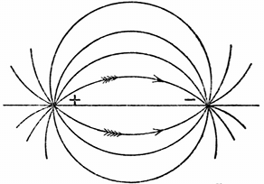
 Fig. 1.—Lines of Electric Strain between a Positive
and Negative Electron at Rest.
Fig. 1.—Lines of Electric Strain between a Positive
and Negative Electron at Rest.
The Project Gutenberg EBook of Hertzian Wave Wireless Telegraphy, by
John Ambrose Fleming

This eBook is for the use of anyone anywhere at no cost and with
almost no restrictions whatsoever.  You may copy it, give it away or
re-use it under the terms of the Project Gutenberg License included
with this eBook or online at www.gutenberg.org


Title: Hertzian Wave Wireless Telegraphy

Author: John Ambrose Fleming

Release Date: January 8, 2012 [EBook #38526]

Language: English

Character set encoding: ISO-8859-1

*** START OF THIS PROJECT GUTENBERG EBOOK HERTZIAN WAVE WIRELESS TELEGRAPHY ***


Produced by Robert Cicconetti, Tim Madden and the Online
Distributed Proofreading Team at https://www.pgdp.net (This
file was produced from images generously made available
by The Internet Archive/American Libraries.)
Transcriber's Notes:
All apparent printer's errors and variations in spelling have been retained, there are also some inconsistencies in the hyphenation of words. All these have been detailed at the end of the text.
The middle dot has been used in the original text, both as a multiplication symbol and as a decimal point. These have been kept but the middle dot as a multiplication symbol in formulae is surrounded by single spaces.
THE immense public interest which has been aroused of late years in the subject of telegraphy without connecting wires has undoubtedly been stimulated by the achievements of Mr. Marconi in effecting communication over great distances by means of Hertzian waves. The periodicals and daily journals, which are the chief avenues through which information reaches the public, whilst eager to describe in a sensational manner these wonderful applications of electrical principles, have done little to convey an intelligible explanation of them. Hence it appeared probable that a service would be rendered by an endeavour to present an account of the present condition of electric wave telegraphy in a manner acceptable to those unversed in the advanced technicalities of the subject, but acquainted at least with the elements of electrical science. It is the purpose of these articles to attempt this task. We shall, however, limit the discussion to an account of the scientific principles underlying the operation of this particular form of wireless telegraphy, omitting, as far as possible, references to mere questions of priority and development.
The practical problem of electric wave wireless telegraphy, which has been variously called Hertzian wave telegraphy, Marconi telegraphy, or spark telegraphy (Funkentelegraphie), is that of the production of an effect called an electric wave or train of electric waves, which can be sent out from one place, controlled, detected at another place, and interpreted into an alphabetic code. Up to the present time, the chief part of that intercommunication has been effected by means of the Morse code, in which a group of long and short signs form the letter or symbol. Some attempts have been made with more or less, success to work printing telegraphs and even writing or [Pg 2]drawing telegraphs by Hertzian waves, but have not passed beyond the experimental stage, whilst wireless telephony by this means is still a dream of the future.
We shall, in the first place, consider the transmitting arrangements and, incidentally, the nature of the effect or wave transmitted; in the second place, the receiving appliances; and, finally, discuss the problem of the isolation or secrecy of the intelligence conveyed between any two places.
The transmitter used in Hertzian wave telegraphy consists essentially of a device for producing electric waves of a type which will travel over the surface of the land or sea without speedy dissipation, and the important element in this arrangement is the radiator, by which these waves are sent out. It will be an advantage to begin by explaining the electrical action of the radiator, and then proceed to discuss the details of the transmitting appliances.
It will probably assist the reader to arrive most easily at a general idea of the functions of the various portions of the transmitting arrangements, and in particular of the radiator, if we take as our starting point an analogy which exists between electric wave generation for telegraphic purposes and air wave generation for sound signal purposes. Most persons have visited some of the large lighthouses which exist around our coasts and have there seen a steam or air siren, as used for the production of sound signals during fogs. If they have examined this appliance, they will know that it consists, in the first place, of a long metal tube, generally with a trumpet-shaped mouthpiece. At the bottom of this tube there is a fixed plate with holes in it, against which revolves another similarly perforated plate. These two plates separate a back chamber or wind chest from the tube, and the wind chest communicates with a reservoir of compressed air or a high-pressure steam boiler. In the communication pipe there is a valve which can be suddenly opened for a longer or shorter time. When the movable plate revolves, the coincidence or non-coincidence of the holes in the two plates opens or shuts the air passage way very rapidly. Hence when the blast of air or steam is turned on, the flow is cut up by the revolving plates into a series of puffs which inflict blows upon the stationary air in the siren tube. If these blows come at the rate, say, of a hundred a second, they give rise to aerial oscillations in the tube, which impress the ear as a deep, musical note or roar; and this continuous sound can be cut up by closing the valve intermittently into long and short periods, and so caused to signal a letter according to the Morse code, denoting the name of the lighthouse. In this case the object is to produce: first, aerial vibrations in the tube, giving rise to a train of powerful air waves; secondly, to intermit this wave-train so as to produce an intelligible signal; and thirdly, to transmit this wave as far as possible through space.
The production of a sound or air wave can only be achieved by administering a very sudden blow to the general mass of the air in the tube. This impulse must be sufficient to call into operation the inertia and elastic qualities of the air. It is found, moreover, that the amplitude of the resulting wave, or the loudness of the sound, is increased[Pg 3] by suitably proportioning the length of the siren pipe and the frequency of the air puffs; whilst the distance at which it is heard depends also in some degree upon the form of the mouthpiece.
Inside the siren tube, when it is in operation, the air molecules are in rapid vibratory motion in the direction of the length of the tube. If we could at any one instant examine the distribution and changes of air pressure in the tube, we should find that at some places there are large, and at others small, variations in air pressure. These latter places are called the nodes of pressure. At the pressure nodes, however, we should find large variations in the velocity of the air particles, and these points are called the antinodes of velocity. In those places at which the pressure variation is greatest, the velocity changes are least, and vice versa. Outside the tube, as a result of these air motions in it, we have a hemispherical air wave produced, which travels out from the mouthpiece as a centre; and if we could examine the distribution of air pressure and velocity through all external space, we should find a distribution which is periodic in space as well as time, constituting the familiar phenomenon of an air wave.
Turning then to consider the production of an electric, instead of an air wave, we notice in the first place that the medium with which we are concerned is the ether filling all space. This ether permits the production of physical changes in it which are analogous to, but not identical in nature with, the pressures and movements which constitute a sound wave. The Hertzian radiator is an appliance for acting on the ether as the siren acts on the air. It produces a wave in it, and it can be shown that all the parts of the above described siren apparatus have their electrical equivalents in the transmitter employed in Hertzian wave wireless telegraphy.
To understand the nature of an electric wave we must consider, in the first place, some properties of the ether. In this medium we can at any place produce a state called electric displacement or ether strain as we can produce compression or rarefaction in air; and, just as the latter changes are said to be created by mechanical force, so the former is said to be due to electric force. We can not define more clearly the nature of this ether strain or displacement until we know much more about the structure of the ether than we do at present. We can picture to ourselves the operation of compressing air as an approximation of the air molecules, but the difficulty of comprehending the nature of an electric wave arises from the fact that we cannot yet definitely resolve the notion of electric strain into any simpler or more familiar ideas.
We have to be content, therefore, to disguise our present ignorance by the use of some descriptive term, such as electric strain, electrostatic strain or ether strain, to describe the directed condition of the space around a body in a state of electrification which is produced by electric force. This electric strain is certainly not of the nature of a compression in the ether, but much more akin to a twist or rotational strain in a solid body.
For our present purpose it is not so necessary to postulate any particular theory of the ether as it is to possess some consistent hypothesis, in terms of which we can describe the phenomena which will[Pg 4] concern us. These effects are, as we shall see, partly states of electrification on the surface or distributions of electric current in wires or rods, and partly conditions in the space outside them, which we are led to recognise as distributions of electric strain and of an associated effect called magnetic flux.
We find such a theory at hand at the present time in the electronic theory of electricity, which has now been sufficiently developed and popularised to make it useful as, a descriptive hypothesis.[2] This theory has the great recommendation that it offers a means of abolishing the perplexing dualism of ether and ponderable matter, and gives a definite and, in a sense, objective meaning to the word electricity. In this physical speculation, the chief subject of contemplation is the electron, or ultimate particle of negative electricity, which, when associated in greater or less number with a matrix of some description, forms the atom of ponderable matter. To avoid further hypothesis, this matrix may be called the co-electron; and we shall adopt the view that a single chemical atom is a union of a co-electron with a surrounding envelope or group of electrons, one or more of the latter being detachable. We need not stop to speculate on the structure of the atomic core or co-electron, whether it is composed of positive and negative electrons or of something entirely different. The single electron is the indivisible unit or atomic element of so-called negative electricity, and the neutral chemical atom deprived of one electron is the unit of positive electricity. On this hypothesis, the chemical atom is to be regarded as a microcosm, a sort of a solar system in miniature, the component electrons being capable of vibration relatively to the atomic centre of mass. Furthermore, from this point of view it is the electron which is the effective cause of radiation. It alone has a grip on the ether whereby it is able to establish wave motion in the latter.
Dr. Larmor has developed in considerable detail an hypothesis of the nature of an electron which makes it the centre or convergence-point of lines of a self-locked ether strain of a torsional type. The notion of an atom merely as a "centre of force" was one familiar to Faraday and much supported by Boscovich and others. The fatal objection to the validity of this notion as originally stated was that it offers no possibility of explaining the inertia of matter. On the electronic hypothesis, the source of all inertia is the inertia of the ether, and until we are able to dissect this last quality into anything simpler than the time-element involved in the production of an ether strain or displacement, we must accept it as an ultimate fact, not more elucidated because we speak of it as the inductance of the electron.
We postulate, therefore, the following ideas: We have to think of the ether as a homogeneous medium in which a strain of some kind, most probably of a rotational type, is possible. This strain appears only under the influence of an appropriate stress called the electric force, and disappears when the force is removed. Hence to create this strain necessitates the expenditure of energy. An electron is a [Pg 5] centre or convergence-point of lines of permanent ether strain of such nature that it cannot release itself. To obtain some idea of the nature of such a structure, let us imagine a flat steel band formed into a ring by welding the ends together. There is then no torsional strain. If, however, we suppose the band cut in one place, one end then given half a turn and the cut ends again welded, we shall have on the band a self-locked twist, which can be displaced on the band, but which can not release itself or be released except by cutting the ring. Hence we see that to make an electron in an ether possessing torsional elasticity would require creative energy, and when made, the electron cannot destroy itself except by occupying simultaneously the same place as an electron of opposite type. Every electron extends, therefore, as Faraday said of the atom, throughout the universe, and the properties that we find in the electron are only there because they are first in the universal medium, the ether. Every line of ether or electric strain must, therefore, be a self-closed line, or else it must terminate on an electron and a co-electron.
So far we have only considered the electron at rest. If, however, it moves, it can be mathematically demonstrated that it must give rise to a second form of ether strain which is related to the electric strain as a twist is related to a thrust or a vortex ring to a squirt in liquid or a rotation to a linear progression. The ether strain which results from the lateral movement of lines of electric strain is called the magnetic flux, and it can be mathematically shown that the movement of an electron, consisting when a rest of a radial convergence of lines of electric strain, must be accompanied by the production of self-closed lines of magnetic flux, distributed in concentric circles or rings round it, the planes of these circles being perpendicular to the direction of motion of the electron.
This electronic hypothesis, therefore, affords a basis on which we can build up a theory affording an explanation of the nature of the intimate connection known to exist between ether, matter and electricity. The electron is the connecting link between them all, for it is in itself a centre of convergent ether strain; isolated, it presents itself as electricity of the negative or resinous kind; and, in combination with co-electrons and other electrons, it forms the atoms of ponderable matter. At rest the electron or the co-electron constitutes an electric charge, and when in motion it is an electric current. A steady flux or drift of electrons in one direction and co-electrons in the opposite direction is a continuous electric current, whilst their mere oscillation about a mean position is an alternating current. Furthermore, the vibration of an electron, if sufficiently rapid, enables it to establish what are called electric waves in the ether, but which are really detached and self-closed lines of ether strain distributed in a periodic manner through space.
We have, therefore, to start with, three conceptions concerning the electron, viz.: Its condition when at rest; its state when in uniform motion; and its operations when in vibration or rapid oscillation. In the first case, by our fundamental supposition, it consists of lines of ether strain of a type called the electric strain, radiating uniformly in [Pg 6]all directions. When in uniform motion, it can be shown that these lines of electric strain tend to group themselves in a plane perpendicular to the line of motion drawn through the electron, and their lateral motion generates another class of strain called the magnetic strain, disposed in concentric circles described round the electron and lying in this equatorial plane.
The proof of the above propositions cannot be given verbally, but requires the aid of mathematical analysis of an advanced kind. The reader must be referred for the complete demonstration to the writings of Professor J. J. Thomson[3] and Mr. Oliver Heaviside.[4]
In the third case, when the electron vibrates, we have a state in which self-closed lines of electric strain and magnetic flux are thrown off and move away through the ether constituting electric radiation, The manner in which this happens was first described by Hertz in a Paper on "Electric Oscillations treated according to the Method of Maxwell."[5] As this phenomenon lies at the very root of Hertzian wave wireless telegraphy, we must spend a moment or two in its careful examination.
Fig. 1.—Lines of Electric Strain between a Positive
and Negative Electron at Rest.
Let us imagine two metal rods placed in line and constituting what is called a linear oscillator. Let these rods have adjacent ends separated by a very small air space, and let one rod be charged with positive and the other with negative electricity. On the electronic theory this is explained by stating that there is an accumulation of electrons in one and of co-electrons in the other. These charges create a distribution of electric strain throughout their neighbourhood, which follows approximately the same law of distribution as the lines of magnetic force of a bar magnet, and may be roughly represented as in Fig. 1. Suppose then that the air gap is destroyed, these charges move towards each other and disappear by uniting, the lines of electric strain then collapse, and as they shrink in give rise to circular lines of magnetic flux embracing the rods. This external distribution of magnetism constitutes an electric current in the rods produced by the movement of the two opposite electric charges. At this stage it may be explained that the electrons or atoms of electricity can in some cases make their way freely between the atoms of ponderable matter. The former are incomparably smaller than the latter, and in those cases in which this electronic movement can take place easily, we call the material a good conductor.
Suppose then the electric charges reappear in reversed positions and go through an oscillatory motion. The result in the external [Pg 7]space would be the alternate production of lines of electric strain and magnetic flux, the direction of these lines being reversed each half cycle. Inside the rods we have a movement of electrons and co-electrons to and fro, electric charges at the ends of the rods alternating with electric currents in the rods, the charges being at a maximum when the current is zero, and the current at a maximum when the charges have for the moment disappeared. Outside the rods we have a corresponding set of charges, lines of electric strain stretching from end to end of the rod, alternating with rings of magnetic flux embracing the rod. So far we have supposed the oscillation to be relatively a slow one.
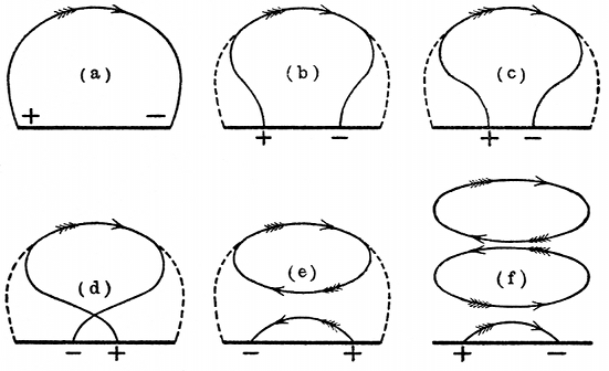 Fig. 2.—Successive Stages in the Deformation of a Line
of Strain between Positive and Negative Electrons in Rapid
Oscillation, showing Closed Loop of Electric Strain thrown off.
Fig. 2.—Successive Stages in the Deformation of a Line
of Strain between Positive and Negative Electrons in Rapid
Oscillation, showing Closed Loop of Electric Strain thrown off.
Imagine next that the to and fro movement of the electrons or charges is sufficiently rapid to bring into play the inertia quality of the medium. We then have a different state of affairs. The lines of strain in the external medium cannot contract or collapse quickly enough to keep up with the course of events, or movements of the electrons in the rods, and hence their regular contraction and absorption is changed into a process of a different kind. As the electrons and co-electrons, i.e., the electric charges, vibrate to and fro, the lines of electric strain connecting them are nipped in and thrown off as completely independent and closed lines of electric strain, and at each successive alternation, groups or batches of these loops of strain are detached from the rod, and, so to speak, take on an independent existence. The whole process of the formation of these self-closed lines of electric strain is best understood by examining a series of diagrams which roughly represent the various stages of the process. In Fig. 2 we have a diagram (a) the curved line in which delineates approximately the form of one line of electric strain round a linear oscillator, with spark gap in the centre, one half being charged positively and the other negatively. Let us then suppose that the insulation of the spark gap is destroyed, so that the opposite electric charges rush together and oscillate to and fro. The strain lines at each oscillation [Pg 8]are then crossed or decussate, and the result, as shown in Fig. 2, d, is that a portion of the energy of the field is thrown off in the form of self-closed lines of strain (see Fig. 2, e). At each oscillation of the charges the direction of the lines of strain springing from end to end of the radiator is reversed. It is a general property of lines of strain whether electric or magnetic, that there is a tension along the line and a pressure at right angles. In other words, these lines of electric strain are like elastic threads, they tend to contract in the direction of their length and press sideways on each other when in the same direction. Hence it is not difficult to see that as each batch of self-closed lines of strain is thrown off, the direction of the strain round each loop is alternately in one direction and in the other. Hence these loops of electric strain press each other out, and each one that is formed squeezes the already formed loops further and further from the radiator. The loops, therefore, march away into space (see Fig. 2, f). If we imagine ourselves standing at a little distance at a point on the equatorial line and able to see these loops of strain as they pass, we should recognise a procession of loops, consisting of alternately directed strain lines marching past. This movement through the ether of self-closed lines of electric strain constitutes what is called electric radiation.
Hence along a line drawn perpendicular to the radiator through its centre, there is a distribution of electric strain normal to that line, which is periodic in space and in time. Moreover, in addition to these lines of electric strain, there are at right angles to them another set of self-closed lines of magnetic flux. Alternated between the instants when the electric charges at the ends of the radiator are at their maximum, we have instants when the radiator rod is the seat of an electric current, and hence the field round it is filled with circular lines of magnetic flux coaxial with the radiator. As the current alternates in direction each half period, these rings of magnetic flux alternate in direction as regards the flux, and hence we must complete our mental picture of the space round the radiator rods when the charges are oscillating by supposing it filled with concentric rings of magnetic flux which are periodically reversed in direction, and have their maximum values at those instants and places where the lines of electric strain have their zero values. Accordingly, along the equatorial line we have two sets of strains in the ether, distributed periodically in space and in time. First, the lines of electric strain in the plane of the radiator, and, secondly, the lines of magnetic flux at right angles to these. At any one point in space these two changes, the strain and the flux, succeed each other periodically, being, however, at right angles in direction. At any one moment these two effects are distributed periodically or cyclically through space, and these changes in time and space constitute an electric wave or electromagnetic wave.
We may then summarise the above statements by saying that the most recent hypothesis as to the nature of electrical action and of electricity itself is briefly comprised in the following statements: The universally diffused medium called the ether has had created in it [Pg 9]certain centres of strain or radiating points from which proceed lines of strain, and these centres of force are called electrons. Electrons must, therefore, be of two kinds, positive and negative, according to the direction of the strain radiating from the centre. These electrons in their free condition constitute what we call electricity, and the electrons themselves are the atoms of electricity which, in one sense, is, therefore, as much material as that which we call ordinary gross or ponderable matter.
Collocations of these electrons constitute the atoms of gross matter, and we must consider that the individuality of any atom is not determined merely by the identity of the electrons composing it, but by the permanence of their arrangement or form. In any mass of material substance there is probably a continual exchange of electrons from one atom to another, and hence at any one given moment, whilst a number of the electrons are an association forming material atoms, there will be a further number of isolated but intermingled electrons, which are called the free electrons. In substances which we call good conductors, we must imagine that the free electrons have the power of moving freely through or between the material atoms, and this movement of the electrons constitutes a current of electricity; whilst a superfluity of electrons of either type in any one mass of matter constitutes what we call a charge of electricity. Hence an electrical oscillation, which is merely a very rapid alternating current taking place in a conductor, is on this hypothesis assumed to consist in a rapid movement to and fro of the free electrons. We may picture to ourselves, therefore, a rod of metal in which electrical oscillations are taking place, as similar to an organ-pipe or siren tube in which movements of the air particles are taking place to and fro, the free electrons corresponding with the air particles.
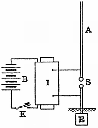 Fig. 3.—Simple Marconi Radiator. B, battery; I,
induction coil; K, signalling key; S, spark gap; A, aerial wire; E,
earth plate.
Fig. 3.—Simple Marconi Radiator. B, battery; I,
induction coil; K, signalling key; S, spark gap; A, aerial wire; E,
earth plate.
Owing to the nature of the structure of an electron, it follows, however, that every movement of an electron is accompanied by changes in the distribution of the electric strain or ether strain taking place throughout all surrounding space, and, as already explained, certain very rapid movements of the electrons have the effect of detaching closed lines of strain in the ether which move off through space, forming, when cyclically distributed, an electric wave.
We may next proceed to apply these principles to the explanation of the action of the simplest form of Hertzian wave telegraphic radiator, viz., the Marconi aerial wire. In its original form this consists of a long vertical insulated wire, A, the lower end of which is attached to one of the spark balls S of an induction coil, I, the other spark ball being connected to earth E, and the two spark balls being placed a few millimetres apart (see Fig. 3). When the coil is set in action oscillatory or Hertzian sparks pass between the balls, electric [Pg 10] oscillations are set up in the wire and electric waves are radiated from it. Deferring for the moment a more detailed examination of the operations of the coil and at the spark gap, we may here say that the action which takes place in the aerial wire is as follows: The wire is first charged to a high potential, let us suppose, with negative electricity. We may imagine this process to consist in forcing additional electrons into it, the induction coil acting as an electron pump. Up to a certain pressure the spark gap is a perfect insulator, but at a critical pressure, which for spark gap lengths of four or five millimetres and balls about one centimetre in diameter approximates to three thousand volts per millmetre, the insulation of the air gives way, and the charge in the wire rushes into the earth. In consequence, however, of the inertia of the medium or of the electrons, the charge, so to speak, overshoots the mark, and the wire is then left with a charge of opposite sign. This again in turn rebounds, and so the wire is discharged by a series of electrical oscillations, consisting of alternations of static charge and electric discharge. We may fasten our attention either on the events taking place in the vertical wire or in the medium outside, but the two sets of phenomena are inseparably connected and go on together. When the aerial wire is statically charged, we may describe it by saying that there is an accumulation of electrons or co-electrons in it. Outside the wire there is, however, a distribution of electric strain the strain lines proceeding from the wire to the earth (see Fig. 4).
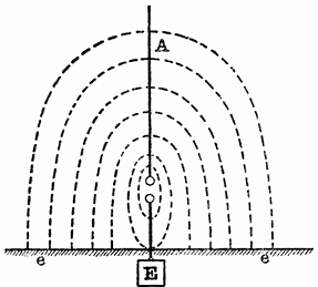 Fig. 4.—Lines of Electric Strain (Dotted Lines)
extending between a Marconi Aerial, A, and the Earth ee before
Discharge.
Fig. 4.—Lines of Electric Strain (Dotted Lines)
extending between a Marconi Aerial, A, and the Earth ee before
Discharge.
The wire has capacity with respect to the earth, and it acts like the inner coating of a Leyden jar, of which the dielectric is the air and ether around it, and the outer coating is the earth's surface. When the discharge takes place, we may consider that electrons rush out of the wire and then rush back again into it. At the moment when the electrons rush out of or into the aerial wire, we say there is an electric current flowing into or out of the wire, and this electron movement, therefore, creates the magnetic flux which is distributed in concentric circles round the wire. This current, and, therefore, motion of electrons, can be proved to exist by its heating effect upon a fine wire inserted in series with the aerial, and in the case of large aerials it may have a mean value of many amperes and a maximum value of hundreds of amperes. Inside the aerial wire we have, therefore, alternations of electric potential or charge and electric current, or we may call it electron-pressure and electron-movement.
There is, therefore, an oscillation of electrons in the aerial wire, just as in the case of an organ-pipe there is an oscillation of air molecules in the pipe. Outside the aerial we have variations and distributions of electric strain and magnetic flux. The resemblance between the closed organ-pipe and the simple Marconi aerial is, in [Pg 11] fact, very complete. In the case of the closed organ-pipe, we have a longitudinal oscillation of air molecules in the pipe. At the open end or mouthpiece, where we have air moving in and out, the air movement is alternating and considerable, but there is little or no variation of air pressure. At the upper or closed end of the pipe we have great variation of air pressure, but little or no air movement (see Fig. 5).
Compare this now with the electrical phenomena of the aerial. At the spark ball or lower end we have little or no variation of potential or electron pressure, but we have electrons rushing into and out of the aerial at each half oscillation, forming the electric discharge or current. At the upper or insulated end we have little or no current, but great variations of potential or electron pressure. Supposing we could examine the wire inch by inch, all the way up from the spark balls at the bottom to the top, we should find at each stage of our journey that the range of variation and maximum value of the current in the wire became less and those of the potential became greater. At the bottom we have nearly zero potential or no electric pressure, but large current, and at the top end, no current, but great variation of potential.
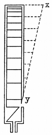 Fig. 5.—Amplitude of Pressure Variation in a Closed
Organ Pipe, indicated by the Ordinates of the Dotted Line xy.
Fig. 5.—Amplitude of Pressure Variation in a Closed
Organ Pipe, indicated by the Ordinates of the Dotted Line xy.
We can represent the amplitude of the current and potential values along the aerial by the ordinates of a dotted line so drawn that its distance from the aerial represents the potential oscillation or current oscillation at that point (see Fig. 6).
This distribution of potential and current along the wire does not necessarily imply that any one electron moves far from its normal position. The actual movement of any particular air molecule in the case of a sound wave is probably very small, and reckoned in millionths of an inch. So also we must suppose that any one electron may have a small individual amplitude of movement, but the displacement is transferred from one to another. Conduction in a solid may be effected by the movement of free electrons intermingled with the chemical atoms, but any one electron may be continually passing from a condition of freedom to one of combination.
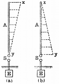 Fig. 6.—(a) Distribution of Electric Pressure in a
Marconi Aerial, A, (b) Distribution of Electric Current in a Marconi
Aerial, as shown by the Ordinates of the Dotted Line xy.
Fig. 6.—(a) Distribution of Electric Pressure in a
Marconi Aerial, A, (b) Distribution of Electric Current in a Marconi
Aerial, as shown by the Ordinates of the Dotted Line xy.
So much for the events inside the wire, but now outside the wire its electric charge is represented by lines of electric strain springing from the aerial to the earth. It must be remembered that every line of strain terminates on an electron or a co-electron. Hence, when the discharge or spark takes place between the spark balls, the rapid movement of the electrons in the wire is accompanied by a redistribution and movement of the lines [Pg 12]of strain outside. As the negative charge flows out of the aerial the ends of the strain lines abutting on to it run down the wire and are transferred to the earth, and at the next instant this semi-loop of electric or ether strain, with its ends on the earth, is pushed out sideways from the wire by the growth of a new set of lines of ether strain in an opposite direction. The process is best understood by consulting a series of diagrams which represent the distribution and approximate form of a few of the strain lines at successive instants (see Fig. 7). In between the lines of formation of the successive strain lines between the aerial and the earth, corresponding to the successive alternate electric charges of the aerial with opposite sign, there are a set of concentric rings of magnetic flux formed round it which are alternately in opposite directions, and these expand out, keeping step with the progress of the detached strain loops and having their planes at right angles to the latter. As the semi-loops of electric strain march outwards with their feet on the ground, these strain lines must always be supposed to terminate on electrons, but not continually on the same electrons. Since the earth is a conductor, we must suppose that there is a continual migration of the electrons forming the atoms of the earth, and that when one electron enters an atom, another leaves it. Hence, corresponding to the electric wave in the space above, there are electrical changes in the ground beneath. This view is confirmed by the well-known fact that the achievement of Hertzian wave telegraphy is much dependent on the nature of the surface over which it is conducted, and can be carried on more easily over good conducting material, like sea water, than over badly conducting dry land.
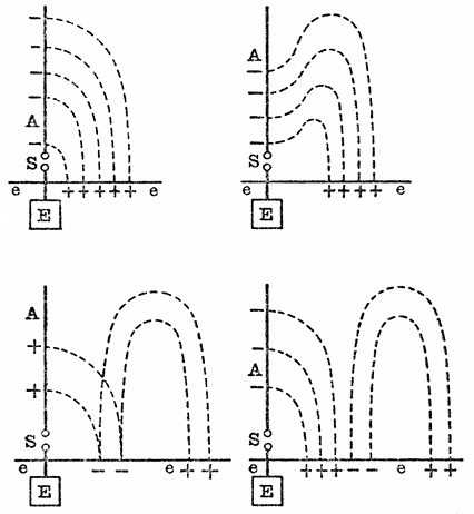 Fig. 7.—Successive Stages in the Production of a
Semi-loop of Electric Strain by a Marconi Aerial Radiator.
Fig. 7.—Successive Stages in the Production of a
Semi-loop of Electric Strain by a Marconi Aerial Radiator.
The matter may be viewed, however, from another standpoint. Good conductors are opaque to Hertzian waves; in other words, are [Pg 13] non-absorptive. The energy of the electric wave is not so rapidly absorbed when it glides over a sea surface as when it is passing over a surface which is an indifferent conductor, like dry land. In fact, it is possible by the improvement of the signals to detect a heavy fall of rain in the space between two stations separated only by dry land. It is, however, clear that on the electronic theory the progression of the lines of electric strain can only take place if the surface over which they move is a fairly good conductor, unless these lines of strain form completely closed loops. Hence we may sum up by saying that there are three set of phenomena to which we must pay attention in formulating any complete theory of the aerial. The first is the operation taking place in the vertical wire, which is described by saying that electrical oscillations or vibratory movements of electrons are taking place in it, and, on our adopted theory, it may be said to consist in a longitudinal vibration of electrons of such a nature that we may appropriately call the aerial an ether organ-pipe. Then in the next place, we have the distribution and movement of the lines of electric strain and magnetic flux in the space outside the wire, constituting the electric wave; and lastly, there are the electrical changes in the conductor over which the wave travels, which is the earth or water surrounding the aerial. In subsequently dealing with the details of transmitting arrangements, attention will be directed to the necessity for what telegraphists call a "good earth" in connection with Hertzian wave telegraphy. This only means that there must be a perfectly free egress and ingress for the electrons leaving or entering the aerial, so that nothing hinders their access to the conducting surface over which the wave travels. There must be nothing to stop or throttle the rush of electrons into or out of the aerial wire, or else the lines of strain cannot be detached and and travel away.
We may next consider more particularly the energy which is available for radiation and which is radiated. In the original form of simple Marconi aerial, the aerial itself when insulated forms one coating or surface of a condenser, the dielectric being the air and ether around it, and the other conductor being the earth. The electric energy stored up in it just before discharge takes place is numerically equal to the product of the capacity of the aerial and half the square of the potential to which it is charged.
If we call C the capacity of the aerial in microfarads, and V the potential in volts to which it is raised before discharge, then the energy storage in joules E is given by the equation,

Since one joule is nearly equal to three-quarters of a foot-pound, the
energy storage in foot-pounds F is roughly given by the rule
 . For spark lengths of the order of five to fifteen
millimetres, the disruptive voltage in air of ordinary pressure is at
the rate of 3,000 volts per millimetre. Hence, if S stands for the
spark length in millimetres, and C for the aerial capacity in
microfarads, it is easy to see that the energy storage in foot-pound
is
. For spark lengths of the order of five to fifteen
millimetres, the disruptive voltage in air of ordinary pressure is at
the rate of 3,000 volts per millimetre. Hence, if S stands for the
spark length in millimetres, and C for the aerial capacity in
microfarads, it is easy to see that the energy storage in foot-pound
is

If the aerial consists of a stranded wire formed of 7/22 and has a length of 150 feet, and is insulated and held vertically with its lower end near the earth, it would have a capacity of about one three ten-thousandths of a microfarad or 0·0003 mfd.[6] Hence, if it is used as a Marconi aerial and operated with a spark gap of one centimetre in length, the energy stored up in the wire before each discharge would be only one-tenth (0·1) of a foot-pound.
By no means can all of this energy be radiated as Hertzian waves; part of it is dissipated as heat and light in the spark, and yet such an aerial can, with a sensitive receiver such as that devised by Mr. Marconi, make itself felt for a hundred miles over sea in every direction. This fact gives us an idea of the extremely small energy which, when properly imparted to the ether, can effect wireless telegraphy over immense distances. Of course, the minimum telegraphic signal, say the Morse dot, may involve a good many, perhaps half-a-dozen, discharges of the wire, but even then the amount of energy concerned in affecting the receiver at the distant place is exceedingly small.
The problem, therefore, of long-distance telegraphy by Hertzian waves is largely, though not entirely, a matter of associating sufficient energy with the aerial wire or radiator. There are obviously two things which may be done; first, we may increase the capacity of the aerial, and secondly, we may increase the charging voltage or, in other words, lengthen the spark gap. There is, however, a well-defined limit to this last achievement. If we lengthen the spark gap too much, its resistance becomes too great and the spark ceases to be oscillatory. We can make a discharge, but we obtain no radiation. When using an induction coil, about a centimetre, or at most a centimetre and a half, is the limiting length of oscillatory sparks; in other words, our available potential difference is restricted to 30,000 or 40,000 volts. By other appliances we can, however, obtain oscillatory sparks having a voltage of 100,000 or 200,000 volts, and so obtain what Hertz called "active sparks" five or six centimetres in length.
Turning then to the question of capacity, we may enquire in the next place how the capacity of an aerial wire can be increased. This has generally been done by putting up two or more aerial wires in contiguity and joining them together, and so making arrangements called in the admitted slang of the subject "multiple aerials." The measurement of the capacity of insulated wires can be easily carried out by means of an appliance devised by the author and Mr. W. C. Clinton, consisting of a rotating commutator which alternately charges the insulated wire at a source of known electromotive force and then discharges it through a galvanometer. If this galvanometer is subsequently standardised, so that the ampere value of its deflection is known, we can determine easily the capacity C of the aerial or insulated conductor, reckoned in microfarads, when it is charged to a potential of V volts, and discharged n times a second through a [Pg 15] galvanometer. The series of discharges are equivalent to a current, of which the value in amperes A is given by the equation

and hence, if the value of the current resulting is known, we have the capacity of the aerial or conductor expressed in microfarads, given by the formula

A series of experiments made on this plan have revealed the fact that if a number of vertical insulated wires are hung up in the air and rather near together, the electrical capacity of the whole of the wires in parallel is not nearly equal to the sum of their individual capacities. If a number of parallel insulated wires are separated by a distance equal to about 3 per cent. of their length, the capacity of the whole lot together varies roughly as the square root of their number. Thus, if we call the capacity of one vertical wire in free space unity, then the capacity of four wires placed rather near together will only be about twice that of one wire, and that of twenty-five wires will only be about five times one wire.
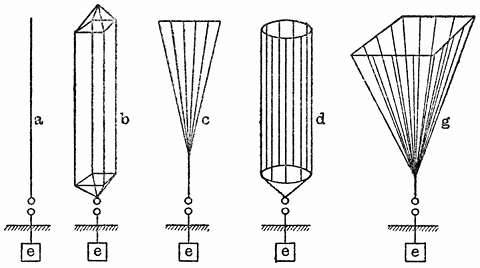 Fig. 8.—Various Forms of Aerial Radiator. a, single
wire; b, multiple wire; c, fan shape; d, cylindrical; g,
Conical.
Fig. 8.—Various Forms of Aerial Radiator. a, single
wire; b, multiple wire; c, fan shape; d, cylindrical; g,
Conical.
This approximate rule has been confirmed by experiments made with long wires one hundred or two hundred feet in length in the open air. Hence it points to the fact that the ordinary plan of endeavouring to obtain a large capacity by putting several wires in parallel and not very far apart is very uneconomical in material. The diagrams in Fig. 8 show the various methods which have been employed by Mr. Marconi and others in the construction of such multiple wire aerials. If, for instance, we put four insulated stranded 7/22 wires each 100 feet long, about six feet apart, all being held in a vertical position, the capacity of the four together is not much more than twice that of a single wire. In the same manner, if we arrange 150 similar wires, each 100 feet long, in the form of a conical aerial, the wires being distributed at the top round a circle 100 feet in diameter, the whole group will not have much more than twelve times the capacity of one single wire, although it weighs 150 times as much.
The author has designed an aerial in which the wires, all of equal length, are arranged sufficiently far apart not to reduce each other's capacity.
As a rough guide in practice, it may be borne in mind that a wire about one tenth of an inch in diameter and one hundred feet long, held vertical and insulated, with its bottom end about six feet from the ground, has a capacity of 0·0002 of a microfarad, if no other earthed vertical conductors are very near it. The moral of all this is that the amount of electric energy which can be stored up in a simple Marconi aerial is very limited, and is not much more than one-tenth of a joule or one-fourteenth of a foot-pound, per hundred feet of 7/22 wire. The astonishing thing is that with so little storage of energy it should be possible to transmit intelligence to a distance of a hundred miles without connecting wires.
One consequence, however, of the small amount of energy which can be accumulated in a simple Marconi aerial is that this energy is almost entirely radiated in one oscillation or wave. Hence, strictly speaking, a simple aerial of this type does not create a train of waves in the ether, but probably at most a single impulse or two.
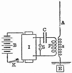 Fig. 9.—Marconi-Braun System of inducing Electromotive
Force in an Aerial, A. B, battery; K, key; I, induction coil; S, spark
gap; C, Leyden jar; E, earth plate; ps, oscillation transformer.
Fig. 9.—Marconi-Braun System of inducing Electromotive
Force in an Aerial, A. B, battery; K, key; I, induction coil; S, spark
gap; C, Leyden jar; E, earth plate; ps, oscillation transformer.
We shall later on consider some consequences which follow from this fact. Meanwhile, it may be explained that there are methods by which not only a much larger amount of energy can be accumulated in connection with an aerial, but more sustained oscillations created than by the original Marconi method. One of these methods originated with Professor Braun, of Strasburg, and a modification was first described by Mr. Marconi in a lecture before the Society of Arts of London.[7] In this method the charge in the aerial is not created by the direct application to it of the secondary electromotive force of an induction coil, but by means of an induced electromotive force created in the aerial by an oscillation transformer. The method due to Professor Braun is as follows: A condenser or Leyden jar has one terminal, say, its inside, connected to one spark ball of an induction coil. The other spark ball is connected to the outside of the Leyden jar or condenser through the primary coil of a transformer of a particular kind, called an oscillation transformer (see Fig. 9). The spark balls are brought within a few millimetres of each other. When the coil is set in operation, the jar is charged and discharged through the spark gap, and electrical oscillations are set up in the circuit consisting of the dielectric of the jar, the primary coil of the oscillation transformer and the spark gap. The secondary circuit of this oscillation transformer is connected in between the earth and the insulated aerial wire; hence, when the oscillations take place in the primary circuit, they induce other oscillations in the aerial circuit. But the arrangement is not very effective unless, [Pg 17]as is shown by Mr. Marconi, the two circuits of the oscillation transformer are tuned together.
We shall return presently to the consideration of this form of transmitter; meanwhile we may notice that by means of such an arrangement it is possible to create in the aerial a far greater charging electromotive force than would be the case if the aerial were connected directly to one terminal of the secondary circuit of the induction coil, the other terminal being to earth, and the two terminals connected as usual by spark balls. By the inductive arrangement it is possible to create in an aerial electromotive forces which are equivalent to a spark of a foot in length, and when the length of the aerial is also properly proportioned the potential along it will increase all the way up, until at the top or insulated end of the aerial it may reach an amount capable of giving sparks several feet in length. From the remarks already made on the analogy between the closed organ-pipe and the Marconi aerial wire, it will be seen that the wave which is radiated from the aerial must have a wave length four times that of the aerial if the aerial is vibrating in its fundamental manner. It is also possible to create electrical oscillations in a vertical wire which are the harmonics of the fundamental.
All musicians are aware that in the case of an organ-pipe if the pipe is blown gently it sounds a note which is called the fundamental of the pipe. The celebrated mathematician, Daniel Bernouilli, discovered that an organ-pipe can be made to yield a succession of musical notes by properly varying the pressure of the current of air blown into it. If the pipe is an open pipe, and if we call the frequency of the primary note obtained when the pipe is gently blown, unity, then when we blow more strongly the pipe yields notes which are the harmonics of the fundamental one; that is to say, notes which have frequencies represented by the numbers 2, 3, 4, 5, &c. If, however, the pipe is closed at the top, then over-blowing the pipe makes it yield the odd harmonics or the tones which are related to the primary tone in the ratio of 3, 5, 7, &c., to unity. Accordingly, if a stopped pipe gives as its fundamental the note C, its first overtone will be the fifth above the octave or G'.
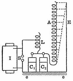 Fig. 10.—Seibt's Apparatus for showing Stationary
Waves in long Solenoid A. I, induction coil; S, spark gap; L,
inductance coil; C1C2, Leyden jars; E, earth wire.
Fig. 10.—Seibt's Apparatus for showing Stationary
Waves in long Solenoid A. I, induction coil; S, spark gap; L,
inductance coil; C1C2, Leyden jars; E, earth wire.
As already remarked, the aerial wire or radiator as used in Marconi telegraphy may be looked upon as a kind of ether organ-pipe or siren tube, and its electrical phenomena are in every respect similar to the acoustic phenomena of the ordinary closed organ-pipe. When the aerial is sounding its fundamental ether note, the conditions which pertain are that there is a current flowing into the aerial at the lower end, but at that point the variation in potential is very small, whereas at the upper end there is no current, but the variations of potential are very large. Accordingly, we say that at the upper end of the aerial there is an antinode of potential and a node of current, and at the bottom an antinode of current and a node of potential. By altering the frequency of the electrical impulses we can create in the aerial an arrangement of nodes of current or potential corresponding to the overtones of a closed organ-pipe. But whatever may be the arrangement the conditions must always hold that there is a node of current at the upper end and an antidote of current [Pg 18]at the lower end. In other words, there are large variations of current at the place where the aerial terminates on the spark-gap and no current at the upper end. The first harmonic is formed where there is a node of potential at one-third of the length of the aerial from the top. In this case we have a node of potential not only at the lower end of the wire, but at two-thirds of the way up. In the same way we can create in the closed organ-pipe, by properly overblowing the pipe, a region about two-thirds of the way up the pipe, where the pressure changes in the air are practically no greater than they are at the mouthpiece. We can make evident visually in a beautiful manner the existence of similar stationary electrical waves in an aerial by means of an ingenious arrangement devised by Dr. Georg Seibt, of Berlin. It consists of a very long silk-covered copper wire, A (see Fig. 10), wound in a close spiral of single layer round a wooden rod six feet long and about two inches in diameter. This rod is insulated, and at the lower end the wire is connected to a Leyden jar circuit, consisting of a Leyden jar or jars and an inductance coil, L, the inductance of which can be varied. Oscillations are set up in this jar circuit by means of an induction-coil discharge, and the lower end of the long spiral wire is attached to one point on the jar circuit. In this manner we can communicate to the bottom end of the long spiral wire a series of electric impulses, the time period of which depends upon the capacity of the jar and the inductance of the discharge circuit. We can, moreover, vary this frequency over wide limits. Parallel to the long spiral wire is suspended another copper wire, E (see Fig. 10), and between this wire and the silk-covered copper wire discharges take place due to the potential difference between each part of the wire and this long aerial wire. If we arrange matters so that the impulses communicated to the bottom end of the long spiral wire correspond to its fundamental note or periodic time, then in a darkened room we shall see a luminous glow or discharge between the vertical wire and the spiral wire, which increases in intensity all the way up to the top of the spiral wire. The luminosity of this brush discharge at any point is evidence of the potential of the spiral wire at that point, and its distribution clearly demonstrates that the difference of potential between the spiral wire and the aerial increases all the way up from the bottom to the top of the spiral wire. In the next place, by making a little adjustment and by varying the inductance of the jar circuit, we can increase the frequency of the impulses which are falling upon the spiral wire; and then it will be noticed that the distribution of the brush discharge or luminosity is altered, and that there is a [Pg 19]maximum now at about one-third of the height of the spiral wire, and a dark place at about two-thirds of the height, and another bright place at the top, thus showing that we have a node of potential at about two-thirds the way up the wire (see Fig. 11), and we have therefore set up in the spiral wire electrical oscillations corresponding to the first overtone. It is possible to show in the same way the existence of the second harmonic in the coil, but the luminosity then becomes too faint to be seen at a distance.
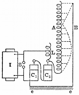 Fig. 11.—Harmonic Oscillations in Long Solenoid shown
with Seibt's Apparatus.
Fig. 11.—Harmonic Oscillations in Long Solenoid shown
with Seibt's Apparatus.
An interesting form of aerial devised by Professor Slaby, of Berlin, depends for its action entirely on the fact that the electrical oscillations set up in it which radiate are harmonics of the fundamental tone.
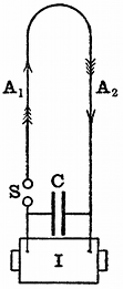 Fig. 12.—Non-radiative Closed Loop Aerial.
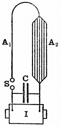 Fig. 13.—Slaby's Loop Radiator.
A closed vertical loop, A1A2 (see Fig. 12), is formed by erecting two parallel insulated wires vertically a few feet apart and joining them together at the top. At the bottom these wires are connected, with the secondary terminals of an induction coil, a condenser, C, or Leyden jar, being bridged across the terminals and a pair of spark balls, S, inserted in one side of the loop. It will readily be seen that on setting the coil in action, oscillations will take place in these vertical wires, but that if the oscillations are simply the fundamental note of the system, then at any moment corresponding to a current going up one side of the loop of wire there must be a current coming down the other. Accordingly, an arrangement of this kind, forming what is called a closed circuit, will not radiate or radiates but very feebly. Professor Slaby found, however, that it might be converted into a powerful radiator if we give the two sides of the loop unequal capacity or inductance and at the same time earth one of the lower ends of the loop, as shown in Fig. 13. By this means it is possible to set up in the loop electrical overtones or harmonics of the fundamental oscillation, and if we cause the system to vibrate so as to produce its first odd harmonic, there is a potential node at the lower end of both vertical sides of the loop, a potential node on both vertical sides at two-thirds of the way up, and a potential antinode at the summit of the loop; then, under these circumstances, the closed loop of wire is in the same electrical condition as if two simple Marconi aerials, both emitting their first odd harmonic oscillation, were placed side by side and joined together at the top.
It is a little difficult without the employment of mathematical analysis to explain precisely the manner in which earthing one side of the loop or making the loop unsymmetrical as regards inductance has the effect of creating overtones in it. The following rough illustration may, however, be of some assistance. Imagine a long spiral metallic spring supported horizontally by threads. Let this represent a conductor, and let any movement to or fro of a part of the spring represent a current in that conductor. Suppose we take hold of the spring at one end, we can move it bodily to and fro as a whole. In this case, every part of the spring is moving one way or the other in the same manner at the same time. This corresponds with the case in which the discharge of the condenser through the uniform loop conductor is a flow of electricity, all in one direction one way or the other. The current is in the same direction in all parts of the loop at the same time, and, therefore, if the current is going up one side of the loop it is at the same time coming down the other side. Hence the two sides of the loop are always in exact opposition as regards the effect of the current in them on the external space, and the loop does not radiate. Returning again to the case of the spring. Supposing that we add a weight to one end of the spring by attaching to it a metal ball, and then move the other end to and fro with certain periodic motion, it will be found quite easy to set up in the spring a pulsatory motion resembling the movement of the air in an open organ-pipe. Under these circumstances both ends of the spring will be moving inwards or outwards at the same time, and the central portions of the spring, although being pressed and expanded slightly, are moving to and fro very little. This corresponds in the case of the looped aerial with a current flowing up or down both sides at the same time; in other words, when this mode of electrical oscillation is established in the loop, its electrical condition is just that of two simple Marconi aerials joined together at the top and vibrating in their fundamental manner. Accordingly, if one side of the double loop is earthed, we then have an arrangement which radiates waves. Professor Slaby found that by giving one side of the loop less inductance than the other, and at the same time earthing the side having greater inductance at the bottom, he was able to make an arrangement which radiated, not in virtue of the normal oscillations of the condenser, but in virtue of the harmonic oscillations set up in the conductor itself. The mathematical theory of this radiator has been very fully developed by Dr. Georg Seibt.
It will be seen, therefore, that there are several ways in which we may start into existence oscillations in an aerial. First, the aerial may be insulated, and we may charge it to a high potential and allow this charge suddenly to rush out. Although this process gives rise to a disturbance in the ether, as already explained, it is analogous to a pop or explosion in the air, rather than to a sustained musical note. The exact acoustic analogue would be obtained if we imagine a long pipe pumped full of air and then suddenly opened at one end. The air would rush out, and, communicating a blow to the outer air, would create an atmospheric disturbance appreciated as a noise or small explosion. This is what happens when we cut the string and let the cork [Pg 21]fly out from a bottle of champagne. At the same time, the inertia of the air rushing out of the tube would cause it to overshoot the mark, and a short time after opening the valve the tube, so far from containing compressed air, would contain air slightly rarefied near its mouth, and this rarefication would travel back up the tube in the form of wave motion, and, being reflected as condensation at the closed end, travel down again; and so after being reflected once or twice at the open or closed end, become damped out very rapidly in virtue of both air friction and the radiation of the energy. In the case, however, of the ordinary organ-pipe, we do not depend merely upon a store of compressed air put into the pipe, but we have a store of energy to draw upon in the form of the large amount of compressed air contained in a wind chest, which is being continually supplied by the bellows. This store of compressed air is fed into the organ-pipe, with the result that we obtain a continuous radiation of sound waves. The first case, in which the only store of energy is the compressed air originally contained in the pipe, illustrates the operation of the simple Marconi aerial. The second case, in which there is a larger store of energy to draw upon, the organ-pipe being connected to a wind chest, illustrates the Marconi-Braun method, in which an aerial is employed to radiate a store of electric energy contained in a condenser, gradually liberated by the aerial in the form of a series of electrical oscillations and waves. In this arrangement the condenser corresponds to the wind chest, and it is continually kept full of electrical energy by means of the induction coil or transformer, which answers to the bellows of the organ. From the condenser, electrical energy is discharged each time the spark discharge passes at a spark gap in the form of electrical oscillations set up in the primary circuit of an oscillation transformer. The secondary circuit of this transformer is connected in between the earth and the aerial, and therefore may be considered as part of it, and, accordingly, the energy which is radiated from the aerial is not simply that which is stored up in it in virtue of its own small capacity, but that which is stored up in the much larger capacity represented by the primary condenser or, as it may be called, the electrical wind chest. By the second arrangement we have therefore the means of radiating more or less continuous trains of electric waves, corresponding with each spark discharge. To create powerful oscillations in the aerial, one condition of success is that there shall be an identity in time-period between the circuit of the aerial and that of the primary condenser. The aerial is an open circuit which has capacity with respect to the earth, and it has also inductance, partly due to the wire of the aerial and partly due to the secondary circuit of the oscillation transformer in series with it. The primary circuit or spark circuit has capacity—viz., the capacity of the energy-storing condenser—and it has also inductance—viz., the inductance of the primary circuit of the oscillation transformer. We shall consider at a later stage more particularly the details of syntonising arrangements, but meanwhile it may be said that one condition for setting up powerful waves by means of the above arrangement is that the electrical time-period of both the two circuits mentioned shall be the same. This involves adjusting the inductance and capacity so [Pg 22]that the product of conductance and capacity for each of these two circuits is numerically the same. Instead of employing an oscillation transformer between the condenser circuit and the aerial, the aerial may be connected directly to some point on the condenser circuit at which the potential oscillations are large, and we have then another arrangement devised by Professor Braun (see Fig. 14). In this case, in order to accumulate large potential oscillations at the top of the aerial, it is, as we have seen, necessary that the length of the aerial shall be one quarter the length of the wave. If, therefore, the electrical oscillations in the condenser circuit are at the rate of N per second, in other words, have a frequency N, the wave-length correponding to this frequency is given by the expression,
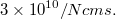
 Fig. 14.—Braun's Radiator. B, battery; I, induction
coil; K, key; S, spark-gap; L, inductance coil; C, condenser; A,
aerial.
Fig. 14.—Braun's Radiator. B, battery; I, induction
coil; K, key; S, spark-gap; L, inductance coil; C, condenser; A,
aerial.
The number 3×10¹⁰ is the value in centimetres per second of the
velocity of the electromagnetic wave, and is identical with that of
light. The corresponding resonant length of the aerial is therefore
one-fourth of this wave-length, or  . Generally speaking,
however, it will be found that with any length of aerial which is
practicable, say, 200 feet or 6,000 cms., this proportion necessitates
rather a high frequency in the primary oscillation circuit. In the
case considered—viz., for an aerial 200 feet in height—the
oscillations in the primary circuit must have a frequency of one and a
quarter million. This high frequency can only be obtained either by
greatly reducing the inductance of the primary discharge circuit, or
reducing the capacity. If we reduce the capacity, we thereby greatly
reduce the storage of energy, and it is not practicable to reduce the
inductance below a certain amount.
. Generally speaking,
however, it will be found that with any length of aerial which is
practicable, say, 200 feet or 6,000 cms., this proportion necessitates
rather a high frequency in the primary oscillation circuit. In the
case considered—viz., for an aerial 200 feet in height—the
oscillations in the primary circuit must have a frequency of one and a
quarter million. This high frequency can only be obtained either by
greatly reducing the inductance of the primary discharge circuit, or
reducing the capacity. If we reduce the capacity, we thereby greatly
reduce the storage of energy, and it is not practicable to reduce the
inductance below a certain amount.
Summing up, it may be said that there are three, and, as far as the writer is aware, at present only three, modes of exciting the electrical oscillations in an aerial wire. First, the aerial may itself be used as an electrical reservoir and charged to a high potential and suddenly discharged to the earth. This is the original Marconi method. The second method, due to Braun, consist of attaching the aerial to some point on an oscillation circuit consisting of a condenser, an inductance coil and a spark gap, in series with one another, and charging and discharging the condenser across the spark gap so as to create alterations of potential at some point on the oscillation circuit. The length of the aerial must then be so proportioned as above described that it is resonant to this frequency. Thirdly, we may employ the arrangement involving an oscillation transformer, in which the oscillations in the primary condenser circuit are made to induce others in the aerial circuit, the time-period of the two circuits being the same. This method may be called the Braun-Marconi method. Professor Slaby has combined together in a certain way the original Marconi simple aerial with the [Pg 23]resonant quarter-wave-length wire of Braun. He constructs what he calls a multiplicator, which is really a wire wound into a loose spiral connected at one point to an oscillation circuit consisting of a condenser inductance, the length of this wire being proportioned so that there is a great resonance or multiplication of tension or potential at its free end. This free end is then attached to the lower end of an ordinary Marconi aerial, and serves to charge it with a higher potential than could be obtained by the use of the induction coil directly attached to it.
We have next to consider the appliances for creating the necessary charging electromotive force, and for storing and releasing this charge at pleasure, so as to generate the required electrical oscillations in the aerial.
It is essential that this generator should be able to create not only large potential difference, but also a certain minimum electric current. Accordingly, we are limited at the present moment to one of two appliances—viz., the induction coil or the alternating current transformer.
It will not be necessary to enter into an explanation of the action of the induction coil. The coil generally employed for wireless telegraphy is technically known as a ten-inch coil—i.e., a coil which is capable of giving a ten-inch spark between pointed conductors in air at ordinary pressure. The construction of a large coil of this description is a matter requiring great technical skill, and is not to be attempted without considerable previous experience in the manufacture of smaller coils. The secondary circuit of a ten-inch coil is formed of double silk-covered copper wire; generally speaking, the gauge called No. 36, or else No. 34 S.W.G. is used, and a length of ten to seventeen miles of wire is employed on the secondary circuit, according to the gauge of wire selected. For the precautions necessary in constructing the secondary coil, practical manuals must be consulted.[8]
Very great care is required in the insulation of the secondary circuit of an induction coil to be used in Hertzian wave telegraphy, because the secondary circuit is then subjected to impulsive electromotive forces lasting for a short time, having a much higher electromotive force than that which the coil itself normally produces.
The primary circuit of a ten-inch coil generally consists of a length of 300 or 400 feet of thick insulated copper wire. In such a coil the secondary circuit would require about ten miles of No. 34 H.C. copper wire, making 50,000 turns round the core. It would have a resistance at ordinary temperatures of 6,600 ohms, and an inductance of 460 henrys. The primary circuit, if formed of 360 turns of No. 12 H.C. copper wire, would have a resistance of 0·36 of an ohm, and an inductance of 0·02 of a henry.
An important matter in connection with an induction coil to be used for wireless telegraphy is the resistance of the secondary circuit. The purpose for which we employ the coil is to charge a condenser of some kind. If a constant electromotive force (V) is applied to the terminals of a condenser having a capacity C, then the difference of potential (v) of the terminals of the condenser at any time that the contact is made is given by the expression:
In the above equation, the letter e stands for the number 2·71828, the base of the Napierian logarithms, and R is the resistance in series with the condenser, of which the capacity is C, to which the electromotive force is applied. This equation can easily be deduced from first principles,[9] and it shows that the potential difference v of the terminals of the condenser does not instantly attain a value equal to the impressed electromotive force V, but rises up gradually. Thus, for instance, suppose that a condenser of one microfarad is being charged through a resistance of one megohm by an impressed voltage of 100 volts, the equation shows that at the end of the first second after contact, the terminal potential difference of the condenser will be only 63 volts, at the end of the second second, 86 volts, and so on.
Since e-10 is an exceedingly small number, it follows that in 10 seconds the condenser would be practically charged with a voltage equal to 100 volts. The product CR in the above equation is called the time-constant of the condenser, and we may say that the condenser is practically charged after an interval of time equal to ten times the time-constant, counting from the moment of first contact between the condenser and the source of constant voltage. The time-constant is to be reckoned as the product of the capacity (C) in microfarads, by the resistance of the charging circuit (R) in megohms. To take another illustration. Supposing we are charging a condenser having a capacity of one-hundreth of a microfarad, through a resistance of ten thousand ohms. Since ten thousand ohms is equal to one-hundredth of a megohm, the time-constant would be equal to one-ten-thousandth of a second, and ten times this time-constant would be equal to a thousandth of a second. Hence, in order to charge the above capacity through the above resistance, it is necessary that the contact between the source of voltage and the condenser should be maintained for at least one-thousandth part of a second.
In discussing the methods of interrupting the circuit, we shall return to this matter, but, meanwhile, it may be said that in order to secure a small time-constant for the charging circuit, it is desirable that the secondary circuit of the induction coil should have as low a resistance as possible. This, of course, involves winding the secondary circuit with a rather thick wire. If, however, we employ a wire larger in size than No. 34, or at the most No. 32, the bulk and the cost of the induction coil began to rise very rapidly. Hence, as in all other [Pg 25]departments of electrical construction, the details of the design are more or less a matter of compromise. Generally speaking, however, it may be said that the larger the capacity which is to be charged, the lower should be the resistance of the secondary circuit of the induction coil.
In the practical construction of induction coils for wireless telegraphy, manufacturers have departed from the stock designs. We are all familiar with the appearance of the instrument maker's induction coil; its polished mahogany base, its lacquered brass fittings, and its secondary bobbin constructed of and covered with ebonite. But such a coil, although it may look very pretty on the lecture table, is yet very unsuited to positions in which it may be used in connection with Hertzian wave telegraphy.
Three important adjuncts of the induction coil are the primary condenser, the interrupter and the primary key. The interrupter is the arrangement for intermitting the primary current. We have in some way or other to rapidly interrupt the primary current, and the torrent of sparks that then appears between the secondary terminals of the coil is due to the electromotive force set up in the secondary circuit at each break or interruption of the primary circuit. We may divide interrupters into five classes.
We have first the well-known hammer interrupter which Continental writers generally attribute to Neef or Wagner.[10] In this interrupter, the magnetisation of the iron core of the coil is caused to attract a soft-iron block fixed at the top of a brass spring, and by so doing to interrupt the primary circuit between two platinum contacts. Mr. Apps, of London, added an arrangement for pressing back the spring against the back contact, and the form of hammer that is now generally employed is therefore called an Apps break.
As the ten-inch coil takes a primary current of ten amperes at sixteen volts when in operation, it requires very substantial platinum contacts to withstand the interruption of this current continuously without damage. The small platinum contacts that are generally put on these coils by instrument makers are very soon worn out in practical wireless telegraph work. If a hammer break is used at all, it is essential to make the contacts of very stout pieces of platinum, and from time to time, as they get burnt away or roughened, they must be smoothed up with a fine file. It does not require much skill to keep the hammer contacts in good order and prevent them from sticking together and becoming damaged by the break spark.
By regulating the pressure of the spring against the back contact, by means of an adjusting screw, the rate at which the break vibrates can be regulated, but as a rule it is not possible, with a hammer break, to obtain more than about 800 interruptions per minute, or, say, twelve a second. The hammer break is usually operated by the magnetism of the iron core of the coil, but for some reasons it is better to separate the break from the coil altogether, and to work it [Pg 26]by an independent electromagnet, which, however, may be excited by a current from the same battery supplying the induction coil. For coils up to the ten-inch size the hammer break can be used when very rapid interruptions are not required. It is not in general practicable to work coils larger than the ten-inch size with a platinum contact hammer break, as such a butt contact becomes overheated and sticks if more than ten amperes is passed through it. In the case of larger coils, we have to employ some form of interrupter in which mercury or a conducting liquid forms one of the contact surfaces.
The next class of interrupter is the vibrating or hand-worked mercury break, in which a platinum or steel pin is made to vibrate in and out of mercury. This movement may be effected by the attraction of an iron armature by an electromagnet, or by the varying magnetism of the core of the coil, or it may be effected more slowly by hand.
The mercury surface must be covered with water, alcohol, paraffin or creosote oil to prevent oxidation and to extinguish the break spark. The interruption of the primary current obtained by the mercury break is more sudden than that obtained by the platinum contact in air, in consequence of the more rapid extinction of the spark; hence the sparks obtained from coils fitted with mercury interrupters are generally from twenty to thirty per cent. longer than those obtained from the same coil under the same conditions, with platinum contact interrupters. The mercury breaks will not, however, work well unless cleaned at regular intervals by emptying off the oil and rinsing well with clean water, and hence they require rather more attention than platinum interrupters. It is not generally possible to obtain so many interruptions per minute with the simple vibrating mercury interrupter as with the ordinary hammer interrupter. The mercury interrupter has, however, the advantage that the contact time during which the circuit is kept closed may be made longer than is the case with the hammer break. Also, if fresh water is allowed to flow continuously over the mercury surface, it can be kept clean, and the break will then operate for considerable periods of time without attention. The mercury interrupter may be worked by a separate electromagnet or by the magnetism of the core of the induction coil.
The third class of interrupter may be called the motor interrupter, of which a large number have been invented in recent years. In this interrupter some form of a continuously-rotating electromotor is employed to make and break a mercury or other liquid contact. In one simple form the motor shaft carries an eccentric, which simply dips a platinum point into mercury, or else a platinum horseshoe into two mercury surfaces, making in this manner an interruption of the primary circuit at one or two places. As a small motor can easily be run at twelve hundred revolutions per minute, or twenty per second, it is possible to secure easily in this manner a uniform rate of interruption of the primary current at the rate of about twenty per second. If, however, much higher speeds are employed, then the time of contact becomes abbreviated, and the ability of the coil to charge a capacity is diminished.
Professor J. Trowbridge has described an effective form of motor break for large coils, in which the interruption is caused by withdrawing a stout platinum wire from a dilute solution of sulphuric acid, and by this means he increased the spark given by a coil provided with hammer break and condenser from fifteen inches to thirty inches when using the liquid break and no condenser.[11]
A good form of motor-interrupter, due to Dr. Mackenzie Davidson, consists of a slate disc bearing pin contacts fixed on the prolonged steel axle of a motor placed in an inclined position; the disc and the lower part of the axle lie in a vessel filled one-third with mercury and two-thirds with paraffin oil. The circuit is made and broken by the revolution of the disc causing the pins to enter and leave the mercury. The speed of the motor can be regulated by a small resistance, and can be adapted to the electromotive force used in the primary circuit. When the motor is running slowly the interrupter can be used with a low electromotive force, that is to say, something between twelve and twenty volts, but with a higher speed a large electromotive force can be used without danger of overheating the primary coil, and with an electromotive force of about fifty volts, the interruptions may be so rapid that an unbroken arc of flame, resembling an alternating-current arc, springs between the secondary terminals of the coil.
Mr. Tesla has devised numerous forms of rotating mercury break. In one, a star-shaped metal disc revolves in a box so that its points dip into mercury covered with oil, and make and break contact. In another form, a jet of mercury plays against a similar shaped rotating wheel. For details, the reader must consult the fuller descriptions in The Electrical World of New York, Vol. XXXII., p. 111, 1898; also Vol. XXXIII., p. 247; or Science Abstracts, Vol. II., pp. 46 and 47, 1898.
The fourth class of interrupter is called a turbine interrupter. In this appliance, a jet of mercury is forced out of a small aperture by means of a centrifugal pump, and is made to squirt against a metal plate, and interrupted intermittently by a toothed wheel made of insulating material rotated by the motor which drives the pump. The current supplying the coil passes through or along this jet of mercury, and is therefore rendered intermittent when the wheel revolves. In the case of this interrupter, the duration of the contacts, as well as the number of interruptions per second, is under control, and for this reason better results are probably obtained with it than with any other form of break.
A description of a turbine mercury break devised by M. Max Levy was given in the Elektrotechnische Zeitschrift, Vol. XX., p. 717, October 12, 1899 (see also Science Abstracts, Vol. III., p. 63, abstract No. 165) as follows:—
A toothed wheel made of insulating material carries from 6 to 24 teeth, and can be made to rotate from 300 to 1,000 times per minute, the interruptions being thus regulated between 5 and 400 per second. By raising or lowering the position of the jet of mercury and that of the plate against which it strikes, the duration of the contact can be [Pg 28]varied, so that it is possible to regulate this period without disturbing the number of interruptions per second.
The sparks obtained from a coil worked with a turbine interrupter have more quantity than the sparks obtained with any other interrupter under similar conditions, and the coil can be worked with a far higher voltage than is possible when using the hammer break. In this manner, the appearance of the secondary sparks can be varied from the thin snappy sparks given by the hammer break to the thick flame-like arc sparks given by the electrolytic break. This break can be adapted for any voltage from twelve to two hundred and fifty volts, and the primary circuit cannot be closed before the interrupter is acting. The mercury in the break is generally covered with alcohol or paraffin oil to reduce oxidation, and the appliance is nearly noiseless when in operation. The mercury has to be cleaned at intervals, if the interrupter is much used. If alcohol is used to cover the mercury, the cleaning is very simple; the break requires only to be rinsed under a water tap. When paraffin oil is used, the cleaning is generally effected with the help of a few ounces of sulphuric acid in a very few minutes. It is best, however, to clean the mercury continuously by allowing the water to flow over it.
The motor driving the centrifugal pump and the fan can be wound for any voltage, and it is best to have it so arranged that this motor works on the same battery which supplies the primary circuit of the coil, the two circuits working parallel together. A rheostat can be added to the motor circuit to regulate the speed.
The turbine break driven by an independent motor, which is kept always running, has another advantage over the hammer break in practical wireless telegraphy, viz., that a useful secondary spark can be secured with a shorter time of closure of the primary circuit, since there is no inertia to overcome as in the case of the hammer break. This latter form has only continued in use because of its simplicity and ease of management by ordinary operators.
The mercury turbine interrupter has been extensively adopted both in the German and British navies in connection with induction coils used for wireless telegraphy.
Lastly we have the electrolytic interrupters, the first of which was introduced by Dr. Wehnelt, of Charlottenburg, in the year 1899, and modified by subsequent inventors. In its original form, a glass vessel filled with dilute sulphuric acid (one of acid to five or else ten parts of water) contains two electrodes of very different sizes; one is a large lead electrode formed of a piece of sheet lead laid round the interior of the vessel, and the other is a short piece of platinum wire projecting from the end of a glass or porcelain tube. The smaller of these electrodes is made the positive, and the large one the negative. If this electrolytic cell is connected in series with the primary circuit of the induction coil (the condenser being cut out) and supplied with an electromotive force from forty to eighty volts, an electrolytic action takes place which interrupts the current periodically.[12] An enormous number of interruptions can, by suitable adjustment, be [Pg 29]produced per second, and the appearance of a discharge from the secondary terminals of the coil, while using the Wehnelt break, more resembles an alternate-current arc than the usual disruptive spark.
At the time when the Wehnelt break was first introduced, great interest was excited in it, and the technical journals in 1899 were full of discussions as to the theory of its operation.[13] The general facts concerning the Wehnelt break are that the electrolyte must be dilute sulphuric acid in the proportion of one of acid to five or ten of water. The large lead plate must be the cathode or negative pole, and the anode or positive pole must be a platinum wire, about a millimetre in diameter, and projecting one or two millimetres from the pointed end of a porcelain, glass or other acid-proof insulating tube. The aperture through which the platinum wire works must be so tight that acid cannot enter, yet it is desirable that the platinum wire should be capable of being projected more or less from the aperture by means of an adjusting screw. The glass vessel which contains these two electrodes should be of considerable size, holding, say, a quart of fluid, and it is better to include this vessel in a larger one in which water can be placed to cool the electrolyte, as the latter gets very warm when the break is used continuously. If such an electrolytic cell has a continuous electromotive force applied to it tending to force a current through the electrolyte from the platinum wire to the lead plate, we can distinguish three stages in its operation, which are determined by the electromotive force and the inductance in the circuit. First, if the electromotive force is below sixteen or twenty volts, then ordinary and silent electrolysis of the liquid proceeds, bubbles of oxygen being liberated from the platinum wire and hydrogen set free against the lead plate. If the electromotive force is raised above twenty-five volts, then if there is no inductance in the circuit, the continuous flow of current proceeds, but if the circuit of the electrolyte possesses a certain minimum inductance, the character of the current flow changes, and it becomes intermittent, and the cell acts as an interrupter, the current being interrupted from 100 to 2,000 times per second, according to the electromotive force and the inductance of the circuit. Under these conditions, the cell produces a rattling noise and a luminous glow appears round the tip of the platinum wire. Thus, in a particular case, with an inductance of 0·004 millihenry in the circuit of a Wehnelt break, no interruption of the circuit took place, but with one millihenry of inductance in the circuit, and with an electromotive force of 48 volts, the current became intermittent at the rate of 930 per second, and by increasing the voltage to 120 volts, the intermittency rose to 1,850 a second.
The Wehnelt break acts best as an interrupter with an electromotive force from 40 to 80 volts. At higher voltages a third stage sets in: the luminous glow round the platinum wire disappears, and it [Pg 30]becomes surrounded with a layer of vapour, as observed by MM. Violle and Chassagny; the interruptions of current cease, and the platinum wire becomes red hot. If there is no inductance in the circuit, the interrupter stage never sets in at all, but the first stage passes directly into the third stage. In the first stage bubbles of oxygen rise steadily from the platinum wire, and in the interrupted stage they rise at longer intervals, but regularly. The cell will not, however, act as a break at all unless some inductance exists in the circuit.
In applying the Wehnelt break to an induction coil, the condenser is discarded and also the ordinary hammer break, and the Wehnelt break is placed in circuit with the primary coil. In some cases, the inductance of the primary coil alone is sufficient to start the break in operation, but with voltages above 50 or 60, it is generally necessary to supplement the inductance of the primary coil by another inductive coil. The best form of Wehnelt break for operating induction coils is the one with multiple anodes (see Dr. Marchant, The Electrician, Vol. XLII., p. 841, 1899), and when it has to be used for long periods, the cathode may advantageously be formed of a spiral of lead pipe, through which cold water is made to circulate.
Another form of electrolytic break was introduced by Mr. Caldwell. In this, a vessel containing dilute sulphuric acid is divided into two parts. In the partition is a small hole, and in the two compartments are electrodes of sheet lead. The small hole causes an intermittency in the current which converts the arrangement into a break. Mr. Campbell Swinton modified the above arrangement by making the partition to consist of a sort of porcelain test-tube with a hole in the bottom. This hole can be more or less plugged up by a glass rod drawn out to a point, and this is used to more or less close the hole. This porcelain vessel contains dilute acid and stands in a larger vessel of acid, and lead electrodes are placed in both compartments. The current and intermittency can be regulated by more or less closing the aperture between the two regions.
When the Wehnelt break is applied to an ordinary ten-inch induction coil, and the inductance of the primary circuit and the electromotive force varied until the break interrupts the current regularly and with the frequency of some hundred a second, the character of the secondary discharge is entirely different from its appearance with the ordinary hammer break. The thin blue lightning-like sparks are then replaced by a thicker mobile flaming discharge, which resembles an alternating-current arc, and, when carefully examined or photographed, is found to consist of a number of separate discharges superimposed upon one another in slightly different positions.
Many theories have been adopted as to the action of the break, but time will not permit us to examine these. Professor S. P. Thompson and Dr. Marchant have suggested a theory of resonance.[14] One difficulty in explaining the action of the break is created by the fact that it will not work if the platinum wire is made a cathode.
Although the Wehnelt break has some advantages in connection with the use of the induction coil for Röntgen ray work, its utility [Pg 31]as far as regards Hertzian wave telegraphy is not by any means so marked. It has already been explained that, in order to charge a condenser of a given capacity at a constant voltage, the electromotive force must be applied for a certain minimum time, which is determined by the value of the capacity and the resistance of the secondary circuit of the induction coil. If the coil is a ten-inch coil and has a secondary resistance of, say, 6,000 ohms, and if the capacity to be charged has a value, say, of one-thirtieth of a microfarad, then the time-constant of the circuit is 1/5,000 of a second. Therefore, the contact with the condenser must be maintained for at least 1/500 of a second, during the time that the secondary electromotive force of the coil is at its maximum, so that the condenser may become charged to a voltage which the coil is then capable of producing.
In the induction coil, the electromotive force generated in the secondary coil at the "break" of the primary current is higher than that at the "make," and this electromotive force, other things being equal, depends upon the rate at which the magnetism of the iron core dies away, and its duration is shorter in proportion as the whole time occupied in the disappearance of the magnetism is less. The Wehnelt break does not increase the actual secondary electromotive force, nor apparently its duration, but it greatly increases the number of times per second this electromotive force makes it appearance. Hence this break increases the current, but not the electromotive force in the secondary coil. It, therefore, does not assist us in the direction required—viz., in prolonging the duration of the secondary electromotive force to enable larger capacities to be charged.
The important point in connection with the working of a coil used for charging a condenser is not the length of spark which the coil can give alone, but the length of spark which can be obtained between small balls attached to the secondary terminals, when these terminals are also connected to the two surfaces of the condenser. Thus, a coil may give a ten-inch spark if worked alone, but on a capacity of one-thirtieth of a microfarad it may not be able to give more than a five-millimetre spark. Hence, in describing the value of a coil for wireless telegraph purposes, it is not the least use to state the length of spark which the coil will give between the pointed conductors in air, but we must know the spark length which it will give between brass balls, say, 1 centimetre in diameter, connected to the secondary terminals, when these terminals are also short-circuited by a stated capacity, the spark not exceeding that length at which it becomes non-oscillatory.
A good way of describing the value of an induction coil for wireless telegraph purposes is to state the length of oscillatory spark which can be produced between balls one centimetre in diameter connected to the secondary terminals, when these balls are short-circuited by a condenser having a capacity, say, of one-hundredth of a microfarad, and also one-tenth of a microfarad.
If a hammer or motor interrupter is employed with the coil, then a primary condenser must be connected across the points between which the primary circuit is broken. This condenser generally [Pg 32]consists of sheets of tinfoil alternated with sheets of paraffin paper, and for a ten-inch coil may have a capacity of about 0·4 or 0·5 of a microfarad.[15]
Lord Rayleigh discovered that if the interruption of the primary circuit is sufficiently sudden and complete, as when the primary circuit is severed by a bullet from a gun, the primary condenser can be removed and yet the sparks obtained from the secondary circuit are actually longer than those obtained with the condenser and the ordinary break.[16]
In the use, however, of the coil for Hertzian wave telegraphy, with all interrupters except the Wehnelt break a condenser of suitable capacity must be joined across the break points.
Turning in the next place to the primary key, or signalling interrupter, it is necessary to be able to control the torrent of sparks between the secondary terminals of the coil, and to cut them up into long and short periods in accordance with the letters of the Morse alphabet. This is done by means of the primary key. The primary key generally consists of an ordinary massive single contact key with heavy platinum contacts. As the current to be interrupted amounts to about ten amperes and is flowing in a highly inductive circuit, the spark at break is considerable. If the attempt is made to extinguish this spark by making the contacts move rapidly away from one another through a long distance, in other words, by using a key with a wide movement, then the speed at which the signals can be set is greatly diminished. The speed of sending greatly depends upon the time taken to move the key up and down between sending two dots, and hence a short range key sends quicker than a long range key. If it is desired to use a short range key, then some method must be employed to extinguish the spark at the contacts. This is done in one of three ways: Either by using a high resistance coil to short-circuit these contacts, or by a condenser, or by a magnetic blow-out, as in the case of an electric tramcar circuit controller. Of these, the magnetic blow-out is probably the best.
Mr. Marconi has designed a signalling key which performs the function not only of interrupting the primary circuit, but at the same time breaks connection between the receiving appliance and the aerial.
The author has designed for signalling purposes a multiple contact key which interrupts the circuit simultaneously in ten or twelve different places. The particular point about this break is the means which are taken to make the twelve interruptions absolutely simultaneous. If these interruptions are not simultaneous, the spark always takes place at the contact which is broken first, but if the circuit is interrupted in a dozen places quite simultaneously, then the spark is cut up into a dozen different portions, and the spark at each contact is very much diminished. By this break, voltages up to two thousand volts may be quite easily dealt with.
Various forms of break have been devised in which the circuit is [Pg 33] broken under oil or insulating fluids, but, generally speaking, these devices are not very portable, and a dry contact between platinum surfaces with appropriate means for cutting up the spark and blowing it out so that the mechanical movement of the switch may be small is the best thing to use.
The signalling key is really a very important part of the transmitting arrangement, because whatever may be the improvements in receiving instruments, it is not possible to receive faster than we can send. A great many statements have appeared in the daily papers as to the possibility of receiving hundreds of words a minute by Hertzian wave telegraphy, but the fact remains that whatever may be the sensibility of the receiving appliance, the rate at which telegraphy of any kind can be conducted is essentially dependent upon the rate at which the signals can be sent, and this in turn is largely dependent upon the mechanical movement which the key has to make to interrupt the primary circuit, and so interrupt the secondary discharge.
In order to make the separation of the contact points of the switch as small as possible, and yet prevent an arc being established, various blow-out devices have been employed. The simplest arrangement for this purpose is a powerful permanent magnet so placed that its inter-polar field embraces the contact points and is at right angles to them.
As already explained, the applicability of the induction coil in wireless telegraphy is limited by the fact of the high resistance of the secondary circuit and the small current that can be supplied from it. Data are yet wanting to show what is the precise efficiency of the induction coil, as used in Hertzian wave telegraphy, but there are reasons for believing that it does not exceed 50 or 60 per cent.
Where large condensers have to be charged—in other words, where we have to deal with larger powers—we are obliged to discard the induction coil and to employ the alternating-current transformer. But this introduces us to a new class of difficulties. If an alternating-current transformer wound for a secondary voltage, say, of 20,000 or 30,000 volts, has its primary circuit connected to an alternator, then if the secondary terminals, to which are connected two spark balls, are gradually brought within striking distance of one another, the moment we do this an alternating-current arc starts between these balls. If the transformer is a small one, there is no difficulty in extinguishing this arc by withdrawing the secondary terminals, but if the transformer is a large one, say, of ten or twenty kilowatts, dangerous effects are apt to ensue when such an experiment is tried. The short circuiting of the secondary circuit almost entirely annuls the inductance of the primary circuit. There is, therefore, a rush of current into the transformer, and if it is connected to an alternator of low armature resistance the fuses are generally blown and other damage done.
Let us supppse, then, that the secondary terminals of the transformer are also connected to a condenser. On bringing together the spark balls connected with the secondary terminals we may have one or more oscillatory discharges, but the process will not be continuous, because the moment that the alternating-current arc starts between the spark balls it reduces their difference of potential to a [Pg 34] comparatively low value, and hence the charge taken by the condenser is very small, and, moreover, the circuit is not interrupted periodically so as to re-start a train of oscillations.
When, therefore, we desire to employ an alternating-current transformer as a source of electromotive force, although it may have the advantage that the resistance of the secondary circuit of the transformer is generally small compared with that of the secondary circuit of an induction coil, yet, nevertheless, we are confronted with two practical difficulties: (1) How to control the primary current flowing into the transformer, and (2) how to destroy the alternating-current arc between the spark balls and reduce the discharge entirely to the disruptive or oscillatory discharge of the condenser.
The control over the current can be obtained, in accordance with a plan suggested by the author, by inserting in the primary circuit of the transformer two variable choking coils. The form in which it is preferred to construct these is that of a cylindrical bobbin standing upon a laminated cross-piece of iron. These bobbins can have let down into them an E-shaped piece of laminated iron, so as to complete the magnetic circuit, and thus raise the inductance of the bobbin. By placing two of these variable choking coils in series with the primary circuit, the current is under perfect control. We can fix a minimum value below which the current shall not fall, by adjusting the position of the cores of these two choking coils, and we can then cause that current to be increased up to a certain limit which it cannot exceed, by short-circuiting one of these choking coils by an appropriate switch. Several ways have been suggested for extinguishing the alternating current arc which forms between the spark balls connected to the secondary terminals when these are brought within a certain distance of one another. One of these is due to Mr. Tesla. He places a strong electromagnet so that its lines of magnetic flux pass transversely between the spark balls. When the discharge takes place the electric arc is blown out, but if the balls are short-circuited by a condenser the oscillatory discharge of the condenser still takes place across the spark gap. Professor Elihu Thomson achieves the same result by employing a blast of air thrown on the spark gap. This has the effect of destroying the alternating-current arc, but still leaves the oscillating discharge of the condenser. The action is somewhat tedious to explain in words, but it can easily be understood that the blast of air, by continually breaking down the alternating-current arc which tends to form, allows the condenser connected to the spark balls to become charged with the potential of the secondary circuit of the transformer, and that this condenser then discharges across the spark gap, producing an oscillatory discharge in the usual manner. The author has found that, without the use of any air blast or electromagnet, simple adjustment of the double choking coil in the primary circuit of the transformer, as above described, is sufficient to bring about the desired result, when the capacity of the condenser is adjusted to be in resonance.
Another method, which has been adopted by M. d'Arsonval, is to cause the spark to pass between two balls placed at the extremities of [Pg 35] metal rods, which are in rapid rotation like the spokes of a wheel. In this case, the draught of air produced by the passage of the spark balls blows out the arc and performs the same function as the blast of air in Professor Elihu Thomson's method. When these adjustments are properly made, it is possible, by means of a condenser and an alternating-current transformer supplied with current from an alternator, to create a rapidly intermittent oscillatory discharge, the sparks of which succeed one another so quickly that it appears almost continuous. When using a large transformer and condenser, the noise and brilliancy of these sparks are almost unbearable, and the eyes may be injured by looking at this spark for more than a moment. In the construction of transformers intended to be used in this manner, very special precautions have to be taken in the insulation of the primary and secondary circuits, and the insulation of these from the core.
It may be remarked in passing that experimenting with large high-tension transformers coupled to condensers of large capacity is exceedingly dangerous work, and the greatest precautions are necessary to avoid accident. In the light, however, of sufficient experience there is no difficulty in employing high-tension transformers in the above-described manner, and in obtaining electromotive forces of upwards of a hundred thousand volts supplied through transformers capable of yielding any required amount of current.
On occasions where continuous current alone is available, a motor generator has to be employed converting the continuous current into an alternating current. This is best achieved by the employment of a small alternator directly coupled to a continuous-current motor; or by providing the shaft of a continuous-current motor with two rings connected to two opposite portions of its armature, so that when continuous current is supplied to the brushes pressing against the commutator, an alternating current can be drawn off from two other brushes touching the above-mentioned insulated rings.
The next element of importance in the transmitting arrangement is the spark gap. In the case of those transmitters employing an ordinary induction coil, the secondary spark, or the discharge of any condenser connected to the secondary terminals can be taken between the brass balls about half an inch or one inch in diameter, with which the terminals of the secondary coil are usually furnished; and it is generally the custom to allow this spark discharge to take place in air at ordinary pressure. In the very early days of his work Mr. Marconi adopted the discharger devised by Professor Rhigi, in which the spark takes place between two brass balls placed in vaseline or other highly insulating oil.[17] But whatever advantage may accrue from using oil as the dielectric in which the spark discharge takes place, when carrying out simple laboratory experiments on Hertzian waves, there is no advantage in the case of wireless telegraphy. The Rhigi discharger [Pg 36]was, therefore, soon discarded. If discharges having large quantity are passed through oil, it is rapidly decomposed or charred, and ceases to retain the special insulating and self-restoring character which is necessary in the medium in which an oscillating spark is formed. The conditions when the discharges of large condensers are passed between spark balls are entirely different from those when the quantity of the spark, or to put it in more exact language, the current passing, is very small. In the case of Hertzian experiments it is necessary, as shown by Hertz, to maintain a high state of polish on the spark balls when they are employed for the production of short waves of small energy, but when we are dealing with large quantities of energy at each discharge, those methods which succeed for laboratory experiments are perfectly impracticable. The conditions necessary to be fulfilled by a discharger for use in Hertzian wave telegraphy are that the surfaces shall maintain a constant condition and not be fused or eaten away by the spark, and, next, that the medium in which the discharge takes place shall not be decomposed by the passage of the spark, but shall maintain the property of giving way suddenly when a certain critical pressure is reached, and passing instantly from a condition in which it is a very perfect insulator to one in which it is a very good conductor; and, thirdly, that on the cessation of the discharge, the medium shall immediately restore itself to its original condition.
When using the ordinary ten-inch induction coil, and when the capacity charged by it does not exceed a small fraction of a microfarad, it is quite sufficient to employ brass or steel balls separated by a certain distance in air, at the ordinary pressure, as the arrangement of the discharger. When, however, we come to deal with the discharges of very large condensers, at high electromotive forces, then it is necessary to have special arrangements to prevent the destruction of the surfaces between which the spark passes, or their continual alteration, and many devices have been invented for this purpose. The author has devised an arrangement which fulfils the above conditions very perfectly for use in large power stations, but the details of this cannot be made public at the present time.
We have to consider in connection with this part of the subject the dielectric strength of air under different pressures and for different thicknesses. It was shown by Lord Kelvin, in 1860, that the dielectric strength of very thin layers of air is greater than that of thick layers.[18] The electric force, reckoned in volts per centimetre, required to pierce a thickness of air from two to ten millimetres in thickness, at atmospheric pressure, may be taken at 30,000 volts per centimetre. The same force in electrostatic units is represented by the number 100, since a gradient of 300 volts per centimetre corresponds to a force of one electrostatic unit. It appears also that for air and other gases there is a certain minimum voltage (approximately 400 volts) below which no discharge takes place, however near the conducting surfaces [Pg 37]may be approximated. In this particular practical application, however, we are only concerned with spark lengths which are measured in millimetres or centimetres, lying, say, between one or two millimetres and five or six centimetres. Over this range of spark length we shall not generally be wrong in reckoning the voltage required to produce a spark between metal balls in air at the ordinary pressure to be given by the rule:

If, however, the air pressure is increased above the normal by including the spark balls in a vessel in which air can be compressed, then the spark length, corresponding to a given potential difference, very rapidly decreases. Mr. F. J. Jervis-Smith[19] found that by increasing the air pressure from one atmosphere to two atmospheres round a pair of spark balls he reduced the spark length given by a certain voltage from 2·5 to 0·75 centimetre.
Professor R. A. Fessenden has also made some interesting observations on the effect of using compressed air round spark gaps. He found that if a certain voltage between metal surfaces would yield a spark four inches in length, at the ordinary pressure of the air, if the spark balls were enclosed in a cylinder, the air round them compressed at 50lb. per square inch, the spark length for the same potential difference of the balls was only one quarter of an inch, or one-sixteenth of its former value.
The writer has also made experiments with an apparatus designed to study the effect of compressed air round the spark gap. The experimental arrangements are as follows: A ten-inch induction coil has one of its terminals connected to the internal coating of a battery of Leyden jars. The external coating is connected through the primary coil of an oscillation transformer with the other secondary terminal of the coil, and these secondary terminals are also connected to a spark gap consisting of two brass balls enclosed in a glass vessel into which air can be forced by a pump, the air pressure being measured by a gauge. The balls in the glass vessel are set at a distance of about three millimetres apart. The secondary circuit of the oscillation transformer is connected to another pair of spark balls, the distance of which can be varied.
Suppose we begin with the air in the glass vessel containing the balls connected to the secondary terminals of the induction coil, which may be called the secondary balls, at atmospheric pressure, and create oscillatory discharges in the primary coil of the oscillation transformer, we have a spark between the balls, which may be called the tertiary balls, connected to the secondary terminals of the oscillation transformer. If the secondary balls are placed, say, three millimetres apart, the air in the glass vessel enclosing them being at the ordinary atmospheric pressure, then with one particular arrangement of jars [Pg 38]used, a spark twenty-five or twenty-six millimetres long between the tertiary balls will take place. Suppose, then, we increase the pressure of the air round the secondary balls, pumping it by degrees to 10, 20, 30, 40 and 50lb. per square inch above the atmospheric pressure. We find that the spark between the tertiary balls will gradually leap a greater and greater distance, and when the pressure of the air is 50lb. per square inch, we can obtain a fifty-millimetre spark between the tertiary balls, whereas when the air in the glass vessel is at atmospheric pressure, we can only obtain a spark between the tertiary balls of half that length.
This experiment demonstrates that the effect of compressing the air round the secondary terminals of the induction coil is to greatly increase the difference of potential between these balls before the spark passes. In fact, it requires about double the voltage to force a spark of the same length through air compressed at 50lb. on the square inch that it does to make a spark of identical length between the same balls in air at normal pressure. This shows that there is a very great advantage in taking the discharge spark in compressed air. A better effect can be produced by substituting dry gaseous hydrochloric acid for air at ordinary pressures.
One other incidental advantage is that the noise of the spark is very much reduced. The continual crackle, of the discharge spark of the induction coil in connection with wireless telegraphy is very annoying to sensitive ears, but in this manner we can render it perfectly silent.
Professor Fessenden also states that when the spark balls are surrounded by compressed air, and if one of the balls is connected with a radiator, the compression of the air, although it shortens the spark-gap corresponding to a given voltage, does not in any way increase the radiation. When, however, the air in the spark-ball vessel is compressed to 60lb. in the square inch, there is a marked increase in the effective radiation, and at 80lb. per square inch the energy emitted in the form of waves is nearly three and a-half times greater than at 50lb., the potential difference between the balls remaining the same.
This effect is no doubt connected with the fact that the production of a wave, whether in ether or in any other material, is not so much dependent upon the absolute force applied as upon the suddenness of its application. To translate it into the language of the electronic theory, we may say that the electron radiates only whilst it is being accelerated, and that its radiating power, therefore, depends not so much upon its motion as upon the rate at which its motion is changing.
The advantage in using compressed air round the spark gap is that we can increase the effective potential difference between the balls without rendering the spark non-oscillatory. In air of the ordinary pressure there is a certain well-defined limit of spark length for each voltage, beyond which the discharge becomes non-oscillatory, but by the employment of spark balls in compressed air, we can increase the potential difference between the balls corresponding to a given distance apart before a discharge takes place, or employ higher potentials with [Pg 39]the same length of spark gap. In addition to this, we have, perhaps, the production of a more effective radiation, as asserted by Fessenden, when the air pressure exceeds a certain critical value.
The next element which we have to consider in the transmitting arrangements is a condenser of some kind for storing the energy which is radiated at intervals. Where a condenser other than the aerial is employed for storing the electric energy which is to be radiated by the aerial, some form of it must be constructed which will withstand high potentials. As the dielectric for such a condenser, only two materials seem to be of any practical use, viz., glass and micanite. Glass condensers in the form of Leyden jars have been extensively employed, but they have the disadvantage that they are very bulky in proportion to their electrical capacity. The instrument maker's quart Leyden jar has a capacity of about one-five hundredth of a microfarad, but it occupies about 150 cubic inches or more. Professor Braun has employed in his transmitting arrangements condensers consisting of small glass tubes like test tubes, lined on the inside and outside with tinfoil, which are more economical in space. The author has found that condensers for this purpose are best made of sheet glass about one-eighth or one-tenth of an inch in thickness, coated to within one inch of their edge on both sides with tinfoil, and arranged in a vessel containing resin or linseed oil, like the plates of a storage battery. M. d'Arsonval has employed micanite, but although this material has a considerably higher dielectric strength than glass, it is much more expensive to obtain a given capacity by means of micanite than by glass, although the bulk of the condenser for a given capacity is less.
To store up a certain amount of electric energy in a condenser, we require a certain definite volume of dielectric, no matter how we may arrange it, and the volume required per unit of energy is determined by the dielectric strength of the material. Thus, for instance, ordinary sheet glass cannot be safely employed with a greater electric force than is represented by 20,000 volts for one-tenth of an inch in thickness, or, say, a potential gradient of 160,000 volts per centimetre. This is equivalent to an electric force of about 500 electrostatic units. This may be called the safe-working force. The electrostatic capacity of a condenser formed of two metal surfaces a foot square separated by glass three millimetres in thickness is between 1/360 and 1/400 of a microfarad. If this condenser is charged to 20,000 volts, we have stored up in it half a joule of electric energy, and the volume of the dielectric is 270 cubic centimetres. Hence, to store up in a glass condenser electric energy represented by one joule at a pressure of 20,000 volts, we require 500 cubic centimetres of glass, and it will be found that if we double the pressure and double the thickness of the glass, we still require the same volume.[20] Hence, in the construction of high-tension condensers to store up a given amount of energy, the economical problem is how to obtain the greatest energy-storing capacity for the [Pg 40]least money. Glass fulfils this condition better than any other material. Although some materials may have very high dielectric strength, such as paper saturated with various oils, or resins, yet they cannot be used for the purpose of making condensers to yield oscillatory discharges, because the oscillations are damped out of existence too soon by the dielectric.
In arranging condensers to attain a given capacity, regard has to be taken of the fact that for a given potential difference there must be a certain total thickness of dielectric, and that if condensers of equal size are being arranged in parallel it adds to their capacity, whilst joining them in series divides their capacity. If N equal condensers or Leyden jars have each a capacity represented by C, and if they are joined n in series and m in parallel, the joint capacity of the whole number is mC/n, where the product mn = N.
Passing on next to the consideration of oscillation transformers of various kinds—these are appliances of the nature of induction coils for transforming the current or electromotive force of electrical oscillations in a required ratio. These coils are, however, destitute of any iron core, and they generally consist of coils of wire wound on a fibre, wooden or ebonite frame, and must be immersed in a vat of oil to preserve the necessary insulation. No dry insulation of the nature of indiarubber or gutta-percha will withstand the high pressures that are brought to bear upon the circuits of an oscillation transformer. In constructing these transformers we have to set aside all previous notions gathered from the design of low-frequency iron-core transformers. The chief difficulty we have to contend against in the construction of an effective oscillation transformer is the inductance of the primary circuit and the magnetic leakage that takes place. In other words, the failure of the whole of the flux generated by the primary circuit to pass through or be linked with the secondary circuit. Mr. Marconi has employed an excellent form of oscillation transformer, in the design of which he was guided by a large amount of experience. In this transformer the two circuits are wound round a square wooden frame. The primary circuit consists of a number of strands of thick insulated cable laid on in parallel, so that it consists of only one turn of a stranded conductor. The secondary circuit consists of a number of turns, say, ten to twenty, of thinner insulated wire laid over the primary circuit and close to it, so that the transformer has the transformation ratio of one to ten or one to twenty. In the arrangements devised and patented by Mr. Marconi, these two circuits, with their respective capacities in series with them, are tuned to one another, so that the time-period of each circuit is exactly the same, and without this tuning the device becomes ineffective as a transformer.[21] There is no advantage in putting a number of turns on the primary circuit, because such multiplication simply increases the inductance, and, therefore, diminishes the primary current in the same ratio which it multiplies the turns, and hence the magnetic field due to the primary circuit remains the same. Where it is desired to [Pg 41]put a number of turns upon a coil, and yet at the same time keep the inductance down, the writer has adopted the device of winding a silk or hemp rope well paraffined between the turns of the circuit, so as to keep them further apart from one another, and as the inductance depends on the turns per centimetre, this has the effect of reducing the inductance.
The next and most important element in any transmitting station is the aerial or radiator, and it was the introduction of this element by Mr. Marconi which laid the foundation for Hertzian wave telegraphy as opposed to mere experiments with the Hertzian waves. We may consider the different varieties of aerial which have been evolved from the fundamental idea. The simple single Marconi aerial consists of a bare or insulated wire, generally about 100ft. or 150ft. in length, suspended from a sprit attached to a tall mast. As these masts have generally to be erected in exposed positions, considerable care has to be taken in erecting them with a large margin of strength. To the end of a sprit is attached an insulator of some kind, which may be a simple ebonite rod, or sometimes a more elaborate arrangement of oil insulators, and to the lower end of this insulator is attached the aerial wire. As at the top of the aerial we have to deal with potentials capable sometimes of giving sparks several feet in length, the insulation of the upper end of the aerial is an important matter.
In the original Marconi system, the lower end of the aerial was simply
attached to one spark ball connected to one terminal of the induction
coil, and the other terminal and spark ball were connected to the
earth. In this arrangement, the aerial acted not only as radiator, but
as energy-storing capacity, and as already explained, its radiating
power was on that account limited. The earth connection is an
important matter. For long distance work, a good earth is essential.
This earth must be made by embedding a metal plate in the soil, and
many persons are under the impression that the efficiency of the earth
plate depends upon its area, but this is not the fact. It depends much
more upon its shape, and principally upon the amount of its "edge." It
has been shown by Professor A. Tanakadate, of Japan, that if a metal
plate of negligible resistance is embedded in an infinite medium
having a resistivity r, the electrical conductance of this plate is
equal to  times the electrostatic capacity of the same
plate placed in a dielectric of infinite extent. Hence in designing an
earth plate, we have to consider not how to give it the utmost amount
of surface, but how to give it the greatest electrostatic capacity,
and for this purpose it is far better to divide a given amount of
metal into long strips radiating out in different directions, rather
than to employ it in the form of one big square or circular plate. The
importance of the "good earth" will have been seen from our discussion
on the mode of formation of electric waves. There must be a perfectly
free access for the electrons to pass into and out of the aerial.
Hence, if the soil is dry, or badly conductive in the neighbourhood,
we have to go down to a level at which we get a good moist earth. In
fact, the precautions which have to be taken in making a [Pg 42]good earth
for Hertzian wave telegraphy are exactly those which should be taken
in making a good earth for a lightning conductor.
times the electrostatic capacity of the same
plate placed in a dielectric of infinite extent. Hence in designing an
earth plate, we have to consider not how to give it the utmost amount
of surface, but how to give it the greatest electrostatic capacity,
and for this purpose it is far better to divide a given amount of
metal into long strips radiating out in different directions, rather
than to employ it in the form of one big square or circular plate. The
importance of the "good earth" will have been seen from our discussion
on the mode of formation of electric waves. There must be a perfectly
free access for the electrons to pass into and out of the aerial.
Hence, if the soil is dry, or badly conductive in the neighbourhood,
we have to go down to a level at which we get a good moist earth. In
fact, the precautions which have to be taken in making a [Pg 42]good earth
for Hertzian wave telegraphy are exactly those which should be taken
in making a good earth for a lightning conductor.
Whilst on the subject of aerials, a word may be said on the localisation of wireless telegraph stations on the Marconi system. For reasons which were explained previously, the transmission of signals is effected more easily over water than over dry land, and it is hindered if the soil in the neighbourhood of the sending station is a poor conductor. Hence, all active Hertzian wave telegraph stations, like all active volcanoes, are generally found near the sea. In those cases in which a multiple aerial has to be put up consisting of many wires, one mast may be insufficient to support the structure, and several masts arranged in the form of a square or a circle have to be employed. The illustrated papers have reproduced numerous pictures of the Marconi power stations at Poldhu in Cornwall, Glace Bay in Nova Scotia, and Cape Cod in the United States. In these stations, after preliminary failures to obtain the necessary structural strength with ordinary masts, tall lattice girder wooden towers have been built, about 215 feet in height, well stayed against wind pressure, and which so far have proved themselves capable of withstanding any storm of wind which has come against them.
An important question in connection with the sending power of an aerial is that of the relation of its height to the distance covered. Some time ago Mr. Marconi enunciated a law, as the result of his experiments, connecting these two quantities, which may be called Marconi's Law. He stated that the height of the aerial to cover a given distance, other things remaining the same, varies as the square root of the distance. Let D be the distance and let L be the length of the aerial, then if both the transmitting and receiving aerial are the same height, we may say that D varies as L2. This relation may be theoretically deduced as follows:—Any given receiving apparatus for Hertzian wave telegraphy requires a certain minimum energy to be imparted to it to make it yield a signal. If the resistance and the capacity of the receiver is taken as constant, this minimum working energy is proportional to the square of the electromotive force set up in the receiving aerial by the impact on it of the electric waves. This electromotive force varies as the length of the receiving aerial and as the magnetic force due to the wave cutting across it, and the magnetic force varies as the current in the transmitting aerial, and therefore, for any given voltage varies as the capacity, and therefore as the length of the transmitting aerial. If, therefore, the transmitting and receiving aerial have the same length, the minimum energy varies as the square of the electromotive force in the receiving aerial, and therefore as the fourth power of the length of either aerial, since the electromotive force varies as the product of the lengths of the aerials. Hence, when the distance between the aerials is constant, the minimum working energy varies as the fourth power of the height of either aerial, but when the lengths of the aerials are constant, the energy caught up by the receiving aerial must vary inversely as the square of the distance D between the aerials. Hence, if we call e this minimum working energy, e must vary as 1/D2 when L is constant, [Pg 43]or as L4 when D is constant, and since e is a constant quantity for any given arrangements of receiver and transmitter, it follows that when the height of aerial and distance vary, the ratio L4/D2 is constant, or, in other words, D2 varies as L4 or D varies as L2—i.e., distance varies as the square of the height of the aerial, which is Marconi's Law. The curve, therefore, connecting height of aerial with sending distance for given arrangements is a portion of a parabola.
Otherwise, the law may be stated in the form  , where a
is a numerical coefficient. If L and D are both measured in metres,
then, for recent Marconi apparatus as used on ships, a=0·15 roughly.
(See a report on experiments made for the Italian Navy, 1900-1901, by
Captain Quintino Bonomo—"Telegrafia senza fili," Rome, 1902.)
, where a
is a numerical coefficient. If L and D are both measured in metres,
then, for recent Marconi apparatus as used on ships, a=0·15 roughly.
(See a report on experiments made for the Italian Navy, 1900-1901, by
Captain Quintino Bonomo—"Telegrafia senza fili," Rome, 1902.)
This law, however, must not be used without discretion. After Mr. Marconi had transmitted signals across the British Channel, some people, forgetting that a little knowledge is a dangerous thing, predicted that aerials a thousand feet in height would be required to signal across the Atlantic, but Mr. Marconi has made such improvements of late years in the receiving arrangements that he has been able to receive signals over three thousand miles in 1903 with aerials only thirty-three per cent. longer than those which, in 1899, he employed to cover twenty miles across the English Channel.
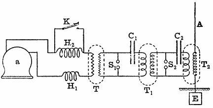 Fig. 15.—Alternating-current Double-transformation
Power Plant for Generating Electric Waves (Fleming). a, alternator;
H1H2, choking coil; K, signalling key; T, step-up transformer;
S1S2 spark-gap; C1C2 condensers; T1T2, oscillation
transformers; A, aerial; E, earthplate.
Fig. 15.—Alternating-current Double-transformation
Power Plant for Generating Electric Waves (Fleming). a, alternator;
H1H2, choking coil; K, signalling key; T, step-up transformer;
S1S2 spark-gap; C1C2 condensers; T1T2, oscillation
transformers; A, aerial; E, earthplate.
We turn, in the next place, to the consideration of those devices for putting more power into the aerial than can be achieved when the aerial itself is simply employed as the reservoir of energy. Professor Braun, of Strassburg, in 1899, described a method for doing this by inducing oscillations in the aerial by means of an oscillation transformer, these oscillations being set up by the discharges from a Leyden jar or battery of Leyden jars, which formed the reservoir of energy. The induction coil is employed to produce a rapidly intermittent series of electrical oscillations in the primary coil of an oscillation transformer by the discharge through it of a Leyden jar. Mr. Marconi immensely improved this arrangement, as described by him in a lecture given before the Society of Arts on May 17, 1901, by syntonising the two circuits and making the circuit, consisting of the capacity of the aerial and the inductance of the secondary circuit of the oscillation transformer, have the same time-period as the circuit consisting [Pg 44]of the Leyden jars, or energy-storing condenser, and the primary circuit of the oscillation transformer, and by so doing immensely added to the power and range of the apparatus.
Starting from these inventions of Braun and Marconi, the author devised a double transmission system in which the oscillations are twice transformed before being generated in the aerial, each time with a multiplication of electromotive force and a multiplication of the number of groups of oscillations per second. This arrangement can best be understood from the diagram (see Fig. 15).
In this case a transformer, T, or transformers receive alternating low-frequency current from an alternator, a, being regulated by passing through two variable choking coils, H1 and H2, so as to control it. This alternating current is transformed up from a potential of two thousand to twenty, forty or a hundred thousand, and is employed to charge a large condenser, C1, which discharges across a primary spark-gap, S1, through the primary coil of an oscillation transformer, T1. The secondary circuit of the oscillation transformer is connected to a second pair of spark balls, S2, which in turn are connected by a secondary condenser, C2, and the primary circuit of a third transformer, T2 and the secondary circuit of this last transformer are inserted between a Marconi aerial, A, and the earth E. When all these circuits are tuned to resonance by Mr. Marconi's methods, we have an enormously powerful arrangement for creating electric waves, or rather trains of electric waves, sent out from the aerial, and the oscillations are controlled and the signals made by short-circuiting one of the choking coils.
Another transmitting arrangement, which involves a slightly different principle, and employs no oscillation transformer, is one due also to Professor Braun. In this case, a condenser and inductance are connected in series to the spark balls of an induction coil, and oscillations are set up in this circuit. Accordingly, there are rapid fluctuations of potential at one terminal of the condenser. If to this we connect a long aerial, the length of which has been adjusted to be one quarter of the length of wave corresponding to the frequency, in other words, to make it a quarter-wave resonator, then powerful oscillations will be accumulated in this rod. The relation between the height (H) of the aerial and the frequency is given by the equation 3 × 1010=4nH, where n is the frequency of the oscillations and H the height of the aerial in centimetres. The frequency of the oscillations is determined by the capacity (C) and inductance (L) of the condenser circuit, and can be calculated from the formula
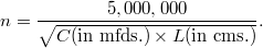
That is, the frequency is obtained by dividing into the number 5,000,000, the square root of the product of the capacity in microfarads, and inductance in centimetres, of the condenser circuit. It will be found, on applying these rules, that it is impossible to unite together any aerial of a length obtainable in practice with a condenser circuit of more than a very moderate capacity. It has been shown that [Pg 45]for an aerial two hundred feet in height the corresponding resonating frequency is about one and a quarter million.[22] As we are limited in the amount to which we can reduce the inductance of a discharge circuit, probably to something like a thousand centimetres, a simple calculation shows that the largest capacity we can employ is about a sixtieth of a microfarad. This capacity, even if charged at 60,000 volts, would only contain thirty joules of energy, or about 22·5 foot-pounds, which is a small storage compared to that which can be achieved when we are employing the above-described methods, which involve the use of an oscillation transformer. In such a case, however, it is an advantage to employ a spark-gap in compressed air, because we can then raise the voltage to a much higher value than in air of ordinary pressure without lengthening the spark so much as to render it non-oscillatory.
When employing methods involving the use of an oscillation transformer, it is possible to use multiple aerials having large capacity, and hence to store up a very large amount of energy in the aerial, which is liberated at each discharge. The most effective arrangement is one in which the radiator draws off gradually a large supply of energy from a non-radiating circuit, and so sends out a true train of waves, and not mere impulses, into the ether, and as we shall see later on, it is only when the radiation takes place in the form of true wave trains that anything like syntony can be obtained.
There are a number of variants of the above methods of arranging the radiator and associated energy-storing in circuit. Descriptions of these arrangements will be found in patents by Mr. Marconi, Professor Slaby and Count von Arco, Sir Oliver Lodge, Dr. Muirhead, Professor Popoff, Professor Fessenden and others. In all cases, however, they are variations of the three simple forms of radiator already described.
Returning to the analogy with the air or steam siren suggested at the commencement of this article, the reader will see in the light of the explanations already given, that all parts of the air-wave producing apparatus have their analogues in the electrical radiator as used in Hertzian wave telegraphy. The object in the one case is to produce rapid oscillations of air particles in a tube, which result in the production of an air wave in external space; in the other case, the arrangement serves to produce oscillations of electrons or electrical particles in a wire, the movements of which create a disturbance in the ether called an electrical wave. Comparing together, item by item, it will be seen, therefore, that the induction coil or transformer used in connection with electric-wave apparatus is analogous to the air pump in the siren plant. In the electrical apparatus, this electron pump is employed to put an electrical charge into a condenser; in the air wave apparatus, the air pump is employed to charge an air vessel with high [Pg 46]pressure air. From the electrical condenser the charge is released in the form of a series of electrical oscillations, and in the air wave producing appliance, the compressed air is released in the form of a series of intermittent puffs or blasts. In the electrical wave producing apparatus, these electrical oscillations in the condenser circuit are finally made to produce other oscillations in an air wire or open circuit, just as the puffs of air finally expend themselves in producing aerial oscillations in the siren tube. Finally, in the one case we have a series of air waves and in the other case, a series of electrical waves. These trains of electric waves or air waves, as the case may be, are intermitted into long and short groups, in accordance with the signals of the Morse alphabet, and, therefore, the Hertzian wave transmitter, in whatever form it may be employed, when operated by means of a Marconi aerial, is in fact an electrical siren apparatus, the function of which is to create periodic disturbances in the universal ether of the same character as those which the siren produces in atmospheric air.
We have to consider in the next place the arrangements of the receiving station and the various forms of receivers that have been devised for effecting telegraphy by Hertzian waves. Just as the transmitting station consists essentially of two parts, viz., a part for creating electrical oscillations and a part for throwing out or radiating electric waves, so the receiving-station appliances may be divided into two portions; the function of one being to catch up a portion of the energy of the passing wave, and that of the other to make a record or intelligible signal in some manner in the form of an audible or visible sign.
Accordingly, there must be at the receiving station an arrangement called a receiving aerial, which in general takes the form of a long vertical wire or wires, similar in form to the transmitting aerial, There is, however, a distinct difference in the function of the transmitting aerial and the receiving aerial. The function of the first is effective radiation, and for this purpose the aerial must have associated with it a store of energy to be released as wave energy; but the function of the receiving aerial is to be the seat of an electromotive force which is created by the electric force and the magnetic force of the incident electric wave.
In tracing out the mode of operation of the transmitting aerial, it was pointed out that the electric waves emitted consisted of alternations of electric force in a direction which is perpendicular to the surface of the earth, and magnetic force parallel to the surface of the earth. These two quantities, the electric force and the magnetic force, are called the wave vectors, and they both lie in a plane perpendicular to the direction in which the wave is travelling and at right angles to one another, the electric force being perpendicular to the surface of the earth. In optical language, the wave sent out by the aerial would be called a plane polarised wave, the plane of polarisation being parallel to the magnetic force. Hence, if at any point in the path of the wave we erect a vertical conductor, as the wave passes over it, it is cut transversely by the magnetic force of the wave and longitudinally [Pg 47]by the electric force. Both of these operations result in the creation of an alternating electromotive force in the receiving aerial wire.
As in all other cases of oscillatory motion, the principle of resonance may here be brought into play to increase immensely the amplitude of the current oscillations thereby set up in the receiving aerial. As already explained, any vertical insulated wire placed with its lower end near the earth has capacity with respect to the earth, and it has also inductance, the value of these factors depending on its shape and height. Accordingly, it has a natural electrical time-period of its own, and if the periodic electromotive impulses which are set up in it by the passage of the waves over it agree in period with its own natural time-period, then the amplitude of the current vibrations in it may become enormously greater than when there is a disagreement between these two periods. Before concluding these articles we shall return to this subject of electric resonance and syntony, and discuss it with reference to what is called the tuning of Hertzian wave stations. Meanwhile, it may be said that for the sake of obtaining, at any rate in an approximate degree, this coincidence of time-period, it is generally usual to make the receiving aerial as far as possible identical with the transmitting aerial. If the receiving aerial is not insulated, but is connected to the earth at its lower end through the primary coil of an oscillation transformer, we can still set up in it electrical oscillations by the impact on it of an electric wave of proper period; and if the oscillation transformer is properly constructed we can draw from its secondary circuit electric oscillations in a similar period.
One problem in connection with the design of a receiving aerial is that of increasing its effective length and capacity so as to increase correspondingly the electromotive force or current oscillations in it. It is clear that if we put a number of receiving wires in parallel so that each one of them is operated upon by the wave separately, although we can increase in this way the magnitude of the alternating current which can be drawn off from the aerial, we cannot increase the electromotive force in it except by increasing the actual height of the wires. Unfortunately, there is a limit to the height of the receiving aerial. It has to be suspended, like the transmitting aerial, from a mast or tower, and the engineering problem of constructing such a permanent supporting structure higher than, say, two hundred feet is a difficult one.
Since any one station has to send as well as receive, it is usual to make one and the same aerial wire or wires do double duty. It is switched over from the transmitting to the receiving apparatus, as required. This, however, is a concession to convenience and cost. In some respects it would be better to have two separate aerials at each station, the one of the best form for sending, and the other of the best form for receiving.
In Mr. Marconi's early arrangements, the so-called coherer or sensitive wave-detecting appliance, to be described more in detail presently, was inserted between the base of the insulated receiving aerial and the earth, but it was subsequently found by him to be a great improvement to act upon the receiving device, not directly by the electromotive force set up in the aerial, but by the induced [Pg 48] electromotive force of a special form of step-up oscillation transformer he calls a "jigger," the primary circuit of which was inserted in between the receiving aerial and the earth plate, and the secondary circuit was connected to the sensitive organ of the telegraphic receiving arrangements.[23] A suggestion to employ transformed oscillations in affecting a coherer, had also been described in a patent specification by Sir Oliver Lodge, in 1897, but the essence of success in the use of this device is not merely the employment of a transformer, but of a transformer constructed specially to transform electrical oscillations.
Turning, then, to the consideration of the relation existing between the transmitting and receiving aerials, we note that in their simplest form these consist of two similar tall rods of metal placed upright, with their feet in good connection with the earth at two places. We may think of them as two identical lightning conductors, well earthed at the bottom, and supported by non-conducting masts or towers. These rods must be in good connection with the earth, and therefore with it form, as it were, one conductor. If, as usual, these aerials are separated by the sea, the intermediate portion of this circuit is an electrolyte. The operations which take place when a signal is sent are as follows:—
At the transmitting station, we set up in the transmitting aerial electric oscillations, of which the frequency may be of the order of a million, i.e., the oscillations as long as they last are at the rate of a million a second. Each spark discharge at the transmitter results, however, only in the production of a train of a dozen or two oscillations, and these trains succeed each other at a rate depending upon the transmitting arrangements used. Each oscillation in the transmitting aerial is accompanied by the detachment from it of semi-loops of electric strain, as already explained. The alterations of electric strain directed perpendicularly to the earth, and of the associated magnetic force parallel to the earth, constitute an electric wave in the ether, just as the alternations of pressure and motion of air molecules constitute an air wave. Associated with these physical actions above ground, there is a propagation through the earth of electric action, which may consist in a motion or atomic exchange of electrons. Each change or movement of a semi-loop of electric strain above ground has its equivalent below ground in inter-atomic exchanges or movements of the electrons, on which the ends of these semi-loops of electric strain terminate. The earth must play, therefore, a very important part in so-called "wireless telegraphy," and we might also say the earth does as much as the ether in its production.
The function of the receiving aerial is to bring about a union between these two operations above and below ground. When the electric waves fall upon it, they give rise to electromotive force in the receiving aerial, and, therefore, produce oscillations in it which, in fact, [Pg 49] are electric currents flowing into and out of the receiving aerial. We may say that the transmitting aerial, the receiving aerial and the earth form one gigantic Hertz oscillator. In one part of this system, electric oscillations of a certain period are set up by the discharge of a condenser and are propagated to the other part. In the earth, there is a propagation of electric oscillations; in the space above and between the aerials, there is a propagation of electric waves. The receiving aerial feels, therefore, what is happening at the distant aerial and can be made to record it.[24]
We have next to consider the question of the wave-detecting devices which enable us to appreciate and record the impact of a wave or wave train against the aerial. At the very outset it will be necessary to coin a new word to apply generally to these appliances. Most readers are probably familiar with the term "coherer," which was applied by Sir Oliver Lodge, in the first instance, to an electric wave-detecting device of one particular kind—viz., that in which a metal point was lightly pressed against another metal surface and caused to stick to it when an electric wave fell upon it. As our knowledge increased, it was found that there were many cases in which the effect of the electric radiation was to cause a severance and not a coherence, and hence such clumsy phrases as "anticoherer" and "self-decohering coherer" have come into use. Moreover, we have now many kinds of electric wave detectors based on quite different physical principles. At the risk of incurring reprobation for adding to scientific nomenclature, the author ventures to think that the time has arrived when a simple and inclusive term will be found useful to describe all the devices, whatever their nature, which are employed for detecting the presence of an electric wave. For this purpose the term kumascope, from the Greek κυμα (a wave), is suggested. The scientific study of waves has already been called kumatology, and in view of our familiarity with such terms as microscope, electroscope and hygroscope, there does not seem to be any objection to enlarging our vocabulary by calling a wave-detecting appliance a kumascope. We are then able to look at the subject broadly and to classify kumascopes of different kinds.
We may, in the first place, arrange them according to the principle on which they act. Thus, we may have electric, magnetic, thermal, chemical and physiological operations involved; and finally, we may divide them into those which are self-restoring, in the sense that after the passage or action of a wave upon them they return to their original sensitive condition; and those which are non-restoring, in that they must be subjected to some treatment to bring them back again to a condition in which they are fit to respond again to the action of a wave.
We have no space to refer to the whole of the steps of discovery which led up to the invention of all the various forms of the modern electric kumascope or wave detector. Suffice it to say that the researches of Hertz in 1887 threw a flood of light upon many previously obscure phenomena, and enabled us to see that an electric spark, [Pg 50]and especially an oscillatory spark, creates a disturbance in the ether, which has a resemblance in Nature to the expanding ripples produced by a stone hurled into water. Scientific investigation then returned with fresh interest to previously incomprehensible effects, and a new meaning was read into many old observations. Again and again it had been noticed that loose metallic contacts, loose aggregations of metallic filings or fragments, had a mysterious way of altering their conductivity under the action of electric sparks, lightning discharges and high electromotive forces.
As far back as 1852, Mr. Varley had noticed that masses of powdered metals had a very small conductivity, which increased in a remarkable way during thunderstorms;[25] and in 1866, C. and S. A. Varley patented a device for protecting telegraphic instruments from lightning, which consisted of a small box of powdered carbon in which were buried two nearly touching metal points, and they stated that "powdered conducting matter offers a great resistance to a current of moderate tension, but offers but little resistance to currents of high tension."[26]
We then pass over a long interval and find that the next published account of similar observations was due to Professor T. Calzecchi-Onesti, who described in an Italian journal, Il Nuovo Cimento (see Vol. XVI., p. 58, and Vol. XVII., p. 38), in 1884 and 1885 his observations on the decrease in resistance of metal powders when the spark from an induction coil was sent through them.[27] These observations did not attract much attention until Professor E. Branly, of Paris, in 1890 and 1891, repeated them on an extended scale and with great variations, making the important observation that an electric spark at a distance had a similar effect in increasing the conductivity of metallic powders.[28] Branly, however, noticed that in some cases of conductors in powder, such as the peroxide of lead or antimony, the effect of the spark was to cause a decrease of conductivity.
To Professor E. Branly unquestionably belongs the honour of giving to science a new weapon in the shape of a tube containing metallic filings or powder rather loosely packed between metal plugs, and of showing that when the pressure on the powder was adjusted such a tube may be a conductor of very high resistance, but that the electrical conductivity is enormously increased if an electric spark is made in its neighbourhood. He also proved that the same effect occurred in the case of two slightly oxidised steel or copper wires laid across one another with light pressure, and that this loose or imperfect contact was extraordinarily sensitive to an electric spark, dropping in resistance from thousands of ohms to a few ohms when a spark was made many yards away.
It is curious to notice how long some important researches take to become generally known. Branly's work did not attract much [Pg 51]attention in England until 1892, when Dr. Dawson Turner described his own repetition of Branly's experiments with the metallic filings tube at a meeting of the British Association in Edinburgh. In the discussion which followed, Professor George Forbes made an important remark. He asked whether it was possible that the decrease in resistance could be brought about by Hertz waves.[29]
This question shows that even in 1892 the idea that the effect of the spark on the Branly tube was really due to Hertzian waves was only just beginning to arise. The following year, however, Mr. W. B. Croft repeated Branly's experiment with copper filings before the Physical Society of London, and entitled his short Paper "Electric Radiation on Copper Filings."[30] He exhibited a tube containing copper filings loosely held between two copper plugs and joined in series with a galvanometer and cell. The effect of an electric spark at a distance, in causing increase of conductivity, was shown, and the return of the tube to its non-conducting state when tapped was also noticed.
In the discussion which followed the reading of this Paper, Professor Minchin described the effects of electric radiation on his impulsion cells. He followed up this by reading a Paper to the Physical Society on November 24, 1893, on the action of Hertzian radiation on films containing metallic powders, and expressed the opinion that the change in resistance of the Branly tube was due to electric radiation.[31]
Thus, at the end of 1893, a few physicists clearly recognised that a new means had been given to us for detecting those invisible ether waves, the chief properties of which Hertz had unravelled with surpassing skill six years before, by means of a detector consisting of a ring of wire having a small spark-gap in it.
In June, 1894, Sir Oliver Lodge delivered a discourse at the Royal Institution, entitled "The Work of Hertz," and at this lecture use was made of the Branly tube as a Hertz wave detector. The chief object of the lecture was to describe the properties of Hertzian waves and their reflection, absorption and transmission, and many brilliant quasi-optical experiments were exhibited. Although a Branly tube, or imperfect metallic contact, then named by him a coherer, was employed by Sir Oliver Lodge to detect an electric wave generated in another room, there was no mention in this lecture of any use of the instrument for telegraphic purposes.[32]
As we are here concerned only with the applications in telegraphy, [Pg 52]we shall not spend any more time discussing the purely scientific work done with laboratory forms of this wave detector.
Without attempting to touch the very delicate question as to the precise point at which laboratory research passed into technical application, we shall briefly describe the forms of kumascope which have been devised with special reference to Hertzian wave telegraphic work. A very exact classification is at present impossible, but we may say that telegraphic kumascopes may be roughly divided into six classes. The first class includes all those that depend for their action on the "coherer principle" or the reduction of the resistance of a metallic microphone by the action of electromotive force. As they depend upon an imperfect contact, they may be called contact kumascopes. This class is furthermore subdivided into the self-restoring and the non-self-restoring varieties. The second class comprises the magnetic kumascopes which depend upon the action of an electrical oscillation as a magnetising or demagnetising agency. The third class comprises the electrolytic responders, in which the action of electric oscillations either promotes or destroys the results of electrolysis. The fourth class consists of the electrothermal detectors, in which the power of an electrical oscillation as a high frequency electric current to heat a conductor is utilised. The fifth class comprises the electromagnetic or electro-dynamic instruments, which are virtually very sensitive alternating-current ammeters, adapted for immensely high frequency. The sixth class must be made to contain all those which cannot be well fitted at present into any of the others, such as the sensitive responder of Schäfer, the action of which is not very clearly made out.
We may proceed briefly to describe the construction of the principal forms of kumascope coming under the above headings. In the first place, let us consider those which are commonly called the "coherers" or, as the writer prefers to call them, the contact kumascopes. The simplest of these is the crossed needle or single contact, which originated with Professor E. Branly.[33] The pressure of the point of a steel needle against an aluminium plate was subsequently found by Sir Oliver Lodge to be a very sensitive arrangement when so adjusted that a single cell sends little or no current through the contact.[34] When an electric wave passes over it, good conducting contact ensues. The point is, in fact, welded to the plate, and can only be detached by giving the plate or needle a light shock or vibration. A variation of the above form is a pair of crossed needles, one resting on the other.
Professor Branly found, in 1891, that if a pair of slightly-oxidised copper wires rest across one another the contact-resistance may fall from 8,000 to 7 ohms by the impact of an electric wave. He has recently devised a tripod arrangement, in which a light metal stool with three slightly-oxidised legs stands on a polished plate of steel. The contact points must be oxidised, but not too heavily, and the [Pg 53] stool makes a bad electrical contact until a wave falls upon it.[35] The decoherence is effected by giving the stool a tilt by means of an electromagnet.
These single or multiple-point kumascopes labour under the disadvantage that only a very small current can be passed through the variable contact when used as a relay arrangement, without welding them together so much that a considerable mechanical shock is required to break the contact and reset the trap.
The logical development of the single contact is, therefore, the infinite number of contacts existing in the tube of metallic filings, which has been the form of kumascope most used for many years. In its typical form it consists of a tube of insulating material with metallic plugs at each end, and between them a mass of metallic powder, filings, borings, granules or small spheres, lightly touching one another. Imperfect contact must be arranged by light pressure, and in the majority of cases the resistance is very large until an electric wave falls upon the tube, when it drops suddenly to a small value and remains there until the tube is given a slight shake or the granules disturbed in any way, when the resistance suddenly rises again. This type of responder is a non-restoring kumascope, and requires the continual operation of some external agency to keep it in a condition in which it is receptive or sensitive to electric waves.
Much discussion and considerable research have taken place in connection with the action and improvement of these metallic powder kumascopes. As regards materials, the magnetic metals, nickel, iron and cobalt, in the order named, appear to give the best results. The noble metals, gold, silver and platinum, are too sensitive, and the very oxidisable metals too insensitive, for telegraphic work, but an admixture may be advantageously made.
Omitting the intermediate developments of invention, it may be said that Mr. Marconi was the first to recognise that to secure great sensibility in an electric wave detector of this type the following conditions must be fulfilled: An exceedingly small mass of metallic filings must be placed in a very narrow gap between two plugs, the whole being contained in a vessel which is wholly or partly exhausted of its air. Mr. Marconi devoted himself with great success to the development of this instrument, and in a very short time succeeded in transforming it from an uncertain laboratory appliance, capable of yielding results only in very skilled hands, into an instrument certain and simple in its operations as an ordinary telegraphic relay. He did this, partly by reducing its size, and partly by a most judicious selection of materials for its construction. As made at present, the Marconi metallic filings tube consists of a small glass tube, the interior diameter of which is not much more than one-eighth of an inch, which has in it two silver plugs which are bevelled off obliquely. These are placed opposite to each other, so as to form a wedge-shaped gap, about a millimetre in width at the bottom and [Pg 54]two, or at most three, millimetres in width at the top (see Fig. 16). The silver plugs exactly fill the aperture of the tube, and are connected to platinum wires sealed through the glass. The tube has a lateral glass tube fused into it, by which the exhaustion is made, which is afterwards sealed off, and this tube projects on the side of the wider portion of the gap between the silver plugs. The sensitive material consists of a mixture of metallic filings, five per cent. silver and ninety-five per cent. nickel, being carefully mixed and sifted to a certain standard fineness. In the manufacture of these tubes, great care is taken to make them as far as possible absolutely identical. Each tube when finished is exhausted, but not to a very high vacuum. The tube so finished is attached to a bone holder, by which it can be held in a horizontal position. The object of bevelling off the plugs in the Marconi tube is to enable the sensitiveness of the tube to be varied by turning it round, so that the small quantity of filings lie in between a wider or narrower part of the gap.[36]
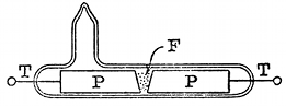 Fig. 16.—Marconi Sensitive Tube or Metallic Filings
Kumascope. PP, silver plugs; TT, platinum wires; F, nickel and silver
filings.
Fig. 16.—Marconi Sensitive Tube or Metallic Filings
Kumascope. PP, silver plugs; TT, platinum wires; F, nickel and silver
filings.
Other ways of adjusting the quantity of the filings to the width of the gap have been devised. Sometimes one of the plugs is made movable. In other cases, such as the tubes devised by M. Blondel and Sir Oliver Lodge, there is a pocket in the glass receptacle to hold square filings, from which more or less can be shaken into the gap.
An interesting question, which we have not time to discuss in full, is the cause of the initial coherence of the metallic filings in a Branly tube. It does not seem to be a simple welding action due to heat, and it certainly takes place with a difference of potential, which is very far indeed below that which we know is required to produce a spark. On the other hand, it seems to be proved that in a Banly tube, when acted upon by electric waves, chains of metallic particles are produced. The effect is not peculiar to electric waves. It can be accomplished by the application of any high electromotive force. Thus Branly found that coherence may be produced by the application of an electromotive force of twenty or thirty volts, operating through a very high water resistance, and thus precluding the passage of any but an excessively small current. Again, the coherence seems to take place in some cases when metallic particles are immersed in a liquid, or even in a solid, insulator. Processor Branly has, therefore, preferred to speak of masses of metallic granules as radio-conductors, and Professor Bose has divided substances into positive and negative, according as the operation of electromotive force is to increase the coherence of the particles or to decrease it.
It has been asserted that for every particular Branly tube, there is a critical electromotive force, in the neighbourhood of two or three volts [Pg 55]which causes the tube to break down and pass instantly from a non-conductive to a conductive condition, and that this critical electromotive force may become a measure of the utility of the tube for telegraphic purposes. Thus, C. Kinsley (Physical Review, Vol. XII., p. 177, 1901) has made measurements of this supposed critical potential for different "coherers," and subsequently tested the same as receivers at a wireless telegraph station of the U.S.A. Signal Corps. The average of twenty-four experiments gave in one case 2·2 volts as the breaking down potential of one of these coherers or Branly tubes, 3·8 volts for a second and 5·5 volts for the third. These same instruments, tested as telegraphic kumascopes, showed that the first of the three was most sensitive.
On the other hand, W. H. Eccles (Electrician, Vol. XLVII., pp. 682 and 715, 1901) has made experiments with Marconi nickel-silver sensitive tubes, using a liquid potentiometer made with copper sulphate, to apply the potential so that infinitesimal spark contacts might be avoided and the changes in potential made without any abruptness. He states that if the coherer tube is continuously tapped, say at the rate of fifty vibrations per second, whilst at the same time an increasing potential is applied to its terminals and the current passing through it measured on a galvanometer, there is no abrupt change in current at any point. He found that when the current and voltage were plotted against each other, a regular curve was obtained, which after a time becomes linear. A decided change occurs in the conductivity of the mass of metallic filings when treated in this manner at voltages lower than the critical voltage obtained by previous methods. He ascertained that there was a complete correspondence between the sensitiveness of the tubes used as telegraphic instruments and the form of the characteristic curve of current and voltage drawn by the above-described method.
In the same manner, K. E. Guthe and A. Trowbridge (Physical Review, Vol. II., p. 22, 1900) investigated the action of a simple ball coherer formed of half a dozen steel, lead or phosphor-bronze balls in slight contact. They measured the current i passing through the series under the action of a difference of potential v between the ends, and found a relation which could be expressed in the form
where V and k are constants.
The current through this ball coherer is, therefore, a logarithmic function of the potential difference between its ends, of the form
and exhibits no discontinuity.
The inference was drawn that the "resistance" is due to films of water adhering to the metallic particles through which electrolytic action occurs.
A good metallic filings tube for use as a receiver in Hertzian wave telegraphy should exhibit a constancy of action and should cohere and decohere, to use the common terms, sharply, at the smallest possible [Pg 56] tap. It should not have a current passed through it by the external cell of more than a fraction of a milliampere, or else it becomes wounded and unsensitive.
The investigations which have already taken place seem to show pretty clearly that the agency causing the masses of filings to pass from a non-conductive to a conductive condition is electromotive force, and that, therefore, it is the electromotive force set up in the aerial by the incident waves which is the effective agent in causing the change in the metallic filings tube, when this is used as a telegraphic kumascope. This transformation of the tube from a non-conductor to a conductor is made to act as a circuit-closer, completing the circuit, by means of which a single cell of a local battery is made to send current through an ordinary telegraph relay, and so by the aid of a second battery operate a telegraphic printer or recorder of any kind. Hence it is clear that after one impact, the metallic filings tube has to be brought back to its non-conductive condition, and this may be achieved in several ways. (1) By the administration of carefully-regulated taps or shocks or by rotating the tube on its axis; (2) by the aid of an alternating current; (3) in those cases where filings of magnetic metals are employed, by magnetism.
The decoherence by taps was discovered by Branly,[37] and Popoff, following the example of Sir Oliver Lodge, employed an electric bell arrangement for this purpose.[38]
Mr. Marconi, in his original receiving instruments, placed an electromagnet under the coherer tube with a vibrating armature like an electric bell.[39] This armature carries a small hammer or tapper, which, when set in action, hits the tube on the under side, and various adjusting screws are arranged for regulating exactly the force and amplitude of the blows. This tapper is actuated by the same current as the Morse printer, or other telegraphic recorder, so that when the signal is received and the metallic filings tube passes into the conductive condition and closes the relay circuit, this latter in turn closes the circuit of the Morse printer or other recorder, and at the same time, a current passes through the electromagnet of the tapper and the tube is tapped back. This sequence of operations requires a certain time which limits the speed of receiving. The tapper has to be so arranged that it is possible to receive and to record not only the dot but a dash on the Morse system. The dash is really a series of closely adjacent dots, which run together in virtue of the inertia and inductance of the different parts of the whole receiving apparatus. The adjustment has so to be made that, whilst the dash is being recorded and a continuous tapping is kept up, yet, nevertheless the continued electromotive force in the aerial, due to the continually arriving trains of waves, is able to act against the tapping and to keep the filings in the tube in the conductive condition. Hence, the successful operation of the arrangement requires attention to a number of adjustments, but [Pg 57]these are not more difficult, or even as difficult, as those involved in the use of many telegraphic receivers employed in ordinary telegraphy with wires.
Mr. Marconi also introduced devices for preventing the sparks at the contacts of the electromagnetic hammer from directly affecting the tube, and also to prevent the electric oscillations which are set up in the aerial from being partly shunted through other circuits than that of the sensitive tube. We pass on to notice the remaining devices for restoring the metallic filings tube to a condition of sensitiveness or receptiveness.
A method for doing this by alternating currents is due to Mr. S. G. Brown.[40] The pole pieces of the coherer tube are made of iron, and they are enveloped in magnetising coils traversed by an alternating electric current. Between these pole pieces is placed a small quantity of nickel or iron filings, and under the action of the electromotive force, due to an electric wave acting on them, may be made to cohere in the usual fashion; but the moment that the wave ceases, the alternating magnetism of the electrodes causes the filings to drop apart or decohere. In place of the alternating current, Mr. Brown finds that a revolving permanent magnet can be used to produce the alternating magnetisation of the pole pieces of the sensitive tube or coherer.
The third method of causing the decoherence of the filings is that due to T. Tommasina. He found that when a Branly tube is made with filings of a magnetic metal, such as iron, nickel and cobalt, the decoherence of the filings can be produced by means of an electromagnet placed in a suitable position under the tube.[41] The explanation of this fact seems to be that, when an electric wave falls upon the tube or when any other source of electromotive force acts upon it, chains of metallic particles are formed, stretching from one electrode to the other. Tommasina contends that he has proved the existence of these chains of particles by experiments made with iron filings; and R. Malagoli,[42] in referring to Tommasina's assertion, states that it can be witnessed in the case of brass filings placed between two plates of metal and immersed in vaseline oil, when a difference of potential is made between the plates.
T. Sundorph[43] says he has confirmed Tommasina's discovery of the formation of these chains of metallic particles in the coherer. The filings do not all cling together, but certain chains are formed which afford a conducting path for the current subsequently passed through the coherer from an external source. Accordingly, Tommasina's method of causing decoherence in the case of filings of magnetic metals is to pull them apart by an external magnetic field; and he stated that decoherence can be effected more easily and regularly in this way than by tapping. Whilst on this point, it may be mentioned that C. Tissot[44] says that he has found that the sensitiveness of a coherer formed of nickel and iron filings can be increased by placing it in the magnetic [Pg 58]field, the lines of which are parallel to the axis of the tube. According to MM. A. Blondel and G. Dobkevitch, this is merely the result of an increased coherence of the particles.
Quite recently, Sir Oliver Lodge and Dr. Muirhead have employed as a self-restoring coherer or kumascope a steel disc revolved by clockwork, the edge of which just touches a globule of mercury covered with a thin film of paraffin oil. The contact is made between the mercury and the steel by the electric wave generating an electromotive force in the aerial, sufficient to break through the thin film of oil. When the wave stops, the circuit is again interrupted automatically.
This device is used without a relay to actuate directly a syphon recorder as used in submarine telegraphy. The working battery employed with it must only have an electromotive force of about a tenth of a volt. It may be used also with a telephone in circuit and can, therefore, be employed either for telegraphic or telephonic reception.[45]
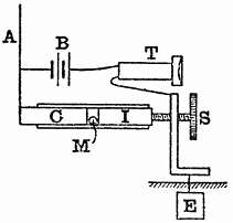 Fig. 17.—Italian Navy Self-restoring Kumascope. C,
carbon plug; I, iron plug; M, mercury globule; A, aerial; B, battery;
T, telephone; S, adjusting screw.
Fig. 17.—Italian Navy Self-restoring Kumascope. C,
carbon plug; I, iron plug; M, mercury globule; A, aerial; B, battery;
T, telephone; S, adjusting screw.
One of the most sensitive of these self-restoring kumascopes is the carbon-steel-mercury coherer, the invention of which has been attributed to Castelli, a signalman in the Italian Navy,[46] but also stated on good authority to have been the invention of officers in the Royal Italian Navy, and has, therefore, been called the Italian Navy coherer.[47] This instrument has been arranged in several forms, but in the simplest of these it consists of a glass tube, having in it a plug of iron and a plug of arc-lamp carbon, or two plugs of iron with a plug of carbon between them. The plugs of iron, or of iron and carbon, are separated by an exceedingly small globule of mercury, the size of which should be between one and a-half and three millimetres. The plugs closing the tube must be capable of movement, one of them by means of a screw, as shown in the diagram (Fig. 17), taken from a patent specification communicated to Mr. Marconi by the Marchese Luigi Solari, of the Royal Italian Navy. One of the plugs of this tube is connected to the aerial and the other to the earth, and they are also connected through another circuit composed of a single dry cell and a telephone. The arrangement then forms an extremely sensitive detector of electric waves or of small electromotive forces, or, if a wave falls on the aerial, the electromotive force at once improves the contact between the mercury and the plugs, and therefore causes a sudden increase in the current through the telephone, giving rise to a sound; but when the wave ceases, or the electromotive force is withdrawn, the [Pg 59]resistance falls back again to its origin value, and the arrangement is, therefore, self-acting, requiring no tapping or other device for restoring it to receptivity.
A very ingenious form of combined telephone and coherer has been devised by T. Tommasina.[48] In this instrument the diaphragm of an ordinary Bell telephone carries upon it a very small carbon or metallic coherer. This coherer is connected in between the aerial and the earth, and is also in circuit with a battery and the electromagnet of a telegraphic relay. When this relay operates it closes the circuit of another battery which is placed in series with the telephone coil. The moment the current passes through the telephone coil it attracts, and therefore vibrates, the diaphragm and shakes up the metallic filings. If an observer, therefore, places the telephone to his ear, he hears a sound corresponding to every train of waves incident upon the aerial. With this arrangement, one can obtain two different kinds of results, according to the nature of the cohering powder placed in the cavity in the diaphragm. First, if the powder consists of a non-magnetic metal, gold, silver, platinum or the like, the receiver will be very sensitive; and at the same time the current passing through it when it is cohered will be sufficient to work a sensive recording apparatus in series with the telephone coil. Secondly, if the metallic powder placed in the cavity is a magnetic metal, the receiver will be somewhat less sensitive, but will work with more precision, because of the magnetic action of the magnet of the telephone upon the cohering powder. If no recording apparatus is used, the observer must write down the signals as heard in the telephone, since corresponding to a short spark at the transmitting station, a single tick or short sound is heard at the telephone, and corresponding to a series of rapidly successive sparks, a more prolonged sound is heard in the telephone. These two sounds, as already explained, constitute the dot and the dash of the Morse signals.
We may, in the next place, refer to that form of kumascope in which the action of the wave or of electromotive force is not to decrease the resistance of a contact, but to increase that of an imperfect contact. As already mentioned, Professor Branly discovered long ago that peroxide of lead acts in an opposite manner to metallic filings, in that when placed in a Branly tube it increases its resistance under the action of an electric spark, instead of decreasing it. Again, Professor Bose has found that fragments of metallic potassium in kerosene oil behave in a similar manner, and that certain varieties of silver, antimony and of arsenic, and a few other metals, have a similar property. Branly tubes, therefore, made with these materials, or any arrangements which act in a similar manner, have been called "anti-coherers." The most interesting arragement which has been called by this name is that of Schäfer.[49] Schäfer's kumascope is made in the following manner: A very thin film of silver is deposited upon glass, and a strip of this silver is scratched across with a diamond, making a fine transverse cut or gap. If the resistance of this divided strip of silver is [Pg 60]measured, it will be found not to be infinite, but may have a resistance as low as forty or fifty ohms if the strip is thirty millimetres wide. On examining the cut in the strip with a microscope, it will be found that the edges are ragged and that there are little particles of silver lying about in the gap. If, then, an electromotive force of three volts or more is put on the two separated parts of the strip, these little particles of silver fly to and fro like the pith balls in a familiar electrical experiment, and they convey electricity across from side to side. Hence a current passes having a magnitude of a few milliamperes. If, however, the strip is employed as a kumascope and connected at one end to the earth and at the other end to an aerial, when electric waves fall upon the aerial, the electrical oscillations thereby excited seem to have the property of stopping this dance of silver particles and the resistance of the gap is increased several times, but falls again when the wave ceases. If, therefore, a telephone and battery are connected between two portions of the strip, the variation of this battery current will affect the telephone in accordance with the waves which fall upon the aerial, and the arrangement becomes therefore a wave-detecting device. It is said to have been used in wireless telegraph experiments in Germany up to a distance of ninety-five kilometres.
We must next direct attention to those wave-detecting devices which depend upon magnetisation of iron, and here we are able to record recent and most interesting developments. More than seventy years ago Joseph Henry, in the United States, noticed the effect of an electric spark at a distance upon magnetised needles.[50] Of recent times, the subject came back into notice through the researches of Professor E. Rutherford,[51] who carried out at Cambridge, England, in 1896, a valuable series of experiments on this subject. He found that if a magnetised steel needle or a very small bundle of extremely thin iron wires is magnetised and placed in the interior of a small coil, the ends of which are connected to two long collecting wires, then an electric wave started from a Hertz oscillator at a distance causes an immediate demagnetisation of the iron. This demagnetisation he detected by means of the movement of the needle of a magnetometer placed near one end of the iron wire. Although Rutherford's wave detector has been much used in scientific research, it was not, in the form in which he used it, a telegraphic instrument, and could not record alphabetic signals.
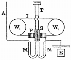 Fig. 18.—Marconi Magnetic Receiver. W1W2, wheels; I,
iron wire band; P, primary coil; S, secondary coil; T, telephone;
A, aerial; E, earthplate.
Fig. 18.—Marconi Magnetic Receiver. W1W2, wheels; I,
iron wire band; P, primary coil; S, secondary coil; T, telephone;
A, aerial; E, earthplate.
Not long ago Mr. Marconi invented, however, a telegraphic instrument based upon his discovery that the magnetic hysteresis of iron can be annulled by electric oscillations. In one form, Mr. Marconi's magnetic receiver is constructed as follows[52] (see Fig. 18): An endless band of thin iron wire composed of several iron wires about No. 36 gauge, arranged in parallel, is made to move slowly round on two pulleys, like the driving belt of a machine. In one part of its [Pg 61]path the wire passes through a glass tube, on which are found two coils of wire, one a rather short, thick coil, and the other a very fine, long one. The fine, long coil is connected with a telephone, and the shorter coil is connected at one end to the earth and the other to the aerial. Two permanent horse-shoe magnets are placed as shown n Fig. 18, with their similar poles together, and, as the iron band passes through their field, a certain length of it is magnetised, and owing to the hysteresis of the material, it retains this magnetism for a short time after it has passed out of the centre of the field. If then an electric oscillation, coming down from the aerial, is passed through the shorter coil, it changes the position of the magnetised portion of the iron and, so to speak, brings the magnetised portion of iron back into the position it would have occupied if the iron had had no hysteresis. This action, by varying the magnetic flux through the secondary coil, creates in it an electromotive force which causes a sound to be heard in the telephone connected to it. If at a distant place a single wave or train of waves is started and received by the aerial, this will express itself by making an audible tick in the telephone, and if several groups of closely adjacent wave trains are sent, these will indicate themselves by producing a rapid series of ticks in the telephone, heard as a short continuous noise and taken as equivalent to the Morse dash.
It was by means of this remarkably ingenious instrument that Mr. Marconi was able, in the summer of 1902, to detect the waves sent out from Poldhu on the coast of Cornwall, and receive messages as far as Cronstadt in the Baltic, in one direction, and as far as Spezzia in the Mediterranean in another direction, and also to receive messages across the Atlantic from the power stations situated in Glace Bay, Nova Scotia, and from one at Cape Cod in Massachusetts, U.S.A., in December, 1902.
There can be no question that this magnetic detector of Mr. Marconi's, used in connection with a good telephone and an acute human ear, is the most sensitive device yet invented for the detection of electric waves and their utilisation in telegraphy without continuous wires. It is marvellously simple, ingenious and yet effective, as a Hertzian wave telegraphic receiver.
Whilst on the subject of magnetic wave detectors, the author may describe experiments that he has been recently making to construct a Hertzian wave detector on the Rutherford principle, which shall be strictly quantitative. All the receivers of the coherer type and electrolytic type give no indications that are at all proportional to the energy of the incident wave. Their indications are more or less accidental and depend upon the manner in which the receiver was last left. There is a great need for a quantitative wave detector, the indications [Pg 62]of which shall give us a measure of the energy of the arriving wave. It is only by the possession of such an instrument that we can hope to study properly the sending powers of various transmitters or the efficiency of different forms of aerial or devices by which the wave is produced. This magnetic receiver is constructed as follows:
A coil of fine wire is constructed in sections like the secondary coil of an induction coil, and in the instrument already made, this coil contains thirty or forty thousand turns of wire. In the interior of this coil are placed a number of little bundles of fine iron wire wound round with two coils, a fine wire coil which is a magnetising coil, and a thicker wire coil which is a demagnetising coil. These sets of coils are joined up, respectively, in series or in parallel. Then, associated with this form of induction coil is a commutator of a peculiar kind, which performs the following functions when a battery is connected to it and when it is made to revolve by a motor or by clockwork. First, during part of the revolution, the commutator closes the battery circuit and magnetises the iron cores, and whilst this is taking place the secondary circuit of the induction coil is short-circuited and the galvanometer is disconnected from it. Secondly, the magnetising current is stopped, and soon after that the secondary coil is unshort-circuited and connected to the galvanometer, and remains in this condition during the remainder of the revolution. This cycle of operations is repeated at every revolution. If then an electrical oscillation is sent into the demagnetising coils, and if it continues longer than one revolution of the commutator, it will demagnetise the iron core during that period of time in which the battery is disconnected and the galvanometer connected. The demagnetisation of the iron which ensues produces an electromotive force in the secondary coil and causes a deflection of the galvanometer, and this deflection will continue and remain steady if the oscillation persists. Moreover, since this deflection is due to the passage through the galvanometer of a rapid series of discharges, it is large when the oscillations continue for a long time and are powerful, and small when they continue for a short time or are weak. We can, therefore, with this arrangement, receive on the galvanometer, just as on the mirror galvanometer used in submarine cable work, a dot or dash, and, moreover, the magnitude of these deflections is a measure of the energy of the wave.
It is probable that when this arrangement is perfected it will become exceedingly useful for making all kinds of tests and measurements in connection with Hertzian telegraphy, even if it is not sensitive enough to use as a long distance receiver.
Of late years a variety of wave-detecting devices have been brought forward which depend upon electrolysis. One of the best known of these is that by De Forest and Smythe.[53] In this arrangement, a tube contains two small electrodes like plugs, which may be made of tin, silver or nickel, or other metal. The ends of these plugs are flat and separated from each other by about one two-hundredth of an inch. Sometimes the end of one of these plugs is made cup shaped and the cup or recess is filled with a mass of peroxide of lead and glycerine. [Pg 63]In the interval between the electrodes is placed an electrolyzable mixture, which consists of glycerine or vaseline mixed with water or alcohol, and a small quantity of litharge and metallic filings. These metallic filings act as secondary electrodes. When a small electromotive force is applied between the terminals of the electrodes of this tube through a very high resistance of twenty or thirty thousand ohms, an exceedingly small current passes through this mixture, and it causes an electrolytic action which results in the production of chains of metallic particles connecting the two electrodes together. If, in addition to this, one terminal or electrode of the arrangement is connected to an aerial wire and the other terminal to the earth, then on the arrival of an electric wave creating oscillations in the wire, these oscillations pass down into the electrolytic cell, where they break up the chains of metallic particles and thus interrupt the current passing through the telephone quite suddenly, which is heard as a slight tick by an ear applied to it. As soon as the wave ceases, the chain of metallic particles is re-established, so that the appliance is always in a condition to be affected by a wave. It is said that this breaking up and reformation of the chains of metallic particles is so rapid that a short spark made at the transmitting station is heard as a tick in the telephone, but a rapid succession of oscillatory sparks is heard as a short continuous sound; hence the two signals necessary for alphabetical conversation can be transmitted.
Another receiver which has some resemblance to the above, although different in principle, is that of Neugschwender.[54] In this arrangement, which to a certain extent resembles the Schäfer detector, a glass plate has upon it a deposit of silver in the form of a strip, which is cut across at one place, thus interrupting it. If the cut is breathed upon or placed in a moist atmosphere, a little dew is deposited upon the glass, which bridges over the cut in the metal and creates an electric continuity. Hence a small current can be passed across the gap and through a telephone by one or two cells of a battery. If, however, an electric oscillation passes across the gap on its way from an aerial to the earth, then the continuity of the liquid film is destroyed, and the current is interrupted and a sound created in the telephone.
The opinion has been expressed by Sir Oliver Lodge that in this case the interruption of the circuit which occurs is really due to the coalescence of minute water particles into larger drops, as when vapour is condensed into rain, and hence the continuity of the material is interrupted.
We must then make a brief reference to other kumascopes which depend upon the heating power of an electrical oscillation, which it possesses in common with every other form of electric current. Professor R. A. Fessenden[55] has constructed a very ingenious thermal receiver in the following manner: An extremely fine platinum wire, about 0·003 of an inch in diameter, is embedded in the middle of a silver wire about one tenth of an inch in diameter, like the wick of a [Pg 64]candle. This compound wire is then drawn down until the diameter of the silver wire is only 0·002 of an inch, and hence the platinum wire in its interior, being reduced in the same ratio, will have been drawn to a diameter of 0·00006 of an inch. A short piece of this drawn wire is then bent into a loop and the ends fixed to wires. The tip of the loop is then immersed in nitric acid and dissolved in the silver, leaving an exquisitely fine platinum wire a few hundredths of an inch in length and having a resistance of about thirty ohms. This little loop is sealed into a glass bulb like a very small incandescent lamp, or it may be enclosed in a small silver bulb and the air may be exhausted. If an electrical oscillation is sent through this exceedingly fine platinum wire it heats it and rapidly increases its resistance. The electrical oscillations produced in an aerial are sent through a number of these loops arranged in parallel, and the loops are short-circuited by a telephone, joined in series with a source of very small electromotive force produced by shunting a single cell or opposing to one another two cells of nearly equal electromotive force. Any variation of resistance of the little platinum loops due to the heat produced by the oscillations, by suddenly altering the current flowing through the telephone, will cause a sound to be heard in it. The electrical oscillations when passing through the loops are therefore detected by the heat which they generate in these exquisitely fine platinum wires.
Finally, one word must be said on the subject of electrodynamic receivers, due to the same inventor. An exceedingly small silver ring is suspended by a quartz fibre and has a mirror attached to it in the manner of a galvanometer. This ring is suspended between two coils joined in series, which are placed either in the circuit of the aerial or in the secondary circuit of the small air core transformer inserted between the aerial and the earth. When electrical oscillations travel down the aerial they induce other electrical oscillations in the silver ring, and if the ring is so placed that its normal position is with its plane inclined at an angle of forty-five degrees to the plane of the fixed coils, then the ring will be slightly deflected every time an oscillation occurs in the aerial.
Omitting further mention of the details of the kumascopes in use and the receiving aerial, we must next proceed to consider the receiving arrangements taken as a whole.
In the original Marconi system, the sensitive tube or coherer was inserted between the bottom of the receiving aerial and the earth.[56] Accordingly, when the incident electric wave strikes the receiving aerial and creates in it an oscillatory electromotive force, this last will, if of sufficient amplitude, cause the particles of the coherer to cohere and become conductive. This sudden change from a nearly perfect non-conductivity to a conductive condition is made to act as a switch or relay, closing or completing the circuit of a single cell, and so sending a current through an ordinary telegraphic relay, closing or completing the circuit of a single cell, which may in turn actuate another recording telegraphic instrument, such as a Morse printer. To [Pg 65]prevent the oscillations from passing into the relay circuit, small choking or inductance coils are inserted between the ends of the sensitive tube and the relay and cell and serve to confine the oscillations to the tube.
It has already been pointed out that in the transmitting aerial the amplitude at the potential vibrations increases from the bottom to the top, and when vibrating in its fundamental manner there is a potential node at the earth connection and a potential loop or antinode at the top. The same is true of the receiving aerial. Hence, if the kumascope employed is a Branly metallic filings tube and is inserted near the base of the aerial, the difference of potential between its two ends will be small.
It has also been mentioned that a receiver of this type acts in virtue of electromotive force or potential difference, and hence the proper place to insert the coherer is not at the base of the aerial, but between the top of the aerial and the earth. This, however, could not be done by running up another wire from the earth, as that would amount to putting the coherer between the tops of two identical aerials, and between its ends there would be no difference of potential. Professor Slaby, in conjunction with Count von Arco, has given an ingenious solution of this problem. If we take two equal lengths of wire, bent at right angles, and connect the point of intersection with the earth, placing one of these wires vertically and the other horizontally, we then have an arrangement which responds to the impact of electric waves, and has electrical oscillations set up in it in such fashion that the common point of the two wires has a very small amplitude of potential, but the two extremities have equal and large variations. If, then, we insert a coherer tube between the earth and the outer extremity of the horizontal wire, it is influenced in the same manner as it would be by the potential variations at the top of the vertical wire. In other words, it is acted upon by a large difference of potential instead of a small one. It is not found necessary to stretch the horizontal wire out straight; it may be coiled into a spiral with open turns, and the slight decrease in capacity and increase in inductance resulting from this can be compensated by cutting off a short piece of it.
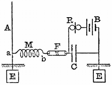 Fig. 19.—Slaby Receiver. A, aerial; E, earth plate; F,
coherer; M, multiplier; C, condenser; R, relay; B, battery; E, earth
plate.
Fig. 19.—Slaby Receiver. A, aerial; E, earth plate; F,
coherer; M, multiplier; C, condenser; R, relay; B, battery; E, earth
plate.
In this way we have an arrangement (see Fig. 19) in which the outer extremity of this open spiral experiences variations or potential which exactly correspond with those at the summit of the vertical aerial. The receiving arrangements are then completed as in Fig. 19, one end of the coherer being attached to the outer end of the spiral and the other end through a condenser to the earth, a relay and a voltaic cell being arranged as shown in the diagram. The mode of operation of this receiver is as follows: When the wave strikes the aerial it sets up in it electrical oscillations with a potential antinode at the summit, and at the same time a potential antinode is created at the outer end of the spiral attached near the base of the aerial, this spiral being called by Professor Slaby a multiplicator. [Pg 66]As long as the coherer tube remains non-conductive, the local cell cannot send a current through the relay, but, as soon as the resistance is broken down by the impact of a wave, the local cell sends a current through the coherer tube which, passing down to the earth through the base of the aerial and up through the earth connection to the condenser, completes its circuit through the relay. Many variations of this arrangement have been made by Slaby and Von Arco and by the Allgemeine Elektricitäts Gesellschaft of Berlin.
In 1898, Mr. Marconi made a great advance in the construction of his receiving apparatus by the insertion of his "jigger" or oscillation transformer in the aerial receiving circuit.[57] In this arrangement, the primary coil of an air core transformer wound in a particular way is inserted between the receiving aerial and the earth, and the secondary circuit is cut in the middle and connected to the two surfaces of a condenser, these surfaces being also connected through the circuit of an ordinary telegraphic relay and a single cell (see Fig. 20). The ends of the secondary circuit of this oscillation transformer are also connected to the terminals of the coherer tube, and these again are short-circuited by a small condenser.
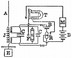 Fig. 20.—Marconi Receiver. A, aerial; J, jigger; CC,
condensers; F, filings tube; T, tapper; R, relay; B, battery; M, Morse
printer.
Fig. 20.—Marconi Receiver. A, aerial; J, jigger; CC,
condensers; F, filings tube; T, tapper; R, relay; B, battery; M, Morse
printer.
The operation of this receiver is as follows: The oscillations set up in the aerial pass through the primary circuit of the jigger, and these induce other oscillations in the secondary circuit; the electromotive force or difference of potential between the primary terminals being transformed up in any desired ratio. It is this exalted electromotive force which is made to act on the coherer tube, and, inasmuch as the jigger operates in virtue of a current passing through its primary circuit and this current is at a maximum at the lower end of the aerial, the arrangement is exceedingly effective, because it, so to speak, converts current into voltage. At the lower end of the aerial, although the amplitude of the potential oscillations is a minimum, the amplitude of the current oscillations is a maximum, and the jigger transforms these large current oscillations into large potential oscillations, provided it is constructed in the right manner. We can also transform up or increase the amplitude of the small potential variations near the bottom of the aerial by employing the principle of resonance. Many devices of this kind, due to Professor Slaby and others, have been suggested and tried but the details are rather too technical to be fully described here.
It will be noticed that the receiving aerial may be arranged in one of two ways—it may be either earthed at the lower end or it may be insulated. It has been claimed that there is a great advantage in earthing the receiving aerial directly in that it eliminates atmospheric disturbances.
We shall allude to this point more particularly later on. Meanwhile it may be mentioned that the receiving arrangements, as a whole, constitute a sensitive arrangement, as shown by Popoff, Tommasina and by all the large experience of Mr. Marconi himself for detecting changes in the electrical condition of the atmosphere, which are doubtless of the nature of electrical oscillations. On the other hand, the receiving arrangements may be perfectly insulated and some experimentalists have asserted that by this method the greatest freedom is secured from atmospheric disturbances. Amongst the non-earthed arrangements the system invented by Professor F. Braun, of Strassburg, and worked by Messrs. Siemens, of Berlin, may be mentioned.[58]
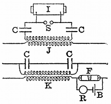 Fig. 21.—Braun's Non-earthed Receiver. I, induction
coil; CC, condensers; S, spark gap; J, transmitting jigger; K,
receiving jigger; F, filings tube; R, relay; B, battery.
Fig. 21.—Braun's Non-earthed Receiver. I, induction
coil; CC, condensers; S, spark gap; J, transmitting jigger; K,
receiving jigger; F, filings tube; R, relay; B, battery.
Professor Braun's arrangements are indicated in the diagram in Fig. 21. In this case an induction coil is used to create a discharge between two spark balls, and to these two balls are connected the two outer coatings of two condensers, the inner coatings of which are connected together through the primary coil of an air core transformer. The secondary coil of this transformer is connected to two extension wires forming a Hertz resonator, and the length of these wires is so adjusted with reference to the time period of the primary circuit that they resonate to it, the whole length from end to end of the secondary circuit being half a wave-length. The receiver, as shown in the diagram, consists of a pair of quarter wave-length receiving wires connected through two condensers, which are short-circuited by the primary coil of an oscillation transformer. The secondary circuit of this last oscillation transformer has two extension wires to it, turned in the same manner, to respond to the primary oscillator; and in the circuit of one of these extension wires is placed a coherer tube, short-circuited by a relay and a local battery.
It will thus be seen that there is an entire abolition of ground connection, which, Professor Braun claims, practically avoids all atmospheric disturbances.[59] The details of the receiving arrangement are as follows:—The coherer tube consists of an ebonite tube containing hard steel particles of a uniform size, placed in the adjustable space between two polished steel electrodes. It is found that with this steel coherer, a small amount of magnetism in the particles increases its sensitiveness, and to obtain this, a ring magnet is employed in connection with a coherer tube. Receiving apparatus arranged on this system is said to have been used for telegraphing between Heligoland and Cuxhaven, a distance of thirty-six miles.
All the immense experience, however, gained by Mr. Marconi and those who have worked with his system, is in favour of using the earth connection. There is no doubt that Hertzian wave telegraphy can be conducted over short distances by means of totally insulated aerials, but for long distances the earth connection is essential, for the reasons that have been explained previously.
There are many of the details of the receiving arrangements which remain to be considered. If the communication is received by a telegraphic instrument like the Morse printer, which requires a current of anything like ten milliamperes to work it, then an important element in the receiving arrangement is the relay. The relay that is generally used is a modified form of the Siemens polarised relay, which is so adjusted as to make a single contact. For marine work on board ship, it is essential that this relay shall be balanced so that variations in position shall not affect it. Sometimes the relay is hung in gimbals like a compass, and at other times suspended from a support by elastic bands, so as to avoid jolting. In any case, the relay must be so adjusted that no change of position will cause it to close the circuit of the telegraphic printer or recorder. Its sensibility ought to be such that it is actuated by a tenth of a milliampere, and, if possible, even by less. The alteration of sensibility in the ordinary contact form of relay is the pressure that is necessary to bring the platinum points of the circuit closer together, so as to pass the minimum current which will work the telegraph printer.
The important matter, however, in connection with the use of the relay in Hertzian wave telegraphy, is that it should be capable of adjustment without extraordinary skill. It is no use to put into the hands of an operator a relay which requires abnormal dexterity to make it work at all.
It remains, then, to consider some of the questions connected with practical Hertzian wave telegraphy and the problem of the limitation of communication. These matters at the present moment very much occupy the public attention, and many conflicting opinions are expressed concerning them.
It may be observed at the outset that the difficulty of dealing with the subject as freely as many desire is that Hertzian wave telegraphy is no longer merely a subject of scientific investigation, but has developed into a business and involves, therefore, other interests than the simple advancement of scientific knowledge. We can, however, discuss in a general manner some of the scientific problems which present themselves for solution. The first of these is the independence of communication between stations. It is desirable, at the outset, to clear up a little misunderstanding. There is a great difference between preventing the reception of communication when it is not desired by the recipient, and preventing it when it is the object of the latter to overhear if he can. It is, therefore, necessary to distinguish between isolation and overhearing. We may say that a station is isolated when it is not affected by Hertzian waves other than those it desires to receive; but that a station overhears when it can, if it chooses, pick up [Pg 69]communications not intended for it, or cannot help receiving them against its will.
This distinction is a perfectly fair one. Any telegraph or telephone wire can be tapped, if it is desired, but unless there is some fault on the line, no station will receive a message against its desires. Moreover, it may be noted that there are penalties attached to tapping a telegraph wire, and at present there are none connected with the misappropriation of an ether wave.
We shall, therefore, consider in the first place the methods so far proposed for preventing any given receiver from being affected by Hertzian waves sent out from other stations, except that of those from which it is desired to receive them. The first method is that which has been called the method of electrical syntony, and consists in adjusting the electrical capacity and inductance of the various open and closed circuits of the receiving and transmitting stations to be put in communication so that they have the same electrical time-period.[60]
In the Cantor Lectures before the Society of Arts in 1900, on electrical oscillations and electric waves, the author has discussed at length the conditions under which powerful electrical oscillations can be set up in a circuit. It was there shown that every electric circuit having capacity and inductance has a particular or natural time-period of electrical oscillation depending on the product of these qualities, and that, to accumulate powerful electrical oscillations in it, the electromotive impulses on it must be delivered at this rate. Illustrations were drawn from mechanics, such as the examples furnished by vibrating pendulums and springs, and from acoustics, as illustrated by the phenomena of resonance, to show that small or feeble blows or impulses delivered at the proper time intervals have a cumulative effect in setting up vibrations in a body capable of oscillation. It is a familiar fact that if we time our blows, we can achieve that which no single blow, however powerful, can accomplish in throwing into vibration a body such as a pendulum, which is capable of oscillation under the action of a restoring force. Precisely the same is true of an electric circuit. We have already seen that the receiving aerial has an alternating electromotive force set up in it by the impact of the successive electric waves sent out from the transmitter. It must, however, be remembered that the transmitter sends out a series of trains of waves, not by any means a continuous train, but one cut up into groups of probably ten to fifty waves, each separated by intervals of silence, long, compared with the duration of a single train of waves.
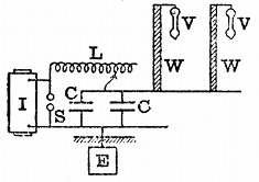 Fig. 22.—Seibt's Apparatus for Exhibiting Electric
Resonance. I, induction coil; S, spark gap; CC, condensers; L,
variable inductance; E, earth plate; WW, wire spirals; VV, vacuum
tubes.
Fig. 22.—Seibt's Apparatus for Exhibiting Electric
Resonance. I, induction coil; S, spark gap; CC, condensers; L,
variable inductance; E, earth plate; WW, wire spirals; VV, vacuum
tubes.
If, however, by a suitable adjustment of capacity and inductance, we make the natural time-period of oscillation of the receiving aerial circuits agree with those of the transmitting aerial, within certain limits the former will only be receptive for waves of the frequency sent out by the transmitter. It is quite easy to illustrate this principle by numerous experiments. It can be done by means of an apparatus [Pg 70]devised by Dr. Georg Seibt for showing in an interesting manner the syntonisation or tuning of two electric circuits. This consists of two bobbins, each consisting of one layer of insulated wire wound on a wooden rod (see Fig. 22). Each of these bobbins has a certain electrical capacity with respect to the earth, when considered as an insulated conductor, and it has also a certain inductance. If, therefore, electromotive impulses are applied to one end of the bobbin at regular intervals, electrical oscillations will be set up in it, and, as already explained, if these are timed at a certain rate, the bobbin will act like a closed organ-pipe to air impulses and oscillations of potential will be accumulated at the opposite end, which have much greater amplitude than the impressed oscillations at the end at which they are applied. We can make the existence of the amplitude oscillations of potential evident by attaching to one end of the bobbin a vacuum tube, which will be illuminated thereby, or by terminating it by a pointed piece of wire, so that an electrical brush can be formed at the point, if the potential variations have sufficient amplitude. We arrange also another closed oscillation circuit, consisting of two Leyden jars and a variable inductance coil and a pair of spark balls which are connected to an induction coil. In this manner we can set up oscillations in the discharge circuit of these Leyden jars, and we can vary the time period by altering the inductance and the capacity. If we denote the capacity of the jars in the microfarads by the letter C and the inductance in centimetres of the discharge circuit of the jars by the letter L, it can then be shown that the number of oscillations per second denoted by n is given by the expression—[61]
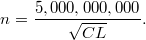
If now we adjust the Leyden jar circuit to a particular rate of oscillation, we have between the terminals of the jar or condenser an alternating difference of potential or electromotive force. If we connect one side of the jars to the earth and the other side to the foot of one of the spirals or bobbins above described, we shall find perhaps that the vacuum tube at the other end is not rendered luminous. When, however, we adjust the inductance in the discharge circuit of the jar to a certain value to make the frequency of the condenser oscillations agree with the natural time period of the bobbin terminated by the vacuum tube, this latter at once lights up brilliantly. Again, if we connect both these bobbins at the same time to the discharge circuit of the [Pg 71]Leyden jar, we shall find that we can make an adjustment of the inductance of that circuit, such that either of the bobbins at pleasure can be made to respond and be set in electrical vibration, as shown by the illumination of the vacuum tube at its upper end or by an electrical brush being formed at the terminal. In making this adjustment of inductance, we are tuning, as it is called, the Leyden jar discharge circuit to the resonating bobbin. A very small variation of the inductance of the jar circuit causes the vacuum tube to change in luminosity. If, however, the natural time periods of these bobbins do not lie very far apart, then a faint luminosity will make its appearance in both the vacuum tubes. Supposing, therefore, that we connect to the oscillating circuit of the jar a number of bobbins having different time periods of oscillation, like organ-pipes, and supply them all with one common alternating electromotive force. These bobbins, whose natural time period is very different to that of the osciilating circuit or impressed electromotive force, will not respond, but those bobbins of which the natural time period lies near to, even if not quite exactly the same as, that of the impressed electromotive force will give evidence of being set in oscillation. A very violent electromotive force will cause them all to respond to some slight extent, no matter whether the period of that impluse is tuned to their common period precisely or not.
At this point questions arise of great practical importance. A matter which has been in dispute in connection with practical Hertzian wave telegraphy is how far this electrical tuning is a sufficient solution of the practical problem of isolation. It is not denied that experiments such as those made with Seibt's apparatus can be shown on a small scale; and, on a still larger scale, Mr. Marconi gave to the author in September, 1900, a demonstration in practical telegraphic work of sending two independent Hertzian wave messages and receiving them on two independent receivers attached to the same aerial.
Since that date much experience has been gained and large power stations erected, and a statement has been frequently made that syntony is no protection against interference when one of the stations is sending out very powerful waves. The contention has been raised that large power stations producing electric waves will therefore play havoc with Hertzian wave telegraphy on a smaller scale, such as the ship to shore and intermarine communication. Under these circumstances, it appeared to the author important to subject the matter to a special test, and Mr. Marconi, therefore, offered to give a demonstration, with this object, in support of the opinion that he has expressed positively that waves from his power stations do not interfere with the working of his ship installations. This matter is vital to the whole question of practical Hertzian wave telegraphy, for the ship to shore communication is of stupendous importance; and if Mr. Marconi had done nothing else except to render this possible and effective, he would have earned, as he has done, the gratitude of humanity for all time. Accordingly, the author embraced the opportunity of making some careful tests to settle the question whether the powerful waves sent out from a station such as Poldhu did or did not affect the exchange of messages between ship [Pg 72]and shore stations in proximity, equipped with Marconi apparatus of a suitable type.
These experiments were carried out on the eighteenth of March last, at Poldhu, in Cornwall, and a programme was arranged by the author of the following kind. Close to the Poldhu station is an isolated mast, which was equipped by Mr. Marconi with a Hertzian wave apparatus, similar to that he places on ships. Six miles from Poldhu is the Lizard receiving station, with which ships proceeding up or down the English Channel communicate. It was arranged that a series of secret messages, some of them in cipher, should be delivered simultaneously at certain known times, both to the power station at Poldhu and to the small adjacent ship station; and it was arranged that these messages should be sent off simultaneously, the operators being kept in ignorance up to the moment of sending as to the nature of the messages. At the Lizard, Mr. Marconi connected two of his receiving instruments to the aerial, one of them tuned to the waves proceeding from the power station at Poldhu, and the other to those proceeding from the small ship station. At the appointed time, these two sets of messages were received simultaneously in the presence of the author, each message being printed down independently on its own receiver; and Mr. Marconi read off and interpreted all these messages perfectly correctly, not having known before what was the message that was about to be sent. In addition to this, precautions were taken to prove that the power station at Poldhu was really emitting waves sufficiently powerful to cross the Atlantic and not being made to sing small for the occasion. To assist in proving this, the messages sent out from the power station were also received at a station at Poole, two hundred miles away, and the assistant there was instructed to telegraph back these messages by wire as soon as he received them. These messages came back perfectly correctly, thus demonstrating that the power station was sending out power waves. The whole programme was carried out with the greatest care to avoid any mistakes on the part of the assistants, and provided an absolute demonstration of the truth of Mr. Marconi's assertion that the waves from one of his power stations, such as Poldhu, do not in the least degree interfere with the transmission and reception of messages between ship and shore, effected by means of certain forms of Marconi apparatus for producing and detecting waves of a different wave length.[62] This complete independence of transmission, however, is entirely due to the employment of a receiving circuit of a certain type in Mr. Marconi's receivers. It does not at all follow that a receiving circuit of any kind, even a Marconi receiver not especially arranged, set up in proximity to a power station would not be affected. This, however, is not an important matter. Far more important is it to show, as has been shown, that practically perfect isolation can be achieved if it is desired.
It must be noted, however, that, although the fact that electric circuits have a natural time-period of oscillation of their own is a scientific principle which carries us a considerable way towards a [Pg 73] solution of what is called syntonic Hertzian wave telegraphy, it is not in itself alone in every respect an entire solution of the practical problem. The degree to which it is a solution depends to a considerable extent upon the nature of the detecting device, or kumascope, which we are employing. The coherer, or Branly filings tube, has the peculiarity that its passage from a non-conductive to a conductive condition follows immediately when the difference of potential between its ends is made sufficiently great. In other words, if the tube is acted upon by a sufficient electromotive force, it is not necessary that electromotive force should be repeated at intervals to make this particular form of kumascope responsive. Again, if we consider the nature of the oscillations which are sent out from any transmitting aerial, we find that each group of oscillations corresponding to a single spark consists of waves gradually decreasing in amplitude. In other words, the first wave of the group is the strongest, and the decay in amplitude is often very rapid. Supposing, then, we construct a simple receiver consisting of an aerial having inserted in its circuit a sensitive Branly filings tube. Such a receiver is almost entirely non-syntonic; that is to say, it is affected by any wave passing over it which is sufficiently powerful. We may look upon it that if the first wave of the series is sufficiently powerful to affect the kumascope, the conductive change takes place whether or not the first wave is followed by others. Accordingly, it is perfectly certain that if a transmitter is sending out trains of waves of any period, a simple combination of coherer and aerial will be influenced, if it is placed near enough to the transmitter. On the other hand, it is possible to combine a kumascope of a certain type with a receiving aerial and other circuits in such a manner that when the waves that reach it are feeble it shall not respond at all unless those waves have very nearly a time period of a certain value.
At this stage, it may be perhaps well to explain a little in detail what is meant by an easily responsive circuit, and, on the other hand, by an irresponsive circuit, or, as we may call it, a stiff circuit. Supposing that we consider an aerial consisting of a simple straight wire having small capacity and small inductance, such a circuit admits of being sent into electrical oscillation, not only by waves of its own natural time-period, but by the sudden application of any violent electromotive impulse. If, on the other hand, we bestow upon the circuit in any way considerable inductance, we then obtain what may be called a stiff or irresponsive circuit, which is one in which electrical oscillations can be accumulated only by the prolonged action of impulses tuned to a particular period.
A mechanical analogue of this difference may be found in considering the different behaviour of elastic bodies to mechanical blows. Take, for instance, a piece of elastic steel and fix the bottom end in a vice. The steel strip may be thrown into vibration by deflecting the upper end. It has, however, a very small mass, and therefore any violent blow or blows, even although not repeated, will set it in oscillation. If, however, we add mass to it by fixing at the other end a heavy weight, such as a ball of lead, and at the same time make the [Pg 74] spring stiffer, we have an arrangement which is capable of being sent into considerable oscillation only by the action of a series of impulses or blows which are timed at a particular rate.
Returning then to the electrical problem, we see that in order to preserve a kumascope or wave detector from being operated on by any vagrant wave or waves having a period very different to an assigned period, it must be associated with an electrical circuit of the kind above called a stiff circuit.
We will now consider the manner in which the problem has been practically attacked by Mr. Marconi, Dr. Slaby, Sir Oliver Lodge and others, who have invented forms of receiver and transmitter, which are syntonic or sympathetic to one another.
Some of the methods which Mr. Marconi has devised for the achievement of syntonic wireless telegraphy were fully described by him in a Paper read before the Society of Arts on May, 17, 1901.[63]
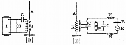 Fig. 23.—Marconi Transmitter and Receiver. I,
induction coil; A, aerial; E, earth plate; HH, choking coils; S, spark
gap; J, transmitting jigger; K, receiving jigger; R, relay; C,
condenser; F, filings tube; B, battery. Many practical details are
omitted.
Fig. 23.—Marconi Transmitter and Receiver. I,
induction coil; A, aerial; E, earth plate; HH, choking coils; S, spark
gap; J, transmitting jigger; K, receiving jigger; R, relay; C,
condenser; F, filings tube; B, battery. Many practical details are
omitted.
On referring to his Paper, it will be seen that in one form his transmitter consists of an aerial, near the base of which is inserted the secondary circuit of an oscillation transformer or transmitting jigger. One end of this secondary circuit is attached to the aerial and the other end is connected to the earth through a variable inductance coil. The primary circuit of this oscillation transformer is connected in series with a condenser, consisting of a battery of Leyden jars, and the two together are connected across to the spark balls which close the secondary circuit of an induction coil, having the usual make and break key in the primary circuit. Mr. Marconi so adjusts the induction of the aerial and the capacity of the condenser, or battery of Leyden jars, that the two circuits, consisting respectively of this battery of Leyden jars and the primary circuit of the transformer, and on the other hand of the capacity of the aerial and the inductance in series with it, and that of the secondary circuit of the transformer have the same time period. In other words, these two inductive circuits are tuned together. At the receiving end, the aerial is connected in series with a variable inductance and with the primary circuit of another oscillation transformer, the second terminal of which is connected to the earth. The secondary circuit of this last oscillation transformer is cut in the middle and is connected to the terminals of a small condenser. The outer terminals [Pg 75] of this secondary circuit are connected to the metallic filings tube or other sensitive receiver and to a small condenser in parallel with it (see Fig. 23). The terminals of the condenser which is inserted in the middle of the secondary circuit of the oscillation transformer are connected through two small inductance coils with a relay and a single cell. This relay in turn actuates a Morse printer by means of a local battery. The two circuits of the oscillation transformer are tuned or syntonised to one another, and also to the similar circuit of the transmitting arrangement. When this is the case, the transmitter affects the co-resonant receiving arrangement, but will not affect any other similar arrangement, unless it is within a certain minimum range of distance. Owing to the inductance of the oscillation transformer forming part of the receiving arrangements, the receiving circuit is, as before stated, very stiff or irresponsive; the sensitive tube is therefore not acted upon in virtue merely of the impact of the single wave against the aerial, but it needs repeated or accumulated effects of a great many waves, coming in proper time, to break down the coherer and cause the recording mechanism to act. An inspection of the diagram will show that as soon as the secondary electromotive force in the small oscillation transformer or jigger of the receiving instrument is of sufficient amplitude to break down the resistance of the coherer, the local cell in circuit with the relay can send a current through it and cause the relay to act and in turn make the associated telegraphic instrument record or sound.
Mr. Marconi described in the above-mentioned Paper some other arrangements for achieving the same result, but those mentioned all depend for their operation upon the construction of a receiving circuit on which the time-period of electrical oscillations is identical with that of a transmitting arrangement. By this means he showed experiments during the reading of his Paper, illustrating the fact that two pairs of transmitting and receiving arrangements could be so syntonised that each receiver responded only to its particular transmitter and not to the other.
With arrangements of substantially the same nature, he made experiments in the autumn of 1900 between Niton, in the Isle of Wight, and Bournemouth, a distance of about thirty miles, in which independent messages were sent and received on the same aerial.
Dr. Slaby and Count von Arco, working in Germany, have followed very much on the same lines as Mr. Marconi, though with appliances of a somewhat different nature. As constructed by the General Electric Company, of Berlin, the Slaby-Arco syntonic system of Hertzian telegraphy is arranged in one form as follows:—The transmitter consists of a vertical rod like a lightning conductor, say, 100 or 150 feet in height. At a point six or nine feet above the ground, a connection is made to a spark ball (see Fig. 24), and the corresponding ball is connected through a variable inductance with one terminal of a condenser, the other terminal of which is connected to the earth. The two spark balls are connected to an induction coil, or alternating current transformer, and by variation of the inductance and capacity the frequency is so arranged that the wave-length corresponding to it is equal to four [Pg 76]times the length of that portion of the aerial which is above the spark ball connection. The method by which this tuning is achieved is to insert in the portion of the aerial below the spark balls, between it and the earth, a hot wire ammeter of some form. It has already been shown that in the case of such an earthed aerial, when electrical oscillations are set up in it, there is a potential node at the earth and a potential anti-node or loop at the summit, if it is vibrating in its fundamental manner; also, there is a node of current at the summit of the aerial and an anti-node at the base. This amounts to saying that the amplitude of the potential vibrations is greatest at the top end of the aerial, and the amplitude of the current vibrations is greatest at the bottom or earthed end. Accordingly, the inductance and capacity of the lateral branch of the transmitter is altered until the hot wire ammeter in the base of the aerial shows the largest possible current.
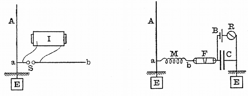 Fig. 24.—Slaby-Arco Syntonic Transmitter and Receiver.
I, induction coil; M, multiplier; B, battery; A, aerial; F, filings
tube; R, relay; E, earth plate; C, condenser.
Fig. 24.—Slaby-Arco Syntonic Transmitter and Receiver.
I, induction coil; M, multiplier; B, battery; A, aerial; F, filings
tube; R, relay; E, earth plate; C, condenser.
The corresponding receiver is constructed in a very similar manner. A lightning conductor or long vertical rod of the same height as the transmitting aerial is set up at the receiving station, and at a point six or nine feet from the ground a circuit is taken off, consisting of a wire loosely coiled in a spiral, the length of which is nearly equal to, although a little shorter than, the height of the vertical wire above the point of connection. The outer end of this loose spiral is connected to one terminal of the coherer tube, and the other terminal of the coherer is connected to the earth through a condenser of rather large capacity. The terminals of this last condenser are short-circuited by a relay and a single cell. When the adjustments are properly made, it is claimed that the receiver responds only to waves coming from its own syntonised or tuned transmitter. In this case the length of the receiving aerial above the point of junction with the coherer circuit is one quarter the length of the wave. A variation of the above arangements consists in making this lateral circuit equal in length to one-half of a wave, and connecting the coherer to its centre through a condenser to the earth. The outer end of this lateral circuit is also connected to the earth (see Fig. 24).[64]
Dr. Slaby claims that this arrangement is not affected by atmospheric electricity, and that the complete and direct earthing of the [Pg 77]aerial and also in the second arrangement, of the receiver of the outer end of the lateral conductor, conduces to preserve the receiver immune from any electrical disturbances except those having a period to which it is tuned.
A method has also been arranged by him for receiving on the same aerial two messages from different transmitting stations simultaneously. In this case, two lateral wires of different lengths are connected to the receiving aerial, and to the outer end of each of these is connected a coherer tube, the other end of which is earthed through a condenser. One of these lateral wires is made equal, or nearly equal, in length to the aerial, and the other is made longer to fulfil the following condition.[65] If we call H the height of the receiving aerial above point of junction of the lateral wires, then the length of one lateral wire is made equal to H, and the height of the aerial is adjusted to be equal to one-quarter of the wave length of one incident wave. The other lateral wire may then be made of a length equal to one-third of H, and it will then respond to the first odd harmonic of that wave, of which the fundamental is in syntony with the vertical wire. By suitably choosing the relation between the wave-lengths of the two transmitting stations, it is possible to receive in this manner two different messages at the same time on the same aerial. Subsequently to the date of the above-mentioned demonstration of multiplex wireless telegraphy by Mr. Marconi an exhibition of a similar nature was given by Professor Slaby in a lecture given in Berlin on December 22, 1900.[66]
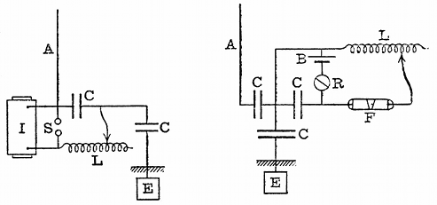 Fig. 25.—Lodge-Muirhead Syntonic Receiver. I,
induction coil; S, spark gap; A, aerial; CC, condensers; E, earth
plate; R, relay; L, variable inductance; F, filings tube; B, battery.
Fig. 25.—Lodge-Muirhead Syntonic Receiver. I,
induction coil; S, spark gap; A, aerial; CC, condensers; E, earth
plate; R, relay; L, variable inductance; F, filings tube; B, battery.
Both the above-described syntonic systems of Mr. Marconi and Dr. Slaby are "earthed" systems, but arrangements for syntonic telegraphy have been devised by Sir Oliver Lodge and Professor Braun which are "non-earthed."
Sir Oliver Lodge and Dr. Muirhead have devised also syntonic systems. According to their last methods, the systonic transmitting and receiving arrangements are as shown in Fig. 25.[67] On examining the [Pg 78] diagrams it will be seen that the secondary terminals of the induction coil are, as usual, connected to a pair of spark balls, and that these spark balls are connected by a condenser and by a variable inductance. One terminal of the condenser is earthed through another condenser of large capacity, and the remaining terminal of the first condenser is connected to an aerial. It should, therefore, be borne in mind in dealing with electrical oscillations that a condenser of sufficient capacity is practically a conductor, and an inductance coil of sufficient inductance is practically a non-conductor. Hence the insertion of a large capacity in the path of the aerial wire is no advantage whatever and makes no essential difference in the arrangement. In order to obtain any powerful radiation, the length of the aerial, or sky wire, as they call it, must be so adjusted that its length is one-quarter the wave-length corresponding to the oscillation circuit, consisting of the condenser and variable inductance.
The receiving arrangement consists of a similar sky wire or aerial earthed through a condenser of large capacity and having in the portion above this last condenser another condenser of similar capacity. At the earthed side of this last condenser a connection is made to a resonant circuit, consisting of a variable inductance, and another condenser and a sensitive metallic filings tube of the Branly type; also a portion of this resonant circuit is shunted by another consisting of a battery and telegraphic relay, as shown in the diagram. The circuit, including the coherer, is tuned to its own aerial and also to that of the transmitting circuit, and under these circumstances trains of waves thrown off at the transmitting aerial will sympathetically affect the receiving aerial.
There is nothing in the arrangement which specially calls for notice. It is simply a variation of other known forms of syntonic transmitter and receiver, and possesses all the advantages and disadvantages attaching to such electrical syntonic methods.
Professor Braun's syntonic system, the receiver and transmitter of which have been described, is also in one form a non-earthed system. Innumerable other patentees have taken out patents for devices which are modifications in small degree of the above arrangements.
It may be well to note at this point the disadvantages that are possessed by any form of coherer as a telegraphic kumascope in connection with proposed arrangements for the isolation of Hertzian wave stations. All the detectors of the coherer type really depend for their actuation upon electromotive force; that is to say, upon the application to the terminals of the detector of a certain electromotive force. Although there may be no sharp and defined critical electromotive force, yet, nevertheless, as a matter of fact, if the electromotive force applied exceeds a certain value, then the detector passes suddenly from one state of conductivity to another. It may be of great conductivity, as in the case of the Branly coherer, or of lesser conductivity, as in the case of the so-called anti-coherers, of which the Schäfer kumascope may be taken as a type. Accordingly, when these instruments are subjected to a train of waves, each individual group of which is damped, their operation is largely governed by the fact that [Pg 79]if the first wave or oscillation set up in the receiving circuit is powerful enough to break down the coherer, then the receiving mechanism acts, no matter whether the first impulse is followed by others or not.
In comparison with so-called coherers, those depending upon the changes in the magnetisation of iron by electrical oscillations certainly have an advantage, because this is a process which requires the application of alternating electric currents decreasing in strength for a certain time; and it is found, therefore, that the magnetic receivers do not require to be associated with such a stiff or irresponsive resonant circuit to confine their indications to oscillations or waves of one definite period, and that they lend themselves much more perfectly to the work of "tuning" or syntonising stations than do those kumascopes depending upon the contact or coherer principle.
We may then glance at the alternative solutions of the problem offered by other investigators. M. Blondel has proposed to effect the syntonisation of two stations, not by syntonising the receiver for the exceedingly high-frequency oscillations of the individual electric waves, but to syntonise it for the much lower frequency, corresponding to that of the intervals between the groups of waves. Thus, for instance, if an ordinary simple transmitting aerial is set up, the production of sparks between the spark balls results in the emission of short trains of waves, each of which may consist of half a dozen or more individual waves, the time of production of the whole group being very small compared with the interval between the groups. M. Blondel proposes, however, to syntonise the receiver, not for the high-frequency period of the waves themselves, which may be reckoned in millions per second, but for the low-frequency period between the groups of waves, which is reckoned in hundreds per second. Thus, for instance, if sparks are made at the rate of fifty or a hundred per second, they can be made to actuate the telephone receiver and so produce in the telephone a sound corresponding to a frequency of 50 or 100; in other words, to make a low musical note or hum. This continuous sound can be cut up, by means of a key placed in the primary circuit of the transmitting arrangement, into long or short periods, and hence the letters of the alphabet signal.
M. Blondel's arrangements comprise a Mercadier's monotone telephone and either a coherer or a particular form of vacuum tube as a kumascope. On August 16, 1898, M. Blondel deposited with the Academy of Sciences in Paris a sealed envelope containing a description of his improvements in syntonic wireless telegraphy, which was opened on May 19, 1900.[68] The arrangement of the receiving apparatus was as follows:—A single-battery cell keeps a condenser charged until the kumascope is rendered conductive by the oscillations coming down the aerial; and under these circumstances the condenser discharges through the telephone and causes a tick to be heard in it. If the trains of waves are at the rate of 50 or 100 per second, these small sounds run together into a musical note, and this continuous hum can [Pg 80]be cut up into long and short spaces, in accordance with the Morse alphabet signals. The telephone must not be an ordinary telephone, capable of being influenced by any frequency, but be one which responds only to a particular note, and under these conditions the receiving arrangement is receptive only when the trains of waves arrive at certain regular predetermined intervals, corresponding with the tone to which the telephone is sensitive.
A number of more or less imperfect arrangements, having the isolation of communications for their object, have been devised or patented, which are dependent upon the use of several aerials, each supposed to be responsive only to a particular frequency; and attempts have been made to solve the problem of isolation by MM. Tommasi, Tesla, Jegon, Tissot, Ducretet and others.
We may then pass on to notice the attempts that have been made to secure isolation by a plan which is not dependent on electrical syntony. One of these, which has the appearance of developing into a practical solution of the problem, is that due to Anders Bull.[69] In the first arrangements proposed by this inventor, a receiver is constructed which is not capable of being acted upon merely by a single wave or train of waves or even a regularly-spaced train of electric waves, but only by a group of wave trains which are separated from one another by certain unequal, predetermined intervals of time. Thus, for instance, to take a simple instance, the transmitting arrangements are so devised as to send out groups of electric waves, these wave trains following one another at time intervals which may be represented by the numbers 1, 3 and 5; that is to say, the interval which elapses between the second and third is three times that between the first two, and the interval between the fourth and fifth is five times that between the first two. This is achieved by making five electric oscillatory sparks with a transmitter of the ordinary kind, the intervals between which are settled by the intervals between holes punched upon strips of paper, like that used in a Wheatstone automatic telegraphic instrument. It will easily be understood that by a device of this kind, groups of sparks can be made, say, five sparks rapidly succeeding each other, but not at equal intervals of time. One such group constitutes the Morse dot, and two or three such groups succeeding one another very quickly constitute the Morse dash. These waves, on arriving at the receiving station, are caused to actuate a punching arrangement by the intermediation of a coherer or other kumascope, and to punch upon a uniformly moving strip of paper holes, which are at intervals of time corresponding to the intervals between the sparks at the transmitting station. This strip of paper then passes through another telegraphic instrument, which is so constructed that it prints upon another strip a dot or a dash, according to the disposition of the holes on the first strip. Accordingly, taken as a whole, the receiving arrangement is not capable of being influenced so as to print a telegraphic sign except by the operation of a series of wave trains succeeding one another at certain assigned intervals of time.
An improvement has been lately described by the same inventor,[70] in which the apparatus used, although more complicated, performs the same functions. At each station two instruments have to be employed; at the transmitting station one to effect the conversion of Morse signals into the properly arranged series of wave trains, and at the receiving station an instrument to effect the re-conversion of the series of wave trains into the Morse signals. These are called respectively the dispenser and the collector. The details of the arrangements are somewhat complicated, and can only be described by the aid of numerous detailed drawings, but the inventor states that he has been able to carry on Hertzian wave telegraphy by means of these arrangements for short distances. Moreover, the method lends itself to an arrangement of multiplex telegraphy, by sending out from different transmitters signals which are based upon different arrangements of time intervals between the electric wave trains. Although this method may succeed in preventing a receiving arrangement from being influenced by vagrant waves or waves not intended for it, yet an objection which arises is that there is nothing to prevent any one from intercepting these wave trains, and with a little skill interpreting their meaning. Thus, if the record were received in the ordinary way on a simple receiver, corresponding to a Morse dot would be printed five dots at unequal intervals, and corresponding to a Morse dash would be printed two such sets of five dots. A little skill would then enable an operator to interpret these arbitrary signals. On the other hand, the inventor asserts that he can overcome this difficulty by making intervals of time between the impulses in the series so long that the latter become longer than the intervals between each of the series of waves which are despatched in continuous succession when the key is pressed for a dash. In this case, when telegraphing, the series of dots would overlap and intermingle with each other in a way which would make the record unintelligible if received in the usual manner, but would be perfectly legible if received and interpreted by a receiver adapted for the purpose.
Another way of obliterating the record, as far as outsiders are concerned, is to interpolate between the groups of signals an irregular series of dots—i.e., of wave trains—which would affect an ordinary coherer, and so make an unintelligible record on an ordinary receiver, but these dots are not received or picked up by the appropriate selecting instrument used in the Anders Bull system.
The matter most interesting to the public at the present time is the long-distance telegraphy by Hertzian waves to the accomplishment of which Mr. Marconi has devoted himself with so much energy of late years. Everyone, except perhaps those whose interests may be threatened by his achievements, must accord their hearty admiration of the indomitable perseverance and courage which he has shown in overcoming the immense difficulties which have presented themselves. Five years ago he was engaged in sending signals from Alum Bay, in the Isle of Wight, to Bournemouth, a distance of twelve or fourteen miles; and to-day he has conquered twice that number of [Pg 82]hundred miles and succeeded in sending, not merely signals, but long messages of all descriptions over three thousand miles across the Atlantic. Critics there are in abundance, who declare that the process can never become a commercial one, that it will destroy short-distance Hertzian telegraphy, or that the multiplication of long-distance stations will end in the annihilation of all Hertzian wave telegraphy. No one, however, can contemplate the history of any development of applied science without seriously taking to heart the lesson that the obstacles which arise and which prove serious in any engineering undertaking are never those which occur to armchair critics. Sometimes the seemingly impossible proves the most easy to accomplish, whilst difficulties of a formidable nature often spring up where least expected.
The long-distance transmission is a matter of peculiar interest to the author of these articles, because he was at an early stage in connection with it invited to render Mr. Marconi assistance in the matter.[71] The particular work entrusted to him was that of planning the electrical engineering arrangements of the first power station erected for the production of electric waves for long-distance Hertzian wave telegraphy at Poldhu, in Cornwall. When Mr. Marconi returned from the United States in the early part of 1900, he had arrived at the conclusion that the time had come for a serious attempt to accomplish wireless telegraphy across the Atlantic. Up to that date the project had been an inventor's dream, much discussed, long predicted, but never before practically taken in hand. The only appliances, moreover, which had been used for creating Hertzian waves were induction coils or small transformers, and the greatest distance covered, even by Mr. Marconi himself, had been something like 150 miles over sea. Accordingly, to grapple with the difficulty of creating an electric wave capable of making itself felt at a distance of 3,000 miles, even with the delicate receiving appliances invented by Mr. Marconi, seemed to require the means of producing at least four hundred times the wave-energy that had been previously employed. The author was, therefore, requested to prepare plans and specifications for an electric generating plant for this purpose, which would enable electrical oscillations to be set up in an aerial on a scale never before accomplished.
This work involved, not merely the ordinary experience of an electrical engineer, but also the careful consideration of many new problems and the construction of devices not before used. Every step had to be made secure by laboratory experiments before the responsibility could be incurred of advising on the nature of the machinery and appliances to be ordered. Many months in the year 1901 were thus occupied by the author in making small-scale experiments in London and in superintendence of large-scale experiments at the site of the first power station at Poldhu, near Mullion, in Cornwall, before the plant was erected and any attempt was made by Mr. Marconi to commence actual telegraphic experiments. As this work was of a highly confidential nature, it is obviously impossible to enter into the details of the arrangements, either as made by the writer in the first instance, [Pg 83]or as they have been subsequently modified by Mr. Marconi. The design of the aerial and of the oscillation transformers and many of the details in the working appliances are entirely due to Mr. Marconi, but as a final result, a power plant was erected for the production of Hertzian waves on a scale never before attempted. The utilisation of 50 H.P. or 100 H.P. for electric wave production has involved dealing with many difficult problems in electrical engineering, not so much in novelty of general arrangement as in details. It will easily be understood that Leyden jars, spark balls and oscillators, which are quite suitable for use with an induction coil, would be destroyed immediately if employed with a large alternating-current plant and immensely powerful transformers.
 Fig. 26.—Wooden Towers supporting the Marconi Aerial
at Poldhu Power Station, Cornwall, England.
Fig. 26.—Wooden Towers supporting the Marconi Aerial
at Poldhu Power Station, Cornwall, England.
In the initial experiments with this machinery and in its first working there was very considerable risk, owing to its novel and dangerous nature; but throughout the whole of the work from the very beginning, no accident of any kind has taken place, so great have been the precautions taken. The only thing in the nature of a mishap was the collapse of a ring of tall masts, erected in the first place to sustain the aerial wires, but which now have been replaced by four substantial timber towers, 215 feet in height, placed at the corners of a square, 200 feet in length. These four towers sustain a conical arrangement of insulated wires (see Fig. 26) which can be used in sections and which constitute the transmitting radiator or receiver, as the case may be. Each of these wires is 200 feet in length and formed of bare stranded wire.
At the outset, there was much uncertainty as to the effect of the curvature of the earth on the propagation of a Hertzian wave over a distance of many hundreds of miles. In the case of the Atlantic transmission between the station at Poldhu in Cornwall and that at Cape Cod in Massachusetts, U.S.A., we have two stations separated by about 45 degrees of longitude on a great circle, or one-eighth part of the circumference of the world. In this case, the versine of the arc or height of the sea at the half-way point above the straight line or chord joining the two places is 300 miles.
The question has recently attracted the attention of several eminent mathematical physicists. The extent to which a free wave propagated in a medium bends round any object or is diffracted depends on the relation between the length of the wave and the size of the object. Thus, for instance, an object the size of an orange held just in front of the mouth does not perceptibly interfere with the propagation of the waves produced by the speaking or singing voice, because these are from two to six feet in length: but if arrangements are made by means of a Galton whistle to produce air waves half an inch in length, then an obstacle the size of an orange causes a very distinct acoustic shadow. The same thing is true of waves in the ether. The amount of bending of light waves round material objects is exceedingly small, because the average length of light waves is about one-fifty-thousandth part of an inch. In the case of Hertzian wave telegraphy, we are, however, dealing with ether waves many hundreds of feet in length, and the waves sent out from Poldhu have a wave-length of a thousand feet or more, say, one-fifth to one-quarter of a mile. The distance, therefore, between Poldhu and Cape Cod is only at most about twelve thousand wave-lengths, and stands in the same relation to the length of the Hertzian wave used as does a body the diameter of a pea to the wave-length of yellow light. There is unquestionably a large amount of diffraction or bending of the electric wave round the earth, and, proportionately speaking, it is larger than in the case of light waves incident on objects of the same relative size.
Quite recently Mr. H. M. Macdonald (see Proc. Roy. Soc., London, Vol. LXXI., p. 251) has submitted the problem to calculation, and has shown that the power required to send given electric waves 3,000 miles along a meridian of the earth is greater than would be required to send them over the same distance if the sea surface were flat in the ratio of 10 to 3. Hence the rotundity of the earth does introduce a very important reduction factor, although it does not inhibit the transmission. Mr. Macdonald's mathematical argument has, however, been criticised by Lord Rayleigh and by M. H. Poincaré (see Proc. Roy. Soc., Vol. LXXII., p. 40, 1903).
The accomplishment of very long distances by Hertzian wave telegraphy is, however, not merely a question of power, it is also a question of wave-length. Having regard, however, to the possibility that the propagation which takes place in Hertzian wave telegraphy is not that simply of a free wave in space, but the transmission of a semi-loop of electric strain with its feet tethered to the earth, it is quite possible that if it were worth while to make the attempt, an ether [Pg 85] disturbance could be made in England sufficiently powerful to be felt in New Zealand.
Leaving, however, these hypothetical questions and matters of pure conjecture, we may consider some of the facts which have resulted from Mr. Marconi's long-distance experiments. One of the most interesting of these is the effect of daylight upon the wave propagation. In one of his voyages across the Atlantic, when receiving signals from Poldhu on board the S.S. Philadelphia, he noticed that the signals were received by night when they could not be detected by day.[72] In these experiments Mr. Marconi instructed his assistants at Poldhu to send signals at a certain rate from 12 to 1 a.m., from 6 to 7 a.m., from 12 to 1 p.m., and from 6 to 7 p.m., Greenwich mean time, every day for a week. He has stated that on board the Philadelphia he did not notice any apparent difference between the signals received in the day and those received at night until after the vessel had reached a distance of 500 statute miles from Poldhu. At distances of over 700 miles, the signals transmitted during the day failed entirely, while those sent at night remained quite strong up to 1,551 miles, and were clearly decipherable up to a distance of 2,099 miles from Poldhu. Mr. Marconi also noted that at distances of over 700 miles, the signals at 6 a.m., in the week between February 23 and March 1, were quite clear and distinct, whereas by 7 a.m. they had become weak almost to total disappearance. This fact led him at first to conclude that the cause of the weakening was due to the action of the daylight upon the transmitting aerial, and that as the sun rose over Poldhu, so the wave energy radiated, diminished, and he suggested as an explanation the known fact of the dissipating action of light upon a negative charge.
Although the facts seem to support this view, another explanation may be suggested. It has been shown by Professor J. J. Thomson that gaseous ions or electrons can absorb the energy of an electric wave, if present in a space through which waves are being transmitted.[73] If it be a fact, as suggested by Professor J. J. Thomson, that the sun is projecting into space streams of electrons, and if these are continually falling in a shower upon the earth, in accordance with the fascinating hypothesis of Professor Arrhenius, then that portion of the earth's atmosphere which is facing the sun will have present in it more electrons or gaseous ions than that portion which is turned towards the dark space, and it will therefore be less transparent to long Hertzian waves.[74] In other words, clear sunlit air, though extremely transparent to light waves, acts as if it were a slightly turbid medium for long Hertzian waves. The dividing line between that portion of the earth's atmosphere which is impregnated with gaseous ions or [Pg 86]electrons is not sharply delimited from the part not so illuminated, and there may be, therefore, a considerable penetration of these ions into the regions which I may call the twilight areas. Accordingly, as the earth rotates, a district in which Hertzian waves are being propagated is brought, towards the time of sunrise, into a position in which the atmosphere begins to be ionised, although far from as freely as is the case during the hours of bright sunshine.
Mr. Marconi states that he has found a similar effect between inland stations, signals having been received by him during the night between Poldhu and Poole with an aerial the height of which was not sufficient to receive them by day. It has been found, however, that the effect simply amounts to this, that rather more power is required by day than by night to send signals by Hertzian waves over long distances.
Some interesting observations have also been made by Captain H. B. Jackson, R.N.,[75] on the influence of various states of the atmosphere upon Hertzian wave telegraphy. These experiments were all made between ships of the British Royal Navy, furnished with Hertzian wave telegraphy apparatus on the Marconi system. Some of his observations concerned the effect of the interpositon of land between two ships. He found that the interposition of land containing iron ores reduced the signalling distances, compared with the maximum distance at open sea, to about 30 per cent. of the latter; whilst hard limestone reduced it to nearly 60 per cent. and soft sandstone or shale to 70 per cent. These results show that there is a considerable absorption effect when waves of certain wave-length pass through or over hard rocks containing iron ores. It would be interesting to know, however, whether this reduction was in any degree proportional to the dryness or moisture of the soil. Earth conductivity is far more dependent upon the presence or absence of moisture than upon the particular nature of the material which composes it other than water.
The observations of Captain Jackson, however, only confirm the already well-known fact that Hertzian waves, as employed in the Marconi system of wireless telegraphy, within a certain range of wave-length, are considerably weakened by their passage through land, over land or round land. In some cases he noticed that quite sharp electric shadows were produced by rocky promontories projecting into the line of transmission. His attention was also directed (loc. cit.) to the more important matter of the effect of atmospheric electrical conditions upon the transmission. The effect of all lightning discharges, whether visible or invisible, is to make a record on the telegraphic receiver. On the approach of an atmospheric electrical disturbance towards the receiving station on a ship, the first visible indications generally are the recording of dots at intervals from a few minutes to a few seconds on the telegraphic tape. Captain Jackson states that the most frequent record is that of three dots, the first being separated from the other two by a slight interval like the letters [Pg 87]E I on the Morse code, and this is the sign most frequently recorded by distant lightning. But in addition to this, dashes are recorded and irregular signs, which, however, sometimes spell out words in the Morse code. He noted that these disturbances are more frequent in summer and autumn than in winter and spring, and in the neighbourhood of high mountains more than in the open sea. In settled weather, if present, they reach their maximum between 8 p.m. and 10 p.m., and frequently last during the whole of the night, with a minimum of disturbance between 9 a.m. and 1 p.m. Another important matter noted by Captain Jackson is the shorter distance at which signals can usually be received when any electrical disturbances are present in the atmosphere, compared with the distance at which they can be received when none are present. This reduction in signalling distance may vary from 20 to 70 per cent, of that obtainable in fine weather. It does not in any way decrease with the number of lightning flashes, but rather the reverse, the loss in signalling distance generally preceding the first indications on the instrument of the approaching electrical disturbance. It is clear that these observations fit in very well with the theory outlined above, viz., that the atmosphere when impregnated with free electrons or negatively-charged gaseous ions is more opaque to Hertzian waves than when they are absent. Captain Jackson gives an instance of ships whose normal signalling distance was 65 miles, failing to communicate at 22 miles when in the neighbourhood of a region of electrical disturbance. These effects in the case of wireless telegraphy have their parallel in the disturbances caused to telegraphy with wires by earth currents and magnetic storms.
Another effect which he states reduces the usual maximum signaling distance is the presence of material particles held in suspension by the water spherules in moist atmosphere. The effect has been noticed in the Mediterranean Sea when the sirocco wind is blowing. This is a moist wind conveying dust and salt particles from the African coast. A considerable reduction in signalling distance is produced by its advent.
Another interesting observation due to Captain Jackson is the existence of certain zones of weak signals. Thus, for instance, two ships at a certain distance may be communicating well; if their distance increases, the signalling falls off, but is improved again at a still greater distance. He advances an ingenious theory to show that this fact may be due to the interference between two sets of waves sent out by the transmitter having different wave-lengths.
Finally, in the Paper referred to, he emphasises the well-known fact that long-distance signalling can only be accomplished by the aid of an aerial wire and a "good earth." Summing up his results, he concludes: (1) That intervening land of any kind reduces the practical signalling distance between two ships or stations, compared with that which would be obtainable over the open sea, and that this loss in distance varies with the height, thickness, contour, and nature of the land; (2) material particles, such as dust and salt, held in suspension in a moist atmosphere also reduce the signalling distance, probably by [Pg 88]dissipating and absorbing the waves; (3) that electrical disturbances in the atmosphere also act most adversely in addition to affecting the receiving instrument and making false signals or strays, as they are called; (4) that with certain forms of transmitting arrangement, interference effects may take place which have the result of creating certain areas of silence very similar to those which are observed in connection with sound signals from a siren.
It is clear, therefore, from all the above observations, that Hertzian-wave telegraphy taking place through the terrestrial atmosphere is not by any means equivalent to the propagation of a wave in free or empty space; and that just as the atmosphere varies in its opacity to rays of light, sometimes being clear and sometimes clouded, so it varies from time to time in transparency to Hertzian waves, the cause of this variation in transparency probably being the presence in the atmosphere of negatively-charged corpuscles or electrons. If there are present in the atmosphere at certain times "clouds of electrons" or "electronic fogs," these may have the effect of producing a certain opacity, or rather diminution in transparency to Hertzian waves, just as water particles do in the case of sunlight.
We may, therefore, in conclusion, review a few of the outstanding problems awaiting solution in connection with Hertzian wave wireless telegraphy. In spite of the fact that this new telegraphy has not been accorded a very hearty welcome by the representatives of official or established telegraphy in Great Britain, it has reached a point, unquestionably owing to Mr. Marconi's energy and inventive power, at which it is bound to continue its progress. But that progress will not be assisted by shutting our eyes to facts. Many problems of great importance remain to be solved. We have not yet reached a complete solution of all the difficulties connected with isolation of stations. In the next place, the question of localising the source of the signals and waves is most important. Our kumascopes and receiving appliances at present are like the rudimentary eyes of the lower organisms, which are probably sensitive to mere differences in light and darkness, but which are not able to see or visualise, in the sense of locating the direction and distance of a radiating or luminous body. Just as we have, as little children, to learn to see, so a similar process has to be accomplished in connection with Hertzian telegraphy, and the accomplishment of this does not seem by any means impossible or even distant. We are dealing with hemispherical waves of electric and magnetic force, which are sent out from a certain radiating centre, and in order to localise that centre we have to determine the position of the plane of the wave and also the curvature of the surface at the receiving point. Something, therefore, equivalent to a range finder in connection with light is necessary to enable us to locate the distance and the direction of the radiant point.
Lastly, there are important improvements possible in connection with the generation of the waves themselves. At the present moment, our mode of generating Hertzian waves involves a dissipation of energy in the form of the light and heat of the spark. Just as in the case of ordinary artificial illuminants, such as lamps of various kinds, we have to manufacture a large amount of ether radiation of long wave length, which is of no use to us for visual purposes—in fact, creating ninety-five per cent, of dark and useless waves for every five per cent. of luminous or useful waves—so in connection with present methods of generating Hertzian waves, we are bound [Pg 89]to manufacture by the discharge spark a large amount of light and heat rays which are not wanted, in order to create the Hertzian waves we desire. It is impossible yet to state precisely what is the efficiency, in the ordinary sense of the word, of a Hertzian wave radiator; how much of the energy imparted to the aerial falls back upon it and contributes to the production of the spark, and how much is discharged into the ether in the form of a wave.
Nothing is more remarkable, however, than the small amount of energy which, if properly utilised in electric wave making, will suffice to influence a sensitive receiver at a distance of even one or two hundred miles. Suppose, for instance, that we charge a condenser consisting of a battery of Leyden jars, having a capacity of one seventy-fifth of a microfarad, to a potential of 15,000 volts; the energy stored up in this condenser is then equal to 1·5 joules, or a little more than one foot-pound. If this energy is discharged in the form of a spark five millimetres in length through the primary coil of an oscillation transformer, associated with an aerial 150 feet in height, the circuits being properly tuned by Mr. Marconi's method, then such an aerial will affect, as he has shown, one of Mr. Marconi's receivers, including a nickel silver filings coherer tube, at a distance of over two hundred miles over sea. Consider what this means. The energy stored up in the Leyden jars cannot all be radiated as wave energy by the aerial, probably only half of it is thus radiated. Hence the impartation to the ether at any one locality of about half a foot-pound of energy in the form of a long Hertzian wave is sufficient to affect sensitive receivers situated at any point on the circumference of a circle of 200 miles radius described on the open sea. Hertzian wave telegraphy is sometimes described as being extravagant in power, but, as a matter of fact, the most remarkable thing about it is the small amount of power really involved in conducting it. On the other hand, Hertzian wave manufacture is not altogether a matter of power. It is much more dependent upon the manner in which the ether is struck. Just as half an ounce of dynamite in exploding may make more noise than a ton of gunpowder, because it hits the air more suddenly, so the formation of an effective wave in the ether is better achieved by the right application of a small energy than by the wrong mode of application of a much larger amount. If we translate this fact into the language of electronic theory, it amounts simply to this. It is the electron alone which has a grip of the ether. To create an ether wave, we have to start or stop crowds of electrons very suddenly. If in motion, their motion implies energy, but it is not only their energy which is concerned in the wave making, but the acceleration, positive or negative—i.e., the quickness with which they are started or stopped. It is possible we may discover in time a way of manufacturing long ether waves without the use of an electric spark, but at present we [Pg 90]know only one way of doing this—viz., by the discharge of a condenser, and in the discharge of large condensers of very high potentials it is difficult to secure that extreme suddenness of starting the discharge which we can do in the case of smaller capacities and voltages.
How strange it is that the discharge of a Leyden jar studied so profoundly by Franklin, Henry, Faraday, Maxwell, Kelvin and Lodge should have become an electrical engineering appliance of great importance!
Whilst there are many matters connected with the commercial aspect of Hertzian wave telegraphy with which we are not here concerned, there is one on which a word may properly be said. The ability to communicate over long distances by Hertzian waves is now demonstrated beyond question, and even if all difficulties are not overcome at once, it has a field of very practical utility, and may even become of national importance. Under these circumstances, we may consider whether it is absolutely necessary to place the signalling stations so near the coast. The greater facility of transmission over sea has already been discussed and explained, but in time of war, the masts and towers which are essential at present in connection with transmitting stations could be wrecked by shot or shell from an enemy's battleship at a distance of five or six miles out at sea, and would certainly be done within territorial waters. Should not this question receive attention in choosing the location of important signalling stations? For if they can, without prejudice to their use, be placed inland by a distance sufficient to conceal them from sight, their value as a national asset in time of war might be greatly increased.
It has been often contended that whilst cables could be cut in time of war no one can cut the ether; but wireless telegraph stations in exposed situations on high promontories, where they are visible for ten to fifteen miles out at sea and undefended by any forts, could easily be destroyed. The great towers which are essential to carry large aerials are a conspicuous object for ten miles out at sea; and a single well-placed shell from a six-inch gun would wreck the place and put the station completely out of use for many months. Hence if oceanic telegraphy is ever to be conducted in a manner in which the communication will be inviolable or, at any rate, not be capable of interruption by acts of war, the careful selection of the sites for stations is a matter of importance. A small station consisting of a single 150-foot mast and a wooden hut can easily be removed or replaced, but an expensive power station, the mere aerial of which may cost several thousand pounds, is not to be put up in a short time.[76]
Meanwhile, whatever may be the future achievements of this new supermarine wireless telegraphy conducted over long distances, there can be no question as to its enormous utility and present value for intercommunication between ships on the ocean and ships and the shore. At the present time, there are some forty or more of the transatlantic ocean liners and many other ships equipped with this [Pg 91]Hertzian wave wireless telegraph apparatus on the Marconi system. Provided with this latest weapon of applied science, they are able to chat with one another, though a hundred miles apart on the ocean, with the ease of guests round a dinner table, to exchange news or make demands for assistance.
Abundant experience has been gathered to show the inexpressible value of this means of communication in case of accident, and it can hardly be doubted that before long the possession of this apparatus on board every passenger vessel will be demanded by the public, even if not made compulsory. Although the privacy of an ocean voyage may have been somewhat diminished by this utilisation of ether waves, there is a vast compensation in the security that is thereby gained to human life and property by this latest application of the great energies of nature for the use and benefit of mankind.
Footnotes:
[1] This series of articles is based on the Cantor Lectures delivered before the Society of Arts, London, in March, 1903. The lectures were attended by many of the leading British scientific men and electrical engineers, and attracted wide attention as the most complete and authoritative statement hitherto made of wireless telegraphy. In writing the articles for the "Popular Science Monthly," the author has omitted advanced technicalities in order that the substance may be suitable for the general reader.—Editor.
[2] For a more detailed account of this hypothesis, the reader is referred to an article by the present writer, entitled "The Electronic Theory of Electricity," published in the "Popular Science Monthly" for May, 1902.
[3] See J. J. Thomson, "Recent Researches in Electricity and Magnetism," chap. I., p. 16.
[4] See O. Heaviside, "Electromagnetic Theory," Vol. I., p. 54.
[5] Wiedemann's Annalen, 36, p. 1, 1889; or in his republished Papers, "Electric Waves," p. 137, English translation by D. E. Jones.
[6] The fraction 7/22 here denotes a stranded wire formed of seven strands, each single wire having a diameter expressed by the number 22 on the British standard wire gauge.
[7] G. Marconi, "Syntonic Wireless Telegraphy," Journal of the Society of Arts, Vol. XLIX., p. 501, 1901.
[8] Instruction for the manufacture of large induction coils may be obtained from a "Treatise on the Construction of Large Induction Coils," by A. T. Hare. (Methuen & Co., London.)
Also see Vol. II. of "The Alternate-Current Transformer," by J. A. Fleming, chap. I. ("The Electrician" Printing and Publishing Co., 1, 2 and 3, Salisbury-court, Fleet-street, London, E.C.)
[9] See "The Alternate-Current Transformer," by J. A. Fleming. Vol. I., p. 184.
[10] Du Moncel states that MacGauley of Dublin independently invented the form of hammer break as now used. See "The Alternate-Current Transformer," Vol. II. chap. I. J. A. Fleming.
[11] See Professor J. Trowbridge, "On the Induction Coil" Phil. Mag., April, 1902 Vol. III., Series 6, p. 393.
[12] See Dr. Wehnelt's article in the Elektrotechnische Zeitschrift, January, 1899.
[13] See The Electrician, Vol. XLII., 1899, pp. 721, 728, 731, 732 and 841; communications from Mr. Campbell Swinton, Professor S. P. Thompson, Dr. Marchant, the author and others; also p. 864, same volume, for a leader on the subject; also p. 870, letters by M. Blondel and Professor E. Thomson. See also The Electrician, Vol. XLIII., p. 5, 1899, extracts from a Paper by P. Barry; Comptes Rendus, April, 1899. See also the Electrical Review, Vol. XLIV., p. 235, 1899, February 17.
[14] See The Electrician, Vol. XLII., 1899.
[15] For a discussion of the function of the condenser in an ordinary induction coil, see "The Alternate-Current Transformer," by J. A. Fleming. Vol. II., p. 51.
[16] See Lord Rayleigh, Phil. Mag., December, 1901.
[17] It has sometimes been stated that the spark balls must be solid metal and no hollow, but this is a fallacy, and has been disproved by Mr. C. A. Chant. See "An Experimental Investigation into the Skin Effect in Electrical Oscillators," Phil. Mag., Vol. III., Sec. 6, p. 425, 1902.
[18] See Proc. Roy. Soc., London, February 23 and April 12, 1860; or reprint of Papers on electrostatics and magnetism, p. 247.
[19] See Phil. Mag., August, 1902, Vol. IV., p. 224, 6th Series. Mr. Jervis-Smith has also described an experiment to show how much the use of compressed air round a spark gap is of advantage in working an ordinary Tesla coil. In his British specification, No. 12,039 of 1896, Mr. Marconi had long previously mentioned the use of compressed air round the spark gap.
[20] This energy storage is at the rate of 44 foot-pounds per cubic foot of glass. This figure shows what a relatively small amount of energy is capable of being stored up in the form of electric strain in glass. In the case of an air condenser, it is only stored at the rate of 1 foot-pound per cubic foot.
[21] See British specification No. 7,777 of 1900.—G. Marconi. "Improvements in Apparatus for Wireless Telegraphy."
[22] That this number really does represent the order of this oscillation frequency in an aerial has been shown by C. Tissot, Comptes Rendus, 132, p. 763, March 25, 1901, by photographs taken of the oscillatory spark of a Hertzian wave telegraphic transmitter. (See Science Abstracts, Vol. IV., Abs. 1,518.) He found frequencies from 0·5 million to 1·6 million.
[23] The term "jigger" is one of those slang terms which contrive to effect a permanent attachment to various arts and crafts. Similarly, the word "booster" is now used for a step-up or voltage-raising transformer or dynamo, inserted in series with an electric supply main. The word "boost" is a slang term signifying to raise or lift up. "To give a real good boost" is an expression for lending a helping hand. The term "jigger," in the same manner, is an adaptation of a seaman's term for hoisting tackle or lift.
[24] The "earth" itself probably only conducts electrolytically. All such materials as sand, clay, chalk, etc., and most surface soils are fairly good insulators when very dry, but conduct in virtue of moisture present in them.
[25] The Electrician, Vol. XL., p. 86 (leader).
[26] British Patent Specification, C. and S. A. Varley, No. 165, 1866.
[27] See also Journal de Physique, Vol. V., p. 573, 1886.
[28] See Comptes Rendus, Vol. CXI., p. 785; Vol. CXII., p. 112, 1891; or La Lumière Electrique, Vol. XL., pp. 301, 506, 1891; or The Electrician, Vol. XXVII., 1891, pp. 221, 448.
[29] See The Electrician, Vol. XXIX., 1892, pp. 397 and 432.
[30] Mr. W. B. Croft, Proc. Phys. Soc., Vol. XII., p. 421. Report of meeting on October 27, 1893.
[31] See Professor Minchin, Proc. Phys. Soc., November 24, 1893; or The Electrician, Vol. XXXII., 1893, p. 123. See also Professor Minchin, Phil Mag., January, 1894, Vol. XXXVII., p. 90, "On the Action of Electromagnetic Radiation on Films containing Metallic Powders."
[32] This lecture was afterwards published as a book, the first edition bearing the same title as the lecture—viz., "The Work of Hertz and Some of His Successors." In the second edition, published in 1898, an appendix was added (p. 59) containing "The History of the Coherer Principle," and the original title of the work had prefixed to it "Signalling Without Wires."
[33] See The Electrician, Vol. XXVII., p. 222, 1891. E. Branly, "Variations of Conductivity under Electrical Influence."
[34] See The Electrician, Vol. XL., p. 90. Sir Oliver Lodge, "The History of the Coherer Principle."
[35] See Professor E. Branly, "A Sensitive Coherer," Comptes Rendus, Vol. CXXXIV., p. 1,187, 1902; or Science Abstracts, Vol. V., p. 852, 1902.
[36] This device of making the inter-electrode gap in a tubular filings coherer wedge-shaped has been patented again and again by various inventors. See German patent No. 116,113, Class 21a, 1900. It has also been claimed by M. Tissot.
[37] See The Electrician, Vol. XXVII., 1891, p. 448.
[38] Journal of the Russian Physical and Chemical Society, Vol. XXVIII., Division of Physics, Part I., January, 1896.
[39] See British Patent Specification No. 12,039, June 2, 1896.
[40] British Patent Specification No. 19,710 of 1899.
[41] Comptes Rendus., Vol. CXXVIII., p. 1,225, 1889; Science Abstracts, Vol. II., p. 521.
[42] Il Nuovo Cimento, Vol. X., p. 279, 1899.
[43] Wied Ann., Vol. LXVIII., p. 594, 1899; Science Abstracts, Vol. II., p. 757.
[44] Comptes Rendus, Vol. CXXX., p. 902, 1900; Science Abstracts, Vol. III., p. 615.
[45] See Proc. Roy. Soc., London, Vol. LXXI., p. 402.
[46] See Report by Capt. Quintino Bonomo, "Telegrafia Senza Fili," Rome, 1902; L'Elettricista, Ser. II., Vol. I., pp. 118, 173.
[47] See Royal Institution, Friday evening discourse, by Mr. Marconi, June 13, 1902; also The Electrician, Vol. XLIX., p. 490; also a letter to The Times of July 3, 1902, by the Marchese Luigi Solari.
[48] See U.S.A. Patent Specification No. 700,161, May 24, 1900.
[49] See E. Marx, Phys. Zeitschrift, Vol. II., p. 249; Science Abstracts, Vol. IV., p. 471. See also German Patent Specification No. 121,663, Class 21a.
[50] See "The Scientific Writings of Professor Joseph Henry."
[51] Phil. Trans. Roy. Soc., London, 1897, Vol. CLXXXIX.a, p. 1.
[52] See Proc. Roy. Soc., London, June 12, 1902. "Note on a Magnetic Detector for Electric Waves which can be employed as a Receiver for Space Telegraphy," by G. Marconi.
[53] See U.S.A. Patent Specification No. 716,000, Application of July 5, 1901.
[54] See the Electrical Review, Vol. XLIV., 1899, May 26; Wied Ann., Vol. LXVIII., p. 92; or German Patent Specification No. 107,843.
[55] U.S.A. Patent Specification No. 706,742, 1902.
[56] See British Patent Specification, G. Marconi, No. 12,039, June 2, 1896.
[57] See G. Marconi, British Patent Specification No. 12,326, of June 1, 1898.
[58] See the Electrical Review, September 26, 1902, Vol. LI., p. 543.
[59] There is a good deal of contradiction between various inventors on this point, some saying that "earthed" aerials obviate atmospheric electrical disturbances, and others that insulated aerials are in this respect superior. The truth appears to be that, neither form is absolutely free from risk of disturbance by this cause.
[60] The capacity of an electrical circuit corresponds to the elastic pliability, or what is commonly called the elasticity, of a material substance, and the inductance to mass or inertia. Hence capacity and inductance are qualities of an electric circuit which are analogous to the elasticity and inertia of such a body as a heavy spring.
[61] See Cantor Lectures, on "Electrical Oscillations and Electric Waves," delivered before the Society of Arts, London, November 26, December 4, 10, 17, 1900. Lecture I., p. 12, of reprint.
[62] A fuller account of these experiments was given by the author in a letter to the London Times published on April 14, 1903.
[63] See Journal of the Society of Arts, Vol. XLIX., p. 505. "Syntonic Wireless Telegraphy," by G. Marconi.
[64] See German Patent Specifications, Class 21a, No. 7,452 of 1900, and also No. 8,087 of 1901.
[65] See German Patent Specification, Class 21a, No. 7,498 of 1900, applied for November 9, 1900. The above-mentioned patent is subsequent in date to Mr. Marconi's experiments on the same subject.
[66] See The Electrician, January 18, 1900, Vol. XLVI., p. 475. Also reprint of a Paper of Professor A. Slaby, "Abgestimmte und mehrfache Funkentelegraphie."
[67] See British Specification No. 11,348 of 1901.
[68] See Comptes Rendus, May 21, 1900; Rapports du Congrès International d'Electricité, Paris, 1900, p. 341.
[69] See The Electrician, Vol. XLVI., p. 573, February 8, 1901.
[70] See The Electrician, Vol. L., p. 418, January 2, 1903.
[71] See Mr. Marconi's Friday evening discourse at the Royal Institution, June 13, 1902; also The Electrician, Vol. XLIX., p. 390.
[72] See Proc. Roy. Soc., June 12, 1902. "A Note on the Effect of Daylight upon the Propagation of Electromagnetic Impulses over Long Distances," by G. Marconi.
[73] See Phil. Mag., Vol. IV., p. 253, Series 6, August, 1902. J. J. Thomson, "On Some Consequences of the Emission of Negatively-electrified Corpuscles by Hot Bodies."
[74] The opinion that ionisation of the air by sunlight is a cause of obstruction to Hertzian waves propagated over long distances has also been expressed by Mr. J. E. Taylor. See Proc. Roy. Soc., Vol. LXXI., p. 225, 1903. "Characteristics of Earth Current Disturbances and their Origin."
[75] See Proc. Roy. Soc., May 15, 1902. "On Some Phenomena affecting the Transmission of Electric Waves over the Surface of the Sea and Earth," by Captain H. B. Jackson, R.N., F.R.S.
[76] Mr. Marconi has informed the writer that these strategic questions have received attention in selecting the sites for large Marconi power stations in Italy.
Detailed Transcriber's Notes
The text has been made to match the original text as much as possible retaining all apparent printer's errors and inconsistencies. The following, detail the apparent printer's errors etc. identified in the original text.
Variation in spelling, Strasburg and Strassburg for Strasbourg.
There are a number of inconsistencies in hyphenation present in the original text. Those concerned with the variation between one word or a hyphenated word are detailed below. Those concerned with the variation between multiple words and hyphenated words are too numerous to detail individually.
Inconsistent hyphenation of word, 'anti-node' and 'antinode' both present in original text.
Inconsistent hyphenation of word, 'electro-dynamic' and 'electrodynamic' both present in original text.
Inconsistent hyphenation of word, 'horse-shoe' and 'horseshoe' both present in original text.
Inconsistent hyphenation of word, 'over-blowing' and 'overblowing' both present in original text.
Page 5, possible printer's error, a for at, 'consisting when a rest'.
Page 6, printer's error, comma rather than full stop at end of sentence, 'ether constituting electric radiation,'.
Page 10, printer's error, millmetre for millimetre, 'three thousand volts per millmetre,'.
Page 13, possible printer's error, set for sets, 'there are three set of phenomena'.
Page 13, printer's error, duplicate word, 'detached and and travel away.'.
Page 22, printer's error, correponding for corresponding, 'correponding to this frequency'.
Page 22, printer's error, consist for consists, 'due to Braun, consist of attaching'.
Page 24, printer's error, one-hundreth for one-hundredth, 'capacity of one-hundreth of a microfarad,'.
Page 28, printer's error, missing full stop at end of sentence added, 'in the case of the hammer break.'.
Page 33, printer's error, supppse for suppose, 'Let us supppse'.
Page 46, printer's error, comma rather than full stop at end of sentence, 'to the transmitting aerial,'.
Page 48, possible printer's error, alterations for alternations, 'alterations of electric strain'.
Page 54, printer's error, Banly for Branly, 'proved that in a Banly tube,'.
Page 56, variation in spelling, unsensitive for insensitive, 'wounded and unsensitive.'.
Page 59, possible printer's error, sensive for sensitive 'to work a sensive recording apparatus'.
Page 59, possible printer's error, arragement for arrangement, 'most interesting arragement'.
Page 61, printer's error, missing letter i, 'as shown n Fig. 18,'.
Page 71, printer's error, osciilating for oscillating, 'to that of the osciilating circuit'.
Page 71, printer's error, impluse for impulse, 'the period of that impluse'.
Page 74, possible printer's error, extra comma in date, 'on May, 17, 1901.'.
Page 76, printer's error, arangements for arrangements, 'variation of the above arangements'.
Page 77, printer's error, systonic for syntonic, 'the systonic transmitting'.
Page 86, printer's error, interpositon for interposition, 'effect of the interpositon of land'.
Page 87, printer's error, signaling for signalling, 'the usual maximum signaling'.
Footnote 17, printer's error, missing letter t, 'must be solid metal and no hollow,'.
Footnote 31, printer's error, missing full stop after abbreviation, 'Phil Mag.'.
Footnote 41, printer's error, extra full stop after reference, 'Comptes Rendus.'.
End of the Project Gutenberg EBook of Hertzian Wave Wireless Telegraphy, by
John Ambrose Fleming

*** END OF THIS PROJECT GUTENBERG EBOOK HERTZIAN WAVE WIRELESS TELEGRAPHY ***

***** This file should be named 38526-h.htm or 38526-h.zip *****
This and all associated files of various formats will be found in:
        https://www.gutenberg.org/3/8/5/2/38526/

Produced by Robert Cicconetti, Tim Madden and the Online
Distributed Proofreading Team at https://www.pgdp.net (This
file was produced from images generously made available
by The Internet Archive/American Libraries.)


Updated editions will replace the previous one--the old editions
will be renamed.

Creating the works from public domain print editions means that no
one owns a United States copyright in these works, so the Foundation
(and you!) can copy and distribute it in the United States without
permission and without paying copyright royalties.  Special rules,
set forth in the General Terms of Use part of this license, apply to
copying and distributing Project Gutenberg-tm electronic works to
protect the PROJECT GUTENBERG-tm concept and trademark.  Project
Gutenberg is a registered trademark, and may not be used if you
charge for the eBooks, unless you receive specific permission.  If you
do not charge anything for copies of this eBook, complying with the
rules is very easy.  You may use this eBook for nearly any purpose
such as creation of derivative works, reports, performances and
research.  They may be modified and printed and given away--you may do
practically ANYTHING with public domain eBooks.  Redistribution is
subject to the trademark license, especially commercial
redistribution.


*** START: FULL LICENSE ***

THE FULL PROJECT GUTENBERG LICENSE
PLEASE READ THIS BEFORE YOU DISTRIBUTE OR USE THIS WORK

To protect the Project Gutenberg-tm mission of promoting the free
distribution of electronic works, by using or distributing this work
(or any other work associated in any way with the phrase "Project
Gutenberg"), you agree to comply with all the terms of the Full Project
Gutenberg-tm License (available with this file or online at
https://gutenberg.org/license).


Section 1.  General Terms of Use and Redistributing Project Gutenberg-tm
electronic works

1.A.  By reading or using any part of this Project Gutenberg-tm
electronic work, you indicate that you have read, understand, agree to
and accept all the terms of this license and intellectual property
(trademark/copyright) agreement.  If you do not agree to abide by all
the terms of this agreement, you must cease using and return or destroy
all copies of Project Gutenberg-tm electronic works in your possession.
If you paid a fee for obtaining a copy of or access to a Project
Gutenberg-tm electronic work and you do not agree to be bound by the
terms of this agreement, you may obtain a refund from the person or
entity to whom you paid the fee as set forth in paragraph 1.E.8.

1.B.  "Project Gutenberg" is a registered trademark.  It may only be
used on or associated in any way with an electronic work by people who
agree to be bound by the terms of this agreement.  There are a few
things that you can do with most Project Gutenberg-tm electronic works
even without complying with the full terms of this agreement.  See
paragraph 1.C below.  There are a lot of things you can do with Project
Gutenberg-tm electronic works if you follow the terms of this agreement
and help preserve free future access to Project Gutenberg-tm electronic
works.  See paragraph 1.E below.

1.C.  The Project Gutenberg Literary Archive Foundation ("the Foundation"
or PGLAF), owns a compilation copyright in the collection of Project
Gutenberg-tm electronic works.  Nearly all the individual works in the
collection are in the public domain in the United States.  If an
individual work is in the public domain in the United States and you are
located in the United States, we do not claim a right to prevent you from
copying, distributing, performing, displaying or creating derivative
works based on the work as long as all references to Project Gutenberg
are removed.  Of course, we hope that you will support the Project
Gutenberg-tm mission of promoting free access to electronic works by
freely sharing Project Gutenberg-tm works in compliance with the terms of
this agreement for keeping the Project Gutenberg-tm name associated with
the work.  You can easily comply with the terms of this agreement by
keeping this work in the same format with its attached full Project
Gutenberg-tm License when you share it without charge with others.

1.D.  The copyright laws of the place where you are located also govern
what you can do with this work.  Copyright laws in most countries are in
a constant state of change.  If you are outside the United States, check
the laws of your country in addition to the terms of this agreement
before downloading, copying, displaying, performing, distributing or
creating derivative works based on this work or any other Project
Gutenberg-tm work.  The Foundation makes no representations concerning
the copyright status of any work in any country outside the United
States.

1.E.  Unless you have removed all references to Project Gutenberg:

1.E.1.  The following sentence, with active links to, or other immediate
access to, the full Project Gutenberg-tm License must appear prominently
whenever any copy of a Project Gutenberg-tm work (any work on which the
phrase "Project Gutenberg" appears, or with which the phrase "Project
Gutenberg" is associated) is accessed, displayed, performed, viewed,
copied or distributed:

This eBook is for the use of anyone anywhere at no cost and with
almost no restrictions whatsoever.  You may copy it, give it away or
re-use it under the terms of the Project Gutenberg License included
with this eBook or online at www.gutenberg.org

1.E.2.  If an individual Project Gutenberg-tm electronic work is derived
from the public domain (does not contain a notice indicating that it is
posted with permission of the copyright holder), the work can be copied
and distributed to anyone in the United States without paying any fees
or charges.  If you are redistributing or providing access to a work
with the phrase "Project Gutenberg" associated with or appearing on the
work, you must comply either with the requirements of paragraphs 1.E.1
through 1.E.7 or obtain permission for the use of the work and the
Project Gutenberg-tm trademark as set forth in paragraphs 1.E.8 or
1.E.9.

1.E.3.  If an individual Project Gutenberg-tm electronic work is posted
with the permission of the copyright holder, your use and distribution
must comply with both paragraphs 1.E.1 through 1.E.7 and any additional
terms imposed by the copyright holder.  Additional terms will be linked
to the Project Gutenberg-tm License for all works posted with the
permission of the copyright holder found at the beginning of this work.

1.E.4.  Do not unlink or detach or remove the full Project Gutenberg-tm
License terms from this work, or any files containing a part of this
work or any other work associated with Project Gutenberg-tm.

1.E.5.  Do not copy, display, perform, distribute or redistribute this
electronic work, or any part of this electronic work, without
prominently displaying the sentence set forth in paragraph 1.E.1 with
active links or immediate access to the full terms of the Project
Gutenberg-tm License.

1.E.6.  You may convert to and distribute this work in any binary,
compressed, marked up, nonproprietary or proprietary form, including any
word processing or hypertext form.  However, if you provide access to or
distribute copies of a Project Gutenberg-tm work in a format other than
"Plain Vanilla ASCII" or other format used in the official version
posted on the official Project Gutenberg-tm web site (www.gutenberg.org),
you must, at no additional cost, fee or expense to the user, provide a
copy, a means of exporting a copy, or a means of obtaining a copy upon
request, of the work in its original "Plain Vanilla ASCII" or other
form.  Any alternate format must include the full Project Gutenberg-tm
License as specified in paragraph 1.E.1.

1.E.7.  Do not charge a fee for access to, viewing, displaying,
performing, copying or distributing any Project Gutenberg-tm works
unless you comply with paragraph 1.E.8 or 1.E.9.

1.E.8.  You may charge a reasonable fee for copies of or providing
access to or distributing Project Gutenberg-tm electronic works provided
that

- You pay a royalty fee of 20% of the gross profits you derive from
     the use of Project Gutenberg-tm works calculated using the method
     you already use to calculate your applicable taxes.  The fee is
     owed to the owner of the Project Gutenberg-tm trademark, but he
     has agreed to donate royalties under this paragraph to the
     Project Gutenberg Literary Archive Foundation.  Royalty payments
     must be paid within 60 days following each date on which you
     prepare (or are legally required to prepare) your periodic tax
     returns.  Royalty payments should be clearly marked as such and
     sent to the Project Gutenberg Literary Archive Foundation at the
     address specified in Section 4, "Information about donations to
     the Project Gutenberg Literary Archive Foundation."

- You provide a full refund of any money paid by a user who notifies
     you in writing (or by e-mail) within 30 days of receipt that s/he
     does not agree to the terms of the full Project Gutenberg-tm
     License.  You must require such a user to return or
     destroy all copies of the works possessed in a physical medium
     and discontinue all use of and all access to other copies of
     Project Gutenberg-tm works.

- You provide, in accordance with paragraph 1.F.3, a full refund of any
     money paid for a work or a replacement copy, if a defect in the
     electronic work is discovered and reported to you within 90 days
     of receipt of the work.

- You comply with all other terms of this agreement for free
     distribution of Project Gutenberg-tm works.

1.E.9.  If you wish to charge a fee or distribute a Project Gutenberg-tm
electronic work or group of works on different terms than are set
forth in this agreement, you must obtain permission in writing from
both the Project Gutenberg Literary Archive Foundation and Michael
Hart, the owner of the Project Gutenberg-tm trademark.  Contact the
Foundation as set forth in Section 3 below.

1.F.

1.F.1.  Project Gutenberg volunteers and employees expend considerable
effort to identify, do copyright research on, transcribe and proofread
public domain works in creating the Project Gutenberg-tm
collection.  Despite these efforts, Project Gutenberg-tm electronic
works, and the medium on which they may be stored, may contain
"Defects," such as, but not limited to, incomplete, inaccurate or
corrupt data, transcription errors, a copyright or other intellectual
property infringement, a defective or damaged disk or other medium, a
computer virus, or computer codes that damage or cannot be read by
your equipment.

1.F.2.  LIMITED WARRANTY, DISCLAIMER OF DAMAGES - Except for the "Right
of Replacement or Refund" described in paragraph 1.F.3, the Project
Gutenberg Literary Archive Foundation, the owner of the Project
Gutenberg-tm trademark, and any other party distributing a Project
Gutenberg-tm electronic work under this agreement, disclaim all
liability to you for damages, costs and expenses, including legal
fees.  YOU AGREE THAT YOU HAVE NO REMEDIES FOR NEGLIGENCE, STRICT
LIABILITY, BREACH OF WARRANTY OR BREACH OF CONTRACT EXCEPT THOSE
PROVIDED IN PARAGRAPH 1.F.3.  YOU AGREE THAT THE FOUNDATION, THE
TRADEMARK OWNER, AND ANY DISTRIBUTOR UNDER THIS AGREEMENT WILL NOT BE
LIABLE TO YOU FOR ACTUAL, DIRECT, INDIRECT, CONSEQUENTIAL, PUNITIVE OR
INCIDENTAL DAMAGES EVEN IF YOU GIVE NOTICE OF THE POSSIBILITY OF SUCH
DAMAGE.

1.F.3.  LIMITED RIGHT OF REPLACEMENT OR REFUND - If you discover a
defect in this electronic work within 90 days of receiving it, you can
receive a refund of the money (if any) you paid for it by sending a
written explanation to the person you received the work from.  If you
received the work on a physical medium, you must return the medium with
your written explanation.  The person or entity that provided you with
the defective work may elect to provide a replacement copy in lieu of a
refund.  If you received the work electronically, the person or entity
providing it to you may choose to give you a second opportunity to
receive the work electronically in lieu of a refund.  If the second copy
is also defective, you may demand a refund in writing without further
opportunities to fix the problem.

1.F.4.  Except for the limited right of replacement or refund set forth
in paragraph 1.F.3, this work is provided to you 'AS-IS' WITH NO OTHER
WARRANTIES OF ANY KIND, EXPRESS OR IMPLIED, INCLUDING BUT NOT LIMITED TO
WARRANTIES OF MERCHANTIBILITY OR FITNESS FOR ANY PURPOSE.

1.F.5.  Some states do not allow disclaimers of certain implied
warranties or the exclusion or limitation of certain types of damages.
If any disclaimer or limitation set forth in this agreement violates the
law of the state applicable to this agreement, the agreement shall be
interpreted to make the maximum disclaimer or limitation permitted by
the applicable state law.  The invalidity or unenforceability of any
provision of this agreement shall not void the remaining provisions.

1.F.6.  INDEMNITY - You agree to indemnify and hold the Foundation, the
trademark owner, any agent or employee of the Foundation, anyone
providing copies of Project Gutenberg-tm electronic works in accordance
with this agreement, and any volunteers associated with the production,
promotion and distribution of Project Gutenberg-tm electronic works,
harmless from all liability, costs and expenses, including legal fees,
that arise directly or indirectly from any of the following which you do
or cause to occur: (a) distribution of this or any Project Gutenberg-tm
work, (b) alteration, modification, or additions or deletions to any
Project Gutenberg-tm work, and (c) any Defect you cause.


Section  2.  Information about the Mission of Project Gutenberg-tm

Project Gutenberg-tm is synonymous with the free distribution of
electronic works in formats readable by the widest variety of computers
including obsolete, old, middle-aged and new computers.  It exists
because of the efforts of hundreds of volunteers and donations from
people in all walks of life.

Volunteers and financial support to provide volunteers with the
assistance they need are critical to reaching Project Gutenberg-tm's
goals and ensuring that the Project Gutenberg-tm collection will
remain freely available for generations to come.  In 2001, the Project
Gutenberg Literary Archive Foundation was created to provide a secure
and permanent future for Project Gutenberg-tm and future generations.
To learn more about the Project Gutenberg Literary Archive Foundation
and how your efforts and donations can help, see Sections 3 and 4
and the Foundation web page at https://www.pglaf.org.


Section 3.  Information about the Project Gutenberg Literary Archive
Foundation

The Project Gutenberg Literary Archive Foundation is a non profit
501(c)(3) educational corporation organized under the laws of the
state of Mississippi and granted tax exempt status by the Internal
Revenue Service.  The Foundation's EIN or federal tax identification
number is 64-6221541.  Its 501(c)(3) letter is posted at
https://pglaf.org/fundraising.  Contributions to the Project Gutenberg
Literary Archive Foundation are tax deductible to the full extent
permitted by U.S. federal laws and your state's laws.

The Foundation's principal office is located at 4557 Melan Dr. S.
Fairbanks, AK, 99712., but its volunteers and employees are scattered
throughout numerous locations.  Its business office is located at
809 North 1500 West, Salt Lake City, UT 84116, (801) 596-1887, email
business@pglaf.org.  Email contact links and up to date contact
information can be found at the Foundation's web site and official
page at https://pglaf.org

For additional contact information:
     Dr. Gregory B. Newby
     Chief Executive and Director
     gbnewby@pglaf.org


Section 4.  Information about Donations to the Project Gutenberg
Literary Archive Foundation

Project Gutenberg-tm depends upon and cannot survive without wide
spread public support and donations to carry out its mission of
increasing the number of public domain and licensed works that can be
freely distributed in machine readable form accessible by the widest
array of equipment including outdated equipment.  Many small donations
($1 to $5,000) are particularly important to maintaining tax exempt
status with the IRS.

The Foundation is committed to complying with the laws regulating
charities and charitable donations in all 50 states of the United
States.  Compliance requirements are not uniform and it takes a
considerable effort, much paperwork and many fees to meet and keep up
with these requirements.  We do not solicit donations in locations
where we have not received written confirmation of compliance.  To
SEND DONATIONS or determine the status of compliance for any
particular state visit https://pglaf.org

While we cannot and do not solicit contributions from states where we
have not met the solicitation requirements, we know of no prohibition
against accepting unsolicited donations from donors in such states who
approach us with offers to donate.

International donations are gratefully accepted, but we cannot make
any statements concerning tax treatment of donations received from
outside the United States.  U.S. laws alone swamp our small staff.

Please check the Project Gutenberg Web pages for current donation
methods and addresses.  Donations are accepted in a number of other
ways including including checks, online payments and credit card
donations.  To donate, please visit: https://pglaf.org/donate


Section 5.  General Information About Project Gutenberg-tm electronic
works.

Professor Michael S. Hart was the originator of the Project Gutenberg-tm
concept of a library of electronic works that could be freely shared
with anyone.  For thirty years, he produced and distributed Project
Gutenberg-tm eBooks with only a loose network of volunteer support.


Project Gutenberg-tm eBooks are often created from several printed
editions, all of which are confirmed as Public Domain in the U.S.
unless a copyright notice is included.  Thus, we do not necessarily
keep eBooks in compliance with any particular paper edition.


Most people start at our Web site which has the main PG search facility:

     https://www.gutenberg.org

This Web site includes information about Project Gutenberg-tm,
including how to make donations to the Project Gutenberg Literary
Archive Foundation, how to help produce our new eBooks, and how to
subscribe to our email newsletter to hear about new eBooks.