The Project Gutenberg EBook of Scientific American Supplement, No. 648,
June 2, 1888., by Various

This eBook is for the use of anyone anywhere at no cost and with
almost no restrictions whatsoever.  You may copy it, give it away or
re-use it under the terms of the Project Gutenberg License included
with this eBook or online at www.gutenberg.org


Title: Scientific American Supplement, No. 648, June 2, 1888.

Author: Various

Release Date: December 24, 2011 [EBook #38403]

Language: English

Character set encoding: ISO-8859-1

*** START OF THIS PROJECT GUTENBERG EBOOK SC. AMERICAN SUPP., JUNE 2, 1888 ***


Produced by Juliet Sutherland, Henry Gardiner and the
Online Distributed Proofreading Team at https://www.pgdp.net.
| PAGE | |
| I. ARCHITECTURE.—Evolution of the Modern Mill.—By C. J. H. Woodbury.—Continuation of this Sibley College lecture, treating of the practical details of mill structures. | 10346 |
| II. ASTRONOMY.—Changes in the Stellar Heavens.—By J. E. Gore, F.R.A.S.—Changes of color, brightness, and position in the fixed stars as attested to by the records of the ancient and modern astronomers. | 10355 |
| Distance and Constitution of the Sun.—Modern theories of the sun and difficulties in formulating a satisfactory explanation of all of its phenomena. | 10354 |
| III. BOTANY.—The Common Dandelion.—By Frederick Leroy Sargent.—The properties and life history of this common plant.—Its wonderful seed-distributing apparatus.—8 illustrations. | 10355 |
| IV. CHEMISTRY.—Poison of the Somalis extracted from the Wood of the Ouabaio.—A recently investigated plant principle. | 10358 |
| V. CIVIL ENGINEERING.—Test of a Wrought Iron Double Track Floor Beam.—By Alfred P. Boller.—A test pushed to actual rupture of a full-sized member of a bridge.—1 illustration. | 10344 |
| Timber and Some of its Diseases.—By H. Marshall Ward.—Part V. of this exhaustive treatise of the deterioration of one of the great structural materials.—1 illustration. | 10345 |
| Improved Torpedo Boat.—1 illustration. | 10348 |
| VI. ELECTRICITY.—Effect of Chlorine on the Electro-motive Force of a Voltaic Couple.—By D. G. Gore, F.R.S.—A very curious investigation, disclosing the sudden change in E. M. F. produced by a definite addition of chlorine. | 10351 |
| On a Theory Concerning the Sudden Loss of Magnetic Properties of Iron and Nickel.—By Mr. A. Tomlinson, B.A.—A new theory, involving the probable rearrangement of the molecules or "magnetic atoms" of the metals in question. | 10358 |
| The Passive State of Iron and Nickel.—Note of this curious phenomenon. | 10347 |
| The Wimshurst Electric Machine.—Illustration of 13½ inch sparks produced by it.—1 illustration. | 10352 |
| The Application of Electricity to Lighting and Working.—By W. H. Preece.—Lecture I. | 10350 |
| VII. ENTOMOLOGY.—Systematic Relations of Platypsyllus as determined by the Larva.—By Dr. C. V. Riley.—An important contribution to entomological science, a paper read at the meeting of the National Academy of Science, April 20, 1888.—4 illustrations. | 10356 |
| VIII. HYGIENE.—Reducing Obesity—Note of general principles to be applied to diet and life. {Transcriber: Omitted by publisher.} | 10352 |
| The Care of the Eyes.—By Prof. David Webster.—A practical and scientific examination of how to preserve the eyesight and of the use and abuse of this important organ of sense. | 10352 |
| Sanitation in Massachusetts. | 10352 |
| IX. MECHANICAL ENGINEERING.—Hydraulic Tube Press.—An extraordinarily powerful press for striking up tubes from flat plates. | 10345 |
| The Distribution of Hydraulic Power in London.—A recent system introduced in London, with description of the plant and distribution pipes. | 10344 |
| The One Hundred and Twenty Ton Shears of the Port of Marseilles.—An immense set of hoisting apparatus described and illustrated.—3 illustrations. | 10343 |
| X. PHOTOGRAPHY.—Colored Photography.—Mr. J. E. Mayall's recent advances in this phase of photography. | 10349 |
| XI. PHYSICS.—Scientific Apparatus at the Manchester Royal Jubilee Exhibition.—Notes of the most interesting electrical, photometrical, and communicating apparatus. | 10348 |
| The Spectra of Oxygen.—Interesting investigations of absorption spectra of oxygen. | 10358 |
| XII. SURGERY.—Papillomatous Tumor of the Bladder, demonstrated by Means of Lister's Electro-cystoscope.—By F. N. Otis, M.D.—An interesting instance of the use of an exploratory electric light.—2 illustrations. | 10354 |
| Tumors of the Bladder Diagnosed by Means of the Electro-Endoscopic Cystoscope.—By Dr. Max Nitze.—The same general subject in further detail, giving the German practice.—5 illustrations. | 10353 |
| XIII. TECHNOLOGY.—Future Prospects for Gas Companies.—By Mr. Thos. Wood.—Fuel and oil gas and the future Utopia of improved gas manufacturing.—The ideal gas company of after days.—A valuable and suggestive paper. | 10349 |
| Advertisements. | 10358 |
For a quarter of a century maritime nations have been continuously engaged in improving the mechanical appliances of their large ports. The use of tracks to bring goods to be placed on vessels as near as possible to the shipping point, the substitution of oblique moles for perpendicular ones in large docks, the creation of a hydraulic method of loading and unloading through movable cranes (which will perhaps in a near future cede to an electrical one), constitute the means most used for expediting transshipments and reducing the expense of them to a minimum. But, at the same time that the facilities for all kinds for handling packages have been increased, it has also become necessary to greatly increase the power of the machines applied to them. The construction of large packets now requires the putting in place of boilers of great weight, and the adoption of the huge pieces that compose the artillery of ironclads necessitates the use of force that has been unknown up to recent times.
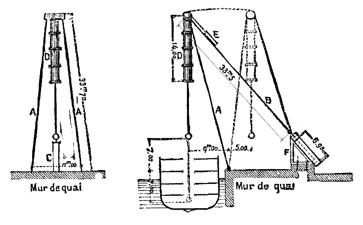 Fig. 1.—DIAGRAM OF SHEARS.
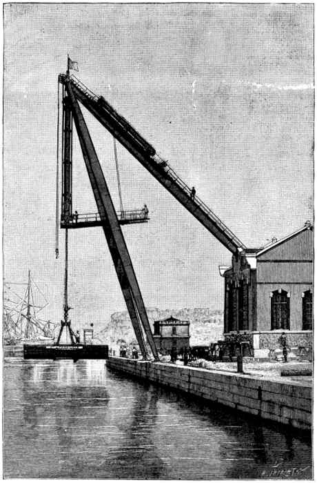 Fig. 2.—ONE
HUNDRED AND TWENTY TON SHEARS OF THE PORT OF
MARSEILLES.
Fig. 2.—ONE
HUNDRED AND TWENTY TON SHEARS OF THE PORT OF
MARSEILLES.
At present, then, we could no longer be content with manual power, acting upon windlasses or capstans, for lifting and shifting. It has become necessary to apply steam or hydraulic motors to these operations. Of these, the latter are the most used, on account of their easy operation and their submitting to the greatest stresses with a very satisfactory proportionality of the expenditure of motive power. One of the most remarkable of such apparatus is the one that the Compagnie de Fives-Lille has recently set up on one of the moles of the national dock at Marseilles, for the service of the chamber of commerce, and this merits a description so much the more in that it is an important improvement upon the analogous apparatus now in use in other ports.
According to the conditions of the programme, powers of 25, 75, and 120 tons had to be obtained at will, with a proportional output of water, and the load had to be lifted 22 ft. above the quay and carried horizontally from 28 ft. beyond the edge to 16 ft. in the rear, so that the load might be taken from a ship and deposited upon a wagon, and vice versa. The shears, then, had to be capable of performing two operations, viz., of lifting the load and of carrying it horizontally. To facilitate the description, we shall first make known the arrangements that assure the second operation.
The apparatus is of the type known as oscillating tripod. The tripod consists of two lateral iron plate uprights, A A (Fig. 1), resting upon the wharf wall, and of a beam, B, jointed to them above and connected below with the head of the piston of a hydraulic press. This latter rests upon an iron plate frame, solidly bolted to masonry. The piston pulls the beam, B, toward it when it descends, and carries along in the same motion the shears, A, as well as the load suspended from their point of junction, and the load is thus carried to a distance of 16 ft. from the edge of the wharf in order to be placed upon a wagon. Conversely, if the piston rises, it pushes before it the entire framework, as well as the lifting apparatus, the hook of which travels 28 ft. beyond the edge of the wharf.
The lifting apparatus consists likewise of a hydraulic press suspended from the summit of the tripod; but, in order to prevent the joints of the cylinder from working under the action of the load, which would tend to open them and cause leakages, it is not suspended from the very axis of the junction of the shears. The cylinder rests directly upon a huge stirrup 45 ft. in length, the arms alone of which are affixed to the axis, through a Cardan joint. Under such circumstances, the stress of the load carried by the piston rod is exerted solely upon the branches of the stirrup, and the sides of the cylinder work only under the pressure of the motive water. The latter is introduced at the base of the press, through a valve that a special workman, standing upon a platform supported by the stirrup, maneuvers at will.
It will be seen that the general principle applied for utilizing the motive power is that of direct action. It has already been employed in a few analogous apparatus constructed by Sir William Armstrong, especially those of the arsenal of Spezia and of the Elswick cannon foundry, but solely for the lifting press. This is the first time that use has been made of it to effect the oscillating motion corresponding to the horizontal shifting of the load. This was formerly done through the intermedium of a mechanism that, aside from its complication and higher cost, presented the inconvenience of absorbing a large quantity of force in friction; besides, the direct action permits of performing the maneuvers much more quickly by the use of the water in reserve contained in the accumulators.
Another important improvement, likewise due to the Compagnie Fives-Lille, consists in the addition of safety clicks, which engage with racks parallel with the piston rod of each of the presses and movable with it. The clicks, on the contrary, are jointed to axes fixed on the bottom of the cylinders. This arrangement presents the following advantages: If a leakage occurs in the joints or feed pipe of the hoisting press, the descent of the load can be stopped instantaneously, thus preventing the grave damage that would be done to ships and even to the shears themselves by the descent of a 120 ton load, however slow it might be. As regards the oscillating press, this arrangement permits of fixing the base of the connecting beam at any point whatever of its travel, when it is desired to dismount the piston. Further, it permits of maintaining the shears in an invariable position in case of sudden damages to the piping.
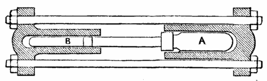 Fig. 3.—AUTOMATIC MULTIPLIER.
In order to produce the three powers of 25, 75, and 120 tons required by the programme, and at the same time expend in each case a corresponding quantity of water under pressure, it is of course necessary to cause the pressure of the motive water to vary in the same proportion as the stress to be extended. This result is reached by calculating the diameter of the two cylinders in such a way as to obtain the mean power of 75 tons, in making the water of the general conduit act directly under the normal pressure of 50 atmospheres. For the powers of 25 and 120 tons, use is made of an automatic multiplier, that consists of two cylinders arranged end to end, in which move pistons, A and B (Fig. 3), of different diameters. When it is a question of lifting 120 tons, the water at 50 atmospheres actuates the piston, A, and the other forces into the lifting cylinder motive water under a much greater pressure. If the load to be lifted is but 25 tons, the water at 50 atmospheres actuates the piston, B, and A forces the water into the same cylinder at a much lower pressure. The same operations are effected in the other cylinder when the extreme loads of 25 and 120 tons are moved.
The shears are likewise provided with a hydraulic cylinder, E (Fig. 1), placed on the back of the beam, B, and serving, through a cable, to bring the piston of the large cylinder to the end of its upward stroke, and for certain accessory work.
Finally, the apparatus as a whole is completed by an accumulator containing in reserve a large part of the water necessary for each operation.
The apparatus is capable of lifting a maximum load of 120 tons from 22 feet beneath the wharf to 22 feet above, and of 10344moving it from 28 feet beyond the edge to 16 feet back of it, say a total of 44 feet. The cylinders of the lifting and oscillating presses are 1¾ feet in diameter and 4 inches in thickness. The stroke of the second is 22½ feet. The length of the uprights is 110½ feet and that of the connecting beam is 109 feet. The apparatus has been tested under satisfactory conditions with a load of 140 tons.—La Nature.
At a recent meeting of the Institution of Civil Engineers, a paper on the above subject was read by Mr. Edward Bayzand Ellington, M. Inst. C. E. The author observed that water power was no new force, but that, as formerly understood, it was limited in its application to systems of mechanism suitable for the low pressures found in nature. The effects obtained by the use of high pressure were so different in degree from all previous experience, that a new name was needed, and had been found in the term "hydraulic power." Bramah's genius produced the hydraulic press, and he clearly foresaw the future development and great capabilities of his system; but it was reserved for Lord Armstrong to work out and superintend the intricate details that had to be developed before the system could be made fully serviceable. The public supply of hydraulic power in London constituted the latest development of this system. The hydraulic power was supplied through mains charged by pumping at a pressure of 700 lb. per square inch. The first and largest pumping station had been erected on a site known as Falcon Wharf, about 200 yards east of Blackfriars Bridge. The engine house at present contained four sets of pumping engines, each set being capable of exerting 200 I. H. P.
The engines were vertical compound, of a type comprising the advantages of a three-throw pump with direct connection between the pump plungers and the steam pistons. Each set of engines would deliver 240 gallons of water per minute into the accumulators at 750 lb. pressure per square in. at a piston speed of 200 ft. per minute. This was the normal speed of working; but, when required, they could be worked at 250 ft. per minute, the maximum delivery being 300 gallons per minute. The condensing water was obtained from storage tanks over the engine house, and was returned by circulating pumps to one or other of those tanks. The water delivered into the mains was maintained all the year round at temperatures of between 60° and 85°. The boilers were of the double flued Lancashire type, and were made of steel. All were fitted with Vicars' mechanical stokers. At the back of the boilers was a Green's economizer, consisting of ninety-six tubes. The economizer and the stoker gear and worm were driven by a Brotherhood three cylinder hydraulic engine. The reservoir of power consisted of accumulators. The accumulators at the pumping station were two in number, each having a ram 20 in. in diameter and 23 ft. stroke.
The weight cases were of wrought iron, and were filled with iron slag. The total weight of the case and load on each ram was approximately 106 tons, corresponding to a pressure of 750 lb. per square in. The storage tanks formed the roofs for the engine and boiler houses. The water for the power supply was obtained from the river Thames, and was pumped into the tank over the engines. The water passed through the filtering apparatus by gravity into the filtered water tank over the boiler house, which was 7 ft. below the level of the unfiltered water tank. The filters consisted of cast iron cylinders, and each contained a movable perforated piston and a perforated diaphragm, between which was introduced a quantity of broken sponge; the sponge was compressed by means of hydraulic pressure from the mains. The delivery of power water from the Falcon Wharf pumping station was through four 6 in. mains. The most distant point of the mains from the accumulators was at the west end of Victoria Street, and was 5,320 yards, or just over three miles. To provide for all frictional loss in the pipes and valves, the accumulators had been loaded to 750 lb., the stated pressure supplied being 700 lb. per square in. The total length of the mains at present laid was nearly twenty-seven miles. The mains were laid in circuit, and there were stop valves at about every 400 yards, so that any such section of main could be isolated.
The method employed for detecting leakage was based upon an automatic record of the number of gallons delivered into the mains, and in cases of abnormal increase during the night, if found to arise during the early hours of the morning, the mains were tested. The power water used was invariably registered through meters on the exhaust pipes from the machines, and from the meters passed to the drains. There was a sliding scale of charges from 8s. to 2s. per 1,000 gallons at 700 lb. pressure per square inch, designed to meet, as nearly as possible, the variable conditions and requirements of consumers. The more continuous the use, the lower the charges. The scale was intended chiefly for intermittently acting machinery, and experience had fully proved that these rates were sufficiently low to effect a large saving to the consumer in almost all cases, whether for a large or a small plant. The author believed any idea of supplying power from a central source at rates much below these to be chimerical. The practical efficiency of the hydraulic system might be fixed at from 50 to 60 per cent. of the power developed at the central station. No other method of transmission would, he thought, show a better result; and the general convenience and simplicity of the hydraulic system were such that its use would hardly be affected, even if there were no direct economy in the cost of working.
In addition to the general supply of hydraulic power, in the City and adjoining districts, to the six hundred and fifty machines at present worked, a new departure had been taken by the application of hydraulic power to an estate at Kensington Court—the name given to an area of about seven acres opposite Kensington Gardens. Seventy houses and dwellings were to be built on this estate, of which thirty had been already erected. Each house was fitted with a hydraulic lift, taking the place of a back staircase, and the power supply was provided on the estate expressly for working these lifts. The driven machinery was of as great importance to an economical and satisfactory result as the distributing plant, but this obvious fact was not always understood. General regulations had been prepared by the author, defining the conditions to be observed by manufacturers in fitting up machinery for connection to the power mains.
They were intended to secure safety, and an efficient registration of the quantity of power used; but they left the question of the economy and of the efficiency of the machines to be settled between the consumers and the makers. In London more lifts were working from the mains and more power was used by them than by any other description of machinery. The number of all classes at present at work was over four hundred. The principal types in use were fully described. In some cases there had been, by adopting the public supply, a saving in the cost of working of about 30 per cent., as compared with the steam pumping plant previously in use.
Lifts were now becoming so general, and the number of persons who used them was so great, that the author considered it necessary to urge the importance of securing the greatest possible safety in their construction, by the general adoption of the simple ram. Suspended lifts depended on the sound condition of the ropes or chains from which the cages hung. As they became worn and unreliable after a short period, it was usual to add safety appliances to stop the fall of the cage in case of breakage of the suspending ropes; but they could not be expected to act under all circumstances. As an indication of the important part which lifts occupied in a modern hotel, it might be mentioned that at the Hotel Metropole there were, including the two passenger lifts and that for the passengers' luggage, no less than seventeen hydraulic lifts in use day and night, while the work done represented about 2,000 tons lifted 40 ft. in this time. The next largest use of the power was for working hydraulic cranes and hoists of various kinds along the river side, and in the city warehouses. It often happened that the pressure in the power mains was not sufficient for pressing purposes.
The apparatus known as an intensifier was then used, by which any pressure required could be obtained. Hydraulic power was also used at Westminster Chambers, and elsewhere, for the purpose of pumping water from the chalk for domestic use. The pump was set going in the evening and continued working till the tanks were full, or until it was stopped in the morning. For work of this kind, done exclusively at night, a discount was allowed from the usual rates. Mr. Greathead's injector hydrant, made at the Elswick works, had been in use to a limited extent in London in connection with the power mains.
A small jet of high pressure water, injected into a larger jet from the water works mains, intensified the pressure of the latter in the delivery hose, and also increased the quantity. By this means a jet of great power could be obtained at the top of the highest building without the intervention of fire engines. This apparatus enabled the hydraulic power supply to act as a continuous fire engine wherever the mains were laid, and was capable of rendering the greatest assistance in the extinction of fire; but there was an apathy on the subject of its use difficult to understand. In Hull the corporation had put down a number of these hydrants in High Street, where the hydraulic power mains were laid, and they had been used with great success at a fire in that street. The number of machines under contract to be supplied with power was sufficient, with a suitable reserve, to absorb the full capacity of the station at Falcon Wharf, and another station of about equal capacity was now in course of erection at Millbank Street, Westminster. The works had been carried out jointly by the author and Mr. Corbet Woodall, M. Inst. C. E.; Mr. G. Cochrane had been resident engineer and superintendent. The pumping engines, accumulators, valves, etc., and a considerable portion of the consumers' machinery, had been constructed at the Hydraulic Engineering Works, Chester. Sir James Allport, Assoc. Inst. C. E., who was the first to adopt hydraulic power for railway work, had been associated with the enterprise from the commencement of its operations in 1882. His wide influence and extended experience had greatly assisted the commercial development of the undertaking.
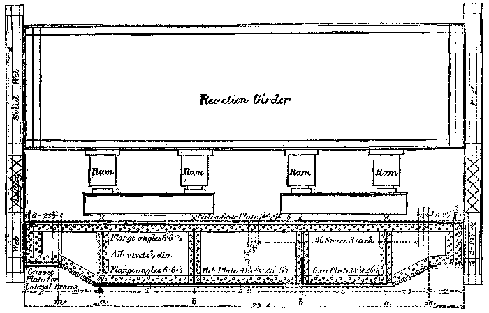
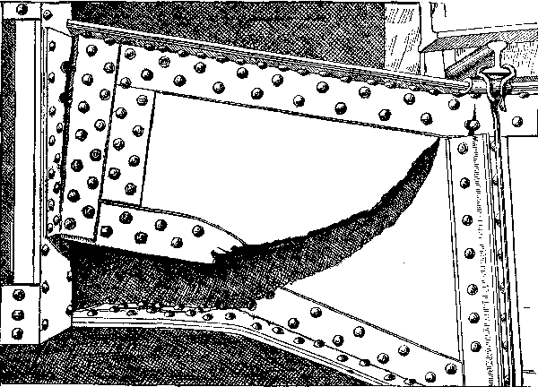
Testing to rupture actual bridge members is always a matter of great scientific interest, and while the record is quite extensive in eye bars, posts, or small parts, the great cost, time, and inconvenience of handling heavy girders has prevented experiment in that direction. In fact, the writer is unaware of any experiment upon compound riveted beams on a large scale, as actually used, until the experiment recorded below was made under his supervision. The beam was an exact duplicate of those in use on a bridge, about which more or less controversy had arisen as to their practical safety, and the test was made under, as near as possible, actual conditions of attachment and loading. The annexed drawing shows the form and proportion of the beam and connection with the posts, together with the position of the track stringers. The actual static loads to which the beam could be subjected by the heaviest engines in use on the road, with weight of floor, is 40,000 lb. at each stringer bearing, the strains computed therefrom being as follows: Flange strains at m, 3,800 lb. per square inch; at a, 5,700 lb. per square inch; at b, 6,400 lb. per square inch. Shear strains in web, between a and b, 2,600 lb. per square inch. Shear strains in web, between a and end, 8,000 lb. per square inch at least section, or where the web is 2 feet 4 inches deep, or 42 diameters between angle iron.
[1] Abstract of a paper read before the American Society of Civil Engineers, November 16, 1887.
Rivets.—All rivets 7⁄8 inch diameter, or 15⁄26 inch when driven to fill holes; area of section, 0.6 square inch; bearing area, diameter × 3⁄8 plate = 0.35 square inch, and for 1⁄2 inch plate 0.47 square inch. Post attachment, 10345considering all the twenty-six rivets doing duty, yields rivet strain as follows: In shear, single 5,000 lb. per square inch: and bearing area—1⁄2 inch plate—6,600 lb. per square inch.
Connection of 3⁄8 Web to Flange Angles.—Taking the forty rivets between ends of girder and second stringer, the horizontal strain difference is 162,000 lb., the rivets being strained 3,400 lb. per square inch double shear, and 11,600 lb. per square inch bearing area. Taking distance from ends to first stringer, the horizontal strain difference is 105,000 lb., yielding on twenty rivets 4,200 lb. per square inch double shear, and 15,000 lb. per square inch bearing area. Taking a short distance of 2 feet from ends, the horizontal strain is 70,000 lb. on ten rivets, giving 5,800 lb. per square inch double shear, and 20,000 lb. per square inch bearing area. In these girders the weakness feared was in the end flange riveting and shear in end web, and caused the test recorded below. The test was recently made at the works of the Keystone Bridge Company, by means of hydraulic power applied at stringer points. Convenience made it necessary to make the test with the beam blocked up horizontal on the ground, so that the weight of the beam is necessarily neglected. The beam was connected with a pair of posts, precisely as in the actual structure, between which an additional girder was framed as a reaction base for the rams. The annexed diagram shows the general arrangements. The hydraulic power was derived from the testing machine plant of the Keystone establishment, and the deflections measured from a fine wire parallel to the lower flange, and about 3 inches therefrom. The diameter of the ram was 10 inches; area 78.54 inches. The record was as follows:
| Gauge reading. | Load on each ram. lb. | Deflections. b in. | Total b' in. | load. lb. |
| 565 | 44,375 | 1⁄8 | 1⁄8 | 177,500 |
| 1130 | 88,750 | 5⁄16 | 5⁄16 | 355,000 |
| 1412 | 110,900 | 3⁄8 | 3⁄8 | 443,600 |
| No permanent set in above | ||||
| 1695 | 133,125 uncertain. | — | — | 532,500 |
| Permanent set scant 1⁄32 inch. | ||||
| 1980 | 155,500 not recorded. | — | — | 622,000 |
| Permanent set 5⁄32 inch. | ||||
| 2080 | Failure commenced. | — | — | 653,500 |
Failure commenced through giving way of angle irons, beginning in a fine seam in the first bend of the lower flange from the end support, the seam being along the root of the angle, which continual pressure tore apart across the angle as shown, when the web commenced to tear like a sheet of paper, in direction and manner as exhibited on plate herewith—from photograph. From some cause not apparent the deflections were not similar at the symmetrical end rams, a, the point where the web failed—left side—being sharply deflected. While the angles showed root fracture at the opposite point, the web did not fail or show indications of so doing, the deflection being on an easy curve. With the extreme yielding of the lower flange angles, the angle brackets connecting girder with posts commenced to go, tearing likewise along the root, and stripping the heads from the extreme upper rivets as shown. The internal diaphragm connecting the channel sides of the posts was unaffected. The rivets connecting the ruptured flange with web appeared as perfect as when driven, and no indication was disclosed, as far as it was possible to tell, of the holes in the web elongating or any upsetting of bearing surface. There is no telling what the web and rivets would have borne had not the solid angle irons given way at the first bend. It is to be noted that flange plate with leg of angle attached thereto was intact, showing no indication of rupture.
Discussion.—Taking that stage of the experiment when a permanent set was first noted—viz., 1⁄32 inch—the recorded load was 532,500 lb., or as near as may be 31⁄3 times the basis on which the calculations in the first part of this paper were made—40,000 lb. on each stringer, or 160,000 lb. total. Applying this ratio to the preceding computations, the iron would be apparently strained as follows:
| Flanges at: | m 3,800 × 31⁄3 = 12,600 lb. per square inch (psi). |
| a 5,700 × 31⁄3 = 19,000 psi. | |
| b 6,400 × 31⁄3 = 21,200 psi. | |
| Web. | Between a and b, 2,600 × 31⁄3 = 8,700 psi. |
| At least section, 8,000 × 31⁄3 = 26,600 psi. | |
| Rivets. | Post attachment: |
| Bearing area, 6,600 × 31⁄3 = 22,000 psi. | |
| Single shear, 5,000 × 31⁄3 = 16,600 psi. | |
| Web and flange connections, end rivets: | |
| Bearing area, 20,000 × 31⁄3 = 66,600 psi. | |
| Double shear, 5,800 × 31⁄3 = 19,300 psi. |
When failure in angles was first noted, the recorded load was 653,500 lb., or slightly more than four times the computed basis of load, which would increase the above strains about one-fifth, giving a calculated flange strain when angle failed of some 15,000 lb. per square inch, and bearing area strain on end flange and web rivets about 80,000 lb. per square inch, neither of which could possibly be true, or the web would have torn out from the rivets, and the flanges be perfectly sound, well within elastic limits, although in the last case it is to be noted that the horizontal table of the flange was perfectly sound, the flange failure commencing primarily with a long split along the weld of the angle iron root, throwing the whole flange duty upon the vertical legs of the angle iron, when a rupture strain was quickly reached. Had the angles been rolled from a solid ingot, or on the German method of developing from a flat instead of from the ordinary welded pile, the strength of this beam would have been largely increased. The prime weakness in this beam was due, therefore, to the mode of manufacturing the angle irons, which were weak along the weld at the root. This was also shown in the end bracket angles uniting the beam to the posts. The writer deduces from this experiment that a plate web is an exceedingly stiff member, much stiffer than is commonly supposed; that the customary method of proportioning rivets—viz., the horizontal component between any two given points divided by allowable bearing pressure per square inch equals number of rivets required—is not true, and that the friction due to power riveting has enormous value. This beam was reported to the company interested as practically safe by the writer, on general considerations, before the experiment was made, and the opinion reaffirmed after the experiment.
London Bridge cost $10,000,000. It is 900 feet long and 54 feet wide. 100,000 persons pass over it every twenty-four hours. The lamp posts are made from cannon taken during the Peninsular War.
Forming metal tubes from circular plates by pressing or forcing them, by the aid of mandrels, through dies or annular rings, though comparatively a modern manufacture, is carried on to a considerable extent, and with the improvements that are almost daily being made in it, and the rapidly extending use of such tubes, this extraordinary process bids fair to become a most important manufacture.
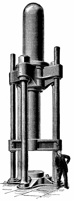
The press illustrated here was designed and made by Messrs. Henry Bessemer & Co., of Sheffield, for Mr. Samuel Walker, of Birmingham, for the manufacture of tubes of large size, and also for making hollow steel projectiles.
The press is made entirely of Bessemer steel, and is of the three-column construction, a strong casting of triangular form serving as a base of the press; into this casting the three columns fit, and carry on their upper ends a like casting, forming a top or entablature. Into this top casting the main cylinder is fixed mouth downward, concentric with the machine. Two small cylinders for giving the return or upward stroke rest mouth upward in the bottom casting at opposite sides. The two rams of these cylinders pass through the ends of, and carry, a crosshead, upon which the main ram rests. The two lifting rams are made long enough to pass through holes in the top casting, and thus form guides to the crosshead and mandrel.
The main ram is 24 in. in diameter, and has a stroke of 12 ft. The press is worked at a pressure of 3 tons per square inch, giving a down force of 1,300 tons. The two lifting rams are each 8½ in. in diameter, and give an upward force of 300 tons. This large upward force is required for stripping the tubes off the mandrels, in addition to raising the main ram crosshead, etc.
Referring to the engraving, the main cylinder is seen at the top with the main ram carrying the crosshead, to which are connected the two lifting rams, the cylinders for which extend below ground. By this arrangement a reciprocating motion is obtained, rams only being used, the central ram giving the downward thrust, and the two smaller side rams giving the upward stroke.
Mr. Walker has this press in operation, and from a disk of steel 3 ft. in diameter, having a mean thickness of about 4 in., he has raised a tube or cylinder with a solid end to it 3 ft. 6 in. long and 12 in. in diameter, of a uniform thickness of about 1 in., and sanguine hopes are entertained of producing greater results. Messrs. Bessemer & Co. are now making a larger press of similar construction.—Engineering.
If we turn our attention for a moment to the illustrations in the first article, it will be remembered that our typical log of timber was clothed in a sort of jacket termed the cortex, the outer parts of which constitute what is generally known as the bark. This cortical covering is separated from the wood proper by the cambium, and I pointed out that the cells produced by divisions on the outside of the cambium cylinder are employed to add to the cortex.
[2] Continued from Supplement, No. 644, page 10281.
Now this cortical jacket is a very complicated structure, since it not only consists of numerous elements, differing in different trees, but it also undergoes some very curious changes as the plant grows up into a tree. It is beyond the purpose of these articles to enter in detail into these anatomical matters, however; and I must refer the reader to special text books for them, simply contenting myself here with general truths which will serve to render clearer certain statements which are to follow.
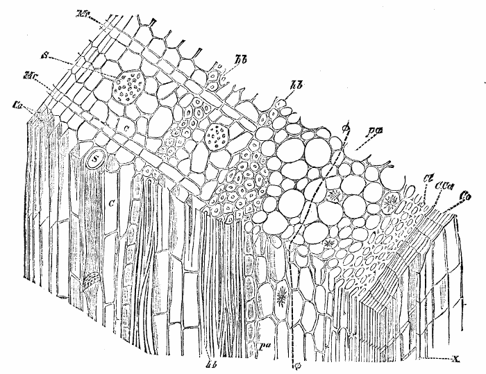 Fig. 20.—A piece of the cambium and cortical
jacket of a young oak, at the end of the first year. It may be regarded as
consisting of three parts, in addition to the cambium, Ca. Beginning
from the outside, we have: 1. Cork cells, X, formed from the cork cambium,
C.Ca: the cells developed on the inside of the latter, Cl, are termed
collenchyma, and go to add to the cortex. 2. The cortex proper, consisting
of parenchyma cells, pa, some of which contain crystals. 3. The inner or
secondary cortex (termed phloem or bast), developed chiefly by the
activity of the cambium, Ca: this phloem consists of hard bast fibers,
hb, sieve tubes, S, and cells, c, and is added to internally by the
cambium, Ca, each year. It is also traversed by medullary rays, Mr,
which are continuations of those in the wood. The dotted line, ψ, in
the cortical parenchyma indicates where the new cork cambium will be
developed: when this is formed, all the tissues (e.g. pa, Cl) lying on
the outside of the new cork will die, and constitute (together with the
cork) the true bark.
Fig. 20.—A piece of the cambium and cortical
jacket of a young oak, at the end of the first year. It may be regarded as
consisting of three parts, in addition to the cambium, Ca. Beginning
from the outside, we have: 1. Cork cells, X, formed from the cork cambium,
C.Ca: the cells developed on the inside of the latter, Cl, are termed
collenchyma, and go to add to the cortex. 2. The cortex proper, consisting
of parenchyma cells, pa, some of which contain crystals. 3. The inner or
secondary cortex (termed phloem or bast), developed chiefly by the
activity of the cambium, Ca: this phloem consists of hard bast fibers,
hb, sieve tubes, S, and cells, c, and is added to internally by the
cambium, Ca, each year. It is also traversed by medullary rays, Mr,
which are continuations of those in the wood. The dotted line, ψ, in
the cortical parenchyma indicates where the new cork cambium will be
developed: when this is formed, all the tissues (e.g. pa, Cl) lying on
the outside of the new cork will die, and constitute (together with the
cork) the true bark.
It is possible to make two generalizations, which apply not only to the illustration (Fig. 20) here selected, but also to most of our timber trees. In the first place, the cortical jacket, taken as a whole, consists not of rigid lignified elements, such as the tracheids and fibers of the wood, but of thin-walled, soft, elastic elements of various kinds, which are easily compressed or displaced, and for the most part easily killed or injured—I say for the most part easily injured, because, as we shall see immediately, a reservation must be made in favor of the outermost tissue, or cork and bark proper, which is by no means so easily destroyed, and acts as a protection to the rest.
The second generalization is, that since the cambium adds new elements to the cortex on the inside of the latter, and since the cambium cylinder as a whole is traveling radially outward—i.e., further from the pith—each year, as follows from its mode of adding the new annual rings of wood on to the exterior of the older ones, it is clear that the cortical jacket as a whole must suffer distention from within, and tend to become too small for the enlarging cylinder of rigid wood and growing cambium combined. Indeed, it is not difficult to see that unless certain provisions are made for keeping up the continuity of the cortical tissues, they must give way under the pressure from within. As we shall see, such a catastrophe is in part prevented by a very peculiar and efficient process.
Before we can understand this, however, we must 10346take a glance at the structural characters of the whole of this jacket (Fig. 20). While the branch or stem is still young, it may be conveniently considered as consisting of three chief parts.
(1) On the outside is a thin layer of flat, tabular cork cells (Fig. 20, Co), which increase in number by the activity of certain layers of cells along a plane parallel to the surface of the stem or branch. These cells (C.Ca) behave very much like the proper cambium, only the cells divided off from them do not undergo the profound changes suffered by those which are to become elements of the wood and inner cortex. The cells formed on the outside of the line C.Ca in fact simply become cork cells; while those formed on the inside of the line C.Ca become living cells (Cl) very like those I am now going to describe.
(2) Inside this cork-forming layer is a mass of soft, thin-walled "juicy" cells, pa, which are all living, and most of which contain granules of chlorophyl, and thus give the green color to the young cortex—a color which becomes toned down to various shades of olive, gray, brown, etc., as the layers of cork increase with the age of the part. It is because the corky layers are becoming thicker that the twig passes from green to gray or brown as it grows older. Now, these green living cells of the cortex are very important for our purpose, because, since they contain much food material and soft juicy contents of just the kind to nourish a parasitic fungus, we shall find that, whenever they are exposed by injury, etc., they constitute an important place of weakness—nay, more, various fungi are adapted in most peculiar ways to get at them. Since these cells are for the most part living, and capable of dividing, also, we have to consider the part they play in increasing the extent of the cortex.
(3) The third of the partly natural, partly arbitrary portions into which we are dividing the cortical jacket is found between the green, succulent cells (pa) of the cortex proper (which we have just been considering) and the proper cambium, Ca, and it may be regarded as entirely formed directly from the cambium cells. These latter, developed in smaller numbers on the outside, toward the cortex, than on the inside, toward the wood, undergo somewhat similar changes in shape to those which go to add to the wood, but they show the important differences that their walls remain unlignified, and for the most part very thin and yielding, and retain their living contents. For the rest, we may neglect details and refer to the illustration for further particulars. The tissue in question is marked by S, c, hb in the figure, and is called phloem or bast.
A word or two as to the functions of the cortex, though the subject properly demands much longer discussion. It may be looked upon as especially the part through which the valuable substances formed in the leaves are passing in various directions to be used where they are wanted. When we reflect that these substances are the foods from which everything in the tree—new cambium, new roots, buds, flowers, and fruit, etc.—are to be constructed, it becomes clear that if any enemy settles in the cortex and robs it of these substances, it reduces not only the general powers of the tree, but also—and this is the point which especially interests us now—its timber-producing capacity. In the same way, anything which cuts or injures the continuity of the cortical layers results in diverting the nutritive substances into other channels. A very large class of phenomena can be explained if these points are understood, which would be mysterious, or at least obscure, otherwise.
Having now sketched the condition of this cortical jacket when the branch or stem is still young, it will be easy to see broadly what occurs as it thickens with age.
In the first place, it is clear that the continuous sheet of cork (Co) must first be extended, and finally ruptured, by the pressure exerted from within. It is true, this layer is very elastic and extensible, and impervious to water or nearly so—in fact, it is a thin layer or skin, with properties like those of a bottle cork—but even it must give way as the cylinder goes on expanding, and it cracks and peels off. This would expose the delicate tissues below, if it were not for the fact that another layer of cork has by this time begun to form below the one which is ruptured: a cork-forming layer arises along the line φ and busily produces another sheet of this protective tissue in a plane more or less exactly parallel with the one which is becoming cracked. This new cork-forming tissue behaves as before: the outer cells become cork, the inner ones add to the green succulent parenchyma cells (pa). As years go on, and this layer in its turn splits and peels, others are formed further inward, and if it is remembered that a layer of cork is particularly impervious to water and air, it is easy to understand that each successive sheet of cork cuts off all the tissues on its exterior from participation in the life processes of the plant: consequently we have a gradually increasing bark proper, formed of the accumulated cork layers and other dead tissues.
A great number of interesting points, important in their proper connections, must be passed over here. Some of these refer to the anatomy of the various "barks"—the word "bark" being commonly used in commerce to mean the whole of the cortical jacket—the places of origin of the cork layer, and the way in which the true bark peels off: those further interested here may compare the plane, the birch, the Scotch pine, and the elm, for instance, with the oak. Other facts have reference to the chemical and other substances found in the cells of the cortex, and which make "barks" of value commercially. I need only quote the alkaloids in cinchona, the fibers in the malveceæ, the tannin in the oaks, the coloring matter in Garcinia (gamboge), the gutta percha from Isonandra, the ethereal oil of cinnamon, as a few examples in this connection, since our immediate subject does not admit of a detailed treatment of these extremely interesting matters.
The above brief account may suffice to give a general idea of what the cortical jacket covering our timber is, and how it comes about that in the normal case the thickening of the cylinder is rendered possible without exposing the cambium and other delicate tissues: it may also serve to show why bark is so various in composition and other characters. But it is also clear that this jacket of coherent bark, bound together by the elastic sheets of cork, must exert considerable pressure as it reacts on the softer, living, succulent parts of the cortex, trapped as they are between the rigid wood cylinder and the bark; and it is easy to convince ourselves that such is the case. By simply cutting a longitudinal slit through the cortex, down to near the cambium, but taking care not to injure the latter, the following results may be obtained. First, the bark gapes, the raw edges of the wound separating and exposing the tissues below; next in course of time the raw edges are seen to be healed over with cork—produced by the conversion of the outer cells into cork cells. As time passes, provided no external interference occurs, the now rounded and somewhat swollen cork-covered edges of the wound will be found closing up again; and sooner or later, depending chiefly on the extent of the wound and the vigor of the tree, the growing lips of the wound will come together and unite completely.
But examination will show that although such a slit wound is so easily healed over, it has had an effect on the wood. Supposing it has required three years to heal over, it will be found that the new annual rings of wood are a little thicker just below the slit; this is simply because the slit had released the pressure on the cambium. The converse has also been proved to be true—i.e., by increasing the pressure on the cambium by means of iron bands, the annual rings below the bands are thinner and denser than elsewhere.
But we have also seen that the cambium is not the only living tissue below the bark: the cortical parenchyma (pa) and the cells (c) of the inner cortex (technically the phloem) are all living and capable of growth and division, as was described above. The release from pressure affects them also; in fact, the "callus," or cushion of tissue which starts from the lips of the wound and closes it over, simply consists of the rapidly growing and dividing cells of this cortex, i.e., the release from pressure enables them to more than catch up the enlarging layer of cortex around the wound.
An elegant and simple instance of this accelerated growth of the cortex and cambium when released from the pressure of other tissues is exhibited in the healing over of the cut ends of a branch, a subject to be dealt with later on; and the whole practice of propagation by slips or cuttings, the renewal of the "bark" of cinchonas, and other economic processes, depend on these matters.
In anticipation of some points to be explained only if these phenomena are understood, I may simply remark here that, obviously, if some parasite attacks the growing lips of the "callus" as it is trying to cover up the wound, or if the cambium is injured below, the pathological disturbances thus introduced will modify the result: the importance of this will appear when we come to examine certain disturbances which depend upon the attacks of fungi which settle on these wounds before they are properly healed over. In concluding this brief sketch of a large subject, it may be noted that, generally speaking, what has been stated of branches, etc., is also true of roots; and it is easy to see how the nibbling or gnawing of small animals, the pecking of birds, abrasions, and numerous other things, are so many causes of such wounds in the forest.
The distribution of power has not always received the judicious treatment which its importance deserves. There are but few references to this question in the books on the subject, and these treat of methods that are not in accordance with the application of the art in its present state.
[3] Continued from Supplement, No. 647, page 10331.
The lecture was illustrated by about fifty views on the screen, which cannot be reproduced here, showing photographs of mills and mechanical drawings of the methods of construction alluded to in the lecture.
The early form of the distribution of power consisted in placing a vertical shaft extending through the whole mill and distributing the power at each story by means of beveled gears, generally of skew-beveled form. The mechanical defects of such a method of distributing power, with regard to protection, repairs, and necessary care, are readily apparent, and there have also been many severe accidents caused by the breaking of teeth in these gears.
The present method of distributing power in this country is entirely by lines of belts extending up through what is known as a belt tower, which constitutes an element of great fire hazard to a mill. In some cases the belts are carried from story to story, covered by a casing of wood, and in other instances the tower forms a flue which may be the means of the rapid spread of fire throughout the building.
Before the introduction of automatic sprinklers there was not, I believe, a single instance of a fire entering the lower portion of a belt tower during working hours without accomplishing the destruction of the mill. Since the equipment of such places with automatic sprinklers, there have been several fires of this nature extinguished with nearly nominal damage. That is to say, the hazard of fire starting in such places is beyond the capacity of any apparatus other than automatic sprinklers to cope with it.
It would be impossible to arrange the distribution of power in many mills to conform to conditions of safety without reorganizing the whole plant, which would, of course, be impracticable. But in many instances modifications can be introduced which will diminish the hazard to a great degree. When the pulleys and belting are covered with sheathing in each room, the continuity of these flues can be broken by removing this sheathing down to the height of four or five feet above the floor, so that the covering will merely constitute a physical protection to any one approaching the belting.
The best method of arranging the belt tower has been in the case of a mill at Fall River, which was erected upon the ruins of a building destroyed by a fire originating in the belt tower. The machinery is driven by a steam engine situated in an ell projecting from one side at about the middle of the mill; and the main belt communicates to pulleys in a stone masonry tower located directly inside the walls of the main mill; and thence, from pulley to pulley, the power is communicated to each floor by shafting passing through holes left in the tower, and in no instances by means of belts.
There is a separate stairway inside of the tower for lubricating the journals, etc., and the top of the tower is covered with skylights protected underneath by a wire netting. In case of a fire in the belt tower, the heat will readily break the glass at the top, and the fire will tend to go up and out of the tower rather than through the mill.
The questions involved in designing the floors of a mill are of great importance, contributing in no small measure to elements concerned in the successful operation of the mill, and to a greater extent to its standing as a fire risk, and therefore affecting the constant expense of insurance.
In the case of a building designed merely for sustaining of loads, as in a storehouse, a floor would naturally be designed on the basis of considering the breaking strength of the timber. But in the case of a mill, the limitation is the amount of flexure allowable under the circumstances; and therefore the floors of the building are made more nearly rigid than would be required merely from the consideration of the ultimate strength of the structure.
The books on the subject, repeating over a constant which was first, I believe, given by Brunel in testimony before a parliamentary commission, have held that one four-hundredth of a span is the proper ratio of flexure. This may have been a very good rule to give to the parliamentary commission, but it is hardly the practical method of limitation for a matter of engineering construction, because the flexure of a loaded beam is in the form of a curve, and therefore its law is that of a curvilinear function, and not of a straight line. I have examined a great number of precedents of good construction in this connection, and for mill use have deduced the formula for deflection in inches, d = 0.0012 L², in which L is the length of span in feet. It will be readily recognized that the true constant of deflection of span is measured by the radius of curvature which will give a uniform and allowable distortion to the floor in either direction to the limit of the radius upon which this formula is based, which is 1,250 feet.
I do not propose to offer to you on this occasion any remarks in regard to the treatment of the mathematics of the problem of applied mechanics concerned in the questions of transverse stress, knowing that you have certainly received instruction upon these subjects. But referring to the questions of mill floors, I would state that Southern pine beams of solid timber twelve by fourteen up to fourteen by sixteen inches are used; and instead of attempting the use of one piece of timber, it is preferable to use two pieces of the same depth and of half the breadth. These should be bolted together, with a space of an inch or so between them left by placing small vertical pieces of wood between the timbers when they are bolted together. In this manner one is more sure of sound timber, and in the process of seasoning there is less liability of dry rot in the interior, or of injurious checking, warping, or twisting.
The end of the beams should rest upon iron plates in the masonry, and should be secured by means of a tongue upon the plate entering a groove across the lower side of the beam. It is not feasible to make this groove to a close fit with the tongue; but it is cut a great deal larger, and the whole brought to a firm bearing by means of pairs of wedges or quoins driven into the groove each side of the iron tongue.
The outer end of the plate contains ribs or tongues reaching down into the brickwork. In this manner the timber is securely fastened to the brickwork; and yet in time of accident or of fire the falling of the beam in the middle of the mill will raise it up sufficiently so that it will clear the tongue and fall without tearing the wall down, which is the case whenever the beams are secured by bolts entering the end of the beam from the face of the wall.
At the points of support in a line of columns, the beams should be free from all compressive stress, transmitted through the lines of columns from floors above, by means of iron pintles between the cap of one column and the floor of the next one carrying this load.
A faulty method of construction, quite frequently used, consists in covering each column with a bolster of timber, four or five feet long, reaching out under the floor beams.
The transverse contraction of wood in seasoning after it is in position in the mill varies from three-eighths of an inch to double that quantity per foot; and the aggregation of such shrinkage amounts to a very considerable distortion or settling of the floor in a mill of several stories. Moreover, the resistance of timber to transverse crushing has been shown by experiments on the testing machine at the United States arsenal at Watertown to be about three times the resistance to longitudinal crushing.
Iron columns for mills have been entirely displaced by those of timber, as it was found that the latter were more reliable in resistance to fire, were freer from defects in construction, and possessed less tendency to vibration. A series of tests on full-sized mill columns of various forms of construction and age, made in the experiments referred to, at the Watertown arsenal, showed that resistance to crushing of Southern pine columns was about 4,500 pounds to the square inch, and remarkably uniform as to the different results. In white oak there was a wider range, owing to the difference in the grain of the various samples, the generality of the specimens being of somewhat less resistance than that of Southern pine.
It was furthermore found by these experiments, on comparing the crushing resistance of a full-sized column with that of a portion of the same, perhaps two feet in length, that the results were practically identical, likewise that within the limits of construction used for these columns the question of flexure did not enter at all in the problem, but they gave way by direct crushing, and that the resistance to crushing was proportional to its load upon the minimum cross section.
The precedents of safe construction in this matter show that wood columns in mills have successfully sustained for many years a load of six hundred pounds to 10347the square inch without deterioration. As the resistance of such columns is proportional to the cross section, the results of these experiments have changed the practice of mill engineers in the matter; and square columns are of almost universal use, which interfere with no greater area on the floor than the round column of the same diameter, while they furnish an increased resistance of a little over twenty per cent. in excess.
Along the axis of such columns a hole of about one and one-half inches in diameter is bored, and near each end a couple of transverse holes, generally half an inch in diameter, furnish means of ventilating the inside of the column for the prevention of dry rot and also checking, due to contraction and seasoning.
There are several methods of laying the floor plank upon these beams, which are placed from eight to ten feet apart, according to the dimensions of the machinery to be placed in the mill. The first floor of three-inch plank, planed on one side and grooved on both edges, is laid planed side down, and the hardwood splines are inserted into the grooves before the planks are pressed up and spiked to the beams. An agreeable finish is sometimes arranged underneath by plowing a rabbet in each of the corners, and inserting a bead in the groove thus formed, which is secured by nails driven diagonally into the plank on one side only, because if the nails were driven into both sides, the bead would be split by the contraction of the plank.
These planks should be cut to sufficient length to cover two bays of the mill; and their transverse resistance is that of a beam fixed at one end and supported at the other, or one and three-fifths as much as a plank of the same size but half the length would support; but it should be remembered in this connection that, if evenly distributed on the floor, five-eighths of the load would be carried by every alternate beam unless the planks are so laid to break joints at convenient intervals of about three feet.
The top flooring is generally laid directly upon the floor plank, with one or two thicknesses of roofing paper interposed; but the preferable method, which deadens the sound and vibration, and also greatly increases the fire-resisting qualities of the structure, is to lay a coat of mortar on the floor plank, preserving the uniform thickness by means of furring placed about sixteen inches apart, and then to lay the upper floor upon this.
For these upper floors hardwood plank, one and one-fourth inches thick, and not over four inches wide, is used. The black birch is considered by many to possess the greater resistance to wear; and Southern pine is ranked next, although the latter wood gives trouble by stringing, especially when trucks are rolled over it. White maple forms an excellent top floor, although not so hard as others, especially where the floor is likely to be exposed to water, as in paper mills and bleacheries.
Benjamin Franklin once said that next to a good foundation a good roof was the most important feature of a building. Although the constructive features of mill roofs are well defined, yet with regard to roof covering there is a wide diversity of experience and opinion.
The present form of factory roofing resembles a floor in its construction, being made, in a similar manner, of plank laid upon beams which project through the walls, where they act as a bracket to the cornice, the ends being sawed after any suitable ornamentation. The inclination for such roofs is about three-fourths of an inch to the foot. Where a mill is narrow enough for a single beam to reach from the wall to the ridge, they form cantilevers, the second point of support from the wall being by the columns one-third of the distance across the mill, and the ends of the beams are further secured together by means of iron dogs. For mills of greater width, the beam would reach only to the row of columns, and over the middle of the mill a beam is placed, usually horizontal on the under side, and hewn down from the middle to each end, so as to preserve the same slope on the upper side of the beam as for the roof.
In many instances mills are built with brick cornices, without any of the wood projection from the side; and in other buildings the walls are carried above the roof, which slopes toward the center, and all water falling on it or melted from the snow is conducted from it by pipes leading down through the middle of the mill.
It is not desirable to place gutters around the edge of the mill, as they serve no useful purpose, and are in continual need of repairs. By leaving the edge of the mill plank square and protecting it by sheet metal flashing, the rain falling from the roof can be received by a concave walk of coal tar concrete placed on the ground around the building. Suitable porches over doors, or some guard on the roof at these points, will prevent people who may be passing in at doors from being unduly wet by water from the roof.
There are numerous forms of roof coverings, the use of the different varieties being to a great extent local; that is, the sheet iron coverings used in the Middle States are almost unknown in New England; and in the latter place the ordinary tinned iron roofing is universally painted, while in the Dominion of Canada it is laid obliquely and never painted.
It is conceded by all that sheet copper forms the most desirable method of covering a roof; and, if one could be assured of the permanence of the structure, irrespective of the necessity for making changes every half year in order to keep pace with the march of invention, it would doubtless be shown that under such conditions of permanency copper would form the cheapest roof.
The most widely used roofing materials for this class of buildings are the asphalt and the coal tar roof, the latter being the most widely used in New England. There are numerous varieties of these composition coverings, which are applied by various methods. Some of these are of the most satisfactory character, while others are poorly designed and unskillfully applied, and are a constant source of trouble and expense to the occupant of the building.
One of the leading manufacturers, the efficiency of whose work for many years over a large amount of mill property I can vouch for by personal knowledge, uses the following method of applying the roofing. Three layers of roofing felt are placed on the plank parallel to the eaves, and continued by lapping each additional layer two thirds of its width upon the preceding one, and in this manner covering the roof with three thicknesses of the felt, breaking joints. This is secured to the roof by nails through tin washers and coated with a melted composition, and then two additional layers of felt are placed over the whole. Another coat of composition is then applied and gravel is placed over the whole while soft.
This maker does not approve of the practice of cementing each sheet of felt when it is laid, because it does not allow the felt freedom to yield from the expansion and contraction of the roof. When tin is applied to roofs, resin-sized building paper should first be laid on the roof plank, and the sheets of tin should be painted on the lower side before being laid.
Of late years cotton duck has been applied as a roof covering, and has been watched with a great deal of anticipation, although it has been used for similar purposes in covering ships' decks for many years. But the two uses are not strictly comparable, because the ship's deck is calked tight, and therefore the covering is free from the application of moisture underneath, while the roof is never tight, and the warm air underneath, heavily charged with moisture, which permeates the cracks between the planks, becomes chilled and condenses as it nears the top, carrying on a process of distillation.
As an example of the extent to which this can be carried on, I have known of instances where people presumed they were making a good roof by leaving slight air spaces by means of the furring laid between the roof plank and the top boarding. The circulation of air in these spaces deposited sufficient moisture to rot the boards.
A mill manager, wishing to have a roof over a very warm room, which should be both tight and a very perfect non-conductor, made a roof containing a space of about sixteen inches, which was filled with sawdust, and the roof boarding on top of this was covered with tar and gravel in the usual manner. In a few weeks the water began to drip through the ceiling as if the roof was leaking, although there was no snow on the top of the roof. Investigation showed that within that short time a sufficient amount of water had condensed with the sawdust to saturate the whole.
I would say in this connection that three inches of plank afford an ample protection against condensation over any ordinary process of manufacture, although four inches of plank have been used as a roof over paper machines in order to be safe beyond peradventure; but it is necessary that nails should not be driven into the bottom of this roof plank, because the point of a nail will reach to a lower temperature near the outside of the roof in the winter, and being a better conductor, it will cause moisture to condense upon the head of the nail.
Tin roofing is so general in use as not to require any allusion to methods of application, but the only course to reach economical and satisfactory results for a term of years, especially for locations near to the sea shore, is to use the best quality of dipped roofing plates of some brand which can be relied on as conforming to the standard and free from "wasters" or imperfect plates.
Duck roofing has been successfully applied by first laying and tacking down a covering of two-ply asphalt paper, and upon this was spread a covering of resin-sized sheathing paper, tacked in the usual manner. Upon this was laid a covering consisting of cotton duck, forty-four inches wide and weighing twenty-six ounces to the yard. Several methods of joining the edges of the duck together have been tried, resulting in the abandonment of the method of sewing used, for the preferable method of nailing the duck down, laying one strip over the other, and then opening the duck, a lock joint is formed without any jointure between the two sheets exposed to the weather. After the duck is stretched on the roof, it is securely fastened by means of round-headed woodscrews, one and one-fourth inches long, through a concave tin washer three-fourths of an inch in diameter, resting upon a seven-eighths of an inch washer made of roofing felt.
A coat of hot pine tar with a small quantity of linseed oil is laid upon the whole of the duck roofing, after being laid, for the purpose of filling the fiber and preserving the cotton fabric by means of the antiseptic principles of the pine tar. The surface is then covered with two coats of mineral paint.
Within a year, paper has been very successfully used as a roof covering. Sheets of wood pulp board about one-sixteenth of an inch in thickness are treated by a process which renders them hard and elastic, and secured upon the roof by means of tacks through concave tin washers. The edge of each sheet is grooved, in order to allow for the expansion and contraction of the roof. The whole roof is then covered with a heavy mineral paint. Experience with this during the past severe winter in Maine has been of the most satisfactory nature.
Shingles furnish a much better roof covering than slate, both in the matter of conduction of heat or cold in the extremes of summer and winter and also in resistance to fire. The heat of a slight fire underneath the roof will cause slates to crumble; and the same result will be obtained by heavy sparks falling and burning upon the roof. Some people treat shingles by boiling them under pressure in a solution of salt and chloride of lime, for the purpose of antiseptic treatment and also to render them fireproof.
The latest form of storehouses tends to one of two extremes. Where land is nearly level, and cheap, the greatest storage capacity can be obtained with the greatest economy by means of a one or two story storehouse built with a plank construction, with the beams secured to the posts by means of knees. A traveling crane or railroad runs along the middle of the storehouse, affording a ready means for rapid changes of the contents of the storehouse.
Another form for storage is by means of very large brick buildings, especially arranged as a protection against outside fire. In designing a storehouse it is of especial importance that the stories should not be made so high that it will be possible for a dangerous load to be piled upon any one floor.
The wool storehouse of the Pacific Mills at Lawrence can be safely said to be in its design and construction the finest example of mill engineering in the country.
Another type of mill storehouse, designed for both raw material and finished goods, is designed by Mr. John Kilburn, of Lowell, and consists of two buildings placed at right angles to each other, and joining only at one corner. These buildings do not contain openings through the floors of any nature whatsoever, either for stairways, elevators, or any other purpose; but all vertical communication is furnished by means of a masonry tower at one corner of the buildings, which contains an elevator and stairway. At the level of each floor, substantial balconies lead through a doorway in the tower to one in the storehouse, and the storage is added to or withdrawn from the storehouse in this manner.
I have not made any reference to the use of rolled iron for structural purposes, because such material has not been used to any extent in mill architecture. Irrespective of questions of space or of strength, wood beams possess advantages in the reduction of vibration, facility of securing the plank above and hangers below, and a great many other purposes in the changing and alterations of a mill, which render them peculiarly useful, and I believe that the results with Southern pine beams in American mills are much superior to those of the iron beams in European mills.
No small part of the success attending the use of rolled iron in the structural purposes for which it is adapted, has been due to the excellent and reliable engineering information contained in the manuals and catalogues issued by the rolling mills. Such works are reliable and clear, and, as far as I know, can without exception be safely followed.
The general tendency of American mill construction is toward as low buildings as the price of land will admit. The American mills being devoted to a large variety of operations, instead of being confined to a single process after the manner of those of European type, require a great deal more care in their organization, not merely in the original lay-out for the purpose of arranging for the passage of the stock in processes from the raw material to the finished product in as straight lines as possible, but due consideration should also be given to providing facilities for the enlargement of the mill.
As an illustration of the methods employed, in a paper mill plan of my own design, [the view and plan being thrown on the screen], the various operations containing processes of different hazard in regard to fire are completely isolated from each other by means of fire walls, and the storage of the mill is in turn isolated from the manufactory.
The storehouse consists of three sections, the largest section for paper stock, which is sorted in the upper story, the second section, one story in height, for other manufacturing supplies, and beyond the fire wall the storehouse is arranged to contain the finished paper. Goods can be taken away from or added to the storehouse at the single line of teams, or railroad siding.
After the stock leaves the sorting room, it is carried to the dusting room over a covered bridge, which is protected from the weather on one side, yet does not form a flue for the spread of fire as does a closed bridge.
The first room in the main mill is used for a dusting room, and thence the stock falls into the rotary bleach, whence it is carried through the fire doors to the engine room. Here it meets the wood pulp and clay wheeled from the middle section of the storehouse, which is on that same level. After washing and beating, the stock is run into the drainers below, whence it is raised again, and after suitable intermediate processes the pulp is converted into paper on the paper machine in the connecting building. This paper is then taken into the upper part of the main building, and after being dried on the lofts is suitably calendered and packed before being transferred into the extreme end of the storehouse to await shipment.
At the present time it has been found that an inclined roof of the olden type is not a necessity over a paper machine, as has been decreed by the tradition passed down from old practices. Within the last year, a number of flat roofs have been placed over paper machines, without any trouble ensuing from condensed water forming on the ceiling and thence dropping upon the stock. It is well known that the use of a flat roof in such places is attended with a great many mechanical conveniences; and the pitched roof hitherto used for these purposes has been submitted to, only because it was presumed to be necessary. The whole tendency of mill design is in the line of fitness of means to ends, in the simplest and most direct manner.
When the mills in Lowell were first built, they consisted of isolated buildings, which it was presumed would remain for all time; but when it became necessary to increase the plant, it was found that the engineer had wisely laid out the mills in the same yard in reference to a fixed grade, so that corresponding floors would meet when the buildings were extended so that they reached each other.
Wherever a strong and diffused light is necessary for any manufacturing process, or the conditions are such as to require unusual stability of the building, one-story mills lighted by monitors afford accommodations not reached by any other form of construction.
In presenting before you some of the salient features of modern mill construction, I have endeavored to show the various steps of progress leading up to the development of the present types of design, as well as some of the methods of construction in present use.
These various steps in advance, producing mills better suited for the purposes for which a mill is built, are not generally due to elements originating with the manufacturers, but with the Factory Mutual Underwriters, who, finding it cheaper to prevent a fire than to settle a loss, have in every manner encouraged improvements in construction, equipment, and administration, with the result of diminishing the insurance on textile manufacturing property during the last generation from two and one-half down to one-fourth of one per cent., or reducing the cost of insurance eighty per cent.
In designing any work, a careful regard should be given to precedents, remembering that a good designer must also be a good copyist.
The Passive State of Iron and Nickel.—E. Saint Edme.—The nickel of commerce immediately becomes passive if immersed in ordinary nitric acid. Iron, while being briskly attacked by common nitric acid, is rendered passive by contact with nickel. If steel and nickel are plunged into the acid together, the former metal is not even momentarily attacked. Nickel retains energetically a proportion of combined nitrogen, to which its passivity is due.10348
We give an illustration of the new type of second class torpedo boat which Messrs. Yarrow & Co. have recently constructed to the order of the Admiralty, and which was tried at the latter part of last year. The boat is 60 ft. long over all and 8 ft. 6 in. wide, 3 ft. shorter and from a foot to 15 in. wider than the old type of second class boats. She attained a speed of rather more than 17 knots per hour on her official trial with 4 tons on board. The speed, when light, for six runs on the measured mile was 18½ knots. The latter seems a very high speed for so small a vessel, and indeed it is a remarkable performance, but at the same time the speed of 17.031 knots on a four hours' trial with 4 tons on board is more remarkable still. It is well to note, says Engineering, in comparing speeds of torpedo boats, under what conditions as to weight carried and duration of running the trial is made. In our previous notice we referred to the manner in which this boat differs from ordinary second class boats in the manner of ejecting the torpedo; and the arrangement is well shown in the engraving. The more ordinary method of firing the torpedo from a tube or tubes, built into the hull and pointing forward through the bow, will be familiar to the majority of our readers; but here it will be seen the bow fire has been altogether abandoned, and a swiveling gun placed aft is substituted. The gun, of course, is not new; indeed, one was placed on the old Lightning, the first torpedo boat built for the English navy. That vessel was, however, a first class boat, and although not so large as the first class boats now built, was considerably bigger than No. 50, which is the official designation of the craft under notice. In the Lightning, too, the torpedo gun was placed forward, and was trained in quite a different manner to that of this second class boat. We have already commented on the offensive advantages of being able to eject the torpedo through a wide angle of range, and when going at speed, rather than having to bring the boat to a stop and fire only end on. We need not therefore recur to this point; but since our former notice appeared we have had, while on shore, an opportunity of seeing the boat steam at speed and maneuver. Our previous experience was obtained on board—a position which, in some respects, does not afford so good a point of observation as when one is at some little distance from the boat. It is certainly a remarkable sight to see the manner in which this little vessel winds among craft or round buoys, or turns circles of surprisingly small diameter. She seems to pivot on a point very near the bow, a fact which is no doubt chiefly to be accounted for by the way the deadwood is cut away aft. This allows the stream of water diverted by the unusually large rudder to swing the after part round with facility.
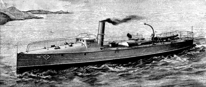 IMPROVED TORPEDO BOAT.
Another notable feature about No. 50 is the comparatively small bow wave she throws up. We believe it is pretty generally acknowledged now that the most noticeable point at night about a torpedo boat traveling at high speed—putting on one side flame and sparks from the funnel—is the high bow wave the majority of these vessels throw up when going quickly through the water. The powerful electric search light causes this mass of foaming water to show up with peculiar distinctness against the dark background of sea and sky. It has been, therefore, thought advisable to reduce this undesirable feature even if something in the shape of speed has to be sacrificed. Fairly full bow lines are the best for fast boats of this class, but in such a model the big bow wave is very noticeable. Messrs. Yarrow have met the demand of naval officers for a less easily observed boat by placing the greatest cross section further aft than they would have done had speed alone been the point aimed at, as it almost always was in the earlier torpedo boats. It is therefore additionally creditable to Messrs. Yarrow that they have reached the unprecedentedly high speed of seventeen knots, with so considerable an addition to the beam, and that they have at the same time reduced the bow wave.
There is a further advantage of less surface disturbance when running torpedo boats. It is unnecessary to point out that surprise will be the chief element of success in future possible attacks in which these craft may be engaged. As the bow wave is most likely to reveal the presence of the boat by sight, so also will it most probably give first warning of approach by sound. It is the splash of the water and not the noise of the machinery that can be heard for the greatest distance when a boat is running with hatches closed—speaking of course of high-speed boats in which the engines are kept to a high degree of perfection, as they should be, and in the Royal Navy are, with all torpedo boats. It will therefore be seen that there is an additional reason for reducing the objectionable bow wave.
The boat which we illustrate recently made the run from the Thames to Portsmouth, and, the weather being bad, was taken through the somewhat intricate but more sheltered fairways and channels of what is known as the "overland passage." Off Margate she managed to get on the ground—a result by no means to be wondered at; and, as the sands here are very hard, she smashed her propeller. After a time she was got off and beached, when a new propeller was fitted. We mention this incident, as it is generally supposed that these craft are of a very fragile description; "egg shell" is the favorite term of comparison. One distinguished naval officer—retired—has said he would never willingly go on board these craft, for fear of putting his foot through the bottom; and there is a very funny story extant about a sailor with a wooden leg. It would seem, however, from the experience of No. 50, that steel vessels are of much more robust constitution than is generally supposed, and, indeed, there is ample testimony to the fact. We recently witnessed the efforts of a small working party to get one of these vessels over a bank. She was pushed as high up as the strength of the party would allow, and in this position her fore part was over the bank for about a third of the length of the boat. A tackle was then put on the bow, which was bowsed down until the boat could be dragged straight ahead.
A few words may appropriately be added here as to torpedo boat policy generally. Admiral Colomb, in the opening remarks of his excellent little manual, "The Naval Year Book," refers to the torpedo boat question in the following terms: "The fleet, the flotilla, the cruiser, and the harbor attack and defense have each had (i. e., during the past year) their share of attention, and developed exercise, and opinion has been advanced, guided, or turned back by the observation of facts which these exercises have brought out. While it cannot, perhaps, be said that the torpedo, as torpedo, has much altered its position in naval estimation, it seems fair to assume that the torpedo boat, as boat, has fallen in repute. In the first, it has grown very much larger, and has, in point of fact, ceased to be a boat. In part this may have come about because the role which some proposed for the torpedo boat, of being an entirely defensive weapon confined to territorial localities, and operating only within a short distance from its port, has never been generally accepted. Boats which were never intended for voyages have been sent on voyages, and, being found more or less unsuited for that kind of service, supposed improvements have been made, so that they should be capable of executing it. The 'harbor defense' instrument has become a 'sea attack' instrument, and in some sense an unrecognized rival to the undoubted sea-going torpedo vessels like the Archer, the Fearless, and the Rattlesnake."
In these passages Admiral Colomb has put the present aspect of the torpedo boat question very aptly. We are now experiencing the inevitable reaction consequent upon our early over-valuing of the torpedo. The unknown possibilities for distinction of those weapons were so magnified that scarcely any expenditure was thought too great to provide means for their employment, both in and out of season. Torpedo vessels have been growing in size and costliness. More and more gear has been crowded into them, increasing their weight and cost, and also the intricacy of their machinery. In all this, cheapness, the one great virtue of the torpedo, has been overshadowed. No doubt it is right for a great naval power like Great Britain to have vessels of all classes, and the possible value of small fast vessels such as the Archer or the Rattlesnake—not necessarily as connected with the torpedo—can hardly be overestimated. But for smaller naval powers, that look on the torpedo boat as a means of coast defense, especially those countries having a broken coast line studded with islands, bays, and inlets, it is very questionable whether the smaller boats, such as that now under notice, will not be a better investment than the larger craft at present more in vogue. By the additional seaworthiness of this boat, secured chiefly by the increased width, the 60 ft., or second class, boat has been lifted into the category of practicable vessels; and it must be remembered that four or five of these smaller craft can be purchased for the price of one modern first class boat. This is the crucial point, the money standard, and it is to that that all ship and boat building questions must be reduced, whether it be in wealthy England or the most impecunious and perhaps hardly more than half-civilized state.
The question may be argued from many points of view, and we put forward these remarks simply as suggestions, without any wish to dogmatize. But it seems that, as the cheaper second class boat has been carried so many steps in advance, it may be worth while to reconsider the position with a view to returning to the original torpedo boat idea of small, inexpensive vessels, acting by surprise; and not putting too many eggs in one basket.
Sine and Tangent Galvanometer.—An exhibit of original scientific apparatus was contributed by Prof. G. F. Fitzgerald, of Trinity College, Dublin. The first instrument was a sine and tangent galvanometer, which combines both instruments, and has four interesting peculiarities: (1) The windings of the coils are visible through the plate glass sides, so as to be capable of easy measurement in situ. (2) The position of the needle is read by reflections of a cylindrical scale in two rectangular mirrors whose intersection is horizontal, and which are attached to the magnet. These mirrors reflect images of opposite sides of the scale to a fixed mirror which reflects them into a microscope, in which, by means of a micrometer, it is possible to read accurately the position of the line which is the same in the two images. (3) This cylindrical scale is affixed to the base of the instrument, and the coils can be rotated round it, so that when the instrument is used as a sine galvanometer its position is read by reflection in the rectangular mirrors attached to the magnet of a pointer attached to the coils. (4) By a slight modification of the suspension, a beam of light can be reflected from a mirror connected to the magnet at 45° to its axis of rotation, and can emerge through the plate glass side of the instrument and fall on a horizontal scale, where it will measure the tangent of the deviation instead of the tangent of twice the deviation, as in ordinary reflecting galvanometers.
The meldometer shown is an instrument for facilitating the identification of small quantities of minerals by comparative observations on their melting points, and for observing the phenomena of their fusion and ebullition. It consists of a strip of platinum arranged to traverse the stage of a microscope, and heated by a current derived from two Grove's cells.
On this strip the fragments of the mineral, or, if for comparative observation, of two or more minerals, are placed. The temperature of the platinum is then raised by gradually diminishing a resistance placed in circuit with the battery and meldometer, the behavior of the substance being meanwhile observed through the microscope. To effect the elevation of a temperature automatically, a resistance, consisting of a rod of carbon fitted in a vertical glass tube, is employed. Professor Fitzgerald showed two sets of apparatus for measuring the densities of gases. Both methods depend on the determination of the amount by which a body is buoyed up when immersed in the gas.
Model for Illustrating the Properties of the Ether.—A very interesting exhibit was the model for illustrating the electromagnetic and luminiferous properties of the ether, of which a detailed description is almost necessary. The model consists of a series of wheels, rotating on axes fixed perpendicularly in a plane board, and connected together by India-rubber bands. The axes are fixed at the intersections of two systems of perpendicular lines, and each wheel is connected with each of its four neighbors by an India-rubber band. Thus all the wheels can rotate without any consequent straining of the system if they all rotate at the same rate. If, however, some of the wheels are rotated through a different angle from others, the India-rubber bands will be strained. If it be desired to represent a region in which conducting matter exists, it will be represented by removing the bands from a set of wheels. Suppose the bands are removed from the regions, A and B, and from the connecting line, A B, then we can represent the charging of these regions with opposite electricities by introducing some mechanism by means of which the wheels on opposite sides of the line, A B, can be rotated in opposite directions. The model is not intended to illustrate in any way the connection between the ether and matter; indeed, one of the advantages claimed for the model is, that the study of it so distinctly emphasizes the distinction between the phenomena depending on the general properties of the ether by itself and 10349those depending on its connection with matter. For instance, from the very case we have just considered, we get impressed upon us that it is by means of matter only that we can get a hold on the ether so as to strain it. As the object is not to illustrate the connection between matter and ether, any rough method of turning the wheels so as to create the proper strain will do well enough, as it is not the method of producing, but the nature of the strain produced that is to be considered. Having once rotated these wheels, we may replace the bands along the line, A B, and we have the state of the ether between two oppositely electrified bodies represented on the model.
It will be observed that half the India-rubber bands are strained, and that in lines running round the bodies the tight side of a band is always away from one body and next the other. This represents the polarization of the ether. The late Prof. Clerk-Maxwell defined polarization as a state in which the opposite sides of each element are in opposite states. Now, the opposite sides of each band are in opposite states—one side loose, the other tight; and so it can very well represent the polarized state of the ether. The displacement producing the polarization is due to the different rotation of the wheels carrying the band causing more of the band to be at one side of the wheels than at the other—less at the tight and more at the loose side of the pair of wheels, and this represents the electric displacement producing the polarization. The direction of this displacement is at right angles to the line of the bands that are strained, and is out from one body and in toward the other all round.
Considering the other properties of the ether that are represented by the model, we observe in the first place that during the time polarization is taking place the wheels are rotating, and that the rate of rotation of the wheels is proportional to the rate of increase of polarization, and that the direction of the axis of rotation is perpendicular to the direction of the displacement. Hence it is seen that the magnetic force is properly represented by the rate of rotation of the wheels, and its direction by the axis of rotation. The model, although simple in construction, is very useful, and its careful study will greatly assist the student in obtaining definite physical conceptions of many of the more abstruse phenomena depending on the ether.
Prismatic Photometers.—Another exhibit was a photometer made of solid paraffin, or any other translucent substance, invented by Mr. J. Joly, of the University of Dublin. The arrangement is at once simple and effective. The instrument depends upon the fact that if a prism be cut from a translucent body, and so exposed to a source of light that one only of its faces is illuminated, the light diffused through the substance and reflected out through the illuminated faces of the prism gives it an appearance as if lighted up internally. The effect is, in fact, as if the prism itself was a source of light. Two such prisms laid together on smooth faces, and receiving light from separate sources, if placed so as to be at opposite sides of the plane of division, appear as if each was emitting light proportional in intensity to the source of its supply. The double prism has the appearance of two luminous bodies laid side by side.
When, however, the supply to each prism is brought to equality, they appear as if emitting equal quantities of light; and it is hard to detect any longer that two prisms are being observed, so completely does all trace of the plane of division disappear. An ingenious piece of apparatus invented by Mr. Joly was one for carrying out his method of determining the specific gravity of small quantities of dense or porous bodies. The method here shown enables the specific gravity to be determined whatever the density or state of aggregation of the substances, and in extremely minute quantities, with an accuracy limited only by the sensitiveness of the chemical balance.
Telegraphing the Readings of Scientific Instruments.—Another invention of Mr. Joly was his apparatus for obtaining telegraphically the readings of meteorological instruments placed at a distance from the observer. This apparatus may be attached or adapted to the various thermometers, the barometer, rain gauge, and to other instruments placed in a mountain station, thus enabling their readings to be taken from a conveniently placed observatory. Any number of instruments may be worked with perfect reliability and certainty by the use of three wires only; the only extra piece of apparatus needed being a disk, carrying insulated contact pieces arranged round its circumference, to which the wires of the different instruments are attached. Of these three wires, one serves to put one after the other of the contacts into circuit with the home station through the second wire. By this second wire the readings are taken and the readjustment of the instruments effected. The third wire is for the indication of the contacts, and is taken from all the instruments to the galvanometer in the home station.—Industries.
About nine months since we directed attention to the system of colored photography invented by Mr. J. E. Mayall, London. Since that time, Mr. Mayall has further developed the details of his process, and as a result his color pictures have been much improved both as regards appearance and size, and are beautiful specimens of this new departure in photographic art. As stated in our previous notice, Mr. Mayall, after fourteen years of experimental research, has discovered the art of reproducing the colors latent in the negative of the photograph, having arrived at his discovery by the aid of spectrum analysis, which led him to the conclusion that every color in the organic world, when exposed to a suitable photographic plane in a camera, registers exact vibrations. Mr. Mayall has succeeded in producing chemical colors extremely attenuated, which exactly correspond with the vibrations in the negative. In doing this, he keeps the film alive to the smallest vibrations of light. He uses, first, lactate of iron to impregnate the isinglass film with a salt of iron capable of uniting with any stronger organic acid; and, secondly, meconic acid, which impregnates the film of albumen, and has a stronger affinity for iron than lactic acid. It unites with the iron, and forms a red film, which is in a state to receive all the lower vibrations of the red end of the spectrum, and this gives these lower vibrations a fair chance with the electric light. All subsequent processes assist this chemical march to the final end of making a print that will take up colors, which, when added, fall in their places, and there remain indelible and unalterable.—Iron.
Those who were in attendance at our Dayton meeting will perhaps recall the fact that the writer, in a paper read at that time, strongly advocated gas companies taking hold of the electric light business and running the same in connection with their gas business; you will also recall the fact that the writer suggested that gas companies should take up the incandescent electric light and fuel gas. Since that time it has been demonstrated by several gas companies in this and other States that the electric arc system can be added with success, financially, to gas companies and with satisfaction to their patrons; and the writer derives great pleasure in hearing of so many companies who have left the narrow and beaten track of prejudice and are now walking in the broad road of progression.
[4] A paper read lately before the Ohio Gas Light Association.
It is not my intention to dwell upon arc lighting now only long enough to state that, after two years of practical experience with the combination, our company consider they have taken a right step in adopting it, and that it is satisfactory in every respect. Other gas companies that have adopted the arc system can undoubtedly corroborate this with their experience. I would make this paper a continuation of the last one by now taking up the incandescent electric system and fuel gas question. That both will be introduced into every city in the United States before long by some one I have not a shadow of a doubt; and why? Simply because they are both desirable commodities in domestic economy and hygiene.
Please lay aside all prejudice, and I will show you an ideal domestic burner for illumination purposes. Now, what comprises an ideal burner for domestic use? In the first place, such a burner must not blacken our walls and ceilings, neither must it give off deleterious products of combustion; it must be a steady light, and not subject to draughts; it must not give out heat in summer, it must not be possible for inflammable goods to ignite by coming in contact with it; it must be a light that will have no ill effect if by accident the key is left open; it must be a light that our country cousins cannot blow out, neither must it be one that requires dangerous matches to ignite it, and lastly, it must be a fairly cheap light.
Now, gentlemen, if you have thrown prejudice to the winds, perhaps you can recognize in this ideal burner the incandescent electric light for domestic use. Now, if this light is an ideal one, who is going to prevent its adoption by the public? Gas companies cannot, and if they cannot no one can. So, in my mind, the wisest course to pursue is to admit what we know to be true, and proceed at once to supply the demand, increase our revenue, push out into the suburbs of our cities, sell it as cheaply as possible, and don't let others come in and take away what rightly belongs to you. If there is any money to be made in the business by others, there is still more in it for us.
For store purposes, where the hours of burning are defined, I think it better to abandon the meter system and fix a price per annum or month for each lamp, taking into consideration the hours of use as a basis for charges. For private dwellings this would not be practicable, and we would have to resort in this case to meters, or perhaps fix upon a price for furnishing the current and have the consumer purchase the bulbs or lamps whenever renewals were necessary. In this way economy would cheapen the light to the consumer. Any method that will dispense with the meter and still be satisfactory will be the one to adopt.
I cannot understand how some gas companies who have the incandescent electric system as a competitor can console themselves with the fact that it is not injurious to their gas business, even taking it for granted they are selling as much gas as before its advent. Is this a just reason why they should make no effort to secure their old patronage? I think not, for it is human nature to secure a whole loaf in place of the half, when it is possible to get it. A gas company's revenues would certainly be increased by the step, and a dangerous rival would be made profitable.
I think it is a mistake to think that by and by the people will get back to gas. Of course some will, just as gas consumers sometimes go back to coal oil; but, because a few give it up, don't let us deceive ourselves by thinking that all will do it eventually, for the incandescent electric burner is bound to remain wherever it is now in use, and will find its way to the other places where it is not now in use. "That is all very well to talk about," I hear some one say, "but what are they going to do with our prior investment?" To such I would say, push that, too. Cheapen it to its lowest point and urge its use for power and cook stoves until such time that you find yourselves able to supply gas for heating purposes of all kinds.
What difference does it make to a company whether the money expended for improvement account be coal gas benches, holders and mains, or dynamos, boilers, and wire? I fail to see the difference, and if improvements have to be made in both, so much the better—it shows a healthy demand for both branches, and should be promptly provided for.
If arc lighting is to be the light on our streets and the incandescent electric light for our stores and dwellings, shall we have to draw our fires from under our gas benches and stop making gas? This, to the writer, would be an absurd deduction, for the very reason that in nature's laboratory all these elements are placed, and gas would not be one of them if there were not some important part for it to play in the supplying of man's wants. It is for us to take the things we find in nature's laboratory and select the fittest articles for each special use; and it is reasonable to suppose that it will be only the fittest that will finally be a success. The arc light, so far as the writer has ascertained, has asserted pretty generally throughout the country its supremacy on our streets, and this in spite of all opposition from gas companies—showing conclusively that it has gained its position by the force of demand for the fittest. Incandescent electric light is just as surely finding its position and field of usefulness, and in its turn will assert its supremacy, and why? Because it has the qualifications called for in the public specifications. Some will assert that it is too expensive to come into general use, and also that it is not as reliable as gas. The first is no argument against it, for was not coal gas sold at exorbitant prices in its early days? It certainly is capable of being cheapened in the future, as gas has been, and this is one reason why gas companies should enter the business, as it is in their power to cheapen it.
As far as unreliability is concerned, it certainly looks the most serious objection; but don't be alarmed on that score, for duplicate machinery or storage batteries will eventually overcome this bugbear, and while discussing this subject don't let us forget that the breaking of a main, the filling up of a drip, a flood or explosion, or even Jack Frost, has often caused our customers to think that even gas is not very reliable.
I cannot understand what prompts gas companies as a rule to prejudice against electric lighting, unless it be they imagine the outcome to be idle gas mains and cold benches. This I think is all wrong. The largest unoccupied field to-day is the fuel gas field, and who should step in and supply this demand? Could any one do it as well as the present gas companies? We have our mains and services already laid; we have our holders, meters, and trained labor, most of us have also the necessary land to spare on which to erect the generators.
Next to the fuel gas field I think I can see another field nearly as extensive, and that is the coal oil field.
Please imagine the following picture, which is representative of the writer's belief of what a gas company will be in the near future; in fact so near in the future that before our next convention rolls around it will be a reality.
One set of officers, whose principal qualifications shall be progressiveness—their duties to be divided between electric lighting of all kinds, including electric power, fuel gas for all purposes, including gas engines; also incandescent lights off fuel gas mains.
Now let us see what the plant will consist of. One set of mains for fuel gas, from which our patrons will draw all their fuel, and also light, if they wish. Gas engines will be run economically with this gas. One set of meters only will be required.
There will be no coal gas benches as we have them now, as the method of manufacture is too laborious, too expensive and very primitive, not to say barbarous—everything now being built on the horizontal plan, requiring the greatest possible exertion to both draw a charge and stoke. The generators of the future will be on the cupola style, feeding by gravitation from the top. Native coals in all probability will be sufficiently good to make gas of. One portion of the plant will be devoted to the dynamos and engines for furnishing the electric light. Where the coal gas benches now are will be boilers, or perhaps even these will be unnecessary if gas engines be used. If steam boilers be used, they will be fired with producer gas, and the holders will become simply pressure regulators. The revenues of gas companies will be increased fivefold, if not more; the consumer will get cheaper fuel, cheaper power, and cheaper light.
Native coal fields will become more valuable, and we will not pay tribute to other States, as heretofore. The change from illuminating coal gas to fuel gas will perhaps be a slow one, owing to the conservatism of gas companies and imperfected details; but eventually it will be brought about in spite of all obstacles. If a company is operated as pictured, it will furnish arc lighting, incandescent electric lighting, and electric motors, fuel gas, incandescent gas lighting, and gas engines.
Gas will be made on a larger scale, with less dirt and nuisance, and without that laboriousness now made necessary. Valves, levers, and push buttons will displace scoop, drawing hook, and wheelbarrow, and the employees will no longer be known as "gas house terriers," but will become elevated to a higher plane. The officers of the company will also of necessity have to be more active and alert, and the rule of thumb will be at a discount. Now let us see where the gas man will be who fails to occupy these new fields of pasture green.
He will, of course, go on making coal gas in the old way; he will still wrestle with stopped stand pipes, steam jet exhausters, naphthaline, etc., and worry over how much a bushel of coke weighs. He will try to convince his customers that he knows better than they do what they want, and that anything but his gas is of no account. He will keep on cutting out items from the newspapers whenever he finds it recorded that an electric light somewhere failed to flicker.
He will still maintain that there is not a company in the country making anything out of electric lighting, and that it is only a matter of time when some fellow slips into his town and, noting things, works up an arc light company, captures the street lighting and some of our friend's best consumers. The price of gas is lowered; all kinds of patent gas burners are invested in to recapture those lost consumers; a fight ensues, factions are made in the town, and the arc light company adds an incandescent plant to the arc light, and captures more of our friend's consumers. To cap the climax, another fellow comes along and proposes to supply fuel gas to the citizens, gets a franchise, puts in pipes and services, and our friend wakes up some fine morning to find that what the electric light fellow has left him in the shape of lighting has been captured by the fellow with the fuel gas plant, who puts in the incandescent gas burners.
Evidence is cropping up all around us that tends to this change. We find manufacturers of fireclay goods now making carbons for electric lighting; we also find gas fixture manufacturers now making and selling electric wires of all kinds, besides other apparatus connected with the electrical field. Manufacturers of meters have not yet devised a meter for measuring electrical currents, but perhaps it would pay them to devote a portion of their time to studying one out. As far as the present meter business is concerned, I think, if this transformation of the gas business is brought about, the demand for gas meters would be quadrupled and the use of the larger sizes of meters would be made necessary; but if accuracy could be insured with a much smaller meter with quicker action, I think it would be better adapted for the purpose. Fuel gas, if it can be manufactured at a price at which it could be sold with profit at a lower or as low price as coal, would prove a larger field than all the kinds of lighting put together, and is certainly worth our while to 10350investigate thoroughly. The owners of the smallest houses of our cities would become our patrons, and a small profit per thousand would represent a wide margin when taking into consideration the large amount that would be consumed.
But is the fuel gas practical, and has there been sufficient progress made to date to warrant gas companies taking hold of it with any assurance of success?
In the first place, what assurance do we require? Do we want some one to come along and guarantee us a profit of 20 per cent. on our investment if we enter the field? If so, the patentees of the different processes might just as well negotiate with the shoe maker as with the gas company. I think all the assurance we want in the premises is that with certain apparatus we can get certain results from a ton of coal (the kind of coal being specified), or that from a ton of coal we can get a certain amount of available deliverable heat units.
The balance we should be capable of working out ourselves, such as labor, leakage, cost of gas at consumers' meters, and such other data that we certainly should be more familiar with than any one else.
Of course, the fuel gas will have to have an odor, and must be delivered at a proper pressure; and proper appliances for governing supply and insuring perfect safety will have to be calculated on. In fact, the gas man must try to improve on methods adopted, and do his best to hasten the day when solid fuel in our homes shall be no more—in other words, we have to take hold of the fuel gas business in its infancy or it will get weaned away from us.
Mr. McMillin, with others, has given us some figures on fuel gas which have been verified by practical tests. For instance, he gives us as his opinion that a mixed gas is more adapted for all-round purposes than either coal or water gas alone.
From experiments made we find that from a ton of bituminous coal, making a mixed gas, we can realize as salable gas 63 or 64 per cent. of the total heat units in the original ton of coal, or about 17,000,000 heat units, besides a residue of heat sufficient to produce the steam for making the above amount.
Of this mixture 20 per cent. is coal gas, made in the ordinary way, which is the only objectionable feature the writer can see in the process. I am inclined to think that Mr. McMillin rather strained a point here in order not to alarm coal gas men, or else to avoid a too radical change in the apparatus now in vogue for making coal gas.
By his statement we find that in water gas, labor and repairs cost but 7 cents per M, while coal gas costs for the same items 15 cents per M. Of course, the proportion of coal gas made by the old method is of more value in heat units than the water gas made by the new method; but what I wished to suggest was this, that if the whole process be made in the cupola as water gas is now made, whether the result would be the same number, or nearly so, of heat units in amount of gas made, with a large reduction in labor making the coal gas cost no more than the water gas for the item of labor repairs. If the mixture can be made in this manner, and I have some assurance that it can be done successfully, then I think it would pay any company to abandon the use of the present style of gas benches, and use the space now occupied by them with more improved apparatus, rather than use them at a loss, simply because we have them on hand.
We have pictured an ideal burner for our homes in the fore part of this paper, and I cannot refrain from holding up to your view this ideal fuel, which has no smoke, no dirt, no ashes, and entails on the housewife no extra labor, can be regulated automatically to one steady temperature, and does not require a workingman, after doing a hard day's work, to come home and find a ton of coal dumped on the front sidewalk, which has to be wheeled or carried in before night comes on.
Now that we have seen an ideal street light, an ideal house light, and an ideal fuel, we will endeavor to show you an ideal gas company; and we cannot do it in a more concise way than to say that an ideal gas company is one that keeps all these ideal commodities for sale at a reasonable price.
This may look visionary on my part to some of you, perhaps all of you; but, nevertheless, I feel that this is the place and time to talk over "our future prospects," and if this paper is the cause of any one investigating the subjects spoken of or bringing forth discussion regarding the same, I shall feel I have not written in vain.
I appear before you to give a short course of two lectures on the application of electricity to lighting and working. To-night I shall confine my attention entirely to lighting, and if we succeed in getting through our subject, we shall devote ourselves next Wednesday to the application of electricity for working tramways, to the transmission of power for various purposes, and generally to working.
[5] Two juvenile lectures recently delivered before the Society of Arts, London.—From the Journal of the Society.
Many people imagine the electric light to be a cold light. It is a delusion. It is called a cold light because in many of its forms it gives what we may call a cheerless light; it has not got the warmth, the comfortable look, of other artificial means of illumination.
The electric light owes its existence to the intense heat that the electric current produces, and heat lies at the root of every system of artificial illumination. For instance, suppose we take a common match and light it, we light it simply because by the friction of the two surfaces together we generate heat, the heat burns the substance of which the match is made. We are able to light a common candle because we have applied heat to the wick, the heat liquefies the wax of which the candle is made, the wax is decomposed, it combines with the oxygen of the air, intense heat is produced at that point, carbon is consumed, and the consequence is light. So with all our various modes of artificial illumination. Gas, as you are well aware, produces intense heat, and the result of that heat is light. There are various ways in which gas is applied to produce heat and the necessary consequence—light. Here is a Sellon gas burner, in which the combustion of gas raises the temperature of a fine platinum cap, and the result is, as you see, a very beautiful light. In one lamp we have a cap or mantle, in the other case there is merely a flat disk gauze of platinum. The combustion of the gas produces intense heat, which raises the network to a very high state of temperature, though in the present case the light is not so good as it should be, probably through the pressure in the supply main not being sufficiently great.
In another case we have a gas jet surrounded with a network of some vegetable matter, linen or cambric, steeped in a solution of salts of zirconium, and a few other rare earths, and the intense heat of the gas causes a very high temperature, and, as you see, a very brilliant effect is produced.
You will see from this that in all cases of artificial illumination bodies have to be raised to a high state of temperature. I hold in my hand a piece of magnesium wire; it is really flat magnesium tape, but it is called wire. If I heat that, you will observe that a very brilliant light is produced, due to the very high temperature at which it burns. Now, if I take a lump of coal and heat it—it requires to be raised to a certain temperature before the oxygen is directed upon it—and subject it to a jet of oxygen, you will see that it burns with very much more intense light than you are accustomed to in the ordinary fire. If I take a piece of iron wire and place it in a jar of oxygen, you see what a very brilliant effect the combination of oxygen and iron produces through the iron being raised to a very high temperature.
I have now shown you that in order to produce light we must, by some means or other, raise the temperature of a body. But the high temperature that we have to deal with is not that produced by the combination of the oxygen of the air and carbon, and other bodies such as I have shown you, but it is produced by the aid of the electric current. In all these cases the result of the combustion you have seen has been to remove oxygen from the air, but now I want to show you how a body can be raised to a high state of temperature without combustion of any kind. In front of me I have a fine platinum wire. In my hand I hold a wire that is in connection with a battery upstairs, the other wire in connection with the battery is attached to the far end of the fine platinum wire; now, when I make contact with the near end of the platinum wire, you observe that the wire is raised to redness, its temperature is high, and as I reduce the length of the platinum wire it gets brighter and brighter, the amount of electricity passing through it is greater and greater, and presently the wire is fused. I should have pointed out that as the quantity of heat generated in a wire increases, so does the color of the light. When heat is applied to a body, that body is first warmed, then it gets gradually hotter and hotter, until it becomes red hot, and the first color that appears is always red. The temperature is further raised, and the body assumes the color of orange, then at a little higher temperature it appears yellow, and so the different colors of the rainbow are perceived according to the different temperatures to which the body tested with is raised. Now, I want to show you the most intense form in which heat can be produced on this earth. There is no hotter object that we can obtain than that of the electric arc. I will try and produce this arc. You observe that when I bring these two pieces of carbon together, a current of electricity passes between them, and the passage of the current of electricity between them creates such an intense temperature that a brilliant white light, as you see, is produced. Incandescent particles of carbon pass between the two points, forming a sort of bridge or arch, which is called the electric arc. But the temperature of this arc is, as I said before, the highest temperature that we can produce; it has been measured, and is found to be 8,500° Fahr. That is a temperature that can hardly be conceived; the melting point of iron is only about 1,200° Fahr.; the melting point of platinum, which is one of the most refractory metals we have, is about 3,000° Fahr.; but here in the arc we have the intense temperature that nothing can withstand, equal to 8,500° Fahr. The color is really due to the combustion that takes place between the materials forming the arc. I have just used two pieces of carbon, but I will now try other materials—copper, iron, and zinc. You will see a difference in the color of the light, due to the fact that metal is burned in the arc instead of carbon. Every metal has its own distinct and particular color, and the presence of the different metals can be detected by the character of the small arcs produced.
I have shown you that we have two modes of producing intense heat, and therefore light, by electricity. I want now to show you how we produce electricity. The first essential for the production of electricity with a hand machine like this is a good dinner. The energy provided by beef or mutton enables the operator to turn the big wheel of the machine, whence motion is transmitted to the apparatus for producing the electricity. This machine when rotated causes a coil of copper wire to be whirled in a magnetic field, and that rotation of the coil in a magnetic field converts the energy derived from the grass and from the mutton through the machine into electric currents; those electric currents flow through wires that are under the table, they will appear in the two wires I hold in my hand, and will, I hope, reappear in the little glow-lamps I have before me in the shape of heat, and then of light when I attach the wires. The light of the glow-lamp is of just the same form of energy as that which passed from the sun to the earth, and by beginning backward from the lamps we have light, heat, electric currents, mechanical motion, food or fuel in the shape of mutton, grass on the South Downs, to the sun. Whichever way it is taken, you will find there is direct action between the sun and the glow-lamp. The lamps are now burning, and you see that we are able to produce electricity to our hearts' content. Down-stairs there is a gas-engine; the gas-engine is at work; the gas-engine works because the gas supplies energy which, stored up in the bowels of the earth in the form of coal for ages and ages, has been extracted; it has been converted into gas at the large gas works down the River Thames, it has been brought up here, it is burned in the gas-engine, and produces energy in the gas-engine exactly in the same way as the mutton or beef produced energy just now. There is a dynamo down-stairs exactly like the dynamo that we have upon the platform, and the current that is produced is exactly as the current we just obtained, and is sending electricity through all the lamps in this room. The currents of electricity passing through the lamps are producing intense heat, the heat is producing the incandescence of a fine carbon filament, such as I will show you directly, and the consequence is that we are now being lighted in this room by the energy that unmistakably and undisputably arrived on this earth millions of years ago in the form of sunshine.
We can store up the energy in batteries. I shall show you to-night two or three different forms of battery. Here is what is called a primary battery. The only difference between a primary battery and a secondary battery is this, that a primary battery consists of chemical elements that at once combine and produce electricity by combustion, whereas a secondary battery involves some anterior electrical action, which prepares the surfaces of two bodies to put them in exactly the same condition as a primary battery. Here is a primary battery known as the Schanschieff, which is charged with a solution of sulphate of mercury, and into that sulphate of mercury we will dip plates of zinc and plates of carbon. Zinc has a greater affinity for the sulphuric acid of the sulphate of mercury than mercury has; the sulphuric acid will at once combine with the zinc; it will burn the zinc just as the gas burned just now, but instead of burning with heat and light in the battery, it burns in the form of electricity, which appears in the glow-lamps attached. You see that the moment the zinc and carbons are placed in the cell electricity is produced, and the lamp is lighted. The form of battery from which we are drawing our electricity to-night is the accumulator, or the storage or secondary battery. The secondary battery simply consists of plates or "grids," as they are called, one filled with litharge, and the other with red lead; the one becomes pure lead, the other becomes peroxide of lead; the plates are combined in this form, and then placed in a glass cell, and upstairs there are 52 of these E.P.S. cells, which have been charged all day long by the gas-engine of which I spoke, and which now contain a store of electricity that I shall make considerable use of to-night before I finish.
I showed you the form of electric light which we call the arc, and I have here to-night two or three different forms of arc lamps, which I will show in action. But I want you to see this arc light for yourselves, and I want you to feel, as I feel, that in all nature there is nothing more wonderful and nothing more beautiful than the action of electric currents in the arc. The light is, as I attempted to show you, the very same light that came from the sun. I can show you that it is of the same character as the light of the sun, and in the lantern on the table there is an arc lamp the light of which we will throw on the paper before me in the form of a spectrum. There you see the spectrum in all its purity; the spectrum from the sun is no purer as regards light than what you now see. There you see all the colors of the rainbow, and I had intended, if it were possible, to show you in the first experiment, in which we raised platinum wire to incandescence, that the first color would be the red, then the orange, then the yellow, then the green, then the blue, then the indigo, and lastly the violet. Beyond the violet there are rays of light which we cannot see; they are the rays that produce the photographic pictures, and, had time permitted it, we would probably have taken to-night a picture by means of the arc lamps, but it requires a long time to do so, and it really is no more interesting than an ordinary photographic picture. There are all the different colors of the rainbow. Those who are anxious to remember the order of the colors can very easily do so if they will remember this simple sentence, "Read over your good book in verse." The first letter of each word in that sentence gives the first letter of the color in the order of the spectrum. It would be a very good thing if some of our artists were to study and remember the colors of the rainbow, for it is an extremely rare thing indeed to find a picture with the colors of the rainbow properly depicted, sometimes they are upside down, sometimes they are mixed, and if you discuss the fact with an artist, he will say, "I do not care about your science. I simply paint my own impressions."
I will now show you the arc in another form. We are to-night connected in this room—I have told you there is a gas-engine down-stairs; there are also secondary batteries upstairs—but we are in connection with the Grosvenor Gallery in Bond Street. The Grosvenor Gallery has a central station where a very large dynamo is at work, from which electricity is supplied to different parts of London; many thousand lamps are fed, in a great many clubs, theaters, and private houses; they are all lit up by the currents generated underneath the Grosvenor Gallery. The Grosvenor Gallery Company, through their engineer, Mr. Ferranti, have very kindly undertaken to supply us to-night with a current. The current is supposed to be a very dangerous one, in reality it is not; there is no electric current that has ever been produced that is one-tenth as dangerous as a steam boiler, and all these currents, however immense they may be, are very simply controlled, and very easily brought within the region of safety. There is no doubt that with the apparatus that is now being handled in this room, if anybody were deliberately to put one wire in his mouth and the other in his hand, he would have the funeral service performed over him in two or three days; but those who know what they are about no more handle electric light wires carelessly than they put their hands in a furnace or their noses in boiling water. We acquire experience by practice, and we know by this time pretty well how to deal with electric currents. Now, you see in the lower arrangement there that safety catches are being put in, which render any accident quite impossible. Passing through each of those boxes there is what is called a "cut-out" safety fuse, or safety valve, and should, from any accident, anything go wrong in this theater, or in any way with the system outside the theater, the safety fuses would burst, and would so remove all danger from inside. The switch has now been turned, and by it the current from the Grosvenor Gallery has been brought within our reach. You see an arc light produced by it, and you see how intensely bright and brilliant that light is. I do not want you so much to see that light itself, but I want you to see its projection, or picture; and if Mr. Wickham will kindly direct it on that white paper, at the 10351end of the room furthest from the table, you will see a picture of the carbons which are now emitting that intense and brilliant light. You will see that between what appears to you as the top carbon (but which is in reality the bottom carbon of the two) and the bottom one there is playing, apparently, a shower of minute fragments of something, but which are in reality innumerable minute flashes of lightning, there is a constant uninterrupted shower of electric shocks passing, that produce that intense brilliancy, and that very bright appearance. There is intense commotion, a terrible surging about of matter in a molten condition. Well, that arc that you see is produced by the currents from the Grosvenor Gallery. They are alternating currents of electricity, currents that are constantly and suddenly circulating backward and forward. The arc that we have at this other end of the room is a direct current one, and it is now projected on to another sheet of paper, where you see a different form of are altogether. This arc is produced by the direct current from a battery. You will see the form is quite different from that in the alternate current arc. You heard a peculiar hissing sound just now; that is a peculiar phenomenon in arc lamps that has attracted a good deal of attention from physicists, but nobody has yet arrived at a satisfactory conclusion as to the cause. The lamp sometimes sings and sometimes hisses, and while thus behaving it produces an intense and variable inverse electro-motive force, that has to be overcome before the current can produce a steady and silent arc. You will notice in the upper carbon of this form of lamp a kind of cup, or "crater." The lower carbon forms a kind of point, a raised surface, and between the two there is on the projection that which appears as a glow, but which in reality has very intense heat, reaching, as I told you, a temperature of 8,500° Fahr. In those two projections you have, I think, within my experience for the first time, been shown in public an alternate current arc and a direct current arc at the same time, so that you are really able to see what I do not think most people have seen before.
There are a great many different arc lamps. I have not time to bring before you all the various lamps that I might have secured for your inspection. There is the Brush lamp, that for a long time lit up the streets of our city, and I sincerely hope very soon is going to light up the city again. There was the Jablochkoff lamp, that lighted up our Thames Embankment, and which can be seen, on going down the Strand, at the Tivoli Restaurant, not far from here. The offices of the Daily Telegraph, in Fleet Street, and many other places, are lighted up by different lamps, many of them excellent. Our experience of the last two or three years at the exhibitions has taught us that there are a great many different kinds of arc lamps, but all these arc lamps are lamps so constructed that they cause the pair of carbons to be fed, to be kept together, as they consume, at the same rate as they do consume. The mechanism is of great delicacy, it acts with great promptitude, and the one that we have here to-night is one of the last and one of the best; it is known as the Brockie-Pell lamp. The lamp now at work is a Brockie-Pell, and for those who are interested, a diagram representing it is upon the wall, and its operation I shall be very happy to explain after the lecture; it feeds with great rapidity, with great convenience, and is one of the steadiest lamps we have.
There are objections to the arc light; it is extremely dazzling and irritating to the eye. Although the arc lamps we have here to-night are of the very best of their kind, and are certainly almost steady, still they have little irregularities in their action, and worst of all, they throw intense shadows. The light from them is not very well diffused, still the light is very brilliant, and it raises the envy of a good many people. For instance, the Brush Company were once establishing a light in the neighborhood of Cork, and an Irish farmer was remarkably struck by the appearance and the steadiness of the light, so he came to the engineer in charge and asked him, as a great favor, if he could kindly tell him where he got his oil from.
I must now go from this to the next branch, the glow-lamp, the lamp that is burning so steadily and so nicely above us. For this lamp we do not use platinum, such as I heated before you just now, but we use carbon, so fine that although I have probably one hundred or more in my hand, they feel no heavier than a feather. These extremely fine filaments of carbon are made with very great care from cotton. I cannot show you the whole operation of making carbons and some of the preliminary operations connected with the making of the lamp; but owing to the kindness of the Anglo-American Brush Company, their manager, Mr. Sillar, is here to-night, and we shall have the pleasure of seeing how the whole operation of the manufacture of one of these glow lamps, such as we have above us now, is carried out. The carbons have already been formed, but the first process is that the cotton fiber is carefully tied and wrapped around pieces of carbon, as you see. It is then placed in a furnace and carbonized. After being thus prepared, a glass tube of special quality selected for the purpose is used to form the glass globe. Mr. Donaldson will take a piece of the glass tube before you, and will blow it into the shape similar to the lamp I hold, which is of the very familiar pear-like form. The carbon filament will then be fixed in the glass bulb, the latter will be exhausted and sealed, and the whole process be passed through before your eyes. I must first of all show you why it is necessary to take all this care. We have in front of the board one of these carbon filaments suspended, and we will now pass a current through it, and the carbon filament is raised to incandescence, it combines with the oxygen of the air, it is at once consumed, and, as you saw, we only had a light for a few seconds. Now, in order to make that light permanent, it is necessary to inclose the carbon filament in a glass globe, and to exhaust from that glass globe all the air, or as much of it as possible, and then, instead of having a life of a few seconds, the life of a lamp frequently continues for 4,000 or 5,000 hours. The first process, as I said, in making an incandescent lamp, after the carbon filament has been prepared, is that of blowing a glass bulb. The blowpipe has now been put on, and the intense heat of the Bunsen burner raises the glass to incandescence, to a soft, plastic condition, so plastic that the manipulator can do with it just whatever he likes. Having got the glass to this particular shape, the filament will be placed inside it, first of all mounting the filament, which is an operation requiring a great deal of care and great skill in handling. It is an extremely pretty operation, and I beg to call your attention to it. The carbon is fixed inside a fine spiral of platinum, which is at the same time subjected to an intense current which decomposes the oil or the hydrocarbon in which it is placed, the carbon deposits on the carbon filament, and cements it to the platinum spiral. That is called mounting the filament. When that is done, the filament is fixed in the glass globe, and the platinum and glass are fused together. The brilliance of the platinum can be seen during this operation, and it is very pretty. I do not know how it would have been possible for us to have glow-lamps if it had not been for the fact that the coefficients or rates of expansion of platinum and glass are practically exactly the same, and the result is that when the platinum and glass are combined together, as they are in a glow-lamp, the two contract and expand at the same rate, and the result is there is no leakage; if there had been leakage through the glass, it would have been quite impossible to have made a glow-lamp. The success of a glow-lamp depends upon the vacuum produced, and the next process is to cement the lamp so far to a vacuum tube connected to a mercurial air-pump. The one before you is Mr. Lane Fox's. It would have been also impossible to have produced these beautiful glow-lamps without the mercurial air-pump, so that the success of electric lighting and its perfection depend upon, first, the similarity of expansion of glass and platinum, and secondly upon our power of producing a vacuum. As it takes ten minutes or a quarter of an hour to carry out the process of exhaustion, I will proceed with other portions of my subject, and presently, when the time is ready, Mr. Sillar will inform me, and we will light up the lamp that has been made before you this evening, and, I hope, with success. The operation we have just seen is one that has been just as interesting to me as it has been to you. There are very few who are permitted to see this operation. We once had it before in this hall when General Webber read a paper on glow-lamps, but with that exception I am not aware that the manufacture of glow-lamps has ever been shown in public before. It is most wonderful to watch the marvelous way in which glass can be twisted and turned to our ways and to our wants, and the skill with which the blower is able to manipulate glass in its plastic condition, and to shape it in any form he likes, is an operation which never ceases to excite one's wonderment. The form of lamp that is being made before us is of the ordinary size that we see used generally, but there are a great many different sizes of glow-lamps. For instance, here is a very small lamp; above me you will see, if I may call the small one a dwarf, there is a giant glow-lamp. It is a lamp invented by the Honorable Charles Parsons, it is made by the Sunbeam Lamp Company, of Gateshead, and is called the Sunbeam lamp; it has the same proportion to an ordinary lamp that an ostrich egg has to a hen's egg, and the light from it is of equally large proportion, as you see now the current has been turned on to it. It gives a light of four hundred candles, but it is rather too brilliant I see by your faces, and we will go back to our old friends of the ordinary size. There are also above us lamps of various sizes; there is a five-candle, ten-candle, sixteen-candle, twenty-candle, and a hundred-candle lamp. Here also are a fifty-candle Swan lamp, a sixteen-candle Swan, and an eight-candle Swan lamp. There are the ordinary sixteen-candle lamp; these are being burned from the Grosvenor Gallery. Here is a miner's lamp, which is supplied with a current by the Schanschieff battery, the same as I showed you at first. The peculiarity of this arrangement is that when the battery is turned upside down the light goes off, the zincs and carbons occupy one half of the cell, and the solution the other half, the zincs and carbons being at the bottom, and the battery is not excited unless contact is made with the carbons and zinc. Such a battery as this will maintain its lamp for 12 or 13 hours. There are several forms of the Schanschieff battery. Here is a portable form, and lamp connected with it by a flexible wire, which can be used when traveling; or in the night, when you want to know the time, you can have a lamp and battery like this by your bedside, and you can turn it upside down, and produce a light, see the hour, and turn the battery back.
These glow-lamps are used for different purposes and ways. They may be used with care, they may be used recklessly; their duration depends a good deal upon the care with which they are used. A practiced eye, one who is accustomed to deal with electric lamps, can tell at a glance when the lamp is raised to a proper incandescence; but there is a point in all lamps that is a sign of danger, and indicates "breakers (or breakage) ahead." Whenever in an electric light installation a glow-lamp begins to show a blue effect, then breakers are ahead; the current must be reduced or other steps taken. I want to show you this blue effect, which is extremely pretty, and I want you to see the gradual stages through which a lamp passes from long life to death, or rather to a very short and merry life. We can make the life of a lamp just exactly what we like; we can make a lamp last a minute, or we can make it last a hundred years, and the number of years of its duration is simply dependent upon the current employed. I have here a glow-lamp, and I pass a current through it. There is no blue effect at present; the current is increased, and the carbon filament is raised to a high state of incandescence. In such a state it would not last for a long time, not more than ten minutes or a quarter of an hour; but it does not show the blue effect yet. On further increasing the current the blue effect appears, though I doubt whether it is visible to many of the audience; a little more current is put on, and the blue effect is very marked, the globe itself looks very brilliant, and—there—the current has been increased until the filament has parted.
It is always better, when making an observation or experiment, to know what you are going to see, so that you can direct your attention to exactly what is being done or to what you want to know. If I put another lamp through the same experiment, you will be better able to understand this blue effect, and see just that point where the lamp is about to give out. The current is now on, and is being gradually increased; the lamp is now intensely blue, and—there—it has gone in the same way exactly as the other one did. The way in which lamps burst is sometimes very beautiful; they disintegrate, they seem to volatilize, and the substance of the lamp is projected with great force against the side of the globe. On the table there are several beautiful specimens showing this effect.
The glow-lamp in process of manufacture before you is now being unsealed from the pump; it is now exhausted, and we will pass a current through it so as to raise it to incandescence. The current is now on, and you see the lamp burns with full brilliancy. The next experiment is rather a cruel one, because it is willful destruction. I will not destroy the lamp that has just been made before us, for I will keep it as a memento of this evening. I want to show the safety of the electric lamp. Many people imagine that there is a great deal of danger about it. I will take a handkerchief, and in it place a lighted lamp, when, on the globe being broken, the carbon filament instantly goes out, and there is no damage to the handkerchief, or the slightest appearance of scorching or heating upon it. On breaking that lamp you heard a report. That is due to the vacuum, which, on sudden rupture, the air rushes in to fill. These lamps will not only burn in air, but will actually burn in water. Here I have a lamp which on placing in a bowl of water continues alight in the water just as well as in the air. You can imagine what an immense boon that is to our divers and others who unfortunately have to work under water for our benefit.
I will not attempt to occupy your time in speaking of the beauties of this wonderful light, how it removes really poison from our air, how it is very good for sore eyes, because it burns with such steadiness that those who work under it really never find, in any shape or form, any inconvenience or discomfort to the eyes. It is extremely cleanly; it does not fill the air we breathe with noxious fumes. People are little aware of it, but it is a very simple calculation to show that thirty gas burners produce a gallon of water in an hour, so that if you have thirty burners in a shop, for instance, alight for six hours, six gallons of water are produced and the water can very often be seen running down the cold windows of shops. That water absorbs sulphur and sulphuric acid, and when deposited on books and decorations destroys them. If we could only get the electric light cheap, delivered at our doors, then everybody who has an idea of luxury and comfort would at once take it.
I want now to show you some of the dodges of the electric light. First I will show you that by the action of a cut-out an excess of current is prevented from injuring the lamps. A cut-out is inserted so as to protect a group of lamps here, and on a large current being sent you hear a crack, and the lamps have gone out; the safety fuse has perished in performing its duty. To prove this we will renew the cut-out, and on the proper current being turned on, you see the lamps are sound. Here is an electric cigar lighter. I raise this up and the wire in front of it comes to a state of incandescence, and I have there, as you see, sufficient heat to light my cigarette. Some years ago, I had my daughter's doll house, which was furnished by herself, fitted up with the electric light, and I thought that some of my younger hearers to-night, who were still in the doll age, would appreciate the way in which a doll's house can be lighted up by electricity. You now see the doll's house illuminated; it has a hall door lamp which lights up on the opening of the door; the house has rooms furnished, occupied with handsome dolls, and fitted with every kind of contrivance; the doll who occupies the drawing room has the convenience of a portable lamp, which she can move about wherever she likes, and each room and the kitchen has a particular form of lamp.
I have also here a model of that famous ship the Captain, which was wrecked off Cape Finisterre. The model has been fitted with electric light, and you now see the mast head-light, the red light for the port side, and the green light for the starboard side; there are high jinks going on in the saloon by the aid of the electric light, and there is also a search light which can be used for looking for the advance of the enemy. A beautiful phosphorescent effect is produced upon the water, which is covered with blue cotton wool, in which a lamp is placed, causing really a very pretty illustration of what the phosphorescence of the sea is like.
Here I have an apparatus for heating curling tongs by electricity; here is a flat iron treated in the same way, and here is a kettle in which the current is carried to boil water. I travel a good deal, and I always carry in my traveling bag a battery like this, which is one of Pitkin's secondary batteries; it is light and extremely convenient. I can strap it on my shoulder like an opera glass. To this is attached a reading lamp which I fix in my waistcoat, and to the astonishment of my fellow travelers, when the shades of evening are beginning to set, I take out the lamp and put it in operation—so. My reading lamp is thus provided, and it is fixed in the most convenient position, for the light falls just where it is wanted, it does not offend the eye, and enables me to read the smallest print. I have always got with me my own light, perhaps much to the annoyance of my fellow passengers, and with the electric light machinery at my own house, I have little or no trouble in recharging the battery, or keeping it in order. The Pitkin battery is also applied to a miner's lamp.
If the electro-motive force of a small voltaic couple of unamalgamated magnesium and platinum and distilled water is balanced through the coil of a moderately sensitive galvanometer of about 100 ohms resistance, by means of that of a small Daniells cell, plus that of a sufficient number of couples of iron and German silver of a suitable thermo-electric pile (see Proc. Birm. Phil. Soc., vol. iv., p. 130), the degree of potential being noted, and sufficiently minute quantities of very dilute chlorine water are then added in succession to the distilled water, the degree of electro-motive force of the couple is not affected until a certain definite proportion of chlorine has been added; the potential then suddenly commences to increase, and continues to do so with each further addition within a certain limit. Instead 10352of making the experiment by adding chlorine water, it may be made by gradually diluting a very weak aqueous solution of chlorine.
[6] Read before the Royal Society, May 3, 1888.
The minimum proportion of chlorine necessary to cause this sudden change of electro-motive force is extremely small; in my experiments it has been one part in 17,000 million parts of water;[7] or less than 1⁄7000 part of that required to yield a barely perceptible opacity in ten times the bulk of a solution of sal-ammoniac by means of nitrate of silver. The quantity of liquid required for acting upon the couple is small, and it would be easy to detect the effect of the above proportion or of less than one ten-thousand millionth part of a grain of chlorine in one tenth of a cubic centimeter of distilled water by this process. The same kind of action occurs with other electrolytes, but requires larger proportions of dissolved substance.
[7] As one part of chlorine in 17,612 million parts of water had no visible effect, and one in 17,000 million had a distinct effect, the influence of the difference, or of one part in 500,000 millions, has been detected.
As the degree of sensitiveness of the method appears extreme, I add the following remarks: The original solution of washed chlorine in distilled water was prepared in a dark place by the usual method from hydrochloric acid and manganic oxide, and was kept in an opaque, well-stoppered bottle in the dark. The strength of this liquid was found by means of volumetric analysis with a standard solution of argentic nitrate in the usual manner. The accuracy of the silver solution being proved by means of a known weight of pure chloride of sodium. The chlorine liquid contained 2.3 milligrammes or 0.03565 grain of chlorine per cubic centimeter, and was just about three-fourths saturated.
One tenth of a cubic centimeter of this solution ("No. 1") or 0.003565 grain of chlorine was added to 9.9 c. c. of distilled water and mixed. One cubic centimeter of this second liquid ("No. 2"), or 0.0003565 grain of chlorine, was added to 99 c. c. of water and mixed; the resulting liquid ("No. 3") contained 0.000003565 grain of chlorine per cubic centim. To make the solutions ("No. 4") for exciting voltaic couple, successive portions of 1⁄10 or 1⁄20 c. c. of "No. 3" liquid were added to 900 cubic centimeters of distilled water and mixed.
I have employed the foregoing method for examining the states and degrees of combination of dissolved substances in electrolytes, and am also investigating its various relations.
In our last number we gave illustrations of this machine, in which 12 plates 30 in. in diameter are used, and sparks nearly 14 in. in length are obtained. The engraving, from photographs, shows sparks 13½ in. in length, obtained from this machine.
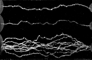 DISCHARGE FROM THE WIMSHURST INFLUENCE MACHINE.
This subject was prominently considered by Dr. H. P. Walcott, of Boston, in his address on state medicine, at the meeting of the American Medical Association recently. The vital statistics of Massachusetts, he said, showed a declining death rate for the last thirty-six years, under the influence of state sanitation. The most marked decrease had been observed in the mortality from zymotic diseases; there had been a less decided reduction of that from constitutional diseases; that from local diseases had increased; and that from mental diseases and from violence had remained stationary. In 1876 there was not a single death from small-pox. Typhoid fever had diminished most in cities having a good system of sewerage and water supply, and least in towns without such improvements. Diphtheria, which reached its maximum in 1877, had since declined, until it now caused only one per cent. of the total mortality. Ovariotomy saved more lives than any other surgical operation, but, taking Somerville as a basis of calculation, the ascertained results of preventive medicine had saved more lives in ten years, among thirty thousand people, than ovariotomy would save in the same time among two millions. Great attention was given to small-pox, which had killed but 5,500 persons in Massachusetts in thirty-six years, and to cholera, which had destroyed only 2,000; but too little heed was given to scarlet fever, with its mortality of 37,000, and to typhoid fever, with its mortality of 45,000.—N. Y. Med. Jour.
A vast amount of popular misapprehension and prejudice exists as to the use of spectacles. Many persons who need them object to wearing them for various reasons. Some fear that it will lead their friends to suspect that they are getting old. Others think it will cause them to be suspected of wishing to appear learned or cultured. Some persons do not want to begin to wear them lest, having acquired the habit, they may not be able to leave them off or to see well without them. Others again object to glasses only on account of their inconvenience. I have personally met with many of all these classes of persons, but I have frequently heard of another class that I have never met with, namely, those who do not need glasses, but who wear them just for effect and to attract attention. Now, the simple truth is that there are just two good reasons for wearing spectacles, and only two. One is that we may see better, the other is that our eyes may be relieved of strain. Often both these reasons are combined in the same case. Many children begin to be near-sighted after they have attended school a few years. They first find it out by observing that they cannot see letters or figures on the blackboard as far as the other children. They can use their eyes as much as they want to without fatigue or blurring, or smarting, or burning, or itching, or pain in the eyes, or headache. In short, they show no symptoms of eye strain. They simply do not see distant objects distinctly. Such children should be fitted with glasses at once that will enable them to see as well as others at a distance, and these glasses should be worn constantly. The child should be instructed to take them off only when necessary to wipe them or to wipe or bathe the eyes and on going to bed. The sooner the eyes get accustomed to them the less likely is the near-sightedness to increase. Moreover, the child who sees clearly only a few feet away from him loses a very important part of his education. Our eyes gather information for us when we are least thinking of it, by taking cognizance of the many objects that come within our field of vision just as our ears gather material for the proper development of our minds in listening to general conversation or to the sounds of nature and of busy life about us. It is the duty of every one to make the best possible use of the faculties the Creator has bestowed upon him. The near-sighted person who does not have his vision corrected by glasses fails in the performance of this duty.
[8] Continued from Supplement, No. 647, page 10342.
From a paper by David Webster. M.D., professor of ophthalmology in the New York Polyclinic and surgeon to the Manhattan Eye and Ear Hospital, New York.
Again, the time comes in the life of every one who is not near-sighted, and who lives to a good old age, when he cannot see near objects well without glasses. Between the ages of 40 and 50, the crystalline lenses of his eyes having hardened along with the other tissues of his body, he finds it impossible to focalize as he used to. He holds his book farther and farther away from his eyes, and finally he finds that he cannot read fine print at all, or without straining his eyes. Then he must accept the unpleasant fact that he is getting old-sighted, and if he wishes to use, and not abuse, his eyes, he must get glasses to take the place of his lost accommodation and with which he can read easily. Some persons who are near-sighted in one eye and far-sighted in the other never need glasses, but always do their reading and other near work with the near-sighted eye and their distant seeing with the far-sighted eye. I believe I read a long time ago, in an article by himself in the New York Ledger, that this was the case with the late Rev. Henry Ward Beecher. But the vast majority of persons who wear glasses, both for the distance and for the near, can see quite as well without them. They do not wear them in order to be able to see, but in order to have the strain removed from their eyes, and to be relieved from the many disagreeable symptoms, both direct and reflex, that result from eye strain.
The act of focalization is a muscular act and requires an effort, an output of nervous energy, just as much in proportion as any other muscular act, such as lifting a weight or shoving a saw or a jack plane. The eye that is normally shaped forms pictures of objects, more than a few feet distant, on its back wall without any muscular effort, and has to focalize only when engaged in near work. But the oversighted eye is compelled to do this extra work all the time, except when closed. If it did not focalize, it would see indistinctly. This it refuses to do, independently of any volition on the part of its owner. The eye that can see distinctly will see distinctly, no matter how great the strain, and this by a volition apparently entirely its own. The results are headache, vertigo, nausea, nervousness, irritability, and other disagreeable reflex conditions, besides the pain and inflammation, and other symptoms manifested in the eyes themselves. Of course, the only remedy in such cases is glasses, and these glasses should be carefully selected by a competent person, and should be worn as much of the time as is necessary to relieve the eye strain. I find in Taggart's Times, February 5, 1888, the following: "A French philosopher has said that a man who wears gold-bowed spectacles always admires himself, and it would seem as though spectacles were becoming a sort of badge of distinction, since young and old who have the slightest excuse for using them put them on.
"When one suffers from headache, he is told that he overstrains the nerves of the eyes, and must relieve this by the use of spectacles. When things dance before the sight, the cure for that is also spectacles; and when tired with close attention to work, the cure for wearied eyes is not rest, but spectacles.
"People who live much out of doors are usually very keen-sighted, owing probably to the ever-varying impressions made on the eyes, and this might reasonably suggest that the proper relief for a great many eye troubles would be a change from overwork."
I can only say that the person who wrote it seems not only to be prejudiced against glasses, but to know very little of the anatomy and physiology of the eye. The fact is that oversighted and astigmatic eyes, needing glasses to relieve the constant and severe strain upon the accommodative muscular apparatus, are benefited by rest and by change of air and occupation only to a limited degree. Real rest for such eyes is possible only from the use of glasses. Moreover, it is not possible for all who suffer from fatigue of the eyes to take the time for rest. It is necessary for many to use their eyes daily and almost constantly in order to make a living for themselves and for those dependent upon them. There is much more good sense in the paragraphs which follow and which are extracted from the same article.
"It is not surprising that so many school children suffer with weak eyes when we consider the conditions under which they are forced to use them. The very fact that the light in many school rooms is twice strained through glass partitions before it penetrates the inside rooms is in itself a severe test of sight. The preponderance of sash-wood over the panes of glass is anything but propitious to clear seeing. With heads bent over desks doing arithmetical examples, or studying the fine printed school books, or reading their own imperfect handwriting from which many of the lessons must be learned, the only wonder is that all the little ones are not purblind before they reach the grammar schools.
"But this is not all. Girls wear long and fluffy bangs, intercepting the sight, and both boys and girls seldom bathe their faces with clear cold water. In the matutinal face washing the eyes are usually closed, while a wet towel is delicately passed over the eyelids. Few persons can bear the pain of opening their eyes wide in a basin of cold water, yet Mr. A. M. Spangler told, in his interesting lecture on Nassau, how the native population would dive to the bottom of the sea and bring up shells, sponges, etc., that had been pointed out to them by curious visitors through a sea glass. Not only men divers, but also little boys and girls could keep their eyes open in the water and search for cents which had been thrown in for them to pick up. This shows that even salt water is not injurious to eyes accustomed to it, and that habit makes the eye unnaturally sensitive."
As to the statement that "people who live much out of doors are usually very keen-sighted," it is an expression of a popular idea, but, like most popular ideas, is true only to a limited extent. The fact is that persons who do not live much out of doors generally use their eyes more for near work, such as reading, sewing, drawing, etc., and hence are more likely to develop near-sightedness. Persons living indoors who are not near-sighted are able to see as well and as far as those who live outdoors. It is true that the old sailor will recognize a ship in the horizon, or any other distant object at sea, sooner than a landsman. But it is not because he is any more "keen-sighted." It is because he knows just what to look for. He has seen such objects amid similar surroundings a thousand times, and recognizes them, even though his vision be considerably impaired by disease. I have often found, on testing the vision of such persons, that it was not more than one-half the normal, and yet they declared, and, I believe, conscientiously so, that they could discern a ship at sea as far as any one. A very large proportion of the North American Indians, who live much out of doors, have poor sight from inflammatory diseases of their eyes caused by exposure to smoke in their wigwams, and by contagious eye diseases, the propagation of which is favored by their unsanitary methods of living. But, no doubt, many of them can discern distant objects upon the prairies and in the forests farther than their white brothers because of their greater familiarity with the appearances of such objects.
It seems to me that the practice of opening the eyes under water is not to be specially recommended, except in cases of necessity. While many bear it well, to others it is more or less painful and irritating. Moreover, nature furnishes a fluid with which to wash the eyeballs, and applies it herself. It is only necessary to keep the eyelids scrupulously clean, and especially the edges of the eyelids where the eyelashes grow out. For bathing the eyelids when uninflamed, nothing is better than pure cold water. When the eyes become red and inflamed, the best domestic remedy is salt and water, about a teaspoonful to the pint, and applied warm or cold, or at whatever temperature seems most agreeable to the eyes in any particular case.10353
Under no circumstances should poultices be applied to the eyes unless ordered by a physician. I have seen many cases in which a simple inflammation of the inside lining of the eyelids had been greatly aggravated by bread and milk poultices, or tea leaves, bound upon the closed eyelids and left on overnight. In fact, a distinguished professor of diseases of the eye has formulated the results of his observations thus: "Poultices spoil eyes."
All patent eye washes, eye salves, and other remedies advertised to cure all diseases of the eye should be avoided. Different diseases require different remedies. What will benefit one may injure another. When one gets something the matter with his eyes and resorts to the use of a patent medicine for its relief, he is in danger of losing valuable time. He may lose an eye from want of proper treatment at the outset of the disease. In a great city like New York, every one may easily avail himself of the services of the most skillful physician. If unable to visit them at their offices and pay their fees, they may consult them at the numerous dispensaries, hospitals, and medical schools and colleges, where it will cost them nothing.
A lesson that is very difficult for many of us to learn is that inflamed eyes should not be used actively. Children with sore eyes should not be allowed to go to school for two reasons. First, the use of their eyes in reading will prevent or retard their recovery. Secondly, sore eyes are usually communicable, and one such child may infect a whole school. It is highly important that all persons with inflamed eyes should use only their own wash basins, towels, and handkerchiefs, and so avoid spreading the disease. We not infrequently see a catarrhal inflammation of the eyes run through a whole family. Of course, they catch it one from another, and, as there is no disease of the eye which is, like measles, or scarlet fever, or smallpox, communicable through the air, such spread of the disease might easily be prevented by proper care of the person first affected. Persons whose eyes are sensitive to light should not be kept in dark rooms, which are always unhealthy. They may have their eyes protected by shades or by smoke colored glasses, but should keep them open and exposed to the air, and should remain out of doors as much as possible.
I must not close without warning my hearers against the baneful effects of alcohol and tobacco upon the eyes. It is not uncommon for the eye surgeon to meet with persons who have become partially blind from the effects of these poisons upon their optic nerves. Of course, only a small proportion of those who use alcohol and tobacco to excess are affected in this way, but this renders it none the less certain that impaired sight is one of the dangers that we may avoid by abstaining from the use of these unnecessary and poisonous luxuries.
In the following lines I wish to direct the attention of my English confreres to the value of the electro-endoscopic mode of examination of the male urinary bladder, invented by me. I believe I could not have chosen a more suitable theme for that purpose than a short report of the bladder tumors diagnosed by me cystoscopically; for the diagnosis of these new formations offers the greatest difficulty, and in most cases it has been impossible till now to prove their existence with accuracy without digital exploration of the bladder. By the new method of cystoscopical examination the conditions have entirely changed. One look into the bladder, illuminated as if by daylight, is generally sufficient to afford means for forming an opinion of all the questions coming into consideration—viz., size, form, and site of the tumor. The accompanying diagrams (Figs. 1, 2, 3, 4) may give an idea of the appearances which the different forms of bladder tumors present endoscopically. I regret that they cannot show the brightness of the light by which one sees the tumors during examination. The celebrated Vienna specialist, V. Dittel, is right in saying that "they offer sometimes truly charming pictures;" especially certain kinds of villous tumors, whose long slender villi floating in the liquid often present a splendid appearance. The following are the cases cystoscopically diagnosed by me.
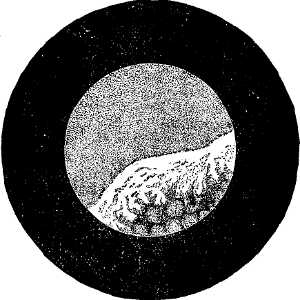 Fig. 1.
Case 1.—A man, aged fifty-five, under the care of Dr. Ch. Mayer, suffered from attacks of hæmaturia for thirty years. During the last six years he has had dysuria and inability to empty the bladder completely. The patient had been examined by the sound repeatedly by eminent surgeons and specialists, but none could give a certain diagnosis. On Nov. 11, 1886, I undertook the cystoscopic examination. I found on the anterior wall of the bladder a puffy swelling covered with white masses of mucus. (See Fig. 1.) The trigone was covered by a mass consisting of pointed papillæ. On account of the weakness of the patient extirpation was impossible. The patient became weaker and weaker, and died in June, 1887. The post mortem examination showed the internal orifice of the urethra surrounded by a swelling representing a continuous tumor as large as a small apple. It was found that the instrument had penetrated through the middle of this swelling, which bled easily on pressure. In spite of this, the clearness of the picture was not interfered with in the least.
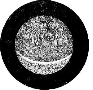 Fig. 2.
Case 2.—A man, aged fifty, was obliged to exert a strong pressure in order to empty the bladder. The flow of urine often stopped. He himself introduced a catheter, and on withdrawing it a piece of villous tissue was found. On Dec. 10, 1886, I saw, on cystoscopical examination, directly and immediately over the internal orifice of the urethra, a villous swelling hanging from the anterior wall of the bladder. (See Fig. 2.) On Jan. 15, 1887, extirpation of the tumor by means of the high section was performed by Professor v. Bergmann. The size of the tumor (which was as large as a pigeon's egg) and its position corresponded exactly to the endoscopic picture. The patient recovered.
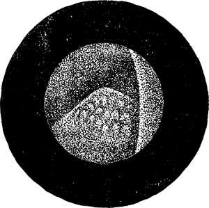 Fig. 3.
Case 3.—A patient under the care of Professor Madelung, aged fifty-five, suffered from attacks of hæmaturia. Examination by sound and rectal palpation had given me negative results. On Feb. 20, 1887, cystoscopical examination was made. On the left side of the trigone a tumor with a broad base was seen, which resembled somewhat a strawberry in size and form. (See Fig. 3.) On March 1, Professor Madelung undertook the extirpation of the tumor. The appearance corresponded exactly to the cystoscopic picture. The patient recovered.
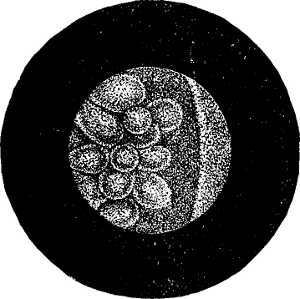 Fig. 4.
Case 4.—This was a patient on whom Dr. Israel had performed the high section a long time before, on account of a bladder tumor. The extent was so great that only its most prominent part could be removed. The microscopical examination proved the diagnosis of cancer. Quick healing took place. The patient became free from pain, and the urine became clear. In order to see what had become of the remaining part, the cystoscopical examination was undertaken on April 3. It was easy to see that the right lateral wall was covered to an extent of from three to four centimeters with thick masses of verrucous and fungiform excrescences. (See Fig. 4.)
[We omit the description of the additional cases.]
The above shortly described fifteen[9] cases of bladder tumors have been diagnosed by me cystoscopically during the last sixteen months. This is a proof, on the one hand, of the value of the cystoscopic examination; on the other hand, of the fact that the new formations in question are not of so rare occurrence as has been hitherto thought. I would like to emphasize that the important results were often obtained under the most difficult circumstances. In several cases the external orifice of the urethra was found abnormally small; in others (Cases 8 and 11) the examination was made during the occurrence of a continuous hemorrhage from the tumor; in one case (Case 1) I introduced the instrument through the center of the tumor, which bled on the slightest pressure. In spite of this the appearances were seen satisfactorily. In the first case a post mortem examination was made; in eight other cases (Cases 2, 3, 9, 10, 11, 13, 14, and 15) the tumor was extirpated, seven times by the high section—in one case, that of a woman, through the dilated urethra. In these nine cases the endoscopic appearances were in every important respect confirmed in the most perfect manner. In every case my opinion regarding the size, position, and form was found to be correct. It is only in those cases where the edges of the tumor overlap the short pedicle that the latter cannot be observed. Besides, the relative good results of the operations undertaken on account of the cystoscopic appearance may be emphasized. Of the eight patients from whom the tumors had been extirpated, none died from the result of the operation. Case 9 proved fatal on account of the progressive extension of the growth. In the eleventh case there was a recurrence, but the patient is still alive. Five patients (Cases 2, 3, 10, 13, 14) must be considered entirely cured. Case 15 is still under treatment, and, as the conditions of the patient are at present (ninth day after operation) in every way satisfactory, a complete recovery is anticipated.
[9] The first eight cases are more fully described in the Arch. fur Chirurgie, vol. xxxvi., Part 3 (Dr. Nitze, Beitrage zur Endoscopie der mannlichen Harnblase). The full account of the last seven cases will be published soon.
Finally, on comparing the above cystoscopic appearances with the results obtained by other methods of examination, it must be observed that the examination of the urine, in most cases carefully made, had only in two cases shown the presence of villous tissue, which in one instance was brought out by the catheter. The rectal palpation, when made, had always given negative results. Further, the examination by means of the sound had been made in nine cases before the cystoscopic examination. In none of the cases had the sound revealed the presence of a tumor (which in two had attained the size of a small apple), although the examination was made by most experienced surgeons and eminent specialists. Those cases show how imperfect an instrument the sound is for the diagnosis of bladder tumors.
Only one method can compare with the cystoscope in giving valuable information regarding the size and nature of a bladder tumor—viz., the digital exploration of the internal surface of the bladder after a previous boutonniere, or the high section. The superiority of the cystoscopic method over the latter, on account of the smaller amount of inconvenience it causes the patient, need not be insisted on. The latter involves a cutting operation not free from danger, as well as deep narcosis, while the cystoscopic method is similar to a simple catheterization.
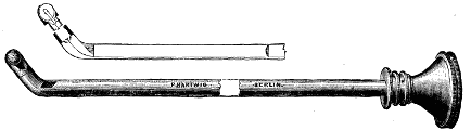 Fig. 5.
The accompanying diagram (Fig. 5) shows the instrument used by me for cystoscopic examination. It has been made by the Berlin instrument maker, Hartwig, according to my instructions. The source of the light (Mignon lamp) is cemented in a silver capsule, which is screwed into the distal end of the cystoscope. This instrument is superior to that made by Leiter, the Vienna instrument maker, because of its greater simplicity in construction, which allows the lamp to be easily replaced when necessary, and also on account of the greater length of the shaft.
I mention this because it differs from the explanation 10354which Mr. Fenwick gave in his speech concerning my method of examination at the meeting of the Medical Society of London on Jan. 23, 1888. I must also strongly contradict Mr. Fenwick's statements concerning the share which he attributed to the Vienna instrument maker in the construction of the instrument. Leiter's connection with our instrument will be best explained when I say that he had to buy the patent[10] from me first in order to be allowed to make the instrument. Leiter has had no share in those peculiarities which characterize it as new. The introduction of the source of light into the organ had been practically brought about, the optical apparatus enlarging the view designed, the whole construction perfected, the instrument had proved itself useful in examining patients, and had been demonstrated by me in the Saechsisches Landes Medicinal Collegium before Leiter had any idea of the new invention! Also the eventual replacement of the first source of light (platinum wire) had been provided for.[11] Leiter has only made a few technical modifications on the finished instrument. I protest most emphatically against the incorrect explanations given by Mr. Fenwick, and against every connection of Leiter's name with my instruments. I hope to obtain in England the same generous recognition of my labors in this field that has been accorded to me in Germany.—Lancet.
[10] Deutsche Patentschrifte, No. 6, 853.
[11] Ibid.
A. G——, aged twenty-three, United States; single; barber.
The young man was referred to me by his former medical attendant, March 16, 1883. His urine was found to be slightly but distinctly tinged with blood, and contained some small clots as well as some pus and mucus. He complained of exquisite pain on urination, increased at the close, recurring every half hour. Through examination per rectum (a posteriori) unusual tenderness was found. Distinct increase in the density and thickness of the right inferior section of the bladder was recognized by the bimanual touch; a catheter was introduced, and three ounces of bloody urine removed. The bladder was then irrigated gently with a saturated solution of boric acid until the fluid returned clear. The catheter was then withdrawn, leaving about four ounces of the solution, of a temperature of 80°, in the bladder, as a preparation for its examination by the electro-cystoscope of Lister. The required current was furnished by the small six-cell battery of the Galvano-Faradic Co. The cystoscope was then introduced into the bladder, and the current turned on. The illumination was complete. Through the slightly rosy medium the small blood vessels in the bladder mucous membrane were distinctly seen. On the right side a deep red, granular-looking mass, with a wavy outline, was then distinctly observed, covering about one-fourth of the cystoscopic field. This appearance was verified by Drs. Abbe, Bangs, and W. K. Otis—the unanimous opinion being that it represented a papillomatous growth, to some extent covered by coagulated blood. Two days later a similar examination was made, under the influence of an anæsthetic, which corroborated the previous observations in every particular. (See illustration.)
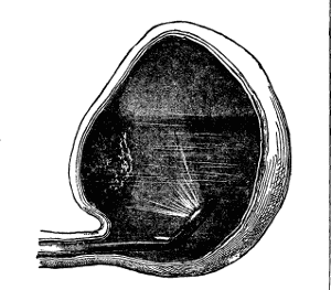 DIAGRAM OF BLADDER, SHOWING LOCATION OF TUMOR
AND POSITION OF CYSTOSCOPE.
DIAGRAM OF BLADDER, SHOWING LOCATION OF TUMOR
AND POSITION OF CYSTOSCOPE.
Some small filaments were subsequently removed with the lithotrite, but on microscopical examination nothing of diagnostic importance was discovered. From lack of the capacity of the bladder, the field was necessarily limited, nevertheless, a very excellent view of the tumor could be obtained. This is shown in the illustration, from a sketch made at the time of the first examination. It represents the position of the tumor and cystoscope when the best view of it was obtained.
On the following Monday the patient entered St. Luke's Hospital, and was operated upon by my associate, Dr. L. B. Bangs, Dr. Charles McBurney assisting. The high operation was performed, and the bladder being examined by means of an electric light, introduced through the suprapubic incision, the diagnosis made by the cystoscope was verified in every particular. The growth was then removed, as far as possible, with the scissors, and the surface cauterized with the Paquelin cautery. At the present writing the patient is going on toward a satisfactory recovery. The pathological examination made by Dr. Frank Ferguson, pathologist of St. Luke's Hospital, showed the neoplasm to be a simple papilloma.
This case is deserving of especial interest as being the first tumor of the bladder diagnosticated in this country by means of the cystoscope, and verified by subsequent operation, and adds one more to the list of sixteen cases so made out by foreign observers, and two by Dr. Fenwick, of England. In this instance the instrument deserves particular credit, as other methods had completely failed in the practice of competent observers.
This consists of a metal tube, about seven inches long, of a caliber of 22 French, having at the proximal end a funnel shaped ocular opening; at the distal, a short beak, similar to that of the catheter coudé. A window of rock crystal is set in the end of this beak, behind which a small electric lamp, controlled by a switch at the ocular end, is placed. A rectangular prism, the hypothenuse plane of which is silvered, is placed in the end of the straight portion of the tube, its superior face being seen just anterior to the angle formed by the beak. The distended bladder is illuminated by the electric lamp, the rays reflected from its wall falling on the prism experience total reflection, an inverted image being formed within the tube. The size of the field thus obtained is greatly increased by means of a telescope introduced into the tube. The image seen through the cystoscope is an inverted image, but right and left are not transposed.
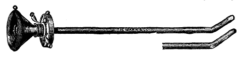 THE CYSTOSCOPE.
There can be no question as to the great prospective value of the electro-cystoscope in diagnosis of many difficulties to which the bladder is subject. A variety of foreign bodies have already been reported as made out by use of this instrument. The locality, size, and color of vesical calculi have been demonstrated in my own experience. In one instance two stones were seen where only one had been previously found, but this of course might with care have been effected by means of the lithotrite. But it is in the diagnosis of the tumors, and encysted or impacted calculi, that the most essential service may be anticipated from the use of the cystoscope. The orifices of the ureters are quite readily brought into the cystoscopic field, and it is more than probable that (perhaps through the introduction of some clear fluid with which blood does not readily mingle—glycerine, for instance) the true source of a previously doubtful hæmaturia will be demonstrated.—Medical Record.
So many queries about the solar system, or the members of it, have come recently to the attention of those in charge of this journal, from various sources, that it is thought best to make a brief statement of the present state of knowledge that astronomy has of the solar neighborhood in which we live.
Naturally we begin with the sun, and the oldest and most important problem which the study of this body offers is the determination of its distance from the earth in terrestrial units of measure. This distance is important because the knowledge of all the phenomena of all the heavenly bodies, except those of the moon, depend directly or indirectly on its value. The problem of the sun's distance is difficult because the data given for determining it are insufficient to enable the astronomer to apply the principles of trigonometry directly to it. He is, therefore, compelled to use indirect methods of solution, which, at best, give only approximations to the true distance, arising chiefly from small errors in observation, which, at the present time, seem unavoidable. A familiar illustration will make our meaning clear. The knowledge we have of the sun's distance depends on the accurate measurement of a small angle formed by drawing two lines from a point at the sun to the extremities of the earth's radius. That angle is called the sun's parallax. Ptolemy thought that this angle was 3′ of arc, but we now know that its value is very near 8.80" of arc, and that the error of this amount from the true angle probably is not more than 0.02". To measure this small angle has been the astronomer's great trouble since the time of Aristarchus, and he does not yet know its value accurately. His problem is like that of a surveyor attempting to measure a ball, whose real diameter is one foot, at the distance of 4.4 miles nearly; and unless he can determine the diameter of the ball so that he shall not be uncertain in his measure to the amount of 0.03 of an inch, his work will not add anything useful to present knowledge.
If we suppose the angle of parallax to be known, the computation of the distance of a celestial body is easy. Multiply earth's radius by 206,265 (seconds of arc in the unit radius), and divide the product by the angle of parallax in seconds of arc. The mean equatorial radius of the earth, as given in Clark's Geodesy, is 3963.3 English miles. The sun's distance for a parallax of 8.78" would be
206,265" × 3963.3
—————————————————  = 93,108,000 miles.
      8.78"

For parallax of 8.80" = 92,897,000 miles.
For parallax of 8.82" = 92,686,000 miles.
The range of error in parallax, as here given, is 0.04", and the change of the distance of the sun in allowing for this error is nearly half a million of miles. If 8.80" be the assumed parallax, with ± 0.02" as probable error, then the uncertainty of the sun's distance is still nearly a quarter of a million of miles.
So far astronomers are pretty generally agreed, unless it be in the value of the earth's radius used above. In his excellent work, entitled "The Sun," we notice that Professor Young gives 3,962.72 English miles as the "latest and most reliable determination" (page 22), while he seems to use Bessel's value of 3,962.80 in obtaining 92,885,000. This may be because the last named value is still in most general use, though less accurate undoubtedly than that of Clarke.
Since the transit of Venus, of 1874, the determination of the solar parallax has not been very much improved. The transit of 1882, so far as known, has given surprisingly discordant results, and probably they will be of very little service in improving our knowledge of the distance of the sun. In the midst of all this uncertainty of late work, in ordinary methods two ways of studying the problem show results almost exactly alike. They are obtained from late improved measures of the velocity of light, and from measures by the heliometer. The parallax from these sources is 8.794". The Brazilian results of transit of Venus for 1882, by Wolf and Andre, recently published, make the parallax 8.808". The American reductions for the last transit are not yet completed.
From the above brief statement of results, it seems that the value of the solar parallax is likely to be a trifle under 8.80", rather than above it, making the distance of the sun probably very near 93,000,000 miles.
The next most important problem pertaining to the sun is its constitution, which is usually considered under four heads:
1. The central portion, thought to be made up chiefly of intensely heated gases.
2. That part which is seen by the aid of the telescope, called the photosphere, consisting of a "shell of luminous clouds formed by the cooling and condensation of the condensible vapors at the surface where exposed to the cold of outer space." (Young.)
3. Outside of the photosphere is a shallow stratum, called the chromosphere, "composed mainly of uncondensible gases (conspicuously hydrogen) left behind by the formation of the photospheric clouds, and bearing something the same relation to them that the oxygen and nitrogen of our own atmosphere do to our own clouds." (Young.) And—
4. The corona, which is the beautiful halo seen, with the naked eye, outside of all, during the time of a total eclipse of the sun. This curious halo with all its streamers and rifts is thought to be composed chiefly of an incandescent material, in a far more attenuated state than that of hydrogen, the rarest gas known, because it yields freely in the spectroscope a certain line, 1474 K, which most agree can mean nothing else, although no one knows what the gas or metallic vapor is. Hydrogen is also found in the corona extending to the height of 600,000 miles above the photosphere, and possibly 1,200,000 miles. Suspended in this mixture of vapors, and "falling into, or projected from, the sun is a large quantity of solid or liquid material, which is at such a temperature as to be self-luminous. It is this which yields the continuous spectrum, free from dark lines.
"Besides these components in the outer envelope, there is present matter which reflects or diffuses light much as our own atmosphere does.
"To this is attributed the partial radial polarization of the corona. The streamers and rifts indicate matter repelled, in various quantities, from the sun by forces which may be electrical." (Hastings.)
These are the views advanced by astronomers and physicists, as theories or working hypotheses, until something better or more certain can be known. They are not held as facts by any, because of insufficient proof to establish them as such, and because there are very grave objections to some of them which are at present unanswerable.
For example, the spectroscope shows that the gaseous pressure at the limit of the chromosphere is very small, although that is at the base of an atmosphere from 600,000 to 1,200,000 miles deep, and under the influence of a force of gravity more than twenty-seven times as great as that in action at the surface of the earth.
Optically, the atmosphere of the earth ceases at a height of forty-five miles, but bodies at twice that altitude, moving at the rate of twenty-seven miles per second, meet resistance of air enough to render them incandescent almost instantly. But the evidence seems clear that, far within the corona, the resistance to moving bodies is much less than in our atmosphere at a height of sixty miles. The great comet of 1882 passed through the coronal atmosphere within 300,000 miles of the sun, with a velocity one hundred and eighty times that of the earth in its orbit. The comet was not stopped, nor destroyed, nor its orbit disturbed, as subsequent observations showed. The same thing was true, so far as known, of the comet of 1843, which passed still nearer the solar surface. These facts are troublesome to explain on the hypothesis of a coronal atmosphere.
Still further: if the sun be surrounded by a gaseous envelope, its density, as aforesaid, ought to diminish from the solar surface outward to its upper limits; but the fact is, the material of 1474 K line always appears in the spectrum of chromosphere, which would seem to indicate, by its place, that it is as much more dense than hydrogen as is magnesium vapor, or even the vapor of iron. But the evidence of the spectroscope makes this 1474 K material far less dense than that of hydrogen, and this is a contradiction that is very troublesome to the student of solar physics.
In studying the polarization of the light of the corona, it is clear that the amount of polarized light reflected from a particle at the surface of the sun is nothing, "because the luminous source there is a surface with an angular subtense of 180°;" hence polarization of the corona near the limb of the moon ought to be small, farther away, larger. But observation shows that the contrary is true, i. e., the percent. of polarized light increases as the corona is observed nearer the limb of the moon during totality.
These are a few of the difficult questions that stand in the way of accepting the foregoing theories as facts pertaining to, or well grounded knowledge of, the constitution of the sun. They are by no means all, or possibly the most important ones. They are certainly among those that are receiving very general attention at the hands of physicists at the present time.—Sidereal Messenger. 10355
If we look up at the starry heavens on a clear, moonless night, all seems still, lifeless, and devoid of energy and motion. All of us are—or at least should be—familiar with the apparent diurnal motion of the star sphere, caused by the actual rotation of the earth on its axis, and with the slower annual motion, due to the earth's revolution round the sun, which brings different constellations into view at different seasons of the year. These motions, due to the great and universal law of gravitation, discovered and so ably expounded by the famous Sir Isaac Newton, are of course wonderful and orderly in their regularity, and bear silent testimony to the amazing power, majesty, and goodness of a great and glorious Creator. There are, however, other motions and changes, even still more wonderful, going on in the depths of space, which, though unperceived by the ordinary observer, have been revealed to the eye and contemplation of the astronomer by the accurate instruments and methods of research which modern science has placed at his disposal. Some accounts of these marvelous discoveries may prove of interest to the reader. The "fixed stars" are so called because they apparently hold a fixed position with reference to each other on the concave surface of the celestial vault, and do not, as far as the unaided eye can judge, change their relative positions as the planets do. Many stars have, however, what is technically called a "proper motion," which, though of course very minute, and only to be detected by the aid of refined and accurate instruments, yet accumulate in the course of ages, and sensibly alter their position in the sky. The largest "proper motion" hitherto detected (about seven seconds of arc per annum) is that of a small star in the constellation Ursa Major, known to astronomers as No. 1830 of Groonbridge's catalogue. It has been calculated that this star is rushing through space with the amazing and almost inconceivable velocity of 200 miles per second!—a velocity which would carry it from the earth to the sun in about 5½ days and to the moon in 20 minutes! The well-known double star 61 Cygni has a proper motion of about five seconds of arc per annum, both components moving through space together. This is, as far as yet known, the nearest star to the earth in the northern hemisphere. Its parallax, as determined by Sir R. S. Ball, is 0.4676 of a second of arc, and by Prof. Pritchard (by photography) 0.43 of a second. Taking the mean of these values, its distance from the earth would be about 460,000 times the earth's mean distance from the sun, and its actual velocity about 33 miles per second. This is, of course, the motion at right angles to the line of sight, but as it may also have a motion in the line of sight, either to or from the eye, its real velocity is probably greater than this. The remarkable triple star 40 Eridani has a proper motion of four seconds annually. The components are a fourth magnitude star accompanied by a distant double companion which is a binary (or revolving double star), and accompanies the bright star in its flight through space. There are two other faint and distant companions which do not partake in the motion of the ternary star. In the year 1864 the bright star was situated to the east of a line joining these faint companions, but owing to its large proper motion it is now to the west of them. In the case of the triple star Struve 1516, one of the companions, which was to the west of the primary star in 1831, is, owing to the proper motion of the bright star, now to the east of it. Prof. Asaph Hall has found a parallax for 40 Eridani of 0.223 of a second. This, combined with the observed proper motion, indicates an actual velocity of about 54 miles per second. The star Mu Cassiopeiæ has also a large proper motion. This star, about 4,000 years ago, must have been close to Alpha Cassiopeiæ, and might have been so seen by the ancient astronomers. The proper motion of the bright star Arcturus is so considerable that in the course of about 30,000 years it will be near the equator, and about 10° to the north of the bright star Spica, from which it is at present separated by over 30°. These motions are of course those which take place across the face of the sky. There are, however, motions in the line of sight—both toward and from the eye—which have of late years been revealed to us by the spectroscope, that wonderful instrument of modern scientific research, by the aid of which several new metals have been discovered, and which has been found so useful in chemical analysis, and even in the manufacture of steel by the Bessemer process. Some years since, Dr. Huggins, the eminent spectroscopist, found that the bright star Sirius, "the monarch of the skies," was receding from the earth at the rate of about 20 miles a second. Later observations at Greenwich Observatory showed that this motion was gradually diminishing, and within the last few years it has been found that the motion of recession has been actually changed into a motion of approach, showing that this giant sun is probably traveling in a mighty orbit round some as yet unknown center of gravity.
From a consideration of stellar proper motions, it has been concluded that the sun—and therefore the whole solar system—is moving through space. Recent investigations make the velocity of translation about 19 miles per second (30 kilometers). The Greenwich observations place the "apex of the solar motion" (as the point toward which the sun is moving is called) between Rho and Sigma Cygni, while Dr. Huggins' results fix a point near Beta Cephei. Both these points are near the Milky Way.
There are other startling changes which have occasionally taken place among the stars, and which must be looked upon almost in the light of catastrophes. At rare intervals in the history of astronomy "temporary" or "new" stars have suddenly blazed out in the heavens which were previously either unknown to astronomers, or else were invisible, except in the telescope. Some of these were of great brilliancy. In A.D. 173 a bright star is recorded in the Chinese annals as having appeared between Alpha and Beta Centauri (two bright stars in the southern hemisphere). It remained visible for seven or eight months, and is described as resembling "a large bamboo mat" (!)—a not very lucid description. It is worthy of remark that there exists at the present time, close to the spot indicated, an interesting variable star, which may possibly be identical with the bright star of the second century. Perhaps the most remarkable of these wonderful objects was that observed by the famous Tycho Brahe in 1572, in Cassiopeia, and called the "Pilgrim." It was so brilliant that it rivaled the planet Venus at its brightest, and was visible at noonday. It remained visible for over a year and then disappeared.
A small star close to its recorded position has been observed in recent years, and as it is thought to be slightly variable in its light, it may possibly be identical with the long lost star of Tycho Brahe. Another new star of almost equal brilliancy was observed in October, 1604, in Ophiuchus, a few degrees southeast of the star Eta Ophiuchi. The planets Mars, Jupiter, and Saturn were close together in this vicinity, and one evening Mostlin, a pupil of Kepler's, remarked that a new and very brilliant star had joined the group. When first seen it was white, and exceeded in brightness Mars and Jupiter, and was even thought to rival Venus in splendor! It gradually diminished, however, and in six months was not equal in luster to Saturn; in March, 1606, it had entirely disappeared. In 1670 a star of the third magnitude was observed by Anthelm near Beta Cygni. It remained visible for about two years, and increased and diminished several times before it finally disappeared. Flamsteed's star, No. 11 of Vulpecula, has been supposed to be identical with Anthelm's star, but Baily could not find that such a star exists. A small star has, however, been observed at Greenwich within one minute of arc of the place assigned to the temporary star by Picard's observations.
Variability has been suspected in this faint star, and according to Hind it has a hazy, ill-defined appearance about it, which may perhaps suggest that it may be a small planetary nebula, similar to Schmidt's new star of 1876 in Cygnus. A small new star was observed by Hind in Ophiuchus on April 28, 1848. When first noticed it was about the fifth magnitude. It afterward rose to about fourth magnitude, but very soon faded away, and, although still visible in the telescope, has become very faint in recent years. A new star of seventh magnitude was found by Pogson on May 28, 1860, in the well-known star cluster known as 80 Messier in Scorpio. The light of the star when first seen obscured the light of the nebula. On June 10 the star had nearly disappeared, and the nebula was again seen shining with great brilliancy.
A very interesting temporary star—known as the "Blaze Star"—suddenly appeared in Corona Borealis in May, 1866. It was first seen by the late Mr. Birmingham, of Tuam, Ireland, on the night of May 12, when it was of the second magnitude and equal in brightness to Alphecca, the brightest star in the well-known "Coronet." It must have made its appearance very suddenly, for Dr. Schmidt, the director of the Athens observatory, stated that he was observing this region of the heavens a few hours previously, and noticed nothing unusual. It rapidly diminished in brightness, and on May 24 of the same year was reduced to nearly the ninth magnitude. It was soon discovered that the star had been previously observed, and its place registered by the great German astronomer, Argelander, as of magnitude 9½, so that it is possibly a variable star of irregular period and fitful variability. When near its maximum brilliancy, its light was examined by Dr. Huggins with the spectroscope, which showed the bright lines of incandescent hydrogen gas in addition to the ordinary stellar spectrum. This implies that the great increase in its light was due to a sudden outburst of hydrogen in the star's atmosphere. Some observers remarked that when viewed with the naked eye it decidedly twinkled more than other stars in the neighborhood, which rendered a correct estimate of its relative brightness somewhat difficult. During the years 1866 to 1876, Schmidt detected variations of light which seemed to show a period of about 94 days, and these observations were confirmed by Schonfeld.
On the evening of November 24, 1876, the late Dr. Schmidt, of Athens, discovered a new star of the third magnitude, near Rho Cygni, in a spot where he was certain that no bright star was visible four nights previously. When first seen, it was somewhat brighter than Eta Pegasi. It did not, however, remain long at this degree of brightness, but rapidly decreased, and on November 30 had faded to fifth magnitude. It afterward diminished very regularly, and in September, 1885, was estimated only fifteenth magnitude with the 15½ inch refractor of Mr. Wigglesworth's observatory. The star was examined with the spectroscope a few days after its discovery, and showed bright lines similar to the "Blaze Star" in the Northern Crown. One of these bright lines was believed to be identical with Kirchhoff's No. 1474, which has been observed in the spectrum of the solar corona during total eclipses of the sun. This star would seem to be quite new, as there is no star in any of the catalogues in its position. In September, 1877, it was examined with the spectroscope at Lord Crawford's observatory, and its light was found to be almost entirely monochromatic (of only one color), showing that the star "had changed into a planetary nebula of small angular diameter" (!)
In August, 1885, a star of about seventh magnitude made its appearance close to the nucleus of the Great Nebula in Andromeda—a well-known object visible to the naked eye, and which has been well called "the Queen of the Nebulæ." The new star was independently discovered by several observers toward the end of August, but seems to have been first certainly seen by Mr. T. W. Ward, of Belfast, on August 19, at 11 P.M. At Greenwich observatory the spectrum of the new star was found "of precisely the same character as that of the nebula, i. e., it was perfectly continuous, no lines, either bright or dark, being visible, and the red end was wanting." Dr. Huggins, however, on September 9, thought he could see from three to five bright lines in its spectrum. The star gradually faded away, and on February 7, 1886, was estimated only sixteenth magnitude in the 26 inch refractor of the naval observatory at Washington. From a series of measures by Prof. Asaph Hall he found "no certain indications of any parallax," so that evidently the star and the nebula, in which it probably lies, are situated at an immense distance from the earth. Prof. Seeliger has investigated the decrease in light of the star on the hypothesis that it was a cooling body, which had been suddenly raised to an intense heat by the shock of a collision, and finds a fair agreement between theory and observation. Anwers points out the similarity between this outburst and the new star of 1860 in the cluster 80 Messier, and thinks it very probable that both phenomena were due to physical changes in the nebulæ in which they occurred.
With reference to the colors of the stars, some of the red stars have been suspected to vary in color. The bright star Sirius is supposed—from the description of it by ancient astronomers—to have been originally red, but this seems very doubtful. The Persian astronomer Al Sufi, in his "Description of the Heavens," written in the tenth century, describes the well-known variable star Algol distinctly as a red star. It is now white, and this is perhaps the best attested instance on record of change of color in a bright star.—Naturalists' Monthly.
In the various names which the dandelion has received, we see expressed, for the most part, either a reference to the tooth-like recurved lobes of the leaves, Fig. 1, or an allusion to the medicinal properties of the plant. Thus, our English name is a modified form of the French dent de lion, meaning lion's tooth, and in German we have the same idea expressed in Löwenzahn. Fifty years ago this plant appeared in the botanies as Leontodon taraxicum, the generic name being derived from the Greek leon, lion, and odons, tooth, and the specific from the Greek tarasso, to stir up, in reference to the effect of a dose. In later works we find the genus Leontodon, including the "fall dandelion" (L. autumnale), but not the true dandelion, which now appears in a genus by itself under the name Taraxicum Densleonis. Here the specific name is merely "lion's tooth" again, in Latin.
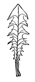 Fig. 1.
Finally, in the latest works our plant is given as Taraxicum officinale, since this has been found to be the name which, according to the rules of botanical nomenclature, takes precedence of all others. An allusion to the teeth is thus no longer retained, the only reference remaining being to the plant's officinal use.
To the majority of people the mention of the dandelion calls to mind not so much its medicinal properties as its use for food. Although its cultivation, either as a spring pot herb or as a salad with blanched leaves, is comparatively modern, the wild plant seems to have been long valued as a vegetable. There is reason to believe that the Romans made use of it as a pot herb, and Chinese writers of the fourteenth century mention its being eaten in their country, although there is no evidence of cultivation at that time.
There are but few of our flowering plants that grow so widespread over the world. It occurs in North America from the Atlantic to the Pacific coast, in Europe, in Asia, and in the Arctic regions. This extensive range may in part be accounted for by the fact that our plant belongs to the large and aggressive family of the Compositæ, and is thus related to such invaders as daisies, burdocks, and thistles. Still, the dandelion has more to recommend it than mere family connection; for, despite its lowly aspect, it is no poor relation, but, as we shall hope to show in the present article, it has many virtues of its own which entitle it to respect.
Prominent among these is its adaptability to the different conditions under which it grows. It seems to make the best of everything. If by chance a seed falls upon poor, thin soil, the young plant sends forth, as rapidly as possible, a rosette of leaves pressed close to the earth. And thus, on the principle that "possession is nine points of the law," it secures for its roots the use of a certain amount of territory quite safe from the encroachments of other plants. In rich ground the case is quite different, for here there is so much nutriment in a small quantity of earth, that the struggle for soil is not such a life and death matter as in the less favored localities. Consequently we find a large number of plants crowded together as close as they can stand; and it is obvious that if, under these circumstances, the dandelion should develop a flat rosette of leaves, the grass and other plants growing around would soon overshadow it, and it would have small chance for life.
Our plant, therefore, extends its leaves upward, and does its best to elongate them so as to keep pace with the growth of its rivals. But as these are for the most part grasses and plants which grow by elongation of the stem, the race for sunshine is rather in favor of these other plants, for the reason that a given amount of material put into a stem makes a stiffer organ than when put into a leaf. Still, even with these odds against it, the dandelion seems well able to hold its own, for it probably derives more or less advantage from the recurved lobes, or teeth, which give the plant its name. These are admirably fitted to act in much the same manner as a ratchet; and when the neighboring grasses are blown against the dandelion, a blade may slide along the margin of the leaf toward the base; but, as it springs back from its own elasticity, it cannot slide in the opposite direction, for a tooth will catch it, and thus force it to help support the leaf, and hold it up to the sunshine. We need not stop to consider how the dandelion behaves in soil which is neither very rich nor very poor, for enough has been said to show that it has not much to fear from any rivals it may meet under ordinary circumstances.
It is not only against the aggressions of neighboring plants, however, that our dandelion needs to be prepared. 10356It is at least equally important for its welfare that it have some means of protection against herbivorous animals—not only such as might eat its leaves, but also the more stealthy ones that live upon the food which plants store underground. All such foes it thwarts by a means as simple as it is efficient. Every part of the plant contains a milky juice which is intensely bitter, and a first taste is quite enough to convince the most stupid animal that raw dandelion is not good eating, and most animals know enough to let it severely alone. Curiously enough, however, in this, as in many other cases, it happens that what in nature acts to deter animals from eating the plant, with man offers the chief attraction, for it is this very bitter principle (taraxacin) which gives to dandelion greens their peculiar flavor, and affords the essential element in the extract which physicians prescribe.
The store of food, referred to above, which the dandelion accumulates in its root, not infrequently enables it to pass, almost unharmed, through dangers that with less provident plants would surely prove fatal. For example, it must often happen that from drought or from being trampled upon by animals, the leaves become wholly or in part destroyed. Now, if there were no reserve store of food, the plant would have no chance of rallying; but as it is, this food supplies the material for new growth, and upon the return of favorable conditions, fresh leaves are developed, and the plant lives on as before. Primarily, of course, the purpose of this storage of food is to enable the plant to live on from year to year, resting in the winter, and in the spring beginning work again with a good start.
In comparing the higher with the lower plants, the superiority of the former is most beautifully shown in the better provision which is made for the welfare of offspring; and in this regard our dandelion stands among the highest. Before we can understand the ways in which our little plant performs this part of its life work, we must briefly consider the structure of the blossom.
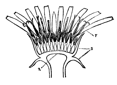 Fig. 2.
If with a sharp knife we cut a blossom in halves, from the stem upward, the parts represented in Fig. 2 will be disclosed. Surmounting the stalk is a cushion-like receptacle, R, from the top of which arise a number of tiny flowers, F, while from the side grow out a series of green scales, S, forming an involucre around the whole. A single one of these florets, Fig. 3, exhibits the following parts: First, a bright yellow corolla, C O, tubular below, but strap-shaped above, as if a tube had been split for part of the way on one side, and the upper part flattened. Second, five stamens, S K, attached by slender filaments, F M, to the tubular part of the corolla, and with their anthers or pollen sacs, A N, joined together by the edges to form a tube. Third, a single pistil having a long style, S Y, which, above, passes through the anther tube, and bears at its end two diverging stigmas, S G, and below connects by a short neck, N, with the small ovary, O, which contains a solitary ovule. Fourth, a calyx, C X, composed of numerous slender bristles.
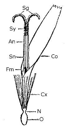 Fig. 3.
The purpose of these complex structures is, of course, in one way or another to secure the development of the ovule into a seed fitted to produce a new plant. This development will proceed only after the ovule has been influenced (i. e., fertilized) by pollen placed upon the stigma; but when once the mysterious process of fertilization has taken place, then there follows immediately those wonderful changes in the blossom which culminate in the ripening of the fruit.
There are but two possible ways in which fertilization may be secured; either the pollen which affects the ovule must come from the same flower (then called close fertilization), or the pollen must come from another flower of the same kind (cross fertilization). Now, while either of these methods will insure the production of a seed, numerous experiments go to show that those offspring which result from cross fertilization are in many ways superior to those which are produced from close fertilization; and it is to the advantages of cross fertilization that we have to look for an explanation of the significance of many peculiar structures, not only of the dandelion, but of flowers in general.
It is obvious that, to secure cross fertilization, there must be some agent to transfer the pollen from one plant to another. Most commonly, either the wind is taken advantage of for this purpose, as with elms, pines, grasses, etc., or else flying insects are induced to perform the office, as is the case with the majority of our familiar flowers. The wind is a very wasteful carrier, so that for every grain that is properly placed, thousands, or even millions, may be lost. Insects, on the contrary, waste but little; and, moreover, as Aristotle so shrewdly observed, they habitually confine their visits, for a number of trips, exclusively to the flowers of one species.
The dandelion seems to fully appreciate the great advantages of securing the services of insects, for it appeals most strongly to their love of bright colors and their passion for sweets. As the flowers open, each tiny golden cup is filled to the brim with purest nectar, and he must be a very dull insect, indeed, that cannot see the brilliant head of flowers as far as he can see anything. At any rate, it is not the dandelion's fault if he does not, for the blossom is placed where it will be as conspicuous as possible. If the surrounding herbage is tall, the flower stalk is elongated, so that the crown of flowers may not be obscured. If the plants around are low-lying, it would be wasteful to have a long stalk, so it has a short one, sometimes so short that the blossom looks like a button in the center of the leaf rosette. Economy of material is furthermore shown in the fact that the stalk is always hollow, for it is a principle well known to builders that, when there is required a pillar of a given strength, less material is needed for the tubular form than for the solid cylinder.
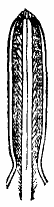 Fig. 4.
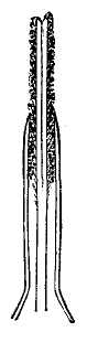 Fig. 5.
But to return to our flower. We have next to consider how the visits of insects are utilized to secure cross fertilization. If we examine the anther tube of a flower that has just opened, Fig. 4, we shall see that the style has not yet protruded, but fills the entire cavity, except such space as is occupied by a quantity of pollen which the anthers have shed. So much of the style as is within the tube is thickly beset with hairs that point upward; and when the lower portion elongates, this hairy part brushes the pollen out of the tube, and protrudes, covered with the yellow dust, Fig. 5. At this stage, an insect coming for nectar must rub against the style, and so become more or less covered with pollen. None of it, however, can get upon the stigmas, for they are not yet exposed. After a short time has elapsed, during which much of the pollen has probably been rubbed off, the style is seen to split at the top; and as the halves separate and roll back, Fig. 3, their inner faces (the stigmas) are exposed. If, now, the flower be visited by an insect which has previously been to a younger flower, the pollen he brings will be deposited upon the stigmas as he rubs against them, and cross fertilization will be effected.
Let us suppose, however, that no insect visits the blossom—and this must often happen to such as appear very early in the spring or late in the fall, when hardly any insects are around. In such cases we find that seeds are produced, and therefore we must infer that fertilization has in some way or other been secured. An examination of a flower still older than any we have considered, Fig. 6, will show us what takes place. Here it will be seen that, after the stigmas have diverged, they continue to roll back, until a coil of one or more turns has been made; and as a result of this the stigmatic surface comes in contact with the hairs on the style, and touches the pollen grains entangled by them. Still, the close fertilization thus accomplished is only a last resort, and it can only occur in the event of insects' visits having failed; for when pollen from another flower has once fallen on the stigma, no pollen coming afterward can have the least effect. Thus, we have another instance of the dandelion's ability to make the best of its surroundings.
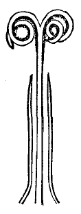 Fig. 6.
It even adapts itself to the weather; for when the sun shines, the scales of the involucre bend back, and the blossom is expanded to its fullest extent; but in dull weather, or at night, the scales bend inward, and the blossom is tightly closed. The advantages of this remarkable movement, with its implied sensitiveness, is obvious when we consider that insects are abroad only in sunshine, while at other times there is danger of dew or rain getting into the nectar, and so spoiling it for the insects.
After fertilization has been accomplished throughout the blossom, the involucre closes, and remains closed during the ripening of the fruit. The changes which now take place are as follows: In each flower the corolla, stamens, and style, being of no further use, wither, and sever their connection with the ovary; the ovule develops into a seed containing a tiny plantlet well provided with food for its use during germination; the ovary grows to keep pace with the seed, its tissues become hardened, and a number of spine-like projections develop near the upper part; and finally the short neck which bears the calyx bristles elongates, pushing upward the withered parts of the flower. At this stage the involucral scales bend back through an arc of about 180°, the cushion-like receptacle becomes almost spherically convex, the fruits radiate in all directions, the bristles spread, and a beautiful cluster of little parachutes is presented to the wind.
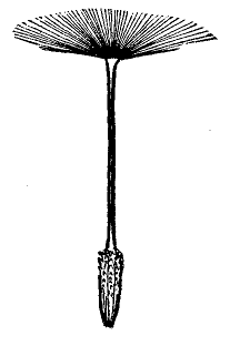 Fig. 7.
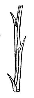 Fig. 8.
Even a glance at one of these fruits, Fig. 7, is sufficient to discover a wonderful fitness for transportation by wind, and more careful study shows that this fitness pervades every detail. For example, on examining the bristles microscopically, Fig. 8, it is shown that they are not simple threads, but each is hollow and has numerous projections extending on either side, all of which serves to increase the buoyancy in a very effective way.
The experience of aeronauts has shown that a highly important part in the equipment of a balloon, after the attainment of buoyancy, is the provision of some means of arresting the balloon's progress when the destination has been reached. One of the most successful means which they employ is the grappling hook; and as we find the base of our diminutive parachute provided with a number of upwardly directed spines, it seems fair to conclude that these serve to arrest the fruit upon favorable soil. If it comes to rest upon a smooth surface—which, of course, would be barren—the next breeze would easily blow it away; but if it chance to fall on soil or among other plants, the effect of the spines would be to retain it against the power of even a strong wind. Thus, we may leave it safely landed upon good soil, ready to begin under favorable conditions the cycle of its wonderful life.—Popular Science News.
There is always a great deal of interest attaching to organisms which are unique in character and which systematists find difficulty in placing in any of their schemes of classification. A number of instances will occur to every working naturalist, and I need only refer to Limulus, and the extensive literature devoted, during the past decade, to the discussion of its true position, as a marked and well-known illustration. In hexapods the common earwig and flea are familiar illustrations. These osculant or aberrant forms occur most among parasitic groups, as the Stylopidæ, Hippoboscidæ, Pulicidæ, Mallophaga, etc. Probably no hexapod, however, has more interested entomologists than Platypsyllus castoris Ritsema, a parasite of the beaver. I cannot better illustrate the diversity of opinion respecting its true position in zoology than by giving an epitome of the more important literature upon it.
[12] Read at the meeting of the National Academy of Sciences, April 20, 1888.
J. Ritsema, in Petites Nouvelles Entomologiques for September 15, 1869, described the species as Platypsyllus castoris. He found it on some American beavers (Castor canadensis) in the zoological garden of Rotterdam. He considered it to "undoubtedly" belong to the Suctoria of De Geer, and to form a new genus of Pulicidæ.
In the same year, in the Tijdschrift voor Entomologie, 2d ser., vol. v., p. 185 (which I have not seen), the same author publishes what is apparently a redescription of the insect. He gives his views more fully as to its systematic position, considering that it belongs to the Aphaniptera, and is equivalent to the Pulicidæ.
In the same year, Prof. J. O. Westwood (having previously read a description of the species, November 9, 1868, before the Ashmolean Society of Oxford) published in the Entomologist's Monthly Magazine, vol. vi., October, 1869, pp. 118-119, a full characterization of the insect under the name of Platypsyllus castorinus. A new order, Achreioptera, is established upon the species, which he very aptly likens, in general appearance, to a cross between a flattened flea and a diminutive cockroach. "The abnormal economy of the insect, its remarkable structure, the apparent want of mandibles, our ignorance of its transformations, and the possibility that the creature may be homomorphous in the larva and pupa states," are the reasons assigned for establishing the new order, and here Prof. Westwood is perfectly consistent, as in his famous "Introduction to the Classification of Insects" the Forficulidæ are placed in the order Euplexoptera; the Thripidæ in the order Thysanoptera; the Phryganeidæ in the order Thrichoptera; the Stylopidæ in the order Strepsiptera; and the Pulicidæ in the order Aphaniptera.
In 1872, Dr. J. L. Le Conte published his paper "On Platypsyllidæ, a New Family of Coleoptera" (Proc. Zool. Soc. of London for 1872, pp. 779-804, pl. lxviii.), in which he shows that Platypsylla is undoubtedly coleopterous and cannot possibly be referred to the Aphaniptera. Careful descriptions and figures of anatomical details are given, and he finds that its affinities are very composite, but in the direction of the Adephagous and Clavicorn series. Its most convenient place is 10357shown to be between the Hydrophilidæ and Leptinidæ. There seems to be no good reason why the name Platypsyllus is here changed to Platypsylla, a spelling adopted by most subsequent American writers.
In 1874, Prof. Westwood, in the "Thesaurus Entomologicus Oxoniensis" (Oxford, 1874), p. 194, pl. xxxvii., gives figures with details; reprints his previous diagnosis, and maintains his previous course in erecting a new order for the insect, without giving any additional reasons.
In 1880, P. Megnin, in "Les Parasites et les maladies parasitaires," etc., Paris, 1880, gives (pp. 66-67) a description of the family "Platypsyllines" without expressing an opinion concerning the systematic position. He also describes and figures the species.
In 1882, Dr. Geo. H. Horn (Trans. Amer. Ent. Soc., x., 1882-83; Monthly Proc., Feb. 10, 1882, p. ii.) exhibited drawings illustrating the anatomy of Platypsylla and Leptinus, and showed that a close relationship exists between these genera. Later, in his "Notes on Some Little Known Genera and Species of Coleoptera" (Trans. Amer. Ent. Soc., x., 1882-83, pp. 113-126, pl. v., 114-116), he reviews the characters, and explains and illustrates the anatomical details. The differences he points out between his observations and those of Le Conte are more particularly in the mandibles. In connection with this paper he also describes and illustrates the structure of Leptinillus, which he separates from Leptinus, and demonstrates their close relationship with Platypsyllus.
In 1883, Le Conte and Horn, in their "Classification of the Coleoptera of North America" (Washington, Smithsonian Institution, 1883), give (pp. 13-15) a full description of the family characters, a little modified from Le Conte's first description, but sustaining his views on the systematic position of Platypsyllidæ.
In 1883, Alphonse Bonhoure (Ann. Soc. de France, 1883; Bull, des Seances, p. cxxvi.) exhibited drawings and specimens of Platypsyllus castoris found in the Departement des Bouches du Rhone.
In 1884, Edm. Reitter, in "Platypsylla castoris Rits. als Vertreter einer neuer europaischen Coleopteren-Familie" (Wiener entom. Zeit. iii., 1884, pp. 19-21) gives a lengthy description of the species with special regard to the sexual differences. He shows that the European insect is not specifically distinct from the American form, but he does not express an opinion on the position of the family among the Coleoptera.
In the same year, Bonhoure (Ann. Soc. Ent. de France, 1884, pp. 143-153) more fully records its discovery on Castor fiber taken in the Petit-Rhone. It is a question whether this European beaver, now quite rare, is distinct from ours. He gives a very good review of the subject, with a plate of the most important details, after Horn, and he fully indorses the coleopterological position of the insect.
In the same year Ritsema (Tijdschrift voor Entomologie, 1883-84, lxxxvi.) refers to Bonhoure's discovery of Platypsylla in France, and corrects Reitter in some unimportant details.
In 1885, Reitter, in "Coleopterologische Notizen" xiii. (Wiener entomolog. Zeit., vol. iv., 1885, p. 274), answers Ritsema's criticism.
In the same year, Dr. Friederich Brauer, in his masterly "Systematisch-zoologische Studien" (Sitzh. der Kais. Akad. der Wissensch., xci., p. 364), speaks of the relationship in the thoracic characters between Mallophaga and Coleoptera as illustrated by Platypsyllus, by inference admitting the coleopterous nature of the latter, but recognizing that it has mallophagous affinities.
In 1886, H. J. Kolbe, in his "Ueber die Stellung von Platypsyllus im System" (Berlin entom. Zeitsch., xxx., 1886, pp. 103-105), discusses the subject, without any new evidence, however. He concludes that most of its characteristics relate it to the Corrodentia, and particularly to the sub-order Mallophaga, in which it has its closest kinship in Liotheidæ. The remarkable tripartite mentum he thinks should not be compared with the bipartite mentum of Leptinus, and calls attention to the fact that in Ancistrona in Mallophaga it is also trilobed.
The above are the more important papers on the subject, though the insect has been referred by other authors to both Neuroptera and Orthoptera.
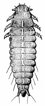 LARVA OF PLATYPSYLLUS CASTORIS—DORSAL VIEW.
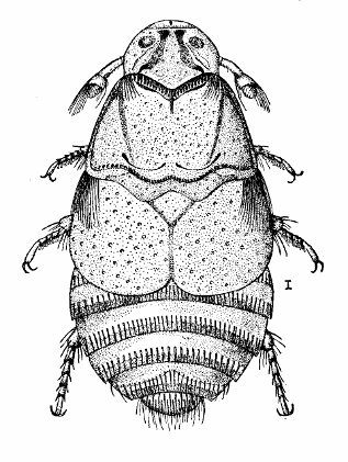 PLATYPSYLLUS CASTORIS.
Where the characters of the image have been so often described, it is unnecessary to refer to them in detail, and I will only call attention to the more striking structural features and to some omissions by, or differences between, previous authors. A glance at the illustrations which I have prepared will show the prevailing characteristics of this interesting creature, its general ovoid and flattened form, and more particularly the flattened semicircular head. Dorsally, we notice the rather prominent occiput fringed behind with short and broad depressed spines or teeth which form a sort of comb, the prothorax trapezoidal and but very slightly curved, with side margins strongly grooved. There is a very distinct scutellem, and the two elytra are rounded at the tip and without venation. Hind wings and eyes are both wanting. The abdomen shows five segments, each with a row of depressed bristles.
On the ventral surface we find among the more curious characteristics, first the antennæ; these were originally described by Westwood as three-jointed, the club being annulated. Le Conte could not distinctly make out the number of annular joints upon this club, though he thought he detected seven, which made nine joints to the whole antenna. The club is received in the deep cup-shaped excavation of the second joint. Horn thought he detected a division of the second joint, and resolved but six segments in the club, making also nine joints to the whole antenna, but in a somewhat different fashion from Le Conte. Westwood's figure shows eight annuli to the club. He failed to find any trace of the mandibles, but Le Conte described them as small, flat, subquadrate, with the inner side deeply crenulate, and resembling those of Corylophus; the stipes well developed, and biarticulate. Horn could not entirely make out the mandibles as described by Le Conte, and rather concluded that what Le Conte described is really one of the granules which occur behind the labrum. He considered that the piece could hardly be even an aborted mandible, because of its diminutive size.
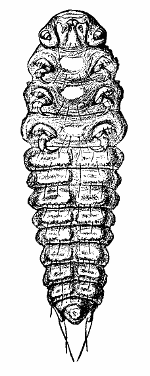 YOUNG LARVA.
What all authors have agreed in calling the mentum is very noticeable, being large and broad, and trilobed behind. The maxillæ are strong, with complicated stipes and with two flat, thin lobes, the inner one smaller than the outer and rounded at the tip, both lobes being ciliate. The maxillary palpi are four-jointed, the labial palpi three-jointed. The prosternum is very large, subtriangular, concealing the insertion of the coxæ, and extending over the front part of the mesosternum, as does this over the front of the metasternum. Six ventral segments of the abdomen are visible behind the posterior coxæ, which conceal two and the base of a third. The coxæ are flat and not at all prominent. The legs are characterized by broad and flattened tibiæ and femora, and the strong spines with which they are armed. The tarsi are five-jointed, the front and middle pair with a row of claviform membraneous appendages each side, which Le Conte found only in the male.
American entomologists have been satisfied to follow Le Conte and Horn as to the position of Platypsyllus. Yet with such diversity of opinion on the subject among high European authorities, the importance of a knowledge of the adolescent states has been recognized, as the character of either the larva or pupa would settle the question.
During a stay at West Point, Neb., in October, 1886, I learned from one of my agents, Mr. Lawrence Bruner, that there was a beaver in a creek not far from that point, and I at once made arrangements for him to trap the beaver, and to look particularly for living specimens of Platypsyllus on the skin, and especially the earlier stages. He succeeded in capturing the beaver and sent me some fifteen specimens of the larva and also some imagos, but neither eggs nor pupæ were found. A glance at the larva satisfied me at once of its coleopterous nature; but as we have, waiting to be worked up and published, an embarras de richesses entomologiques in the collections of the National Museum, and as circumstances largely decide the precedence, I should probably not have called attention to this larva for some time, had it not been that at the last monthly meeting of the Entomological Society of Washington, Dr. Horn, who was present, announced the finding, the present spring, by one of his correspondents, of this very larva, and exhibited a specimen. Some points about it, and especially the position of the spiracles, being yet rather obscure in his mind, he requested me to examine my material, which I have thus been led to do. I have made a figure of this larva which will sufficiently indicate its nature.
The general form of the trophi, and particularly the anal cerci, fully settle the disputed point, and remove this insect completely from the Mallophaga (none of which possess them), and confirm its position in the Clavicorn series of the Coleoptera. Yet in the larva, as in the imago, the effects of its parasitic life are shown in certain modifications which approach the running section of the Mallophaga. Without going into details I may say that, besides its general and more decided coleopterological features, this larva is distinguished by the shortness and stoutness of its legs, by the size and stoutness of the antennæ, by the stiff and long depressed hairs on the dorsal and more particularly on the ventral surface, and by the dorsal position of the abdominal spiracles, all characters approaching the Mallophaga. The first pair of spiracles is lateral, and may be said to be mesothoracic, being placed on the mesothoracic joint, but on a distinct fold. The eight abdominal spiracles are placed on the sides of the dorsum, and in this respect recall the parasitic triungulin of the meloid larvæ. The mandibles are barely corneous, and they are more elongate and curved in the younger than in the older larva, while the legs are also relatively stouter, more curved, and with a much longer and sharper claw in the younger larva, which seems well fitted for grasping the hairs of its host.
There can no longer be any doubt, therefore, about the true position of Platypsyllus. The eggs will probably be found attached in some way to the hairs of the animal they are laid on, much as they are in Mallophaga, and the pupa is probably formed in the nests of the host, and not upon the skin, which will explain the reason for its not occurring with the larva and imago upon the beaver, either in the case of my specimens or those of Dr. Horn.
The greatest resemblance of Platypsyllus in the imago state to the Mallophaga is found in the spinous comb on the hind border of the occiput, the arrangement of the spines on the abdomen, and the superficial antennal structure, but particularly in the broad trilobed mentum. All of the other characteristics are readily referable to the Coleoptera, though, as Le Conte pointed out, they are composite, recalling in the antennæ the Grynidæ, in the pronotum the Silphidæ, in the mesosternum Limulodes, in the elytra the Staphilindæ, in the legs the Anisotomidæ, and in the mandibles the Corylophidæ. The scutellum and the five-jointed tarsi at once remove it from Mallophaga, and it is a wonder that Le Conte and Horn have not more fully insisted on this fact. The trophi are very complicated, and there are various details of structure not noticed or not mentioned by any of the writers upon the subject hitherto.
I have been led to very carefully examine the imago, and the more closely I have done so, the more completely I realize the accuracy of Le Conte's original work. The mandibles are visible or not, according as they are exposed or withdrawn, and their existence may depend on the sex, as, so far as my material justifies conclusion, they are visible in the male only. Where found they correspond to Le Conte's description. Even in the larva they are weak and of doubtful service in mastication, while in the imago they are, as is also the labrum, quite rudimentary, which fact hardly justifies us, however, in arguing their non-existence.
As confirmatory of the affinities of Platypsyllus, as here proved, it may be mentioned that Leptinus testaceous Mull., the only species of its genus, is known to be parasitic on mice, as it has been found upon them in Philadelphia by Dr. Jno. A. Ryder, and I have taken it in the nests of a common field mouse near Washington. But still more interesting is the fact that Leptinillus validus Horn (also the only species of its genus) is an associate parasite of Platypsyllus on the beaver, a number of both having been taken by one of my agents, Mr. A. Koebele, in San Francisco, from beaver skins brought from Alaska.
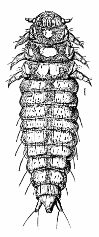 LARVA OF PLATYPSYLLUS CASTORIS.
In reference to the classificatory value that should be attached to an aberrant type like this, I have already expressed my opinion in a paper on Megathymus, a Lepidopteron that connects in many ways the two great divisions of butterflies and moths, published in the Transactions of the Academy of Sciences of St. 10358 Louis, volume iii., 1876, and will take the liberty of reading a few passages therefrom:
"Between all classificatory divisions, from variety to kingdom, the separating lines we draw get more and more broken in proportion as our knowledge of forms, past and present, increases. Every step in advance toward a true conception of the relations of animals brings the different groups closer together, until at last we perceive an almost continuous chain. Even the older naturalists had an appreciation of this fact. Linnæus' noted dictum, 'Natura saltus non facit' implies it; and Kirby and Spence justly observe that 'it appears to be the opinion of most modern physiologists that the series of affinities in nature is a concatenation or continuous series; and that though an hiatus is here and there observable, this has been caused either by the annihilation of some original group or species, or that the objects required to fill it up are still in existence but have not yet been discovered.'"
"Modern naturalists find in this more or less gradual blending their strongest arguments in favor of community of descent; and speculation as to the origin, or outcome rather, in the near present or remote past of existing forms is naturally and very generally indulged, even by those who a few years back were more inclined to ridicule than accept Darwinian doctrine. Shall we then say that the old divisions must be discarded because not absolute? As well might we argue for the abolition of the four seasons because they differ with the latitude, or because they gradually blend into each other. Entomologists will always speak of moths and butterflies, howsoever arbitrary the groups may come to be looked upon, or however numerous the intermediate gradations."
"Families should, I think, be made as comprehensive as possible, and not unduly multiplied; and in considering aberrant forms, the objects of classification are best subserved by retaining them in whatever division can claim the balance of characters. It is better to widen than to restrict in the higher groups. Le Conte does better service in bringing Platypsylla among the Coleoptera than does Westwood in creating a new order—Achreioptera—for it. Phylloxera, in Homoptera, is much more wisely retained in the Aphididæ than made the type of a new family."
Platypsyllus, therefore, is a good Coleopteron, and in all the characters in which it so strongly approaches the Mallophaga it offers merely an illustration of modification due to food habit and environment. In this particular it is, however, of very great interest as one of the most striking illustrations we have of variation in similar lines through the influence of purely external or dynamical conditions, and where genetic connection and heredity play no part whatever. It is at the same time interesting because of its synthetic characteristics, being evidently an ancient type from which we get a very good idea of the connection in the past of some of the present well-defined orders of insects.
Westwood, though now an octogenarian, may safely be called England's most eminent entomologist by virtue of the character and volume of the work which he has accomplished. Dr. Le Conte was, facile princeps, America's leading coleopterist. I do not know that any greater tribute could be added to the sound judgment and deep knowledge possessed by that late distinguished member of the Academy than the confirmation of his views as opposed to the views of Westwood and other European authorities which the discovery of this larva now gives us.
The author has observed a fact which furnishes a remarkable demonstration of the law of the production of the dark bands which he has detected in the spectrum of oxygen. The phenomena of elective absorption in oxygen gas are manifested in two mutually distinct spectral systems. A first system, formed of fine rays, follows the law of the product of the gaseous system traversed by its density. The second system is formed of bands much less easily resolved, is governed by the law of the product of the thickness by the square of the density. This second law being quite novel in spectral analysis, the author has instituted experiments necessary to prove that this system of obscure bands really belongs to oxygen. These experiments range from pressures of 100 atmospheres down to those of a few units, and with lengths of tubes from 0.42 meter to 60 meters. At the same time prolonged observations have been made upon the atmosphere, brought into connection with the experiments in the tubes. These observations, and especially those made during autumn last on the Pic du Midi, prove that all the bands of the spectrum of oxygen are found in the spectrum of the solar light if it is allowed to traverse a sufficient thickness of the atmospheric medium. Further, on comparing, by the aid of photography, the intensities of the bands of the atmospheric spectrum with those given in the tubes, the author has found that the intensities of these atmospheric bands fulfill the law of the square. It appears from Wiedemann's Annalen that M. Olszewski, when liquefying oxygen, examined its spectrum and ascertained the existence of the bands in question with a stratum of 7 mm. of liquid oxygen.—J. Jansen.
Experiments by himself and other observers have shown that the temperatures at which iron and nickel lose their magnetic properties depend on the specimens used and the magnetizing forces employed; but the temperatures at which they begin to lose these properties are definite—for nickel about 300° C., and iron about 680° C. The author's own experiments on "Recalescence of Iron" show two critical temperatures; and Pinchon has shown by calorimetric measurement that between 660° and 720° C., and between 1,000° and 1,050° C., heat becomes latent. All these facts seem to indicate a molecular rearrangement about these temperatures.
In his proposed theory he assumes that the molecules of iron (say) contain magnetic atoms capable of motions of translation and of rotation. These tend to form closed magnetic circuits, but at ordinary temperatures are unable to do so on account of the close proximity of their centers. On raising the temperature their centers are further separated, till at about 680° C. their polar extremities rush together, forming complete circuits and exhibiting no external magnetic properties. On cooling down, the centers approach until the gravitation attraction overcomes the magnetic attraction of their poles, when the magnetic properties reappear.
Prof. Ayrton asked whether the author had made experiments on the reappearance of magnetic properties when raised to a white heat, and Prof. Thompson inquired whether cobalt had been tested. Both questions were answered negatively.
The principle in question, ouabaine, forms rectangular plates, very slender, of a nacreous appearance. It is absolutely white, inodorous, and not appreciably bitter. It contains no nitrogen, and does not react with coloring matters. At a boiling heat, in presence of dilute acids, it is split up, yielding a reductive sugar. Its composition is C90H45O12. It is poisonous if introduced into the circulation, but not if swallowed.—M. Arnaud, in Comptes Rendus.
This is a Special Edition of the Scientific American, issued monthly—on the first day of the month. Each number contains about forty large quarto pages, equal to about two hundred ordinary book pages, forming, practically, a large and splendid Magazine of Architecture, richly adorned with elegant plates in colors and with fine engravings, illustrating the most interesting examples of modern Architectural Construction and allied subjects.
A special feature is the presentation in each number of a variety of the latest and best plans for private residences, city and country, including those of very moderate cost as well as the more expensive. Drawings in perspective and in color are given, together with full Plans, Specifications, Costs, Bills of Estimate, and Sheets of Details.
No other building paper contains so many plans, details, and specifications regularly presented as the Scientific American. Hundreds of dwellings have already been erected on the various plans we have issued during the past year, and many others are in process of construction.
Architects, Builders, and Owners will find this work valuable in furnishing fresh and useful suggestions. All who contemplate building or improving homes, or erecting structures of any kind, have before them in this work an almost endless series of the latest and best examples from which to make selections, thus saving time and money.
Many other subjects, including Sewerage, Piping, Lighting, Warming, Ventilating, Decorating, Laying out of Grounds, etc., are illustrated. An extensive Compendium of Manufacturers' Announcements is also given, in which the most reliable and approved Building Materials, Goods, Machines, Tools, and Appliances are described and illustrated, with addresses of the makers, etc.
The fullness, richness, cheapness, and convenience of this work have won for it the Largest Circulation of any Architectural publication in the world.
A Catalogue of valuable books on Architecture, Building, Carpentry, Masonry, Heating, Warming, Lighting, Ventilation, and all branches of industry pertaining to the art of Building, is supplied free of charge, sent to any address.
In connection with the publication of the Building Edition of the Scientific American, Messrs. Munn & Co. furnish plans and specifications for buildings of every kind, including Churches, Schools, Stores, Dwellings, Carriage Houses, Barns, etc.
In this work they are assisted by able and experienced architects. Full plans, details, and specifications for the various buildings illustrated in this paper can be supplied.
Those who contemplate building, or who wish to alter, improve, extend, or add to existing buildings, whether wings, porches, bay windows, or attic rooms, are invited to communicate with the undersigned. Our work extends to all parts of the country. Estimates, plans, and drawings promptly prepared. Terms moderate. Address
Sent by mail, postage prepaid, to subscribers in any part of the United States or Canada. Six dollars a year, sent, prepaid, to any foreign country.
All the back numbers of The Supplement, from the commencement, January 1, 1876, can be had. Price, 10 cents each.
All the back volumes of The Supplement can likewise be supplied. Two volumes are issued yearly. Price of each volume, $2.50 stitched in paper, or $3.50 bound in stiff covers.
Combined Rates.—One copy of Scientific American and one copy of Scientific American Supplement, one year, postpaid, $7.00.
A liberal discount to booksellers, news agents, and canvassers.
Manufacturers, Agriculturists, Chemists, Engineers, Mechanics, Builders, men of leisure, and professional men, of all classes, need good books in the line of their respective callings. Our post office department permits the transmission of books through the mails at very small cost. A comprehensive catalogue of useful books by different authors, on more than fifty different subjects, has recently been published, for free circulation, at the office of this paper. Subjects classified with names of author. Persons desiring a copy have only to ask for it, and it will be mailed to them. Address,
In connection with the Scientific American, Messrs. Munn & Co. are solicitors of American and Foreign Patents, have had 42 years' experience, and now have the largest establishment in the world. Patents are obtained on the best terms.
A special notice is made in the Scientific American of all inventions patented through this Agency, with the name and residence of the Patentee. By the immense circulation thus given, public attention is directed to the merits of the new patent, and sales or introduction often easily effected.
Any person who has made a new discovery or invention can ascertain, free of charge, whether a patent can probably be obtained, by writing to Munn & Co.
We also send free our Hand Book about the Patent Laws, Patents, Caveats, Trade Marks, their costs, and how procured. Address
Transcriber's Note: Some illustrations may have been moved. We have rendered consistent on a per-word-pair basis the hyphenation or spacing of such pairs when repeated in the same grammatical context. The table of contents has been moved to the front.
Other changes are listed below. The listed source publication page number also applies in this reproduction except for the table of contents since it has been moved.
  Page          Change

10343  [Fig. 1 redrawn slightly to reduce the reader's confusion.]
10345  [Nature.][Heading deleted.]
10345  12,600 lb. per square inch [(psi)].[also in following lines.]
10346  [First line of heading moved to footnote.]
10347  as much as [a] plank of the same size
10347  For these upper floors hard-wood[hardwood] plank,
10349  asserted pretty generally thoughout[throughout] the country
10349  employes[employees] will no longer be known as "gas house
10350  reappear in the little glow lamp[glow-lamp][multiple instances]
10351  through[though] I doubt whether it is visible
10351  due to the vacum[vacuum],
10351  and to the atonishment[astonishment] of my fellow
10352  the many disagreeable symptons[symptoms],
10352  [Part of Care of The Eyes header moved to footnote.]
10354  but on miscroscopical[microscopical] examination
10354  neigborhood[neighborhood] in which we live.
10355  It[Its] parallax, as determined by Sir R. S. Ball,
10355  The well known[well-known] double star 61 Cygni
10356  [Fig. 3: Illegible text re-composed.]
10358  [Advertisements header added.]
10358  [Table of contents moved to front of publication.]
10358  The One Hundred and Twenty Foot[Ton] Shears {Table of Contents}
End of the Project Gutenberg EBook of Scientific American Supplement, No.
648, June 2, 1888., by Various

*** END OF THIS PROJECT GUTENBERG EBOOK SC. AMERICAN SUPP., JUNE 2, 1888 ***

***** This file should be named 38403-h.htm or 38403-h.zip *****
This and all associated files of various formats will be found in:
        https://www.gutenberg.org/3/8/4/0/38403/

Produced by Juliet Sutherland, Henry Gardiner and the
Online Distributed Proofreading Team at https://www.pgdp.net.


Updated editions will replace the previous one--the old editions
will be renamed.

Creating the works from public domain print editions means that no
one owns a United States copyright in these works, so the Foundation
(and you!) can copy and distribute it in the United States without
permission and without paying copyright royalties.  Special rules,
set forth in the General Terms of Use part of this license, apply to
copying and distributing Project Gutenberg-tm electronic works to
protect the PROJECT GUTENBERG-tm concept and trademark.  Project
Gutenberg is a registered trademark, and may not be used if you
charge for the eBooks, unless you receive specific permission.  If you
do not charge anything for copies of this eBook, complying with the
rules is very easy.  You may use this eBook for nearly any purpose
such as creation of derivative works, reports, performances and
research.  They may be modified and printed and given away--you may do
practically ANYTHING with public domain eBooks.  Redistribution is
subject to the trademark license, especially commercial
redistribution.


*** START: FULL LICENSE ***

THE FULL PROJECT GUTENBERG LICENSE
PLEASE READ THIS BEFORE YOU DISTRIBUTE OR USE THIS WORK

To protect the Project Gutenberg-tm mission of promoting the free
distribution of electronic works, by using or distributing this work
(or any other work associated in any way with the phrase "Project
Gutenberg"), you agree to comply with all the terms of the Full Project
Gutenberg-tm License (available with this file or online at
https://gutenberg.org/license).


Section 1.  General Terms of Use and Redistributing Project Gutenberg-tm
electronic works

1.A.  By reading or using any part of this Project Gutenberg-tm
electronic work, you indicate that you have read, understand, agree to
and accept all the terms of this license and intellectual property
(trademark/copyright) agreement.  If you do not agree to abide by all
the terms of this agreement, you must cease using and return or destroy
all copies of Project Gutenberg-tm electronic works in your possession.
If you paid a fee for obtaining a copy of or access to a Project
Gutenberg-tm electronic work and you do not agree to be bound by the
terms of this agreement, you may obtain a refund from the person or
entity to whom you paid the fee as set forth in paragraph 1.E.8.

1.B.  "Project Gutenberg" is a registered trademark.  It may only be
used on or associated in any way with an electronic work by people who
agree to be bound by the terms of this agreement.  There are a few
things that you can do with most Project Gutenberg-tm electronic works
even without complying with the full terms of this agreement.  See
paragraph 1.C below.  There are a lot of things you can do with Project
Gutenberg-tm electronic works if you follow the terms of this agreement
and help preserve free future access to Project Gutenberg-tm electronic
works.  See paragraph 1.E below.

1.C.  The Project Gutenberg Literary Archive Foundation ("the Foundation"
or PGLAF), owns a compilation copyright in the collection of Project
Gutenberg-tm electronic works.  Nearly all the individual works in the
collection are in the public domain in the United States.  If an
individual work is in the public domain in the United States and you are
located in the United States, we do not claim a right to prevent you from
copying, distributing, performing, displaying or creating derivative
works based on the work as long as all references to Project Gutenberg
are removed.  Of course, we hope that you will support the Project
Gutenberg-tm mission of promoting free access to electronic works by
freely sharing Project Gutenberg-tm works in compliance with the terms of
this agreement for keeping the Project Gutenberg-tm name associated with
the work.  You can easily comply with the terms of this agreement by
keeping this work in the same format with its attached full Project
Gutenberg-tm License when you share it without charge with others.

1.D.  The copyright laws of the place where you are located also govern
what you can do with this work.  Copyright laws in most countries are in
a constant state of change.  If you are outside the United States, check
the laws of your country in addition to the terms of this agreement
before downloading, copying, displaying, performing, distributing or
creating derivative works based on this work or any other Project
Gutenberg-tm work.  The Foundation makes no representations concerning
the copyright status of any work in any country outside the United
States.

1.E.  Unless you have removed all references to Project Gutenberg:

1.E.1.  The following sentence, with active links to, or other immediate
access to, the full Project Gutenberg-tm License must appear prominently
whenever any copy of a Project Gutenberg-tm work (any work on which the
phrase "Project Gutenberg" appears, or with which the phrase "Project
Gutenberg" is associated) is accessed, displayed, performed, viewed,
copied or distributed:

This eBook is for the use of anyone anywhere at no cost and with
almost no restrictions whatsoever.  You may copy it, give it away or
re-use it under the terms of the Project Gutenberg License included
with this eBook or online at www.gutenberg.org

1.E.2.  If an individual Project Gutenberg-tm electronic work is derived
from the public domain (does not contain a notice indicating that it is
posted with permission of the copyright holder), the work can be copied
and distributed to anyone in the United States without paying any fees
or charges.  If you are redistributing or providing access to a work
with the phrase "Project Gutenberg" associated with or appearing on the
work, you must comply either with the requirements of paragraphs 1.E.1
through 1.E.7 or obtain permission for the use of the work and the
Project Gutenberg-tm trademark as set forth in paragraphs 1.E.8 or
1.E.9.

1.E.3.  If an individual Project Gutenberg-tm electronic work is posted
with the permission of the copyright holder, your use and distribution
must comply with both paragraphs 1.E.1 through 1.E.7 and any additional
terms imposed by the copyright holder.  Additional terms will be linked
to the Project Gutenberg-tm License for all works posted with the
permission of the copyright holder found at the beginning of this work.

1.E.4.  Do not unlink or detach or remove the full Project Gutenberg-tm
License terms from this work, or any files containing a part of this
work or any other work associated with Project Gutenberg-tm.

1.E.5.  Do not copy, display, perform, distribute or redistribute this
electronic work, or any part of this electronic work, without
prominently displaying the sentence set forth in paragraph 1.E.1 with
active links or immediate access to the full terms of the Project
Gutenberg-tm License.

1.E.6.  You may convert to and distribute this work in any binary,
compressed, marked up, nonproprietary or proprietary form, including any
word processing or hypertext form.  However, if you provide access to or
distribute copies of a Project Gutenberg-tm work in a format other than
"Plain Vanilla ASCII" or other format used in the official version
posted on the official Project Gutenberg-tm web site (www.gutenberg.org),
you must, at no additional cost, fee or expense to the user, provide a
copy, a means of exporting a copy, or a means of obtaining a copy upon
request, of the work in its original "Plain Vanilla ASCII" or other
form.  Any alternate format must include the full Project Gutenberg-tm
License as specified in paragraph 1.E.1.

1.E.7.  Do not charge a fee for access to, viewing, displaying,
performing, copying or distributing any Project Gutenberg-tm works
unless you comply with paragraph 1.E.8 or 1.E.9.

1.E.8.  You may charge a reasonable fee for copies of or providing
access to or distributing Project Gutenberg-tm electronic works provided
that

- You pay a royalty fee of 20% of the gross profits you derive from
     the use of Project Gutenberg-tm works calculated using the method
     you already use to calculate your applicable taxes.  The fee is
     owed to the owner of the Project Gutenberg-tm trademark, but he
     has agreed to donate royalties under this paragraph to the
     Project Gutenberg Literary Archive Foundation.  Royalty payments
     must be paid within 60 days following each date on which you
     prepare (or are legally required to prepare) your periodic tax
     returns.  Royalty payments should be clearly marked as such and
     sent to the Project Gutenberg Literary Archive Foundation at the
     address specified in Section 4, "Information about donations to
     the Project Gutenberg Literary Archive Foundation."

- You provide a full refund of any money paid by a user who notifies
     you in writing (or by e-mail) within 30 days of receipt that s/he
     does not agree to the terms of the full Project Gutenberg-tm
     License.  You must require such a user to return or
     destroy all copies of the works possessed in a physical medium
     and discontinue all use of and all access to other copies of
     Project Gutenberg-tm works.

- You provide, in accordance with paragraph 1.F.3, a full refund of any
     money paid for a work or a replacement copy, if a defect in the
     electronic work is discovered and reported to you within 90 days
     of receipt of the work.

- You comply with all other terms of this agreement for free
     distribution of Project Gutenberg-tm works.

1.E.9.  If you wish to charge a fee or distribute a Project Gutenberg-tm
electronic work or group of works on different terms than are set
forth in this agreement, you must obtain permission in writing from
both the Project Gutenberg Literary Archive Foundation and Michael
Hart, the owner of the Project Gutenberg-tm trademark.  Contact the
Foundation as set forth in Section 3 below.

1.F.

1.F.1.  Project Gutenberg volunteers and employees expend considerable
effort to identify, do copyright research on, transcribe and proofread
public domain works in creating the Project Gutenberg-tm
collection.  Despite these efforts, Project Gutenberg-tm electronic
works, and the medium on which they may be stored, may contain
"Defects," such as, but not limited to, incomplete, inaccurate or
corrupt data, transcription errors, a copyright or other intellectual
property infringement, a defective or damaged disk or other medium, a
computer virus, or computer codes that damage or cannot be read by
your equipment.

1.F.2.  LIMITED WARRANTY, DISCLAIMER OF DAMAGES - Except for the "Right
of Replacement or Refund" described in paragraph 1.F.3, the Project
Gutenberg Literary Archive Foundation, the owner of the Project
Gutenberg-tm trademark, and any other party distributing a Project
Gutenberg-tm electronic work under this agreement, disclaim all
liability to you for damages, costs and expenses, including legal
fees.  YOU AGREE THAT YOU HAVE NO REMEDIES FOR NEGLIGENCE, STRICT
LIABILITY, BREACH OF WARRANTY OR BREACH OF CONTRACT EXCEPT THOSE
PROVIDED IN PARAGRAPH 1.F.3.  YOU AGREE THAT THE FOUNDATION, THE
TRADEMARK OWNER, AND ANY DISTRIBUTOR UNDER THIS AGREEMENT WILL NOT BE
LIABLE TO YOU FOR ACTUAL, DIRECT, INDIRECT, CONSEQUENTIAL, PUNITIVE OR
INCIDENTAL DAMAGES EVEN IF YOU GIVE NOTICE OF THE POSSIBILITY OF SUCH
DAMAGE.

1.F.3.  LIMITED RIGHT OF REPLACEMENT OR REFUND - If you discover a
defect in this electronic work within 90 days of receiving it, you can
receive a refund of the money (if any) you paid for it by sending a
written explanation to the person you received the work from.  If you
received the work on a physical medium, you must return the medium with
your written explanation.  The person or entity that provided you with
the defective work may elect to provide a replacement copy in lieu of a
refund.  If you received the work electronically, the person or entity
providing it to you may choose to give you a second opportunity to
receive the work electronically in lieu of a refund.  If the second copy
is also defective, you may demand a refund in writing without further
opportunities to fix the problem.

1.F.4.  Except for the limited right of replacement or refund set forth
in paragraph 1.F.3, this work is provided to you 'AS-IS' WITH NO OTHER
WARRANTIES OF ANY KIND, EXPRESS OR IMPLIED, INCLUDING BUT NOT LIMITED TO
WARRANTIES OF MERCHANTIBILITY OR FITNESS FOR ANY PURPOSE.

1.F.5.  Some states do not allow disclaimers of certain implied
warranties or the exclusion or limitation of certain types of damages.
If any disclaimer or limitation set forth in this agreement violates the
law of the state applicable to this agreement, the agreement shall be
interpreted to make the maximum disclaimer or limitation permitted by
the applicable state law.  The invalidity or unenforceability of any
provision of this agreement shall not void the remaining provisions.

1.F.6.  INDEMNITY - You agree to indemnify and hold the Foundation, the
trademark owner, any agent or employee of the Foundation, anyone
providing copies of Project Gutenberg-tm electronic works in accordance
with this agreement, and any volunteers associated with the production,
promotion and distribution of Project Gutenberg-tm electronic works,
harmless from all liability, costs and expenses, including legal fees,
that arise directly or indirectly from any of the following which you do
or cause to occur: (a) distribution of this or any Project Gutenberg-tm
work, (b) alteration, modification, or additions or deletions to any
Project Gutenberg-tm work, and (c) any Defect you cause.


Section  2.  Information about the Mission of Project Gutenberg-tm

Project Gutenberg-tm is synonymous with the free distribution of
electronic works in formats readable by the widest variety of computers
including obsolete, old, middle-aged and new computers.  It exists
because of the efforts of hundreds of volunteers and donations from
people in all walks of life.

Volunteers and financial support to provide volunteers with the
assistance they need are critical to reaching Project Gutenberg-tm's
goals and ensuring that the Project Gutenberg-tm collection will
remain freely available for generations to come.  In 2001, the Project
Gutenberg Literary Archive Foundation was created to provide a secure
and permanent future for Project Gutenberg-tm and future generations.
To learn more about the Project Gutenberg Literary Archive Foundation
and how your efforts and donations can help, see Sections 3 and 4
and the Foundation web page at https://www.pglaf.org.


Section 3.  Information about the Project Gutenberg Literary Archive
Foundation

The Project Gutenberg Literary Archive Foundation is a non profit
501(c)(3) educational corporation organized under the laws of the
state of Mississippi and granted tax exempt status by the Internal
Revenue Service.  The Foundation's EIN or federal tax identification
number is 64-6221541.  Its 501(c)(3) letter is posted at
https://pglaf.org/fundraising.  Contributions to the Project Gutenberg
Literary Archive Foundation are tax deductible to the full extent
permitted by U.S. federal laws and your state's laws.

The Foundation's principal office is located at 4557 Melan Dr. S.
Fairbanks, AK, 99712., but its volunteers and employees are scattered
throughout numerous locations.  Its business office is located at
809 North 1500 West, Salt Lake City, UT 84116, (801) 596-1887, email
business@pglaf.org.  Email contact links and up to date contact
information can be found at the Foundation's web site and official
page at https://pglaf.org

For additional contact information:
     Dr. Gregory B. Newby
     Chief Executive and Director
     gbnewby@pglaf.org


Section 4.  Information about Donations to the Project Gutenberg
Literary Archive Foundation

Project Gutenberg-tm depends upon and cannot survive without wide
spread public support and donations to carry out its mission of
increasing the number of public domain and licensed works that can be
freely distributed in machine readable form accessible by the widest
array of equipment including outdated equipment.  Many small donations
($1 to $5,000) are particularly important to maintaining tax exempt
status with the IRS.

The Foundation is committed to complying with the laws regulating
charities and charitable donations in all 50 states of the United
States.  Compliance requirements are not uniform and it takes a
considerable effort, much paperwork and many fees to meet and keep up
with these requirements.  We do not solicit donations in locations
where we have not received written confirmation of compliance.  To
SEND DONATIONS or determine the status of compliance for any
particular state visit https://pglaf.org

While we cannot and do not solicit contributions from states where we
have not met the solicitation requirements, we know of no prohibition
against accepting unsolicited donations from donors in such states who
approach us with offers to donate.

International donations are gratefully accepted, but we cannot make
any statements concerning tax treatment of donations received from
outside the United States.  U.S. laws alone swamp our small staff.

Please check the Project Gutenberg Web pages for current donation
methods and addresses.  Donations are accepted in a number of other
ways including including checks, online payments and credit card
donations.  To donate, please visit: https://pglaf.org/donate


Section 5.  General Information About Project Gutenberg-tm electronic
works.

Professor Michael S. Hart was the originator of the Project Gutenberg-tm
concept of a library of electronic works that could be freely shared
with anyone.  For thirty years, he produced and distributed Project
Gutenberg-tm eBooks with only a loose network of volunteer support.


Project Gutenberg-tm eBooks are often created from several printed
editions, all of which are confirmed as Public Domain in the U.S.
unless a copyright notice is included.  Thus, we do not necessarily
keep eBooks in compliance with any particular paper edition.


Most people start at our Web site which has the main PG search facility:

     https://www.gutenberg.org

This Web site includes information about Project Gutenberg-tm,
including how to make donations to the Project Gutenberg Literary
Archive Foundation, how to help produce our new eBooks, and how to
subscribe to our email newsletter to hear about new eBooks.