Project Gutenberg's Hawkins Electrical Guide, Number One, by Nehemiah Hawkins

This eBook is for the use of anyone anywhere at no cost and with
almost no restrictions whatsoever.  You may copy it, give it away or
re-use it under the terms of the Project Gutenberg License included
with this eBook or online at www.gutenberg.org


Title: Hawkins Electrical Guide, Number One
       Questions, Answers, & Illustrations, A Progressive Course
              of Study for Engineers, Electricians, Students and Those
              Desiring to acquire a Working Knowledge of Electricity and
              its Applications

Author: Nehemiah Hawkins

Release Date: December 22, 2011 [EBook #38384]

Language: English

Character set encoding: UTF-8

*** START OF THIS PROJECT GUTENBERG EBOOK HAWKINS ELECTRICAL GUIDE, NO. ONE ***


Produced by Juliet Sutherland, Henry Gardiner and the
Online Distributed Proofreading Team at https://www.pgdp.net
The word “guide” is defined as:
One who leads another in any path or direction; a person who shows or points out the way, especially by accompanying or going before; more particularly, one who shows strangers or tourists about; a conductor; leader, as “let us follow our guide.”
This book, or “Guide,” is so called because it leads or points out the way to the acquirement of a theoretical and practical knowledge of Electricity.
There are several guides, each covering in detail a certain phase of the broad subject of Electricity and leading the reader progressively, and in such a way, that he easily grasps, not only the simple fundamental facts, but the more complex problems, encountered in the study of Electricity. This is accomplished by the aid of a very large number of illustrations, together with specific explanations, worded in concise and simple language.
The Guides are written partly in the question and answer form, as this style of presentation has met with hearty approval, not only from those of limited education, but also from the better informed.
Where recourse is had to the question and answer form, the special aim of the author has been to give short and direct answers, in such plain language as to preclude a misconception of the meaning. With this in view, the answer gives simply the information sought by the question.
The answer is limited to one paragraph so that the reader may concentrate upon the fact or facts demanded by the question.
Any enlargement of the answer or specific explanations of items contained therein, are presented in separate paragraphs printed, in smaller type.
With this plan of separating the answer, as it were, from items of secondary importance, and making it short and simple, its content is more forcibly impressed upon the mind of the reader.
In a text book, it is necessary to illustrate and explain the various species of commercial apparatus met with in practice, and in this connection the Publishers desire to call attention to the manner in which the author has treated what may be classed as the “descriptive matter.” Contrary to the usual custom of giving descriptions of commercial machines in the main text, where they would occupy considerable space, to the exclusion of the more important matter, all such descriptions are placed in small type directly under the illustrations, leaving space for an adequate presentation of the underlying principles, theories, and for the large amount of practical information that is essential to obtain a general knowledge of Electricity and its numerous applications.
Credit is largely due to Frank D. Graham, B.S., M.S. (Princeton University), and M.E. (Stevens Institute), practical engineer, for the authorship of the Guides, and for original sketches illustrating electrical principles and construction.
| INTRODUCTORY CHAPTER | |
| SIGNS AND SYMBOLS | |
| ELECTRICITY | 1 to 4 |
| Nature and source—kinds of electricity: static, current, dynamic, radiated, positive, negative, atmospheric, frictional, resinous, vitreous. | |
| STATIC ELECTRICITY | 5 to 26 |
| Electrical attraction and repulsion—the charge—distribution of the charge—free and bound electricity—conductors and insulators—electroscopes—gold leaf electroscope—electric screens—electrification by induction—nature of the induced charge—the electrophorus—condensers; Leyden jar—electric machines—action of Toepler-Holtz machine—Wimshurst machines. | |
| THE ELECTRIC CURRENT | 27 to 34 |
| Volt—ampere—ohm—Ohm’s law—production of the electric current—current strength—voltage drop in an electric current. | |
| PRIMARY CELLS | 35 to 67 |
| The word “battery”—action of cell—chemical changes; polarization—effects of polarization—methods of depolarization—depolarizers—depolarizer bag—Volta’s contact law—contact series of metals—laws of chemical action in cell—requirements of a good cell—single and two fluid cells—the Leclanche cell—Fuller bichromate cell—the Edison cell—Grenet bichromate cell—Daniell cell—directions for making a Daniell cell—gravity cells—Daniell gravity cell—so-called “dry” cells—points relating to dry cells—care of cells—cleanliness—separating the elements—creeping—amalgamated zinc—battery connections. | |
| CONDUCTORS AND INSULATORS | 68 to 74 |
| The so-called “non-conductors”—table of conductors and insulators—mode of transmission—effect of heat—heating effect of the current—insulators—impregnating compounds—water as a conductor. | |
| RESISTANCE AND CONDUCTIVITY | 75 to 82 |
| Standard of resistance—conductivity of metals and liquids—effect of heat—laws of electrical resistance—conductivity—specific conductivity—divided circuits. | |
| ELECTRICAL AND MECHANICAL ENERGY | 83 to 92 |
| Definitions: energy, matter, molecule, work, foot-pound, volt-coulomb, ampere-hour, power, horse power, watt, kilowatt, watt-hour—mechanical equivalent of heat—British thermal unit—electrical horse power—the farad. | |
| EFFECTS OF THE CURRENT | 93 to 104 |
| Thermal effect—use of heat from the current—magnetic effect—chemical effect—electrolysis—electro-chemical series—electric osmose—electric distillation—muscular contractions—electroplating—electrotyping. | |
| MAGNETISM | 105 to 124 |
| Two kinds of magnetism—nature of each—poles—magnetic field—magnetic force—magnetic circuit—magnetic flux—the Maxwell—the Gauss—magnetic effect of the current—corkscrew rule—solenoids—permeability—magnetic saturation—magnetomotive force—reluctance—analogy between electric and magnetic circuits—hystereses—residual magnetism. | |
| ELECTROMAGNETIC INDUCTION | 125 to 136 |
| Faraday’s discovery—Faraday’s machine—Faraday’s principle—line of force—induction of current—laws of electromagnetic induction—rules for direction of induced current—Fleming’s rule—Ampere’s rule—the palm rule—self-induction. | |
| INDUCTION COILS | 137 to 154 |
| Self-induction—mutual induction—primary induction coils—secondary induction coils—plain secondary induction coils—secondary induction coils with vibrator and condenser; cycle of action—magnetic vibrators—vibrator adjustment—table of induction coil dimensions—table of sparking distances in air—points relating to induction coils—wiring diagram. | |
| THE DYNAMO | 155 to 160 |
| Operation—essential parts—field magnets—armature—construction of dynamos—parts; bed plate, field magnets, armature, commutator, brushes. | |
| THE DYNAMO: BASIC PRINCIPLES | 161 to 170 |
| Definitions—essential parts—elementary alternator—operation—direction of induced current—application of Fleming’s rule—cycle of operation—the sine curve; its construction and application. | |
| THE DYNAMO: CURRENT COMMUTATION | 171 to 180 |
| How the current is produced—how direct current is obtained—the commutator—inductors—“continuous current”—action of four coil elementary dynamo—conditions for steadiness of the current. | |
| CLASSES OF DYNAMO | 181 to 198 |
| Classification—bipolar and multi-polar dynamos—difference between dynamo and magneto—self-exciting dynamo—the series dynamo—regulation of series dynamo; difficulties experienced—the shunt dynamo—adaptation—operation—characteristic—regulation—the compound dynamo—service intended for—regulation—over compounding—usual degree of over compounding—short shunt—long shunt—voltage of short and long shunt machines—separately excited dynamos—Dobrowolski three wire dynamo. | |
| FIELD MAGNETS | 199 to 220 |
| Object—essential parts—classes of field magnet—multi-polar field magnets—construction—choice of materials—design—pole pieces—eddy current—laminated fields—construction to reduce reluctance of the magnetic circuit—magnetizing coils—methods of winding—coil ends—insulation—attachment of coils—coil connections—heating—ventilation. |
The subject matter of this work relates to one of the secrets of creation which appears to have been intended at the very beginning to be “sought out.” This idea is expressed in a certain saying copied three or four thousand years ago by the men of Hezekiah, King of Judah: from Solomon’s proverbs: “It is the glory of God to conceal a thing: But the glory of Kings (i.e., wise men), to search out a matter.”
In all that may be said hereafter through the work, it is admitted that the results recorded are the determinations of experiments performed by an incredible number of searchers extending through many ages. These inquiries have been pursued with a generous rivalry which has permitted discovery to be added to discovery, until the sum total has been wrought into such exactness that it has been thoughtlessly stated that there is nothing more, save its application.
It may be well, however, to state a few fundamental facts relating to electricity: 1, Electricity and magnetism are one and the same thing; 2, what is really known about it has come as a discovery and not as an invention. Thus, we say the intrepid explorer discovered the pole, not that he invented it. So with electricity it has been a subject of discovery while its many applications to useful purposes have been veritable inventions; 3, the earth itself is a magnet.
This last is shown by the fact that the earth affects a magnet just as one magnet affects another. Magnets are bodies, either natural or artificial, which have the property of attracting iron, and the power, when freely suspended, of taking a direction toward the poles of the earth. The natural magnet is sometimes called the loadstone. This word is said to be derived from loedan, a Saxon word which signifies to guide. It is an oxide of iron of a peculiar character, found occasionally in beds of iron ore. Though commonly met with in irregular masses only a few inches in diameter, however, loadstones of larger sizes are sometimes found.
By means of simple experiments it may be ascertained that the magnet has the following general properties, viz: 1, power of attraction; 2, power of repulsion; 3, power of communicating magnetism to iron or steel; 4, polarity, or the power of taking a direction toward the poles of the earth; 5, power of inclining itself toward a point below the horizon.
Speaking generally we may say, that magnetism is a department of electrical science which treats of the properties and effects of the magnet. The same terms are also used to denote the unknown cause of magnetic phenomena, as when we speak of magnetism as excited, imparted, and so on.
Lightning and the Northern Lights are displays of electricity on a grand scale. Electricity is a term derived from the Greek word for amber, that being the substance in which a property of the agent now denominated electricity was first observed.
The ancient Greek philosophers were acquainted with the fact that amber, when rubbed, acquired the property of attracting light bodies; hence the effect was denominated electrical and in later times, the term electricity has been used to denote the unknown cause of electrical phenomena, and broadly the science which treats of electrical phenomena and their causes.
Electricity, whatever it may prove to be, is not matter nor is it energy; it is however a means or medium of transmitting energy.
If electricity is to transmit or convey energy along a wire, this energy must be imparted to the electricity from some external source, that is to say, before electricity can perform any work it must be set in motion, against more or less resistance. This involves that pressure must be applied, and to obtain this pressure, energy must be expended from some external source.
Accordingly, in electrical engineering, the first principle to be grasped is that of energy. Without the expenditure of energy no useful work can be accomplished.
Energy may be defined as the capacity for performing work.
Although electricity is not energy, electricity under pressure is a form of energy spoken of as electrical energy.
In an expenditure of energy in this form, the electricity acts simply as a transmission agent or medium to transmit the energy imparted to it in causing it to flow.
In a similar manner, steam acts as a transmission agent or medium to transmit the heat energy of the coal to the steam engine, where it is converted into mechanical energy.
As just stated, electricity under pressure is a form of energy, and its generation is simply a transformation of energy from one form into another. Usually, mechanical energy is converted into electrical energy, and a dynamo is employed for effecting the transformation.
In transforming the mechanical energy of waterfalls into electric energy, this natural power of water due to its weight and motion is first converted into rotary motion by a turbine or water wheel, and then converted into electric energy by a dynamo, or an alternator.
All dynamos are but machines for converting into electric energy the energy which is given to them by some prime mover, as a steam engine, a gas engine, by hydraulic or even by wind power.
All electric motors are merely machines for reconverting the electric energy which they receive by means of the conducting wires or mains, into mechanical energy.
All electric lamps are contrivances for converting into luminous energy a percentage of the electric energy that is supplied through the mains.
Potential and Kinetic Energy.—Potential energy is the capacity for performing work which a body possesses by virtue of its position. Kinetic energy is the capacity for performing work which a body possesses by virtue of its motion.
It must be evident that position or motion given to a body enables it to perform work. In the first instance, for example, a heavy weight at the top of a high tower possesses potential energy. A ten pound weight supported one foot above a plane has ten foot pounds of potential energy.
The flywheel of a steam engine in motion is an example of a body possessing kinetic energy. Some of this kinetic energy which was stored up in the fly wheel during the working stroke is expended in moving the engine over the “dead center,” and any other point where no torque is produced by the pressure on the piston.
Chemical Energy can be converted into electric energy to a limited extent by means of the electric battery, but the cost of this energy is so high that it is commercially feasible only where small quantities are required, and the cost of production is secondary to the convenience of generation, as for signalling purposes, the operation of bells and annunciators, etc.
The chemical energy of coal and other fuels cannot be directly converted into electric energy. For power producing purposes, the chemical energy of a fuel is first converted into heat by combustion, and the heat thus obtained converted into mechanical energy by some form of heat engine, and the mechanical energy subsequently transformed into electric energy in an electric generator.
Energy cannot be created or destroyed. This is the law known as the conservation of energy which has been built up by Helmholtz, Thomson, Joule and others. It teaches further, that energy can be transmitted from one body to another or transformed in its manifestations.
Energy may be dissipated, that is, converted into a form from which it cannot be recovered, as is the case with the great percentage of heat escaping from the exhaust nozzle of a locomotive or in the circulating water of a steamship, but the total amount of energy in the universe, it is argued, remains constant and invariable.
Following this law comes the doctrine of the conservation of electricity as announced by Lippman, being undoubtedly the outcome of the ideas of Maxwell and of Faraday as to the nature of electricity. According to their doctrine, electricity cannot be created or destroyed, although its distribution may be altered.
Lippman states that every charge of electricity has an opposite and equal charge somewhere in the universe more or less distributed; that is, the sum of positive charges is always equal to the sum of negative charges.
In altering the distribution of electricity, we may cause more to appear at one place and less at another, or may change it from the condition of rest to that of motion, or may cause it to spin round in whirlpools or vortices, which themselves can attract or repel other vortices. According to this view all our electrical machines and batteries are merely instruments for altering the distribution of electricity by moving some of it from one place to another, or for causing electricity, when accumulated or heaped, together in one place, to do work in returning to its former distribution.
Electrical engineering has developed largely and widely within a very short time and its many applications has created so great a demand for various kinds of electrical apparatus, that their manufacture forms one of the leading industries.
Electricity is very valuable as a medium for the transmission of energy, especially to long distances; it is also used to great advantage in lighting, being free from the disagreeable properties of gas or oil.
Again, electricity finds various applications, in extracting gold from the ore, pumping and ventilation of mines, traction, telephone, telegraph, electroplating, therapeutics, etc.
These few, of its many applications will perhaps serve to indicate the far reaching interest and importance of electricity, and possibly help to kindle in the student something of the eagerness in his work and enthusiasm without which he will fail to do justice either to his calling or to himself.
The following signs, symbols and abbreviations are almost universally employed in descriptive and technical works on electrical subjects.
Although, in the arrangement of the Guides, the direct current and alternating current matter has been kept separate, it is perhaps advisable in the case of signs and symbols, to combine those relating to the alternating current with the direct current and other symbols, making a single table, rather than have them scattered throughout the work.
| 1. Fundamental. | |
| l, | Length. cm. = centimeter; in., or ″ = inch, ft. or ′ = foot. |
| M, | Mass. gr. = mass of 1 gramme kg. = 1 kilogramme. |
| T, t, | Time, s = second. |
| 2. Derived Geometric. | |
| S, s, | Surface. |
| E, | Volume. |
| α, β, | Angle. |
| 3. Derived Mechanical. | |
| v, | Velocity. |
| ω, | Angular velocity. |
| r, | Momentum. |
| a, | Acceleration. |
| g, | Acceleration due to gravity = 32.2 feet per second. |
| F, f, | Force. |
| W, | Work. |
| P, | Power. |
| δ, | Dyne. |
| ε, | Ergs, |
| ft. lb., | Foot pound. |
| H.P., h.p. | Horse power. |
| I.H.P., | Indicated horse power. |
| B.H.P., | Brake horse power. |
| E.H.P., | Electrical horse power. |
| J, | Joule’s equivalent. |
| p, | Pressure. |
| K, | Moment of inertia. |
| 4. Derived Electrostatic. | |
| e, | Pressure difference. |
| i, | Current. |
| r, | Resistance. |
| q, | Quantity. |
| c, | Capacity. |
| sc, | Specific inductive capacity. |
| 5. Derived Magnetic. | |
| m, | Strength of pole. |
 , , | Intensity of magnetization. |
 , , | Magnetic moment. |
 , , | Horizontal intensity of earth’s magnetism. |
| , | Field intensity. |
| φ, | Magnetic flux. |
 , , | Magnetic flux density or magnetic induction. |
| , | Magnetizing force. |
 , , | Magnetomotive force. |
 , , | Reluctance, magnetic resistance. |
| μ, | Magnetic permeability. |
| κ, | Magnetic susceptibility. |
| ν, | Reluctivity (specific magnetic resistance). |
| 6. Derived Electromagnetic. | |
| R, | Resistance, ohm. |
| O, | do, megohm. |
| E, | Volt, pressure. |
| Eim | Impressed pressure. |
| Ea, Eo | Active pressure; ohmic drop. |
| Ev | Virtual pressure. |
| Emax | Maximum pressure. |
| Eav | Average pressure. |
| Eef | Effective pressure. |
| Ei | Inductance pressure. |
| Ec | Capacity pressure. |
| U, | Difference of pressure, volt. |
| I, | Intensity of current, ampere. |
| Iim | Impressed current. |
| Ia | Active current. |
| Iv | Virtual current. |
| Imax | Maximum current. |
| Iav | Average current. |
| Ief | Effective current. |
| Q, | Quantity of electricity, ampere-hour; coulomb. |
| C, | Capacity, farad. |
| W, | Electric energy, watt-hour; Joule. |
| P, | Electric power, watt; kilowatt. |
| p, | Resistivity (specific resistance) ohm centimeter. |
| G, | Conductance, mho. |
| γ, | Conductivity (specific conductivity). |
| Y, | Admittance, mho. |
| Z, | Impedance, ohm. |
| X, | Reactance, ohm. |
| Xi | Inductance reactance. |
| Xc | Capacity reactance. |
| B, | Susceptance, mho. |
| L, | Inductance (coefficient of Induction), henry. |
| v, | Ratio of electromagnetic to electrostatic unit of quantity = 3×10¹⁰ centimeters per second approximately. |
| 7. Symbols in general use. | |
| D, | Diameter. |
| r, | Radius. |
| t, | Temperature. |
| θ, | Deflection of galvanometer needle. |
| N, n, | Number of anything. |
| π, | Circumference ÷ diameter = 3.141592. |
| ω, | 2πf = 6.2831 × frequency, in alternating current. |
| ~, f, | Frequency, periodicity, cycles per second. |
| φ, | Phase angle. |
| G, | Galvanometer. |
| S, | Shunt. |
| N, n, | North pole of a magnet. |
| S, s, | South pole of a magnet. |
| A.C. | Alternating current. |
| D.C. | Direct current. |
| P.D. | Pressure difference. |
| P.F. | Power factor. |
| C.G.S. | Centimeter, Gramme, Second system. |
| B.&S. | Brown & Sharpe wire gauge. |
| B.W.G. | Birmingham wire gauge. |
| R.p.m. | Revolutions per minute. |
| C.P. | Candle power. |
 , , | Incandescent lamp. |
 , , | Arc lamp. |
 , OR , OR  , , | Condenser. |
 , , | Battery of cells. |
 , , | Dynamo, or direct current motor. |
 , , | Alternator, or alternating current motor. |
 , , | Converter. |
| Static transformer. | |
 , , | Inductive resistance. |
 , , | Non-inductive resistance. |
Nature and Source of Electricity.—What is electricity? This is a question that is frequently asked, but has not yet been satisfactorily answered. It is a force, subject to control under well known laws.
While the nature and source of electricity still remain a mystery, many things about it have become known, thus, it is positively assured that electricity never manifests itself except when there is some mechanical disturbance in ordinary matter.
The true nature of electricity has not yet been discovered. Many think it a quality inherent in nearly all the substances, and accompanied by a peculiar movement or arrangement of the molecules. Some assume that the phenomena of electricity are due to a peculiar state of strain or tension in the ether which is present everywhere, even in and between the atoms of the most solid bodies. If the latter theory be the true one, and if the atmosphere of the earth be surrounded by the same ether, it may be possible to establish these assumptions as facts.
The most modern supposition regarding this matter, by Maxwell, is that light itself is founded on electricity, and that light waves are merely electromagnetic waves. The theory “that2 electricity is related to, or identical with, the luminiferous ether,” has been accepted by the most prominent scientists.
But while electricity is still a mystery, much is known about the laws governing its phenomena. Man has mastered this mighty force and made it his powerful servant; he can produce it and use it.
Electricity, it is also conceded, is without weight, and, while it is without doubt, one and the same, it is for convenience sometimes classified according to its motion, as:
Other useful divisions are:
Static Electricity.—This is a term employed to define electricity produced by friction. It is properly employed in the sense of a static charge which shows itself by the attraction or repulsion between charged bodies.
When static electricity is discharged, it causes more or less of a current, which shows itself by the passage of sparks or a brush discharge; by a peculiar prickling sensation; by a peculiar smell due to its chemical effects; by heating the air or other substances in its path; and sometimes in other ways.[1] 3
Current Electricity.—This may be defined as the quantity of electricity which passes through a conductor in a given time—or, electricity in the act of being discharged, or electricity in motion.
An electric current manifests itself by heating the wire or conductor; by causing a magnetic field around the conductor and by causing chemical changes in a liquid through which it may pass.
Dynamic Electricity.—This term is used to define current electricity to distinguish it from static electricity.
Radiated Electricity.—Electricity in vibration. Where the current oscillates or vibrates back and forth with extreme rapidity, it takes the form of waves which are similar to waves of light.
Positive electricity.—This term expresses the condition of the point of an electrified body having the higher energy from which it flows to a lower level. The sign which denotes this phase of electric excitement is +; all electricity is either positive or negative.
Negative Electricity.—This is the reverse condition to the above and is expressed by the sign or symbol -. These two terms are used in the same sense as hot and cold.4
Atmospheric Electricity is the free electricity of the air which is almost always present in the atmosphere. Its exact cause is unknown.
The phenomena of atmospheric electricity are of two kinds; there are the well known manifestations of thunderstorms; and there are the phenomena of continual slight electrification in the air, best observed when the weather is fine; the Aurora constitutes a third branch of the subject.
Frictional Electricity is that produced by the friction of one substance against another.
Resinous Electricity.—The kind of electricity produced upon a resinous substances such as sealing wax, resin, shellac, rubber or amber when rubbed with wool or fur. Resinous electricity is negative electricity.
Vitreous Electricity.—A term applied to the positive electricity developed in a glass rod by rubbing it with silk. This electric charge will attract to itself bits of pith or paper which have been repelled from a rod of sealing wax or other resinous substance which had been rubbed with wool or fur.
Static electricity may be defined simply as electricity at rest; the term properly applies to an isolated charge of electricity produced by friction. The presence of static electricity manifests itself by attraction or repulsion.
Electrical Attraction and Repulsion.—When a glass rod, or a stick of sealing wax or shellac is held in the hand and rubbed with a piece of flannel or cat skin, the parts will be found to have the property of attracting bodies, such as pieces of silk, wool, feathers, gold leaf, etc.; they are then said to be electrified. In order to ascertain whether bodies are electrified or not, instruments called electroscopes are used.
There are two opposite kinds of electrification:
Franklin called the electricity excited upon glass by rubbing it with silk positive electricity, and that produced on resinous bodies by friction with wool or fur, negative electricity.
The electricity developed on a body by friction depends on the rubber as well as the body rubbed. Thus glass becomes6 negatively electrified when rubbed with catskin, but positively electrified when rubbed with silk.
The nature of the electricity set free by friction depends on the degree of polish, the direction of the friction, and the temperature. If two glass discs of different degrees of polish be rubbed against each other, that which is most polished is positively, and that which is least polished is negatively electrified. If two silk ribbons of the same kind be rubbed across each other, that which is transversely rubbed is negatively and the other positively electrified. If two bodies of the same substance, of the same polish, but of different temperatures, be rubbed together, that which is most heated is negatively electrified. Generally speaking, the particles which are most readily displaced are negatively electrified.
In the following list, which is mainly due to Faraday, the substances are arranged in such order that each becomes7 positively electrified when rubbed with any of the bodies following, but negatively when rubbed with any of those which precede it:
The Charge.—The quantity of electrification of either kind produced by friction or other means upon the surface of a body is spoken of as a charge, and a body when electrified is said to be charged. It is clear that there may be charges of different values as well as of either kind. When the charge of electricity is removed from a charged body it is said to be discharged. Good conductors of electricity are instantaneously discharged if touched by the hand or by any conductor in contact with the ground, the charge thus finding a means of escaping to earth. A body that is not a good conductor may be readily discharged by passing it rapidly through the flame of a lamp or candle; for the flame instantly carries off the electricity and dissipates it in the air.
Distribution of the Charge.—When an insulated sphere of conducting material is charged with electricity, the latter passes to the surface of the sphere, and forms there an extremely thin layer. The distribution of the charge then, depends on the extent of the surface and not on the mass.
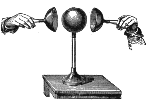
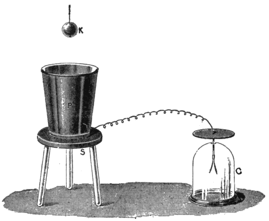
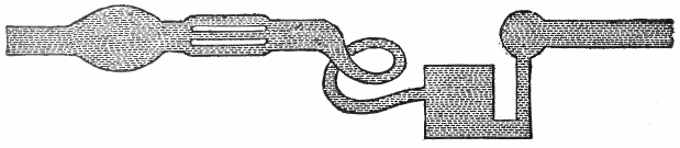
Boit proved that the charge resides on the surface by the following experiment:8
A copper ball was electrified and insulated. Two hollow hemispheres of copper of a larger size, provided with glass handles, were then placed near the sphere, as in fig. 4. So long as they did not touch the sphere, the charge remained on the latter, but if the hemispheres touched the inner sphere, the whole of the electricity passed to the exterior, and when the hemispheres were separated and removed the inner globe was found to be completely discharged.
The distribution of a charge over an insulated sphere of conducting material is uniform, provided the sphere is remote from all other conductors and electrified bodies.
Figs. 5 to 8 show, by the dotted lines, the distribution of a charge for bodies of various shapes. Fig. 6 shows that for elongated bodies, the charge collects at the ends.
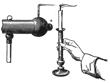
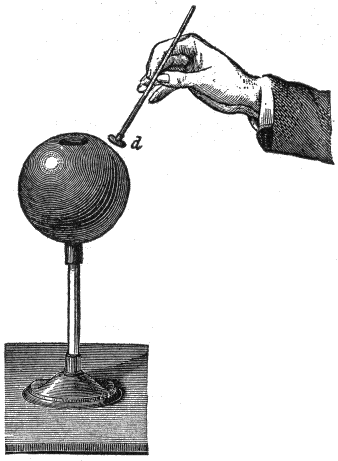
The effects of points is illustrated in fig. 9; when a charged body is provided with a point as here shown, the current accumulates at the point to such a high degree of density that it passes off into the air, and if a lighted candle be held in front of the point, the flame will be visibly blown aside.9
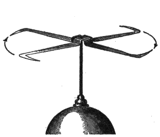
Fig. 10 shows an electric windmill or experimental device for illustrating the escape of electricity from points. It consists of a vane of several pointed wires bent at the tips in the same direction, radiating from a center which rests upon a pivot. When mounted upon the conductor of an electrostatic machine, the vane rotates in a direction opposite that of the points. The movement of the vane is due to the repulsion of the electrified air particles near the points and the electricity on the points themselves. The motion of the air is called electric wind. This device is also called electric flyer, and electric whirl.

“Free” and “Bound” Electricity.—These terms may be defined as follows:
The expression free electricity relates to the ordinary state of electricity upon a charged conductor, not in the presence of a charge of the opposite kind. A free charge will flow away to the earth if a conducting path be provided.
A charge of electricity upon a conductor is said to be bound, when it is attracted by the presence of a neighboring charge of the opposite kind.10
Conductors and Insulators.—The term conductors is applied to those bodies which readily allow electricity to flow through them, in distinction from insulators or so-called non-conductors, which practically allow no flow of electricity.
Strictly speaking, there is no substance which will prevent the passage of electricity, hence, the term non-conductors, though extensively used, is not correct.
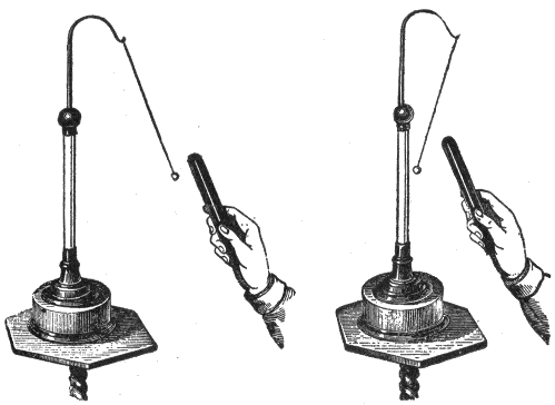
Electroscopes.—These are instruments for detecting whether a body be electrified or not, and indicating also whether the electrification be positive or negative. The earliest electroscope devised consisted of a stiff straw balanced lightly upon a sharp point; a thin strip of brass or wood, or even a goose quill, balanced upon a sewing needle will serve equally well. Another form of electroscope is the pith ball pendulum, shown in figs. 2 and 3. When an electrified body is held near the electroscope it is attracted or repelled thus indicating the presence and nature of the charge.11
Gold Leaf Electroscope.—This form of electroscope, which is very sensitive, was invented by Bennet. Its operation depends on the fact that like charges repel each other.
The gold leaf electroscope as shown in fig. 11, is conveniently made by suspending the two narrow strips of gold leaf within a wide mouthed glass jar, which both serves to protect them from draughts of air and to support them from contact with the ground. A piece of varnished glass tube is pushed through the cork, which should be varnished with shellac or with paraffin wax. Through this passes a stiff brass wire, the lower end of which is bent at a right angle to receive the two strips of gold leaf, while the upper end is attached to a flat plate of metal, or may be furnished with a brass knob.
When kept dry and free from dust it will indicate excessively small quantities of electricity. A rubbed glass rod, even while two or three feet from the instrument, will cause the leaves to repel one another. If the knob be brushed with only a small12 camel’s hair brush, the slight friction produces a perceptible effect. With this instrument all kinds of friction can be shown to produce electrification.
The gold leaf electroscope can be further used to indicate the kind of electricity on an excited body. Thus, if a piece of brown paper be rubbed with a piece of india rubber, the nature of the charge is determined as follows:
First charge the gold leaves of the electroscope by touching the knob with a glass rod rubbed on silk. The leaves diverge, being electrified with positive electrification. When they are thus charged the approach of a body which is positively electrified will cause them to diverge still13 more widely; while, on the approach of one negatively electrified, they will tend to close together. If now the brown paper be brought near the electroscope, the leaves will be seen to diverge more, proving the electrification of the paper to be of the same kind as that with which the electroscope is charged.
The gold leaf electroscope will also indicate roughly the amount of electricity on a body placed in contact with it, for the gold leaves open out more widely when the quantity of electricity thus imparted to them is greater.

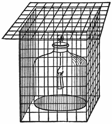
Electric Screens.—That the charge on the outside of a conductor always distributes itself in such a way that there is no electric force within the conductor was first proved experimentally by Faraday. He covered a large box with tin foil14 and went inside with the most delicate electroscopes obtainable. Faraday found that the outside of the box could be charged so strongly that long sparks would fly from it without any electrical effects being observable anywhere inside the box.
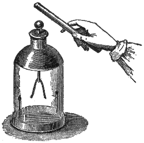
To repeat the experiment in modified form, let an electroscope be placed beneath a bird cage or wire netting, as in fig. 15. Let charged rods or other powerfully charged bodies be brought near the electroscope outside the cage. The leaves will be found to remain undisturbed.
Electrification by Induction.—An insulated conductor, charged with either kind of electricity, acts on bodies in a neutral state placed near it in a manner analogous to that of the action of a magnet on soft iron; that is, it decomposes the neutral electricity, attracting the opposite and repelling the15 like kind of electricity. The action thus exerted is said to take place by influence or induction.
The phenomenon of electrification by induction may be demonstrated by the following experiment:
In fig. 16, let the ebonite rod be electrified by friction and slowly brought toward the knob of the gold leaf electroscope. The leaves will be seen to diverge, even though the rod does not approach to within a foot of the electroscope.
This experiment shows that the mere influence which an electric charge exerts upon a conductor placed in its vicinity is able to produce electrification in that conductor. This method of producing electrification is called electrostatic induction.
As soon as the charged rod is removed the leaves will collapse, indicating that this form of electrification is only a temporary phenomenon which is due simply to the presence of the charged body in the neighborhood.
Nature of the Induced Charge.—This is shown by the experiment illustrated in fig. 17.16
Let a metal ball A be charged by rubbing it with a charged rod, and let it then be brought near an insulated metal cylinder B which is provided with pith balls on strips of paper C, D, E, as shown.
The divergence of C and E will show that the ends of B have received electrical charges because of the presence of A, while the failure of D to diverge will show that the middle of B is uncharged. Further, the rod which charged A will be found to repel C but to attract E.
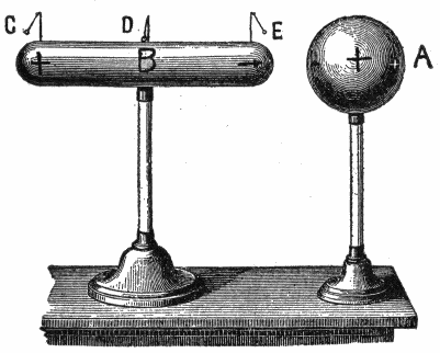
From these experiments, the conclusion is that when a conductor is brought near a charged body, the end away from the inducing charge is electrified with the same kind of electricity as that on the inducing body, while the end toward the inducing body receives electricity of opposite sign.
The Electrophorus.—This is a simple and ingenious instrument, invented by Volta in 1775 for the purpose of procuring, by the principle of induction, an unlimited number of charges of electricity from one single charge.17
It consists of two parts, as shown in fig. 19, a round cake of resinous material B, cast in a metal dish or “sole” about one foot in diameter, and a round disc A, of slightly smaller diameter made of metal or of wood covered with tinfoil, and provided with a glass handle. Shellac, or sealing wax, or a mixture of resin shellac and Venice turpentine, may be used to make the cake.

To use the electrophorus, the resinous cake B must be first beaten or rubbed with fur or a woolen cloth, the disc A is then placed on the cake, touched with the finger and then lifted by the handle. The disc will now be found to be charged and will yield a spark when touched with the hand, as in fig. 19.
The “cover” may be replaced, touched, and once more removed, and will thus yield any number of sparks, the original18 charge on the resinous plate meanwhile remaining practically as strong as before.
The theory of the electrophorus is very simple, provided the student has clearly grasped the principle of induction.

When the resinous cake is first beaten with the cat’s skin its surface is negatively electrified, as indicated in fig. 20. Again, when the metal disc is placed down upon it, it rests really only on three or four points of the surface, and may be regarded as an insulated conductor in the presence of an electrified body. The negative electrification of the cake therefore acts inductively on the metallic disc or “cover,” attracting a positive charge to its under side, and repelling a negative charge to its upper surface, as shown in fig. 21.19
If, now, the cover be touched for an instant with the finger, the negative charge of the upper surface (which is upon the upper surface being repelled by the negative charge on the cake) will be neutralized by electricity flowing in from the earth through the hand and body of the experimenter. The attracted positive charge will, however remain being bound as it were by its attraction towards the negative charge on the cake.

Fig. 22 shows the result after the cover has been touched. If, finally, the cover be lifted by its handle, the remaining positive charge will no longer be “bound” on the lower surface by attraction, but will distribute itself on both sides of the cover, and may be used to give a spark. It is clear that no20 part of the original charge has been consumed in the process, which may be repeated as often as desired. As a matter of fact, the charge on the cake slowly dissipates—especially if the air be damp. Hence it is needful sometimes to renew the original charge by again beating the cake with the cat’s skin.
The labor of touching the cover with the finger at each operation may be saved by having a pin of brass or a strip of tinfoil projecting from the metallic “sole” on to the top of the cake, so that it touches the plate each time, and thus neutralizes the negative charge by allowing electricity to flow in from the earth.21

Since the electricity thus yielded by the electrophorus is not obtained at the expense of any part of the original charge, it is a matter of some interest to inquire whence is the source from which the energy of this apparently unlimited supply is drawn;22 for it cannot be called into existence without the expenditure of some other form of energy. The fact is, more work is done in lifting the cover when it is charged with the positive electricity than when it is not charged; for when charged, there is the force of the electric attraction to be overcome as well as the force of gravity; this excess force is the real origin of the energy stored up in the separate charges.
Condensers; Leyden Jar.—A condenser is an apparatus for condensing a large quantity of electricity on a comparatively small surface. The form may vary considerably, but in all cases it consists essentially of two insulated conductors, separated by an insulator and the working depends on the action of induction.
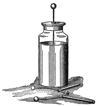
A form of condenser generally used in making experiments on static electricity is the Leyden jar, so named from the town23 of Leyden where it was invented. It consists of a glass jar coated inside and out to a certain height with tinfoil, having a brass rod terminating in a knob passed through a wooden stopper, and connected to the inner coat by a loose chain, as shown in fig. 30.
The jar may be charged by repeatedly touching the knob with the charged plate of the electrophorus or by connecting the inner coating to one knob of an electrical machine and the outer coating to the other knob.
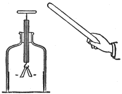
The discharge of a condenser is effected by connecting the plates having an opposite charge. This may be done by use of a wire or a discharger, as shown in fig. 31; the connection is made between the outer coat and the knob.
When the knob of the discharger is sufficiently close to the knob of the jar, a bright spark will be observed between the knobs. This discharge occurs whenever the difference of potential between the coats is great enough to overcome the resistance of the air between the knobs.
Let a charged jar be placed on a glass plate so as to insulate the outer coat. Let the knob be touched with the finger. No appreciable discharge will be noticed. Let the outer coat be in turn touched with the finger. Again no appreciable discharge will appear. But if the inner and outer coatings be connected with the discharger, a powerful spark will pass.
Electric Machines.—Various machines have been devised for producing electric charges such as have been described. The ordinary “static” or electric machine, is nothing but a continuously acting electrophorus.
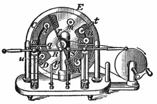
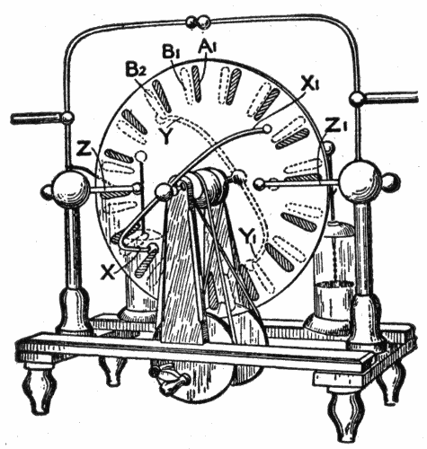
Fig. 32 represents the so-called Toepler-Holtz machine. Upon the back of the stationary plate E, are pasted paper sectors, beneath which are strips of tinfoil AB and CD called inductors.
In front of E is a revolving glass plate carrying discs l, m, n, o, p and q, called carriers.24
To the inductors AB and CD are fastened metal arms t and u, which bring B and C into electrical contact with the discs l, m, n, o, p and q, when these discs pass beneath the tinsel brushes carried by t and u.
A stationary metallic rod rs carries at its ends stationary brushes as well as sharp pointed metallic combs.
The two knobs R and S have their capacity increased by the Leyden jars L and L′.
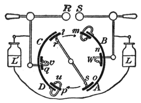
Action of the Toepler-Holtz Machine.—The action of the machine described above is best understood from the diagram of fig. 33. Suppose that a small + charge is originally placed on the inductor CD. Induction takes place in the metallic system consisting of the discs l and o and the rod rs, l becoming negatively charged and o positively charged. As the plate carrying l, m, n, o, p, q rotates in the direction of the arrow the negative charge on l is carried over to the position m, where a part of it passes over to the inductor AB, thus charging it negatively.
When l reaches the position n the remainder of its charge, being repelled by the negative electricity which is now on AB, passes over into the Leyden jar L.25
When l reaches the position o it again becomes charged by induction, this time positively, and more strongly than at first, since now the negative charge on AB, as well as the positive charge on CD, is acting inductively upon the rod rs.
When l reaches the position u, a part of its now strong positive charge passes to CD, thus increasing the positive charge upon this inductor.
In the position v the remainder of the positive charge on l passes over to L′. This completes the cycle for l. Thus as the rotation continues AB and CD acquire stronger and stronger charges, the inductive action upon rs becomes more and more intense, and positive and negative charges are continuously imparted to L′ and L until a discharge takes place between the knobs R and S.
There is usually sufficient charge on one of the inductors to start the machine, but in damp weather it will often be found necessary to apply a charge to one of the inductors by means of the ebonite or glass rod before the machine will work.
The Wimshurst Machine.—The essential parts of an ordinary Wimshurst machine, as shown in fig. 34, are two insulating plates or drums. On each plate are fixed a large number of strips of conducting material, which are equal in size and are equally spaced—radially if on a plate, and circumferentially if on a drum. The plates, or drums, are made to rotate in opposite directions. The capacity of the inductors therefore varies from a maximum when each strip on one plate is facing a strip on the other, to a minimum when the conducting strips on each plate are facing blank or insulating portions of the other plate.26
There are three pairs of contact brushes, the members of two of the pairs being at opposite ends of diametrical conducting rods placed at right angles to one another; the third pair are insulated from one another and form the principal collectors, the one giving positive and the other negative electricity.
The plates are revolving in opposite directions; thus if there be a charge on one of the conducting segments of one plate and an opposite charge on one of the conducting segments on the other plate near it, their potential will be raised as the rotation of the plates separates them.[2]
The ordinary statement that an electric current is flowing along a wire is only a conventional way of expressing the fact that the wire and the space around the wire are in a different state from that in which they are when no electric current is said to be flowing.
In order to make laymen understand the action of this so called current, it is generally compared with the flow of water.
In comparing hydraulics and electricity, it must be borne in mind, however, that there is really no such thing as an “electric fluid,” and that water in pipes has mass and weight, while electricity has none. It should be noted, however, that electricity is conveniently spoken of as having weight in explaining some of the ways in which it manifests itself.
All electrical machines and batteries are merely instruments for moving electricity from one place to another, or for causing electricity, when accumulated in one place, to do work in returning to its former level of distribution.
The head or pressure in a standpipe is what causes water to move through the pipes which offer resistance to the flow.
Similarly, the conductors, along which the electric current is said to flow, offer more or less resistance to the flow, depending28 on the material. Copper wire is generally used as it offers little resistance.
The current must have pressure to overcome the resistance of the conductor and flow along its surface. This pressure is called voltage caused by what is known as difference of potential between the source and terminal.
The pressure under which a current flows is measured in volts and the quantity that passes in amperes. The resistance with which the current meets in flowing along a conductor is measured in ohms.
Ques. What is a volt?
Ans. A volt is that electromotive force (E. M. F.) which produces a current of one ampere against a resistance of one ohm.29
Ques. What is an ampere?
Ans. An ampere is the current produced by an E. M. F. of one volt in a circuit having a resistance of one ohm. It is that quantity of electricity which will deposit .005084 grain of copper per second.
Ques. What is an ohm?
Ans. An ohm is equal to the resistance offered to an unvarying electric current by a column of mercury at 32° Fahr., 14.4521 grams in mass, of a constant cross sectional area, and of the length of 106.3 centimeters.
Ohm’s Law.—In a given circuit, the amount of current in amperes is equal to the E. M. F. in volts divided by the resistance in ohms; that is:
expressed as a formula:
in which
From (1) is derived the following:
From (1) it is seen that the flow of the current is proportional to the voltage and inversely proportional to the resistance; the latter depends upon the material, length and diameter of the conductor.
Since the current will always flow along the path of least resistance; it must be so guarded that there will be no leakage. Hence, to prevent leakage, wires are insulated, that is, covered by wrapping them with cotton or silk thread or other insulating material. If the insulation be not effective, the current may leak, and so return to the source without doing its work. This is known as a short circuit.
The conductor which receives the current from the source is called the lead, and the one by which it flows back, the return.
When wires are used for both lead and return, it is called a metallic circuit: when the ground is used for the return, it is called a ground circuit. An electric current is said to be:
A high tension current is capable of forcing its way against considerable resistance, whereas, a low tension current must have its path made easy.
Production of the Electric Current.—To produce a steady flow of water in a pipe two conditions are necessary. There must first be available a hydraulic pressure, or, as it is31 technically called, a “head” of water produced by a pump, or a difference of level or otherwise.
In addition to the pressure there must also be a suitable path or channel provided for the water to flow through, or there will be no flow, however great the “head,” until something breaks down under the strain. In the case just cited, although there is full pressure in the water in the pipe, there is no current of water as long as the tap remains closed. The opening of the tap completes the necessary path (the greater part of which was already in existence) and the water flows.
For the production of a steady electric current two very similar conditions are necessary. There must be a steadily maintained electric pressure, known under different aspects as “electromotive force,” “potential difference,” or “voltage.” This alone, however, is not sufficient. In addition, a suitable conducting path is necessary. Any break in this path occupied by unsuitable material acts like the closed tap in the analogous case above mentioned, and it is only when all such breaks have32 been properly bridged by suitable material, that is, by conductors, that the effects which denote the flow of the current will begin to be manifested.
The necessary electromotive force or voltage required to cause the current to flow may be obtained:
In the first method, two dissimilar metals such as copper and zinc called elements, are immersed in an exciting fluid or electrolyte.
When the elements are connected at their terminals by a wire or conductor a chemical action takes place, producing a current which flows from the copper to the zinc. This device is called a cell, and the combination of two or more of them connected so as to form a unit is known as a battery. The word battery is frequently used incorrectly for a single cell. That terminal of the element from which the current flows is called the plus or positive pole, and the terminal of the other element the negative pole.
Cells are said to be primary or secondary according as they generate a current of themselves, or first require to be charged from an external33 source, storing up a current supply which is afterwards yielded in the reverse direction to that of the charging current.
An electric current is generated mechanically by a dynamo. In either case no electricity is produced, but part of the supply already existing is simply set in motion by creating an electric pressure.
An electric current, according to the third method, is generated directly from heat energy, as will be later explained; the current thus obtained is very feeble.
Strength of Current.—It is important that the reader have a clear conception of this term, which is so often used. The exact definition of the strength of a current is as follows:
The strength of a current is the quantity of electricity which flows past any point of the circuit in one second.
Example.—If, during 10 seconds, 25 coulombs of electricity flow through a circuit, then the average strength of the current during that time is 21⁄2 coulombs per second, or 21⁄2 amperes.34
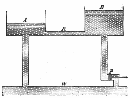
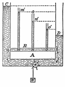
Voltage Drop in an Electric Circuit.—A difference of potential exists between any two points on a conductor through which a current is flowing on account of the resistance offered to the current by the conductor.
For instance, in the electrical circuit shown in fig. 39, the potential at the point a is higher than that at m, that at m higher than that at n, etc., just as in the water circuit, shown in fig. 38, the hydrostatic pressure at a is greater than that at m′, that at m′ greater than that at n′, etc. The fall in the water pressure between m′ and n′ (fig. 38) is measured by the water head n’s.
In order to measure the fall in electrical potential between m and n, (fig. 39), the terminals of a volt meter are placed in contact with these points as shown. Its reading will give the difference of potential between m and n, in volts, provided that its own current carrying capacity is so small that it does not appreciably lower the potential difference between the points m and n by being touched across them; that is, provided the current which flows through it is negligible in comparison with that which flows through the conductor which already joins the points m and n.
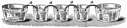
The word “battery” is a much abused word, being often used incorrectly for “cell,” as in fig. 40. Hence, careful distinction should be made between the two terms.
A battery consists of two or more cells joined together so as to form a single unit.
There are numerous forms of primary cell; they may be classified as follows:
1. According to the service for which they are designed;
2. According to the chemical features.
With respect to the first method cells are classified as:
1. Open circuit cells;
Used for intermittent work, where the cell is in service for short periods of time, such as in electric bells, signaling work, and electric gas lighting. If kept in continuous service for any length of time the cell soon polarizes or “runs down,” but will recuperate after remaining on open circuit for some little time.
2. Closed circuit cells.
This type of cell is adapted to furnishing current continuously, as in telegraphy, etc.
With respect to the second method, cells are classified as:
Ques. Describe a primary cell.
Ans. A primary cell consists of a vessel containing a liquid in which two dissimilar metal plates are immersed.
In one fluid cells both metal plates are immersed in the same solution. In two fluid cells each metal plate is immersed in a separate solution, one of which is contained in a porous cup which is immersed in the other liquid.
Ques. What name is given to the metal plates?
Ans. They are called elements.
Ques. What is the fluid called?
Ans. The electrolyte or exciting fluid.
The term “electropoion” is a trade name for the electrolyte employed in the Fuller cell.
Action of a Primary Cell.—The fundamental fact on which the electro-chemical generation of current depends is, that if a plate of metal be placed in a liquid there is a difference of electrical condition produced between them of such sort that the metal either takes a lower or higher electrical potential than the liquid, according to the nature of the metal and the liquid. If two different metals be placed in one electrolytic liquid, then there is a difference of state produced between them, so that, if joined by wire outside the liquid, a current of electricity will traverse the wire. This current proceeds in the liquid from the metal which is most acted upon chemically to that which is least acted upon.
Referring to fig. 41, the construction and action of a simple primary cell may be briefly described as follows:
Place in a glass jar some water having a little sulphuric or other acid added to it. Place in it separately two clean strips, one of zinc, Z, and one of copper, C. This cell is capable of supplying a continuous flow of electricity through a wire whose37 ends are brought into connection with the two strips. When the current flows, the zinc strip is observed to waste away, its consumption in fact furnishing the energy or electromotive force required to drive the current through the cell and the connecting wire. The cell may therefore be regarded as a kind of chemical furnace in which the fuel is the zinc.
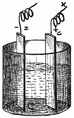
Ques. How are the positive and negative elements of a primary cell distinguished?
Ans. The plate attacked by the electrolyte is the negative element, and the one unattacked the positive element.
Chemical Changes; Polarization.—The chemical changes which take place in a simple cell, consisting of zinc and copper elements in an electrolyte of dilute sulphuric acid, may be briefly38 described as follows: When the two elements are connected and the current commences to flow, the sulphuric acid acts on the surface of the zinc plate and forms sulphate of zinc. The formation of this new substance necessitates the liberation of some of the hydrogen contained in the sulphuric acid, and it will be found that bubbles of free hydrogen gas speedily appear on the surface of the negative element, that is, on the copper plate.
While the zinc is being dissolved to form zinc sulphate, hydrogen gas is liberated from the sulphuric acid.

Some bubbles of the gas rise to the surface of the electrolyte and so escape into the air, but much of it clings to the surface of the copper element which thus gradually becomes covered with a thin film of hydrogen.
Partly on account of the decreased area of copper plate in contact with the electrolyte, and partly because the hydrogen tends to produce a current in the opposite direction, the useful electrical output becomes considerably diminished and the cell is said to be polarized. This state of affairs may be rectified39 by stirring up the electrolyte, or by shaking the cell, so as to assist the hydrogen bubbles to detach themselves from the surface of the copper plate and make their way to the atmosphere through the electrolyte. This, however, is only a temporary remedy, as the polarized condition will soon be reached again, and a further agitation of the cell will be necessary. Hence, a simple cell of this kind is not desirable for practical work, and it must be modified to adapt it to constant use.
When the sulphuric acid in a cell acts in the zinc element and produces sulphate of zinc, a certain amount of work is done which is manifested partly in the form of useful electric energy, and partly as heat which warms the electrolyte and which is thereby lost for all practical purposes.
Ques. If the zinc and copper electrodes of a simple cell be not connected externally what changes take place within the cell?
Ans. The zinc plate immediately becomes strongly charged with negative electricity, and the copper plate weakly so. As long as the plates remain unconnected, and the zinc is pure, no further action takes place.
Ques. If the electrodes be connected externally what happens?
Ans. If the plates be connected by a wire outside the electrolyte, the tendency which dissimilar electrical charges have to neutralize one another causes a flow of negative electricity through the wire from zinc to copper, and a positive flow in the opposite direction. The “static” charge being thus disposed of, a fresh charge is given to the plates by the action of the acid, which commences to dissolve the zinc. As long as the wire connects the copper and zinc plates, the acid will continue its action on the zinc until either acid or zinc is exhausted.40
The reader may ask: how can there be a positive flow when both plates are negatively electrified?
An analogy is the best way to make this point clear: Imagine two equal vessels, from each of which the air has been partially exhausted, but from one (A) 10 times as much air has been taken as from the other (B). Connect A and B by a tube. Now, although both vessels have less than the atmospheric pressure, that is, both have “negative” pressures, yet a current of air will flow from B to A until the pressures in each are equalized; that is, until both have equal “negative charges” of air.
There is a second important effect of the acid solution or electrolyte in a cell. If pure sulphuric acid were used, the first action or production of an electrical charge on the zinc plate would be the same, but when the plates were joined by the wire the current would soon cease. The reason for this lies in the fact that the sulphate of zinc, which is the compound produced by the acid plus the zinc, being insoluble in pure undiluted sulphuric acid, remains on the surface of the zinc plate. The coating of sulphate of zinc thus formed also operates as a protective agent, and no further electrical charge can be induced until it is removed. The addition of water to the acid has the effect of allowing the sulphate of zinc to dissolve, and the zinc plate is left free for further action.
Ques. What governs the rate of current flow of a primary cell?
Ans. The size of the elements and their proximity.
Effects of Polarization.—The film of hydrogen bubbles affects the strength of the current of the cell in two ways:
1. It weakens the current by the increased resistance which it offers to the flow, for bubbles of gas are bad conductors;
2. It weakens the current by setting up an opposing electromotive force41.
Hydrogen is almost as oxidizable a substance as zinc, especially when freshly deposited (in the “nascent” state), and is electro-positive; hence, the hydrogen itself produces a difference of potential, which would tend to start a current in the opposite direction to the true zinc-to-copper current. It is therefore an important matter to abolish this polarization, otherwise the currents furnished by batteries would not be constant.
Methods of Depolarizing.—One of the chief aims in the arrangement of the numerous cells which have been devised is to avoid polarization. The following are the methods usually employed:
1. Chemical methods;
a. Oxidation of the hydrogen by potassium bichromate and by nitric acid.
b. Substitution of the hydrogen by some other substance which does not give a counter electromotive force of polarization; for instance, in the Daniell cell by replacement of the copper in copper sulphate by the hydrogen, the copper being deposited on the positive pole.
2. Electro-chemical means;
It is possible by employing double cells, to secure such action that some solid metal, such as copper, shall be liberated instead of hydrogen bubbles, at the point where the current leaves the liquid. This electro-chemical exchange obviates polarization.
3. Mechanical methods.
a. Agitation of the liquid or of the positive electrode, in order to prevent the accumulation of hydrogen thereon.
b. Corrugating or roughing the positive electrode, as in the Smee cell. This causes the hydrogen gas to form in large bubbles which rise to the surface more rapidly than the small bubbles which form on a smooth electrode.
In the simplest form of cell, as zinc, copper, and dilute sulphuric acid, no attempt has been made to prevent the evil of polarization, hence, it will quickly polarize when the current is closed for any length of time, and may be classified as an open circuit cell.42
When polarization is remedied by chemical means, the chemical added is one that has a strong affinity for hydrogen and will combine with it, thus preventing the covering of the negative plate with the hydrogen gas.
Ques. What is a depolarizer?
Ans. A substance employed in some types of cell to combine with the hydrogen which would otherwise be set free at the positive electrode and cause polarization.43
The chemical used for this purpose may be either in a solid or liquid form, which gives rise to several types of cell, such as cells with a single fluid, containing both the acid and the depolarizer, cells with a single exciting fluid and a solid depolarizer, and cells with two separate fluids.
In the two fluid cell, the zinc is immersed in the liquid (frequently dilute sulphuric acid) to be decomposed by the action upon it, and the negative plate is surrounded by the liquid depolarizer, which will be decomposed by the hydrogen gas it arrests, thereby preventing polarization.
In open circuit cells polarization does not have much opportunity to occur, since the circuit is closed for such a short period of time; hence, these cells are always ready to deliver a strong current when used intermittently.
In closed circuit cells polarization is prevented by chemical action, so that the current will be constant and steady till the energy of the chemicals is expended.
Ques. What is a depolarizer bag?
Ans. A cylinder of hemp or other fabric used in place of a porous pot in some forms of Leclanche cell, and also as a support for the depolarizing mass in some forms of dry cell where the electrolyte is of a thin gelatinous nature.
Volta’s Contact Law.—When metals differing from each other are brought into contact, different results are obtained, both as to the kind of electrification as well as the difference of potentials.
Volta found that iron, when in contact with zinc, becomes negatively electrified; the same takes place, but somewhat weaker, when iron is touched with lead or tin. When, however, iron is touched by copper or silver, it becomes positively electrified. Volta, Seebeck, Pfaff, and others have investigated the behavior of many metals and alloys when in contact with each other.44
The following lists are so arranged that those metals first in each list become positively electrified when touched by any taking rank after them:
| According to Volta. | According to Pfaff. | ||
| + | zinc | + | zinc |
| lead | cadmium | ||
| tin | tin | ||
| iron | lead | ||
| copper | tungsten | ||
| silver | iron | ||
| gold | bismuth | ||
| graphite | antimony | ||
| - | manganese ore | copper | |
| silver | |||
| gold | |||
| uranium | |||
| tellurium | |||
| platinum | |||
| - | palladium | ||
Volta laid down a law regarding the position of the metals in his table which may be stated as follows:
The difference of potential between any two metals is equal to the sum of the differences of potentials of all the intermediate members of the series.
Hence, it is immaterial for the total effect whether the first and the last are brought into contact directly, or whether the contact is brought about by means of all or any of the intermediate metals.
Volta’s law further asserts that when any number of metals are brought into contact with each other, but so that the chain closes with the metal with which it was begun, the total difference must be zero.45
Laws of Chemical Action in the Cell.—There are two simple laws of chemical action in the cell:
1. The amount of chemical action in a cell is proportional to the quantity of electricity that passes through it.
One coulomb of electricity in passing through the cell liberates .000010352 of a gramme of hydrogen, and causes .00063344 of a gramme of zinc to dissolve in the acid.
2. The amount of chemical action is equal in each cell of a battery connected in series.
Requirements of a Good Cell.—The several conditions which should be fulfilled by a good cell are as follows:
Single and Two Fluid Cells.—The distinction between a single and a two fluid cell has already been given. The single fluid cell of Volta with its zinc and copper plates represents the simplest form of primary cell.
In the two fluid cell, the positive (zinc) plate is immersed in the exciting liquid (usually dilute sulphuric acid) and is decomposed by the action upon it, while the negative plate is placed in the liquid depolarizer which is decomposed by the hydrogen arrested by it, thus preventing polarization.
In some forms of cell, the two liquids are separated by a porous partition of unglazed earthenware, which, while it prevents46 the liquids mixing except very slowly, does not prevent the passage of hydrogen and electricity.
Complete depolarization is usually obtained also in single fluid cells, having in addition a depolarizing solid body, such as oxide of manganese, oxide of copper, or peroxide of lead, in contact with the carbon pole. Such cells really do not belong47 to the single fluid cells, and are considered in the two fluid class.
A few examples of single and double fluid primary cells will now be described.
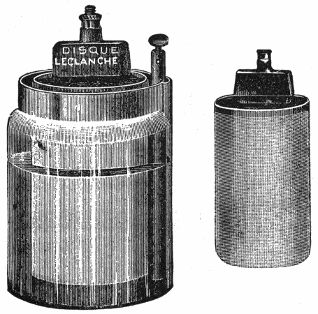
The Leclanche Cell.—This cell was invented by Leclanche, a French electrician, and was the first cell in which sal-ammoniac was used. This form of cell, as shown in fig. 45, is in general use for electric bells, its great recommendation being that, once charged, it retains its power without attention for considerable time.
Two jars are employed in its construction; the outer one is of glass, contains a zinc rod, and is charged with a solution of ammonium chloride, called sal-ammoniac.
The inner jar is of porous earthenware, containing a carbon plate, and is filled with a mixture of manganese peroxide and broken gas carbon. When the carbon plate and the zinc rod are connected, a steady current of electricity is set up, the chemical action which takes place being as follows: the zinc becomes oxidized by the oxygen from the manganese peroxide, and is subsequently converted into zinc chloride by the action of the sal-ammoniac.
After the battery has been in continuous use for some hours, the manganese becomes exhausted of oxygen, and the force of the electrical current is greatly diminished; but if the battery be allowed to rest for a short time, the manganese obtains a fresh supply of oxygen from the atmosphere, and is again fit for use.
After about 18 months work, the glass cell will probably require recharging with sal-ammoniac, and the zinc rod may also need renewing; but should the porous cell get out of order, it is better to get a new one than to attempt to recharge it.48
The directions for setting up a Leclanche cell are as follows:
The Leclanche cell is adapted to open circuit work, being extensively used for ringing electric bells.
The objections to the Leclanche cell are:
Fuller Bichromate Cell.—In the bichromate cells or the chromic acid cells, bichromate of soda, or bichromate of potassium, is used for the depolarizer, water and sulphuric acid being added for attacking the zinc.
The Fuller cell is of the two fluid type. A pyramidal block of zinc at the end of a metallic rod covered with gutta-percha is placed in the bottom of a porous cup containing an ounce of mercury. The cup is then filled with a very dilute solution of sulphuric acid or water and placed in a jar of glass or earthenware containing the bichromate solution and the carbon plate. The diffusion of the acid through the porous cup is sufficiently rapid to attack the zinc, which being well amalgamated, prevents local action; while the hydrogen passes through the porous cup and combines with the oxygen in the bichromate of potassium.49 This type of cell has an electromotive force of 2.14 volts, and is suited to open circuit, or semi-closed circuit work. The directions for setting up a Fuller cell are as follows:

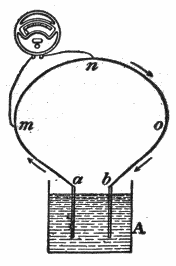
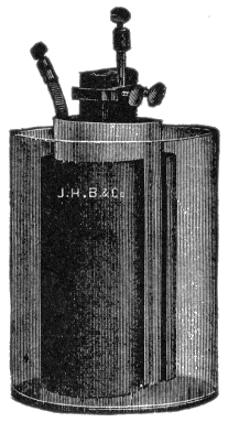
The Edison Cell.—This is a single fluid cell with a solid depolarizer, as shown in fig. 48, and is well adapted for use on closed circuits.

The positive element is zinc, and the negative element black oxide of copper. The exciting fluid is a solution of caustic potash. The black oxide of copper plates are suspended from the cover of the jar by a light framework of copper, one end of51 which forms the positive pole of the battery. A zinc plate is suspended on each side of the copper oxide element and kept from coming in contact with the latter by means of vulcanite buttons.
When the cell is in action, the water is decomposed, and the oxygen thus liberated combines with the zinc and forms oxide of zinc, which combines with the potash to form a double salt of zinc and potash. The last combination dissolves as rapidly as it is formed. The hydrogen liberated by the decomposition of the water reduces the copper oxide to pure metallic copper. It is highly important that the copper oxide plates be completely submerged in the solution of caustic potash, and that heavy paraffin oil be poured on top of the solution to the depth of about 1⁄4 of an inch to exclude the air. If oil be not used, the formation of creeping salts will reduce the life of the battery fully two-thirds. The battery has a low electromotive force, about 0.7 of a volt, but as the internal resistance is also very low, quite a large current can be drawn from the cell.
The Bunsen Cell, shown in figs. 49 and 50, is a two fluid cell constructed with zinc and carbon electrodes. The negative plate is carbon, the positive plate amalgamated zinc. The excitant is a dilute solution of sulphuric acid. The top part of the carbon is sometimes impregnated with paraffin (to keep the acid from creeping up).
The force of the Bunsen cell increases after setting up for about an hour, and the full effect is not attained until the acid soaks through the porous cell. Carbons are not affected and last any length of time. The zinc is slowly consumed through the mercury coating.
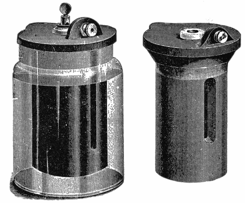
Grenet Bichromate Cell.—In this cell, as shown in figs. 49 and 50, the positive element is zinc and the negative element carbon.52 The electrolyte is a solution of bichromate of potash in a mixture of sulphuric acid and water.
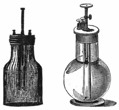
The cell consists of a glass bottle containing the electrolyte and fitted with a lid from which the elements are supported. There is a zinc plate in the center and a carbon plate on each side. The two carbon plates are connected to the same terminal, thus forming a large negative surface, and the zinc plate to a terminal on the top of the brass rod to which it is attached.53 This rod slides through a hole in the lid so that the zinc plate can be lifted out of the electrolyte when the cell is not at work, thus preventing wasteful consumption of zinc and of the electrolyte. Bichromate cells give a strong current, the electromotive force of a single cell being 2 volts.
Daniell Cell.—This is one of the best known and most widely used forms of primary cell. It is a double fluid cell, composed of an inner porous vessel containing an electrolyte of either54 dilute sulphuric acid or dilute zinc sulphate solution, and an outer vessel containing a saturated solution of copper sulphate.
A zinc rod is placed in the inner electrolyte, and a thin plate of sheet copper in the outer electrolyte. Sometimes this arrangement of the elements is modified, the outer vessel being made of copper and serving as the copper plate. This would then contain the copper sulphate solution, while the zinc sulphate and the zinc rod would be contained in the porous pot as before.
The chemical reactions which take place in a Daniell cell are as follows:
The zinc dissolves in the dilute acid, thus producing zinc sulphate, and liberating hydrogen gas. The free hydrogen passes through the walls of the porous pot, but when it reaches the copper sulphate solution it displaces some of the copper therefrom, and combines with this solution, forming sulphuric acid. The copper, which is thus set free, is deposited on the surface of the copper plate. In this way polarization is avoided, and a practically constant current is obtained.
When the zinc sulphate solution is employed in place of dilute acid, a similar series of chemical reactions occur, except that the zinc is liberated instead of hydrogen.
Daniell cells are used especially for electroplating, electrotyping and telegraphic work. The electromotive force of a single cell is 1.079 volts.
Directions for Making a Daniell Cell.—The simple Daniell cell shown in fig. 52 may be easily made as follows: The outer vessel A, consists of a glass jar (an ordinary glass jam jar will do) containing a solution of sulphuric acid (1 part in 12 to 20 parts of water), and a zinc rod B.
Inside the jar is placed a porous pot C containing a strip of thin sheet copper D, and a saturated solution of sulphate of copper (also called “blue stone” and “blue vitrol”).
The zinc is preferably of the Leclanche form, which will be55 found to be cleaner, more durable, and cheaper than a zinc sheet. The porous pot should be dipped in melted paraffin wax, both top and bottom, to prevent the solution mingling too freely and “creeping.” A few crystals of copper sulphate are placed in the pot as shown.
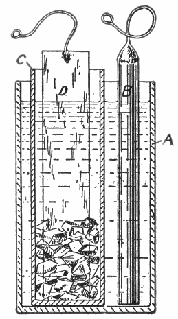
In mixing the sulphuric acid and water, the acid should be added to the water—never the reverse. Zinc sulphate is sometimes used instead, as it reduces the wasteful consumption of the zinc, but it should be pure.
With care the cell will last for weeks. When it weakens or “runs down,” an addition of sulphuric acid to the outer jar and56 a few more crystals placed in the porous pot will put the cell in good condition.
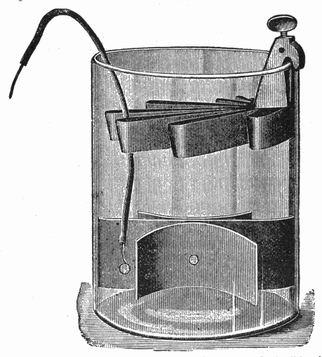
Gravity Cells.—In a two liquid cell, instead of employing a porous cell to keep the two liquids separate, it is possible, where one of the liquids is heavier than the other, to arrange that the heavier liquid shall form a stratum at the bottom of the cell, the lighter floating upon it. Such arrangements are called gravity cells; but the separation is never perfect, the heavy liquid slowly diffusing upwards.57
Daniell Gravity Cell.—In this cell, shown in fig. 53, the same elements are used as in the ordinary Daniell cell, but the porous pot is dispensed with, the two solutions being separated by the action of gravity as explained in the preceding paragraph.
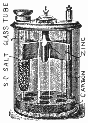
The copper sulphate solution, being the heavier of the two, rests at the bottom of the battery jar, while the dilute sulphuric acid remains at the top. To suit this arrangement the copper and zinc elements are located as shown, the copper elements58 being at the bottom, and the zinc element, shaped like a crow’s foot (hence the name “crowfoot cell”) is suspended at the top.
The absence of the porous pot decreases the internal resistance, but the electromotive force is the same as in the ordinary type of Daniell cell.

When a current is produced by a Daniell cell:
If, however, the copper sulphate solution be too weak, the water is decomposed instead of the copper sulphate, and hydrogen is deposited on the copper plate. This deposit of hydrogen lowers the voltage, hence care should be taken to maintain an adequate supply of copper sulphate.
The voltage of a Daniell cell varies from about 1.07 volt to 1.14 volt, according to the density of the copper sulphate solution and the amount of zinc sulphate present in the dilute sulphuric acid.
“Dry” Cells.—It is often necessary to use cells in places where there is considerable jarring or motion, as for automobile or marine ignition. The ordinary cell is not well adapted to this service on account of the liability of spilling the electrolyte, hence, the introduction of the so-called dry cell.
A dry cell is composed of two elements, usually zinc and carbon, and a liquid electrolyte. A zinc cup closed at the bottom and open at the top forms the negative electrode; this is lined with several layers of blotting paper or other absorbing material.
The positive electrode consists of a carbon rod placed in the center of the cup; the space between is filled with carbon—ground coke and dioxide of manganese mixed with an absorbent material. This filling is moistened with a liquid, generally sal-ammoniac. The top of the cell is closed with pitch to prevent leakage and evaporation. A binding post for holding the wire connections is attached to each electrode and each cell is placed in a paper box to protect the zincs of adjacent cells from coming into contact with each other when finally connected together to form a battery.60
Points Relating to Dry Cells.—The following instructions on the care and operation of dry cells should be carefully noted and followed to get the best results:


Points Relating to the Care of Cells.—To get the best results from primary cells, they should receive proper attention and be maintained in good condition. The instructions here given should be carefully followed.

Cleanliness.—In the care of batteries, cleanliness is essential in order to secure best results. Zincs and coppers should be thoroughly cleaned every time a cell is taken out of use. The zinc, after being thoroughly cleaned, should be rubbed with a little mercury. This prevents local action. Porous cups should be soaked in clean water four or five hours and then wiped dry.
The terminals of each cell should be thoroughly cleansed and scraped bright so as to get good contact of the connecting wires and thus avoid extra resistance in the circuit.63
Separating the Elements.—Obviously the positive and negative elements of a cell must not be in contact within the exciting fluid; they should be separated by a space of 3⁄8 to 1⁄2 inch. In the case of cells without porous cups, periodic attention must be given to ensure this condition being maintained.

Creeping.—As evaporation of the electrolyte takes place in a cell, it increases in strength, and crystals are left on the sides of the jar previously wetted by the solution, the action being very marked when the solution is a saturated one. The space between these crystals and the side of the jar acts as a number of capillary tubes, and draws up more liquid, which itself evaporates and deposits crystals above the former ones. So that finally the film of crystals passes over the edge of the jar and forms on the outside, thus making a kind of syphon which draws off the liquid. This action may, to a great extent, be prevented by warming the edges of the glass, or stoneware, jars, and of the porous pots, before the cells are made up, and dipping them while warm into some paraffin wax melted in64 warm oil, a precaution that should always be carried out when a dense solution of zinc sulphate is employed in the cell.
Amalgamated Zinc.—To “amalgamate” a piece of zinc, dip it into dilute sulphuric acid to clean its surface, then rub a little mercury over it by means of a piece of rag tied on to the end of a stick, and lastly, leave the zinc standing for a short time in a dish to catch the surplus mercury as it drains off.

The action of the amalgamated zinc is not well understood; by some it is considered that amalgamating the zinc prevents local currents by the amalgam mechanically covering up the impurities on the surface of the zinc and preventing their coming into contact with the liquid. By others it is thought that amalgamating the zinc protects it from local action by causing a film of hydrogen gas to adhere to it. This theory is based on65 the fact that while no action takes place when amalgamated zinc is placed in dilute sulphuric acid at ordinary atmospheric pressure, the creation of a vacuum above the liquid causes a rapid evolution of hydrogen, which, however, stops on the readmission of the air.
Amalgamating a zinc causes it to act as a somewhat more positive substance than before, therefore the voltage of a cell containing amalgamated zinc is slightly higher than that of a cell constructed with unamalgamated zinc.
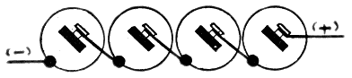
The addition of a very small amount of zinc to mercury causes the mercury to act as if it were zinc alone, arising perhaps from the amalgam having the effect of bringing the zinc to the surface.
Battery Connections.—There are three methods of connecting cells to form a battery; they may be connected:
A series connection consists in joining the positive pole of one cell to the negative pole of the other, as shown in fig. 72; this adds the voltage of each cell.
Thus, connecting in series four cells of one and one-half volts each will give a total of six volts.66
Fig. 73 illustrates a parallel or multiple connection; this is made by connecting the positive terminal of one cell with the positive terminal of another cell and the negative terminal of the first cell with the negative terminal of the second cell.
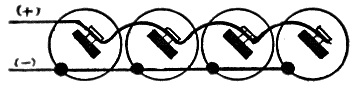

A paralleled or multiple connection adds the amperage of each cell; that is, the amperage of the battery will equal the sum of the amperage of each cell.
For instance, four cells of twenty-five amperes each would give a total of one hundred amperes when connected in parallel.67
A series multiple connection, fig. 74, consists of two series sets of cells connected in parallel. In series multiple connections the voltage of each set of cells or battery must be equal, or the batteries will be weakened, hence each battery of a series multiple connection should contain the same number of cells.
The voltage of a series multiple connection is equal to the voltage of one cell multiplied by the number of cells in one battery, and the amperage is equal to the amperage of one cell multiplied by the number of batteries.

Fig. 75 shows an incorrect method of wiring in series multiple connection. If the circuit be open, the six cells, on account of having more electromotive force than the four cells, will overpower them and cause a current to flow in the direction indicated by the arrows until the pressure of the six cells has dropped to that of the four. This will use up the energy of the six cells, but will not weaken the four cell battery. This action can be corrected by placing a two-way switch in the circuit at the junction of the two negative terminals so that only one battery can be used at a time.
Bodies differ from each other in a striking manner in the freedom with which the electric current moves upon them. If the electric current be imparted to a certain portion of the surface of glass or wax, it will be confined strictly to that portion of the surface which originally receives it, by contact with the source of electricity; but if it be in like manner imparted to a portion of the surface of a metallic body, it will instantaneously diffuse itself uniformly over the entire extent of such metallic surface, exactly as water would spread itself uniformly over a level surface on which it is poured.[3]
Bodies in which the electric current moves freely are called conductors, and those in which it does not move freely are called insulators. There is, however, no substance so good a conductor as to be devoid of resistance, and no substance of such high resistance as to be a non-conductor.
Mention should be made here of the misuse of the word non-conductor; the so-called “non-conductors” are properly termed insulators.69
The bodies named in the following series possess conducting power in different degrees in the order in which they stand, the most efficient conductor being first, and the most efficient insulator being last in the list.
| Good conductors (metals and alloys)[4] | Silver |
| Copper | |
| Aluminum | |
| Zinc | |
| Brass (according to composition) | |
| Platinum | |
| Iron | |
| Nickel | |
| Tin | |
| Lead | |
| German silver (copper 2 parts, zinc 1, nickel 1) | |
| Platinoid (German silver 49 parts, tungsten 1 part) | |
| Antimony | |
| Mercury | |
| Bismuth. | |
| Fair conductors | Charcoal and coke |
| Carbon | |
| Plumbago | |
| Acid solutions | |
| Sea water | |
| Saline solutions | |
| Metallic ores | |
| Living vegetable substances | |
| Moist earth. | |
| Partial conductors | Water |
| The body | |
| Flame | |
| Linen | |
| Cotton | |
| Mahogany | Dry woods |
| Pine | |
| Rosewood | |
| Lignum Vitæ } | |
| Teak | |
| Marble.70 | |
| Insulators, or so-called non-conductors. | Slate |
| Oils | |
| Porcelain | |
| Dry leather | |
| Dry paper | |
| Wool | |
| Silk | |
| Sealing wax | |
| Sulphur | |
| Resin | |
| Gutta-percha | |
| Shellac | |
| Ebonite | |
| Mica | |
| Jet | |
| Amber | |
| Paraffin wax | |
| Glass (varies with quality) | |
| Dry air. |
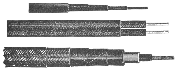
The earth is a good conductor; much difficulty is frequently experienced by the wires making contact with some substance that will conduct the electricity to the earth. This is called “grounding.”71

Mode of Transmission.—The exact nature of electricity is not known, yet the laws governing its action, under various conditions are well understood, just as the laws of gravitation are known, although the constitution of gravity cannot be defined. Electricity, though not a substance, can be associated with matter, and its transmission requires energy. While it is neither a gas nor a liquid, its behavior sometimes is similar to that of a fluid so that it is said to “flow” through a conductor. This expression of flowing does not really mean that there is an actual movement in the wire, similar to the flow of water in a pipe, but is a convenient expression for the phenomena involved.
Effect of Heat.—The conducting power of bodies is affected in different ways by their temperature. In the metals it is diminished by elevation of temperature; but in all other bodies,72 and especially in liquids, it is augmented. Some substances which are insulators in the solid state, become conductors when fused.
Sir H. Davy found that glass raised to a red heat became a conductor; and that sealing wax, pitch, amber, shellac, sulphur, and wax, became conductors when liquefied by heat.
Heating Effect of the Current.—If a current of electricity pass over a conductor, no change in the heat condition of the conductor will be observed as long as its transverse section is so considerable as to leave sufficient space for the free passage of the current. But, if this thickness be diminished, or the quantity of electricity passing over it be augmented, or, in general, if the ratio of the electricity to the magnitude of the space afforded to it be increased, the conductor will be found to undergo an elevation of temperature, which will be greater, the greater the quantity of the electricity and the less the space supplied for its passage.

These heat effects are manifested in different degrees in different metals, according to their varying conducting powers.
The poorest conductors, such as platinum and iron, suffer much greater changes of temperature by the same charge than the best conductors, such as gold and copper.73
The charge of electricity, which only elevates the temperature of one conductor a small amount, will sometimes render another incandescent, and will vaporize a third.
Insulators.—The term insulator is used in two ways: 1, as in insulating substance or medium, and 2, as a specially formed piece of some insulating material, such as glass, porcelain, etc. No substance has the power of absolutely preventing the passage of electric currents between conductors but many have sufficient insulating power for practical purposes. The properties to be desired in a good insulating material are:
Permanence is the most important quality, and is the one least easily attained. The power of resisting breakdown is a complex quality, for it is not solely dependent on mere puncturing pressure, but also on mechanical goodness, and to a certain extent on the insulation resistance. It cannot be easily determined by a simple laboratory test, but must be found by experience of actual service conditions.
Impregnating Compounds.—These are used for the treatment of fibrous materials. They increase the insulating properties of the fibrous materials, render them moisture proof and able to withstand the effect of heat with less rapid deterioration.74
When wires or cables are to be used under water, they must be made impervious, and great care must be taken to prevent the water penetrating and thus injuring the insulation.
Water as a Conductor.—Water, whether in the liquid or vaporous form, is a conductor, though of an order greatly inferior to the metals. This fact is of great importance in electrical phenomena. The atmosphere contains, suspended in it, always more or less aqueous vapor, the presence of which impairs its insulating property.
The best insulators become less efficient if their surface be moist, the electricity passing by the conducting power of the moisture. This circumstance also shows why it is necessary to dry previously the bodies on which it is desired to develop electricity by friction.
Resistance is that property of a substance that opposes the flow of an electric current through it.
The practical electrician has to measure electrical resistance, electromotive forces, and the capacities of condensers. Each of these several quantities is measured by comparison with ascertained standards, the particular methods of comparison varying, however, to meet the circumstances of the case.
Ohm’s law states that the strength of a current due to an electromotive force falls off in proportion as the resistance in the circuit increases. It is therefore possible to compare two resistances with one another by finding out in what proportion each will cause the current of a constant battery to fall off.[5]
Silver is taken as the standard, with the percentage of 100, and the conductivity of all other metals is expressed in hundredths of the conductivity of silver.76
Conductivity of Metals and Liquids.—The metals in general, conduct well, hence their resistance is small, but metal wires must not be too thin or too long, or they will resist too much, and permit only a feeble current to pass through them. The liquids in the battery do not conduct nearly so well as the metals, and different liquids have different resistances. Pure water will hardly conduct at all, unless the voltage be very high.
Salt and saltpetre dissolved in water are good conductors, and so are dilute acids, though strong sulphuric acid is a bad conductor. Gases are bad conductors.
Effect of Heat.—Another very important fact concerning the resistance of conductors is that the resistance in general increases with the temperature. While this fact is true regarding metals, it does not apply to non-metals. The resistance of different metals does not increase in the same proportion. Iron at 100 degrees C, has lost 39 per cent. of the conducting power it possessed at zero, while silver loses but 23 per cent.
Laws of Electrical Resistance.—Resistances in a circuit may be of two kinds:
1. Resistance of the conductors;
2. Resistance due to imperfect contact.
The latter kind of resistance is affected by pressure, for when the surfaces of two conductors are brought into more intimate contact the current passes more freely from one conductor to the other.
The following are the laws of the resistance of conductors:
1. The resistance of a conducting wire is proportional to its length.
If the resistance of a mile of telegraph wire be 13 ohms, that of fifty miles will be 50 × 13 = 650 ohms.77
2. The resistance of a conducting wire is inversely proportional to the area of its cross section, and therefore in the usual round wires is inversely proportional to the square of its diameter.
Ordinary telegraph wire is about 1⁄6th of an inch thick; a wire twice as thick would conduct four times as well, having four times the area of cross section; hence an equal length of it would have only 1⁄4th the resistance.
3. The resistance of a conducting wire of given length and thickness depends upon the material of which it is made—that is, upon the specific resistance of the material.
Conductivity.—This is the inverse of resistance. The term expresses the capability of a substance to conduct the electric current.
If the symbol Y represent the conductivity of a substance, and I the current then:
and if R represent the resistance of a substance, then
Good conductors of heat are also good conductors of electricity.
Specific Conductivity.—The figure which indicates the relation between one substance and another as to their capacity to conduct electricity is called specific or relative conductivity.78 Taking the specific conductivity of silver as 100, that of pure copper is 96.
The specific resistance of a substance is the reverse of its relative conductivity. The specific resistance of a metal is generally expressed in millionths of an ohm as the resistance of a centimeter cube of that metal between opposite sides.
The following table gives the data for a few metals:
| Substance. | Specific Resistance in Microhms. | Specific Conductivity. |
| Silver | 1.609 | 100. |
| Copper | 1.642 | 96. |
| Gold | 2.154 | 74. |
| Iron (soft) | 9.827 | 16. |
| Lead | 19.847 | 8. |
| German Silver | 21.470 | 7.5 |
| Mercury (liquid) | 96.146 | 1.6 |
The specific resistance of copper is therefore:
Divided Circuits.—If a circuit be divided, as in fig. 83, into two branches at A, uniting again at B, the current will also be divided, part flowing through one branch and part through the other.
The relative strength of current in the two branches will be proportional to their conductivities.
This law will hold good for any number of branch resistances connected between A and B. Conductivity is, as shown before, the reciprocal of resistance79.
EXAMPLE—If, in fig 83, the resistance of R = 10 ohms, and R′ = 20 ohms, the current through R will be to the current through R′ as 1⁄10 to 1⁄20; or, as 2:1, or, in other words, 2⁄3 of the total current will pass through R and 1⁄3 through R′. The joint resistance of the two branches between A and B will be less than the resistance of either branch singly, because the current has increased facilities for travel. In fact, the joint conductivity will be the sum of the two separate conductivities.
Taking again the resistance of R = 10 ohms and R′ = 20 ohms, the joint conductivity is
and the joint resistance is equal to the reciprocal[7] of 3⁄20
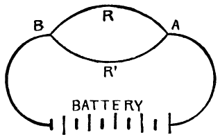
In most cases the resistance of the different branches will be alike. This simplifies the calculations considerably. Take, for instance, two branches of 100 ohms resistance each and find the joint resistance80.
SOLUTION: 1⁄100 + 1⁄100 = 2⁄100; the reciprocal is 100⁄2 = 50 ohms, or, in other words, the joint resistance is one-half of the resistance of a single branch, and each branch, of course, will carry one-half of the total current in amperes.
With three branches of equal resistance, the joint resistance will be 1⁄3; with four branches 1⁄4; with 100 branches 1⁄100 of the resistance of a single branch.
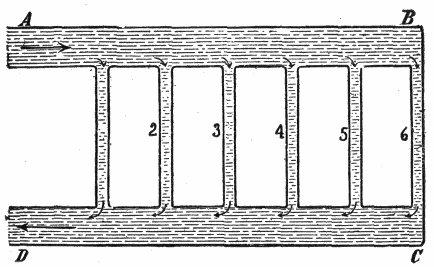
If, for instance, the resistance of an incandescent lamp hot be 180 ohms, the joint resistance of 100 such lamps connected in multiple is
If the electromotive force of the system is to be, say 110 volts, then, according to Ohm’s law, the current for 100 lamps is:81
giving for each lamp a current of
In the case of two branches only, the following rule may be applied also:
Multiply the two resistances and divide the product by their sum.
Written as a formula:
Again, assuming that R = 10 ohms and R′ = 20 ohms:
This rule cannot be employed for more than two branches at a time.
EXAMPLE—A current of 42 amperes flows through three conductors in parallel of 5, 10 and 20 ohms resistance respectively. Find the current in each conductor.
SOLUTION: Joint Conductance = 1⁄5 + 1⁄10 + 1⁄20 = 7⁄20.
Supposing the current to be divided into 7 parts, 4 of these parts would flow in the first conductor 2 in the second and 1 in the third.82
The whole current is 42 amperes.
The production of electricity is simply a transformation of energy from one form into another, usually mechanical energy is changed into electrical energy and a dynamo is simply a device for effecting the transformation.
Prof. Fessenden truly remarks there are two independent properties of matter—gravity and inertia—and these give two ways of defining force and energy.
It should always be remembered that electricity is something real, although not easily defined. And then, too, while it is not matter and not energy, yet under proper conditions (it having the power of doing work) it is convenient to speak of its performances as electric energy. The following questions and answers, although few in number, may present the subject with clearness.
Ques. What is energy?
Ans. Energy is the capacity for doing work.
Steam under pressure is an example, a spring bent ready to be released is another form, again, water stored in an elevated tank has capacity for doing work. These examples illustrate potential energy, as distinguished from kinetic energy. Potential energy may be defined as energy due to position, and kinetic energy, as energy due to momentum.84
Ques. What is matter?
Ans. Matter is anything occupying space, and which prevents other matter occupying the same space at the same time.
Ques. What name is given the smallest quantity of matter which can exist?
Ans. The atom.
An atom means that which cannot be cut, scratched, or changed in form and that cannot be affected by heat or cold or any known force; although inconceivably small, atoms possess a definite size and mass.
Ques. What is a molecule?
Ans. A molecule is composed of two or more atoms.
Ques. What is the behaviour of these minute bodies?
Ans. They are perpetually in motion, vibrating with incredible velocities.
Ques. Why at this point are definitions of energy and of matter most useful?
Ans. Because, as stated, all electric action is an exhibition of energy, and energy must act through matter as its medium.85
Ques. What is the difference between electricity and magnetism?[8]
Ans. The ultimate nature of neither is known. There are, however, some differences. To sustain a current of electricity requires energy. To sustain magnetism requires no energy. A current of electricity is always accompanied by a magnetic field of peculiar form. Magnetism alone cannot produce electricity. Electricity can do work; but magnetism cannot in the same sense—and alike with electricity, neither can it exist without contact with matter.
Ques. How is energy transmitted from one part of a material substance to another?
Ans. Gradually and successively. It requires a medium and also time.
Ques. What is the principal use or function in mechanics of electricity?
Ans. It is purely that of transmission. It corresponds to ropes, shafts and fluids as a medium of conveying and translating power or work.
Ques. What is work?
Ans. Work is the overcoming of resistance through a certain distance.
As a quantity of water moving from a higher to a lower level will do work, so also will a quantity of electricity falling through a difference of potential.
Ques. How is work measured?
Ans. In foot pounds.86
Ques. What is a foot pound?
Ans. The amount of work done in raising a weight of one pound one foot or the equivalent, overcoming a pressure of one pound through a distance of one foot.
Ques. What is the electrical unit of work?
Ans. The volt-coulomb.
A volt-coulomb of work is performed when one ampere of current flows for one second in a circuit whose resistance is one ohm, when the pressure is one volt.
The Ampere-Hour.—A gallon of water may be drawn from a hydrant in a minute, or in an hour; it is still one gallon. So in electricity, a given amount of the current, say one coulomb, may be obtained in a second or in an hour.
The ampere is the unit rate of flow.
What is called the electric current is simply the relation of any quantity of electricity passed to the time it is passing; that is
quantity in coulombs = current in amperes × time in seconds, or simply
Again:
One ampere-hour is simply another way of saying 3,600 coulombs. Of course 3,600 coulombs of electricity may be obtained in any desired time. It all depends on the rate of flow or the current strength in amperes.
For instance, 2 amperes in 1⁄2 hour, or 4 amperes in 1⁄4 hour will also give one ampere-hour of 3,600 coulombs.
It is well to keep the distinction between coulombs and amperes in mind, as even in text books very lately published these units are confounded. To illustrate further the difference between coulombs and amperes, the following example is given.
It is sometimes estimated that the quantity of electricity in a flash of lightning is 1⁄10 coulomb, and the duration of the discharge 1⁄20000 part of a second. What is the current in amperes?
Now since
solving (1) for the current,
substituting the given values in (2),
Power.—The term power means the rate at which work is done; it is usually expressed as the number of foot pounds done in one minute, that is
Power exerted for a certain time produces work.
Ques. What is the mechanical unit of power?
Ans. The horse power.
Ques. What is one horse power?
Ans. 33,000 foot pounds per minute.88
The unit is due to James Watt as being the power of a strong London draught horse to do work during a short interval and used by him to measure the power of his steam engines. One horse power = 33,000 ft. lbs. per minute = 550 ft. lbs. per sec. = 1,980,000 ft. lbs. per hour.
Ques. What is one horse power hour?
Ans. Work done at the rate of one horse power for one hour.
Ques. What is the electrical unit of power?
Ans. The watt.
Ques. What is a watt?
Ans. It is the power due to a current of one ampere flowing at a pressure of one volt. One watt = one ampere × one volt. It is equal to one joule per second.
Ques. What is a kilowatt?
Ans. 1,000 watts.
The Watt-Hour.—The elements which may be measured are, however, not only the volume of current, the unit of which is the ampere, and time, the unit of which is the hour, but also the pressure, the unit of which is the volt.
It is evident that a perfect system of electrical measurement should take account of the total amount of energy consumed, and should depend not only upon the volume of current, but also upon the pressure at which the current is applied.
The basis of such a system if provided in a unit which is the product of the two units of current and pressure, and which is termed a volt-ampere or watt.
The watt-hour represents the amount of work done by an electric current of one ampere strength flowing for one hour under a pressure of one volt.89
EXAMPLE—An incandescent lamp taking one-half an ampere of current on a circuit having a pressure of 100 volts, or a lamp taking one ampere on a circuit having a pressure of 50 volts, would each be consuming 50 watts of energy, and this multiplied by the number of hours would give the total number of watt-hours for any definite time.
The watt, then, is an accurate and complete unit of measurement and is generally applicable to all forms of electrical consumption.

A watt of electrical energy corresponds to 1⁄746 of a horse power of mechanical energy; hence, if a lamp or motor require energy equivalent to 1⁄746 of a horse power for one hour, it might be said to take one watt-hour.
Mechanical Equivalent of Heat.—The eminent English physicist, James Prescott Joule, worked for more than forty years in establishing the relation between heat and mechanical work; he stated the doctrine of the conservation of energy and90 discovered the law, known as Joule’s law, for determining the relation between the heat, current pressure, and time in an electric circuit.
Ques. What is heat?
Ans. A form of energy.
Heat is produced in the agitation of the molecules of matter—the energy expended in agitating these molecules is transformed into heat.
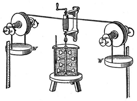
Ques. How is heat measured?
Ans. In British thermal units (B.t.u.).91
Ques. What is the British thermal unit?
Ans. The quantity of heat required to raise the temperature of 1 lb. of pure water 1° Fahr., at or near 39.1° F., the temperature of maximum density.
Ques. What is the mechanical equivalent of heat?
Ans. The number of foot pounds of mechanical energy equivalent to one British thermal unit.
Joule’s experiments 1843-50 gave the figure 772 ft. lbs. which is known as Joule’s equivalent. Later experiments gave higher figures, and the present accepted value is 778 ft. lbs., that is: 1 B.t.u. = 778 ft. lbs.
Electrical Horse Power.—It is desirable to establish the relation between watts and foot pounds in order to determine the capacity of an electric generator or motor in terms of horse power.
One watt is equivalent to one joule per second or 60 joules per minute. One joule in turn, is equivalent to .7374 ft. lbs., hence 60 joules equal:
Since one horse power = 33000 ft. lbs. per minute, the electrical equivalent of one horse power is
or,
Again, one kilowatt or 1000 watts is equivalent to
The Farad.—The measure constructed to hold a gallon of water may be called the gallon measure. The capacity of a condenser which would contain a charge of one coulomb under one volt pressure is the farad. It may seem strange that there is a unit of quantity and another of capacity to hold that quantity, when in the case of water the term “gallon” may suffice for the measure and the liquid it can hold. Electricity in this respect, however, corresponds to a compressible fluid or a gas.
A gallon measure may hold a gallon of gas or ten; it depends entirely upon the pressure. So a condenser of a certain size may hold any number of coulombs, according to the electrical pressure.
The farad being inconveniently large for practical use, one-millionth of a farad, called a microfarad, is generally adopted.
The term “electric current,” in the present state of our knowledge, should be regarded as denoting the existence of a state of things in which certain definite experimental effects are produced, for some of which there certainly is no analogy exhibited in ordinary hydraulic currents. The following are the most important of these effects:
It is rather to these effects than to any imaginary current flow in the conductor that the mind of the reader should be directed.
With this preliminary caution, which should never be lost sight of, the use of familiar words and expressions connected with the flow of water in pipes is justified in order to avoid roundabout and cumbrous phrases which, though perhaps more nearly in accord with present knowledge of the facts, would not tend to clearness or conciseness.
The three most important effects of the current just mentioned, may be presented in more detail as follows:94
1. The Thermal effect:—
The conductor along which the current flows becomes heated. The rise of temperature may be small or great according to circumstances, but some heat is always produced.
2. The Magnetic effect;
The space both outside and inside the substance of the conductor, but more especially the former, becomes a “magnetic field” in which delicately pivoted or suspended magnetic needles will take up definite positions and magnetic materials will become magnetized.
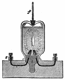
3. The Chemical effect;—
If the conductor be a liquid which is a chemical compound of a certain class called electrolytes, the liquid will be decomposed at the places where the current enters and leaves it.95
Thermal Effect.—If a quantity of electricity were set flowing in a closed circuit and the latter offered no resistance, it would flow forever, just as a wagon set rolling along a circular railway would never stop if there were no friction.

When matter in motion is stopped by friction, the energy of its motion is converted into heat by the friction thus causing the matter to come to rest. Similarly, when electricity in motion, that is, an electric current is stopped by resistance, the energy of its flow is transformed into heat by the resistance of the circuit.96
If the terminals of a battery be joined by a short thick wire of low resistance, most of the heat will be developed in the battery, whereas, if a thin wire of high resistance be used it will become hot, while the battery itself will remain comparatively cool.
To investigate the development of heat by a current, Joule and Lenz used instruments on the principle of fig. 87, in which a thin wire joined to two stout conductors is enclosed within a glass vessel containing alcohol, into which is placed a thermometer. The resistance of the wire being known, its relation to the other resistances can be calculated. Joule found that the number of heat units developed in a conductor is proportional to:
Joules’ law may be stated as follows:
The heat generated in a conductor by an electric current is proportional to the resistance of the conductor, the time during which the current flows, and the square of the strength of the current.
The quantity of heat in calories may be calculated by use of the equation,
The total number of calories H developed in t seconds will be given by
EXAMPLE—If a current of 10 amperes flows in a wire whose terminals are at a potential difference of 12 volts, how much heat will be developed in 5 minutes?
Substituting in equation (2):
Since by Ohm’s Law potential difference = I × R substituting IR for P.D. in (2)
Use of Heat from Electric Current.—In the transmission of electricity from place to place, it is very desirable that none of the energy be expended in heating the conductor. Hence copper wires of the proper size must be used.
In wiring a building for electric lights, the insurance rules require that the wires be of a certain size and that they be put up in a certain manner. Otherwise they will not insure a building against fire.
It is often desirable, however, to use the electric current for the purpose of producing heat. The carbons of the arc and incandescent lamps are intensely heated that they may produce light. Coils of German silver wire or other high resistance wire are heated by the passage of a current through them. In this manner the electric stove is made.
Soldering coppers, smoothing irons, and baking ovens are heated in a similar manner.
Magnetic Effect.—An electric current flowing in a wire causes it to be surrounded by a magnetic field, which consists of lines of force encircling the wire. The field is strongest near the wire and diminishes gradually in strength at increasing distances therefrom. The presence of this magnetic field is shown by various experiments and the subject is fully explained in chapter IX on magnetism.
Chemical Effect.—Pats van Trostwyk (1789) pointed out that an electric discharge was capable of decomposing water; to show this he used gold wires, which he allowed to dip in water, connecting one of them with the inner, and another with the outer coating of a Leyden jar, and passing the discharge through the water. The gas bubbles collected proved to consist of oxygen and hydrogen gas.98
Nicholson and Carlisle (1800) dipped a copper wire which was connected with one of the poles of a voltaic pile into a drop of water, which happened to be on the plate connected with the other pole; gas bubbles appeared, and the drop of water became smaller and smaller.
This experiment was repeated in a somewhat different manner, the brass wires from a pile being brought under a tube filled with water and closed at the top. Gas bubbles were produced by the wire in connection with the negative pole of the pile, and the water was observed to diminish gradually. At the positive wire, on the contrary, no gas came off, but the metal lost its metallic lustre, became dark, and finally crumbled away. The gas which had collected in the tube proved to be hydrogen; while on examining the black mass it was found that the constituents of brass, viz., copper and zinc, had become oxidized.

Electrolysis.—Electric analysis or more briefly electrolysis was the term applied by Faraday to the process of decomposing a liquid by the passage of a current of electricity through it.
The vessel containing the liquid is known as an electrolytic cell. In fig. 89, A is the cell, which may be of glass or of any other99 suitable material, and B is the liquid which is to be electrolyzed. Current enters by the positive electrode C, also known as the anode, traverses the liquid, and leaves by the negative electrode, or cathode, D.
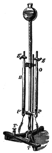
The passage of current through the water splits up its molecules into their constituent atoms of oxygen and hydrogen, the former being given off in bubbles at the anode, and the latter at the cathode.
When current is passed through a solution of copper sulphate between platinum electrodes, the liquid is decomposed, atoms of copper being deposited at the cathode, bubbles of oxygen being given off at the anode, and sulphuric acid being formed in the liquid, which latter becomes more and more acid as the copper is withdrawn.
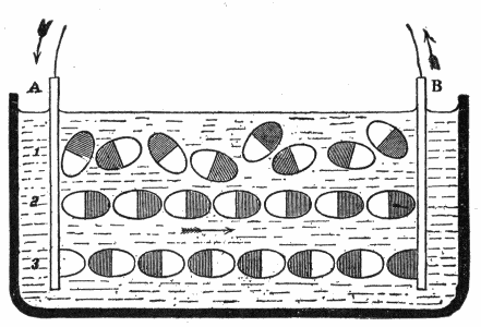
If, however, the anode be of copper instead of platinum, no sulphuric acid will be formed, neither will oxygen be given off at the anode. As copper is deposited at the cathode, an equal quantity will be dissolved at the anode, so that the original constitution of the liquid is maintained.
The atoms separated from each other by the electric current were called ions by Faraday; those going to the anode being anions, and those going to the cathode being kathions.
Anions are generally regarded as electro-negative, because they move as if attracted to the positive electrode, while kathions are regarded as electro-positive.
In order to explain the transfer of electricity and the transfer of matter through the electrolyte, Grotthuss put forward the hypothesis that when two metal plates at different potentials are placed in a cell, the effect produced in the liquid is that the molecules of the liquid arrange themselves in innumerable chains, as shown in fig. 91, in which every molecule has its atoms pointing in a certain direction, the electro-positive atom being attracted towards the cathode and the electro-negative towards the anode. An interchange then takes place all along the line, the free atoms appearing at the electrodes, and every atom discharging a minute charge of electricity upon the electrode at which it is liberated.
Electro-chemical Series.—This is an arrangement of the metals in a series in such a manner that the most electro-positive is at one end and the most electro-negative at the other.
The order of the metals varies with the electrolyte in which the metals are tested.
The following table shows such series for the most common metals, in three different solutions:102
| Sulphuric acid. | Hydrochloric acid. | Caustic potash. |
| Zinc | Zinc | Zinc |
| Cadmium | Cadmium | Tin |
| Tin | Tin | Cadmium |
| Lead | Lead | Antimony |
| Iron | Iron | Lead |
| Nickel | Copper | Bismuth |
| Bismuth | Bismuth | Iron |
| Antimony | Nickel | Copper |
| Copper | Silver | Nickel |
| Silver | Antimony | Silver |
| Gold | ||
| Platinum |
Faraday stated several laws of electrolysis, as follows:
1. The quantity of an ion liberated in a given time is proportional to the quantity of electricity that has passed through the voltameter[10] in that time.
2. The quantity of an ion liberated in a voltameter is proportional to the electro-chemical equivalent of the ion.
3. The quantity of an ion liberated is equal to the electro-chemical equivalent of the ion multiplied by the total quantity of electricity that has passed.
Electric Osmose.—Porret observed that if a strong current be led into certain liquids as if to electrolyze them, a porous partition being placed between the electrodes, the current mechanically carries part of the liquid through the porous diaphragm, so that the liquid is forced to a higher level on one side than on the other. This phenomenon is known as electric osmose.
Electric Distillation.—Closely connected with the preceding phenomenon is that of the electric distillation of liquids. It was noticed by Beccaria that an electrified liquid evaporates more rapidly than one not electrified.103
Gernez has recently shown that in a bent closed tube, containing two portions of liquid, one of which is made highly + and the other highly -, the liquid passes over from + to -. This apparent distillation is not due to difference of temperature, nor does it depend on the extent of surface exposed, but is effected by a slow creeping of the liquid along the interior surface of the glass tubes. Bad conductors, such as turpentine, do not thus pass over.
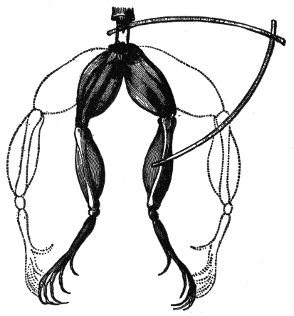
Muscular Contractions.—It was discovered in 1678 that when a portion of muscle of a frog’s leg, hanging by a thread of nerve bound with a silver wire, was held over a copper support so that both nerve and wire touched the copper, the muscle immediately contracted.
More than a century later Galvani’s attention was drawn to the subject by his observation of spasmodic contractions in the legs of freshly killed frogs under the influence of the “return shock” experienced every time a neighboring electric machine was discharged.104
The limbs of the frog, prepared as directed by Galvani, are shown in fig. 92. After the animal has been killed the hind limbs are detached and skinned; the crural nerves and their attachments to the lumbar vertebrae remaining. For some hours after death the limbs retain their contractile power. The frog’s limbs thus prepared form an excessively delicate galvanoscope.
Electroplating.—This is the process of depositing a layer or coating of a rarer metal upon the surface of a baser, or of a metal upon any conducting surface, by electrolysis.
The electric current used may be obtained from a battery or other source. The battery has its positive plate connected to a rod extending across a trough or tank containing the plating bath.
Suspended from the rod are anodes of gold, silver, or copper or whatever metal from which a deposit is desired. The other plates of the battery or the negative elements, are connected with another rod across the trough, to which are suspended the articles to be plated.
Electrotyping.—This is the process by which, type, wood cuts, etc., are reproduced in copper by the process of electroplating. A mould is first made of the set type in wax; this mould is next coated with black lead to give it a metallic surface, as the wax is an insulator; the mould is then subjected to the process of electro deposition, resulting in the formation of a film of copper on the prepared surface.
The copper shell is removed from the mould by applying hot water; the shell is then backed up with electrotype metal to render it strong enough for use.
Almost all the illustrations in this book, for example, are printed from electrotype copies, and not from the original wood blocks, which would not wear so well.
Magnetism.—The ancients applied the word “magnet,” magnes lapes, to certain hard black stones which possess the property of attracting small pieces of iron, and as discovered later, to have the still more remarkable property of pointing north and south when hung up by a string. At this time the magnet received the name of lodestone or “leading stone.” It is commonly, though incorrectly, spelled loadstone.
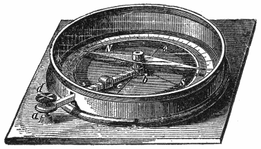
Ques. Describe two kinds of magnetism.
Ans. Magnets have two opposite kinds of magnetism or magnetic poles, which attract or repel each other in much the same way as would two opposite kinds of electrification.106
Ques. What is the nature of each kind of magnetism?
Ans. One has a tendency to move toward the north and the other toward the south.

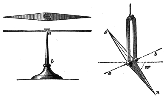
Ques. Where is the magnetism the strongest?
Ans. In two regions called the poles.
Ques. Describe the distribution of magnetism in a long shaped magnet.
Ans. The strongest magnetism resides in the ends, while all around the magnet half way between the poles there is no attraction at all.
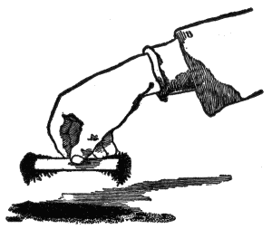
Ques. How are the poles designated?
Ans. They are called the north pole and the south pole.
Ques. What is the distinguishing feature of each?
Ans. The north pole points approximately to the earth’s geographical north, while the south pole of a magnet points approximately to the earth’s geographical south.
The north pole is the positive (+) pole and the south pole is the negative. The north and south poles were formerly called in France, the austral and boreal poles respectively.108
Magnetic Field.—When a straight bar magnet is held under a piece of card board upon which iron filings are sprinkled, the filings will arrange themselves in curved lines radiating from the poles. If a horse shoe magnet be held at right angles to the plane of the card board, the filings will arrange themselves in curved lines, as shown in fig. 108. These lines are called magnetic lines of force or simply lines of force; they show that the medium surrounding a magnet is in a state of stress, the space so affected being called the magnetic field.
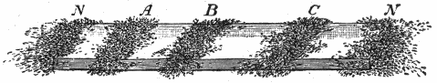

Ques. What is the extent and character of the magnetic field?
Ans. The influence of a magnet is supposed to extend in all directions indefinitely, however, the effect is very slight beyond a comparatively limited area.109
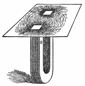

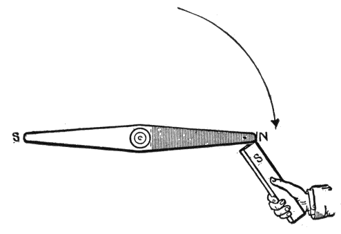

Magnetic Force.—This is the force with which a magnet attracts or repels another magnet or any piece of iron or steel. The force varies with the distance, being greater when the magnet is nearer and less when the magnet is farther off. The following are the laws relating to magnetic force:
1. Like magnetic poles repel one another; unlike magnetic poles attract one another.
2. The force exerted between two magnetic poles varies inversely as the square of the distance between them.
Magnetic Circuit.—The path taken by magnetic lines of force is called a magnetic circuit; the greater part of such a circuit is usually in magnetic material, but there are often one or more air gaps included. The total number of lines of force in the circuit is known as the magnetic flux.
Ques. How is magnetic flux measured?
Ans. By a unit called the maxwell.
Named after James Clerk Maxwell the Scottish physicist.
Ques. What is the maxwell?
Ans. The amount of magnetism passing through every square centimetre of a field of unit density.
Ques. What is the unit of field strength?
Ans. The gauss.
Ques. What is a gauss?
Ans. The intensity of field which acts on a unit pole with a force of one dyne. It is equal to one line of force per square112 centimetre. Named after Karl Friedrich Gauss, the German mathematician.
The Magnetic Effect of the Current.—Hans Christian Oerstead, the Danish scientist, discovered in 1819 that a magnet tends to set itself at right angles to a wire carrying an electric current. He also found that the way in which the needle turns, whether to the right or left of its usual position, depends: 1, upon the position of the wire that carries the current, whether it be above or below the needle, and 2, on the direction in which the current flows through the wire.
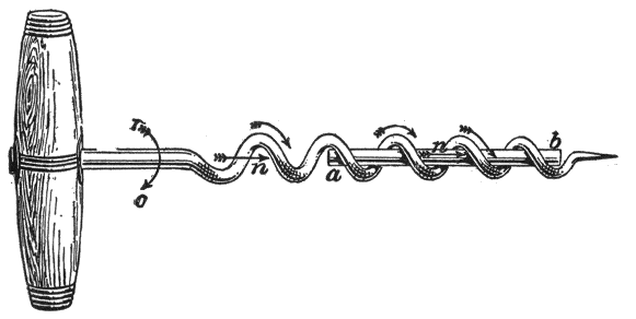
To keep these movements in mind numerous rules have been suggested, of which the following will be found convenient:
Corkscrew Rule.—If the direction of travel of a right handed corkscrew represent the direction of the current in a straight conductor, the direction of rotation of the corkscrew will represent the direction of the magnetic lines of force.113

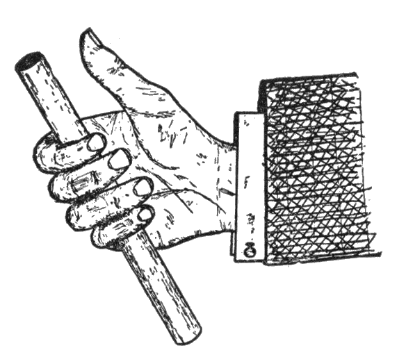
Ques. What is the effect of a current flowing in a loop of wire?
Ans. If, in figs. 116 and 117, the current flow in the direction indicated by the arrow, the lines for magnetic force are found to surround the loop as shown; all the lines leave on one side of the loop and return on the other; accordingly, a north pole is formed on one side, and a south pole on the other.


Solenoids.—A solenoid consists of a spiral of conducting wire wound cylindrically so that, when an electric current passes through it, its turns are nearly equivalent to a succession of parallel circular circuits, and it acquires magnetic properties similar to those of a bar magnet.

Ques. What is the character of the lines of force of a solenoid in which a current is flowing?
Ans. The lines of force must be thought of as closed loops linked with the current. The conductor conveying the current passes through all the loops of force, and these are, so to speak, threaded or slung on the current-line of flow, as in fig. 116.
Ques. What is the distribution of the lines of force?
Ans. The lines of force form continuous closed curves running through the interior of the coil; they issue from one end and enter into the other end of the coil, as shown in fig. 117.116
Ques. What are the properties of a solenoid?
Ans. A solenoid has north and south poles, and in fact possesses all the properties of an ordinary permanent magnet, with the important difference that the magnetism is entirely under control.
Since a solenoid carrying a current attracts and repels by its extremities the poles of a magnet, two such solenoids will attract and repel each other.
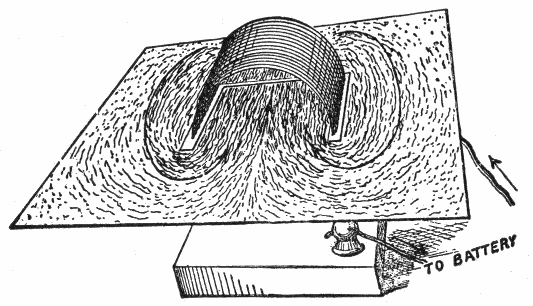
Ques. How does the magnetic strength of a solenoid vary?
Ans. It is proportional to the strength of the electric current passing through it.117
Ques. On what, besides the current strength, does the magnetizing power of a solenoid depend?
Ans. The magnetic effect or the magnetizing power is proportional to the number of turns of wire composing the coil.
Ques. How may the magnetizing power of a solenoid be increased?
Ans. By inserting in the solenoid an iron core or round bar of soft iron.
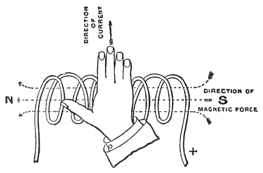
Ques. Describe the action of an iron core.
Ans. At first, the presence of an iron core greatly increases the strength of the field; after a time, however, as the strength of the current flowing in the exciting coils is increased, the conductibility of the iron for the lines of force appears to decrease, until a point is eventually reached when the presence of the iron core appears to have no effect in increasing the strength of the field.118
Permeability.—Permeability is a measure of the ease with which magnetism passes through any substance. It is defined as: the ratio between the number of lines of force per unit area passing through a magnetizable substance, and the magnetizing force which produces them.
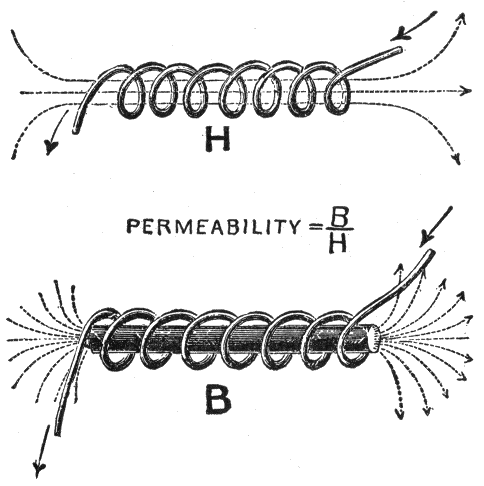
In other words, it is the ratio of flux density to magnetizing force. Permeability is a measure of the ease with which magnetism passes through any substance. The permeability of good soft wrought iron is sometimes 3000 times that of air, varying with the quality of the iron.119
Ques. What is the effect of increasing the magnetization?
Ans. The magnetic permeability decreases as the magnetization increases.
Ques. What is magnetic saturation?
Ans. The state of a magnet which has reached the highest degree of magnetization.
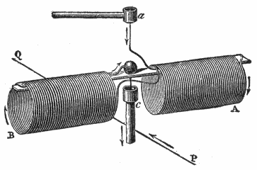
A magnet, just after being magnetized, will appear to have a higher degree of magnetism than it is able to retain permanently; that is, it will appear to be super-saturated, since it will support a greater weight immediately after being magnetized than it will after its armature has been once removed.
For all practical purposes, magnetic saturation may be defined as: That point of magnetization where a very large increase in the magnetizing force does not produce any perceptible increase in the magnetization.120
From tests it has been shown that permeability increases with the flux density up to a certain point and then decreases, indicating that the iron is approaching a state of saturation.
Magnetomotive Force.—This is a force similar to electromotive force, that is, magnetic pressure. When a coil passes around a core several times, its magnetizing power, or magnetomotive force, (m.m.f.) is proportional both to the strength of the current and to the number of turns in the coil. The product of the current passing through the coil multiplied by the number of turns composing the coil is called the ampere turns.
It is known by experiment that one ampere turn produces 1.2566 units of magnetic pressure, hence:
that is,
The unit of magnetic pressure is the gilbert (named after William Gilbert, the English physicist) and is equal to
Reluctance.—The magnetic pressure (magnetomotive force) acting in a magnetic circuit encounters a certain opposition to the production of a magnetic field, just as electromotive force in an electric circuit encounters opposition to the production of a current. In the magnetic circuit this opposition is called the reluctance; it is simply magnetic resistance and may be defined as: the resistance offered to the magnetic flux by the substance magnetized, being the ratio of the magnetomotive force to the magnetic flux.121
The unit of reluctance or magnetic resistance is the oersted (named after Hans Christian Oersted, the Danish physicist) and is defined as: the reluctance offered by a cubic centimetre of vacuum.
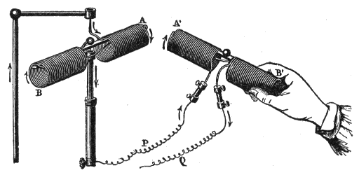
Analogy Between Electric and Magnetic Circuits.—The total number of magnetic lines of force, or magnetic flux, produced in any magnetic circuit will depend on the magnetic pressure (m.m.f.) acting on the circuit and the total reluctance of the circuit, just as the current in the electrical circuit depends upon the electrical pressure and the resistance of the circuit.
To make this plain, Ohm’s law states that
expressed in units
The resistance, as already explained, depends on the materials of which the circuit is composed, and their geometrical shape and size.
Similarly, in the magnetic circuit, the total number of magnetic lines produced by a given magnetizing solenoid depends on the magnetic pressure, the material composing the circuit, and its shape and size.
That is,
expressed in units, the equation becomes:
The gilbert is the unit of magnetomotive force, equivalent to the magnetomotive force of .7958 ampere turn.
It should be noted that in the electric circuit resistance causes heat to be generated and therefore energy to be wasted, but in the magnetic circuit reluctance does not involve any similar waste of energy.
Ques. Upon what does the reluctance of a magnetic circuit depend?
Ans. The reluctance is directly proportional to the length of the circuit, and inversely proportional to its cross sectional area.
The reluctance of a magnetic circuit is calculated according to the following equation:
Hysteresis.—The term hysteresis has been given by Ewing to the subject of lag of magnetic effects behind their causes. Hysteresis means to “lag behind,” hence its application to denote the lagging of magnetism, in a magnetic metal, behind the magnetizing flux which produces it.
Ques. What is the cause of hysteresis?
Ans. It is due to the friction between the molecules of iron or other magnetic substance which requires an expenditure of energy to change their positions.
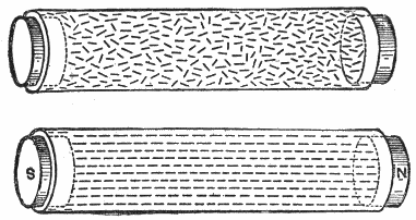
Ques. When do the molecules change their positions?
Ans. Both in the process of magnetization and demagnetization.
Ques. What becomes of the loss of energy due to hysteresis?
Ans. It is converted into heat in changing the positions of the molecules during magnetization and demagnetization.
Ewing gives the value for the energy in ergs dissipated per cubic centimetre, for a complete cycle of doubly reversed strong magnetization for a number of substances as follows:124
| Substance | Energy dissipated (ergs) |
| Very soft annealed iron | 9,300 |
| Less soft annealed iron | 16,300 |
| Hard drawn steel wire | 60,000 |
| Annealed steel wire | 70,000 |
| Same steel glass hard | 76,000 |
| Piano steel wire annealed | 94,000 |
| Piano steel wire normal temper | 116,000 |
| Piano steel wire glass hard | 117,000 |
Approximately 28 foot pounds of energy are converted into heat in making a double reversal of strong magnetization in a cubic foot of iron.
Residual Magnetism.—When a mass of iron has once been magnetized, it becomes a difficult matter to entirely remove all traces when the magnetizing agent has been removed, and, as a general rule, a small amount of magnetism is permanently retained by the iron. This is known as residual magnetism, and it varies in amount with the quality of the iron.
Well annealed, pure wrought iron, as a rule, possesses very little residual magnetism, while, on the other hand, wrought iron, which contains a large percentage of impurities, or which has been subjected to some hardening process, such as hammering, rolling, stamping, etc., and cast iron, possess a very large amount of residual magnetism.
Residual magnetism in iron is of great importance in the working of the self-exciting dynamo, and is, indeed, the essential principle of this class of machine.
That is, without residual magnetism in the field magnet core, the dynamo when started would not generate any current unless it received an initial excitation from an external source.
The word induction, introduced by Faraday, has various meanings so far as it relates to electricity. It signifies, in general, phenomena produced in bodies by the influence of other bodies, having no necessary material connection with them.
A body charged with electricity causes or “induces” charges on neighboring bodies. The process in this case is called electrostatic induction.
A magnet induces magnetism in neighboring masses of iron or other magnetic materials by the process of magnetic induction.
Again, a moving magnet induces electric currents in neighboring conductors by the process of electromagnetic induction.
Faraday’s Discovery.—All dynamos of whatever form, are based upon the discovery made by Faraday[11] in 1831, which may be stated as follows:
Electric currents are generated in conductors by moving them in a magnetic field, so as to cut magnetic lines of force.126
Ques. What does the expression “cut lines of force” mean?
Ans. A conductor, forming part of an electric circuit, cuts lines of force when it moves across a magnetic field in such manner as to alter the number of magnetic lines of force which are embraced by the circuit.
It is important to clearly understand the meaning of this expression, which will be later explained in more detail.

Faraday’s Machine.—After various experiments, Faraday made his “new electrical machine” as shown in fig. 126. This piece of apparatus is preserved and was shown in perfect action by Prof. S. P. Thompson in a lecture delivered April 11th, 1891, after an interval of sixty years.
It consists of a horse shoe magnet and a copper disc attached to a shaft and supported so as to turn freely. The magnet is so placed that its inter-polar lines of force traverse the disc from side to side. There are two copper brushes, one bears against the shaft, and the other against the circumference of the disc. A handle serves to rotate the disc in the magnetic field.
Now, if the north pole of the magnet be nearest the observer and the disc be rotated clockwise, the current induced in the circuit will flow out at the brush which touches the circumference, and return through the brush at the shaft.127
Faraday’s Principle.—The principle deduced from Faraday’s experiment may be stated as follows:
When a conducting circuit is moved in a magnetic field so as to alter the number of lines of force passing through it, a current is induced therein, in a direction at right angles to the direction of the motion, and at right angles also to the direction of the lines of force, and to the right of the lines of force, as viewed from the point from which the motion originated.
Faraday’s principle may be extended as follows to cover all cases of electromagnetic induction:
When a conducting circuit is moved in a magnetic field, so as to alter the number of lines of force passing through it, or when the strength of the field is varied so as to either increase or decrease the number of lines of force passing through the circuit, a current is induced therein which lasts only during the interval of change in the number of lines of force embraced by the circuit.
Ques. Explain just what happens when a current is induced by electromagnetic induction.
Ans. In order to induce an electromotive force by moving a conductor across a uniform magnetic field, it is necessary that the conductor, in its motion, should so cut the magnetic lines as to alter the number of lines of force that pass through the circuit of which the moving conductor forms a part.
Ques. What is the proper name for a “conductor” which moves across the magnetic field?
Ans. An inductor, because it is that part of the electric circuit in which induction takes place.
In the case of a dynamo, an inductor may be either a copper wire or copper bar.128
Ques. How may a conducting circuit be moved across a magnetic field without having a current induced therein?
Ans. If a conducting circuit—a wire ring or single coil, for example—be moved in a uniform magnetic field, as shown in fig. 127, so that only the same number of lines of force pass through it, no current will be generated, for since the coil is moved by a motion of translation to another part of the field, as many lines of force will be left behind as are gained in advancing from its first to its second position.

Ques. Describe another movement by which no current will be induced.
Ans. If the coil be merely rotated on itself around a central axis, that is, like a fly wheel rotating around a shaft, the number of lines of force passing through the coil will not be altered, hence no current will be generated.129
Ques. State the essential condition for current induction in a uniform field.
Ans. The coil in which a current is to be induced, must be tilted in its motion across the uniform field, or rotated around any axis in its plane as in fig. 128, so as to alter the number of lines of force which pass through it.

Ques. In what direction will the current flow in the coil, fig. 128?
Ans. The current induced in the coil will flow around it in a clockwise direction (as observed by looking along the magnetic field in the direction in which the magnetic lines run) if the effect of the movement be to diminish the number of lines of force that pass through the coil. The current will flow in the opposite direction, (counter-clockwise) if the movement be such as to increase the number of intercepted lines of force.
Ques. If the magnetic field be not uniform, as in fig. 129, what will be the result?
Ans. The effect of moving the coil by a simple motion of translation from a dense region of the field to one less dense, or130 vice versa, will be to induce a current because in either case, the number of lines of force passing through the coil is altered.[12]
Laws of Electromagnetic Induction.—There are certain laws of electromagnetic induction which, on account of the importance of the subject, it is well to carefully consider. The facts presented in the preceding paragraphs are embodied in the following fundamental laws:

1. To induce a current in a circuit, there must be a relative motion between the circuit and a magnetic field, of such a kind as to alter the number of magnetic lines embraced in the circuit.
2. The electromotive force induced in a circuit is proportional to the rate of increase or decrease in the number of magnetic lines embraced by the circuit.131
For instance, if n equal the number of magnetic lines embraced by the circuit at the beginning of the movement, and n′ the number embraced after a very short interval of time t, then
It would require the cutting of 100,000,000 lines per second to produce an electromotive force equal to that of one Daniell cell.
The unit of electromotive force, called the volt, is the electric pressure produced by cutting 100,000,000 lines per second, usually expressed 108.

3. By joining in series a number of conductors or coils moving in a magnetic field, the electromotive forces in the separate parts are added together.
The reason for this is apparent by considering a coil of wire having several turns and moving in a magnetic field so as to cut magnetic lines. During the movement, the lines cut by the first turn are successively cut by all the other turns of the coil, hence, the total number of lines cut is equal to the number cut by a single turn multiplied by the number of turns. The electromotive forces therefore of the separate turns are added.132
EXAMPLE—If a coil of wire of 50 turns cut 100,000 lines in 1⁄100 of a second, what will be the induced voltage?
The number of lines cut per second per turn of the coil is
The total number of lines cut by the coil of 50 turns is
which will induce a pressure of
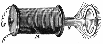
4. A decrease in the number of magnetic lines which pass through a circuit induces a current around the circuit in the positive direction.
The term positive direction is understood to be the direction along which a free N pole would tend to move.
5. An increase in the number of magnetic lines which pass through a circuit induces a current in the negative direction around the circuit.
The reason for the change of direction of the current for decrease or increase in the number of lines cut, as stated in the fourth and fifth laws, will be seen by aid of the formula given under the second law, viz:
but by Ohm’s law
current = electromotive force / resistance or, I = E/R (2)Substituting (1) in (2)

Now in equation (3) if there be a decrease in the number of lines cut n′ will be less than n hence the current will be positive (+); again, if the lines increase n′ will be greater than n, which will give a minus value, that is, the current will be negative or in a reverse direction.
6. The approach and recession of a conductor from a magnet pole will yield currents alternating in direction.134
Since the strength of the field depends on the proximity to the pole, the approach and recession of a conductor involve an increase and decrease in the rate of cutting of magnetic lines, hence a reversal of current.
7. The more rapid the motion, the higher will be the induced electromotive force.
In other words, the greater the number of lines cut per unit of time, the higher will be the voltage.

8. Lenz’s law. The direction of the induced current is always such that its magnetic field opposes the motion which produces it.
This is illustrated in figs. 130 and 131.
Rules for Direction of Induced Current.—There are a number of rules to quickly determine the direction of an induced current, when the direction of the lines of force, and motion of the conductor are known. The first rule here given was devised by Fleming and is very useful. It is sometimes called the “dynamo rule.”135
Fleming’s Rule.—If the forefinger of the right hand be pointed in the direction of the magnetic lines, and the thumb (at right angles to the forefinger) be turned in the direction of the motion of the conductor, then will the middle finger, bent at right angles to both thumb and forefinger, show the direction of the induced current.
The application of this rule is shown in fig. 132. Here the right hand is so placed at the north pole of a magnet, that the forefinger points in the direction of the magnetic lines; the thumb in the direction of motion of the conductor; the middle finger pointed at right angles to the thumb and forefinger indicates the direction of the current induced in the conductor.

Ampere’s Rule.—If a man could swim in a conductor with the current, then the north seeking (+) pole of a magnetic needle placed directly ahead of him, will be deflected to the left, while the south seeking (-) pole will be urged to the right.
For certain particular cases in which a fixed magnet pole acts on a movable circuit, the following converse to Ampere’s rule will be found useful: If a man swim in the wire with the current, and turn so as to look along the direction of the lines of force of the pole (that is, as the lines of force run, from the pole if it be north seeking, toward the pole if it be south seeking), then he and the conducting wire with him will be urged toward his left.136
The palm rule.—If the palm of the right hand be held facing or against the lines of force, and the thumb in the direction of the motion, then will the fingers point in the direction of the induced current.
Self-induction.—This term signifies the property of an electric current by virtue of which it tends to resist any change of value. Self-induction is sometimes spoken of as electromagnetic inertia, and is analogous to the mechanical inertia of matter.
It is on account of self-induction of the induced currents in the armature winding of a dynamo, that sparks appear at the brushes when the latter are not properly adjusted, hence the importance of clearly understanding the nature of this peculiar property of the current.
Self-induction is fully explained in the chapter following.
The induction coil has always been a popular piece of apparatus with those interested in electrical science; the experiments which can be performed with its aid are very numerous. It is of considerable importance, especially in its application to such useful purposes as X ray work, wireless telegraphy and ignition for gas engines. The latter has caused manufacturers to give much attention to the development of the induction coil, resulting in many refinements of design and construction.
Induction coils may be divided into two general classes:
The subject of electromagnetic induction has been fully explained in chapter X, but it may be said, with special reference to induction coils, that the operation of the two classes just mentioned is respectively due to:
Self-induction.—This is the property of an electric current by virtue of which it tends to resist any change in its rate of flow. It is sometimes spoken of as electromagnetic inertia and is analogous to the mechanical inertia of matter.138
Self-induction is due to the action of the current upon itself during variations in strength. It becomes especially marked in a coil of wire, in which the adjacent turns act inductively upon each other upon the principle of mutual induction arising between two separate adjacent circuits. Self-induction manifests itself by giving “momentum” to the current so that it cannot be instantly stopped when the circuit is broken, the result being a bright spark at the moment of breaking the circuit. On account of this spark a primary induction coil is used in low tension or “make and break” ignition systems.

In a single circuit, consisting of a straight wire and a parallel return wire there is little or no self-induction. When a circuit containing a primary induction coil and a battery is closed there is no spark because at the instant of closing the circuit the current is at rest and on account of self-induction the current cannot at once rise to its full value.139
Mutual Induction.—This is a particular case of electromagnetic induction in which the magnetic field producing an electromotive force in a circuit is due to the current in a neighboring circuit.
The effect of mutual induction may be explained with the aid of fig. 135. If, as illustrated, a circuit including a battery and a switch, be placed near another circuit, formed by connecting the two terminals of a galvanometer by a wire, it will be found that whenever the first circuit, 1, is closed by the switch, allowing a current to pass in a given direction, a momentary current will be induced in the second circuit, 2, as shown by the galvanometer. A similar result will follow on the opening of the battery circuit, the difference being that the momentary induced current occurring at closure moves in a direction opposite to that in the battery circuit, while the momentary current at opening moves in the same direction.
Currents, besides being induced in circuit 2 at make or break of circuit 1, are also induced when the current in 1 is fluctuating in intensity.
The most marked results are observed when the make or break is sudden, the action being strongest at the break of the current in 1.
The inductive effect of the current in the arrangement shown in fig. 135 is very weak.
Ques. What name is given to circuit 1?
Ans. The primary circuit.
Ques. What name is given to circuit 2?
Ans. The secondary circuit.
Ques. What names are given respectively to the currents in circuits 1 and 2?
Ans. The primary and secondary or induced currents.140
Primary Induction Coils.—These represent the simplest form of coil, and are used chiefly in low tension ignition to intensify the spark when a battery forms the current source.
A primary coil consists of a long iron core wound with a considerable length of low resistance insulated copper wire, the length of the core and the number of turns of the insulated wire winding determining the efficiency. The effect of the iron core is to increase the self-induction.

The spark produced, as previously explained, is due to self-induction, and it should be remembered that in the operation of the coil, the spark occurs at the instant of breaking the circuit, not at the instant of making.
Secondary Induction Coils.—The arrangement shown in fig. 137, may be considered as a very simple or rudimentary form of secondary induction coil. In the actual coil, the primary and secondary circuits (corresponding to 1 and 2 in fig. 135) are made up of coils of insulated wire, as shown in fig. 143, the primary coil P, being wound over a core C and the secondary coil S being wound over the primary.
The one property of such an arrangement that makes it of great value for most purposes is that the voltage of the induced141 currents may be increased or diminished to any extent depending on the relation between the number of turns in the primary and secondary winding.
This relation may be expressed in the following rule:
The voltage of the secondary current is (approximately) to the voltage of the primary current as the number of turns of the secondary winding is to the number of turns of the primary winding.

For instance, if the voltage of the primary current be 5 volts, the primary winding have 10 turns and the secondary 100 turns, then
The watts in each circuit are approximately the same; hence: if, for instance, the current strength in the primary circuit be 5 amperes, the watts in primary circuit are 5 × 5 = 25. Accordingly, for the secondary circuit the current strength is:
From this, it is seen that where the voltage is raised in the secondary circuit, the current flow is small as compared to that in the primary circuit; therefore, heavy wire is used in the primary winding and fine wire in the secondary, as indicated in figs. 137 and 143.
For most purposes a very much higher secondary voltage is required than in the example just given.
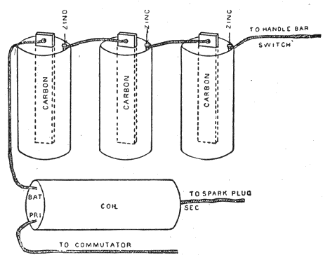
Secondary induction coils may be divided into three general classes:
The plain coil gives but one spark when the primary circuit is made and broken, while the vibrator coil gives a series of sparks following each other in rapid succession.
Plain Secondary Induction Coils.—Coils of this class are very simple and consist of:
The construction of a plain coil, such as would be suitable for ignition service, is about as follows:
The core is made of soft annealed iron wires (No. 20 B and S gauge) from one-half to three-quarters of an inch in diameter and about six inches long. Over this core is slipped a spool of insulating material (hard rubber or composition), on which is wound first the primary winding of the coil, which consists of several layers of about No. 18 B and S gauge silk insulated magnet wire.
After the primary winding has been wound over the insulated core, and the ends have been properly brought out through the heads of the spool to be connected to binding posts thereon, a layer of insulating material is applied over the primary wire, and the secondary winding is then wound on.
The wire for the secondary winding consists of about No. 36 B and S gauge silk covered magnet wire, the amount used varying considerably, depending on the desired voltage of the secondary current.
When all the wire has been wound on, the ends are brought out to the binding posts, the coil is soaked in shellac dissolved in alcohol and baked, or in melted paraffin or a paraffin compound, and allowed to cool. It is then placed in either a cylindrical hard rubber shell or in a hard wood box.
The proportions of such coils vary greatly; for motor cycle use they are made long and of small diameter (10×21⁄2 inches for instance), while for some other purposes short and thick coils are found more convenient.
Ques. How may the coil just described be connected for demonstrating purposes?
Ans. Connect the ends of the secondary winding to fixed insulators and bend the ends so they are about 1⁄8 inch or less144 apart. Connect one end of the primary winding to a battery and brush the other end of the primary winding against the other terminal of the battery as indicated in fig. 137.
Ques. What happens when the primary circuit is made?
Ans. An electric pressure is induced in the secondary circuit, but of not enough intensity to cause a spark to jump across the air gap.
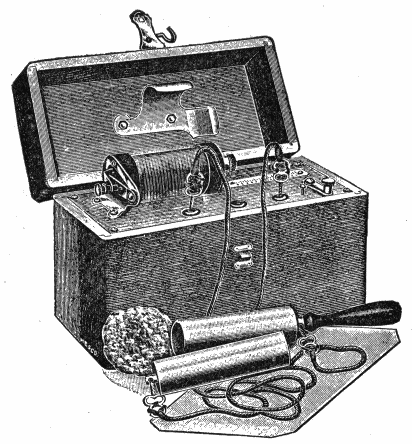
Ques. What happens when the primary circuit is suddenly broken?
Ans. A spark is produced both at the point of break in the primary circuit and at the air gap in the secondary circuit.145
Ques. Why is a spark produced at the air gap at break and not at make of the primary current?
Ans. Because when the current is flowing it cannot be stopped instantly on account of self-induction, that is, it acts as though it possessed weight.
If the reader has charge of a gas engine with a make and break ignition system, he will often avoid vexatious delays in locating ignition troubles, if he remember that one of the most important conditions for obtaining a good spark is that the break take place with great rapidity. This, of course, involves that the ignition spring be adjusted to the proper tension.
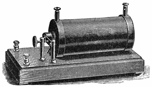
Secondary Induction Coils with Vibrator and Condenser.—A plain secondary coil, such as just described, will only give feeble sparks for its size for the following reasons: The inductive effect of the primary winding in the secondary depends as previously explained on the rate at which the current in the primary winding decreases or dies out.146
If a strong inductive effect is to be produced in the secondary, the current in the primary must stop suddenly. This is prevented by self-induction in the primary winding, which opposes any change in the current strength. The direct result is that, as the primary circuit is broken, a spark appears at the break, which means that the current continues to flow after the break has occurred, dying down comparatively slowly, hence, the inductive effect on the secondary winding is small.

The spark at the break in the primary circuit is even larger than that in the secondary circuit, and as this primary spark serves no useful purpose, but, on the contrary, quickly burns away the contact points, such an arrangement is obviously defective.
The vibrator-condenser coil is designed to overcome this trouble and also to give a series of sparks following in rapid succession instead of one.
It should be noted that a series of sparks following each other with considerable rapidity may be obtained with a plain coil by placing a mechanical vibrator in the primary circuit, as used on some motor cycle ignition circuits.
The object of the vibrator, of a vibrator-condenser coil, is to rapidly make and break the primary circuit during the time the147 primary circuit is closed externally. It consists of a flat steel spring secured at one end, with the other free to vibrate. At a point about midway between its ends, contact is made with the point of an adjusting screw, from which it springs away and returns in vibrating. The points of contact of blade and screw are tipped with platinum. One wire of the primary circuit is connected to the blade and the other to the screw, hence, the circuit is made when the blade is in contact with the screw and broken when it springs away.
A condenser is used to absorb the self-induced current of the primary winding and thus prevent it opposing the rapid fall of the primary current.
Every conductor of electricity forms a condenser and its capacity for absorbing a charge depends upon the extent of its surface. Hence, a condenser is constructed of conductive material so arranged as to present the greatest surface for a given amount of material.148
The usual form of condenser for induction coils as shown in figs. 141 and 142 is composed of a number of layers of tin foil separated by paraffin paper, each alternate layer being connected at the ends.
Fig. 143 is a diagram of a vibrator coil. CC represents the core composed of soft iron wires. PP is the primary winding and SS the secondary. There is no connection between these windings and they are carefully insulated. Y is the vibrator or trembler and D the center about which it vibrates. W is a switch used for opening and closing the primary circuit; B, a battery of five cells. The point of adjusting screw A rests against a platinum point R soldered upon the vibrator.

If the switch W be closed, the electric current generated by the battery B will flow through the primary winding. This will cause the core CC to become magnetized, and the vibrator Y will at once be drawn toward it. This will break the connection at R. The core, being made of soft iron, immediately upon the interruption of the current, will again lose its magnetism, and the vibrator will return to its original position. This again closes the circuit, after which the operation of opening and closing it is repeated with great rapidity so long as the switch W remains closed.
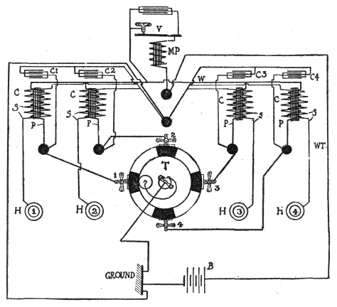
The cycle of actions may be briefly stated as follows:150

Magnetic Vibrators.—Many types of vibrator are used on induction coils, the most important requirement being that the break occur with great rapidity. In order to render the break as sudden as possible, different expedients have been resorted to, all tending to make the mechanism more complicated, yet having sufficient merit in some cases to warrant their adoption.151
In the plain vibrator, the circuit is broken at the instant the spring begins to move, hence, the operation must be comparatively slow.
In order to render the break more abrupt some vibrators have two moving parts, one of which is attracted by the magnetic core of the coil and moved a certain distance before the break is effected. A vibrator of this type is shown in fig. 146 and described under the illustration.

Vibrator Adjustment.—When a vibrator coil is used, the quality of the spark depends largely upon the proper adjustment of the vibrator. The following general instructions for adjusting a plain vibrator should be carefully noted:
| Length of spark | 3⁄8 inch | 1⁄2 inch | 1 inch | 2 inches |
| Size of bobbin ends | 21⁄8 × 11⁄4 | 21⁄2 × 5⁄16 | 3 × 3⁄8 | 4 × 23⁄4 × 3⁄8 |
| Length of bobbin | 4 | 51⁄2 | 61⁄2 | 61⁄2 |
| Length and diameter of core | 41⁄4 × 7⁄16 | 6 × 5⁄8 | 61⁄2 × 3⁄4 | |
| Size of base | 71⁄4 × 31⁄4 × 11⁄2 | 9 × 5 × 2 | 141⁄2 × 6 × 13⁄4 | 12 × 71⁄2 × 31⁄4 |
| Size of tinfoil sheets | 4 × 2 | 51⁄2 × 31⁄4 | 6 × 4 | 6 × 6 |
| Number of tinfoil sheets | 36 | 40 | 40 | 60 |
| Size of paper sheets | 5 × 3 | 61⁄2 × 41⁄4 | 9 × 5 | |
| Primary coil | No. 18 | No. 18 | 2 layers No. 16, silk covered. | 2 layers 14 B. W. G., silk covered. |
| Secondary coil | 3⁄4 lb. No. 40 | 1 lb. No. 40 | 11⁄4 lbs. No. 38 | 21⁄2 lbs. No. 36 |
| Volts. | Distance. |
| (Inches.) | |
| 5000 | .225 |
| 10000 | .47 |
| 20000 | 1.00 |
| 30000 | 1.625 |
| 35000 | 2.00 |
| 45000 | 2.95 |
| 60000 | 4.65 |
| 70000 | 4.85 |
| 80000 | 7.1 |
| 100000 | 9.6 |
| 130000 | 12.95 |
| 150000 | 15.00 |
Points Relating to Ignition Coils.—1. Most ignition induction coils or “spark coils” as they are called, have terminals marked “battery,” “ground,” etc., and to short circuit the timer153 for the purpose of testing the vibrator, it is only necessary to bridge with a screw driver from the “battery” binding post to the “ground” binding post.
2. In adjusting the vibrator of an ignition coil, the latter should not require over one-half ampere of current.
3. A half turn of the adjusting screw on a coil will often increase the strength of the current four or five times the original amount, hence, the necessity of carefully adjusting the vibrator. When the adjustment is not properly made it causes, 1, short life of the battery, 2, burned contact points, and 3, poor running of the engine.154
4. In adjusting a multi-unit coil, if any misfiring be noticed, hold down one vibrator after another until the faulty one is located, then screw in its contact screw very slightly.
5. The number of cells in the circuit should be proportioned to the design of the coil.
If the coil be described by the maker as a 4 volt coil, it should be worked by two cells of a storage battery or four dry cells. The voltage of the latter will be somewhat higher, but since their internal resistance is also greater, the current delivery will be about the same. Most coils are made to operate on from 4 to 6 volts.
6. It is a mistake to use a higher voltage than that for which the coil is designed, because it does not improve the spark and the contact points of the vibrator will be burned more rapidly, moreover, the life of the battery will be shortened.
The dynamo is a machine which converts mechanical energy into electrical energy by electromagnetic induction.
The word dynamo is used to designate a machine which produces direct current as distinguished from the alternator or machine generating an alternating current. In a broader sense, the word generator is used to denote any machine generating electric current by electromagnetic induction; the term therefore includes both dynamos and alternators.
Operation of a Dynamo.—A dynamo does not create electricity, but generates or produces an induced electromotive force which causes a current of electricity to flow through a circuit of conductors in much the same way as a force pump causes a current of water to flow in pipes. The electromotive force generated in the dynamo causes the current of electricity to pass from a lower to a higher potential in the machine, and from the higher back to the lower potential in the external circuit; that is, the dynamo generates electrical pressure which overcomes the resistance or opposition to the current flow in the circuit. The pump produces a mechanical pressure which, for instance, may be used to force water into an elevated reservoir against the back pressure due to its weight.156

The point to be emphasized is that the dynamo does not create electricity (nor the pump water) but sets into motion something already existing by generating sufficient pressure to overcome the opposition to its movement.

Essential Parts of a Dynamo.—The dynamo in its simplest form consists of two principal parts:

Ques. What is the object of the field magnet?
Ans. To provide a field of magnetic lines or lines of force to be cut by the armature inductors as they revolve in the field.
Ques. What is an armature?
Ans. A collection of inductors mounted on a shaft and arranged to rotate in a magnetic field with provision for collecting the currents induced in the inductors.
A simple loop or turn or wire may be considered as the simplest form of armature.
Ques. How do armatures and field magnets differ in dynamos and alternators?
Ans. A characteristic feature is that in the dynamo the field magnet is the stationary part and the armature the rotating part, while in the alternator the reverse conditions usually obtain.
Ques. With respect to this feature, what names are sometimes given to the armature and field magnet?
Ans. The stator and the rotor depending on which moves.
Ques. What is the real distinction between an armature and a field magnet?
Ans. The name field magnet is properly given to that part which, whether stationary or revolving, maintains its magnetism steady during operation; the name armature is properly given to that part which, whether revolving or fixed, has its magnetism changed in a regularly repeated fashion when the machine is in motion.
Construction of Dynamos.—In the make up of a dynamo, as actually constructed, there are five principal parts, as follows:160
A dynamo is a machine for converting mechanical energy into electrical energy, by means of electromagnetic induction, the amount of electric energy thus obtained depending upon the mechanical energy originally supplied.
The word dynamo is properly applied to a machine which generates[14] direct current, as distinguished from the alternator, which generates alternating current.
Ques. Define a dynamo with respect to its principle of operation.
Ans. A dynamo is a machine for filling and emptying conducting loops with magnetic flux, and utilizing the electromotive force thus induced in them for the production of current in the external circuit.
The fitness of this definition is apparent, having in mind the principles of electromagnetic induction.
Ques. What are the three essential parts of a dynamo?
Ans. The field magnet, armature, and commutator.162
Ques. What is the object of the field magnet?
Ans. To provide a magnetic field, through which the conducting loops arranged on a central hub and forming the armature are carried, or the flux carried through them, so that they are successively filled and emptied of magnetic lines.
Ques. What is a commutator?
Ans. A device for causing the alternating currents generated in the armature to flow in the same direction in the external circuit.
Ques. Upon what does the voltage depend?
Ans. Upon the rate at which each conducting loop is filled and emptied of lines of force and the number of such loops with their grouping or connection.
Ques. How is the operation of a dynamo best explained?
Ans. By considering first the action of the simplest form of current generator, or elementary alternator.
Ques. Describe an elementary alternator.
Ans. It consists, as shown in fig. 165, of a single rectangular loop of wire A B C D, one end being attached to a ring F and the other to the shaft G, and arranged so as to revolve around the axis X X′, which is located midway between the two poles of the magnet. Two metallic strips or brushes M and S connected with the external circuit, bear on the ring F and shaft G, respectively, in order to “collect” the current generated in the armature when the machine is in operation. The long, straight, horizontal arrows joining the two poles of the magnet, represent163 the lines of force which make up the magnetic field between the poles. The field is here assumed to be uniform, as indicated by the equal spacing of the arrows.
Ques. What happens when the loop is rotated?
Ans. According to the law of electromagnetic induction, when the loop is rotated around its horizontal axis in the direction indicated by the curved arrow, an electromotive force will be induced in the loop, the magnitude of which depends on the rate of change of the number of lines of force threading through, or embraced by the loop.

That is, if the number of lines embraced by the loop be increased from, say, 0 to 1000, or decreased from 1000 to 0, in one second, the electromotive force generated will be two times as great as if the increase or decrease were only 500 lines per second.
Ques. Upon what does the direction of the induced current depend?
Ans. Upon the direction of the lines of force and direction of rotation of the loop.
Ques. How is Fleming’s rule applied to determine the direction of current?
Ans. In applying this rule, the horizontal portion of the loop, such as A B or C D (fig. 165), is to be considered as moving up or down; that is, the component of its motion at right angles to the lines of force is taken as the direction of motion. When the loop is in the position A B C D, such that its plane is vertical or perpendicular to the lines of force, the maximum number of magnetic lines thread through it, but when it is in a horizontal position, A′ B′ C′ D′, so that its plane is parallel to the lines of force, no lines pass through the loop. During the rotation from position A B C D to A′ B′ C′ D′, the number of lines passing through the loop is reduced from the maximum to zero, the reduction taking place with increasing rapidity as the loop approaches the horizontal position, the electromotive force thus induced increasing in like proportion. Continuing the rotation from the horizontal position A′ B′ C′ D′ to the inverted vertical position A B C D (fig. 166), the number of lines passing through the loop is increased from zero to the maximum, the increase taking place with decreasing rapidity as the loop approaches the inverted vertical position, the electromotive force thus induced decreasing in like proportion.165
Ques. How does the current flow during the first half of the revolution of the loop?
Ans. It flows in the direction A B C D (fig. 165), as is easily ascertained by aid of Fleming’s rule.
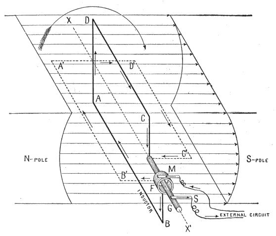
Ques. What is the path of the current to the external circuit?
Ans. It flows out through brush M (fig. 165) and returns through brush S, thus making M positive and S negative.166
Ques. What occurs during the second half of the revolution?
Ans. The wire A B (fig. 166), which before was moving in a downward direction, moves in an upward direction; hence, the current is reversed and flows around the loop in the direction A D C B (fig. 166), going out through brush S and returning through brush M. This makes M negative and S positive.
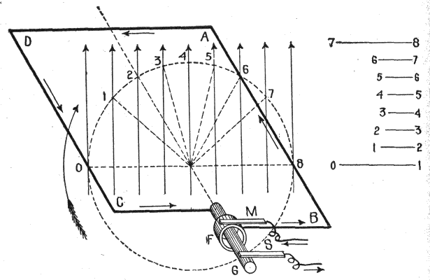
Ques. What may be said of the electromotive force during the second half of the revolution?
Ans. It varies in a similar manner as in the first half of the revolution; that is, the magnetic lines are cut with increasing rapidity during the third quarter, and with decreasing rapidity167 during the fourth quarter of the revolution, which causes the electromotive force to increase and decrease during these intervals.
The cycle of events just described may be summed up as follows: During the revolution of the loop:
It was stated that, during the revolution of the loop, the magnetic lines were cut “with increasing or decreasing rapidity,” causing the electromotive force to rise or fall. The reason for this is illustrated in fig. 167. The loop is here shown in a horizontal position at right angles to the direction of the magnetic field; the latter, as indicated by the even spacing of the vertical arrows representing the magnetic lines, is assumed to be uniform.
The wire C D of the loop, as it rotates at constant speed, cuts the magnetic lines at the points 0, 1, 2, 3, etc., but the distances 0-1, 1-2, 2-3, etc., between these points, are unequal; that is, the wire C D travels farther in cutting the lines 0 and 1, than it does in cutting 1 and 2, and still less in cutting the lines 2 and 3. After cutting the line 4, which passes through the axis of revolution, the opposite conditions obtain.
If the arcs 0-1, 1-2, etc., of the dotted circle, which are intercepted by the magnetic lines and passed through by the wire, be rectified and laid down under each other, as lines 0-1, 1-2, etc., the time of passage of the wire between successive magnetic lines will vary as the length, since the speed is uniform. Thus the wire in passing from line 0 to line 1, takes much more time than in passing from 1 to 2, as indicated at the left of the figure by 0-1 and 1-2, and still less in passing from 2 to 3; that is, the rate of cutting the lines increases as C D rotates from 0 to 4 and decreases from 4 to 8.
Since similar conditions prevail with respect to A B, for its corresponding movement, it is evident that the number of lines which thread through the loop are decreased with increasing rapidity as the loop rotates through the first quarter of a revolution, and increased with decreasing rapidity during the second quarter of the revolution. Moreover, it must be evident that the reverse conditions obtain for the third and fourth quarters of the revolution.168
The Sine Curve.—In the preceding paragraph it was shown that an alternating current is induced in the armature of either an alternator or dynamo; that is, the current: 1, begins with zero electromotive force, 2, rises to a maximum, 3, decreases again to zero, 4, increases to a maximum in the opposite direction, and 5, decreases to zero.

A wave-like curve, as shown in fig. 168, is used to represent these several changes, in which the horizontal distances represent time, and the vertical distances, the varying values of the electromotive force. It is called the sine curve because a perpendicular at any point to its axis is proportional to the sine of the angle corresponding to that point.169
Ques. Describe the construction and application of the sine curve.
Ans. In fig. 168, at the left, is shown an elementary armature in the horizontal position, but at right angles to the magnetic field. The dotted circle indicates the circular path described by A B or C D during the revolution of the loop. Now, as the loop rotates, the induced electromotive force will vary in such a manner that its intensity at any point of the rotation is proportional to the sine of the angle corresponding to that point. Hence, on the horizontal line which passes through the center of the dotted circle, take any length, as 08, and divide it into any number of parts representing fractions of a revolution, as 0°, 90°, 180°, etc. Erect perpendiculars at these points, and from the corresponding points on the dotted circle project lines parallel to 08; the intersections with the perpendiculars give points on the sine curve. Thus the loop passes through 2 at the 90° point of its revolution, hence, projecting over to the corresponding perpendicular gives 2 2′, a point whose elevation from the axis is proportional to the electromotive force at that point. In like manner other points are obtained, and the curved line through them will represent the variation in the electromotive force for all points of the revolution.
At 90°, the electromotive force is at a maximum; hence, by using a pressure scale such that the length of the perpendicular 2 2′ for 90° will measure the maximum voltage the length of the perpendicular at any other point will represent the actual pressure at that point.
The curve lies above the horizontal axis during the first half of the revolution, and below it during the second half, which indicates that the current flows in one direction for a half revolution and in the opposite direction during the remainder of the revolution.
The application of the sine curve to represent the alternating cycle, is further illustrated in figs. 169 to 173, which show the position of the armature at each quarter of the revolution.170
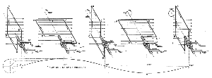 Figs. 169 to 173.—The sine curve with view of armature for
each 90° of the revolution, showing progressively the application of the
sine curve to the alternating current cycle.
Figs. 169 to 173.—The sine curve with view of armature for
each 90° of the revolution, showing progressively the application of the
sine curve to the alternating current cycle.In fig. 179, the loop A B C D is in the vertical position at the beginning of the revolution. At this instant the electromotive force is zero, hence the sine curve as shown begins at E, the zero point—that is, on the axis or line of no pressure.
As soon as the loop rotates out of the vertical plane, the electromotive force rises and the current begins to flow in the direction indicated by the arrows, going out to the external circuit through brush M, and returning through brush S.
Continuing the rotation, the electromotive force increases in proportion to the sine of the angle made by the plane of the loop with the horizontal, until the loop comes into the horizontal position illustrated in fig. 170. This increase is indicated by the gradual rise of the sine curve from E to F. The loop has now made one quarter of a revolution and the electromotive force reached its maximum value.
As the loop rotates past the horizontal position of fig. 170, the electromotive force gradually decreases in intensity, reaching the zero point at the end of the second quarter—that is, when the loop has turned one half revolution. This is indicated by the gradual fall of the curve from F to G.
When the loop turns out of the vertical position shown in fig. 171 the current reverses, because the movement of A B and C D is reversed; at this instant the brush M becomes negative, and S positive. This reversal of current is indicated by the curve falling below the axis from G to I.
During the second half of the revolution, figs. 171 to 173, the changes that occur are the same as in the first half, with the exception that the current is in the reverse direction; these changes are as shown by the curve from G to I.
How the Dynamo Produces Direct Current: The Commutator.—The essential difference between an alternator and a dynamo is that the alternator delivers alternating current to the external circuit while the dynamo delivers direct current. In both machines, as before stated, alternating currents are induced in the armature, but the kind of current delivered to the external circuit depends on the manner in which the armature currents are collected.
In the case of an alternator, the method is quite simple. As previously explained, each end of the loop is connected with an insulated collector ring carried by the shaft, the current being collected by means of brushes which bear against the rings. This principle, rather than the actual construction, is shown in the preceding illustrations. Its important point, as distinguished from other methods of collecting the current, is that each end of the loop is always in connection with the same brush.
Ques. How is direct current obtained in a dynamo?
Ans. A form of switch called the commutator is placed between the armature and the external circuit and so arranged that it will reverse the connections with the external circuit at the instant of each reversal of current in the armature.
Ques. How is a commutator constructed?
Ans. It consists of a series of copper bars or segments arranged side by side forming a cylinder, and insulated from each other by sheets of mica or other insulating material.172
Ques. Where is the commutator placed?
Ans. It is attached to the shaft at the front end of the armature.
Ques. What are inductors?
Ans. The insulated wires wound on the armature core, and in which the electric current is induced.
Ques. How are the inductors connected to the commutator?
Ans. The ends of each conducting loop or coil must be connected with the commutator segments in a certain order to correspond with the type of winding.173
Ques. Explain in detail how direct current is obtained in a dynamo.
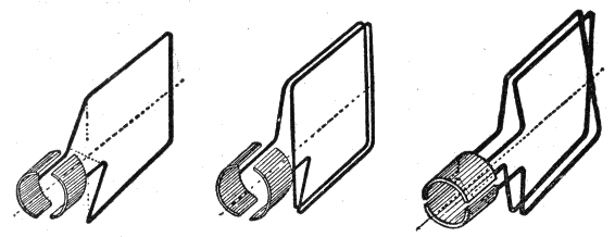
Ans. It will be easily seen by the aid of a series of illustrations just how the alternating armature currents are transformed into direct current. Figs. 174 to 178 show, in several positions, a single loop of wire with its ends joined to a commutator; the latter has only two segments, one for each end of the loop. In fig. 174 the loop is shown in the vertical position, and it should be noted that the division between the two segments forming the commutator is in the same plane as the loop. When the loop is in the vertical position, as shown in fig. 174, brush M is in contact with segment F, and S with G. As the armature rotates, the current flows for one half revolution in the direction A B, through segment F and out to the external circuit through brush M as shown in figs. 174 and 175, returning through brush S and segment G. At the beginning of the second half of the revolution, fig. 176, the current in the loop reverses and flows in the opposite direction B A as indicated by the arrows. At this instant, however, the brushes M and S174 pass out of contact with segments F and G, and come into contact with G and F respectively; that is, M leaves F and contacts with G, while S leaves G and contacts with F. The effect of this is to reverse the connections with the external circuit at the instant the alternation or reversal of current in the armature takes place, thus keeping the current in the external circuit in the same direction.

Ques. How is this indicated by the sine curve?
Ans. The sine curve, instead of falling below the axis, as in figs. 169 to 173, again rises as in the first half of the period, that is G′H′I′ is identical with E′F′G′.
Ques. Is the direct current indicated by the sine curve in figs. 174 to 178 continuous?
Ans. No; it is properly described as a pulsating current, or one, constant in direction, but periodically varying in intensity so as to progress in a series of throbbings or pulsations instead of with uniform strength.175
Ques. What is generally understood by the word “continuous” as applied to the current obtained from a dynamo?
Ans. It is usually accepted as meaning a steady or non-pulsating direct current; one that has a uniform pressure and constant direction of flow as opposed to an alternating current.
Ques. Is a continuous current ever obtained with a dynamo?
Ans. No.

It should be clearly understood at the outset that it is impossible to obtain a continuous current with a dynamo. The so-called continuous current which it is said to produce is in reality a pulsating current, but with pulsations so minute and following each other with such rapidity that the current is practically continuous, and as such is generally called continuous.
Ques. How is the so-called continuous current produced by a dynamo?
Ans. In order to obtain a large number of small pulsations per revolution of the armature instead of two large pulsations,176 as with the single loop armature, the latter must be replaced by one having a great number of loops properly connected to commutator segments and so arranged that the successive loops begin the cycle progressively.
The difficulties encountered in connecting up numerous loops were overcome by Gramme, who, in 1871 invented a “ring” armature. His method consists in winding a ring with a continuous coil of wire, connections being made at suitable intervals with the commutator.

In order to understand the action of such an arrangement, it will be well to first consider four separate coils wound on a ring as shown in fig. 184. These coils are all similar, but at the moment occupy different magnetic positions on the ring. The rotation being clockwise, 1 is about to enter the field adjacent to the north pole, while 2 is emerging from the field in the region of the south pole. Again, 3 is approaching the south pole and 4 receding from the north pole.177
Ques. Describe in detail the action of the four coils wound around the ring as in fig. 184.
Ans. According to the laws of electromagnetic induction, pressures are set up at the ends of the coils such as tend to produce currents in the directions indicated by the arrows. Now, assuming the electromotive forces in coils 1 and 2 to be equal, if the adjacent ends be joined, no flow of current will take place, but the junction will be at a higher pressure than the loose ends of the coils and if a wire be attached to this junction, and the necessary circuits completed, a current will flow along the wire outward from the junction. Similarly, if the adjacent ends of coils 3 and 4 be joined, there will be no flow of current, but the junction will be at a lower pressure than the loose ends, and if a wire be attached to the junction and the necessary circuits completed, current will flow from the junction around the coils.
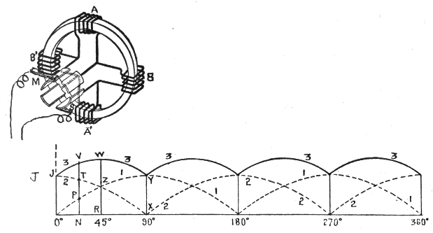
Ques. What may be said with respect to the four coil Gramme ring armature shown in fig. 185?
Ans. According to the laws of electromagnetic induction, with the north pole of the field at the left and clockwise rotation, the induced currents flow upward on both sides of the ring, hence, the electromotive forces oppose each other at only two of the junctions, namely: at the one connected to brush M where the pressures on either side are both directed toward the junction and the other at the junction connected to brush S, at which the pressures are both directed from the junction.

It is evident, then, that the pressure at M is higher than at S; that is, M is positive and S negative; consequently, the current flows from M to the external circuit and returns through S.179
Ques. In what other way may the four coils of the armature in fig. 185 be regarded?
Ans. They may be considered as two pairs A A′ and B B′, the action of either pair being identical with the two coil armature shown in fig. 183; this, in turn, produces the same effect as the one coil armature of fig. 182, with the exception that the amplitude of the current generated with two coils is twice as great as that with one coil of the same number of turns.
Again considering the action of the four ring coil shown in fig. 185, and starting at the beginning of the revolution, the variation of electromotive force induced in coils AA′ is indicated by the dotted sine curve 1, and of BB′ by dotted curve 2. It will be seen that 1 begins at the axis or line of no pressure, and 2 at maximum pressure.

The two curves overlap each other, and in order to determine the effect of this it is necessary to trace the resultant curve, 3. This is easily done, as the resultant electromotive force induced at any point in the revolution of the armature is equal to the sum of the pressures induced in AA′ and BB′. Thus, at the beginning of the revolution the pressure induced in AA′ is at zero point, and in BB′ at its maximum J, hence, the resultant curve begins at the point J. Again, for any point180 in the revolution, as N, the height of the resultant curve is equal to NP + NT = NV. For 45° or 1⁄8 revolution, the resultant curve reaches its amplitude, which is equal to 2 × RZ = RW, and at 90° it again reaches its minimum, XY.
Ques. State the conditions upon which the steadiness of the current depends.
Ans. It depends on the number of coils and the manner in which they are connected.
Comparing curves 1 and 3, in fig. 185, it will be noted that with four coils the variation of pressure or amplitude of the pulsations is less than half that obtained with two; moreover, with four coils the number of pulsations per cycle is doubled.
In order to further observe the approach to continuous current obtained by increasing the number of coils, the effect of a six coil armature is shown in fig. 186, the resultant curve being obtained in the same manner as just explained. For comparison, the curves for the three cases of two, four, and six coils are reproduced under each other in fig. 187.
As the number of coils is further increased, the amplitude of the pulsations decreases so that the resultant curve approaches nearer the form of a straight line.
In the actual dynamo there are a great many coils, hence the amplitude of the pulsations is exceedingly small; accordingly, it is customary to speak of the current as “continuous,” although as previously mentioned such is not the case.
In order to adapt the dynamo to the varied conditions of service, its design is modified in numerous ways, giving rise to the different “types.” These may be classified with respect to:
The first division relates to the number of magnetic poles, as unipolar, bipolar, and multi-polar dynamos; also inter-polar dynamos. Under the second division are included the following:
1. Self-exciting machines of which the magneto is the simplest. Its magnetic field is obtained from permanent magnets, hence the electromotive force generated is comparatively small. The more important type of self-exciting machine is provided with electromagnets in which the field of force is “built up” from the residual magnetism of the soft iron or steel cores of the field magnets of the dynamo itself. Nearly all commercial types of dynamo are of this class.
2. Separately excited machines in which the field magnets are magnetized when the machine is in operation by current supplied from a separate source such as a battery or magneto generator.182
With respect to the third division, based on the field winding, dynamos are classed as:
In addition to the foregoing there are further distinctions with respect to the mechanical features. Most dynamos have a revolving armature and stationary field magnets; however, in some cases, both the armature and field magnets are stationary, a revolving iron inductor being provided to intercept the magnetic lines intermittently which produces the same effect as is obtained in cutting the magnetic lines by a revolving armature.
Ques. What may be said of bipolar and multi-polar dynamos?
Ans. Dynamos with bipolar field magnets were universally used prior to 1890, but since that time machines of this type are only made in very small sizes; the multi-polar dynamo is the type now in general use.
Ques. State some of the features of the multi-polar dynamo.
Ans. In this class of machine, the armature and field magnets are surrounded by a circular frame, or ring yoke to which the field magnets are attached. This ring arrangement has the advantages of strength, simplicity, symmetrical appearance, and minimum magnetic leakage, since the pole pieces have the least possible surface and the path of the magnetic flux is shorter.
Ques. What important advantage is gained by the use of multi-pole field magnets?
Ans. Commercial voltages are obtained at moderate armature speed183.
The difficulty experienced with bipolar machines is that, with a dynamo of large output, the speed at which its armature would have to rotate to generate commercial voltages would be excessive.
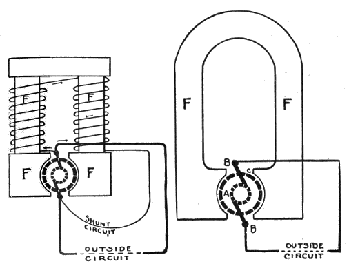
It is evident that with two or more magnetic fields, secured by increasing the number of poles, the armature inductors revolving between them cut more magnetic lines in one revolution than with a single field, hence, a given voltage is obtained with less speed of the armature than in the bipolar machine.
For instance, if a bipolar dynamo be required to run at say 900 revolutions per minute to generate 125 volts, a four pole machine of equal output will require only 450 revolutions, and one of eight poles only 225 revolutions per minute.184
Ques. What is a self-exciting dynamo?
Ans. A machine in which the initial excitation of the field is due to the residual magnetism retained by the cores.
Ques. What may be said of the field due to this residual magnetism?
Ans. It presents a very weak field, and the voltage that could be generated by the armature revolving in such a field would be only about two to ten volts.

Ques. How then can commercial voltages such as 100 or more volts be obtained with a self-exciting dynamo?
Ans. Part or all of the current induced in the armature is passed through the windings of the field magnets, thus strengthening the field. The voltage, therefore, will “build up,” increasing until the maximum has been reached185.
The maximum voltage will depend upon the capacity of the field magnets as determined by the construction, and upon the strength of current used to excite them.
Ques. How long does the process of “building up” require?
Ans. The time required to fully excite the field magnets is from ten to twenty seconds, the rise in field strength being indicated on the voltmeter or by the gradual increase in the brilliancy of the pilot lamp.
Ques. Name three important classes of dynamo.
Ans. Series wound, shunt wound, and compound wound.
Ques. Describe the winding of a series dynamo.
Ans. In this machine, the field magnets are wound with a few turns of thick wire joined in series with the armature brushes as shown in fig. 190.
Ques. What is the effect of this arrangement?
Ans. All of the current generated by the machine passes through the coils of the field magnets to the external circuit. The current in passing through the field magnets, energizes them and strengthens the weak field due to the residual magnetism of the magnet cores, resulting in the gradual building up of the field.
Ques. For what service is the series dynamo adapted?
Ans. It may be used for series arc lighting, series incandescent lighting, and as a booster for increasing the pressure on a feeder carrying current furnished by some other generator.
Ques. What is the effect of the series winding in the operation of the machine?
Ans. Its characteristic is to furnish current at an increased voltage as the load increases. If sufficient current be drawn to overload the machine, the voltage will drop.186
Since the armature coils, field magnets and external circuits are in series, any increase in the resistance of the external circuit lessens the power of the machine to supply current, because it diminishes the current in the coils of the field magnets and therefore diminishes the effective magnetism. Again, a decrease in the resistance of the external circuit will increase the voltage because more current will flow through the field magnets. Accordingly, when the external circuit has lamps in series (as is common in an arc light circuit) the switching on of an additional lamp both adds to the resistance of the circuit and diminishes the power of the machine to supply current. When the lamps are in parallel, the switching on of additional lamps not only diminishes the resistance of the circuit, but causes the field magnets to be further excited by the increased current, so that the greater the number of lamps put on, the greater becomes the risk of inducing too much current.
The series dynamo has also the disadvantage of not starting action until a certain speed has been attained, or unless the resistance of the external circuit be below a certain limit.
Regulation of Series Dynamos.—The series dynamo is ordinarily used for operating arc lamps connected in series. The current generally consumed is about 10 amperes, and it is necessary that it should remain at this strength to keep the lights burning steadily. If it increase, the lights will be too bright, and if it decrease, they will be too dim or flicker.
With all the lamps connected in series it is evident that the resistance of the circuit will vary widely as they are turned on or off, the resistance increasing as the lamps are turned on, and decreasing as they are turned off. It is necessary, therefore, that some means of regulation be provided to enable the dynamo to increase or decrease the voltage in proportion to the load. There are several methods of regulation, as by:
Whatever method be used the necessary regulation should be accomplished by automatic devices, as it would not be practical to station a man in constant attendance to regulate187 the voltage every time one or more lamps were thrown on or off.
Ques. When is the first method of regulation used?
Ans. It is only used in special cases, as for constant load; if the voltage be not just right to give the required current, it may be adjusted by changing the speed of the engine.
Ques. What may be said of the second method?
Ans. In both the “ring” and “drum” types of armature, rotating in a bipolar field, there are two points situated at opposite extremities of a diameter of the commutator, at one of which the potential is a maximum and at the other a minimum, and it is at these points that the brushes must be placed in order to obtain the greatest difference of pressure, the difference being less at other points. Hence, by rocking the brushes around the commutator the pressure at the terminals of the machine may be varied and regulated as required.
Ques. What difficulty is experienced in rocking the brushes to regulate the voltage?
Ans. Sparking takes place at the brushes when they are moved any considerable distance from the neutral position.
Special dynamos have been designed to overcome this objectionable feature, still this method of regulation is not extensively used.
Ques. What may be said of the third method of regulation?
Ans. The third method, that of variation of field strength, is the one in general use.
Ques. How is the field strength varied?
Ans. This may be done by the two path method, or by the variable field coil method.188
Ques. Describe the two path method of field regulation.
Ans. An adjustable resistance or rheostat is connected in parallel with the field winding as shown in fig. 191. This shunts more or less of the current from the field winding according to the amount of resistance made active by the lever, L.
Thus, if the current in the armature and main circuit be 10 amperes and the resistance of the field winding 10 ohms, a resistance of 40 ohms in parallel with the winding would cause the current to split in the ratio of 40 to 10, or 4 to 1; 2 amperes would pass through the resistance and 8 amperes through the field.


Ques. Describe the variable field coil method of field regulation.
Ans. This consists in dividing the field winding into a number of sections and throwing the sections in and out of circuit as shown in fig. 192.
Since the strength of any magnet depends on the number of ampere turns in its field winding, reducing or increasing the number of turns will respectively reduce or increase the field strength, the current being kept constant.189
Ques. What is the objection to this method?
Ans. This arrangement is undesirable for magnets of large size, because of the tendency to flashing at the contacts of the regulating switch.

The Shunt Dynamo.—The shunt wound dynamo differs from the series wound machine, in that an independent circuit is used for exciting its field magnet. This circuit is composed of a large number of turns of fine insulated copper wire, which is wound round the field magnets and connected to the brushes, so as to form a shunt or “by pass” to the brushes and external circuit, as shown in fig. 193. Two paths are thus presented to the current as it leaves the armature, between which it divides in the inverse ratio of the resistance. One part of the current flows through the magnetizing coils, and the other portion through the external circuit.190
In all well designed shunt dynamos, the resistance of the shunt circuit is always very great, as compared with the resistance of the armature and external circuit, the strength of the current flowing in the shunt coils being very small even in the largest machines.
Ques. For what service is the shunt dynamo adapted?
Ans. It is used for constant voltage circuits, as in incandescent lighting.
Ques. In the operation of a shunt dynamo what is its characteristic feature?
Ans. The voltage at the dynamo remains practically unchanged, and the current varies according to the load.
Ques. Does the voltage remain constant for all loads?
Ans. There is a certain maximum load current that the shunt dynamo is capable of supplying at constant voltage; beyond this, the voltage will decrease, the machine finally demagnetizing itself, and ceasing to generate current.
Ques. Why does the voltage not remain constant for all loads?
Ans. Because there is a drop in the voltage in forcing the current through the armature windings which increases with the load.
Ques. What is the usual method of regulation for shunt dynamos?
Ans. The method of varying the current through the field coils by means of a rheostat inserted in series with the field winding as shown in fig. 194.191
Moving the lever L of the rheostat to the right increases the resistance in series with the field winding, and this reduces the amount of current in that winding, thus reducing the strength of the magnet and consequently the voltage at the brushes. The contrary movement of the lever, by cutting out the resistance, produces the opposite effect.
The Compound Dynamo.—This class of generator is designed to automatically give a better regulation of voltage on constant pressure circuits than is possible with a shunt machine. It possesses the characteristics of both the series and shunt machines, of which it is in fact a combination.
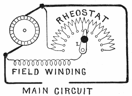
The field magnets of the compound dynamo, as shown in fig. 195, are wound with two sets of coils, one set being connected in series, and the other set in parallel, with the armature and external circuit. The purpose of the series winding is to strengthen the magnets by the current supplied from the armature to the circuit, and thus automatically sustain the pressure. If the series winding were not present, the pressure at the192 terminals would fall as the load increased. This fall of pressure is counteracted by the excitation of the series winding, which increases with the load and causes the pressure to rise. The number of turns and relative current strengths of the series and shunt windings are so adjusted that the pressure at the terminals is maintained practically constant under varying loads.
With respect to the ratio between the number of turns of the two field windings, the dynamo is spoken of as:
Ques. What is the difference between a compound and an over compounded dynamo?
Ans. In the first instance, there are just enough turns in the series winding to maintain the voltage constant at the brushes for variable load. If a greater number of turns be used in the series winding than is required for constant voltage at the brushes for all loads, the voltage will rise as the load is increased, and thus make up for the loss or drop in the transmission lines, so that a constant voltage will be maintained at some distant point from the generator. The machine is then said to be over compounded.
Ques. For what service is over compounding desirable?
Ans. For incandescent lighting where there is considerable length of transmission lines.
Ques. What is the usual degree of over compounding?
Ans. Generally for a rise of voltage of from five to ten per cent.193
In construction, the field coils are wound with a greater number of turns than actually required, the machine being accurately adjusted by a running load test after completion.
Ques. How is the degree of over compounding varied?
Ans. A rheostat is placed in shunt with the series winding so that the current passing through the winding may be regulated to control the voltage of the machine.

Ques. How are the ends of the shunt winding of a compound dynamo connected?
Ans. There are two methods of connection, being known as the short shunt and the long shunt.
Ques. Describe the short shunt.
Ans. In the short shunt, the ends of the shunt winding are connected directly to the brushes as in fig. 196.194
Ques. Describe the long shunt.
Ans. In the long shunt, one end of the shunt winding is connected to one of the brushes and the other end to the terminal connecting the series winding with the external circuit as in fig. 197.
Ques. Which is the more desirable?
Ans. Theoretically, the long shunt is preferable as being the more efficient; however, in practice, the gain is not very appreciable and the short shunt is generally used.

Ques. What may be said regarding the voltage in short, and long shunt machines?
Ans. In a short shunt machine, the shunt winding is subjected to a higher voltage than with a long shunt. The pressure applied through a shunt winding with a long shunt, for any195 particular load, is equal to the voltage at the brushes plus the drop in the series winding.
Ques. For what other service besides incandescent lighting are compound dynamos adapted?
Ans. They are employed in electric railway power stations where the load is very fluctuating.
Ques. What is the effect of a short circuit on a compound dynamo?
Ans. It overloads the machine, since the excessive current flowing through the series field tends to keep the voltage at its normal value.
Unless the line be automatically opened under such a condition either by a fuse or circuit breaker, the machine and its driving engine may be damaged. To avoid this danger fuses or automatic circuit breakers are employed.
Ques. Mention another service for which the compound dynamo is used.
Ans. In some isolated plants, as small country residences where it is frequently necessary to have a dynamo capable of charging a storage battery during the day, and of furnishing current for lighting during a certain portion of the evening.
Under such conditions the compound machine with slight modification is used, the ordinary shunt dynamo not being capable of maintaining the necessary consistency of voltage, without attention to the shunt regulator in driving the lamps direct, the ordinary compound dynamo on the other hand, being unsatisfactory for charging storage batteries.
Ques. How is the compound dynamo modified to adapt it to the dual service of lighting and battery charging?
Ans. It is furnished with alternative compound winding, in which the series winding is provided with a switch, which196 may be fixed either upon the machine itself or upon the switchboard. This switch permits the series coils to be either short circuited in part or cut out of the circuit entirely while the machine is charging the storage battery, being again cut into circuit when the machine is required to furnish current for the lamps.

Separately Excited Dynamos.—In this class of machine the current required to excite the field magnets is obtained from some independent external source. Though used by Faraday, the separately excited dynamo did not come into favor until, in 1866, Wilde employed a small auxiliary magneto machine to furnish currents to excite the field magnets of a larger dynamo.
A separately excited dynamo is shown in fig. 198. This197 method of field excitation is seldom used except for alternators; it is, however, to be found occasionally in street railway power houses, the shunt fields of all the dynamos being separately excited by one dynamo.
In common with the magneto, the separately excited machine possesses the property that, with the exception of armature reactions, the magnetism in its field and therefore the total voltage of the machine is independent of variations in the load.

Dobrowolski Three Wire Dynamo.—This type of dynamo was designed to operate a three wire system of distribution without a balancer. The armature is provided with insulated slip rings connected to suitable points in the armature winding and (by means of brushes) with choking coils meeting at a common point, to which the neutral wire of the system is connected, the main terminals being connected with the outside wires.198
The machine is capable of feeding unbalanced loads without serious disturbance of the pressure on either side of the system.
The principle of the Dobrowolski three wire dynamo is illustrated in fig. 199. The armature A is tapped at two points, B and B′, and connected to slip rings C C′. A compensator or reactance coil D, between the two halves of which there is minimum magnetic leakage, is connected to C and C′ by brushes, and has its middle point tapped and connected to the neutral wire E.

It is clear, from the symmetry of the arrangement, that the center point of the coil must always be approximately midway in pressure between that of the brushes, and hence any unbalanced current will return into the armature, dividing equally between the two halves of the coil.
The arrangement forms a cheap and effective substitute for a balancer set, but lacks the adjustable properties of the latter.
There are various modifications of the arrangement. Thus more than two slip rings may be used. The compensator windings, however, should always be arranged so that the magnetizing effect of the neutral current is self-neutralized in the windings, as otherwise saturation occurs causing a very heavy alternating magnetizing component.
The object of the field magnet is to produce an intense magnetic field within which the armature revolves. It is constructed in various forms, due in a large measure to considerations of economy, and also to the special conditions under which the machine is required to work.
Electromagnets are generally used in place of permanent magnets on account of: 1, the greater magnetic effect obtained, and 2, the ability to regulate the strength of the magnetic field by suitably adjusting the strength of the magnetizing current flowing through the magnet coils.
The field magnet, in addition to furnishing the magnetic field, has to do duty as a framework which often involves considerations other than those respecting maximum economy.
The Make Up of a Field Magnet.—In construction, the electromagnet, used for creating a field in which the armature of a dynamo revolves, consists of four parts:
These are shown assembled in figs. 201 to 204.
Ques. What is the object of the yoke?
Ans. The yoke serves to connect the two “limbs,” that is, the cores and pole pieces, and thus provide a continuous metallic circuit up to the faces of the pole pieces.
Ques. How is the yoke constructed?
Ans. It usually forms the frame of the dynamo as shown in figs. 205 and 206.

Ques. What may be said of the cores?
Ans. The cores, which are usually of circular form, carry the coils of insulated wire used to excite the magnets.
Classes of Field Magnet.—Although numerous forms of field magnet have been devised, they can be classed into two groups according to the type of pole, as:
The distinction between these two types of pole is shown in figs. 201 to 203. By inspection of the figures, it will be seen that the term salient applies to poles produced when the pole pieces form the ends of the magnet, as distinguished from consequent poles, or those formed by coils wound on a continuous metal ring or equivalent.
In the salient pole bipolar magnet, the winding may be either upon the limbs, M M fig. 202, or upon the yoke, Y as shown in fig. 201. The magnetic circuit of salient and consequent poles is indicated in the figures by the dotted lines.


Multi-Polar Field Magnets.—In the multi-polar machine, the subdivision of the magnetic flux reduces the amount of material of both magnet and armature. Moreover, there is less heating on account of the greater capability of dissipating the heat, offered by the increased area of surface per unit of volume in each magnet pole and winding.

There may be four, six, eight, or more poles, arranged in alternate order around the armature. Fig. 204 shows a four pole field magnet having a common yoke or iron ring, with four pole pieces projecting inwardly, and over which the exciting coils are slipped.
In the larger machines the yoke is made in two parts bolted together as shown in fig. 206, so that the upper portion may be lifted off for examination of the armature.
Ques. Can the number of poles in a multi-polar machine be advantageously increased to 16, 32, or more?
Ans. A large number of poles is not advisable except in very large machines, since it involves an increase in the expense203 of machine work, fittings, etc., somewhat out of proportion to the reduction in cost of material and increase in efficiency.
Ques. What materials are generally used for field magnets?
Ans. Wrought iron, steel and copper.
There are a number of considerations which govern the selection of the materials to be used in a particular machine, such as initial cost, weight, efficiency, etc.

Ques. In the construction of field magnets, what governs the choice of materials?
Ans. For cores, wrought iron is most desirable, as requiring the smallest amount of material for a given flux. There is a saving in copper due to using wrought iron for the core since, on account of its small size, the length of each turn of the204 magnetizing coil is reduced. For heavy yokes, where lightness is not essential, but very often the reverse, cast iron is used, as its cross section can be made larger than that of the cores, this increase in area serving to give strength and rigidity to the machine. Cast steel occupies a place intermediate between cast iron and wrought iron both in cost and magnetic properties.


Ques. Name two forms of yoke in general use.
Ans. The solid, and divided types as shown in figs. 205 and 206.
Ques. What is the object of dividing a yoke?
Ans. To permit access to the armature, where the construction does not admit of removal of the latter from the side.205
Ques. How is the yoke usually divided?
Ans. Across its horizontal diameter into an upper and lower half, as shown in fig. 206, the lower half being seated on, or more frequently cast in one piece with the bed plate.
Ques. What is the objection to dividing a yoke?
Ans. The joints introduced, even if carefully faced and well bolted together, add a little reluctance to the magnetic circuit.

Ques. How does this affect the poles adjacent to the points, and what provision is made?
Ans. It weakens them, and in order to overcome this, the coils of these poles are given a few extra turns.
Ques. How is the reluctance of a yoke joint reduced?
Ans. By enlarging the area of contact; the flange for the bolts furnishes the necessary increase.
Ques. What determines chiefly the cost of field magnets?
Ans. The material used in making the cores and their shape.206
Ques. How does this affect the cost?
Ans. Since considerable cross sectional area of core is required, the problem confronting the designer is to design the core by judicious selection of material and shape, that the required number of turns in the magnetizing coil is obtained with the shortest length of wire.

Ques. What is the principal objection to the use of cast iron for core construction?
Ans. Since its sectional area must be considerably more than wrought iron, a much greater quantity of copper is required for the magnetizing coils.
Copper is expensive, while cast iron cores are less expensive than equivalent ones of wrought iron; in this connection, it is interesting to observe how different designers aim at true economy in construction.207
Steel is sometimes used in place of wrought iron, and though less efficient magnetically, it can be cast into the desired shape, thus avoiding the somewhat expensive processes of forging and machining, which are necessary in the case of wrought iron.
Ques. What form of core requires the least amount of copper for the magnetizing coils, and why?
Ans. The cylindrical core, because it has the shortest periphery or boundary for a given area enclosed.
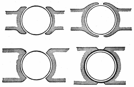
Figs. 216 to 221, show a series of cross sections, all of the same area. The number marked on each section indicates the length of the boundary line, that of the circle being taken for convenience as 100.
Ques. What are the pole pieces?
Ans. These are the end portions of the field magnets, joined to, or cast together with the core and placed adjacent to the armature.208
The faces of the pole pieces are of circular shape, thus forming the sides of the so-called armature chamber within which the armature rotates.

Ques. Why are the pole faces made larger than the coils?
Ans. In order to reduce the reluctance of the air gap between the face and the armature, thus enabling fewer magnetizing coils to be used.

It is important that the field should be magnetically rigid, that is, not easily distorted. This stiffness of field can be partially secured by judicious shaping of the pole pieces. A few forms of pole piece are shown in figs. 222 to 231.209
If the projecting tips of the pole pieces, or horns as they are called, be widely separated, as in fig. 222, they are not always good, even though thin. It is better that they should be extended as in fig. 223 so that they may be saturated by the leakage field or else cut off as in fig. 224.
An extreme design, suggested by Dobrowolski, as shown in fig. 225, surrounds the armature with iron.


Another scheme, proposed by Gravier, employed the unsymmetrical form shown in fig. 226. In this pole piece the forward horn is elongated. The action due to this arrangement is such that when the machine is working at small loads, the field in the gap is nearly uniform, but at heavy loads with distorting reactions which have a tendency to drive the flux into the forward horn, the small section of the latter causes it to become saturated, thus reducing the distortion to a minimum.
Eddy Currents; Laminated Fields.—The field magnet cores and pole pieces, as well as the armature of a dynamo are subject to eddy currents, that is, induced electric211 currents occurring when a solid metallic mass is rotated in a magnetic field. These currents consume a large amount of energy and often occasion harmful rise in temperature. This loss may be almost entirely avoided by laminating the pole piece, or both pole piece and core; in the latter case, both form one part without any joint.


Ques. What is a laminated pole?
Ans. One built up of layers of iron sheets, stamped from sheet metal and insulated, as shown in fig. 234.
Ques. What may be said of this construction?
Ans. It is a most approved method, and one frequently employed in the construction of cores and pole pieces.212
Fig. 234 shows a combined core and pole piece made entirely of sheet iron punchings assembled and riveted together, and fig. 235, a core to be used with separate pole piece. It should be noted that in both cases there is a longitudinal slot extending from the end into the core. This was first suggested by Lundell, the object being to prevent, as far as possible, the distortion of the magnetic field due to armature reaction especially on heavy overloads.

Ques. What mode of construction is adopted to reduce the reluctance of the magnetic circuit when laminated poles are used?
Ans. They are cast welded into the frame.

The frame end of the core as shown in the illustrations has irregularities in the heights of the different sheets, as well as grooved undercut214 surfaces, in order to enable the molten metal of the frame to key well into the laminations of the core, making a good joint, both mechanically and electrically. By this construction, the continuity of the magnetic circuit is practically unbroken save for the air gap between the pole piece and armature.
Fig. 236 shows a one piece frame of a six pole dynamo having cast welded into it, combined cores and pole pieces.
Ques. What is the disadvantage of laminating a core?
Ans. It necessitates a nearly square or rectangular section, which requires more copper for the winding than the cylindrical form.

The Magnetizing Coils.—The object of the magnetizing coils, is to provide, under the various conditions of operation, the number of ampere turns of excitation required to give the proper flux through the armature to produce the desired electromotive force.
With respect to the manner in which magnetizing coils are wound they are said to be:
Ques. Describe the methods of constructing spool wound coils.
Ans. The spool is made in various ways, sometimes entirely of brass, or of sheet iron with brass flanges, or of very thin cast iron. Some builders use sheet metal with a flange of hardwood, such as teak. If a spool be simply put upon a lathe to be wound, the inner end of the wire, which must be properly secured, should be brought out in such a way that it cannot possibly make a short circuit with any of the wires in the upper layers. To avoid this difficulty, the wire is sometimes wound on the spool in two separate halves, the two inner ends of which are united, so that both the working ends of the coil come to the outside as shown in fig. 238.

Ques. Describe the construction of former wound coils.
Ans. Former wound coils are wound upon a block of wood having temporary flanges to hold the wire together during the winding. Such coils have pieces of strong tape inserted between216 the layers and lapped at intervals over the windings to bind them together. Coils are usually soaked with insulating varnish and stove dried.
Ques. What may be said with respect to the coil ends?
Ans. Several methods of bringing out the ends of coils are shown in figs. 238 to 241. In fig. 239 copper strip, laid in behind an end sheet of insulating material, makes connection to the inner end, as shown in the right side of the figure, while another strip, shown on the left side similarly inlaid, serves as a mechanical and electrical attachment for the outer end of the winding.
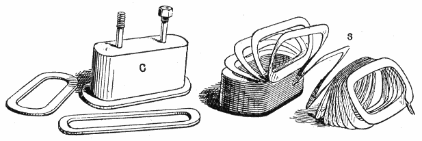
Two other methods are shown in figs. 240 and 241. A simple device for securing the outer end is to fashion a terminal piece so that it can be laid upon the winding, the last three or four turns of which are wound over its base, and after winding, are bared at the place and securely soldered.
Ques. How are the coils insulated?
Ans. The spools upon which the coils are wound are usually insulated with several layers of paper preparations; a thickness217 of one-tenth of an inch made up of several superposed layers is generally sufficient. Varnished canvas is useful as an underlay, and vulcanized fibre for lining the flanges. It is important to protect the joint between the cylindrical part and the flanges. A core paper may be laid upon every four layers of winding. Between series and shunt coils, in compound wound machines there should be an insulation as efficient as that on the cores.218 When the winding is completed, two layers of pressed board or equivalent are laid over and bound with an external winding of hard rope or tape. This protective external lagging covering the outer surface of the completed coils is not altogether a benefit for it tends to prevent dissipation of heat.
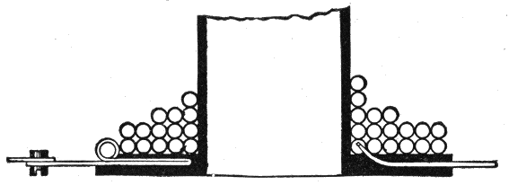


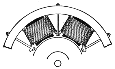
Ques. How are the coils attached?
Ans. Where the pole pieces are simply extensions of the cores without enlargement, the coils can be slipped over the ends, but some kind of clamping device is necessary to hold them in place, as for instance, the method shown in fig. 244.
In case the pole piece be made larger than the core and separate therefrom, it is put into position after the coils are in place, thus serving the double purpose of pole piece and clamp.219
Ques. Describe the coil connections.
Ans. Coils are generally united in series so that the same magnetizing current may flow through all of them. The coils should be so connected that they produce alternate north and south poles.
If all the coils be similarly wound with respect to the terminals, and similarly placed; that is, so placed that the winding, considered from the coil terminal nearest the pole face, starts in all the coils in the same direction, then the connections will come at the north end and at the south end of the spools.

Heating.—The heat generated in the magnetizing coils is dissipated in three ways; by:
In the first instance, it passes through the copper and the insulation, either to the external surface, whence it passes off by radiation and convection into the air, or to the magnet220 core and yoke, which in turn conduct it away. In large multi-polar machines the masses of metal in the pole cores and frame are more efficient in dissipating heat than the external surface of the coil.

Ventilation.—Sometimes provision is made for ventilation of the field magnet coils as shown in fig. 246. Here the series and shunt coils are wound side by side, ample ventilation being provided lengthwise through and between the coils.
They are not only the best, but the cheapest work published on Electricity. Each number being complete in itself. Separate numbers sent postpaid to any address on receipt of price. They are guaranteed in every way or your money will be returned. Complete catalog of series will be mailed free on request.
ELECTRICAL GUIDE, NO. 1
Containing the principles of Elementary Electricity, Magnetism, Induction, Experiments, Dynamos, Electric Machinery.
ELECTRICAL GUIDE, NO. 2
The construction of Dynamos, Motors, Armatures, Armature Windings, Installing of Dynamos.
ELECTRICAL GUIDE, NO. 3
Electrical Instruments, Testing, Practical Management of Dynamos and Motors.
ELECTRICAL GUIDE, NO. 4
Distribution Systems, Wiring, Wiring Diagrams, Sign Flashers, Storage Batteries.
ELECTRICAL GUIDE, NO. 5
Principles of Alternating Currents and Alternators.
ELECTRICAL GUIDE, NO. 6
Alternating Current Motors, Transformers, Converters, Rectifiers.
ELECTRICAL GUIDE, NO. 7
Alternating Current Systems, Circuit Breakers, Measuring Instruments.
ELECTRICAL GUIDE, NO. 8
Alternating Current Switch Boards, Wiring, Power Stations, Installation and Operation.
ELECTRICAL GUIDE, NO. 9
Telephone, Telegraph, Wireless, Bells, Lighting, Railways.
ELECTRICAL GUIDE, NO. 10
Modern Practical Applications of Electricity and Ready Reference Index of the 10 Numbers.
[1] NOTE.—In 1749, Benjamin Franklin, observing lightning to possess almost all the properties observable in electric sparks, suggested that the electric action of points, which was discovered by him, might be tried on thunderclouds, and so draw from them a charge of electricity. He proposed, therefore, to fix a pointed iron rod to a high tower, but shortly after succeeded in another way. He sent up a kite during the passing of a storm, and found the wetted string to conduct the electricity to the earth, and to yield abundance of sparks. These he drew from a key tied to the string, a silk ribbon being interposed between his hand and the key for safety. Leyden jars could be charged, and all other electrical effects produced, by the sparks furnished from the clouds. The proof of the identity was complete. The kite experiment was repeated by Romas, who drew from a metallic string sparks 9 feet long. In 1753, Richmann, of St. Petersburg, who was experimenting with a similar apparatus, was struck by a sudden discharge and killed.
[2] NOTE.—Suppose that the conditions are as in the fig. 34, that is, the segment A1 is positive and the segment B1 negative. Now, as A1 moves to the left and B1 to the right, their potentials will rise on account of the work done in separating them against attraction. When A1 comes opposite the segment B2 of the B plate, which is now in contact with the brush Y, it will be at a high positive potential, and will therefore cause a displacement of electricity along the conductor between Y and Y1, bringing a large negative charge on B2 and sending a positive charge to the segment touching Y1.
As A1 moves on, it passes near the brush Z and is partially discharged into the external circuit. It then passes on until, on touching the brush X, it is put in connection with X, and has a new charge, this time negative, driven into it by induction from B2. Positive electricity, then, being carried by the conducting patches from right to left on the upper half of the A plate, and negative from left to right on its lower half.
A similar process is taking place on the B plate, but in this case the negative electricity is going from left to right above, and the positive from right to left below. On the whole, therefore, positive electricity is being supplied to the left hand main conductor Z by both upper and lower plates, and negative to Z1.
[3] NOTE.—The discovery of this property of matter is due to Stephen Gray, who, in 1729, found that a cork, inserted into the end of a rubbed glass tube, and even a rod of wood stuck into the cork, possessed the power of attracting light bodies. He found, similarly, that metallic wire and pack thread conducted electricity, while silk did not.
Gray even succeeded in transmitting a charge of electricity through a hempen thread over 700 feet long, suspended on silken loops. A little later, Du Fay succeeded in sending electricity to no less a distance than 1,256 feet through a moistened thread, thus proving the conducting power of moisture. From that time the classification of bodies into conductors and insulators has been observed.
[4] NOTE.—Copper is pre-eminently the metal used for electric conduction, being among the best conductors, it is excelled by one or more of the other metals, but no other approaches it in the average of all qualities.
[5] NOTE.—A current of electricity always flows in a conducting circuit when its ends are kept at different potentials, in the same way that a current of water flows in a pipe when a certain pressure is supplied. The same electrical pressure does not, however, always produce a current of electricity of the same strength, nor does a certain pressure of water always produce a current of water of the same volume or quantity. In both cases the strength or volume of the currents is dependent not only upon the pressure applied, but also upon the resistance which the conducting circuit offers to the flow in the case of electricity, and on the friction (which may be expressed as resistance) which the pipe offers to the flow in the case of water.
[6] NOTE.—The prefixes “meg” and “micro” denote million and millionth. For example, a megohm equals 1,000,000 ohms, a microhm equals 1⁄1,000,000 of an ohm.
[7] NOTE.—The reciprocal of a number is equal to 1 ÷ the number; for instance, the reciprocal of 3⁄20 = 1 ÷ 3⁄20 = 20⁄3 = 62⁄3
[8] NOTE.—A writer in the New Science Review undertakes to answer the question: “What is electricity?” In order to lead the reader up to the main question, he first considers the natural forces, gravitation and heat. Examples are given of how these forces are manifested and how energy is changed from one form to another. Every form of force, the author says, should be regarded as a different method in which energy makes itself known to the senses. He calls particular attention to the important fact that the “resistance of one kind or another is always the agent that acts to alter energy from one form to another,” and suggests that electricity is simply a form or manifestation that energy may assume under given conditions, and generally is a mere transitory stage between the mechanical form and the heat form. “In most operations,” he continues, “mechanical force passes to the heat form without passing through the electric form; but whenever magnetism is brought into play as a resistance that must be overcome, then mechanical power applied to overcome this resistance always becomes electricity, if only momentarily in its passage from the mechanical to the heat form.” In conclusion, he asks if the question: “What is electricity?” cannot be answered in a fairly satisfactory way by saying that it is simply a form that energy may assume while undergoing transformation from the mechanical or the chemical form to the heat form or the reverse.
[9] NOTE.—The cathode is the conductor by which current flows away as distinguished from the anode or conductor through which the current enters. The terms usually apply to conductors leading the current through a liquid or gas, as an electrolytic cell, or vacuum tube.
[10] NOTE.—The name voltameter was given by Faraday to an electrolytic cell employed as a means of measuring an electric current by the amount of chemical decomposition the current effects in passing through the cell.
[11] NOTE.—Faraday’s own description of his discovery is as follows: “Two hundred and three feet of copper wire in one length were coiled round a large block of wood; another two hundred and three feet of similar wire were introposed as a spiral between the turns of the first coil, and metallic contact everywhere prevented by twine. One of these helices was connected with a galvanometer, and the other with a battery of one hundred pairs of plates, four inches square, with double coppers, and well charged. When the contact was made there was a sudden and very slight effect at the galvanometer, and there was also a similar slight effect when the contact with the battery was broken.”
[12] NOTE.—In reality it would be impossible to have a magnetic field exactly like fig. 129, for in the less dense part, the magnetic lines would be of curved complex form.
[13] NOTE.—These values are correct for effective sinusoidal voltages.
[14] NOTE.—It should be understood that a dynamo does not generate electricity, for if it were only the quantity of electricity that is desired, it would be of no use, as the earth may be regarded as a vast reservoir of electricity. However, electricity without pressure is incapable of doing work, hence a dynamo, or so-called “generator,” is necessary to create an electromotive force by electromagnetic induction in order to cause the current to flow against the resistance of the circuit and do useful work.
Transcriber’s Note: Blank pages have been deleted. Some illustrations may have been moved. Notes at the bottom of pages in the text were converted to footnotes and footnote tags were added to the text itself. The footnotes are now located prior to this section. When the author’s preference can be determined, we have rendered consistent on a per-word-pair basis the hyphenation or spacing of such pairs when repeated in the same grammatical context. The publisher’s inadvertent omissions of important punctuation have been corrected. Duplicative front matter has been removed. Ditto marks may have been replaced by the text represented.
The following list indicates any additional changes. The page number represents that of the original publication and applies in this etext except for footnotes and illustrations since they may have been moved.
  TOC = Table of Contents

  TOC  [Added INTRODUCTORY CHAPTER and SIGNS AND SYMBOLS]
  TOC  between electric and netic[magnetic] circuits
  TOC  action of Toepler-Holz[Holtz] machine
    4  species inhabiting the Mediteranean[Mediterranean]
   14  would fly from it without any elecrical[electrical]
   16  pith balls [on] strips of paper C, D, E, as shown.
   28  between the source and rerminal[terminal].
   39  a certain anount[amount] of work
   43  When metals differeing[differing] from each other
   61  Various zincs; fig. 58 Fuller; fig. 59 Daniel[Daniell]
   62  Various carbons; fig. 61 Cylindrical from[form],
   63  fig. 68 Lockwood; fig. 69 fire alram[alarm].
   66  A paralled[paralleled] or multiple connection
   70  but no other aproaches[approaches]it
   93  With this prelimary[preliminary] caution,
   96  If a current of 10 amperes flow[flows] in a wire
   98  as an electrotylic[electrolytic] cell,
   99  rising from the kathode[cathode] P′ is hydrogen
  100  hydrogen atoms in their journey towards b[B] meet
  100  at the electrodues[electrodes] and not
  133  VI.[6.] The approach and recession of a conductor
  142  3[2]. Vibrator coils;
  142  2[3]. Condenser coils.
  143  soaked in shellac dissolved in alchool[alcohol]
  151  the hammer or piece of of[2nd ‘of’ del] iron
  170  FIG.[FIGS.] 169 to 173.-- The sine curve
  209  An extreme design, suggested by Dobrowolsky[Dobrowolski],
End of the Project Gutenberg EBook of Hawkins Electrical Guide, Number One, by
Nehemiah Hawkins

*** END OF THIS PROJECT GUTENBERG EBOOK HAWKINS ELECTRICAL GUIDE, NO. ONE ***

***** This file should be named 38384-h.htm or 38384-h.zip *****
This and all associated files of various formats will be found in:
        https://www.gutenberg.org/3/8/3/8/38384/

Produced by Juliet Sutherland, Henry Gardiner and the
Online Distributed Proofreading Team at https://www.pgdp.net


Updated editions will replace the previous one--the old editions
will be renamed.

Creating the works from public domain print editions means that no
one owns a United States copyright in these works, so the Foundation
(and you!) can copy and distribute it in the United States without
permission and without paying copyright royalties.  Special rules,
set forth in the General Terms of Use part of this license, apply to
copying and distributing Project Gutenberg-tm electronic works to
protect the PROJECT GUTENBERG-tm concept and trademark.  Project
Gutenberg is a registered trademark, and may not be used if you
charge for the eBooks, unless you receive specific permission.  If you
do not charge anything for copies of this eBook, complying with the
rules is very easy.  You may use this eBook for nearly any purpose
such as creation of derivative works, reports, performances and
research.  They may be modified and printed and given away--you may do
practically ANYTHING with public domain eBooks.  Redistribution is
subject to the trademark license, especially commercial
redistribution.


*** START: FULL LICENSE ***

THE FULL PROJECT GUTENBERG LICENSE
PLEASE READ THIS BEFORE YOU DISTRIBUTE OR USE THIS WORK

To protect the Project Gutenberg-tm mission of promoting the free
distribution of electronic works, by using or distributing this work
(or any other work associated in any way with the phrase "Project
Gutenberg"), you agree to comply with all the terms of the Full Project
Gutenberg-tm License (available with this file or online at
https://gutenberg.org/license).


Section 1.  General Terms of Use and Redistributing Project Gutenberg-tm
electronic works

1.A.  By reading or using any part of this Project Gutenberg-tm
electronic work, you indicate that you have read, understand, agree to
and accept all the terms of this license and intellectual property
(trademark/copyright) agreement.  If you do not agree to abide by all
the terms of this agreement, you must cease using and return or destroy
all copies of Project Gutenberg-tm electronic works in your possession.
If you paid a fee for obtaining a copy of or access to a Project
Gutenberg-tm electronic work and you do not agree to be bound by the
terms of this agreement, you may obtain a refund from the person or
entity to whom you paid the fee as set forth in paragraph 1.E.8.

1.B.  "Project Gutenberg" is a registered trademark.  It may only be
used on or associated in any way with an electronic work by people who
agree to be bound by the terms of this agreement.  There are a few
things that you can do with most Project Gutenberg-tm electronic works
even without complying with the full terms of this agreement.  See
paragraph 1.C below.  There are a lot of things you can do with Project
Gutenberg-tm electronic works if you follow the terms of this agreement
and help preserve free future access to Project Gutenberg-tm electronic
works.  See paragraph 1.E below.

1.C.  The Project Gutenberg Literary Archive Foundation ("the Foundation"
or PGLAF), owns a compilation copyright in the collection of Project
Gutenberg-tm electronic works.  Nearly all the individual works in the
collection are in the public domain in the United States.  If an
individual work is in the public domain in the United States and you are
located in the United States, we do not claim a right to prevent you from
copying, distributing, performing, displaying or creating derivative
works based on the work as long as all references to Project Gutenberg
are removed.  Of course, we hope that you will support the Project
Gutenberg-tm mission of promoting free access to electronic works by
freely sharing Project Gutenberg-tm works in compliance with the terms of
this agreement for keeping the Project Gutenberg-tm name associated with
the work.  You can easily comply with the terms of this agreement by
keeping this work in the same format with its attached full Project
Gutenberg-tm License when you share it without charge with others.

1.D.  The copyright laws of the place where you are located also govern
what you can do with this work.  Copyright laws in most countries are in
a constant state of change.  If you are outside the United States, check
the laws of your country in addition to the terms of this agreement
before downloading, copying, displaying, performing, distributing or
creating derivative works based on this work or any other Project
Gutenberg-tm work.  The Foundation makes no representations concerning
the copyright status of any work in any country outside the United
States.

1.E.  Unless you have removed all references to Project Gutenberg:

1.E.1.  The following sentence, with active links to, or other immediate
access to, the full Project Gutenberg-tm License must appear prominently
whenever any copy of a Project Gutenberg-tm work (any work on which the
phrase "Project Gutenberg" appears, or with which the phrase "Project
Gutenberg" is associated) is accessed, displayed, performed, viewed,
copied or distributed:

This eBook is for the use of anyone anywhere at no cost and with
almost no restrictions whatsoever.  You may copy it, give it away or
re-use it under the terms of the Project Gutenberg License included
with this eBook or online at www.gutenberg.org

1.E.2.  If an individual Project Gutenberg-tm electronic work is derived
from the public domain (does not contain a notice indicating that it is
posted with permission of the copyright holder), the work can be copied
and distributed to anyone in the United States without paying any fees
or charges.  If you are redistributing or providing access to a work
with the phrase "Project Gutenberg" associated with or appearing on the
work, you must comply either with the requirements of paragraphs 1.E.1
through 1.E.7 or obtain permission for the use of the work and the
Project Gutenberg-tm trademark as set forth in paragraphs 1.E.8 or
1.E.9.

1.E.3.  If an individual Project Gutenberg-tm electronic work is posted
with the permission of the copyright holder, your use and distribution
must comply with both paragraphs 1.E.1 through 1.E.7 and any additional
terms imposed by the copyright holder.  Additional terms will be linked
to the Project Gutenberg-tm License for all works posted with the
permission of the copyright holder found at the beginning of this work.

1.E.4.  Do not unlink or detach or remove the full Project Gutenberg-tm
License terms from this work, or any files containing a part of this
work or any other work associated with Project Gutenberg-tm.

1.E.5.  Do not copy, display, perform, distribute or redistribute this
electronic work, or any part of this electronic work, without
prominently displaying the sentence set forth in paragraph 1.E.1 with
active links or immediate access to the full terms of the Project
Gutenberg-tm License.

1.E.6.  You may convert to and distribute this work in any binary,
compressed, marked up, nonproprietary or proprietary form, including any
word processing or hypertext form.  However, if you provide access to or
distribute copies of a Project Gutenberg-tm work in a format other than
"Plain Vanilla ASCII" or other format used in the official version
posted on the official Project Gutenberg-tm web site (www.gutenberg.org),
you must, at no additional cost, fee or expense to the user, provide a
copy, a means of exporting a copy, or a means of obtaining a copy upon
request, of the work in its original "Plain Vanilla ASCII" or other
form.  Any alternate format must include the full Project Gutenberg-tm
License as specified in paragraph 1.E.1.

1.E.7.  Do not charge a fee for access to, viewing, displaying,
performing, copying or distributing any Project Gutenberg-tm works
unless you comply with paragraph 1.E.8 or 1.E.9.

1.E.8.  You may charge a reasonable fee for copies of or providing
access to or distributing Project Gutenberg-tm electronic works provided
that

- You pay a royalty fee of 20% of the gross profits you derive from
     the use of Project Gutenberg-tm works calculated using the method
     you already use to calculate your applicable taxes.  The fee is
     owed to the owner of the Project Gutenberg-tm trademark, but he
     has agreed to donate royalties under this paragraph to the
     Project Gutenberg Literary Archive Foundation.  Royalty payments
     must be paid within 60 days following each date on which you
     prepare (or are legally required to prepare) your periodic tax
     returns.  Royalty payments should be clearly marked as such and
     sent to the Project Gutenberg Literary Archive Foundation at the
     address specified in Section 4, "Information about donations to
     the Project Gutenberg Literary Archive Foundation."

- You provide a full refund of any money paid by a user who notifies
     you in writing (or by e-mail) within 30 days of receipt that s/he
     does not agree to the terms of the full Project Gutenberg-tm
     License.  You must require such a user to return or
     destroy all copies of the works possessed in a physical medium
     and discontinue all use of and all access to other copies of
     Project Gutenberg-tm works.

- You provide, in accordance with paragraph 1.F.3, a full refund of any
     money paid for a work or a replacement copy, if a defect in the
     electronic work is discovered and reported to you within 90 days
     of receipt of the work.

- You comply with all other terms of this agreement for free
     distribution of Project Gutenberg-tm works.

1.E.9.  If you wish to charge a fee or distribute a Project Gutenberg-tm
electronic work or group of works on different terms than are set
forth in this agreement, you must obtain permission in writing from
both the Project Gutenberg Literary Archive Foundation and Michael
Hart, the owner of the Project Gutenberg-tm trademark.  Contact the
Foundation as set forth in Section 3 below.

1.F.

1.F.1.  Project Gutenberg volunteers and employees expend considerable
effort to identify, do copyright research on, transcribe and proofread
public domain works in creating the Project Gutenberg-tm
collection.  Despite these efforts, Project Gutenberg-tm electronic
works, and the medium on which they may be stored, may contain
"Defects," such as, but not limited to, incomplete, inaccurate or
corrupt data, transcription errors, a copyright or other intellectual
property infringement, a defective or damaged disk or other medium, a
computer virus, or computer codes that damage or cannot be read by
your equipment.

1.F.2.  LIMITED WARRANTY, DISCLAIMER OF DAMAGES - Except for the "Right
of Replacement or Refund" described in paragraph 1.F.3, the Project
Gutenberg Literary Archive Foundation, the owner of the Project
Gutenberg-tm trademark, and any other party distributing a Project
Gutenberg-tm electronic work under this agreement, disclaim all
liability to you for damages, costs and expenses, including legal
fees.  YOU AGREE THAT YOU HAVE NO REMEDIES FOR NEGLIGENCE, STRICT
LIABILITY, BREACH OF WARRANTY OR BREACH OF CONTRACT EXCEPT THOSE
PROVIDED IN PARAGRAPH 1.F.3.  YOU AGREE THAT THE FOUNDATION, THE
TRADEMARK OWNER, AND ANY DISTRIBUTOR UNDER THIS AGREEMENT WILL NOT BE
LIABLE TO YOU FOR ACTUAL, DIRECT, INDIRECT, CONSEQUENTIAL, PUNITIVE OR
INCIDENTAL DAMAGES EVEN IF YOU GIVE NOTICE OF THE POSSIBILITY OF SUCH
DAMAGE.

1.F.3.  LIMITED RIGHT OF REPLACEMENT OR REFUND - If you discover a
defect in this electronic work within 90 days of receiving it, you can
receive a refund of the money (if any) you paid for it by sending a
written explanation to the person you received the work from.  If you
received the work on a physical medium, you must return the medium with
your written explanation.  The person or entity that provided you with
the defective work may elect to provide a replacement copy in lieu of a
refund.  If you received the work electronically, the person or entity
providing it to you may choose to give you a second opportunity to
receive the work electronically in lieu of a refund.  If the second copy
is also defective, you may demand a refund in writing without further
opportunities to fix the problem.

1.F.4.  Except for the limited right of replacement or refund set forth
in paragraph 1.F.3, this work is provided to you 'AS-IS' WITH NO OTHER
WARRANTIES OF ANY KIND, EXPRESS OR IMPLIED, INCLUDING BUT NOT LIMITED TO
WARRANTIES OF MERCHANTIBILITY OR FITNESS FOR ANY PURPOSE.

1.F.5.  Some states do not allow disclaimers of certain implied
warranties or the exclusion or limitation of certain types of damages.
If any disclaimer or limitation set forth in this agreement violates the
law of the state applicable to this agreement, the agreement shall be
interpreted to make the maximum disclaimer or limitation permitted by
the applicable state law.  The invalidity or unenforceability of any
provision of this agreement shall not void the remaining provisions.

1.F.6.  INDEMNITY - You agree to indemnify and hold the Foundation, the
trademark owner, any agent or employee of the Foundation, anyone
providing copies of Project Gutenberg-tm electronic works in accordance
with this agreement, and any volunteers associated with the production,
promotion and distribution of Project Gutenberg-tm electronic works,
harmless from all liability, costs and expenses, including legal fees,
that arise directly or indirectly from any of the following which you do
or cause to occur: (a) distribution of this or any Project Gutenberg-tm
work, (b) alteration, modification, or additions or deletions to any
Project Gutenberg-tm work, and (c) any Defect you cause.


Section  2.  Information about the Mission of Project Gutenberg-tm

Project Gutenberg-tm is synonymous with the free distribution of
electronic works in formats readable by the widest variety of computers
including obsolete, old, middle-aged and new computers.  It exists
because of the efforts of hundreds of volunteers and donations from
people in all walks of life.

Volunteers and financial support to provide volunteers with the
assistance they need are critical to reaching Project Gutenberg-tm's
goals and ensuring that the Project Gutenberg-tm collection will
remain freely available for generations to come.  In 2001, the Project
Gutenberg Literary Archive Foundation was created to provide a secure
and permanent future for Project Gutenberg-tm and future generations.
To learn more about the Project Gutenberg Literary Archive Foundation
and how your efforts and donations can help, see Sections 3 and 4
and the Foundation web page at https://www.pglaf.org.


Section 3.  Information about the Project Gutenberg Literary Archive
Foundation

The Project Gutenberg Literary Archive Foundation is a non profit
501(c)(3) educational corporation organized under the laws of the
state of Mississippi and granted tax exempt status by the Internal
Revenue Service.  The Foundation's EIN or federal tax identification
number is 64-6221541.  Its 501(c)(3) letter is posted at
https://pglaf.org/fundraising.  Contributions to the Project Gutenberg
Literary Archive Foundation are tax deductible to the full extent
permitted by U.S. federal laws and your state's laws.

The Foundation's principal office is located at 4557 Melan Dr. S.
Fairbanks, AK, 99712., but its volunteers and employees are scattered
throughout numerous locations.  Its business office is located at
809 North 1500 West, Salt Lake City, UT 84116, (801) 596-1887, email
business@pglaf.org.  Email contact links and up to date contact
information can be found at the Foundation's web site and official
page at https://pglaf.org

For additional contact information:
     Dr. Gregory B. Newby
     Chief Executive and Director
     gbnewby@pglaf.org


Section 4.  Information about Donations to the Project Gutenberg
Literary Archive Foundation

Project Gutenberg-tm depends upon and cannot survive without wide
spread public support and donations to carry out its mission of
increasing the number of public domain and licensed works that can be
freely distributed in machine readable form accessible by the widest
array of equipment including outdated equipment.  Many small donations
($1 to $5,000) are particularly important to maintaining tax exempt
status with the IRS.

The Foundation is committed to complying with the laws regulating
charities and charitable donations in all 50 states of the United
States.  Compliance requirements are not uniform and it takes a
considerable effort, much paperwork and many fees to meet and keep up
with these requirements.  We do not solicit donations in locations
where we have not received written confirmation of compliance.  To
SEND DONATIONS or determine the status of compliance for any
particular state visit https://pglaf.org

While we cannot and do not solicit contributions from states where we
have not met the solicitation requirements, we know of no prohibition
against accepting unsolicited donations from donors in such states who
approach us with offers to donate.

International donations are gratefully accepted, but we cannot make
any statements concerning tax treatment of donations received from
outside the United States.  U.S. laws alone swamp our small staff.

Please check the Project Gutenberg Web pages for current donation
methods and addresses.  Donations are accepted in a number of other
ways including including checks, online payments and credit card
donations.  To donate, please visit: https://pglaf.org/donate


Section 5.  General Information About Project Gutenberg-tm electronic
works.

Professor Michael S. Hart was the originator of the Project Gutenberg-tm
concept of a library of electronic works that could be freely shared
with anyone.  For thirty years, he produced and distributed Project
Gutenberg-tm eBooks with only a loose network of volunteer support.


Project Gutenberg-tm eBooks are often created from several printed
editions, all of which are confirmed as Public Domain in the U.S.
unless a copyright notice is included.  Thus, we do not necessarily
keep eBooks in compliance with any particular paper edition.


Most people start at our Web site which has the main PG search facility:

     https://www.gutenberg.org

This Web site includes information about Project Gutenberg-tm,
including how to make donations to the Project Gutenberg Literary
Archive Foundation, how to help produce our new eBooks, and how to
subscribe to our email newsletter to hear about new eBooks.
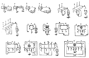
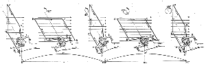