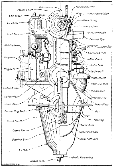
Part Sectional View of Hall-Scott Airplane Motor, Showing Principal Parts.
This eBook is for the use of anyone anywhere at no cost and with
almost no restrictions whatsoever.  You may copy it, give it away or
re-use it under the terms of the Project Gutenberg License included
with this eBook or online at www.gutenberg.org
Title: Aviation Engines
Design--Construction--Operation and Repair
Author: Victor Wilfred Pagé
Release Date: December 2, 2011 [eBook #38187]
Language: English
Character set encoding: ISO-8859-1
***START OF THE PROJECT GUTENBERG EBOOK AVIATION ENGINES***
Please see Transcriber’s Notes at the end of this document.
AVIATION ENGINES. Their Design, Construction, Operation and Repair.
By Lieut. Victor W. Pagé, Aviation Section, S.C.U.S.R.
A practical work containing valuable instructions for aviation students, mechanicians, squadron engineering officers and all interested in the construction and upkeep of airplane power plants. 576 octavo pages. 250 illustrations. Price $3.00.
AVIATION CHART, or the Location of Airplane Power Plant Troubles Made Easy.
By Lieut. Victor W. Pagé, A.S., S.C.U.S.R.
A large chart outlining all parts of a typical airplane power plant, showing the points where trouble is apt to occur and suggesting remedies for the common defects. Intended especially for aviators and aviation mechanics on school and field duty. Price 50 cents.
GLOSSARY OF AVIATION TERMS.
Compiled by Lieuts. Victor W. Pagé, A.S., S.C.U.S.R. and Paul Montariol of the French Flying Corps on duty at Signal Corps Aviation School, Mineola, L. I.
A complete glossary of practically all terms used in aviation, having lists in both French and English, with equivalents in either language. A very valuable book for all who are about to leave for duty overseas. Price, cloth, $1.00.
THE NORMAN W. HENLEY PUBLISHING COMPANY
2 WEST 45th ST., NEW YORK
CENSORED
This Book Entitled
AVIATION ENGINES
By LIEUT. VICTOR W. PAGÉ
has been censored by the United States Government, and pages and parts of pages have been omitted by special instructions from Washington.
The book has been passed by THE COMMITTEE ON PUBLIC INFORMATION and is as complete as we can furnish it, and we so advise the purchaser of it.
THE NORMAN W. HENLEY PUBLISHING COMPANY
A COMPLETE, PRACTICAL TREATISE OUTLINING CLEARLY THE ELEMENTS OF INTERNAL COMBUSTION ENGINEERING WITH SPECIAL REFERENCE TO THE DESIGN, CONSTRUCTION, OPERATION AND REPAIR OF AIRPLANE POWER PLANTS; ALSO THE AUXILIARY ENGINE SYSTEMS, SUCH AS LUBRICATION, CARBURETION, IGNITION AND COOLING.
IT INCLUDES COMPLETE INSTRUCTIONS FOR ENGINE REPAIRING AND SYSTEMATIC LOCATION OF TROUBLES, TOOL EQUIPMENT AND USE OF TOOLS, ALSO OUTLINES THE LATEST MECHANICAL PROCESSES.
BY
First Lieut. VICTOR W. PAGÉ, A. S. S. C., U. S. R.
Assistant Engineering Officer, Signal Corps Aviation School, Mineola, L. I.
Author of “The Modern Gasoline Automobile,” Etc.

CONTAINS VALUABLE INSTRUCTIONS FOR ALL AVIATION STUDENTS, MECHANICIANS, SQUADRON ENGINEERING OFFICERS AND ALL INTERESTED IN THE CONSTRUCTION AND UPKEEP OF AIRPLANE POWER PLANTS.
NEW YORK
THE NORMAN W. HENLEY PUBLISHING COMPANY
2 West 45th Street
1917
Copyrighted, 1917
by
The Norman W. Henley Publishing Co.
PRINTED IN U. S. A.
ALL ILLUSTRATIONS IN THIS BOOK HAVE BEEN SPECIALLY MADE BY THE PUBLISHERS, AND THEIR USE, WITHOUT PERMISSION, IS STRICTLY PROHIBITED
COMPOSITION, ELECTROTYPING AND PRESSWORK
BY THE PUBLISHERS PRINTING CO., NEW YORK
In presenting this treatise on “Aviation Engines,” the writer realizes that the rapidly developing art makes it difficult to outline all latest forms or describe all current engineering practice. This exposition has been prepared primarily for instruction purposes and is adapted for men in the Aviation Section, Signal Corps, and students who wish to become aviators or aviation mechanicians. Every effort has been made to have the engineering information accurate, but owing to the diversity of authorities consulted and use of data translated from foreign language periodicals, it is expected that some slight errors will be present. The writer wishes to acknowledge his indebtedness to such firms as the Curtiss Aeroplane and Motor Co., Hall-Scott Company, Thomas-Morse Aircraft Corporation and General Vehicle Company for photographs and helpful descriptive matter. Special attention has been paid to instructions on tool equipment, use of tools, trouble “shooting” and engine repairs, as it is on these points that the average aviation student is weakest. Only such theoretical consideration of thermo-dynamics as was deemed absolutely necessary to secure a proper understanding of engine action after consulting several instructors is included, the writer’s efforts having been confined to the preparation of a practical series of instructions that would be of the greatest value to those who need a diversified knowledge of internal-combustion engine operation and repair, and[10] who must acquire it quickly. The engines described and illustrated are all practical forms that have been fitted to airplanes capable of making flights and may be considered fairly representative of the present state of the art.
Victor W. Pagé,
1st Lieut. A. S. S. C., U. S. R.
Mineola, L. I.,
October, 1917.
AVIATION ENGINES
DESIGN—CONSTRUCTION—REPAIR
Brief Consideration of Aircraft Types—Essential Requirements of Aerial Motors—Aviation Engines Must Be Light—Factors Influencing Power Needed—Why Explosive Motors Are Best—Historical—Main Types of Internal Combustion Engines.
The conquest of the air is one of the most stupendous achievements of the ages. Human flight opens the sky to man as a new road, and because it is a road free of all obstructions and leads everywhere, affording the shortest distance to any place, it offers to man the prospect of unlimited freedom. The aircraft promises to span continents like railroads, to bridge seas like ships, to go over mountains and forests like birds, and to quicken and simplify the problems of transportation. While the actual conquest of the air is an accomplishment just being realized in our days, the idea and yearning to conquer the air are old, possibly as old as intellect itself. The myths of different races tell of winged gods and flying men, and show that for ages to fly was the highest conception of the sublime. No other agent is more responsible for sustained flight than the internal combustion motor, and it was only when this form of prime mover had been fully developed that it was possible for man to leave the ground and alight at will, not depending upon the caprices of the winds or lifting power of gases as with the balloon. It is safe to say that the solution of the problem of flight would have been attained many years ago if the proper source of power had been available as all the essential[18] elements of the modern aeroplane and dirigible balloon, other than the power plant, were known to early philosophers and scientists.
Aeronautics is divided into two fundamentally different branches—aviatics and aerostatics. The first comprises all types of aeroplanes and heavier than air flying machines such as the helicopters, kites, etc.; the second includes dirigible balloons, passive balloons and all craft which rise in the air by utilizing the lifting force of gases. Aeroplanes are the only practical form of heavier-than-air machines, as the helicopters (machines intended to be lifted directly into the air by propellers, without the sustaining effect of planes), and ornithopters, or flapping wing types, have not been thoroughly developed, and in fact, there are so many serious mechanical problems to be solved before either of these types of air craft will function properly that experts express grave doubts regarding the practicability of either. Aeroplanes are divided into two main types—monoplanes or single surface forms, and bi-planes or machines having two sets of lifting surfaces, one suspended over the other. A third type, the triplane, is not very widely used.
Dirigible balloons are divided into three classes: the rigid, the semi-rigid, and the non-rigid. The rigid has a frame or skeleton of either wood or metal inside of the bag, to stiffen it; the semi-rigid is reinforced by a wire net and metal attachments; while the non-rigid is just a bag filled with gas. The aeroplane, more than the dirigible and balloon, stands as the emblem of the conquest of the air. Two reasons for this are that power flight is a real conquest of the air, a real victory over the battling elements; secondly, because the aeroplane, or any flying machine that may follow, brings air travel within the reach of everybody. In practical development, the dirigible may be the steamship of the air, which will render invaluable services of a certain kind, and the aeroplane will be the automobile of the air, to be used by the multitude, perhaps for as many purposes as the automobile is now being used.
One of the marked features of aircraft development has been the effect it has had upon the refinement and perfection of the internal combustion motor. Without question gasoline-motors intended for aircraft are the nearest to perfection of any other type yet evolved. Because of the peculiar demands imposed upon the aeronautical motor it must possess all the features of reliability, economy and efficiency now present with automobile or marine engines and then must have distinctive points of its own. Owing to the unstable nature of the medium through which it is operated and the fact that heavier-than-air machines can maintain flight only as long as the power plant is functioning properly, an airship motor must be more reliable than any used on either land or water. While a few pounds of metal more or less makes practically no difference in a marine motor and has very little effect upon the speed or hill-climbing ability of an automobile, an airship motor must be as light as it is possible to make it because every pound counts, whether the motor is to be fitted into an aeroplane or in a dirigible balloon.
Airship motors, as a rule, must operate constantly at high speeds in order to obtain a maximum power delivery with a minimum piston displacement. In automobiles, or motor boats, motors are not required to run constantly at their maximum speed. Most aircraft motors must function for extended periods at speed as nearly the maximum as possible. Another thing that militates against the aircraft motor is the more or less unsteady foundation to which it is attached. The necessarily light framework of the aeroplane makes it hard for a motor to perform at maximum efficiency on account of the vibration of its foundation while the craft is in flight. Marine and motor car engines, while not placed on foundations as firm as those provided for stationary power plants, are installed on bases of much more stability than the light structure of an aeroplane. The aircraft motor, therefore, must be balanced to a nicety[20] and must run steadily under the most unfavorable conditions.
The capacity of light motors designed for aerial work per unit of mass is surprising to those not fully conversant with the possibilities that a thorough knowledge of proportions of parts and the use of special metals developed by the automobile industry make possible. Activity in the development of light motors has been more pronounced in France than in any other country. Some of these motors have been complicated types made light by the skillful proportioning of parts, others are of the refined simpler form modified from current automobile practice. There is a tendency to depart from the freakish or unconventional construction and to adhere more closely to standard forms because it is necessary to have the parts of such size that every quality making for reliability, efficiency and endurance are incorporated in the design. Aeroplane motors range from two cylinders to forms having fourteen and sixteen cylinders and the arrangement of these members varies from the conventional vertical tandem and opposed placing to the V form or the more unusual radial motors having either fixed or rotary cylinders. The weight has been reduced so it is possible to obtain a complete power plant of the revolving cylinder air-cooled type that will not weigh more than three pounds per actual horse-power and in some cases less than this.
If we give brief consideration to the requirements of the aviator it will be evident that one of the most important is securing maximum power with minimum mass, and it is desirable to conserve all of the good qualities existing in standard automobile motors. These are certainty of operation, good mechanical balance and uniform delivery of power—fundamental conditions which must be attained before a power plant can be considered practical. There are in addition, secondary considerations, none the less desirable, if not absolutely essential. These are minimum[21] consumption of fuel and lubricating oil, which is really a factor of import, for upon the economy depends the capacity and flying radius. As the amount of liquid fuel must be limited the most suitable motor will be that which is powerful and at the same time economical. Another important feature is to secure accessibility of components in order to make easy repair or adjustment of parts possible. It is possible to obtain sufficiently light-weight motors without radical departure from established practice. Water-cooled power plants have been designed that will weigh but four or five pounds per horse-power and in these forms we have a practical power plant capable of extended operation.
Work is performed whenever an object is moved against a resistance, and the amount of work performed depends not only on the amount of resistance overcome but also upon the amount of time utilized in accomplishing a given task. Work is measured in horse-power for convenience. It will take one horse-power to move 33,000 pounds one foot in one minute or 550 pounds one foot in one second. The same work would be done if 330 pounds were moved 100 feet in one minute. It requires a definite amount of power to move a vehicle over the ground at a certain speed, so it must take power to overcome resistance of an airplane in the air. Disregarding the factor of air density, it will take more power as the speed increases if the weight or resistance remains constant, or more power if the speed remains constant and the resistance increases. The airplane is supported by air reaction under the planes or lifting surfaces and the value of this reaction depends upon the shape of the aerofoil, the amount it is tilted and the speed at which it is drawn through the air. The angle of incidence or degree of wing tilt regulates the power required to a certain degree as this affects the speed of horizontal flight as well as the resistance. Resistance may be of two kinds, one that is[22] necessary and the other that it is desirable to reduce to the lowest point possible. There is the wing resistance and the sum of the resistances of the rest of the machine such as fuselage, struts, wires, landing gear, etc. If we assume that a certain airplane offered a total resistance of 300 pounds and we wished to drive it through the air at a speed of sixty miles per hour, we can find the horse-power needed by a very simple computation as follows:
| The product of 300 pounds resistance times speed of 88 feet per second times 60 seconds in a minute |
= H.P. needed. |
| divided by 33,000 foot pounds per minute in one horse-power |
The result is the horse-power needed, or
| 300 × 88 × 60 | = 48 H.P. |
| 33,000 |
Just as it takes more power to climb a hill than it does to run a car on the level, it takes more power to climb in the air with an airplane than it does to fly on the level. The more rapid the climb, the more power it will take. If the resistance remains 300 pounds and it is necessary to drive the plane at 90 miles per hour, we merely substitute proper values in the above formula and we have
| 300 pounds times 132 feet per second times 60 seconds in a minute |
= 72 H.P. |
| 33,000 foot pounds per minute in one horse-power |
The same results can be obtained by dividing the product of the resistance in pounds times speed in feet per second by 550, which is the foot-pounds of work done in one second to equal one horse-power. Naturally, the amount of propeller thrust measured in pounds necessary to drive an airplane must be greater than the resistance by a substantial margin if the plane is to fly and climb as well.[23] The following formulæ were given in “The Aeroplane” of London and can be used to advantage by those desiring to make computations to ascertain power requirements:
The thrust of the propeller depends on the power of[24] the motor, and on the diameter and pitch of the propeller. If the required thrust to a certain machine is known, the calculation for the horse-power of the motor should be an easy matter.
The required thrust is the sum of three different “resistances.” The first is the “drift” (dynamical head resistance of the aerofoils), i.e., tan α × lift (L), lift being equal to the total weight of machine (W) for horizontal flight and α equal to the angle of incidence. Certainly we must take the tan α at the maximum Ky value for minimum speed, as then the drift is the greatest (Fig. 1, A).
Another method for finding the drift is D = K × AV2, when we take the drift again so as to be greatest.
The second “resistance” is the total head resistance of the machine, at its maximum velocity. And the third is the thrust for climbing. The horse-power for climbing can be found out in two different ways. I first propose to deal with the method, where we find out the actual horse-power wanted for a certain climbing speed to our machine, where
| H.P. = | climbing speed/sec. × W |
| 550 |
In this case we know already the horse-power for climbing, and we can proceed with our calculation.
With the other method we shall find out the “thrust” in pounds or kilograms wanted for climbing and add it to drift and total head resistance, and we shall have the total “thrust” of our machine and we shall denote it with T, while thrust for climbing shall be Tc.
The following calculation is at our service to find out this thrust for climbing
| Vc × W | = H.P., |
| 550 |
thence
| Vc = | H.P. × 550 | (1) |
| W |
| H.P. = | Tc × V | , |
| 550 |
then from (1)
|
Tc × V | |||||
| Vc = | = | , | ||||
| W | W |
thence,
| Tc = | Vc × W | . |
| V |
Whether T means drifts, head resistance and thrust for climbing, or drift and head resistance only, the following calculation is the same, only in the latter case, of course, we must add the horse-power required for climbing to the result to obtain the total horse-power.
Now, when we know the total thrust, we shall find the horse-power in the following manner:
We know that the
| H.P. = | P r 2π R |
| 75 × 60 |
in kilograms, or in English measure,
| H.P. = | P r 2π R | (Fig. 1, B) |
| 33,000 |
where
| P | = | pressure in klgs. or lbs. |
| r | = | radius on which P is acting. |
| R | = | Revolution/min. |
When P × r = M, then
| H.P. = | M.R.2π | , |
| 4,500 |
thence,
| M = | H.P. × 4,500 | = | 716.2 H.P. | in meter kilograms, |
| R2π | R |
or in English system
| M = | H.P. 33,000 | = | 5253.1 H.P. | in foot pounds. |
| R2π | R |
Now the power on the circumference of the propeller will be reduced by its radius, so it will be M/r = p. A part[26] of p will be used for counteracting the air and bearing friction, so that the total power on the circumference of the propeller will be (M/r) × η = p where η is the mechanical efficiency of the propeller. Now η/tan α = T, where α is taken on the tip of the propeller.
I take α at the tip, but it can be taken, of course, at any point, but then in equation p = M/r, r must be taken only up to this point, and not the whole radius; but it is more comfortable to take it at the tip, as tan α = Pitch/r2π (Fig. 1, C).
Now we can write up the equation of the thrust:
| T = | 716.2 H.P. η | , or in English measure | 5253.1 H.P. η | , |
| R r tan α | R r tan α |
thence
| H.P. = | T × R × r tan α | , or in English measure | T × R × r tan α | . |
| 716.2 η | 5253.1 η |
The computations and formulæ given are of most value to the student engineer rather than matters of general interest, but are given so that a general idea may be secured of how airplane design influences power needed to secure sustained flight. It will be apparent that the resistance of an airplane depends upon numerous considerations of design which require considerable research in aerodynamics to determine accurately. It is obvious that the more resistance there is, the more power needed to fly at a given speed. Light monoplanes have been flown with as little as 15 horse-power for short distances,[27] but most planes now built use engines of 100 horse-power or more. Giant airplanes have been constructed having 2,000 horse-power distributed in four power units. The amount of power provided for an airplane of given design varies widely as many conditions govern this, but it will range from approximately one horse-power to each 8 pounds weight in the case of very light, fast machines to one horse-power to 15 or 18 pounds of the total weight in the case of medium speed machines. The development in airplane and power plant design is so rapid, however, that the figures given can be considered only in the light of general averages rather than being typical of current practice.
Internal combustion engines are best for airplanes and all types of aircraft for the same reasons that they are universally used as a source of power for automobiles. The gasoline engine is the lightest known form of prime mover and a more efficient one than a steam engine, especially in the small powers used for airplane propulsion. It has been stated that by very careful designing a steam plant an engine could be made that would be practical for airplane propulsion, but even with the latest development it is doubtful if steam power can be utilized in aircraft to as good advantage as modern gasoline-engines are. While the steam-engine is considered very much simpler than a gas-motor, the latter is much more easily mastered by the non-technical aviator and certainly requires less attention. A weight of 10 pounds per horse-power is possible in a condensing steam plant but this figure is nearly double or triple what is easily secured with a gas-motor which may weigh but 5 pounds per horse-power in the water cooled forms and but 2 or 3 pounds in the air-cooled types. The fuel consumption is twice as great in a steam-power plant (owing to heat losses) as would be the case in a gasoline engine of equal power and much less weight.
[28]The internal-combustion engine has come seemingly like an avalanche of a decade; but it has come to stay, to take its well-deserved position among the powers for aiding labor. Its ready adaptation to road, aerial and marine service has made it a wonder of the age in the development of speed not before dreamed of as a possibility; yet in so short a time, its power for speed has taken rank on the common road against the locomotive on the rail with its century’s progress. It has made aerial navigation possible and practical, it furnishes power for all marine craft from the light canoe to the transatlantic liner. It operates the machine tools of the mechanic, tills the soil for the farmer and provides healthful recreation for thousands by furnishing an economical means of transport by land and sea. It has been a universal mechanical education for the masses, and in its present forms represents the great refinement and development made possible by the concentration of the world’s master minds on the problems incidental to internal combustion engineering.
Although the ideal principle of explosive power was conceived some two hundred years ago, at which time experiments were made with gunpowder as the explosive element, it was not until the last years of the eighteenth century that the idea took a patentable shape, and not until about 1826 (Brown’s gas-vacuum engine) that a further progress was made in England by condensing the products of combustion by a jet of water, thus creating a partial vacuum.
Brown’s was probably the first explosive engine that did real work. It was clumsy and unwieldy and was soon relegated to its place among the failures of previous experiments. No approach to active explosive effect in a cylinder was reached in practice, although many ingenious designs were described, until about 1838 and the following years. Barnett’s engine in England was the first attempt to compress the charge before exploding. From this time[29] on to about 1860 many patents were issued in Europe and a few in the United States for gas-engines, but the progress was slow, and its practical introduction for power came with spasmodic effect and low efficiency. From 1860 on, practical improvement seems to have been made, and the Lenoir motor was produced in France and brought to the United States. It failed to meet expectations, and was soon followed by further improvements in the Hugon motor in France (1862), followed by Beau de Rocha’s four-cycle idea, which has been slowly developed through a long series of experimental trials by different inventors. In the hands of Otto and Langdon a further progress was made, and numerous patents were issued in England, France, and Germany, and followed up by an increasing interest in the United States, with a few patents.
From 1870 improvements seem to have advanced at a steady rate, and largely in the valve-gear and precision of governing for variable load. The early idea of the necessity of slow combustion was a great drawback in the advancement of efficiency, and the suggestion of de Rocha in 1862 did not take root as a prophetic truth until many failures and years of experience had taught the fundamental axiom that rapidity of action in both combustion and expansion was the basis of success in explosive motors.
With this truth and the demand for small and safe prime movers, the manufacture of gas-engines increased in Europe and America at a more rapid rate, and improvements in perfecting the details of this cheap and efficient prime mover have finally raised it to the dignity of a standard motor and a dangerous rival of the steam-engine for small and intermediate powers, with a prospect of largely increasing its individual units to many hundred, if not to the thousand horse-power in a single cylinder. The unit size in a single cylinder has now reached to about 700 horse-power and by combining cylinders in the same machine, powers of from 1,500 to 2,000 horse-power are now available for large power-plants.
This form of prime mover has been built in so many different types, all of which have operated with some degree of success that the diversity in form will not be generally appreciated unless some attempt is made to classify the various designs that have received practical application. Obviously the same type of engine is not universally applicable, because each class of work has individual peculiarities which can best be met by an engine designed with the peculiar conditions present in view. The following tabular synopsis will enable the reader to judge the extent of the development of what is now the most popular prime mover for all purposes.
| A. | Internal Combustion (Standard Type) | ||
| 1. | Single Acting (Standard Type) | ||
| 2. | Double Acting (For Large Power Only) | ||
| 3. | Simple (Universal Form) | ||
| 4. | Compound (Rarely Used) | ||
| 5. | Reciprocating Piston (Standard Type) | ||
| 6. | Turbine (Revolving Rotor, not fully developed) | ||
| A1. | Two-Stroke Cycle | ||
| a. | Two Port | ||
| b. | Three Port | ||
| c. | Combined Two and Three Port | ||
| d. | Fourth Port Accelerator | ||
| e. | Differential Piston Type | ||
| f. | Distributor Valve System | ||
| A2. | Four-Stroke Cycle | ||
| a. | Automatic Inlet Valve | ||
| b. | Mechanical Inlet Valve | ||
| c. | Poppet or Mushroom Valve | ||
| d. | Slide Valve | ||
| d 1. | Sleeve Valve | ||
| d 2. | Reciprocating Ring Valve | ||
| d 3. | Piston Valve[31] | ||
| e. | Rotary Valves | ||
| e 1. | Disc | ||
| e 2. | Cylinder or Barrel | ||
| e 3. | Single Cone | ||
| e 4. | Double Cone | ||
| f. | Two Piston (Balanced Explosion) | ||
| g. | Rotary Cylinder, Fixed Crank (Aerial) | ||
| h. | Fixed Cylinder, Rotary Crank (Standard Type) | ||
| A3. | Six-Stroke Cycle | ||
| B. | External Combustion (Practically Obsolete) | ||
| a. | Turbine, Revolving Rotor | ||
| b. | Reciprocating Piston | ||
| Single Cylinder | ||
| a. | Vertical | |
| b. | Horizontal | |
| c. | Inverted Vertical | |
| Double Cylinder | ||
| a. | Vertical | |
| b. | Horizontal (Side by Side) | |
| c. | Horizontal (Opposed) | |
| d. | 45 to 90 Degrees V (Angularly Disposed) | |
| e. | Horizontal Tandem (Double Acting) | |
| Three Cylinder | ||
| a. | Vertical | |
| b. | Horizontal | |
| c. | Rotary (Cylinders Spaced at 120 Degrees) | |
| d. | Radially Placed (Stationary Cylinders) | |
| e. | One Vertical, One Each Side at an Angle | |
| f. | Compound (Two High Pressure, One Low Pressure) | |
| Four Cylinder | ||
| a. | Vertical | |
| b. | Horizontal (Side by Side)[32] | |
| c. | Horizontal (Two Pairs Opposed) | |
| d. | 45 to 90 Degrees V | |
| e. | Twin Tandem (Double Acting) | |
| Five Cylinder | ||
| a. | Vertical (Five Throw Crankshaft) | |
| b. | Radially Spaced at 72 Degrees (Stationary) | |
| c. | Radially Placed Above Crankshaft (Stationary) | |
| d. | Placed Around Rotary Crankcase (72 Degrees Spacing) | |
| Six Cylinder | ||
| a. | Vertical | |
| b. | Horizontal (Three Pairs Opposed) | |
| c. | 45 to 90 Degrees V | |
| Seven Cylinder | ||
| a. | Equally Spaced (Rotary) | |
| Eight Cylinder | ||
| a. | Vertical | |
| b. | Horizontal (Four Pairs Opposed) | |
| c. | 45 to 90 Degrees V | |
| Nine Cylinder | ||
| a. | Equally Spaced (Rotary) | |
| Twelve Cylinder | ||
| a. | Vertical | |
| b. | Horizontal (Six Pairs Opposed) | |
| c. | 45 to 90 Degrees V | |
| Fourteen Cylinder | ||
| a. | Rotary | |
| Sixteen Cylinder | ||
| a. | 45 to 90 Degrees V | |
| b. | Horizontal (Eight Pairs Opposed) | |
| Eighteen Cylinder | ||
| a. | Rotary Cylinder | |
Fig. 2.—Plate Showing Heavy, Slow Speed Internal Combustion Engines Used Only for Stationary Power in Large Installations Giving Weight to Horse-Power Ratio.
Fig. 3.—Various Forms of Internal Combustion Engines Showing Decrease in Weight to Horse-Power Ratio with Augmenting Speed of Rotation.
Fig. 4.—Internal Combustion Engine Types of Extremely Fine Construction and Refined Design, Showing Great Power Outputs for Very Small Weight, a Feature Very Much Desired in Airplane Power Plants.
[36]Of all the types enumerated above engines having less than eight cylinders are the most popular in everything but aircraft work. The four-cylinder vertical is without doubt the most widely used of all types owing to the large number employed as automobile power plants. Stationary engines in small and medium powers are invariably of the single or double form. Three-cylinder engines are seldom used at the present time, except in marine work and in some stationary forms. Eight- and twelve-cylinder motors have received but limited application and practically always in automobiles, racing motor boats or in aircraft. The only example of a fourteen-cylinder motor to be used to any extent is incorporated in aeroplane construction. This is also true of the sixteen- and eighteen-cylinder forms and of twenty-four-cylinder engines now in process of development.
The duty an engine is designed for determines the weight per horse-power. High powered engines intended for steady service are always of the slow speed type and consequently are of very massive construction. Various forms of heavy duty type stationary engines are shown at Fig. 2. Some of these engines may weigh as much as 600 pounds per horse-power. A further study is possible by consulting data given on Figs. 3 and 4. As the crank-shaft speed increases and cylinders are multiplied the engines become lighter. While the big stationary power plants may run for years without attention, airplane engines require rebuilding after about 60 to 80 hours air service for the fixed cylinder types and 40 hours or less for the rotary cylinder air-cooled forms. There is evidently a decrease in durability and reliability as the weight is lessened. These illustrations also permit of obtaining a good idea of the variety of forms internal combustion engines are made in.
Operating Principles of Two- and Four-Stroke Engines—Four-cycle Action—Two-cycle Action—Comparing Two- and Four-cycle Types—Theory of Gas and Gasoline Engine—Early Gas-Engine Forms—Isothermal Law—Adiabatic Law—Temperature Computations—Heat and Its Work—Conversion of Heat to Power—Requisites for Best Power Effect.
Before discussing the construction of the various forms of internal combustion engines it may be well to describe the operating cycle of the types most generally used. The two-cycle engine is the simplest because there are no valves in connection with the cylinder, as the gas is introduced into that member and expelled from it through ports cored into the cylinder walls. These are covered by the piston at a certain portion of its travel and uncovered at other parts of its stroke. In the four-cycle engine the explosive gas is admitted to the cylinder through a port at the head end closed by a valve, while the exhaust gas is expelled through another port controlled in a similar manner. These valves are operated by mechanism distinct from the piston.
The action of the four-cycle type may be easily understood if one refers to illustrations at Figs. 5 and 6. It is called the “four-stroke engine” because the piston must make four strokes in the cylinder for each explosion or power impulse obtained. The principle of the gas-engine of the internal combustion type is similar to that of a gun, i.e., power is obtained by the rapid combustion of some explosive or other quick burning substance. The bullet is driven out of the gun barrel by the pressure of the gas evolved when the charge of powder is ignited. The piston or movable element of the gas-engine is driven[38] from the closed or head end to the crank end of the cylinder by a similar expansion of gases resulting from combustion. The first operation in firing a gun or securing an explosion in the cylinder of the gas-engine is to fill the combustion space with combustible material. This is done by a down stroke of the piston during which time the inlet valve opens to admit the gaseous charge to the cylinder interior. This operation is shown at Fig. 5, A. The second operation is to compress this gas which is done by an upward stroke of the piston as shown at[39] Fig. 5, B. When the top of the compression stroke is reached, the gas is ignited and the piston is driven down toward the open end of the cylinder, as indicated at Fig. 6, C. The fourth operation or exhaust stroke is performed by the return upward movement of the piston as shown at Fig. 6, D during which time the exhaust valve is opened to permit the burnt gases to leave the cylinder. As soon as the piston reaches the top of its exhaust stroke, the energy stored in the fly-wheel rim during the power stroke causes that member to continue revolving and as the piston[41] again travels on its down stroke the inlet valve opens and admits a charge of fresh gas and the cycle of operations is repeated.
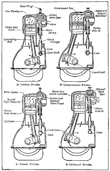
Fig. 7.—Sectional View of L Head Gasoline Engine Cylinder Showing Piston Movements During Four-Stroke Cycle.
The illustrations at Fig. 7 show how the various cycle functions take place in an L head type water cooled cylinder engine. The sections at A and C are taken through the inlet valve, those at B and D are taken through the exhaust valve.
The two-cycle engine works on a different principle, as while only the combustion chamber end of the piston is employed to do useful work in the four-cycle engine, both upper and lower portions are called upon to perform the functions necessary to two-cycle engine operation. Instead of the gas being admitted into the cylinder as is the case with the four-stroke engine, it is first drawn into the engine base where it receives a preliminary compression prior to its transfer to the working end of the cylinder. The views at Fig. 8 should indicate clearly the operation of the two-port two-cycle engine. At A the piston is seen reaching the top of its stroke and the gas above the piston is being compressed ready for ignition, while the suction in the engine base causes the automatic valve to open and admits mixture from the carburetor to the crank case. When the piston reaches the top of its stroke, the compressed gas is ignited and the piston is driven down on the power stroke, compressing the gas in the engine base.
When the top of the piston uncovers the exhaust port the flaming gas escapes because of its pressure. A downward movement of the piston uncovers the inlet port opposite the exhaust and permits the fresh gas to bypass through the transfer passage from the engine base to the cylinder. The conditions with the intake and exhaust port fully opened are clearly shown at Fig. 8, C. The deflector plate on the top of the piston directs the entering fresh gas to the top of the cylinder and prevents the main portion of the gas stream from flowing out through the open exhaust port. On the next upstroke of the piston[44] the gas in the cylinder is compressed and the inlet valve opened, as shown at A to permit a fresh charge to enter the engine base.
The operating principle of the three-port, two-cycle engine is practically the same as that previously described with the exception that the gas is admitted to the crank-case through a third port in the cylinder wall, which is uncovered by the piston when that member reaches the end of its upstroke. The action of the three-port form can be readily ascertained by studying the diagrams given at Fig. 9. Combination two- and three-port engines have been evolved and other modifications made to improve the action.
In the earlier years of explosive-motor progress was evolved the two types of motors in regard to the cycles of their operation. The early attempts to perfect the two-cycle principle were for many years held in abeyance from the pressure of interests in the four-cycle type, until its simplicity and power possibilities were demonstrated by Mr. Dugald Clerk in England, who gave the principles of the two-cycle motor a broad bearing leading to immediate improvements in design, which has made further progress in the United States, until at the present time it has an equal standard value as a motor-power in some applications as its ancient rival the four-cycle or Otto type, as demonstrated by Beau de Rocha in 1862.
Thermodynamically, the methods of the two types are equal as far as combustion is concerned, and compression may favor in a small degree the four-cycle type as well as the purity of the charge. The cylinder volume of the two-cycle motor is much smaller per unit of power, and the enveloping cylinder surface is therefore greater per unit of volume. Hence more heat is carried off by the jacket water during compression, and the higher compression available from this tends to increase the economy during compression which is lost during expansion.
[45]From the above considerations it may be safely stated that a lower temperature and higher pressure of charge at the beginning of compression is obtained in the two-cycle motor, greater weight of charge and greater specific power of higher compression resulting in higher thermal efficiency. The smaller cylinder for the same power of the two-cycle motor gives less friction surface per impulse than of the other type; although the crank-chamber pressure may, in a measure, balance the friction of the four-cycle type. Probably the strongest points in favor of the two-cycle type are the lighter fly-wheel and the absence of valves and valve gear, making this type the most simple in construction and the lightest in weight for its developed power. Yet, for the larger power units, the four-cycle type will no doubt always maintain the standard for efficiency and durability of action.
The distribution of the charge and its degree of mixture with the remains of the previous explosion in the clearance space, has been a matter of discussion for both types of explosive motors, with doubtful results. In Fig. 10, A we illustrate what theory suggests as to the distribution of the fresh charge in a two-cycle motor, and in Fig. 10, B what is the probable distribution of the mixture when the piston starts on its compressive stroke. The arrows show the probable direction of flow of the fresh charge and burnt gases at the crucial moment.
In Fig. 10, C is shown the complete out-sweep of the products of combustion for the full extent of the piston stroke of a four-cycle motor, leaving only the volume of the clearance to mix with the new charge and at D the manner by which the new charge sweeps by the ignition device, keeping it cool and avoiding possibilities of pre-ignition by undue heating of the terminals of the sparking device. Thus, by enveloping the sparking device with the pure mixture, ignition spreads through the charge with its greatest possible velocity, a most desirable condition in high-speed motors with side-valve chambers and igniters within the valve chamber.
The laws controlling the elements that create a power by their expansion by heat due to combustion, when properly understood, become a matter of computation in regard to their value as an agent for generating power in the various kinds of explosive engines. The method of heating the elements of power in explosive engines greatly widens the limits of temperature as available in other types of heat-engines. It disposes of many of the practical troubles of hot-air, and even of steam-engines, in the simplicity and directness of application of the elements of power. In the explosive engine the difficulty of conveying heat for producing expansive effect by convection is displaced by the generation of the required heat within the expansive element and at the instant of its useful work. The low conductivity of heat to and from air has been the great obstacle in the practical development of the hot-air engine; while, on the contrary, it has become the source of economy and practicability in the development of the internal-combustion engine.
The action of air, gas, and the vapors of gasoline and petroleum oil, whether singly or mixed, is affected by changes of temperature practically in nearly the same ratio; but when the elements that produce combustion are interchanged in confined spaces, there is a marked difference of effect. The oxygen of the air, the hydrogen and carbon of a gas, or vapor of gasoline or petroleum oil are the elements that by combustion produce heat to expand the nitrogen of the air and the watery vapor produced by the union of the oxygen in the air and the hydrogen in the gas, as well as also the monoxide and carbonic-acid gas that may be formed by the union of the carbon of gas or vapor with part of the oxygen of the air. The various mixtures as between air and gas, or air and vapor, with the proportion of the products of combustion left in the cylinder from a previous combustion, form the elements to be considered in estimating the amount of[48] pressure that may be obtained by their combustion and expansive force.
The working process of the explosive motor may be divided into three principal types: 1. Motors with charges igniting at constant volume without compression, such as the Lenoir, Hugon, and other similar types now abandoned as wasteful in fuel and effect. 2. Motors with charges igniting at constant pressure with compression, in which a receiver is charged by a pump and the gases burned while being admitted to the motor cylinder, such as types of the Simon and Brayton engine. 3. Motors with charges igniting at constant volume with variable compression, such as the later two- and four-cycle motors with compression of the indrawn charge; limited in the two-cycle type and variable in the four-cycle type with the ratios of the clearance space in the cylinder. This principle produces the explosive motor of greatest efficiency.
The phenomena of the brilliant light and its accompanying heat at the moment of explosion have been witnessed in the experiments of Dugald Clerk in England, the illumination lasting throughout the stroke; but in regard to time in a four-cycle engine, the incandescent state exists only one-quarter of the running time. Thus the time interval, together with the non-conductibility of the gases, makes the phenomena of a high-temperature combustion within the comparatively cool walls of a cylinder a practical possibility.
The natural laws, long since promulgated by Boyle, Gay Lussac, and others, on the subject of the expansion and compression of gases by force and by heat, and their variable pressures and temperatures when confined, are conceded to be practically true and applicable to all gases, whether single, mixed, or combined.
[49]The law formulated by Boyle only relates to the compression and expansion of gases without a change of temperature, and is stated in these words:
If the temperature of a gas be kept constant, its pressure or elastic force will vary inversely as the volume it occupies.
It is expressed in the formula P × V = C, or pressure × volume = constant. Hence, C/P = V and C/V = P.
Thus the curve formed by increments of pressure during the expansion or compression of a given volume of gas without change of temperature is designated as the isothermal curve in which the volume multiplied by the pressure is a constant value in expansion, and inversely the pressure divided by the volume is a constant value in compressing a gas.
But as compression and expansion of gases require force for their accomplishment mechanically, or by the application or abstraction of heat chemically, or by convection, a second condition becomes involved, which was formulated into a law of thermodynamics by Gay Lussac under the following conditions: A given volume of gas under a free piston expands by heat and contracts by the loss of heat, its volume causing a proportional movement of a free piston equal to 1⁄273 part of the cylinder volume for each degree Centigrade difference in temperature, or 1⁄492 part of its volume for each degree Fahrenheit. With a fixed piston (constant volume), the pressure is increased or decreased by an increase or decrease of heat in the same proportion of 1⁄273 part of its pressure for each degree Centigrade, or 1⁄492 part of its pressure for each degree Fahrenheit change in temperature. This is the natural sequence of the law of mechanical equivalent, which is a necessary deduction from the principle that[50] nothing in nature can be lost or wasted, for all the heat that is imparted to or abstracted from a gaseous body must be accounted for, either as heat or its equivalent transformed into some other form of energy. In the case of a piston moving in a cylinder by the expansive force of heat in a gaseous body, all the heat expended in expansion of the gas is turned into work; the balance must be accounted for in absorption by the cylinder or radiation.
This theory is equally applicable to the cooling of gases by abstraction of heat or by cooling due to expansion by the motion of a piston. The denominators of these heat fractions of expansion or contraction represent the absolute zero of cold below the freezing-point of water, and read -273° C. or -492.66° = -460.66° F. below zero; and these are the starting-points of reference in computing the heat expansion in gas-engines. According to Boyle’s law, called the first law of gases, there are but two characteristics of a gas and their variations to be considered, viz., volume and pressure: while by the law of Gay Lussac, called the second law of gases, a third is added, consisting of the value of the absolute temperature, counting from absolute zero to the temperatures at which the operations take place. This is the Adiabatic law.
The ratio of the variation of the three conditions—volume, pressure, and heat—from the absolute zero temperature has a certain rate, in which the volume multiplied by the pressure and the product divided by the absolute temperature equals the ratio of expansion for each degree. If a volume of air is contained in a cylinder having a piston and fitted with an indicator, the piston, if moved to and fro slowly, will alternately compress and expand the air, and the indicator pencil will trace a line or lines upon the card, which lines register the change of pressure and volume occurring in the cylinder. If the piston is perfectly free from leakage, and it be supposed[51] that the temperature of the air is kept quite constant, then the line so traced is called an Isothermal line, and the pressure at any point when multiplied by the volume is a constant, according to Boyle’s law,
pv = a constant.
If, however, the piston is moved very rapidly, the air will not remain at constant temperature, but the temperature will increase because work has been done upon the air, and the heat has no time to escape by conduction. If no heat whatever is lost by any cause, the line will be traced over and over again by the indicator pencil, the cooling by expansion doing work precisely equalling the heating by compression. This is the line of no transmission of heat, therefore known as Adiabatic.
The expansion of a gas 1⁄273 of its volume for every degree Centigrade, added to its temperature, is equal to the decimal .00366, the coefficient of expansion for Centigrade units. To any given volume of a gas, its expansion may be computed by multiplying the coefficient by the[52] number of degrees, and by reversing the process the degree of acquired heat may be obtained approximately. These methods are not strictly in conformity with the absolute mathematical formula, because there is a small increase in the increment of expansion of a dry gas, and there is also a slight difference in the increment of expansion due to moisture in the atmosphere and to the vapor of water formed by the union of the hydrogen and oxygen in the combustion chamber of explosive engines.
The ratio of expansion on the Fahrenheit scale is derived from the absolute temperature below the freezing-point of water (32°) to correspond with the Centigrade scale; therefore 1⁄492.66 = .0020297, the ratio of expansion from 32° for each degree rise in temperature on the Fahrenheit scale. As an example, if the temperature of any volume of air or gas at constant volume is raised, say from 60° to 2000° F., the increase in temperature will be 1940°. The ratio will be 1⁄520.66 = .0019206. Then by the formula:
Ratio × acquired temp. × initial pressure = the gauge pressure; and .0019206 × 1940° × 14.7 = 54.77 lbs.
By another formula, a convenient ratio is obtained by (absolute pressure)/(absolute temp.) or 14.7⁄520.66 = .028233; then, using the difference of temperature as before, .028233 × 1940° = 54.77 lbs. pressure.
By another formula, leaving out a small increment due to specific heat at high temperatures:
| I. | Atmospheric pressure × absolute temp. + acquired temp. | = |
| Absolute temp. + initial temp. |
absolute pressure due to the acquired temperature, from which the atmospheric pressure is deducted for the gauge pressure. Using the foregoing example, we have
| 14.7 × 460.66° + 2000° | = 69.47 - 14.7 = 54.77, the gauge pressure, |
| 460.66 + 60° |
460.66 being the absolute temperature for zero Fahrenheit.
For obtaining the volume of expansion of a gas from a given increment of heat, we have the approximate formula:
| II. | Volume × absolute temp. + acquired temp. | = heated volume. |
| Absolute temp. + initial temp. |
In applying this formula to the foregoing example, the figures become:
| I. × | 460.66° + 2000° | = 4.72604 volumes. |
| 460.66 + 60° |
From this last term the gauge pressure may be obtained as follows:
III. 4.72604 × 14.7 = 69.47 lbs. absolute - 14.7 lbs. atmospheric pressure = 54.77 lbs. gauge pressure; which is the theoretical pressure due to heating air in a confined space, or at constant volume from 60° to 2000° F.
By inversion of the heat formula for absolute pressure we have the formula for the acquired heat, derived from combustion at constant volume from atmospheric pressure to gauge pressure plus atmospheric pressure as derived from Example I., by which the expression
| absolute pressure × absolute temp. + initial temp. |
| initial absolute pressure |
[54]= absolute temperature + temperature of combustion, from which the acquired temperature is obtained by subtracting the absolute temperature.
Then, for example,
| 69.47 × 460.66 + 60 | = 2460.66, and 2460.66 - 460.66 = 2000°, |
| 14.7 |
the theoretical heat of combustion. The dropping of terminal decimals makes a small decimal difference in the result in the different formulas.
By Joule’s law of the mechanical equivalent of heat, whenever heat is imparted to an elastic body, as air or gas, energy is generated and mechanical work produced by the expansion of the air or gas. When the heat is imparted by combustion within a cylinder containing a movable piston, the mechanical work becomes an amount measurable by the observed pressure and movement of the piston. The heat generated by the explosive elements and the expansion of the non-combining elements of nitrogen and water vapor that may have been injected into the cylinder as moisture in the air, and the water vapor formed by the union of the oxygen of the air with the hydrogen of the gas, all add to the energy of the work from their expansion by the heat of internal combustion. As against this, the absorption of heat by the walls of the cylinder, the piston, and cylinder-head or clearance walls, becomes a modifying condition in the force imparted to the moving piston.
It is found that when any explosive mixture of air and gas or hydrocarbon vapor is fired, the pressure falls far short of the pressure computed from the theoretical effect of the heat produced, and from gauging the expansion of the contents of a cylinder. It is now well known that in practice the high efficiency which is promised by theoretical calculation is never realized; but it must always be[55] remembered that the heat of combustion is the real agent, and that the gases and vapors are but the medium for the conversion of inert elements of power into the activity of energy by their chemical union. The theory of combustion has been the leading stimulus to large expectations with inventors and constructors of explosive motors; its entanglement with the modifying elements in practice has delayed the best development in construction, and as yet no really positive design of best form or action seems to have been accomplished, although great progress has been made during the past decade in the development of speed, reliability, economy, and power output of the individual units of this comparatively new power.
One of the most serious difficulties in the practical development of pressure, due to the theoretical computations of the pressure value of the full heat, is probably caused by imparting the heat of the fresh charge to the balance of the previous charge that has been cooled by expansion from the maximum pressure to near the atmospheric pressure of the exhaust. The retardation in the velocity of combustion of perfectly mixed elements is now well known from experimental trials with measured quantities; but the principal difficulty in applying these conditions to the practical work of an explosive engine where a necessity for a large clearance space cannot be obviated, is in the inability to obtain a maximum effect from the imperfect mixture and the mingling of the products of the last explosion with the new mixture, which produces a clouded condition that makes the ignition of the mass irregular or chattering, as observed in the expansion lines of indicator cards; but this must not be confounded with the reaction of the spring in the indicator.
Stratification of the mixture has been claimed as taking place in the clearance chamber of the cylinder; but this is not a satisfactory explanation in view of the vortical effect of the violent injection of the air and gas or vapor mixture. It certainly cannot become a perfect mixture in the time of a stroke of a high-speed motor of the two-cycle[56] class. In a four-cycle engine, making 1,500 revolutions per minute, the injection and compression in any one cylinder take place in one twenty-fifth of a second—formerly considered far too short a time for a perfect infusion of the elements of combustion but now very easily taken care of despite the extremely high speed of numerous aviation and automobile power-plants.
| Diagram Curve Fig. 8. |
Mixture Injected. | Temp. of Injection Fahr. |
Time of Explosion. Second. |
Observed Gauge Pressure. Pounds. |
Computed Temp. Fahr. |
||||||||
| a | 1 | volume | gas | to | 14 | volumes | air. | 64° | 0.45 | 40. | 1,483° | ||
| b | 1 | „ | „ | „ | 13 | „ | „ | 51° | 0.31 | 51. | 5 | 1,859° | |
| c | 1 | „ | „ | „ | 12 | „ | „ | 51° | 0.24 | 60. | 2,195° | ||
| d | 1 | „ | „ | „ | 11 | „ | „ | 51° | 0.17 | 61. | 2,228° | ||
| e | 1 | „ | „ | „ | 9 | „ | „ | 62° | 0.08 | 78. | 2,835° | ||
| f | 1 | „ | „ | „ | 7 | „ | „ | 62° | 0.06 | 87. | 3,151° | ||
| g | 1 | „ | „ | „ | 6 | „ | „ | 51° | 0.04 | 90. | 3,257° | ||
| h | 1 | „ | „ | „ | 5 | „ | „ | 51° | 0.05 | 5 | 91. | 3,293° | |
| i | 1 | „ | „ | „ | 4 | „ | „ | 66° | 0.16 | 80. | 2,871° | ||
In an examination of the times of explosion and the corresponding pressures in both tables, it will be seen that a mixture of 1 part gas to 6 parts air is the most effective and will give the highest mean pressure in a gas-engine. There is a limit to the relative proportions of illuminating gas and air mixture that is explosive, somewhat variable, depending upon the proportion of hydrogen in the gas. With ordinary coal-gas, 1 of gas to 15 parts of air; and on the lower end of the scale, 1 volume of gas to 2 parts air, are non-explosive. With gasoline vapor the explosive effect ceases at 1 to 16, and a saturated mixture of equal volumes of vapor and air will not explode, while the most intense explosive effect is from a mixture of 1 part vapor to 9 parts air. In the use of gasoline and air mixtures from a carburetor, the best effect is from 1 part saturated air to 8 parts free air.
| Propor- tion, Air to Gas by Volumes. |
Pounds in One Cubic Foot of Mixture. |
Specific Heat. Heat Units Required to Raise 1 Lb. 1 Deg. Fahrenheit. |
Heat to Raise One Cubic Foot of Mixture 1 Deg. Fahr. |
Heat Units Evolved by Combus- tion. |
Ratio Col. 6/5 |
Usual Combus- tion Efficien- cy. |
Usual Rise of Temperature due to Explosion at Constant Volume. |
|||||
| Constant Pressure. |
Constant Volume. |
|||||||||||
| 6 | to | 1 | .074195 | .2668 | .1913 | .014189 | 94. | 28 | 6644. | 6 | .465 | 3090 |
| 7 | to | 1 | .075012 | .2628 | .1882 | .014116 | 82. | 5844. | 4 | .518 | 3027 | |
| 8 | to | 1 | .075647 | .2598 | .1858 | .014059 | 73. | 33 | 5216. | 1 | .543 | 2832 |
| 9 | to | 1 | .076155 | .2575 | .1846 | .014013 | 66. | 4709. | 9 | .56 | 2637 | |
| 10 | to | 1 | .076571 | .2555 | .1825 | .013976 | 60. | 4293. | .575 | 2468 | ||
| 11 | to | 1 | .076917 | .2540 | .1813 | .013945 | 55. | 3944. | .585 | 2307 | ||
| 12 | to | 1 | .077211 | .2526 | .1803 | .013922 | 50. | 77 | 3646. | 7 | .58 | 2115 |
The weight of a cubic foot of gas and air mixture as given in Col. 2 is found by adding the number of volumes of air multiplied by its weight, .0807, to one volume of gas of weight .035 pound per cubic foot and dividing by the total number of volumes; for example, as in the table, 6 × .0807 = .5192⁄7 = .074195 as in the first line, and so on for any mixture or for other gases of different specific weight per cubic foot. The heat units evolved by combustion of the mixture (Col. 6) are obtained by dividing the total heat units in a cubic foot of gas by the total proportion of the mixture, 660⁄7 = 94.28 as in the first line of the table. Col. 5 is obtained by multiplying the weight of a cubic foot of the mixture in Col. 2 by the specific heat at a constant volume (Col. 4), Col. 6/Col. 5 = Col. 7 the total heat[58] ratio, of which Col. 8 gives the usual combustion efficiency—Col. 7 × Col. 8 gives the absolute rise in temperature of a pure mixture, as given in Col. 9.
The many recorded experiments made to solve the discrepancy between the theoretical and the actual heat development and resulting pressures in the cylinder of an explosive motor, to which much discussion has been given as to the possibilities of dissociation and the increased specific heat of the elements of combustion and non-combustion, as well, also, of absorption and radiation of heat, have as yet furnished no satisfactory conclusion as to what really takes place within the cylinder walls. There seems to be very little known about dissociation, and somewhat vague theories have been advanced to explain the phenomenon. The fact is, nevertheless, apparent as shown in the production of water and other producer gases by the use of steam in contact with highly incandescent fuel. It is known that a maximum explosive mixture of pure gases, as hydrogen and oxygen or carbonic oxide and oxygen, suffers a contraction of one-third their volume by combustion to their compounds, steam or carbonic acid. In the explosive mixtures in the cylinder of a motor, however, the combining elements form so small a proportion of the contents of the cylinder that the shrinkage of their volume amounts to no more than 3 per cent. of the cylinder volume. This by no means accounts for the great heat and pressure differences between the theoretical and actual effects.
The utilization of heat in any heat-engine has long been a theme of inquiry and experiment with scientists and engineers, for the purpose of obtaining the best practical conditions and construction of heat-engines that would represent the highest efficiency or the nearest approach to the theoretical value of heat, as measured by empirical laws that have been derived from experimental researches relating to its ultimate volume. It is well known that the[59] steam-engine returns only from 12 to 18 per cent. of the power due to the heat generated by the fuel, about 25 per cent. of the total heat being lost in the chimney, the only use of which is to create a draught for the fire; the balance, some 60 per cent., is lost in the exhaust and by radiation. The problem of utmost utilization of force in steam has nearly reached its limit.
The internal-combustion system of creating power is comparatively new in practice, and is but just settling into definite shape by repeated trials and modification of details, so as to give somewhat reliable data as to what may be expected from the rival of the steam-engine as a prime mover. For small powers, the gas, gasoline, and petroleum-oil engines are forging ahead at a rapid rate, filling the thousand wants of manufacture and business for a power that does not require expensive care, that is perfectly safe at all times, that can be used in any place in the wide world to which its concentrated fuel can be conveyed, and that has eliminated the constant handling of crude fuel and water.
The utilization of heat in a gas-engine is mainly due to the manner in which the products entering into combustion are distributed in relation to the movement of the piston. The investigation of the foremost exponent of the theory of the explosive motor was prophetic in consideration of the later realization of the best conditions under which these motors can be made to meet the requirements of economy and practicability. As early as 1862, Beau de Rocha announced, in regard to the coming power, that four requisites were the basis of operation for economy and best effect. 1. The greatest possible cylinder volume with the least possible cooling surface. 2. The greatest possible rapidity of expansion. Hence, high speed. 3. The greatest possible expansion. Long stroke. 4. The greatest possible pressure at the commencement of expansion. High compression.
Efficiency of Internal Combustion Engines—Various Measures of Efficiency—Temperatures and Pressures—Factors Governing Economy—Losses in Wall Cooling—Value of Indicator Cards—Compression in Explosive Motors—Factors Limiting Compression—Causes of Heat Losses and Inefficiency—Heat Losses to Cooling Water.
Efficiencies are worked out through intricate formulas for a variety of theoretical and unknown conditions of combustion in the cylinder: ratios of clearance and cylinder volume, and the uncertain condition of the products of combustion left from the last impulse and the wall temperature. But they are of but little value, except as a mathematical inquiry as to possibilities. The real commercial efficiency of a gas or gasoline-engine depends upon the volume of gas or liquid at some assigned cost, required per actual brake horse-power per hour, in which an indicator card should show that the mechanical action of the valve gear and ignition was as perfect as practicable, and that the ratio of clearance, space, and cylinder volume gave a satisfactory terminal pressure and compression: i.e., the difference between the power figured from the indicator card and the brake power being the friction loss of the engine.
In four-cycle motors of the compression type, the efficiencies are greatly advanced by compression, producing a more complete infusion of the mixture of gas or vapor and air, quicker firing, and far greater pressure than is possible with the two-cycle type previously described. In the practical operation of the gas-engine during the past twenty years, the gas-consumption efficiencies per indicated horse-power have gradually risen from 17 per cent. to a maximum of 40 per cent. of the theoretical heat, and[61] this has been done chiefly through a decreased combustion chamber and increased compression—the compression having gradually increased in practice from 30 lbs. per square inch to above 100; but there seems to be a limit to compression, as the efficiency ratio decreases with greater increase in compression. It has been shown that an ideal efficiency of 33 per cent. for 38 lbs., compression will increase to 40 per cent. for 66 lbs., and 43 per cent. for 88 lbs. compression. On the other hand, greater compression means greater explosive pressure and greater strain on the engine structure, which will probably retain in future practice the compression between the limits of 40 and 90 lbs. except in super-compression engines intended for high altitude work where compression pressures as high as 125 pounds have been used.
In experiments made by Dugald Clerk, in England, with a combustion chamber equal to 0.6 of the space swept by the piston, with a compression of 38 lbs., the consumption of gas was 24 cubic feet per indicated horse-power per hour. With 0.4 compression space and 61 lbs. compression, the consumption of gas was 20 cubic feet per indicated horse-power per hour; and with 0.34 compression space and 87 lbs. compression, the consumption of gas fell to 14.8 cubic feet per indicated horse-power per hour—the actual efficiencies being respectively 17, 21, and 25 per cent. This was with a Crossley four-cycle engine.
The efficiencies in regard to power in a heat-engine may be divided into four kinds, as follows: I. The first is known as the maximum theoretical efficiency of a perfect engine (represented by the lines in the indicator diagram). It is expressed by the formula
| T1 - T0 |
| T1 |
and shows the work of a perfect cycle in an engine working between the received temperature + absolute temperature (T1) and[62] the initial atmospheric temperature + absolute temperature (T0). II. The second is the actual heat efficiency, or the ratio of the heat turned into work to the total heat received by the engine. It expresses the indicated horse-power. III. The third is the ratio between the second or actual heat efficiency and the first or maximum theoretical efficiency of a perfect cycle. It represents the greatest possible utilization of the power of heat in an internal-combustion engine. IV. The fourth is the mechanical efficiency. This is the ratio between the actual horse-power delivered by the engine through a dynamometer or measured by a brake (brake horse-power), and the indicated horse-power. The difference between the two is the power lost by engine friction. In regard to the general heat efficiency of the materials of power in explosive engines, we find that with good illuminating gas the practical efficiency varies from 25 to 40 per cent.; kerosene-motors, 20 to 30; gasoline-motors, 20 to 32; acetylene, 25 to 35; alcohol, 20 to 30 per cent. of their heat value. The great variation is no doubt due to imperfect mixtures and variable conditions of the old and new charge in the cylinder; uncertainty as to leakage and the perfection[63] of combustion. In the Diesel motors operating under high pressure, up to nearly 500 pounds, an efficiency of 36 per cent. is claimed.
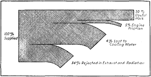
Fig. 12.—Graphic Diagram Showing Approximate Utilization of Fuel Burned in Internal-Combustion Engine.
The graphic diagram at Fig. 12 is of special value as it shows clearly how the heat produced by charge combustion is expended in an engine of average design.
On general principles the greater difference between the heat of combustion and the heat at exhaust is the relative measure of the heat turned into work, which represents the degree of efficiency without loss during expansion. The mathematical formulas appertaining to the computation of the element of heat and its work in an explosive engine are in a large measure dependent upon assumed values, as the conditions of the heat of combustion are made uncertain by the mixing of the fresh charge with the products of a previous combustion, and by absorption, radiation, and leakage. The computation of the temperature from the observed pressure may be made as before explained, but for compression-engines the needed starting-points for computation are very uncertain, and can only be approximated from the exact measure and value of the elements of combustion in a cylinder charge.
Owing to the decrease from atmospheric pressure in the indrawing charge of the cylinder, caused by valve and frictional obstruction, the compression seldom starts above 13 lbs. absolute, especially in high-speed engines. Col. 3 in the following table represents the approximate absolute compression pressure for the clearance percentage and ratio in Cols. 1 and 2, while Col. 4 indicates the gauge pressure from the atmospheric line. The temperatures in Col. 5 are due to the compression in Col. 3 from an assumed temperature of 560° F. in the mixture of the fresh charge of 6 air to 1 gas with the products of combustion left in the clearance chamber from the exhaust stroke of a medium-speed motor. This temperature is subject to[64] considerable variation from the difference in the heat-unit power of the gases and vapors used for explosive power, as also of the cylinder-cooling effect. In Col. 6 is given the approximate temperatures of explosion for a mixture of air 6 to gas 1 of 660 heat units per cubic foot, for the relative values of the clearance ratio in Col. 2 at constant volume.
| Clearance Per Cent. of Piston Volume. |
Ratio
|
Approximate Compression from 13 Pounds Absolute. |
Approximate Gauge Pressure. |
Absolute Temperature of Compression from 560 Deg. Fahrenheit in Cylinder. |
Absolute Temperature of Explosion. Gas, 1 part; Air, 6 parts. |
Approximate Explosion Pressure Absolute. |
Approximate Gauge Pressure. |
Approximate Temperature of Explosion, Fahrenheit. |
||||||
| 1 | 2 | 3 | 4 | 5 | 6 | 7 | 8 | 9 | ||||||
| Lbs. | Deg. | Deg. | Lbs. | Lbs. | Deg. | |||||||||
| .50 | 3. | 57. | 42. | 822. | 2488 | 169 | 144 | 2027 | ||||||
| .444 | 3. | 25 | 65. | 50. | 846. | 2568 | 197 | 182 | 2107 | |||||
| .40 | 3. | 50 | 70. | 55. | 868. | 2638 | 212 | 197 | 2177 | |||||
| .363 | 3. | 75 | 77. | 62. | 889. | 2701 | 234 | 219 | 2240 | |||||
| .333 | 4. | 84. | 69. | 910. | 2751 | 254 | 239 | 2290 | ||||||
| .285 | 4. | 50 | 102. | 88. | 955. | 2842 | 303 | 288 | 2381 | |||||
| .25 | 5. | 114. | 99. | 983. | 2901 | 336 | 321 | 2440 | ||||||
In view of the experiments in this direction, it clearly shows that in practical work, to obtain the greatest economy per effective brake horse-power, it is necessary: 1st. To transform the heat into work with the greatest rapidity mechanically allowable. This means high piston speed. 2d. To have high initial compression. 3d. To reduce the duration of contact between the hot gases and the cylinder walls to the smallest amount possible; which means short stroke and quick speed, with a spherical cylinder head. 4th. To adjust the temperature of the jacket water to[65] obtain the most economical output of actual power. This means water-tanks or water-coils, with air-cooling surfaces suitable and adjustable to the most economical requirement of the engine, which by late trials requires the jacket water to be discharged at about 200° F. 5th. To reduce the wall surface of the clearance space or combustion chamber to the smallest possible area, in proportion to its required volume. This lessens the loss of the heat of combustion by exposure to a large surface, and allows of a higher mean wall temperature to facilitate the heat of compression.
In an experimental investigation of the efficiency of a gas-engine under variable piston speeds made in France, it was found that the useful effect increases with the velocity of the piston—that is, with the rate of expansion of the burning gases with mixtures of uniform volumes: so that the variations of time of complete combustion at constant pressure, and the variations due to speed, in a way compensate in their efficiencies. The dilute mixture, being slow burning, will have its time and pressure quickened by increasing the speed.
Careful trials give unmistakable evidence that the useful effect increases with the velocity of the piston—that is, with the rate of expansion of the burning gases. The time necessary for the explosion to become complete and to attain its maximum pressure depends not only on the composition of the mixture, but also upon the rate of expansion. This has been verified in experiments with a high-speed motor, at speeds from 500 to 2,000 revolutions per minute, or piston speeds of from 16 to 64 feet per second. The increased speed of combustion due to increased piston speed is a matter of great importance to builders of gas-engines, as well as to the users, as indicating the mechanical direction of improvements to lessen the wearing strain due to high speed and to lighten the vibrating parts with increased strength, in order that the[66] balancing of high-speed engines may be accomplished with the least weight.
From many experiments made in Europe and in the United States, it has been conclusively proved that excessive cylinder cooling by the water-jacket results in a marked loss of efficiency. In a series of experiments with a simplex engine in France, it was found that a saving of 7 per cent. in gas consumption per brake horse-power was made by raising the temperature of the jacket water from 141° to 165° F. A still greater saving was made in a trial with an Otto engine by raising the temperature of the jacket water from 61° to 140° F.—it being 9.5 per cent. less gas per brake horse-power.
It has been stated that volumes of similar cylinders increase as the cube of their diameters, while the surface of their cold walls varies as the square of their diameters; so that for large cylinders the ratio of surface to volume is less than for small ones. This points to greater economy in the larger engines. The study of many experiments goes to prove that combustion takes place gradually in the gas-engine cylinder, and that the rate of increase of pressure or rapidity of firing is controlled by dilution and compression of the mixture, as well as by the rate of expansion or piston speed. The rate of combustion also depends on the size and shape of the explosion chamber, and is increased by the mechanical agitation of the mixture during combustion, and still more by the mode of firing.
To the uninitiated, indicator cards are considerable of a mystery; to those capable of reading them they form an index relative to the action of any engine. An indicator card, such as shown at Fig. 13, is merely a graphical representation of the various pressures existing in the cylinder for different positions of the piston. The length is to some scale that represents the stroke of the piston. During the intake stroke, the pressure falls below the[67] atmospheric line. During compression, the curve gradually becomes higher owing to increasing pressure as the volume is reduced. After ignition the pressure line moves upward almost straight, then as the piston goes down on the explosion stroke, the pressure falls gradually to the point of exhaust valve, opening when the sudden release of the imprisoned gas causes a reduction in pressure to nearly atmospheric. An indicator card, or a series of them, will always show by its lines the normal or defective condition of the inlet valve and passages; the actual line of compression; the firing moment; the pressure of explosion; the velocity of combustion; the normal or defective line of expansion, as measured by the adiabatic curve,[68] and the normal or defective operation of the exhaust valve, exhaust passages, and exhaust pipe. In fact, all the cycles of an explosive motor may be made a practical study from a close investigation of the lines of an indicator card.
A most unique card is that of the Diesel motor (Fig. 14), which involves a distinct principle in the design and operation of internal-combustion motors, in that instead of taking a mixed charge for instantaneous explosion, its charge primarily is of air and its compression to a pressure at which a temperature is attained above the igniting point of the fuel, then injecting the fuel under a still higher pressure by which spontaneous combustion takes place gradually with increasing volume over the compression for part of the stroke or until the fuel charge is consumed. The motor thus operating between the pressures of 500 and 35 lbs. per square inch, with a clearance of about 7 per cent., has given an efficiency of 36 per cent. of the total heat value of kerosene oil.
That the compression in a gas, gasoline, or oil-engine has a direct relation to the power obtained, has been long known to experienced builders, having been suggested by M. Beau de Rocha, in 1862, and afterward brought into practical use in the four-cycle or Otto type about 1880. The degree of compression has had a growth from zero, in the early engines, to the highest available due to the varying ignition temperatures of the different gases and vapors used for explosive fuel, in order to avoid premature explosion from the heat of compression. Much of the increased power for equal-cylinder capacity is due to compression of the charge from the fact that the most powerful explosion of gases, or of any form of explosive material, takes place when the particles are in the closest contact or cohesion with one another, less energy in this form being consumed by the ingredients themselves to bring about their chemical combination, and consequently[69] more energy is given out in useful or available work. This is best shown by the ignition of gunpowder, which, when ignited in the open air, burns rapidly, but without explosion, an explosion only taking place if the powder be confined or compressed into a small space.
In a gas or gasoline-motor with a small clearance or compression space—with high compression—the surface with which the burning gases come into contact is much smaller in comparison with the compression space in a low-compression motor. Another advantage of a high-compression motor is that on account of the smaller clearance of combustion space less cooling water is required than with a low-compression motor, as the temperature,[70] and consequently the pressure, falls more rapidly. The loss of heat through the water-jacket is thus less in the case of a high-compression than in that of a low-compression motor. In the non-compression type of motor the best results were obtained with a charge of 16 to 18 parts of gas and 100 parts of air, while in the compression type the best results are obtained with an explosive mixture of 7 to 10 parts of gas and 100 parts of air, thus showing that by the utilization of compression a weaker charge with a greater thermal efficiency is permissible.
It has been found that the explosive pressure resulting from the ignition of the charge of gas or gasoline-vapor and air in the gas-engine cylinder is about 41⁄2 times the pressure prior to ignition. The difficulty about getting high compression is that if the pressure is too high the charge is likely to ignite prematurely, as compression always results in increased temperature. The cylinder may become too hot, a deposit of carbon, a projecting electrode or plug body in the cylinder may become incandescent and ignite the charge which has been excessively heated by the high compression and mixture of the hot gases of the previous explosion.
With gasoline-vapor and air the compression should not be raised above about 90 to 95 pounds to the square inch, many manufacturers not going above 65 or 70 pounds. For natural gas the compression pressure may easily be raised to from 85 to 100 pounds per square inch. For gases of low calorific value, such as blast-furnace or producer-gas, the compression may be increased to from 140 to 190 pounds. In fact the ability to raise the compression to a high point with these gases is one of the principal reasons for their successful adoption for gas-engine use. In kerosene injection engines the compression of 250 pounds per square inch has been used with marked economy. Many troubles in regard to loss of power and increase of fuel have occurred and will no doubt continue,[71] owing to the wear of valves, piston, and cylinder, which produces a loss in compression and explosive pressure and a waste of fuel by leakage. Faulty adjustment of valve movement is also a cause of loss of power; which may be from tardy closing of the inlet-valve or a too early opening of the exhaust-valve.
The explosive pressure varies to a considerable amount in proportion to the compression pressure by the difference in fuel value and the proportions of air mixtures, so that for good illuminating gas the explosive pressure may be from 2.5 to 4 times the compression pressure. For natural gas 3 to 4.5, for gasoline 3 to 5, for producer-gas 2 to 3, and for kerosene by injection 3 to 6.
The compression temperatures, although well known and easily computed from a known normal temperature of the explosive mixture, are subject to the effect of the uncertain temperature of the gases of the previous explosion remaining in the cylinder, the temperature of its walls, and the relative volume of the charge, whether full or scant; which are terms too variable to make any computations reliable or available.
For the theoretical compression temperatures from a known normal temperature, we append a table of the rise in temperature for the compression pressures in the following table:
| 100 | lbs. | gauge | 484° | 60 | lbs. | gauge | 373° |
| 90 | lbs. | gauge | 459° | 50 | lbs. | gauge | 339° |
| 80 | lbs. | gauge | 433° | 40 | lbs. | gauge | 301° |
| 70 | lbs. | gauge | 404° | 30 | lbs. | gauge | 258° |
A very useful chart (Fig. 16) for determining compression pressures in gasoline-engine cylinders for various ratios of compression space to total cylinder volume is given by P. S. Tice, and described in the Chilton Automobile Directory by the originator as follows:
[72]It is many times desirable to have at hand a convenient means for at once determining with accuracy what the compression pressure will be in a gasoline-engine cylinder, the relationship between the volume of the compression space and the total cylinder volume or that swept by the piston being known. The curve at Fig. 16 is offered as such a means. It is based on empirical data gathered from upward of two dozen modern automobile engines and represents what may be taken to be the results as found in practice. It is usual for the designer to find compression pressure values, knowing the volumes from the equation
| P2 = P1 ( | V1 | )1.4 | 1 |
| V2 |
which is for adiabatic compression of air. Equation (1) is right enough in general form but gives results which[73] are entirely too high, as almost all designers know from experience. The trouble lies in the interchange of heat between the compressed gases and the cylinder walls, in the diminution of the exponent (1.4 in the above) due to the lesser ratio of specific heat of gasoline vapor and in the transfer of heat from the gases which are being compressed to whatever fuel may enter the cylinder in an unvaporized condition. Also, there is always some piston leakage, and, if the form of the equation (1) is to be retained, this also tends to lower the value of the exponent. From experience with many engines, it appears that compression reaches its highest value in the cylinder for but a short range of motor speeds, usually during the mid-range. Also, it appears that, at those speeds at which compression shows its highest values, the initial pressure at the start of the compression stroke is from .5 to .9 lb. below atmospheric. Taking this latter loss value, which shows more often than those of lesser value, the compression is seen to start from an initial pressure of 13.9 lbs. per sq. in. absolute.
Also, experiment shows that if the exponent be given the value 1.26, instead of 1.4, the equation will embrace all heat losses in the compressed gas, and compensate for the changed ratio of specific heats for the mixture and also for all piston leakage, in the average engine with rings in good condition and tight. In the light of the foregoing, and in view of results obtained from its use, the above curve is offered—values of P2 being found from the equation
| P2 = 13.8 ( | V1 | )1.26 |
| V2 |
In using this curve it must be remembered that pressures are absolute. Thus: suppose it is desired to know the volumetric relationships of the cylinder for a compression pressure of 75 lbs. gauge. Add atmospheric pressure to the desired gauge pressure 14.7 + 75 = 89.7 lbs. absolute. Locate this pressure on the scale of ordinates[74] and follow horizontally across to the curve and then vertically downward to the scale of abscissas, where the ratio of the combustion chamber volume to the total cylinder volume is given, which latter is equal to the sum of the combustion chamber volume and that of the piston sweep. In the above case it is found that the combustion space for a compression pressure of 75 lbs. gauge will be .225 of the total cylinder volume, or .225 ÷ .775 = .2905 of the piston sweep volume. Conversely, knowing the volumetric ratios, compression pressure can be read directly by proceeding from the scale of abscissas vertically to the curve and thence horizontally to the scale of ordinates.
The difference realized in the practical operation of an internal combustion heat engine from the computed effect derived from the values of the explosive elements is probably the most serious difficulty that engineers have encountered in their endeavors to arrive at a rational conclusion as to where the losses were located, and the ways and means of design that would eliminate the causes of loss and raise the efficiency step by step to a reasonable percentage of the total efficiency of a perfect cycle.
An authority on the relative condition of the chemical elements under combustion in closed cylinders attributes the variation of temperature shown in the fall of the expansion curve, and the suppression or retarded evolution of heat, entirely to the cooling action of the cylinder walls, and to this nearly all the phenomena hitherto obscure in the cylinder of a gas-engine. Others attribute the great difference between the theoretical temperature of combustion and the actual temperature realized in the practical operation of the gas-engine, a loss of more than one-half of the total heat energy of the combustibles, partly to the dissociation of the elements of combustion at extremely high temperatures and their reassociation by expansion in the cylinder, to account for the supposed continued[75] combustion and extra adiabatic curve of the expansion line on the indicator card.
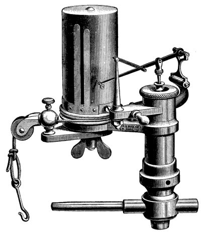
Fig. 17.—The Thompson Indicator, an Instrument for Determining Compressions and Explosion Pressure Values and Recording Them on Chart.
The loss of heat to the walls of the cylinder, piston, and clearance space, as regards the proportion of wall surface to the volume, has gradually brought this point to its smallest ratio in the concave piston-head and globular cylinder-head, with the smallest possible space in the inlet and exhaust passage. The wall surface of a cylindrical clearance space or combustion chamber of one-half its unit diameter in length is equal to 3.1416 square units, its volume but 0.3927 of a cubic unit; while the same wall[76] surface in a spherical form has a volume of 0.5236 of a cubic unit. It will be readily seen that the volume is increased 331⁄3 per cent. in a spherical over a cylindrical form for equal wall surfaces at the moment of explosion, when it is desirable that the greatest amount of heat is generated, and carrying with it the greatest possible pressure from which the expansion takes place by the movement of the piston.
The spherical form cannot continue during the stroke for mechanical reasons; therefore some proportion of piston stroke of cylinder volume must be found to correspond with a spherical form of the combustion chamber to produce the least loss of heat through the walls during the combustion and expansion part of the stroke. This idea is illustrated in Figs. 18 and 19, showing how the relative volumes of cylinder stroke and combustion chamber may be varied to suit the requirements due to the quality of the elements of combustion.
Although the concave piston-head shows economy in regard to the relation of the clearance volume to the wall area at the moment of explosive combustion, it may be clearly seen that its concavity increases its surface area and its capacity for absorbing heat, for which there is no provision for cooling the piston, save its contact with the walls of the cylinder and the slight air cooling of its back by its reciprocal motion. For this reason the concave piston-head has not been generally adopted and the concave cylinder-head, as shown in Fig. 19, with a flat[78] piston-head is the latest and best practice in airplane engine construction.
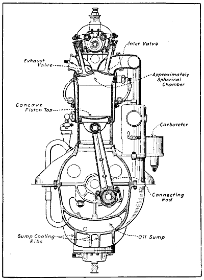
Fig. 20.—Mercedes Aviation Engine Cylinder Section Showing Approximately Spherical Combustion Chamber and Concave Piston Top.
The practical application of the principle just outlined to one of the most efficient airplane motors ever designed, the Mercedes, is clearly outlined at Fig. 20.
The mean temperature of the wall surface of the combustion chamber and cylinder, as indicated by the temperatures of the circulating water, has been found to be an important item in the economy of the gas-engine. Dugald Clerk, in England, a high authority in practical work with the gas-engine, found that 10 per cent. of the gas for a stated amount of power was saved by using water at a temperature in which the ejected water from the cylinder-jacket was near the boiling-point, and ventures the opinion that a still higher temperature for the circulating water may be used as a source of economy. This could be made practical in the case of aviation engines by adjusting the air-cooling surface of the radiator so as to maintain the inlet water at just below the boiling point, and by the rapid circulation induced by the pump pressure, to return the water from the cylinder-jacket a few degrees above the boiling point. The thermal displacement systems of cooling employed in automobiles are working under more favorable temperature conditions than those engines in which cooling is more energetic.
For a given amount of heat taken from the cylinder by the largest volume of circulating water, the difference in temperature between inlet and outlet of the water-jacket should be the least possible, and this condition of the water circulation gives a more even temperature to all parts of the cylinder; while, on the contrary, a cold-water supply, say at 60° F., so slow as to allow the ejected water to flow off at a temperature near the boiling-point, must make a great difference in temperature between the bottom and top of the cylinder, with a loss in economy[79] in gas and other fuels, as well as in water, if it is obtained by measurement.
From the foregoing considerations of losses and inefficiencies, we find that the practice in motor design and construction has not yet reached the desired perfection in its cycular operation. Step by step improvements have been made with many changes in design though many have been without merit as an improvement, farther than to gratify the longings of designers for something different from the other thing, and to establish a special construction of their own. These efforts may in time produce a motor of normal or standard design for each kind of fuel that will give the highest possible efficiency for all conditions of service.
Engine Parts and Functions—Why Multiple Cylinder Engines Are Best—Describing Sequence of Operations—Simple Engines—Four and Six Cylinder Vertical Tandem Engines—Eight and Twelve Cylinder V Engines—Radial Cylinder Arrangement—Rotary Cylinder Forms.
The principal elements of a gas engine are not difficult to understand and their functions are easily defined. In place of the barrel of the gun one has a smoothly machined cylinder in which a small cylindrical or barrel-shaped element fitting the bore closely may be likened to a bullet or cannon ball. It differs in this important respect, however, as while the shot is discharged from the mouth of the cannon the piston member sliding inside of the main cylinder cannot leave it, as its movements back and forth from the open to the closed end and back again are limited by simple mechanical connection or linkage which comprises crank and connection rod. It is by this means that the reciprocating movement of the piston is transformed into a rotary motion of the crank-shaft.
The fly-wheel is a heavy member attached to the crank-shaft of an automobile engine which has energy stored in its rim as the member revolves, and the momentum of this revolving mass tends to equalize the intermittent pushes on the piston head produced by the explosion of the gas in the cylinder. In aviation engines, the weight of the propeller or that of rotating cylinders themselves performs the duty of a fly-wheel, so no separate member is needed. If some explosive is placed in the chamber formed by the piston and closed end of the cylinder and exploded, the piston would be the only part that would yield to the pressure which would produce a downward movement. As this is forced down the crank-shaft is[82] turned by the connecting rod, and as this part is hinged at both ends it is free to oscillate as the crank turns, and thus the piston may slide back and forth while the crank-shaft is rotating or describing a curvilinear path.
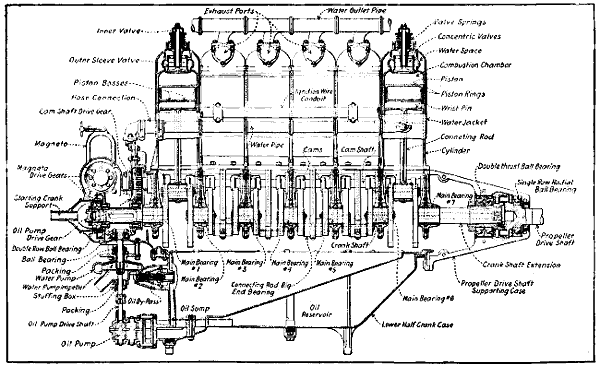
Fig. 21.—Side Sectional View of Typical Airplane Engine, Showing Parts and Their Relation to Each Other. This Engine is an Aeromarine Design and Utilizes a Distinctive Concentric Valve Construction.
In addition to the simple elements described it is evident that a gasoline engine must have other parts. The most important of these are the valves, of which there are generally two to each cylinder. One closes the passage connecting to the gas supply and opens during one stroke of the piston in order to let the explosive gas into the combustion chamber. The other member, or exhaust valve, serves as a cover for the opening through which the burned gases can leave the cylinder after their work is done. The spark plug is a simple device which may be compared to the fuse or percussion cap of the cannon. It permits one to produce an electric spark in the cylinder when the piston is at the best point to utilize the pressure which obtains when the compressed gas is fired. The valves are open one at a time, the inlet valve being lifted from its seat while the cylinder is filling and the exhaust valve is opened when the cylinder is being cleared. They are normally kept seated by means of compression springs. In the simple motor shown at Fig. 5, the exhaust valve is operated by means of a pivoted bell crank rocked by a cam which turns at half the speed of the crank-shaft. The inlet valve operates automatically, as will be explained in proper sequence.
In order to obtain a perfectly tight combustion chamber, both intake and exhaust valves are closed before the gas is ignited, because all of the pressure produced by the exploding gas is to be directed against the top of the movable piston. When the piston reaches the bottom of its power stroke, the exhaust valve is lifted by means of the bell crank which is rocked because of the point or lift on the cam. The cam-shaft is driven by positive gearing and revolves at half the engine speed. The exhaust valve remains open during the whole of the return stroke of the piston, and as this member moves toward[83] the closed end of the cylinder it forces out burned gases ahead of it, through the passage controlled by the exhaust valve. The cam-shaft is revolved at half the engine speed because the exhaust valve is raised from its seat during only one stroke out of four, or only once every two revolutions. Obviously, if the cam was turned at the same speed as the crank-shaft it would remain open once every revolution, whereas the burned gases are expelled from the individual cylinders only once in two turns of the crank-shaft.
Owing to the vibration which obtains from the heavy explosion in the large single-cylinder engines used for stationary power other forms were evolved in which the cylinder was smaller and power obtained by running the engine faster, but these are suitable only for very low powers.
When a single-cylinder engine is employed a very heavy fly-wheel is needed to carry the moving parts through idle strokes necessary to obtain a power impulse. For this reason automobile and aircraft designers must use more than one cylinder, and the tendency is to produce power by frequently occurring light impulses rather than by a smaller number of explosions having greater force. When a single-cylinder motor is employed the construction is heavier than is needed with a multiple-cylinder form. Using two or more cylinders conduces to steady power generation and a lessening of vibration. Most modern motor cars employ four-cylinder engines because a power impulse may be secured twice every revolution of the crank-shaft, or a total of four power strokes during two revolutions. The parts are so arranged that while the charge of gas in one cylinder is exploding, those which come next in firing order are compressing, discharging the inert gases and drawing in a fresh charge respectively. When the power stroke is completed in one cylinder, the piston in that member in[84] which a charge of gas has just been compressed has reached the top of its stroke and when the gas is exploded the piston is reciprocated and keeps the crank-shaft turning. When a multiple-cylinder engine is used the fly-wheel can be made much lighter than that of the simpler form and eliminated altogether in some designs. In fact, many modern multiple-cylinder engines developing 300 horse-power weigh less than the early single- and double-cylinder forms which developed but one-tenth or one-twentieth that amount of energy.
Referring to Fig. 22, A, the sequence of operation in a single-cylinder motor can be easily understood. Assuming that the crank-shaft is turning in the direction of the arrow, it will be seen that the intake stroke comes first, then the compression, which is followed by the power impulse, and lastly the exhaust stroke. If two cylinders are used, it is possible to balance the explosions in such a way that one will occur each revolution. This is true with either one of two forms of four-cycle motors. At B, a two-cylinder vertical engine using a crank-shaft in which the crank-pins are on the same plane is shown. The two pistons move up and down simultaneously. Referring to the diagram describing the strokes, and assuming that the outer circle represents the cycle of operations in one cylinder while the inner circle represents the sequence of events in the other cylinder, while cylinder No. 1 is taking in a fresh charge of gas, cylinder No. 2 is exploding. When cylinder No. 1 is compressing, cylinder No. 2 is exhausting. During the time that the charge in cylinder No. 1 is exploded, cylinder No. 2 is being filled with fresh gas. While the exhaust gases are being discharged from cylinder No. 1, cylinder No. 2 is compressing the gas previously taken.
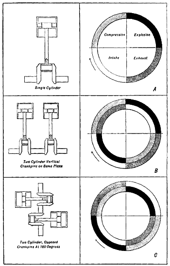
Fig. 22.—Diagrams Illustrating Sequence of Cycles in One- and Two-Cylinder Engines Showing More Uniform Turning Effort on Crank-Shaft with Two-Cylinder Motors.
The same condition obtains when the crank-pins are arranged at one hundred and eighty degrees and the cylinders are opposed, as shown at C. The reason that the[86] two-cylinder opposed motor is more popular than that having two vertical cylinders is that it is difficult to balance the construction shown at B, so that the vibration will not be excessive. The two-cylinder opposed motor has much less vibration than the other form, and as the explosions occur evenly and the motor is a simple one to construct, it has been very popular in the past on light cars and has received limited application on some early, light airplanes.
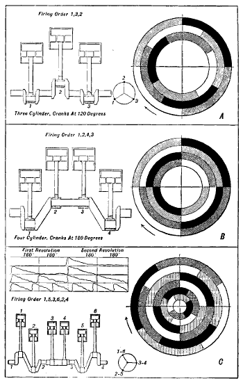
Fig. 23.—Diagrams Demonstrating Clearly Advantages which Obtain when Multiple-Cylinder Motors are Used as Power Plants.
To demonstrate very clearly the advantages of multiple-cylinder engines the diagrams at Fig. 23 have been prepared. At A, a three-cylinder motor, having crank-pins at one hundred and twenty degrees, which means that they are spaced at thirds of the circle, we have a form of construction that gives a more even turning than that possible with a two-cylinder engine. Instead of one explosion per revolution of the crank-shaft, one will obtain three explosions in two revolutions. The manner in which the explosion strokes occur and the manner they overlap strokes in the other cylinder is shown at A. Assuming that the cylinders fire in the following order, first No. 1, then No. 2, and last No. 3, we will see that while cylinder No. 1, represented by the outer circle, is on the power stroke, cylinder No. 3 has completed the last two-thirds of its exhaust stroke and has started on its intake stroke. Cylinder No. 2, represented by the middle circle, during this same period has completed its intake stroke and two-thirds of its compression stroke. A study of the diagram will show that there is an appreciable lapse of time between each explosion.
Three-cylinder engines are not used on aircraft at the present time, though Bleriot’s flight across the British Channel was made with a three-cylinder Anzani motor. It was not a conventional form, however. The three-cylinder engine is practically obsolete at this time for any purpose except “penguins” or school machines that are incapable of flight and which are used in some French training schools for aviators.
In the four-cylinder engine operation which is shown at Fig. 23, B, it will be seen that the power strokes follow each other without loss of time, and one cylinder begins to fire and the piston moves down just as soon as the member ahead of it has completed its power stroke. In a four-cylinder motor, the crank-pins are placed at one hundred and eighty degrees, or on the halves of the crank circle. The crank-pins for cylinders No. 1 and No. 4 are on the same plane, while those for cylinders No. 2 and No. 3 also move in unison. The diagram describing sequence of operations in each cylinder is based on a firing order of one, two, four, three. The outer circle, as in previous instances, represents the cycle of operations in cylinder one. The next one toward the center, cylinder No. 2, the third circle represents the sequence of events in cylinder No. 3, while the inner circle outlines the strokes in cylinder four. The various cylinders are working as follows:
| 1. | 2. | 3. | 4. |
| Explosion | Compression | Exhaust | Intake |
| Exhaust | Explosion | Intake | Compression |
| Intake | Exhaust | Compression | Explosion |
| Compression | Intake | Explosion | Exhaust |
It will be obvious that regardless of the method of construction, or the number of cylinders employed, exactly the same number of parts must be used in each cylinder assembly and one can conveniently compare any multiple-cylinder power plant as a series of single-cylinder engines joined one behind the other and so coupled that one will deliver power and produce useful energy at the crank-shaft where the other leaves off. The same fundamental laws governing the action of a single cylinder obtain when a number are employed, and the sequence of operation is the same in all members, except that the necessary functions take place at different[89] times. If, for instance, all the cylinders of a four-cylinder motor were fired at the same time, one would obtain the same effect as though a one-piston engine was used, which had a piston displacement equal to that of the four smaller members. As is the case with a single-cylinder engine, the motor would be out of correct mechanical balance because all the connecting rods would be placed on crank-pins that lie in the same plane. A very large fly-wheel would be necessary to carry the piston through the idle strokes, and large balance weights would be fitted to the crank-shaft in an effort to compensate for the weight of the four pistons, and thus reduce vibratory stresses which obtain when parts are not in correct balance.
There would be no advantage gained by using four cylinders in this manner, and there would be more loss of heat and more power consumed in friction than in a one-piston motor of the same capacity. This is the reason that when four cylinders are used the arrangement of crank-pins is always as shown at Fig. 23, B—i.e., two pistons are up, while the other two are at the bottom of the stroke. With this construction, we have seen that it is possible to string out the explosions so that there will always be one cylinder applying power to the crank-shaft. The explosions are spaced equally. The parts are in correct mechanical balance because two pistons are on the upstroke while the other two are descending. Care is taken to have one set of moving members weigh exactly the same as the other. With a four-cylinder engine one has correct balance and continuous application of energy. This insures a smoother running motor which has greater efficiency than the simpler one-, two-, and three-cylinder forms previously described. Eliminating the stresses which would obtain if we had an unbalanced mechanism and irregular power application makes for longer life. Obviously a large number of relatively light explosions will produce less wear and strain than would a lesser number of powerful ones. As the parts can be built lighter if the explosions are not heavy, the engine can be operated[90] at higher rotative speeds than when large and cumbersome members are utilized. Four-cylinder engines intended for aviation work have been built according to the designs shown at Fig. 24, but these forms are unconventional and seldom if ever used.
The six-cylinder type of motor, the action of which is shown at Fig. 23, C, is superior to the four-cylinder, inasmuch as the power strokes overlap, and instead of having two explosions each revolution we have three explosions. The conventional crank-shaft arrangement in a six-cylinder engine is just the same as though one used two three-cylinder shafts fastened together, so pistons 1 and 6 are on the same plane as are pistons 2 and 5. Pistons 3 and 4 also travel together. With the cranks arranged as outlined at Fig. 23, C, the firing order is one, five, three, six, two, four. The manner in which the power strokes overlap is clearly shown in the diagram. An interesting comparison[91] is also made in the diagrams at Fig. 25 and in the upper corner of Fig. 23, C.
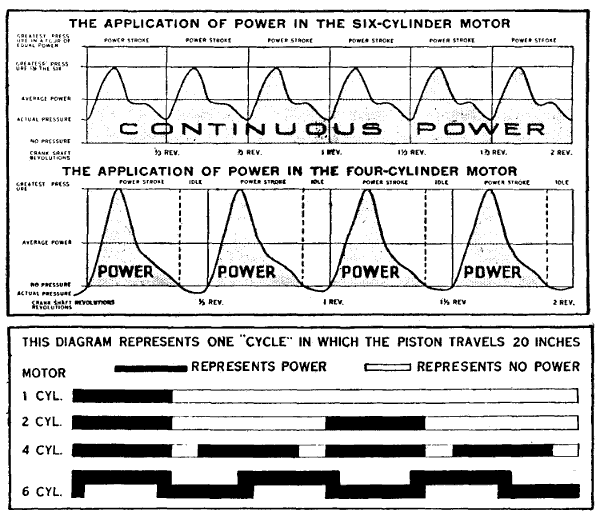
Fig. 25.—Diagrams Outlining Advantages of Multiple Cylinder Motors, and Why They Deliver Power More Evenly Than Single Cylinder Types.
A rectangle is divided into four columns; each of these corresponds to one hundred and eighty degrees, or half a revolution. Thus the first revolution of the crank-shaft is represented by the first two columns, while the second revolution is represented by the last two. Taking the portion of the diagram which shows the power impulse in a one-cylinder engine, we see that during the first revolution there has been no power impulse. During the first half of the second revolution, however, an explosion takes place and a power impulse is obtained. The last portion of the second revolution is devoted to exhausting the burned gases, so that there are three idle strokes and but one power stroke. The effect when two cylinders are employed is shown immediately below.
[92]Here we have one explosion during the first half of the first revolution in one cylinder and another during the first half of the second revolution in the other cylinder. With a four-cylinder engine there is an explosion each half revolution, while in a six-cylinder engine there is one and one-half explosions during each half revolution. When six cylinders are used there is no lapse of time between power impulses, as these overlap and a continuous and smooth-turning movement is imparted to the crank shaft. The diagram shown at Fig. 26, prepared by E. P. Pulley, can be studied to advantage in securing an idea of the coordination of effort that takes place in an engine of the six-cylinder type.
In the diagrams previously presented the writer has assumed, for the sake of simplicity, that each stroke takes place during half of one revolution of the crank-shaft, which corresponds to a crank-pin travel of one hundred and eighty degrees. The actual duration of these strokes is somewhat different. For example, the inlet stroke is usually a trifle more than a half revolution, and the exhaust is always considerably more. The diagram showing the comparative duration of the strokes is shown at Fig. 27.[94] The inlet valve opens ten degrees after the piston starts to go down and remains open thirty degrees after the piston has reached the bottom of its stroke. This means that the suction stroke corresponds to a crank-pin travel of two hundred degrees, while the compression stroke is measured by a movement of but one hundred and fifty degrees. It is common practice to open the exhaust valve before the piston reaches the end of the power stroke so that the actual duration of the power stroke is about one hundred and forty degrees, while the exhaust stroke corresponds to a crank-pin travel of two hundred and twenty-five degrees. In this diagram, which represents proper time for the valves to open and close, the dimensions in inches given are measured on the fly-wheel and apply only to a certain automobile motor. If the fly-wheel were smaller ten degrees would take up less than the dimensions given, while if the fly-wheel was larger a greater space on its circumference would represent the same crank-pin travel. Aviation engines are timed by using a timing disc attached to the crank-shaft as they are not provided with fly-wheels. Obviously, the distance measured in inches will depend upon the diameter of the disc, though the number of degrees interval would not change.
Those who have followed the development of the gasoline engine will recall the arguments that were made when the six-cylinder motor was introduced at a time that the[95] four-cylinder type was considered standard. The arrival of the eight-cylinder has created similar futile discussion of its practicability as this is so clearly established as to be accepted without question. It has been a standard power plant for aeroplanes for many years, early exponents having been the Antoinette, the Woolsley, the Renault, the E. N. V. in Europe and the Curtiss in the United States.
The reason the V type shown at Fig. 29, A is favored is that the “all-in-line form” which is shown at Fig. 29, B is not practical for aircraft because of its length. Compared to the standard four-cylinder engine it is nearly twice as long and it required a much stronger and longer crank-shaft. It will be evident that it could not be located to advantage in the airplane fuselage. These undesirable factors are eliminated in the V type eight-cylinder motor, as it consists of two blocks of four cylinders each, so arranged that one set or block is at an angle of forty-five degrees from the vertical center line of the motor, or at an angle of ninety degrees with the other set. This arrangement of cylinders produces a motor that is no[96] longer than a four-cylinder engine of half the power would be.
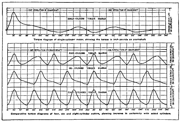
Fig. 30.—Curves Showing Torque of Various Engine Types Demonstrate Graphically Marked Advantage of the Eight-Cylinder Type.
Apparently there is considerable misconception as to the advantage of the two extra cylinders of the eight as compared with the six-cylinder. It should be borne in mind that the multiplication in the number of cylinders noticed since the early days of automobile development has not been for solely increasing the power of the engine, but to secure a more even turning movement, greater flexibility and to eliminate destructive vibration. The ideal internal combustion motor, is the one having the most uniform turning movement with the least mechanical friction loss. Study of the torque outlines or plotted graphics shown at Figs. 25 and 30 will show how multiplication of cylinders will produce steady power delivery due to overlapping impulses. The most practical form would be that which more nearly conforms to the steady running produced by a steam turbine or electric motor. The advocates of the eight-cylinder engine bring up the item of uniform torque[97] as one of the most important advantages of the eight-cylinder design. A number of torque diagrams are shown at Fig. 30. While these appear to be deeply technical, they may be very easily followed when their purpose is explained. At the top is shown the torque diagram of a single-cylinder motor of the four-cycle type. The high point in the line represents the period of greatest torque or power generation, and it will be evident that this occurs early in the first revolution of the crank-shaft. Below this diagram is shown a similar curve except that it is produced by a four-cylinder engine. Inspection will show that the turning-moment is much more uniform than in the[98] single cylinder; similarly, the six-cylinder diagram is an improvement over the four, and the eight-cylinder diagram is an improvement over the six-cylinder.
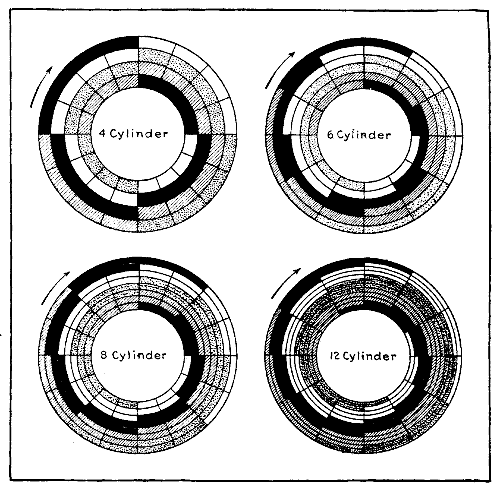
Fig. 31—Diagrams Showing How Increasing Number of Cylinders Makes for More Uniform Power Application.
The reason that practically continuous torque is obtained in an eight-cylinder engine is that one cylinder fires every ninety degrees of crank-shaft rotation, and as each impulse lasts nearly seventy-five per cent. of the stroke, one can easily appreciate that an engine that will give four explosions per revolution of the crank-shaft will run more uniformly than one that gives but three explosions per revolution, as the six-cylinder does, and will be twice as smooth running as a four-cylinder, in which but two explosions occur per revolution of the crank-shaft. The comparison is so clearly shown in graphical diagrams and in Fig. 31 that further description is unnecessary.
Any eight-cylinder engine may be considered a “twin-four,” twelve-cylinder engines may be considered “twin sixes.”
The only points in which an eight-cylinder motor differs from a four-cylinder is in the arrangement of the connecting rod, as in many designs it is necessary to have two rods working from the same crank-pin. This difficulty is easily overcome in some designs by staggering the cylinders and having the two connecting rod big ends of conventional form side by side on a common crank-pin. In other designs one rod is a forked form and works on the outside of a rod of the regular pattern. Still another method is to have a boss just above the main bearing on one connecting rod to which the lower portion of the connecting rod in the opposite cylinder is hinged. As the eight-cylinder engine may actually be made lighter than the six-cylinder of equal power, it is possible to use smaller reciprocating parts, such as pistons, connecting rods and valve gear, and obtain higher engine speed with practically no vibration. The firing order in nearly every case is the same as in a four-cylinder except that the explosions occur alternately in each set of cylinders. The firing order of an eight-cylinder motor is apt to be confusing to the[100] motorist, especially if one considers that there are eight possible sequences. The majority of engineers favor the alternate firing from side to side. Firing orders will be considered in proper sequence.
The demand of aircraft designers for more power has stimulated designers to work out twelve-cylinder motors. These are high-speed motors incorporating all recent features of design in securing light reciprocating parts, large valve openings, etc. The twelve-cylinder motor incorporates the best features of high-speed motor design and there is no need at this time to discuss further the pros and cons of the twelve-cylinder versus the eight or six, because it is conceded by all that there is the same degree of steady power application in the twelve over the eight as there would be in the eight over the six. The question resolves[102] itself into having a motor of high power that will run with minimum vibration and that produces smooth action. This is well shown by diagrams at Fig. 31. It should be remembered that if an eight-cylinder engine will give four explosions per revolution of the fly-wheel, a twelve-cylinder type will give six explosions per revolution, and instead of the impulses coming 90 degrees crank travel apart, as in the case of the eight-cylinder, these will come but 60 degrees of crank travel apart in the case of the twelve-cylinder. For this reason, the cylinders of a twelve are usually separated by 60 degrees while the eight has the blocks spaced 90 degrees apart. The comparison can be easily made by comparing the sectional views of Vee engines at Fig. 32. When one realizes that the actual duration of the power stroke is considerably greater than 120 degrees crank travel, it will be apparent that the overlapping of explosions must deliver a very uniform application of power. Vee engines have been devised[103] having the cylinders spaced but 45 degrees apart, but the explosions cannot be timed at equal intervals as when 90 degrees separate the cylinder center lines.
While the fixed cylinder forms of engines, having the cylinders in tandem in the four- and six-cylinder models as shown at Figs. 33 to 35 inclusive and the eight-cylinder V types as outlined at Figs. 36 and 37 have been generally used and are most in favor at the present time, other forms of motors having unconventional cylinder arrangements have been devised, though most of these are practically[104] obsolete. While many methods of decreasing weight and increasing mechanical efficiency of a motor are known to designers, one of the first to be applied to the construction of aeronautical power plants was an endeavor to group the components, which in themselves were not extremely light, into a form that would be considerably lighter than the conventional design. As an example, we may consider those multiple-cylinder forms in which the cylinders are disposed around a short crank-case, either radiating from a common center as at Fig. 38 or of the fan shape shown at Fig. 39. This makes it possible to use a crank-case but slightly larger than that needed for one or two cylinders and it also permits of a corresponding decrease in length of the crank-shaft. The weight of the engine is lessened because of the reduction in crank-shaft and crank-case weight and the elimination of a number of intermediate bearings and their supporting webs which would be necessary with the usual tandem construction. While there are six power impulses to every two revolutions of the crank-shaft,[105] in the six-cylinder engine, they are not evenly spaced as is possible with the conventional arrangement.
In the Anzani form, which is shown at Fig. 38, the crank-case is stationary and a revolving crank-shaft is employed as in conventional construction. The cylinders are five in number and the engine develops 40 to 50 H.P. with a weight of 72 kilograms or 158.4 lbs. The cylinders are of the usual air-cooled form having cooling flanges only part of the way down the cylinder. By using five cylinders it is possible to have the power impulses come regularly, they coming 145° crank-shaft travel apart, the crank-shaft making two turns to every five explosions. The balance is good and power output regular. The valves are[106] placed directly in the cylinder head and are operated by a common pushrod. Attention is directed to the novel method of installing the carburetor which supplies the mixture to the engine base from which inlet pipes radiate to the various cylinders. This engine is used on French school machines.
In the form shown at Fig. 39 six cylinders are used, all being placed above the crank-shaft center line. This engine is also of the air-cooled form and develops 50 H. P. and weighs 105 kilograms, or 231 lbs. The carburetor is connected to a manifold casting attached to the engine base from which the induction pipes radiate to the various cylinders. The propeller design and size relative to the engine is clearly shown in this view. While flights have been made with both of the engines described, this method of construction is not generally followed and has been almost entirely displaced abroad by the revolving motors or by the more conventional eight-cylinder V engines. Both of the engines shown were designed about eight years[107] ago and would be entirely too small and weak for use in modern airplanes intended for active duty.
Rotary engines such as shown at Fig. 40 are generally associated with the idea of light construction and it is rather an interesting point that is often overlooked in connection with the application of this idea to flight motors, that the reason why rotary engines are popularly supposed to be lighter than the others is because they form their own fly-wheel, yet on aeroplanes, engines are seldom fitted with a fly-wheel at all. As a matter of fact the[108] Gnome engine is not so light because it is a rotary motor, and it is a rotary motor because the design that has been adopted as that most conducive to lightness is also most suited to an engine working in this way. The cylinders could be fixed and crank-shaft revolve without increasing the weight to any extent. There are two prime factors governing the lightness of an engine, one being the initial design, and the other the quality of the materials employed. The consideration of reducing weight by cutting away metal is a subsidiary method that ought not to play a part in standard practice, however useful it may be in special cases. In the Gnome rotary engine the lightness is entirely due to the initial design and to the materials employed in manufacture. Thus, in the first case, the engine is a radial engine, and has its seven or nine cylinders spaced equally around a crank-chamber that is no wider or rather longer than would be required for any one of the cylinders. This shortening of the crank-chamber not only effects a considerable saving of weight on its own account, but there is a corresponding saving in the shafts and other members, the dimensions of which are governed by the size of the crank-chamber. With regard to materials, nothing but steel is used throughout, and most of the metal is forged chrome nickel steel. The beautifully steady running of the engine is largely due to the fact that there are literally no reciprocating parts in the absolute sense, the apparent reciprocation between the pistons and cylinders being solely a relative reciprocation since both travel in circular paths, that of the pistons, however, being electric by one-half of the stroke length to that of the cylinder.
While the Gnome engine has many advantages, on the other hand the head resistance offered by a motor of this type is considerable; there is a large waste of lubricating oil due to the centrifugal force which tends to throw the oil away from the cylinders; the gyroscopic effect of the rotary motor is detrimental to the best working of the[109] aeroplane, and moreover it requires about seven per cent. of the total power developed by the motor to drive the revolving cylinders around the shaft. Of necessity, the compression of this type of motor is rather low, and an additional disadvantage manifests itself in the fact that there is as yet no satisfactory way of muffling the rotary type of motor. The modern Gnome engine has been widely copied in various European countries, but its design was originated in America, the early Adams-Farwell engine being the pioneer form. It has been made in seven- and nine-cylinder types and forms of double these numbers. The engine illustrated at Fig. 40 is a fourteen-cylinder form. The simple engines have an odd number of cylinders in order to secure evenly spaced explosions. In the seven-cylinder, the impulses come 102.8° apart. In the nine-cylinder form, the power strokes are spaced 80° apart. The fourteen-cylinder engine is virtually two seven-cylinder types mounted together, the cranks being just the same as in a double cylinder opposed motor, the explosions coming 51.4° apart; while in the eighteen-cylinder model the power impulses come every 40° cylinder travel. Other rotary motors have been devised, such as the Le Rhone and the Clerget in France and several German copies of these various types. The mechanical features of these motors will be fully considered later.
Properties of Liquid Fuels—Distillates of Crude Petroleum—Principles of Carburetion Outlined—Air Needed to Burn Gasoline—What a Carburetor Should Do—Liquid Fuel Storage and Supply—Vacuum Fuel Feed—Early Vaporizer Forms—Development of Float Feed Carburetor—Maybach’s Early Design—Concentric Float and Jet Type—Schebler Carburetor—Claudel Carburetor—Stewart Metering Pin Type—Multiple Nozzle Vaporizers—Two-Stage Carburetor—Master Multiple Jet Type—Compound Nozzle Zenith Carburetor—Utility of Gasoline Strainers—Intake Manifold Design and Construction—Compensating for Various Atmospheric Conditions—How High Altitude Affects Power—The Diesel System—Notes on Carburetor Installation—Notes on Carburetor Adjustment.
There is no appliance that has more material value upon the efficiency of the internal combustion motor than the carburetor or vaporizer which supplies the explosive gas to the cylinders. It is only in recent years that engineers have realized the importance of using carburetors that are efficient and that are so strongly and simply made that there will be little liability of derangement. As the power obtained from the gas-engine depends upon the combustion of fuel in the cylinders, it is evident that if the gas supplied does not have the proper proportions of elements to insure rapid combustion the efficiency of the engine will be low. When a gas engine is used as a stationary installation it is possible to use ordinary illuminating or natural gas for fuel, but when this prime mover is applied to automobiles or airplanes it is evident that considerable difficulty would be experienced in carrying enough compressed coal gas to supply the engine for even a very short trip. Fortunately, the development of the internal-combustion motor was not delayed by the lack of suitable fuel.
Engineers were familiar with the properties of certain[111] liquids which gave off vapors that could be mixed with air to form an explosive gas which burned very well in the engine cylinders. A very small quantity of such liquids would suffice for a very satisfactory period of operation. The problem to be solved before these liquids could be applied in a practical manner was to evolve suitable apparatus for vaporizing them without waste. Among the liquids that can be combined with air and burned, gasoline is the most volatile and is the fuel utilized by internal-combustion engines.
The widely increasing scope of usefulness of the internal-combustion motor has made it imperative that other fuels be applied in some instances because the supply of gasoline may in time become inadequate to supply the demand. In fact, abroad this fuel sells for fifty to two hundred per cent. more than it does in America because most of the gasoline used must be imported from this country or Russia. Because of this foreign engineers have experimented widely with other substances, such as alcohol, benzol, and kerosene, but more to determine if they can be used to advantage in motor cars than in airplane engines.
Crude petroleum is found in small quantities in almost all parts of the world, but a large portion of that produced commercially is derived from American wells. The petroleum obtained in this country yields more of the volatile products than those of foreign production, and for that reason the demand for it is greater. The oil fields of this country are found in Pennsylvania, Indiana, and Ohio, and the crude petroleum is usually in association with natural gas. This mineral oil is an agent from which many compounds and products are derived, and the products will vary from heavy sludges, such as asphalt, to the lighter and more volatile components, some of which will evaporate very easily at ordinary temperatures.
The compounds derived from crude petroleum are composed[112] principally of hydrogen and carbon and are termed “Hydrocarbons.” In the crude product one finds many impurities, such as free carbon, sulphur, and various earthy elements. Before the oil can be utilized it must be subjected to a process of purifying which is known as refining, and it is during this process, which is one of destructive distillation, that the various liquids are separated. The oil was formerly broken up into three main groups of products as follows: Highly volatile, naphtha, benzine, gasoline, eight to ten per cent. Light oils, such as kerosene and light lubricating oils seventy to eighty per cent. Heavy oils or residuum five to nine per cent. From the foregoing it will be seen that the available supply of gasoline is determined largely by the demand existing for the light oils forming the larger part of the products derived from crude petroleum. New processes have been recently discovered by which the lighter oils, such as kerosene, are reduced in proportion and that of gasoline increased, though the resulting liquid is neither the high grade, volatile gasoline known in the early days of motoring nor the low grade kerosene.
The process of carburetion is combining the volatile vapors which evaporate from the hydrocarbon liquids with certain proportions of air to form an inflammable gas. The quantities of air needed vary with different liquids and some mixtures burn quicker than do other combinations of air and vapor. Combustion is simply burning and it may be rapid, moderate or slow. Mixtures of gasoline and air burn quickly, in fact the combustion is so rapid that it is almost instantaneous and we obtain what is commonly termed an “explosion.” Therefore the explosion of gas in the automobile engine cylinder which produces the power is really a combination of chemical elements which produce heat and an increase in the volume of the gas because of the increase in temperature.
If the gasoline mixture is not properly proportioned[113] the rate of burning will vary, and if the mixture is either too rich or too weak the power of the explosion is reduced and the amount of power applied to the piston is decreased proportionately. In determining the proper proportions of gasoline and air, one must take the chemical composition of gasoline into account. The ordinary liquid used for fuel is said to contain about eight-four per cent. carbon and sixteen per cent. hydrogen. Air is composed of oxygen and nitrogen and the former has a great affinity, or combining power, with the two constituents of hydro-carbon liquids. Therefore, what we call an explosion is merely an indication that oxygen in the air has combined with the carbon and hydrogen of the gasoline.
In figuring the proper volume of air to mix with a given quantity of fuel, one takes into account the fact that one pound of hydrogen requires eight pounds of oxygen to burn it, and one pound of carbon needs two and one-third pounds of oxygen to insure its combustion. Air is composed of one part of oxygen to three and one-half portions of nitrogen by weight. Therefore for each pound of oxygen one needs to burn hydrogen or carbon four and one-half pounds of air must be allowed. To insure combustion of one pound of gasoline which is composed of hydrogen and carbon we must furnish about ten pounds of air to burn the carbon and about six pounds of air to insure combustion of hydrogen, the other component of gasoline. This means that to burn one pound of gasoline one must provide about sixteen pounds of air.
While one does not usually consider air as having much weight, at a temperature of sixty-two degrees Fahrenheit about fourteen cubic feet of air will weigh a pound, and to burn a pound of gasoline one would require about two hundred cubic feet of air. This amount will provide for combustion theoretically, but it is common practice to allow twice this amount because the element nitrogen, which is the main constituent of air, is an inert gas and[114] instead of aiding combustion it acts as a deterrent of burning. In order to be explosive, gasoline vapor must be combined with definite quantities of air. Mixtures that are rich in gasoline ignite quicker than those which have more air, but these are only suitable when starting or when running slowly, as a rich mixture ignites much quicker than a weak mixture. The richer mixture of gasoline and air not only burns quicker but produces the most heat and the most effective pressure in pounds per square inch of piston top area.
The amount of compression of the charge before ignition also has material bearing on the force of the explosion. The higher the degree of compression the greater the force exerted by the rapid combustion of the gas. It may be stated that as a general thing the maximum explosive pressure is somewhat more than four times the compression pressure prior to ignition. A charge compressed to sixty pounds will have a maximum of approximately two hundred and forty pounds; compacted to eighty pounds it will produce a pressure of about three hundred pounds on each square inch of piston area at the beginning of the power stroke. Mixtures varying from one part of gasoline vapor to four of air to others having one part of gasoline vapor to thirteen of air can be ignited, but the best results are obtained when the proportions are one to five or one to seven, as this mixture is said to be the one that will produce the highest temperature, the quickest explosion, and the most pressure.
While it is apparent that the chief function of a carbureting device is to mix hydrocarbon vapors with air to secure mixtures that will burn, there are a number of factors which must be considered before describing the principles of vaporizing devices. Almost any device which permits a current of air to pass over or through a volatile liquid will produce a gas which will explode when[116][115] compressed and ignited in the motor cylinder. Modern carburetors are not only called upon to supply certain quantities of gas, but these must deliver a mixture to the cylinders that is accurately proportioned and which will be of proper composition at all engine speeds.
Flexible control of the engine is sought by varying the engine speed by regulating the supply of gas to the cylinders. The power plant should run from its lowest to its highest speed without any irregularity in torque, i.e., the acceleration should be gradual rather than spasmodic. As the degree of compression will vary in value with the amount of throttle opening, the conditions necessary to obtain maximum power differ with varying engine speeds. When the throttle is barely opened the engine speed is low and the gas must be richer in fuel than when the throttle is wide open and the engine speed high.
When an engine is turning over slowly the compression has low value and the conditions are not so favorable to rapid combustion as when the compression is high. At high engine speeds the gas velocity through the intake piping is higher than at low speeds, and regular engine action is not so apt to be disturbed by condensation of liquid fuel in the manifold due to excessively rich mixture or a superabundance of liquid in the stream of carbureted air.
The problem of gasoline storage and method of supplying the carburetor is one that is determined solely by design of the airplane. While the object of designers should be to supply the fuel to the carburetor by as simple means as possible the fuel supply system of some airplanes is quite complex. The first point to consider is the location of the gasoline tank. This depends upon the amount of fuel needed and the space available in the fuselage.
A very simple and compact fuel supply system is shown at Fig. 41. In this instance the fuel container is placed immediately back of the engine cylinder. The carburetor[117] which is carried as indicated is joined to the tank by a short piece of copper or flexible rubber tubing. This is the simplest possible form of fuel supply system and one used on a number of excellent airplanes.
As the sizes of engines increase and the power plant fuel consumption augments it is necessary to use more fuel, and to obtain a satisfactory flying radius without frequent landings for filling the fuel tank it is necessary to supply large containers.
When a very powerful power plant is fitted, as on battle planes of high capacity, it is necessary to carry large quantities of gasoline. In order to use a tank of sufficiently large capacity it may be necessary to carry it lower than the carburetor. When installed in this manner it is necessary to force fuel out of the tank by air pressure or to pump it with a vacuum tank because the gasoline tank is lower than the carburetor it supplies and the gasoline cannot flow by gravity as in the simpler systems. While the pressure and gravity feed systems are generally used in airplanes, it may be well to describe the vacuum lift system which has been widely applied to motor cars and which may have some use in connection with airplanes as these machines are developed.
One of the marked tendencies has been the adoption of a vacuum fuel feed system to draw the gasoline from tanks placed lower than the carburetor instead of using either exhaust gas or air pressure to achieve this end. The device generally fitted is the Stewart vacuum feed tank which is clearly shown in section at Fig. 42. In this system the suction of a motor is employed to draw gasoline from the main fuel tank to the auxiliary tank incorporated in the device and from this tank the liquid flows to the carburetor. It is claimed that all the advantages of the pressure system are obtained with very little more complication than is found on the ordinary gravity feed. The mechanism is all contained in the cylindrical tank shown,[118] which may be mounted either on the front of the dash or on the side of the engine as shown.
The tank is divided into two chambers, the upper one being the filling chamber and the lower one the emptying chamber. The former, which is at the top of the device, contains the float valve, as well as the pipes running to the main fuel container and to the intake manifold. The lower chamber is used to supply the carburetor with gasoline and is under atmospheric pressure at all times, so the flow of fuel from it is by means of gravity only. Since[119] this chamber is located somewhat above the carburetor, there must always be free flow of fuel. Atmospheric pressure is maintained by the pipes A and B, the latter opening into the air. In order that the fuel will be sucked from a main tank to the upper chamber, the suction valve must be opened and the atmospheric valve closed. Under these conditions the float is at the bottom and the suction at the intake manifold produces a vacuum in the tank which draws the gasoline from the main tank to the upper chamber. When the upper chamber is filled at the proper height the float rises to the top, this closing the suction valve and opening the atmospheric valve. As the suction is now cut off, the lower chamber is filled by gravity owing to there being atmospheric pressure in both upper and lower chambers. A flap valve is provided between the two chambers to prevent the gasoline in the lower one from being sucked back into the upper one. The atmospheric and suction valves are controlled by the levers C and D, both of which are pivoted at E, their outer ends being connected by two coil springs. It is seen that the arrangement of these two springs is such that the float must be held at the extremity of its movement, and that it cannot assume an intermediate position.
This intermittent action is required to insure that the upper part of the tank may be under atmospheric pressure part of the time for the gasoline to flow to the lower chamber. When the level of gasoline drops to a certain point, the float falls, thus opening the suction valve and closing the atmospheric valve. The suction of the motor then causes a flow of fuel from the main container. As soon as the level rises to the proper height the float returns to its upper position. It takes about two seconds for the chamber to become full enough to raise the float, as but .05 gallon is transferred at a time. The pipe running from the bottom of the lower chamber to the carburetor extends up a ways, so that there is but little chance of dirt or water being carried to the float chamber.
If the engine is allowed to stand long enough so that the[120] tank becomes empty, it will be replenished after the motor has been cranked over four or five times with the throttle closed. The installation of the Stewart Vacuum-Gravity System is very simple. The suction pipe is tapped into the manifold at a point as near the cylinders as possible, while the fuel pipe is inserted into the gasoline tank and runs to the bottom of that member. There is a screen at the end of the fuel pipe to prevent any trouble due to deposits of sediment in the main container. As the fuel is sucked from the gasoline tank a small vent must be made in the tank filler cap so that the pressure in the main tank will always be that of the atmosphere.
The early types of carbureting devices were very crude and cumbersome, and the mixture of gasoline vapor and air was accomplished in three ways. The air stream was passed over the surface of the liquid itself, through loosely placed absorbent material saturated with liquid, or directly through the fuel. The first type is known as the surface carburetor and is now practically obsolete. The second form is called the “wick” carburetor because the air stream was passed over or through saturated wicking. The third form was known as a “bubbling” carburetor. While these primitive forms gave fairly good results with the early slow-speed engines and the high grade, or very volatile, gasoline which was first used for fuel, they would be entirely unsuitable for present forms of engines because they would not carburate the lower grades of gasoline which are used to-day, and would not supply the modern high-speed engines with gas of the proper consistency fast enough even if they did not have to use very volatile gasoline. The form of carburetor used at the present time operates on a different principle. These devices are known as “spraying carburetors.” The fuel is reduced to a spray by the suction effect of the entering air stream drawing it through a fine opening.
The advantage of this construction is that a more[121] thorough amalgamation of the gasoline and air particles is obtained. With the earlier types previously considered the air would combine with only the more volatile elements, leaving the heavier constituents in the tank. As the fuel became stale it was difficult to vaporize it, and it had to be drained off and fresh fuel provided before the proper mixture would be produced. It will be evident that when the fuel is sprayed into the air stream, all the fuel will be used up and the heavier portions of the gasoline will be taken into the cylinder and vaporized just as well as the more volatile vapors.
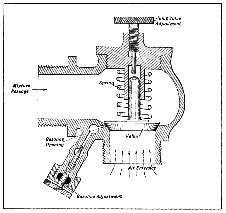
Fig. 43.—Marine-Type Mixing Valve, by which Gasoline is Sprayed into Air Stream Through Small Opening in Air-Valve Seat.
The simplest form of spray carburetor is that shown at Fig. 43. In this the gasoline opening through which[122] the fuel is sprayed into the entering air stream is closed by the spring-controlled mushroom valve which regulates the main air opening as well. When the engine draws in a charge of air it unseats the valve and at the same time the air flowing around it is saturated with gasoline particles through the gasoline opening. The mixture thus formed goes to the engine through the mixture passage. Two methods of varying the fuel proportions are provided. One of these consists of a needle valve to regulate the amount of gasoline, the other is a knurled screw which controls the amount of air by limiting the lift of the jump valve.
The modern form of spraying carburetor is provided with two chambers, one a mixing chamber through which the air stream passes and mixes with a gasoline spray, the other a float chamber in which a constant level of fuel is maintained by simple mechanism. A jet or standpipe is used in the mixing chamber to spray the fuel through and the object of the float is to maintain the fuel level to such a point that it will not overflow the jet when the motor is not drawing in a charge of gas. With the simple forms of generator valve in which the gasoline opening is controlled by the air valve, a leak anywhere in either valve or valve seat will allow the gasoline to flow continuously whether the engine is drawing in a charge or not. The liquid fuel collects around the air opening, and when the engine inspires a charge it is saturated with gasoline globules and is excessively rich. With a float-feed construction, which maintains a constant level of gasoline at the right height in the standpipe, liquid fuel will only be supplied when drawn out of the jet by the suction effect of the entering air stream.
The first form of spraying carburetor ever applied successfully was evolved by Maybach for use on one of the[124] earliest Daimler engines. The general principles of operation of this pioneer float-feed carburetor are shown at Fig. 44, A. The mixing chamber and valve chamber were one and the standpipe or jet protruded into the mixing chamber. It was connected to the float compartment by a pipe. The fuel from the tank entered the top of the float compartment and the opening was closed by a needle valve carried on top of a hollow metal float. When the level of gasoline in the float chamber was lowered the float would fall and the needle valve uncover the opening. This would permit the gasoline from the tank to flow into the float chamber, and as the chamber filled the float would rise until the proper level had been reached, under which conditions the float would shut off the gasoline opening. On every suction stroke of the engine the inlet valve, which was an automatic type, would leave its seat and a stream of air would be drawn through the air opening and around the standpipe or jet. This would cause the gasoline to spray out of the tube and mix with the entering air stream.
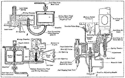
Fig. 44.—Tracing Evolution of Modern Spray Carburetor. A—Early Form Evolved by Maybach. B.—Phœnix-Daimler Modification of Maybach’s Principle. C—Modern Concentric Float Automatic Compensating Carburetor.
The form shown at B was a modification of Maybach’s simple device and was first used on the Phœnix-Daimler engines. Several improvements are noted in this device. First, the carburetor was made one unit by casting the float and mixing chambers together instead of making them separate and joining them by a pipe, as shown at A. The float construction was improved and the gasoline shut-off valve was operated through leverage instead of being directly fastened to the float. The spray nozzle was surrounded by a choke tube which concentrated the air stream around it and made for more rapid air flow at low engine speeds. A conical piece was placed over the jet to break up the entering spray into a mist and insure more intimate admixture of air and gasoline. The air opening was provided with an air cone which had a shutter controlling the opening so that the amount of air entering could be regulated and thus vary the mixture proportions within certain limits.
The form shown at B has been further improved, and the type shown at C is representative of modern single jet practice. In this the float chamber and mixing chamber are concentric. A balanced float mechanism which insures steadiness of feed is used, the gasoline jet or standpipe is provided with a needle valve to vary the amount of gasoline supplied the mixture and two air openings are provided. The main air port is at the bottom of the vaporizer, while an auxiliary air inlet is provided at the side of the mixing chamber. There are two methods of controlling the mixture proportions in this form of carburetor. One may regulate the gasoline needle or adjust the auxiliary air valve.
A Schebler carburetor, which has been used on some airplane engines, is shown in Fig. 45. It will be noticed that a metering pin or needle valve opens the jet when the air valve opens. The long arm of a leverage is connected to the air valve, while the short arm is connected to the needle, the reduction in leverage being such that the needle valve is made to travel much less than the air valve. For setting the amount of fuel passed or the size of the jet orifice when running with the air valve closed, there is a screw which raises or lowers the fulcrum of the lever and there is also a dash control having the same effect by pushing down the fulcrum against a small spring. A long extension is given to the venturi tube which is very narrow around the jet orifices, which are horizontal and shown at A in the drawing. Fuel enters the float chamber through the union M, and the spring P holds the metering pin upward against the restraining action of the lever. The air valve may be set by an easily adjustable knurled screw shown in the drawing, and fluttering of the valve is prevented by the piston dash pot carried in a chamber above the valve into which the valve stem projects. The[127] primary air enters beneath the jet passage and there is a small throttle in the intake to increase the speed of air flow for starting purposes. The carburetor is adapted for the use of a hot-air connection to the stove around the exhaust pipe and it is recommended that such a fitting be supplied. The lever which controls the supply of air through the primary air intake is so arranged that if desired it can be connected with a linkage on the dash or control column by means of a flexible wire.
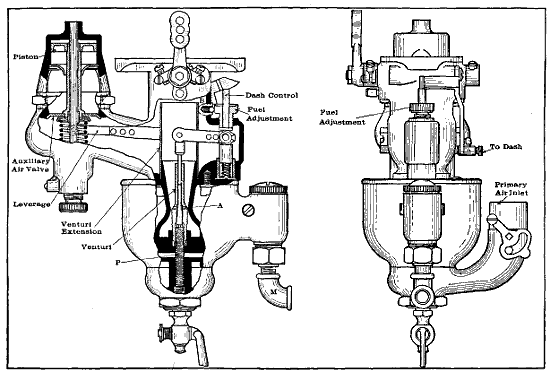
Fig. 45.—New Model of Schebler Carburetor With Metering Valve and Extended Venturi. Note Mechanical Connection Between Air Valve and Fuel Regulating Needle.
This carburetor is of extremely simple construction, because it has no supplementary or auxiliary air valve and no moving parts except the throttle controlling the gas flow. The construction is already shown in Fig. 46.[128] The spray jet is eccentric with a surrounding sleeve or tube in which there are two series of small orifices, one at the top and the other near the bottom. The former are about level with the spray jet opening. The sleeve surrounding the nozzle is closed at the top. The air, passing the upper holes in the sleeve, produces a vacuum in the sleeve, thereby drawing air in through the bottom holes. It is this moving interior column of air that controls the flow of gasoline from the nozzle. Owing to the friction of the small passages, the speed of air flow through the sleeve does not increase as fast as the speed of air flow outside the sleeve, hence there is a tendency for the mixture to remain constant. The throttle of this carburetor is of the barrel type, and the top of the spray nozzle and its surrounding sleeve are located inside the throttle.
The carburetor shown at Fig. 47 is a metering type in which the vacuum at the jet is controlled by the weight of the metering valve surrounding the upright metering pin. The only moving part is the metering valve, which rises and falls with the changes in vacuum. The air chamber surrounds the metering valve, and there is a mixing chamber above. As the valve is drawn up the gasoline passage is enlarged on account of the predetermined taper on the metering pin, and the air passage also is increased proportionately, giving the correct mixture. A dashpot at the bottom of the valve checks flutter. In idling the valve rests on its seat, practically closing the air and giving the necessary idling mixture. A passage through the valve acts as an aspirating tube. When the valve is closed altogether the primary air passes through ducts in the valve itself, giving the proper amount for idling. The one adjustment consists in raising or lowering the tapered metering pin, increasing or decreasing the supply of gasoline. Dash control is supplied. This pulls down the metering pin, increasing the gasoline flow. The duplex type for eight- and twelve-cylinder motors is the same in[129] principle as model 25, but it is a double carburetor synchronized as to throttle movements, adjustments, etc. The duplex for aeronautical motors is made of cast aluminum alloy.
To secure properly proportioned mixtures some carburetor designers have evolved forms in which two or more nozzles are used in a common mixing chamber. The usual construction is to use two, one having a small opening and placed in a small air tube and used only for low[130] speeds, the other being placed in a larger air tube and having a slightly augmented bore so that it is employed on intermediate speeds. At high speeds both jets would be used in series. Some multiple jet carburetors could be considered as a series of these instruments, each one being designed for certain conditions of engine action. They would vary from small size just sufficient to run the engine at low speed to others having sufficient capacity to furnish gas for the highest possible engine speed when used in conjunction with the smaller members which have been brought into service progressively as the engine speed has been augmented. The multiple nozzle carburetor differs from that in which a single spray tube is used only in the construction of the mixing chamber, as a common float bowl can be used to supply all spray pipes. It is common practice to bring the jets into action progressively by some form of mechanical connection with the throttle or by automatic valves.
The object of any multiple nozzle carburetor is to secure greater flexibility and endeavor to supply mixtures of proper proportions at all speeds of the engine. It should be stated, however, that while devices of this nature lend themselves readily to practical application it is more difficult to adjust them than the simpler forms having but one nozzle. When a number of jets are used the liability of clogging up the carburetor is increased, and if one or more of the nozzles is choked by a particle of dirt or water the resulting mixture trouble is difficult to detect. One of the nozzles may supply enough gasoline to permit the engine to run well at certain speeds and yet not be adequate to supply the proper amount of gas under other conditions. In adjusting a multiple jet carburetor in which the jets are provided with gasoline regulating needles, it is customary to consider each nozzle as a distinct carburetor and to regulate it to secure the best motor action at that throttle position which corresponds to the conditions under which the jet is brought into service. For instance, that supplied the primary mixing chamber[131] should be regulated with the throttle partly closed, while the auxiliary jet should be adjusted with the throttle fully opened.
This is a two-stage vaporizing device, hot air being used in the primary or initial stage of vaporization and cold air in the supplementary stage. Referring to the sectional illustration at Fig. 48, it will be seen that there is a hot-air passage with a choke-valve; the primary venturi appears at B; J is its gasoline jet, and V is a spring-loaded idling valve in a fixed air opening. These parts constitute the primary system. In the secondary system A is a cold-air passage, T a butterfly valve and J a gasoline jet discharging into the cold-air passage. This system is brought into operation by opening the butterfly T. A connection between the butterfly T and the throttle, not shown, throws the butterfly wide open when the throttle is not quite wide open; at all other times the butterfly[132] is held closed by a spring. The cylindrical chamber at the right of the mixing chamber has an extension E of reduced diameter connecting it with the intake manifold through a passage D. A restricted opening connects the float chamber with the cylindrical chamber so that the gasoline level is the same in both. A loosely fitting plunger P in the cylindrical chamber has an upward extension into the small part of the chamber. O is a small air opening and M is a passage from the cylindrical chamber to the mixing chamber. Air constantly passes through this when the carburetor is in operation. The carburetor is really two in one. The primary carburetor is made up of a central jet in a venturi passage. The float chamber is eccentric. In the air passage there is a fixed opening, and additional air is taken in by the opening through suction of a spring-opposed air valve. The second stage, which comes into play as soon as the carburetor is called upon for additional mixture above low medium speeds, is made up of an independent air passage containing another air valve. As the valve is opened this jet is uncovered, and air is led past it. For easy starting an extra passage leads from the float bowl passage to a point above the throttle. All the suction falls upon this passage when the throttle is closed. The passage contains a plunger and acts as a pick-up device. When the vacuum increases the plunger rises and shuts off the flow of gasoline from the intake passage. As the throttle is opened the vacuum in the intake passage is broken, and the plunger falls, causing gasoline to gather above it. This is immediately drawn through the pick-up passage and gives the desired mixture for acceleration.
This carburetor, shown in detail in Figs. 49 and 50, has been very popular in racing cars and aviation engines because of exceptionally good pick-up qualities and its thorough atomization of fuel. Its principle of operation is the breaking up of the fuel by a series of jets, which[133] vary in number from fourteen to twenty-one, according to the size of the carburetor. These are uncovered by opening the throttle, which is curved—a patented feature—to secure the correct progression of jets. The carburetor has an eccentric float chamber, from which the gasoline is led to the jet piece from which the jets stand up in a row. The tops of these jets are closed until the throttle is opened far enough to pass them, which it does progressively. The air opening is at the bottom, and the throttle opening is such that a modified venturi is formed.[134] The throttle is carried in a cylindrical barrel with the jets placed below it, and the passage from the barrel to the intake is arranged so that there is no interruption in the flow. For easy starting a dash-controlled shutter closes off the air, throwing the suction on the jets, thus giving a rich mixture.
The only adjustment is for idling, and once that is fixed it need never be touched. This is in the form of a screw and regulates the position of the throttle when at idling position. The dash control has high-speed, normal and rich-starting positions. In installing the Master carburetor the float chamber may be turned either toward the radiator or driver’s seat. If the float is turned toward the radiator, however, a forward lug plate should be ordered; otherwise it will be difficult to install the control. The throttle lever must go all the way to the stop lug[135] or maximum power will not be secured. In adjusting the idle screw it is turned in for rich and out for lean.
The Zenith carburetor, shown at Fig. 51, has become very popular for airplane engine use because of its simplicity, as mixture compensation is secured by a compensating compound nozzle principle that works very well in practice. To illustrate this principle briefly, let us consider the elementary type of carburetor or mixing valve, as shown in Fig. 52, A. It consists of a single jet or spraying nozzle placed in the path of the incoming air and fed from the usual float chamber. It is a natural[137] inference to suppose that as the speed of the motor increases, both the flow of air and of gasoline will increase in the same proportion. Unhappily, such is not the case. There is a law of liquid bodies which states that the flow of gasoline from the jet increases under suction faster than the flow of air, giving a mixture which grows richer and richer—a mixture containing a much higher percentage of gasoline at high suction than at low. The tendency is shown by the accompanying curve (Fig. 52, B), which gives the ratio of gasoline to air at varying speeds from this type of jet. The mixture is practically constant only between narrow limits and at very high speed. The most common method of correcting this defect is by putting various auxiliary air valves which, adding air, tends to dilute this mixture as it gets too rich. It is difficult with makeshift devices to gauge this dilution accurately for every motor speed.
Now, if we have a jet which grows richer as the suction increases, the opposite type of jet is one which would grow leaner under similar conditions. Baverey, the inventor of the Zenith, discovered the principle of the constant flow device which is shown in Fig. 52, C. Here a certain fixed amount of gasoline determined by the opening I is permitted to flow by gravity into the well J open to the air. The suction at jet H has no effect upon the gravity compensator I because the suction is destroyed by the open well J. The compensator, then, delivers a steady rate of flow per unit of time, and as the motor suction increases more air is drawn up, while the amount of gasoline remains the same and the mixture grows poorer and poorer. Fig. 52, D, shows this curve.
By combining these two types of rich and poor mixture carburetors the Zenith compound nozzle was evolved. In Fig. 52, E, we have both the direct suction or richer type leading through pipe E and nozzle G and the “constant flow” device of Baverey shown at J, I, K and nozzle H. One counteracts the defects of the other, so that from the cranking of the motor to its highest speed there is[138] a constant ratio of air and gasoline to supply efficient combustion.
In addition to the compound nozzle the Zenith is equipped with a starting and idling well, shown in the cut of Model L carburetor at P and J. This terminates in a priming hole at the edge of the butterfly valve, where the suction is greatest when this valve is slightly open. The gasoline is drawn up by the suction at the priming hole and, mixed with the air rushing by the butterfly, gives an ideal slow speed mixture. At higher speeds with the butterfly valve opened further the priming well ceases to operate and the compound nozzle drains the well and compensates correctly for any motor speed.
With the coming of the double motor containing eight or twelve cylinders arranged in two V blocks, the question of good carburetion has been a problem requiring much study. The single carburetor has given only indifferent results due to the strong cross suction in the inlet manifold from one set of cylinders to the other. This naturally led to the adoption of two carburetors in which each set of cylinders was independently fed by a separate carburetor.[139] Results from this system were very good when the two carburetors were working exactly in unison, but as it was extremely difficult to accomplish this co-operation, especially where the adjustable type was employed, this system never gained in favor. The next logical step was the Zenith Duplex, shown at Fig. 53. This consists of two separate and distinct carburetors joined together so that a common gasoline float chamber and air inlet could be used by both. It does away with cross suction in the manifold because each set of cylinders has a separate[140] intake of its own. It does away with two carburetors and makes for simplicity. The practical application of the Zenith carburetor to the Curtiss 90 horse-power OX-2 motor used on the JN-4 standard training machine is shown at Fig. 54, which outlines a rear view of the engine in question. The carburetor is carried low to permit of fuel supply from a gravity tank carried back of the motor.
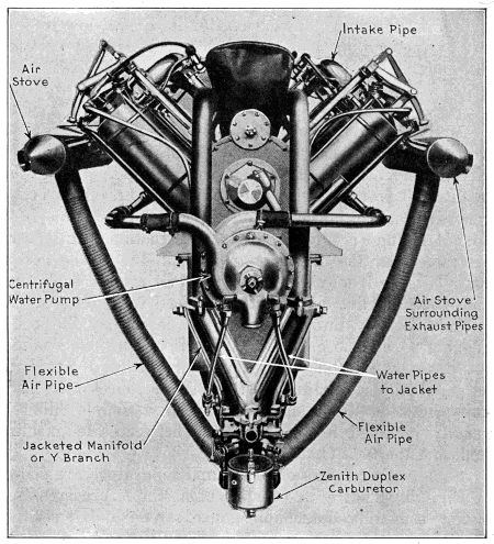
Fig. 54.—Rear View of Curtiss OX-2 90 Horse-Power Airplane Motor Showing Carburetor Location and Hot Air Leads.
Many carburetors include a filtering screen at the point where the liquid enters the float chamber in order to keep dirt or any other foreign matter which may be present in the fuel from entering the float chamber. This is not general practice, however, and the majority of vaporizers do not include a filter in their construction. It is very desirable that the dirt should be kept out of the carburetor because it may get under the float control fuel valve and cause flooding by keeping it raised from its seat. If it finds its way into the spray nozzle it may block the opening so that no gasoline will issue or may so constrict the passage that only very small quantities of fuel will be supplied the mixture. Where the carburetor itself is not provided with a filtering screen a simple filter is usually installed in the pipe line between the gasoline tank and the float chamber.
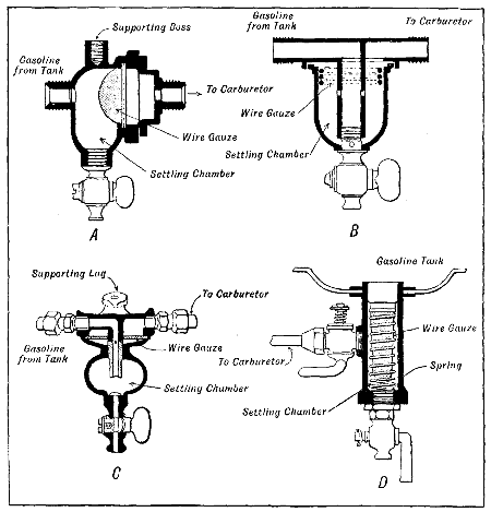
Fig. 55.—Types of Strainers Interposed Between Vaporizer and Gasoline Tank to Prevent Water or Dirt Passing Into Carbureting Device.
Some simple forms of filters and separators are shown at Fig. 55. That at A consists of a simple brass casting having a readily detachable gauze screen and a settling chamber of sufficient capacity to allow the foreign matter to settle to the bottom, from which it is drained out by a pet cock. Any water or dirt in the gasoline will settle to the bottom of the chamber, and as all fuel delivered to the carburetor must pass through the wire gauze screen it is not likely to contain impurities when it reaches the float chamber. The heavier particles, such as scale from the tank or dirt and even water, all of which have greater weight than the gasoline, will sink to the bottom of the[141] chamber, whereas light particles, such as lint, will be prevented from flowing into the carburetor by the filtering screen.
The filtering device shown at B is a larger appliance than that shown at A, and should be more efficient as a separator because the gasoline is forced to pass through three filtering screens before it reaches the carburetor. The gasoline enters the device shown at C through a bent pipe which leads directly to the settling chamber and from thence through a wire gauze screen to the upper compartment which leads to the carburetor. The device shown at D is a combination strainer, drain, and sediment[142] cup. The filtering screen is held in place by a spring and both are removed by taking out a plug at the bottom of the device. The shut-off valve at the top of the device is interposed between the sediment cup and the carburetor. This separating device is incorporated with the gasoline tank and forms an integral part of the gasoline supply system. The other types shown are designed to be interposed between the gasoline tank and the carburetor at any point in the pipe line where they may be conveniently placed.
On four- and six-cylinder engines and in fact on all multiple-cylinder forms, it is important that the piping leading from the carburetor to the cylinders be made in such a way that the various cylinders will receive their full quota of gas and that each cylinder will receive its charge at about the same point in the cycle of operations. In order to make the passages direct the bends should be as few as possible, and when curves are necessary they should be of large radius because an abrupt corner will not only impede gas flow but will tend to promote condensation of the fuel. Every precaution should be taken with four- and six-cylinder engines to insure equitable gas distribution to the valve chambers if regular action of the power plant is desired. If the gas pipe has many turns and angles it will be difficult to charge all cylinders properly. On some six-cylinder aviation engines, two carburetors are used because of trouble experienced with manifolds designed for one carburetor. Duplex carburetors are necessary to secure the best results from eight- and twelve-cylinder V engines.
The problem of intake piping is simplified to some extent on block motors where the intake passage is cored in the cylinder casting and where but one short pipe is needed to join this passage to the carburetor. If the cylinders are cast in pairs a simple pipe of T or Y form can be used with success. When the engine is of a type[143] using individual cylinder castings, especially in the six-cylinder power plants, the proper application and installation of suitable piping is a difficult problem. The reader is referred to the various engine designs outlined to ascertain how the inlet piping has been arranged on representative aviation engines. Intake piping is constructed in two ways, the most common method being to cast the manifold of brass or aluminum. The other method, which is more costly, is to use a built-up construction of copper or brass tubing with cast metal elbows and Y pieces. One of the disadvantages advanced against the cast manifold is that blowholes may exist which produce imperfect castings and which will cause mixture troubles because the entering gas from the carburetor, which may be of proper proportions, is diluted by the excess air which leaks in through the porous casting. Another factor of some moment is that the roughness of the walls has a certain amount of friction which tends to reduce the velocity of the gases, and when projecting pieces are present, such as core wire or other points of metal, these tend to collect the drops of liquid fuel and thus promote condensation. The advantage of the built-up construction is that the walls of the tubing are very smooth, and as the castings are small it is not difficult to clean them out thoroughly before they are incorporated in the manifold. The tubing and castings are joined together by hard soldering, brazing or autogenous welding.
The low-grade gasoline used at the present time makes it necessary to use vaporizers that are more susceptible to atmospheric variations than when higher grade and more volatile liquids are vaporized. Sudden temperature changes, sometimes being as much as forty degrees rise or fall in twelve hours, affect the mixture proportions to some extent, and not only changes in temperature but variations in altitude also have a bearing on mixture proportions by affecting both gasoline and air. As the temperature[144] falls the specific gravity of the gasoline increases and it becomes heavier, this producing difficulty in vaporizing. The tendency of very cold air is to condense gasoline instead of vaporizing it and therefore it is necessary to supply heated air to some carburetors to obtain proper mixtures during cold weather. In order that the gas mixtures will ignite properly the fuel must be vaporized and thoroughly mixed with the entering air either by heat or high velocity of the gases. The application of air stoves to the Curtiss OX-2 motor is clearly shown at Fig. 54. It will be seen that flexible metal pipes are used to convey the heated air to the air intakes of the duplex mixing chamber.
Any internal combustion engine will show less power at high altitudes than it will deliver at sea level, and this has caused a great deal of questioning. “There is a good[145] reason for this,” says a writer in “Motor Age,” “and it is a physical impossibility for the engine to do otherwise. The difference is due to the lower atmospheric pressure the higher up we get. That is, at sea level the atmosphere has a pressure of 14.7 pounds per square inch; at 5,000 feet above sea level the pressure is approximately 12.13 pounds per square inch, and at 10,000 feet it is 10 pounds per square inch. From this it will be seen that the final pressure attained after the piston has driven the gas into compressed condition ready for firing is lower as the atmospheric pressure drops. This means that there is not so much power in the compressed charge of gas the higher up you get above sea level.
“For example, suppose the compression ratio to be 41⁄2 to 1; in other words, suppose the air space above the piston to have 41⁄2 times the volume when the piston is at the bottom of its stroke that it has when the piston is at the top of the stroke. That is a common compression ratio for an average motor, and is chosen because it is considered to be the best for maximum horse-power and in order that the compression pressure will not be so high as to cause pre-ignition. Knowing the compression ratio, we can determine the final pressure immediately before ignition by substituting in the standard formula:
| P1 = | ( | V | ) | 1.3 |
| V1 |
in which P is the atmospheric pressure; P1 is the final pressure, and V/V1 is the compression ratio, therefore P1 = 14.7 (4.5)1.3 = 104 pounds per square inch, absolute.
“That is, 104 pounds per square inch is the most efficient final compression pressure to have for this engine at sea level, since it comes directly from the compression ratio.
“Now supposing we consider that the altitude is 7,000[146] feet above sea level. At this height the atmospheric pressure is 11.25 pounds per square inch, approximately. In this case we can again substitute in the formula, using the new atmospheric pressure figure. The equation becomes:
P1 = 11.25 (4.5)1.3—79.4 pounds per square inch, absolute.
“Therefore we now have a final compression pressure of only 79.4 pounds per square inch, which is considerably below the pressure we have just found to be the most efficient for the motor. The resulting power drop is evident.
“It should be borne in mind that these final compression pressures are absolute pressures—that is, they include the atmospheric pressure. In the first case, to get the pressure above atmospheric you would subtract 14.7 and in the latter 11.25 would have to be deducted. In other words, where the sea level compression is 89.3 pounds per square inch above the atmosphere, the same motor will have only a compression pressure of 68.15 pounds per square inch above the atmosphere at 7,000 feet elevation.
“From the above it is evident that in order to bring the final compression pressure up to the efficient figure we have determined, a different compression ratio would have to be used. That is, the final volume would have to be less, and as it is impossible to vary this to meet the conditions of altitude, the loss of power cannot be helped except by the replacing of the standard pistons with some that are longer above the wrist-pin so as to reduce the space above the pistons when on top center. Then if the ratio is thereby raised to some such figures as 5 to 1, the engine will again have its proper final pressure, but it will still not have as much power as it would have at sea level, since the horse-power varies directly with the atmospheric pressure, final compression being kept constant. That is, at 7,000 feet the horse-power of[147] an engine that had 40 horse-power at sea level would be equal to
| 11.25 | = 30.6 horse-power. |
| 14.7 |
“If the original compression ratio of 4.5 were retained, the drop in horse-power would be even greater than this. These computations and remarks will make it clear that the designer who contemplates building an airplane for high altitude use should see to it that it is of sufficient power to compensate for the drop that is inevitable when it is up in the air. This is often illustrated in stationary gas-engine installations. An engine that had a sea-level rating amply sufficient for the work required, might not be powerful enough when brought up several thousand feet.” When one considers that airplanes attain heights of over 18,000 feet, it will be evident that an ample margin of engine power is necessary.
A system of fuel supply developed by the late Dr. Diesel, a German chemist and engineer, is attracting considerable attention at the present time on account of the ability of the Diesel engine to burn low-grade fuels, such as crude petroleum. In this system the engines are built so that very high compressions are used, and only pure air is taken into the cylinder on the induction stroke. This is compressed to a pressure of about 500 pounds per square inch, and sufficient heat is produced by this compression to explode a hydrocarbon mixture. As the air which is compressed to this high point cannot burn, the fuel is introduced into the cylinder combustion chamber under still higher compression than that of the compressed air, and as it is injected in a fine stream it is immediately vaporized because of the heat. Just as soon as the compressed air becomes thoroughly saturated with the liquid fuel, it will explode on account of the degree of[148] heat present in the combustion chamber. Such motors have been used in marine and stationary applications, but are not practical for airplanes or motor cars because of lack of flexibility and great weight in proportion to power developed. The Diesel engine is the standard power plant used in submarine boats and motor ships, as its efficiency renders it particularly well adapted for large units.
A writer in “The Aeroplane,” an English publication, discourses on some features of carburetor installation that may be of interest to the aviation student, so portions of the dissertation are reproduced herewith.
“Users of airplanes fitted with ordinary type carburetors will do well to note carefully the way in which these are fitted, for several costly machines have been burnt lately through the sheer carelessness of their users. These particular machines were fitted with a high powered V-type engine, made by a firm which is famous as manufacturers of automobiles de luxe. In these engines there are four carburetors, mounted in the V between the cylinders. When the engine is fitted as a tractor, the float chambers are in front of the jet chambers. Consequently, when the tail of the machine is resting on the ground, the jets are lower than the level of the gasoline in the float chamber.
“Quite naturally, the gasoline runs out of the jet, if it is left turned on when the machine is standing in its normal position, and trickles into the V at the top of the crank-case. Thence it runs down to the tail of the engine, where the magnetos are fitted, and saturates them. If left long enough, the gasoline manages to soak well into the fuselage before evaporating. And what does evaporate makes an inflammable gas in the forward cockpit. Then some one comes along and starts up the engine. The spark-gap of the magneto gives one flash, and the whole front of the machine proceeds to give a Fourth of July performance forthwith. Naturally, one safeguard is to turn the petrol off directly the machine lands. Another is never to turn it on till the engine is actually being started up.
“One would be asking too much of the human boy—who is officially regarded as the only person fit to fly an aeroplane—if one depended upon his memory of such a detail to save his machine, though one might perhaps reasonably expect the older pilots to remember not to forget. Even so, other means of prevention[149] are preferable, for fire is quite as likely to occur from just the same cause if the engine happens to be a trifle obstinate in starting, and so gives the carburetors several minutes in which to drip—in which operation they would probably be assisted by air-mechanics ‘tickling’ them.
“One way out of the trouble is to fit drip tins under the jet chamber to catch the gasoline as it falls. This is all very well just to prevent fire while the machine is being started up, but it will not save it if it is left standing with the tail on the ground and the petrol turned on, for the drip tins will then fill up and run over. And if it catches then, the contents of the drip tins merely add fuel to the fire.
“Yet another way is to turn the carburetors round, so that the float chambers are behind the jets, and so come below them when the tail is on the ground, thus cutting off the gasoline low down in the jets. There seems to be no particular mechanical difficulty about this, though I must confess that I did not note very carefully whether the reversal of the float chambers would make them foul any other fittings on the engine. It has been argued, however, that doing this would starve the engine of gasoline when climbing at a steep angle, as the gasoline would then be lowered in the jets and need more suction to get into the cylinders. This is rather a pretty point of amateur motor mechanics to discuss, for, obviously, when the same engine is used as a ‘pusher’ instead of a tractor, the jets are in front of the floats, and there seems to be no falling off in power.
“Moreover, the higher a machine goes the lower is the atmospheric pressure, and, consequently, the less is the amount of air sucked in at each induction stroke. This means, of course, that with the gasoline supply the mixture at high altitudes is too rich, so that, in order to get precisely the right mixture when very high up, it is necessary to reduce the gasoline supply by screwing down the needle valve between the tank and the carburetor—at least, that has been the experience of various high-flying pilots. No doubt something might be done in the way of forced air feed to compensate for reduced atmospheric pressure, but it remains to be proved whether the extra weight of mechanism involved would pay for the extra power obtained. Variable compression might do something, also, to even things up, but here, also, weight of mechanism has to be considered.
“In any case, at present, the higher one goes the more the[150] power of the engine is reduced, for less air means a less volume of mixture per cylinder, and as the petrol feed has to be starved to suit the smaller amount of air available, this means further loss of power. I do not know whether anyone has evolved a carburetor which automatically starves the gasoline feed when high up, but it seems possible that when an airplane is sagging about ‘up against the ceiling’—as a French pilot described the absolute limit of climb for his particular machine—it might be a good thing to have the jets in front of the float chamber, for then a certain amount of automatic starvation would take place.
“When a machine is right up at its limiting height, and the pilot is doing his best to make it go higher still, it is probably flying with its tail as low as the pilot dares to let it go, and the lateral and longitudinal controls are on the verge of vanishing, so that if the carburetor jets are behind the float chambers there is bound to be an over-rich mixture in any case. There is even a possibility of a careless or ignorant pilot carrying on in this tail-down position till one set of cylinders cuts out altogether, in which case the carburetor feeding that set may flood over, just as if the machine were on the ground, and the whole thing may catch fire. Whereas, with the jets in front of the floats, though the mixture may starve a trifle, there is, at any rate, no danger of fire through climbing with the tail down.
“On the other hand, in a ‘pusher’ with this type of engine, if the jets are in their normal position—which is in front of the floats—there is danger of fire in a dive. That is to say, if the pilot throttles right down, or switches off and relies on air pressure on his propeller to start the engine again, so that the gasoline is flooding over out of the jets instead of being sucked into the engine, there may be flooding over the magnetos if the dive is very steep and prolonged. In any case, a long dive will mean a certain amount of flooding, and, probably, a good deal of choking and spitting by the engine before it gets rid of the over-rich mixture and picks up steady firing again. Which may indicate to young pilots that it is not good to come down too low under such circumstances, trusting entirely to their engines to pick up at once and get going before they hit the ground.
“On the whole, it seems that it might be better practice to set the carburetors thwartwise of engines, for then jets and floats would always be at approximately the same level, no matter what the longitudinal position of the machine, and it is never long enough in one position at a big lateral angle to raise any serious carburetor troubles. Car manufacturers who dive cheerfully into[151] the troubled waters of aero-engine designs are a trifle apt to forget that their engines are put into positions on airplanes which would be positively indecent in a motor car. An angle of 1 in 10 is the exception on a car, but it is common on an airplane, and no one ever heard of a car going down a hill of 10 to 1—which is not quite a vertical dive. Therefore, there is every excuse for a well-designed and properly brought-up carburetor misbehaving itself in an aeroplane.
“It seems, then, that it is up to the manufacturers to produce better carburetors—say, with the jet central with the float. But it also behooves the user to show ordinary common sense in handling the material at present available, and not to make a practice of burning up $25,000 worth or so of airplane just because he is too lazy to turn off his gasoline, or to have the tail of his machine lifted up while he is tinkering with his engines.”
The modern float feed carburetor is a delicate and nicely balanced appliance that requires a certain amount of attention and care in order to obtain the best results. The adjustments can only be made by one possessing an intelligent knowledge of carburetor construction and must never be made unless the reason for changing the old adjustment is understood. Before altering the adjustment of the leading forms of carburetors, a few hints regarding the quality to be obtained in the mixture should be given some consideration, as if these are properly understood this knowledge will prove of great assistance in adjusting the vaporizer to give a good working proportion of fuel and air. There is some question regarding the best mixture proportions and it is estimated that gas will be explosive in which the proportions of fuel vapor and air will vary from one part of the former to a wide range included between four and eighteen parts of the latter. A one to four mixture is much too rich, while the one in eighteen is much too lean to provide positive ignition.
A rich mixture should be avoided because the excessive fuel used will deposit carbon and will soot the cylinder walls, combustion chamber interior, piston top and valves and also tend to overheat the motor. A rich mixture will[152] also seriously interfere with flexible control of the engine, as it will choke up on low throttle and run well on open throttle when the full amount of gas is needed. A rich mixture may be quickly discovered by black smoke issuing from the muffler, the exhaust gas having a very pungent odor. If the mixture contains a surplus of air there will be popping sounds in the carburetor, which is commonly termed “blowing back.” To adjust a carburetor is not a difficult matter when the purpose of the various control members is understood. The first thing to do in adjusting a carburetor is to start the motor and to retard the sparking lever so the motor will run slowly leaving the throttle about half open. In order to ascertain if the mixture is too rich cut down the gasoline flow gradually by screwing down the needle valve until the motor commences to run irregularly or misfire. Close the needle valves as far as possible without having the engine come to a stop, and after having found the minimum amount of fuel gradually unscrew the adjusting valve until you arrive at the point where the engine develops its highest speed. When this adjustment is secured the lock nut is screwed in place so the needle valve will keep the adjustment. The next point to look out for is regulation of the auxiliary air supply on those types of carburetors where an adjustable air valve is provided. This is done by advancing the spark lever and opening the throttle. The air valve is first opened or the spring tension reduced to a point where the engine misfires or pops back in the carburetor. When the point of maximum air supply the engine will run on is thus determined, the air valve spring may be tightened by screwing in on the regulating screw until the point is reached where an appreciable speeding up of the engine is noticed. If both fuel and air valves are set right, it will be possible to accelerate the engine speed uniformly without interfering with regularity of engine operation by moving the throttle lever or accelerator pedal from its closed to its wide open position, this being done with the spark lever advanced. All types of carburetors do not have the same[153] means of adjustment; in fact, some adjust only with the gasoline regulating needle; others must have a complete change of spray nozzles; while in others the mixture proportions may be varied only by adjustment of the quantity of entering air. Changing the float level is effective in some carburetors, but this should never be done unless it is certain that the level is not correct. Full instructions for locating carburetion troubles will be given in proper sequence.
It is a fact well known to experienced repairmen and motorists that atmospheric conditions have much to do with carburetor action. It is often observed that a motor seems to develop more power at night than during the day, a circumstance which is attributed to the presence of more moisture in the cooler night air. Likewise, taking a motor from sea level to an altitude of 10,000 feet involves using rarefied air in the engine cylinders and atmospheric pressures ranging from 14.7 pounds at sea level to 10.1 pounds per square inch at the high altitude. All carburetors will require some adjustment in the course of any material change from one level to another. Great changes of altitude also have a marked effect on the cooling system of an airplane. Water boils at 212 degrees F. only at sea level. At an altitude of 10,000 feet it will boil at a temperature nineteen degrees lower, or 193 degrees F.
In high altitudes the reduced atmospheric pressure, for 5,000 feet or higher than sea level, results in not enough air reaching the mixture, so that either the auxiliary air opening has to be increased, or the gasoline in the mixture cut down. If the user is to be continually at high altitudes he should immediately purchase either a larger dome or a smaller strangling tube, mentioning the size carburetor that is at present in use and the type of motor that it is on, including details as to the bore and stroke. The smaller strangling tube makes an increased suction at the spray nozzle; the air will have to be readjusted to meet it and you can use more auxiliary[154] air, which is necessary. The effect on the motor without a smaller strangling tube is a perceptible sluggishness and failure to speed up to its normal crank-shaft revolutions, as well as failure to give power. It means that about one-third of the regular speed is cut out. The reduced atmospheric pressure reduces the power of the explosion, in that there is not the same quantity of oxygen in the combustion chamber as at sea level; to increase the amount taken in, you must also increase the gasoline speed, which is done by an increased suction through the smaller strangling aperture. Some forms of carburetors are affected more than others by changes of altitude, which explains why the Zenith is so widely employed for airplane engine use. The compensating nozzle construction is not influenced as much by changes of altitude as the simpler nozzle types are.
Early Ignition Systems—Electrical Ignition Best—Fundamentals of Magnetism Outlined—Forms of Magneto—Zones of Magnetic Influence—How Magnets are Made—Electricity and Magnetism Related—Basic Principles of Magneto Action—Essential Parts of Magneto and Functions—Transformer Coil Systems—True High Tension Type—The Berling Magneto—Timing and Care—The Dixie Magneto—Spark Plug Design and Application—Two-Spark Ignition—Special Airplane Plug.
One of the most important auxiliary groups of the gasoline engine comprising the airplane power plant and one absolutely necessary to insure engine action is the ignition system or the method employed of kindling the compressed gas in the cylinder to produce an explosion and useful power. The ignition system has been fully as well developed as other parts of the engine, and at the present time practically all ignition systems follow principles which have become standard through wide acceptance.
During the early stages of development of the gasoline engine various methods of exploding the charge of combustible gas in the cylinder were employed. On some of the earliest engines a flame burned close to the cylinder head, and at the proper time for ignition a slide or valve moved to provide an opening which permitted the flame to ignite the gas back of the piston. This system was practical only on the primitive form of gas engines in which the charge was not compressed before ignition. Later, when it was found desirable to compress the gas a certain degree before exploding it, an incandescent platinum tube in the combustion chamber, which was kept in a heated condition by a flame burning in it, exploded the gas. The naked flame was not suitable in this application[156] because when the slide was opened to provide communication between the flame and the gas the compressed charge escaped from the cylinder with enough pressure to blow out the flame at times and thus cause irregular ignition. When the flame was housed in a platinum tube it was protected from the direct action of the gas, and as long as the tube was maintained at the proper point of incandescence regular ignition was obtained.
Some engineers utilized the property of gases firing themselves if compressed to a sufficient degree, while others depended upon the heat stored in the cylinder-head to fire the highly compressed gas. None of these methods were practical in their application to motor car engines because they did not permit flexible engine action which is so desirable. At the present time, electrical ignition systems in which the compressed gas is exploded by the heating value of the minute electric arc or spark in the cylinder are standard, and the general practice seems to be toward the use of mechanical producers of electricity rather than chemical batteries.
Two general forms of electrical ignition systems may be used, the most popular being that in which a current of electricity under high tension is made to leap a gap or air space between the points of the sparking plug screwed into the cylinder. The other form, which has been almost entirely abandoned in automobile and which was never used with airplane engine practice, but which is still used to some extent on marine engines, is called the low-tension system because current of low voltage is used and the spark is produced by moving electrodes in the combustion chamber.
The essential elements of any electrical ignition system, either high or low tension, are: First, a simple and practical method of current production; second, suitable timing apparatus to cause the spark to occur at the right point in the cycle of engine action; third, suitable wiring[157] and other apparatus to convey the current produced by the generator to the sparking member in the cylinder.
The various appliances necessary to secure prompt ignition of the compressed gases should be described in some detail because of the importance of the ignition system. It is patent that the scope of a work of this character does not permit one to go fully into the theory and principles of operation of all appliances which may be used in connection with gasoline motor ignition, but at the same time it is important that the elementary principles be considered to some extent in order that the reader should have a proper understanding of the very essential ignition apparatus. The first point considered will be the common methods of generating the electricity, then the appliances to utilize it and produce the required spark in the cylinder. Inasmuch as magneto ignition is universally used in connection with airplane engine ignition it will not be necessary to consider battery ignition systems.
To properly understand the phenomena and forces involved in the generation of electrical energy by mechanical means it is necessary to become familiar with some of the elementary principles of magnetism and its relation to electricity. The following matter can be read with profit by those who are not familiar with the subject. Most persons know that magnetism exists in certain substances, but many are not able to grasp the terms used in describing the operation of various electrical devices because of not possessing a knowledge of the basic facts upon which the action of such apparatus is based.
Magnetism is a property possessed by certain substances and is manifested by the ability to attract and repel other materials susceptible to its effects. When this phenomenon is manifested by a conductor or wire through which a current of electricity is flowing it is termed “electro-magnetism.” Magnetism and electricity are closely related, each being capable of producing the other. Practically[158] all of the phenomena manifested by materials which possess magnetic qualities naturally can be easily reproduced by passing a current of electricity through a body which, when not under electrical influence, is not a magnetic substance. Only certain substances show magnetic properties, these being iron, nickel, cobalt and their alloys.
The earliest known substance possessing magnetic properties was a stone first found in Asia Minor. It was called the lodestone or leading stone, because of its tendency, if arranged so it could be moved freely, of pointing one particular portion toward the north. The compass of the ancient Chinese mariners was a piece of this material, now known to be iron ore, suspended by a light thread or floated on a cork in some liquid so one end would point toward the north magnetic pole of the earth. The reason that this stone was magnetic was hard to define for a time, until it was learned that the earth was one huge magnet and that the iron ore, being particularly susceptible, absorbed and retained some of this magnetism.
Most of us are familiar with some of the properties of the magnet because of the extensive sale and use of small horseshoe magnets as toys. As they only cost a few pennies every one has owned one at some time or other and has experimented with various materials to see if they would be attracted. Small pieces of iron or steel were quickly attracted to the magnet and adhered to the pole pieces when brought within the zone of magnetic influence. It was soon learned that brass, copper, tin or zinc were not affected by the magnet. A simple experiment that serves to illustrate magnetic attraction of several substances is shown at A, Fig. 57. In this, several balls are hung from a standard or support, one of these being of iron, another of steel. When a magnet is brought near either of these they will be attracted toward it, while the others will remain indifferent to the magnetic force. Experimenters soon learned that of the common metals only iron or steel were magnetic.
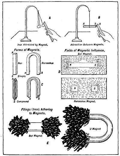
Fig. 57.—Some Simple Experiments to Demonstrate Various Magnetic Phenomena and Clearly Outline Effects of Magnetism and Various Forms of Magnets.
If the ordinary bar or horseshoe magnet be carefully[159] examined, one end will be found to be marked N. This indicates the north pole, while the other end is not usually marked and is the south pole. If the north pole of one magnet is brought near the south pole of another, a strong attraction will exist between them, this depending upon[160] the size of the magnets used and the air gap separating the poles. If the south pole of one magnet is brought close to the end of the same polarity of the other there will be a pronounced repulsion of like force. These facts are easily proved by the simple experiment outlined at B, Fig. 57. A magnet will only attract or influence a substance having similar qualities. The like poles of magnets will repel each other because of the obvious impossibility of uniting two influences or forces of practically equal strength but flowing in opposite directions. The unlike poles of magnets attract each other because the force is flowing in the same direction. The flow of magnetism is through the magnet from south to north and the circuit is completed by the flow of magnetic influence through the air gap or metal armature bridging it from the north to the south pole.
Magnets are commonly made in two forms, either in the shape of a bar or horseshoe. These two forms are made in two types, simple or compound. The latter are composed of a number of magnets of the same form united so the ends of like polarity are laced together, and such a construction will be more efficient and have more strength than a simple magnet of the same weight. The two common forms of simple and compound magnets are shown at C, Fig. 57. The zone in which a magnetic influence occurs is called the magnetic field, and this force can be graphically shown by means of imaginary lines, which are termed “lines of force.” As will be seen from the diagram at D, Fig. 57, the lines show the direction of action of the magnetic force and also show its strength, as they are closer together and more numerous when the intensity of the magnetic field is at its maximum. A simple method of demonstrating the presence of the force is to lay a piece of thin paper over the pole pieces of either a bar or horseshoe magnet and sprinkle fine iron filings[161] on it. The particles of metal arrange themselves in very much the manner shown in the illustrations and prove that the magnetic field actually exists.
The form of magnet used will materially affect the size and area of the magnetic field. It will be noted that the field will be concentrated to a greater extent with the horseshoe form because of the proximity of the poles. It should be understood that these lines have no actual existence, but are imaginary and assumed to exist only to show the way the magnetic field is distributed. The magnetic influence is always greater at the poles than at the center, and that is why a horseshoe or U-form magnet is used in practically all magnetos or dynamos. This greater attraction at the poles can be clearly demonstrated by sprinkling iron filings on bar and U magnets, as outlined at E, Fig. 57. A large mass gathers at the pole pieces, gradually tapering down toward the point where the attraction is least.
From the diagrams it will be seen that the flow of magnetism is from one pole to the other by means of curved paths between them. This circuit is completed by the magnetism flowing from one pole to the other through the magnet, and as this flow is continued as long as the body remains magnetic it constitutes a magnetic circuit. If this flow were temporarily interrupted by means of a conductor of electricity moving through the field there would be a current of electricity induced in the conductor every time it cut the lines of force. There are three kinds of magnetic circuits. A non-magnetic circuit is one in which the magnetic influence completes its circuit through some substance not susceptible to the force. A closed magnetic circuit is one in which the influence completes its circuit through some magnetic material which bridges the gap between the poles. A compound circuit is that in which the magnetic influence passes through magnetic substances and non-magnetic substances in order to complete its circuit.
Magnetism may be produced in two ways, by contact or induction. If a piece of steel is rubbed on a magnet it will be found a magnet when removed, having a north and south pole and all of the properties found in the energizing magnet. This is magnetizing by contact. A piece of steel will retain the magnetism imparted to it for a considerable length of time, and the influence that remains is known as residual magnetism. This property may be increased by alloying the steel with tungsten and hardening it before it is magnetized. Any material that will retain its magnetic influence after removal from the source of magnetism is known as a permanent magnet. If a piece of iron or steel is brought into the magnetic field of a powerful magnet it becomes a magnet without actual contact with the energizer. This is magnetizing by magnetic induction. If a powerful electric current flows through an insulated conductor wound around a piece of iron or steel it will make a magnet of it. This is magnetizing by electro-magnetic induction. A magnet made in this manner is termed an electro-magnet and usually the metal is of such a nature that it will not retain its magnetism when the current ceases to flow around it. Steel is used in all cases where permanent magnets are required, while soft iron is employed in all cases where an intermittent magnetic action is desired. Magneto field magnets are always made of tungsten steel alloy, so treated that it will retain its magnetism for lengthy periods.
There are many points in which magnetism and electricity are alike. For instance, air is a medium that offers considerable resistance to the passage of both magnetic influence and electric energy, although it offers more resistance to the passage of the latter. Minerals like iron or steel are very easily influenced by magnetism and[163] easily penetrated by it. When one of these is present in the magnetic circuit the magnetism will flow through the metal. Any metal is a good conductor for the passage of the electric current, but few metals are good conductors of magnetic energy. A body of the proper metal will become a magnet due to induction if placed in the magnetic field, having a south pole where the lines of force enter it and a north pole where they pass out.
We have seen that a magnet is constantly surrounded by a magnetic field and that an electrical conductor when carrying a current is also surrounded by a field of magnetic influence. Now if the conductor carrying a current of electricity will induce magnetism in a bar of iron or steel, by a reversal of this process, a magnetized iron or steel bar will produce a current of electricity in a conductor. It is upon this principle that the modern dynamo or magneto is constructed. If an electro-motive force is induced in a conductor by moving it across a field of magnetic influence, or by passing a magnetic field near a conductor, electricity is said to be generated by magneto-electric induction. All mechanical generators of the electric current using permanent steel magnets to produce a field of magnetic influence are of this type.
The accompanying diagram, Fig. 58, will show these principles very clearly. As stated on an earlier page, if the lines of force in the magnetic field are cut by a suitable conductor an electrical impulse will be produced in that conductor. In this simple machine the lines of force exist between the poles of a horseshoe magnet. The conductor, which in this case is a loop of copper wire, is mounted upon a spindle in order that it may be rotated in the magnetic field to cut the lines of magnetic influence present between the pole pieces. Both of the ends of this loop are connected, one with the insulated drum shown upon the shaft, the other to the shaft. Two metal brushes are employed to collect the current and cause it[164] to flow through the external circuit. It can be seen that when the shaft is turned in the direction of the arrow the loop will cut through the lines of magnetic influence and a current will be generated therein.
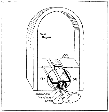
Fig. 58.—Elementary Form of Magneto Showing Principal Parts Simplified to Make Method of Current Generation Clear.
The pressure of the current and the amount produced vary in accordance to the rapidity with which the lines of magnetic influence are cut. The armature of a practical magneto, therefore, differs materially from that shown in the diagram. A large number of loops of wire would be mounted upon this shaft in order that the lines of magnetic influence would be cut a greater number of times in a given period and a core of iron used as a backing[165] for the wire. This would give a more rapid alternating current and a higher electro-motive force than would be the case with a smaller number of loops of wire.
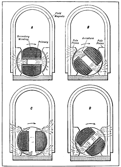
Fig. 59.—Showing How Strength of Magnetic Influence and of the Currents Induced in the Windings of Armature Vary with the Rapidity of Changes of Flow.
The illustrations at Fig. 59 show a conventional double[166] winding armature and field magnetic of a practical magneto in part section and will serve to more fully emphasize the points previously made. If the armature or spindle were removed from between the pole pieces there would exist a field of magnetic influence as shown at Fig. 57, but the introduction of this component provides a conductor (the iron core) for the magnetic energy, regardless of its position, though the facility with which the influence will be transmitted depends entirely upon the position of the core. As shown at A, the magnetic flow is through the main body in a straight line, while at B, which position the armature has attained after one-eighth revolution, or 45 degrees travel in the direction of the arrow, the magnetism must pass through in the manner indicated. At C, which position is attained every half revolution, the magnetic energy abandons the longer path through the body of the core for the shorter passage offered by the side pieces, and the field thrown out by the cross bar disappears. On further rotation of the armature, as at D, the body of the core again becomes energized as the magnetic influence resumes its flow through it. These changes in the strength of the magnetic field when distorted by the armature core, as well as the intensity of the energy existing in the field, affect the windings, and the electrical energy induced therein corresponds in strength to the rapidity with which these changes in magnetic flow occur. The most pronounced changes in the strength of the field will occur as the armature passes from position B to D, because the magnetic field existing around the core will be destroyed and again re-established.
During the most of the armature rotation the changes in strength will be slight and the currents induced in the wire correspondingly small; but at the instant the core becomes remagnetized, as the armature leaves position C, the current produced will be at its maximum, and it is necessary to so time the rotation of the armature that at this instant one of the cylinders is in condition to be fired. It[167] is imperative that the armature be driven in such relation to the crank-shaft that each production of maximum current coincides with the ignition point, this condition existing twice during each revolution of the armature, or at every 180 degrees travel. Each position shown corresponds to 45 degrees travel of the armature, or one-eighth of a turn, and it takes just three-eighths revolution to change the position from A to that shown at D.
The magnets which produce the influence that in turn induces the electrical energy in the winding or loops of wire on the armature, and which may have any even number of opposed poles, are called field magnets. The loops of wire which are mounted upon a suitable drum and rotate in the field of magnetic influence in order to cut the lines of force is called an armature winding, while the core is the metal portion. The entire assembly is called the armature. The exposed ends of the magnets are called pole pieces and the arrangement used to collect the current is either a commutator or a collector. The stationary pieces which bear against the collector or commutator and act as terminals for the outside circuit are called brushes. These brushes are often of copper, or some of its alloys, because copper has a greater electrical conductivity than any other metal.
These brushes are nearly always of carbon, which is sometimes electroplated with copper to increase its electrical conductivity, though cylinders of copper wire gauze impregnated with graphite are utilized at times. Carbon is used because it is not so liable to cut the metal of the commutator as might be the case if the contact was of the metal to metal type. The reason for this is that carbon has the peculiar property in that it materially assists in the lubrication of the commutator, and being of soft, unctuous composition, will wear and conform to any irregularities on the surface of the metal collector rings.
The magneto in common use consists of a number of[168] horseshoe magnets which are compound in form and attached to suitable cast-iron pole pieces used to collect and concentrate the magnetic influence of the various magnets. Between these pole pieces an armature rotates. This is usually shaped like a shuttle, around which are wound coils of insulated wire. These are composed of a large number of turns and the current produced depends in great measure upon the size of the wire and the number of turns per coil. An armature winding of large wire will deliver a current of great amperage, but of small voltage. An armature wound with very fine wire will deliver a current of high voltage but of low amperage. In the ordinary form of magneto, such as used for ignition, the current is alternating in character and the break in the circuit should be timed to occur when the armature is at the point of its greatest potential or pressure. Where such a generator is designed for direct current production the ends of the winding are attached to the segments of a commutator, but where the instrument is designed to deliver an alternating current one end of the winding is fastened to an insulator ring on one end of the armature shaft and the other end is grounded on the frame of the machine.
The quantity of the current depends upon the strength of the magnetic field and the number of lines of magnetic influence acting through the armature. The electro-motive force varies as to the length of the armature winding and the number of revolutions at which the armature is rotated.
The magneto in the various systems which employ a transformer coil is very similar to a low-tension generator in general construction, and the current delivered at the terminals seldom exceeds 100 volts. As it requires many times that potential or pressure to leap the gap which exists between the points of the conventional spark plug, a separate coil is placed in circuit to intensify the current to one of greater capacity. The essential parts[169] of such a system and their relation to each other are shown in diagrammatic form at Fig. 60 and as a complete system at Fig. 61. As is true of other systems the magnetic influence is produced by permanent steel magnets clamped to the cast-iron pole pieces between which the armature rotates. At the point of greatest potential in the armature winding the current is broken by the contact breaker, which is actuated by a cam, and a current of higher value is induced in the secondary winding of the transformer coil when the low voltage current is passed through the primary winding.
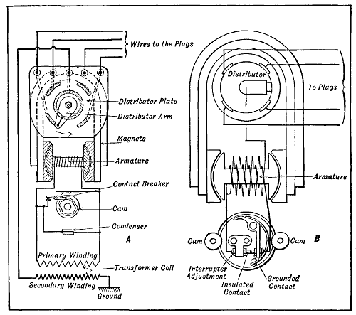
Fig. 60.—Diagrams Explaining Action of Low Tension Transformer Coil and True High Tension Magneto Ignition Systems.
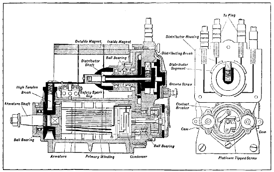
Fig. 60A.—Side Sectional View of Bosch High-Tension Magneto Shows Disposition of Parts. End Elevation Depicts Arrangement of Interruptor and Distributor Mechanism.
It will be noted that the points of the contact breaker are together except for the brief instant when separated by the action of the point of the cam upon the lever. It is obvious that the armature winding is short-circuited[171] upon itself except when the contact points are separated. While the armature winding is thus short-circuited there will be practically no generation of current. When the points are separated there is a sudden flow of current through the primary winding of the transformer coil, inducing a secondary current in the other winding, which can be varied in strength by certain considerations in the preliminary design of the apparatus. This current of higher potential or voltage is conducted directly to the plug if the device is fitted to a single-cylinder engine, or to the distributor arm if fitted to a multiple-cylinder motor. The distributor consists of an insulator in which is placed a number of segments, one for each cylinder to be fired, and so spaced that the number of degrees between them correspond to the ignition points of the motor. A two-cylinder motor would have two segments, a three-cylinder, three segments, and so on within the capacity of the instrument. In the illustration a four-cylinder distributor is fitted, and the distributing arm is in contact[172] with the segment corresponding to the cylinder about to be fired.
The true high-tension magneto differs from the preceding inasmuch as the current of high voltage is produced in the armature winding direct, without the use of the separate coil. Instead of but one coil, the armature carries two, one of comparatively coarse wire, the other of many turns of finer wire. The arrangement of these windings can be readily ascertained by reference to the diagram B, Fig. 60, which shows the principle of operation very clearly. The simplicity of the ignition system is evident by inspection of Fig. 62. One end of the primary winding (coarse wire) is coupled or grounded to the armature core, and the other passes to the insulated part of the interrupter. While in some forms the interrupter or contact breaker mechanism does not revolve, the desired motion being imparted to the contact lever to separate the points of a revolving cam, in this the cam or tripping mechanism is stationary and the contact breaker revolves. This arrangement makes it possible to conduct the current from the revolving primary coil to the interrupter by a direct connection, eliminating[173] the use of brushes, which would otherwise be necessary. In other forms of this appliance where the winding is stationary, the interrupter may be operated by a revolving cam, though, if desired, the used of a brush at this point will permit this construction with a revolving winding.
During the revolution of the armature the grounded lever makes and breaks contact with the insulated point, short-circuiting the primary winding upon itself until the armature reaches the proper position of maximum intensity of current production, at which time the circuit is broken, as in the former instance. One end of the secondary winding (fine wire) is grounded on the live end of the primary, the other end being attached to the revolving arm of the distributor mechanism. So long as a closed circuit is maintained feeble currents will pass through the primary winding, and so long as the contact points are together this condition will exist. When the current reaches its maximum value, because of the armature being in the best position, the cam operates the interrupter and the points are separated, breaking the short circuit which has existed in the primary winding.
The secondary circuit has been open while the distributor arm has moved from one contact to another and there has been no flow of energy through this winding. While the electrical pressure will rise in this, even if the distributor arm contacted with one of the segments, there would be no spark at the plug until the contact points separated, because the current in the secondary winding would not be of sufficient strength. When the interrupter operates, however, the maximum primary current will be diverted from its short circuit and can flow to the ground only through the secondary winding and spark-plug circuit. The high pressure now existing in the secondary winding will be greatly increased by the sudden flow of primary current, and energy of high enough potential to successfully bridge the gap at the plug is thereby produced in the winding.
The Berling magneto is a true high tension type delivering two impulses per revolution, but it is made in a variety of forms, both single and double spark. Its principle of action does not differ in essentials from the high tension type previously described. This magneto is used on Curtiss aviation engines and will deliver sparks in a positive manner sufficient to insure ignition of engines up to 200 horse-power and at rotative speeds of the magneto armature up to 4,000 r. p. m. which is sufficient to take care of an eight-cylinder V engine running up to 2,000[175] r. p. m. The magneto is driven at crank-shaft speed on four-cylinder engines, at 11⁄2 times crank-shaft speed on six-cylinder engines and at twice crank-shaft speed on eight-cylinder V types. The types “D” and “DD” BERLING Magnetos are interchangeable with corresponding magnetos of other standard makes. The dimensions of the four-, six- and eight-cylinder types “D” and “DD” are all the same.
The ideal method of driving the magneto is by means of flexible direct connecting coupling to a shaft intended for the purpose of driving the magneto. As the magneto must be driven at a high speed, a coupling of some flexibility is preferable. The employment of such a coupling will facilitate the mounting of the magneto, because a small inaccuracy in the lining up of the magneto with the driving shaft will be taken care of by the flexible coupling, whereas with a perfectly rigid coupling the line-up of the magneto must be absolutely accurate. Another advantage of the flexible coupling is that the vibration of the motor will not be as fully transmitted to the armature shaft on the magneto as in case a rigid coupling is used. This means prolonged life for the magneto.
The next best method of driving the magneto is by means of a gear keyed to the armature shaft. When this method of driving is employed, great care must be exercised in providing sufficient clearance between the gear on the magneto and the driving gear. If there should be a tight spot between these two gears it will react disadvantageously on the magneto. The third available method is to drive the magneto by means of a chain. This is the least desirable of the three methods and should be resorted to only in case of absolute necessity. It is difficult to provide sufficient clearance when using a chain without rendering the timing less accurate and positive.
Fig. 64, A shows diagrammatically the circuit of the “D” type two-spark independent magneto and the switch used with it. In position OFF the primary winding[176] of the magneto is short-circuited and in this position the switch serves as an ordinary cut-out or grounding switch. In position “1” the switch connects the magneto in such a way that it operates as an ordinary single-spark magneto. In this position one end of the secondary winding is grounded to the body of the motor. This is the starting position. In this position of the switch the entire voltage generated in the magneto is concentrated at one spark-plug instead of being divided in half. With the motor turning over very slowly, as is the case in starting, the full voltage generated by the[177] magneto will not in all cases be sufficient to bridge simultaneously two spark gaps, but is amply sufficient to bridge one. Also, this position of the switch tends to retard the ignition and should be used in starting to prevent back-firing. With the switch in position “2” the magneto applies ignition to both plugs in each cylinder simultaneously. This is the normal running position.
Fig. 64, B shows diagrammatically the circuit of the type “DD” BERLING high-tension two-spark dual magneto. This type is recommended for certain types of heavy-duty airplane motors, which it is impossible to turn over fast enough to give the magneto sufficient speed to generate even a single spark of volume great enough to ignite the gas in the cylinder. The dual feature consists of the addition to the magneto of a battery interrupter. The equipment consists of the magneto, coil and special high-tension switch. The coil is intended to operate on six volts. Either a storage battery or dry cells may be used.
With the switch in the OFF position, the magneto is grounded, and the battery circuit is open. With the switch in the second or battery position marked “BAT,” one end of the secondary winding of the magneto is grounded, and the magneto operates as a single-spark magneto delivering high-tension current to the inside distributor, and the battery circuit being closed the high-tension current from the coil is delivered to the outside distributor. In this position the battery current is supplied to one set of spark plugs, no matter how slowly the motor is turned over, but as soon as the motor starts, the magneto supplies current as a single-spark magneto to the other set of the spark-plugs. After the engine is running, the switch should be thrown to the position marked “MAG.” The battery and coil are then disconnected, and the magneto furnishes ignition to both plugs in each cylinder. This is the normal running position. Either a non-vibrating coil type “N-1” is[178] furnished or a combined vibrating and non-vibrating coil type “VN-1.”
The magneto may be set according to one of two different methods, the selection of which is, to some extent, governed by the characteristics of the engine, but largely due to the personal preference on the part of the user. In the first method described below, the most advantageous position of the piston for fully advanced ignition is determined in relation to the extreme advanced position of the magneto. In this case, the fully retarded ignition will not be a matter of selection, but the timing range of the magneto is wide enough to bring the fully retarded ignition after top-center position of the piston. The second method for the setting of the magneto fixes the fully retarded position of the magneto in relation to that position of the piston where fully retarded ignition is desired. In this case, the extreme advance position of the magneto will not always correspond with the best position of the piston for fully advanced ignition, and the amount of advance the magneto should have to meet ideal requirements in this respect must be determined by experiment.
1. Designate one cylinder as cylinder No. 1.
2. Turn the crank-shaft until the piston in cylinder No. 1 is in the position where the fully advanced spark is desired to occur.
3. Remove the cover from the distributor block and turn the armature shaft in the direction of rotation of the magneto until the distributor finger-brush comes into such a position that this brush makes contact with the segment which is connected to the cable terminal marked “1.” This is either one of the two bottom segments, depending upon the direction of rotation.
4. Place the cam housing in extreme advance, i.e.,[179] turn the cam housing until it stops, in the direction opposite to the direction of rotation of the armature. With the cam housing in this position, open the cover.
5. With the armature in the approximate position as described in “3,” turn the armature slightly in either direction to such a point that the platinum points of the magneto interrupter will just begin to open at the end of the cam, adjacent to the fibre lever on the interrupter.
6. With this exact position of the armature, fix the magneto to the driving member of the engine.
1. Designate one cylinder as cylinder No. 1.
2. Turn the crank-shaft until the piston in cylinder No. 1 is in the position at which the fully retarded spark is desired to occur.
3. Same as No. 3 under First Method.
4. Place the cam housing in extreme retard, i.e., turn the cam housing until it stops, in the same direction as the direction of rotation of the armature. With the cam housing in this position, open the cover.
5. Same as No. 5 under First Method.
6. Same as No. 6 under First Method.
The wiring of the magneto is clearly shown by wiring diagram.
First determine the sequence of firing for the cylinders and then connect the cables to the spark plug in the cylinders in proper sequence, beginning with cylinder No. 1 marked on the distributor block.
The switch used with the independent type must be mounted in such a manner that there will be a metallic connection between the frame of the magneto and the metal portion of the switch.
It is advisable to use a separate battery, either storage or dry cells, as a source of current for the dual equipment.[180] Connecting to the same battery that is used with the generator and other electrical equipment may cause trouble, as a “ground” in this battery causes the coil to overheat.
Use only the very best of oil for the oil cups.
Put five drops of oil in the oil cup at the driving end of the magneto for every fifty hours of actual running.
Put five drops of oil in the oil cup at the interrupter end of the magneto, located at one side of the cam housing, for every hundred hours of actual running.
Lubricate the embossed cams in the cam housing with a thin film of vaseline every fifty hours of actual running. Wipe off all superfluous vaseline. Never use oil in the interrupter. Do not lubricate any other part of the interrupter.
With the fibre lever in the center of one of the embossed cams, as at Fig. 65, the opening between the platinum contacts should be not less than .016′′ and not more than .020′′. The gauge riveted to the adjusting wrench should barely be able to pass between the contacts when fully open. The platinum contacts must be smoothed off with a very fine file. When in closed position, the platinum contacts should make contact with each other over their entire surfaces.
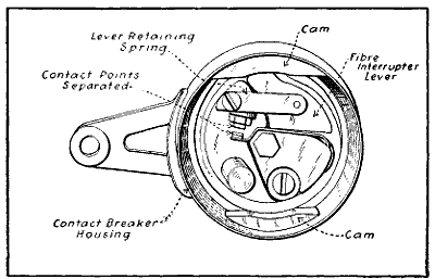
Fig. 65.—The Berling Magneto Breaker Box Showing Contact Points Separated and Interruptor Lever on Cam.
When inspecting the interrupter, make sure that the ground brush in the back of the interrupter base is making good contact with the surface on which it rubs.
The distributor block cover should be removed for inspection every twenty-five hours of actual running and the carbon deposit from the distributor finger-brush wiped off the distributor block by rubbing with a rag[181] or piece of waste dipped in gasoline or kerosene. The high-tension terminal brush on the side of the magneto should also be carefully inspected for proper tension.
Trouble in the ignition system is indicated by the motor “missing,” stopping entirely, or by inability to start.
It is safe to assume that the trouble is not in the magneto, and the carburetor, gasoline supply and spark-plugs should first be investigated.
If the magneto is suspected, the first thing to do is to determine if it will deliver a spark. To determine this, disconnect one of the high-tension leads from the spark-plug in one of the cylinders and place it so that there is approximately 1⁄16′′ between the terminal and the cylinder frame.
Open the pet cocks on the other cylinders to prevent the engine from firing and turn over the engine until the piston is approaching the end of the compression[182] stroke in the cylinder from which the cable has been removed. Set the magneto in the advance position and rapidly rock the engine over the top-center position, observing closely if a spark occurs between the end of the high-tension cable and the frame.
If the magneto is of the dual type, the trouble may be either in the magneto or in the battery or coil system, therefore disconnect the battery and place the switch in the position marked “MAG.” The magneto will then operate as an independent magneto and should spark in the proper manner. After this the battery system should be investigated. To test the operation of the battery and coil, examine all connections, making sure that they are clean and tight, and then with the switch, in the “BAT,” rock the piston slowly back and forth. If a type “VN-1” coil is used, a shower of sparks should jump between the high-tension cable terminal and the cylinder frame when the piston is in the correct position for firing. If no spark occurs, remove the cover from the coil and see that the vibrating tongue is free. If a type “N-1” coil is used, a single spark will occur. The battery should furnish six volts when connected to the coil, and this should also be verified.
If the coil still refuses to give a spark and all connections are correct, the coil should be replaced and the defective coil returned to the manufacturer.
If both magneto and coil give a spark when tested as just described, the spark-plugs should be investigated. To do this, disconnect the cables and remove the spark-plugs. Then reconnect the cables to the plugs and place them so that the frame portions of the plugs are in metallic connection with the frame of the motor. Then turn over the motor, thus revolving the magneto armature, and see if a spark is produced at the spark gaps of the plugs.
The most common defects in spark-plugs are breaking down of the insulation, fouling due to carbon, or too large or small a spark gap. To clean the plugs a stiff brush[183] and gasoline should be used. The spark gap should be about 1⁄32′′ and never less than 1⁄64′′. Too small a gap may have been caused by beads of metal forming due to the heat of the spark. Too long a gap may have been caused by the points burning off.
If the magneto and spark plugs are in good condition and the engine does not run satisfactorily, the setting should be verified according to instructions previously given, and, if necessary, readjusted.
Be careful to observe that both the type “VN-1” and type “N-1” coils are so arranged that the spark occurs on the opening of the contacts of the timer. As this is just the reverse of the usual operation, it should be carefully noted when any change in the setting of the timer is made. The timer on the dual type magneto is adjusted so that the battery spark occurs about 5° later[184] than the magneto spark. This provides an automatic advance as soon as the switch is thrown to the magneto position “MAG.” This relative timing can be easily adjusted by removing the interrupter and shifting the cam in the direction desired.
The Dixie magneto, shown at Fig. 66, operates on a different principle than the rotary armature type. It is used on the Hall-Scott and other aviation engines. In this magneto the rotating member consists of two pieces of magnetic material separated by a non-magnetic center piece. This member constitutes true rotating poles for the magnet and rotates in a field structure, composed of two laminated field pieces, riveted between two non-magnetic rings. The bearings for the rotating poles are[185] mounted in steel plates, which lie against the poles of the magnets. When the magnet poles rotate, the magnetic lines of force from each magnet pole are carried directly to the field pieces and through the windings, without reversal through the mass of the rotating member and with only a single air gap. There are no losses by flux reversal in the rotating part, such as take place in other[186] machines, and this is said to account for the high efficiency of the instrument.
And this “Mason Principle” involved in the operation of the Dixie is simplified by a glance at the field structure, consisting of the non-magnetic rings, assembled to which are the field pieces between which the rotating poles revolve (see Fig. 68). Rotating between the limbs of the magnets, these two pieces of magnetic material form true extensions to the poles of the magnets, and are, in consequence, always of the same polarity. It will be seen there is no reversal of the magnetism through them, and consequently no eddy current or hysteresis losses which are present in the usual rotor or inductor types. The simplicity features of construction stand out prominently here, in that there are no revolving windings, a detail entirely differing from the orthodox high-tension instrument. This simplicity becomes instantly apparent when it is found that the circuit breaker, instead of revolving as it does in other types, is stationary and that the whole breaker mechanism is exposed by simply turning the cover spring aside and removing cover. This makes inspection and adjustment particularly simple, and the fact that no special tool is necessary for adjustment of the platinum points—an ordinary small screw-driver is the whole “kit of tools” needed in the work of disassembling or assembling—is a feature of some value.
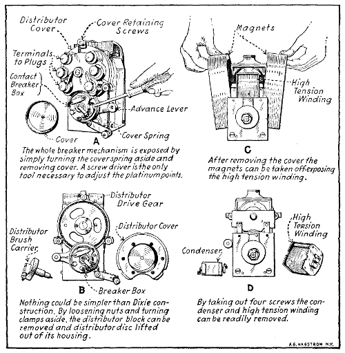
Fig. 69.—Suggestions for Adjusting and Dismantling Dixie Magneto. A—Screw Driver Adjusts Contact Points. B—Distributor Block Removed. C—Taking off Magnets. D—Showing How Easily Condenser and High Tension Windings are Removed.
With dust- and water-protecting casing removed, and one of the magnets withdrawn, as in Fig. 69, the winding can be seen with its core resting on the field pole pieces and the primary lead attached to its side. An important feature of the high-tension winding is that the heads are of insulating material, and there is not the tendency for the high-tension current to jump to the side as in the ordinary armature type magneto. The high-tension current is carried to the distributor by means of an insulated block with a spindle, at one end of which is a spring brush bearing directly on the winding, thus shortening[187] the path of the high-tension current and eliminating the use of rubber spools and insulating parts. The moving parts of the magneto need never be disturbed if the high-tension winding is to be removed. This winding constitutes all of the magneto windings, no external spark coil being necessary. The condenser is placed directly above the winding and is easily removable by taking out two screws, instead of being placed in an armature where it is inaccessible except to an expert, and where it cannot be replaced except at the factory whence it emanated.
The bearings of the magneto are provided with oil cups and a few drops of light oil every 1,000 miles are sufficient. The breaker lever should be lubricated every 1,000 miles with a drop of light oil, applied with a tooth-pick. The proper distance between the platinum points when separated should not exceed .020 or one-fiftieth of an inch. A gauge of the proper size is attached to the screwdriver furnished with the magneto. The platinum contacts should be kept clean and properly adjusted. Should the contacts become pitted, a fine file should be used to smooth them in order to permit them to come into perfect contact. The distributor block should be removed occasionally and inspected for an accumulation of carbon dust. The inside of the distributor block should be cleaned with a cloth moistened with gasoline and then wiped dry with a clean cloth. When replacing the block, care must be exercised in pushing the carbon brush into the socket. Do not pull out the carbon brushes in the distributor because you think there is not enough tension on the small brass springs. In order to obtain the most efficient results, the normal setting of the spark-plug points should not exceed .025 of an inch, and it is advisable to have the gap just right before a spark-plug is inserted.
The spark-plug electrodes may be easily set by means of the gauge attached to the screwdriver. The setting of the spark-plug points is an important function which is usually overlooked, with the result that the magneto is blamed when it is not at fault.
In order to obtain the utmost efficiency from the engine, the magneto must be correctly timed to it. This operation is usually performed when the magneto is fitted to the engine at the factory. The correct setting may vary according to individuality of the engine, and some[190] engines may require an earlier setting in order to obtain the best results. However, should the occasion arise to retime the magneto, the procedure is as follows: Rotate the crank-shaft of the engine until one of the pistons, preferably that of cylinder No. 1, is 1⁄16 of an inch ahead of the end of the compression stroke. With the timing lever in full retard position, the driving shaft of the magneto should be rotated in the direction in which it will be driven. The circuit breaker should be closely observed and when the platinum contact points are about to separate, the drive gear or coupling should be secured to the drive shaft of the magneto. Care should be taken not to alter the position of the magneto shaft when tightening the nut to secure the gear or coupling, after which the magneto should be secured to its base. Remove the distributor block and determine which terminal of the block is in contact with the carbon brush of the distributor finger and connect with plug wire leading to No. 1 cylinder to this terminal. Connect the remaining plug wires in turn according to the proper sequence of firing of the cylinders. (See the wiring diagram for a typical six-cylinder engine at Fig. 70.) A terminal on the end of the cover spring of the magneto is provided for the purpose of connecting the wire leading to a ground switch for stopping the engine.
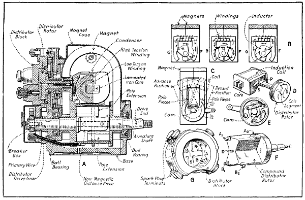
Fig. 69A.—Sectional Views Outlining Construction of Dixie Magneto with Compound Distributor for Eight-Cylinder Engine Ignition.
A special model or type of magneto is made for V engines which use a compound distributor construction instead of the simple type on the model illustrated and a different interior arrangement permits the production of four sparks per revolution of the rotors. This makes it possible to run the magneto slower than would be possible with the two-spark form. The application of two compound distributor magnetos of this type to a Thomas-Morse 135 horse-power motor of the eight-cylinder V pattern is clearly shown at Fig. 71.
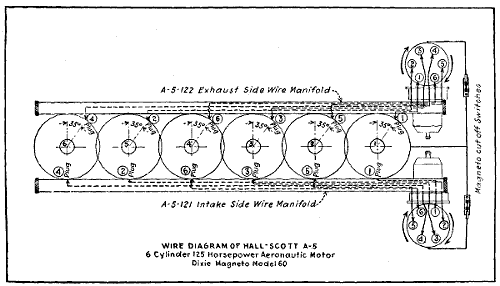
Fig. 70.—Wiring Diagram of Dixie Magneto Installation on Hall-Scott Six-Cylinder 125 Horse-Power Aeronautic Motor.
With the high-tension system of ignition the spark is produced by a current of high voltage jumping between two points which break the complete circuit, which would exist otherwise in the secondary coil and its external connections. The spark-plug is a simple device which[193] consists of two terminal electrodes carried in a suitable shell member, which is screwed into the cylinder. Typical spark-plugs are shown in section at Fig. 72 and the construction can be easily understood. The secondary wire from the coil is attached to a terminal at the top of a central electrode member, which is supported in a bushing of some form of insulating material. The type shown at A employs a molded porcelain as an insulator, while that depicted at B uses a bushing of mica. The insulating bushing and electrode are housed in a steel body, which is provided with a screw thread at the bottom, by which means it is screwed into the combustion chamber.
When porcelain is used as an insulating material it is kept from direct contact with the metal portion by some form of yielding packing, usually asbestos. This is necessary because the steel and porcelain have different coefficients of expansion and some flexibility must be provided at the joints to permit the materials to expand differently when heated. The steel body of the plug which is screwed into the cylinder is in metallic contact with it and carries sparking points which form one of the terminals of the air gap over which the spark occurs. The[194] current entering at the top of the plug cannot reach the ground, which is represented by the metal portion of the engine, until it has traversed the full length of the central electrode and overcome the resistance of the gap between it and the terminal point on the shell. The porcelain bushing is firmly seated against the asbestos packing by means of a brass screw gland which sets against a flange formed on the porcelain, and which screws into a thread at the upper portion of the plug body.
The mica plug shown at B is somewhat simpler in construction than that shown at A. The mica core which keeps the central electrode separated from the steel body is composed of several layers of pure sheet mica wound around the steel rod longitudinally, and hundreds of stamped steel washers which are forced over this member and compacted under high pressure with some form of a binding material between them. Porcelain insulators are usually molded from high-grade clay and are approximately of the shapes desired by the designers of the plug. The central electrode may be held in place by mechanical means such as nuts, packings, and a shoulder on the rod, as shown at A. Another method sometimes used is to cement the electrode in place by means of some form of fire-clay cement. Whatever method of fastening is used, it is imperative that the joints be absolutely tight so that no gas can escape at the time of explosion. Porcelain is the material most widely used because it can be glazed so that it will not absorb oil, and it is subjected to such high temperature in baking that it is not liable to crack when heated.
The spark-plugs may be screwed into any convenient part of the combustion chamber, the general practice being to install them in the caps over the inlet valves, or in the side of the combustion chamber, so the points will be directly in the path of the entering fresh gases from the carburetor.
Other insulating materials sometimes used are glass,[195] steatite (which is a form of soapstone) and lava. Mica and porcelain are the two common materials used because they give the best results. Glass is liable to crack, while lava or the soapstone insulating bushings absorb oil. The spark gap of the average plug is equal to about 1⁄32 of an inch for coil ignition and 1⁄40 of an inch when used in magneto circuits. A simple gauge for determining the gap setting is the thickness of an ordinary visiting card for magneto plugs, or a space equal to the thickness of a worn dime for a coil plug. The insulating bushings are made in a number of different ways, and while details of construction vary, spark-plugs do not differ essentially in design. The dimensions of the standardized plug recommended by the S. A. E. are shown at Fig. 73.
It is often desirable to have a water-tight joint between the high-tension cable and the terminal screw on top of the insulating bushing of the spark-plug, especially in marine applications. The plug shown at C, Fig. 72,[196] is provided with an insulating member or hood of porcelain, which is secured by a clip in such a manner that it makes a water-tight connection. Should the porcelain of a conventional form of plug become covered with water or dirty oil, the high-tension current is apt to run down this conducting material on the porcelain and reach the ground without having to complete its circuit by jumping the air gap and producing a spark. It will be evident that wherever a plug is exposed to the elements, which is often the case in airplane service, that it should be protected by an insulating hood which will keep the insulator dry and prevent short circuiting of the spark. The same end can be attained by slipping an ordinary rubber nipple over the porcelain insulator of any conventional plug and bringing up one end over the cable.
On most aviation engines, especially those having large cylinders, it is sometimes difficult to secure complete combustion by using a single-spark plug. If the combustion is not rapid the efficiency of the engine will be reduced proportionately. The compressed charge in the cylinder does not ignite all at once or instantaneously, as many assume, but it is the strata of gas nearest the plug which is ignited first. This in turn sets fire to consecutive layers of the charge until the entire mass is aflame. One may compare the combustion of gas in the gas-engine cylinder to the phenomenon which obtains when a heavy object is thrown into a pool of still water. First a small circle is seen at the point where the object has passed into the water, this circle in turn inducing other and larger circles until the whole surface of the pool has been agitated from the one central point. The method of igniting the gas is very similar, as the spark ignites the circle of gas immediately adjacent to the sparking point, and this circle in turn ignites a little larger one concentric with it. The second circle of flame[197] sets fire to more of the gas, and finally the entire contents of the combustion chamber are burning.
While ordinarily combustion is sufficiently rapid with a single plug so that the proper explosion is obtained at moderate engine speeds, if the engine is working fast and the cylinders are of large capacity more power may be obtained by setting fire to the mixture at two different points instead of but one. This may be accomplished by using two sparking-plugs in the cylinder instead of one, and experiments have shown that it is possible to gain from twenty-five to thirty per cent. in motor power at high speed with two-spark plugs, because the combustion of gas is accelerated by igniting the gas simultaneously in two places. The double-plug system on airplane engines is also a safeguard, as in event of failure of one plug in the cylinder the other would continue to fire the gas, and the engine will continue to function properly.
In using magneto ignition some precautions are necessary relating to wiring and also the character of the spark-plugs employed. The conductor should be of good quality, have ample insulation, and be well protected from accumulations of oil, which would tend to decompose rubber insulation. It is customary to protect the wiring by running it through the conduits of fiber or metal tubing lined with insulating material. Multiple strand cables should be used for both primary and secondary wiring, and the insulation should be of rubber at least 3⁄16 inch thick.
The spark-plugs commonly used for battery and coil ignition cannot always be employed when a magneto is fitted. The current produced by the mechanical generator has a greater amperage and more heat value than that obtained from transformer coils excited by battery current. The greater heat may burn or fuse the slender points used on some battery plugs and heavier electrodes are needed to resist the heating effect of the more intense arc. While the current has greater amperage it is not of as high potential or voltage as that commonly produced by the secondary winding of an induction coil, and it[198] cannot overcome as much of a gap. Manufacturers of magneto plugs usually set the spark points about 1⁄64 of an inch apart. The most efficient magneto plug has a plurality of points so that when the distance between one set becomes too great the spark will take place between one of the other pairs of electrodes which are not separated by so great an air space.
Airplane work calls for special construction of spark-plugs, owing to the high compression used in the engines and the fact that they are operated on open throttle practically all the time, thus causing a great deal of heat to[199] be developed. The plug shown at Fig. 74 was recently described in “The Automobile,” and has been devised especially for airplane engines and automobile racing power plants. The core C is built up of mica washers, and has square shoulders. As mica washers of different sizes may be used, and accurate machining, such as is necessary with conical clamping surfaces, is not required, the plug can be produced economically. The square shoulders of the core afford two gasket seats, and when the core is clamped in the shell by means of check nut E, it is accurately centered and a tight joint is formed. This construction also makes a shorter plug than where conical fits are used, thus improving the heat radiation through the stem. The lower end of the shell is provided with a baffle plate O, which tends to keep the oil away from the mica. There are perforations L in this baffle plate to prevent burnt gases being pocketed behind the baffle plate and pre-igniting the new charge. This construction also brings the firing point out into the firing chamber of the engine, and has all the other advantages of a closed-end plug. The stem P is made of brass or copper, on account of their superior heat conductivity, and the electrode J is swedged into the bottom of the stem, as shown at K, in a secure manner.
The shell is finned, as shown at G, to provide greater heat radiating surface. There is also a fin F at the top of the stem, to increase the radiation of heat from the stem and electrode. The top of this finned portion is slightly countersunk, and the stem is riveted into same, thereby reducing the possibility of leakage past the threads on the stem. This finned portion is necked at A to take a slip terminal.
In building up the core a small section of washers, I, is built up before the mica insulating tube D is placed on. This construction gives a better support to section I. Baffle plate O is bored out to allow the electrode J to pass through, and the clearance between baffle plate and electrode is made larger than the width of the gap between[200] the firing points, so that there is no danger of the spark jumping from the electrode to the baffle plate.
This plug will be furnished either with or without the finned portion, to meet individual requirements. The manufacturers lay special stress upon the simplicity of construction and upon the method of clamping, which is claimed to make the plug absolutely gas-tight.
Why Lubrication Is Necessary—Friction Defined—Theory of Lubrication—Derivation of Lubricants—Properties of Cylinder Oils—Factors Influencing Lubrication System Selection—Gnome Type Engines Use Castor Oil—Hall-Scott Lubrication System—Oil Supply by Constant Level Splash System—Dry Crank-Case System Best for Airplane Engines—Why Cooling Systems Are Necessary—Cooling Systems Generally Applied—Cooling by Positive Pump Circulation—Thermo-Syphon System—Direct Air-Cooling Methods—Air-Cooled Engine Design Considerations.
The importance of minimizing friction at the various bearing surfaces of machines to secure mechanical efficiency is fully recognized by all mechanics, and proper lubricity of all parts of the mechanism is a very essential factor upon which the durability and successful operation of the motor car power plant depends. All of the moving members of the engine which are in contact with other portions, whether the motion is continuous or intermittent, of high or low velocity, or of rectilinear or continued rotary nature, should be provided with an adequate supply of oil. No other assemblage of mechanism is operated under conditions which are so much to its disadvantage as the motor car, and the tendency is toward a simplification of oiling methods so that the supply will be ample and automatically applied to the points needing it.
In all machinery in motion the members which are in contact have a tendency to stick to each other, and the very minute projections which exist on even the smoothest of surfaces would have a tendency to cling or adhere to each other if the surfaces were not kept apart by some elastic and unctuous substance. This will flow or spread out over the surfaces and smooth out the inequalities existing[202] which tend to produce heat and retard motion of the pieces relative to each other.
A general impression which obtains is that well machined surfaces are smooth, but while they are apparently free from roughness, and no projections are visible to the naked eye, any smooth bearing surface, even if very carefully ground, will have a rough appearance if examined with a magnifying glass. An exaggerated condition to illustrate this point is shown at Fig. 75. The amount of friction will vary in proportion to the pressure on the surfaces in contact and will augment as the loads increase; the rougher surfaces will have more friction than smoother ones and soft bodies will produce more friction than hard substances.
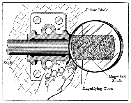
Fig. 75.—Showing Use of Magnifying Glass to Demonstrate that Apparently Smooth Metal Surfaces May Have Minute Irregularities which Produce Friction.
Friction is always present in any mechanism as a resisting force that tends to retard motion and bring all moving parts to a state of rest. The absorption of power by friction may be gauged by the amount of heat which exists at the bearing points. Friction of solids may be divided into two classes: sliding friction, such as exists between the piston and cylinder, or the bearings of a gas-engine, and rolling friction, which is that present when the load is supported by ball or roller bearings, or that which exists between the tires or the driving wheels and the road. Engineers endeavor to keep friction losses as low as possible, and much care is taken in all modern airplane engines to provide adequate methods of lubrication, or anti-friction bearings at all points where considerable friction exists.
The reason a lubricant is supplied to bearing points will be easily understood if one considers that these elastic substances flow between the close fitting surfaces, and by filling up the minute depressions in the surfaces and covering the high spots act as a cushion which[203] absorbs the heat generated and takes the wear instead of the metallic bearing surface. The closer the parts fit together the more fluid the lubricant must be to pass between their surfaces, and at the same time it must possess sufficient body so that it will not be entirely forced out by the pressure existing between the parts.
Oils should have good adhesive, as well as cohesive, qualities. The former are necessary so that the oil film will cling well to the surfaces of the bearings; the latter, so the oil particles will cling together and resist the tendency to separation which exists all the time the bearings are in operation. When used for gas-engine lubrication the oil should be capable of withstanding considerable heat in order that it will not be vaporized by the hot portions of the cylinder. It should have sufficient cold test so that it will remain fluid and flow readily at low temperature. Lubricants should be free from acid, or alkalies,[204] which tend to produce a chemical action with metals and result in corrosion of the parts to which they are applied. It is imperative that the oil be exactly the proper quality and nature for the purpose intended and that it be applied in a positive manner. The requirements may be briefly summarized as follows:
First—It must have sufficient body to prevent seizing of the parts to which it is applied and between which it is depended upon to maintain an elastic film, and yet it must not have too much viscosity, in order to minimize the internal or fluid friction which exists between the particles of the lubricant itself.
Second—The lubricant must not coagulate or gum; must not injure the parts to which it is applied, either by chemical action or by producing injurious deposits, and it should not evaporate readily.
Third—The character of the work will demand that the oil should not vaporize when heated or thicken to such a point that it will not flow readily when cold.
Fourth—The oil must be free from acid, alkalies, animal or vegetable fillers, or other injurious agencies.
Fifth—It must be carefully selected for the work required and should be a good conductor of heat.
The first oils which were used for lubricating machinery were obtained from animal and vegetable sources, though at the present time most unguents are of mineral derivation. Lubricants may exist as fluids, semifluids, or solids. The viscosity will vary from light spindle or dynamo oils, which have but little more body than kerosene, to the heaviest greases and tallows. The most common solid employed as a lubricant is graphite, sometimes termed “plumbago” or “black lead.” This substance is of mineral derivation.
The disadvantage of oils of organic origin, such as those obtained from animal fats or vegetable substances, is that they will absorb oxygen from the atmosphere,[205] which causes them to thicken or become rancid. Such oils have a very poor cold test, as they solidify at comparatively high temperatures, and their flashing point is so low that they cannot be used at points where much heat exists. In most animal oils various acids are present in greater or less quantities, and for this reason they are not well adapted for lubricating metallic surfaces which may be raised high enough in temperature to cause decomposition of the oils.
Lubricants derived from the crude petroleum are called “Oleonaphthas” and they are a product of the process of refining petroleum through which gasoline and kerosene are obtained. They are of lower cost than vegetable or animal oil, and as they are of non-organic origin, they do not become rancid or gummy by constant exposure to the air, and they will have no corrosive action on metals because they contain no deleterious substances in chemical composition. By the process of fractional distillation mineral oils of all grades can be obtained. They have a lower cold and higher flash test and there is not the liability of spontaneous combustion that exists with animal oils.
The organic oils are derived from fatty substances, which are present in the bodies of all animals and in some portions of plants. The general method of extracting oil from animal bodies is by a rendering process, which consists of applying sufficient heat to liquefy the oil and then separating it from the tissue with which it is combined by compression. The only oil which is used to any extent in gas-engine lubrication that is not of mineral derivation is castor oil. This substance has been used on high-speed racing automobile engines and on airplane power plants. It is obtained from the seeds of the castor plant, which contain a large percentage of oil.
Among the solid substances which may be used for lubricating purposes may be mentioned tallow, which is obtained from the fat of animals, and graphite and soapstone, which are of mineral derivation. Tallow is never[206] used at points where it will be exposed to much heat, though it is often employed as a filler for greases used in transmission gearing of autos. Graphite is sometimes mixed with oil and applied to cylinder lubrication, though it is most often used in connection with greases in the landing gear parts and for coating wires and cables of the airplane. Graphite is not affected by heat, cold, acids, or alkalies, and has a strong attraction for metal surfaces. It mixes readily with oils and greases and increases their efficiency in many applications. It is sometimes used where it would not be possible to use other lubricants because of extremes of temperature.
The oils used for cylinder lubrication are obtained almost exclusively from crude petroleum derived from American wells. Special care must be taken in the selection of crude material, as every variety will not yield oil of the proper quality to be used as a cylinder lubricant. The crude petroleum is distilled as rapidly as possible with fire heat to vaporize off the naphthas and the burning oils. After these vapors have been given off superheated steam is provided to assist in distilling. When enough of the light elements have been eliminated the residue is drawn off, passed through a strainer to free it from grit and earthy matters, and is afterwards cooled to separate the wax from it. This is the dark cylinder oil and is the grade usually used for steam-engine cylinders.
The oil that is to be used in the gasoline engine must be of high quality, and for that reason the best grades are distilled in a vacuum that the light distillates may be separated at much lower temperatures than ordinary conditions of distilling permit. If the degree of heat is not high the product is not so apt to decompose and deposit carbon. If it is desired to remove the color of the oil which is caused by free carbon and other impurities it can be accomplished by filtering the oil through charcoal. The greater the number of times the oil is filtered,[207] the lighter it will become in color. The best cylinder oils have flash points usually in excess of 500 degrees F., and while they have a high degree of viscosity at 100 degrees F. they become more fluid as the temperature increases.
The lubricating oils obtained by refining crude petroleum may be divided into three classes:
First—The natural oils of great body which are prepared for use by allowing the crude material to settle in tanks at high temperature and from which the impurities are removed by natural filtration. These oils are given the necessary body and are free from the volatile substances they contain by means of superheated steam which provides a source of heat.
Second—Another grade of these natural oils which are filtered again at high temperatures and under pressure through beds of animal charcoal to improve their color.
Third—Pale, limpid oils, obtained by distillation and subsequent chemical treatment from the residuum produced in refining petroleum to obtain the fuel oils.
Authorities agree that any form of mixed oil in which animal and mineral lubricants are combined should never be used in the cylinder of a gas engine as the admixture of the lubricants does not prevent the decomposition of the organic oil into the glycerides and fatty acids peculiar to the fat used. In a gas-engine cylinder the flame tends to produce more or less charring. The deposits of carbon will be much greater with animal oils than with those derived from the petroleum base because the constituents of a fat or tallow are not of the same volatile character as those which comprise the hydro-carbon oils which will evaporate or volatilize before they char in most instances.
The suitability of oil for the proper and efficient lubrication of all internal combustion engines is determined chiefly by the following factors:
[208]1. Type of cooling system (operating temperatures).
2. Type of lubricating system (method of applying oil to the moving parts).
3. Rubbing speeds of contact surfaces.
Were the operating temperatures, bearing surface speeds and lubrication systems identical, a single oil could be used in all engines with equal satisfaction. The only change then necessary in viscosity would be that due to climatic conditions. As engines are now designed, only three grades of oil are necessary for the lubrication of all types with the exception of Knight, air-cooled and some engines which run continuously at full load. In the specification of engine lubricants the feature of load carried by the engine should be carefully considered.
Full Load Engines.
Variable Load Engines.
Of the forms outlined, the only one we have any immediate concern about is the airplane power plant. The Platt & Washburn Refining Company, who have made a careful study of the lubrication problem as applied to all types of engines, have found a peculiar set of conditions to apply to oiling high-speed constant-duty or “full-load” engines. Modern airplane engines are designed to operate continuously at a fairly uniform high rotative speed and at full load over long periods of time. As a sequence to this heavy duty the operating[209] temperatures are elevated. For the sake of extreme lightness in weight of all parts, very thin alloy steel aluminum or cast iron pistons are fitted and the temperature of the thin piston heads at the center reaches anywhere between 600° and 1,400° Fahr., as in automobile racing engines. Freely exposed to such intense heat hydro-carbon oils are partially “cracked” into light and heavy products or polymerized into solid hydro-carbons. From these facts it follows that only heavy mineral oils of low carbon residue and of the greatest chemical purity and stability should be used to secure good lubrication. In all cases the oil should be sufficiently heavy to assure the highest horse-power and fuel and oil economy compatible with perfect lubrication, avoiding, at the same time, carbonization and ignition failure. When aluminum pistons are used their superior heat-conducting properties aid materially in reducing the rate of oil destruction.
The extraordinary evolutions described by airplanes in flight make it a matter of vital necessity to operate engines inclined at all angles to the vertical as well as in an upside-down position. To meet this situation lubricating systems have been elaborated so as to deliver an abundance of oil where needed and to eliminate possible flooding of cylinders. This is done by applying a full force feed system, distributing oil under considerable pressure to all working parts. Discharged through the bearings, the oil drains down to the suction side of a second pump located in the bottom of the base chamber. This pump being of greater capacity than the first prevents the accumulation of oil in the crank-case, and forces it to a separate oil reservoir-cooler, whence it flows back in rapid circulation to the pump feeding the bearings. With this arrangement positive lubrication is entirely independent of engine position. The lubricating system of the Thomas-Morse aviation engines, which is shown at Fig. 76, is typical of current practice.
The construction and operation of rotative radial cylinder engines introduce additional difficulties of lubrication to those already referred to and merit especial attention. Owing to the peculiar alimentation systems of Gnome type engines, atomized gasoline mixed with air is drawn through the hollow stationary crank-shaft directly into the crank-case which it fills on the way to the cylinders. Therein lies the trouble. Hydrocarbon oils are soon dissolved by the gasoline and washed off, leaving the bearing surfaces without adequate protection and exposed to instant wear and destruction. So castor oil is resorted to as an indispensable but unfortunate compromise. Of vegetable origin, it leaves a much more bulky carbon deposit in the explosion chambers than does mineral oil and its great affinity for oxygen causes the formation of voluminous gummy deposit in the crank-case. Engines employing it need to be dismounted and thoroughly scraped out at frequent intervals. It is advisable to use only unblended chemically pure castor oil in rotative engines, first by virtue of its insolubility in gasoline and second because its extra heavy body can resist the high temperature of air-cooled cylinders.
The oiling system of the Hall-Scott type A-5 125 horse-power engine is clearly shown at Fig. 77. It is completely described in the instruction book issued by the company from which the following extracts are reproduced by permission. Crank-shaft, connecting rods and all other parts within the crank-case and cylinders are lubricated directly or indirectly by a force-feed oiling system. The cylinder walls and wrist pins are lubricated by oil spray thrown from the lower end of connecting rod bearings. This system is used only upon A-5 engines. Upon A-7a and A-5a engines a small tube supplies oil[212] from connecting rod bearing directly upon the wrist pin. The oil is drawn from the strainer located at the lowest portion of the lower crank-case, forced around the main intake manifold oil jacket. From here it is circulated to the main distributing pipe located along the lower left hand side of upper crank-case. The oil is then forced directly to the lower side of crank-shaft, through holes drilled in each main bearing cup. Leakage from these main bearings is caught in scuppers placed upon the cheeks of the crank-shafts furnishing oil under pressure to the connecting rod bearings. A-7a and A-5a engines have small tubes leading from these bearings which convey the oil under pressure to the wrist pins.
A bi-pass located at the front end of the distributing oil pipe can be regulated to lessen or raise the pressure. By screwing the valve in, the pressure will raise and more oil will be forced to the bearings. By unscrewing, pressure is reduced and less oil is fed. A-7a and A-5a engines have oil relief valves located just off of the main oil pump in the lower crank-case. This regulates the pressure at all times so that in cold weather there will be no danger of bursting oil pipes due to excessive pressure. If it is found the oil pressure is not maintained at a high enough level, inspect this valve. A stronger spring will not allow the oil to bi-pass so freely, and consequently the pressure will be raised; a weaker spring will bi-pass more oil and reduce the oil pressure materially. Independent of the above-mentioned system, a small, directly driven rotary oiler feeds oil to the base of each individual cylinder. The supply of oil is furnished by the main oil pump located in the lower crank-case. A small sight-feed regulator is furnished to control the supply of oil from this oiler. This instrument should be placed higher than the auxiliary oil distributor itself to enable the oil to drain by gravity feed to the oiler. If there is no available place with the necessary height in the front seat of plane, connect it directly to the intake L fitting on the oiler in an upright position. It should[214] be regulated with full open throttle to maintain an oil level in the glass, approximately half way.
An oil pressure gauge is provided. This should be run to the pilot’s instrument board. The gauge registers the oil pressure upon the bearings, also determining its circulation. Strict watch should be maintained of this instrument by pilot, and if for any reason its hand should drop to 0 the motor should be immediately stopped and the trouble found before restarting engine. Care should be taken that the oil does not work up into the gauge, as it will prevent the correct gauge registering of oil pressure. The oil pressure will vary according to weather conditions and viscosity of oil used. In normal weather, with the engine properly warmed up, the pressure will register on the oil gauge from 5 to 10 pounds when the engine is turning from 1,275 to 1,300 r. p. m. This does not apply to all aviation engines, however, as the proper pressure advised for the Curtiss OX-2 motor is from 40 to 55 pounds at the gauge.
The oil sump plug is located at the lowest point of the lower crank-case. This is a combination dirt, water and sediment trap. It is easily removed by unscrewing. Oil is furnished mechanically to the cam-shaft housing under pressure through a small tube leading from the main distributing pipe at the propeller end of engine directly into the end of cam-shaft housing. The opposite end of this housing is amply relieved to allow the oil to rapidly flow down upon cam-shaft, magneto, pinion-shaft, and crank-shaft gears, after which it returns to lower crank-case. An outside overflow pipe is also provided to carry away the surplus oil.
The oil strainer is placed at the lowest point of the lower crank-case. This strainer should be removed after every five to eight hours running of the engine and cleaned thoroughly with gasoline. It is also advisable to squirt distillate up into the case through the opening[215] where the strainer has been removed. Allow this distillate to drain out thoroughly before replacing the plug with strainer attached. Be sure gasket is in place on plug before replacing. Pour new oil in through either of the two breather pipes on exhaust side of motor. Be sure to replace strainer screens if removed. If, through oversight, the engine does not receive sufficient lubrication and begins to heat or pound, it should be stopped immediately. After allowing engine to cool pour at least three gallons of oil into oil sump. Fill radiator with water after engine has cooled. Should there be apparent damage, the engine should be thoroughly inspected immediately without further running. If no obvious damage has been done, the engine should be given a careful examination at the earliest opportunity to see that the running without oil has not burned the bearings or caused other trouble.
Oils best adapted for Hall-Scott engines have the following properties: A flash test of not less than 400° F.; viscosity of not less than 75 to 85 taken at 21° F. with Saybolt’s Universal Viscosimeter.
Zeroline heavy duty oil, manufactured by the Standard Oil Company of California; also,
Gargoyle mobile B oil, manufactured by the Vacuum Oil Company, both fulfill the above specifications. One or the other of these oils can be obtained all over the world.
Monogram extra heavy is also recommended.
The splash system of lubrication that depends on the connecting rod to distribute the lubricant is one of the most successful and simplest forms for simple four- and six-cylinder vertical automobile engines, but is not as well adapted to the oiling of airplane power plants for reasons previously stated. If too much oil is supplied the surplus will work past the piston rings and into the combustion chamber, where it will burn and cause carbon[216] deposits. Too much oil will also cause an engine to smoke and an excess of lubricating oil is usually manifested by a bluish-white smoke issuing from the exhaust.
A good method of maintaining a constant level of oil for the successful application of the splash system is shown at Fig. 78. The engine base casting includes a separate chamber which serves as an oil container and which is below the level of oil in the crank-case. The lubricant is drawn from the sump or oil container by means of a positive oil pump which discharges directly into the engine case. The level is maintained by an overflow pipe which allows all excess lubricant to flow back into the oil container at the bottom of the cylinder. Before passing into the pump again the oil is strained or filtered by a screen of wire gauze and all foreign matter removed. Owing to the rapid circulation of the oil it may be used over and over again for quite a period of time. The oil is introduced directly into the crank-case by a breather pipe and the level is indicated by a rod carried by a float which rises when the container is replenished and falls when the available supply diminishes. It will be noted that with such system the only apparatus required besides the oil tank which is cast integral with the bottom of the crank-case is a suitable pump to maintain circulation of oil. This member is always positively driven, either by means of shaft and universal coupling or direct gearing. As the system is entirely automatic in action, it will furnish a positive supply of oil at all desired points, and it cannot be tampered with by the inexpert because no adjustments are provided or needed.
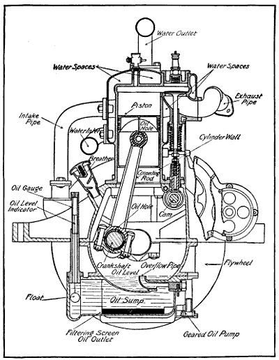
Fig. 78.—Sectional View of Typical Motor Showing Parts Needing Lubrication and Method of Applying Oil by Constant Level Splash System. Note also Water Jacket and Spaces for Water Circulation.
In most airplane power plants it is considered desirable to supply the oil directly to the parts needing it by suitable leads instead of depending solely upon the distributing action of scoops on the connecting rod big ends. A system of this nature is shown at Fig. 77. The oil[217] is carried in the crank-case, as is common practice, but the normal oil level is below the point where it will be reached by the connecting rod. It is drawn from the crank-case by a plunger pump which directs it to a manifold leading directly to conductors which supply the main[218] journals. After the oil has been used on these points it drains back into the bottom of the crank-case. An excess is provided which is supplied to the connecting rod ends by passages drilled into the webs of the crank-shaft and part way into the crank-pins as shown by the dotted lines. The oil which is present at the connecting rod crank-pins is thrown off by centrifugal force and lubricates the cylinder walls and other internal parts. Regulating screws are provided so that the amount of oil supplied the different points may be regulated at will. A relief check valve is installed to take care of excess lubricant and to allow any oil that does not pass back into the pipe line to overflow or bi-pass into the main container.
A simple system of this nature is shown graphically in a phantom view of the crank-case at Fig. 79, in which[219] the oil passages are made specially prominent. The oil is taken from a reservoir at the bottom of the engine base by the usual form of gear oil pump and is supplied to a main feed manifold which extends the length of the crank-case. Individual conductors lead to the five main bearings, which in turn supply the crank-pins by passages drilled through the crank-shaft web. In this power plant the connecting rods are hollow section bronze castings and the passage through the center of the connecting rod serves to convey the lubricant from the crank-pins to the wrist-pins. The cylinder walls are oiled by the spray of lubricant thrown off the revolving crank-shaft by centrifugal force. Oil projection by the dippers on the connecting rod ends from constant level troughs is unequal upon the cylinder walls of the two-cylinder blocks of an eight- or twelve-cylinder V engine. This gives rise, on one side of the engine, to under-lubrication, and, on the other side, to over-lubrication, as shown at Fig. 80, A. This applies to all modifications of splash lubricating systems.
When a force-feed lubricating system is used, the oil, escaping past the cheeks of both ends of the crank-pin bearings, is thrown off at a tangent to the crank-pin circle in all directions, supplying the cylinders on both sides with an equal quantity of oil, as at Fig. 80, B.
The reader should understand from preceding chapters that the power of an internal-combustion motor is obtained by the rapid combustion and consequent expansion of some inflammable gas. The operation in brief is that when air or any other gas or vapor is heated, it will expand and that if this gas is confined in a space which will not permit expansion, pressure will be exerted against all sides of the containing chamber. The more a gas is heated, the more pressure it will exert upon the walls of the combustion chamber it[221] confines. Pressure in a gas may be created by increasing its temperature and inversely heat may be created by pressure. When a gas is compressed its total volume is reduced and the temperature is augmented.
The efficiency of any form of heat engine is determined by the power obtained from a certain fuel consumption. A definite amount of energy will be liberated in the form of heat when a pound of any fuel is burned. The efficiency of any heat engine is proportional to the power developed from a definite quantity of fuel with the least loss of thermal units. If the greater proportion of the heat units derived by burning the explosive mixture could be utilized in doing useful work, the efficiency of the gasoline engine would be greater than that of any other form of energizing power. There is a great loss of heat from various causes, among which can be cited the reduction of pressure through cooling the motor and the loss of heat through the exhaust valves when the burned gases are expelled from the cylinder.
The loss through the water jacket of the average automobile power plant is over 50 per cent. of the total fuel efficiency. This means that more than half of the heat units available for power are absorbed and dissipated by the cooling water. Another 16 per cent. is lost through the exhaust valve, and but 331⁄3 per cent. of the heat units do useful work. The great loss of heat through the cooling systems cannot be avoided, as some method must be provided to keep the temperature of the engine within proper bounds. It is apparent that the rapid combustion and continued series of explosions would soon heat the metal portions of the engine to a red heat if some means were not taken to conduct much of this heat away. The high temperature of the parts would burn the lubricating oil, even that of the best quality, and the piston and rings would expand to such a degree, especially when deprived of oil, that they would seize in the cylinder. This would score the walls, and the friction which ensued would tend to bind the parts so tightly[222] that the piston would stick, bearings would be burned out, the valves would warp, and the engine would soon become inoperative.
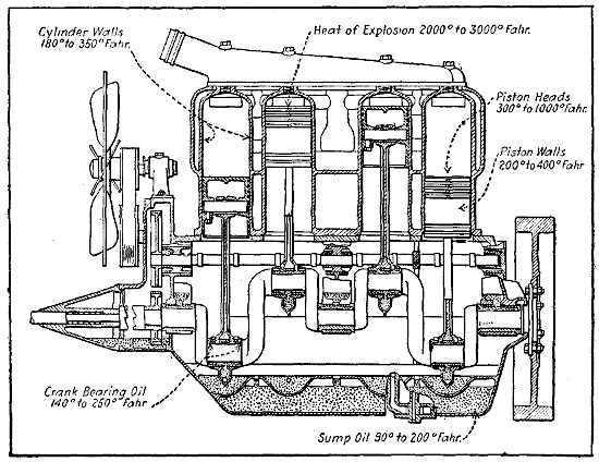
Fig. 81.—Operating Temperatures of Automobile Engine Parts Useful as a Guide to Understand Airplane Power Plant Heat.
The best temperature to secure efficient operation is one on which considerable difference of opinion exists among engineers. The fact that the efficiency of an engine is dependent upon the ratio of heat converted into useful work compared to that generated by the explosion of the gas is an accepted fact. It is very important that the engine should not get too hot, and on the other hand it is equally vital that the cylinders be not robbed of too much heat. The object of cylinder cooling is to keep the temperature of the cylinder below the danger point, but at the same time to have it as high as possible to secure maximum power from the gas burned. The usual operating temperatures of an[223] automobile engine are shown at Fig. 81, and this can be taken as an approximation of the temperatures apt to exist in an airplane engine of conventional design as well when at ground level or not very high in the air. The newer very high compression airplane engines in which compressions of eight or nine atmospheres are used, or about 125 pounds per square inch, will run considerably hotter than the temperatures indicated.
There are two general systems of engine cooling in common use, that in which water is heated by the absorption of heat from the engine and then cooled by air, and the other method in which the air is directed onto the cylinder and absorbs the heat directly instead of through the medium of water. When the liquid is employed in cooling it is circulated through jackets which surround the cylinder casting and the water may be kept in motion by two methods. The one generally favored is to use a positive circulating pump of some form which is driven by the engine to keep the water in motion. The other system is to utilize a natural principle that heated water is lighter than cold liquid and that it will tend to rise to the top of the cylinder when it becomes heated to the proper temperature and cooled water takes its place at the bottom of the water jacket.
Air-cooling methods may be by radiation or convection. In the former case the effective outer surface of the cylinder is increased by the addition of flanges machined or cast thereon, and the air is depended on to rise from the cylinder as heated and be replaced by cooler air. This, of course, is found only on stationary engines. When a positive air draught is directed against the cylinder by means of the propeller slip stream in an airplane, cooling is by convection and radiation both. Sometimes the air draught may be directed against the[224] cylinder walls by some form of jacket which confines it to the heated portions of the cylinder.
A typical water-cooling system in which a pump is depended upon to promote circulation of the cooling liquid is shown at Figs. 82 and 83. The radiator is carried at the front end of the fuselage in most cases, and serves as a combined water tank and cooler, but in some cases it is carried at the side of the engine, as in Fig. 84, or attached to the central portion of the aerofoil or wing structure. It is composed of an upper and lower portion joined together by a series of pipes which may be round and provided with a series of fins to radiate the heat, or which may be flat in order to have the water pass through in thin sheets and cool it more easily. Cellular or honeycomb coolers are composed of a large number of bent tubes which will expose a large area of surface to the cooling influence of the air draught forced through the radiator either by the forward movement of the vehicle or by some type of fan. The cellular and[225] flat tube types have almost entirely displaced the flange tube radiators which were formerly popular because they cool the water more effectively, and may be made lighter than the tubular radiator could be for engines of the same capacity.
The water is drawn from the lower header of the radiator by the pump and is forced through a manifold to the lower portion of the water jackets of the cylinder. It becomes heated as it passes around the cylinder walls and combustion chambers and the hot water passes out of the top of the water jacket to the upper portion of the radiator. Here it is divided in thin streams and directed against comparatively cool metal which abstracts the heat from the water. As it becomes cooler it falls to the bottom of the radiator because its weight increases as the temperature becomes lower. By the time it reaches[226] the lower tank of the radiator it has been cooled sufficiently so that it may be again passed around the cylinders of the motor. The popular form of circulating pump is known as the “centrifugal type” because a rotary impeller of paddle-wheel form throws water which it receives at a central point toward the outside and thus causes it to maintain a definite rate of circulation. The pump is always a separate appliance attached to the engine and driven by positive gearing or direct-shaft connection. The centrifugal pump is not as positive as the gear form, and some manufacturers prefer the latter because of the positive pumping features. They are very simple in form, consisting of a suitable cast body in which a pair of spur pinions having large teeth are carried. One of these gears is driven by suitable means, and as it turns the other member they maintain a flow of water around the pump body. The pump should always be installed in series with the water pipe which[227] conveys the cool liquid from the lower compartment of the radiator to the coolest portion of the water jacket.
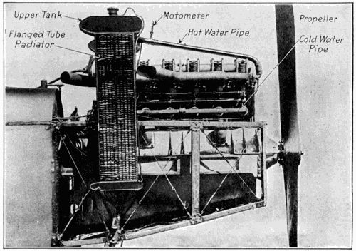
Fig. 84.—Finned Tube Radiators at the Side of Hall-Scott Airplane Power Plant Installed in Standard Fuselage.
Some automobile engineers contend that the rapid water circulation obtained by using a pump may cool the cylinders too much, and that the temperature of the engine may be reduced so much that the efficiency will be lessened. For this reason there is a growing tendency to use the natural method of water circulation as the cooling liquid is supplied to the cylinder jackets just below the boiling point and the water issues from the jacket at the top of the cylinder after it has absorbed sufficient heat to raise it just about to the boiling point.
As the water becomes heated by contact with the hot cylinder and combustion-chamber walls it rises to the top of the water jacket, flows to the cooler, where enough of the heat is absorbed to cause it to become sensibly greater in weight. As the water becomes cooler, it falls to the bottom of the radiator and it is again supplied to the water jacket. The circulation is entirely automatic and continues as long as there is a difference in temperature between the liquid in the water spaces of the engine and that in the cooler. The circulation becomes brisker as the engine becomes hotter and thus the temperature of the cylinders is kept more nearly to a fixed point. With the thermosyphon system the cooling liquid is nearly always at its boiling point, whereas if the circulation is maintained by a pump the engine will become cooler at high speed and will heat up more at low speed.
With the thermosyphon, or natural system of cooling, more water must be carried than with the pump-maintained circulation methods. The water spaces around the cylinders should be larger, the inlet and discharge water manifolds should have greater capacity, and be free from sharp corners which might impede the flow. The radiator must also carry more water than the form used in connection with the pump because of the brisker[228] pump circulation which maintains the engine temperature at a lower point. Consideration of the above will show why the pump system is almost universally used in connection with airplane power plant cooling.
The earliest known method of cooling the cylinder of gas-engines was by means of a current of air passed through a jacket which confined it close to the cylinder walls and was used by Daimler on his first gas-engine. The gasoline engine of that time was not as efficient as the later form, and other conditions which materialized made it desirable to cool the engine by water. Even as gasoline engines became more and more perfected there has always existed a prejudice against air cooling, though many forms of engines have been used, both in automobile and aircraft applications where the air-cooling method has proven to be very practical.
The simplest system of air cooling is that in which the cylinders are provided with a series of flanges which increase the effective radiating surface of the cylinder and directing an air-current from a fan against the flanges to absorb the heat. This increase in the available radiating surface of an air-cooled cylinder is necessary because air does not absorb heat as readily as water and therefore more surface must be provided that the excess heat be absorbed sufficiently fast to prevent distortion of the cylinders. Air-cooling systems are based on a law formulated by Newton, which is: “The rate for cooling for a body in a uniform current of air is directly proportional to the speed of the air current and the amount of radiating surface exposed to the cooling effect.”
There are certain considerations which must be taken into account in designing an air-cooled engine, which are often overlooked in those forms cooled by water. Large[229] valves must be provided to insure rapid expulsion of the flaming exhaust gas and also to admit promptly the fresh cool mixture from the carburetor. The valves of air-cooled engines are usually placed in the cylinder-head, in order to eliminate any pockets or sharp passages which would impede the flow of gas or retain some of the products of combustion and their heat. When high power is desired multiple-cylinder engines should be used, as there is a certain limit to the size of a successful[230] air-cooled cylinder. Much better results are secured from those having small cubical contents because the heat from small quantities of gas will be more quickly carried off than from greater amounts. All successful engines of the aviation type which have been air-cooled have been of the multiple-cylinder type.
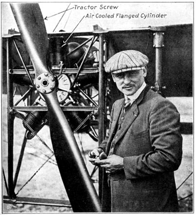
Fig. 85.—Anzani Testing His Five-Cylinder Air Cooled Aviation Motor Installed in Bleriot Monoplane. Note Exposure of Flanged Cylinders to Propeller Slip Stream.
An air-cooled engine must be placed in the fuselage, as at Fig. 85, in such a way that there will be a positive circulation of air around it all the time that it is in operation. The air current may be produced by the tractor screw at the front end of the motor, or by a suction or blower fan attached to the crank-shaft as in the Renault engine or by rotating the cylinders as in the Le Rhone and Gnome motors. Greater care is required in lubrication of the air-cooled cylinders and only the best quality of oil should be used to insure satisfactory oiling.
The combustion chambers must be proportioned so that distribution of metal is as uniform as possible in order to prevent uneven expansion during increase in temperature and uneven contraction when the cylinder is cooled. It is essential that the inside walls of the combustion chamber be as smooth as possible because any sharp angle or projection may absorb sufficient heat to remain incandescent and cause trouble by igniting the mixture before the proper time. The best grades of cast iron or steel should be used in the cylinder and piston and the machine work must be done very accurately so the piston will operate with minimum friction in the cylinder. The cylinder bore should not exceed 41⁄2 or 5 inches and the compression pressure should never exceed 75 pounds absolute, or about five atmospheres, or serious overheating will result.
As an example of the care taken in disposing of the exhaust gases in order to obtain practical air-cooling, some cylinders are provided with a series of auxiliary exhaust ports uncovered by the piston when it reaches the end of its power stroke. The auxiliary exhaust ports open just as soon as the full force of the explosion has[231] been spent and a portion of the flaming gases is discharged through the ports in the bottom of the cylinder. Less of the exhaust gases remains to be discharged through the regular exhaust member in the cylinder-head and this will not heat the walls of the cylinder nearly as much as the larger quantity of hot gas would. That the auxiliary exhaust port is of considerable value is conceded by many designers of fixed and fan-shaped air-cooled motors for airplanes.
Among the advantages stated for direct air cooling, the greatest is the elimination of cooling water and its cooling auxiliaries, which is a factor of some moment, as it permits considerable reduction in horse-power-weight ratio of the engine, something very much to be desired. In the temperate zone, where the majority of airplanes are used, the weather conditions change in a very few months from the warm summer to the extreme cold winter, and when water-cooled systems are employed it is necessary to add some chemical substance to the water to prevent it from freezing. The substances commonly employed are glycerine, wood alcohol, or a saturated solution of calcium chloride. Alcohol has the disadvantage in that it vaporizes readily and must be often renewed. Glycerine affects the rubber hose, while the calcium chloride solution crystallizes and deposits salt in the radiator and water pipes.
One of the disadvantages of an air-cooling method, as stated by those who do not favor this system, is that engines cooled by air cannot be operated for extended periods under constant load or at very high speed without heating up to such a point that premature ignition of the charge may result. The water-cooling systems, at the other hand, maintain the temperature of the engine more nearly constant than is possible with an air-cooled motor, and an engine cooled by water can be operated under conditions of inferior lubrication or poor mixture adjustment that would seriously interfere with proper and efficient cooling by air.
[232]Air-cooled motors, as a rule, use less fuel than water-cooled engines, because the higher temperature of the cylinder does not permit of a full charge of gas being inspired on the intake stroke. As special care is needed in operating an air-cooled engine to obtain satisfactory results and because of the greater difficulty which obtains in providing proper lubrication and fuel mixtures which will not produce undue heating, the air-cooled system has but few adherents at the present time, and practically all airplanes, with but very few exceptions, are provided with water-cooled power plants. Those fitted with air-cooled engines are usually short-flight types where maximum lightness is desired in order to obtain high speed and quick climb. The water-cooled engines are best suited for airplanes intended for long flights. The Gnome, Le Rhone and Clerget engines are thoroughly practical and have been widely used in France and England. These are rotary radial cylinder types. The Anzani is a fixed cylinder engine used on training machines, while the Renault is a V-type engine made in eight- and twelve-cylinder V forms that has been used on reconnaissance and bombing airplanes with success. These types will be fully considered in proper sequence.
Methods of Cylinder Construction—Block Castings—Influence on Crank-Shaft Design—Combustion Chamber Design—Bore and Stroke Ratio—Meaning of Piston Speed—Advantage of Off-Set Cylinders—Valve Location of Vital Import—Valve Installation Practice—Valve Design and Construction—Valve Operation—Methods of Driving Cam-Shaft—Valve Springs—Valve Timing—Blowing Back—Lead Given Exhaust Valve—Exhaust Closing, Inlet Opening—Closing the Inlet Valve—Time of Ignition—How an Engine Is Timed—Gnome “Monosoupape” Valve Timing—Springless Valves—Four Valves per Cylinder.
The improvements noted in the modern internal combustion motors have been due to many conditions. The continual experimenting by leading mechanical minds could have but one ultimate result. The parts of the engines have been lightened and strengthened, and greater power has been obtained without increasing piston displacement. A careful study has been made of the many conditions which make for efficient motor action, and that the main principles are well recognized by all engineers is well shown by the standardization of design noted in modern power plants. There are many different methods of applying the same principle, and it will be the purpose of this chapter to define the ways in which the construction may be changed and still achieve the same results. The various components may exist in many different forms, and all have their advantages and disadvantages. That all methods are practical is best shown by the large number of successful engines which use radically different designs.
One of the most important parts of the gasoline engine and one that has material bearing upon its efficiency is the cylinder unit. The cylinders may be cast[234] individually, or in pairs, and it is possible to make all cylinders a unit or block casting. Some typical methods of cylinder construction are shown in accompanying illustrations. The appearance of individual cylinder castings may be ascertained by examination of the Hall-Scott airplane engine. Air-cooled engine cylinders are always of the individual pattern.
Considered from a purely theoretical point of view, the individual cylinder casting has much in its favor. It is advanced that more uniform cooling is possible than where the cylinders are cast either in pairs or three or four in one casting. More uniform cooling insures that the expansion or change of form due to heating will be more equal. This is an important condition because the cylinder bore must remain true under all conditions of operation. If the heating effect is not uniform, which condition is liable to obtain if metal is not evenly distributed, the cylinder may become distorted by heat and the bore be out of truth. When separate cylinders are used it is possible to make a uniform water space and have the cooling liquid evenly distributed around the cylinder. In multiple cylinder castings this is not always the rule, as in many instances, especially in four-cylinder block motors where compactness is the main feature, there is but little space between the cylinders for the passage of water. Under such circumstances the cooling effect is not even, and the stresses which obtain because of unequal expansion may distort the cylinder to some extent. When steel cylinders are made from forgings, the water jackets are usually of copper or sheet steel attached to the forging by autogenous welding; in the case of the latter and, in some cases, the former may be electro-deposited on the cylinders.
The advantage of casting the cylinders in blocks is that a motor may be much shorter than it would be if individual castings were used. It is admitted that when[235] the cylinders are cast together a more compact, rigid, and stronger power plant is obtained than when cast separately. There is a disadvantage, however, in that if one cylinder becomes damaged it will be necessary to replace the entire unit, which means scrapping three good cylinders because one of the four has failed. When the cylinders are cast separately one need only replace the one that has become damaged. The casting of four cylinders in one unit is made possible by improved[236] foundry methods, and when proper provision is made for holding the cores when the metal is poured and the cylinder casts are good, the construction is one of distinct merit. It is sometimes the case that the proportion of sound castings is less when cylinders are cast in block, but if the proper precautions are observed in molding and the proper mixtures of cast iron used, the ratio of defective castings is no more than when cylinders are molded individually. As an example of the courage of engineers in departing from old-established rules, the cylinder casting shown at Fig. 86 may be considered typical. This is used on the Duesenberg four-cylinder sixteen-valve 43⁄4′′ × 7′′ engine which has a piston displacement of 496 cu. in. At a speed of 2,000 r.p.m., corresponding to a piston speed of 2,325 ft. per min., the engine is guaranteed to develop 125 horse-power. The weight of the model engine without gear reduction is 436 lbs., but a number of refinements have been made in the design whereby it is expected to get the weight down to 390 lbs. The four cylinders are cast from semi-steel in a single block, with integral heads. The cylinder construction is the same as that which has always been used by Mr. Duesenberg, inlet and exhaust valves being arranged horizontally opposite each other in the head. There are large openings in the water jacket at both sides and at the ends, which are closed by means of aluminum covers, water-tightness being secured by the use of gaskets. This results in a saving in weight because the aluminum covers can be made considerably lighter than it would be possible to cast the jacket walls, and, besides, it permits of obtaining a more nearly uniform thickness of cylinder wall, as the cores can be much better supported. The cooling water passes completely around each cylinder, and there is a very considerable space between the two central cylinders, this being made necessary in order to get the large bearing area desirable for the central bearing.
It is common practice to cast the water jackets integral[237] with the cylinders, if cast iron or aluminum is used, and this is also the most economical method of applying it because it gives good results in practice. An important detail is that the water spaces must be proportioned so that they are equal around the cylinders whether these members are cast individually, in pairs, threes or fours. When cylinders are cast in block form it is good practice to leave a large opening in the jacket wall which will assist in supporting the core and make for uniform water space. It will be noticed that the casting shown at Fig. 86 has a large opening in the side of the cylinder block. These openings are closed after the interior of the casting is thoroughly cleaned of all sand, core wire, etc., by brass, cast iron or aluminum plates. These also have particular value in that they may be removed after the motor has been in use, thus permitting one to clean out the interior of the water jacket and dispose of the rust, sediment, and incrustation which are always present after the engine has been in active service for a time.
Among the advantages claimed for the practice of casting cylinders in blocks may be mentioned compactness, lightness, rigidity, simplicity of water piping, as well as permitting the use of simple forms of inlet and exhaust manifolds. The light weight is not only due to the reduction of the cylinder mass but because the block construction permits one to lighten the entire motor. The fact that all cylinders are cast together decreases vibration, and as the construction is very rigid, disalignment of working parts is practically eliminated. When inlet and exhaust manifolds are cored in the block casting, as is sometimes the case, but one joint is needed on each of these instead of the multiplicity of joints which obtain when the cylinders are individual castings. The water piping is also simplified. In the case of a four-cylinder block motor but two pipes are used; one for the water to enter the cylinder jacket, the other for the cooling liquid to discharge through.
The method of casting the cylinders has a material influence on the design of the crank-shaft as will be shown in proper sequence. When four cylinders are combined in one block it is possible to use a two-bearing crank-shaft. Where cylinders are cast in pairs a three-bearing crank-shaft is commonly supplied, and when cylinders are cast as individual units it is thought necessary to supply a five-bearing crank-shaft, though sometimes shafts having but three journals are used successfully. Obviously the shafts must be stronger and stiffer to withstand the stresses imposed if two supporting bearings are used than if a larger number are employed. In this connection it may be stated that there is less difficulty in securing alignment with a lesser number of bearings and there is also less friction. On the other hand, the greater the number of points of support a crank-shaft has the lighter the webs can be made and still have requisite strength.
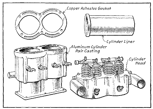
Fig. 87.—Twin-Cylinder Block of Sturtevant Airplane Engine is Cast of Aluminum, and Has Removable Cylinder Head.
Another point of importance in the design of the cylinder, and one which has considerable influence upon the power developed, is the shape of the combustion chamber. The endeavor of designers is to obtain maximum power from a cylinder of certain proportions, and the greater energy obtained without increasing piston displacement or fuel consumption the higher the efficiency of the motor. To prevent troubles due to pre-ignition it is necessary that the combustion chamber be made so that there will be no roughness, sharp corners, or edges of metal which may remain incandescent when heated or which will serve to collect carbon deposits by providing a point of anchorage. With the object of providing an absolutely clean combustion chamber some makers use a separable head unit to their twin cylinder castings, such as shown at Fig. 87 and Fig. 88. These permit one to machine the entire interior of the cylinder and combustion chamber. The relation of valve location and combustion chamber design will be considered in proper sequence. These cylinders are cast of aluminum, instead of cast iron, as[240] is customary, and are provided with steel or cast iron cylinder liners forced in the soft metal casting bores.
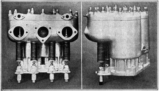
Fig. 88.—Aluminum Cylinder Pair Casting of Thomas 150 Horse-Power Airplane Engine is of the L Head Type.
A question that has been a vexed one and which has been the subject of considerable controversy is the proper proportion of the bore to the stroke. The early gas engines had a certain well-defined bore to stroke ratio, as it was usual at that time to make the stroke twice as long as the bore was wide, but this cannot be done when high speed is desired. With the development of the present-day motor the stroke or piston travel has been gradually shortened so that the relative proportions of bore and stroke have become nearly equal. Of late there seems to be a tendency among designers to return to the proportions which formerly obtained, and the stroke is sometimes one and a half or one and three-quarter times the bore.
Engines designed for high speed should have the stroke not much longer than the diameter of the bore. The disadvantage of short-stroke engines is that they will not pull well at low speeds, though they run with great regularity and smoothness at high velocity. The long-stroke engine is much superior for slow speed work, and it will pull steadily and with increasing power at low speed. It was formerly thought that such engines should never turn more than a moderate number of revolutions, in order not to exceed the safe piston speed of 1,000 feet per minute. This old theory or rule of practice has been discarded in designing high efficiency automobile racing and aviation engines, and piston speeds from 2,500 to 3,000 feet per minute are sometimes used, though the average is around 2,000 feet per minute. While both short- and long-stroke motors have their advantages, it would seem desirable to average between the two. That is why a proportion of four to five or six seems to be more general than that of four to seven or eight, which would be a long-stroke ratio. Careful analysis of a number[241] of foreign aviation motors shows that the average stroke is about 1.2 times the bore dimensions, though some instances were noted where it was as high as 1.7 times the bore.
The factor which limits the stroke and makes the speed of rotation so dependent upon the travel of the piston is piston speed. Lubrication is the main factor which determines piston speed, and the higher the rate of piston travel the greater care must be taken to insure proper oiling. Let us fully consider what is meant by piston speed.
Assume that a motor has a piston travel or stroke of six inches, for the sake of illustration. It would take two strokes of the piston to cover one foot, or twelve inches, and as there are two strokes to a revolution it will be seen that this permits of a normal speed of 1,000 revolutions per minute for an engine with a six-inch stroke, if one does not exceed 1,000 feet per minute. If the stroke was only four inches, a normal speed of 1,500 revolutions per minute would be possible without exceeding the prescribed limit. The crank-shaft of a small engine, having three-inch stroke, could turn at a speed of 2,000 revolutions per minute without danger of exceeding the safe speed limit. It will be seen that the longer the stroke the slower the speed of the engine, if one desires to keep the piston speed within the bounds as recommended, but modern practice allows of greatly exceeding the speeds formerly thought best.
Another point upon which considerable difference of opinion exists relates to the method of placing the cylinder upon the crank-case—i.e., whether its center line should be placed directly over the center of the crank-shaft, or to one side of center. The motor shown at Fig. 90 is an off-set type, in that the center line of the[242] cylinder is a little to one side of the center of the crank-shaft. Diagrams are presented at Fig. 91 which show the advantages of off-set crank-shaft construction. The view at A is a section through a simple motor with the conventional cylinder placing, the center line of both crank-shaft and cylinder coinciding. The view at B shows[243] the cylinder placed to one side of center so that its center line is distinct from that of the crank-shaft and at some distance from it. The amount of off-set allowed is a point of contention, the usual amount being from fifteen to twenty-five per cent. of the stroke. The advantages of the off-set are shown at Fig. 91, C. If the crank turns in direction of the arrow there is a certain resistance to motion which is proportional to the amount of energy exerted by the engine and the resistance offered by the load. There are two thrusts acting against the cylinder wall to be considered, that due to explosion or expansion of the gas, and that which resists the motion of the piston. These thrusts may be represented by arrows, one which acts directly in a vertical direction on the piston top, the[244] other along a straight line through the center of the connecting rod. Between these two thrusts one can draw a line representing a resultant force which serves to bring the piston in forcible contact with one side of the cylinder wall, this being known as side thrust. As shown at C, the crank-shaft is at 90 degrees, or about one-half stroke, and the connecting rod is at 20 degrees angle. The shorter connecting rod would increase the diagonal resultant and side thrusts, while a longer one would reduce the angle of the connecting rod and the side thrust of the piston would be less. With the off-set construction, as shown at D, it will be noticed that with the same connecting-rod length as shown at C and with the crank-shaft at 90 degrees of the circle that the connecting-rod angle is 14 degrees and the side thrust is reduced proportionately.
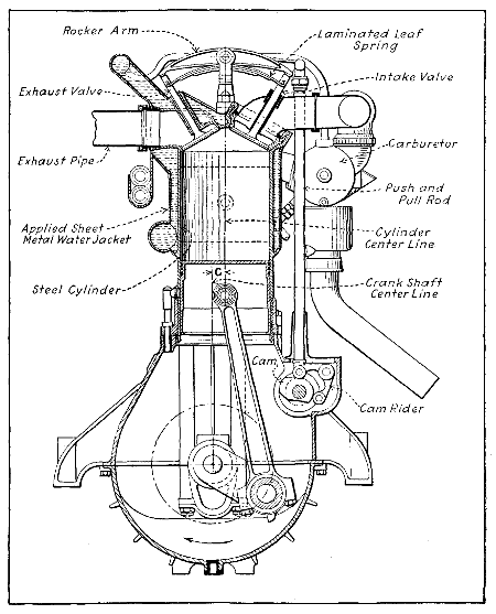
Fig. 90.—Cross Section of Austro-Daimler Engine, Showing Offset Cylinder Construction. Note Applied Water Jacket and Peculiar Valve Action.
Another important advantage is that greater efficiency is obtained from the explosion with an off-set crank-shaft, because the crank is already inclined when the piston is at top center, and all the energy imparted to the piston by the burning mixture can be exerted directly into producing a useful turning effort. When a cylinder is placed directly on a line with the crank-shaft, as shown at A, it will be evident that some of the force produced by the expansion of the gas will be exerted in a direct line and until the crank moves the crank throw and connecting rod are practically a solid member. The pressure which might be employed in obtaining useful turning effort is wasted by causing a direct pressure upon the lower half of the main bearing and the upper half of the crank-pin bushing.
Very good and easily understood illustrations showing advantages of the off-set construction are shown at E and F. This is a bicycle crank-hanger. It is advanced that the effort of the rider is not as well applied when the crank is at position E as when it is at position F. Position E corresponds to the position of the parts when the cylinder is placed directly over the crank-shaft center.[245] Position F may be compared to the condition which is present when the off-set cylinder construction is used.
It has often been said that a chain is no stronger than its weakest link, and this is as true of the explosive motor as it is of any other piece of mechanism. Many motors which appeared to be excellently designed and which were well constructed did not prove satisfactory because some minor detail or part had not been properly considered by the designer. A factor having material bearing upon the efficiency of the internal combustion motor is the location of the valves and the shape of the combustion chamber which is largely influenced by their placing. The fundamental consideration of valve design is that the gases be admitted and discharged from the cylinder as quickly as possible in order that the speed of gas flow will not be impeded and produce back pressure. This is imperative in obtaining satisfactory operation in any form of motor. If the inlet passages are constricted the cylinder will not fill with explosive mixture promptly, whereas if the exhaust gases are not fully expelled the parts of the inert products of combustion retained dilute the fresh charge, making it slow burning and causing lost power and overheating. When an engine employs water as a cooling medium this substance will absorb the surplus heat readily, and the effects of overheating are not noticed as quickly as when air-cooled cylinders are employed. Valve sizes have a decided bearing upon the speed of motors and some valve locations permit the use of larger members than do other positions.
While piston velocity is an important factor in determinations of power output, it must be considered from the aspect of the wear produced upon the various parts of the motor. It is evident that engines which run very fast, especially of high power, must be under a greater strain than those operating at lower speeds. The valve-operating mechanism is especially susceptible to the influence[246] of rapid movement, and the slower the engine the longer the parts will wear and the more reliable the valve action.
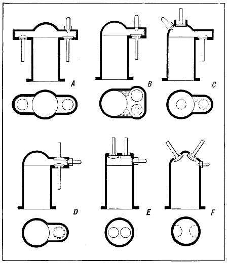
Fig. 92.—Diagram Showing Forms of Cylinder Demanded by Different Valve Placings. A—T Head Type, Valves on Opposite Sides. B—L Head Cylinder, Valves Side by Side. C—L Head Cylinder, One Valve in Head, Other in Pocket. D—Inlet Valve Over Exhaust Member, Both in Side Pocket. E—Valve-in-the-Head Type with Vertical Valves. F—Inclined Valves Placed to Open Directly into Combustion Chamber.
As will be seen by reference to the accompanying illustration, Fig. 92, there are many ways in which valves may be placed in the cylinder. Each method outlined possesses some point of advantage, because all of the types[247] illustrated are used by reputable automobile manufacturers. The method outlined at Fig. 92, A, is widely used, and because of its shape the cylinder is known as the “T” form. It is approved for automobile use for several reasons, the most important being that large valves can be employed and a well-balanced and symmetrical cylinder casting obtained. Two independent cam-shafts are needed, one operating the inlet valves, the other the exhaust members. The valve-operating mechanism can be very simple in form, consisting of a plunger actuated by the cam which transmits the cam motion to the valve-stem, raising the valve as the cam follower rides on the point of the cam. Piping may be placed without crowding, and larger manifolds can be fitted than in some other constructions. This has special value, as it permits the use of an adequate discharge pipe on the exhaust side with its obvious advantages. This method of cylinder construction is never found on airplane engines because it does not permit of maximum power output.
On the other hand, if considered from a viewpoint of actual heat efficiency, it is theoretically the worst form of combustion chamber. This disadvantage is probably compensated for by uniformity of expansion of the cylinder because of balanced design. The ignition spark-plug may be located directly over the inlet valve in the path of the incoming fresh gases, and both valves may be easily removed and inspected by unscrewing the valve caps without taking off the manifolds.
The valve installation shown at C is somewhat unusual, though it provides for the use of valves of large diameter. Easy charging is insured because of the large inlet valve directly in the top of the cylinder. Conditions may be reversed if necessary, and the gases discharged through this large valve. Both methods are used, though it would seem that the free exhaust provided by allowing the gases to escape directly from the combustion chamber through the overhead valve to the exhaust manifold[248] would make for more power. The method outlined at Fig. 92, F and at Fig. 90 is one that has been widely employed on large automobile racing motors where extreme power is required, as well as in engines constructed for aviation service. The inclination of the valves permits the use of large valves, and these open directly into the combustion chamber. There are no pockets to retain heat or dead gas, and free intake and outlet of gas is obtained. This form is quite satisfactory from a theoretical point of view because of the almost ideal combustion chamber form. Some difficulty is experienced, however, in properly water-jacketing the valve chamber which experience has shown to be necessary if the engine is to have high power.
The motor shown at Fig. 92, B and Fig. 88 employs cylinders of the “L” type. Both valves are placed in a common extension from the combustion chamber, and being located side by side both are actuated from a common cam-shaft. The inlet and exhaust pipes may be placed on the same side of the engine and a very compact assemblage is obtained, though this is optional if passages are cored in the cylinder pairs to lead the gases to opposite sides. The valves may be easily removed if desired, and the construction is fairly good from the viewpoint of both foundry man and machinist. The chief disadvantage is the limited area of the valves and the loss of heat efficiency due to the pocket. This form of combustion chamber, however, is more efficient than the “T” head construction, though with the latter the use of larger valves probably compensates for the greater heat loss. It has been stated as an advantage of this construction that both manifolds can be placed at the same side of the engine and a compact assembly secured. On the other hand, the disadvantage may be cited that in order to put both pipes on the same side they must be of smaller size than can be used when the valves are oppositely placed. The “L” form cylinder is sometimes made more efficient if but one valve is placed in the pocket[249] while the other is placed over it. This construction is well shown at Fig. 92, D and is found on Anzani motors.
The method of valve application shown at Fig. 87 is an ingenious method of overcoming some of the disadvantages inherent with valve-in-the-head motors. In the first place it is possible to water-jacket the valves thoroughly, which is difficult to accomplish when they are mounted in cages. The water circulates directly around the walls of the valve chambers, which is superior to a construction where separate cages are used, as there are two thicknesses of metal with the latter, that of the valve-cage proper and the wall of the cylinder. The cooling medium is in contact only with the outer wall, and as there is always a loss of heat conductivity at a joint it[250] is practically impossible to keep the exhaust valves and their seats at a uniform temperature. The valves may be of larger size without the use of pockets when seating directly in the head. In fact, they could be equal in diameter to almost half the bore of the cylinder, which provides an ideal condition of charge placement and exhaust. When valve grinding is necessary the entire head is easily removed by taking off six nuts and loosening inlet manifold connections, which operation would be necessary even if cages were employed, as in the engine shown at Fig. 93.
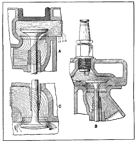
Fig. 94.—Diagrams Showing How Gas Enters Cylinder Through Overhead Valves and Other Types. A—Tee Head Cylinder. B—L Head Cylinder. C—Overhead Valve.
[251]At Fig. 94, A and B, a section through a typical “L”-shaped cylinder is depicted. It will be evident that where a pocket construction is employed, in addition to its faculty for absorbing heat, the passage of gas would be impeded. For example, the inlet gas rushing in through the open valve would impinge sharply upon the valve-cap or combustion head directly over the valve and then must turn at a sharp angle to enter the combustion chamber[252] and then at another sharp angle to fill the cylinders. The same conditions apply to the exhaust gases, though they are reversed. When the valve-in-the-head type of cylinder is employed, as at C, the only resistance offered the gas is in the manifold. As far as the passage of the gases in and out of the cylinder is concerned, ideal conditions obtain. It is claimed that valve-in-the-head motors are more flexible and responsive than other forms, but the construction has the disadvantage in that the valves must be opened through a rather complicated system of push rods and rocker arms instead of the simpler and direct plunger which can be used with either the “T” or “L” head cylinders. This is clearly outlined in the illustrations at Fig. 95, where A shows the valve in the head-operating mechanism necessary if the cam-shaft is carried at the cylinder base, while B shows the most direct push-rod action obtained with “T” or “L” head cylinder placing.
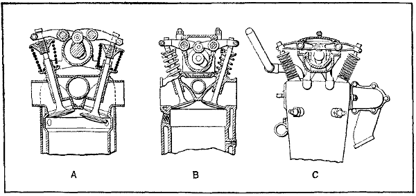
Fig. 96.—Examples of Direct Valve Actuation by Overhead Cam-Shaft. A—Mercedes. B—Hall-Scott. C—Wisconsin.
[253] Fig. 97.
CENSORED
CENSORED
The objection can be easily met by carrying the cam-shaft above the cylinders and driving it by means of gearing. The types of engine cylinders using this construction are shown at Fig. 96, and it will be evident that a positive and direct valve action is possible by following the construction originated by the Mercedes (German)[254] aviation engine designers and outlined at A. The other forms at B and C are very clearly adaptations of this design. The Hall-Scott engine at Fig. 97 is depicted in part section and no trouble will be experienced in understanding the bevel pinion and gear drive from the crank-shaft[255] to the overhead cam-shaft through a vertical counter-shaft. A very direct valve action is used in the Duesenberg engines, one of which is shown in part section at Fig. 98. The valves are parallel with the piston top and are actuated by rocker arms, one end of which bears against the valve stem, and the other rides the cam-shaft.
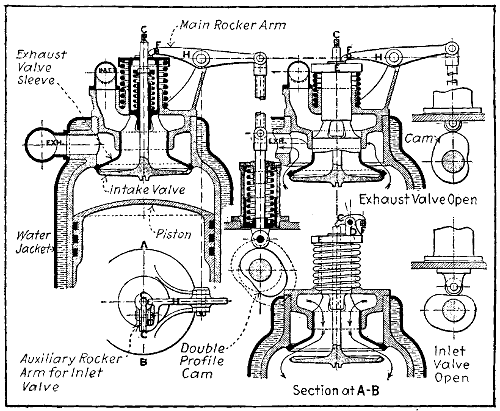
Fig. 99.—Sectional Views Showing Arrangement of Novel Concentric Valve Arrangement Devised by Panhard for Aerial Engines.
The form shown at Fig. 99 shows an ingenious application of the valve-in-the-head idea which permits one to obtain large valves. It has been used on some of the Panhard aviation engines and on the American Aeromarine power plants. The inlet passage is controlled by the sliding sleeve which is hollow and slotted so as to permit the inlet gases to enter the cylinder through the regular type poppet valve which seats in the exhaust sleeve. When the exhaust valve is operated by the tappet rod and rocker arm the intake valve is also carried[256] down with it. The intake gas passage is closed, however, and the burned gases are discharged through the large annular passage surrounding the sleeve. When the inlet valve leaves its seat in the sleeve the passage of cool gas around the sleeve keeps the temperature of both valves to a low point and the danger of warping is minimized. A dome-shaped combustion chamber may be used, which is an ideal form in conserving heat efficiency, and as large valves may be installed the flow of both fresh and exhaust gases may be obtained with minimum resistance. The intake valve is opened by a small auxiliary rocker arm which is lifted when the cam follower rides into the depression in the cam by the action of the strong spring around the push rod. When the cam follower rides on the high point the exhaust sleeve is depressed from its seat against the cylinder. By using a cam having both positive and negative profiles, a single rod suffices for both valves because of its push and pull action.
Valve dimensions are an important detail to be considered and can be determined by several conditions, among which may be cited method of installation, operating mechanism, material employed, engine speed desired, manner of cylinder cooling and degree of lift desired. A review of various methods of valve location has shown that when the valves are placed directly in the head we can obtain the ideal cylinder form, though larger valves may be used if housed in a separate pocket, as afforded by the “T” head construction. The method of operation has much to do with the size of the valves. For example, if an automatic inlet valve is employed it is good practice to limit the lift and obtain the required area of port opening by augmenting the diameter. Because of this a valve of the automatic type is usually made twenty per cent. larger than one mechanically operated. When both are actuated by cam mechanism, as is now common practice, they are usually made the same[257] size and are interchangeable, which greatly simplifies manufacture. The relation of valve diameter to cylinder bore is one that has been discussed for some time by engineers. The writer’s experience would indicate that they should be at least half the bore, if possible. While the mushroom type or poppet valve has become standard and is the most widely used form at the present time, there is some difference of opinion among designers as to the materials employed and the angle of the seat. Most valves have a bevel seat, though some have a flat seating. The flat seat valve has the distinctive advantage of providing a clear opening with lesser lift, this conducing to free gas flow. It also has value because it is silent in operation, but the disadvantage is present that best material and workmanship must be used in their construction to obtain satisfactory results. As it can be made very light it is particularly well adapted for use as an automatic inlet valve. Among other disadvantages cited is the claim that it is more susceptible to derangement, owing to the particles of foreign matter getting under the seat. With a bevel seat it is argued that the foreign matter would be more easily dislodged by the gas flow, and that the valve would close tighter because it is drawn positively against the bevel seat.
Several methods of valve construction are the vogue, the most popular form being the one-piece type; those which are composed of a head of one material and stem of another are seldom used in airplane engines because they are not reliable. In the built-up construction the head is usually of high nickel steel or cast iron, which metals possess good heat-resisting qualities. Heads made of these materials are not likely to warp, scale, or pit, as is sometimes the case when ordinary grades of machinery steel are used. The cast-iron head construction is not popular because it is often difficult to keep the head tight on the stem. There is a slight difference in expansion ratio between the head and the stem, and as the stem is either screwed or riveted to the cast-iron head[258] the constant hammering of the valve against its seat may loosen the joint. As soon as the head is loose on the stem the action of the valve becomes erratic. The best practice is to machine the valves from tungsten steel forgings. This material has splendid heat-resisting qualities and will not pit or become scored easily. Even the electrically welded head to stem types which are used in automobile engines are not looked upon with favor in the aviation engine. Valve stem guides and valve stems must be machined very accurately to insure correct action. The usual practice in automobile engines is shown at Fig. 100.
The methods of valve operation commonly used vary according to the type of cylinder construction employed. In all cases the valves are lifted from their seats by cam-actuated mechanism. Various forms of valve-lifting cams are shown at Fig. 101. As will be seen, a cam consists[259] of a circle to which a raised, approximately triangular member has been added at one point. When the cam follower rides on the circle, as shown at Fig. 102, there is no difference in height between the cam center and its periphery and there is no movement of the plunger. As soon as the raised portion of the cam strikes the plunger it will lift it, and this reciprocating movement is transmitted to the valve stem by suitable mechanical connections.
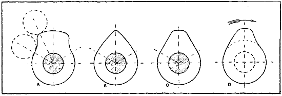
Fig. 101.—Forms of Valve-Lifting Cams Generally Employed. A—Cam Profile for Long Dwell and Quick Lift. B—Typical Inlet Cam Used with Mushroom Type Follower. C—Average Form of Cam. D—Designed to Give Quick Lift and Gradual Closing.
The cam forms outlined at Fig. 101 are those commonly used. That at A is used on engines where it is desired to obtain a quick lift and to keep the valve fully opened as long as possible. It is a noisy form, however, and is not very widely employed. That at B is utilized more often as an inlet cam while the profile shown at C is generally depended on to operate exhaust valves. The cam shown at D is a composite form which has some of the features of the other three types. It will give the quick opening of form A, the gradual closing of form B, and the time of maximum valve opening provided by cam profile C.
The various types of valve plungers used are shown at Fig. 102. That shown at A is the simplest form, consisting of a simple cylindrical member having a rounded end which follows the cam profile. These are sometimes[260] made of square stock or kept from rotating by means of a key or pin. A line contact is possible when the plunger is kept from turning, whereas but a single point bearing is obtained when the plunger is cylindrical and free to revolve. The plunger shown at A will follow only cam profiles which have gradual lifts. The plunger shown at B is left free to revolve in the guide bushing and is provided with a flat mushroom head which serves as a cam follower. The type shown at C carries a roller at its lower end and may follow very irregular cam profiles if abrupt lifts are desired. While forms A and B are the simplest, that outlined at C in its various forms is more widely used. Compound plungers are used on the Curtiss OX-2 motors, one inside the other. The small or inner one works on a cam of conventional design, the outer plunger follows a profile having a flat spot to permit of a pull rod action instead of a push rod action. All the methods in which levers are used to operate valves are more or less noisy because clearance must be left between the valve stem and the stop of the plunger. The space must be taken up before the valve will leave its seat, and when[261] the engine is operated at high speeds the forcible contact between the plunger and valve stem produces a rattling sound until the valves become heated and expand and the stems lengthen out. Clearance must be left between the valve stems and actuating means. This clearance is clearly shown in Fig. 103 and should be .020′′ (twenty thousandths) when engine is cold. The amount of clearance allowed depends entirely upon the design of the engine and length of valve stem. On the Curtiss OX-2 engines the clearance is but .010′′ (ten thousandths) because the valve stems are shorter. Too little clearance will result in loss of power or misfiring when engine is hot. Too much clearance will not allow the valve to open its full amount and will disturb the timing.
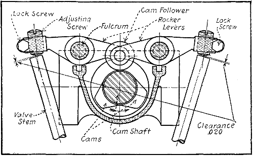
Fig. 103.—Diagram Showing Proper Clearance to Allow Between Adjusting Screw and Valve Stems in Hall-Scott Aviation Engines.
Two systems of cam-shaft operation are used. The most common of these is by means of gearing of some form. If the cam-shaft is at right angles to the crank-shaft it may be driven by worm, spiral, or bevel gearing.[262] If the cam-shaft is parallel to the crank-shaft, simple spur gear or chain connection may be used to turn it. A typical cam-shaft for an eight-cylinder V engine is shown at Fig. 104. It will be seen that the sixteen cams are forged integrally with the shaft and that it is spur-gear driven. The cam-shaft drive of the Hall-Scott motor is shown at Fig. 97.
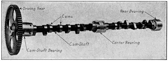
Fig. 104.—Cam-Shaft of Thomas Airplane Motor Has Cams Forged Integral. Note Split Cam-Shaft Bearings and Method of Gear Retention.
While gearing is more commonly used, considerable attention has been directed of late to silent chains for cam-shaft operation. The ordinary forms of block or roller chain have not proven successful in this application, but the silent chain, which is in reality a link belt operating over toothed pulleys, has demonstrated its worth. The tendency to its use is more noted on foreign motors than those of American design. It first came to public notice when employed on the Daimler-Knight engine for driving the small auxiliary crank-shafts which reciprocated the sleeve valves. The advantages cited for the application of chains are, first, silent operation, which obtains even after the chains have worn considerably; second, in designing it is not necessary to figure on maintaining certain absolute center distances between the crank-shaft and cam-shaft sprockets, as would be the case if conventional forms of gearing were used. On some forms of motor employing gears, three and even four[263] members are needed to turn the cam-shaft. With a chain drive but two sprockets are necessary, the chain forming a flexible connection which permits the driving and driven members to be placed at any distance apart that the exigencies of the design demand. When chains are used it is advised that some means for compensating chain slack be provided, or the valve timing will lag when chains are worn. Many combination drives may be worked out with chains that would not be possible with other forms of gearing. Direct gear drive is favored at the present time by airplane engine designers because they are the most certain and positive means, even when a number of gears must be used as intermediate drive members. With overhead cam-shafts, bevel gears work out very well in practice, as in the Hall-Scott motors and others of that type.
Another consideration of importance is the use of proper valve-springs, and particular care should be taken with those, of automatic valves. The spring must be weak enough to allow the valve to open when the suction is light, and must be of sufficient strength to close it in time at high speeds. It should be made as large as possible in diameter and with a large number of convolutions, in order that fatigue of the metal be obviated, and it is imperative that all springs be of the same strength when used on a multiple-cylinder engine. Practically all valves used to control the gas flow in airplane engines are mechanically operated. On the exhaust valve the spring must be strong enough so that the valve will not be sucked in on the inlet stroke. It should be borne in mind that if the spring is too strong a strain will be imposed on the valve-operating mechanism, and a hammering action produced which may cause deformation of the valve-seat. Only pressure enough to insure that the operating mechanism will follow the cam is required. It is common practice to make the inlet and exhaust valve springs of[264] the same tension when the valves are of the same size and both mechanically operated. This is done merely to simplify manufacture and not because it is necessary for the inlet valve-spring to be as strong as the other. Valve springs of the helical coil type are generally used, though torsion or “scissors” springs and laminated or single-leaf springs are also utilized in special applications. Two[265] springs are used on each valve in some valve-in-the-head types; a spring of small pitch diameter inside the regular valve-spring and concentric with it. Its function is to keep the valve from falling into the cylinder in event of breakage of the main spring in some cases, and to provide a stronger return action in others.
The sectional view through the cylinder at Fig. 105 shows the Knight sliding sleeves and their actuating means very clearly. The diagrams at Fig. 106 show graphically the sleeve movements and their relation to the crank-shaft and piston travel. The action may be summed up as follows: The inlet port begins to open when the lower edge of the opening of the outside sleeve which is moving down passes the top of the slot in the inner member also moving downwardly. The inlet port is closed when the lower edge of the slot in the inner sleeve which is moving up passes the top edge of the port in the outer sleeve which is also moving toward the top of the cylinder. The inlet opening extends over two hundred degrees of crank motion. The exhaust port is uncovered slightly when the lower edge of the port in the inner sleeve which is moving down passes the lower edge of the portion of the cylinder head which protrudes in the cylinder. When the top of the port in the outer sleeve traveling toward the bottom of the cylinder passes the lower edge of the slot in the cylinder wall the exhaust passage is closed. The exhaust opening extends over a period corresponding to about two hundred and forty degrees of crank motion. The Knight motor has not been applied to aircraft to the writer’s knowledge, but an eight-cylinder Vee design that might be useful in that connection if lightened is shown at Fig. 107. The main object is to show that the Knight valve action is the only other besides the mushroom or poppet valve that has been applied successfully to high speed gasoline engines.
It is in valve timing that the greatest difference of opinion prevails among engineers, and it is rare that one will see the same formula in different motors. It is true that the same timing could not be used with motors of[267] different construction, as there are many factors which determine the amount of lead to be given to the valves. The most important of these is the relative size of the valve to the cylinder bore, the speed of rotation it is desired to obtain, the fuel efficiency, the location of the valves, and other factors too numerous to mention.
Most of the readers should be familiar with the cycle of operation of the internal combustion motor of the four-stroke type, and it seems unnecessary to go into detail except to present a review. The first stroke of the piston is one in which a charge of gas is taken into the[268] motor; the second stroke, which is in reverse direction to the first, is a compression stroke, at the end of which the spark takes place, exploding the charge and driving the piston down on the third or expansion stroke, which is in the same direction as the intake stroke, and finally, after the piston has nearly reached the end of this stroke, another valve opens to allow the burned gases to escape, and remains open until the piston has reached the end of the fourth stroke and is in a position to begin the series over again. The ends of the strokes are reached when the piston comes to a stop at either top or bottom of the cylinder and reverses its motion. That point is known as a center, and there are two for each cylinder, top and bottom centers, respectively.
All circles may be divided into 360 parts, each of which is known as a degree, and, in turn, each of these degrees may be again divided into minutes and seconds, though we need not concern ourselves with anything less than the degree. Each stroke of the piston represents 180 degrees travel of the crank, because two strokes represent one complete revolution of three hundred and sixty degrees. The top and bottom centers are therefore separated by 180 degrees. Theoretically each phase of a four-cycle engine begins and ends at a center, though in actual practice the inertia or movement of the gases makes it necessary to allow a lead or lag to the valve, as the case may be. If a valve opens before a center, the distance is called “lead”; if it closes after a center, this distance is known as “lag.” The profile of the cams ordinarily used to open or close the valves represents a considerable time in relation to the 180 degrees of the crank-shaft travel, and the area of the passages through which the gases are admitted or exhausted is quite small owing to the necessity of having to open or close the valves at stated times; therefore, to open an adequately large passage for the gases it is necessary to open the valves earlier and close them later than at centers.
That advancing the opening of the exhaust valve was[269] of value was discovered on the early motors and is explained by the necessity of releasing a large amount of gas, the volume of which has been greatly raised by the heat of combustion. When the inlet valves were mechanically operated it was found that allowing them to lag at closing enabled the inspiration of a greater volume of gas. Disregarding the inertia or flow of the gases, opening the exhaust at center would enable one to obtain full value of the expanding gases the entire length of the piston stroke, and it would not be necessary to keep the valve open after the top center, as the reverse stroke would produce a suction effect which might draw some of the inert charge back into the cylinder. On the other hand, giving full consideration to the inertia of the gas, opening the valve before center is reached will provide for quick expulsion of the gases, which have sufficient velocity at the end of the stroke, so that if the valve is allowed to remain open a little longer, the amount of lag varying with the opinions of the designer, the cylinder is cleared in a more thorough manner.
When the factor of retarded opening is considered without reckoning the inertia of the gases, it would appear that if the valve were allowed to remain open after center had passed, say, on the closing of the inlet, the piston, having reversed its motion, would have the effect of expelling part of the fresh charge through the still open valve as it passed inward at its compression stroke. This effect is called blowing back, and is often noted with motors where the valve settings are not absolutely correct, or where the valve-springs or seats are defective and prevent proper closing.
This factor is not of as much import as might appear, as on closer consideration it will be seen that the movement of the piston as the crank reaches either end of the stroke is less per degree of angular movement than it is when the angle of the connecting rod is greater. Then,[270] again, a certain length of time is required for the reversal of motion of the piston, during which time the crank is in motion but the piston practically at a standstill. If the valves are allowed to remain open during this period, the passage of the gas in or out of the cylinder will be by its own momentum.
The faster a motor turns, all other things being equal, the greater the amount of lead or advance it is necessary to give the opening of the exhaust valve. It is self-evident truth that if the speed of a motor is doubled it travels twice as many degrees in the time necessary to lower the pressure. As most designers are cognizant of this fact, the valves are proportioned accordingly. It is well to consider in this respect that the cam profile has much to do with the manner in which the valve is opened; that is, the lift may be abrupt and the gas allowed to escape in a body, or the opening may be gradual, the gas issuing from the cylinder in thin streams. An analogy may be made with the opening of any bottle which contains liquid highly carbonated. If the cork is removed suddenly the gas escapes with a loud pop, but, on the other hand, if the bottle is uncorked gradually, the gas escapes from the receptacle in thin streams around the cork, and passage of the gases to the air is accomplished without noise. While the second plan is not harsh, it is slower than the former, as must be evident.
A point which has been much discussed by engineers is the proper relation of the closing of the exhaust valve and the opening of the inlet. Theoretically they should succeed each other, the exhaust closing at upper dead center and the inlet opening immediately afterward. The reason why a certain amount of lag is given the exhaust closing in practice is that the piston cannot drive the[271] gases out of the cylinder unless they are compressed to a degree in excess of that existing in the manifold or passages, and while toward the end of the stroke this pressure may be feeble, it is nevertheless indispensable. At the end of the piston’s stroke, as marked by the upper dead center, this compression still exists, no matter how little it may be, so that if the exhaust valve is closed and the inlet opened immediately afterward, the pressure which exists in the cylinder may retard the entrance of the fresh gas and a certain portion of the inert gas may penetrate into the manifold. As the piston immediately begins to aspirate, this may not be serious, but as these gases are drawn back into the cylinder the fresh charge will be diluted and weakened in value. If the spark-plug is in a pocket, the points may be surrounded by this weak gas, and the explosion will not be nearly as energetic as when the ignition spark takes place in pure mixture.
It is a well-known fact that the exhaust valve should close after dead center and that a certain amount of lag should be given to opening of the inlet. The lag given the closing of the exhaust valve should not be as great as that given the closing of the inlet valve. Assuming that the excess pressure of the exhaust will equal the depression during aspiration, the time necessary to complete the emptying of the cylinder will be proportional to the volume of the gas within it. At the end of the suction stroke the volume of gas contained in the cylinder is equal to the cylindrical volume plus the space of the combustion chamber. At the end of the exhaust stroke the volume is but that of the dead space, and from one-third to one-fifth its volume before compression. While it is natural to assume that this excess of burned gas will escape faster than the fresh gas will enter the cylinder, it will be seen that if the inlet valve were allowed to lag twenty degrees, the exhaust valve lag need not be more than five degrees, providing that the capacity of the combustion chamber was such that the gases occupied one-quarter of their former volume.
[272]It is evident that no absolute rule can be given, as back pressure will vary with the design of the valve passages, the manifolds, and the construction of the muffler. The more direct the opening, the sooner the valve can be closed and the better the cylinder cleared. Ten degrees represent an appreciable angle of the crank, and the time required for the crank to cover this angular motion is not inconsiderable and an important quantity of the exhaust may escape, but the piston is very close to the dead center after the distance has been covered.
Before the inlet valve opens there should be a certain depression in the cylinder, and considerable lag may be allowed before the depression is appreciable. So far as the volume of fresh gas introduced during the admission stroke is concerned, this is determined by the displacement of the piston between the point where the inlet valve opens and the point of closing, assuming that sufficient gas has been inspired so that an equilibrium of pressure has been established between the interior of the cylinder and the outer air. The point of inlet opening varies with different motors. It would appear that a fair amount of lag would be fifteen degrees past top center for the inlet opening, as a certain depression will exist in the cylinder, assuming that the exhaust valve has closed five or ten degrees after center, and at the same time the piston has not gone down far enough on its stroke to materially decrease the amount of gas which will be taken into the cylinder.
As in the case with the other points of opening and closing, there is a wide diversity of practice as relates to closing the inlet valve. Some of the designers close this exactly at bottom center, but this practice cannot be commended, as there is a considerable portion of time, at least ten or fifteen degrees angular motion of the crank, before the piston will commence to travel to any extent on its compression stroke. The gases rushing into the[273] cylinder have considerable velocity, and unless an equilibrium is obtained between the pressure inside and that of the atmosphere outside, they will continue to rush into the cylinder even after the piston ceases to exert any suction effect.
For this reason, if the valve is closed exactly on center, a full charge may not be inspired into the cylinder, though if the time of closing is delayed, this momentum or inertia of the gas will be enough to insure that a maximum charge is taken into the cylinder. The writer considers that nothing will be gained if the valve is allowed to remain open longer than twenty degrees, and an analysis of practice in this respect would seem to confirm this opinion. From that point in the crank movement the piston travel increases and the compressive effect is appreciable, and it would appear that a considerable proportion of the charge might be exhausted into the manifold and carburetor if the valve were allowed to remain open beyond a point corresponding to twenty degrees angular movement of the crank.
In this country engineers unite in providing a variable time of ignition, though abroad some difference of opinion is noted on this point. The practice of advancing the time of ignition, when affected electrically, was severely condemned by early makers, these maintaining that it was necessary because of insufficient heat and volume of the spark, and it was thought that advancing ignition was injurious. The engineers of to-day appreciate the fact that the heat of the electric spark, especially when from a mechanical generator of electrical energy, is the only means by which we can obtain practically instantaneous explosion, as required by the operation of motors at high speeds, and for the combustion of large volumes of gas.
It is apparent that a motor with a fixed point of[274] ignition is not as desirable, in every way, as one in which the ignition can be advanced to best meet different requirements, and the writer does not readily perceive any advantage outside of simplicity of control in establishing a fixed point of ignition. In fact, there seems to be some difference of opinion among those designers who favor[275] fixed ignition, and in one case this is located forty-three degrees ahead of center, and in another motor the point is fixed at twenty degrees, so that it may be said that this will vary as much as one hundred per cent. in various forms. This point will vary with different methods of ignition, as well as the location of the spark-plug or igniter. For the sake of simplicity, most airplane engines use set spark; if an advancing and retarding mechanism is fitted, it is only to facilitate starting, as the spark is kept advanced while in flight, and control is by throttle alone.
It is obvious by consideration of the foregoing that there can be no arbitrary rules established for timing,[276] because of the many conditions which determine the best times for opening and closing the valves. It is customary to try various settings when a new motor is designed until the most satisfactory points are determined, and the setting which will be very suitable for one motor is not always right for one of different design. The timing diagram shown at Fig. 108 applies to the Hall-Scott engine, and may be considered typical. It should be easily followed in view of the very complete explanation given in preceding pages. Another six-cylinder engine diagram is shown at Fig. 109, and an eight-cylinder timing diagram is shown at Fig. 110. In timing automobile engines no trouble is experienced, because timing marks[277] are always indicated on the engine fly-wheel register with an indicating trammel on the crank-case. To time an airplane engine accurately, as is necessary to test for a suspected cam-shaft defect, a timing disc of aluminum is attached to the crank-shaft which has the timing marks indicated thereon. If the disc is made 10 or 12 inches in diameter, it may be divided into degrees without difficulty.
In timing a motor from the marks on the timing disc rim it is necessary to regulate the valves of but one cylinder at a time. Assuming that the disc is revolving in the direction of engine rotation, and that the firing order of the cylinders is 1-3-4-2, the operation of timing would be carried on as follows: The crank-shaft would be revolved until the line marked “Exhaust opens 1 and 4” registered with the trammel on the motor bed. At this point the exhaust-valve of either cylinder No. 1 or No. 4 should begin to open. This can be easily determined by noting which of these cylinders holds the compressed charge ready for ignition. Assuming that the spark has occurred in cylinder No. 1, then when the fly-wheel is turned from the position to that in which the line marked “Exhaust opens 1 and 4” coincides with the trammel point, the valve-plunger under the exhaust-valve of cylinder No. 1 should be adjusted in such a way that there is no clearance between it and the valve stem. Further movement of the wheel in the same direction should produce a lift of the exhaust valve. The disc is turned about two hundred and twenty-five degrees, or a little less than three-quarters of a revolution; then the line marked “Exhaust closes 1 and 4” will register with the trammel point. At this period the valve-plunger and the valve-stem should separate and a certain amount of clearance obtain between them. The next cylinder to time would be No. 3. The crank-shaft is rotated until mark “Exhaust opens 2 and 3” comes in line with the trammel. At this[278] point the exhaust valve of cylinder No. 3 should be just about opening. The closing is determined by rotating the shaft until the line “Exhaust closes 2 and 3” comes under the trammel.
This operation is carried on with all the cylinders, it being well to remember that but one cylinder is working at a time and that a half-revolution of the fly-wheel corresponds to a full working stroke of all the cylinders, and that while one is exhausting the others are respectively taking in a new charge, compressing and exploding. For instance, if cylinder No. 1 has just completed its power-stroke, the piston in cylinder No. 3 has reached the point where the gas may be ignited to advantage. The piston of cylinder No. 4, which is next to fire, is at the bottom of its stroke and will have inspired a charge, while cylinder No. 2, which is the last to fire, will have just finished expelling a charge of burned gas, and will be starting the intake stroke. This timing relates to a four-cylinder engine in order to simplify the explanation. The timing instructions given apply only to the conventional motor types. Rotary cylinder engines, especially the Gnome “monosoupape,” have a distinctive valve timing on account of the peculiarities of design.
In the present design of the Gnome motor, a cycle of operations somewhat different from that employed in the ordinary four-cycle engine is made use of, says a writer in “The Automobile,” in describing the action of this power-plant. This cycle does away with the need for the usual inlet valve and makes the engine operable with only a single valve, hence the name monosoupape, or “single-valve.” The cycle is as follows: A charge being compressed in the outer end of the cylinder or combustion chamber, it is ignited by a spark produced by the spark-plug located in the side of this chamber, and the burning charge expands as the piston moves down in the cylinder while the latter revolves around the crank-shaft. When[279] the piston is about half-way down on the power stroke, the exhaust valve, which is located in the center of the cylinder-head, is mechanically opened, and during the following upstroke of the piston the burnt gases are expelled from the cylinder through the exhaust valve directly into the atmosphere.
Instead of closing at the end of the exhaust stroke, or a few degrees thereafter, the exhaust valve is held open for about two-thirds of the following inlet stroke of the piston, with the result that fresh air is drawn through the exhaust valve into the cylinder. When the cylinder is still 65 degrees from the end of the inlet half-revolution, the exhaust valve closes. As no more air can get into the cylinder, and as the piston continues to move inwardly, it is obvious that a partial vacuum is formed.
When the cylinder approaches within 20 degrees of the end of the inlet half-revolution a series of small inlet ports all around the circumference of the cylinder wall is uncovered by the top edge of the piston, whereby the combustion chamber is placed in communication with the crank chamber. As the pressure in the crank chamber is substantially atmospheric and that in the combustion chamber is below atmospheric, there results a suction effect which causes the air from the crank chamber to flow into the combustion chamber. The air in the crank chamber is heavily charged with gasoline vapor, which is due to the fact that a spray nozzle connected with the gasoline supply tank is located inside the chamber. The proportion of gasoline vapor in the air in the crank chamber is several times as great as in the ordinary combustible mixture drawn from a carburetor into the cylinder. This extra-rich mixture is diluted in the combustion chamber with the air which entered it through the exhaust valve during the first part of the inlet stroke, thus forming a mixture of the proper proportion for complete combustion.
The inlet ports in the cylinder wall remain open until[280] 20 degrees of the compression half-revolution has been completed, and from that moment to near the end of the compression stroke the gases are compressed in the cylinder. Near the end of the stroke ignition takes place and this completes the cycle.
The exact timing of the different phases of the cycle is shown in the diagram at Fig. 111. It will be seen that ignition occurs substantially 20 degrees ahead of the outer dead center, and expansion of the burning gases continues until 85 degrees past the outer dead center, when the piston is a little past half-stroke. Then the exhaust-valve opens and remains open for somewhat more than a complete revolution of the cylinders, or, to be exact, for 390 degrees of cylinder travel, until 115 degrees past the top dead center on the second revolution. Then for 45 degrees of travel the charge within the cylinder is expanded, whereupon the inlet ports are uncovered and remain open for 40 degrees of cylinder travel, 20 degrees on each side of the inward dead center position.
Springless valves are the latest development on French racing car engines, and it is possible that the positively-operated types will be introduced on aviation engines also. Two makes of positively-actuated valves are shown at Fig. 112. The positive-valve motor differs from the conventional form by having no necessity for valve-springs, as a cam not only assures the opening of the valve, but also causes it to return to the valve-seat. In this respect it is much like the sleeve-valve motor, where the uncovering of the ports is absolutely positive. The cars equipped with these valves were a success in long-distance auto races. Claims made for this type of valve mechanism include the possibility of a higher number of revolutions and consequently greater engine power. With the spring-controlled, single-cam operated valve a point is reached where the spring is not capable of returning the valve[281] to its seat before the cam has again begun its opening movement. It is possible to extend the limits considerably by using a light valve on a strong spring, but the valve still remains a limiting factor in the speed of the motor.
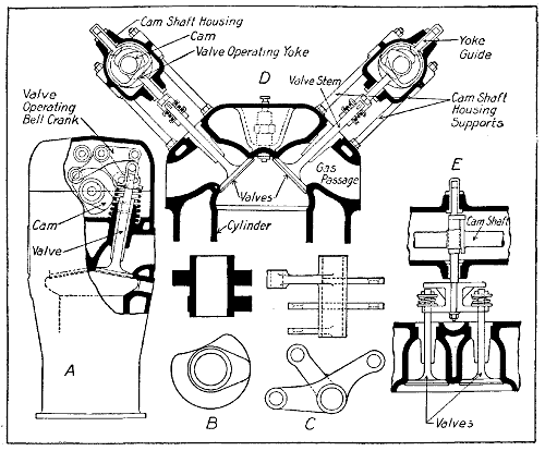
Fig. 112.—Two Methods of Operating Valves by Positive Cam Mechanism Which Closes as Well as Opens Them.
A part sectional view through a cylinder of an engine designed by G. Michaux is shown at Fig. 112, A. There are two valves per cylinder, inclined at about ten degrees from the vertical. The valve-stems are of large diameter, as owing to positive control, there is no necessity of lightening this part in an unusual degree. A single overhead[282] cam-shaft has eight pairs of cams, which are shown in detail at B. For each valve there is a three-armed rocker, one arm of which is connected to the stem of the valve and the two others are in contact respectively with the opening and closing cams. The connection to the end of the valve-stem is made by a short connecting link, which is screwed on to the end of the valve-stem and locked in position. This allows some adjustment to be made between the valves and the actuating rocker. It will be evident that one cam and one rocker arm produce the opening of the valve and that the corresponding rocker arm and cam result in the closing of the valve. If the opening cam has the usual convex profile, the closing cam has a correspondingly concave profile. It will be noticed that a light valve-spring is shown in drawing. This is provided to give a final seating to its valve after[283] it has been closed by the cam. This is not absolutely necessary, as an engine has been run successfully without these springs. The whole mechanism is contained within an overhead aluminum cover.
The positive-valve system used on the De Lage motor is shown at D. In this the valves are actuated as shown in sectional views D and E. The valve system is unique in that four valves are provided per cylinder, two for exhaust and two for intake. The valves are mounted side by side, as shown at E, so the double actuator member may be operated by a single set of cams. The valve-operating member consists of a yoke having guide bars at the top and bottom. The actuating cam works inside of this yoke. The usual form of cam acts on the lower portion of the yoke to open the valve, while the concave cam acts on the upper part to close the valves. In this design provision is made for expansion of the valve-stems due to heat, and these are not positively connected to the actuating member. As shown at E, the valves are held against the seat by short coil springs at the upper end of the stem. These are very stiff and are only intended to provide for expansion. A slight space is left between the top of the valve-stem and the portion of the operating member that bears against them when the regular profile cam exerts its pressure on the bottom of the valve-operating mechanism. Another novelty in this motor design is that the cam-shafts and the valve-operating members are carried in casing attached above the motor by housing supports in the form of small steel pillars. The overhead cam-shafts are operated by means of bevel gearing.
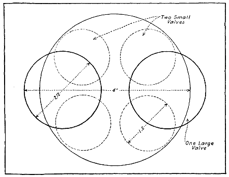
Fig. 113.—Diagram Comparing Two Large Valves and Four Small Ones of Practically the Same Area. Note How Easily Small Valves are Installed to Open Directly Into the Cylinder.
Mention has been previously made of the sixteen-valve four-cylinder Duesenberg motor and its great power output for the piston displacement. This is made possible by the superior volumetric efficiency of a motor provided with four valves in each cylinder instead of[284] but two. This principle was thoroughly tried out in racing automobile motors, and is especially valuable in permitting of greater speed and power output from simple four- and six-cylinder engines. On eight- and twelve-cylinder types, it is doubtful if the resulting complication due to using a very large number of valves would be worth while. When extremely large valves are used, as shown in diagram at Fig. 113, it is difficult to have them open directly into the cylinder, and pockets are sometimes necessary. A large valve would weigh more than two smaller valves having an area slightly larger in the aggregate; it would require a stiffer valve spring on account of its greater weight. A certain amount of metal in the valve-head is necessary to prevent warping; therefore, the inertia forces will be greater in the large valve than in the two smaller valves. As a greater port[286] area is obtained by the use of two valves, the gases will be drawn into the cylinder or expelled faster than with a lesser area. Even if the areas are practically the same as in the diagram at Fig. 113, the smaller valves may have a greater lift without imposing greater stresses on the valve-operating mechanism and quicker gas intake and exhaust obtained. The smaller valves are not affected by heat as much as larger ones are. The quicker gas movements made possible, as well as reduction of[287] inertia forces, permits of higher rotative speed, and, consequently, greater power output for a given piston displacement. The drawings at Fig. 114 show a sixteen-valve motor of the four-cylinder type that has been designed for automobile racing purposes, and it is apparent that very slight modifications would make it suitable for aviation purposes. Part of the efficiency is due to the reduction of bearing friction by the use of ball bearings, but the multiple-valve feature is primarily responsible for the excellent performance.
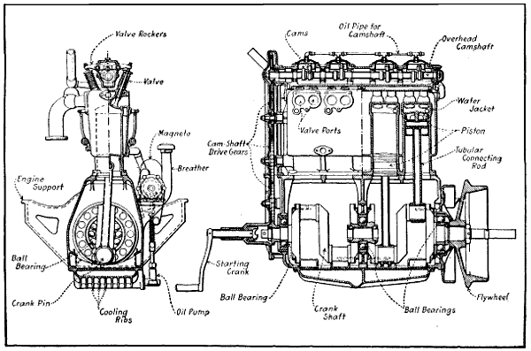
Fig. 114.—Sectional Views of Sixteen-Valve Four-Cylinder Automobile Racing Engine That May Have Possibilities for Aviation Service.
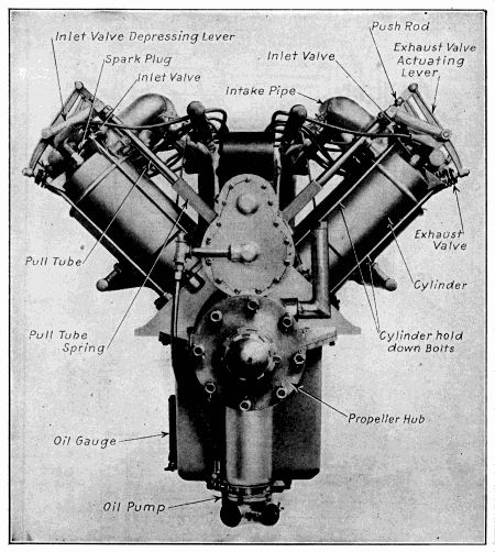
Fig. 115.—Front View of Curtiss OX-3 Aviation Motor, Showing Unconventional Valve Action by Concentric Push Rod and Pull Tube.
Constructional Details of Pistons—Aluminum Cylinders and Pistons—Piston Ring Construction—Leak Proof Piston Rings—Keeping Oil Out of Combustion Chamber—Connecting Rod Forms—Connecting Rods for Vee Engines—Cam-Shaft and Crank-Shaft Designs—Ball Bearing Crank-Shafts—Engine Base Construction.
The piston is one of the most important parts of the gasoline motor inasmuch as it is the reciprocating member that receives the impact of the explosion and which transforms the power obtained by the combustion of gas to mechanical motion by means of the connecting rod to which it is attached. The piston is one of the simplest elements of the motor, and it is one component which does not vary much in form in different types of motors. The piston is a cylindrical member provided with a series of grooves in which packing rings are placed on the outside and two bosses which serve to hold the wrist pin in its interior. It is usually made of cast iron or aluminum, though in some motors where extreme lightness is desired, such as those used for aëronautic work, it may be made of steel. The use of the more resisting material enables the engineer to use lighter sections where it is important that the weight of this member be kept as low as possible consistent with strength.
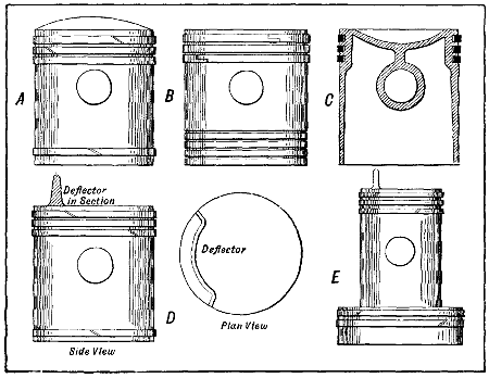
Fig. 116.—Forms of Pistons Commonly Employed in Gasoline Engines. A—Dome Head Piston and Three Packing Rings. B—Flat Top Form Almost Universally Used. C—Concave Piston Utilized in Knight Motors and Some Having Overhead Valves. D—Two-Cycle Engine Member with Deflector Plate Cast Integrally. E—Differential of Two-Diameter Piston Used in Some Engines Operating on Two-Cycle Principle.
A number of piston types are shown at Fig. 116. That at A has a round top and is provided with four split packing rings and two oil grooves. A piston of this type is generally employed in motors where the combustion chamber is large and where it is desired to obtain a higher degree of compression than would be possible with a flat top piston. This construction is also stronger because of the arched piston top. The most common form[289] of piston is that shown at B, and it differs from that previously described only in that it has a flat top. The piston outlined in section at C is a type used on some of the sleeve-valve motors of the Knight pattern, and has a concave head instead of the convex form shown at A. The design shown at D in side and plan views is the conventional form employed in two-cycle engines. The deflector plate on the top of the cylinder is cast integral and is utilized to prevent the incoming fresh gases from flowing directly over the piston top and out of the exhaust port, which is usually opposite the inlet opening. On these types of two-cycle engines where a two-diameter cylinder is employed, the piston shown at E is[291] used. This is known as a “differential piston,” and has an enlarged portion at its lower end which fits the pumping cylinder. The usual form of deflector plate is provided at the top of the piston and one may consider it as two pistons in one.
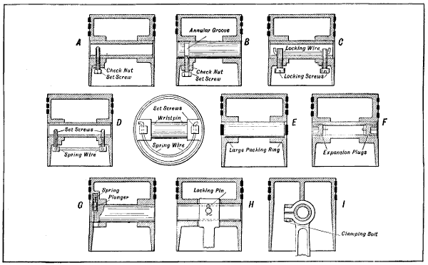
Fig. 117.—Typical Methods of Piston Pin Retention Generally Used in Engines of American Design. A—Single Set Screw and Lock Nut. B—Set Screw and Check Nut Fitting Groove in Wrist Pin. C, D—Two Locking Screws Passing Into Interior of Hollow Wrist Pin. E—Split Ring Holds Pin in Place. F—Use of Taper Expanding Plugs Outlined. G—Spring Pressed Plunger Type. H—Piston Pin Pinned to Connecting Rod. I—Wrist Pin Clamped in Connecting Rod Small End by Bolt.
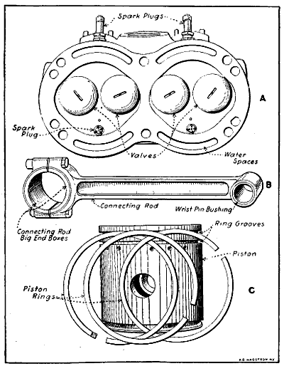
Fig. 119.—Parts of Sturtevant Aviation Engine. A—Cylinder Head Showing Valves. B—Connecting Rod. C—Piston and Rings.
One of the important conditions in piston design is the method of securing the wrist pin which is used to[292] connect the piston to the upper end of the connecting rod. Various methods have been devised to keep the pin in place, the most common of these being shown at Fig. 117. The wrist pin should be retained by some positive means which is not liable to become loose under the vibratory stresses which obtain at this point. If the[293] wrist pin was free to move it would work out of the bosses enough so that the end would bear against the cylinder wall. As it is usually made of steel, which is a harder material than cast iron used in cylinder construction, the rubbing action would tend to cut a groove in the cylinder wall which would make for loss of power because it would permit escape of gas. The wrist pin member is a simple cylindrical element that fits the bosses closely, and it may be either hollow or solid stock. A typical piston and connecting rod assembly which shows a piston in section also is given at Fig. 118. The piston of the Sturtevant aëronautical motor is shown at Fig. 119, the aluminum piston of the Thomas airplane motor with piston rings in place is shown at Fig. 120. A good view of the wrist pin and connecting rod are also given. The iron piston of the Gnome “Monosoupape” airplane engine and the unconventional connecting rod assembly are clearly depicted at Fig 121.
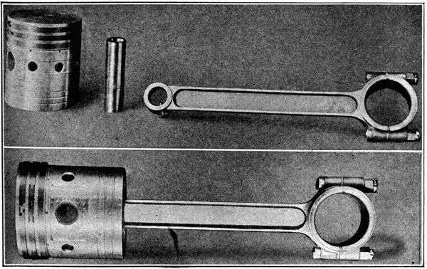
Fig. 120.—Aluminum Piston and Light But Strong Steel Connecting Rod and Wrist Pin of Thomas Aviation Engine.
The method of retention shown at A is the simplest and consists of a set screw having a projecting portion[294] passing into the wrist pin and holding it in place. The screw is kept from turning or loosening by means of a check nut. The method outlined at B is similar to that shown at A, except that the wrist pin is solid and the point of the set screw engages an annular groove turned in the pin for its reception. A very positive method is shown at C. Here the retention screws pass into the wrist pin and are then locked by a piece of steel wire which passes through suitable holes in the ends. The method outlined at D is sometimes employed, and it varies from that shown at C only in that the locking wire, which is made of spring steel, is passed through the heads of the locking screws. Some designers machine a large groove around the piston at such a point that when the wrist pin is put in place a large packing ring may be sprung in the groove and utilized to hold the wrist pin in place.
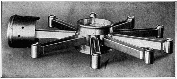
Fig. 121.—Cast Iron Piston of “Monosoupape” Gnome Engine Installed On One of the Short Connecting Rods.
The system shown at F is not so widely used as the simpler methods, because it is more costly and does not offer any greater security when the parts are new than the simple lock shown at A. In this a hollow wrist pin is used, having a tapered thread cut at each end. The wrist pin is slotted at three or four points, for a distance equal to the length of the boss, and when taper expansion plugs[295] are screwed in place the ends of the wrist pin are expanded against the bosses. This method has the advantage of providing a certain degree of adjustment if the wrist pin should loosen up after it has been in use for some time. The taper plugs would be screwed in deeper and the ends of the wrist pin expanded proportionately to take up the loss motion. The method shown at G is an ingenious one. One of the piston bosses is provided with a projection which is drilled out to receive a plunger. The wrist pin is provided with a hole of sufficient size to receive the plunger, which is kept in place by means of a spring in back of it. This makes a very positive lock and one that can be easily loosened when it is desired to remove the wrist pin. To unlock, a piece of fine rod is thrust into the hole at the bottom of the boss which pushes the plunger back against the spring until the wrist pin can be pushed out of the piston.
Some engineers think it advisable to oscillate the wrist pin in the piston bosses, instead of in the connecting rod small end. It is argued that this construction gives more bearing surface at the wrist pin and also provides for more strength because of the longer bosses that can be used. When this system is followed the piston pin is held in place by locking it to the connecting rod by some means. At H the simplest method is outlined. This consisted of driving a taper pin through both rod and wrist pin and then preventing it from backing out by putting a split cotter through the small end of the tapered locking pin. Another method, which is depicted at I, consists of clamping the wrist pin by means of a suitable bolt which brings the slit connecting rod end together as shown.
Aluminum pistons outlined at Fig. 122, have replaced cast iron members in many airplane engines, as these weigh about one-third as much as the cast iron forms of the same size, while the reduction in the inertia forces[296] has made it possible to increase the engine speed without correspondingly stressing the connecting rods, crank-shaft and engine bearings.
Aluminum has not only been used for pistons, but a number of motors will be built for the coming season that will use aluminum cylinder block castings as well. Of course, the aluminum alloy is too soft to be used as a bearing for the piston, and it will not withstand the hammering action of the valve. This makes the use of cast iron or steel imperative in all motors. When used in connection with an aluminum cylinder block the cast iron pieces are placed in the mould so that they act as cylinder liners and valve seats, and the molten metal is poured around them when the cylinder is cast. It is said that this construction results in an intimate bond between the cast iron and the surrounding aluminum metal. Steel liners may also be pressed into the aluminum cylinders after these are bored out to receive them. Aluminum has for a number of years been used in many motor[297] car parts. Alloys have been developed that have greater strength than cast iron and that are not so brittle. Its use for manifolds and engine crank and gear cases has been general for a number of years.
At first thought it would seem as though aluminum would be entirely unsuited for use in those portions of internal combustion engines exposed to the heat of the explosion, on account of the low melting point of that metal and its disadvantageous quality of suddenly “wilting” when a critical point in the temperature is reached. Those who hesitated to use aluminum on account of this defect lost sight of the great heat conductivity of that metal, which is considerably more than that of cast iron. It was found in early experiments with aluminum pistons that this quality of quick radiation meant that aluminum pistons remained considerably cooler than cast iron ones in service, which was attested to by the reduced formation of carbon deposit thereon. The use of aluminum makes possible a marked reduction in power plant weight. A small four-cylinder engine which was not particularly heavy even with cast iron cylinders was found to weigh 100 pounds less when the cylinder block, pistons, and upper half of the crank-case had been made of aluminum instead of cast iron. Aluminum motors are no longer an experiment, as a considerable number of these have been in use on cars during the past year without the owners of the cars being apprised of the fact. Absolutely no complaint was made in any case of the aluminum motor and it was demonstrated, in addition to the saving in weight, that the motors cost no more to assemble and cooled much more efficiently than the cast iron form. One of the drawbacks to the use of aluminum is its growing scarcity, which results in making it a “near precious” metal.
As all pistons must be free to move up and down in the cylinder with minimum friction, they must be less in[298] diameter than the bore of the cylinder. The amount of freedom or clearance provided varies with the construction of the engine and the material the piston is made of, as well as its size, but it is usual to provide from .005 to .010 of an inch to compensate for the expansion of the piston due to heat and also to leave sufficient clearance for the introduction of lubricant between the working surfaces. Obviously, if the piston were not provided with packing rings, this amount of clearance would enable a portion of the gases evolved when the charge is exploded to escape by it into the engine crank-case. The packing members or piston rings, as they are called, are split rings of cast iron, which are sprung into suitable grooves machined on the exterior of the piston, three or four of these being the usual number supplied. These have sufficient elasticity so that they bear tightly against the cylinder wall and thus make a gas-tight joint. Owing to the limited amount of surface in contact with the cylinder wall and the elasticity of the split rings the amount of friction resulting from the contact of properly fitted rings and the cylinder is not of enough moment to cause any damage and the piston is free to slide up and down in the cylinder bore.
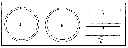
Fig. 123.—Types of Piston Rings and Ring Joints. A—Concentric Ring. B—Eccentrically Machined Form. C—Lap Joint Ring. D—Butt Joint, Seldom Used. E—Diagonal Cut Member, a Popular Form.
These rings are made in two forms, as outlined at Fig. 123. The design shown at A is termed a “concentric[299] ring,” because the inner circle is concentric with the outer one and the ring is of uniform thickness at all points. The ring shown at B is called an “eccentric ring,” and it is thicker at one part than at others. It has theoretical advantages in that it will make a tighter joint than the other form, as it is claimed its expansion due to heat is more uniform. The piston rings must be split in order that they may be sprung in place in the grooves, and also to insure that they will have sufficient elasticity to take the form of the cylinder at the different points in their travel. If the cylinder bore varies by small amounts the rings will spring out at the points where the bore is larger than standard, and spring in at those portions where it is smaller than standard.
It is important that the joint should be as nearly gas-tight as possible, because if it were not a portion of the gases would escape through the slots in the piston rings. The joint shown at C is termed a “lap joint,” because the ends of the ring are cut in such a manner that they overlap. This is the approved joint. The butt joint shown at D is seldom used and is a very poor form, the only advantage being its cheapness. The diagonal cut shown at E is a compromise between the very good form shown at C and the poor joint depicted at D. It is also widely used, though most constructors prefer the lap joint, because it does not permit the leakage of gas as much as the other two types.
There seems to be some difference of opinion relative to the best piston ring type—some favoring the eccentric pattern, others the concentric form. The concentric ring has advantages from the lubricating engineer’s point of view; as stated by the Platt & Washburn Company in their text-book on engine lubrication, the smaller clearance behind the ring possible with the ring of uniform section is advantageous.
Fig. 124, A, shows a concentric piston ring in its groove. Since the ring itself is concentric with the groove, very small clearance between the back of the ring[300] and the bottom of its groove may be allowed. Small clearance leaves less space for the accumulation of oil and carbon deposits. The gasket effect of this ring is uniform throughout the entire length of its edges, which is its marked advantage over the eccentric ring. This type of piston ring rarely burns fast in its groove. There are a large number of different concentric rings manufactured of different designs and of different efficiency.
Figs. 124, B and 124, C show eccentric rings assembled in the ring groove. It will be noted that there is a large space between the thin ends of this ring and the bottom of the groove. This empty space fills up with oil which in the case of the upper ring frequently is carbonized, restricting the action of the ring and nullifying its usefulness. The edges of the thin ends are not sufficiently wide to prevent rapid escape of gases past them. In a practical way this leakage means loss of compression and noticeable drop in power. When new and properly fitted, very little difference can be noted between the tightness of eccentric and concentric rings. Nevertheless, after several months’ use, a more rapid leakage will always occur past the eccentric than past the concentric. If continuous trouble with the carbonization of cylinders, smoking and sooting of spark-plugs is experienced, it is[301] a sure indication that mechanical defects exist in the engine, assuming of course, that a suitable oil has been used. Such trouble can be greatly lessened, if not entirely eliminated, by the application of concentric rings (lap joint), of any good make, properly fitted into the grooves of the piston. Too much emphasis cannot be put upon this point. If the oil used in the engine is of the correct viscosity, and serious carbon deposit, smoking, etc., still result, the only certain remedy then is to have the cylinders rebored and fitted with properly designed, oversized pistons and piston rings.
In order to reduce the compression loss and leakage of gas by the ordinary simple form of diagonal or lap joint one-piece piston ring a number of compound rings have been devised and are offered by their makers to use in making replacements. The leading forms are shown at Fig. 125. That shown at A is known as the “Statite” and consists of three rings, one carried inside while the other two are carried on the outside. The ring shown at B is a double ring and is known as the McCadden. This is composed of two thin concentric lap joint rings so disposed relative to each other that the opening in the inner ring comes opposite to the opening in the outer ring.
The form shown at C is known as the “Leektite,” and is a single ring provided with a peculiar form of lap and dove tail joint. The ring shown at D is known as the “Dunham” and is of the double concentric type being composed of two rings with lap joints which are welded together at a point opposite the joint so that there is no passage by which the gas can escape. The Burd high compression ring is shown at E. The joints of these rings are sealed by means of an H-shaped coupler of bronze which closes the opening. The ring ends are made with tongues which interlock with the coupling. The[302] ring shown at F is called the “Evertite” and is a three-piece ring composed of three members as shown in the sectional view below the ring. The main part or inner ring has a circumferential channel in which the two outer rings lock, the resulting cross-section being rectangular just the same as that of a regular pattern ring. All three rings are diagonally split and the joints are spaced equally and the distances maintained by small pins. This results in each joint being sealed by the solid portion of the other rings.
The use of a number of light steel rings instead of one wide ring in the groove is found on a number of automobile power plants, but as far as known, this construction is not used in airplane power plants. It is contended that where a number of light rings is employed a more flexible packing means is obtained and the possibility of leakage is reduced. Rings of this design are made of square section steel wire and are given a spring temper. Owing to the limited width the diagonal[303] cut joint is generally employed instead of the lap joint which is so popular on wider rings.
An examination of the engine design that is economical in oil consumption discloses the use of tight piston rings, large centrifugal rings on the crank-shaft where it passes through the case, ample cooling fins in the pistons, vents between the crank-case chamber and the valve enclosures, etc. Briefly put, cooling of the oil in this engine has been properly cared for and leakage reduced to a minimum. To be specific regarding details of design: Oil surplus can be kept out of the explosion chambers by leaving the lower edge of the piston skirt sharp and by the use of a shallow groove (C), Fig. 126, just below the lower piston ring. Small holes are bored through the piston walls at the base of this groove and communicate with the crank-case. The similarity of the sharp edges of piston skirt (D) and piston ring to a carpenter’s plane bit, makes their operation plain.
The cooling of oil in the sump (A) can be accomplished most effectively by radiating fins on its outer surface. The lower crank-case should be fully exposed to the outer air. A settling basin for sediment (B) should be provided having a cubic content not less than one-tenth of the total oil capacity as outlined at Fig. 126. The depth of this basin should be at least 21⁄2 inches, and its walls vertical, as shown, to reduce the mixing of sediment with the oil in circulation. The inlet opening to the oil pump should be near the top of the sediment basin in order to prevent the entrance into the pump with the oil of any solid matter or water condensed from the products of combustion. This sediment basin should be drained after every five to seven hours air service of an airplane engine. Concerning filtering screens there is little to be said, save that their areas should be ample and the mesh coarse enough (one-sixteenth of an inch) to[304] offer no serious resistance to the free flow of cold or heavy oil through them; otherwise the oil in the crank-case may build up above them to an undesirable level. The necessary frequency of draining and flushing out the oil sump differs greatly with the age (condition) of the engine and the suitability of the oil used. In broad terms, the oil sump of a new engine should be thoroughly drained and flushed with kerosene at the end of the first 200[305] miles, next at the end of 500 miles and thereafter every 1,000 miles. While these instructions apply specifically to automobile motors, it is very good practice to change the oil in airplane engines frequently. In many cases, the best results have been secured when the oil supply is completely replenished every five hours that the engine is in operation.
The connecting rod is the simple member that joins the piston to the crank-shaft and which transmits the power imparted to the piston by the explosion so that it may be usefully applied. It transforms the reciprocating movement of the piston to a rotary motion at the crank-shaft. A typical connecting rod and its wrist pin are shown at Fig. 120. It will be seen that it has two bearings, one at either end. The small end is bored out to receive the wrist pin which joins it to the piston, while the large end has a hole of sufficient size to go on the crank-pin. The airplane and automobile engine connecting rod is invariably a steel forging, though in marine engines it is sometimes made a steel or high tensile strength bronze casting. In all cases it is desirable to have softer metals than the crank-shaft and wrist pin at the bearing point, and for this reason the connecting rod is usually provided with bushings of anti-friction or white metal at the lower end, and bronze at the upper. The upper end of the connecting rod may be one piece, because the wrist pin can be introduced after it is in place between the bosses of the piston. The lower bearing must be made in two parts in most cases, because the crank-shaft cannot be passed through the bearing owing to its irregular form. The rods of the Gnome engine are all one piece types, as shown at Fig. 127, owing to the construction of the “mother” rod which receives the crank-pins. The complete connecting rod assembly is shown in Fig. 121, also at A, Fig. 127. The “mother[306]” rod, with one of the other rods in place and one about to be inserted, is shown at Fig. 127, B. The built-up crank-shaft which makes this construction feasible is shown at Fig. 127, C.
Some of the various designs of connecting rods that have been used are shown at Fig. 128. That at A is a simple form often employed in single-cylinder motors, having built-up crank-shafts. Both ends of the connecting rod are bushed with a one-piece bearing, as it can be assembled in place before the crank-shaft assembly is built up. A built-up crank-shaft such as this type of connecting rod would be used with is shown at Fig. 106. The pattern shown at B is one that has been used to some extent on heavy work, and is known as the “marine type.” It is made in three pieces, the main portion being a steel forging having a flanged lower end to which the bronze boxes are secured by bolts. The modified marine type depicted at C is the form that has received the widest application in automobile and aviation engine construction.[308] It consists of two pieces, the main member being a steel drop forging having the wrist-pin bearing and the upper crank-pin bearing formed integral, while the lower crank-pin bearing member is a separate forging secured to the connecting rod by bolts. In this construction bushings of anti-friction metal are used at the lower end, and a bronze bushing is forced into the upper- or wrist-pin end. The rod shown at D has also been widely used. It is similar in construction to the form shown at C, except that the upper end is split in order to permit of a degree of adjustment of the wrist-pin bushing, and the lower bearing cap is a hinged member which is retained by one bolt instead of two. When it is desired to assemble it on the crank-shaft the lower cap is swung to one side and brought back into place when the connecting rod has been properly located. Sometimes the lower bearing member is split diagonally instead of horizontally, such a construction being outlined at E.
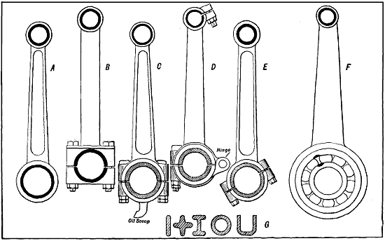
Fig. 128.—Connecting Rod Types Summarized. A—Single Connecting Rod Made in One Piece, Usually Fitted in Small Single-Cylinder Engines Having Built-Up Crank-Shafts. B—Marine Type, a Popular Form on Heavy Engines. C—Conventional Automobile Type, a Modified Marine Form. D—Type Having Hinged Lower Cap and Split Wrist Pin Bushing. E—Connecting Rod Having Diagonally Divided Big End. F—Ball-Bearing Rod. G—Sections Showing Structural Shapes Commonly Employed in Connecting Rod Construction.
In a number of instances, instead of plain bushed bearings anti-friction forms using ball or rollers have been used at the lower end. A ball-bearing connecting rod is shown at F. The big end may be made in one piece, because if it is possible to get the ball bearing on the crank-pins it will be easy to put the connecting rod in place. Ball bearings are not used very often on connecting rod big ends because of difficulty of installation, though when applied properly they give satisfactory service and reduce friction to a minimum. One of the advantages of the ball bearing is that it requires no adjustment, whereas the plain bushings depicted in the other connecting rods must be taken up from time to time to compensate for wear.
This can be done in forms shown at B, C, D, and E by bringing the lower bearing caps closer to the upper one and scraping out the brasses to fit the shaft. A number of liners or shims of thin brass or copper stock, varying from .002 inch to .005 inch, are sometimes interposed between the halves of the bearings when it is first[309] fitted to the crank-pin. As the brasses wear the shims may be removed and the portions of the bearings brought close enough together to take up any lost motion that may exist, though in some motors no shims are provided and depreciation can be remedied only by installing new brasses and scraping to fit.
The various structural shapes in which connecting rods are formed are shown in section at G. Of these the I section is most widely used in airplane engines, because it is strong and a very easy shape to form by the drop-forging process or to machine out of the solid bar when extra good steel is used. Where extreme lightness is desired, as in small high-speed motors used for cycle propulsion, the section shown at the extreme left is often used. If the rod is a cast member as in some marine engines, the cross, hollow cylinder, or U sections are sometimes used. If the sections shown at the right are employed,[310] advantage is often taken of the opportunity for passing lubricant through the center of the hollow round section on vertical motors or at the bottom of the U section, which would be used on a horizontal cylinder power plant.
Connecting rods of Vee engines are made in two distinct styles. The forked or “scissors” joint rod assembly is employed when the cylinders are placed directly opposite each other. The “blade” rod, as shown at Fig. 129, fits between the lower ends of the forked rod, which oscillate on the bearing which encircles the crank-pin. The lower end of the “blade” rod is usually attached to the bearing brasses, the ends of the “forked” rod move on the outer surfaces of the brasses. Another form of rod devised for use under these conditions is shown at Fig. 130 and installed in an aviation engine at Fig. 132. In this construction the shorter rod is attached to a boss on the master rod by a short pin to form a hinge and to permit the short rod to oscillate as the conditions dictate.[312] This form of rod can be easily adjusted when the bearing depreciates, a procedure that is difficult with the forked type rod. The best practice, in the writer’s opinion, is to stagger the cylinders and use side-by-side rods as is done in the Curtiss engine. Each rod may be fitted independently of the other and perfect compensation for wear of the big ends is possible.
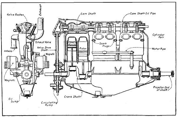
Fig. 131.—Part Sectional View of Wisconsin Aviation Engine, Showing Four-Bearing Crank-Shaft, Overhead Cam-Shaft, and Method of Combining Cylinders in Pairs.
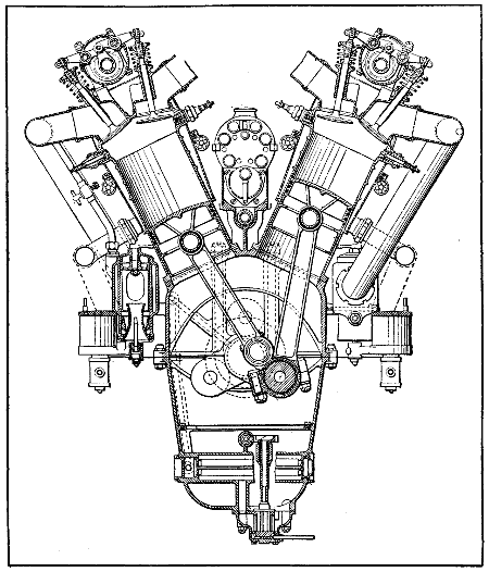
Fig. 132.—Part Sectional View of Renault Twelve-Cylinder Water-Cooled Engine, Showing Connecting Rod Construction and Other Important Internal Parts.
Before going extensively into the subject of crank-shaft construction it will be well to consider cam-shaft design, which is properly a part of the valve system and which has been considered in connection with the other elements which have to do directly with cylinder construction to some extent. Cam-shafts are usually simple members carried at the base of the cylinder in the engine case of Vee type motors by suitable bearings and having the cams employed to lift the valves attached at intervals. A typical cam-shaft design is shown at Fig. 133. Two main methods of cam-shaft construction are followed—that in which the cams are separate members, keyed and pinned to the shaft, and the other where the cams are formed integral, the latter being the most suitable for airplane engine requirements.
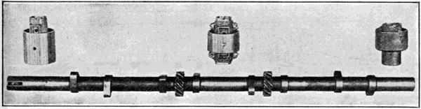
Fig. 133.—Typical Cam-Shaft, with Valve Lifting Cams and Gears to Operate Auxiliary Devices Forged Integrally.
The cam-shafts shown at Figs. 133 and 134, B, are of the latter type, as the cams are machined integrally. In this case not only the cams but also the gears used in driving the auxiliary shafts are forged integral. This is a more expensive construction, because of the high initial cost of forging dies as well as the greater expense of machining. It has the advantage over the other form in which the cams are keyed in place in that it is stronger, and as the cams are a part of the shaft they can never become loose, as might be possible where they are separately formed and assembled on a simple shaft.
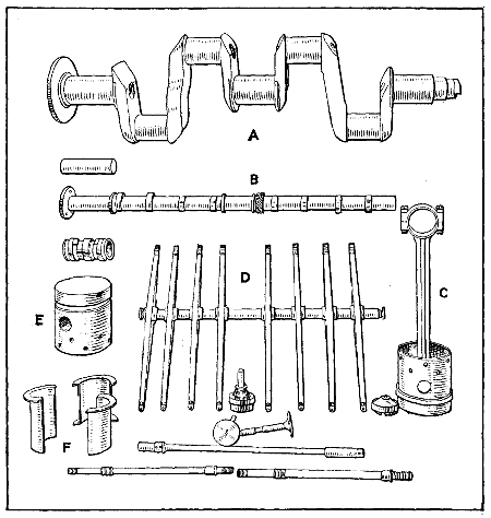
Fig. 134.—Important Parts of Duesenberg Aviation Engine. A—Three Main Bearing Crank-Shaft. B—Cam-Shaft with Integral Cams. C—Piston and Connecting Rod Assembly. D—Valve Rocker Group. E—Piston. F—Main Bearing Brasses.
The importance of the crank-shaft has been previously[314] considered, and some of its forms have been shown in views of the motors presented in earlier portions of this work. The crank-shaft is one of the parts subjected to the greatest strain and extreme care is needed in its construction and design, because practically the entire duty of transmitting the power generated by the motor to the gearset devolves upon it. Crank-shafts are usually made of high tensile strength steel of special composition. They may be made in four ways, the most common being from[315] a drop or machine forging which is formed approximately to the shape of the finished shaft and in rare instances (experimental motors only) they may be steel castings. Sometimes they are made from machine forgings, where considerably more machine work is necessary than would be the case where the shaft is formed between dies. Some engineers favor blocking the shaft out of a solid slab of metal and then machining this rough blank to form. In some radial-cylinder motors of the Gnome and Le Rhone type the crank-shafts are built up of two pieces, held together by taper fastenings or bolts.
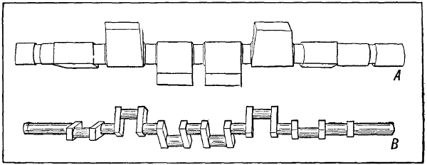
Fig. 135.—Showing Method of Making Crank-Shaft. A—The Rough Steel Forging Before Machining. B—The Finished Six-Throw, Seven-Bearing Crank-Shaft.
The form of the shaft depends on the number of cylinders and the form has material influence on the method of construction. For instance, a four-cylinder crank-shaft could be made by either of the methods outlined. On the other hand, a three- or six-cylinder shaft is best made by the machine forging process, because if drop forged or cut from the blank it will have to be heated and the crank throws bent around so that the pins will lie in three planes one hundred and twenty degrees apart, while the other types described need no further attention, as the crank-pins lie in planes one hundred and eighty degrees apart. This can be better understood by referring to Fig. 135, which shows a six-cylinder shaft in the rough and finished stages. At A the appearance[316] of the machine forging before any of the material is removed is shown, while at B the appearance of the finished crank-shaft is clearly depicted. The built-up crank-shaft is seldom used on multiple-cylinder motors, except in some cases where the crank-shafts revolve on ball bearings as in some automobile racing engines.
Crank-shaft form will vary with a number of cylinders and it is possible to use a number of different arrangements of crank-pins and bearings for the same number of cylinders. The simplest form of crank-shaft is that used on simple radial cylinder motors as it would consist of but one crank-pin, two webs, and the crank-shaft. As the number of cylinders increase in Vee motors as a general rule more crank-pins are used. The crank-shaft that[317] would be used on a two-cylinder opposed motor is shown at Fig. 136. This has two throws and the crank-pins are spaced 180 degrees apart. The bearings are exceptionally long. Four-cylinder crank-shafts may have two, three or five main bearings and three or four crank-pins. In some forms of two-bearing crank-shafts, such as used when four-cylinders are cast in a block, or unit casting, two of the pistons are attached to one common crank-pin, so that in reality the crank-shaft has but three crank-pins. A typical three bearing, four-cylinder crank-shaft is shown at Fig. 134, A. The same type can be used for an eight-cylinder Vee engine, except for the greater length of crank-pins to permit of side by side rods as shown at Fig. 137. Six cylinder vertical tandem and twelve-cylinder Vee engine crank-shafts usually have four or seven main bearings depending upon the disposition of the crank-pins and arrangement of cylinders. At Fig. 138, A,[318] the bottom view of a twelve-cylinder engine with bottom half of crank case removed is given. This illustrates clearly the arrangement of main bearings when the crank-shaft is supported on four journals. The crank-shaft shown at Fig. 138, B, is a twelve-cylinder seven-bearing type.
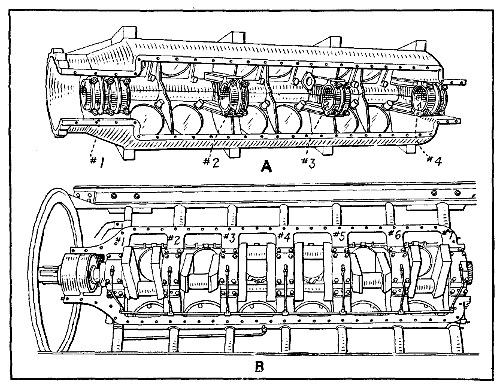
Fig. 138.—Crank-Case and Crank-Shaft Construction for Twelve-Cylinder Motors. A—Duesenberg. B—Curtiss.
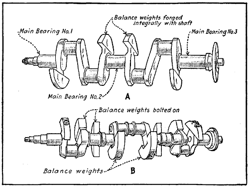
Fig. 139.—Counterbalanced Crank-Shafts Reduce Engine Vibration and Permit of Higher Rotative Speeds.
In some automobile engines, extremely good results have been secured in obtaining steady running with minimum vibration by counterbalancing the crank-shafts as outlined at Fig. 139. The shaft at A is a type suitable for a high speed four-cylinder vertical or an eight-cylinder Vee type. That at B is for a six-cylinder vertical or a twelve-cylinder V with scissors joint rods. If counterbalancing crank-shafts helps in an automobile engine, it should have advantages of some moment in airplane engines, even though the crank-shaft weight is greater.
While crank-shafts are usually supported in plain journals there seems to be a growing tendency of late to use anti-friction bearings of the ball type for their support. This is especially noticeable on block motors where but two main bearings are utilized. When ball bearings are selected with proper relation to the load which obtains they will give very satisfactory service. They permit the crank-shaft to turn with minimum friction, and if properly selected will never need adjustment. The front end is supported by a bearing which is clamped in such a manner that it will take a certain amount of load in a direction parallel to the axis of the shaft, while the rear end is so supported that the outer race of the bearing has a certain amount of axial freedom or “float.” The inner race or cone of each bearing is firmly clamped against shoulders on the crank-shaft. At the front end of the crank-shaft timing gear and a suitable check nut are used, while at the back end the bearing is clamped by a threaded retention member between the fly-wheel and a shoulder on the crank-shaft. The fly-wheel is held in place by a taper and key retention. The ball bearings are carried in a light housing of bronze or malleable iron, which in turn are held in the crank-case by bolts. The Renault engine uses ball bearings at front and rear ends of the crank-shaft, but has plain bearings around intermediate crank-shaft journals. The rotary engines of the Gnome, Le Rhone and Clerget forms would not be practical if ball bearings were not used as the bearing friction and consequent depreciation would be very high.
One of the important parts of the power plant is the substantial casing or bed member, which is employed to support the cylinders and crank-shaft and which is attached directly to the fuselage engine supporting members.[320] This will vary widely in form, but as a general thing it is an approximately cylindrical member which may be divided either vertically or horizontally in two or more parts. Airplane engine crank-cases are usually made of aluminum, a material which has about the same strength as cast iron, but which only weighs a third as much. In rare cases cast iron is employed, but is not favored by most engineers because of its brittle nature, great weight and low resistance to tensile stresses. Where exceptional strength is needed alloys of bronze may be used, and in some cases where engines are produced in large quantities a portion of the crank-case may be a sheet steel or aluminum stamping.
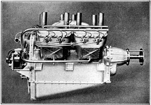
Fig. 140.—View of Thomas 135 Horse-Power Aeromotor, Model 8, Showing Conventional Method of Crank-Case Construction.
Crank-cases are always large enough to permit the crank-shaft and parts attached to it to turn inside and obviously its length is determined by the number of cylinders and their disposition. The crank-case of the radial cylinder or double-opposed cylinder engine would be substantially the same in length. That of a four-cylinder[321] will vary in length with the method of casting the cylinder. When the four-cylinders are cast in one unit and a two-bearing crank-shaft is used, the crank-case is a very compact and short member. When a three-bearing crank-shaft is utilized and the cylinders are cast in pairs, the engine base is longer than it would be to support a block casting, but is shorter than one designed to sustain individual[322] cylinder castings and a five-bearing crank-shaft. It is now common construction to cast an oil container integral with the bottom of the engine base and to draw the lubricating oil from it by means of a pump, as shown at Fig. 140. The arms by which the motor is supported[323] in the fuselage are substantial-ribbed members cast integrally with the upper half.
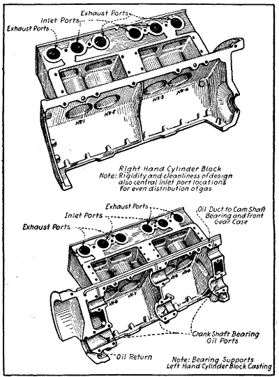
Fig. 142.—Method of Constructing Eight-Cylinder Vee Engine, Possible if Aluminum Cylinder and Crank-Case Castings are Used.
The approved method of crank-case construction favored by the majority of engineers is shown at the top of Fig. 141, bottom side up. The upper half not only forms a bed for the cylinder but is used to hold the crank-shaft as well. In the illustration, the three-bearing boxes form part of the case, while the lower brasses are in the form of separately cast caps retained by suitable bolts. In the construction outlined the bottom part of the case serves merely as an oil container and a protection for the interior mechanism of the motor. The cylinders are held down by means of studs screwed into the crank-case top, as shown at Fig. 141, lower view. If the aluminum cylinder motor has any future, the method of construction outlined at Fig. 142, which has been used in cast iron for an automobile motor, might be used for an eight-cylinder Vee engine for airplane use. The simplicity of the crank-case needed for a revolving cylinder motor and its small weight can be well understood by examination of the illustration at Fig. 143, which shows the engine crank-case for the nine-cylinder “Monosoupape” Gnome engine. This consists of two accurately machined forgings held together by bolts as clearly indicated.
Power Plant Installation—Curtiss OX-2 Engine Mounting and Operating Rules—Standard S. A. E. Engine Bed Dimensions—Hall-Scott Engine Installation and Operation—Fuel System Rules—Ignition System—Water System—Preparations to Start Engine—Mounting Radial and Rotary Engines—Practical Hints to Locate Engine Troubles—All Engine Troubles Summarized—Location of Engine Troubles Made Easy.
The proper installation of the airplane power plant is more important than is generally supposed, as while these engines are usually well balanced and run with little vibration, it is necessary that they be securely anchored and that various connections to the auxiliary parts be carefully made in order to prevent breakage from vibration and that attendant risk of motor stoppage while in the air. The type of motor to be installed determines the method of installation to be followed. As a general rule six-cylinder vertical engine and eight-cylinder Vee type are mounted in substantially the same way. The radial, fixed cylinder forms and the radial, rotary cylinder Gnome and Le Rhone rotary types require an entirely different method of mounting. Some unconventional mountings have been devised, notably that shown at Fig. 144, which is a six-cylinder German engine that is installed in just the opposite way to that commonly followed. The inverted cylinder construction is not generally followed because even with pressure feed, dry crank-case type lubricating system there is considerable danger of over-lubrication and of oil collecting and carbonizing in the combustion chamber and gumming up the valve action much quicker than would be the case if the engine was operated in the conventional upright position. The reason for mounting an engine in this way is to obtain a lower center of gravity and also to make for[325] more perfect streamlining of the front end of the fuselage in some cases. It is rather doubtful if this slight advantage will compensate for the disadvantages introduced by this unusual construction. It is not used to any extent now but is presented merely to show one of the possible systems of installing an airplane engine.
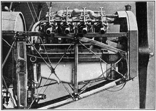
Fig. 145.—How Curtiss Model OX-2 Motor is Installed in Fuselage of Curtiss Tractor Biplane. Note Similarity of Mounting to Automobile Power Plant.
In a number of airplanes of the tractor-biplane type the power plant installation is not very much different than that which is found in automobile practice. The illustration at Fig. 145 is a very clear representation of the method of mounting the Curtiss eight-cylinder 90 H. P. or model OX-2 engine in the fuselage of the Curtiss JN-4 tractor biplane which is so generally used in the United States as a training machine. It will be observed that the fuel tank is mounted under a cowl directly behind the motor and that it feeds the carburetor by means of a[326] flexible fuel pipe. As the tank is mounted higher than the carburetor, it will feed that member by gravity. The radiator is mounted at the front end of the fuselage and connected to the water piping on the motor by the usual rubber hose connections. An oil pan is placed under the engine and the top is covered with a hood just as in motor car practice. The panels of aluminum are attached to the sides of the fuselage and are supplied with doors which open and provide access to the carburetor, oil-gauge and other parts of the motor requiring inspection. The complete installation with the power plant enclosed is given at Fig. 146, and in this it will be observed that the exhaust pipes are connected to discharge members that lead the gases above the top plane. In the engine shown at Fig. 145 the exhaust flows directly into the air at the sides of the machine through short pipes bolted to the exhaust gas outlet ports. The installation of the[328] radiator just back of the tractor screw insures that adequate cooling will be obtained because of the rapid air flow due to the propeller slip stream.
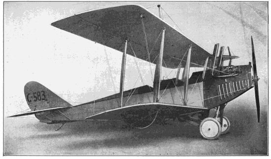
Fig. 146.—Latest Model of Curtiss JN-4 Training Machine, Showing Thorough Enclosure of Power Plant and Method of Disposing of the Exhaust Gases.
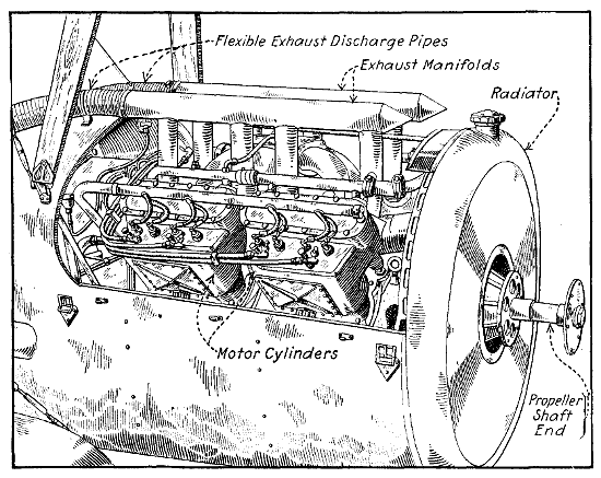
Fig. 147.—Front View of L. W. F. Tractor Biplane Fuselage, Showing Method of Installing Thomas Aeromotor and Method of Disposing of Exhaust Gases.
The following instructions are given in the Curtiss Instruction Book for installing the OX-2 engine and preparing it for flights, and taken in connection with the very clear illustration presented no difficulty should be experienced in understanding the proper installation, and mounting of this power plant. The bearers or beds should be 2 inches wide by 3 inches deep, preferably of laminated hard wood, and placed 115⁄8 inches apart. They must be well braced. The six arms of the base of the motor are[329] drilled for 3⁄8-inch bolts, and none but this size should he used.
1. Anchoring the Motor. Put the bolts in from the bottom, with a large washer under the head of each so the head cannot cut into the wood. On every bolt use a castellated nut and a cotter pin, or an ordinary nut and a lock washer, so the bolt will not work loose. Always set motor in place and fasten before attaching any auxiliary apparatus, such as carburetor, etc.
2. Inspecting the Ignition-Switch Wires. The wires leading from the ignition switch must be properly connected—one end to the motor body for ground, and the other end to the post on the breaker box of the magneto.
3. Filling the Radiator. Be sure that the water from the radiator fills the cylinder jackets. Pockets of air may remain in the cylinder jackets even though the radiator may appear full. Turn the motor over a few times by hand after filling the radiator, and then add more water if the radiator will take it. The air pockets, if allowed to remain, may cause overheating and develop serious trouble when the motor is running.
4. Filling the Oil Reservoir. Oil is admitted into the crank-case through the breather tube at the rear. It is well to strain all oil put into the crank-case. In filling the oil reservoir be sure to turn the handle on the oil sight-gauge till it is at right angles with the gauge. The oil sight-gauge is on the side of the lower half of the crank-case. Put in about 3 gallons of the best obtainable oil, Mobile B recommended. It is important to remember that the very best oil is none too good.
5. Oiling Exposed Moving Parts. Oil all rocker-arm bearings before each flight. A little oil should be applied where the push rods pass through the stirrup straps.
6. Filling the Gasoline Tanks. Be certain that all connections in the gasoline system are tight.
7. Turning on the Gasoline. Open the cock leading from the gasoline tank to the carburetor.
8. Charging the Cylinders. With the ignition switch[330] OFF, prime the motor by squirting a little gasoline in each exhaust port and then turn the propeller backward two revolutions. Never open the exhaust valve by operating the rocker-arm by hand, as the push-rod is liable to come out of its socket in the cam follower and bend the rocker-arm when the motor turns over.
9. Starting the Motor by Hand. Always retard the spark part way, to prevent back-firing, by pulling forward the wire attached to the breaker box. Failure to so retard the spark in starting may result in serious injury to the operator. Turn on the ignition switch with throttle partly open; give a quick, strong pull down and outward on the starting crank or propeller. As soon as the motor is started advance the spark by releasing the retard wire.
10. Oil Circulation. Let the motor run at low speed for a few minutes in order to establish oil circulation in all bearings. With all parts functioning properly, the throttle may be opened gradually for warming up before flight.
The Society of Automotive Engineers have made efforts to standardize dimensions of bed timbers for supporting power plant in an aeroplane. Owing to the great difference in length no standardization is thought possible in this regard. The dimensions recommended are as follows:
| Distance between timbers | 12 | in. | 14 | in. | 16 | in. | ||
| Width of bed timbers | 1 | 1⁄2 | in. | 1 | 3⁄4 | in. | 2 | in. |
| Distance between centers of bolts | 13 | 1⁄2 | in. | 15 | 3⁄4 | in. | 18 | in. |
It will be evident that if any standard of this nature were adopted by engine builders that the designers of fuselage could easily arrange their bed timbers to conform to these dimensions, whereas it would be difficult to have them adhere to any standard longitudinal dimensions which are much more easily varied in fuselages than the transverse dimensions are. It, however, should[332] be possible to standardize the longitudinal positions of the holding down bolts as the engine designer would still be able to allow himself considerable space fore-and-aft of the bolts.
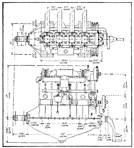
Fig. 149.—Plan and Side Elevation of Hall-Scott A-7 Four-Cylinder Airplane Engine, with Installation Dimensions.
The very thorough manner in which installation diagrams are prepared by the leading engine makers leaves nothing to the imagination. The dimensions of the Hall-Scott four-cylinder airplane engine are given clearly in[333] our inch measurements with the metric equivalents at Figs. 148 and 149, the former showing a vertical elevation while the latter has a plan view and side elevation. The installation of this engine in airplanes is clearly shown at Figs. 150 and 151, the former having the radiator installed at the front of the motor and having all exhaust pipes joined to one common discharge funnel, which deflects the gas over the top plane while the latter has the radiator placed vertically above the motor at the back end and has a direct exhaust gas discharge to the air.
CENSORED
CENSORED
The dimensions of the six-cylinder Hall-Scott motor which is known as the type A-5 125 H. P. are given at Fig. 152, which is an end sectional elevation, and at Fig. 153, which is a plan view. The dimensions are given both in inch sizes and the metric equivalents. The appearance[334] of a Hall-Scott six-cylinder engine installed in a fuselage is given at Fig. 154, while a diagram showing the location of the engine and the various pipes leading to the auxiliary groups is outlined at Fig. 155. The following instructions for installing the Hall-Scott power plant are[336] reproduced from the instruction book issued by the maker. Operating instructions which are given should enable any good mechanic to make a proper installation and to keep the engine in good running condition.
CENSORED
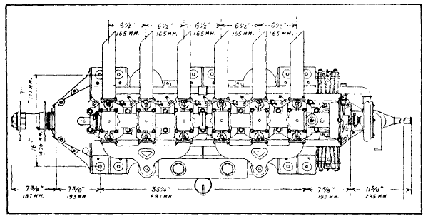
Fig. 153.—Plan View of Hall-Scott Type A-5 125 Horse-Power Airplane Engine, Showing Installation Dimensions.
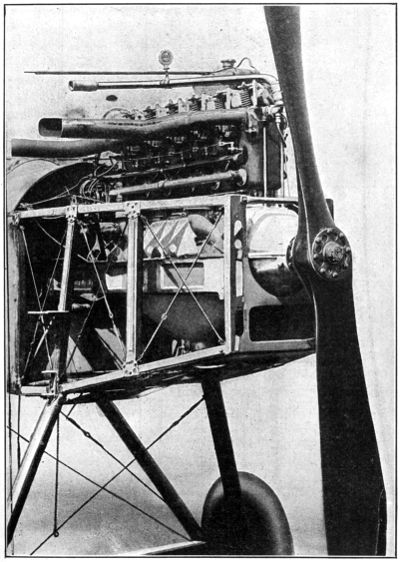
Fig. 154.—Three-Quarter View of Hall-Scott Type A-5 125 Horse-Power Six-Cylinder Engine, with One of the Side Radiators Removed to Show Installation in Standard Fuselage.
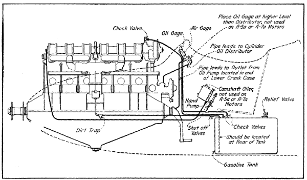
Fig. 155.—Diagram Showing Proper Installation of Hall-Scott Type A-5 125 Horse-Power Engine with Pressure Feed Fuel Supply System.
Gasoline giving the best results with this equipment is as follows: Gravity 58-62 deg. Baume A. Initial boiling point—Richmond method—102° Fahr. Sulphur .014. Calorimetric bomb test 20610 B. T. U. per pound. If the gasoline tank is placed in the fuselage below the level of the carburetor, a hand pump must be used to maintain air pressure in gas tank to force the gasoline to the carburetor. After starting the engine the small auxiliary air pump upon the engine will maintain sufficient pressure. A-7a and A-5a engines are furnished with a new type auxiliary air pump. This should be frequently oiled and care taken so no grit or sand will enter which might lodge between the valve and its seat, which would make it fail to operate properly. An air relief valve is furnished with each engine. It should be screwed into the gas tank and properly regulated to maintain the pressure required.[337] This is done by screwing the ratchet on top either up or down. If two tanks are used in a plane one should be installed in each tank. All air pump lines should be carefully[339] gone over quite frequently to ascertain if they are tight. Check valves have to be placed in these lines. In some cases the gasoline tank is placed above the engine, allowing it to drain by gravity to the carburetor. When using this system there should be a drop of not less than two feet from the lowest portion of the gasoline tank to the upper part of the carburetor float chamber. Even this height might not be sufficient to maintain the proper volume of gasoline to the carburetor at high speeds. Air pressure is advised upon all tanks to insure the proper supply of gasoline. When using gravity feed without air pressure be sure to vent the tank to allow circulation of air. If gravity tank is used and the engine runs satisfactorily at low speeds but cuts out at high speeds the trouble is undoubtedly due to insufficient height of the tank above the carburetor. The tank should be raised or air pressure system used.
Two “DIXIE” switches are furnished with each engine. Both of these should be installed in the pilot’s seat, one controlling the R. H., and the other the L. H. magneto. By shorting either one or the other it can be quickly determined if both magnetos, with their respective spark-plugs, are working correctly. Care should be taken not to use spark-plugs having special extensions or long protruding points. Plugs giving best results are extremely small with short points.
A temperature gauge should be installed in the water pipe, coming directly from the cylinder nearest the propeller (note illustration above). This instrument installed in the radiator cap has not always given satisfactory results. This is especially noticeable when the water in the radiator becomes low, not allowing it to touch the bulb on the moto-meter. For ordinary running,[340] it should not indicate over 150 degrees Fahr. In climbing tests, however, a temperature of 160 degrees Fahr. can be maintained without any ill effects upon the engine. In case the engine becomes overheated, the indicator will register above 180 degrees Fahr., in which case it should be stopped immediately. Overheating is most generally caused by retarded spark, excessive carbon in the cylinders, insufficient lubrication, improperly timed valves, lack of water, clogging of water system in any way which would obstruct the free circulation of the water.
Overheating will cause the engine to knock, with possible damaging results. Suction pipes should be made out of thin tubing, and run within a quarter or an eighth of an inch of each other, so that when a hose is placed over the two, it will not be possible to suck together. This is often the case when a long rubber hose is used, which causes overheating. Radiators should be flushed out and cleaned thoroughly quite often. A dirty radiator may cause overheating.
When filling the radiator it is very important to remove the plug on top of the water pump until water appears. This is to avoid air pockets being formed in the circulating system, which might not only heat up the engine, but cause considerable damage. All water pump hoses and connections should be tightly taped and shellacked after the engine is properly installed in the plane. The greatest care should be taken when making engine installation not to use smaller inside diameter hose connection than water pump suction end casting. One inch and a quarter inside diameter should be used on A-7 and A-5 motors, while nothing less than one inch and a half inside diameter hose or tubing on all A-7a and A-5a engines. It is further important to have light spun tubing, void of any sharp turns, leads from pump to radiator and cylinder water outlet to radiator. In other words, the water circulation through the engine must be as little restricted as possible. Be sure no light hose is used, that[341] will often suck together when engine is started. To thoroughly drain the water from the entire system, open the drain cock at the lowest side of the water pump.
Always replenish gasoline tanks through a strainer which is clean. This strainer must catch all water and other impurities in the gasoline. Pour at least three gallons of fresh oil into the lower crank-case. Oil all rocker arms through oilers upon rocker arm housing caps. Be sure radiators are filled within one inch of the top.
After all the parts are oiled, and the tanks filled, the following must be looked after before starting: See if crank-shaft flange is tight on shaft. See if propeller bolts are tight and evenly drawn up. See if propeller bolts are wired. See if propeller is trued up to within 1⁄8′′.
Every four days the magnetos should be oiled if the engine is in daily use.
Every month all cylinder hold-down nuts should be gone over to ascertain if they are tight. (Be sure to recotter nuts.)
See if magnetos are bolted on tight and wired.
See if magneto cables are in good condition.
See if rocker arm tappets have a .020′′ clearance from valve stem when valve is seated.
See if tappet clamp screws are tight and cottered.
See if all gasoline, oil, water pipes and connections are in perfect condition.
Air on gas line should be tested for leaks.
Pump at least three pounds air pressure into gasoline tank.
After making sure that above rules have been observed, test compression of cylinders by turning propeller.
“DO NOT FORGET TO SHORT BOTH MAGNETOS”
Be sure all compression release and priming cocks do not leak compression. If they do, replace same with a[342] new one immediately, as this might cause premature firing.
Open priming cocks and squirt some gasoline into each.
Close cocks.
Open compression release cocks.
Open throttle slightly.
If using Berling magnetos they should be three-quarters advanced.
If all the foregoing directions have been carefully followed, the engine is ready for starting.
In cranking engine either by starting crank, or propeller, it is essential to throw it over compression quickly.
Immediately upon starting, close compression release cocks.
When engine is running, advance magnetos.
After it has warmed up, short one magneto and then the other, to be sure both magnetos and spark-plugs are firing properly. If there is a miss, the fouled plug must be located and cleaned. There is a possibility that the jets in the carburetor are stopped up. If this is the case, do not attempt to clean same with any sharp instrument. If this is done, it might change the opening in the jets, thus spoiling the adjustment. Jets and nozzles should be blown out with air or steam.
An open intake or exhaust valve, which might have become sluggish or stuck from carbon, might cause trouble. Be sure to remedy this at once by using a little coal-oil or kerosene on same, working the valve by hand until it becomes free. We recommend using graphite on valve stems mixed with oil to guard against sticking or undue wear.
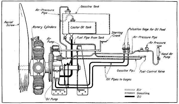
Fig. 156.—Diagram Defining Installation of Gnome “Monosoupape” Motor in Tractor Biplane. Note Necessary Piping for Fuel, Oil, and Air Lines.
When rotary engines are installed simple steel stamping or “spiders,” are attached to the fuselage to hold the fixed crank-shaft. Inasmuch as the motor projects clear of the fuselage proper there is plenty of room back of[344] the front spider plate to install the auxiliary parts such as the oil pump, air pump and ignition magneto and also the fuel and oil containers. The diagram given at Fig. 156 shows how a Gnome “monosoupape” engine is installed on the anchorage plates and it also outlines clearly the piping necessary to convey the oil and fuel and also the air-piping needed to put pressure on both fuel and oil tanks to insure positive supply of these liquids which may be carried in tanks placed lower than the motor in some installations. The diagram given at Figs. 157 and 158 shows other mountings of Gnome engines and are self-explanatory. The simple mounting possible when the Anzani ten-cylinder radial fixed type engine is used given at Fig. 159. The front end of the fuselage is provided with a substantial pressed steel plate having members projecting from it which may be bolted to the longerons. The bolts that hold the two halves of the crank-case together project through the steel plate and hold the engine securely to the front end of the fuselage.
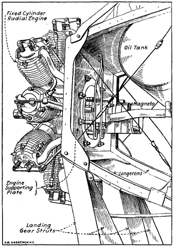
Fig. 159.—How Anzani Ten-Cylinder Radial Engine is Installed to Plate Securely Attached to Front End of Tractor Airplane Fuselage.
One who is not thoroughly familiar with engine construction will seldom locate troubles by haphazard experimenting and it is only by a systematic search that the cause can be discovered and the defects eliminated. In this chapter the writer proposes to outline some of the most common power-plant troubles and to give sufficient advice to enable those who are not thoroughly informed to locate them by a logical process of elimination. The internal-combustion motor, which is the power plant of all gasoline automobiles as well as airplanes, is composed of a number of distinct groups, which in turn include distinct components. These various appliances are so closely related to each other that defective action of any one may interrupt the operation of the entire power plant. Some of the auxiliary groups are more necessary than others and the power plant will continue to operate for a time even after the failure of some important parts of some of the auxiliary groups. The gasoline engine in itself is[346] a complete mechanism, but it is evident that it cannot deliver any power without some means of supplying gas to the cylinders and igniting the compressed gas charge after it has been compressed in the cylinders. From this[347] it is patent that the ignition and carburetion systems are just as essential parts of the power plant as the piston, connecting rod, or cylinder of the motor. The failure of either the carburetor or igniting means to function properly will be immediately apparent by faulty action of the power plant.
To insure that the motor will continue to operate it is necessary to keep it from overheating by some form of cooling system and to supply oil to the moving parts to reduce friction. The cooling and lubrication groups are not so important as carburetion and ignition, as the engine would run for a limited period of time even should the cooling system fail or the oil supply cease. It would only be a few moments, however, before the engine would overheat if the cooling system was at fault, and the parts seize if the lubricating system should fail. Any derangement in the carburetor or ignition mechanism would manifest itself at once because the engine operation would be affected, but a defect in the cooling or oiling system would not be noticed so readily.
The careful aviator will always inspect the motor mechanism before starting on a trip of any consequence, and if inspection is carefully carried out and loose parts tightened it is seldom that irregular operation will be found due to actual breakage of any of the components of the mechanism. Deterioration due to natural causes matures slowly, and sufficient warning is always given when parts begin to wear so satisfactory repairs may be promptly made before serious derangement or failure is manifested.
Before describing the points that may fail in the various auxiliary systems it will be well to assume a typical case of engine failure and show the process of locating the trouble in a systematic manner by indicating the various steps which are in logical order and which could[348] reasonably be followed. In any case of engine failure the ignition system, motor compression, and carburetor should be tested first. If the ignition system is functioning properly one should determine the amount of compression in all cylinders and if this is satisfactory the carbureting group should be tested. If the ignition system is working properly and there is a decided resistance in the cylinders when the propeller is turned, proving that there is good compression, one may suspect the carburetor.
If the carburetor appears to be in good condition, the trouble may be caused by the ignition being out of time, which condition is possible when the magneto timing gear or coupling is attached to the armature shaft by a taper and nut retention instead of the more positive key or taper-pin fastening. It is possible that the inlet manifold may be broken or perforated, that the exhaust valve is stuck on its seat because of a broken or bent stem, broken or loose cam, or failure of the cam-shaft drive because the teeth are stripped from the engine shaft or cam-shaft[349] gears; or because the key or other fastening on either gear has failed, allowing that member to turn independently of the shaft to which it normally is attached. The gasoline feed pipe may be clogged or broken, the fuel supply may be depleted, or the shut-off cock in the gasoline line may have jarred closed. The gasoline filter may be filled with dirt or water which prevents passage of the fuel.
The defects outlined above, except the failure of the[350] gasoline supply, are very rare, and if the container is found to contain fuel and the pipe line to be clear to the carburetor, it is safe to assume the vaporizing device is at fault. If fuel continually runs out of the mixing chamber the carburetor is said to be flooded. This condition results from failure of the shut-off needle to seat properly or from a punctured hollow metal float or a gasoline-soaked cork float. It is possible that not enough gasoline is present in the float chamber. If the passage controlled by the float-needle valve is clogged or if the float was badly out of adjustment, this contingency would be probable. When the carburetor is examined, if the gasoline level appears to be at the proper height, one may suspect that a particle of lint, or dust, or fine scale, or rust from the gasoline tank has clogged the bore of the jet in the mixing chamber.
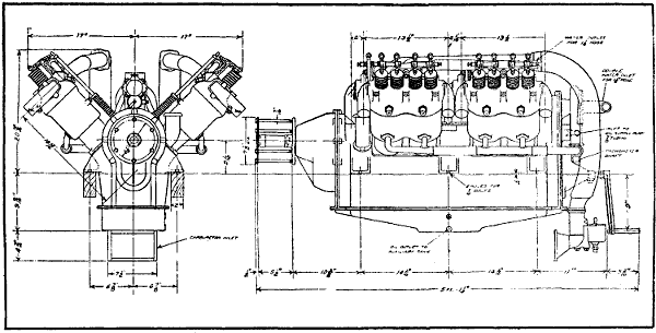
Fig. 162.—Front and Side Elevations of Sturtevant Airplane Engine, Giving Principal Dimensions to Facilitate Installation.
If the ignition system and carburetor appear to be in good working order, and the hand crank shows that there is no compression in one or more of the cylinders, it means some defect in the valve system. If the engine is a multiple-cylinder type and one finds poor compression in all of the cylinders it may be due to the rare defect of improper valve timing. This may be caused by a gear having altered its position on the cam-shaft or crank-shaft, because of a sheared key or pin having permitted the gear to turn about half of a revolution and then having caught and held the gear in place by a broken or jagged end so that cam-shaft would turn, but the valves open at the wrong time. If but one of the cylinders is at fault and the rest appear to have good compression the trouble may be due to a defective condition either inside or outside of that cylinder. The external parts may be inspected easily, so the following should be looked for: a broken valve, a warped valve-head, broken valve-springs, sticking or bent valve-stems, dirt under valve-seat, leak at valve-chamber cap or spark-plug gasket. Defective priming cock, cracked cylinder head (rarely occurs), leak through cracked spark-plug insulation, valve-plunger[352] stuck in the guide, lack of clearance between valve-stem end and top of plunger caused by loose adjusting screw which has worked up and kept the valve from seating. The faulty compression may be due to defects inside the motor. The piston-head may be cracked (rarely occurs), piston rings may be broken, the slots in the piston rings may be in line, the rings may have lost their elasticity or have become gummed in the grooves of the piston, or the piston and cylinder walls may be badly scored by a loose wrist pin or by defective lubrication. If the motor is a type with a separate head it is possible the gasket or packing between the cylinder and combustion chamber may leak, either admitting water to the cylinder or allowing compression to escape.
If the first test of the motor had showed that the compression was as it should be and that there were no serious mechanical defects and there was plenty of gasoline at the carburetor, this would have demonstrated that the ignition system was not functioning properly. If a battery is employed to supply current the first step is to take the spark-plugs out of the cylinders and test the system by turning over the engine by hand. If there is no spark in any of the plugs, this may be considered a positive indication that there is a broken main current lead from the battery, a defective ground connection, a loose battery terminal, or a broken connector. If none of these conditions are present, it is safe to say that the battery is no longer capable of delivering current. While magneto ignition is generally used on airplane engines, there is apt to be some development of battery ignition, especially on engines equipped with electric self-starters which are now being experimented with. The spark-plugs may be short circuited by cracked insulation or carbon and oil deposits around the electrode. The secondary wires may be broken or have defective insulation which permits[353] the current to ground to some metal part of the fuselage or motor. The electrodes of the spark-plug may be too far apart to permit a spark to overcome the resistance of the compressed gas, even if a spark jumps the air space, when the plug is laid on the cylinder.
If magnetos are fitted as is usually the case at present and a spark is obtained between the points of the plug and that device or the wire leading to it from the magneto is in proper condition, the trouble is probably caused by the magneto being out of time. This may result if the driving gear is loose on the armature-shaft or crank-shaft, and is a rare occurrence. If no spark is produced at the plugs the secondary wire may be broken, the ground wire may make contact with some metallic portion of the chassis before it reaches the switch, the carbon collecting brushes may be broken or not making contact, the contact points of the make-and-break device may be out of adjustment, the wiring may be attached to wrong terminals, the distributor filled with metallic particles, carbon, dust or oil accumulations, the distributor contacts may not be making proper connection because of wear and there may be a more serious derangement, such as a burned out secondary winding or a punctured condenser.
If the motor runs intermittently, i.e., starts and runs only a few revolutions, aside from the conditions previously outlined, defective operation may be due to seizing between parts because of insufficient oil or deficient cooling, too much oil in the crank-case which fouls the cylinder after the crank-shaft has revolved a few turns, and derangements in the ignition or carburetion systems that may be easily remedied. There are a number of defective conditions which may exist in the ignition group, that will result in “skipping” or irregular operation and the following points should be considered first: weak source of current due to worn out dry cells or discharged storage batteries; weak magnets in magneto, or defective contacts at magneto; dirt in magneto distributor or poor contact at collecting brushes. Dirty or cracked insulator[354] at spark-plug will cause short circuit and can only be detected by careful examination. The following points should also be checked over when the plug is inspected: Excessive space between electrodes, points too close together, loose central electrodes, or loose point on plug body, soot or oil particles between electrodes, or on the surface of the insulator, cracked insulator, oil or water on outside of insulator. Short circuits in the condenser or internal wiring of induction coils or magnetos, which are fortunately not common, can seldom be remedied except at the factory where these devices were made. If an engine stops suddenly and the defect is in the ignition system the trouble is usually never more serious than a broken or loose wire. This may be easily located by inspecting the wiring at the terminals. Irregular operation or misfiring is harder to locate because the trouble can only be found after the many possible defective conditions have been checked over, one by one.
Defective carburetion often causes misfiring or irregular operation. The common derangement of the components of the fuel system that are common enough to warrant suspicion and the best methods for their location follows: First, disconnect the feed pipe from the carburetor and see if the gasoline flows freely from the tank. If the stream coming out of the pipe is not the full size of the orifice it is an indication that the pipe is clogged with dirt or that there is an accumulation of rust, scale, or lint in the strainer screens of the filter. It is also possible that the fuel shut-off valve may be wholly or partly closed. If the gasoline flows by gravity the liquid may be air bound in the tank, while if a pressure-feed system is utilized the tank may leak so that it does not retain pressure; the check valve retaining the pressure may be defective or the pipe conveying the air or gas under pressure to the tank may be clogged.
[355]If the gasoline flows from the pipe in a steady stream the carburetor demands examination. There may be dirt or water in the float chamber, which will constrict the passage between the float chamber and the spray nozzle, or a particle of foreign matter may have entered the nozzle and stopped up the fine holes therein. The float may bind on its guide, the needle valve regulating the gasoline-inlet opening in bowl may stick to its seat. Any of the conditions mentioned would cut down the gasoline supply and the engine would not receive sufficient quantities of gas. The air-valve spring may be weak or the air valve broken. The gasoline-adjusting needle may be loose and jar out of adjustment, or the air-valve spring-adjusting nuts may be such a poor fit on the stem that adjustments will not be retained. These instructions apply only to carburetors having air valves and mixture regulating means which are used only in rare instances in airplane work. Air may leak in through the manifold, due to a porous casting, or leaky joints in a built up form and dilute the mixture. The air-intake dust screen may be so clogged with dirt and lint that not enough air will pass through the mesh. Water or sediment in the gasoline will cause misfiring because the fuel feed varies when the water or dirt constricts the standpipe bore.
It is possible that the carburetor may be out of adjustment. If clouds of black smoke are emitted at the exhaust pipe it is positive indication that too much gasoline is being supplied the mixture and the supply should be cut down by screwing in the needle valve on types where this method of regulation is provided, and by making sure that the fuel level is at the proper height, or that the proper nozzle is used in those forms where the spray nozzle has no means of adjustment. If the mixture contains too much air there will be a pronounced popping back in the carburetor. This may be overcome by screwing in the air-valve adjustment so the spring tension is increased or by slightly opening up the gasoline-supply regulation needle. When a carburetor is properly adjusted[356] and the mixture delivered the cylinder burns properly, the exhaust gas will be clean and free from the objectionable odor present when gasoline is burned in excess.
The character of combustion may be judged by the color of the flame which issues from it when the engine is running with an open throttle after nightfall. If the flame is red, it indicates too much gasoline. If yellowish, it shows an excess of air, while a properly proportioned mixture will be evidenced by a pronounced blue flame, such as given by a gas-stove burner.
The Duplex Model O. D. Zenith carburetor used upon most of the six- and eight-cylinder airplane engines consists of a single float chamber, and a single air intake, joined to two separate and distinct spray nozzles, venturi and idling adjustments. It is to be noted that as the carburetor barrels are arranged side by side, both valves are mounted on the same shaft, and work in unison through a single operating lever. It is not necessary to alter their position. In order to make the engine idle well, it is essential that the ignition, especially the spark-plugs, should be in good condition. The gaskets between carburetor and manifold, and between manifold and cylinders should be absolutely air-tight. The adjustment for low speed on the carburetor is made by turning in or out the two knurled screws, placed one on each side of the float chamber. After starting the engine and allowing it to become thoroughly warmed, one side of the carburetor should be adjusted so that the three cylinders it affects fire properly at low speed. The other side should be adjusted in the same manner until all six cylinders fire perfectly at low speed. As the adjustment is changed on the knurled screw a difference in the idling of the engine should be noticed. If the engine begins to run evenly or speeds up it shows that the mixture becomes right in its proportion.
Be sure the butterfly throttle is closed as far as possible by screwing out the stop screw which regulates the[357] closed position for idling. Care should be taken to have the butterfly held firmly against this stop screw at all times while idling engine. If three cylinders seem to run irregularly after changing the position of the butterfly, still another adjustment may have to be made with the knurled screw. Unscrewing this makes the mixture leaner. Screwing in closes off some of the air supply to the idling jet, making it richer. After one side has been made to idle satisfactorily repeat the same procedure with the opposite three cylinders. In other words, each side should be idled independently to about the same speed.
Remember that the main jet and compensating jet have no appreciable effect on the idling of the engine. The idling mixture is drawn directly through the opening determined by the knurled screw and enters the carburetor barrel through the small hole at the edge of each butterfly. This is called the priming hole and is only effective during idling. Beyond that point the suction is transferred to the main jet and compensator, which controls the power of the engine beyond the idling position of the throttle.
While troubles existing in the ignition or carburetion groups are usually denoted by imperfect operation of the motor, such as lost power, and misfiring, derangements of the lubrication or cooling systems are usually evident by overheating, diminution in engine capacity, or noisy operation. Overheating may be caused by poor carburetion as much as by deficient cooling or insufficient oiling. When the oiling group is not functioning as it should the friction between the motor parts produces heat. If the cooling system is in proper condition, as will be evidenced by the condition of the water in the radiator, and the carburetion group appears to be in good condition, the overheating is probably caused by some defect in the oiling system.
The conditions that most commonly result in poor[358] lubrication are: Insufficient oil in the engine crank-case or sump, broken or clogged oil pipes, screen at filter filled with lint or dirt, broken oil pump, or defective oil-pump drive. The supply of oil may be reduced by a defective inlet or discharge-check valve at the mechanical oiler or worn pumps. A clogged oil passage or pipe leading to an important bearing point will cause trouble because the oil cannot get between the working surfaces. It is well to remember that much of the trouble caused by defective oiling may be prevented by using only the best grades of lubricant, and even if all parts of the oil system are working properly, oils of poor quality will cause friction and overheating.
Cooling systems are very simple and are not liable to give trouble as a rule if the radiator is kept full of clean water and the circulation is not impeded. When overheating is due to defective cooling the most common troubles are those that impede water circulation. If the radiator is clogged or the piping of water jackets filled with rust or sediment the speed of water circulation will be slow, which will also be the case if the water pump or its driving means fail. Any scale or sediment in the water jackets or in the piping or radiator passages will reduce the heat conductivity of the metal exposed to the air, and the water will not be cooled as quickly as though the scale was not present.
The rubber hose often used in making the flexible connections demanded between the radiator and water manifolds of the engine may deteriorate inside and particles of rubber hang down that will reduce the area of the passage. The grease from the grease cups mounted on the pump-shaft bearing to lubricate that member often finds its way into the water system and rots the inner walls of the rubber hose, this resulting in strips of the partly decomposed rubber lining hanging down and restricting[359] the passage. The cooling system is prone to overheat after antifreezing solutions of which calcium chloride forms a part have been used. This is due to the formation of crystals of salt in the radiator passages or water jackets, and these crystals can only be dissolved by suitable chemical means, or removed by scraping when the construction permits.
Overheating is often caused by some condition in the fuel system that produces too rich or too lean mixture. Excess gasoline may be supplied if any of the following conditions are present: Bore of spray nozzle or standpipe too large, auxiliary air-valve spring too tight, gasoline level too high, loose regulating valve, fuel-soaked cork float, punctured sheet-metal float, dirt under float control shut-off valve or insufficient air supply because of a clogged air screen. If pressure feed is utilized there may be too much pressure in the tank, or the float controlled mechanism operating the shut-off in the float bowl of the carburetor may not act quickly enough.
There are a number of power-plant derangements which give positive indication because of noisy operation. Any knocking or rattling sounds are usually produced by wear in connecting rods or main bearings of the engine, though sometimes a sharp metallic knock, which is very much the same as that produced by a loose bearing, is due to carbon deposits in the cylinder heads, or premature ignition due to advanced spark-time lever. Squeaking sounds invariably indicate dry bearings, and whenever such a sound is heard it should be immediately located and oil applied to the parts thus denoting their dry condition. Whistling or blowing sounds are produced by leaks, either in the engine itself or in the gas manifolds. A sharp whistle denotes the escape of gas under pressure and is usually caused by a defective packing or gasket that seals a portion of the combustion chamber or that is[360] used for a joint as the exhaust manifold. A blowing sound indicates a leaky packing in crank-case. Grinding noises in the motor are usually caused by the timing gears and will obtain if these gears are dry or if they have become worn. Whenever a loud knocking sound is heard careful inspection should be made to locate the cause of the trouble. Much harm may be done in a few minutes if the engine is run with loose connecting rod or bearings that would be prevented by taking up the wear or looseness between the parts by some means of adjustment.
First make sure that all cylinders have compression. To ascertain this, open pet cocks of all cylinders except the one to be tested, crank over motor and see that a strong opposition to cranking is met with once in two revolutions. If motor has no pet cocks, crank and notice that oppositions are met at equal distances, two to every revolution of the starting crank in a four-cylinder motor. If compression is lacking, examine the parts of the cylinder or cylinders at fault in the following order, trying to start the motor whenever any one fault is found and remedied. See that the valve push rods or rocker arms do not touch valve stems for more than approximately 1⁄2 revolution in every 2 revolutions, and that there is not more than .010 to .020 inch clearance between them depending on the make of the motor. Make sure that the exhaust valve seats. To determine this examine the spring and see that it is connected to the valve stem properly. Take out valve and see that there is no obstruction, such as carbon, on its seat. See that valve works freely in its guide. Examine inlet valve in same manner. Listen for hissing sound while cranking motor for leaks at other places.
Make sure that a spark occurs in each cylinder as follows: If magneto or magneto and battery with non-vibrating coil is used: Disconnect wire from spark-plug,[361] hold end about 1⁄8 inch from cylinder or terminal of spark-plug. Have motor cranked briskly and see if spark occurs. Examine adjustment of interrupter points. See that wires are placed correctly and not short circuited. Take out spark-plug and lay it on the cylinder, being careful that base of plug only touches the cylinder and that ignition wire is connected. Have motor cranked briskly and see if spark occurs. Check timing of magneto and see that all brushes are making contact.
See if there is gasoline in the carburetor. See that there is gasoline in the tank. Examine valve at tank. Prime carburetor and see that spray nozzle passage is clear. Be sure throttle is open. Prime cylinders by putting about a teaspoonful of gasoline in through pet cock or spark-plug opening. Adjust carburetor if necessary.
The following tabulation has been prepared and originated by the writer to outline in a simple manner the various troubles and derangements that interfere with efficient internal-combustion engine action. The parts and their functions are practically the same in all gas or gasoline engines of the four-cycle type, and the general instructions given apply just as well to all hydro-carbon engines, even if the parts differ in form materially. The essential components are clearly indicated in the many part sectional drawings in this book so they may be easily recognized. The various defects that may materialize are tabulated in a manner that makes for ready reference, and the various defective conditions are found opposite the part affected, and under a heading that denotes the main trouble to which the others are contributing causes. The various symptoms denoting the individual troubles outlined are given to facilitate their recognition in a positive manner.
Brief note is also made of the remedies for the restoration of the defective part or condition. It is apparent[362] that a table of this character is intended merely as a guide, and it is a compilation of practically all the known troubles that may materialize in gas-engine operation. While most of the defects outlined are common enough to warrant suspicion, they will never exist in an engine all at the same time, and it will be necessary to make a systematic search for such of those as exist.
To use the list advantageously, it is necessary to know one main trouble easily recognized. For example, if the power plant is noisy, look for the possible troubles under the head of Noisy Operation; if it lacks capacity, the derangement will undoubtedly be found under the head of Lost Power. It is assumed in all cases that the trouble exists in the power plant or its components, and not in the auxiliary members of the ignition, carburetion, lubrication, or cooling systems. The novice and student will readily recognize the parts of the average aviation engine by referring to the very complete and clearly lettered illustrations of mechanism given in many parts of this treatise.
| LOST POWER AND OVERHEATING[363] | |||
| PART AFFECTED | NATURE OF TROUBLE | SYMPTOMS AND EFFECTS | REMEDY |
| Water Pipe Joint. | Loose. | Loss of water, heating. | Tighten bolts, replace gaskets. |
| Spark Plug. | Leakage in threads, insulation, or packing. | Loss of power. Hissing caused by escaping gas. | Replace insulation if defective, screw down tighter. |
| Compression Release Cock. | Leak in threads. Leak in fitting. | Loss of power. Whistling or hissing. | Tighten if loose. Grind fitting to new seating in body. |
| Combustion Chamber. | Crack or blowhole. Roughness. Carbon deposits. Sharp edges. | Loss of compression. Preignition. | Fill by welding. Smooth out roughness. Scrape out or dissolve carbon. |
| Valve Chamber Cap. | Leak in threads. Defective gasket. | Loss of compression. Hissing. | Remove. Apply pipe compound to threads and replace. Use new gasket or packing. |
| Valve Head. | Warped. Scored or pitted. Carbonized. Covered with scale. Loose on stem (two-piece valves only). | Loss of compression. | True up in lathe. Grind to seat. Scrape off. Smooth with emery cloth. Tighten by riveting. |
| Valve Seat. | Warped or pitted. Covered with carbon. Foreign matter between valve and seat. | Loss of compression. | Use reseating reamer. Clean off and grind valve to seat. |
| Valve Stem. | Covered with scale. Bent. Binding in guide. Stuck in guide. | Valve does not close. Loss of compression. | Clean with emery cloth; straighten. True up and smooth off. free with kerosene. |
| Valve Stem Guide. | Burnt or rough. Loose in valve chamber. | Valve may stick. Action irregular. | Clean out hole. Screw in tighter. |
| Valve Spring. | Weak or broken. | Valve does not close. | |
| Valve Operating Plunger. | Loose in guide. Too much clearance between valve stem. | Valve action poor. Lift insufficient. | Replace with new. Adjust screw closer. |
| Valve Lift Adjusting Screw. | Threads stripped. Too near valve. Too far from valve. | Poor valve action. | Replace with new. Adjust with proper reference to valve stem. |
| Valve Lift Cam.[364] | Worn cam contour. Loose on shaft. Out of time. | Not enough valve lift. Will not lift valve. Valve opens at wrong time. | Replace with new. Replace pins or keys. Set to open properly. |
| Cam-shaft. | Sprung or twisted. | Valves out of time. | Straighten. |
| Cam-shaft Bushing. | Worn. | Not enough valve lift. | Replace. |
| Cam-shaft Drive Gear. | Loose on shaft. Out of time. Worn or broken teeth. | Irregular valve action. | Fasten securely. Time properly. Replace with new. |
| Cam Fastenings. | Worn or broken. | Valves out of time. | Replace with new. |
| Cylinder Wall. | Scored, gas leaks. Poor lubrication causes friction. | Poor compression. Overheating. | Grind out bore. Repair oiling system. |
| Piston. | Binds in cylinder. Walls scored. Worn out of round. | Overheating. Poor compression. | Lap off excess metal. Replace with new. |
| Piston Rings. | Loss of spring. Loose in grooves. Scored. Worn or broken. Slots in line. | Loss of compression. Gas blows by. | Peen ring or replace. Fit new rings. Grind smooth. Replace. Turn slots apart. |
| Carbon in grooves. Insufficient opening. Binding on cylinder. | Overheating because of friction. | Remove deposits. File slot. Grind or lap to fit cylinder bore. | |
| Wristpin. | Loose, scores cylinder. | Loss of compression. | Fasten securely. Replace cylinder if groove is deep. |
| Crank-shaft. | Scored or rough on journals. Sprung. | Overheating because of friction. | Smooth up. Straighten. |
| Crank Bearings. Main Bearings. | Adjusted too tight. Defective oiling. Brasses burned. | Overheating because of friction. | Adjust freely, clean out oil holes and enlarge oil grooves. |
| Oil Sump. | Insufficient oil. Poor lubricant. Dirty oil. | Overheating. | Replenish supply. Use best oil. Wash out with kerosene; put in clean oil. |
| Water Space. Water Pipes. | Clogged with sediment or scale. | Overheating. | Dissolve foreign matter and remove. |
| Piston Head. | Cracked (rare). Carbon deposits. | Loss of compression. Preignition. | Weld by autogenous process. Scrape off carbon accumulations. |
| NOISY OPERATION OF POWER PLANT[365] | |||
| PART AFFECTED | NATURE OF TROUBLE | CHARACTER OF NOISE | REMEDY |
| Compression Release Cock. | Leakage. | Hissing. | Previously given. |
| Spark Plug. | Leakage. | Hissing. | Previously given. |
| Valve Chamber Cap. | Leakage. | Hiss or whistle. | Previously given. |
| Combustion Chamber. | Carbon deposits. | Knocking. | Previously given. |
| Inlet Valve Seat. | Defects previously given. | Popping in carburetor. | Previously given. |
| Valve Head. | Loose on stem. | Clicking. | Previously given. |
| Valve Stem. Valve Stem Guide. | Wear or looseness. | Rattle or clicking. | Previously given. |
| Inlet Valve. | Closes too late. Opens too early. | Blowback in carburetor. | Previously given. |
| Valve Spring. | Weak or broken. | Blowback in carburetor. | Previously given. |
| Cylinder Casting. | Retaining bolts loose. Piston strikes at upper end. | Sharp metallic knock. | Tighten bolts. Round edges of piston top. |
| Cylinder Wall. | Scored. | Hissing. | Previously given. |
| Valve Stem Clearance. | Too much. Too little (inlet valve). | Clicking. Blowback in carburetor. | Previously given. |
| Valve Operating Plunger. Plunger Guide. | Looseness. | Rattle or clicking. | Previously given. |
| Timing Gears. | Loose on fastenings. Worn teeth. Meshed too deeply. | Metallic knock. Rattle. Grinding. | Previously given. |
| Cylinder or Piston. | No oil, or poor lubricant. | Grinding. | Repair oil system. |
| Cam. | Loose on shaft. Worn contour. | Metallic knock. | Previously given. |
| Cam-shaft Bearing. | Looseness or wear. | Slight knock. | Previously given. |
| Cam Fastening. | Looseness. | Clicking. | Previously given. |
| Piston. | Binding in cylinder. Worn oval, causes side slap in cylinder. | Grinding or dull squeak. Dull hammering. | Previously given. |
| Piston Head. | Carbon deposits. | Knocking. | Previously given. |
| Piston Rings. | Defective oiling. Leakage. Binding in cylinder. | Squeaking. Hissing. Grinding. | Previously given. |
| Wrist-pin. | Loose in piston. Worn. | Dull metallic knock. | Replace with new member. |
| Connecting Rod.[366] | Wear in upper bushing. Wear at crank-pin. Side play in piston. | Distinct knock. | Adjust or replace. Scrape and fit. Use longer wrist-pin bushing. |
| Crank Bearings. | Looseness. Excessive end play. Binding, fitted too tight. | Metallic knock. Intermittent knock. Squeaking. | Refit bearings. Longer bushings needed. Insert shims to allow more play. |
| Main Bearings. | Looseness. Defective lubrication. | Metallic knock. Squeaking. | Fit brasses closer to shaft. Clean out oil holes and grooves. |
| Connecting Rod Bolts. Main Bearing Bolts. | Loose. | Sharp knock. | Tighten. |
| Crank-shaft. | Defective oiling. | Squeaking. | Previously given. |
| Engine Base. | Loose on frame. | Sharp pounding. | Tighten bolts. |
| Lower Half Crank-case. | Bolts loose. | Knocking. | Tighten bolts. |
| Fly-wheel. | Loose on crank-shaft. | Very sharp knock. | Tighten retention bolts or fit new keys. |
| Oil Sump. | Oil level too low. Poor lubricant. | Grinding and squeak in all bearings. | Replenish with best cylinder oil. |
| Valve Plunger Retention Stirrups. | Looseness. | Clicking. | Tighten nuts. |
| Fan. | Blade loose. Blade strikes cooler. | Clicking or rattle. | Tighten. Bend back. |
| Exhaust Pipe Joints. | Leakage. | Sharp hissing. | Tighten or use new gasket. |
| Crank-case Packing. | Leakage. | Blowing sound. | Use new packing. Tighten bolts. |
| Water Pipe. | Leaks. Loss of water. Clogged with sediment. | Pounding because engine heats. | Previously given. |
| Water Jacket. | Clogged with sediment. Walls covered with scale. | Knocking because engine heats. | Dissolve scale and flush out water space with water under pressure. |
| “SKIPPING” OR IRREGULAR OPERATION[367] | |||
| PART AFFECTED | NATURE OF TROUBLE | SYMPTOMS AND EFFECTS | REMEDY |
| Compression Relief Cock. | Leak in threads or spigot. | Dilutes mixture with air, causes blowback. | Screw down tighter. Grind spigot to seat with emery. |
| Spark-Plug. | Leak in threads. Defective gasket. Cracked insulator. Points too near. Points covered with carbon. Too much air gap. | Dilutes mixture. Allows short circuit. No spark. | Screw down tighter. Replace with new. Set points 1⁄64′′ apart for magneto, 1⁄32′′ for battery spark. |
| Valve Chamber Cap. | Leak in threads. Defective gasket. | Dilutes mixture by allowing air to enter cylinder on suction stroke. | Previously given. |
| Combustion Chamber. | Carbon deposits. | Preignition. | Scrape out. |
| Valve Head. | Warped or pitted. Loose on stem. | Dilutes charge with poor air or gas. | Previously given. |
| Valve Stem. | Binding in guide. Sticking. | Irregular valve action. | Previously given. |
| Valve Seat. | Scored or warped. Cracked. Covered with scale. Dirt under valve. | Gas leak, poor mixture. Poor compression. Valve will not close. | Previously given. |
| Induction Pipe. | Leak at joints. Crack or blowhole. | Mixture diluted with excess air. | Stop all leaks. |
| Inlet Valve. | Closes too late. Opens too early. | Blowback in carburetor. | Time properly. |
| Exhaust Valve. | Opens too late. Closes too early. | Retention of burnt gas dilutes charge. | Time properly. |
| Valve Stem Guide. | Bent or carbonized. | Causes valve to stick. | Previously given. |
| Inlet Valve Stem Guide.[368] | Worn, stem loose. | Air drawn in on suction thins gas. | Bush guide or use new member. |
| Valve Spring. | Weakened or broken. | Irregular action. | Use new spring. |
| Valve Stem Clearance. | Too little. Too much. | Valve will not shut. Valve opens late, closes early. | Adjust gap .009′′ inlet, .010′′ exhaust. |
| Valve Spring Collar Key. | Broken. | Releases spring. | Replace. |
| Cam. | Worn cam contour. Loose on shaft. Out of time. | Valve lift reduced. Does not lift valve. Valves operate at wrong time. | Previously given. |
| Cam-shaft Bearing. | Looseness or wear. | Valve timing altered. Valve lift decreased. | Replace. |
| Cam-shaft. | Twisted. | Valves out of time. | Previously given. |
| Cam Fastening. | Worn or broken. | Valve action irregular. | Replace with new. |
| Valve Operating Plunger. | Loose in guide. | Alters valve timing. | Replace with new. |
| Valve Plunger Guide. | Wear in bore. Loose on engine base. | Alters valve timing. | Replace or bush. Fasten securely. |
| Timing Gears. | Not properly meshed. Loose on shaft. | Valves out of time. Valves do not operate. | Retime properly. Fasten to shaft. |
| Piston. | Walls scored. | Leakage of gas. | Smooth up if possible. |
| Piston Head. | Carbon deposits. Crack or blowhole (rare). | Cause premature ignition. | Previously given. |
| Piston Rings. | No spring. Loose in grooves. Worn or broken. | Leakage weakens suction. | Previously given. |
| Cylinder Wall. | Scored by wristpin. Scored by lack of oil. | Gas leaks by. Poor suction. | Previously given. |
Loose Battery Terminal.
Magneto Ground Wire Shorted.
Magneto Defective (No Spark at Plugs).
Broken Spark Plug Insulation.
Carbon Deposits or Oil Between Plug Points.
Spark-Plug Points Too Near Together or Far Apart.
Wrong Cables to Plugs.
Short Circuited Secondary Cable.
Broken Secondary Cable.
| Dry Battery Weak. | ⎫ | Battery Systems Only. |
| Storage Battery Discharged. | ⎬ | |
| Poor Contact at Timer. | ⎮ | |
| Timer Points Dirty. | ⎭ |
| Poor Contact at Switch. | ⎫ | Battery and Coil Ignition System Only. |
| Primary Wires Broken, or Short Circuited. | ⎮ | |
| Battery Grounded in Metal Container. | ⎬ | |
| Battery Connectors Broken or Loose. | ⎮ | |
| Timer Points Out of Adjustment. | ⎮ | |
| Defects in Induction Coil. | ⎭ |
Ignition Timing Wrong, Spark Too Late or Too Early.
Defective Platinum Points in Breaker Box (Magneto).
Points Not Separating.
Broken Contact Maker Spring.
No Contact at Secondary Collector Brush.
Platinum Contact Points Burnt or Pitted.
Contact Breaker Bell Crank Stuck.
Fiber Bushing in Bell Crank Swollen.
Short Circuiting Spring Always in Contact.
Dirt or Water in Magneto Casing.
Oil in Contact Breaker.
Oil Soaked Brush and Collector Ring.
Distributor Filled with Carbon Particles.
Broken Magneto Carbon Brush.
Broken Lead Wire.
Broken Ground Wire.
Battery Ignition Systems.
Water on High Tension Magneto Terminal.
Main Secondary Cable Burnt Through by Hot Exhaust Pipe (Transformer Coil, Magneto Systems).
Particle of Carbon Between Spark Plug Points.
Magneto Short Circuited by Ground Wire.
Magneto Out of Time, Due to Slipping Drive.
Water or Oil in Safety Spark Gap (Multi-cylinder Magneto).
Magneto Contact Breaker or Timer Stuck in Retard Position.
Worn Fiber Block in Magneto Contact Breaker.
Binding Fiber Bushing in Contact Breaker Bell Crank.
Spark Advance Rod or Wire Broken.
Contact Breaker Parts Stuck.
Loose Wiring or Terminals.
Broken Spark-Plug Insulator.
Spark-Plug Points Sooted or Oily.
Wrong Spark Gap at Plug Points.
Leaking Secondary Cable.
Prematurely Grounded Primary Wire.
Batteries Running Down (Battery Ignition only).
Poor Adjustment of Contact Points at Timer.
Wire Broken Inside of Insulation.
Loose Platinum Points in Magneto.
Weak Contact Spring.
Broken Collector Brush.
Dirt in Magneto Distributor Casing or Contact Breaker.
Worn Fiber Block or Cam Plate in Magneto.
Worn Cam or Contact Roll in Timer (Battery System only).[371]
Dirty Oil in Timer.
Sticking Coil Vibrators.
Coil Vibrator Points Pitted.
Oil Soaked Magneto Winding.
Punctured Magneto or Coil Winding.
Distributor Contact Segments Rough.
Sulphated Storage Battery Terminals.
Weak Magnets in Magneto.
Poor Contact at Magneto Contact Breaker Points.
To further simplify the location of electrical system faults it is thought desirable to outline the defects that can be present in the various parts of the individual devices comprising the ignition system. If an airplane engine is provided with magneto ignition solely, as most engines are at the present time, no attention need be paid to such items as storage or dry batteries, timer or induction coil. There seems to be some development in the direction of battery ignition so it has been considered desirable to include components of these systems as well as the almost universally used magneto group. Spark-plugs, wiring and switches are needed with either system.
| SPARK-PLUGS | |||
| DEFECT | TROUBLE CAUSED | REMEDY | |
| Insulation cracked. | Plug inoperative. | New insulation. | |
| Insulation oil soaked. | Cylinder misfires. | Clean. | |
| Carbon deposits. | Short circuited spark. | Remove. | |
| Insulator loose. | Cylinder misfires. | Tighten. | |
| Gasket broken. | Gas leaks by. | New gasket. | |
| Electrode loose on shell. | Cylinder misfires. | Tighten. | |
| Wire loose in insulator. | Cylinder misfires. | Tighten. | |
| Air gap too close. | Short circuits spark. | Set correctly. | |
| Air gap too wide. | Spark will not jump. | Set points 1⁄32′′ apart. | |
| Loose terminal. | Cylinder may misfire. | Tighten. | |
| Plug loose in cylinder. | Gas leaks. | Tighten. | |
| Mica insulation oil soaked. | Short circuits spark. | Replace. | |
| MAGNETO[372] | |||
| DEFECT | TROUBLE CAUSED | REMEDY | |
| Dirty oil in distributor. | Engine misfires. | Clean. | |
| Metal dust in distributor. | Engine misfires. | Clean. | |
| Brushes not making contact. | Current cannot pass. | Strengthen spring. | |
| Distributor segments worn. | Engine misfires. | Secure even bearing. | |
| Collecting brush broken. | Engine misfires. | New brush. | |
| Distributing brush broken. | Engine misfires. | New brush. | |
| Oil soaked winding. | Engine misfires. | Clean. | |
| Magnets loose on pole pieces. | Engine misfires. | Tighten screws. | |
| Armature rubs. | Engine misfires. | Repair bearings. | |
| Bearings worn. | Noisy. | Replace. | |
| Magnets weak. | Weak spark. | Recharge. | |
| Contact breaker points pitted. | Engine misfires. | Clean. | |
| Breaker points out of adjustment. | Engine misfires. | Reset. | |
| Defective winding (rare). | No spark. | Replace. | |
| Punctured condenser (rare). | Weak or no spark. | Replace. | |
| Driving gear loose. | Noise. | Tighten. | |
| Magneto armature out of time. | Spark will not fire charge. | Retime. | |
| Magneto loose on base. | Misfiring and noisy. | Tighten. | |
| Contact breaker cam worn. | Misfiring. | Replace. | |
| Fibre shoe or rolls worn (Bosch). | Misfiring. | Replace. | |
| Fibre bushing binding in contact lever (Bosch). | Misfiring. | Ream slightly. | |
| Contact lever return spring broken. | No spark. | Replace. | |
| Contact lever return spring weak. | Misfiring. | Replace. | |
| Ground wire grounded. | No spark. | Insulate. | |
| Ground wire broken. | Engine will not stop. | Connect up. | |
| Safety spark gap dirty. | No spark. | Clean. | |
| Fused metal in spark gap. | No spark. | Remove. | |
| Safety spark gap points too close. | Misfiring. | Set properly. | |
| Loose distributor terminals. | Misfiring. | Tighten. | |
| Contact breaker sticks. | No spark control. | Remove and clean bearings. | |
| Magneto switch short-circuited. | No spark. | Insulate. | |
| Magneto switch open circuit. | No engine stop. | Restore contact. | |
| STORAGE BATTERY | |||
| DEFECT | TROUBLE CAUSED | REMEDY | |
| Electrolyte low. | Weak current. | Replenish with distilled water. | |
| Loose terminals. | Misfiring. | Tighten. | |
| Sulphated terminals. | Misfiring. | Clean thoroughly and coat with vaseline. | |
| Battery discharged. | Misfiring or no spark. | New charge. | |
| Electrolyte weak. | Weak current. | Bring to proper specific gravity. | |
| Plates sulphated. | Poor capacity. | Special slow charge. | |
| Sediment or mud in bottom. | Weak current. | Clean out. | |
| Active material loose in grids. | Poor capacity. | New plates. | |
| Moisture or acid on top of cells. | Shorts terminals. | Remove.[373] | |
| Plugged vent cap. | Buckles cell jars. | Make vent hole. | |
| Cracked vent cap. | Acid spills out. | New cap. | |
| Cracked cell jar. | Electrolyte runs out. | New jar. | |
| DRY CELL BATTERY | |||
| DEFECT | TROUBLE CAUSED | REMEDY | |
| Broken wires. | No current. | New wires. | |
| Loose terminals. | Misfiring. | Tighten. | |
| Weak cell (7 amperes or less). | Misfiring. | New cells. | |
| Cells in contact. | Short circuit. | Separate and insulate. | |
| Water in battery box. | Short circuit. | Dry out. | |
| TIMER | |||
| DEFECT | TROUBLE CAUSED | REMEDY | |
| Contact segments worn or pitted. | Misfiring. | Grind down smooth. | |
| Platinum points pitted. | Misfiring. | Smooth with oil stone. | |
| Dirty oil or metal dust in interior. | Misfiring. | Clean out. | |
| Worn bearing. | Misfiring. | Replace. | |
| Loose terminals. | Misfiring. | Tighten. | |
| Worn revolving contact brush. | Misfiring. | Replace. | |
| Out of time. | Irregular spark. | Reset. | |
| INDUCTION COIL | |||
| DEFECT | TROUBLE CAUSED | REMEDY | |
| Loose terminals. | Misfiring. | Tighten. | |
| Broken connections. | No spark. | Make new joints. | |
| Vibrators out of adjustment. | Misfiring. | Readjust. | |
| Vibrator points pitted. | Misfiring. | Clean. | |
| Defective condenser | } rare. | No spark. | Send to maker for repairs. |
| Defective winding | |||
| Poor contact at switch. | Misfiring. | Tighten. | |
| Broken internal wiring. | No spark. | Replace. | |
| Poor coil unit. | One cylinder affected. | Replace. | |
| WIRING | |||
| DEFECT | TROUBLE CAUSED | REMEDY | |
| Loose terminals anywhere. | Misfiring. | Tighten. | |
| Broken plug wire. | One cylinder will not fire. | Replace. | |
| Broken timer wire. | One coil will not buzz. | Replace. | |
| Broken main battery wire. | } No spark. | Replace. | |
| Broken battery ground wire. | |||
| Broken magneto ground wire. | Engine will not stop. | Replace. | |
| Chafed insulation anywhere. | } Misfiring. | Insulate. | |
| Short circuit anywhere. | |||
No Gasoline in Tank.
No Gasoline in Carburetor Float Chamber.
Tank Shut-Off Closed.
Clogged Filter Screen.
Fuel Supply Pipe Clogged.
Gasoline Level Too Low.
Gasoline Level Too High (Flooding).
Bent or Stuck Float Lever.
Loose or Defective Inlet Manifold.
Not Enough Gasoline at Jet.
Cylinders Flooded with Gas.
Fuel Soaked Cork Float (Causes Flooding).
Water in Carburetor Spray Nozzle.
Dirt in Float Chamber.
Gas Mixture Too Lean.
Carburetor Frozen (Winter Only).
Gasoline Shut-Off Valve Jarred Closed.
Gasoline Supply Pipe Clogged.
No Gasoline in Tank.
Spray Nozzle Stopped Up.
Water in Spray Nozzle.
Particles of Carbon Between Spark-Plug Points.
Magneto Short Circuited by Ground in Wire.
Air Lock in Gasoline Pipe.
Broken Air Line or Leaky Tank (Pressure Feed System Only).
Fuel Supply Pipe Partially Clogged.
Air Vent in Tank Filler Cap Stopped Up (Gravity and Vacuum Feed System).
Float Needle Valve Stuck.
Water or Dirt in Spray Nozzle.
Mixture Adjusting Needle Jarred Loose (Rotary Motors Only).
Air Leak in Inlet Piping.
Air Leak Through Inlet Valve Guides.
Control Rods Broken.
Defective Induction Pipe Joints.
Leaky Carburetor Flange Packing.
Throttle Not Closing.
Poor Slow Speed Adjustment (Zenith Carburetor).
Carburetor Float Chamber Getting Dry.
Water or Dirt in Gasoline.
Poor Gasoline Adjustment (Rotary Motors).
Not Enough Gasoline in Float Chamber.
Too Much Gasoline, Carburetor Flooding.
Incorrect Jet or Choke (Zenith Carburetor).
Broken Cylinder Head Packing Between Cylinders.
Popping or Blowing Back in Carburetor.
Incorrectly Timed Inlet Valves.
Inlet Valve Not Seating.
Defective Inlet Valve Spring.
Dirt Under Inlet Valve Seat.
Not Enough Gasoline (Open Needle Valve).
Muffler or Manifold Explosions.
Mixture Not Exploding Regularly.
Exhaust Valve Sticking.
Dirt Under Exhaust Valve Seat.
Tools for Adjusting and Erecting—Forms of Wrenches—Use and Care of Files—Split Pin Removal and Installation—Complete Chisel Set—Drilling Machines—Drills, Reamers, Taps and Dies—Measuring Tools—Micrometer Calipers and Their Use—Typical Tool Outfits—Special Hall-Scott Tools—Overhauling Airplane Engines—Taking Engine Down—Defects in Cylinders—Carbon Deposits, Cause and Prevention—Use of Carbon Scrapers—Burning Out Carbon with Oxygen—Repairing Scored Cylinders—Valve Removal and Inspection—Reseating and Truing Valves—Valve Grinding Processes—Depreciation in Valve Operating System—Piston Troubles—Piston Ring Manipulation—Fitting Piston Rings—Wrist-Pin Wear—Inspection and Refitting of Engine Bearings—Scraping Brasses to Fit—Fitting Connecting Rods—Testing for Bearing Parallelism—Cam-Shafts and Timing Gears—Precautions in Reassembling Parts.
A very complete outfit of small tools, some of which are furnished as part of the tool equipment of various engines are shown in group at Fig. 163. This group includes all of the tools necessary to complete a very practical kit and it is not unusual for the mechanic who is continually dismantling and erecting engines to possess even a larger assortment than indicated. The small bench vise provided is a useful auxiliary that can be clamped to any convenient bench or table or even fuselage longeron in an emergency and should have jaws at least three inches wide and capable of opening four or five inches. It is especially useful in that it will save trips to the bench vises, as it has adequate capacity to handle practically any of the small parts that need to be worked on when making repairs. A blow torch, tinner’s snips and soldering copper are very useful in sheet metal work and in making any repairs requiring the use of solder. The torch can be used in any operation requiring a source of[378] heat. The large box wrench shown under the vise is used for removing large special nuts and sometimes has one end of the proper size to fit the valve chamber cap. The piston ring removers are easily made from thin strips of sheet metal securely brazed or soldered to a light wire handle. These are used in sets of three for removing and applying piston rings in a manner to be indicated. The uses of the wrenches, screw drivers, and pliers shown are known to all and the variety outlined should be sufficient for all ordinary work of restoration. The wrench equipment is very complete, including a set of open end S-wrenches to fit all standard bolts, a spanner wrench, socket or box wrenches for bolts that are inaccessible with the ordinary type, adjustable end wrenches, a thin monkey wrench of medium size, a bicycle wrench for handling small nuts and bolts, a Stillson wrench for pipe and a large adjustable monkey wrench for the stubborn fastenings of large size.
Four different types of pliers are shown, one being a parallel jaw type with size cutting attachment, while the other illustrated near it is a combination parallel jaw type adapted for use on round work as well as in handling flat stock. The most popular form of pliers is the combination pattern shown beneath the socket wrench set. This is made of substantial drop forgings having a hinged joint that can be set so that a very wide opening at the jaws is possible. These can be used on round work and for wire cutting as well as for handling flat work. Round nose pliers are very useful also.
A very complete set of files, including square, half round, mill, flat bastard, three-cornered and rat tail are also necessary. A hacksaw frame and a number of saws, some with fine teeth for tubing and others with coarser teeth for bar or solid stock will be found almost indispensable. A complete punch and chisel set should be provided, samples of which are shown in the group while the complete outfit is outlined in another illustration. A number of different forms and sizes of chisels are necessary,[379] as one type is not suitable for all classes of work. The adjustable end wrenches can be used in many places where a monkey wrench cannot be fitted and where it will be difficult to use a wrench having a fixed opening. The Stillson pipe wrench is useful in turning studs, round rods, and pipes that cannot be turned by any other means. A complete shop kit must necessarily include various sizes for Stillson and monkey wrenches, as no one size can be expected to handle the wide range of work the engine repairman must cope with. Three sizes of each form of wrench can be used, one, a 6 inch, is as small as is needed while, a 12 inch tool will handle almost any piece of pipe or nut used in engine construction.
Three or four sizes of hammers should be provided, according to individual requirement, these being small riveting, medium and heavyweight machinist’s hammers. A very practical tool of this nature for the repair shop can be used as a hammer, screw driver or pry iron. It is known as the “Spartan” hammer and is a tool steel drop forging in one piece having the working surfaces properly hardened and tempered while the metal is distributed so as to give a good balance to the head and a comfortable grip to the handle. The hammer head provides a positive and comfortable T-handle when the tool is used as a screw driver or “tommy” bar. Machinist’s hammers are provided with three types of heads, these being of various weights. The form most commonly used is termed the “ball pein” on account of the shape of the portion used for riveting. The straight pein is just the same as the cross pein, except that in the latter the straight portion is at right angles to the hammer handle, while in the former it is parallel to that member.
Wrenches have been made in infinite variety and there are a score or more patterns of different types of adjustable socket and off-set wrenches. The various wrench[380] types that differ from the more conventional monkey wrenches or those of the Stillson pattern are shown at Fig. 164. The “perfect handle” is a drop forged open end form provided with a wooden handle similar to that used on a monkey wrench in order to provide a better grip for the hand. The “Saxon” wrench is a double alligator form, so called because the jaws are in the form of a V-groove having one side of the V plain, while the other is serrated in order to secure a tight grip on round objects. In the form shown, two jaws of varying sizes are provided, one for large work, the other to handle the smaller rods. One of the novel features in connection with this wrench is the provision of a triple die block in the centre of the handle which is provided with three most commonly used of the standard threads including 5⁄16-inch-18, 3⁄8-inch-16, and 1⁄2-inch-13. This is useful in cleaning up burred threads on bolts before they are replaced, as burring is unavoidable if it has been necessary to drive them out with a hammer. The “Lakeside” wrench has an adjustable pawl engaging with one of a series of notches by which the opening may be held in any desired position.
Ever since the socket wrench was invented it has been[381] a popular form because it can be used in many places where the ordinary open end or monkey wrench cannot be applied owing to lack of room for the head of the wrench. A typical set which has been made to fit in a very small space is shown at D. It consists of a handle, which is nickel-plated and highly polished, a long extension bar, a universal joint and a number of case hardened cold drawn steel sockets to fit all commonly used standard nuts and bolt heads. Two screw-driver bits, one small and the other large to fit the handle, and a long socket to fit spark-plugs are also included in this outfit. The universal joint permits one to remove nuts in a position that would be inaccessible to any other form of wrench, as it enables the socket to be turned even if the handle is at one side of an intervening obstruction.
The “Pick-up” wrench, shown at E, is used for spark-plugs and the upper end of the socket is provided with a series of grooves into which a suitable blade carried by the handle can be dropped. The handle is pivoted to the top of the socket in such a way that the blades may be picked up out of the grooves by lifting on the end of the handle and dropped in again when the handle is swung around to the proper point to get another hold on the socket. The “Miller” wrench shown at F, is a combination socket and open end type, made especially for use with spark-plugs. Both the open end and the socket are convenient. The “Handy” set shown at G, consists of a number of thin stamped wrenches of steel held together in a group by a simple clamp fitting, which enables either end of any one of the four double wrenches to be brought into play according to the size of the nut to be turned. The “Cronk” wrench shown at H, is a simple stamping having an alligator opening at one end and a stepped opening capable of handling four different sizes of standard nuts or bolt heads at the other. Such wrenches are very cheap and are worth many times their small cost, especially for fitting nuts where there is not sufficient room to admit the more conventional pattern. The[382] “Starrett” wrench set, which is shown at I, consists of a ratchet handle together with an extension bar and universal joint, a spark-plug socket, a drilling attachment which takes standard square shank drills from 1⁄8-inch to 1⁄2-inch in diameter, a double ended screw-driver bit and several adjustments to go with the drilling attachment. Twenty-eight assorted cold drawn steel sockets similar in design to those shown at D, to fit all standard sizes of square and hexagonal headed nuts are also included. The reversible ratchet handle, which may be slipped over the extension bar or the universal joint and which is also adapted to take the squared end of any one of the sockets is exceptionally useful in permitting, as it does, the instant release of pressure when it is desired to swing the handle back to get another hold on the nut. The socket wrench sets are usually supplied in hard wood cases or in leather bags so that they may be kept together and protected against loss or damage. With a properly selected socket wrench set, either of the ratchet handle or T-handle form, any nut on the engine may be reached and end wrenches will not be necessary.
Mention has been previously made of the importance of providing a complete set of files and suitable handles. These should be in various grades or degrees of fineness and three of each kind should be provided. In the flat and half round files three grades are necessary, one with coarse teeth for roughing, and others with medium and fine teeth for the finishing cuts. The round or rat tail file is necessary in filing out small holes, the half round for finishing the interior of large ones. Half round files are also well adapted for finishing surfaces of peculiar contour, such as the inside of bearing boxes, connecting rod and main bearing caps, etc. Square files are useful in finishing keyways or cleaning out burred splines, while the triangular section or three-cornered file is of value in[383] cleaning out burred threads and sharp corners. Flat files are used on all plane surfaces.
The file brush shown at Fig. 165, A, consists of a large number of wire bristles attached to a substantial wood back having a handle of convenient form so that the bristles may be drawn through the interstices between the teeth of the file to remove dirt and grease. If the[384] teeth are filled with pieces of soft metal, such as solder or babbitt, it may be necessary to remove this accumulation with a piece of sheet metal as indicated at Fig. 165, B. The method of holding a file for working on plain surfaces when it is fitted with the regular form of wooden handle is shown at C, while two types of handles enabling the mechanic to use the flat file on plain surfaces of such size that the handle type indicated at C, could not be used on account of interfering with the surface finished are shown at D. The method of using a file when surfaces are finished by draw filing is shown at E. This differs from the usual method of filing and is only used when surfaces are to be polished and very little metal removed.
One of the most widely used of the locking means to prevent nuts or bolts from becoming loose is the simple split pin, sometimes called a “cotter pin.” These can be handled very easily if the special pliers shown at Fig. 166, A, are used. They have a curved jaw that permits of grasping the pin firmly and inserting it in the hole ready to receive it. It is not easy to insert these split pins by other means because the ends are usually spread out and it is hard to enter the pin in the hole. With the cotter pin pliers the ends may be brought close together and as the plier jaws are small the pin may be easily pushed in place. Another use of this plier, also indicated, is to bend over the ends of the split pin in order to prevent it from falling out. To remove these pins a simple curved lever, as shown at Fig. 166, B, is used. This has one end tapering to a point and is intended to be inserted in the eye of the cotter pin, the purchase offered by the handle permitting of ready removal of the pin after the ends have been closed by the cotter pin pliers.
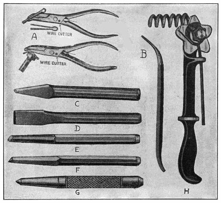
Fig. 166.—Outlining Use of Cotter Pin Pliers, Spring Winder, and Showing Practical Outfit of Chisels.
A complete chisel set suitable for repair shop use is also shown at Fig. 166. The type at C is known as a “cape” chisel and has a narrow cutting point and is intended to chip keyways, remove metal out of corners and for all other work where the broad cutting edge chisel, shown at D, cannot be used. The form with the wide cutting edge is used in chipping, cutting sheet metal, etc. At E, a round nose chisel used in making oil ways is outlined, while a similar tool having a pointed cutting edge and often used for the same purpose is shown at F. The centre punch depicted at G, is very useful for marking parts either for identification or for drilling. In addition[386] to the chisels shown, a number of solid punches or drifts resembling very much that shown at E, except that the point is blunt should be provided to drive out taper pins, bolts, rivets, and other fastenings of this nature. These should be provided in the common sizes. A complete set of real value would start at 1⁄8-inch and increase by increments of 1⁄32-inch up to 1⁄2-inch. A simple spring winder is shown at Fig. 166, H, this making it possible for the repairman to wind coil springs, either on the lathe or in the vise. It will handle a number of different sizes of wire and can be set to space the coils as desired.
Drilling machines may be of two kinds, hand or power operated. For drilling small holes in metal it is necessary to run the drill fast, therefore the drill chuck is usually driven by gearing in order to produce high drill speed without turning the handle too fast. A small hand drill is shown at Fig. 167, A. As will be observed, the chuck spindle is driven by a small bevel pinion, which in turn, is operated by a large bevel gear turned by a crank. The gear ratio is such that one turn of the handle will turn the chuck five or six revolutions. A drill of this design is not suited for drills any larger than one-quarter inch. For use with drills ranging from one-eighth to three-eighths, or even half-inch the hand drill presses shown at C and D are used. These have a pad at the upper end by which pressure may be exerted with the chest in order to feed the drill into the work, and for this reason they are termed “breast drills.” The form at C has compound gearing, the drill chuck being driven by the usual form of bevel pinion in mesh with a larger bevel gear at one end of a countershaft. A small helical spur pinion at the other end of this countershaft receives its motion from a larger gear turned by the hand crank. This arrangement of gearing permits of high spindle speed without the use of large gears, as would be necessary[387] if but two were used. The form at D gives two speeds, one for use with small drills is obtained by engaging the lower bevel pinion with the chuck spindle and driving it by the large ring gear. The slow speed is obtained by shifting the clutch so that the top bevel pinion drives the drill chuck. As this meshes with a gear but slightly larger in diameter, a slow speed of the drill chuck is possible. Breast drills are provided with a[388] handle screwed into the side of the frame, these are used to steady the drill press. For drilling extremely large holes which are beyond the capacity of the usual form of drill press the ratchet form shown at B, may be used or the bit brace outlined at E. The drills used with either of these have square shanks, whereas those used in the drill presses have round shanks. The bit brace is also used widely in wood work and the form shown is provided with a ratchet by which the bit chuck may be turned through only a portion of a revolution in either direction if desired.
In addition to the larger machine tools and the simple hand tools previously described, an essential item of equipment of any engine or plane repair shop, even in cases where the ordinary machine tools are not provided, is a complete outfit of drills, reamers, and threading tools. Drills are of two general classes, the flat and the twist drills. The flat drill has an angle between cutting edges of about 110 degrees and is usually made from special steel commercially known as drill rod.
A flat drill cannot be fed into the work very fast because it removes metal by a scraping, rather than a cutting process. The twist drill in its simplest form is cylindrical throughout the entire length and has spiral flutes which are ground off at the end to form the cutting lip and which also serve to carry the metal chips out of the holes. The simplest form of twist drill used is shown at Fig. 168, C, and is known as a “chuck” drill, because it must be placed in a suitable chuck to turn it. A twist drill removes metal by cutting and it is not necessary to use a heavy feed as the drill will tend to feed itself into the work.
Larger drills than 3⁄4-inch are usually made with a tapered shank as shown at Fig. 168, B. At the end of the taper a tongue is formed which engages with a suitable opening in the collet, as the piece used to support[389] the drill is called. The object of this tongue is to relieve the tapered portion of the drill from the stress of driving by frictional contact alone, as this would not turn the drill positively and the resulting slippage would wear the socket, this depreciation changing the taper and making it unfit for other drills. The tongue is usually proportioned so it is adequate to drive the drill under any condition. A small keyway is provided in the collet into which a tapering key of flat stock may be driven against the end of the tongue to drive the drill from the spindle. A standard taper for drill shanks generally accepted by the machine trade is known as the Morse and is a taper of five-eighths of an inch to the foot. The Brown and Sharp form tapers six-tenths of an inch to the foot. Care must be taken, therefore, when purchasing drills and collets,[390] to make sure that the tapers coincide, as no attempt should be made to run a Morse taper in a Brown and Sharp collet, or vice versa.
Sometimes cylindrical drills have straight flutes, as outlined at Fig. 168, A. Such drills are used with soft metals and are of value when the drill is to pass entirely through the work. The trouble with a drill with spiral flutes is that it will tend to draw itself through as the cutting lips break through. This catching of the drill may break it or move the work from its position. With a straight flute drill the cutting action is practically the same as with the flat drill shown at Fig. 168, E and F.
If a drill is employed in boring holes through close-grained, tough metals, as wrought or malleable iron and steel, the operation will be facilitated by lubricating the drill with plenty of lard oil or a solution of soda and water. Either of these materials will effectually remove the heat caused by the friction of the metal removed against the lips of the drill, and the danger of heating the drill to a temperature that will soften it by drawing the temper is minimized. In drilling large or deep holes it is good practice to apply the lubricating medium directly at the drill point. Special drills of the form shown at Fig. 168, B, having a spiral oil tube running in a suitably formed channel, provides communication between the point of the drill and a suitable receiving hole on a drilled shank. The oil is supplied by a pump and its pressure not only promotes positive circulation and removal of heat, but also assists in keeping the hole free of chips. In drilling steel or wrought iron, lard oil applied to the point of the drill will facilitate the drilling, but this material should never be used with either brass or cast iron.
The sizes to be provided depend upon the nature of the work and the amount of money that can be invested in drills. It is common practice to provide a set of drills, such as shown at Fig. 169, which are carried in a suitable metal stand, these being known as number drills on account[391] of conforming to the wire gauge standards. Number drills do not usually run higher than 5⁄16 inch in diameter. Beyond this point drills are usually sold by the diameter. A set of chuck drills, ranging from 3⁄8 to 3⁄4 inch, advancing by 1⁄32 inch, and a set of Morse taper shank drills ranging from 3⁄4 to 11⁄4 inches, by increments of 1⁄16 inch, will be all that is needed for the most pretentious repair shop, as it is cheaper to bore holes larger than 11⁄4 inches with a boring tool than it is to carry a number of large drills in stock that would be used very seldom, perhaps not enough to justify their cost.
In grinding drills, care must be taken to have the lips of the same length, so that they will form the same angle with the axis. If one lip is longer than the other, as shown in the flat drill at Fig. 168, E, the hole will be larger than the drill size, and all the work of cutting will come upon the longest lip. The drill ends should be symmetrical, as shown at Fig. 168, F.
It is considered very difficult to drill a hole to an exact diameter, but for the most work a variation of a few thousandths of an inch is of no great moment. Where accuracy is necessary, holes must be reamed out to the required size. In reaming, a hole is drilled about 1⁄32 inch[392] smaller than is required, and is enlarged with a cutting tool known as the reamer. Reamers are usually of the fluted form shown at Fig. 170, A. Tools of this nature are not designed to remove considerable amounts of metal, but are intended to augment the diameter of the drill hole by only a small fraction of an inch. Reamers are tapered slightly at the point in order that they will enter the hole easily, but the greater portion of the fluted part is straight, all cutting edges being parallel. Hand reamers are made in either the straight or taper forms, that at A, Fig. 170, being straight, while B has tapering flutes. They are intended to be turned by a wrench similar to that employed in turning a tap, as shown at[393] Fig. 172, C. The reamer shown at Fig. 170, C, is a hand reamer. The form at D has spiral flutes similar to a twist drill, and as it is provided with a taper shank it is intended to be turned by power through the medium of a suitable collet.
As the solid reamers must become reduced in size when sharpened, various forms of inserted blade reamers have been designed. One of these is shown at E, and as the cutting surfaces become reduced in diameter it is possible to replace the worn blades with others of proper size. Expanding reamers are of the form shown at F. These have a bolt passing through that fits into a tapering hole in the interior of the split reamer portion of the tool. If the hole is to be enlarged a few thousandths of an inch, it is possible to draw up on the nut just above the squared end of the shank, and by drawing the tapering wedge farther into the reamer body, the cutting portion will be expanded and will cut a larger hole.
Reamers must be very carefully sharpened or there will be a tendency toward chattering with a consequent production of a rough surface. There are several methods of preventing this chattering, one being to separate the cutting edges by irregular spaces, while the most common method, and that to be preferred on machine reamers, is to use spiral flutes, as shown at Fig. 170, D. Special taper reamers are made to conform to the various taper pin sizes which are sometimes used in holding parts together in an engine. A taper of 1⁄16 inch per foot is intended for holes where a pin, once driven in, is to remain in place. When it is desired that the pin be driven out, the taper is made steeper, generally 1⁄4 inch per foot, which is the standard taper used on taper pins.
When threads are to be cut in a small hole, it will be apparent that it will be difficult to perform this operation economically on a lathe, therefore when internal threading is called for, a simple device known as a “tap” is used. There are many styles of taps, all conforming to different standards. Some are for metric or foreign[394] threads, some conform to the American standards, while others are used for pipe and tubing. Hand taps are the form most used in repair shops, these being outlined at Fig. 171, A and B. They are usually sold in sets of three, known respectively as taper, plug, and bottoming. The taper tap is the one first put into the hole, and is then followed by the plug tap which cuts the threads deeper. If it is imperative that the thread should be full size clear to the bottom of the hole, the third tap of the set, which is straight-sided, is used. It would be difficult to start a bottoming tap into a hole because it would be larger in diameter at its point than the hole. The taper tap, as shown at A, Fig. 171, has a portion of the cutting lands ground away at the point in order that it will enter the hole. The manipulation of a tap is not hard, as it does not need to be forced into the work, as the thread[395] will draw it into the hole as the tap is turned. The tapering of a tap is done so that no one thread is called upon to remove all of the metal, as for about half way up the length of the tap each succeeding thread is cut a little larger by the cutting edge until the full thread enters the hole. Care must be taken to always enter a tap straight in order to have the thread at correct angles to the surface.
In cutting external threads on small rods or on small pieces, such as bolts and studs, it is not always economical to do this work in the lathe, especially in repair work. Dies are used to cut threads on pieces that are to be placed in tapped holes that have been threaded by the corresponding size of tap. Dies for small work are often made solid, as shown at Fig. 171, C, but solid dies are usually limited to sizes below 1⁄2 inch. Sometimes the solid die is cylindrical in shape, with a slot through one side which enables one to obtain a slight degree of adjustment by squeezing the slotted portion together. Large dies, or the sizes over 1⁄2 inch, are usually made in two pieces in order that the halves may be closed up or brought nearer together. The advantage of this form of die is that either of the two pieces may be easily sharpened, and as it may be adjusted very easily the thread may be cut by easy stages. For example, the die may be adjusted to cut large, which will produce a shallow thread that will act as an accurate guide when the die is closed up and a deeper thread cut.
A common form of die holder for an adjustable die is shown at Fig. 172, A. As will be apparent, it consists of a central body portion having guide members to keep the die pieces from falling out and levers at each end in order to permit the operator to exert sufficient force to remove the metal. The method of adjusting the depth of thread with a clamp screw when a two-piece die is employed is also clearly outlined. The diestock shown at B is used for the smaller dies of the one-piece pattern, having a slot in order that they may be closed up slightly[396] by the clamp screw. The reverse side of the diestock shown at B is outlined below it, and the guide pieces, which may be easily moved in or out, according to the size of the piece to be threaded by means of eccentrically disposed semi-circular slots in the adjustment plate, are shown. These movable guide members have small pins let into their surface which engage the slots, and they may be moved in or out, as desired, according to the position of the adjusting plate. The use of the guide pieces makes for accurate positioning or centering of the rod to be threaded. Dies are usually sold in sets, and are commonly furnished as a portion of a complete outfit such as[397] outlined at Fig. 173. That shown has two sizes of diestock, a tap wrench, eight assorted dies, eight assorted taps, and a small screw driver for adjusting the die. An automobile repair shop should be provided with three different sets of taps and dies, as three different standards for the bolts and nuts are used in fastening automobile components. These are the American, metric (used on foreign engines), and the S. A. E. standard threads. A set of pipe dies and taps will also be found useful.
The tool outfit of the machinist or the mechanic who aspires to do machine work must include a number of measuring tools which are not needed by the floor man or one who merely assembles and takes apart the finished pieces. The machinist who must convert raw material into finished products requires a number of measuring tools, some of which are used for taking only approximate measurements, such as calipers and scales, while others are intended to take very accurate measurements, such as the Vernier and the micrometer. A number of common forms of calipers are shown at Fig. 174. These are known as inside or outside calipers, depending upon the measurements they are intended to take. That at A[398] is an inside caliper, consisting of two legs, A and D, and a gauging piece, B, which can be locked to leg A, or released from that member by the screw, C. The object of this construction is to permit of measurements being taken at the bottom of a two diameter hole, where the point to be measured is of larger diameter than the portion of the hole through which the calipers entered. It will be apparent that the legs A and D must be brought close together to pass through the smaller holes. This may be done without losing the setting, as the guide bar B will remain in one position as determined by the size of the hole to be measured, while the leg A may be swung in to clear the obstruction as the calipers are lifted out. When it is desired to ascertain the measurements the leg A is pushed back into place into the slotted portion of the guide B, and locked by the clamp screw C. A tool of this form is known as an internal transfer caliper.
The form of caliper shown at B is an outside caliper. Those at C and D are special forms for inside and outside[399] work, the former being used, if desired, as a divider, while the latter may be employed for measuring the walls of tubing. The calipers at E are simple forms, having a friction joint to distinguish them from the spring calipers shown at B, C and D. In order to permit of ready adjustment of a spring caliper, a split nut as shown at G is sometimes used. A solid nut caliper can only be adjusted by screwing the nut in or out on the screw, which may be a tedious process if the caliper is to be set from one extreme to the other several times in succession. With a slip nut as shown at G it is possible to slip it from one end of the thread to the other without turning it, and of locking it in place at any desired point by simply allowing the caliper leg to come in contact with it. The method of adjusting a spring caliper is shown at Fig. 174, H.
Among the most common of the machinist’s tools are those used for linear measurements. The usual forms are shown in group, Fig. 175. The most common tool, which is widely known, is the carpenter’s folding two-foot rule or the yardstick. While these are very convenient for taking measurements where great accuracy is not required, the machinist must work much more accurately than the carpenter, and the standard steel scale which is shown at D, is a popular tool for the machinist. The steel scale is in reality a graduated straight edge and forms an important part of various measuring tools. These are made of high grade steel and vary from 1 to 48 inches in length. They are carefully hardened in order to preserve the graduations, and all surfaces and edges are accurately ground to insure absolute parallelism. The graduations on the high grade scales are produced with a special device known as a dividing engine, but on cheaper scales, etching suffices to provide a fairly accurate graduation. The steel scales may be very thin and flexible, or may be about an eighth of an inch thick on the twelve-inch size, which is that commonly used with combination squares, protractors and other tools of that[400] nature. The repairman’s scale should be graduated both with the English system, in which the inches are divided into eighths, sixteenths, thirty-secondths and sixty-fourths, and also in the metric system, divided into millimeters and centimeters. Some machinists use scales graduated in tenths, twentieths, fiftieths and hundredths.[401] This is not as good a system of graduation as the more conventional one first described.
Some steel scales are provided with a slot or groove cut the entire length on one side and about the center of the scales. This permits the attachment of various fittings such as the protractor head, which enables the machinist to measure angles, or in addition the heads convert the scale into a square or a tool permitting the accurate bisecting of pieces of circular section. Two scales are sometimes joined together to form a right angle, such as shown at Fig. 175, C. This is known as a square and is very valuable in ascertaining the truth of vertical pieces that are supposed to form a right angle with a base piece.
The Vernier is a device for reading finer divisions on a scale than those into which the scale is divided. Sixty-fourths of an inch are about the finest division that can be read accurately with the naked eye. When fine work is necessary a Vernier is employed. This consists essentially of two rules so graduated that the true scale has each inch divided into ten equal parts, the upper or Vernier portion has ten divisions occupying the same space as nine of the divisions of the true scale. It is evident, therefore, that one of the divisions of the Vernier is equal to nine-tenths of one of those on the true scale. If the Vernier scale is moved to the right so that the graduations marked “1” shall coincide, it will have moved one-tenth of a division on the scale or one-hundredth of an inch. When the graduations numbered 5 coincide the Vernier will have moved five-hundredths of an inch; when the lines marked 0 and 10 coincide, the Vernier will have moved nine-hundredths of an inch, and when 10 on the Vernier comes opposite 10 on the scales, the upper rule will have moved ten-hundredths of an inch, or the whole of one division on the scale. By this means the scale, though it may be graduated only to tenths of an inch, may be accurately set at points with positions expressed in hundredths of an inch. When graduated to read in thousandths, the true scale is divided into fifty parts and[402] the Vernier into twenty parts. Each division of the Vernier is therefore equal to nineteen-twentieths of one of the true scale. If the Vernier be moved so the lines of the first division coincide, it will have moved one-twentieth of one-fiftieth, or .001 inch. The Vernier principle can be readily grasped by studying the section of the Vernier scale and true scale shown at Fig. 176, A.
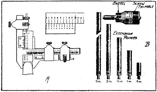
Fig. 176.—At Left, Special Form of Vernier Caliper for Measuring Gear Teeth; at Right, Micrometer for Accurate Internal Measurements.
The caliper scale which is shown at Fig. 175, A, permits of taking the over-all dimension of any parts that will go between the jaws. This scale can be adjusted very accurately by means of a fine thread screw attached to a movable jaw and the divisions may be divided by eye into two parts if one sixty-fourth is the smallest of the divisions. A line is indicated on the movable jaw and coincides with the graduations on the scale. As will be apparent, if the line does not coincide exactly with one of the graduations it will be at some point between the lines and the true measurement may be approximated without trouble.
A group of various other measuring tools of value to the machinist is shown at Fig. 177. The small scale at A is termed a “center gauge,” because it can be used to test[403] the truth of the taper of either a male or female lathe center. The two smaller nicks, or v’s, indicate the shape of a standard thread, and may be used as a guide for grinding the point of a thread-cutting tool. The cross level which is shown at B is of marked utility in erecting, as it will indicate absolutely if the piece it is used to test is level. It will indicate if the piece is level along its width as well as its length.
A very simple attachment for use with a scale that enables the machinist to scribe lines along the length of a cylindrical piece is shown at Fig. 177, C. These are merely small wedge-shaped clamps having an angular face to rest upon the bars. The thread pitch gauge which is shown at Fig. 177, D, is an excellent pocket tool for the mechanic, as it is often necessary to determine without loss of time the pitch of the thread on a bolt or in a nut. This consists of a number of leaves having serrations on one edge corresponding to the standard thread it is to be[404] used in measuring. The tool shown gives all pitches up to 48 threads per inch. The leaves may be folded in out of the way when not in use, and their shape admits of their being used in any position without the remainder of the set interfering with the one in use. The fine pitch gauges have slim, tapering leaves of the correct shape to be used in finding the pitch of small nuts. As the tool is round when the leaves are folded back out of the way, it is an excellent pocket tool, as there are no sharp corners to wear out the pocket. Practical application of a Vernier having measuring heads of special form for measuring gear teeth is shown at Fig. 176, A. As the action of this tool has been previously explained, it will not be necessary to describe it further.
Where great accuracy is necessary in taking measurements the micrometer caliper, which in the simple form will measure easily .001 inch (one-thousandth part of an inch) and when fitted with a Vernier that will measure .0001 inch (one ten-thousandth part of an inch), is used. The micrometer may be of the caliper form for measuring outside diameters or it may be of the form shown at Fig. 176, B, for measuring internal diameters. The operation of both forms is identical except that the internal micrometer is placed inside of the bore to be measured while the external form is used just the same as a caliper. The form outlined will measure from one and one-half to six and a half inches as extension points are provided to increase the range of the instrument. The screw has a movement of one-half inch and a hardened anvil is placed in the end of the thimble in order to prevent undue wear at that point. The extension points or rods are accurately made in standard lengths and are screwed into the body of the instrument instead of being pushed in, this insuring firmness and accuracy. Two forms of micrometers for external measurements are shown at Fig. 178. The[405] top one is graduated to read in thousandths of an inch, while the lower one is graduated to indicate hundredths of a millimeter. The mechanical principle involved in the construction of a micrometer is that of a screw free to move in a fixed nut. An opening to receive the work to be measured is provided by the backward movement of the thimble which turns the screw and the size of the opening is indicated by the graduations on the barrel.
[406]The article to be measured is placed between the anvil and spindle, the frame being held stationary while the thimble is revolved by the thumb and finger. The pitch of the screw thread on the concealed part of the spindle is 40 to an inch. One complete revolution of the spindle, therefore, moves it longitudinally one-fortieth, or twenty-five thousandths of an inch. As will be evident from the development of the scale on the barrel of the inch micrometer, the sleeve is marked with forty lines to the inch, each of these lines indicating twenty-five thousandths. The thimble has a beveled edge which is graduated into twenty-five parts. When the instrument is closed the graduation on the beveled edge of the thimble marked 0 should correspond to the 0 line on the barrel. If the micrometer is rotated one full turn the opening between the spindle and anvil will be .025 inch. If the thimble is turned only one graduation, or one twenty-fifth of a revolution, the opening between the spindle and anvil will be increased only by .001 inch (one-thousandth of an inch).
As many of the dimensions of the airplane parts, especially of those of foreign manufacture or such parts as ball and roller bearings, are based on the metric system, the competent repairman should possess both inch and metric micrometers in order to avoid continual reference to a table of metric equivalents. With a metric micrometer there are fifty graduations on the barrel, these representing .01 of a millimeter, or approximately .004 inch. One full turn of the barrel means an increase of half a millimeter, or .50 mm. (fifty one-hundredths). As it takes two turns to augment the space between the anvil and the stem by increments of one millimeter, it will be evident that it would not be difficult to divide the spaces on the metric micrometer thimble in halves by the eye, and thus the average workman can measure to .0002 inch plus or minus without difficulty. As set in the illustration, the metric micrometers show a space of 13.5 mm., or about one millimeter more than half an inch. The[407] inch micrometer shown is set to five-tenths or five hundred one-thousandths or one-half inch. A little study of the foregoing matter will make it easy to understand the action of either the inch or metric micrometer.
Both of the micrometers shown have a small knurled knob at the end of the barrel. This controls the ratchet stop, which is a device that permits a ratchet to slip by a pawl when more than a certain amount of pressure is applied, thereby preventing the measuring spindle from turning further and perhaps springing the instrument. A simple rule that can be easily memorized for reading the inch micrometer is to multiply the number of vertical divisions on the sleeve by 25 and add to that the number of divisions on the bevel of the thimble reading from the zero to the line which coincides with the horizontal line on the sleeve. For example: if there are ten divisions visible on the sleeve, multiply this number by 25, then add the number of divisions shown on the bevel of the thimble, which is 10. The micrometer is therefore opened 10 × 25 equals 250 plus 10 equals 260 thousandths.
Micrometers are made in many sizes, ranging from those having a maximum opening of one inch to special large forms that will measure forty or more inches. While it is not to be expected that the repairman will have use for the big sizes, if a caliper having a maximum opening of six inches is provided with a number of extension rods enabling one to measure smaller objects, practically all of the measuring needed in repairing engine parts can be made accurately. Two or three smaller micrometers having a maximum range of two or three inches will also be found valuable, as most of the measurements will be made with these tools which will be much easier to handle than the larger sizes.
The equipment of tools necessary for repairing airplane engines depends entirely upon the type of the power[408] plant and while the common hand tools can be used on all forms, the work is always facilitated by having special tools adapted for reaching the nuts and screws that would be hard to reach otherwise. Special spanners and socket wrenches are very desirable. Then again, the nature of the work to be performed must be taken into consideration. Rebuilding or overhauling an engine calls for considerably more tools than are furnished for making field repairs or minor adjustments. A complete set of tools supplied to men working on Curtiss OX-2 engines and JN-4 training biplanes is shown at Fig. 179. The tools are placed in a special box provided with a hinged cover and are arranged in the systematic manner outlined. The various tools and supplies shown are: A, hacksaw blades; B, special socket wrenches for engine bolts and nuts; C, ball pein hammers, four sizes; D, five assorted sizes of screw drivers ranging from very long for heavy work to short and small for fine work; E, seven pairs of pliers including combination in three sizes, two pairs of cutting pliers and one round nose; F, two split pin extractors and spreaders; G, wrench set including three adjustable monkey wrenches, one Stillson or pipe wrench, five sizes adjustable end wrenches and ten double end S wrenches; H, set of files, including flat, three cornered and half round; I, file brush; J, chisel and drift pin; K, three small punches or drifts; L, hacksaw frame; M, soldering copper; N, special spanners for propeller retaining nuts; O, special spanners; P, socket wrenches, long handle; Q, long handle, stiff bristle brushes for cleaning motor; R, gasoline blow torch; S, hand drill; T, spools of safety wire; U, flash lamp; V, special puller and castle wrenches; W, oil can; X, large adjustable monkey wrench; Y, washer and gasket cutter; Z, ball of heavy twine. In addition to the tools, various supplies, such as soldering acid, solder, shellac, valve grinding compound, bolts and nuts, split pins, washers, wood screws, etc., are provided.
| NO. | TOOL | DIRECTIONS FOR USE |
| 1 | Engine hoisting hook, 6-cylinder | Hook under cam-shaft housing, when hoisting engine. |
| 2 | Engine hoisting hook, 4-cylinder | Hook under cam-shaft housing, when hoisting engine. |
| 3 | Water plug wrench | For use on water plugs on top and end of cylinders. |
| 4 | Vertical shaft flange puller | For pulling lower pinion shaft flange from shaft. (Used on A-5 and A-7 engines only.) |
| 5 | Oil gun | For general lubrication use. |
| 6 | Magneto gear puller | For pulling magneto gears from magneto shaft. |
| 7 | Socket wrench, 1⁄4′′ A.L.A.M. | For use on bolts and nuts on crank cases. |
| 8 | Socket wrench, 1⁄4′′ A.L.A.M | For use on crank cases and magneto gear housings. |
| 9 | Socket wrench, 1⁄4′′ A.L.A.M. | For use on magneto gear housings. |
| 10 | Socket wrench, 3⁄8′′ standard | For bolts and nuts which fasten magnetos to crank-case. |
| 11 | Socket wrench, 1⁄4′′ A.L.A.M. | For use on magneto gear housings. |
| 12 | Vertical shaft gear puller | For removing water pump and magneto drive gear. |
| 13 | Brace and facing cutter | For facing lugs on cylinders for cylinder hold down stud washers. |
| 14 | Handle for brace | Use with brace. |
| 15 | Valve grinding brace | For grinding in valves. |
| 16 | Socket wrench base, 3⁄8′′ A.L.A.M. | For thrust bearing cap screws. |
| 17 | Brace and facing cutter, 5⁄16′′ A.L.A.M. | For facing lugs on rocker arm covers. |
| 18 | Valve grinding screw driver | For grinding in valves. |
| 19 | Valve spring tool | For putting on and taking off valve springs. |
| 20 | Block-valve spring tool | For use with valve spring tool. |
| 21 | Socket wrench, 5⁄8′′ A.L.A.M. | For main bearing nuts. |
| 22 | Socket wrench, 1⁄4′′ A.L.A.M. | For use on cam-shaft housing. |
| 23 | Socket wrench, 5⁄16′′ A.L.A.M. | For cam-shaft housing hold down stud nuts. |
| 24 | Socket wrench, 1⁄2′′ A.L.A.M. | For cylinder hold down stud nuts. |
| 25 | Socket wrench, 5⁄16′′ A.L.A.M. | For carburetor and water pump bolts and nuts. |
| 26 | Socket wrench, 5⁄16′′ A.L.A.M. | For carburetor and water pump bolts and nuts. |
| 27 | Socket wrench | For use on carburetor jets. |
| 28 | Magneto screw driver | For general magneto use. |
| 29 | Brass bar, 1′′ diameter × 7′′ long | For driving piston pins from pistons. |
| 30 | Hack saw | For general use. |
| 31 | Oil can | For cam-shaft housing lubrication.[411] |
| 32 | Gasoline or distillate can | For priming or other use. |
| 33 | Oil can | For magneto gear lubrication. |
| 34 | Shellac can | For rubber hose connections and gaskets. |
| 35 | Magneto cleaner | For use on magnetos. |
| 36 | Clamps | For holding cylinder hold down studs, when fitting main bearings. |
| 37 | Piston guards | For use in pistons, when out of engine, to protect them. |
| 38 | Screw driver | For general use. |
| 39 | Vertical shaft clamps | For clamping vertical shaft flanges, when timing engine. |
| 40 | Thrust adjusting nut wrench | For adjusting propeller thrust bearing. |
| 41 | Stuffing box spanner wrench | For adjusting stuffing box nut on vertical shaft. |
| 42 | Water pump spanner wrench | For adjusting water pump stuffing nut. |
| 43 | Wrench | For use on cylinder relief cocks and cylinder priming cocks. |
| 44 | Hose clamp wrench | For use on hose clamps. |
| 45 | Scraper | For cleaning piston ring grooves on pistons. |
| 46 | Crank-shaft nut wrench | For adjusting crank-shaft nut. |
| 47 | Spark-plug wrench | For putting in and taking out spark-plugs in cylinders. |
| 48 | Timing disc (single disc) | For use on crank-shaft to time engine. |
| Specify type motor disc should be made for. If double disc is required, specify the two types of motors the disc is to be made for. Double disc. | ||
| 49 | Main bearing scraper | For scraping in bearings. |
| 50 | Cylinder carbon scraper | For removing carbon from heads of cylinders. |
| 51 | Valve seating tool | For seating valves in cylinder heads. |
| 52 | Scraper, small | For general bearing use. |
| 53 | Scraper, large | For general bearing use. |
| 54 | Crank-shaft flange puller | For pulling crank-shaft flange from crank-shaft. |
| 55 | Piston and connecting rod racks. | |
| 56 | Main bearing stud nuts and shim rack. | |
| 57 | Main bearing board rack. | |
| 58 | Rocker arm and cover rack. | |
[412]The special tools and fixtures recommended by the Hall-Scott Company for work on their engines are clearly shown at Fig. 180. All tools are numbered and their uses may be clearly understood by reference to the illustration and explanatory list given on pages 410 and 411.
After an airplane engine has been in use for a period ranging from 60 to 80 hours, depending upon the type, it is necessary to give it a thorough overhauling before it is returned to service. To do this properly, the engine is removed from the fuselage and placed on a special supporting stand, such as shown at Fig. 181, so it can be placed in any position and completely dismantled. With a stand of this kind it is as easy to work on the bottom of the engine as on the top and every part can be instantly reached. The crank-case shown in place in illustration is in a very convenient position for scraping in the crank-shaft bearings.
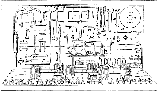
Fig. 180.—Special Tools and Appliances to Facilitate Overhauling Work on Hall-Scott Airplane Engines.
In order to look over the parts of an engine and to restore the worn or defective components it is necessary to take the engine entirely apart, as it is only when the power plant is thoroughly dismantled that the parts can be inspected or measured to determine defects or wear. If one is not familiar with the engine to be inspected, even though the work is done by a repairman of experience, it will be found of value to take certain precautions when dismantling the engine in order to insure that all parts will be replaced in the same position they occupied before removal. There are a number of ways of identifying the parts, one of the simplest and surest being to mark them with steel numbers or letters or with a series of center punch marks in order to retain the proper relation when reassembling. This is of special importance in connection with dismantling multiple cylinder engines as it is vital that pistons, piston rings, connecting rods, valves, and other cylinder parts be always replaced in[414] the same cylinder from which they were removed, because it is uncommon to find equal depreciation in all cylinders. Some repairmen use small shipping tags to identify the pieces. This can be criticised because the tags may become detached and lost and the identity of the piece mistaken. If the repairing is being done in a shop where other engines of the same make are being worked on, the repairman should be provided with a large chest fitted with a lock and key in which all of the smaller parts, such as rods, bolts and nuts, valves, gears, valve springs, cam-shafts, etc., may be stored to prevent the possibility of confusion with similar members of other[415] engines. All parts should be thoroughly cleaned with gasoline or in the potash kettle as removed, and wiped clean and dry. This is necessary to show wear which will be evidenced by easily identified indications in cases where the machine has been used for a time, but in others, the deterioration can only be detected by delicate measuring instruments.
In taking down a motor the smaller parts and fittings such as spark-plugs, manifolds and wiring should be removed first. Then the more important members such as cylinders may be removed from the crank-case to give access to the interior and make possible the examination of the pistons, rings and connecting rods. After the cylinders are removed the next operation is to disconnect the connecting rods from the crank-shaft and to remove them and the pistons attached as a unit. Then the crank-case is dismembered, in most cases by removing the bottom half or oil sump, thus exposing the main bearings and crank-shaft. The first operation is the removal of the inlet and exhaust manifolds. In some cases the manifolds are cored integral with the cylinder head casting and it is merely necessary to remove a short pipe leading from the carburetor to one inlet opening and the exhaust pipe from the outlet opening common to all cylinders. In order to remove the carburetor it is necessary to shut off the gasoline supply at the tank and to remove the pipe coupling at the float chamber. It is also necessary to disconnect the throttle operating rod. After the cylinders are removed and before taking the crank-case apart it is well to remove the water pump and magneto. The wiring on most engines of modern development is carried in conduits and usually releasing two or three minor fastenings will permit one to take off the plug wiring as a unit. The wire should be disconnected from both spark-plugs and magneto distributor before its removal. When the cylinders are removed, the pistons, piston rings, and connecting rods are clearly exposed and their condition may be readily noticed.
[416]Before disturbing the arrangement of the timing gears, it is important that these be marked so that they will be replaced in exactly the same relation as intended by the engine designer. If the gears are properly marked the valve timing and magneto setting will be undisturbed when the parts are replaced after overhauling. With the cylinders off, it is possible to ascertain if there is any undue wear present in the connecting rod bearings at either the wrist pin or crank-pin ends and also to form some idea of the amount of carbon deposits on the piston top and back of the piston rings. Any wear of the timing gears can also be determined. The removal of the bottom plate of the engine enables the repairman to see if the main bearings are worn unduly. Often bearings may be taken up sufficiently to eliminate all looseness. In other cases they may be worn enough so that careful refitting will be necessary. Where the crank-case is divided horizontally into two portions, the upper one serving as an engine base to which the cylinders and in fact all important working parts are attached, the lower portion performs the functions of an oil container and cover for the internal mechanism. This is the construction generally followed.
After the cylinders have been removed and stripped of all fittings, they should be thoroughly cleaned and then carefully examined for defects. The interior or bore should be looked at with a view of finding score marks, grooves, cuts or scratches in the interior, because there are many faults that may be ascribed to depreciation at this point. The cylinder bore may be worn out of round, which can only be determined by measuring with an internal caliper or dial indicator even if the cylinder bore shows no sign of wear. The flange at the bottom of the cylinder by which it is held to the engine base may be cracked. The water jacket wall may have opened up due[417] to freezing of the jacket water at some time or other or it may be filled with scale and sediment due to the use of impure cooling water. The valve seat may be scored or pitted, while the threads holding the valve chamber cap may be worn so that the cap will not be a tight fit. The detachable head construction makes it possible to remove that member and obtain ready access to the piston tops for scraping out carbon without taking the main cylinder portion from the crank-case. When the valves need grinding the head may be removed and carried to the bench where the work may be performed with absolute assurance that none of the valve grinding compound will penetrate into the interior of the cylinder as is sometimes unavoidable with the I-head cylinder. If the cylinder should be scored, the water jacket and combustion head may be saved and a new cylinder casting purchased at considerably less cost than that of the complete unit cylinder.
The detachable head construction has only recently been applied on airplane engines, though it was one of the earliest forms of automobile engine construction. In the early days it was difficult to procure gaskets or packings that would be both gas and water tight. The sheet asbestos commonly used was too soft and blew out readily. Besides a new gasket had to be made every time the cylinder head was removed. Woven wire and asbestos packings impregnated with rubber, red lead, graphite and other filling materials were more satisfactory than the soft sheet asbestos, but were prone to burn out if the water supply became low. Materials such as sheet copper or brass proved to be too hard to form a sufficiently yielding packing medium that would allow for the inevitable slight inaccuracies in machining the cylinder head and cylinder. The invention of the copper-asbestos gasket, which is composed of two sheets of very thin, soft copper bound together by a thin edging of the same material and having a piece of sheet asbestos interposed solved this problem. Copper-asbestos packings form an effective seal against leakage of water and a positive retention[418] means for keeping the explosion pressure in the cylinder. The great advantage of the detachable head is that it permits of very easy inspection of the piston tops and combustion chamber and ready removal of carbon deposits.
Most authorities agree that carbon is the result of imperfect combustion of the fuel and air mixture as well as the use of lubricating oils of improper flash point. Lubricating oils that work by the piston rings may become decomposed by the great heat in the combustion chamber, but at the same time one cannot blame the lubricating oil for all of the carbon deposits. There is little reason to suspect that pure petroleum oil of proper body will deposit excessive amounts of carbon, though if the oil is mixed with castor oil, which is of vegetable origin, there would be much carbon left in the interior of the combustion chamber. Fuel mixtures that are too rich in gasoline also produce these undesirable accumulations.
A very interesting chemical analysis of a sample of carbon scraped from the interior of a motor vehicle engine shows that ordinarily the lubricant is not as much to blame as is commonly supposed. The analysis was as follows:
| Oil | 14.3 | % |
| Other combustible matter | 17.9 | |
| Sand, clay, etc. | 24.8 | |
| Iron oxide | 24.5 | |
| Carbonate of lime | 8.9 | |
| Other constituents | 9.6 |
It is extremely probable that the above could be divided into two general classes, these being approximately 32.2% oil and combustible matter and a much larger proportion, or 67.8% of earthy matter. The presence of such a large percentage of earthy matter is undoubtedly due to the impurities in the air, such as road dust which[419] has been sucked in through the carburetor. The fact that over 17% of the matter which is combustible was not of an oily nature lends strong support to this view. There would not be the amount of earthy material present in the carbon deposits of an airplane engine as above stated because the air is almost free from dust at the high altitudes planes are usually flown. One could expect to find more combustible and less earthy matter and the carbon would be softer and more easily removed. It is very good practice to provide a screen on the air intake to reduce the amounts of dust sucked in with the air as well as observing the proper precautions relative to supplying the proper quantities of air to the mixture and of not using any more oil than is needed to insure proper lubrication of the internal mechanism.
It is not unusual for one to hear an aviator complain that the engine he operates is not as responsive as it was when new after he has run it but relatively few hours. There does not seem to be anything actually wrong with the engine, yet it does not respond readily to the throttle and is apt to overheat. While these symptoms denote a rundown condition of the mechanism, the trouble is often due to nothing more serious than accumulations of carbon. The remedy is the removal of this matter out of place. The surest way of cleaning the inside of the motor thoroughly is to remove the cylinders, if these members are cast integrally with the head or of removing the head member if that is a separate casting, to expose all parts.
In certain forms of cylinders, especially those of the L form, it is possible to introduce simple scrapers down through the valve chamber cap holes and through the spark-plug hole if this component is placed in the cylinder in some position that communicates directly to the interior of the cylinder or to the piston top. No claim can be made for originality or novelty of this process as[420] is has been used for many years on large stationary engines. The first step is to dismantle the inlet and exhaust piping and remove the valve caps and valves, although if the deposit is not extremely hard or present in large quantities one can often manipulate the scrapers in the valve cap openings without removing either the piping or the valves. Commencing with the first cylinder, the crank-shaft is turned till the piston is at the top of its stroke, then the scraper may be inserted, and the operation of removing the carbon started by drawing the tool toward the opening. As this is similar to a small hoe, the cutting edge will loosen some of the carbon and will draw it toward the opening. A swab is made of a piece of cloth or waste fastened at the end of a wire and well soaked in kerosene to clean out the cylinder.
When available, an electric motor with a length of flexible shaft and a small circular cleaning brush having wire bristles can be used in the interior of the engine. The electric motor need not be over one-eighth horsepower running 1,200 to 1,600 R. P. M., and the wire brush must, of course, be of such size that it can be easily inserted through the valve chamber cap. The flexible shaft permits one to reach nearly all parts of the cylinder interior without difficulty and the spreading out and flattening of the brush insures that considerable surface will be covered by that member.
A process of recent development that gives very good results in removing carbon without disassembling the motor depends on the process of burning out that material by supplying oxygen to support the combustion and to make it energetic. A number of concerns are already offering apparatus to accomplish this work, and in fact any shop using an autogenous welding outfit may use the oxygen tank and reducing valve in connection with a simple special torch for burning the carbon. Results[421] have demonstrated that there is little danger of damaging the motor parts, and that the cost of oxygen and labor is much lower than the old method of removing the cylinders and scraping the carbon out, as well as being very much quicker than the alternative process of using carbon solvent. The only drawback to this system is that there is no absolute insurance that every particle of carbon will be removed, as small protruding particles may be left at points that the flame does not reach and cause pre-ignition and consequent pounding, even after the oxygen treatment. It is generally known that carbon will burn in the presence of oxygen, which supports combustion of all materials, and this process takes advantage of this fact and causes the gas to be injected into the combustion chamber over a flame obtained by a match or wax taper.
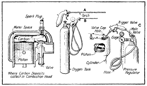
Fig. 182.—Showing Where Carbon Deposits Collect in Engine Combustion Chamber, and How to Burn Them Out with the Aid of Oxygen. A—Special Torch. B—Torch Coupled to Oxygen Tank. C—Torch in Use.
It is suggested by those favoring this process that the night before the oxygen is to be used the engine be given a conventional kerosene treatment. A half tumbler full of this liquid or of denatured alcohol is to be poured[422] into each cylinder and permitted to remain there over night. As a precaution against fire, the gasoline is shut off from the carburetor before the torch is inserted in the cylinder and the motor started so that the gasoline in the pipe and carburetor float chamber will be consumed. Work is done on one cylinder at a time. A note of caution was recently sounded by a prominent spark-plug manufacturer recommending that the igniter member be removed from the cylinder in order not to injure it by the heat developed. The outfits on the market consist of a special torch having a trigger controlled valve and a length of flexible tubing such as shown at Fig. 182, A, and a regulating valve and oxygen tank as shown at B. The gauge should be made to register about twelve pounds pressure.
The method of operation is very simple and is outlined at C. The burner tube is placed in the cylinder and the trigger valve is opened and the oxygen permitted to circulate in the combustion chamber. A lighted match or wax taper is dropped in the chamber and the injector tube is moved around as much as possible so as to cover a large area. The carbon takes fire and burns briskly in the presence of the oxygen. The combustion of the carbon is accompanied by sparks and sometimes by flame if the deposit is of an oily nature. Once the carbon begins to burn the combustion continues without interruption as long as the oxygen flows into the cylinder. Full instructions accompany each outfit and the amount of pressure for which the regulator should be set depends upon the design of the torch and the amount of oxygen contained in the storage tank.
If the engine has been run at any time without adequate lubrication, one or more of the cylinders may be found to have vertical scratches running up and down the cylinder walls. The depth of these will vary according[423] to the amount of time the cylinder was without lubrication, and if the grooves are very deep the only remedy is to purchase a new member. Of course, if sufficient stock is available in the cylinder walls, the cylinders may be rebored and new pistons which are oversize, i.e., larger than standard, may be fitted. Where the scratches are not deep they may be ground out with a high speed emery wheel or lapped out if that type of machine is not available. Wrist pins have been known to come loose, especially when these are retained by set screws that are not properly locked, and as wrist-pins are usually of hardened steel it will be evident that the sharp edge of that member can act as a cutting tool and make a pronounced groove in the cylinder. Cylinder grinding is a job that requires skilled mechanics, but may be accomplished on any lathe fitted with an internal grinding attachment. While automobile engine cylinders usually have sufficient wall thickness to stand reboring, those of airplane engines seldom have sufficient metal to permit of enlarging the bore very much by a boring tool. A few thousandths of an inch may be ground out without danger, however. An airplane engine cylinder with deep grooves must be scrapped as a general rule.
Where the grooves in the cylinder are not deep or where it has warped enough so the rings do not bear equally at all parts of the cylinder bore, it is possible to obtain a fairly accurate degree of finish by a lapping process in which an old piston is coated with a mixture of fine emery and oil and is reciprocated up and down in the cylinder as well as turned at the same time. This may be easily done by using a dummy connecting rod having only a wrist pin end boss, and of such size at the other end so that it can be held in the chuck of a drill press. The cylinder casting is firmly clamped on the drill press table by suitable clamping blocks, and a wooden block is placed in the combustion chamber to provide a stop for the piston at its lower extreme position. The back gears are put in and the drill chuck is revolved slowly. All the[424] while that the piston is turning the drill chuck should be raised up and down by the hand feed lever, as the best results are obtained when the lapping member is given a combination of rotary and reciprocating motion.
One of the most important parts of the gasoline engine and one that requires frequent inspection and refitting to keep in condition, is the mushroom or poppet valve that controls the inlet and exhaust gas flow. In overhauling it is essential that these valves be removed from their seatings and examined carefully for various defects which will be enumerated at proper time. The problem that concerns us now is the best method of removing the valve. These are held against the seating in the cylinder by a coil spring which exerts its pressure on the cylinder casting at the upper end and against a suitable collar held by a key at the lower end of the valve stem. In order to remove the valve it is necessary to first compress the spring by raising the collar and pulling the retaining key out of the valve stem. Many forms of valve spring lifters have been designed to permit ready removal of the valves.
When the cylinder is of the valve in-the-head form, the method of valve removal will depend entirely upon the system of cylinder construction followed. In the Sturtevant cylinder design it is possible to remove the head from the cylinder castings and the valve springs may be easily compressed by any suitable means when the cylinder head is placed on the work bench where it can be easily worked on. The usual method is to place the head on a soft cloth with the valves bearing against the bench. The valve springs may then be easily pushed down with a simple forked lever and the valve stem key removed to release the valve spring collar. In the Curtiss OX-2 (see Fig. 1821⁄2) and Hall-Scott engines it is not possible to remove the valves without taking the cylinder[425] off the crank-case, because the valve seats are machined directly in the cylinder head and the valve domes are cast integrally with the cylinder. This means that if the valves need grinding the cylinder must be removed from the engine base to provide access to the valve heads which are inside of that member, and which cannot be reached from the outside as is true of the L-cylinder construction. In the Curtiss VX engines, the valves are carried in detachable cages which may be removed when the valves need attention.
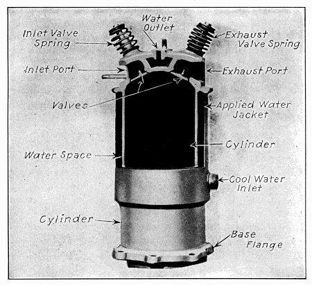
Fig. 1821⁄2.—Part Sectional View, Showing Valve Arrangement in Cylinder of Curtiss OX-2 Aviation Engine.
Much has been said relative to valve grinding, and despite the mass of information given in the trade prints[426] it is rather amusing to watch the average repairman or the engine user who prides himself on maintaining his own motor performing this essential operation. The common mistakes are attempting to seat a badly grooved or pitted valve head on an equally bad seat, which is an almost hopeless job, and of using coarse emery and bearing down with all one’s weight on the grinding tool with the hope of quickly wearing away the rough surfaces. The use of improper abrasive material is a fertile cause of failure to obtain a satisfactory seating. Valve grinding is not a difficult operation if certain precautions are taken before undertaking the work. The most important of these is to ascertain if the valve head or seat is badly scored or pitted. If such is found to be the case no ordinary amount of grinding will serve to restore the surfaces. In this event the best thing to do is to remove the valve from its seating and to smooth down both the valve head and the seat in the cylinder before attempt is made to fit them together by grinding. Another important precaution is to make sure that the valve stem is straight, and that the head is not warped out of shape.
A number of simple tools is available at the present time for reseating valves, these being outlined at Fig. 183. That shown at A is a simple fixture for facing off the valve head. The stem is supported by suitable bearings carried by the body or shank of the tool, and the head is turned against an angularly disposed cutter which is set for the proper valve seat angle. The valve head is turned by a screw-driver, the amount of stock removed from the head depending upon the location of the adjusting screw. Care must be taken not to remove too much metal, only enough being taken off to remove the most of the roughness. Valves are made in two standard tapers, the angle being either 45 or 60 degrees. It is imperative that the cutter blade be set correctly in order that the bevel is not changed. A set of valve truing and valve-seat reaming cutters is shown at Fig. 183, B. This is adaptable to various size valve heads, as the cutter[427] blade D may be moved to correspond to the size of the valve head being trued up. These cutter blades are made of tool steel and have a bevel at each end, one at 45 degrees, the other at 60 degrees. The valve seat reamer shown at G will take any one of the heads shown at F.[428] It will also take any one of the guide bars shown at H. The function of the guide bars is to fit the valve stem bearing in order to locate the reamer accurately and to insure that the valve seat is machined concentrically with its normal center. Another form of valve seat reamer and a special wrench used to turn it is shown at C. The valve head truer shown at Fig. 183, D, is intended to be placed in a vise and is adaptable to a variety of valve head sizes. The smaller valves merely fit deeper in the conical depression. The cutter blade is adjustable and the valve stem is supported by a simple self-centering bearing. In operation it is intended that the valve stem, which protrudes through the lower portion of the guide bearing, shall be turned by a drill press or bit stock while the valve head is set against the cutter by pressure of a pad carried at the end of a feed screw which is supported by a hinged bridge member. This can be swung out of place as indicated to permit placing the valve head against the cutter or removing it.
As the sizes of valve heads and stems vary considerably a “Universal” valve head truing tool must have some simple means of centering the valve stem in order to insure concentric machining of the valve head. A valve head truer which employs an ingenious method of guiding the valve stem is shown at Fig. 183, E. The device consists of a body portion, B, provided with an external thread at the top on which the cutter head, A, is screwed. A number of steel balls, C, are carried in the grooves which may be altered in size by the adjustment nut, F, which screws in the bottom of the body portion, B. As the nut F is screwed in against the spacer member E, the V-grooves are reduced in size and the steel balls, C, are pressed out in contact with the valve stem. As the circle or annulus is filled with balls in both upper and lower portions the stem may be readily turned because it is virtually supported by ball bearing guides. When a larger valve stem is to be supported, the adjusting nut F, is screwed out which increases the size of the grooves[429] and permits the balls, C, to spread out and allow the larger stem to be inserted.
Mention has been previously made of the importance of truing both valve head and seat before attempt is made to refit the parts by grinding. After smoothing the valve seat the next step is to find some way of turning the valve. Valve heads are usually provided with a screw-driver slot passing through the boss at the top of the valve or with two drilled holes to take a forked grinding tool. A combination grinding tool has been devised which may be used when either the two drilled holes or the slotted head form of valve is to be rotated. This consists of a special form of screw driver having an enlarged boss just above the blade, this boss serving to support a U-shape piece which can be securely held in operative position by the clamp screw or which can be turned out of the way if the screw driver blade is to be used.
As it is desirable to turn the valve through a portion of a revolution and back again rather than turning it always in the same direction, a number of special tools has been designed to make this oscillating motion possible without trouble. A simple valve grinding tool is shown at Fig. 184, C. This consists of a screw-driver blade mounted in a handle in such a way that the end may turn freely in the handle. A pinion is securely fastened to the screw-driver blade shank, and is adapted to fit a race provided with a wood handle and guided by a bent bearing member securely fastened to the screw-driver handle. As the rack is pushed back and forth the pinion must be turned first in one direction and then in the other.
A valve grinding tool patterned largely after a breast drill is shown at Fig. 184, D. This is worked in such a manner that a continuous rotation of the operating crank will result in an oscillating movement of the chuck carrying the screw-driver blade. The bevel pinions which are[430] used to turn the chuck are normally free unless clutched to the chuck stem by the sliding sleeve which must turn with the chuck stem and which carries clutching members at each end to engage similar members on the bevel pinions and lock these to the chuck stem, one at a time. The bevel gear carries a cam-piece which moves the clutch[431] sleeve back and forth as it revolves. This means that the pinion giving forward motion of the chuck is clutched to the chuck spindle for a portion of a revolution of the gear and clutch sleeve is moved back by the cam and clutched to the pinion giving a reverse motion of the chuck during the remainder of the main drive gear revolution.
It sometimes happens that the adjusting screw on the valve lift plunger or the valve lift plunger itself when L head cylinders are used does not permit the valve head to rest against the seat. It will be apparent that unless a definite space exists between the end of the valve stem and the valve lift plunger that grinding will be of little avail because the valve head will not bear properly against the abrasive material smeared on the valve seat.
The usual methods of valve grinding are clearly outlined at Fig. 184. The view at the left shows the method of turning the valve by an ordinary screw driver and also shows a valve head at A, having both the drilled holes and the screw-driver slot for turning the member and two special forms of fork-end valve grinding tools. In the sectional view shown at the right, the use of the light spring between the valve head and the bottom of the valve chamber to lift the valve head from the seat whenever pressure on the grinding tool is released is clearly indicated. It will be noted also that a ball of waste or cloth is interposed in the passage between the valve chamber and the cylinder interior to prevent the abrasive material from passing into the cylinder from the valve chamber. When a bitstock is used, instead of being given a true rotary motion the chuck is merely oscillated through the greater part of the circle and back again. It is necessary to lift the valve from its seat frequently as the grinding operation continues; this is to provide an even distribution of the abrasive material placed between the valve head and its seat. Only sufficient pressure is given to the bitstock to overcome the uplift of the spring and to insure that the valve will be held against the seat. Where[432] the spring is not used it is possible to raise the valve from time to time with the hand which is placed under the valve stem to raise it as the grinding is carried on. It is not always possible to lift the valve in this manner when the cylinders are in place on the engine base owing to the space between the valve lift plunger and the end of the valve stem. In this event the use of the spring as shown in sectional view will be desirable.
The abrasive generally used is a paste made of medium or fine emery and lard oil or kerosene. This is used until the surfaces are comparatively smooth, after which the final polish or finish is given with a paste of flour emery, grindstone dust, crocus, or ground glass and oil. An erroneous impression prevails in some quarters that the valve head surface and the seating must have a mirror-like polish. While this is not necessary it is essential that the seat in the cylinder and the bevel surface of the head be smooth and free from pits or scratches at the completion of the operation. All traces of the emery and oil should be thoroughly washed out of the valve chamber with gasoline before the valve mechanism is assembled and in fact it is advisable to remove the old grinding compound at regular intervals, wash the seat thoroughly and supply fresh material as the process is in progress.
The truth of seatings may be tested by taking some Prussian blue pigment and spreading a thin film of it over the valve seat. The valve is dropped in place and is given about one-eighth turn with a little pressure on the tool. If the seating is good both valve head and seat will be covered uniformly with color. If high spots exist, the heavy deposit of color will show these while the low spots will be made evident because of the lack of pigment. The grinding process should be continued until the test shows an even bearing of the valve head at all points of the cylinder seating. When the valves are held in cages it is possible to catch the cage in a vise and to turn the valve in any of the ways indicated. It is much[433] easier to clean off the emery and oil and there is absolutely no danger of getting the abrasive material in the cylinder if the construction is such that the valve cage or cylinder head member carrying the valve can be removed from the cylinder. When valves are held in cages, the tightness of the seat may be tested by partially filling the cage with gasoline and noticing how much liquid oozes out around the valve head. The degree of moisture present indicates the efficacy of the grinding process.
The valves of Curtiss OX-2 cylinders are easily ground in by using a simple fixture or tool and working from the top of the cylinder instead of from the inside. A tube having a bore just large enough to go over the valve stem is provided with a wooden handle or taped at one end and a hole of the same size as that drilled through the valve stem is put in at the other. To use, the open end of the tube is pushed over the valve stem and a split pin pushed through the tube and stem. The valve may be easily manipulated and ground in place by oscillating in the customary manner.
There are a number of points to be watched in the valve operating system because valve timing may be seriously interfered with if there is much lost motion at the various bearing points in the valve lift mechanism. The two conventional methods of opening valves are shown at Fig. 185. That at A is the type employed when the valve cages are mounted directly in the head, while the form at B is the system used when the valves are located in a pocket or extension of the cylinder casting as is the case if an L, or T-head cylinder is used. It will be evident that there are several points where depreciation may take place. The simplest form is that shown at B, and even on this there are five points where lost motion may be noted. The periphery of the valve opening cam or roller may be worn, though this is not likely unless the roller or cam has[434] been inadvertently left soft. The pin which acts as a bearing for the roller may become worn, this occurring quite often. Looseness may materialize between the bearing surfaces of the valve lift plunger and the plunger guide casting, and there may also be excessive clearance between the top of the plunger and the valve stem.
On the form shown at A, there are several parts added to those indicated at B. A walking beam or rocker lever is necessary to transform the upward motion of the tappet rod to a downward motion of the valve stem. The pin[435] on which this member fulcrums may wear as will also the other pin acting as a hinge or bearing for the yoke end of the tappet rod. It will be apparent that if slight play existed at each of the points mentioned it might result in a serious diminution of valve opening. Suppose, for example, that there were .005-inch lost motion at each of three bearing points, the total lost motion would be .015-inch or sufficient to produce noisy action of the valve mechanism. When valve plungers of the adjustable form, such as shown at B, are used, the hardened bolt head in contact with the end of the valve stem may become hollowed out on account of the hammering action at that point. It is imperative that the top of this member be ground off true and the clearance between the valve stem and plunger properly adjusted. If the plunger is a non-adjustable type it will be necessary to lengthen the valve stem by some means in order to reduce the excessive clearance. The only remedy for wear at the various hinges and bearing pins is to bore the holes out slightly larger and to fit new hardened steel pins of larger diameter. Depreciation between the valve plunger guide and the valve plunger is usually remedied by fitting new plunger guides in place of the worn ones. If there is sufficient stock in the plunger guide casting as is sometimes the case when these members are not separable from the cylinder casting, the guide may be bored out and bushed with a light bronze bushing.
A common cause of irregular engine operation is due to a sticking valve. This may be owing to a bent valve stem, a weak or broken valve spring or an accumulation of burnt or gummed oil between the valve stem and the valve stem guide. In order to prevent this the valve stem must be smoothed with fine emery cloth and no burrs or shoulders allowed to remain on it, and the stem must also be straight and at right angles to the valve head. If the spring is weak it may be strengthened in some cases by stretching it out after annealing so that a larger space will exist between the coils and re-hardening. Obviously[436] if a spring is broken the only remedy is replacement of the defective member.
Mention has been made of wear in the valve stem guide and its influence on engine action. When these members are an integral part of the cylinder the only method of compensating for this wear is to drill the guide out and fit a bushing, which may be made of steel tube.
In some engines, especially those of recent development, the valve stem guide is driven or screwed into the cylinder casting and is a separate member which may be removed when worn and replaced with a new one. When the guides become enlarged to such a point that considerable play exists between them and the valve stems, they may be easily knocked out or unscrewed.
If an engine has been entirely dismantled it is very easy to examine the pistons for deterioration. While it is important that the piston be a good fit in the cylinder it is mainly upon the piston rings that compression depends. The piston should fit the cylinder with but little looseness, the usual practice being to have the piston about .001-inch smaller than the bore for each inch of piston diameter at the point where the least heat is present or at the bottom of the piston. It is necessary to allow more than this at the top of the piston owing to its expansion due to the direct heat of the explosion. The clearance is usually graduated and a piston that would be .005-inch smaller than the cylinder bore at the bottom would be about .0065-inch at the middle and .0075-inch at the top. If much more play than this is evidenced the piston will “slap” in the cylinder and the piston will be worn at the ends more than in the center. Aluminum or alloy pistons require more clearance than cast iron ones do, usually 1.50 times as much. Pistons sometimes warp out of shape and are not truly cylindrical. This results in the high spots rubbing on the cylinder while the low[437] spots will be blackened where a certain amount of gas has leaked by.
Mention has been previously made of the necessity of reboring or regrinding a cylinder that has become scored or scratched and which allows the gas to leak by the piston rings. When the cylinder is ground out, it is necessary to use a larger piston to conform to the enlarged cylinder bore. Most manufacturers are prepared to furnish over-size pistons, there being four standard over-size dimensions adopted by the S. A. E. for rebored cylinders. These are .010-inch, .020-inch, .030-inch, and .040-inch larger than the original bore.
The piston rings should be taken out of the piston grooves and all carbon deposits removed from the inside of the ring and the bottom of the groove. It is important to take this deposit out because it prevents the rings from performing their proper functions by reducing the ring elasticity, and if the deposit is allowed to accumulate it may eventually result in sticking and binding of the ring, this producing excessive friction or loss of compression. When the rings are removed they should be tested to see if they retain their elasticity and it is also well to see that the small pins in some pistons which keep the rings from turning around so the joints will not come in line are still in place. If no pins are found there is no cause for alarm because these dowels are not always used. When fitted, they are utilized with rings having a butt joint or diagonal cut as the superior gas retaining qualities of the lap or step joint render the pins unnecessary.
If gas has been blowing by the ring or if these members have not been fitting the cylinder properly the points where the gas passed will be evidenced by burnt, brown or roughened portions of the polished surface of the pistons and rings. The point where this discoloration will be noticed more often is at the thin end of an eccentric ring, the discoloration being present for about 1⁄2-inch or 3⁄4-inch each side of the slot. It may be possible that[438] the rings were not true when first put in. This made it possible for the gas to leak by in small amounts initially which increased due to continued pressure until quite a large area for gas escape had been created.
Removing piston rings without breaking them is a difficult operation if the proper means are not taken, but is a comparatively simple one when the trick is known. The tools required are very simple, being three strips of thin steel about one-quarter inch wide and four or five inches long and a pair of spreading tongs made up of one-quarter inch diameter keystock tied in the center with a copper wire to form a hinge. The construction is such that when the hand is closed and the handles brought together the other end of the expander spreads out, an action just opposite to that of the conventional pliers. The method of using the tongs and the metal strips is clearly indicated at Fig. 186. At A the ring expander is shown spreading the ends of the rings sufficiently to insert the pieces of sheet metal between one of the rings and the piston. Grasp the ring as shown at B, pressing with the thumbs on the top of the piston and the ring will slide off easily, the thin metal strips acting as guide members to prevent the ring from catching in the other piston grooves. Usually no difficulty is experienced in removing the top or bottom rings, as these members may be easily expanded and worked off directly without the use of a metal strip. When removing the intermediate rings, however, the metal strips will be found very useful. These are usually made by the repairman by grinding the teeth from old hacksaw blades and rounding the edges and corners in order to reduce the liability of cutting the fingers. By the use of the three metal strips a ring is removed without breaking or distorting it and practically no time is consumed in the operation.
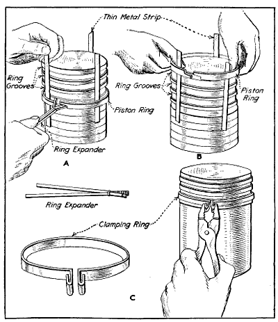
Fig. 186.—Method of Removing Piston Rings, and Simple Clamp to Facilitate Insertion of Rings in Cylinder.
Before installing new rings, they should be carefully fitted to the grooves to which they are applied. The tools required are a large piece of fine emery cloth, a thin, flat file, a small vise with copper or leaden jaw clips, and a smooth hard surface such as that afforded by the top of a surface plate or a well planed piece of hard wood. After making sure that all deposits of burnt oil and carbon have been removed from the piston grooves, three rings are selected, one for each groove. The ring is turned all around its circumference into the groove it is to fit, which can be done without springing it over the piston as the outside edge of the ring may be used to test the width of the groove just as well as the inside edge. The ring should be a fair fit and while free to move circumferentially there should be no appreciable up and down motion. If the ring is a tight fit it should be laid edge down upon the piece of emery cloth which is placed on the surface plate and carefully rubbed down until it fits the groove it is to occupy. It is advisable to fit each piston ring individually and to mark them in some way to insure that they will be placed in the groove to which they are fitted.
The repairman next turns his attention to fitting the ring in the cylinder itself. The ring should be pushed into the cylinder at least two inches up from the bottom and endeavor should be made to have the lower edge of the ring parallel with the bottom of the cylinder. If the ring is not of correct diameter, but is slightly larger than the cylinder bore, this condition will be evident by the angular slots of the rings being out of line or by difficulty in inserting the ring if it is a lap joint form. If such is the case the ring is removed from the cylinder and placed in the vise between soft metal jaw clips. Sufficient metal is removed with a fine file from the edges of the ring at the slot until the edges come into line and a slight space exists between them when the ring is placed into the cylinder. It is important that this space be left between the[440] ends, for if this is not done when the ring becomes heated the expansion of metal may cause the ends to abut and the ring to jam in the cylinder.
It is necessary to use more than ordinary caution in replacing the rings on the piston because they are usually made of cast iron, a metal that is very fragile and liable to break because of its brittleness. Special care should be taken in replacing new rings as these members are[441] more apt to break than old ones. This is probably accounted for by the heating action on used rings which tends to anneal the metal as well as making it less springy. The bottom ring should be placed in position first which is easily accomplished by springing the ring open enough to pass on the piston and then sliding it into place in the lower groove which on some types of engines is below the wrist pin, whereas in others all grooves are above that member. The other members are put in by a reversal of the process outlined at Fig. 186, A and B. It is not always necessary to use the guiding strips of metal when replacing rings as it is often possible, by putting the rings on the piston a little askew and maneuvering them to pass the grooves without springing the ring into them. The top ring should be the last one placed in position.
Before placing pistons in the cylinder one should make sure that the slots in the piston rings are spaced equidistant on the piston, and if pins are used to keep the ring from turning one should be careful to make sure that these pins fit into their holes in the ring and that they are not under the ring at any point. Practically all cylinders are chamfered at the lower end to make insertion of piston rings easier. The operation of putting on a cylinder casting over a piston really requires two pairs of hands, one to manipulate the cylinder, the other person to close the rings as they enter the cylinder. This may be done very easily by a simple clamp member made of sheet brass or iron and used to close the ring as indicated at Fig. 186, C. It is apparent that the clamp must be adjusted to each individual ring and that the split portion of the clamp must coincide with the split portion of the ring. The cylinder should be well oiled before any attempt is made to install the pistons. The engine should be run with more than the ordinary amount of lubricant for several hours after new piston rings have been inserted. On first starting the engine, one may be disappointed in that the compression is even less than that obtained with the old rings. This condition will soon be remedied as the rings become[442] polished and adapt themselves to the contour of the cylinder.
While wrist pins are usually made of very tough steel, case hardened with the object of wearing out an easily renewable bronze bushing in the upper end of the connecting rod rather than the wrist pin it sometimes happens that these members will be worn so that even the replacement of a new bushing in the connecting rod will not reduce the lost motion and attendant noise due to a loose wrist pin. The only remedy is to fit new wrist pins to the piston. Where the connecting rod is clamped to the wrist pin and that member oscillates in the piston bosses the wear will usually be indicated on bronze bushings which are pressed into the piston bosses. These are easily renewed and after running a reamer through them of the proper size no difficulty should be experienced in replacing either the old or a new wrist pin depending upon the condition of that member. If no bushings are provided, as in alloy pistons, the bosses can sometimes be bored out and thin bushings inserted, though this is not always possible. The alternative is to ream out the bosses and upper end of rod a trifle larger after holes are trued up and fit oversize wrist pins.
While the engine is dismantled one has an excellent opportunity to examine the various bearing points in the engine crank-case to ascertain if any looseness exists due to depreciation of the bearing surfaces. As will be evident, both main crank-shaft bearings and the lower end of the connecting rods may be easily examined for deterioration. With the rods in place, it is not difficult to feel the amount of lost motion by grasping the connecting rod firmly with the hand and moving it up and down. After the connecting rods have been removed and the[443] propeller hub taken off the crank-shaft to permit of ready handling, any looseness in the main bearing may be detected by lifting up on either the front or rear end of the crank-shaft and observing if there is any lost motion between the shaft journal and the main bearing caps. It is not necessary to take an engine entirely apart to examine the main bearings, as in most forms these may be readily reached by removing the sump. The symptoms of worn main bearings are not hard to identify. If an engine knocks regardless of speed or spark-lever position, and the trouble is not due to carbon deposits in the combustion chamber, one may reasonably surmise that the main bearings have become loose or that lost motion may exist at the connecting rod big ends, and possibly at the wrist pins. The main journals of any well resigned engine are usually proportioned with ample surface and will not wear unduly unless lubrication has been neglected. The connecting rod bearings wear quicker than the main bearings owing to being subjected to a greater unit stress, and it may be necessary to take these up.
When the bearings are not worn enough to require refitting the lost motion can often be eliminated by removing one or more of the thin shims or liners ordinarily used to separate the bearing caps from the seat. These are shown at Fig. 187, A. Care must be taken that an even number of shims of the same thickness are removed from each side of the journal. If there is considerable lost motion after one or two shims have been removed, it will be advisable to take out more shims and to scrape the bearing to a fit before the bearing cap is tightened up. It may be necessary to clean up the crank-shaft journals as these may be scored due to not having received clean oil or having had bearings seize upon them. It is not difficult to true up the crank-pins or main journals if the score marks are not deep. A fine file and[445] emery cloth may be used, or a lapping tool such as depicted at Fig. 187, B. The latter is preferable because the file and emery cloth will only tend to smooth the surface while the lap will have the effect of restoring the crank to proper contour.
A lapping tool may be easily made, as shown at B, the blocks being of lead or hard wood. As the width of these are about half that of the crank-pin the tool may be worked from side to side as it is rotated. An abrasive paste composed of fine emery powder and oil is placed between the blocks, and the blocks are firmly clamped to the crank-pin. As the lead blocks bed down, the wing nut should be tightened to insure that the abrasive will be held with some degree of pressure against the shaft. A liberal supply of new abrading material is placed between the lapping blocks and crank-shaft from time to time and the old mixture cleaned off with gasoline. It is necessary to maintain a side to side movement of the lapping tool in order to have the process affect the whole width of the crank-pin equally. The lapping is continued until a smooth surface is obtained. If a crank-pin is worn out of true to any extent the only method of restoring it is to have it ground down to proper circular form by a competent mechanic having the necessary machine tools to carry on the work accurately. A crank-pin truing tool that may be worked by hand is shown at Fig. 187, K.
After the crank-shaft is trued the next operation is to fit it to the main bearings or rather to scrape these members to fit the shaft journal. In order to bring the brasses closer together, it may be necessary to remove a little metal from the edges of the caps to compensate for the lost motion. A very simple way of doing this is shown at Fig. 187, D. A piece of medium emery cloth is rested on the surface plate and the box or brass is pushed back and forth over that member by hand, the amount of pressure and rapidity of movement being determined by the amount of metal it is necessary to remove. This is better than filing, because the edges will be flat and there will be[446] no tendency for the bearing caps to rock when placed against the bearing seat. It is important to take enough off the edges of the boxes to insure that they will grip the crank tightly. The outer diameter must be checked with a pair of calipers during this operation to make sure that the surfaces remain parallel. Otherwise, the bearing brasses will only grip at one end and with such insufficient support they will quickly work loose, both in the bearing seat and bearing cap.
To insure that the bearing brasses will be a good fit on the trued-up crank-pins or crank-shaft journals, they must be scraped to fit the various crank-shaft journals. The process of scraping, while a tedious one, is not difficult, requiring only patience and some degree of care to do a good job. The surface of the crank-pin is smeared with Prussian blue pigment which is spread evenly over the entire surface. The bearings are then clamped together in the usual manner with the proper bolts, and the crank-shaft revolved several times to indicate the high spots on the bearing cap. At the start of the process of scraping in, the bearing may seat only at a few points as shown at Fig. 187, G. Continued scraping will bring the bearing surface as indicated at H, which is a considerable improvement, while the process may be considered complete when the brass indicates a bearing all over as at I. The high spots are indicated by blue, as where the shaft does not bear on the bearing there is no color. The high spots are removed by means of a scraping tool of the form shown at Fig. 187, F, which is easily made from a worn-out file. These are forged to shape and ground hollow as indicated in the section, and are kept properly sharpened by frequent rubbing on an ordinary oil stone. To scrape properly, the edge of the scraper must be very keen. The straight and curved half-round scrapers, shown at M and N, are used for bearings. The[447] three-cornered scraper, outlined at O, is also used on curved surfaces, and is of value in rounding off the sharp corners. The straight or curved half-round type works well on soft-bearing metals, such as babbitt, or white brass, but on yellow brass or bronze it cuts very slowly, and as soon as the edge becomes dull considerable pressure is needed to remove any metal, this calling for frequent sharpening.
When correcting errors on flat or curved surfaces by hand-scraping, it is desirable, of course, to obtain an evenly spotted bearing with as little scraping as possible. When the part to be scraped is first applied to the surface-plate, or to a journal in the case of a bearing, three or four “high” spots may be indicated by the marking material. The time required to reduce these high spots and obtain a bearing that is distributed over the entire surface depends largely upon the way the scraping is started. If the first bearing marks indicate a decided rise in the surface, much time can be saved by scraping larger areas than are covered by the bearing marks; this is especially true of large shaft and engine bearings, etc. An experienced workman will not only remove the heavy marks, but also reduce a larger area; then, when the bearing is tested again, the marks will generally be distributed somewhat. If the heavy marks which usually appear at first are simply removed by light scraping, these “point bearings” are gradually enlarged, but a much longer time will be required to distribute them.
The number of times the bearing must be applied to the journal for testing is important, especially when the box or bearing is large and not easily handled. The time required to distribute the bearing marks evenly depends largely upon one’s judgment in “reading” these marks. In the early stages of the scraping operation, the marks should be used partly as a guide for showing the high areas, and instead of merely scraping the marked spot the surface surrounding it should also be reduced, unless it is evident that the unevenness is local. The idea should[448] be to obtain first a few large but generally distributed marks; then an evenly and finely spotted surface can be produced quite easily.
In fitting brasses when these are of the removable type, two methods may be used. The upper half of the engine base may be inverted on a suitable bench or stand and the boxes fitted by placing the crank-shaft in position, clamping down one bearing cap at a time and fitting each bearing in succession until they bed equally. From that time on the bearings should be fitted at the same time so the shaft will be parallel with the bottom of the cylinders. Considerable time and handling of the heavy crank-shaft may be saved if a preliminary fitting of the bearing brasses is made by clamping them together with a carpenter’s wood clamp as shown at Fig. 187, J, and leaving the crank-shaft attached to the bench as shown at C. The brasses are revolved around the crank-shaft journal and are scraped to fit wherever high spots are indicated until they begin to seat fairly. When the brasses assume a finished appearance the final scraping should be carried on with all bearings in place and revolving the crank-shaft to determine the area of the seating. When the brasses are properly fitted they will not only show a full bearing surface, but the shaft will not turn unduly hard if revolved with a moderate amount of leverage.
Bearings of white metal or babbitt can be fitted tighter than those of bronze, and care must be observed in supplying lubricant as considerably more than the usual amount is needed until the bearings are run in by several hours of test block work. Before the scraping process is started it is well to chisel an oil groove in the bearing as shown at Fig. 187, L. Grooves are very helpful in insuring uniform distribution of oil over the entire width of bearing and at the same time act as reservoirs to retain a supply of oil. The tool used is a round-nosed chisel, the effort being made to cut the grooves of uniform depth and having smooth sides. Care should be taken not to cut the grooves too deeply, as this will seriously[449] reduce the strength of the bearing bushing. The shape of the groove ordinarily provided is clearly shown at Fig. 187, G, and it will be observed that the grooves do not extend clear to the edge of the bearing, but stop about a quarter of an inch from that point. The hole through which the oil is supplied to the bearing is usually drilled in such a way that it will communicate with the groove.
The tool shown at Fig. 187, K, is of recent development, and is known as a “crank-shaft equalizer.” This is a hand-operated turning tool, carrying cutters which are intended to smooth down scored crank-pins without using a lathe. The feed may be adjusted by suitable screws and the device may be fitted to crank-pins and shaft-journals of different diameters by other adjusting screws. This device is not hard to operate, being merely clamped around the crank-shaft in the same manner as the lapping tool previously described, and after it has been properly adjusted it is turned around by the levers provided for the purpose, the continuous rotary motion removing the metal just as a lathe tool would.
In the marine type rod, which is the form generally used in airplane engines, one or two bolts are employed at each side and the cap must be removed entirely before the bearing can be taken off of the crank-pin. The tightness of the brasses around the crank-pin can never be determined solely by the adjustment of the bolts, as while it is important that these should be drawn up as tightly as possible, the bearing should fit the shaft without undue binding, even if the brasses must be scraped to insure a proper fit. As is true of the main bearings, the marine form of connecting rod in some engines has a number of liners or shims interposed between the top and lower portions of the rod end, and these may be reduced in number when necessary to bring the brasses closer together. The general tendency in airplane engines is to[450] eliminate shims in either the main or connecting rod bearings, and when wear is noticed the boxes or liners are removed and new ones supplied. The brasses are held in the connecting rod and cap by brass rivets and are generally attached in the main bearing by small brass machine screws. The form of box generally favored is a brass sand casting rich in copper to secure good heat conductivity which forms a backing for a thin layer of white brass, babbitt or similar anti-friction metal.
In fitting new brasses there are two conditions to be avoided, these being outlined at Fig. 188, B and C. In the case shown at C the light edges of the bushings are in contact, but the connecting rod and its cap do not meet. When the retaining nuts are tightened the entire strain is taken on the comparatively small area of the edges of the bushings which are not strong enough to withstand the strains existing and which flatten out quickly, permitting the bearing to run loose. In the example outlined at B the edges of the brasses do not touch when the connecting rod cap is drawn in place. This is not good practice, because the brasses soon become loose in their retaining member. In the case outlined it is necessary[451] to file off the faces of the rod and cap until these meet, and to insure contact of the edges of the brasses as well. In event of the brasses coming together before the cap and rod make contact, as shown at C, the bearing halves should be reduced at the edges until both the caps and brasses meet against each other or the surfaces of the liners as shown at A.
If the cam-shaft is sprung or twisted it will alter the valve timing to such an extent that the smoothness of operation of the engine will be materially affected. If this condition is suspected the cam-shaft may be swung on lathe centers and turned to see if it runs out and can be straightened in any of the usual form of shaft-straightening machines. The shaft may be twisted without being sprung. This can only be determined by supporting one end of the shaft in an index head and the other end on a milling machine center. The cams are then checked to see that they are separated by the proper degree of angularity. This process is one that requires a thorough knowledge of the valve timing of the engine in question, and is best done at the factory where the engine was made. The timing gears should also be examined to see if the teeth are worn enough so that considerable back lash or lost motion exists between them. This is especially important where worm or spiral gears are used. A worn timing gear not only produces noise, but it will cause the time of opening and closing of the engine valves to vary materially.
When all of the essential components of a power plant have been carefully looked over and cleaned and all defects eliminated, either by adjustment or replacement of worn portions, the motor should be reassembled, taking[452] care to have the parts occupy just the same relative positions they did before the motor was dismantled. As each part is added to the assemblage care should be taken to insure adequate lubrication of all new points of bearing by squirting liberal quantities of cylinder oil upon them with a hand oil can or syringe provided for the purpose. In adjusting the crank-shaft bearings, tighten them one at a time and revolve the shafts each time one of the bearing caps is set up to insure that the newly adjusted bearing does not have undue friction. All retaining keys and pins must be positively placed and it is good practice to cover such a part with lubricant before replacing it because it will not only drive in easier, but the part may be removed more easily if necessary at some future time. If not oiled, rust collects around it.
When a piece is held by more than one bolt or screw, especially if it is a casting of brittle material such as cast iron or aluminum, the fastening bolts should be tightened uniformly. If one bolt is tightened more than the rest it is liable to spring the casting enough to break it. Spring washers, check nuts, split pins or other locking means should always be provided, especially on parts which are in motion or subjected to heavy loads.
Before placing the cylinder over the piston it is imperative that the slots in the piston rings are spaced equidistant and that the piston is copiously oiled before the cylinder is slipped over it. When reassembling the inlet and exhaust manifolds it is well to use only perfect packings or gaskets and to avoid the use of those that seem to have hardened up or flattened out too much in service. If it is necessary to use new gaskets it is imperative to employ these at all joints on a manifold, because if old and new gaskets are used together the new ones are apt to keep the manifold from bedding properly upon the used ones. It is well to coat the threads of all bolts and screws subjected to heat, such as cylinder head and exhaust manifold retaining bolts, with a mixture of graphite and oil. Those that enter the water jacket should[453] be covered with white or red lead or pipe thread compound. Gaskets will hold better if coated with shellac before the manifold or other parts are placed over them. The shellac fills any irregularities in the joint and assists materially in preventing leakage after the joint is made up and the coating has a chance to set.
Before assembling on the shaft, it is necessary to fit the bearings by scraping, the same instructions given for restoring the contour of the main bearings applying just as well in this case. It is apparent that if the crank-pins are not round no amount of scraping will insure a true bearing. A point to observe is to make sure that the heads of the bolts are imbedded solidly in their proper position, and that they are not raised by any burrs or particles of dirt under the head which will flatten out after the engine has been run for a time and allow the bolts to slack off. Similarly, care should be taken that there is no foreign matter under the brasses and the box in which they seat. To guard against this the bolts should be struck with a hammer several times after they are tightened up, and the connecting rod can be hit sharply several times under the cap with a wooden mallet or lead hammer. It is important to pin the brasses in place to prevent movement, as lubrication may be interfered with if the bushing turns round and breaks the correct register between the oil hole in the cap and brasses.
Care should be taken in screwing on the retaining nuts to insure that they will remain in place and not slack off. Spring washers should not be used on either connecting rod ends or main bearing nuts, because these sometimes snap in two pieces and leave the nut slack. The best method of locking is to use well-fitting split pins and castellated nuts.
It is not possible to give other than general directions regarding the proper degree of tightening for a connecting rod bearing, but as a guide to correct adjustment[454] it may be said that if the connecting rod cap is tightened sufficiently so the connecting rod will just about fall over from a vertical position due to the piston weight when the bolts are fully tightened up, the adjustment will be nearly correct. As previously stated, babbitt or white metal bearings can be set up more tightly than bronze, as the metal is softer and any high spots will soon be leveled down with the running of the engine. It is important that care be taken to preserve parallelism of the wrist-pins and crank-shafts while scraping in bearings. This can be determined in two ways. That shown at Fig. 189, A, is used when the parts are not in the engine assembly and when the connecting rod bearing is being fitted to a mandrel or arbor the same size as the crank-pin. The arbor, which is finished very smooth and of uniform diameter, is placed in two V blocks, which in turn are supported by a level surface plate. An adjustable height gauge may be tried, first at one side of the wrist-pin which is placed at the upper end of the connecting rod, then at the other, and any variation will be easily determined by the degree of tilting of the rod. This test may be made with the wrist-pin alone, or if the piston is in place, a straight edge or spirit level may be employed. The spirit level will readily show any inclination while the straight edge is used in connection with the height gauge as indicated. Of course, the surface plate must be absolutely level when tests are made.
When the connecting rods are being fitted with the crank-shaft in place in crank-case, and that member secured in the frame, a steel square may be used as it is reasonable to assume that the wrist-pin, and consequently the piston it carries, should observe a true relation with the top of the engine base. If the piston side is at right angles with the top of the engine base it is reasonable to assume that the wrist-pin and crank-pin are parallel. If the piston is canted to one side or the other, it will indicate that the brasses have been scraped tapering, which would mean considerable heating and undue friction[455] if the piston is installed in the cylinder on account of the pressure against one portion of the cylinder wall. If the degree of canting is not too great, the connecting rods may be sprung very slightly to straighten up the piston, but this is a makeshift that is not advised. The height gauge method shown above may be used instead of the steel square, if desired, because the top of the crank-case is planed or milled true and should be parallel with the center line of the crank-shaft.
Knocking sounds are also evident if the cam-shaft is loose in its bearings, and also if the cams or timing gears are loose on the shaft. The cam-shaft is usually supported by solid bearings of the removable bushing type, having no compensation for depreciation. If these bearings wear the only remedy is replacement with new ones. In the older makes of cars it was general practice to machine the cams separately and to secure these to the cam-shaft by means of taper pins or keys. These members sometimes loosened and caused noise. In the event of the cams being loose, care should be taken to use new keys or taper pins, as the case may be. If the fastening used was a pin, the hole through the cam-shaft will invariably be slightly oval from wear. In order to insure a tight job, the holes in cam and shaft must be reamed with the next larger size of standard taper reamer and a larger pin driven in. Another point to watch is the method of retaining the cam-shaft gear in place. On some engines the gear is fastened to a flange on the cam-shaft by retaining screws. These are not apt to become loose, but where reliance is placed on a key the cam-shaft gear may often be loose on its supporting member. The only remedy is to enlarge the key slot in both gear and shaft and to fit a larger retaining key.
Aviation Engine Types—Division in Classes—Anzani Engines—Canton and Unné Engine—Construction of Gnome Engines—“Monosoupape” Gnome—German “Gnome” Type—Le Rhone Engine—Renault Air-Cooled Engine—Simplex Model “A” Hispano-Suiza—Curtiss Aviation Motors—Thomas-Morse Model 88 Engine—Duesenberg Engine—Aeromarine Six-Cylinder—Wisconsin Aviation Engines—Hall-Scott Engines—Mercedes Motor—Benz Motor—Austro-Daimler—Sunbeam-Coatalen.
Inasmuch as numerous forms of airplane engines have been devised, it would require a volume of considerable size to describe even the most important developments of recent years. As considerable explanatory matter has been given in preceding chapters and the principles involved in internal combustion engine operation considered in detail, a relatively brief review of the features of some of the most successful airplane motors should suffice to give the reader a complete enough understanding of the art so all types of engines can be readily recognized and the advantages and disadvantages of each type understood, as well as defining the constructional features enough so the methods of locating and repairing the common engine and auxiliary system troubles will be fully grasped.
Aviation engines can be divided into three main classes. One of the earliest attempts to devise distinctive power plant designs for aircraft involved the construction of engines utilizing a radial arrangement of the cylinders or a star-wise disposition. Among the engines of this class may be mentioned the Anzani, R. E. P. and the Salmson or Canton and Unné forms. The two former are air-cooled, the latter design is water-cooled. Engines[458] of this type have been built in cylinder numbers ranging from three to twenty. While the simple forms were popular in the early days of aviation engine development, they have been succeeded by the more conventional arrangements which now form the largest class. The reason for the adoption of a star-wise arrangement of cylinders has been previously considered. Smoothness of running can only be obtained by using a considerable number of cylinders. The fundamental reason for the adoption of the star-wise disposition is that a better distribution of stress is obtained by having all of the pistons acting on the same crank-pin so that the crank-throw and pin are continuously under maximum stress. Some difficulty has been experienced in lubricating the lower cylinders in some forms of six cylinder, rotary crank, radial engines but these have been largely overcome so they are not as serious in practice as a theoretical consideration would indicate.
Another class of engines developed to meet aviation requirements is a complete departure from the preceding class, though when the engines are at rest, it is difficult to differentiate between them. This class includes engines having a star-wise disposition of the cylinders but the cylinders themselves and the crank-case rotate and the crank-shaft remains stationary. The important rotary engines are the Gnome, the Le Rhone and the Clerget. By far the most important classification is that including engines which retain the approved design of the types of power plants that have been so widely utilized in automobiles and which have but slight modifications to increase reliability and mechanical strength and produce a reduction in weight. This class includes the vertical engines such as the Duesenberg and Hall-Scott four-cylinder; the Wisconsin, Aeromarine, Mercedes, Benz, and Hall-Scott six-cylinder vertical engines and the numerous eight- and twelve-cylinder Vee designs such as the Curtiss, Renault, Thomas-Morse, Sturtevant, Sunbeam, and others.
The attention of the mechanical world was first directed to the great possibilities of mechanical flight when Bleriot crossed the English Channel in July, 1909, in a monoplane of his own design and construction, having the power furnished by a small three-cylinder air-cooled engine rated at about 24 horse-power and having cylinders 4.13 inches bore and 5.12 inches stroke, stated to develop the power at about 1600 R.P.M. and weighing 145 pounds. The arrangement of this early Anzani engine is shown at Fig. 190, and it will be apparent that in the main, the lines worked out in motorcycle practice were followed to a large extent. The crank-case was of the usual vertically divided pattern, the cylinders and heads being cast in one piece and held to the crank-case by stud bolts passing through substantial flanges at the cylinder base. In order to utilize but a single crank-pin for the three cylinders it was necessary to use two forked rods and one rod of the conventional type. The arrangement shown at Fig. 190, called for the use of counter-balanced flywheels which were built up in connection with shafts and a crank-pin to form what corresponds to the usual crank-shaft assembly.
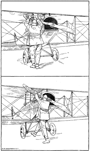
Fig. 190a.—Illustrations Depicting Wrong and Right Methods of “Swinging the Stick” to Start Airplane Engine. At Top, Poor Position to Get Full Throw and Get Out of the Way. Below, Correct Position to Get Quick Turn Over of Crank-Shaft and Spring Away from Propeller.
The inlet valves were of the automatic type so that a very simple valve mechanism consisting only of the exhaust valve push rods was provided. One of the difficulties of this arrangement of cylinders was that the impulses are not evenly spaced. For instance, in the forms where the cylinders were placed 60 degrees apart the space between the firing of the first cylinder and that next in order was 120 degrees crank-shaft rotation, after which there was an interval of 300 degrees before the last cylinder to fire delivered its power stroke. In order to increase the power given by the simple three-cylinder air-cooled engine a six-cylinder water-cooled type, as shown at Figs. 191 and 192, was devised. This was practically the same in action as the three-cylinder except[462] that a double throw crank-shaft was used and while the explosions were not evenly spaced the number of explosions obtained resulted in fairly uniform application of power.
The latest design of three-cylinder Anzani engine, which is used to some extent for school machines, is shown at Fig. 193. In this, the three-cylinders are symmetrically arranged about the crank-case or 120 degrees apart. The balance is greatly improved by this arrangement and the power strokes occur at equal intervals of 240 degrees of crank-shaft rotation. This method of construction is known as the Y design. By grouping two of these engines together, as outlined at Fig. 194, which gives an internal view, and at Fig. 195, which shows the sectional view, and using the ordinary form of double throw crank-shaft with crank-pins separated by 180 degrees, a six-cylinder radial engine is produced which runs[463] very quietly and furnishes a steady output of power. The peculiarity of the construction of this engine is in the method of grouping the connecting rod about the common crank-pin without using forked rods or the “Mother rod” system employed in the Gnome engines. In the Anzani the method followed is to provide each connecting rod big end with a shoe which consists of a portion of a hollow cylinder held against the crank-pin by split clamping rings. The dimensions of these shoes are so proportioned that the two adjacent connecting rods of a group of three will not come into contact even when the connecting rods are at the minimum relative angle. The three shoes of each group rest upon a bronze sleeve which is in halves and which surrounds the crank-pin[464] and rotates relatively to it once in each crank-shaft revolution. The collars, which are of tough bronze, resist the inertia forces while the direct pressure of the explosions is transmitted directly to the crank-pin bushing by the shoes at the big end of the connecting rod. The same method of construction, modified to some extent, is used in the Le Rhone rotary cylinder engine.
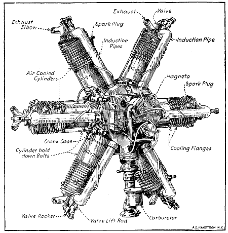
Fig. 194.—Anzani Fixed Crank-Case Engine of the Six-Cylinder Form Utilizes Air Cooling Successfully.
Both cylinders and pistons of the Anzani engines are of cast iron, the cylinders being provided with a liberal number of cooling flanges which are cast integrally. A series of auxiliary exhaust ports is drilled near the base[465] of each cylinder so that a portion of the exhaust gases will flow out of the cylinder when the piston reaches the end of its power stroke. This reduces the temperature of the gases passing around the exhaust valves and prevents warping of these members. Another distinctive feature of this engine design is the method of attaching the Zenith carburetor to an annular chamber surrounding the rear portion of the crank-case from which the intake pipes leading to the intake valves radiate. The magneto[466] is the usual six-cylinder form having the armature geared to revolve at one and one-half times crank-shaft speed.
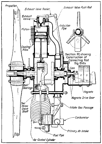
Fig. 195.—Sectional View Showing Internal Parts of Six-Cylinder Anzani Engine, with Starwise Disposition of Cylinders.
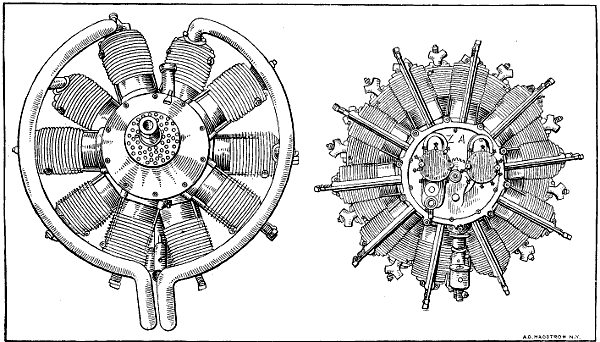
Fig. 196.—The Anzani Ten-Cylinder Aviation Engine at the Left, and the Twenty-Cylinder Fixed Type at the Right.
The Anzani aviation engines are also made in ten- and twenty-cylinder forms as shown at Fig. 196. It will[468] be apparent that in the ten-cylinder form explosions will occur every 72 degrees of crank-shaft rotation, while in the twenty-cylinder, 200 horse-power engine at any instant five of the cylinders are always working and explosions are occurring every 36 degrees of crank-shaft rotation. On the twenty-cylinder engine, two carburetors[469] are used and two magnetos, which are driven at two and one-half times crank-shaft speed. The general cylinder and valve construction is practically the same, as in the simpler engines.
This engine, which has been devised specially for aviation service, is generally known as the “Salmson” and is manufactured in both France and Great Britain. It is a nine-cylinder water-cooled radial engine, the nine cylinders being symmetrically disposed around the crank-shaft while the nine connecting rods all operate on a common crank-pin in somewhat the same manner as the rods in the Gnome motor. The crank-shaft of the Salmson engine is not a fixed one and inasmuch as the cylinders do not rotate about the crank-shaft it is necessary for that member to revolve as in the conventional engine. The stout hollow steel crank-shaft is in two pieces and has a single throw. The crank-shaft is built up somewhat the same as that of the Gnome engine. Ball bearings are used throughout this engine as will be evident by inspecting the sectional view given at Fig. 199. The nine steel connecting rods are machined all over and are fitted at each end with bronze bushings, the distance between the bearing centers being about 3.25 times crank length. The method of connecting up the rods to the crank-pin is one of the characteristic features of this design. No “mother” rod as supplied in the Gnome engine is used in this type inasmuch as the steel cage or connecting rod carrier is fitted with symmetrically disposed big end retaining pins. Inasmuch as the carrier is mounted on ball bearings some means must be provided of regulating the motion of the carrier as if no means were provided the resulting motion of the pistons would be irregular.
The method by which the piston strokes are made to occur at precise intervals involves a somewhat lengthy and detailed technical explanation. It is sufficient to say[470] that an epicyclic train of gears, one of which is rigidly attached to the crank-case so it cannot rotate is used, while other gears make a connection between the fixed gear and with another gear which is exactly the same size as the fixed gear attached to the crank-case and which is formed integrally with the connecting rod carrier. The action of the gearing is such that the cage carrying the big end retaining pins does not rotate independently of[471] the crank-shaft, though, of course, the crank-shaft or rather crank-pin bearings must turn inside of the big end carrier cage.
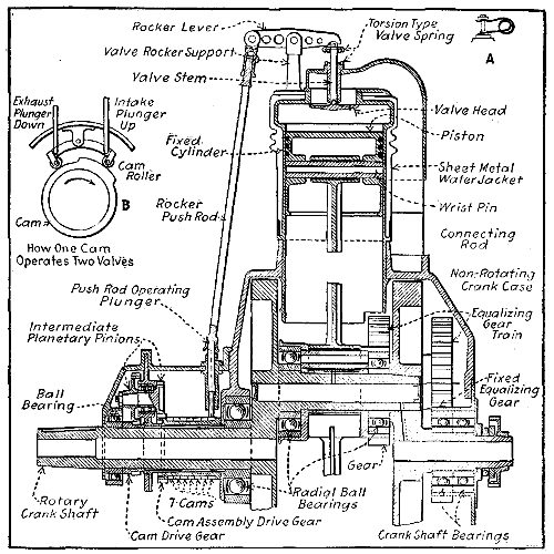
Fig. 199.—Sectional View Showing Construction of Canton and Unné Water-Cooled Radial Cylinder Engine.
Cylinders of this engine are of nickel steel machined all over and carry water-jackets of spun copper which are attached to the cylinders by brazing. The water jackets are corrugated to permit the cylinder to expand freely. The ignition is similar to that of the fixed crank rotating cylinder engine. An ordinary magneto of the two spark type driven at 13⁄4 times crank-shaft speed is sufficient to ignite the seven-cylinder form, while in the[472] nine-cylinder engines the ignition magneto is of the “shield” type giving four sparks per revolution. The magneto is driven at 11⁄9 times crank-shaft speed. Nickel steel valves are used and are carried in castings or cages which screw into bosses in the cylinder head. Each valve is cam operated through a tappet, push rod and rocker arm, seven cams being used on a seven-cylinder engine and nine cams on the nine-cylinder. One cam serves to open both valves as in its rotation it lifts the tappets in succession and so operates the exhaust and inlet valves respectively. This method of operation involves the same period of intake and exhaust. In normal engine practice the inlet valve opens 12 degrees late and closes 20 degrees late. The exhaust opens 45 degrees early and closes 6 degrees late. This means about 188 degrees in the case of inlet valve and 231 degrees crank-shaft travel for exhaust valves. In the Salmson engine, the exhaust closes and the inlet opens at the outer dead center and the exhaust opens and the inlet closes at about the inner dead center. This engine is also made in a fourteen-cylinder 200 B. H. P. design which is composed of two groups of seven-cylinders, and it has been made in an eighteen-cylinder design of 600 horse-power. The nine-cylinder 130 horse-power has a cylinder bore of 4.73 inches and a stroke of 5.52 inches. Its normal speed of rotation is 1250 R. P. M. Owing to the radial arrangement of the cylinders, the weight is but 41⁄4 pounds per B. H. P.
It cannot be denied that for a time one of the most widely used of aeroplane motors was the seven-cylinder revolving air-cooled Gnome, made in France. For a total weight of 167 pounds this motor developed 45 to 47 horsepower at 1,000 revolutions, being equal to 3.35 pounds per horse-power, and has proved its reliability by securing many long-distance and endurance records. The same[474] engineers have produced a nine-cylinder and by combining two single engines a fourteen-cylinder revolving Gnome, having a nominal rating of 100 horse-power, with which world’s speed records were broken. A still more powerful engine has been made with eighteen-cylinders. The nine-cylinder “monosoupape” delivers 100 horse-power at 1200 R. P. M., the engine of double that number of cylinders is rated at about 180 horse-power.
Except in the number of cylinders and a few mechanical details the fourteen-cylinder motor is identical with the seven-cylinder one; fully three-quarters of the parts used by the assemblers would do just as well for one motor as for the other. Owing to the greater power demands of the modern airplane the smaller sizes of Gnome engines are not used as much as they were except for school machines. There is very little in this motor that is common to the standard type of vertical motorcar engine. The cylinders are mounted radially round a circular crank-case; the crank-shaft is fixed, and the entire mass of cylinders and crank-case revolves around it as outlined at Fig. 200. The explosive mixture and the lubricating oil are admitted through the fixed hollow crank-shaft, passed into the explosion chamber through an automatic intake valve in the piston head in the early pattern, and the spent gases exhausted through a mechanically operated valve in the cylinder head. The course of the gases is practically a radial one. A peculiarity of the construction of the motor is that nickel steel is used throughout. Aluminum is employed for the two oil pump housings; the single compression ring known as the “obdurator” for each piston is made of brass; there are three or four brass bushes; gun metal is employed for certain pins—the rest is machined out of chrome nickel steel. The crank-case is practically a steel hoop, the depth depending on whether it has to receive seven-or fourteen-cylinders; it has seven or fourteen holes bored as illustrated on its circumference. When fourteen or eighteen cylinders are used the holes are[475] bored in two distinct planes, and offset in relation one to the other.
The cylinders of the small engine which have a bore of 43⁄10 inches and a stroke of 47⁄10 inches, are machined out of the solid bar of steel until the thickness of the walls is only 1.5 millimeters—.05905 inch, or practically 1⁄16 inch. Each one has twenty-two fins which gradually taper down as the region of greatest pressure is departed from. In addition to carrying away heat, the fins assist in strengthening the walls of the cylinder. The barrel of the cylinder is slipped into the hole bored for it on the circumference of the crank-case and secured by a locking member in the nature of a stout compression ring, sprung onto a groove on the base of the cylinder within the crank chamber. On each lateral face of the crank chamber are seven holes, drilled right through the chamber parallel with the crank-shaft. Each one of these holes receives a stout locking-pin of such a diameter that it presses against the split rings of two adjacent cylinders; in addition each cylinder is fitted with a key-way. This construction is not always followed, some of the early Gnome engines using the same system of cylinder retention as used on the latest “monosoupape” pattern.
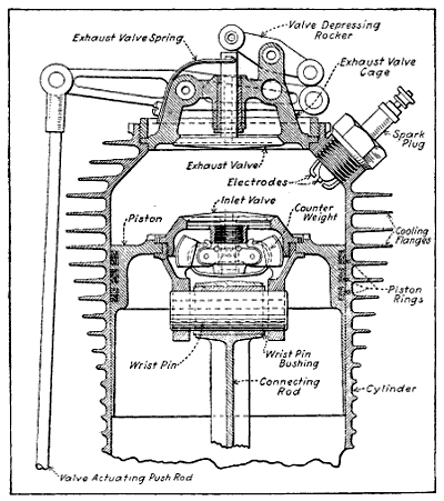
Fig. 201.—Sectional View of Early Type Gnome Cylinder and Piston Showing Construction and Application of Inlet and Exhaust Valves.
The exhaust valve is mounted in the cylinder head, Fig. 201, its seating being screwed in by means of a special box spanner. On the fourteen-cylinder model the valve is operated directly by an overhead rocker arm with a gun metal rocker at its extremity coming in contact with the extremity of the valve stem. As in standard motor car practice, the valve is opened under the lift of the vertical push rod, actuated by the cam. The distinctive feature is the use of a four-blade leaf spring with a forked end encircling the valve stems and pressing against a collar on its extremity. On the seven-cylinder model the movement is reversed, the valve being opened on the downward pull of the push rod, this lifting the outer extremity of the main rocker arm, which tips a secondary and smaller rocker arm in direct contact with[476] the extremity of the valve stem. The springs are the same in each case. The two types are compared at A and B, Fig. 202.
The pistons, like the cylinders, are machined out of the solid bar of nickel steel, and have a portion of their wall cut away, so that the two adjacent ones will not come together at the extremity of their stroke. The head[478] of the piston is slightly reduced in diameter and is provided with a groove into which is fitted a very light L-section brass split ring; back of this ring and carried within the groove is sprung a light steel compression ring, serving to keep the brass ring in expansion. As already mentioned, the intake valves are automatic, and are mounted in the head of the piston as outlined at Fig. 202, C. The valve seating is in halves, the lower portion being made to receive the wrist-pin and connecting rod, and the upper portion, carrying the valve, being screwed into it. The spring is composed of four flat blades, with the hollowed stem of the automatic valve passing through their center and their two extremities attached to small levers calculated to give balance against centrifugal force. The springs are naturally within the piston, and are lubricated by splash from the crank chamber. They are of a delicate construction, for it is necessary that they shall be accurately balanced so as to have no tendency to fly open under the action of centrifugal force. The intake valve is withdrawn by the use of special tools through the cylinder head, the exhaust valve being first dismounted.
The fourteen-cylinder motor shown at Fig. 203, has a two-throw crank-shaft with the throws placed at 180 degrees, each one receiving seven connecting rods. The parts are the same as for the seven-cylinder motor, the larger one consisting of two groups placed side by side. For each group of seven-cylinders there is one main connecting rod, together with six auxiliary rods. The main connecting rod, which, like the others, is of H section, has machined with it two L-section rings bored with six holes—511⁄2 degrees apart to take the six other connecting rods. The cage of the main connecting rod carries two ball races, one on either side, fitting onto the crank-pin and receiving the thrust of the seven connecting rods. The auxiliary connecting rods are secured in position in each case by a hollow steel pin passing through the two rings. It is evident that there is a slightly greater angularity for the six shorter rods, known as auxiliary connecting[480] rods, than for the longer main rods; this does not appear to have any influence on the running of the motor.
Coming to the manner in which the earliest design exhaust valves are operated on the old style motor, this at first sight appears to be one of the most complicated parts of the motor, probably because it is one in which standard practice is most widely departed from. Within the cylindrical casing bolted to the rear face of the crank-case are seven, thin flat-faced steel rings, forming female cams. Across a diameter of each ring is a pair of projecting rods fitting in brass guides and having their extremities terminating in a knuckle eye receiving the adjustable push rods operating the overhead rocker arms of the exhaust valve. The guides are not all in the same plane, the difference being equal to the thickness of the steel rings, the total thickness being practically 2 inches. Within the female cams is a group of seven male cams of the same total thickness as the former and rotating within them. As the boss of the male cam comes into contact with the flattened portion of the ring forming the female cam, the arm is pushed outward and the exhaust valve opened through the medium of the push-rod and overhead rocker. This construction was afterwards changed to seven male cams and simple valve operating plunger and roller cam followers as shown at Fig. 204.
On the face of the crank-case of the fourteen-cylinder motor opposite to the valve mechanism is a bolted-on end plate, carrying a pinion for driving the two magnetos and the two oil pumps, and having bolted to it the distributor for the high-tension current. Each group of seven-cylinders has its own magneto and lubricating pump. The two magnetos and the two pumps are mounted on the fixed platform carrying the stationary crank-shaft, being driven by the pinion on the revolving crank chamber. The magnetos are geared up in the proportion of 4 to 7. Mounted on the end plate back of the driving pinion are the two high-tension distributor plates, each one with seven brass segments let into it and connection[481] made to the plugs by means of plain brass wire. The wire passes through a hole in the plug and is then wrapped round itself, giving a loose connection.
[482]A good many people doubtless wonder why rotary engines are usually provided with an odd number of cylinders in preference to an even number. It is a matter of even torque, as can easily be understood from the accompanying diagram. Fig. 205, A, represents a six-cylinder rotary engine, the radial lines indicating the cylinders. It is possible to fire the charges in two ways, firstly, in rotation, 1, 2, 3, 4, 5, 6, thus having six impulses in one revolution and none in the next; or alternately, 1, 3, 5, 2, 4, 6, in which case the engine will have turned through an equal number of degrees between impulses 1 and 3, and 3 and 5, but a greater number between 5 and 2, even again between 2 and 4, 4 and 6, and a less number between 6 and 1, as will be clearly seen on reference to the diagram. Turning to Fig. 205, B, which represents a seven-cylinder engine. If the cylinders fire alternately it is obvious that the engine turns through an equal number of degrees between each impulse, thus, 1, 3, 5, 7, 2, 4, 6, 1, 3, etc. Thus supposing the engine to be revolving, the explosion takes place as each alternate cylinder passes, for instance, the point 1 on the diagram, and the ignition is actually operated in this way by a single contact.
[483]The crank-shaft of the Gnome, as already explained, is fixed and hollow. For the seven- and nine-cylinder motors it has a single throw, and for the fourteen- and eighteen-cylinder models has two throws at 180 degrees. It is of the built-up type, this being necessary on account of the distinctive mounting of the connecting rods. The carburetor shown at Fig. 206 is mounted at one end of the stationary crank-shaft, and the mixture is drawn in through a valve in the piston as already explained. There is neither float chamber nor jet. In many of the tests made at the factory it is said the motor will run with the extremity of the gasoline pipe pushed into the hollow[484] crank-shaft, speed being regulated entirely by increasing or decreasing the flow through the shut-off valve in the base of the tank. Even under these conditions the motor has been throttled down to run at 350 revolutions without misfiring. Its normal speed is 1,000 to 1,200 revolutions a minute. Castor oil is used for lubricating the engine, the oil being injected into the hollow crank-shaft through slight-feed fittings by a mechanically operated pump which is clearly shown in sectional diagrams at Fig. 207.
The Gnome is a considerable consumer of lubricant, the makers’ estimate being 7 pints an hour for the 100 horse-power motor; but in practice this is largely exceeded. The gasoline consumption is given as 300 to 350 grammes per horse-power. The total weight of the fourteen-cylinder motor is 220 pounds without fuel or lubricating[485] oil. Its full power is developed at 1,200 revolutions, and at this speed about 9 horse-power is lost in overcoming air resistance to cylinder rotation.
While the Gnome engine has many advantages, on the other hand, the head resistance offered by a motor of this type is considerable; there is a large waste of lubricating oil due to the centrifugal force which tends to throw the oil away from the cylinders; the gyroscopic effect of the rotary motor is detrimental to the best working of the aeroplane, and moreover it requires about seven per cent. of the total power developed by the motor to drive the revolving cylinders around the shaft. Of necessity, the[486] compression of this type of motor is rather low, and an additional disadvantage manifests itself in the fact that there is as yet no satisfactory way of muffling the rotary type of motor.
The latest type of Gnome engine is known as the “monosoupape” type because but one valve is used in the cylinder head, the inlet valve in the piston being dispensed with on account of the trouble caused by that member on earlier engines. The construction of this latest type follows the lines established in the earlier designs to some extent and it differs only in the method of charging. The very rich mixture of gas and air is forced into the crank-case through the jet inside the crank-shaft, and enters the cylinder when the piston is at its lowest position, through the half-round openings in the guiding flange and the small holes or ports machined in the cylinder and clearly shown at Fig. 210. The returning piston covers the port, and the gas is compressed and fired in the usual way. The exhaust is through a large single valve in the cylinder head, which gives rise to the name “monosoupape,” or single-valve motor, and this valve also remains open a portion of the intake stroke to admit air into the cylinder and dilute the rich gas forced in from the crank-case interior. Aviators who have used the early form of Gnome say that the inlet valve in the piston type was prone to catch on fire if any valve defect materialized, but the “monosoupape” pattern is said to be nearly free of this danger. The bore of the 100 horse-power nine-cylinder engine is 110 mm., the piston stroke 150 mm. Extremely careful machine work and fitting is necessary. In many parts, tolerances of less than .0004′′ (four ten thousandths of an inch) are all that are allowed. This is about one-sixth the thickness of the average human hair, and in other parts the size must be absolutely standard, no appreciable variation being allowable. The manufacture[487] of this engine establishes new mechanical standards of engine production in this country. Much machine work is needed in producing the finished components from the bar and forging.
The cylinders, for example, are machined from 6 inch solid steel bars, which are sawed into blanks 11 inches in length and weighing about 97 pounds. The first operation is to drill a 21⁄16 inch hole through the center of the block. A heavy-duty drilling machine performs this[489][488] work, then the block goes to the lathe for further operations. Fig. 211 shows six stages of the progress of a cylinder, a few of the intermediate steps being omitted. These give, however, a good idea of the work done. The turning of the gills, or cooling flanges, is a difficult proposition, owing to the depth of the cut and the thin metal that forms the gills. This operation requires the utmost care of tools and the use of a good lubricant to prevent[490] the metal from tearing as the tools approach their full depth. These gills are only 0.6 mm., or 0.0237 in., thick at the top, tapering to a thickness of 1.4 mm. (0.0553 in.) at the base, and are 16 mm. (0.632 in.) deep. When the machine work is completed the cylinder weighs but 51⁄2 pounds.
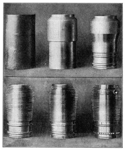
Fig. 211.—How a Gnome Cylinder is Reduced from Solid Chunk of Steel Weighing 97 Pounds to Finished Cylinder Weighing 51⁄2 Pounds.
The following description of the fuel supply, ignition and oiling of the “monosoupape,” or single valve Gnome, is taken from “The Automobile.”
Gasoline is fed to the engine by means of air pressure at 5 pounds per sq. in., which is produced by the air pump on the engine clearly shown at Fig. 210. A pressure gauge convenient to the operator indicates this pressure, and a valve enables the operator to control it. No carburetor is used. The gasoline flows from the tank through a shut-off valve near the operator and through a tube leading through the hollow crank-shaft to a spray nozzle located in the crank-case. There is no throttle valve, and as each cylinder always receives the same amount of air as long as the atmospheric pressure is the same, the output cannot be varied by reducing the fuel supply, except within narrow limits. A fuel capacity of 65 gallons is provided. The fuel consumption is at the rate of 12 U. S. gallons per hour.
The high-tension magnetos, with double cam or two break per revolution interrupter, is located on the thrust plate in an inverted position, and is driven at such a speed as to produce nine sparks for every two revolutions; that is, at 21⁄4 times engine speed. A Splitdorf magneto is fitted. There is no distributor on the magneto. The high-tension collector brush of the magneto is connected to a distributor brush holder carried in the bearer plate of the engine. The brush in this brush holder is pressed against a distributor ring of insulating material molded in position in the web of a gear wheel[491] keyed to the thrust plate, which gear serves also for starting the engine by hand. Molded in this ring of insulating material are nine brass contact sectors, connecting with contact screws at the back side of the gear, from which bare wires connect to the spark-plugs. The distributor revolves at engine speed, instead of at half engine speed as on ordinary engines, and the distributor brush is brought into electrical connection with each spark-plug every time the piston in the cylinder in which this spark-plug is located approaches the outer dead center. However, on the exhaust stroke no spark is being generated in the magneto, hence none is produced at the spark-plug.
Ordinarily the engine is started by turning on the propeller, but for emergency purposes as in seaplanes or for a quick “get away” if landing inadvertently in enemy territory, a hand starting crank is provided. This is supported in bearings secured to the pressed steel carriers of the engine and is provided with a universal[492] joint between the two supports so as to prevent binding of the crank in the bearings due to possible distortion of the supports. The gear on this starting crank and the one on the thrust plate with which it meshes are cut with helical teeth of such hand that the starting pinion is thrown out of mesh as soon as the engine picks up its cycle. A coiled spring surrounds part of the shaft of the starting crank and holds it out of gear when not in use.
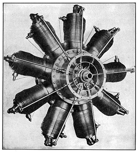
Fig. 213.—G. V. Gnome “Monosoupape,” with Cam-Case Cover Removed to Show Cams and Valve-Operating Plungers with Roller Cam Followers.
Lubricating oil is carried in a tank of 25 gallon capacity, and if this tank has to be placed in a low position[493] it is connected with the air-pressure line, so that the suction of the oil pump is not depended upon to get the oil to the pump. From the bottom of the oil tank a pipe leads to the pump inlet. There are two outlets from the pump, each entering the hollow crank-shaft, and there is a branch from each outlet pipe to a circulation indicator convenient to the operator. One of the oil leads feeds to the housing in the thrust plate containing the two rear ball bearings, and the other lead feeds through the crank-pin to the cams, as already explained.
Owing to the effect of centrifugal force and the fact that the oil is not used over again, the oil consumption of a revolving cylinder engine is considerably higher than that of a stationary cylinder engine. Fuel consumption is also somewhat higher, and for this reason the revolving cylinder engine is not so well suited for types of airplanes designed for long trips, as the increased weight of supplies required for such trips, as compared with stationary cylinder type motors, more than offsets the high weight efficiency of the engine itself. But for short trips, and especially where high speed is required, as in single seated scout and battle planes or “avions de chasse,” as the French say, the revolving cylinder engine has the advantage. The oil consumption of the Gnome engine is as high as 2.4 gallon per hour. Castor oil is used for lubrication because it is not cut by the gasoline mist present in the engine interior as an oil of mineral derivation would be.
A German adaptation of the Gnome design is shown at Fig. 214. This is known as the Bayerischen Motoren Gesellschaft engine and the type shown is an early design rated at 50 horse-power. The bore is 110 mm., the stroke is 120 mm., and it is designed to run at a speed of 1,200 R. P. M. It is somewhat similar in design to the early Gnome “valve-in-piston” design except that two valves[495] are carried in the piston top instead of one. The valve operating arrangement is different also, as a single four point cam is used to operate the seven exhaust valves. It is driven by epicyclic gearing, the cam being driven by an internal gear machined integrally with it, the cam being turned at 7⁄8 times the engine speed. Another feature is the method of holding the cylinders on the crank-case. The cylinder is provided with a flange that registers with a corresponding member of the same diameter on the crank-case. A U section, split clamping ring is bolted in place as shown, this holding both flanges firmly together and keeping the cylinder firmly seated against the crank-case flange. The “monosoupape” type has also been copied and has received some application in Germany, but the most successful German airplanes are powered with six-cylinder vertical engines such as the Benz and Mercedes.
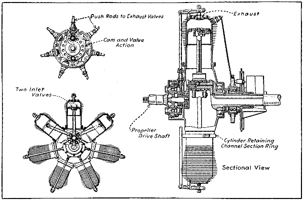
Fig. 214.—The 50 Horse-Power Rotary Bayerischen Motoren Gesellschaft Engine, a German Adaptation of the Early Gnome Design.
The Le Rhone motor is a radial revolving cylinder engine that has many of the principles which are incorporated in the Gnome but which are considered to be an improvement by many foreign aviators. Instead of having but one valve in the cylinder head, as the latest type “monosoupape” Gnome has, the Le Rhone has two valves, one for intake and one for exhaust in each cylinder. By an ingenious rocker arm and tappet rod arrangement it is possible to operate both valves with a single push rod. Inlet pipes communicate with the crank-case at one end and direct the fresh gas to the inlet valve cage at the other. Another peculiarity in the design is the method of holding the cylinders in place. Instead of having a vertically divided crank-case as the Gnome engine has and clamping both halves of the case around the cylinders, the crank-case of the Le Rhone engine is in the form of a cylinder having nine bosses provided with threaded openings into which the cylinders are screwed.[496] A thread is provided at the base of each cylinder and when the cylinder has been screwed down the proper amount it is prevented from further rotation about its own axis by a substantial lock nut which screws down against the threaded boss on the crank-case. The external appearance of the Le Rhone type motor is clearly shown at Fig. 215, while the general features of construction are clearly outlined in the sectional views given at Figs. 216 and 217.
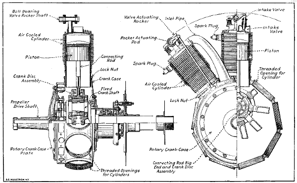
Fig. 216.—Part Sectional Views of Le Rhone Rotary Cylinder Engine, Showing Method of Cylinder Retention, Valve Operation and Novel Crank Disc Assembly.
[498]The two main peculiarities of this motor are the method of valve actuation by two large cams and the distinctive crank-shaft and connecting rod big end construction. The connecting rods are provided with “feet” or shoes on the end which fit into grooves lined with bearing metal which are machined into crank discs revolving on ball bearings and which are held together so that the connecting rod big ends are sandwiched between them by clamping screws. This construction is a modification of that used on the Anzani six-cylinder radial engine. There are three grooves machined in each crank disc and three connecting rod big ends run in each pair of grooves. The details of this construction can be readily ascertained by reference to explanatory diagrams at Figs. 218 and 219, A. Three of the rods which work[499] in the groove nearest the crank-pin are provided with short shoes as shown at Fig. 219, B. The short shoes are used on the rods employed in cylinders number 1, 4, and 7. The set of connecting rods that work in the central grooves are provided with medium-length shoes and actuate the pistons in cylinders numbers 3, 6, and 9. The three rods that work in the outside grooves have still longer shoes and are employed in cylinders numbers 2, 5, and 8. The peculiar profile of the inlet and exhaust cam plates are shown at C, Fig. 219, while the construction of the wrist-pin, wrist-pin bushing and piston are clearly outlined at the sectional view at E. The method[500] of valve actuation is clearly outlined at Fig. 220, which shows an end section through the cam case and also a partial side elevation showing one of the valve operating levers which is fulcrumed at a central point and which has a roller at one end bearing on one cam while the roller or cam follower at the other end bears on the other cam. The valve rocker arm actuating rod is, of course, operated by this simple lever and is attached to it in such a way that it can be pulled down to depress the inlet valve and pushed up to open the exhaust valve.
[501]A carburetor of peculiar construction is employed in the Le Rhone engine, this being a very simple type as outlined at Fig. 221. It is attached to the threaded end of the hollow crank-shaft by a right and left coupling.[502] The fuel is pumped to the spray nozzle, the opening in which is controlled by a fuel regulating needle having a long taper which is lifted out of the jet opening when the air-regulating slide is moved. The amount of fuel supplied the carburetor is controlled by a special needle valve fitting which combines a filter screen and which is shown at B. In regulating the speed of the Le Rhone engine, there are two possible means of controlling the mixture, one by altering the position of the air-regulating slide, which also works the metering needle in the jet, and the other by controlling the amount of fuel supplied to the spray nozzle through the special fitting provided for that purpose.
In considering the action of this engine one can refer to Fig. 222. The crank O. M. is fixed, while the cylinders can turn about the crank-shaft center O and the piston[503] turns around the crank-pin M, because of the eccentricity of the centers of rotation the piston will reciprocate in the cylinders. This distance is at its maximum when the cylinder is above O and at a minimum when it is above M, and the difference between these two positions is equal to the stroke, which is twice the distance of the crank-throw O, M. The explosion pressure resolves itself into the force F exerted along the line of the connecting rod A, M, and also into a force N, which tends to make the cylinders rotate around point O in the direction of the arrow. An odd number of cylinders acting on one crank-pin is desirable to secure equally spaced explosions, as the basic action is the same as the Gnome engine.
The magneto is driven by a gear having 36 teeth attached to crank-case which meshes with 16-tooth pinion on armature. The magneto turns at 2.25 times crank-case speed. Two cams, one for inlet, one for exhaust, are mounted on a carrying member and act on nine rocker arms which are capable of giving a push-and-pull[504] motion to the valve-actuating rocker-operating rods. A gear driven by the crank-case meshes with a larger member having internal teeth carried by the cam carrier. Each cam has five profiles and is mounted in staggered relation to the other. These give the nine fulcrumed levers the proper motion to open the inlet and exhaust valves at the proper time. The cams are driven at 45⁄50 or 9⁄10 of the motor speed. The cylinder dimensions and timing follows; the weight can be approximated by figuring 3 pounds per horse-power.
| 80 | H.P. | 105 | M/M bore | 4.20′′ | bore. |
| 140 | M/M stroke | 5.60′′ | stroke. | ||
| 110 | H.P. | 112 | M/M bore | 4.48′′ | bore. |
| 170 | M/M stroke | 6.80′′ | stroke. | ||
| Timing— | Intake valve opening, lag | 18° | ⎫ | 110 H.P. | 18° | ⎫ | 80 H.P. |
| Intake valve closing, lag | 35° | ⎮ | 35° | ⎮ | |||
| Exhaust valve opening, lead | 55° | ⎬ | 45° | ⎬ | |||
| Exhaust valve closing, lag | 5° | ⎮ | 5° | ⎮ | |||
| Ignition time advance | 26° | ⎭ | 26° | ⎭ |
Air-cooled stationary engines are rarely used in airplanes, but the Renault Frères of France have for several years manufactured a complete series of such engines of the general design shown at Fig. 225, ranging from a[506] low-powered one developed eight or nine years ago and rated at 40 and 50 horse-power, to later eight-cylinder models rated at 70 horse-power and a twelve-cylinder, or twin six, rated at 90 horse-power. The cylinders are of cast iron and are furnished with numerous cooling ribs[507] which are cast integrally. The cylinder heads are separate castings and are attached to the cylinder as in early motorcycle engine practice, and serve to hold the cylinder in place on the aluminum alloy crank-case by a cruciform yoke and four long hold-down bolts (Fig. 226). The pistons are of cast steel and utilize piston rings of cast iron. The valves are situated on the inner side of the cylinder head, the arrangement being unconventional in that the exhaust valves are placed above the inlet. The inlet valves seat in an extension of the combustion head and are actuated by direct push rod and cam in the usual manner while an overhead gear in which rockers are operated[508] by push rods is needed to actuate the exhaust valves. The valve action is clearly shown in Figs. 226 and 227. The air stream by which the cylinders are cooled is produced by a centrifugal or blower type fan of relatively large diameter which is mounted on the end of a crank-shaft and the air blast is delivered from this blower into an enclosed space between the cylinder from which it escapes only after passing over the cooling fins. In spite of the fact that considerable prejudice exists against air-cooling fixed cylinder engines, the Renault has given very good service in both England and France.
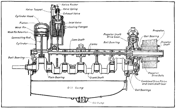
Fig. 227.—Side Sectional View of Renault Twelve-Cylinder Air-Cooled Aviation Engine Crank-Case, Showing Use of Plain and Ball Bearings for Crank-Shaft Support.
As will be seen by the sectional view at Fig. 227, the steel crank-shaft is carried in a combination of plain bearings inside the crank-case and by ball bearings at the ends. Owing to air cooling, special precautions are taken with the lubrication system, though the lubrication is not forced or under high pressure. An oil pump of the gear-wheel type delivers oil from the sump at the bottom of the crank-case to a chamber above, from which the oil flows by gravity along suitable channels to the various main bearings. It flows from the bearings into hollow rings fastened to the crank-webs, and the oil thrown from the whirling connecting rod big ends bathes the internal parts in an oil mist. In the eight-cylinder designs ignition is effected by a magneto giving four sparks per revolution and is accordingly driven at engine speed. In the twelve-cylinder machine two magnetos of the ordinary revolving armature or two-spark type, each supplying six cylinders, are fitted as outlined at Fig. 228. The carburetor is a float feed form. Warm air is supplied for Winter and damp weather by air pipes surrounding the exhaust pipes. The normal speed of the Renault engine is 1,800 R. P. M., but as the propeller is mounted upon an extension of the cam-shaft the normal propeller speed is but half that of the engine, which makes it possible to use a propeller of large diameter and high efficiency. Owing to the air cooling, but low compression may be used, this being about 60 pounds per square inch,[510] which, of course, lowers the mean effective pressure and makes the engine less efficient than water-cooled forms where it is possible to use compression pressure of 100[512] or more pounds per square inch. The 70 horse-power engine has cylinders with a bore of 3.78 inches and a stroke of 5.52 inches. Its weight is given as 396 pounds, when in running order, which figures 5.7 pounds per horse-power. The same cylinder size is used on the twelve-cylinder 100 horse-power and the stroke is the same. This engine in running order weighs 638 pounds, which figures approximately 6.4 pounds per B. H. P.
The Model A is of the water-cooled four-cycle Vee type, with eight cylinders, 4.7245 inch bore by 5.1182 inch stroke, piston displacement 718 cubic inches. At sea-level it develops 150 horse-power at 1,450 R. P. M. It can be run successfully at much higher speeds, depending on propeller design and gearing, developing proportionately increased power. The weight, including carburetor, two magnetos, propeller hub, starting magneto and crank, but without radiator, water or oil or exhaust pipes, is 445 pounds. Average fuel consumption is .5 pound per horse-power hour and the oil consumption at 1,450 R. P. M. is three quarts per hour. The external appearance is shown at Fig. 230.
Four cylinders are contained in each block, which is of built-up construction; the water jackets and valve ports are cast aluminum and the individual cylinders heat-treated steel forgings threaded into the bored holes of the aluminum castings. Each block after assembly is given a number of protective coats of enamel, both inside and out, baked on. Coats on the inside are applied under pressure. The pistons are aluminum castings, ribbed. Connecting rods are tubular, of the forked type. One rod bears directly on the crank-pin; the other rod has a bearing on the outside of the one first mentioned.
The crank-shaft is of the five-bearing type, very short, stiff in design, bored for lightness and for the oiling system. The crank-shaft extension is tapered for the[513] French standard propeller hub, which is keyed and locked to the shaft. This makes possible instant change of propellers. The case is in two halves divided on the center line of the crank-shaft, the bearings being fitted between the upper and lower sections. The lower half is deep, providing a large oil reservoir and stiffening the engine. The upper half is simple and provides magneto supports on extension ledges of the two main faces. The valves are of large diameter with hollow stems, working in cast iron bushings. They are directly operated by a single hollow cam-shaft located over the valves. The cam-shafts are driven from the crank-shaft by vertical shafts and bevel gears. The cam-shafts, cams and heads of the valve stems are all enclosed in oil-tight removable housings of cast aluminum.
Oiling is by a positive pressure system. The oil is taken through a filter and steel tubes cast in the case to main bearings, through crank-shaft to crank-pins. The fourth main bearing is also provided with an oil lead from the system and through tubes running up the end of each cylinder block, oil is provided for the cam-shafts,[514] cams and bearings. The surplus oil escapes through the end of the cam-shaft where the driving gears are mounted, and with the oil that has gathered in the top casing, descends through the drive shaft and gears to the sump.
Ignition is by two eight-cylinder magnetos firing two spark-plugs per cylinder. The magnetos are driven from each of the two vertical shafts by small bevel pinions meshing in bevel gears. The carburetor is mounted between the two cylinder blocks and feeds the two blocks through aluminum manifolds which are partly water-jacketed. The engine can be equipped with a geared hand crank-starting device.
These motors are of the eight-cylinder “V” type, four-stroke cycle, water-cooled, having a bore of 4 inches and a stroke of 51⁄2 inches, equivalent to 102 mm. × 140 mm. The normal operating speed of the crank-shaft is 2,000 R. P. M. The propeller shaft is driven through reducing gears which can be furnished in different gear ratios. The standard ratio is 5:3, allowing a propeller speed of 1,200 R. P. M.
The construction of the motor is such as to permit of the application of a direct drive. The change from the direct drive to gear drive, or vice versa, can be accomplished in approximately one hour.
The cylinders are cast in pairs from an aluminum alloy and are provided with steel sleeves, carefully fitted into each cylinder. A perfect contact is secured between cylinder and sleeve; at the same time a sleeve can be replaced without injury to the cylinder proper. No difficulties due to expansion occur on account of the rapid transmission of heat and the fact that the sleeve is always at higher temperature than the cylinder. A moulded copper asbestos gasket is placed between the cylinder and the head, permitting the cooling water to circulate[515] freely and at the same time insuring a tight joint. The cylinder heads are cast in pairs from an aluminum alloy and contain ample water passages for circulation of cooling water over the entire head. Trouble due to hot valves is thereby eliminated, a most important consideration in the operation of an aeroplane motor. The water jacket of the head corresponds to the water jacket of the cylinders and large openings in both allow the unobstructed circulation of the cooling water. The cylinder heads and cylinders are both held to the base by six long bolts. The valves are located in the cylinder heads and are mechanically operated. The valves and valve springs are especially accessible and of such size as to permit high volumetric efficiency. The valves are constructed of hardened tungsten steel, the heads and stems being made from one piece. The valve rocker arms located on the top of the cylinder are provided with adjusting screws. A check nut enables the adjusting screw to be securely locked in position, once the correct clearance has been determined. The rocker arm bearings are adequately lubricated by a compression grease cup. Cam-rollers are interposed between the cams and the push rods in order to reduce the side thrust on the push rods.
A system of double springs is employed which greatly reduces the stress on each spring and insures utmost reliability. A spring of extremely large diameter returns the valve; a second spring located at the cylinder base handles the push rod linkage. These springs, which operate under low stress, are made from the best of steel and are given a special double heat treatment. The pistons are made from a special aluminum alloy; are deeply ribbed in the head for cooling and strength and provided with two piston rings. These pistons are exceedingly light weight in order to minimize vibration and prevent wear on the bearings. The piston pin is made of chrome nickel steel, bored hollow and hardened. It is allowed to turn, both in piston and connecting rod. The[516] piston rings are of special design, developed after years of experimenting in aeronautical engines.
The connecting rods are of “H” section, machined all over from forgings of a special air-hardening chrome nickel steel which, after being heat treated has a tensile strength of 280,000 pounds per square inch. They are consequently very strong and yet unusually light, and being machined all over are of absolutely uniform section, which gives as nearly perfect balance as can be obtained. The big ends are lined with white metal and the small ends are bushed with phosphor bronze. The connecting rods are all alike and take their bearings side by side on the crank-pin, the cylinders being offset to permit of this arrangement. The crank-shaft is machined from the highest grade chrome nickel steel, heat treated in order to obtain the best properties of this material. It is 21⁄4 inches in diameter (57 mm.) and bored hollow throughout, insuring maximum strength with minimum weight. It is carried in three large, bronze-backed white metal bearings. A new method of producing these bearings insures a perfect bond between the two metals and eliminates breakage.
The base is cast from an aluminum alloy. Great strength and rigidity is combined with light weight. The sides extend considerably below the center line of the crank-shaft, providing an extremely deep section. At all highly stressed points, deep ribs are provided to distribute the load evenly and eliminate bending. The lower half of the base is of cast aluminum alloy of extreme lightness. This collects the lubricating oil and acts as a small reservoir for same. An oil-filtering screen of large area covers the entire surface of the sump. The propeller shaft is carried on two large annular ball bearings driven from the crank-shaft by hardened chrome nickel steel spur gears. These gears are contained within an oil-tight casing integral with the base on the opposite end from the timing gears. A ball-thrust bearing is provided on the propeller shaft to take the thrust of[517] a propeller or tractor, as the case may be. In case of the direct drive a stub shaft is fastened direct to the crank-shaft and is fitted with a double thrust bearing.
The cam-shaft is contained within the upper half of the base between the two groups of cylinders, and is supported in six bronze bearings. It is bored hollow throughout and the cams are formed integral with the shaft and ground to the proper shape and finish. An important development in the shape of cams has resulted in a maintained increase of power at high speeds. The gears operating the cam-shaft, magneto, oil and water pumps are contained within an oil-tight casing and operate in a bath of oil.
Lubrication is of the complete forced circulating system, the oil being supplied to every bearing under high pressure by a rotary pump of large capacity. This is operated by gears from the crank-shaft. The oil passages from the pump to the main bearings are cast integral with the base, the hollow crank-shaft forming a passage through the connecting rod bearings and the hollow cam-shaft distributing the oil to the cam-shaft bearings. The entire surface of the lower half of the base is covered with a fine mesh screen through which the oil passes before reaching the pump. Approximately one gallon of oil is contained within the base and this is continually circulated through an external tank by a secondary pump operated by an eccentric on the cam-shaft. This also draws fresh oil from the external tank which can be made of any desired capacity.
The Curtiss OX motor has eight cylinders, 4-inch bore, 5-inch stroke, delivers 90 horse-power at 1,400 turns, and the weight turns out at 4.17 pounds per horse-power. This motor has cast iron cylinders with monel metal jackets, overhead inclined valves operated by means of two rocker arms, push-and-pull rods from the central cam-shaft located in the crank-case. The cam and push rod design is extremely ingenious and the whole valve construction turns out very light. This motor is an evolution from the early Curtiss type motor which was used by Glenn Curtiss when he won the Gordon Bennett Cup at Rheims. A slightly larger edition of this type motor is the OXX-5, as shown at Figs. 231 and 232, which has cylinders 41⁄4 inches by 5 inches, delivers 100 horse-power at 1,400 turns and has the same fuel and oil consumption as the OX type motor, namely, .60 pound of fuel per brake horse-power hour and .03 pound of lubricating oil per brake horse-power hour.
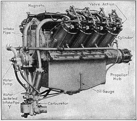
Fig. 231.—The Curtiss OXX-5 Aviation Engine is an Eight-Cylinder Type Largely Used on Training Machines.
The Curtiss Company have developed in the last two years a larger-sized motor now known as the V-2, which was originally rated at 160 horse-power and which[519] has since been refined and improved so that the motor gives 220 horse-power at 1,400 turns, with a fuel consumption of 52⁄100 of a pound per brake horse-power hour and an oil consumption of .02 of a pound per brake horse-power hour. This larger motor has a weight of 3.45 pounds per horse-power and is now said to be giving very satisfactory service. The V-2 motor has drawn steel cylinders, with a bore of 5 inches and a stroke of 7 inches, with a steel water jacket top and a monel metal cylindrical jacket, both of which are brazed on to the cylinder barrel itself. Both these motors use side by side connecting rods and fully forced lubrication. The cam-shafts act as a gallery from which the oil is distributed to the cam-shaft bearings, the main crank-shaft[520] bearings, and the gearing. Here again we find extremely short rods, which, as before mentioned, enables the height and the consequent weight of construction to be very much reduced. For ordinary flying at altitudes of 5,000 to 6,000 feet, the motors are sent out with an aluminum liner, bolted between the cylinder and the crank-case in order to give a compression ratio which does not result in pre-ignition at a low altitude. For high flying, however, these aluminum liners are taken out and the compression[521] volume is decreased to about 18.6 per cent. of the total volume.
The Curtiss Aeroplane Company announces that it has recently built, and is offering, a twelve-cylinder 5′′ × 7′′ motor, which was designed for aeronautical uses primarily. This engine is rated at 250 horse-power, but it is claimed to develop 300 at 1,400 R. P. M. Weights—Motor, 1,125 pounds; radiator, 120 pounds; cooling water, 100 pounds; propeller, 95 pounds.
Gasoline Consumption per Horse-power Hour, 6⁄10 pounds.
Oil Consumption per Hour at Maximum Speed—2 pints.
Installation Dimensions—Overall length, 845⁄8 inches; overall width, 341⁄8 inches; overall depth, 40 inches; width at bed, 301⁄2 inches; height from bed, 211⁄8 inches; depth from bed, 181⁄2 inches.
The Thomas-Morse Aircraft Corporation of Ithaca, N. Y., has produced a new engine, Model 88, bearing a close resemblance to the earlier model. The main features of that model have been retained; in fact, many parts are interchangeable in the two engines. Supported by the great development in the wide use of aluminum, the Thomas engineers have adopted this material for cylinder construction, which adoption forms the main departure from previous accepted design.
The marked tendency to-day toward a higher speed of rotation has been conclusively justified, in the opinion of the Thomas engineers, by the continued reliable performance of engines with crank-shafts operating at speeds near 2,000 revolutions per minute, driving the propeller through suitable gearing at the most efficient speed. High speed demands that the closest attention be paid to the design of reciprocating and rotating parts and their adjacent units. Steel of the highest obtainable[522] tensile strength must be used for connecting rods and piston pins, that they may be light and yet retain a sufficient factor of safety. Piston design is likewise subjected to the same strict scrutiny. At the present day, aluminum alloy pistons operate so satisfactorily that they may be said to have come to stay.
The statement often made in the past, that the gearing down of an engine costs more in the weight of reduction gears and propeller shaft than is warranted by the increase in horse-power, is seldom heard to-day.
The mean effective pressure remaining the same, the brake horse-power of any engine increases as the speed. That is, an engine delivering 100 brake horse-power at 1,500 revolutions per minute will show 133 brake horse-power at 2,000 revolutions per minute, an increase of 33 brake horse-power. To utilize this increase in horse-power, a matter of some fifteen pounds must be spent in gearing and another fifteen perhaps on larger valves, bearings, etc. Two per cent. may be assumed lost in the gears. In other words, the increase in horse-power due to increasing the speed has been attained at the expense of about one pound per brake horse-power.
The advantages of the eight-cylinder engine over the six and twelve, briefly stated, are: lower weight per horse-power, shorter length, simpler and stiffer crank-shaft, cam-shaft and crank-case, and simpler and more direct manifold arrangement. As to torque, the eight is superior to the six, and yet in practice not enough inferior to the twelve to warrant the addition of four more cylinders. It must, however, be recognized that the eight is subject to the action of inherent unbalanced inertia couples, which set up horizontal vibrations, impossible of total elimination. These vibrations are functions of the reciprocating weights, which, as already mentioned, are cut down to the minimum. Vibrations due to the elasticity of crank-case, crank-shaft, etc., can be and are reduced in the Thomas engine to minor quantities by ample webbing of the crank-case and judicious[523] use of metal elsewhere. All things considered, there is actually so little difference to be discerned between the balance of a properly designed eight-cylinder engine and that of a six or twelve as to make a discussion of the pros and cons more one of theory than of practice.
The main criticisms of the L head cylinder engine are that it is less efficient and heavier. This is granted, as it relates to cylinders alone. More thorough investigation, however, based on the main desideratum, weight-power ratio, leads us to other conclusions, particularly with reference to high speed engines. The valve gear must not be forgotten. A cylinder cannot be taken completely away from its component parts and judged, as to its weight value, by itself alone. A part away from the whole becomes an item unimportant in comparison with the whole. The valve gear of a high speed engine is a too often overlooked feature. The stamp of approval has been made by high speed automobile practice upon the overhead cam-shaft drive, with valves in the cylinder head operated direct from the cam-shaft or by means of valve lifters or short rockers.
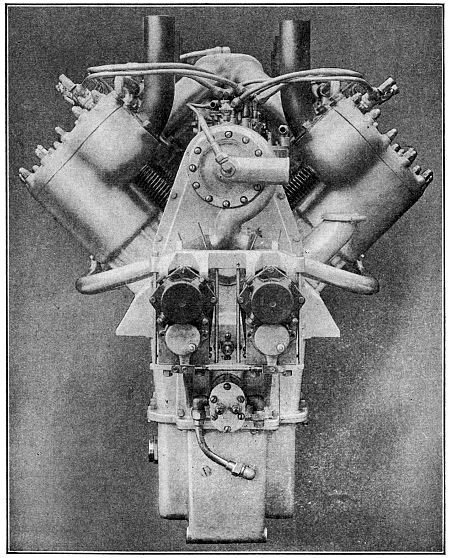
Fig. 233.—End View of Thomas-Morse 150 Horse-Power Aluminum Cylinder Aviation Motor Having Detachable Cylinder Heads.
The overhead cam-shaft mechanism applied to an eight-cylinder engine calls for two separate cam-shafts carried above and supported by the cylinders in an oil-tight housing, and driven by a series of spur gears or bevels from the crank-shaft. It is patent that this valve gearing is heavy and complicated in comparison with the simple moving valve units of the L head engine, which are operated from one single cam-shaft, housed rigidly in the crank-case. The inherently lower volumetric efficiency of the L head engine is largely overcome by the use of a properly designed head, large valves and ample gas passages. Again, the customary use of a dual ignition system gives to the L head a relatively better opportunity for the advantageous placing of spark-plugs, in order that better flame propagation and complete combustion may be secured.
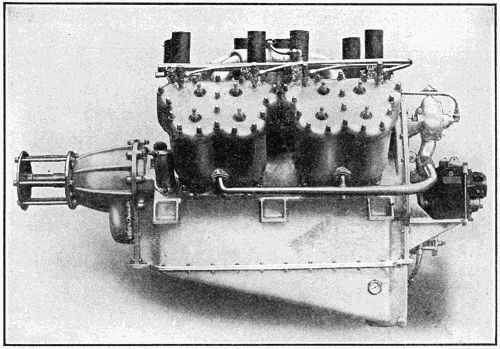
Fig. 234.—Side View of Thomas-Morse High Speed 150 Horse-Power Aviation Motor with Geared Down Propeller Drive.
[524]The Thomas Model 88 engine is 41⁄8 inch bore and 51⁄2 inch stroke. The cylinders and cylinder heads are of aluminum, and as steel liners are used in the cylinders the pistons are also made of aluminum. This engine is actually lighter than the earlier model of less power. It weighs but 525 pounds, with self-starter. The general[525] features of design can be readily ascertained by study of the illustrations: Fig. 233, which shows an end view; Fig. 234, which is a side view, and Fig. 235, which outlines the reduction gear-case and the propeller shaft supporting bearings.
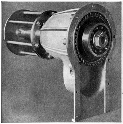
Fig. 235.—The Reduction Gear-Case of Thomas-Morse 150 Horse-Power Aviation Motor, Showing Ball Bearing and Propeller Drive Shaft Gear.
This engine is a four-cylinder, 43⁄4′′ × 7′′, 125 horse-power at 2,100 R. P. M. of the crank-shaft and 1,210 R. P. M. of the propeller. Motors are sold on above rating; actual power tests prove this motor capable of developing 140 horse-power at 2,100 R. P. M. of the motor. The exact weight with magneto, carburetor, gear reduction and propeller hub, as illustrated, 509 pounds; without gear reduction, 436 pounds. This motor has been produced as a power plant weighing 3.5 pounds per horse-power, yet nothing has been sacrificed in rigidity and strength. At its normal speed it develops 1 horse-power[526] for every 3.5 cubic inches piston displacement. Cylinders are semi-steel, with aluminum plates enclosing water jackets. Pistons specially ribbed and made of Magnalite aluminum compound. Piston rings are special Duesenberg design, being three-piece rings. Valves are tungsten steel, 115⁄16′′ inlets and 2′′ exhausts, two of each to each cylinder. Arranged horizontally in the head, allowing very thorough water-jacketing. Inlet valves in cages. Exhaust valves, seating directly in the cylinder head, are removable through the inlet valve holes. Valve stems lubricated by splash in the valve action covers. Valve rocker arms forged with cap screw and nut at[527] upper end to adjust clearance. Entirely enclosed by aluminum housing, as is entire valve mechanism. Connecting rods are tubular, chrome nickel steel, light and strong. Crank-shaft is one-piece forging, hollow bored, 21⁄2-inch diameter at main bearings. Connecting rod bearings, 21⁄4-inch diameter, 3 inches long. Front main bearing, 31⁄2 inches long; intermediate main bearing, 31⁄2 inches long; rear main bearing, 4 inches long. Crank-case of aluminum, barrel type, oil pan on bottom removable. Hand hole plates on both sides. Strongly webbed.
The oiling system of this sixteen-valve Duesenberg motor is one of its vital features. An oil pump located in the base and submerged in oil forces oil through cored passages to the three main bearings, then through tubes under each connecting rod into which the rod dips. The oil is thrown off from these and lubricates every part of the motor. This constitutes the main oiling system; it is supplemented by a splash system, there being a trough under each connecting rod into which the rod slips. The oil is returned to the main supply sump by gravity, where it is strained and re-used. Either system is in itself sufficient to operate the motor. A pressure gauge is mounted for observation on a convenient part of the system. A pressure of approximately 25 pounds is maintained by the pressure system, which insures efficient lubrication at all speeds of the motor. The troughs under the connecting rods are so constructed that no matter what the angle of flight may be, oil is retained in each individual trough so that each connecting rod can dip up its supply of oil at each revolution.
These motors are four-stroke cycle, six-cylinder vertical type, with cylinder 45⁄16′′ bore by 51⁄8′′ stroke. The general appearance of this motor is shown in illustration at Fig. 236. This engine is rated at 85-90 horse-power. All reciprocating and revolving parts of this[528] motor are made of the highest grades of steel obtainable as are the studs, nuts and bolts. The upper and lower parts of crank-case are made of composition aluminum casting. Lower crank-case is made of high grade aluminum composition casting and is bolted directly to the upper half. The oil reservoir in this lower half casting provides sufficient oil capacity for five hours’ continuous running at full power. Increased capacity can be provided if needed to meet greater endurance requirements. Oil is forced under pressure to all bearings by means of high-pressured duplex-geared pumps. One side of this pump delivers oil under pressure to all the bearings, while the other side draws the oil from the splash case and delivers it to the main sump. The oil reservoir is entirely separate from the crank-case chamber. Under no circumstances will oil flood the cylinder, and the oiling system is not affected in any way by any angle of flight or position of motor. An oil pressure gauge is placed on instrument board of machine, which gives at all times[529] the pressure in oil system, and a sight glass at lower half of case indicates the amount of oil contained. The oil pump is external on magneto end of motor, and is very accessible. An external oil strainer is provided, which is removable in a few minutes’ time without the loss of any oil. All oil from reservoir to the motor passes through this strainer. Pressure gauge feed is also attached and can be piped to any part of machine desired.
The cylinders are made of high-grade castings and are machined and ground accurately to size. Cylinders are bolted to crank-case with chrome nickel steel studs and nuts which securely lock cylinder to upper half of crank-case. The main retaining cylinder studs go through crank-case and support crank-shaft bearings so that crank-shaft and cylinders are tied together as one unit. Water jackets are of copper, 1⁄16′′ thick, electrically deposited. This makes a non-corrosive metal. Cooling is furnished by a centrifugal pump, which delivers 25 gallons per minute at 1,400 R. P. M. Pistons are made cast iron, accurately machined and ground to exact dimensions, which are carefully balanced. Piston rings are semi-steel rings of Aeromarine special design.
[530]Connecting rods are of chrome nickel steel, H-section. Crank-shaft is made of chrome nickel steel, machined all over, and cut from solid billet, and is accurately balanced through the medium of balance weights being forged integral with crank. It is drilled for lightness and plugged for force feed lubrication. There are seven main bearings to crank-shaft. All bearings are of high-grade babbitt, die cast, and are interchangeable and easily replaced. The main bearings of the crank-shaft are provided with a single groove to take oil under pressure from pressure tube which is cast integral with case. Connecting rod bearings are of the same type. The gudgeon pin is hardened, ground and secured in connecting rod, and is allowed to work in piston. Cam-shaft is of steel, with cams forged integral, drilled for lightness and forced-feed lubrication, and is case-hardened.[531] The bearings of cam-shaft are of bronze. Magneto, two high-tension Bosch D. U. 6. The intake manifold for carburetors are aluminum castings and are so designed that each carburetor feeds three cylinders, thereby insuring easy flow of vapor at all speeds. Weight, 420 pounds.
The new six-cylinder Wisconsin aviation engines, one of which is shown at Fig. 237, are of the vertical type, with cylinders in pairs and valves in the head. Dimensioned drawings of the six-cylinder vertical type are given at Figs. 238 and 239. The cylinders are made of aluminum alloy castings, are bored and machined and then fitted with hardened steel sleeves about 1⁄16 inch in thickness. After these sleeves have been shrunk into the cylinders, they are finished by grinding in place. Gray iron valve seats are cast into the cylinders. The valve seats and cylinders, as well as the valve ports, are[532] entirely surrounded by water jackets. The valves set in the heads at an angle of 25° from the vertical, are made of tungsten steel and are provided with double springs, the outer or main spring and the inner or auxiliary spring, which is used as a precautionary measure to prevent a valve falling into the cylinder in remote case of a main spring breaking. The cam-shaft is made of one solid forging, case-hardened. It is carried in an aluminum housing bolted to the top of the cylinders. This housing is split horizontally, the upper half carrying the chrome vanadium steel rocker levers. The lower half has an oil return trough cast integral, into which the excess oil overflows and then drains back to the crank-case. Small inspection plates are fitted over the cams and inner ends of the cam rocker levers. The cam-shaft runs in bronze bearings and the drive is through vertical shaft and bevel gears.
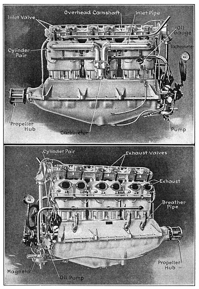
Fig. 237.—The Wisconsin Aviation Engine, at Top, as Viewed from Carburetor Side. Below, the Exhaust Side.
The crank-case is made of aluminum, the upper half[533] carrying the bearings for the crank-shaft. The lower half carries the oil sump in which all of the oil except that circulating through the system at the time is carried. The crank-shaft is made of chrome vanadium steel of an elastic limit of 115,000 pounds. The crank-pins and ends of the shaft are drilled for lightness and the cheeks are also drilled for oil circulation. The crank-shaft runs in bronze-backed, Fahrig metal-lined bearings, four in number. A double thrust bearing is also provided, so that the motor may be used either in a tractor or pusher type of machine. Outside of the thrust bearing an annular ball bearing is used to take the radial load of the propeller. The propeller is mounted on a taper. At the opposite end of the shaft a bevel gear is fitted which drives the cam-shaft, through a vertical shaft, and also drives the water and oil pumps and magnetos. All gears are made of chrome vanadium steel, heat-treated.
The connecting rods are tubular and machined from chrome vanadium steel forgings. Oil tubes are fitted to the rods which carry the oil up to the wrist-pins and pistons. The rods complete with bushings weigh 51⁄2 pounds each. The pistons are made of aluminum alloy and are very light and strong, weighing only 2 pounds 2 ounces each. Two leak-proof rings are fitted to each piston. The wrist-pins are hollow, of hardened steel, and are free to turn either in the piston or the rod. A bronze bushing is fitted in the upper end of the rod, but no bushing is fitted in the pistons, the hardened steel wrist-pins making an excellent bearing in the aluminum alloy.
The water circulation is by centrifugal pump, which is mounted at the lower end of the vertical shaft. The water is pumped through brass pipes to the lower end of the cylinder water jackets and leaves the upper end of the jackets just above the exhaust valves. The lubricating system is one of the main features of the engines, being designed to work with the motor at any angle. The oil is carried in the sump, from where it is taken[534] by the oil circulating pump through a strainer and forced through a header, extending the full length of the crank-case, and distributed to the main bearings. From the main bearings it is forced through the hollow crank-shaft to the connecting rod big ends and then through[535] tubes on the rods to wrist-pins and pistons. Another lead takes oil from the main header to the cam-shaft bearings. The oil forced out of the ends of the cam-shaft bearings fills pockets under the cams and in the cam rocker levers. The excess flows back through pipes and through the train of gears to the crank-case. A strainer is fitted at each end of the crank-case, through which the oil is drawn by separate pumps and returned to the sump. Either one of these pumps is large enough to take care of all of the return oil, so that the operation is perfect whether the motor is inclined up or down. No splash is used in the crank-case, the system being a full force feed. An oil level indicator is provided, showing the amount of oil in the sump at all times. The oil pressure in these motors is carried at ten pounds, a relief valve being fitted to hold the pressure constant.
Ignition is by two Bosch magnetos, each on a separate set of plugs fired simultaneously on opposite sides of the cylinders. Should one magneto fail, the other would still run the engine at only a slight loss in power. The Zenith double carburetor is used, three cylinders being supplied by each carburetor. This insures a higher volumetric efficiency, which means more power, as there is no overlapping[536] of inlet valves whatever by this arrangement. All parts of these motors are very accessible. The water and oil pumps, carburetors, magnetos, oil strainer or other parts can be removed without disturbing other parts. The lower crank-case can be removed for inspection or adjustment of bearings, as the crank-shaft and bearing caps are carried by the upper half. The motor supporting lugs are also part of the upper crank-case.
The six-cylinder motor, without carburetors or magnetos, weighs 547 pounds. With carburetor and magnetos, the weight is 600 pounds. The weight of cooling water in the motor is 38 pounds. The sump will carry 4 gallons of oil, or about 28 pounds. A radiator can be furnished suitable for the motor, weighing 50 pounds. This radiator will hold 3 gallons of water or about 25 pounds. The motor will drive a two-blade, 8 feet diameter by 6.25 feet pitch Paragon propeller 1400 revolutions per minute, developing 148 horse-power. The weight of this propeller is 42 pounds. This makes a total weight of motor, complete with propeller, radiator filled with water, but without lubricating oil, 755 pounds, or about 5.1 pounds per horse-power for complete power plant. The fuel consumption is .5 pound per horse-power per hour. The lubricating oil consumption is .0175 pound per horse-power per hour, or a total of 2.6 pounds per hour at 1400 revolutions per minute. This would make the weight of fuel and oil, per hour’s run at full power at 1400 revolutions per minute, 76.6 pounds.
Following are the principal dimensions of the six-cylinder motor:
The horse-power developed at 1200 revolutions per minute is 130, at 1300 revolutions per minute 140, at 1400 revolutions per minute 148. 1400 is the maximum speed at which it is recommended to run these motors.
A twelve-cylinder V-type engine illustrated, is also being built by this company, similar in dimensions of cylinders to the six. The principal differences being in the drive to cam-shaft, which is through spur gears instead of bevel. A hinged type of connecting rod is used which does not increase the length of the motor and, at the same time, this construction provides for ample bearings. A double centrifugal water pump is provided for this motor, so as to distribute the water uniformly to both sets of cylinders. Four magnetos are used, two for each set of six cylinders. The magnetos are very accessibly located on a bracket on the spur gear cover. The carburetors are located on the outside of the motors, where they are very accessible, while the exhaust is in the center of the valley. The crank-shaft on the twelve is 21⁄2 inches in diameter and the shaft is bored to reduce weight. Dimensioned drawings of the twelve-cylinder engine are given at Figs. 242 and 243 and should prove useful for purposes of comparison with other motors.
The following specifications of the Hall-Scott “Big Four” engines apply just as well to the six-cylinder vertical types which are practically the same in construction except for the structural changes necessary to accommodate the two extra cylinders. Cylinders are cast[538] separately from a special mixture of semi-steel, having cylinder head with valve seats integral. Special attention has been given to the design of the water jacket around the valves and head, there being two inches of water space above same. The cylinder is annealed, rough machined, then the inner cylinder wall and valve seats ground to mirror finish. This adds to the durability of the cylinder, and diminishes a great deal of the excess friction.
[539]Great care is taken in the casting and machining of these cylinders, to have the bore and walls concentric with each other. Small ribs are cast between outer and inner walls to assist cooling as well as to transfer stresses direct from the explosion to hold-down bolts which run from steel main bearing caps to top of cylinders. The cylinders are machined upon the sides so that when assembled on the crank-case with grooved hold-down washers tightened, they form a solid block, greatly assisting the rigidity of crank-case.
The connecting rods are very light, being of the I beam type, milled from a solid Chrome nickel die forging. The caps are held on by two 1⁄2′′-20 thread Chrome nickel through bolts. The rods are first roughed out, then annealed. Holes are drilled, after which the rods are hardened and holes ground parallel with each other. The piston end is fitted with a gun metal bushing, while the crank-pin end carries two bronze serrated shells, which are tinned and babbitted hot, being broached to harden the babbitt. Between the cap and rod proper are placed[540] laminated shims for adjustment. Crank-cases are cast of the best aluminum alloy, hand scraped and sand blasted inside and out. The lower oil case can be removed without breaking any connections, so that the connecting rods and other working parts can readily be inspected. An extremely large strainer and dirt trap is located in the center and lowest point of the case, which is easily removed from the outside without disturbing the oil pump or any working parts. A Zenith carburetor is provided. Automatic valves and springs are absent, making the adjustment simple and efficient. This carburetor is not affected by altitude to any appreciable extent. A Hall-Scott device, covered by U. S. Patent No. 1,078,919, allows the oil to be taken direct from the crank-case and run around the carburetor manifold, which assists carburetion as well as reduces crank-case heat. Two waterproof four-cylinder Splitdorf “Dixie” magnetos are provided. Both magneto interruptors are connected to a rock shaft integral with the motor, making outside connections unnecessary. It is worthy of note that with this independent double magneto system, one complete magneto can become inoperative, and still the motor will run and continue to give good power.
The pistons as provided in the A-7 engines are cast from a mixture of steel and gray iron. These are extremely light, yet provided with six deep ribs under the arch head, greatly aiding the cooling of the piston as well as strengthening it. The piston pin bosses are located very low in order to keep the heat from the piston head away from the upper end of the connecting rod, as well as to arrange them at the point where the piston fits the cylinder best. Three 1⁄4′′ rings are carried. The pistons as provided in the A-7a engines are cast from aluminum alloy. Four 1⁄4′′ rings are carried. In both piston types a large diameter, heat treated, Chrome nickel steel wrist-pin is provided, assembled in such a way as to assist the circular rib between the wrist-pin bosses to keep the piston from being distorted from the explosions.
[541]The oiling system is known as the high pressure type, oil being forced to the under side of the main bearings with from 5 to 30 points pressure. This system is not affected by extreme angles obtained in flying, or whether the motor is used for push or pull machines. A large gear pump is located in the lowest point of the oil sump, and being submerged at all times with oil, does away with troublesome stuffing boxes and check valves. The oil is first drawn from the strainer in oil sump to the long jacket around the intake manifold, then forced to the main distributor pipe in crank-case, which leads to all main bearings. A bi-pass, located at one end of the distributor pipe, can be regulated to provide any pressure required, the surplus oil being returned to the case. A special feature of this system is the dirt, water and sediment trap, located at the bottom of the oil sump. This can be removed without disturbing or dismantling the oil pump or any oil pipes. A small oil pressure gauge is provided, which can be run to the aviator’s instrument board. This registers the oil pressure, and also determines its circulation.
The cooling of this motor is accomplished by the oil as well as the water, this being covered by patent No. 1,078,919. This is accomplished by circulating the oil around a long intake manifold jacket; the carburetion of gasoline cools this regardless of weather conditions. Crank-case heat is therefore kept at a minimum. The uniform temperature of the cylinders is maintained by the use of ingenious internal outlet pipes, running through the head of each of the six-cylinders, rubber hose connections being used so that any one of the cylinders may be removed without disturbing the others. Slots are cut in these pipes so that cooler water is drawn directly around the exhaust valves. Extra large water jackets are provided upon the cylinders, two inches of water space is left above the valves and cylinder head. The water is circulated by a large centrifugal pump insuring ample circulation at all speeds.
[542]The crank-shaft is of the five bearing type, being machined from a special heat treated drop forging of the highest grade nickel steel. The forging is first drilled, then roughed out. After this the shaft is straightened, turned down to a grinding size, then ground accurately to size. The bearing surfaces are of extremely large size, over-size, considering general practice in the building of high speed engines of similar bore and stroke. The crank-shaft bearings are 2′′ in diameter by 115⁄16′′ long, excepting the rear main bearing, which is 43⁄8′′ long, and front main bearing, which is 23⁄16′′ long. Steel oil scuppers are pinned and sweated onto the webs of the shaft, which allows of properly oiling the connecting rod bearings. Two thrust bearings are installed on the propeller end of the shaft, one for pull and the other for push. The propeller is driven by the crank-shaft flange, which is securely held in place upon the shaft by six keys. These drive an outside propeller flange, the propeller being clamped between them by six through bolts. The flange is fitted to a long taper on crank-shaft. This enables the propeller to be removed without disturbing the bolts. Timing gears and starting ratchets are bolted to a flange turned integral with shaft.
The cam-shaft is of the one piece type, air pump eccentric, and gear flange being integral. It is made from a low carbon specially heat treated nickel forging, is first roughed out and drilled entire length; the cams are then formed, after which it is case hardened and ground to size. The cam-shaft bearings are extra long, made from Parson’s White Brass. A small clutch is milled in gear end of shaft to drive revolution indicator. The cam-shaft is enclosed in an aluminum housing bolted directly on top of all six cylinders, being driven by a vertical shaft in connection with bevel gears. This shaft, in conjunction with rocker arms, rollers and other working parts, are oiled by forcing the oil into end of shaft, using same as a distributor, allowing the surplus supply to flow back into the crank-case through hollow vertical[543] tube. This supply oils the magneto and pump gears. Extremely large Tungsten valves, being one-half the cylinder diameter, are seated in the cylinder heads. Large diameter oil tempered springs held in tool steel cups, locked with a key, are provided. The ports are very large and short, being designed to allow the gases to enter and exhaust with the least possible resistance. These valves are operated by overhead one piece cam-shaft in connection with short Chrome nickel rocker arms. These arms have hardened tool steel rollers on cam end with hardened tool steel adjusting screws opposite. This construction allows accurate valve timing at all speeds with least possible weight.
CENSORED
In a paper on “Aviation Motors,” presented by E. H. Sherbondy before the Cleveland section of the S. A. E. in June, 1917, the Mercedes and Benz airplane motor is discussed in some detail and portions of the description follow.
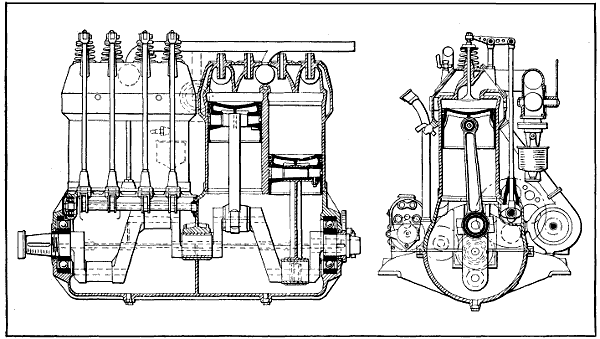
Fig. 244.—Side and End Sectional Views of Four-Cylinder Argus Engine, a German 100 Horse-Power Design Having Bore and Stroke of 140 mm., or 5.60 inches, and Developing Its Power at 1,368 R.P.M. Weight, 350 Pounds.
The 150 horse-power six-cylinder Mercedes motor is 140 millimeters bore and 160 millimeters stroke. The Mercedes company started with smaller-sized cylinders, namely 100 millimeters bore and 140 millimeters stroke, six-cylinders. The principal features of the design are forged steel cylinders with forged steel elbows for gas passages, pressed steel water jackets, which when welded together forms the cylinder assembly, the use of inclined overhead valves operated by means of an overhead cam-shaft through rocker arms which multiply with the motion of the cam. By the use of steel cylinders, not only is the weight greatly reduced, but certain freedom from distortion through unequal sections, leaks and cracks are entirely avoided. The construction is necessarily very expensive. It is certainly a sound job. In the details of this construction there are a number of important things, such as finished gas passages, water-cooled valve guides and a very small mass of metal, which is water-cooled, surrounding the spark-plug. Of course, it is necessary to use very high compression in aviation motors in order to secure high power and economy and owing to the fact that aviation motors are worked at nearly their maximum, the heat flow through the cylinder, piston, and valves is many times higher than that encountered in automobile motors. It has been found necessary to develop special types of pistons to carry the heat from the center of the head in order to prevent pre-ignition. In the Mercedes motor the pistons have a drop forged steel head which includes the piston boss and this head is screwed into a cast iron skirt which has been machined inside to secure uniform wall thickness.
CENSORED
[548]The carburetor used on this 150 horse-power Mercedes motor is precisely of the same type used on the Twin Six motor. It has two venturi throats, in the center of which is placed the gasoline spray nozzle of conventional type, fixed size orifices, immediately above which are placed two panel type throttles with side outlets. An idling or primary nozzle is arranged to discharge above the top of the venturi throat. The carburetor body is of cast aluminum and is water jacketed. It is bolted directly to air passage passing through the top and bottom half of the crank-case which passes down through the oil reservoir. The air before reaching the carburetor proper to some extent has cooled the oil in the crank chamber and has itself been heated to assist[549] in the vaporization. The inlet pipes themselves are copper. All the passages between the venturi throat and the inlet valve have been carefully finished and polished. The only abnormal thing in the design of this motor is the short connecting rod which is considerably less than twice the stroke and would be considered very bad practice in motor car engines. A short connecting rod, however, possesses two very real virtues in that it cuts down height of the motor and the piston passes over the bottom dead center much more slowly than with a long rod.
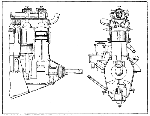
Fig. 245.—Part Sectional View of 90 Horse-Power Mercedes Engine, Which is Typical of the Design of Larger Sizes.
Other features of the design are a very stiff crank-case, both halves of which are bolted together by means of long through bolts, the crank-shaft main bearings are seated in the lower half of the case instead of in the usual caps and no provision is made for taking up the main bearings. The Mercedes company uses a plunger[550] type of pump having mechanically operated piston valves and it is driven by means of worm gearing.
The overhead cam-shaft construction is extremely light. The cam-shaft is mounted in a nearly cylindrical cast bronze case and is driven by means of bevel gears from the crank-shaft. The vertical bevel gear shaft through which the drive is taken from the crank-shaft to the cam-shaft operates at one and one-half times the crank-shaft speeds and the reduction to the half-time cam-shaft is secured through a pair of bevels. On this vertical shaft there is mounted the water pump and a bevel gear for driving two magnetos. The water pump mounted on this shaft tends to steady the drive and avoid vibration in the gearing.
The cylinder sizes of six-cylinder aviation motors which have been built by Mercedes are
| Bore | Stroke | Horse-power |
| 105 mm. | 140 mm. | 100 |
| 120 mm. | 140 mm. | 135 |
| 140 mm. | 150 mm. | 150 |
| 140 mm. | 160 mm. | 160 |
The largest of these motors has recently had its horsepower increased to 176 at 1450 R. P. M. This general design of motor has been the foundation for a great many other aviation motor designs, some of which have proved very successful but none of which is equal to the original. Among the motors which follow more or less closely the scheme of design and arrangement are the Hall-Scott, the Wisconsin motor, the Renault water-cooled, the Packard, the Christofferson and the Rolls-Royce. Each of these motors show considerable variation in detail. The Rolls-Royce and Renault are the only ones who have used the steel cylinder with the steel jacket. The Wisconsin motor uses an aluminum cylinder with a hardened steel liner and cast-iron valve seats. The Christofferson has somewhat similar design to the Wisconsin with the exception that the valve seats are threaded into the aluminum[551] jacket and the cylinder head has a blank end which is secured to the aluminum casting by means of the valve seat pieces. The Rolls-Royce motors show small differences in details of design in cylinder head and cam-shaft housing from the Mercedes on which it has taken out patents, not only abroad but in this country.
In the Kaiser prize contest for aviation motors a four-cylinder Benz motor of 130 by 180 mm. won first prize, developing 103 B. H. P. at 1290 R. P. M. The fuel consumption was 210 grams per horse-power hour. Total weight of the motor was 153 kilograms. The oil consumption was .02 of a kilogram per horse-power hour. This motor was afterward expanded into a six-cylinder design and three different sizes were built.
The accompanying table gives some of the details of weight, horse-power, etc.
| Motor type | B | FD | FF | |||
| Rated horse-power | 85 | 100 | 150 | |||
| Horse-power at 1250 r.p.m | 88 | 108 | 150 | |||
| Horse-power at 1350 r.p.m | 95 | 115 | 160 | |||
| Bore in millimeters | 106 | 116 | 130 | |||
| Stroke in millimeters | 150 | 160 | 180 | |||
| Offset of the cylinders in millimeters | 18 | 20 | 20 | |||
| Rate of gasoline consumption in grams | 240 | 230 | 225 | |||
| Oil consumption in grams per b.h.p. hour | 10 | 10 | 10 | |||
| Oil capacity in kilograms | 36 | 4 | 4 | 1⁄2 | ||
| Water capacity in litres | 5 | 1⁄2 | 7 | 1⁄2 | 9 | 1⁄2 |
| The weight with water and oil but with two magnetos, fuel feeder and air pump in kilograms | 170 | 200 | 245 | |||
| The weight of motors, including the water pump, two magnetos, double ignition, etc. | 160 | 190 | 230 | |||
| The weight of the exhaust pipe, complete in kilograms | 4 | 4 | .8 | 5 | 1⁄2 | |
| The weight of the propeller hub in kilograms. | 3 | 1⁄2 | 4 | 4 | ||
The Benz cylinder is a simple, straightforward design and a very reliable construction and not particularly difficult to manufacture. The cylinder is cast of iron without[552] a water jacket but including 45 degrees angle elbows to the valve ports. The cylinders are machined wherever possible and at other points have been hand filed and scraped, after which a jacket, which is pressed in two halves, is gas welded by means of short pipes welded on to the jacket. The bottom and the top of the cylinders become water galleries, and by this means separate water pipes with their attendant weight and complication are eliminated. Rubber rings held in aluminum clamps serve to connect the cylinders together. The whole construction turns out very neat and light. The cylinder walls are 4 mm. or 3⁄16′′ thick and the combustion chamber is of cylindrical pancake form and is 140 mm. or 5.60 inch in diameter. The valve seats are 68 mm. in diameter and the valve port is 62 mm. in diameter.
The passage joining the port is 57 mm. in diameter. In order to insert the valves into the cylinder the valve stem is made with two diameters and the valve has to be cocked to insert it in the guide, which has a bronze bushing at its upper end to compensate for the smaller valve stem diameter. The valve stem is 14 mm. or 9⁄16′′ in diameter and is reduced at its upper portion to 91⁄2 mm. The valves are operated through a push rod and rocker arm construction, which is 7⁄16′′ and exceedingly light. Rocker arm supports are steel studs with enlarged heads to take a double row ball bearing. A roller is mounted at one end of the rocker arm to impinge on the end of the valve stem, and the rocker arm has an adjustable globe stud at the other end. The push rods are light steel tubes with a wall thickness of 0.75 mm. and have a hardened steel cup at their upper end to engage the rocker arm globe stud and a hardened steel globe at their lower end to socket in the roller plunger.
The Benz cam-shaft has a diameter of 26 mm. and is bored straight through 18 mm. and there is a spiral gear made integrally with the shaft in about the center of its length for driving the oil pump gear. The cam faces are 10 mm. wide. There is also, in addition to the intake[553] and exhaust cams, a set of half compression cams. The shaft is moved longitudinally in its bearings by means of an eccentric to put these cams into action. At the fore end of the shaft is a driving gear flange which is very small in diameter and very thin. The flange is 68 mm. in diameter and 4 mm. thick and is tapped to take 6 mm. bolts. The total length of cam-shaft is 1038 mm., and it becomes a regular gun boring job to drill a hole of this length.
The cam-shaft gear is 140 mm. or 51⁄2 inches outside diameter. It has fifty-four teeth and the gear face is 15 mm. or 19⁄32′′. The flange and web have an average thickness of 4 mm. or 5⁄32′′ and the web is drilled full of holes interposed between the spur gear mounted on the cam-shaft and the cam-shaft gear. There is a gear which serves to drive the magnetos and tachometer, also the air pump. The shaft is made integrally with this gear and has an eccentric portion against which the air pump roll plunger impinges.
The seven-bearing crank-shaft is finished all over in a beautiful manner, and the shaft out of the particular motor we have shows no signs of wear whatever. The crank-pins are 55 mm. in diameter and 69 mm. long. Through both the crank-pin and main bearings there is drilled a 28 mm. hole, and the crank cheeks are plugged with solder. The crank cheeks are also built to convey the lubricant to the crank-pins. At the fore end of the crank cheek there is pressed on a spur driving gear. There is screwed on to the front end of the shaft a piece which forms a bevel water pump driving gear and the starting dog. At the rear end of the shaft very close to the propeller hub mounting there is a double thrust bearing to take the propeller thrust.
Long, shouldered studs are screwed into the top half of the crank-case portion of the case and pass clean through the bottom half of the case. The case is very stiff and well ribbed. The three center bearing diaphragms have double walls. The center one serves as a[554] duct through which water pipe passes, and those on either side of the center form the carburetor intake air passages and are enlarged in section at one side to take the carburetor barrel throttle.
The pistons are of cast iron and carry three concentric rings 1⁄4 inch wide on their upper end, which are pinned at the joint. The top of the piston forms the frustum of the cone and the pistons are 110 mm. in length. The lower portion of the skirt is machined inside and has a wall thickness of 1 mm. Riveted to the piston head is a conical diaphragm which contacts with the piston pin when in place and serves to carry the heat off the center of the piston.
The oil pump assembly comprises a pair of plunger pumps which draw oil from a separate outside pump, and constructed integrally with it is a gear pump which delivers the oil under about 60 pound pressure through a set of copper pipes in the base to the main bearings. The plunger oil pump shows great refinement of detail. A worm wheel and two eccentrics are machined up out of one piece and serve to operate the plungers.
Some interesting details of the 160 horse-power Benz motor, which is shown at Fig. 246, are reproduced from the “Aerial Age Weekly,” and show how carefully the design has been considered.
One of the first very successful European flying engines which was developed in Europe is the Austro-Daimler, which is shown in end section in a preceding chapter. The first of these motors had four-cylinders, 120 by 140 millimeters, bore and stroke, with cast iron cylinders, overhead valves operated by means of a single rocker arm, controlled by two cams and the valves were closed by a single leaf spring which oscillates with the rocker arm. The cylinders are cast singly and have either copper or steel jackets applied to them. The four-cylinder design was afterwards expanded to the six-cylinder design and still later a six-cylinder motor of 130 by 175 millimeters was developed. This motor uses an offset crank-shaft, as does the Benz motor, and the effect of offset has been discussed earlier on in this treatise. The Benz motor also uses an offset cam-shaft which improves the valve operation and changes the valve lift diagram. The lubrication also is different than any other aviation motor, since[558] individual high pressure metering pumps are used to deliver fresh oil only to the bearings and cylinders, as was the custom in automobile practice some ten years ago.
These very successful engines have been developed by Louis Coatalen. At the opening of the war the largest sized Coatalen motor was 225 horse-power and was of the L-head type having a single cam-shaft for operating valves and was an evolution from the twelve-cylinder racing car which the Sunbeam Company had previously built. Since 1914 the Sunbeam Company have produced engines of six-, eight-, twelve- and eighteen-cylinders from 150 to 500 horse-power with both iron and aluminum cylinders. For the last two years all the motors have had overhead cam-shafts with a separate shaft for operating the intake and exhaust valves. Cam-shafts are connected through to the crank-shaft by means of a train of spur gears, all of which are mounted on two double row ball bearings. In the twin six, 350 horse-power engine, operating at 2100 R. P. M., requires about 4 horse-power to operate the cam-shafts. This motor gives 362 horsepower at 2100 revolutions and has a fuel consumption of 51⁄100 of a pint per brake horse-power hour. The cylinders are 110 by 160 millimeters. The same design has been expanded into an eighteen-cylinder which gives 525 horsepower at 2100 turns. There has also been developed a very successful eight-cylinder motor rated at 2220 horsepower which has a bore and stroke of 120 by 130 millimeters, weight 450 pounds. This motor is an aluminum block construction with steel sleeves inserted. Three valves are operated, one for the inlet and two for the exhaust. One cam-shaft operates the three valves.
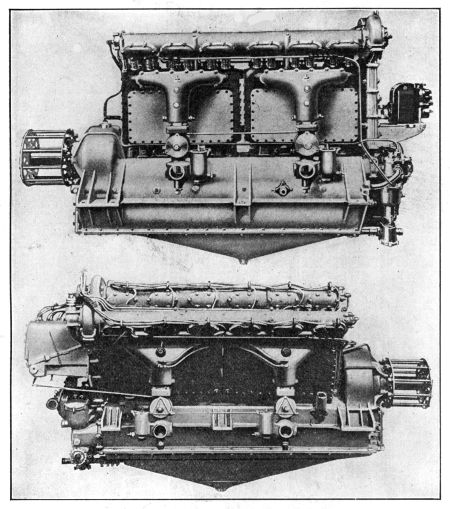
Fig. 247.—At Top, the Sunbeam Overhead Valve 170 Horse-Power Six-Cylinder Engine. Below, Side View of Sunbeam 350 Horse-Power Twelve-Cylinder Vee Engine.
The modern Sunbeam engines operate with a mean effective pressure of 135 pounds with a compression ratio of 6 to 1 sea level. The connecting rods are of the articulated type as in the Renault motor and are very short.[559] The weight of these motors turns out at 2.6 pounds per brake horse-power, and they are able to go through a 100 hour test without any trouble of any kind. The lubricating system comprises a dry base and oil pump for drawing the oil off from the base, whence it is delivered to the filter and cooling system. It then is pumped by a separate high pressure gear pump through the entire motor. In these larger European motors, castor-oil is[561] used largely for lubrication. It is said that without the use of castor-oil it is impossible to hold full power for five hours. Coatalen favors aluminum cylinders rather than cast iron. The series of views in Figs. 247 to 250 inclusive, illustrates the vertical, narrow type of engine; the V-form; and the broad arrow type wherein three rows, each of six-cylinders, are set on a common crank-case. In this water-cooled series the gasoline and oil consumption are notably low, as is the weight per horse-power.
In the eighteen-cylinder overhead valve Sunbeam-Coatalen aircraft engine of 475 brake horse-power, there are no fewer than half a dozen magnetos. Each magneto is inclosed. Two sparks are furnished to each cylinder[562] from independent magnetos. On this engine there are also no fewer than six carburetors. Shortness of crank-shaft, and therefore of engine length, and absence of vibration are achieved by the linking of the connecting-rods. Those concerned with three-cylinders in the broad arrow formation work on one crank-pin, the outer rods being linked to the central master one. In consequence of this arrangement, the piston travel in the case of the central row of cylinders is 160 mm., while the stroke of the pistons of the cylinders set on either side is in each case 168 mm. Inasmuch as each set of six-cylinders is completely balanced in itself, this difference in stroke does not affect the balance of the engine as a whole. The[563] duplicate ignition scheme also applies to the twelve-cylinder 350 brake horse-power Sunbeam-Coatalen overhead valve aircraft engine type. It is distinguishable, incidentally, by the passage formed through the center of each induction pipe for the sparking plug in the center cylinder of each block of three. In this, as in the eighteen-cylinder and the six-cylinder types, there are two cam-shafts for each set of cylinders. These cam-shafts are lubricated by low pressure and are operated through a train of inclosed spur wheels at the magneto end of the machine. The six-cylinder, 170 brake horse-power vertical type employs the same general principles, including the detail that each carburetor serves gas to a group of three-cylinders only. It will be observed that this engine presents notably little head resistance, being suitable for multi-engined aircraft.
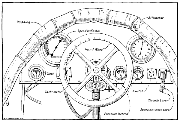
Fig. 251.—View of Airplane Cowl Board, Showing the Various Navigating and Indicating Instruments to Aid the Aviator in Flight.
The proper functioning of the power plant and the various groups comprising it may be readily ascertained at any time by the pilot because various indicating meters and pressure gauges are provided which are located on a dash or cowl board in front of the aviator, as shown at Fig. 251. The speed indicator corresponds to the speedometer of an automobile and gives an indication of the speed the airplane is making, which taken in conjunction with the clock will make it possible to determine the distance covered at a flight. The altimeter, which is an aneroid barometer, outlines with fair accuracy the height above the ground at which a plane is flying. These instruments are furnished to enable the aviator to navigate the airplane when in the air, and if the machine is to be used for cross-country flying, they may be supplemented by a compass and a drift set. It will be evident that these are purely navigating instruments and only indicate the motor condition in an indirect manner. The best way of keeping track of the motor action is to watch the tachometer[565] or revolution counter which is driven from the engine by a flexible shaft. This indicates directly the number of revolutions the engine is making per minute and, of course, any slowing up of the engine in normal flights indicates that something is not functioning as it should. The tachometer operates on the same principle as the speed indicating device or speedometer used in automobiles except that the dial is calibrated to show revolutions per minute instead of miles per hour. At the extreme right of the dash at Fig. 251 the spark advance and throttle control levers are placed. These, of course, regulate the motor speed just as they do in an automobile. Next to the engine speed regulating levers is placed a push button cut-out switch to cut out the ignition and stop the motor. Three pressure gauges are placed in a line. The one at the extreme right indicates the pressure of air on the fuel when a pressure feed system is used. The middle one shows oil pressure, while that nearest the center of the dash board is employed to show the air pressure available in the air starting system. It will be evident that the character of the indicating instruments will vary with the design of the airplane. If it was provided with an electrical starter instead of an air system electrical indicating instruments would have to be provided.
Two forms of air-starting systems are in general use, one in which the crank-shaft is turned by means of an air motor, the other class where compressed air is admitted to the cylinders proper and the motor turned over because of the air pressure acting on the engine pistons. A system known as the “Never-Miss” utilizes a small double-cylinder air pump is driven from the engine by means of suitable gearing and supplies air to a substantial container located at some convenient point in the fuselage. The air is piped from the container to a dash-control valve and from this member to a peculiar form[566] of air motor mounted near the crank-shaft. The air motor consists of a piston to which a rack is fastened which engages a gear mounted on the crank shaft provided with some form of ratchet clutch to permit it to revolve only in one direction, and then only when the gear is turning faster than the engine crank-shaft.
The method of operation is extremely simple, the dash-control valve admitting air from the supply tank to the top of the pump cylinder. When in the position shown in cut the air pressure will force the piston and rack down and set the engine in motion. A variety of air motors are used and in some the pump and motor may be the same device, means being provided to change the pump to an air motor when the engine is to be turned over.
The “Christensen” air starting system is shown at Figs. 252 and 253. An air pump is driven by the engine, and this supplies air to an air reservoir or container attached to the fuselage. This container communicates with the top of an air distributor when a suitable control valve is open. An air pressure gauge is provided to enable one to ascertain the air pressure available. The top of each cylinder is provided with a check valve, through which air can flow only in one direction, i.e., from the tank to the interior of the cylinder. Under explosive pressure these check valves close. The function of the distributor is practically the same as that of an ignition timer, its purpose being to distribute the air to the cylinders of the engine only in the proper firing order. All the while that the engine is running and the car is in motion the air pump is functioning, unless thrown out of action by an easily manipulated automatic control. When it is desired to start the engine a starting valve is opened which permits the air to flow to the top of the distributor, and then through a pipe to the check valve on top of the cylinder about to explode. As the air is going through under considerable pressure it will move the piston down just as the explosion would, and start the engine rotating. The inside of the distributor rotates and directs a charge[567] of air to the cylinder next to fire. In this way the engine is given a number of revolutions, and finally a charge of gas will be ignited and the engine start off on its cycle of operation. To make starting positive and easier some gasoline is injected in with the air so an inflammable mixture is present in the cylinders instead of air only. This ignites easily and the engine starts off sooner than would otherwise be the case. The air pressure required varies from 125 to 250 pounds per square inch, depending upon the size and type of the engine to be set in motion.
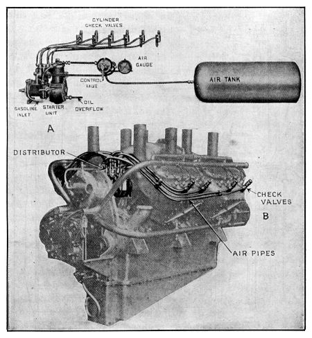
Fig. 252.—Parts of Christensen Air Starting System Shown at A, and Application of Piping and Check Valves to Cylinders of Thomas-Morse Aeromotor Outlined at B.
Starters utilizing electric motors to turn over the engine have been recently developed, and when properly made and maintained in an efficient condition they answer all the requirements of an ideal starting device. The capacity is very high, as the motor may draw current from a storage battery and keep the engine turning over for considerable time on a charge. The objection against their use is that it requires considerable complicated and costly apparatus which is difficult to understand and which requires the services of an expert electrician to repair should it get out of order, though if battery ignition is used the generator takes the place of the usual ignition magneto.
In the Delco system the electric current is generated by a combined motor-generator permanently geared to the engine. When the motor is running it turns the armature and the motor generator is acting as a dynamo, only supplying current to a storage battery. On account of the varying speeds of the generator, which are due to the fluctuation in engine speed, some form of automatic switch which will disconnect the generator from the battery at such times that the motor speed is not sufficiently high to generate a current stronger than that delivered by the battery is needed. These automatic switches are the only delicate part of the entire apparatus, and while they require very delicate adjustment they seem to perform very satisfactorily in practice.
When it is desired to start the engine an electrical connection is established between the storage battery and the motor-generator unit, and this acts as a motor and turns the engine over by suitable gearing which engages the gear teeth cut into a special gear or disc attached to the engine crank-shaft. When the motor-generator furnishes current for ignition as well as for starting the motor, the fact that the current can be used for this work as well as starting justifies to a certain extent the rather[570] complicated mechanism which forms a complete starting and ignition system, and which may also be used for lighting if necessary in night flying.
An electric generator and motor do not complete a self-starting system, because some reservoir or container for electric current must be provided. The current from the generator is usually stored in a storage battery from which it can be made to return to the motor or to the same armature that produced it. The fundamental units of a self-starting system, therefore, are a generator to produce the electricity, a storage battery to serve as a reservoir, and an electric motor to rotate the motor crank-shaft. Generators are usually driven by enclosed gearing, though silent chains are used where the center distance between the motor shaft and generator shaft is too great for the gears. An electric starter may be directly connected to the gasoline engine, as is the case where the combined motor-generator replaces the fly-wheel in an automobile engine. The motor may also drive the engine by means of a silent chain or by direct gear reduction.
Every electric starter must use a switch of some kind for starting purposes and most systems include an output regulator and a reverse current cut-out. The output regulator is a simple device that regulates the strength of the generator current that is supplied the storage battery. A reverse current cut-out is a form of check valve that prevents the storage battery from discharging through the generator. Brief mention is made of electric starting because such systems will undoubtedly be incorporated in some future airplane designs. Battery ignition is already being experimented with.
A battery ignition system in its simplest form consists of a current producer, usually a set of dry cells or a storage battery, an induction coil to transform the low tension current to one having sufficient strength to jump[571] the air gap at the spark-plug, an igniter member placed in the combustion chamber and a timer or mechanical switch operated by the engine so that the circuit will be closed only when it is desired to have a spark take place in the cylinders. Battery ignition systems may be of two forms, those in which the battery current is stepped up or intensified to enable it to jump an air gap between the points of the spark plug, these being called “high tension” systems and the low tension form (never used on airplane motors) in which the battery current is not intensified to a great degree and a spark produced in the cylinder by the action of a mechanical circuit breaker in the combustion chamber. The low tension system is the simplest electrically but the more complex mechanically. The high tension system has the fewest moving parts but numerous electrical devices. At the present time all airplane engines use high tension ignition systems, the magneto being the most popular at the present time. The current distribution and timing devices used with modern battery systems are practically the same as similar parts of a magneto.
| A | |
| PAGE | |
| Action of Four-cycle Engine | 38 |
| Action of Le Rhone Rotary Engine | 503 |
| Action of Two-cycle Engine | 41 |
| Action of Vacuum Feed System | 119 |
| Actual Duration of Different Functions | 93 |
| Actual Heat Efficiency | 62 |
| Adiabatic Diagram | 51 |
| Adiabatic Law | 50 |
| Adjustment of Bearings | 449 |
| Adjustment of Carburetors | 151 |
| Aerial Motors, Must be Light | 20 |
| Aerial Motors, Operating Conditions of | 19 |
| Aerial Motors, Requirements of | 19 |
| Aeromarine Six-cylinder Engine | 527 |
| Aeronautics, Division in Branches | 18 |
| Aerostatics | 18 |
| Air-cooled Engine Design | 229 |
| Air-cooling Advantages | 231 |
| Air-cooling, Direct Method | 228 |
| Air-cooling Disadvantages | 231 |
| Air-cooling Systems | 223 |
| Aircraft, Heavier Than Air | 17 |
| Aircraft, Lighter Than Air | 18 |
| Aircraft Types, Brief Consideration of | 17 |
| Air Needed to Burn Gasoline | 113 |
| Airplane Engine, Power Needed | 21 |
| Airplane Engines, Overhauling | 412 |
| Airplane Engine, How to Time | 269 |
| Airplane Engine Lubrication | 209 |
| Airplane, How Supported | 21 |
| Airplane Motors, German | 543 |
| Airplane Motor Types | 20 |
| Airplane Motors, Weight of | 21 |
| Airplane Power Plant Installation | 324 |
| Airplane Types | 18 |
| Airplanes, Horse-power Used in | 26 |
| Air Pressure Diminution, With Altitude | 144 |
| Altitude, How it Affects Mixture | 153 |
| Aluminum, Use in Pistons | 297 |
| American Aviation Engines, Statistics[574] | 546 |
| Anzani Radial Engine Installation | 344 |
| Anzani Six-cylinder Star Engine | 465 |
| Anzani Six-cylinder Water-cooled Engine | 459 |
| Anzani Ten- and Twenty-cylinder Engines | 468 |
| Anzani Three-cylinder Engine | 459 |
| Anzani Three-cylinder Y Type | 462 |
| Argus Engine Construction | 545 |
| Armature Windings | 168 |
| Atmospheric Conditions, Compensating For | 143 |
| Austro-Daimler Engine | 557 |
| Aviatics | 18 |
| Aviation Engine, Aeromarine | 527 |
| Aviation Engine, Anzani Six-cylinder Star | 465 |
| Aviation Engine, Canton and Unné | 469 |
| Aviation Engine Cooling | 219 |
| Aviation Engine, Curtiss | 519 |
| Aviation Engine Cylinders | 233 |
| Aviation Engine, Early Gnome | 472 |
| Aviation Engine, German Gnome Type | 495 |
| Aviation Engine, Gnome Monosoupape | 486 |
| Aviation Engine, How To Dismantle | 415 |
| Aviation Engine, How to Start | 460 |
| Aviation Engine, Le Rhone Rotary | 495 |
| Aviation Engine Oiling | 218 |
| Aviation Engine Parts, Functions of | 82 |
| Aviation Engine, Renault Air-cooled | 507 |
| Aviation Engine, Stand for Supporting | 414 |
| Aviation Engine, Sturtevant | 515 |
| Aviation Engine, Thomas-Morse | 521 |
| Aviation Engine Types | 457 |
| Aviation Engine, Wisconsin | 531 |
| Aviation Engines, Anzani Six-cylinder Water-cooled | 459 |
| Aviation Engines, Anzani Ten- and Twenty-cylinder | 468 |
| Aviation Engines, Anzani Three-cylinder | 459 |
| Aviation Engines, Anzani Y Type | 462 |
| Aviation Engines, Argus | 545 |
| Aviation Engines, Austro-Daimler | 557 |
| Aviation Engines, Benz | 551 |
| Aviation Engines, Four- and Six-cylinder | 88 |
| Aviation Engines, German | 543 |
| Aviation Engines, Hall-Scott | 539 |
| Aviation Engines, Hispano-Suiza | 512 |
| Aviation Engines, Mercedes | 543 |
| Aviation Engines, Overhauling | 412 |
| Aviation Engines, Principal Parts of | 80 |
| Aviation Engines, Starting Systems For | 567 |
| Aviation Engines, Sunbeam | 558 |
| B[575] | |
| Balanced Crank-shafts | 318 |
| Ball-bearing Crank-shafts | 319 |
| Battery Ignition Systems | 571 |
| Baverey Compound Nozzle | 137 |
| Bearings, Adjustment of | 449 |
| Bearing Alignment | 453 |
| Bearing Brasses, Fitting | 450 |
| Bearing Parallelism, Testing | 453 |
| Bearing Scrapers and Their Use | 446 |
| Benz Aviation Engines | 551 |
| Benz Engine Statistics | 551 |
| Berling Magneto | 174 |
| Berling Magneto, Adjustment of | 180 |
| Berling Magneto Care | 180 |
| Berling Magneto Circuits | 176 |
| Berling Magneto, Setting | 178 |
| Block Castings | 234 |
| Blowing Back | 269 |
| Bolts, Screwing Down | 452 |
| Bore and Stroke Ratio | 240 |
| Boyle’s Law | 49 |
| Brayton Engine | 48 |
| Breaker Box, Adjustment of | 180 |
| Breast and Hand Drills | 387 |
| Burning Out Carbon Deposits | 421 |
| Bushings, Camshaft, Wear in | 456 |
| C | |
| Calipers, Inside and Outside | 398 |
| Cam Followers, Types of | 260 |
| Cams for Valve Actuation | 259 |
| Cam-shaft Bushings | 456 |
| Cam-shaft Design | 313 |
| Cam-shaft Drive Methods | 261 |
| Cam-shaft Testing | 451 |
| Cam-shafts and Timing Gears | 456 |
| Canton and Unné Engine | 469 |
| Carbon, Burning out with Oxygen | 421 |
| Carbon Deposits, Cause of | 418 |
| Carbon Removal | 419 |
| Carbon Scrapers, How Used | 420 |
| Carburetion Principles | 112 |
| Carburetion System Troubles | 355 |
| Carburetor, Claudel | 127 |
| Carburetor, Compound Nozzle Zenith | 135 |
| Carburetor, Concentric Float and Jet Type[576] | 125 |
| Carburetor, Duplex Zenith | 138 |
| Carburetor, Duplex Zenith, Trouble in | 357 |
| Carburetor Installation, In Airplanes | 148 |
| Carburetor, Le Rhone | 501 |
| Carburetor, Master Multiple Jet | 133 |
| Carburetor, Schebler | 125 |
| Carburetor Troubles, How to Locate | 354 |
| Carburetor, Two Stage | 131 |
| Carburetor, What it Should Do | 114 |
| Carburetors, Float Feed | 122 |
| Carburetors, Multiple Nozzle | 130 |
| Carburetors, Notes on Adjustment | 151 |
| Carburetors, Reversing Position of | 149 |
| Carburetors, Spraying | 120 |
| Care of Dixie Magneto | 188 |
| Castor Oil, for Cylinder Lubrication | 205 |
| Castor Oil, Why Used In Gnome Engines | 211 |
| Center Gauge | 403 |
| Chisels, Forms of | 384 |
| Christensen Air Starting System | 567 |
| Circuits, Magnetic | 161 |
| Classification of Engines | 458 |
| Claudel Carburetor | 127 |
| Cleaning Distributor | 180 |
| Clearances Between Valve Stem and Actuators | 261 |
| Combustion Chamber Design | 239 |
| Combustion Chambers, Spherical | 76 |
| Common Tools, Outfit of | 378 |
| Comparing Two-cycle and Four-cycle Types | 44 |
| Compound Cam Followers | 260 |
| Compound Piston Rings | 301 |
| Compressed Air Starting System | 565 |
| Compression, Factors Limiting | 69 |
| Compression, in Explosive Motors, Value of | 68 |
| Compression Pressures, Chart for | 72 |
| Compression Temperature | 71 |
| Computations for Horse-power Needed | 25 |
| Computations for Temperature | 52 |
| Concentric Piston Ring | 299 |
| Concentric Valves | 255 |
| Connecting Rod Alignment, Testing | 454 |
| Connecting Rod, Conventional | 308 |
| Connecting Rod Forms | 305 |
| Connecting Rod, Gnome Engine | 305 |
| Connecting Rods, Fitting | 449 |
| Connecting Rods for Vee Engines | 310 |
| Connecting Rods, Le Rhone | 498 |
| Connecting Rods, Master[577] | 310 |
| Constant Level Splash System | 215 |
| Construction of Dixie Magneto | 186 |
| Construction of Pistons | 288 |
| Conversion of Heat to Power | 58 |
| Cooling by Air | 223 |
| Cooling by Positive Water Circulation | 224 |
| Cooling, Heat Loss in | 66 |
| Cooling System Defects | 358 |
| Cooling Systems Used | 223 |
| Cooling Systems, Why Needed | 219 |
| Cotter Pin Pliers | 384 |
| Crank-case, Conventional | 320 |
| Crank-case Forms | 320 |
| Crank-case, Gnome | 323 |
| Crank-shaft, Built Up | 315 |
| Crank-shaft Construction | 315 |
| Crank-shaft Design | 315 |
| Crank-shaft Equalizer | 449 |
| Crank-shaft Form | 315 |
| Crank-shaft, Gnome Engine | 483 |
| Crank-shafts, Balanced | 318 |
| Crank-shafts, Ball Bearing | 319 |
| Cross Level | 403 |
| Crude Petroleum, Distillates of | 111 |
| Curtiss Aviation Engines | 519 |
| Curtiss Engine Installation | 328 |
| Curtiss Engine Repairing Tools | 408 |
| Cutting Oil Grooves | 448 |
| Cylinder Blocks, Advantages of | 237 |
| Cylinder Block, Duesenberg | 235 |
| Cylinder Castings, Individual | 234 |
| Cylinder Construction | 233 |
| Cylinder Faults and Correction | 416 |
| Cylinder Form and Crank-shaft Design | 238 |
| Cylinder Head Packings | 417 |
| Cylinder Head, Removable | 239 |
| Cylinder, I Head Form | 248 |
| Cylinder, L Head Form | 248 |
| Cylinder Oils | 206 |
| Cylinder Placing | 20 |
| Cylinder Placing in V Motor | 99 |
| Cylinder Retention, Gnome | 475 |
| Cylinder, T Head Form | 248 |
| Cylinders, Cast in Blocks | 235 |
| Cylinders, Odd Number in Rotary Engines | 482 |
| Cylinders, Repairing Scored | 423 |
| Cylinders, Valve Location in | 245 |
| D[578] | |
| Defects in Cylinders | 417 |
| Defects in Dry Battery | 373 |
| Defects in Fuel System | 354 |
| Defects in Induction Coil | 373 |
| Defects in Magneto | 372 |
| Defects in Storage Battery | 372 |
| Defects in Timer | 373 |
| Defects in Wiring and Remedies | 373 |
| Die Holder | 394 |
| Dies for Thread Cutting | 395 |
| Diesel Motor Cards | 67 |
| Diesel System | 144 |
| Direct Air Cooling | 228 |
| Dirigible Balloons | 18 |
| Dismantling Airplane Engine | 415 |
| Distillates of Crude Petroleum | 111 |
| Division of Circle in Degrees | 268 |
| Dixie Ignition Magneto | 184 |
| Dixie Magneto, Care of | 188 |
| Draining Oil From Crank-case | 214 |
| Drilling Machines | 386 |
| Drills, Types and Use | 388 |
| Driving Cam-shaft, Methods of | 262 |
| Dry Cell Battery, Defects in | 373 |
| Duesenberg Sixteen Valve Engine | 525 |
| Duesenberg Valve Action | 255 |
| Duplex Zenith Carburetor | 138 |
| E | |
| Early Gnome Motor, Construction of | 472 |
| Early Ignition Systems | 155 |
| Early Types of Gas Engine | 28 |
| Early Vaporizer Forms | 120 |
| Eccentric Piston Ring | 299 |
| Economy, Factors Governing | 64 |
| Efficiency, Actual Heat | 62 |
| Efficiency, Maximum Theoretical | 61 |
| Efficiency, Mechanical | 62 |
| Efficiency of Internal Combustion Engine | 60 |
| Efficiency, Various Measures of | 61 |
| Eight-cylinder Engine | 95 |
| Eight-cylinder Timing Diagram | 276 |
| Electricity and Magnetism, Relation of | 162 |
| Electrical Ignition Best | 156 |
| Electric Starting Systems | 569 |
| Engine, Advantages of V Type | 95 |
| Engine Base Construction[579] | 319 |
| Engine Bearings, Adjusting | 443 |
| Engine Bearings, Refitting | 442 |
| Engine Bed Timbers, Standard | 330 |
| Engine, Four-cycle, Action of | 38 |
| Engine, Four-cycle, Piston Movements in | 40 |
| Engine Functions, Duration of | 93 |
| Engine Ignition, Locating Troubles | 353 |
| Engine Installation, Gnome | 344 |
| Engine Installation, Anzani Radial | 344 |
| Engine Installation, Hall-Scott | 332 |
| Engine Installation, Rotary | 342 |
| Engine Operation, Sequence of | 84 |
| Engine Parts and Functions | 80 |
| Engine Starts Hard, Ignition Troubles Causing | 369 |
| Engine Stoppage, Causes of | 347 |
| Engine Temperatures | 221 |
| Engine Trouble Charts | 369 |
| Engine Troubles, Cooling | 358 |
| Engine Troubles, Hints For Locating | 345 |
| Engine Troubles, Ignition | 353 |
| Engine Troubles, Noisy Operation | 359 |
| Engine Troubles, Oiling | 357 |
| Engine Troubles Summarized | 350 |
| Engine, Two-cycle, Action of | 41 |
| Engines, Classification of | 458 |
| Engines, Cylinder Arrangement | 31-32 |
| Engines, Eight-cylinder V | 95 |
| Engines, Four-cylinder Forms | 88 |
| Engines, Graphic Comparison of | 33-34-35 |
| Engines, Internal Combustion, Types of | 30 |
| Engines, Multiple Cylinder, Power Delivery in | 91 |
| Engines, Multiple Cylinder, Why Best | 83 |
| Engines, Rotary Cylinder | 107 |
| Engines, Six-cylinder Forms | 88 |
| Engines, Twelve-cylinder | 96 |
| Equalizer, Crank-shaft | 449 |
| Exhaust Closing | 270 |
| Exhaust Valve Design, Early Gnome | 475 |
| Exhaust Valve Opening | 270 |
| Explosive Gases, Mixtures of | 56 |
| Explosive Motors, Inefficiency in | 74 |
| Explosive Motors, Why Best | 27 |
| F | |
| Factors Governing Economy | 64 |
| Factors Limiting Compression | 70 |
| Faults in Ignition | 352 |
| Figuring Horse-power Needed[580] | 21 |
| Files, Use and Care of | 383 |
| First Law of Gases | 49 |
| Fitting Bearings By Scraping | 447 |
| Fitting Brasses | 450 |
| Fitting Connecting Rods | 449 |
| Fitting Main Bearings | 448 |
| Fitting Piston Rings | 439 |
| Float Feed Carburetor Development | 124 |
| Float Feed Carburetors | 122 |
| Force Feed Oiling System | 218 |
| Forked Connecting Rods | 310 |
| Four-cycle Engine, Action of | 38 |
| Four-cycle Engine, Why Best | 45 |
| Fourteen-cylinder Engine | 474 |
| Four Valves Per Cylinder | 284 |
| Friction, Definition of | 302 |
| Fuel Feed By Gravity | 116 |
| Fuel Feed by Vacuum Tank | 117 |
| Fuel Storage and Supply | 116 |
| Fuel Strainers, Types of | 141 |
| Fuel Strainers, Utility of | 140 |
| Fuel System Faults | 354 |
| Fuel System Installation, Hall-Scott | 336 |
| Fuel System, Gnome | 490 |
| Fuel Utilization Chart | 62 |
| G | |
| Gas Engine, Beau de Rocha’s Principles | 59 |
| Gas Engine Development | 28 |
| Gas Engine, Early Forms of | 48 |
| Gas Engine, Inventors of | 29 |
| Gas Engine, Theory of | 47 |
| Gases, Compression of | 49 |
| Gases, First Law of | 49 |
| Gases, Second Law of | 50 |
| Gaskets, How to Use | 452 |
| Gasoline, Air Needed to Burn | 113 |
| Gas Engines, Parts of | 80 |
| Gas Vacuum Engine, Brown’s | 28 |
| German Airplane Motors | 543 |
| German Gnome Type Engine | 495 |
| Gnome Aviation Engine, Early Form | 472 |
| Gnome Crank-shaft | 483 |
| Gnome Cylinder, Machining | 489 |
| Gnome Cylinder Retention | 475 |
| Gnome Engine, Fuel, Lubrication and Ignition | 490 |
| Gnome Engine, German Type[581] | 495 |
| Gnome Engine Installation | 344 |
| Gnome Firing Order | 482 |
| Gnome Fourteen-cylinder, Engine | 474 |
| Gnome Fourteen-cylinder Engine Details | 480 |
| Gnome Monosoupape, How to Time | 278 |
| Gnome Monosoupape Type Engine | 486 |
| Graphic Comparison of Engine Types | 33-34-35 |
| Graphic Comparison, Two- and Four-cycle | 46 |
| Gravity Feed System | 116 |
| Grinding Valves | 429 |
| H | |
| Hall-Scott Aviation Engines | 539 |
| Hall-Scott Engine Installation | 332 |
| Hall-Scott Engine, Preparations For Starting | 341 |
| Hall-Scott Engine Tools | 410 |
| Hall-Scott Lubrication System | 211 |
| Hall-Scott Statistic Sheet | 544 |
| Heat and Its Work | 54 |
| Heat in Gas Engine Cylinder | 69 |
| Heat Given to Cooling Water | 78 |
| Heat Loss, Causes of | 74 |
| Heat Loss in Airplane Engine | 221 |
| Heat Loss in Wall Cooling | 65 |
| High Altitude, How it Affects Power | 144 |
| High Tension Magneto | 172 |
| Hints For Locating Engine Troubles | 345 |
| Hints for Starting Engine | 361 |
| Hispano-Suiza Model A Engine | 512 |
| Horse-power Needed in Airplane | 21 |
| Horse-power Needed, How Figured | 22 |
| How An Engine is Timed | 277 |
| I | |
| Ignition, Electric | 156 |
| Ignition, Elements of | 157 |
| Ignition of Gnome Engine | 490 |
| Ignition System, Battery | 571 |
| Ignition Systems, Early | 155 |
| Ignition System Faults | 352 |
| Ignition, Time of | 273 |
| Ignition, Two Spark | 196 |
| I Head Cylinders | 248 |
| Improvements in Gas Engines | 29 |
| Indicating Meters, Engine Speed | 563 |
| Indicating Meters, Oil and Air Pressure[582] | 563 |
| Indicator Cards, How To Read | 66 |
| Indicator Cards, Value of | 66 |
| Individual Cylinder Castings | 234 |
| Induction Coil, Defects in | 373 |
| Inefficiency, Causes of | 74 |
| Inlet Valve Closing | 272 |
| Inlet Valve Opening | 270 |
| Installation, Airplane Engine | 324 |
| Installation, Curtiss OX-2 Engine | 328 |
| Installation, Hall-Scott Engine | 332 |
| Installation of Rotary Engines | 342 |
| Intake Manifold Construction | 143 |
| Intake Manifold Design | 142 |
| Internal Combustion Engine, Efficiency of | 60, 62 |
| Internal Combustion Engines, Main Types of | 30 |
| Inverted Engine Placing | 325 |
| Isothermal Diagram | 51 |
| Isothermal Law | 48 |
| K | |
| Keeping Oil Out of Combustion Chamber | 303 |
| Knight Sleeve Valves | 266 |
| L | |
| Lag and Lead, Explanation of | 268 |
| Lapping Crank-pins | 445 |
| Lead Given Exhaust Valve | 270 |
| Leak Proof Piston Rings | 301 |
| Lenoir Engine Action | 48 |
| Le Rhone Cams and Valve Actuation | 500 |
| Le Rhone Carburetor | 501 |
| Le Rhone Connecting Rod Assembly, Distinctive | 498 |
| Le Rhone Engine Action | 503 |
| Le Rhone Rotary Engine | 495 |
| L Head Cylinders | 248 |
| Liquid Fuels, Properties of | 110 |
| Locating Carburetor Troubles | 354 |
| Locating Engine Troubles | 350 |
| Locating Ignition Troubles | 353 |
| Locating Oiling Troubles | 357 |
| Location of Magneto Trouble | 181 |
| Losses in Wall Cooling | 65 |
| Lost Power and Overheating, Summary of Troubles Causing | 363 |
| Lubricants, Derivation of | 204 |
| Lubricants, Requirements of | 204 |
| Lubricating System Classification[583] | 208 |
| Lubricating Systems, Selection of | 208 |
| Lubrication By Constant Level Splash System | 215 |
| Lubrication By Dry Crank-case Method | 218 |
| Lubrication By Force Feed Best | 218 |
| Lubrication of Magneto | 180 |
| Lubrication System, Gnome | 490 |
| Lubrication System, Hall-Scott | 211 |
| Lubrication System, Thomas-Morse | 210 |
| Lubrication, Theory of | 202 |
| Lubrication, Why Necessary | 201 |
| M | |
| Magnetic Circuits | 161 |
| Magnetic Influence Defined | 158 |
| Magnetic Lines of Force | 161 |
| Magnetic Substances | 158 |
| Magnetism, Flow Through Armature | 166 |
| Magnetism, Fundamentals of | 157 |
| Magnetism, Relation to Electricity | 162 |
| Magneto, Action of High Tension | 173 |
| Magneto Armature Windings | 168 |
| Magneto, Basic Principles of | 163 |
| Magneto, Berling | 174 |
| Magneto, Defects in | 372 |
| Magneto Distributor, Cleaning | 180 |
| Magneto Ignition Systems | 169 |
| Magneto Ignition Wiring | 179 |
| Magneto Interrupter, Adjustment of | 180 |
| Magneto, Low Voltage | 168 |
| Magneto, Lubrication of | 180 |
| Magneto Maintenance | 180 |
| Magneto, Method of Driving | 175 |
| Magneto Parts and Functions | 167 |
| Magneto, The Dixie | 184 |
| Magneto Timing | 179 |
| Magneto, Timing Dixie | 188 |
| Magneto, Transformer System | 171 |
| Magneto Trouble, Location of | 181 |
| Magneto, True High Tension | 172 |
| Magneto, Two Spark Dual | 177 |
| Magnets, Forms of | 160 |
| Magnets, How Produced | 162 |
| Magnets, Properties of | 159 |
| Main Bearings, Fitting | 448 |
| Manifold, Intake | 143 |
| Master Multiple Jet Carburetor | 133 |
| Master Rod Construction[584] | 310 |
| Maximum Theoretical Efficiency | 61 |
| Meaning of Piston Speed | 241 |
| Measures of Efficiency | 61 |
| Measuring Tools | 397 |
| Mechanical Efficiency | 62 |
| Mercedes Aviation Engine | 543 |
| Metering Pin Carburetor, Stewart | 128 |
| Micrometer Caliper, Beading | 405 |
| Micrometer Calipers, Types and Use | 404 |
| Mixture, Effect of Altitude on | 153 |
| Mixture, Proportions of | 151 |
| Mixture, Starvation of | 149 |
| Monosoupape Gnome Engine | 486 |
| Mother Bod, Gnome Engine | 305 |
| Motor Misfires, Carburetor Faults Causing | 374 |
| Motor Misfires, Ignition Troubles Causing | 370 |
| Motor Races, Carburetor Faults Causing | 374 |
| Motor Starts Hard, Carburetor Faults Causing | 374 |
| Motor Stops In Flight, Carburetor Faults | 374 |
| Motor Stops Without Warning, Ignition Troubles | 370 |
| Multiple Cylinder Engine, Why Best | 83 |
| Multiple Nozzle Vaporizers | 129 |
| Multiple Valve Advantages | 286 |
| N | |
| Noisy Engine Operation, Causes of | 359 |
| Noisy Operation, Carburetor Faults Causing | 374 |
| Noisy Operation, Summary of Troubles Causing | 365 |
| O | |
| Off-set Cylinders, Reason for | 243 |
| Oil Bi-pass, Function of | 213 |
| Oil, Draining From Crank-case | 214 |
| Oil Grooves, Cutting | 448 |
| Oil Pressure in Hall-Scott System | 214 |
| Oil Pressure Relief Bi-pass | 213 |
| Oiling System Defects | 357 |
| Oils for Cylinder Lubrication | 206 |
| Oils for Hall-Scott Engine | 215 |
| Oils for Lubrication | 204 |
| Operating Principles of Engines | 37 |
| Oscillating Piston Pin | 295 |
| Otto Four-cycle Cards | 67 |
| Overhauling Aviation Engines | 412 |
| Overhead Cam-shaft Location | 252 |
| Overheating, Causes of | 359 |
| P[585] | |
| Panhard Concentric Valves | 255 |
| Petroleum, Distillates of | 111 |
| Piston, Differential | 291 |
| Piston Pin Retention | 293 |
| Piston Ring Construction | 298 |
| Piston Ring Joints | 299 |
| Piston Ring Manipulation | 438 |
| Piston Ring Troubles | 437 |
| Piston Rings, Compound | 301 |
| Piston Rings, Concentric | 299 |
| Piston Rings, Eccentric | 299 |
| Piston Rings, Fitting | 439 |
| Piston Rings, Leak Proof | 301 |
| Piston Rings, Replacing | 441 |
| Piston Speed in Airplane Engines | 241 |
| Piston Speed, Meaning of | 241 |
| Piston Troubles and Remedies | 436 |
| Pistons, Aluminum | 296 |
| Pistons, Details of | 288 |
| Pistons for Two-cycle Engines | 289 |
| Positive Valve Systems | 283 |
| Power, Affected by High Altitude | 145 |
| Power Delivery in Multiple Cylinder Engines | 91 |
| Power, How Obtained From Heat | 58 |
| Power Needed in Airplane Engines | 21 |
| Power Used in Airplanes | 26 |
| Precautions in Assembling Parts | 452 |
| Pressure Relief Fitting | 213 |
| Pressures and Temperatures | 63 |
| Principles of Carburetion | 112 |
| Principles of Magneto Action | 163 |
| Properties of Cylinder Oils | 207 |
| Properties of Liquid Fuels | 110 |
| Pump Circulation Systems | 226 |
| Pump Forms | 226 |
| R | |
| Radial Cylinder Arrangement | 103 |
| Reading Indicator Cards | 67 |
| Reamers, Types and Use | 392 |
| Reassembling Parts, Precautions in | 451 |
| Removable Cylinder Head | 239 |
| Renault Air Cooled Engine | 507 |
| Renault Engine Details | 508 |
| Repairing Scored Cylinders | 423 |
| Requisites for Best Power Effect | 59 |
| Reseating and Truing Valves[586] | 426 |
| Resistance, Influence of | 22 |
| Rotary Cylinder Engines | 107 |
| Rotary Engine, Le Rhone | 495 |
| Rotary Engines, Castor Oil for | 211 |
| Rotary Engines, Installing | 342 |
| Rotary Engines, Why Odd Number of Cylinders | 109 |
| Rotary Engines, Why Odd Number of Cylinders Is Used | 482 |
| S | |
| S. A. E. Engine Bed Dimensions | 330 |
| Salmson Nine-cylinder Engine | 470 |
| Scissors Joint Rods | 310 |
| Scored Cylinders, Repairing | 422 |
| Scrapers, Types of Bearing | 446 |
| Scraping Bearings to Fit | 447 |
| Second Law of Gases | 50 |
| Sequence of Engine Operation | 84 |
| Shebler Carburetor | 125 |
| Six-cylinder Timing Diagram | 275 |
| Sixteen Valve Duesenberg Engine | 525 |
| Skipping or Irregular Operation, Causes of | 367 |
| Sliding Sleeve Valves | 266 |
| Spark Plug Air Gaps, Setting | 197 |
| Spark Plug, Design of | 193 |
| Spark Plug, Mica | 194 |
| Spark Plug, Porcelain | 193 |
| Spark Plugs, Defects in | 371 |
| Spark Plugs for Two Spark Ignition | 197 |
| Spark Plug, Special for Airplane Engine | 199 |
| Spark Plug, Standard S. A. E. | 195 |
| Spherical Combustion Chambers | 76 |
| Splash Lubrication | 215 |
| Split Pin Remover | 384 |
| Spraying Carburetors | 120 |
| Springless Valves | 280 |
| Springs, for Valves | 263 |
| Spring Winder | 384 |
| Sprung Cam-shaft, Testing | 451 |
| Stand for Supporting Engine | 414 |
| Starting Engine, Hints for | 361 |
| Starting Hall-Scott Engine | 341 |
| Starting System, Christensen | 567 |
| Starting Systems, Compressed Air | 565 |
| Starting Systems, Electric | 569 |
| Statistics, American Engines | 546, 547 |
| Statistic Sheet, Hall-Scott Engines | 544 |
| Statistics of Benz Engine[587] | 551 |
| Steam Engine, Efficiency of | 59 |
| Steam Engine, Why Not Used | 27 |
| Steel Scale, Machinists’ | 399 |
| Stewart Metering Pin Carburetor | 128 |
| Storage Battery, Defects in | 372 |
| Stroke and Bore Ratio | 240 |
| Sturtevant Model 5A Engine | 515 |
| Summary of Engine Types | 30 |
| Sunbeam Aviation Engines | 588 |
| Sunbeam Eighteen-Cylinder Engine | 561 |
| T | |
| Tap and Die Sets | 397 |
| Taps for Thread Cutting | 394 |
| Tee Head Cylinders | 247 |
| Temperature Computations | 52 |
| Temperatures and Explosive Pressures | 64 |
| Temperatures and Pressures | 63 |
| Temperatures, Operating | 221 |
| Testing Bearing Parallelism | 453 |
| Testing Connecting Rod Alignment | 454 |
| Testing Fit of Bearings | 446 |
| Testing Sprung Cam-shaft | 451 |
| Theory of Gas Engine | 47 |
| Theory of Lubrication | 203 |
| Thermo-syphon Cooling System | 227 |
| Thomas-Morse Aviation Engine | 521 |
| Thomas-Morse Lubrication System | 210 |
| Thread Pitch Gauge | 403 |
| Time of Ignition | 273 |
| Timer, Defects in | 373 |
| Times of Explosion | 56 |
| Timing Dixie Magneto | 188 |
| Timing Gears, Effects of Wear | 456 |
| Timing Magneto | 179 |
| Timing Valves | 267 |
| Tool Outfits, Typical | 408 |
| Tools for Adjusting and Erecting | 378 |
| Tools for Bearing Work | 445 |
| Tools for Curtiss Engines | 408 |
| Tools for Grinding Valves | 430 |
| Tools for Hall-Scott Engines | 410, 411 |
| Tools for Measuring | 397 |
| Tools for Reseating Valves | 426 |
| Trouble in Carburetion System | 355 |
| Trouble, Location of Magneto | 181 |
| Troubles, Engine, How to Locate[588] | 345 |
| Troubles, Ignition | 353 |
| Troubles in Oiling System | 357 |
| True High Tension Magneto | 172 |
| Twelve-Cylinder Engines | 96 |
| Two-and Four-Cycle Types, Comparison of | 44 |
| Two-Cycle Engine Action | 41 |
| Two-Cycle Three-Port Engine | 43 |
| Two-Cycle Two-Port Engine | 42 |
| Two-Spark Ignition | 196 |
| Two-Stage Carburetor | 131 |
| Types of Aircraft | 17 |
| Types of Internal Combustion Engines | 30 |
| V | |
| Vacuum Fuel Feed, Stewart | 119 |
| Value of Compression | 69 |
| Value of Indicator Cards | 66 |
| Valve Actuation, Le Rhone | 500 |
| Valve Design and Construction | 256 |
| Valve-Grinding Processes | 429 |
| Valve-Lifting Cams | 259 |
| Valve-Lifting Plungers | 260 |
| Valve Location Practice | 245 |
| Valve Operating Means | 252 |
| Valve Operating System, Depreciation in | 433 |
| Valve Operation | 258 |
| Valve Removal and Inspection | 424 |
| Valve Seating, How to Test | 432 |
| Valve Springs | 263 |
| Valve Timing, Exhaust | 270 |
| Valve Timing, Gnome Monosoupape | 278 |
| Valve Timing, Intake | 270 |
| Valve Timing, Lag and Lead | 269 |
| Valve Timing Procedure | 277 |
| Valve Timing Practice | 267 |
| Valves, Electric Welded | 258 |
| Valves, Flat and Bevel Seat | 257 |
| Valves, Four per Cylinder | 284 |
| Valves, How Placed in Cylinder | 247 |
| Valves in Cages | 249 |
| Valves in Removable Heads | 249 |
| Valves, Materials Used for | 258 |
| Valves, Reseating | 426 |
| Vaporizer, Simple Forms of | 120 |
| V Engines, Cylinder Arrangement in | 102 |
| Vernier, How Used | 401 |
| W[589] | |
| Wall Cooling, Losses in | 65 |
| Water Cooling by Natural Circulation | 227 |
| Water Cooling System | 224 |
| Weight of Airplane Motors | 21 |
| Wiring, Defects in | 373 |
| Wiring Magneto Ignition System | 179 |
| Wisconsin Engines | 531 |
| Wrenches, Forms of | 380 |
| Wristpin Retention | 293 |
| Wristpin Retention Locks | 295 |
| Wristpin Wear and Remedy | 442 |
| Z | |
| Zenith Carburetor, Action of | 137 |
| Zenith Duplex Carburetor, Troubles in | 356 |
| Zenith Carburetor Installation | 139 |
| Frontispiece. | Part Sectional View of Hall-Scott Airplane Motor, Showing Principal Parts. |
| Fig. 1. | Diagrams Illustrating Computations for Horse-Power Required for Airplane Flight. |
| Fig. 2. | Plate Showing Heavy, Slow Speed Internal Combustion Engines Used Only for Stationary Power in Large Installations Giving Weight to Horse-Power Ratio. |
| Fig. 3. | Various Forms of Internal Combustion Engines Showing Decrease in Weight to Horse-Power Ratio with Augmenting Speed of Rotation. |
| Fig. 4. | Internal Combustion Engine Types of Extremely Fine Construction and Refined Design, Showing Great Power Outputs for Very Small Weight, a Feature Very Much Desired in Airplane Power Plants. |
| Fig. 5. | Outlining First Two Strokes of Piston in Four-Cycle Engine. |
| Fig. 6. | Outlining Second Two Strokes of Piston in Four-Cycle Engine. |
| Fig. 7. | Sectional View of L Head Gasoline Engine Cylinder Showing Piston Movements During Four-Stroke Cycle. |
| Fig. 8. | Showing Two-port, Two-cycle Engine Operation. |
| Fig. 9. | Defining Three-port, Two-cycle Engine Action. |
| Fig. 10. | Diagrams Contrasting Action of Two- and Four-Cycle Cylinders on Exhaust and Intake Stroke. |
| Fig. 11. | Diagram Isothermal and Adiabatic Lines. |
| Fig. 12. | Graphic Diagram Showing Approximate Utilization of Fuel Burned in Internal-Combustion Engine. |
| Fig. 13. | Otto Four-Cycle Card. |
| Fig. 14. | Diesel Motor Card. |
| Fig. 15. | Diagram of Heat in the Gas Engine Cylinder. |
| Fig. 16. | Chart Showing Relation Between Compression Volume and Pressure. |
| Fig. 17. | The Thompson Indicator, an Instrument for Determining Compressions and Explosion Pressure Values and Recording Them on Chart. |
| Fig. 18. | Spherical Combustion Chamber. |
| Fig. 19. | Enlarged Combustion Chamber. |
| Fig. 20. | Mercedes Aviation Engine Cylinder Section Showing Approximately Spherical Combustion Chamber and Concave Piston Top. |
| Fig. 21. | Side Sectional View of Typical Airplane Engine, Showing Parts and Their Relation to Each Other. This Engine is an Aeromarine Design and Utilizes a Distinctive Concentric Valve Construction. |
| Fig. 22. | Diagrams Illustrating Sequence of Cycles in One- and Two-Cylinder Engines Showing More Uniform Turning Effort on Crank-Shaft with Two-Cylinder Motors. |
| Fig. 23. | Diagrams Demonstrating Clearly Advantages which Obtain when Multiple-Cylinder Motors are Used as Power Plants. |
| Fig. 24. | Showing Three Possible Though Unconventional Arrangements of Four-Cylinder Engines. |
| Fig. 25. | Diagrams Outlining Advantages of Multiple Cylinder Motors, and Why They Deliver Power More Evenly Than Single Cylinder Types. |
| Fig. 26. | Diagrams Showing Duration of Events for a Four-Stroke Cycle, Six-Cylinder Engine. |
| Fig. 27. | Diagram Showing Actual Duration of Different Strokes in Degrees. |
| Fig. 28. | Another Diagram to Facilitate Understanding Sequence of Functions in Six-Cylinder Engine. |
| Fig. 29. | Types of Eight-Cylinder Engines Showing the Advantage of the V Method of Cylinder Placing. |
| Fig. 30. | Curves Showing Torque of Various Engine Types Demonstrate Graphically Marked Advantage of the Eight-Cylinder Type. |
| Fig. 31. | Diagrams Showing How Increasing Number of Cylinders Makes for More Uniform Power Application. |
| Fig. 32. | How the Angle Between the Cylinders of an Eight- and Twelve-Cylinder V Motor Varies. |
| Fig. 33. | The Hall-Scott Four-Cylinder 100 Horse-Power Aviation Motor. |
| Fig. 34. | Two Views of the Duesenberg Sixteen Valve Four-Cylinder Aviation Motor. |
| Fig. 35. | The Hall-Scott Six-Cylinder Aviation Engine. |
| Fig. 36. | The Curtiss Eight-Cylinder, 200 Horse-Power Aviation Engine. |
| Fig. 37. | The Sturtevant Eight-Cylinder, High Speed Aviation Motor. |
| Fig. 38. | Anzani 40-50 Horse-Power Five-Cylinder Air Cooled Engine. |
| Fig. 39. | Unconventional Six-Cylinder Aircraft Motor of Masson Design. |
| Fig. 40. | The Gnome Fourteen-Cylinder Revolving Motor. |
| Fig. 41. | How Gravity Feed Fuel Tank May Be Mounted Back of Engine and Secure Short Fuel Line. |
| Fig. 42. | The Stewart Vacuum Fuel Feed Tank. |
| Fig. 43. | Marine-Type Mixing Valve, by which Gasoline is Sprayed into Air Stream Through Small Opening in Air-Valve Seat. |
| Fig. 44. | Tracing Evolution of Modern Spray Carburetor. A—Early Form Evolved by Maybach. B.—Phœnix-Daimler Modification of Maybach’s Principle. C—Modern Concentric Float Automatic Compensating Carburetor. |
| Fig. 45. | New Model of Schebler Carburetor With Metering Valve and Extended Venturi. Note Mechanical Connection Between Air Valve and Fuel Regulating Needle. |
| Fig. 46. | The Claudel Carburetor. |
| Fig. 47. | The Stewart Metering Pin Carburetor. |
| Fig. 48. | The Ball and Ball Two-Stage Carburetor. |
| Fig. 49. | The Master Carburetor. |
| Fig. 50. | Sectional View of Master Carburetor Showing Parts. |
| Fig. 51. | Sectional View of Zenith Compound Nozzle Compensating Carburetor. |
| Fig. 52. | Diagrams Explaining Action of Baverey Compound Nozzle Used in Zenith Carburetor. |
| Fig. 53. | The Zenith Duplex Carburetor for Airplane Motors of the V Type. |
| Fig. 54. | Rear View of Curtiss OX-2 90 Horse-Power Airplane Motor Showing Carburetor Location and Hot Air Leads. |
| Fig. 55. | Types of Strainers Interposed Between Vaporizer and Gasoline Tank to Prevent Water or Dirt Passing Into Carbureting Device. |
| Fig. 56. | Chart Showing Diminution of Air Pressure as Altitude Increases. |
| Fig. 57. | Some Simple Experiments to Demonstrate Various Magnetic Phenomena and Clearly Outline Effects of Magnetism and Various Forms of Magnets. |
| Fig. 58. | Elementary Form of Magneto Showing Principal Parts Simplified to Make Method of Current Generation Clear. |
| Fig. 59. | Showing How Strength of Magnetic Influence and of the Currents Induced in the Windings of Armature Vary with the Rapidity of Changes of Flow. |
| Fig. 60. | Diagrams Explaining Action of Low Tension Transformer Coil and True High Tension Magneto Ignition Systems. |
| Fig. 60A. | Side Sectional View of Bosch High-Tension Magneto Shows Disposition of Parts. End Elevation Depicts Arrangement of Interruptor and Distributor Mechanism. |
| Fig. 61. | Berling Two-Spark Dual Ignition System. |
| Fig. 62. | Berling Double-Spark Independent System. |
| Fig. 63. | Type DD Berling High Tension Magneto. |
| Fig. 64. | Wiring Diagrams of Berling Magneto Ignition Systems. |
| Fig. 65. | The Berling Magneto Breaker Box Showing Contact Points Separated and Interruptor Lever on Cam. |
| Fig. 66. | The Dixie Model 60 for Six-Cylinder Airplane Engine Ignition. |
| Fig. 67. | Installation Dimensions of Dixie Model 60 Magneto. |
| Fig. 68. | The Rotating Elements of the Dixie Magneto. |
| Fig. 69. | Suggestions for Adjusting and Dismantling Dixie Magneto. A—Screw Driver Adjusts Contact Points. B—Distributor Block Removed. C—Taking off Magnets. D—Showing How Easily Condenser and High Tension Windings are Removed. |
| Fig. 69A. | Sectional Views Outlining Construction of Dixie Magneto with Compound Distributor for Eight-Cylinder Engine Ignition. |
| Fig. 70. | Wiring Diagram of Dixie Magneto Installation on Hall-Scott Six-Cylinder 125 Horse-Power Aeronautic Motor. |
| Fig. 71. | How Magneto Ignition is Installed on Thomas-Morse 135 Horse-Power Motor. |
| Fig. 72. | Spark-Plug Types Showing Construction and Arrangement of Parts. |
| Fig. 73. | Standard Airplane Engine Plug Suggested by S. A. E. Standards Committee. |
| Fig. 74. | Special Mica Plug for Aviation Engines. |
| Fig. 75. | Showing Use of Magnifying Glass to Demonstrate that Apparently Smooth Metal Surfaces May Have Minute Irregularities which Produce Friction. |
| Fig. 76. | Pressure Feed Oiling System of Thomas Aviation Engine Includes Oil Cooling Means. |
| Fig. 77. | Diagram of Oiling System, Hall-Scott Type A 125 Horse-Power Engine. |
| Fig. 78. | Sectional View of Typical Motor Showing Parts Needing Lubrication and Method of Applying Oil by Constant Level Splash System. Note also Water Jacket and Spaces for Water Circulation. |
| Fig. 79. | Pressure Feed Oil-Supply System of Airplane Power Plants has Many Good Features. |
| Fig. 80. | Why Pressure Feed System is Best for Eight-Cylinder Vee Airplane Engines. |
| Fig. 81. | Operating Temperatures of Automobile Engine Parts Useful as a Guide to Understand Airplane Power Plant Heat. |
| Fig. 82. | Water Cooling of Salmson Seven-Cylinder Radial Airplane Engine. |
| Fig. 83. | How Water Cooling System of Thomas Airplane Engine is Installed in Fuselage. |
| Fig. 84. | Finned Tube Radiators at the Side of Hall-Scott Airplane Power Plant Installed in Standard Fuselage. |
| Fig. 85. | Anzani Testing His Five-Cylinder Air Cooled Aviation Motor Installed in Bleriot Monoplane. Note Exposure of Flanged Cylinders to Propeller Slip Stream. |
| Fig. 86. | Views of Four-Cylinder Duesenberg Airplane Engine Cylinder Block. |
| Fig. 87. | Twin-Cylinder Block of Sturtevant Airplane Engine is Cast of Aluminum, and Has Removable Cylinder Head. |
| Fig. 88. | Aluminum Cylinder Pair Casting of Thomas 150 Horse-Power Airplane Engine is of the L Head Type. |
| Fig. 90. | Cross Section of Austro-Daimler Engine, Showing Offset Cylinder Construction. Note Applied Water Jacket and Peculiar Valve Action. |
| Fig. 91. | Diagrams Demonstrating Advantages of Offset Crank-Shaft Construction. |
| Fig. 92. | Diagram Showing Forms of Cylinder Demanded by Different Valve Placings. A—T Head Type, Valves on Opposite Sides. B—L Head Cylinder, Valves Side by Side. C—L Head Cylinder, One Valve in Head, Other in Pocket. D—Inlet Valve Over Exhaust Member, Both in Side Pocket. E—Valve-in-the-Head Type with Vertical Valves. F—Inclined Valves Placed to Open Directly into Combustion Chamber. |
| Fig. 93. | Sectional View of Engine Cylinder Showing Valve and Cage Installation. |
| Fig. 94. | Diagrams Showing How Gas Enters Cylinder Through Overhead Valves and Other Types. A—Tee Head Cylinder. B—L Head Cylinder. C—Overhead Valve. |
| Fig. 95. | Conventional Methods of Operating Internal Combustion Motor Valves. |
| Fig. 96. | Examples of Direct Valve Actuation by Overhead Cam-Shaft. A—Mercedes. B—Hall-Scott. C—Wisconsin. |
| Fig. 97. | CENSORED |
| Fig. 98. | CENSORED |
| Fig. 99. | Sectional Views Showing Arrangement of Novel Concentric Valve Arrangement Devised by Panhard for Aerial Engines. |
| Fig. 100. | Showing Clearance Allowed Between Valve Stem and Valve Stem Guide to Secure Free Action. |
| Fig. 101. | Forms of Valve-Lifting Cams Generally Employed. A—Cam Profile for Long Dwell and Quick Lift. B—Typical Inlet Cam Used with Mushroom Type Follower. C—Average Form of Cam. D—Designed to Give Quick Lift and Gradual Closing. |
| Fig. 102. | Showing Principal Types of Cam Followers which Have Received General Application. |
| Fig. 103. | Diagram Showing Proper Clearance to Allow Between Adjusting Screw and Valve Stems in Hall-Scott Aviation Engines. |
| Fig. 104. | Cam-Shaft of Thomas Airplane Motor Has Cams Forged Integral. Note Split Cam-Shaft Bearings and Method of Gear Retention. |
| Fig. 105. | Section Through Cylinder of Knight Motor, Showing Important Parts of Valve Motion. |
| Fig. 106. | Diagrams Showing Knight Sleeve Valve Action. |
| Fig. 107. | Cross Sectional View of Knight Type Eight Cylinder V Engine. |
| Fig. 108. | Diagrams Explaining Valve and Ignition Timing of Hall-Scott Aviation Engine. |
| Fig. 109. | Timing Diagram of Typical Six-Cylinder Engine. |
| Fig. 110. | Timing Diagram of Typical Eight-Cylinder V Engine. |
| Fig. 111. | Timing Diagram Showing Peculiar Valve Timing of Gnome “Monosoupape” Rotary Motor. |
| Fig. 112. | Two Methods of Operating Valves by Positive Cam Mechanism Which Closes as Well as Opens Them. |
| Fig. 113. | Diagram Comparing Two Large Valves and Four Small Ones of Practically the Same Area. Note How Easily Small Valves are Installed to Open Directly Into the Cylinder. |
| Fig. 114. | Sectional Views of Sixteen-Valve Four-Cylinder Automobile Racing Engine That May Have Possibilities for Aviation Service. |
| Fig. 115. | Front View of Curtiss OX-3 Aviation Motor, Showing Unconventional Valve Action by Concentric Push Rod and Pull Tube. |
| Fig. 116. | Forms of Pistons Commonly Employed in Gasoline Engines. A—Dome Head Piston and Three Packing Rings. B—Flat Top Form Almost Universally Used. C—Concave Piston Utilized in Knight Motors and Some Having Overhead Valves. D—Two-Cycle Engine Member with Deflector Plate Cast Integrally. E—Differential of Two-Diameter Piston Used in Some Engines Operating on Two-Cycle Principle. |
| Fig. 117. | Typical Methods of Piston Pin Retention Generally Used in Engines of American Design. A—Single Set Screw and Lock Nut. B—Set Screw and Check Nut Fitting Groove in Wrist Pin. C, D—Two Locking Screws Passing Into Interior of Hollow Wrist Pin. E—Split Ring Holds Pin in Place. F—Use of Taper Expanding Plugs Outlined. G—Spring Pressed Plunger Type. H—Piston Pin Pinned to Connecting Rod. I—Wrist Pin Clamped in Connecting Rod Small End by Bolt. |
| Fig. 118. | Typical Piston and Connecting Rod Assembly. |
| Fig. 119. | Parts of Sturtevant Aviation Engine. A—Cylinder Head Showing Valves. B—Connecting Rod. C—Piston and Rings. |
| Fig. 120. | Aluminum Piston and Light But Strong Steel Connecting Rod and Wrist Pin of Thomas Aviation Engine. |
| Fig. 121. | Cast Iron Piston of “Monosoupape” Gnome Engine Installed On One of the Short Connecting Rods. |
| Fig. 122. | Types of Aluminum Pistons Used In Aviation Engines. |
| Fig. 123. | Types of Piston Rings and Ring Joints. A—Concentric Ring. B—Eccentrically Machined Form. C—Lap Joint Ring. D—Butt Joint, Seldom Used. E—Diagonal Cut Member, a Popular Form. |
| Fig. 124. | Diagrams Showing Advantages of Concentric Piston Rings. |
| Fig. 125. | Leak-Proof and Other Compound Piston Rings. |
| Fig. 126. | Sectional View of Engine Showing Means of Preventing Oil Leakage By Piston Rings. |
| Fig. 127. | Connecting Rod and Crank-Shaft Construction of Gnome “Monosoupape” Engine. |
| Fig. 128. | Connecting Rod Types Summarized. A—Single Connecting Rod Made in One Piece, Usually Fitted in Small Single-Cylinder Engines Having Built-Up Crank-Shafts. B—Marine Type, a Popular Form on Heavy Engines. C—Conventional Automobile Type, a Modified Marine Form. D—Type Having Hinged Lower Cap and Split Wrist Pin Bushing. E—Connecting Rod Having Diagonally Divided Big End. F—Ball-Bearing Rod. G—Sections Showing Structural Shapes Commonly Employed in Connecting Rod Construction. |
| Fig. 129. | Double Connecting Rod Assembly For Use On Single Crank-Pin of Vee Engine. |
| Fig. 130. | Another Type of Double Connecting Rod for Vee Engines. |
| Fig. 131. | Part Sectional View of Wisconsin Aviation Engine, Showing Four-Bearing Crank-Shaft, Overhead Cam-Shaft, and Method of Combining Cylinders in Pairs. |
| Fig. 132. | Part Sectional View of Renault Twelve-Cylinder Water-Cooled Engine, Showing Connecting Rod Construction and Other Important Internal Parts. |
| Fig. 133. | Typical Cam-Shaft, with Valve Lifting Cams and Gears to Operate Auxiliary Devices Forged Integrally. |
| Fig. 134. | Important Parts of Duesenberg Aviation Engine. A—Three Main Bearing Crank-Shaft. B—Cam-Shaft with Integral Cams. C—Piston and Connecting Rod Assembly. D—Valve Rocker Group. E—Piston. F—Main Bearing Brasses. |
| Fig. 135. | Showing Method of Making Crank-Shaft. A—The Rough Steel Forging Before Machining. B—The Finished Six-Throw, Seven-Bearing Crank-Shaft. |
| Fig. 136. | Showing Form of Crank-Shaft for Twin-Cylinder Opposed Power Plant. |
| Fig. 137. | Crank-Shaft of Thomas-Morse Eight-Cylinder Vee Engine. |
| Fig. 138. | Crank-Case and Crank-Shaft Construction for Twelve-Cylinder Motors. A—Duesenberg. B—Curtiss. |
| Fig. 139. | Counterbalanced Crank-Shafts Reduce Engine Vibration and Permit of Higher Rotative Speeds. |
| Fig. 140. | View of Thomas 135 Horse-Power Aeromotor, Model 8, Showing Conventional Method of Crank-Case Construction. |
| Fig. 141. | Views of Upper Half of Thomas Aeromotor Crank-Case. |
| Fig. 142. | Method of Constructing Eight-Cylinder Vee Engine, Possible if Aluminum Cylinder and Crank-Case Castings are Used. |
| Fig. 143. | Simple and Compact Crank-Case, Possible When Radial Cylinder Engine Design is Followed. |
| Fig. 144. | Unconventional Mounting of German Inverted Cylinder Motor. |
| Fig. 145. | How Curtiss Model OX-2 Motor is Installed in Fuselage of Curtiss Tractor Biplane. Note Similarity of Mounting to Automobile Power Plant. |
| Fig. 146. | Latest Model of Curtiss JN-4 Training Machine, Showing Thorough Enclosure of Power Plant and Method of Disposing of the Exhaust Gases. |
| Fig. 147. | Front View of L. W. F. Tractor Biplane Fuselage, Showing Method of Installing Thomas Aeromotor and Method of Disposing of Exhaust Gases. |
| Fig. 148. | End Elevation of Hall-Scott A-7 Four-Cylinder Motor, with Installation Dimensions. |
| Fig. 149. | Plan and Side Elevation of Hall-Scott A-7 Four-Cylinder Airplane Engine, with Installation Dimensions. |
| Fig. 150. | CENSORED |
| Fig. 151. | CENSORED |
| Fig. 152. | CENSORED |
| Fig. 153. | Plan View of Hall-Scott Type A-5 125 Horse-Power Airplane Engine, Showing Installation Dimensions. |
| Fig. 154. | Three-Quarter View of Hall-Scott Type A-5 125 Horse-Power Six-Cylinder Engine, with One of the Side Radiators Removed to Show Installation in Standard Fuselage. |
| Fig. 155. | Diagram Showing Proper Installation of Hall-Scott Type A-5 125 Horse-Power Engine with Pressure Feed Fuel Supply System. |
| Fig. 156. | Diagram Defining Installation of Gnome “Monosoupape” Motor in Tractor Biplane. Note Necessary Piping for Fuel, Oil, and Air Lines. |
| Fig. 157. | Showing Two Methods of Placing Propeller on Gnome Rotary Motor. |
| Fig. 158. | How Gnome Rotary Motor May Be Attached to Airplane Fuselage Members. |
| Fig. 159. | How Anzani Ten-Cylinder Radial Engine is Installed to Plate Securely Attached to Front End of Tractor Airplane Fuselage. |
| Fig. 160. | Side Elevation of Thomas 135 Horse-Power Airplane Engine, Giving Important Dimensions. |
| Fig. 161. | Front Elevation of Thomas-Morse 135 Horse-Power Aeromotor, Showing Main Dimensions. |
| Fig. 162. | Front and Side Elevations of Sturtevant Airplane Engine, Giving Principal Dimensions to Facilitate Installation. |
| Fig. 163. | Practical Hand Tools Useful in Dismantling and Repairing Airplane Engines. |
| Fig. 164. | Wrenches are Offered in Many Forms. |
| Fig. 165. | Illustrating Use and Care of Files. |
| Fig. 166. | Outlining Use of Cotter Pin Pliers, Spring Winder, and Showing Practical Outfit of Chisels. |
| Fig. 167. | Forms of Hand Operated Drilling Machines. |
| Fig. 168. | Forms of Drills Used in Hand and Power Drilling Machines. |
| Fig. 169. | Useful Set of Number Drills, Showing Stand for Keeping These in an Orderly Manner. |
| Fig. 170. | Illustrating Standard Forms of Hand and Machine Reamers. |
| Fig. 171. | Tools for Thread Cutting. |
| Fig. 172. | Showing Holder Designs for One- and Two-Piece Thread Cutting Dies. |
| Fig. 173. | Useful Outfit of Taps and Dies for the Engine Repair Shop. |
| Fig. 174. | Common Forms of Inside and Outside Calipers. |
| Fig. 175. | Measuring Appliances for the Machinist and Floor Man. |
| Fig. 176. | At Left, Special Form of Vernier Caliper for Measuring Gear Teeth; at Right, Micrometer for Accurate Internal Measurements. |
| Fig. 177. | Measuring Appliances of Value in Airplane Repair Work. |
| Fig. 178. | Standard Forms of Micrometer Caliper for External Measurements. |
| Fig. 179. | Special Tools for Maintaining Curtiss OX-2 Motor Used in Curtiss JN-4 Training Biplane. |
| Fig. 180. | Special Tools and Appliances to Facilitate Overhauling Work on Hall-Scott Airplane Engines. |
| Fig. 181. | Special Stand to Make Motor Overhauling Work Easier. |
| Fig. 182. | Showing Where Carbon Deposits Collect in Engine Combustion Chamber, and How to Burn Them Out with the Aid of Oxygen. A—Special Torch. B—Torch Coupled to Oxygen Tank. C—Torch in Use. |
| Fig. 1821⁄2. | Part Sectional View, Showing Valve Arrangement in Cylinder of Curtiss OX-2 Aviation Engine. |
| Fig. 183. | Tools for Restoring Valve Head and Seats. |
| Fig. 184. | Tools and Processes Utilized in Valve Grinding. |
| Fig. 185. | Outlining Points in Valve Operating Mechanism Where Depreciation is Apt to Exist. |
| Fig. 186. | Method of Removing Piston Rings, and Simple Clamp to Facilitate Insertion of Rings in Cylinder. |
| Fig. 187. | Tools and Processes Used in Refitting Engine Bearings. |
| Fig. 188. | Showing Points to Observe When Fitting Connecting Rod Brasses. |
| Fig. 189. | Methods of Testing to Insure Parallelism of Bearings After Fitting. |
| Fig. 190. | Views Outlining Construction of Three-Cylinder Anzani Aviation Motor. |
| Fig. 190a. | Illustrations Depicting Wrong and Right Methods of “Swinging the Stick” to Start Airplane Engine. At Top, Poor Position to Get Full Throw and Get Out of the Way. Below, Correct Position to Get Quick Turn Over of Crank-Shaft and Spring Away from Propeller. |
| Fig. 191. | The Anzani Six-Cylinder Water-Cooled Aviation Engine. |
| Fig. 192. | Sectional View of Anzani Six-Cylinder Water-Cooled Aviation Engine. |
| Fig. 193. | Three-Cylinder Anzani Air-Cooled Y-Form Engine. |
| Fig. 194. | Anzani Fixed Crank-Case Engine of the Six-Cylinder Form Utilizes Air Cooling Successfully. |
| Fig. 195. | Sectional View Showing Internal Parts of Six-Cylinder Anzani Engine, with Starwise Disposition of Cylinders. |
| Fig. 196. | The Anzani Ten-Cylinder Aviation Engine at the Left, and the Twenty-Cylinder Fixed Type at the Right. |
| Fig. 197. | Application of R. E. P. Five-Cylinder Fan-Shape Air-Cooled Motor to Early Monoplane. |
| Fig. 198. | The Canton and Unné Nine-Cylinder Water-Cooled Radial Engine. |
| Fig. 199. | Sectional View Showing Construction of Canton and Unné Water-Cooled Radial Cylinder Engine. |
| Fig. 200. | Sectional View Outlining Construction of Early Type Gnome Valve-in-Piston Type Motor. |
| Fig. 201. | Sectional View of Early Type Gnome Cylinder and Piston Showing Construction and Application of Inlet and Exhaust Valves. |
| Fig. 202. | Details of Old Style Gnome Motor Inlet and Exhaust Valve Construction and Operation. |
| Fig. 203. | The Gnome Fourteen-Cylinder 100 Horse-Power Aviation Engine. |
| Fig. 204. | Cam and Cam-Gear Case of the Gnome Seven-Cylinder Revolving Engine. |
| Fig. 205. | Diagrams Showing Why An Odd Number of Cylinders is Best for Rotary Cylinder Motors. |
| Fig. 206. | Simple Carburetor Used On Early Gnome Engines Attached to Fixed Crank-Shaft End. |
| Fig. 207. | Sectional Views of the Gnome Oil Pump. |
| Fig. 208. | Simplified Diagram Showing Gnome Motor Magneto Ignition System. |
| Fig. 209. | The G. V. Gnome “Monosoupape” Nine-Cylinder Rotary Engine Mounted on Testing Stand. |
| Fig. 210. | Sectional View Showing Construction of General Vehicle Co. “Monosoupape” Gnome Engine. |
| Fig. 211. | How a Gnome Cylinder is Reduced from Solid Chunk of Steel Weighing 97 Pounds to Finished Cylinder Weighing 51⁄2 Pounds. |
| Fig. 212. | The Gnome Engine Cam-Gear Case, a Fine Example of Accurate Machine Work. |
| Fig. 213. | G. V. Gnome “Monosoupape,” with Cam-Case Cover Removed to Show Cams and Valve-Operating Plungers with Roller Cam Followers. |
| Fig. 214. | The 50 Horse-Power Rotary Bayerischen Motoren Gesellschaft Engine, a German Adaptation of the Early Gnome Design. |
| Fig. 215. | Nine-Cylinder Revolving Le Rhone Type Aviation Engine. |
| Fig. 216. | Part Sectional Views of Le Rhone Rotary Cylinder Engine, Showing Method of Cylinder Retention, Valve Operation and Novel Crank Disc Assembly. |
| Fig. 217. | Side Sectional View of Le Rhone Aviation Engine. |
| Fig. 218. | View Showing Le Rhone Valve Action and Connecting Rod Big End Arrangement. |
| Fig. 219. | Diagrams Showing Important Components of Le Rhone Motor. |
| Fig. 220. | How the Cams of the Le Rhone Motor Can Operate Two Valves with a Single Push Rod. |
| Fig. 221. | The Le Rhone Carburetor at A and Fuel Supply Regulating Device at B. |
| Fig. 222. | Diagrams Showing Le Rhone Motor Action and Firing Order. |
| Fig. 223. | Diagram Showing Positions of Piston in Le Rhone Rotary Cylinder Motor. |
| Fig. 224. | Diagrams Showing Valve Timing of Le Rhone Aviation Engine. |
| Fig. 225. | Diagrams Showing How Cylinder Cooling is Effected in Renault Vee Engines. |
| Fig. 226. | End Sectional View of Renault Air-Cooled Aviation Engine. |
| Fig. 227. | Side Sectional View of Renault Twelve-Cylinder Air-Cooled Aviation Engine Crank-Case, Showing Use of Plain and Ball Bearings for Crank-Shaft Support. |
| Fig. 228. | End View of Renault Twelve-Cylinder Engine Crank-Case, Showing Magneto Mounting. |
| Fig. 229. | Diagram Outlining Renault Twelve-Cylinder Engine Ignition System. |
| Fig. 230. | The Simplex Model A Hispano-Suiza Aviation Engine, a Very Successful Form. |
| Fig. 231. | The Curtiss OXX-5 Aviation Engine is an Eight-Cylinder Type Largely Used on Training Machines. |
| Fig. 232. | Top and Bottom Views of the Curtiss OXX-5 100 Horse-Power Aviation Engine. |
| Fig. 233. | End View of Thomas-Morse 150 Horse-Power Aluminum Cylinder Aviation Motor Having Detachable Cylinder Heads. |
| Fig. 234. | Side View of Thomas-Morse High Speed 150 Horse-Power Aviation Motor with Geared Down Propeller Drive. |
| Fig. 235. | The Reduction Gear-Case of Thomas-Morse 150 Horse-Power Aviation Motor, Showing Ball Bearing and Propeller Drive Shaft Gear. |
| Fig. 236. | The Six-Cylinder Aeromarine Engine. |
| Fig. 237. | The Wisconsin Aviation Engine, at Top, as Viewed from Carburetor Side. Below, the Exhaust Side. |
| Fig. 238. | Dimensioned End Elevation of Wisconsin Six Motor. |
| Fig. 239. | Dimensioned Side Elevation of Wisconsin Six Motor. |
| Fig. 240. | Power, Torque and Efficiency Curves of Wisconsin Aviation Motor. |
| Fig. 241. | Timing Diagram, Wisconsin Aviation Engine. |
| Fig. 242. | Dimensioned End View of Wisconsin Twelve-Cylinder Airplane Motor. |
| Fig. 243. | Dimensioned Side Elevation of Wisconsin Twelve-Cylinder Airplane Motor. |
| Fig. 244. | Side and End Sectional Views of Four-Cylinder Argus Engine, a German 100 Horse-Power Design Having Bore and Stroke of 140 mm., or 5.60 inches, and Developing Its Power at 1,368 R.P.M. Weight, 350 Pounds. |
| Fig. 245. | Part Sectional View of 90 Horse-Power Mercedes Engine, Which is Typical of the Design of Larger Sizes. |
| Fig. 246. | Part Sectional Side View and Sectional End View of Benz 160 Horse-Power Aviation Engine. |
| Fig. 247. | At Top, the Sunbeam Overhead Valve 170 Horse-Power Six-Cylinder Engine. Below, Side View of Sunbeam 350 Horse-Power Twelve-Cylinder Vee Engine. |
| Fig. 248. | Side View of Eighteen-Cylinder Sunbeam Coatalen Aircraft Engine Rated at 475 B.H.P. |
| Fig. 249. | Sunbeam Eighteen-Cylinder Motor, Viewed from Pump and Magneto End. |
| Fig. 250. | Propeller End of Sunbeam Eighteen-Cylinder 475 B.H.P. Aviation Engine. |
| Fig. 251. | View of Airplane Cowl Board, Showing the Various Navigating and Indicating Instruments to Aid the Aviator in Flight. |
| Fig. 252. | Parts of Christensen Air Starting System Shown at A, and Application of Piping and Check Valves to Cylinders of Thomas-Morse Aeromotor Outlined at B. |
| Fig. 253. | Diagrams Showing Installation of Air Starting System on Thomas-Morse Aviation Motor. |
Of the LATEST and BEST
PRACTICAL and MECHANICAL
BOOKS
Including Automobile and Aviation Books
Any of these books will be sent prepaid to any part of the world, on receipt of price. Remit by Draft, Postal Order, Express Order or Registered Letter
Published and For Sale By
The Norman W. Henley Publishing Co.,
2 West 45th Street, New York, U.S.A.
| PAGES | |
| Air Brakes | 21, 24 |
| Arithmetic | 14, 25, 31 |
| Automobile Books | 3, 4, 5, 6 |
| Automobile Charts | 6, 7 |
| Automobile Ignition Systems | 5 |
| Automobile Lighting | 5 |
| Automobile Questions and Answers | 4 |
| Automobile Repairing | 4 |
| Automobile Starting Systems | 5 |
| Automobile Trouble Charts | 5, 6 |
| Automobile Welding | 5 |
| Aviation | 7 |
| Aviation Chart | 7 |
| Batteries, Storage | 5 |
| Bevel Gear | 19 |
| Boiler-Room Chart | 9 |
| Brazing | 7 |
| Cams | 19 |
| Carburetion Trouble Chart | 6 |
| Change Gear | 19 |
| Charts | 6, 7, 8 |
| Coal | 22 |
| Coke | 9 |
| Combustion | 22 |
| Compressed Air | 10 |
| Concrete | 10, 11, 12 |
| Concrete for Farm Use | 11 |
| Concrete for Shop Use | 11 |
| Cosmetics | 27 |
| Cyclecars | 5 |
| Dictionary | 12 |
| Dies | 12, 13 |
| Drawing | 13, 14 |
| Drawing for Plumbers | 28 |
| Drop Forging | 13 |
| Dynamo Building | 14 |
| Electric Bells | 14 |
| Electric Switchboards | 14, 16 |
| Electric Toy Making | 15 |
| Electric Wiring | 14, 15, 16 |
| Electricity | 14, 15, 16, 17 |
| Encyclopedia | 24 |
| E-T Air Brake | 24 |
| Every-day Engineering | 34 |
| Factory Management | 17 |
| Ford Automobile | 3 |
| Ford Trouble Chart | 6 |
| Formulas and Recipes | 29 |
| Fuel | 17 |
| Gas Construction | 18 |
| Gas Engines | 18, 19 |
| Gas Tractor | 33 |
| Gearing and Cams | 19 |
| Glossary of Aviation Terms | 7, 12 |
| Heating | 31, 32 |
| Horse-Power Chart | 9 |
| Hot-Water Heating | 31, 32 |
| House Wiring | 15, 17 |
| How to Run an Automobile | 3 |
| Hydraulics | 5 |
| Ice and Refrigeration | 20 |
| Ignition Systems | 5 |
| Ignition-Trouble Chart | 6 |
| India Rubber | 30 |
| Interchangeable Manufacturing | 24 |
| Inventions | 20 |
| Knots | 20 |
| Lathe Work | 20 |
| Link Motions | 22 |
| Liquid Air | 21 |
| Locomotive Boilers | 22 |
| Locomotive Breakdowns | 22 |
| Locomotive Engineering | 21, 22, 23, 24 |
| Machinist Book | 24, 25, 26 |
| Magazine, Mechanical | 34 |
| Manual Training | 26 |
| Marine Engineering | 26 |
| Marine Gasoline Engines | 19 |
| Mechanical Drawing | 13, 14 |
| Mechanical Magazine | 34 |
| Mechanical Movements | 25 |
| Metal Work | 12, 13 |
| Motorcycles | 5, 6 |
| Patents | 20 |
| Pattern Making | 27 |
| Perfumery | 27 |
| Perspective | 13 |
| Plumbing | 28, 29 |
| Producer Gas | 19 |
| Punches | 13 |
| Questions and Answers on Automobile | 4 |
| Questions on Heating | 32 |
| Railroad Accidents | 23 |
| Railroad Charts | 9 |
| Recipe Book | 29 |
| Refrigeration | 20 |
| Repairing Automobiles | 4 |
| Rope Work | 20 |
| Rubber | 30 |
| Rubber Stamps | 30 |
| Saw Filing | 30 |
| Saws, Management of | 30 |
| Sheet-Metal Works | 12, 13 |
| Shop Construction | 25 |
| Shop Management | 25 |
| Shop Practice | 25 |
| Shop Tools | 25 |
| Sketching Paper | 14 |
| Soldering | 7 |
| Splices and Rope Work | 20 |
| Steam Engineering | 30, 31 |
| Steam Heating | 31, 32 |
| Steel | 32 |
| Storage Batteries | 5 |
| Submarine Chart | 9 |
| Switchboards | 14, 16 |
| Tapers | 21 |
| Telegraphy, Wireless | 17 |
| Telephone | 16 |
| Thread Cutting | 26 |
| Tool Making | 24 |
| Toy Making | 15 |
| Train Rules | 23 |
| Tractive Power Chart | 9 |
| Tractor, Gas | 33 |
| Turbines | 33 |
| Vacuum Heating | 32 |
| Valve Setting | 22 |
| Ventilation | 31 |
| Watch Making | 33 |
| Waterproofing | 12 |
| Welding with Oxy-acetylene Flame | 5, 33 |
| Wireless Telegraphy | 17 |
| Wiring | 14, 15 |
| Wiring Diagrams | 14 |
Any of these books promptly sent prepaid to any address in the world on receipt of price.
HOW TO REMIT—By Postal Money Order, Express Money Order, Bank Draft or Registered Letter.
The Modern Gasoline Automobile—Its Design, Construction, and Operation, 1918 Edition. By Victor W. Pagé, M.S.A.E.
This is the most complete, practical and up-to-date treatise on gasoline automobiles and their component parts ever published. In the new revised and enlarged 1918 edition, all phases of automobile construction, operation and maintenance are fully and completely described, and in language anyone can understand. Every part of all types of automobiles, from light cycle-cars to heavy motor trucks and tractors, are described in a thorough manner, not only the automobile, but every item of it; equipment, accessories, tools needed, supplies and spare parts necessary for its upkeep, are fully discussed.
It is clearly and concisely written by an expert familiar with every branch of the automobile industry and the originator of the practical system of self-education on technical subjects. It is a liberal education in the automobile art, useful to all who motor for either business or pleasure.
Anyone reading the incomparable treatise is in touch with all improvements that have been made in motor-car construction. All latest developments, such as high speed aluminum motors and multiple valve and sleeve-valve engines, are considered in detail. The latest ignition, carburetor and lubrication practice is outlined. New forms of change speed gears, and final power transmission systems, and all latest chassis improvements are shown and described. This book is used in all leading automobile schools and is conceded to be the Standard Treatise. The chapter on Starting and Lighting Systems has been greatly enlarged, and many automobile engineering features that have long puzzled laymen are explained so clearly that the underlying principles can be understood by anyone. This book was first published six years ago and so much new matter has been added that it is nearly twice, its original size. The only treatise covering various forms of war automobiles and recent developments in motor-truck design as well as pleasure cars. This book is not too technical for the layman nor too elementary for the more expert. It is an incomparable work of reference, for home or school. 1,000 6x9 pages, nearly 1,000 illustrations, 12 folding plates. Cloth bound. Price $3.00
“It is the best book on the Automobile seen up to date.”—J. H. Pile, Associate Editor Automobile Trade Journal.
“Every Automobile Owner has use for a book of this character.”—The Tradesman.
“This book is superior to any treatise heretofore published on the subject.”—The Inventive Age.
“We know of no other volume that is so complete in all its departments, and in which the wide field of automobile construction with its mechanical intricacies is so plainly handled, both in the text and in the matter of illustrations.”—The Motorist.
“The book is very thorough, a careful examination failing to disclose any point in connection with the automobile, its care and repair, to have been overlooked.”—Iron Age.
“Mr. Pagé has done a great work, and benefit to the Automobile Field.”—W. C. Hasford, Mgr. Y. M. C. A. Automobile School, Boston, Mass.
“It is just the kind of a book a motorist needs if he wants to understand his car.”—American Thresherman.
The Model T Ford Car, Its Construction, Operation and Repair. By Victor W. Pagé, M.S.A.E.
This is a complete instruction book. All parts of the Ford Model T Car are described and illustrated; the construction is fully described and operating principles made clear to everyone. Every Ford owner needs this practical book. You don’t have to guess about the construction or where the trouble is, as it shows how to take all parts apart and how to locate and fix all faults. The writer, Mr. Pagé, has operated a Ford car for many years and writes from actual knowledge. Among the contents are: 1. The Ford Car: Its Parts and Their Functions. 2. The Engine and Auxiliary Groups. How the Engine Works—The Fuel Supply System—The Carburetor—Making the Ignition Spark—Cooling and Lubrication. 3. Details of Chassis. Change Speed Gear—Power Transmission—Differential Gear Action—Steering Gear—Front Axle—Frame and Springs—Brakes. 4. How to Drive and Care for the Ford. The Control System Explained—Starting the Motor—Driving the Car—Locating Roadside Troubles—Tire Repairs—Oiling the Chassis—Winter Care of Car. 5. Systematic Location of Troubles and Remedies. Faults in Engine—Faults in Carburetor—Ignition Troubles—Cooling and Lubrication System Defects—Adjustment of Transmission Gear—General Chassis Repairs. 95 illustrations, 300 pages, 2 large folding plates. Price $1.00
How to Run an Automobile. By Victor W. Pagé, M.S.A.E.
This treatise gives concise instructions for starting and running all makes of gasoline automobiles, how to care for them, and gives distinctive features of control. Describes every step for shifting gears, controlling engines, etc. Among the chapters contained are: I.—Automobile Parts and Their Functions. II.—General Starting and Driving Instructions. III.—Typical 1917 Control Systems. IV.—Care of Automobiles. 178 pages. 72 specially made illustrations. Price $1.00
[4]Automobile Repairing Made Easy. By Victor W. Pagé, M.S.A.E.
A comprehensive, practical exposition of every phase of modern automobile repairing practice. Outlines every process incidental to motor car restoration. Gives plans for workshop construction, suggestions for equipment, power needed, machinery and tools necessary to carry on business successfully. Tells how to overhaul and repair all parts of all automobiles. Everything is explained so simply that motorists and students can acquire a full working knowledge of automobile repairing. This work starts with the engine, then considers carburetion, ignition, cooling and lubrication systems. The clutch, change speed gearing and transmission system are considered in detail. Contains instructions for repairing all types of axles, steering gears and other chassis parts. Many tables, short cuts in figuring and rules of practice are given for the mechanic. Explains fully valve and magneto timing, “tuning” engines, systematic location of trouble, repair of ball and roller bearings, shop kinks, first aid to injured and a multitude of subjects of interest to all in the garage and repair business. This book contains special instructions on electric starting, lighting and ignition systems, tire repairing and rebuilding, autogenous welding, brazing and soldering, heat treatment of steel, latest timing practice, eight and twelve-cylinder motors, etc. 53⁄4x8. Cloth. 1,056 pages, 1,000 illustrations, 11 folding plates. Price $3.00
“‘Automobile Repairing Made Easy’ is the best book on the subject I have ever seen and the only book I ever saw that is of any value in a garage.”—Fred Jeffrey, Martinsburg, Neb. “I wish to thank you for sending me a copy of ‘Automobile Repairing Made Easy.’ I do not think it could be excelled.”—S. W. Gisriel, Director of Instruction, Y. M. C. A., Philadelphia, Pa.
Questions and Answers Relating to Modern Automobile Construction, Driving and Repair. By Victor W. Pagé, M.S.A.E.
A practical self-instructor for students, mechanics and motorists, consisting of thirty-seven lessons in the form of questions and answers, written with special reference to the requirements of the non-technical reader desiring easily understood, explanatory matter relating to all branches of automobiling. The subject-matter is absolutely correct and explained in simple language. If you can’t answer all of the following questions, you need this work. The answers to these and over 2,000 more are to be found in its pages. Give the name of all important parts of an automobile and describe their functions. Describe action of latest types of kerosene carburetors. What is the difference between a “double” ignition system and a “dual” ignition system? Name parts of an induction coil. How are valves timed? What is an electric motor starter and how does it work? What are advantages of worm drive gearing? Name all important types of ball and roller bearings. What is a “three-quarter” floating axle? What is a two-speed axle? What is the Vulcan electric gear shift? Name the causes of lost power in automobiles. Describe all noises due to deranged mechanism and give causes? How can you adjust a carburetor by the color of the exhaust gases? What causes “popping” in the carburetor? What tools and supplies are needed to equip a car? How do you drive various makes of cars? What is a differential lock and where is it used? Name different systems of wire wheel construction, etc., etc. A popular work at a popular price. 51⁄4x71⁄2. Cloth. 650 pages, 350 illustrations, 3 folding plates. Price $1.50
“If you own a car—get this book.”—The Glassworker.
“Mr. Page has the faculty of making difficult subjects plain and understandable.”—Bristol Press.
“We can name no writer better qualified to prepare a book of instruction on automobiles than Mr. Victor W. Pagé.”—Scientific American.
“The best automobile catechism that has appeared.”—Automobile Topics.
“There are few men, even with long experience, who will not find this book useful. Great pains have been taken to make it accurate. Special recommendation must be given to the illustrations, which have been made specially for the work. Such excellent books as this greatly assist in fully understanding your automobile.”—Engineering News.
The Automobilist’s Pocket Companion and Expense Record. Arranged by Victor W. Pagé, M.S.A.E.
This book is not only valuable as a convenient cost record but contains much information of value to motorists. Includes a condensed digest of auto laws of all States, a lubrication schedule, hints for care of storage battery and care of tires, location of road troubles, anti-freezing solutions, horse-power table, driving hints and many useful tables and recipes of interest to all motorists. Not a technical book in any sense of the word, just a collection of practical facts in simple language for the everyday motorist. Price $1.00
[5]Modern Starting, Lighting and Ignition Systems. By Victor W. Pagé, M.E.
This practical volume has been written with special reference to the requirements of the non-technical reader desiring easily understood, explanatory matter, relating to all types of automobile ignition, starting and lighting systems. It can be understood by anyone, even without electrical knowledge, because elementary electrical principles are considered before any attempt is made to discuss features of the various systems. These basic principles are clearly stated and illustrated with simple diagrams. All the leading systems of starting, lighting and ignition have been described and illustrated with the co-operation of the experts employed by the manufacturers. Wiring diagrams are shown in both technical and non-technical forms. All symbols are fully explained. It is a comprehensive review of modern starting and ignition system practice, and includes a complete exposition of storage battery construction, care and repair. All types of starting motors, generators, magnetos, and all ignition or lighting system-units are fully explained. Every person in the automobile business needs this volume. Among some of the subjects treated are: I.—Elementary Electricity; Current Production; Flow; Circuits; Measurements; Definitions; Magnetism; Battery Action; Generator Action. II.—Battery Ignition Systems. III.—Magneto Ignition Systems. IV.—Elementary Exposition of Starting System Principles. V.—Typical Starting and Lighting Systems; Practical Application; Wiring Diagrams; Auto-lite, Bijur, Delco, Dyneto-Entz, Gray and Davis, Remy, U. S. L., Westinghouse, Bosch-Rushmore, Genemotor, North-East, etc. VI.—Locating and Repairing Troubles in Starting and Lighting Systems. VII.—Auxiliary. Electric Systems; Gear-shifting by Electricity; Warning Signals; Electric Brake; Entz-Transmission, Wagner-Saxon Circuits, Wagner-Studebaker Circuits. 51⁄4x71⁄2. Cloth. 530 pages, 297 illustrations, 3 folding plates. Price $1.50
Automobile Welding With the Oxy-Acetylene Flame. By M. Keith Dunham.
This is the only complete book on the “why” and “how” of Welding with the Oxy-Acetylene Flame, and from its pages one can gain information so that he can weld anything that comes along.
No one can afford to be without this concise book, as it first explains the apparatus to be used, and then covers in detail the actual welding of all automobile parts. The welding of aluminum, cast iron, steel, copper, brass and malleable iron is clearly explained, as well as the proper way to burn the carbon out of the combustion head of the motor. Among the contents are: Chapter I.—Apparatus Knowledge. Chapter II.—Shop Equipment and Initial Procedure. Chapter III.—Cast Iron. Chapter IV.—Aluminum. Chapter V.—Steel. Chapter VI.—Malleable Iron, Copper, Brass, Bronze. Chapter VII.—Carbon Burning and other Uses of Oxygen and Acetylene. Chapter VIII.—How to Figure Cost of Welding. 167 pages, fully illustrated. Price $1.00
Storage Batteries Simplified. By Victor W. Pagé, M.S.A.E.
A comprehensive treatise devoted entirely to secondary batteries and their maintenance, repair and use.
This is the most up-to-date book on this subject. Describes fully the Exide, Edison, Gould, Willard, U. S. L. and other storage battery forms in the types best suited for automobile, stationary and marine work. Nothing of importance has been omitted that the reader should know about the practical operation and care of storage batteries. No details have been slighted. The instructions for charging and care have been made as simple as possible. Brief Synopsis of Chapters: Chapter I.—Storage Battery Development; Types of Storage Batteries; Lead Plate Types; The Edison Cell. Chapter II.—Storage Battery Construction; Plates and Girds; Planté Plates; Fauré Plates; Non-Lead Plates; Commercial Battery Designs. Chapter III.—Charging Methods; Rectifiers; Converters; Rheostats; Rules for Charging. Chapter IV.—Battery Repairs and Maintenance. Chapter V.—Industrial Application of Storage Batteries; Glossary of Storage Battery Terms. 208 Pages. Very Fully Illustrated. Price $1.50 net.
Motorcycles, Side Cars and Cyclecars; their Construction, Management and Repair. By Victor W. Pagé, M.S.A.E.
The only complete work published for the motorcyclist and cyclecarist. Describes fully all leading types of machines, their design, construction, maintenance, operation and repair. This treatise outlines fully the operation of two- and four-cycle power plants and all ignition, carburetion and lubrication systems in detail. Describes all representative types of free engine clutches, variable speed gears and power transmission systems. Gives complete instructions for operating and repairing all types. Considers fully electric self-starting and lighting systems, all types of spring frames and spring forks and shows leading control methods. For those desiring technical information a complete series of tables and many formulæ to assist in designing are included. The work tells how to figure power needed to climb grades, overcome air resistance and attain high speeds. It shows how to select gear ratios for various weights and powers, how to figure braking efficiency required, gives sizes of belts and chains to transmit power safely, and shows how to design sprockets, belt pulleys, etc. This work also includes complete formulæ for figuring horse-power, shows how dynamometer tests are[6] made, defines relative efficiency of air and water-cooled engines, plain and anti-friction bearings and many other data of a practical, helpful, engineering nature. Remember that you get this information in addition to the practical description and instructions which alone are worth several times the price of the book. 550 pages. 350 specially made illustrations, 5 folding plates. Cloth. Price $1.50
“Here is a book that should be in the cycle repairer’s kit.”—American Blacksmith.
“The best way for any rider to thoroughly understand his machine, is to get a copy of this book; it is worth many times its price.”—Pacific Motorcyclist.
Chart. Location of Gasoline Engine Troubles Made Easy—A Chart Showing Sectional View of Gasoline Engine. Compiled by Victor W. Pagé, M.S.A.E.
It shows clearly all parts of a typical four-cylinder gasoline engine of the four-cycle type.
It outlines distinctly all parts liable to give trouble and also details the derangements apt to interfere with smooth engine operation.
Valuable to students, motorists, mechanics, repairmen, garagemen, automobile salesmen, chauffeurs, motorboat owners, motor-truck and tractor drivers, aviators, motor-cyclists, and all others who have to do with gasoline power plants.
It simplifies location of all engine troubles, and while it will prove invaluable to the novice, it can be used to advantage by the more expert. It should be on the walls of every public and private garage, automobile repair shop, club house or school. It can be carried in the automobile or pocket with ease, and will insure against loss of time when engine trouble manifests itself.
This sectional view of engine is a complete review of all motor troubles. It is prepared by a practical motorist for all who motor. More information for the money than ever before offered. No details omitted. Size 25x38 inches. Securely mailed on receipt of 25 Cents
Chart. Location of Ford Engine Troubles Made Easy. Compiled by Victor W. Pagé, M.S.A.E.
This shows clear sectional views depicting all portions of the Ford power plant and auxiliary groups. It outlines clearly all parts of the engine, fuel supply system, ignition group and cooling system, that are apt to give trouble, detailing all derangements that are liable to make an engine lose power, start hard or work irregularly. This chart is valuable to students, owners, and drivers, as it simplifies location of all engine faults. Of great advantage as an instructor for the novice, it can be used equally well by the more expert as a work of reference and review. It can be carried in the tool-box or pocket with ease and will save its cost in labor eliminated the first time engine trouble manifests itself. Prepared with special reference to the average man’s needs and is a practical review of all motor troubles because it is based on the actual experience of an automobile engineer-mechanic with the mechanism the chart describes. It enables the non-technical owner or operator of a Ford car to locate engine derangements by systematic search, guided by easily recognized symptoms instead of by guesswork. It makes the average owner independent of the roadside repair shop when touring. Must be seen to be appreciated. Size 25x38 inches. Printed on heavy bond paper. Price 25 cents
Chart. Lubrication of the Motor Car Chassis. Compiled by Victor W. Pagé, M.S.A.E.
This chart presents the plan view of a typical six-cylinder chassis of standard design and all parts are clearly indicated that demand oil, also the frequency with which they must be lubricated and the kind of oil to use. A practical chart for all interested in motor-car maintenance. Size 24x38 inches. Price 25 cents
Chart. Location of Carburetion Troubles Made Easy. Compiled by Victor W. Pagé, M.S.A.E.
This chart shows all parts of a typical pressure feed fuel supply system and gives causes of trouble, how to locate defects and means of remedying them. Size 24x38 inches. Price 25 cents
Chart. Location of Ignition System Troubles Made Easy. Compiled by Victor W. Pagé, M.S.A.E.
In this diagram all parts of a typical double ignition system using battery and magneto current are shown, and suggestions are given for readily finding ignition troubles and eliminating them when found. Size 24x38 inches. Price 25 cents
[7]Chart. Location of Cooling and Lubrication System Faults. Compiled by Victor W. Pagé, M.S.A.E.
This composite diagram shows a typical automobile power plant using pump circulated water-cooling system and the most popular lubrication method. Gives suggestions for curing all overheating and loss of power faults due to faulty action of the oiling or cooling group. Size 24x38 inches. Price 25 cents
Chart. Motorcycle Troubles Made Easy. Compiled by Victor W Pagé, M.S.A.E.
A chart showing sectional view of a single-cylinder gasoline engine. This chart simplifies location of all power-plant troubles. A single-cylinder motor is shown for simplicity. It outlines distinctly all parts liable to give trouble and also details the derangements apt to interfere with smooth engine operation. This chart will prove of value to all who have to do with the operation, repair or sale of motorcycles. No details omitted. Size 30x20 inches Price 25 cents
Aviation Engines, their Design, Construction, Operation and Repair. By Lieut. Victor W. Pagé, Aviation Section, S.C.U.S.R.
A practical work containing valuable instructions for aviation students, mechanicians, squadron engineering officers and all interested in the construction and upkeep of airplane power plants.
The rapidly increasing interest in the study of aviation, and especially of the highly developed internal combustion engines that make mechanical flight possible, has created a demand for a text-book suitable for schools and home study that will clearly and concisely explain the workings of the various aircraft engines of foreign and domestic manufacture.
This treatise, written by a recognized authority on all of the practical aspects of internal combustion engine construction, maintenance and repair fills the need as no other book does.
The matter is logically arranged; all descriptive matter is simply expressed and copiously illustrated so that anyone can understand airplane engine operation and repair even if without previous mechanical training. This work is invaluable for anyone desiring to become an aviator or aviation mechanician.
The latest rotary types, such as the Gnome, Monosoupape, and Le Rhone, are fully explained, as well as the recently developed Vee and radial types. The subjects of carburetion, ignition, cooling and lubrication also are covered in a thorough manner. The chapters on repair and maintenance are distinctive and found in no other book on this subject.
Invaluable to the student, mechanic and soldier wishing to enter the aviation service.
Not a technical book, but a practical, easily understood work of reference for all interested in aeronautical science. 576 octavo pages. 253 specially made engravings. Price $3.00 net
Termes D’Aviation, English-French, French-English. Compiled by Lieuts. Victor W. Pagé, A.S., S.C.U.S.R., and Paul Montariol of the French Flying Corps, on duty on Signal Corps Aviation School, Mineola, L. I.
A complete, well illustrated volume intended to facilitate conversation between English-speaking and French aviators. A very valuable book for all who are about to leave for duty overseas.
Approved for publication by Major W. G. Kilner, S.C., U.S.C.O. Signal Corps Aviation School. Hazelhurst Field, Mineola, L. I.
This book should be in every Aviator’s and Mechanic’s Kit for ready reference. 128 pages. Fully illustrated with detailed engravings. Price $1.00
Aviation Chart. Location of Airplane Power Plant Troubles Made Easy. By Lieut. Victor W. Pagé, A.S., S.C.U.S.R.
A large chart outlining all parts of a typical airplane power plant, showing the points where trouble is apt to occur and suggesting remedies for the common defects. Intended especially for Aviators and Aviation Mechanics on School and Field Duty. Price 50 cents
Brazing and Soldering. By James F. Hobart.
The only book that shows you just how to handle any job of brazing or soldering that comes along; it tells you what mixture to use, how to make a furnace if you need one. Full of valuable kinks. The fifth edition of this book has just been published, and to it much new matter and a large number of tested formulæ for all kinds of solders and fluxes have been added. Illustrated. Price 25 cents
Aviation Chart. Location of Airplane Power Plant Troubles Made Easy. By Lieut. Victor W. Pagé, A.S., S.C.U.S.R.
A large chart outlining all parts of a typical airplane power plant, showing the points where trouble is apt to occur and suggesting remedies for the common defects. Intended especially for Aviators and Aviation Mechanics on School and Field Duty. Price 50 cents
Gasoline Engine Troubles Made Easy—A Chart Showing Sectional View of Gasoline Engine. Compiled by Lieut. Victor W. Pagé, A.S., S.C.U.S.R.
It shows clearly all parts of a typical four-cylinder gasoline engine of the four-cycle type. It outlines distinctly all parts liable to give trouble and also details the derangements apt to interfere with smooth engine operation.
Valuable to students, motorists, mechanics, repairmen, garagemen, automobile salesmen, chauffeurs, motor-boat owners, motor-truck and tractor drivers, aviators, motor-cyclists, and all others who have to do with gasoline power plants.
It simplifies location of all engine troubles, and while it will prove invaluable to the novice, it can be used to advantage by the more expert. It should be on the walls of every public and private garage, automobile repair shop, club house or school. It can be carried in the automobile or pocket with ease and will insure against loss of time when engine trouble manifests itself.
This sectional view of engine is a complete review of all motor troubles. It is prepared by a practical motorist for all who motor. No details omitted. Size 25x38 inches. Price 25 cents
Lubrication of the Motor Car Chassis.
This chart presents the plan view of a typical six-cylinder chassis of standard design and all parts are clearly indicated that demand oil, also the frequency with which they must be lubricated and the kind of oil to use. A practical chart for all interested in motor-car maintenance. Size 24x38 inches. Price 25 cents
Location of Carburetion Troubles Made Easy.
This chart shows all parts of a typical pressure feed fuel supply system and gives causes of trouble, how to locate defects and means of remedying them. Size 24x38 inches. Price 25 cents
Location of Ignition System Troubles Made Easy.
In this chart all parts of a typical double ignition system using battery and magneto current are shown and suggestions are given for readily finding ignition troubles and eliminating them when found. Size 24x38 inches. Price 25 cents
Location of Cooling and Lubrication System Faults.
This composite chart shows a typical automobile power plant using pump circulated water-cooling system and the most popular lubrication method. Gives suggestions for curing all overheating and loss of power faults due to faulty action of the oiling or cooling group. Size 24x38 inches. Price 25 Cents
Motorcycle Troubles Made Easy—A Chart Showing Sectional View of Single-Cylinder Gasoline Engine. Compiled by Victor W. Pagé, M.S.A.E.
This chart simplifies location of all power-plant troubles, and will prove invaluable to all who have to do with the operation, repair or sale of motorcycles. No details omitted. Size 25x38 inches. Price 25 cents
Location of Ford Engine Troubles Made Easy. Compiled by Victor W. Pagé, M.S.A.E.
This shows clear sectional views depicting all portions of the Ford power plant and auxiliary groups. It outlines clearly all parts of the engine, fuel supply system, ignition group and cooling system, that are apt to give trouble, detailing all derangements that are liable to make an engine lose power, start hard or work irregularly. This chart is valuable to students, owners, and drivers, as it simplifies location of all engine faults. Of great advantage as an instructor for the novice, it can be used equally well by the more expert as a work of reference and review. It can be carried in the toolbox or pocket with ease and will save its cost in labor eliminated the first time engine trouble manifests itself. Prepared with special reference to the average man’s needs and is a practical review of all motor troubles because it is based on the actual experience of an automobile engineer-mechanic with the mechanism the chart describes. It enables the non-technical owner or operator of a Ford car to locate engine derangements by systematic search, guided by easily recognized symptoms instead of by guesswork. It makes the average owner independent of the roadside repair shop when touring. Must be seen to be appreciated. Size 25x38 inches. Printed on heavy bond paper. Price 25 cents
[9]Modern Submarine Chart—with Two Hundred Parts Numbered and Named.
A cross-section view, showing clearly and distinctly all the interior of a Submarine of the latest type. You get more information from this chart, about the construction and operation of a Submarine, than in any other way. No details omitted—everything is accurate and to scale. It is absolutely correct in every detail, having been approved by Naval Engineers. All the machinery and devices fitted in a modern Submarine Boat are shown, and to make the engraving more readily understood all the features are shown in operative form, with Officers and Men in the act of performing the duties assigned to them in service conditions. This CHART IS REALLY AN ENCYCLOPEDIA OF A SUBMARINE. It is educational and worth many times its cost. Mailed in a Tube for 25 Cents
Box Car Chart.
A chart showing the anatomy of a box car, having every part of the car numbered and its proper name given in a reference list. Price 25 Cents
Gondola Car Chart.
A chart showing the anatomy of a gondola car, having every part of the car numbered and its proper reference name given in a reference list. Price 25 Cents
Passenger-Car Chart.
A chart showing the anatomy of a passenger-car, having every part of the car numbered and its proper name given in a reference list 25 Cents
Steel Hopper Bottom Coal Car.
A chart showing the anatomy of a steel Hopper Bottom Coal Car, having every part of the car numbered and its proper name given in a reference list. Price 25 Cents
Tractive Power Chart.
A chart whereby you can find the tractive power or drawbar pull of any locomotive without making a figure. Shows what cylinders are equal, how driving wheels and steam pressure affect the power. What sized engine you need to exert a given drawbar pull or anything you desire in this line. Price 50 Cents
Horse-Power Chart.
Shows the horse-power of any stationary engine without calculation. No matter what the cylinder diameter of stroke, the steam pressure of cut-off, the revolutions, or whether condensing or non-condensing, it’s all there. Easy to use, accurate, and saves time and calculations. Especially useful to engineers and designers. Price 50 Cents
Boiler Room Chart. By Geo. L. Fowler.
A chart—size 14x28 inches—showing in isometric perspective the mechanisms belonging in a modern boiler room. The various parts are shown broken or removed, so that the internal construction is fully illustrated. Each part is given a reference number, and these, with the corresponding name, are given in a glossary printed at the sides. This chart is really a dictionary of the boiler room—the names of more than 200 parts being given. Price 25 Cents
Modern Coking Practice, Including Analysis of Materials and Products.
By J. E. Christopher and T. H. Byrom.
This, the standard work on the subject, has just been revised. It is a practical work for those engaged in Coke manufacture and the recovery of By-products. Fully illustrated with folding plates. It has been the aim of the authors, in preparing this book, to produce one which shall be of use and benefit to those who are associated with, or interested in, the modern developments of the industry. Among the Chapters contained in Volume I are: Introduction; Classification of Fuels; Impurities of Coals; Coal Washing; Sampling and Valuation of Coals, etc.; Power of Fuels; History of Coke Manufacture; Developments in the Coke Oven Design; Recent Types of Coke Ovens; Mechanical Appliances at Coke Ovens; Chemical and Physical Examination of Coke. Volume II covers fully the subject of By-Products. Price, per volume $3.00 net
Compressed Air in All Its Applications. By Gardner D. Hiscox.
This is the most complete book on the subject of Air that has ever been issued, and its thirty-five chapters include about every phase of the subject one can think of. It may be called an encyclopedia of compressed air. It is written by an expert, who, in its 665 pages, has dealt with the subject in a comprehensive manner, no phase of it being omitted. Includes the physical properties of air from a vacuum to its highest pressure, its thermodynamics, compression, transmission and uses as a motive power, in the Operation of Stationary and Portable Machinery, in Mining, Air Tools, Air Lifts, Pumping of Water, Acids, and Oils; the Air Blast for Cleaning and Painting the Sand Blast and its Work, and the Numerous Appliances in which Compressed Air is a Most Convenient and Economical Transmitter of Power for Mechanical Work, Railway Propulsion, Refrigeration, and the Various Uses to which Compressed Air has been applied. Includes forty-four tables of the physical properties of air, its compression, expansion, and volumes required for various kinds of work, and a list of patents on compressed air from 1875 to date. Over 500 illustrations, 5th Edition, revised and enlarged.
Cloth bound. Price $5.00
Half Morocco. Price $6.50
Concrete Workers’ Reference Books. A Series of Popular Handbooks for Concrete Users. Prepared by A. A. Houghton 50 cents
The author, in preparing this Series, has not only treated on the usual types of construction, but explains and illustrates molds and systems that are not patented, but which are equal in value and often superior to those restricted by patents. These molds are very easily and cheaply constructed and embody simplicity, rapidity of operation, and the most successful results in the molded concrete. Each of these books is fully illustrated, and the subjects are exhaustively treated in plain English.
Concrete Wall Forms. By A. A. Houghton.
A new automatic wall clamp is illustrated with working drawings. Other types of wall forms, clamps, separators, etc., are also illustrated and explained. (No. 1 of Series) Price 50 cents
Concrete Floors and Sidewalks. By A. A. Houghton.
The molds for molding squares, hexagonal and many other styles of mosaic floor and sidewalk blocks are fully illustrated and explained. (No. 2 of Series) Price 50 cents
Practical Concrete Silo Construction. By A. A. Houghton.
Complete working drawings and specifications are given for several styles of concrete silos, with illustrations of molds for monolithic and block silos. The tables, data, and information presented in this book are of the utmost value in planning and constructing all forms of concrete silos. (No. 3 of Series) Price 50 cents
Molding Concrete Chimneys, Slate and Hoof Tiles. By A. A. Houghton.
The manufacture of all types of concrete slate and roof tile is fully treated. Valuable data on all forms of reinforced concrete roofs are contained within its pages. The construction of concrete chimneys by block and monolithic systems is fully illustrated and described. A number of ornamental designs of chimney construction with molds are shown in this valuable treatise. (No. 4 of Series.) Price 50 cents
Molding and Curing Ornamental Concrete. By A. A. Houghton.
The proper proportions of cement and aggregates for various finishes, also the method of thoroughly mixing and placing in the molds, are fully treated. An exhaustive treatise on this subject that every concrete worker will find of daily use and value. (No. 5 of Series.) Price 50 cents
Concrete Monuments, Mausoleums and Burial Vaults. By A. A. Houghton.
The molding of concrete monuments to imitate the most expensive cut stone is explained in this treatise with working drawings of easily built molds. Cutting inscriptions and designs are also fully treated. (No. 6 of Series.) Price 50 cents
Molding Concrete Bathtubs, Aquariums and Natatoriums. By A. A. Houghton.
Simple molds and instruction are given for molding many styles of concrete bathtubs, swimming-pools, etc. These molds are easily built and permit rapid and successful work. (No. 7 of Series.) Price 50 cents
[11]Concrete Bridges, Culverts and Sewers. By A. A. Houghton.
A number of ornamental concrete bridges with illustrations of molds are given. A collapsible center or core for bridges, culverts and sewers is fully illustrated with detailed instructions for building. (No. 8 of Series.) Price 50 cents
Constructing Concrete Porches. By A. A. Houghton.
A number of designs with working drawings of molds are fully explained so any one can easily construct different styles of ornamental concrete porches without the purchase of expensive molds. (No. 9 of Series.) Price 50 cents
Molding Concrete Flower-Pots, Boxes, Jardinieres, Etc. By A. A. Houghton.
The molds for producing many original designs of flower-pots, urns, flower-boxes, jardinieres, etc., are fully illustrated and explained, so the worker can easily construct and operate same. (No. 10 of Series.) Price 50 cents
Molding Concrete Fountains and Lawn Ornaments. By A. A. Houghton.
The molding of a number of designs of lawn seats, curbing, hitching posts, pergolas, sun dials and other forms of ornamental concrete for the ornamentation of lawns and gardens, is fully illustrated and described. (No. 11 of Series.) Price 50 cents
Concrete from Sand Molds. By A. A. Houghton.
A Practical Work treating on a process which has heretofore been held as a trade secret by the few who possessed it, and which will successfully mold every and any class of ornamental concrete work. The process of molding concrete with sand molds is of the utmost practical value, possessing the manifold advantages of a low cost of molds, the ease and rapidity of operation, perfect details to all ornamental designs, density and increased strength of the concrete, perfect curing of the work without attention and the easy removal of the molds regardless of any undercutting the design may have. 192 pages. Fully illustrated Price $2.00
Ornamental Concrete without Molds. By A. A. Houghton.
The process for making ornamental concrete without molds has long been held as a secret, and now, for the first time, this process is given to the public. The book reveals the secret and is the only book published which explains a simple, practical method whereby the concrete worker is enabled, by employing wood and metal templates of different designs, to mold or model in concrete any Cornice, Archivolt, Column, Pedestal, Base Cap, Urn or Pier in a monolithic form—right upon the job. These may be molded in units or blocks and then built up to suit the specifications demanded. This work is fully illustrated, with detailed engravings. Price $2.00
Concrete for the Farm and in the Shop. By H. Colin Campbell, C.E., E.M.
“Concrete for the Farm and in the Shop” is a new book from cover to cover, illustrating and describing in plain, simple language many of the numerous applications of concrete within the range of the home worker. Among the subjects treated are: Principles of Reinforcing; Methods of Protecting Concrete so as to Insure Proper Hardening; Home-made Mixers; Mixing by Hand and Machine; Form Construction, Described and Illustrated by Drawings and Photographs; Construction of Concrete Walls and Fences; Concrete Fence Posts; Concrete Gate Posts; Corner Posts; Clothes Line Posts; Grape Arbor Posts; Tanks; Troughs; Cisterns; Hog Wallows; Feeding Floors and Barnyard Pavements; Foundations; Well Curbs and Platforms; Indoor Floors; Sidewalks; Steps; Concrete Hotbeds and Cold Frames; Concrete Slab Roofs; Walls for Buildings; Repairing Leaks in Tanks and Cisterns; and all topics associated with these subjects as bearing upon securing the best results from concrete are dwelt upon at sufficient length in plain every-day English so that the inexperienced person desiring to undertake a piece of concrete construction can, by following the directions set forth in this book, secure 100 per cent. success every time. A number of convenient and practical tables for estimating quantities, and some practical examples, are also given. (5x7.) 149 pages. 51 illustrations. Price 75 cents
Popular Handbook for Cement and Concrete Users. By Myron H. Lewis.
This is a concise treatise of the principles and methods employed in the manufacture and use of cement in all classes of modern works. The author has brought together in this work all the salient matter of interest to the user of concrete and its many diversified products. The matter is presented in logical and systematic order, clearly written, fully illustrated and free from involved mathematics. Everything of value to the concrete user is given, including kinds of cement employed in construction, concrete architecture, inspection and testing, waterproofing, coloring and painting, rules, tables, working and cost data. The book comprises thirty-three chapters, as follow: Introductory. Kinds of Cement and How They are Made. Properties. Testing and Requirements of Hydraulic Cement. Concrete and Its Properties. Sand, Broken Stone and Gravel for Concrete. How to Proportion the Materials. How to Mix and Place Concrete. Forms of Concrete Construction. The Architectural and Artistic Possibilities of Concrete. Concrete Residences. Mortars, Plasters and Stucco, and How to Use Them. The Artistic Treatment of Concrete Surfaces. Concrete Building[12] Blocks. The Making of Ornamental Concrete. Concrete Pipes, Fences, Posts, etc. Essential Features and Advantages of Reenforced Concrete. How to Design Reenforced Concrete Beams, Slabs and Columns. Explanations of the Methods and Principles in Designing Reenforced Concrete, Beams and Slabs. Systems of Reenforcement Employed. Reenforced Concrete in Factory and General Building Construction. Concrete in Foundation Work. Concrete Retaining Walls, Abutments and Bulkheads. Concrete Arches and Arch Bridges. Concrete Beam and Girder Bridges. Concrete in Sewerage and Draining Works. Concrete Tanks, Dams and Reservoirs. Concrete Sidewalks, Curbs and Pavements. Concrete in Railroad Construction. The Utility of Concrete on the Farm. The Waterproofing of Concrete Structures. Grout of Liquid Concrete and Its Use. Inspection of Concrete Work. Cost of Concrete Work. Some of the special features of the book are: 1.—The Attention Paid to the Artistic and Architectural Side of Concrete Work. 2.—The Authoritative Treatment of the Problem of Waterproofing Concrete. 3.—An Excellent Summary of the Rules to be Followed in Concrete Construction. 4.—The Valuable Cost Data and Useful Tables given. A valuable Addition to the Library of Every Cement and Concrete User. Price $2.50
“The field of Concrete Construction is well covered and the matter contained is well within the understanding of any person.”—Engineering-Contracting.
“Should be on the bookshelves of every contractor, engineer, and architect in the land.”—National Builder.
Waterproofing Concrete. By Myron H. Lewis.
Modern Methods of Waterproofing Concrete and Other Structures. A condensed statement of the Principles, Rules, and Precautions to be Observed in Waterproofing and Dampproofing Structures and Structural Materials. Paper binding. Illustrated. Price 50 cents
Aviation Terms, Termes D’Aviation, English-French, French-English. Compiled by Lieuts. Victor W. Pagé, A.S., S.C.U.S.R., and Paul Montariol, of the French Flying Corps, on duty on Signal Corps Aviation School, Mineola, L. I.
The lists contained are confined to essentials, and special folding plates are included to show all important airplane parts. The lists are divided in four sections as follows: 1.—Flying Field Terms. 2.—The Airplane. 3.—The Engine. 4.—Tools and Shop Terms.
A complete, well illustrated volume intended to facilitate conversation between English-speaking and French aviators. A very valuable book for all who are about to leave for duty overseas.
Approved for publication by Major W. G. Kilner, S.C., U.S.C.O. Signal Corps Aviation School, Hazelhurst Field, Mineola, L. I. This book should be in every Aviator’s and Mechanic’s Kit for ready reference. 128 pages, fully illustrated, with detailed engravings. Price $1.00
Standard Electrical Dictionary. By T. O’Conor Sloane.
An indispensable work to all interested in electrical science. Suitable alike for the student and professional. A practical handbook of reference containing definitions of about 5,000 distinct words, terms and phrases. The definitions are terse and concise; and include every term used in electrical science. Recently issued. An entirely new edition. Should be in the possession of all who desire to keep abreast with the progress of this branch of science. Complete, concise and convenient. 682 pages, 393 illustrations. Price $3.00
Dies: Their Construction and Use for the Modern Working of Sheet Metals. By J. V. Woodworth.
A most useful book, and one which should be in the hands of all engaged in the press working of metals; treating on the Designing, Constructing, and Use of Tools, Fixtures and Devices, together with the manner in which they should be used in the Power Press, for the cheap and rapid production of the great variety of sheet-metal articles now in use. It is designed as a guide to the production of sheet-metal parts at the minimum of cost with the maximum of output. The hardening and tempering of Press tools and the classes of work which may be produced to the best advantage by the use of dies in the power press are fully treated. Its 515 illustrations show dies, press fixtures and sheet-metal working devices, the descriptions of which are so clear and practical that all metal-working mechanics will be able to understand how to design, construct and use them. Many of the dies and press fixtures treated were either constructed by the author or under his supervision. Others were built by skilful mechanics and are in use in large sheet-metal establishments and machine shops. 6th Revised and Enlarged Edition. Price $3.00
[13]Punches, Dies and Tools for Manufacturing in Presses. By J. V. Woodworth.
This work is a companion volume to the author’s elementary work entitled “Dies: Their Construction and Use.” It does not go into the details of die-making to the extent of the author’s previous book, but gives a comprehensive review of the field of operations carried on by presses. A large part of the information given has been drawn from the author’s personal experience. It might well be termed an Encyclopedia of Die-Making, Punch-Making, Die-Sinking, Sheet-Metal Working, and Making of Special Tools, Sub-presses, Devices and Mechanical Combinations for Punching, Cutting, Bending, Forming, Piercing, Drawing, Compressing and Assembling Sheet-Metal Parts, and also Articles of other Materials in Machine Tools. 2d Edition. Price $4.00
Drop Forging, Die-Sinking and Machine-Forming of Steel. By J. V. Woodworth.
This is a practical treatise on Modern Shop Practice, Processes, Methods, Machine Tools, and Details treating on the Hot and Cold Machine-Forming of Steel and Iron into Finished Shapes: together with Tools, Dies, and Machinery involved in the manufacture of Duplicate Forgings and Interchangeable Hot and Cold Pressed Parts from Bar and Sheet Metal. This book fills a demand of long standing for information regarding drop-forgings, die-sinking and machine-forming of steel and the shop practice involved, as it actually exists in the modern drop-forging shop. The processes of die-sinking and force-making, which are thoroughly described and illustrated in this admirable work, are rarely to be found explained in such a clear and concise manner as is here set forth. The process of die-sinking relates to the engraving or sinking of the female or lower dies, such as are used for drop-forgings, hot and cold machine-forging, swedging, and the press working of metals. The process of force-making relates to the engraving or raising of the male or upper dies used in producing the lower dies for the press-forming and machine-forging of duplicate parts of metal.
In addition to the arts above mentioned the book contains explicit information regarding the drop-forging and hardening plants, designs, conditions, equipment, drop hammers, forging machines, etc., machine forging, hydraulic forging, autogenous welding and shop practice. The book contains eleven chapters, and the information contained in these chapters is just what will prove most valuable to the forged-metal worker. All operations described in the work are thoroughly illustrated by means of perspective half-tones and outline sketches of the machinery employed. 300 detailed illustrations. Price $2.50
Practical Perspective. By Richards and Colvin.
Shows just how to make all kinds of mechanical drawings in the only practical perspective isometric. Makes everything plain, so that any mechanic can understand a sketch or drawing in this way. Saves time in the drawing room, and mistakes in the shops. Contains practical examples of various classes of work. 4th Edition. Price 50 cents
Linear Perspective Self-Taught. By Herman T. C. Kraus.
This work gives the theory and practice of linear perspective, as used in architectural, engineering and mechanical drawings. Persons taking up the study of the subject by themselves will be able, by the use of the instruction given, to readily grasp the subject, and by reasonable practice become good perspective draftsmen. The arrangement of the book is good; the plate is on the left-hand, while the descriptive text follows on the opposite page, so as to be readily referred to. The drawings are on sufficiently large scale to show the work clearly and are plainly figured. There is included a self-explanatory chart which gives all information necessary for the thorough understanding of perspective. This chart alone is worth many times over the price of the book. 2d Revised and Enlarged Edition. Price $2.50
Self-Taught Mechanical Drawing and Elementary Machine Design. By F. L. Sylvester, M.E., Draftsman, with additions by Erik Oberg, associate editor of “Machinery.”
This is a practical treatise on Mechanical Drawing and Machine Design, comprising the first principles of geometric and mechanical drawing, workshop mathematics, mechanics, strength of materials and the calculations and design of machine details. The author’s aim has been to adapt this treatise to the requirements of the practical mechanic and young draftsman and to present the matter in as clear and concise a manner as possible. To meet the demands of this class of students, practically all the important elements of machine design have been dealt with, and in addition algebraic formulas have been explained, and the elements of trigonometry treated in the manner best suited to the needs of the practical man. The book is divided into 20 chapters, and in arranging the material, mechanical drawing, pure and simple, has been taken up first, as a thorough understanding of the principles of representing objects facilitates the further study of mechanical subjects. This is followed by the mathematics necessary for the solution of the problems in machine design which are presented later, and a practical introduction to theoretical mechanics and the strength of materials. The various elements entering into machine design, such as cams, gears, sprocket-wheels, cone pulleys, bolts, screws, couplings, clutches, shafting and fly-wheels, have been treated in such a way as to make possible the use of the work as a text-book for a continuous course of study. It is easily comprehended and assimilated even by students of limited previous training. 330 pages, 215 engravings. Price $2.00
[14]A New Sketching Paper.
A new specially ruled paper to enable you to make sketches or drawings in isometric perspective without any figuring or fussing. It is being used for shop details as well as for assembly drawings, as it makes one sketch do the work of three, and no workman can help seeing just what is wanted.
| Pads of 40 sheets, 6x9 inches. | Price | 25 cents |
| Pads of 40 sheets, 9x12 inches. | Price | 50 cents |
| 40 sheets, 12x18 inches. | Price | $1.00 |
Arithmetic of Electricity. By Prof. T. O’Conor Sloane.
A practical treatise on electrical calculations of all kinds reduced to a series of rules, all of the simplest forms, and involving only ordinary arithmetic; each rule illustrated by one or more practical problems, with detailed solution of each one. This book is classed among the most useful works published on the science of electricity, covering as it does the mathematics of electricity in a manner that will attract the attention of those who are not familiar with algebraical formulas. 20th Edition. 160 pages. Price $1.00
Commutator Construction. By Wm. Baxter, Jr.
The business end of any dynamo or motor of the direct current type is the commutator. This book goes into the designing, building, and maintenance of commutators, shows how to locate troubles and how to remedy them; everyone who fusses with dynamos needs this. 4th Edition. Price 25 cents
Dynamo Building for Amateurs, or How to Construct a Fifty-Watt Dynamo. By Arthur J. Weed, Member of N. Y. Electrical Society.
A practical treatise showing in detail the construction of a small dynamo or motor, the entire machine work of which can be done on a small foot lathe. Dimensioned working drawings are given for each piece of machine work, and each operation is clearly described. This machine, when used as a dynamo, has an output of fifty watts; when used as a motor it will drive a small drill press or lathe. It can be used to drive a sewing machine on any and all ordinary work. The book is illustrated with more than sixty original engravings, showing the actual construction of the different parts. Among the contents are chapters on: 1. Fifty-Watt Dynamo. 2. Side Bearing Rods. 3. Field Punching. 4. Bearings. 5. Commutator. 6. Pulley. 7. Brush Holders. 8. Connection Board. 9. Armature Shaft. 10. Armature. 11. Armature Winding. 12. Field Winding. 13. Connecting and starting.
| Paper. | Price | 50 Cents |
| Cloth. | Price | $1.00 |
Electric Bells. By M. B. Sleeper.
A complete treatise for the practical worker in Installing, Operating and Testing Bell Circuits, Burglar Alarms, Thermostats, and other apparatus used with Electric Bells.
Both the electrician and the experimenter will find in this book new material which is essential in their work. Tools, bells, batteries, unusual circuits, burglar alarms, annunciator systems, thermostats, circuit breakers, time alarms, and other apparatus used in bell circuits are described from the standpoints of their application, construction and repair. The detailed instruction for building the apparatus will appeal to the experimenter particularly.
The practical worker will find the chapter on Wiring, Calculation of Wire Sizes and Magnet Winding, Upkeep of Systems, and the Location of Faults, of the greatest value in their work. Among the chapters are: Tools and Materials for Bell Work; How and Why Bell Work; Batteries for Small Installations; Making Bells and Push Buttons; Wiring Bell Systems; Construction of Annunciators and Signals; Burglary Alarms and Auxiliary Apparatus; More Elaborate Bell Systems; Finding Faults and Remedying Them. 124 pages, fully illustrated. Price 50 cents
Electric Lighting and Heating Pocket Book. By Sydney F. Walker.
This book puts in convenient form useful information regarding the apparatus which is likely to be attached to the mains of an electrical company. Tables of units and equivalents are included and useful electrical laws and formulas are stated. 438 pages, 300 engravings. Bound in leather. Pocket book form. Price $3.00
Electric Wiring, Diagrams and Switchboards. By Newton Harrison, with additions by Thomas Poppe.
A thoroughly practical treatise covering the subject of Electric Wiring in all its branches, deluding explanations and diagrams which are thoroughly explicit and greatly simplify the subject. Practical every-day problems in wiring are presented and the method of obtaining intelligent results clearly shown. Only arithmetic is used. Ohm’s law is given a simple explanation with reference to wiring for direct and alternating currents. The fundamental principle of drop of potential in circuits is shown with its various applications. The simple circuit is developed with the position of mains, feeders and branches; their treatment[15] as a part of a wiring plan and their employment in house wiring clearly illustrated. Some simple facts about testing are included in connection with the wiring. Molding and conduit work are given careful consideration; and switchboards are systematically treated, built up and illustrated, showing the purpose they serve, for connection with the circuits, and to shunt and compound wound machines. The simple principles of switchboard construction, the development of the switchboard, the connections of the various instruments, including the lightning arrester, are also plainly set forth.
Alternating current wiring is treated, with explanations of the power factor, conditions calling for various sizes of wire, and a simple way of obtaining the sizes for single-phase, two-phase and three-phase circuits. This is the only complete work issued showing and telling you what you should know about direct and alternating current wiring. It is a ready reference. The work is free from advanced technicalities and mathematics, arithmetic being used throughout. It is in every respect a handy, well-written, instructive, comprehensive volume on wiring for the wireman, foreman, contractor, or electrician. 2nd Revised Edition. 303 pages, 130 illustrations. Price $1.50
Electric Furnaces and their Industrial Applications. By J. Wright.
This is a book which will prove of interest to many classes of people: the manufacturer who desires to know what product can be manufactured successfully in the electric furnace, the chemist who wishes to post himself on the electro-chemistry, and the student of science who merely looks into the subject from curiosity. New, Revised and Enlarged Edition. 320 pages. Fully illustrated, cloth. Price $3.00
Electric Toy Making, Dynamo Building, and Electric Motor Construction. By Prof. T. O’Conor Sloane.
This work treats of the making at home of electrical toys, electrical apparatus, motors, dynamos, and instruments in general, and is designed to bring within the reach of young and old the manufacture of genuine and useful electrical appliances. The work is especially designed for amateurs and young folks.
Thousands of our young people are daily experimenting, and busily engaged in making electrical toys and apparatus of various kinds. The present work is just what is wanted to give the much needed information in a plain, practical manner, with illustrations to make easy the carrying out of the work. 20th Edition. Price $1.00
Practical Electricity. By Prof. T. O’Conor Sloane.
This work of 768 pages was previously known as Sloane’s Electricians’ Hand Book, and is intended for the practical electrician who has to make things go. The entire field of electricity is covered within its pages. Among some of the subjects treated are: The Theory of the Electric Current and Circuit, Electro-Chemistry, Primary Batteries, Storage Batteries, Generation and Utilization of Electric Powers, Alternating Current, Armature Winding, Dynamos and Motors, Motor Generators, Operation of the Central Station Switchboards, Safety Appliances, Distribution of Electric Light and Power, Street Mains, Transformers, Arc and Incandescent Lighting, Electric Measurements, Photometry, Electric Railways, Telephony, Bell-Wiring, Electric-Plating, Electric Heating, Wireless Telegraphy, etc. It contains no useless theory; everything is to the point. It teaches you just what you want to know about electricity. It is the standard work published on the subject. Forty-one chapters, 556 engravings. Price $2.50
Electricity Simplified. By Prof. T. O’Conor Sloane.
The object of “Electricity Simplified” is to make the subject as plain as possible and to show what the modern conception of electricity is; to show how two plates of different metal, immersed in acid, can send a message around the globe; to explain how a bundle of copper wire rotated by a steam engine can be the agent in lighting our streets; to tell what the volt, ohm and ampere are, and what high and low tension mean; and to answer the questions that perpetually arise in the mind in this age of electricity. 13th Edition. 172 pages. Illustrated. Price $1.00
House Wiring. By Thomas W. Poppe.
This work describes and illustrates the actual installation of Electric Light Wiring, the manner in which the work should be done, and the method of doing it. The book can be conveniently carried in the pocket. It is intended for the Electrician, Helper and Apprentice. It solves all Wiring Problems and contains nothing that conflicts with the rulings of the National Board of Fire Underwriters. It gives just the information essential to the Successful Wiring of a Building. Among the subjects treated are: Locating the Meter. Panel-Boards. Switches. Plug Receptacles. Brackets. Ceiling Fixtures. The Meter Connections. The Feed Wires. The Steel Armored Cable System. The Flexible Steel Conduit System. The Ridig Conduit System. A digest of the National Board of Fire Underwriters’ rules relating to metallic wiring systems. Various switching arrangements explained and diagrammed. The easiest method of testing the Three- and Four-way circuits explained. The grounding of all metallic wiring systems and the reason for doing so shown and explained. The insulation of the metal parts of lamp fixtures and the reason for the same described and illustrated. 125 pages. 2nd Edition, revised and enlarged. Fully illustrated. Flexible cloth. Price 50 cents
[16]How to Become a Successful Electrician. By Prof. T. O’Conor Sloane.
Every young man who wishes to become a successful electrician should read this book. It tells in simple language the surest and easiest way to become a successful electrician. The studies to be followed, methods of work, field of operation and the requirements of the successful electrician are pointed out and fully explained. Every young engineer will find this an excellent stepping stone to more advanced works on electricity which he must master before success can be attained. Many young men become discouraged at the very outstart by attempting to read and study books that are far beyond their comprehension. This book serves as the connecting link between the rudiments taught in the public schools and the real study of electricity. It is interesting from cover to cover. 18th Revised Edition, just issued. 205 pages. Illustrated. Price $1.00
Management of Dynamos. By Lummis-Paterson.
A handbook of theory and practice. This work is arranged in three parts. The first part covers the elementary theory of the dynamo. The second part, the construction and action of the different classes of dynamos in common use are described; while the third part relates to such matters as affect the practical management and working of dynamos and motors. 4th Edition. 292 pages, 117 illustrations. Price $1.50
Standard Electrical Dictionary. By T. O’Conor Sloane.
An indispensable work to all interested in electrical science. Suitable alike for the student and professional. A practical handbook of reference containing definitions of about 5,000 distinct words, terms and phrases. The definitions are terse and concise and include every term used in electrical science. Recently issued. An entirely new edition. Should be in the possession of all who desire to keep abreast with the progress of this branch of science. In its arrangement and typography the book is very convenient. The word or term defined is printed in black-faced type, which readily catches the eye, while the body of the page is in smaller but distinct type. The definitions are well worded, and so as to be understood by the non-technical reader. The general plan seems to be to give an exact, concise definition, and then amplify and explain in a more popular way. Synonyms are also given, and references to other words and phrases are made. A very complete and accurate index of fifty pages is at the end of the volume; and as this index contains all synonyms, and as all phrases are indexed in every reasonable combination of words, reference to the proper place in the body of the book is readily made. It is difficult to decide how far a book of this character is to keep the dictionary form, and to what extent it may assume the encyclopedia form. For some purposes, concise, exactly worded definitions are needed; for other purposes, more extended descriptions are required. This book seeks to satisfy both demands, and does it with considerable success. 682 pages, 393 illustrations. 12th Edition. Price $3.00
Storage Batteries Simplified. By Victor W. Pagé, M.E.
A complete treatise on storage battery operating principles, repairs and applications. The greatly increasing application of storage batteries in modern engineering and mechanical work has created a demand for a book that will consider this subject completely and exclusively. This is the most thorough and authoritative treatise ever published on this subject. It is written in easily understandable, non-technical language so that any one may grasp the basic principles of storage battery action as well as their practical industrial applications. All electric and gasoline automobiles use storage batteries. Every automobile repairman, dealer or salesman should have a good knowledge of maintenance and repair of these important elements of the motor car mechanism. This book not only tells how to charge, care for and rebuild storage batteries but also outlines all the industrial uses. Learn how they run street cars, locomotives and factory trucks. Get an understanding of the important functions they perform in submarine boats, isolated lighting plants, railway switch and signal systems, marine applications, etc. This book tells how they are used in central station standby service, for starting automobile motors and in ignition systems. Every practical use of the modern storage battery is outlined in this treatise. 320 pages, fully illustrated. Price $1.50
Switchboards. By William Baxter, Jr.
This book appeals to every engineer and electrician who wants to know the practical side of things. It takes up all sorts and conditions of dynamos, connections and circuits, and shows by diagram and illustration just how the switchboard should be connected. Includes direct and alternating current boards, also those for arc lighting, incandescent and power circuits. Special treatment on high voltage boards for power transmission. 2nd Edition. 190 pages, Illustrated. Price $1.50
Telephone Construction, Installation, Wiring, Operation and Maintenance. By W. H. Radcliffe and H. C. Cushing.
This book is intended for the amateur, the wireman, or the engineer who desires to establish a means of telephonic communication between the rooms of his home, office, or shop. It deals only with such things as may be of use to him rather than with theories.
Gives the principles of construction and operation of both the Bell and Independent instruments; approved methods of installing and wiring them; the means of protecting them from lightning and abnormal currents; their connection together for operation as series or bridging stations; and rules for their inspection and maintenance. Line wiring and the wiring and operation of special telephone systems are also treated. Intricate mathematics are avoided, and all apparatus, circuits and systems are thoroughly described. The appendix[17] contains definitions of units and terms used in the text. Selected wiring tables, which are very helpful, are also included. Among the subjects treated are Construction, Operation, and Installation of Telephone Instruments; Inspection and Maintenance of Telephone Instruments; Telephone Line Wiring; Testing Telephone Line Wires and Cables; Wiring and Operation of Special Telephone Systems, etc. 2nd Edition, Revised and Enlarged. 223 pages, 154 illustrations. Price $1.00
Wireless Telegraphy and Telephony Simply Explained. By Alfred P. Morgan.
This is undoubtedly one of the most complete and comprehensible treatises on the subject ever published, and a close study of its pages will enable one to master all the details of the wireless transmission of messages. The author has filled a long-felt want and has succeeded in furnishing a lucid, comprehensible explanation in simple language of the theory and practice of wireless telegraphy and telephony.
Among the contents are: Introductory; Wireless Transmission and Reception—The Aerial System, Earth Connections—The Transmitting Apparatus, Spark Coils and Transformers, Condensers, Helixes, Spark Gaps, Anchor Gaps, Aerial Switches—The Receiving Apparatus, Detectors, etc.—Tuning and Coupling, Tuning Coils, Loose Couplers, Variable Condensers, Directive Wave Systems—Miscellaneous Apparatus, Telephone Receivers, Range of Stations, Static Interference—Wireless Telephones, Sound and Sound Waves, The Vocal Cords and Ear—Wireless Telephone, How Sounds Are Changed into Electric Waves—Wireless Telephones, The Apparatus—Summary. 154 pages, 156 engravings. Price $1.00
Wiring a House. By Herbert Pratt.
Shows a house already built; tells just how to start about wiring it; where to begin; what wire to use; how to run it according to Insurance Rules; in fact, just the information you need. Directions apply equally to a shop. 4th Edition. Price 25 cents
Modern Machine Shop Construction, Equipment and Management. By O. E. Perrigo, M.E.
The only work published that describes the modern machine shop or manufacturing plant from the time the grass is growing on the site intended for it until the finished product is shipped. By a careful study of its thirty-two chapters the practical man may economically build, efficiently equip, and successfully manage the modern machine shop or manufacturing establishment. Just the book needed by those contemplating the erection of modern shop buildings, the rebuilding and reorganization of old ones, or the introduction of modern shop methods, time and cost systems. It is a book written and illustrated by a practical shop man for practical shop men who are too busy to read theories and want facts. It is the most complete all-around book of its kind ever published. It is a practical book for practical men, from the apprentice in the shop to the president in the office. It minutely describes and illustrates the most simple and yet the most efficient time and cost system yet devised. 2nd Revised and Enlarged Edition, just issued. 384 pages, 219 illustrations. Price $5.00
Combustion of Coal and the Prevention of Smoke. By Wm. M. Barr.
This book has been prepared with special reference to the generation of heat by the combustion of the common fuels found in the United States, and deals particularly with the conditions necessary to the economic and smokeless combustion of bituminous coals in Stationary and Locomotive Steam Boilers.
The presentation of this important subject is systematic and progressive. The arrangement of the book is in a series of practical questions to which are appended accurate answers, which describe in language, free from technicalities, the several processes involved in the furnace combustion of American fuels; it clearly states the essential requisites for perfect combustion, and points out the best methods for furnace construction for obtaining the greatest quantity of heat from any given quality of coal. Nearly 350 pages, fully illustrated. Price $1.00
Smoke Prevention and Fuel Economy. By Booth and Kershaw.
A complete treatise for all interested in smoke prevention and combustion, being based on the German work of Ernst Schmatolla, but it is more than a mere translation of the German treatise, much being added. The authors show as briefly as possible the principles of fuel combustion, the methods which have been and are at present in use, as well as the proper scientific methods for obtaining all the energy in the coal and burning it without smoke. Considerable space is also given to the examination of the waste gases, and several of the representative English and American mechanical stoker and similar appliances are described. The losses carried away in the waste gases are thoroughly analyzed and discussed in the Appendix, and abstracts are also here given of various patents on combustion apparatus. The book is complete and contains much of value to all who have charge of large plants. 194 pages. Illustrated. Price $2.50
Gas, Gasoline and Oil Engines. By Gardner D. Hiscox. Revised by Victor W. Pagé, M.E.
Just issued New 1918 Edition, Revised and Enlarged. Every user of a gas engine needs this book. Simple, instructive and right up-to-date. The only complete work on the subject. Tells all about internal combustion engineering, treating exhaustively on the design, construction and practical application of all forms of gas, gasoline, kerosene and crude petroleum-oil engines. Describes minutely all auxiliary systems, such as lubrication, carburetion and ignition. Considers the theory and management of all forms of explosive motors for stationary and marine work, automobiles, aeroplanes and motor-cycles. Includes also Producer Gas and Its Production. Invaluable instructions for all students, gas-engine owners, gas-engineers, patent experts, designers, mechanics, draftsmen and all having to do with the modern power. Illustrated by over 400 engravings, many specially made from engineering drawings, all in correct proportion. 650 pages, 435 engravings. Price $2.50 net
The Gasoline Engine on the Farm: Its Operation, Repair and Uses. By Xeno W. Putnam.
This is a practical treatise on the Gasoline and Kerosene Engine intended for the man who wants to know just how to manage his engine and how to apply it to all kinds of farm work to the best advantage.
This book abounds with hints and helps for the farm and suggestions for the home and house-wife. There is so much of value in this book that it is impossible to adequately describe it in such small space. Suffice to say that it is the kind of a book every farmer will appreciate and every farm home ought to have. Includes selecting the most suitable engine for farm work, its most convenient and efficient installation, with chapters on troubles, their remedies, and how to avoid them. The care and management of the farm tractor in plowing, harrowing, harvesting and road grading are fully covered; also plain directions are given for handling the tractor on the road. Special attention is given to relieving farm life of its drudgery by applying power to the disagreeable small tasks which must otherwise be done by hand. Many home made contrivances for cutting wood, supplying kitchen, garden, and barn with water, loading, hauling and unloading hay, delivering grain to the bins or the feed trough are included; also full directions for making the engine milk the cows, churn, wash, sweep the house and clean the windows, etc. Very fully illustrated with drawings of working parts and cuts showing Stationary, Portable and Tractor Engines doing all kinds of farm work. All money-making farms utilize power. Learn how to utilize power by reading the pages of this book. It is an aid to the result getter, invaluable to the up-to-date farmer, student, blacksmith, implement dealer and, in fact, all who can apply practical knowledge of stationary gasoline engines or gas tractors to advantage. 530 pages. Nearly 180 engravings. Price $2.00
“Am much pleased with the book and find it to be very complete and up-to-date. I will heartily recommend it to students and farmers whom I think would stand in need of such a work, as I think it is an exceptionally good one.”—N. S. Gardiner, Prof. in Charge, Clemson Agr. College of S. C.; Dept. of Agri. and Agri. Exp. Station, Clemson College, S. C.
“I feel that Mr. Putnam’s book covers the main points which a farmer should know.”—R. T. Burdick, Instructor in Agronomy, University of Vermont, Burlington, Vt.
Gasoline Engines: Their Operation, Use and Care. By A. Hyatt Verrill.
The simplest, latest and most comprehensive popular work published on Gasoline Engines, describing what the Gasoline Engine is; its construction and operation; how to install it; how to select it; how to use it and how to remedy troubles encountered. Intended for Owners, Operators and Users of Gasoline Motors of all kinds. This work fully describes and illustrates the various types of Gasoline Engines used in Motor Boats, Motor Vehicles and Stationary Work. The parts, accessories and appliances are described with chapters on ignition, fuel, lubrication, operation and engine troubles. Special attention is given to the care, operation and repair of motors, with useful hints and suggestions on emergency repairs and makeshifts. A complete glossary of technical terms and an alphabetically arranged table of troubles and their symptoms form most valuable and unique features of this manual. Nearly every illustration in the book is original, having been made by the author. Every page is full of interest and value. A book which you cannot afford to be without. 275 pages, 152 specially made engravings. Price $1.50
Gas Engine Construction, or How to Build a Half-horsepower Gas Engine. By Parsell and Weed.
A practical treatise of 300 pages describing the theory and principles of the action of Gas Engines of various types and the design and construction of a half-horsepower Gas Engine, with illustrations of the work in actual progress, together with the dimensioned working drawings, giving clearly the sizes of the various details; for the student, the scientific investigator, and the amateur mechanic. This book treats of the subject more from the standpoint of practice than that of theory. The principles of operation of Gas Engines are clearly and simply described, and then the actual construction of a half-horsepower engine is taken up, step by step, showing in detail the making of the Gas Engine. 3rd Edition. 300 pages. Price $2.50
[19]How to Run and Install Two- and Four-Cycle Marine Gasoline Engines. By C. Von Culin.
Revised and enlarged edition just issued. The object of this little book is to furnish a pocket instructor for the beginner, the busy man who uses an engine for pleasure or profit, but who does not have the time or inclination for a technical book, but simply to thoroughly understand how to properly operate, install and care for his own engine. The index refers to each trouble, remedy, and subject alphabetically. Being a quick reference to find the cause, remedy and prevention for troubles, and to become an expert with his own engine. Pocket size. Paper binding. Price 25 cents
Modern Gas Engines and Producer Gas Plants. By R. E. Mathot.
A guide for the gas engine designer, user, and engineer in the construction, selection, purchase, installation, operation, and maintenance of gas engines. More than one book on gas engines has been written, but not one has thus far even encroached on the field covered by this book. Above all, Mr. Mathot’s work is a practical guide. Recognizing the need of a volume that would assist the gas engine user in understanding thoroughly the motor upon which he depends for power, the author has discussed his subject without the help of any mathematics and without elaborate theoretical explanations. Every part of the gas engine is described in detail, tersely, clearly, with a thorough understanding of the requirements of the mechanic. Helpful suggestions as to the purchase of an engine, its installation, care, and operation, form a most valuable feature of the work. 320 pages, 175 detailed illustrations. Price $2.50
The Modern Gas Tractor. By Victor W. Pagé, M. E.
A complete treatise describing all types and sizes of gasoline, kerosene and oil tractors. Considers design and construction exhaustively, gives complete instructions for care, operation and repair, outlines all practical applications on the road and in the field. The best and latest work on farm tractors and tractor power plants. A work needed by farmers, students, blacksmiths, mechanics, salesmen, implement dealers, designers and engineers. 2nd Edition, Revised. 504 pages, 228 illustrations, 3 folding plates. Price $2.00
Bevel Gear Tables. By D. Ag. Engstrom.
A book that will at once commend itself to mechanics and draftsmen. Does away with all the trigonometry and fancy figuring on bevel gears, and makes it easy for anyone to lay them out or make them just right. There are 36 full-page tables that show every necessary dimension for all sizes or combinations you’re apt to need. No puzzling, figuring or guessing. Gives placing distance, all the angles (including cutting angles), and the correct cutter to use. A copy of this prepares you for anything in the bevel-gear line. 3rd Edition. 66 pages. Price $1.00
Change Gear Devices. By Oscar E. Perrigo.
A practical book for every designer, draftsman, and mechanic interested in the invention and development of the devices for feed changes on the different machines requiring such mechanism. All the necessary information on this subject is taken up, analyzed, classified, sifted, and concentrated for the use of busy men who have not the time to go through the masses of irrelevant matter with which such a subject is usually encumbered and select such information as will be useful to them.
It shows just what has been done, how it has been done, when it was done, and who did it. It saves time in hunting up patent records and re-inventing old ideas. 88 pages. 3rd Edition. Price $1.00
Drafting of Cams. By Louis Rouillion.
The laying out of cams is a serious problem unless you know how to go at it right. This puts you on the right road for practically any kind of cam you are likely to run up against. 3rd Edition. Price 25 Cents
Hydraulic Engineering. By Gardner D. Hiscox.
A treatise on the properties, power, and resources of water for all purposes. Including the measurement of streams, the flow of water in pipes or conduits; the horsepower of falling water, turbine and impact water-wheels, wave motors, centrifugal, reciprocating and air-lift pumps. With 300 figures and diagrams and 36 practical tables. All who are interested in water-works development will find this book a useful one, because it is an entirely practical treatise upon a subject of present importance and cannot fail in having a far-reaching influence, and for this reason should have a place in the working library of every engineer. Among the subjects treated are: Historical Hydraulics; Properties of Water; Measurement of the Flow of Streams;[20] Flow from Sub-surface Orifices and Nozzles; Flow of Water in Pipes; Siphons of Various Kinds; Dams and Great Storage Reservoirs; City and Town Water Supply; Wells and Their Reinforcement; Air-lift Methods of Raising Water; Artesian Wells; Irrigation of Arid Districts; Water Power; Water Wheels; Pumps and Pumping Machinery; Reciprocating Pumps; Hydraulic Power Transmission; Hydraulic Mining; Canals; Ditches; Conduits and Pipe Lines; Marine Hydraulics; Tidal and Sea Wave Power, etc. 320 pages. Price $4.00
Pocketbook of Refrigeration and Ice Making. By A. J. Wallis-Taylor.
This is one of the latest and most comprehensive reference books published on the subject of refrigeration and cold storage. It explains the properties and refrigerating effect of the different fluids in use, the management of refrigerating machinery and the construction and insulation of cold rooms with their required pipe surface for different degrees of cold; freezing mixtures and non-freezing brines, temperatures of cold rooms for all kinds of provisions, cold storage charges for all classes of goods, ice making and storage of ice, data and memoranda for constant reference by refrigerating engineers, with nearly one hundred tables containing valuable references to every fact and condition required in the installment and operation of a refrigerating plant. New edition just published. Price $1.50
Inventors’ Manual: How to Make a Patent Pay.
This is a book designed as a guide to inventors in perfecting their inventions, taking out their patents and disposing of them. It is not in any sense a Patent Solicitor’s Circular nor a Patent Broker’s Advertisement. No advertisements of any description appear in the work. It is a book containing a quarter of a century’s experience of a successful inventor, together with notes based upon the experience of many other inventors.
Among the subjects treated in this work are: How to Invent. How to Secure a Good Patent. Value of Good Invention. How to Exhibit an Invention. How to Interest Capital. How to Estimate the Value of a Patent. Value of Design Patents. Value of Foreign Patents. Value of Small Inventions. Advice on Selling Patents. Advice on the Formation of Stock Companies. Advice on the Formation of Limited Liability Companies. Advice on Disposing of Old Patents. Advice as to Patent Attorneys. Advice as to Selling Agents. Forms of Assignments. License and Contracts. State Laws Concerning Patent Rights. 1900 Census of the United States by Counts of Over 10,000 Population. Revised Edition. 120 pages. Price $1.00
Knots, Splices and Rope Work. By A. Hyatt Verrill.
This is a practical book giving complete and simple directions for making all the most useful and ornamental knots in common use, with chapters on Splicing, Pointing, Seizing, Serving, etc. This book is fully illustrated with 154 original engravings, which show how each knot, tie or splice is formed, and its appearance when finished. The book will be found of the greatest value to Campers, Yachtsmen, Travelers, Boy Scouts, in fact, to anyone having occasion to use or handle rope or knots for any purpose. The book is thoroughly reliable and practical, and is not only a guide, but a teacher. It is the standard work on the subject. Among the contents are: 1. Cordage, Kinds of Rope. Construction of Rope, Parts of Rope Cable and Bolt Rope. Strength of Rope, Weight of Rope. 2. Simple Knots and Bends. Terms Used in Handling Rope. Seizing Rope. 3. Ties and Hitches. 4. Noose, Loops and Mooring Knots. 5. Shortenings, Grommets and Salvages. 6. Lashings, Seizings and Splices. 7. Fancy Knots and Rope Work. 128 pages, 150 original engravings. 2nd Revised Edition. Price 75 cents
Lathe Design, Construction, and Operation, with Practical Examples of Lathe Work. By Oscar E. Perrigo.
A new, revised edition, and the only complete American work on the subject, written by a man who knows not only how work ought to be done, but who also knows how to do it, and how to convey this knowledge to others. It is strictly up-to-date in its descriptions and illustrations. Lathe history and the relations of the lathe to manufacturing are given; also a description of the various devices for feeds and thread-cutting mechanisms from early efforts in this direction to the present time. Lathe design is thoroughly discussed, including back gearing, driving cones, thread-cutting gears, and all the essential elements of the modern lathe. The classification of lathes is taken up, giving the essential differences of the several types of lathes including, as is usually understood, engine lathes, bench lathes, speed lathes, forge lathes, gap lathes, pulley lathes, forming lathes, multiple-spindle lathes, rapid-reduction lathes, precision lathes, turret lathes, special lathes, electrically driven lathes,[21] etc. In addition to the complete exposition on construction and design, much practical matter on lathe installation, care and operation has been incorporated in the enlarged new edition. All kinds of lathe attachments for drilling, milling, etc., are described and complete instructions are given to enable the novice machinist to grasp the art of lathe operation as well as the principles involved in design. A number of difficult machining operations are described at length and illustrated. The new edition has nearly 500 pages and 350 illustrations. Price $2.50
“This is a lathe book from beginning to end, and is just the kind of a book which one delights to consult—a masterly treatment of the subject in hand.”—Engineering News.
“This work will be of exceptional interest to any one who is interested in lathe practice, as one very seldom sees such a complete treatise on a subject as this is on the lathe.”—Canadian Machinery.
Practical Metal Turning. By Joseph G. Horner.
A work of 404 pages, fully illustrated, covering in a comprehensive manner the modern practice of machining metal parts in the lathe, including the regular engine lathe, its essential design, its uses, its tools, its attachments, and the manner of holding the work and performing the operations. The modernized engine lathe, its methods, tools and great range of accurate work. The turret lathe, its tools, accessories and methods of performing its functions. Chapters on special work, grinding, tool holders, speeds, feeds, modern tool steels, etc. Second edition $3.50
Turning and Boring Tapers. By Fred H. Colvin.
There are two ways to turn tapers; the right way and one other. This treatise has to do with the right way; it tells you how to start the work properly, how to set the lathe, what tools to use and how to use them, and forty and one other little things that you should know. Fourth edition 25 cents
Liquid Air and the Liquefaction of Gases. By T. O’Conor Sloane.
This book gives the history of the theory, discovery and manufacture of Liquid Air, and contains an illustrated description of all the experiments that have excited the wonder of audiences all over the country. It shows how liquid air, like water, is carried hundreds of miles and is handled in open buckets. It tells what may be expected from it in the near future.
A book that renders simple one of the most perplexing chemical problems of the century. Startling developments illustrated by actual experiments.
It is not only a work of scientific interest and authority, but is intended for the general reader, being written in a popular style—easily understood by every one. Second edition. 365 pages. Price $2.00
Air-Brake Catechism. By Robert H. Blackall.
This book is a standard text-book. It covers the Westinghouse Air-Brake Equipment, including the No. 5 and the No. 6 E.-T. Locomotive Brake Equipment; the K (Quick Service) Triple Valve for Freight Service; and the Cross-Compound Pump. The operation of all parts of the apparatus is explained in detail, and a practical way of finding their peculiarities and defects, with a proper remedy, is given. It contains 2,000 questions with their answers, which will enable any railroad man to pass any examination on the subject of Air Brakes. Endorsed and used by air-brake instructors and examiners on nearly every railroad in the United States. Twenty-sixth edition. 411 pages, fully illustrated with colored plates and diagrams. Price $2.00
American Compound Locomotives. By Fred H. Colvin.
The only book on compounds for the engineman or shopman that shows in a plain, practical way the various features of compound locomotives in use. Shows how they are made, what to do when they break down or balk. Contains sections as follows: A Bit of History. Theory of Compounding Steam Cylinders. Baldwin Two-Cylinder Compound. Pittsburg Two-Cylinder Compound. Rhode Island Compound. Richmond Compound. Rogers Compound. Schenectady Two-Cylinder Compound. Vauclain Compound. Tandem Compounds. Baldwin Tandem. The Colvin-Wightman Tandem. Schenectady Tandem. Balanced Locomotives. Baldwin Balanced Compound. Plans for Balancing. Locating Blows. Breakdowns. Reducing Valves. Drifting. Valve Motion. Disconnecting. Power of Compound Locomotives. Practical Notes.
Fully illustrated and containing ten special “Duotone” inserts on heavy Plate Paper, showing different types of Compounds. 142 pages. Price $1.00
[22]Application of Highly Superheated Steam to Locomotives. By Robert Garbe.
A practical book which cannot be recommended too highly to those motive-power men who are anxious to maintain the highest efficiency in their locomotives. Contains special chapters on Generation of Highly Superheated Steam; Superheated Steam and the Two-Cylinder Simple Engine; Compounding and Superheating; Designs of Locomotive Superheaters; Constructive Details of Locomotives Using Highly Superheated Steam. Experimental and Working Results. Illustrated with folding plates and tables. Cloth. Price $2.50
Combustion of Coal and the Prevention of Smoke. By Wm. M. Barr.
This book has been prepared with special reference to the generation of heat by the combustion of the common fuels found in the United States and deals particularly with the conditions necessary to the economic and smokeless combustion of bituminous coal in Stationary and Locomotive Steam Boilers.
Presentation of this important subject is systematic and progressive. The arrangement of the book is in a series of practical questions to which are appended accurate answers, which describe in language free from technicalities the several processes involved in the furnace combustion of American fuels; it clearly states the essential requisites for perfect combustion, and points out the best methods of furnace construction for obtaining the greatest quantity of heat from any given quality of coal. Nearly 350 pages, fully illustrated. Price $1.00
Diary of a Round-House Foreman. By T. S. Reilly.
This is the greatest book of railroad experiences ever published. Containing a fund of information and suggestions along the line of handling men, organizing, etc., that one cannot afford to miss. 176 pages. Price $1.00
Link Motions, Valves and Valve Setting. By Fred H. Colvin, Associate Editor of “American Machinist.”
A handy book for the engineer or machinist that clears up the mysteries of valve setting. Shows the different valve gears in use, how they work, and why. Piston and slide valves of different types are illustrated and explained. A book that every railroad man in the motive-power department ought to have. Contains chapters on Locomotive Link Motion, Valve Movements, Setting Slide Valves, Analysis by Diagrams, Modern Practice, Slip of Block, Slice Valves, Piston Valves, Setting Piston Valves, Joy-Allen Valve Gear, Walschaert Valve Gear, Gooch Valve Gear, Alfree-Hubbell Valve Gear, etc., etc. Fully illustrated. Price 50 cents
Locomotive Boiler Construction. By Frank A. Kleinhans.
The construction of boilers in general is treated and, following this, the locomotive boiler is taken up in the order in which its various parts go through the shop. Shows all types of boilers used; gives details of construction; practical facts, such as life of riveting, punches and dies; work done per day, allowance for bending and flanging sheets and other data. Including the recent Locomotive Boiler Inspection Laws and Examination Questions with their answers for Government Inspectors. Contains chapters on Laying-Out Work; Flanging and Forging; Punching; Shearing; Plate Planing; General Tables; Finishing Parts; Bending; Machinery Parts; Riveting; Boiler Details; Smoke-Box Details; Assembling and Calking; Boiler-Shop Machinery, etc., etc.
There isn’t a man who has anything to do with boiler work, either new or repair work, who doesn’t need this book. The manufacturer, superintendent, foreman and boiler worker—all need it. No matter what the type of boiler, you’ll find a mint of information that you wouldn’t be without. Over 400 pages, five large folding plates. Price $3.00
Locomotive Breakdowns and their Remedies. By Geo. L. Fowler. Revised by Wm. W. Wood, Air-Brake Instructor. Just issued. Revised pocket edition.
It is out of the question to try and tell you about every subject that is covered in this pocket edition of Locomotive Breakdowns. Just imagine all the common troubles that an engineer may expect to happen some time, and then add all of the unexpected ones, troubles that could occur, but that you have never thought about, and you will find that they are all treated with the very best methods of repair. Walschaert Locomotive Valve Gear Troubles, Electric Headlight Troubles, as well as Questions and Answers on the Air Brake are all included. 312 pages. 8th Revised Edition. Fully illustrated. Price $1.00
Locomotive Catechism. By Robert Grimshaw.
The revised edition of “Locomotive Catechism,” by Robert Grimshaw, is a New Book from Cover to Cover. It contains twice as many pages and double the number of illustrations of previous editions. Includes the greatest amount of practical information ever published on the construction and management of modern locomotives. Specially Prepared Chapters on the Walschaert Locomotive Valve Gear, the Air-Brake Equipment and the Electric Headlight are given.
[23]It commends itself at once to every Engineer and Fireman, and to all who are going in for examination or promotion. In plain language, with full, complete answers, not only all the questions asked by the examining engineer are given, but those which the young and less experienced would ask the veteran, and which old hands ask as “stickers.” It is a veritable Encyclopedia of the Locomotive, is entirely free from mathematics, easily understood and thoroughly up to date. Contains over 4,000 Examination Questions with their Answers. 825 pages, 437 illustrations, and 3 folding plates. 28th Revised Edition. Price $2.50
Practical Instructor and Reference Book for Locomotive Firemen and Engineers. By Chas. F. Lockhart.
An entirely new book on the Locomotive. It appeals to every railroad man, as it tells him how things are done and the right way to do them. Written by a man who has had years of practical experience in locomotive shops and on the road firing and running. The information given in this book cannot be found in any other similar treatise. Eight hundred and fifty-one questions with their answers are included, which will prove specially helpful to those preparing for examination. Practical information on: The Construction and Operation of Locomotives, Breakdowns and their Remedies, Air Brakes and Valve Gears. Rules and Signals are handled in a thorough manner. As a book of reference it cannot be excelled. The book is divided into six parts, as follows: 1. The Fireman’s Duties. 2. General Description of the Locomotive. 3. Breakdowns and their Remedies. 4. Air Brakes. 5. Extracts from Standard Rules. 6. Questions for Examination. The 851 questions have been carefully selected and arranged. These cover the examinations required by the different railroads. 368 pages, 88 illustrations. Price $1.50
Prevention of Railroad Accidents, or Safety in Railroading. By George Bradshaw.
This book is a heart-to-heart talk with Railroad Employees, dealing with facts, not theories, and showing the men in the ranks, from every-day experience, how accidents occur and how they may be avoided. The book is illustrated with seventy original photographs and drawings showing the safe and unsafe methods of work. No visionary schemes, no ideal pictures. Just Plain Facts and Practical Suggestions are given. Every railroad employee who reads the book is a better and safer man to have in railroad service. It gives just the information which will be the means of preventing many injuries and deaths. All railroad employees should procure a copy, read it, and do their part in preventing accidents. 169 pages. Pocket size. Fully illustrated. Price 50 cents
Train Rule Examinations Made Easy. By G. E. Collingwood.
This is the only practical work on train rules in print. Every detail is covered, and puzzling points are explained in simple, comprehensive language, making it a practical treatise for the Train Dispatcher, Engineman, Trainman, and all others who have to do with the movements of trains. Contains complete and reliable information of the Standard Code of Train Rules for single track. Shows Signals in Colors, as used on the different roads. Explains fully the practical application of train orders, giving a clear and definite understanding of all orders which may be used. The meaning and necessity for certain rules are explained in such a manner that the student may know beyond a doubt the rights conferred under any orders he may receive or the action required by certain rules. As nearly all roads require trainmen to pass regular examinations, a complete set of examination questions, with their answers, are included. These will enable the student to pass the required examinations with credit to himself and the road for which he works. 2nd Edition, Revised. 256 pages, fully illustrated, with Train Signals in Colors. Price $1.25
The Walschaert and Other Modern Radial Valve Gears for Locomotives. By Wm. W. Wood.
If you would thoroughly understand the Walschaert Valve Gear you should possess a copy of this book, as the author takes the plainest form of a steam engine—a stationary engine in the rough, that will only turn its crank in one direction—and from it builds up, with the reader’s help, a modern locomotive equipped with the Walschaert Valve Gear, complete. The points discussed are clearly illustrated: Two large folding plates that show the positions of the valves of both inside or outside admission type, as well as the links and other parts of the gear when the crank is at nine different points in its revolution, are especially valuable in making the movement clear. These employ sliding cardboard models which are contained in a pocket in the cover.
The book is divided into five general divisions, as follows: 1. Analysis of the gear. 2. Designing and erecting the gear. 3. Advantages of the gear. 4. Questions and answers relating to the Walschaert Valve Gear. 5. Setting valves with the Walschaert Valve Gear; the three primary types of locomotive valve motion; modern radial valve gears other than the Walschaert; the Hobart All-free Valve and Valve Gear, with questions and answers on breakdowns; the Baker-Pilliod Valve Gear; the Improved Baker-Pilliod Valve Gear, with questions and answers on breakdowns.
The questions with full answers given will be especially valuable to firemen and engineers in preparing for an examination for promotion. 245 pages. 3rd Revised Edition. Price $1.50
[24]Westinghouse E-T Air-Brake Instruction Pocket Book. By Wm. W. Wood, Air-Brake Instructor.
Here is a book for the railroad man, and the man who aims to be one. It is without doubt the only complete work published on the Westinghouse E-T Locomotive Brake Equipment. Written by an Air-Brake Instructor who knows just what is needed. It covers the subject thoroughly. Everything about the New Westinghouse Engine and Tender Brake Equipment, including the standard No. 5 and the Perfected No. 6 style of brake, is treated in detail. Written in plain English and profusely illustrated with Colored Plates, which enable one to trace the flow of pressures throughout the entire equipment. The best book ever published on the Air Brake. Equally good for the beginner and the advanced engineer. Will pass any one through any examination. It informs and enlightens you on every point. Indispensable to every engineman and trainman.
Contains examination questions and answers on the E-T equipment. Covering what the E-T Brake is. How it should be operated. What to do when defective. Not a question can be asked of the engineman up for promotion, on either the No. 5 or the No. 6 E-T equipment, that is not asked and answered in the book. If you want to thoroughly understand the E-T equipment get a copy of this book. It covers every detail. Makes Air-Brake troubles and examinations easy. Price $1.50
American Tool Making and Interchangeable Manufacturing. By J. V. Woodworth.
A “shoppy” book, containing no theorizing, no problematical or experimental devices. There are no badly proportioned and impossible diagrams, no catalogue cuts, but a valuable collection of drawings and descriptions of devices, the rich fruits of the author’s own experience. In its 500-odd pages the one subject only, Tool Making, and whatever relates thereto, is dealt with. The work stands without a rival. It is a complete, practical treatise, on the art of American Tool Making and system of interchangeable manufacturing as carried on to-day in the United States. In it are described and illustrated all of the different types and classes of small tools, fixtures, devices, and special appliances which are in general use in all machine-manufacturing and metal-working establishments where economy, capacity, and interchangeability in the production of machined metal parts are imperative. The science of jig making is exhaustively discussed, and particular attention is paid to drill jigs, boring, profiling and milling fixtures and other devices in which the parts to be machined are located and fastened within the contrivances. All of the tools, fixtures, and devices illustrated and described have been or are used for the actual production of work, such as parts of drill presses, lathes, patented machinery, typewriters, electrical apparatus, mechanical appliances, brass goods, composition parts, mould products, sheet-metal articles, drop-forgings, jewelry, watches, medals, coins, etc. 531 pages. Price $4.00
HENLEY’S ENCYCLOPEDIA OF PRACTICAL ENGINEERING AND ALLIED TRADES. Edited by Joseph G. Horner, A.M.I., M.E.
This set of five volumes contains about 2,500 pages with thousands of illustrations, including diagrammatic and sectional drawings with full explanatory details. This work covers the entire practice of Civil and Mechanical Engineering. The best known experts in all branches of engineering have contributed to these volumes. The Cyclopedia is admirably well adapted to the needs of the beginner and the self-taught practical man, as well as the mechanical engineer, designer, draftsman, shop superintendent, foreman, and machinist. The work will be found a means of advancement to any progressive man. It is encyclopedic in scope, thorough and practical in its treatment on technical subjects, simple and clear in its descriptive matter, and without unnecessary technicalities or formulæ. The articles are as brief as may be and yet give a reasonably clear and explicit statement of the subject, and are written by men who have had ample practical experience in the matters of which they write. It tells you all you want to know about engineering and tells it so simply, so clearly, so concisely, that one cannot help but understand. As a work of reference it is without a peer. Complete set of five volumes, price $25.00
The Modern Machinist. By John T. Usher.
This is a book, showing by plain description and by profuse engravings made expressly for the work, all that is best, most advanced, and of the highest efficiency in modern machine-shop practice, tools and implements, showing the way by which and through which, as Mr. Maxim says “American machinists have become and are the finest mechanics in the world.” Indicating as it does, in every line, the familiarity of the author with every detail of daily experience in the shop, it cannot fail to be of service to any man practically connected with the shaping or finishing of metals.
There is nothing experimental or visionary about the book, all devices being in actual use and giving good results. It might be called a compendium of shop methods, showing a variety of special tools and appliances which will give new ideas to many mechanics, from the superintendent down to the man at the bench. It will be found a valuable addition to any machinist’s library, and should be consulted whenever a new or difficult job is to be done, whether it is boring, milling, turning, or planing, as they are all treated m a practical manner. Fifth edition. 320 pages. 250 illustrations. Price $2.50
We publish two books by Gardner D. Hiscox that will keep you from “inventing” things that have been done before, and suggest ways of doing things that you have not thought of before. Many a man spends time and money pondering over some mechanical problem, only to learn, after he has solved the problem, that the same thing has been accomplished and put in practice by others long before. Time and money spent in an effort to accomplish what has already been accomplished are time and money LOST. The whole field of mechanics, every known mechanical movement, and practically every device are covered by these two books. If the thing you want has been invented, it is illustrated in them. If it hasn’t been invented, then you’ll find in them the nearest things to what you want, some movements or devices that will apply in your case, perhaps; or which will give you a key from which to work. No book or set of books ever published is of more real value to the Inventor, Draftsman, or practical Mechanic than the two volumes described below.
Mechanical Movements, Powers, and Devices. By Gardner D. Hiscox.
This is a collection of 1,890 engravings of different mechanical motions and appliances, accompanied by appropriate text, making it a book of great value to the inventor, the draftsman, and to all readers with mechanical tastes. The book is divided into eighteen sections or chapters, in which the subject-matter is classified under the following heads: Mechanical Powers; Transmission of Power; Measurement of Power; Steam Power; Air Power Appliances; Electric Power and Construction; Navigation and Roads; Gearing; Motion and Devices; Controlling Motion; Horological; Mining; Mill and Factory Appliances; Construction and Devices; Drafting Devices; Miscellaneous Devices, etc. 15th Edition. 400 octavo pages. Price $3.00
Mechanical Appliances, Mechanical Movements and Novelties of Construction. By Gardner D. Hiscox.
This is a supplementary volume to the one upon mechanical movements. Unlike the first volume, which is more elementary in character, this volume contains illustrations and descriptions of many combinations of motions and of mechanical devices and appliances found in different lines of machinery, each device being shown by a line drawing with a description showing its working parts and the method of operation. From the multitude of devices described and illustrated might be mentioned, in passing, such items as conveyors and elevators, Pony brakes, thermometers, various types of boilers, solar engines, oil-fuel burners, condensers, evaporators, Corliss and other valve gears, governors, gas engines, water motors of various descriptions, air ships, motors and dynamos, automobile and motor bicycles, railway lock signals, car couplers, link and gear motions, ball bearings, breech-block mechanism for heavy guns, and a large accumulation of others of equal importance. One thousand specially made engravings. 396 octavo pages. Fourth edition. Price $3.00
Machine-Shop Tools and Shop Practice. By W. H. Vandervoort.
A work of 555 pages and 673 illustrations, describing in every detail the construction, operation and manipulation of both hand and machine tools. Includes chapters on filing, fitting and scraping surfaces; on drills, reamers, taps and dies; the lathe and its tools: planers, shapers, and their tools; milling machines and cutters; gear cutters and gear cutting; drilling machines and drill work; grinding machines and their work; hardening and tempering; gearing, belting and transmission machinery; useful data and tables. Sixth edition. Price $3.00
Machine-Shop Arithmetic. By Colvin-Cheney.
This is an arithmetic of the things you have to do with daily. It tells you plainly about: how to find areas in figures; how to find surface or volume of balls or spheres; handy ways for calculating; about compound gearing; cutting screw threads on any lathe; drilling for taps; speeds of drills; taps, emery wheels, grindstones, milling cutters, etc.; all about the Metric system with conversion tables; properties of metals; strength of bolts and nuts; decimal equivalent of an inch. All sorts of machine-shop figuring and 1,001 other things, any one of which ought to be worth more than the price of this book to you, as it saves you the trouble of bothering the boss. 6th Edition. 131 pages. Price 50 cents
Modern Machine-Shop Construction, Equipment and Management. By Oscar E. Perrigo.
The only work published that describes the Modern Shop or Manufacturing Plant from the time the grass is growing on the site intended for it until the finished product is shipped. Just the book needed by those contemplating the erection of modern shop buildings, the rebuilding and reorganization of old ones, or the introduction of Modern Shop Methods, time and cost systems. It is a book written and illustrated by a practical shop man for practical shop men who are too busy to read theories and want facts. It is the most complete all-round book of its kind ever published. Second Edition, Revised. 384 large quarto pages. 219 original and specially made illustrations. 2nd Revised and Enlarged Edition. Price $5.00
[26]Modern Milling Machines: Their Design, Construction, and Operation. By Joseph G. Horner.
This book describes and illustrates the Milling Machine and its work in such a plain, clear and forceful manner, and illustrates the subject so clearly and completely, that the up-to-date machinist, student or mechanical engineer cannot afford to do without the valuable information which it contains. It describes not only the early machines of this class, but notes their gradual development into the splendid machines of the present day, giving the design and construction of the various types, forms, and special features produced by prominent manufacturers, American and foreign. 304 pages, 300 illustrations. Cloth. Price $4.00
“Shop Kinks.” By Robert Grimshaw.
A book of 400 pages and 222 illustrations, being entirely different from any other book on machine-shop practice. Departing from conventional style, the author avoids universal or common shop usage and limits his work to showing special ways of doing things better, more cheaply and more rapidly than usual. As a result the advanced methods of representative establishments of the world are placed at the disposal of the reader. This book shows the proprietor where large savings are possible, and how products may be improved. To the employee it holds out suggestions that, properly applied, will hasten his advancement. No shop can afford to be without it. It bristles with valuable wrinkles and helpful suggestions. It will benefit all, from apprentice to proprietor. Every machinist, at any age, should study its pages. Fifth edition. Price $2.50
Threads and Thread Cutting. By Colvin and Stabel.
This clears up many of the mysteries of thread-cutting, such as double and triple threads, internal threads, catching threads, use of hobs, etc. Contains a lot of useful hints and several tables. Third edition. Price 25 cents
Economics of Manual Training. By Louis Rouillion.
The only book published that gives just the information needed by all interested in Manual Training, regarding Buildings, Equipment, and Supplies. Shows exactly what is needed for all grades of the work from the Kindergarten to the High and Normal School. Gives itemized lists of everything used in Manual Training Work and tells just what it ought to cost. Also shows where to buy supplies, etc. Contains 174 pages, and is fully illustrated. Second edition. Price $1.50
The Naval Architect’s and Shipbuilder’s Pocket Book of Formulæ, Rules, and Tables and Marine Engineer’s and Surveyor’s Handy Book of Reference. By Clement Mackrow and Lloyd Woollard.
The eleventh Revised and Enlarged Edition of this most comprehensive work has just been issued. It is absolutely indispensable to all engaged in the Shipbuilding Industry, as it condenses into a compact form all data and formulæ that are ordinarily required. The book is completely up to date, including among other subjects a section on Aeronautics. 750 pages, limp leather binding. Price $5.00 net
Marine Engines and Boilers: Their Design and Construction. By Dr. G. Bauer, Leslie S. Robertson and S. Bryan Donkin.
In the words of Dr. Bauer, the present work owes its origin to an oft felt want of a condensed treatise embodying the theoretical and practical rules used in designing marine engines and boilers. The need of such a work has been felt by most engineers engaged in the construction and working of marine engines, not only by the younger men, but also by those of greater experience. The fact that the original German work was written by the chief engineer of the famous Vulcan Works, Stettin, is in itself a guarantee that this book is in all respects thoroughly up-to-date, and that it embodies all the information which is necessary for the design and construction of the highest types of marine engines and boilers. It may be said that the motive power which Dr. Bauer has placed in the fast German liners that have been turned out of late years from the Stettin Works represent the very best practice in marine engineering of the present day. The work is clearly written, thoroughly systematic, theoretically sound; while the character of the plans, drawings, tables, and statistics is without reproach. The illustrations are careful reproductions from actual working drawings, with some well-executed photographic views of completed engines and boilers. 744 pages, 550 illustrations and numerous tables. Cloth. Price $9.00 net
Ore Deposits, with a Chapter on Hints to Prospectors. By J. P. Johnson.
This book gives a condensed account of the ore deposits at present known in South Africa. It is also intended as a guide to the prospector. Only an elementary knowledge of geology and some mining experience are necessary in order to understand this work. With these qualifications, it will materially assist one in his search for metalliferous mineral occurrences and, so far as simple ores are concerned, should enable one to form some idea of the possibilities of any he may find. Illustrated. Cloth. Price $2.00
Practical Coal Mining. By T. H. Cockin.
An important work, containing 428 pages and 213 illustrations, complete with practical details, which will intuitively impart to the reader not only a general knowledge of the principles of coal mining, but also considerable insight into allied subjects. The treatise is positively up-to-date in every instance, and should be in the hands of every colliery engineer, geologist, mine operator, superintendent, foreman, and all others who are interested in or connected with the industry. 3d Edition. Cloth. Price $2.50
Physics and Chemistry of Mining. By T. H. Byrom.
A practical work for the use of all preparing for examinations in mining or qualifying for colliery managers’ certificates. The aim of the author in this excellent book is to place clearly before the reader useful and authoritative data which will render him valuable assistance in his studies. The only work of its kind published. The information incorporated in it will prove of the greatest practical utility to students, mining engineers, colliery managers, and all others who are specially interested in the present-day treatment of mining problems. 160 pages, illustrated. Price $2.00
Practical Pattern Making. By F. W. Barrows.
This book, now in its second edition, is a comprehensive and entirely practical treatise on the subject of pattern making, illustrating pattern work in both wood and metal, and with definite instructions on the use of plaster of paris in the trade. It gives specific and detailed descriptions of the materials used by pattern makers, and describes the tools, both those for the bench and the more interesting machine tools, having complete chapters on the Lathe, the Circular Saw, and the Band Saw. It gives many examples of pattern work, each one fully illustrated and explained with much detail. These examples, in their great variety, offer much that will be found of interest to all pattern makers, and especially to the younger ones, who are seeking information on the more advanced branches of their trade.
In this second edition of the work will be found much that is new, even to those who have long practised this exacting trade. In the description of patterns as adapted to the Moulding Machine many difficulties which have long prevented the rapid and economical production of castings are overcome; and this great, new branch of the trade is given much space. Stripping plate and stool plate work and the less expensive vibrator, or rapping plate work, are all explained in detail.
Plain, every-day rules for lessening the cost of patterns, with a complete system of cost keeping, a detailed method of marking, applicable to all branches of the trade, with complete information showing what the pattern is, its specific title, its cost, date of production, material of which it is made, the number of pieces and core-boxes, and its location in the pattern safe, all condensed into a most complete card record, with cross index. The book closes with an original and practical method for the inventory and valuation of patterns. Containing nearly 350 pages and 170 illustrations. Price $2.00
Perfumes and Cosmetics: Their Preparation and Manufacture. By G. W. Askinson, Perfumer.
A comprehensive treatise, in which there has been nothing omitted that could be of value to the perfumer or manufacturer of toilet preparations. Complete directions for making handkerchief perfumes, smelling-salts, sachets, fumigating pastilles; preparations for the care of the skin, the mouth, the hair, cosmetics, hair dyes and other toilet articles are given, also a detailed description of aromatic substances; their nature, tests of purity, and wholesome manufacture, including a chapter on synthetic products, with formulas for their use. A book of general as well as professional interest, meeting the wants not only of the druggist and perfume manufacturer, but also of the general public. Among the contents are: 1. The History of Perfumery. 2. About Aromatic Substances in General. 3. Odors from the Vegetable Kingdom. 4. The Aromatic Vegetable Substances Employed in Perfumery. 5. The Animal Substances Used in Perfumery. 6. The Chemical Products Used in Perfumery. 7. The Extraction of Odors. 8. The Special Characteristics of Aromatic Substances. 9 The Adulteration of Essential Oils and Their Recognition. 10. Synthetic Products. 11. Table of Physical Properties of Aromatic Chemicals. 12. The Essences or Extracts Employed in Perfumery. 13. Directions for Making the Most Important Essences and Extracts.[28] 14. The Division of Perfumery. 15. The Manufacture of Handkerchief Perfumes. 16. Formulas for Handkerchief Perfumes. 17. Ammoniacal and Acid Perfumes. 18. Dry Perfumes. 19. Formulas for Dry Perfumes. 20. The Perfumes Used for Fumigation. 21. Antiseptic and Therapeutic Value of Perfumes. 22. Classification of Odors. 23. Some Special Perfumery Products. 24. Hygiene and Cosmetic Perfumery. 25. Preparations for the Care of the Skin. 26. Manufacture of Casein. 27. Formulas for Emulsions. 28. Formulas for Cream. 29. Formulas for Meals, Pastes and Vegetable Milk. 30. Preparations Used for the Hair. 31. Formulas for Hair Tonics and Restorers. 32. Pomades and Hair Oils 33. Formulas for the Manufacture of Pomades and Hair Oils. 34. Hair Dyes and Depilatories. 35. Wax Pomades, Bandolines and Brilliantines. 36. Skin Cosmetics and Face Lotions. 37. Preparations for the Nails. 38. Water Softeners and Bath Salts. 39. Preparations for the Care of the Mouth. 40. The Colors Used in Perfumery. 41. The Utensils Used in the Toilet. Fourth edition, much enlarged and brought up to date. Nearly 400 pages, illustrated. Price $5.00
“The most satisfactory work on the subject of Perfumery that we have ever seen.”
“We feel safe in saying that here is a book on Perfumery that will not disappoint you, for it has practical and excellent formulæ that are within your ability to prepare readily.”
“We recommend the volume as worthy of confidence, and say that no purchaser will be disappointed in securing from its pages good value for its cost, and a large dividend on the same, even if he should use but one per cent. of its working formulæ. There is money in it for every user of its information.”—Pharmaceutical Record.
Mechanical Drawing for Plumbers. By R. M. Starbuck.
A concise, comprehensive and practical treatise on the subject of mechanical drawing in its various modern applications to the work of all who are in any way connected with the plumbing trade. Nothing will so help the plumber in estimating and in explaining work to customers and workmen as a knowledge of drawing, and to the workman it is of inestimable value if he is to rise above his position to positions of greater responsibility. Among the chapters contained are: 1. Value to plumber of knowledge of drawing; tools required and their use; common views needed in mechanical drawing. 2. Perspective versus mechanical drawing in showing plumbing construction. 3. Correct and incorrect methods in plumbing drawing; plan and elevation explained. 4. Floor and cellar plans and elevation; scale drawings; use of triangles. 5. Use of triangles; drawing of fittings, traps, etc. 6. Drawing plumbing elevations and fittings. 7. Instructions in drawing plumbing elevations. 8. The drawing of plumbing fixtures; scale drawings. 9. Drawings of fixtures and fittings. 10. Inking of drawings. 11. Shading of drawings. 12. Shading of drawings. 13. Sectional drawings; drawing of threads. 14. Plumbing elevations from architect’s plan. 15. Elevations of separate parts of the plumbing system. 16. Elevations from the architect’s plans. 17. Drawings of detail plumbing connections. 18. Architect’s plans and plumbing elevations of residence. 19. Plumbing elevations of residence (continued); plumbing plans for cottage. 20. Plumbing elevations; roof connections. 21. Plans and plumbing elevations for six-flat building. 22. Drawing of various parts of the plumbing system; use of scales. 23. Use of architect’s scales. 24. Special features in the illustrations of country plumbing. 25. Drawing of wrought-iron piping, valves, radiators, coils, etc. 26. Drawing of piping to illustrate heating systems. 150 illustrations. Price $1.50
Modern Plumbing Illustrated. By R. M. Starbuck.
This book represents the highest standard of plumbing work. It has been adopted and used as a reference book by the United States Government in its sanitary work in Cuba, Porto Rico and the Philippines, and by the principal Boards of Health of the United States and Canada.
It gives connections, sizes and working data for all fixtures and groups of fixtures. It is helpful to the master plumber in demonstrating to his customers and in figuring work. It gives the mechanic and student quick and easy access to the best modern plumbing practice. Suggestions for estimating plumbing construction are contained in its pages. This book represents, in a word, the latest and best up-to-date practice and should be in the hands of every architect, sanitary engineer and plumber who wishes to keep himself up to the minute on this important feature of construction. Contains following chapters, each illustrated with a full-page plate: Kitchen sink, laundry tubs, vegetable wash sink; lavatories, pantry sinks, contents of marble slabs; bath tub, foot and sitz bath, shower bath; water closets, venting of water closets; low-down water closets, water closets operated by flush valves, water closet range; slop sink, urinals, the bidet; hotel and restaurant sink, grease trap; refrigerators, safe wastes, laundry waste, lines of refrigerators, bar sinks, soda fountain sinks; horse stall, frost-proof water closets; connections for S traps, venting; connections for drum traps; soil-pipe connections; supporting of soil pipe; main trap and fresh-air inlet: floor drains and cellar drains, subsoil drainage; water closets and floor connections; local venting; connections for bath rooms; connections for bath rooms, continued; examples of poor practice; roughing work ready for test; testing of plumbing systems; method of continuous venting; continuous venting for two-floor work; continuous venting for two lines of fixtures on three or more floors; continuous venting of water closets; plumbing for cottage house; construction for cellar piping; plumbing for residence, use of special fittings; plumbing for two-flat house: plumbing for apartment building, plumbing for double apartment building; plumbing for office building; plumbing for public toilet rooms; plumbing for public toilet rooms, continued; plumbing for bath establishment; plumbing for engine house, factory plumbing, automatic flushing for schools, factories, etc.; use of flushing valves; urinals for public toilet rooms; the Durham system, the destruction of pipes by electrolysis; construction of work[29] without use of lead; automatic sewage lift; automatic sump tank; country plumbing; construction of cesspools; septic tank and automatic sewage siphon; water supply for country house; thawing of water mains and service by electricity; double boilers; hot water supply of large buildings; automatic control of hot-water tank; suggestions for estimating plumbing construction. 407 octavo pages, fully illustrated by 57 full-page engravings. Third, revised and enlarged edition, just issued. Price $4.00
Standard Practical Plumbing. By R. M. Starbuck.
A complete practical treatise of 450 pages, covering the subject of Modern Plumbing in all its branches, a large amount of space being devoted to a very complete and practical treatment of the subject of Hot Water Supply and Circulation and Range Boiler Work. Its thirty chapters include about every phase of the subject one can think of, making it an indispensable work to the master plumber, the journeyman plumber, and the apprentice plumber, containing chapters on: the plumber’s tools; wiping solder; composition and use; joint wiping; lead work; traps; siphonage of traps; venting; continuous venting; house sewer and sewer connections; house drain; soil piping, roughing; main trap and fresh air inlet; floor, yard, cellar drains, rain leaders, etc.; fixture wastes; water closets; ventilation; improved plumbing connections; residence plumbing; plumbing for hotels, schools, factories, stables, etc.; modern country plumbing; filtration of sewage and water supply; hot and cold supply; range boilers; circulation; circulating pipes; range boiler problems; hot water for large buildings; water lift and its use; multiple connections for hot water boilers; heating of radiation by supply system; theory for the plumber; drawing for the plumber. Fully illustrated by 347 engravings. Price $3.00
Henley’s Twentieth Century Book of Recipes, Formulas and Processes. Edited by Gardner D. Hiscox.
The most valuable Techno-chemical Formula Book published, including over 10,000 selected scientific, chemical, technological, and practical recipes and processes.
This is the most complete Book of Formulas ever published, giving thousands of recipes for the manufacture of valuable articles for everyday use. Hints, Helps, Practical Ideas, and Secret Processes are revealed within its pages. It covers every branch of the useful arts and tells thousands of ways of making money, and is just the book everyone should have at his command.
Modern in its treatment of every subject that properly falls within its scope, the book may truthfully be said to present the very latest formulas to be found in the arts and industries, and to retain those processes which long experience has proven worthy of a permanent record. To present here even a limited number of the subjects which find a place in this valuable work would be difficult. Suffice to say that in its pages will be found matter of intense interest and immeasurably practical value to the scientific amateur and to him who wishes to obtain a knowledge of the many processes used in the arts, trades and manufacture, a knowledge which will render his pursuits more instructive and remunerative. Serving as a reference book to the small and large manufacturer and supplying intelligent seekers with the information necessary to conduct a process, the work will be found of inestimable worth to the Metallurgist, the Photographer, the Perfumer, the Painter, the Manufacturer of Glues, Pastes, Cements, and Mucilages, the Compounder of Alloys, the Cook, the Physician, the Druggist, the Electrician, the Brewer, the Engineer, the Foundryman, the Machinist, the Potter, the Tanner, the Confectioner, the Chiropodist, the Manicurist, the Manufacturer of Chemical Novelties and Toilet Preparations, the Dyer, the Electroplater, the Enameler, the Hat Maker, the Ink Manufacturer, the Optician, the Farmer, the Dairyman, the Paper Maker, the Wood and Metal Worker, the Chandler and Soap Maker, the Veterinary Surgeon, and the Technologist in general.
A mine of information, and up-to-date in every respect. A book which will prove of value to EVERYONE, as it covers every branch of the Useful Arts. Every home needs this book; every office, every factory, every store, every public and private enterprise—EVERYWHERE—should have a copy. 800 pages. Price $3.00
“Your Twentieth Century Book of Recipes, Formulas, and Processes duly received. I am glad to have a copy of it, and if I could not replace it, money couldn’t buy it. It is the best thing of the sort I ever saw.” (Signed) M. E. Trux, Sparta, Wis.
“There are few persons who would not be able to find in the book some single formula that would repay several times the cost of the book.”—Merchants’ Record and Show Window.
“I purchased your book, ‘Henley’s Twentieth Century Book of Recipes, Formulas and Processes,’ about a year ago and it is worth its weight in gold.”—Wm. H. Murray, Bennington, Vt.
“Some time ago I got one of your ‘Twentieth Century Books of Formulas,’ and have made my living from it ever since. I am alone since my husband’s death with two small children to care for and am trying so hard to support them. I have customers who take from me Toilet Articles I put up, following directions given in the book, and I have found everyone of them to be fine.”—Mrs. J. H. McMaken, West Toledo, Ohio.
Rubber Hand Stamps and the Manipulation of India Rubber. By T. O’Conor Sloane.
This book gives full details on all points, treating in a concise and simple manner the elements of nearly everything it is necessary to understand for a commencement in any branch of the India Rubber Manufacture. The making of all kinds of Rubber Hand Stamps, Small Articles of India Rubber, U. S. Government Composition, Dating Hand Stamps, the Manipulation of Sheet Rubber, Toy Balloons, India Rubber Solutions, Cements, Blackings, Renovating, Varnish, and Treatment for India Rubber Shoes, etc.; the Hektograph Stamp Inks, and Miscellaneous Notes, with a Short Account of the Discovery, Collection and Manufacture of India Rubber, are set forth in a manner designed to be readily understood, the explanations being plain and simple. Including a chapter on Rubber Tire Making and Vulcanizing; also a chapter on the uses of rubber in Surgery and Dentistry. 3rd Revised and Enlarged Edition. 175 pages. Illustrated $1.00
Saw Filing and Management of Saws. By Robert Grimshaw.
A practical hand-book on filing, gumming, swaging, hammering, and the brazing of band saws, the speed, work, and power to run circular saws, etc. A handy book for those who have charge of saws, or for those mechanics who do their own filing, as it deals with the proper shape and pitches of saw teeth of all kinds and gives many useful hints and rules for gumming, setting, and filing, and is a practical aid to those who use saws for any purpose. Complete tables of proper shape, pitch, and saw teeth as well as sizes and number of teeth of various saws are included. 3rd Edition, Revised and Enlarged. Illustrated. Price $1.00
American Stationary Engineering. By W. E. Crane.
This book begins at the boiler room and takes in the whole power plant. A plain talk on every-day work about engines, boilers, and their accessories. It is not intended to be scientific or mathematical. All formulas are in simple form so that any one understanding plain arithmetic can readily understand any of them. The author has made this the most practical book in print; has given the results of his years of experience, and has included about all that has to do with an engine room or a power plant. You are not left to guess at a single point. You are shown clearly what to expect under the various conditions; how to secure the best results; ways of preventing “shut downs” and repairs; in short, all that goes to make up the requirements of a good engineer, capable of taking charge of a plant. It’s plain enough for practical men and yet of value to those high in the profession.
A partial list of contents is: The boiler room, cleaning boilers, firing, feeding; pumps, inspection and repair; chimneys, sizes and cost; piping; mason work; foundations; testing cement; pile driving; engines, slow and high speed; valves; valve setting; Corliss engines, setting valves, single and double eccentric; air pumps and condensers; different types of condensers; water needed; lining up; pounds; pins not square in crosshead or crank; engineers’ tools; pistons and piston rings; bearing metal; hardened copper; drip pipes from cylinder jacket; belts, how made, care of; oils; greases; testing lubricants; rules and tables, including steam tables; areas of segments; squares and square roots; cubes and cube root; areas and circumferences of circles. Notes on: Brick work; explosions; pumps; pump valves; heaters, economizers; safety valves; lap, lead, and clearance. Has a complete examination for a license, etc., etc. 3rd Edition. 345 pages, illustrated. Price $2.00
Engine Runner’s Catechism. By Robert Grimshaw.
A practical treatise for the stationary engineer, telling how to erect, adjust, and run the principal steam engines in use in the United States. Describing the principal features of various special and well-known makes of engines: Temper Cut-off, Shipping and Receiving Foundations, Erecting and Starting, Valve Setting, Care and Use, Emergencies, Erecting and Adjusting Special Engines.
The questions asked throughout the catechism are plain and to the point, and the answers are given in such simple language as to be readily understood by anyone. All the instructions given are complete and up-to-date; and they are written in a popular style, without any technicalities or mathematical formulæ. The work is of a handy size for the pocket, clearly and well printed, nicely bound, and profusely illustrated.
To young engineers this catechism will be of great value, especially to those who may be preparing to go forward to be examined for certificates of competency; and to engineers generally it will be of no little service, as they will find in this volume more really practical and useful information than is to be found anywhere else within a like compass. 387 pages. 7th Edition. Price $2.00
[31]Modern Steam Engineering in Theory and Practice. By Gardner D. Hiscox.
This is a complete and practical work issued for Stationary Engineers and Firemen, dealing with the care and management of boilers, engines, pumps, superheated steam, refrigerating machinery, dynamos, motors, elevators, air compressors, and all other branches with which the modern engineer must be familiar. Nearly 200 questions with their answers on steam and electrical engineering, likely to be asked by the Examining Board, are included.
Among the chapters are: Historical: steam and its properties; appliances for the generation of steam; types of boilers; chimney and its work; heat economy of the feed water; steam pumps and their work; incrustation and its work; steam above atmospheric pressure; flow of steam from nozzles; superheated steam and its work; adiabatic expansion of steam; indicator and its work; steam engine proportions; slide valve engines and valve motion; Corliss engine and its valve gear; compound engine and its theory; triple and multiple expansion engine; steam turbine; refrigeration; elevators and their management; cost of power; steam engine troubles; electric power and electric plants. 487 pages, 405 engravings. 3rd Edition. Price $3.00
Steam Engine Catechism. By Robert Grimshaw.
This unique volume of 413 pages is not only a catechism on the question and answer principle but it contains formulas and worked-out answers for all the Steam problems that appertain to operation and management of the Steam Engine. Illustrations of various valves and valve gear with their principles of operation are given. Thirty-four Tables that are indispensable to every engineer and fireman that wishes to be progressive and is ambitious to become master of his calling are within its pages. It is a most valuable instructor in the service of Steam Engineering. Leading engineers have recommended it as a valuable educator for the beginner as well as a reference book for the engineer. It is thoroughly indexed for every detail. Every essential question on the Steam Engine with its answer is contained in this valuable work. 16th Edition. Price $2.00
Steam Engineer’s Arithmetic. By Colvin-Cheney.
A practical pocket-book for the steam engineer. Shows how to work the problems of the engine room and shows “why.” Tells how to figure horsepower of engines and boilers; area of boilers; has tables of areas and circumferences; steam tables; has a dictionary of engineering terms. Puts you on to all of the little kinks in figuring whatever there is to figure around a power plant. Tells you about the heat unit; absolute zero; adiabatic expansion; duty of engines; factor of safety; and a thousand and one other things; and everything is plain and simple—not the hardest way to figure, but the easiest. 2nd Edition. Price 50 Cents
Engine Tests and Boiler Efficiencies. By J. Buchetti.
This work fully describes and illustrates the method of testing the power of steam engines, turbines and explosive motors. The properties of steam and the evaporative power of fuels. Combustion of fuel and chimney draft; with formulas explained or practically computed. 255 pages, 179 illustrations. Price $3.00
Horsepower Chart.
Shows the horsepower of any stationary engine without calculation. No matter what the cylinder diameter of stroke, the steam pressure of cut-off, the revolutions, or whether condensing or non-condensing, it’s all there. Easy to use. accurate, and saves time and calculations. Especially useful to engineers and designers. Price 50 Cents
Practical Steam, Hot-Water Heating and Ventilation. By A. G. King.
This book is the standard and latest work published on the subject and has been prepared for the use of all engaged in the business of steam, hot-water heating, and ventilation. It is an original and exhaustive work. Tells how to get heating contracts, how to install heating and ventilating apparatus, the best business methods to be used, with “Tricks of the Trade” for shop use. Rules and data for estimating radiation and cost and such tables and information as make it an indispensable work for everyone interested in steam, hot-water heating, and ventilation. It describes all the principal systems of steam, hot-water, vacuum, vapor, and vacuum-vapor heating, together with the new accelerated systems of hot-water circulation, including chapters on up-to-date methods of ventilation and the fan or blower system of heating and ventilation. Containing chapters on: I. Introduction. II. Heat. III. Evolution of artificial heating apparatus. IV. Boiler surface and settings. V. The chimney flue. VI. Pipe and fittings. VII. Valves, various kinds. VIII. Forms of radiating surfaces. IX.[32] Locating of radiating surfaces. X. Estimating radiation. XI. Steam-heating apparatus XII. Exhaust-steam heating. XIII. Hot-water heating. XIV. Pressure systems of hot-water work. XV. Hot-water appliances. XVI. Greenhouse heating. XVII. Vacuum vapor and vacuum exhaust heating. XVIII. Miscellaneous heating. XIX. Radiator and pipe connections. XX. Ventilation. XXI. Mechanical ventilation and hot-blast heating. XXII. Steam appliances. XXIII. District heating. XXIV. Pipe and boiler covering. XXV. Temperature regulation and heat control. XXVI. Business methods. XXVII. Miscellaneous. XXVIII. Rules, tables, and useful information. 367 pages, 300 detailed engravings. 2nd Edition—Revised. Price $3.00
Five Hundred Plain Answers to Direct Questions on Steam, Hot-Water, Vapor and Vacuum Heating Practice. By Alfred G. King.
This work, just off the press, is arranged in question and answer form; it is intended as a guide and text-book for the younger, inexperienced fitter and as a reference book for all fitters. This book tells “how” and also tells “why”. No work of its kind has ever been published. It answers all the questions regarding each method or system that would be asked by the steam fitter or heating contractor, and may be used as a text or reference book, and for examination questions by Trade Schools or Steam Fitters’ Associations. Rules, data, tables and descriptive methods are given, together with much other detailed information of daily practical use to those engaged in or interested in the various methods of heating. Valuable to those preparing for examinations. Answers every question asked relating to modern Steam, Hot-Water, Vapor and Vacuum Heating. Among the contents are: The Theory and Laws of Heat. Methods of Heating. Chimneys and Flues. Boilers for Heating. Boiler Trimmings and Settings. Radiation. Steam Heating. Boiler, Radiator and Pipe Connections for Steam Heating. Hot Water Heating. The Two-Pipe Gravity System of Hot Water Heating. The Circuit System of Hot Water Heating. The Overhead System of Hot Water Heating. Boiler, Radiator and Pipe Connections for Gravity Systems of Hot Water Heating. Accelerated Hot Water Heating. Expansion Tank Connections. Domestic Hot Water Heating. Valves and Air Valves. Vacuum Vapor and Vacuo-Vapor Heating. Mechanical Systems of Vacuum Heating. Non-Mechanical Vacuum Systems. Vapor Systems. Atmospheric and Modulating Systems. Heating Greenhouses. Information, Rules and Tables. 200 pages, 127 illustrations. Octavo. Cloth. Price $1.50
Steel: Its Selection, Annealing, Hardening, and Tempering. By E. R. Markham.
This work was formerly known as “The American Steel Worker,” but on the publication of the new, revised edition, the publishers deemed it advisable to change its title to a more suitable one. It is the standard work on Hardening, Tempering, and Annealing Steel of all kinds. This book tells how to select, and how to work, temper, harden, and anneal steel for everything on earth. It doesn’t tell how to temper one class of tools and then leave the treatment of another kind of tool to your imagination and judgment, but it gives careful instructions for every detail of every tool, whether it be a tap, a reamer or just a screw-driver. It tells about the tempering of small watch springs, the hardening of cutlery, and the annealing of dies. In fact, there isn’t a thing that a steel worker would want to know that isn’t included. It is the standard book on selecting, hardening and tempering all grades of steel. Among the chapter headings might be mentioned the following subjects: Introduction; the workman; steel; methods of heating; heating tool steel; forging; annealing; hardening baths; baths for hardening; hardening steel; drawing the temper after hardening; examples of hardening; pack hardening; case hardening; spring tempering; making tools of machine steel; special steels; steel for various tools; causes of trouble; high-speed steels, etc. 400 pages. Very fully illustrated. Fourth edition. Price $2.50
Hardening, Tempering, Annealing, and Forging of Steel. By J. V. Woodworth.
A new work treating in a clear, concise manner all modern processes for the heating, annealing, forging, welding, hardening and tempering of steel, making it a book of great practical value to the metal-working mechanic in general, with special directions for the successful hardening and tempering of all steel tools used in the arts, including milling cutters, taps, thread dies, reamers, both solid and shell, hollow mills, punches and dies, and all kinds of sheet-metal working tools, shear blades, saws, fine cutlery, and metal-cutting tools of all description, as well as for all implements of steel both large and small. In this work the simplest and most satisfactory hardening and tempering processes are given.
The uses to which the leading brands of steel may be adapted are concisely presented, and their treatment for working under different conditions explained, also the special methods for the hardening and tempering of special brands.
A chapter devoted to the different processes for case-hardening is also included, and special reference made to the adaptation of machinery steel for tools of various kinds, Fourth edition. 288 pages. 201 illustrations. Price $2.50
The Modern Gas Tractor. By Victor W. Pagé, M.E.
A complete treatise describing all types and sizes of gasoline, kerosene and oil tractors. Considers design and construction exhaustively, gives complete instructions for care, operation and repair, outlines all practical applications on the road and in the field. The best and latest work on farm tractors and tractor power plants. A work needed by farmers, students, blacksmiths, mechanics, salesmen, implement dealers, designers, and engineers. Second edition, revised and enlarged. 504 pages. Nearly 300 illustrations and folding plates. Price $2.00
Marine Steam Turbines. By Dr. G. Bauer and O. Lasche. Assisted by E. Ludwig and H. Vogel.
Translated from the German and edited by M. G. S. Swallow. The book is essentially practical and discusses turbines in which the full expansion of steam passes through a number of separate turbines arranged for driving two or more shafts, as in the Parsons system, and turbines in which the complete expansion of steam from inlet to exhaust pressure occurs in a turbine on one shaft, as in the case of the Curtis machines. It will enable a designer to carry out all the ordinary calculation necessary for the construction of steam turbines, hence it fills a want which is hardly met by larger and more theoretical works. Numerous tables, curves and diagrams will be found, which explain with remarkable lucidity the reason why turbine blades are designed as they are, the course which steam takes through turbines of various types, the thermodynamics of steam turbine calculation, the influence of vacuum on steam consumption of steam turbines, etc. In a word, the very information which a designer and builder of steam turbines most requires. Large octavo, 214 pages. Fully illustrated and containing eighteen tables, including an entropy chart. Price, net $3.50
Watchmaker’s Handbook. By Claudius Saunier.
No work issued can compare with this book for clearness and completeness. It contains 498 pages and is intended as a workshop companion for those engaged in watch-making and allied mechanical arts. Nearly 250 engravings and fourteen plates are included. This is the standard work on watch-making. Price $3.00
Automobile Welding with the Oxy-Acetylene Flame. By M. Keith Dunham.
Explains in a simple manner apparatus to be used, its care, and how to construct necessary shop equipment. Proceeds then to the actual welding of all automobile parts, in a manner understandable by every one. Gives principles never to be forgotten. Aluminum, cast iron, steel, copper, brass, bronze, and malleable iron are fully treated, as well as a clear explanation of the proper manner to burn the carbon out of the combustion head. This book is of utmost value, since the perplexing problems arising when metal is heated to a melting point are fully explained and the proper methods to overcome them shown. 167 pages, fully illustrated. Price $1.00
Every Practical Man Needs A Magazine Which
Will Tell Him How To Make And Do Things
Have us enter your subscription to the best mechanical magazine on the market. Only one dollar a year for twelve numbers. Subscribe today to
Everyday Engineering
A monthly magazine devoted to practical mechanics for everyday men. Its aim is to popularize engineering as a science, teaching the elements of applied mechanics and electricity in a straightforward and understandable manner. The magazine maintains its own experimental laboratory where the devices described in articles submitted to the Editor are first tried out and tested before they are published. This important innovation places the standard of the published material very high, and it insures accuracy and dependability.
The magazine is the only one in this country that specializes in practical model building. Articles in past issues have given comprehensive designs for many model boats, including submarines and chasers, model steam and gasoline engines, electric motors and generators, etc., etc. This feature is a permanent one in this magazine.
Another popular department is that devoted to automobiles and airplanes. Care, maintenance, and operation receive full and authoritative treatment. Every article is written from the practical, everyday man, standpoint rather than from that of the professional.
The magazine entertains while it instructs. It is a journal of practical, dependable information given in such a style that it may be readily assimilated and applied by the man with little or no technical training. The aim is to place before the man who leans toward practical mechanics, a series of concise, crisp, readable talks on what is going on and how it is done. These articles are profusely illustrated with clear, snappy photographs, specially posed to illustrate the subject in the magazine’s own studio by its own staff of technically-trained illustrators and editors.
The subscription price of the magazine is one dollar per year of twelve numbers. Sample copy sent on receipt of ten cents.
Enter your subscription to this practical magazine with your bookseller.
The Norman W. Henley Publishing Co.,
2 West 45th Street, New York
General remarks:
Changes made:
***END OF THE PROJECT GUTENBERG EBOOK AVIATION ENGINES***
******* This file should be named 38187-h.txt or 38187-h.zip *******
This and all associated files of various formats will be found in:
http://www.gutenberg.org/3/8/1/8/38187
Updated editions will replace the previous one--the old editions will be renamed.
Creating the works from public domain print editions means that no one owns a United States copyright in these works, so the Foundation (and you!) can copy and distribute it in the United States without permission and without paying copyright royalties. Special rules, set forth in the General Terms of Use part of this license, apply to copying and distributing Project Gutenberg-tm electronic works to protect the PROJECT GUTENBERG-tm concept and trademark. Project Gutenberg is a registered trademark, and may not be used if you charge for the eBooks, unless you receive specific permission. If you do not charge anything for copies of this eBook, complying with the rules is very easy. You may use this eBook for nearly any purpose such as creation of derivative works, reports, performances and research. They may be modified and printed and given away--you may do practically ANYTHING with public domain eBooks. Redistribution is subject to the trademark license, especially commercial redistribution.
*** START: FULL LICENSE ***

THE FULL PROJECT GUTENBERG LICENSE
PLEASE READ THIS BEFORE YOU DISTRIBUTE OR USE THIS WORK

To protect the Project Gutenberg-tm mission of promoting the free
distribution of electronic works, by using or distributing this work
(or any other work associated in any way with the phrase "Project
Gutenberg"), you agree to comply with all the terms of the Full Project
Gutenberg-tm License (available with this file or online at
http://www.gutenberg.org/license).


Section 1.  General Terms of Use and Redistributing Project Gutenberg-tm
electronic works

1.A.  By reading or using any part of this Project Gutenberg-tm
electronic work, you indicate that you have read, understand, agree to
and accept all the terms of this license and intellectual property
(trademark/copyright) agreement.  If you do not agree to abide by all
the terms of this agreement, you must cease using and return or destroy
all copies of Project Gutenberg-tm electronic works in your possession.
If you paid a fee for obtaining a copy of or access to a Project
Gutenberg-tm electronic work and you do not agree to be bound by the
terms of this agreement, you may obtain a refund from the person or
entity to whom you paid the fee as set forth in paragraph 1.E.8.

1.B.  "Project Gutenberg" is a registered trademark.  It may only be
used on or associated in any way with an electronic work by people who
agree to be bound by the terms of this agreement.  There are a few
things that you can do with most Project Gutenberg-tm electronic works
even without complying with the full terms of this agreement.  See
paragraph 1.C below.  There are a lot of things you can do with Project
Gutenberg-tm electronic works if you follow the terms of this agreement
and help preserve free future access to Project Gutenberg-tm electronic
works.  See paragraph 1.E below.

1.C.  The Project Gutenberg Literary Archive Foundation ("the Foundation"
or PGLAF), owns a compilation copyright in the collection of Project
Gutenberg-tm electronic works.  Nearly all the individual works in the
collection are in the public domain in the United States.  If an
individual work is in the public domain in the United States and you are
located in the United States, we do not claim a right to prevent you from
copying, distributing, performing, displaying or creating derivative
works based on the work as long as all references to Project Gutenberg
are removed.  Of course, we hope that you will support the Project
Gutenberg-tm mission of promoting free access to electronic works by
freely sharing Project Gutenberg-tm works in compliance with the terms of
this agreement for keeping the Project Gutenberg-tm name associated with
the work.  You can easily comply with the terms of this agreement by
keeping this work in the same format with its attached full Project
Gutenberg-tm License when you share it without charge with others.

1.D.  The copyright laws of the place where you are located also govern
what you can do with this work.  Copyright laws in most countries are in
a constant state of change.  If you are outside the United States, check
the laws of your country in addition to the terms of this agreement
before downloading, copying, displaying, performing, distributing or
creating derivative works based on this work or any other Project
Gutenberg-tm work.  The Foundation makes no representations concerning
the copyright status of any work in any country outside the United
States.

1.E.  Unless you have removed all references to Project Gutenberg:

1.E.1.  The following sentence, with active links to, or other immediate
access to, the full Project Gutenberg-tm License must appear prominently
whenever any copy of a Project Gutenberg-tm work (any work on which the
phrase "Project Gutenberg" appears, or with which the phrase "Project
Gutenberg" is associated) is accessed, displayed, performed, viewed,
copied or distributed:

This eBook is for the use of anyone anywhere at no cost and with
almost no restrictions whatsoever.  You may copy it, give it away or
re-use it under the terms of the Project Gutenberg License included
with this eBook or online at www.gutenberg.org

1.E.2.  If an individual Project Gutenberg-tm electronic work is derived
from the public domain (does not contain a notice indicating that it is
posted with permission of the copyright holder), the work can be copied
and distributed to anyone in the United States without paying any fees
or charges.  If you are redistributing or providing access to a work
with the phrase "Project Gutenberg" associated with or appearing on the
work, you must comply either with the requirements of paragraphs 1.E.1
through 1.E.7 or obtain permission for the use of the work and the
Project Gutenberg-tm trademark as set forth in paragraphs 1.E.8 or
1.E.9.

1.E.3.  If an individual Project Gutenberg-tm electronic work is posted
with the permission of the copyright holder, your use and distribution
must comply with both paragraphs 1.E.1 through 1.E.7 and any additional
terms imposed by the copyright holder.  Additional terms will be linked
to the Project Gutenberg-tm License for all works posted with the
permission of the copyright holder found at the beginning of this work.

1.E.4.  Do not unlink or detach or remove the full Project Gutenberg-tm
License terms from this work, or any files containing a part of this
work or any other work associated with Project Gutenberg-tm.

1.E.5.  Do not copy, display, perform, distribute or redistribute this
electronic work, or any part of this electronic work, without
prominently displaying the sentence set forth in paragraph 1.E.1 with
active links or immediate access to the full terms of the Project
Gutenberg-tm License.

1.E.6.  You may convert to and distribute this work in any binary,
compressed, marked up, nonproprietary or proprietary form, including any
word processing or hypertext form.  However, if you provide access to or
distribute copies of a Project Gutenberg-tm work in a format other than
"Plain Vanilla ASCII" or other format used in the official version
posted on the official Project Gutenberg-tm web site (www.gutenberg.org),
you must, at no additional cost, fee or expense to the user, provide a
copy, a means of exporting a copy, or a means of obtaining a copy upon
request, of the work in its original "Plain Vanilla ASCII" or other
form.  Any alternate format must include the full Project Gutenberg-tm
License as specified in paragraph 1.E.1.

1.E.7.  Do not charge a fee for access to, viewing, displaying,
performing, copying or distributing any Project Gutenberg-tm works
unless you comply with paragraph 1.E.8 or 1.E.9.

1.E.8.  You may charge a reasonable fee for copies of or providing
access to or distributing Project Gutenberg-tm electronic works provided
that

- You pay a royalty fee of 20% of the gross profits you derive from
     the use of Project Gutenberg-tm works calculated using the method
     you already use to calculate your applicable taxes.  The fee is
     owed to the owner of the Project Gutenberg-tm trademark, but he
     has agreed to donate royalties under this paragraph to the
     Project Gutenberg Literary Archive Foundation.  Royalty payments
     must be paid within 60 days following each date on which you
     prepare (or are legally required to prepare) your periodic tax
     returns.  Royalty payments should be clearly marked as such and
     sent to the Project Gutenberg Literary Archive Foundation at the
     address specified in Section 4, "Information about donations to
     the Project Gutenberg Literary Archive Foundation."

- You provide a full refund of any money paid by a user who notifies
     you in writing (or by e-mail) within 30 days of receipt that s/he
     does not agree to the terms of the full Project Gutenberg-tm
     License.  You must require such a user to return or
     destroy all copies of the works possessed in a physical medium
     and discontinue all use of and all access to other copies of
     Project Gutenberg-tm works.

- You provide, in accordance with paragraph 1.F.3, a full refund of any
     money paid for a work or a replacement copy, if a defect in the
     electronic work is discovered and reported to you within 90 days
     of receipt of the work.

- You comply with all other terms of this agreement for free
     distribution of Project Gutenberg-tm works.

1.E.9.  If you wish to charge a fee or distribute a Project Gutenberg-tm
electronic work or group of works on different terms than are set
forth in this agreement, you must obtain permission in writing from
both the Project Gutenberg Literary Archive Foundation and Michael
Hart, the owner of the Project Gutenberg-tm trademark.  Contact the
Foundation as set forth in Section 3 below.

1.F.

1.F.1.  Project Gutenberg volunteers and employees expend considerable
effort to identify, do copyright research on, transcribe and proofread
public domain works in creating the Project Gutenberg-tm
collection.  Despite these efforts, Project Gutenberg-tm electronic
works, and the medium on which they may be stored, may contain
"Defects," such as, but not limited to, incomplete, inaccurate or
corrupt data, transcription errors, a copyright or other intellectual
property infringement, a defective or damaged disk or other medium, a
computer virus, or computer codes that damage or cannot be read by
your equipment.

1.F.2.  LIMITED WARRANTY, DISCLAIMER OF DAMAGES - Except for the "Right
of Replacement or Refund" described in paragraph 1.F.3, the Project
Gutenberg Literary Archive Foundation, the owner of the Project
Gutenberg-tm trademark, and any other party distributing a Project
Gutenberg-tm electronic work under this agreement, disclaim all
liability to you for damages, costs and expenses, including legal
fees.  YOU AGREE THAT YOU HAVE NO REMEDIES FOR NEGLIGENCE, STRICT
LIABILITY, BREACH OF WARRANTY OR BREACH OF CONTRACT EXCEPT THOSE
PROVIDED IN PARAGRAPH 1.F.3.  YOU AGREE THAT THE FOUNDATION, THE
TRADEMARK OWNER, AND ANY DISTRIBUTOR UNDER THIS AGREEMENT WILL NOT BE
LIABLE TO YOU FOR ACTUAL, DIRECT, INDIRECT, CONSEQUENTIAL, PUNITIVE OR
INCIDENTAL DAMAGES EVEN IF YOU GIVE NOTICE OF THE POSSIBILITY OF SUCH
DAMAGE.

1.F.3.  LIMITED RIGHT OF REPLACEMENT OR REFUND - If you discover a
defect in this electronic work within 90 days of receiving it, you can
receive a refund of the money (if any) you paid for it by sending a
written explanation to the person you received the work from.  If you
received the work on a physical medium, you must return the medium with
your written explanation.  The person or entity that provided you with
the defective work may elect to provide a replacement copy in lieu of a
refund.  If you received the work electronically, the person or entity
providing it to you may choose to give you a second opportunity to
receive the work electronically in lieu of a refund.  If the second copy
is also defective, you may demand a refund in writing without further
opportunities to fix the problem.

1.F.4.  Except for the limited right of replacement or refund set forth
in paragraph 1.F.3, this work is provided to you 'AS-IS,' WITH NO OTHER
WARRANTIES OF ANY KIND, EXPRESS OR IMPLIED, INCLUDING BUT NOT LIMITED TO
WARRANTIES OF MERCHANTIBILITY OR FITNESS FOR ANY PURPOSE.

1.F.5.  Some states do not allow disclaimers of certain implied
warranties or the exclusion or limitation of certain types of damages.
If any disclaimer or limitation set forth in this agreement violates the
law of the state applicable to this agreement, the agreement shall be
interpreted to make the maximum disclaimer or limitation permitted by
the applicable state law.  The invalidity or unenforceability of any
provision of this agreement shall not void the remaining provisions.

1.F.6.  INDEMNITY - You agree to indemnify and hold the Foundation, the
trademark owner, any agent or employee of the Foundation, anyone
providing copies of Project Gutenberg-tm electronic works in accordance
with this agreement, and any volunteers associated with the production,
promotion and distribution of Project Gutenberg-tm electronic works,
harmless from all liability, costs and expenses, including legal fees,
that arise directly or indirectly from any of the following which you do
or cause to occur: (a) distribution of this or any Project Gutenberg-tm
work, (b) alteration, modification, or additions or deletions to any
Project Gutenberg-tm work, and (c) any Defect you cause.


Section  2.  Information about the Mission of Project Gutenberg-tm

Project Gutenberg-tm is synonymous with the free distribution of
electronic works in formats readable by the widest variety of computers
including obsolete, old, middle-aged and new computers.  It exists
because of the efforts of hundreds of volunteers and donations from
people in all walks of life.

Volunteers and financial support to provide volunteers with the
assistance they need are critical to reaching Project Gutenberg-tm's
goals and ensuring that the Project Gutenberg-tm collection will
remain freely available for generations to come.  In 2001, the Project
Gutenberg Literary Archive Foundation was created to provide a secure
and permanent future for Project Gutenberg-tm and future generations.
To learn more about the Project Gutenberg Literary Archive Foundation
and how your efforts and donations can help, see Sections 3 and 4
and the Foundation web page at http://www.gutenberg.org/fundraising/pglaf.


Section 3.  Information about the Project Gutenberg Literary Archive
Foundation

The Project Gutenberg Literary Archive Foundation is a non profit
501(c)(3) educational corporation organized under the laws of the
state of Mississippi and granted tax exempt status by the Internal
Revenue Service.  The Foundation's EIN or federal tax identification
number is 64-6221541.  Contributions to the Project Gutenberg
Literary Archive Foundation are tax deductible to the full extent
permitted by U.S. federal laws and your state's laws.

The Foundation's principal office is located at 4557 Melan Dr. S.
Fairbanks, AK, 99712., but its volunteers and employees are scattered
throughout numerous locations.  Its business office is located at
809 North 1500 West, Salt Lake City, UT 84116, (801) 596-1887, email
business@pglaf.org.  Email contact links and up to date contact
information can be found at the Foundation's web site and official
page at http://www.gutenberg.org/about/contact

For additional contact information:
     Dr. Gregory B. Newby
     Chief Executive and Director
     gbnewby@pglaf.org

Section 4.  Information about Donations to the Project Gutenberg
Literary Archive Foundation

Project Gutenberg-tm depends upon and cannot survive without wide
spread public support and donations to carry out its mission of
increasing the number of public domain and licensed works that can be
freely distributed in machine readable form accessible by the widest
array of equipment including outdated equipment.  Many small donations
($1 to $5,000) are particularly important to maintaining tax exempt
status with the IRS.

The Foundation is committed to complying with the laws regulating
charities and charitable donations in all 50 states of the United
States.  Compliance requirements are not uniform and it takes a
considerable effort, much paperwork and many fees to meet and keep up
with these requirements.  We do not solicit donations in locations
where we have not received written confirmation of compliance.  To
SEND DONATIONS or determine the status of compliance for any
particular state visit http://www.gutenberg.org/fundraising/pglaf

While we cannot and do not solicit contributions from states where we
have not met the solicitation requirements, we know of no prohibition
against accepting unsolicited donations from donors in such states who
approach us with offers to donate.

International donations are gratefully accepted, but we cannot make
any statements concerning tax treatment of donations received from
outside the United States.  U.S. laws alone swamp our small staff.

Please check the Project Gutenberg Web pages for current donation
methods and addresses.  Donations are accepted in a number of other
ways including checks, online payments and credit card donations.
To donate, please visit: http://www.gutenberg.org/fundraising/donate


Section 5.  General Information About Project Gutenberg-tm electronic
works.

Professor Michael S. Hart is the originator of the Project Gutenberg-tm
concept of a library of electronic works that could be freely shared
with anyone.  For thirty years, he produced and distributed Project
Gutenberg-tm eBooks with only a loose network of volunteer support.

Project Gutenberg-tm eBooks are often created from several printed
editions, all of which are confirmed as Public Domain in the U.S.
unless a copyright notice is included.  Thus, we do not necessarily
keep eBooks in compliance with any particular paper edition.

Each eBook is in a subdirectory of the same number as the eBook's
eBook number, often in several formats including plain vanilla ASCII,
compressed (zipped), HTML and others.

Corrected EDITIONS of our eBooks replace the old file and take over
the old filename and etext number.  The replaced older file is renamed.
VERSIONS based on separate sources are treated as new eBooks receiving
new filenames and etext numbers.

Most people start at our Web site which has the main PG search facility:

http://www.gutenberg.org

This Web site includes information about Project Gutenberg-tm,
including how to make donations to the Project Gutenberg Literary
Archive Foundation, how to help produce our new eBooks, and how to
subscribe to our email newsletter to hear about new eBooks.

EBooks posted prior to November 2003, with eBook numbers BELOW #10000,
are filed in directories based on their release date.  If you want to
download any of these eBooks directly, rather than using the regular
search system you may utilize the following addresses and just
download by the etext year.

http://www.gutenberg.org/dirs/etext06/

    (Or /etext 05, 04, 03, 02, 01, 00, 99,
     98, 97, 96, 95, 94, 93, 92, 92, 91 or 90)

EBooks posted since November 2003, with etext numbers OVER #10000, are
filed in a different way.  The year of a release date is no longer part
of the directory path.  The path is based on the etext number (which is
identical to the filename).  The path to the file is made up of single
digits corresponding to all but the last digit in the filename.  For
example an eBook of filename 10234 would be found at:

http://www.gutenberg.org/dirs/1/0/2/3/10234

or filename 24689 would be found at:
http://www.gutenberg.org/dirs/2/4/6/8/24689

An alternative method of locating eBooks:
http://www.gutenberg.org/dirs/GUTINDEX.ALL

*** END: FULL LICENSE ***
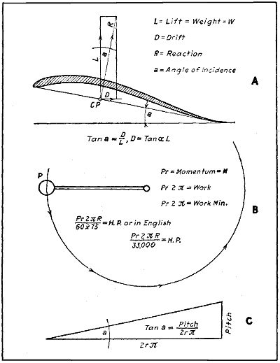
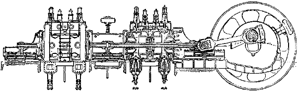
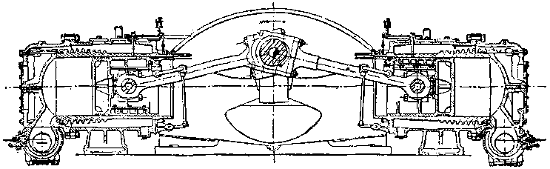
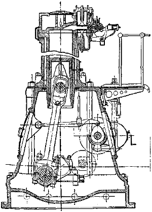
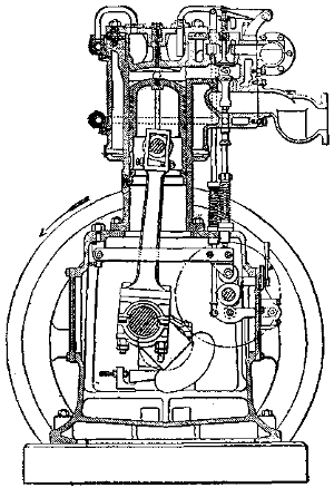
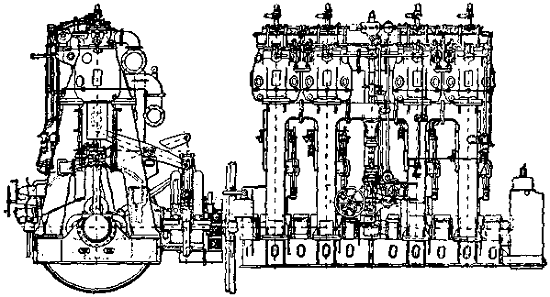
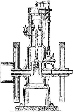
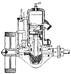
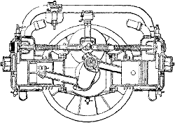
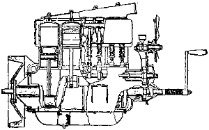
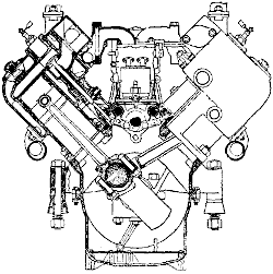
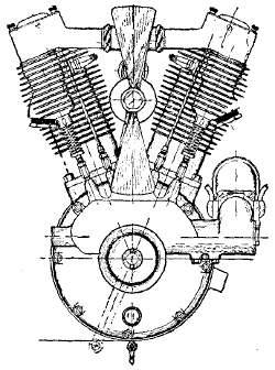
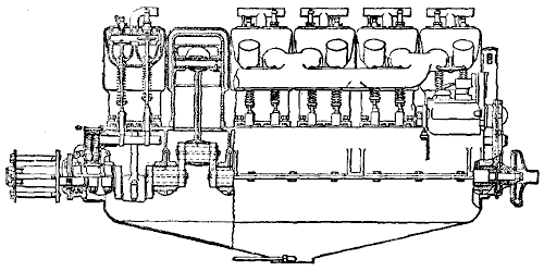
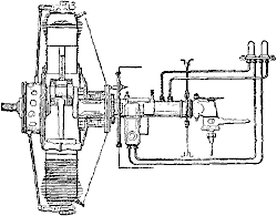
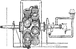
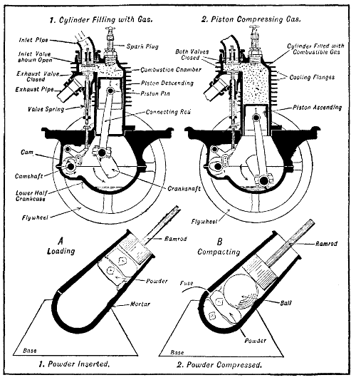
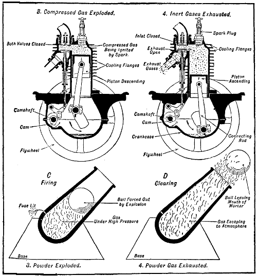
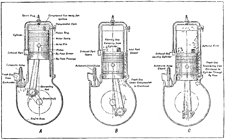
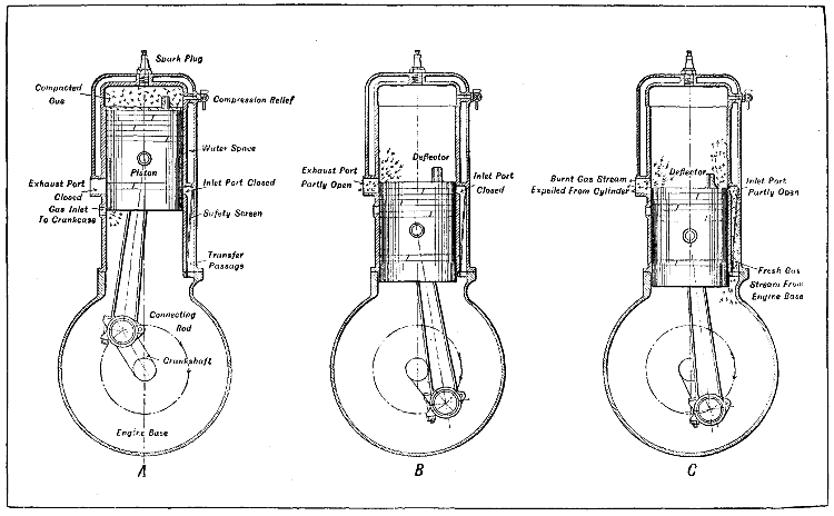
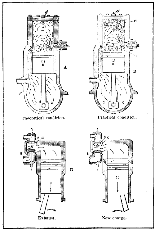
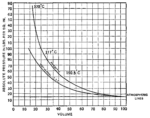
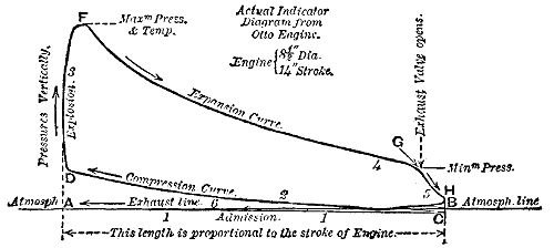
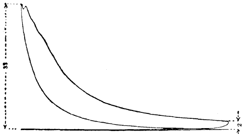
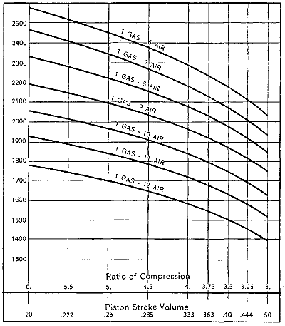
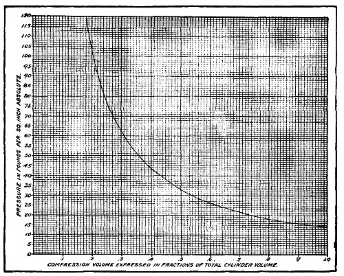
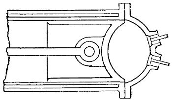
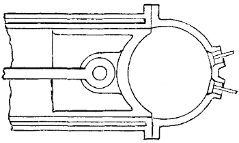
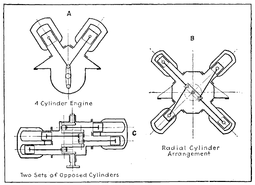
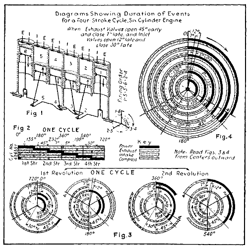
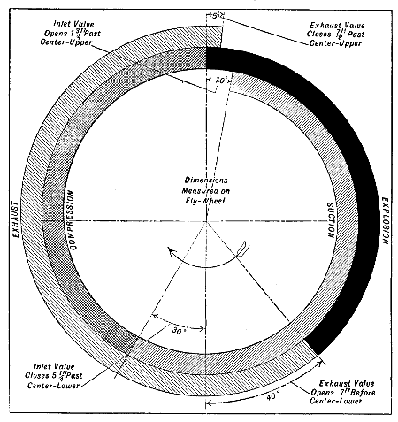
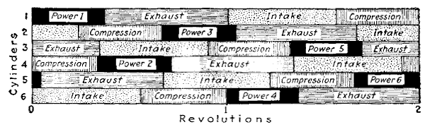
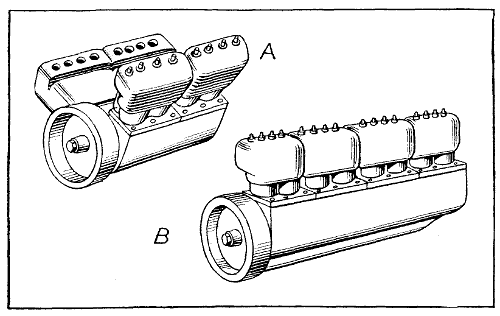
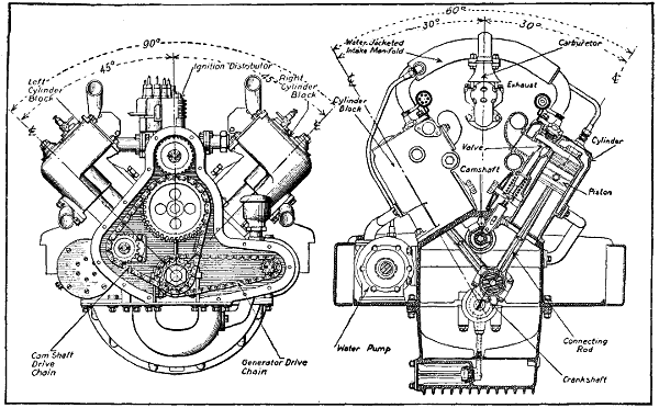
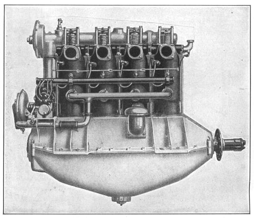
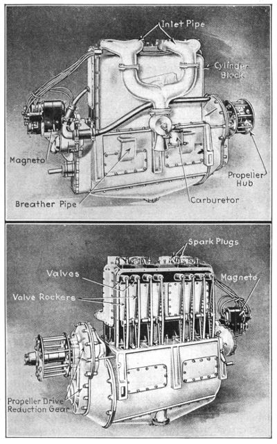
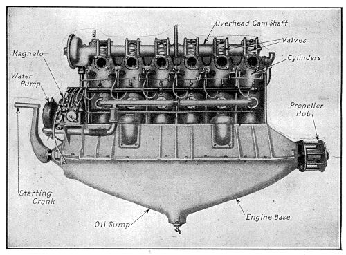
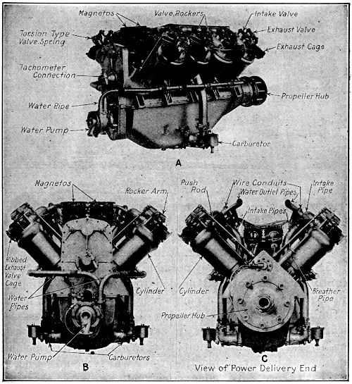
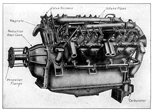
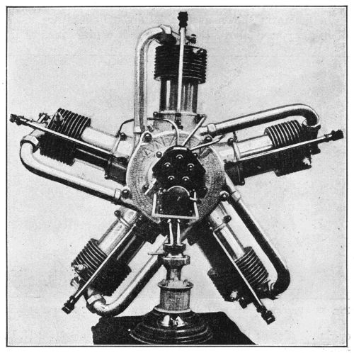
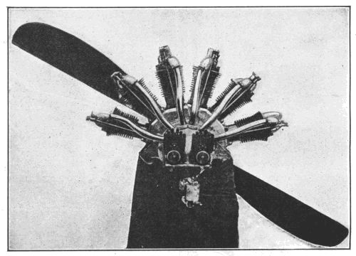
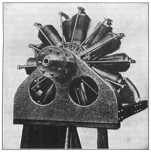
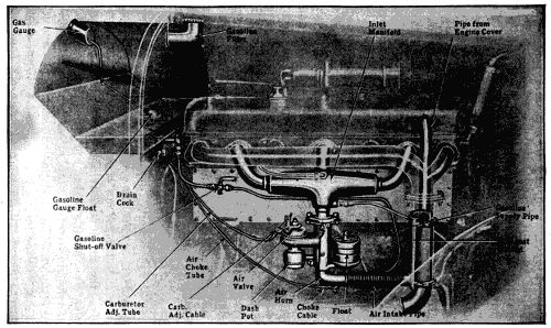
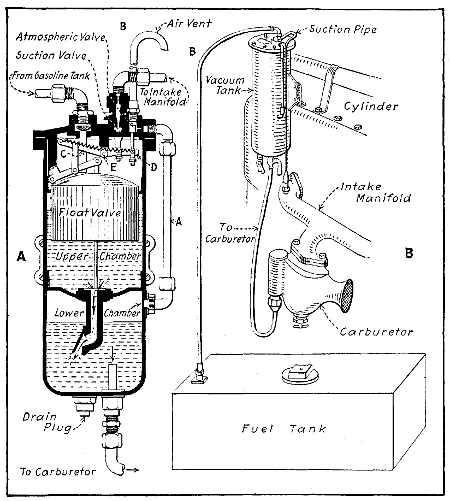
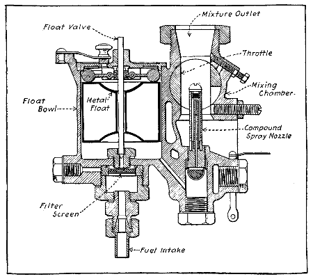
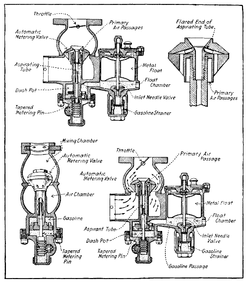
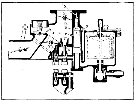
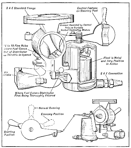
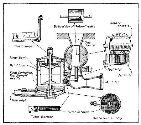
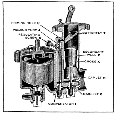
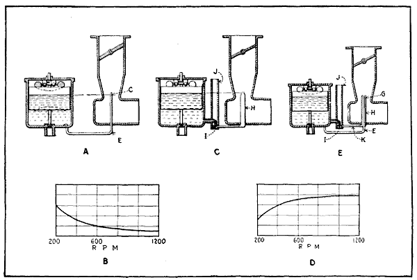
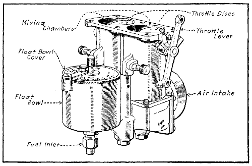
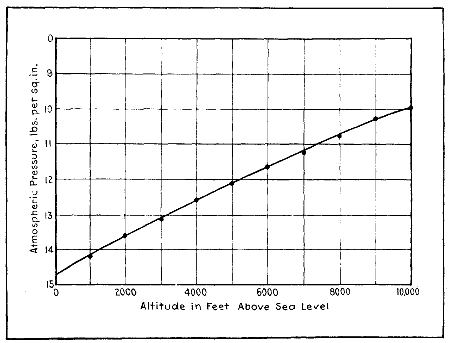
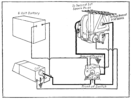
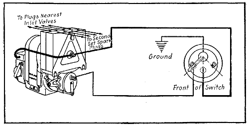
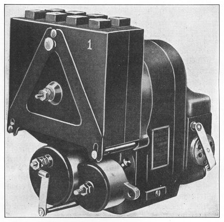
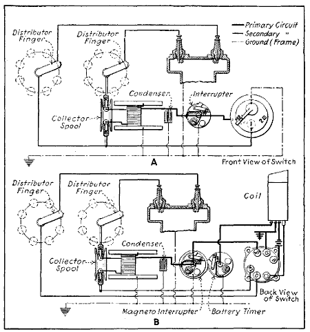
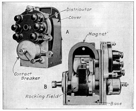
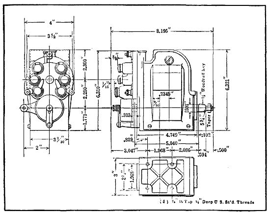
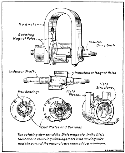
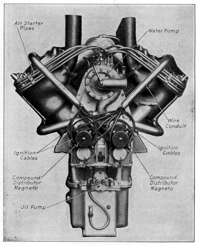
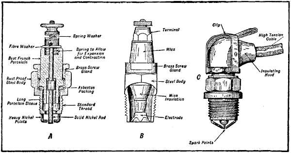

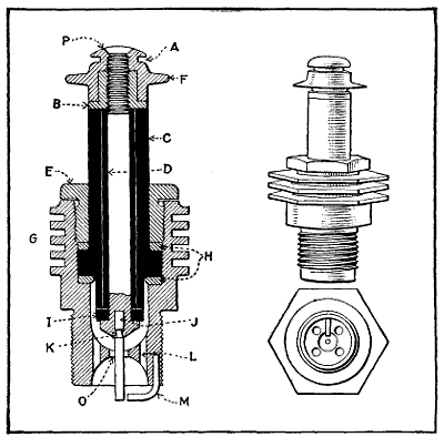
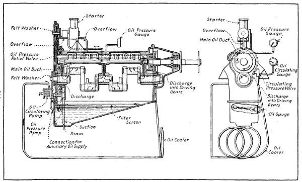
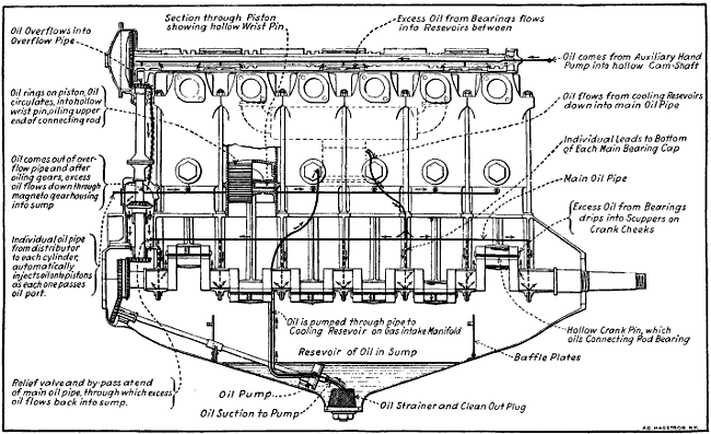
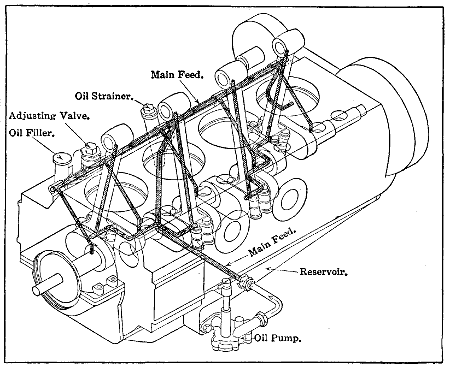
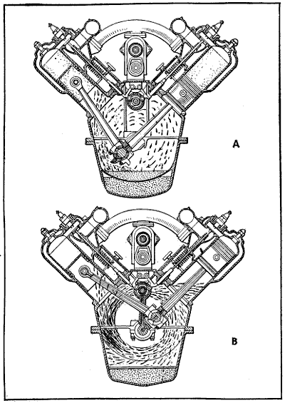
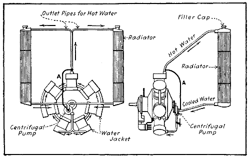
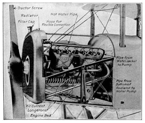
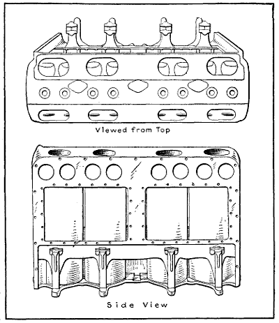
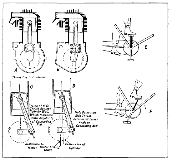
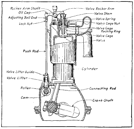
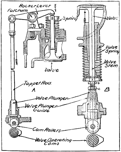
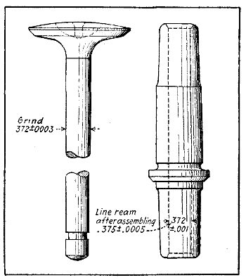
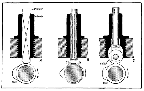
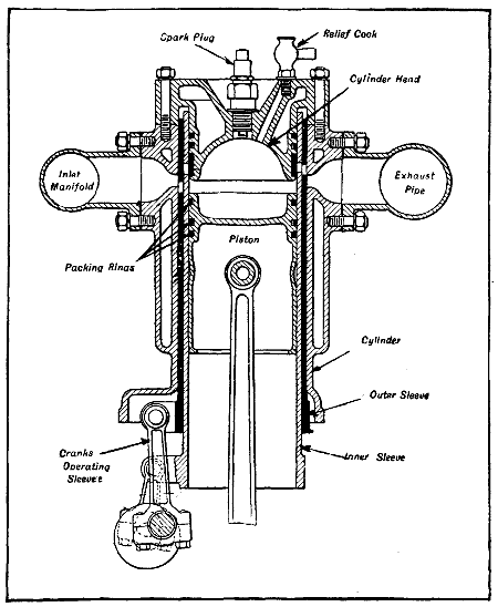
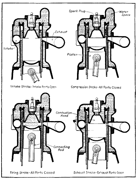
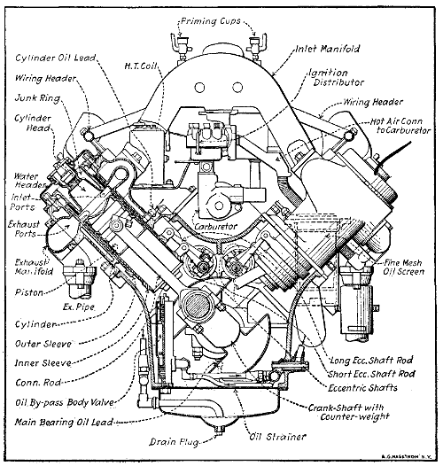
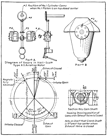
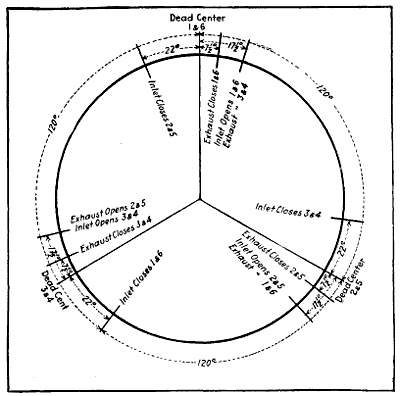
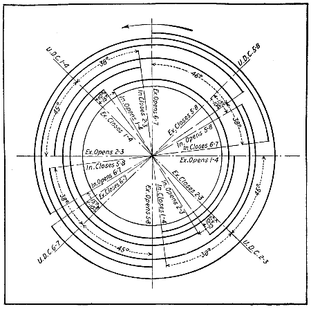
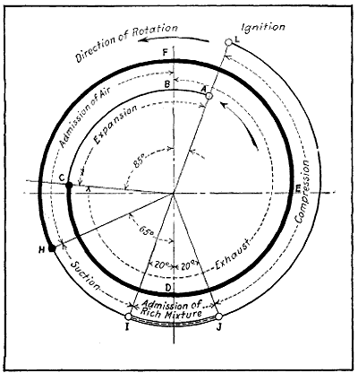
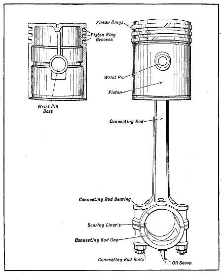
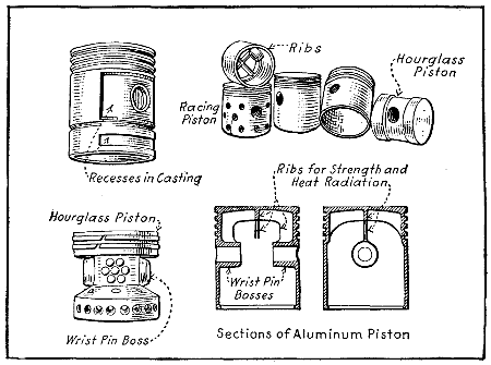
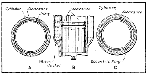
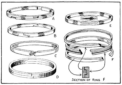
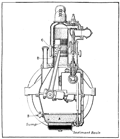
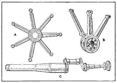
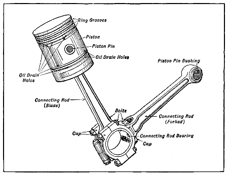
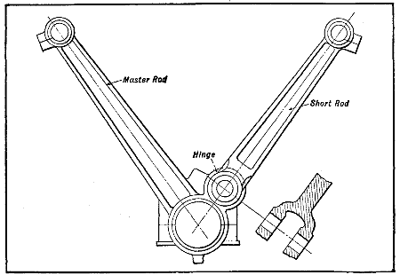
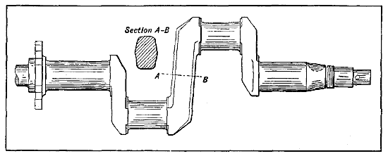
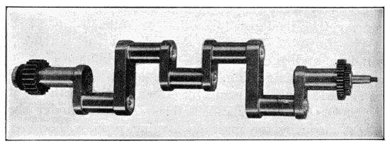
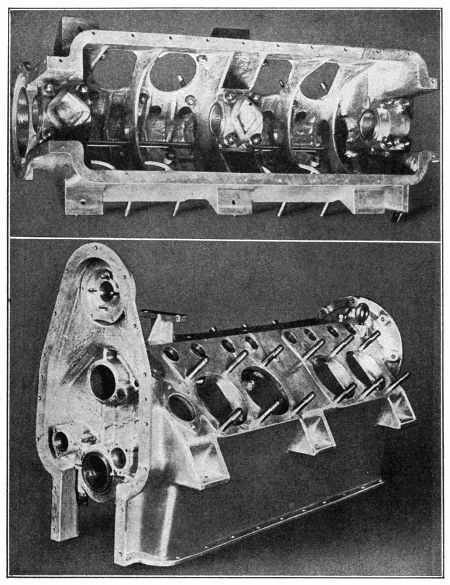
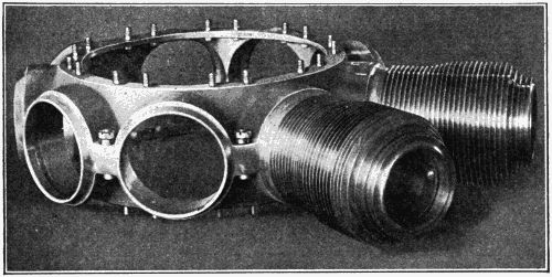
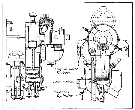
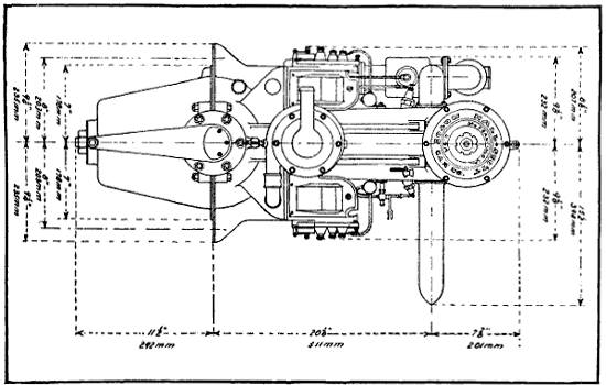
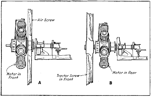
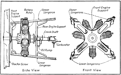
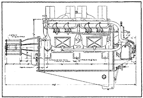
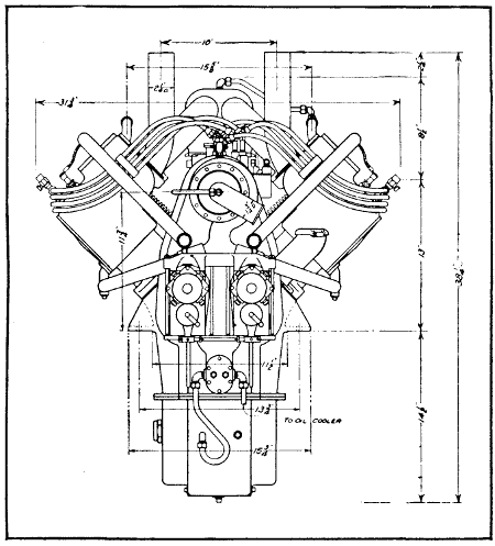
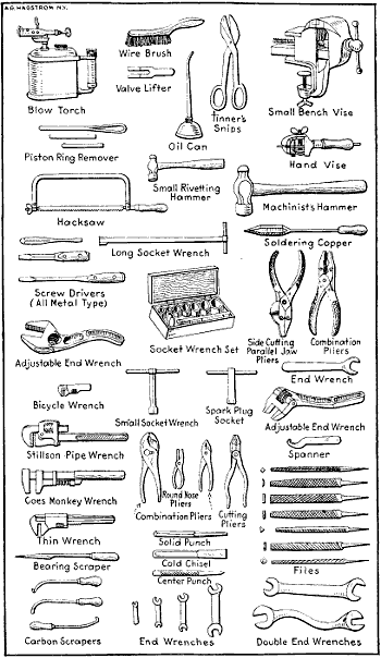
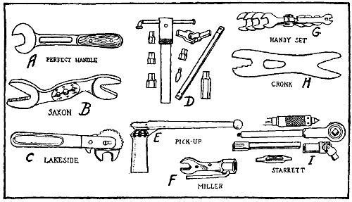
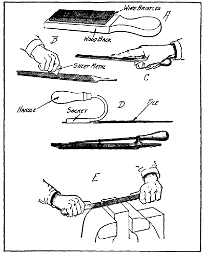
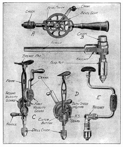
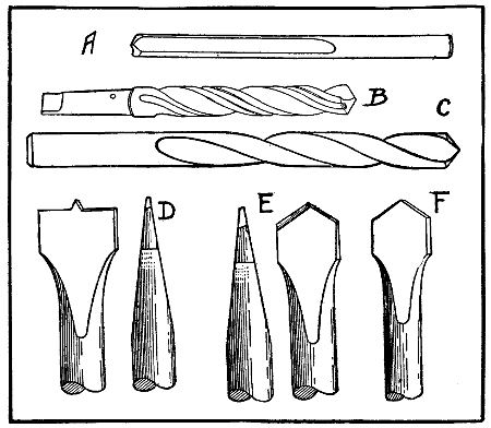
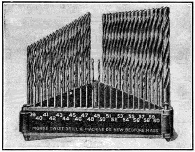
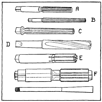
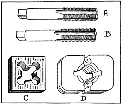
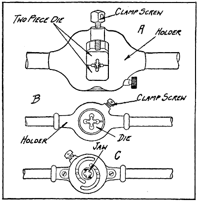
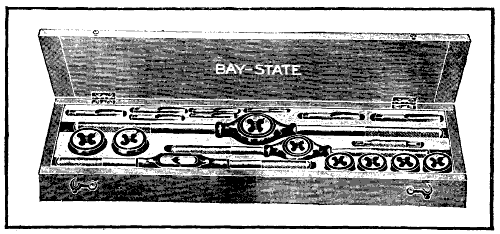
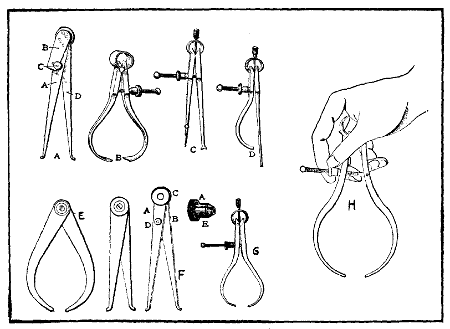
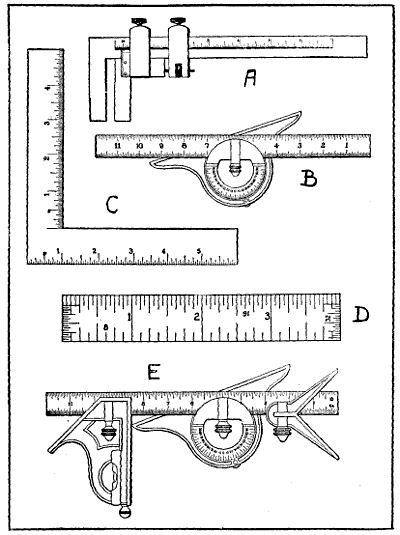
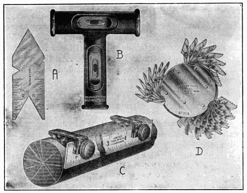
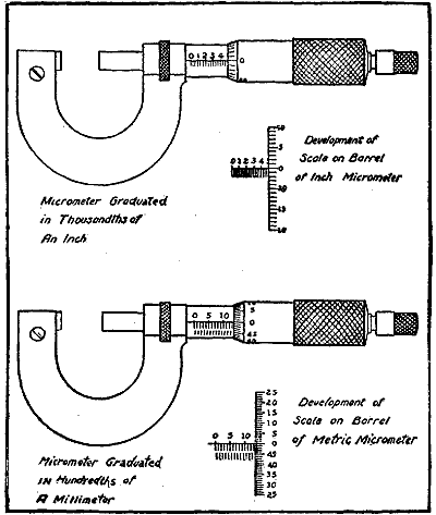
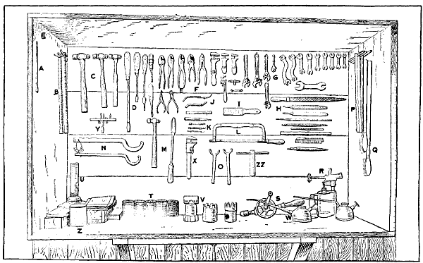
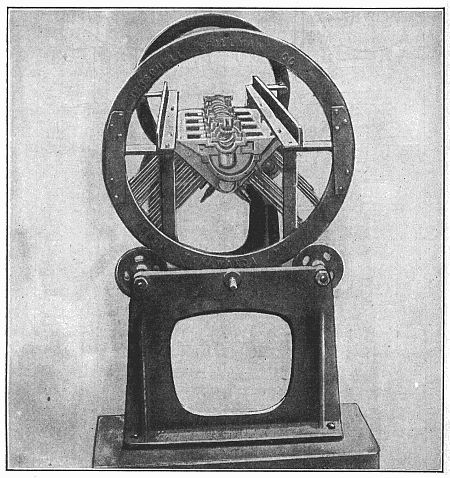
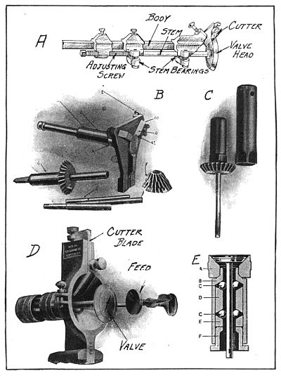
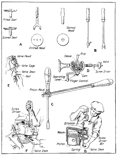
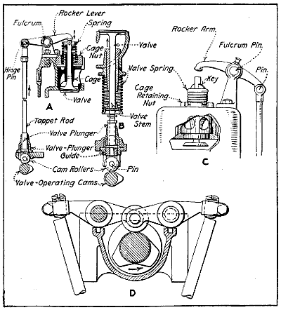
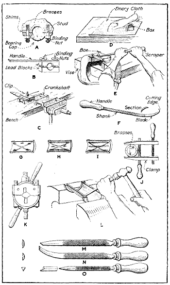
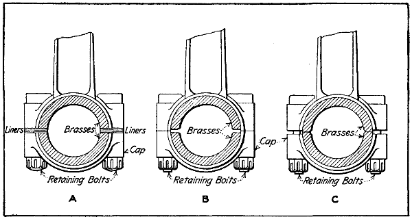
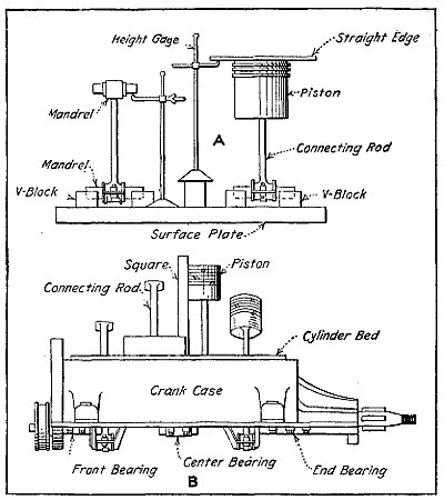
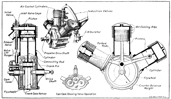
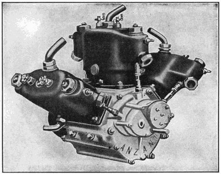
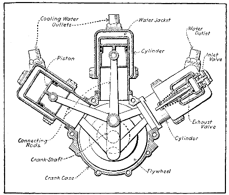
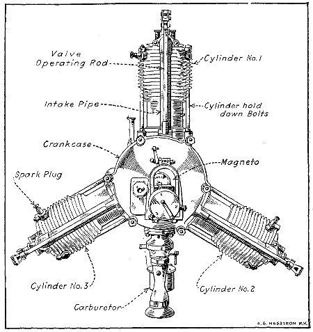
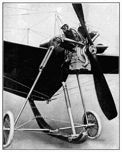
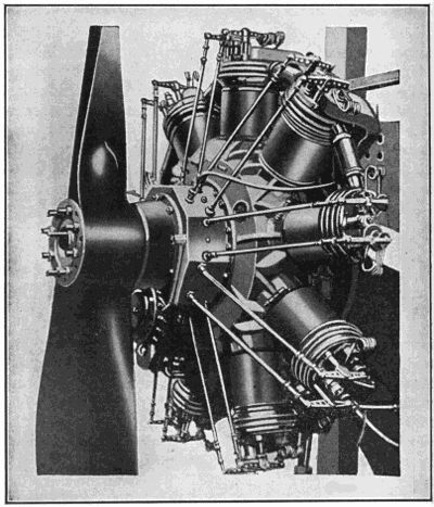
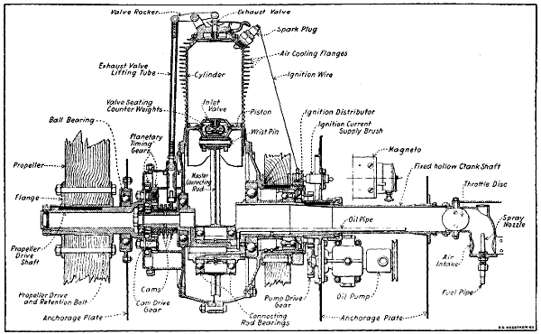
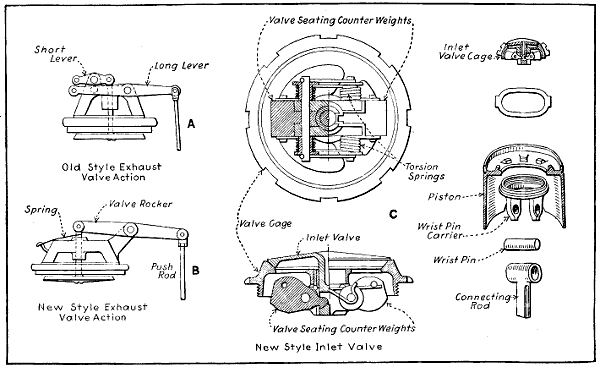
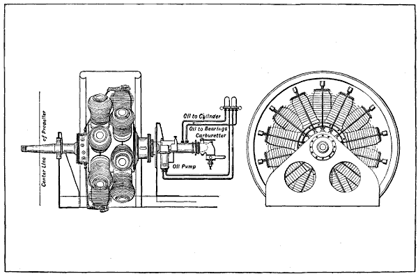
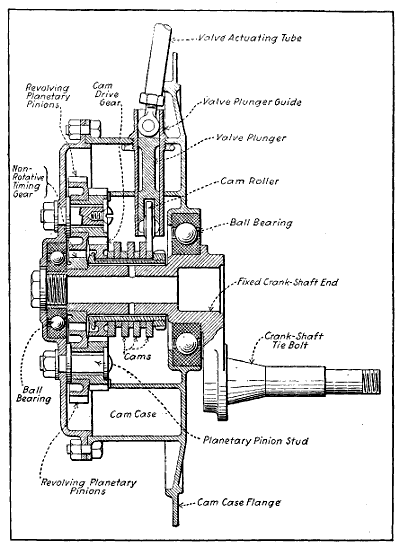
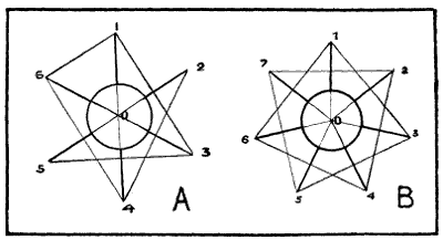
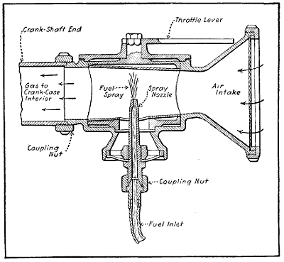
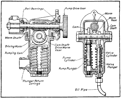
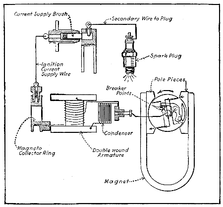
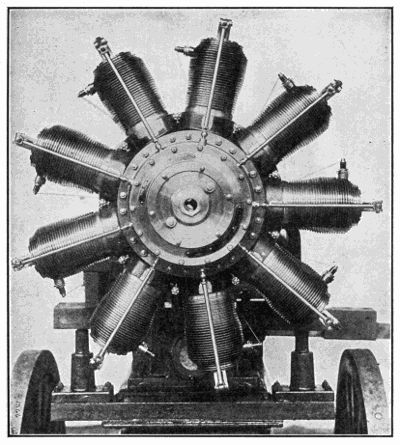
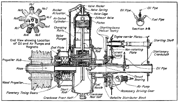
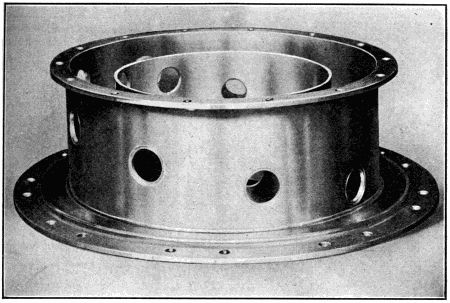
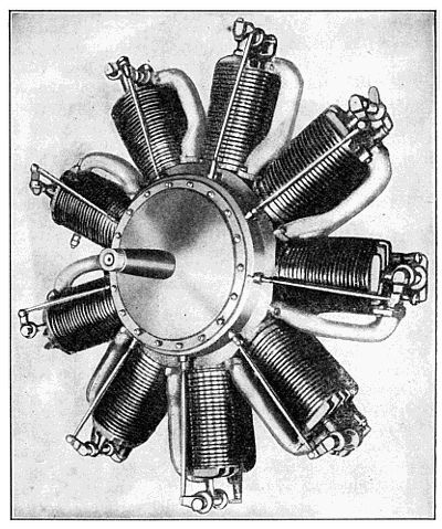
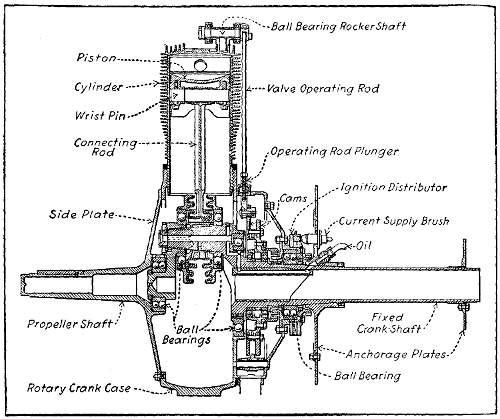
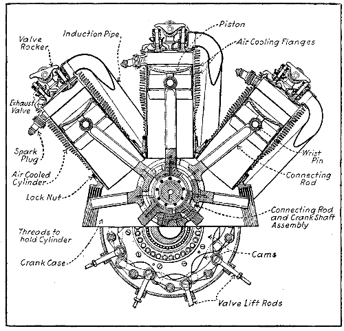
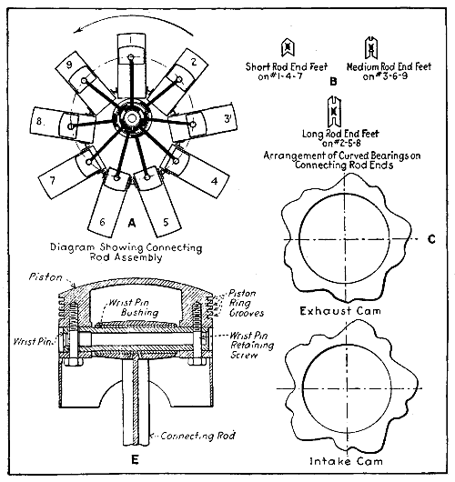
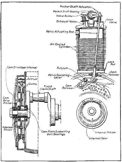
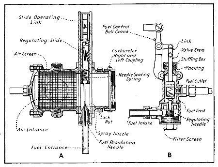
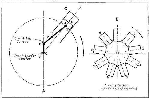
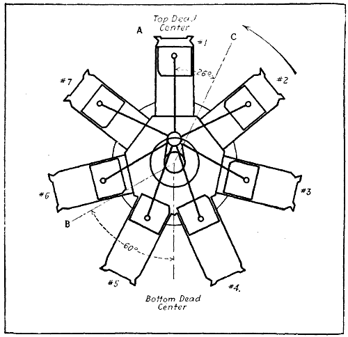
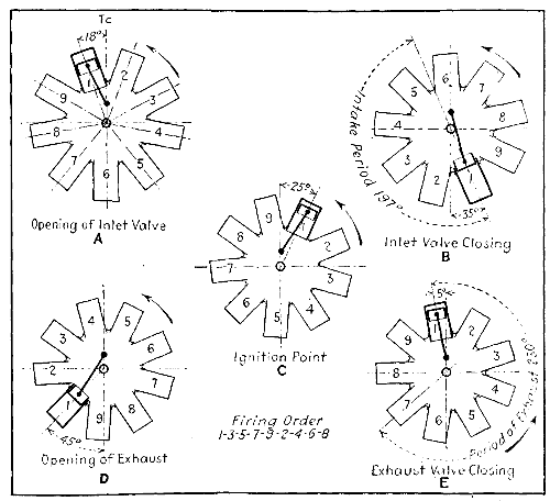
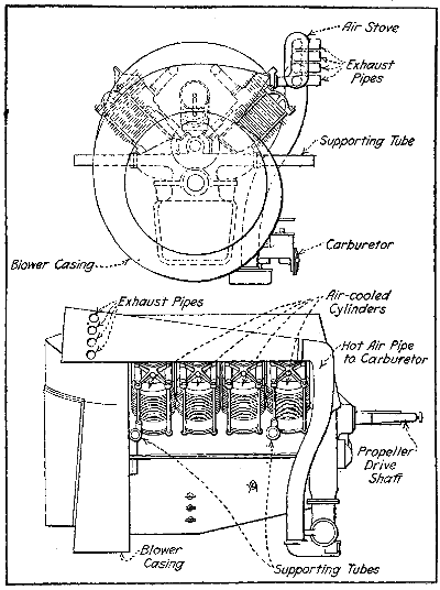
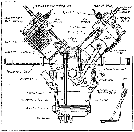
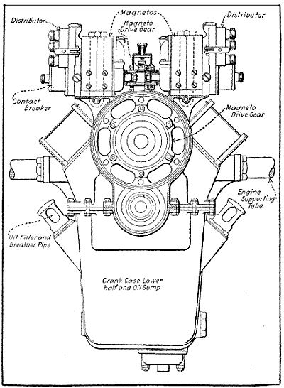
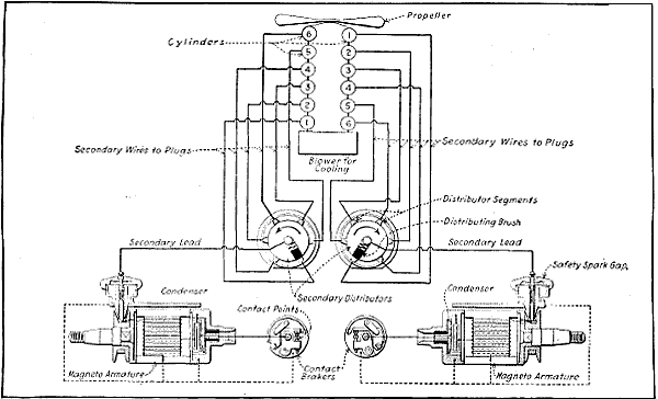
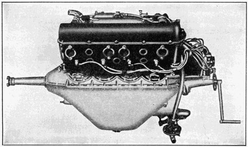
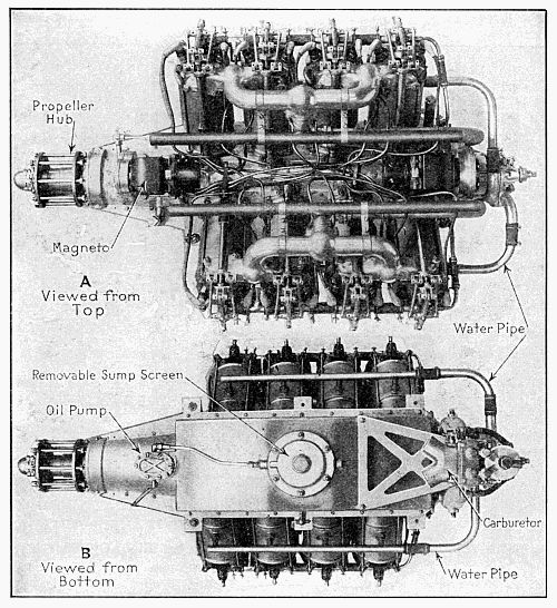
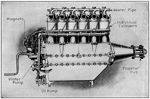
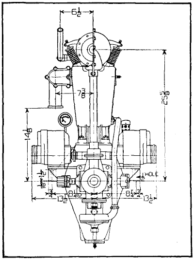
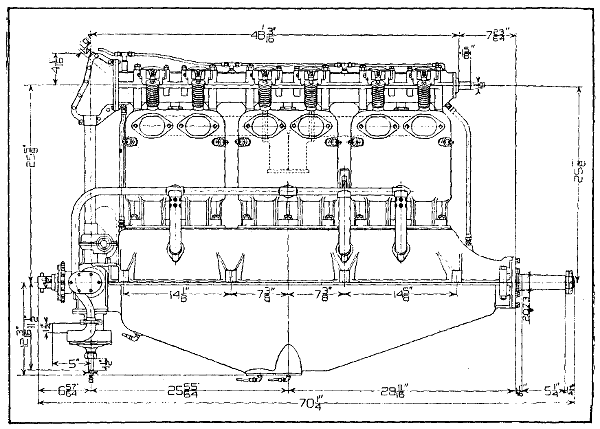
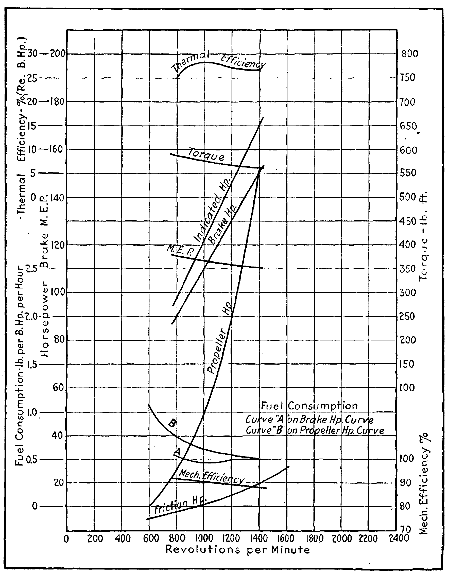
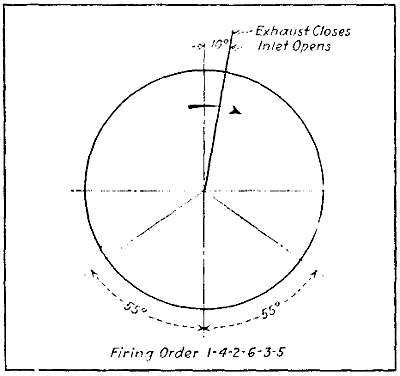
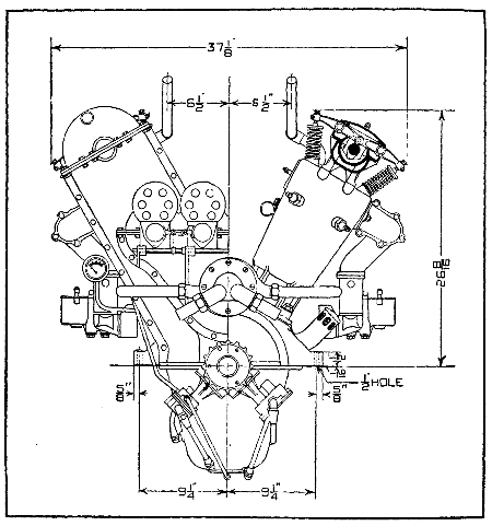
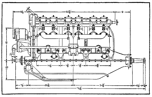
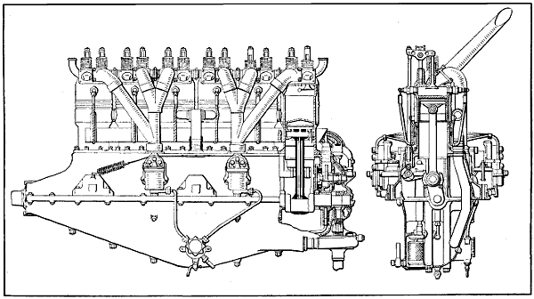
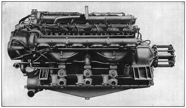
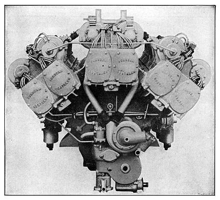
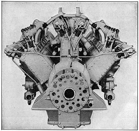
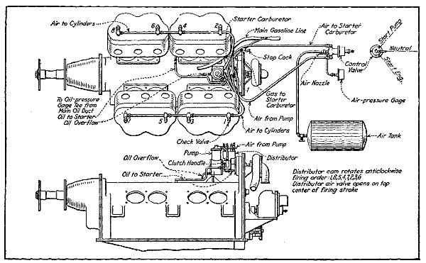
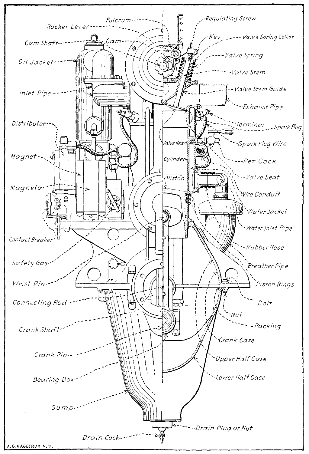
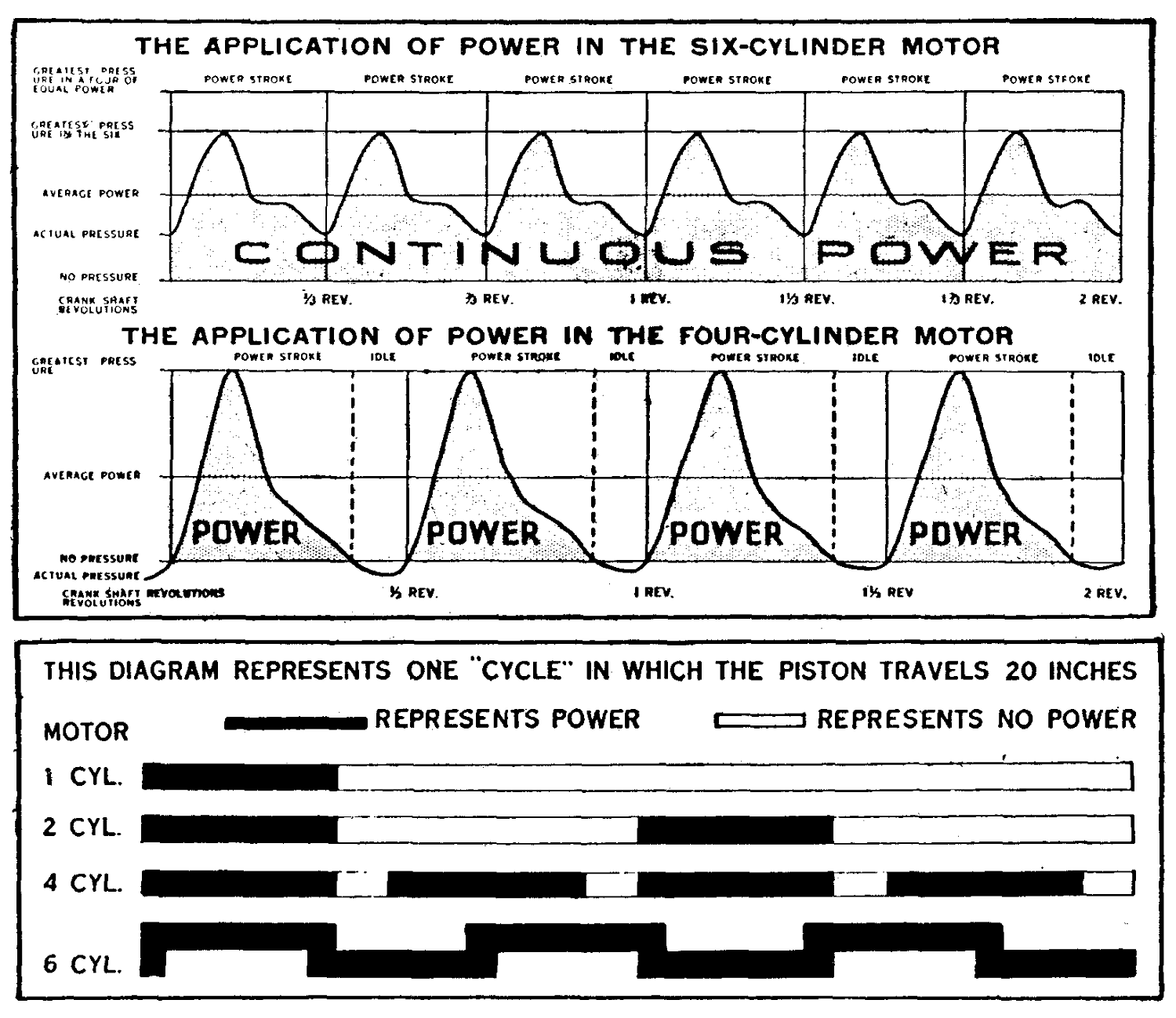
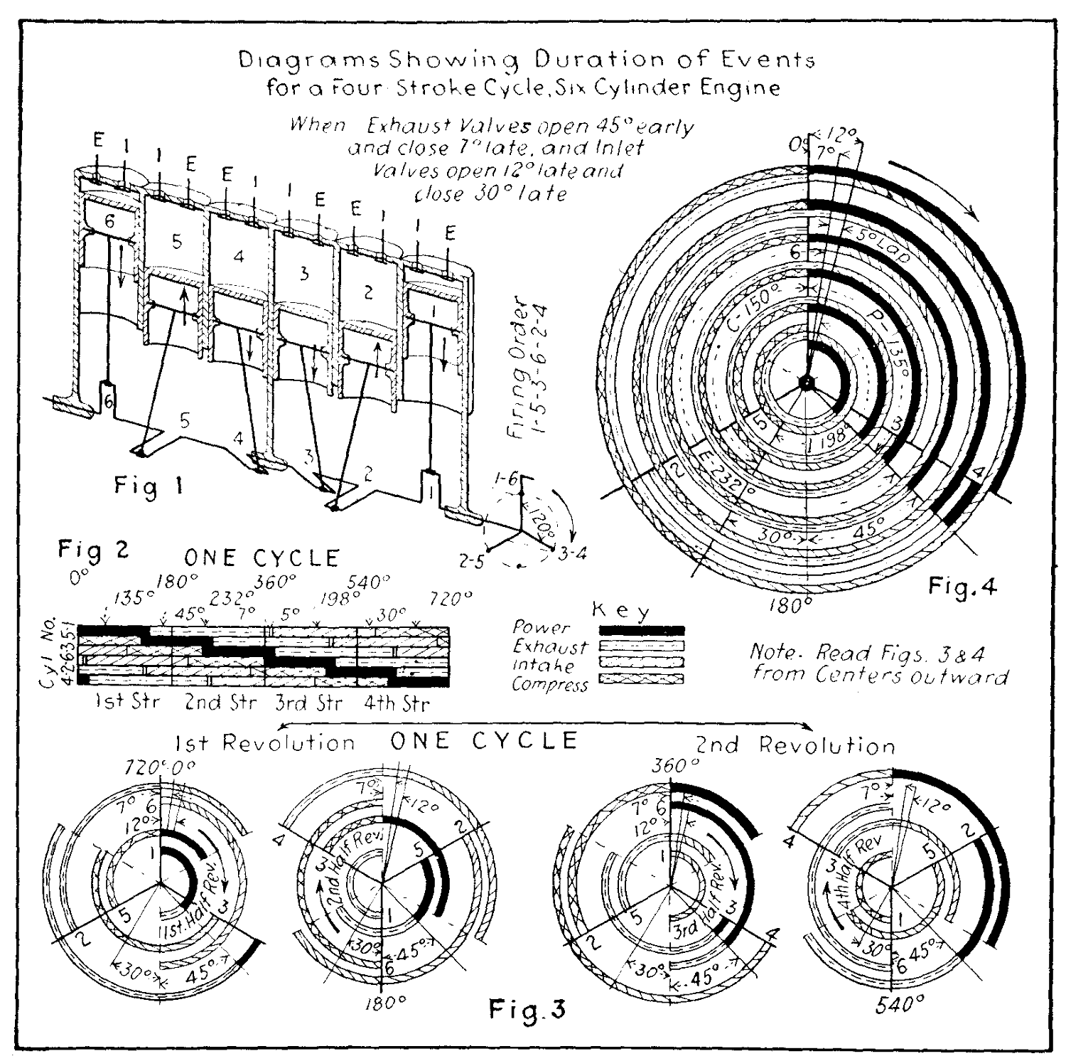
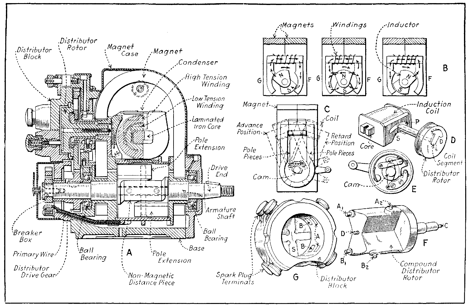
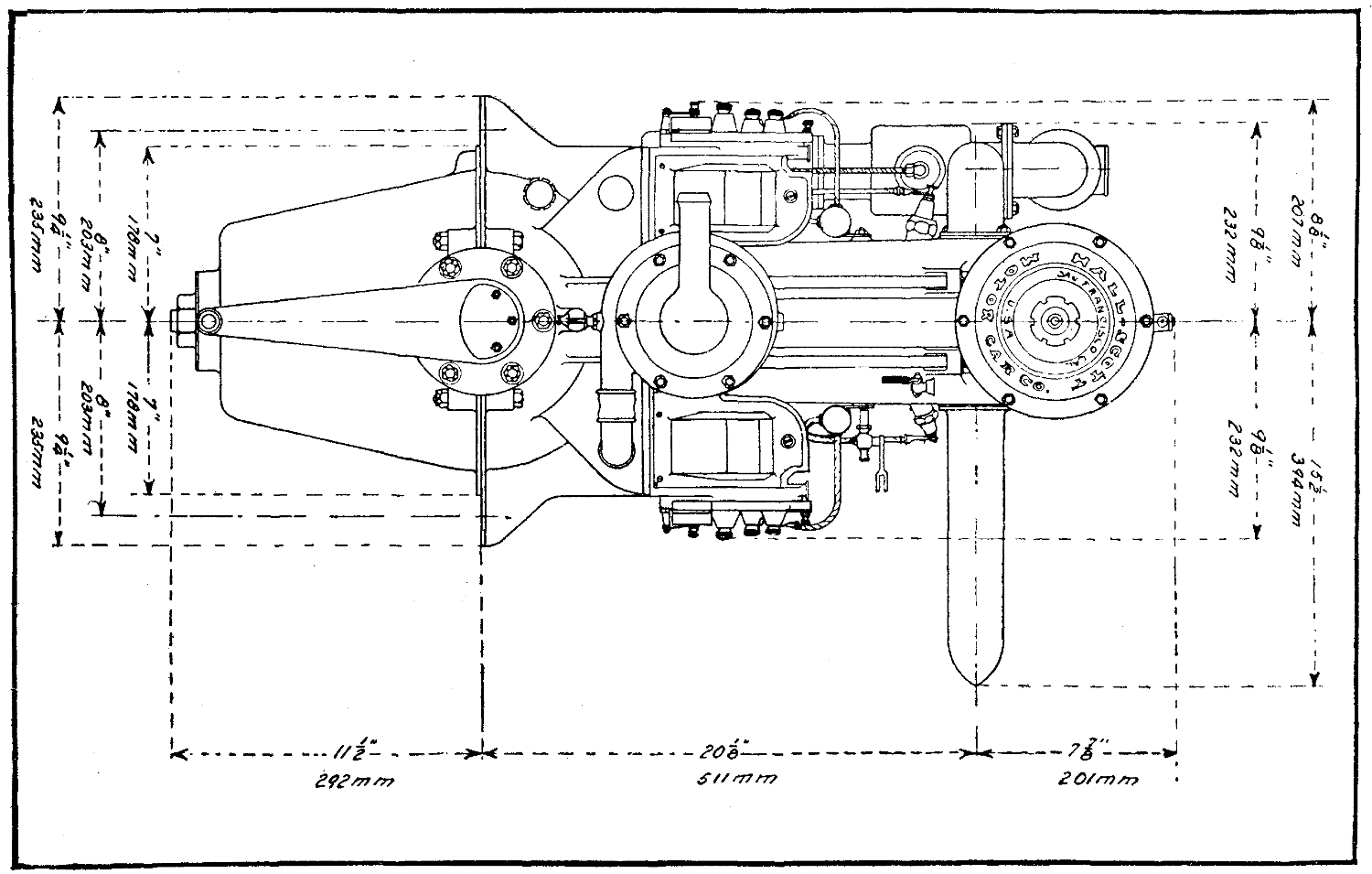
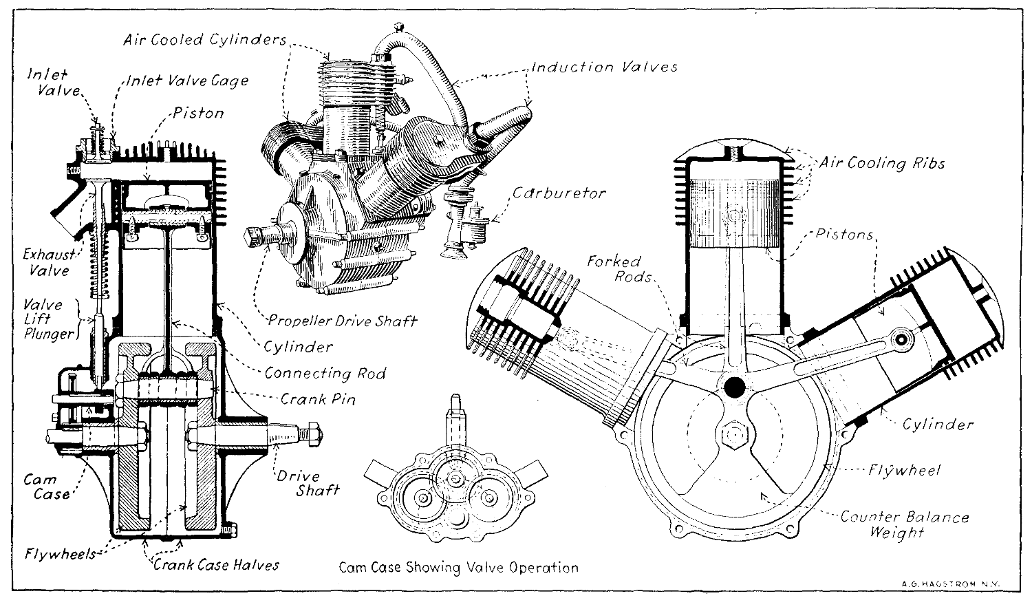
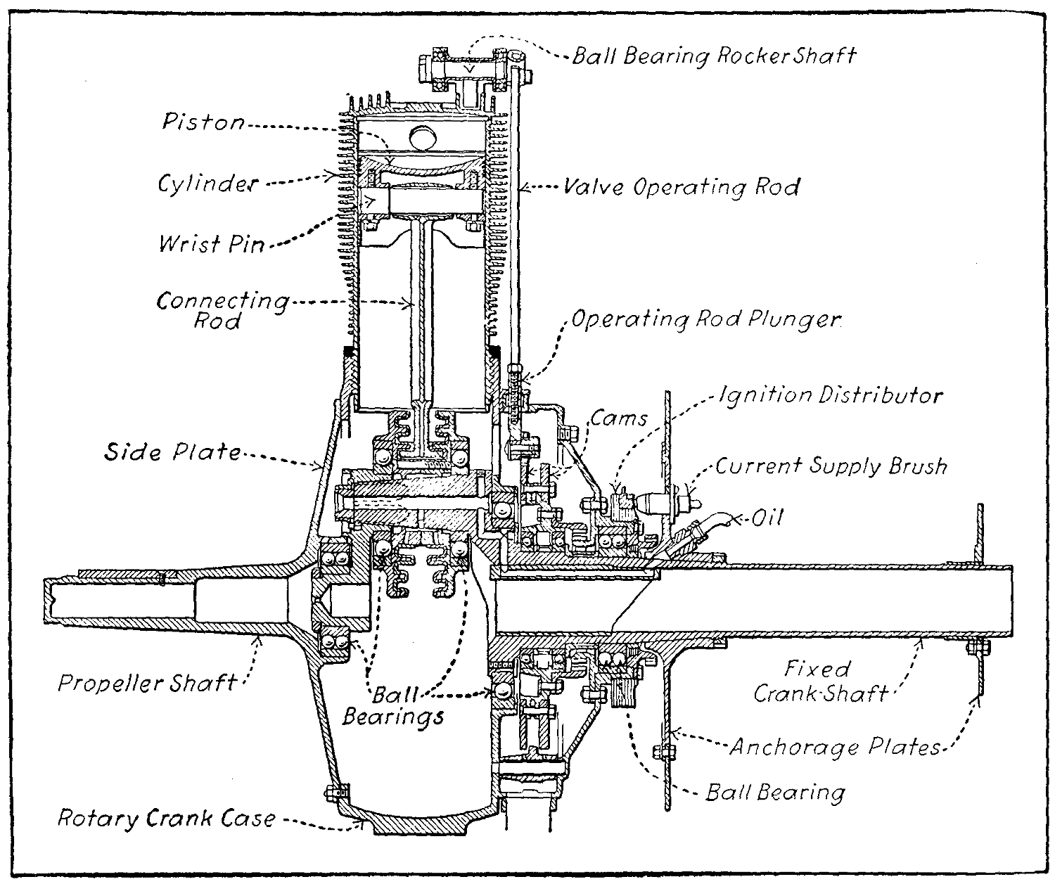
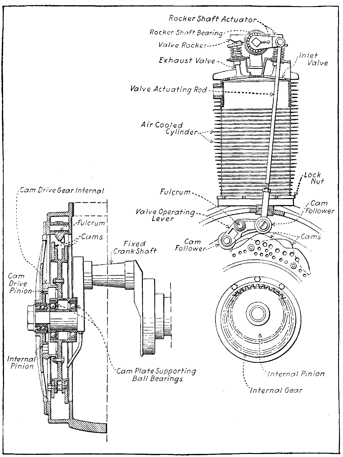