
The Project Gutenberg EBook of A History of the Growth of the Steam-Engine, by
Robert H. Thurston

This eBook is for the use of anyone anywhere at no cost and with
almost no restrictions whatsoever.  You may copy it, give it away or
re-use it under the terms of the Project Gutenberg License included
with this eBook or online at www.gutenberg.org


Title: A History of the Growth of the Steam-Engine

Author: Robert H. Thurston

Release Date: April 19, 2011 [EBook #35916]

Language: English

Character set encoding: ISO-8859-1

*** START OF THIS PROJECT GUTENBERG EBOOK STEAM ***


Produced by Chris Curnow, Harry Lamé and the Online
Distributed Proofreading Team at http://www.pgdp.net (This
file was produced from images generously made available
by The Internet Archive)
Transcriber's Notes:
Some minor typographical errors have been corrected. Where necessary, illustrations have been edited to include the reference letters used in the text or to increase their visibility.
Full notes can be found here.
Each book complete in One Volume, 12mo, and bound in Cloth.
1. FORMS OF WATER: A Familiar Exposition of the Origin and Phenomena of Glaciers. By J. Tyndall, LL. D., F. R. S. With 25 Illustrations. $1.50.
2. PHYSICS AND POLITICS; Or, Thoughts on the Application of the Principles of “Natural Selection” and “Inheritance” to Political Society. By Walter Bagehot. $1.50.
3. FOODS. By Edward Smith, M. D., LL. B., F. R. S. With numerous Illustrations. $1.75.
4. MIND AND BODY: The Theories of their Relation. By Alexander Bain, LL. D. With 4 Illustrations. $1.50.
5. THE STUDY OF SOCIOLOGY. By Herbert Spencer. $1.50.
6. THE NEW CHEMISTRY. By Professor J. P. Cooke, of Harvard University. With 31 Illustrations. $2.00.
7. ON THE CONSERVATION OF ENERGY. By Balfour Stewart, M. A., LL. D., F. R. S. With 14 Illustrations. $1.50.
8. ANIMAL LOCOMOTION; or, Walking, Swimming, and Flying. By J. B. Pettigrew, M. D., F. R. S., etc. With 130 Illustrations. $1.75.
9. RESPONSIBILITY IN MENTAL DISEASE. By Henry Maudsley, M. D. $1.50.
10. THE SCIENCE OF LAW. By Professor Sheldon Amos. $1.75.
11. ANIMAL MECHANISM: A Treatise on Terrestrial and Aërial Locomotion. By Professor E. J. Marey. With 117 Illustrations. $1.75.
12. THE HISTORY OF THE CONFLICT BETWEEN RELIGION AND SCIENCE. By J. W. Draper, M. D., LL. D. $1.75.
13. THE DOCTRINE OF DESCENT AND DARWINISM. By Professor Oscar Schmidt (Strasburg University). With 26 Illustrations. $1.50.
14. THE CHEMICAL EFFECTS OF LIGHT AND PHOTOGRAPHY. By Dr. Hermann Vogel (Polytechnic Academy of Berlin). Translation thoroughly revised. With 100 Illustrations. $2.00.
[2] 15. FUNGI: Their Nature, Influences, Uses, etc. By M. C. Cooke, M. A., LL. D. Edited by the Rev. M. J. Berkeley, M. A., F. L. S. With 109 Illustrations. $1.50.
16. THE LIFE AND GROWTH OF LANGUAGE. By Professor William Dwight Whitney, of Yale College. $1.50.
17. MONEY AND THE MECHANISM OF EXCHANGE. By W. Stanley Jevons, M. A., F. R. S. $1.75.
18. THE NATURE OF LIGHT, with a General Account of Physical Optics. By Dr. Eugene Lommel. With 188 Illustrations and a Table of Spectra in Chromo-lithography. $2.00.
19. ANIMAL PARASITES AND MESSMATES. By Monsieur Van Beneden. With 83 Illustrations. $1.50.
20. FERMENTATION. By Professor Schützenberger. With 28 Illustrations. $1.50.
21. THE FIVE SENSES OF MAN. By Professor Bernstein. With 91 Illustrations. $1.75.
22. THE THEORY OF SOUND IN ITS RELATION TO MUSIC. By Professor Pietro Blaserna. With numerous Illustrations. $1.50.
23. STUDIES IN SPECTRUM ANALYSIS. By J. Norman Lockyer, F. R. S. With 6 Photographic Illustrations of Spectra, and numerous Engravings on Wood. $2.50.
24. A HISTORY OF THE GROWTH OF THE STEAM-ENGINE. By Professor E. H. Thurston. With 163 Illustrations. $2.50.
25. EDUCATION AS A SCIENCE. By Alexander Bain, LL. D. $1.75.
26. STUDENTS’ TEXT-BOOK OF COLOR; Or, Modern Chromatics. With Applications to Art and Industry. By Professor Ogden N. Rood, Columbia College. New edition. With 130 Illustrations. $2.00.
27. THE HUMAN SPECIES. By Professor A. de Quatrefages, Membre de l’Institut. $2.00.
28. THE CRAYFISH: An Introduction to the Study of Zoology. By T. H. Huxley, F. R. S. With 82 Illustrations. $1.75.
29. THE ATOMIC THEORY. By Professor A. Wurtz. Translated by E. Cleminshaw, F. C. S. $1.50.
[3] 30. ANIMAL LIFE AS AFFECTED BY THE NATURAL CONDITIONS OF EXISTENCE. By Karl Semper. With 2 Maps and 106 Woodcuts. $2.00.
31. SIGHT: An Exposition of the Principles of Monocular and Binocular Vision. By Joseph Le Conte, LL. D. With 132 Illustrations. $1.50.
32. GENERAL PHYSIOLOGY OF MUSCLES AND NERVES. By Professor J. Rosenthal. With 75 Illustrations. $1.50.
33. ILLUSIONS: A Psychological Study. By James Sully. $1.50.
34. THE SUN. By C. A. Young, Professor of Astronomy in the College of New Jersey. With numerous Illustrations. $2.00.
35. VOLCANOES: What they Are and what they Teach. By John W. Judd, F. R. S., Professor of Geology in the Royal School of Mines. With 96 Illustrations. $2.00.
36. SUICIDE: An Essay in Comparative Moral Statistics. By Henry Morselli, M. D., Professor of Psychological Medicine, Royal University, Turin. $1.75.
37. THE FORMATION OF VEGETABLE MOULD, THROUGH THE ACTION OF WORMS. With Observations on their Habits. By Charles Darwin, LL. D., F. R. S. With Illustrations. $1.50.
38. THE CONCEPTS AND THEORIES OF MODERN PHYSICS. By J. B. Stallo. $1.75.
39. THE BRAIN AND ITS FUNCTIONS. By J. Luys. $1.50.
40. MYTH AND SCIENCE. By Tito Vignoli. $1.50.
41. DISEASES OF MEMORY: An Essay in the Positive Psychology. By Th. Ribot, author of “Heredity.” $1.50.
42. ANTS, BEES, AND WASPS. A Record of Observations of the Habits of the Social Hymenoptera. By Sir John Lubbock, Bart., F. R. S., D. C. L., LL. D., etc. $2.00.
43. SCIENCE OF POLITICS. By Sheldon Amos. $1.75.
44. ANIMAL INTELLIGENCE. By George J. Romanes. $1.75.
45. MAN BEFORE METALS. By N. Joly, Correspondent of the Institute. With 148 Illustrations. $1.75.
[4]46. THE ORGANS OF SPEECH AND THEIR APPLICATION IN THE FORMATION OF ARTICULATE SOUNDS. By G. H. von Meyer, Professor in Ordinary of Anatomy at the University of Zürich. With 47 Woodcuts. $1.75.
47. FALLACIES: A View of Logic from the Practical Side. By Alfred Sidgwick, B. A., Oxon. $1.75.
48. ORIGIN OF CULTIVATED PLANTS. By Alphonse de Candolle. $2.00.
49. JELLY-FISH, STAR-FISH, AND SEA-URCHINS. Being a Research on Primitive Nervous Systems. By George J. Romanes. $1.75.
50. THE COMMON SENSE OF THE EXACT SCIENCES. By the late William Kingdon Clifford. $1.50.
51. PHYSICAL EXPRESSION: Its Modes and Principles. By Francis Warner, M. D., Assistant Physician, and Lecturer on Botany to the London Hospital, etc. With 51 Illustrations. $1.75.
52. ANTHROPOID APES. By Robert Hartmann, Professor in the University of Berlin. With 63 Illustrations. $1.75.
53. THE MAMMALIA IN THEIR RELATION TO PRIMEVAL TIMES. By Oscar Schmidt. $1.50.
New York: D. APPLETON & CO., 1, 3, & 5 Bond Street.
PROFESSOR OF ENGINEERING STEVENS INSTITUTE OF TECHNOLOGY, PAST PRESIDENT
AMERICAN SOCIETY MECHANICAL ENGINEERS, MEMBER OF SOCIETY OF CIVIL
ENGINEERS, SOCIÉTÉ DES INGÉNIEURS CIVILS, VEREIN DEUTSCHE
INGENIEURE, OESTERREICHISCHER INGENIEUR- UND
ARCHITEKTEN-VEREIN; ASSOCIATE BRITISH
INSTITUTION OF NAVAL ARCHITECTS,
ETC., ETC.
SECOND REVISED EDITION.
NEW YORK:
D. APPLETON AND COMPANY,
1, 3, AND 5 BOND STREET.
1886.
This little work embodies the more generally interesting portions of lectures first written for delivery at the Stevens Institute of Technology, in the winter of 1871-’72, to a mixed audience, composed, however, principally of engineers by profession, and of mechanics; it comprises, also, some material prepared for other occasions.
These lectures have been rewritten and considerably extended, and have been given a form which is more appropriate to this method of presentation of the subject. The account of the gradual development of the philosophy of the steam-engine has been extended and considerably changed, both in arrangement and in method. That part in which the direction of improvement during the past history of the steam-engine, the course which it is to-day taking, and the direction and limitation of that improvement in the future, are traced, has been somewhat modified to accord with the character of the revised work.
The author has consulted a large number of authors in the course of his work, and is very greatly indebted to several earlier writers. Of these, Stuart[1] is entitled[iv] to particular mention. His “History” is the earliest deserving the name; and his “Anecdotes” are of exceedingly great interest and of equally great historical value. The artistic and curious little sketches at the end of each chapter are from John Stuart, as are, usually, the drawings of the older forms of engines.
Greenwood’s excellent translation of Hero, as edited by Bennett Woodcroft (London, 1851), can be consulted by those who are curious to learn more of that interesting old Greek treatise.
Some valuable matter is from Farey,[2] who gives the most extended account extant of Newcomen’s and Watt’s engines. The reader who desires to know more of the life of Worcester, and more of the details of his work, will find in the very complete biography of Dircks[3] all that he can wish to learn of that great but unfortunate inventor. Smiles’s admirably written biography of Watt[4] gives an equally interesting and complete account of the great mechanic and of his partners; and Muirhead[5] furnishes us with a still more detailed account of his inventions.
For an account of the life and work of John Elder, the great pioneer in the introduction of the now standard[v] double-cylinder, or “compound,” engine, the student can consult a little biographical sketch by Prof. Rankine, published soon after the death of Elder.
The only published sketch of the history of the science of thermo-dynamics, which plays so large a part of the philosophy of the steam-engine, is that of Prof. Tait—a most valuable monograph.
The section of this work which treats of the causes and the extent of losses of heat in the steam-engine, and of the methods available, or possibly available, to reduce the amount of this now immense waste of heat, is, in some respects, quite new, and is equally novel in the method of its presentation. The portraits with which the book is well furnished are believed to be authentic, and, it is hoped, will lend interest, if not adding to the real value of the work.
Among other works which have been of great assistance to the author, and will be found, perhaps, equally valuable to some of the readers of this little treatise, are several to which reference has not been made in the text. Among them the following are deserving of special mention: Zeuner’s “Wärmetheorie,” the treatises of Stewart and of Maxwell, and McCulloch’s “Mechanical Theory of Heat,” a short but thoroughly logical and exact mathematical treatise; Cotterill’s “Steam-Engine considered as a Heat-Engine,” a more extended work on the same subject, which will be found an excellent companion to, and commentary upon, Rankine’s “Steam-Engine and Prime Movers,” which is the standard[vi] treatise on the theory of the steam-engine. The works of Bourne, of Holley, of Clarke, and of Forney, are standards on the practical every-day matters of steam-engine construction and management.
The author is almost daily in receipt of inquiries which indicate that the above remarks will be of service to very many young engineers, as well as to many to whom the steam-engine is of interest from a more purely scientific point of view.
[1] “History of the Steam-Engine,” London, 1824. “Anecdotes of the Steam-Engine,” London, 1829.
[2] “Treatise on the Steam-Engine,” London, 1827.
[3] “Life, Times, and Scientific Labors of the Second Marquis of Worcester,” London, 1865.
[4] “Lives of Boulton and Watt,” London, 1865.
[5] “Life of James Watt,” D. Appleton & Co., New York, 1859. “Mechanical Inventions of James Watt,” London, 1854.
| CHAPTER I. | ||
| The Steam-Engine as a Simple Machine. | ||
| PAGE | ||
| Section I.—The Period of Speculation—From Hero to Worcester, b. c. 200 to a. d. 1650 | 1 | |
| Introduction—the Importance of the Steam-Engine, 1; Hero and his Treatise on Pneumatics, 4; Hero’s Engines, b. c. 200, 8; William of Malmesbury on Steam, a. d. 1150, 10; Hieronymus Cardan on Steam and the Vacuum, 10; Malthesius on the Power of Steam, a. d. 1571, 10; Jacob Besson on the Generation of Steam, a. d. 1578, 11; Ramelli’s Work on Machines, a. d. 1588, 11; Leonardo da Vinci on the Steam-Gun, 12; Blasco de Garay’s Steamer, a. d. 1543, 12; Battista della Porta’s Steam-Engine, a. d. 1601, 13; Florence Rivault on the Force of Steam, a. d. 1608, 15; Solomon de Caus’s Apparatus, a. d. 1615, 16; Giovanni Branca’s Steam-Engine, a. d. 1629, 16; David Ramseye’s Inventions, a. d. 1630, 17; Bishop John Wilkins’s Schemes, a. d. 1648, 18; Kircher’s Apparatus, 19. | ||
| Section II.—The Period of Application—Worcester, Papin, and Savery | 19 | |
| Edward Somerset, Marquis of Worcester, a. d. 1663, 19; Worcester’s Steam Pumping-Engines, 21; Jean Hautefeuille’s Alcohol and Gunpowder Engines, a. d. 1678, 24; Huyghens’s Gunpowder-Engine, a. d. 1680, 25; Invention in Great Britain, 26; Sir Samuel Morland, a. d. 1683, 27; Thomas Savery and his Engine, a. d. 1698, 31; Desaguliers’s Savery Engines, a. d. 1718, 41; Denys Papin and his Work, a. d. 1675, 45; Papin’s Engines, a. d. 1685-1695, 50; Papin’s Steam-Boilers, 51. | ||
| CHAPTER II. | ||
| The Steam-Engine as a Train of Mechanism. | ||
| The Modern Type as developed by Newcomen, Beighton, and Smeaton | 55 | |
| Defects of the Savery Engine, 55; Thomas Newcomen, a. d. 1705, 57; the Newcomen Steam Pumping-Engine, 59; Advantages of Newcomen’s Engine, 60; Potter’s and Beighton’s Improvements, a. d. 1713-’18, 61; Smeaton’s Newcomen Engines, a. d. 1775, 64; Operation of the Newcomen Engine, 65; Power and Economy of the Engine, 69; Introduction of the Newcomen Engine, 70. | ||
| CHAPTER III.[viii] | ||
| The Development of the Modern Steam-Engine. James Watt and his Contemporaries. | ||
| Section I.—James Watt and his Inventions | 79 | |
| James Watt, his Birth and Parentage, 79; his Standing in School, 81; he learns his Trade in London, 81; Return to Scotland and Settlement in Glasgow, 82; the Newcomen Engine Model, 83; Discovery of Latent Heat, 84; Sources of Loss in the Newcomen Engine, 85; Facts experimentally determined by Watt, 86; Invention of the Separate Condenser, 87; the Steam-Jacket and other Improvements, 90; Connection with Dr. Roebuck, 91; Watt meets Boulton, 93; Matthew Boulton, 93; Boulton’s Establishment at Soho, 95; the Partnership of Boulton and Watt, 97; the Kinneil Engine, 97; Watt’s Patent of 1769, 98; Work of Boulton and Watt, 101; the Rotative Engine, 103; the Patent of 1781, 104; the Expansion of Steam—its Economy, 105; the Double-Acting Engine, 110; the “Compound” Engine, 110; the Steam-Hammer, 111; Parallel Motions, the Counter, 112; the Throttle-Valve and Governor, 114; Steam, Vacuum, and Water Gauges, 116; Boulton & Watt’s Mill-Engine, 118; the Albion Mill and its Engine, 119; the Steam-Engine Indicator, 123; Watt in Social Life, 125; Discovery of the Composition of Water, 126; Death of James Watt, 128; Memorials and Souvenirs, 128. | ||
| Section II.—The Contemporaries of James Watt | 132 | |
| William Murdoch and his Work, 132; Invention of Gas-Lighting, 134; Jonathan Hornblower and the Compound Engine, 135; Causes of the Failure of Hornblower, 137; William Bull and Richard Trevithick, 138; Edward Cartwright and his Engine, 140. | ||
| CHAPTER IV. | ||
| The Modern Steam-Engine. | ||
| The Second Period of Application—1800-1850—Steam-Locomotion on Railroads | 144 | |
| Introduction, 144; the Non-Condensing Engine and the Locomotive, 147; Newton’s Locomotive, 1680, 149; Nathan Read’s Steam-Carriage, 150; Cugnot’s Steam-Carriage, 1769, 151; the Model Steam-Carriage of Watt and Murdoch, 1784, 153; Oliver Evans and his Plans, 1786, 153; Evans’s Oruktor Amphibolis, 1804, 157; Richard Trevithick’s Steam-Carriage, 1802, 159; Steam-Carriages of Griffiths and others, 160; Steam-Carriages of Goldsworthy Gurney, 1827, 161; Steam-Carriages of Walter Hancock, 1831, 165; Reports to the House of Commons, 1831, 170; the Introduction of the Railroad, 172; Richard Trevithick’s Locomotives, 1804, 174; John Stevens and the Railroad, 1812, 178; William Hedley’s Locomotives, 1812, 181; George Stephenson, 183; Stephenson’s Killingworth Engine, 1813, 186; Stephenson’s Second Locomotive, 1815, 187; Stephenson’s Safety-Lamp, 1815, 187; Robert Stephenson & Co., 1824, 190; the Stockton & Darlington Engine, 1825, 191; the Liverpool & Manchester Railroad, 1826, 193; Trial of Competing Engines at Rainhill, 1829, 195; the Rocket and the Novelty, 198; Atmospheric Railways, 201; Character of George [ix]Stephenson, 204; the Locomotive of 1833, 204; Introduction of Railroads in Europe, 206; Introduction of Railroads in the United States, 207; John Stevens’s Experimental Railroad, 1825, 207; Horatio Allen and the “Stourbridge Lion,” 1829, 208; Peter Cooper’s Engine, 1829, 209; E. L. Miller and the S. C. Railroad, 1830, 210; the “American” Type of Engine of John B. Jervis, 1832, 212; Robert L. Stevens and the T-rail, 1830, 214; Matthias W. Baldwin and his Engine, 1831, 215; Robert Stephenson on the Growth of the Locomotive, 220. | ||
| CHAPTER V. | ||
| The Modern Steam-Engine. | ||
| The Second Period of Application—1800-1850 (continued)—The Steam-Engine applied to Ship-Propulsion | 221 | |
| Introduction, 221; Ancient Prophecies, 223; the Earliest Paddle-Wheel, 223; Blasco de Garay’s Steam-Vessel, 1543, 224; Experiments of Dionysius Papin, 1707, 224; Jonathan Hulls’s Steamer, 1736, 225; Bernouilli and Gauthier, 228; William Henry, 1782, 230; the Comte d’Auxiron, 1772, 232; the Marquis de Jouffroy, 1776, 233; James Rumsey, 1774, 234; John Fitch, 1785, 235; Fitch’s Experiments on the Delaware, 1787, 237; Fitch’s Experiments at New York, 1796, 240; the Prophecy of John Fitch, 241; Patrick Miller, 1786-’87, 241; Samuel Morey, 1793, 243; Nathan Read, 1788, 244; Dundas and Symmington, 1801, 246; Henry Bell and the Comet, 1811, 248; Nicholas Roosevelt, 1798, 250; Robert Fulton, 1802, 251; Fulton’s Torpedo-Vessels, 1801, 252; Fulton’s First Steamboat, 1803, 253; the Clermont, 1807, 257; Voyage of the Clermont to Albany, 259; Fulton’s Later Steamboats, 260; Fulton’s War-Steamer Fulton the First, 1815, 261; Oliver Evans, 1804, 263; John Stevens’s Screw-Steamer, 1804, 264; Stevens’s Steam-Boilers, 1804, 264; Stevens’s Iron-Clad, 1812, 268; Robert L. Stevens’s Improvements, 270; the “Stevens Cut-off,” 1841, 276; the Stevens Iron-Clad, 1837, 277; Robert L. Thurston and John Babcock, 1821, 280; James P. Allaire and the Messrs. Copeland, 281; Erastus W. Smith’s Compound Engine, 283; Steam-Navigation on Western Rivers, 1811, 283; Ocean Steam-Navigation, 1808, 285; the Savannah, 1819, 286; the Sirius and the Great Western, 1838, 289; the Cunard Line, 1840, 290; the Collins Line, 1851, 291; the Side-Lever Engine, 292; Introduction of Screw-Steamers, 293; John Ericsson’s Screw-Vessels, 1836, 294; Francis Pettit Smith, 1837, 296; the Princeton, 1841, 297; Advantages of the Screw, 299; the Screw on the Ocean, 300; Obstacles to Improvement, 301; Changes in Engine-Construction, 302; Conclusion, 303. | ||
| CHAPTER VI. | ||
| The Steam-Engine of To-Day. | ||
| The Period of Refinement—1850 to Date | 303 | |
| Condition of the Steam-Engine at this Time, 303; the Later Development of the Engine, 304; Stationary Steam-Engines, 307; the Steam-Engine for Small Powers, 307; the Horizontal Engine with Meyer Valve-Gear, 311; the Allen Engine, 314; its Performance, 316; the Detachable Valve-Gear, 316; the Sickels Cut-off, 317; Expansion adjusted by the Governor, 318; the Corliss Engine, 319;[x] the Greene Engine, 321; Perkins’s Experiments, 323; Dr. Alban’s Work, 325; the Perkins Compound Engine, 327; the Modern Pumping-Engine, 328; the Cornish Engine, 328; the Steam-Pump, 331; the Worthington Pumping-Engine, 333; the Compound Beam and Crank Engine, 335; the Leavitt Pumping-Engine, 336; the Stationary Steam-Boiler, 338; “Sectional” Steam-Boilers, 343; “Performance” of Boilers, 344. | ||
| Section II.—Portable and Locomotive Engines. | 347 | |
| The Semi-Portable Engine, 348; Performance of Portable Engines, 350; their Efficiency, 352; the Hoadley Engine, 354; the Mills Farm and Road Engine, 356; Fisher’s Steam-Carriage, 356; Performance of Road-Engines, 357; Trial of Road-Locomotives by the Author, 358; Conclusions, 358; the Steam Fire-Engine, 360; the Rotary Steam-Engine and Pump, 365; the Modern Locomotive, 368; Dimensions and Performance, 373; Compound Engines for Locomotives, 376; Extent of Modern Railroads, 378; | ||
| Section III.—Marine Engines. | 379 | |
| The Modern Marine Engine, 379; the American Beam Engine, 379; the Oscillating Engine and Feathering Wheel, 381; the two “Rhode Islands,” 382; River-Boat Engines on the Mississippi, 384; Steam Launches and Yachts, 386; Marine Screw-Engines, 389; the Marine Compound Engine, 390; its Introduction by John Elder and others, 393; Comparison with the Single-Cylinder Engine, 395; its Advantages, 396; the Surface Condenser, 397; Weight of Machinery, 398; Marine Engine Performance, 398; Relative Economy of Simple and Compound Engines, 399; the Screw-Propeller, 399; Chain-Propulsion, or Wire-Rope Towage, 402; Marine Steam-Boilers, 403; the Modern Steamship, 405; Examples of Merchant Steamers, 406; Naval Steamers—Classification, 409; Examples of Iron-Clad Steamers, 412; Power of the Marine Engine, 415; Conclusion, 417. | ||
| CHAPTER VII. | ||
| The Philosophy of the Steam-Engine. | ||
| The History of its Growth; Energetics and Thermo-dynamics | 419 | |
| General Outline, 419; Origin of its Power, 419; Scientific Principles involved in its Operation, 420; the Beginnings of Modern Science, 421; the Alexandrian Museum, 422; the Aristotelian Philosophy, 424; the Middle Ages, 426; Galileo’s Work, 428; Da Vinci and Stevinus, 429; Kepler, Hooke, and Huyghens, 429; Newton and the New Mechanical Philosophy, 430; the Inception of the Science of Energetics, 433; the Persistence of Energy, 433; Rumford’s Experiments, 434; Fourier, Carnot, Seguin, 437; Mayer and the Mechanical Equivalent of Heat, 438; Joule’s Determination of its Value, 438; Prof. Rankine’s Investigations, 442; Clausius-Thompson’s Principles, 444; Experimental Work of Boyle, Black, and Watt, 446; Robison’s, Dalton’s, Ure’s, and Biot’s Study of Pressures and Temperatures of Steam, 447; Arago’s and Dulong’s Researches, 447; Franklin Institute Investigation, 447; Cagniard de la Tour—Faraday, 447; Dr. Andrews and the Critical Point, 448; Donny’s and Dufour’s Researches, 448; Regnault’s Determination of Temperatures and Pressures of Steam, 449; Hirn’s Experiments, 450; Résumé of the Philosophy of the Steam-Engine, 451; Energy—Definitions and Principles, 451; its Measure, 452; the Laws of Energetics, 453; Thermo-dynamics, 453; its Beginnings, 454; its Laws, 454; Rankine’s General Equation, 455; Rankine’s Treatise on the Theory of Heat-Engines, 456; Merits of the Great Philosopher, 456. | ||
| CHAPTER VIII.[xi] | ||
| The Philosophy of the Steam-Engine. | ||
| Its Application; its Teachings Respecting the Construction of the Engine and its Improvement | 457 | |
| Origin of all Energy, 457; the Progress of Energy through Boiler and Engine, 458; Conditions of Heat-Development in the Boiler, 458; the Steam in the Engine, 458; the Expansion of Steam, 459; Conditions of Heat-Utilization, 460; Loss of Power in the Engine, 462; Conditions affecting the Design of the Steam-Engine, 466; the Problem stated, 466; Economy as affected by Pressure and Temperature, 467; Changes which have already occurred, 468; Direction of Changes now in Progress, 470; Summary of Facts, 471; Characteristics of a Good Steam-Engine, 473; Principles of Steam-Boiler Construction, 476. | ||
Frontispiece: The Grecian Idea of the Steam-Engine.
| NO. | PAGE | |
| 1. | Edward Somerset, the Second Marquis of Worcester | 20 |
| 2. | Thomas Savery | 31 |
| 3. | Denys Papin | 46 |
| 4. | James Watt | 80 |
| 5. | Matthew Boulton | 94 |
| 6. | Oliver Evans | 154 |
| 7. | Richard Trevithick | 174 |
| 8. | Colonel John Stevens | 178 |
| 9. | George Stephenson | 183 |
| 10. | Robert Fulton | 251 |
| 11. | Robert L. Stevens | 270 |
| 12. | John Elder | 393 |
| 13. | Benjamin Thompson, Count Rumford | 434 |
| 14. | James Prescott Joule | 439 |
| 15. | Prof. W. J. M. Rankine | 443 |
[“A Machine, receiving at distant times and from many hands new combinations and improvements, and becoming at last of signal benefit to mankind, may be compared to a rivulet swelled in its course by tributary streams, until it rolls along a majestic river, enriching, in its progress, provinces and kingdoms.
“In retracing the current, too, from where it mingles with the ocean, the pretensions of even ample subsidiary streams are merged in our admiration of the master-flood, glorying, as it were, in its expansion. But as we continue to ascend, those waters which, nearer the sea, would have been disregarded as unimportant, begin to rival in magnitude and share our attention with the parent stream; until, at length, on our approaching the fountains of the river, it appears trickling from the rock, or oozing from among the flowers of the valley.
“So, also, in developing the rise of a machine, a coarse instrument or a toy may be recognized as the germ of that production of mechanical genius, whose power and usefulness have stimulated our curiosity to mark its changes and to trace its origin. The same feelings of reverential gratitude which attached holiness to the spot whence mighty rivers sprang, also clothed with divinity, and raised altars in honor of, inventors of the saw, the plough, the potter’s wheel, and the loom.”—Stuart.]
One of the greatest of modern philosophers—the founder of that system of scientific philosophy which traces the processes of evolution in every department, whether physical or intellectual—has devoted a chapter of his “First Principles” of the new system to the consideration of the multiplication of the effects of the various forces, social and other, which are continually modifying this wonderful and mysterious universe of which we form a part. Herbert Spencer, himself an engineer, there traces the wide-spreading, never-ceasing influences of new inventions, of the introduction of new forms of mechanism, and of the growth of industrial organization, with a clearness and a conciseness which are so eminently characteristic of his style. His illustration of this idea by reference to the manifold effects of the introduction of steam-power and its latest[2] embodiment, the locomotive-engine, is one of the strongest passages in his work. The power of the steam-engine, and its inconceivable importance as an agent of civilization, has always been a favorite theme with philosophers and historians as well as poets. As Religion has always been, and still is, the great moral agent in civilizing the world, and as Science is the great intellectual promoter of civilization, so the Steam-Engine is, in modern times, the most important physical agent in that great work.
It would be superfluous to attempt to enumerate the benefits which it has conferred upon the human race, for such an enumeration would include an addition to every comfort and the creation of almost every luxury that we now enjoy. The wonderful progress of the present century is, in a very great degree, due to the invention and improvement of the steam-engine, and to the ingenious application of its power to kinds of work that formerly taxed the physical energies of the human race. We cannot examine the methods and processes of any branch of industry without discovering, somewhere, the assistance and support of this wonderful machine. Relieving mankind from manual toil, it has left to the intellect the privilege of directing the power, formerly absorbed in physical labor, into other and more profitable channels. The intelligence which has thus conquered the powers of Nature, now finds itself free to do head-work; the force formerly utilized in the carrying of water and the hewing of wood, is now expended in the God-like work of thought. What, then, can be more interesting than to trace the history of the growth of this wonderful machine?—the greatest among the many great creations of one of God’s most beneficent gifts to man—the power of invention.
While following the records and traditions which relate to the steam-engine, I propose to call attention to the fact that its history illustrates the very important truth: Great inventions are never, and great discoveries are seldom, the[3] work of any one mind. Every great invention is really either an aggregation of minor inventions, or the final step of a progression. It is not a creation, but a growth—as truly so as is that of the trees in the forest. Hence, the same invention is frequently brought out in several countries, and by several individuals, simultaneously. Frequently an important invention is made before the world is ready to receive it, and the unhappy inventor is taught, by his failure, that it is as unfortunate to be in advance of his age as to be behind it. Inventions only become successful when they are not only needed, but when mankind is so far advanced in intelligence as to appreciate and to express the necessity for them, and to at once make use of them.
More than half a century ago, an able New England writer, in a communication to an English engineering periodical, described the new machinery which was built at Newport, R. I., by John Babcock and Robert L. Thurston, for one of the first steamboats that ever ran between that city and New York. He prefaced his description with a frequently-quoted remark to the effect that, as Minerva sprang, mature in mind, in full stature of body, and completely armed, from the head of Jupiter, so the steam-engine came forth, perfect at its birth, from the brain of James Watt. But we shall see, as we examine the records of its history, that, although James Watt was an inventor, and probably the greatest of the inventors of the steam-engine, he was still but one of the many men who have aided in perfecting it, and who have now made us so familiar with it, and its tremendous power and its facile adaptations, that we have almost ceased to admire it, or to wonder at the workings of the still more admirable intelligence that has so far perfected it.
Twenty-one centuries ago, the political power of Greece was broken, although Grecian civilization had risen to its zenith. Rome, ruder than her polished neighbor, was growing continually stronger, and was rapidly gaining territory by[4] absorbing weaker states. Egypt, older in civilization than either Greece or Rome, fell but two centuries later before the assault of the younger states, and became a Roman province. Her principal city was at this time Alexandria, founded by the great soldier whose name it bears, when in the full tide of his prosperity. It had now become a great and prosperous city, the centre of the commerce of the world, the home of students and of learned men, and its population was the wealthiest and most civilized of the then known world.
It is among the relics of that ancient Egyptian civilization that we find the first records in the early history of the steam-engine. In Alexandria, the home of Euclid, the great geometrician, and possibly contemporary with that talented engineer and mathematician, Archimedes, a learned writer, called Hero, produced a manuscript which he entitled “Spiritalia seu Pneumatica.”
It is quite uncertain whether Hero was the inventor of any number of the contrivances described in his work. It is most probable that the apparatus described are principally devices which had either been long known, or which were invented by Ctesibius, an inventor who was famous for the number and ingenuity of the hydraulic and pneumatic machines that he devised. Hero states, in his Introduction, his intention to describe existing machines and earlier inventions, and to add his own. Nothing in the text, however, indicates to whom the several machines are to be ascribed.[6]
The first part of Hero’s work is devoted to applications[5] of the syphon. The 11th proposition is the first application of heat to produce motion of fluids.
An altar and its pedestal are hollow and air-tight. A liquid is poured into the pedestal, and a pipe inserted, of which the lower end passes beneath the surface of the liquid, and the upper extremity leads through a figure standing at the altar, and terminates in a vessel inverted above this altar. When a fire is made on the altar, the heat produced expands the confined air, and the liquid is driven up the tube, issuing from the vessel in the hand of the figure standing by the altar, which thus seems to be offering a libation. This toy embodies the essential principle of all modern heat-engines—the change of energy from the form known as heat-energy into mechanical energy, or work. It is not at all improbable that this prototype of the modern wonder-working machine may have been known centuries before the time of Hero.
Many forms of hydraulic apparatus, including the hand fire-engine, which is familiar to us, and is still used in many of our smaller cities, are described, the greater number of which are probably attributable to Ctesibius. They demand no description here.
A hot-air engine, however, which is the subject of his 37th proposition, is of real interest.
Hero sketches and describes a method of opening temple-doors by the action of fire on an altar, which is an ingenious device, and contains all the elements of the machine of the Marquis of Worcester, which is generally considered the first real steam-engine, with the single and vital defect that the expanding fluid is air instead of steam. The sketch, from Greenwood’s translation, exhibits the device very plainly. Beneath the temple-doors, in the space A B C D, is placed a spherical vessel, H, containing water. A pipe, F G, connects the upper part of this sphere with the hollow and air-tight shell of the altar above, D E. Another pipe, K L M, leads from the bottom of the vessel,[6] H, over, in syphon-shape, to the bottom of a suspended bucket, N X. The suspending cord is carried over a pulley and led around two vertical barrels, O P, turning on pivots at their feet, and carrying the doors above. Ropes led over a pulley, R, sustain a counterbalance, W.
On building a fire on the altar, the heated air within expands, passes through the pipe, F G, and drives the water contained in the vessel, H, through the syphon, K L M, into the bucket, N X. The weight of the bucket, which then descends, turns the barrels, O P, raises the counterbalance, and opens the doors of the temple. On extinguishing the fire, the air is condensed, the water returns through the syphon from the bucket to the sphere, the counterbalance falls, and the doors are closed.
Another contrivance is next described, in which the bucket is replaced by an air-tight bag, which, expanding as the heated air enters it, contracts vertically and actuates the mechanism, which in other respects is similar to that just described.
In these devices the spherical vessel is a perfect anticipation[7] of the vessels used many centuries later by several so-called inventors of the steam-engine.
Proposition 45 describes the familiar experiment of a ball supported aloft by a jet of fluid. In this example steam is generated in a close cauldron, and issues from a pipe inserted in the top, the ball dancing on the issuing jet.
No. 47 is a device subsequently reproduced—perhaps reinvented by the second Marquis of Worcester.
A strong, close vessel, A B C D, forms a pedestal, on which are mounted a spherical vessel, E F, and a basin. A pipe, H K, is led from the bottom of the larger vessel into the upper part of the sphere, and another pipe from the lower part of the latter, in the form of a syphon, over to the basin, M. A drain-pipe, N O, leads from the basin to the reservoir, A D. The whole contrivance is called “A fountain which is made to flow by the action of the sun’s rays.”
It is operated thus: The vessel, E F, being filled nearly to the top with water, or other liquid, and exposed to the action of the sun’s rays, the air above the water expands, and drives the liquid over, through the syphon, G, into the basin, M, and it will fall into the pedestal, A B C D.
Hero goes on to state that, on the removal of the sun’s rays, the air in the sphere will contract, and that the water[8] will be returned to the sphere from the pedestal. This can, evidently, only occur when the pipe G is closed previous to the commencement of this cooling. No such cock is mentioned, and it is not unlikely that the device only existed on paper.
Several steam-boilers are described, usually simple pipes or cylindrical vessels, and the steam generated in them by the heat of the fire on the altar forms a steam-blast. This blast is either directed into the fire, or it “makes a blackbird sing,” blows a horn for a triton, or does other equally useless work. In one device, No. 70, the steam issues from a reaction-wheel revolving in the horizontal plane, and causes dancing images to circle about the altar. A more mechanical and more generally-known form of this device is that which is frequently described as the “First Steam Engine.” The sketch from Stuart is similar in general form, but more elaborate in detail, than that copied by Greenwood, which is here also reproduced, as representing more accurately the simple form which the mechanism of the “Æolipile,” or Ball of Æolus, assumed in those early times.
The cauldron, A B, contains water, and is covered by the steam-tight cover, C D. A globe is supported above the cauldron by a pair of tubes, terminating, the one, C M, in a[9] pivot, L, and the other, E F, opening directly into the sphere at G. Short, bent pipes, H and K, issue from points diametrically opposite each other, and are open at their extremities.
A fire being made beneath the cauldron, steam is formed and finds exit through the pipe, E F G, into the globe, and thence rushes out of the pipes, H K, turning the globe on its axis, G L, by the unbalanced pressure thus produced.
The more elaborate sketch which forms the frontispiece represents a machine of similar character. Its design and ornamentation illustrate well the characteristics of ancient art, and the Greek idea of the steam-engine.
This “Æolipile” consisted of a globe, X, suspended between trunnions, O S, through one of which steam enters from the boiler, P, below. The hollow, bent arms, W and Z, cause the vapor to issue in such directions that the reaction produces a rotary movement of the globe, just as the rotation of reaction water-wheels is produced by the outflowing water.
It is quite uncertain whether this machine was ever more than a toy, although it has been supposed by some authorities that it was actually used by the Greek priests for the purpose of producing motion of apparatus in their temples.
It seems sufficiently remarkable that, while the power of steam had been, during all the many centuries that man has existed upon the globe, so universally displayed in so many of the phenomena of natural change, that mankind lived almost up to the Christian era without making it useful in giving motion even to a toy; but it excites still greater surprise that, from the time of Hero, we meet with no good evidence of its application to practical purposes for many hundreds of years.
Here and there in the pages of history, and in special treatises, we find a hint that the knowledge of the force of steam was not lost; but it is not at all to the credit of[10] biographers and of historians, that they have devoted so little time to the task of seeking and recording information relating to the progress of this and other important inventions and improvements in the mechanic arts.
Malmesbury states[7] that, in the year a. d. 1125, there existed at Rheims, in the church of that town, a clock designed or constructed by Gerbert, a professor in the schools there, and an organ blown by air escaping from a vessel in which it was compressed “by heated water.”
Hieronymus Cardan, a wonderful mathematical genius, a most eccentric philosopher, and a distinguished physician, about the middle of the sixteenth century called attention, in his writings, to the power of steam, and to the facility with which a vacuum can be obtained by its condensation. This Cardan was the author of “Cardan’s Formula,” or rule for the solution of cubic equations, and was the inventor of the “smoke-jack.” He has been called a “philosopher, juggler, and madman.” He was certainly a learned mathematician, a skillful physician, and a good mechanic.
Many traces are found, in the history of the sixteenth century, of the existence of some knowledge of the properties of steam, and some anticipation of the advantages to follow its application. Matthesius, a. d. 1571, in one of his sermons describes a contrivance which may be termed a steam-engine, and enlarges on the “tremendous results which may follow the volcanic action of a small quantity of confined vapor;”[8] and another writer applied the steam æolipile of Hero to turn the spit, and thus rivaled and excelled Cardan, who was introducing his “smoke-jack.”
As Stuart says, the inventor enumerated its excellent qualities with great minuteness. He claimed that it would “eat nothing, and giving, withal, an assurance to those[11] partaking of the feast, whose suspicious natures nurse queasy appetites, that the haunch has not been pawed by the turnspit in the absence of the housewife’s eye, for the pleasure of licking his unclean fingers.”[9]
Jacob Besson, a Professor of Mathematics and Natural Philosophy at Orleans, and who was in his time distinguished as a mechanician, and for his ingenuity in contriving illustrative models for use in his lecture-room, left evidence, which Beroaldus collected and published in 1578,[10] that he had found the spirit of his time sufficiently enlightened to encourage him to pay great attention to applied mechanics and to mechanism. There was at this time a marked awakening of the more intelligent men of the age to the value of practical mechanics. A scientific tract, published at Orleans in 1569, and probably written by Besson, describes very intelligently the generation of steam by the communication of heat to water, and its peculiar properties.
The French were now becoming more interested in mechanics and the allied sciences, and philosophers and literati, of native birth and imported by the court from other countries, were learning more of the nature and importance of such studies as have a bearing upon the work of the engineer and of the mechanic.
Agostino Ramelli, an Italian of good family, a student and an artist when at leisure, a soldier and an engineer in busier times, was born and educated at Rome, but subsequently was induced to make his home in Paris. He published a book in 1588,[11] in which he described many machines, adapted to various purposes, with a skill that was only equaled by the accuracy and general excellence of his delineations. This work was produced while its author was[12] residing at the French capital, supported by a pension which had been awarded him by Henry III. as a reward for long and faithful services.
The books of Besson and of Ramelli are the first treatises of importance on general machinery, and were, for many years, at once the sources from which later writers drew the principal portion of their information in relation to machinery, and wholesome stimulants to the study of mechanism. These works contain descriptions of many machines subsequently reinvented and claimed as new by other mechanics.
Leonardo da Vinci, well known as a mathematician, engineer, poet, and painter, of the sixteenth century, describes, it is said, a steam-gun, which he calls the “Architonnerre,” and ascribes to Archimedes. It was a machine composed of copper, and seems to have had considerable power. It threw a ball weighing a talent. The steam was generated by permitting water in a closed vessel to fall on surfaces heated by a charcoal fire, and by its sudden expansion to eject the ball.
In the year 1825, the superintendent of the royal Spanish archives at Simancas furnished an account which, it was said, had been there discovered of an attempt, made in 1543 by Blasco de Garay, a Spanish navy-officer under Charles V., to move a ship by paddle-wheels, driven, as was inferred from the account, by a steam-engine.
It is impossible to say to how much credit the story is entitled, but, if true, it was the first attempt, so far as is now known, to make steam useful in developing power for practical purposes. Nothing is known of the form of the engine employed, it only having been stated that a “vessel of boiling water” formed a part of the apparatus.
The account is, however, in other respects so circumstantial, that it has been credited by many; but it is regarded as apocryphal by the majority of writers upon the subject. It was published in 1826 by M. de Navarrete, in[13] Zach’s “Astronomical Correspondence,” in the form of a letter from Thomas Gonzales, Director of the Royal Archives at Simancas, Spain.
In 1601, Giovanni Battista della Porta, in a work called “Spiritali,” described an apparatus by which the pressure of steam might be made to raise a column of water. It included the application of the condensation of steam to the production of a vacuum into which the water would flow.
Porta is described as a mathematician, chemist, and physicist, a gentleman of fortune, and an enthusiastic student of science. His home in Naples was a rendezvous for students, artists, and men of science distinguished in every branch. He invented the magic lantern and the camera obscura, and described it in his commentary on the “Pneumatica.” In his work,[12] he described this machine for raising water, as shown in Fig. 4, which differs from one shown by Hero in the use of steam pressure, instead of the pressure of heated air, for expelling the liquid.
The retort, or boiler, is fitted to a tank from which the bent pipe leads into the external air. A fire being kindled under the retort, the steam generated rises to the upper part of the tank, and its pressure on the surface of the water drives it out through the pipe, and it is then led to any desired height. This was called by Porta an improved “Hero’s Fountain,” and was named his “Steam Fountain.” He described with perfect accuracy the action of condensation in producing a vacuum, and sketched an apparatus in which the vacuum thus secured was filled by water forced in by the pressure of the external atmosphere. His contrivances were not apparently ever applied to any practically useful purpose. We have not yet passed out of the age of speculation, and are just approaching the period of application. Porta is, nevertheless, entitled to credit as having[14] proposed an essential change in this succession, which begins with Hero, and which did not end with Watt.
The use of steam in Hero’s fountain was as necessary a step as, although less striking than, any of the subsequent modifications of the machine. In Porta’s contrivance, too, we should note particularly the separation of the boiler from the “forcing vessel”—a plan often claimed as original with later inventors, and as constituting a fair ground for special distinction.
The rude engraving (Fig. 4) above is copied from the book of Porta, and shows plainly the boiler mounted above a furnace, from the door of which the flame is seen issuing, and above is the tank containing water. The opening in the top is closed by the plug, as shown, and the steam issuing[15] from the boiler into the tank near the top, the water is driven out through the pipe at the left, leading up from the bottom of the tank.
Florence Rivault, a Gentleman of the Bedchamber to[16] Henry IV., and a teacher of Louis XIII., is stated by M. Arago, the French philosopher, to have discovered, as early as 1605, that water confined in a bomb-shell and there heated would explode the shell, however thick its walls might be made. The fact was published in Rivault’s treatise on artillery in 1608. He says: “The water is converted into air, and its vaporization is followed by violent explosion.”
In 1615, Salomon de Caus, who had been an engineer and architect under Louis XIII. of France, and later in the employ of the English Prince of Wales, published a work at Frankfort, entitled “Les Raisons des Forces Mouvantes, avec diverses machines tant utile que plaisante,” in which he illustrated his proposition, “Water will, by the aid of fire, mount higher than its source,” by describing a machine designed to raise water by the expanding power of steam.
In the sketch here given (Fig. 5), and which is copied from the original in “Les Raisons des Forces Mouvantes,” etc., A is the copper ball containing water; B, the cock at the extremity of the pipe, taking water from the bottom, C, of the vessel; D, the cock through which the vessel is filled. The sketch was probably made by De Caus’s own hand.
The machine of De Caus, like that of Porta, thus consisted of a metal vessel partly filled with water, and in which a pipe was fitted, leading nearly to the bottom, and open at the top. Fire being applied, the steam formed by its elastic force drove the water out through the vertical pipe, raising it to a height limited only by either the desire of the builder or the strength of the vessel.
In 1629, Giovanni Branca, of the Italian town of Loretto, described, in a work[13] published at Rome, a number of ingenious mechanical contrivances, among which was a steam-engine (Fig. 6), in which the steam, issuing from a boiler, impinged upon the vanes of a horizontal wheel. This it was proposed to apply to many useful purposes.
[17]At this time experiments were in progress in England which soon resulted in the useful application of steam-power to raising water.
A patent, dated January 21, 1630, was granted to David Ramseye[14] by Charles I., which covered a number of distinct inventions. These were: “1. To multiply and make saltpeter in any open field, in fower acres of ground, sufficient to serve all our dominions. 2. To raise water from low pitts by fire. 3. To make any sort of mills to goe on standing waters by continual motion, without help of wind, water, or horse. 4. To make all sortes of tapistrie without any weaving-loom, or waie ever yet in use in this kingdome. 5. To make boats, shippes, and barges to goe against strong wind and tide. 6. To make the earth more fertile than usual. 7. To raise water from low places and mynes, and coal pitts, by a new waie never yet in use. 8. To make hard iron soft, and likewise copper to be tuffe and soft, which is not in use in this kingdome. 9. To make yellow waxe white verie speedilie.”
This seems to have been the first authentic reference to[18] the use of steam in the arts which has been found in English literature. The patentee held his grant fourteen years, on condition of paying an annual fee of £3 6s. 8d. to the Crown.
The second claim is distinct as an application of steam, the language being that which was then, and for a century and a half subsequently, always employed in speaking of its use. The steam-engine, in all its forms, was at that time known as the “fire-engine.” It would seem not at all improbable that the third, fifth, and seventh claims are also applications of steam-power.
Thomas Grant, in 1632, and Edward Ford, in 1640, also patented schemes, which have not been described in detail, for moving ships against wind and tide by some new and great force.
Dr. John Wilkins, Bishop of Chester, an eccentric but learned and acute scholar, described, in 1648, Cardan’s smoke-jack, the earlier æolipiles, and the power of the confined steam, and suggested, in a humorous discourse, what he thought to be perfectly feasible—the construction of a flying-machine. He says: “Might not a ‘high pressure’ be applied with advantage to move wings as large as those of the ‘ruck’s’ or the ‘chariot’? The engineer might probably find a corner that would do for a coal-station near some of the ‘castles’” (castles in the air). The reverend wit proposed the application of the smoke-jack to the chiming of bells, the reeling of yarn, and to rocking the cradle.
Bishop Wilkins writes, in 1648 (“Mathematical Magic”), of æolipiles as familiar and useful pieces of apparatus, and describes them as consisting “of some such material as may endure the fire, having a small hole at which they are filled with water, and out of which (when the vessels are heated) the air doth issue forth with a strong and lasting violence.” “They are,” the bishop adds, “frequently used for the exciting and contracting of heat in the melting of glasses or[19] metals. They may also be contrived to be serviceable for sundry other pleasant uses, as for the moving of sails in a chimney-corner, the motion of which sails may be applied to the turning of a spit, or the like.”
Kircher gives an engraving (“Mundus Subterraneus”) showing the last-named application of the æolipile; and Erckern (“Aula Subterranea,” 1672) gives a picture illustrating their application to the production of a blast in smelting ores. They seem to have been frequently used, and in all parts of Europe, during the seventeenth century, for blowing fires in houses, as well as in the practical work of the various trades, and for improving the draft of chimneys. The latter application is revived very frequently by the modern inventor.
We next meet with the first instance in which the expansive force of steam is supposed to have actually been applied to do important and useful work.
In 1663, Edward Somerset, second Marquis of Worcester, published a curious collection of descriptions of his inventions, couched in obscure and singular language, and called “A Century of the Names and Scantlings of Inventions by me already Practised.”
One of these inventions is an apparatus for raising water by steam. The description was not accompanied by a drawing, but the sketch here given (Fig. 7) is thought probably to resemble one of his earlier contrivances very closely.
Steam is generated in the boiler a, and thence is led into the vessel e, already nearly filled with water, and fitted up like the apparatus of De Caus. It drives the water in a jet out through the pipe f. The vessel e is then shut off from the boiler a, is again filled through the pipe h, and the operation [20] is repeated. Stuart thinks it possible that the marquis may have even made an engine with a piston, and sketches it.[15] The instruments of Porta and of De Caus were “steam fountains,” and were probably applied, if used at all, merely to ornamental purposes. That of the Marquis of Worcester was actually used for the purpose of elevating water for practical purposes at Vauxhall, near London.
How early this invention was introduced at Raglan Castle by Worcester is not known, but it was probably not much later than 1628. In 1647 Dircks shows the marquis probably to have been engaged in getting out parts of the later engine which was erected at Vauxhall, obtaining his[21] materials from William Lambert, a brass-founder. His patent was issued in June, 1663.
We nowhere find an illustrated description of the machine, or such an account as would enable a mechanic to reproduce it in all its details. Fortunately, the cells and grooves (Fig. 9) remaining in the wall of the citadel of Raglan Castle indicate the general dimensions and arrangement of the engine; and Dircks, the biographer of the inventor, has suggested the form of apparatus shown in the sketch (Fig. 8) as most perfectly in accord with the evidence there found, and with the written specifications.
The two vessels, A A′, are connected by a steam-pipe, B B′, with the boiler, C, behind them. D is the furnace. A vertical water-pipe, E, is connected with the cold-water vessels, A A′, by the pipes, F F′, reaching nearly to the bottom. Water is supplied by the pipes, G G′, with valves, a a′, dipping into the well or ditch, H. Steam from[22] the boiler being admitted to each vessel, A and A′, alternately, and there condensing, the vacuum formed permits the pressure of the atmosphere to force the water from the well through the pipes, G and G′. While one is filling, the steam is forcing the charge of water from the other up the discharge-pipe, E. As soon as each is emptied, the steam is shut off from it and turned into the other, and the condensation of the steam remaining in the vessel permits it to fill again. As will be seen presently, this is substantially, and almost precisely, the form of engine of which the invention is usually attributed to Savery, a later inventor.
Worcester never succeeded in forming the great company which he hoped would introduce his invention on a scale commensurate with its importance, and his fate was that of nearly all inventors. He died poor and unsuccessful.
His widow, who lived until 1681, seemed to have become as confident as was Worcester himself that the invention had value, and, long after his death, was still[23] endeavoring to secure its introduction, but with equal non-success. The steam-engine had taken a form which made it inconceivably valuable to the world, at a time when no more efficient means of raising water was available at the most valuable mines than horse-power; but the people, greatly as it was needed, were not yet sufficiently intelligent to avail themselves of the great boon, the acceptance of which was urged upon them with all the persistence and earnestness which characterizes every true inventor.
Worcester is described by his biographer as having been a learned, thoughtful, studious, and good man—a Romanist without prejudice or bigotry, a loyal subject, free from partisan intolerance; as a public man, upright, honorable, and humane; as a scholar, learned without being pedantic; as a mechanic, patient, skillful, persevering, and of wonderful ingenuity, and of clear, almost intuitive, apprehension.
Yet, with all these natural advantages, reinforced as they were by immense wealth and influence in his earlier life, and by hardly lessened social and political influence when a large fortune had been spent in experiment, and after misfortune had subdued his spirits and left him without money or a home, the inventor failed to secure the introduction of a device which was needed more than any other. Worcester had attained practical success; but the period of speculation was but just closing, and that of the application of steam had not quite yet arrived.
The second Marquis of Worcester stands on the record as the first steam-engine builder, and his death marks the termination of the first of those periods into which we have divided the history of the growth of the steam-engine.
The “water-commanding engine,” as its inventor called it, was the first instance in the history of the steam-engine in which the inventor is known to have “reduced his invention to practice.”
It is evident, however, that the invention of the separate boiler, important as it was, had been anticipated by Porta,[24] and does not entitle the marquis to the honor, claimed for him by many English authorities, of being the inventor of the steam-engine. Somerset was simply one of those whose works collectively made the steam-engine.
After the time of Worcester, we enter upon a stage of history which may properly be termed a period of application; and from this time forward steam continued to play a more and more important part in social economy, and its influence on the welfare of mankind augmented with a rapidly-increasing growth.
The knowledge then existing of the immense expansive force of steam, and the belief that it was destined to submit to the control of man and to lend its immense power in every department of industry, were evidently not confined to any one nation. From Italy to Northern Germany, and from France to Great Britain, the distances, measured in time, were vastly greater then than now, when this wonderful genius has helped us to reduce weeks to hours; but there existed, notwithstanding, a very perfect system of communication, and the learning of every centre was promptly radiated to every other. It thus happened that, at this time, the speculative study of the steam-engine was confined to no part of Europe; inventors and experimenters were busy everywhere developing this promising scheme.
Jean Hautefeuille, the son of a French boulanger, born at Orleans, adopted by the Duchess of Bouillon at the suggestion of De Sourdis, profiting by the great opportunities offered him, entered the Church, and became one of the most learned men and greatest mechanicians of his time. He studied the many schemes then brought forward by inventors with the greatest interest, and was himself prolific of new ideas.
In 1678, he proposed the use of alcohol in an engine, “in such a manner that the liquid should evaporate and be condensed, tour à tour, without being wasted”[16]—the first[25] recorded plan, probably, for surface-condensation and complete retention of the working-fluid. He proposed a gunpowder-engine, of which[17] he described three varieties.
In one of these engines he displaced the atmosphere by the gases produced by the explosion, and the vacuum thus obtained was utilized in raising water by the pressure of the air. In the second machine, the pressure of the gases evolved by the combustion of the powder acted directly upon the water, forcing it upward; and in the third design, the pressure of the vapor drove a piston, and this engine was described as fitted to supply power for many purposes. There is no evidence that he constructed these machines, however, and they are here referred to simply as indicating that all the elements of the machine were becoming well known, and that an ingenious mechanic, combining known devices, could at this time have produced the steam-engine. Its early appearance should evidently have been anticipated.
Hautefeuille, if we may judge from evidence at hand, was the first to propose the use of a piston in a heat-engine, and his gunpowder-engine seems to have been the first machine which would be called a heat-engine by the modern mechanic. The earlier “machines” or “engines,” including that of Hero and those of the Marquis of Worcester, would rather be denominated “apparatus,” as that term is used by the physicist or the chemist, than a machine or an engine, as the terms are used by the engineer.
Huyghens, in 1680, in a memoir presented to the Academy of Sciences, speaks of the expansive force of gunpowder as capable of utilization as a convenient and portable mechanical power, and indicates that he had designed a machine in which it could be applied.
This machine of Huyghens is of great interest, not[26] simply because it was the first gas-engine and the prototype of the very successful modern explosive gas-engine of Otto and Langen, but principally as having been the first engine which consisted of a cylinder and piston. The sketch shows its form. It consisted of a cylinder, A, a piston, B, two relief-pipes, C C, fitted with check-valves and a system of pulleys, F, by which the weight is raised. The explosion of the powder at H expels the air from the cylinder. When the products of combustion have cooled, the pressure of the atmosphere is no longer counterbalanced by that of air beneath, and the piston is forced down, raising the weight. The plan was never put in practice, although the invention was capable of being made a working and possibly useful machine.
At about this period the English attained some superiority over their neighbors on the Continent in the practical application of science and the development of the useful arts, and it has never since been lost. A sudden and great development of applied science and of the useful arts took place during the reign of Charles II., which is probably largely attributable to the interest taken by that monarch in many branches of construction and of science. He is said to have been very fond of mathematics, mechanics, chemistry, and natural history, and to have had a laboratory erected, and to have employed learned men to carry on experiments and lines of research for his satisfaction. He was especially fond of the study and investigation of the arts and sciences most closely related to naval architecture and navigation, and devoted much attention to the determination of the best forms of vessels, and to the discovery of the best kinds of ship-timber. His brother, the Duke of York, was equally fond of this study, and was his companion in some of his work.
[27]Great as is the influence of the monarch, to-day, in forming the tastes and habits and in determining the direction of the studies and labors of the people, his influence was vastly more potent in those earlier days; and it may well be believed that the rapid strides taken by Great Britain from that time were, in great degree, a consequence of the well-known habits of Charles II., and that the nation, which had an exceptional natural aptitude for mechanical pursuits, should have been prompted by the example of its king to enter upon such a course as resulted in the early attainment of an advanced position in all branches of applied science.
The appointment, under Sir Robert Moray, the superintendent of the laboratory of the king, of Master Mechanic, was conferred upon Sir Samuel Morland, a nobleman who, in his practical knowledge of mechanics and in his ingenuity and fruitfulness of invention, was apparently almost equal to Worcester. He was the son of a Berkshire clergyman, was educated at Cambridge, where he studied mathematics with great interest, and entered public life soon after. He served the Parliament under Cromwell, and afterward went to Geneva. He was of a decidedly literary turn of mind, and wrote a history of the Piedmont churches, which gave him great repute with the Protestant party. He was induced subsequently, on the accession of Charles II., to take service under that monarch, whose gratitude he had earned by revealing a plot for his assassination.
He received his appointment and a baronetcy in 1660, and immediately commenced making experiments, partly at his own expense and partly at the cost of the royal exchequer, which were usually not at all remunerative. He built hand fire-engines of various kinds, taking patents on them, which brought him as small profits as did his work for the king, and invented the speaking-trumpet, calculating machines, and a capstan. His house at Vauxhall was full of curious devices, the products of his own ingenuity.
[28]He devoted much attention to apparatus for raising water. His devices seem to have usually been modifications of the now familiar force-pump. They attracted much attention, and exhibitions were made of them before the king and queen and the court. He was sent to France on business relating to water-works erected for King Charles, and while in Paris he constructed pumps and pumping apparatus for the satisfaction of Louis XIV. In his book,[18] published in Paris in 1683, and presented to the king, and an earlier manuscript,[19] still preserved in the British Museum, Morland shows a perfect familiarity with the power of steam. He says, in the latter: “Water being evaporated by fire, the vapors require a greater space (about two thousand times) than that occupied by the water; and, rather than submit to imprisonment, it will burst a piece of ordnance. But, being controlled according to the laws of statics, and, by science, reduced to the measure of weight and balance, it bears its burden peaceably (like good horses), and thus may be of great use to mankind, especially for the raising of water, according to the following table, which indicates the number of pounds which may be raised six inches, 1,800 times an hour, by cylinders half-filled with water, and of the several diameters and depths of said cylinders.”
He then gives the following table, a comparison of which with modern tables proves Morland to have acquired a very considerable and tolerably accurate knowledge of the volume and pressure of saturated steam:
| [29]Cylinders. | Pounds. | ||
| Diameter in Feet. | Depth in Feet. | Weight to be Raised. | |
| 1 | 2 | 15 | |
| 2 | 4 | 120 | |
| 3 | 6 | 405 | |
| 4 | 8 | 960 | |
| 5 | 10 | 1,876 | |
| 6 | 10 | 3,240 | |
| Num- ber of cylin- ders having a dia- meter of 6 feet and a depth of 12 feet. |
1 | 12 | 3,240 |
| 2 | 12 | 6,480 | |
| 3 | 12 | 9,720 | |
| 4 | 12 | 12,960 | |
| 5 | 12 | 16,200 | |
| 6 | 12 | 19,440 | |
| 7 | 12 | 22,680 | |
| 8 | 12 | 25,920 | |
| 9 | 12 | 29,190 | |
| 10 | 12 | 32,400 | |
| 20 | 12 | 64,800 | |
| 30 | 12 | 97,200 | |
| 40 | 12 | 129,600 | |
| 50 | 12 | 162,000 | |
| 60 | 12 | 194,400 | |
| 70 | 12 | 226,800 | |
| 80 | 12 | 259,200 | |
| 90 | 12 | 291,600 | |
The rate of enlargement of volume in the conversion of water into steam, as given in Morland’s book, appears remarkably accurate when compared with statements made by other early experimenters. Desaguliers gave the ratio of volumes at 14,000, and this was accepted as correct for many years, and until Watt’s experiments, which were quoted by Dr. Robison as giving the ratio at between 1,800 and 1,900. Morland also states the “duty” of his engines in the same manner in which it is stated by engineers to-day.
Morland must undoubtedly have been acquainted with the work of his distinguished contemporary, Lord Worcester, and his apparatus seems most likely to have been a [30] modification—perhaps improvement—of Worcester’s engine. His house was at Vauxhall, and the establishment set up for the king was in the neighborhood. It may be that Morland is to be credited with greater success in the introduction of his predecessor’s apparatus than the inventor himself.
Dr. Hutton considered this book to have been the earliest account of the steam-engine, and accepts the date—1682—as that of the invention, and adds, that “the project seems to have remained obscure in both countries till 1699, when Savery, who probably knew more of Morland’s invention than he owned, obtained a patent,” etc. We have, however, scarcely more complete or accurate knowledge of the extent of Morland’s work, and of its real value, than of that of Worcester. Morland died in 1696, at Hammersmith, not far from London, and his body lies in Fulham church.
From this time forward the minds of many mechanicians were earnestly at work on this problem—the raising of water by aid of steam. Hitherto, although many ingenious toys, embodying the principles of the steam-engine separately, and sometimes to a certain extent collectively, had been proposed, and even occasionally constructed, the world was only just ready to profit by the labors of inventors in this direction.
But, at the end of the seventeenth century, English miners were beginning to find the greatest difficulty in clearing their shafts of the vast quantities of water which they were meeting at the considerable depths to which they had penetrated, and it had become a matter of vital importance to them to find a more powerful aid in that work than was then available. They were, therefore, by their necessities stimulated to watch for, and to be prepared promptly to take advantage of, such an invention when it should be offered them.
The experiments of Papin, and the practical application of known principles by Savery, placed the needed apparatus in their hands.
[31] Thomas Savery was a member of a well-known family of Devonshire, England, and was born at Shilston, about 1650. He was well educated, and became a military engineer. He exhibited great fondness for mechanics, and for mathematics and natural philosophy, and gave much time to experimenting, to the contriving of various kinds of apparatus, and to invention. He constructed a clock, which still remains in the family, and is considered an ingenious piece of mechanism, and is said to be of excellent workmanship.
He invented and patented an arrangement of paddle-wheels, driven by a capstan[20] for propelling vessels in calm weather, and spent some time endeavoring to secure its adoption by the British Admiralty and the Navy Board,[32] but met with no success. The principal objector was the Surveyor of the Navy, who dismissed Savery, with a remark which illustrates a spirit which, although not yet extinct, is less frequently met with in the public service now than then: “What have interloping people, that have no concern with us, to do to pretend to contrive or invent things for us?”[21] Savery then fitted his apparatus into a small vessel, and exhibited its operation on the Thames. The invention was never introduced into the navy, however.
It was after this time that Savery became the inventor of a steam-engine. It is not known whether he was familiar with the work of Worcester, and of earlier inventors. Desaguliers[22] states that he had read the book of Worcester, and that he subsequently endeavored to destroy all evidence of the anticipation of his own invention by the marquis by buying up all copies of the century that he could find, and burning them. The story is scarcely credible. A comparison of the drawings given of the two engines exhibits, nevertheless, a striking resemblance; and, assuming that of the marquis’s engine to be correct, Savery is to be given credit for the finally successful introduction of the “semi-omnipotent” “water-commanding” engine of Worcester.
The most important advance in actual construction, therefore, was made by Thomas Savery. The constant and embarrassing expense, and the engineering difficulties presented by the necessity of keeping the British mines, and particularly the deep pits of Cornwall, free from water, and the failure of every attempt previously made to provide effective and economical pumping-machinery, were noted by Savery, who, July 25, 1698, patented the design of the first engine which was ever actually employed in this work. A working-model was submitted to the Royal Society of[33] London in 1699, and successful experiments were made with it. Savery spent a considerable time in planning his engine and in perfecting it, and states that he expended large sums of money upon it.
Having finally succeeded in satisfying himself with its operation, he exhibited a model “Fire-Engine,” as it was called in those days, before King William III. and his court, at Hampton Court, in 1698, and obtained his patent without delay. The title of the patent reads: “A grant to Thomas Savery, Gentl., of the sole exercise of a new invention by him invented, for raising of water, and occasioning motion to all sorts of mill-works, by the impellant force of fire, which will be of great use for draining mines, serving towns with water, and for the working of all sorts of mills, when they have not the benefit of water nor constant winds; to hold for 14 years; with usual clauses.”
Savery now went about the work of introducing his invention in a way which is in marked contrast with that usually adopted by the inventors of that time. He commenced a systematic and successful system of advertisement, and lost no opportunity of making his plans not merely known, but well understood, even in matters of detail. The Royal Society was then fully organized, and at one of its meetings he obtained permission to appear with his model “fire-engine” and to explain its operation; and, as the minutes read, “Mr. Savery entertained the Society with showing his engine to raise water by the force of fire. He was thanked for showing the experiment, which succeeded, according to expectation, and was approved of.” He presented to the Society a drawing and specifications of his machine, and “The Transactions”[23] contain a copperplate engraving and the description of his model. It consisted of a furnace, A, heating a boiler, B, which was connected by[34] pipes, C C, with two copper receivers, D D. There were led from the bottom of these receivers branch pipes, F F, which turned upward, and were united to form a rising main, or “forcing-pipe,” G. From the top of each receiver was led a pipe, which was turned downward, and these pipes united to form a suction-pipe, which was led down to the bottom of the well or reservoir from which the water was to be drawn. The maximum lift allowable was stated at 24 feet.
The engine was worked as follows: Steam is raised in the boiler, B, and a cock, C, being opened, a receiver, D, is filled with steam. Closing the cock, C, the steam condensing in the receiver, a vacuum is created, and the pressure of the atmosphere forces the water up, through the supply-pipe, from the well into the receiver. Opening the cock, C, again, the check-valve in the suction-pipe at E closes, the steam drives the water out through the forcing-pipe, G, the clack-valve, E, on that pipe opening before it, and the liquid is expelled from the top of the pipe. The valve, C, is again closed; the steam again condenses, and the engine is worked as before. While one of the two receivers is discharging, the other is filling, as in the machine of the Marquis of Worcester, and thus the steam is drawn from the boiler with tolerable regularity, and the expulsion of water takes place with similar uniformity, the two systems of receivers and pipes being worked alternately by the single boiler.
In another and still simpler little machine,[24] which he[35] erected at Kensington (Fig. 12), the same general plan was adopted, combining a suction-pipe, A, 16 feet long and 3 inches in diameter; a single receiver, B, capable of containing 13 gallons; a boiler, C, of about 40 gallons capacity; a forcing-pipe, D, 42 feet high, with the connecting pipe and cocks, E F G; and the method of operation was as already described, except that surface-condensation was employed, the cock, F, being arranged to shower water from the rising main over the receiver, as shown. Of the first engine Switzer says: “I have heard him say myself, that the very first time he played, it was in a potter’s house at Lambeth, where, though it was a small engine, yet it (the water) forced its way through the roof, and struck off the tiles in a manner that surprised all the spectators.”
The Kensington engine cost £50, and raised 3,000 gallons per hour, filling the receiver four times a minute, and required a bushel of coal per day. Switzer remarks: “It must be noted that this engine is but a small one in comparison with many others that are made for coal-works; but this is sufficient for any reasonable family, and other[36] uses required of it in watering all middling gardens.” He cautions the operator: “When you have raised water enough, and you design to leave off working the engine, take away all the fire from under the boiler, and open the cock (connected to the funnel) to let out the steam, which would otherwise, were it to remain confined, perhaps burst the engine.”
With the intention of making his invention more generally known, and hoping to introduce it as a pumping-engine in the mining districts of Cornwall, Savery wrote a prospectus for general circulation, which contains the earliest account of the later and more effective form of engine. He entitled his pamphlet “The Miner’s Friend; or, A Description of an Engine to raise Water by Fire described, and the Manner of fixing it in Mines, with an Account of the several Uses it is applicable to, and an Answer to the Objections against it.” It was printed in London in 1702, for S. Crouch, and was distributed among the proprietors and managers of mines, who were then finding the flow of water at depths so great as, in some cases, to bar further progress. In many cases, the cost of drainage left no satisfactory margin of profit. In one mine, 500 horses were employed raising water, by the then usual method of using horse-gins and buckets.
The approval of the King and of the Royal Society, and the countenance of the mine-adventurers of England, were acknowledged by the author, who addressed his pamphlet to them.
The engraving of the engine was reproduced, with the description, in Harris’s “Lexicon Technicum,” 1704; in Switzer’s “Hydrostatics,” 1729; and in Desaguliers’s “Experimental Philosophy,” 1744.
The sketch which here follows is a neater engraving of the same machine. Savery’s engine is shown in Fig. 13, as described by Savery himself, in 1702, in “The Miner’s Friend.”
[37]L is the boiler in which steam is raised, and through the pipes O O it is alternately let into the vessels P P.
Suppose it to pass into the left-hand vessel first. The valve M being closed, and R being opened, the water contained in P is driven out and up the pipe S to the desired height, where it is discharged.
The valve R is then closed, and the valve in the pipe O; the valve M is next opened, and condensing water is turned upon the exterior of P by the cock Y, leading water from the cistern X. As the steam contained in P is condensed, forming a vacuum there, a fresh charge of water is driven by atmospheric pressure up the pipe T.
Meantime, steam from the boiler has been let into the right-hand vessel P, the cock W having been first closed, and R opened.
[38]The charge of water is driven out through the lower pipe and the cock R, and up the pipe S as before, while the other vessel is refilling preparatory to acting in its turn.
The two vessels are thus alternately charged and discharged, as long as is necessary.
Savery’s method of supplying his boiler with water was at once simple and ingenious.
The small boiler, D, is filled with water from any convenient source, as from the stand-pipe, S. A fire is then built under it, and, when the pressure of steam in D becomes greater than in the main boiler, L, a communication is opened between their lower ends, and the water passes, under pressure, from the smaller to the larger boiler, which is thus “fed” without interrupting the work. G and N are gauge-cocks, by which the height of water in the boilers is determined; they were first adopted by Savery.
Here we find, therefore, the first really practicable and commercially valuable steam-engine. Thomas Savery is entitled to the credit of having been the first to introduce a machine in which the power of heat, acting through the medium of steam, was rendered generally useful.
It will be noticed that Savery, like the Marquis of Worcester, used a boiler separate from the water-reservoir.
He added to the “water-commanding engine” of the marquis the system of surface-condensation, by which he was enabled to charge his vessels when it became necessary to refill them; and added, also, the secondary boiler, which enabled him to supply the working-boiler with water without interrupting its work.
The machine was thus made capable of working uninterruptedly for a period of time only limited by its own decay.
Savery never fitted his boilers with safety-valves, although it was done earlier by Papin; and in deep mines he was compelled to make use of higher pressures than his rudely-constructed boilers could safely bear.
Savery’s engine was used at a number of mines, and[39] also for supplying water to towns; some large estates, country houses, and other private establishments, employed them for the same purpose. They did not, however, come into general use among the mines, because, according to Desaguliers, they were apprehensive of danger from the explosion of the boilers or receivers. As Desaguliers wrote subsequently: “Savery made a great many experiments to bring this machine to perfection, and did erect several which raised water very well for gentlemen’s seats, but could not succeed for mines, or supplying towns, where the water was to be raised very high and in great quantities; for then the steam required being boiled up to such a strength as to be ready to tear all the vessels to pieces.” “I have known Captain Savery, at York’s buildings, to make steam eight or ten times stronger than common air; and then its heat was so great that it would melt common soft solder, and its strength so great as to blow open several joints of the machine; so that he was forced to be at the pains and charge to have all his joints soldered with spelter or hard solder.”
Although there were other difficulties in the application of the Savery engine to many kinds of work, this was the most serious one, and explosions did occur with fatal results. The writer just quoted relates, in his “Experimental Philosophy,” that a man who was ignorant of the nature of the engine undertook to work a machine which Desaguliers had provided with a safety-valve to avoid this very danger, “and, having hung the weight at the further end of the steelyard, in order to collect more steam in order to make his work the quicker, he hung also a very heavy plumber’s iron upon the end of the steelyard; the consequence proved fatal; for, after some time, the steam, not being able, with the safety-cock, to raise up the steelyard loaded with all this unusual weight, burst the boiler with a great explosion, and killed the poor man.” This is probably the earliest record of a steam-boiler explosion.
[40]Savery proposed to use his engine for driving mills; but there is no evidence that he actually made such an application of the machine, although it was afterward so applied by others. The engine was not well adapted to the drainage of surface-land, as the elevation of large quantities of water through small heights required great capacity of receivers, or compelled the use of several engines for each case. The filling of the receivers, in such cases, also compelled the heating of large areas of cold and wet metallic surfaces by the steam at each operation, and thus made the work comparatively wasteful of fuel. Where used in mines, they were necessarily placed within 30 feet or less of the lowest level, and were therefore exposed to danger of submergence whenever, by any accident, the water should rise above that level. In many cases this would result in the loss of the engine, and the mine would remain “drowned,” unless another engine should be procured to pump it out. Where the mine was deep, the water was forced by the pressure of steam from the level of the engine-station to the top of the lift. This compelled the use of pressures of several atmospheres in many cases; and a pressure of three atmospheres, or about 45 pounds per square inch, was considered, in those days, as about the maximum pressure allowable. This difficulty was met by setting a separate engine at every 60 or 80 feet, and pumping the water from one to the other. If any one engine in the set became disabled, the pumping was interrupted until that one machine could be repaired. The size of Savery’s largest boilers was not great, their maximum diameter not exceeding two and a half feet. This made it necessary to provide several of his engines, usually, for a single mine, and at each level. The first cost and the expense of repairs were exceedingly serious items. The expense and danger, either real or apparent, were thus sufficient to deter many from their use, and the old method of raising water by horse-power was adhered to.
[41]The consumption of fuel with these engines was very great. The steam was not generated economically, as the boilers used were of such simple forms as only could then be produced, and presented too little heating surface to secure a very complete transfer of heat from the gases of combustion to the water within the boiler. This waste in the generation of steam in these uneconomical boilers was followed by still more serious waste in its application, without expansion, to the expulsion of water from a metallic receiver, the cold and wet sides of which absorbed heat with the greatest avidity. The great mass of the liquid was not, however, heated by the steam, and was expelled at the temperature at which it was raised from below.
Savery quaintly relates the action of his machine in “The Miner’s Friend,” and so exactly, that a better description could scarcely be asked: “The steam acts upon the surface of the water in the receiver, which surface only being heated by the steam, it does not condense, but the steam gravitates or presses with an elastic quality like air, and still increasing its elasticity or spring, until it counterpoises, or rather exceeds, the weight of the column of water in the force-pipe, which then it will necessarily drive up that pipe; the steam then takes some time to recover its power, but it will at last discharge the water out at the top of the pipe. You may see on the outside of the receiver how the water goes out, as well as if it were transparent; for, so far as the steam is contained within the vessel, it is dry without, and so hot as scarcely to endure the least touch of the hand; but so far as the water is inside the vessel, it will be cold and wet on the outside, where any water has fallen on it; which cold and moisture vanish as fast as the steam takes the place of the water in its descent.”
After Savery’s death, in 1716, several of these engines were erected in which some improvements were introduced. Dr. Desaguliers, in 1718, built a Savery engine, in which he avoided some defects which he, with Dr. Gravesande, had[42] noted two years earlier. They had then proposed to adopt the arrangement of a single receiver which had been used by Savery himself, as already described, finding, by experiment on a model which they had made for the purpose, that one could be discharged three times, while the same boiler would empty two receivers but once each. In their arrangement, the steam was shut back in the boiler while the receiver was filling with water, and a high pressure thus accumulated, instead of being turned into the second receiver, and the pressure thus kept comparatively low.
In the engine built in 1718, Desaguliers used a spherical boiler, which he provided with the lever safety-valve already applied by Papin, and adopted a comparatively small receiver—one-fifth the capacity of the boiler—of slender cylindrical form, and attached a pipe leading the water for condensation into the vessel, and effected its distribution by means of the “rose,” or a “sprinkling-plate,” such as is still frequently used in modern engines having jet-condensers. This substitution of jet for surface-condensation was of very great advantage, securing great promptness in the formation of a vacuum and a rapid filling of the receiver. A “two-way cock” admitted steam to the receiver, or, being turned the other way, admitted the cold condensing water. The dispersion of the water in minute streams or drops was a very important detail, not only as securing great[43] rapidity of condensation, but enabling the designer to employ a comparatively small receiver or condenser.
The engine is shown in Fig. 15, which is copied from the “Experimental Philosophy” of Desaguliers.
The receiver, A, is connected to the boiler, B, by a steam-pipe, C, terminating at the two-way cock, D; the “forcing-pipe,” E, has at its foot a check-valve, F, and the valve G is a similar check at the head of the suction-pipe. H is a strainer, to prevent the ingress of chips or other bodies carried to the pipe by the current; the cap above the valves is secured by a bridle, or stirrup, and screw, I, and may be readily removed to clear the valves or to renew them; K is the handle of the two-way cock; M is the injection-cock, and is kept open during the working of the engine; L is the chimney-flue; N and O are gauge-cocks fitted to pipes leading to the proper depths within the boiler, the water-line being somewhere between the levels of their lower ends; P is a lever safety-valve, as first used on the[44] “Digester” of Papin; R is the reservoir into which the water is pumped; T is the flue, leading spirally about the boiler from the furnace, V, to the chimney; Y is a cock fitted in a pipe through which the rising-main may be filled from the reservoir, should injection-water be needed when that pipe is empty.
Seven of these engines were built, the first of which was made for the Czar of Russia. Its boiler had a capacity of “five or six hogsheads,” and the receiver, “holding one hogshead,” was filled and emptied four times a minute. The water was raised “by suction” 29 feet, and forced by steam pressure 11 feet higher.
Another engine built at about this time, to raise water 29 feet “by suction,” and to force it 24 feet higher, made 6 “strokes” per minute, and, when forcing water but 6 or 8 feet, made 8 or 9 strokes per minute. Twenty-five years later a workman overloaded the safety-valve of this engine, by placing the weight at the end and then adding “a very heavy plumber’s iron.” The boiler exploded, killing the attendant.
Desaguliers says that one of these engines, capable of raising ten tons an hour 38 feet, in 1728 or 1729, cost £80, exclusive of the piping.
Blakely, in 1766, patented an improved Savery engine, in which he endeavored to avoid the serious loss due to condensation of the steam by direct contact with the water, by interposing a cushion of oil, which floated upon the water and prevented the contact of the steam with the surface of the water beneath it. He also used air for the same purpose, sometimes in double receivers, one supported on the other. These plans did not, however, prove satisfactory.
Rigley, of Manchester, England, soon after erected Savery engines, and applied them to the driving of mills, by pumping water into reservoirs, from whence it returned to the wells or ponds from which it had been raised, turning water-wheels as it descended.
[45]Such an arrangement was in operation many years at the works of a Mr. Kiers, St. Pancras, London. It is described in detail, and illustrated, in Nicholson’s “Philosophical Journal,” vol. i., p. 419. It had a “wagon-boiler” 7 feet long, 5 wide, and 5 deep; the wheel was 18 feet in diameter, and drove the lathes and other machinery of the works. In this engine Blakely’s plan of injecting air was adopted. The injection-valve was a clack, which closed automatically when the vacuum was formed.
The engine consumed 6 or 7 bushels of good coals, and made 10 strokes per minute, raising 70 cubic feet of water 14 feet, and developing nearly 3 horse-power.
Many years after Savery’s death, in 1774, Smeaton made the first duty-trials of engines of this kind. He found that an engine having a cylindrical receiver 16 inches in diameter and 22 feet high, discharging the water raised 14 feet above the surface of the water in the well, making 12 strokes, and raising 100 cubic feet per minute, developed 22∕3 horse-power, and consumed 3 hundredweight of coals in four hours. Its duty was, therefore, 5,250,000 pounds raised one foot per bushel of 84 pounds of coals, or 62,500 “foot-pounds” of work per pound of fuel. An engine of slightly greater size gave a duty about 5 per cent. greater.
When Louis XIV. revoked the edict of Nantes, by which Henry IV. had guaranteed protection to the Protestants of France, the terrible persecutions at once commenced drove from the kingdom some of its greatest men. Among these was Denys Papin.
It was at about this time that the influence of the atmospheric pressure on the boiling-point began to be observed, Dr. Hooke having found that the boiling-point was a fixed temperature under the ordinary pressure of the atmosphere, and the increase in temperature and pressure of steam when confined having been shown by Papin with his “Digester.”
[46] Denys Papin was of a family which had attached itself to the Protestant Church; but he was given his education in the school of the Jesuits at Blois, and there acquired his knowledge of mathematics. His medical education was given him at Paris, although he probably received his degree at Orleans. He settled in Paris in 1672, with the intention of practising his profession, and devoted all his spare time, apparently, to the study of physics.
Meantime, that distinguished philosopher, Huyghens, the inventor of the clock and of the gunpowder-engine, had been induced by the linen-draper’s apprentice, Colbert, now the most trusted adviser of the king, to take up his residence in Paris, and had been made one of the earliest members of the Academy of Science, which was founded at about that time. Papin became an assistant to Huyghens,[47] and aided him in his experiments in mechanics, having been introduced by Madame Colbert, who was also a native of Blois. Here he devised several modifications of the instruments of Guericke, and printed a description of them.[25] This little book was presented to the Academy, and very favorably noticed. Papin now became well known among contemporary men of science at Paris, and was well received everywhere. Soon after, in the year 1675, as stated by the Journal des Savants, he left Paris and took up his residence in England, where he very soon made the acquaintance of Robert Boyle, the founder, and of the members of the Royal Society. Boyle speaks of Papin as having gone to England in the hope of finding a place in which he could satisfactorily pursue his favorite studies.
Boyle himself had already been long engaged in the study of pneumatics, and had been especially interested in the investigations which had been original with Guericke. He admitted young Papin into his laboratory, and the two philosophers worked together at these attractive problems. It was while working with Boyle that Papin invented the double air-pump and the air-gun.
Papin and his work had now become so well known, and he had attained so high a position in science, that he was nominated for membership in the Royal Academy, and was elected December 16, 1680. He at once took his place among the most talented and distinguished of the great men of his time.
He probably invented his “Digester” while in England, and it was first described in a brochure written in English, under the title, “The New Digester.” It was subsequently published in Paris.[26] This was a vessel, B (Fig. 16), capable of being tightly closed by a screw, D, and a lid, C, in[48] which food could be cooked in water raised by a furnace, A, to the temperature due to any desired safe pressure of steam. The pressure was determined and limited by a weight, W, on the safety-valve lever, G. It is probable that this essential attachment to the steam-boiler had previously been used for other purposes; but Papin is given the credit of having first made use of it to control the pressure of steam.
From England, Papin went to Italy, where he accepted membership and held official position in the Italian Academy of Science. Papin remained in Venice two years, and then returned to England. Here, in 1687, he announced one of his inventions, which is just becoming of great value in the arts. He proposed to transmit power from one point to another, over long distances, by the now well-known “pneumatic” method. At the point where power was available,[49] he exhausted a chamber by means of an air-pump, and, leading a pipe to the distant point at which it was to be utilized, there withdrew the air from behind a piston, and the pressure of the air upon the latter caused it to recede into the cylinder, in which it was fitted, raising a weight, of which the magnitude was proportionate to the size of the piston and the degree of exhaustion. Papin was not satisfactorily successful in his experiments; but he had created the germ of the modern system of pneumatic transmission of power. His disappointment at the result of his efforts to utilize the system was very great, and he became despondent, and anxious to change his location again.
In 1687 he was offered the chair of Mathematics at Marburg by Charles, the Landgrave of Upper Hesse, and, accepting the appointment, went to Germany. He remained in Germany many years, and continued his researches with renewed activity and interest. His papers were published in the “Acta Eruditorum” at Leipsic, and in the “Philosophical Transactions” at London. It was while at Marburg that his papers descriptive of his method of pneumatic transmission of power were printed.[27]
In the “Acta Eruditorum” of 1688 he exhibited a practicable plan, in which he exhausted the air from a set of engines or pumps by means of pumps situated at a long distance from the point of application of the power, and at the place where the prime mover—which was in this case a water-wheel—was erected.
After his arrival at the University of Marburg, Papin exhibited to his colleagues in the faculty a modification of Huyghens’s gunpowder-engine, in which he had endeavored to obtain a more perfect vacuum than had Huyghens in the first of these machines. Disappointed in this, he finally adopted the expedient of employing steam to displace the[50] air, and to produce, by its condensation, the perfect vacuum which he sought; and he thus produced the first steam-engine with a piston, and the first piston steam-engine, in which condensation was produced to secure a vacuum. It was described in the “Acta” of Leipsic,[28] in June, 1690, under the title, “Nova Methodus ad vires motrices validissimas leri pretio comparandeo” (“A New Method of securing cheaply Motive Power of considerable Magnitude”). He describes first the gunpowder-engine, and continues by stating that, “until now, all experiments have been unsuccessful; and after the combustion of the exploded powder, there always remains in the cylinder about one-fifth its volume of air.” He says that he has endeavored to arrive by another route at the same end; and “as, by a natural property of water, a small quantity of this liquid, vaporized by the action of heat, acquires an elasticity like that of the air, and returns to the liquid state again on cooling, without retaining the least trace of its elastic force,” he thought that it would be easy to construct machines in which, “by means of a moderate heat, and without much expense,” a more perfect vacuum could be produced than could be secured by the use of gunpowder.
The first machine of Papin (Fig. 17) was very similar to the gunpowder-engine already described as the invention of Huyghens. In place of gunpowder, a small quantity of water is placed at the bottom of the cylinder, A; a fire is built beneath it, “the bottom being made of very thin metal,” and the steam formed soon raises the piston, B, to the top, where a latch, E, engaging a notch in the piston-rod, H, holds it up until it is desired that it shall[51] drop. The fire being removed, the steam condenses, and a vacuum is formed below the piston, and the latch, E, being disengaged, the piston is driven down by the superincumbent atmosphere and raises the weight which has been, meantime, attached to a rope, L, passing from the piston-rod over pulleys, T T. The machine had a cylinder two and a half inches in diameter, and raised 60 pounds once a minute; and Papin calculated that a machine of a little more than two feet diameter of cylinder and of four feet stroke would raise 8,000 pounds four feet per minute—i. e., that it would yield about one horse-power.
The inventor claimed that this new machine would be found useful in relieving mines from water, in throwing bombs, in ship-propulsion, attaching revolving paddles—i. e., paddle-wheels—to the sides of the vessel, which wheels were to be driven by several of his engines, in order to secure continuous motion, the piston-rods being fitted with racks which were to engage ratchet-wheels on the paddle-shafts.
“The principal difficulty,” he says, answering anticipated objections, “is that of making these large cylinders.”
In a reprint describing his invention, in 1695, Papin gives a description of a “newly-invented furnace,” a kind of fire-box steam-boiler, in which the fire, completely surrounded by water, makes steam so rapidly that his engine could be driven at the rate of four strokes per minute by the steam supplied by it.
Papin also proposed the use of a peculiar form of furnace with this engine, which, embodying as it does some suggestions that very probably have since been attributed to later inventors, deserves special notice. In this furnace, Papin proposed to burn his fuel on a grate within a furnace arranged with a down-draught, the air entering above the grate, passing down through the fire, and from the ash-pit through a side flue to the chimney. In starting the fire, the coal was laid on the grate, covered with wood, and the latter was ignited, the flame, passing downward through the[52] coal, igniting that in turn, and, as claimed by Papin, the combustion was complete, and the formation of smoke was entirely prevented. He states, in “Acta Eruditorum,” that the heat was intense, the saving of fuel very great, and that the only difficulty was to find a refractory material which would withstand the high temperature attained.
This is the first fire-box and flue boiler of which we have record. The experiment is supposed to have led Papin to suggest the use of a hot-blast, as practised by Neilson more than a century later, for reducing metals from their ores.
Papin made another boiler having a flue winding through the water-space, and presenting a heating surface of nearly 80 square feet. The flue had a length of 24 feet, and was about 10 inches square. It is not stated what were the maximum pressures carried on these boilers; but it is known that Papin had used very high pressures in his digesters—probably between 1,200 and 1,500 pounds per square inch.
In the year 1705, Leibnitz, then visiting England, had seen a Savery engine, and, on his return, described it to Papin, sending him a sketch of the machine. Papin read the letter and exhibited the sketch to the Landgrave of Hesse, and Charles at once urged him to endeavor to perfect his own machine, and to continue the researches which he had been intermittently pursuing since the earlier machine had been exhibited in public.
In a small pamphlet printed at Cassel in 1707,[29] Papin describes a new form of engine, in which he discards the original plan of a modified Huyghens engine, with tight-fitting piston and cylinder, raising its load by indirect action, and makes a modified Savery engine, which he calls the “Elector’s Engine,” in honor of his patron. This is the engine shown in the engraving, and as proposed to be used by him in turning a water-wheel.
[53]The sketch is that given by the inventor in his memoir. It consists (Fig. 18) of a steam-boiler, a, from which steam is led through the cock, c, to the working cylinder, n n. The water beneath the floating-piston, h, which latter serves simply as a cushion to protect the steam from sudden condensation or contact with the water, is forced into the vessel r r, which is a large air-chamber, and which serves to render the outflow of water comparatively uniform, and the discharge occurs by means of the pipe q, from which the water rises to the desired height. A fresh supply of water is introduced through the funnel k, after condensation of the steam in n n, and the operation of expulsion is repeated.
This machine is evidently a retrogression, and Papin, after having earned the honor of having invented the first steam-engine of the typical form which has since become so universally applied, forfeited that credit by his evident ignorance of its superiority over existing devices, and by attempting unsuccessfully to perfect the inferior device of another inventor.
Subsequently, Papin made an attempt to apply the steam-engine to the propulsion of vessels, the account of which will be given in the chapter on Steam-Navigation.
Again disappointed, Papin once more visited England,[54] to renew his acquaintance with the savans of the Royal Society; but Boyle had died during the period which Papin had spent in Germany, and the unhappy and disheartened inventor and philosopher died in 1810, without having seen any one of his many devices and ingenious inventions a practical success.
[6] The British Museum contains four manuscript copies of Hero’s “Pneumatics,” which were written in the fifteenth and sixteenth centuries. These manuscripts have been examined with great care, and a translation from them prepared by Prof. J. G. Greenwood, and published at the desire of Mr. Bennett Woodcroft, the author of a valuable little treatise on “Steam Navigation.” This is, so far as the author is aware, the only existing English translation of any portion of Hero’s works.
[7] Stuart’s “Anecdotes.”
[8] “Berg-Postilla, oder Sarepta von Bergwerk und Metallen.” Nuremberg, 1571.
[9] “History of the Steam-Engine,” 1825.
[10] “Theatrum Instrumentorum et Machinarum, Jacobi Bessoni, cum Franc Beroaldus, figuarum declaratione demonstrativa.” Lugduni, 1578.
[11] “Le diverse et artificiose machine del Capitano Agostino Ramelli, del Ponte della Prefia.” Paris, 1588.
[12] “Pneumaticorum libri tres,” etc., 4to. Naples, 1601. “I Tre Libri de’ Spiritali.” Napoli, 1606.
[13] “Le Machine deverse del Signior Giovanni Branca, cittadino Romano, Ingegniero, Architetto della Sta. Casa di Loretto.” Roma, MDCXXIX.
[14] Rymer’s “Fœdera,” Sanderson. Ewbank’s “Hydraulics,” p. 419.
[15] “Anecdotes of the Steam-Engine,” vol. i., p. 61.
[16] Stuart’s “Anecdotes.”
[17] “Pendule Perpetuelle, avec la manière d’élever d’eau par le moyen de la poudre à canon,” Paris, 1678.
[18] “Elevation des Eaux par toute sorte de Machines réduite à la Mesure au Poids et à la Balance, présentée a Sa Majesté Très Chrétienne, par le Chevalier Morland, Gentilhomme Ordinaire de la Chambre Privée et Maistre de Mechaniques du Roy de la Grande Bretagne, 1683.”
[19] “Les Principes de la Nouvelle Force de Feu, inventée par le Chevalier Morland, l’an 1682, et présentée a Sa Majesté Très Chrétienne, 1683.”
[20] Harris, “Lexicon Technicum,” London, 1710.
[21] “Navigation Improved; or, The Art of Rowing Ships of all rates in Calms, with a more Easy, Swift, and Steady Motion, than Oars can,” etc., etc. By Thomas Savery, Gent. London, 1698.
[22] “Experimental Philosophy,” vol. ii., p. 465.
[23] “Philosophical Transactions, No. 252.” Weld’s “Royal Society,” vol. i., p. 357. Lowthorp’s “Abridgment,” vol. i.
[24] Bradley, “New Improvements of Planting and Gardening.” Switzer, “Hydrostatics,” 1729.
[25] “Nouvelles Expériences du Vuide, avec la description des Machines qui servent à le faire.” Paris, 1674.
[26] “La manière d’amollir les os et de faire cuire toutes sortes de viandes,” etc.
[27] “Recueil des diverses Pieces touchant quelques Nouvelles Machines et autres Sujets Philosophiques,” M. D. Papin. Cassel, 1695.
[28] “Acta Eruditorum,” Leipsic, 1690.
[29] “Nouvelle manière d’élever l’Eau par la Force du Feu, mis en Lumière,” par D. Papin. Cassel, 1707.
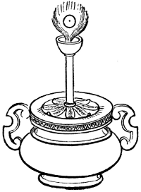
“The introduction of new Inventions seemeth to be the very chief of all human Actions. The Benefits of new Inventions may extend to all Mankind universally; but the Good of political Achievements can respect but some particular Cantons of Men; these latter do not endure above a few Ages, the former forever. Inventions make all Men happy, without either Injury or Damage to any one single Person. Furthermore, new Inventions are, as it were, new Erections and Imitations of God’s own Works.”—Bacon.
At the beginning of the eighteenth century every element of the modern type of steam-engine had been separately invented and practically applied. The character of atmospheric pressure, and of the pressure of gases, had become understood. The nature of a vacuum was known, and the method of obtaining it by the displacement of the air by steam, and by the condensation of the vapor, was understood. The importance of utilizing the power of steam, and the application of condensation in the removal of atmospheric pressure, was not only recognized, but had been actually and successfully attempted by Morland, Papin, and Savery.
Mechanicians had succeeded in making steam-boilers capable of sustaining any desired or any useful pressure, and Papin had shown how to make them comparatively safe[56] by the attachment of the safety-valve. They had made steam-cylinders fitted with pistons, and had used such a combination in the development of power.
It now only remained for the engineer to combine known forms of mechanism in a practical machine which should be capable of economically and conveniently utilizing the power of steam through the application of now well-understood principles, and by the intelligent combination of physical phenomena already familiar to scientific investigators.
Every essential fact and every vital principle had been learned, and every one of the needed mechanical combinations had been successfully effected. It was only requisite that an inventor should appear, capable of perceiving that these known facts and combinations of mechanism, properly illustrated in a working machine, would present to the world its greatest physical blessing.
The defects of the simple engines constructed up to this time have been noted as each has been described. None of them could be depended upon for safe, economical, and continuous work. Savery’s was the most successful of all. But the engine of Savery, even with the improvements of Desaguliers, was unsafe where most needed, because of the high pressures necessarily carried in its boilers when pumping from considerable depths; it was uneconomical, in consequence of the great loss of heat in its forcing-cylinders when the hot steam was surrounded at its entrance by colder bodies; it was slow in operation, of great first cost, and expensive in first cost and in repairs, as well as in its operation. It could not be relied upon to do its work uninterruptedly, and was thus in many respects a very unsatisfactory machine.
The man who finally effected a combination of the elements of the modern steam-engine, and produced a machine which is unmistakably a true engine—i. e., a train of mechanism consisting of several elementary pieces combined in a train capable of transmitting a force applied at one end[57] and of communicating it to the resistance to be overcome at the other end—was Thomas Newcomen, an “iron-monger” and blacksmith of Dartmouth, England. The engine invented by him, and known as the “Atmospheric Steam-Engine,” is the first of an entirely new type.
The old type of engine—the steam-engine as a simple machine—had been given as great a degree of perfection, by the successive improvements of Worcester, Savery, and Desaguliers, as it was probably capable of attaining by any modification of its details. The next step was necessarily a complete change of type; and to effect such a change, it was only necessary to combine devices already known and successfully tried.
But little is known of the personal history of Newcomen. His position in life was humble, and the inventor was not then looked upon as an individual of even possible importance in the community. He was considered as one of an eccentric class of schemers, and of an order which, concerning itself with mechanical matters, held the lowest position in the class.
It is supposed that Savery’s engine was perfectly well known to Newcomen, and that the latter may have visited Savery at his home in Modbury, which was but fifteen miles from the residence of Newcomen. It is thought, by some biographers of these inventors, that Newcomen was employed by Savery in making the more intricate forgings of his engine. Harris, in his “Lexicon Technicum,” states that drawings of the engine of Savery came into the hands of Newcomen, who made a model of the machine, set it up in his garden, and then attempted its improvement; but Switzer says that Newcomen “was as early in his invention as Mr. Savery was in his.”
Newcomen was assisted in his experiments by John Calley, who, with him, took out the patent. It has been stated that a visit to Cornwall, where they witnessed the working of a Savery engine, first turned their attention to the subject;[58] but a friend of Savery has stated that Newcomen was as early with his general plans as Savery.
After some discussion with Calley, Newcomen entered into correspondence with Dr. Hooke, proposing a steam-engine to consist of a steam-cylinder containing a piston similar to that of Papin’s, and to drive a separate pump, similar to those generally in use where water was raised by horse or wind power. Dr. Hooke advised and argued strongly against their plan, but, fortunately, the obstinate belief of the unlearned mechanics was not overpowered by the disquisitions of their distinguished correspondent, and Newcomen and Calley attempted an engine on their peculiar plan. This succeeded so well as to induce them to continue their labors, and, in 1705, to patent,[30] in combination with Savery—who held the exclusive right to practise surface-condensation, and who induced them to allow him an interest with them—an engine combining a steam-cylinder and piston, surface-condensation, a separate boiler, and separate pumps.
In the atmospheric-engine, as first designed, the slow process of condensation by the application of the condensing water to the exterior of the cylinder, to produce the vacuum, caused the strokes of the engine to take place at very long intervals. An improvement was, however, soon effected, which immensely increased the rapidity of condensation. A jet of water was thrown directly into the cylinder, thus effecting for the Newcomen engine just what Desaguliers had done for the Savery engine previously. As thus improved, the Newcomen engine is shown in Fig. 19.
Here b is the boiler. Steam passes from it through the cock, d, and up into the cylinder, a, equilibrating the pressure of the atmosphere, and allowing the heavy pump-rod, k, to[59] fall, and, by the greater weight acting through the beam, i i, to raise the piston, s, to the position shown. The rod m carries a counterbalance, if needed. The cock d being shut, f is then opened, and a jet of water from the reservoir, g, enters the cylinder, producing a vacuum by the condensation of the steam. The pressure of the air above the piston now forces it down, again raising the pump-rods, and thus the engine works on indefinitely.
The pipe h is used for the purpose of keeping the upper side of the piston covered with water, to prevent air-leaks—a device of Newcomen. Two gauge-cocks, c c, and a safety-valve, N, are represented in the figure, but it will be noticed that the latter is quite different from the now usual form. Here, the pressure used was hardly greater than that of the atmosphere, and the weight of the valve itself was ordinarily sufficient to keep it down. The condensing water, together with the water of condensation, flows off through the open pipe p. Newcomen’s first engine made 6 or 8[60] strokes a minute; the later and improved engines made 10 or 12.
The steam-engine has now assumed a form that somewhat resembles the modern machine.
The Newcomen engine is seen at a glance to have been a combination of earlier ideas. It was the engine of Huyghens, with its cylinder and piston as improved by Papin, by the substitution of steam for the gases generated by the explosion of gunpowder; still further improved by Newcomen and Calley by the addition of the method of condensation used in the Savery engine. It was further modified, with the object of applying it directly to the working of the pumps of the mines by the introduction of the overhead beam, from which the piston was suspended at one end and the pump-rod at the other.
The advantages secured by this combination of inventions were many and manifest. The piston not only gave economy by interposing itself between the impelling and the resisting fluid, but, by affording opportunity to make the area of piston as large as desired, it enabled Newcomen to use any convenient pressure and any desired proportions for any proposed lift. The removal of the water to be lifted from the steam-engine proper and handling it with pumps, was an evident cause of very great economy of steam.
The disposal of the water to be raised in this way also permitted the operations of condensation of steam, and the renewal of pressure on the piston, to be made to succeed each other with rapidity, and enabled the inventor to choose, unhampered, the device for securing promptly the action of condensation.
Desaguliers, in his account of the introduction of the engine of Newcomen, says that, with his coadjutor Calley, he “made several experiments in private about the year 1710, and in the latter end of the year 1711 made proposals to drain the water of a colliery at Griff, in Warwickshire,[61] where the proprietors employed 500 horses, at an expense of £900 a year; but, their invention not meeting with the reception they expected, in March following, through the acquaintance of Mr. Potter, of Bromsgrove, in Worcestershire, they bargained to draw water for Mr. Back, of Wolverhampton, where, after a great many laborious attempts, they did make the engine work; but, not being either philosophers to understand the reason, or mathematicians enough to calculate the powers and proportions of the parts, they very luckily, by accident, found what they sought for.
“They were at a loss about the pumps, but, being so near Birmingham, and having the assistance of so many admirable and ingenious workmen, they came, about 1712, to the method of making the pump-valves, clacks, and buckets, whereas they had but an imperfect notion of them before. One thing is very remarkable: as they were at first working, they were surprised to see the engine go several strokes, and very quick together, when, after a search, they found a hole in the piston, which let the cold water in to condense the steam in the inside of the cylinder, whereas, before, they had always done it on the outside. They used before to work with a buoy to the cylinder, inclosed in a pipe, which buoy rose when the steam was strong and opened the injection, and made a stroke; thereby they were only capable of giving 6, 8, or 10 strokes in a minute, till a boy, named Humphrey Potter, in 1713, who attended the engine, added (what he called a scoggan) a catch, that the beam always opened, and then it would go 15 or 16 strokes a minute. But, this being perplexed with catches and strings, Mr. Henry Beighton, in an engine he had built at Newcastle-upon-Tyne in 1718, took them all away but the beam itself, and supplied them in a much better manner.”
In illustration of the application of the Newcomen engine to the drainage of mines, Farey describes a small machine, of which the pump is 8 inches in diameter, and[62] the lift 162 feet. The column of water to be raised weighed 3,535 pounds. The steam-piston was made 2 feet in diameter, giving an area of 452 square inches. The net working-pressure was assumed at 103∕4 pounds per square inch; the temperature of the water of condensation and of uncondensed vapor after the entrance of the injection-water being usually about 150° Fahr. This gave an excess of pressure on the steam-side of 1,324 pounds, the total pressure on the piston being 4,859 pounds. One-half of this excess is counterweighted by the pump-rods, and by weight on that end of the beam; and the weight, 662 pounds, acting on each side alternately as a surplus, produced the requisite rapidity of movement of the machine. This engine was said to make 15 strokes per minute, giving a speed of piston of 75 feet per minute, and the power exerted usefully was equivalent to 265,125 pounds raised one foot high per minute. As the horse-power is equivalent to 33,000 “foot-pounds” per minute, the engine was of 265125∕ 33000 = 8.034—almost exactly 8 horse-power.
It is instructive to contrast this estimate with that made for a Savery engine doing the same work. The latter would have raised the water about 26 feet in its “suction-pipe,” and would then have forced it, by the direct pressure of steam, the remaining distance of 136 feet; and the steam-pressure required would have been nearly 60 pounds per square inch. With this high temperature and pressure, the waste of steam by condensation in the forcing-vessels would have been so great that it would have compelled the adoption of two engines of considerable size, each lifting the water one-half the height, and using steam of about 25 pounds pressure. Potter’s rude valve-gear was soon improved by Henry Beighton, in an engine which that talented engineer erected at Newcastle-upon-Tyne in 1718, and in which he substituted substantial materials for the cords, as in Fig. 20.
In this sketch, r is a plug-tree, plug-rod, or plug-frame,[63] as it is variously called, suspended from the great beam, with which it rises and falls, bringing the pins p and k, at the proper moment, in contact with the handles k k and n n of the valves, moving them in the proper direction and to the proper extent. A lever safety-valve is here used, at the suggestion, it is said, of Desaguliers. The piston was packed with leather or with rope, and lubricated with tallow.
After the death of Beighton, the atmospheric engine of Newcomen retained its then standard form for many years, and came into extensive use in all the mining districts, particularly in Cornwall, and was also applied occasionally to the drainage of wet lands, to the supply of water to towns, and it was even proposed by Hulls to be used for ship-propulsion.[64]
The proportions of the engines had been determined in a hap-hazard way, and they were in many cases very unsafe. John Smeaton, the most distinguished engineer of his time, finally, in 1769, experimentally determined proper proportions, and built several of these engines of very considerable size. He built his engines with steam-cylinders of greater length of stroke than had been customary, and gave them such dimensions as, by giving a greater excess of pressure on the steam-side, enabled him to obtain a greatly-increased speed of piston. The first of his new style of engine was erected at Long Benton, near Newcastle-upon-Tyne, in 1774.
Fig. 21[31] illustrates its principal characteristic features. The boiler is not shown.
The steam is led to the engine through the pipe, C, and is regulated by turning the cock in the receiver, D, which connects with the steam-cylinder by the pipe, E, which latter pipe rises a little way above the bottom of the cylinder, F, in order that it may not drain off the injection-water into the steam-pipe and receiver.
The steam-cylinder, about ten feet in length, is fitted with a carefully-made piston, G, having a flanch rising four or five inches and extending completely around its circumference, and nearly in contact with the interior surface of the cylinder. Between this flanch and the cylinder is driven a “packing” of oakum, which is held in place by weights; this prevents the leakage of air, water, or steam, past the piston, as it rises and falls in the cylinder at each stroke of the engine. The chain and piston-rod connect the piston to the beam, I I. The arch-heads at each end of the beam keep the chains of the piston-rod and the pump-rods perpendicular and in line.
A “jack-head” pump, N, is driven by a small beam deriving its motion from the plug-rod at g, raises the water[65] required for condensing the steam, and keeps the cistern, O, supplied. This “jack-head cistern” is sufficiently elevated to give the water entering the cylinder the velocity requisite to secure prompt condensation. A waste-pipe carries away any surplus water. The injection-water is led from the cistern by the pipe, P P, which is two or three inches in diameter,[66] and the flow of water is regulated by the injection-cock, r. The cap at the end, d, is pierced with several holes, and the stream thus divided rises in jets when admitted, and, striking the lower side of the piston, the spray thus produced very rapidly condenses the steam, and produces a vacuum beneath the piston. The valve, e, on the upper end of the injection-pipe, is a check-valve, to prevent leakage into the engine when the latter is not in operation. The little pipe, f, supplies water to the upper side of the piston, and, keeping it flooded, prevents the entrance of air when the packing is not perfectly tight.
The “working-plug,” or plug-rod, Q, is a piece of timber slit vertically, and carrying pins which engage the handles of the valves, opening and closing them at the proper times. The steam-cock, or regulator, has a handle, h, by which it is moved. The iron rod, i i, or spanner, gives motion to the handle, h.
The vibrating lever, k l, called the Y, or the “tumbling-bob,” moves on the pins, m n, and is worked by the levers, o p, which in turn are moved by the plug-tree. When o is depressed, the loaded end, k, is given the position seen in the sketch, and the leg l of the Y strikes the spanner, i i, and, opening the steam-valve, the piston at once rises as steam enters the cylinder, until another pin on the plug-rod raises the piece, P, and closes the regulator again. The lever, q r, connects with the injection-cock, and is moved, when, as the piston rises, the end, q, is struck by a pin on the plug-rod, and the cock is opened and a vacuum produced. The cock is closed on the descent of the plug-tree with the piston. An eduction-pipe, R, fitted with a clock, conveys away the water in the cylinder at the end of each down-stroke; the water thus removed is collected in the hot-well, S, and is used as feed-water for the boiler, to which it is conveyed by the pipe T. At each down-stroke, while the water passes out through R, the air which may have collected in the cylinder is driven out through the “snifting-valve,” [67] s. The steam-cylinder is supported on strong beams, t t; it has around its upper edge a guard, v, of lead, which prevents the overflow of the water on the top of the piston. The excess of this water flows away to the hot-well through the pipe W.
Catch-pins, x, are provided, to prevent the beam descending too far should the engine make too long a stroke; two wooden springs, y y, receive the blow. The great beam is carried on sectors, z z, to diminish losses by friction.
The boilers of Newcomen’s earlier engines were made of copper where in contact with the products of combustion, and their upper parts were of lead. Subsequently, sheet-iron was substituted. The steam-space in the boiler was made of 8 or 10 times the capacity of the cylinder of the engine. Even in Smeaton’s time, a chimney-damper was not used, and the supply of steam was consequently very variable. In the earlier engines, the cylinder was placed on the boiler; afterward, they were placed separately, and supported on a foundation of masonry. The injection or “jack-head” cistern was placed from 12 to 30 feet above the engine, the velocity due the greater altitude being found to give the most perfect distribution of the water and the promptest condensation.
Smeaton covered the lower side of his steam-pistons with wooden plank about 21∕4 inches thick, in order that it should absorb and waste less heat than when the iron was directly exposed to the steam. Mr. Beighton was the first to use the water of condensation for feeding the boiler, taking it directly from the eduction-pipe, or the “hot-well.” Where only a sufficient amount of pure water could be obtained for[68] feeding the boiler, and the injection-water was “hard,” Mr. Smeaton applied a heater, immersed in the hot-well, through which the feed passed, absorbing heat from the water of condensation en route to the boiler. Farey first proposed the use of the “coil-heater”—a pipe, or “worm,” which, forming a part of the feed-pipe, was set in the hot-well.
As early as 1743, the metal used for the cylinders was cast-iron. The earlier engines had been fitted with brass cylinders. Desaguliers recommended the iron cylinders, as being smoother, thinner, and as having less capacity for heat than those of brass.
In a very few years after the invention of Newcomen’s engine it had been introduced into nearly all large mines in Great Britain; and many new mines, which could not have been worked at all previously, were opened, when it was found that the new machine could be relied upon to raise the large quantities of water to be handled. The first engine in Scotland was erected in 1720 at Elphinstone, in Stirlingshire. One was put up in Hungary in 1723.
The first mine-engine, erected in 1712 at Griff, was 22 inches in diameter, and the second and third engines were of similar size. That erected at Ansthorpe was 23 inches in diameter of cylinder, and it was a long time before much larger engines were constructed. Smeaton and others finally made them as large as 6 feet in diameter.
In calculating the lifting-power of his engines, Newcomen’s method was “to square the diameter of the cylinder in inches, and, cutting off the last figure, he called it ‘long hundredweights;’ then writing a cipher on the right hand, he called the number on that side ‘odd pounds;’ this he reckoned tolerably exact at a mean, or rather when the barometer was above 30 inches, and the air heavy.” In allowing for frictional and other losses, he deducted from one-fourth to one-third. Desaguliers found the rule quite exact. The usual mean pressure resisting the motion of the piston averaged, in the best engines, about 8 pounds per[69] square inch of its area. The speed of the piston was from 150 to 175 feet per minute. The temperature of the hot-well was from 145° to 175° Fahr.
Smeaton made a number of test-trials of Newcomen engines to determine their “duty”—i. e., to ascertain the expenditure of fuel required to raise a definite quantity of water to a stated height. He found an engine 10 inches in diameter of cylinder, and of 3 feet stroke, could do work equal to raising 2,919,017 pounds of water one foot high, with a bushel of coals weighing 84 pounds.
One of Smeaton’s larger engines, erected at Long Benton, was 52 inches in diameter of cylinder and of 7 feet stroke of piston, and made 12 strokes per minute. Its load was equal to 71∕2 pounds per square inch of piston-area, and its effective capacity about 40 horse-power. Its duty was 91∕2 millions of pounds raised one foot high per bushel of coals. Its boiler evaporated 7.88 pounds of water per pound of fuel consumed. It had 35 square feet of grate-surface and 142 square feet of heating-surface beneath the boilers, and 317 square feet in the flues—a total of 459 square feet. The moving parts of this engine weighed 81∕2 tons.
Smeaton erected one of these engines at the Chasewater mine, in Cornwall, in 1775, which was of very considerable size. It was 6 feet in diameter of steam-cylinder, and had a maximum stroke of piston of 91∕2 feet. It usually worked 9 feet. The pumps were in three lifts of about 100 feet each, and were 163∕4 inches in diameter. Nine strokes were made per minute. This engine replaced two others, of 64 and of 62 inches diameter of cylinder respectively, and both of 6 feet stroke. One engine at the lower lift supplied the second, which was set above it. The lower one had pumps 181∕2 inches in diameter, and raised the water 144 feet; the upper engine raised the water 156 feet, by pumps 171∕2 inches in diameter. The later engine replacing them exerted 761∕2 horse-power. There were three boilers, each 15 feet in[70] diameter, and having each 23 square feet of grate-surface. The chimney was 22 feet high. The great beam, or “lever,” of this engine was built up of 20 beams of fir in two sets, placed side by side, and ten deep, strongly bolted together. It was over 6 feet deep at the middle and 5 feet at the ends, and was 2 feet thick. The “main centres,” or journals, on which it vibrated were 81∕2 inches in diameter and 81∕2 inches long. The cylinder weighed 61∕2 tons, and was paid for at the rate of 28 shillings per hundredweight.
By the end of the eighteenth century, therefore, the engine of Newcomen, perfected by the ingenuity of Potter and of Beighton, and by the systematic study and experimental research of Smeaton, had become a well-established form of steam-engine, and its application to raising water had become general. The coal-mines of Coventry and of Newcastle had adopted this method of drainage; and the tin and the copper mines of Cornwall had been deepened, using, for drainage, engines of the largest size.
Some engines had been set up in and about London, the scene of Worcester’s struggles and disappointments, where they were used to supply water to large houses. Others were in use in other large cities of England, where water-works had been erected.
Some engines had also been erected to drive mills indirectly by raising water to turn water-wheels. This is said by Farey to have been first practised in 1752, at a mill near Bristol, and became common during the next quarter of a century. Many engines had been built in England and sent across the channel, to be applied to the drainage of mines on the Continent. Belidor[32] stated that the manufacture of these “fire-engines” was exclusively confined to England; and this remained true many years after his time. When used for the drainage of mines, the engine usually worked the ordinary lift or bucket pump; when employed[71] for water-supply to cities, the force or plunger pump was often employed, the engine being placed below the level of the reservoir. Dr. Rees states that this engine was in common use among the collieries of England as early as 1725.
The Edmonstone colliery was licensed, in 1725, to erect an engine, not to exceed 28 inches diameter of cylinder and 9 feet stroke of piston, paying a royalty of £80 per annum for eight years. This engine was built in Scotland, by workmen sent from England, and cost about £1,200. Its “great cost” is attributed to an extensive use of brass. The workmen were paid their expenses and 15s. per week as wages. The builders were John and Abraham Potter, of Durham. An engine built in 1775, having a steam-cylinder 48 inches in diameter and of 7 feet stroke, cost about £2,000.
Smeaton found 57 engines at work near Newcastle in 1767, ranging in size from 28 to 75 inches in diameter of cylinder, and of, collectively, about 1,200 horse-power. Fifteen of these engines gave an average of 98 square inches of piston to the horse-power, and the average duty was 5,590,000 pounds raised 1 foot high by 1 bushel (84 pounds) of coal. The highest duty noted was 7.44 millions; the lowest was 3.22 millions. The most efficient engine had a steam-cylinder 42 inches in diameter; the load was equivalent to 91∕4 pounds per square inch of piston-area, and the horse-power developed was calculated to be 16.7.
Price, writing in 1778, says, in the Appendix to his “Mineralogia Cornubiensis:” “Mr. Newcomen’s invention of the fire-engine enabled us to sink our mines to twice the depth we could formerly do by any other machinery. Since this invention was completed, most other attempts at its improvement have been very unsuccessful; but the vast consumption of fuel in these engines is an immense drawback on the profit of our mines, for every fire-engine of magnitude consumes £3,000 worth of coals per annum. This heavy tax amounts almost to a prohibition.”[72]
Smeaton was given the description, in 1773, of a stone boiler, which was used with one of these engines at a copper mine at Camborne, in Cornwall. It contained three copper flues 22 inches in diameter. The gases were passed through these flues successively, finally passing off to the chimney. This boiler was cemented with hydraulic mortar. It was 20 feet long, 9 feet wide, and 81∕2 feet deep. It was heated by the waste heat from the roasting-furnaces. This was one of the earliest flue-boilers ever made.
In 1780, Smeaton had a list of 18 large engines working in Cornwall. The larger number of them were built by Jonathan Hornblower and John Nancarron. At this time, the largest and best-known pumping-engine for water-works was at York Buildings, in Villiers Street, Strand, London. It had been in operation since 1752, and was erected beside one of Savery’s engines, built in 1710. It had a steam-cylinder 45 inches in diameter, and a stroke of piston of 8 feet, making 71∕2 strokes per minute, and developing 351∕2 horse-power. Its boiler was dome-shaped, of copper, and contained a large central fire-box and a spiral flue leading outward to the chimney. Another somewhat larger machine was built and placed beside this engine, some time previous to 1775. Its cylinder was 49 inches in diameter, and its stroke 9 feet. It raised water 102 feet. This engine was altered and improved by Smeaton in 1777, and continued in use until 1813.
Smeaton, as early as 1765, designed a portable engine,[33] in which he supported the machinery on a wooden frame mounted on short legs and strongly put together, so that the whole machine could be transported and set at work wherever convenient.
In place of the beam, a large pulley was used, over which a chain was carried, connecting the piston with the pump-rod, and the motion was similar to that given by the[73] discarded beam. The wheel was supported on A-frames, resembling somewhat the “gallows-frames” still used with the beam-engines of American river-boats. The sills carrying the two A’s supported the cylinder. The injection-cistern was supported above the great pulley-wheel. The valve-gearing and the injection-pump were worked by a smaller wheel, mounted on the same axis with the larger one. The boiler was placed apart from the engine, with which it was connected by a steam-pipe, in which was placed the “regulator,” or throttle-valve. The boiler (Fig. 23) “was shaped like a large tea-kettle,” and contained a fire-box, B, or internal furnace, of which the sides were made of cast-iron. The fire-door, C, was placed on one side and opposite the flue, D, through which the products of combustion were led to the chimney, E; a short, large pipe, F, leading downward from the furnace to the outside of the boiler, was the ash-pit. The shell of the boiler, A, was made of iron plate one-quarter of an inch thick. The steam-cylinder[74] of the engine was 18 inches in diameter, the stroke of piston 6 feet, the great wheel 61∕2 feet in diameter, and the A-frames 9 feet high. The boiler was made 6 feet, the furnace 34 inches, and the grate 18 inches in diameter. The piston was intended to make 10 strokes per minute, and the engine to develop 41∕8 horse-power.
In 1773, Smeaton prepared plans for a pumping-engine to be set up at Cronstadt, the port of St. Petersburg, to empty the great dry dock constructed by Peter the Great and Catherine, his successor. This great dock was begun in 1719. It was large enough to dock ten of the ships of that time, and had previously been imperfectly drained by two great windmills 100 feet high. So imperfectly did they do their work, that a year was required to empty the dock, and it could therefore only be used once in each summer. The engine was built at the Carron Iron Works, in England. It had a cylinder 66 inches in diameter, and a stroke of piston of 81∕2 feet. The lift varied from 33 feet when the dock was full to 53 feet when it was cleared of water. The load on the engine averaged about 81∕3 pounds per square inch of piston-area. There were three boilers, each 10 feet in diameter, and 16 feet 4 inches high to the apex of its hemispherical dome. They contained internal fire-boxes with grates of 20 feet area, and were surrounded by flues helically traversing the masonry setting. The engine was started in 1777, and worked very successfully.
The lowlands of Holland were, before the time of Smeaton, drained by means of windmills. The uncertainty and inefficiency of this method precluded its application to anything like the extent to which steam-power has since been utilized. In 1440, there were 150 inland lakes, or “meers,” in that country, of which nearly 100, having an extent of over 200,000 acres, have since been drained. The “Haarlemmer Meer” alone covers nearly 50,000 acres, and forms the basin of a drainage-area of between 200,000 and 300,000 acres, receiving a rainfall of 54,000,000 tons, which[75] must be raised 16 feet in discharging it. The beds of these lakes are from 10 to 20 feet lower than the water-level in the adjacent canals. In 1840, 12,000 windmills were still employed in this work. In the following year, William II., at the suggestion of a commission, decreed that only steam-engines should be employed to do this immense work. Up to this time the average consumption of fuel for the pumping-engines in use is said to have been 20 pounds per hour per horse-power.
The first engine used was erected in 1777 and 1778, on the Newcomen plan, to assist the 34 windmills employed to drain a lake near Rotterdam. This lake covered 7,000 acres, and its bed was 12 feet below the surface of the river Meuse, which passes it, and empties into the sea in the immediate neighborhood. The iron parts of the engine were built in England, and the machine was put together in Holland. The steam-cylinder was 52 inches in diameter, and the stroke of piston 9 feet. The boiler was 18 feet in diameter, and contained a double flue. The main beam was 27 feet long. The pumps were 6 in number, 3 cylindrical and 3 having a square cross-section; 3 were of 6 feet and 3 of 21∕2 feet stroke. Two pumps only were worked at high-tide, and the others were added one at a time, as the tide fell, until, at low-tide, all 6 were at work.
The size of this engine, and the magnitude of its work, seem insignificant when compared with the machinery installed 60 years later to drain the Haarlemmer Meer, and with the work done by the last. These engines are 12 feet in diameter of cylinder and 10 feet stroke of piston, and work—they are 3 in number—the one 11 pumps of 63 inches diameter and 10 feet stroke, the others 8 pumps of 73 inches diameter and of the same length of stroke. The modern engines do a “duty” of 75,000,000 to 87,000,000 with 94 pounds of coal, consuming 21∕4 pounds of coal per hour and per horse-power.
The first steam-engine applied to working the blowing-machinery[76] of a blast-furnace was erected at the Carron Iron-Works, in Scotland, near Falkirk, in 1765, and proved very unsatisfactory. Smeaton subsequently, in 1769 or 1770, introduced better machinery into these works and improved the old engine, and this use of the steam-engine soon became usual. This engine did its work indirectly, furnishing water, by pumping, to drive the water-wheels which worked the blowing-cylinders. Its steam-cylinder was 6 feet in diameter, and the pump-cylinder 52 inches. The stroke was 9 feet.
A direct-acting engine, used as a blowing-engine, was not constructed until about 1784, at which time a single-acting blowing-cylinder, or air-pump, was placed at the “out-board” end of the beam, where the pump-rod had been attached. The piston of the air-cylinder was loaded with the weights needed to force it down, expelling the air, and the engine did its work in raising the loaded piston, the air-cylinder filling as the piston rose. A large “accumulator” was used to equalize the pressure of the expelled air. This consisted of another air-cylinder, having a loaded piston which was left free to rise and fall. At each expulsion of air by the blowing-engine this cylinder was filled, the loaded piston rising to the top. While the piston of the former was returning, and the air-cylinder was taking in its charge of air, the accumulator would gradually discharge the stored air, the piston slowly falling under its load. This piston was called the “floating piston,” or “fly-piston,” and its action was, in effect, precisely that of the upper portion of the common blacksmith’s bellows.
Dr. Robison, the author of “Mechanical Philosophy,” one of the very few works even now existing deserving such a title, describes one of these engines[34] as working in Scotland in 1790. It had a steam-cylinder 40 or 44 inches in diameter, a blowing-cylinder 60 inches in diameter, and the[77] stroke of piston was 6 feet. The air-pressure was 2.77 pounds per square inch as a maximum in the blowing-cylinder; and the floating piston in the regulating-cylinder was loaded with 2.63 pounds per square inch. Making 15 or 18 strokes per minute, this engine delivered about 1,600 cubic feet of air, or 1201∕2 pounds in weight, per minute, and developed 20 horse-power.
At about the same date a change was made in the blowing-cylinder. The air entered at the bottom, as before, but was forced out at the top, the piston being fitted with valves, as in the common lifting-pump, and the engine thus being arranged to do the work of expulsion during the down-stroke of the steam-piston.
Four years later, the regulating-cylinder, or accumulator, was given up, and the now familiar “water-regulator” was substituted for it. This consists of a tank, usually of sheet-iron, set open-end downward in a large vessel containing water. The lower edge of the inner tank is supported on piers a few inches above the bottom of the large one. The pipe carrying air from the blowing-engine passes above this water-regulator, and a branch-pipe is led down into the inner tank. As the air-pressure varies, the level of the water within the inverted tank changes, rising as pressure falls at the slowing of the motion of the piston, and falling as the pressure rises again while the piston is moving with an accelerated velocity. The regulator, thus receiving surplus air to be delivered when needed, greatly assists in regulating the pressure. The larger the regulator, the more perfectly uniform the pressure. The water-level outside the inner tank is usually five or six feet higher than within it. This apparatus was found much more satisfactory than the previously-used regulator, and, with its introduction, the establishment of the steam-engine as a blowing-engine for iron-works and at blast-furnaces may be considered as having been fully established.
Thus, by the end of the third quarter of the eighteenth[78] century, the steam-engine had become generally introduced, and had been applied to nearly all of the purposes for which a single-acting engine could be used. The path which had been opened by Worcester had been fairly laid out by Savery and his contemporaries, and the builders of the Newcomen engine, with such improvements as they had been able to effect, had followed it as far as they were able. The real and practical introduction of the steam-engine is as fairly attributable to Smeaton as to any one of the inventors whose names are more generally known in connection with it. As a mechanic, he was unrivaled; as an engineer, he was head and shoulders above any constructor of his time engaged in general practice. There were very few important public works built in Great Britain at that time in relation to which he was not consulted; and he was often visited by foreign engineers, who desired his advice with regard to works in progress on the Continent.
[30] It has been denied that a patent was issued, but there is no doubt that Savery claimed and received an interest in the new engine.
[31] A fac-simile of a sketch in Galloway’s “On the Steam-Engine,” etc.
[32] “Architecture Hydraulique,” 1734.
[33] Smeaton’s “Reports,” vol. i., p. 223.
[34] “Encyclopædia Britannica,” 1st edition.
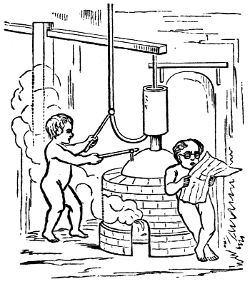
The world is now entering upon the Mechanical Epoch. There is nothing in the future more sure than the great triumphs which that epoch is to achieve. It has already advanced to some glorious conquests. What miracles of invention now crowd upon us! Look abroad, and contemplate the infinite achievements of the steam-power.
And yet we have only begun—we are but on the threshold of this epoch.... What is it but the setting of the great distinctive seal upon the nineteenth century?—an advertisement of the fact that society has risen to occupy a higher platform than ever before?—a proclamation from the high places, announcing honor, honor immortal, to the workmen who fill this world with beauty, comfort, and power—honor to be forever embalmed in history, to be perpetuated in monuments, to be written in the hearts of this and succeeding generations!—Kennedy.
The success of the Newcomen engine naturally attracted the attention of mechanics, and of scientific men as well, to the possibility of making other applications of steam-power.
The best men of the time gave much attention to the subject, but, until James Watt began the work that has made him famous, nothing more was done than to improve the proportions and slightly alter the details of the Newcomen and Calley engine, even by such skillful engineers as Brindley and Smeaton. Of the personal history of the earlier inventors and improvers of the steam-engine, very little is ascertained; but that of Watt has become well known.
[80] James Watt was of an humble lineage, and was born at Greenock, then a little Scotch fishing village, but now a considerable and a busy town, which annually launches upon the waters of the Clyde a fleet of steamships whose engines are probably, in the aggregate, far more powerful than were all the engines in the world at the date of Watt’s birth, January 19, 1736. His grandfather, Thomas Watt, of Crawfordsdyke, near Greenock, was a well-known mathematician about the year 1700, and was for many years a schoolmaster at that place. His father was a prominent citizen of Greenock, and was at various times chief magistrate and treasurer of the town. James Watt was a bright boy, but exceedingly delicate in health, and quite unable to attend school regularly, or to apply himself closely to either study or play. His early education was given by his parents, who were respectable and intelligent people, and the tools borrowed from his father’s carpenter-bench served at[81] once to amuse him and to give him a dexterity and familiarity with their use that must undoubtedly have been of inestimable value to him in after-life.
M. Arago, the eminent French philosopher, who wrote one of the earliest and most interesting biographies of Watt, relates anecdotes of him which, if correct, illustrate well his thoughtfulness and his intelligence, as well as the mechanical bent of the boy’s mind. He is said, at the age of six years, to have occupied himself during leisure hours with the solution of geometrical problems; and Arago discovers, in a story in which he is described as experimenting with the tea-kettle,[35] his earliest investigations of the nature and properties of steam.
When finally sent to the village school, his ill health prevented his making rapid progress; and it was only when thirteen or fourteen years of age that he began to show that he was capable of taking the lead in his class, and to exhibit his ability in the study, particularly, of mathematics. His spare time was principally spent in sketching with his pencil, in carving, and in working at the bench, both in wood and metal. He made many ingenious pieces of mechanism, and some beautiful models. His favorite work seemed to be the repairing of nautical instruments. Among other pieces of apparatus made by the boy was a very fine barrel-organ. In boyhood, as in after-life, he was a diligent reader, and seemed to find something to interest him in every book that came into his hands.
At the age of eighteen, Watt was sent to Glasgow, there to reside with his mother’s relatives, and to learn the trade of a mathematical-instrument maker. The mechanic with whom he was placed was soon found too indolent, or was otherwise incapable of giving much aid in the project, and Dr. Dick, of the University of Glasgow, with whom Watt became acquainted, advised him to go to London. Accordingly,[82] he set out in June, 1755, for the metropolis, where, on his arrival, he arranged with Mr. John Morgan, in Cornhill, to work a year at his chosen business, receiving as compensation 20 guineas. At the end of the year he was compelled, by serious ill-health, to return home.
Having become restored to health, he went again to Glasgow in 1756, with the intention of pursuing his calling there. But, not being the son of a burgess, and not having served his apprenticeship in the town, he was forbidden by the guilds, or trades-unions, to open a shop in Glasgow. Dr. Dick came to his aid, and employed him to repair some apparatus which had been bequeathed to the college. He was finally allowed the use of three rooms in the University building, its authorities not being under the municipal rule. He remained here until 1760, when, the trades no longer objecting, he took a shop in the city; and in 1761 moved again, into a shop on the north side of the Trongate, where he earned a scanty living without molestation, and still kept up his connection with the college. He did some work as a civil engineer in the neighborhood of Glasgow, but soon gave up all other employment, and devoted himself entirely to mechanics.
He spent much of his leisure time—of which he had, at first, more than was desirable—in making philosophical experiments and in the manufacture of musical instruments, in making himself familiar with the sciences, and in devising improvements in the construction of organs. In order to pursue his researches more satisfactorily, he studied German and Italian, and read Smith’s “Harmonics,” that he might become familiar with the principles of construction of musical instruments. His reading was still very desultory; but the introduction of the Newcomen engine in the neighborhood of Glasgow, and the presence of a model in the college collections, which was placed in his hands, in 1763, for repair, led him to study the history of the steam-engine, and to conduct for himself an experimental research[83] into the properties of steam, with a set of improvised apparatus.
Dr. Robison, then a student of the University, who found Watt’s shop a pleasant place in which to spend his leisure, and whose tastes affiliated so strongly with those of Watt that they became friends immediately upon making acquaintance, called the attention of the instrument-maker to the steam-engine as early as 1759, and suggested that it might be applied to the propulsion of carriages. Watt was at once interested, and went to work on a little model, having tin steam-cylinders and pistons connected to the driving-wheels by an intermediate system of gearing. The scheme was afterwards given up, and was not revived by Watt for a quarter of a century.
Watt studied chemistry, and was assisted by the advice and instruction of Dr. Black, who was then making the researches which resulted in the discovery of “latent heat.” His proposal to repair the model Newcomen engine in the college collections led to his study of Desaguliers’s treatise, and of the works of Switzer and others. He thus learned what had been done by Savery and by Newcomen, and by those who had improved the engine of the latter.
In his own experiments he used, at first, apothecaries’ phials and hollow canes for steam reservoirs and pipes, and later a Papin’s digester and a common syringe. The latter combination made a non-condensing engine, in which he used steam at a pressure of 15 pounds per square inch. The valve was worked by hand, and Watt saw that an automatic valve-gear only was needed to make a working machine. This experiment, however, led to no practical result. He finally took hold of the Newcomen model, which had been obtained from London, where it had been sent for repairs, and, putting it in good working order, commenced experiments with that.
The Newcomen model, as it happened, had a boiler which, although made to a scale from engines in actual use,[84] was quite incapable of furnishing steam enough to work the engine. It was about nine inches in diameter; the steam-cylinder was two inches in diameter, and of six inches stroke of piston, arranged as in Fig. 24, which is a picture of the model as it now appears. It is retained among the most carefully-preserved treasures of the University of Glasgow.
Watt made a new boiler for the experimental investigation on which he was about to enter, and arranged it in such a manner that he could measure the quantity of water evaporated and of steam used at every stroke of the engine.
He soon discovered that it required but a very small quantity of steam to heat a very large quantity of water, and immediately attempted to determine with precision the relative weights of steam and water in the steam-cylinder when condensation took place at the down-stroke of the[85] engine, and thus independently proved the existence of that “latent heat,” the discovery of which constitutes, also, one of the greatest of Dr. Black’s claims to distinction. Watt at once went to Dr. Black and related the remarkable fact which he had thus detected, and was, in turn, taught by Black the character of the phenomenon as it had been explained to his classes by the latter some little time previously. Watt found that, at the boiling-point, his steam, condensing, was capable of heating six times its weight of water such as was used for producing condensation.
Perceiving that steam, weight for weight even, was a vastly greater absorbent and reservoir of heat than water, Watt saw plainly the importance of taking greater care to economize it than had previously been customary. He first attempted to economize in the boiler, and made boilers with wooden “shells,” in order to prevent losses by conduction and radiation, and used a larger number of flues to secure more complete absorption of the heat from the furnace-gases. He also covered his steam-pipes with non-conducting materials, and took every precaution that his ingenuity could devise to secure complete utilization of the heat of combustion. He soon found, however, that he was not working at the most important point, and that the great source of loss was to be found in defects which he noted in the action of the steam in the cylinder. He soon concluded that the sources of loss of heat in the Newcomen engine—which would be greatly exaggerated in a small model—were:
First, the dissipation of heat by the cylinder itself, which was of brass, and was both a good conductor and a good radiator.
Secondly, the loss of heat consequent upon the necessity of cooling down the cylinder at every stroke, in producing the vacuum.
Thirdly, the loss of power due to the pressure of vapor beneath the piston, which was a consequence of the imperfect method of condensation.[86]
He first made a cylinder of non-conducting material—wood soaked in oil and then baked—and obtained a decided advantage in economy of steam. He then conducted a series of very accurate experiments upon the temperature and pressure of steam at such points on the scale as he could readily reach, and, constructing a curve with his results, the abscesses representing temperatures and the pressures being represented by the ordinates, he ran the curve backward until he had obtained closely-approximate measures of temperatures less than 212°, and pressures less than atmospheric. He thus found that, with the amount of injection-water used in the Newcomen engine, bringing the temperature of the interior, as he found, down to from 140° to 175° Fahr., a very considerable back-pressure would be met with.
Continuing his examination still further, he measured the amount of steam used at each stroke, and, comparing it with the quantity that would just fill the cylinder, he found that at least three-fourths was wasted. The quantity of cold water necessary to produce the condensation of a given weight of steam was next determined; and he found that one pound of steam contained enough heat to raise about six pounds of cold water, as used for condensation, from the temperature of 52° to the boiling-point; and, going still further, he found that he was compelled to use, at each stroke of the Newcomen engine, four times as much injection-water as should suffice to condense a cylinder full of steam. This confirmed his previous conclusion that three-fourths of the heat supplied to the engine was wasted.
Watt had now, therefore, determined by his own researches, as he himself enumerates them,[36] the following facts:
“1. The capacities for heat of iron, copper, and of some sorts of wood, as compared with water.
“2. The bulk of steam compared with that of water.
[87]“3. The quantity of water evaporated in a certain boiler by a pound of coal.
“4. The elasticities of steam at various temperatures greater than that of boiling water, and an approximation to the law which it follows at other temperatures.
“5. How much water in the form of steam was required every stroke by a small Newcomen engine, with a wooden cylinder 6 inches in diameter and 12 inches stroke.
“6. The quantity of cold water required in every stroke to condense the steam in that cylinder, so as to give it a working-power of about 7 pounds on the square inch.”
After these well-devised and truly scientific investigations, Watt was enabled to enter upon his work of improving the steam-engine with an intelligent understanding of its existing defects, and with a knowledge of their cause. Watt soon saw that, in order to reduce the losses in the working of the steam in the steam-cylinder, it would be necessary to find some means, as he said, to keep the cylinder “always as hot as the steam that entered it,” notwithstanding the great fluctuations of temperature and pressure of the steam during the up and the down strokes. He has told us how, finally, the happy thought occurred to him which relieved him of all difficulty, and led to the series of modifications which at last gave to the world the modern type of steam-engine.
He says:[37] “I had gone to take a walk on a fine Sabbath afternoon. I had entered the Green by the gate at the foot of Charlotte street, and had passed the old washing-house. I was thinking upon the engine at the time, and had gone as far as the herd’s house, when the idea came into my mind that, as steam was an elastic body, it would rush into a vacuum, and, if a communication were made between the cylinder and an exhausted vessel, it would rush into it, and might be there condensed without cooling the[88] cylinder. I then saw that I must get rid of the condensed steam and injection-water if I used a jet, as in Newcomen’s engine. Two ways of doing this occurred to me: First, the water might be run off by a descending pipe, if an offlet could be got at the depth of 35 or 36 feet, and any air might be extracted by a small pump. The second was, to make the pump large enough to extract both water and air.” “I had not walked farther than the Golf-house, when the whole thing was arranged in my mind.”
Referring to this invention, Watt said to Prof. Jardine:[38] “When analyzed, the invention would not appear so great as it seemed to be. In the state in which I found the steam-engine, it was no great effort of mind to observe that the quantity of fuel necessary to make it work would forever prevent its extensive utility. The next step in my progress was equally easy—to inquire what was the cause of the great consumption of fuel. This, too, was readily suggested, viz., the waste of fuel which was necessary to bring the whole cylinder, piston, and adjacent parts from the coldness of water to the heat of steam, no fewer than from 15 to 20 times in a minute.” It was by pursuing this train of thought that he was led to devise the separate condenser.
On Monday morning Watt proceeded to make an experimental test of his new invention, using for his steam-cylinder and piston a large brass surgeon’s-syringe, 13∕4-inch diameter and 10 inches long. At each end was a pipe leading steam from the boiler, and fitted with a cock to act as a steam-valve. A pipe led also from the top of the cylinder to the condenser, the syringe being inverted and the piston-rod hanging downward for convenience. The condenser was made of two pipes of thin tin plate, 10 or 12 inches long, and about one-sixth of an inch in diameter, standing vertically, and having a connection at the top[89] with a horizontal pipe of larger size, and fitted with a “snifting-valve.” Another vertical pipe, about an inch in diameter, was connected to the condenser, and was fitted with a piston, with a view to using it as an “air-pump.” The whole was set in a cistern of cold water. The piston-rod of the little steam-cylinder was drilled from end to end to permit the water to be removed from the cylinder. This little model (Fig. 25) worked very satisfactorily, and the perfection of the vacuum was such that the machine lifted a weight of 18 pounds hung upon the piston-rod, as in the sketch. A larger model was immediately afterward constructed, and the result of its test confirmed fully the anticipations which had been awakened by the first experiment.
Having taken this first step and made such a radical improvement, the success of this invention was no sooner determined than others followed in rapid succession, as consequences of the exigencies arising from the first change in the old Newcomen engine. But in the working out of the forms and proportions of the details of the new engine, even Watt’s powerful mind, stored as it was with happily-combined scientific and practical information, was occupied[90] for years. In attaching the separate condenser, he first attempted surface-condensation; but this not succeeding well, he substituted the jet. Some provision became at once necessary for preventing the filling of the condenser with water.
Watt at first intended adopting the expedient which had worked satisfactorily with the less effective condensation of Newcomen’s engine—i. e., leading a pipe from the condenser to a depth greater than the height of a column of water which could be counterbalanced by the pressure of the atmosphere; but he subsequently employed the air-pump, which relieves the condenser not only of the water, but of the air which also usually collects in considerable volume in the condenser, and vitiates the vacuum. He next substituted oil and tallow for water in the lubrication of the piston and keeping it steam-tight, in order to avoid the cooling of the cylinder incident to the use of the latter. Another cause of refrigeration of the cylinder, and consequent waste of power in its operation, was seen to be the entrance of the atmosphere, which followed the piston down the cylinder at each stroke, cooling its interior by its contact. This the inventor concluded to prevent by covering the top of the cylinder, allowing the piston-rod to play through a “stuffing-box”—which device had long been known to mechanics.
He accordingly not only covered the top, but surrounded the whole cylinder with an external casing, or “steam-jacket,” and allowed the steam from the boiler to pass around the steam-cylinder and to press upon the upper surface of the piston, where its pressure was variable at pleasure, and therefore more manageable than that of the atmosphere. It also, besides keeping the cylinder hot, could do comparatively little harm should it leak by the piston, as it could be condensed, and thus readily disposed of.
When he had concluded to build the larger experimental engine, Watt determined to give his whole time and attention to the work, and hired a room in an old deserted[91] pottery near the Broomielaw. Here he worked with a mechanic—John Gardiner, whom he had taken into his employ—uninterruptedly for many weeks. Meantime, through his friend Dr. Black, probably, he had made the acquaintance of Dr. Roebuck, a wealthy physician, who had, with other Scotch capitalists, just founded the celebrated Carron Iron-Works, and had opened a correspondence with him, in which he kept that gentleman informed of the progress of his work on the new engine.
This engine had a steam-cylinder, Watt tells us, of “five or six” inches diameter, and of two feet stroke. It was of copper, smooth-hammered, but not bored out, and “not very true.” This was encased in another cylinder of wood. In August, 1765, he tried the small engine, and wrote Dr. Roebuck that he had had “good success,” although the machine was very imperfect. “On turning the exhausting-cock, the piston, when not loaded, ascended as quick as the blow of a hammer, and as quick when loaded with 18 pounds (being 7 pounds on the inch) as it would have done if it had had an injection as usual.” He then tells his correspondent that he was about to make the larger model. In October, 1765, he finished the latter. The engine, when ready for trial, was still very imperfect. It nevertheless did good work for so rude a machine.
Watt was now reduced to poverty, and, after borrowing considerable sums from friends, he was finally compelled to give up his scheme for the time, and to seek employment in order to provide for his family. During an interval of about two years he supported himself by surveying, and by the work of exploring coal-fields in the neighborhood of Glasgow for the magistrates of the city. He did not, however, entirely give up his invention.
In 1767, Dr. Roebuck assumed Watt’s liabilities to the amount of £1,000, and agreed to provide capital for the prosecution of his experiments and to introduce his invention; and, on the other hand, Watt agreed to surrender to Dr.[92] Roebuck two-thirds of the patent. Another engine was next built, having a steam-cylinder seven or eight inches in diameter, which was finished in 1768. This worked sufficiently well to induce the partners to ask for a patent, and the specifications and drawings were completed and presented in 1769.
Watt also built and set up several Newcomen engines, partly, perhaps, to make himself thus thoroughly familiar with the practical details of engine-building. Meantime, also, he prepared the plans for, and finally had built, a moderately large engine of his own new type. Its steam-cylinder was 18 inches in diameter, and the stroke of piston was 5 feet. This engine was built at Kinneil, and was finished in September, 1769. It was not all satisfactory in either its construction or its operation. The condenser was a surface-condenser composed of pipes somewhat like that used in his first little model, and did not prove to be satisfactorily tight. The steam-piston leaked seriously, and repeated trials only served to make more evident its imperfections. He was assisted in this time of need by both Dr. Black and Dr. Roebuck; but he felt strongly the risks which he ran of involving his friends in serious losses, and became very despondent. Writing to Dr. Black, he says: “Of all things in life, there is nothing more foolish than inventing;” and probably the majority of inventors have been led to the same opinion by their own experiences.
“Misfortunes never come singly;” and Watt was borne down by the greatest of all misfortunes—the loss of a faithful and affectionate wife—while still unable to see a successful issue of his schemes. Only less disheartening than this was the loss of fortune of his steadfast friend, Dr. Roebuck, and the consequent loss of his aid. It was at about this time, in the year 1769, that negotiations were commenced which resulted in the transfer of the capitalized interest in Watt’s engine to the wealthy manufacturer whose name, coupled with that of Watt, afterward became known[93] throughout the civilized world, as the steam-engine in its new form was pushed into use by his energy and business tact.
Watt met Mr. Boulton, who next became his partner, in 1768, on his journey to London to procure his patent, and the latter had then examined Watt’s designs, and, at once perceiving their value, proposed to purchase an interest. Watt was then unable to reply definitely to Boulton’s proposition, pending his business arrangements with Dr. Roebuck; but, with Roebuck’s consent, afterwards proposed that Boulton should take a one-third interest with himself and partner, paying Roebuck therefor one-half of all expenses previously incurred, and whatever he should choose to add to compensate “for the risk he had run.” Subsequently, Dr. Roebuck proposed to transfer to Boulton and to Dr. Small, who was desirous of taking interest with Boulton, one-half of his proprietorship in Watt’s inventions, on receiving “a sum not less than one thousand pounds,” which should, after the experiments on the engine were completed, be deemed “just and reasonable.” Twelve months were allowed for the adjustment of the account. This proposal was accepted in November, 1769.
Matthew Boulton, who now became a partner with James Watt, was the son of a Birmingham silver stamper and piecer, and succeeded to his father’s business, building up a great establishment, which, as well as its proprietor, was well known in Watt’s time. Watt, writing to Dr. Roebuck before the final arrangement had been made, urged him to close with Boulton for “the following considerations:
“1st. From Mr. Boulton’s own character as an ingenious, honest, and rich man. 2dly. From the difficulty and expense there would be of procuring accurate and honest workmen and providing them with proper utensils, and getting a proper overseer or overseers. If, to avoid this inconvenience, you were to contract for the work to be done[94] by a master-workman, you must give up a great share of the profit. 3dly. The success of the engine is far from being verified. If Mr. Boulton takes his chance of success from the account I shall write Dr. Small, and pays you any adequate share of the money laid out, it lessens your risk, and in a greater proportion than I think it will lessen your profits. 4thly. The assistance of Mr. Boulton’s and Dr. Small’s ingenuity (if the latter engage in it) in improving and perfecting the machine may be very considerable, and may enable us to get the better of the difficulties that might otherwise damn it. Lastly, consider my uncertain health, my irresolute and inactive disposition, my inability to bargain and struggle for my own with mankind: all which disqualify me for any great undertaking. On our side, consider the first outlay and interest, the patent, the present engine, about £200 (though there would not be much loss[95] in making it into a common engine), two years of my time, and the expense of models.”
Watt’s estimate of the value of Boulton’s ingenuity and talent was well-founded. Boulton had shown himself a good scholar, and had acquired considerable knowledge of the languages and of the sciences, particularly of mathematics, after leaving the school from which he graduated into the shop when still a boy. In the shop he soon introduced a number of valuable improvements, and he was always on the lookout for improvements made by others, with a view to their introduction in his business. He was a man of the modern style, and never permitted competitors to excel him in any respect, without the strongest efforts to retain his leading position. He always aimed to earn a reputation for good work, as well as to make money. His father’s workshop was at Birmingham; but Boulton, after a time, found that his rapidly-increasing business would compel him to find room for the erection of a more extensive establishment, and he secured land at Soho, two miles distant from Birmingham, and there erected his new manufactory, about 1762.
The business was, at first, the manufacture of ornamental metal-ware, such as metal buttons, buckles, watch-chains, and light filigree and inlaid work. The manufacture of gold and silver plated-ware was soon added, and this branch of business gradually developed into a very extensive manufacture of works of art. Boulton copied fine work wherever he could find it, and often borrowed vases, statuettes, and bronzes of all kinds from the nobility of England, and even from the queen, from which to make copies. The manufacture of inexpensive clocks, such as are now well known throughout the world as an article of American trade, was begun by Boulton. He made some fine astronomical and valuable ornamental clocks, which were better appreciated on the Continent than in England. The business of the Soho manufactory in a few years became so extensive,[96] that its goods were known to every civilized nation, and its growth, under the management of the enterprising, conscientious, and ingenious Boulton, more than kept pace with the accumulation of capital; and the proprietor found himself, by his very prosperity, often driven to the most careful manipulation of his assets, and to making free use of his credit.
Boulton had a remarkable talent for making valuable acquaintances, and for making the most of advantages accruing thereby. In 1758 he made the acquaintance of Benjamin Franklin, who then visited Soho; and in 1766 these distinguished men, who were then unaware of the existence of James Watt, were corresponding, and, in their letters, discussing the applicability of steam-power to various useful purposes. Between the two a new steam-engine was designed, and a model was constructed by Boulton, which was sent to Franklin and exhibited by him in London.
Dr. Darwin seems to have had something to do with this scheme, and the enthusiasm awakened by the promise of success given by this model may have been the origin of the now celebrated prophetic rhymes so often quoted from the works of that eccentric physician and poet. Franklin contributed, as his share in the plan, an idea of so arranging the grate as to prevent the production of smoke. He says: “All that is necessary is to make the smoke of fresh coals pass descending through those that are already ignited.” His idea has been, by more recent schemers, repeatedly brought forward as new. Nothing resulted from these experiments of Boulton, Franklin, and Darwin, and the plan of Watt soon superseded all less well-developed plans.
In 1767, Watt visited Soho and carefully inspected Boulton’s establishment. He was very favorably impressed by the admirable arrangement of the workshops and the completeness of their outfit, as well as by the perfection of the organization and administration of the business. In the following year he again visited Soho, and this time met[97] Boulton, who had been absent at the previous visit. The two great mechanics were mutually gratified by the meeting, and each at once acquired for the other the greatest respect and esteem. They discussed Watt’s plans, and Boulton then definitely decided not to continue his own experiments, although he had actually commenced the construction of a pumping-engine. With Dr. Small, who was also at Soho, Watt discussed the possibility of applying his engine to the propulsion of carriages, and to other purposes. On his return home, Watt continued his desultory labors on his engines, as already described; and the final completion of the arrangement with Boulton, which immediately followed the failure of Dr. Roebuck, took place some time later.
Before Watt could leave Scotland to join his partner at Soho, it was necessary that he should finish the work which he had in hand, including the surveys of the Caledonian canal, and other smaller works, which he had had in progress some months. He reached Birmingham in the spring of 1774, and was at once domiciled at Soho, where he set at work upon the partly-made engines which had been sent from Scotland some time previously. They had laid, unused and exposed to the weather, at Kinneil three years, and were not in as good order as might have been desired. The block-tin steam-cylinder was probably in good condition, but the iron parts were, as Watt said, “perishing,” while he had been engaged in his civil engineering work. At leisure moments, during this period, Watt had not entirely neglected his plans for the utilization of steam. He had given much thought, and had expended some time, in experiments upon the plan of using it in a rotary or “wheel” engine. He did not succeed in contriving any plan which seemed to promise success.
It was in November, 1774, that Watt finally announced to his old partner, Dr. Roebuck, the successful trial of the Kinneil engine. He did not write with the usual enthusiasm[98] and extravagance of the inventor, for his frequent disappointments and prolonged suspense had very thoroughly extinguished his vivacity. He simply wrote: “The fire-engine I have invented is now going, and answers much better than any other that has yet been made; and I expect that the invention will be very beneficial to me.”
The change of the “atmospheric engine” of Newcomen into the modern steam-engine was now completed in its essential details. The first engine which was erected at Kinneil, near Boroughstoness, had a steam-cylinder 18 inches in diameter. It is seen in the accompanying sketch.
In Fig. 26, the steam passes from the boiler through the pipe d and the valve c to the cylinder-casing or steam-jacket, Y Y, and above the piston, b, which it follows in its[99] descent in the cylinder, a, the valve f being at this time open, to allow the exhaust into the condenser, h.
The piston now being at the lower end of the cylinder, and the pump-rods at the opposite end of the beam, y, being thus raised and the pumps filled with water, the valves c and f close, while e opens, allowing the steam which remains above the piston to flow beneath it, until, the pressures becoming equal above and below, the weight of the pump-rods overbalancing that of the piston, the latter is rapidly drawn to the top of the cylinder, while the steam is displaced above, passing to the under-side of the piston.
The valve e is next closed, and c and f are again opened; the down-stroke is repeated. The water and air entering the condenser are removed at each stroke by the air-pump, i, which communicates with the condenser by the passage s. The pump q supplies condensing-water, and the pump A takes away a part of the water of condensation, which is thrown by the air-pump into the “hot-well,” k, and from it the feed-pump supplies the boiler. The valves are moved by valve-gear very similar to Beighton’s and Smeaton’s, by the pins, m m, in the “plug-frame” or “tappet-rod,” n n.
The engine is mounted upon a substantial foundation, B B. F is an opening out of which, before starting the engine, the air is driven from the cylinder and condenser.
The inventions covered by the patent of 1769 were described as follows:
“My method of lessening the consumption of steam, and consequently fuel, in fire-engines, consists in the following principles:
“1st. That the vessel in which the powers of steam are to be employed to work the engine—which is called ‘the cylinder’ in common fire-engines, and which I call ‘the steam-vessel’—must, during the whole time that the engine is at work, be kept as hot as the steam which enters it; first, by inclosing it in a case of wood, or any other materials that[100] transmit heat slowly; secondly, by surrounding it with steam or other heated bodies; and thirdly, by suffering neither water nor other substances colder than the steam to enter or touch it during that time.
“2dly. In engines that are to be worked, wholly or partially, by condensation of steam, the steam is to be condensed in vessels distinct from the steam-vessel or cylinder, though occasionally communicating with them. These vessels I call condensers; and while the engines are working, these condensers ought at least to be kept as cold as the air in the neighborhood of the engines, by application of water or other cold bodies.
“3dly. Whatever air or other elastic vapor is not condensed by the cold of the condenser, and may impede the working of the engine, is to be drawn out of the steam-vessels or condensers by means of pumps, wrought by the engines themselves, or otherwise.
“4thly. I intend in many cases to employ the expansive force of steam to press on the pistons, or whatever may be used instead of them, in the same manner as the pressure of the atmosphere is now employed in common fire-engines. In cases where cold water cannot be had in plenty, the engines may be wrought by this force of steam only, by discharging the steam into the open air after it has done its office.
“5thly. Where motions round an axis are required, I make the steam-vessels in form of hollow rings or circular channels, with proper inlets and outlets for the steam, mounted on horizontal axles like the wheels of a water-mill. Within them are placed a number of valves that suffer any body to go round the channel in one direction only. In these steam-vessels are placed weights, so fitted to them as to fill up a part or portion of their channels, yet rendered capable of moving freely in them by the means hereinafter mentioned or specified. When the steam is admitted in these engines between these weights and the valves, it acts[101] equally on both, so as to raise the weight on one side of the wheel, and, by the reaction of the valves successively, to give a circular motion to the wheel, the valves opening in the direction in which the weights are pressed, but not in the contrary. As the vessel moves round, it is supplied with steam from the boiler, and that which has performed its office may either be discharged by means of condensers, or into the open air.
“6thly. I intend in some cases to apply a degree of cold not capable of reducing the steam to water, but of contracting it considerably, so that the engines shall be worked by the alternate expansion and contraction of the steam.
“Lastly, instead of using water to render the piston or other parts of the engine air or steam-tight, I employ oils, wax, resinous bodies, fat of animals, quicksilver, and other metals, in their fluid state.”
In the construction and erection of his engines, Watt still had great difficulty in finding skillful workmen to make the parts with accuracy, to fit them with care, and to erect them properly when once finished. And the fact that both Newcomen and Watt met with such serious trouble, indicates that, even had the engine been designed earlier, it is quite unlikely that the world would have seen the steam-engine a success until this time, when mechanics were just acquiring the skill requisite for its construction. But, on the other hand, it is not at all improbable that, had the mechanics of an earlier period been as skillful and as well-educated in the manual niceties of their business, the steam-engine might have been much earlier brought into use.
In the time of the Marquis of Worcester it would have probably been found impossible to obtain workmen to construct the steam-engine of Watt, had it been then invented. Indeed, Watt, upon one occasion, congratulated himself that one of his steam-cylinders only lacked three-eighths of an inch of being truly cylindrical.
The history of the steam-engine is from this time a history[102] of the work of the firm of Boulton & Watt. Newcomen engines continued to be built for years after Watt went to Soho, and by many builders. A host of inventors still worked on the most attractive of all mechanical combinations, seeking to effect further improvements. Some inventions were made by contemporaries of Watt, as will be seen hereafter, which were important as being the germs of later growths; but these were nearly all too far in advance of the time, and nearly every successful and important invention which marked the history of steam-power for many years originated in the fertile brain of James Watt.
The defects of the Newcomen engine were so serious, that it was no sooner known that Boulton of Soho had become interested in a new machine for raising water by steam-power, than inquiries came to him from all sides, from mine-owners who were on the point of being drowned out, and from proprietors whose profits were absorbed by the expense of pumping, and who were glad to pay the £5 per horse-power per year finally settled upon as royalty. The London municipal water-works authorities were also ready to negotiate for pumping-engines for raising water to supply the metropolis. The firm was therefore at once driven to make preparations for a large business.
The first and most important matter, however, was to secure an extension of the patent, which was soon to expire. If not renewed, the 15 years of study and toil, of poverty and anxiety, through which Watt had toiled, would prove profitless to the inventor, and the fruits of his genius would have become the unearned property of others. Watt saw, at one time, little hope of securing the necessary act of Parliament, and was greatly tempted to accept a position tendered him by the Russian Government, upon the solicitation of his old friend, Dr. Robison, then a Professor of Mathematics at the Naval School at Cronstadt. The salary was £1,000—a princely income for a man in Watt’s circumstances, and a peculiar temptation to the needy mechanic.
[103]Watt, however, went to London, and, with the help of his own and of Boulton’s influential friends, succeeded in getting his bill through. His patent was extended 24 years, and Boulton & Watt set about the work of introducing their engines with the industry and enterprise which characterized their every act.
In the new firm, Boulton took charge of the general business, and Watt superintended the design, construction, and erection of their engines. Boulton’s business capacity, with Watt’s wonderful mechanical ability—Boulton’s physical health, and his vigor and courage, offsetting Watt’s feeble health and depression of spirits—and, more than all, Boulton’s pecuniary resources, both in his own purse and in those of his friends, enabled the firm to conquer all difficulties, whether in finance, in litigation, or in engineering.
It was only after the successful erection and operation of several engines that Boulton and Watt became legally partners. The understood terms were explicitly stated by Watt to include an assignment to Boulton of two-thirds the patent-right; Boulton paying all expenses, advancing stock in trade at an appraised valuation, on which it was to draw interest; Watt making all drawings and designs, and drawing one-third net profits.
As soon as Watt was relieved of the uncertainties regarding his business connections, he married a second wife, who, as Arago says, by “her various talent, soundness of judgment, and strength of character,” made a worthy companion to the large-hearted and large-brained engineer. Thenceforward his cares were only such as every business-man expects to be compelled to sustain, and the next ten years were the most prolific in inventions of any period in Watt’s life.
From 1775 to 1785 the partners acquired five patents, covering a large number of valuable improvements upon the steam-engine, and several independent inventions. The first of these patents covered the now familiar and universally-used[104] copying-press for letters, and a machine for drying cloth by passing it between copper rollers filled with steam of sufficiently high temperature to rapidly evaporate the moisture. This patent was issued February 14, 1780.
In the following year, October 25, 1781, Watt patented five devices by which he obtained the rotary motion of the engine-shaft without the use of a crank. One of these was the arrangement shown in Fig. 27, and known as the “sun-and-planet”[105] wheels. The crank-shaft carries a gear-wheel, which is engaged by another securely fixed upon the end of the connecting-rod. As the latter is compelled to revolve about the axis of the shaft by a tie which confines the connecting-rod end at a fixed distance from the shaft, the shaft-gear is compelled to revolve, and the shaft with it. Any desired velocity-ratio was secured by giving the two gears the necessary relative diameters. A fly-wheel was used to regulate the motion of the shaft.[39] Boulton & Watt used the sun-and-planet device on many engines, but finally adopted the crank, when the expiration of the patent held by Matthew Wasborough, and which had earlier date than Watt’s patent of 1781, permitted them. Watt had proposed the use of a crank, it is said, as early as 1771, but Wasborough anticipated him in securing the patent. Watt had made a model of an engine with a crank and fly-wheel, and he has stated that one of his workmen, who had seen the model, described it to Wasborough, thus enabling the latter to deprive Watt of his own property. The proceeding excited great indignation on the part of Watt; but no legal action was taken by Boulton & Watt, as the overthrow of the patent was thought likely to do them injury by permitting its use by more active competitors and more ingenious men.
The next patent issued to Watt was an exceedingly important one, and of especial interest in a history of the development of the economical application of steam. This patent included:
1. The expansion of steam, and six methods of applying the principle and of equalizing the expansive power.
2. The double-acting steam-engine, in which the steam acts on each side of the piston alternately, the opposite side being in communication with the condenser.
[106]3. The double or coupled steam-engine—two engines capable of working together, or independently, as may be desired.
4. The use of a rack on the piston-rod, working into a sector on the end of the beam, thus securing a perfect rectilinear motion of the rod.
5. A rotary engine, or “steam-wheel.”
The efficiency to be secured by the expansion of steam had long been known to Watt, and he had conceived the idea of economizing some of that power, the waste of which was so plainly indicated by the violent rushing of the exhaust-steam into the condenser, as early as 1769. This was described in a letter to Dr. Small, of Birmingham, in May of that year. When experimenting at Kinneil, he had tried to determine the real value of the principle by trial on his small engine.
Boulton had also recognized the importance of this improved method of working steam, and their earlier Soho engines were, as Watt said, made with cylinders “double the size wanted, and cut off the steam at half-stroke.” But, though “this was a great saving of steam, so long as the valves remained as at first,” the builders were so constantly annoyed by alterations of the valves by proprietors and their engineers, that they finally gave up that method of working, hoping ultimately to be able to resume it when workmen of greater intelligence and reliability could be found. The patent was issued July 17, 1782.
Watt specified a cut-off at one-quarter stroke as usually best.
Watt’s explanation of the method of economizing by expansive working, as given to Dr. Small,[40] is worthy of reproduction. He says: “I mentioned to you a method of still doubling the effect of steam, and that tolerably easy, by using the power of steam rushing into a vacuum, at[107] present lost. This would do a little more than double the effect, but it would too much enlarge the vessels to use it all. It is peculiarly applicable to wheel-engines, and may supply the want of a condenser where force of steam is only used; for, open one of the steam-valves and admit steam, until one-fourth of the distance between it and the next valve is filled with steam, shut the valve, and the steam will continue to expand and to pass round the wheel with a diminishing power, ending in one-fourth its first exertion. The sum of this series you will find greater than one-half, though only one-fourth steam was used. The power will indeed be unequal, but this can be remedied by a fly, or in several other ways.”
It will be noticed that Watt suggests, above, the now well-known non-condensing engine. He had already, as has been seen, described it in his patent of 1769, as also the rotary engine.
Watt illustrates and explains his idea very neatly, by a sketch similar to that here given (Fig. 28).
Steam, entering the cylinder at a, is admitted until one-fourth the stroke has been made, when the steam-valve is closed, and the remainder of the stroke is performed without further addition of steam. The variation of steam-pressure is approximately inversely proportional to the variation of its volume. Thus, at half-stroke, the pressure becomes one-half that at which the steam was supplied to the cylinder. At the end of the stroke it has fallen to one-fourth the initial pressure. The pressure is always nearly equal to the product of the initial pressure and volume divided by the volume at the given instant. In symbols,
| P′ = | PV |
| V′ |
It is true that the condensation of steam doing work changes this law in a marked manner; but the condensation and reëvaporation of steam, due to the transfer of heat to[108] and from the metal of the cylinder, tends to compensate the first variation by a reverse change of pressure with change of volume.
The sketch shows this progressive variation of pressure as expansion proceeds. It is seen that the work done per unit of volume of steam as taken from the boiler is much greater than when working without expansion. The product of the mean pressure by the volume of the cylinder is less, but the quotient obtained by dividing this quantity by the volume or weight of steam taken from the boiler, is much greater with than without expansion. For the case assumed and illustrated, the work done during expansion is one and two-fifths times that done previous to cutting off the steam, and the work done per pound of steam is 2.4 times that done without expansion.
Were there no losses to be met with and to be exaggerated by the use of steam expansively, the gain would become[109] very great with moderate expansion, amounting to twice the work done when “following” full stroke, when the steam is cut off at one-seventh. The estimated gain is, however, never realized. Losses by friction, by conduction and radiation of heat, and by condensation and reëvaporation in the cylinder—of which losses the latter are most serious—after passing a point which is variable, and which is determined by the special conditions in each case, augment with greater rapidity than the gain by expansion.
In actual practice, it is rarely found, except where special precautions are taken to reduce these losses, that economy follows expansion to a greater number of volumes than about one-half the square root of the steam-pressure; i. e., about twice for 15 or 20 pounds pressure, three times for about 30 pounds, and four and five times for 60 or 65 and for 100 to 125 pounds respectively. Watt very soon learned this general principle; but neither he, nor even many modern engineers, seem to have learned that too great expansion often gives greatly-reduced economy.
The inequality of pressure due to expansion, to which he refers, was a source of much perplexity to Watt, as he was for a long time convinced that he must find some method of “equalizing” the consequent irregular effort of the steam upon the piston. The several methods of “equalizing the expansive power” which are referred to in the patent were attempts to secure this result. By one method, he shifted the centre as the beam vibrated, thus changing the lengths of the arms of that great lever, to compensate the change of moment consequent upon the change of pressure. He finally concluded that a fly-wheel, as first proposed by Fitzgerald, who advised its use on Papin’s engine, would be the best device on engines driving a crank, and trusted to the inertia of a balance-weight in his pumping-engines, or to the weight of the pump-rods, and permitted the piston to take its own speed so far as it was not thus controlled.
The double-acting engine was a modification of the[110] single-acting engine, and was very soon determined upon after the successful working of the latter had become assured.
Watt had covered in the top of his single-acting engine, to prevent cooling the interior of the cylinder by contact with the comparatively cold atmosphere. When this had been done, there was but a single step required to convert the machine into the double-acting engine. This alteration, by which the steam was permitted to act upon the upper and the lower sides of the piston alternately, had been proposed by Watt as early as 1767, and a drawing of the engine was laid before a committee of the House of Commons in 1774-’75. By this simple change Watt doubled the power of his engine. Although invented much earlier, the plan was not patented until he was, as he states, driven to take out the patent by the “plagiarists and pirates” who were always ready to profit by his ingenuity. This form of engine is now almost universally used. The single-acting pumping-engine remains in use in Cornwall, and in a few other localities, and now and then an engine is built for other purposes, in which steam acts only on one side of the piston; but these are rare exceptions to the general rule.
The subject of his next invention was not less interesting. The double-cylinder or “compound” engine has now, after the lapse of nearly a century, become an important and usual type of engine. It is impossible to determine precisely to whom to award the credit of its first conception. Dr. Falk, in 1779, had proposed a double-acting engine, in which there were two single-acting cylinders, acting in opposite directions and alternately on opposite sides of a wheel, with which a rack on the piston-rod of each geared.
Watt claimed that Hornblower, the patentee of the “compound engine,” was an infringer upon his patents; and, holding the patent on the separate condenser, he was able to prevent the engine of his competitor taking such form as to be successfully introduced. The Hornblower engine was soon given up.
[111]Watt stated that this form of engine had been invented by him as early as 1767, and that he had explained its peculiarities to Smeaton and others several years before Hornblower attempted to use it. He wrote to Boulton: “It is no less than our double-cylinder engine, worked upon our principle of expansion.” He never made use of the plan, however; and the principal object sought, apparently, in patenting this, as well as many other devices, was to secure himself against competition.
The rack and sector patented at this time was soon superseded by the parallel-motion; and the last claim, the “steam-wheel” or rotary engine, although one was built of considerable size, was not introduced.
After the patent of 1782 had been secured, Watt turned his attention, when not too hard-pressed by business, to other schemes, and to experimenting with still other modifications and applications of his engine. He had, as early as 1777, proposed to make a steam-hammer for Wilkinson’s forge; but he was too closely engaged with more important matters to take hold of the project with much earnestness until late in the year 1782, when, after some preliminary trials, he reported, December 13th: “We have tried our little tilting-forge hammer at Soho with success. The following are some of the particulars: Cylinder, 15 inches in diameter; 4 feet stroke; strokes per minute, 20. The hammer-head, 120 pounds weight, rises 8 inches, and strikes 240 blows per minute. The machine goes quite regularly, and can be managed as easily as a water-mill. It requires a very small quantity of steam—not above half the contents of the cylinder per stroke. The power employed is not more than one-fourth of what would be required to raise the quantity of water which would enable a water-wheel to work the same hammer with the same velocity.”
He immediately set about making a much heavier hammer, and on April 26, 1783, he wrote that he had done “a thing never done before”—making his hammer[112] strike 300 blows a minute. This hammer weighed 71∕2 hundredweight, and had a drop of 2 feet. The steam-cylinder had a diameter of 42 inches and 6 feet stroke of piston, and was calculated to have sufficient power to drive four hammers weighing 7 hundredweight each. The engine made 20 strokes per minute, the hammer giving 90 blows in the same time.
This new application of steam-power proving successful, Watt next began to develop a series of minor inventions, which were finally secured by his patent of April 27, 1784, together with the steam tilt-hammer, and a steam-carriage, or “locomotive engine.”
The contrivance previously used for guiding the head of the piston-rod—the sectors and chains, or rack—had never given satisfaction. The rudeness of design of the contrivance was only equalled by its insecurity. Watt therefore contrived a number of methods of accomplishing the purpose, the most beautiful and widely-known of which is the “parallel-motion,” although it has now been generally superseded by one of the other devices patented at the same time—the cross-head and guides. As originally proposed, a rod was attached to the head of the piston-rod, standing vertically when the latter was at quarter-stroke. The upper end of this rod was pivoted to the end of the beam, and the lower end to the extremity of a horizontal rod having a length equal to one-half the length of the beam. The other end of the horizontal rod was coupled to the frame of the engine. As the piston rose and fell, the upper and lower ends of the vertical rod were swayed in opposite directions, and to an equal extent, by the beam and the lower horizontal rod, the middle point at which the piston-rod was attached preserving its position in the vertical line. This form was objectionable, as the whole effort of the engine was transmitted through the parallel-motion rods. Another form is shown in the sketch given of the double-acting engine in Fig. 31, which was free from this defect. The[113] head of the piston-rod, g, was guided by rods connecting it with the frame at c, and forming a “parallelogram,” g d e b, with the beam. Many varieties of “parallel-motion” have been devised since Watt’s invention was attached to his engines at Soho. They usually are more or less imperfect, guiding the piston-rod in a line only approximately straight.
The cross-head and guides are now generally used, very much as described by Watt in this patent as his “second principle.” This device will be seen in the engravings given hereafter of more modern engines. The head of the piston-rod is fitted into a transverse bar, or cross-head, which carries properly-shaped pieces at its extremities, to which are bolted “gibs,” so made as to fit upon guides secured to the engine-frame. These guides are adjusted to precise parallelism with the centre line of the cylinder. The cross-head, sliding in or on these guides, moves in a perfectly straight line, and, compelling the piston-rod to move with it, the latter is even more perfectly guided than by a parallel-motion. This arrangement, where properly proportioned, is not necessarily subject to great friction, and is much more easily adjusted and kept in line than the parallel-motion when wear occurs or maladjustment takes place.
By the same patent, Watt secured the now common “puppet-valve” with beveled seat, and the application of the steam-engine to driving rolling-mills and hammers for forges, and to “wheel-carriages for removing persons or goods, or other matters, from place to place.” For the latter purpose he proposes to use boilers “of wood, or of thin metal, strongly secured by hoops or otherwise,” and containing “internal fire-boxes.” He proposed to use a condenser cooled by currents of air.
It would require too much space to follow Watt in all his schemes for the improvement and for the application of the steam-engine. A few of the more important and more ingenious only can be described. Many of the contracts of[114] Boulton & Watt gave them, as compensation for their engines, a fraction—usually one-third—of the value of the fuel saved by the use of the Watt engine in place of the engine of Newcomen, the amount due being paid annually or semiannually, with an option of redemption on the part of the purchaser at ten years’ purchase. This form of agreement compelled a careful determination, often, of the work done and fuel consumed by both the engine taken out and that put in its place. It was impossible to rely upon any determination by personal observation of the number of strokes made by the engine. Watt therefore made a “counter,” like that now familiar to every one as used on gas-meters. It consists of a train of wheels moving pointers on several dials, the first dial showing tens, the second hundreds, the third thousands, etc., strokes or revolutions. Motion was communicated to the train by means of a pendulum, the whole being mounted on the beam of the engine, where every vibration produced a swing of the pendulum. Eight dials were sometimes used, the counter being set and locked, and only opened once a year, when the time arrived for determining the work done during the preceding twelve-month.
The application of his engine to purposes for which careful adjustment of speed was requisite, or where the load was subject to considerable variation, led to the use of a controlling-valve in the steam-pipe, called the “throttle-valve,” which was adjustable by hand, and permitted the supply of steam to the engine to be adjusted at any instant and altered to any desired extent. It is now given many forms, but it still is most usually made just as originally designed by Watt. It consists of a circular disk, which just closes up the steam-pipe when set directly across it, or of an elliptical disk, which closes the pipe when standing at an angle of somewhat less than 90° with the line of the pipe. This disk is carried on a spindle extending through the pipe at one side, and carrying on its outer end[115] an arm by means of which it may be turned into any position. When placed with its face in line with the pipe, it offers very little resistance to the flow of steam to the engine. When set in the other position, it shuts off steam entirely and stops the engine. It is placed in such position at any time, that the speed of the engine is just that required at the time. In the engraving of the double-acting engine with fly-wheel (Fig. 31), it is shown at T, as controlled by the governor.
The governor, or “fly-ball governor,” as it is often distinctively called, was another of Watt’s minor but very essential inventions. Two heavy iron or brass balls, B B′, were suspended from pins, C C′, in a little cross-piece carried on the head of a vertical spindle, A A′, driven by the engine. The speed of the engine varying, that of the spindle changed correspondingly, and the faster the balls were swung the farther they separated. When the engine’s speed decreased, the period of revolution of the balls was increased, and they fell back toward the spindle. Whenever the velocity of the engine was uniform, the balls preserved their distance from the spindle and remained at the same height, their[116] altitude being determined by the relation existing between the force of gravity and centrifugal force in the temporary position of equilibrium. The distance from the point of suspension down to the level of the balls is always equal to 9.78 inches divided by the square of the number of revolutions per second—i. e.,
| h = 9.78 | 1 | = 0.248 | 1 | meters. |
| N2 | N2 |
The arms carrying the balls, or the balls themselves, are pinned to rods, M M′, which are connected to a piece, N N′, sliding loosely on the spindle. A score, T, cut in this piece engages a lever, V, and, as the balls rise and fall, a rod, W, is moved, closing and opening the throttle-valve, and thus adjusting the supply of steam in such a way as to preserve a nearly fixed speed of engine. The connection with the throttle-valve and with the cut-off valve-gear is seen not only in the engraving of the double-acting Watt engine, but also in those of the Greene and the Corliss engines. This contrivance had previously been used in regulating water-wheels and windmills. Watt’s invention consisted in its application to the regulation of the steam-engine.
Still another useful invention of Watt’s was his “mercury steam-gauge”—a barometer in which the height of the mercury was determined by the pressure of the steam instead of that of the atmosphere. This simple instrument consisted merely of a bent tube containing a portion of mercury. One leg, B D, of this U-tube was connected with the steam-pipe, or with the boiler by a small steam-pipe; the other end, C, was open to the atmosphere. The pressure of the steam on the mercury in B D caused it to rise in the other “leg” to a height exactly proportioned to the pressure, and causing very nearly two inches difference of level to the pound, or one inch to the pound actual rise in the outer leg. The rude sketch from Farey, here given (Fig. 30), indicates sufficiently well the form of this gauge. It is still considered by engineers the most reliable of all forms of steam-gauge. Unfortunately, it is not conveniently applicable[117] at high pressure. The scale, A, is marked with numbers indicating the pressure, which numbers are indicated by the head of a rod floating up with the mercury.
A similar gauge was used to determine the degree of perfection of vacuum attained in the condenser, the mercury falling in the outer leg as the vacuum became more complete. A perfect vacuum would cause a depression of level in that leg to 30 inches below the level of the mercury in the leg connected with the condenser. In a more usual form, it consisted of a simple glass tube having its lower end immersed in a cistern of mercury, as in the ordinary barometer, the top of the tube being connected with a pipe leading to the condenser. With a perfect vacuum in the condenser, the mercury would rise in the tube very nearly 30 inches. Ordinarily, the vacuum is not nearly perfect, and, a back pressure remaining in the condenser of one or two pounds per square inch, the atmospheric pressure remaining unbalanced is only sufficient to raise the mercury 26 or 28 inches above the level of the liquid metal in the cistern.
To determine the height of water in his boiler, Watt added to the gauge-cocks already long in use the “glass water-gauge,” which is still seen in nearly every well-arranged[118] boiler. This was a glass tube, a a′ (Fig. 30), mounted on a standard attached to the front of the boiler, and at such a height that its middle point was very little below the proposed water-level. It was connected by a small pipe, r, at the top to the steam-space, and another little pipe, r′, led into the boiler from its lower end below the water-line. As the water rose and fell within the boiler, its level changed correspondingly in the glass. This little instrument is especially liked, because the position of the water is at all times shown to the eye of the attendant. If carefully protected against sudden changes of temperature, it answers perfectly well with even very high pressures.
The engines built by Boulton & Watt were finally fitted with the crank and fly-wheel for application to the driving of mills and machinery. The accompanying engraving (Fig. 31) shows the engine as thus made, combining all of the essential improvements designed by its inventor.
In the engraving, C is the steam-cylinder, P the piston, connected to the beam by the link, g, and guided by the parallel-motion, g d c. At the opposite end of the beam a connecting-rod, O, connects with the crank and fly-wheel shaft. R is the rod of the air-pump, by means of which the condenser is kept from being flooded by the water used for condensation, which water-supply is regulated by an “injection-handle,” E. A pump-rod, N, leads down from the beam to the cold-water pump, by which water is raised from the well or other source to supply the needed injection-water. The air-pump rod also serves as a “plug-rod,” to work the valves, the pins at m and R striking the lever, m, at either end of the stroke. When the piston reaches the top of the cylinder, the lever, m, is raised, opening the steam-valve, B, at the top, and the exhaust-valve, E, at the bottom, and at the same time closing the exhaust at the top and the steam at the bottom. When the entrance of steam at the top and the removal of steam-pressure below[119] the piston has driven the piston to the bottom, the pin, R, strikes the lever, m, opening the steam and closing the exhaust valve at the bottom, and similarly reversing the position of the valves at the top. The position of the valves is changed in this manner with every reversal of the motion of the piston as the crank “turns over the centre.”
The earliest engines of the double-acting kind, and of any considerable size, which were built to turn a shaft, were those which were set up in the Albion Mills, near Blackfriars’ Bridge, London, in 1786, and destroyed when the mills burned down in 1791. There were a pair of these engines (shown in Fig. 27), of 50 horse-power each, and geared to drive 20 pairs of stones, making fine flour and meal. Previous to the erection of this mill the power in all such establishments had been derived from windmills and water-wheels. This mill was erected by Boulton[120] & Watt, and capitalists working with them, not only to secure the profit anticipated from locating a flour-mill in the city of London, but also with a view to exhibiting the capacity of the new double-acting “rotating” engine. The plan was proposed in 1783, and work was commenced in 1784; but the mill was not set in operation until the spring of 1786. The capacity of the mill was, in ordinary work, 16,000 bushels of wheat ground into fine flour per week. On one occasion, the mill turned out 3,000 bushels in 24 hours. In the construction of the machinery of the mill, many improvements upon the then standard practice were introduced, including cast-iron gearing with carefully-formed teeth and iron framing. It was here that John Rennie commenced his work, after passing through his apprenticeship in Scotland, sending his chief assistant, Ewart, to superintend the erection of the milling machinery. The mill was a success as a piece of engineering, but a serious loss was incurred by the capitalists engaged in the enterprise, as it was set on fire a few years afterward and entirely destroyed. Boulton and Watt were the principal losers, the former losing £6,000, and the latter £3,000.
The valve-gear of this engine, a view of which is given in Fig. 27, was quite similar to that used on the Watt pumping-engine. The accompanying illustration (Fig. 32) represents this valve-motion as attached to the Albion Mills engine.
The steam-pipe, a b d d e, leads the steam from the boiler to the chambers, b and e. The exhaust-pipe, g g, leads from h and i to the condenser. In the sketch, the upper steam and the lower exhaust valves, b and f, are opened, and the steam-valve, e, and exhaust-valve, c, are closed, the piston being near the upper end of the cylinder and descending. l represents the plug-frame, which carries tappets, 2 and 3, which engage the lever, s, at either end of its throw, and turn the shaft, u, thus opening and closing c and e simultaneously by means of the connecting-links, 13 and[121] 14. A similar pair of tappets on the opposite side of the plug-rod move the valves, b and f, by means of the rods, 10 and 11, the arm, r, when struck by those tappets, turning the shaft, t, and thus moving the arms to which those rods are attached. Counterbalance-weights, carried on the ends of the arms, 4 and 15, retain the valves on their seats when closed by the action of the tappets. When the piston nearly reaches the lower end of the cylinder, the tappet, 1, engages the arm, r, closing the steam-valve, b, and the next instant shutting the exhaust-valve, f. At the same time, the tappet, 3, by moving the arm, s, downward, opens the steam-valve, e, and the exhaust-valve, c. Steam now no longer issues from the steam-pipe into the space, c, and thence into the engine-cylinder (not shown in the sketch); but it now enters the engine through the valve, e, forcing the piston[122] upwards. The exhaust is simultaneously made to occur at the upper end, the rejected steam passing from the engine into the space, c, and thence through c and the pipe, g, into the condenser.
This kind of valve-gear was subsequently greatly improved by Murdoch, Watt’s ingenious and efficient foreman, but it is now entirely superseded on engines of this class by the eccentric, and the various forms of valve-gear driven by it.
The “trunk-engine” was still another of the almost innumerable inventions of Watt. A half-trunk engine is described in his patent of 1784, as shown in the accompanying sketch (Fig. 33), in which A is the cylinder, B the piston, and C its rod, encased in the half-trunk, D. The plug-rod, G, moves the single pair of valves by striking the catches, E and F, as was usual with Watt’s earlier engines.
[123]Watt’s steam-hammer was patented at the same time. It is seen in Fig. 34, in which A is the steam-cylinder and B its rod, the engine being evidently of the form just described. It works a beam, C C, which in turn, by the rod, M, works the hammer-helve, L J, and the hammer, L. The beam, F G, is a spring, and the block, N, the anvil.
Watt found it impossible to determine the duty of his engines at all times by measurement of the work itself, and endeavored to find a way of ascertaining the power produced, by ascertaining the pressure of steam within the cylinder. This pressure was so variable, and subject to such rapid as well as extreme fluctuations, that he found it impossible to make use of the steam-gauge constructed for use on the boiler. He was thus driven to invent a special instrument for this work, which he called the “steam-engine indicator.” This consisted of a little steam-cylinder containing a nicely-fitting piston, which moved without noticeable friction through a range which was limited by the compression of a helical spring, by means of which the piston was secured to the top of its cylinder. The distance through which the piston rose was proportional to the pressure exerted upon it, and a pointer attached to its rod traversed a scale upon which the pressure per square inch could be read. The lower end of the instrument being connected with the steam-cylinder of the[124] engine by a small pipe fitted with a cock, the opening of the latter permitted steam from the engine-cylinder to fill the indicator-cylinder, and the pressure of steam was always the same in both cylinders. The indicator-pointer therefore traversed the pressure-scale, always exhibiting the pressure existing at the instant in the cylinder of the engine. When the engine was at rest and steam off, the indicator-piston stood at the same level as when detached from the engine, and the pointer stood at 0 on the scale. When steam entered, the piston rose and fell with the fluctuations of pressure; and when the exhaust-valve opened, discharging the steam and producing a vacuum in the steam-cylinder, the pointer of the indicator dropped below 0, showing the degree of exhaustion. Mr. Southern, one of Watt’s assistants, fitted the instrument with a sliding board, moved horizontally backward and forward by a cord or link-work connecting directly or indirectly with the engine-beam, and thus giving it a motion coincident with that of the piston. This board carried a piece of paper, upon which a pencil attached to the indicator piston-rod drew a curve. The vertical height of any point on this curve above the base-line measured the pressure in the cylinder at the moment when it was made, and the horizontal distance of the point from either end of the diagram determined the position, at the same moment, of the engine-piston. The curve thus inscribed, called the “indicator card,” or indicator diagram, exhibiting every minute change in the pressure of steam in the engine, not only enabled the mean pressure and the power of the engine to be determined by its measurement, but, to the eye of the expert engineer, it was a perfectly legible statement of the position of the valves of the engine, and revealed almost every defect in the action of the engine which could not readily be detected by external examination. It has justly been called the “engineers’ stethoscope,” opening the otherwise inaccessible parts of the steam-engine to the inspection of the engineer even more satisfactorily[125] than the stethoscope of the physician gives him a knowledge of the condition and working of organs contained within the human body. This indispensable and now familiar engineers’ instrument has since been modified and greatly improved in detail.
The Watt engine had, by the construction of the improvements described in the patents of 1782-’85, been given its distinctive form, and the great inventor subsequently did little more than improve it by altering the forms and proportions of its details. As thus practically completed, it embodied nearly all the essential features of the modern engine; and, as we have seen, the marked features of our latest practice—the use of the double cylinder for expansion, the cut-off valve-gear, and surface-condensation—had all been proposed, and to a limited extent introduced. The growth of the steam-engine has here ceased to be rapid, and the changes which followed the completion of the work of James Watt have been minor improvements, and rarely, if ever, real developments.
Watt’s mind lost none of its activity, however, for many years. He devised and patented a “smoke-consuming furnace,” in which he led the gases produced on the introduction of fresh fuel over the already incandescent coal, and thus burned them completely. He used two fires, which were coaled alternately. Even when busiest, also, he found time to pursue more purely scientific studies. With Boulton, he induced a number of well-known scientific men living near Birmingham to join in the formation of a “Lunar Society,” to meet monthly at the houses of its members, “at the full of the moon.” The time was thus fixed in order that those members who came from a distance should be able to drive home, after the meetings, by moonlight. Many such societies were then in existence in England; but that at Birmingham was one of the largest and most distinguished of them all. Boulton, Watt, Drs. Small, Darwin, and Priestley, were the leaders, and among their occasional[126] visitors were Herschel, Smeaton, and Banks. Watt called these meetings “Philosophers’ meetings.” It was during the period of most active discussion at the “philosophers’ meetings” that Cavendish and Priestley were experimenting with mixtures of oxygen and hydrogen, to determine the nature of their combustion. Watt took much interest in the subject, and, when informed by Priestley that he and Cavendish had both noticed a deposit of moisture invariably succeeding the explosion of the mixed gases, when contained in a cold vessel, and that the weight of this water was approximately equal to the weight of the mixed gases, he at once came to the conclusion that the union of hydrogen with oxygen produced water, the latter being a chemical compound, of which the former were constituents. He communicated this reasoning, and the conclusions to which it had led him, to Boulton, in a letter written in December, 1782, and addressed a letter some time afterward to Priestley, which was to have been read before the Royal Society in April, 1783. The letter was not read, however, until a year later, and, three months after, a paper by Cavendish, making the same announcement, had been laid before the Society. Watt stated that both Cavendish and Lavoisier, to whom also the discovery is ascribed, received the idea from him.
The action of chlorine in bleaching organic coloring-matters, by (as since shown) decomposing them and combining with their hydrogen, was made known to Watt by M. Berthollet, the distinguished French chemist, and the former immediately introduced its use into Great Britain, by inducing his father-in-law, Mr. Macgregor, to make a trial of it.
The copartnership of Boulton & Watt terminated by limitation, and with the expiration of the patents under which they had been working, in the first year of the present century; and both partners, now old and feeble, withdrew from active business, leaving their sons to renew the agreement[127] and to carry on the business under the same firm-style.
Boulton, however, still interested himself in some branches of manufacture, especially in his mint, where he had coined many years and for several nations.
Watt retired, a little later, to Heathfield, where he passed the remainder of his life in peaceful enjoyment of the society of his friends, in studies of all current matters of interest in science, as well as in engineering. One by one his old friends died—Black in 1799, Priestley, an exile to America, in 1803, and Robison a little later. Boulton died, at the age of eighty-one, August 17, 1809, and even the loss of this nearest and dearest of his friends outside the family was a less severe blow than that of his son Gregory, who died in 1804.
Yet the great engineer and inventor was not depressed by the loneliness which was gradually coming upon him. He wrote: “I know that all men must die, and I submit to the decrees of Nature, I hope, with due reverence to the Disposer of events;” and neglected no opportunity to secure amusement or instruction, and kept body and mind constantly occupied. He still attended the weekly meetings of the club, meeting Rennie and Telford, and other distinguished men of his own and the succeeding generation. He lost nothing of his fondness for invention, and spent many months in devising a machine for copying statuary, which he had not perfected to his own satisfaction at the time of his death, ten years later. This machine was a kind of pentagraph, which could be worked in any plane, and in which the marking-pencil gave place to a cutting-tool. The tracing-point followed the surface of the pattern, while the cutting-point, following its motion precisely, formed a fac-simile in the material operated upon.
In the year 1800 he invented the water-main which was laid down by the Glasgow Water-Works Company across[128] the Clyde. The joints were spherical and articulated, like those of the lobster’s tail.
His workshop, of which a sketch is hereafter given, as drawn by the artist Skelton, was in the garret of his house, and was well supplied with tools and all kinds of laboratory material. His lathe and his copying-machine were placed before the window, and his writing-desk in the corner. Here he spent the greater part of his leisure time, often even taking his meals in the little shop, rather than go to the table for them. Even when very old, he occasionally made a journey to London or Glasgow, calling on his old friends and studying the latest engineering devices and inspecting public works, and was everywhere welcomed by young and old as the greatest living engineer, or as the kind and wise friend of earlier days.
He died August 19, 1819, in the eighty-third year of his age, and was buried in Handsworth Church. The sculptor Chantrey was employed to place a fitting monument above his grave, and the nation erected a statue of the great man in Westminster Abbey.
This sketch of the greatest of all the inventors of the steam-engine has been given no greater length than its subject justifies. Whether we consider Watt as the inventor of the standard steam-engine of the nineteenth century, as the scientific investigator of the physical principles upon which the invention is based, or as the builder and introducer of the most powerful known instrument by which the “great sources of power in Nature are converted, adapted, and applied for the use and convenience of man,” he is fully entitled to preëminence. His character as a man was no less admirable than as an engineer.
Smiles, Watt’s most conscientious and indefatigable biographer, writes:[41]
“Some months since, we visited the little garret at[129] Heathfield in which Watt pursued the investigations of his later years. The room had been carefully locked up since his death, and had only once been swept out. Everything lay very much as he left it. The piece of[130] iron which he was last employed in turning, lay on the lathe. The ashes of the last fire were in the grate; the last bit of coal was in the scuttle. The Dutch oven was in its place over the stove, and the frying-pan in which he cooked his meals was hanging on its accustomed nail. Many objects lay about or in the drawers, indicating the pursuits which had been interrupted by death—busts, medallions, and figures, waiting to be copied by the copying-machine—many medallion-moulds, a store of plaster-of-Paris, and a box of plaster casts from London, the contents of which do not seem to have been disturbed. Here are Watt’s ladles for melting lead, his foot-rule, his glue-pot, his hammer. Reflecting mirrors, an extemporized camera with the lenses mounted on pasteboard, and many camera-glasses laid about, indicate interrupted experiments in optics. There are quadrant-glasses, compasses, scales, weights, and sundry boxes of mathematical instruments, once doubtless highly prized. In one place a model of the governor, in another of the parallel-motion, and in a little box, fitted with wooden cylinders mounted with paper and covered with figures, is what we suppose to be a model of his calculating-machine. On the shelves are minerals and chemicals in pots and jars, on which the dust of nearly half a century has settled. The moist substances have long since dried up; the putty has been turned to stone, and the paste to dust. On one shelf we come upon a dish in which lies a withered bunch of grapes. On the floor, in a corner, near to where Watt sat and worked, is a hair-trunk—a touching memorial of a long-past love and a long-dead sorrow. It contains all poor Gregory’s school-books, his first attempts at writing, his boy’s drawings of battles, his first school-exercises down to his college-themes, his delectuses, his grammars, his dictionaries, and his class-books—brought into this retired room, where the father’s eye could rest upon them. Near at hand is the sculpture-machine, on which he continued working to the last. Its wooden frame is worm-eaten, and dropping[131] into dust, like the hands that made it. But though the great workman is gone to rest, with all his griefs and cares, and his handiwork is fast crumbling to decay, the spirit of his work, the thought which he put into his inventions, still survives, and will probably continue to influence the destinies of his race for all time to come.”
The visitor to Westminster Abbey will find neither monarch, nor warrior, nor statesman, nor poet, honored with a nobler epitaph than that which is inscribed on the pedestal of Chantrey’s monument to Watt:
Not to perpetuate a Name,
WHICH MUST ENDURE WHILE THE PEACEFUL ARTS FLOURISH,
BUT TO SHOW
THAT MANKIND HAVE LEARNT TO HONOR THOSE WHO BEST DESERVE THEIR
GRATITUDE,
THE KING,
HIS MINISTERS, AND MANY OF THE NOBLES AND COMMONERS OF THE REALM,
RAISED THIS MONUMENT TO
JAMES WATT,
WHO, DIRECTING THE FORCE OF AN ORIGINAL GENIUS,
EARLY EXERCISED IN PHILOSOPHIC RESEARCH,
TO THE IMPROVEMENT OF
THE STEAM-ENGINE,
ENLARGED THE RESOURCES OF HIS COUNTRY, INCREASED THE POWER OF MAN,
AND ROSE TO AN EMINENT PLACE
AMONG THE MOST ILLUSTRIOUS FOLLOWERS OF SCIENCE AND THE REAL
BENEFACTORS OF THE WORLD.
Born at Greenock, MDCCXXXVI.
Died at Heathfield, in Staffordshire, MDCCCXIX.
In the chronology of the steam-engine, the contemporaries of Watt have been so completely overshadowed by the greater and more successful inventor, as to have been almost forgotten by the biographer and by the student of history. Yet, among the engineers and engine-builders, as well as among the inventors of his day, Watt found many enterprising rivals and keen competitors. Some of these men, had they not been so completely fettered by Watt’s patents, would have probably done work which would have entitled them to far higher honor than has been accorded them.
William Murdoch was one of the men to whom Watt, no less than the world, was greatly indebted. For many years he was the assistant, friend, and coadjutor of Watt; and it is to his ingenuity that we are to give credit for not only[133] many independent inventions, but also for the suggestions and improvements which were often indispensable to the formation and perfection of some of Watt’s own inventions.
Murdoch was employed by Boulton & Watt in 1776, and was made superintendent of construction in the engine department, and given general charge of the erection of engines. He was sent into Cornwall, and spent in that district much of the time during which he served the firm, erecting pumping-engines, the construction of which for so many years constituted a large part of the business of the Soho establishment. He was looked upon by both Boulton and Watt as a sincere friend, as well as a loyal adherent, and from 1810 to 1830 was given a partner’s share of the income of the firm, and a salary of £1,000. He retired from business at the last of the two dates named, and, dying in 1839, was buried near the two partners in Handsworth Church.
Murdoch made a model, in 1784, of the locomotive patented by Watt in that year. He devised the arrangement of “sun-and-planet wheels,” adopted for a time in all of Watt’s “rotative” engines, and invented the oscillating steam-engine (Fig. 36) in 1785, using the “D-slide valves,” G, moved by the gear, E, which was driven by an eccentric on the shaft, without regard to the oscillation of the cylinder, A. He was the inventor of a rotary engine and of many minor machines for special purposes, and of many machine-tools used at Soho in building engines and machines. He seems, like Watt, to have had special fondness for the worm-gear, and introduced it wherever it could properly take the place of ordinary gearing. Some of the machines designed by Watt and Murdoch, who always worked well together, were found still in use and in good working condition by the author when visiting the works at Soho in 1873. The old mint in which, from 1797 to 1805, Boulton had coined 4,000 tons of copper, had then been pulled down, and a new mint had been erected in 1860.[134] Many old machines still remained about the establishment as souvenirs of the three great mechanics.
Outside of Soho, Murdoch also found ample employment for his inventive talent. In 1792, while at Redruth, his residence before finally returning to Soho, he was led to speculate upon the possibility of utilizing the illuminating qualities of coal-gas, and, convinced of its practicability, he laid the subject before the Royal Society in 1808, and was awarded the Rumford gold medal. He had, ten years earlier, lighted a part of the Soho works with coal-gas, and in 1803 Watt authorized him to extend his pipes throughout all the buildings. Several manufacturers promptly introduced the new light, and its use extended very rapidly.
Still another of Murdoch’s favorite schemes was the transmission of power by the use of compressed air. He drove the pattern-shop engine at Soho by means of air from the blowing-engine in the foundery, and erected a pneumatic lift to elevate castings from the foundery-floor to the canal-bank.[135] He made a steam-gun, introduced the heating of buildings by the circulation of hot water, and invented the method of transmitting packages through tubes by the impulse of compressed air, as now practised by the “pneumatic dispatch” companies. He died at the age of eighty-five years.
Among the most active and formidable of Watt’s business rivals was Jonathan Hornblower, the patentee of the “compound” or double-cylinder engine. A sketch of this engine, as patented by Hornblower in 1781, is here given (Fig. 37). It was first described by the inventor in the “Encyclopædia Britannica.” It consists, as is seen by reference to the engraving, of two steam-cylinders, A and B—A being the low and B the high pressure cylinder—the steam leaving the latter being exhausted into the former, and, after doing its work there, passing into the condenser, as already described. The piston-rods, C and D, are both connected to the same part of the beam by chains, as in the other early engines. These rods pass through stuffing-boxes in the cylinder-heads, which are fitted up like those seen on the Watt engine. Steam is led to the engine through the pipe, G Y, and cocks, a, b, c, and d, are adjustable, as required, to lead steam into and from the cylinders, and are moved by the plug-rod, W, which actuates handles not shown. K is the exhaust-pipe leading to the condenser. V is the engine feed-pump rod, and X the great rod carrying the pump-buckets at the bottom of the shaft.
The cocks c and a being open and b and d shut, the steam passes from the boiler into the upper part of the steam-cylinder, B; and the communication between the lower part of B and the top of A is also open. Before starting, steam being shut off from the engine, the great weight of the pump-rod, X, causes that end of the beam to preponderate, the pistons standing, as shown, at the top of their respective steam-cylinders.
The engine being freed from all air by opening all the[136] valves and permitting the steam to drive it through the engine and out of the condenser through the “snifting-valve,” O, the valves b and d are closed, and the cock in the exhaust-pipe opened.
The steam beneath the piston of the large cylinder is immediately condensed, and the pressure on the upper side of that piston causes it to descend, carrying that end of the beam with it, and raising the opposite end with the pump-rods and their attachments. At the same time, the steam from the lower end of the small high-pressure cylinder being let into the upper end of the larger cylinder, the completion of the stroke finds a cylinder full of steam transferred from the one to the other with corresponding increase of volume and decrease of pressure. While expanding and diminishing in pressure as it passes from the smaller into the larger[137] cylinder, this charge of steam gradually resists less and less the pressure of the steam from the boiler on the upper side of the piston of the small cylinder, B, and the net result is the movement of the engine by pressures exerted on the upper sides of both pistons and against pressures of less intensity on the under sides of both. The pressures in the lower part of the small cylinder, in the upper part of the large cylinder, and in the communicating passage, are evidently all equal at any given time.
When the pistons have reached the bottoms of their respective cylinders, the valves at the top of the small cylinder, B, and at the bottom of the large cylinder, A, are closed, and the valves c and d are opened. Steam from the boiler now enters beneath the piston of the small cylinder; the steam in the larger cylinder is exhausted into the condenser, and the steam already in the small cylinder passes over into the large cylinder, following up the piston as it rises.
Thus, at each stroke a small cylinder full of steam is taken from the boiler, and the same weight, occupying the volume of the larger cylinder, is exhausted into the condenser from the latter cylinder.
Referring to the method of operation of this engine, Prof. Robison demonstrated that the effect produced was the same as in Watt’s single-cylinder engine—a fact which is comprehended in the law enunciated many years later by Rankine, that, “so far as the theoretical action of the steam on the piston is concerned, it is immaterial whether the expansion takes place in one cylinder, or in two or more cylinders.” It was found, in practice, that the Hornblower engine was no more economical than the Watt engine; and that erected at the Tin Croft Mine, Cornwall, in 1792, did even less work with the same fuel than the Watt engines.
Hornblower was prosecuted by Boulton & Watt for infringement. The suit was decided against him, and he[138] was imprisoned in default of payment of the royalty, and fine demanded. He died a disappointed and impoverished man. The plan thus unsuccessfully introduced by Hornblower was subsequently modified and adopted by others among the contemporaries of Watt; and, with higher steam and the use of the Watt condenser, the “compound” gradually became a standard type of steam-engine.
Arthur Woolf, in 1804, re-introduced the Hornblower or Falck engine, with its two steam-cylinders, using steam of higher tension. His first engine was built for a brewery in London, and a considerable number were subsequently made. Woolf expanded his steam from six to nine times, and the pumping-engines built from his plans were said to have raised about 40,000,000 pounds one foot high per bushel of coals, when the Watt engine was raising but little more than 30,000,000. In one case, a duty of 57,000,000 was claimed.
The most successful of those competitors of Watt who endeavored to devise a peculiar form of pumping-engine, which should have the efficiency of that of Boulton & Watt, and the necessary advantage in first cost, were William Bull and Richard Trevithick.[42] The accompanying illustration shows the design, which was then known as the “Bull Cornish Engine.”
The steam-cylinder, a, is carried on wooden beams, b, extending across the engine-house directly over the pump-well. The piston-rod, c, is secured to the pump-rods, d d, the cylinder being inverted, and the pumps, e, in the shaft, f, are thus operated without the intervention of the beam invariably seen in Watt’s engines. A connecting-rod, g, attached to the pump-rod and to the end of a balance-beam, h, operates the latter, and is counterbalanced by a weight, i. The rod, j, serves both as a plug-rod and as an air-pump connecting-rod. A snifting-valve, k, opens[139] when the engine is blown through, and relieves the condenser and air-pump, l, of all air. The rod, m, operates a solid air-pump piston, the valves of the pump being placed on either side at the base, instead of in the pump-bucket, as[140] in Watt’s engines. The condensing-water cistern was a wooden tank, n. A jet “pipe-condenser,” o, was used instead of a jet condenser of the form adopted by other makers, and was supplied with water through the cock, p. The plug-rod, q, as it rises and falls with the pump-rods and balance-beam, operates the “gear-handles,” r r, and opens and closes the valves, s s, at the required points in the stroke. The attendant works these valves by hand, in starting, from the floor, t. The operation of the engine is similar to that of a Watt engine. It is still in use, with a few modifications and improvements, and is a very economical and durable machine. It has not been as generally adopted, however, as it would probably have been had not the legal proscription of Watt’s patents so seriously interfered with its introduction. Its simplicity and lightness are decided advantages, and its designers are entitled to great credit for their boldness and ingenuity, as displayed in their application of the minor devices which distinguish the engine. The design is probably to be credited to Bull originally; but Trevithick built some of these engines, and is supposed to have greatly improved them while working with Edward Bull, the son of the inventor, William Bull. One of these engines was erected by them at the Herland Mine, Cornwall, in 1798, which had a steam-cylinder 60 inches in diameter, and was built on the plan just described.
Another of the contemporaries of James Watt was a clergyman, Edward Cartwright, the distinguished inventor of the power-loom, and of the first machine ever used in combing wool, who revived Watt’s plan of surface-condensation in a somewhat modified form. Watt had made a “pipe-condenser,” similar in plan to those now often used, but had simply immersed it in a tank of water, instead of in a constantly-flowing stream. Cartwright proposed to use two concentric cylinders or spheres, between which the steam entered when exhausted from the cylinder of the engine,[141] and was condensed by contact with the metal surfaces. Cold water within the smaller and surrounding the exterior vessel kept the metal cold, and absorbed the heat discharged by the condensing vapor.
Cartwright’s engine is best described in the Philosophical Magazine of June, 1798, from which the accompanying sketch is copied.
The object of the inventor is stated to have been to remedy the defects of the Watt engine—imperfect vacuum, friction, and complication.
In the figure, the steam-cylinder takes steam through the pipe, B. The piston, R, has a rod extending downward to the smaller pump-piston, G, and upward to the cross-head, which, in turn, drives the cranks above, by means of connecting-rods. The shafts thus turned are connected[142] by a pair of gears, M L, of which one drives a pinion on the shaft of the fly-wheel. D is the exhaust-pipe leading to the condenser, F; and the pump, G, removes the air and water of condensation, forcing it into the hot-well, H, whence it is returned to the boiler through the pipe, I. A float in H adjusts an air-valve, so as to keep a supply of air in the chamber, to serve as a cushion and to make an air-chamber of the reservoir, and permits the excess to escape. The large tank contains the water supplied for condensing the steam.
The piston, R, is made of metal, and is packed with two sets of cut metal rings, forced out against the sides of the cylinder by steel springs, the rings being cut at three points in the circumference, and kept in place by the springs. The arrangement of the two cranks, with their shafts and gears, is intended to supersede Watt’s plan for securing a perfectly rectilinear movement of the head of the piston-rod, without friction.
In the accounts given of this engine, great stress is laid upon the supposed important advantage here offered, by the introduction of the surface-condenser, of permitting the employment of a working-fluid other than steam—as, for example, alcohol, which is too valuable to be lost. It was proposed to use the engine in connection with a still, and thus to effect great economy by making the fuel do double duty. The only part of the plan which proved both novel and valuable was the metallic packing and piston, which has not yet been superseded. The engine itself never came into use.
At this point, the history of the steam-engine becomes the story of its applications in several different directions, the most important of which are the raising of water—which had hitherto been its only application—the locomotive-engine, the driving of mill-machinery, and steam-navigation.
Here we take leave of James Watt and of his contemporaries,[143] of the former of whom a French author[43] says: “The part which he played in the mechanical applications of the power of steam can only be compared to that of Newton in astronomy and of Shakespeare in poetry.” Since the time of Watt, improvements have been made principally in matters of mere detail, and in the extension of the range of application of the steam-engine.
[35] The same story is told of Savery and of Worcester.
[36] Robison’s “Mechanical Philosophy,” edited by Brewster.
[37] “Reminiscences of James Watt,” Robert Hart; “Transactions of the Glasgow Archæological Society,” 1859.
[38] “Lives of Boulton and Watt,” Smiles.
[39] For the privilege of using the fly-wheel to regulate the motion of the engine, Boulton & Watt paid a royalty to Matthew Wasborough, who had patented it, and who held also the patent for its combination with a crank, as invented by Pickard and Steed.
[40] “Lives of Boulton and Watt,” Smiles.
[41] “Life of Watt,” p. 512.
[42] For an exceedingly interesting and very faithful account of their work, see “Life of Richard Trevithick,” by F. Trevithick, London, 1872.
[43] Bataille. “Traité des Machines à Vapeur,” Paris, 1847.
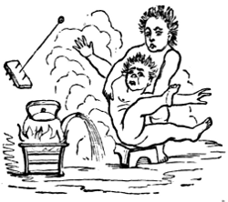
“Those projects which abridge distance have done most for the civilization and happiness of our species.”—Macaulay.
Introductory.—The commencement of the nineteenth century found the modern steam-engine fully developed in all its principal features, and fairly at work in many departments of industry. The genius of Worcester, and Morland, and Savery, and Desaguliers, had, in the first period of the[145] application of the power of steam to useful work, effected a beginning which, looked upon from a point of view which exhibits its importance as the first step toward the wonderful results to-day familiar to every one, appears in its true light, and entitles those great men to even greater honor than has been accorded them. The results actually accomplished, however, were absolutely insignificant in comparison with those which marked the period of development just described. Yet even the work of Watt and of his contemporaries was but a mere prelude to the marvellous advances made in the succeeding period, to which we are now come, and, in extent and importance, was insignificant in comparison with that accomplished by their successors in the development of all mechanical industries by the application of the steam-engine to the movement of every kind of machine.
The first of the two periods of application saw the steam-engine adapted simply to the elevation of water and the drainage of mines; during the second period it was adapted to every variety of useful work, and introduced wherever the muscular strength of men and animals, or the power of wind and of falling water, which had previously been the only motors, had found application. A history of the development of industries by the introduction of steam-power during this period, would be no less extended and hardly less interesting than that of the steam-engine itself.
The way had been fairly opened by Boulton and Watt; and the year 1800 saw a crowd of engineers and manufacturers entering upon it, eager to reap the harvest of distinction and of pecuniary returns which seemed so promising to all. The last year of the eighteenth century was also the last of the twenty-five years of partnership of Boulton & Watt, and, with it, the patents under which that firm had held the great monopoly of steam-engine building expired. The right to manufacture the modern steam-engine was common to all. Watt had, at the commencement of the new century,[146] retired from active business-life. Boulton remained in business; but he was not the inventor of the new engine, and could not retain, by the exercise of all his remaining power, the privileges previously held by legal authorization.
The young Boulton and the young Watt were not the Boulton & Watt of earlier years; and, had they possessed all of the business talent and all of the inventive genius of their fathers, they could not have retained control of a business which was now growing far more rapidly than the facilities for manufacturing could be extended in any single establishment. All over the country, and even on the Continent of Europe, and in America, thousands of mechanics, and many men of mechanical tastes in other professions, were familiar with the principles of the new machine, and were speculating upon its value for all the purposes to which it has since been applied; and a multitude of enthusiastic mechanics, and a larger multitude of visionary and ignorant schemers, were experimenting with every imaginable device, in the vain hope of attaining perpetual motion, and other hardly less absurd results, by its modification and improvement. Steam-engine building establishments sprang up wherever a mechanic had succeeded in erecting a workshop and in acquiring a local reputation as a worker in metal, and many of Watt’s workmen went out from Soho to take charge of the work done in these shops. Nearly all of the great establishments which are to-day most noted for their extent and for the importance and magnitude of the work done in them, not only in Great Britain, but in Europe and the United States, came into existence during this second period of the application of the steam-engine as a prime mover.
The new establishments usually grew out of older shops of a less pretentious character, and were managed by men who had been trained by Watt, or who had had a still more awakening experience with those who vainly strove to make[147] up, by their ingenuity and by great excellence of workmanship, the advantages possessed at Soho in a legal monopoly and greater experience in the business.
It was exceedingly difficult to find expert and conscientious workmen, and machine-tools had not become as thoroughly perfected as had the steam-engine itself. These difficulties were gradually overcome, however, and thenceforward the growth of the business was increasingly rapid.
Every important form of engine had now been invented. Watt had perfected, with the aid of Murdoch, both the pumping-engine and the rotative steam-engine for application to mills. He had invented the trunk engine, and Murdoch had devised the oscillating engine and the ordinary slide-valve, and had made a model locomotive-engine, while Hornblower had introduced the compound engine. The application of steam to navigation had been often proposed, and had sometimes been attempted, with sufficient success to indicate to the intelligent observer an ultimate triumph. It only remained to extend the use of steam as a motor into all known departments of industry, and to effect such improvements in details as experience should prove desirable.
The engines of Hero, of Porta, and of Branca were, it will be remembered, non-condensing; but the first plan of a non-condensing engine that could be made of any really practical use is given in the “Theatrum Machinarum” of Leupold, published in 1720. This sketch is copied in Fig. 41. It is stated by Leupold that this plan was suggested by Papin. It consists of two single-acting cylinders, r s, receiving steam alternately from the same steam-pipe through a “four-way cock,” x, and exhausting into the atmosphere. Steam is furnished by the boiler, a, and the pistons, c d, are alternately raised and depressed, depressing and raising the pump-rods, k l, to which they are attached by the beams, h g, vibrating on the centres, i i. The water from the pumps, o p, is forced up the stand-pipe, q, and discharged at its top. The alternate action of the steam-pistons is secured[148] by turning the “four-way cock,” x, first into the position shown, and then, at the completion of the stroke, into the reverse position, by which change the steam from the boiler is then led into the cylinder, s, and the steam in r is discharged into the atmosphere.[44]
Leupold states that he is indebted to Papin for the suggestion of the peculiar valve here used. He also proposed to use a Savery engine without condensation in raising water. We have no evidence that this engine was ever built.
The first rude scheme for applying steam to locomotion on land was probably that of Isaac Newton, who, in 1680, proposed the machine shown in the accompanying figure (42), which will be recognized as representing the scientific [149] toy which is found in nearly every collection of illustrative philosophical apparatus. As described in the “Explanation of the Newtonian Philosophy,” it consists of a spherical boiler, B, mounted on a carriage. Steam issuing from the pipe, C, seen pointing directly backward, by its reaction upon the carriage, drives the latter ahead. The driver, sitting at A, controls the steam by the handle, E, and cock, F. The fire is seen at D.
When, at the end of the eighteenth century, the steam-engine had been so far perfected that the possibility of its successful application to locomotion had become fully and very generally recognized, the problem of adapting it to locomotion on land was attacked by many inventors.
Dr. Robison had, as far back as in 1759, proposed it to James Watt during one of their conferences, at a time when the latter was even more ignorant than the former of the principles which were involved in the construction of the steam-engine, and this suggestion may have had some influence in determining Watt to pursue his research; thus setting in operation that train of thoughtful investigation and experiment which finally earned for him his splendid fame.
In 1765, that singular genius, Dr. Erasmus Darwin, whose celebrity was acquired by speculations in poetry and philosophy as well as in medicine, urged Matthew Boulton—subsequently Watt’s partner, and just then corresponding with our own Franklin in relation to the use of steam-power—to construct a steam-carriage, or “fiery chariot,” as he[150] poetically styled it, and of which he sketched a set of plans. A young man named Edgeworth became interested in the scheme, and, in 1768, published a paper which had secured for him a gold medal from the Society of Arts. In this paper he proposed railroads on which the carriages were to be drawn by horses, or by ropes from steam-winding engines.
Nathan Read, of whom an account will be given hereafter, when describing his attempt to introduce steam-navigation, planned, and in 1790 obtained a patent for, a steam-carriage, of which the sketch seen in Fig. 43 is copied from the rough drawing accompanying his application. In the figure, A A A A are the wheels; B B, pinions on the hubs of the rear wheels, which are driven by a ratchet arrangement on the racks, G G, connected with the piston-rods; C o is the boiler; D D, the steam-pipes carrying steam to the steam-cylinder, E E; F F are the engine-frames; H is the “tongue” or “pole” of the carriage, and is turned by a horizontal steering-wheel, with which it is connected by the ropes or chains, I K, I K; W W are the cocks, which serve to shut off steam from the engine when necessary, and[151] to determine the amount of steam to be admitted. The pipes a a are exhaust-pipes, which the inventor proposed to turn so that they should point backward, in order to secure the advantage of the effort of reaction of the expelled steam. (!)
Read made a model steam-carriage, which he exhibited when endeavoring to secure assistance in furtherance of his schemes, but seems to have given more attention to steam-navigation, and nothing was ever accomplished by him in this direction.
These were merely promising schemes, however. The first actual experiment was made, as is supposed, by a French army-officer, Nicholas Joseph Cugnot, who in 1769 built a steam-carriage, which was set at work in presence of the French Minister of War, the Duke de Choiseul. The funds required by him were furnished by the Compte de Saxe. Encouraged by the partial success of the first locomotive, he, in 1770, constructed a second (Fig. 44), which is still preserved in the Conservatoire des Arts et Métiers, Paris.
This machine, when recently examined by the author, was still in an excellent state of preservation. The carriage and its machinery are substantially built and well-finished, and exceedingly creditable pieces of work in every respect. It surprises the engineer to find such evidence of the high[152] character of the work of the mechanic Brezin a century ago. The steam-cylinders were 13 inches in diameter, and the engine was evidently of considerable power. This locomotive was intended for the transportation of artillery. It consists of two beams of heavy timber extending from end to end, supported by two strong wheels behind, and one still heavier but smaller wheel in front. The latter carries on its rim blocks which cut into the soil as the wheel turns, and thus give greater holding power. The single wheel is turned by two single-acting engines, one on each side, supplied with steam by a boiler (seen in the sketch) suspended in front of the machine. The connection between the engines and the wheels was effected by means of pawls, as first proposed by Papin, which could be reversed when it was desired to drive the machine backward. A seat is mounted on the carriage-body for the driver, who steers the machine by a train of gearing, which turns the whole frame, carrying the machinery 15 or 20 degrees either way. This locomotive was found to have been built on a tolerably satisfactory general plan; but the boiler was too small, and the steering apparatus was incapable of handling the carriage with promptness.
The death of one of Cugnot’s patrons, and the exile of the other, put an end to Cugnot’s experiments.
Cugnot was a mechanic by choice, and exhibited great talent. He was a native of Vaud, in Lorraine, where he was born in 1725. He served both in the French and the German armies. While under the Maréchal de Saxe, he constructed his first steam locomotive-engine, which only disappointed him, as he stated, in consequence of the inefficiency of the feed-pumps. The second was that built under the authority of the Minister Choiseul, and cost 20,000 livres. Cugnot received from the French Government a pension of 600 livres. He died in 1804, at the age of seventy-nine years.
Watt, at a very early period, proposed to apply his own[153] engine to locomotion, and contemplated using either a non-condensing engine or an air-surface condenser. He actually included the locomotive-engine in his patent of 1784; and his assistant, Murdoch, in the same year, made a working-model locomotive (Fig. 45), which was capable of running at a rapid rate. This model, now deposited in the Patent Museum at South Kensington, London, had a flue-boiler, and its steam-cylinder was three-fourths of an inch in diameter, and the stroke of piston 2 inches. The driving-wheels were 91∕2 inches diameter.
Nothing was, however, done on a larger scale by either Watt or Murdoch, who both found more than enough to claim their attention in the construction and introduction of other engines. Murdoch’s model is said to have run from 6 to 8 miles an hour, its little driving-wheels making from 200 to 275 revolutions per minute. As is seen in the sketch, this model was fitted with the same form of engine, known as the “grasshopper-engine,” which was used in the United States by Oliver Evans.
“To Oliver Evans,” says Dr. Ernest Alban, the distinguished German engineer, “was it reserved to show the true value of a long-known principle, and to establish thereon a new and more simple method of applying the power of steam—a method that will remain an eternal memorial to[154] its introducer.” Dr. Alban here refers to the earliest permanently successful introduction of the non-condensing high-pressure steam-engine.
Oliver Evans, one of the most ingenious mechanics that America has ever produced, was born at Newport, Del., in 1755 or 1756, the son of people in very humble circumstances.
He was, in his youth, apprenticed to a wheelwright, and soon exhibited great mechanical talent and a strong desire to acquire knowledge. His attention was, at an early period, drawn to the possible application of the power of steam to useful purposes by the boyish pranks of one of his comrades, who, placing a small quantity of water in a gun-barrel, and ramming down a tight wad, put the barrel in the fire of a blacksmith’s forge. The loud report which[155] accompanied the expulsion of the wad was an evidence to young Evans of great and (as he supposed) previously undiscovered power.
Subsequently meeting with a description of a Newcomen engine, he at once noticed that the elastic force of confined steam was not there utilized. He then designed the non-condensing engine, in which the power was derived exclusively from the tension of high-pressure steam, and proposed its application to the propulsion of carriages.
About the year 1780, Evans joined his brothers, who were millers by occupation, and at once employed his inventive talent in improving the details of mill-work, and with such success as to reduce the cost of attendance one-half, and also to increase the fineness of the flour made. He proved himself a very expert millwright.
In 1786 he applied to the Pennsylvania Legislature for a patent for the application of the steam-engine to driving mills, and to the steam-carriage, but was refused it. In 1800 or 1801, Evans, after consultation with Professor Robert Patterson, of the University of Pennsylvania, and getting his approval of the plans, commenced the construction of a steam-carriage to be driven by a non-condensing engine. He soon concluded, however, that it would be a better scheme, pecuniarily, to adapt his engine, which was novel in form and of small first cost, to driving mills; and he accordingly changed his plans, and built an engine of 6 inches diameter of cylinder and 18 inches stroke of piston, which he applied with perfect success to driving a plaster-mill.
This engine, which he called the “Columbian Engine,” was of a peculiar form, as seen in Fig. 46. The beam is supported at one end by a rocking column; at the other, it is attached directly to the piston-rod, while the crank lies beneath the beam, the connecting-rod, 1, being attached to the latter at the extreme end. The head of the piston-rod is compelled to rise and fall in a vertical line by the “Evans’s[156] parallelogram”—a kind of parallel-motion very similar to one of those designed by Watt. In the sketch (Fig. 46), 2 is the crank, 3 the valve-motion, 4 the steam-pipe from the boiler, E, 5 6 7 the feed-pipe leading from the pump, F. A is the boiler. The flame from the fire on the grate, H, passes under the boiler between brick walls, and back through a central flue to the chimney, I.
Subsequently, Evans continued to extend the applications of his engine and to perfect its details; and, others following in his track, the non-condensing engine is to-day fulfilling the predictions which he made 70 years ago, when he said:
“I have no doubt that my engines will propel boats against the current of the Mississippi, and wagons on turnpike roads, with great profit....”
“The time will come when people will travel in stages moved by steam-engines from one city to another, almost as fast as birds can fly, 15 or 20 miles an hour.... A carriage will start from Washington in the morning, the passengers will breakfast at Baltimore, dine at Philadelphia, and sup in New York the same day....
“Engines will drive boats 10 or 12 miles an hour, and[157] there will be hundreds of steamers running on the Mississippi, as predicted years ago.”[45]
In 1804, Evans applied one of his engines in the transportation of a large flat-bottomed craft, built on an order of the Board of Health of Philadelphia, for use in clearing some of the docks along the water-front of the city. Mounting it on wheels, he placed in it one of his 5-horse power engines, and named the odd machine (Fig. 47) “Oruktor Amphibolis.” This steam dredging-machine, weighing about 40,000 pounds, was then propelled very slowly from the works, up Market Street, around to the Water-Works, and then launched into the Schuylkill. The engine was then applied to the paddle-wheel at the stern, and drove the craft down the river to its confluence with the Delaware.
In September of the same year, Evans laid before the Lancaster Turnpike Company a statement of the estimated expenses and profits of steam-transportation on the common road, assuming the size of the carriage used to be sufficient for transporting 100 barrels of flour 50 miles in 24 hours,[158] and placed in competition with 10 wagons drawn by 5 horses each.
In the sketch above given of the “Oruktor Amphibolis,” the engine is seen to resemble that previously described. The wheel, A, is driven by a rod depending from the end of a beam, B′ B, the other end of which is supported at E by the frame, E F G. The body of the machine is carried on wheels, K K, driven by belts, M M, from the pulley on the shaft carrying A. The paddle-wheel is seen at W. Evans had some time previously sent Joseph Sampson to England with copies of his plans, and by him they were shown to Trevithick, Vivian, and other British engineers.
Among other devices, the now familiar Cornish boiler, having a single internal flue, and the Lancashire boiler, having a pair of internal flues, were planned and used by Evans.
At about the time that he was engaged on his steam dredging-machine, Evans communicated with Messrs. McKeever & Valcourt, who contracted with him to build an engine for a steam-vessel to ply between New Orleans and Natchez on the Mississippi, the hull of the vessel to be built on the river, and the machinery to be sent to the first-named city to be set up in the boat. Financial difficulties and low water combined to prevent the completion of the steamer, and the engine was set at work driving a saw-mill, where, until the mill was destroyed by fire, it sawed lumber at the rate of 250 feet of boards per hour.
Evans never succeeded in accomplishing in America as great a success as had rewarded Watt in Great Britain; but he continued to build steam-engines to the end of his life, April 19, 1819, and was succeeded by his sons-in-law, James Rush and David Muhlenberg.
He exhibited equal intelligence and ingenuity in perfecting the processes of milling, and in effecting improvements in his own business, that of the millwright. When but twenty-four years old, he invented a machine for making[159] the wire teeth used in cotton and woolen cards, turning them out at the rate of 3,000 per minute. A little later he invented a card-setting machine, which cut the wire from the reel, bent the teeth, and inserted them. In milling, he invented a whole series of machines and attachments, including the elevator, the “conveyor,” the “hopper-box,” the “drill,” and the “descender,” and enabled the miller to make finer flour, gaining over 20 pounds to the barrel, and to do this at half the former cost of attendance. The introduction of his improvements into Ellicott’s mills, near Baltimore, where 325 barrels of flour were made per day, was calculated to have saved nearly $5,000 per year in cost of labor, and over $30,000 by increasing the production. He wrote “The Young Steam-Engineer’s Guide,” and a work which remained standard many years after his death, “The Young Millwright’s Guide.” Less fortunate than his transatlantic rival, he was nevertheless equally deserving of fame. He has sometimes been called “The Watt of America.”
The application of steam to locomotion on the common road was much more successful in Great Britain than in the United States. As early as 1786, William Symmington, subsequently more successful in his efforts to introduce steam for marine propulsion, assisted by his father, made a working model of a steam-carriage, which did not, however, lead to important results.
In 1802, Richard Trevithick, a pupil of Murdoch’s, who afterward became well known in connection with the introduction of railroads, made a model steam-carriage, which was patented in the same year. The model may still be seen in the Patent Museum at South Kensington.[46]
In this engine, high-pressure steam was employed, and the condenser was dispensed with. The boiler was of the form devised by Evans, and was subsequently generally[160] used in Cornwall, where it was called the “Trevithick Boiler.” The engine had but one cylinder, and the piston-rod drove a “cross-tail,” working in guides, which was connected with a “cross-head” on the opposite side of the shaft by two “side-rods.” The connecting-rod was attached to the cross-head and the crank, “returning” toward the cylinder as the shaft lay between the latter and the cross-head. This was probably the first example of the now common “return connecting-rod engine.” The connection between the crank-shaft and the wheels of the carriage was effected by gearing. The valve-gear and the feed-pumps were worked from the engine-shaft. The inventor proposed to secure his wheels against slipping by projecting bolts, when necessary, through the rim of the wheel into the ground. The first carriage of full size was built by Trevithick and Vivian at Camborne, in 1803, and, after trial, was taken to London, where it was exhibited to the public. En route, it was driven by its own engines to Plymouth, 90 miles from Camborne, and then shipped by water. It is not known whether the inventor lost faith in his invention; but he very soon dismantled the machine, sold the engine and carriage separately, and returned to Cornwall, where he soon began work on a railroad-locomotive.
In 1821, Julius Griffiths, of Brompton, Middlesex, England, patented a steam-carriage for the transportation of passengers on the highway. His first road-locomotive was built in the same year by Joseph Bramah, one of the ablest mechanics of his time. The frame of the carriage carried a large double coach-body between the two axles, and the machinery was mounted over and behind the rear axle. One man was stationed on a rear platform, to manage the engine and to attend to the fire, and another, stationed in front of the body of the coach, handled the steering-wheel. The boiler was composed of horizontal water-tubes and steam-tubes, the latter being so situated as to receive heat from the furnace-gases en route to the chimney, and thus to[161] act as a superheater. The wheels were driven, by means of intermediate gearing, by two steam-engines, which, with their attachments, were suspended on helical springs, to prevent injury by jars and shocks. An air-surface condenser was used, consisting of flattened thin metal tubes, cooled by the contact of the external air, and discharging the water of condensation, as it accumulated within them, into a feed-pump, which, in turn, forced it into the lowest row of tubes in the boiler.
The boiler did not prove large enough for continuous work; but the carriage was used experimentally, now and then, for a number of years.
During the succeeding ten years the adaptation of the steam-engine to land-transportation continued to attract more and more attention, and experimental road-engines were built with steadily-increasing frequency. The defects of these engines revealing themselves on trial, they were one by one remedied, and the road-locomotive gradually assumed a shape which was mechanically satisfactory. Their final introduction into general use seemed at one time only a matter of time; their non-success was due to causes over which the legislator and the general public, and not the engineer, had control, as well as to the development of steam-transportation on a rival plan.
In 1822, David Gordon patented a road-engine, but it is not known whether it was ever built. At about the same time, Mr. Goldsworthy Gurney, who subsequently took an active part in their introduction, stated, in his lectures, that “elementary power is capable of being applied to propel carriages along common roads with great political advantage, and the floating knowledge of the day places the object within reach.” He made an ammonia-engine—probably the first ever made—and worked it so successfully, that he made use of it in driving a little locomotive.
Two years later, Gordon patented a curious arrangement, which, however, had been proposed twelve years earlier by[162] Brunton, and was again proposed afterward by Gurney, and others. This consisted in fitting to the engine a set of jointed legs, imitating, as nearly as the inventor could make them, the action of a horse’s legs and feet. Such an arrangement was actually experimented with until it was found that they could not be made to work satisfactorily, when it was also found that they were not needed.
During the same season, Burstall & Hill made a steam-carriage, and made many unsuccessful attempts to introduce their plan. The engine used was like that of Evans, except that the steam-cylinder was placed at the end of the beam, and the crank-shaft under the middle. The front and rear wheels were connected by a longitudinal shaft and bevel gearing. The boiler was found to have the usual defect, and would only supply steam for a speed of three or four miles an hour. The result was a costly failure. W. H. James, of London, in 1824-’25, proposed several devices for placing the working parts, as well as the body of the carriage, on springs, without interfering with their operation, and the Messrs. Seaward patented similar devices. Samuel Brown, in 1826, introduced a gas-engine, in which the piston was driven by the pressure produced by the combustion of gas, and a vacuum was secured by the condensation of the resulting vapor. Brown built a locomotive which he propelled by this engine. He ascended Shooter’s Hill, near London, and the principal cause of his ultimate failure seems to have been the cost of operating the engine.
From this date forward, during several years, a number of inventors and mechanics seem to have devoted their whole time to this promising scheme. Among them, Burstall & Hill, Gurney, Ogle & Summers, Sir Charles Dance, and Walter Hancock, were most successful.
Gurney, in the year 1827, built a steam-carriage, which he kept at work nearly two years in and about London, and sometimes making long journeys. On one occasion he made the journey from Meksham to Cranford Bridge, a distance[163] of 85 miles, in 10 hours, including all stops. He used the mechanical legs previously adopted by Brunton and by Gordon, but omitted this rude device in those engines subsequently built.
Gurney’s engine of 1828 is of interest to the engineer as exhibiting a very excellent arrangement of machinery, and as having one of the earliest of “sectional boilers.” The latter was of peculiar form, and differed greatly in design from the sectional boiler invented a quarter of a century earlier by John Stevens, in the United States.
In the sketch (Fig. 48) this boiler is seen at the right. It was composed of bent ◁-shaped tubes, a a, connected to two cylinders, b b, the upper one of which was a steam-chamber. Vertical tubes connected these two chambers, and permitted a complete and regular circulation of the water. A separate reservoir, called a separator, d, was connected with these chambers by pipes, as shown. From the top of this separator a steam-pipe, e e e, conveyed steam to the engine-cylinders at f. The cranks, g, on the rear axle were turned by the engines, and the eccentric, h, on the axle drove the valve-gearing and the valve, i. The link, k l, being moved by a line, l l, led from the driver’s seat, the carriage was started, stopped, or reversed, by throwing the upper end[164] of the link into gear with the valve-stem, by setting the link midway between its upper and lower positions, or by raising it until the lower end, coming into action on the valve-stem, produced a reverse motion of the valve. The pin on which this link vibrated is seen at the centre of its elliptical strap. The throttle-valve, o, by which the supply of steam to the engine was adjusted, was worked by the lever, n. The exhaust-pipe, p, led to the tank, q, and the uncondensed vapor passed to the chimney, s s, by the pipe, r r. The force-pump, u, taking feed-water from the tank, t, supplied it to the boiler by the pipe, x x x, which, en route, was coiled up to form a “heater” directly above the boiler. The supply was regulated by the cock, y. The attendant had a seat at z. A blast-apparatus, 1, was driven by an independent engine, 2 3, and produced a forced blast, which was led to the boiler-furnace through the air-duct, 5 5; 4 4 represents the steam-pipe to the little blowing-engine. The steering-wheel, 6, was directed by a lever, 7, and the change of direction of the perch, 8, which turned about a king-bolt at 9, gave the desired direction to the forward wheels and to the carriage.
This seems to have been one of the best designs brought out at that time. The boiler, built to carry 70 pounds, was safe and strong, and was tested up to 800 pounds pressure. A forced draught was provided. The engines were well placed, and of good design. The valve was arranged to work the steam with expansion from half-stroke. The feed-water was heated, and the steam slightly superheated. The boiler here used has been since reproduced under new names by later inventors, and is still used with satisfactory results. Modifications of the “pipe-boiler” were made by several other makers of steam-carriages also. Anderson & James made their boilers of lap-welded iron tubes of one inch internal diameter and one-fifth inch thick, and claimed for them perfect safety. Such tubes should have sufficient strength to sustain a pressure of 20,000 pounds per square[165] inch. If made of such good iron as the makers claimed to have put into them, “which worked like lead,” they would, as was also claimed, when ruptured, open by tearing, and discharge their contents without producing the usual disastrous consequences of boiler explosions.
The primary principle of the sectional boiler was then well understood. The boilers of Ogle & Summers were made up of pairs of upright tubes, set one within the other, the intervening space being filled with water and steam, and the flame passing through the inner and around the outer tube of each pair.
One of the engines of Sir James Anderson and W. H. James was built in 1829. It had two 31∕2-inch steam-cylinders, driving the rear wheels independently. In James’s earlier plan of 1824-’25, a pair of cylinders was attached to each of the two halves into which the rear axle was divided, and were arranged to drive cranks set at right-angles with each other. The later machine weighed 3 tons, and carried 15 passengers, on a rough graveled road across the Epping Forest, at the rate of from 12 to 15 miles per hour. Steam was carried at 300 pounds. Several tubes gave way in the welds, but the carriage returned, carrying 24 passengers at the rate of 7 miles per hour. On a later trial, with new boilers, the carriage again made 15 miles per hour. It was, however, subject to frequent accidents, and was finally withdrawn.
Walter Hancock was the most successful and persevering of all those who attempted the introduction of steam on the common road. He had, in 1827, patented a boiler of such peculiar form, that it deserves description. It consisted of a collection of flat chambers, of which the walls were of boiler-plate. These chambers were arranged side by side, and connected laterally by tubes and stays, and all were connected by short vertical tubes to a horizontal large pipe placed across the top of the boiler-casing, and serving as a steam-drum or separator. This earliest of “sheet flue-boilers”[166] did excellent service on Hancock’s steam-carriages, where experience showed that there was little or no danger of disruptive explosions.
Hancock’s first steam-carriage was mounted on three wheels, the leading-wheel arranged to swivel on a king-bolt, and driven by a pair of oscillating cylinders connected with its axle, which was “cranked” for the purpose. The engines turned with the steering-wheel. This carriage was by no means satisfactory, but it was used for a long time, and traveled many hundreds of miles without once failing to do the work assigned it.
By this time there were a half-dozen steam-carriages under construction for Hancock, for Ogle & Summers, and for Sir Charles Dance.
In 1831, Hancock placed a new carriage on a route between London and Stratford, where it ran regularly for hire. Dance, in the same season, started another on the line between Cheltenham and Gloucester, where it ran from February 21st to June 22d, traveling 3,500 miles and carrying 3,000 passengers, running the 9 miles in 55 minutes usually, and sometimes in three-quarters of an hour, and never meeting with an accident, except the breakage of an axle in running over heaps of stones which had been purposely placed on the road by enemies of the new system of transportation. Ogle & Summers’s carriage attained a speed, as testified by Ogle before a committee of the House of Commons, of from 32 to 35 miles an hour, and on a rising grade, near Southampton, at 241∕2 miles per hour. They carried 250 pounds of steam, ran 800 miles, and met with no accident. Colonel Macerone, in 1833, ran a steam-carriage of his own design from London to Windsor and back, with 11 passengers, a distance of 231∕2 miles, in 2 hours. Sir Charles Dance, in the same year, ran his carriage 16 miles an hour, and made long excursions at the rate of 9 miles an hour. Still another experimenter, Heaton, ascended Lickey Hill, between Worcester and Birmingham, on gradients of[167] one in eight and one in nine, in places; this was considered one of the worst pieces of road in England. The carriage towed a coach containing 20 passengers.
Of all these, and many others, Hancock, however, had most marked success. His coach, called the “Infant,” which was set at work in February, 1831, was, a year later, plying between London “City” and Paddington. Another, called the “Era,” was built for the London and Greenwich Steam-Carriage Company, which was mechanically a success. The company, however, was financially unsuccessful. In October, 1832, the “Infant” ran to Brighton from London, carrying a party of 11, at the rate of 9 miles per hour, ascending Redhill at a speed of 5 miles. They steamed 38 miles the first day, stopping at night at Hazledean, and reached Brighton next day, running 11 miles per hour. Returning with 15 passengers, the coach ran 1 mile in less than 4 minutes, and made 10 miles in 55 minutes. A run from Stratford to Brighton was made in less than 10 hours, at an average speed of 12 miles an hour running time, the actual running time being less than 6 hours. The next year another carriage, the “Enterprise,” was put on the road to Paddington by Hancock for another company, and ran regularly over two weeks; but this company was also unsuccessful. In the summer of 1833 he brought out still another steam-coach, the “Autopsy” (Fig. 49), which he ran to Brighton, and then, returning to London, manœuvred the carriage in the crowded streets without difficulty or accident. He went about the streets of London at all times, and without hesitation. The coach next ran between Finsbury Square and Pentonville regularly for four weeks, without accident or delay. In the sketch, a part of the side is broken away to show the machinery. The boiler, A B, supplies steam through the steam-pipe, H K, to the steam-engine, C D, which is coupled to the crank-shaft, F. E is the feed-pump. The rear axle is turned by the endless chain seen connecting it with the engine-shaft, and the rear[168] wheels, S, are thus driven. A blower, T, gives a forced draught. The driver sits at M, steering by the wheel, N, which is coupled to the larger wheel, P, and thus turns the forward axle into any desired position. In 1834, Hancock built a steam “drag” on an Austrian order, which, carrying 10 persons and towing a coach containing 6 passengers, was driven through the city beyond Islington, making 14 miles an hour on a level, and 8 miles or more on rising ground. In the same year he built the “Era,” and, in August, put the “Autopsy” on with it, to make a steam-line to Paddington. These coaches ran until the end of November, carrying 4,000 passengers, at a usual rate of speed of 12 miles per hour. He then sent the “Era” to Dublin, where, on one occasion, it ran 18 miles per hour.
In 1835 a large carriage, the “Erin,” was completed, which was intended to carry 20 passengers. It towed three omnibuses and a stage-coach, with 50 passengers, on a level road, at the speed of 10 miles an hour. It drew an omnibus with 18 passengers through Whitehall, Charing Cross, and Regent Street, and out to Brentford, running 14 miles an hour. It ran also to Reading, making 38 miles, with the same load, in 3 hours and 8 minutes running time. The stops en route occupied a half-hour. The same carriage made 75 miles to Marlborough in 71∕2 hours running time,[169] stopping 41∕2 hours on the road, in consequence of having left the tender and supplies behind.
In May, 1836, Hancock put all his carriages on the Paddington road, and ran regularly for over five months, running 4,200 miles in 525 trips to Islington, 143 to Paddington, and 44 to Stratford, passing through the city over 200 times. The carriages averaged 5 hours and 17 or 18 minutes daily running time. A light steam-phaeton, built in 1838, for his own use, made 20 miles an hour, and was driven about the city, and among horses and carriages, without causing annoyance or danger. Its usual speed was about 10 miles an hour. Altogether, Hancock built nine steam-carriages, capable of carrying 116 passengers in addition to the regular attendants.[47]
In December, 1833, about 20 steam-carriages and traction road-engines were running, or were in course of construction, in and near London. In our own country, the roughness of roads discouraged inventors; and in Great Britain even, the successful introduction of road-locomotives, which seemed at one time almost an accomplished fact, finally met with so many obstacles, that even Hancock, the most ingenious, persistent, and successful constructor, gave up in despair. Hostile legislation procured by opposing interests, and the rapid progress of steam-locomotion on railroads, caused this result.
In consequence of this interruption of experiment, almost nothing was done during the succeeding quarter of a century, and it is only within a few years that anything like a business success has been founded upon the construction of road-locomotives, although the scheme seems to have been at no time entirely given up.
The opposition of coach-proprietors, and of all classes having an interest in the old lines of coaches, was most determined,[170] and the feeling evinced by them was intensely bitter; but the advocates of the new system of transportation were equally determined and persevering, and, having right on their side, and the pecuniary advantage of the public as their object, they would probably have succeeded ultimately, except for the introduction of the still better method of transportation by rail.
In the summer of 1831, when the war between the two parties was at its height, a committee of the British House of Commons made a very complete investigation of the subject. This committee reported that they had become convinced that “the substitution of inanimate for animal power, in draught on common roads, is one of the most important improvements in the means of internal communication ever introduced.” They considered its practicability to have been “fully established,” and predicted that its introduction would “take place more or less rapidly, in proportion as the attention of scientific men shall be drawn, by public encouragement, to further improvement.” The success of the system had, as they stated, been retarded by prejudice, adverse interests, and prohibitory tolls; and the committee remark: “When we consider that these trials have been made under the most unfavorable circumstances, at great expense, in total uncertainty, without any of those guides which experience has given to other branches of engineering; that those engaged in making them are persons looking solely to their own interests, and not theorists attempting the perfection of ingenious models; when we find them convinced, after long experience, that they are introducing such a mode of conveyance as shall tempt the public, by its superior advantages, from the use of the admirable lines of coaches which have been generally established, it surely cannot be contended that the introduction of steam-carriages on common roads is, as yet, an uncertain experiment, unworthy of legislative attention.”
Farey, one of the most distinguished mechanical engineers[171] of the time, testified that he considered the practicability of such a system as fully established, and that the result would be its general adoption. Gurney had run his carriage between 20 and 30 miles an hour; Hancock could sustain a speed of 10 miles; Ogle had run his coach 32 to 35 miles an hour, and ascended a hill rising 1 in 6 at the speed of 241∕2 miles. Summers had traveled up a hill having a gradient of 1 in 12, with 19 passengers, at the rate of speed of 15 miles per hour; he had run 41∕2 hours at 30 miles an hour. Farey thought that steam-coaches would be found to cost one-third as much as the stage-coaches in use. The steam-carriages were reported to be safer than those drawn by horses, and far more manageable; and the construction of boilers adopted—the “sectional” boiler, as it is now called—completely insured against injury by explosion, and the dangers and inconveniences arising from the frightening of horses had proved to be largely imaginary. The wear and tear of roads were found to be less than with horses, while with broad wheel-tires the carriages acted beneficially as road-rollers. The committee finally concluded:
“1. That carriages can be propelled by steam on common roads at an average rate of 10 miles per hour.
“2. That at this rate they have conveyed upward of 14 passengers.
“3. That their weight, including engine, fuel, water, and attendants, may be under three tons.
“4. That they can ascend and descend hills of considerable inclination with facility and safety.
“5. That they are perfectly safe for passengers.
“6. That they are not (or need not be, if properly constructed) nuisances to the public.
“7. That they will become a speedier and cheaper mode of conveyance than carriages drawn by horses.
“8. That, as they admit of greater breadth of tire than other carriages, and as the roads are not acted on so injuriously as by the feet of horses in common draught, such carriages[172] will cause less wear of roads than coaches drawn by horses.
“9. That rates of toll have been imposed on steam-carriages, which would prohibit their being used on several lines of road, were such charges permitted to remain unaltered.”
The Railroad, which now, by the adaptation of steam to the propulsion of its carriages, became the successful rival of the system of transportation of which an account has just been given, was not a new device. It, like all other important changes of method and great inventions, had been growing into form for ages. The ancients were accustomed to lay down blocks of stone as a way upon which their heavily-loaded wagons could be drawn with less resistance than on the common road. This practice was gradually so modified as to result in the adoption of the now universally-practised methods of paving and road-making. The old tracks, bearing the marks of heavy traffic, are still seen in the streets of the unearthed city of Pompeii.
In the early days of mining in Great Britain, the coal or the ore was carried from the mine to the vessel in which it was to be embarked in sacks on the backs of horses. Later, the miners laid out wagon-roads, and used carts and wagons drawn by horses, and the roads were paved with stone along the lines traversed by the wheels of the vehicles. Still later (about 1630), heavy planks or squared timber took the place of the stone, and were introduced into the north of England by a gentleman of the name of Beaumont, who had transferred his property there from the south. A half century later, the system had become generally introduced. By the end of the eighteenth century the construction of these “tram-ways” had become well-understood, and the economy which justified the expenditure of considerable amounts of money in making cuts and in filling, to bring the road to a uniform grade, had become well-recognized. Arthur Young, writing at this time, says the[173] coal wagon-roads were “great works, carried over all sorts of inequalities of ground, so far as the distance of nine or ten miles,” and that, on these tram-ways of timber, “one horse is able to draw, and that with ease, fifty or sixty bushels of coals.” The wagon-wheels were of cast-iron, and made with grooved rims, which fitted the rounded tops of the wooden rails. But these wooden rails were found subject to rapid decay, and at Whitehaven, in 1738, they were protected from wear by cast-iron plates laid upon them, and this improvement rapidly became known and adopted. A tram-road, laid down at Sheffield for the Duke of Norfolk, in 1776, was made by laying angle-bars of cast-iron on longitudinal sleepers of timber; another, built by William Jessup in Leicestershire, in 1789, had an edge-rail, and the wheels were made with flanges, like those used to-day. The coned “tread” of the wheel, which prevents wear of flanges and reduces resistance, was the invention of James Wright, of Columbia, Pa., 40 years later. The modern railroad was simply the result of this gradual improvement of the permanent way, and the adaptation of the steam-engine to the propulsion of its wagons.
At the beginning of the nineteenth century, therefore, the steam-engine had been given a form which permitted its use, and the railroad had been so far perfected that there were no difficulties to be anticipated in the construction of the permanent way, and inventors were gradually preparing, as has been seen, to combine these two principal elements into one system. Railroads had been introduced in all parts of Great Britain, some of them of considerable length, and involving the interests of so many private individuals that they were necessarily constructed under the authorization of legal enactments. In the year 1805 the Merstham Railway was opened to traffic, and it is stated that on that occasion one horse drew a train of 12 wagons, carrying 38 tons of stone, on a “down gradient” of 1 in 120, at the rate of 6 miles per hour.
[174]Richard Trevithick was the first engineer to apply steam-power to the haulage of loads on the railroad. Trevithick was a Cornishman by birth, a native of Redruth. He was naturally a skillful mechanic, and was placed by his father with Watt’s assistant, Murdoch, who was superintending the erection of pumping-engines in Cornwall; and from that ingenious and accomplished engineer young Trevithick probably acquired both the skill and the knowledge which, with his native talent, enterprise, and industry, enabled him to accomplish the work which has made him famous. He was soon intrusted with the erection and management of large pumping-engines, and subsequently went into the business of constructing steam-engines with another engineer, Edward Bull, who took an active part, with the[175] Hornblowers and others, in opposing the Boulton & Watt patents. The termination of the suits which established the validity of Watt’s patent put an end to their business, and Trevithick looked about for other work, and, not long after, entered into partnership with a relative, Andrew Vivian, who was also a skillful mechanic; they together designed and patented the steam-carriage already referred to. Its success was sufficiently satisfactory to awaken strong confidence of a perfect success on the now common tram-roads; and Trevithick, in February, 1804, had completed a “locomotive” engine to work on the Welsh Pen-y-darran road. This engine (Fig. 50) had a cylindrical flue-boiler, A, like that designed by Oliver Evans, and a single steam-cylinder, B, set vertically into the steam-space of the boiler,[176] and driving the outside cranks, L, on the rear axle of the engine by very long connecting-rods, D, attached to its cross-head at E. The guide-bars, I, were stayed by braces leading to the opposite end of the boiler. No attempt was made to condense the exhaust-steam, which was discharged into the smoke-pipe. The pressure of steam adopted was 40 pounds per square inch; but Trevithick had already made a number of non-condensing engines on which he carried from 50 to 145 pounds pressure.
In the year 1808, Trevithick built a railroad in London, on what was known later as Torrington Square, or Euston Square, and set at work a steam-carriage, which he called “Catch-me-who-can.” This was a very plain and simple machine. The steam-cylinder was set vertically in the after-end of the boiler, and the cross-head was connected to two rods, one on either side, driving the hind pair of wheels. The exhaust-steam entered the chimney, aiding the draught. This engine, weighing about 10 tons, made from 12 to 15 miles an hour on the circular railway in London, and was said by its builder to be capable of making 20 miles an hour. The engine was finally thrown from the track, after some weeks of work, by the breaking of a rail, and, Trevithick’s funds having been expended, it was never replaced. This engine had a steam-cylinder 141∕2 inches in diameter, and a stroke of piston of 4 feet. Trevithick used no device to aid the friction of the wheels on the rails in giving pulling-power, and seems to have understood that none was needed. This plan of working a locomotive-engine without such complications as had been proposed by other engineers was, however, subsequently patented, in 1813, by Blackett & Hedley. The latter was at one time Trevithick’s agent, and was director of Wylam Colliery, of which Mr. Blackett was proprietor.
Trevithick applied his high-pressure non-conducting engine not only to locomotives, but to every purpose that opportunity offered him. He put one into the Tredegar Iron-Works,[177] to drive the puddle-train, in 1801. This engine had a steam-cylinder 28 inches in diameter, and 6 feet stroke of piston; a boiler of cast-iron, 63∕4 feet in diameter and 20 feet long, with a wrought-iron internal tube, 3 feet in diameter at the furnace-end and 24 inches beyond the furnace. The steam-pressure ranged from 50 to 100 pounds per square inch. The valve was a four-way cock. The exhaust-steam was carried into the chimney, passing through a feed-water heater en route. This engine was taken down in 1856.[48]
In 1803, Trevithick applied his engine to driving rock-drills, and three years later made a large contract with the Trinity Board for dredging in the Thames, and constructed steam dredging-machines for the work, of the form which is still most generally used in Great Britain, although rarely seen in the United States—the “chain-and-bucket dredger.”
A little later, Trevithick was engaged upon the first and unsuccessful attempt to carry a tunnel under the Thames, at London; but no sooner had that costly scheme been given up, than he returned to his favorite pursuits, and continued his work on interrupted schemes for ship-propulsion. Trevithick at last left England, spent some years in South America, and finally returned home and died in extreme poverty, April, 1833, at the age of sixty-two, without having succeeded in accomplishing the general introduction of any of his inventions.
Trevithick was characteristically an inventor of the typical sort. He invented many valuable devices, but brought but few into even experimental use, and reaped little advantage from any of them. He was ingenious, a thorough mechanic, bold, active, and indefatigable; but his lack of persistence made his whole life, as Smiles has said, “but a series of beginnings.”
It is at about this period that we find evidence of the intelligent labors of another of our own countrymen—one[178] who, in consequence of the unobtrusive manner in which his work was done, has never received the full credit to which he is entitled.
Colonel John Stevens, of Hoboken, as he is generally called, was born in the city of New York, in 1749; but throughout his business-life he was a resident of New Jersey.
His attention is said to have been first called to the application of steam-power by seeing the experiments of John Fitch with his steamer on the Delaware, and he at once devoted himself to the introduction of steam-navigation with characteristic energy, and with a success that will be indicated when we come to the consideration of that subject.
But this far-sighted engineer and statesman saw plainly[179] the importance of applying the steam-engine to land-transportation as well as to navigation; and not only that, but he saw with equal distinctness the importance of a well-devised and carefully-prosecuted scheme of internal communication by a complete system of railroads. In 1812 he published a pamphlet containing “Documents tending to prove the superior advantages of Railways and Steam-Carriages over Canal-Navigation.”[49] At this time, the only locomotive in the world was that of Trevithick and Vivian, at Merthyr Tydvil, and the railroad itself had not grown beyond the old wooden tram-roads of the collieries. Yet Colonel Stevens says, in this paper: “I can see nothing to hinder a steam-carriage moving on its ways with a velocity of 100 miles an hour;” adding, in a foot-note: “This astonishing velocity is considered here merely possible. It is probable that it may not, in practise, be convenient to exceed 20 or 30 miles per hour. Actual experiment can only determine this matter, and I should not be surprised at seeing steam-carriages propelled at the rate of 40 or 50 miles an hour.”
At a yet earlier date he had addressed a memoir to the proper authorities, urging his plans for railroads. He proposed rails of timber, protected, when necessary, by iron plates, or to be made wholly of iron; the car-wheels were to be of cast-iron, with inside flanges to keep them on the track. The steam-engine was to be driven by steam of 50 pounds pressure and upward, and to be non-condensing.
Answering the objections of Robert R. Livingston and of the State Commissioners of New York, he goes further into details. He gives 500 to 1,000 pounds as the maximum weight to be placed on each wheel; shows that the trains, or “suits of carriages,” as he calls them, will make their journeys with as much certainty and celerity in the darkest night as in the light of day; shows that the grades of proposed[180] roads would offer but little resistance; and places the whole subject before the public with such accuracy of statement and such evident appreciation of its true value, that every one who reads this remarkable document will agree fully with President Charles King, who said[50] that “whosoever shall attentively read this pamphlet, will perceive that the political, financial, commercial, and military aspects of this great question were all present to Colonel Stevens’s mind, and that he felt that he was fulfilling a patriotic duty when he placed at the disposal of his native country these fruits of his genius. The offering was not then accepted. The ‘Thinker’ was ahead of his age; but it is grateful to know that he lived to see his projects carried out, though not by the Government, and that, before he finally, in 1838, closed his eyes in death, at the great age of eighty-nine, he could justly feel assured that the name of Stevens, in his own person and in that of his sons, was imperishably enrolled among those which a grateful country will cherish.”
Without having made any one superlatively great improvement in the mechanism of the steam-engine, like that which gave Watt his fame—without having the honor even of being the first to propose the propulsion of vessels by the modern steam-engine, or steam-transportation on land—he exhibited a far better knowledge of the science and the art of engineering than any man of his time; and he entertained and urged more advanced opinions and more statesmanlike views in relation to the economical importance of the improvement and the application of the steam-engine, both on land and water, than seem to be attributable to any other leading engineer of that time.
Says Dr. King: “Who can estimate if, at that day, acting upon the well-considered suggestion of President Madison, ‘of the signal advantages to be derived to the United States from a general system of internal communication and[181] conveyance,’ Congress had entertained Colonel Stevens’s proposal, and, after verifying by actual experiment upon a small scale the accuracy of his plan, had organized such a ‘general system of internal communication and conveyance;’ who can begin to estimate the inappreciable benefits that would have resulted therefrom to the comfort, the wealth, the power, and, above all, to the absolutely impregnable union of our great Republic and all its component parts? All this Colonel Stevens embraced in his views, for he was a statesman as well as an experimental philosopher; and whoever shall attentively read his pamphlet, will perceive that the political, financial, commercial, and military aspects of this great question were all present to his mind, and he felt that he was fulfilling a patriotic duty when he placed at the disposal of his native country these fruits of his genius.”
William Hedley, who has already been referred to, seems to have been the first to show, by carefully-conducted experiment, how far the adhesion of the wheels of the locomotive-engine could be relied upon for hauling-power in the transportation of loads.
His employer, Blackett, had applied to Trevithick for a locomotive-engine to haul coal-trains at the Wylam collieries; but Trevithick was unable, or was disinclined, to build him one, and in October, 1812, Hedley was authorized to attempt the construction of an engine. It was at about this time that Blenkinsop (1811) was trying the toothed rail or rack, the Messrs. Chapman (December, 1812) were experimenting with a towing-chain, and (May, 1813) Brunton with movable legs.
Hedley, who had known of the success met with in the experiments of Trevithick with smooth wheels hauling loads of considerable weight, in Cornwall, was confident that equal success might be expected in the north-country, and built a carriage to be moved by men stationed at four handles, by which its wheels were turned.
[182]This carriage was loaded with heavy masses of iron, and attached to trains of coal-wagons on the railway. By repeated experiment, varying the weight of the traction-carriage and the load hauled, Hedley ascertained the proportion of the weight required for adhesion to that of the loads drawn. It was thus conclusively proven that the weight of his proposed locomotive-engine would be sufficient to give the pulling-power necessary for the propulsion of the coal-trains which it was to haul.
When the wheels slipped in consequence of the presence of grease, frost, or moisture on the rail, Hedley proposed to sprinkle ashes on the track, as sand is now distributed from the sand-box of the modern engine. This was in October, 1812.
Hedley now went to work building an engine with smooth wheels, and patented his design March 13, 1813, a month after he had put his engine at work. The locomotive had a cast-iron boiler, and a single steam-cylinder 6 inches in diameter, with a small fly-wheel. This engine had too small a boiler, and he soon after built a larger engine, with a return-flue boiler made of wrought-iron. This hauled 8 loaded coal-wagons 5 miles an hour at first, and a little later 10, doing the work of 10 horses. The steam-pressure was carried at about 50 pounds, and the exhaust, led into the chimney, where the pipe was turned upward, thus secured a blast of considerable intensity in its small chimney. Hedley also contracted the opening of the exhaust-pipe to intensify the blast, and was subjected to some annoyance by proprietors of lands along his railway, who were irritated by the burning of their grass and hedges, which were set on fire by the sparks thrown out of the chimney of the locomotive. The cost of Hedley’s experiment was defrayed by Mr. Blackett.
Subsequently, Hedley mounted his engine on eight wheels, the four-wheeled engines having been frequently stopped by breaking the light rails then in use. Hedley’s[183] engines continued in use at the Wylam collieries many years. The second engine was removed in 1862, and is now preserved at the South Kensington Museum, London.
George Stephenson, to whom is generally accorded the honor of having first made the locomotive-engine a success, built his first engine at Killingworth, England, in 1814.
At this time Stephenson was by no means alone in the field, for the idea of applying the steam-engine to driving carriages on common roads and on railroads was beginning, as has been seen, to attract considerable attention. Stephenson, however, combined, in a very fortunate degree, the advantages of great natural inventive talent and an excellent mechanical training, reminding one strongly of James Watt. Indeed, Stephenson’s portrait bears some resemblance to that of the earlier great inventor.
George Stephenson was born June 9, 1781, at Wylam,[184] near Newcastle-upon-Tyne, and was the son of a “north-country miner.” When still a child, he exhibited great mechanical talent and unusual love of study. When set at work about the mines, his attention to duty and his intelligence obtained for him rapid promotion, until, when but seventeen years of age, he was made engineer, and took charge of the pumping-engine at which his father was fireman.
When a mere child, and employed as a herd-boy, he amused himself making model engines in clay, and, as he grew older, never lost an opportunity to learn the construction and management of machinery. After having been employed at Newburn and Callerton, where he first became “engine-man,” he began to study with greater interest than ever the various steam-engines which were then in use; and both the Newcomen engine and the Watt pumping-engine were soon thoroughly understood by him. After having become a brakeman, he removed to Willington Quay, where he married, and commenced his wedded life on 18 or 20 shillings per week. It was here that he became an intimate friend of the distinguished William Fairbairn, who was then working as an apprentice at the Percy Main Colliery, near by. The “father of the railroad” and the future President of the British Association were accustomed, at times, to “change works,” and were frequently seen in consultation over their numerous projects. It was at Willington Quay that his son Robert, who afterward became a distinguished civil engineer, was born, October 16, 1803.
In the following year Stephenson removed to Killingworth, and became brakeman at that colliery; but his wife soon died, and he gladly accepted an invitation to become engine-driver at a spinning-mill near Montrose, Scotland. At the end of a year he returned, on foot, to Killingworth with his savings (about £28), expended over one-half of the amount in paying his father’s debts and in making[185] his parents comfortable, and then returned to his old station as brakeman at the pit.
Here he made some useful improvements in the arrangement of the machinery, and spent his spare hours in studying his engine and planning new machines. He a little later distinguished himself by altering and repairing an old Newcomen engine at the High Pit, which had failed to give satisfaction, making it thoroughly successful after three days’ work. The engine cleared the pit, at which it had been vainly laboring a long time, in two days after Stephenson started it up.
In the year 1812, Stephenson was made engine-wright of the Killingworth High Pit, receiving £100 a year, and it was made his duty to supervise the machinery of all the collieries under lease by the so-called “Grand Allies.” It was here, and at this period, that he commenced a systematic course of self-improvement and the education of his son, and here he first began to be recognized as an inventor. He was full of life and something of a wag, and often made most amusing applications of his inventive powers: as when he placed the watch, which a comrade had brought him as out of repairs, in the oven “to cook,” his quick eye having noted the fact that the difficulty arose simply from the clogging of the wheels by the oil, which had been congealed by cold.
Smiles,[51] his biographer, describes his cottage as a perfect curiosity-shop, filled with models of engines, machines of various kinds, and novel apparatus. He connected the cradles of his neighbors’ wives with the smoke-jacks in their chimneys, and thus relieved them from constant attendance upon their infants; he fished at night with a submarine lamp, which attracted the fish from all sides, and gave him wonderful luck; he also found time to give colloquial instruction to his fellow-workmen.
[186]He built a self-acting inclined plane for his pit, on which the wagons, descending loaded, drew up the empty trains; and made so many improvements at the Killingworth pit, that the number of horses employed underground was reduced from 100 to 16.
Stephenson now had more liberty than when employed at the brakes, and, hearing of the experiments of Blackett and Hedley at Wylam, went over to their colliery to study their engine. He also went to Leeds to see the Blenkinsop engine draw, at a trial, 70 tons at the rate of 3 miles an hour, and expressed his opinion in the characteristic remark, “I think I could make a better engine than that to go upon legs.” He very soon made the attempt.
Having laid the subject before the proprietors of the lease under which the collieries were worked, and convinced Lord Ravensworth, the principal owner, of the advantages to be secured by the use of a “traveling engine,” that nobleman advanced the money required. Stephenson at once commenced his first locomotive-engine, building it in the workshops at West Moor, assisted mainly by John Thirlwall, the colliery blacksmith, during the years 1813 and 1814, completing it in July of the latter year.
This engine had a wrought-iron boiler 8 feet long and 2 feet 10 inches in diameter, with a single flue 20 inches in diameter. The cylinders were vertical, 8 inches in diameter and of 2 feet stroke of piston, set in the boiler, and driving a set of wheels which geared with each other and with other cogged wheels on the two driving-axles. A feed-water heater surrounded the base of the chimney. This engine drew 30 tons on a rising gradient of 10 or 12 feet to the mile at the rate of 4 miles an hour. This engine proved in many respects defective, and the cost of its operation was found to be about as great as that of employing horse-power.
Stephenson determined to build another engine on a somewhat different plan, and patented its design in February,[187] 1815. It proved a much more efficient machine than the “Blücher,” the first engine.
This second engine (Fig. 51) was also fitted with two vertical cylinders, C c, but the connecting-rods were attached directly to the four driving-wheels, W W′. To permit the necessary freedom of motion, “ball-and-socket” joints were adopted, to unite the rods with the cross-heads, R r, and with the cranks, R′ Y′; and the two driving-axles were connected by an endless chain, T t′. The cranked axle and the outside connection of the wheels, as specified in the patent, were not used until afterward, it having been found impossible to get the cranked axles made. In this engine the forced draught obtained by the impulse of the exhaust-steam was adopted, doubling the power of the machine and permitting the use of coke as a fuel, and making it possible to adopt the multi-tubular boiler. Small steam-cylinders, S S S, took the weight of the engine and served as springs.
It was at about this time that George Stephenson and[188] Sir Humphry Davy, independently and almost simultaneously, invented the “safety-lamp,” without which few mines of bituminous coal could to-day be worked. The former used small tubes, the latter fine wire gauze, to intercept the flame. Stephenson proved the efficiency of his lamp by going with it directly into the inflammable atmosphere of a dangerous mine, and repeatedly permitting the light to be extinguished when the lamp became surcharged with the explosive mixture which had so frequently proved fatal to the miners. This was in October and November, 1815, and Stephenson’s work antedates that of the great philosopher.[52] The controversy which arose between the supporters of the rival claims of the two inventors was very earnest, and sometimes bitter. The friends of the young engineer raised a subscription, amounting to above £1,000, and presented it to him as a token of their appreciation of the value of his simple yet important contrivance. Of the two forms of lamp, that of Stephenson is claimed to be safest, the Davy lamp being liable to produce explosions by igniting the explosive gas when, by its combustion within the gauze cylinder, the latter is made red-hot. Under similar conditions, the Stephenson lamp is simply extinguished, as was seen at Barnsley, in 1857, at the Oaks Colliery, where both kinds of lamp were in use, and elsewhere.
Stephenson continued to study and experiment, with a view to the improvement of his locomotive and the railroad. He introduced better methods of track-laying and of jointing the rails, adopting a half-lap, or peculiar scarf-joint, in place of the then usual square-butt joint. He patented, with these modifications of the permanent way, several of his improvements of the engine. He had substituted forged for the rude cast wheels previously used,[53] and had[189] made many minor changes of detail. The engines built at this time (1816) continued in use many years. Two years later, with a dynamometer which he designed for the purpose, he made experimental determinations of the resistance of trains, and showed that it was made up of several kinds, as the sliding friction of the axle-journals in their bearings, the rolling friction of the wheels on the rails, the resistance due to gravity on gradients, and that due to the resistance of the air.
These experiments seemed to him conclusive against the possibility of the competition of engines on the common highway with locomotives hauling trains on the rail. Finding that the resistance, with his rolling-stock, and at all the speeds at which he made his experiments, was approximately invariable, and equivalent to about 10 pounds per ton, and estimating that a gradient rising but 1 foot in 100 would decrease the hauling power of the engine 50 per cent., he saw at once the necessity of making all railroads as nearly absolutely level as possible, and, consequently, the radically distinctive character of this branch of civil engineering work. He persistently condemned the “folly” of attempting the general introduction of steam on the common road, where great changes of level and an impressible road-bed were certain to prove fatal to success, and was most strenuous in his advocacy of the policy of securing level tracks, even at very great expense.
Taking part in the contest, which now became a serious one, between the advocates of steam on the common road and those urging the introduction of locomotives and their trains on an iron track, he calculated that a road-engine capable of carrying 20 or 30 passengers at 10 miles per hour, could, on the rail, carry ten times as many people at three or four times that speed. The railway-engine finally superseded its predecessor—the engine of the common road—almost completely.
In 1817, Stephenson built an engine for the Duke of[190] Portland, to haul coal from Kilmarnock to Troon, which cost £750, and, with some interruptions, this engine worked on that line until 1848, when it was broken up. On November 18, 1822, the Hetton Railway, near Sunderland, was opened. George Stephenson was the engineer of the line—a short track, 8 miles long, built from the Hetton Colliery to the docks on the bank of the river Wear. On this line he put in five of the “self-acting inclines”—two inclines worked by stationary engines, the gradients being too heavy for locomotives—and used five locomotive-engines of his own design, which were called by the people of the neighborhood, possibly for the first time, “the iron horses.” These engines were quite similar to the Killingworth engine. They drew a train of 17 coal-cars—a total load of 64 tons—about 4 miles an hour. Meantime, also, in 1823, Stephenson had been made engineer of the Stockton & Darlington Railroad, which had been projected for the purpose of securing transportation to tide-water for the valuable coal-lands of Durham. This road was built without an expectation on the part of any of its promoters, Stephenson excepted, that steam would be used as a motor to the exclusion of horses.
Mr. Edward Pearse, however, one of the largest holders of stock in the road, and one of its most earnest advocates, became so convinced, by an examination of the Killingworth engines and their work, of the immense advantage to be derived by their use, that he not only supported Stephenson’s arguments, but, with Thomas Richardson, advanced £1,000 for the purpose of assisting Stephenson to commence the business of locomotive-engine construction at Newcastle. This workshop, which subsequently became a great and famous establishment, was commenced in 1824.
For this road Stephenson recommended wrought-iron rails, which were then costing £12 per ton—double the price of cast rails. The directors, however, stipulated that he should only buy one-half the rails required from the dealers[191] in “malleable” iron. These rails weighed 20 pounds to the yard. After long hesitation, in the face of a serious opposition, the directors finally concluded to order three locomotives of Stephenson. The first, or “No. 1,” engine (Fig. 52) was delivered in time for the opening of the road, September 27, 1825. It weighed 8 tons. Its boiler contained a single straight flue, one end of which was the furnace. The cylinders were vertical, like those of the earlier engines, and coupled directly to the driving-wheels. The crank-pins were set in the wheels at right angles, in order that, while one engine was “turning the centre,” the other might exert its maximum power. The two pairs of drivers were coupled by horizontal rods, as seen in the figure, which represents this engine as subsequently mounted on a pedestal at the Darlington station. A steam-blast in the chimney gave the requisite strength of draught. These engines were built for slow and heavy work, but were capable of making what was then thought the satisfactorily high speed of 16 miles per hour. The inclines on the road were worked by fixed engines.
On the opening day, which was celebrated as a holiday[192] by the people far and near, the No. 1 engine drew 90 tons at the rate of 12, and at times 15, miles an hour.
Stephenson’s engines were kept at work hauling coal-trains,[193] but the passenger-coaches were all drawn for some time by horses, and the latter system was a rude forerunner, in most respects, of modern street-railway transportation. Mixed passenger and freight trains were next introduced, and, soon after, separate passenger-trains drawn by faster engines were placed on the line, and the present system of railroad transportation was now fairly inaugurated.
A railroad between Manchester and Liverpool had been projected at about the time that the Stockton & Darlington road was commenced. The preliminary surveys had been made in the face of strong opposition, which did not always stop at legal action and verbal attack, but in some instances led to the display of force. The surveyors were sometimes driven from their work by a mob armed with sticks and stones, urged on by land-proprietors and those interested in the lines of coaches on the highway. Before the opening of the Stockton & Darlington Railroad, the Liverpool & Manchester bill had been carried through Parliament, after a very determined effort on the part of coach-proprietors and landholders to defeat it, and Stephenson urged the adoption of the locomotive to the exclusion of horses. It was his assertion, made at this time, that he could build a locomotive to run 20 miles an hour, that provoked the celebrated rejoinder of a writer in the Quarterly Review, who was, however, in favor of the construction of the road and of the use of the locomotive upon it: “What can be more palpably absurd and ridiculous, than the prospect held out of locomotives traveling twice as fast as stage-coaches? We would as soon expect the people of Woolwich to suffer themselves to be fired off upon one of Congreve’s ricochet-rockets, as trust themselves to the mercy of such a machine going at such a rate.”
It was during his examination before a committee of the House of Commons, during this contest, that Stephenson, when asked, “Suppose, now, one of your engines to be going at the rate of 9 or 10 miles an hour, and that a[194] cow were to stray upon the line and get in the way of the engine, would not that be a very awkward circumstance?” replied, “Yes, very awkward—for the coo!” And when asked if men and animals would not be frightened by the red-hot smoke-pipe, answered, “But how would they know that it was not painted?” The line was finally built, with George Rennie as consulting, and Stephenson as principal constructing engineer.
His work on this road became one of the important elements of the success, and one of the great causes of the distinction, which marked the life of these rising engineers. The successful construction of that part of the line which lay across “Chat Moss,” an unfathomable swampy deposit of peat, extending over an area of 12 square miles, and the building of which had been repeatedly declared an impossibility, was in itself sufficient to prove that the engineer who had accomplished it was no common man. Stephenson adopted the very simple yet bold expedient of using, as a filling, compacted turf and peat, and building a road-bed of materials lighter than water, or the substance composing the bog, and thus forming a floating embankment, on which he laid his rails. To the surprise of every one but Stephenson himself, the plan proved perfectly successful, and even surprisingly economical, costing but little more than one-tenth the estimate of at least one engineer. Among the other great works on this remarkable pioneer-line were the tunnel, a mile and a half long, from the station at Liverpool to Edgehill; the Olive Mount deep-cut, two miles long, and in some places 100 feet deep, through red sandstone, of which nearly 500,000 yards were removed; the Sankey Viaduct, a brick structure of nine arches, of 50 feet span each, costing £45,000; and a number of other pieces of work which are noteworthy in even these days of great works.
Stephenson planned all details of the line, and even designed the bridges, machinery, engines, turn-tables, switches,[195] and crossings, and was responsible for every part of the work of their construction.
Finally, the work of building the line approached completion, and it became necessary promptly to settle the long-deferred question of a method of applying motive-power. Some of the directors and their advisers still advocated the use of horses; many thought stationary hauling-engines preferable; and the remainder were, almost to a man, undecided. The locomotive had no outspoken advocate, and few had the slightest faith in it. George Stephenson was almost alone, and the opponents of steam had secured a provision in the Newcastle & Carlisle Railroad concession, stipulating expressly that horses should there be exclusively employed. The directors did, however, in 1828, permit Stephenson to put on the line a locomotive, to be used, during its construction, in hauling gravel-trains. A committee was sent, at Stephenson’s request, to see the Stockton & Darlington engines, but no decided expression of opinion seems to have been made by them. Two well-known professional engineers reported in favor of fixed engines, and advised the division of the line into 19 stages of about a mile and a half each, and the use of 21 fixed engines, although they admitted the excessive first-cost of that system. The board was naturally strongly inclined to adopt their plan. Stephenson, however, earnestly and persistently opposed such action, and, after long debate, it was finally determined “to give the traveling engine a chance.” The board decided to offer a reward of £500 for the best locomotive-engine, and prescribed the following conditions:
1. The engine must consume its own smoke.
2. The engine, if of 6 tons weight, must be able to draw after it, day by day, 20 tons weight (including the tender and water-tank) at 10 miles an hour, with a pressure of steam on the boiler not exceeding 50 pounds to the square inch.
3. The boiler must have two safety-valves, neither of which must be fastened down, and one of them completely out of the control of the engine-man.
[196]4. The engine and boiler must be supported on springs, and rest on 6 wheels, the height of the whole not exceeding 15 feet to the top of the chimney.
5. The engine, with water, must not weigh more than 6 tons; but an engine of less weight would be preferred, on its drawing a proportionate load behind it; if of only 41∕2 tons, then it might be put only on 4 wheels. The company to be at liberty to test the boiler, etc., by a pressure of 150 pounds to the square inch.
6. A mercurial gauge must be affixed to the machine, showing the steam-pressure above 45 pounds to the square inch.
7. The engine must be delivered, complete and ready for trial, at the Liverpool end of the railway, not later than the 1st of October, 1829.
8. The price of the engine must not exceed £550.
This circular was printed and published throughout the kingdom, and a considerable number of engines were constructed to compete at the trial, which was proposed to take place October 1, 1829, but which was deferred to the 6th of that month. Only four engines, however, were finally entered on the day of the trial. These were the “Novelty,” constructed by Messrs. Braithwaite & Ericsson, the latter being the distinguished engineer who subsequently came to the United States to introduce screw-propulsion, and, later, the monitor system of iron-clads; the “Rocket,” built from Stephenson’s plans; and the “Sanspareil” and the “Perseverance,” built by Hackworth and Burstall, respectively.
The “Sanspareil,” which was built under the direction of Timothy Hackworth, one of Stephenson’s earlier foremen, resembled the engine built by the latter for the Stockton & Darlington road, but was heavier than had been stipulated, was not ready for work when called, and, when finally set at work, proved to be very extravagant in its use of fuel, partly in consequence of the extreme intensity of its blast, which caused the expulsion of unconsumed coals from the furnace.
The “Perseverance” could not attain the specified speed, and was withdrawn.
[197]The “Novelty” was apparently a well-designed and for that time a remarkably well-proportioned machine. A, in Fig. 54, is the boiler, D the steam-cylinders, E a heater. Its weight but slightly exceeded three tons, and it was a “tank engine,” carrying its own fuel and water at B. A forced draught was obtained by means of the bellows, C. This engine was run over the line at the rate of about 28 miles an hour at times, but its blowing apparatus failed, and the “Rocket” held the track alone. A later trial still left the “Rocket” alone in the field.
The “Rocket” (Fig. 55) was built at the works of Robert Stephenson & Co., at Newcastle-upon-Tyne. The boiler was given considerable heating-surface by the introduction of 25 3-inch copper tubes, at the suggestion of Henry Booth, secretary of the railroad company. The blast was altered by gradually closing in the opening at the extremity of the exhaust-pipe, and thus “sharpening” it until it was found to have the requisite intensity. The effect of this modification of the shape of the pipe was observed carefully by means of syphon water-gauges attached to the chimney. The draft was finally given such an intensity as to raise the water 3 inches in the tube of the draught-gauge. The[198] total length of the boiler was 6 feet, its diameter 40 inches. The fire-box was attached to the rear of the boiler, and was 3 feet high and 2 feet wide, with water-legs to protect its side-sheets from injury by overheating. The cylinders, as seen in the sketch, were inclined, and coupled to a single pair of driving-wheels. A tender, attached to the engine, carried the fuel and water. The engine weighed less than 41∕2 tons.
The little engine does not seem to have been very prepossessing in appearance, and the “Novelty” is said to have been the general favorite, the Stephenson engine having few, if any, backers among the spectators. On its first trial, it ran 12 miles in less than an hour.
After the accident which disabled the “Novelty,” the “Rocket” came forward again, and ran at the rate of from 25 to 30 miles an hour, drawing a single carriage carrying 30 passengers. Two days later, on the 8th of October, steam was raised in a little less than an hour from cold water, and[199] it then, with 13 tons of freight in the train, ran 35 miles in 1 hour and 48 minutes, including stops, and attained a speed of 29 miles an hour. The average of all runs for the trial was 15 miles an hour.
This success, far exceeding the expectation of the most sanguine of the advocates of the system, and greatly exceeding what had been asserted by opponents to be the bounds of possibility, settled completely the whole question, and the Manchester & Liverpool road was at once equipped with locomotive engines.
The “Rocket” remained on the line until 1837, when it was sold, and set at work by the purchasers on the Midgeholme Railway, near Carlisle. On one occasion, on this road, it was driven 4 miles in 41∕2 minutes. It is now in the Patent Museum at South Kensington, London.
In January, 1830, a single line of rails had been carried across Chat Moss, and, six months later, the first train, drawn by the “Arrow,” ran through, June 14th, from Liverpool to Manchester, making the trip in an hour and a half, and attaining a maximum speed of over 27 miles an hour. The line was formally opened to traffic September 15, 1830.
This was one of the most notable occasions in the history of the railroad, and the successful termination of the great work was celebrated, as so important an event should be, by impressive ceremonies. Among the distinguished spectators were Sir Robert Peel and the Duke of Wellington. Mr. Huskisson, a Member of Parliament for Liverpool, was also present. There had been built for the line, by Robert Stephenson & Co., 7 locomotives besides the “Rocket,” and a large number of carriages. These were all brought out in procession, and 600 passengers entered the train, which started for Manchester, and ran at times, on smooth portions of the road, at the rate of 20 and 25 miles an hour. Crowds of people along the line cheered at this strange and to them incomprehensible spectacle, and the story of[200] the wonderful performances of that day on the new railroad was repeated in every corner of the land. A sad accident, the precursor of thousands to follow the introduction of the new method of transportation, while it repressed the rising enthusiasm of the people and dampened the ardor of the most earnest of the advocates of the railroad, occurring during this trip, assisted in making known the power of the new motor and the danger attending its use as well. The trains stopped for water at Parkside, and occasion was taken to send the “Northumbrian,” an engine driven by George Stephenson himself, on a side track, with the carriage containing the Duke of Wellington, and the other engines and trains were all directed to be sent along the main track in view of the Duke and his party. While this movement was in process of execution, Mr. Huskisson, who had carelessly stood on the main line until the “Rocket,” which led the column, had nearly reached him, attempted to enter the carriage of the Duke. He was too late, and was struck by the “Rocket,” thrown down across the rail, and the advancing engine crushed a leg so seriously that he died the same evening. Immediately after the accident, he was placed on the “Northumbrian,” and Stephenson made the 15 miles to the destination of the wounded man in 25 minutes—a speed of 36 miles an hour. The news of this accident, and the statement of the velocity of the engine, were published throughout the kingdom and Europe; and the misfortune of this first victim of a railroad accident was one of the causes of the immediate adoption and rapid spread of the modern railway system.
This road, which was built in the hope of securing 400 passengers per day, almost immediately averaged 1,200, and in five years reported 500,000 passengers for the year.[54] The success of this road insured the general introduction of railroads, and from this time forward there was never a[201] doubt of their ultimate adoption to the exclusion of every other system of general internal communication and transportation.
For some years after this his first great triumph, George Stephenson gave his whole time to the building of railroads and the improvement of the engine. He was assisted by his son Robert, to whom he gradually surrendered his business, and retired to Tapton House, on the Midland Railway, and led a busy but pleasant life during the remaining years of his existence.
Even as early as 1840, he seems to have projected many improvements which were only generally adopted many years later. He proposed self-acting and continuous systems of brake, and considered a good system of brake of so great importance, that he advocated their compulsory introduction by State legislation. He advised moderate speeds, from considerations both of safety and of expense.
A few years after the opening of the Liverpool & Manchester road, great numbers of schemes were proposed by ignorant or designing men, which had for their object the filling of the pockets of their proposers rather than the benefit of the stockholders and the public; and the Stephensons were often called upon to combat these crude and ill-digested plans. Among these was the pneumatic system of propulsion, already referred to as first proposed by Papin, in combination with his double-acting air-pump, in 1687. It had been again proposed in the early part of the present century by Medhurst, who proposed a method of pneumatic transmission of small parcels and of letters, which is now in use, and, 15 years later, a railroad to take the place of that of Stephenson and his coadjutors. The most successful of several attempts to introduce this method was that of Clegg & Samuda, at West London, and on the London & Croydon road, and again in Ireland, between Kingstown and Dalkey. A line of pipe, B B, seen in Fig. 56, two feet in diameter, was laid between the rails, A A, of[202] the road. This pipe was fitted with a nicely-packed piston, carrying a strong arm, which rose through a slit made along the top of the pipe, and covered by a flexible strip of leather, E E. This arm was attached to the carriage, C C, to be propelled. The pressure of the atmosphere being removed, by the action of a powerful pump, from the side toward which the train was to advance, the pressure of the atmosphere on the opposite side drove the piston forward, carrying the train with it. Stephenson was convinced, after examining the plans of the projectors, that the scheme would fail, and so expressed himself. Those who favored it, however, had sufficient influence with capitalists to secure repeated trials, although each was followed by failure, and it was several years before the last was heard of this system.
A considerable portion of several of the later years of Stephenson’s life was spent in traveling in Europe, partly on business and partly for pleasure. During a visit to Belgium in 1845, he was received everywhere, and by all[203] classes, from the king down to the humblest of his subjects, with such distinction as is rarely accorded even to the greatest men. He soon after visited Spain with Sir Joshua Walmsley, to report on a proposed railway from the capital to the Bay of Biscay. On this journey he was taken ill, and his health was permanently impaired. Thenceforward he devoted himself principally to the direction of his own property, which had become very considerable, and spent much of his time at the collieries and other works in which he had invested it. His son had now entirely relieved him of all business connected with railroads, and he had leisure to devote to self-improvement and social amusement. Among his friends he claimed Sir Robert Peel, his old acquaintance, now Sir William, Fairbairn, Dr. Buckland, and many others of the distinguished men of that time.
In August, 1848, Stephenson was attacked with intermittent fever, succeeded by hæmorrhage from the lungs, and died on the 12th of that month, at the age of sixty-six years, honored of all men, and secure of an undying fame. Soon after his death, statues were erected at Liverpool, London, and Newcastle, the cost of the second of which was defrayed by private subscriptions, including a contribution of about $1,500 by 3,150 workingmen—one of the finest tributes ever offered to the memory of a great man.
But the noblest monument is that which he himself erected by the establishment of a system of education and protection of his working-people at Clay Cross. He made it a condition of employment that every employé should contribute from five to twelve pence each fortnight to a fund, to which the works also made liberal contributions. From that fund it was directed that the expenses of free education of the children of the work-people, night-schools for those employed in the works, a reading-room and library, medical treatment, and a benevolent fund were to be defrayed. Music and cricket-clubs, and prize funds for the best garden, were also founded. The school, public hall, and the[204] church of Clay Cross, and this noble system of support, are together a nobler monument than any statue or similar structure could be.
The character of George Stephenson was in every way admirable. Simple, earnest, and honorable; courageous, indomitable, and industrious; humorous, kind, and philanthropic, his memory will long be cherished, and will long prove an incentive to earnest effort and to the pursuit of an honorable fame with hundreds of the youth who, reading his simple yet absorbing story, as told by his biographer, shall in later years learn to know him.
After the death of his father, Robert Stephenson continued, as he had already done for several years, to conduct the business of building locomotives, as well as of constructing railroads. The work of locomotive engine-building was done at Newcastle, and for many years those works were the principal engine-building establishment of the world.
[205]After their introduction on the Liverpool & Manchester road, the engines of the firm of Robert Stephenson & Co. were rapidly modified, until they assumed the form shown in Fig. 57, which remained standard until their gradual increase in weight compelled the builders to place a larger number of wheels beneath them, and make those other changes which finally resulted in the creation of distinct types for special kinds of work. In the engine of 1833, as shown above, the cylinders, A, are carried at the extreme forward end of the boiler, and the driving-wheels, B, are coupled directly to the connecting-rod of the engine and to each other. A buffer, C, extends in front, and the rear end of the boiler is formed into a rectangular fire-box, D, continuous with the shell, E, and the flame and gases pass to the connection and smoke-pipe, F, G, through a large number of small tubes, a. Steam is led to the cylinders by a steam-pipe, H H, to which it is admitted by the throttle-valve, b. A steam-dome, I, from which the steam is taken, assists by giving more steam-space far above the water-line, and thus furnishing dry steam. The exhaust steam issues with great velocity into the chimney from the pipe, J, giving great intensity of draught. The engine-driver stands on the platform, K, from which all the valves and handles are accessible. Feed-pumps, L, supply the boiler with water, which is drawn from the tender through the pipes, e, f.
The valve-gear was then substantially what it is to-day, the “Stephenson link” (Fig. 58). On the driving-axle were keyed two eccentrics, E, so set that the motion of the one was adapted to driving the valve when the engine was moving forward, and the other was arranged to move the valve when running backward. The former was connected, through its strap and the rod, B, to the upper end of a “strap-link,” A, while the second was similarly connected with the lower end. By means of a handle, L, and the link, n, and its connections, including the counterweighted bell-crank,[206] M, this link could be raised or depressed, thus bringing the pin on the link-block, to which the valve-stem was connected, into action with either eccentric. Or, the link being set in mid-gear, the valve would cover both steam-ports of the cylinder, and the engine could move neither way. As shown, the engine is in position to run backward. A series of notches, Z, into either of which a catch on L could be dropped, enabled the driver to place the link where he chose. In intermediate positions, between mid-gear and full-gear, the motion of the valve is such as to produce expansion of the steam, and some gain in economy of working, although reducing the power of the engine.
The success of the railroad and the locomotive in Great Britain led to its rapid introduction in other countries. In France, as early as 1823, M. Beaunier was authorized to construct a line of rails from the coal-mines of St. Étienne to the Loire, using horses for the traction of his trains; and in 1826, MM. Seguin began a road from St. Étienne to Lyons. In 1832, engines built at Lyons were substituted for horses on these roads, but internal agitations interrupted the progress of the new system in France, and, for 10 years after the opening of the Manchester & Liverpool road, France remained without steam-transportation on land.
In Belgium the introduction of the locomotive was more[207] promptly accomplished. Under the direction of Pierre Simon, an enterprising and well-informed young engineer, who had become known principally as an advocate of the even then familiar project of a canal across the Isthmus of Darien, very complete plans of railroad communication for the kingdom were prepared, in compliance with a decree dated July 31, 1834, and were promptly authorized. The road between Brussels and Mechlin was opened May 6, 1837, and other roads were soon built; and the railway system of Belgium was the first on the Continent of Europe.
The first German railroad worked with locomotive steam-engines was that between Nuremberg and Fürth, built under the direction of M. Denis. The other European countries soon followed in this rapid march of improvement.
In the United States, public attention had been directed to this subject, as has already been stated, very early in the present century, by Evans and Stevens. At that time the people of the United States, as was natural, closely watched every important series of events in the mother-country; and so remarkable and striking a change as that which was taking place in the time of Stephenson, in methods of communication and transportation, could not fail to attract general attention and awaken universal interest.
Notwithstanding the success of the early experiments of Evans and others, and in spite of the statesmanlike arguments of Stevens and Dearborn, and the earnest advocacy of the plan by all who were familiar with the revelations which were daily made of the power and capabilities of the steam-engine, it was not until after the opening of the Manchester & Liverpool road that any action was taken looking to the introduction of the locomotive. Colonel John Stevens, in 1825, had built a small locomotive, which he had placed on a circular railway before his house—now Hudson Terrace—at Hoboken, to prove that his statements had a basis of fact. This engine had two “lantern” tubular boilers, each composed of small iron tubes, arranged[208] vertically in circles about the furnaces.[55] This exhibition had no other effect, however, than to create some interest in the subject, which aided in securing a rapid adoption of the railroad when once introduced.
The first line of rails in the New England States is said to have been laid down at Quincy, Mass., from the granite quarry to the Neponset River, three miles away, in 1826 and 1827. That between the coal-mines of Mauch Chunk, Pa., and the river Lehigh, nine miles distant, was built in 1827. In the following year the Delaware & Hudson Canal Company built a railroad from their mines to the termination of the canal at Honesdale. These roads were worked either by gravity or by horses and mules.
The competition at Rainhill, on the Liverpool and Manchester Railroad, had been so widely advertised, and promised to afford such conclusive evidence relative to the value of the locomotive steam-engine and the railroad, that engineers and others interested in the subject came from all parts of the world to witness the trial. Among the strangers present were Mr. Horatio Allen, then chief-engineer of the Delaware & Hudson Canal Company, and Mr. E. L. Miller, a resident of Charleston, S. C., who went from the United States for the express purpose of seeing the new machines tested.
Mr. Allen had been authorized to purchase, for the company with which he was connected, three locomotives and the iron for the road, and had already shipped one engine to the United States, and had set it at work on the road. This engine was received in New York in May, 1829, and its trial took place in August at Honesdale, Mr. Allen himself driving the engine. But the track proved too light for the locomotive, and it was laid up and never set at regular work. This engine was called the “Stourbridge Lion”; it was built by Foster, Rastrick & Co., of Stourbridge, England.[209] During the summer of the next year, a small experimental engine, which was built in 1829 by Peter Cooper, of New York, was successfully tried on the Baltimore & Ohio Railroad, at Baltimore, making 13 miles in less than an hour, and moving, at some points on the road, at the rate of 18 miles an hour. One carriage carrying 36 passengers was attached. This was considered a working-model only, and was rated at one horse-power.
Ross Winans, writing of this trial of Cooper’s engine, makes a comparison with the work done by Stephenson’s “Rocket,” and claims a decided superiority for the former. He concluded that the trial established fully the practicability of using locomotives on the Baltimore & Ohio road at high speeds, and on all its curves and heavy gradients, without inconvenience or danger.
This engine had a vertical tubular boiler, and the draught was urged, like that of the “Novelty” at Liverpool, by mechanical means—a revolving fan. The single steam-cylinder was 31∕4 inches in diameter, and the stroke of piston 141∕2 inches. The wheels were 30 inches in diameter, and connected to the crank-shaft by gearing. The engine, on the trial, worked up to 1.43 horse-power, and drew a gross weight of 41∕2 tons. Mr. Cooper, unable to find such tubes as he needed for his boiler, used gun-barrels. The whole machine weighed less than a ton.
Messrs. Davis & Gartner, a little later, built the “York” for this road—a locomotive having also a vertical boiler, of very similar form to the modern steam fire-engine boiler, 51 inches in diameter, and containing 282 fire-tubes, 16 inches long, and tapering from 11∕2 inches diameter at the bottom to 11∕4 at the top, where the gases were discharged through a combustion-chamber into a steam-chimney. This engine weighed 31∕2 tons.
They subsequently built several “grasshopper” engines (Fig. 59), some of which ran many years, doing good work, and one or two of which are still in existence. The first—the[210] “Atlantic”—was set at work in September, 1832, and hauled 50 tons from Baltimore 40 miles, over gradients having a maximum rise of 37 feet to the mile, and on curves having a minimum radius of 400 feet, at the rate of 12 to 15 miles an hour. This engine weighed 61∕2 tons, carried 50 pounds of steam—a pressure then common on both continents —and burned a ton of anthracite coal on the round trip. The blast was secured by a fan, and the valve-gear was worked by cams instead of eccentrics. This engine made the round trip at a cost of $16, doing the work of 42 horses, which had cost $33 per trip. The engine cost $4,500, and was designed by Phineas Davis, assisted by Ross Winans.
Mr. Miller, on his return from the Liverpool & Manchester trial, ordered a locomotive for the Charleston & Hamburg Railroad from the West Point Foundery. This[211] engine was guaranteed by Mr. Miller to draw three times its weight at the rate of 10 miles an hour. It was built during the summer of 1830, from the plans of Mr. Miller, and reached Charleston in October. The trials were made in November and December.
This engine (Fig. 60) had a vertical tubular boiler, in which the gases rose through a very high fire-box, into which large numbers of rods projected from the sides and top, and passed out through tubes leading them laterally outward into an outside jacket, through which they rose to the chimney. The steam-cylinders were two in number, 8 inches in diameter and of 16 inches stroke, inclined so as to connect with the driving-axle. The four wheels were all of the same size, 41∕2 feet in diameter, and connected by coupling-rods. The engine weighed 41∕2 tons. The “Best Friend,” as it was called, did excellent work until June, 1831, when the explosion of the boiler, in consequence of the recklessness of the fireman, unexpectedly closed its career.
[212]A second engine (Fig. 61) was built for this road, at the West Point Foundery, from plans furnished by Horatio Allen, and was received and set at work early in the spring of 1831. The engine, called the “West Point,” had a horizontal tubular boiler, but was in other respects very similar to the “Best Friend.” It is said to have done very good work.
The Mohawk & Hudson Railroad ordered an engine at about this time, also, of the West Point Foundery, and the trials, made in July and August, 1831, proved thoroughly successful.
This engine, the “De Witt Clinton,” was contracted for by John B. Jervis, and fitted up by David Matthew. It had two steam-cylinders, each 51∕2 inches in diameter and 16 inches stroke of piston. The connecting-rods were directly[213] attached to a cranked axle, and turned four coupled wheels 41∕2 feet in diameter. These wheels had cast-iron hubs and wrought-iron spokes and tires. The tubes were of copper, 21∕2 inches in diameter and 6 feet long. The engine weighed 31∕2 tons, and hauled 5 cars at the rate of 30 miles an hour.
Another engine, the “South Carolina” (Fig. 62), was designed by Horatio Allen for the South Carolina Railroad, and completed late in the year 1831. This was the first eight-wheeled engine, and the prototype, also, of a peculiar and lately-revived form of engine.
In the summer of 1832, an engine built by Messrs. Davis & Gartner, of York, Pa., was put on the Baltimore & Ohio road, which at times attained a speed, unloaded, of 30 miles an hour. The engine weighed 31∕2 tons, and drew, usually, 4 cars, weighing altogether 14 tons, from Baltimore to Ellicott’s Mills, a distance of 13 miles, in the schedule-time, one hour.
Horatio Allen’s engine on the South Carolina Railroad is said to have been the first eight-wheeled engine ever built.
It was at about the time of which we are now writing that the first locomotive was built of what is now distinctively[214] known as the American type—an engine with a “truck” or “bogie” under the forward end of the boiler. This was the “American” No. 1, built at the West Point Foundery, from plans furnished by John B. Jervis, Chief Engineer, for the Mohawk & Hudson Railroad. Ross Winans had already (1831) introduced the passenger-car with swiveling trucks.[56] It was completed in August, 1832, and is said by Mr. Matthew to have been an extremely fast and smooth-running engine. A mile a minute was repeatedly attained, and it is stated by the same authority,[57] that a speed of 80 miles an hour was sometimes made over a single mile. This engine had cylinders 91∕2 inches diameter, 16 inches stroke of piston, two pairs of driving-wheels, coupled, 5 feet in diameter each; and the truck had four 33-inch wheels. The boiler contained tubes 3 inches in diameter, and its fire-box was 5 feet long and 2 feet 10 inches wide. Robert Stephenson & Co. subsequently built a similar engine, from the plans of Mr. Jervis, and for the same road. It was set at work in 1833. In both engines the driving-wheels were behind the fire-box. This engine is another illustration of the fact—shown by the description already given of other and earlier engines—that the independence of the American mechanic, and the boldness and self-confidence which have to the present time distinguished him, were among the earliest of the fruits of our political independence and freedom.
These American engines were all designed to burn anthracite coal. The English locomotives all burned bituminous coal.
Robert L. Stevens, the President and Engineer of the Camden & Amboy Railroad, and a distinguished son of Colonel John Stevens, of Hoboken, was engaged, at the time of the opening of the Liverpool & Manchester Railroad,[215] in the construction of the Camden & Amboy Railroad. It was here that the first of the now standard form of T-rail was laid down. It was of malleable iron, and of the form shown in the accompanying figure. It was designed by Mr. Stevens, and is known in the United States as the “Stevens” rail. In Europe, where it was introduced some years afterward, it is sometimes called the “Vignolles” rail. He purchased an engine of the Stephensons soon after the trial at Rainhill, and this engine, the “John Bull,” was set up on the then uncompleted road at Bordentown, in the year 1831. Its first public trial was made in November of that year. The road was opened for traffic, from end to end, two years later. This engine had steam-cylinders 9 inches in diameter, 2 feet stroke of piston, one pair of drivers 41∕2 feet in diameter, and weighed 10 tons. This engine, and that built by Phineas Davis for the Baltimore & Ohio Railroad, were exhibited at the Centennial Exhibition at Philadelphia, in the year 1876.
Engines supplied to the Camden & Amboy Railroad subsequent to 1831 were built from the designs of Robert L. Stevens, in the shop of the Messrs. Stevens, at Hoboken. The other principal roads of the country, at first, very generally purchased their engines of the Baldwin Locomotive Works, then a small shop owned by Matthias W. Baldwin. Baldwin’s first engine was a little model built for Peale’s Museum, to illustrate to the visitors of that then well-known place of entertainment the character of the[216] new motor, the success of which, at Rainhill, had just then excited the attention of the world. This was in 1831, and the successful working of this little model led to his receiving an order for an engine from the Philadelphia & Germantown Railroad. Mr. Baldwin, after studying the new engine of the Camden & Amboy road, made his plans, and built an engine (Fig. 64), completing it in the autumn of 1832, and setting it in operation November 23d of that year. It was kept at work on that line of road for a period of 20 years or more. This engine was of Stephenson’s “Planet” class, mounted on two driving-wheels 41∕2 feet in diameter each, and two separate wheels of the same size, uncoupled. The steam-cylinders were 91∕2 inches in diameter, 18 inches stroke of piston, and were placed horizontally on each side of the smoke-box. The boiler, 21∕2 feet in diameter, contained 72 copper tubes 11∕2 inches in diameter and 7 feet long. The engine cost the railroad company $3,500. On the trial, steam was raised in 20 minutes, and the maximum speed noted was 28 miles an hour. The engine subsequently attained a speed of over 30 miles. In 1834, Mr.[217] Baldwin completed for Mr. E. L. Miller, of Charleston, a six-wheeled engine, the “E. L. Miller” (Fig. 65), with cylinders 10 inches in diameter and 16 inches stroke of piston. He made the boiler of this engine of a form which remained standard many years, with a high dome over the fire-box. At about the same time, he built the “Lancaster,” an engine resembling the “Miller,” for the State road to Columbia, and several others were soon contracted for and built. By the end of 1834, 5 engines had been built by him, and the construction of locomotive-engines had become one of the leading and most promising industries of the United States. Mr. William Norris established a shop in Philadelphia in 1832, which he gradually enlarged until it, like the Baldwin Works, became a large establishment. He usually built a six-wheeled engine, with a leading-truck or bogie, and placed his driving-wheels in front of the fire-box.
At this time the English locomotives were built to carry 60 pounds of steam. The American builders adopted pressures of 120 to 130 pounds per square inch, the now generally standard pressures throughout the world. In the years 1836 and 1837, Baldwin built 80 engines. They were of three classes: 1st, with cylinders 121∕2 inches in diameter and of 16 inches stroke, weighing 12 tons; 2d, with cylinders[218] 12 by 16, and a weight of 101∕2 tons; and 3d, engines weighing 9 tons, and having steam-cylinders of 101∕2 inches diameter and of the same stroke. The driving-wheels were usually 41∕2 feet in diameter, and the cylinder “inside-connected” to cranked axles. A few “outside-connected” engines were made, this plan becoming generally adopted at a later period.
The railroads of the United States were very soon supplied with locomotive-engines built in America. In the year 1836, William Norris, who had two years before purchased the interest of Colonel Stephen H. Long, an army-officer who patented and built locomotives of his own design, built the “George Washington,” and set it at work. This engine, weighing 14,400 pounds, drew 19,200 pounds up an incline 2,800 feet long, rising 369 feet to the mile, at the speed of 151∕2 miles an hour. This showed an adhesion not far from one-third the weight on the driving-wheels. This was considered a very wonderful performance, and it produced such an impression at the time, that several copies of the “George Washington” were made, on orders from British railroads, and the result was the establishment of the reputation of the locomotive-engine builders of the United States upon a foundation which has never since failed them. The engine had Jervis’s forward-truck, now always seen under standard engines, which had already been placed under railroad-cars by Ross Winans.
In New England, the Locks & Canals Company, of Lowell, began building engines as early as 1834, copying the Stephenson engine. Hinckley & Drury, of Boston, commenced building an outside-connected engine in 1840, and their successors, the Boston Locomotive Works, became the largest manufacturing establishment of the kind in New England. Two years later, Ross Winans, the Baltimore builder, introduced some of his engines upon Eastern railroads, fitting them with upright boilers, and burning anthracite coal.
[219]The changes which have been outlined produced the now typical American locomotive. It was necessarily given such form that it would work safely and efficiently on rough, ill-ballasted, and often sharply-winding tracks; and thus it soon became evident that the two pairs of coupled driving-wheels, carrying two-thirds the weight of the whole engine, the forward-truck, and the system of “equalizing” suspension-bars, by which the weight is distributed fairly among all the wheels, whatever the position of the engine, or whatever the irregularity of the track, made it the very best of all known types of locomotive for the railroads of a new country. Experience has shown it equally excellent on the smoothest and best of roads. The “cow-catcher,” placed in front to remove obstacles from the track, the bell, and the heavy whistle, are characteristics of the American engine also. The severity of winter-storms compelled the adoption of the “cab,” or house, and the use of wood for fuel led to the invention of the “spark-arrester” for that class of engines. The heavy grades on many roads led to the use of the “sand-box,” from which sand was sprinkled on the track, to prevent the slipping of the wheels.
In the year 1836, the now standard chilled wheel was introduced for cars and trucks; the single eccentric, which had been, until then, used on Baldwin engines, was displaced by the double eccentric, with hooks in place of the link; and, a year later, the iron frame took the place of the previously-used wooden frame on all engines.
The year 1837 introduced a period of great depression in all branches of industry, which continued until the year 1840, or later, and seriously checked all kinds of manufacturing, including the building of locomotives. On the revival of business, numbers of new locomotive-works were started, and in these establishments originated many new types of engine, each of the more successful of which was adapted to some peculiar set of conditions. This variety of type is still seen on nearly all of the principal roads.
[220]The direction of change in the construction of locomotive-engines at the period at which this division of the subject terminates is very well indicated in a letter from Robert Stephenson to Robert L. Stevens, dated 1833, which is now preserved at the Stevens Institute of Technology. He writes: “I am sorry that the feeling in the United States in favor of light railways is so general. In England we are making every succeeding railway stronger and more substantial.” He adds: “Small engines are losing ground, and large ones are daily demonstrating that powerful engines are the most economical.” He gives a sketch of his latest engine, weighing nine tons, and capable, as he states, of “taking 100 tons, gross load, at the rate of 16 or 17 miles an hour on a level.” To-day there are engines built weighing 70 tons, and our locomotive-builders have standard sizes guaranteed to draw over 2,000 tons on a good and level track.
[44] Vide “Theatrum Machinarum,” vol. iii., Tab. 30.
[46] See “Life of Trevithick.”
[47] For a detailed account of the progress of steam on the highway, see “Steam on Common Roads,” etc., by Young, Holley, & Fisher, London, 1861.
[48] “Life of Trevithick.”
[49] Printed by T. & J. Swords, 160 Pearl Street, New York, 1812.
[50] “Progress of the City of New York.”
[51] “Lives of George and Robert Stephenson,” by Samuel Smiles. New York and London, 1868.
[52] Vide “A Description of the Safety-Lamp invented by George Stephenson,” etc., London, 1817.
[53] The American chilled wheel of cast-iron, a better wheel than that above described, has never been generally and successfully introduced in Europe.
[54] Smiles.
[55] One of these sectional boilers is still preserved in the lecture-room of the author, at the Stevens Institute of Technology.
[56] “History of the First Locomotives in America,” Brown.
[57] “Ross Winans vs. The Eastern Railroad Company—Evidence.” Boston, 1854.
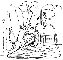
“Voilà la plus merveilleuse de toutes les Machines; le Mécanisme ressemble à celui des animaux. La chaleur est le principe de son mouvement; il se fait dans ses différens tuyaux une circulation, comme celle du sang dans les veines, ayant des valvules qui s’ouvrent et se ferment à propos; elles se nourrit, s’évacue d’elle même dans les temps réglés, et tire de son travail tout ce qu’il lui faut pour subsister. Cette Machine a pris sa naissance en Angleterre, et toutes les Machines à feu qu’on a construites ailleurs que dans la Grande Brétagne ont été exécutées par des Anglais.”—Belidor.
Among the most obviously important and most inconceivably fruitful of all the applications of steam which marked the period we are now studying, is that of the steam-engine to the propulsion of vessels. This direction of application has been that which has, from the earliest period in the history of the steam-engine, attracted the attention of the political economist and the historian, as well as the mechanician, whenever a new improvement, or the revival of an old device, has awakened a faint conception of the possibilities attendant upon the introduction of a machine capable of making so great a force available. The realization of the hopes, the prophecies, and the aspirations of earlier times, in the modern marine steam-engine, may be justly regarded as the greatest of all the triumphs of mechanical engineering. Although, as has already been stated,[222] attempts were made at a very early period to effect this application of steam-power, they were not successful, and the steamship is a product of the present century. No such attempts were commercially successful until after the time of Newcomen and Watt, and at the commencement of the nineteenth century. It is, indeed, but a few years since the passage across the Atlantic was frequently made in sailing-vessels, and the dangers, the discomforts, and the irregularities of their trips were most serious. Now, hardly a day passes that does not see several large and powerful steamers leaving the ports of New York and Liverpool to make the same voyages, and their passages are made with such regularity and safety, that travelers can anticipate with confidence the time of their arrival at the termination of their voyage to a day, and can cross with safety and with comparative comfort even amid the storms of winter. Yet all that we to-day see of the extent and the efficiency of steam-navigation has been the work of the present century, and it may well excite our wonder and our admiration.
The history of this development of the use of steam-power illustrates most perfectly that process of growth of this invention which has been already referred to; and we can here trace it, step by step, from the earliest and rudest devices up to those most recent and most perfect designs which represent the most successful existing types of the heat-engine—whether considered with reference to its design and construction, or as the highest application of known scientific principles—that have yet been seen in even the present advanced state of the mechanic arts.
The paddle-wheel was used as a substitute for oars at a very early date, and a description of paddle-wheels applied to vessels, curiously illustrated by a large wood-cut, may be found in the work of Fammelli, “De l’artificioses machines,” published in old French in 1588. Clark[58] quotes from[223] Ogilby’s edition of the “Odyssey” a stanza which reads like a prophecy, and almost awakens a belief that the great poet had a knowledge of steam-vessels in those early times—a thousand years before the Christian era. The prince thus addresses Ulysses:
Pope’s translation[59] furnishes the following rendering of Homer’s prophecy:
It is stated that the Roman army under Claudius Caudex was taken across to Sicily in boats propelled by paddle-wheels turned by oxen. Vulturius gives pictures of such vessels.
This application of the force of steam was very possibly anticipated 600 years ago by Roger Bacon, the learned Franciscan monk, who, in an age of ignorance and intellectual torpor, wrote:
“I will now mention some wonderful works of art and nature, in which there is nothing of magic, and which magic[224] could not perform. Instruments may be made by which the largest ships, with only one man guiding them, will be carried with greater velocity than if they were full of sailors,” etc., etc.
Darwin’s poetical prophecy was published long years before Watt’s engine rendered its partial fulfillment a possibility; and thus, for many years before even the first promising effort had been made, the minds of the more intelligent had been prepared to appreciate the invention when it should finally be brought forward.
The earliest attempt to propel a vessel by steam is claimed by Spanish authorities, as has been stated, to have been made by Blasco de Garay, in the harbor of Barcelona, Spain, in 1543. The record, claimed as having been extracted from the Spanish archives at Simancas, states the vessel to have been of 200 tons burden, and to have been moved by paddle-wheels; and it is added that the spectators saw, although not allowed closely to inspect the apparatus, that one part of it was a “vessel of boiling water”; and it is also stated that objection was made to the use of this part of the machine, because of the danger of explosion.
The account seems somewhat apocryphal, and it certainly led to no useful results.
In an anonymous English pamphlet, published in 1651, which is supposed by Stuart to have been written by the Marquis of Worcester, an indefinite reference to what may probably have been the steam-engine is made, and it is there stated to be capable of successful application to propelling boats.
In 1690, Papin proposed to use his piston-engine to drive paddle-wheels to propel vessels; and in 1707 he applied the steam-engine, which he had proposed as a pumping-engine, to driving a model boat on the Fulda at Cassel. In this trial he used the arrangement of which a sketch has been shown, his pumping-engine forcing up water to turn a water-wheel, which, in turn, was made to drive the paddles.[225] An account of his experiments is to be found in manuscript in the correspondence between Leibnitz and Papin, preserved in the Royal Library at Hanover. Professor Joy found there the following letter:[60]
“Dionysius Papin, Councillor and Physician to his Royal Highness the Elector of Cassel, also Professor of Mathematics at Marburg, is about to dispatch a vessel of singular construction down the river Weser to Bremen. As he learns that all ships coming from Cassel, or any point on the Fulda, are not permitted to enter the Weser, but are required to unload at Münden, and as he anticipates some difficulty, although those vessels have a different object, his own not being intended for freight, he begs most humbly that a gracious order be granted that his ship may be allowed to pass unmolested through the Electoral domain; which petition I most humbly support.
G. W. Leibnitz.
“Hanover, July 13, 1707.”
This letter was returned to Leibnitz, with the following indorsement:
“The Electoral Councillors have found serious obstacles in the way of granting the above petition, and, without giving their reasons, have directed me to inform you of their decision, and that, in consequence, the request is not granted by his Electoral Highness.
H. Reiche.
“Hanover, July 25, 1707.”
This failure of Papin’s petition was the death-blow to his effort to establish steam-navigation. A mob of boatmen, who thought they saw in the embryo steamship the ruin of their business, attacked the vessel at night, and utterly destroyed it. Papin narrowly escaped with his life, and fled to England.
In the year 1736, Jonathan Hulls took out an English patent for the use of a steam-engine for ship-propulsion, proposing to employ his steamboat in towing. In 1737 he published a well-written pamphlet, describing this apparatus, which is shown in Fig. 66, a reduced fac-simile of the plate accompanying his paper.
[226]He proposed using the Newcomen engine, fitted with a counterpoise-weight and a system of ropes and grooved wheels, which, by a peculiar ratchet-like action, gave a continuous rotary motion. His vessel was to have been used as a tow-boat. He says, in his description: “In some convenient part of the Tow-boat there is placed a Vessel about two-3rds full of water, with the Top closed; and this Vessel being kept Boiling, rarifies the Water into a Steam, this Steam being convey’d thro’ a large pipe into a cylindrical Vessel, and there condensed, makes a Vacuum, which causes the weight of the atmosphere to press down on this Vessel, and so presses down a Piston that is fitted into this Cylindrical Vessel, in the same manner as in Mr. Newcomen’s Engine, with which he raises Water by Fire.
“P, the Pipe coming from the Furnace to the Cylinder. Q, the Cylinder wherein the steam is condensed. R, the Valve that stops the Steam from coming into the Cylinder, whilst the Steam within the same is condensed. S, the Pipe to convey the condensing Water into the Cylinder. T, a cock to let in the condensing Water when the Cylinder is full of Steam and the Valve, P, is shut. U, a Rope fixed to the Piston that slides up and down in the Cylinder.
“Note. This Rope, U, is the same Rope that goes round the wheel, D, in the machine.”
In the large division of his plate, A is the chimney; B[227] is the tow-boat; CC is the frame carrying the engine; Da, D, and Db are three wheels carrying the ropes M, Fb, and Fa, M being the rope U of his smaller figure, 30. Ha and Hb are two wheels on the paddle-shafts, II, arranged with pawls so that the paddle-wheel, II, always turns the same way, though the wheels Ha and Hb are given a reciprocating motion; Fb is a rope connecting the wheels in the vessel, Db, with the wheels at the stern. Hulls says:
“When the Weight, G, is so raised, while the wheels Da, D, and Db are moving backward, the Rope Fa gives way, and the Power of the Weight, G, brings the Wheel Ha forward, and the Fans with it, so that the Fans always keep going forward, notwithstanding the Wheels Da, D, and Db move backward and forward as the Piston moves up and down in the Cylinder. LL are Teeth for a Catch to drop in from the Axis, and are so contrived that they catch in an alternate manner, to cause the Fan to move always forward, for the Wheel Ha, by the power of the weight, G, is performing his Office while the other wheel, Hb, goes back in order to fetch another stroke.
“Note. The weight, G, must contain but half the weight of the Pillar of Air pressing on the Piston, because the weight, G, is raised at the same time as the Wheel Hb performs its Office, so that it is in effect two Machines acting alternately, by the weight of one Pillar of Air, of such a Diameter as the Diameter of the Cylinder is.”
The inventor suggests the use of timber guards to protect the wheels from injury, and, in shallow water, the attachment to the paddle-shafts of cranks “to strike a Shaft to the Bottom of the River, which will drive the Vessel forward with the greater Force.” He concludes: “Thus I have endeavoured to give a clear and satisfactory Account of my New-invented Machine, for carrying Vessels out of and into any Port, Harbour, or River, against Wind and Tide, or in a Calm; and I doubt not but whoever shall[228] give himself the Trouble to peruse this Essay, will be so candid as to excuse or overlook any Imperfections in the diction or manner of writing, considering the Hand it comes from, if what I have imagined may only appear as plain to others as it has done to me, viz., That the Scheme I now offer is Practicable, and if encouraged will be Useful.”
There is no positive evidence that Hulls ever put his scheme to the test of experiment, although tradition does say that he made a model, which he tried with such ill success as to prevent his prosecution of the experiment further; and doggerel rhymes are still extant which were sung by his neighbors in derision of his folly, as they considered it.
A prize was awarded by the French Academy of Sciences, in 1752, for the best essay on the manner of impelling vessels without wind. It was given to Bernouilli, who, in his paper, proposed a set of vanes like those of a windmill—a screw, in fact—one to be placed on each side of the vessel, and two more behind. For a vessel of 100 tons, he proposed a shaft 14 feet long and 2 inches in diameter, carrying “eight wheels, for acting on the water, to each of which it” (the shaft) “is perpendicular, and forms an axis for them all; the wheels should be at equal distances from each other. Each wheel consists of 8 arms of iron, each 3 feet long, so that the whole diameter of the wheel is 6 feet. Each of these arms, at the distance of 20 inches from the centre, carries a sheet-iron plane (or paddle) 16 inches square, which is inclined so as to form an angle of 60 degrees, both with the arbor and keel of the vessel, to which the arbor is placed parallel. To sustain this arbor and the wheels, two strong bars of iron, between 2 and 3 inches thick, proceed from the side of the vessel at right angles to it, about 21∕2 feet below the surface of the water.” He proposed similar screw-propellers at the stern, and suggested that they could be driven by animal or by steam-power.
[229] But a more remarkable essay is quoted by Figuier[61]—the paper of l’Abbé Gauthier, published in the “Mémoires de la Société Royale des Sciences et Lettres de Nancy.” Bernouilli had expressed the belief that the best steam-engine then known—that of Newcomen—was not superior to some other motors. Gauthier proposed to use that engine in the propulsion of paddle-wheels placed at the side of the vessel. His plan was not brought into use, but his paper embodied a glowing description of the advantages to be secured by its adoption. He states that a galley urged by 26 oars on a side made but 4,320 toises (8,420 meters), or about 5 miles, an hour, and required a crew of 260 men. A steam-engine, doing the same work, would be ready for action at all times, could be applied, when not driving the vessel, to raising the anchor, working the pumps, and to ventilating the ship, while the fire would also serve to cook with. The engine would occupy less space and weight than the men, would require less aliment, and that of a less expensive kind, etc. He would make the boiler safe against explosions by bands of iron; would make the fire-box of iron, with a water-filled ash-pit and base-plate. His injection-water was to come from the sea, and return by a delivery-pipe placed above the water-line. The chains, usually leading from the end of the beam to the pump-rods, were to be carried around wheels on the paddle-shaft, which were to be provided with pawls entering a ratchet, and thus the paddles, having been given several revolutions by the descent of the piston and the unwinding of the chain, were to revolve freely while the return-stroke was made, the chain being hauled down and rewound by the wheel on the shaft, the latter being moved by a weight. The engine was proposed to be of 6 feet stroke, and to make 15 strokes per minute, with a force of 11,000 pounds.
A little later (1760), a Swiss clergyman, J. A. Genevois,[230] published in London a paper relating to the improvement of navigation,[62] in which his plan was proposed of compressing springs by steam or other power, and applying their effort while recovering their form to ship-propulsion.
It was at this time that the first attempts were made in the United States to solve this problem, which had begun to be recognized as one of the greatest which had presented itself to the mechanic and the engineer.
William Henry was a prominent citizen of the then little village of Lancaster, Pa., and was noted as an ingenious and successful mechanic.[63] He was still living at the beginning of the present century. Mr. Henry was the first to make the “rag” carpet, and was the inventor of the screw-auger. He was of a Scotch and North-of-Ireland family, his father, John Henry, and his two older brothers, Robert and James, having come to the United States about 1720. Robert settled, finally, in Virginia, and it is said that Patrick Henry, the patriot and orator, was of his family. The others remained in Chester County, Pa., where William was born, in 1729. He learned the trade of a gunsmith, and, driven from his home during the Indian war (1755 to 1760), settled in Lancaster.
In the year 1760 he went to England on business, where his attention was attracted to the invention—then new, and the subject of discussion in every circle—of James Watt. He saw the possibility of its application to navigation and to driving carriages, and, on his return home, commenced the construction of a steam-engine, and finished it in 1763.
Placing it in a boat fitted with paddle-wheels, he made a trial of the new machine on the Conestoga River, near Lancaster, where the craft, by some accident, sank,[64] and[231] was lost. He was not discouraged by this failure, but made a second model, adding some improvements. Among the records of the Pennsylvania Philosophical Society is, or was, a design, presented by Henry in 1782, of one of his steamboats. The German traveler Schöpff visited the United States in 1783, and at Mr. Henry’s house, at Lancaster, was shown “a machine by Mr. Henry, intended for the propelling of boats, etc.; ‘but,’ said Mr. Henry, ‘I am doubtful whether such a machine would find favor with the public, as every one considers it impracticable against wind and tide;’ but that such a Boat will come into use and navigate on the waters of the Ohio and Mississippi, he had not the least doubt of, but the time had not yet arrived of its being appreciated and applied.”
John Fitch, whose experiments will presently be referred to, was an acquaintance and frequent visitor to the house of Mr. Henry, and may probably have there received the earliest suggestions of the importance of this application of steam. About 1777, when Henry was engaged in making mathematical and philosophical instruments, and the screw-auger, which at that time could only be obtained of him, Robert Fulton, then twelve years old, visited him, to study the paintings of Benjamin West, who had long been a friend and protégé of Henry. He, too, not improbably received there the first suggestion which afterward led him to desert the art to which he at first devoted himself, and which made of the young portrait-painter a successful inventor and engineer. West’s acquaintance with Henry had no such result. The young painter was led by his patron and friend to attempt historical pictures,[65] and probably owes his fame greatly to the kindly and discerning mechanic. Says Galt, in his “Memoirs of Sir Benjamin West” (London, 1816): “Towards his old friend, William Henry, of Lancaster City, he always cherished the most[232] grateful affection; he was the first who urged him to attempt historical composition.”
When, after the invention of Watt, the steam-engine had taken such shape that it could really work the propelling apparatus of a paddle or screw vessel, a new impetus was given to the work of its adaptation. In France, the Marquis de Jouffroy was one of the earliest to perceive that the improvements of Watt, rendering the engine more compact, more powerful, and, at the same time, more regular and positive in its action, had made it, at last, readily applicable to the propulsion of vessels. The brothers Périer had imported a Watt engine from Soho, and this was attentively studied by the marquis,[66] and its application to the paddle-wheels of a steam-vessel seemed to him a simple problem. Comte d’Auxiron and Chevalier Charles Mounin, of Follenai, friends and companions of Jouffroy, were similarly interested, and the three are said to have often discussed the scheme together, and to have united in devising methods of applying the new motor.
In the year 1770, D’Auxiron determined to attempt the realization of the plans which he had conceived. He resigned his position in the army, prepared his plans and drawings, and presented them to M. Bertin, the Prime Minister, in the year 1771 or 1772. The Minister was favorably impressed, and the King (May 22, 1772) granted D’Auxiron a monopoly of the use of steam in river-navigation for 15 years, provided he should prove his plans practicable, and they should be so adjudged by the Academy.
A company had been formed, the day previous, consisting of D’Auxiron, Jouffroy, Comte de Dijon, the Marquis d’Yonne, and Follenai, which advanced the requisite funds. The first vessel was commenced in December, 1772. When nearly completed, in September, 1774, the boat sprung a leak, and, one night, foundered at the wharf.[233] After some angry discussion, during which d’Auxiron was rudely, and probably unjustly, accused of bad faith, the company declined to advance the money needed to recover and complete the vessel. They were, however, compelled by the court to furnish it; but, meantime, d’Auxiron died of apoplexy, the matter dropped, and the company dissolved. The cost of the experiment had been something more than 15,000 francs.
The heirs of d’Auxiron turned the papers of the deceased inventor over to Jouffroy, and the King transferred to him the monopoly held by the former. Follenai retained all his interest in the project, and the two friends soon enlisted a powerful adherent and patron, the Marquis Ducrest, a well-known soldier, courtier, and member of the Academy, who took an active part in the prosecution of the scheme. M. Jacques Périer, the then distinguished mechanic, was consulted, and prepared plans, which were adopted in place of those of Jouffroy. The boat was built by Périer, and a trial took place in 1774, on the Seine. The result was unsatisfactory. The little craft could hardly stem the sluggish current of the river, and the failure caused the immediate abandonment of the scheme by Périer.
Still undiscouraged, Jouffroy retired to his country home, at Baume-les-Dames, on the river Doubs. There he carried on his experiments, getting his work done as best he could, with the rude tools and insufficient apparatus of a village blacksmith. A Watt engine and a chain carrying “duck-foot” paddles were his propelling apparatus. The boat, which was about 14 feet long and 6 wide, was started in June, 1776. The duck’s-foot system of paddles proved unsatisfactory, and Jouffroy gave it up, and renewed his experiments with a new arrangement. He placed on the paddle-wheel shaft a ratchet-wheel, and on the piston-rod of his engine, which was placed horizontally in the boat, a double rack, into the upper and the lower parts of which the ratchet-wheel geared. Thus the wheels turned in the[234] same direction, whichever way the piston was moving. The new engine was built at Lyons in 1780, by Messrs. Frères-Jean. The new boat was about 140 feet long and 14 feet wide; the wheels were 14 feet in diameter, their floats 6 feet long, and the “dip,” or depth to which they reached, was about 2 feet. The boat drew 3 feet of water, and had a total weight of about 150 tons.
At a public trial of the vessel at Lyons, July 15, 1783, the little steamer was so successful as to justify the publication of the fact by a report and a proclamation. The fact that the experiment was not made at Paris was made an excuse on the part of the Academy for withholding its indorsement, and on the part of the Government for declining to confirm to Jouffroy the guaranteed monopoly. Impoverished and discouraged, Jouffroy gave up all hope of prosecuting his plans successfully, and reëntered the army. Thus France lost an honor which was already within her grasp, as she had already lost that of the introduction of the steam-engine, in the time of Papin.
About 1785, John Fitch and James Rumsey were engaged in experiments having in view the application of steam to navigation.
Rumsey’s experiments began in 1774, and in 1786 he succeeded in driving a boat at the rate of four miles an hour against the current of the Potomac at Shepherdstown, W. Va., in presence of General Washington. His method of propulsion has often been reinvented since, and its adoption urged with that enthusiasm and persistence which is a peculiar characteristic of inventors.
Rumsey employed his engine to drive a great pump which forced a stream of water aft, thus propelling the boat forward, as proposed earlier by Bernouilli. This same method has been recently tried again by the British Admiralty, in a gunboat of moderate size, using a centrifugal pump to set in motion the propelling stream, and with some other modifications which are decided improvements[235] upon Rumsey’s rude arrangements, but which have not done much more than his toward the introduction of “Hydraulic or Jet Propulsion,” as it is now called.
In 1787 he obtained a patent from the State of Virginia for steam-navigation. He wrote a treatise “On the Application of Steam,” which was printed at Philadelphia, where a Rumsey society was organized for the encouragement of attempts at steam-navigation.
Rumsey died of apoplexy, while explaining some of his schemes before a London society a short time later, December 23, 1793, at the age of fifty years. A boat, then in process of construction from his plans, was afterward tried on the Thames, in 1793, and steamed at the rate of four miles an hour. The State of Kentucky, in 1839, presented his son with a gold medal, commemorative of his father’s services “in giving to the world the benefit of the steamboat.”
John Fitch was an unfortunate and eccentric, but very ingenious, Connecticut mechanic. After roaming about until forty years of age, he finally settled on the banks of the Delaware, where he built his first steamboat.
In April, 1785, as Fitch himself states, at Neshamony, Bucks County, Pa., he suddenly conceived the idea that a carriage might be driven by steam. After considering the subject a few days, his attention was led to the plan of using steam to propel vessels, and from that time to the day of his death he was a persistent advocate of the introduction of the steamboat. At this time, Fitch says, “I did not know that there was a steam-engine on the earth;” and he was somewhat disappointed when his friend, the Rev. Mr. Irwin, of Neshamony, showed him a sketch of one in “Martin’s Philosophy.”
Fitch’s first model was at once built, and was soon after tried on a small stream near Davisville. The machinery was made of brass, and the boat was impelled by paddle-wheels. A rough model of his steamboat was shown to[236] Dr. John Ewing, Provost of the University of Pennsylvania, who, August 20, 1785, addressed a commendatory letter to an ex-Member of Congress, William C. Houston, asking him to assist Fitch in securing the aid of the General Government. The latter referred the inventor, by a letter of recommendation, to a delegate from New Jersey, Mr. Lambert Cadwalader. With this, and other letters, Fitch proceeded to New York, where Congress then met, and made his application in proper form. He was unsuccessful, and equally so in attempting to secure aid from the Spanish minister, who desired that the profits should be secured, by a monopoly of the invention, to the King of Spain. Fitch declined further negotiation, determined that, if successful at all, the benefit should accrue to his own countrymen.
In September, 1785, Fitch presented to the American Philosophical Society, at Philadelphia, a model in which he had substituted an endless chain and floats for the paddle-wheels, with drawings and a descriptive account of his scheme. This model is shown in the accompanying figure.
In March, 1786, Fitch was granted a patent by the State of New Jersey, for the exclusive right to the navigation of the waters of the State by steam, for 14 years. A month later, he was in Philadelphia, seeking a similar patent from the State of Pennsylvania. He did not at once succeed, but in a few days he had formed a company, raised $300, and set about finding a place in which to construct his engine. Henry Voight, a Dutch watchmaker, a good mechanic, and a very ingenious man, took an interest in the[237] company, and with him Fitch set about his work with great enthusiasm. After making a little model, having a steam-cylinder but one inch in diameter, they built a model boat and engine, the latter having a diameter of cylinder of three inches. They tried the endless chain, and other methods of propulsion, without success, and finally succeeded with a set of oars worked by the engine. In August, 1786, it was determined by the company to authorize the construction of a larger vessel; but the money was not readily obtained. Meantime, Fitch continued his efforts to secure a patent from the State, and was finally, March 28, 1787, successful. He also obtained a similar grant from the State of Delaware, in February of the same year, and from New York, March 19.
Money was now subscribed more freely, and the work on the boat continued uninterruptedly until May, 1787, when a trial was made, which revealed many defects in the machinery. The cylinder-heads were of wood, and leaked badly; the piston leaked; the condenser was imperfect; the valves were not tight. All these defects were remedied, and a condenser invented by Voight—the “pipe-condenser”—was substituted for that defective detail as previously made.
The steamboat was finally placed in working order, and was found capable, on trial, of making three or four miles an hour. But now the boiler proved to be too small to furnish steam steadily in sufficient quantity to sustain the higher speed. After some delay, and much distress on the part of the sanguine inventor, who feared that he might be at last defeated when on the very verge of success, the necessary changes were finally made, and a trial took place at Philadelphia, in presence of the members of the Convention—then in session at Philadelphia framing the Federal Constitution—August 22, 1787. Many of the distinguished spectators gave letters to Fitch certifying his success. Fitch now went to Virginia, where he succeeded in obtaining a[238] patent, November 7, 1787, and then returned to ask a patent of the General Government.
A controversy with Rumsey now followed, in which Fitch asserted his claims to the invention of the steamboat, and denied that Rumsey had done more than to revive the scheme which Bernouilli, Franklin, Henry, Paine, and others, had previously proposed, and that Rumsey’s steamboat was not made until 1786.
The boiler adopted in Fitch’s boat of 1787 was a “pipe-boiler,” which he had described in a communication to the Philosophical Society, in September, 1785. It consisted (Fig. 68) of a small water-pipe, winding backward and forward in the furnace, and terminating at one end at the point at which the feed-water was introduced, and at the other uniting with the steam-pipe leading to the engine. Voight’s condenser was similarly constructed. Rumsey claimed that this boiler was copied from his designs. Fitch brought evidence to prove that Rumsey had not built such a boiler until after his own.
Fitch’s first boat-engine had a steam-cylinder 12 inches in diameter. A second engine was now built (1788) with a[239] cylinder 18 inches in diameter, and a new boat. The first vessel was 45 feet long and 12 feet wide; the new boat was 60 feet long and of but 8 feet breadth of beam. The first boat (Fig. 69) had paddles worked at the sides, with the motion given the Indian paddle in propelling a canoe; in the second boat (Fig. 70) they were similarly worked, but were placed at the stern. There were three of these paddles. The boat was finally finished in July, 1788, and made a trip to Burlington, 20 miles from Philadelphia. When just reaching their destination, their boiler gave out, and they made their return-trip to Philadelphia floating with the tide. Subsequently, the boat made a number of excursions on the Delaware River, making three or four miles an hour.
Another of Fitch’s boats, in April, 1790, made seven miles an hour. Fitch, writing of this boat, says that “on the 16th of April we got our work completed, and tried our boat again; and, although the wind blew very fresh at the east, we reigned lord high admirals of the Delaware,[240] and no boat on the river could hold way with us.” In June of that year it was placed as a passenger-boat on a line from Philadelphia to Burlington, Bristol, Bordentown, and Trenton, occasionally leaving that route to take excursions to Wilmington and Chester. During this period, the boat probably ran between 2,000 and 3,000 miles,[67] and with no serious accident. During the winter of 1790-’91, Fitch commenced another steamboat, the “Perseverance,” and gave considerable time to the prosecution of his claim for a patent from the United States. The boat was never completed, although he received his patent, after a long and spirited contest with other claimants, on the 26th of August, 1791, and Fitch lost all hope of success. He went to France in 1793, hoping to obtain the privilege of building steam-vessels there, but was again disappointed, and worked his passage home in the following year.
In the year 1796, Fitch was again in New York City, experimenting with a little screw steamboat on the “Collect” Pond, which then covered that part of the city now[241] occupied by the “Tombs,” the city prison. This little boat was a ship’s yawl fitted with a screw, like that adopted later by Woodcroft, and driven by a rudely-made engine.
Fitch, while in the city of Philadelphia at about this time, met Oliver Evans, and discussed with him the probable future of steam-navigation, and proposed to form a company in the West, to promote the introduction of steam on the great rivers of that part of the country. He settled at last in Kentucky, on his land-grant, and there amused himself with a model steamboat, which he placed in a small stream near Bardstown. His death occurred there in July, 1798, and his body still lies in the village cemetery, with only a rough stone to mark the spot.
Both Rumsey and Fitch endeavored to introduce their methods in Great Britain; and Fitch, while urging the importance and the advantages of his plan, confidently stated his belief that the ocean would soon be crossed by steam-vessels, and that the navigation of the Mississippi would also become exclusively a steam-navigation. His reiterated assertion, “The day will come when some more powerful man will get fame and riches from my invention; but no one will believe that poor John Fitch can do anything worthy of attention,” now almost sounds like a prophecy.
During this period, an interest which had never diminished in Great Britain had led to the introduction of experimental steamboats in that country. Patrick Miller, of Dalswinton, had commenced experimenting, in 1786-’87, with boats having double or triple hulls, and propelled by paddle-wheels placed between the parts of the compound vessel. James Taylor, a young man who had been engaged as tutor for Mr. Miller’s sons, suggested, in 1787, the substitution of steam for the manual power which had been, up to that time, relied upon in their propulsion. Mr. Miller, in 1787, printed a description of his plan of propelling apparatus, and in it stated that he had “reason to believe[242] that the power of the Steam-Engine may be applied to work the wheels.”
In the winter of 1787-’88, William Symmington, who had planned a new form of steam-engine, and made a successful working-model, was employed by Mr. Miller to construct an engine for a new boat. This was built; the little engine, having two cylinders of but four inches in diameter, was placed on board, and a trial was made October 14, 1788. The vessel (Fig. 72) was 25 feet long, of 7 feet beam, and made 5 miles an hour.
In the year 1789, a large vessel was built, with an engine having a steam-cylinder 18 inches in diameter, and this vessel was ready for trial in November of that year. On the first trial, the paddle-wheels proved too slight, and broke down; they were replaced by stronger wheels, and, in December, the boat, on trial, made seven miles an hour.
Miller, like many other inventors, seems to have lost his interest in the matter as soon as success seemed assured, and dropped it to take up other incomplete plans. More than a quarter of a century later, the British Government gave Taylor a pension of £50 per annum, and, in 1837, his[243] four daughters were each given a similar annuity. Mr. Miller received no reward, although he is said to have expended over £30,000. The engine of Symmington was condemned by Miller as “the most improper of all steam-engines for giving motion to a vessel.” Nothing more was done in Great Britain until early in the succeeding century.
In the United States, several mechanics were now at work besides Fitch. Samuel Morey and Nathan Read were among these. Nicholas Roosevelt was another. It had just been found that American mechanics were able to do the required shop-work. The first experimental steam-engine built in America is stated to have been made in 1773 by Christopher Colles, a lecturer before the American Philosophical Society at Philadelphia. The first steam-cylinder of any considerable size is said[68] to have been made by Sharpe & Curtenius, of New York City.
Samuel Morey was the son of one of the first settlers of Orford, N. H. He was naturally fond of science and mechanics, and became something of an inventor. He began experimenting with the steamboat in 1790 or earlier, building a small vessel, and fitting it with paddle-wheels driven by a steam-engine of his own design, and constructed by himself.[69] He made a trial-trip one Sunday morning in the summer of 1790, a friend to accompany him, from Oxford, up the Connecticut River, to Fairlee, Vt., a distance of several miles, and returned safely. He then went to New York, and spent the summer of each year until 1793 in experimenting with his boat and modifications of his engine. In 1793 he made a trip to Hartford, returning to New York the next summer. His boat was a “stern-wheeler,” and is stated to have been capable of steaming five miles an hour. He next went to Bordentown, N. J., where he built a larger boat, which is said to have been a[244] side-wheel boat, and to have worked satisfactorily. His funds finally gave out, and he gave up his project after having, in 1797, made a trip to Philadelphia. Fulton, Livingston, and Stevens met Morey at New York, inspected his boat, and made an excursion to Greenwich with him.[70] Livingston is said[71] to have offered to assist Morey if he should succeed in attaining a speed of eight miles an hour.
Morey’s experiments seem to have been conducted very quietly, however, and almost nothing is known of them. The author has not been able to learn any particulars of the engines used by him, and nothing definite is known of the dimensions of either boat or machinery. Morey never, like Fitch and Rumsey, sought publicity for his plans or notoriety for himself.
Nathan Read, who has already been mentioned, a native of Warren, Mass., where he was born in the year 1759, and a graduate of Harvard College, was a student of medicine, and subsequently a manufacturer of chain-cables and other iron-work for ships. He invented, and in 1798 patented, a nail-making machine. He was at one time (1800-1803) a Member of Congress, and, later, a Justice of the Court of Common Pleas, and Chief Justice in Hancock County, Me., after his removal to that State in 1807. He died in Belfast, Me., in 1849, at the age of ninety years.
In the year 1788 he became interested in the problem of steam-navigation, and learned something of the work of Fitch. He first attempted to design a boiler that should be strong, light, and compact, as well as safe. His first plan was that of the “Portable Furnace-Boiler,” as he called it; it was patented August 26, 1791. As designed, it consisted, as seen in Figs. 73 and 74, which are reduced from his patent drawings, of a shell of cylindrical form, like the now common vertical tubular boiler. A is the furnace-door, B a heater and feed-water reservoir, D a pipe leading[245] the feed-water into the boiler,[72] E the smoke-pipe, and F the steam-pipe leading to the engine. G is the “shell” of the boiler, and H the fire-box. The crown-sheet, I I, has depending from it, in the furnace, a set of water-tubes, b b, closed at their lower ends, and another set, a a, which connect the water-space above the furnace with the water-bottom, K K. L is the furnace, and M the draught-space between the boiler and the ash-pit, in which the grates are set.
This boiler was intended to be used in both steamboats and steam-carriages. The first drawings were made in 1788 or 1789, as were those of a peculiar form of steam-engine which also resembled very closely that afterward constructed in Great Britain by Trevithick.[73] He built a[246] boat in 1789, which he fitted with paddle-wheels and a crank, which was turned by hand, and, by trial, satisfied himself that the system would work satisfactorily.
He then applied for his patent, and spent the greater part of the winter of 1789-’90 in New York, where Congress then met, endeavoring to secure it. In January, 1791, Read withdrew his petitions for patents, proposing to incorporate accounts of new devices, and renewed them a few months later. His patents were finally issued, dated August 26, 1791. John Fitch, James Rumsey, and John Stevens, also, all received patents at the same date, for various methods of applying steam to the propulsion of vessels.
Read appears to have never succeeded in even experimentally making his plans successful. He deserves credit for his early and intelligent perception of the importance of the subject, and for the ingenuity of his devices. As the inventor of the vertical multi-tubular fire-box boiler, he has also entitled himself to great distinction. This boiler is now in very general use, and is a standard form.
In 1792, Elijah Ormsbee, a Rhode Island mechanic, assisted pecuniarily by David Wilkinson, built a small steamboat at Winsor’s Cove, Narragansett Bay, and made a successful trial-trip on the Seekonk River. Ormsbee used an “atmospheric engine” and “duck’s-foot” paddles. His boat attained a speed of from three to four miles an hour.
In Great Britain, Lord Dundas and William Symmington, the former as the purveyor of funds and the latter as engineer, followed by Henry Bell, were the first to make the introduction of the steam-engine for the propulsion of ships so completely successful that no interruption subsequently took place in the growth of the new system of water-transportation.
Thomas, Lord Dundas, of Kerse, had taken great interest in the experiments of Miller, and had hoped to be able to apply the new motor on the Forth and Clyde Canal, in[247] which he held a large interest. After the failure of the earlier experiments, he did not forget the matter; but subsequently, meeting with Symmington, who had been Miller’s constructing engineer, he engaged him to continue the experiments, and furnished all required capital, about £7,000. This was ten years after Miller had abandoned his scheme.
Symmington commenced work in 1801. The first boat built for Lord Dundas, which has been claimed to have been the “first practical steamboat,” was finished ready for trial early in 1802. The vessel was called the “Charlotte Dundas,” in honor of a daughter of Lord Dundas, who became Lady Milton.
The vessel (Fig. 75) was driven by a Watt double-acting engine, turning a crank on the paddle-wheel shaft. The sectional sketch below exhibits the arrangement of the machinery. A is the steam-cylinder, driving, by means of the connecting-rod, B C, a stern-wheel, E E. F is the boiler, and G the tall smoke-pipe. An air-pump and condenser, H, is seen under the steam-cylinder.
In March, 1802, the boat was brought to Lock No. 20 on the Forth and Clyde Canal, and two vessels of 70 tons burden each taken in tow. Lord Dundas, William Symmington, and a party of invited guests, were taken on board,[248] and the boat steamed down to Port Glasgow, a distance of about 20 miles, against a strong head-wind, in six hours.
The proprietors of the canal were now urged to adopt the new plan of towing; but, fearing injury to the banks of the canal, they declined to do so. Lord Dundas then laid the matter before the Duke of Bridgewater, who gave Symmington an order for eight boats like the Charlotte Dundas, to be used on his canal. The death of the Duke, however, prevented the contract from being carried into effect, and Symmington again gave up the project in despair. A quarter of a century later, Symmington received from the British Government £100, and, a little later, £50 additional, as an acknowledgment of his services. The Charlotte Dundas was laid up, and we hear nothing more of that vessel.
Among those who saw the Charlotte Dundas, and who appreciated the importance of the success achieved by Symmington, was Henry Bell, who, 10 years afterward, constructed the Comet (Fig. 76), the first passenger-vessel built[249] in Europe. This vessel was built in 1811, and completed January 18, 1812. The craft was of 30 tons burden, 40 feet in length, and 101∕2 feet breadth of beam. There were two paddle-wheels on each side, driven by engines rated at three horse-power.
Bell had, it is said, been an enthusiastic believer in the advantages to be secured by this application of steam, from about 1786. In 1800, and again in 1803, he applied to the British Admiralty for aid in securing those advantages by experimentally determining the proper form and proportions of machinery and vessel; but was not able to convince the Admiralty of “the practicability and great utility of applying steam to the propelling of vessels against winds and tides, and every obstruction on rivers and seas where there was depth of water.” He also wrote to the United States Government, urging his views in a similar strain.
Bell’s boat was, when finished, advertised as a passenger-boat, to leave Greenock, where the vessel was built, on Mondays, Wednesdays, and Fridays, for Glasgow, 24 miles distant, returning Tuesdays, Thursdays, and Saturdays. The fare was made “four shillings for the best cabin, and three shillings for the second.” It was some months before the vessel became considered a trustworthy means of conveyance. Bell, on the whole, was at first a heavy loser by his venture, although his boat proved itself a safe, stanch vessel.
Bell constructed several other boats in 1815, and with his success steam-navigation in Great Britain was fairly inaugurated. In 1814 there were five steamers, all Scotch, regularly working in British waters; in 1820 there were 34, one-half of which were in England, 14 in Scotland, and the remainder in Ireland. Twenty years later, at the close of the period to which this chapter is especially devoted, there were about 1,325 steam-vessels in that kingdom, of which 1,000 were English and 250 Scotch.
[250]But we must return to America, to witness the first and most complete success, commercially, in the introduction of the steamboat.
The Messrs. Stevens, Livingston, Fulton, and Roosevelt were there the most successful pioneers. The latter is said to have built the “Polacca,” a small steamboat launched on the Passaic River in 1798. The vessel was 60 feet long, and had an engine of 20 inches diameter of cylinder and 2 feet stroke, which drove the boat 8 miles an hour, carrying a party of invited guests, which included the Spanish Minister. Livingston and John Stevens had induced Roosevelt to try their plans still earlier,[74] paying the expense of the experiments. The former adopted the plan of Bernouilli and Rumsey, using a centrifugal pump to force a jet of water from the stern; the latter used the screw. Livingston going to France as United States Minister, Barlow carried over the plans of the “Polacca,” and Roosevelt’s friends state that a boat built by them, in conjunction with Fulton, was a “sister-ship” to that vessel. In 1798, Roosevelt patented a double engine, having cranks set at right angles. As late as 1814 he received a patent for a steam-vessel, fitted with paddle-wheels having adjustable floats. His boat of 1798 is stated by some writers to have been made by him on joint account of himself, Livingston, and Stevens. Roosevelt, some years later, was again at work, associating himself with Fulton in the introduction of steam-navigation of the rivers of the West.[75]
In 1798, the Legislature of New York passed a law giving Chancellor Livingston the exclusive right to steam-navigation in the waters of the State for a period of 20 years, provided that he should succeed, within a twelve-month, in producing a boat that should steam four miles an hour.
[251]Livingston did not succeed in complying with the terms of the act, but, in 1803, he procured the reënactment of the law in favor of himself and Robert Fulton, who was then experimenting in France, after having, in England, watched the progress of steam-navigation there, and then taken a patent in this country.
Robert Fulton was a native of Little Britain, Lancaster County, Pa., born 1765. He commenced experimenting with paddle-wheels when a mere boy, in 1779, visiting an aunt living on the bank of the Conestoga.[76] During his youth he spent much of his time in the workshops of his neighborhood, and learned the trade of a watchmaker; but he adopted, finally, the profession of an artist, and exhibited great skill in portrait-painting. While his tastes were[252] at this time taking a decided bent, he is said to have visited frequently the house of William Henry, already mentioned, to see the paintings of Benjamin West, who in his youth had been a kind of protégé of Mr. Henry; and he may probably have seen there the model steamboats which Mr. Henry exhibited, in 1783 or 1784, to the German traveler Schöpff. In later years, Thomas Paine, the author of “Common Sense,” at one time lived with Mr. Henry, and afterward, in 1788, proposed that Congress take up the subject for the benefit of the country.
Fulton went to England when he came of age, and studied painting with Benjamin West. He afterward spent two years in Devonshire, where he met the Duke of Bridgewater, who afterward so promptly took advantage of the success of the “Charlotte Dundas.”
While in England and in France—where he went in 1797, and resided some time—he may have seen something of the attempts which were beginning to be made to introduce steam-navigation in both of those countries.
At about this time—perhaps in 1793—Fulton gave up painting as a profession, and became a civil engineer. In 1797 he went to Paris, and commenced experimenting with submarine torpedoes and torpedo-boats. In 1801 he had succeeded so well with them as to create much anxiety in the minds of the English, then at war with France.
He had, as early as 1793, proposed plans for steam-vessels, both to the United States and the British Governments, and seems never entirely to have lost sight of the subject.[77] While in France he lived with Joel Barlow, who subsequently became known as a poet, and as Embassador to France from the United States, but who was then engaged in business in Paris.
When about leaving the country, Fulton met Robert Livingston (Chancellor Livingston, as he is often called),[253] who was then (1801) Embassador of the United States at the court of France. Together they discussed the project of applying steam to navigation, and determined to attempt the construction of a steamboat on the Seine; and in the early spring of the year 1802, Fulton having attended Mrs. Barlow to Plombières, where she had been sent by her physician, he there made drawings and models, which were sent or described to Livingston. In the following winter Fulton completed a model side-wheel boat.
January 24, 1803, he delivered this model to MM. Molar, Bordel, and Montgolfier, with a descriptive memoir, in which he stated that he had, by experiment, proven that side-wheels were better than the “chaplet” (paddle-floats set on an endless chain).[78] These gentlemen were then building for Fulton and Livingston their first boat, on L’Isle des Cygnes, in the Seine. In planning this boat, Fulton[254] had devised many different methods of applying steam to its propulsion, and had made some experiments to determine the resistance of fluids. He therefore had been able to calculate, more accurately than had any earlier inventor, the relative size and proportions of boat and machinery.
The author has examined a large collection of Fulton’s drawings, among which are sketches, very neatly executed, of many of these plans, including the chaplet, side-wheel, and stern-wheel boats, driven by various forms of steam-engine, some working direct, and some geared to the paddle-wheel shaft. Figs. 77 and 78 are engraved from two of these sheets. The first represents the method adopted by Fulton to determine the resistance of masses of wood of various forms and proportions, when towed through water. The other is “A Table of the resistance of bodies moved through water, taken from experiments made in England by a society for improving Naval architecture, between the years 1793 and 1798” (Fig. 78). This latter is from a certified copy of “The Original Drawing on file in the Office of the Clerk of the New York District, making a part of the Demonstration of the patent granted to Robert Fulton, Esqr., on the 11th day of February, 1809. Dated[255] this 3rd March, 1814,” and is signed by Theron Rudd, Clerk of the New York District. Resistances are given in pounds per square foot.
Guided by these experiments and calculations, therefore, Fulton directed the construction of his vessel. It was completed in the spring of 1803. But, unfortunately, the hull of the little vessel was too weak for its heavy machinery, and it broke in two and sank to the bottom of the Seine. Undiscouraged, Fulton at once set about repairing damages. He was compelled to direct the rebuilding of the hull. The machinery was little injured. In June, 1803, the reconstruction was completed, and the vessel was set afloat in July. The hull was 66 feet long, of 8 feet beam, and of light draught.
August 9, 1803, this boat was cast loose, and steamed up the Seine, in presence of an immense concourse of spectators. A committee of the National Academy, consisting of Bougainville, Bossuet, Carnot, and Périer, were present to witness the experiment. The boat moved but slowly, making only between 3 and 4 miles an hour against the current, the speed through the water being about 41∕2 miles; but this was, all things considered, a great success.
The experiment was successful, but it attracted little attention, notwithstanding the fact that its success had been witnessed by the committee of the Academy and by many well-known savants and mechanics, and by officers on Napoleon’s staff. The boat remained a long time on the Seine, near the palace. The water-tube boiler of this vessel (Fig. 79) is still preserved at the Conservatoire des Arts et Métiers at Paris, where it is known as Barlow’s boiler. Barlow patented it in France as early as 1793, as a steamboat-boiler, and states that the object of his construction was to obtain the greatest possible extent of heating-surface.
Fulton endeavored to secure the pecuniary aid and the countenance of the First Consul, but in vain.
Livingston wrote home, describing the trial of this steamboat[256] and its results, and procured the passage of an act by the Legislature of the State of New York, extending a monopoly granted him in 1798 for the term of 20 years from April 5, 1803, the date of the new law, and extending the time allowed for proving the practicability of driving a boat four miles an hour by steam to two years from the same date. A later act further extended the time to April, 1807.
In May, 1804, Fulton went to England, giving up all hope of success in France with either his steamboats or his torpedoes. Fulton had already written to Boulton & Watt, ordering an engine to be built from plans which he furnished them; but he had not informed them of the purpose to which it was to be applied. This engine was to have a steam-cylinder 2 feet in diameter and of 4 feet stroke. The engine of the Charlotte Dundas was of very nearly the same size; and this fact, and the visit of Fulton to Symmington in 1801, as described by the latter, have been made the basis of a claim that Fulton was a copyist of the plans of others. The general accordance of the dimensions of his boat on the Seine with those of the “Polacca” of Roosevelt is also made the basis of similar claims by the friends[257] of the latter. It would appear, however, that Symmington’s statement is incorrect, as Fulton was in France, experimenting with torpedoes, at the time (July, 1801[79]) when he is accused of having obtained from the English engineer the dimensions and a statement of the performance of his vessel. Yet a fireman employed by Symmington has made an affidavit to the same statement. It is evident, however, from what has preceded, that those inventors and builders who were at that time working with the object of introducing the steamboat were usually well acquainted with what had been done by others, and with what was being done by their contemporaries; and it is undoubtedly the fact that each profited, so far as he was able, by the experience of others.
While in England, however, Fulton was certainly not so entirely absorbed in the torpedo experiments with which he was occupied in the years 1804-’6 as to forget his plans for a steamboat; and he saw the engine ordered by him in 1804 completed in the latter year, and preceded it to New York, sailing from Falmouth in October, 1806, and reaching the United States December 13, 1806.
The engine was soon received, and Fulton immediately contracted for a hull in which to set it up. Meantime, Livingston had also returned to the United States, and the two enthusiasts worked together on a larger steamer than any which had yet been constructed.
In the spring of 1807, the “Clermont” (Fig. 80), as the new boat was christened, was launched from the ship-yard of Charles Brown, on the East River, New York. In August the machinery was on board and in successful operation. The hull of this boat was 133 feet long, 18 wide, and 9 deep. The boat soon made a trip to Albany, running the distance of 150 miles in 32 hours running time, and returning in 30 hours. The sails were not used on either occasion.[258]
This was the first voyage of considerable length ever made by a steam-vessel; and Fulton, though not to be classed with James Watt as an inventor, is entitled to the great honor of having been the first to make steam-navigation an every-day commercial success, and of having thus made the first application of the steam-engine to ship-propulsion, which was not followed by the retirement of the experimenter from the field of his labors before success was permanently insured.
The engine of the Clermont (Fig. 81) was of rather peculiar[259] form, the piston, E, being coupled to the crank-shaft, O, by a bell-crank, I H P, and a connecting-rod, P Q, the paddle-wheel shaft, M N, being separate from the crank-shaft, and connected with the latter by gearing, O O. The cylinders were 24 inches in diameter by 4 feet stroke. The paddle-wheels had buckets 4 feet long, with a dip of 2 feet. Old drawings, made by Fulton’s own hand, and showing the engine as it was in 1808, and the engine of a later steamer, the Chancellor Livingston, are in the lecture-room of the author at the Stevens Institute of Technology.
The voyage of the Clermont to Albany was attended by some ludicrous incidents, which found their counterparts wherever, subsequently, steamers were for the first time introduced. Mr. Colden, the biographer of Fulton, says that she was described, by persons who had seen her passing by night, “as a monster moving on the waters, defying wind and tide, and breathing flames and smoke.”
This first steamboat used dry pine wood for fuel, and the flames rose to a considerable distance above the smoke-pipe. When the fires were disturbed, mingled smoke and sparks would rise high in the air. “This uncommon light,” says Colden, “first attracted the attention of the crews of other vessels. Notwithstanding the wind and tide were averse to its approach, they saw with astonishment that it was rapidly coming toward them; and when it came so near that the noise of the machinery and paddles was heard, the crews (if what was said in the newspapers of the time be true), in some instances, shrank beneath their decks from the terrific sight, and left their vessels to go on shore; while others prostrated themselves, and besought Providence to protect them from the approach of the horrible monster which was marching on the tides, and lighting its path by the fires which it vomited.”
In the Clermont, Fulton used several of the now characteristic features of the American river steamboat, and subsequently introduced others. His most important and[260] creditable work, aside from that of the introduction of the steamboat into every-day use, was the experimental determination of the magnitude and the laws of ship-resistance, and the systematic proportioning of vessel and machinery to the work to be done by them.
The success of the Clermont on the trial-trip was such that Fulton soon after advertised the vessel as a regular passenger-boat between New York and Albany.[80]
During the next winter the Clermont was repaired and enlarged, and in the summer of 1808 was again on the route to Albany; and, meantime, two new steamboats—the Raritan and the Car of Neptune—had been built by Fulton. In the year 1811 he built the Paragon. Both of the[261] two vessels last named were of nearly double the size of the Clermont. A steam ferry-boat was built to ply between New York and Jersey City in 1812, and the next year two others, to connect the metropolis with Brooklyn. These were “twin-boats,” the two parallel hulls being connected by a “bridge” or deck common to both. The Jersey ferry was crossed in fifteen minutes, the distance being a mile and a half. To-day, the time occupied at the same ferry is about ten minutes. Fulton’s ferry-boat carried, at one load, 8 carriages, and about 30 horses, and still had room for 300 or 400 foot-passengers. Fulton also designed steam-vessels for use on the Western rivers, and, in 1815, some of his boats were started as “packets” on the line between New York and Providence, R. I.
Meantime, the War of 1812 was in progress, and Fulton designed a steam vessel-of-war, which was then considered a wonderfully formidable craft. His plans were submitted to a commission of experienced naval officers, among whom were Commodores Decatur and Perry, Captain John Paul Jones, Captain Evans, and others whose names are still familiar, and were favorably commended. Fulton proposed to build a steam-vessel capable of carrying a heavy battery, and of steaming four miles an hour. The ship was to be fitted with furnaces for red-hot shot. Some of her guns were to be discharged below the water-line. The estimated cost was $320,000.
The construction of the vessel was authorized by Congress in March, 1814; the keel was laid June 20, 1814, and the vessel was launched October 29th of the same year.
The “Fulton the First,” as she was called, was considered an enormous vessel at that time. The hull was double, 156 feet long, 56 feet wide, and 20 feet deep, measuring 2,475 tons. In the following May the ship was ready for her engine, and in July was so far completed as to steam, on a trial-trip, to the ocean at Sandy Hook and back—53 miles—in 8 hours and 20 minutes. In September of the same[262] year, with armament and stores on board, the same route was traversed again, the vessel making 51∕2 miles an hour. The vessel, as thus completed, had a double hull, each about 20 feet longer than the Clermont, and separated by a space 15 feet across. Her engine, having a steam-cylinder 48 inches in diameter and of 5 feet stroke of piston, was furnished with steam by a copper boiler 22 feet long, 12 feet wide, and 8 feet high, and turned a wheel between the two hulls which was 16 feet in diameter, and carried “floats” or “buckets” 14 feet long, and with a dip of 4 feet. The engine was in one of the two hulls, and the boiler in the other. The sides, at the gun-deck, were 4 feet 10 inches thick, and her spar-deck was surrounded by heavy musket-proof bulwarks. The armament consisted of 30 32-pounders, which were intended to discharge red-hot shot. There was one heavy mast for each hull, fitted with large latteen sails. Each end of each hull was fitted with a rudder. Large pumps were carried, which were intended to throw heavy streams of water upon the decks of the enemy, with a view to disabling the foe by wetting his ordnance and ammunition. A submarine gun was to have been carried at each bow, to discharge shot weighing 100 pounds, at a depth of 10 feet below the water-line.
[263]This was the first application of the steam-engine to naval purposes, and, for the time, it was an exceedingly creditable one. Fulton, however, did not live to see the ship completed. He was engaged in a contest with Livingston, who was then endeavoring to obtain permission from the State of New Jersey to operate a line of steamboats in the waters of the Hudson River and New York Bay, and, while returning from attending a session of the Legislature at Trenton, in January, 1815, was exposed to the weather on the bay at a time when he was ill prepared to withstand it. He was taken ill, and died February 24th of that year. His death was mourned as a national calamity.
From the above brief sketch of this distinguished man and his work, it is seen that, although Robert Fulton is not entitled to distinction as an inventor, he was one of the ablest, most persistent, and most successful of those who have done so much for the world by the introduction of the inventions of others. He was an intelligent engineer and an enterprising business-man, whose skill, acuteness, and energy have given the world the fruits of the inventive genius of all who preceded him, and have thus justly earned for him a fame that can never be lost.
Fulton had some active and enterprising rivals.
Oliver Evans had, in 1801 or 1802, sent one of his engines, of about 150 horse-power, to New Orleans, for the purpose of using it to propel a vessel owned by Messrs. McKeever and Valcourt, which was there awaiting it. The engine was actually set up in the boat, but at a low stage of the river, and no trial could be made until the river should again rise, some months later. Having no funds to carry them through so long a period, Evans’s agents were induced to remove the engine again, and to set it up in a saw-mill, where it created great astonishment by its extraordinary performance in sawing lumber.
Livingston and Roosevelt were also engaged in experiments quite as early as Fulton, and perhaps earlier.
[264]The prize gained by Fulton was, however, most closely contested by Colonel John Stevens, of Hoboken, who has been already mentioned in connection with the early history of railroads, and who had been since 1791 engaged in similar experiments. In 1789 he had petitioned the Legislature of the State of New York for a grant similar to that accorded to Livingston, and he then stated that his plans were complete, and on paper.
In 1804, while Fulton was in Europe, Stevens had completed a steamboat, 68 feet long and of 14 feet beam, which combined novelties and merits of design in a manner that exhibited the best possible evidence of remarkable inventive talent, as well as of the most perfect appreciation of the nature of the problem which he had proposed to himself to solve. Its boiler (Fig. 83) was of what is now known as the water-tubular variety. It was quite similar to some now known as sectional boilers, and contained 100 tubes 2 inches in diameter and 18 inches long, each fastened at one end to a central water-leg and steam-drum, and plugged at the other end. The flames from the furnace passed around and among the tubes, the water being inside them. The engine (Fig. 84) was a direct-acting high-pressure condensing engine, having a 10-inch cylinder, 2 feet stroke of piston, and drove a screw having four blades, and of a form which, even to-day, appears quite good. The whole is a most remarkable piece of early engineering.
[265]A model of this little steamer, built in 1804, is preserved in the lecture-room of the Department of Mechanical Engineering at the Stevens Institute of Technology; and the machinery itself, consisting of the high-pressure “sectional” or “safety” tubular boiler, as it would be called to-day, the high-pressure condensing engine, with rotating valves, and twin screw-propellers, as just described, is given a place of honor in the model-room, or museum, where it contrasts singularly with the mechanism contributed to the collection by manufacturers and inventors of our own time. The hub and blade of a single screw, also used with the same machinery, is likewise to be seen there.
[266]Stevens seems to have been the first to fully recognize the importance of the principle involved in the construction of the sectional steam-boiler. His eldest son, John Cox Stevens, was in Great Britain in the year 1805, and, while there, patented another modification of this type of boiler. In his specification, he details both the method of construction and the principles which determine its form. He says that he describes this invention as it was made known to him by his father, and adds:
“From a series of experiments made in France, in 1790, by M. Belamour, under the auspices of the Royal Academy of Sciences, it has been found that, within a certain range the elasticity of steam is nearly doubled by every addition of temperature equal to 30° of Fahrenheit’s thermometer. These experiments were carried no higher than 280°, at which temperature the elasticity of steam was found equal to about four times the pressure of the atmosphere. By experiments which have lately been made by myself, the elasticity of steam at the temperature of boiling oil, which has been estimated at about 600°, was found to equal 40 times the pressure of the atmosphere.
“To the discovery of this principle or law, which obtains when water assumes a state of vapor, I certainly can lay no claim; but to the application of it, upon certain principles, to the improvement of the steam-engine, I do claim exclusive right.
“It is obvious that, to derive advantage from an application of this principle, it is absolutely necessary that the vessel or vessels for generating steam should have strength sufficient to withstand the great pressure from an increase of elasticity in the steam; but this pressure is increased or diminished in proportion to the capacity of the containing vessel. The principle, then, of this invention consists in forming a boiler by means of a system, or combination of a number of small vessels, instead of using, as in the usual mode, one large one; the relative strength of[267] the materials of which these vessels are composed increasing in proportion to the diminution of capacity. It will readily occur that there are an infinite variety of possible modes of effecting such combinations; but, from the nature of the case, there are certain limits beyond which it becomes impracticable to carry on improvement. In the boiler I am about to describe, I apprehend that the improvement is carried to the utmost extent of which the principle is capable. Suppose a plate of brass of one foot square, in which a number of holes are perforated; into each of which holes is fixed one end of a copper tube, of about an inch in diameter and two feet long; and the other ends of these tubes inserted in like manner into a similar piece of brass; the tubes, to insure their tightness, to be cast in the plates; these plates are to be inclosed at each end of the pipes by a strong cap of cast-iron or brass, so as to leave a space of an inch or two between the plates or ends of the pipes and the cast-iron cap at each end; the caps at each end are to be fastened by screw-bolts passing through them into the plates; the necessary supply of water is to be injected by means of a forcing-pump into the cap at one end, and through a tube inserted into the cap at the other end the steam is to be conveyed to the cylinder of the steam-engine; the whole is then to be encircled in brickwork or masonry in the usual manner, placed either horizontally or perpendicularly, at option.
“I conceive that the boiler above described embraces the most eligible mode of applying the principle before mentioned, and that it is unnecessary to give descriptions of the variations in form and construction that may be adopted, especially as these forms may be diversified in many different modes.”
Boilers of the character of those described in the specification given above were used on the locomotive built by John Stevens in 1824-’25, and one of them remains in the collections of the Stevens Institute of Technology.
[268]The use of such a boiler 70 years ago is even more remarkable than the adoption of the screw-propeller, in such excellent proportions, 30 years before the labors of Smith and of Ericsson brought the screw into general use; and we have, in this strikingly original combination, as good evidence of the existence of unusual engineering talent in this great engineer as we found of his political and statesmanlike ability in his efforts to forward the introduction of railways.
Colonel John Stevens designed a peculiar form of iron-clad in the year 1812, which has been since reproduced by no less distinguished and successful an engineer than the late John Elder, of Glasgow, Scotland. It consisted of a saucer-shaped hull, carrying a heavy battery, and plated with iron of ample thickness to resist the shot fired from the heaviest ordnance then known. This vessel was secured to a swivel, and was anchored in the channel to be defended. A set of screw-propellers, driven by steam-engines, and situated beneath the vessel, where they were safe against injury by shot, were so arranged as to permit the vessel to be rapidly revolved about its centre. As each gun was brought into line of fire, it was discharged, and was then reloaded before coming around again. This was probably the earliest embodiment of the now well-established “Monitor” principle. It was probably the first iron-clad ever designed. It has recently been again brought out and introduced into the Russian navy, and is there called the “Popoffka.”
The first of Stevens’s boats performed so well, that he immediately built another one, using the same engine as before, but employing a larger boiler, and propelling the vessel by twin screws, the latter being another instance of his use of a device brought forward long afterward as new, and frequently adopted. This boat was sufficiently successful to prove the practicability of making steam-navigation a commercial success; and Stevens, assisted by his sons, built[269] a boat which he named the “Phœnix,” and made the first trial in 1807, but just too late to anticipate Fulton. This boat was driven by paddle-wheels.
The Phœnix, being shut out of the waters of the State of New York by the monopoly held by Fulton and Livingston, was used for a time between New York and New Brunswick, and then, anticipating a better pecuniary return, it was concluded to send her to Philadelphia, to ply on the Delaware.
At that time no canal offered the opportunity to make an inland passage; and in June, 1808, Robert L. Stevens, a son of John, started with her to make the passage by sea. Although meeting a gale of wind, he arrived at Philadelphia safely, having been the first to trust himself on the open sea in a vessel relying entirely upon steam-power.
From this time forward the Stevenses, father and sons, continued to construct steam-vessels; and, after the breaking down of the Fulton monopoly by the courts, they built the most successful steamboats that ran on the Hudson River.
After Fulton and Stevens had thus led the way, steam-navigation was introduced very rapidly on both sides of the ocean; and on the Mississippi the number of boats set afloat was soon large enough to fulfill Evans’s prediction that the[270] navigation of that river would ultimately be effected by steam-vessels.
The changes and improvements which, during the 20 years succeeding the time of Fulton and of John Stevens, gradually led to the adoption of the now recognized type of “American river-boat” and its steam-engine, were principally made by that son of the senior Stevens, who has already been mentioned—Robert L. Stevens—and who became known later as the designer and builder of the first well-planned iron-clad ever constructed, the Stevens Battery. Much of his best work was done during his father’s lifetime.
He made many extended and most valuable, as well as interesting, experiments on ship-propulsion, expending much time and large sums of money upon them; and many years before they became generally understood, he had arrived[271] at a knowledge not only of the laws governing the variation of resistance at excessive speeds, but he had determined, and had introduced into his practice, those forms of least resistance and those graceful water-lines which have only recently distinguished the practice of other successful naval architects.
Referring to his invaluable services, President King, who seems to have been the first to thoroughly appreciate the immense amount of original invention and the surprising excellence of the engineering of this family, in a lecture delivered in New York in 1851, gave, for the first time, a connected and probably accurate description of their work, upon which nearly all later accounts have been based.
Young Stevens began working in his father’s machine-shop in 1804 or 1805, when a mere boy, and thus acquired at a very early age that familiarity with practical details of work and of business which is essential to perfect success. It was he who introduced the now common “hollow water-line” in the Phœnix, and thus anticipated the claims of the builders of the once famous “Baltimore clippers,” and of the inventors of the “wave-line” form of vessels. In the same vessel he adopted a feathering paddle-wheel and the guard-beam now universally seen in our river steamboats.
As usually constructed, this arrangement of float is as shown in Fig. 87. The rods, F F, connect the eccentrically-set collar, G, carried on H, a pin mounted on the paddle-beam outside the wheel, or an eccentric secured to the vessel, with the short arms, D D, by which the paddles are turned upon the pins, E E. A is the centre of the paddle-wheel, and C C are arms. Circular hoops, or bands, connect all of the arms, each of which carries a float. They are all thus tied together, forming a very firm and powerful combination to resist external forces.
The steamboat Philadelphia was built in the year 1813, and the young naval architect took advantage of the opportunity to introduce several new devices, including screw-bolts[272] in place of tree-nails, and diagonal knees of wood and of iron. Two years later he altered the engines of this boat, and arranged them to work steam expansively. A little later he commenced using anthracite coal, which had been discovered in 1791 by Philip Ginter, and introduced at Wilkesbarre, Pa., in the smith-shops, some years before the Revolution. It had been used in a peculiar grate devised by Judge Fell, of that town, in 1808. Oliver Evans also had used it in stoves even earlier than the latter date, and at about the same time it had been used in the blast-furnace[81] at Kingston. Stevens was the first of whom we have record who was thoroughly successful in using, as a steam-coal, the new and almost unmanageable fuel. He fitted up the[273] boiler of the steamboat Passaic for it in 1818, and adopted anthracite as a steaming-coal. He used it in a cupola-furnace in the same year, and its use then rapidly became general in the Eastern States.
Stevens continued his work of improving the beam-engine for many years. He designed the now universally-used “skeleton-beam,” which is one of the characteristic features of the American engine, and placed the first example of this light and elegant, yet strong, construction on the steamer Hoboken in the year 1822. He built the Trenton, which was then considered an extraordinarily powerful, fast, and handsome vessel, two years afterward, and placed the two boilers on the guards—a custom which is still general on the river steamboats of the Eastern States. In this vessel he also adopted the plan of making the paddle-wheel floats in two parts, placing one above the other, and securing the upper half on the forward and the lower half on the after side of the arm, thus obtaining a smoother action of the wheel, and less loss by oblique pressures.
In 1827 he built the North America (Fig. 88), one of his largest and most successful steamers, a vessel fitted with a pair of engines each 441∕2 inches in diameter of cylinder and 8 feet stroke of piston, making 24 revolutions per minute, driving the boat 15 to 16 miles an hour. Anticipating difficulty in keeping the long, light, shallow vessel in shape when irregularly laden, and when steaming at the high speed expected to be obtained when her powerful engine was exerting its maximum effort, he adopted the expedient of stiffening the hull by means of a truss of simple form. This proved thoroughly satisfactory, and the “hog-frame,” as it has since been inelegantly but universally called, is still one of the peculiar features of every American river-steamer of any considerable size. It was in the North America, also, that he first introduced the artificial blast for forcing the fires, which is still another detail of now usual practice.[274]
Stevens next turned his attention to the engine again, and adopted spring bearings under the paddle-shaft of the[275] New Philadelphia in 1828, and fitted the steam-cylinder with the “double-poppet” valve, which is now universally used on beam-engines. This consists of two disk-valves, connected by the valve-spindle. The disks are of unequal sizes, the smaller passing through the seat of the larger. When seated, the pressure of the steam is, in the steam-valve, taken on the upper side of the larger and the lower side of the smaller disk, thus producing a partial balancing of the valve, and rendering it easy to work the heaviest engine by the hand-gear. The two valve-seats are formed in the top and the bottom, respectively, of the steam-passage leading to the cylinder; and when the valve is raised, the steam enters at the top and the bottom at the same time, and the two currents, uniting, flow together into the steam-cylinder. The same form of valve is used as an exhaust-valve.
At about the same time he built the now standard form of return tubular boilers for moderate pressures. In the figure, S is the steam and W the water space, and F the furnace. The direction of the currents of smoke and gas are shown by the arrows.
Some years later (1840), Stevens commenced using steam-packed pistons on the Trenton, in which steam was[276] admitted by self-adjusting valves behind the metallic packing-rings, setting them out more effectively than did the steel springs then (and still) usually employed.
His pistons, thus fitted, worked well for many years. A set of the small brass check-valves used in a piston of this kind, built by Stevens, and preserved in the cabinets of the Stevens Institute of Technology, are good evidence of the ingenuity and excellent workmanship which distinguished the machinery constructed under the direction of this great engineer.
The now familiar “Stevens cut-off,” a peculiar device for securing the expansion of steam in the steam-cylinder, was the invention (1841) of Robert L. Stevens and a nephew, who inherited the same constructive talent which distinguished the first of these great men—Mr. Francis B. Stevens. In this form of valve-gear, the steam and exhaust valves are independently worked by separate eccentrics, the latter being set in the usual manner, opening and closing the exhaust-passages just before the crank passes its centre. The steam-eccentric is so placed that the steam-valve is opened as usual, but closed when but about one-half the stroke has been made. This result is accomplished by giving the eccentric a greater throw than is required by the motion of the valve, and permitting it to move through a portion of its path without moving the valve. Thus, in Fig. 90, if A B be the direction of motion of the eccentric-rod, the valve would ordinarily open the steam-port when the eccentric assumes the position O C, closing when the eccentric has passed around to O D. With the Stevens valve-gear, the valve is opened when the eccentric reaches O E, and closes when it arrives at O F. The steam-valve of the opposite end of the cylinder is open while the eccentric is moving from O M to O K. Between K and E, and[277] between F and M, both valves are seated. H B is proportional to the lift of the valve, and O H to the motion of the valve-gear when out of contact with the valve-lifters. While the crank is moving through an arc, E F, steam is entering the cylinder; from F to M the steam is expanding. At M the stroke is completed, and the other steam-valve opens. The ratio E M∕E L is the ratio of expansion.
This form of cut-off motion is still a very usual one, and can be seen in nearly all steamers in the United States not using the device of Sickles. It was at about this time, also, that Stevens, having succeeded his father in the business of introducing the steam-engine in land-transportation, as well as on the water, adopted the use of steam expansively on the locomotives of the Camden & Amboy Railroad, which was controlled and built by capital furnished principally by the Messrs. Stevens. He at the same time constructed eight-wheeled engines for heavy work, and adopted anthracite coal as fuel. In the latter change he was thoroughly successful, and the same improvement was made with engines built for fast traffic in 1848.
The most remarkable of all the applications of steam-power proposed by Robert L. Stevens was that known as the Stevens Steam Iron-Clad Battery. As has already been stated, Colonel John Stevens had proposed, as early as 1812, to build a circular or saucer-shaped iron-clad, like those built 60 years later for the Russian Navy. Nothing was done, however, although the son revived the idea in a modified form 20 years afterward. In the years 1813-’14, the war with England being then in progress, he invented, after numerous and hazardous experiments, an elongated shell, to be fired from ordinary smooth-bored cannon. Having perfected this invention, he sold the secret to the United States, after making experiments to prove their destructiveness so decisive as to leave no doubt of the efficacy of such projectiles.
[278]As early as 1837 he had perfected a plan of an iron-clad war-vessel, and in August, 1841, his brothers, James C. and Edwin A. Stevens, representing Robert L., addressed a letter to the Secretary of the Navy, proposing to build an iron-clad vessel of high speed, with all its machinery below the water-line, and having submerged screw-propellers. The armament was to consist of the most powerful rifled guns, loading at the breech, and provided with elongated shot and shell. In the year 1842, having contracted to build for the United States Government a large war-steamer on this plan, which should be shot and shell proof, Robert L. Stevens built a steamboat at Bordentown, for the sole purpose of experimenting on the forms and curves of propeller-blades, as compared with side-wheels, and continued his experiments for many months. After some delay, during which Mr. Stevens and his brothers were engaged with their experiments and in perfecting their plans, the keel of an iron-clad was laid down in a dry-dock which had been constructed for the purpose at great cost. This vessel was to have been 250 feet long, of 40 feet beam, and 28 feet deep. The machinery was designed to furnish 700 indicated horse-power. The plating was proposed to be 41∕2 inches thick—the same thickness of armor as was adopted 10 years later by the French for their comparatively rude constructions.
In 1854, such marked progress had been made in the construction of ordnance that Mr. Stevens was no longer willing to proceed with the original plans, fearing that, were the ship completed, it might prove not invulnerable, and might throw some discredit upon its designer, as well as upon the navy of which it was to form a part. The work, which had, in those years of peace, progressed very slowly and intermittently, was therefore stopped entirely, the vessel given up, and in 1854 the keel of a ship of vastly greater size and power was laid down. The new design was 415 feet long, of 45 feet beam, and of something over 5,000 tons displacement. The thickness of armor proposed[279] was 63∕4 inches—21∕4 inches thicker than that of the first French and British iron-clads—and the machinery was designed by Mr. Stevens to be of 8,624 indicated horse-power, driving twin-screws, and propelling the vessel 20 miles or more an hour. As with the preceding design, the progress of construction was intermittent and very slow. Government advanced funds, and then refused to continue the work; successive administrations alternately encouraged and discouraged the engineer; and he finally, cutting loose entirely from all official connections, went on with the work at his own expense.
The remarkable genius of the elder Stevens was well reflected in the character of his son, and is in no way better exemplified than by the accuracy with which, in this great ship, those forms and proportions, both of hull and machinery, were adopted which are now, twenty-five years later, recognized as most correct under similar conditions. The lines of the vessel are beautifully fair and fine, and are what J. Scott Russell has called “wave-lines,” or trochoidal lines, such as Rankine has shown to be the best possible for easy propulsion. The proportion of length to midship dimensions is such as to secure the speed proposed with a minimum resistance, and to accord closely with the proportions arrived at and adopted by common consent in present transoceanic navigation by the best—not to say radical—builders.
The death of Robert L. Stevens occurred in April, 1856, when this larger vessel had advanced so far toward completion that the hull and machinery were practically finished, and it only remained to add the armor-plating, and to decide upon the form of fighting-house and upon the number and size of guns. The construction of the vessel, which had proceeded slowly and intermittently during the years of peace, as successive administrations had considered it necessary to continue the payment of appropriations, or had stopped temporarily in the absence of any apparent immediate[280] necessity for continuance of the work, was again interrupted by his death.
The name of Robert L. Stevens will be long remembered as that of one of the greatest of American mechanics, the most intelligent of naval architects, and as the first, and one of the greatest, of those to whom we are indebted for the commencement of the mightiest of revolutions in the methods and implements of modern naval warfare. American mechanical genius and engineering skill have rarely been too promptly recognized, and no excuse will be required for an attempt (which it is hoped may yet be made) to place such splendid work as that of the Messrs. Stevens in a light which shall reveal both its variety and extent and its immense importance.
While Fulton was introducing the steamboat upon the waters of New York Bay and the Hudson River, and while the Stevenses, father and sons, were rapidly bringing out a fleet of steamers on the Delaware River and Bay, other mechanics were preparing to contest the field with them as opportunity offered, and as legislative acts authorizing monopoly expired by limitation or were repealed.
About 1821, Robert L. Thurston, John Babcock, and Captain Stephen T. Northam, of Newport, R. I., commenced building steamboats, beginning with a small craft intended for use at Slade’s Ferry, on an arm of Narragansett Bay, near Fall River. They afterward built vessels to ply on Long Island Sound. One of their earliest boats was the Babcock, built at Newport in 1826. The engine was built by Thurston and Babcock, at Portsmouth, R. I. They were assisted in their work by Richard Sanford, and with funds by Northam. The engine was of 10 or 12 inches diameter of cylinder, and 3 or 4 feet stroke of piston. The boiler was a form of “pipe-boiler,” subsequently (1824) patented by Babcock. The water used was injected into the hot boiler as fast as required to furnish steam, no water being retained in the steam-generator. This boat[281] was succeeded, in 1827-’28, by a larger vessel, the Rushlight, for which the engine was built by James P. Allaire, at New York, while the boat was built at Newport. The boilers of both vessels had tubes of cast-iron. The smaller of these boats was of 80 tons burden; it steamed from Newport to Providence, 30 miles, in 31∕2 hours, and to New York, a distance of 175 miles, in 25 hours, using 13∕4 cord of wood.[82] Thurston and Babcock subsequently removed to Providence, where the latter soon died. Thurston continued to build steam-engines at this place until nearly a half-century later, dying in 1874.[83] The establishment founded by him, after various changes, became the Providence Steam-Engine Works.
James P. Allaire, of New York, the West Point Iron Foundery, at West Point, on the Hudson River, and Daniel Copeland and his son, Charles W. Copeland, on the Connecticut River, were also early builders of engines for steam-vessels. Daniel Copeland was probably the first (1850) to adopt a slide-valve working with a lap to secure the expansion of steam. His steamboats were then usually stern-wheel vessels, and were built to ply on several routes on the Connecticut River and Long Island Sound. The son, Charles W. Copeland, went to West Point, and while there designed some heavy marine steam-machinery, and subsequently designed several steam vessels-of-war for the United States Navy. He was the earliest designer of iron steamers in the United States, building the Siamese in 1838. This steamer was intended for use on Lake Pontchartrain and the canal to New Orleans. It had two hulls, was 110 feet long, and drew but 22 inches of water, loaded. The two horizontal non-condensing engines turned a single paddle-wheel placed between the two hulls, driving the boat 10 miles an hour. The hull was constructed of plates[282] of iron 10 feet long, formed on blocks after having been heated in a furnace constructed especially for the purpose. The frames were of T-iron, which was probably here used for the first time. The same engineer, associated with Samuel Hart, a well-known naval constructor, built, in 1841, for the United States Navy, the iron steamer Michigan, a war-vessel intended for service on the great northern lakes. This vessel is still in service, and in good order. The hull is 1621∕2 feet in length, 27 feet in breadth, and 121∕2 feet in depth, measuring 500 tons. The frames were made of T-iron, stiffened by reverse bars of L-iron. The keel-plate was 5∕8 inch thick, the bottom plates 3∕8, and the sides 3∕16 inch. The deck-beams were of iron, and the vessel, as a whole, was a good specimen of iron-ship building.
During the period from 1830 to 1840, a considerable number of the now standard details of steam-engine and steamboat construction were devised or introduced by Copeland. He was probably the first to use (on the Fulton, 1840) an independent engine to drive the blowing-fans where an artificial draught was required. He made a practice of fitting his steamers with a “bilge-injection,” by means of which the vessel could be freed of water, through the condenser and air-pump, when leaking seriously; the condensing-water is, in such a case, taken from inside the vessel, instead of from the sea. This is probably an American device. It was in use in the United States previously to 1835, as was the use of anthracite coal on steamers, which was continued by Copeland in manufacturing and in air-furnaces, as well as on steamboats. He also modified the form of Stevens’s double-poppet valve, giving it such shape that it was comparatively easy to grind it tight and to keep it in order.
In 1825, James P. Allaire, of New York, built compound engines for the Henry Eckford, and subsequently constructed similar engines for several other steamers, one of which, the Sun, made the trip from New York to Albany in 12 hours 18 minutes. He used steam at 100 pounds[283] pressure. Erastus W. Smith afterward introduced this form of engine on the Great Lakes, and still later they were introduced into British steamers. The machinery of the steamer Buckeye State was constructed at the Allaire Works, New York, in 1850, from the designs of John Baird and Erastus W. Smith, the latter being the designing and constructing engineer. The steamer was placed on the route between Buffalo, Cleveland, and Detroit, in 1851, and gave most satisfactory results, consuming less than two-thirds the fuel required by a similar vessel of the same line fitted with the single-cylinder engine. The steam-cylinders of this engine were placed one within the other, the low-pressure exterior cylinder being annular. They were 37 and 80 inches in diameter respectively, and the stroke was 11 feet. Both pistons were connected to one cross-head, and the general arrangement of the engine was similar to that of the common form of beam-engine. The steam-pressure was from 70 to 75 pounds—about the maximum pressure adopted a quarter of a century later on transatlantic lines. This steamer was of high speed, as well as economical of fuel.
In the year 1830, there were 86 steamers on the Hudson River and in Long Island Sound.
During the early part of the nineteenth century, the introduction of the steamboat upon the waters of the great rivers of the interior of the United States was one of the most notable details of its history. Inaugurated by the unsuccessful experiment of Evans, the building of steamboats on those waters, once commenced, never ceased; and a generation after Fitch’s burial on the shore of the Ohio, his last wish—that he might lie “where the song of the boatman would enliven the stillness of his resting-place, and the music of the steam-engine soothe his spirit”—was fulfilled day by day unceasingly.
Nicholas J. Roosevelt was, as has been already stated, the first to take a steamboat down the great rivers. His[284] boat was built at Pittsburgh in 1811, under an arrangement with Fulton and Livingston, from Fulton’s plans. It was called the “New Orleans,” was of about 200 tons burden, and was propelled by a stern-wheel, assisted, when the winds were favorable, by sails carried on two masts. The hull was 138 feet long, 30 feet beam, and the cost of the whole, including engines, was about $40,000. The builder, with his family, an engineer, a pilot, and six “deck-hands,” left Pittsburgh in October, 1811, reaching Louisville in 70 hours (steaming about 10 miles an hour), and New Orleans in 14 days, steaming from Natchez.
The next steamers built on Western waters were probably the Comet and the Vesuvius, both of which were in service some time. The Comet was finally laid aside, and the engine used to drive a mill, and the Vesuvius was destroyed by the explosion of her boilers. As early as 1813 there were two shops at Pittsburgh building steam-engines. Steamboat-building now became an important and lucrative business in the West; and it is stated that as early as 1840 there were a thousand steamers on the Mississippi and its tributaries.
In the Washington, built at Wheeling, Va., in 1816, under the direction of Captain Henry M. Shreve, the boilers, which had previously been placed in the hold, were carried on the main-deck, and a “hurricane-deck” was built over them. Shreve substituted two horizontal direct-acting engines for the single upright engine used by Fulton, drove them by high-pressure steam without condensation, and attached them, one on each side the boat, to cranks placed at right angles. He adopted a cam cut-off expanding the steam considerably, and the flue-boiler of Evans. At that time the voyage from New Orleans to Louisville occupied three weeks, and Shreve was made the subject of many witticisms when he predicted that the time would ultimately be shortened to ten days. It is now made in four days. The Washington was seized at New Orleans,[285] in 1817, by order of Livingston, who claimed that his rights included the monopoly of the navigation of the Mississippi and its tributaries. The courts decided adversely on this claim, and the release of the Washington was the act which removed every obstacle to the introduction of steam-navigation throughout the United States.
The first steamer on the Great Lakes was the Ontario, built in 1816, at Sackett’s Harbor. Fifteen years later, Western steamboats had taken the peculiar form which has since usually distinguished them.
The use of the steam-engine for ocean-navigation kept pace with its introduction on inland waters. Begun by Robert L. Stevens in the United States, in the year 1808, and by his contemporaries, Bell and Dodd, in Great Britain, it steadily and rapidly advanced in effectiveness and importance, and has now nearly driven the sailing fleet from the ocean. Transatlantic steam-navigation began with the voyage of the American steamer Savannah from Savannah, Ga., to St. Petersburg, Russia, via Great Britain and the North-European ports, in the year 1819. Fulton, not long before his death, planned a vessel, which it was proposed to place in service in the Baltic Sea; but circumstances compelled a change of plan finally, and the steamer was placed on a line between Newport, R. I., and the city of New York; and the Savannah, several years later, made the voyage then proposed for Fulton’s ship. The Savannah measured 350 tons, and was constructed by Crocker & Fickett, at Corlears Hook, N. Y. She was purchased by Mr. Scarborough, of Savannah, who placed Captain Moses Rogers, previously in command of the Clermont and of Stevens’s boat, the Phœnix, in charge. The ship was fitted with steam-machinery and paddle-wheels, and sailed for Savannah April 27, 1819, making the voyage successfully in seven days. From Savannah, the vessel sailed for Liverpool May 26th, and arrived at that port June 20th. During this trip the engines were used 18 days, and the remainder of the voyage was[286] made under sail. From Liverpool the Savannah sailed, July 23d, for the Baltic, touching at Copenhagen, Stockholm, St. Petersburg, and other ports. At St. Petersburg, Lord Lyndock, who had been a passenger, was landed; and, on taking leave of the commander of the steamer, the distinguished guest presented him with a silver tea-kettle, suitably inscribed with a legend referring to the importance of the event which afforded him the opportunity. The Savannah left St. Petersburg in November, passing New York December 9th, and reaching Savannah in 50 days from the date of departure, stopping four days at Copenhagen, Denmark, and an equal length of time at Arundel, Norway. Several severe gales were met in the Atlantic, but no serious injury was done to the ship.
The Savannah was a full-rigged ship. The wheels were turned by an inclined direct-acting low-pressure engine, having a steam-cylinder 40 inches in diameter and 6 feet stroke of piston. The paddle-wheels were of wrought-iron, and were so attached that they could be detached and hoisted on board when it was desired. After the return of the ship to the United States, the machinery was removed and was sold to the Allaire Works, of New York. The steam-cylinder was exhibited by the purchasers at the “World’s Fair” at New York thirty years later. The vessel was employed, as a sailing-vessel, on a line between New York and Savannah, and was finally lost in the year 1822. Under sail, with a moderate breeze, this ship is said to have sailed about three knots, and to have steamed five knots. Pine-wood was used as the fuel, which fact accounts for the necessity of making the transatlantic voyage partly under sail.
Renwick states that another vessel, ship-rigged and fitted with a steam-engine, was built at New York in 1819, to ply between New York and Charleston, and to New Orleans and Havana, and that it proved perfectly successful as a steamer, having good speed, and proving an excellent[287] sea-boat. The enterprise was, however, pecuniarily a failure, and the vessel was sold to the Brazilian Government after the removal of the engine. In 1825 the steamer Enterprise made a voyage to India, sailing and steaming as the weather and the supply of fuel permitted. The voyage occupied 47 days.
Notwithstanding these successful passages across the ocean, and the complete success of the steamboat in rivers and harbors, it was asserted, as late as 1838, by many who were regarded as authority, that the passage of the ocean by steamers was quite impracticable, unless possibly they could steam from the coasts of Europe to Newfoundland or to the Azores, and, replenishing their coal-bunkers, resume their voyages to the larger American ports. The voyage was, however, actually accomplished by two steamers in the year just mentioned. These were the Sirius, a ship of 700 tons and of 250 horse-power, and the Great Western, of 1,340 tons and 450 horse-power. The latter was built for this service, and was a large ship for that time, measuring 236 feet in length. Her wheels were 28 feet in diameter, and 10 feet in breadth of face. The Sirius sailed from Cork April 4, 1838, and the Great Western from Bristol April 8th, both arriving at New York on the same day—April 23d—the Sirius in the morning, and the Great Western in the afternoon.
The Great Western carried out of Bristol 660 tons of coal. Seven passengers chose to take advantage of the opportunity, and made the voyage in one-half the time usually occupied by the sailing-packets of that day. Throughout the voyage the wind and sea were nearly ahead, and the two vessels pursued the same course, under very similar conditions. Arriving at New York, they were received with the greatest possible enthusiasm. They were saluted by the forts and the men-of-war in the harbor; the merchant-vessels dipped their flags, and the citizens assembled on the Battery, and, coming to meet them in boats of all[288] kinds and sizes, cheered heartily. The newspapers of the time were filled with the story of the voyage and with descriptions of the steamers themselves and of their machinery.
A few days later the two steamers started on their return to Great Britain, the Sirius reaching Falmouth safely in 18 days, and the Great Western making the voyage to Bristol in 15 days, the latter meeting with head-winds and working, during a part of the time, against a heavy gale and in a high sea, at the rate of but two knots an hour. The Sirius was thought too small for this long and boisterous route, and was withdrawn and replaced on the line between London and Cork, where the ship had previously been employed. The Great Western continued several years in the transatlantic trade.
Thus these two voyages inaugurated a transoceanic steam-service, which has steadily grown in extent and in importance. The use of steam-power for this work of extended ocean-transportation has never since been interrupted. During the succeeding six years the Great Western made 70 passages across the Atlantic, occupying on the voyages to the westward an average of 151∕2 days, and eastward 131∕2. The quickest passage to New York was made in May, 1843, in 12 days and 18 hours, and the fastest steaming was logged 12 months earlier, when the voyage from New York was made in 12 days and 7 hours.
Meantime, several other steamers were built and placed in the transatlantic trade. Among these were the Royal William, the British Queen, the President, the Liverpool, and the Great Britain. The latter, the finest of the fleet, was launched in 1843. This steamer was 300 feet long, 50 feet beam, and of 1,000 horse-power. The hull was of iron, and the whole ship was an example of the very best work of that time. After several voyages, this vessel went ashore on the coast of Ireland, and there remained several weeks, but was finally got off, without having suffered serious injury—a remarkable illustration of the stanchness[289] of an iron hull when well built and of good material. The vessel was repaired, and many years afterward was still afloat, and engaged in the transportation of passengers and merchandise to Australia.
The “Cunard Line” of transatlantic steamers was established in the year 1840. The first of the line—the Britannia—sailed from Liverpool for New York, July 4th of that year, and was followed, on regular sailing-days, by the other three of the four ships with which the company commenced business. These four vessels had an aggregate tonnage of 4,600 tons, and their speed was less than eight knots. To-day, the tonnage of a single vessel of the fleet exceeds that of the four; the total tonnage has risen to many times that above given. There are 50 steamers in the line, aggregating nearly 50,000 horse-power. The speed of the steamships of the present time is double that of the vessels of that date, and passages are not infrequently made in eight days.
The form of steam-engine in most general use at this time, on transatlantic steamers, was that known as the “side-lever engine.” It was first given the standard form by Messrs. Maudsley & Co., of London, about 1835, and was built by them for steamers supplied to the British Government for general mail service.
The steam-vessels of the time are well represented in the accompanying engraving (Fig. 91) of the steamship Atlantic—a vessel which was shortly afterward (1851) built as the pioneer steamer of the American “Collins Line.” This steamship was one of several which formed the earliest of American steamship-lines, and is one of the finest examples of the type of paddle-steamers which was finally superseded by the later screw-fleets. The “Collins Line” existed but a very few years, and its failure was probably determined as much by the evident and inevitable success of screw-propulsion as by the difficulty of securing ample capital, complete organization, and efficient general management.[290] This steamer was built at New York—the hull by William Brown, and the machinery by the Novelty Iron-Works. The length of the hull was 276 feet, its breadth 45 feet, and the depth of hold 311∕2 feet. The width over the paddle-boxes was 75 feet. The ship measured 2,860 tons. The form of the hull was then peculiar in the fineness of its lines; the bow was sharp, and the stern fine and smooth, and the general outline such as best adapted the ship for high speed. The main saloon was about 70 feet long, and the dining-room was 60 feet in length and 20 feet wide. The state-rooms were arranged on each side the dining “saloon,” and accommodated 150 passengers. These vessels were beautifully fitted up, and with them was inaugurated that wonderful system of passenger-transportation which has since always been distinguished by those comforts and conveniences which the American traveler has learned to consider his by right.
The machinery of these ships was, for that time, remarkably powerful and efficient. The engines were of the[291] side-lever type, as illustrated in Fig. 92, which represents the engine of the Pacific, designed by Mr. Charles W. Copeland, and built by the Allaire Works.
In this type of engine, as is seen, the piston-rod was attached to a cross-head working vertically, from which, at each side, links, B C, connected with the “side-lever,” D E F. The latter vibrated about a “main centre” at E, like the overhead beam of the more common form of engine; from its other end, a “connecting-rod,” H, led to the “cross-tail,” W, which was, in turn, connected to the crank-pin, I. The condenser, M, and air-pump, Q, were constructed in the same manner as those of other engines, their only peculiarities being such as were incident to their location between the cylinder, A, and the crank, I J. The[292] paddle-wheels were of the common “radial” form, covered in by paddle-boxes so strongly built that they were rarely injured by the heaviest seas.
These vessels surpassed, for a time, all other sea-going steamers in speed and comfort, and made their passages with great regularity. The minimum length of voyage of the Baltic and Pacific, of this line, was 9 days 19 hours.
During the latter part of the period the history of which has been here given, the marine steam-engine became subject to very marked changes in type and in details, and a complete revolution was effected in the method of propulsion. This change has finally resulted in the universal adoption of a new propelling instrument, and in driving the whole fleet of paddle-steamers from the ocean. The Great Britain was a screw-steamer.
The screw-propeller, which, as has been stated, was probably first proposed by Dr. Hooke in 1681, and by Dr. Bernouilli, of Groningen, at about the middle of the eighteenth century, and by Watt in 1784, was, at the end of the century, tried experimentally in the United States by David Bushnell, an ingenious American, who was then conducting the experiments with torpedoes which were the cause of the incident which originated that celebrated song by Francis Hopkinson, the “Battle of the Kegs,” using the screw to propel one of his submarine boats, and by John Fitch, and by Dallery in France.
Joseph Bramah, of Great Britain, May 9, 1785, patented a screw-propeller identical in general arrangement with those used to-day. His sketch exhibits a screw, apparently of very fair shape, carried on an horizontal shaft, which passes out of the vessel through a stuffing-box, the screw being wholly submerged. Bramah does not seem to have put his plan in practice. It was patented again in England, also, by Littleton in 1794, and by Shorter in 1800.
John Stevens, however, first gave the screw a practically[293] useful form, and used it successfully, in 1804 and 1805, on the single and the twin screw boats which he built at that time. This propelling instrument was also tried by Trevithick, who planned a vessel to be propelled by a steam-engine driving a screw, at about this time, and his scheme was laid before the Navy Board in the year 1812. His plans included an iron hull. Francis Pettit Smith tried the screw also in the year 1808, and subsequently.
Joseph Ressel, a Bohemian, proposed to use a screw in the propulsion of balloons, about 1812, and in the year 1826 proposed its use for marine propulsion. He is said to have built a screw-boat in the year 1829, at Trieste, which he named the Civetta. The little craft met with an accident on the trial-trip, and nothing more was done.
The screw was finally brought into general use through the exertions of John Ericsson, a skillful Swedish engineer, who was residing in England in the year 1836, and of Mr. F. P. Smith, an English farmer. Ericsson patented a peculiar form of screw-propeller, and designed a steamer 40 feet in length, of 8 feet beam, and drawing 3 feet of water. The screw was double, two shafts being placed the one within the other, revolving in opposite directions, and carrying the one a right-hand and the other a left-hand screw. These screws were 51∕4 feet in diameter. On her trial-trip this little steamer attained a speed of 10 miles an hour. Its power as a “tug” was found to be very satisfactory; it towed a schooner of 140 tons burden at the rate of 7 miles, and the large American packet-ship Toronto was towed on the Thames at a speed of 5 miles an hour.
Ericsson endeavored to interest the British Admiralty in his improvements, and succeeded only so far as to induce the Lords of the Admiralty to make an excursion with him on the river. No interest was awakened in the new system, and nothing was done by the naval authorities. A note to the inventor from Captain Beaufort—one of the party—was received shortly afterward, in which it was stated that the[294] excursionists had not found the performance of the little vessel to equal their hopes and expectations. All the interests of the then existing engine-building establishments were opposed to the innovation, and the proverbial conservatism of naval men and naval administrations aided in procuring the rejection of Ericsson’s plans.
Fortunately for the United States, it happened, at that time, that we had in Great Britain both civil and naval representatives of greater intelligence, or of greater boldness and enterprise. The consul at Liverpool was Mr. Francis B. Ogden, of New Jersey, a gentleman who was somewhat familiar with the steam-engine and with steam-navigation. He had seen Ericsson’s plans at an earlier period, and had at once seen their probable value. He was sufficiently confident of success to place capital at the disposal of the inventor. The little screw-boat just described was built with funds of which he furnished a part, and was named, in his honor, the Francis B. Ogden.
Captain Robert F. Stockton, an officer of the United States Navy, and also a resident of New Jersey, was in London at the time, and made an excursion with Ericsson on the Ogden. He was also at once convinced of the value of the new method of application of steam-power to ship-propulsion, and gave the engineer an order to build two iron screw-steamboats for use in the United States. Ericsson was induced, by Messrs. Ogden and Stockton, to take up his residence in the United States.[84] The Stockton was sent over to the United States in April, 1839, under sail, and was sold to the Delaware & Raritan Canal Company. Her name was changed, and, as the New Jersey, she remained in service many years.
The success of the boat built by Ericsson was so evident that, although the naval authorities remained inactive, a private company was formed, in 1839, to work the patents[295] of F. P. Smith, and this “Ship-Propeller Company” built an experimental craft called the Archimedes, and its trial-trip was made October 14th of the same year. The speed attained was 9.64 miles an hour. The result was in every respect satisfactory, and the vessel, subsequently, made many voyages from port to port, and finally circumnavigated the island of Great Britain. The proprietors of the ship were not pecuniarily successful in their venture, however, and the sale of the vessel left the company a heavy loser. The Archimedes was 125 feet long, of 21 feet 10 inches beam, and 10 feet draught, registering 232 tons. The engines were rated at 80 horse-power. Smith’s earlier experiments (1837) were made with a little craft of 6 tons burden, driven by an engine having a steam-cylinder 6 inches in diameter and 15 inches stroke of piston. The funds needed were furnished by a London banker—Mr. Wright.
Bennett Woodcroft had also used the screw experimentally as early as 1832, on the Irwell, near Manchester, England, in a boat of 55 tons burden. Twin-screws were used, right and left handed respectively; they were each two feet in diameter, and were given an expanding pitch. The boat attained a speed of four miles an hour.
Experiments made subsequently (1843) with this form of screw, and in competition with the “true” screw of Smith, brought out very distinctly the superiority of the former, and gave some knowledge of the proper proportions for maximum efficiency. In later examples of the Woodcroft screw, the blades were made detachable and adjustable—a plan which is still a usual one, and which has proved to be, in some respects, very convenient.
When Ericsson reached the United States, he was almost immediately given an opportunity to build the Princeton—a large screw-steamer—and at about the same time the English and French Governments also had screw-steamers built from his plans, or from those of his agent in England,[296] the Count de Rosen. In these latter ships—the Amphion and the Pomona—the first horizontal direct-acting engines ever built were used, and they were fitted with double-acting air-pumps, having canvas valves and other novel features. The great advantages exhibited by these vessels over the paddle-steamers of the time did for screw-propulsion what Stephenson’s locomotive—the Rocket—did for railroad locomotion ten years earlier.
Congress, in 1839, had authorized the construction of three war-vessels, and the Secretary of the Navy ordered that two be at once built in the succeeding year. Of these, one was the Princeton, the screw-steamer of which the machinery was designed by Ericsson. The length of this vessel was 164 feet, beam 301∕2 feet, and depth 211∕2 feet. The ship drew from 161∕2 to 18 feet of water, displacing at those draughts 950 and 1,050 tons. The hull had a broad, flat floor, with sharp entrance and fine run, and the lines were considered at that time remarkably fine.
The screw was of gun-bronze, six-bladed, and was 14 feet in diameter and of 35 feet pitch; i. e., were there no slip, the screw working as if in a solid nut, the ship would have been driven forward 35 feet at each revolution.
The engines were two in number, and very peculiar in form; the cylinder was, in fact, a semi-cylinder, and the place of the piston-rod, as usually built, was taken by a vibrating shaft, or “rock-shaft,” which carried a piston of rectangular form, and which vibrated like a door on its hinges as the steam was alternately let into and exhausted from each side of it. The great rock-shaft carried, at the outer end, an arm from which a connecting-rod led to the crank, thus forming a “direct-acting engine.”
The draught in the boilers was urged by blowers. Ericsson had adopted this method of securing an artificial draught ten years before, in one of his earlier vessels, the Corsair. The Princeton carried a XII-inch wrought-iron gun. This gun exploded after a few trials, with terribly[297] disastrous results, causing the death of several distinguished men, including members of the President’s cabinet.
The Princeton proved very successful as a screw-steamer, attaining a speed of 13 knots, and was then considered very remarkably fast. Captain Stockton, who commanded the vessel, was most enthusiastic in praise of her.
Immediately there began a revolution in both civil and naval ship-building, which progressed with great rapidity. The Princeton was the first of the screw-propelled navy which has now entirely displaced the older type of steam-vessel. The introduction of the screw now took place with great rapidity. Six steamers were fitted with Ericsson’s screw in 1841, 9 in 1842, and nearly 30 in the year 1843.
In Great Britain, France, Germany, and other European countries, the revolution was also finally effected, and was equally complete. Nearly all sea-going vessels built toward the close of the period here considered were screw-steamers, fitted with direct-acting, quick-working engines. It was, however, many years before the experience of engineers in the designing and in the construction and management of this new machinery enabled them to properly proportion it for the various kinds of service to which they were called upon to adapt it. Among other modifications of earlier practice introduced by Ericsson was the surface-condenser with a circulating pump driven by a small independent engine.
The screw was found to possess many advantages over the paddle-wheel as an instrument for ship-propulsion. The cost of machinery was greatly reduced by its use; the expense of maintenance in working order was, however, somewhat increased. The latter disadvantage was, nevertheless, much more than compensated by an immense increase in the economy of ship-propulsion, which marked the substitution of the new instrument and its impelling machinery.
When a ship is propelled by paddles, the motion of the vessel creates, in consequence of the friction of the fluid[298] against the sides and bottom, a current of water which flows in the direction in which the ship is moving, and forms a current following the ship for a time, and finally losing all motion by contact with the surrounding mass of water. All the power expended in the production of this great stream is, in the case of the paddle-steamer, entirely lost. In screw-steamers, however, the propelling instrument works in this following current, and the tendency of its action is to bring the agitated fluid to rest, taking up and thus restoring, usefully, a large part of that energy which would otherwise have been lost. The screw is also completely covered by the water, and acts with comparative efficiency in consequence of its submersion. The rotation of the screw is comparatively rapid and smooth, also, and this permits the use of small, light, fast-running engines. The latter condition leads to economy of weight and space, and consequently saves not only the cost of transportation of the excess of weight of the larger kind of engine, but, leaving so much more room for paying cargo, the gain is found to be a double one. Still further, the quick-running engine is, other things being equal, the most economical of steam; and thus some expense is saved not only in the purchase of fuel, but in its transportation, and some still additional gain is derived from the increased amount of paying cargo which the vessel is thus enabled to carry. The change here described was thus found to be productive of enormous direct gain. Indirectly, also, some advantage was derived from the greater convenience of a deck clear from machinery and the great paddle-shaft, in the better storage of the lading, the greater facility with which the masts and sails could be fitted and used; and directly, again, in clear sides unencumbered by great paddle-boxes which impeded the vessel by catching both sea and wind.
The screw was, for some years, generally regarded as simply auxiliary in large vessels, assisting the sails. Ultimately[299] the screw became the essential feature, and vessels were lightly sparred and were given smaller areas of sail, the latter becoming the auxiliary power.
In November of the year 1843, the screw-steamer Midas, Captain Poor, a small schooner-rigged craft, left New York for China, on probably the first voyage of such length ever undertaken by a steamer; and in the following January the Edith, Captain Lewis, a bark-rigged screw-vessel, sailed from the same port for India and China. The Massachusetts, Captain Forbes, a screw-steamship of about 800 tons, sailed for Liverpool September 15, 1845, the first voyage of an American transatlantic passenger-steamer since the Savannah’s pioneer adventure a quarter of a century before. Two years later, American enterprise had placed both screw and paddle steamers on the rivers of China—principally through the exertions of Captain R. B. Forbes—and steam-navigation was fairly established throughout the world.
On comparing the screw-steamer of the present time with the best examples of steamers propelled by paddle-wheels, the superiority of the former is so marked that it may cause some surprise that the revolution just described should have progressed no more rapidly. The reason of this slow progress, however, was probably that the introduction of the rapidly-revolving screw, in place of the slow-moving paddle-wheel, necessitated a complete revolution in the design of their steam-engines; and the unavoidable change from the heavy, long-stroked, low-speed engines previously in use, to the light engines, with small cylinders and high piston-speed, called for by the new system of propulsion, was one that necessarily occurred slowly, and was accompanied by its share of those engineering blunders and accidents that invariably take place during such periods of transition. Engineers had first to learn to design such engines as should be reliable under the then novel conditions of screw-propulsion, and their experience could only be[300] gained through the occurrence of many mishaps and costly failures. The best proportions of engines and screws, for a given ship, were determined only by long experience, although great assistance was derived from the extensive series of experiments made with the French steamer Pelican. It also became necessary to train up a body of engine-drivers who should be capable of managing these new engines; for they required the exercise of a then unprecedented amount of care and skill. Finally, with the accomplishment of these two requisites to success must simultaneously occur the enlightenment of the public, professional as well as non-professional, in regard to their advantages. Thus it happens that it is only after a considerable time that the screw attained its proper place as an instrument of propulsion, and finally drove the paddle-wheel quite out of use, except in shoal water.
Now our large screw-steamers are of higher speed than any paddle-steamers on the ocean, and develop their power at far less cost. This increased economy is due not only to the use of a more efficient propelling instrument, and to changes already described, but also, in a great degree, to the economy which has followed as a consequence of other changes in the steam-engine driving it. The earliest days of screw-propulsion witnessed the use of steam of from 5 to 15 pounds pressure, in a geared engine using jet-condensation, and giving a horse-power at an expense of perhaps 7 to 10, or even more, pounds of coal per hour. A little later came direct-acting engines with jet-condensation and steam at 20 pounds pressure, costing about 5 or 6 pounds per horse-power per hour. The steam-pressure rose a little higher with the use of greater expansion, and the economy of fuel was further improved. The introduction of the surface-condenser, which began to be generally adopted some ten years ago, brought down the cost of power to from 3 to 4 pounds in the better class of engines. At about the same time, this change to surface-condensation helping[301] greatly to overcome those troubles arising from boiler-incrustation which had prevented the rise of steam-pressure above about 25 pounds per square inch, and as, at the same time, it was learned by engineers that the deposit of lime-scale in the marine boiler was determined by temperature rather than by the degree of concentration, and that all the lime entering the boiler was deposited at the pressure just mentioned, a sudden advance took place. Careful design, good workmanship, and skillful management, made the surface-condenser an efficient apparatus; and, the dangers of incrustation being thus lessened, the movement toward higher pressures recommenced, and progressed so rapidly that now 75 pounds per square inch is very usual, and more than 125 pounds has since been attained.
The close of this period was marked by the construction of the most successful types of paddle-steamers, the complete success of transoceanic steam-transportation, the introduction of the screw-propeller and the peculiar engine appropriate to it, and, finally, a general improvement, which had finally become marked both in direction and in rapidity of movement, leading toward the use of higher steam-pressure, greater expansion, lighter and more rapidly-working machinery, and decidedly better design and construction, and the use of better material. The result of these changes was seen in economy of first cost and maintenance, and the ability to attain greater speed, and to assure greater safety to passengers and less risk to cargo.
The introduction of the changes just noted finally led to the last great change in the form of the marine steam-engine, and a revolution was inaugurated, which, however, only became complete in the succeeding period. The non-success of Hornblower and of Wolff, and others who had attempted to introduce the “compound” or double-cylinder engine on land, had not convinced all engineers that it might not yet be made a successful rival of the then standard type; and the three or four steamers which were built[302] for the Hudson River at the end of the first quarter of the nineteenth century are said to have been very successful vessels. Carrying 75 to 100 pounds of steam in their boilers, the Swiftsure and her contemporaries were by that circumstance well fitted to make that form of engine economically a success. This form of engine was built occasionally during the succeeding quarter of a century, but only became a recognized standard type after the close of the epoch to the history of which this chapter is devoted. That latest and greatest advance in the direction of increased efficiency in the marine steam-engine was, however, commenced very soon after Watt’s death, and its completion was the work of nearly a half-century.
[58] “Steam and the Steam-Engine.”
[61] “Les Merveilles de la Science.”
[62] “Some New Enquiries tending to the Improvement of Navigation.” London, 1760.
[63] Lancaster Daily Express, December 10, 1872. This account is collated from various manuscripts and letters in the possession of the author.
[64] Bowen’s “Sketches,” p. 56.
[65] Some of West’s portraits, including those of Mr. and Mrs. Henry, were lately in the possession of Mr. John Jordan, of Philadelphia.
[66] Figuier.
[67] “Life of John Fitch,” Westcott.
[68] Rivington’s Gazette, February 16, 1775.
[69] Providence Journal, May 7, 1874. Coll., N. H. Antiquar. Soc., No. 1; “Who invented the Steamboat?” William A. Mowry, 1874.
[70] Rev. Cyrus Mann, in the Boston Recorder, 1858.
[71] Westcott.
[72] This is substantially an arrangement that has recently become common. It has been repatented by later inventors.
[73] “Nathan Read and the Steam-Engine.”
[74] “Encyclopædia Americana.”
[75] “A Lost Chapter in the History of the Steamboat,” J. H. B. Latrobe, 1871.
[76] Vide “Life of Fulton,” Reigart.
[77] Vide “Life of Fulton,” Colden.
[78] A French inventor, a watchmaker of Trévoux, named Desblancs, had already deposited at the Conservatoire a model fitted with “chaplets.”
[79] Woodcroft, p. 64.
[80] A newspaper-slip in the scrap-book of the author has the following:
“The traveler of today, as he goes on board the great steamboats St. John or Drew, can scarcely imagine the difference between such floating palaces and the wee-bit punts on which our fathers were wafted 60 years ago. We may, however, get some idea of the sort of thing then in use by a perusal of the steamboat announcements of that time, two of which are as follows:
[“Copy of an Advertisement taken from the Albany Gazette, dated September, 1807.]
“The North River Steamboat will leave Pauler’s Hook Ferry [now Jersey City] on Friday, the 4th of September, at 9 in the morning, and arrive at Albany on Saturday, at 9 in the afternoon. Provisions, good berths, and accommodations are provided.
“The charge to each passenger is as follows:
| “To | Newburg | dols. | 3 | , | time | 14 | hours. |
| „ | Poughkeepsie | „ | 4 | , | „ | 17 | „ |
| „ | Esopus | „ | 5 | , | „ | 20 | „ |
| „ | Hudson | „ | 5 | 1∕2, | „ | 30 | „ |
| „ | Albany | „ | 7 | , | „ | 36 | „ |
“For places, apply to William Vandervoort, No. 48 Courtlandt Street, on the corner of Greenwich Street.
“September 2, 1807.
[“Extract from the New York Evening Post, dated October 2, 1807.]
“Mr. Fulton’s new-invented Steamboat, which is fitted up in a neat style for passengers, and is intended to run from New York to Albany as a Packet, left here this morning with 90 passengers, against a strong head-wind. Notwithstanding which, it was judged she moved through the waters at the rate of six miles an hour.”
[81] Bishop.
[82] American Journal of Science, March, 1827; London Mechanics’ Magazine, June 16, 1827.
[83] “New Universal Cyclopædia,” vol. iv., 1878.
[84] This distinguished inventor is still a resident of New York (1878).
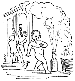
... “And, last of all, with inimitable power, and ‘with whirlwind sound,’ comes the potent agency of steam. In comparison with the past, what centuries of improvement has this single agent comprised in the short compass of fifty years! Everywhere practicable, everywhere efficient, it has an arm a thousand times stronger than that of Hercules, and to which human ingenuity is capable of fitting a thousand times as many hands as belonged to Briareus. Steam is found in triumphant operation on the seas; and, under the influence of its strong propulsion, the gallant ship—
It is on the rivers, and the boatman may repose on his oars; it is on highways, and exerts itself along the courses of land-conveyance; it is at the bottom of mines, a thousand feet below the earth’s surface; it is in the mills, and in the workshops of the trades. It rows, it pumps, it excavates, it carries, it draws, it lifts, it hammers, it spins, it weaves, it prints. It seems to say to men, at least to the class of artisans: ‘Leave off your manual labor; give over your bodily toil; bestow but your skill and reason to the directing of my power, and I will bear the toil, with no muscle to grow weary, no nerve to relax, no breast to feel faintness!’ What further improvement may still be made in the use of this astonishing power it is impossible to know, and it were vain to conjecture. What we do know is, that it has most essentially altered the face of affairs, and that no visible limit yet appears beyond which its progress is seen to be impossible.”—Daniel Webster.
By the middle of the present century, as we have now seen, the steam-engine had been applied, and successfully, to every great purpose for which it was fitted. Its first application was to the elevation of water; it next was applied to the driving of mills and machinery; and it finally[304] became the great propelling power in transportation by land and by sea.
At the beginning of the period to which we are now come, these applications of steam-power had become familiar both to the engineer and to the public. The forms of engine adapted to each purpose had been determined, and had become usually standard. Every type of the modern steam-engine had assumed, more or less closely, the form and proportions which are now familiar; and the most intelligent designers and builders had been taught—by experience rather than by theory, for the theory of the steam-engine had then been but little investigated, and the principles and laws of thermo-dynamics had not been traced in their application to this engine—the principles of construction essential to successful practice, and were gradually learning the relative standing of the many forms of steam-engine, from among which have been preserved a few specially fitted for certain specific methods of utilization of power.
During the years succeeding the date 1850, therefore, the growth of the steam-engine had been, not a change of standard type, or the addition of new parts, but a gradual improvement in forms, proportions, and arrangements of details; and this period has been marked by the dying out of the forms of engine least fitted to succeed in competition with others, and the retention of the latter has been an example of “the survival of the fittest.” This has therefore been a Period of Refinement.
During this period invention has been confined to details; it has produced new forms of parts, new arrangements of details; it has devised an immense variety of valves, valve-motions, regulating apparatus, and a still greater variety of steam-boilers and of attachments, essential and non-essential, to both engines and boilers. The great majority of these peculiar devices have been of no value, and very many of the best of them have been found[305] to have about equal value. All the well-known and successful forms of engine, when equally well designed and constructed and equally well managed, are of very nearly equal efficiency; all of the best-known types of steam-boiler, where given equal proportions of grate to heating-surface and equally well designed, with a view to securing a good draught and a good circulation of water, have been found to give very nearly equally good results; and it has become evident that a good knowledge of principles and of practice, on the part of the designer, the constructor, and the manager of the boiler, is essential in the endeavor to achieve economical success; that good engineering is demanded, rather than great ingenuity. The inventor has been superseded here by the engineer.
The knowledge acquired in the time of Watt, of the essential principles of steam-engine construction, has since become generally familiar to the better class of engineers. It has led to the selection of simple, strong, and durable forms of engine and boiler, to the introduction of various kinds of valves and of valve-gearing, capable of adjustment to any desired range of expansive working, and to the attachment of efficient forms of governor to regulate the speed of the engine, by determining automatically the point of cut-off which will, at any instant, best adjust the energy exerted by the expanding steam to the demand made by the work to be done.
The value of high pressures and considerable expansion was recognized as long ago as in the early part of the present century, and Watt, by combining skillfully the several principal parts of the steam-engine, gave it very nearly the shape which it has to-day. The compound engine, even, as has been seen, was invented by contemporaries of Watt, and the only important modifications since his time have occurred in details. The introduction of the “drop cut-off,” the attachment of the governor to the expansion-apparatus in such a manner as to determine the degree of[306] expansion, the improvement of proportions, the introduction of higher steam and greater expansion, the improvement of the marine engine by the adoption of surface-condensation, in addition to these other changes, and the introduction of the double-cylinder engine, after the elevation of steam-pressure and increase of expansion had gone so far as to justify its use, are the changes, therefore, which have taken place during this last quarter-century. It began then to be generally understood that expansion of steam produced economy, and mechanics and inventors vied with each other in the effort to obtain a form of valve-gear which should secure the immense saving which an abstract consideration of the expansion of gases according to Marriotte’s law would seem to promise. The counteracting phenomena of internal condensation and reëvaporation, of the losses of heat externally and internally, and of the effect of defective vacuum, defective distribution of steam, and of back-pressure, were either unobserved or were entirely overlooked.
It was many years, therefore, before engine-builders became convinced that no improvement upon existing forms of expansion-gear could secure even an approximation to theoretical efficiency.
The fact thus learned, that the benefit of expansive working has a limit which is very soon reached in ordinary practice, was not then, and has only recently become, generally known among our steam-engine builders, and for several years, during the period upon which we now enter, there continued the keenest competition between makers of rival forms of expansion-gear, and inventors were continually endeavoring to produce something which should far excel any previously-existing device.
In Europe, as in the United States, efforts to “improve” standard designs have usually resulted in injuring their efficiency, and in simply adding to the first cost and running expense of the engines, without securing a marked increase in economy in the consumption of steam.
“Stationary Engines” had been applied to the operation of mill-machinery, as has been seen, by Watt and by Murdoch, his assistant and pupil; and Watt’s competitors, in Great Britain and abroad, had made considerable progress before the death of the great engineer, in its adaptation to its work. In the United States, Oliver Evans had introduced the non-condensing high-pressure stationary engine, which was the progenitor of the standard engine of that type which is now used far more generally than any other form. These engines were at first rude in design, badly proportioned, rough and inaccurate as to workmanship, and uneconomical in their consumption of fuel. Gradually, however, when made by reputable builders, they assumed neat and strong shapes, good proportions, and were well made and of excellent materials, doing their work with comparatively little waste of heat or of fuel.
One of the neatest and best modern designs of stationary engine for small powers is seen in Fig. 93, which represents a “vertical direct-acting engine,” with base-plate—a form which is a favorite with many engineers.
The engine shown in the engraving consists of two principal parts, the cylinder and the frame, which is a tapering column having openings in the sides, to allow free access to all the working parts within. The slides and pillow-blocks are cast with the column, so that they cannot become loose or out of line; the rubbing surfaces are large and easily lubricated. Owing to the vertical position, there is no tendency to side wear of cylinder or piston. The packing-rings are self-adjusting, and work free but tight. The crank is counterbalanced; the crank-pin, cross-head pin, piston-rod, valve-stem, etc., are made of steel; all the bearing surfaces are made extra large, and are accurately fitted; and the best quality of Babbitt-metal only used for the journal-bearings.
[308]The smaller sizes of these engines, from 2 to 10 horse-power, have both pillow-blocks cast in the frame, giving a bearing each side of the double cranks. They are built by some constructors in quantities, and parts duplicated by[309] special machinery (as in fire-arms and sewing-machines), which secures great accuracy and uniformity of workmanship, and allows of any part being quickly and cheaply replaced, when worn or broken by accident. The next figure is a vertical section through the same engine.
Engines fitted with the ordinary rigid bearings require to be erected on a firm foundation, and to be kept in perfect line. If, by the settling of the foundation, or from any other cause, they get out of line, heating, cutting, and thumping result. To obviate this, modern engines are often fitted with self-adjusting bearings throughout; this gives the engine great flexibility and freedom from friction. The accompanying cuts show clearly how this is accomplished.[310] The pillow-block has a spherical shell turned and fitted into the spherically-bored pillow-block, thus allowing a slight angular motion in any direction. The connecting-rod is forged in a single piece, without straps, gibs, or key, and is mortised through at each end for the reception of the brass boxes, which are curved on their backs, and fit the cheek-pieces, between which they can turn to adjust themselves to the pins, in the plane of the axis of the rod. The adjustment for wear is made by wedge-blocks and set screws, as shown, and they are so constructed that the parts cannot get loose and cause a break-down. The cross-head has adjustable gibs on each side, turned to fit the slides, which are cast solidly in the frame, and bored out exactly in the line with the cylinder. This permits it freely to turn on its axis, and, in connection with the adjustable boxes in the connecting-rod, allows a perfect self-adjustment to the line of the crank-pin. The out-board bearing may be moved an inch or more out of position in any direction, without detriment to the running of the engine, all bearings accommodating themselves perfectly to whatever position the shaft may assume.
The ports and valve-passages are proportioned as in locomotive practice. The valve-seat is adapted to the ordinary plain slide or D-valve, should it be preferred, but the balanced piston slide-valve works with equal ease whether the steam-pressure is 10 or 100 pounds, and at the same time gives double steam and exhaust openings, which greatly facilitates the entrance of the steam to, and its escape from, the cylinder, thus securing a nearer approach to boiler-pressure and a less back-pressure, saving the power required to work an ordinary valve, and reducing the wear of valve-gear.
This is a type of engine frequently seen in the United States, but more rarely in Europe. It is an excellent form of engine. The vertical direct-acting engine is sometimes, though rarely, built of very considerable size, and these large engines are more frequently seen in rolling-mills than elsewhere.[311]
Where much power is required, the stationary engine is usually an horizontal direct-acting engine, having a more or less effective cut-off valve-gear, according to the size of engine and the cost of fuel. A good example of the simpler form of this kind of engine is the small horizontal slide-valve engine, with independent cut-off valve riding on the back of the main valve—a combination generally known among engineers as the Meyer system of valve-gear. This form of steam-engine is a very effective machine, and does excellent work when properly proportioned to yield the required amount of power. It is well adapted to an expansion of from four to five times. Its disadvantages are the difficulty which it presents in the attachment of the regulator, to determine the point of cut-off by the heavy work which it throws upon the governor when attached, and the rather inflexible character of the device as an expansive valve-gear. The best examples of this class of engine have neat heavy bed-plates, well-designed cylinders and details, smooth-working valve-gear, the expansion-valve adjusted by a right and left hand screw, and regulation secured by the attachment of the governor to the throttle-valve.
The engine shown in the accompanying illustration (Fig. 95) is an example of an excellent British stationary steam-engine. It is simple, strong, and efficient. The frame, front cylinder-head, cross-head guides, and crank-shaft “plumber-block,” are cast in one piece, as has so generally been done in the United States for a long time by some of our manufacturers. The cylinder is secured against the end of the bed-plate, as was first done by Corliss. The crank-pin is set in a counterbalanced disk. The valve-gear is simple, and the governor effective, and provided with a safety-device to prevent injury by the breaking of the governor-belt. An engine of this kind of 10 inches diameter of cylinder, 20 inches stroke of piston, is rated by the builders at about 25 horse-power; a similar engine 30 inches in diameter of cylinder would yield from[312-313] 225 to 250 horse-power. In this example, all parts are made to exact size by gauges standardized to Whitworth’s sizes.
In American engines (as is seen in Fig. 96), usually, two supports are placed—the one under the latter bearing, and the other under the cylinder—to take the weight of the engine; and through them it is secured to the foundation. As in the vertical engine already described, a valve is sometimes used, consisting of two pistons connected by a[314] rod, and worked by an ordinary eccentric. By a simple arrangement these pistons have always the same pressure inside as out, which prevents any leakage or blowing through; and they are said always to work equally as well and free from friction under 150 pounds pressure as under 10 pounds per square inch, and to require no adjustment. It is more usual, however, to adopt the three-ported valve used on locomotives, with (frequently) a cut-off valve on the back of this main valve, which cut-off valve is adjusted either by hand or by the governor.
Engines of the class just described are especially well fitted, by their simplicity, compactness, and solidity, to work at the high piston-speeds which are gradually becoming generally adopted in the effort to attain increased economy of fuel by the reduction of the immense losses of heat which occur in the expansion of steam in the metallic cylinders through which we are now compelled to work it.
One of the best known of recent engines is the Allen engine, a steam-engine having the same general arrangement of parts seen in the above illustration, but fitted with a peculiar valve-gear, and having proportions of parts which are especially calculated to secure smoothness of motion and uniformity of pressure on crank-pin and journals, at speeds so high that the inertia of the reciprocating parts becomes a seriously-important element in the calculation of the distribution of stresses and their effect on the dynamics of the machine.
In the Allen engine,[85] the cylinder and frame are connected as in the engine seen above, and the crank-disk, shaft-bearings, and other principal details, are not essentially different. The valve-gear[86] differs in having four valves, one at each end on the steam as well as on the exhaust side, all of which are balanced and work with very little resistance. These valves are not detachable, but are driven by[315] a link attached to and moved by an eccentric on the main shaft, the position of the valve-rod attachment to which link is determined by the governor, and the degree of expansion is thus adjusted to the work of the engine. The engine has usually a short stroke, not exceeding twice the diameter of cylinder, and is driven at very high speed, generally averaging from 600 to 800 feet per minute.[87] This high piston-speed and short stroke give very great velocity of rotation. The effect is, therefore, to produce an exceptional smoothness of motion, while permitting the use of small fly-wheels. Its short stroke enables entire solidity to be attained in a bed of rigid form, making it a very completely self-contained engine, adapted to the heaviest work, and requiring only a small foundation.
The journals of the shaft, and all cylindrical wearing surfaces, are finished by grinding in a manner that leaves them perfectly round. The crank-pin and cross-head pin are hardened before being ground. The joints of the valve-gear consist of pins turning in solid ferrules in the rod-ends, both hardened and ground. After years of constant use thus, no wear occasioning lost time in the valve-movements has been detected.
High speed and short strokes are essential elements of economy. It is now well understood that all the surfaces with which the steam comes in contact condense it.
Obviously, one way to diminish this loss is to reduce the extent of surface to which the steam is exposed. In engines of high speed and short stroke, the surfaces with which the steam comes in contact, while doing a given amount of work, present less area than in ordinary engines running at low speed. Where great steadiness of motion is desired, the expense of coupled engines is often incurred. Quick-running engines do not require to be coupled; a single engine may give greater uniformity of motion than is usually[316] obtained with coupled engines at ordinary speeds. The ports and valve-movements, the weight of the reciprocating parts, and the size and weight of the fly-wheels, should be calculated expressly for the speeds chosen.
The economy of the engine here described is unexcelled by the best of the more familiar “drop cut-off” engines.
An engine reported upon by a committee of the American Institute, of which Dr. Barnard was chairman, was non-condensing, 16 inches in diameter of cylinder, 30 inches stroke, making 125 revolutions per minute, and developed over 125 horse-power with 75 pounds of steam in the boiler, using 253∕4 pounds of steam per indicated horse-power, and 2.87 pounds of coal—an extraordinarily good performance for an engine of such small power.
The governor used on this engine is known as the Porter governor. It is given great power and delicacy by weighting it down, and thus obtaining a high velocity of rotation, and by suspending the balls from forked arms, which are given each two bearing-pins separated laterally so far as to permit considerable force to be exerted in changing speeds without cramping those bearings sufficiently to seriously impair the sensitiveness of the governor. This engine as a whole may be regarded as a good representative of the high-speed engine of to-day.
Since this change in the direction of high speeds has already gone so far that the “drop cut-off” is sometimes inapplicable, in consequence of the fact that the piston would, were such a valve-gear adopted, reach the end of its stroke before the detached valve could reach its seat; and since this progress is only limited by our attainments in mechanical skill and accuracy, it seems probable that the “positive-motion expansion-gear” type of engine will ultimately supersede the now standard “drop cut-off engine.”
The best known and most generally used class of stationary engines at the present time is, however, that which[317] has the so-called “drop cut-off,” or “detachable valve-gear.” The oldest well-known form of valve-motion of this description now in use is that known as the Sickels cut-off, patented by Frederick E. Sickels, an American mechanic, about the year 1841, and also built by Hogg, of New York, who placed it upon the engine of the steamer South America. The invention is claimed for both Hogg and Sickels. It was introduced by the inventor in a form which especially adapted it to use with the beam-engine used on the Eastern waters of the United States, and was adapted to stationary engines by Messrs. Thurston, Greene & Co., of Providence, R. I., who made use of it for some years before any other form of “drop cut-off” came into general use. The Sickels cut-off consisted of a set of steam-valves, usually independent of the exhaust-valves, and each raised by a catch, which could be thrown out, at the proper moment, by a wedge with which it came in contact as it rose with the opening valve. This wedge, or other equivalent device, was so adjusted that the valve should be detached and fall to its seat when the piston reached that point in its movement, after taking steam, at which expansion was to commence. From this point, no steam entering the cylinder, the piston was impelled by the expanding vapor. The valve was usually the double-poppet. Sickels subsequently invented what was called the “beam-motion,” to detach the valve at any point in the stroke. As at first arranged, the valve could only be detached during the earlier half-stroke, since at mid-stroke the direction of motion of the eccentric rod was reversed and the valve began to descend. By introducing a “wiper” having a motion transverse to that of the valve and its catch, and by giving this wiper a motion coincident with that of the piston by connecting it with the beam or other part of the engine moving with the piston, he obtained a kinematic combination which permitted the valve to be detached at any point in the stroke, adding a very simple contrivance which enabled the attendant to set the[318] wiper so that it should strike the catch at any time during the forward movement of the “beam-motion.”
On stationary engines, the point of cut-off was afterward determined by the governor, which was made to operate the detaching mechanism, the combination forming what is sometimes called an “automatic” cut-off. The attachment of the governor so as to determine the degree of expansion had been proposed before Sickels’s time. One of the earliest of these contrivances was that of Zachariah Allen, in 1834, using a cut-off valve independent of the steam-valve. The first to so attach the governor to a drop cut-off valve-motion was George H. Corliss, who made it a feature of the Corliss valve-gear in 1849. In the year 1855, N. T. Greene introduced a form of expansion-gear, in which he combined the range of the Sickels beam-motion device with the expansion-adjustment gained by the attachment of the governor, and with the advantages of flat slide-valves at all ports—both steam and exhaust.
Many other ingenious forms of expansion valve-gear have been invented, and several have been introduced, which, properly designed and proportioned to well-planned engines, and with good construction and management, should give economical results little if at all inferior to those just named. Among the most ingenious of these later devices is that of Babcock & Wilcox, in which a very small auxiliary steam-cylinder and piston is employed to throw the cut-off valve over its port at the instant at which the steam is to be cut off. A very beautiful form of isochronous governor is used on this engine, to regulate the speed of the engine by determining the point of cut-off.
In Wright’s engine, the expansion is adjusted by the movement, by the regulator, of cams which operate the steam-valves so that they shall hold the valve open a longer or shorter time, as required.
Since compactness and lightness are not as essential as in portable, locomotive, and marine engines, the parts are[319] arranged, in stationary engines, with a view simply to securing efficiency, and the design is determined by circumstances. It was formerly usual to adopt the condensing engine in mills, and wherever a stationary engine was required. In Europe generally, and to some extent in the United States, where a supply of condensing water is obtainable, condensing engines and moderate steam-pressures are still employed. But this type of engine is gradually becoming superseded by the high-pressure condensing engine, with considerable expansion, and with an expansion-gear in which the point of cut-off is determined by the governor.
The best-known engine of this class is the Corliss engine, which is very extensively used in the United States, and which has been copied very generally by European builders. Fig. 97 represents the Corliss engine. The horizontal steam-cylinder is bolted firmly to the end of the frame, which is so formed as to transmit the strain to the main journal with the greatest directness. The frame carries the guides for the cross-head, which are both in the same vertical plane. The valves are four in number, a steam and an exhaust valve being placed at each end of the steam-cylinder. Short steam-passages are thus secured, and[320] this diminution of clearance is a source of some economy. Both sets of valves are driven by an eccentric operating a disk or wrist-plate, E (Fig. 98), which vibrates on a pin projecting from the cylinder. Short links reaching from this wrist-plate to the several valves, D D, F F, move them with a peculiarly varying motion, opening and closing them rapidly, and moving them quite slowly when the port is either nearly open or almost closed. This effect is ingeniously secured by so placing the pins on the wrist-plate that their line of motion becomes nearly transverse to the direction of the valve-links when the limit of movement is approached. The links connecting the wrist-plate with the arms moving the steam-valves have catches at their extremities, which are disengaged by coming in contact, as the arm swings around with the valve-stem, with a cam adjusted by the governor. This adjustment permits the steam to follow the piston farther when the engine is caused to “slow down,” and thus tends to restore the proper speed. It disengages the steam-valve earlier, and expands the steam to a greater[321] extent, when the engine begins to run above the proper speed. When the catch is thrown out, the valve is closed by a weight or a strong spring. To prevent jar when the motion of the valve is checked, a “dash-pot” is used, invented originally by F. E. Sickels. This is a vessel having a nicely-fitted piston, which is received by a “cushion” of water or air when the piston suddenly enters the cylinder at the end of the valve-movement. In the original water dash-pot of Sickels, the cylinder is vertical, and the plunger or piston descends upon a small body of water confined in the base of the dash-pot. Corliss’s air dash-pot is now often set horizontally.
In the Greene steam-engine (Fig. 99), the valves are[322] four in number, as in the Corliss. The cut-off gear consists of a bar, A, moved by the steam-eccentric in a direction parallel with the centre-line of the cylinder and nearly coincident as to time with the piston. On this bar are tappets, C C, supported by springs and adjustable in height by the governor, G. These tappets engage the arms B B, on the ends of rock-shafts, E E, which move the steam-valves and remain in contact with them a longer or shorter time, and holding the valve open during a greater or less part of the piston-stroke, as the governor permits the tappets to rise with diminishing engine-speed, or forces them down as speed increases. The exhaust-valves are moved by an independent eccentric rod, which is itself moved by an eccentric set, as is usual with the Corliss and with other engines generally, at right angles with the crank. This engine, in consequence of the independence of the steam-eccentric, and of the contemporary movement of steam valve-motion and steam-piston, is capable of cutting off at any point from beginning to nearly the end of the stroke. The usual arrangement, by which steam and exhaust valves are moved by the same eccentric, only permits expansion with the range from the beginning to half-stroke. In the Corliss engine the latter construction is retained, with the object, in part, of securing a means of closing the valve by a “positive motion,” should, by any accident, the closing not be effected by the weight or spring usually relied upon.
[323]The steam-valve of the Greene engine, as designed by the author, is seen in Fig. 100, where the valve, G H, covering the port, D, in the steam-cylinder, A B, is moved by the rod, J J, connected to the rock-shaft, M, by the arm, L K. The line, K I, should, when carried out, intersect the valve-face at its middle point, under G.
The characteristics of the American stationary engine, therefore, are high steam-pressure without condensation, an expansion valve-gear with drop cut-off adjustable by the governor, high piston-speed, and lightness combined with strength of construction. The pressure most commonly adopted in the boilers which furnish steam to this type of engine is from 75 to 80 pounds per square inch; but a pressure of 100 pounds is not infrequently carried, and the latter pressure may be regarded as a “mean maximum,” corresponding to a pressure of 60 pounds at about the commencement of the period here considered—1850.
Very much greater pressures have, however, been adopted by some makers, and immensely “higher steam” has been experimented with by several engineers. As early as 1823, Jacob Perkins[88] commenced experimenting with steam of very great tension. As has already been stated, the usual pressure at the time of Watt was but a few pounds—5 or 7—in excess of that of the atmosphere. Evans, Trevithick, and Stevens, had previously worked steam at pressures of from 50 to 75 pounds per square inch, and pressures on the Western rivers and elsewhere in the United States had already been raised to 100 or 150 pounds, and explosions were becoming alarmingly frequent.
Perkins’s experimental apparatus consisted of a copper boiler, of a capacity of about one cubic foot, having sides 3 inches in thickness. It was closed at the bottom and top, and had five small pipes leading from the upper head.[324] This was placed in a furnace kept at a high temperature by a forced combustion. Safety-valves loaded respectively to 425 and 550 pounds per square inch were placed on each of two of the steam-pipes.
Perkins used the steam generated under these great pressures in a little engine having a piston 2 inches in diameter and a stroke of 1 foot. It was rated at 10 horse-power.[89]
In the year 1827, Perkins had attained working pressures, in a single-acting, single-cylinder engine, of upward of 800 pounds per square inch. At pressures exceeding 200 pounds, he had much trouble in securing effective lubrication, as all oils charred and decomposed at the high temperatures then unavoidably encountered, and he finally succeeded in evading this seemingly insurmountable obstacle by using for rubbing parts a peculiar alloy which required no lubrication, and which became so beautifully polished, after some wear, that the friction was less than where lubricants were used. At these high pressures Perkins seems to have met with no other serious difficulty. He condensed the exhaust-steam and returned it to the boiler, but did not attempt to create a vacuum in his condenser, and therefore needed no air-pump. Steam was cut off at one-eighth stroke.
In the same year, Perkins made a compound engine on the Woolf plan, and adopted a pressure of 1,400 pounds, expanding[325] eight times. In still another engine, intended for a steam-vessel, Perkins adopted, or proposed to adopt, 2,000 pounds pressure, cutting off the admission at one-sixteenth, in single-acting engines of 6 inches diameter of cylinder and 20 inches stroke of piston. The steam did not retain boiler-pressure at the cylinder, and this engine was only rated at 30 horse-power.[90]
Stuart follows a description of Perkins’s work in the improvement of the steam-engine and the introduction of steam-artillery by the remark:
“ ... No other mechanic of the day has done more to illustrate an obscure branch of philosophy by a series of difficult, dangerous, and expensive experiments; no one’s labors have been more deserving of cheering encouragement, and no one has received less. Even in their present state, his experiments are opening new fields for philosophical research, and his mechanism bids fair to introduce a new style into the proportions, construction, and form, of steam-machinery.”
Perkins’s experience was no exception to the general rule, which denies to nearly all inventors a fair return for the benefits which they confer upon mankind.
Another engineer, a few years later, was also successful in controlling and working steam under much higher pressures than are even now in use. This was Dr. Ernst Alban, a distinguished German engine-builder, of Plau, Mecklenburg, and an admirer of Oliver Evans, in whose path he, a generation later, advanced far beyond that great pioneer. Writing in 1843, he describes a system of engine and boiler construction, with which he used steam under pressures about equal to those experimentally worked by Jacob Perkins, Evans’s American successor. Alban’s treatise was translated and printed in Great Britain,[91] four years later.
[326]Alban, on one occasion, used steam of 1,000 pounds pressure. His boilers were similar in general form to the boiler patented by Stevens in 1805, but the tubes were horizontal instead of vertical. He evaporated from 8 to 10 pounds of water into steam of 600 to 800 pounds pressure with each pound of coal. He states that the difficulty met by Perkins—the decomposition of lubricants in the steam-cylinder—did not present itself in his experiments, even when working steam at a pressure of 600 pounds on the square inch, and he found that less lubrication was needed at such high pressures than in ordinary practice. Alban expanded his steam about as much as Evans, in his usual practice, carrying a pressure of 150 pounds, and cutting off at one-third; he adopted greatly increased piston-speed, attaining 300 feet per minute, at a time when common practice had only reached 200 feet. He usually built an oscillating engine, and rarely attached a condenser. The valve was the locomotive-slide.[92] The stroke was made short to secure strength, compactness, cheapness, and high speed of rotation; but Alban does not seem to have understood the principles controlling the form and proportions of the expansive engine, or the necessity of adopting considerable expansion in order to secure economy in working steam of great tension, and therefore was, apparently, not aware of the advantages of a long stroke in reducing losses by “dead-space,” in reducing risk of annoyance by hot journals, or in enabling high piston-speeds to be adopted. He seems never to have attained a sufficiently high speed of piston to become aware that the oscillating cylinder cannot be used at speeds perfectly practicable with the fixed cylinder.
Alban states that one of his smallest engines, having a cylinder 41∕2 inches in diameter and 1 foot stroke of piston, with a piston-speed of but 140 to 160 feet per minute, developed 4 horse-power, with a consumption of 5.3 pounds[327] of coal per hour. This is a good result for so small an amount of work, and for an engine working at so low a speed of piston. An engine of 30 horse-power, also working very slowly, required but 4.1 pounds of coal per hour per horse-power.
The work of Perkins and of Alban, like that of their predecessors, Evans, Stevens, and Trevithick, was, however, the work of engineers who were far ahead of their time. The general practice, up to the time which marked the beginning of the modern “period of refinement,” had been but gradually approximating that just described. Higher pressures were slowly approached; higher piston-speeds came slowly into use; greater expansion was gradually adopted; the causes of losses of heat were finally discovered, and steam-jacketing and external non-conducting coverings were more and more generally applied as builders became more familiar with their work. The “compound engine” was now and then adopted; and each experiment, made with higher steam and greater expansion, was more nearly successful than the last.
Finally, all these methods of securing economy became recognized, and the reasons for their adoption became known. It then remained, as the final step in this progression, to combine all these requisites of economical working in a double-cylinder engine, steam-jacketed, well protected by non-conducting coverings, working steam of high pressure, and with considerable expansion at high piston-speed. This is now done by the best builders.
One of the best examples of this type of engine is that constructed by the sons of Jacob Perkins, who continued the work of their father after his death. Their engines are single-acting, and the small or high-pressure cylinder is placed on the top of the larger or low-pressure cylinder. The valves are worked by rotating stems, and the loss of heat and burning of packing incident to the use of the common method are thus avoided. The stuffing-boxes are[328] placed at the end of long sleeves, closely surrounding the vertical valve-stems also, and the water of condensation which collects in these sleeves is an additional and thorough protection against excessively high temperature at the packing. The piston-rings are made of the alloy which has been found to require no lubrication.
Steam is usually worked at from 250 to 450 pounds, and is generated in boilers composed of small tubes three inches in diameter and three-eighths of an inch thick, which are tested under a pressure of 2,500 pounds per square inch. The safety-valve is usually loaded to 400 pounds. The boiler is fed with distilled water, obtained principally by condensation of the exhaust-steam, any deficiency being made up by the addition of water from a distilling apparatus. Under these conditions, but 11∕4 pound of coal is consumed per hour and per horse-power.
The Pumping-Engine in use at the present time has passed through a series of changes not differing much from that which has been traced with the stationary mill-engine. The Cornish engine is still used to some extent for supplying water to towns, and is retained at deep mines. The modern Cornish engine differs very little from that of the time of Watt, except in the proportions of parts and the form of its details. Steam-pressures are carried which were never reached during the preceding period, and, by careful adjustment of well-set and well-proportioned valves and gearing, the engine has been made to work rather more rapidly, and to do considerably more work. It still remains, however, a large, costly, and awkward contrivance, requiring expensive foundations, and demanding exceptional care, skill, and experience in management. It is gradually going out of use. This engine, as now constructed by good builders, is shown in section in Fig. 101.
A comparison with the Watt engine of a century earlier will at once enable any one to appreciate the extent to which changes may be made in perfecting a machine, even[329] after it has become complete, so far as supplying it with all essential parts can complete it.
In the figure, A is the cylinder, taking steam from the boiler through the steam-passage, M. The steam is first admitted above the piston, B, driving it rapidly downward and raising the pump-rod, E. At an early period in the stroke the admission of steam is checked by the sudden closing of the induction-valve at M, and the stroke is completed under the action of expanding steam assisted by the inertia of the heavy parts already in motion. The necessary weight and inertia is afforded, in many cases, where the engine is applied to the pumping of deep mines, by the[330] immensely long and heavy pump-rods. Where this weight is too great, it is counterbalanced, and where too small, weights are added. When the stroke is completed, the “equilibrium valve” is opened, and the steam passes from above to the space below the piston, and an equilibrium of pressure being thus produced, the pump-rods descend, forcing the water from the pumps and raising the steam-piston. The absence of the crank, or other device which might determine absolutely the length of stroke, compels a very careful adjustment of steam-admission to the amount of load. Should the stroke be allowed to exceed the proper length, and should danger thus arise of the piston striking the cylinder-head, N, the movement is checked by buffer-beams. The valve-motion is actuated by a plug-rod, J K, as in Watt’s engine. The regulation is effected by a “cataract,” a kind of hydraulic governor, consisting of a plunger-pump, with a reservoir attached. The plunger is raised by the engine, and then automatically detached. It falls with greater or less rapidity, its velocity being determined by the size of the eduction-orifice, which is adjustable by hand. When the plunger reaches the bottom of the pump-barrel, it disengages a catch, a weight is allowed to act upon the steam-valve, opening it, and the engine is caused to make a stroke. When the outlet of the cataract is nearly closed, the engine stands still a considerable time while the plunger is descending, and the strokes succeed each other at long intervals. When the opening is greater, the cataract acts more rapidly, and the engine works faster. This has been regarded until recently as the most economical of pumping-engines, and it is still generally used in freeing mines of water, and in situations where existing heavy pump-rods may be utilized in counterbalancing the steam-pressure, and, by their inertia, in continuing the motion after the steam, by its expansion, has become greatly reduced in pressure.
In this engine a gracefully-shaped and strong beam, D,[331] has taken the place of the ruder beam of the earlier period, and is carried on a well-built wall of masonry, R. F is the exhaust-valve, by which the steam passes to the condenser, G, beside which is the air-pump, H, and the hot-well, I. The cylinder is steam-jacketed, P, and protected against losses of heat by radiation by a brick wall, O, the whole resting on a heavy foundation, Q.
The Bull Cornish engine is also still not infrequently seen in use. The Cornish engine of Great Britain averages a duty of about 45,000,000 pounds raised one foot high per 100 pounds of coal. More than double this economy has sometimes been attained.
A vastly simpler form of pumping-engine without fly-wheel is the now common “direct-acting steam-pump.” This engine is generally made use of in feeding steam-boilers, as a forcing and fire pump, and wherever the[332] amount of water to be moved is not large, and where the pressure is comparatively great. The steam-cylinder, A R, and feed-pump, B Q (Fig. 102), are in line, and the two pistons have usually one rod, D, in common. The two cylinders are connected by a strong frame, N, and two standards fitted with lugs carry the whole, and serve as a means of bolting the pump to the floor or to its foundation.
The method of working the steam-valve of the modern steam-pump is ingenious and peculiar. As shown, the pistons are moving toward the left; when they reach the end of their stroke, the face of the piston strikes a pin or other contrivance, and thus moves a small auxiliary valve, I, which opens a port, E, and causes steam to be admitted behind a piston, or permits steam to be exhausted, as in the figure, from before the auxiliary piston, F, and the pressure within the main steam-chest then forces that piston over, moving the main steam-valve, G, to which it is attached, admitting steam to the left-hand side of the main piston, and exhausting on the right-hand side, A. Thus the motion of the engine operates its own valves in such a manner that it is never liable to stop working at the end of the stroke, notwithstanding the absence of the crank and fly-wheel, or of independent mechanism, like the cataract of the Cornish engine. There is a very considerable variety of pumps of this class, all differing in detail, but all presenting the distinguishing feature of auxiliary valve and piston, and a connection by which it and the main engine each works the valve of the other combination.
In some cases these pumps are made of considerable size, and are applied to the elevation of water in situations to which the Cornish engine was formerly considered exclusively applicable. The accompanying figure illustrates such a pumping-engine, as built for supplying cities with water. This is a “compound” direct-acting pumping-engine. The cylinders, A B, are placed in line, working one pump, F, and operating their own air-pumps, D D, by a bell-crank[333] lever, L H, connected to the pump-buckets by links, I K. Steam exhausted from the small cylinder, A, is further expanded in the large cylinder, B, and thence goes to the condenser, C. The valves, N M, are moved by the valve-gear, L, which is actuated by the piston-rod of a similar pair of cylinders placed by the side of the first. These[334] valves are balanced, and the balance-plates, R Q, are suspended from the rods, O P, which allow them to move with the valves. By connecting the valves of each engine with[335] the piston-rod of the other, it is seen that the two engines must work alternately, the one making a stroke while the other is still, and then itself stopping a moment while the latter makes its stroke.
Water enters the pump through the induction-pipe, E, passes into the pump-barrel through the valves, V V, and issues through the eduction-valves, T T, and goes on to the “mains” by the pipe, G, above which is seen an air-chamber, which assists to preserve a uniform pressure on that side the pump. This engine works very smoothly and quietly, is cheap and durable, and has done excellent duty.
Beam pumping-engines are now almost invariably built with crank and fly-wheel, and very frequently are compound engines. The accompanying illustration represents an engine of the latter form.
A and B are the two steam-cylinders, connected by links and parallel motion, C D, to the great cast-iron beam, E F. At the opposite end of the beam, the connecting-rod,[336] G, turns a crank, H, and fly-wheel, L M, which regulates the motion of the engine and controls the length of stroke, averting all danger of accident occurring in consequence of the piston striking either cylinder-head. The beam is carried on handsomely-shaped iron columns, which, with cylinders, pump, and fly-wheel, are supported by a[337] substantial stone foundation. The pump-rod, I, works a double-acting pump, J, and the resistance to the issuing water is rendered uniform by an air-chamber, K, within which the water rises and falls when pressures tend to vary greatly. A revolving shaft, N, driven from the fly-wheel shaft, carries cams, O P, which move the lifting-rods seen directly over them and the valves which they actuate. Between the steam-cylinders and the columns which carry the beams is a well, in which are placed the condenser and air-pump. Steam is carried at 60 or 80 pounds pressure, and expanded from 6 to 10 times.
A later form of double-cylinder beam pumping-engine is that invented and designed by E. D. Leavitt, Jr., for the Lawrence Water-Works, and shown in Figs. 106 and 107. The two cylinders are placed one on each side the centre of the beam, and are so inclined that they may be coupled to[338] opposite ends of it, while their lower ends are placed close together. At their upper ends a valve is placed at each end of the connecting steam-pipe. At their lower ends a single valve serves as exhaust-valve to the high-pressure and as steam-valve to the low-pressure cylinder. The pistons move in opposite directions, and steam is exhausted from the high-pressure cylinder directly into the nearer end of the low-pressure cylinder. The pump, of the “Thames-Ditton” or “bucket-and-plunger” variety, takes a full supply of water on the down-stroke, and discharges half when rising and half when descending again. The duty of this engine is reported by a board of engineers as 103,923,215 foot-pounds for every 100 pounds of coal burned. The duty of a moderately good engine is usually considered to be from 60 to 70 millions. This engine has steam-cylinders of 171∕2 and 36 inches diameter respectively, with a stroke of 7 feet. The pump had a capacity of about 195 gallons, and delivered 96 per cent. Steam was carried at a pressure of 75 pounds above the atmosphere, and was expanded about 10 times. Plain horizontal tubular boilers were used, evaporating 8.58 pounds of water from 98° Fahr. per pound of coal.
Steam-boilers.—The steam supplied to the forms of stationary engine which have been described is generated in steam-boilers of exceedingly varied forms. The type used is determined by the extent to which their cost is increased in the endeavor to economize fuel by the pressure of steam carried, by the greater or less necessity of providing against risk of explosion, by the character of the feed-water to be used, by the facilities which may exist for keeping in good repair, and even by the character of the men in whose hands the apparatus is likely to be placed.
As has been seen, the changes which have marked the growth and development of the steam-engine have been accompanied by equally marked changes in the forms of the steam-boiler. At first, the same vessel served the distinct[339] purposes of steam-generator and steam-engine. Later, it became separated from the engine, and was then specially fitted to perform its own peculiar functions; and its form went through a series of modifications under the action of the causes already stated.
When steam began to be usefully applied, and considerable pressures became necessary, the forms given to boilers were approximately spherical, ellipsoidal, or cylindrical. Thus the boilers of De Caus (1615) and of the Marquis of Worcester (1663) were spherical and cylindrical; those of Savery (1698) were ellipsoidal and cylindrical. After the invention of the steam-engine of Newcomen, the pressures adopted were again very low, and steam-boilers were given irregular forms until, at the beginning of the present century, they were again of necessity given stronger shapes. The material was at first frequently copper; it is now usually wrought-iron, and sometimes steel.
The present forms of steam-boilers may be classified as plain, flue, and tubular boilers. The plain cylindrical or common cylinder boiler is the only representative of the first class in common use. It is perfectly cylindrical, with heads either flat or hemispherical. There is usually attached to the boiler a “steam-drum” (a small cylindrical vessel), from which the steam is taken by the steam-pipe. This enlargement of the steam-space permits the mist, held in suspension by the steam when it first rises from the surface of the water, to separate more or less completely before the steam is taken from the boiler.
Flue-boilers are frequently cylindrical, and contain one or more cylindrical flues, which pass through from end to end, beneath the water-line, conducting the furnace-gases, and affording a greater area of heating-surface than can be obtained in the plain boiler. They are usually from 30 to 48 inches in diameter, and one foot or less in length for each inch of diameter. Some are, however, made 100 feet and more in length. The boiler is made of iron 1∕4 to 3∕8 of an[340] inch in thickness, with hemispherical or carefully stayed flat heads, and without flues. The whole is placed in a brickwork setting. These boilers are used where fuel is inexpensive, where the cost of repairing would be great, or where the feed-water is impure. A cylindrical boiler, having one flue traversing it longitudinally, is called a Cornish boiler, as it is generally supposed to have been first used in Cornwall. It was probably first invented by Oliver Evans in the United States, previous to 1786, at which time he had it in use. The flue has usually a diameter 0.5 or 0.6 the diameter of the boiler. A boiler containing two longitudinal flues is called the Lancashire boiler. This form was also introduced by Oliver Evans. The flues have one-third the diameter of the boiler. Several flues of smaller diameter are often used, and when a still greater proportional area of heating-surface is required, tubes of from 11∕4 inch to 4 or 5 inches in diameter are substituted for flues. The flues are usually constructed by riveting sheets together, as in making the shell or outer portion. They are sometimes welded by British manufacturers, but rarely if ever in the United States. Tubes are always “lap-welded” in the process of rolling them. Small tubes were first used in the United States, about 1785. In portable, locomotive, and marine steam-boilers, the fire must be built within the boiler itself, instead of (as in the above described stationary boilers) in a furnace of brickwork exterior to the boiler. The flame and gases from the furnace or fire-box in these kinds of boiler are never led through brick passages en route to the chimney, as often in the preceding case, but are invariably conducted through flues or tubes, or both, to the smoke-stack. These boilers are also sometimes used as stationary boilers. Fig. 108 represents such a steam-boiler in section, as it is usually exhibited in working drawings. Provision is made to secure a good circulation of water in these boilers by means of the “baffle-plates,” seen in the sketch, which compel the water to flow as indicated by the[341] arrows. The tubes are frequently made of brass or of copper, to secure rapid transmission of heat to the water, and thus to permit the use of a smaller area of heating-surface and a smaller boiler. The steam-space is made as large as possible, to secure immunity from “priming” or the “entrainment” of water with the steam. This type of steam-boiler, invented by Nathan Read, of Salem, Mass., in 1791, and patented in April of that year, was the earliest of the tubular boilers. In the locomotive boiler (Fig. 109), as in the preceding, the characteristics are a fire-box at one end of the shell and a set of tubes through which the gases pass[342] directly to the smoke-stack. Strength, compactness, great steaming capacity, fair economy, moderate cost, and convenience of combination with the running parts, are secured by the adoption of this form. It is frequently used also for portable and stationary engines. It was invented in France by M. Seguin, and in England by Booth, and used by George Stephenson at about the same time—1828 or 1829.
Since the efficiency of a steam-boiler depends upon the extent of effective heating-surface per unit of weight of fuel burned in any given time—or, ordinarily, upon the ratio of the areas of heating and grate surface—peculiar expedients are sometimes adopted, having for their object the increase of heating-surface, without change of form of boiler and without proportionate increase of cost.
One of these methods is that of the use of Galloway conical tubes (Fig. 110). These are very largely used in[343] Great Britain, but are seldom if ever seen in the United States. The Cornish boiler, to which they are usually applied, consists of a large cylindrical shell, 6 feet or more in diameter, containing one tube of about one-half as great dimensions, or sometimes two of one-third the diameter of the shell each. Such boilers have a very small ratio of heating to grate surface, and their large tubes are peculiarly liable to collapse. To remove these objections, the Messrs. Galloway introduced stay-tubes into the flues, which tubes are conical in form, and are set in either a vertical or an inclined position, the larger end uppermost. The area of heating-surface is thus greatly increased, and, at the same time, the liability to collapse is reduced. The same results are obtained by another device of Galloway, which is sometimes combined with that just described in the same boiler. Several sheets in the flue have “pockets” worked into them, which pockets project into the flue-passage.
Another device is that of an American engineer, Miller, who surrounds the furnace of cylindrical and other boilers with water-tubes. The “fuel-economizers” of Greene and others consist of similar collections of tubes set in the flues, between the boiler and the chimney.
“Sectional” boilers are gradually coming into use with high pressures, on account of their greater safety against disastrous explosions. The earliest practicable example of a boiler of this class was probably that of Colonel John Stevens, of Hoboken, N. J. Dr. Alban, who, forty years later, attempted to bring this type into general use, and constructed a number of such boilers, did not succeed. Their introduction, like that of all radical changes in engineering, has been but slow, and it has been only recently that their manufacture has become an important branch of industry.[344]
A committee of the American Institute, of which the author was chairman, in 1871, examined several boilers of this and the ordinary type, and tested them very carefully. They reported that they felt “confident that the introduction of this class of steam-boilers will do much toward the removal of the cause of that universal feeling of distrust which renders the presence of a steam-boiler so objectionable in every locality. The difficulties in thoroughly inspecting these boilers, in regulating their action, and other faults of the class, are gradually being overcome, and the committee look forward with confidence to the time when their use will become general, to the exclusion of older and more dangerous forms of steam-boilers.”
The economical performance of these boilers with a similar ratio of heating to grate surface is equal to that of other kinds. In fact, they are usually given a somewhat higher ratio, and their economy of fuel frequently exceeds that of the other types. Their principal defect is their small capacity for steam and water, which makes it extremely difficult to obtain steady steam-pressure. Where they are employed, the feed and draught should be, if possible, controlled by automatic attachments, and the feed-water heated to the highest attainable temperature. Their satisfactory working depends, more than in other cases, on the ability of the fireman, and can only be secured by the exercise of both care and skill.
Many forms of these boilers have been devised. Walter Hancock constructed boilers for his steam-carriage of flat plates connected by stay-bolts, several such sections composing the boiler; and about the same time (1828) Sir Goldsworthy Gurney constructed for a similar purpose boilers consisting of a steam and a water reservoir, placed one above the other, and connected by triangularly-bent water-tubes exposed to the heat of the furnace-gases. Jacob Perkins made many experiments looking to the employment of very high steam-pressures, and in 1831 patented a boiler of[345] this class, in which the heating-surfaces nearest the fire were composed of iron tubes, which tubes also served as grate-bars. The steam and water space was principally comprised within a comparatively large chamber, of which the walls were secured by closely distributed stay-bolts. For extremely high pressures, boilers composed only of tubes were used. Dr. Ernst Alban described the boiler already referred to, and its construction and operation, and stated that he had experimented with pressures as high as 1,000 pounds to the square inch.
The Harrison steam-boiler, which has been many years in use in the United States, consists of several sections, each of which is made up of hollow globes of cast-iron, communicating with each other by necks cast upon the spheres, and fitted together with faced joints. Long bolts, extending from end to end of each row, bind the spheres together. (See Fig. 111.)
An example of another modern type in extensive use is given in Fig. 112, a semi-sectional boiler, which consists of a series of inclined wrought-iron tubes, connected by T-heads,[346] which form the vertical water-channels, at each end. The joints are faced by milling them, and then ground so perfectly tight that a pressure of 500 pounds to the square inch is insufficient to produce leakage. No packing is used. The fire is made under the front and higher end of the tubes, and the products of combustion pass up between the tubes into a combustion-chamber under the steam and water drum; hence they pass down between the tubes, then once more up through the space between the tubes, and off to the chimney. The steam is taken out at the top of the steam-drum near the back end of the boiler. The rapid circulation prevents to some extent the formation of deposits or incrustations upon the heating-surfaces, sweeping them away and depositing them in the mud-drum, whence they are blown out. Rapid circulation of water, as has been shown by Prof. Trowbridge, also assists in the extraction of the heat from the gases, by the presentation of fresh water continually, as well as by the prevention of incrustation.
[347]Attempts have been made to adapt sectional boilers to marine engines; but very little progress has yet been made in their introduction. The Root sectional boiler (Fig. 113), an American design, which is in extensive use in the United States and Europe, has also been experimentally placed in service on shipboard. Its heating-surface consists wholly of tubes, which are connected by a peculiarly formed series of caps; the joints are made tight with rubber “grummets.”
Engines and boilers, when of small size, are now often combined in one structure which may be readily transported. Where they have a common base-plate simply, as in Fig. 114, they are called, usually, “semi-portable engines.” These little engines have some decided advantages. Being attached to one base, the combined engine and boiler is[348] easily transported, occupies little space, and may very readily be mounted upon wheels, rendering it peculiarly well adapted for agricultural purposes.
The example here shown differs in its design from those usually seen in the market. The engine is not fastened to or upon the boiler, and is therefore not affected by expansion, nor are the bearings overheated by conduction or by ascending heat from the boiler. The fly-wheel is at the base, which arrangement secures steadiness at the high speed which is a requisite for economy of fuel. The boilers are of the upright tubular style, with internal fire-box,[349] and are intended to be worked at 150 pounds pressure per inch. They are fitted with a baffle-plate and circulating-pipe, to prevent priming, and also with a fusible plug, which will melt and prevent the crown-sheet of the boiler burning, if the water gets low.
Another illustration of this form of engine, as built in small sizes, is seen below. The peculiarity of this engine is, that the cylinder is placed in the top of the boiler, which is upright. By this arrangement the engine is constantly drawing from the boiler the hottest and driest steam, and there is thus no liability of serious loss by condensation, which is rapid, even in a short pipe, when the engine is separate from the boiler.
The engine illustrated is rated at 10 horse-power, and makers are always expected to guarantee their machines to[350] work up to the rated power. The cylinder is 7 by 7 inches, and the main shaft is directly over it. On this shaft are three eccentrics, one working the pump, one moving the valves, and the third one operating the cut-off. The driving-pulley is 20 inches in diameter, and the balance-wheel 30 inches. The boiler has 15 11∕4-inch flues. It is furnished with a heater in its lower portion. The boiler of this engine is tested up to 200 pounds, and is calculated to carry 100 pounds working pressure, though that is not necessary to develop the full power of the engine. The compactness of the whole machine is exceptional. It can be set up in a space 5 feet square and 8 feet high. The weight of the 10 horse-power engine is 1,540 pounds, and of the whole machine 4,890 pounds, boxed for shipment. Every part of the mechanism usually fits and works with the exactness of a gun-lock, as each piece is carefully made to gauge.
Portable engines are those which are especially intended to be moved conveniently from place to place. The engine is usually attached to the boiler, and the feed-pump is generally attached to the engine. The whole machine is carried on wheels, and is moved from one place to another, usually by horses, but sometimes by its own engine, which is coupled by an engaging and disengaging apparatus to the rear-wheels. English builders have usually excelled in the construction of this class of steam-engine, although it is probable that the best American engines are fully equal to them in design, material, and construction.
The later work of the best-known English builders has given economical results that have surprised engineers. The annual “shows” of the Royal Agricultural Society have elicited good evidence of skill in management as well as of excellence of design and construction. Some little portable engines have exhibited an economical efficiency superior to that of the largest marine engines of any but the compound type, and even closely competing with that form. The causes of this remarkable economy are readily[351] learned by an inspection of these engines, and by observation of the method of managing them at the test-trial. The engines are usually very carefully designed. The cylinders are nicely proportioned to their work, and their pistons travel at high speed. Their valve-gear consists usually of a plain slide-valve, supplemented by a separate expansion-slide, driven by an independent eccentric, and capable of considerable variation in the point of cut-off. This form of expansion-gear is very effective—almost as much so as a drop cut-off—at the usual grade of expansion, which is not far from four times. The governor is usually attached to a throttle-valve in the steam-pipe, an arrangement which is not the best possible under variable loads, but which produces no serious loss of efficiency when the engine is driven, as at competitive trials, under the very uniform load of a Prony strap-brake and at very nearly the maximum capacity of the machine. The most successful engines have had steam-jacketed cylinders—always an essential to maximum economy—with high steam and a considerable expansion. The boilers are strongly made, and are, as are also all other heated surfaces, carefully clothed with non-conducting material, and well lagged over all. The details are carefully proportioned, the rods and frames are strong and well secured together, and the bearings have large rubbing-surfaces. The connecting-rods are long and easy-working, and every part is capable of doing its work without straining and with the least friction.
In handling the engines at the competitive trial, most experienced and skillful drivers are selected. The difference between the performances of the same engine in different hands has been found to amount to from 10 to 15 per cent., even where the competitors were both considered exceptionally skillful men. In manipulating the engine, the fires are attended to with the utmost care; coal is thrown upon them at regular and frequent intervals, and a uniform depth of fuel and a perfectly clean fire are secured. The sides[352] and corners of the fire are looked after with especial care. The fire-doors are kept open the least possible time; not a square inch of grate-surface is left unutilized, and every pound of coal gives out its maximum of calorific power, and in precisely the place where it is needed. Feed-water is supplied as nearly as possible continuously, and with the utmost regularity. In some cases the engine-driver stands by his engine constantly, feeding the fire with coal in handfuls, and supplying the water to the heater by hand by means of a cup. Heaters are invariably used in such cases. The exhaust is contracted no more than is absolutely necessary for draught. The brake is watched carefully, lest irregularity of lubrication should cause oscillation of speed with the changing resistance. The load is made the maximum which the engine is designed to drive with economy. Thus all conditions are made as favorable as possible to economy, and they are preserved as invariable as the utmost care on the part of the attendant can make them.
These trials are usually of only three or five hours’ duration, and thus terminate before it becomes necessary to clean fires. The following are results obtained at the trial of engines which took place in July, 1870, at the Oxford Agricultural Fair:
| MAKER’S NAME AND RESIDENCE |
Cylinders. | Stroke. | Horse-Power. | Point of cut off. |
Revolutions per minute. |
Pounds coal per horse-power per hour. |
||||
| Number. | Diameter. | Nominal. | Dynamo- metric. |
|||||||
| Inches. | In. | |||||||||
| Clayton, Shuttleworth & Co., Lincoln | 1 | 7 | 12 | 4 | 4.42 | ..... | 121.6 | 5 | 3.73 | |
| Brown & May, Devizes | 1 | 7 | 3∕16 | 12 | 4 | 4.19 | 11.48 | 125.6 | 5 | 4.44 |
| Reading Iron-Works Company, Reading | 1 | 5 | 3∕4 | 14 | 4 | 4.16 | ..... | 145.7 | 4.65 | |
[353]These were horizontal engines, attached to locomotive boilers.
At a similar exhibition held at Bury, in 1867, considerably better results even than these were reported, as below, from engines of similar size and styles:
| MAKER’S NAME AND RESIDENCE |
Cylinders. | Stroke. | Horse-Power. | Point of cut off. |
Revolutions per minute. |
Pounds coal per horse-power per hour. |
||||
| Number. | Diameter. | Nominal. | Dynamo- metric. |
|||||||
| Inches. | In. | |||||||||
| Clayton, Shuttleworth & Co., Lincoln. | 1 | 10 | 20 | 10 | 11.00 | 3.1 | 0 | 71.5 | 4.13 | |
| Reading Iron-Works Company, Reading. | 1 | 8 | 5∕8 | 20 | 10 | 10.43 | 1.4 | 109.4 | 4.22 | |
With all these engines steam-jackets were used; the feed-water was highly and uniformly heated by exhaust-steam; the coal was selected, finely broken, and thrown on the fire with the greatest care; the velocity of the engines, the steam-pressure, and the amount of feed-water, were very carefully regulated, and all bearings were run quite loose; the engine-drivers were usually expert “jockeys.”
The next illustration represents the portable steam-engine as built by one of the oldest and most experienced manufacturers of such engines in the United States.
In the boilers of these engines the heating-surface is given less extent than in the stationary engine-boiler, but much greater than in the locomotive, and varies from 10 to 20 square feet per horse-power. The boilers are made very strong, to enable them to withstand the strains due to the attached engine, which are estimated as equivalent to from one-tenth to one-fifth that due to the steam-pressure. The[354] boiler is sometimes given even double the strength usual with stationary boilers of similar capacity. The engine is mounted, in this example, directly over the boiler, and all parts are in sight and readily accessible to the engineer.
One of these engines, of 20 horse-power, has a steam-cylinder 10 inches in diameter and 18 inches stroke of piston,[355] making 125 revolutions per minute, and has 9 square feet of grate-surface and 288 feet of heating-surface. It weighs about 41∕2 tons. Steam is carried at 125 pounds.
In the class of engines just described, the draught is obtained by the blast of the exhaust-steam which is led into the chimney. Such engines are now sold at from $120 to $150 per horse-power, according to size and quality, the smaller engines costing most. The usual consumption of fuel is from 4 to 6 pounds per hour and per horse-power, burning from 15 to 20 pounds on each square foot of grate, and each pound evaporating about 8 pounds of water. A usual weight is, for the larger sizes, 500 pounds per horse-power.
These engines are sometimes arranged to propel themselves,[356] as in the Mills “Thrashers’” road-engine or locomotive, of which the accompanying engraving is a good representation. This engine is proportioned for hauling a tank containing 10 barrels, or more, of water and a grain-separator over all ordinary roads, and to drive a thrashing-machine or saw-mill, developing 20 or 25 horse-power. This example of the road-engine has a boiler built to work at 250 pounds of steam; the engine is designed for a maximum power of 30 horses.
This engine has a balanced valve and automatic cut-off, and is fitted with a reversing-gear for use on the road. The driving-wheels are of wrought-iron, 56 inches diameter and 8 inches wide, with cast-iron driving-arms. Both wheels are drivers on curves as well as on straight lines. The engine is guided and fired by one man, and the total weight is so small that it will pass safely over any good country bridge. A brake is attached, to insure safety when going down-hill. Although designed to move at a speed of about three miles per hour, the velocity of the piston may be increased so that four miles per hour may be accomplished when necessary.
This is an excellent example of this kind of engine as constructed at the present time. The strongly-built boiler, with its heater, the jacketed cylinder, and light, strong frame of the engine, the steel running-gear, the carefully-covered[357] surfaces of cylinder and boiler, and excellent proportions of details, are illustrations of good modern engineering, and are in curious contrast with the first of the class, built a century earlier by Smeaton.
Steam-carriages for passengers are now rarely built. Fig. 118 represents that designed by Fisher about 1870 or earlier. It was only worked experimentally.
The above is an engraving of a road and farm locomotive as built by one of the most successful among several British firms engaged in this work.
The capacity of these engines has been determined by experiment by the author in the United States, and abroad by several distinguished engineers.
The author made a trial of one of these engines at South Orange, N. J., to determine its power, speed, and convenience of working and manœuvring. The following were the principal dimensions:
| Weight of engine, complete, 5 tons 4 cwt. | 11,648 | pounds. | |||
| Steam-cylinder—diameter | 7 | 3∕4 | inches. | ||
| Stroke of piston | 10 | inches. | |||
| Revolution of crank to one of driving-wheels | 17 | ||||
| Driving-wheels— | diameter | 60 | inches. | ||
| „ | breadth of tire | 10 | inches. | ||
| „ | weight, each | 450 | pounds. | ||
| Boiler— | length over all | 8 | feet. | ||
| „ | diameter of shell | 30 | feet. | ||
| „ | thickness of shell | 7∕16 | inch. | ||
| „ | fire-box sheets, outside, thickness | 1∕2 | inch. | ||
| Load on driving-wheels, 4 tons 10 cwt. | 10,080 | pounds. | |||
The boiler was of the ordinary locomotive type, and the engine was mounted upon it, as is usual with portable engines.
The steam-cylinder was steam-jacketed, in accordance with the most advanced practice here and abroad. The crank-shaft and other wrought-iron parts subjected to heavy strains were strong and plainly finished. The gearing was of malleableized cast-iron, and all bearings, from crank-shaft to driving-wheel, on each side, were carried by a single sheet of half-inch plate, which also formed the sides of the fire-box exterior.
The following is a summary of the conclusions deduced by the author from the trial, and published in the Journal of the Franklin Institute: A traction-engine may be so constructed as to be easily and rapidly manœuvred on the common road; and an engine weighing over 5 tons may be turned continuously without difficulty on a circle of 18 feet radius, or even on a road but little wider than the length of the engine. A locomotive of 5 tons 4 hundredweight has been constructed, capable of drawing on a good road 23,000 pounds up a grade of 533 feet to the mile, at the rate of four miles an hour; and one might be constructed to draw more than 63,000 pounds up a grade of 225 feet to the mile, at the rate of two miles an hour.
It was further shown that the coefficient of traction[359] with heavily-laden wagons on a good macadamized road is not far from .04; the traction-power of this engine is equal to that of 20 horses; the weight, exclusive of the weight of the engine, that could be drawn on a level road, was 163,452 pounds; and the amount of fuel required is estimated at 500 pounds a day. The advantages claimed for the traction-engine over horse-power are: no necessity for a limitation of working-hours; a difference in first cost in favor of steam; and in heavy work on a common road the expense by steam is less than 25 per cent. of the average cost of horse-power, a traction-engine capable of doing the work of 25 horses being worked at as little expense as 6 or 8 horses. The cost of hauling heavy loads has been estimated at 7 cents per ton per mile.
Such engines are gradually becoming useful in steam-ploughing. Two systems are adopted. In the one the engine is stationary, and hauls a “gang” of ploughs by means of a windlass and wire rope; in the other the engine traverses a field, drawing behind it a plough or a gang of ploughs. The latter method has been proposed for breaking up prairie-land.
Thus, thirty years after the defeat of the intelligent, courageous, and persistent Hancock and his coworkers in the scheme of applying the steam-engine usefully on the common road, we find strong indications that, in a new form, the problem has been again attacked, and at least partially solved.
One of the most important of the prerequisites to ultimate success in the substitution of steam for animal power on the highway is that our roads shall be well made. As the greatest care and judgment are exercised, and an immense outlay of capital is considered justifiable, in securing easy grades and a smooth track on our railroad routes, we may readily believe that similar precaution and outlay will be found advisable in adapting the common road to the road-locomotive. It would seem to the engineer that the[360] natural obstacles generally supposed to stand in the way have, after all, no real existence. The principal inconvenience that may be anticipated will probably arise from the carelessness or avarice of proprietors, which may sometimes cause them to appoint ignorant and inefficient engine-drivers, giving them charge of what are always excellent servants, but terrible masters. Nevertheless, as the transportation of passengers on railroads is found to be attended with less liability to loss of life or injury of person than their carriage by stage-coach, it will be found, very probably, that the general use of steam in transporting freight on common roads may be attended with less risk to life or property than to-day attends the use of horse-power.
The Steam Fire-Engine is still another form of portable engine. It is also one of the latest of all applications of steam-power. The steam fire-engine is peculiarly an American production. Although previously attempted, their permanently successful introduction has only occurred within the last fifteen years.
As early as 1830, Braithwaite and Ericsson, of London, England, built an engine with steam and pump cylinders of 7 and 61∕2 inches diameter, respectively, with 16 inches stroke of piston. This machine weighed 21∕2 tons, and is said to have thrown 150 gallons of water per minute to a height of between 80 and 100 feet. It was ready for work in about 20 minutes after lighting the fire. Braithwaite afterward supplied a more powerful engine to the King of Prussia, in 1832. The first attempt made in the United States to construct a steam fire-engine was probably that of Hodge, who built one in New York in 1841. It was a strong and very effective machine, but was far too heavy for rapid transportation. The late J. K. Fisher, who throughout his life persistently urged the use of steam-carriages and traction-engines, designing and building several, also planned a steam fire-engine. Two were built from his design by the Novelty Works, New York, about 1860, for Messrs. Lee & Larned.[361] They were “self-propellers,” and one of them, built for the city of Philadelphia, was sent to that city over the highway, driven by its own engines. The other was built for and used by the New York Fire Department, and did good service for several years. These engines were heavy, but very powerful, and were found to move at good speed under steam[362] and to manœuvre well. The Messrs. Latta, of Cincinnati, soon after succeeded in constructing comparatively light and very effective engines, and the fire department of that city was the first to adopt steam fire-engines definitely as their principal reliance. This change has now become general.
The steam fire-engine has now entirely displaced the old hand-engine in all large cities. It does its work at a fraction of the cost of the latter. It can force its water to a height of 225 feet, and to a distance of more than 300 feet horizontally, while the hand-engine can seldom throw it one-third these distances; and the “steamer” may be relied upon to work at full power many hours if necessary, while the men at the hand-engine soon become fatigued, and require frequent relief. The city of New York has 40 steam fire-engines. One engine to every 10,000 inhabitants is a proper proportion.
In the standard steam fire-engine (Fig. 120) reciprocating engines and pumps are adopted, as seen in section in Fig. 121, in which A is the furnace, and B the set of closely-set vertical fire-tubes in the boiler. C is the combustion-chamber, D the smoke-pipe, and R the steam-space. E is the steam-cylinder, and F the pump, which is seen to be double-acting. There are two pairs of engines and pumps, working on cranks, set at right angles, and turning a balance-wheel seen behind them. G is the feed-pump which supplies water to the boiler, H the air-chamber which equalizes the water-pressure, which reaches it through the pipe, I J. K is the feed-water tank, under the driver’s seat, L, which, with the engines and boiler, are carried on the frame, M M. The fireman stands on the platform, N. When it is necessary to move the machine, an endless chain connects the crank-shaft with the rear-wheels, and the engine, with pumps shut off, is thus made to drive the wheels at any desired speed.
A self-propelling engine by the Amoskeag Company[363] had the following dimensions and performance: Weight, 4 tons; speed, 8 miles per hour; steam-pressure, 75 pounds per square inch; height of stream from 11∕4-inch nozzle, 225 feet; 13∕4-inch nozzle, 150 feet; distance horizontally, 11∕4-inch[364-365] nozzle, 300 feet; 13∕4-inch, 250 feet—a performance which contrasts wonderfully with that of the hand-worked fire-engine which these engines have now superseded.
It has recently become common to construct the steam fire-engine with rotary engine and pump (Fig. 122). The superiority of a rotary motion for a steam-engine is apparently so evident that many attempts have been made to overcome the practical difficulties to which it is subject. One of these difficulties, and the principal one, has been the packing of the part which performs the office of the piston in the straight cylinder. Robert Stephenson once expressed the opinion that a rotary engine would never be made to work successfully, on account of this difficulty of packing. The most palpable of the advantages of the rotary engine are the reduction in the size of the engine, claimed to result from the great velocity of the piston; the avoidance of great accidental strains, especially noticed in propelling ships; and a great saving of the power which is asserted to be expended in the reciprocating engine in overcoming the inertia while changing the direction of the motions. These advantages adapt the rotary engine, in an especial manner, to the driving of a locomotive or steam fire-engine.
In the Holly rotary engine, seen in Fig. 123, eccentrics and sliding-cams, which are frequently used in rotary engines,[366] and which are objectionable on account of their great friction, are avoided. Corrugated pistons, or irregular cams, C D, are adopted, forming chambers within the cases. In the engine the steam enters at A, at the bottom of the case, and presses the cams apart. The only packing used is in the ends of the long metal cogs, which are ground to fit the case and are kept out by the momentum of the cams, assisted by a slight spring back of the packing-pieces. The friction on the pump (Fig. 124) is said to be less than in the engine. This is the reason given in support of the claim that the rotary engine forces water to a given distance with from one-fourth to one-third the steam-pressure necessary to drive all reciprocating engines. The smaller amount of power necessary to do the work, the less strain and consequent wear and tear upon the whole machine, are said to make it more durable and reliable. The pump being chambered, its liability to injury by the use of dirty or gritty water is lessened, and it is stated that it will last for years, pumping gritty water that would soon cut out a piston-pump. The pump used with this engine is, as shown in the above illustration, somewhat similar to the rotary engine driving it. Each of the revolving pistons has three long teeth bearing against the cylinder, and packed, to prevent leakage, like the engine-cams. They are carried on steel[367] shafts coupled to the engine-shafts. The water enters at E and is discharged at F, and the passages are purposely made large in order that sand, chips, and dirt, which may enter with the water, may pass through.
The rotary engine is gradually coming into use for various special purposes, where small power is called for, and where economy of fuel is not important; but it has never yet competed, and may perhaps never in the future compete, with the reciprocating-piston engine where large engines are required, or where even moderate economy of fuel is essential. This form of engine has assumed so little importance, in fact, in the application of the steam-engine, that comparatively little is known of its history. Watt invented a rotary engine, and Yule many years afterward (1836) constructed such engines at Glasgow. Lamb patented another in 1842, Behrens still another in 1847. Napier, Hall, Massey, Holly, La France, and others, have built engines of this class in later times. Nearly all consist either of cams rotating in gear, as in those above sketched, or of a piston set radially in a cylinder of small diameter, which turns on its axis within a much larger cylinder set eccentrically, the piston, as the former turns, sliding in and out of the smaller cylinder as its outer edge slides in contact with the inner surface of the larger. In some forms of rotary engine, a piston revolves on a central shaft, and a sliding abutment in the external cylinder serves to separate the steam from the exhaust side and to confine the steam expanding while doing work. Nearly all of these combinations are also used as pumps.
Fire-engines, made by the best-known American builders of engines, with reciprocating engines and pumps, such as are in general use in the United States, have become standard in general plan and arrangement of details. These are probably the best illustrations of extreme lightness, combined with strength of parts and working power, which have ever been produced in any branch of mechanical engineering.[368] By using a small boiler crowded with heating-surface, very carefully proportioned and arranged, and with small water-spaces; by adopting steel for running-gear and working parts wherever possible; by working at high piston-speed and with high steam-pressure; by selecting fuel with extreme care—by all these expedients, the steam fire-engine has been brought, in this country, to a state of efficiency far superior to anything seen elsewhere. Steam is raised with wonderful promptness, even from cold water, and water is thrown from the nozzle at the end of long lines of hose to great distances. But this combination of lightness with power is only attained at the expense of a certain regularity of action which can only be secured by greater water and steam capacity in the boiler. The small quantity of water contained within the boiler makes it necessary to give constant attention to the feed, and the tendency, almost invariably observed, to serious foaming and priming not only compels unintermitted care while running, but even introduces an element of danger which is not to be despised, even though the machine be in charge of the most experienced and skillful attendants. Even the greatest care, directed by the utmost skill, would not avail to prevent frequent explosions, were it not for the fact that it rarely, if ever, happens that accidents to such boilers occur from low water, unless the boiler is actually completely emptied of water. In driving them at fires, they frequently foam so violently that it is utterly impossible to obtain any clew to the amount of water present, and the attendant usually keeps his feed-pump on and allows the foaming to go on. As long as water is passing into the boiler it is very unlikely that any portion will become overheated and that accident will occur. Such management appears very reckless, and yet accident from such a cause is exceedingly rare.
The changes which have been made in Locomotive-Construction during the past few years have also been in the direction of the refinement of the earlier designs, and[369] have been accompanied by corresponding changes in all branches of railroad-work. The adjustment of parts to each other and proportioning them to their work, the modification of the minor details to suit changes of general dimensions, the improvement of workmanship, and the use of better material, have signalized this latest period. Special forms of engine have been devised for special kinds of work. Small, light tank-engines (Fig. 125), carrying their own fuel and water without “tenders,” are used for moving cars about terminal stations and for making up trains; powerful, heavy, slow-moving engines, of large boiler-capacity and with small wheels, are used on steep gradients and for hauling long trains laden with coal and heavy merchandise; and hardly less powerful but quite differently proportioned “express”-engines are used for passenger and mail service.
A peculiar form of engine (Fig. 126) has been designed by Forney, in which the whole weight of engine, tender, coal, and water, is carried by one frame and on one set of wheels, the permanent weight falling on the driving-wheels and the variable load on the truck. These engines have also a comparatively short wheel-base and high pulling-power. The lightest tank-engines of the first class mentioned weigh 8 or 10 tons; but engines much lighter than these,[370] even, are built for mines, where they are sent into the galleries to bring out the coal-laden wagons. The heaviest engines of this class attain weights of 20 or 30 tons. The heaviest engine yet constructed in the United States is said to be one in use on the Philadelphia & Reading Railroad,[371] having a weight of about 100,000 pounds, which is carried on 12 driving-wheels.
A locomotive has two steam-cylinders, either side by side within the frame, and immediately beneath the forward end of the boiler, or on each side and exterior to the frame. The engines are non-condensing, and of the simplest possible construction. The whole machine is carried upon strong but flexible steel springs. The steam-pressure is usually more than 100 pounds. The pulling-power is generally about one-fifth the weight under most favorable conditions, and becomes as low as one-tenth on wet rails. The fuel employed is wood in new countries, coke in bituminous coal districts, and anthracite coal in the eastern part of the United States. The general arrangement and the proportions of locomotives differ somewhat in different localities. In Fig. 127, a British express-engine, O is the boiler, N the fire-box, X the grate, G the smoke-box, and P the chimney. S is a spring and R a lever safety-valve, T is the whistle, L the throttle or regulator valve, E the steam-cylinder, and W the driving-wheel. The force-pump, B C, is driven from the cross-head, D. The frame is the base of the whole system, and all other parts are firmly secured to it. The boiler is made fast at one end, and provision is made for its expansion when heated. Adhesion is secured by throwing a proper[372] proportion of the weight upon the driving-wheel, W. This is from about 6,000 pounds on standard freight-engines,[373] having several pairs of drivers, to 10,000 pounds on passenger-engines, per axle. The peculiarities of the American type (Fig. 128) are the truck, I J, or bogie, supporting the forward part of the engine, the system of equalizers, or beams which distribute the weight of the machine equally over the several axles, and minor differences of detail. The cab or house, r, protecting the engine-driver and fireman, is an American device, which is gradually coming into use abroad also. The American locomotive is distinguished by its flexibility and ease of action upon even roughly-laid roads. In the sketch, which shows a standard American engine in section, A B is the boiler, C one of the steam-cylinders, D the piston, E the cross-head, connected to the crank-shaft, F, by the connecting-rod, G H the driving-wheels, I J the truck-wheels, carrying the truck, K L; N N is the fire-box, O O the tubes, of which but four are shown. The steam-pipe, R S, leads the steam to the valve-chest, T, in which is seen the valve, moved by the valve-gear, U V, and the link, W. The link is raised or depressed by a lever, X, moved from the cab. The safety-valve is seen at the top of the dome, at Y, and the spring-balance by which the load is adjusted is shown at Z. At a is the cone-shaped exhaust-pipe, by which a good draught is secured. The attachments b, c, d, e, f, g—whistle, steam-gauge, sand-box, bell, head-light, and “cow-catcher”—are nearly all peculiar, either in construction or location, to the American locomotive. The cost of passenger-locomotives of ordinary size is about $12,000; heavier engines sometimes cost $20,000. The locomotive is usually furnished with a tender, which carries its fuel and water. The standard passenger-engine on the Pennsylvania Railroad has four driving-wheels, 51∕2 feet diameter; steam-cylinders, 17 inches diameter and 2 feet stroke; grate-surface 151∕2 square feet, and heating-surface 1,058 square feet. It weighs 63,100 pounds, of which 39,000 pounds are on the drivers and 24,100 on the truck. The freight-engine has six driving-wheels,[374] 545∕8 inches in diameter. The steam-cylinders are 18 inches in diameter, stroke 22 inches, grate-surface 14.8 square feet, heating-surface 1,096 feet. It weighs 68,500 pounds, of which 48,000 are on the drivers and 20,500 on the truck. The former takes a train of five cars up an average grade of 90 feet to the mile. The latter is attached[375] to a train of 11 cars. On a grade of 50 feet to the mile, the former takes 7 and the latter 17 cars. Tank-engines for very heavy work, such as on grades of 320 feet to the mile, which are found on some of the mountain lines of road, are made with five pairs of driving-wheels, and with no truck. The steam-cylinders are 201∕8 inches in diameter, 2 feet stroke; grate-area, 153∕4 feet; heating-surface, 1,380 feet; weight with tank full, and full supply of wood, 112,000 pounds; average weight, 108,000 pounds. Such an engine has hauled 110 tons up this grade at the speed of 5 miles an hour, the steam-pressure being 145 pounds. The adhesion was about 23 per cent. of the weight.
In checking a train in motion, the inertia of the engine itself absorbs a seriously large portion of the work of the brakes. This is sometimes reduced by reversing the engine and allowing the steam-pressure to act in aid of the brakes. To avoid injury by abrasion of the surfaces of piston, cylinder, and the valves and valve-seats, M. Le Chatelier introduces a jet of steam into the exhaust-passages when reversing, and thus prevents the ingress of dust-laden air and the drying of the rubbing surfaces. This method of checking a train is rarely resorted to, however, except in case of danger. The introduction of the “continuous” or “air” brake, which can be thrown into action in an instant on every car of the train by the engine-driver, is so efficient that it is now almost universally adopted. It is one of the most important safeguards which American ingenuity has yet devised. In drawing a train weighing 150 tons at the rate of 60 miles an hour, about 800 effective horse-power is required. A speed of 80 miles an hour has been often attained, and 100 miles has probably been reached.
The American locomotive-engine has a maximum life which may be stated at about 30 years. The annual cost of repairs is from 10 to 15 per cent. of its first cost. On moderately level roads, the engine requires a pint of oil to each 25 miles, and a ton of coal to each 40 or 50 miles run.[376] One of the best-managed railroads in the United States reports expenses as follows for one month:
| Number “train-miles” run per ton of coal burned | 53.95 |
| Number “train-miles” run per quart of oil used | 34.44 |
| Passenger-cars hauled 1 mile per ton of coal | 275.7 |
| Other cars hauled 1 mile per ton of coal | 634.8 |
| Cost repairs per mile run | $2 43 |
| Cost fuel per mile run | 3 64 |
| Cost oil and waste per mile run | 62 |
| Cost wages of engine-men per mile run | 6 22 |
| All other expenses per mile | 1 91 |
| Total cost per “train-mile” run | 14 82 |
Although the above sketch and description represent the construction and performance of the standard locomotive of the present time, there are indications that the compound arrangement of engines will ultimately be adopted. This will involve a considerable change of proportions, greatly increasing the volume and weight of steam-cylinders, but enabling the designer to more than proportionally decrease the weight of boiler and the quantity of fuel carried. There is no serious objection to their use, however, and no insuperable difficulty in the construction of the “double-cylinder” type of engine for the locomotive. A few such engines have already been put in service. In these engines the high-pressure cylinder is placed on one side and the larger low-pressure cylinder on the other side of the locomotive, thus having but two cylinders, as in the older plan. The valve-gear is the Stephenson link, as in the ordinary engine. At starting, the steam is allowed to act on both pistons; but after a few revolutions the course of the steam is changed, and the exhaust from the smaller cylinder, instead of passing into the chimney, is sent to the larger cylinder, which is at the same time cut off from the main steam-pipe. When the engine is ascending a steep gradient the steam may, if necessary, be taken from the boiler into both cylinders, as when starting.[377] Compound engines of this kind have been used on the French line of railroad from Bayonne to Biarritz. They were designed by Mallet and built at Le Creuzot. The steam-cylinders are of 91∕2 and 153∕4 inches diameter, and of 173∕4 inches stroke of piston. The four driving-wheels are 4 feet in diameter, and the total weight of engine is 20 tons. The boiler has 4841∕2 square feet of heating-surface, and is built to carry 10 atmospheres pressure. When hauling trains of 50 tons at 25 miles an hour, these engines require about 15 pounds of good coal per mile.
The total length of the railways in operation in the United States on the 1st day of January, 1877, was 76,640 miles,[93] being an average of one mile of railway for every 600 inhabitants. The railways are as follows:
| Miles. | Miles. | Miles. | |||
| Alabama | 1,722 | Kentucky | 1,464 | Ohio | 4,680 |
| Alaska | 0 | Louisiana | 539 | Oregon | 251 |
| Arizona | 0 | Maine | 987 | Pennsylvania | 5,896 |
| Arkansas | 787 | Maryland | 1,092 | Rhode Island | 182 |
| California | 1,854 | Massachusetts | 1,825 | South Carolina | 1,352 |
| Colorado | 950 | Michigan | 3,437 | Tennessee | 1,638 |
| Connecticut | 925 | Minnesota | 2,024 | Texas | 2,072 |
| Dakota | 290 | Mississippi | 1,028 | Utah | 486 |
| Delaware | 285 | Missouri | 3,016 | Vermont | 810 |
| Florida | 484 | Montana | 0 | Virginia | 1,648 |
| Georgia | 2,308 | Nebraska | 1,181 | Washington | 110 |
| Idaho | 0 | Nevada | 714 | West Virginia | 576 |
| Illinois | 6,980 | New Hampshire | 942 | Wisconsin | 2,575 |
| Indiana | 4,072 | New Jersey | 1,594 | Wyoming | 459 |
| Indian Territory | 281 | New Mexico | 0 | ||
| Iowa | 3,937 | New York | 5,520 | Total | 76,640 |
| Kansas | 3,226 | North Carolina | 1,371 | ||
In 1873 came the great financial crisis, with its terrible results of interrupted production, poverty, and starvation, and an almost total cessation of the work of building new railroads. The largest number of miles ever built in any one year were constructed in 1872. The greatest mileage is in Illinois, reaching 6,589; the smallest in Rhode Island, 136, and in Washington Territory, 110. The State of Massachusetts has one mile of railroad to 4.86[378] miles of territory, this ratio being the greatest in the country. The longest road in operation is the Chicago & Northwestern, extending 1,500 miles; the shortest, the Little Saw-Mill Run Road in Pennsylvania, which is but three miles in length. The total capital of railways in the country is $6,000,000,000, or an average of $100,000 per mile. The earnings for the year 1872 amounted to $454,969,000, or $7,500 per mile. The largest net earnings recorded as made on any road were gained by the New York Central & Hudson River, $8,260,827; the smallest on several roads which not only earned nothing, but incurred a loss.
The catastrophe of 1873-’74 revealed the fact that the latter condition of railroad finances was vastly more common than had been suspected; and it is still doubtful whether the existing immense network of railroads which covers the United States can be made, as a whole, to pay even a moderate return on the money invested in their construction. At the period of maximum rate of extension of railroads in the United States—1873—the reported lengths of the railroads of Europe and America were as follows:[94]
Railroads in Europe and America in 1873.
| COUNTRIES. | Railroads, Miles. |
Population | Area, Sq. Miles. |
| United States | 71,565 | 40,232,000 | 2,492,316 |
| Germany | 12,207 | 40,111,265 | 212,091 |
| Austria | 5,865 | 35,943,592 | 227,234 |
| France | 10,333 | 36,469,875 | 201,900 |
| Russia in Europe | 7,044 | 71,207,794 | 1,992,574 |
| Great Britain, 1872 | 15,814 | 31,817,108 | 120,769 |
| Belgium | 1,301 | 4,839,094 | 11,412 |
| Netherlands | 886 | 3,858,055 | 13,464 |
| Switzerland | 820 | 2,669,095 | 15,233 |
| Italy | 3,667 | 26,273,776 | 107,961 |
| Denmark | 420 | 1,784,741 | 14,453 |
| Spain | 3,401 | 16,301,850 | 182,758 |
| Portugal | 453 | 3,987,867 | 36,510 |
| Sweden and Norway | 1,049 | 5,860,122 | 188,771 |
| Greece | 100 | 1,332,508 | 19,941 |
[379]The railroads in Great Britain comprise over 15,000 miles of track now being worked in the United Kingdom, on which have been expended $2,800,000,000. This sum is equal to five times the amount of the annual value of all the real property in Great Britain, and two-thirds of the national debt. After deducting all the working expenses, the gross net annual revenue of all the roads exceeds by $110,000,000 the total revenue from all sources of Belgium, Holland, Portugal, Denmark, Sweden and Norway. An army of 100,000 officers and servants is in the employ of the companies, and the value of the rolling-stock exceeds $150,000,000.
The changes which have now become completed in the marine steam-engine have been effected at a later date than those which produced the modern locomotive. On the American rivers the modification of the beam-engine since the time of Robert L. Stevens has been very slight. The same general arrangement is retained, and the details are little, if at all, altered. The pressure of steam is sometimes as high as 60 pounds per square inch.
The valves are of the disk or poppet variety, rising and falling vertically. They are four in number, two steam and two exhaust valves being placed at each end of the steam-cylinder. The beam-engine is a peculiarly American type, seldom if ever seen abroad. Fig. 130 is an outline sketch of this engine as built for a steamer plying on the Hudson River. This class of engine is usually adopted in vessels of great length, light draught, and high speed. But one steam-cylinder is commonly used. The cross-head is coupled to one end of the beam by means of a pair of links, and the motion of the opposite end of the beam is transmitted to the crank by a connecting-rod of moderate length. The beam has a cast-iron centre surrounded by a wrought-iron strap of lozenge shape, in which are forged[380] the bosses for the end-centres, or for the pins to which the connecting-rod and the links are attached. The main centre of the beam is supported by a “gallows-frame” of timbers so arranged as to receive all stresses longitudinally. The crank and shaft are of wrought-iron. The valve-gear is usually of the form already mentioned as the Stevens valve-gear, the invention of Robert L. and Francis B. Stevens. The condenser is placed immediately beneath the[381] steam-cylinder. The air-pump is placed close beside it, and worked by a rod attached to the beam. Steam-vessels on the Hudson River have been driven by such engines at the rate of 20 miles an hour. This form of engine is remarkable for its smoothness of operation, its economy and durability, its compactness, and the latitude which it permits in the change of shape of the long, flexible vessels in which it is generally used, without injury by “getting out of line.”
For paddle-engines of large vessels, the favorite type, which has been the side-lever engine, is now rarely built. For smaller vessels, the oscillating engine with feathering paddle-wheels is still largely employed in Europe. This style of engine is shown in Fig. 131. It is very compact, light, and moderately economical, and excels in simplicity. The usual arrangement is such that the feathering-wheel has the same action upon the water as a radial wheel of double diameter. This reduction of the diameter of the wheel, while retaining maximum effectiveness, permits a high speed of engine, and therefore less weight, volume, and cost. The smaller wheel-boxes, by offering less resistance to the wind, retard the progress of the vessel less than those[382] of radial wheels. Inclined engines are sometimes used for driving paddle-wheels. In these the steam-cylinder lies in an inclined position, and its connecting-rod directly connects the crank with the cross-head. The condenser and air-pump usually lie beneath the cross-head guides, and are worked by a bell-crank driven by links on each side the connecting-rod, attached to the cross-head. Such engines are used to some extent in Europe, and they have been adopted in the United States navy for side-wheel gunboats. They are also used on the ferry-boats plying between New York and Brooklyn.
Among the finest illustrations of recent practice in the construction of side-wheel steamers are those built for the several routes between New York and the cities of New England which traverse Long Island Sound. Our illustration exhibits the form of these vessels, and also shows well the modifications in structure and size which have been made during this generation. The later vessel is 325 feet long, 45 feet beam, 80 feet wide over the “guards,” and 16 feet deep, drawing 10 feet of water. The “frames” upon which the planking of the hull is fastened are of white-oak, and the lighter and “top” timbers of cedar and locust. The engine has a steam-cylinder 90 inches in diameter and 12 feet stroke of piston.[95] On each side the great saloons which extend from end to end of the upper deck are state-rooms, containing each two berths and elegantly furnished. The engine of this vessel is capable of developing about 2,500 horse-power. The great wheels, of which the paddle-boxes are seen rising nearly to the height of the hurricane-deck, are 371∕2 feet in diameter and 12 in breadth. The hull of this vessel, including all wood-work, weighs over 1,200 tons. The weight of the machinery is about 625 tons. The steamer makes 16 knots an hour when the engine is at its best speed—about 17 revolutions per minute—and its[383] average speed is about 14 knots on its route of 160 miles. The coal required to supply the furnaces of such a vessel and with such machinery would be about 3 tons per hour.[384] or a little over 21∕2 pounds per horse-power. The construction of such a vessel occupies, usually, about a year, and costs a quarter of a million dollars.
The non-condensing direct-acting engine is used principally on the Western rivers, driven by steam of from 100 to 150 pounds pressure, and exhausts its steam into the atmosphere. It is the simplest possible form of direct-acting engine. The valves are usually of the “poppet” variety, and are operated by cams which act at the ends of long levers having their fulcra on the opposite side of the valve, the stem of which latter is attached at an intermediate point. The engine is horizontal, and the connecting-rod directly attached to cross-head and crank-pin without intermediate mechanism. The paddle-wheel is used, sometimes as a stern-wheel, as in the plan of Jonathan Hulls of one and[385] a half century ago, sometimes as a side-wheel, as is most usual elsewhere. One of the most noted of these steamers, plying on the Mississippi, is shown in the preceding sketch.
One of the largest of these steamers was the Grand Republic,[96] a vessel 340 feet long, 56 feet beam, and 101∕4 feet depth. The draught of water of this great craft was 31∕2 feet forward and 41∕2 aft. The two sets of compound engines, 28 and 56 inches diameter and of 10 feet stroke, drive wheels 381∕2 feet in diameter and 18 feet wide. The boilers were steel. A steamer built still later on the Ohio has the following dimensions: Length, 225 feet; breadth, 351∕2 feet; depth, 5 feet; cylinders, 173∕8 inches in diameter, 6 feet stroke; three boilers. The hull and cabin were built at Jeffersonville, Ind. She has 40 large state-rooms. The cost of the steamer was $40,000.
These vessels have now opened to commerce the whole extent of the great Mississippi basin, transporting a large share of the products of a section of country measuring a million and a half square miles—an area equal to many times that of New York State, and twelve times that of the island of Great Britain—an area exceeding that of the whole of Europe, exclusive of Russia and Turkey, and capable, if as thoroughly cultivated as the Netherlands, of supporting a population of between three and four hundred millions of people.
The steam-engine and propelling apparatus of the modern ocean-steamer have now become almost exclusively the compound or double-cylinder engine, driving the screw. The form and the location of the machinery in the vessel vary with the size and character of the ship which it drives. Very small boats are fitted with machinery of quite a different kind from that built for large steamers, and war-vessels have usually been supplied with engines of a design radically different from that adopted for merchant-steamers.
The introduction of Steam-Launches and small pleasure-boats[386] driven by steam-power is of comparatively recent date, but their use is rapidly increasing. Those first built were heavy, slow, and complicated; but, profiting by experience, light and graceful boats are now built, of remarkable swiftness, and having such improved and simplified machinery that they require little fuel and can be easily[387] managed. Such boats have strong, carefully-modeled hulls, light and strong boilers, capable of making a large amount of dry steam with little fuel, and a light, quick-running engine, working without shake or jar, and using steam economically.
The above sketch represents the engine built by a New York firm for such little craft. This is the smallest size made for the market. It has a steam-cylinder 3 inches in diameter and a stroke of piston of 5 inches, driving a screw 26 inches in diameter and of 3 feet pitch. The maximum[388] power of the engine is four or five times the nominal power. The boiler is of the form shown in the illustrations of semi-portable engines, and has a heating-surface, in this case, of 75 square feet. The boat itself is like that seen on page 386, and is 25 feet long, of 5 feet 8 inches beam, and draws 21∕4 feet of water. These little machines weigh about 150 pounds per nominal horse-power, and the boilers about 300.
Some of these little vessels have attained wonderful speed. A British steam-yacht, the Miranda, 451∕2 feet in length, 53∕4 feet wide, and drawing 21∕2 feet of water, with a total weight of 33∕4 tons, has steamed nearly 181∕2 miles an hour for short runs. The boat was driven by an engine of 6 inches diameter of cylinder and 8 inches stroke of piston, making 600 revolutions per minute, driving a two-bladed screw 21∕2 feet in diameter and of 31∕3 feet pitch. Its machinery had a total weight of two tons. Another English yacht, the Firefly, is said to have made 18.94 miles an hour. A little French yacht, the Hirondelle, has attained a speed of 16 knots, equal to about 181∕2 miles, an hour. This was, however, a much larger vessel than the preceding. One of the most remarkable of these little steamers is a torpedo-boat built for the United States navy. This vessel is 60 feet long, 6 feet wide, and 5 feet deep; its screw is 38 inches in diameter and of 5 feet pitch, two-bladed, and is driven, by a very light engine and boiler, 400 revolutions per minute, the boat attaining a speed of 19 to 20 miles an hour. Another little vessel, the Vision, made nearly as great speed, developing 20 horse-power with engine and boiler weighing but about 400 pounds.
Yachts of high speed require such weight and bulk of engine that but little space is left for cabins, and they are usually exceedingly uncomfortable vessels. In the Miranda the weight of machinery is more than one-half the total weight of the whole. An illustration of the more comfortable and more generally liked pleasure-yacht is the Day Dream. The length is 105 feet, and the boat draws 51∕2[389] feet of water. There are two engines, having steam-cylinders 14 inches in diameter and of the same length of stroke, direct-acting, condensing, and driving a screw, of 7 feet diameter and of 101∕2 feet pitch, 135 revolutions a minute, giving the yacht a speed of 131∕2 knots an hour.
In larger vessels, as in yachts, in nearly all cases, the ordinary screw-engine is direct-acting. Two engines are placed side by side, with cranks on the shaft at an angle of 90° with each other. In merchant-steamers the steam-cylinders are usually vertical and directly over the crank-pins, to which the cross-heads are coupled. The condenser is placed behind the engine-frame, or, where a jet-condenser is used, the frame itself is sometimes made hollow, and serves as a condenser. The air-pump is worked by a beam connected by links with the cross-head. The general arrangement is like that shown in Figs. 137 and 138. For naval purposes such a form is objectionable, since its height is so great that it would be exposed to injury by shot. In naval engineering the cylinder is placed horizontally, as in Fig. 136, which is a sectional view, representing an horizontal, direct-acting naval screw-engine, with jet-condenser and double-acting air and circulating pumps. A is the steam-cylinder, B the piston, which is connected to the crank-pin by the piston-rod, D, and connecting-rod, E.[390] F is the cross-head guide. The eccentrics, G, operate the valve, which is of the “three-ported variety,” by a Stephenson link. Reversing is effected by the hand-wheel, C, which, by means of a gear, m, and a rack, k, elevates and depresses the link, and thus reverses the valve.
The trunk-engine, in which the connecting-rod is attached directly to the piston and vibrates within a trunk or cylinder secured to the piston, moving with it, and extending outside the cylinder, like an immense hollow piston-rod, is frequently used in the British navy. It has rarely been adopted in the United States.
[391]In nearly all steam-vessels which have been built for the merchant service recently, and in some naval vessels, the compound engine has been adopted. Figs. 137 and 138 represent the usual form of this engine. Here A A, B B are the small and the large, or the high-pressure and the low-pressure cylinders respectively. C C are the valve-chests. G G is the condenser, which is invariably a surface-condenser. The condensing water is sometimes directed around the tubes contained within the casing, G G, while the steam is exhausted around them and among them,[392] and sometimes the steam is condensed within the tubes, while the injection-water which is sent into the condenser to produce condensation passes around the exterior of the tubes. In either case, the tubes are usually of small diameter, varying from five-eighths to half an inch, and in length from four to seven feet. The extent of heating-surface is usually from one-half to three-fourths that of the heating-surface of the boilers.
The air and circulating pumps are placed on the lower part of the condenser-casting, and are operated by a crank on the main shaft at N; or they are sometimes placed as in the style of engine last described, and driven by a beam worked by the cross-head. The piston-rods, T S, are guided by the cross-heads, V V, working in slipper-guides, and to these cross-heads are attached the connecting-rods, X X, driving the cranks, M M. The cranks are now usually set at right angles; in some engines this angle is increased to 120°, or even 180°. Where it is arranged as here shown, an intermediate reservoir, P O, is placed between the two cylinders to prevent the excessive variations of pressure that would otherwise accompany the varying relative motions of the pistons, as the steam passes from the high-pressure to the low-pressure cylinder. Steam from the boilers enters the high-pressure steam-chest, x, and is admitted by the steam-valve alternately above and below the piston as usual. The exhaust steam is conducted through the exhaust passage around into the reservoir, P, whence it it is taken by the low-pressure cylinder, precisely as the smaller cylinder drew its steam from the boiler. From the large or low-pressure cylinder the steam is exhausted into the condenser. The valve-gear is usually a Stephenson link, g e, the position of which is determined, and the reversal of which is accomplished, by a hand-wheel, o, and screw, m n p, which, by the bell-crank, k i, are attached to the link, g e. The “box-framing” forms also the hot-well. The surface-condenser is cleared by a single-acting air-pump,[393] inside the frame, at T. The feed-pump and the bilge-pumps are driven from the cross-head of the air-pump.
The successful introduction of the double-cylinder engine was finally accomplished by the exertions of a few engineers, who were at once intelligent enough to understand its advantages, and energetic and enterprising enough to push it forward in spite of active opposition, and powerful enough, pecuniarily and in influence, to succeed. The most active and earnest of these eminent men was John Elder, of the firm of Randolph, Elder & Co., subsequently John Elder & Co., of Glasgow.[97]
Elder was of Scotch descent. His ancestors had, for[394] generations, shown great skill and talent in construction, and had always been known as successful millwrights. John Elder was born at Glasgow, March 8, 1824, and died in London, September 17, 1869. He was educated at the Glasgow High-School and in the College of Engineering at the University of Glasgow, where, however, his attendance was but for a short time. He learned the trade under his father in the workshops of the Messrs. Napier, and became an unusually expert draughtsman. After spending three years in charge of the drawing-office at the engine-building works of Robert Napier, where his father had been manager, Elder became a partner in the firm which had previously been known as Randolph, Elliott & Co., in the year 1852. The firm commenced building iron vessels in 1860.
In the mean time, the experiments of Hornblower and Wolff, of Allaire and Smith, and of McNaught, Craddock, and Nicholson, together with the theoretical investigations of Thompson, Rankine, Clausius, and others, had shown plainly in what direction to look for improvement upon then standard engines, and what direction practice was taking with all types. The practical deductions which were becoming evident were recognized very early by Elder, and he promptly began to put in practice the principles which his knowledge of thermo-dynamics and of mechanics enabled him to appreciate. He adopted the compound engine, and coupled his cranks at angles of 180°, in order to avoid losses due to the friction of the crank-shaft in its bearings, by effecting a partial counterbalancing of pressures on the journals. Elder was one of the first to point out the fact that the compound engine had proved itself more efficient than the single-cylinder engine, only when the pressure of steam carried and the extent to which expansion was adopted exceeded the customary practice of his time. His own practice was, from the first, successful, and from 1853 to 1867 he and his partners were continually engaged in the construction of steamers and fitting them with compound engines.
[395]The engines of their first vessel, the Brandon, required but 31∕4 pounds of coal per hour and per horse-power, in 1854, when the usual consumption was a third more. Five years later, they had built engines which consumed a third less than those of the Brandon; and thenceforward, for many years, their engines, when of large size, exhibited what was then thought remarkable economy, running on a consumption of from 21∕4 to 21∕2 pounds.
In the year 1865 the British Government ordered a competitive trial of three naval vessels, which only differed in the form of their engines. The Arethusa was fitted with trunk-engines of the ordinary kind; the Octavia had three steam-cylinders, coupled to three cranks placed at angles of 120° with each other; and the Constance was fitted with compound engines, two sets of three cylinders each, and each taking steam from the boiler into one cylinder, passing it through the other two with continuous expansion, and finally exhausting from the third into the condenser. These vessels, during one week’s steaming at sea, averaged, respectively, 3.64, 3.17, and 2.51 pounds of coal per hour and per horse-power, and the Constance showed a marked superiority in the efficiency of the mechanism of her engines, when the losses by friction were compared.
The change from the side-lever single-cylinder engine, with jet-condenser and paddle-wheels, to the direct-acting compound engine, with surface-condenser and screw-propellers, has occurred within the memory and under the observation of even young engineers, and it may be considered that the revolution has not been completely effected. This change in the design of engine is not as great as it at first seemed likely to become. Builders have but slowly learned the principles stated above in reference to expansion in one or more cylinders, and the earlier engines were made with a high and low pressure cylinder working on the same connecting-rod, and each machine consisted of four steam-cylinders. It was at last discovered that a high-pressure single-cylinder[396] engine exhausting into a separate larger low-pressure engine might give good results, and the compound engine became as simple as the type of engine which it displaced. This independence of high and low pressure engines is not in itself novel, for the plan of using the exhaust of a high-pressure engine to drive a low-pressure condensing engine was one of the earliest of known combinations.
The advantage of introducing double engines at sea is considerably greater than on land. The coal carried by a steam-vessel is not only an item of great importance in consequence of its first cost, but, displacing its weight or bulk of freight which might otherwise be carried, it represents so much non-paying cargo, and is to be charged with the full cost of transportation in addition to first cost. The best of steam-coal is therefore usually chosen for steamers making long voyages, and the necessity of obtaining the most economical engines is at once seen, and is fully appreciated by steamship proprietors. Again, an economy of one-fourth of a pound per horse-power per hour gives, on a large transatlantic steamer, a saving of about 100 tons of coal for a single voyage. To this saving of cost is to be added the gain in wages and sustenance of the labor required to handle that coal, and the gain by 100 tons of freight carried in place of the coal.
For many years the change which has here been outlined, in the forms of engine and the working of steam expansively, was retarded by the inefficiency of methods and tools used in construction. With gradual improvement in tools and in methods of doing work, it became possible to control higher steam and to work it successfully; and the change in this direction has been steadily going on up to the present time with all types of steam-engine. At sea this rise of pressure was for a considerable time retarded by the serious difficulty encountered in the tendency of the sulphate of lime to deposit in the boiler. When steam-pressure had risen to 25 pounds per square inch, it was[397] found that no amount of “blowing out” would prevent the deposition of seriously large quantities of this salt, while at the lower pressures at first carried at sea no troublesome precipitation occurred, and the only precaution necessary was to blow out sufficient brine to prevent the precipitation of common salt from a supersaturated solution. The introduction of surface-condensation was promptly attempted as the remedy for this evil, but for many years it was extremely doubtful whether its disadvantages were not greater than its advantages. It was found very difficult to keep the condensers tight, and boilers were injured by some singular process of corrosion, evidently due to the presence of the surface-condenser. The simple expedient of permitting a very thin scale to form in the boiler was, after a time, hit upon as a means of overcoming this difficulty, and thenceforward the greatest obstacle to the general introduction was the conservative disposition found among those who had charge of marine machinery, which conservatism regarded with suspicion every innovation. Another trouble arose from the difficulty of finding men neither too indolent nor too ignorant to take charge of the new condenser, which, more complicated and more readily disarranged than the old, demanded a higher class of attendants. Once introduced, however, the surface-condenser removed the obstacle to further elevation of steam-pressure, and the rise from 20 to 60 pounds pressure soon occurred. Elder and his competitors on the Clyde were the first to take advantage of the fact when these higher pressures became practicable.
The lightness of engine and the smaller weight of boiler secured when the simpler type of “compound” engine is used are great advantages, and, when coupled with the fact that by no other satisfactory device can great expansion and consequent economy of fuel be obtained at sea, the advantages are such as to make the adoption of this style of engine imperative for ship-propulsion.
[398]This extreme lightness in machinery has been largely, also, the result of very careful and skillful designing, of intelligent construction, and of care in the selection and use of material. British builders had, until after the introduction of these later types of vessels-of-war, been distinguished rather by the weight of their machinery than for nice calculation and proportioning of parts. Now the engines of the heavy iron-clads are models of good proportions, excellence in materials, and of workmanship, which are well worthy of study. The weight per indicated horse-power has been reduced from 400 or 500 pounds to less than half that amount within the last ten years. This has been accomplished by forcing the boilers—although thus, to some extent, losing economy—by higher steam-pressure, a very much higher piston-speed, reduction of friction of parts, reduction of capacity for coal-stowage, and exceedingly careful proportioning. The reduction of coal-bunker capacity is largely compensated by the increase of economy secured by superheating, by increased expansion, elevation of piston-speed, and the introduction of surface-condensation.
A good marine steam-engine of the form which was considered standard 15 or 20 years ago, having low-pressure boilers carrying steam at 20 or 25 pounds pressure as a maximum, expanding twice or three times, and having a jet-condenser, would require about 30 or 35 pounds of feed-water per horse-power per hour; substituting surface-condensation for that produced by the jet brought down the weight of steam used to from 25 to 30 pounds; increasing steam-pressure to 60 pounds, expanding from five to eight times, and combining the special advantages of the superheater and the compound engine with surface-condensation, has reduced the consumption of steam to 20, or even, in some cases, 15 pounds of steam per horse-power per hour. Messrs. Perkins, of London, guarantee, as has already been stated, to furnish engines capable of giving a horse-power with a consumption of but 11∕4 pound of coal. Mr.[399] C. E. Emery reports the United States revenue-steamer Hassler, designed by him, to have given an ordinary sea-going performance which is probably fully equal to anything yet accomplished. The Hassler is a small steamer, of but 151 feet in length, 241∕2 feet beam, and 10 feet draught. The engines have steam-cylinders 18.1 and 28 inches diameter, respectively, and of 28 inches stroke of piston, indicating 125 horse-power; with steam at 75 pounds pressure, and at a speed of but 7 knots, the coal consumed was but 1.87 pound per horse-power per hour.
The committee of the British Admiralty on designs of ships-of-war have reported recently: “The carrying-power of ships may certainly be to some extent increased by the adoption of compound engines in her Majesty’s service. Its use has recently become very general in the mercantile marine, and the weight of evidence in favor of the large economy of fuel thereby gained is, to our minds, overwhelming and conclusive. We therefore beg earnestly to recommend that the use of compound engines may be generally adopted in ships-of-war hereafter to be constructed, and applied, whenever it can be done with due regard to economy and to the convenience of the service, to those already built.”
The forms of screws now employed are exceedingly diverse, but those in common use are not numerous. In naval vessels it is common to apply screws of two blades, that they may be hoisted above water into a “well” when the vessel is under sail, or set with the two blades directly behind the stern-post, when their resistance to the forward motion of the vessel will be comparatively small. In other vessels, and in the greater number of full-power naval vessels, screws of three or four blades are used.
The usual form of screw (Fig. 139) has blades of nearly equal breadth from the hub to the periphery, or slightly widening toward their extremities, as is seen in an exaggerated degree in Fig. 140, representing the form adopted for[400] tug-boats, where large surface near the extremity is more generally used than in vessels of high speed running free. In the Griffith screw, which has been much used, the hub is globular and very large. The blades are secured to the hub by flanges, and are bolted on in such a manner that their position may be changed slightly if desired. The blades are shaped like the section of a pear, the wider part being nearest the hub, and the blades tapering rapidly toward their extremities. A usual form is intermediate between the last, and is like that shown in Fig. 141, the hub being sufficiently enlarged to permit the blades to be attached as in the Griffith screw, but more nearly cylindrical, and the blades having nearly uniform width from end to end.
[401]The pitch of a screw is the distance which would be traversed by the screw in one revolution were it to move through the water without slip; i. e., it is double the distance C D, Fig. 140. C D′ represents the helical path of the extremity of the blade B, and O E F H K is that of the blade A. The proportion of diameter to the pitch of the screw is determined by the speed of the vessel. For low speed the pitch may be as small as 11∕4 the diameter. For vessels of high speed the pitch is frequently double the diameter. The diameter of the screw is made as great as possible, since the slip decreases with the increase of the area of screw-disk. Its length is usually about one-sixth of the diameter. A greater length produces loss by increase of surface causing too great friction, while a shorter screw does not fully utilize the resisting power of the cylinder of water within which it works, and increased slip causes waste of power. An empirical value for the probable slip in vessels of good shape, which is closely approximate usually, is S = 4M∕A, in which S is the slip per cent., and M and A are the areas of the midship section and of the screw-disk in square feet.
[402]The most effective screws have slightly greater pitch at the periphery than at the hub, and an increasing pitch from the forward to the rear part of the screw. The latter method of increasing pitch is more generally adopted alone. The thrust of the screw is the pressure which it exerts in driving the vessel forward. In well-formed vessels, with good screws, about two-thirds of the power applied to the screw is utilized in propulsion, the remainder being wasted in slip and other useless work. Its efficiency is in such a case, therefore, 66 per cent. Twin screws, one on each side of the stern-post, are sometimes used in vessels of light draught and considerable breadth, whereby decreased slip is secured.
As has already been stated, the introduction of the compound engine has been attempted, but with less success than in Europe, by several American engineers.
The most radical change in the methods of ship-propulsion which has been successfully introduced in some localities has been the adoption of a system of “wire-rope towage.” It is only well adapted for cases in which the steamer traverses the same line constantly, moving backward and forward between certain points, and is never compelled to deviate to any considerable extent from the path selected. A similar system is in use in Canada, but it has not yet come into use in the United States, notwithstanding the fact that, wherever its adoption is practicable, it has a marked superiority in economy over the usual methods of propulsion. With chain or rope traction there is no loss by slip or oblique action, as in both screw and paddle-wheel propulsion. In the latter methods these losses amount to an important fraction of the total power; they rarely, if ever, fall below a total of 25 per cent., and probably in towage exceed 50 per cent. The objection to the adoption of chain-propulsion, as it is also often called, is the necessity of following closely the line along which the chain or the rope is laid. There is, however, much less difficulty than[403] would be anticipated in following a sinuous route or in avoiding obstacles in the channel or passing other vessels. The system is particularly well adapted for use on canals.
The steam-boilers in use in the later and best marine engineering practice are of various forms, but the standard types are few in number. That used on river-steamers in the United States has already been described.
Fig. 142 is a type of marine tubular boiler which is in most extensive use in sea-going steamers for moderate pressure, and particularly for naval vessels. Here the gases pass directly into the back connection from the fire, and thence forward again, through horizontal tubes, to the front connection and up the chimney. In naval vessels the steam-chimney is omitted, as it is there necessary to keep all parts of the boiler as far below the water-line as possible. Steam is taken from the boiler by pipes which are carried from end to end of the steam-space, near the top of the boiler, the steam entering these pipes through small holes drilled on the other side. Steam is thus taken from the boiler “wet,” but no large quantity of water can usually be “entrained” by the steam.
A marine boiler has been quite extensively introduced[404] into the United States navy, in which the gases are led from the back connection through a tube-box around and among a set of upright water-tubes, which are filled with water, circulation taking place freely from the water-space immediately above the crown-sheet of the furnace up through these tubes into the water-space above them. These “water-tubular” boilers have a slight advantage over the “fire-tubular” boilers already described in compactness, in steaming capacity, and in economical efficiency. They have a very marked advantage in the facility with which the tubes may be scraped or freed from the deposit when a scale of sulphate of lime or other salt has formed within them by precipitation from the water. The fire-tubular boiler excels in convenience of access for plugging up leaking tubes, and is much less costly than the water-tubular. The water-tube class of boilers still remain in extensive use in the United States naval steamers. They have never been much used in the merchant service, although introduced by James Montgomery in the United States and by Lord Dundonald in Great Britain twenty years earlier. Opinion still remains divided among engineers in regard to their relative value. They are gradually reassuming prominence by their introduction in the modified form of sectional boilers.
Marine boilers are now usually given the form shown in section in Fig. 143. This form of boiler is adopted where[405] steam-pressures of 60 pounds and upward are carried, as in steam-vessels supplied with compound engines, cylindrical forms being considered the best with high pressures. The large cylindrical flues, therefore, form the furnaces as shown in the transverse sectional view. The gases rise, as shown in the longitudinal section, through the connection, and pass back to the end of the boiler through the tubes, and thence, instead of entering a steam-chimney, they are conducted by a smoke-connection, not shown in the sketch, to the smoke funnel or stack. In merchant-steamers, a steam-drum is often mounted horizontally above the boiler. In other cases a separator is attached to the steam-pipe between boilers and engines. This usually consists of an iron tank, divided by a vertical partition extending from the top nearly to the bottom. The steam, entering the top at one side of this partition, passes underneath it, and up to the top on the opposite side, where it issues into a steam-pipe leading directly to the engine. The sudden reversal of its course at the bottom causes it to leave the suspended water in the bottom of the separator, whence it is drained off by pipes.
The most interesting illustrations of recent practice in marine engineering and naval architecture are found in the steamers which are now seen on transoceanic routes for the merchant service, and, in the naval service, in the enormous iron-clads which have been built in Great Britain.
The City of Peking is one of the finest examples of American practice. This vessel was constructed for the Pacific Mail Company. The hull is 423 feet long, of 48 feet beam, and 381∕2 feet deep. Accommodations are furnished for 150 cabin and 1,800 steerage passengers, and the coal-bunkers “stow” 1,500 tons of coal. The iron plates of which the sides and bottom are made are from 11∕16 to one inch in thickness. The weight of iron used in construction was about 5,500,000 pounds. The machinery weighed nearly 2,000,000 pounds, with spare gear and accessory apparatus.[406] The engines are compound, with two steam-cylinders of 51 inches and two of 88 inches diameter, and a stroke of piston of 41∕2 feet. The condensing water is sent through the surface-condensers by circulating-pumps driven by their own engines. Ten boilers furnish steam to these engines, each having a diameter of 13 feet, a length of 131∕2 feet, and a thickness of “shell” of 13∕16 inch. Each has three furnaces, and contains 204 tubes of an outside diameter of 31∕4 inches. All together, they have 520 square feet of grate-surface and 17,000 square feet of heating-surface. The area of cooling-surface in the condensers is 10,000 square feet. The City of Rome, a ship of later design, is 590 feet long, “over all,” 52 feet beam, 52 feet deep, and measures 8,300 tons. The engines, of 8,500 horse-power, will drive the vessel 18 knots (21 miles) an hour; they have six steam-cylinders (three high and three low pressure), and are supplied with steam by 8 boilers heated by 48 furnaces. The hull is of steel, the bottom double, and the whole divided into ten compartments by transverse bulkheads. Two longitudinal bulkheads in the engine and boiler compartments add greatly to the safety of the vessel.
The most successful steam-vessels in general use are these screw-steamers of transoceanic lines. Those of the transatlantic lines are now built from 350 to 550 feet long, generally propelled from 12 to 18 knots (14 to 21 miles) an hour, by engines of from 3,000 to 8,000 horse-power, consuming from 70 to 250 tons of coal a day, and crossing the Atlantic in from eight to ten days. These vessels are now invariably fitted with the compound engine and surface-condensers. One of these vessels, the Germanic, has been reported at Sandy Hook, the entrance to New York Harbor, in 7 days 11 hours 37 minutes from Queenstown—a distance, as measured by the log and by observation, of 2,830 miles. Another steamer, the Britannic, has crossed the Atlantic in 7 days 10 hours and 53 minutes. These vessels are of 5,000 tons burden, of 750 “nominal” horse-power (probably 5,000 actual).
[407-408]The modern steamship is as wonderful an illustration of ingenuity and skill in all interior arrangements as in size, power, and speed. The size of sea-going steamers has become so great that it is unsafe to intrust the raising of the anchor or the steering of the vessel to manual power and skill; and these operations, as well as the loading and unloading of the vessel, are now the work of the same great motor—steam.
The now common form of auxiliary engine for controlling the helm is one of the inventions of the American engineer F. E. Sickels, who devised the “Sickels cut-off,” and was first invented about 1850. It was exhibited at London at the International Exhibition of 1851. It consists[98] principally of two cylinders working at right angles upon a shaft geared into a large wheel fastened by a friction-plate lined with wood, and set by a screw to any desired pressure on the steering-apparatus. The wheel turned by the steersman is connected with the valve-gear of the cylinders, so that the steam, or other motor, will move the rudder precisely as the helmsman moves the wheel adjusting the steam-valves. This wheel thus becomes the steering-wheel. The apparatus is usually so arranged that it may be connected or disconnected in an instant, and hand-steering adopted if the smoothness of the sea and the low speed of the vessel make it desirable or convenient. This method was first adopted in the United States on the steamship Augusta.
The same inventor and others have contrived “steam-windlasses,” some of which are in general use on large vessels. The machinery of these vessels is also often fitted with a steam “reversing-gear,” by means of which the engines are as easily manœuvred as are those of the smallest vessels, to which hand-gear is always fitted. In one of these little auxiliary engines, as devised by the author, a small handle being adjusted to a marked position, as to the point marked “stop” on an index-plate, the auxiliary engine at once starts, throws the valve-gear into the proper position—as,[409] if a link-motion, into “middle-gear”—thus stopping the large engines, and then it itself stops. Setting the handle so that its pointer shall point to “ahead,” the little engine starts again, sets the link in position to go ahead, thus starting the large engines, and again stops itself. If set at “back,” the same series of operations occurs, leaving the main engines backing and the little “reversing engine” stopped. A number of forms of reversing engine are in use, each adapted to some one type of engine.
The hull of the transatlantic steamer is now always of iron, and is divided into a number of “compartments,” each of which is water-tight and separated from the adjacent compartments by iron “bulkheads,” in which are fitted doors which, when closed, are also water-tight. In some cases these doors close automatically when the water rises in the vessel, thus confining it to the leaking portion.
Thus we have already seen a change in transoceanic lines from steamers like the Great Western (1837), 212 feet in length, of 351∕2 feet beam, and 23 feet depth, driven by engines of 450 horse-power, and requiring 15 days to cross the Atlantic, to steamships over 550 feet long, 55 feet beam, and 55 feet deep, with engines of 10,000 horse-power, crossing the Atlantic in 7 days; iron substituted for wood in construction, the cost of fuel reduced one-half, and the speed raised from 8 to 18 knots and over. In the earlier days of steamships they were given a proportion of length to breadth of from 5 to 6 to 1; in forty years the proportion increased until 11 to 1 was reached.
The whole naval establishment of every country has been greatly modified by the recent changes in methods of attack and defense; but the several classes of ships which still form the naval marine are all as dependent upon their steam-machinery as ever.
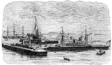 |
|||
| H. B. M. Iron-Clad Captain. | H. B. M. Iron-Clad Thunderer. | U. S. Iron-Clad Dictator. | U. S. Iron-Clad Monitor. |
| H. B. M. Iron-Clad Giatton. | French Iron-Clad Dunderberg. | ||
Fig. 145.—Modern Iron-Clads.
It is only recently that the attempt seems to have been made to determine a classification of war-vessels and to plan a naval establishment which shall be likely to meet[410] fully the requirements of the immediate future. It has hitherto been customary simply to make each ship a little stronger, faster, or more powerful to resist or to make[411] attack than was the last. The fact that the direction of progress in naval science and architecture is plainly perceivable, and that upon its study may be based a fair estimate of the character and relative distribution of several classes of vessels, seems to have been appreciated by very few.
In the year 1870 the writer proposed[99] a classification of vessels other than torpedo-vessels, which has since been also proposed in a somewhat modified form by Mr. J. Scott Russell.[100] The author then remarked that the increase so rapidly occurring in weight of ordnance and of armor, and in speed of war-vessels, would probably soon compel a division of the vessels of every navy into three classes of ships, exclusive of torpedo-vessels, one for general service in time of peace, the others for use only in time of war.
“The first class may consist of unarmored vessels of moderate size, fair speed under steam, armed with a few tolerably heavy guns, and carrying full sail-power.
“The second class may be vessels of great speed under steam, unarmored, carrying light batteries and as great spread of canvas as can readily be given them; very much such vessels as the Wampanoag class of our own navy were intended to be—calculated expressly to destroy the commerce of an enemy.
“The third class may consist of ships carrying the heaviest possible armor and armament, with strongly-built bows, the most powerful machinery that can be given them, of large coal-carrying capacity, and unencumbered by sails, everything being made secondary to the one object of obtaining victory in contending with the most powerful of possible opponents. Such vessels could never go to sea singly, but would cruise in couples or in squadrons. It seems hardly doubtful that attempts to combine the qualities of all classes in a single vessel, as has hitherto been[412] done, will be necessarily given up, although the classification indicated will certainly tend largely to restrict naval operations.”
The introduction of the stationary, the floating, and the automatic classes of torpedoes, and of torpedo-vessels, has now become accomplished, and this element, which it was predicted by Bushnell and by Fulton three-quarters of a century ago would at some future time become important in warfare, is now well recognized by all nations. How far it may modify future naval establishments cannot be yet confidently stated, but it seems sufficiently evident that the attack, by any navy, of stationary defenses protected by torpedoes is now quite a thing of the past. It may be perhaps looked upon as exceedingly probable that torpedo-ships of very high speed will yet drive all heavily-armored vessels from the ocean, thus completing the historic parallel between the man-in-armor of the middle ages and the armored man-of-war of our own time.[101]
Of these classes, the third is of most interest, as exhibiting most perfectly the importance and variety of the work which the steam-engine is made to perform. On the later of these vessels, the anchor is raised by a steam anchor-hoisting apparatus; the heavier spars and sails are handled by the aid of a steam-windlass; the helm is controlled by a steering-engine, and the helmsman, with his little finger, sets in motion a steam-engine, which adjusts the rudder with a power which is unimpeded by wind or sea, and with an exactness that could not be exceeded by the hand-steering gear of a yacht; the guns are loaded by steam, are elevated or depressed, and are given lateral training, by the same power; the turrets in which the guns are incased are turned, and the guns are whirled toward every point of the compass, in less time than is required to sponge and reload[413] them; and the ship itself is driven through the water by the power of ten thousand horses, at a speed which is only excelled on land by that of the railroad-train.
The British Minotaur was one of the earlier iron-clads. The great length and consequent difficulty of manœuvring, the defect of speed, and the weakness of armor of these vessels have led to the substitution of far more effective designs in later constructions. The Minotaur is a four-masted screw iron-clad, 400 feet long, of 59 feet beam and 261∕2 feet draught of water. Her speed at sea is about 121∕2 knots, and her engines develop, as a maximum, nearly 6,000 indicated horse-power. Her heaviest armor-plates are but 6 inches in thickness. Her extreme length and her unbalanced rudder make it difficult to turn rapidly. With eighteen men at the steering-wheel and sixty others on the tackle, the ship, on one occasion, was 71∕2 minutes in turning completely around. These long iron-clads were succeeded by the shorter vessels designed by Mr. E. J. Reed, of which the first, the Bellerophon, was of 4,246 tons burden, 300 feet long by 56 feet beam, and 241∕2 feet draught, of the 14-knot speed, with 4,600 horse-power; and having the “balanced rudder” used many years earlier in the United States by Robert L. Stevens,[102] it can turn in four minutes with eight men at the wheel. The cost of construction was some $600,000 less than that of the Minotaur. A still later vessel, the Monarch, was constructed on a system quite similar to that known in the United States as the Monitor type, or as a turreted iron-clad. This vessel is 330 feet long, 571∕2 feet wide, and 36 feet deep, drawing 241∕2 feet of water. The total weight of ship and contents is over 8,000 tons, and the engines are of over 8,500 horse-power. The armor is 6 and 7 inches thick on the hull, and 8 inches on the two turrets, over a heavy teak backing. The turrets contain each two 12-inch rifled guns, weighing 25 tons each, and,[414] with a charge of 70 pounds of powder, throwing a shot of 600 pounds weight with a velocity of 1,200 feet per second, and giving it a vis viva equivalent to the raising of over 6,100 tons one foot high, and equal to the work of penetrating an iron plate 131∕2 inches thick. This immense vessel is driven by a pair of “single-cylinder” engines having steam-cylinders ten feet in diameter and of 41∕2 feet stroke of piston, driving a two-bladed Griffith screw of 231∕2 feet diameter and 261∕2 feet pitch, 65 revolutions, at the maximum speed of 14.9 knots, or about 171∕2 miles, an hour. To drive these powerful engines, boilers having an aggregate of about 25,000 square feet (or more than a half-acre) of heating-surface are required, with 900 square feet of grate-surface. The refrigerating surface in the condensers has an area of 16,500 square feet—over one-third of an acre. The cost of these engines and boilers was £66,500.
Were all this vast steam-power developed, giving the vessel a speed of 15 knots, the ship, if used as a “ram,” would strike an enemy at rest with the tremendous “energy” of 48,000 foot-tons—equal to the shock of the projectiles of eight or nine such guns as are carried by the iron-clad itself, simultaneously discharged upon one spot.
But even this great vessel is less formidable than later vessels. One of the latter, the Inflexible, is a shorter but wider and deeper ship than the Monarch, measuring 320 feet long, 75 feet beam, and 25 draught, displacing over 10,000 tons. The great rifles carried by this vessel weigh 81 tons each, throwing shot weighing a half-ton from behind iron-plating two feet in thickness. The steam-engines are of about the same power as those of the Monarch, and give this enormous hull a speed of 14 knots an hour.
The navy of the United States does not to-day possess iron-clads of power even approximating that of either of several classes of British and other foreign naval vessels.
The largest vessel of any class yet constructed is the Great Eastern (Fig. 146), begun in 1854 and completed in[415] 1859, by J. Scott Russell, on the Thames, England. This ship is 680 feet long, 83 feet wide, 58 feet deep, 28 feet draught, and of 24,000 tons measurement. There are four paddle and four screw engines, the former having steam-cylinders 74 inches in diameter, with 14 feet stroke, the latter 84 inches in diameter and 4 feet stroke. They are collectively of 10,000 actual horse-power. The paddle-wheels are 56 feet in diameter, the screw 24 feet. The steam-boilers supplying the paddle-engines have 44,000 square feet (more than an acre) of heating-surface. The boilers supplying the screw-engines are still larger. At 30 feet draught, this great vessel displaces 27,000 tons. The engines were designed to develop 10,000 horse-power, driving the ship at the rate of 161∕2 statute miles an hour.
The figures quoted in the descriptions of these great steamships do not enable the non-professional reader to form a conception of the wonderful power which is concentrated within so small a space as is occupied by their steam-machinery. The “horse-power” of the engines is that determined[416] by James Watt as the maximum obtainable for eight hours a day from the strongest London draught-horses. The ordinary average draught-horse would hardly be able to exert two-thirds as much during the eight hours’ steady work of a working-day. The working-day of the steam-engine, on the other hand, is twenty-four hours in length.
The work of the 10,000 horse-power engines of the Great Eastern could be barely equaled by the efforts of 15,000 horses; but to continue their work uninterruptedly, day in and day out, for weeks together, as when done by steam, would require at least three relays, or 45,000 horses. Such a stud would weigh 25,000 tons, and if harnessed “tandem” would extend thirty miles. It is only by such a comparison that the mind can begin to comprehend the utter impossibility of accomplishing by means of animal[417] power the work now done for the world by steam. The cost of the greater power is but about one-tenth that of horse-power, and by its means tasks are accomplished with ease which are absolutely impossible of accomplishment by animal power.
It is estimated that the total steam-power of the world is about 15,000,000 horse-power, and that, were horses actually employed to do the work which these engines would be capable of doing were they kept constantly in operation, the number required would exceed 60,000,000.
Thus, from the small beginnings of the Comte d’Auxiron and the Marquis de Jouffroy in France, of Symmington in Great Britain, and of Henry, Rumsey, and Fitch, and of Fulton and Stevens, in the United States, steam-navigation has grown into a great and inestimable aid and blessing to mankind.
We to-day cross the ocean with less risk, and transport ourselves and our goods at as little cost in either time or money as, at the beginning of the century, our parents experienced in traveling one-tenth the distance.
It is largely in consequence of this ingenious application of a power that reminds one of the fabled genii of Eastern romance, that the mechanic and the laborer of to-day enjoy comforts and luxuries that were denied to wealth, and to royalty itself, a century ago.
The magnitude of our modern steamships excites the wonder and admiration of even the people of our own time; and there is certainly no creation of art that can be grander in appearance than a transatlantic steamer a hundred and fifty yards in length, and weighing, with her stores, five or six thousand tons, as she starts on her voyage, moved by engines equal in power to the united strength of thousands of horses; none can more fully awaken a feeling of awe than an immense structure like the great modern iron-clads (Fig. 145), vessels having a total weight of 8,000 to 10,000 tons, and propelled by steam-engines of as many horse-power,[418] carrying guns whose shot penetrate solid iron 20 inches thick, and having a power of impact, when steaming at moderate speed, sufficient to raise 35,000 tons a foot high.
Far more huge than the Monarch among the iron-clads even is that prematurely-built monster, the Great Eastern (Fig. 147), already described, an eighth of a mile long, and with steam doing the work of a stud of 45,000 horses.
Thus we are to-day witnessing the literal fulfillment of the predictions of Oliver Evans and of John Stevens, and almost that contained in the couplets written by the poet Darwin, who, more than a century ago, before even the earliest of Watt’s improvements had become generally known, sang:
[85] The invention of Messrs. Charles T. Porter and John F. Allen.
[86] Invented by Mr. John F. Allen.
[87] Or not far from 600 times the cube root of the length of stroke, measured in feet.
[88] Perkins was a native of Newburyport, Mass. He was born July 9, 1766, and died in London, July 30, 1849. He went to England when fifty-two years of age, to introduce his inventions.
[89] It was when writing of this engine that Stuart wrote, in 1824: “Judging from the rapid strides the steam-engine has made during the last forty years to become a universal first-mover, and from the experience that has arisen from that extension, we feel convinced that every invention which diminishes its size without impairing its power brings it a step nearer to the assistance of the ‘world’s great laborers,’ the husbandman and the peasant, for whom, as yet, it performs but little. At present, it is made occasionally to tread out the corn. What honors await not that man who may yet direct its mighty power to plough, to sow, to harrow, and to reap!” The progress of the steam-engine during those forty years does not to-day appear so astounding. The sentiment here expressed has lost none of its truth, nevertheless.
[90] Galloway and Hebert, on the Steam-Engine. London, 1836.
[91] “The High-Pressure Steam-Engine,” etc. By Dr. Ernst Alban. Translated by William Pole, F. R. A. S. London, 1847.
[92] Invented by Joseph Maudsley, of London, 1827.
[93] January, 1884, over 120,000 miles.
[94] Railroad Gazette.
[95] The steam-cylinders of the engines of steamers Bristol and Providence are 110 inches in diameter and of 12 feet stroke.
[96] Burned in 1877.
[97] Vide “Memoir of John Elder,” W. J. M. Rankine, Glasgow, 1871.
[98] “Official Catalogue,” 1862, vol. iv., Class viii., p. 123.
[99] Journal Franklin Institute, 1870. H. B. M. S. Monarch.
[100] London Engineering, 1875.
[101] Vide “Report on Machinery and Manufactures, etc., at Vienna,” by the author, Washington, 1875.
[102] Still in use on the Hoboken ferry-boats.
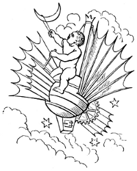
“Of all the features which characterize this progressive economical movement of civilized nations, that which first excites attention, through its intimate connection with the phenomena of production, is the perpetual and, so far as human foresight can extend, the unlimited growth of man’s power over Nature. Our knowledge of the properties and laws of physical objects shows no sign of approaching its ultimate boundaries; it is advancing more rapidly, and in a greater number of directions at once, than in any previous age or generation, and affording such frequent glimpses of unexplored fields beyond as to justify the belief that our acquaintance with Nature is still almost in its infancy.”—Mill.
The growth of the philosophy of the steam-engine presents as interesting a study as that of the successive changes which have occurred in its mechanism.
In the operation of the steam-engine we find illustrated many of the most important principles and facts which constitute the physical sciences. The steam-engine is an exceedingly ingenious, but, unfortunately, still very imperfect, machine for transforming the heat-energy obtained by the chemical combination of a combustible with the supporter of combustion into mechanical energy. But the original source of all this energy is found far back of its first appearance in the steam-boiler. It had its origin at the beginning, when all Nature came into existence. After the solar system had been formed from the nebulous chaos of creation, the glowing mass which is now called the sun was the[420] depository of a vast store of heat-energy, which was thence radiated into space and showered upon the attendant worlds in inconceivable quantity and with unmeasured intensity. During the past life of the globe, the heat-energy received from the sun upon the earth’s surface was partly expended in the production of great forests, and the storage, in the trunks, branches, and leaves of the trees of which they were composed, of an immense quantity of carbon, which had previously existed in the atmosphere, combined with oxygen, as carbonic acid. The great geological changes which buried these forests under superincumbent strata of rock and earth resulted in the formation of coal-beds, and the storage, during many succeeding ages, of a vast amount of carbon, of which the affinity for oxygen remained unsatisfied until finally uncovered by the hand of man. Thus we owe to the heat and light of the sun, as was pointed out by George Stephenson, the incalculable store of potential energy upon which the human race is so dependent for life and all its necessaries, comforts, and luxuries.
This coal, thrown upon the grate in the steam-boiler, takes fire, and, uniting again with the oxygen, sets free heat in precisely the same quantity that it was received from the sun and appropriated during the growth of the tree. The actual energy thus rendered available is transferred, by conduction and radiation, to the water in the steam-boiler, converts it into steam, and its mechanical effect is seen in the expansion of the liquid into vapor against the superincumbent pressure. Transferred from the boiler to the engine, the steam is there permitted to expand, doing work, and the heat-energy with which it is charged becomes partly converted into mechanical energy, and is applied to useful work in the mill or to driving the locomotive or the steamboat.
Thus we may trace the store of energy received from the sun and contained in our coal through its several changes until it is finally set at work; and we might go still further[421] and observe how, in each case, it is again usually re-transformed and again set free as heat-energy.
The transformation which takes place in the furnace is a chemical change; the transfer of heat to the water and the subsequent phenomena accompanying its passage through the engine are physical changes, some of which require for their investigation abstruse mathematical operations. A thorough comprehension of the principles governing the operation of the steam-engine, therefore, can only be attained after studying the phenomena of physical science with sufficient minuteness and accuracy to be able to express with precision the laws of which those sciences are constituted. The study of the philosophy of the steam-engine involves the study of chemistry and physics, and of the new science of energetics, of which the now well-grown science of thermo-dynamics is a branch. This sketch of the growth of the steam-engine may, therefore, be very properly concluded by an outline of the growth of the several sciences which together make up its philosophy, and especially of the science of thermo-dynamics, which is peculiarly the science of the steam-engine and of the other heat-engines.
These sciences, like the steam-engine itself, have an origin which antedates the commencement of the Christian era; but they grew with an almost imperceptible growth for many centuries, and finally, only a century ago, started onward suddenly and rapidly, and their progress has never since been checked. They are now fully-developed and well-established systems of natural philosophy. Yet, like that of the steam-engine and of its companion heat-engines, their growth has by no means ceased; and, while the student of science cannot do more than indicate the direction of their progress, he can readily believe that the beginning of the end is not yet reached in their movement toward completeness, either in the determination of facts or in the codification of their laws.
[422]When Hero lived at Alexandria, the great “Museum” was a most important centre, about which gathered the teachers of all then known philosophies and of all the then recognized but unformed sciences, as well as of all those technical branches of study which had already been so far developed as to be capable of being systematically taught. Astronomical observations had been made regularly and uninterruptedly by the Chaldean astrologers for two thousand years, and records extending back many centuries had been secured at Babylon by Calisthenes and given to Aristotle, the father of our modern scientific method. Ptolemy had found ready to his hand the records of Chaldean observers of eclipses extending back nearly 650 years, and marvelously accurate.[103]
A rude method of printing with an engraved roller on plastic clay, afterward baked, thus making up ceramic libraries, was practised long previous to this time; and in the alcoves in which Hero worked were many of these books of clay.
This great Library and Museum of Alexandria was founded three centuries before the birth of Christ, by Ptolemy Soter, who established as his capital that great Egyptian city when the death of his brother, the youthful but famous conqueror whose name he gave it, placed him upon the throne of the colossal successor of the then fallen Persian Empire. The city itself, embellished with every ornament and provided with every luxury that the wealth of a conquered world or the skill, taste, and ingenuity of the Greek painters, sculptors, architects, and engineers could provide, was full of wonders; it was a wonder in itself. This rich, populous, and magnificent city was the metropolis of the then civilized world. Trade, commerce, manufactures, and the fine arts were all represented in this[423] splendid exchange, and learning found its most acceptable home and noblest field within the walls of Ptolemy’s Museum; its disciples found themselves welcomed and protected by its founder and his successors, Philadelphus and the later Ptolemies.
The Alexandrian Museum was founded with the declared object of collecting all written works of authority, of promoting the study of literature and art, and of stimulating and assisting experimental and mathematical scientific investigation and research. The founders of modern libraries, colleges, and technical schools have their prototype in intelligence, public spirit, and liberality, in the first of the Ptolemies, who not only spent an immense sum in establishing this great institution, but spared no expense in sustaining it. Agents were sent out into all parts of the world, purchasing books. A large staff of scribes was maintained at the museum, whose duty it was to multiply copies of valuable works, and to copy for the library such works as could not be purchased.
The faculty of the museum was as carefully organized as was the plan of its administration. The four principal faculties of astronomy, literature, mathematics, and medicine were subdivided into sections devoted to the several branches of each department. The collections of the museum were as complete as the teachers of the undeveloped sciences of the time could make them. Lectures were given in all branches of study, and the number of students was sometimes as great as twelve or thirteen thousand. The number of books which were collected here, when the barbarian leaders of the Roman troops under Cæsar burned the greater part of it, was stated to be 700,000. Of these, 400,000 were within the museum itself, and were all destroyed; the rest were in the temple of Serapis, and, for the time, escaped destruction.
The greatest of all the great men who lived at Alexandria at the time of the establishment of the museum was[424] Aristotle, the teacher of Alexander and the friend of Ptolemy. It is to Aristotle that we owe the systematization of the philosophical ideas of Plato and the creation of the inductive method, in which has originated all modern science. It is to the learned men of Alexandria that we are indebted for so effective an application of the Aristotelian philosophy that all the then known sciences were given form, and were so thoroughly established that the work of modern science has been purely one of development.
The inductive method, which built up all the older sciences, and which has created all those of recent development, consists, first, in the discovery and quantitative determination of facts; secondly, when a sufficient number of facts have been thus observed and defined, in the grouping of those facts, and the detection, by a study of their mutual relations, of the natural laws which give rise to or regulate them. This simple method is that—and the only—method by which science advances. By this method, and by it only, do we acquire connected and systematic knowledge of all the phenomena of Nature of which the physical sciences are cognizant. It is only by the application of this Aristotelian method and philosophy that we can hope to acquire exact scientific knowledge of existing phenomena, or to become able to anticipate the phenomena which are to distinguish the future. The Aristotelian method of observing facts, and of inductive reasoning with those facts as a basis, has taught the chemist the properties of the known elementary substances and their characteristic behavior under ascertained conditions, and has taught him the laws of combination and the effects of their union, enabling him to predict the changes and the phenomena, chemical and physical, which inevitably follow their contact under any specified set of conditions.
It is this process which has enabled the physicist to ascertain the methods of molecular motion which give us light, heat, or electricity, and the range of action and the[425] laws which govern the transfer of energy from one of these modes of motion to another. It was this method of study which enabled James Watt to detect and to remedy the defects of the Newcomen engine, and it is by the Aristotelian philosophy that the engineer of to-day is taught to construct the modern steamship, and to predict, before the keel is laid or a blow struck in the workshop or the ship-yard, what will be the weight of the vessel, its cargo-carrying capacity, the necessary size and power of its engines, the quantity of coal which they will require per day while crossing the ocean, the depth at which the great hull will float in the water, and the exact speed that the vessel will attain when the engines are exerting their thousand or their ten thousand horse-power.
It was at Alexandria that this mighty philosophy was first given a field in which to work effectively. Here Ptolemy studied astronomy and “natural philosophy;” Archimedes applied himself to the studies which attract the mathematician and engineer; Euclid taught his royal pupil those elements of geometry which have remained standard twenty-two centuries; Eratosthenes and Hipparchus studied and taught astronomy, and inaugurated the existing system of quantitative investigation, proving the spherical form of the earth; and Ctesibius and Hero studied pneumatics and experimented with the germs of the steam-engine and of less important machines.
When, seven centuries later, the destruction of this splendid institution was signalized by the death of that brilliant scholar and heathen teacher of philosophy, Hypatia, at the hands of the more heathenish fanatics who tore her in pieces at the foot of the cross, and by the dispersion of the library left by Cæsar’s soldiers in the Serapeum, a true philosophy had been created, and the inductive method was destined to live and to overcome every obstacle in the path of enlightenment and civilization. The fall of the Alexandrian Museum, sad as was the event, could not destroy the[426] new philosophical method. Its fruits ripened slowly but surely, and we are to-day gathering a plentiful harvest.
Science, literature, and the arts, all remained dormant for several centuries after the catastrophe which deprived them of the light in which they had flourished so many centuries. The armies of the caliphs made complete the shameful work of destruction begun by the armies of Cæsar, and the Alexandrian Library, partly destroyed by the Romans, was completely dispersed by the Patriarchs and their ignorant and fanatical followers; and finally all the scattered remnants were burned by the Saracens. But when the thirst for conquest had become satiated or appeased, the followers of the caliphs turned their attention to intellectual pursuits, and the ninth century of the Christian era saw once more such a collection of philosophical writings, collected at Bagdad, as could only be gathered by the power and wealth of the later conquerors of the world. Philosophy once again resumed its empire, and another race commenced the study of the mathematics of India and of Greece, the astronomy of Chaldea, and of all the sciences which originated in Greece and in Egypt. By the conquest of Spain by the Saracens, the new civilization was imported into Western Europe and libraries were gathered together under the Moorish rulers, one of which numbered more than a half-million volumes. Wherever Saracen armies had extended Mohammedan rule, schools and colleges, libraries and collections of philosophical apparatus, were scattered in strange profusion; and students, teachers, philosophers, of all—the speculative as well as the Aristotelian—schools, gathered together at these intellectual ganglia, as enthusiastic in their work as were their Alexandrian predecessors. The endowment of colleges, that truest gauge of the intelligence of the wealthy classes of any community, became as common—perhaps more so—as at the present time, and provision was made for the education of rich and poor alike. The mathematical sciences,[427] and the wonderful and beautiful phenomena which—but a thousand years later—were afterward grouped into a science and called chemistry, were especially attractive to the Arabian scholars, and technical applications of discovered facts and laws assisted in a wonderfully rapid development of arts and manufactures.
When, a thousand years after Christ, the centre of intellectual activity and of material civilization had drifted westward into Andalusia, the foundation of every modern physical science except that now just taking shape—the all-grasping science of energetics—had been laid with experimentally derived facts; and in mathematics there had been erected a symmetrical and elegant superstructure. Even that underlying principle of all the sciences, the principle of the persistence of energy, had been, perhaps unwittingly, enunciated.
Distinguished historians have shown how the progress of civilization in Europe resulted in the creation, during the middle ages, of the now great middle class, which, holding the control of political power, governs every civilized nation, and has come into power so gradually that it was only after centuries that its influence was seen and felt. This, which Buckle[104] calls the intellectual class, first became active, independently of the military and of the clergy, in the fourteenth century. In the two succeeding centuries this class gained power and influence; and in the seventeenth century we find a magnificent advance in all branches of science, literature, and art, marking the complete emancipation of the intellect from the artificial conditions which had so long repressed its every effort at advancement.
Another great social revolution thus occurred, following another period of centuries of intellectual stagnation. The Saracen invaders were driven from Europe; the Crusaders invaded Palestine, in the vain effort to recover from the hands of the infidels the Holy Sepulchre and the Holy[428] Land; and intestine broils and inter-state conflicts, as well as these greater social movements, withdrew the minds of men once more from the arts of peace and the pursuits of scholars. It is not, then, until the beginning of the seventeenth century—the time of Galileo and of Newton—that we find the nations of Europe sufficiently quiet and secure to permit general attention to intellectual vocations, although it was a half-century earlier (1543) that Copernicus left to the world that legacy which revolutionized the theories of the astronomers and established as correct the hypothesis which made the sun the centre of the solar system.
Galileo now began to overturn the speculations of the deductive philosophers, and to proclaim the still disputed principle that the book of Nature is a trustworthy commentary in the study of theological and revealed truths, so far as they affect or are affected by science; he suffered martyrdom when he proclaimed the fact that God’s laws, as they now stand, had been instituted without deference to the preconceived notions of the most ignorant of men. Bruno had a few years earlier (1600) been burned at the stake for a similar offense.
Galileo was perhaps the first, too, to combine invariably in application the idea of Plato, the philosophy of Aristotle, and the methods of modern experimentation, to form the now universal scientific method of experimental philosophy. He showed plainly how the grouping of ascertained facts, in natural sequence, leads to the revelation of the law of that sequence, and indicated the existence of a principle which is now known as the law of continuity—the law that in all the operations of Nature there is to be seen an unbroken chain of effect leading from the present back into a known or an unknown past, toward a cause which may or may not be determinable by science or known to history.
Galileo, the Italian, was worthily matched by Newton, the prince of English philosophers. The science of theoretical mechanics was hardly beginning to assume the position[429] which it was afterward given among the sciences; and the grand work of collating facts already ascertained, and of definitely stating principles which had previously been vaguely recognized, was splendidly done by Newton. The needs of physical astronomy urged this work upon him.
Da Vinci had, in the latter half of the fifteenth century, summarized as much of the statics of mechanical philosophy as had, up to his time, been given shape; he also rewrote and added very much to what was known on the subject of friction, and enunciated its laws. He had evidently a good idea of the principle of “virtual velocities,” that simple case of equivalence of work, in a connected system, which has done such excellent service since; and with his mechanical philosophy this versatile engineer and artist curiously mingled much of physical science. Then Stevinus, the “brave engineer of Bruges,” a hundred years later (1586), alternating office and field work, somewhat after the manner of the engineer of to-day, wrote a treatise on mechanics, which showed the value of practical experience and judgment in even scientific work. And thus the path had been cleared for Newton.
Meantime, also, Kepler had hit upon the true relations of the distances of the planets and their periodic times, after spending half a generation in blindly groping for them, thus furnishing those great landmarks of fact in the mechanics of astronomy; and Galileo had enunciated the laws of motion. Thus the foundation of the science of dynamics, as distinguished from statics, was laid, and the beginning was made of that later science of energetics, of which the philosophy of the steam-engine is so largely constituted.
Hooke, Huyghens, and others, had already seen some of the principal consequences of these laws; but it remained for Newton to enunciate them with the precision of a true mathematician, and to base upon them a system of dynamical laws, which, complemented by his announcement of the existence of the force of gravitation, and his statement of its laws,[430] gave a firm basis for all that the astronomer has since done in those quantitative determinations of size, weight, and distance, and of the movements of the heavenly bodies, which compel the wonder and admiration of mankind.
The Arabians and Greeks had noticed that the direction taken by a body falling under the action of gravitation was directly toward the centre of the earth, wherever its fall might occur; Galileo had shown, by his experiments at Pisa, that the velocity of fall, second after second, varied as the numbers 1, 3, 5, 7, 9, etc., and that the distances varied as the squares of the total periods of time during which the body was falling, and that it was, in British feet, very nearly sixteen times the square of that time in seconds. Kepler had proved that the movements of the heavenly bodies were just such as would occur under the action of central attractive forces and of centrifugal force.
Putting all these things together, Newton was led to believe that there existed a “force of gravity,” due to the attraction, by the great mass of the earth, of its own particles and of neighboring bodies, like the moon, of which force the influence extended as far, at least, as the latter. He calculated the motion of the earth’s satellite, on the assumption that his theory and the then accepted measurements of the earth’s dimensions were correct, and obtained a roughly approximate result. Later, in 1679, he revised his calculations, using Picard’s more accurate determination of the dimensions of the earth, and obtained a result which precisely tallied with careful measurements, made by the astronomers, of the moon’s motion.
The science of mechanics had now, with the publication of Newton’s “Principia,” become thoroughly consistent and logically complete, so far as was possible without a knowledge of the principles of energetics; and Newton’s enunciations of the laws of motion, concise and absolutely perfect as they still seem, were the basis of the whole science of dynamics, as applied to bodies moving freely under the[431] action of applied forces, either constant or variable. They are as perfect a basis for that science as are the primary principles of geometry for the whole beautiful structure which is built up on them.
The three perfect qualitative expressions of dynamical law are:
1. Every free body continues in the state in which it may be, whether of rest or of rectilinear uniform motion, until compelled to deviate from that state by impressed forces.
2. Change of motion is proportional to the force impressed, and in the direction of the right line in which that force acts.
3. Action is always opposed by reaction; action and reaction are equal, and in directly contrary directions.
We may add to these principles a definition of a force, which is equally and absolutely complete:
Force is that which produces, or tends to produce, motion, or change of motion, in bodies. It is measured statically by the weight that will counterpoise it, or by the pressure which it will produce, and dynamically by the velocity which it will produce, acting in the unit of time on the unit of mass.
The quantitative determinations of dynamic effects of forces are always readily made when it is remembered that the effect of a force equal to its own weight, when the body is free to move, is to produce in one second a velocity of 32.2 feet per second, which quantity is the unit of dynamic measurement.
Work is the product of the resistance met in any instance of the exertion of a force, into the distance through which that force overcomes the resistance.
Energy is the work which a body is capable of doing, by its weight or inertia, under given conditions. The energy of a falling body, or of a flying shot, is about 1∕64 its weight multiplied by the square of its velocity, or, which[432] is the same thing, the product of its weight into the height of fall or height due its velocity. These principles and definitions, with the long-settled definitions of the primary ideas of space and time, were all that were needed to lead the way to that grandest of all physical generalizations, the doctrine of the persistence or conservation of all energy, and to its corollary declaring the equivalence of all forms of energy, and also to the experimental demonstration of the transformability of energy from one mode of existence to another, and its universal existence in the various modes of motion of bodies and of their molecules.
Experimental physical science had hardly become acknowledged as the only and the proper method of acquiring knowledge of natural phenomena at the time of Newton; but it soon became a generally accepted principle. In physics, Gilbert had made valuable investigations before Newton, and Galileo’s experiments at Pisa had been examples of similarly useful research. In chemistry, it was only when, a century later, Lavoisier showed by his splendid example what could be done by the skillful and intelligent use of quantitative measurements, and made the balance the chemist’s most important tool, that a science was formed comprehending all the facts and laws of chemical change and molecular combination. We have already seen how astronomy and mathematics together led philosophers to the creation and the study of what finally became the science of mechanics, when experiment and observation were finally brought to their aid. We can now see how, in all these physical sciences, four primitive ideas are comprehended: matter, force, motion, and space—which latter two terms include all relations of position.
Based on these notions, the science of mechanics comprehends four sections, which are of general application in the study of all physical phenomena. These are:
Statics, which treats of the action and effect of forces.
Kinematics, which treats of relations of motion simply.[433]
Dynamics, or kinetics, which treats of simple motion as an effect of the action of forces.
Energetics, which treats of modifications of energy under the action of forces, and of its transformation from one mode of manifestation to another, and from one body to another.
Under the latter of these four divisions of mechanical philosophy is comprehended that latest of the minor sciences, of which the heat-engines, and especially the steam-engine, illustrate the most important applications—Thermo-dynamics. This science is simply a wider generalization of principles which, as we have seen, have been established one at a time, and by philosophers widely separated both geographically and historically, by both space and time, and which have been slowly aggregated to form one after another of the sciences, and out of which, as we now are beginning to see, we are slowly evolving wider generalizations, and thus tending toward a condition of scientific knowledge which renders more and more probable the truth of Cicero’s declaration: “One eternal and immutable law embraces all things and all times.” At the basis of the whole science of energetics lies a principle which was enunciated before Science had a birthplace or a name:
All that exists, whether matter or force, and in whatever form, is indestructible, except by the Infinite Power which has created it.
That matter is indestructible by finite power became admitted as soon as the chemists, led by their great teacher Lavoisier, began to apply the balance, and were thus able to show that in all chemical change there occurs only a modification of form or of combination of elements, and no loss of matter ever takes place. The “persistence” of energy was a later discovery, consequent largely upon the experimental determination of the convertibility of heat-energy into other forms and into mechanical work, for which we are indebted to Rumford and Davy, and to the[434] determination of the quantivalence anticipated by Newton, shown and calculated approximately by Colding and Mayer, and measured with great probable accuracy by Joule.
The great fact of the conservation of energy was loosely stated by Newton, who asserted that the work of friction and the vis viva of the system or body arrested by friction were equivalent. In 1798, Benjamin Thompson, Count Rumford, an American who was then in the Bavarian service, presented a paper[105] to the Royal Society of Great Britain, in which he stated the results of an experiment which he had recently made, proving the immateriality of heat and the transformation of mechanical into heat energy.[435] This paper is of very great historical interest, as the now accepted doctrine of the persistence of energy is a generalization which arose out of a series of investigations, the most important of which are those which resulted in the determination of the existence of a definite quantivalent relation between these two forms of energy and a measurement of its value, now known as the “mechanical equivalent of heat.” His experiment consisted in the determination of the quantity of heat produced by the boring of a cannon at the arsenal at Munich.
Rumford, after showing that this heat could not have been derived from any of the surrounding objects, or by compression of the materials employed or acted upon, says: “It appears to me extremely difficult, if not impossible, to form any distinct idea of anything capable of being excited and communicated in the manner that heat was excited and communicated in these experiments, except it be motion.”[106] He then goes on to urge a zealous and persistent investigation of the laws which govern this motion. He estimates the heat produced by a power which he states could easily be exerted by one horse, and makes it equal to the “combustion of nine wax candles, each three-quarters of an inch in diameter,” and equivalent to the elevation of “25.68 pounds of ice-cold water” to the boiling-point, or 4,784.4 heat-units.[107] The time was stated at “150 minutes.” Taking the actual power of Rumford’s Bavarian “one horse” as the most probable figure, 25,000 pounds raised one foot high per minute,[108] this gives the “mechanical equivalent”[436] of the foot-pound as 783.8 heat-units, differing but 1.5 per cent. from the now accepted value.
Had Rumford been able to eliminate all losses of heat by evaporation, radiation, and conduction, to which losses he refers, and to measure the power exerted with accuracy, the approximation would have been still closer. Rumford thus made the experimental discovery of the real nature of heat, proving it to be a form of energy, and, publishing the fact a half-century before the now standard determinations were made, gave us a very close approximation to the value of the heat-equivalent. Rumford also observed that the heat generated was “exactly proportional to the force with which the two surfaces are pressed together, and to the rapidity of the friction,” which is a simple statement of equivalence between the quantity of work done, or energy expended, and the quantity of heat produced. This was the first great step toward the formation of a Science of Thermo-dynamics. Rumford’s work was the corner-stone of the science.
Sir Humphry Davy, a little later (1799), published the details of an experiment which conclusively confirmed these deductions from Rumford’s work. He rubbed two pieces of ice together, and found that they were melted by the friction so produced. He thereupon concluded: “It is evident that ice by friction is converted into water.... Friction, consequently, does not diminish the capacity of bodies for heat.”
Bacon and Newton, and Hooke and Boyle, seem to have anticipated—long before Rumford’s time—all later philosophers, in admitting the probable correctness of that modern dynamical, or vibratory, theory of heat which considers it a mode of motion; but Davy, in 1812, for the first[437] time, stated plainly and precisely the real nature of heat, saying: “The immediate cause of the phenomenon of heat, then, is motion, and the laws of its communication are precisely the same as the laws of the communication of motion.” The basis of this opinion was the same that had previously been noted by Rumford.
So much having been determined, it became at once evident that the determination of the exact value of the mechanical equivalent of heat was simply a matter of experiment; and during the succeeding generation this determination was made, with greater or less exactness, by several distinguished men. It was also equally evident that the laws governing the new science of thermo-dynamics could be mathematically expressed.
Fourier had, before the date last given, applied mathematical analysis in the solution of problems relating to the transfer of heat without transformation, and his “Théorie de la Chaleur” contained an exceedingly beautiful treatment of the subject. Sadi Carnot, twelve years later (1824), published his “Réflexions sur la Puissance Motrice du Feu,” in which he made a first attempt to express the principles involved in the application of heat to the production of mechanical effect. Starting with the axiom that a body which, having passed through a series of conditions modifying its temperature, is returned to “its primitive physical state as to density, temperature, and molecular constitution,” must contain the same quantity of heat which it had contained originally, he shows that the efficiency of heat-engines is to be determined by carrying the working fluid through a complete cycle, beginning and ending with the same set of conditions. Carnot had not then accepted the vibratory theory of heat, and consequently was led into some errors; but, as will be seen hereafter, the idea just expressed is one of the most important details of a theory of the steam-engine.
Seguin, who has already been mentioned as one of the[438] first to use the fire-tubular boiler for locomotive engines, published in 1839 a work, “Sur l’Influence des Chemins de Fer,” in which he gave the requisite data for a rough determination of the value of the mechanical equivalent of heat, although he does not himself deduce that value.
Dr. Julius R. Mayer, three years later (1842), published the results of a very ingenious and quite closely approximate calculation of the heat-equivalent, basing his estimate upon the work necessary to compress air, and on the specific heats of the gas, the idea being that the work of compression is the equivalent of the heat generated. Seguin had taken the converse operation, taking the loss of heat of expanding steam as the equivalent of the work done by the steam while expanding. The latter also was the first to point out the fact, afterward experimentally proved by Hirn, that the fluid exhausted from an engine should heat the water of condensation less than would the same fluid when originally taken into the engine.
A Danish engineer, Colding, at about the same time (1843), published the results of experiments made to determine the same quantity; but the best and most extended work, and that which is now almost universally accepted as standard, was done by a British investigator.
James Prescott Joule commenced the experimental investigations which have made him famous at some time previous to 1843, at which date he published, in the Philosophical Magazine, his earliest method. His first determination gave 770 foot-pounds. During the succeeding five or six years Joule repeated his work, adopting a considerable variety of methods, and obtaining very variable results. One method was to determine the heat produced by forcing air through tubes; another, and his usual plan, was to turn a paddle-wheel by a definite power in a known weight of water. He finally, in 1849, concluded these researches.
The method of calculating the mechanical equivalent of[439] heat which was adopted by Dr. Mayer, of Heilbronn, is as beautiful as it is ingenious: Conceive two equal portions of atmospheric air to be inclosed, at the same temperature—as at the freezing-point—in vessels each capable of containing one cubic foot; communicate heat to both, retaining the one portion at the original volume, and permitting the other to expand under a constant pressure equal to that of the atmosphere. In each vessel there will be inclosed 0.08073 pound, or 1.29 ounce, of air. When, at the same temperature, the one has doubled its pressure and the other has doubled its volume, each will be at a temperature of 525.2° Fahr., or 274° C, and each will have double the original temperature, as measured on the absolute scale from the[440] zero of heat-motion. But the one will have absorbed but 63∕4 British thermal units, while the other will have absorbed 91∕2. In the first case, all of this heat will have been employed in simply increasing the temperature of the air; in the second case, the temperature of the air will have been equally increased, and, besides, a certain amount of work—2,116.3 foot-pounds—must have been done in overcoming the resistance of the air; it is to this latter action that we must debit the additional heat which has disappeared. Now, (2,116.3/23∕4) = 770 foot-pounds per heat-unit—almost precisely the value derived from Joule’s experiments. Had Mayer’s measurement been absolutely accurate, the result of his calculation would have been an exact determination of the heat-equivalent, provided no heat is, in this case, lost by internal work.
Joule’s most probably accurate measure was obtained by the use of a paddle-wheel revolving in water or other fluid. A copper vessel contained a carefully weighed portion of the fluid, and at the bottom was a step, on which stood a vertical spindle carrying the paddle-wheel. This wheel was turned by cords passing over nicely-balanced grooved wheels, the axles of which were carried on friction-rollers. Weights hung at the ends of these cords were the moving forces. Falling to the ground, they exerted an easily and accurately determinable amount of work, W × H, which turned the paddle-wheel a definite number of revolutions, warming the water by the production of an amount of heat exactly equivalent to the amount of work done. After the weight had been raised and this operation repeated a sufficient number of times, the quantity of heat communicated to the water was carefully determined and compared with the amount of work expended in its development. Joule also used a pair of disks of iron rubbing against each other in a vessel of mercury, and measured the heat thus developed by friction, comparing it with the[441] work done. The average of forty experiments with water gave the equivalent 772.692 foot-pounds; fifty with mercury gave 774.083; twenty with cast-iron gave 774.987—the temperature of the apparatus being from 55° to 60° Fahr.
Joule also determined, by experiment, the fact that the expansion of air or other gas without doing work produces no change of temperature, which fact is predicable from the now known principles of thermo-dynamics. He stated the results of his researches relating to the mechanical equivalent of heat as follows:
1. The heat produced by the friction of bodies, whether solid or liquid, is always proportional to the quantity of work expended.
2. The quantity required to increase the temperature of a pound of water (weighed in vacuo at 55° to 60° Fahr.) by one degree requires for its production the expenditure of a force measured by the fall of 772 pounds from a height of one foot. This quantity is now generally called “Joule’s equivalent.”
During this series of experiments, Joule also deduced the position of the “absolute zero,” the point at which heat-motion ceases, and stated it to be about 480° Fahr. below the freezing-point of water, which is not very far from the probably true value,-493.2° Fahr. (-273° C.), as deduced afterward from more precise data.
The result of these, and of the later experiments of Hirn and others, has been the admission of the following principle:
Heat-energy and mechanical energy are mutually convertible and have a definite equivalence, the British thermal unit being equivalent to 772 foot-pounds of work, and the metric calorie to 423.55, or, as usually taken, 424 kilogrammetres. The exact measure is not fully determined, however.
It has now become generally admitted that all forms of[442] energy due to physical forces are mutually convertible with a definite quantivalence; and it is not yet determined that even vital and mental energy do not fall within the same great generalization. This quantivalence is the sole basis of the science of Energetics.
The study of this science has been, up to the present time, principally confined to that portion which comprehends the relations of heat and mechanical energy. In the study of this department of the science, thermo-dynamics, Rankine, Clausius, Thompson, Hirn, and others have acquired great distinction. In the investigations which have been made by these authorities, the methods of transfer of heat and of modification of physical state in gases and vapors, when a change occurs in the form of the energy considered, have been the subjects of especial study.
According to the law of Boyle and Marriotte, the expansion of such fluids follows a law expressed graphically by the hyperbola, and algebraically by the expression PVx = A, in which, with unchanging temperature, x is equal to 1. One of the first and most evident deductions from the principles of the equivalence of the several forms of energy is that the value of x must increase as the energy expended in expansion increases. This change is very marked with a vapor like steam—which, expanded without doing work, has an exponent less than unity, and which, when doing work by expanding behind a piston, partially condenses, the value of x increases to, in the case of steam, 1.111 according to Rankine, or, probably more correctly, to 1.135 or more, according to Zeuner and Grashof. This fact has an important bearing upon the theory of the steam-engine, and we are indebted to Rankine for the first complete treatise on that theory as thus modified.
Prof. Rankine began his investigations as early as 1849, at which time he proposed his theory of the molecular constitution of matter, now well known as the theory of molecular vortices. He supposes a system of whirling rings or[443] vortices of heat-motion, and bases his philosophy upon that hypothesis, supposing sensible heat to be employed in changing the velocity of the particles, latent heat to be the work of altering the dimensions of the orbits, and considering the effort of each vortex to enlarge its boundaries to be due to centrifugal force. He distinguished between real and apparent specific heat, and showed that the two methods of absorption of heat, in the case of the heating of a fluid, that due to simple increase of temperature and that due to increase of volume, should be distinguished; he proposed, for the latter quantity, the term heat-potential, and for the sum of the two, the name of thermo-dynamic function.
Carnot had stated, a quarter of a century earlier, that the efficiency of a heat-engine is a function of the two limits of temperature between which the machine is worked, and[444] not of the nature of the working substance—an assertion which is quite true where the material does not change its physical state while working. Rankine now deduced that “general equation of thermo-dynamics” which expresses algebraically the relations between heat and mechanical energy, when energy is changing from the one state to the other, in which equation is given, for any assumed change of the fluids, the quantity of heat transformed. He showed that steam in the engine must be partially liquefied by the process of expanding against a resistance, and proved that the total heat of a perfect gas must increase with rise of temperature at a rate proportional to its specific heat under constant pressure.
Rankine, in 1850, showed the inaccuracy of the then accepted value, 0.2669, of the specific heat of air under constant pressure, and calculated its value as 0.24. Three years later, the experiments of Regnault gave the value 0.2379, and Rankine, recalculating it, made it 0.2377. In 1851, Rankine continued his discussion of the subject, and, by his own theory, corroborated Thompson’s law giving the efficiency of a perfect heat-engine as the quotient of the range of working temperature to the temperature of the upper limit, measured from the absolute zero.
During this period, Clausius, the German physicist, was working on the same subject, taking quite a different method, studying the mechanical effects of heat in gases, and deducing, almost simultaneously with Rankine (1850), the general equation which lies at the beginning of the theory of the equivalence of heat and mechanical energy. He found that the probable zero of heat-motion is at such a point that the Carnot function must be approximately the reciprocal of the “absolute” temperature, as measured with the air thermometer, or, stated exactly, that quantity as determined by a perfect gas thermometer. He confirmed Rankine’s conclusion relative to the liquefaction of saturated vapors when expanding against resistance, and, in 1854,[445] adapted Carnot’s principle to the new theory, and showed that his idea of the reversible engine and of the performance of a cycle in testing the changes produced still held good, notwithstanding Carnot’s ignorance of the true nature of heat. Clausius also gave us the extremely important principle: It is impossible for a self-acting machine, unaided, to transfer heat from one body at a low temperature to another having a higher temperature.
Simultaneously with Rankine and Clausius, Prof. William Thomson was engaged in researches in thermo-dynamics (1850). He was the first to express the principle of Carnot as adapted to the modern theory by Clausius in the now generally quoted propositions:[109]
1. When equal mechanical effects are produced by purely thermal action, equal quantities of heat are produced or disappear by transformation of energy.
2. If, in any engine, a reversal effects complete inversion of all the physical and mechanical details of its operation, it is a perfect engine, and produces maximum effect with any given quantity of heat and with any fixed limits of range of temperature.
William Thomson and James Thompson showed, among the earliest of their deductions from these principles, the fact, afterward confirmed by experiment, that the melting-point of ice should be lowered by pressure 0.0135° Fahr, for each atmosphere, and that a body which contracts while being heated will always have its temperature decreased by sudden compression. Thomson applied the principles of energetics in extended investigations in the department of electricity, while Helmholtz carried some of the same methods into his favorite study of acoustics.
The application of now well-settled principles to the physics of gases led to many interesting and important deductions:[446] Clausius explained the relations between the volume, density, temperature, and pressure of gases, and their modifications; Maxwell reëstablished the experimentally determined law of Dalton and Charles, known also as that of Gay-Lussac (1801), which asserts that all masses of equal pressure, volume, and temperature, contain equal numbers of molecules. On the Continent of Europe, also, Hirn, Zeuner, Grashof, Tresca, Laboulaye, and others have, during the same period and since, continued and greatly extended these theoretical researches.
During all this time, a vast amount of experimental work has also been done, resulting in the determination of important data without which all the preceding labor would have been fruitless. Of those who have engaged in such work, Cagniard de la Tour, Andrews, Regnault, Hirn, Fairbairn and Tate, Laboulaye, Tresca, and a few others have directed their researches in this most important direction with the special object of aiding in the advancement of the new-born sciences. By the middle of the present century, the time which we are now studying, this set of data was tolerably complete. Boyle had, two hundred years before, discovered and published the law, which is now known by his name[110] and by that of Marriotte,[111] that the pressure of a gas varies inversely as its volume and directly as its density; Dr. Black and James Watt discovered, a hundred years later (1760), the latent heat of vapors, and Watt determined the method of expansion of steam; Dalton, in England, and Gay-Lussac, in France, showed, at the beginning of the nineteenth century, that all gaseous fluids are expanded by equal fractions of their volume by equal increments of temperature; Watt and Robison had given tables of the elastic force of steam, and Gren had shown that, at the temperature[447] of boiling water, the pressure of steam was equal to that of the atmosphere; Dalton, Ure, and others proved (1800-1818) that the law connecting temperatures and pressures of steam was expressed by a geometrical ratio; and Biot had already given an approximate formula, when Southern introduced another, which is still in use.
The French Government established a commission in 1823 to experiment with a view to the institution of legislation regulating the working of steam-engines and boilers; and this commission, MM. de Prony, Arago, Girard, and Dulong, determined quite accurately the temperatures of steam under pressures running up to twenty-four atmospheres, giving a formula for the calculation of the one quantity, the other being known. Ten years later, the Government of the United States instituted similar experiments under the direction of the Franklin Institute.
The marked distinction between gases, like oxygen and hydrogen, and condensible vapors, like steam and carbonic acid, had been, at this time, shown by Cagniard de la Tour, who, in 1822, studied their behavior at high temperatures and under very great pressures. He found that, when a vapor was confined in a glass tube in presence of the same substance in the liquid state, as where steam and water were confined together, if the temperature was increased to a certain definite point, the whole mass suddenly became of uniform character, and the previously existing line of demarkation vanished, the whole mass of fluid becoming, as he inferred, gaseous. It was at about this time that Faraday made known his then novel experiments, in which gases which had been before supposed permanent were liquefied, simply by subjecting them to enormous pressures. He then also first stated that, above certain temperatures, liquefaction of vapors was impossible, however great the pressure.
Faraday’s conclusion was justified by the researches of Dr. Andrews, who has since most successfully extended the investigation commenced by Cagniard de la Tour, and who has[448] shown that, at a certain point, which he calls the “critical point,” the properties of the two states of the fluid fade into each other, and that, at that point, the two become continuous. With carbonic acid, this occurs at 75 atmospheres, about 1,125 pounds per square inch, a pressure which would counterbalance a column of mercury 60 yards, or nearly as many metres, high. The temperature at this point is about 90° Fahr., or 31° Cent. For ether, the temperature is 370° Fahr., and the pressure 38 atmospheres; for alcohol, they are 498° Fahr., and 120 atmospheres; and for bisulphide of carbon, 505° Fahr., and 67 atmospheres. For water, the pressure is too high to be determined; but the temperature is about 775° Fahr., or 413° Cent.
Donny and Dufour have shown that these normal properties of vapors and liquids are subject to modification by certain conditions, as previously (1818) noted by Gay-Lussac, and have pointed out the bearing of this fact upon the safety of steam-boilers. It was discovered that the boiling-point of water could be elevated far above its ordinary temperature of ebullition by expedients which deprive the liquid of the air usually condensed within its mass, and which prevent contact with rough or metallic surfaces. By suspension in a mixture of oils which is of nearly the same density, Dufour raised drops of water under atmospheric pressure to a temperature of 356° Fahr.—180° Cent.—the temperature of steam of about 150 pounds per square inch. Prof. James Thompson has, on theoretical grounds, indicated that a somewhat similar action may enable vapor, under some conditions, to be cooled below the normal temperature of condensation, without liquefaction.
Fairbairn and Tate repeated the attempt to determine the volume and temperature of water at pressures extending beyond those in use in the steam-engine, and incomplete determinations have also been made by others.
Regnault is the standard authority on these data. His experiments (1847) were made at the expense of the French[449] Government, and under the direction of the French Academy. They were wonderfully accurate, and extended through a very wide range of temperatures and pressures. The results remain standard after the lapse of a quarter of a century, and are regarded as models of precise physical work.[112]
Regnault found that the total heat of steam is not constant, but that the latent heat varies, and that the sum of the latent and sensible heats, or the total heat, increases 0.305 of a degree for each degree of increase in the sensible heat, making 0.305 the specific heat of saturated steam. He found the specific heat of superheated steam to be 0.4805.
Regnault promptly detected the fact that steam was not subject to Boyle’s law, and showed that the difference is very marked. In expressing his results, he not only tabulated them but also laid them down graphically; he further determined exact constants for Biot’s algebraic expression,
log. p = a - bAx - cBx;
making x = 20 + t° Cent.; a = 6.264035; log. b = 0.1397743; log. c = 0.6924351; log. A = 1.9940493, and log. B = 1.9983439; p is the pressure in atmospheres. Regnault, in the expression for the total heat, H = A + bt, determined on the centigrade scale θ = 606.5 + 0.305 t Cent. For the Fahrenheit scale, we have the following equivalent expressions:
| H | = | 1,113.44° + 0.305 t° Fahr., if measured from 0° Fahr. | |||
| = | 1,091.9° | + 0.305 (t° - 32) Fahr., | } | if measured from | |
| = | 1,081.94° | + 0.305 t° Fahr., | the freezing-point. | ||
For latent heat, we have:
| L | = | 606.5° | - 0.695 t° Cent. |
| = | 1,091.7° | - 0.695 (t° - 32) Fahr. | |
| = | 1,113.94° | - 0.695 t° Fahr. |
[450]Since Regnault’s time, nothing of importance has been done in this direction. There still remains much work to be done in the extension of the research to higher pressures, and under conditions which obtain in the operation of the steam-engine. The volumes and densities of steam require further study, and the behavior of steam in the engine is still but little known, otherwise than theoretically. Even the true value of Joule’s equivalent is not undisputed.
Some of the most recent experimental work bearing directly upon the philosophy of the steam-engine is that of Hirn, whose determination of the value of the mechanical equivalent was less than two per cent. below that of Joule. Hirn tested by experiment, in 1853, and repeatedly up to 1876, the analytical work of Rankine, which led to the conclusion that steam doing work by expansion must become gradually liquefied. Constructing a glass steam-engine cylinder, he was enabled to see plainly the clouds of mist which were produced by the expansion of steam behind the piston, where Regnault’s experiments prove that the steam should become drier and superheated, were no heat transformed into mechanical energy. As will be seen hereafter, this great discovery of Rankine is more important in its bearing upon the theory of the steam-engine than any made during the century. Hirn’s confirmation stands, in value, beside the original discovery. In 1858 Hirn confirmed the work of Mayer and Joule by determining the work done and the carbonic acid produced, as well as the increased temperature due to their presence, where men were set at work in a treadmill; he found the elevation of temperature to be much greater in proportion to gas produced when the men were resting than when they were at work. He thus proved conclusively the conversion of heat-energy into mechanical work. It was from these experiments that Helmholtz deduced the “modulus of efficiency” of the human machine at one-fifth, and concluded that the heart works with eight times the efficiency of a locomotive-engine, thus[451] confirming a statement of Rumford, who asserted the higher efficiency of the animal.
Hirn’s most important experiments in this department were made upon steam-engines of considerable size, including simple and compound engines, and using steam sometimes saturated and sometimes superheated to temperatures as high, on some occasions, as 340° Cent. He determined the work done, the quantity of heat entering, and the amount rejected from, the steam-cylinder, and thus obtained a coarse approximation to the value of the heat-equivalent. His figure varied from 296 to 337 kilogrammetres. But, in all cases, the loss of heat due to work done was marked, and, while these researches could not, in the nature of the case, give accurate quantitative results, they are of great value as qualitatively confirming Mayer and Joule, and proving the transformation of energy.
Thus, as we have seen, experimental investigation and analytical research have together created a new science, and the philosophy of the steam-engine has at last been given a complete and well-defined form, enabling the intelligent engineer to comprehend the operation of the machine, to perceive the conditions of efficiency, and to look forward in a well-settled direction for further advances in its improvement and in the increase of its efficiency.
A very concise résumé of the principal facts and laws bearing upon the philosophy of the steam-engine will form a fitting conclusion to this historical sketch.
The term “energy” was first used by Dr. Young as the equivalent of the work of a moving body, in his hardly yet obsolete “Lectures on Natural Philosophy.”
Energy is the capacity of a moving body to overcome resistance offered to its motion; it is measured either by the product of the mean resistance into the space through which it is overcome, or by the half-product of the mass of the body into the square of its velocity. Kinetic energy is the actual energy of a moving body; potential energy is[452] the measure of the work which a body is capable of doing under certain conditions which, without expending energy, may be made to affect it, as by the breaking of a cord by which a weight is suspended, or by firing a mass of explosive material. The British measure of energy is the foot-pound; the metric measure is the kilogrammetre.
Energy, whether kinetic or potential, may be observable and due to mass-motion; or it may be invisible and due to molecular movements. The energy of a heavenly body or of a cannon-shot, and that of heat or of electrical action, are illustrations of the two classes. In Nature we find utilizable potential energy in fuel, in food, in any available head of water, and in available chemical affinities. We find kinetic energy in the motion of the winds and the flow of running water, in the heat-motion of the sun’s rays, in heat-currents on the earth, and in many intermittent movements of bodies acted on by applied forces, natural or artificial. The potential energy of fuel and of food has already been seen to have been derived, at an earlier period, from the kinetic energy of the sun’s rays, the fuel or the food being thus made a storehouse or reservoir of energy. It is also seen that the animal system is simply a “mechanism of transmission” for energy, and does not create but simply diverts it to any desired direction of application.
All the available forms of energy can be readily traced back to a common origin in the potential energy of a universe of nebulous substance (chaos), consisting of infinitely diffused matter of immeasurably slight density, whose “energy of position” had been, since the creation, gradually going through a process of transformation into the several forms of kinetic and potential energy above specified, through intermediate methods of action which are usually still in operation, such as the potential energy of chemical affinity, and the kinetic forms of energy seen in solar radiation, the rotation of the earth, and the heat of its interior.
The measure of any given quantity of energy, whatever[453] may be its form, is the product of the resistance which it is capable of overcoming into the space through which it can move against that resistance, i. e., by the product RS. Or it is measured by the equivalent expressions 1∕2MV2, or WV2/2g, in which W is the weight, M is the “mass” of matter in motion, V the velocity, and g the dynamic measure of the force of gravity, 321∕6 feet, or 9.8 metres, per second.
There are three great laws of energetics:
1. The sum total of the energy of the universe is invariable.
2. The several forms of energy are interconvertible, and possess an exact quantitative equivalence.
3. The tendency of all forms of kinetic energy is continually toward reduction to forms of molecular motion, and to their final dissipation uniformly throughout space.
The history of the first two of these laws has already been traced. The latter was first enunciated by Prof. Sir William Thomson in 1853. Undissipated energy is called “Entrophy.”
The science of thermo-dynamics is, as has been stated, a branch of the science of energetics, and is the only branch of that science in the domain of the physicist which has been very much studied. This branch of science, which is restricted to the consideration of the relations of heat-energy to mechanical energy, is based upon the great fact determined by Rumford and Joule, and considers the behavior of those fluids which are used in heat-engines as the media through which energy is transferred from the one form to the other. As now accepted, it assumes the correctness of the hypothesis of the dynamic theory of fluids, which supposes their expansive force to be due to the motion of their molecules.
This idea is as old as Lucretius, and was distinctly expressed by Bernouilli, Le Sage and Prévost, and Herapath. Joule recalled attention to this idea, in 1848, as explaining[454] the pressure of gases by the impact of their molecules upon the sides of the containing vessels. Helmholtz, ten years later, beautifully developed the mathematics of media composed of moving, frictionless particles, and Clausius has carried on the work still further.
The general conception of a gas, as held to-day, including the vortex-atom theory of Thomson and Rankine, supposes all bodies to consist of small particles called molecules, each of which is a chemical aggregation of its ultimate parts or atoms. These molecules are in a state of continual agitation, which is known as heat-motion. The higher the temperature, the more violent this agitation; the total quantity of motion is measured as vis viva by the half-product of the mass into the square of the velocity of molecular movement, or in heat-units by the same product divided by Joule’s equivalent. In solids, the range of motion is circumscribed, and change of form cannot take place. In fluids, the motion of the molecules has become sufficiently violent to enable them to break out of this range, and their motion is then no longer definitely restricted.
The laws of thermo-dynamics are, according to Rankine:
1. Heat-energy and mechanical energy are mutually convertible, one British thermal unit being the equivalent in heat-energy of 772 foot-pounds of mechanical energy, and one metric calorie equal to 423.55 kilogrammetres of work.
2. The energy due to the heat of each of the several equal parts into which a uniformly hot substance may be divided is the same; and the total heat-energy of the mass is equal to the sum of the energies of its parts.[113]
It follows that the work performed by the transformation of the energy of heat, during any indefinitely small[455] variation of the state of a substance as respects temperature, is measured by the product of the absolute temperature into the variation of a “function,” which function is the rate of variation of the work so done with temperature. This function is the quantity called by Rankine the “heat-potential” of the substance for the given kind of work. A similar function, which comprehends the total heat-variation, including both heat transformed and heat needed to effect accompanying physical changes, is called the “thermo-dynamic function.” Rankine’s expression for the general equation of thermo-dynamics includes the latter, and is given by him as follows:
Jdh = dH = kdτ + τdF = τdφ,
in which J is Joule’s equivalent, dh the variation of total heat in the substance, kdτ the product of the “dynamic specific heat” into the variation of temperature, or the total heat demanded to produce other changes than a transformation of energy, and τdF is the work done by the transformation of heat-energy, or the product of the absolute temperature, τ, into the differential of the heat-potential. φ is the thermo-dynamic function, and τdφ measures the whole heat needed to produce, simultaneously, a certain amount of work or of mechanical energy, and, at the same time, to change the temperature of the working substance.
Studying the behavior of gases and vapors, it is found that the work done when they are used, like steam, in heat-engines, consists of three parts:
(a.) The change effected in the total actual heat-motion of the fluid.
(b.) That heat which is expended in the production of internal work.
(c.) That heat which is expended in doing the external work of expansion.
In any case in which the total heat expended exceeds that due the production of work on external bodies, the excess[456] so supplied is so much added to the intrinsic energy of the substance absorbing it.
The application of these laws to the working of steam in the engine is a comparatively recent step in the philosophy of the steam-engine, and we are indebted to Rankine for the first, and as yet only, extended and in any respect complete treatise embodying these now accepted principles.
It was fifteen years after the publication of the first logical theory of the steam-engine, by Pambour,[114] before Rankine, in 1859, issued the most valuable of all his works, “The Steam-Engine and other Prime Movers.” The work is far too abstruse for the general reader, and is even difficult reading for many accomplished engineers. It is excellent beyond praise, however, as a treatise on the thermo-dynamics of heat-engines. It will be for his successors the work of years to extend the application of the laws which he has worked out, and to place the results of his labors before students in a readily comprehended form.
William J. Macquorn Rankine, the Scotch engineer and philosopher, will always be remembered as the author of the modern philosophy of the steam-engine, and as the greatest among the founders of the science of thermo-dynamics. His death, while still occupying the chair of engineering at the University of Glasgow, December 24, 1872, at the early age of fifty-two, was one of the greatest losses to science and to the profession which have occurred during the century.
[103] Their estimate of the length of the Saros, or cycle of eclipses—over 19 years—was “within 191∕2 minutes of the truth.”—Draper.
[104] “History of Civilization in England,” vol. i., p. 208. London, 1868.
[105] “Philosophical Transactions,” 1798.
[106] This idea was not by any means original with Rumford. Bacon seems to have had the same idea; and Locke says, explicitly enough: “Heat is a very brisk agitation of the insensible parts of the object ... so that what in our sensation is heat, in the object is nothing but motion.”
[107] The British heat-unit is the quantity of heat required to heat one pound of water 1° Fahr. from the temperature of maximum density.
[108] Rankine gives 25,920 foot-pounds per minute—or 432 per second—for the average draught-horse in Great Britain, which is probably too high for Bavaria. The engineer’s “horse-power”—33,000 foot-pounds per minute—is far in excess of the average power of even a good draught-horse, which latter is sometimes taken as two-thirds the former.
[109] Vide Tait’s admirable “Sketch of Thermodynamics,” second edition, Edinburgh, 1877.
[110] “New Experiments, Physico-Mechanical, etc., touching the Spring of Air,” 1662.
[111] “De la Nature de l’Air,” 1676.
[112] See Porter on the Steam-Engine Indicator for the best set of Regnault’s tables generally accessible.
[113] This uniformity is not seen where a substance is changing its physical state while developing its heat-energy, as occurs with steam doing work while expanding.
[114] “Théorie de la Machine à Vapeur,” par le Chevalier F. M. G. de Pambour, Paris, 1844.
“Oftentimes an Uncertaintie hindered our going on so merrily, but by persevering the Difficultie was mastered, and the new Triumph gave stronger Heart unto us.”—Raleigh.
“If everything which we cannot comprehend is to be called an impossibility, how many are daily presented to our eyes! and in contemning as false that which we consider to be impossible, may we not be depreciating a giant’s effort to give an importance to our own weakness?”—Montaigne.
“They who aim vigorously at perfection will come nearer to it than those whose laziness or despondency makes them give up its pursuit from the feeling of its being unattainable.”—Chesterfield.
As has been already stated, the steam-engine is a machine which is especially designed to transform energy, originally dormant or potential, into active and usefully available kinetic energy.
When, millions of years ago, in that early period which the geologists call the carboniferous, the kinetic energy of the sun’s rays, and of the glowing interior of the earth, was expended in the decomposition of the vast volumes of carbonic acid with which air was then charged, and in the production of a life-sustaining atmosphere and of the immense forests which then covered the earth with their almost[458] inconceivably luxuriant vegetation, there was stored up for the benefit of the human race, then uncreated, an inconceivably great treasure of potential energy, which we are now just beginning to utilize. This potential energy becomes kinetic and available wherever and whenever the powerful chemical affinity of oxygen for carbon is permitted to come into play; and the fossil fuel stored in our coal-beds or the wood of existing forests is, by the familiar process of combustion, permitted to return to the state of combination with oxygen in which it existed in the earliest geological periods.
The philosophy of the steam-engine, therefore, traces the changes which occur from this first step, by which, in the furnace of the steam-boiler, this potential energy which exists in the tendency of carbon and oxygen to combine to form carbonic acid is taken advantage of, and the utilizable kinetic energy of heat is produced in equivalent amount, to the final application of resulting mechanical energy to machinery of transmission, through which it is usefully applied to the elevation of water, to the driving of mills and machinery of all kinds, or to the hauling of “lightning” trains on our railways, or to the propulsion of the Great Eastern.
The kinetic heat-energy developed in the furnace of the steam-boiler is partly transmitted through the metallic walls which inclose the steam and water within the boiler, there to evaporate water, and to assume that form of energy which exists in steam confined under pressure, and is partly carried away into the atmosphere in the discharged gaseous products of combustion, serving, however, a useful purpose, en route, by producing the draught needed to keep up combustion.
The steam, with its store of heat-energy, passes through tortuous pipes and passages to the steam-cylinder of the engine, losing more or less heat on the way, and there expands, driving the piston before it, and losing heat by the[459] transformation of that form of energy while doing mechanical work of equivalent amount. But this steam-cylinder is made of metal, a material which is one of the best conductors of heat, and therefore one of the very worst possible substances with which to inclose anything as subtile and difficult of control as the heat pervading a condensible vapor like steam. The process of internal condensation and reëvaporation, which is the great enemy of economical working, thus has full play, and is only partly checked by the heat from the steam-jacket, which, penetrating the cylinder, assists by keeping up the temperature of the internal surface and checking the first step, condensation, which is an essential preliminary to the final waste by reëvaporation. The piston, too, is of metal, and affords a most excellent way of exit for the heat escaping to the exhaust side.
Finally, all unutilized heat rejected from the steam-cylinder is carried away from the machine, either by the water of condensation, or, in the non-condensing engine, by the atmosphere into which it is discharged.
Having traced the method of operation of the steam-engine, it is easy to discover what principles are comprehended in its philosophy, to learn what are known facts bearing upon its operation, and to determine what are the directions in which improvement must take place, what are the limits beyond which improvement cannot possibly be carried, and, in some directions, to determine what is the proper course to pursue in effecting improvements. The general direction of change in the past, as well as at present, is easily seen, and it may usually be assumed that there will be no immediate change of direction in a course which has long been preserved, and which is well defined. We may, therefore, form an idea of the probable direction in which to look for improvement in the near future.
Reviewing the operations which go on in this machine during the process of transformation of energy which has been outlined, and studying it more in detail, we may deduce[460] the principles which govern its design and construction, guide us in its management, and determine its efficiency.
In the furnace of the boiler, the quantity of heat developed in available form is proportional to the amount of fuel burned. It is available in proportion to the temperature attained by the products of combustion; were this temperature no higher than that of the boiler, the heat would all pass off unutilized. But the temperature produced by a given quantity of heat, measured in heat-units, is greater as the volume of gas heated is less. It follows that, at this point, therefore, the fuel should be perfectly consumed with the least possible air-supply, and the least possible abstraction of heat before combustion is complete. High temperature of furnace, also, favors complete combustion. We hence conclude that, in the steam-boiler furnace, fuel should be burned completely in a chamber having non-conducting walls, and with the smallest air-supply compatible with thorough combustion; and, further, that the air should be free from moisture, that greatest of all absorbents of heat, and that the products of combustion should be removed from the furnace before beginning to drain their heat into the boiler. A fire-brick furnace, a large combustion-chamber with thorough intermixture of gases within it, good fuel, and a restricted and carefully-distributed supply of air, seem to be the conditions which meet these requisites best.
The heat generated by combustion traverses the walls which separate the gases of the furnace from the steam and water confined within the boiler, and is then taken up by those fluids, raising their temperature from that of the entering “feed-water” to that due the steam-pressure, and expanding the liquid into steam occupying a greatly-increased volume, thus doing a certain amount of work, besides increasing temperature. The extent to which heat may thus be usefully withdrawn from the furnace-gases depends upon the conductivity of the metallic wall, the[461] rate at which the water will take heat from the metal, and the difference of temperature on the two sides of the metal. Extended “heating-surface,” therefore, a metal of high conducting power, and a maximum difference of temperature on the two sides of the separating wall of metal, are the essential conditions of economy here. The heating-surface is sometimes made of so great an area that the temperature of the escaping gases is too low to give good chimney-draught, and a “mechanical draught” is resorted to, revolving “fan-blowers” being ordinarily used for its production. It is most economical to adopt this method. The steam-boiler is generally constructed of iron—sometimes, but rarely, of cast-iron, although “steel,” where not hard enough to harden or temper, is better in consequence of its greater strength and homogeneousness of structure, and its better conductivity. The maximum conductivity of flow of heat for any given material is secured by so designing the boiler as to secure rapid, steady, and complete circulation of the water within it. The maximum rapidity of transfer throughout the whole area of heating-surface is secured, usually, by taking the feed-water into the boiler as nearly as possible at the point where the gases are discharged into the chimney-flue, withdrawing the steam nearer the point of maximum temperature of flues, and securing opposite directions of flow for the gases on the one side and the water on the other. Losses of heat from the boiler, by conduction and radiation to surrounding bodies, are checked as far as possible by non-conducting coverings.
The mechanical equivalent of the heat generated in the boiler is easily calculated when the conditions of working are known. A pound of pure carbon has been found to be capable of liberating by its perfect combustion, resulting in the formation of carbonic acid, 14,500 British thermal units, equivalent to 14,500 × 772 = 11,194,000 foot-pounds of work, and, if burned in one hour, to 11194000∕1980000 = 5.6 horse-power. In other words, with perfect utilization, but 10∕56 = 0.177, or[462] about one-sixth, of a pound of carbon would be needed per hour for each horse-power of work done. But even good coal is not nearly all carbon, and has but about nine-tenths this heat-producing power, and it is usually rated as yielding about 10,000,000 foot-pounds of work per pound. The evaporative power of pure carbon being rated at 15 pounds of water, that of good coal may be stated at 131∕2. In metric measures, one gramme of good coal should evaporate about 131∕2 grammes of water from the boiling-point, producing the equivalent of about 3,000,000 kilogrammetres of work from the 7,272 calories of heat thus generated. A gramme of pure carbon generates in its combustion 8,080 calories of heat. Per hour and per horse-power, 0.08, or less than one-twelfth, of a kilogram of carbon burned per hour evolves heat-energy equal to one horse-power.
Of the coal burned in a steam-boiler, it rarely happens that more than three-fourths is utilized in making steam; 7,500,000 foot-pounds (1,036,898 kilogrammetres) is, therefore, as much energy as is usually sent to the engine per pound of good coal burned in the steam-boiler. The “efficiency” of a good steam-boiler is therefore usually not far from 0.75 as a maximum. Rankine estimates this quantity for ordinary boilers of good design and with chimney-draught at
| E = | 0.92 | ; | |
| 1 + 0.5 |
|
||
in which F∕S is the ratio of weight of fuel burned per square foot of grate to the ratio of heating to grate surface; this is a formula of fairly close approximation for general practice.
The steam in the engine first drives the piston some distance before the induction or steam valve is closed, and it then expands, doing work, and condensing in proportion to work done as the expansion proceeds, until it is finally released by the opening of the exhaust or eduction valve. Saturated steam is modified in its action by a process which[463] has already been described, condensing at the beginning and reëvaporating at the end of the stroke, thus carrying into the condenser considerable quantities of heat which should have been utilized in the development of power. Whether this operation takes place in one cylinder or in several is only of importance in so far as it modifies the losses due to conduction and radiation of heat, to condensation and reëvaporation of steam, and to the friction of the machine. It has already been seen how these losses are modified by the substitution of the compound for the single-cylinder engine.
The laws of thermo-dynamics teach, as has been stated, that the proportion of the heat-energy contained in the steam or other working fluid which may be transformed into mechanical energy is a fraction (H1 - H2)∕H1, of the total, in which H1 and H2 are the quantities of heat contained in the steam at the beginning and at the end of its operation, measuring from the absolute zero of heat-motion. In perfect gases,
| H1 - H2 | = | τ1 - τ2 | = | T1 - T2 | ; |
| H1 | τ1 | T1 + 461.2° Fahr. |
but in imperfect gases, and especially in vapors which, like steam, condense, or otherwise change their physical state, this equality may still exist, (H1 - H2)∕H1 = (τ1 - τ2)∕τ1; and the fluid is equally efficient with the perfect gas as a working substance in a heat-engine. In any case it is seen that the efficiency is greatest when the whole of the heat is received at the maximum and rejected at the minimum attainable temperatures.
Assuming this expression strictly accurate, a hot-air engine working from 413.6° Fahr, or 874.8° absolute temperature, down to 122° Fahr, or 583.2° absolute, should have an efficiency of 0.263, transforming that proportion of[464] available heat into mechanical work. The engines of the steamer Ericsson closely approached this figure, and gave a horse-power for each 1.87 pound of coal burned per hour.
Steam expands in the steam-cylinder quite differently under different circumstances. If no heat is either communicated to it or abstracted from it, however, it expands in an hyperbolic curve, losing its tension much more rapidly than when expanded without doing work, in consequence both of its change of volume and its condensation. The algebraic expression for this method of expansion is, according to Rankine, PV1.111 = C, a constant, or, according to other authorities, from PV1.135 = C to PV1.140 = C. The greater the value of the exponent of V, the greater the efficiency of the fluid between any two temperatures. The maximum value has been found to be given where the steam is saturated, but perfectly dry, at the commencement of its expansion. The loss due to condensation on the cooled interior surface of the cylinder at the commencement of the stroke and the subsequent reëvaporation as expansion progresses is least when the cylinder is kept hot by its steam-jacket and when least time is given during the stroke for this transfer of heat between the metal and the vapor.
It may be said that, all things considered, therefore, losses of heat in the steam-cylinder are least when the steam enters dry, or moderately superheated, where the interior surfaces are kept hottest by the steam-jacket or by the hot-air jacket sometimes used, and where piston-speed and velocity of rotation are highest.[115] The best of compound engines, using steam of seventy-five pounds pressure and condensing, usually require about two pounds of coal per hour—20,000,000 foot-pounds of energy at the furnace—to develop a horse-power, i. e., about ten times the heat-equivalent[465] of the mechanical work which they accomplish. Were the steam to expand like the permanent gases, they would have a theoretical efficiency of about one-quarter; actually, the efficiency is only one-tenth. The steam-engine, therefore, utilizes about two-fifths the heat-energy theoretically available with the best type of engine in general use. By far the greater part, nearly all, in fact, of the nine-tenths wasted is rejected in the exhaust steam, and can only be saved by some such method as is hereafter to be suggested of retaining that heat and returning it to the boiler.
The mechanical power which has now been communicated to the mechanism of the engine by the transfer of the kinetic energy of the hot steam to the piston is finally usefully applied to whatever “mechanism of transmission” forms the connection with the machinery driven by the engine. In this transfer, there is some loss in the engine itself, by friction. This is an extremely variable amount, and it can be made very small by skillful design and good workmanship and management. It may be taken at one-half pound per square inch of piston for good engines of 100 horse-power and upward, but is often several pounds in very small engines. It is least when the rubbing surfaces are of different materials, but both of smooth, hard, close-grained metal, well lubricated, and where advantage is taken of any arrangement of parts which permits the equilibration of pressure, as on the shaft-bearings of double and triple engines. The friction of a steam-engine of large size and good design is usually between five and seven per cent. of its total power. It increases rapidly as the size of engine decreases.
Having now traced somewhat minutely the growth of the steam-engine from the beginning of the Christian era to the present time, having rapidly outlined the equally gradual, though intermittent, growth of its philosophy, and having shown how the principles of science find application in the operation of this wonderful machine, we are now prepared[466] to study the conditions which control the intelligent designer, and to endeavor to learn what are the lessons taught us by science and by experience in regard to the essential requisites of efficient working of steam and economy in the consumption of fuel. We may even venture to point out definitely the direction in which improvement is now progressing as indicated by a study of these requisites, and may be able to perceive the natural limits to such progress, and possibly to conjecture what must be the character of that change of type which only can take the engineer beyond the limit set to his advance so long as he is confined to the construction of the present type of engine.
First, we must consider the question: What is the problem, stated precisely and in its most general form, that engineers have been here attempting to solve?
After stating the problem, we will examine the record with a view to determine what direction the path of improvement has taken hitherto, to learn what are the conditions of efficiency which should govern the construction of the modern steam-engine, and, so far as we may judge the future by the past, by inference, to ascertain what appears to be the proper course for the present and for the immediate future. Still further, we will inquire, what are the conditions, physical and intellectual, which best aid our progress in perfecting the steam-engine.
This most important problem may be stated in its most general, yet definite, form as follows:
To construct a machine which shall, in the most perfect manner possible, convert the kinetic energy of heat into mechanical power, the heat being derived from the combustion of fuel, and steam being the receiver and the conveyer of that heat.
The problem, as we have already seen, embodies two distinct and equally important inquiries:
The first: What are the scientific principles involved in the problem as stated?
[467]The second: How shall a machine be constructed that shall most efficiently embody, and accord with, not only those scientific principles, but also all of those principles of engineering practice that so vitally affect the economical value of every machine?
The one question is addressed to the man of science, the other to the engineer. They can be satisfactorily answered, even so far as our knowledge at present permits, after studying with care the scientific principles involved in the theory of the steam-engine under the best light that science can afford us, and by a careful study of the various steps of improvement that have taken place and of accompanying variations of structure, analyzing the effect of each change, and tracing the reasons for them.
The theory of the steam-engine is too important and too extensive a subject to be satisfactorily treated here in even the most concise possible manner. I can only attempt a plain statement of the course which seems to be pointed out by science as the proper one to pursue in the endeavor to increase the economical efficiency of steam-engines.
The teachings of science indicate that success in economically deriving mechanical power from the energy of heat-motion will, in all cases, be the greater as we work between more widely separated limits of temperature, and as we more perfectly provide against losses by dissipation of heat in directions in which it is unavailable for the production of power.
Scientific research, as we have seen, has proved that, in all known varieties of heat-engine, a large loss of effect is unavoidable from the fact that we cannot, in the ordinary steam-engine, reduce the lower limit of temperature, in working, below a point which is far above the absolute zero of temperature—far above that point at which bodies have no heat-motion. The point corresponding to the mean temperature of the surface of the earth is above the ordinary lower limit.
[468]The higher the temperature of the steam when it enters the steam cylinder, and the lower that which it reaches before the exhaust occurs, the greater, science tells us, will be our success, provided we at the same time avoid waste of heat and power.
Now, looking back over the history of the steam-engine, we may briefly note the prominent improvements and the most striking changes of form, and may thus endeavor to obtain some idea of the general direction in which we are to look for further advance.
Beginning with the machine of Porta, at which point we may first take up an unbroken thread, it will be remembered that we there found a single vessel performing the functions of all the parts of a modern pumping-engine; it was, at once, boiler, steam-cylinder, and condenser, as well as both a lifting and a forcing pump.
The Marquis of Worcester divided the engine into two parts, using a separate boiler.
Savery duplicated that part of the engine of Worcester which performed the several parts of pump, steam-cylinder, and condenser, and added the use of water to effect rapid condensation, perfecting, so far as it was ever perfected, the steam-engine as a simple machine.
Newcomen and Calley next separated the pump from the steam-engine proper, producing the modern steam-engine—the engine as a train of mechanism; and in their engine, as in Savery’s, we noticed the use of surface condensation first, and subsequently that of the jet thrown into the midst of the steam to be condensed.
Watt finally effected the crowning improvements, and completed the movement o£ “differentiation” by separating the condenser from the steam-cylinder. Here this process of change ceased, the several important operations of the steam-engine now being conducted each in a separate vessel. The boiler furnished the steam, the cylinder derived from it mechanical power, and it was finally condensed in a separate[469] vessel, while the power which had been obtained from it in the steam-cylinder was transmitted through still other parts, to the pumps, or wherever work was to be done.
Watt, also, took the initiative in another direction. He continually increased the efficiency of the machine by improving the proportions of its parts and the character of its workmanship, thus making it possible to render available many of those improvements in detail upon which effectiveness is so greatly dependent and which are only useful when made by a skillful workman.
Watt and his contemporaries also commenced that movement toward higher pressures of steam and greater expansion which has been the most striking feature noticed in the progress of steam-engineering since his time. Newcomen used steam of barely more than atmospheric pressure and raised 105,000 pounds of water one foot high with a pound of coal consumed. Smeaton raised the pressure somewhat and increased the duty considerably. Watt started with a duty double that of Newcomen and raised it to 320,000 foot-pounds per pound of coal, with steam at 10 pounds pressure. To-day, Cornish engines of the same general plan as those of Watt, but worked with 40 to 60 pounds of steam and expanding three or four times, do a duty probably averaging, with the better class of engines, 600,000 foot-pounds per pound of coal. The compound pumping-engine runs the figure up to above 1,000,000.
The increase in steam-pressure and in expansion since Watt’s time has been accompanied by a very great improvement in workmanship—a consequence, very largely, of the rapid increase in perfection, and in the wide range of adaptation of machine-tools—by higher skill and intelligence in designing engines and boilers, by increased piston-speed, greater care in obtaining dry steam, and in keeping it dry until thrown out of the cylinder, either by steam-jacketing or by superheating, or both combined; it has further been accompanied by a greater attention to the important[470] matter of providing carefully against losses by radiation and conduction of heat. We use, finally, the compound or double-cylinder engine for the purpose of saving some of the heat usually lost in internal condensation and reëvaporation, and precipitation of condensed vapor from great expansion.
It is evident that, although there is a limit, tolerably well defined, in the scale of temperature, below which we cannot expect to pass, a degree gained in approaching this lower limit is more remunerative than a degree gained in the range of temperature available by increasing temperatures.[116]
Hence the attempt made by the French inventor, Du Trembly, about the year 1850, and by other inventors since, to utilize a larger proportion of heat by approaching more closely the lower limit, was in accordance with known scientific principles.
We may summarize the result of our examination of the growth of the steam-engine thus:
First. The process of improvement has been one, primarily, of “differentiation;”[117] the number of parts has been continually increased; while the work of each part has been simplified, a separate organ being appropriated to each process in the cycle of operations.
Secondly. A kind of secondary process of differentiation[471] has, to some extent, followed the completion of the primary one, in which secondary process one operation is conducted partly in one and partly in another portion of the machine. This is illustrated by the two cylinders of the compound engine and by the duplication noticed in the binary engine.
Thirdly. The direction of improvement has been marked by a continual increase of steam-pressure, greater expansion, provision for obtaining dry steam, high piston-speed, careful protection against loss of heat by conduction or radiation, and, in marine engines, by surface condensation.
The direction which improvement seems now to be taking, and the proper direction, as indicated by an examination of the principles of science, as well as by our review of the steps already taken, would seem to be: working between the widest attainable limits of temperature.
Steam must enter the machine at the highest possible temperature, must be protected from waste, and must retain, at the moment before exhaust, the least possible amount of heat. He whose inventive genius, or mechanical skill, contributes to effect either the use of higher steam with safety and without waste, or the reduction of the temperature of discharge, confers a boon upon mankind.
In detail: In the engine, the tendency is, and may probably be expected to continue, in the near future at least, toward higher steam-pressure, greater expansion in more than one cylinder, steam-jacketing, superheating, a careful use of non-conducting protectors against waste, and the adoption of still higher piston-speeds.
In the boiler: more complete combustion without excess of air passing through the furnace, and more thorough absorption of heat from the furnace-gases. The latter will probably be ultimately effected by the use of a mechanically produced draught, in place of the far more wasteful method of obtaining it by the expenditure of heat in the chimney.
[472]In construction we may anticipate the use of better materials, and more careful workmanship, especially in the boiler, and much improvement in forms and proportions of details.
In management, there is a wide field for improvement, which improvement we may feel assured will rapidly take place, as it has now become well understood that great care, skill, and intelligence are important essentials to the economical management of the steam-engine, and that they repay, liberally, all of the expense in time and money that is requisite to secure them.
In attempting improvements in the directions indicated, it would be the height of folly to assume that we have reached a limit in any one of them, or even that we have approached a limit. If further progress seems checked by inadequate returns for efforts made, in any case, to advance beyond present practice, it becomes the duty of the engineer to detect the cause of such hinderance, and, having found it, to remove it.
A few years ago, the movement toward the expansive working of high steam was checked by experiments seeming to prove positive disadvantage to follow advance beyond a certain point. A careful revision of results, however, showed that this was true only with engines built, as was then common, in utter disregard of all the principles involved in such a use of steam, and of the precautions necessary to be taken to insure the gain which science taught us should follow. The hinderances are mechanical, and it is for the engineer to remove them.
The last remark is especially applicable to the work of the engineer who is attempting to advance in the direction in which, as already intimated, an unmistakable revolution is now progressing, the modification of the modern steam-engine to adapt it safely and successfully to run at the high piston-speed, and great velocity of rotation which have been already attained and which must undoubtedly be[473] greatly exceeded in the future. As there is no known and definite limit to the economical increase of speed, and as the limit set by practical conditions is continually being set farther back as the builder acquires greater skill and attains greater accuracy of workmanship and the power to insure greater rigidity of parts and durability of wearing surfaces, we must anticipate a continued and indefinite progress in this direction—a progress which must evidently be of advantage, whatever may be the direction that other changes may take.
It is evident that this adaptation of the steam-engine to great speed of piston is the work now to be done by the engineer. The requisites to success are obvious, and may be concisely stated as follows:
1. Extreme accuracy in proportions.
2. Perfect accuracy in fitting parts to each other.
3. Absolute symmetry of journals.
4. Ample area and maximum durability of rubbing surfaces.
5. Perfect certainty of an ample and continuous lubrication.
6. A nicely calculated and adjusted balance of reciprocating parts.
7. Security against injury by shock, whether due to the presence of water in the cylinder or to looseness of running parts.
8. A “positive-motion” cut-off gear.
9. A powerful but sensitive and accurately-working governor determining the degree of expansion.[118]
[474]10. Well-balanced valves and an easy-working valve-gear.
11. Small volume of “dead-space,” or “clearance,” and properly adjusted “compression.”
It would seem sufficiently evident that the engine with detachable (“drop”) cut-off valve-gear must, sooner or later, become an obsolete type, although the substitution of springs or of steam-pressure for gravity in the closing of the detached valve may defer greatly this apparently inevitable change. The “engine of the future” will not probably be a “drop cut-off engine.”
As regards the construction of the engine as a piece of mechanism, the principles and practice of good engineering are precisely the same, whether applied in the designing of the compound or of the ordinary type of steam-engine. The proportioning of the two machines to each other in such manner as to form an effective whole, by procuring approximately equal amounts of work from both, is the only essential peculiarity of compound-engine design which calls for especial care, and the method of securing success in practice may be stated to be, for both forms of engines, as follows:
1. A good design, by which is meant—
a. Correct proportions, both in general dimensions and in arrangement of parts, and proper forms and sizes of details to withstand safely the forces which may be expected to come upon them.
b. A general plan which embodies the recognized practice of good engineering.
c. Adaptation to the specific work which it is intended to perform, in size and in efficiency. It sometimes happens that good practice dictates the use of a comparatively uneconomical design.
2. Good construction, by which is meant—
a. The use of good material.
b. Accurate workmanship.
c. Skillful fitting and a proper “assemblage” of parts.
[475]3. Proper connection with its work, that it may do that work under the conditions assumed in its design.
4. Skillful management by those in whose hands it is placed.
In general, it may be stated that, to secure maximum economical efficiency, steam should be worked at as high a pressure as possible, and the expansion should be fixed as nearly as possible at the point of maximum economy for that pressure. In general, the number of times which the volume of steam may be expanded in the standard single-cylinder, high-pressure engine with maximum economy, is not far from 1∕2√P, where P is the pressure in pounds per square inch; it rarely exceeds 0.75√P. This may be exceeded in double-cylinder engines. It is even more disadvantageous to cut off too short than to “‘follow’ too far.” With considerable expansion, steam-jacketing and moderate superheating should be adopted, to prevent excessive losses by internal condensation and reëvaporation; and expansion should take place in double cylinders, to avoid excessive weight of parts, irregularity of motion, and great loss by friction.
To secure this vitally important economy, it is advisable to seek some practicable method of lining the cylinder with a non-conducting material. This plan, as has been seen, was adopted by Smeaton, in constructing Newcomen engines a century ago. Smeaton used wood on his pistons, and Watt tried wood as a material for steam-cylinder linings. That material is too perishable at temperatures now common, and no metal has yet been substituted, or even discovered, which answers the same purpose. The loss will also be reduced by increasing the speed of rotation and velocity of piston. Where no effectual means can be found of preventing contact of the steam with a good absorbent and conductor of heat, it will be found best to sacrifice some of the efficiency due to the change of state of the vapor, by superheating it and sending it into the cylinder[476] at a temperature considerably exceeding that of saturation. With low steam and slowly-moving pistons, it is better to pursue the latter course than to attempt to increase the efficiency of the engine by greater expansion.
External surfaces should be carefully covered by non-conductors and non-radiators, to prevent losses by conduction and radiation of heat. It is especially necessary to reduce back-pressure and to obtain the most perfect vacuum possible without overloading the air-pump, if it is desired to obtain the maximum efficiency by expansion, and it then becomes also very necessary to reduce losses by “dead-spaces” and by badly-adjusted valves.
The piston-speed should be as great as can be sustained with safety.
Good engines should not require more than W = 200∕√P where W = the weight of steam per hour and per horse-power; the best practice gives about W = 180∕√P in large engines with dry steam, high piston-speed, and good design, construction, and management.
The expansion-valve gear should be simple. The point of cut-off is perhaps best determined by the governor. The valve should close rapidly, but without shock, and should be balanced, or some other device should be adopted to make it easy to move and free from liability to cutting or rapid wear.
The governor should act promptly and powerfully, and should be free from liability to oscillate, and to thus introduce irregularities which are sometimes not less serious than those which the instrument is intended to prevent.
Friction should be reduced as much as possible, and careful provision should be made to economize lubricants as well as fuel.
The Principles of Steam-Boiler Construction are exceedingly simple; and although attempts are almost daily made[477] to obtain improved results by varying the design and arrangement of heating-surface, the best boilers of nearly all makers of acknowledged standing are practically equal in merit, although of very diverse forms.
In making boilers, the effort of the engineer should evidently be:
1. To secure complete combustion of the fuel without permitting dilution of the products of combustion by excess of air.
2. To secure as high temperature of furnace as possible.
3. To so arrange heating-surfaces that, without checking draught, the available heat shall be most completely taken up and utilized.
4. To make the form of boiler such that it shall be constructed without mechanical difficulty or excessive expense.
5. To give it such form that it shall be durable, under the action of the hot gases and of the corroding elements of the atmosphere.
6. To make every part accessible for cleaning and repairs.
7. To make every part as nearly as possible uniform in strength, and in liability to loss of strength by wear and tear, so that the boiler when old shall not be rendered useless by local defects.
8. To adopt a reasonably high “factor of safety” in proportioning parts.
9. To provide efficient safety-valves, steam-gauges, and other appurtenances.
10. To secure intelligent and very careful management.
In securing complete combustion, the first of these desiderata, an ample supply of air and its thorough intermixture with the combustible elements of the fuel are essential; for the second—high temperature of furnace—it is necessary that the air-supply shall not be in excess of that absolutely[478] needed to give complete combustion. The efficiency of a furnace in making heat available is measured by
| E = | T - T′ | ; |
| T - t |
in which E represents the ratio of heat utilized to the whole calorific value of the fuel, T is the furnace-temperature, T′ the temperature of the chimney, and t that of the external air. The higher the furnace-temperature and the lower that of the chimney, the greater the proportion of heat available. It is further evident that, however perfect the combustion, no heat can be utilized if either the temperature of the chimney approximates to that of the furnace, or if the temperature of the furnace is reduced by dilution approximately to that of the boiler. Concentration of heat in the furnace is secured, in some cases, by special expedients, as by heating the entering air, or as in the Siemens gas-furnace, heating both the combustible gases and the supporter of combustion. Detached fire-brick furnaces have an advantage over the “fire-boxes” of steam-boilers in their higher temperature; surrounding the fire with non-conducting and highly heated surfaces is an effective method of securing high furnace-temperature.
In arranging heating-surface, the effort should be to impede the draught as little as possible, and so to place them that the circulation of water within the boiler should be free and rapid at every part reached by the hot gases. The directions of circulation of water on the one side and of gas on the other side of the sheet should, whenever possible, be opposite. The cold water should enter where the cooled gases leave, and the steam should be taken off farthest from that point. The temperature of chimney-gases has thus been reduced in practice to less than 300° Fahr., and an efficiency equal to 0.75 to 0.80 the theoretical has been attained.
The extent of heating-surface simply, in all of the best forms of boiler, determines the efficiency, and in them the disposition of that surface seldom affects it to any great[479] extent. The area of heating-surface may also be varied within very wide limits without very greatly modifying efficiency. A ratio of 25 to 1 in flue and 30 to 1 in tubular boilers represents the relative area of heating and grate surfaces as chosen in the practice of the best-known builders.
The material of the boiler should be tough and ductile iron, or, better, a soft steel containing only sufficient carbon to insure melting in the crucible or on the hearth of the melting-furnace, and so little that no danger may exist of hardening and cracking under the action of sudden and great changes of temperature.
Where iron is used, it is necessary to select a somewhat hard, but homogeneous and tough, quality for the fire-box sheets or any part exposed to flames.
The factor of safety is invariably too low in this country, and is never too high in Europe. Foreign builders are more careful in this matter than our makers in the United States. The boiler should be built strong enough to bear a pressure at least six times the proposed working-pressure; as the boiler grows weak with age, it should be occasionally tested to a pressure far above the working-pressure, which latter should be reduced gradually to keep within the bounds of safety. In the United States, the factor of safety is seldom more than four in the new boilers, frequently much less, and even this is reduced practically to one and a third by the operation of our inspection-laws.
The principles just enunciated are those generally, perhaps universally, accepted principles which are stated in all text-books of science and of steam-engineering, and are accepted by both engineers and men of science.
These principles are correct, and the deductions which have been here formulated are rigidly exact, as applied to all types of heat-engine in use; and they lead us to the determination, in all cases, of the “modulus” of efficiency of the engine, i. e., to the calculation of the ratio of its actual efficiency to that efficiency which it would have, were it[480] absolutely free from loss of heat by conduction or radiation, or other method of loss of heat or waste of power, by friction of parts or by shock.
The best modern marine compound engines sometimes, as we have seen, consume as little as two pounds of coal per horse-power and per hour; but this is but about one-tenth the power derivable from the fuel, were all its heat thoroughly utilized. This loss may be divided thus: 70 per cent. rejected in exhausted steam; 20 per cent. lost by conduction and radiation and by faults of mechanism and design; and only the 10 per cent. remaining is utilized. Thirty per cent. of the heat generated in the furnace is usually lost in the chimney, and of the remainder, which enters the engine, 20 per cent. at most is all which we can hope to save any portion of by improvements effected in our best existing type of steam-engine. It has already been shown how the engineer can best proceed in attempting this economy.
The direction in which further improvement must take place in the standard type of engine is plainly that which shall most efficiently check losses by internal condensation and reëvaporation by the transfer of heat to and from the metal of the steam-cylinder. The condensation of steam doing work is evidently not a disadvantage, but, on the contrary, a decided advantage.
A new type of engine can, if at all, probably only supersede the common form when engineers can employ steam of very high pressure, and adopt much greater range of expansion than is now usual. Great velocity of piston and high speed of rotation are also essential in the attempt to make any revolution in steam-engine construction a success.
When a new form of steam-engine is likely to be introduced, if at all, can be scarcely even conjectured. It seems evident that its success is to be secured, if a revolution is ever to occur, by the adoption of high steam-pressures, of great piston speeds, by care and skill in design, by the use of exceptionally excellent materials of construction,[481] by great perfection of workmanship, and by intelligence in its management.
Experiment and experience will probably lead gradually to the general and safe employment of much higher steam-pressures and very greatly increased piston-speeds, and may ultimately reveal and remove all those difficulties which must invariably be expected to be met here, as in all other attempts to effect radical changes, however important they may be.
[115] In some cases, as in the Allen engine, the speed of piston has become very high, approaching 800 3√stroke.
[116] The fact here referred to is easily seen if it is supposed that an engine is supplied with steam at a temperature of 400° above absolute zero and works it, without waste, down to a temperature of 200°. Suppose one inventor to adapt the engine to the use of steam of a range from 500° down to 200°, while another works his engine, with equally effective provision against losses, between the limits of 400° and 100°, an equal range with a lower mean. The first case gives an efficiency of one-half, the second three-fifths, and the third three-fourths, the last giving the highest effect.
[117] This term, though perhaps not familiar to engineers, expresses the idea perfectly.
[118] The author is not absolutely confident on the latter point. It may be found more economical and satisfactory, ultimately, to determine the point of cut-off by an automatic apparatus adjusting the expansion-gear by reference to the steam-pressure, regulating the speed by attaching the governor elsewhere. The author has devised several forms of apparatus of the kind referred to.
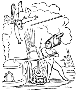
THE HUMAN SPECIES. By A. De Quatrefages, Professor of Anthropology in the Museum of Natural History, Paris. 12mo, cloth, $2.00.
The work treats of the unity, origin, antiquity, and original localization of the human species, peopling of the globe, acclimatization, primitive man, formation of the human races, fossil human races, present human races, and the physical and psychological characters of mankind.
STUDENTS’ TEXT-BOOK OF COLOR; or, MODERN CHROMATICS. With Applications to Art and Industry. With 130 Original Illustrations, and Frontispiece in Colors. By Ogden N. Rood, Professor of Physics in Columbia College. 12mo, cloth, $2.00.
“In this interesting book Professor Rood, who, as a distinguished Professor of Physics in Columbia College, United States, must be accepted as a competent authority on the branch of science of which he treats, deals briefly and succinctly with what may be termed the scientific rationale of his subject. But the chief value of his work is to be attributed to the fact that he is himself an accomplished artist as well as an authoritative expounder of science.”—Edinburgh Review, October, 1879, in an article on “The Philosophy of Color.”
EDUCATION AS A SCIENCE. By Alexander Bain, LL. D. 12mo, cloth, $1.75.
“This work must be pronounced the most remarkable discussion of educational problems which has been published in our day. We do not hesitate to bespeak for it the widest circulation and the most earnest attention. It should be in the hands of every school-teacher and friend of education throughout the land.”—New York Sun.
A HISTORY OF THE GROWTH OF THE STEAM-ENGINE. By Robert H. Thurston, A. M., C. E., Professor of Mechanical Engineering in the Stevens Institute of Technology, Hoboken, N. J., etc. With 163 Illustrations, including 15 Portraits. 12mo, cloth, $2.50.
“Professor Thurston almost exhausts his subject; details of mechanism are followed by interesting biographies of the more important inventors. If, as is contended, the steam-engine is the most important physical agent in civilizing the world, its history is a desideratum, and the readers of the present work will agree that it could have a no more amusing and intelligent historian than our author.”—Boston Gazette.
STUDIES IN SPECTRUM ANALYSIS. By J. Norman Lockyer, F. R. S., Correspondent of the Institute of France, etc. With 60 Illustrations. 12mo, cloth, $2.50.
“The study of spectrum analysis is one fraught with a peculiar fascination, and some of the author’s experiments are exceedingly picturesque in their results. They are so lucidly described, too, that the reader keeps on, from page to page, never flagging in interest in the matter before him, nor putting down the book until the last page is reached.”—New York Evening Express.
GENERAL PHYSIOLOGY OF MUSCLES AND NERVES. By Dr. I. Rosenthal, Professor of Physiology at the University of Erlangen. With seventy-five Woodcuts. (“International Scientific Series.”) 12mo, cloth, $1.50.
“The attempt at a connected account of the general physiology of muscles and nerves is, as far as I know, the first of its kind. The general data for this branch of science have been gained only within the past thirty years.”—Extract from Preface.
SIGHT: An Exposition of the Principles of Monocular and Binocular Vision By Joseph Le Conte, LL. D., author of “Elements of Geology”; “Religion and Science”; and Professor of Geology and Natural History in the University of California. With numerous Illustrations. 12mo, cloth, $1.50.
“It is pleasant to find an American book which can rank with the very best of foreign works on this subject. Professor Le Conte has long been known as an original investigator in this department; all that he gives us is treated with a master-hand.”—The Nation.
ANIMAL LIFE, as affected by the Natural Conditions of Existence. By Karl Semper, Professor of the University of Würzburg. With 2 Maps and 106 Woodcuts, and Index. 12mo, cloth, $2.00.
“This is in many respects one of the most interesting contributions to zoölogical literature which has appeared for some time.”—Nature.
THE ATOMIC THEORY. By Ad. Wurtz, Membre de l’Institut; Doyen Honoraire de la Faculté de Médecine; Professeur à la Faculté des Sciences de Paris. Translated by E. Cleminshaw, M. A., F. C. S., F. I. C., Assistant Master at Sherborne School. 12mo, cloth, $1.50.
“There was need for a book like this, which discusses the atomic theory both in its historic evolution and in its present form. And perhaps no man of this age could have been selected so able to perform the task in a masterly way as the illustrious French chemist, Adolph Wurtz. It is impossible to convey to the reader, in a notice like this, any adequate idea of the scope, lucid instructiveness, and scientific interest of Professor Wurtz’s book. The modern problems of chemistry, which are commonly so obscure from imperfect exposition, are here made wonderfully clear and attractive.”—The Popular Science Monthly.
THE CRAYFISH. An Introduction to the Study of Zoölogy. By Professor T. H. Huxley, F. R. S. With 82 Illustrations. 12mo, cloth, $1.75.
“Whoever will follow these pages, crayfish in hand, and will try to verify for himself the statements which they contain, will find himself brought face to face, with all the great zoölogical questions which excite so lively an interest at the present day.”
“The reader of this valuable monograph will lay it down with a feeling of wonder at the amount and variety of matter which has been got out of so seemingly slight and unpretending a subject.”—Saturday Review.
SUICIDE: An Essay In Comparative Moral Statistics. By Henry Morselli, Professor of Psychological Medicine in Royal University, Turin. 12mo, Cloth, $1.75.
“Suicide” is a scientific inquiry, on the basis of the statistical method, into the laws of suicidal phenomena. Dealing with the subject as a branch of social science, it considers the increase of suicide in different countries, and the comparison of nations, races, and periods in its manifestation. The influences of age, sex, constitution, climate, season, occupation, religion, prevailing ideas, the elements of character, and the tendencies of civilization, are comprehensively analyzed in their bearing upon the propensity to self-destruction. Professor Morselli is an eminent European authority on this subject. It is accompanied by colored maps illustrating pictorially the results of statistical inquiries.
VOLCANOES: What they Are and what they Teach. By J. W. Judd, Professor of Geology in the Royal School of Mines (London). With Ninety-six Illustrations. 12mo. Cloth, $2.00.
“In no field has modern research been more fruitful than in that of which Professor Judd gives a popular account in the present volume. The great lines of dynamical, geological, and meteorological inquiry converge upon the grand problem of the interior constitution of the earth, and the vast influence of subterranean agencies.... His book is very far from being a mere dry description of volcanoes and their eruptions; it is rather a presentation of the terrestrial facts and laws with which volcanic phenomena are associated.”—Popular Science Monthly.
“The volume before us is one of the pleasantest science manuals we have read for some time.”—Athenæum.
“Mr. Judd’s summary is so full and so concise that it is almost impossible to give a fair idea in a short review.”—Pall Mall Gazette.
THE SUN. By C. A. Young, Ph. D., LL. D., Professor of Astronomy in the College of New Jersey. With numerous Illustrations. 12mo. Cloth, $2.00.
“Professor Young is an authority on ‘The Sun,’ and writes from intimate knowledge. He has studied that great luminary all his life, invented and improved instruments for observing it, gone to all quarters of the world in search of the best places and opportunities to watch it, and has contributed important discoveries that have extended our knowledge of it.
“It would take a cyclopædia to represent all that has been done toward clearing up the solar mysteries. Professor Young has summarized the information, and presented it in a form completely available for general readers. There is no rhetoric in his book; he trusts the grandeur of his theme to kindle interest and impress the feelings. His statements are plain, direct, clear, and condensed, though ample enough for his purpose, and the substance of what is generally wanted will be found accurately given in his pages.”—Popular Science Monthly.
ILLUSIONS: A Psychological Study. By James Sully, author of “Sensation and Intuition,” etc. 12mo. Cloth. $1.50.
This volume takes a wide survey of the field of error, embracing in its view not only the illusions commonly regarded as of the nature of mental aberrations or hallucinations, but also other illusions arising from that capacity for error which belongs essentially to rational human nature. The author has endeavored to keep to a strictly scientific treatment—that is to say, the description and classification of acknowledged errors, and the exposition of them by a reference to their psychical and physical conditions.
“This is not a technical work, but one of wide popular interest, in the principles and results of which every one is concerned. The illusions of perception of the senses and of dreams are first considered, and then the author passes to the illusions of introspection, errors of insight, illusions of memory, and illusions of belief. The work is a noteworthy contribution to the original progress of thought, and may be relied upon as representing the present state of knowledge on the important subject to which it is devoted.”—Popular Science Monthly.
THE BRAIN AND ITS FUNCTIONS. By J. Luys, Physician to the Hospice de la Salpêtrière. With Illustrations. 12mo. Cloth, $1.50.
“No living physiologist is better entitled to speak with authority upon the structure and functions of the brain than Dr. Luys. His studies on the anatomy of the nervous system are acknowledged to be the fullest and most systematic ever undertaken. Dr. Luys supports his conclusions not only by his own anatomical researches, but also by many functional observations of various other physiologists, including of course Professor Ferrier’s now classical experiments.”—St. James’s Gazette.
“Dr. Luys, at the head of the great French Insane Asylum, is one of the most eminent and successful investigators of cerebral science now living; and he has given unquestionably the clearest and most interesting brief account yet made of the structure and operations of the brain. We have been fascinated by this volume more than by any other treatise we have yet seen on the machinery of sensibility and thought; and we have been instructed not only by much that is new, but by many sagacious practical hints such as it is well for everybody to understand.”—The Popular Science Monthly.
THE CONCEPTS AND THEORIES OF MODERN PHYSICS. By J. B. Stallo. 12mo. Cloth, $1.75.
“Judge Stallo’s work is an inquiry into the validity of those mechanical conceptions of the universe which are now held as fundamental in physical science. He takes up the leading modern doctrines which are based upon this mechanical conception, such as the atomic constitution of matter, the kinetic theory of gases, the conservation of energy, the nebular hypothesis, and other views, to find how much stands upon solid empirical ground, and how much rests upon metaphysical speculation. Since the appearance of Dr. Draper’s ‘Religion and Science,’ no book has been published in the country calculated to make so deep an impression on thoughtful and educated readers as this volume.... The range and minuteness of the author’s learning, the acuteness of his reasoning, and the singular precision and clearness of his style, are qualities which very seldom have been jointly exhibited in a scientific treatise.”—New York Sun.
THE FORMATION OF VEGETABLE MOULD, THROUGH THE ACTION OF WORMS, WITH OBSERVATIONS ON THEIR HABITS. By Charles Darwin, LL. D., F. R. S., author of “On the Origin of Species,” etc., etc. With Illustrations. 12mo, cloth. Price, $1.50.
“Mr. Darwin’s little volume on the habits and instincts of earth-worms is no less marked than the earlier or more elaborate efforts of his genius by freshness of observation, unfailing power of interpreting and correlating facts, and logical vigor in generalizing upon them. The main purpose of the work is to point out the share which worms have taken in the formation of the layer of vegetable mould which covers the whole surface of the land in every moderately humid country. All lovers of nature will unite in thanking Mr. Darwin for the new and interesting light he has thrown upon a subject so long overlooked, yet so full of interest and instruction, as the structure and the labors of the earth-worm.”—Saturday Review.
“Respecting worms as among the most useful portions of animate nature, Dr. Darwin relates, in this remarkable book, their structure and habits, the part they have played in the burial of ancient buildings and the denudation of the land, in the disintegration of rocks, the preparation of soil for the growth of plants, and in the natural history of the world.”—Boston Advertiser.
ANTS, BEES, AND WASPS. A Record of Observations on the Habits of the Social Hymenoptera. By Sir John Lubbock, Bart., M. P., F. R. S., etc., author of “Origin of Civilization, and the Primitive Condition of Man,” etc., etc. With Colored Plates. 12mo, cloth, $2.00.
“This volume contains the record of various experiments made with ants, bees, and wasps during the last ten years, with a view to test their mental condition and powers of sense. The principal point in which Sir John’s mode of experiment differs from those of Huber, Forel, McCook, and others, is that he has carefully watched and marked particular insects, and has had their nests under observation for long periods—one of his ants’ nests having been under constant inspection ever since 1874. His observations are made principally upon ants because they show more power and flexibility of mind; and the value of his studies is that they belong to the department of original research.”
“We have no hesitation in saying that the author has presented us with the most valuable series of observations on a special subject that has ever been produced, charmingly written, full of logical deductions, and, when we consider his multitudinous engagements, a remarkable illustration of economy of time. As a contribution to insect psychology, it will be long before this book finds a parallel.”—London Athenæum.
DISEASES OF MEMORY: An Essay in the Positive Psychology. By Th. Ribot, author of “Heredity,” etc. Translated from the French by William Huntington Smith. 12mo, cloth, $1.50.
“M. Ribot reduces diseases of memory to law, and his treatise is of extraordinary interest.”—Philadelphia Press.
“Not merely to scientific, but to all thinking men, this volume will prove intensely interesting.”—New York Observer.
“M. Ribot has bestowed the most painstaking attention upon his theme, and numerous examples of the conditions considered greatly increase the value and interest of the volume.”—Philadelphia North American.
“To the general reader the work is made entertaining by many illustrations connected with such names as Linnæus, Newton, Sir Walter Scott, Horace Vernet, Gustave Doré, and many others.”—Harrisburg Telegraph.
“The whole subject is presented with a Frenchman’s vivacity of style.”—Providence Journal.
“It is not too much to say that in no single work have so many curious cases been brought together and interpreted in a scientific manner.”—Boston Evening Traveller.
MYTH AND SCIENCE. By Tito Vignoli. 12mo, cloth, price, $1.50.
“His book is ingenious; ... his theory of how science gradually differentiated from and conquered myth is extremely well wrought out, and is probably in essentials correct.”—Saturday Review.
“The book is a strong one, and far more interesting to the general reader than its title would indicate. The learning, the acuteness, the strong reasoning power, and the scientific spirit of the author, command admiration.”—New York Christian Advocate.
“An attempt made, with much ability and no small measure of success, to trace the origin and development of the myth. The author has pursued his inquiry with much patience and ingenuity, and has produced a very readable and luminous treatise.”—Philadelphia North American.
“It is a curious if not startling contribution both to psychology and to the early history of man’s development.”—New York World.
MAN BEFORE METALS. By N. Joly, Professor at the Science Faculty of Toulouse; Correspondent of the Institute. With 148 Illustrations, 12mo. Cloth, $1.75.
“The discussion of man’s origin and early history, by Professor De Quatrefages, formed one of the most useful volumes in the ‘International Scientific Series,’ and the same collection is now further enriched by a popular treatise on paleontology, by M. N. Joly, Professor in the University of Toulouse. The title of the book, ‘Man before Metals,’ indicates the limitations of the writer’s theme. His object is to bring together the numerous proofs, collected by modern research, of the great age of the human race, and to show us what man was, in respect of customs, industries, and moral or religious ideas, before the use of metals was known to him.”—New York Sun.
“An interesting, not to say fascinating volume.”—New York Churchman.
ANIMAL INTELLIGENCE. By George J. Romanes, F. R. S., Zoölogical Secretary of the Linnæan Society, etc. 12mo. Cloth, $1.75.
“My object in the work as a whole is twofold: First, I have thought it desirable that there should be something resembling a text-book of the facts of Comparative Psychology, to which men of science, and also metaphysicians, may turn whenever they have occasion to acquaint themselves with the particular level of intelligence to which this or that species of animal attains. My second and much more important object is that of considering the facts of animal intelligence in their relation to the theory of descent.”—From the Preface.
“Unless we are greatly mistaken, Mr. Romanes’s work will take its place as one of the most attractive volumes of the ‘International Scientific Series.’ Some persons may, indeed, be disposed to say that it is too attractive, that it feeds the popular taste for the curious and marvelous without supplying any commensurate discipline in exact scientific reflection; but the author has, we think, fully justified himself in his modest preface. The result is the appearance of a collection of facts which will be a real boon to the student of Comparative Psychology for this is the first attempt to present systematically well-assured observations on the mental life of animals.”—Saturday Review.
“The author believes himself, not without ample cause, to have completely bridged the supposed gap between instinct and reason by the authentic proofs here marshaled of remarkable intelligence in some of the higher animals. It is the seemingly conclusive evidence of reasoning; powers furnished by the adaptation of means to ends in cases which can not be explained on the theory of inherited aptitude or habit.”—New York Sun.
THE SCIENCE OF POLITICS. By Sheldon Amos, M. A., author of “The Science of Law,” etc. 12mo. Cloth, $1.75.
“To the political student and the practical statesman it ought to be of great value.”—New York Herald.
“The author traces the subject from Plato and Aristotle in Greece, and Cicero in Rome, to the modern schools in the English field, not slighting the teachings of the American Revolution or the lessons of the French Revolution of 1793. Forms of government, political terms, the relation of law, written and unwritten, to the subject, a codification from Justinian to Napoleon in France and Field in America, are treated as parts of the subject in hand. Necessarily the subjects of executive and legislative authority, police, liquor, and land laws are considered, and the question ever growing in importance in all countries, the relations of corporations to the state.”—New York Observer.
THE FUNDAMENTAL CONCEPTS OF MODERN PHILOSOPHIC THOUGHT, CRITICALLY AND HISTORICALLY CONSIDERED. By Rudolph Eucken, Ph. D., Professor in Jena. With an Introduction by Noah Porter, President of Yale College. One vol., 12mo, 304 pages. Cloth. Price, $1.75.
President Porter declares of this work that “there are few books within his knowledge which are better fitted to aid the student who wishes to acquaint himself with the course of modern speculation and scientific thinking, and to form an intelligent estimate of most of the current theories.”
MIND IN THE LOWER ANIMALS IN HEALTH AND DISEASE. By W. Lauder Lindsay, M. D., F. R. S. E., etc. 2 vols., 8vo. Cloth, $4.00.
“The author of this work, which, regarded merely as an accumulation of verified and classified facts, is a unique and precious contribution to the data of comparative psychology, claims that he entered on his inquiry without any theory to defend, support, or illustrate. We are bound to say that, while his general conclusions are boldly and continually avowed, his claim of fairness and caution is justified by his method of examining particular phenomena; that he seems willing at all times to renounce any impression or belief which is shown to be scientifically untenable.”—New York Sun.
“In this work—two volumes of over 500 pages—Dr. Lindsay marshals a proportionately large number of facts against those philosophers who maintain that the intelligence of man differs in kind and not simply in degree from that of the lower animals. It is one purpose of his book to show that the main differences between man and the lower animals exist rather in their physical than in their mental structure. In this way of thinking, all animals possess not the semblance of, but the true substance of mind and will.”—New York World.
“So far as we are aware there has been no treatise upon the subject of animal intelligence so broad in its foundations, so well considered, or so scientific in its methods of inquiry, as that which has been prepared by Dr. W. Lauder Lindsay in two large volumes, the first being devoted to a study of animal mind in health, and the second to animal mind in disease. We may safely say that his work is, in some respects, the most important essay of the kind that has yet been undertaken. His observations have been supplemented by a thorough mastery of the history and literature of the subject, and hence his conclusions rest upon the broadest possible foundation of safe induction. There is a good analytical index to the book, as there ought to be to every work of the kind.”—New York Evening Post.
THE ELEMENTARY PRINCIPLES OF SCIENTIFIC AGRICULTURE. By N. T. Lupton, LL. D., Professor of Chemistry in Vanderbilt University, Nashville, Tenn. 18mo. Cloth. Price, 45 cents.
A GLOSSARY OF BIOLOGICAL, ANATOMICAL, AND PHYSIOLOGICAL TERMS. By Thomas Dunman. Small 8vo. Cloth. 161 pages. Price, $1.00.
“It has been the author’s task to furnish here a small and convenient but very complete glossary of those terms; and he has done this so well, both in his choice of terms for definition and in his clear exposition of their etymological and technical meaning, as to leave nothing to be desired in this direction.”—New York Evening Post.
For sale by all booksellers, or any work sent by mail, post-paid, on receipt of price.
D. APPLETON & CO., Publishers,
1, 3, & 5 Bond Street, New York.
Popular Lectures on Scientific Subjects. By H. Helmholtz, Professor of Physics in the University of Berlin. First Series. Translated by E. Atkinson, Ph. D., F. C. S. With an Introduction by Professor Tyndall. With 51 Illustrations. 12mo. Cloth, $2.00.
CONTENTS.—On the Relation of Natural Science to Science in General.—On Goethe’s Scientific Researches.—On the Physiological Causes of Harmony in Music—Ice and Glaciers.—Interaction of the Natural Forces.—The Recent Progress of the Theory of Vision.—The Conservation of Force.—Aim and Progress of Physical Science.
Popular Lectures on Scientific Subjects. By H. Helmholtz. Second Series. 12mo. Cloth, $1.50.
CONTENTS.—Gustav Magnus.—In Memoriam.—The Origin and Significance of Geometrical Axioms.—Relation of Optics to Painting.—Origin of the Planetary System.—On Thought in Medicine.—Academic Freedom in German Universities.
“Professor Helmholtz’s second series of ‘Popular Lectures on Scientific Subjects’ forms a volume of singular interest and value. He who anticipates a dry record of facts or a sequence of immature generalization will find himself happily mistaken. In style and method these discourses are models of excellence, and, since they come from a man whose learning and authority are beyond dispute, they may be accepted as presenting the conclusions of the best thought of the times in scientific fields.”—Boston Traveler.
Science and Culture, and other Essays. By Professor T. H. Huxley, F. R. S. 12mo. Cloth, $1.50.
“Of the essays that have been collected by Professor Huxley in this volume, the first four deal with some aspect of education. Most of the remainder are expositions of the results of biological research, and, at the same time, illustrations of the history of scientific ideas. Some of these are among the most interesting of Professor Huxley’s contributions to the literature of science.”—London Academy.
“It is refreshing to be brought into converse with one of the most vigorous and acute thinkers of our time, who has the power of putting his thoughts into language so clear and forcible.”—London Spectator.
Scientific Culture, and other Essays. By Josiah Parsons Cooke, Professor of Chemistry and Mineralogy in Harvard College. 12mo. Cloth, $1.00.
These essays are an outcome of a somewhat large experience in teaching physical science to college students. Cambridge, Massachusetts, early set the example of making the student’s own observations in the laboratory or cabinet the basis of all teaching, either in experimental or natural history science; and this example has been generally followed. “But in most centers of education,” writes Professor Cooke, “the old traditions so far survive that the great end of scientific culture is lost in attempting to conform even laboratory instruction to the old academic methods of recitations and examinations. To point out this error, and to claim for science-teaching its appropriate methods, was one object of writing these essays.”
For sale by all booksellers; or sent by mail, post-paid, on receipt of price.
New York: D. APPLETON & CO., 1, 3, & 5 Bond Street.
End of the Project Gutenberg EBook of A History of the Growth of the
Steam-Engine, by Robert H. Thurston

*** END OF THIS PROJECT GUTENBERG EBOOK STEAM ***

***** This file should be named 35916-h.htm or 35916-h.zip *****
This and all associated files of various formats will be found in:
        http://www.gutenberg.org/3/5/9/1/35916/

Produced by Chris Curnow, Harry Lamé and the Online
Distributed Proofreading Team at http://www.pgdp.net (This
file was produced from images generously made available
by The Internet Archive)


Updated editions will replace the previous one--the old editions
will be renamed.

Creating the works from public domain print editions means that no
one owns a United States copyright in these works, so the Foundation
(and you!) can copy and distribute it in the United States without
permission and without paying copyright royalties.  Special rules,
set forth in the General Terms of Use part of this license, apply to
copying and distributing Project Gutenberg-tm electronic works to
protect the PROJECT GUTENBERG-tm concept and trademark.  Project
Gutenberg is a registered trademark, and may not be used if you
charge for the eBooks, unless you receive specific permission.  If you
do not charge anything for copies of this eBook, complying with the
rules is very easy.  You may use this eBook for nearly any purpose
such as creation of derivative works, reports, performances and
research.  They may be modified and printed and given away--you may do
practically ANYTHING with public domain eBooks.  Redistribution is
subject to the trademark license, especially commercial
redistribution.


*** START: FULL LICENSE ***

THE FULL PROJECT GUTENBERG LICENSE
PLEASE READ THIS BEFORE YOU DISTRIBUTE OR USE THIS WORK

To protect the Project Gutenberg-tm mission of promoting the free
distribution of electronic works, by using or distributing this work
(or any other work associated in any way with the phrase "Project
Gutenberg"), you agree to comply with all the terms of the Full Project
Gutenberg-tm License (available with this file or online at
http://gutenberg.org/license).


Section 1.  General Terms of Use and Redistributing Project Gutenberg-tm
electronic works

1.A.  By reading or using any part of this Project Gutenberg-tm
electronic work, you indicate that you have read, understand, agree to
and accept all the terms of this license and intellectual property
(trademark/copyright) agreement.  If you do not agree to abide by all
the terms of this agreement, you must cease using and return or destroy
all copies of Project Gutenberg-tm electronic works in your possession.
If you paid a fee for obtaining a copy of or access to a Project
Gutenberg-tm electronic work and you do not agree to be bound by the
terms of this agreement, you may obtain a refund from the person or
entity to whom you paid the fee as set forth in paragraph 1.E.8.

1.B.  "Project Gutenberg" is a registered trademark.  It may only be
used on or associated in any way with an electronic work by people who
agree to be bound by the terms of this agreement.  There are a few
things that you can do with most Project Gutenberg-tm electronic works
even without complying with the full terms of this agreement.  See
paragraph 1.C below.  There are a lot of things you can do with Project
Gutenberg-tm electronic works if you follow the terms of this agreement
and help preserve free future access to Project Gutenberg-tm electronic
works.  See paragraph 1.E below.

1.C.  The Project Gutenberg Literary Archive Foundation ("the Foundation"
or PGLAF), owns a compilation copyright in the collection of Project
Gutenberg-tm electronic works.  Nearly all the individual works in the
collection are in the public domain in the United States.  If an
individual work is in the public domain in the United States and you are
located in the United States, we do not claim a right to prevent you from
copying, distributing, performing, displaying or creating derivative
works based on the work as long as all references to Project Gutenberg
are removed.  Of course, we hope that you will support the Project
Gutenberg-tm mission of promoting free access to electronic works by
freely sharing Project Gutenberg-tm works in compliance with the terms of
this agreement for keeping the Project Gutenberg-tm name associated with
the work.  You can easily comply with the terms of this agreement by
keeping this work in the same format with its attached full Project
Gutenberg-tm License when you share it without charge with others.

1.D.  The copyright laws of the place where you are located also govern
what you can do with this work.  Copyright laws in most countries are in
a constant state of change.  If you are outside the United States, check
the laws of your country in addition to the terms of this agreement
before downloading, copying, displaying, performing, distributing or
creating derivative works based on this work or any other Project
Gutenberg-tm work.  The Foundation makes no representations concerning
the copyright status of any work in any country outside the United
States.

1.E.  Unless you have removed all references to Project Gutenberg:

1.E.1.  The following sentence, with active links to, or other immediate
access to, the full Project Gutenberg-tm License must appear prominently
whenever any copy of a Project Gutenberg-tm work (any work on which the
phrase "Project Gutenberg" appears, or with which the phrase "Project
Gutenberg" is associated) is accessed, displayed, performed, viewed,
copied or distributed:

This eBook is for the use of anyone anywhere at no cost and with
almost no restrictions whatsoever.  You may copy it, give it away or
re-use it under the terms of the Project Gutenberg License included
with this eBook or online at www.gutenberg.org

1.E.2.  If an individual Project Gutenberg-tm electronic work is derived
from the public domain (does not contain a notice indicating that it is
posted with permission of the copyright holder), the work can be copied
and distributed to anyone in the United States without paying any fees
or charges.  If you are redistributing or providing access to a work
with the phrase "Project Gutenberg" associated with or appearing on the
work, you must comply either with the requirements of paragraphs 1.E.1
through 1.E.7 or obtain permission for the use of the work and the
Project Gutenberg-tm trademark as set forth in paragraphs 1.E.8 or
1.E.9.

1.E.3.  If an individual Project Gutenberg-tm electronic work is posted
with the permission of the copyright holder, your use and distribution
must comply with both paragraphs 1.E.1 through 1.E.7 and any additional
terms imposed by the copyright holder.  Additional terms will be linked
to the Project Gutenberg-tm License for all works posted with the
permission of the copyright holder found at the beginning of this work.

1.E.4.  Do not unlink or detach or remove the full Project Gutenberg-tm
License terms from this work, or any files containing a part of this
work or any other work associated with Project Gutenberg-tm.

1.E.5.  Do not copy, display, perform, distribute or redistribute this
electronic work, or any part of this electronic work, without
prominently displaying the sentence set forth in paragraph 1.E.1 with
active links or immediate access to the full terms of the Project
Gutenberg-tm License.

1.E.6.  You may convert to and distribute this work in any binary,
compressed, marked up, nonproprietary or proprietary form, including any
word processing or hypertext form.  However, if you provide access to or
distribute copies of a Project Gutenberg-tm work in a format other than
"Plain Vanilla ASCII" or other format used in the official version
posted on the official Project Gutenberg-tm web site (www.gutenberg.org),
you must, at no additional cost, fee or expense to the user, provide a
copy, a means of exporting a copy, or a means of obtaining a copy upon
request, of the work in its original "Plain Vanilla ASCII" or other
form.  Any alternate format must include the full Project Gutenberg-tm
License as specified in paragraph 1.E.1.

1.E.7.  Do not charge a fee for access to, viewing, displaying,
performing, copying or distributing any Project Gutenberg-tm works
unless you comply with paragraph 1.E.8 or 1.E.9.

1.E.8.  You may charge a reasonable fee for copies of or providing
access to or distributing Project Gutenberg-tm electronic works provided
that

- You pay a royalty fee of 20% of the gross profits you derive from
     the use of Project Gutenberg-tm works calculated using the method
     you already use to calculate your applicable taxes.  The fee is
     owed to the owner of the Project Gutenberg-tm trademark, but he
     has agreed to donate royalties under this paragraph to the
     Project Gutenberg Literary Archive Foundation.  Royalty payments
     must be paid within 60 days following each date on which you
     prepare (or are legally required to prepare) your periodic tax
     returns.  Royalty payments should be clearly marked as such and
     sent to the Project Gutenberg Literary Archive Foundation at the
     address specified in Section 4, "Information about donations to
     the Project Gutenberg Literary Archive Foundation."

- You provide a full refund of any money paid by a user who notifies
     you in writing (or by e-mail) within 30 days of receipt that s/he
     does not agree to the terms of the full Project Gutenberg-tm
     License.  You must require such a user to return or
     destroy all copies of the works possessed in a physical medium
     and discontinue all use of and all access to other copies of
     Project Gutenberg-tm works.

- You provide, in accordance with paragraph 1.F.3, a full refund of any
     money paid for a work or a replacement copy, if a defect in the
     electronic work is discovered and reported to you within 90 days
     of receipt of the work.

- You comply with all other terms of this agreement for free
     distribution of Project Gutenberg-tm works.

1.E.9.  If you wish to charge a fee or distribute a Project Gutenberg-tm
electronic work or group of works on different terms than are set
forth in this agreement, you must obtain permission in writing from
both the Project Gutenberg Literary Archive Foundation and Michael
Hart, the owner of the Project Gutenberg-tm trademark.  Contact the
Foundation as set forth in Section 3 below.

1.F.

1.F.1.  Project Gutenberg volunteers and employees expend considerable
effort to identify, do copyright research on, transcribe and proofread
public domain works in creating the Project Gutenberg-tm
collection.  Despite these efforts, Project Gutenberg-tm electronic
works, and the medium on which they may be stored, may contain
"Defects," such as, but not limited to, incomplete, inaccurate or
corrupt data, transcription errors, a copyright or other intellectual
property infringement, a defective or damaged disk or other medium, a
computer virus, or computer codes that damage or cannot be read by
your equipment.

1.F.2.  LIMITED WARRANTY, DISCLAIMER OF DAMAGES - Except for the "Right
of Replacement or Refund" described in paragraph 1.F.3, the Project
Gutenberg Literary Archive Foundation, the owner of the Project
Gutenberg-tm trademark, and any other party distributing a Project
Gutenberg-tm electronic work under this agreement, disclaim all
liability to you for damages, costs and expenses, including legal
fees.  YOU AGREE THAT YOU HAVE NO REMEDIES FOR NEGLIGENCE, STRICT
LIABILITY, BREACH OF WARRANTY OR BREACH OF CONTRACT EXCEPT THOSE
PROVIDED IN PARAGRAPH 1.F.3.  YOU AGREE THAT THE FOUNDATION, THE
TRADEMARK OWNER, AND ANY DISTRIBUTOR UNDER THIS AGREEMENT WILL NOT BE
LIABLE TO YOU FOR ACTUAL, DIRECT, INDIRECT, CONSEQUENTIAL, PUNITIVE OR
INCIDENTAL DAMAGES EVEN IF YOU GIVE NOTICE OF THE POSSIBILITY OF SUCH
DAMAGE.

1.F.3.  LIMITED RIGHT OF REPLACEMENT OR REFUND - If you discover a
defect in this electronic work within 90 days of receiving it, you can
receive a refund of the money (if any) you paid for it by sending a
written explanation to the person you received the work from.  If you
received the work on a physical medium, you must return the medium with
your written explanation.  The person or entity that provided you with
the defective work may elect to provide a replacement copy in lieu of a
refund.  If you received the work electronically, the person or entity
providing it to you may choose to give you a second opportunity to
receive the work electronically in lieu of a refund.  If the second copy
is also defective, you may demand a refund in writing without further
opportunities to fix the problem.

1.F.4.  Except for the limited right of replacement or refund set forth
in paragraph 1.F.3, this work is provided to you 'AS-IS' WITH NO OTHER
WARRANTIES OF ANY KIND, EXPRESS OR IMPLIED, INCLUDING BUT NOT LIMITED TO
WARRANTIES OF MERCHANTIBILITY OR FITNESS FOR ANY PURPOSE.

1.F.5.  Some states do not allow disclaimers of certain implied
warranties or the exclusion or limitation of certain types of damages.
If any disclaimer or limitation set forth in this agreement violates the
law of the state applicable to this agreement, the agreement shall be
interpreted to make the maximum disclaimer or limitation permitted by
the applicable state law.  The invalidity or unenforceability of any
provision of this agreement shall not void the remaining provisions.

1.F.6.  INDEMNITY - You agree to indemnify and hold the Foundation, the
trademark owner, any agent or employee of the Foundation, anyone
providing copies of Project Gutenberg-tm electronic works in accordance
with this agreement, and any volunteers associated with the production,
promotion and distribution of Project Gutenberg-tm electronic works,
harmless from all liability, costs and expenses, including legal fees,
that arise directly or indirectly from any of the following which you do
or cause to occur: (a) distribution of this or any Project Gutenberg-tm
work, (b) alteration, modification, or additions or deletions to any
Project Gutenberg-tm work, and (c) any Defect you cause.


Section  2.  Information about the Mission of Project Gutenberg-tm

Project Gutenberg-tm is synonymous with the free distribution of
electronic works in formats readable by the widest variety of computers
including obsolete, old, middle-aged and new computers.  It exists
because of the efforts of hundreds of volunteers and donations from
people in all walks of life.

Volunteers and financial support to provide volunteers with the
assistance they need, are critical to reaching Project Gutenberg-tm's
goals and ensuring that the Project Gutenberg-tm collection will
remain freely available for generations to come.  In 2001, the Project
Gutenberg Literary Archive Foundation was created to provide a secure
and permanent future for Project Gutenberg-tm and future generations.
To learn more about the Project Gutenberg Literary Archive Foundation
and how your efforts and donations can help, see Sections 3 and 4
and the Foundation web page at http://www.pglaf.org.


Section 3.  Information about the Project Gutenberg Literary Archive
Foundation

The Project Gutenberg Literary Archive Foundation is a non profit
501(c)(3) educational corporation organized under the laws of the
state of Mississippi and granted tax exempt status by the Internal
Revenue Service.  The Foundation's EIN or federal tax identification
number is 64-6221541.  Its 501(c)(3) letter is posted at
http://pglaf.org/fundraising.  Contributions to the Project Gutenberg
Literary Archive Foundation are tax deductible to the full extent
permitted by U.S. federal laws and your state's laws.

The Foundation's principal office is located at 4557 Melan Dr. S.
Fairbanks, AK, 99712., but its volunteers and employees are scattered
throughout numerous locations.  Its business office is located at
809 North 1500 West, Salt Lake City, UT 84116, (801) 596-1887, email
business@pglaf.org.  Email contact links and up to date contact
information can be found at the Foundation's web site and official
page at http://pglaf.org

For additional contact information:
     Dr. Gregory B. Newby
     Chief Executive and Director
     gbnewby@pglaf.org


Section 4.  Information about Donations to the Project Gutenberg
Literary Archive Foundation

Project Gutenberg-tm depends upon and cannot survive without wide
spread public support and donations to carry out its mission of
increasing the number of public domain and licensed works that can be
freely distributed in machine readable form accessible by the widest
array of equipment including outdated equipment.  Many small donations
($1 to $5,000) are particularly important to maintaining tax exempt
status with the IRS.

The Foundation is committed to complying with the laws regulating
charities and charitable donations in all 50 states of the United
States.  Compliance requirements are not uniform and it takes a
considerable effort, much paperwork and many fees to meet and keep up
with these requirements.  We do not solicit donations in locations
where we have not received written confirmation of compliance.  To
SEND DONATIONS or determine the status of compliance for any
particular state visit http://pglaf.org

While we cannot and do not solicit contributions from states where we
have not met the solicitation requirements, we know of no prohibition
against accepting unsolicited donations from donors in such states who
approach us with offers to donate.

International donations are gratefully accepted, but we cannot make
any statements concerning tax treatment of donations received from
outside the United States.  U.S. laws alone swamp our small staff.

Please check the Project Gutenberg Web pages for current donation
methods and addresses.  Donations are accepted in a number of other
ways including checks, online payments and credit card donations.
To donate, please visit: http://pglaf.org/donate


Section 5.  General Information About Project Gutenberg-tm electronic
works.

Professor Michael S. Hart is the originator of the Project Gutenberg-tm
concept of a library of electronic works that could be freely shared
with anyone.  For thirty years, he produced and distributed Project
Gutenberg-tm eBooks with only a loose network of volunteer support.


Project Gutenberg-tm eBooks are often created from several printed
editions, all of which are confirmed as Public Domain in the U.S.
unless a copyright notice is included.  Thus, we do not necessarily
keep eBooks in compliance with any particular paper edition.


Most people start at our Web site which has the main PG search facility:

     http://www.gutenberg.org

This Web site includes information about Project Gutenberg-tm,
including how to make donations to the Project Gutenberg Literary
Archive Foundation, how to help produce our new eBooks, and how to
subscribe to our email newsletter to hear about new eBooks.
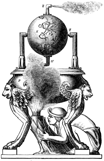
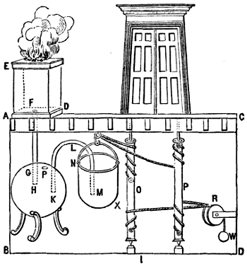
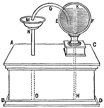
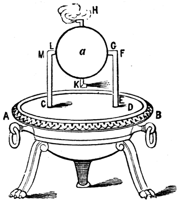
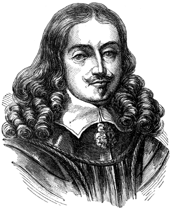
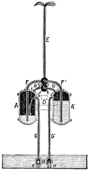
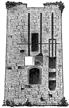
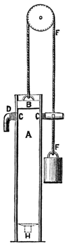
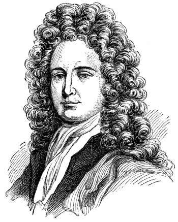
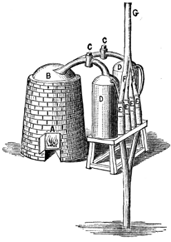
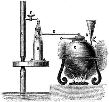
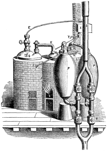
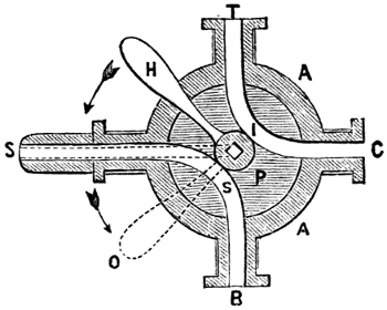
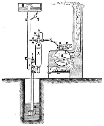
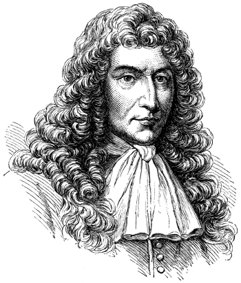
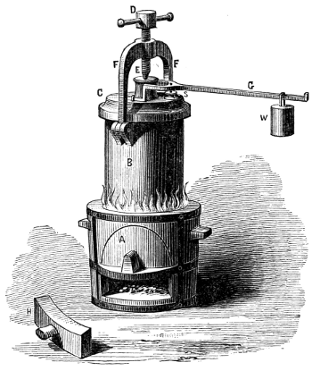
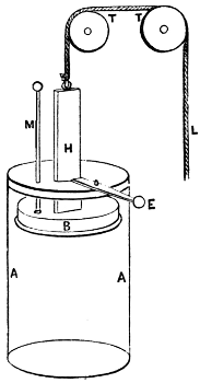
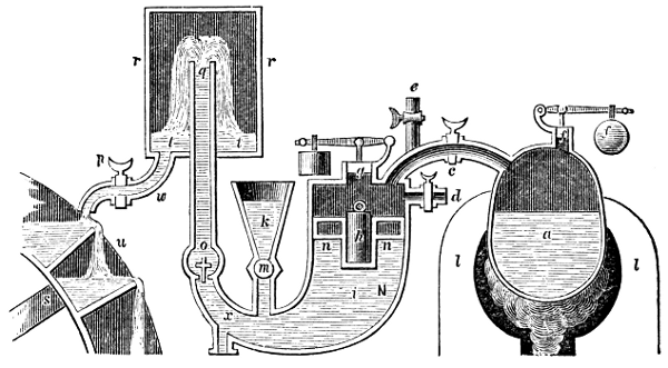
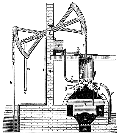
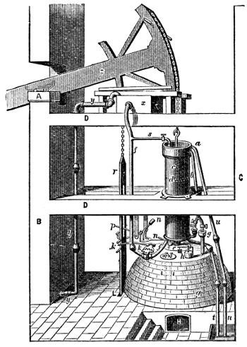
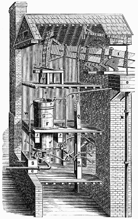
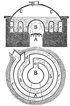
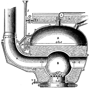
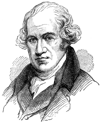
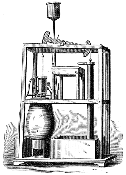
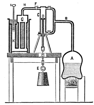
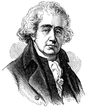
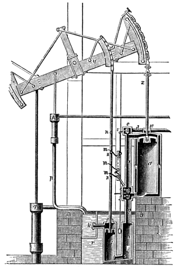
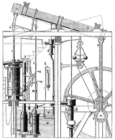
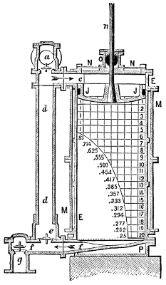
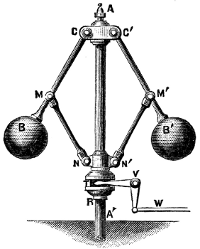
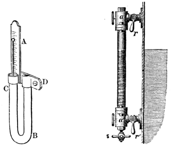
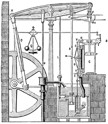
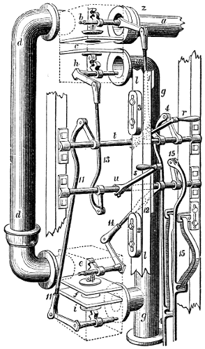
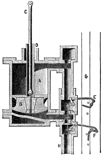
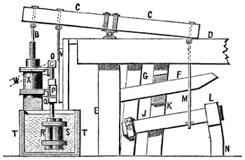
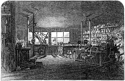
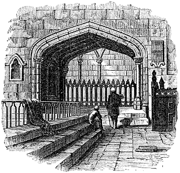
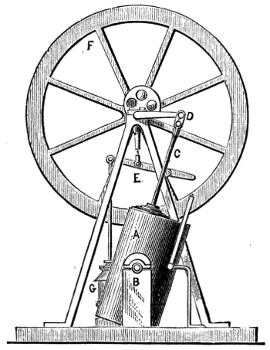
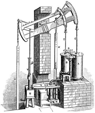
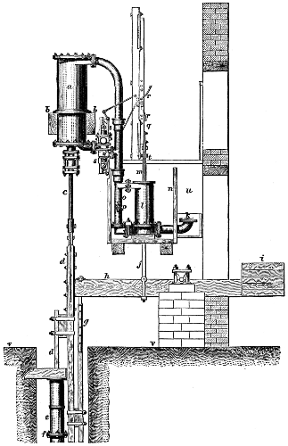
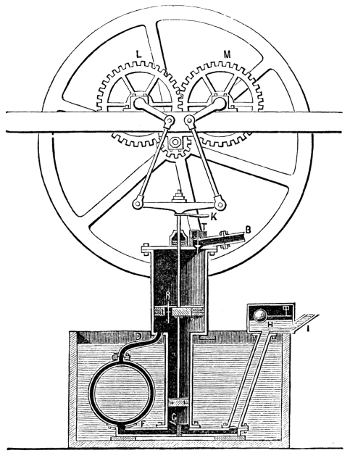
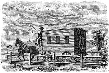
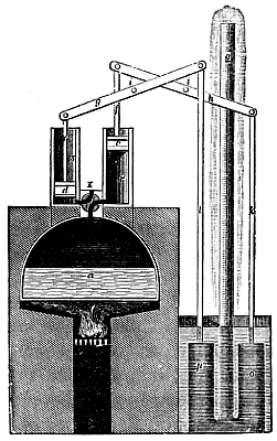
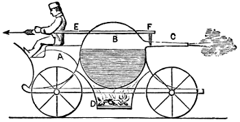
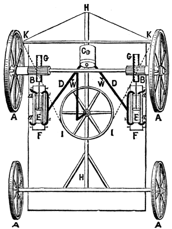
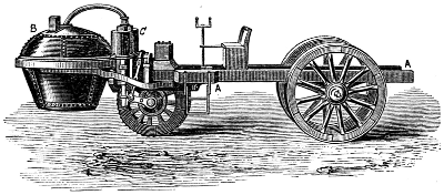
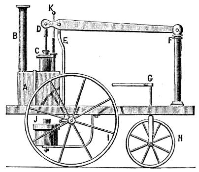
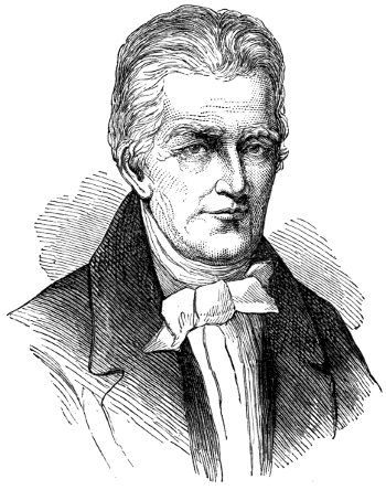
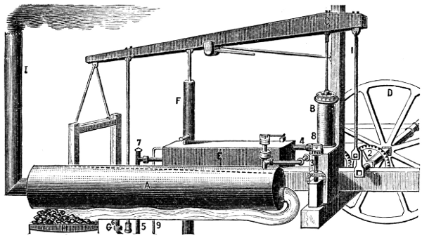
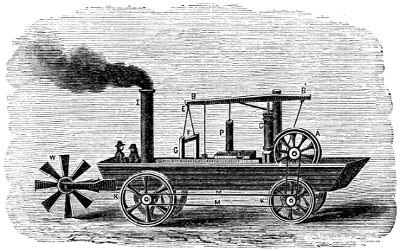
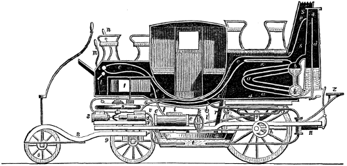
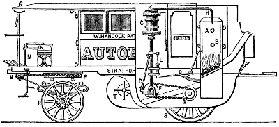
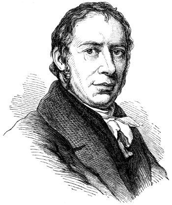
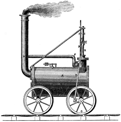
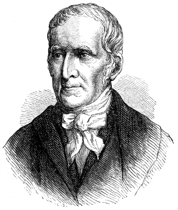
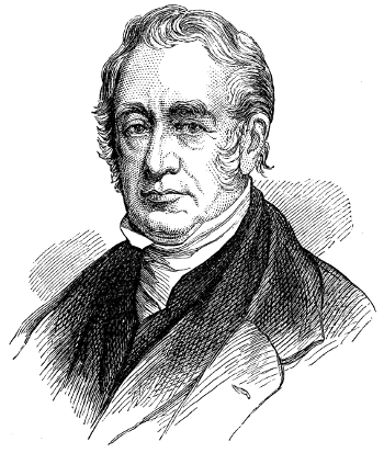
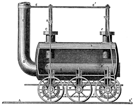
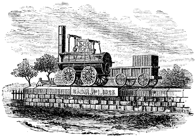
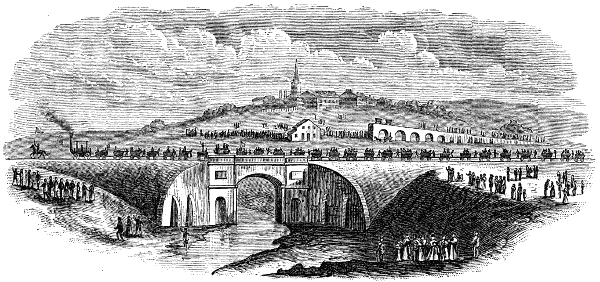
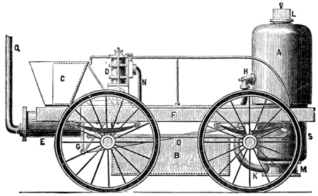
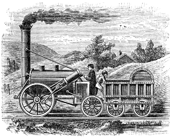
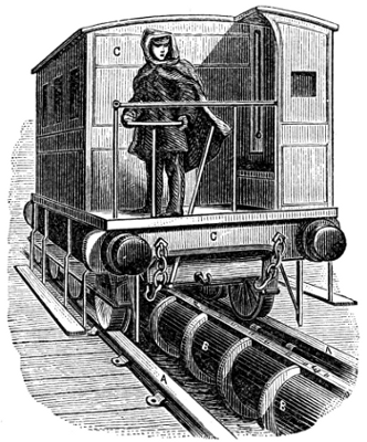
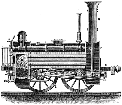
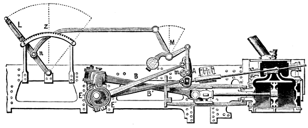
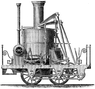
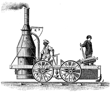
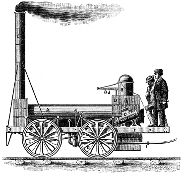
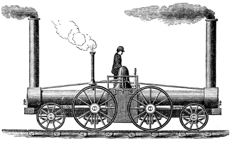
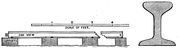
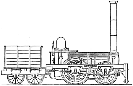
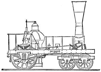
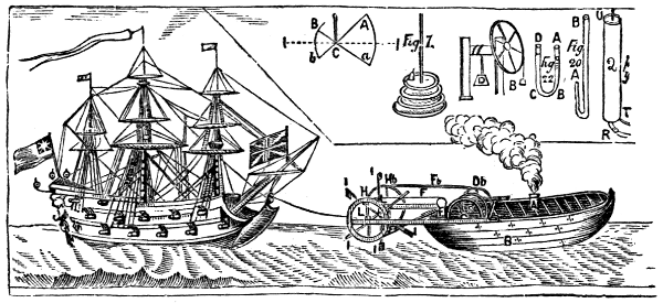
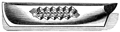
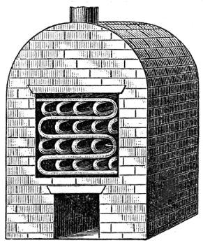
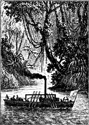
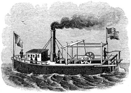
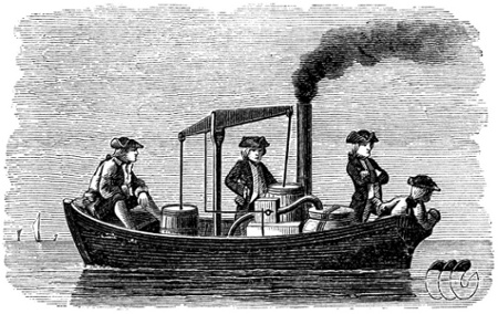
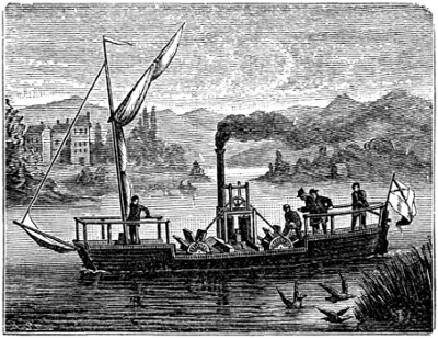
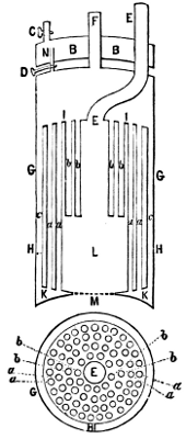
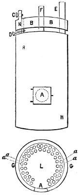
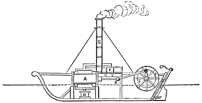
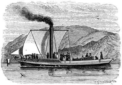
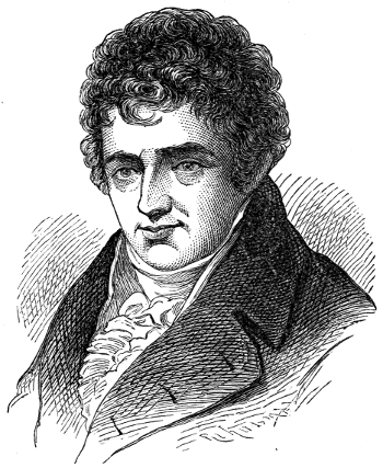
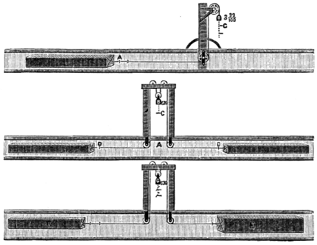
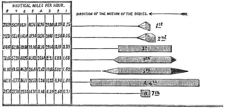
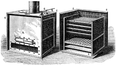
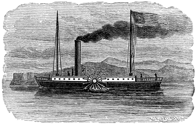
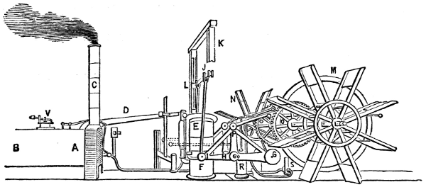
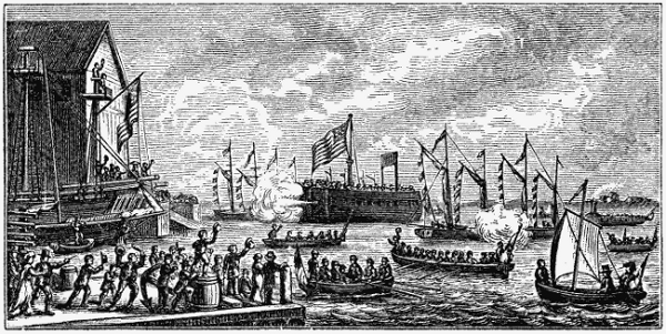
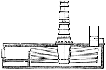
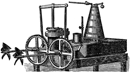
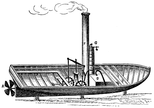
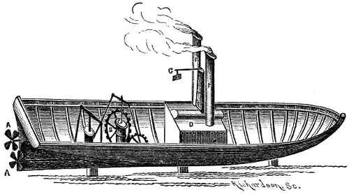
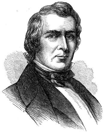
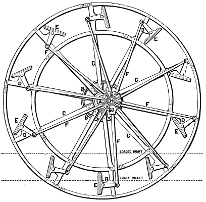
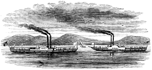
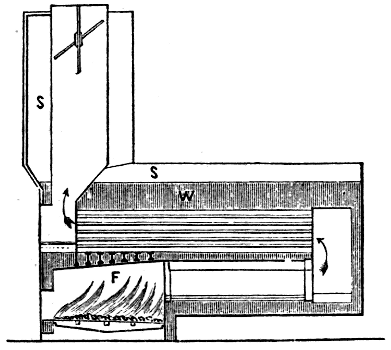
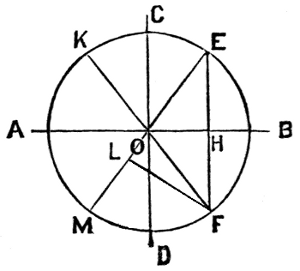
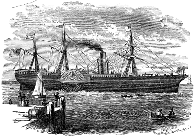
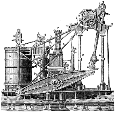
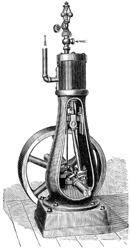
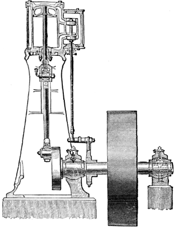
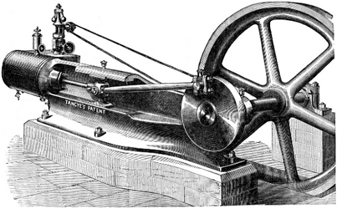
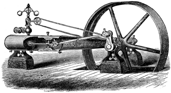
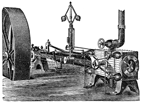
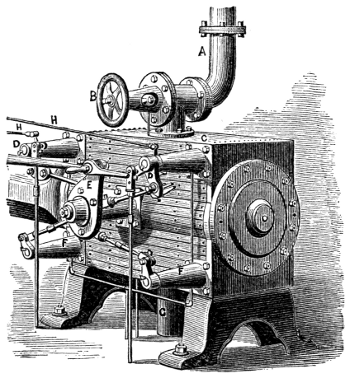
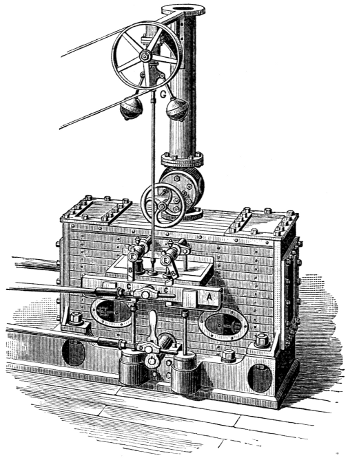
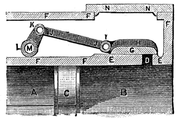
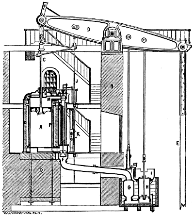
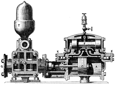
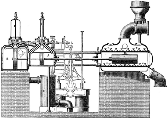
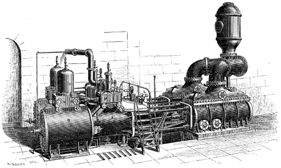
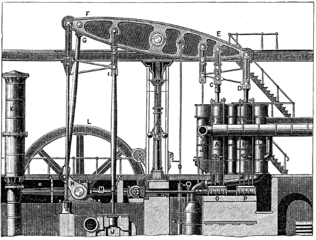
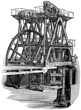
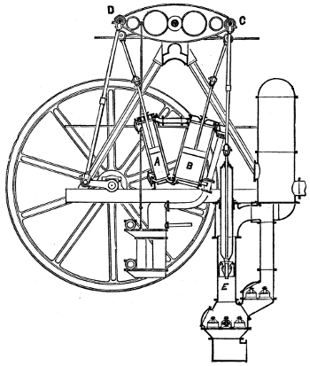
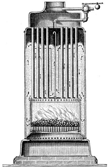
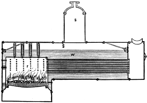
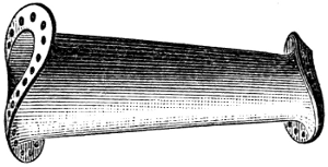
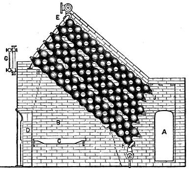
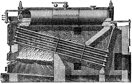
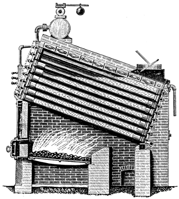
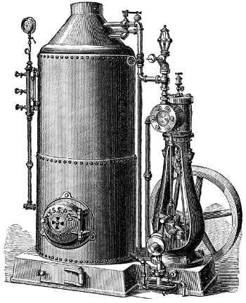
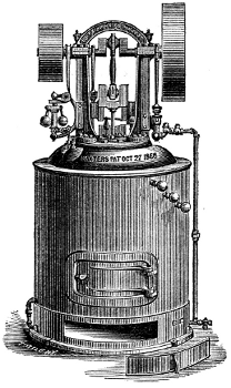
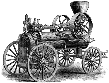
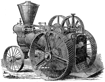
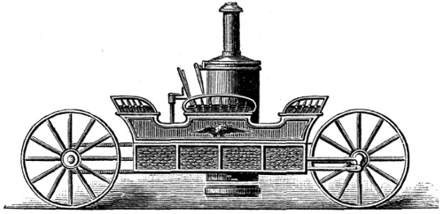
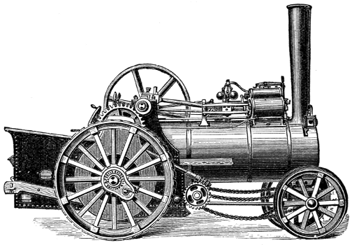
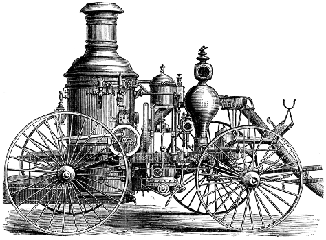
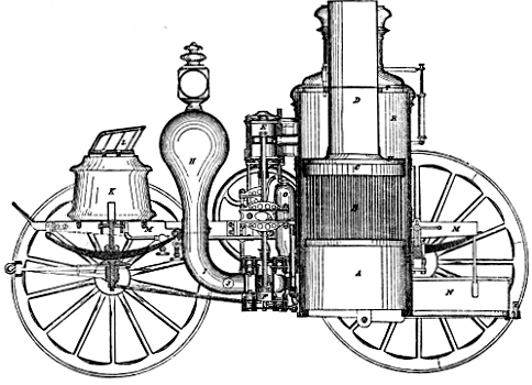
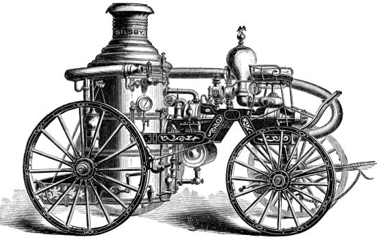
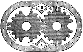
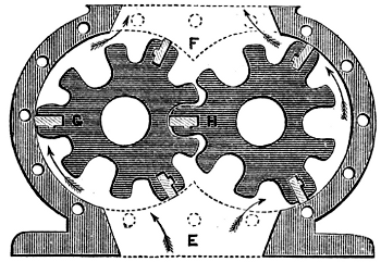
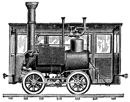
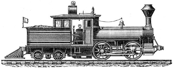
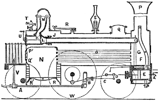
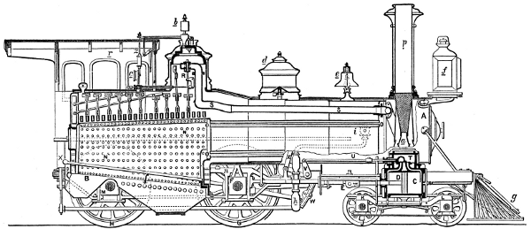
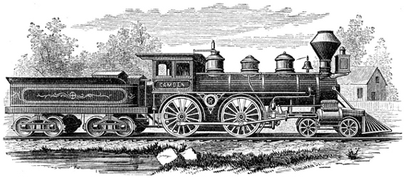
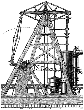
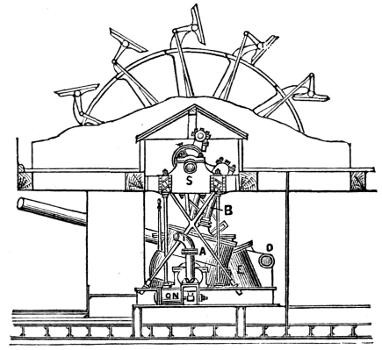
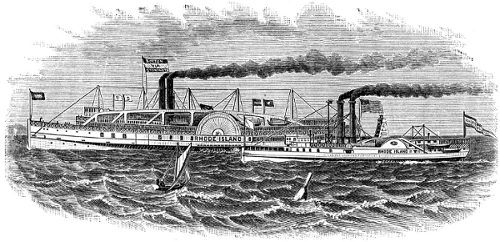
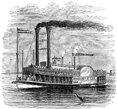
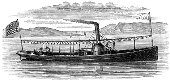
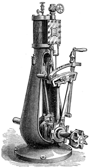
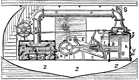
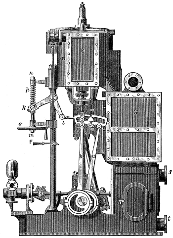
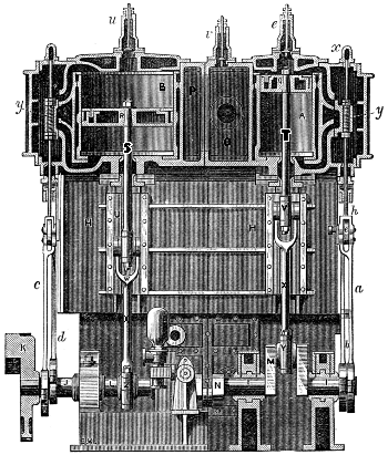
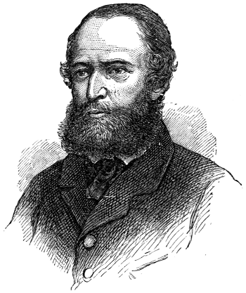
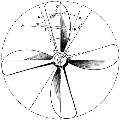
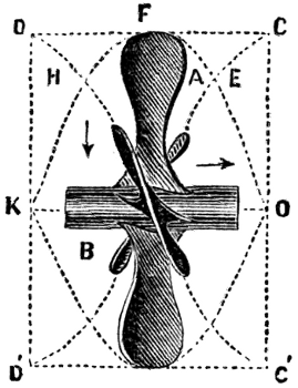
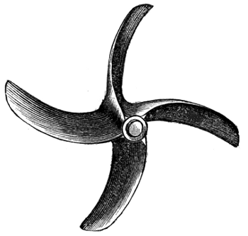
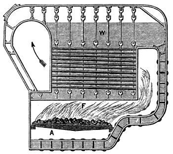
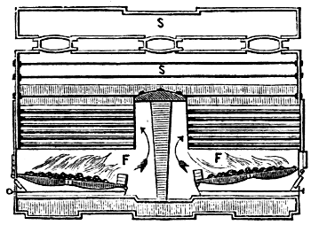
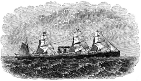
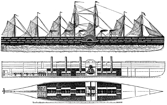
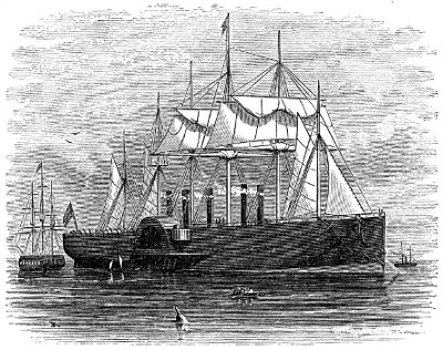
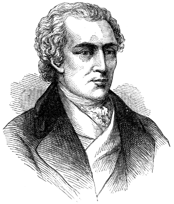
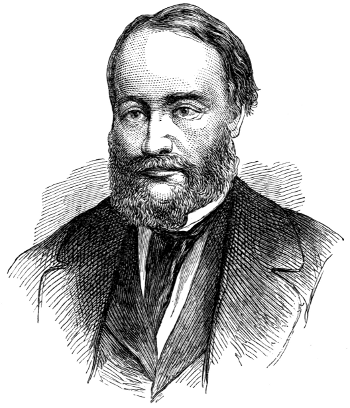
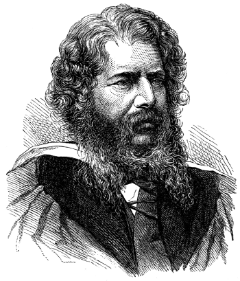