This eBook is for the use of anyone anywhere at no cost and with
almost no restrictions whatsoever.  You may copy it, give it away or
re-use it under the terms of the Project Gutenberg License included
with this eBook or online at www.gutenberg.org
Title: Paper-Cutting Machines
A Primer of Information about Paper and Card Trimmers, Hand-Lever Cutters, Power Cutters and Other Automatic Machines for Cutting Paper (Typographic Technical Series Part 1, No. 10)
Author: Niel, Jr., Gray
Release Date: December 28, 2010 [eBook #34774]
Language: English
Character set encoding: ISO-8859-1
***START OF THE PROJECT GUTENBERG EBOOK PAPER-CUTTING MACHINES***
PREFACE
The paper-cutting machine is a recent development in the industrial world. Its importance in the graphic arts is only just being recognized. That it has heretofore been considered an apparatus of minor importance is proven by the lack of information on the subject, either historical or technical. No mention is made of a paper-cutting machine in the eleventh edition of the Encyclopædia Britannica, either in the index or under the various trade headings. Mention is omitted entirely from De Vinne's History of Printing. There are no references to it in many other standard books, nor in the engineering libraries; neither are there any comprehensive articles on the subject in any of the trade journals, either American or foreign. A few scattered references may be found in dictionaries and manuals having to do with bookbinding and presswork.
This manual on the paper-cutting machine has the distinction of being, as far as the author knows, the first book ever written on the subject. It will endeavor to help toward a better understanding of this important mechanism, its use and care, and it may also serve as a starting point from which subsequent treatises may be written.
The difficulty of making a successful machine of this kind to meet the new demands for accuracy, speed, convenience, and safety, has been overcome gradually in recent years and there are now several machines quite efficient and adequate to meet these demands of the modern manufacturer. To coördinate a number of inanimate pieces of steel and iron, to operate at high speed with precision, requires fine skill. The evolution from the first cutting machine—the old hand-operated wooden plough and press—to the present power-driven steel mechanism is like the advance from the old wooden sailing vessel to the modern steel ship.
The objects of this manual are to acquaint the beginner with the essential features of the machine itself and to provide clear, comprehensive information which will enable him to become a competent operator. It is not possible within so small a book to give complete detailed instructions for all the different conditions which may arise in the many kinds of work done in establishments where paper-cutting machines are used. Each of these places has its own particular requirements; and while the machine can do its part quickly and efficiently it needs the intelligent and skillful operator to get good results. The instructions given herein for a few cases, which have been made as general as possible, indicate the complexity of this operation as carried on in modern workshops. There is necessity for a careful study of the subject in any important industry to insure this part of the work being successful and profitable.
Not all the kinds of cutting machines in use in the printing and bindery industries are considered in the following pages, but simply the typical machines in common use for cutting and trimming printed paper. There are many other styles, such as die-cutting presses, automatic book-trimming machines, punching, stabbing, and eyeletting machines, rotary cutters and revolving-blade cutters attached to presses and other paper machines. These might properly be classed under the title, but as they are chiefly specialized machines the limits of space do not permit a consideration of them here.
CONTENTS
PAGE
Importance of the Paper Cutter7
Evolution of the Paper-Cutting Machine8
Description of Typical Machines11
The Knife16
Grinding Paper-Cutter Knives21
Honing Paper-Cutter Knives22
The Clamping Pressure23
Cutting Sticks25
The Back Gage25
Power Back Gage Movement28
Special Devices28
Application of Power30
Care of the Machine32
Operating the Machine35
Safety of the Knife37
Handling Paper38
To Cut a Pile into Strips of Equal Width43
To Cut a Pile Rectangular44
To Square a Pile45
To Cut Unusual Shapes46
Trimming Books46
Paper Cuttings and Waste50
Depreciation of a Paper-Cutting Machine51
Review Questions53
Glossary of Terms Used58
PAPER-CUTTING MACHINES
Importance of the Paper Cutter
A paper-cutting machine is used for dividing piles of large sized sheets into smaller sized sheets; also for squaring a pile; i.e., making all four corners rectangular; and for trimming off irregular or incorrect edges.
It increases the possible printing output largely because presses of large size can now print many duplicates of a single design on a single sheet, and many of these sheets piled can be separated at a single cut, whereas a fly or rotating cutter cuts but one sheet at a time.
The importance of the paper-cutting machine can hardly be overestimated. The correct position of the printed matter, the widths of head, tail, and fore edge may be destroyed by careless cutting. Friendly coöperation with every department is necessary to produce good work. No matter how fine the printing and color work is, if the margins are uneven and the folds mismatched, then the resulting air of slovenliness discredits the entire work. The final touch that gives the character to a piece of printed matter is the way it is trimmed.
Modern power automatic-clamp cutting machines, in spite of the high speed of their operation, are able to cut with absolute accuracy. Perhaps on no other machine will a little careful study return so large a profit in dollars and cents.
Evolution of the Paper-Cutting Machine
The practice of cutting paper began long before the making of the book of bound leaves, and the necessity of making a number of sheets of the same size called for some mechanical means of cutting and trimming. The earliest cutting machine was no doubt a sharp stone or a stick; then a piece of metal, dragged across the parchment, with a guide to keep the cut in a straight line. The sheet was simply held by the hand, and later the straight-edge formed a clamp also.
About the fifth century the important step of folding the vellum into leaves became the practice. The instrument which we know to-day as scissors or shears probably had a large part to do in these early operations. With the invention of printing and the multiplication of books larger and stronger means were necessary to cut the sheets. Although the book with the untrimmed sheets was the rule of this earlier time, and of a later time, for the smaller books and for divisions of the sheet a cutter was necessary.
For a time the cutting of piles of paper was done by hand with a knife, a small pile being put upon a table and a weight laid upon it. The operator leaned his weight with one hand upon it, while he cut with the other. The earliest attempt to improve this consisted of a table, a framework of wood or metal above it, having a groove in which the knife could be worked, and a screw clamp to hold the pile. The knife was originally short; then longer, until it became long enough to cut through the thickness of the book. The deckle-edge of the earlier and untrimmed books was improved upon and made easier to turn over and refer to rapidly by the improvement of trimming the leaves. The hand-plough cutter was probably the first successful machine intended to cut a number of sheets at a time.
In the Haupt Halle at the great Graphic Arts Exhibition, Leipzig, 1914, were some illustrations showing the earliest German cutting machines and their evolution to date. The earliest among them is the lightly constructed hand-driven vertical cutter of 1855. This consisted of two side frames, the knife-bar guides in their slots and a large hand wheel at the right. The next stage was a cutter of 1876, a hand-driven wheel at the right turning gears above and outside the table. A crank and a rod connected to the center top of the knife-bar pulled the knife in the direction of the two slots in the knife-bar, giving it a shearing motion. This model is the same as that used by most German manufacturers for both hand and power-driven cutters until within a few years, when the greatly improved, rapid, and more convenient American examples became known.
From simply pressing with the hand to hold the sheets the hand clamp was evolved; then the clamp was attached to a gear by which it could be held down on the sheets with greater and steadier pressure. To quicken this operation the spring clamp was devised, with automatic pressure—fixed at first, then variable to suit varying requirements.
Perhaps the most signal advance in the art of paper-cutting machinery that has been made is the invention of Samuel R. Brown, who devised the fixed "throw" of the knife by means of two cranks at opposite ends of a shaft parallel with the knife. This control of the knife enables a hair to be cut through, or half through, or the knife edge to just touch it, with remarkable precision. The various other mechanical connections for power-cutting machines between the pulley and the knife, consisting of rolls, slots, guides, cams, chains, levers, etc., all require a great number of parts between the pulley and the knife, with the consequent and necessary "looseness" of the mechanism. This allows, after short wear, a play or "chug" of the knife which quickly tends to destroy its best cutting abilities.
The evolution of the cutting machine has been rapid and distinctly marked in all its essential features, from the oscillating plough to the vertical stroke, to the shear stroke, to the double-shear stroke; from a single-rod pull-down of the knife (by a chain, by a cam, or by a crank) to the two-rod pull-down by cams, rolls, slots, slides, to the cranks which give a fixed dependable stroke; to the cranks which give a fixed dependable stroke, and at the same time pull the knife endwise; from swinging-link shear to a straight-line shear; from man-drive to power-drive; from driving by power fixtures in front and outside the frame to fixtures located back and underneath; from low piles to high piles; from hand clamp to power clamp, to self clamp, to automatic clamp, finally to friction adjustable pressure clamp; from measuring by rule to the use of rapid automatic measuring and spacing devices.
The best paper-cutting machine is designed with a knife motion operated by cranks which give an endwise pull to the knife; with the table of medium height; with quick and accurate adjustments for the knife; with a foot treadle for bringing the clamp down to the pile when desired to see exactly where the knife will strike; with an accurate and dependable device for moving the back gage and the pile and measuring quickly the widths to be cut; with starting handles easily reachable without bending; with a powerful clamping pressure automatic for all height piles and instantly adjustable for heavy or delicate work; with universal fine adjustments for squaring the back gage with the knife; with a simple change for the cutting stick; with the driving shaft running at a low speed; and with a powerful main driving clutch or friction material that will not cut or damage the parts under the heavy, constant thrusts.
Description of Typical Machines
PLOUGH AND PRESS CUTTER
An early form of cutting machine, made almost entirely of wood. The pile of paper or book was clamped to the table by the upper cross-bar of the clamp, which was brought down by the geared vertical arm. As shown by picture, these arms were raised and lowered by turning the large toothed wheel. The steel chisel (A) operating in a holder running in a groove, was moved to and fro across the paper, cutting deeper each time as the chisel was gradually lowered by the handle.
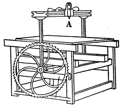
Fig. 1. Plough and Press Cutter
CARD CUTTER OR TRIMMER
Card trimmers are knives hinged at one end to a base upon which the work is laid and held, while the knife is pulled down by hand to shear it off against a metal edge. Stock cut this way has a slight burr on its lower edge, caused by the "drag" or downward pressure of the knife. To cut cards free from burr a rotary card-cutting machine is used, with a rotating shaft carrying a small wheel cutter. These cutters are used on a workbench.
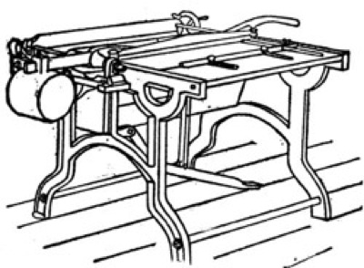
Fig. 2 Binder Shears or Table Cutter
Fig. 3 Card Cutter and Trimmer
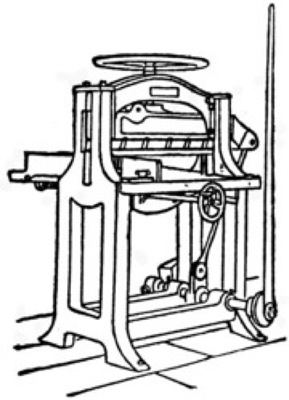
Fig. 4. Hand-Lever Cutter
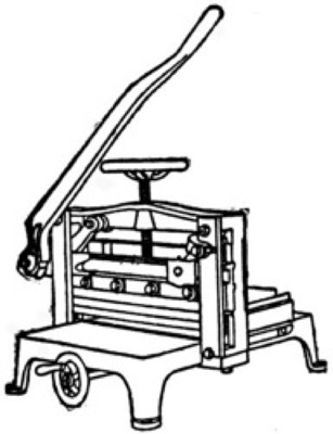
Fig. 5. Bench-Lever Cutter
HAND-LEVER CUTTER
Hand-lever cutters stand on the floor and have a convenient height table to lay the work upon. The cut is made by pulling the knife down through the pile. The knife is hung from two swinging links, and is easily operated when it has double shear and a toggle crank connection to the hand-lever shaft.
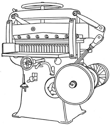
Fig. 6
POWER CUTTING MACHINE (HAND-CLAMP)
Knife Pulled Down at One End
Power cutting machines substitute power fixtures for the hand (sometimes in addition to the hand operating fixtures), and eliminate labor and save time. A hand-clamp power cutter is operated first by screwing the clamp by hand down firmly upon the line where the work is to be cut; then pulling the starting lever, which causes the knife to make the cut, return to the top, and stop.
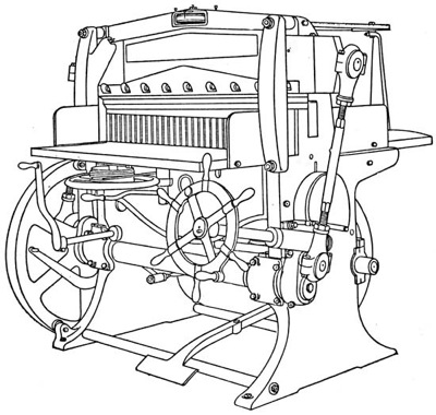
Fig. 7
POWER CUTTING MACHINE (HAND-CLAMP)
Knife Pulled at Both Ends
Semi-automatic means a cutting machine which has a treadle to bring the clamp down quickly upon the work, and a regular hand-clamping wheel instantly acting to produce the clamping pressure when it is turned a part of a revolution. The clamp returns automatically to the top by touching the treadle lightly with the foot and giving the clamping wheel a slight backward turn. The advantages are the simplicity of construction and operation of the regular hand-clamp machine, and a gain of about one-third greater output with one-third less effort. Automatic-clamp power cutting machines save labor by pressing the pile by power, instead of requiring the operator to screw the clamp down and back again by hand. In the larger sizes power attachments save the labor of pulling the back gage and work forward by hand. Automatic spacing (or measuring) devices for duplicating any desired width, without the customary measuring for each cut, enable larger production.
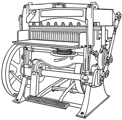
Fig.8
AUTOMATIC-CLAMP POWER CUTTING MACHINE
With Instantly Variable Automatic Clamping Device
An automatic power cutter is operated first by determining the line of the cut by the indicator or by pulling the clamp down upon the work; then pulling the starting lever, which automatically forces the clamp down first upon the stock, and then drives the knife through it, and returns both knife and clamp to stop at the top.
Automatic-clamp power cutting machines are also furnished with hand-clamp attachment for special clamping pressures.
Continuous running is effected by devices which permit the quick disengagement of the stop throw-out mechanism. This is desirable with duplicate work in quantities carefully arranged for fast production. Automatic cutting machines are also furnished with spacing devices for the rapid duplication of exact widths of any size.
Vertical stroke (and vertical changeable to shear stroke) cutting machines (see Fig. 9, page 17), both hand power and also power, are used with special shaped knives for cutting fancy edges, and pinking cloth samples, etc., some having back tables of great length, moved on rollers or slides by spacing devices. Considerable ingenuity has been shown in the variable method and mechanism used for moving the knife up and down.
The Knife
The knife is most important. It must be kept sharp. It must be of the proper shape and thickness and bevel and temper and free from any burrs or lumps on its back edge. A cutting-machine knife is like a razor that, stropped correctly, does not pull the beard, but stropped an infinitesimally different way—a difference impossible to see except with a microscope—pulls hard. Study carefully the knife. No matter how carefully the machine is built, an imperfect knife cannot cut right. Most knives are imperfect in spite of the rigorous specifications given them by makers. They vary in thickness, straightness, concave, bevel, flatness, temper, and quality of steel; and also in the character of their sharpening and honing, which varies with the fineness or coarseness of the grinding wheel and stone. These variations need only be a few thousandths of an inch to cause trouble.
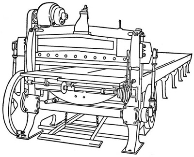
Fig. 9
VERTICAL-STROKE POWER MACHINE
Changeable to Double Shear
A blue wave mark indicates where the temper is drawn, and a file which "drags" when pushed fairly hard across the flat of the bevel indicates the soft spots, where the temper is imperfect.
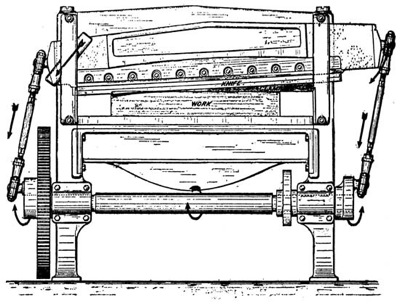
Fig. 10
DIAGRAM SHOWING DOUBLE SHEAR STROKE OF THE
KNIFE PASSING OBLIQUELY THROUGH THE PILE
At the beginning of the stroke the knife is higher at the right-hand
side; when finishing the cut the knife is parallel to the table
To ascertain if a knife has a correct face, hold it flat, face up, with one end on a window ledge, and look along the face for variations. This is a simple matter which any one can do. Use a perfectly straight and clean-edged steel rule and pass it along from one end to the other as shown in Figs. 11 and 12. A dark spot shows the point of contact of the rule with the knife. These dark spots should show only exactly at the cutting edge and at the back edge. If a dark spot shows away from the cutting edge, it indicates that the knife is imperfect there and will not make a true cut. Regrinding the face by the makers can correct this fault, except where it is the fault of the one who hones the knife after it is sharpened.
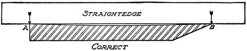
Fig. 11
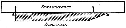
Fig. 12
Hone the knife only on the bevel. To remove the wire edge burrs along the edge lay the hone flat on the face and rub gently so as not to round over the edge.
A knife will sometimes cut better after it has been ground the first time. A polished knife will give a better surface to the cut. The cutting of the same kind of stock will often vary with different makes of knives. An oily rag tied to a stick kept handy and passed along the bevel of the knife before cutting hard stock will improve the cut. A blunt bevel is preferred for hard stock; a long, thin bevel for soft stock.
A general rule for the length of bevel on knives is two and one-half times the thickness of the knife. This may be varied to suit the different materials to be cut, but must be held within reasonable limits to preserve the strength of the cutting edge of the knife and also to secure accurate, clean cutting.
The face of a knife should be as nearly flat as possible and must not be convex. It is better to have it concave than convex, but not over two or three thousandths of an inch concave. A knife that is too concave or convex will tend to dig in or out of the work.
For safe clearance the knife should be a few thousandths of an inch thinner at the top than the distance from its back to the line of its cutting edge.
The knife bolts should always be screwed up snug, so that the cutting edge of the knife will have the correct pitch in relation to the pile. The top or back edge of a knife should be held absolutely straight to get a firm thrust—bearing all along the knife-bar. Knives abutting against adjusting screws for this reason are not apt to give so good results as knives that abut against a solid shoulder all across the knife-bar.
Dirt, oil, grease, paper, chips, etc., in the knife-slot or bar, or a bruise or nick on the back edge of the knife, or a defective knife bolt, may prevent the knife seating firm and true in its proper place and may cause poor cutting.
Knives bought from the maker of paper-cutting machines are apt to give the best results because they receive two inspections: one by the knife maker, and another by the machine maker, who is careful to see that only perfect knives are supplied.
In order to understand how important it is to use a sharp knife on a power cutter, throw off the belt and pull the machine around by hand through a high cut with a dull knife. Then put in a sharp knife and make the same cut. Where there is much cutting to be done and the machine is in constant use, it is well to keep extra knives on hand to allow one to be sharpened while the other is being used.
A specially tempered knife is best for boards or varnished paper. Gummed and varnished stock are likely to break small pieces off the knife edge. The double shear motion for the knife now furnished on the new automatic rapid production cutting machines practically eliminates this trouble.
The first place to look when work is not cut true, after making sure there is correct clamping pressure, is the knife. See if it is sharp. See if it has been honed properly. See if it has the proper length of bevel.
Grinding Paper-Cutter Knives
It is best to grind with a soft sandstone; but if an emery wheel is used, it should be about 46-60 grain, 5½ grade, or soft enough so that a light feed can be taken without burning or glazing the bevel of the knife.
The operator of the grinding machine should be in constant attendance while the knife is being ground, and should have a liberal supply of water feeding on the wheel where it comes in contact with the bevel of the knife, not at the top of the wheel. If this supply of water is cut off and the wheel continues to grind without water, this will create friction, heat up, and draw the temper in the knife or crack it.
Extra precaution should be taken to grind the cutting edge of the knife parallel with the back of the knife, and not have one end of the knife wider than the other. When this occurs the cutting edge of the knife does not hit the cutting stick squarely, and not only has a tendency to snip out at the wide end, but also to destroy the cutting stick quickly.
The bevel should be ground flat or a shade concave, and must not exceed twice the thickness of the knife, plus one-quarter inch, or twenty-four degrees. If this rule is not adhered to and a longer bevel than this is ground on the knife, the flat side or face of the knife will become rounded about one-half inch back from the cutting edge, thereby taking the slight concave out of the knife and causing the machine to cut tapering; i.e., the top of the cut, say four or five inches high, will be narrower than the bottom of the cut.
If a knife is ground on the rim of an ordinary emery wheel worn to a small diameter, the smallness of the emery wheel will tend to make the bevel concave. This weakens the edge of the knife. A knife grinder with a cup-shape emery wheel makes it easier to grind the bevel straight.
Honing Paper-Cutter Knives
Every knife, when coming direct from the grinding machine, has a wire edge which should be honed off before the knife is adjusted to the knife-bar. Excellent results in honing are obtained from No. 1 Washita oilstone (Pike Mfg. Co., N.H., U.S.A.), or an india oilstone made by W. H. Price, Hartford, Conn.
The knife should be laid on a bench or table, flat side down, with the edge of the knife protruding about one-eighth of an inch beyond the edge of the table. The hone should be held flat on the bevel, and the motion should be a circular or rotary movement as well as up and down, and the honing should be done from one end to the other without lifting the hone from the knife.
When a fine wire edge appears on the flat side, lay the hone on lightly with no pressure and absolutely flat, and draw from one end to the other. After honing the knife for a short time (four or five minutes) the wire edge will disappear or get so thin that a small piece of white pine or other soft wood, if drawn along the cutting edge, will eliminate this thin wire edge. Never hone the flat side of the knife. Never hone a knife while in the machine.
A wooden holder for the oilstone will protect the fingers.
For smooth "glass edge" cutting, the bevel of the knife may be ground slightly concave. Then hone thoroughly with an extra fine hone slightly convex in shape.
No method of grinding has yet been devised which will leave a perfectly smooth surface, because no matter how fine the stone or material that is used for grinding it will leave marks on the edge of the knife, and these marks cause roughness in the cut. The reason the above method gives almost a perfectly smooth cut is because a thorough honing removes most of the marks.
The Clamping Pressure
The clamping of the stock in the machine while the cut is being made is an important feature of a modern paper cutter. This is done by means of a horizontal bar placed behind the knife and parallel with it. This clamping bar is moved up out of the way while the stock is being placed in position and is then brought down with the desired pressure to hold the pile of sheets firmly until the cut is made, and is again lifted up out of the way.
In the simpler machines the clamping pressure is obtained by means of a stout vertical threaded rod to which the clamp bar is attached at the lower end. The rod is operated by a hand wheel at the top and turns in a threaded opening in the cross-head of the frame.
Clamping pressures vary greatly under different conditions, from a light pressure to several tons. The ratio of the power applied in hand clamping to the pressure secured on the clamp is, in ordinary commercial machines, about 1 to 150 for small machines up to 32 inches wide, using a 2-foot-diameter clamp wheel and overhead screw. The ratio of power in cutting machines 34 inches and wider, having a 1½-foot-diameter clamp wheel, and worm of ¾-inch pitch at the side engaging a worm gear keyed to the clamp shaft, is about 1 to 180. That is, a pull by the hand of 1 pound on the overhead clamp wheel will produce about 150 pounds pressure of the clamp on the stock to be cut; and a pull by the hand of 1 pound on the side clamping wheel will produce about 180 pounds pressure of the clamp, less friction. Operators will pull ordinarily from 10 to 100 pounds; i.e., producing a pressure of from one to nine tons.
The first type of automatic-clamp cutting machines produced always the same arbitrary pressure on the clamp, with consequent waste of power, crushing and indenting the work, offsetting the ink unless it was absolutely dry, and requiring adjusting with a wrench, which was slow, dirty, and indefinite.
All modern automatic-clamp cutting machines have independent automatic-clamp pressure, and these apply the pressure at both ends of the clamp. The earliest power clamps were called "self-clamp." In these the knife and clamp were connected together (i.e., dependent). The modern automatic-clamp mechanism is not only independent of the knife, but in addition practically all the power of the belt goes first to clamp the work and then afterwards to drive the knife through the cut. This separation of the clamping effort from the cutting effort increases efficiency and economy.
By a modern device on some machines this clamping pressure is instantly variable to suit different kinds of stock and other conditions.
Cutting Sticks
The cutting stick, into which the knife passes after cutting through the bottom sheet, saves the edge from cutting on the iron table.
Correctly designed cutting machines have knife-bar motions that permit no "chug" of the knife into the stick and thus conserve its sharp edge. Many designs, however, are faulty in this respect and the unrecorded expense of their operation is a serious leak.
The cutting stick is set in a slot in the table. The most common and perhaps best form, everything considered, is a ¾-inch square hard maple stick, set so that the knife strikes it ¼-inch from the edge. All four faces of such a stick may be used.
A metal frame for holding a ¼-inch square hardwood stick, or a soft metal (so-called) cutting stick, is made. A round wood cutting stick connected to a timing mechanism which rotates it automatically for every cut, or for a certain number of cuts, is valuable for hard stock requiring microscopical perfection.
The Back Gage
The back gage is moved and controlled on the machine table in several ways. In the simpler machines the gage is attached to a rod under the table, a long slot in the center of the table allowing the connection of the gage with the rod below. The rod is attached to the gage with a worm gear and is operated by a small hand wheel at the front of the table. In other machines the gage is attached to a steel cable, or a metal tape, or a chain which passes over wheels at the back and front below the table.
The one-piece back gage was improved by cutting it into two or three sections so that the first and final cuts of two or three piles may be made at every stroke of the knife. Adjusting screws are provided for tilting the back gage forward or backward to compensate for the variation in the width of the top and the bottom sheets which occurs in the same machine and with the same knife when cutting hard or soft papers. A swinging adjustment is also provided to "square" the back gage parallel with the knife edge.
Various devices for taking up the slack caused by wear in the table slot guiding the back gage are furnished, but probably the simplest and best method is the replacement and refitting of the inexpensive sliding part.
INDICATOR ATTACHMENT FOR BACK GAGE
The distance the back gage is moved is read in different ways. The movement of a gage operated by a screw and wheel is indicated by a pointer on the front edge of the table overlapping the rim of the long screw wheel. If the rim of the screw wheel is lined off in sixteenths of its circumference, the pitch of the screw being one inch, each complete turn of the screw wheel means that the back gage is advanced one inch, and each one-sixteenth turn means that it is advanced one-sixteenth of an inch. It is important always to keep turning the screw and wheel the same way when so measuring, because otherwise the "back lash" (looseness of the screw and its nut to permit easy working) will cause variation.
For a back gage moved by a chain or a wire cable or a metal tape, a graduated dial is attached to the top of the cable hand wheel which reads from a pointer attached to the front edge of the table.
Both these ways of reading require the operator to look down.
For a back gage moved by power, a steel indicator ribbon passing around a wheel overhead in the frame cap and attached to a standard on top of the back gage (see Fig. 7) enables the operator to read the position of the back gage without looking down, and a second wheel indicator and pointer permits reading to less than one-thousandth of an inch. Similar indicator ribbons are attachable to the back gage for screw, cable, chain, and metal tape movements.
These indicator ribbons are usually graduated and marked for inches, halves, quarters, eighths, and sixteenths. They are also furnished with metric system measurements, graduated and marked for centimeters and millimeters. They are also furnished extra wide so that both the English inch measurements as well as the metric system measurements may be put upon the same ribbon. When graduated to thirty-seconds of an inch and millimeters a good magnifying glass of about three inches diameter, adjusted in front of the pointer, enables easier and more accurate reading. An easily operated lock for holding the back gage fast to the table at any exact mark prevents variation in the width of cutting.
Fixed distance gage rods and suitable engagements with the back gage are provided for cutting at any time duplicates of exactly the same width, especially valuable for loose-leaf ledger work. Pins and holes drilled in the back gage and table also secure uniform locations impossible to get solely from reading the overhead ribbon or an indicator dial, which latter may be read incorrectly because of poor light or variation in the operator's position or eye.
Locking devices for the back gage ordinarily consist of (a) a friction grip around the moving screw, or (b) about the cable hand wheel, or (c) a clamping device which holds the back gage, or (d), best of all, a fixed grip rod-holding device operated from the front of the table, thus eliminating any possible lost motion through connecting parts from the jogging or chucking of work.
A back gage is split so that different width piles may be cut at the same time, such as trimming the heads, tails, and fronts of books. The fingers at the splits are placed smooth, so that they may be used as side gages to enable the wear of the knife to be taken its full width, instead of just at the usual left-hand end.
Power Back Gage Movement
The larger sizes of cutting machines are equipped with a labor-saving power connection to the main driving shaft which may be thrown in by the operator at will to move the back gage forward or backward by power, a micrometer reading the position to thousandths of an inch.
Special Devices
Special spacing devices for the back gage are revolutionizing many branches of work. The usual screw or cable is relatively slow and undependable and requires care and time to move the work the exact distance required.
The new way is to equip the cutting machine with a back gage operating mechanism having stops which can be set for any width to be cut. The operator simply pulls a lever between the stops, which instantly moves the pile and measures it exactly. Production has been increased six hundred per cent. with such spacing devices.
Gages for measuring the width of the cut may be simply a sample cut the desired width laid upon the pile, or an exact size wood or metal pattern, or the width may be determined by reading on a steel indicator-ribbon attached to the back gage the distance its face is back from the knife edge.
These methods are only approximately accurate, however; for exact cutting, steel distance-pieces of correct lengths to give the different widths of cut required are set against a fixed stop in the back table and the back gage run back until it grips the steel distance-piece. This brings the face of the back gage the desired distance from the knife.
Modern patented spacing devices for the rapid duplication of exact widths in succession, while the machine runs continuously without stopping between cuts, have been perfected so as to enable, on some classes of work, one cutting machine to do the work of six and still obtain accuracy. These spacing devices operate the back gage through a chain or a screw or a gear by means of a lever driven by hand or by power between accurately set stops fixed for any desired width, and thus eliminate the time ordinarily lost measuring the width for each cut.
Among other conveniences on the large modern cutters two starting levers, one at each side of the machine, or a starting bar extending across the front, save several motions at each cut.
A flat piece of metal, called a clamp face, which may be quickly attached to the under side of the fingered clamp, is used to prevent these fingers marking soft or delicate finished stock.
A snake gage is a folding lattice used in front of the back gage of a solid wide face clamp machine to enable the back gage to push the pile up nearer the knife.
For large pamphlets or magazines an extra clamp attached behind the regular clamp to hold the back of the pile down gently by spring pressure will prevent the sheets springing up and away from the back gage, caused by the folds and air between the sheets.
A plate attached to the machine with hooks upon which to hang the wrenches is provided upon the most modern machines and this helps the operator to keep them together and in order.
Guards covering the gearing, knife edge, pulleys, flywheel and other moving parts are required by many state laws, and power cutting machines are, therefore, so designed and furnished complete.
Application of Power
There are five methods of applying power necessary to operate paper cutters: by hand lever, by belt, by direct gearing, by chain and sprocket, and by direct connection of electric motor.
Figure 13 shows an electric motor on a bracket, adjustable vertically, attached to the frame of the cutting machine, driving by a belt from the motor pulley to the machine pulley. The belt cushions the heavy repeated thrusts of the clamp and knife in cutting upon the motor. The electric motor may be set on the floor or on a bracket on the wall.
Figure 14 shows a direct-geared connection of the electric motor through its noiseless rawhide pinion engaging an iron gear on the machine driving shaft. An adjustment is provided for taking up the wear in the gears, in order to maintain the noiseless running of the machine.
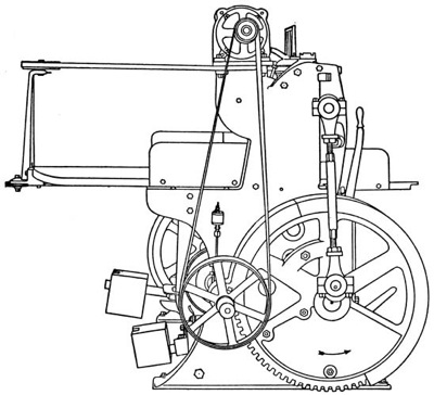
Fig. 13
ELECTRIC MOTOR OVERHEAD, BELT DRIVE
The chain drive is like the direct-geared except that it substitutes a chain and two sprockets for two gears.
It is not generally understood what a large amount of power is required to drive a paper-cutting machine, and how important it is that the number of working parts connecting the belt pulley to the knife be as simple and few as possible in order to eliminate friction and lost motion, and to secure efficiency. Every cut costs money for the power consumed.
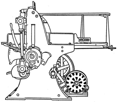
Fig. 14
ELECTRIC MOTOR UNDERNEATH, GEARED DRIVE
An inch-high pile of writing paper with a sharp knife may take one thousand pounds for each foot of length of the knife to drive it through. A higher pile on a fifty-inch power cutter may take three tons pressure, plus the automatic clamping effort and plus frictional losses, and (more important) plus a tremendous increase in case the knife is dull.
Care of the Machine
A man is known by the condition of the machine he keeps. Keep the knife sharp. That is the first rule to repeat every day and every hour of the day. The second rule is to oil every hole and place required on the machine. The third rule is to keep the machine and its neighborhood scrupulously clean. The fourth rule is to learn by heart and follow the printed directions attached to the machine by the maker. If you do not understand or if you cannot follow correctly every instruction on the printed instructions attached to the machine by the maker, first ask your foreman or superintendent. If the directions are not clear, write, or ask the office to write, to the maker for a detailed explanation or to have his traveling representative come and explain them. Any operator who does not understand the adjustments of the machine he operates has but partly learned his trade. Be particular to see that the driving pulley on your machine runs at the speed given for it on the manufacturer's directions.
Keep the machine always in adjustment. See that the brake band is adjusted so that when the starting lever is thrown in to start, the friction is entirely released and there is no drag on machine.
Do not allow the knife to sink any deeper into the cutting stick than to sever the last sheet of the pile.
Never use more pressure on the clamp than is necessary to hold the pile without drawing or slipping; any additional pressure is only an added strain on the machine.
Jog your stock before putting it in the machine and do not use the back gage for that purpose. Continual hard jogging with heavy lifts of stock against first one end of gage and then the other will quickly knock it out of square or loosen it.
A little talcum powder, French chalk, or powdered boracic acid dusted on the table makes the stock handle easier.
A slip-sheet of paper or thin pulp board placed on top or on the bottom of the pile, and cut up with it, protects delicate surfaces from finger marks or soiling. Keep your hands and apron clean. Keep the machine clean in every part.
Use only wrenches furnished with the machine, because they fit the bolt heads properly and because they are the correct lengths to put on the proper tension.
Do not use a monkey wrench, because, unless the jaws are carefully adjusted, it will destroy the bolt heads and if used on small bolts, on account of its length and power, is apt to strip the threads or break the bolt or part.
Occasionally go over every part of machine and see that all taper pins, bolts, nuts, etc., are snug in place.
A locked cupboard or box at the cutting machine is useful to keep the full set of wrenches provided, clean waste, colored crayons, a good magnifying glass, powdered pumice stone, French chalk, talcum powder, boracic acid, special cutting pads, and boards for making them, size strips, dimension records, etc. The oil can should stand always filled and ready on its bracket.
If a belt is put on too tight, it may pull so hard on the bearings as to heat and cause them to cut. It is easier not to put the belt on too tight at first and to relace it several times while it is stretching, than it is to repair a rough bearing.
Keep clean waste in a box. Destroy dirty, oily waste instantly after use, or place it carefully inside a fireproof oily waste can if provided. Do not put dirty, oily waste away or leave it around. It is most dangerous and many plants have been burned by its spontaneous combustion.
Have a definite fixed time to oil, and to clean the machine. Mark the hours when to oil every day, and the day and hour when to clean and polish the machine every week, on the maker's direction sheet attached to the machine.
Oil with intelligence, not just with an oil can and oil. Oil freely, but not sloppily. Oil should not drip upon the floor. Oil should not flow over parts not requiring it. An excess of oil on a brake band will prevent its acting and stopping the machine promptly. Wipe out the excess oil in this case by passing a rag under and around the bands. Oil that runs or drops or is wiped off is wasted.
Oil the parts above the table carefully and thoroughly. A few drops of oil on the palm of the hand and applied to the four front and back faces of the knife-bar prevents dripping on the table from the oil can. Run the machine through a few strokes after oiling and then wipe off clean with a cloth or piece of waste the surfaces against which the stock to be cut is placed.
When oiling, remember it is only the oil that reaches the bearing that does any good. Any surplus that runs over and defaces the machine is waste.
The best kind of oil to use is a free-running, light-colored petroleum machine oil. Cheap oils cost more in the end.
Operating the Machine
The character of the cutting depends upon, first, the machine, second, the knife, and third, the man.
Successful cutting is a fine manual art. The finest razor improperly stropped and used in unskilled hands does poor work. The finest cutting machine unintelligently operated will stultify the best efforts of the printing plant.
The machine that has the simplest mechanism evolved by long experience and study ensures the first safeguard of accuracy. The knife that fulfils the specifications given elsewhere furnishes the second. And third, the man whose standard of work is high, who is conscientious in following his instructions, who is big enough and broad enough to understand how important his position is, and how necessary, therefore, it is for him to coöperate with every other department in a friendly and intelligent manner, completes the tripod that can stand up successfully under any job.
A cutting machine is a sharp-edged tool and, therefore, dangerous when run by a careless or unskilled operator. "Look before you leap" applies especially to the cutting machine. Its action is powerful and quick. Accidents occur through failure of the operator to watch his own motions and because of the improper operation of the machine through failure of some of its parts. Sufficient safety devices to make all accidents impossible would render the cutting machine as useless as an axe in a velvet case. Accidents which occur from undue wear or neglect to oil are apt to happen. Two preventives are available: first, to train the operator to care; second, to provide as many safeguards as can be utilized and still permit commercially successful operation.
With the modern high-speed machine operating at from twenty-five to forty cuts a minute, the time consumed in the cutting room is not the time taken by the knife to pass through the stock, but rather the time getting the stock laid up and measured ready to cut. Consequently, these latter operations are the ones to study for savings.
The time and labor required to cut a job depends upon the number and kind of motions of the hands and body and feet that are made to get the stock ready and to take it away. The fewer motions necessary to do this and to operate the machine, the easier and pleasanter it is to work at a cutting machine.
Powdered chalk and naphtha put on the bright parts and nickel and allowed to stay over night will polish off in the morning and leave the machine appearing clean and free from rust.
The clamp strap ways should be kept clean and free from the fuzz from the cuttings and thick oil. This can be done by occasionally cleaning them out with kerosene.
If the oil gets in the friction brake band the machine may not stop promptly at the proper point. Throw off the driving belt, and throw on the starting lever to loosen the brake band; then pass a rag around under the band, between it and the clutch rings, so as to remove the oil, then throw off the starting lever. If a piece of waste is laid on the lower part of the friction brake band just next to the ring, it will keep it free from oil for some time.
Rub the knife and other bright parts of the machine with an oily rag every night. This will prevent the rust forming with the variation of temperature between day and night.
When using the graduations on its rim to measure by, always keep turning the gage screw wheel in one direction, without reversing it, when pulling the back gage forward for successive cuts. This will keep up all the slack and lost motion of the screw and its nut. If the screw wheel is moved first one way and then another, little dependence can be placed upon the graduated reading of the scale.
Safety of the Knife
The best automatic rapid-production cutting machines are provided with four safety devices to prevent the knife making an unexpected stroke.
First—A solid knocker throws out the clutch positively. Neither gravity nor a spring for a trip is depended upon to move an intercepting part, but the certain fact that two solid bodies cannot occupy the same space at the same time.
Second—An automatic friction brake grips firmly and stops all motion silently.
Third—An automatic counterbalance is used for both the knife-bar and the clamp, and retains them at the top position.
Fourth—An automatic steel safety bolt engages a solid lug on the large gear, so that the gear cannot revolve further until the operator deliberately pulls the starting lever for another cut.
These four safety devices are designed so as to act positively and simultaneously on the completion of each cut. To start requires a deliberate action of the starting lever by the operator.
Handling Paper
Paper is made principally in long webs, or continuous strips, and is rolled up as it comes from the paper-making machine. It is then cut into sheets by a revolving fly cutter or a shear knife, cutting one sheet at a time off the roll. These sheets are furnished by the mills in bundles or cases, which are trimmed to certain sizes on a paper-cutting machine.
The best method of handling and cutting stock, the proper quantity to take on at each lift, the height of the pile to cut, and the routine of passing each cut section along in orderly fashion, should be given careful study.
Convenient tables of the right height and of ample surface are essential if the work is to be carried on satisfactorily, without backtracking or unnecessary motions and lifting.
Large stock should be piled on movable wooden platforms which can be moved quickly from place to place.
A primary difficulty in cutting-machine work is due to the great variety of papers and sizes required to be handled on the machine. This varies from little narrow slips to piles the full width of the table, from a few sheets to a pile the full height allowed by the clamp, and from soft book paper to stock nearly as tough as tin. All these varying conditions cannot be met with equal success in one automatic machine. Therefore, superior intelligence rather than unusual muscle should be required of the operator.
Good judgment is required to determine the proper height of a pile to cut. This will often depend upon how much can be grasped each time with the hands and put into place in good order. Time may be lost and sheets wasted trying to fill up to the capacity of the machine; smaller piles and more of them may sometimes be a more economical method. The time taken for the knife stroke is only a second, while the time necessary to jog up several lifts may be minutes more than to put one lift into place. The convenient lift, as large as possible, and uniform in size if there are several of them, is the advisable practise.
Inaccurate cutting may be the result of several causes: (a) Not jogging the pile thoroughly against the back gage; this should be done by pressing the ball of the thumbs against the front of the pile from top to bottom. (b) By disturbing the pile when turning it for the next cut. (c) By lifting out the pile and failing to jog it carefully when flat against the back gage again. (d) Work that is fed to points on the printing press may not be square and true and consequently cannot be jogged against a straightedge gage and cut accurately. This condition should be watched for in such cases. Find out, if possible, which is the feed edge in the printing and jog up to that. Pressmen are often careless about this necessary instruction in sending printed sheets to the cutter.
Inaccurate cutting is also due to insufficient clamping pressure, allowing the pile to slip out of place slightly; or to excessive clamping pressure, compressing the pile more than necessary just at the line behind the knife cut.
The above causes may result in imperfect cutting when the machine is in good order. When the machine is not in the proper condition, and the knife is dull, or of a shape not adapted to the work, accurate cutting cannot be expected.
When piling up sheets see that each sheet is laid in exact register with all the others, that is, that the printed pages, guide marks, and edges are all in the same position throughout the pile. One sheet on top laid the wrong way may be the cause of cutting every other sheet of the pile wrong unless (and this is very important) the operator looks at the under sheets to make sure that they are all laid alike.
When cutting or trimming printed sheets it is necessary that the operator should jog the sheets to the pressman's feed edges. These should be marked plainly, without chance of misunderstanding. If they are not, he should ask for directions. One wrong cut will spoil the whole pile.
When a sheet is taken off a pile for examination or for any other purpose, care should be observed that it is laid back again uniform with the other sheets. A pile is easily disturbed in this manner either when swinging it over, turning it around, or rejogging, if the utmost care and orderliness are not observed.
Papers received from the mills or from dealers are not always trimmed squarely, but have what is called a mill edge. This edge is only approximately straight and the corners only apparently square. For accurate work, either in printing or in cutting, one or two edges may need to be retrimmed on a paper cutter to get them straight and have a true corner. The ultimate accuracy of the finished work will depend upon this proper trimming before the sheets are printed.
Exact register and accurate trimming can be secured only by working from the same edges of the paper at every operation and the edges must be straight and squarely cut. When the edges are thus trimmed they should be marked with a red crayon, or in some similar manner, in order to be readily identified at each handling.
A pile may be tested for squareness by jogging it in the cutter table against both the back gage and the side gage, if the machine gages are themselves in perfect adjustment. If it is difficult to see whether the sides of the pile are close against the gages at all points, narrow strips of paper put between the pile and gages will show whether the pile touches the gages uniformly.
When cutting lithographed work or similar close-register printing, where large sheets are apt to come with an irregular edge, a small wooden block against the back gage or the side gage at points on the sheet where the original register guides of the press were placed, will usually insure cutting on an accurate line with the printing. In this manner the same points of contact as were used in the press feeding may be secured.
To cut a pile of paper in half, fold over the top sheet and fold at the middle, carefully matching the edges. Crease this fold distinctly and use the crease as a guide when the sheet is opened out and laid on the pile. To cut into thirds or fifths it is better to measure the sheet exactly with a rule and make clear pencil marks at the points of cutting.
Hand-made papers have rough, uneven edges which are thicker than the rest of the sheet and, therefore, require particular care in jogging and clamping. They should be handled in small piles.
Gummed and varnished papers require special care even when perfectly dry, but more so in a moist atmosphere. Varnished stock if it is very dry may nick the knife, and a clean oily (but not too oily) swab run over the bevel of the knife before the cut will make a smoother, safer cut. It is not well to use soap on the knife, especially on lithographic work.
Freshly printed work which tends to offset on the next sheet may be cut where necessary by placing strips of reglet or thick card around the margin close to the line of the proposed cut, so as to keep the pressure of the clamp off the printed matter.
Tissue paper requires to be firmly clamped to cut accurately. A clamping motion that will first exert a gentle pressure to squeeze the air out between the sheets and pack the pile down evenly all over and then apply a powerful pressure before the knife strikes the pile, gives the best results.
Accuracy is required in manifold duplicate work, where absolute register must be made, to secure the proper location of dollars in dollars columns and cents in cents columns. The ruling and printing both depend entirely on the square and accurate cutting of the stock to secure proper register.
The cutting of waxed and oiled manifold stock, if carefully jogged up, is not difficult with the newer types of clamping mechanism, especially on that type of cutting machine where the pressure of the automatic clamp is applied at first gently and then with maximum pressure, similar to the hand-clamp.
To Cut a Pile into Strips of Equal Width
This is sometimes required to be done for a large quantity of stock and it is desirable to do it with economy of time and labor. The obvious method is to first trim one edge of the stock, then set the back gage to the required width and jog the pile up to it for each cut. This method is usually accurate but requires a great deal of handling of the stock—almost three times as much as is necessary by some other methods.
The following methods require the pile of paper to be first trimmed with a true edge in order to jog it against the back gage, and also with a true edge on the opposite or front side.
1. Make a mark or place a thin paper sticker on the top surface of the front table the exact distance in front of the cutting edge of the knife to correspond with the required width of the strip. Place the pile of paper on the back table with a trimmed edge against the back gage. Move the gage forward so that the front edge of the pile comes to the mark on the front table. Make the cut. Repeat this until the pile is cut up. This requires only one jogging of the pile into place.
2. Same as the method just described, except that a small hinged metal gage is used instead of a mark on the table. This requires a special device. The front flange of this device or gage may be slotted and fastened to the table by a thumbscrew. The vertical angle part must be hinged to the part fixed to the table so that it can be swung upward and back far enough to leave the cut pile room to move forward on the table when the knife passes down through the pile.
3. Use a hand automatic spacing device, gage screw movement.
4. Use a template placed on top of the pile. Run the clamp down to the pile, place a card or fiber template on top of the pile in front of the clamp. Draw the pile forward until this front edge coincides with the front edge of the template. Make the cut and repeat the operation until the pile is cut up.
5. Draw the front edge of the pile forward to dimension on the regular graduated rule set in the front table.
6. Draw the pile forward the distance desired by reading the steel tape scale overhead, or the dial, or the graduation on the gage movement wheel.
7. Use a hand automatic spacing device, chain movement.
To Cut a Pile Rectangular
To trim a pile with perfectly true corners first jog its straightest edge against the back gage, and make the first trim. Then jog this cut edge against the back gage and make the second trim, keeping the pile away from the side gage. This trimmed edge should be exactly parallel with the edge trimmed first. Then jog either of these cut edges against the side gage, and push gently (but do not jog) to the back gage, for distance. This cut will be at exact right angles to the first and second. Turn the pile and make the last cut with the trimmed edge against the back gage keeping the pile away from the side gage.
Do not try to jog a pile against both side gage and back gage at the same time, for, although these are at right angles, the attempt to force a pile against both will slue the pile.
Turn the pile on the table with the greatest care; do not lift it between cuts or jog it vertically. To test a pile for rectangularity, turn part of it one-half way around and match the edges.
To Square a Pile
First—Set the back gage about one-eighth inch further from the cutting edge of the knife than the desired dimension of the square. The extra distance the back gage is set beyond the dimension of the square will depend upon the amount necessary to trim it to a true, clean edge.
Second—Jog an uncut edge of the pile against the back gage and make a clean trim.
Third—Jog this clean trim against the side gage and just "feel" the back gage for distance. This trim is at right angles to the first.
Fourth—Now draw the back gage up to the exact dimension of the square desired.
Fifth—Jog either of the clean trimmed edges against the back gage (keep the pile away from the side gage). This trims three sides.
Sixth—Jog the pile against the back gage and trim the remaining uncut edge, keeping the pile away from the side gage. This completes the square.
To test a pile for squareness, turn part of the pile one quarter way around and match the edges.
To Cut Unusual Shapes
Any odd shapes having straight lines may be cut by the following method: Make a sample of the shape and size required; then take a piece of No. 70 strawboard a little larger than the pattern. The board must be squared up, and the odd-shaped card laid on it; then put the two pieces under the clamp and adjust the strawboard against the back gage and the sample card even with the clamp in front; then run the clamp down and draw a pencil line around the sample card on the strawboard. A piece of wood can then be glued on to the strawboard along the pencil line at the back and another at the end. If a bunch of cards is laid into this box gage and the board pushed up against the back gage of the machine, a narrow strip of wood or board must be glued on the clamp right over the card, so that a pressure may be secured on the stock. This clamp-stick must, of course, fit into the box gage, so that it will take up the difference in thickness between the pile of stock and the height of the box gage. These gages may be made by means of a square and a pair of dividers, as well as in the machine.
Celluloid may be cut into narrow strips by using the method described above. A sharp knife and rubber bands are all that are necessary.
Trimming Books
A common error made by printers is to make up forms nearly the full measurement of the leaf, thereby leaving the binder very little trim margin. A standing rule of every printing and binding establishment should be to allow one-eighth of an inch trim margin for the fore-edge, head, and tail of all stitched tablets and quarter-bound cut-flush books. All sewed books should have three-sixteenths of an inch for the fore-edge, and one-eighth of an inch for the head and tail trim margins. The trimming of letter-press work should be standardized, so that paper-covered books are trimmed a trifle larger to permit a retrim when books are returned for a substantial cover. To illustrate this, a sheet 24 × 38 inches made up into thirty-two-page signatures, when folded, is 6 × 9½ inches. The paper-covered books should be trimmed 5-7/8 × 9-1/8 inches; one-eighth of an inch is trimmed off the head, the balance off the tail, while the fore-edge has one-eighth of an inch trim. These books, when returned for permanent covers, as they frequently are, have one-sixteenth of an inch trimmed off the head and tail; and one-eighth of an inch off the fore-edge. This gives the standard book size, 5¾ × 9 inches for the bound volume.
When the entire edition is to be bound with a permanent cover, provision is made for three-sixteenths of an inch trim at the head. This enables the printer to standardize forms without varying the head margins, and gives the binder sufficient margin to trim inaccurately folded sheets.
To trim books on a cutting machine, take as many as will make a pile about three inches high, and jog at the head and back. Set the back gage the exact size to which the book is to be trimmed; put the books in the machine with the head against the side and the back against the back gage. Run down the clamp, provided the machine has a hand clamp; an automatic or self-clamp requires nothing more than to pull the lever. When the cut has been made and the machine stops, remove the books and put to one side. Repeat this operation until all books are trimmed on the fore-edge and lay aside in piles with the backs out.
To trim the heads and tails, fillers must be made to take up the thickness of the back. Cut strips of straw or binders' board about four inches wide; glue them together; fan out and press. Put the books in the machine with the heads against the back gage and the trimmed fore-edges against the side; then lay the board filler on top in such a way that the fanned-out ends are sufficiently away from the back to permit an even pressure of the clamp on the books. Pull the lever, and repeat the operation for subsequent books. The filler can be glued to the clamp and the books put directly under it.
For the head, the gage is set forward and the trimmed tail is placed against the back and side gage. The board filler is placed on top in the same manner as above described and the operation continued. On thin books the board filler may be dispensed with by reversing the backs of the books alternately, so as to distribute the thickness of the back on both sides of the pile.
If there are two splits in the back gage, i.e., if it is a three-part back gage, set the center for trimming the fore-edge, the left for trimming the tail, and the right end for the head. This, however, should be done only when the quantity to be trimmed justifies it. When the back gage is set, tighten the thumbscrew with the hand. To guard against the marking of the book by the pressure of the clamp, cut a piece of binders' board somewhat larger than the width of the clamp face and glue it on the clamp.
Waste leaves should be placed on the top and bottom of enameled or glazed stock to keep it clean.
To trim quarter-bound cut-flush tablets or pads which are bound two or more on a sheet, as in the case of receipts, trim the fore-edges, cut all the tails alike, then the heads. The knife should cut against the back. In making up books to be bound two or more on, one-fourth of an inch trim must be provided for, to clear the bevel caused by the knife. This is provided for if books are made up with one-eighth of an inch trim for the head and tail. Thick books can be bound two or more on until the stitching is completed. Then cut apart and proceed with the rest of the binding in the regular way.
Blank books are trimmed so that the standard sizes are reduced one-fourth of an inch for the length and three-sixteenths of an inch for the width. The paper for a medium book is 18 × 23 inches; when folded, 11½ × 18 inches. If such standard sizes are adopted the work of forwarding is greatly facilitated, as cases and boards can be made in advance without fear of the books being trimmed too large.
In trimming spring-back account-books, sewed straight or on guards, the fore-ends are trimmed, then forwarded until the books are in straps. Sharp knives are indispensable in trimming books which are concave on the fore-edge. Deep rounds should be filled in with waste paper to prevent the top sections and the back from breaking. Board fillers are always laid on top and the book placed so that the knife will cut against the back.
Brochures with extended cover should have the stock first cut to size of cover before printing, and sufficient extra stock allowed for an all-round trim of the inset after, especially at the fore-edge where after folding in sections the inner sheets are apt to bulge forward. The printer should know how much will be taken off in the after trim to enable him to allow uniform widths of margin. After a job is bound, the cutting machine cannot remedy any defect of edges.
Paper Cuttings and Waste
Cuttings and waste may be disposed of by throwing them into a large bag attached to or placed near the machine. When filled, this can be taken away and another substituted. Throwing waste on the floor should not be tolerated. It is untidy, costs time and labor to gather up, and is dangerous.
A light box on wheels is also a good plan for caring for waste of this kind. In some places where there is a great deal of trimming, a chute in the floor next to the machine provides a convenient method of disposing of waste from a number of machines. This chute leads into a large bin or baling machine below, from which the material is carted away.
The worth of a paper-cutter operator can be measured by an examination of the waste cuttings. A careless operator can waste a large sum of money in a year. Many persons make a good living from the waste paper of large printing and binding plants by buying it at a nominal price and selling it again at a considerable advance.
There is unavoidable waste, of course, but there is often a great deal of unnecessary trimming. When the necessary trimming runs up into hundreds and thousands of pounds, as it does in all large plants, it is worthy of notice, especially when it is realized that this waste has been paid for at the same rate per pound as the stock that is actually used. Some printers and binders sort and bale their waste and dispose of it so as to make a considerable saving, but few understand how a little care and system can be made to return a good profit.
There is another waste, sometimes far greater in amount, caused by the careless cutting of stock. A thoughtless operator will often try to save ten minutes by hasty calculation and then waste stock through inaccurate cutting that costs several dollars.
In some binderies the operator is instructed to sort his trimmings according to the kind of stock; that is, clean white edge trimmings kept by themselves are worth more than when mixed with miscellaneous colored trimmings. By having two or more bins at hand into which these different kinds can be thrown as they come from the knife the sorting can be done without extra handling.
An intelligent inspection, segregation and saving of the waste cuttings will well repay the effort. The larger pieces of waste can be kept for pads or other use. White stock should be kept separate from colored and where the quantity will warrant the cost, all waste should be baled in a baling press.
Depreciation of a Paper-Cutting Machine
Deterioration takes place in a paper-cutting machine chiefly in the knife, friction clutch, driving-shaft bearings, knife-bar guide ways, and knife pull-down connection. Depreciation in the entire machine occurs rapidly when it is not kept oiled, adjusted, and clean. Neglected bearings which run dry are ruined in a short time. The times for the daily oilings and weekly cleaning and polishing should be fixed and faithfully attended to.
On modern machines the worn knife and the friction-clutch bearings may be easily replaced or repaired. Knife-bar guide ways and the guide slot for the back gage are made with adjustments for taking up wear, for which the maker will give correct instructions on request. The knife-bar pull-down connections are not so easily corrected for wear, and the simpler and more direct these connections are, and the fewer slots and rolls, pins, etc., the better. The general design of the machine also affects its value, especially if it is not adapted for the addition of improvements or attachments for increasing its production.
The depreciation that comes from natural evolution due to the constant effort by machine makers to render their product more efficient, and the impossibility of attaching to the older machines new and improved devices, is more serious for two reasons: first, that it is apt to be overlooked by the owner; second, because of the greater cost of operating the machine, as compared to one of a later and improved design with attachments especially adapted to the particular work in each case, which in some cases permit three, four, five, and six times as much work being produced as can be obtained on a machine not so equipped.
A well designed and built paper-cutting machine will last with care nearly half a century. The prudent manager, however, will find he is obliged to discard most of the machines of various kinds in his plant in much less than twenty years in order to keep pace with the newer shops starting with the advantage of later-designed machines.
SUGGESTIONS TO STUDENTS AND INSTRUCTORS
The following questions, based on the contents of this pamphlet, are intended to serve (1) as a guide to the study of the text, (2) as an aid to the student in putting the information contained into definite statements without actually memorizing the text, (3) as a means of securing from the student a reproduction of the information in his own words.
A careful following of the questions by the reader will insure full acquaintance with every part of the text, avoiding the accidental omission of what might be of value. These primers are so condensed that nothing should be omitted.
In teaching from these books it is very important that these questions and such others as may occur to the teacher should be made the basis of frequent written work, and of final examinations.
The importance of written work cannot be overstated. It not only assures knowledge of material but the power to express that knowledge correctly and in good form.
If this written work can be submitted to the teacher in printed form it will be doubly useful.
REVIEW QUESTIONS
1. For what is a paper cutting machine used?
2. How does it increase printing output?
3. What is its great importance?
4. What were the first methods of cutting paper, or its earlier substitutes?
5. How were piles of paper first cut?
6. How was the process improved?
7. Describe the development of cutting machines down to Samuel R. Brown's invention.
8. Describe that invention.
9. Give the lines of evolution of the cutting machine.
10. What are the characteristics of the best paper-cutting machines?
11. Describe a plough and press cutter.
12. Describe a card cutter.
13. Describe a hand lever cutter.
14. What are the differences between hand and power cutters, and what are the advantages of the latter?
15. Describe two forms of hand-clamp power cutters.
16. What do automatic clamp machines do?
17. How is an automatic power cutter operated?
18. How is continuous running effected?
19. For what are vertical stroke machines used?
20. What results from the great power needed to operate cutting machines?
21. Give some idea of the amount of power needed for these machines.
22. What is the most important part of the machine and why?
23. How do these parts vary?
24. How can you judge the temper of a knife?
25. How can you tell whether a knife has a correct face?
26. How should you hone a knife?
27. What is the rule for the length of the bevel on knives?
28. How is this rule modified by stock?
29. What can you say of the face of the knife?
30. What is desirable in the thickness of the knife?
31. What precaution should be taken as to the setting of the knife?
32. What should you look at if the work is not cut true?
33. Tell all you can about grinding knives.
34. Tell all you can about the use of the hone.
35. What causes are liable to prevent the proper seating of the knife, and what is the result of improper seating?
36. How can the best knives be obtained, and why?
37. How is the paper held in place?
38. Describe the mechanism used.
39. What is the relation of the power exerted by the operator to the power obtained at the clamp?
40. What was the characteristic of the first automatic clamp cutting machines, and how have they been improved?
41. Describe the cutting stick and its substitutes.
42. What is the back gage, and how does it work?
43. Mention some improvements which have been made on the back gage.
44. How is the distance of the back gage read in hand-operated gages?
45. Describe an appliance for reading the movement of a back gage operated by power.
46. What contrivances are in use for cutting at any time duplicates of a given job?
47. How is the back gage locked?
48. How may piles of different widths be cut at the same time?
49. What device is used on the larger sizes of cutting machines?
50. What special devices have been applied to the back gage to increase production?
51. How is the width of the cut measured?
52. Describe some modern patented spacing devices, and tell what they accomplish.
53. What is a clamp face?
54. What is a snake gage?
55. What special contrivance is used for large pamphlets, etc., and for what purpose?
56. What safety devices are required by some states?
57. What five methods of applying power are in use?
58. Give the four great rules for the care of the machines.
59. What advice is given about adjustment, stroke of the knife, pressure of the clamp, use of oil?
60. What is the right time to jog stock, and why?
61. How should you oil the parts above the table?
62. How can you make the stock handle easier?
63. How can you keep stock clean?
64. What wrenches should be used and why?
65. What things should be done periodically?
66. What does a cutter operator need to work with, and how should he care for them?
67. What can you say about belts?
68. How should you care for waste, especially when oily?
69. How should you use oil?
70. What is the best sort of oil?
71. Upon what three things does the character of the cutting depend, and why?
72. How may accidents be prevented?
73. How is time consumed in cutting stock?
74. How can labor saving be accomplished?
75. What safety rule applies to cutting?
76. Why is a sharp knife an economy?
77. How can you keep the machine clean and bright?
78. How should you care for the clamp strap ways?
79. What care should be taken of the friction brake band?
80. How can you prevent rust?
81. How can you keep the gage screw wheel graduation true?
82. Give the four devices which safeguard the knife.
83. What are the things to study in handling stock?
84. What can you say about each of these things?
85. What are the causes of inaccurate cutting when the machine is in good order?
86. What care should be taken in piling sheets?
87. What precaution is necessary in cutting printed sheets?
88. What is a mill edge and what does it require?
89. How can exact register and accurate trimming be secured?
90. How may a pile be tested for squareness?
91. What device is used in cutting lithographed work and the like?
92. How can you cut stock in certain fixed portions?
93. What peculiarity have hand-made papers?
94. What precautions are needed with gummed and varnished stock?
95. What precaution is desirable in the cutting of freshly printed stock?
96. Give several methods of cutting a pile into strips of equal width.
97. How can you cut a pile rectangular?
98. What are the processes for squaring a pile?
99. How can you test a pile for squareness?
100. What care has to be used in cutting tissue paper?
101. How can waxed and oiled manifold stock be managed?
102. What additional margins should be left on book pages for trimming after they are bound?
103. Describe the operation of trimming books on a cutting machine.
104. How are quarter bound cut-flush pads or tablets trimmed?
105. How are blank books trimmed?
106. How are spring-back account books trimmed?
107. How are brochures with extended covers trimmed?
108. What should be done with cuttings and waste?
109. By what can you measure the worth of a paper-cutter operator?
110. How would you apply the test?
111. How can waste be prevented, or waste paper utilized?
112. Where does a paper-cutting machine naturally show special wear?
113. What other consideration affects the value of a machine?
114. How does the invention of improved machines affect the value of old-style machines?
115. How long should a good paper cutter last?
GLOSSARY OF TERMS USED
Automatic Clamping—Means that the clamp descends upon any height pile and produces approximately the same clamping pressure for all heights and all kinds of material. Among the methods for producing this pressure for automatic clamping are devices which employ friction discs turned only one way by ratchets which produce the maximum pressure with the least expenditure of power; friction discs or friction plungers worked forward and reverse; surfaces sometimes combined with wedge-shaped ways for producing a resultant pressure from the knife; weights, oil and hydraulic and air plungers; springs, climbing gears and weights, etc.
Back Gage—A movable device against which the paper is placed for measuring the size of the sheet to be cut.
Brake, Automatic Friction—Generally a band with a lining which grips automatically the outside of a wheel fastened to the driving gear and stops it promptly after every cut when the knife rises to the top.
Chug—The action of the knife that results from lost motion in the parts connecting the knife-bar to the parts that operate it. "Chug" is caused, first, by the looseness of fitting necessary to permit the parts to operate without heating, and second, by wear of these parts. "Chug" dulls knives and spoils stock and makes expense for grinding, sharpening, and knife replacement.
Clamp—The part that presses the work firmly on the table to hold it while being cut.
Clamp, One Piece—Means a single casting used both for marking (or gaging) the stock where the knife is going to cut and also for pressing the pile to hold it.
Clamp Dwell, Long—Means that the clamp is held down a little longer upon the pile after the knife has cut, so as to allow the knife to rise to a safe height before the clamp is released. This prevents the knife rippling up the sheets on the return motion and disturbing the pile.
Clamp Face—A removable flat steel plate fastened underneath across the clamp fingers to prevent the indenting of soft stock.
Clamping, Automatic Pressure Adjustment—A device for varying the holding pressure easily and instantly for different kinds of work.
Clutch, Friction Driving—An improvement over the jaw clutch, because instead of starting the machine with a jar, it permits gradual engagement of the power.
Counterbalance Weight for Knife-Bar—A safety device which, through constant and dependable action of gravity, always tends to keep the knife from dropping.
Cutting Sticks—A wood or soft metal piece inserted in the table, on which the knife edge strikes; in shape usually square, but sometimes round and rotatable by hand or power to present fresh surfaces after a number of cuts.
Double-Shear Stroke—Means there are three motions taking place at the same time; first, the downward motion through the pile; second, the single "shear" motion across the face of the pile; and third, the double-shear motion which means that the cutting edge starts to cut higher at one side than the other and by rocking approximates parallel when it reaches the bottom of the cut at the table. The double-shear cuts more like a pair of scissors, the knife edge entering each sheet at its side and gradually cutting across it. Its advantages are less power required to cut, less strain on the machine and the knife, a more perfectly cut edge and a smoother face to the pile. See Fig. 10, Page 18.
Duplicating Devices, Automatic—See "Spacing Devices."
Gage Movement, Cable—A steel wire cable wound around a drum which when revolved pulls the back gage forward or backward.
Gage Movement, Chain—A connection for operating the back gage to and fro; principally used with automatic spacing devices.
Gage Movement, Power—A friction drive variable speed connection from the main driving shaft to move the back gage forward and backward.
Gage Movement, Screw and Hand Wheel—This is used on the simpler, cheaper styles of cutting machine devices. It is slower than the cable device, but more reliable.
Gage Movement, Automatic Spacing Device—This quickly moves the back gage and the pile forward a given distance without measuring for each cut, thus largely increasing production.
Grease Cups—Receptacles with a screw top containing lubricating grease, which is forced a little at a time upon the bearing when the screw top is turned, or which starts to melt and flow if the bearing warms.
Grooved Table—Means slight rounded depressions lengthwise in the back table in which the back gage fingers travel, extending slightly below the table surface to catch the lowest sheets and prevent them from wedging under the back gage.
Hand Clamping Wheel—Is generally connected to the clamp by a worm and gears (or directly by a screw). A force of one pound exerted on its rim holds the work with about one hundred and fifty pounds pressure and correspondingly more for each additional pound.
Indicator—Generally a steel ribbon ruled to sixteenths of an inch, reading the distance from the front face of the back gage to the cutting edge of the knife.
Interlocking Clamp and Back Gage (also called fingered clamp and fingered back gage)—Recesses in the clamp permit projections on the back gage to push the work farther forward than if both clamp and back gage were solid and the clamp of sufficient width to hold the stock firmly.
Jog—To jog a pile against the gage is to strike it with a blow just sufficient to bring every sheet in the pile so that it touches the gage and in the same relative location with each other if all the margins are uniform.
Knife—A piece of tempered tool steel about one-half the width and thickness of the whole blade, forged into a piece of less expensive soft steel, in which holes can be drilled more easily for the bolts that hold it to the knife bar.
Knife Adjustment—Devices for lowering the knife-bar to compensate for the wear of the knife and for tilting it in case the knife edge is ground out of level.
Knife-Bar—A rigid carrier for the knife. The best style takes the down thrust and side thrust of the knife directly upon a solid shoulder planed in it, instead of the knife back abutting against the points of adjusting screws.
Knife-Bar Motion—A mechanical way of imitating the action of a draw shave in pulling down the knife. The nearer it is to the hand method, the more simple and successful it is. Rods connected to each end of the knife-bar and pulled down by simple cranks at each end approach nearest to the method of human hands.
Lift—The pile of paper or other stock cut and handled at one time.
Marker—A part of the clamp on some machines, separate from the pressing part, that may be pulled down by a treadle to show where the knife is going to cut.
Motor Bracket—A support attached to one side or top of the cutter to which the electric driving motor is firmly bolted.
Oil Boxes—Channels containing oily waste which allows the oil to seep slowly upon the bearing.
Oil Cups—An oil feeding device requiring careful attention.
Plain Clamp and Back Gage—The under face of the clamp is a solid broad surface without any recesses; consequently the back gage has no projections but is simply a solid smooth front.
Pilot Clamping Wheel—A wheel with handles projecting from the rim to give a firmer grasp.
Power Attachments—For hand-power cutters. These may be put only on machines designed and built originally for them.
Safety Bolt (Lock Stop)—A steel bar which must be unlocked each time before the machine can make a cut.
Side Gages—Flat guides bolted to each side of the table, front and back, accurately set at right angles to the knife and the table, against which the stock may be set to cut square.
Single-Shear Stroke—The stroke of a knife which has a side-wise motion at the same time that it descends, with its edge always parallel with the table top. The single-shear cuts the entire width of each sheet at the same time all through the pile.
Solid Knocker for Throw-Out—This is a part solidly fastened to the shaft (or gear) making one revolution for each cut of the knife and that throws the clutch out positively and puts on the brake throwing in the safety bolt after every stroke of the knife.
Spacing Devices, Automatic—See "Gage Movement, Automatic Spacing Device."
Starting Bar—A rod extending clear across the front of the larger size of the machines to start and stop the machines.
Starting Levers—Preferably two, one at each side, on medium size machines, to start and stop the machines.
Table—A slab of metal upon which the stock is laid and handled for cutting.
Table, Front Side Extensions—Wings bolted on the front table upon which work may be handled before and after cut without having to turn around.
Toggling Crank—A device on hand-lever cutters that increases the power as knife goes down and eliminates jumping on the lever to get the knife down through the lower part of the cut.
Treadle, Foot (for clamping)—A convenience which leaves the operator's two hands free to handle the work while locating the line of the cut by pulling down the clamp with foot treadle.
Vertical Stroke—An attachment for shear or double-shear stroke cutting machines which brings the knife down vertically, instead of side-ways. It is used with knives of a special shape to cut irregular or fancy edges or to pink cloth samples. See Fig. 9, page 17.
TYPOGRAPHIC TECHNICAL SERIES FOR APPRENTICES
The following list of publications, comprising the Typographic Technical Series for Apprentices, has been prepared under the supervision of the Committee on Education of the United Typothetae of America for use in trade classes, in courses of printing instruction, and by individuals.
Each publication has been compiled by a competent author or group of authors, and carefully edited, the purpose being to provide the printers of the United States—employers, journeymen, and apprentices—with a comprehensive series of handy and inexpensive compendiums of reliable, up-to-date information upon the various branches and specialties of the printing craft, all arranged in orderly fashion for progressive study.
The publications of the series are of uniform size, 5 × 8 inches. Their general make-up, in typography, illustrations, etc., has been, as far as practicable, kept in harmony throughout. A brief synopsis of the particular contents and other chief features of each volume will be found under each title in the following list.
Each topic is treated in a concise manner, the aim being to embody in each publication as completely as possible all the rudimentary information and essential facts necessary to an understanding of the subject. Care has been taken to make all statements accurate and clear, with the purpose of bringing essential information within the understanding of beginners in the different fields of study. Wherever practicable, simple and well-defined drawings and illustrations have been used to assist in giving additional clearness to the text.
In order that the pamphlets may be of the greatest possible help for use in trade-school classes and for self-instruction, each title is accompanied by a list of Review Questions covering essential items of the subject matter. A short Glossary of technical terms belonging to the subject or department treated is also added to many of the books.
These are the Official Text-books of the United Typothetae of America.
Address all orders and inquiries to Committee on Education, United Typothetae of America, Chicago, Illinois, U.S.A.
TYPOGRAPHIC TECHNICAL SERIES for APPRENTICES
PART I—Types, Tools, Machines, and Materials
1. Type: a Primer of InformationBy A. A. Stewart
Relating to the mechanical features of printing types; their sizes, font schemes, etc., with a brief description of their manufacture. 44 pp.; illustrated; 74 review questions; glossary.
2. Compositors' Tools and MaterialsBy A. A. Stewart
A primer of information about composing sticks, galleys, leads, brass rules, cutting and mitering machines, etc. 47 pp.; illustrated; 50 review questions; glossary.
3. Type Cases, Composing Room FurnitureBy A. A. Stewart
A primer of information about type cases, work stands, cabinets, case racks, galley racks, standing galleys, etc. 43 pp.; illustrated; 33 review questions; glossary.
4. Imposing Tables and Lock-up AppliancesBy A. A. Stewart
Describing the tools and materials used in locking up forms for the press, including some modern utilities for special purposes. 59 pp.; illustrated; 70 review questions; glossary.
5. Proof PressesBy A. A. Stewart
A primer of information about the customary methods and machines for taking printers' proofs. 40 pp.; illustrated; 41 review questions; glossary.
6. Platen Printing PressesBy Daniel Baker
A primer of information regarding the history and mechanical construction of platen printing presses, from the original hand press to the modern job press, to which is added a chapter on automatic presses of small size. 51 pp.; illustrated; 49 review questions; glossary.
7. Cylinder Printing PressesBy Herbert L. Baker
Being a study of the mechanism and operation of the principal types of cylinder printing machines. 64 pp.; illustrated; 47 review questions; glossary.
8. Mechanical Feeders and FoldersBy William E. Spurrier
The history and operation of modern feeding and folding machines; with hints on their care and adjustments. Illustrated; review questions; glossary.
9. Power for Machinery in Printing HousesBy Carl F. Scott
A treatise on the methods of applying power to printing presses and allied machinery, with particular reference to electric drive. 53 pp.; illustrated; 69 review questions; glossary.
10. Paper Cutting MachinesBy Niel Gray, Jr.
A primer of information about paper and card trimmers, hand-lever cutters, power cutters, and other automatic machines for cutting paper. 70 pp.; illustrated; 115 review questions; glossary.
11. Printers' RollersBy A. A. Stewart
A primer of information about the composition, manufacture, and care of inking rollers. 46 pp.; illustrated; 61 review questions; glossary.
12. Printing InksBy Philip Ruxton
Their composition, properties and manufacture (reprinted by permission from Circular No. 53, United States Bureau of Standards); together with some helpful suggestions about the everyday use of printing inks by Philip Ruxton. 80 pp.; 100 review questions; glossary.
13. How Paper is MadeBy William Bond Wheelwright
A primer of information about the materials and processes of manufacturing paper for printing and writing. 68 pp.; illustrated; 62 review questions; glossary.
14. Relief Engravings
Brief history and non-technical description of modern methods of engraving: woodcut, zinc plate, halftone; kind of copy for reproduction; things to remember when ordering engravings. Illustrated; review questions; glossary.
15. Electrotyping and StereotypingBy Harris B. Hatch and A. A. Stewart
A primer of information about the processes of electrotyping and stereotyping. 94 pp.; illustrated; 129 review questions; glossaries.
PART II—Hand and Machine Composition
16. TypesettingBy A. A. Stewart
A handbook for beginners, giving information about justifying, spacing, correcting, and other matters relating to typesetting. Illustrated; review questions; glossary.
17. Printers' ProofsBy A. A. Stewart
The methods by which they are made, marked, and corrected, with observations on proofreading. Illustrated; review questions; glossary.
18. First Steps in Job CompositionBy Camille DeVèze
Suggestions for the apprentice compositor in setting his first jobs, especially about the important little things which go to make good display in typography. 63 pp.; examples; 55 review questions; glossary.
19. General Job Composition
How the job compositor handles business stationery, programs and miscellaneous work. Illustrated; review questions; glossary.
20. Book CompositionBy J. W. Bothwell
Chapters from De Vinne's "Modern Methods of Book Composition," revised and arranged for this series of text-books by J. W. Bothwell of The De Vinne Press, New York. Part I: Composition of pages. Part II: Imposition of pages. 229 pp.; illustrated; 525 review questions; glossary.
21. Tabular CompositionBy Robert Seaver
A study of the elementary forms of table composition, with examples of more difficult composition. 86 pp.; examples; 45 review questions.
22. Applied ArithmeticBy E. E. Sheldon
Elementary arithmetic applied to problems of the printing trade, calculation of materials, paper weights and sizes, with standard tables and rules for computation, each subject amplified with examples and exercises. 159 pp.
23. Typecasting and Composing MachinesA. W. Finlay, Editor
Section I—The LinotypeBy L. A. Hornstein
Section II—The MonotypeBy Joseph Hays
Section III—The IntertypeBy Henry W. Cozzens
Section IV—Other Typecasting and Typesetting MachinesBy Frank H. Smith
A brief history of typesetting machines, with descriptions of their mechanical principles and operations. Illustrated; review questions; glossary.
PART III—Imposition and Stonework
24. Locking Forms for the Job PressBy Frank S. Henry
Things the apprentice should know about locking up small forms, and about general work on the stone. Illustrated; review questions; glossary.
25. Preparing Forms for the Cylinder PressBy Frank S. Henry
Pamphlet and catalog imposition; margins; fold marks, etc. Methods of handling type forms and electrotype forms. Illustrated; review questions; glossary.
PART IV—Presswork
26. Making Ready on Platen PressesBy T. G. McGrew
The essential parts of a press and their functions; distinctive features of commonly used machines. Preparing the tympan, regulating the impression, underlaying and overlaying, setting gauges, and other details explained. Illustrated; review questions; glossary.
27. Cylinder PressworkBy T. G. McGrew
Preparing the press; adjustment of bed and cylinder, form rollers, ink fountain, grippers and delivery systems. Underlaying and overlaying; modern overlay methods. Illustrated; review questions; glossary.
28. Pressroom Hints and HelpsBy Charles L. Dunton
Describing some practical methods of pressroom work, with directions and useful information relating to a variety of printing-press problems. 87 pp.; 176 review questions.
29. Reproductive Processes of the Graphic ArtsBy A. W. Elson
A primer of information about the distinctive features of the relief, the intaglio, and the planographic processes of printing. 84 pp.; illustrated; 100 review questions; glossary.
PART V—Pamphlet and Book Binding
30. Pamphlet BindingBy Bancroft L. Goodwin
A primer of information about the various operations employed in binding pamphlets and other work in the bindery. Illustrated; review questions; glossary.
31. Book BindingBy John J. Pleger
Practical information about the usual operations in binding books: folding, gathering, collating, sewing, forwarding, finishing. Case making and cased-in books. Hand work and machine work. Job and blank-book binding. Illustrated; review questions; glossary.
PART VI—Correct Literary Composition
32. Word Study and English GrammarBy F. W. Hamilton
A primer of information about words, their relations, and their uses. 68 pp.; 84 review questions; glossary.
33. PunctuationBy F. W. Hamilton
A primer of information about the marks of punctuation and their use, both grammatically and typographically. 56 pp.; 59 review questions; glossary.
34. CapitalsBy F. W. Hamilton
A primer of information about capitalization, with some practical typographic hints as to the use of capitals. 48 pp.; 92 review questions; glossary.
35. Division of WordsBy F. W. Hamilton
Rules for the division of words at the ends of lines, with remarks on spelling, syllabication and pronunciation. 42 pp.; 70 review questions.
36. Compound WordsBy F. W. Hamilton
A study of the principles of compounding, the components of compounds, and the use of the hyphen. 34 pp.; 62 review questions.
37. Abbreviations and SignsBy F. W. Hamilton
A primer of information about abbreviations and signs, with classified lists of those in most common use. 58 pp.; 32 review questions.
38. The Uses of ItalicBy F. W. Hamilton
A primer of information about the history and uses of italic letters. 31 pp.; 37 review questions.
39. ProofreadingBy Arnold Levitas
The technical phases of the proofreader's work; reading, marking, revising, etc.; methods of handling proofs and copy. Illustrated by examples. 59 pp.; 69 review questions; glossary.
40. Preparation of Printers' CopyBy F. W. Hamilton
Suggestions for authors, editors, and all who are engaged in preparing copy for the composing room. 36 pp.; 67 review questions.
41. Printers' Manual of Style
A reference compilation of approved rules, usages, and suggestions relating to uniformity in punctuation, capitalization, abbreviations, numerals, and kindred features of composition.
42. The Printer's DictionaryBy A. A. Stewart
A handbook of definitions and miscellaneous information about various processes of printing, alphabetically arranged. Technical terms explained. Illustrated.
PART VII—Design, Color, and Lettering
43. Applied Design for PrintersBy Harry L. Gage
A handbook of the principles of arrangement, with brief comment on the periods of design which have most influenced printing. Treats of harmony, balance, proportion, and rhythm; motion; symmetry and variety; ornament, esthetic and symbolic. 37 illustrations; 46 review questions; glossary; bibliography.
44. Elements of Typographic DesignBy Harry L. Gage
Applications of the principles of decorative design. Building material of typography: paper, types, ink, decorations and illustrations. Handling of shapes. Design of complete book, treating each part. Design of commercial forms and single units. Illustrations; review questions; glossary; bibliography.
45. Rudiments of Color in PrintingBy Harry L. Gage
Use of color: for decoration of black and white, for broad poster effect, in combinations of two, three, or more printings with process engravings. Scientific nature of color, physical and chemical. Terms in which color may be discussed: hue, value, intensity. Diagrams in color, scales and combinations. Color theory of process engraving. Experiments with color. Illustrations in full color, and on various papers. Review questions; glossary; bibliography.
46. Lettering in TypographyBy Harry L. Gage
Printer's use of lettering: adaptability and decorative effect. Development of historic writing and lettering and its influence on type design. Classification of general forms in lettering. Application of design to lettering. Drawing for reproduction. Fully illustrated; review questions; glossary; bibliography.
47. Typographic Design in AdvertisingBy Harry L. Gage
The printer's function in advertising. Precepts upon which advertising is based. Printer's analysis of his copy. Emphasis, legibility, attention, color. Method of studying advertising typography. Illustrations; review questions; glossary; bibliography.
48. Making Dummies and LayoutsBy Harry L. Gage
A layout: the architectural plan. A dummy: the imitation of a proposed final effect. Use of dummy in sales work. Use of layout. Function of layout man. Binding schemes for dummies. Dummy envelopes. Illustrations; review questions; glossary; bibliography.
PART VIII—History of Printing
49. Books Before TypographyBy F. W. Hamilton
A primer of information about the invention of the alphabet and the history of book-making up to the invention of movable types. 62 pp.; illustrated; 64 review questions.
50. The Invention of TypographyBy F. W. Hamilton
A brief sketch of the invention of printing and how it came about. 64 pp.; 62 review questions.
51. History of Printing—Part IBy F. W. Hamilton
A primer of information about the beginnings of printing, the development of the book, the development of printers' materials, and the work of the great pioneers. 63 pp.; 55 review questions.
52. History of Printing—Part IIBy F. W. Hamilton
A brief sketch of the economic conditions of the printing industry from 1450 to 1789, including government regulations, censorship, internal conditions and industrial relations. 94 pp.; 128 review questions.
53. Printing in EnglandBy F. W. Hamilton
A short history of printing in England from Caxton to the present time. 89 pp.; 65 review questions.
54. Printing in AmericaBy F. W. Hamilton
A brief sketch of the development of the newspaper, and some notes on publishers who have especially contributed to printing. 98 pp.; 84 review questions.
55. Type and Presses in AmericaBy F. W. Hamilton
A brief historical sketch of the development of type casting and press building in the United States. 52 pp.; 61 review questions.
PART IX—Cost Finding and Accounting
56. Elements of Cost in PrintingBy Henry P. Porter
A primer of information about all the elements that contribute to the cost of printing and their relation to each other. Review questions. Glossary.
57. Use of a Cost SystemBy Henry P. Porter
The Standard Cost-Finding Forms and their uses. What they should show. How to utilize the information they give. Review questions. Glossary.
58. The Printer as a MerchantBy Henry P. Porter
The selection and purchase of materials and supplies for printing. The relation of the cost of raw material and the selling price of the finished product. Review questions. Glossary.
59. Fundamental Principles of EstimatingBy Henry P. Porter
The estimator and his work; forms to use; general rules for estimating. Review questions. Glossary.
60. Estimating and SellingBy Henry P. Porter
An insight into the methods used in making estimates, and their relation to selling. Review questions. Glossary.
61. Accounting for PrintersBy Henry P. Porter
A brief outline of an accounting system for printers; necessary books and accessory records. Review questions. Glossary.
PART X—Miscellaneous
62. Health, Sanitation, and SafetyBy Henry P. Porter
Hygiene in the printing trade; a study of conditions old and new; practical suggestions for improvement; protective appliances and rules for safety.
63. Topical IndexBy F. W. Hamilton
A book of reference covering the topics treated in the Typographic Technical Series, alphabetically arranged.
64. Courses of StudyBy F. W. Hamilton
A guidebook for teachers, with outlines and suggestions for classroom and shop work.
ACKNOWLEDGMENT
This series of Typographic Text-books is the result of the splendid co-operation of a large number of firms and individuals engaged in the printing business and its allied industries in the United States of America.
The Committee on Education of the United Typothetae of America, under whose auspices the books have been prepared and published, acknowledges its indebtedness for the generous assistance rendered by the many authors, printers, and others identified with this work.
While due acknowledgment is made on the title and copyright pages of those contributing to each book, the Committee nevertheless felt that a group list of co-operating firms would be of interest.
The following list is not complete, as it includes only those who have co-operated in the production of a portion of the volumes, constituting the first printing. As soon as the entire list of books comprising the Typographic Technical Series has been completed (which the Committee hopes will be at an early date), the full list will be printed in each volume.
The Committee also desires to acknowledge its indebtedness to the many subscribers to this Series who have patiently awaited its publication.
Committee on Education,
United Typothetae of America.
Henry P. Porter,
Chairman,
E. Lawrence Fell,
A. M. Glossbrenner,
J. Clyde Oswald,
Toby Rubovits.
Frederick W. Hamilton, Education Director.
CONTRIBUTORS
For Composition and Electrotypes
Isaac H. Blanchard Company, New York, N.Y.
S. H. Burbank & Co., Philadelphia, Pa.
J. S. Cushing & Co., Norwood, Mass.
The De Vinne Press, New York, N.Y.
R. R. Donnelley & Sons Co., Chicago, Ill.
Geo. H. Ellis Co., Boston, Mass.
Evans-Winter-Hebb, Detroit, Mich.
Franklin Printing Company, Philadelphia, Pa.
F. H. Gilson Company, Boston, Mass.
Stephen Greene & Co., Philadelphia, Pa.
W. F. Hall Printing Co., Chicago, Ill.
J. B. Lippincott Co., Philadelphia, Pa.
McCalla & Co. Inc., Philadelphia, Pa.
The Patteson Press, New York.
The Plimpton Press, Norwood, Mass.
Poole Bros., Chicago, Ill.
Edward Stern & Co., Philadelphia, Pa.
The Stone Printing & Mfg. Co., Roanoke, Va.
C. D. Traphagen, Lincoln, Neb.
The University Press, Cambridge, Mass.
For Composition
Boston Typothetae School of Printing, Boston, Mass.
William F. Fell Co., Philadelphia, Pa.
The Kalkhoff Company, New York, N.Y.
Oxford-Print, Boston, Mass.
Toby Rubovits, Chicago, Ill.
For Electrotypes
Blomgren Brothers Co., Chicago, Ill.
Flower Steel Electrotyping Co., New York, N.Y.
C. J. Peters & Son Co., Boston, Mass.
Royal Electrotype Co., Philadelphia, Pa.
H. C. Whitcomb & Co., Boston, Mass.
For Engravings
American Type Founders Co., Boston, Mass.
C. B. Cottrell & Sons Co., Westerly, R.I.
Golding Manufacturing Co., Franklin, Mass.
Harvard University, Cambridge, Mass.
Inland Printer Co., Chicago, Ill.
Lanston Monotype Machine Company, Philadelphia, Pa.
Mergenthaler Linotype Company, New York, N.Y.
Geo. H. Morrill Co., Norwood, Mass.
Oswald Publishing Co., New York, N.Y.
The Printing Art, Cambridge, Mass.
B. D. Rising Paper Company, Housatonic, Mass.
The Vandercook Press, Chicago, Ill.
For Book Paper
American Writing Paper Co., Holyoke, Mass.
West Virginia Pulp & Paper Co., Mechanicville, N.Y.
***END OF THE PROJECT GUTENBERG EBOOK PAPER-CUTTING MACHINES***
******* This file should be named 34774-h.txt or 34774-h.zip *******
This and all associated files of various formats will be found in:
http://www.gutenberg.org/3/4/7/7/34774
Updated editions will replace the previous one--the old editions will be renamed.
Creating the works from public domain print editions means that no one owns a United States copyright in these works, so the Foundation (and you!) can copy and distribute it in the United States without permission and without paying copyright royalties. Special rules, set forth in the General Terms of Use part of this license, apply to copying and distributing Project Gutenberg-tm electronic works to protect the PROJECT GUTENBERG-tm concept and trademark. Project Gutenberg is a registered trademark, and may not be used if you charge for the eBooks, unless you receive specific permission. If you do not charge anything for copies of this eBook, complying with the rules is very easy. You may use this eBook for nearly any purpose such as creation of derivative works, reports, performances and research. They may be modified and printed and given away--you may do practically ANYTHING with public domain eBooks. Redistribution is subject to the trademark license, especially commercial redistribution.
*** START: FULL LICENSE ***

THE FULL PROJECT GUTENBERG LICENSE
PLEASE READ THIS BEFORE YOU DISTRIBUTE OR USE THIS WORK

To protect the Project Gutenberg-tm mission of promoting the free
distribution of electronic works, by using or distributing this work
(or any other work associated in any way with the phrase "Project
Gutenberg"), you agree to comply with all the terms of the Full Project
Gutenberg-tm License (available with this file or online at
http://www.gutenberg.org/license).


Section 1.  General Terms of Use and Redistributing Project Gutenberg-tm
electronic works

1.A.  By reading or using any part of this Project Gutenberg-tm
electronic work, you indicate that you have read, understand, agree to
and accept all the terms of this license and intellectual property
(trademark/copyright) agreement.  If you do not agree to abide by all
the terms of this agreement, you must cease using and return or destroy
all copies of Project Gutenberg-tm electronic works in your possession.
If you paid a fee for obtaining a copy of or access to a Project
Gutenberg-tm electronic work and you do not agree to be bound by the
terms of this agreement, you may obtain a refund from the person or
entity to whom you paid the fee as set forth in paragraph 1.E.8.

1.B.  "Project Gutenberg" is a registered trademark.  It may only be
used on or associated in any way with an electronic work by people who
agree to be bound by the terms of this agreement.  There are a few
things that you can do with most Project Gutenberg-tm electronic works
even without complying with the full terms of this agreement.  See
paragraph 1.C below.  There are a lot of things you can do with Project
Gutenberg-tm electronic works if you follow the terms of this agreement
and help preserve free future access to Project Gutenberg-tm electronic
works.  See paragraph 1.E below.

1.C.  The Project Gutenberg Literary Archive Foundation ("the Foundation"
or PGLAF), owns a compilation copyright in the collection of Project
Gutenberg-tm electronic works.  Nearly all the individual works in the
collection are in the public domain in the United States.  If an
individual work is in the public domain in the United States and you are
located in the United States, we do not claim a right to prevent you from
copying, distributing, performing, displaying or creating derivative
works based on the work as long as all references to Project Gutenberg
are removed.  Of course, we hope that you will support the Project
Gutenberg-tm mission of promoting free access to electronic works by
freely sharing Project Gutenberg-tm works in compliance with the terms of
this agreement for keeping the Project Gutenberg-tm name associated with
the work.  You can easily comply with the terms of this agreement by
keeping this work in the same format with its attached full Project
Gutenberg-tm License when you share it without charge with others.

1.D.  The copyright laws of the place where you are located also govern
what you can do with this work.  Copyright laws in most countries are in
a constant state of change.  If you are outside the United States, check
the laws of your country in addition to the terms of this agreement
before downloading, copying, displaying, performing, distributing or
creating derivative works based on this work or any other Project
Gutenberg-tm work.  The Foundation makes no representations concerning
the copyright status of any work in any country outside the United
States.

1.E.  Unless you have removed all references to Project Gutenberg:

1.E.1.  The following sentence, with active links to, or other immediate
access to, the full Project Gutenberg-tm License must appear prominently
whenever any copy of a Project Gutenberg-tm work (any work on which the
phrase "Project Gutenberg" appears, or with which the phrase "Project
Gutenberg" is associated) is accessed, displayed, performed, viewed,
copied or distributed:

This eBook is for the use of anyone anywhere at no cost and with
almost no restrictions whatsoever.  You may copy it, give it away or
re-use it under the terms of the Project Gutenberg License included
with this eBook or online at www.gutenberg.org

1.E.2.  If an individual Project Gutenberg-tm electronic work is derived
from the public domain (does not contain a notice indicating that it is
posted with permission of the copyright holder), the work can be copied
and distributed to anyone in the United States without paying any fees
or charges.  If you are redistributing or providing access to a work
with the phrase "Project Gutenberg" associated with or appearing on the
work, you must comply either with the requirements of paragraphs 1.E.1
through 1.E.7 or obtain permission for the use of the work and the
Project Gutenberg-tm trademark as set forth in paragraphs 1.E.8 or
1.E.9.

1.E.3.  If an individual Project Gutenberg-tm electronic work is posted
with the permission of the copyright holder, your use and distribution
must comply with both paragraphs 1.E.1 through 1.E.7 and any additional
terms imposed by the copyright holder.  Additional terms will be linked
to the Project Gutenberg-tm License for all works posted with the
permission of the copyright holder found at the beginning of this work.

1.E.4.  Do not unlink or detach or remove the full Project Gutenberg-tm
License terms from this work, or any files containing a part of this
work or any other work associated with Project Gutenberg-tm.

1.E.5.  Do not copy, display, perform, distribute or redistribute this
electronic work, or any part of this electronic work, without
prominently displaying the sentence set forth in paragraph 1.E.1 with
active links or immediate access to the full terms of the Project
Gutenberg-tm License.

1.E.6.  You may convert to and distribute this work in any binary,
compressed, marked up, nonproprietary or proprietary form, including any
word processing or hypertext form.  However, if you provide access to or
distribute copies of a Project Gutenberg-tm work in a format other than
"Plain Vanilla ASCII" or other format used in the official version
posted on the official Project Gutenberg-tm web site (www.gutenberg.org),
you must, at no additional cost, fee or expense to the user, provide a
copy, a means of exporting a copy, or a means of obtaining a copy upon
request, of the work in its original "Plain Vanilla ASCII" or other
form.  Any alternate format must include the full Project Gutenberg-tm
License as specified in paragraph 1.E.1.

1.E.7.  Do not charge a fee for access to, viewing, displaying,
performing, copying or distributing any Project Gutenberg-tm works
unless you comply with paragraph 1.E.8 or 1.E.9.

1.E.8.  You may charge a reasonable fee for copies of or providing
access to or distributing Project Gutenberg-tm electronic works provided
that

- You pay a royalty fee of 20% of the gross profits you derive from
     the use of Project Gutenberg-tm works calculated using the method
     you already use to calculate your applicable taxes.  The fee is
     owed to the owner of the Project Gutenberg-tm trademark, but he
     has agreed to donate royalties under this paragraph to the
     Project Gutenberg Literary Archive Foundation.  Royalty payments
     must be paid within 60 days following each date on which you
     prepare (or are legally required to prepare) your periodic tax
     returns.  Royalty payments should be clearly marked as such and
     sent to the Project Gutenberg Literary Archive Foundation at the
     address specified in Section 4, "Information about donations to
     the Project Gutenberg Literary Archive Foundation."

- You provide a full refund of any money paid by a user who notifies
     you in writing (or by e-mail) within 30 days of receipt that s/he
     does not agree to the terms of the full Project Gutenberg-tm
     License.  You must require such a user to return or
     destroy all copies of the works possessed in a physical medium
     and discontinue all use of and all access to other copies of
     Project Gutenberg-tm works.

- You provide, in accordance with paragraph 1.F.3, a full refund of any
     money paid for a work or a replacement copy, if a defect in the
     electronic work is discovered and reported to you within 90 days
     of receipt of the work.

- You comply with all other terms of this agreement for free
     distribution of Project Gutenberg-tm works.

1.E.9.  If you wish to charge a fee or distribute a Project Gutenberg-tm
electronic work or group of works on different terms than are set
forth in this agreement, you must obtain permission in writing from
both the Project Gutenberg Literary Archive Foundation and Michael
Hart, the owner of the Project Gutenberg-tm trademark.  Contact the
Foundation as set forth in Section 3 below.

1.F.

1.F.1.  Project Gutenberg volunteers and employees expend considerable
effort to identify, do copyright research on, transcribe and proofread
public domain works in creating the Project Gutenberg-tm
collection.  Despite these efforts, Project Gutenberg-tm electronic
works, and the medium on which they may be stored, may contain
"Defects," such as, but not limited to, incomplete, inaccurate or
corrupt data, transcription errors, a copyright or other intellectual
property infringement, a defective or damaged disk or other medium, a
computer virus, or computer codes that damage or cannot be read by
your equipment.

1.F.2.  LIMITED WARRANTY, DISCLAIMER OF DAMAGES - Except for the "Right
of Replacement or Refund" described in paragraph 1.F.3, the Project
Gutenberg Literary Archive Foundation, the owner of the Project
Gutenberg-tm trademark, and any other party distributing a Project
Gutenberg-tm electronic work under this agreement, disclaim all
liability to you for damages, costs and expenses, including legal
fees.  YOU AGREE THAT YOU HAVE NO REMEDIES FOR NEGLIGENCE, STRICT
LIABILITY, BREACH OF WARRANTY OR BREACH OF CONTRACT EXCEPT THOSE
PROVIDED IN PARAGRAPH 1.F.3.  YOU AGREE THAT THE FOUNDATION, THE
TRADEMARK OWNER, AND ANY DISTRIBUTOR UNDER THIS AGREEMENT WILL NOT BE
LIABLE TO YOU FOR ACTUAL, DIRECT, INDIRECT, CONSEQUENTIAL, PUNITIVE OR
INCIDENTAL DAMAGES EVEN IF YOU GIVE NOTICE OF THE POSSIBILITY OF SUCH
DAMAGE.

1.F.3.  LIMITED RIGHT OF REPLACEMENT OR REFUND - If you discover a
defect in this electronic work within 90 days of receiving it, you can
receive a refund of the money (if any) you paid for it by sending a
written explanation to the person you received the work from.  If you
received the work on a physical medium, you must return the medium with
your written explanation.  The person or entity that provided you with
the defective work may elect to provide a replacement copy in lieu of a
refund.  If you received the work electronically, the person or entity
providing it to you may choose to give you a second opportunity to
receive the work electronically in lieu of a refund.  If the second copy
is also defective, you may demand a refund in writing without further
opportunities to fix the problem.

1.F.4.  Except for the limited right of replacement or refund set forth
in paragraph 1.F.3, this work is provided to you 'AS-IS,' WITH NO OTHER
WARRANTIES OF ANY KIND, EXPRESS OR IMPLIED, INCLUDING BUT NOT LIMITED TO
WARRANTIES OF MERCHANTIBILITY OR FITNESS FOR ANY PURPOSE.

1.F.5.  Some states do not allow disclaimers of certain implied
warranties or the exclusion or limitation of certain types of damages.
If any disclaimer or limitation set forth in this agreement violates the
law of the state applicable to this agreement, the agreement shall be
interpreted to make the maximum disclaimer or limitation permitted by
the applicable state law.  The invalidity or unenforceability of any
provision of this agreement shall not void the remaining provisions.

1.F.6.  INDEMNITY - You agree to indemnify and hold the Foundation, the
trademark owner, any agent or employee of the Foundation, anyone
providing copies of Project Gutenberg-tm electronic works in accordance
with this agreement, and any volunteers associated with the production,
promotion and distribution of Project Gutenberg-tm electronic works,
harmless from all liability, costs and expenses, including legal fees,
that arise directly or indirectly from any of the following which you do
or cause to occur: (a) distribution of this or any Project Gutenberg-tm
work, (b) alteration, modification, or additions or deletions to any
Project Gutenberg-tm work, and (c) any Defect you cause.


Section  2.  Information about the Mission of Project Gutenberg-tm

Project Gutenberg-tm is synonymous with the free distribution of
electronic works in formats readable by the widest variety of computers
including obsolete, old, middle-aged and new computers.  It exists
because of the efforts of hundreds of volunteers and donations from
people in all walks of life.

Volunteers and financial support to provide volunteers with the
assistance they need are critical to reaching Project Gutenberg-tm's
goals and ensuring that the Project Gutenberg-tm collection will
remain freely available for generations to come.  In 2001, the Project
Gutenberg Literary Archive Foundation was created to provide a secure
and permanent future for Project Gutenberg-tm and future generations.
To learn more about the Project Gutenberg Literary Archive Foundation
and how your efforts and donations can help, see Sections 3 and 4
and the Foundation web page at http://www.gutenberg.org/fundraising/pglaf.


Section 3.  Information about the Project Gutenberg Literary Archive
Foundation

The Project Gutenberg Literary Archive Foundation is a non profit
501(c)(3) educational corporation organized under the laws of the
state of Mississippi and granted tax exempt status by the Internal
Revenue Service.  The Foundation's EIN or federal tax identification
number is 64-6221541.  Contributions to the Project Gutenberg
Literary Archive Foundation are tax deductible to the full extent
permitted by U.S. federal laws and your state's laws.

The Foundation's principal office is located at 4557 Melan Dr. S.
Fairbanks, AK, 99712., but its volunteers and employees are scattered
throughout numerous locations.  Its business office is located at
809 North 1500 West, Salt Lake City, UT 84116, (801) 596-1887, email
business@pglaf.org.  Email contact links and up to date contact
information can be found at the Foundation's web site and official
page at http://www.gutenberg.org/about/contact

For additional contact information:
     Dr. Gregory B. Newby
     Chief Executive and Director
     gbnewby@pglaf.org

Section 4.  Information about Donations to the Project Gutenberg
Literary Archive Foundation

Project Gutenberg-tm depends upon and cannot survive without wide
spread public support and donations to carry out its mission of
increasing the number of public domain and licensed works that can be
freely distributed in machine readable form accessible by the widest
array of equipment including outdated equipment.  Many small donations
($1 to $5,000) are particularly important to maintaining tax exempt
status with the IRS.

The Foundation is committed to complying with the laws regulating
charities and charitable donations in all 50 states of the United
States.  Compliance requirements are not uniform and it takes a
considerable effort, much paperwork and many fees to meet and keep up
with these requirements.  We do not solicit donations in locations
where we have not received written confirmation of compliance.  To
SEND DONATIONS or determine the status of compliance for any
particular state visit http://www.gutenberg.org/fundraising/pglaf

While we cannot and do not solicit contributions from states where we
have not met the solicitation requirements, we know of no prohibition
against accepting unsolicited donations from donors in such states who
approach us with offers to donate.

International donations are gratefully accepted, but we cannot make
any statements concerning tax treatment of donations received from
outside the United States.  U.S. laws alone swamp our small staff.

Please check the Project Gutenberg Web pages for current donation
methods and addresses.  Donations are accepted in a number of other
ways including checks, online payments and credit card donations.
To donate, please visit: http://www.gutenberg.org/fundraising/donate


Section 5.  General Information About Project Gutenberg-tm electronic
works.

Professor Michael S. Hart is the originator of the Project Gutenberg-tm
concept of a library of electronic works that could be freely shared
with anyone.  For thirty years, he produced and distributed Project
Gutenberg-tm eBooks with only a loose network of volunteer support.

Project Gutenberg-tm eBooks are often created from several printed
editions, all of which are confirmed as Public Domain in the U.S.
unless a copyright notice is included.  Thus, we do not necessarily
keep eBooks in compliance with any particular paper edition.

Each eBook is in a subdirectory of the same number as the eBook's
eBook number, often in several formats including plain vanilla ASCII,
compressed (zipped), HTML and others.

Corrected EDITIONS of our eBooks replace the old file and take over
the old filename and etext number.  The replaced older file is renamed.
VERSIONS based on separate sources are treated as new eBooks receiving
new filenames and etext numbers.

Most people start at our Web site which has the main PG search facility:

http://www.gutenberg.org

This Web site includes information about Project Gutenberg-tm,
including how to make donations to the Project Gutenberg Literary
Archive Foundation, how to help produce our new eBooks, and how to
subscribe to our email newsletter to hear about new eBooks.

EBooks posted prior to November 2003, with eBook numbers BELOW #10000,
are filed in directories based on their release date.  If you want to
download any of these eBooks directly, rather than using the regular
search system you may utilize the following addresses and just
download by the etext year.

http://www.gutenberg.org/dirs/etext06/

    (Or /etext 05, 04, 03, 02, 01, 00, 99,
     98, 97, 96, 95, 94, 93, 92, 92, 91 or 90)

EBooks posted since November 2003, with etext numbers OVER #10000, are
filed in a different way.  The year of a release date is no longer part
of the directory path.  The path is based on the etext number (which is
identical to the filename).  The path to the file is made up of single
digits corresponding to all but the last digit in the filename.  For
example an eBook of filename 10234 would be found at:

http://www.gutenberg.org/dirs/1/0/2/3/10234

or filename 24689 would be found at:
http://www.gutenberg.org/dirs/2/4/6/8/24689

An alternative method of locating eBooks:
http://www.gutenberg.org/dirs/GUTINDEX.ALL

*** END: FULL LICENSE ***