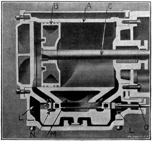
Fig. 1. Longitudinal Section through the Ames High-speed Engine
This eBook is for the use of anyone anywhere at no cost and with
almost no restrictions whatsoever.  You may copy it, give it away or
re-use it under the terms of the Project Gutenberg License included
with this eBook or online at www.gutenberg.org
Title: Steam Engines
Machinery's Reference Series, Number 70
Author: Anonymous
Release Date: December 19, 2010 [eBook #34701]
Language: English
Character set encoding: ISO-8859-1
***START OF THE PROJECT GUTENBERG EBOOK STEAM ENGINES***
| Note: | Images of the original pages are available through Internet Archive. See http://www.archive.org/details/steamengines00newyrich |
EACH NUMBER IS A UNIT IN A SERIES ON ELECTRICAL AND
STEAM ENGINEERING DRAWING AND MACHINE
DESIGN AND SHOP PRACTICE
| Action of Steam Engines | 3 |
| Rating and General Proportions of Steam Engines | 11 |
| Steam Engine Details | 15 |
| Steam Engine Economy | 30 |
| Types of Steam Engines | 36 |
| Steam Engine Testing | 41 |
Copyright, 1911, The Industrial Press, Publishers of Machinery,
49-55 Lafayette Street, New York City.
A steam engine is a device by means of which heat is transformed into work. Work may be defined as the result produced by a force acting through space, and is commonly measured in foot-pounds; a foot-pound represents the work done in raising 1 pound 1 foot in height. The rate of doing work is called power. It has been found by experiment that there is a definite relation between heat and work, in the ratio of 1 thermal unit to 778 foot-pounds of work. The number 778 is commonly called the heat equivalent of work or the mechanical equivalent of heat.
Heat may be transformed into mechanical work through the medium of steam, by confining a given amount in a closed chamber, and then allowing it to expand by means of a movable wall (piston) fitted into one side of the chamber. Heat is given up in the process of expansion, as shown by the lowered pressure and temperature of the steam, and work has been done in moving the wall (piston) of the closed chamber against a resisting force or pressure. When the expansion of steam takes place without the loss of heat by radiation or conduction, the relation between the pressure and volume is practically constant; that is, if a given quantity of steam expands to twice its volume in a closed chamber of the kind above described, its final pressure will be one-half that of the initial pressure before expansion took place. A pound of steam at an absolute pressure of 20 pounds per square inch has a volume of practically 20 cubic feet, and a temperature of 228 degrees. If now it be expanded so that its volume is doubled (40 cubic feet), the pressure will drop to approximately 10 pounds per square inch and the temperature will be only about 190 degrees. The drop in temperature is due to the loss of heat which has been transformed into work in the process of expansion and in moving the wall (piston) of the chamber against a resisting force, as already noted.
The steam engine makes use of a closed chamber with a movable wall in transforming the heat of steam into mechanical work in the manner just described. Fig. 1 shows a longitudinal section through an engine of simple design, and illustrates the principal parts and their relation to one another.
The cylinder A is the closed chamber in which expansion takes place, and the piston B, the movable wall. The cylinder is of cast iron, accurately bored and finished to a circular cross-section. The piston is carefully fitted to slide easily in the cylinder, being made practically steam tight by means of packing rings. The work generated in moving the piston is transferred to the crank-pin H by means[4] of the piston-rod C, and the connecting-rod F. The piston-rod passes out of the cylinder through a stuffing box, which prevents the leakage of steam around it. The cross-head D serves to guide the piston-rod in a straight line, and also contains the wrist-pin E which joins the piston-rod and connecting-rod. The cross-head slides upon the guide-plate G, which causes it to move in an accurate line, and at the same time takes the downward thrust from the connecting-rod.
The crank-pin is connected with the main shaft I by means of a crank arm, which in this case is made in the form of a disk in order to give a better balance. The balance wheel or flywheel J carries the crank past the dead centers at the ends of the stroke, and gives a uniform motion to the shaft. The various parts of the engine are carried on a rigid bed K, usually of cast iron, which in turn is bolted to a foundation of brick or concrete. The power developed is taken off by means of a belted pulley attached to the main shaft, or, in certain cases, in the form of electrical energy from a direct-connected dynamo.
When in action, a certain amount of steam (1⁄4 to 1⁄3 of the total cylinder volume in simple engines) is admitted to one end of the cylinder, while the other is open to the atmosphere. The steam forces the piston forward a certain distance by its direct action at the boiler pressure. After the supply is shut off, the forward movement of the piston is continued to the end of the stroke by the expansion of the steam. Steam is now admitted to the other end of the cylinder, and the operation repeated on the backward or return stroke.
An enlarged section of the cylinder showing the action of the valve for admitting and exhausting the steam is shown in Fig. 2. In this case the piston is shown in its extreme backward position, ready for the forward stroke. The steam chest L is filled with steam at boiler pressure, which is being admitted to the narrow space back of the piston through the valve N, as indicated by the arrows. The exhaust port M is in communication with the other end of the cylinder and[5] allows the piston to move forward without resistance, except that due to the piston-rod, which transfers the work done by the expanding steam to the crank-pin. The valve N is operated automatically by a crank or eccentric attached to the main shaft, and opens and closes the supply and exhaust ports at the proper time to secure the results described.
Having discussed briefly the general principle upon which an engine operates, the next step is to study more carefully the transformation of heat into work within the cylinder, and to become familiar with the graphical methods of representing it. Work has already been defined as the result of force acting through space, and the unit of work as the foot-pound, which is the work done in raising 1 pound 1 foot in height. For example, it requires 1 × 1 = 1 foot-pound to raise 1 pound 1 foot, or 1 × 10 = 10 foot-pounds to raise 1 pound 10 feet, or 10 × 1 = 10 foot-pounds to raise 10 pounds 1 foot, or 10 × 10 = 100 foot-pounds to raise 10 pounds 10 feet, etc. That is, the product of weight or force acting, times the distance moved through, represents work; and if the force is taken in pounds and the distance in feet, the result will be in foot-pounds. This result may be shown graphically by a figure called a work diagram.
In Fig. 3, let distances on the line OY represent the force acting, and distances on OX represent the space moved through. Suppose the figure to be drawn to such a scale that OY is 5 feet in height, and OX 10 feet long. Let each division on OY represent 1 pound pressure, and[6] each division on OX 1 foot of space moved through. If a pressure of 5 pounds acts through a distance of 10 feet, then an amount of 5 × 10 = 50 foot-pounds of work has been done. Referring to Fig. 3, it is evident that the height OY (the pressure acting), multiplied by the length OX (the distance moved through), gives 5 × 10 = 50 square feet, which is the area of the rectangle YCXO; that is, the area of a rectangle may represent work done, if the height represents a force acting, and the length the distance moved through. If the diagram were drawn to a smaller scale so that the divisions were 1 inch in length instead of 1 foot, the area YCXO would still represent the work done, except each square inch would equal 1 foot-pound instead of each square foot, as in the present illustration.
In Fig. 4 the diagram, instead of being rectangular in form, takes a different shape on account of different forces acting at different periods over the distance moved through. In the first case (Fig. 3), a uniform force of 5 pounds acts through a distance of 10 feet, and produces 5 × 10 = 50 foot-pounds of work. In the second case (Fig. 4), forces of 5 pounds, 4 pounds, 3 pounds, 2 pounds, and 1 pound, act through distances of 2 feet each, and produce (5 × 2) + (4 × 2) + (3 × 2) + (2 × 2) + (1 × 2) = 30 foot-pounds. This is also the area, in square feet, of the figure Y54321XO, which is made up of the areas of the five small rectangles shown by the dotted lines. Another way of finding the total area of the figure shown in Fig. 4, and determining the work[7] done, is to multiply the length by the average of the heights of the small rectangles. The average height is found by adding the several heights and dividing the sum by their number, as follows:
| 5 + 4 + 3 + 2 + 1 | |
| ——————— | = 3, and 3 × 10 = 30 square feet, as before. |
| 5 |
This, then, means that the average force acting throughout the stroke is 3 pounds, and the total work done is 3 × 10 = 30 foot-pounds.
In Fig. 5 the pressure drops uniformly from 5 pounds at the beginning to 0 at the end of the stroke. In this case also the area and work done are found by multiplying the length of the diagram by the average height, as follows:
| 5 + 0 | |
| ——— | × 10 = 25 square feet, |
| 2 |
or 25 foot-pounds of work done.
The object of Figs. 3, 4 and 5 is to show how foot-pounds of work may be represented graphically by the areas of diagrams, and also to make it clear that this remains true whatever the form of the diagram. It is also evident that knowing the area, the average height or pressure may be found by dividing by the length, and vice versa.
Fig. 6 shows the form of work diagram which would be produced by the action of the steam in an engine cylinder, if no heat were lost by conduction and radiation. Starting with the piston in the position shown in Fig. 2, steam is admitted at a pressure represented by the height of the line OY. As the piston moves forward, sufficient steam is admitted to maintain the same pressure. At the point B the valve closes and steam is cut off. The work done up to this time is shown by the rectangle YBbO. From the point B to the end of the stroke C, the piston is moved forward by the expansion of the steam, the pressure falling in proportion to the distance moved through, until at the end of the stroke it is represented by the vertical line CX. At the point C the exhaust valve opens and the pressure drops to 0 (atmospheric pressure in this case).
As it is always desirable to find the work done by a complete stroke of the engine, it is necessary to find the average or mean pressure [8]acting throughout the stroke. This can only be done by determining the area of the diagram and dividing by the length of the stroke. This gives what is called the mean ordinate, which multiplied by the scale of the drawing, will give the mean or average pressure. For example, if the area of the diagram is found to be 6 square inches, and its length is 3 inches, the mean ordinate will be 6 ÷ 3 = 2 inches. If the diagram is drawn to such a scale that 1 inch on OY represents 10 pounds, then the average or mean pressure will be 2 × 10 = 20 pounds, and this multiplied by the actual length of the piston stroke will give the work done in foot-pounds. The practical application of the above, together with the method of obtaining steam engine indicator diagrams and measuring the areas of the same, will be taken up in detail under the heading of Steam Engine Testing.
Before taking up the construction of an actual engine diagram, it is first necessary to become familiar with certain terms which are used in connection with it.
Cut-off.—The cut-off is the point in the stroke at which the admission valve closes and the expansion of steam begins.
Ratio of Expansion.—This is the reciprocal of the cut-off, that is, if the cut-off is 1⁄4, the ratio of expansion is 4. In other words, it is the ratio of the final volume of the steam at the end of the stroke to its volume at the point of cut-off. For example, a cylinder takes steam at boiler pressure until the piston has moved one-fourth the length of its stroke; the valve now closes and expansion takes place until the stroke is completed. The one-fourth cylinderful of steam has become a cylinderful, that is, it has expanded to four times its original volume, and the ratio of expansion is said to be 4.
Point of Release.—This is the point in the stroke at which the exhaust valve opens and relieves the pressure acting on the piston. This takes place just before the end of the stroke in order to reduce the shock when the piston changes its direction of travel.
Compression.—This acts in connection with the premature release in order to reduce the shock at the end of the stroke. During the forward stroke of an engine the exhaust valve in front of the piston remains open as shown in Fig. 2. Shortly before the end of the stroke[9] this closes, leaving a certain amount of steam in the cylinder. The continuation of the stroke compresses this steam, and by raising its pressure forms a cushion, which, in connection with the removal of the pressure back of the piston by release, brings the piston to a stop and causes it to reverse its direction without shock. High-speed engines require a greater amount of compression than those running at low speed.
Clearance.—This is the space between the cylinder head and the piston when the latter is at the end of its stroke; it also includes that portion of the steam port between the valve and the cylinder. Clearance is usually expressed as a percentage of the piston-displacement of the cylinder, and varies in different types of engines. The following table gives approximate values for engines of different design.
| TABLE I. CLEARANCE OF STEAM ENGINES | |||
| Type of Engine | Per Cent Clearance | ||
| Corliss | 1.5 | to | 3.5 |
| Moderate-speed | 3 | to | 8 |
| High-speed | 4 | to | 10 |
A large clearance is evidently objectionable because it represents a space which must be filled with steam at boiler pressure at the beginning of each stroke, and from which but a comparatively small amount of work is obtained. As compression increases, the amount of steam required to fill the clearance space diminishes, but on the other hand, increasing the compression reduces the mean effective pressure.
Initial Pressure.—This is the pressure in the cylinder up to the point of cut-off. It is usually slightly less than boiler pressure owing to “wire-drawing” in the steam pipe and ports.
Terminal Pressure.—This is the pressure in the cylinder at the time release occurs, and depends upon the initial pressure, the ratio of expansion, and the amount of cylinder condensation.
Back Pressure.—This is the pressure in the cylinder when the exhaust port is open, and is that against which the piston is forced during the working stroke. For example, in Fig. 2 the small space at the left of the piston is filled with steam at initial pressure, while the space at the right of the piston is exposed to the back pressure. The working pressure varies throughout the stroke, due to the expansion of the steam, while the back pressure remains constant, except for the effect of compression at the end of the stroke. The theoretical back pressure in a non-condensing engine (one exhausting into the atmosphere) is that of the atmosphere or 14.7 pounds per square inch above a vacuum, but in actual practice it is about 2 pounds above atmospheric pressure, or 17 pounds absolute, due to the resistance of exhaust ports and connecting pipes. In the case of a condensing engine (one exhausting into a condenser) the back pressure depends upon the efficiency of the condenser, averaging about 3 pounds absolute pressure in the best practice.
Effective Pressure.—This is the difference between the pressure on the steam side of the piston and that on the exhaust side, or in other words, the difference between the working pressure and the back[10] pressure. This value varies throughout the stroke with the expansion of the steam.
Mean Effective Pressure.—It has just been stated that the effective pressure varies throughout the stroke. The mean effective pressure (M. E. P.) is the average of all the effective pressures, and this average multiplied by the length of stroke, gives the work done per stroke.
Line of Absolute Vacuum.—In the diagram shown in Fig. 6, the line OX is the line of absolute vacuum; that is, it is assumed that there is no pressure on the exhaust side of the piston. In other words, the engine is exhausting into a perfect vacuum.
Atmospheric Line.—This is a line drawn parallel to the line of absolute vacuum at such a distance above it as to represent 14.7 pounds pressure per square inch, according to the scale used.
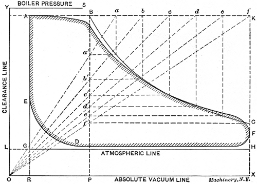
One of the first steps in the design of a steam engine is the construction of an ideal diagram, and the engine is planned to produce this as nearly as possible when in operation. First assume the initial pressure, the ratio of expansion, and the percentage of clearance, for the type of engine under consideration. Draw lines OX and OY at right angles as in Fig. 7. Make OR the same percentage of the stroke that the clearance is of the piston displacement; make RX equal to the length of the stroke (on a reduced scale). Erect the perpendicular RA of such a height that it shall represent, to scale, an absolute pressure per square inch equal to 0.95 of the boiler pressure. Draw in the dotted lines AK and KX, and the atmospheric line LH at a height above OX to represent 14.7 pounds per square inch. Locate the point of cut-off, B, according to the assumed ratio of expansion. Points on the expansion curve BC are found as follows: Divide the distance BK into any[11] number of equal spaces, as shown by a, b, c, d, etc., and connect them with the point O. Through the points of intersection with BP, as a´, b´, c´, d´, etc., draw horizontal lines, and through a, b, c, d, etc., draw vertical lines. The intersection of corresponding horizontal and vertical lines will be points on the theoretical expansion line. If the engine is to be non-condensing, the theoretical work, or indicator diagram, as it is called, will be bounded by the lines ABCHG.
The actual diagram will vary somewhat from the theoretical, as shown by the shaded lines. The admission line between A and B will slant downward slightly, and the point of cut-off will be rounded, owing to the slow closing of the valve. The first half of the expansion line will fall below the theoretical, owing to a drop in pressure caused by cylinder condensation, but the actual line will rise above the theoretical in the latter part of the stroke on account of re-evaporation, due to heat given out by the hot cylinder walls to the low-pressure steam. Instead of the pressure dropping abruptly at C, release takes place just before the end of the stroke, and the diagram is rounded at CF instead of having sharp corners. The back pressure line FD is drawn slightly above the atmospheric line, a distance to represent about 2 pounds per square inch. At D the exhaust valve closes and compression begins, rounding the bottom of the diagram up to E.
The area of the actual diagram, as shown by the shaded lines in Fig. 7, will be smaller than the theoretical, in about the following ratio:
Large medium-speed engines, 0.90 of theoretical area.
Small medium-speed engines, 0.85 of theoretical area.
High-speed engines, 0.75 of theoretical area.
The capacity or power of a steam engine is rated in horsepower, one horsepower (H. P.) being the equivalent of 33,000 foot-pounds of work done per minute. The horsepower of a given engine may be computed by the formula:
| APLN | |
| H. P. = | ——— |
| 33,000 |
in which
| A | = | area of piston, in square inches, |
| P | = | mean effective pressure per square inch, |
| L | = | length of stroke, in feet, |
| N | = | number of strokes per minute = number of revolutions × 2. |
The derivation of the above formula is easily explained, as follows: The area of the piston, in square inches, multiplied by the mean [12]effective pressure, in pounds per square inch, gives the total force acting on the piston, in pounds. The length of stroke, in feet, times the number of strokes per minute gives the distance the piston moves through, in feet per minute. It has already been shown that the pressure in pounds multiplied by the distance moved through in feet, gives the foot-pounds of work done. Hence, A × P × L × N gives the foot-pounds of work done per minute by a steam engine. If one horsepower is represented by 33,000 foot-pounds per minute, the power or rating of the engine will be obtained by dividing the total foot-pounds of work done per minute by 33,000. For ease in remembering the formula given, it is commonly written
| PLAN | |
| H. P. = | ——— |
| 33,000 |
in which the symbols in the numerator of the second member spell the word “Plan.”
Example:—Find the horsepower of the following engine, working under the conditions stated below:
In this problem, then, A = 113 square inches; P = 40 pounds; L = 1.5 feet; and N = 600 strokes.
Substituting in the formula,
| 40 × 1.5 × 113 × 600 | ||
| H. P. = | ————————— | = 123. |
| 33,000 |
The mean effective pressure may be found, approximately, for different conditions by means of the factors in the following table of ratios, covering ordinary practice. The rule used is as follows: Multiply the absolute initial pressure by the factor corresponding to the clearance and cut-off as found from Table II, and subtract the absolute back pressure from the result, assuming this to be 17 pounds for non-condensing engines, and 3 pounds for condensing.
Example 1:—A non-condensing engine having 3 per cent clearance, cuts off at 1⁄3 stroke; the initial pressure is 90 pounds gage. What is the M. E. P.?
The absolute initial pressure is 90 + 15 = 105 pounds. The factor for 3 per cent clearance and 1⁄3 cut-off, from Table II, is 0.71. Applying the rule we have: (105 × 0.71) - 17 = 57.5 pounds per square inch.
Example 2:—A condensing engine has a clearance of 5 per cent. It is supplied with steam at 140 pounds gage pressure, and has a ratio of expansion of 6. What is the M. E. P.?
The absolute initial pressure is 140 + 15 = 155. The factor for a ratio of expansion of 6 (1⁄6 cut-off) and 5 per cent clearance is 0.5, which gives (155 × 0.5) - 3 = 74.5 pounds per square inch.
The power of an engine computed by the method just explained is[13] called the indicated horsepower (I. H. P.), and gives the total power developed, including that required to overcome the friction of the engine itself. The delivered or brake horsepower (B. H. P.) is that delivered by the engine after deducting from the indicated horsepower the power required to operate the moving parts. The brake horsepower commonly varies from 80 to 90 per cent of the indicated horsepower at full load, depending upon the type and size of engine.
In proportioning an engine cylinder for any given horsepower, the designer usually has the following data, either given or assumed, for the special type of engine under consideration: Initial pressure, back pressure, clearance, cut-off, and piston speed.
These quantities vary in different types of engines, but in the absence of more specific data the values in Table III will be found useful. The back pressure may be taken as 17 pounds per square inch, absolute, for non-condensing engines, and as 3 pounds for condensing engines as previously stated.
The first step in proportioning the cylinder is to compute the approximate mean effective pressure from the assumed initial pressure, clearance, and cut-off, by the method already explained. Next assume the piston speed for the type of engine to be designed, and determine the piston area by the following formula:
| 33,000 H. P. | |
| A = | ——————————. |
| M. E. P. × piston speed |
This formula usually gives the diameter of the piston in inches and fractions of an inch, while it is desirable to make this dimension an even number of inches. This may be done by taking as the diameter the nearest whole number, and changing the piston speed to correspond. This is done by the use of the following equation.
| First piston speed × first piston area | |
| —————————————— | = new piston speed. |
| new piston area |
In calculating the effective piston area, the area of the piston rod upon one side must be allowed for. The effective or average piston area will then be (2A - a)⁄2, in which A = area of piston, a = area of piston rod. This latter area must be assumed. After assuming a new piston [14]diameter of even inches, its effective or average area must be used in determining the new piston speed. The length of stroke is commonly proportioned to the diameter of cylinder, and the piston speed divided by this will give the number of strokes per minute.
Example:—Find the diameter of cylinder, length of stroke, and revolutions per minute for a simple high-speed non-condensing engine of 200 I. H. P., with the following assumptions: Initial pressure, 90 pounds gage; clearance, 7 per cent; cut-off, 1⁄4; piston speed, 700 feet per minute; length of stroke, 1.5 times cylinder diameter.
By using the rules and formulas in the foregoing, we have:
M. E. P. = (90 + 15) × 0.63 - 17 = 49 pounds.
| 33,000 × 200 | ||
| A = | —————— | = 192.4 square inches. |
| 49 × 700 |
The nearest piston diameter of even inches is 16, which corresponds to an area of 201 square inches. Assume a piston rod diameter of 21⁄2 inches, corresponding to an area of 4.9 square inches, from which the average or effective piston area is found to be (2 × 201) - 4.9⁄2 = 198.5 square inches.
Determining now the new piston speed, we have:
| 700 × 192.4 | |
| ————— | = 678.5 feet per minute. |
| 198.5 |
Assuming the length of stroke to be 1.5 times the diameter of the cylinder, it will be 24 inches, or 2 feet.
This will call for 678.5 ÷ 2 = 340 strokes per minute, approximately, or 340 ÷ 2 = 170 revolutions per minute.
Some of the most important details of a steam engine are those of its valve gear. The simplest form of valve is that known as the plain slide valve, and as nearly all others are a modification of this, it is essential that the designer should first familiarize himself with this particular type of valve in all its details of operation. After this has been done, a study of other forms of valves will be found a comparatively easy matter. The so called Corliss valve differs radically from the slide valve, but the results to be obtained and the terms used in its design are practically the same. The valve gear of a steam engine is made up of the valve or valves which admit steam to and exhaust it from the cylinder, and of the mechanism which governs the valve movements, the latter usually consisting of one or more eccentrics attached to the main shaft.
Fig. 8 shows a longitudinal section of a slide valve with the ports, bridges, etc. The valve is shown in mid-position in order that certain points relating to it may be more easily understood. The valve, V, consists of a hollow casting, with ends projecting beyond the ports as shown; the lower face is smoothly finished and fitted to the valve seat AB. In operation it slides back and forth, opening and closing the ports which connect the steam chest with the cylinder. Steam is admitted to the cylinder when either port CD or DC is opened, and is released when the ports are brought into communication with the exhaust port MN. This is accomplished by the movement of the valve, which brings one of the cylinder ports and the exhaust port both under the hollow arch K. The portions DM and ND of the valve seat are called the bridges.
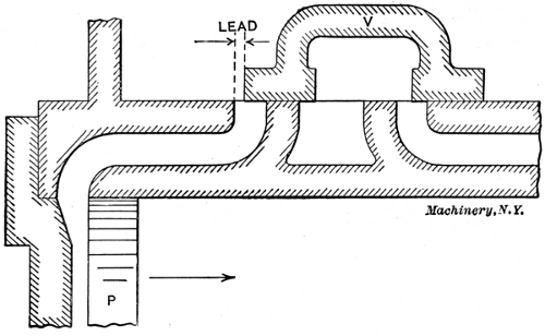
[16]It will be seen by reference to Fig. 8 that the portions OI and IO are wider than the ports which they cover. This extra width is called the lap, OC being the outside lap and DI the inside or exhaust lap. The object of outside lap is that the steam may be shut off after the piston has moved forward a certain distance, and be expanded during the remainder of the stroke. If there were no outside lap, steam would be admitted throughout the entire stroke and there would be no expansion. If there were no inside lap, exhaust would take place throughout the whole stroke, and the advantages of premature release and compression would be lost. Hence, outside lap affects the cut-off, and inside lap affects release and compression. A valve has lead when it begins to uncover the steam port before the end of the return stroke of the piston. This is shown in Fig. 9, where the piston P is just ready to start on its forward stroke as indicated by the arrow. The valve has already opened a distance equal to the lead, and the steam has had an opportunity to enter and fill the clearance space before the beginning of the stroke. The lead varies in different engines, being greater in high-speed than in low-speed types.
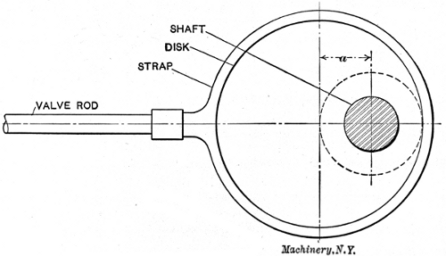
The slide valve is usually driven by an eccentric attached to the main shaft. A diagram of an eccentric is shown in Fig. 10. An eccentric is, in reality, a short crank with a crank-pin of such size that it surrounds the shaft. The arm of a crank is the distance between the center of the shaft, and the center of the crank-pin. The throw of an eccentric corresponds to this, and is the distance between the center of the shaft and the center of the eccentric disk, as shown at a in Fig. 10. The disk is keyed to the shaft, and as the shaft revolves, the center of the disk rotates about it as shown by the dotted line, and gives a forward and backward movement to the valve rod equal to twice the throw a.
In Fig. 11 let A represent the center of the main shaft, B the crank-pin to which the connecting-rod is attached (see H, 1), and the dotted circle through B the path of the crank-pin around the shaft. For simplicity, let the eccentric be represented in a similar manner by the crank Ab, and its path by the dotted circle through b. Fig. 12 shows a similar diagram with the piston P and the valve in the positions corresponding to the positions of the crank and eccentric in Fig. 11, and in the diagram at the right in Fig. 12. The piston is at the extreme left, ready to start on its forward stroke toward the right. The crank-pin B is at its extreme inner position. When the valve is at its mid-position, as in Fig. 8, the eccentric arm Ab will coincide with the line AC, Fig. 11. If the eccentric is turned on the shaft sufficiently to bring the left-hand edge O, Fig. 8, of the valve in line with the edge C of the port, the arm of the eccentric will have moved from its vertical position to that shown by the line Ab´ in Fig. 11. The angle through which the eccentric has been turned from the vertical to bring about this result is called the angular advance, and is shown by angle CAb´ in Fig. 11. The angular advance evidently depends upon the amount of lap.
If the valve is to be given a lead, as indicated in Fig. 12, the eccentric must be turned still further on the shaft to open the valve slightly before the piston starts on its forward movement. This brings the eccentric to the position Ab shown in Fig. 11. The angle through which the eccentric is turned to give the necessary lead opening to the[18] valve is called the angle of lead, and is shown by angle b´Ab. By reference to Fig. 11, it is seen that the total angle between the crank and the eccentric is 90 degrees, plus the angular advance, plus the angle of lead. This is the total angle of advance.
The relative positions of the piston and valve at different periods of the stroke are illustrated in Figs. 12 to 16. Fig. 12 shows the piston just beginning the forward stroke, the valve having uncovered the admission port an amount equal to the lead. The crank is in a horizontal position, and the eccentric has moved from the vertical an amount sufficient to move the valve toward the right a distance equal to the outside lap plus the lead. The arrows show that steam is entering the left-hand port and is being exhausted through the right-hand port.
 |
 |
| Fig. 12. Piston just beginning Forward Stroke | Fig. 13. Steam Port fully Opened |
 |
 |
| Fig. 14. Valve has started on Backward Stroke | Fig. 15. Both Steam Ports Closed |
[19]In Fig. 13 it is seen that the valve has traveled forward sufficiently to open the steam port to its fullest extent, and the piston has moved to the point indicated. The exhaust port is still wide open, and the relative positions of the crank and eccentric are shown in the diagram at the right. In Fig. 14 the eccentric has passed the horizontal position and the valve has started on its backward stroke, while the piston is still moving forward. The admission port is closed, cut-off having taken place, and the steam is expanding. The exhaust port is still partially open.
In Fig. 15 both ports are closed and compression is taking place in front of the piston while expansion continues back of it. Release occurs in Fig. 16 just before the piston reaches the end of its stroke. The eccentric crank is now in a vertical position, pointing downward, and exhaust is just beginning to take place through the left-hand port.[20] This completes the different stages of a single stroke, the same features being repeated upon the return of the piston to its original position. The conditions of lap, lead, angular advance, etc., pertain to practically all valves, whatever their design.
In the following are shown some of the valves in common use, being, with the exception of the Corliss, modifications of the plain slide valve, and similar in their action.
Double-Ported Balanced Valve.—A valve of this type has already been shown in Fig. 2. This valve is flat in form, with two finished surfaces,[21] and works between the valve-seat and a plate, the latter being prevented from pressing against the valve by special bearing surfaces which hold it about 0.002 inch away. The construction of the valve is such that when open the steam reaches the port through two openings as indicated by the arrows at the left. The object of this is to reduce the motion of the valve and quicken its action in admitting and cutting off steam.
Piston Valve.—The piston valve shown in Fig. 17 is identical in its action with the plain slide valve shown in Fig. 8, except that it is circular in section instead of being flat or rectangular. The advantage claimed for this type of valve is the greater ease in fitting cylindrical surfaces as compared with flat ones. The valve slides in special[22] bushings which may be renewed when worn. Piston valves are also made with double ports.
Four-Valve Type.—Fig. 18 shows a horizontal section through the cylinder and valves of an engine of the four-valve type. The admission valves are shown at the top of the illustration and the exhaust valves at the bottom, although, in reality, they are at the sides of the cylinder. The advantage of an arrangement of this kind is that the valves may be set independently of each other and the work done by the two ends[23] of the cylinder equalized. The various events, such as cut-off, compression, etc., may be adjusted without regard to each other, and in such a manner as to give the best results, a condition which is not possible with a single valve.
Gridiron Valve.—One of the principal objects sought in the design of a valve is quick action at the points of admission and cut-off. This requires the uncovering of a large port opening with a comparatively small travel of the valve. The gridiron valve shown in Fig. 21 is constructed especially for this purpose. This valve is of the four-valve type, one steam valve and one exhaust valve being shown in the section. Both the valve and its seat contain a number of narrow openings or ports, so that a short movement of the valve will open or close a comparatively large opening. For example, the steam valve in the illustration has 12 openings, so that if they are 1⁄4 inch in width each, a movement of 1⁄4 inch of the valve will open a space 12 × 1⁄4 = 3 inches in length.
Corliss Valve.—A section through an engine cylinder equipped with Corliss valves is shown in Fig. 20. There are four cylindrical valves in this type of engine, two steam valves at the top and two exhaust valves at the bottom. This arrangement is used to secure proper drainage. The action of the admission and exhaust valves is indicated by the arrows, the upper left-hand and the lower right-hand valve being open and the other two closed.[24]

Fig. 22. The Monarch Engine with Corliss Valve Gear.—A, Rod to Eccentric; B, Governor;
C, Reach Rod; D, Radial Arm; E, Steam Valve; F, Bell-crank; G, Wrist Plate;
H, Exhaust Valve; K, Dash-pot
Side and sectional views of different forms of this type of valve are shown in Fig. 19. They are operated by means of short crank-arms which are attached to a wrist-plate by means of radial arms or rods, as shown in Fig. 22. The wrist-plate, in turn, is given a partial backward and forward rotation by means of an eccentric attached to the main shaft and connected to the upper part of the wrist-plate by a rod as indicated. The exhaust valves are both opened and closed by the action of the wrist-plate and connecting rods. The steam valves are opened in this manner, but are closed by the suction of dash pots attached to the drop levers on the valve stems by means of vertical rods, as shown.
 |
 |
| Fig. 23 | Fig. 24 |
 |
 |
| Fig. 25 | Fig. 26 |
Figs. 23 to 26. Action of Corliss Valve Gear
The action of the steam or admission valves is best explained by reference to Figs. 23 to 26. Referring to Fig. 23, A is a bell-crank which turns loosely upon the valve stem V. The lower left-hand extension of A carries the grab hook H, while the upper extension is connected with the wrist-plate as indicated. Ordinarily the hook H is pressed[25] inward by the spring S, so that the longer arm of the hook is always pressed against the knock-off cam C. The cam C also turns upon the valve stem V and is connected with the governor by means of a reach rod as indicated in Fig. 23 and shown in Fig. 22. The drop lever B is keyed to the valve stem V, and is connected with the dash pot by a rod as indicated by the dotted line. This is also shown in Fig. 22. The end of the drop lever carries a steel block (shown shaded in Fig. 23), which engages with the grab hook H.
When in operation, the bell-crank is rotated in the direction of the arrow by the action of the wrist-plate and connecting-rod. As the bell-crank rotates, the grab hook engages the steel block at the end of the drop lever B and lifts it, thus causing the valve to open, and to remain so until the bell-crank has advanced so far that the longer arm of the grab hook H is pressed outward by the projection on the knock-off cam, as shown in Fig. 24. The drop lever now being released, the valve is quickly closed by the suction of the dash pot, which pulls the lever down to its original position by means of the rod previously mentioned.
The governor operates by changing the point of cut-off through the action of the cam C. With the cam in the position shown in Fig. 25, cut-off occurs earlier than in Fig. 24. Should the cam be turned in the opposite direction (clockwise), cut-off would take place later. A detailed view of the complete valve mechanism described is shown assembled in Fig. 26, with each part properly named. A detail of the governor is shown in Fig. 27. An increase in speed causes the revolving balls BB to swing outward, thus raising the weight W and the sleeve S. This in turn operates the lever L through rod R and a bell-crank attachment, as shown in the right-hand view. An upward and downward movement of the balls, due to a change in speed of the engine, swings the lever L backward and forward as shown by the[26] full and dotted lines. The ends of this lever are attached by means of reach-rods to the knock-off cams, this being shown more clearly in Fig. 22. The connections between the lever L and cam C are such that a raising of the balls, due to increased speed, will reduce the cut-off and thus slow down the engine. On the other hand, a falling of the balls will lengthen the cut-off through the same mechanism.
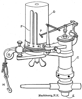
Mention has already been made of the dash pot which is used to close the valve suddenly after being released from the grab hook. The dash-pot rod is shown in Fig. 26, and indicated by dotted lines in Figs. 23 to 25. A detailed view of one form of dash pot is shown in Fig. 28. When the valve is opened, the rod attached to lever B, Figs. 23 and 24, raises the piston P, Fig. 28, and a partial vacuum is formed beneath it which draws the piston and connecting rod down by suction as soon as the lever B is released, and thus closes the valve suddenly and [27]without shock. The strength of the suction and the air cushion for this piston are regulated by the inlet and outlet valves shown on the sides of the dash pot.
Figs. 29 to 37 show various engine details, and illustrate in a simple way some of the more important principles involved in steam engine design.
 |
 |
| Figs. 29 and 30. Plan and Longitudinal Section of Adjustable Piston | |
A partial cross-section of an adjustable piston is shown in Fig. 29, and a longitudinal section of the same piston in Fig. 30. The principal feature to be emphasized is the method of automatic expansion employed to take up any wear and keep the piston tight. In setting up the piston a hand adjustment is made of the outer sleeve or ring R by means of the set-screws AA. Ring R is made in several sections, so that it may be expanded in the form of a true circle. Further tightness is secured without undue friction by means of the packing ring P which fits in a groove in R and is forced lightly against the walls of the cylinder by a number of coil springs, one of which is shown at S. As the cylinder and piston become worn, screws A are adjusted from time to time, and the fine adjustment for tightness is cared for by the packing ring P and the coil springs S.
[28]The points to be brought out in connection with the cross-head are the methods of alignment and adjustment. A typical cross-head is shown in cross and longitudinal sections in Fig. 31. Alignment in a straight line, longitudinally, is secured by the cylindrical form of the bearing surfaces or shoes, shown at S. These are sometimes made V-shaped in order to secure the same result. The wear on a cross-head comes on the surfaces S, and is taken up by the use of screw wedges W, shown in the longitudinal section. As the sliding surfaces become worn, the wedges are forced in slightly by screwing in the set-screws and clamping them in place by means of the check-nuts.
The method commonly employed in taking up the wear in a connecting-rod is shown in Figs. 32 and 33. The wear at the wrist-pin is taken by the so called brasses, shown at B in the illustrations. The inner brass, in both cases, fits in a suitable groove, and is held stationary when once in place. The outer brass is adjustable, being forced toward the wrist-pin by a sliding wedge which is operated by one or more set-screws. In Fig. 32 the wedge is held in a vertical position, and is adjusted by two screws as shown. The arrangement made use of in Fig. 33 has the wedge passing through the rod in a horizontal position, and adjusted by means of a single screw, as shown in the[29] lower view. With the arrangements shown, tightening up the brasses shortens the length of the rod. In practice the wedges at each end of the rod are so placed that tightening one shortens the rod, and tightening the other lengthens it, the total effect being to keep the connecting-rod at its original length.
 |
 |
|
| Fig. 34. Outboard Bearing for Corliss Type Engine | Fig. 35. Inner Bearing and Bed of Corliss Engine |
A common form of outboard bearing for an engine of the slow-speed or Corliss type is illustrated in Fig. 34. The various adjustments for alignment and for taking up wear are the important points considered in this case. The plate B is fastened to the stone foundation by anchor bolts not shown. Sidewise movement is secured by loosening the bolts C, which pass through slots in the bearing, and adjusting by means of the screws S. Vertical adjustment is obtained by use of the wedge W, which is forced in by the screw A, as required. The inner bearing and bed piece of a heavy duty Corliss engine is shown in Fig. 35. The bearing in this case is made up of four sections, so arranged that either horizontal or vertical adjustment may be secured by the use of adjusting screws and check-nuts.
Engines of the slide-valve type are usually provided either with a fly-ball throttling governor, or a shaft governor. A common form of throttling governor is shown in Fig. 36. As the speed increases the balls W are thrown outward by the action of the centrifugal force, and being attached to arms hinged above them, any outward movement causes them to rise. This operates the spindle S, which, in turn, partially closes the balanced valve in body B, thus cutting down the steam supply delivered to the engine. The action of a throttling governor upon the work diagram of an engine is shown in Fig. 38. Let the full line represent the form of the diagram with the engine working at full load. Now, if a part of the load be thrown off, the engine will speed up slightly, causing the governor to act as described, thus bringing the admission and expansion lines into the lower positions, as shown in dotted lines.
The shaft governor is used almost universally on high-speed engines, and is shown in one form in Fig. 37. It consists, in this case, of two weights W, hinged to the spokes of the wheel near the circumference[30] by means of suitable arms. Attached to the arms, as shown, are coil springs C. The ends of the arms beyond the weights are connected by means of levers L to the eccentric disk. When the engine speeds up, the weights tend to swing outward toward the rim of the wheel, the amount of the movement being regulated by the tension of the springs C. As the arms move outward, the levers at the ends turn the eccentric disk on the shaft, the effect of which is to change the angle of advance and shorten the cut-off. When the speed falls below the normal, the weights move toward the center and the cut-off is lengthened. The effect of this form of governor on the diagram is shown in Fig. 39. The full line represents the diagram at full load, and the dotted line when the engine is under-loaded.
Under the general heading of steam engine economy, such items as cylinder condensation, steam consumption, efficiency, ratio of expansion, under- and over-loading, condensing, etc., are treated.
The principal waste of steam in the operation of an engine is due to condensation during the first part of the stroke. This condensation is due to the fact that during expansion and exhaust the cylinder walls[31] and head and the piston are in contact with comparatively cool steam, and, therefore, give up a considerable amount of heat. When fresh steam is admitted at a high temperature, it immediately gives up sufficient heat to raise the cylinder walls to a temperature approximating that of the entering steam. This results in the condensation of a certain amount of steam, the quantity depending upon the time allowed for the transfer of heat, the area of exposed surface, and the temperature of the cylinder walls. During the period of expansion the temperature falls rapidly, and the steam being wet, absorbs a large amount of heat. After the exhaust valve opens, the drop in pressure allows the moisture that has collected on the cylinder walls to evaporate into steam, so that during the exhaust period but little heat is transferred. With the admission of fresh steam at boiler pressure, a mist is condensed on the cylinder walls, which greatly increases the rapidity with which heat is absorbed.
The amount of heat lost through cylinder condensation is best shown by a practical illustration. One horsepower is equal to 33,000 foot-pounds of work per minute, or 33,000 × 60 = 1,980,000 foot-pounds per hour. This is equivalent to 1,980,000 ÷ 778 = 2,550 heat units. The latent heat of steam at 90 pounds gage pressure is 881 heat units. Hence, 2,250 ÷ 881 = 2.9 pounds of steam at 90 pounds pressure is required per horsepower, provided there is no loss of steam, and all of the contained heat is changed into useful work. As a matter of fact, from 30 to 35 pounds of steam are required in the average simple non-condensing high-speed engine.
There are three remedies which are used to reduce the amount of cylinder condensation. The first to be used was called steam jacketing, and consisted in surrounding the cylinder with a layer of high-pressure steam, the idea being to keep the inner walls up to a temperature nearly equal to that of the incoming steam. This arrangement is but little used at the present time, owing both to the expense of operation and to its ineffectiveness as compared with other methods.
The second remedy is the use of superheated steam. It has been stated that the transfer of heat takes place much more rapidly when the interior surfaces are covered with a coating of moisture or mist. Superheated steam has a temperature considerably above the point of saturation at the given pressure; hence, it is possible to cool it a certain amount before condensation begins. This has the effect of reducing the transfer of heat for a short period following admission, and this is the time that condensation takes place most rapidly under ordinary conditions with saturated steam. This, in fact, is the principal advantage derived from the use of superheated steam, although it is also lighter for a given volume, and therefore, a less weight of steam is required, to fill the cylinder up to the point of cut-off. The economical degree of superheating is considered to be that which will prevent the condensation of any steam on the walls of the cylinder up to the point of cut-off, thus keeping them at all times free from moisture. The objections to superheated steam are its cutting effect in the passages through which it flows, and the difficulty experienced in [32]lubricating the valves and cylinder at such a high temperature. The third and most effective remedy for condensation losses is that known as compounding, which will be treated under a separate heading in the following.
It has been explained that cylinder condensation is due principally to the change in temperature of the interior surfaces of the cylinder, caused by the variation in temperature of the steam at initial and exhaust pressures. Therefore, if the temperature range be divided between two cylinders which are operated in series, the steam condensed in the first or high pressure cylinder will be re-evaporated and passed into the low-pressure cylinder as steam, where it will again be condensed and re-evaporated as it passes into the exhaust pipe. Theoretically, this should reduce the condensation loss by one-half, and if three cylinders are used, the loss should be only one-third of that in a simple engine. In actual practice the saving is not as great as this, but with the proper relation between the cylinders, these results are approximated.
Engines in which expansion takes place in two stages are called compound engines. When three stages are employed, they are called triple expansion engines. Compounding adds to the first cost of an engine, and also to the friction, so that in determining the most economical number of cylinders to employ, the actual relation between the condensation loss and the increased cost of the engine and the friction loss, must be considered. In the case of power plant work, it is now the practice to use compound engines for the large sizes, while triple expansion engines are more commonly employed in pumping stations. Many designs of multiple expansion engines are provided with chambers between the cylinders, called receivers. In engines of this type the exhaust is frequently reheated in the receivers by means of brass coils containing live steam. In the case of a cross-compound engine, a receiver is always used. In the tandem design it is often omitted, the piping between the two cylinders being made to answer the purpose.
The ratio of cylinder volumes in compound engines varies with different makers. The usual practice is to make the volume of the low-pressure cylinder from 2.5 to 3 times that of the high-pressure. The total ratio of expansion in a multiple expansion engine is the product of the ratios in each cylinder. For example, if the ratio of expansion is 4 in each cylinder in a compound engine, the total ratio will be 4 × 4 = 16. The effect of a triple-expansion engine is sometimes obtained in a measure by making the volume of the low-pressure cylinder of a compound engine 6 or 7 times that of the high-pressure. This arrangement produces a considerable drop in pressure at the end of the high-pressure stroke, with the result of throwing a considerable increase of work on the high-pressure cylinder without increasing its ratio of expansion, and at the same time securing a large total ratio of expansion in the engine.
In the case of vertical engines, the low-pressure cylinder is sometimes[33] divided into two parts in order to reduce the size of cylinder and piston. In this arrangement a receiver of larger size than usual is employed, and the low-pressure cranks are often set at an angle with each other.
Another advantage gained by compounding is the possibility to expand the steam to a greater extent than can be done in a single cylinder engine, thus utilizing, as useful work, a greater proportion of the heat contained in the steam. This also makes it possible to employ higher initial pressures, in which there is a still further saving, because of the comparatively small amount of fuel required to raise the pressure from that of the common practice of 80 or 90 pounds for simple engines, to 120 to 140 pounds, which is entirely practical in the case of compound engines. With triple expansion, initial pressures of 180 pounds or more may be used to advantage. The gain from compounding may amount to about 15 per cent over simple condensing engines, taking steam at the same initial pressure. When compound condensing engines are compared with simple non-condensing engines, the gain in economy may run from 30 to 40 per cent.
TABLE IV. STEAM CONSUMPTION OF ENGINES
| Kind of Engine | Pounds of Steam per Indicated Horsepower per Hour |
||||
| Non- condensing |
Condensing | ||||
| Simple | { | High-speed | 32 | 24 | |
| Medium-speed | 30 | 23 | |||
| Corliss | 28 | 22 | |||
| Compound | { | High-speed | 26 | 20 | |
| Medium-speed | 25 | 19 | |||
| Corliss | 24 | 18 | |||
The steam consumption is commonly called the water rate, and is expressed in pounds of dry steam required per indicated horsepower per hour. This quantity varies widely in different types of engines, and also in engines of the same kind working under different conditions. The water rate depends upon the “cylinder losses,” which are due principally to condensation, although the effects of clearance, radiation from cylinder and steam chest, and leakage around valves and piston, form a part of the total loss. Table IV gives the average water rate of different types of engines working at full load.
The most economical ratio of expansion depends largely upon the type of the engine. In the case of simple engines, the ratio is limited to 4 or 5 on account of excessive cylinder condensation in case of larger ratios. This limits the initial pressure to an average of about 90 pounds for engines of this type. In the case of compound engines, a ratio of from 8 to 10 is commonly employed to advantage, while with triple-expansion engines, ratios of 12 to 15 are found to give good results.
[35]The thermal efficiency of an engine is the ratio of the heat transformed into work to the total heat supplied to the engine. In order to determine this, the absolute temperature of the steam at admission and exhaust pressures must be known. These pressures can be measured by a gage, and the corresponding temperatures taken from a steam table, or better, the temperatures can be measured direct by a thermometer. The absolute temperature is obtained by adding 461 to the reading in degrees Fahrenheit (F.). The formula for thermal efficiency is:
| T1 - T2 |
| ——— |
| T1 |
in which
| T1 | = | absolute temperature of steam at initial pressure. |
| T2 | = | absolute temperature of steam at exhaust pressure. |
Example:—The temperature of the steam admitted to the cylinder of an engine is 340 degrees F., and that of the exhaust steam 220 degrees F. What is the thermal efficiency of the engine?
| (340 + 461) - (220 + 461) | ||
| Thermal efficiency = | ——————————— | = 0.15 |
| 340 + 461 |
The mechanical efficiency is the ratio of the delivered or brake horsepower to the indicated horsepower, and is represented by the equation:
| B. H. P. | |
| Mechanical efficiency = | ——— |
| I. H. P. |
| in which | B. H. P. | = | brake horsepower, |
| I. H. P. | = | indicated horsepower. |
All engines are designed to give the best economy at a certain developed indicated horsepower called full load. There must, of course, be more or less fluctuation in the load under practical working conditions, especially in certain cases, such as electric railway and rolling mill work. The losses, however, within a certain range on either side of the normal load, are not great in a well designed engine. The effect of increasing the load is to raise the initial pressure or lengthen the cut-off, depending upon the type of governor. This, in turn, raises the terminal pressure at the end of expansion, and allows the exhaust to escape at a higher temperature than before, thus lowering the thermal efficiency.
The effect of reducing the load is to lower the mean effective pressure. (See Figs. 38 and 39.) This, in throttling engines, is due to a reduction of initial pressure, and in the automatic engine to a shortening of the cut-off. The result in each case is an increase in cylinder condensation, and as the load becomes lighter, the friction of the engine itself becomes a more important part of the total indicated horsepower; that is, as the load becomes lighter, the mechanical efficiency is reduced.
So far as the design of the engine itself it concerned, there is no difference between a condensing and a non-condensing engine. The[36] only difference is that in the first case the exhaust pipe from the engine is connected with a condenser instead of discharging into the atmosphere.
A condenser is a device for condensing the exhaust steam as fast as it comes from the engine, thus forming a partial vacuum and reducing the back pressure. The attaching of a condenser to an engine may be made to produce two results, as shown by the work diagrams illustrated in Figs. 40 and 41. In the first case the full line represents the diagram of the engine when running non-condensing, and the area of the diagram gives a measure of the work done. The effect of adding a condenser is to reduce the back pressure on an average of 10 to 12 pounds per square inch, which is equivalent to adding the same amount to the mean effective pressure. The effect of this on the diagram, when the cut-off remains the same, is shown by the dotted line in Fig. 40. The power of the engine per stroke is increased by an amount represented by the area enclosed by the dotted line and the bottom of the original diagram. Assuming the reduction in back pressure to be 10 pounds, which is often exceeded in the best practice, the gain in power by running condensing will be proportional to the increase in mean effective pressure under these conditions. For example, if the mean effective pressure is 40 pounds when running non-condensing, it will be increased to 40 + 10 = 50 pounds when running condensing, that is, it is 50⁄40 = 1.25 times as great as before. Therefore, if the engine develops 100 I. H. P. under the first condition, its final power will be increased to 100 × 1.25 = 125 I. H. P. under the second condition.
Fig. 41 shows the effect of adding a condenser and shortening the cut-off to keep the area of the diagram the same as before. The result in this case is a reduction in the quantity of steam required to develop the same indicated horsepower. The theoretical gain in economy under these conditions will run from about 28 to 30 per cent for simple, and from 20 to 22 per cent for compound engines. The actual gain will depend upon the cost and operation of the condenser which varies greatly in different localities.
There are various ways of classifying steam engines according to their construction, the most common, perhaps, being according to speed. If this classification is employed, they may be grouped under three general headings: High-speed, from 300 to 400 revolutions per minute; moderate-speed, from 100 to 200 revolutions; and slow-speed, from 60 to 90 revolutions; all depending, however, upon the length of stroke. This classification is again sub-divided according to valve mechanism,[37] horizontal and vertical, simple and compound, etc. The different forms of engines shown in the following illustrations show representative types in common use for different purposes.
The Ball engine, as shown in Fig. 42, is a typical horizontal single valve high-speed engine with a direct-connected dynamo. It is very rigid in design and especially compact for the power developed. The valve is of the double-ported type shown in Fig. 2, having a cover plate for removing the steam pressure from the back of the valve. The piston is hollow with internal ribs similar to that shown in Fig. 29, and is provided with spring packing rings carefully fitted in place. The governor is of the shaft type, having only one weight instead of two, as shown in Fig. 37.
The Sturtevant engine shown in Fig. 43 is a vertical high-speed engine of a form especially adapted to electrical work. Engines of this general design are made in a variety of sizes, and are often used on account of the small floor space required. In the matter of detail, such as valves, governors, etc., they do not differ materially from the high-speed horizontal engine.
Fig. 44 illustrates a moderate-speed engine of the four-valve type. These engines are built either with flat valves, or with positively driven rotary or Corliss valves, the latter being used in the engine shown. It will be noticed that the drop-lever and dash-pot arrangement is omitted, the valves being both opened and closed by means of the wrist-plate and its connecting rods. This arrangement is used on account of the higher speed at which the engine is run, the regular Corliss valve gear being limited to comparatively low speeds. All engines of this make are provided with an automatic system of lubrication.[38] The oil is pumped through a filter to a central reservoir, seen above the center of the engine, and from here delivered to all bearings by gravity. The pump is attached to the rocker arm, and therefore easily accessible for repairs.
The standard Harris Corliss engine shown in Fig. 45, is typical of its class. It is provided with the girder type of frame, and with an outboard bearing mounted upon a stone foundation. The valve gear is of the regular Corliss type, driven by a single eccentric and wrist-plate. The dash pots are mounted on cast-iron plates set in the floor at the side of the engine, where they may be easily inspected. The governor is similar in construction to the one already described, and shown in Fig. 27. The four engines so far described are simple engines, the expansion taking place in a single cylinder. Figs. 46 to 48 show three different types of the compound engine.
The engine shown in Fig. 46 is of a type known as the tandem compound. In this design the cylinders are in line, the low-pressure cylinder in front of the high-pressure, as shown. There is only one piston rod, the high-pressure and low-pressure pistons being mounted on the same rod. The general appearance of an engine of this design is the same as a simple engine, except for the addition of the high-pressure cylinder. The governor is of the shaft type and operates by changing the cut-off in the high-pressure cylinder. The cut-off in the low pressure cylinder is adjusted by hand to divide the load equally[39] between the two cylinders for the normal load which the engine is to carry.
The engine shown in Fig. 47 is known as a duplex compound. In this design the high-pressure cylinder is placed directly below the low-pressure cylinder, as indicated, and both piston rods are attached to the same cross-head. The remainder of the engine is practically the same as a simple engine of the same type.
Fig. 48 shows a cross-compound engine of heavy design, built especially for rolling mill work. In this arrangement two complete engines are used, except for the main shaft and flywheel, which are common to both. The engine is so piped that the high-pressure cylinder exhausts into the low-pressure, through a receiver, the connection being under the floor and not shown in the illustration. One of the advantages of the cross-compound engine over other forms is that the cranks may be set 90 degrees apart, so that when one is on a dead center the other is approximately at its position of greatest effort.
The selection of an engine depends upon a number of conditions which vary to a considerable extent in different cases. Among these may be mentioned first cost, size and character of plant, available space, steam economy, and utilization of the exhaust steam. The question of first cost is usually considered in connection with that of operation, and items such as interest and depreciation are compared with the saving made through the saving in steam with high priced engines.
The principal use of the stationary engine is confined to the driving of electric generators and the furnishing of motive power in shops and factories. For the first of these uses, in cases where floor space is limited, as in office buildings, and where the power does not exceed about 100 I. H. P., the simple non-condensing high-speed engine is probably employed more than any other type. For larger installations, a saving may usually be made by the substitution of the moderate-[41]speed four-valve engine. The question of simple and compound engines in this class of work depends largely upon the use made of the exhaust steam. In winter time the exhaust is nearly always utilized in the heating system, hence steam economy is not of great importance, and the simple engine answers all purposes at a smaller first cost. In localities where the heating season is comparatively short and fuel high, there is a decided advantage in using compound engines on account of their greater steam economy when operated within their economical range as regards load.
In large central plants where low cost of operation is always of first importance, it is common practice to use the best class of compound condensing engines of moderate or low speed. Those equipped with some form of Corliss valve gear are frequently found in this class of work. In the generation of power for shops and factories, where there is plenty of floor space, low-speed engines of the Corliss type are most commonly used. When space is limited, very satisfactory results may be obtained by using the moderate-speed four-valve engine. In deciding upon an engine for any particular case, the problem must be studied from all sides, and one be chosen which best answers the greatest number of requirements.
The principal information sought in the usual test of a steam engine is:
1. The indicated horsepower developed under certain standard conditions.
2. The friction of the engine, from which is determined the mechanical efficiency.[42]
3. The steam consumption per indicated horsepower.
4. The general action of the valves.
5. The pressure conditions in the cylinder at different periods of the stroke.
The ultimate object of an efficiency test is to determine the foot-pounds of work delivered by the engine per pound of coal burned in the boiler furnaces. The general method of finding the pounds of dry steam evaporated per pound of coal has been treated in Machinery’s Reference Series No. 67, “Boilers,” under the head of “Boiler Testing.” In the present case it is, therefore, only necessary to carry the process a step further and determine the foot-pounds of work developed per pound of steam.
The apparatus used in engine testing, in addition to that used in boiler testing, consists of a steam engine indicator and reducing device for taking diagrams, and a planimeter for measuring them afterwards. If the test is made independently of the boiler test, a calorimeter for measuring the amount of moisture in the steam should be added to the outfit.
It has already been shown how a diagram may be made to represent graphically the work done in a steam engine cylinder during one stroke of the piston. The diagrams shown thus far have been theoretical or ideal cards constructed from assumed relations of the pressure acting and the distance moved through by the piston. An indicator is a device for making a diagram of what actually takes place in an engine cylinder under working conditions. Such a diagram shows the points of admission, cut-off, and release, and indicates accurately the pressures acting upon both sides of the piston at all points of the stroke.
A common form of steam engine indicator is shown in Fig. 49. It consists of a cylinder C which is placed in communication at E with one end of the engine cylinder by a proper pipe connection, provided with a quick opening and closing cock or valve. The cylinder C contains a piston, above which is placed a coil spring of such strength that a given pressure per square inch acting upon the lower side of the piston will compress the spring a definite and known amount. Extending through the cap or head of cylinder C is a stem attached to the piston below, and connected by suitable levers with a pencil point P. The arrangement of the levers is such that a certain rise of the piston causes the point P to move upward in a vertical line a proportional amount.
The springs used above the piston vary in strength, and are designated as 20-pound, 40-pound, 60-pound, etc. A 20-pound spring is of such strength that a pressure of 20 pounds per square inch, acting beneath the piston in cylinder C, will raise the pencil point 1 inch. With a 40-pound spring, a pressure of 40 pounds per square inch will be required to raise the pencil 1 inch, and so on for the other strengths of spring.
The hollow drum D rotates back and forth upon a vertical stem at its center, its motion being produced by the string H, which is [43]attached by means of a suitable reducing motion to the cross-head of the engine. The return motion to the drum is obtained from a coil spring contained within it and not shown. The paper upon which the diagram is to be drawn is wound around the drum D, and held in place by the spring clip F.
In taking an indicator card, the length of stroke must be reduced to come within the limits of the drum, that is, it must be somewhat less than the circumference of drum D. In practice, the diagram is commonly made from 3 to 4 inches in length. There are a number of devices in use for reproducing the stroke of the engine on a smaller scale. The most accurate consists of a series of pulleys over which the cord passes on its way from the cross-head to the indicator drum.
The indicator is connected with the engine cylinder by means of special openings tapped close to the heads and either plugged or closed by means of stop-cocks when not in use. In some cases two indicators are used, one being connected to each end of the cylinder, while in others a single indicator is made to answer the purpose by being so piped that it can be connected with either end by means of a three-way cock. After the indicator is connected and the cord adjusted to give the proper motion to the drum, a card is attached, after which the three-way cock is opened and steam allowed to blow through the indicator to warm it up. The cock is now closed and the pencil pressed against the drum to get the so-called atmospheric line. The cock is again opened, and the pencil pressed lightly against the drum during one complete revolution of the engine. The cock is then thrown over to connect the indicator with the other end of the cylinder and the operation is repeated.
The indicator card obtained in this way is shown in Fig. 50. It is sometimes preferred to take the diagrams of the two ends on separate cards, but it is simpler to take them both on the same one, and also easier to compare the working of the two ends of the cylinder.
The analysis of a card for practical purposes is shown in Fig. 51. Suppose, for example, that the length of the diagram measures 3.6 inches; the distance to the point of cut-off is 1.2 inch; and the distance to the point of release is 3.3 inches. Then, by dividing 1.2 by 3.6, the cut-off is found to occur at 1.2 ÷ 3.6 = 1⁄3 of the stroke. Release[44] occurs at 3.3 ÷ 3.6 = 0.92 of the stroke. Compression begins at (3.6 - 0.5) ÷ 3.6 = 0.86 of the stroke. The diagrams shown in Figs. 50 and 51 are from non-condensing engines, and the back-pressure line is therefore above the atmospheric line, as indicated.
The indicator diagram gives a means of determining the mean effective pressure, from which the power of the engine can be found from the previously given equation
| APLN | |
| I. H. P. = | ———. |
| 33,000 |
The method of determining the mean effective pressure is as follows: First measure the area of the card in square inches, by means of a planimeter (an instrument described later), and divide this area by the length in inches. This gives the mean ordinate; the mean ordinate, in turn, multiplied by the strength of spring used, will give the mean effective pressure in pounds per square inch. For example, suppose that the card shown in Fig. 51 is taken with a 60-pound spring, and that the area, as measured by a planimeter, is found to be 2.6 square inches. Dividing the area by the length gives 2.6 ÷ 3.6 = 0.722 inch as the mean ordinate, and this multiplied by the strength of spring gives a mean effective pressure of 0.722 × 60 = 43.3 pounds per square inch.
In practice, diagrams taken from the two ends of the cylinder usually vary more or less, due to inequalities in the valve action. Again, the effective area of the piston on the crank end is less than that on the head end, by an amount equal to the area of the piston rod. For these reasons it is customary to compute the mean effective pressure of all the cards separately, and take, for use in the formula, the average of the various computations. The corrected value of the piston area is, as already stated, equal to (2A - a)⁄2, in which A is the area of the piston, and a the area of the piston rod. Substituting these values for A and P in the formula, together with the length of stroke and average number of revolutions per minute, the indicated horsepower is easily computed.
[45]In making an ordinary test, diagrams are taken from both ends of the cylinder at 10-minute intervals for several hours, depending upon the accuracy required. The revolutions of the engine are counted for two or three-minute periods each time a pair of cards are taken, or still better, an automatic counter is used for the run, from which the average number of revolutions per minute may be determined.
The friction of the engine is determined by taking a pair of cards while “running light,” that is, with the belt thrown off, or the engine uncoupled, from the dynamo, if part of a direct-connected outfit. The friction load is then computed in horsepower from the indicator cards, and subtracted from the indicated horsepower when loaded. Thus we obtain the delivered or brake horsepower. The delivered horsepower divided by the indicated horsepower gives the mechanical efficiency. This may be expressed in the form of an equation as follows:
| I. H. P. - friction loss | |
| ———————— | = mechanical efficiency. |
| I. H. P. |
The planimeter is an instrument for measuring areas in general, and especially for measuring the areas of indicator cards. Some forms give the mean effective pressure directly, without computations, by changing the scale to correspond with the spring used in the indicator. A planimeter of this type is shown in Fig. 52. The method of manipulating this instrument is as follows. Set the arm BD equal to the length of the card EF, by means of the thumb screw S, and set the wheel at zero on the scale, which must correspond to the spring used in the indicator. Next, place the point D at about the middle of the area to be measured, and set point C so that the arm CB shall be approximately at right angles with BD. Then move D to the upper left-hand corner of the diagram, and with the left hand move C either to the right or left until the wheel comes back exactly to the zero point on the scale; then press the point firmly into the paper. Now, go[46] around the outline of the diagram with point D from left to right, finishing exactly at the starting point. The mean effective pressure may now be read from the scale opposite the edge of the wheel.
When very accurate results are required, the tracer point D may be passed over the diagram several times, and the reading divided by the number of times it is thus passed around. With short cards, 3 inches and under in length, it is best to make the arm BD twice the length of the card, and go around the diagram twice, taking the reading directly from the scale as in the first case.
When it is desired to determine accurately the water rate of an engine, a boiler test should be carried on simultaneously with the test upon the engine, from which the pounds of dry steam supplied may be determined as described in Machinery’s Reference Series No. 67, “Boilers.” Knowing the average weight of steam supplied per hour for the run, and the average indicated horsepower developed during the same period, the water rate of the engine is easily computed. Sometimes the average cylinder condensation for a given type and make is known for certain standard conditions. In this case an approximation may be made from an indicator diagram which represents the average operation of the engine during the test.
A diagram shows by direct measurement the pressure and volume at any point of the stroke, and the weight of steam per cubic foot for any given pressure may be taken directly from a steam table. The method, then, of finding the weight of steam at any point in the stroke is to find the volume in cubic feet, including the clearance and piston displacement to the given point, which must be taken at cut-off or later, and to multiply this by the weight per cubic foot corresponding to the pressure at the given point measured on the diagram. As this includes the steam used for compression, it must be corrected, as follows, to obtain the actual weight used per stroke. Take some con[47]venient point on the compression curve, as Q, in Fig. 53; measure its absolute pressure from the vacuum line OX and compute the weight of steam to this point. Subtract this weight from that computed above for the given point on the expansion line, and the result will be the weight of steam used per stroke. The best point on the expansion line to use for this purpose is just before release, both because the maximum amount of leakage has taken place, and also because of the re-evaporation of a portion of the steam condensed during admission. The actual computation of the steam consumption from an indicator diagram is best shown by a practical illustration.
Example—Let Fig. 53 represent a diagram taken from the head end of a 16 × 30-inch non-condensing engine, running at a speed of 150 revolutions per minute; the card is taken with a 60-pound spring; the clearance of the engine is 6 per cent; the average cylinder condensation is 20 per cent of the total steam consumption; the diameter of the piston rod is 3 inches.
Measuring the card with a planimeter shows the mean effective pressure to be 48.2 pounds. The area of the piston is 201 square inches; the area of the piston rod is 7 square inches; hence, the average piston area = (2 × 201) - 7⁄2 = 198 square inches, approximately. Then
| 198 × 48.2 × 2.5 × 300 | ||
| I. H. P. = | —————————— | = 217. |
| 33,000 |
In Fig. 53, GH is the atmospheric line; OX is the line of vacuum or zero pressure, drawn so that GO = 14.7 pounds on the scale; and OY is the clearance line, so drawn that ON = 0.06 NX. The line PQ is drawn from OX to some point on the compression line, as at Q. From C, a point on the expansion line, just before release, the line CF is drawn perpendicular to OX. The following dimensions are now carefully measured from the actual diagram (not the one shown in the illustration), with the results given:[48]
| OX = 3.71 | OP = 0.42 |
| NX = 3.50 | CF = 0.81 |
| OF = 3.20 | QP = 0.81 |
On the indicator diagram, being taken with a 60-pound spring, all vertical distances represent pounds per square inch, in the ratio of 60 pounds per inch of height. The stroke of the engine is 30 inches or 2.5 feet. The length of the diagram NX is 3.5 inches; hence, each inch in length represents 2.5⁄3.5 = 0.71 feet. From the above it is evident that vertical distances in Fig. 53 must be multiplied by 60 to reduce them to pounds pressure per square inch, and that horizontal distances must be multiplied by 0.71 to reduce them to feet. Making these reductions gives:
| OX = 2.63 feet. | OP = 0.30 foot. |
| NX = 2.49 feet. | CF = 48.6 pounds. |
| OF = 2.27 feet. | QP = 48.6 pounds. |
As a card from the head end of the cylinder is taken to avoid corrections for the piston rod, the area is 201 square inches or 1.4 square foot. With the above data the volume and weight of the steam in the cylinder can be computed at any point in the stroke. When the piston is at C, the volume is 1.4 × 2.27 = 3.18 cubic feet. When the piston is at Q, the volume is 1.4 × 0.30 = 0.42 cubic foot. From a steam table the weight of a cubic foot of steam at 48.6 pounds absolute pressure is found to be 0.116 pounds. Therefore, the weight of steam present when the piston is at C is 3.18 × 0.116 = 0.369 pounds. The weight of steam present when the piston is at Q is 0.42 × 0.116 = 0.049 pound. That is the weight of steam in the cylinder at release is 0.369 pound, and the weight kept at exhaust closure for compression is 0.049 pound.
The weight exhausted per stroke is therefore 0.369 - 0.049 = 0.32 pound. The number of strokes per hour is 150 × 2 × 60 = 18,000, from which the steam accounted for by the diagram is found to be 18,000 × 0.32 = 5760 pounds, or 5760 ÷ 217 = 26.5 pounds per indicated horsepower per hour. If the cylinder condensation for this type of engine is 20 per cent of the total steam consumption, the water rate will be 26.5 ÷ 0.8 = 33.1 pounds per indicated horsepower per hour.
In the present case it has been assumed, for simplicity, that the head- and crank-end diagrams were exactly alike, except for the piston rod. Ordinarily, the above process should be carried out for both head and crank ends, and the results averaged.
Transcriber's note:
***END OF THE PROJECT GUTENBERG EBOOK STEAM ENGINES***
******* This file should be named 34701-h.txt or 34701-h.zip *******
This and all associated files of various formats will be found in:
http://www.gutenberg.org/3/4/7/0/34701
Updated editions will replace the previous one--the old editions will be renamed.
Creating the works from public domain print editions means that no one owns a United States copyright in these works, so the Foundation (and you!) can copy and distribute it in the United States without permission and without paying copyright royalties. Special rules, set forth in the General Terms of Use part of this license, apply to copying and distributing Project Gutenberg-tm electronic works to protect the PROJECT GUTENBERG-tm concept and trademark. Project Gutenberg is a registered trademark, and may not be used if you charge for the eBooks, unless you receive specific permission. If you do not charge anything for copies of this eBook, complying with the rules is very easy. You may use this eBook for nearly any purpose such as creation of derivative works, reports, performances and research. They may be modified and printed and given away--you may do practically ANYTHING with public domain eBooks. Redistribution is subject to the trademark license, especially commercial redistribution.
*** START: FULL LICENSE ***

THE FULL PROJECT GUTENBERG LICENSE
PLEASE READ THIS BEFORE YOU DISTRIBUTE OR USE THIS WORK

To protect the Project Gutenberg-tm mission of promoting the free
distribution of electronic works, by using or distributing this work
(or any other work associated in any way with the phrase "Project
Gutenberg"), you agree to comply with all the terms of the Full Project
Gutenberg-tm License (available with this file or online at
http://www.gutenberg.org/license).


Section 1.  General Terms of Use and Redistributing Project Gutenberg-tm
electronic works

1.A.  By reading or using any part of this Project Gutenberg-tm
electronic work, you indicate that you have read, understand, agree to
and accept all the terms of this license and intellectual property
(trademark/copyright) agreement.  If you do not agree to abide by all
the terms of this agreement, you must cease using and return or destroy
all copies of Project Gutenberg-tm electronic works in your possession.
If you paid a fee for obtaining a copy of or access to a Project
Gutenberg-tm electronic work and you do not agree to be bound by the
terms of this agreement, you may obtain a refund from the person or
entity to whom you paid the fee as set forth in paragraph 1.E.8.

1.B.  "Project Gutenberg" is a registered trademark.  It may only be
used on or associated in any way with an electronic work by people who
agree to be bound by the terms of this agreement.  There are a few
things that you can do with most Project Gutenberg-tm electronic works
even without complying with the full terms of this agreement.  See
paragraph 1.C below.  There are a lot of things you can do with Project
Gutenberg-tm electronic works if you follow the terms of this agreement
and help preserve free future access to Project Gutenberg-tm electronic
works.  See paragraph 1.E below.

1.C.  The Project Gutenberg Literary Archive Foundation ("the Foundation"
or PGLAF), owns a compilation copyright in the collection of Project
Gutenberg-tm electronic works.  Nearly all the individual works in the
collection are in the public domain in the United States.  If an
individual work is in the public domain in the United States and you are
located in the United States, we do not claim a right to prevent you from
copying, distributing, performing, displaying or creating derivative
works based on the work as long as all references to Project Gutenberg
are removed.  Of course, we hope that you will support the Project
Gutenberg-tm mission of promoting free access to electronic works by
freely sharing Project Gutenberg-tm works in compliance with the terms of
this agreement for keeping the Project Gutenberg-tm name associated with
the work.  You can easily comply with the terms of this agreement by
keeping this work in the same format with its attached full Project
Gutenberg-tm License when you share it without charge with others.

1.D.  The copyright laws of the place where you are located also govern
what you can do with this work.  Copyright laws in most countries are in
a constant state of change.  If you are outside the United States, check
the laws of your country in addition to the terms of this agreement
before downloading, copying, displaying, performing, distributing or
creating derivative works based on this work or any other Project
Gutenberg-tm work.  The Foundation makes no representations concerning
the copyright status of any work in any country outside the United
States.

1.E.  Unless you have removed all references to Project Gutenberg:

1.E.1.  The following sentence, with active links to, or other immediate
access to, the full Project Gutenberg-tm License must appear prominently
whenever any copy of a Project Gutenberg-tm work (any work on which the
phrase "Project Gutenberg" appears, or with which the phrase "Project
Gutenberg" is associated) is accessed, displayed, performed, viewed,
copied or distributed:

This eBook is for the use of anyone anywhere at no cost and with
almost no restrictions whatsoever.  You may copy it, give it away or
re-use it under the terms of the Project Gutenberg License included
with this eBook or online at www.gutenberg.org

1.E.2.  If an individual Project Gutenberg-tm electronic work is derived
from the public domain (does not contain a notice indicating that it is
posted with permission of the copyright holder), the work can be copied
and distributed to anyone in the United States without paying any fees
or charges.  If you are redistributing or providing access to a work
with the phrase "Project Gutenberg" associated with or appearing on the
work, you must comply either with the requirements of paragraphs 1.E.1
through 1.E.7 or obtain permission for the use of the work and the
Project Gutenberg-tm trademark as set forth in paragraphs 1.E.8 or
1.E.9.

1.E.3.  If an individual Project Gutenberg-tm electronic work is posted
with the permission of the copyright holder, your use and distribution
must comply with both paragraphs 1.E.1 through 1.E.7 and any additional
terms imposed by the copyright holder.  Additional terms will be linked
to the Project Gutenberg-tm License for all works posted with the
permission of the copyright holder found at the beginning of this work.

1.E.4.  Do not unlink or detach or remove the full Project Gutenberg-tm
License terms from this work, or any files containing a part of this
work or any other work associated with Project Gutenberg-tm.

1.E.5.  Do not copy, display, perform, distribute or redistribute this
electronic work, or any part of this electronic work, without
prominently displaying the sentence set forth in paragraph 1.E.1 with
active links or immediate access to the full terms of the Project
Gutenberg-tm License.

1.E.6.  You may convert to and distribute this work in any binary,
compressed, marked up, nonproprietary or proprietary form, including any
word processing or hypertext form.  However, if you provide access to or
distribute copies of a Project Gutenberg-tm work in a format other than
"Plain Vanilla ASCII" or other format used in the official version
posted on the official Project Gutenberg-tm web site (www.gutenberg.org),
you must, at no additional cost, fee or expense to the user, provide a
copy, a means of exporting a copy, or a means of obtaining a copy upon
request, of the work in its original "Plain Vanilla ASCII" or other
form.  Any alternate format must include the full Project Gutenberg-tm
License as specified in paragraph 1.E.1.

1.E.7.  Do not charge a fee for access to, viewing, displaying,
performing, copying or distributing any Project Gutenberg-tm works
unless you comply with paragraph 1.E.8 or 1.E.9.

1.E.8.  You may charge a reasonable fee for copies of or providing
access to or distributing Project Gutenberg-tm electronic works provided
that

- You pay a royalty fee of 20% of the gross profits you derive from
     the use of Project Gutenberg-tm works calculated using the method
     you already use to calculate your applicable taxes.  The fee is
     owed to the owner of the Project Gutenberg-tm trademark, but he
     has agreed to donate royalties under this paragraph to the
     Project Gutenberg Literary Archive Foundation.  Royalty payments
     must be paid within 60 days following each date on which you
     prepare (or are legally required to prepare) your periodic tax
     returns.  Royalty payments should be clearly marked as such and
     sent to the Project Gutenberg Literary Archive Foundation at the
     address specified in Section 4, "Information about donations to
     the Project Gutenberg Literary Archive Foundation."

- You provide a full refund of any money paid by a user who notifies
     you in writing (or by e-mail) within 30 days of receipt that s/he
     does not agree to the terms of the full Project Gutenberg-tm
     License.  You must require such a user to return or
     destroy all copies of the works possessed in a physical medium
     and discontinue all use of and all access to other copies of
     Project Gutenberg-tm works.

- You provide, in accordance with paragraph 1.F.3, a full refund of any
     money paid for a work or a replacement copy, if a defect in the
     electronic work is discovered and reported to you within 90 days
     of receipt of the work.

- You comply with all other terms of this agreement for free
     distribution of Project Gutenberg-tm works.

1.E.9.  If you wish to charge a fee or distribute a Project Gutenberg-tm
electronic work or group of works on different terms than are set
forth in this agreement, you must obtain permission in writing from
both the Project Gutenberg Literary Archive Foundation and Michael
Hart, the owner of the Project Gutenberg-tm trademark.  Contact the
Foundation as set forth in Section 3 below.

1.F.

1.F.1.  Project Gutenberg volunteers and employees expend considerable
effort to identify, do copyright research on, transcribe and proofread
public domain works in creating the Project Gutenberg-tm
collection.  Despite these efforts, Project Gutenberg-tm electronic
works, and the medium on which they may be stored, may contain
"Defects," such as, but not limited to, incomplete, inaccurate or
corrupt data, transcription errors, a copyright or other intellectual
property infringement, a defective or damaged disk or other medium, a
computer virus, or computer codes that damage or cannot be read by
your equipment.

1.F.2.  LIMITED WARRANTY, DISCLAIMER OF DAMAGES - Except for the "Right
of Replacement or Refund" described in paragraph 1.F.3, the Project
Gutenberg Literary Archive Foundation, the owner of the Project
Gutenberg-tm trademark, and any other party distributing a Project
Gutenberg-tm electronic work under this agreement, disclaim all
liability to you for damages, costs and expenses, including legal
fees.  YOU AGREE THAT YOU HAVE NO REMEDIES FOR NEGLIGENCE, STRICT
LIABILITY, BREACH OF WARRANTY OR BREACH OF CONTRACT EXCEPT THOSE
PROVIDED IN PARAGRAPH 1.F.3.  YOU AGREE THAT THE FOUNDATION, THE
TRADEMARK OWNER, AND ANY DISTRIBUTOR UNDER THIS AGREEMENT WILL NOT BE
LIABLE TO YOU FOR ACTUAL, DIRECT, INDIRECT, CONSEQUENTIAL, PUNITIVE OR
INCIDENTAL DAMAGES EVEN IF YOU GIVE NOTICE OF THE POSSIBILITY OF SUCH
DAMAGE.

1.F.3.  LIMITED RIGHT OF REPLACEMENT OR REFUND - If you discover a
defect in this electronic work within 90 days of receiving it, you can
receive a refund of the money (if any) you paid for it by sending a
written explanation to the person you received the work from.  If you
received the work on a physical medium, you must return the medium with
your written explanation.  The person or entity that provided you with
the defective work may elect to provide a replacement copy in lieu of a
refund.  If you received the work electronically, the person or entity
providing it to you may choose to give you a second opportunity to
receive the work electronically in lieu of a refund.  If the second copy
is also defective, you may demand a refund in writing without further
opportunities to fix the problem.

1.F.4.  Except for the limited right of replacement or refund set forth
in paragraph 1.F.3, this work is provided to you 'AS-IS,' WITH NO OTHER
WARRANTIES OF ANY KIND, EXPRESS OR IMPLIED, INCLUDING BUT NOT LIMITED TO
WARRANTIES OF MERCHANTIBILITY OR FITNESS FOR ANY PURPOSE.

1.F.5.  Some states do not allow disclaimers of certain implied
warranties or the exclusion or limitation of certain types of damages.
If any disclaimer or limitation set forth in this agreement violates the
law of the state applicable to this agreement, the agreement shall be
interpreted to make the maximum disclaimer or limitation permitted by
the applicable state law.  The invalidity or unenforceability of any
provision of this agreement shall not void the remaining provisions.

1.F.6.  INDEMNITY - You agree to indemnify and hold the Foundation, the
trademark owner, any agent or employee of the Foundation, anyone
providing copies of Project Gutenberg-tm electronic works in accordance
with this agreement, and any volunteers associated with the production,
promotion and distribution of Project Gutenberg-tm electronic works,
harmless from all liability, costs and expenses, including legal fees,
that arise directly or indirectly from any of the following which you do
or cause to occur: (a) distribution of this or any Project Gutenberg-tm
work, (b) alteration, modification, or additions or deletions to any
Project Gutenberg-tm work, and (c) any Defect you cause.


Section  2.  Information about the Mission of Project Gutenberg-tm

Project Gutenberg-tm is synonymous with the free distribution of
electronic works in formats readable by the widest variety of computers
including obsolete, old, middle-aged and new computers.  It exists
because of the efforts of hundreds of volunteers and donations from
people in all walks of life.

Volunteers and financial support to provide volunteers with the
assistance they need are critical to reaching Project Gutenberg-tm's
goals and ensuring that the Project Gutenberg-tm collection will
remain freely available for generations to come.  In 2001, the Project
Gutenberg Literary Archive Foundation was created to provide a secure
and permanent future for Project Gutenberg-tm and future generations.
To learn more about the Project Gutenberg Literary Archive Foundation
and how your efforts and donations can help, see Sections 3 and 4
and the Foundation web page at http://www.gutenberg.org/fundraising/pglaf.


Section 3.  Information about the Project Gutenberg Literary Archive
Foundation

The Project Gutenberg Literary Archive Foundation is a non profit
501(c)(3) educational corporation organized under the laws of the
state of Mississippi and granted tax exempt status by the Internal
Revenue Service.  The Foundation's EIN or federal tax identification
number is 64-6221541.  Contributions to the Project Gutenberg
Literary Archive Foundation are tax deductible to the full extent
permitted by U.S. federal laws and your state's laws.

The Foundation's principal office is located at 4557 Melan Dr. S.
Fairbanks, AK, 99712., but its volunteers and employees are scattered
throughout numerous locations.  Its business office is located at
809 North 1500 West, Salt Lake City, UT 84116, (801) 596-1887, email
business@pglaf.org.  Email contact links and up to date contact
information can be found at the Foundation's web site and official
page at http://www.gutenberg.org/about/contact

For additional contact information:
     Dr. Gregory B. Newby
     Chief Executive and Director
     gbnewby@pglaf.org

Section 4.  Information about Donations to the Project Gutenberg
Literary Archive Foundation

Project Gutenberg-tm depends upon and cannot survive without wide
spread public support and donations to carry out its mission of
increasing the number of public domain and licensed works that can be
freely distributed in machine readable form accessible by the widest
array of equipment including outdated equipment.  Many small donations
($1 to $5,000) are particularly important to maintaining tax exempt
status with the IRS.

The Foundation is committed to complying with the laws regulating
charities and charitable donations in all 50 states of the United
States.  Compliance requirements are not uniform and it takes a
considerable effort, much paperwork and many fees to meet and keep up
with these requirements.  We do not solicit donations in locations
where we have not received written confirmation of compliance.  To
SEND DONATIONS or determine the status of compliance for any
particular state visit http://www.gutenberg.org/fundraising/pglaf

While we cannot and do not solicit contributions from states where we
have not met the solicitation requirements, we know of no prohibition
against accepting unsolicited donations from donors in such states who
approach us with offers to donate.

International donations are gratefully accepted, but we cannot make
any statements concerning tax treatment of donations received from
outside the United States.  U.S. laws alone swamp our small staff.

Please check the Project Gutenberg Web pages for current donation
methods and addresses.  Donations are accepted in a number of other
ways including checks, online payments and credit card donations.
To donate, please visit: http://www.gutenberg.org/fundraising/donate


Section 5.  General Information About Project Gutenberg-tm electronic
works.

Professor Michael S. Hart is the originator of the Project Gutenberg-tm
concept of a library of electronic works that could be freely shared
with anyone.  For thirty years, he produced and distributed Project
Gutenberg-tm eBooks with only a loose network of volunteer support.

Project Gutenberg-tm eBooks are often created from several printed
editions, all of which are confirmed as Public Domain in the U.S.
unless a copyright notice is included.  Thus, we do not necessarily
keep eBooks in compliance with any particular paper edition.

Each eBook is in a subdirectory of the same number as the eBook's
eBook number, often in several formats including plain vanilla ASCII,
compressed (zipped), HTML and others.

Corrected EDITIONS of our eBooks replace the old file and take over
the old filename and etext number.  The replaced older file is renamed.
VERSIONS based on separate sources are treated as new eBooks receiving
new filenames and etext numbers.

Most people start at our Web site which has the main PG search facility:

http://www.gutenberg.org

This Web site includes information about Project Gutenberg-tm,
including how to make donations to the Project Gutenberg Literary
Archive Foundation, how to help produce our new eBooks, and how to
subscribe to our email newsletter to hear about new eBooks.

EBooks posted prior to November 2003, with eBook numbers BELOW #10000,
are filed in directories based on their release date.  If you want to
download any of these eBooks directly, rather than using the regular
search system you may utilize the following addresses and just
download by the etext year.

http://www.gutenberg.org/dirs/etext06/

    (Or /etext 05, 04, 03, 02, 01, 00, 99,
     98, 97, 96, 95, 94, 93, 92, 92, 91 or 90)

EBooks posted since November 2003, with etext numbers OVER #10000, are
filed in a different way.  The year of a release date is no longer part
of the directory path.  The path is based on the etext number (which is
identical to the filename).  The path to the file is made up of single
digits corresponding to all but the last digit in the filename.  For
example an eBook of filename 10234 would be found at:

http://www.gutenberg.org/dirs/1/0/2/3/10234

or filename 24689 would be found at:
http://www.gutenberg.org/dirs/2/4/6/8/24689

An alternative method of locating eBooks:
http://www.gutenberg.org/dirs/GUTINDEX.ALL

*** END: FULL LICENSE ***