Fig. 1. Bradford Belt-driven Lathe—View of Front or Operating Side
The Project Gutenberg EBook of Turning and Boring, by Franklin D. Jones

This eBook is for the use of anyone anywhere at no cost and with
almost no restrictions whatsoever.  You may copy it, give it away or
re-use it under the terms of the Project Gutenberg License included
with this eBook or online at www.gutenberg.org


Title: Turning and Boring
       A specialized treatise for machinists, students in the
              industrial and engineering schools, and apprentices, on
              turning and boring methods, etc.

Author: Franklin D. Jones

Release Date: October 4, 2010 [EBook #34030]

Language: English

Character set encoding: ISO-8859-1

*** START OF THIS PROJECT GUTENBERG EBOOK TURNING AND BORING ***


Produced by Juliet Sutherland, Harry Lamé and the Online
Distributed Proofreading Team at https://www.pgdp.net
TURNING AND
BORING
A SPECIALIZED TREATISE FOR MACHINISTS, STUDENTS IN INDUSTRIAL AND ENGINEERING SCHOOLS, AND APPRENTICES, ON TURNING AND BORING METHODS, INCLUDING MODERN PRACTICE WITH ENGINE LATHES, TURRET LATHES, VERTICAL AND HORIZONTAL BORING MACHINES
By FRANKLIN D. JONES
Associate Editor of MACHINERY
Author of “Planing and Milling”
FIRST EDITION
FIFTH PRINTING
NEW YORK
THE INDUSTRIAL PRESS
London: THE MACHINERY PUBLISHING CO., Ltd.
1919
Copyright, 1914
BY
THE INDUSTRIAL PRESS
NEW YORK
Specialization in machine-tool manufacture has been developed to such a degree that there is need also for treatises which specialize on different classes of tools and their application in modern practice. This book deals exclusively with the use of various types of turning and boring machines and their attachments, and is believed to be unusually complete. In addition to standard practice, it describes many special operations seldom or never presented in text-books. Very little space is given to mere descriptions of different types of machine tools, the principal purpose being to explain the use of the machine and the practical problems connected with its operation, rather than the constructional details. No attempt has been made to describe every machine or tool which might properly be included, but rather to deal with the more important and useful operations, especially those which illustrate general principles.
Readers of mechanical literature are familiar with Machinery's 25-cent Reference Books, of which one hundred and twenty-five different titles have been published during the past six years. Many subjects, however, cannot be adequately covered in all their phases in books of this size, and in response to a demand for more comprehensive and detailed treatments on the more important mechanical subjects, it has been deemed advisable to bring out a number of larger volumes, of which this is one. This work includes much of the material published in Machinery's Reference Books Nos. 91, 92 and 95, together with a great amount of additional information on modern boring and turning methods.
It is a pleasure to acknowledge our indebtedness to the manufacturers who generously supplied illustrations and data, including many interesting operations from actual practice. Much valuable information was also obtained from Machinery.
F. D. J.
New York, May, 1914.
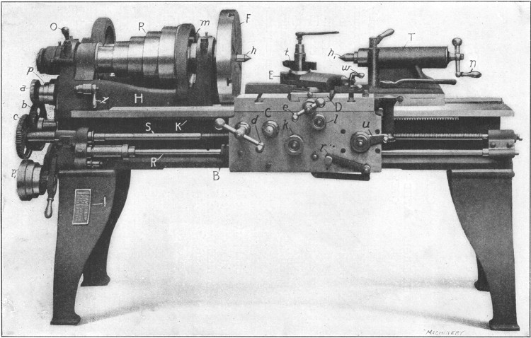
The standard “engine” lathe, which is the type commonly used by machinists for doing general work, is one of the most important tools in a machine shop, because it is adapted to a great variety of operations, such as turning all sorts of cylindrical and taper parts, boring holes, cutting threads, etc. The illustration Fig. 1 shows a lathe which, in many respects, represents a typical design, and while some of the parts are arranged differently on other makes, the general construction is practically the same as on the machine illustrated.
Fig. 1. Bradford Belt-driven Lathe—View of Front or Operating Side
The principal parts are the bed B, the headstock H, the tailstock T, and the carriage C. The headstock contains a spindle which is rotated by a belt that passes over the cone-pulley P, and this spindle rotates the work, which is usually held between pointed or conical centers h and h1 in the headstock and tailstock, or in a chuck screwed onto the spindle instead of the faceplate F. The carriage C can be moved lengthwise along the bed by turning handle d, and it can also be moved by power, the movement being transmitted from the headstock spindle either through gears a, b, c, and lead-screw S, or by a belt operating on pulleys p and p1, which drive the feed-rod R. The lead-screw S is used when cutting threads, and the feed-rod R for ordinary turning operations; in this way the wear on the lead-screw is reduced and its accuracy is preserved.
[2]On the carriage, there is a cross-slide D which can be moved at right angles to the lathe bed by handle e, and on D there is an upper or compound slide E which can be swiveled to different positions. The tool t, that does the turning, is clamped to the [3] upper slide, as shown, and it can be moved with relation to the work by the movement of the carriage C along the bed, or by moving slide D crosswise. The lengthwise movement is used to feed the tool along the work when turning, boring or cutting a screw, and the crosswise movement for facing the ends of shafts, etc., or for radial turning. When the tool is to be fed at an angle, other than at right angles to the bed, slide E, which can be set to the required angle, is used. The lengthwise and crosswise feeding movements can be effected by power, the lengthwise feed being engaged by tightening knob k, and the cross-feed by tightening knob l. The direction of either of these movements can also be reversed by shifting lever r. Ordinarily the carriage and slide are adjusted by hand to bring the tool into the proper position for turning to the required diameter, and then the power feed (operating in the desired direction) is engaged. The tailstock T can be clamped in different positions along the bed, to suit the length of the work, and its center h1 can be moved in or out for a short distance, when adjusting it to the work, by turning handle n.
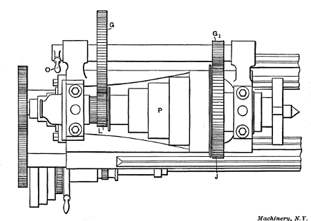
Fig. 2. Plan View of Lathe Headstock showing Back-gears
As some metals are much harder than others, and as the[4] diameters of parts to be turned also vary considerably, speed changes are necessary, because if the speed is excessive, the turning tool will become dull in too short a time. These speed changes (with a belt-driven lathe) are obtained by placing the driving belt on different steps of cone-pulley P, and also by the use of back-gears. The cone-pulley can be connected directly with the spindle or be disengaged from it by means of bolt m. When the pulley and spindle are connected, five speeds (with this particular lathe) are obtained by simply shifting the driving belt to different steps of the cone. When a slower speed is required than can be obtained with the belt on the largest step of the cone, the latter is disconnected from the spindle, and the back-gears G and G1 (shown in the plan view Fig. 2) are moved forward into mesh by turning handle O; the drive is then from cone-pulley P and gear L to gear G, and from gear G1 to the large gear J on the spindle. When driving through the back-gears, five more speed changes are obtained by shifting the position of the driving belt, as before. The fastest speed with the back-gears in mesh is somewhat slower than the slowest speed when driving direct or with the back-gears out of mesh; hence, with this particular lathe, a series of ten gradually increasing speeds is obtained. Changes of feed for the turning[5] tool are also required, and these are obtained by shifting the belt operating on pulleys p and p1 to different-sized steps. On some lathes these feed changes are obtained through gears which can be shifted to give different ratios. Many lathes also have gears in the headstock for changing the speeds.
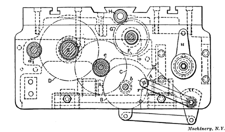
Fig. 3. Feed Mechanism of Lathe Apron
Front and rear views of the carriage apron, which contains the feeding mechanism, are shown in Figs. 3 and 4, to indicate how the feeds are engaged and reversed. The feed-rod R (Fig. 1) drives the small bevel gears A and A1 (Figs. 3 and 4), which are mounted on a slide S that can be moved by lever r to bring either bevel gear into mesh with gear B. Gear B is attached to pinion b (see Fig. 3) meshing with gear C, which, when knob k (Fig. 1) is tightened, is locked by a friction clutch to pinion c. The latter pinion drives gear D which rotates shaft E. A pinion cut on the end of shaft E engages rack K (Fig. 1) attached to the bed, so that the rotation of E (which is controlled by knob k) moves the carriage along the bed. To reverse the direction of the movement, it is only necessary to throw gear A into mesh and gear A1 out, or vice versa, by operating lever r. When the carriage is traversed by hand, shaft E and gear D are rotated by pinion d1 connected with handle d (Fig. 1).
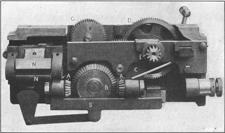
Fig. 4. Rear View of Lathe Apron
The drive for the cross-feed is from gear C to gear F which [6] can be engaged through a friction clutch (operated by knob l, Fig. 1) with gear G meshing with a pinion H. The latter rotates the cross-feed screw, which passes through a nut attached to slide D (Fig. 1), thus moving the latter at right angles to the ways of the bed. The cross-feed is also reversed by means of lever r. As previously explained, lead-screw S is only used for feeding the carriage when cutting threads. The carriage is engaged with this screw by means of two half-nuts N (Fig. 4) that are free to slide vertically and are closed around the screw by operating lever u. These half-nuts can only be closed when lever r is in a central or neutral position, so that the screw feed and the regular turning feed cannot be engaged at the same time. As previously mentioned, lead-screw S, Fig. 1, is rotated from the lathe spindle, through gears a, b and c, called change gears. An assortment of these gears, of various sizes, is provided with the lathe, for cutting screws of different pitch. The gears to use for any pitch within the range of the lathe are given on the plate I.
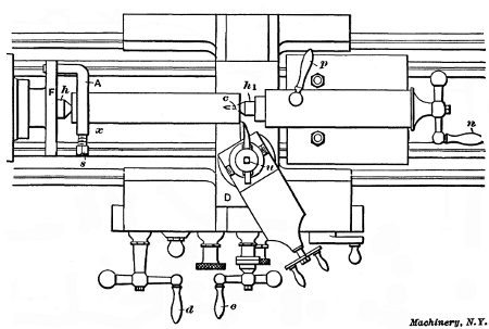
Fig. 5. Plan View showing Work Mounted between Centers of Lathe
Example of Cylindrical Turning.—Having now considered the principal features of what might be called a standard lathe, the method of using it in the production of machine parts will be explained. To begin with a simple example of work, suppose a steel shaft is to be turned to a diameter of 21/4 inches and a length of 141/2 inches, these being the finished dimensions. We will assume that the rough stock is cut off to a length of 145/8 inches and has a diameter of 25/8 inches. The first step in this operation is to form conically shaped center-holes in each end of the piece as indicated at c in Fig. 5. As all work of this kind is held, while being turned, between the centers h and h1, holes corresponding in shape to these centers are necessary to keep the work in place. There are several methods of forming these center-holes, as explained later.
After the work is centered, a dog A is clamped to one end by tightening screw s; it is then placed between the centers of the lathe. The dog has a projecting end or “tail,” as it is commonly called, which enters a slot in the faceplate F and thereby drives [7] or rotates the work, when power is applied to the lathe spindle onto which the faceplate is screwed. The tailstock center h1, after being oiled, should be set up just tight enough to eliminate all play, without interfering with a free rotary movement of the work. This is done by turning handle n, and when the center is properly adjusted, the tailstock spindle containing the center is locked by tightening handle p. (Ordinary machine oil is commonly used for lubricating lathe centers, but a lubricant having more “body” should be used, especially when turning heavy parts. The following mixtures are recommended: 1. Dry or powdered red lead mixed with a good grade of mineral oil to the consistency of cream. 2. White lead mixed with sperm oil with enough graphite added to give the mixture a dark lead color.)
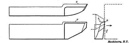
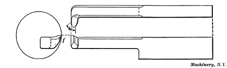
Fig. 6. Lathe Side-tool for Facing Ends of Shafts, etc.
Facing the Ends Square with a Side-tool.—Everything is now ready for the turning operation. The ends of the piece should be faced square before turning the body to size, and the tool for this squaring operation is shown in Fig. 6; this is known as a side-tool. It has a cutting edge e which shaves off the metal as indicated in the end view by the dotted lines. The side f is ground to an angle so that when the tool is moved in the direction shown by the arrow, the cutting edge will come in contact with the part to be turned; in other words, side f is[8] ground so as to provide clearance for the cutting edge. In addition, the top surface against which the chip bears, is beveled to give the tool keenness so that it will cut easily. As the principles of tool grinding are treated separately in Chapter II we shall for the present consider the tool's use rather than its form.
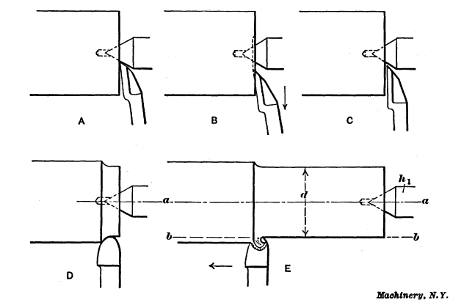
Fig. 7. Facing End with Side-tool and Turning Work Cylindrical
For facing the end, the side tool is clamped in the toolpost by tightening the screw u, Fig. 5, and it should be set with the cutting edge slightly inclined from a right-angled position, the point being in advance so that it will first come into contact with the work. The cutting edge should also be about the same height as the center of the work. When the tool is set, the lathe (if belt-driven) is started by shifting an overhead belt and the tool is then moved in until the point is in the position shown at A, Fig. 7. The tool-point is then fed against the end by handle d, Fig. 5, until a light chip is being turned off, and then it is moved outward by handle e (as indicated by the arrow at B, Fig. 7), the carriage remaining stationary. As the movement of the tool-point is guided by the cross-slide D, which is at right angles with the axis of the work, the end will be faced square. For short turning operations of this kind, the power feeds ordinarily are not used as they are intended for comparatively long cuts. If it were necessary to remove much metal from the end, a number of cuts would be taken across it; in this case, however, the rough stock is only 1/8 inch too long so that this end need only be made true.
After taking a cut as described, the surface, if left rough by[9] the tool-point, should be made smooth by a second or finishing cut. If the tool is ground slightly round at the point and the cutting edge is set almost square, as at C, Fig. 7, a smooth finish can be obtained; the cut, however, should be light and the outward feed uniform. The work is next reversed in the centers and the driving dog is placed on the end just finished; the other end is then faced, enough metal being removed to make the piece 141/2 inches long, as required in this particular case. This completes the facing operation. If the end of the work does not need to be perfectly square, the facing operation can be performed by setting the tool in a right-angled position and then feeding it sidewise, thus removing a chip equal to the width of one side. Evidently this method is confined to comparatively small diameters and the squareness of the turned end will be determined by the position of the tool's cutting edge.
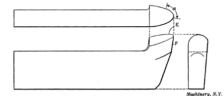
Fig. 8. Tool used for Cylindrical Turning
Turning Tool—Turning Work Cylindrical.—The tool used to turn the body to the required diameter is shaped differently from the side-tool, the cutting edge E of most tools used for plain cylindrical turning being curved as shown in Fig. 8. A [10] tool of this shape can be used for a variety of cylindrical turning operations. As most of the work is done by that part of the edge marked by arrow a, the top of the tool is ground to slope back from this part to give it keenness. The end F, or the flank, is also ground to an angle to provide clearance for the cutting edge. If the tool did not have this clearance, the flank would rub against the work and prevent the cutting edge from entering the metal. This type of tool is placed about square with the work, for turning, and with the cutting end a little above the center.
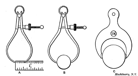
Fig. 9. Setting Calipers by Scale—Setting by Gage—Fixed Gage
Before beginning to turn, a pair of outside calipers or a micrometer should be set to 21/4 inches, which, in this case, is the finished diameter of the work. Calipers are sometimes set by using a graduated scale as at A, Fig. 9, or they can be adjusted to fit a standard cylindrical gage of the required size as at B. Very often fixed caliper gages C are used instead of the adjustable spring calipers. These fixed gages, sometimes called “snap” gages, are accurately made to different sizes, and they are particularly useful when a number of pieces have to be turned to exactly the same size.
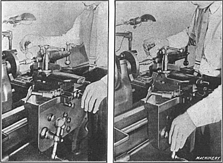
Fig. 10. Views showing how the Cross-slide and Carriage are Manipulated
by
Hand when Starting a Cut—
View to Left, Feeding Tool Laterally;
View to
Right, Feeding Tool in a Lengthwise Direction
The turning tool is started at the right-hand end of the work and the tool should be adjusted with the left hand when beginning a cut, as shown in Fig. 10, in order to have the right hand free for calipering. A short space is first turned by hand feeding, as at D, Fig. 7, and when the calipers show that the diameter is slightly greater than the finished size (to allow for a light finishing [11] cut, either in the lathe or grinding machine) the power feed for the carriage is engaged; the tool then moves along the work, reducing it as at E. Evidently, if the movement is along a line b—b, parallel with the axis a—a, the diameter d will be the same at all points, and a true cylindrical piece will be turned. On the other hand, if the axis a—a is inclined one way or the other, the work will be made tapering; in fact, the tailstock center h1 can be adjusted laterally for turning tapers, but for straight turning, both centers must be in alignment with the carriage travel. Most lathes have lines on the stationary and movable parts of the tailstock base which show when the centers are set for straight turning. These lines, however, may not be absolutely correct, and it is good practice to test the alignment of the centers before beginning to turn. This can be done by taking trial cuts, at each end of the work (without disturbing the tool's crosswise position), and then comparing the diameters, or by testing the carriage travel with a true cylindrical piece held between the centers as explained later.
If the relative positions of the lathe centers are not known, the work should be calipered as the cut progresses to see if the diameter d is the same at all points. In case the diameter gradually increases, the tailstock center should be shifted slightly to the rear before taking the next cut, but if the diameter[12] gradually diminishes, the adjustment would, of course, be made in the opposite direction. The diameter is tested by attempting to pass the calipers over the work. When the measuring points just touch the work as they are gently passed across it, the diameter being turned is evidently the same as the size to which the calipers are set.
As the driving dog is on one end, the cut cannot be taken over the entire length, and when the tool has arrived at say position x, Fig. 5, it is returned to the starting point and the work is reversed in the centers, the dog being placed upon the other end. The unfinished part is then turned, and if the cross-slide is not moved, the tool will meet the first cut. It is not likely that the two cuts will be joined or blended together perfectly, however, and for this reason a cut should be continuous when this is possible.
Roughing and Finishing Cuts.—Ordinarily in lathe work, as well as in other machine work, there are two classes of cuts, known as “roughing” and “finishing” cuts. Roughing cuts are[13] for reducing the work as quickly as possible almost to the required size, whereas finishing cuts, as the name implies, are intended to leave the part smooth and of the proper size. When the rough stock is only a little larger than the finished diameter, a single cut is sufficient, but if there is considerable metal to turn away, one or more deep roughing cuts would have to be taken, and, finally, a light cut for finishing. In this particular case, one roughing and one finishing cut would doubtless be taken, as the diameter has to be reduced 3/8 inch. Ordinarily the roughing cut would be deep enough to leave the work about 1/32 or perhaps 1/16 inch above the finished size. When there is considerable metal to remove and a number of roughing cuts have to be taken, the depth of each cut and the feed of the tool are governed largely by the pulling power of the lathe and the strength of the work to withstand the strain of a heavy cut. The depth of roughing cuts often has to be reduced considerably because the part being turned is so flexible that a heavy cut would spring the work and cause the tool to gouge in. Of course, just as few cuts as possible should be taken in order to save time. The speed of the work should also be as fast as the conditions will allow for the same reason, but as there are many things which govern the speed, the feed of the tool, and the depth of the cut, these important points are referred to separately in Chapter II.
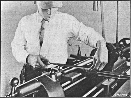
Fig. 11. Filing Work after Finishing Cut is taken
Filing and Finishing.—In many cases the last or finishing cut does not leave as smooth a surface as is required and it is necessary to resort to other means. The method commonly employed for finishing in the lathe is by the use of a file and emery cloth. The work is rotated considerably faster for filing than for turning, and the entire surface is filed by a flat, single-cut file, held as shown in Fig. 11. The file is passed across the work and advanced sidewise for each forward stroke, until the entire surface is finished. The file should be kept in contact with the work continually, but on the return stroke the pressure should be relieved. The movement of the file during the forward or cutting stroke should be much slower than when filing in a vise. By moving the file slowly, the work can make a[14] number of revolutions for each stroke, which tends to keep it round, as practically the same amount of metal is removed from the entire circumference. On the other hand, short rapid strokes tend to produce flat spots, or at least an irregular surface, especially if the work can only make part of a revolution for each cutting stroke. The pressure on the file during the forward stroke should also be kept as nearly uniform as possible.
It is very difficult to file a part smooth and at the same time to keep it round and cylindrical, and the more filing that has to be done, the greater the chance of error. For this reason, the amount left for filing should be very small; in fact, the metal removed by filing should be just enough to take out the tool marks and give a smooth finish. Very often a satisfactory finish can be obtained with a turning tool, and filing is not necessary at all. The file generally used for lathe work is a “single-cut bastard” of “mill” section, having a length of from 12 to 14 inches.
Sometimes particles of metal collect between the teeth of a file and make deep scratches as the file is passed across the work. When this occurs, the teeth should be cleaned by using[15] a wire brush or a file card, which is drawn across the file in the direction of the teeth. This forming of tiny particles between the teeth is known as “pinning” and it can sometimes be avoided by rubbing chalk on the file. Filing is not only done to obtain a smooth finish, but also to reduce the work to an exact diameter, as a very slight reduction can be made in this way.
If a polish is desired, this can be obtained by holding a piece of emery cloth tightly around the work as it revolves. The coarseness of emery cloth is indicated by letters and numbers corresponding to the grain number of loose emery. The letters and numbers for grits ranging from fine to coarse are as follows: FF, F, 120, 100, 90, 80, 70, 60, 54, 46, 40. For large work roughly filed, use coarse cloth such as Nos. 46 or 54, and then finer grades to obtain the required polish. If the work has been carefully filed, a good polish can be obtained with Nos. 60 and 90 cloth, and a brilliant polish by finishing with No. 120 and flour-emery.
Most cylindrical parts can be finished more quickly and accurately in the grinder than in the lathe, and many classes of work are, at the present time, simply rough-turned in the lathe and then ground to size in a cylindrical grinding machine.
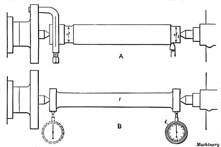
Fig. 12. Two Methods of Aligning Centers for Cylindrical Turning
[16] Aligning Centers for Cylindrical Turning.—Whena rod or shaft must be turned cylindrical or to the same diameter throughout its entire length, it is good practice to test the alignment of the centers, before inserting the work. The position of the tailstock center for cylindrical turning may be indicated by the coincidence of graduation marks on the base, but if accuracy is necessary, the relative position of the two centers should be determined in a more positive way. A very simple and convenient method of testing the alignment is shown at A in Fig. 12. The work is first turned for a short distance, near the dogged end, as shown, and the tool is left as set for this cut; then the tailstock center is withdrawn and the work is moved sufficiently to permit running the tool back to the tailstock end without changing its original setting. A short cut is then taken at this end and the diameters d and d1 are carefully compared. In case there is any variation, the tailstock center is adjusted laterally, other trial cuts are taken, and the test repeated.
Another method is illustrated at B, which requires the use of a test-bar t. This bar should have accurately made centers and the ends finished to exactly the same diameter. The lathe centers are aligned by placing the bar between them and then testing the position of the ends. This can be done by comparing each end with a tool held in the toolpost and moved from one to the other by shifting the carriage, but a better method is to clamp a test indicator i in the toolpost and bring it in contact with first one end of the bar and then the other. If the dial does not register the same at each end, it shows that the lathe centers are not in line. Even when centers are correctly set, lathes that have been in use a long time do not always turn cylindrical or straight, because if the ways that guide the carriage are worn unevenly, the tool as it moves along does not remain in the same plane and this causes a variation in the diameter of the part being turned.
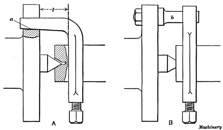
Fig. 13. (A) Dog that is too Short for Faceplate.
(B) Straight Driving Dog
Application of Drivers or Dogs.—Work that is turned between centers is sometimes driven by a dog which is so short for the faceplate that the bent driving end bears against the bottom a of the faceplate slot, as shown at A, Fig. 13. If the [17] dog is nearly the right length, it may allow the headstock center to enter the center in the work part way, with the result that the turned surface is not true with the centers. When a driving dog of this type is used, care should be taken to see that it moves freely in the faceplate slot and does not bind against the bottom. By using a straight dog (B), which is driven by a pin b bolted to the faceplate, all danger from this source is eliminated. The straight dog, however, is used more particularly to do away with the leverage l of a bent dog, as this leverage tends to spring a flexible part when a cut is being taken.
Straight dogs are also made with two driving ends which engage pins on opposite sides of the faceplate. This type is preferable because it applies the power required for turning, evenly to the work, which still further reduces the tendency to spring it out of shape. The principal objection to the double-ended type lies in the difficulty of adjusting the driving pins so that each bears with equal pressure against the dog. The double-ended driver is often used for large work especially if deep roughing cuts are necessary.
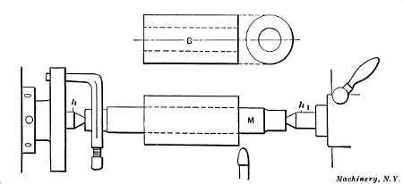
Fig. 14. Bushing mounted on Arbor for Turning
Lathe Arbors or Mandrels.—When it is necessary to turn the outside of a part having a hole through it, centers cannot, of course, be drilled in the ends and other means must be resorted to. We shall assume that the bushing B, Fig. 14, has a [18] finished hole through the center, and it is desired to turn the outside cylindrical and concentric with the hole. This could be done by forcing a tightly-fitted arbor M, having accurately-centered ends, into the bushing and inserting the mandrel and work between the lathe centers h and h1 as shown. Evidently, if the arbor runs true on its centers, the hole in the bushing will also run true and the outside can be turned the same as though the arbor and bushing were a solid piece. From this it will be seen that an arbor simply forms a temporary support for parts that are bored and therefore cannot be centered.
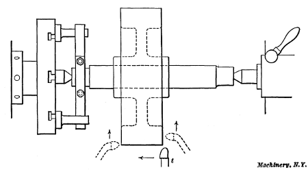
Fig. 15. Turning Pulley Held on an Arbor
Another example of work that would be turned on an arbor is shown in Fig. 15. This is a small cast-iron wheel having a finished hole through the hub, and the outer surface and sides of the rim are to be turned true with this hole. In this case, the casting would also be held by pressing a mandrel through the hub; as shown. This method, however, would only apply to comparatively small wheels because it would be difficult, if not impossible, to prevent a large wheel from turning on the arbor when taking a cut, and even if it could be driven, large work could be done to better advantage on another type of machine. (The vertical boring mill is used extensively for turning large wheels, as explained in Chapter VI.) When turning the outside of the rim, a tool similar to that shown at t should be used, but for facing or turning the sides, it might be better, if not necessary, to use tools having bent ends as shown by the dotted lines; in[19] fact, turning tools of various kinds are made with the ends bent to the right or left, as this enables them to be used on surfaces that could not be reached very well with a straight tool. If a comparatively large pulley is mounted near the end of the arbor, it can be driven directly by pins attached to the faceplate and engaging the pulley arms. This method of driving is often employed when the diameter to be turned is large and the hole for the arbor is so small that there will not be sufficient friction for driving.
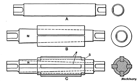
Fig. 16. Different Types of Lathe Arbors
Different Types of Lathe Arbors.—Three different types of lathe arbors are shown in Fig. 16. The kind shown at A is usually made of tool steel and the body is finished to a standard size. The ends are somewhat reduced and flat spots are milled, as shown, to give the clamping screw of the dog a good grip. The body of the arbor is usually tapered about 0.006 inch per foot. This taper makes it easier to insert the arbor in a close-fitting hole, and it also permits slight variations in the diameter of different holes. As to hardening, the practice at the present time among manufacturers is to harden arbors all over, but for extremely accurate work, an arbor having hardened ends and a soft body is generally considered superior, as there is less tendency of distortion from internal stresses. Hardened arbors are “seasoned” before finish-grinding to relieve these internal stresses.
The solid type A, Fig. 16, is used very extensively, but in [20] shops where a great variety of work is being done and there are many odd-sized holes, some form of expanding arbor B can be used to advantage. This type, instead of being solid, consists of a tapering inner arbor M on which is placed a split bushing that can be expanded, within certain limits, by driving in the tapering member. The advantage of this type is that a comparatively small stock of arbors is required, as different-sized bushings can be used. This type can also be fitted to holes of odd sizes, whereas a solid arbor must be provided for each different size hole, unless the variation is very slight. The latter are, however, more accurate than the expanding type.
Another form of expanding arbor is shown at C. This type has a straight body N in which four tapering grooves are cut lengthwise, as shown, and there is a sleeve S, containing four slots that are located to correspond with the tapering grooves. Strips s are fitted into these slots, and as the part N is driven in, the strips are moved outward as they ascend the tapering grooves. By having different sets of these strips of various heights, one arbor of this type can be made to cover quite a range of sizes. It is not suited, however, to thin work, as the pressure, being concentrated in four places, would spring a flexible part out of shape.
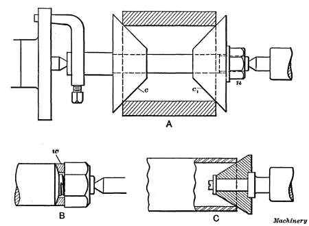
Fig. 17. (A) Cone Arbor.
(B) Nut Arbor.
(C) Pipe Center
The cone arbor or mandrel shown at A, in Fig. 17, is convenient [21] for holding parts having comparatively large holes, as it can be adjusted for quite a range of diameters. The work is gripped between the two cones c and c1 which are forced together by nut n. The cones are prevented from turning upon the arbor by keys. This style of arbor should not be used for accurate work. The threaded arbor B is used for facing the sides of nuts square with the tapped hole. When a nut is first put upon the arbor, the rough side comes against an equalizing washer w. This washer rests against a spherical seat so that it can shift to provide a uniform bearing for the rough side of the nut, even though it is not square with the tapped hole. This feature prevents the nut from being canted on the arbor and insures an accurately faced nut. The revolving conical center shown at C is often used for holding a pipe or tube while turning the outside. The cone is adjusted to fit into the hole of the pipe, by means of the tailstock spindle, and the opposite end is usually held in a chuck.
Particular care should be taken to preserve the accuracy of[22] the centers of lathe arbors by keeping them clean and well-oiled while in use.
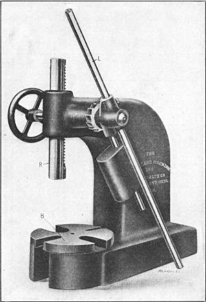
Mandrel or Arbor Press.—The best method of inserting an arbor of the solid type in a hole is by using a press, Fig. 18, designed for that purpose, but if such a press is not available and it is necessary to drive the mandrel in, a “soft” hammer, made of copper, lead or other soft material, should be used to protect the centered end of the arbor. In either case, the arbor should not be forced in too tightly, for if it fits properly, this will not be necessary in order to hold the work securely. On the other hand, the work might easily be broken by attempting to force the arbor in as far and as tightly as possible. In using the arbor press, the work is placed on the base B with the hole in a vertical position, and the arbor (which should be oiled slightly) is forced down into it by ram R, operated by lever L. Slots are provided in the base, as shown, so that the end of the arbor can come through at the bottom of the hole. The lever of this particular press is counter-weighted so that it rises to a vertical position when released. The ram can then be adjusted quickly to any required height by the handwheel seen at the left.
Some shops are equipped with power-driven mandrel or[23] arbor presses. This type is particularly desirable for large work, owing to the greater pressure required for inserting mandrels that are comparatively large in diameter. One well-known type of power press is driven by a belt, and the downward pressure of the ram is controlled by a handwheel. The ram is raised or lowered by turning this handwheel in one direction or the other, and a gage shows how much pressure is being applied. This type of press can also be used for other purposes, such as forcing bushings or pins into or out of holes, bending or straightening parts, or for similar work.
Steadyrest for Supporting Flexible Parts.—Occasionally long slender shafts, rods, etc., which have to be turned, are so flexible that it is necessary to support them at some point between the lathe centers. An attachment for the lathe known as a steadyrest is often used for this purpose. A steadyrest is composed of a frame containing three jaws J (Fig. 19), that can be adjusted in or out radially by turning screws S. The frame is hinged at h, thus allowing the upper half to be swung back (as shown by the dotted lines) for inserting or removing the work. The bolt-clamp c holds the hinged part in the closed position. The base of the frame has V-grooves in it that fit the ways of the lathe bed. When the steadyrest is in use, it is [24] secured to the bed by clamp C, and the jaws J are set in against the work, thus supporting or steadying it during the turning operation. The steadyrest must, of course, be located at a point where it will not interfere with the turning tool.
Fig. 20 shows the application of the steadyrest to a long forged rod, having one small end, which makes it too flexible to be turned without support. As this forging is rough, a true surface n a little wider than the jaws J (Fig. 19) is first turned as a bearing for the jaws. This should be done very carefully to prevent the work from mounting the tool. A sharp pointed tool should be used and very light cuts taken. The steadyrest is next clamped to the lathe bed opposite the turned surface, and the jaws are adjusted in against this surface, thus forming a bearing. Care should be taken not to set up the jaws too tightly, as the work should turn freely but without play. The large part of the rod and central collar are then turned to size, this half being machined while the small part is in the rough and as stiff as possible. The rod is then reversed and the steadyrest is applied to the part just finished, as shown at B, thus supporting the work while the small end is being turned. That part against which the jaws bear should be kept well oiled, and if the surface is finished it should be protected by placing a strip of emery cloth beneath the jaws with the emery side out;[25] a strip of belt leather is also used for this purpose, the object in each case being to prevent the jaws from scratching and marring the finished surface, as they tend to do, especially if at all rough.
If the work were too flexible to permit turning a spot at n, this could be done by first “spotting” it at some point o, and placing the steadyrest at that point while turning another spot at n.
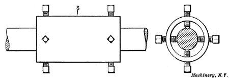
Sometimes it is desirable to apply a steadyrest to a surface that does not run true and one which is not to be turned; in such a case a device called a “cat-head” is used. This is simply a sleeve S (Fig. 21) which is placed over the untrue surface to serve as a bearing for the steadyrest. The sleeve is made to run true by adjusting the four set-screws at each end, and the jaws of the steadyrest are set against it, thus supporting the work.
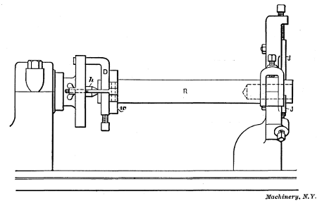
Fig. 22. Shaft supported by Steadyrest for Drilling and Boring End
Application of Steadyrest when Boring.—Another example illustrating the use of the steadyrest is shown in Fig. 22. The rod R is turned on the outside and a hole is to be bored in the end (as shown by dotted lines) true with the outer surface. If the centers used for turning the rod are still in the ends, as they would be ordinarily, this work could be done very accurately by the following method: The rod is first placed between the centers as for turning, with a driving dog D attached, and the steadyrest jaws J are set against it near the outer end, as shown.
Before any machine work is done, means must be provided for holding the rod back against the headstock center h, because, for an operation of this kind, the outer end cannot be supported[26] by the tailstock center; consequently the work tends to shift to the right. One method of accomplishing this is shown in the illustration. A hardwood piece w, having a hole somewhat larger than the work, is clamped against the dog, in a crosswise position, by the swinging bolts and thumb-screws shown. If the dog is not square with the work, the wood piece should be canted so that the bearing will not be all on one side. For large heavy parts a similar “bridle” or “hold-back”—as this is commonly called—is made by using steel instead of wood for the part w. Another very common method which requires no special equipment is illustrated in Fig. 23. An ordinary leather belt lacing L is attached to the work and faceplate while the latter is screwed off a few turns as shown. Then the lacing is drawn up by hand and tied, and the faceplate is screwed onto the spindle, thus tightening the lacing and drawing the work against the headstock center. The method of applying the lacing is quite clearly indicated in the illustration. If a small driving faceplate is used, it may be necessary to drill holes for the belt lacing, as shown.
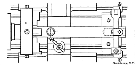
Fig. 24. Testing Work with Dial Indicator
A hole is next drilled in the end of the rod by using a twist drill in the tailstock. If the hole is finished by boring, a depth[27] mark should be made on the tool shank that will warn the workman of the cutting end's approach to the bottom. A chuck can also be used in connection with a steadyrest for doing work of this kind, as shown in Fig. 24, the end of the rod being held and driven by the chuck C. If the piece is centered, it can be held on these centers while setting the steadyrest and adjusting the chuck, but if the ends are without centers, a very good way is to make light centers in the ends with a punch; after these are properly located they are used for holding the work until the steadyrest and chuck jaws have been adjusted. In case it is necessary to have the end hole very accurate with the outside of the finished rod, a test indicator I should be applied to the shaft as shown. This is an instrument which shows with great accuracy whether a rotating part runs true and it is also used for many other purposes in machine shops. The indicator is held in the lathe toolpost and the contact point beneath the dial is brought against the work. If the latter does not run true, the hand of the indicator vibrates and the graduations on the dial show how much the work is out in thousandths of an inch.
The Follow-rest.—When turning long slender parts, such as shafts, etc., a follow-rest is often used for supporting the work. The follow-rest differs from the steadyrest in that it is attached[28] to and travels with the lathe carriage. The type illustrated to the right in Fig. 19 has two adjustable jaws which are located nearly opposite the turning tool, thus providing support where it is most needed. In using this rest, a cut is started at the end and the jaws are adjusted to this turned part. The tool is then fed across the shaft, which cannot spring away from the cut because of the supporting jaws. Some follow-rests have, instead of jaws, a bushing bored to fit the diameter being turned, different bushings being used for different diameters. The bushing forms a bearing for the work and holds it rigidly. Whether a bushing or jaws are used, the turning tool is slightly in advance of the supporting member.
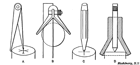
Fig. 25. Centering End with Punch preparatory to Drilling
Centering Parts to be Turned.—As previously mentioned, there are a number of different methods of forming center-holes in the ends of parts that have to be turned while held between lathe centers. A method of centering light work, and one that requires few special tools, is first to locate a central point on the end and then drill and ream the center-hole by using the lathe itself. Hermaphrodite dividers are useful for finding the center, as illustrated at A, Fig. 25, but if the work is fairly round, a center-square B is preferable. A line is scribed across the end and then another line at right angles to the first by changing the position of the square; the intersection of these two lines will be the center, which should be marked by striking[29] a pointed punch C with a hammer. If a cup or bell center-punch D is available, it will not be necessary to first make center lines, as the conical part shown locates the punch in a central position. This style of punch should only be used on work which is fairly round.
After small centers have been located in both ends, their position can be tested by placing the work between the lathe centers and rotating it rapidly by drawing the hand quickly across it. By holding a piece of chalk close to the work as it spins around, a mark will be made on the “high” side if the centers are not accurate; the centers are then shifted toward these marks. If the work is close to the finished diameter, the centers should, of course, be located quite accurately in order that the entire surface of the work will be turned true when it is reduced to the finished size.
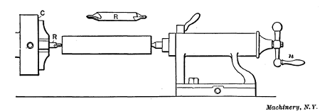
Fig. 26. Drilling Centers in the Lathe
One method of forming these center-holes is indicated in Fig. 26. A chuck C is screwed onto the spindle in place of the faceplate, and a combination center drill and reamer R is gripped by the chuck jaws and set to run true. The center is then drilled and reamed at one end by pressing the work against the revolving drill with the tailstock spindle, which is fed out by turning handle n. The piece is then reversed for drilling the opposite end. The work may be kept from revolving while the centers are being drilled and reamed, by attaching a dog to it close to the tailstock end and then adjusting the cross-slide[30] until the dog rests upon the slide. Many parts can be held by simply gripping them with one hand. From the foregoing it will be seen that the small centers made by punch C, Fig. 25, serve as a starting point for the drill and also as a support for the outer end of the work while the first hole is being drilled.
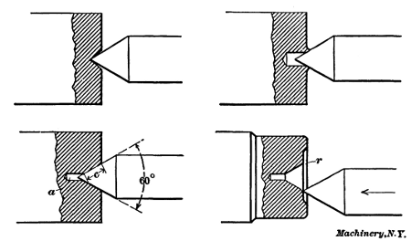
Fig. 27. Centers of Incorrect and Correct Form
The form of center-hole produced by a combination drill and reamer is shown by the lower left-hand view in Fig. 27. A small straight hole a in the bottom prevents the point of the lathe center from coming in contact with the work and insures a good bearing on the conical surface c. The standard angle for lathe centers is sixty degrees, as the illustration shows, and the tapering part of all center-holes should be made to this angle.
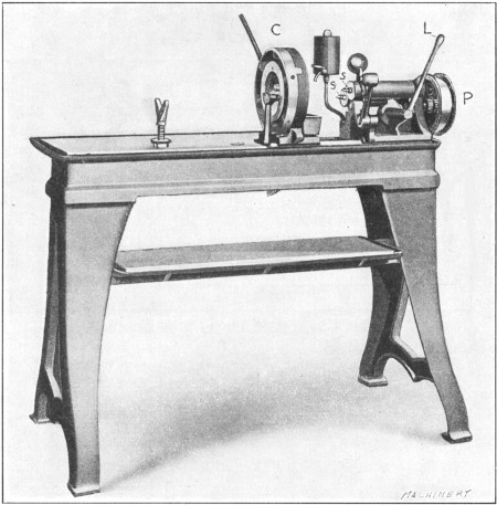
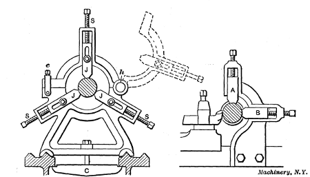
Fig. 28. Special Machine for Centering Parts to be Turned
Centering Machine.—Many shops have a special machine for forming centers which enables the operation to be performed[31] quickly. One type of centering machine is shown in Fig. 28. The work is gripped in a chuck C that automatically locates it in a central position so that it is not necessary to lay out the end before drilling. There are two spindles s, one of which holds the drill and the other the countersink, and these are rotated by a belt passing over pulley P. Each of these spindles is advanced by lever L and either of them can be moved to a position central with the work, as they are mounted in a swiveling frame. In operating this machine, a small straight hole is first made by a twist drill held in one of the spindles; the other spindle is then moved over to the center and the hole is reamed tapering. The arrangement is such that neither spindle can be advanced by the feeding lever except when in a central position.[32] The amount that each spindle can be advanced is limited by a fixed collar inside the head, and there is also a swinging adjustable stop against which the end of the work should be placed before tightening the chuck. These two features make it possible to ream center holes of the same size or depth in any number of pieces.
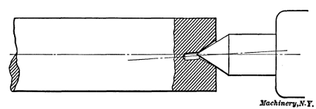
Fig. 29. The Imperfect Center Bearing is the Result of Centering before Straightening
Different Forms of Centers.—In some poorly equipped shops it is necessary to form centers by the use of a center-punch only, as there is no better tool. If the end of the punch has a sixty-degree taper, a fair center can be formed in this way, but it is not a method to be recommended, especially when accurate work is required. Sometimes centers are made with punches that are too blunt, producing a shallow center, such as the one shown in the upper left-hand view, Fig. 27. In this case all the bearing is on the point of the lathe center, which is the worst possible place for it. Another way is to simply drill a straight hole as in the upper view to the right; this is also bad practice in more than one respect. The lower view to the right shows a form of center which is often found in the ends of lathe arbors, the mouth of the center being rounded, at r, and the arbor end recessed as shown. The rounded corner prevents the point of the lathe center from catching when it is moved rapidly towards work which is not being held quite centrally (as shown by the illustration), and the end is recessed to protect the center against bruises. Stock that is bent should always be straightened before the centers are drilled and reamed. If the work is first centered and then straightened the bearing on the lathe center would be as shown in Fig. 29. The center will then wear unevenly [33] with the result that the surfaces last turned will not be concentric with those which were finished first.
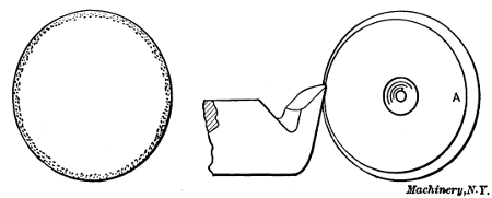
Fig. 30. Tool Steel should be centered Concentric, in order to remove the Decarbonized Outer Surface
Precaution When Centering Tool Steel.—Ordinarily centers are so located that the stock runs approximately true before being turned, but when centering tool steel to be used in making tools, such as reamers, mills, etc., which need to be hardened, particular care should be taken to have the rough surface run fairly true. This is not merely to insure that the piece will “true-up,” as there is a more important consideration, the disregard of which often affects the quality of the finished tool. As is well known, the degree of hardness of a piece of tool steel that has been heated and then suddenly cooled depends upon the amount of carbon that it contains, steel that is high in carbon becoming much harder than that which contains less carbon. Furthermore, the amount of carbon found at the surface, and to some little depth below the surface of a bar of steel, is less than the carbon content in the rest of the bar. This is illustrated diagrammatically in Fig. 30 by the shaded area in the view to the left. (This decarbonization is probably due to the action of the oxygen of the air on the bar during the process of manufacture.) If stock for a reamer is so centered that the tool removes the decarbonized surface only on one side, as illustrated to the right, evidently when the reamer is finished and hardened the teeth on the side A will be harder than those on the opposite side, which would not have been the case if the rough bar had been centered true. To avoid any trouble of this kind, stock that is to be used for hardened tools should be[34] enough larger than the finished diameter and so centered that this decarbonized surface will be entirely removed in turning.
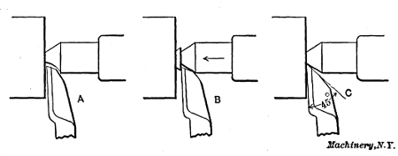
Fig. 31. Three Methods of Facing the Ends Square
Facing the Ends of Centered Stock.—As a piece of work is not properly centered until the ends are faced square, we will consider this operation in connection with centering. Some machinists prefer lathe centers that are cut away as shown at A, Fig. 31, so that the point of the side tool can be fed in far enough to face the end right up to the center hole. Others, instead of using a special center, simply loosen the regular one slightly and then, with the tool in a position as at B, face the projecting teat by feeding both tool and center inward as shown by the arrow. Whenever this method is employed, care should be taken to remove any chips from the center hole which may have entered. A method which makes it unnecessary to loosen the regular center, or to use a special one, is to provide clearance for the tool-point by grinding it to an angle of approximately forty-five degrees, as shown at C. If the tool is not set too high, it can then be fed right up to the lathe center and the end squared without difficulty. As for the special center A, the use of special tools and appliances should always be avoided unless they effect a saving in time or their use makes it possible to accomplish the same end with less work.
Truing Lathe Centers.—The lathe centers should receive careful attention especially when accurate work must be turned. If the headstock center does not run true as it revolves with the work, a round surface may be turned, but if the position of the driving dog with reference to the faceplate is changed, the turned surface will not run true because the turned surface is[35] not true with the work centers. Furthermore, if it is necessary to reverse the work for finishing the dogged or driving end, the last part turned will be eccentric to the first. Therefore, the lathe centers should be kept true in order to produce turned surfaces that are true or concentric with the centered ends, as it is often necessary to change the part being turned “end for end” for finishing, and any eccentricity between the different surfaces would, in many cases, spoil the work.
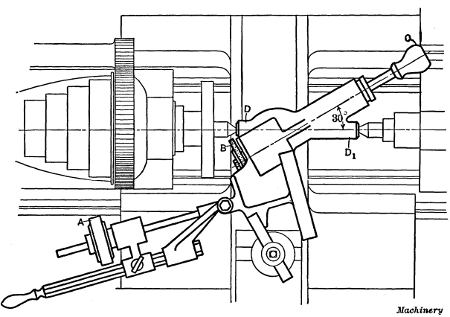
Fig. 32. Grinder for Truing Lathe Centers
Some lathes are equipped with hardened centers in both the head-and tailstock and others have only one hardened center which is in the tailstock. The object in having a soft or unhardened headstock center is to permit its being trued by turning, but as a soft center is quite easily bruised and requires truing oftener than one that is hard, it is better to have both centers hardened. Special grinders are used for truing these hardened centers. One type that is very simple and easily applied to a lathe is shown in Fig. 32. This grinder is held in the lathe toolpost and is driven by a wheel A that is held in contact with the cone-pulley. The emery wheel B is moved to a position for grinding by adjusting the carriage and cross-slide, and it is[36] traversed across the conical surface of the center by handle C. As the grinding proceeds, the wheel is fed inward slightly by manipulating the cross-slide.
This grinder is set to the proper angle by placing the two centered ends D and D1 between the lathe centers, which should be aligned as for straight turning. The grinding spindle will then be 30 degrees from the axis of the lathe spindle. The grinder should be carefully clamped in the toolpost so that it will remain as located by the centered ends. After the tailstock center is withdrawn, the emery wheel is adjusted for grinding. As the wheel spindle is 30 degrees from the axis of the lathe spindle, the lathe center is not only ground true but to an included angle of 60 degrees, which is the standard angle for lathe centers. There are many other styles of center grinders on the market, some of which are driven by a small belt from the cone-pulley and others by electric motors which are connected with ordinary lighting circuits. The tailstock center is ground by inserting it in the spindle in place of the headstock center. Before a center is replaced in its spindle, the hole should be perfectly clean as even a small particle of dirt may affect the alignment. The center in the headstock is usually referred to as the “live center” because it turns around when the lathe is in use, and the center in the tailstock as the “dead center,” because it remains stationary.
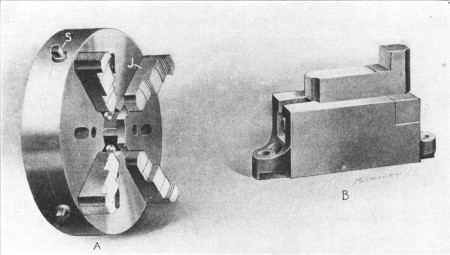
Fig. 33. (A) Lathe Chuck.
(B) Faceplate Jaw
Universal, Independent and Combination Chucks.—Many parts that are turned in the lathe are so shaped that they cannot be held between the lathe centers like shafts and other similar pieces and it is often necessary to hold them in a chuck A, Fig. 33, which is screwed onto the lathe spindle instead of the faceplate. The work is gripped by the jaws J which can be moved in or out to accommodate various diameters. There are three classes of chucks ordinarily used on the lathe, known as the independent, universal and combination types. The independent chuck is so named because each jaw can be adjusted in or out independently of the others by turning the jaw screws S with a wrench. The jaws of the universal chuck all move together and keep the same distance from the center, and they[37] can be adjusted by turning any one of the screws S, whereas with the independent type the chuck wrench must be applied to each jaw screw. The combination chuck, as the name implies, may be changed to operate either as an independent or universal type. The advantage of the universal chuck is that round and other parts of a uniform shape are located in a central position for turning without any adjustment. The independent type is, however, preferable in some respects as it is usually stronger and adapted for holding odd-shaped pieces because each jaw can be set to any required position.
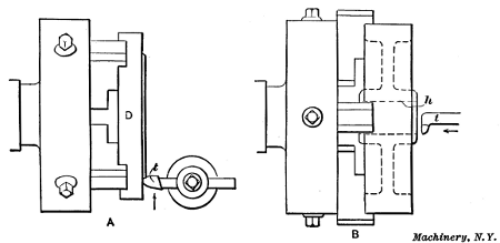
Fig. 34. (A) Radial Facing.
(B) Boring Pulley Held in Chuck
Application of Chucks.—As an example of chuck work, we shall assume that the sides of disk D, Fig. 34, are to be turned flat and parallel with each other and that an independent chuck is to be used. First the chuck is screwed onto the lathe spindle after removing the faceplate. The chuck jaws are then moved out or in, as the case may be, far enough to receive the disk and each jaw is set about the same distance from the center by the aid of concentric circles on the face of the chuck. The jaws are then tightened while the disk is held back against them to bring the rough inner surface in a vertical plane. If the work is quite heavy, it can be held against the chuck, before the jaws are tightened, by inserting a piece of wood between it and the tailstock center; the latter is then run out far[38] enough to force the work back. The outside or periphery of the disk should run nearly true and it may be necessary to move the jaws in on one side and out on the other to bring the disk to a central position. To test its location, the lathe is run at a moderate speed and a piece of chalk is held near the outer surface. If the latter runs out, the “high” side will be marked by the chalk, and this mark can be used as a guide in adjusting the jaws. It should be remembered that the jaws are moved only one-half the amount that the work runs out.
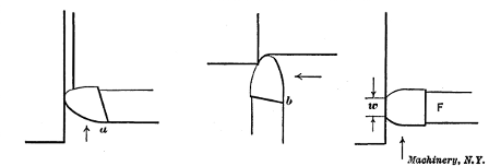
Fig. 35. Tools Ground so that Top Slopes away from Working Part of Cutting Edge
A round-nosed tool t of the shape shown can be used for radial facing or turning operations of the kind illustrated. This tool is similar to the form used when turning between centers, the principal difference being in the direction of the top slope. The radial facing tool should be ground to slope downward toward a (see Fig. 35) whereas the regular turning tool slopes toward b, the inclination in each case being away from that part of the cutting edge which does the work. The cutting edge should be the same height as the lathe centers, and the cut is taken by feeding the tool from the outside in to the center. The cut is started by hand and then the power feed is engaged, except for small surfaces. The first cut should, if possible, be deep enough to get beneath the scale, especially if turning cast iron, as a tool which just grazes the hard outer surface will be dulled in a comparatively short time.
If it were simply necessary to turn a true flat surface and the[39] thickness of the disk were immaterial, two cuts would be sufficient, unless the surface were very uneven, the first or roughing cut being followed by a light finishing cut. For a finishing cut, the same tool could be used, but if there were a number of disks to be faced, a square-nosed tool F, Fig. 35, could probably be used to better advantage. This type has a broad flat cutting edge that is set parallel with the rough-turned surface and this broad edge enables a coarse feed to be taken, thus reducing the time required for the finishing cut. If a coarse feed were taken with the round tool, the turned surface would have spiral grooves in it, whereas with the broad cutting edge, a smooth surface is obtained even though the feed is coarse. The amount of feed per revolution of the work, however, should always be less than the width w of the cutting edge. Very often broad tools cannot be used for finishing cuts, especially when turning steel, because their greater contact causes chattering and results in a rough surface. An old and worn lathe is more liable to chatter than one that is heavy and well-built, and as the diameter of the work also makes a difference, a broad tool cannot always be used for finishing, even though, theoretically, it would be preferable. After one side of the disk is finished, it is reversed in the chuck, the finished surface being placed against the jaws. The remaining rough side is then turned, care being taken when starting the first cut to caliper the width of the disk at several points to make sure that the two sides are parallel.
Example of Boring.—Another example of chuck work is shown at B, Fig. 34. In this case a cast-iron pulley is to have a[40] true hole h bored through the hub. (The finishing of internal cylindrical surfaces in a lathe is referred to as boring rather than turning.) The casting should be set true by the rim instead of by the rough-cored hole in the hub; this can be done by the use of chalk as previously explained. Even though a universal type of chuck were used, the jaws of which, as will be recalled, are self-centering, it might be necessary to turn the pulley relative to the chuck as a casting sometimes runs out because of rough spots or lumps which happen to come beneath one or more of the jaws.
The shape of tool t for boring is quite different from one used for outside turning, as shown by Fig. 36. The cutting end of a solid type of tool is forged approximately at right angles to the body or shank, and the top surface is ground to slope away from the working part w of the cutting edge, as with practically all turning tools. The front part or flank, f is also ground away to give the edge clearance. This type of tool is clamped in the toolpost with the body about parallel with the lathe spindle, and ordinarily the cutting edge would be about as high as the center of the hole, or a little below, if anything. When starting a cut, the tool is brought up to the work by moving the carriage and it is then adjusted radially to get the right depth of cut, by shifting the cross-slide. The power feed for the carriage is then used, the tool feeding back through the hole as indicated by the arrow, Fig. 34. In this case, as with all turning operations, the first cut should be deep enough to remove the hard outer scale at every part of the hole. Usually a rough-cored hole is so much smaller than the finished size that several cuts are necessary; in any case, the last or finishing cut should be very[41] light to prevent the tool from springing away from the work, so that the hole will be as true as possible. Boring tools, particularly for small holes, are not as rigid as those used for outside turning, as the tool has to be small enough to enter the hole and for this reason comparatively light cuts have to be taken. When boring a small hole, the largest tool that will enter it without interference should be used to get the greatest rigidity possible.
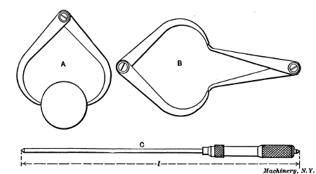
Fig. 37 (A) Setting Outside Calipers.
(B) Transferring Measurements to
Inside Calipers.
(C) Micrometer Gage
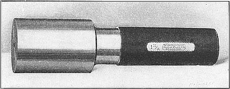
Fig. 38. Standard Plug Gage
Measuring Bored Holes.—The diameters of small holes that are being bored are usually measured with inside calipers or standard gages. If the pulley were being bored to fit over some shaft, the diameter of the shaft would first be measured by using outside calipers, as shown at A, Fig. 37, the measuring points of the calipers being adjusted until they just made contact with the shaft when passed over it. The inside calipers are then set as at B to correspond with the size of the shaft, and the hole is bored just large enough to admit the inside calipers easily. Very accurate measurements can be made with calipers, but to become expert in their use requires experience. Some mechanics never become proficient in the art of calipering because their hands are “heavy” and they lack the sensitiveness and delicacy of touch that is necessary. For large holes, a gage C is often used, the length l being adjusted to the diameter[42] desired. Small holes are often bored to fit hardened steel plug gages (Fig. 38), the cylindrical measuring ends of which are made with great accuracy to standard sizes. This type of gage is particularly useful when a number of holes have to be bored to the same size, all holes being made just large enough to fit the gage without any perceptible play.
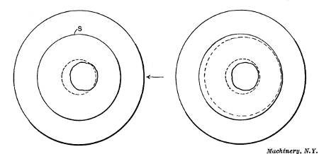
Fig. 39. Diagram Illustrating Importance of Setting Work with Reference to Surfaces to be Turned
Setting Work in the Chuck.—When setting a part in a chuck, care should be taken to so locate it that every surface to be turned will be true when machined to the finished size. As a simple illustration, let us assume that the hole through the cast-iron disk, Fig. 39, has been cored considerably out of center, as shown. If the work is set by the outside surface S, as it would be ordinarily, the hole is so much out of center that it will not be true when bored to the finished size, as indicated by the dotted lines. On the other hand, if the rough hole is set true, the outside cannot be finished all over, without making the diameter too small, when it is finally turned. In such a case, the casting should be shifted, as shown by the arrow, to divide the error between the two surfaces, both of which can then be turned as shown by the dotted lines in the view to the right. This principle of dividing the error when setting work can often be applied in connection with turning and boring. After a casting or other part has been set true by the most important surface, all other surfaces which require machining should be tested to make sure that they all can be finished to the proper size.
Inaccuracy from Pressure of Chuck Jaws.—Work that is held in a chuck is sometimes sprung out of shape by the pressure[43] of the chuck jaws so that when the part is bored or turned, the finished surfaces are untrue after the jaws are released and the work has resumed its normal shape. This applies more particularly to frail parts, such as rings, thin cylindrical parts, etc. Occasionally the distortion can be prevented by so locating the work with relation to the chuck jaws that the latter bear against a rigid part. When the work cannot be held tightly enough for the roughing cuts without springing it, the jaws should be released somewhat before taking the finishing cut, to permit the part to spring back to its natural shape.
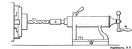
Fig. 40. Drilling in the Lathe
Drilling and Reaming.—When a hole is to be bored from the solid, it is necessary to drill a hole before a boring tool can be used. One method of drilling in the lathe is to insert an ordinary twist drill in a holder or socket S, Fig. 40, which is inserted [44] in the tailstock spindle in place of the center. The drill is then fed through the work by turning the handle n and feeding the spindle outward as shown by the arrow. Before beginning to drill, it is well to turn a conical spot or center for the drill point so the latter will start true. This is often done by using a special tool having a point like a flat drill. This tool is clamped in the toolpost with the point at the same height as the lathe centers. It is then fed against the center of the work and a conical center is turned. If the drill were not given this true starting point, it probably would enter the work more or less off center. Drills can also be started without turning a center by bringing the square end or butt of a tool-shank held in the toolpost in contact with the drill near the cutting end. If the point starts off center, thus causing the drill to wobble, the stationary tool-shank will gradually force or bump it over to the center.
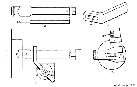
Fig. 41. Flat Drill and Holder
Small holes are often finished in the lathe by drilling and reaming without the use of a boring tool. The form of drill that is used quite extensively for drilling cored holes in castings is shown in Fig. 41, at A. This drill is flat and the right end has a large center hole for receiving the center of the tailstock. To[45] prevent the drill from turning, a holder B, having a slot s in its end through which the drill passes, is clamped in the toolpost, as at C. This slot should be set central with the lathe centers, and the drill, when being started, should be held tightly in the slot by turning or twisting it with a wrench as indicated in the end view at D; this steadies the drill and causes it to start fairly true even though the cored hole runs out considerably.
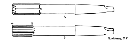
Fig. 42. Rose and Fluted Reamers
Another style of tool for enlarging cored holes is shown in Fig. 42, at A. This is a rose chucking reamer, having beveled cutting edges on the end and a cylindrical body, which fits closely in the reamed hole, thus supporting and guiding the cutting end. The reamer shown at B is a fluted type with cutting edges that extend from a to b; it is used for finishing holes and the drill or rose reamer preceding it should leave the hole very close to the required size. These reamers are held while in use in a socket inserted in the tailstock spindle, as when using a twist drill.
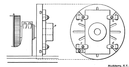
Fig. 43. Casting Clamped to Faceplate for Turning and Boring
Holding Work on Faceplate.—Some castings or forgings are so shaped that they cannot be held in a chuck very well, or perhaps not at all, and work of this kind is often clamped to a faceplate which is usually larger than the faceplate used for driving parts that are turned between the centers. An example of faceplate work is shown in Fig. 43. This is a rectangular-shaped casting having a round boss or projection, the end e of which is to be turned parallel with the back face of the casting previously finished on a planer. A rough cored hole through the center of the boss also needs to be bored true.
The best way to perform this operation in the lathe would be[46] to clamp the finished surface of the casting directly against the faceplate by bolts and clamps a, b, c, and d, as shown; the work would then be turned just as though it were held in a chuck. By holding the casting in this way, face e will be finished parallel with the back surface because the latter is clamped directly against the true-running surface of the faceplate. If a casting of this shape were small enough it could also be held in the jaws of an independent chuck, but if the surface e needs to be exactly parallel with the back face, it is better to clamp the work to the faceplate. Most lathes have two faceplates: One of small diameter used principally for driving work turned between centers, and a large one for holding heavy or irregularly shaped pieces; either of these can be screwed onto the spindle, and the large faceplate has a number of slots through which clamping bolts can be inserted.
The proper way to clamp a piece to the faceplate depends, of course, largely on its shape and the location of the surface to be machined, but in any case it is necessary to hold it securely to prevent any shifting after a cut is started. Sometimes castings can be held by inserting bolts through previously drilled holes, but when clamps are used in connection with the bolts, their outer ends are supported by hardwood or metal blocks which should be just high enough to make the clamp bear evenly on[47] the work. When deep roughing cuts have to be taken, especially on large diameters, it is well to bolt a piece to the faceplate and against one side of the casting, as at D, to act as a driver and prevent the work from shifting; but a driver would not be needed in this particular case. Of course a faceplate driver is always placed to the rear, as determined by the direction of rotation, because the work tends to shift backward when a cut is being taken. If the surface which is clamped against the faceplate is finished as in this case, the work will be less likely to shift if a piece of paper is placed between it and the faceplate.
Work mounted on the faceplate is generally set true by some surface before turning. As the hole in this casting should be true with the round boss, the casting is shifted on the faceplate until the rough outer surface of the boss runs true; the clamps which were previously set up lightly are then tightened. The face e is first turned by using a round-nosed tool. This tool is then replaced by a boring tool and the hole is finished to the required diameter. If the hole being bored is larger than the central hole in the faceplate, the casting should be clamped against parallel pieces, and not directly against the faceplate, to provide clearance for the tool when it reaches the inner end of the hole and prevent it from cutting the faceplate. The parallel pieces should be of the same thickness and be located near the clamps to prevent springing the casting.
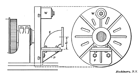
Fig. 44. Cast Elbow held on Angle-plate attached to Faceplate
[48] Application of Angle-plate to Faceplate.—Another example of faceplate work is shown in Fig. 44. This is a cast-iron elbow E, the two flanges of which are to be faced true and square with each other. The shape of this casting is such that it would be very difficult to clamp it directly to the faceplate, but it is easily held on an angle-plate P, which is bolted to the faceplate. The two surfaces of this angle-plate are square with each other so that when one flange of the elbow is finished and bolted against the angle-plate, the other will be faced square. When setting up an angle-plate for work of this kind, the distance from its work-holding side to the center of the faceplate is made equal to the distance d between the center of one flange and the face of the other, so that the flange to be faced will run about true when bolted in place. As the angle-plate and work are almost entirely on one side of the faceplate, a weight W is attached to the opposite side for counterbalancing. Very often weights are also needed to counterbalance offset parts that are bolted directly to the faceplate. The necessity of counterbalancing depends somewhat upon the speed to be used for turning. If the surface to be machined is small in diameter so that the lathe can be run quite rapidly, any unbalanced part should always be counterbalanced.
Sometimes it is rather difficult to hold heavy pieces against the vertical surface of the faceplate while applying the clamps, and occasionally the faceplate is removed and placed in a horizontal position on the bench; the work can then be located about right, and after it is clamped, the faceplate is placed on the lathe spindle by the assistance of a crane.
Special faceplate jaws, such as the one shown to the right in Fig. 33, can often be used to advantage for holding work on large faceplates. Three or four of these jaws are bolted to the faceplate which is converted into a kind of independent chuck. These faceplate jaws are especially useful for holding irregularly shaped parts, as the different jaws can be located in any position.
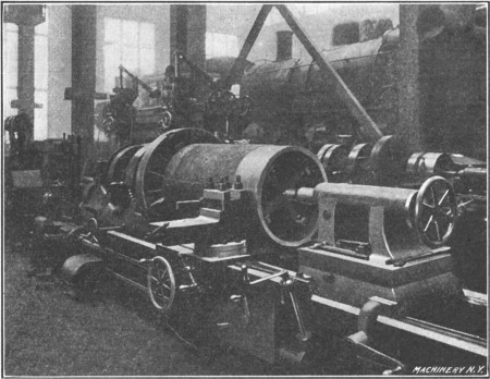
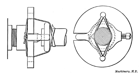
Fig. 45. Rough Turning a Cylinder Lining—Note Method of Supporting Outer End
Supporting Outer End of Chucked Work.—Fig. 45 shows how the tailstock center is sometimes used for supporting the outer end of a long casting, the opposite end of which is held in[49] a chuck. This particular casting is to be turned and bored to make a lining for the cylinder of a locomotive in order to reduce the diameter of the cylinder which has been considerably enlarged by re-boring a number of times. These bushings are rough-turned on the outside while the outer end is supported by the cross-shaped piece or “spider” which forms a center-bearing for the tailstock. This spider has set screws in the flanged ends of the arms, which are tightened against the inner surface of the casting and are adjusted one way or the other in order to locate it in a concentric position. After roughing the outside, the inside is bored to the finish size; then centered disks, which fit into the bore, are placed in the ends of the bushing and the latter is finish-turned. The object in rough turning the outside prior to boring is to avoid the distortion which might occur if this hard outer surface were removed last.
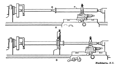
Boring Large Castings in the Lathe.—An ordinary engine lathe is sometimes used for boring engine or pump cylinders, linings, etc., which are too large to be held in the chuck or on a faceplate, and must be attached to the lathe carriage. As a rule, work of this class is done in a special boring machine (see[50] “Horizontal Boring Machines”), but if such a machine is not available, it may be necessary to use a lathe. There are two general methods of boring.
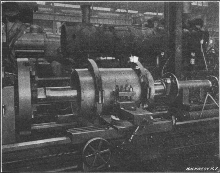
Fig. 46. Boring a Cylinder Lining in an Ordinary Engine Lathe
Fig. 46 shows how the lining illustrated in Fig. 45 is bored in a large engine lathe. The casting is held in special fixtures which are attached to the lathe carriage, and the boring-bar is rotated by the lathe spindle. The tool-head of this boring-bar carries two tools located 180 degrees apart and it is fed along the bar by a star-feed mechanism shown attached to the bar and the tailstock spindle. Each time the bar revolves, the star wheel strikes a stationary pin and turns the feed-screw which, as the illustration shows, extends along a groove cut in one side of the bar. This feed-screw passes through a nut attached to the tool-head so that the latter is slowly fed through the bore. When using a bar of this type, the carriage, of course, remains stationary.
Cylindrical parts attached to the carriage can also be bored by using a plain solid bar mounted between the centers. The bar must be provided with a cutter for small holes or a tool-head for larger diameters (preferably holding two or more tools)[51] and the boring is done by feeding the carriage along the bed by using the regular power feed of the lathe. A symmetrically shaped casting like a bushing or lining is often held upon wooden blocks bolted across the carriage. These are first cut away to form a circular seat of the required radius, by using the boring-bar and a special tool having a thin curved edge. The casting is then clamped upon these blocks by the use of straps and bolts, and if the curved seats were cut to the correct radius, the work will be located concentric with the boring-bar. When using a boring-bar of this type, the bar must be long enough to allow the part being bored to feed from one side of the cutter-head to the other, the cutter-head being approximately in a central location.
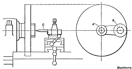
Fig. 47. Method of Setting Circle on Work Concentric with Lathe Spindle
Boring Holes to a Given Center Distance.—In connection with faceplate work, it is often necessary to bore two or more holes at a given distance apart. The best method of doing this may depend upon the accuracy required. For ordinary work sometimes two or more circles A and B (Fig. 47) are drawn upon the part to be bored, in the position for the holes; the piece is then clamped to the faceplate and one of the circles is centered with the lathe spindle by testing it with a pointer C held in the toolpost; that is, when the pointer follows the circle as the work is turned, evidently the circle is concentric with the spindle. The hole is then drilled and bored. The other[52] circle is then centered in the same way for boring the second hole. As will be seen, the accuracy of this method depends first, upon the accuracy with which the circles were laid out, and second; upon the care taken in setting them concentric. For a more accurate way of locating parts for boring, see “Use of Center Indicator” and “Locating Work by the Button Method.”
Turning Brass, Bronze and Copper.—When turning soft yellow brass, a tool should be used having very little or no slope or rake on the top surface against which the chip bears, and for plain cylindrical turning, the point of the tool is drawn out quite thin and rounded, by grinding, to a radius of about 1/8 or 3/16 inch. If a tool having very much top slope is used for brass, there is danger of its gouging into the metal, especially if the part being turned is at all flexible. The clearance angle of a brass tool is usually about 12 or 14 degrees, which is 3 or 4 degrees greater than the clearance for steel turning tools. Most brass is easily turned, as compared with steel, and for that reason this increase in clearance is desirable, because it facilitates feeding the tool into the metal, especially when the carriage and cross-slide movements are being controlled by hand as when turning irregular shapes.
The speed for turning soft brass is much higher than for steel, being ordinarily between 150 and 200 feet per minute. When turning phosphor, tobin or other tough bronze compositions, the tool should be ground with rake the same as for turning steel, and lard oil is sometimes used as a lubricant. The cutting speed for bronzes varies from 35 or 40 to 80 feet per minute, owing to the difference in the composition of bronze alloys.
Turning tools for copper are ground with a little more top rake than is given steel turning tools, and the point should be slightly rounded. It is important to have a keen edge, and a grindstone is recommended for sharpening copper turning tools. Milk is generally considered the best lubricant to use when turning copper. The speed can be nearly as fast as for brass.
[53] Machining Aluminum.—Tools for turning aluminum should have acute cutting angles. After rough-grinding the tool, it is advisable to finish sharpening the cutting edge on a grindstone or with an oilstone for fine work, as a keen edge is very essential. High speeds and comparatively light cuts are recommended. The principal difficulty in the machining of aluminum and aluminum alloys is caused by the clogging of the chips, especially when using such tools as counterbores and milling cutters. This difficulty can be avoided largely by using the right kind of cutting lubricant. Soap-water and kerosene are commonly employed. The latter enables a fine finish to be obtained, provided the cutting tool is properly ground.
The following information on this subject represents the experience of the Brown-Lipe Gear Co., where aluminum parts are machined in large quantities: For finishing bored holes, a bar equipped with cutters has been found more practicable than reamers. The cutters used for machining 4-inch holes have a clearance of from 20 to 22 degrees and no rake or slope on the front faces against which the chips bear. The roughing cutters for this work have a rather sharp nose, being ground on the point to a radius of about 3/32 inch, but for securing a smooth surface, the finishing tools are rounded to a radius of about 3/4 inch. The cutting speed, as well as the feed, for machining aluminum is from 50 to 60 per cent faster than the speeds and feeds for cast iron. The lubricant used by this company is composed of one part “aqualine” and 20 parts water. This lubricant not only gives a smooth finish but preserves a keen cutting edge and enables tools to be used much longer without grinding. Formerly, a lubricant composed of one part of high-grade lard oil and one part of kerosene was used. This mixture costs approximately 30 cents per gallon, whereas the aqualine and water mixture now being used costs less than 4 cents per gallon, and has proved more effective than the lubricant formerly employed.
Notwithstanding the fact that a great variety of work can be done in the lathe, the number of turning tools required is comparatively small. Fig. 1 shows the forms of tools that are used principally, and typical examples of the application of these various tools are indicated in Fig. 2. The reference letters used in these two illustrations correspond for tools of the same type, and both views should be referred to in connection with the following description.
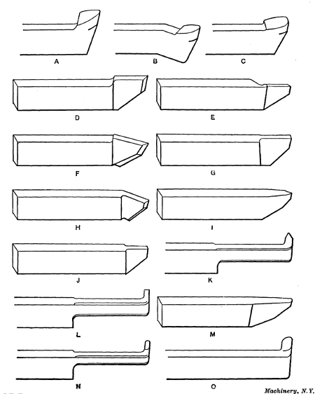
Fig. 1. Set of Lathe Turning Tools for General Work
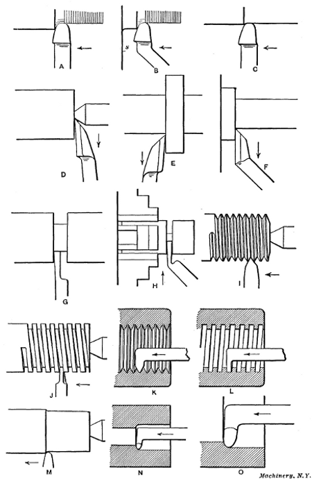
Fig. 2. Views illustrating Use of Various Types of Lathe Tools
Turning Tools for General Work.—The tool shown at A is the form generally used for rough turning, that is for taking deep cuts when considerable metal has to be removed. At B a tool of the same type is shown, having a bent end which enables it to be used close up to a shoulder or surface s that might come in contact with the tool-rest if the straight form were employed. Tool C, which has a straight cutting end, is used on certain classes of work for taking light finishing cuts, with a coarse feed. This type of tool has a flat or straight cutting edge at the end, and will leave a smooth finish even though the feed is coarse, provided the cutting edge is set parallel with the tool's travel so as to avoid ridges. Broad-nosed tools and wide feeds are better adapted for finishing cast iron than steel. When turning steel, if the work is at all flexible, a broad tool tends to gouge into it and for this reason round-nosed tools and finer feeds are generally necessary. A little experience in turning will teach more on this point than a whole chapter on the subject.
The side-tools shown at D and E are for facing the ends of shafts, collars, etc. The first tool is known as a right side-tool because it operates on the right end or side of a shaft or collar, whereas the left side-tool E is used on the opposite side, as shown in Fig. 2. Side-tools are also bent to the right or left because [55] the cutting edge of a straight tool cannot always be located properly for facing certain surfaces. A bent right side-tool is shown at F. A form of tool that is frequently used is shown at G; this is known as a parting tool and is used for severing pieces and for cutting grooves, squaring corners, etc. The same type of tool having a bent end is shown at H (Fig. 2) severing a piece held in the chuck. Work that is held between centers should not be entirely severed with a parting tool unless a steadyrest is[56] placed between the tool and faceplate, as otherwise the tool may be broken by the springing of the work just before the piece is cut in two. It should be noted that the sides of this tool slope[57] inward back of the cutting edge to provide clearance when cutting in a narrow groove.
At I a thread tool is shown for cutting a U. S. standard thread. This thread is the form most commonly used in this country at the present time. A tool for cutting a square thread is shown at J. This is shaped very much like a parting tool except that the cutting end is inclined slightly to correspond with the helix angle of the thread, as explained in Chapter IV, which contains descriptions of different thread forms and methods of cutting them. Internal thread tools are shown at K and L for cutting U. S. standard and square threads in holes. It will be seen that these tools are somewhat like boring tools excepting the ends which are shaped to correspond with the thread which they are intended to cut.
A tool for turning brass is shown at M. Brass tools intended for general work are drawn out quite thin and they are given a narrow rounded point. The top of the brass tool is usually ground flat or without slope as otherwise it tends to gouge into the work, especially if the latter is at all flexible. The end of a brass tool is sometimes ground with a straight cutting edge for turning large rigid work, such as brass pump linings, etc., so that a coarse feed can be used without leaving a rough surface. The tools at N and O are for boring or finishing drilled or cored holes. Two sizes are shown, which are intended for small and large holes, respectively.
The different tools referred to in the foregoing might be called the standard types because they are the ones generally used, and as Fig. 2 indicates, they make it possible to turn an almost [58] endless variety of forms. Occasionally some special form of tool is needed for doing odd jobs, having, perhaps, an end bent differently or a cutting edge shaped to some particular form. Tools of the latter type, which are known as “form tools,” are sometimes used for finishing surfaces that are either convex, concave, or irregular in shape. The cutting edges of these tools are carefully filed or ground to the required shape, and the form given the tool is reproduced in the part turned. Ornamental or other irregular surfaces can be finished very neatly by the use of such tools. It is very difficult, of course, to turn convex or concave surfaces with a regular tool; in fact, it would not be possible to form a true spherical surface, for instance, without special equipment, because the tool could not be moved along a true curve by simply using the longitudinal and cross feeds. Form tools should be sharpened by grinding entirely on the top surface, as any grinding on the end or flank would alter the shape of the tool.
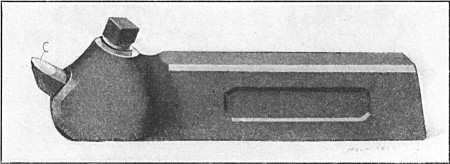
Fig. 3. Turning Tool with Inserted Cutter
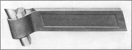
Fig. 4. Heavy Inserted-cutter Turning Tool
Tool-holders with Inserted Cutters.—All of the tools shown in Fig. 1 are forged from the bar, and when the cutting ends have been ground down considerably it is necessary to forge a new end. To eliminate the expense of this continual dressing of tools and also to effect a great reduction in the amount of tool steel required, tool-holders having small inserted cutters are used in many shops. A tool-holder of this type, for outside turning, is shown in Fig. 3. The cutter C is held in a fixed position by the set-screw shown, and it is sharpened, principally, by grinding the end, except when it is desired to give the top of[59] the cutter a different slope from that due to its angular position. Another inserted-cutter turning tool is shown in Fig. 4, which is a heavy type intended for roughing. The cutter in this case has teeth on the rear side engaging with corresponding teeth cut in the clamping block which is tightened by a set-screw on the side opposite that shown. With this arrangement, the cutter can be adjusted upward as the top is ground away.
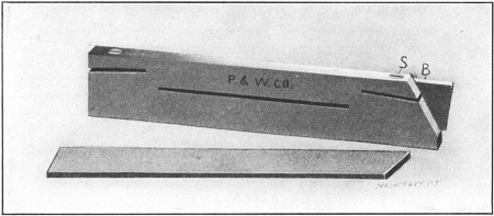
Fig. 5. Parting Tool with Inserted Blade
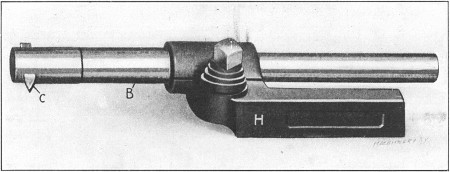
Fig. 6. Boring Tool with Inserted Cutter and Adjustable Bar
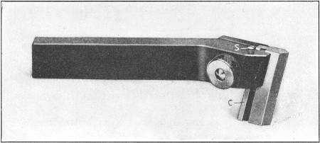
Fig. 7. Threading Tool
A parting tool of the inserted blade type is shown in Fig. 5. The blade B is clamped by screw S and also by the spring of the holder when the latter is clamped in the toolpost. The blade can, of course, be moved outward when necessary. Fig. 6 shows a boring tool consisting of a holder H, a bar B that can be clamped in any position, and an inserted cutter C. With this type of boring tool, the bar can be extended beyond the holder just far enough to reach through the hole to be bored, which makes the tool very rigid. A thread tool of the holder type is shown in Fig. 7. The angular edge of the cutter C is accurately [60] ground by the manufacturers, so that the tool is sharpened by simply grinding it flat on the top. As the top is ground away, the cutter is raised by turning screw S, which can also be used for setting the tool to the proper height.
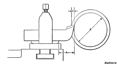
Fig. 8. To avoid springing, Overhang A of Tool should not be Excessive
The Position of Turning Tools.—The production of accurate lathe work depends partly on the condition of the lathe used and also on the care and judgment exercised by the man operating it. Even though a lathe is properly adjusted and in good condition otherwise, errors are often made which are due to other causes which should be carefully avoided. If the turning tool is clamped so that the cutting end extends too far from the supporting block, the downward spring of the tool, owing to the thrust of the cut, sometimes results in spoiled work, especially when an attempt is made to turn close to the finished size by taking a heavy roughing cut. Suppose the end of a cylindrical part is first reduced for a short distance by taking several trial cuts until the diameter d, Fig. 8, is slightly above the finished size and the power feed is then engaged. When the tool begins to take the full depth e of the cut, the point, which ordinarily would be set a little above the center, tends to spring downward into the work, and if there were considerable springing action, the part would probably be turned below the finished size, the increased reduction beginning at the point where the full cut started.
This springing action, as far as the tool is concerned, can be practically eliminated by locating the tool so that the distance[61] A between the tool-block and cutting end, or the “overhang,” is as short as possible. Even though the tool has little overhang it may tilt downward because the toolslide is loose on its ways, and for this reason the slide should have a snug adjustment that will permit an easy movement without unnecessary play. The toolslides of all lathes are provided with gibs which can be adjusted by screws to compensate for wear, or to secure a more rigid bearing.
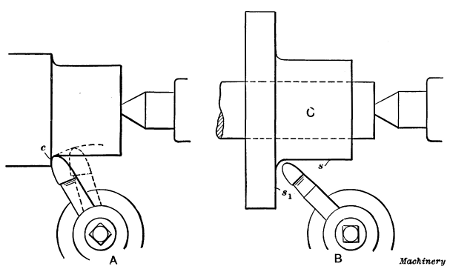
Fig. 9. (A) The Way in which Tool is sometimes displaced by Thrust of Cut,
when set at an Angle.
(B) Tool Set for Finishing both Cylindrical and
Radial Surfaces
When roughing cuts are to be taken, the tool should be located so that any change in its position which might be caused by the pressure of the cut will not spoil the work. This point is illustrated at A in Fig. 9. Suppose the end of a rod has been reduced by taking a number of trial cuts, until it is 1/32 inch above the finished size. If the power feed is then engaged with the tool clamped in an oblique position, as shown, when the full cut is encountered at c, the tool, unless very tightly clamped, may be shifted backward by the lateral thrust of the cut, as indicated by the dotted lines. The point will then begin turning smaller than the finished size and the work will be spoiled. To prevent any change of position, it is good practice, especially when roughing, to clamp the tool square with the surface being turned, or in other words, at right angles to its direction of movement. Occasionally, however, there is a decided advantage in having[62] the tool set at an angle. For example, if it is held about as shown at B, when turning the flange casting C, the surfaces s and s1 can be finished without changing the tool's position. Cylindrical and radial surfaces are often turned in this way in order to avoid shifting the tool, especially when machining parts in quantity.
Tool Grinding.—In the grinding of lathe tools there are three things of importance to be considered: First, the cutting edge of the tool (as viewed from the top) needs to be given a certain shape; second, there must be a sufficient amount of clearance for the cutting edge; and third, tools, with certain exceptions, are ground with a backward slope or a side slope, or with a combination of these two slopes on that part against which the chip bears when the tool is in use.
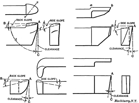
Fig. 10. Illustration showing the Meaning of Terms used
in Tool
Grinding as applied to Tools of Different Types
In Fig. 10 a few of the different types of tools which are used in connection with lathe work are shown. This illustration also indicates the meaning of the various terms used in tool grinding. As shown, the clearance of the tool is represented by the angle α, the back slope is represented by the angle β, and the side slope by the angle γ. The angle δ for a tool without side slope is known as the lip angle or the angle of keenness. When,[63] however, the tool has both back and side slopes, this lip angle would more properly be the angle between the flank f and the top of the tool, measured diagonally along a line z—z. It will be seen that the lines A—B and A—C from which the angles of clearance and back slope are measured are parallel with the top and sides of the tool shank, respectively. For lathe tools, however, these lines are not necessarily located in this way when the tool is in use, as the height of the tool point with relation to the work center determines the position of these lines, so that the effective angles of back slope, clearance and keenness are changed as the tool point is lowered or raised. The way the position of the tool affects these angles will be explained later.
While tools must, of necessity, be varied considerably in shape to adapt them to various purposes, there are certain underlying principles governing their shape which apply generally; so in what follows we shall not attempt to explain in detail just what the form of each tool used on the lathe should be, as it is more important to understand how the cutting action of the tool and its efficiency is affected when it is improperly ground.[64] When the principle is understood, the grinding of tools of various types and shapes is comparatively easy.
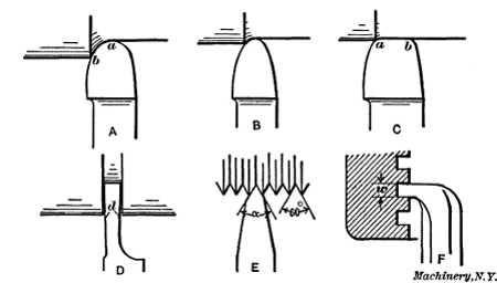
Fig. 11. Plan View of Lathe Turning and Threading Tools
Shape or Contour of Cutting Edge.—In the first place we shall consider the shape or contour of the cutting edge of the tool as viewed from the top, and then take up the question of clearance and slope, the different elements being considered separately to avoid confusion. The contour of the cutting edge depends primarily upon the purpose for which the tool is intended. For example, the tool A, in Fig. 11, where a plan view of a number of different lathe tools is shown, has a very different shape from that of, say, tool D, as the first tool is used for rough turning, while tool D is intended for cutting grooves or severing a turned part. Similarly, tool E is V-shaped because it is used for cutting V-threads. Tools A, B and C, however, are regular turning tools; that is, they are all intended for turning plain cylindrical surfaces, but the contour of the cutting edges varies considerably, as shown. In this case it is the characteristics of the work and the cut that are the factors which determine the shape. To illustrate, tool A is of a shape suitable for rough-turning large and rigid work, while tool B is adapted for smaller and more flexible parts. The first tool is well shaped for roughing because experiments have shown that a cutting edge of a large radius is capable of higher cutting speed than could be used with a tool like B, which has a smaller point. This increase [65] in the cutting speed is due to the fact that the tool A removes a thinner chip for a given feed than tool B; therefore, the speed may be increased without injuring the cutting edge to the same extent. If, however, tool A were to be used for turning a long and flexible part, chattering might result; consequently, a tool B having a point with a smaller radius would be preferable, if not absolutely necessary.
The character of the work also affects the shape of tools. The tool shown at C is used for taking light finishing cuts with a wide feed. Obviously, if the straight or flat part of the cutting edge is in line with the travel of the tool, the cut will be smooth and free from ridges, even though the feed is coarse, and by using a coarse feed the cut is taken in less time; but such a tool cannot be used on work that is not rigid, as chattering would result. Therefore, a smaller cutting point and a reduced feed would have to be employed. Tools with broad flat cutting edges and coarse feeds are often used for taking finishing cuts in cast iron, as this metal offers less resistance to cutting than steel, and is less conducive to chattering.
The shape of a tool (as viewed from the top) which is intended for a more specific purpose than regular turning, can be largely determined by simply considering the tool under working conditions. This point may be illustrated by the parting tool D which, as previously stated, is used for cutting grooves, squaring corners, etc. Evidently this tool should be widest at the cutting edge; that is, the sides d should have a slight amount of clearance so that they will not bind as the tool is fed into a groove. As the tool at E is for cutting a V-thread, the angle α between its cutting edges must equal the angle between the sides of a V-thread, or 60 degrees. The tool illustrated at F is for cutting inside square threads. In this case the width w should be made equal to one-half the pitch of the thread (or slightly greater to provide clearance for the screw), and the sides should be given a slight amount of side clearance, the same as with the parting tool D. So we see that the outline of the tool, as viewed from the top, must conform to and be governed by its use.
[66] Direction of Top Slope for Turning Tools.—Aside from the question of the shape of the cutting edge as viewed from the top, there remains to be determined the amount of clearance that the tool shall have, and also the slope (and its direction) of the top of the tool. By the top is meant that surface against which the chip bears while it is being severed. It may be stated, in a general way, that the direction in which the top of the tool should slope should be away from what is to be the working part of the cutting edge. For example, the working edge of a roughing tool A (Fig. 11), which is used for heavy cuts, would be, practically speaking, between points a and b, or, in other words, most of the work would be done by this part of the cutting edge; therefore the top should slope back from this part of the edge. Obviously, a tool ground in this way will have both a back and a side slope.
When most of the work is done on the point or nose of the tool, as, for example, with the lathe finishing tool C which takes light cuts, the slope should be straight back from the point or cutting edge a—b. As the side tool shown in Fig. 10 does its cutting along the edge a—b, the top is given a slope back from this edge as shown in the end view. This point should be remembered, for when the top slopes in the right direction, less power is required for cutting. Tools for certain classes of work, such as thread tools, or those for turning brass or chilled iron, are ground flat on top, that is, without back or side slope.
Clearance for the Cutting Edge.—In order that the cutting edge may work without interference, it must have clearance; that is, the flank f (Fig. 10) must be ground to a certain angle α so that it will not rub against the work and prevent the cutting edge from entering the metal. This clearance should be just enough to permit the tool to cut freely. A clearance angle of eight or ten degrees is about right for lathe turning tools.
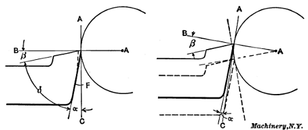
Fig. 12. Illustrations showing how Effective Angles of Slope
and
Clearance change as Tool is raised or lowered
The back slope of a tool is measured from a line A—B which is parallel to the shank, and the clearance angle, from a line A—C at right angles to line A—B. These lines do not, however, always occupy this position with relation to the tool shank when the tool is in use. As shown to the left in Fig. 12, the base line [67] A—B for a turning tool in use intersects with the point of the tool and center of the work, while the line A—C remains at right angles to the first. It will be seen, then, that by raising the tool, as shown to the right, the effective clearance angle α will be diminished, whereas lowering it, as shown by the dotted lines, will have the opposite effect.
A turning tool for brass or other soft metal, particularly where considerable hand manipulation is required, could advantageously have a clearance of twelve or fourteen degrees, as it would then be easier to feed the tool into the metal; but, generally speaking, the clearance for turning tools should be just enough to permit them to cut freely. Excessive clearance weakens the cutting edge and may cause it to crumble under the pressure of the cut.
Angle of Tool-point and Amount of Top Slope.—The lip angle or the angle of keenness δ (Fig. 10) is another important consideration in connection with tool grinding, for it is upon this angle that the efficiency of the tool largely depends. By referring to the illustration it will be seen that this angle is governed by the clearance and the slope β, and as the clearance remains practically the same, it is the slope which is varied to meet different conditions. Now, the amount of slope a tool should have depends on the work for which it is intended. If, for example, a turning tool is to be used for roughing medium or soft steel, it should have a back slope of about eight degrees and a side slope ranging from fourteen to twenty degrees, while [68] a tool for cutting very hard steel should have a back slope of about five degrees and a side slope of nine degrees.
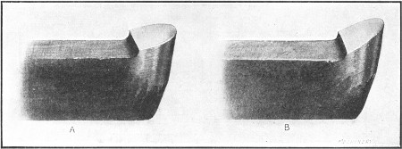
Fig. 13. (A) Blunt Tool for Turning Hard Steel.
(B) Tool-point
Ground to give Keenness
The reason for decreasing the slope and thus increasing the lip angle for harder metals is to give the necessary increased strength to the cutting edge to prevent it from crumbling under the pressure of the cut. The tool illustrated at A, Fig. 13, is much stronger than it would be if ground as shown at B, as the former is more blunt. If a tool ground as at A, however, were used for cutting very soft steel, there would be a greater chip pressure on the top and, consequently, a greater resistance to cutting, than if a keener tool had been employed; furthermore the cutting speed would have to be lower, which is of even greater importance than the chip pressure; therefore, the lip angle, as a general rule, should be as small as possible without weakening the tool so that it cannot do the required work. In order to secure a strong and well-supported cutting edge, tools used for turning very hard metal, such as chilled rolls, etc., are ground with practically no slope and with very little clearance. Brass tools, while given considerable clearance, as previously stated, are ground flat on top or without slope; this is not done, however, to give strength to the cutting edge, but rather to prevent the tool from gouging into the work, which it is likely to do if the part being turned is at all flexible and the tool has top slope.
Experiments conducted by Mr. F. W. Taylor to determine the most efficient form for lathe roughing tools showed that the[69] nearer the lip angle approached sixty-one degrees, the higher the cutting speed. This, however, does not apply to tools for turning cast iron, as the latter will work more efficiently with a lip angle of about sixty-eight degrees. This is doubtless because the chip pressure, when turning cast iron, comes closer to the cutting edge which should, therefore, be more blunt to withstand the abrasive action and heat. Of course, the foregoing remarks concerning lip angles apply more particularly to tools used for roughing.
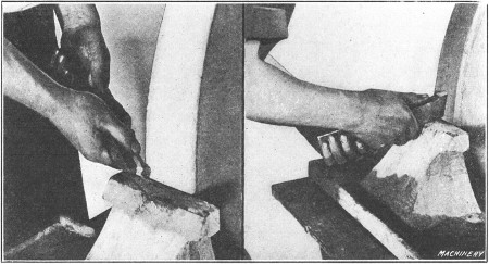
Fig. 14. Grinding the Top and Flank of a Turning Tool
Grinding a Lathe Tool.—The way a turning tool is held while the top surface is being ground is shown to the left in Fig. 14. By inclining the tool with the wheel face, it will be seen that both the back and side slopes may be ground at the same time. When grinding the flank of the tool it should be held on the tool-rest of the emery wheel or grindstone, as shown by the view to the right. In order to form a curved cutting edge, the tool is turned about the face of the stone while it is being ground. This rotary movement can be effected by supporting the inner end of the tool with one hand while the shank is moved to and fro with the other.
Often a tool which has been ground properly in the first place is greatly misshapen after it has been sharpened a few times. This is usually the result of attempts on the part of the workman to re-sharpen it hurriedly; for example, it is easier to secure[70] a sharp edge on the turning tool shown to the left in Fig. 12, by grinding the flank as indicated by the dotted line, than by grinding the entire flank. The clearance is, however, reduced and the lip angle changed.
There is great danger when grinding a tool of burning it or drawing the temper from the fine cutting edge, and, aside from the actual shape of the cutting end, this is the most important point in connection with tool grinding. If a tool is pressed hard against an emery or other abrasive wheel, even though the latter has a copious supply of water, the temper will sometimes be drawn. When grinding a flat surface, to avoid burning, the tool should frequently be withdrawn from the stone so that the cooling water (a copious supply of which should be provided) can reach the surface being ground. A moderate pressure should also be applied, as it is better to spend an extra minute or two in grinding than to ruin the tool by burning, in an attempt to sharpen it quickly. Of course, what has been said about burning applies more particularly to carbon steel, but even self-hardening steels are not improved by being over-heated at the stone. In some shops, tools are ground to the theoretically correct shape in special machines instead of by hand. The sharpened tools are then kept in the tool-room and are given out as they are needed.
Cutting Speeds and Feeds.—The term cutting speed as applied to turning operations is the speed in feet per minute of the surface being turned, or, practically speaking, it is equivalent to the length of a chip, in feet, which would be turned in one minute. The term cutting speed should not be confused with revolutions per minute, because the cutting speed depends not only upon the speed of the work but also upon its diameter. The feed of a tool is the amount it moves across the surface being turned for each revolution; that is, when turning a cylindrical piece, the feed is the amount that the tool moves sidewise for each revolution of the work. Evidently the time required for turning is governed largely by the cutting speed, the feed, and the depth of the cut; therefore, these elements should be carefully considered.
| Steel—Standard 7/8-inch Tool | Cast Iron—Standard 7/8-inch Tool | ||||||||||||||
| Depth of Cut in Inches | Feed in Inches | Speed in Feet per Minute for a Tool which is to last 11/2 Hour before Re-grinding | Depth of Cut in Inches | Feed in Inches | Speed in Feet per Minute for a Tool which is to last 11/2 Hour before Re-grinding | ||||||||||
| Soft Steel |
Medium Steel |
Hard Steel |
Soft Cast Iron |
Medium Cast Iron |
Hard Cast Iron | ||||||||||
| 3/32 | 1/64 | 476 | 238 | 108 | 3/32 | 1/16 | 122 | 61 | .2 | 35 | .7 | ||||
| 1/32 | 325 | 162 | 73 | .8 | 1/8 | 86 | .4 | 43 | .2 | 25 | .2 | ||||
| 1/16 | 222 | 111 | 50 | .4 | 3/16 | 70 | .1 | 35 | .1 | 20 | .5 | ||||
| 3/32 | 177 | 88 | .4 | 40 | .2 | 1/8 | 1/32 | 156 | 77 | .8 | 45 | .4 | |||
| 1/8 | 1/64 | 420 | 210 | 95 | .5 | 1/16 | 112 | 56 | .2 | 32 | .8 | ||||
| 1/32 | 286 | 143 | 65 | .0 | 1/8 | 79 | .3 | 39 | .7 | 23 | .2 | ||||
| 1/16 | 195 | 97 | .6 | 44 | .4 | 3/16 | 64 | .3 | 32 | .2 | 18 | .8 | |||
| 1/8 | 133 | 66 | .4 | 30 | .2 | 3/16 | 1/32 | 137 | 68 | .6 | 40 | .1 | |||
| 3/16 | 1/64 | 352 | 176 | 80 | .0 | 1/16 | 99 | .4 | 49 | .7 | 29 | .0 | |||
| 1/32 | 240 | 120 | 54 | .5 | 1/8 | 70 | .1 | 35 | .0 | 20 | .5 | ||||
| 1/16 | 164 | 82 | 37 | .3 | 3/16 | 56 | .8 | 28 | .4 | 16 | .6 | ||||
| 1/8 | 112 | 56 | 25 | .5 | 1/4 | 1/32 | 126 | 62 | .9 | 36 | .7 | ||||
| 1/4 | 1/64 | 312 | 156 | 70 | .9 | 1/16 | 90 | .8 | 45 | .4 | 26 | .5 | |||
| 1/32 | 213 | 107 | 48 | .4 | 1/8 | 64 | .1 | 32 | .0 | 18 | .7 | ||||
| 1/16 | 145 | 72 | .6 | 33 | .0 | 3/16 | 52 | 26 | .0 | 15 | .2 | ||||
| 3/32 | 116 | 58 | .1 | 26 | .4 | 3/8 | 1/32 | 111 | 55 | .4 | 32 | .3 | |||
| 3/8 | 1/64 | 264 | 132 | 60 | .0 | 1/16 | 80 | 40 | .0 | 23 | .4 | ||||
| 1/32 | 180 | 90 | .2 | 41 | .0 | 1/8 | 56 | .4 | 28 | .2 | 16 | .5 | |||
| 1/16 | 122 | 61 | .1 | 27 | .8 | 1/2 | 1/32 | 104 | 52 | .1 | 30 | .4 | |||
| 1/2 | 1/64 | 237 | 118 | 53 | .8 | 1/16 | 75 | .2 | 37 | .6 | 22 | .0 | |||
| 1/32 | 162 | 80 | .8 | 36 | .7 | 1/8 | 43 | .1 | 21 | .6 | 12 | .6 | |||
| Steel—Standard 5/8-inch Tool | Cast Iron—Standard 5/8-inch Tool | ||||||||||||||
| Depth of Cut | Feed | Soft Steel |
Medium Steel |
Hard Steel |
Depth of Cut | Feed | Soft Cast Iron |
Medium Cast Iron |
Hard Cast Iron |
||||||
| 1/16 | 1/64 | 548 | 274 | 125 | 3/32 | 1/32 | 160 | 80 | .0 | 46 | .6 | ||||
| 1/32 | 358 | 179 | 81 | .6 | 1/16 | 110 | 55 | .0 | 32 | .2 | |||||
| 1/16 | 235 | 117 | 53 | .3 | 1/8 | 75 | .4 | 37 | .7 | 22 | .0 | ||||
| 3/32 | 1/64 | 467 | 234 | 106 | 1/8 | 1/32 | 148 | 74 | .0 | 43 | .3 | ||||
| 1/32 | 306 | 153 | 69 | .5 | 1/16 | 104 | 51 | .8 | 32 | .0 | |||||
| 1/16 | 200 | 100 | 45 | .5 | 1/8 | 69 | .6 | 34 | .8 | 20 | .3 | ||||
| 3/32 | 156 | 78 | 35 | .5 | 3/16 | 1/64 | 183 | 91 | .6 | 68 | .0 | ||||
| 1/8 | 1/64 | 417 | 209 | 94 | .8 | 1/32 | 135 | 67 | .5 | 39 | .4 | ||||
| 1/32 | 273 | 136 | 62 | .0 | 1/16 | 94 | 47 | .0 | 27 | .4 | |||||
| 1/16 | 179 | 89 | .3 | 40 | .6 | 1/8 | 64 | .3 | 32 | .2 | 18 | .8 | |||
| 3/32 | 140 | 69 | .8 | 31 | .7 | 1/4 | 1/64 | 171 | 85 | .7 | 50 | .1 | |||
| 3/16 | 1/64 | 362 | 181 | 82 | .2 | 1/32 | 126 | 63 | .2 | 36 | .9 | ||||
| 1/32 | 236 | 118 | 53 | .8 | 1/16 | 87 | .8 | 43 | .9 | 25 | .6 | ||||
| 1/16 | 155 | 77 | .4 | 35 | .2 | 3/32 | 70 | .4 | 35 | .2 | 20 | .6 | |||
| 1/4 | 1/64 | 328 | 164 | 74 | .5 | 3/8 | 1/64 | 156 | 77 | .8 | 45 | .4 | |||
| 1/32 | 215 | 107 | 48 | .8 | 1/32 | 116 | 57 | .8 | 33 | .8 | |||||
| 3/8 | 1/64 | 286 | 143 | 65 | .0 | 1/16 | 79 | .7 | 39 | .9 | 23 | .3 | |||
[72] Average Cutting Speeds for Turning.—The cutting speed is governed principally by the hardness of the metal to be turned; the kind of steel of which the turning tool is made; the shape of the tool and its heat-treatment; the feed and depth of cut; whether or not a cooling lubricant is used on the tool; the power of the lathe and also its construction; hence it is impossible to give any definite rule for determining either the speed, feed, or depth of cut, because these must be varied to suit existing conditions. A general idea of the speeds used in ordinary machine shop practice may be obtained from the following figures:
Ordinary machine steel is generally turned at a speed varying between 45 and 65 feet per minute. For ordinary gray cast iron, the speed usually varies from 40 to 50 feet per minute; for annealed tool steel, from 25 to 35 feet per minute; for soft yellow brass, from 150 to 200 feet per minute; for hard bronze, from 35 to 80 feet per minute, the speed depending upon the composition of the alloy. While these speeds correspond closely to general practice, they can be exceeded for many machining operations.
The most economical speeds for a given feed and depth of cut, as determined by the experiments conducted by Mr. F. W. Taylor, are given in the table, “Cutting Speeds and Feeds for Turning Tools.” The speeds given in this table represent results obtained with tools made of a good grade of high-speed steel properly heat-treated and correctly ground. It will be noted that the cutting speed is much slower for cast iron than for steel. Cast iron is cut with less pressure or resistance than soft steel, but the slower speed required for cast iron is probably due to the fact that the pressure of the chip is concentrated closer to the cutting edge, combined with the fact that cast iron wears the tool faster than steel. The speeds given are higher than those ordinarily used, and, in many cases, a slower rate would be necessary to prevent chattering or because of some other limiting condition.
Factors which limit the Cutting Speed.—It is the durability of the turning tool or the length of time that it will turn effectively[73] without grinding, that limits the cutting speed; and the hardness of the metal being turned combined with the quality of the tool are the two factors which largely govern the time that a tool can be used before grinding is necessary. The cutting speed for very soft steel or cast iron can be three or four times faster than the speed for hard steel or hard castings, but whether the material is hard or soft, the kind and quality of the tool used must also be considered, as the speed for a tool made of ordinary carbon steel will have to be much slower than for a tool made of modern “high-speed” steel.
When the cutting speed is too high, even though high-speed steel is used, the point of the tool is softened to such an extent by the heat resulting from the pressure and friction of the chip, that the cutting edge is ruined in too short a time. On the other hand, when the speed is too slow, the heat generated is so slight as to have little effect and the tool point is dulled by being slowly worn or ground away by the action of the chip. While a tool operating at such a low speed can be used a comparatively long time without re-sharpening, this advantage is more than offset by the fact that too much time is required for removing a given amount of metal when the work is revolving so slowly.
Generally speaking, the speed should be such that a fair amount of work can be done before the tool requires re-grinding. Evidently, it would not pay to grind a tool every few minutes in order to maintain a high cutting speed; neither would it be economical to use a very slow speed and waste considerable time in turning, just to save the few minutes required for grinding. For example, if a number of roughing cuts had to be taken over a heavy rod or shaft, time might be saved by running at such a speed that the tool would have to be sharpened (or be replaced by a tool previously sharpened) when it had traversed half-way across the work; that is, the time required for sharpening or changing the tool would be short as compared with the gain effected by the higher work speed. On the other hand, it might be more economical to run a little slower and take a continuous cut across the work with one tool.
[74]The experiments of Mr. Taylor led to the conclusion that, as a rule, it is not economical to use roughing tools at a speed so slow as to cause them to last more than 11/2 hour without being re-ground; hence the speeds given in the table previously referred to are based upon this length of time between grindings. Sometimes the work speed cannot be as high as the tool will permit, because of the chattering that often results when the lathe is old and not massive enough to absorb the vibrations, or when there is unnecessary play in the working parts. The shape of the tool used also affects the work speed, and as there are so many things to be considered, the proper cutting speed is best determined by experiment.
Rules for Calculating Cutting Speeds.—The number of revolutions required to give any desired cutting speed can be found by multiplying the cutting speed, in feet per minute, by 12 and dividing the product by the circumference of the work in inches. Expressing this as a formula we have
| C × 12 | ||
| R | = | ——— |
| πd |
in which
| R | = | revolutions per minute; |
| C | = | the cutting speed in feet per minute; |
| π | = | 3.1416; |
| d | = | the diameter in inches. |
For example if a cutting speed of 60 feet per minute is wanted and the diameter of the work is 5 inches, the required speed would be found as follows:
| 60 × 12 | ||||
| R | = | ————— | = | 46 revolutions per minute. |
| 3.1416 × 5 |
If the diameter is simply multiplied by 3 and the fractional part is omitted, the calculation can easily be made, and the result will be close enough for practical purposes. In case the cutting speed, for a given number of revolutions and diameter, is wanted, the following formula can be used:
| Rπd | ||
| C | = | —— |
| 12 |
[75]Machinists who operate lathes do not know, ordinarily, what cutting speeds, in feet per minute, are used for different classes of work, but are guided entirely by past experience.
Feed of Tool and Depth of Cut.—The amount of feed and depth of cut also vary like the cutting speed, for different conditions. When turning soft machine steel the feed under ordinary conditions would vary between 1/32 and 1/16 inch per revolution. For turning soft cast iron the feed might be increased to from 1/16 to 1/8 inch per revolution. These feeds apply to fairly deep roughing cuts. Coarser feeds might be used in many cases especially when turning large rigid parts in a powerful lathe. The depth of a roughing cut in machine steel might vary from 1/8 to 3/8 inch, and in cast iron from 3/16 to 1/2 inch. These figures are intended simply to give the reader a general idea of feeds and cuts that are feasible under average conditions.
Ordinarily coarser feeds and a greater depth of cut can be used for cast iron than for soft steel, because cast iron offers less resistance to turning, but in any case, with a given depth of cut, metal can be removed more quickly by using a coarse feed and the necessary slower speed, than by using a fine feed and the higher speed which is possible when the feed is reduced. When the turning operation is simply to remove metal, the feed should be coarse, and the cut as deep as practicable. Sometimes the cut must be comparatively light, either because the work is too fragile and springy to withstand the strain of a heavy cut, or the lathe has not sufficient pulling power. The difficulty with light slender work is that a heavy cut may cause the part being turned to bend under the strain, thus causing the tool to gouge in, which would probably result in spoiling the work. Steadyrests can often be used to prevent flexible parts from springing, as previously explained, but there are many kinds of light work to which the steadyrest cannot be applied to advantage.
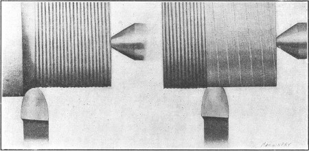
Fig. 15. Roughing Cut—Light Finishing Cut and Coarse Feed
The amount of feed to use for a finishing cut might, properly, be either fine or coarse. Ordinarily, fine feeds are used for finishing steel, especially if the work is at all flexible, whereas finishing[76] cuts in cast iron are often accompanied by a coarse feed. Fig. 15 illustrates the feeds that are often used when turning cast iron. The view to the left shows a deep roughing cut and the one to the right, a finishing cut. By using a broad flat cutting edge set parallel to the tool's travel, and a coarse feed for finishing, a smooth cut can be taken in a comparatively short time. Castings which are close to the finished size in the rough can often be finished to advantage by taking a single cut with a broad tool, provided the work is sufficiently rigid. It is not always practicable to use these broad tools and coarse feeds, as they sometimes cause chattering, and when used on steel, a broad tool tends to gouge or “dig in” unless the part being turned is rigid. Heavy steel parts, however, are sometimes finished in this way. The modern method of finishing many steel parts is to simply rough them out in a lathe to within, say, 1/32 inch of the required diameter and take the finishing cut in a cylindrical grinding machine.
Effect of Lubricant on Cutting Speed.—When turning iron or steel a higher cutting speed can be used, if a stream of soda water or other cooling lubricant falls upon the chip at the point where it is being removed by the tool. In fact, experiments have shown that the cutting speed, when using a large stream of cooling water and a high-speed steel tool, can be about 40 percent higher than when turning dry or without a cooling lubricant.[77] For ordinary carbon steel tools, the gain was about 25 per cent. The most satisfactory results were obtained from a stream falling at a rather slow velocity but in large volume. The gain in cutting speed, by the use of soda water or other suitable fluids, was found to be practically the same for all qualities of steel from the softest to the hardest.
Cast iron is usually turned dry or without a cutting lubricant. Experiments, however, made to determine the effect of applying a heavy stream of cooling water to a tool turning cast iron, showed the following results: Cutting speed without water, 47 feet per minute; cutting speed with a heavy stream of water, nearly 54 feet per minute; increase in speed, 15 per cent. The dirt caused by mixing the fine cast-iron turnings with a cutting lubricant is an objectionable feature which, in the opinion of many, more than offsets the increase in cutting speed that might be obtained.
Turret lathes and automatic turning machines are equipped with a pump and piping for supplying cooling lubricant to the tools in a continuous stream. Engine lathes used for general work, however, are rarely provided with such equipment and a lubricant, when used, is often supplied by a can mounted at the rear of the carriage, having a spout which extends above the tool. Owing to the inconvenience in using a lubricant on an engine lathe, steel, as well as cast iron, is often turned dry especially when the work is small and the cuts light and comparatively short.
Lubricants Used for Turning.—A good grade of lard oil is an excellent lubricant for use when turning steel or wrought iron and it is extensively used on automatic screw machines, especially those which operate on comparatively small work. For some classes of work, especially when high-cutting speeds are used, lard oil is not as satisfactory as soda water or some of the commercial lubricants, because the oil is more sluggish and does not penetrate to the cutting point with sufficient rapidity. Many lubricants which are cheaper than oil are extensively used on “automatics” for general machining operations. These usually consist of a mixture of sal-soda (carbonate of soda) and[78] water, to which is added some ingredient such as lard oil or soft soap to thicken or give body to the lubricant.
A cheap lubricant for turning, milling, etc., and one that has been extensively used, is made in the following proportions: 1 pound of sal-soda, 1 quart of lard oil, 1 quart of soft soap, and enough water to make 10 or 12 gallons. This mixture is boiled for one-half hour, preferably by passing a steam coil through it. If the solution should have an objectionable odor, this can be eliminated by adding 2 pounds of unslaked lime. The soap and soda in this solution improve the lubricating quality and also prevent the surfaces from rusting. For turning and threading operations, plain milling, deep-hole drilling, etc., a mixture of equal parts of lard oil and paraffin oil will be found very satisfactory, the paraffin being added to lessen the expense.
Brass or bronze is usually machined dry, although lard oil is sometimes used for automatic screw machine work. Babbitt metal is also worked dry, ordinarily, although kerosene or turpentine is sometimes used when boring or reaming. If babbitt is bored dry, balls of metal tend to form on the tool point and score the work. Milk is generally considered the best lubricant for machining copper. A mixture of lard oil and turpentine is also used for copper. For aluminum, the following lubricants can be used: Kerosene, a mixture of kerosene and gasoline, soap-water, or “aqualine” one part, water 20 parts.
Lard Oil as a Cutting Lubricant.—After being used for a considerable time, lard oil seems to lose some of its good qualities as a cooling compound. There are several reasons for this: Some manufacturers use the same oil over and over again on different materials, such as brass, steel, etc. This is objectionable, for when lard oil has been used on brass it is practically impossible to get the fine dust separated from it in a centrifugal separator. When this impure oil is used on steel, especially where high-speed steels are employed, it does not give satisfactory results, owing to the fact that when the cutting tool becomes dull, the small brass particles “freeze” to the cutting tool and thus produce rough work. The best results are obtained[79] from lard oil by keeping it thin, and by using it on the same materials—that is, not transferring the oil from a machine in which brass is being cut to one where it would be employed on steel. If the oil is always used on the same class of material, it will not lose any of its good qualities.
Prime lard oil is nearly colorless, having a pale yellow or greenish tinge. The solidifying point and other characteristics of the oil depend upon the temperature at which it was expressed, winter-pressed lard oil containing less solid constituents of the lard than that expressed in warm weather. The specific gravity should not exceed 0.916; it is sometimes increased by adulterants, such as cotton-seed and maize oils.
It is often necessary, in connection with lathe work, to turn parts tapering instead of straight or cylindrical. If the work is mounted between the centers, one method of turning a taper is to set the tailstock center out of alignment with the headstock center. When both of these centers are in line, the movement of the tool is parallel to the axis of the work and, consequently, a cylindrical surface is produced; but if the tailstock h1 is set out of alignment, as shown in Fig. 1, the work will then be turned tapering as the tool is traversed from a to b, because the axis x—x is at an angle with the movement of the tool. Furthermore [81] the amount of taper or the difference between the diameters at the ends for a given length, will depend on how much center h1 is set over from the central position.
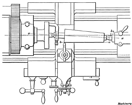
Fig. 1. Taper Turning by the Offset-center Method
The amount of taper is usually given on drawings in inches per foot, or the difference in the diameter at points twelve inches apart. For example, the taper of the piece shown at A, Fig. 2, is 1 inch per foot, as the length of the tapering surface is just twelve inches and the difference between the diameters at the ends is 1 inch. The conical roller shown at B has a total length of 9 inches and a tapering surface 6 inches long, and in this case the taper per foot is also 1 inch, there being a difference of 1/2 inch in a length of 6 inches or 1 inch in twice that length. When the taper per foot is known, the amount that the tailstock center should be set over for turning that taper can easily be estimated, but it should be remembered that the setting obtained in this way is not absolutely correct, and is only intended to locate the center approximately. When a taper needs to be at all accurate, it is tested with a gage, or by other means, after taking a trial cut, as will be explained later, and the tailstock center is readjusted accordingly. There are also more accurate methods of setting the center, than by figuring [82] the amount of offset, but as the latter is often convenient this will be referred to first.
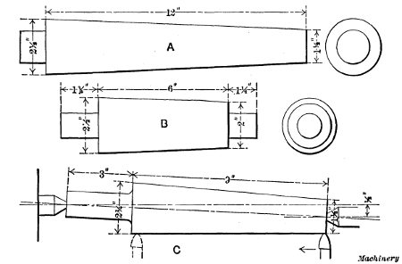
Fig. 2. Examples of Taper Work
Setting Tailstock Center for Taper Turning.—Suppose the tailstock center is to be set for turning part C, Fig. 2, to a taper of approximately 1 inch per foot. In this case the center would simply be moved toward the front of the machine 1/2 inch, or one-half the required taper per foot, because the total length of the work happens to be just 12 inches. This setting, however, would not be correct for all work requiring a taper of 1 inch per foot, as the adjustment depends not only on the amount of the taper but on the total length of the piece.
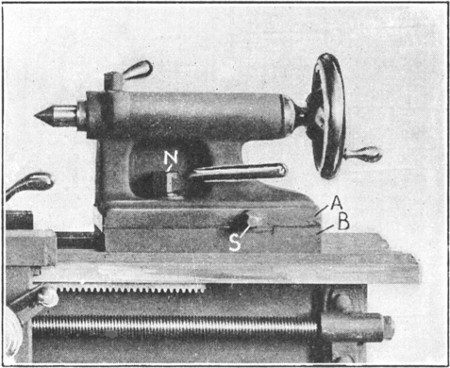
Fig. 3. Detail View of Lathe Tailstock
For example, the taper roller B has a taper of 1 inch per foot, but the center, in this case, would be offset less than one-half the taper per foot, because the total length is only 9 inches. For lengths longer or shorter than twelve inches, the taper per inch should be found first; this is then multiplied by the total length of the work (not the length of the taper) which gives the taper for that length, and one-half this taper is the amount to set over the center. For example, the taper per inch of part B equals 1 inch divided by 12 = 1/12 inch. The total length of 9 inches multiplied by 1/12 inch = 3/4 inch, and 1/2 of 3/4 = 3/8, which is the distance that the tailstock center should be offset. In this example if the taper per foot were not known, and only the diameters of the large and small ends of the tapered part were given, the difference between these diameters should first be found (21/2 - 2 = 1/2); this difference should then be divided by the length of the taper (1/2 ÷ 6 = 1/12 inch) to obtain the taper per inch. The taper per inch times the total length represents what the taper would be if it extended throughout the entire length, and one-half of this equals the offset, which is 3/8 inch.
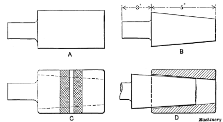
Fig. 4. Taper Plug and Gage
[83] Example of Taper Turning.—As a practical example of taper turning let us assume that the piece A, Fig. 4, which has been centered and rough-turned as shown, is to be made into a taper plug, as indicated at B, to fit a ring gage as at C. If the required taper is 11/2 inch per foot and the total length is 8 inches, the tailstock center would be offset 1/2 inch.
To adjust the tailstock, the nuts N (Fig. 3) are first loosened and then the upper part A is shifted sidewise by turning screw S. Scales are provided on some tailstocks for measuring the amount of this adjustment; if there is no scale, draw a line across the movable and stationary parts A and B, when the tailstock is set for straight turning. The movement of the upper line in relation to the lower will then show the offset, which can be measured with a scale.
When the adjustment has been made, nuts N are tightened and the part to be turned, with a dog attached, is placed between the centers the same as for straight turning. The taper end is then reduced by turning, but before it is near the finished size, the work is removed and the taper tested by inserting it in the gage. If it is much out, this can be felt, as the end that is too small can be shaken in the hole. Suppose the plug did not taper enough and only the small end came into contact with the gage, as shown somewhat exaggerated at D; in that case[84] the center would be shifted a little more towards the front, whereas if the taper were too steep, the adjustment would, of course, be in the opposite direction. A light cut would then be taken, to be followed by another test. If the plug should fit the gage so well that there was no perceptible shake, it could be tested more closely as follows: Draw three or four chalk lines along the tapering surface, place the work in the gage and turn it a few times. The chalk marks will then show whether the taper of the plug corresponds to that of the gage; for example, if the taper is too great, the marks will be rubbed out on the large end, but if the taper is correct, the lines throughout their length will be partially erased.
Another and more accurate method of testing tapers is to apply a thin coat of Prussian-blue to one-half of the tapering surface, in a lengthwise direction. The work is then inserted in the hole or gage and turned to mark the bearing. If the taper is correct, the bearing marks will be evenly distributed, whereas if the taper is incorrect, they will appear at one end. Tapering pieces that have to be driven tightly into a hole, such as a piston-rod, can be tested by the location of the bearing marks produced by actual contact.
After the taper is found to be correct, the plug is reduced in size until it just enters the gage as at C. The final cut should leave it slightly above the required size, so that a smooth surface[85] can be obtained by filing. It should be mentioned that on work of this kind, especially if great accuracy is required, the final finish is often obtained by grinding in a regular grinding machine, instead of by filing. When this method is employed, a lathe is used merely to rough-turn the part close to size.
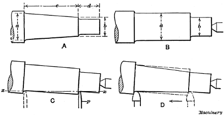
Fig. 5. Setting Work for Taper Turning by use of Caliper Gage
When the amount that the tailstock center should be offset is determined by calculating, as in the foregoing example, it is usually necessary to make slight changes afterward, and the work should be tested before it is too near the finished size so that in case one or more trial cuts are necessary, there will be material enough to permit this. When there are a number of tapered pieces to be turned to the same taper, the adjustment of the tailstock center will have to be changed unless the total length of each piece and the depth of the center holes are the same in each case.
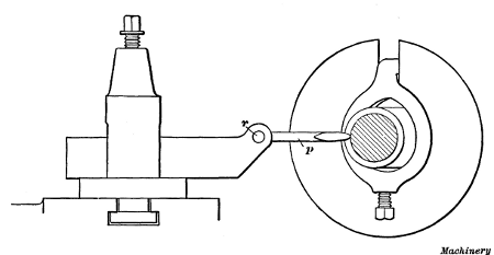
Fig. 6. Side View showing Relative Positions of Gage and Work
Setting the Tailstock Center with a Caliper Tool.—Another method of setting the tailstock center for taper turning is illustrated in Fig. 5. The end of an engine piston-rod is to be made tapering as at A and to dimensions a, b, c and d. It is first turned with the centers in line as at B. The end d is reduced to diameter b up to the beginning of the taper and it is then turned to diameter a as far as the taper part c extends. The tailstock center is next set over by guess and a caliper tool is clamped in the toolpost. This tool, a side view of which is shown in Fig. 6, [86] has a pointer p that is free to swing about pivot r, which should be set to about the same height as the center of the work. The tailstock center is adjusted until this pointer just touches the work when in the positions shown by the full and dotted lines at C, Fig. 5; that is, until the pointer makes contact at the beginning and end of the taper part. The travel of the carriage will then be parallel to a line x—x, representing the taper; consequently, if a tool is started at the small end, as shown by the dotted lines at D, with the nose just grazing the work, it will also just graze it when fed to the extreme left as shown. Of course, if the taper were at all steep, more than one cut would be taken.
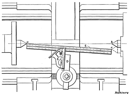
Fig. 7. Obtaining Tailstock Center Adjustment by use of Square
If these various operations are carefully performed, a fairly accurate taper can be produced. The straight end d is reduced to size after the tail-center is set back to the central position. Some mechanics turn notches or grooves at the beginning and end of the tapering part, having diameters equal to the largest and smallest part of the taper; the work is then set by these grooves with a caliper tool. The advantage of the[87] first method is that most of the metal is removed while the centers are in alignment.
Setting the Tailstock Center with a Square.—Still another method of adjusting the tailstock for taper turning, which is very simple and eliminates all figuring, is as follows: The part to be made tapering is first turned cylindrical or straight for 3 or 4 inches of its length, after the ends have been properly centered and faced square. The work is then removed and the tailstock is shifted along the bed until the distance a—b between the extreme points of the centers is exactly 1 foot. The center is next offset a distance b—c equal to one-half the required taper per foot, after which a parallel strip D, having true sides, is clamped in the toolpost. Part D is then set at right angles to a line passing from one center point to the other. This can be done conveniently by holding a 1-foot square (preferably with a sliding head) against one side of D and adjusting the latter in the toolpost until edge E of the square blade is exactly in line with both center points. After part D is set, it should be clamped carefully to prevent changing the position. The angle between the side of D and an imaginary line which is perpendicular to axis a—b is now equal to one-half the angle of the required taper.
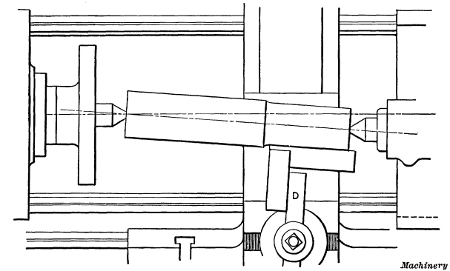
Fig. 8. Second Step in Adjusting Tailstock Center by use of Square
[88]The axis of the part to be turned should be set parallel with line E, which can be done by setting the cylindrical surface which was previously finished, at right angles to the side of D. In order to do this the work is first placed between centers, the tailstock being shifted along the bed if necessary; the tail-center is then adjusted laterally until the finished cylindrical surface is square with the side of D. A small try-square can be used for testing the position of the work, as indicated in Fig. 8. If the length of the work is less than 1 foot, it will be necessary to move the center toward the rear of the machine, and if the length is greater than 1 foot, the adjustment is, of course, in the opposite direction.
The Taper Attachment.—Turning tapers by setting over the tailstock center has some objectionable features. When the lathe centers are not in alignment, as when set for taper turning, they bear unevenly in the work centers because the axis of the work is at an angle with them; this causes the work centers to wear unevenly and results in inaccuracy. Furthermore, the adjustment of the tailstock center must be changed when turning duplicate tapers, unless the length of each piece and the depth of the center holes are the same. To overcome these objections, many modern lathes are equipped with a special device for turning tapers, known as a taper attachment,[89] which permits the lathe centers to be kept in alignment, as for cylindrical turning, and enables more accurate work to be done.
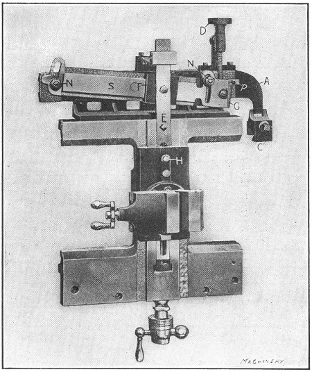
Fig. 9. A Lathe Taper Attachment
Taper attachments, like lathes, vary some in their construction, but all operate on the same principle. An improved form of taper attachment is illustrated in Figs. 9 and 10. Fig. 9 shows a plan view of a lathe carriage with an attachment fitted to it, and Fig. 10 a sectional view. This attachment has an arm A on which is mounted a slide S that can be turned about a central pivot by adjusting screw D. The arm A is supported by, and is free to slide on, a bracket B (see also sectional view) that is fastened to the carriage, and on one end of the arm there is a clamp C that is attached to the lathe bed when turning tapers. On the slide S there is a shoe F that is connected to bar E which passes beneath the toolslide. The rear end of the cross-feed screw is connected to this bar, and the latter is clamped to the toolslide when the attachment is in use.
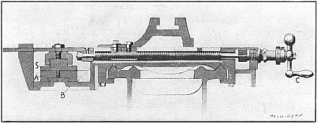
Fig. 10. Sectional View of Taper Attachment
When a taper is to be turned, the carriage is moved opposite the taper part and clamp C is fastened to the bed; this holds arm A and slide S stationary so that the carriage, with bracket B and shoe F, can be moved with relation to the slide. If this slide S is set at an angle, as shown, the shoe as it moves along causes the toolslide and tool to move in or out, but if the slide is set parallel to the carriage travel, the toolslide remains stationary. Now if the tool, as it feeds lengthwise of the work, is also gradually moved crosswise, it will turn a taper, and as[90] this crosswise movement is caused by the angularity of slide S, different tapers are obtained by setting the slide to different positions.
By means of a graduated scale G at the end of slide S, the taper that will be obtained for any angular position of the slide is shown. On some attachments there are two sets of graduations, one giving the taper in inches per foot and the other in degrees. While tapers are ordinarily given in inches per foot on drawings, sometimes the taper is given in degrees instead. The attachment is set for turning tapers by adjusting slide S until pointer p is opposite the division or fractional part of a division representing the taper. The whole divisions on the scale represent taper in inches per foot, and by means of the sub-divisions, the slide can be set for turning fractional parts of an inch per foot. When slide S is properly set, it is clamped to arm A by the nuts N. Bar E is also clamped to the toolslide by bolt H, as previously stated. The attachment is disconnected for straight turning by simply loosening clamp C and the bolt H.
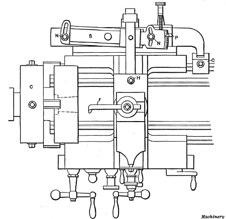
Fig. 11. Lathe with Taper Attachment arranged for Boring Taper Hole in Engine Piston
Application of Taper Attachment.—Practical examples of lathe work, which illustrate the use of the taper attachment, are shown in Figs. 11 and 12. Fig. 11 shows how a taper hole is bored in an engine piston-head, preparatory to reaming. The casting must be held either in a chuck C or on a faceplate if too large for the chuck. The side of the casting (after it has been “chucked”) should run true, and also the circumference, unless the cored hole for the rod is considerably out of center, in which case the work should be shifted to divide the error. The side of the casting for a short space around the hole is faced true with a round nose turning tool, after which the rough-cored hole is bored with an ordinary boring tool t, and then it is finished with a reamer to exactly the right size and taper.
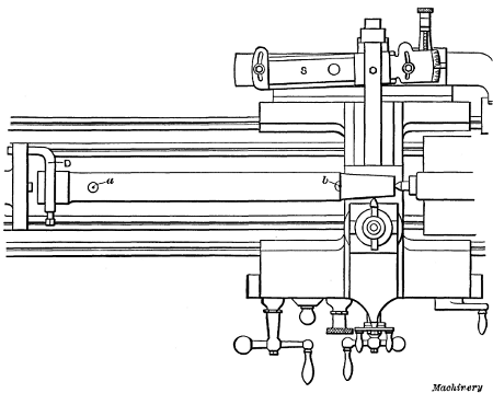
Fig. 12. Taper Attachment Set for Turning Taper End of Piston-rod
This particular taper attachment is set to whatever taper is given on the drawing, by loosening nuts N and turning slide S until pointer P is opposite that division on the scale which represents the taper. The attachment is then ready, after bolt H and nuts N are tightened, and clamp C is fastened to the lathe bed. The hole is bored just as though it were straight, and[91] as the carriage advances, the tool is gradually moved inward by the attachment. If the lathe did not have a taper attachment, the taper hole could be bored by using the compound rest.
The hole should be bored slightly less than the finish size to allow for reaming. When a reamer is used in the lathe, the outer end is supported by the tailstock center and should have a deep center-hole. The lathe is run very slowly for reaming and the reamer is fed into the work by feeding out the tailstock spindle. The reamer can be kept from revolving, either by attaching a heavy dog to the end or, if the end is squared, by the use of a wrench long enough to rest against the lathe carriage. A common method is to clamp a dog to the reamer shank, and then place the tool-rest beneath it to prevent rotation. If the[92] shank of a tool is clamped to the toolpost so that the dog rests against it, the reamer will be prevented from slipping off the center as it tends to do; with this arrangement, the carriage is gradually moved along as the tailstock spindle is fed outward. Some reamers are provided with stop-collars which come against the finished side of the casting when the hole has been reamed to size.
After the reaming operation, the casting is removed from the chuck and a taper mandrel is driven into the hole for turning the outside of the piston. This mandrel should run true on its centers, as otherwise the outside surface of the piston will not be true with the bored hole. The driving dog, especially for large work of this kind, should be heavy and stiff, because light flexible clamps or dogs vibrate and frequently cause chattering. For such heavy work it is also preferable to drive at two points on opposite sides of the faceplate, but the driving pins should be carefully adjusted to secure a uniform bearing on both sides.
The foregoing method of machining a piston is one that would ordinarily be followed when using a standard engine lathe, and it would, perhaps, be as economical as any if only one piston were being made; but where such work is done in large quantities, time could be saved by proceeding in a different way. For example, the boring and reaming operation could be performed much faster in a turret lathe, which is a type designed for just such work, but a turret lathe cannot be used for as great a variety of turning operations as a lathe of the regular type. There are also many other classes of work that can be turned more quickly in special types of machines, but as more or less time is required for arranging these special machines and often special tools have to be made, the ordinary lathe is frequently indispensable when only a few parts are needed; in addition, it is better adapted to some turning operations than any other machine.
Fig. 12 illustrates how a taper attachment would be used for turning the taper fitting for the crosshead end of an engine piston-rod. Even though this taper corresponds to the taper of the hole in the piston, slide S would have to be reset to the corresponding [93] division on the opposite side of the central zero mark, because the taper of the hole decreased in size during the boring operation, whereas the rod is smallest at the beginning of the cut, so that the tool must move outward rather than inward as it advances. The taper part is turned practically the same as a cylindrical part; that is, the power feed is used and, as the carriage moves along the bed, the tool is gradually moved outward by the taper attachment.
If the rod is being fitted directly to the crosshead (as is usually the case), the approximate size of the small end of the taper could be determined by calipering, the calipers being set to the size of the hole at a distance from the shoulder or face side of the crosshead, equal to the length of the taper fitting on the rod. If the crosshead were bored originally to fit a standard plug gage, the taper on the rod could be turned with reference to this gage, but, whatever the method, the taper should be tested before turning too close to the finished size. The test is made by removing the rod from the lathe and driving it tightly[94] into the crosshead. This shows how near the taper is to size, and when the rod is driven out, the bearing marks show whether the taper is exactly right or not. If the rod could be driven in until the shoulder is, say, 1/8 inch from the crosshead face, it would then be near enough to finish to size by filing. When filing, the lathe is run much faster than for turning, and most of the filing should be done where the bearing marks are the heaviest, to distribute the bearing throughout the length of the taper. Care should be taken when driving the rod in or out, to protect the center-holes in the ends by using a “soft” hammer or holding a piece of soft metal against the driving end.
After the crosshead end is finished, the rod is reversed in the lathe for turning the piston end. The dog is clamped to the finished end, preferably over a piece of sheet copper to prevent the surface from being marred. When turning this end, either the piston reamer or the finished hole in the piston can be calipered. The size and angle of the taper are tested by driving the rod into the piston, and the end should be fitted so that by driving tightly, the shoulder will just come up against the finished face of the piston. When the taper is finished, the attachment is disengaged and a finishing cut is taken over the body of the rod, unless it is to be finished by grinding, which is the modern and most economical method.
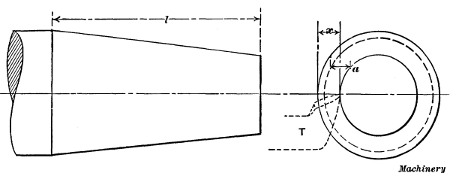
Fig. 13. Tool Point should be in same Horizontal Plane as Axis of Work for Taper Turning
Height of Tool when Turning Tapers.—The cutting edge of the tool, when turning tapers, should be at the same height as the center or axis of the work, whether an attachment is used or[95] not. The importance of this will be apparent by referring to Fig. 13. To turn the taper shown, the tool T would be moved back a distance x (assuming that an attachment is used) while traversing the length l. As an illustration, if the tool could be placed as high as point a, the setting of the attachment remaining as before, the tool would again move back a distance x, while traversing a distance l, but the large end would be under-sized (as shown by the dotted line) if the diameters of the small ends were the same in each case. Of course, if the tool point were only slightly above or below the center, the resulting error would also be small. The tool can easily be set central by comparing the height of the cutting edge at the point of the tool with one of the lathe centers before placing the work in the lathe.
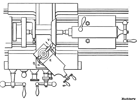
Fig. 14. Plan View showing Method of Turning a Taper with the Compound Rest
Taper Turning with the Compound Rest.—The amount of taper that can be turned by setting over the tailstock center and by the taper attachment is limited, as the centers can only be offset a certain distance, and the slide S (Fig. 9) of the attachment cannot be swiveled beyond a certain position. For steep tapers, the compound rest E is swiveled to the required[96] angle and used as indicated in Fig. 14, which shows a plan view of a rest set for turning the valve V. This compound rest is an upper slide mounted on the lower or main cross-slide D, and it can be turned to any angular position so that the tool, which ordinarily is moved either lengthwise or crosswise of the bed, can be fed at an angle. The base of the compound rest is graduated in degrees and the position of these graduations shows to what angle the upper slide is set. Suppose the seat of valve V is to be turned to an angle of 45 degrees with the axis or center, as shown on the drawing at A, Fig. 15. To set the compound rest, nuts n on either side, which hold it rigidly to the lower slide, are first loosened and the slide is then turned until the 45-degree graduation is exactly opposite the zero line; the slide is then tightened in this position. A cut is next taken across the valve by operating handle w and feeding the tool in the direction of the arrow.
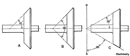
Fig. 15. Example of Taper Work Turned by using Compound Rest
In this particular instance the compound rest is set to the same angle given on the drawing, but this is not always the case. If the draftsman had given the included angle of 90 degrees, as shown at B, which would be another way of expressing it, the setting of the compound rest would, of course, be the same as before, or to 45 degrees, but the number of degrees marked on the drawing does not correspond with the angle to which the rest must be set. As another illustration, suppose the valve were to be turned to an angle of 30 degrees with the[97] axis as shown at C. In this case the compound rest would not be set to 30 degrees but to 60 degrees, because in order to turn the work to an angle of 30 degrees, the rest must be 60 degrees from its zero position, as shown. From this it will be seen that the number of degrees marked on the drawing does not necessarily correspond to the angle to which the rest must be set, as the graduations on the rest show the number of degrees that it is moved from its zero position, which corresponds to the line a—b. The angle to which the compound rest should be set can be found, when the drawing is marked as at A or C, by subtracting the angle given from 90 degrees. When the included angle is given, as at B, subtract one-half the included angle from 90 degrees to obtain the required setting. Of course, when using a compound rest, the lathe centers are set in line as for straight turning, as otherwise the angle will be incorrect.
| Given | To Find | Rule |
| The taper per foot. | The taper per inch. | Divide the taper per foot by 12. |
| The taper per inch. | The taper per foot. | Multiply the taper per inch by 12. |
| End diameters and length of taper in inches. | The taper per foot. | Subtract small diameter from large; divide by length of taper, and multiply quotient by 12. |
| Large diameter and length of taper in inches and taper per foot. | Diameter at small end in inches. | Divide taper per foot by 12; multiply by length of taper, and subtract result from large diameter. |
| Small diameter and length of taper in inches, and taper per foot. | Diameter at large end in inches. | Divide taper per foot by 12; multiply by length of taper, and add result to small diameter. |
| The taper per foot and two diameters in inches. | Distance between two given diameters in inches. | Subtract small diameter from large; divide remainder by taper per foot, and multiply quotient by 12. |
| The taper per foot. | Amount of taper in a certain length given in inches. | Divide taper per foot by 12; multiply by given length of tapered part. |
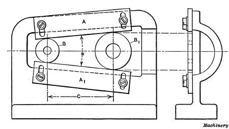
Fig. 16. Disk Gage for Accurate Measurement of Angles and Tapers
Accurate Measurement of Angles and Tapers.—When great accuracy is required in the measurement of angles, or when[98] originating tapers, disks are commonly used. The principle of the disk method of taper measurement is that if two disks of unequal diameters are placed either in contact or a certain distance apart, lines tangent to their peripheries will represent an angle or taper, the degree of which depends upon the diameters of the two disks and the distance between them. The gage shown in Fig. 16, which is a form commonly used for originating tapers or measuring angles accurately, is set by means of disks. This gage consists of two adjustable straight-edges A and A1, which are in contact with disks B and B1. The angle α or the taper between the straight-edges depends, of course, upon the diameters of the disks and the center distance C, and as these three dimensions can be measured accurately, it is possible to set the gage to a given angle within very close limits. Moreover, if a record of the three dimensions is kept, the exact setting of the gage can be reproduced quickly at any time. The following rules may be used for adjusting a gage of this type.
To Find Center Distance for a Given Taper.—When the taper, in inches per foot, is given, to determine center distance C. Rule: Divide the taper by 24 and find the angle corresponding to the quotient in a table of tangents; then find the sine corresponding to this angle and divide the difference between the disk diameters by twice the sine.
[99] Example: Gage is to be set to 3/4 inch per foot, and disk diameters are 1.25 and 1.5 inch, respectively. Find the required center distance for the disks.
| 0.75 | ||
| —— | = | 0.03125. |
| 24 |
The angle whose tangent is 0.03125 equals 1 degree 47.4 minutes;
| sin 1° 47.4' = 0.03123; 1.50 - 1.25 = 0.25 inch; |
| 0.25 | ||
| ————— | = | 4.002 inches = center distance C. |
| 2 × 0.03123 |
To Find Center Distance for a Given Angle.—When straight-edges must be set to a given angle α, to determine center distance C between disks of known diameter. Rule: Find the sine of half the angle α in a table of sines; divide the difference between the disk diameters by double this sine.
Example: If an angle α of 20 degrees is required, and the disks are 1 and 3 inches in diameter, respectively, find the required center distance C.
| 20 | ||
| —— | = | 10 degrees; sin 10° = 0.17365; |
| 2 |
| 3 - 1 | ||
| ————— | = | 5.759 inches = center distance C. |
| 2 × 0.17365 |
To Find Angle for Given Taper per Foot.—When the taper in inches per foot is known, and the corresponding angle α is required. Rule: Divide the taper in inches per foot by 24; find the angle corresponding to the quotient, in a table of tangents, and double this angle.
Example: What angle α is equivalent to a taper of 11/2 inch per foot?
| 1.5 | ||
| —— | = | 0.0625. |
| 24 |
The angle whose tangent is 0.0625 equals 3 degrees 35 minutes, nearly; then, 3 deg. 35 min. × 2 = 7 deg. 10 min.
To Find Angle for Given Disk Dimensions.—When the diameters of the large and small disks and the center distance are given, to determine the angle α. Rule: Divide the difference [100] between the disk diameters by twice the center distance; find the angle corresponding to the quotient, in a table of sines, and double the angle.
Example: If the disk diameters are 1 and 1.5 inch, respectively, and the center distance is 5 inches, find the included angle α.
| 1.5 - 1 | ||
| ——— | = | 0.05. |
| 2 × 5 |
The angle whose sine is 0.05 equals 2 degrees 52 minutes; then, 2 deg. 52 min. × 2 = 5 deg. 44 min. = angle α.
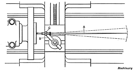
Fig. 17. Setting Center Mark in Line with Axis of Lathe Spindle by use of Test Indicator
Use of the Center Indicator.—The center test indicator is used for setting a center-punch mark, the position of which corresponds with the center or axis of the hole to be bored, in alignment with the axis of the lathe spindle. To illustrate, if two holes are to be bored, say 5 inches apart, small punch marks having that center-to-center distance would be laid out as accurately as possible. One of these marks would then be set central with the lathe spindle by using a center test indicator as shown in Fig. 17. This indicator has a pointer A the end of which is conical and enters the punch mark. The pointer is held by shank B which is fastened in the toolpost. The joint C by means of which the pointer is held to the shank is universal; that is, it allows the pointer to move in any direction. Now when the part being tested is rotated by running the[101] lathe, if the center-punch mark is not in line with the axes of the lathe spindle, obviously the outer end of pointer A will vibrate, and as joint C is quite close to the inner end, a very slight error in the location of the center-punch mark will cause a perceptible movement of the outer end, as indicated by the dotted lines. When the work has been adjusted until the pointer remains practically stationary, the punch mark is central, and the hole is bored. The other center-punch mark is then set in the same way for boring the second hole. The accuracy of this method depends, of course, upon the location of the center-punch marks. A still more accurate way of setting parts for boring holes to a given center-to-center distance is described in the following:
Locating Work by the Button Method.—Among the different methods employed by machinists and toolmakers for accurately locating work such as jigs, etc., on the faceplate of a lathe, the one most commonly used is known as the button method. This scheme is so named because cylindrical bushings or buttons are attached to the work in positions corresponding to the holes to be bored, after which they are used in locating the work. These buttons, which are ordinarily about 1/2 inch in diameter, are ground and lapped to the same size and the ends squared. The diameter should, preferably, be such that the[102] radius can be determined easily, and the hole through the center should be about 1/8 inch larger than the retaining screw, so that the button can be shifted.
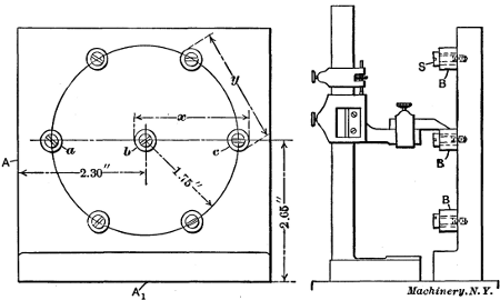
Fig. 18. Jig-plate with Buttons attached, ready for Boring
As an illustration of the practical application of the button method, we shall consider, briefly, the way the holes would be accurately machined in the jig-plate in Fig. 18. First the centers of the seven holes should be laid off approximately correct by the usual methods, after which small holes should be drilled and tapped for the clamping screws S. After the buttons B are clamped lightly in place, they are all set in correct relation with each other and with the jig-plate. The proper location of the buttons is very important as their positions largely determine the accuracy of the work. A definite method of procedure that would be applicable in all cases cannot, of course, be given, as the nature of the work as well as the tools available make it necessary to employ different methods.
In this particular case, the three buttons a, b and c should be set first, beginning with the one in the center. As this central hole must be 2.30 and 2.65 inches from the finished sides A and A1, respectively, the work is first placed on an accurate surface-plate as shown; by resting it first on one of these sides and then on the other, and measuring with a vernier height gage, the central button can be accurately set. The buttons a and c are also set to the correct height from side A1 by using the height [103] gage, and in proper relation to the central button by using a micrometer or a vernier caliper and measuring the over-all dimension x. When measuring in this way, the diameter of one button would be deducted to obtain the correct center-to-center distance. After buttons a, b and c are set equidistant from side A1 and in proper relation to each other, the remaining buttons should be set radially from the central button b and the right distance apart. By having two micrometers or gages, one set for the radial dimension x and the other for the chordal distance y, the work may be done in a comparatively short time.
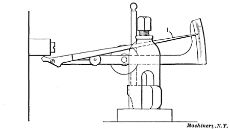
Fig. 19. Setting a Button True Preparatory to Boring, by use of Test Indicator
After the buttons have been tightened, all measurements should be carefully checked; the work is then mounted on the faceplate of the lathe, and one of the buttons, say b, is set true by the use of a test indicator as shown in Fig. 19. When the end of this indicator (which is one of a number of types on the market) is brought into contact with the revolving button, the vibration of the pointer I shows how much the button runs out of true. When the pointer remains practically stationary, thus showing that the button runs true, the latter should be removed. The hole is then drilled nearly to the required size, after which it is bored to the finish diameter. In a similar[104] manner the other buttons are indicated and the holes bored, one at a time. It is evident that if each button is correctly located and set perfectly true in the lathe, the various holes will be located at the required center-to-center dimensions within very close limits.
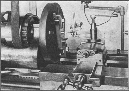
Fig. 20. Testing Concentricity of Button with Dial Gage
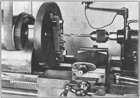
Fig. 21. Drilling a Bushing Hole
Fig. 20 shows how one of the buttons attached to a plate in which three holes are to be bored is set true or concentric. The particular indicator illustrated is of the dial type, any error in the location of the button being shown by a hand over a dial having graduations representing thousandths of an inch. Fig. 21 shows how the hole is drilled after the button is removed. It will be noted that the drill is held in a chuck, the taper shank of which fits into the tailstock spindle, this being the method of holding small drills. After drilling, the hole is bored as shown in Fig. 22. The boring tool should have a keen edge to avoid springing, and if the work when clamped in position, throws the faceplate out of balance, it is advisable to restore the balance, before boring, by the use of a counter-weight, because the lathe can be rotated quite rapidly when boring such a small hole.
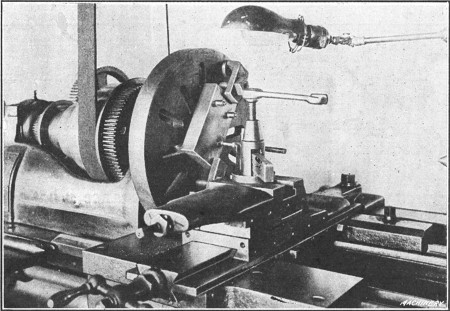
Fig. 22. Boring a Bushing Hole
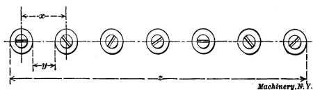
Fig. 23. Example of Work illustrating Accumulation of Errors
When doing precision work of this kind, the degree of accuracy will depend upon the instruments used, the judgment[105] and skill of the workman and the care exercised. A good general rule to follow when locating bushings or buttons is to use the method which is the most direct and which requires the least number of measurements. As an illustration of how errors may accumulate, let us assume that seven holes are to be bored in the jig-plate shown in Fig. 23, so that they are the same distance from each other and in a straight line. The buttons may be brought into alignment by the use of a straight-edge, and to simplify matters, it will be taken for granted that they have been ground and lapped to the same size. If the diameter of the buttons is first determined by measuring with a micrometer, and then this diameter is deducted from the center distance x, the difference will be the distance y between adjacent buttons. Now if a temporary gage is made to length y, all the buttons can be set practically the same distance apart, the error between any two adjacent ones being very slight. If, however, the total length z over the end buttons is measured by some accurate means, the chances are that this distance will not equal six times dimension x plus the diameter of one button, as it should, because even a very slight error in the gage for distance y would gradually accumulate as each button was set. If a micrometer were available that would span two of[106] the buttons, the measurements could be taken direct and greater accuracy would doubtless be obtained. On work of this kind where there are a number of holes that need to have accurate over-all dimensions, the long measurements should first be taken when setting the buttons, providing, of course, there are proper facilities for so doing, and then the short ones. For example, the end buttons in this case should first be set, then the central one and finally those for the sub-divisions.
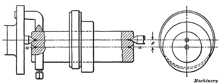
Fig. 24. Special Arbor for Turning Eccentrics
Eccentric Turning.—When one cylindrical surface must be turned eccentric to another, as when turning the eccentric of a steam engine, an arbor having two sets of centers is commonly used, as shown in Fig. 24. The distance x between the centers must equal one-half the total “throw” or stroke of the eccentric. The hub of the eccentric is turned upon the centers a—a, and the tongued eccentric surface, upon the offset centers, as indicated by the illustration. Sometimes eccentrics are turned while held upon special fixtures attached to the faceplate.
When making an eccentric arbor, the offset center in each end should be laid out upon radial lines which can be drawn[107] across the arbor ends by means of a surface gage. Each center is then drilled and reamed to the same radius x as near as possible. The uniformity of the distance x at each end is then tested by placing the mandrel upon the offset centers and rotating it, by hand, with a dial indicator in contact at first one end and then the other. The amount of offset can also be tested either by measuring from the point of a tool held in the toolpost, or by setting the tool to just graze the mandrel at extreme inner and outer positions, and noting the movement of the cross-slide by referring to the dial gage of the cross-feed screw.
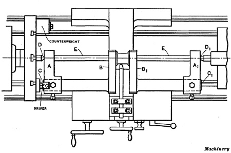
Fig. 25. Turning an Engine Crank-pin in an Ordinary Lathe
Turning a Crankshaft in a Lathe.—Another example of eccentric turning is shown in Fig. 25. The operation is that of turning the crank-pin of an engine crankshaft, in an ordinary lathe. The main shaft is first rough-turned while the forging revolves upon its centers C and C1 and the ends are turned to fit closely the center-arms A and A1. After the sides B and B1 of the crank webs have been rough-faced, the center-arms are attached to the ends of the shaft as shown in the illustration. These arms have centers at D and D1 (located at the required crank radius) which should be aligned with the rough pin, when[108] attaching the arms, and it is advisable to insert braces E between the arms and crank to take the thrust of the lathe centers. With the forging supported in this way, the crank-pin and inner sides of the webs are turned and faced, the work revolving about the axis of the pin. The turning tools must extend beyond the tool-holder far enough to allow the crank to clear as it swings around. Owing to this overhang, the tool should be as heavy as possible to make it rigid and it is necessary to take comparatively light cuts and proceed rather cautiously. After finishing the crank-pin and inside of the crank, the center-arms are removed and the main body of the shaft and the sides B and B1 are finished. This method of turning crankshafts is often used in general repair shops, etc., especially where new shafts do not have to be turned very often. It is slow and inefficient, however, and where crankshafts are frequently turned, special machines or attachments are used.
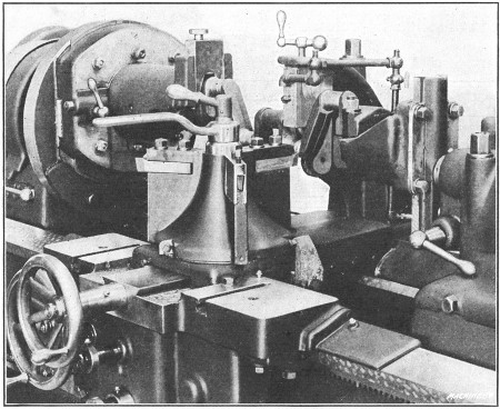
Fig. 26. LeBlond Lathe with Special Equipment for Crankshaft Turning
Special Crankshaft Lathe.—A lathe having special equipment for rough-turning gas engine crankshaft pins is shown in[109] Fig. 26. This lathe is a heavy-duty type built by the R. K. LeBlond Machine Tool Co. It is equipped with special adjustable headstock and tailstock fixtures designed to take crankshafts having strokes up to about 6 inches. The tools are held in a three-tool turret type of toolpost and there are individual cross-stops for each tool. This lathe also has a roller steadyrest for supporting the crankshaft; automatic stops for the longitudinal feed, and a pump for supplying cutting lubricant. The headstock fixture is carried on a faceplate mounted on the spindle and so arranged as to be adjustable for cranks of different throw. When the proper adjustment for a given throw has been made, the slide is secured by four T-bolts. A graduated scale and adjusting screw permit of accurate adjustments.
The revolving fixture is accurately indexed for locating different crank-pins in line with the lathe centers, by a hardened steel plunger in the slide which engages with hardened bushings in the fixture. The index is so divided that the fixture may be rotated 120 or 180 degrees, making it adjustable for 2-, 4- and 6-throw cranks. After indexing, the fixture is clamped by two T-bolts which engage a circular T-slot. The revolving fixture is equipped with removable split bushings which can be replaced to fit the line bearings of different sized crankshafts. The work is driven by a V-shaped dovetail piece having a hand-nut adjustment, which also centers the pin by the cheek or web. The crank is held in position by a hinged clamp on the fixture. The tailstock fixture is also adjustable and it is mounted on a spindle which revolves in a bushing in the tailstock barrel. The adjustment is obtained in the same manner as on the headstock fixture, and removable split bushings as well as a hinged clamp are also employed.
The method of chucking a four-throw crank is as follows: The two fixtures are brought into alignment by two locking pins. One of these is located in the head and enters a bushing in the large faceplate and the other is in the tailstock and engages the tailstock fixture. The crankshaft is delivered to the machine with the line bearings rough-turned and it is clamped by the hinged clamp previously referred to and centered by the[110] V-shaped driver. The locking pins for both fixtures are then withdrawn and the machine is ready to turn two of the pins. After these have been machined, the fixtures are again aligned by the locking pins, the two T-bolts of the headstock fixture and the hinged clamp at the tailstock are released, the indexing plunger is withdrawn and the headstock fixture and crank are turned 180 degrees or until the index plunger drops into place. The crank is then clamped at the tailstock end and the revolving fixture is secured by the two T-bolts previously referred to. After the locking pins are withdrawn, the lathe is ready to turn the two opposite pins.
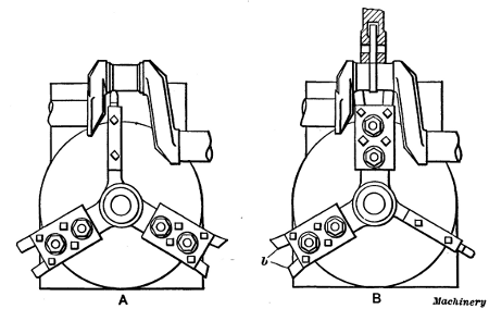
Fig. 27. Diagrams showing Arrangements of Tools on LeBlond Lathe
Operation of Special Crankshaft Lathe.—The total equipment of this machine (see Fig. 27) is carried on a three-tool turret tool-block. The method of turning a crankshaft is as follows: A round-nosed turning tool is first fed into a cross stop as illustrated in the plan view at A, which gives the proper diameter. The feed is then engaged and the tool feeds across the pin until the automatic stop lever engages the first stop, which throws out the feed automatically. The carriage is then moved against a positive stop by means of the handwheel. The roller back-rest is next adjusted against the work by the cross-feed handwheel operating through a telescopic screw, and[111] the filleting tools are brought into position as at B. These are run in against a stop, removing the part left by the turning tool and giving the pin the proper width and fillets of the correct radius. If the crankshaft has straight webs which must be finished, two tools seen at b are used for facing the webs to the correct width. During these last two operations, the crank is supported by the roller back-rest, thus eliminating any tendency of the work to spring.
After one pin is finished in the manner described, the back-rest is moved out of the way, the automatic stop lever raised, the carriage shifted to the next pin, and the operation repeated. The tools are held in position on the turret by studs, and they can be moved and other tools quickly substituted for pins of different widths. This machine is used for rough-turning the pins close to the required size, the finishing operation being done in a grinder. It should be mentioned, in passing, that many crankshafts, especially the lighter designs used in agricultural machinery, etc., are not turned at all but are ground from the rough.
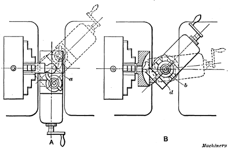
Fig. 28. (A) Spherical Turning with Compound Rest.
(B) Concave Turning
Spherical Turning.—Occasionally it may be necessary to turn a spherical surface in the lathe. Sketch A, Fig. 28, shows [112] how a small ball-shaped end can be turned on a piece held in a chuck. The lathe carriage is adjusted so that the pin around which the compound rest swivels is directly under the center a. The bolts which hold the swivel are slightly loosened to allow the top slide to be turned, as indicated by the dotted lines; this causes the tool point to move in an arc about center a, and a spherical surface is turned. Light cuts must be taken as otherwise it would be difficult to turn the slide around by hand.
Sketch B illustrates how a concave surface can be turned. The cross-slide is adjusted until swivel pin is in line with the lathe centers, and the carriage is moved along the bed until the horizontal distance between center b of the swivel, and the face of the work, equals the desired radius of the concave surface. The turning is then done by swinging the compound rest as indicated by the dotted lines. The slide can be turned more evenly by using the tailstock center to force it around. A projecting bar is clamped across the end of the slide at d, to act as a lever, and a centered bar is placed between this lever and the tailstock center; then by screwing out the tailstock spindle, the slide is turned about pivot b. The alignment between the swivel pin and the lathe centers can be tested by taking a trial cut; if the swivel pin is too far forward, the tool will not touch the turned surface if moved past center c, and if the pin is too far back, the tool will cut in on the rear side.
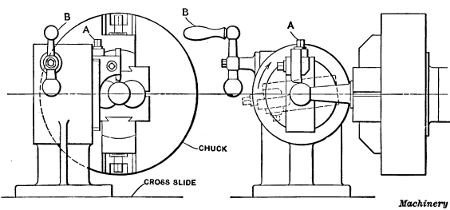
Fig. 29. Spherical Turning Attachment for Engine Lathe
[113] Spherical Turning Attachments.—When spherical turning must be done repeatedly, special attachments are sometimes used. Fig. 29 shows an attachment applied to a lathe for turning the spherical ends of ball-and-socket joints. The height or radius of the cutting tool and, consequently, the diameter of the turned ball, is regulated by adjusting screw A. The tool is swung around in an arc, by turning handle B which revolves a worm meshing with an enclosed worm-wheel. As will be seen, the work is held in a special chuck, owing to its irregular shape.
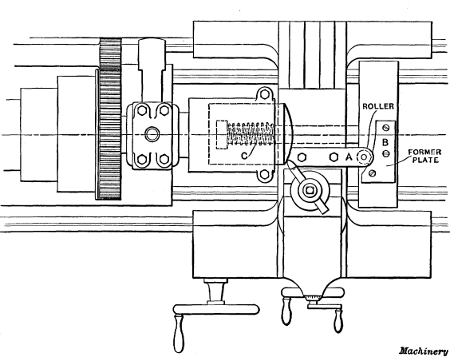
Fig. 30. Attachment for Turning Spherical End of Gasoline Engine Piston
Another spherical turning attachment is shown in Fig. 30. This is used for machining the ends of gasoline engine pistons. The cross-slide has bolted to it a bar A carrying a roller which is pressed against a forming plate B by a heavy spring C. The forming plate B, which is attached to a cross-piece fastened to the ways of the lathe bed, is curved to correspond with the radius required on the piston end, and when the tool is fed laterally by moving the cross-slide, it follows the curve of plate[114] B. The piston is held in a special hollow chuck which locates it in a central position and holds it rigidly.
In connection with lathe work, special attachments and tools are often used, especially when considerable work of one class must be turned; however, if a certain part is required in large quantities, it is usually more economical to use some semi-automatic or automatic turning machine, especially designed for repetition work.
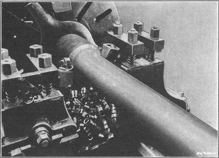
Fig. 31. Front and Rear Tools used for Roughing
Turning with Front and Rear Tools.—In ordinary engine lathe practice, one tool is used at a time, but some lathes are equipped with tool-holders at the front and rear of the carriage so that two tools can be used simultaneously. Fig. 31 shows a detail view of a lathe in which front and rear tools are being used. These tools are of the inserted cutter type and the one at the rear is inverted, as the rotary movement of the work is, of course, upward on the rear side. This particular lathe was designed for taking heavy roughing cuts and has considerable driving power.
The part shown in this illustration is a chrome-nickel steel bar which is being roughed out to form a milling machine[115] spindle. It is necessary to reduce the diameter of the bar from 57/16 inches to 33/4 inches for a length of 27 inches, because of a collar on one end. This reduction is made in one passage of the two tools, with a feed of 1/32 inch per revolution and a speed of 60 revolutions per minute. The use of two tools for such heavy roughing cuts is desirable, especially when the parts are required in large quantities, because the thrust of the cut on one side, which tends to deflect the work, is counteracted by the thrust on the opposite side.
Sometimes special tool-holders are made for the lathe, so that more than one tool can be used for turning different surfaces or diameters at the same time, the tools being set in the proper relation to each other. The advantage of this method has resulted in the design of a special lathe for multiple-tool turning.
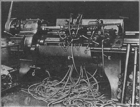
Fig. 32. Lo-swing Lathe for Multiple Turning
A Multiple-tool Lathe.—The lathe shown in Fig. 32 (which is built by the Fitchburg Machine Works and is known as the Lo-swing) is designed especially for turning shafts, pins and forgings not exceeding 31/2 inches in diameter. It has two carriages [116] A and B which, in conjunction with special tool-holders, make it possible to turn several different diameters simultaneously. At the front of this lathe there is an automatic stop-rod C for disengaging the feed when the tools have turned a surface to the required length. This stop-rod carries adjustable stops D which are set to correspond with shoulders, etc., on the work. The rod itself is also adjustable axially, so that the tools, which are usually arranged in groups of two or more (depending upon the nature of the work), can be disengaged at a point nearer or farther from the headstock as may be required, owing to a variation in the depth of center holes. For example, if it were necessary to feed a group of tools farther toward the headstock after they had been automatically disengaged, the entire rod with its stops would be adjusted the required amount in that direction.
The gage G, which is attached to a swinging arm, is used to set the stop bar with reference to a shoulder near the end of the work, when it is necessary to finish other parts to a given distance from such a shoulder or other surface. The use of[117] this gage will be explained more fully later. Cooling lubricant for the tools is supplied through the tubes E. The lathe shown in the illustration is arranged for turning Krupp steel bars. A rough bar and also one that has been turned may be seen to the right. The plain cylindrical bar is turned to five different diameters, by groups of tools held on both carriages.
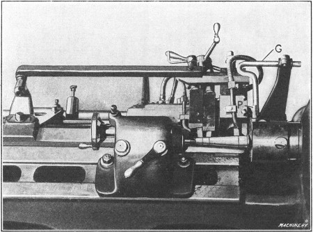
Fig. 33. Plan View showing Method of driving Steering Knuckle and Arrangement of Tools
Examples of Multiple Turning.—Figs. 33 and 34 show how a Lo-swing lathe is used for turning the steering knuckle of an automobile. Four tools are used in this case, three cylindrical surfaces and one tapering surface being turned at the same time. For this job, the four tools are mounted on one carriage. The taper part is turned by the second tool from the headstock, which is caused to feed outward as the carriage[118] advances by a taper attachment. This tool is held in a special holder and bears against a templet at the rear, which is tapered to correspond with the taper to be turned. This templet is attached to a bar which, in turn, is fastened to a stationary bracket seen to the extreme left in Fig. 33. This part is finished in two operations, the tool setting being identical for each operation, except for diameter adjustments. As the illustrations show, three of the four tools employed are used for straight turning on different diameters, while the fourth finishes the taper.
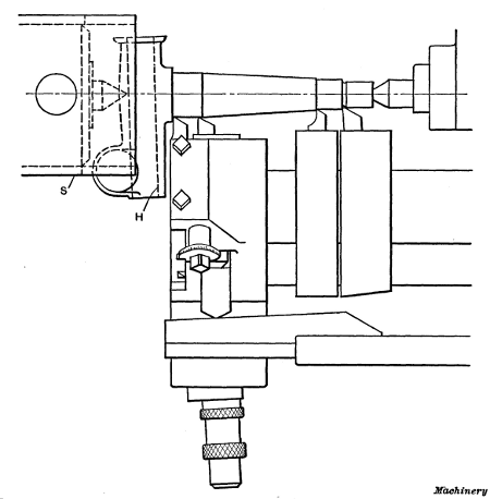
Fig. 34. Plan View showing Method of driving Steering Knuckle and Arrangement of Tools
These pieces, which are rough drop forgings, are first reduced to the approximate size. When it becomes necessary to grind the tools, they are reset and those parts which have been roughed out are turned to the finished size. The average time for the first operation, which includes starting, stopping, turning and replacing the piece, is one minute, while for the second operation with the finer feed, an average time of two minutes is required. The work is driven by sleeve S, which fits over the spindle and is held in position by the regular driver, as shown. This sleeve is notched to fit the knuckle, so that the latter can easily and quickly be replaced when finished.
One of the interesting features of this job lies in the method of locating the shoulders on each knuckle, at the same distance from the hole H which is drilled previously, and which receives the bolt on which the knuckle swivels when assembled in a car. As soon as the knuckle has been placed between the centers, a close-fitting plug P (Fig. 33) is inserted in this hole and the indicator arm with its attached gage or caliper G is swung up to the position shown. The stop-rod on which the stops have been previously set for the correct distance between the shoulders is next adjusted axially until the gage G just touches the plug P. The indicator is then swung out of the way, and the piece turned. If the next knuckle were centered, say, deeper than the previous one which would, of course, cause it to be located nearer the headstock, obviously all the shoulders would be located farther from the finished hole, provided the position of the stops remained the same as[119] before. In such a case their position would, however, be changed by shifting the stop-rod until the gage G again touched the plug thus locating all the stops with reference to the hole. As the adjustment of the stop-rod changes the position of the taper templet as well as the stops, it is evident that both the shoulders and the taper are finished the same distance from the hole in each case. The connection of the bracket (to which the templet arm is attached) with the stop-rod is clearly shown in Fig. 33. This bracket can either be locked to the ways or adjusted to slide when the stop-rod is moved.
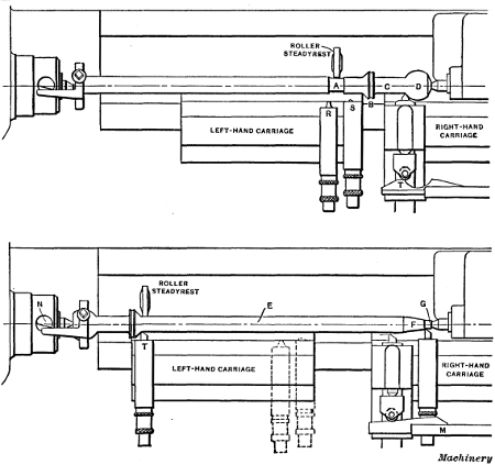
Fig. 35. First and Second Operations on Automobile Transmission Shaft—Lo-swing Lathe
The part illustrated in Fig. 35 is an automobile transmission shaft. In this particular case, cylindrical, tapering and spherical surfaces are turned. The upper view shows, diagrammatically, the arrangement of the tools and work for the first operation. After the shaft is “spotted” at A for the steadyrest, the[120] straight part C and the collar B are sized with tools S and R which are mounted on the left-hand carriage. A concave groove is then cut in collar B by tool R, after which spherical end D is formed by a special attachment mounted on the right-hand carriage. This attachment is the same, in principle, as the regular taper-turning attachment, the substitution of a circular templet T for the straight kind used on taper work being the only practical difference.
After the surfaces mentioned have been finished on a number of pieces, the work is reversed and the tools changed as shown by the lower view. The first step in the second operation is to turn the body E of the shaft with the tool T on the left-hand carriage. The taper F and the straight part G are then finished, which completes the turning. It will be noted that in setting up the machine for this second operation, it is arranged for taper turning by simply replacing the circular templet with the straight one shown. When this taper attachment is not in use, the swiveling arm M, which is attached to a bracket, is swung out of the way.
[121]The method of driving this shaft is worthy of note. A dog having two driving arms each of which bears against a pin N that passes through a hole in the spindle is used. As the ends of this pin, against which the dog bears, are beveled in opposite directions, the pin turns in its hole when the dog makes contact with it and automatically adjusts itself against the two driving members of the dog. The advantage of driving by a two-tailed dog, as most mechanics know, is in equalizing the tendency to spring slender parts while they are being turned.
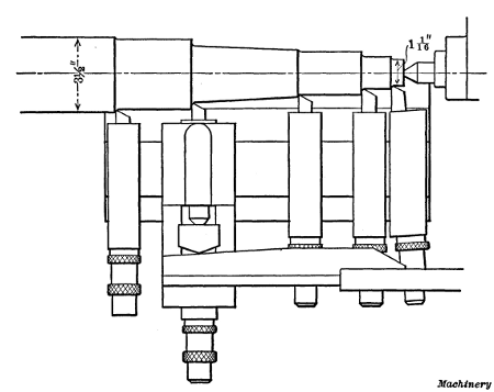
Fig. 36. Axle End turned in One Traverse of the Five Tools shown
In Fig. 36 another turning operation on a lathe of this type is shown, the work in this case being a rear axle for a motor truck. The turning of this part is a good example of that class of work where the rapid removal of metal is the important feature. As the engraving shows, the stock, prior to turning, is 31/2 inches in diameter and it is reduced to a minimum diameter of 11/16 inch. This metal is turned off with one traverse of the carriage or by one passage of the five tools, and the weight of the chips removed from each end of the axle is approximately 12 pounds. The time required for the actual turning is about 9 minutes, while the total time for the operation, which includes placing the heavy piece in the machine, turning, and[122] removing the work from the lathe, is 12 minutes. The axle revolves, while being turned, at 110 revolutions per minute and a feed equivalent to 1 inch of tool travel to 60 revolutions of the work is used. It will be noticed that the taper attachment is also employed on this part, the taper being turned by the second tool from the left. As the axle is equipped with roller bearings, it was found desirable to finish the bearing part by a separate operation; therefore, in the operation shown the axle is simply roughed down rather close to the finished dimensions, leaving enough material for a light finishing cut.
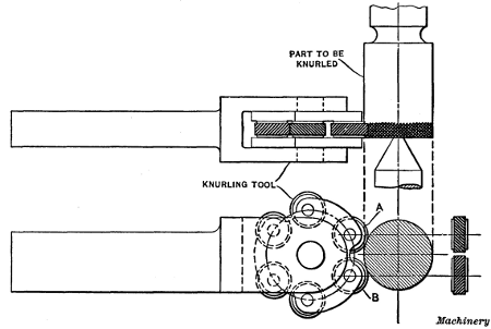
Fig. 37. Lathe Knurling Tool having Three Pairs of Knurls—Coarse, Medium and Fine
Knurling in the Lathe.—Knurling is done either to provide a rough surface which can be firmly gripped by the hand or for producing an ornamental effect. The handles of gages and other tools are often knurled, and the thumb-screws used on instruments, etc., usually have knurled edges. A knurled surface consists of a series of small ridges or diamond-shaped projections, and is produced in the lathe by the use of a tool similar to the one shown in Fig. 37, this being one of several different designs in common use. The knurling is done by two knurls A and B having teeth or ridges which incline to the right on one knurl and to the left on the opposite knurl, as shown by the end view. When these two knurls are pressed against the work as the latter revolves, one knurl forms a series of left-hand ridges and the other knurl right-hand ridges, which cross and form the diamond-shaped knurling which is generally used.
If the surface to be knurled is wider than the knurls, the power feed of the lathe should be engaged and the knurling tool be traversed back and forth until the diamond-shaped projections are well formed. To prevent forming a double set of projections, feed the knurl in with considerable pressure at the start, then partially relieve the pressure before engaging the power feed. Use oil when knurling.
The knurls commonly used for lathe work have spiral teeth and ordinarily there are three classes, known as coarse, medium and fine. The medium pitch is generally used. The teeth of coarse knurls have a spiral angle of 36 degrees and the pitch of the knurled cut (measured parallel to the axis of the work)[123] should be about 8 per inch. For medium knurls, the spiral angle is 291/2 degrees and the pitch, measured as before, is 12 per inch. For fine knurls, the spiral angle is 253/4 degrees and the pitch 20 per inch. The knurls should be about 3/4 inch in diameter and 3/8 inch wide. When made to these dimensions, coarse knurls have 34 teeth; medium, 50 teeth; and fine knurls, 80 teeth.
The particular tool illustrated in Fig. 37 has three pairs of knurls of coarse, medium and fine pitch. These are mounted in a revolving holder which not only serves to locate the required set of knurls in the working position, but enables each knurl to bear against the surface with equal pressure. Concave knurls are sometimes used for knurling rounded edges on screw heads, etc.
Relieving Attachment.—Some lathes, particularly those used in toolrooms, are provided with relieving attachments which are used for “backing off” the teeth of milling cutters, taps, hobs, etc. If a milling cutter of special shape is to be made, the cutter blank is first turned to the required form with a special tool having a cutting edge that corresponds with the shape or profile of the cutter to be made. The blank is then fluted or gashed to form the teeth, after which the tops of the teeth are[124] relieved or backed off to provide clearance for the cutting edges. The forming tool used for turning the blank is set to match the turned surface, and the teeth are backed off as the result of a reciprocating action imparted to the toolslide by the relieving attachment. The motion of the toolslide is so adjusted that the tool will meet the front of each tooth and the return movement begin promptly after the tool leaves the back end of the tooth.
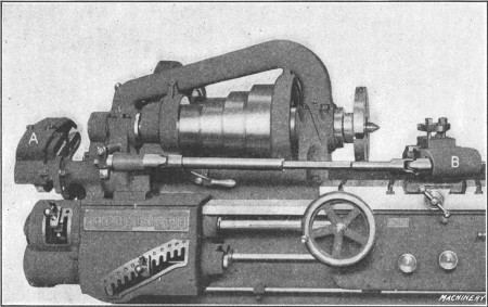
Fig. 38. Hendey Relieving Attachment applied to a Lathe
These attachments differ somewhat in their construction and arrangement but the principle of their operation is similar. Fig. 38 shows a Hendey relieving attachment applied to a lathe. A bracket carrying the gearing A through which the attachment is driven is mounted upon the main gear box of the lathe, and the special slide B, which is used when relieving, is placed on the cross-slide after removing the regular compound rest. The gears at A are changed to suit the number of flutes or gashes in the cutter, tap or whatever is to be relieved. If we assume that the work is a formed milling cutter having nine teeth, then with this particular attachment, a gear having 90 teeth would be placed on the “stud” and a 40-tooth gear on the cam-shaft, the two gears being connected by a 60-tooth intermediate gear.[125] With this combination of gearing, the toolslide would move in and out nine times for each revolution of the work, so that the tool could back off the top of each tooth. (The gearing to use for various numbers of flutes is shown by an index plate on the attachment.) The amount of relief is varied to suit the work being done, by means of a toothed coupling which makes it possible to change the relative position between the eccentric which actuates the toolslide and the cam lever, thereby lengthening or shortening the reciprocating travel of the tool.
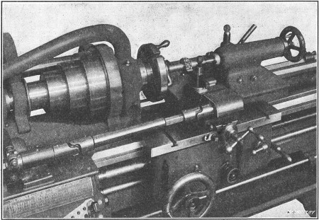
Fig. 39. Relieving a Formed Cutter
Application of Relieving Attachment.—Some typical examples of the kind of work for which the relieving attachment is used are shown in Figs. 39 to 42, inclusive. Fig. 39 shows how a formed milling cutter is relieved. The toolslide is set at right angles to the axis of the work, and the tool moves in as each tooth passes, and out while crossing the spaces or flutes between the teeth. As the result of this movement, the tops of the teeth are backed off eccentrically but the form or shape is the same from the front to the back of the tooth; hence, a cutter that has been relieved in this way can be ground repeatedly without changing the profile of the teeth, provided the faces are ground so as to lie in a radial plane.
[126]When relieving, the cutting speed should be much less than when turning in order to give the toolslide time to operate properly. A maximum of 180 teeth per minute is recommended, and, if wide forming tools are used, it might be advisable to reduce the speed so low that only 8 teeth per minute would be relieved. It is also essential to use a tool having a keen edge, and the toolslide should work freely but be closely adjusted to the dovetail of the lower slide. Before beginning to back off the teeth, it is a good plan to color the work either by heating it or dipping into a strong solution of copper sulphate. This will enable one to see plainly the cutting action of the tool in order to stop relieving at the proper time.
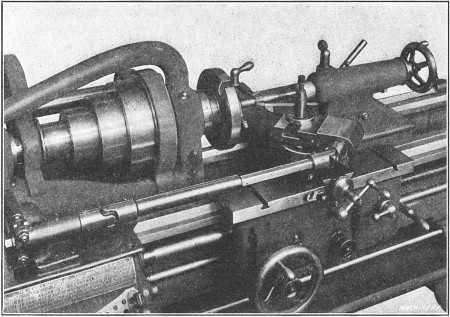
Fig. 40. Relieving Side of Angular Milling Cutter
Fig. 40 shows a method of relieving the teeth of an angular cutter. For an operation of this kind the toolslide is swiveled around at right angles to the side that is to be relieved. By the use of an additional universal joint and bearing to permit the toolslide to be swung to a 90-degree angle, the teeth of counterbores, etc., can be relieved on the ends. When the attachment is used for relieving inside work, such as hollow mills and threading dies, the eccentric which controls the travel of the toolslide is set so that the relieving movement is away from[127] the axis of the cutter instead of toward it. This change is made by the toothed coupling previously referred to, which connects the cam lever and oscillating shaft, the latter being turned beyond the zero mark in a clockwise direction as far as is necessary to obtain the desired amount of travel. For internal work it is also necessary to change the position of the opposing spring of the toolslide, so that it will press against the end of the slide and prevent the tool from jumping into the work.
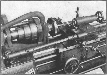
Fig. 41. Relieving a Right-hand Tap
Fig. 41 shows how a right-hand tap is relieved. The ordinary practice is to first set the tool the same as for cutting a thread. The motion of the toolslide is then adjusted so that the tool on the forward stroke will meet the front of each tooth, and start back as soon as the tool leaves the end of the land or top of the tooth. Taps having a left-hand thread can be relieved by two different methods. With the first method the cut starts at the cutting edge of each tooth, and ends at the “heel,” the tool moving in toward the center of the work. With the second method, the cut begins at the heel and discontinues at the cutting edge, the tool being drawn away from the work during the[128] cut. When using the first method the tap must be placed with the point toward the headstock, the shank end being supported by the tailstock center. This is done by providing an extension or blank end at the point of the tap long enough to hold the driving dog. With the second method, the tap is held between centers the same as one having a right-hand thread, but the travel of the toolslide is set the same as for inside relief.
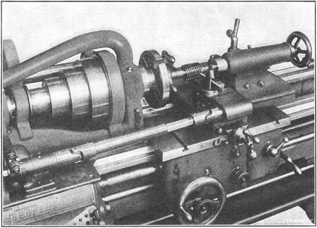
Fig. 42. Relieving a Hob having Spiral Flutes
Relieving Hobs or Taps Having Spiral Flutes.—With this attachment, taps or hobs having “spiral” or helical flutes can also be relieved. (A spiral flute is preferable to one that is parallel to the axis, because with the former the tool has cutting edges which are square with the teeth; this is of especial importance when the lead of the hob or tap thread is considerable.) When relieving work having spiral flutes (as illustrated in Fig. 42), the lead of the spiral and the gears necessary to drive the attachment are first determined. After the attachment is geared for the number of flutes and to compensate for the spiral, the lead-screw is engaged and the backing-off operation is performed the same as though the flutes were straight. The carriage should not be disengaged from the lead-screw after starting the cut, the tool being returned by reversing the lathe.
When gearing the attachment for relieving a tap or hob having spiral flutes, the gears are not selected for the actual number of flutes around the circumference but for a somewhat larger number which depends upon the lead of the hob thread and the lead of the spiral flutes. Let us assume that a hob has 6 spiral flutes and that the attachment is geared for that number. The result would be that as the tool advanced along the thread, it would not keep “in step” with the teeth because the faces of the teeth lie along a spiral (or helix which is the correct name for this curve); in other words, the tool would soon be moving in too late to begin cutting at the proper time, and to compensate for this, the attachment is geared so that the tool will make a greater number of strokes per revolution of the work than the actual number of flutes around the circumference.
With this attachment, the two gears listed on the index plate for the actual number of flutes are selected, and then two compensating [129] gears are added, thus forming a compound train of gearing. The ratio R of these compensating gears is determined as follows:
| r + 1 | ||
| R | = | ——— |
| r |
| r | = | L ÷ l; |
| L | = | lead of spiral; |
| l | = | lead of hob thread. |
For example, if a hob has a pitch circumference of 3.25, a single thread of 0.75 inch lead, and 6 spiral flutes, what compensating gears would be required?
The lead L of the spiral flutes is first determined by dividing the square of the circumference C of the hob at the pitch line by the lead l of the hob thread. Thus lead L = C2 ÷ l, or, in this case, L = 3.252 ÷ 0.75 = 14 inches, approximately. Then r = 14 ÷ 0.75 = 182/3. Inserting these values in the formula for ratio R,
| 182/3 + 1 | 192/3 | 192/3 × 3 | 59 | |||||
| R | = | ———— | = | ——— | = | ———— | = | —— |
| 182/3 | 182/3 | 182/3 × 3 | 56 |
Hence, the compensating gears will have 56 and 59 teeth, respectively, the latter being the driver. As the gears for 6 flutes listed on the regular index plate are, stud-gear 60 teeth, cam-shaft gear 40 teeth, the entire train of gears would be as follows: Gear on stud, 60; driven intermediate gear, 56; driving intermediate gear, 59; cam-shaft gear, 40. It will be understood that the position of the driving gears or the driven gears can be transposed without affecting the ratio.
Classes of Fits Used in Machine Construction.—In assembling machine parts it is necessary to have some members fit together tightly, whereas other parts such as shafts, etc., must be free to move or revolve with relation to each other. The accuracy required for a fitting varies for different classes of work. A shaft that revolves in its bearing must be slightly smaller than the bearing so that there will be room for a film of lubricant. A crank-pin that must be forced into the crank-disk is[130] made a little larger in diameter than the hole, to secure a tight fit. When a very accurate fitting between two cylindrical parts that must be assembled without pressure is required, the diameter of the inner member is made as close to the diameter of the outer member as is possible. In ordinary machine construction, five classes of fits are used, viz; running fit, push fit, driving fit, forced fit and shrinkage fit. The running fit, as the name implies, is employed when parts must rotate; the push fit is not sufficiently free to rotate; the other classes referred to are used for assembling parts that must be held in fixed positions.
Forced Fits.—This is the term used when a pin, shaft or other cylindrical part is forced into a hole of slightly smaller diameter, by the use of a hydraulic press or other means. As a rule, forced fits are restricted to parts of small and medium size, while shrinkage fits have no such limitations and are especially applicable when a maximum “grip” is desired, or when (as in the construction of ordnance) accurate results as to the intensity of stresses produced in the parts united are required. The proper allowance for a forced fit depends upon the mass of metal surrounding the hole, the size of the work, the kind and quality of the material of which the parts are composed and the smoothness and accuracy of the pin and bore. When a pin or other part is pressed into a hole a second time, the allowance for a given tonnage should be diminished somewhat because the surface of the bore is smoother and the metal more compact. The pressure required in assembling a forced fit will also vary for cast hubs of the same size, if they are not uniform in hardness. Then there is the personal factor which is much in evidence in work of this kind; hence, data and formulas for forced fit allowances must be general in their application.
[131](Newall Engineering Co.)
| Class | Tolerances in Standard Holes[1] | ||||||||||
| Nominal Diameters | Up to 1/2" | 9/16" - 1" | 11/16" - 2" | 21/16" - 3" | 31/16" - 4" | ||||||
| A | High Limit | + | 0.0002 | + | 0.0005 | + | 0.0007 | + | 0.0010 | + | 0.0010 |
| Low Limit | - | 0.0002 | - | 0.0002 | - | 0.0002 | - | 0.0005 | - | 0.0005 | |
| Tolerance | 0.0004 | 0.0007 | 0.0009 | 0.0015 | 0.0015 | ||||||
| B | High Limit | + | 0.0005 | + | 0.0007 | + | 0.0010 | + | 0.0012 | + | 0.0015 |
| Low Limit | - | 0.0005 | - | 0.0005 | - | 0.0005 | - | 0.0007 | - | 0.0007 | |
| Tolerance | 0.0010 | 0.0012 | 0.0015 | 0.0019 | 0.0022 | ||||||
| Allowances for Forced Fits | |||||||||||
| F | High Limit | + | 0.0010 | + | 0.0020 | + | 0.0040 | + | 0.0060 | + | 0.0080 |
| Low Limit | + | 0.0005 | + | 0.0015 | + | 0.0030 | + | 0.0045 | + | 0.0060 | |
| Tolerance | 0.0005 | 0.0005 | 0.0010 | 0.0015 | 0.0020 | ||||||
| Allowances for Driving Fits | |||||||||||
| D | High Limit | + | 0.0005 | + | 0.0010 | + | 0.0015 | + | 0.0025 | + | 0.0030 |
| Low Limit | + | 0.0002 | + | 0.0007 | + | 0.0010 | + | 0.0015 | + | 0.0020 | |
| Tolerance | 0.0003 | 0.0003 | 0.0005 | 0.0010 | 0.0010 | ||||||
| Allowances for Push Fits | |||||||||||
| P | High Limit | - | 0.0002 | - | 0.0002 | - | 0.0002 | - | 0.0005 | - | 0.0005 |
| Low Limit | - | 0.0007 | - | 0.0007 | - | 0.0007 | - | 0.0010 | - | 0.0010 | |
| Tolerance | 0.0005 | 0.0005 | 0.0005 | 0.0005 | 0.0005 | ||||||
| Allowances for Running Fits[2] | |||||||||||
| X | High Limit | - | 0.0010 | - | 0.0012 | - | 0.0017 | - | 0.0020 | - | 0.0025 |
| Low Limit | - | 0.0020 | - | 0.0027 | - | 0.0035 | - | 0.0042 | - | 0.0050 | |
| Tolerance | 0.0010 | 0.0015 | 0.0018 | 0.0022 | 0.0025 | ||||||
| Y | High Limit | - | 0.0007 | - | 0.0010 | - | 0.0012 | - | 0.0015 | - | 0.0020 |
| Low Limit | - | 0.0012 | - | 0.0020 | - | 0.0025 | - | 0.0030 | - | 0.0035 | |
| Tolerance | 0.0005 | 0.0010 | 0.0013 | 0.0015 | 0.0015 | ||||||
| Z | High Limit | - | 0.0005 | - | 0.0007 | - | 0.0007 | - | 0.0010 | - | 0.0010 |
| Low Limit | - | 0.0007 | - | 0.0012 | - | 0.0015 | - | 0.0020 | - | 0.0022 | |
| Tolerance | 0.0002 | 0.0005 | 0.0008 | 0.0010 | 0.0012 | ||||||
[1] Tolerance is provided for holes, which ordinary standard reamers can produce, in two grades, Classes A and B, the selection of which is a question for the user's decision and dependent upon the quality of the work required; some prefer to use Class A as working limits and Class B as inspection limits.
[2] Running fits, which are the most commonly required, are divided into three grades: Class X for engine and other work where easy fits are wanted; Class Y for high speeds and good average machine work; Class Z for fine tool work.
Allowance for Forced Fits.—The allowance per inch of diameter usually ranges from 0.001 inch to 0.0025 inch, 0.0015 being a fair average. Ordinarily, the allowance per inch decreases as the diameter increases; thus the total allowance for a diameter of 2 inches might be 0.004 inch, whereas for a diameter of 8 inches the total allowance might not be over 0.009 or[132] 0.010 inch. In some shops the allowance is made practically the same for all diameters, the increased surface area of the larger sizes giving sufficient increase in pressure. The parts to be assembled by forced fits are usually made cylindrical, although sometimes they are slightly tapered. The advantages of the taper form are that the possibility of abrasion of the fitted surfaces is reduced; that less pressure is required in assembling; and that the parts are more readily separated when renewal is required. On the other hand, the taper fit is less reliable, because if it loosens, the entire fit is free with but little axial movement. Some lubricant, such as white lead and lard oil mixed to the consistency of paint, should be applied to the pin and bore before assembling, to reduce the tendency of abrasion.
Pressure for Forced Fits.—The pressure required for assembling cylindrical parts depends not only upon the allowance for the fit, but also upon the area of the fitted surfaces, the pressure increasing in proportion to the distance that the inner member is forced in. The approximate ultimate pressure in pounds can be determined by the use of the following formula in conjunction with the accompanying table of “Pressure Factors.”
| Diameter, Inches | Pressure Factor | Diameter, Inches | Pressure Factor | Diameter, Inches | Pressure Factor | Diameter, Inches | Pressure Factor | Diameter, Inches | Pressure Factor |
| 1 | 500 | 31/2 | 132 | 6 | 75 | 9 | 48.7 | 14 | 30.5 |
| 11/4 | 395 | 33/4 | 123 | 61/4 | 72 | 91/2 | 46.0 | 141/2 | 29.4 |
| 11/2 | 325 | 4 | 115 | 61/2 | 69 | 10 | 43.5 | 15 | 28.3 |
| 13/4 | 276 | 41/4 | 108 | 63/4 | 66 | 101/2 | 41.3 | 151/2 | 27.4 |
| 2 | 240 | 41/2 | 101 | 7 | 64 | 11 | 39.3 | 16 | 26.5 |
| 21/4 | 212 | 43/4 | 96 | 71/4 | 61 | 111/2 | 37.5 | 161/2 | 25.6 |
| 21/2 | 189 | 5 | 91 | 71/2 | 59 | 12 | 35.9 | 17 | 24.8 |
| 23/4 | 171 | 51/4 | 86 | 73/4 | 57 | 121/2 | 34.4 | 171/2 | 24.1 |
| 3 | 156 | 51/2 | 82 | 8 | 55 | 13 | 33.0 | 18 | 23.4 |
| 31/4 | 143 | 53/4 | 78 | 81/2 | 52 | 131/2 | 31.7 | .... | .... |
Assuming that A = area of fitted surface; a = total allowance in inches; P = ultimate pressure required, in tons; F = pressure factor based upon assumption that the diameter of the[133] hub is twice the diameter of the bore, that the shaft is of machine steel, and the hub of cast iron, then,
| A × a × F | ||
| P | = | ————— |
| 2 |
Example:—What will be the approximate pressure required for forcing a 4-inch machine steel shaft having an allowance of 0.0085 inch into a cast-iron hub 6 inches long?
A = 4 × 3.1416 × 6 = 75.39 square inches;
F, for a diameter of 4 inches, = 115 (see table of “Pressure Factors”). Then,
P = (75.39 × 0.0085 × 115)/2 = 37 tons, approximately.
Allowance for Given Pressure.—By transposing the preceding formula, the approximate allowance for a required ultimate tonnage can be determined. Thus, a = 2P ÷ AF. The average ultimate pressure in tons commonly used ranges from 7 to 10 times the diameter in inches. Assuming that the diameter of a machine steel shaft is 4 inches and an ultimate pressure of about 30 tons is desired for forcing it into a cast-iron hub having a length of 51/2 inches, what should be the allowance?
A = 4 × 3.1416 × 51/2 = 69 square inches,
F, for a diameter of 4 inches, = 115. Then,
| 2 × 30 | ||||
| a | = | ————— | = | 0.0075 inch. |
| 69 × 115 |
Shrinkage Fits.—When heat is applied to a piece of metal, such as iron or steel, as is commonly known, a certain amount of expansion takes place which increases as the temperature is increased, and also varies somewhat with different kinds of metal, copper and brass expanding more for a given increase in temperature than iron and steel. When any part which has been expanded by the application of heat is cooled, it contracts and resumes its original size. This expansive property of metals has been taken advantage of by mechanics in assembling various machine details. A cylindrical part which is to be held in position by a shrinkage fit is first turned a few thousandths[134] of an inch larger than the hole; the diameter of the latter is then increased by heating, and after the part is inserted, the heated outer member is cooled, causing it to grip the pin or shaft with tremendous pressure.
General practice seems to favor a smaller allowance for shrinkage fits than for forced fits, although in many shops the allowances are practically the same in each case, and for some classes of work, shrinkage allowances exceed those for forced fits. In any case, the shrinkage allowance varies to a great extent with the form and construction of the part which has to be shrunk into place. The thickness or amount of metal around the hole is the most important factor. The way in which the metal is distributed also has an influence on the results. Shrinkage allowances for locomotive driving wheel tires adopted by the American Railway Master Mechanics Association are as follows:
| Center diameter, inches | 38 | 44 | 50 | 56 | 62 | 66 |
| Allowance, inches | 0.040 | 0.047 | 0.053 | 0.060 | 0.066 | 0.070 |
Whether parts are to be assembled by forced or shrinkage fits depends upon conditions. For example, to press a driving wheel tire over its wheel center, without heating, would ordinarily be a rather awkward and difficult job. On the other hand, pins, etc., are easily and quickly forced into place with a hydraulic press and there is the additional advantage of knowing the exact pressure required in assembling, whereas there is more or less uncertainty connected with a shrinkage fit, unless the stresses are calculated. Tests to determine the difference in the quality of shrinkage and forced fits showed that the resistance of a shrinkage fit to slippage was, for an axial pull, 3.66 times greater than that of a forced fit, and in rotation or torsion, 3.2 times greater. In each comparative test, the dimensions and allowances were the same.
The most important point to consider when calculating shrinkage fits is the stress in the hub at the bore, which depends chiefly upon the shrinkage allowance. If the allowance is excessive, the elastic limit of the material will be exceeded and permanent set will occur, or, in extreme cases, the ultimate strength of the metal will be exceeded and the hub will burst.
When threads are cut in the lathe a tool t is used (see Fig. 2), having a point corresponding to the shape of the thread, and the carriage is moved along the bed a certain distance for each revolution of the work (the distance depending on the number of threads to the inch being cut) by the lead-screw S which is rotated by gears a, b and c, which receive their motion from the spindle. As the amount that the carriage travels per revolution of the work, and, consequently, the number of threads per inch that is cut, depends on the size of the gears a and c (called change gears) the latter have to be changed for cutting different threads. The proper change gears to use for cutting a given number of threads to the inch is ordinarily determined by referring to a table or “index plate” I which shows what the size of gears a and c should be, or the number of teeth each should have, for cutting any given number of threads per inch.
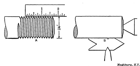
Fig. 1. Measuring Number of Threads per Inch—Setting Thread Tool
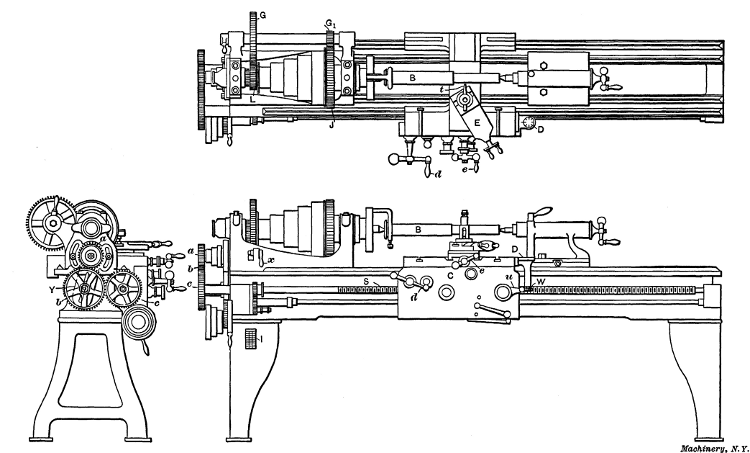
Fig. 2. Plan and Elevations of Engine Lathe
Selecting the Change Gears for Thread Cutting.—Suppose a V-thread is to be cut on the end of the bolt B, Fig. 2, having a diameter of 11/4 inch and seven threads per inch of length, as [137] shown at A in Fig. 1, which is the standard number of threads per inch for that diameter. First the change gears to use are found on plate I which is shown enlarged in Fig. 3. This plate has three columns: The first contains different numbers of threads to the inch, the second the size gear to place on the “spindle” or “stud” at a (Fig. 2) for different threads, and the third the size of gear c for the lead-screw. As the thread selected as an example has 7 threads per inch, gear a should have 48 teeth, this being the number given in the second column opposite figure 7 in the first. By referring to the last column, we find that the lead-screw gear should have 84 teeth. These gears are selected from an assortment provided with the lathe and they are placed on the spindle and lead-screw, respectively.
Intermediate gear b does not need to be changed as it is simply an “idler” for connecting gears a and c. Gear b is mounted on a swinging yoke Y so that it can be adjusted to mesh properly with different gear combinations; after this adjustment is made, the lathe is geared for cutting 7 threads to the inch. (The change gears of many modern lathes are so arranged that different combinations are obtained by simply shifting a lever. A lathe having this quick-change gear mechanism is described in the latter part of this chapter.) The work B is placed between the centers just as it would be for turning, with the end to be threaded turned to a diameter of 11/4 inch, which is the outside diameter of the thread.
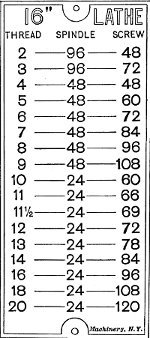
Fig. 3. Index Plate showing Gear Changes for Threading
[138] The Thread Tool.—The form of tool used for cutting a V-thread is shown at A, Fig. 4. The end is ground V-shaped and to an angle of 60 degrees, which corresponds to the angle of a standard V-thread. The front or flank, f of the tool is ground back at an angle to provide clearance, but the top is left flat or without slope. As it is very important to grind the end to exactly 60 degrees, a gage G is used, having 60-degree notches to which the tool-point is fitted. The tool is clamped in the toolpost as shown in the plan view, Fig. 2, square with the work, so that both sides of the thread will be cut to the same angle with the axis of the work. A very convenient way to set a thread tool square is illustrated at B, Fig. 1. The thread gage is placed against the part to be threaded, as shown, and the tool is adjusted until the angular sides of the point bear evenly in the 60-degree notch of the gage. The top of the tool point should be at the same height as the lathe centers, as otherwise the angle of the thread will not be correct.
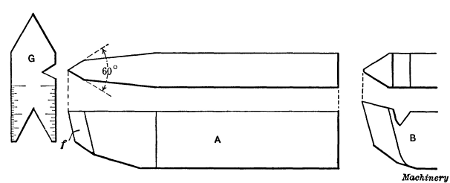
Fig. 4. Thread Tools and Gage for testing Angle of End
Cutting the Thread.—The lathe is now ready for cutting the thread. This is done by taking several cuts, as indicated at A, B, C and D in Fig. 5, the tool being fed in a little farther for each successive cut until the thread is finished. When these cuts are being taken, the carriage is moved along the bed, as previously explained, by the lead-screw S, Fig. 2. The carriage is engaged with the lead-screw by turning lever u which causes the halves of a split nut to close around the screw. The way a lathe is handled when cutting a thread is as follows: After the[139] lathe is started, the carriage is moved until the tool-point is slightly beyond the right end of the work, and the tool is fed in far enough to take the first cut which, ordinarily, would be about 1/16 inch deep. The carriage is then engaged with the lead-screw, by operating lever u, and the tool moves to the left (in this case 1/7 inch for each revolution of the work) and cuts a winding groove as at A, Fig. 5. When the tool has traveled as far as the thread is wanted, it is withdrawn by a quick turn of cross-slide handle e, and the carriage is returned to the starting point for another cut. The tool is then fed in a little farther and a second cut is taken as at B, Fig. 5, and this operation is repeated as at C and D until a “full” thread is cut or until the top of the thread is sharp. The thread is then tested for size but before referring to this part of the work, the way the carriage is returned to the starting point after each cut should be explained.
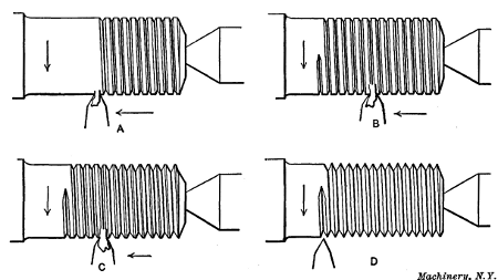
Fig. 5. Thread is formed by taking a Number of Successive Cuts
When the tool is withdrawn at the end of the first cut, if the carriage is disengaged from the lead-screw and returned by hand, the tool may or may not follow the first cut when the carriage is again engaged with the lead-screw. If the number of threads to the inch being cut is a multiple of the number on the lead-screw S, then the carriage can be returned by hand and[140] engaged with the lead-screw at random and the tool will follow the first cut. For example, if the lead-screw has six threads per inch, and 6, 12, 18 or any number of threads is being cut that is a multiple of six, the carriage can be engaged at any time and the tool will always follow the original cut. This is not the case, however, when the number of threads being cut is not a multiple of the number on the lead-screw.
One method of bringing the carriage back to the starting point, when cutting threads which are not multiples, is to reverse the lathe (by shifting the overhead driving belts) in order to bring the tool back to the starting point without disengaging the carriage; in this way the tool is kept in the same relation to the work, and the carriage is not disengaged from the lead-screw until the thread is finished. This is a good method when cutting short threads having a length of say two or three inches; but when they are longer, and especially when the diameter is comparatively large (which means a slower speed), it is rather slow as considerable time is wasted while the tool is moving back to its starting point. This is due to the fact that the carriage is moved slowly by the lead-screw, but when disengaged, it can be traversed quickly by turning handle d, Fig. 2.
A method of returning the carriage by hand when the number of threads being cut is not a multiple of the number on the lead-screw is as follows: The tool is moved a little beyond the right end of the work and the carriage or split nut is engaged with the lead-screw. The lathe is then turned forward by hand to take up any lost motion, and a line is made on the lathe bed showing the position of the carriage. The positions of the spindle and lead-screw are also marked by chalking a tooth on both the spindle and lead-screw gears, which happens to be opposite a corner or other point on the bed. After a cut is taken, the carriage is returned by hand to the original starting point as shown by the line on the bed, and is again engaged when the chalk marks show that the spindle and lead-screw are in their original position; the tool will then follow the first cut. If the body of the tailstock is moved against the bridge of the carriage before starting the first cut, the carriage can be located[141] for each following cut by moving it back against the tailstock, and it will not be necessary to have a line on the bed.
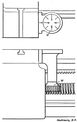
Fig. 6. Indicator used when Cutting Threads
Indicator or Chasing Dial for Catching Threads.—On some lathes there is an indicator for “catching threads,” as this is called in shop language. This is a simple device attached to the carriage and consists of a graduated dial D and a worm-wheel W (see Figs. 2 and 6) which meshes with the lead-screw, so that the dial is revolved by the lead-screw when the carriage is stationary, and when the carriage is moved by the screw, the dial remains stationary. The indicator is used by engaging the carriage when one of the graduation lines is opposite the arrow mark; after a cut is taken the carriage is returned by hand and when one of the graduation lines again moves opposite the arrow, the half-nuts are thrown into mesh, as before, and this is repeated for each successive cut, thus causing the tool to always come right with the thread. If the number of threads per inch is even, engagement can be made when any line is opposite the arrow, but for odd numbers such as 3, 7, 9, 11, etc., one of the four long or numbered lines must be used. Of course, if the thread being cut is a multiple of the number on the lead-screw, engagement can be made at any time, as previously mentioned.
[142] Principle of the Thread Indicator.—The principle upon which the thread indicator operates is as follows: The number of teeth in worm-wheel W is some multiple of the number of threads per inch of the lead-screw, and the number of teeth in the worm-wheel, divided by the pitch of the screw, equals the number of graduations on the dial. For example, if the lead-screw has six threads per inch, the worm-wheel could have twenty-four teeth, in which case the dial would have four divisions, each representing an inch of carriage travel, and by sub-dividing the dial into eighths (as shown) each line would correspond to 1/2 inch of travel. The dial, therefore, would enable the carriage to be engaged with the lead-screw at points equal to a travel of one-half inch. To illustrate the advantage of this suppose ten threads per inch are being cut and (with the lathe stationary) the carriage is disengaged and moved 1/6 inch or one thread on the lead-screw; the tool point will also have moved 1/6 inch, but it will not be opposite the next thread groove in the work as the pitch is 1/10 inch. If the carriage is moved another thread on the lead-screw, or 2/6 inch, the tool will still be out of line with the thread on the work, but when it has moved three threads, or 1/2 inch, the tool will then coincide with the original cut because it has passed over exactly five threads. This would be true for any number of threads per inch that is divisible by 2. If the thread being cut had nine threads per inch or any other odd number, the tool would only coincide with the thread at points 1 inch apart. Therefore, the carriage can only be engaged when one of the four graduations representing an inch of travel is opposite the arrow, when cutting odd threads; whereas even numbers can be “caught” by using any one of the eight lines.
This indicator can also be used for “catching” fractional threads. As an illustration, suppose 111/2 threads per inch are to be cut, and the carriage is engaged for the first cut when graduation line 1 is opposite the arrow; engagement would then be made for each successive cut, when either line 1 or 3 were opposite the arrow, or in other words at spaces equal to a carriage movement of 2 inches. As the use of the indicator when[143] cutting fractional threads is liable to result in error, it is better to keep the half-nuts in engagement and return the carriage by reversing the lathe.
Replacing Sharpened Thread Tool.—If it is necessary to sharpen the thread tool before the thread is finished, it should be reset square with the work by testing with the thread gage as at B, Fig. 1. The carriage is then engaged with the lead-screw and the lathe is turned forward to bring the tool opposite the partly finished thread and also to take up any backlash or lost motion in the gears or half-nut. If the tool-point is not in line with the thread groove previously cut, it can be shifted sidewise by feeding the compound rest E in or out, provided the latter is set in an angular position as shown in the plan view, Fig. 2.
If the thread tool is ground flat on the top as at A, Fig. 4, it is not a good tool for removing metal rapidly as neither of its two cutting edges has any slope. In order to give each cutting edge a backward slope, it would be necessary to grind the top surface hollow or concave, which would be impracticable. When a course thread is to be cut, a tool shaped as at B can be used to advantage for rough turning the thread groove, which is afterward finished to the correct depth and angle by tool A. This roughing tool is ground with a backward slope from the point and the latter is rounded to make it stronger.
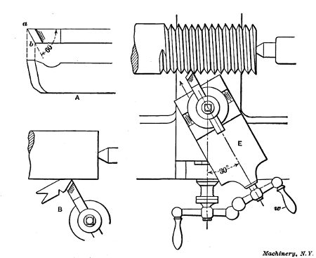
Fig. 7. Cutting Thread by using Compound Rest
Use of Compound Rest for Thread Cutting.—Another form of thread tool is shown at A, Fig. 7, which is very good for cutting V-threads especially of coarse pitch. When this tool is used, the compound rest E is set to an angle of 30 degrees, as shown, and it is fed in for the successive cuts by handle w in the direction indicated by the arrow. It will be seen that the point a of the tool moves at an angle of 60 degrees with the axis of the work, thus forming one side of the thread, and the cutting edge a—b, which can be set as shown at B, forms the opposite side and does all the cutting. As this edge is given a backward slope, as shown, it cuts easily and enables threading operations to be performed quickly. Threads cut in this way are often finished by taking a light cut with a regular thread tool. The[144] cutting edge a—b is ground to an angle of 60 degrees (or slightly less, if anything) with the side, as shown by sketch A.
When cutting threads in steel or wrought iron, some sort of lubricant is usually applied to the tool to preserve the cutting end and give a smooth finish to the thread. Lard oil or a mixture of equal parts of lard oil and paraffin oil are often used for this purpose. If the thread is small, the lubricant may be applied from an ordinary oil can, but when cutting comparatively large threads, it is better to have a stream of oil constantly playing upon the tool-point. This constant flow may be obtained by mounting a can having a spout leading to the tool, on a bracket at the rear of the carriage.
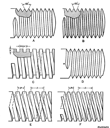
Fig. 8. (A) V-thread.
(B) U. S. Standard Thread.
(C) Square Thread.
(D)
Left-hand Thread.
(E) Double Square Thread.
(F) Triple Square Thread
Threads Commonly Used.—Three forms of threads or screws which are in common use are shown in Fig. 8; these are the V-thread (A), the U. S. standard (B), and the square thread (C). The shapes of these threads are shown by the sectioned parts. The V-thread has straight sides which incline at an[145] angle of 60 degrees with each other and at the same angle with the axis of the screw. The U. S. standard thread is similar to the V-thread except that the top of the thread and bottom of the groove is left flat, as shown, and the width of these flats is made equal to 1/8 of the pitch. The square thread is square in section, the width a, depth b and space c being all equal. All of these threads are right-hand, which means that the grooves wind around to the right so that a nut will have to be turned[146] toward the right to enter it on the thread. A left-hand thread winds in the other direction, as shown at D, and a nut is screwed on by turning it to the left.
Multiple Threads.—Threads, in addition to being right-and left-handed, are single, as at A, B, C and D, double, as at E, and triple, as at F, and for certain purposes quadruple threads or those of a higher multiple are employed. A double thread is different from a single thread in that it has two grooves, starting diametrically opposite, whereas a triple thread has three grooves cut as shown at F. The object of these multiple threads is to obtain an increase in lead without weakening the screw. For example, the threads shown at C and E have the same pitch p but the lead l of the double-threaded screw is twice that of the one with a single thread so that a nut would advance twice as far in one revolution, which is often a very desirable feature. To obtain the same lead with a single thread, the pitch would have to be double, thus giving a much coarser thread, which would weaken the screw, unless its diameter were increased. (The lead is the distance l that one thread advances in a single turn, or the distance that a nut would advance in one turn, and it should not be confused with the pitch p, which is the distance between the centers of adjacent threads. Obviously the lead and pitch of a single thread are the same.)
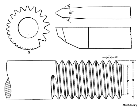
Fig. 9. U. S. Standard Thread, Thread Tool, and Gage
Cutting a U. S. Standard Thread.—The method of cutting a U. S. standard thread is the same as described for a V-thread, so far as handling the lathe is concerned. The thread tool must correspond, of course, to the shape of a U. S. standard thread. This tool is first ground to an angle of 60 degrees, as it would be for cutting a V-thread, and then the point is made flat as shown in Fig. 9. As will be recalled, the width of this flat should be equal to 1/8 of the pitch. By using a gage like the one shown at G, the tool can easily be ground for any pitch, as the notches around the periphery of the gage are marked for different pitches and the tool-point is fitted into the notch corresponding to the pitch wanted. If such a gage is not available, the width of the flat at the point can be tested by using, as a gage, a U. S. standard tap of the same pitch as the thread to be cut.
[147] When cutting the thread, the tool is set square with the blank, and a number of successive cuts are taken, the tool being fed in until the width w of the flat at the top of the thread is equal to the width at the bottom. The thread will then be the right size provided the outside diameter D is correct and the tool is of the correct form. As it would be difficult to measure the width of this flat accurately, the thread can be tested by screwing a standard nut over it if a standard thread is being cut. If it is being fitted to a tapped hole, the tap itself is a very convenient gage to use, the method being to caliper the tap and then compare its size with the work.
A good method of cutting a U. S. standard thread to a given size is as follows: First turn the outside of the blank accurately to diameter D, and then turn a small part of the end to diameter r of the thread at the root. The finishing cut for the thread is then taken with the tool point set to just graze diameter r. If ordinary calipers were set to diameter r and measurements taken in the thread groove, the size would be incorrect owing to[148] the angularity of the groove, which makes it necessary to hold the calipers at an angle when measuring. To determine the root diameter divide 1.299 by the number of threads per inch and subtract the quotient from the outside diameter. Expressing this rule as a formula,
| ( | 1.299 | ) | ||||||
| r | = | D | - | ——— | ||||
| N |
in which D equals outside diameter; N, the number of threads per inch; and r, the root diameter. The number 1.299 is a constant that is always used.
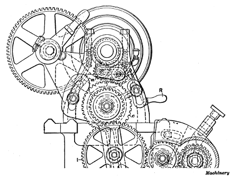
Fig. 10. End View of Lathe Headstock
Cutting a Left-hand Thread.—The only difference between cutting left-hand and right-hand threads in the lathe is in the movement of the tool with relation to the work. When cutting a right-hand thread, the tool moves from right to left, but this movement is reversed for left-hand threads because the thread winds around in the opposite direction. To make the carriage travel from left to right, the lead-screw is rotated backwards by means of reversing gears a and b (Fig. 10) located in the [149] headstock. Either of these gears can be engaged with the spindle gear by changing the position of lever R. When gear a is in engagement, as shown, the drive from the spindle to gear c is through gears a and b, but when lever R is raised thus shifting b into mesh, the drive is direct and the direction of rotation is reversed. The thread is cut by starting the tool at a, Fig. 8, instead of at the end.

Fig. 11. End of Square Thread Tool, and Graphic Method of Determining Helix Angle of Thread
Cutting a Square Thread.—The form of tool used for cutting a square thread is shown in Fig. 11. The width w is made equal to one-half the pitch of the thread to be cut and the end E is at an angle with the shank, which corresponds to the inclination x—y of the threads. This angle A depends upon the diameter of the screw and the lead of the thread; it can be determined graphically by drawing a line a—b equal in length to the circumference of the screw to be cut, and a line b—c, at right angles, equal in length to the lead of the thread. The angle α between lines a—b and a—c will be the required angle A. (See end view of thread tool). It is not necessary to have this angle accurate, ordinarily, as it is simply to prevent the tool from binding against the sides of the thread. The end of a square thread tool is shown in section to the right, to illustrate its position with relation to the threads. The sides e and e1 are ground to slope inward, as shown, to provide additional clearance.
[150] When cutting multiple threads, which, owing to their increased lead, incline considerably with the axis of the screw, the angles for each side of the tool can be determined independently as follows: Draw line a—b equal in length to the circumference of the thread, as before, to obtain the required angle f of the rear or following side e1; the angle l of the opposite or leading side is found by making a—b equal to the circumference at the root of the thread. The tool illustrated is for cutting right-hand threads; if it were intended for a left-hand thread, the end, of course, would incline in the opposite direction. The square thread is cut so that the depth d is equal to the width. When threading a nut for a square thread screw, it is the usual practice to use a tool having a width slightly greater than one-half the pitch, to provide clearance for the screw, and the width of a tool for threading square-thread taps to be used for tapping nuts is made slightly less than one-half the pitch.
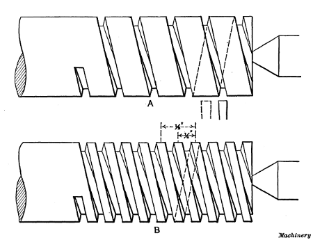
Fig. 12. Views illustrating how a Double Square Thread is Cut
Cutting Multiple Threads.—When a multiple thread is to be cut, such as a double or triple thread, the lathe is geared with reference to the number of single threads to the inch. For example, the lead of the double thread, shown at B, Fig. 12, is one-half inch, or twice the pitch, and the number of single threads to the inch equals 1 ÷ 1/2 = 2. Therefore, the lathe is geared for cutting two threads per inch. The first cut is taken just as though a single thread were being cut, leaving the work as shown at A. When this cut is finished the work is turned one-half a revolution (for a double thread) without disturbing the position of the lead-screw or carriage, which brings the tool midway between the grooves of the single thread as indicated by dotted lines. The second groove is then cut, producing a double thread as shown at B. In the case of a triple thread, the work would be indexed one-third of a revolution after turning the first groove, and then another third revolution to locate the tool for cutting the last groove. Similarly, for a quadruple thread, it would be turned one-quarter revolution after cutting each successive groove or thread.
There are different methods of indexing the work when cutting multiple threads, in order to locate the tool in the[151] proper position for cutting another thread groove. Some machinists, when cutting a double thread, simply remove the work from the lathe and turn it one-half a revolution by placing the tail of the driving dog in the opposite slot of the faceplate. This is a very simple method, but if the slots are not directly opposite or 180 degrees apart, the last thread will not be central with the first. Another and better method is to disengage the idler gear from the gear on the stud, turn the spindle and work one-half, or one-third, of a revolution, as the case might be, and then connect the gears. For example, if the stud gear had 96 teeth, the tooth meshing with the idler gear would be marked with chalk, the gears disengaged, and the spindle turned until the chalked tooth had made the required part of a revolution, which could be determined by counting the teeth. When this method is used, the number of teeth in the stud gear must be evenly divisible by two if a double thread is being cut, or by three for a triple thread, etc. If the stud is not geared to the spindle so that each makes the same number of revolutions, the ratio of the gearing must be considered.
[152] Setting Tool When Cutting Multiple Threads.—Another method, which can sometimes be used for setting the tool after cutting the first groove of a multiple thread, is to disengage the lock-nuts from the lead-screw (while the spindle is stationary) and move the carriage back whatever distance is required to locate the tool in the proper position for taking the second cut. Evidently this distance must not only locate the tool in the right place, but be such that the lock-nuts can be re-engaged with the lead-screw. Beginning with a simple illustration, suppose a double thread is being cut having a lead of 1 inch. After the first thread groove is cut, the tool can be set in a central position for taking the second cut, by simply moving the carriage back 1/2 inch (one-half the lead), or 1/2 inch plus the lead or any multiple of the lead. If the length of the threaded part were 5 inches, the tool would be moved back far enough to clear the end of the work, or say 1/2 + 5 = 51/2 inches. In order to disengage the lock-nuts and re-engage them after moving the carriage 51/2 inches (or any distance equal, in this case, to one-half plus a whole number), the lead-screw must have an even number of threads per inch.
Assume that a double thread is being cut having 11/4 single threads per inch. The lead then would equal 1 ÷ 11/4 = 0.8 inch, and if the carriage is moved back 0.8 ÷ 2 = 0.4 inch, the tool will be properly located for the second cut; but the lock-nuts could not be re-engaged unless the lead-screw had ten threads per inch, which is finer than the pitch found on the lead-screws of ordinary engine lathes. However, if the movement were 0.4 + 0.8 × 2 = 2 inches, the lock-nuts could be re-engaged regardless of the number of threads per inch on the lead-screw. The rule then, is as follows:
Divide the lead of the thread by 2 for a double thread, 3 for a triple thread, 4 for a quadruple thread, etc., thus obtaining the pitch; then add the pitch to any multiple of the lead, which will give a movement, in inches, that will enable the lock-nuts to be re-engaged with the lead-screw.
Whenever the number obtained by this rule is a whole number, obviously, the movement can be obtained with a lead-screw[153] of any pitch. If the number is fractional, the number of threads per inch on the lead-screw must be divisible by the denominator of the fraction.
To illustrate the application of the foregoing rule, suppose a quadruple thread is to be cut having 11/2 single threads per inch (which would be the number the lathe would be geared to cut). Then the lead of the thread = 1 ÷ 11/2 = 0.6666 inch and the pitch = 0.6666 ÷ 4 = 0.1666 inch; adding the pitch to twice the lead we have 0.1666 + 2 × 0.6666 = 1.499 inch. Hence, if the carriage is moved 11/2 inch (which will require a lead-screw having an even number of threads per inch), the tool will be located accurately enough for practical purposes. When the tool is set in this way, if it does not clear the end of the part being threaded, the lathe can be turned backward to place the tool in the proper position.
The foregoing rule, as applied to triple threads or those of a higher number, does not always give the only distance that the carriage can be moved. To illustrate, in the preceding example the carriage movement could be equal to 0.499, or what is practically one-half inch, instead of 11/2 inch, and the tool would be properly located. The rule, however, has the merit of simplicity and can be used in most cases.
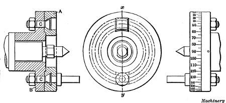
Fig. 13. Indexing Faceplate used for Multiple Thread Cutting
Special faceplates are sometimes used for multiple thread cutting, that enable work to be easily and accurately indexed. One of these is illustrated in Fig. 13; it consists of two parts A [154] and B, part A being free to rotate in relation to B when bolts C are loosened. The driving pin for the lathe dog is attached to plate A. When one groove of a multiple thread is finished, bolts C are loosened and plate A is turned around an amount corresponding to the type of thread being cut. The periphery of plate A is graduated in degrees, as shown, and for a double thread it would be turned one-half revolution or 180 degrees, for a triple thread, 120 degrees, etc. This is a very good arrangement where multiple thread cutting is done frequently.
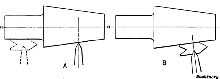
Fig. 14. Correct and Incorrect Positions of Tool for Taper Thread Cutting
Taper Threading.—When a taper thread is to be cut, the tool should be set square with axis a—a as at A, Fig. 14, and not by the tapering surface as at B. If there is a cylindrical part, the tool can be set as indicated by the dotted lines. All taper threads should be cut by the use of taper attachments. If the tailstock is set over to get the required taper, and an ordinary bent-tail dog is used for driving, the curve of the thread will not be true, or in other words the thread will not advance at a uniform rate; this is referred to by machinists as a “drunken thread.” This error in the thread is due to the angularity between the driving dog and the faceplate, which causes the work to be rotated at a varying velocity. The pitch of a taper thread that is cut with the tailstock set over will also be slightly finer than the pitch for which the lathe is geared. The amount of these errors depends upon the angle of the taper and the distance that the center must be offset.
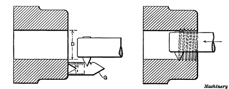
Fig. 15. Method of setting and using Inside Thread Tool
Internal Threading.—Internal threading, or cutting threads in holes, is an operation performed on work held in the chuck or[155] on a faceplate, as for boring. The tool used is similar to a boring tool except that the working end is shaped to conform to the thread to be cut. The method of procedure, when cutting an internal thread, is similar to that for outside work, as far as handling the lathe is concerned. The hole to be threaded is first bored to the root diameter D, Fig. 15, of the screw that is to fit into it. The tool-point (of a tool for a U. S. standard or V-thread) is then set square by holding a gage G against the true side of the work and adjusting the point to fit the notch in the gage as shown. The view to the right shows the tool taking the first cut.
Very often the size of a threaded hole can be tested by using as a gage the threaded part that is to fit into it. When making such a test, the tool is, of course, moved back out of the way. It is rather difficult to cut an accurate thread in a small hole, especially when the hole is quite deep, owing to the flexibility of the tool; for this reason threads are sometimes cut slightly under size with the tool, after which a tap with its shank end held straight by the tailstock center is run through the hole. In such a case, the tap should be calipered and the thread made just small enough with the tool to give the tap a light cut. Small square-threaded holes are often finished in this way, and if a number of pieces are to be threaded, the use of a tap makes the holes uniform in size.
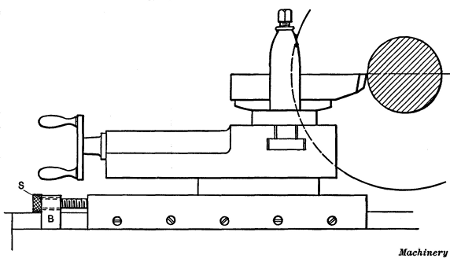
Fig. 16. Cross-slide equipped with Stop for Regulating Depth of Cut when Threading
Stop for Thread Tools.—When cutting a thread, it is rather difficult to feed in the tool just the right amount for each successive cut, because the tool is moved in before it feeds up to[156] the work. A stop is sometimes used for threading which overcomes this difficulty. This stop consists of a screw S, Fig. 16, which enters the tool slide and passes through a block B clamped in front of the slide. The hole in the block through which the stop-screw passes is not threaded, but is large enough to permit the screw to move freely. When cutting a thread, the tool is set for the first cut and the screw is adjusted until the head is against the fixed block. After taking the first cut, the stop-screw is backed out, say one-half revolution, which allows the tool to be fed in far enough for a second cut. If this cut is about right for depth, the screw is again turned about one-half revolution for the next cut and this is continued for each successive cut until the thread is finished. By using a stop of this kind, there is no danger of feeding the tool in too far as is often done when the tool is set by guess. If this form of stop is used for internal threading, the screw, instead of passing through the fixed block, is placed in the slide so that the end or head will come against the stop B. This change is made because the tool is fed outward when cutting an internal thread.

Fig. 17. Gage for grinding and setting Acme Thread Tools
The Acme Standard Thread.—The Acme thread is often used, at the present time, in place of a square thread. The angle between the sides of the Acme thread is 29 degrees (see Fig. 21) and the depth is made equal to one-half the pitch plus [157] 0.010 inch to provide clearance and insure a bearing upon the sides. The thread tool is ordinarily ground to fit a gage having notches representing different pitches. An improved form of Acme thread gage is shown in Fig. 17. The tool point is first ground to the correct angle by fitting it to the 29-degree notch in the end of the gage, as at A. The end is then ground to the proper width for the pitch to be cut, by testing it, as at B. The numbers opposite the shallow notches for gaging the width represent the number of threads per inch. With this particular gage, the tool can be set square by placing edge D against the turned surface to be threaded, and adjusting the tool until the end is in line with the gage, as at C. By placing the tool in this position, the angle between the side and the end can also be tested.
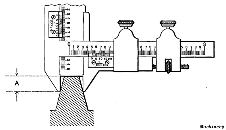
Fig. 18. Measuring Width of Acme Thread Tool with Vernier Gear-tooth Caliper
In case it should be necessary to measure the end width of an Acme thread tool, for a pitch not on the regular gage, this can be done by using a vernier gear-tooth caliper, as indicated in Fig. 18. If we assume that the caliper jaws bear on the sides of the tool at a distance A from the top, equal to 1/4 inch, then the width of the tool point equals the caliper reading (as shown by the horizontal scale) minus 0.1293 inch. For example, if the caliper reading was 0.315 inch, the width at the point would equal 0.315 - 0.1293 = 0.1857 inch, assuming that the sides were ground to the standard angle of 29 degrees. The constant[158] to be subtracted from the caliper reading equals 2 A tan 14° 30' or, in this case, 2 × 0.25 × 0.2586 = 0.1293.
The Whitworth Thread.—The Whitworth (or British Standard Whitworth) thread, which is used principally in Great Britain, has an included angle of 55 degrees, and the threads are rounded at the top and at the root, as shown in Fig. 23. The shape of the tool used for cutting this thread is also shown in this illustration. The end is rounded to form the fillet at the root of the thread, and the round corners on the sides give the top of the thread the required curvature. Every pitch requires a different tool, and the cutting end is given the curved form by milling or hobbing. The hob used for this purpose is accurately threaded to correspond with the pitch for which the tool is required, and then it is fluted to form cutting edges, and is hardened. The hob is then used like a milling cutter for forming the end of the thread tool. The tool is sharpened by grinding on the top. The method of cutting a Whitworth thread is, of course, similar to that followed for a U. S. standard or V-thread, in that the tool is set square with the unthreaded blank and at the same height as the lathe centers, in order to secure a thread of the proper form. Care should be taken to turn the blank to the right diameter so that the top of the thread will be fully rounded when the screw is the required size.
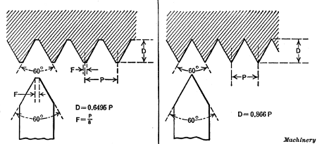
Fig. 19. United States Standard Thread
Fig. 20. Standard Sharp V-thread
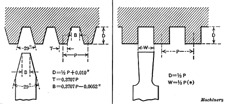
Fig. 21. Acme Standard Thread
Fig. 22. Square Thread
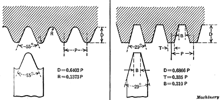
Fig. 23. Whitworth Standard Thread
Fig. 24. Standard Worm Thread
[160] Worm Threads.—The standard worm thread has an angle of 29 degrees between the sides, the same as an Acme thread, but the depth of a worm thread and the width of the flat at the top and bottom differ from the Acme standard, as will be seen by comparing Figs. 21 and 24. The whole depth of the thread equals the linear pitch multiplied by 0.6866, and the width of the thread tool at the end equals the linear pitch multiplied by 0.31. Gages notched for threads of different pitch are ordinarily used when grinding worm thread tools.
When it is necessary to cut multiple-threaded worms of large lead in an ordinary lathe, difficulty is sometimes experienced because the lead-screw must be geared to run much faster than the spindle, thus imposing excessive strains on the gearing. This difficulty is sometimes overcome by mounting a belt pulley on the lead-screw, beside the change gear, and connecting it to the countershaft by a belt; the spindle is then driven through the change gearing from the lead-screw, instead of vice versa.
Coarse Threading Attachment.—To avoid the difficulties connected with cutting threads of large lead, some lathes are equipped with a coarse screw-cutting attachment. The arrangement of this attachment, as made by the Bradford Machine Tool Co., is as follows: On the usual reversing shaft, and inside of the headstock, there is a sliding double gear, so arranged as to be engaged with either the usual gear on the spindle, or with a small pinion at the end of the cone. The gears are so proportioned that the ratio of the two engagements is as 10 to 1; that is, when engaged with the cone gear (the back-gears being thrown in) the mating gear will make ten revolutions to one of the spindle, so that when the lathe is ordinarily geared to cut one thread per inch, it will, when driven by the cone pinion, cut one thread in ten inches. This construction dispenses with the extra strain on the reverse gears due to moving the carriage at the rapid rate that would be necessary for such a large lead, when not using an attachment. These attachments are not only extensively used for the cutting of coarse screws but for cutting oil grooves on cylindrical parts.
[161]When cutting a thread of large lead or “steep pitch,” the top of the thread tool should be ground so that it is at right angles to the thread; then the thread groove will be cut to the same width as the tool.
Testing the Size of a Thread.—When the thread tool has been fed in far enough to form a complete thread, the screw is then tested for size. If we assume that a bolt is being threaded for a standard nut, it would be removed from the lathe and the test made by screwing a nut on the end. If the thread were too large, the nut might screw on very tightly or not at all; in either case, the work would again be placed in the lathe and a light cut taken over it to reduce the thread to the proper size. When replacing a threaded part between the centers, it should be put back in the original position, that is, with the “tail” of the driving dog in the same slot of the faceplate it previously occupied.
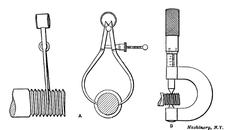
Fig. 25. Testing Diameter of Thread with Calipers and Micrometer
As it is difficult to tell just when a thread is cut to the exact size, special thread calipers having wedge-shaped ends are sometimes used for measuring the diameter of a V-thread or a U. S. standard thread, at the bottom of the grooves or the root diameter, as shown at A in Fig. 25. These calipers can be set from a tap corresponding to the size of the thread being cut, or from a previously threaded piece of the right size.
[162] The Thread Micrometer.—Another form of caliper for testing threads is shown at B. This is one of the micrometer type and is intended for very accurate work. The spindle of this micrometer has a conical end and the “anvil” is V-shaped, and these ends bear on the sides of the thread or the surfaces which form the bearing when the screw is inserted in a nut or threaded hole. The cone-shaped point is slightly rounded so that it will not bear in the bottom of the thread. There is also sufficient clearance at the bottom of the V-shaped anvil to prevent it from bearing on top of the thread. The diameter as indicated by this micrometer is the “pitch diameter” of the thread and is equal to the outside diameter minus the depth of one thread. This depth may be determined as follows:
Depth of a V-thread = 0.866 ÷ No. of threads per inch;
Depth of a U. S. standard thread = 0.6495 ÷ No. of threads per inch;
Depth of Whitworth thread = 0.6403 ÷ No. of threads per inch.
The movable point measures all pitches, but the fixed anvil is limited in its capacity, for if made large enough to measure a thread of, say, 1/4-inch pitch, it would be too wide at the top to measure a thread of 1/24-inch pitch, hence each caliper is limited in the range of threads that the anvil can measure. When measuring the “angle diameter” of a thread, the micrometer should be passed back and forth across the thread, in order to make sure that the largest dimension or the actual diameter is being measured. If the micrometer is placed over what seems to be the center of the screw and the reading is taken by simply adjusting in the anvil or point against the thread, without moving the micrometer back and forth across it, an incorrect reading may be obtained.
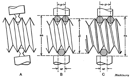
Fig. 26. (A) Testing Size of Thread with Ball-point Micrometer.
(B) Testing Size
of V-thread by the Three-wire System.
(C) Testing the Size of a U. S. Standard Thread
If standard threaded reference gages are available, the size of the thread being cut can be tested by comparing it with the gage. Micrometers having small spherical measuring ends (see sketch A, Fig. 26) are sometimes used for this purpose. The ball points are small enough to bear against the sides of the thread and the diameter, as compared with the reference gage, can be determined with great accuracy.
[163] Three-wire System of Measuring Threads.—A method of measuring threads by using an ordinary micrometer and three wires of equal diameter is illustrated at B and C, Fig. 26. Two wires are placed between the threads on one side and one on the opposite side of the screw. The dimension M over the wires is then measured with an ordinary micrometer. When the thread is cut to a standard size, the dimension M for different threads is as follows:
For a U. S. standard thread:
m = d - 1.5155p + 3w
For a sharp V-thread:
m = d - 1.732p + 3w
For a Whitworth standard thread:
m = d - 1.6008p + 3.1657w
In these formulas, d = standard outside diameter of screw; m = measurement over wires; w = diameter of wires; p = pitch of thread = 1 ÷ number of threads per inch.
To illustrate the use of the formula for the U. S. standard thread, let us assume that a screw having 6 threads per inch (1/6-inch pitch) is to be cut to a diameter of 11/2 inch, and that wires[164] 0.140 inch diameter are to be used in conjunction with a micrometer for measurement. Then the micrometer reading m should be
11/2 - 1.5155 × 1/6 + 3 × 0.140 = 1.6674 inch
If the micrometer reading were 1.670 inch, it would indicate that the pitch diameter of the screw was too large, the error being equal to difference between 1.667 and the actual reading.
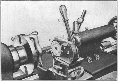
Fig. 27. Rivett-Dock Circular Threading Tool in Working Position
Rivett-Dock Threading Tool.—A special form of thread tool, which overcomes a number of disadvantages common to an ordinary single-point thread tool, is shown in Fig. 27. This tool has a circular-shaped cutter C, having ten teeth around its circumference, which, beginning with tooth No. 1, gradually increase in height, cutter No. 2 being higher than No. 1, etc. This cutter is mounted on a slide S, that is fitted to the frame F, and can be moved in or out by lever L. The hub of this lever has an eccentric stud which moves slide S and locks it when in the forward or cutting position. The action of the lever in moving the slide engages the cutter with pawl P, thus rotating the cutter one tooth at a time and presenting a different tooth to the work for each movement of the lever. When the slide is[165] moved forward, the heel or underside of the tooth which is in the working position rests on a stop that takes the thrust of the cut.
When the tool is in use, it is mounted on the tool-block of the lathe as shown in the illustration. The cutter is set for height by placing a tooth in the working position and setting the top level with the lathe center. The cutter is also set square with the work by using an ordinary square, and it is tilted slightly from the vertical to correspond with the angle of the thread to be cut, by adjusting frame F. At first a light cut is taken with lever L moved forward and tooth No. 1 on the stop. After this cut is completed, the lever is reversed which rotates the cutter one tooth, and the return movement places tooth No. 2 in the working position. This operation is repeated until the tenth tooth finishes the thread. It is often necessary, when using a single-point thread tool, to re-sharpen it before taking the finishing cut, but with a circular tool this is not necessary, for by using the different teeth successively, the last tooth, which only takes finishing cuts, is kept in good condition.
Cutting Screws to Compensate for Shrinkage.—Some tool steels are liable to shrink more or less when they are hardened; consequently if a very accurate hardened screw is required, it is sometimes cut so that the pitch is slightly greater than standard, to compensate for the shrinkage due to the hardening operation. As the amount of contraction incident to hardening is very little, it is not practicable to use change gears that will give the exact pitch required. A well-known method of obtaining this increase of pitch is by the use of a taper attachment.
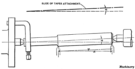
Fig. 28. Diagram Illustrating Method of Cutting a Thread to
Compensate for the Error in Pitch
due to Shrinkage in Hardening
For example, suppose a tap having 8 threads per inch is to be threaded, and, owing to the contraction of the steel, the pitch must be 0.12502 inch instead of 0.125 inch. The lathe is geared to cut 8 threads per inch or 0.125 inch pitch, and then the taper attachment is set to an angle a, Fig. 28, the cosine of which equals 0.125÷0.12502; that is, the cosine of angle a equals the pitch required after hardening, divided by the pitch necessary to compensate for shrinkage. The angle is then found by referring[166] to a table of cosines. The tap blank is also set to the same angle a by adjusting the tailstock center, thus locating the axis of the work parallel with the slide of the taper attachment. When the carriage moves a distance x, the tool point will have moved a greater distance y along the work, the difference between x and y depending upon angle a; hence the tool will cut a thread of slightly greater pitch than the lathe is geared to cut.
To illustrate by using the preceding example, cosine of angle a = 0.125÷0.12502 = 0.99984. By referring to a table of cosines, we find that 0.99984 is the cosine of 1 degree, approximately; hence, the taper attachment slide and the work should be set to this angle. (The angle a in Fig. 28 has been exaggerated in order to more clearly illustrate the principle.)
As is well known, it is objectionable to cut a thread with the tailstock center offset, because the work is not rotated at a uniform velocity, owing to the fact that the driving dog is at an angle with the faceplate. For a small angle such as 1 degree, however, the error resulting from this cause would be very small.
If a thread having a pitch slightly less than standard is needed to fit a threaded part which has contracted in hardening, the taper attachment can also be used provided the lathe is equipped with special gears to cut a little less than the required [167] pitch. Suppose a screw having a pitch of 0.198 inch is required to fit the thread of a nut the pitch of which has been reduced from 0.200 inch to 0.198 inch. If gears having 83 and 84 teeth are available, these can be inserted in a compound train, so as to reduce the 0.200 inch pitch that would be obtained with the regular gearing, to 83/84 of 0.200 or 0.19762 inch. This pitch, which is less than the 0.198 inch pitch required, is then increased by using the taper attachment as previously described. (This method was described by Mr. G. H. Gardner in Machinery, February, 1914.)
Calculating Change Gears for Thread Cutting.—As previously mentioned, the change gears for cutting threads of various pitches are shown by a table or “index plate” attached to the lathe. The proper gears to be used can be calculated, but the use of the table saves time and tends to avoid mistakes. Every machinist, however, should know how to determine the size of gears used for cutting any number of threads to the inch. Before referring to any rules, let us first consider why a lathe cuts a certain number of threads to the inch and how this number is changed by the use of different gears.
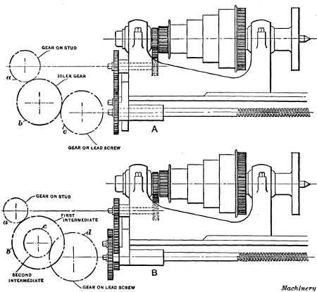
Fig. 29. (A) Lathe with Simple Gearing for Thread Cutting.
(B) Compound Geared Lathe
As the carriage C and the tool are moved by the lead-screw S (see Fig. 2), which is geared to the spindle, the number of threads to the inch that are cut depends, in every case, upon the number of turns the work makes while the lead-screw is moving the carriage one inch. If the lead-screw has six threads per inch, it will make six revolutions while the carriage and the thread tool travel one inch along the piece to be threaded. Now if the change gears a and c (see also sketch A, Fig. 29) are so proportioned that the spindle makes the same number of revolutions as the lead-screw, in a given time, it is evident that the tool will cut six threads per inch. If the spindle revolved twice as fast as the lead-screw, it would make twelve turns while the tool moved one inch, and, consequently, twelve threads per inch would be cut; but to get this difference in speeds it is necessary to use a combination of gearing that will cause the lead-screw to revolve once while the lathe spindle and work make two revolutions.
[168]Suppose that nine threads to the inch are to be cut and the lead-screw has six threads per inch. In this case the work must make nine revolutions while the lead-screw makes six and causes the carriage and thread tool to move one inch, or in other words, one revolution of the lead-screw corresponds to one and one-half revolution of the spindle; therefore, if the lead-screw gear c has 36 teeth, the gear a on the spindle stud should have 24 teeth. The spindle will then revolve one and one-half times faster than the lead-screw, provided the stud rotates at the same rate of speed as the main lathe spindle. The number of teeth in the change gears that is required for a certain pitch can be found by multiplying the number of threads per inch of the lead-screw, and the number of threads per inch to be cut, by the same trial multiplier. The formula which expresses the relation between threads per inch of lead-screw, threads per[169] inch to be cut, and the number of teeth in the change gears, is as follows:
| threads per inch of lead-screw | teeth in gear on spindle stud | |
| ———————————— | = | ———————————— |
| threads per inch to be cut | teeth in gear on lead-screw |
Applying this to the example given, we have 6÷9 = 24÷36. The values of 36 and 24 are obtained by multiplying 6 and 9, respectively, by 4, which, of course, does not change the proportion. Any other number could be used as a multiplier, and if gears having 24 and 36 teeth were not available, this might be necessary. For example, if there were no gears of this size, some other multiplier as 5 or 6 might be used.
Suppose the number of teeth in the change gears supplied with the lathe are 24, 28, 32, 36, etc., increasing by four teeth up to 100, and assume that the lead-screw has 6 threads per inch and that 10 threads per inch are to be cut. Then,
| 6 | 6 × 4 | 24 | ||
| — | = | ——— | = | — |
| 10 | 10 × 4 | 40 |
By multiplying both numerator and denominator by 4, we obtain two available gears having 24 and 40 teeth, respectively. The 24-tooth gear goes on the spindle stud and, the 40-tooth gear on the lead-screw. The number of teeth in the intermediate or “idler” gear b, which connects the stud and lead-screw gears, is not considered as it does not affect the ratios between gears a and c, but is used simply to transmit motion from one gear to the other.
We have assumed in the foregoing that the spindle stud (on which gear a is mounted) and the main spindle of the lathe are geared in the ratio of one to one and make the same number of revolutions. In some lathes, however, these two members do not rotate at the same speed, so that if equal gears were placed on the lead-screw and spindle stud, the spindle would not make the same number of revolutions as the lead-screw. In that case if the actual number of threads per inch in the lead-screw were used when calculating the change gears, the result would be incorrect; hence, to avoid mistakes, the following general rule[170] should be used as it gives the correct result, regardless of the ratios of the gears which connect the spindle and spindle stud:
Rule.—First find the number of threads per inch that is cut when gears of the same size are placed on the lead-screw and spindle, either by actual trial or by referring to the index plate. Then place this number as the numerator of a fraction and the number of threads per inch to be cut, as the denominator; multiply both numerator and denominator by some trial number, until numbers are obtained which correspond to numbers of teeth in gears that are available. The product of the trial number and the numerator (or “lathe screw constant”) represents the gear a for the spindle stud, and the product of the trial number and the denominator, the gear for the lead-screw.
Lathes with Compound Gearing.—When gearing is arranged as shown at A, Fig. 29, it is referred to as simple gearing, but sometimes it is necessary to introduce two gears between the stud and screw as at B, which is termed compound gearing. The method of figuring compound gearing is practically the same as that for simple gearing. To find the change gears used in compound gearing, place the “screw constant” obtained by the foregoing rule, as the numerator, and the number of threads per inch to be cut as the denominator of a fraction; resolve both numerator and denominator into two factors each, and multiply each “pair” of factors by the same number, until values are obtained representing numbers of teeth in available change gears. (One factor in the numerator and one in the denominator make a “pair” of factors.)
Suppose the lathe cuts 6 threads per inch when gears of equal size are used, and that the number of teeth in the gears available are 30, 35, 40 and so on, increasing by 5 up to 100. If 24 threads per inch are to be cut, the screw constant 6 is placed in the numerator and 24 in the denominator. The numerator and denominator are then divided into factors and each pair of factors is multiplied by the same number to find the gears, thus:
| 6 | 2 × 3 | (2 × 20) × (3 × 10) | 40 × 30 | |||
| — | = | ——— | = | ———————— | = | ——— |
| 24 | 4 × 6 | (4 × 20) × (6 × 10) | 80 × 60 |
[171]The last four numbers indicate the gears which should be used. The upper two having 40 and 30 teeth are the driving gears and the lower two having 80 and 60 teeth are the driven gears. The driving gears are gear a on the spindle stud and gear c on the intermediate stud, meshing with the lead-screw gear, and the driven gears are gears b and d. It makes no difference which of the driving gears is placed on the spindle stud, or which of the driven is placed on the lead-screw.
Fractional Threads.—Sometimes the lead of a thread is given as a fraction of an inch instead of stating the number of threads per inch. For example, a thread may be required to be cut, having 3/8-inch lead. The expression “3/8-inch lead” should first be transformed to “number of threads per inch.” The number of threads per inch (the thread being single) equals:
| 1 | 3 | 8 | ||||
| ——— | = | 1 ÷ | — | = | — | = 22/3 |
| 3 | 8 | 3 | ||||
| — | ||||||
| 8 |
To find the change gears to cut 22/3 threads per inch in a lathe having a screw constant of 8 and change gears varying from 24 to 100 teeth, increasing by 4, proceed as follows:
| 8 | 2 × 4 | (2 × 36) × (4 × 24) | 72 × 96 | |||
| — | = | ——— | = | ————————— | = | ———— |
| 22/3 | 1 × 22/3 | (1 × 36) × (22/3 × 24) | 36 × 64 |
As another illustration, suppose we are to cut 13/4 thread per inch on a lathe having a screw constant of 8, and that the gears have 24, 28, 32, 36, 40 teeth, etc., increasing by four up to one hundred. Following the rule:
| 8 | 2 × 4 | (2 × 36) × (4 × 16) | 72 × 64 | |||
| — | = | ——— | = | ————————— | = | ———— |
| 13/4 | 1 × 13/4 | (1 × 36) × (13/4 × 16) | 36 × 28 |
The gears having 72 and 64 teeth are the driving gears, and those with 36 and 28 teeth are the driven gears.
Change Gears for Metric Pitches.—When screws are cut in accordance with the metric system, it is the usual practice to give the lead of the thread in millimeters, instead of the number of threads per unit of measurement. To find the change gears for cutting metric threads, when using a lathe having an English lead-screw, first determine the number of threads per[172] inch corresponding to the given lead in millimeters. Suppose a thread of 3 millimeters lead is to be cut in a lathe having an English lead-screw and a screw constant of 6. As there are 25.4 millimeters per inch, the number of threads per inch will equal 25.4 ÷ 3. Place the screw constant as the numerator, and the number of threads per inch to be cut as the denominator:
| 6 | 25.4 | 6 × 3 | |||
| ———— | = | 6 ÷ | —— | = | —— |
| 25.4 | 3 | 25.4 | |||
| —— | |||||
| 3 |
The numerator and denominator of this fractional expression of the change-gear ratio are next multiplied by some trial number to determine the size of the gears. The first whole number by which 25.4 can be multiplied so as to get a whole number as the result is 5. Thus, 25.4 × 5 = 127; hence, one gear having 127 teeth is always used when cutting metric threads with an English lead-screw. The other gear required in this case has 90 teeth. Thus:
| 6 × 3 × 5 | 90 | |
| ———— | = | —— |
| 25.4 × 5 | 127 |
Therefore, the following rule can be used to find the change gears for cutting metric pitches with an English lead-screw:
Rule.—Place the lathe screw constant multiplied by the lead of the required thread in millimeters multiplied by 5, as the numerator of the fraction, and 127 as the denominator. The product of the numbers in the numerator equals the number of teeth for the spindle-stud gear, and 127 is the number of teeth for the lead-screw gear.
If the lathe has a metric pitch lead-screw, and a screw having a given number of threads per inch is to be cut, first find the “metric screw constant” of the lathe or the lead of thread in millimeters that would be cut with change gears of equal size on the lead-screw and spindle stud; then the method of determining the change gears is simply the reverse of the one already explained for cutting a metric thread with an English lead-screw.
Rule.—To find the change gears for cutting English threads with a metric lead-screw, place 127 in the numerator and the threads per inch to be cut, multiplied by the metric screw constant multiplied [173] by 5, in the denominator; 127 is the number of teeth on the spindle-stud gear and the product of the numbers in the denominator equals the number of teeth in the lead-screw gear.
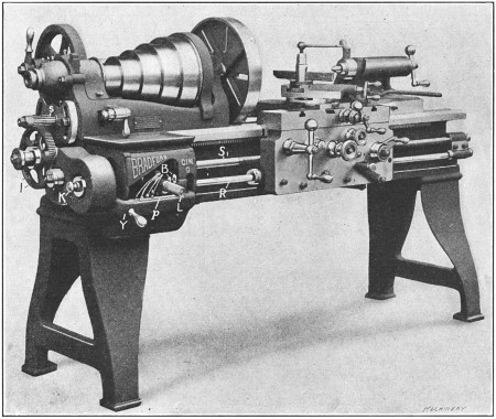
Fig. 30. Lathe having Quick Change-gear Mechanism
Quick Change-gear Type of Lathe.—A type of lathe that is much used at the present time is shown in Fig. 30. This is known as the quick change-gear type, because it has a system of gearing which makes it unnecessary to remove the change gears and replace them with different sizes for cutting threads of various pitches. Changes of feed are also obtained by the same mechanism, but the feeding movement is transmitted to the carriage by the rod R, whereas the screw S1 is used for screw cutting. As previously explained, the idea of using the screw exclusively for threading is to prevent it from being worn excessively, as it would be if continually used in place of rod R, for feeding the carriage when turning.
[174]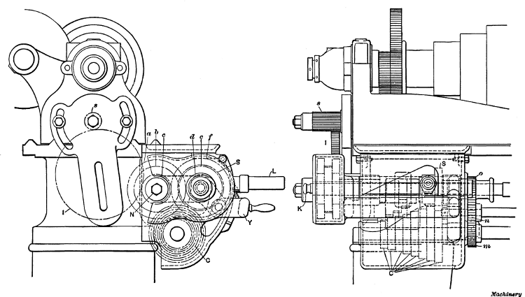
Fig. 31. End and Side Views of Quick Change-gear Mechanism
The general construction of this quick change gear mechanism[175] and the way the changes are made for cutting threads of different pitch, will be explained in connection with Figs. 30, 31 and 32, which are marked with the same reference letters for corresponding parts. Referring to Fig. 30, the movement is transmitted from gear s on the spindle stud through idler gear I, which can be moved sidewise to mesh with either of the three gears a, b or c, Fig. 31. This cone of three gears engages gears d, e and f, any one of which can be locked with shaft T (Fig. 32) by changing the position of knob K. On shaft T there is a gear S which can be moved along the shaft by hand lever L and, owing to the spline or key t, both the sliding gear and shaft rotate together. Shaft T, carrying gears d, e and f and the sliding gear S, is mounted in a yoke Y, which can be turned about shaft N, thus making it possible to lower sliding gear S into mesh with any one of a cone of eight gears C, Fig. 31. The shaft on which the eight gears are mounted has at the end a small gear m meshing with gear n on the feed-rod, and the latter, in turn, drives the lead-screw, unless gear o is shifted to the right out of engagement, which is its position except when cutting threads.
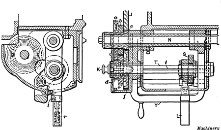
Fig. 32. Sectional Views of Quick Change-gear Mechanism
With this mechanism, eight changes for different threads or feeds are obtained by simply placing gear S into mesh with the [176] various sized gears in cone C. As the speed of shaft T depends on which of the three gears d, e and f are locked to it, the eight changes are tripled by changing the position of knob K, making twenty-four. Now by shifting idler gear I, three speed changes may be obtained for gears a, b and c, which rotate together, so that the twenty-four changes are also tripled, giving a total of seventy-two variations without removing any gears, and if a different sized gear s were placed on the spindle stud, an entirely different range could be obtained, but such a change would rarely be necessary. As shown in Fig. 30, there are eight hardened steel buttons B, or one for each gear of the cone C, placed at different heights in the casing. When lever L is shifted sidewise to change the position of sliding gear S, it is lowered onto one of these buttons (which enters a pocket on the under side) and in this way gear S is brought into proper mesh with any gear of the cone C. To shift lever L, the handle is pulled outward against the tension of spring r (Fig. 32), which disengages latch l and enables the lever to be lifted clear of the button; yoke Y is then raised or lowered, as the case may be, and lever L with the sliding gear is shifted laterally to the required position.
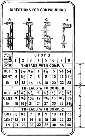
Fig. 33. Index Plate showing Position of Control Levers
for Cutting Threads of Different Pitch
The position of lever L and knob K for cutting threads of different pitches is shown by an index plate or table attached to the lathe and arranged as shown in Fig. 33. The upper section a of this table shows the different numbers of threads to the inch that can be obtained when idler gear I is in the position shown by the diagram A. Section b gives the changes when [177] the idler gear is moved, as shown at B, and, similarly, section c gives the changes for position C of the idler. The horizontal row of figures from 1 to 8 below the word “stops” represents the eight positions for lever L, which has a plate p (Fig. 30) just beneath it with corresponding numbers, and the column to the left shows whether knob K should be out, in a central position, or in.
In order to find what the position of lever L and knob K should be for cutting any given number of threads to the inch, find what “stop” number is directly above the number of threads to be cut, which will indicate the location of lever L, and also what position should be occupied by knob K, as shown in the column to the left. For example, suppose the lathe is to be geared for cutting eight threads to the inch. By referring to section a we see that lever L should be in position 4 and knob K in the center, provided the idler gear I were in position A, as it would be ordinarily, because all standard numbers of threads per inch (U. S. standard) from 1/4 inch up to and including 4 inches in diameter can be cut with the idler gear in that position. As another illustration, suppose we want to cut twenty-eight threads per inch. This is listed in section c, which shows that lever L must be placed in position 3 with knob K pushed in and the idler gear shifted to the left as at C.
The simplicity of this method as compared with the time-consuming operation of removing and changing gears is apparent. The diagram D to the right shows an arrangement of gearing for cutting nineteen threads per inch. A 20-tooth gear is placed on the spindle stud (in place of the regular one having 16 teeth) and one with 95 teeth on the lead-screw, thus driving the latter direct as with ordinary change gears. Of course it will be understood that the arrangement of a quick change-gear mechanism varies somewhat on lathes of different make.
Turret lathes are adapted for turning duplicate parts in quantity. The characteristic feature of a turret lathe is the turret which is mounted upon a carriage and contains the tools which are successively brought into the working position by indexing or rotating the turret. In many instances, all the tools required can be held in the turret, although it is often necessary to use other tools, held on a cross-slide, for cutting off the finished part, facing a radial surface, knurling, or for some other operation. After a turret lathe is equipped with the tools needed for machining a certain part, it produces the finished work much more rapidly than would be possible by using an ordinary engine lathe, principally because each tool is carefully set for turning or boring to whatever size is required and the turret makes it possible to quickly place any tool in the working position. Turret lathes also have systems of stops or gages for controlling the travel of the turret carriage and cross-slide, in order to regulate the depth of a bored hole, the length of a cylindrical part or its diameter; hence, turning machines of this type are much more efficient than ordinary lathes for turning duplicate parts, unless the quantity is small, in which case, the advantage of the turret lathe might be much more than offset by the cost of the special tool equipment and the time required for “setting up” the machine. (See “Selecting Type of Turning Machine.”)
[179]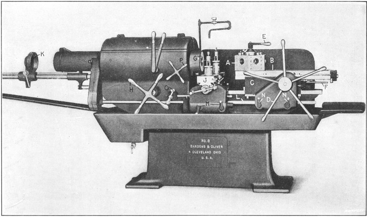
Fig. 1. Bardons & Oliver Turret Lathe of Motor-driven Geared-head Type
General Description of a Turret Lathe.—The turret lathe shown in Fig. 1 has a hexagonal shaped turret A with a hole in each side in which the tools are held. This turret is mounted on a slide B which is carried by a saddle C that can be moved along the bed to locate the turret slide with reference to the length of the tools in the turret and the room required for indexing. The turret slide can be moved longitudinally by turning the pilot[180] wheel or turnstile D, or it can be fed by power. Ordinarily, the hand adjustment is used for quickly moving the carriage when the tools are not cutting, although sometimes the hand feed is preferable to a power feed when the tools are at work, especially if the cuts are short. After a turret tool has finished its cut, the turnstile is used to return the slide to the starting point, and at the end of this backward movement the turret is automatically indexed or turned one-sixth of a revolution, thus bringing the next tool into the working position. The turret is accurately located in each of its six positions by a lock bolt which engages notches formed in a large index ring at the turret base. A binder lever E at the top of the turret stud is used to clamp the turret rigidly to the slide when the tools are cutting.
The forward movement of the slide for each position of the turret is controlled by stops at F, which are set to suit the work being turned. When parts are being turned from bar stock, the latter passes through the hollow spindle of the headstock and extends just far enough beyond the end of the spindle to permit turning one of the parts. The bar is held while the turning tools are at work, by a chuck of the collet type at G. This chuck is opened or closed around the bar by turning handwheel H. After a finished part has been cut off by a tool held in cross-slide J, the chuck is released and further movement of wheel H causes ratchet feed dog K, and the bar which passes through it, to be drawn forward. This forward movement is continued until the end of the bar comes against a stop gage held in one of the turret holes, to insure feeding the bar out just the right amount for turning the next piece. On some turret lathes, the lever which operates the chuck also controls a power feed for the bar stock, the latter being pushed through the spindle against the stop.
The machine illustrated has a power feed for the cross-slide as well as for the turret. The motion is obtained from the same shaft L which actuates the turret slide, but the feed changes are independent. The cross-slide feed changes are varied by levers M and those for the turret by levers N. For many [181] turret lathe operations, such as turning castings, etc., a jawed chuck is screwed onto the spindle and the work is held the same as when a chuck is used on an engine lathe. Sometimes chucks are used having special jaws for holding castings of irregular shape, or special work-holding fixtures which are bolted to the faceplate. The small handle at O is for moving the cross-slide along the bed when this is necessary in order to feed a tool sidewise.
This particular machine is driven by a motor at the rear of the headstock, connection being made with the spindle through gearing. The necessary speed changes are obtained both by varying the speed of the motor and by shifting gears in the headstock. The motor is controlled by the turnstile P and the gears are shifted by the vertical levers shown.
While many of the features referred to are common to turret lathes in general, it will be understood that the details such as the control levers, arrangement of stops, etc., vary on turret lathes of different make.
[182]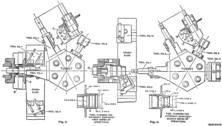
Figs. 2 and 3. Diagrams showing Turret Lathe Tool Equipment for Machining Automobile Hub Casting
Example of Turret Lathe Work.—The diagrams Figs. 2 and 3 show a turret lathe operation which is typical in many respects. The part to be turned is a hub casting for an automobile and it is machined in two series of operations. The first series is shown by the plan view, Fig. 2. The casting A is held in a three-jaw chuck B. Tool No. 1 on the cross-slide is equipped with two cutters and rough faces the flange and end, while the inner and outer surfaces of the cylindrical part are rough bored and turned by combination boring and turning tool No. 2. This tool has, in addition to a regular boring-bar, a bracket or tool-holder which projects above the work and carries cutters that operate on the top surface. Tools Nos. 3 and 4 next come into action, No. 3 finishing the surfaces roughed out by No. 2, and No. 4 finish-facing the flange and end of the hub. The detailed side view of Tool No. 3 (which is practically the same as No. 2), shows the arrangement of the cutters C and D, one of which turns the cylindrical surface and the other bevels the end of the hub. The hole in the hub is next finished by tool No. 5 which is a stepped reamer that machines the bore and counterbore[183] to the required size within very close limits. The surfaces machined by the different tools referred to are indicated by the sectional view E of the hub, which shows by the numbers what tools are used on each surface.
For the second series of operations, the position of the hub is reversed and it is held in a spring or collet type of chuck as shown by the plan view Fig. 3. The finished cylindrical end of the hub is inserted in the split collet F which is drawn back into the tapering collet ring by rod G (operated by turnstile H, Fig. 1) thus closing the collet tightly around the casting. The first operation is that of facing the side of the flange and end of the hub with tool No. 6 on the cross-slide, which is shown in the working position. A broad cutter H is used for facing the flange and finishing the large fillet, and the end is faced by a smaller cutter I. When these tools are withdrawn, tool No. 7 is moved up for rough turning the outside of the cylindrical end (preparatory to cutting a thread) and rough boring the hole. These same surfaces are then finished by tool No. 8. The arrangement of tools Nos. 7 and 8 is shown by the detailed view. Tool J turns the part to be threaded; tool K turns the end beyond the threaded part; and tool L bevels the corner or edge. The reaming tool No. 9 is next indexed to the working position for finishing the hole and beveling the outer edge slightly. At the same time, the form tool No. 10, held at the rear of the cross-slide, is fed up for beveling the flange to an angle of 60 degrees. The final operation is that of threading the end, which is done with die No. 11. The boring-bars of tools Nos. 2, 3, 7 and 8 are all provided with pilots N which enter close fitting bushings held in the spindle, to steady the bar while taking the cut. This is a common method of supporting turret lathe tools.
The feed of the turret for both the first and second series of operations is 1/27 inch per revolution and the speeds 60 revolutions per minute for the roughing cuts and 90 revolutions per minute for the finishing cuts. The total time for machining one of these castings complete is about 71/2 minutes, which includes the time required for placing the work in the chuck.
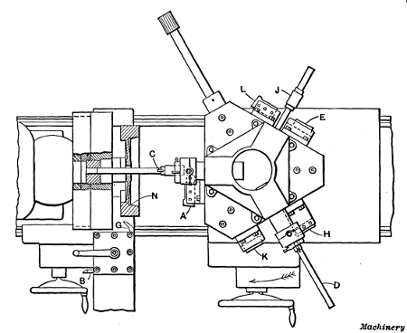
Fig. 4. First Cycle of Operations in Finishing Gasoline Engine
Flywheels on a Pond Turret Lathe
[184] Machining Flywheels in Turret Lathe.—Figs. 4 to 6, inclusive,illustrate how a gasoline engine flywheel is finished all over in two cycles of operations. First the flywheel is turned complete on one side, the hole bored and reamed, and the outside of the rim finished; in the second cycle the other side of the flywheel is completed.
During the first operation, the work is held by the inside of the rim by means of a four-jaw chuck equipped with hard jaws. The side of the rim, the tapering circumference of the recess, the web, and the hub are first rough-turned, using tools held in the carriage toolpost. The hole is then rough-bored by bar C, which is supported in a bushing in the chuck, as shown in Fig. 4. The outside of the wheel rim is rough-turned at the same time by a cutter held in the extension turret tool-holder T (Fig. 5), and the taper fit on the inside of the flywheel is turned by means of cutter A (Fig. 4) held in a tool-holder attached to the turret.
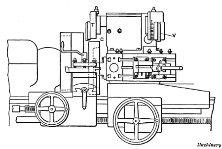
Fig. 5. Elevation of Turret and Tools for Finishing Flywheels—First Operation
The outside of the wheel rim is next finish-turned with cutter V (Fig. 5) held in an extension turret tool-holder the same as [185] the roughing tool T. At the same time, the bore is finished by a cutter in boring-bar D (Fig. 4). The side of the rim and the hub of the wheel are also finished at this time by two facing cutters H and K, held in tool-holders on the face of the turret. When the finishing cuts on the rim and hub are being taken, the work is supported by a bushing on the boring-bar which enters the bore of the wheel, the boring cutter and facing tools being set in such relation to each other that the final boring of the hole is completed before the facing cuts are taken.
The web of the wheel is next finish-faced with the facing cutter held in the holder E, and the taper surface on the inside of the rim is finished by the tool L, at the same time. While these last operations are performed, the work is supported by a bushing on a supporting arbor J, which enters the bore of the wheel. The bore is finally reamed to size by a reamer F held in a “floating” reamer-holder. When the reaming operation is completed, a clearance groove N is cut on the inside of the rim, using a tool G held in the carriage toolpost. The first cycle of operations on the flywheel is now completed.
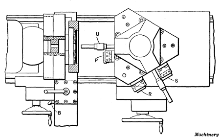
Fig. 6. Second Cycle of Operations on Flywheel
The flywheel is then removed from the chuck, turned around, and held in “soft” jaws for the second cycle of operations, the[186] jaws fitting the outside of the wheel rim. (Soft unhardened jaws are used to prevent marring the finished surface of the rim.) The operations on this side are very similar to those performed on the other side. First, the side of the rim, the inside of the rim, the web, and hub are rough-turned, using tools held in the carriage toolpost. The inside of the rim and the web are then finished by a cutter held in a tool-holder at P, Fig. 6, which is bolted to the face of the turret. The work is supported during this operation by a bushing held on a supporting arbor U, having a pilot which enters a bushing in the chuck. Finally, the rim and hub are finished, by the facing cutters R and S, the work being supported by an arbor, as before.
These operations illustrate the methods employed in automobile factories, and other shops where large numbers of engine flywheels, etc., must be machined.
[188]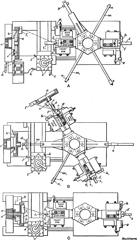
Fig. 7. Turret Lathe Tool Equipment for Machining Flywheels
Finishing a Flywheel at One Setting in Turret Lathe.—The plan view A, Fig. 7, shows an arrangement of tools for finishing a flywheel complete at one setting. The hole for the shaft has to be bored and reamed and the hub faced on both sides. The sides and periphery of the rim also have to be finished and all four corners of the rim rounded. The tools for doing this work consist of boring-bars, a reamer, facing heads on the main turret,[187] a turret toolpost on the slide rest (carrying, in this case, three tools) and a special supplementary wing rest attached to the front of the carriage at the extreme left.
The casting is held by three special hardened jaws b in a universal chuck. These jaws grip the work on the inner side of the rim, leaving room for a tool to finish the rear face without striking the chuck body or jaws. Three rests c are provided between the chuck jaws. The work is pressed against these rests while being tightened in the chuck, and they serve to locate it so that the arms will run true so far as sidewise movement is concerned. These rests also locate the casting with relation to the stops for the turret and carriage movements. The chuck carries a bushing r of suitable diameter to support the boring-bars in the main turret, as will be described.
In the first operation, boring-bar m is brought in line with the spindle and is entered in bushing r in the chuck. Double-ended cutter n is then fed through the hub of the pulley to true up the cored hole. While boring the hole, the scale on the front face of the rim and hub is removed by tool j. Tool k is then brought into action to rough turn the periphery, after which tool e, in the wing rest, is fed down to clean up the back face of the rim. As soon as the scale is removed, the hole is bored nearly to size by cutter n1 in bar m1, and it is finally finished with reamer q mounted on a floating arbor.
The cutters f, g and h, in the facing head, are next brought up to rough face the hub and rim, and round the corners of the rim on the front side. This operation is all done by broad shaving cuts. The facing head in which the tools are held is provided with a pilot bar t which fits the finished hole in the flywheel hub, and steadies the head during the operation. The cutters f, g and h are mounted in holders which may be so adjusted as to bring them to the proper setting for the desired dimensions. This completes the roughing operations.
The periphery of the rim is now finished by cutter l in the turret toolpost which is indexed to the proper position for this operation. The rear face of the rim is finished by the same tool e with which the roughing was done. Tool e is then removed [189] and replaced with d which rounds the inner corner of the rim. Tool d is also replaced with a third tool for rounding the outer corner of the rear side. For finishing the front faces of the rim and hub and rounding the corners of the rim, a second facing head, identical with the first one, is employed. This is shown in position in the illustration. Cutters f1, g1 and h1 correspond with the cutters f, g and h, previously referred to, and perform the same operations.
The remaining operation of finishing the back of the hub is effected by cutter p. This cutter is removed from the bar, which is then inserted through the bore; the cutter is then replaced in its slot and the rear end of the hub is faced by feeding the carriage away from the headstock. This completes the operations, the flywheel being finished at one setting.
Finishing a Webbed Flywheel in Two Settings.—The plan views B and C, Fig. 7, show the arrangement of tools for finishing a webbed flywheel which has to be machined all over. This, of course, requires two operations. In the first of these (see sketch B) the rough casting is chucked on the inside of the rim with regular inside hard chuck jaws b. The cored hole is first rough bored with cutter n attached to the end of boring-bar m, and guided by the drill support d pivoted to the carriage. Next, the boring-bar m1 is brought into position, the drill support being swung back out of the way. This bar is steadied by its bearing in bushing r in the chuck. Two cutters, n1 and n2, are used to roughly shape the hole to the desired taper, the small end being finished to within 0.002 inch of the required diameter. While boring with the bar m1, the scale is broken on the web and hub of the casting by the tool k in the turret toolpost. The latter is then shifted to bring the tool j into position for removing the scale on the periphery of the wheel. Next, the hole is reamed with taper reamer q, the pilot of which is supported by bushing r.
The first of the facing heads is now brought into action. This facing head carries a guide t which is steadied in a taper bushing c, driven into the taper hole of the hub for that purpose. The top cutter f turns the periphery, cutter g turns the hub and faces [190] the web, and cutter h faces the rim. A fourth cutter e on the under side of the head faces the hub. This casting is now machined approximately to size.
For finishing, similar cutters, e1, f1, g1 and h1, in the other facing head are used, the latter being supported by the taper bushing c in the same way. A very light cut is taken for finishing. Tool l in the carriage turret is used to round the outer and inner corners of the rim, which completes the work on this face of the casting.
In the second cycle of operations, shown at C, the casting is chucked on the outside with the soft jaws b, which are bored to the exact diameter of the finished rim. The work is further supported and centered by sliding bushing c, which is tapered to fit the finished hole in the hub, and has an accurate bearing in bushing r in the chuck. This bushing is provided with a threaded collar for forcing it into the work and withdrawing it. The scale on the web and the inside and face of the rim is first broken with the tool k in the turret toolpost. These surfaces are then roughed off with cutters f, g and h, in the facing head. This latter is steadied by a pilot t which enters the hole in the sliding bushing c on which the work is supported. A light cut is next taken with cutters f1, g1 and h1, in the finishing facing head, which completes the operation.
Tools for Turret Lathes.—The operation of a turret lathe after the tools have been properly arranged is not particularly difficult, but designing and making the tools, determining what order of operations will give the most efficient and accurate results, and setting the tools on the machine, requires both skill and experience. For some classes of work, especially if of a rather complicated nature, many of the tools must be specially designed, although there are certain standard types used on turret lathes which are adapted to general turning operations. Some of the principal types are referred to in the following.
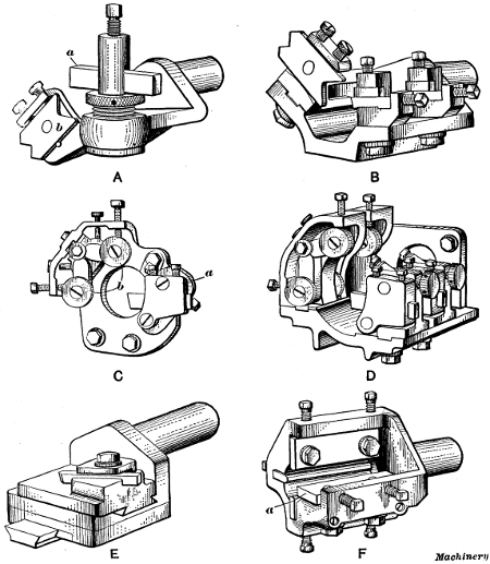
Fig. 8. Different Types of Box-tools for Turret Lathe
Box-tools.—Tools of this type are used for turning bar stock. There are many different designs, some of which are shown in Figs. 8, 9 and 10. Box-tools are held in the turret and they have back-rests opposite the turning tools, for supporting[191] the part being turned. The box-tool shown at A, Fig. 8, is for roughing. The cutter a is a piece of high-speed steel beveled on the cutting end to produce a keen edge. It takes a shearing tangent cut on top of the bar and the latter is kept from springing away by means of the adjustable, hardened tool-steel back-rest b. This tool is considered superior to a hollow mill whenever a fair amount of stock must be removed. If considerable smoothness and accuracy are necessary, the finishing box-tool shown at B should follow the roughing box tool, but in most cases, especially if the part is to be threaded by a die, a finishing cut is unnecessary.
[192] The finishing box-tool B is also used to follow a hollow mill if special accuracy or smoothness is desired. This tool is only intended for light finishing cuts, the allowances varying from 0.005 inch to 0.015 inch in diameter. The cutters are made of square tool steel of commercial size, and are ground and set to take a scraping end cut. This particular tool has two tool-holders which permit finishing two diameters at once. If a larger number of sizes must be turned, extra tool-holders can be applied.
The single-cutter box-tool shown at C is bolted directly to the face of the turret instead of being held by a shank in the turret hole, and it is adapted for heavy cuts such as are necessary when turning comparatively large bar stock. The tool-holder a swivels on a stud, thus allowing the cutter to be withdrawn from the work while being returned, which prevents marring the turned surface. The high-speed steel cutter is ground to take a side cut on the end of the bar. The latter is supported by hardened and ground tool-steel rolls b which revolve on hardened and ground studs. These rolls are mounted on swinging arms which have a screw adjustment for different diameters. They can also be adjusted parallel to the bar, thus enabling them to be set either in advance of or back of the cutter. The opening in the base allows the stock to pass into the turret when it is not larger than the turret hole.
The box-tool shown at D is similar to the one just described, except that it has two or more cutters and roller back-rests, thus enabling different diameters to be turned simultaneously. The cutters are ground to take a side cut. Ordinarily this gives a satisfactory finish, but if special accuracy and smoothness are desired, two tools should be used, one for roughing and one for finishing, the latter being ground to take a light scraping end cut.
The taper-turning box-tool shown at E is designed for accurately turning tapers on brass or cast-iron parts, when there is a small amount of stock to be removed. The taper is obtained by cross motion imparted to the cutter slide as the turret advances. The taper-turning box-tool shown at F, instead of having a single-point cutter, is provided with a wide cutter a. This tool [193] is designed to turn tapering parts of small or medium diameter, requiring the use of a support which cannot be provided with a straight forming tool and holder mounted on the cut-off slide. The cutter is backed up by the screws shown, which also provide adjustment for different tapers within a limited range. The bar is supported by the three back-rests shown, which also have screw adjustment.
[194]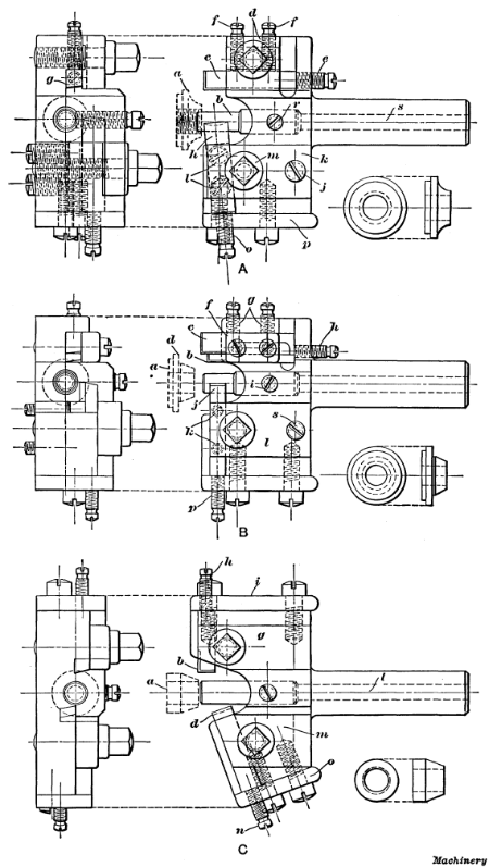
Fig. 9. Box-tools and Work for which they are Intended
Examples of Box-tool Turning.—Box-tools are not only used for cylindrical and taper turning on the end of a bar, but for many other operations. Figs. 9 and 10 show a number of box-tools of different designs, with examples of the work for which each is intended. While these tools are designed for some specific part, they can, of course, with slight modifications be adapted to other work.
A box-tool of the pilot type that is used for finishing, after the surplus stock has been removed by roughing tools, is shown at A, Fig. 9. The work, which is the cone for a ball bearing, is shown at a by the dotted lines and also by the detail view to the right. The pilot b enters the work before either of the cutters begins to operate on its respective surface. The inverted cutter c, which sizes the flange of the cone, is held in position by a clamp d, which is forced down by a collar-head screw. The cutter is further secured against a beveled shoulder at g by the set-screws f, and it is adjusted forward by the screw e. By loosening the screws f and the collar-head screw, the cutter may be removed for sharpening. The cutter h is adjusted to cut to the proper diameter, by the screws l, after which the clamp k is made level by the screw j. The collar-screw m is then used to secure the tool in place. The cutter is made from drill rod and it is slightly cupped out on the cutting end to give keenness to the cutting edge. The adjusting screw o, which passes through plate p, prevents the cutter from backing away from the work. This adjusting screw plate has its screw holes slotted to avoid removing the screws when it becomes necessary to remove the plate and cutter for sharpening. Pilot b is held firmly to the tool body by set-screw r. The hole s through the shank makes it easy to remove the pilot, in case this is necessary.
[195] A pilot box-tool for finishing another type of ball bearing cone is shown at B. The shape of the work itself is indicated by the dotted lines a and by the detail view. This tool is somewhat similar in its construction to the one just described. The cutters b and c are inverted and are used to face the flange at d and to turn it to the proper diameter. These cutters are held by the clamp f and screws g and are adjusted forward by the screw h. The cutter j, which operates on top of the stock, rests on a bolster, of the proper angle and is adjusted up or down by the screws k. The clamp l, which binds against this tool, is beveled to correspond with the angle of the tool. This clamp is secured by the collar-screw shown and it is leveled by set-screws s. The adjusting screw p prevents the cutter from slipping back. The holes in the adjusting-screw plate are also slotted in this case so that it will not be necessary to remove any screws when the cutter has to be taken out of the holder.
A box-tool for finishing a treadle-rod cone for a sewing machine is shown at C. This tool is also of the pilot type. The cutters in it operate on opposite sides of the cone a. The inverted cutter b sizes the cylindrical part of the cone, while the front cutter d is set at the proper angle to finish the tapered part. The rear cutter b is held in place by the clamp g and a collar screw. It is adjusted forward by the screw h in the plate i which is held by screws as shown. The pilot is retained by a set-screw, and it is easily removed by inserting a small rod in the hole l which passes through the shank. The cutter d is held by clamp m and is adjusted by screw n which passes through a tapped hole in plate o. The screw holes in both the adjusting plates i and o are slotted to facilitate their removal.
[197]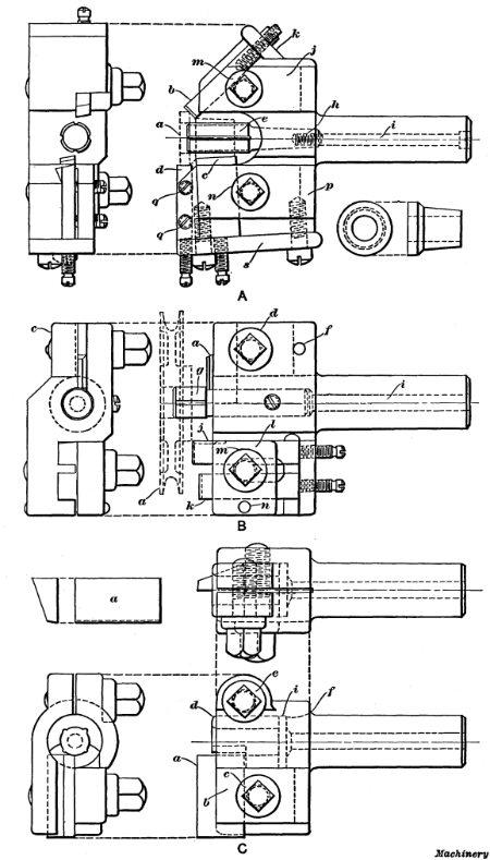
Fig. 10. Examples of Box-tool Designs
The box-tool illustrated at A, Fig. 10, is used for finishing the bushing of a double-taper cone bearing a. The cutters are so arranged that they all cut on the center; that is, the cutting edges lie in a horizontal plane. The inverted cutter b at the rear forms the short angular surface, and the cutter c in front forms the long tapering part of the bearing. The large diameter is turned, to size by cutter d. The pilot e has a bearing in the bore nearly equal to the length of the work and it is provided[196] with oil grooves, as shown. The taper shank of this pilot is tapped for the screw i which extends the whole length of the shank and is used to draw the pilot back to its seat. It is not necessary to remove adjusting-screw plate k to take out the cutter b, as the latter can be drawn out from the front after the collar-screw m is loosened. The cutter c is removed by taking off the adjusting-screw plate s after loosening the collar-screw n. The cutter d is held in a dove-tailed slot by two headless set-screws q. It is also backed up by an adjusting screw in the plate s. These adjusting screws should all have fine threads, say from 32 to 40 per inch, and be nicely fitted so they will not loosen after being adjusted.
The box-tools shown at B and C, Fig. 10, are for turning the sides of a loose pulley for a sewing machine. This pulley (shown by the dotted lines) is finished in two operations. The box-tool for finishing the side of the pulley on which the hub projects beyond the rim, is shown at B. The inverted cutter a, which faces the end of the hub, is held by a clamp c (clearly shown in the end view) from the under side and it has no adjustment. The collar-screw d is tapped into this clamp, which is prevented from getting out of place by the dowel-pin f. The pilot g is made small in the shank, so that tool a can be so placed as to insure the removal of all burrs around the bore of the hub. The pilot is held by a set-screw and it is provided with oil grooves. The cutter j sizes the outside of the hub, and the cutter k faces the side of the pulley rim. These cutters are both held by the clamp l and the collar-screw m. No side plates are used on this tool, and the cutters are all easily removed.
Sketch C shows the box-tool used for the second operation. As the hub is flush with the rim on the side for which this tool is intended, it needs only one cutter to face both. This is done by the wide cutter a which is held in a dove-tailed slot in the front of the tool and is fastened by the clamp b and collar-screw c. The bushing d, in which the end of the work arbor is supported, is held by the collar-screw e, and to obtain the necessary compression, the body of the tool is slotted as far back as f. This bushing is provided with oil grooves and one side is cut away[198] to clear the cutter a. The pilot end of the arbor on which the work is mounted is 1/16 inch smaller than the bore of the pulley, which allows the cutter to be set in far enough to prevent any burr which might form at the edge of the bore. A disk i is inserted back of bushing d, so that the latter may be easily removed by passing a rod through the hollow shank. The special chuck used for this second operation on the loose pulley is screwed onto the spindle, and the work is mounted on a projecting arbor and driven by the pins engaging holes in the pulley web. The arbor is made a driving fit for the work, and the end or pilot is a running fit in the bushing of the box-tool. A counterbore in the arbor hub provides clearance for the hub of the pulley which projects beyond the rim on one side.
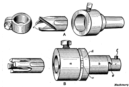
Fig. 11. (A) Hollow Mill and Holder.
(B) Spring Screw-threading Die
and Releasing Die-holder
Hollow Mills.—A hollow mill such as is shown at A in Fig. 11 is sometimes used in place of a box-tool (especially when turning brass) for short roughing cuts preceding a threading operation. The turning is done by the cutting edges e, and the turned part enters the mill and is steadied by it. If this type of tool is used for long, straight cuts, especially on square stock and when making screws with large heads from the bar, it should always be followed by a finishing box-tool to insure accurate work. A[199] hollow mill can be sharpened readily by grinding the ends without materially changing the cutting size. A slight adjustment can be obtained by means of the clamp collar shown to the left, although this is not generally used. When making these mills, they should be reamed out tapering from the rear to give clearance to the cutting edges. For turning steel, the cutting edge should be about 1/10 of the diameter ahead of the center, whereas for brass, it should be on the center-line.
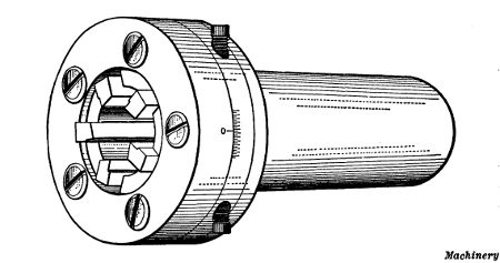
Fig. 12. Geometric Adjustable Hollow Milling Tool
Hollow mills are also made adjustable. The design shown in Fig. 12 is especially adapted for brass finishing. It can also be used for taking light cuts on cast iron or steel but its use in place of roughing or finishing box-tools for general use is not recommended. With the exception of the cutters and screws, the complete tool consists of three parts, viz., the holder, cam, and ring. The cam serves to adjust the cutters for different diameters. The adjustment is made by the two screws shown, the amount being indicated by a micrometer scale. When adjusting the cutters for a given diameter, the use of a hardened steel plug of the required size is advisable, the cutters being adjusted against the plug.
Releasing Die and Tap Holders.—Threads are cut in the turret lathe by means of dies for external threading, and taps for internal threading, the die or tap being held in a holder attached to the turret. A simple form of releasing die holder is shown[200] at B, Fig. 11. This holder was designed for the spring-screw type of threading die shown to the left. The die is clamped in the holder a by the set-screw shown, and the shank b of the holder is inserted in the turret hole. Holder a has an extension c which passes through the hollow shank. When the die is pressed against the end of the work, holder a and its extension moves back until lug d on the holder engages lug e on the shank. The die and holder are then prevented from rotating with the work and the die begins to cut a thread. It continues to screw itself onto the work with the turret following, until the thread has been cut to the required length; the turret is then stopped and as the die and holder a are drawn forward, lugs d and e disengage so that the die simply rotates with the work without continuing to advance. The lathe spindle is then reversed and as the turret is moved back by hand, pin f comes around and enters notch g, thus holding the die stationary; the die then backs off from the threaded end. Some tap holders are also constructed the same as this die holder, so far as the releasing mechanism is concerned. There are also many other designs in use, some of which operate on this same principle.
Self-opening Die Heads.—The type of die holder shown at B in Fig. 11 is objectionable because of the time required for backing the die off the threaded end; hence, self-opening dies are extensively used in turret lathe work. As the name implies,[201] this type of die, instead of being solid, has several chasers which are opened automatically when the thread has been cut to the required length. The turret can then be returned without reversing the lathe spindle. The dies are opened by simply stopping the travel of the turret slide, the stop-rod for the feed of the turret being adjusted to give the proper amount of travel.
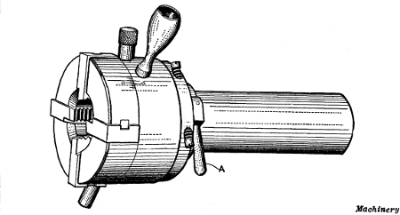
Fig. 13. Geometric Self-opening and Adjustable Screw-cutting Die Head
A well-known die head of the self-opening type is shown in Fig. 13. The dies open automatically as soon as the travel of the head is retarded, or they can be opened at any point by simply holding back on the turnstile or lever by which the turret slide is moved. The die is closed again by means of the small handle seen projecting at right-angles from the side of the head. The closing may be done by hand or automatically by screwing a pin into a threaded hole opposite the handle and attaching a small piece of flat steel to the back edge of the turret slide. The latter will then engage the pin as the turret revolves, thus closing the die head. This die head has a roughing and finishing attachment which is operated by handle A. When this handle is moved forward, the dies are adjusted outward 0.01 inch for the roughing cut, whereas returning the handle closes and locks the dies for the finishing cut. The die head has a micrometer scale which is used when making slight adjustments to compensate for the wear of the chasers or to make either a tight-or a loose-fitting thread.
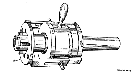
Fig. 14. Geometric Collapsing Tap
[202] Collapsing Taps.—The collapsing tap shown in Fig. 14 is one of many different designs that are manufactured. They are often used in turret lathe practice in place of solid taps. When using this particular style of collapsing tap, the adjustable gage A is set for the length of thread required. When the tap has been fed to this depth, the gage comes into contact with the end of the work, which causes the chasers to collapse automatically. The tool is then withdrawn, after which the chasers are again expanded and locked in position by the handle seen at the side of the holder. In all threading operations, whether using taps or dies, a suitable lubricant should be used, as a better thread is obtained and there is less wear on the tools. Lard oil is a good lubricant, although cheaper compounds give satisfactory results on many classes of work.
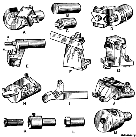
Fig. 15. Various Types of Tools for the Turret Lathe
Miscellaneous Turret Lathe Tools.—The chamfering tool shown at A, Fig. 15, is used for pointing the end of a bar before running on a roughing box-tool. This not only finishes the end of the bar but provides an even surface for the box-tool to start on. The cutter is beveled on the end to form a cutting edge and it is held at an angle. The back-rest consists of a bell-mouthed, hardened tool-steel bushing which supports the bar while the cut is being taken.
The stop gages B and C are used in the turret to govern the length of stock that is fed through the spindle. When a finished piece has been cut off, the rough bar is fed through the spindle and up against the stop gage, thus locating it for another operation. This gage may be a plain cylindrical piece of hardened steel, as at B, or it may have an adjusting screw as at C; for special work, different forms or shapes are also required. The stop gages on some machines, instead of being held in the turret, are attached to a swinging arm or bracket that is fastened to the turret slide and is swung up in line with the spindle when the stock is fed forward.
The center drilling tool D is designed to hold a standard combination center drill and reamer. This type of tool is often used when turning parts that must be finished afterwards by grinding, to form a center for the grinding machine. The adjustable turning[203] tool E is used for turning the outside of gear blanks, pulley hubs or the rims of small pulleys. The pilot a enters the finished bore to steady the tool, and cutter b is adjusted to turn to the required diameter.
The cutting-off tool-holder F (which is held on the cross-slide of the turret lathe) is usually more convenient than a regular toolpost, as the blade can be set closer to the chuck. The blade is held in an inclined position, as shown, to provide rake for the cutting edge; the inclined blade can also be adjusted vertically, a limited amount, by moving it in or out. The multiple cutting-off tool G holds two or more blades and is used for cutting off several washers, collars, etc., simultaneously. By changing the distance pieces between the cutters, the latter are spaced for work of different widths. The flat drill holder[204] H is used for drilling short holes, and also to form a true “spot” or starting point for other drills.
Knurling tools are shown at I and J. The former is intended for knurling short lengths and is sometimes clamped on top of the cut-off tool on the cross-slide, the end being swung back after knurling (as shown by the dotted lines) to prevent interference with the work when the cutting-off tool is in operation. The knurling tool J has a shank and is held in the turret. The two knurls are on opposite sides of the work so that the pressure of knurling is equalized. By adjusting the arms which hold the knurls, the tool can be set for different diameters.
Three styles of drill holders are shown at K, L and M. Holder K is provided with a split collet (seen to the left) which is tightened on the drill shank by a set-screw in the holder. This holder requires a separate collet for each size drill. The taper shank drill holder L has a standard taper hole into which the shank of the drill is inserted. The adjustable type of holder M is extensively used, especially on small and medium sized machines when several sizes of drills are necessary. This holder is simply a drill chuck fitted with a special shank. For large drills the plain style of holder K is recommended, and if only a few sizes of drills are required, it is more satisfactory and economical than the adjustable type.
The various types of small turret lathe tools referred to in the foregoing for turning, threading, tapping, knurling, etc., are a few of the many different designs of tools used in turret lathe practice. Naturally, the tool equipment for each particular job must be changed somewhat to suit the conditions governing each case. The tools referred to, however, represent in a general way, the principal types used in ordinary practice. Some of the more special tools are shown in connection with examples of turret lathe work, which are referred to in the following.
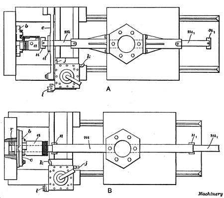
Fig. 16. (A) Method of Boring and Turning Pistons in Gisholt Lathe.
(B)
Special Chuck and Tools for Turning, Boring and Cutting Off Eccentric
Piston Rings
Turning Gasoline Engine Pistons in Turret Lathe.—The making of pistons for gas engines, especially in automobile factories, is done on such a large scale that rapid methods of machining them are necessary. The plan view A, Fig. 16, shows the turret lathe tools used in one shop for doing this work. As [205] is often advisable with work done in large quantities, the rough castings are made with extra projections so arranged as to assist in holding them. These projections are, of course, removed when the piece is completed. In this case the piston casting a has a ring about 11/4 inch long and a little less in diameter than the piston, at the chucking end. The piston is held in suitable chuck jaws b which are tightened against the inside of this ring. The set-screws in these special jaws are then tightened, thus clamping the casting between the points of the screws and the jaws. This method of holding permits the whole exterior of the piston to be turned, since it projects beyond the chuck jaws. This is the object in providing the piston with the projecting ring by which it is held.
The first operation consists in rough-boring the front end of the piston. The double-ended cutter n is held in boring-bar m, which is, in turn, supported by a drill-holder, clamped to one[206] of the faces of the turret. This bar is steadied by a bushing in the drill support c which is attached to the carriage, and may be swung into or out of the operating position, as required. After this cut is completed, the turret is revolved half way around and the casting is finish-bored in a similar manner, with double-ended cutter n1 held in bar m1, the drill support being used as in the previous case. The support is then turned back out of the way to allow the turning tools in the turret toolpost to be used.
The outside of the piston is next rough-turned with tool k in the turret toolpost, which is revolved to bring this cutter into action. The toolpost is then turned to the position shown, and the outside is finish-turned by tool j, which takes a broad shaving cut. The turret tool-holder is again revolved to bring form tool l into position. This tool cuts the grooves for the piston rings. Suitable positive stops are, of course, provided for both the longitudinal and cross movements of the turret toolpost.
In the second operation, the piston a is reversed and held in soft jaws, which are used in place of the hardened jaws b shown in the illustration. These jaws are bored to the outside diameter of the piston, so that when closed, they hold the work true or concentric with the lathe spindle. In this operation the chucking ring by which the piston was previously held is cut off, and the end of the piston is faced true. If the crank-pin hole is to be finished, a third operation is necessary, a self-centering chuck-plate and boring and reaming tools being used. (These are not shown in the illustration.)
Turning Piston Rings in Turret Lathe.—One method of turning piston rings is shown at B in Fig. 16. The piston rings are cut from a cast-iron cylindrical piece which has three lugs b cast on one end and so arranged that they may be held in a three-jawed chuck. This cylindrical casting is about 10 inches long, and when the rings are to have their inside and outside surfaces concentric, the casting is held by the lugs in the regular jaws furnished with the chuck. (The arrangement used for turning and boring eccentric rings, which is that shown in the illustration, will be described later.)
[207] The casting a, from which the rings are made, is first rough-bored with double-ended cutter n in boring-bar m, after which it is finish-bored with cutter n1 in bar m1. While taking these cuts, the bars m and m1 are supported by their extension ends which enter bushing r located in the central hole of the chuck. This furnishes a rigid support so that a heavy cut can be taken.
The outside of the casting is next rough-turned with tool k, held in the turret toolpost. This toolpost is then revolved to bring tool j into position, by which the outside is turned true to size, a broad shaving chip being taken. The toolpost is again swung around, to bring the cutting-off tool-holder l into position. This holder contains four blades set the proper distance apart to give rings of the desired width. Each blade, from right to left, is set a little back of the preceding one, so that the rings are cut off one after the other, the outer rings being supported until they are completely severed. After the first four rings are cut off, the carriage is moved ahead to a second stop, and four more rings are severed, this operation being continued until the casting has been entirely cut up into rings.
When the bore of the ring is to be eccentric with the outside, the holding arrangement shown in the illustration is used. The casting a is bolted to a sliding chuck-plate c, and the outside is rough-turned with tool k in the toolpost. Finishing tool j is then brought into action, and the outside diameter is turned accurately to size. Then the sliding chuck-plate c, carrying the work, is moved over a distance equal to the eccentricity desired, and the work is bored with cutters n and n1 as in the previous case. The turret toolpost is next revolved and the tools l are used for cutting off the rings. The reason for finishing the outside first is to secure smooth rings in cutting off, as this operation should be done when the work is running concentric with the bore, rather than with the exterior surface.
It will be evident that this method gives a far greater output of rings than is possible by finishing them in the more primitive way on engine lathes. The faces of the rings may be finished in a second operation if desired, or they may be ground, depending[208] on the method used in the shop where the work is being done, and the accuracy required.
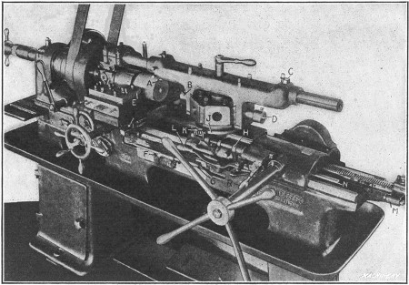
Fig. 17. Turning Gasoline Engine Pistons in Pratt & Whitney Turret Lathe
Piston Turning in Pratt and Whitney Turret Lathe.—A turret lathe equipped with tools for turning, facing and grooving automobile gasoline engine pistons is shown in Fig. 17. The piston is held on an expanding pin chuck which is so constructed that all of the pins are forced outward with equal pressure and automatically conform to any irregularities on the inside of the piston. Tool A rough-turns the outside, and just as this tool completes its cut, a center hole is drilled and reamed in the end of the piston by combination drill and reamer B. The turret is then indexed one-half a revolution and a finishing cut is taken by tool C. After the cylindrical body of the piston has been turned, tools held in a special holder E attached to the cut-off slide are used to face the ends of the piston and cut the packing-ring grooves. While the grooves are being cut, the outer end of the piston is supported by center D. The center hole in the end also serves to support the piston while being ground to the required diameter in a cylindrical grinding machine. The edge at the open end of the piston may also be faced square and[209] the inner corner beveled by a hook tool mounted on the rear cross-slide, although this is usually done in a separate operation. (This provides a true surface by which to hold this end when grinding.)
This illustration (Fig. 17) shows very clearly the stops which automatically disengage the turret feed. A bracket F is bolted to the front of the bed and contains six stop-rods G (one for each position or side of the turret). When one of these stop-rods strikes lever H, the feed is disengaged, the stop being adjusted to throw out the feed when the tool has completed its cut. Lever H is automatically aligned with the stop-rods for different sides of the turret by a cam J on the turret base. A roller K bears against this cam and, through the connecting shaft and lever shown, causes lever H to move opposite the stop-rod for whatever turret face is in the working position. Lever L is used for engaging the feed and lever R for disengaging it by hand.
The indexing of the turret at the end of the backward movement of the slide is controlled by stop M against which rod N [210] strikes, thus disengaging the lock bolt so that the turret can turn. This stop M is adjusted along the bed to a position depending upon the length of the turret tools and the distance the turret must move back to allow the tools to clear as they swing around.
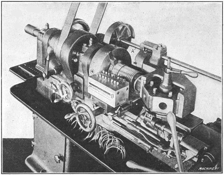
Fig. 18. Pratt & Whitney Turret Lathe equipped with Special
Attachment
for Turning Eccentric Piston Rings
Attachment for Turning Piston Rings.—Fig. 18 shows a special attachment applied to a Pratt & Whitney turret lathe for turning eccentric, gas-engine piston rings. The boring of the ring casting, turning the outside and cutting off the rings, is done simultaneously. The interior of the casting is turned concentric with the lathe spindle by a heavy boring-bar, the end of which is rigidly supported by a bushing in the spindle. The slide which carries the outside turning tool is mounted on a heavy casting which straddles the turret. The outside of the ring casting is turned eccentric to the bore as a result of an in-and-out movement imparted to the tool by a cam on shaft A which is rotated from the lathe spindle through the gearing shown. For each revolution of the work, the tool recedes from the center and advances toward it an amount sufficient to give[211] the required eccentricity. When the turning and boring tools have fed forward about 2 inches, then the cutting-off tools which are held in holder B come into action. The end of each cutting-off tool, from right to left, is set a little farther away from the work than the preceding tool, so that the end rings are always severed first as the tools are fed in by the cross-slide. A number of the completed rings may be seen in the pan of the machine.
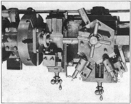
Fig. 19. Tool Equipment for Machining Worm Gear Blanks—Davis Turret Lathe
Turning Worm-gear Blanks in Turret Lathe.—This is a second operation, the hub of worm-gear blank G (Fig. 19) having previously been bored, reamed, and faced on the rear side. The casting is mounted upon a close-fitting arbor attached to a plate bolted to the faceplate of the lathe, and is driven by two pins which engage holes on the rear side. The rim is first rough-turned by a tool A which operates on top, and the side is rough-faced by a toothed or serrated cutter B. A similar tool-holder[212] having a tool C and a smooth cutter D is then used to turn the rim to the required diameter and finish the side. The end of the hub is faced by cutters mounted in the end of bars E and F, one being the roughing cutter and the other the finishing cutter. The work arbor projects beyond the hub, as will be seen, and forms a pilot that steadies these cutter bars. The curved rim of the gear is turned to the required radius (preparatory to gashing and bobbing the worm-wheel teeth) by a formed tool H held on the cross-slide.
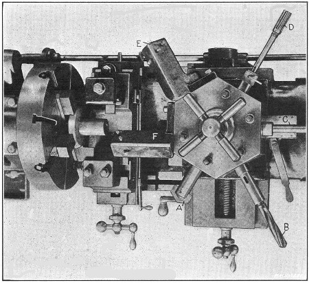
Fig. 20. Turning Bevel Gear Blanks in Davis Turret Lathe—First Operation
Turning Bevel Gear Blanks.—Fig. 20 shows a plan view of the tools used for the first turning operation on bevel gear blanks (these gears are used for driving drill press spindles). The cored hole is beveled true at the end by flat drill A to form a true starting surface for the three-fluted drill B which follows. The hole is bored close to the required size by a tool (not shown) held in the end of bar C, and it is finished by reamer D. The cylindrical end of the gear blank or hub is rough-and finish-turned by[213] tools held in holders E and F, respectively. (These holders were made to set at an angle of 45 degrees, instead of being directly over the work, as usual, so that the cutters would be in view when setting up the machine.) It will be noted that the chuck is equipped with special jaws which fit the beveled part of the casting.
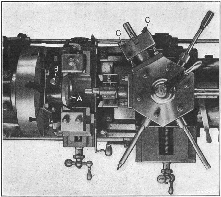
Fig. 21. Second Operation on Bevel Gear Blanks
The second and final operation on this blank is shown in Fig. 21. The work A is held by a special driver plate attached to the faceplate of the machine. This driver plate has two pins which engage holes drilled in the gear blank and prevent it from rotating. The blank is also held by a bolt B which forces a bushing against the cylindrical end. First, the broad beveled side which is to be the toothed part of the gear, is rough-turned by toothed cutters C, and a recess is formed in the end of the blank, by a turning tool in this same tool-holder. A similar tool-holder E, having finishing cutters, is then used to finish the bevel face and recess. The other tools seen in the turret are not used for this second operation. The rear bevel is roughed and finished by tools and held on the cross-slide.
Shell Turning Operation in Flat Turret Lathe.—The “flat turret lathe” is so named because the turret is a flat circular plate mounted on a low carriage to secure direct and rigid support from the lathe bed. The tools, instead of being held by[214] shanks inserted in holes in the turret, are designed so that they can be clamped firmly onto the low circular turret plate.
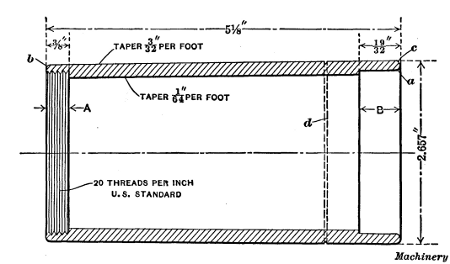
Fig. 22. Sectional View of Tapering Mold Shell which is turned in
Hartness
Flat Turret Lathe, as illustrated in Figs. 23 to 27, Inclusive
An interesting example of flat turret lathe work is shown in Fig. 22. This is a steel shell which must be accurately finished to a slight taper, both inside and out, threaded and plain recesses are required at the ends, and, in addition, one or two minor operations are necessary. This work is done in the Hartness flat turret lathe, built by the Jones & Lamson Machine Co. The shells are turned from cold-drawn seamless steel tubing, having a carbon content of 0.20 per cent, and they are finished at the rate of one in nine minutes. The tubing comes to the machine in 12-foot lengths, and the tube being operated upon is, of course, fed forward through the hollow spindle as each successive shell is severed.
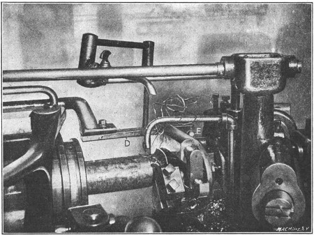
Fig. 23. First Operation on Shell Illustrated in Fig. 22—Rough-turning and Boring
In finishing this shell, five different operations are required. During the first operation the shell is rough-bored and turned by one passage of a box-tool, Fig. 23, and the recess A, Fig. 22, at the outer end, is finished to size by a second cutter located in the boring-bar close to the turret. The turret is then indexed to the second station which brings the threading attachment G into position, as shown in Fig. 24. After the thread is finished, [215] the recess B, Fig. 22, is turned by a flat cutter K, Fig. 25. The inner and outer surfaces are then finished to size by a box-tool mounted on the fourth station of the turret and shown in position in Fig. 26. The final operation, Fig. 27, is performed by three tools held on an auxiliary turret cross-slide, and consists in rounding the corners at b and c, Fig. 22, and severing the finished shell.
One of the interesting features connected with the machining of this shell is the finishing of the inner and outer tapering surfaces. The taper on the outside is 3/32 inch per foot, while the bore has a taper of only 1/64 inch per foot, and these surfaces are finished simultaneously. The box-tool employed is of a standard type, with the exception of an inserted boring-bar, and the taper on the outside is obtained by the regular attachment which consists of a templet D (Fig. 23) of the required taper, that causes the turning tool to recede at a uniform rate as it feeds along. To secure the internal taper, the headstock of the machine is swiveled slightly on its transverse ways by the use of tapering gibs. By this simple method, the double taper is finished to the required accuracy without special tools or equipment.
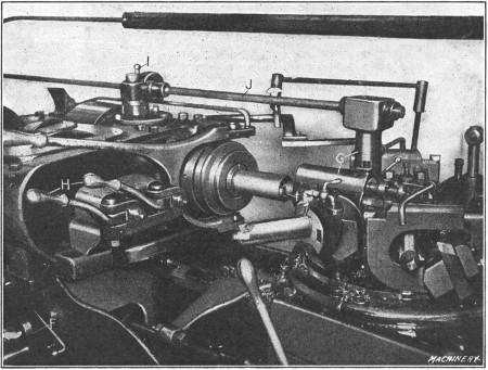
Fig. 24. Second Operation—Cutting Internal Thread
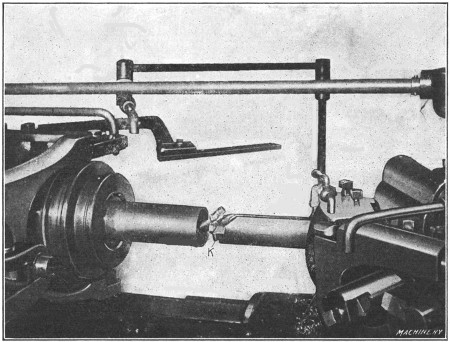
Fig. 25. Third Operation—Turning Recess at Rear End; Tool is shown withdrawn
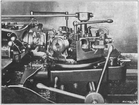
Fig. 26. Fourth Operation—Finishing the Bore and Outside
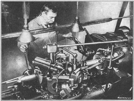
Fig. 27. Fifth Operation—Rounding Ends, Scoring Large End, and Cutting Off
As those familiar with this machine know, the longitudinal[216] movements of the turret as well as the transverse movements of the headstock are controlled by positive stops. The headstock of this machine has ten stops which are mounted in a revolving holder and are brought into position, as required, by manipulating a lever at the front. The stops for length, or those controlling the turret travel, are divided into two general groups, known as “A” and “B”. Each of these groups has six stops so that there are two stops for each of the six positions or stations of the turret, and, in addition, five extra stops are available for any one tool, by the engagement of a pin at the rear of the turret. The change from the “A” to the “B” stops is made by adjusting lever L, Fig. 26, which also has a neutral position.
After the box-tool for the roughing cut, shown at work in Fig. 23, has reached the end of its travel, further movement is arrested by a stop of the “A” group. The outside turning tool is then withdrawn by operating lever E and the turret is run back and indexed to the second station, thus bringing the threading attachment into position. The surface speed of 130 feet per minute which is used for turning is reduced to about 30 feet per minute for threading by manipulating levers H, Fig. 24. After the turret is located by another stop of the “A” group, the[217] threading attachment is made operative by depressing a small plunger I, which connects a vertical driving shaft from the spindle with the splined transmission shaft J. A reciprocating movement is then imparted to the thread chaser t which advances on the cutting stroke and then automatically retreats to clear the thread on the return. This movement is repeated until the thread is cut to the proper depth, as determined by one of the stops for the headstock. While the thread is being cut, the carriage is locked to the bed by the lever N, Fig. 26. It was found necessary to perform the threading operation before taking the outside finishing cut, owing to a slight distortion of the shell wall, caused by the threading operation.
After the thread is finished, the turret is turned to the third station as shown in Fig. 25, and tool K for the inner recess B, Fig. 22, is brought into position and fed to the proper depth, as determined by another cross-stop. The turret is also locked in position for this operation. The finishing cuts for the bore and the outside are next taken by a box-tool which is shown near the end of its cut in Fig. 26. This box-tool is similar to the one used for roughing, but it is equipped with differently shaped cutters to obtain the required finish. The outside turning[218] tool has a straight cutting edge set tangent to the cylindrical surface and at an angle, while the boring tool has a cutting edge of large radius. An end view of this box-tool is shown in Fig. 27. A reduced feed is employed for the finishing cut, and the speed is increased to 130 feet per minute, which is the same as that used for roughing.
During the next and final operation, the turret, after being indexed to the position shown in Fig. 27, is first located by a stop of the “A” group so that the cutting-off tool R in front can be used for rounding the corner b, Fig. 22. The stop lever L is then shifted and the turret is moved to a second stop of the “B” group. The corner c is then rounded and the shell is scored at d by two inverted tools S and T at the rear, after which the finished work is severed by the cut-off tool at the front. The cross-movement of these three tools is controlled by positive stops on the cross-slide, and the latter is moved to and fro by hand lever O. After the shell is cut off, the stop M, mounted on the turret, Fig. 26, is swung into position, and the tube is automatically fed forward to the swinging stop by the roll feed, as soon as the chuck is released by operating lever Q. This completes the cycle of operations. A copious supply of lubricant[219] is, of course, furnished to the tools during these operations, and the two boring-tool shanks are hollow so that lubricant can be forced through them and be made to play directly upon the cutters.
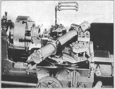
Fig. 28. Tool Equipment for Turning Scroll Gear Blank on Acme Flat Turret Lathe
Chuck Work in Flat Turret Lathe.—Two examples of chuck work on the Acme combination flat turret lathe are shown in Figs. 28 and 29. Fig. 28 shows the tool equipment for turning a cylindrical part A which is held in a three-jaw universal chuck. The front flange is first rough-turned by a bent turning tool B. The diameter is regulated by one of the cross-stops at D which has been previously set and controls the movement of the turret cross-slide. The longitudinal feed is disengaged when the flange has been turned, by an independent stop. This machine has twelve longitudinal stops, there being one for each turret face and six auxiliary stops, in addition to the stops for the cross-slide.
After roughing the flange, the turret carriage is locked or clamped rigidly to the bed to prevent any lengthwise movement, and the back face of the front flange is rough-turned by tool B [220] in to the diameter of the hub which is indicated by a micrometer dial on the cross-feed screw. The carriage is then unlocked and auxiliary stop No. 7 is engaged (by turning a knob at the front of the slide) and the cylindrical hub is turned back to the rear flange, the feed being disengaged by the auxiliary stop just as the tool reaches the flange. The cross-slide is now moved outward, longitudinal auxiliary stop No. 8 is engaged, the turret slide is moved against the stop, the carriage is locked and the front sides of both the front and rear flanges are rough-faced by tools B and C. The turret is next indexed and the hole rough-bored by cutter E. After again indexing the turret, the hub and flanges are finish-turned and faced by tools F and G, as described for the rough-turning operation. The final operation is that of finishing the bore by cutter H.
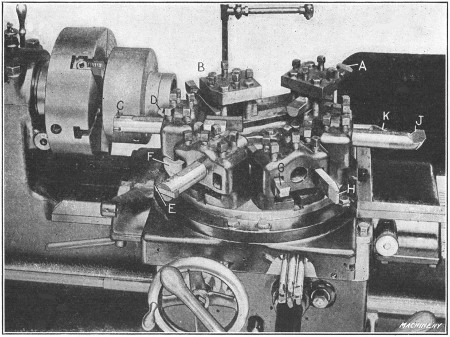
Fig. 29. Acme Flat Turret Lathe Arranged for Turning Roller Feed Body
The operation shown in Fig. 29 is that of turning the body of a roller feed mechanism for a turret lathe. The casting is held in a three-jaw universal chuck and it is first rough-bored by tool A. The turret is then indexed and the side of the body and end of the hub are rough-faced by tools at B. The turret is again indexed for rough-turning the outside of the hub and[221] body, by tools C and D. Similar tools E and F are then used to finish these same surfaces, after which the end of the hub and side of the body are finished by tools G and H similar to those located at B. The final operation is that of finishing the bore by tool J and cutting a groove in the outside of the hub by the bent tool K.
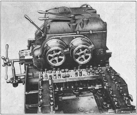
Fig. 30. Turret and Head of Jones & Lamson Double-spindle Flat Turret Lathe
Double-spindle Flat Turret Lathe.—The extent to which modern turning machines have been developed, especially for turning duplicate parts in quantity, is illustrated by the design of turret lathe the turret and head of which is shown in Fig. 30. This machine has two spindles and a large flat turret which holds a double set of tools, so that two duplicate castings or forgings can be turned at the same time. It was designed primarily for chuck work and can be used as a single-spindle machine if desirable. When two spindles are employed for machining two duplicate parts simultaneously, considerably more time is required for setting up the machine than is necessary for the regular single-spindle type, but it is claimed that the increased rate of production obtained with the two-spindle design more than offsets[222] this initial handicap. The manufacturers consider the single-spindle machine the best type for ordinary machine building operations, regardless of whether the work is turned from the bar or is of the chucking variety. On the other hand, the double-spindle type is preferred when work is to be produced in such quantities that the time for setting up the machine becomes a secondary consideration.
When the double-spindle machine is used as a single-spindle type, a chuck 17 inches in diameter is used, and when both spindles are in operation, two 9-inch chucks are employed. The general outline of the turret is square, and the tools are rigidly held, with a minimum amount of overhang, by means of tool-blocks and binding screws connected with the clamping plates. Two duplicate sets of tools are clamped to each side of the turret and these operate simultaneously on the two pieces held in the chucks or on faceplates. Primarily the turret is used[223] in but four positions, but when a 17-inch chuck or faceplate is employed, corner blocks may be held by the clamping plates in which tools are supported, giving, if necessary, four additional operations by indexing the turret to eight positions.
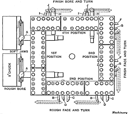
Fig. 31. Diagram showing Tool Equipment and Successive Steps
in
Machining Sprocket Blanks on Double-spindle Flat Turret Lathe
A typical job to demonstrate the application of the double-spindle flat turret lathe is illustrated in Fig. 31. The parts to be turned are sprocket wheels which are held in the two 9-inch chucks. At the first position of the turret (which is the one illustrated), the inside is rough-bored by tools A. At the second position of the turret, tools B rough-face the inner sides of the flanges; tools C face the outer sides of the flanges, while tools D turn the faces of the flanges. At the third position of the turret, tools E finish-turn the inside of the flanges; tools F finish-turn the outside of the flanges, while tools G finish the faces of the flanges. At the fourth position of the turret, tools H finish-bore the sprockets; tools I complete the turning on the outside of the flanges, while tools J accurately size the interior of the flanges.
With the double-spindle flat turret lathe, each operation is a double operation, and the speeds are varied according to the nature of the cut; thus, if at one position of the turret, the tools are required to rough out the work, this may be done rapidly, for it has no bearing on the other operations that are subsequently performed. Furthermore, if the following operation has to be performed with great care, this may be done without reducing the speed of the less exacting operations.
[224]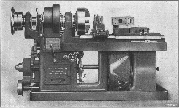
Fig. 32. Potter & Johnston Automatic Chucking and Turning Machine
Automatic Chucking and Turning Machine.—The chucking and turning machine shown in Fig. 32 is automatic in its operation, the feeding of the tools, indexing of the turret, etc., being done automatically after the machine is properly arranged, and the work is placed in the chuck. This machine is adapted to turning and boring a great variety of castings, forgings or parts from bar stock, and it is often used in preference to the hand-operated turret lathe, especially when a great many duplicate parts are required. It is provided with mechanism for operating the cross-slide, feeding the turret slide forward, returning it rapidly, rotating the turret to a new position, and feeding it forward quickly for taking a new cut. The cross-slide [225] and turret-slide movements are effected by cams mounted on the large drum E seen beneath the turret, while the various speed and feed changes are effected by dogs and pins carried on disk D which is keyed to the same shaft that the cam drum is mounted upon. This shaft with the cam drum and governing disk D, makes one revolution for each piece of work completed. The cams for operating the turret slide are mounted upon the periphery of drum E. The roll which engages the angular faces of these cams and imparts movement to the turret is carried by an intermediate slide which has rack teeth engaging a pinion on the square shaft C. By turning this shaft with a crank, the position of the turret-slide, with relation to the cam, may be adjusted for long or short work and long or short tools, as may be required.
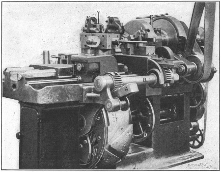
Fig. 33. Rear View of Machine showing the Cross-slide Mechanism, Driving Gearing, etc.
The cams which operate the cross-slide are mounted on the right-hand end of drum E and actuate the yoke A (see Fig. 33) which extends diagonally upward. The rear end of this yoke has rack teeth meshing with the teeth of a segmental pinion,[226] which is fastened to rock-shaft B. At the headstock end, this rock-shaft carries another segmental pinion meshing with rack teeth formed on the cross-slide. The movement imparted to the yoke by the cams is thus transmitted through the pinions and rock-shaft to the cross-slide.
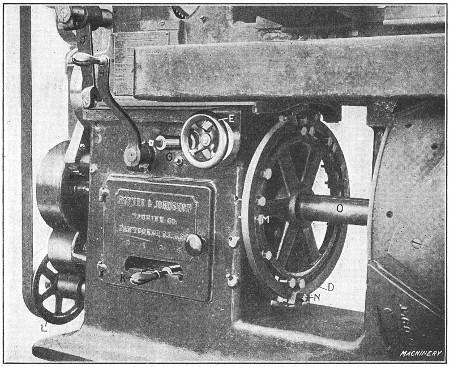
Fig. 34. The Automatic Controlling Mechanism for Feeds and Speeds
The cam drum E is driven by a pinion meshing with a gear attached to its front side. This pinion is driven through a train of gearing from pulley L (see Fig. 34) which is belted to the spindle. The feeds are thus always dependent on the spindle speed. By means of epicyclic gearing and suitable clutches, the motion thus derived from the spindle may be made rapid for returning the turret to be indexed and then advancing it to the cutting position again, or very slow for the forward feed when the tools are at work. These changes from slow to fast or vice versa are controlled by disk D. This disk carries pins which strike a star wheel located back of the disk at the top, and as this star wheel is turned, the speeds are changed by operation of the gearing and clutches referred to. The first pin M that [227] strikes the star wheel advances it one-sixth of a rotation, changing the feed from fast to slow; the next pin that strikes it advances it another sixth of a rotation, changing the feed from slow to fast and so on. By adjusting the pins for each piece of work, the feed changes are made to take place at the proper time. Handwheel E is geared with the cam-shaft on which the star wheel is mounted, so that the feeds may be changed by hand if desired.
In addition to these feed-changing pins, disk D has a dog which operates a lever by which the feed movement is stopped when the work has been completed. Four rates of feed are provided by quick change gearing of the sliding gear type, operated by handle K. With this handle set in the central position, the feed is disengaged. On the periphery of disk D are also clamped dogs or cams N, which operate a horizontal swinging lever P connected by a link with vertical lever J, which controls the two spindle speeds with which the machine is provided. Either one of these speeds can be automatically engaged at any time, by adjusting the cams N on disk D.
Lever H connects or disconnects the driving pulley from the shaft on which it is mounted, thus starting or stopping the machine. The square shaft G serves to operate the drums by hand and is turned with a crank. The rotation of the turret, which takes place at the rear of its travel, is, of course, effected automatically. A dog, which may be seen in Fig. 32 at the side of the bed, is set to trip the turret revolving mechanism at the proper point in the travel, to avoid interference between the tools and the work. The turret is provided with an automatic clamping device. The mechanism first withdraws the locking pin, unclamps the turret, revolves it, then throws in the locking pin and clamps the turret again.
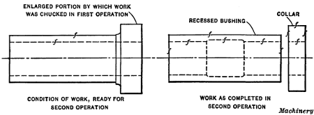
Fig. 35. Simple Example of Work done in Automatic Chucking and Turning Machine
Example of Work on Automatic Turning Machine.—The piece selected for illustrating the “setting up” and operation of the automatic chucking and turning machine is shown in Fig. 35. This is a second operation, and a very simple one which will clearly illustrate the principles involved. In the first operation, the hole was drilled, bored and reamed, the small end[228] of the bushing faced, and the outside diameter finished, as indicated by the sketch to the left. (The enlarged diameter at the end was used for holding the work in the chuck.) In the second operation (illustrated to the right), the enlarged chucking end is cut off and, in order to prevent wasting this piece, it is made into a collar for another part of the machine for which the bushing is intended; hence, the outside diameter is turned and the outside end faced, before cutting off the collar. In addition, the bushing is recessed in the second operation, and the outer end faced. In order to have the surfaces finished in the second operation, concentric with those machined in the first operation, the chuck is equipped with a set of soft “false jaws” which have been carefully bored to exactly the diameter of the work to be held.
The first thing to determine when setting up a machine of this type is the order of operations. In this particular case, the order is as follows: At the first position of the turret, the outside collar is rough-turned and the outer end rough-faced. At the second position, the collar is turned to the required diameter and the outer face is finished. The third face of the turret is not equipped with tools, this part of the cycle being taken up in cutting off the collar with a cut-off tool on the rear cross-slide. The fourth operation is that of recessing the bushing, and the fifth operation, facing the end to remove the rough surface left by the cutting-off tool.
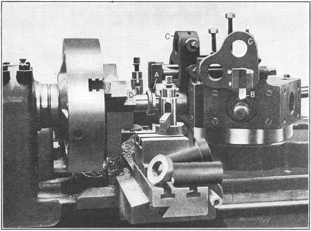
Fig. 36. Front View of Machine set up for the Finishing Operation on the Recessed Bushing and Collar shown in the Foreground and in Fig. 35
The tools A and B, Fig. 36, used for turning the outside of the flange, are held in brackets C bolted to the face of the turret. [229] These brackets are each provided with three holes for carrying turning tool-holders. This arrangement provides for turning a number of diameters at different positions, simultaneously, but for this particular operation, a single cutting tool for each tool-holder is all that is necessary. A special device is used for recessing and will be described later.
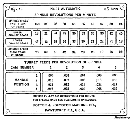
Fig. 37. Plate on the Headstock of Machine Illustrated in
Fig. 32
giving the Speeds and Feeds
Determining Speed and Feed Changes.—As previously mentioned, the particular machine illustrated in Fig. 32 can be arranged for two automatic changes of speed to suit different diameters on the work. The change gears that will give the required spindle speeds should first be selected. These change gears for different speeds are listed on a speed and feed plate attached to the headstock of the machine (see Fig. 37). It is possible to use one speed from the list given for the fast train of gears, and one from the list for the slow train, so long as the same gears are not used in each case. The diameter of the collar on the work shown in Fig. 35 is 21/2 inches, and the diameter of the body is 2 inches. Assuming that the surface speed for this job should be about 40 feet per minute, a little calculation [230] shows that the 66 revolutions per minute, given by the fast train of gears, is equivalent to a surface speed of 43 feet per minute on a diameter of 21/2 inches. Moreover, the 78 revolutions per minute obtained from the slow train of gearing, gives about 41 feet per minute on a diameter of 2 inches. The spindle gearing indicated for these speeds is, therefore, placed in position on the proper studs at the back of the machine.
Next we have to determine on which faces of the turret to place the different tools. Each turret face is numbered to agree with the corresponding feed cam on the drum. The speed and feed plate (Fig. 37) gives the various feeds obtainable per revolution of the spindle. As will be seen, the different cams give different feeds. Cam No. 1 has a coarse feed suitable for roughing; cam No. 2 a finer feed adapted to finishing, and so on. Since the first operation consists in rough-turning, cam No. 1 is used. Cam No. 2, which gives a finer feed, is used for the finish-turning operation. Cam No. 4, which is ordinarily used[231] for reaming, could, in this case, be used for recessing, as this recess is for clearance only and may be bored with a coarse feed.
The final operation, which is that of facing, can be done with any cam and cam No. 5 may be used. It will be understood that for facing operations, the feeds given do not apply. As the roll passes over the point of the feed cam at the extreme end of the movement, the feed of the turret slide is gradually slowed down to zero; since the facing takes place in the last eighth or sixteenth inch of this movement, it is done at a feed which is gradually reduced to zero. This is, of course, as it should be, and it is not necessary to pay any attention to the tabulated feeds in facing operations.
Setting the Turret Slide.—The next adjustment is that of setting the turret slide. In making this adjustment the turret is set in such relation to the work that the tools will have but a small amount of overhang, the cam-shaft being revolved by hand until the cam-roll is at the extreme top of the forward feeding cam, so that the turret slide is at the extreme of its forward movement. When this adjustment has been made by the means provided, set the turret index tripping dog so as to revolve the turret at the proper point. After a turning tool-holder and tool is attached to the face of the turret, cam No. 1 is placed in its operating position and is revolved by hand until the roll is on the point of the cam and the turret at the forward extreme of its motion. At this point the tool-holder is set so that the cutter will be far enough forward to complete its turning operation. The feed cam is then turned backward, thus returning the turret slide, and the cutter is set to turn the flange to the proper diameter for the roughing cut. The turret slide is fed forward and back while the cutter is adjusted, and when it is properly set, the flange is turned, the cam-drum being fed by hand. This is the first trial cut on the piece.
A facing tool, shown in the working position in Fig. 36, is placed at this station of the turret, being held in the turret hole. This tool has a pilot bar and a holder which contains a facing blade. Feeding by hand, as before, the tool is adjusted lengthwise so as to rough-face the work to the dimension desired. In a similar[232] way the finish-turning and facing tools for the second position of the turret are set, the cam-shaft being revolved by hand to bring this second face and second cam into the working position. (The finish-facing tool is not shown in place in Fig. 36.)
Setting the Cross-slide Cam.—As previously mentioned, the third turret face has no tool, the cutting off of the collar being done during this part of the cycle of operations. It has been taken for granted that in setting the turret slide, room has been left between it and the chuck for the cross-slide. The cross-slide is clamped in a longitudinal position on the bed, convenient for the cutting-off operation, which is done with a tool D (Fig. 36) in the rear toolpost, thus leaving the front unobstructed for the operator. When both forming and cutting off are to be done, the forming tool is generally held at the front and the cutting-off tool at the back because heavier and more accurate forming can be done with the work revolving downward toward a tool in the front toolpost, than with the tool at the rear where it is subjected to a lifting action.
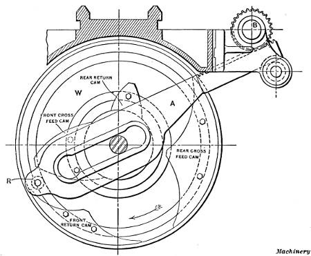
Fig. 38. Diagram of Cross-slide Cams and Feeding Mechanism
[233] The arrangement of the cross-slide cams is shown in Fig. 38, which is an end view of the large drum E, Fig. 32. The rear feed cam is the one to be used, and since this cutting-off operation is a short one, it may be done during the return of the turret for position No. 3. The cam drum is, therefore, rotated by hand until the turret face No. 3 has begun to return. The cross-slide cams are then loosened and the rear feed cam is swung around to just touch the roller R which operates arm A, the cross-slide having been adjusted out to nearly the limit of its forward travel, leaving approximately enough movement for cutting off the collar. The rear feed cam is then clamped in this position.
A cutting-off tool is next placed in the rear toolpost at the proper height. The rear toolpost slide is then adjusted to bring the point of the cutting-off tool up to the work, and the cam drum is revolved by hand until the piece is cut off. The cross-slide tool is, of course, set in the proper position to make a collar of the required thickness. Feeding by hand is discontinued when the roll is on the point of the cam; the cutting-off tool slide is then permanently set on the cross-slide so that the point of the cutting-off tool enters the bore just far enough to completely sever the collar from the bushing. The motion of the cam drum is continued, by hand, until the roll is over the point of the feed cam. The cross-slide is then pushed back, by hand, until the cam and roll are again in contact, when the return cam is brought up and clamped in position, so that there is just room for the roll between the feed cam and the return cam. The rear return cam (as the hand feed of the cam drum is continued) brings the cross-slide back to its central position. Since there is no front tool used for this series of operations (although a tool is shown in the front toolpost, Fig. 36), the first feed and return cams are allowed to remain wherever they happen to be. These cam adjustments can all be made from the front of the machine.
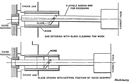
Fig. 39. Flexible Boring Tool used for Recessing
a Bushing in Automatic
Chucking and Turning Machine
Setting the Boring Tool for Recessing.—The feeding of the turret slide is now continued to make sure that the cutting-off tool is returned to its normal position before the facing tool in the next face of the turret begins to work. The facing of the[234] bushing, so far as the setting of the tool is concerned, is merely a repetition of the facing operation at the first position of the turret. The recessing tool is next set. This tool, which is shown diagrammatically in Fig. 39, is very simple as compared with the somewhat complex operation it has to perform. This recess is for clearance only, and accurate dimensions and fine finish are not necessary. The recessing tool consists simply of a slender boring-bar held in the turret and carrying a cutter suitably located about midway the bar. The forward end of the bar is small enough to enter a bell-mouthed bushing held in the chuck. The boring-bar is bent to one side far enough so that the cutter clears the hole as the bar enters, but is forced into the work as the rounded hole of the bushing engages the end of the bar and deflects it into the working position. The upper diagram shows the position of the bar as it enters the hole, and the lower one the position after it has entered the bushing and is engaged in turning the recess. This bar is set in the turret so that at the extreme forward travel of the turret slide, the recess will be bored to the required length. The cutter must also be adjusted to bore to the desired diameter. This completes the setting of the cutting tools.
[235] Adjustments for Automatic Feed and Speed Changes.—The machine must now be set to perform automatically the desired changes of spindle speed and the fast and slow cam movements for the tools. After placing a new piece of work in the machine (the first one having been completed in the setting-up operation), the cam-shaft is revolved by hand until the turning tool in turret face No. 1 is just about to begin its cut. The control wheel D, Fig. 34, is rotated in its normal direction until the next graduation marked “slow” is in line with an index mark on the base of the machine. Then the nearest pin M is moved up until it bears against a tooth of the star wheel (previously referred to) and is clamped in this position. The pin should now be in the proper location, but to test its position, rotate the cam shaft backward by hand and throw in the automatic feed; then watch the cut to see if the drum slows down just before the tool begins to work. If it does not, the pin should be adjusted a little, one way or the other, as may be required. (In going over a piece of work for the first time, it is best to have the feed set to the smallest rate, feed change handle K being in position No. 1.)
After the cut has been completed and the turret feed cam-roll is on the high part of the cam, the power feed should again be stopped and the handwheel revolved until the next graduation marked “fast” is opposite the index mark. The next stop pin is then moved up until it just touches the star wheel, where it is clamped in position. The feed being again thrown in, the turret will be returned rapidly, indexed, and moved forward for the second operation. After stopping the automatic movement, the pins are set for this face, and so on for all the operations, including that in which the cross-slide is used for cutting off the finished collar.
As the first, second, and third operations are on comparatively large diameters, they should be done at the slow speed, handle J, Fig. 34, being set to give that speed. While the turret slide is being returned between operations 3 and 4, one of the spindle speed-changing dogs N should be clamped to the rim of disk D so as to change the spindle speed to the fast movement. This speed is continued until the last operation is completed, when a[236] second dog is clamped in place to again throw in the slow movement. The feed knock-off dog should also be clamped in place on the disk to stop the machine at the completion of the fifth operation, when the turret is in its rear position. This completes the setting up of the machine. If the feed is finer than is necessary, the feed change handle K may now be moved to a position which will give the maximum feed that can be used.
It has taken considerable time to describe the setting up of the machine for this simple operation, but in the hands of a competent man it can be done quite rapidly. While a simple operation has been referred to in the foregoing, it will be understood that a great variety of work can be done on a machine of this type. It is not unusual to see as many as ten cutting tools operating simultaneously on a piece of work, the tools being carried by the turret, cross-slide and back facing attachment. The latter is operated from a separate cam applied to the cam-shaft and acting through levers on a back facing bar which passes through a hole in the spindle. In this back facing bar may be mounted drills, cutters, facing tools, etc. for machining the rear face of a casting held in the chuck jaws. Where extreme accuracy is required, a double back facing attachment may be used, arranged with cutters for taking both roughing and finishing cuts. The use of this attachment often saves a second operation. This automatic chucking and turning machine is also adapted for bar work, especially in diameters varying from 3 to 6 inches.
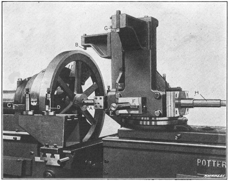
Fig. 40. Machining Flywheels in Potter & Johnston Automatic
Chucking
and Turning Machine
Turning Flywheel in Automatic Chucking and Turning Machine.—A typical operation on the Potter & Johnston automatic chucking and turning machine is illustrated in Fig. 40, which shows the machine arranged for turning the cast-iron flywheel for the engine of a motor truck. The rim is turned and faced on both sides and the hub is bored, reamed and faced on both sides. The flywheel casting is held in a chuck by three special jaws which grip the inside of the rim. The order of the operations is as follows:
The rear end of the hub is faced by the back facing bar; the cored hole is started by a four-lipped drill in the turret and the front end of the hub is rough-faced. (These tools are on the[237] rear side of the turret when the latter is in the position shown in the illustration.) After the turret indexes, the hole is rough-bored by tool A and while this is being done, the outside of the rim is rough-turned by tool B held in a special bracket attached to the turret. Both sides of the rim are also rough-faced by tools C and D held at the front of the cross-slide, this operation taking place at the same time that the rim is turned and the hole is being bored.
The turret again automatically recedes and indexes, thus locating bar E and turning tool G in the working position. The hole is then finish-bored by tool E and the hub is finish-faced by blade F; at the same time the rim is finish-turned by tool G and the sides are finish-faced to the proper width by two tools held at the rear of the cross-slide. The turret automatically recedes and indexes a third time, thus locating the flat-cutter reamer-bar H in the working position and then the hole is reamed to the required diameter. This completes the cycle of operations. The total time for machining this flywheel is forty minutes.
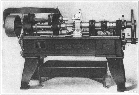
Fig. 41. New Britain Multiple-spindle Automatic
Chucking Machine of
Single-head Type
[238] Automatic Multiple-spindle Chucking Machine.—An example of the specialized machines now used for producing duplicate parts, is shown in Fig. 41. This is a “New Britain” automatic multiple-spindle chucking machine of the single-head type and it is especially adapted for boring, reaming and facing operations on castings or forgings which can readily be held in chuck jaws. This particular machine has five spindles, which carry and revolve the tools. The work being machined is held stationary in the multiple chuck turret A which holds each part in line with one of the spindles and automatically indexes, so that the work passes from one spindle to another until it is finished. The turret then indexes the finished piece to a sixth or “loading position” which is not opposite a spindle, where the part is removed and replaced with a rough casting. Each pair of chuck jaws is operated independently of the others by the use of a chuck wrench. These jaws are made to suit the shape of the work.
When a single-head machine is in operation, the turret advances and feeds the work against the revolving tools so that a number of pieces are operated upon at the same time. The turret is fed by a cam drum B. Cam strips are bolted to the outside of this[239] drum and act directly against a roller attached to the yoke C which can be clamped in different positions on the spindle D, the position depending upon the length of the work. On the opposite end of the turret spindle is the indexing mechanism E. An automatically spring-operated latch F engages notches in the rim of the dividing wheel, thus accurately locating the turret. The turret is locked by a steadyrest G, which, for each working position, automatically slides into engagement with one of the notches in the turret. This relieves the indexing mechanism of all strain.
This type of machine is also built with two spindle heads, the double-head design being used for work requiring operations on both ends. When the double-head machine is in operation, the revolving spindles and tools advance on both sides of the chuck turret, the latter remaining stationary except when indexing. The feed drums on the double-head machine are located directly beneath each group of spindles.

Fig. 42. Detail View of New Britain Double-head Eight-spindle
Machine,
Boring, Reaming and Facing Castings
Fig. 42 shows an example of work on a machine of the double-head design. This is an eight-spindle machine, there being two groups of four spindles on each side of the turret. The castings[240] E are for the wheel hubs of automobiles. The order of the operations on one of the castings, as it indexes around, is as follows: The hole in the hub is first rough-reamed by taper reamer A and the opposite end of the hub is rough-faced and counterbored by a tool in spindle A1. When the turret indexes, this same casting is reamed close to the finished size by reamer B and the left end of the hub is rough-faced by cutter F, while a tool in the opposite spindle B1 finishes the counterboring and facing operation. At the third position, reamer C finishes the hole accurately to size, and when the work is indexed to the fourth position, the hub on the left side is finish-faced by a tool in spindle D. (The third and fourth spindles of the right-hand group are not used for this particular operation.) When the turret again indexes, the finished casting is removed and replaced with a rough one. While the successive operations on a single casting have just been described, it will be understood that all of the tools operate simultaneously and that a finished casting arrives at the unloading and loading position each time the turret indexes. Three hundred of these malleable castings are machined in nine hours.
Selecting Type of Turning Machine.—The variety of machine tools now in use is very extensive, and as different types can often be employed for the same kind of work, the selection of the best and most efficient machine is often a rather difficult problem. To illustrate, there are many different types and designs of turning machines, such as the ordinary engine lathe, the hand-operated turret lathe, the semi-automatic turning machine, and the fully automatic type, which, after it is “set up” and started, is entirely independent. Hence, when a certain part must be turned, the question is, what kind of machine should be used, assuming that it would be possible to employ several different machines? The answer to this question usually depends principally upon the number of parts that must be turned.
For example, a certain casting or forging might be turned in a lathe, which could be finished in some form of automatic or semi-automatic turning machine much more quickly. It does[241] not necessarily follow, however, that the automatic is the best machine to use, because the lathe is designed for general work and the part referred to could doubtless be turned with the regular lathe equipment, whereas the automatic machine would require special tools and it would also need to be carefully adjusted. Therefore, if only a few parts were needed, the lathe might be the best tool to use, but if a large number were required, the automatic or semi-automatic machine would doubtless be preferable, because the saving in time effected by the latter type would more than offset the extra expense for tool equipment and setting the machine. It is also necessary, in connection with some work, to consider the degree of accuracy required, as well as the rate of production, and it is because of these varying conditions that work of the same general class is often done in machines of different types, in order to secure the most efficient results.
All the different types of turning machines now in use originated from the lathe. Many of these tools, however, do not resemble the lathe because, in the process of evolution, there have been many changes made in order to develop turning machines for handling certain classes of work to the best advantage. The machine illustrated in Fig. 1 belongs to the lathe family and is known as a vertical boring and turning mill. This type, as the name implies, is used for boring and turning operations, and it is very efficient for work within its range. The part to be machined is held to the table B either by clamps or in chuck jaws attached to the table. When the machine is in operation, the table revolves and the turning or boring tools (which are held in tool-blocks T) remain stationary, except for the feeding movement. Very often more than one tool is used at a time, as will be shown later by examples of vertical boring mill work. The tool-blocks T are inserted in tool-bars T1 carried by saddles S which are mounted on cross-rail C. Each tool-head (consisting of a saddle and tool-bar) can be moved horizontally along cross-rail C, and the tool-bars T1 have a vertical movement. These movements can be effected either by hand or power.
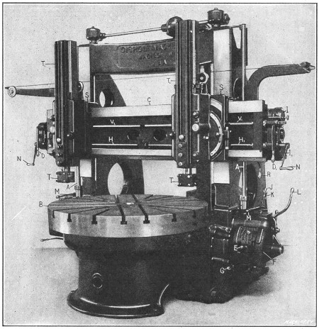
Fig. 1. Gisholt Vertical Boring and Turning Mill
When a surface is being turned parallel to the work table, the entire tool-head moves horizontally along the cross-rail, but when a cylindrical surface is being turned, the tool-bar moves vertically. The tool-heads are moved horizontally by the screws H and H1, and the vertical feed for the tool-bars is obtained from the splined shafts V and V1, there being a separate screw and shaft for each head so that the feeding movements are independent. These feed shafts are rotated for the power feed by vertical shafts A and A1 on each side of the machine. [243] These vertical shafts connect with the feed shafts through bevel and spur gears located at the ends of the cross-rail. On most boring mills, connection is made with one of the splined shafts V or screw H, by a movable gear, which is placed on whichever shaft will give the desired direction of feed. The particular machine illustrated is so arranged that either the right or left screw or feed shaft can be engaged by simply shifting levers D1 or D.
The amount of feed per revolution of the table is varied for each tool-head by feed-changing mechanisms F on each side of the machine. These feed boxes contain gears of different sizes, and by changing the combinations of these gears, the amount of feed is varied. Five feed changes are obtained on this machine[244] by shifting lever E, and this number is doubled by shifting lever G. By having two feed boxes, the feeding movement of each head can be varied independently. The direction of either the horizontal or vertical feed can be reversed by lever R, which is also used for engaging or disengaging the feeds. This machine is equipped with the dials I and I1 which can be set to automatically disengage the feed at any predetermined point. There are also micrometer dials graduated to thousandths of an inch and used for adjusting the tools without the use of measuring instruments.
The work table B is driven indirectly from a belt pulley at the rear, which transmits the power through gearing. The speed of the table can be varied for turning large or small parts, by levers J and K and the table can be started, stopped or rotated part of a revolution by lever L which connects with a friction clutch. There are corresponding feed and speed levers on the opposite side, so that the machine can be controlled from either position.
The heads can be adjusted along the cross-rail for setting the tools by hand-cranks N, and the tool slides can be moved vertically by turning shafts V with the same cranks. With this machine, however, these adjustments do not have to be made by hand, ordinarily, as there are rapid power movements controlled by levers M. These levers automatically disengage the feeds and enable the tool-heads to be rapidly shifted to the required position, the direction of the movement depending upon the position of the feed reverse lever R and lever D. This rapid traverse, which is a feature applied to modern boring mills of medium and large size, saves time and the labor connected with hand adjustments. The cross-rail C has a vertical adjustment on the faces of the right and left housings which support it, in order to locate the tool-heads at the right height for the work. This adjustment is effected by power and is controlled by levers at the sides of the housings. Normally, the cross-rail is bolted to the housings, and these bolts must be loosened before making the adjustment, and must always be tightened afterwards.
[245]The function of these different levers has been explained to show, in a general way, how a vertical boring machine is operated. It should be understood, however, that the arrangement differs considerably on machines of other makes. The construction also varies considerably on machines of the same make but of different size.
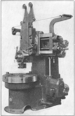
Fig. 2. Small Boring and Turning Mill
with Single Turret-head
All modern vertical boring mills of medium and large sizes are equipped with two tool-heads, as shown in Fig. 1, because a great deal of work done on a machine of this type can have two surfaces machined simultaneously. On the other hand, small[246] mills of the type illustrated in Fig. 2 have a single head. The toolslide of this machine, instead of having a single tool-block, carries a five-sided turret T in which different tools can be mounted. These tools are shifted to the working position as they are needed, by loosening binder lever L and turning or “indexing” the turret. The turret is located and locked in any of its five positions by lever I, which controls a plunger that engages notches at the rear. Frequently, all the tools for machining a part can be held in the turret, so that little time is required for changing from one tool to the next. Some large machines having two tool-heads are also equipped with a turret on one head.
Boring and Turning in a Vertical Boring Mill.—The vertical boring mill is, in many respects, like a lathe placed in a vertical position, the table of the mill corresponding to the faceplate or chuck of the lathe and the tool-head to the lathe carriage. Much of the work done by a vertical mill could also be machined in a lathe, but the former is much more efficient for work within its range. To begin with, it is more convenient to clamp work to a horizontal table than to the vertical surface of a lathe faceplate, or, as someone has aptly said, “It is easier to lay a piece down than to hang it up.” This is especially true of the heavy parts for which the boring mill is principally used. Very deep roughing cuts can also be taken with a vertical mill. This type of machine mill is designed for turning and boring work which, generally speaking, is quite large in diameter in proportion to the width or height. The work varies greatly, especially in regard to its diameter, so that boring mills are built in a large range of sizes. The small and medium sizes will swing work varying from about 30 inches to 6 or 7 feet in diameter, whereas large machines, such as are used for turning very large flywheels, sheaves, etc., have a swing of 16 or 20 feet, and larger sizes are used in some shops. The size of a vertical mill, like any other machine tool, should be somewhat in proportion to the size of the work for which it is intended, as a very large machine is unwieldy, and, therefore, inefficient for machining comparatively small parts.
[247] Holding and Setting Work on Boring Mill Table.—There are three general methods of holding work to the table of a boring mill; namely, by the use of chucks, by ordinary bolts and clamps, or in special fixtures. Chucks which are built into the table (as illustrated in Fig. 2) and have both universal and independent adjustments for the jaws can be used to advantage for holding castings that are either round or irregular in shape. The universal adjustment is used for cylindrical parts, such as disks, flywheels, gear blanks, etc., and the independent adjustment, for castings of irregular shape. Chucks which have either an independent or universal movement for the jaws are known as a “combination” type and usually have three jaws. There is also a four-jaw type which has the independent adjustment only. This style is preferable for work that is not cylindrical and which must be held very securely. Chuck jaws that do not form a part of the machine table, but are bolted to it in the required position, are also employed extensively, especially on comparatively large machines.
Most of the work done in a vertical mill is held in a chuck. Occasionally, however, it is preferable to clamp a part directly to the table. This may be desirable because of the shape and size of the work, or because it is necessary to hold a previously machined surface directly against the table in order to secure greater accuracy. Sometimes a casting is held in the chuck for turning one side, and then the finished side is clamped against the table for turning the opposite side. Parts which are to be machined in large quantities are often held in special fixtures. This method is employed when it enables the work to be set up more quickly than would be possible if regular clamps or chuck jaws were used.
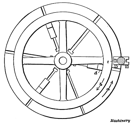
Fig. 3. Plan View showing Flywheel Casting Chucked for Turning
Work that is to be turned or bored should first be set so that the part to be machined is about central with the table. For example, the rim of a flywheel should be set to run true so that it can be finished by removing about the same amount of metal around the entire rim; in other words, the rim should be set concentric with the table, as shown in Fig. 3, and the sides of the rim should also be parallel to the table.
[248]A simple tool that is very useful for testing the position of any cylindrical casting consists of a wooden shank into which is inserted a piece of wire, having one end bent. This tool is clamped in the toolpost and as the work revolves the wire is adjusted close to the cylindrical surface being tested. The movement of the work with relation to the stationary wire point will, of course, show whether or not the part runs true. The advantage of using a piece of wire for testing, instead of a rigid tool, is that the wire, owing to its flexibility, will simply be bent backward if it is moved too close to a surface which is considerably out of true. The upper surface of a casting can be tested for parallelism with the table by using this same wire gage, or by comparing the surface, as the table is revolved slowly, with a tool held in the toolpost. An ordinary surface gage is also used for this purpose. The proper surface to set true, in any case, depends upon the requirements. A plain cylindrical disk would be set so that the outside ran true and the top surface was parallel with the table. When setting a flywheel, if the inside of the rim is to remain rough, the casting should be set by this surface rather than by the outside, so that the rim, when finished, will be uniform in[249] thickness.
As far as possible, chucks should be used for holding cylindrical parts, owing to their convenience. The jaws should be set against an interior cylindrical surface whenever this is feasible. To illustrate, the flywheel in Fig. 3 is gripped by the inside of the rim which permits the outside to be turned at this setting of the work. It is also advisable to set a flywheel casting in the chuck so that a spoke rests against one of the jaws as at d, if this is possible. This jaw will then act as a driver and prevent the casting from slipping or turning in the chuck jaws, owing to the tangential pressure of the turning tool. When a cut is being taken, the table and work rotate as shown by arrow a, and the thrust of the cut (taken by tool t) tends to move the wheel backward against the direction of rotation, as shown by arrow b. If one of the chuck jaws bears against one of the spokes, this movement is prevented. It is not always feasible to use a chuck jaw as a driver and then a special driver having the form of a small angle-plate or block is sometimes bolted directly to the table. Another method of driving is to set a brace between a spoke or projection on the work and a chuck jaw or strip attached to the table. Drivers are not only used when turning flywheels, but in connection with any large casting, especially when heavy cuts have to be taken. Of course, some castings are so shaped that drivers cannot be employed.
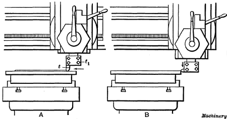
Fig. 4. (A) Turning a Flat Surface.
(B) Turning a Cylindrical Surface
Turning in a Boring Mill.—The vertical type of boring mill is used more for turning cylindrical surfaces than for actual boring, although a large part of the work requires both turning and boring. We shall first consider, in a general way, how surfaces are turned and then refer to some boring operations. The diagram A, Fig. 4, illustrates how a horizontal surface would be turned. The tool t is clamped in tool-block t1, in a vertical position, and it is fed horizontally as the table and work rotate. The tool is first adjusted by hand for the proper depth of cut and the automatic horizontal feed is then engaged. When a cylindrical surface is to be turned, the tool (provided a[250] straight tool is used) is clamped in a horizontal position and is fed downward as indicated at B. The amount that the tool should feed per revolution of the work, depends upon the kind of material being turned, the diameter of the turned part and the depth of the cut.
Most of the parts machined in a vertical boring mill are made of cast iron and, ordinarily, at least one roughing and one finishing cut is taken. The number of roughing cuts required in any case depends, of course, upon the amount of metal to be removed. An ordinary roughing cut in soft cast iron might vary in depth from 1/8 or 3/16 inch to 3/8 or 1/2 inch and the tool would probably have a feed per revolution of from 1/16 to 1/8 inch, although deeper cuts and coarser feeds are sometimes taken. These figures are merely given to show, in a general way, what cuts and feeds are practicable. The tool used for roughing usually has a rounded end which leaves a ridged or rough surface. To obtain a smooth finish, broad flat tools are used. The flat cutting edge is set parallel to the tool's travel and a coarse feed is used in order to reduce the time required for taking the cut. The finishing feeds for cast iron vary from 1/4 to 3/4 inch on ordinary work. The different tools used on the vertical mill will be referred to more in detail later.
All medium and large sized vertical boring mills are equipped with two tool-heads and two tools are frequently used at the[251] same time, especially on large work. Fig. 9 illustrates the use of two tools simultaneously. The casting shown is a flywheel, and the tool on the right side turns the upper side of the rim, while the tool on the left side turns the outside or cylindrical surface. As a boring mill table rotates in a counter-clockwise direction, the left-hand tool is reversed to bring the cutting edge at the rear. By turning two surfaces at once, the total time for machining the casting is, of course, greatly reduced. The turning of flywheels is a common vertical boring mill operation, and this work will be referred to in detail later on.
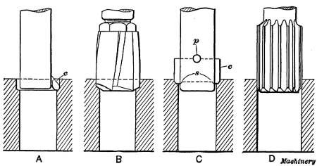
Fig. 5. Tools for Boring and Reaming Holes
Boring Operations.—There are several methods of machining holes when using a vertical boring mill. Ordinarily, small holes are cored in castings and it is simply necessary to finish the rough surface to the required diameter. Some of the tools used for boring and finishing comparatively small holes are shown in Fig. 5. Sketch A shows a boring tool consisting of a cutter c inserted in a shank, which, in turn, is held in the tool slide, or in a turret attached to the tool slide. With a tool of this type, a hole is bored by taking one or more cuts down through it. The tool shown at B is a four-lipped drill which is used for drilling cored holes preparatory to finishing by a cutter or reamer. This drill would probably finish a hole to within about 1/32 inch of the finish diameter, thus leaving a small amount of metal for the reamer to remove. The tool illustrated at C[252] has a double-ended flat cutter c, which cuts on both sides. These cutters are often made in sets for boring duplicate parts. Ordinarily, there are two cutters in a set, one being used for roughing and the other for finishing. The cutter passes through a rectangular slot in the bar and this particular style is centrally located by shoulders s, and is held by a taper pin p. Some cutter bars have an extension end, or “pilot” as it is called, which passes through a close-fitting bushing in the table to steady the bar. Sketch D shows a finishing reamer. This tool takes a very light cut and is intended to finish holes that have been previously bored close to the required size. Sometimes a flat cutter C is used for roughing and a reamer for finishing. The reamer is especially desirable for interchangeable work, when all holes must have a smooth finish and be of the same diameter. When a reamer is held rigidly to a turret or toolslide, it is liable to produce a hole that is either tapering or larger than the reamer diameter. To prevent this, the reamer should be held in a “floating” holder which, by means of a slight adjustment, allows the reamer to align itself with the hole. There are several methods of securing this “floating” movement. (See “Floating Reamer Holders.”)
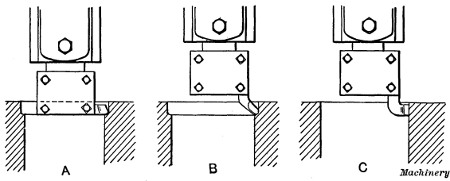
Fig. 6. Boring with Regular Turning Tools
Large holes or interior cylindrical surfaces are bored by tools held in the regular tool-head. The tool is sometimes clamped in a horizontal position as shown at A, Fig. 6, or a bent type is used as at B. Cast iron is usually finished by a broad flat tool as at C, the same as when turning exterior surfaces. Obviously [253] a hole that is bored in this way must be large enough to admit the tool-block.
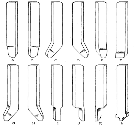
Fig. 7. Set of Boring Mill Tools
Turning Tools for the Vertical Boring Mill.—A set of turning tools for the vertical boring mill is shown in Fig. 7. These tools can be used for a wide variety of ordinary turning operations. When a great many duplicate parts are to be machined, special tool equipment can often be used to advantage, but as the form of this equipment depends upon the character of the work, only standard tools have been shown in this illustration. The tool shown at A is a right-hand, roughing tool, and a left-hand tool of the same type is shown at B. Tool C is an offset or bent, left-hand round nose for roughing, and D is a right-hand offset roughing tool. A straight round nose is shown at E. Tool F has a flat, broad cutting edge and is used for finishing. Left-and right-hand finishing tools of the offset[254] type are shown at G and H, respectively. Tool I has a square end and is used for cutting grooves. Right-and left-hand parting tools are shown at J and K, and tool L is a form frequently used for rounding corners.
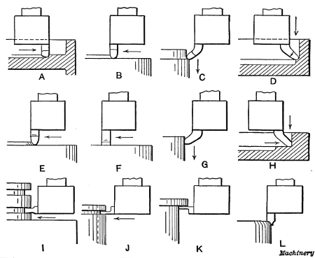
Fig. 8. Diagrams Illustrating Use of Different Forms of Tools
The diagrams in Fig. 8 show, in a general way, how each of the tools illustrated in Fig. 7 are used, and corresponding tools are marked by the same reference letters in both of these illustrations. The right-and left-hand roughing tools A and B are especially adapted for taking deep roughing cuts. One feeds away from the center of the table, or to the right (when held in the right-hand tool-block) and the other tool is ground to feed in the opposite direction. Ordinarily, when turning plain flat surfaces, the cut is started at the outside and the tool feeds toward the center, as at B, although it is sometimes more convenient to feed in the opposite direction, as at A, especially when there is a rim or other projecting part at the outside edge. The tool shown at A could also be used for turning cylindrical surfaces, by clamping it in a horizontal position across the bottom [255] of the tool-block. The feeding movement would then be downward or at right-angles to the work table.
The offset round-nose tools C and D are for turning exterior or interior cylinder surfaces. The shank of this tool is clamped in the tool-block in a vertical position and as the bent end extends below the tool-block, it can be fed down close to a shoulder. The straight type shown at E is commonly used for turning steel or iron, and when the point is drawn out narrower, it is also used for brass, although the front is then ground without slope. Tool F is for light finishing cuts and broad feeds. The amount of feed per revolution of the work should always be less than the width of the cutting edge as otherwise ridges will be left on the turned surface. The offset tools G and H are for finishing exterior and interior cylindrical surfaces. These tools also have both vertical and horizontal cutting edges and are sometimes used for first finishing a cylindrical and then a horizontal surface, or vice versa. Tool I is adapted to such work as cutting packing-ring grooves in engine pistons, forming square or rectangular grooves, and similar work. The parting tools J and K can also be used for forming narrow grooves or for cutting off rings, etc. The sketch K (Fig. 8) indicates how a tool of this kind might be used for squaring a corner under a shoulder. Tool L is frequently used on boring mills for rounding the corners of flywheel rims, in order to give them a more finished appearance. It has two cutting edges so that either side can be used as when rounding the inner and outer corners of a rim.
The turning tools of a vertical boring mill are similar, in many respects, to those used in a lathe, although the shanks of the former are shorter and more stocky than those of lathe tools. The cutting edges of some of the tools also differ somewhat in form, but the principles which govern the grinding of lathe and boring mill tools are identical, and those who are not familiar with tool grinding are referred to Chapter II, in which this subject is treated.
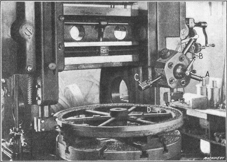
Fig. 9. Turning the Rim of a Flywheel
Turning a Flywheel on a Vertical Mill.—The turning of a flywheel is a good example of the kind of work for which a vertical boring mill is adapted. A flywheel should preferably be[256] machined on a double-head mill so that one side and the periphery of the rim can be turned at the same time. A common method of holding a flywheel is shown in Fig. 9. The rim is gripped by four chuck jaws D which, if practicable, should be on the inside where they will not interfere with the movement of the tool. Two of the jaws, in this case, are set against the spokes on opposite sides of the wheel, to act as drivers and prevent any backward shifting of work when a heavy cut is being taken. The illustration shows the tool to the right rough turning the side of the rim, while the left-hand tool turns the periphery. Finishing cuts are also taken over the rim, at this setting, and the hub is turned on the outside, faced on top, and the hole bored.
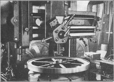
Fig. 10. Tool B set for Boring the Hub
The three tools A, B and C, for finishing the hole, are mounted in the turret. Bar A, which carries a cutter at its end, first rough bores the hole. The sizing cutter B is then used to straighten it before inserting the finishing reamer C. Fig. 10 shows the turret moved over to a central position and the sizing cutter B set for boring. The head is centrally located (on this particular machine) by a positive center-stop. The turret is indexed[257] for bringing the different tools into the working position, by loosening the clamping lever L and pulling down lever I which disengages the turret lock-pin. When all the flywheels in a lot have been machined as described, the opposite side is finished.
[258]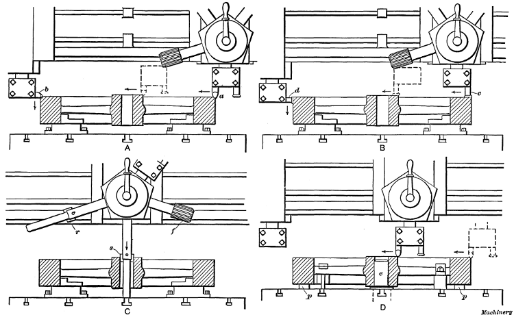
Fig. 11. Diagrams showing Method of Turning and Boring a Flywheel on a Double-head Mill having one Turret Head
In order to show more clearly the method of handling work of this class, the machining of a flywheel will be explained more in detail in connection with Fig. 11, which illustrates practically the same equipment as is shown in Figs. 9 and 10. The successive order in which the various operations are performed is as follows: Tool a (see sketch A) rough turns the side of the rim, while tool b, which is set with its cutting edge toward the rear, rough turns the outside. The direction of the feeding movement for each tool is indicated by the arrows. When tool a has crossed the rim, it is moved over for facing the hub, as shown by the dotted lines. The side and periphery of the rim are next finished by the broad-nose finishing tools c and d (see sketch B). The feed should be increased for finishing, so that each tool will have a movement of say 1/4 or 3/8 inch per revolution of the work, and the cuts should, at least, be deep enough to[259] remove the marks made by the roughing tools. Tool c is also used for finishing the hub as indicated by the dotted lines. After these cuts are taken, the outside of the hub and inner surface of the rim are usually turned down as far as the spokes, by using offset tools similar to the ones shown at C and D in Fig. 7. The corners of the rim and hub are also rounded to give the work a more finished appearance, by using a tool L.
The next operation is that of finishing the hole through the hub. The hard scale is first removed by a roughing cutter r (sketch C), which is followed by a “sizing” cutter s. The hole is then finished smooth and to the right diameter by reamer f. The bars carrying cutters r and s have extensions or “pilots” which enter a close-fitting bushing in the table, in order to steady the bar and hold it in alignment.
When the hole is finished, the wheel is turned over, so that the lower side of the rim and hub can be faced. The method of holding the casting for the final operation is shown at D. The chuck jaws are removed, and the finished side of the rim is clamped against parallels p resting on the table. The wheel is centrally located for turning this side by a plug e which is inserted in a hole in the table and fits the bore of the hub. The wheel is held by clamps which bear against the spokes. Roughing and finishing cuts are next taken over the top surface of the rim and hub and the corners are rounded, which completes the machining operations. If the rim needs to be a certain width, about the same amount of metal should be removed from each side, unless sandy spots or “blow-holes” in the casting make it necessary to take more from one side than from the other. That side of the rim which was up in the mold when the casting was made should be turned first, because the porous, spongy spots usually form on the “cope” or top side of a casting.
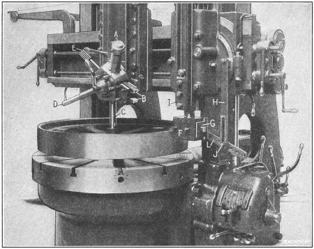
Fig. 12. Gisholt Mill equipped with Convex Turning Attachment
Convex Turning Attachment for Boring Mills.—Fig. 12 shows a vertical boring mill arranged for turning pulleys having convex rims; that is, the rim, instead of being cylindrical, is rounded somewhat so that it slopes from the center toward either side. (The reason for turning a pulley rim convex is to prevent the belt from running off at one side, as it sometimes[260] tends to do when a cylindrical pulley is used.) The convex surface is produced by a special attachment which causes the turning tool to gradually move outward as it feeds down, until the center of the rim is reached, after which the movement is inward.
The particular attachment shown in Fig. 12 consists of a special box-shaped tool-head F containing a sliding holder G, in which the tool is clamped by set-screws passing through elongated slots in the front of the tool-head. In addition, there is a radius link L which swivels on a stud at the rear of the tool-head and is attached to vertical link H. Link L is so connected to the sliding tool-block that any downward movement of the tool-bar I causes the tool to move outward until the link is in a horizontal position, after which the movement is reversed. When the attachment is first set up, the turning tool is placed at the center of the rim and then link L is clamped to the vertical link while in a horizontal position. The cut is started at the top edge of the rim, and the tool is fed downward by power,[261] the same as when turning a cylindrical surface. The amount of curvature or convexity of a rim can be varied by inserting the clamp bolt J in different holes in link L.
The tools for machining the hub and sides of the rim are held in a turret mounted on the left-hand head, as shown. The special tool-holder A contains two bent tools for turning the upper and lower edges of the pulley rim at the same time as the tool-head is fed horizontally. Roughing and finishing tools B are for facing the hub, and the tools C, D, and E rough bore, finish bore, and ream the hole for the shaft.
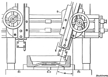
Fig. 13. Turning a Taper or Conical Surface
Turning Taper or Conical Surfaces.—Conical or taper surfaces are turned in a vertical boring mill by swiveling the tool-bar to the proper angle as shown in Fig. 13. When the taper is given in degrees, the tool-bar can be set by graduations on the edge of the circular base B, which show the angle a to which the bar is swiveled from a vertical position. The base turns on a central stud and is secured to the saddle S by the bolts shown, which should be tightened after the tool-bar is set. The vertical power feed can be used for taper turning the same as for cylindrical work.
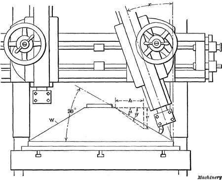
Fig. 14. Turning a Conical Surface by using the
Combined Vertical
and Horizontal Feeds
[262] Occasionally it is necessary to machine a conical surface which has such a large included angle that the tool-bar cannot be swiveled far enough around to permit turning by the method illustrated in Fig. 13. Another method, which is sometimes resorted to for work of this class, is to use the combined vertical and horizontal feeds. Suppose we want to turn the conical casting W (Fig. 14), to an angle of 30 degrees, as shown, and that the tool-head of the boring mill moves horizontally 1/4 inch per turn of the feed-screw and has a vertical movement of 3/16 inch per turn of the upper feed-shaft. If the two feeds are used simultaneously, the tool will move a distance h of say 8 inches, while it moves downward a distance v of 6 inches, thus turning the surface to an angle y. This angle is greater (as measured from a horizontal plane) than the angle required, but, if the tool-bar is swiveled to an angle x, the tool, as it moves downward, will also be advanced horizontally, in addition to the regular horizontal movement. The result is that the angle y is diminished and if the tool-bar is set over the right amount, [263] the conical surface can be turned to an angle a of 30 degrees. The problem, then, is to determine what the angle x should be for turning to a given angle a.
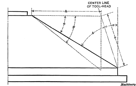
Fig. 15. Diagram showing Method of Obtaining Angular Position
of Tool-head
when Turning Conical Surfaces by using Vertical and
Horizontal
Feeding Movements
The way angle x is calculated will be explained in connection with the enlarged diagram, Fig. 15, which shows one-half of the casting. The sine of the known angle a is first found in a table of natural sines. Then the sine of angle b, between the taper surface and center-line of the tool-head, is determined as follows: sin b = (sin a × h) ÷ v, in which h represents the rate of horizontal feed and v the rate of vertical feed. The angle corresponding to sine b is next found in a table of sines. We now have angles b and a, and by subtracting the sum of these angles from 90 degrees, the desired angle x is obtained. To illustrate:
The sine of 30 degrees is 0.5; then sin b = (0.5 × 1/4) ÷ 3/16 = 0.6666; hence angle b = 41 degrees 49 minutes, and x = 90° - (30° + 41° 49') = 18 degrees 11 minutes. Hence to turn the casting to angle a in a boring mill having the horizontal and vertical feeds given, the tool-head would be set over from the vertical 18 degrees and 11 minutes which is equivalent to about 181/6 degrees.
[264] If the required angle a were greater than angle y obtained from the combined feeds with the tool-bar in a vertical position, it would then be necessary to swing the lower end of the bar to the left rather than to the right of a vertical plane. When the required angle a exceeds angle y, the sum of angles a and b is greater than 90 degrees so that angle x for the tool-head = (a + b) - 90 degrees.
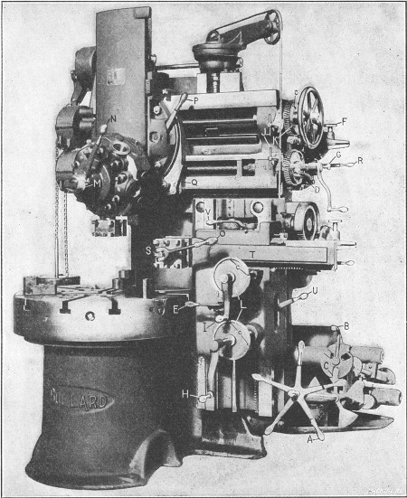
Fig. 16. Bullard Vertical Turret Lathe
Turret-lathe Type of Vertical Boring Mill.—The machine illustrated in Fig. 16 was designed to combine the advantages of the horizontal turret lathe and the vertical boring mill. It is known as a “vertical turret lathe,” but resembles, in many respects, a vertical boring mill. This machine has a turret on the cross-rail the same as many vertical boring mills, and, in addition, a side-head S. The side-head has a vertical feeding movement, and the tool-bar T can be fed horizontally. The tool-bar is also equipped with a four-sided turret for holding turning tools. This arrangement of the tool-heads makes it possible to use two tools simultaneously upon comparatively small work. When both heads are mounted on the cross-rail, as with a double-head boring mill, it is often impossible to machine certain parts to advantage, because one head interferes with the other.
The drive to the table (for the particular machine illustrated) is from a belt pulley at the rear, and fifteen speed changes are available. Five changes are obtained by turning the pilot-wheel A and this series of five speeds is compounded three times by turning lever B. Each spoke of pilot-wheel A indicates a speed which is engaged only when the spoke is in a vertical position, and the three positions for B are indicated, by slots in the disk shown. The number of table revolutions per minute for different positions of pilot-wheel A and lever B are shown by figures seen through whichever slot is at C. There are five rows of figures corresponding to the five spokes of the pilot-wheel and three figures in a row, and the speed is shown by arrows on the sides of the slots. The segment disk containing these figures also serves as an interlocking device which prevents moving more than one speed controlling[265] lever at a time, in order to avoid damaging the driving mechanism.
The feeding movement for each head is independent. Lever D controls the engagement or disengagement of the vertical or cross feeds for the head on the cross-rail. The feed for the side-head is controlled by lever E. When this lever is pushed inward, the entire head feeds vertically, but when it is pulled out, the tool-bar feeds horizontally. These two feeds can be disengaged by placing the lever in a neutral position. The[266] direction of the feeding movement for either head can be reversed by lever R. The amount of feed is varied by feed-wheel F and clutch-rod G. When lever E is in the neutral position, the side-head or tool-bar can be adjusted by the hand-cranks H and I, respectively. The cross-rail head and its turret slide have rapid power traverse movements for making quick adjustments. This rapid traverse is controlled by the key-handles J.
The feed-screws for the vertical head have micrometer dials K for making accurate adjustments. There are also large dials at L which indicate vertical movements of the side head and horizontal movements of the tool slide. All of these dials have small adjustable clips c which are numbered to correspond to numbers on the faces of the respective turrets. These clips or “observation stops” are used in the production of duplicate parts. For example, suppose a tool in face No. 1 for the main turret is set for a given diameter and height of shoulder on a part which is to be duplicated. To obtain the same setting of the tools for the next piece, clips No. 1, on both the vertical feed rod and screw dials, are placed opposite the graduations which are intersected by stationary pointers secured to the cross-rail. The clips are set in this way after the first part has been machined to the required size and before disturbing the final position of the tools. For turning a duplicate part, the tools are simply brought to the same position by turning the feed screws until the clips and stationary pointers again coincide. For setting tools on other faces of either turret, this operation is repeated, except that clips are used bearing numbers corresponding to the turret face in use.
The main turret of this machine has five holes in which are inserted the necessary boring and turning tools, drills or reamers, as may be required. By having all the tools mounted in the turret, they can be quickly and accurately set in the working position. When the turret is indexed from one face to the next, binder lever N is first loosened. The turret then moves forward, away from its seat, thus disengaging the indexing and registering pins which accurately locate it in any one of the five positions.[267] The turret is revolved by turning crank M, one turn of this handle moving the turret 1/5 revolution or from one hole to the next. The side-head turret is turned by loosening lever O. The turret slide can be locked rigidly in any position by lever P and its saddle is clamped to the cross-rail by lever Q. The binder levers for the saddle and toolslide of the side-head are located at U and V, respectively. A slide that does not require feeding movements is locked in order to obtain greater rigidity. To illustrate, if the main tool slide were to feed vertically and not horizontally, it might be advisable to lock the saddle to the cross-rail, while taking the vertical cut.
The vertical slide can be set at an angle for taper turning, and the turret is accurately located over the center of the table for boring or reaming, by a positive center stop. The machine is provided with a brake for stopping the work table quickly, which is operated by lifting the shaft of pilot-wheel A. The side-and cross-rails are a unit and are adjusted together to accommodate work of different heights. This adjustment is effected by power[268] on the particular machine illustrated, and it is controlled by a lever near the left end of the cross-rail. Before making this adjustment, all binder bolts which normally hold the rails rigidly to the machine column must be released, and care should be taken to tighten them after the adjustment is made.
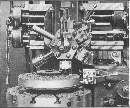
Fig. 17. Turning a Gear Blank on a Vertical Turret Lathe
Examples of Vertical Turret Lathe Work.—In order to illustrate how a vertical turret lathe is used, one or two examples of work will be referred to in detail. These examples also indicate, in a general way, the class of work for which this type of machine is adapted. Fig. 17 shows how a cast-iron gear blank is machined. The work is gripped on the inside of the rim by three chuck jaws, and all of the tools required for the various operations are mounted in the main and side turrets. The illustration[269] shows the first operation which is that of rough turning the hub, the top side of the blank and its periphery. The tools A for facing the hub and upper surface are both held in one tool-block on the main turret, and tool A1 for roughing the periphery is in the side turret. With this arrangement, the three surfaces can be turned simultaneously.
The main turret is next indexed one-sixth of a revolution which brings the broad finishing tools B into position, and the side turret is also turned to locate finishing tool B1 at the front. (The indexing of the main turret on this particular machine is effected by loosening binder lever n and raising the turret lock-pin by means of lever p.) The hub, side and periphery of the blank are then finished. When tools B are clamped in the tool-blocks, [270] they are, of course, set for turning the hub to the required height. The third operation is performed by the tools at C, one of which “breaks” or chamfers the corner of the cored hole in the hub, to provide a starting surface for drill D, and the other turns the outside of the hub, after the chamfering tool is removed. The four-lipped shell-drill D is next used to drill the cored hole and then this hole is bored close to the finished size and concentric with the circumference of the blank by boring tool E, which is followed by the finishing reamer F. When the drill, boring tool and reamer are being used, the turret is set over the center or axis of the table, by means of a positive center stop on the left-side of the turret saddle. If it is necessary to move[271] the turret beyond the central position, this stop can be swung out of the way.
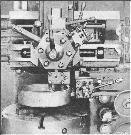
Fig. 18. Turning Gasoline Engine Flywheel on Vertical Turret Lathe—First Position
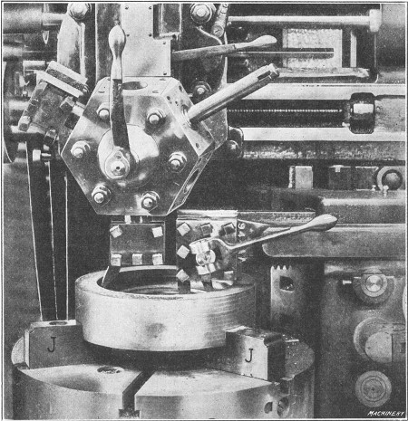
Fig. 19. Turning Gasoline Engine Flywheel—Second Position
Figs. 18 and 19 illustrate the turning of an automobile flywheel, which is another typical example of work for a machine of this type. The flywheel is finished in two settings. Its position for the first series of operations is shown in Fig. 18, and the successive order of the four operations for the first setting is shown by the diagrams, Fig. 20. The first operation requires four tools which act simultaneously. The three held in tool-block A of the turret, face the hub, the web and the rim of the flywheel, while tool a in the side-head rough turns the outside diameter. The outside diameter is also finished by broad-nosed tool b which is given a coarse feed. In the second operation, the under face of the rim is finished by tool c, the outer corners are rounded by tool d and the inner surface of the rim is rough turned by a bent tool B, which is moved into position by indexing the main turret. In the third operation, the side-head is moved out of the way and the inside of the rim is finished by another bent tool B1. The final operation at this setting is the boring of the central hole, which is done with a bar C having interchangeable cutters which make it possible to finish the hole at one setting of the turret.
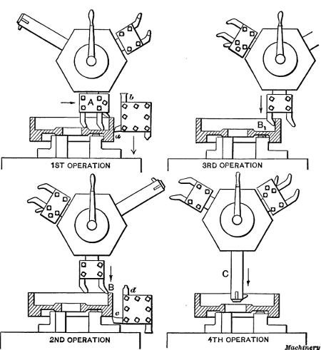
Fig. 20. Diagrams showing How Successive Operations
are Performed
by Different Tools in the Turret
The remaining operations are performed on the opposite side of the work which is held in “soft” jaws J accurately bored to fit the finished outside diameter as indicated in Fig. 19. The tool in the main turret turns the inside of the rim, and the side-head is equipped with two tools for facing the web and hub simultaneously. As the tool in the main turret operates on the left side of the rim, it is set with the cutting edge toward the rear. In order to move the turret to this position, which is beyond the center of the table, the center stop previously referred to is swung out of the way.
Floating Reamer Holders.—If a reamer is held rigidly in the turret of a boring mill or turret lathe, it is liable to produce a hole which tapers slightly or is too large. When a hole is bored with a single-point boring tool, it is concentric with the axis of rotation, and if a reamer that is aligned exactly with the bored[272] hole is fed into the work, the finished hole should be cylindrical and the correct size. It is very difficult, however, to locate a reamer exactly in line with a bored hole, because of slight variations in the indexing of the turret, or errors resulting from wear of the guiding ways or other important parts of the machine.
To prevent inaccuracies due to this cause, reamers are often held in what is known as a “floating” holder. This type of holder is so arranged that the reamer, instead of being held rigidly, is allowed a slight free or floating movement so that it can follow a hole which has been bored true, without restraint. In this way the hole is reamed straight and to practically the same size as the reamer.
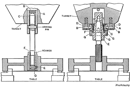
Fig. 21. Two Types of Floating Reamer Holders
There are many different designs of floating holders but the general principle upon which they are based is illustrated by the two types shown in Fig. 21. The reamer and holder shown to the left has a ball-shank A which bears against a backing-up screw B inserted in the end of holder C through which the driving pin passes. The lower end of the reamer shank is also spherical-shaped at D, and screw-pin E secures the shell reamer to this end. It will be noted that the hole in the shank for pin E is “bell-mouthed” on each side of the center and that there[273] is clearance at F between the shank and reamer shell; hence the reamer has a free floating action in any direction. This holder has given very satisfactory results.
The holder shown to the right is attached to the face of the turret by four fillister-head screws. Sleeve C is held in plate A by means of two steel pins B which are tight in plate A and made to fit freely in bayonet grooves D. Reamer holder E floats on sleeve C, the floating motion being obtained through the four steel pins G extending into driving ring F. Two of the pins are tight in the holder E and two in sleeve C. The faces of sleeve C, driving ring F, and reamer holder E are held tightly against each other by means of spring H which insures the reamer being held perfectly true. Spring H is adjusted by means of nut I which is turned with a spanner wrench furnished with each holder. The reamer is so held that its axis is always maintained parallel to the center of the hole, and, at the same time, it has a slight self-adjusting tendency radially, so that the hole and[274] reamer will automatically keep in perfect alignment with each other.
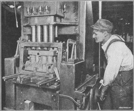
Fig. 22. Multiple-spindle Cylinder Boring Machine
Multiple Cylinder Boring Machine.—In automobile and other factories where a great many gasoline engine cylinders are required, multiple-spindle boring machines of the vertical type are commonly used. The machine shown in Fig. 22 is a special design for boring four cylinders which are cast en bloc or in one solid casting. The work is held in a box jig which has a top plate equipped with guide bearings for holding the spindles rigidly while boring. The lower end of each spindle has attached to it a cutter-head and the boring is done by feeding the table and casting vertically. This feeding movement is effected by power and it is disengaged automatically when the cutters have bored to the required depth. The particular machine illustrated is used for rough boring only, the cylinders being finished by reaming in another similar machine. The cylinders are bored to a diameter of 35/8 inches, and about 3/8 inch of metal is removed by the roughing cut. The spindles have fixed center-to-center distances as the machine is intended for constant use on cylinders of one size, so that adjustment is not necessary. Of course, a special machine of this kind is only used in shops where large numbers of cylinders of one design are required continually. Some cylinder boring machines of the vertical type have spindles which can be adjusted for different center-to-center distances if this should be necessary in order to accommodate a cylinder of another size.
A boring machine of the horizontal type is shown in Fig. 1. The construction and operation of this machine is very different from that of a vertical boring mill and it is also used for an entirely different class of work. The horizontal machine is employed principally for boring, drilling or milling, whereas the vertical design is especially adapted to turning and boring. The horizontal type is also used for turning or facing flanges or similar surfaces when such an operation can be performed to advantage in connection with other machine work on the same part.
[276]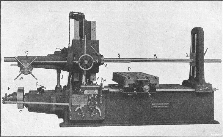
Fig. 1. Lucas Horizontal Boring, Drilling and Milling Machine
The type of machine illustrated in Fig. 1 has a heavy base or bed to which is bolted the column C having vertical ways on which the spindle-head H is mounted. This head contains a sleeve or quill in which the spindle S slides longitudinally. The spindle carries cutters for boring, whereas milling cutters or the auxiliary facing arm are bolted to the end A of the spindle sleeve. The work itself is attached either directly or indirectly to the table or platen P. When the machine is in operation, the cutter or tool revolves with the spindle sleeve or spindle and either the cutter or the part being machined is given a feeding movement, depending on the character of the work. The spindle can be moved in or out by hand for adjustment, or by power for feeding the cutter, as when boring or drilling.
The entire spindle-head H can also be moved vertically on the face of the column C, by hand, for setting the spindle to the proper height, or by power for feeding a milling cutter in a vertical direction. When the vertical position of the spindle-head is changed, the outboard bearing block B also moves up or down a corresponding amount, the two parts being connected[277] by shafts and gearing. Block B steadies the outer end of the boring-bar and the back-rest in which this block is mounted can be shifted along the bed to suit the length of the work, by turning the squared end of shaft D with a crank. The platen P has a cross-feed, and the saddle E on which it is mounted can be traversed lengthwise on the bed; both of these movements can also be effected by hand or power. There is a series of power feeding movements for the cutters and, in addition, rapid power movements in a reverse direction from the feed for returning a cutter quickly to its starting position, when this is desirable.
This machine is driven by a belt connecting pulley G with an overhead shaft. When the machine is in operation, this pulley is engaged with the main driving shaft by a friction clutch F controlled by lever L. This main shaft drives through gearing a vertical shaft I, which by means of other gears in the spindle-head imparts a rotary movement to the spindle. As a machine of this type is used for boring holes of various diameters and for a variety of other work, it is necessary to have a number of speed changes for the spindle. Nine speeds are obtained by changing the position of the sliding gears controlled by levers R and this number is doubled by back-gears in the spindle-head and controlled by lever J.
The amount of feed for the spindle, spindle-head, platen or saddle is varied by two levers K and K1 which control the position of sliding gears through which the feeding movements are transmitted. The direction of the feed can be reversed by shifting lever O. With this particular machine, nine feed changes are available for each position of the spindle back-gears, making a total of eighteen changes. The feeding movement is transmitted to the spindle-head, spindle, platen or saddle, as required, by the three distributing levers T, U and V, which control clutches connecting with the transmission shafts or feed screws. When lever T is turned to the left, the longitudinal power feed for the spindle is engaged, whereas turning it to the right throws in the vertical feed for the spindle-head. Lever U engages the cross-feed for platen P and lever V, the longitudinal [278] feed for saddle E. These levers have a simple but ingenious interlocking device which makes it impossible to engage more than one feed at a time. For example, if lever T is set for feeding the spindle, levers U and V are locked against movement.
The feeds are started and stopped by lever M which also engages the rapid power traverse when thrown in the opposite direction. This rapid traverse operates for whatever feed is engaged by the distributing levers and, as before stated, in a reverse direction. For example, if the reverse lever O is set for feeding the spindle to the right, the rapid traverse would be to the left, and vice versa. The cross-feed for the platen can be automatically tripped at any point by setting an adjustable stop in the proper position and the feed can also be tripped by a hand lever at the side of the platen.
All the different feeding movements can be effected by hand as well as by power. By means of handwheel N, the spindle can be moved in or out slowly, for feeding a cutter by hand. When the friction clamp Q is loosened, the turnstile W can be used for traversing the spindle, in case a hand adjustment is desirable. The spindle-head can be adjusted vertically by turning squared shaft X with a crank, and the saddle can be shifted along the bed by turning shaft Y. The hand adjustment of the platen is effected by shaft Z. The spindle-head, platen and saddle can also be adjusted from the end of the machine, when this is more convenient. Shafts X, Y and Z are equipped with micrometer dials which are graduated to show movements of one-thousandth inch. These dials are used for accurately adjusting the spindle or work and for boring holes or milling surfaces that must be an exact distance apart.
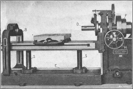
Fig. 2. Horizontal Boring and Drilling Machine with Vertical Table Adjustment
Horizontal Boring Machine with Vertical Table Adjustment.—Another horizontal boring machine is partly shown in Fig. 2. This machine is of the same type as that illustrated in Fig. 1, but its construction is quite different, as will be seen. The spindle cannot be adjusted vertically as with the first design described, but it is mounted and driven very much like the spindle of a lathe, and adjustment for height is obtained by raising or lowering the work table. The design is just the reverse, in this respect,[279] of the machine shown in Fig. 1, which has a vertical adjustment for the spindle, and a work table that remains in the same horizontal plane. The raising or lowering of the table is effected by shaft E, which rotates large nuts engaging the screws S. Shaft E is turned either by hand or power.
The main spindle is driven by a cone pulley P, either directly, or indirectly through the back-gears shown. This arrangement gives six spindle speeds, and double this number is obtained by using a two-speed countershaft overhead. The motion for feeding the spindle longitudinally is transmitted through a cone of gears, which gives the required changes, to a pinion meshing with a rack which traverses the spindle. The large handwheel H and a corresponding wheel on the opposite side are used for adjusting the spindle rapidly by hand. The yoke or outboard bearing B for the boring-bars can be clamped in any position along the bed for supporting the bar as close to the work as possible.
Horizontal boring machines are built in many other designs, but they all have the same general arrangement as the machines illustrated and operate on the same principle, with the exception[280] of special types intended for handling certain classes of work exclusively. The horizontal boring, drilling and milling machine is very efficient for certain classes of work because it enables all the machining operations on some parts to be completed at one setting. To illustrate, a casting which requires drilling, boring and milling at different places, can often be finished without disturbing its position on the platen after it is clamped in place. Frequently a comparatively small surface needs to be milled after a part has been bored. If this milling operation can be performed while the work is set up for boring, accurate results will be obtained (provided the machine is in good condition) and the time saved that would otherwise be required for re-setting the part on another machine. Some examples of work on which different operations are performed at the same setting will be referred to later. The horizontal boring machine also makes it possible to machine duplicate parts without the use of jigs, which is important, especially on large work, owing to the cost of jigs.
Drilling and Boring—Cutters Used.—Holes are drilled in a horizontal machine by simply inserting a drill of required size either directly in the spindle S (see Fig. 1), or in a reducing socket, and then feeding the spindle outward either by hand or power. When a hole is to be bored, a boring-bar B1 is inserted in the spindle and the cutter is attached to this bar. The latter is then fed through the hole as the cutter revolves. The distinction made by machinists between drilling and boring is as follows: A hole is said to be drilled when it is formed by sinking a drill into solid metal, whereas boring means the enlargement of a drilled or cored hole either by the use of a single boring tool, a double-ended cutter which operates on both sides of the hole, or a cutter-head having several tools.
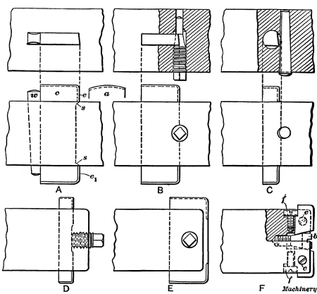
Fig. 3. Boring-cutters of Different Types
There are various methods of attaching cutters to boring-bars and the cutters used vary for different classes of work. A simple style of cutter which is used widely for boring small holes is shown at A in Fig. 3. The cutter c is made from flat stock and the cutting is done by the front edges e and e1, which are beveled in opposite directions. The cutter is held in the bar[281] by a taper wedge w and it is centered by shoulders at s, so that the diameter of the hole will equal the length across the cutter. The outer corners at the front should be slightly rounded, as a sharp corner would be dulled quickly. These cutters are made in different sizes and also in sets for roughing and finishing. The roughing cutter bores holes to within about 1/32 inch of the finish size and it is then replaced by the finishing cutter. A cutter having rounded ends, as shown by the detail sketch a, is sometimes used for light finishing cuts. These rounded ends form the cutting edges and give a smooth finish.
Another method of holding a flat cutter is shown at B. The conical end of a screw bears against a conical seat in, the cutter, thus binding the latter in its slot. The conical seat also centers the cutter. A very simple and inexpensive form of cutter is shown at C. This is made from a piece of round steel, and it is held in the bar by a taper pin which bears against a circular[282] recess in the side of the cutter. This form has the advantage of only requiring a hole through the boring-bar, whereas it is necessary to cut a rectangular slot for the flat cutter.
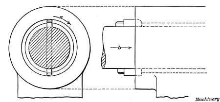
Fig. 4. Boring with a Flat Double-ended Cutter
Fig. 4 shows how a hole is bored by cutters of the type referred to. The bar rotates as indicated by the arrow a and at the same time feeds longitudinally as shown by arrow b. The speed of rotation depends upon the diameter of the hole and the kind of material being bored, and the feed per revolution must also be varied to suit conditions. No definite rule can be given for speed or feed. On some classes of work a long boring-bar is used, which passes through the hole to be bored and is steadied at its outer end by the back-rest B, Figs. 1 and 2. On other work, a short bar is inserted in the spindle having a cutter at the outer end. An inexpensive method of holding a cutter at the end of a bar is shown at D, Fig. 3. The cutter passes through a slot and is clamped by a bolt as shown. When it is necessary to bore holes that are “blind” or closed at the bottom, a long boring-bar which passes through the work cannot, of course, be used.
Sometimes it is necessary to have a cutter mounted at the extreme end of a bar in order to bore close to a shoulder or the bottom of a hole. One method of holding a cutter so that it projects beyond the end of a bar is indicated at E. A screw similar to the one shown at B is used, and the conical end bears in a conical hole in the cutter. This hole should be slightly[283] offset so that the cutter will be forced back against its seat. The tool shown at F has adjustable cutters. The inner end of each cutter is tapering and bears against a conical-headed screw b which gives the required outward adjustment. The cutters are held against the central bolt by fillister-head screws f and they are clamped by the screws c. Boring tools are made in many different designs and the number and form of the cutters is varied somewhat for different kinds of work.
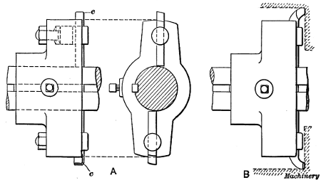
Fig. 5. Cutter-heads for Boring Large Holes
Cutter-heads for Boring Large Holes.—When large holes are to be bored, the cutters are usually held in a cast-iron head which is mounted on the boring-bar. One type of cutter-head is shown in Fig. 5. This particular head is double-ended and carries two cutters c. The cutter-head is bored to fit the bar closely and it is prevented from turning by a key against which a set-screw is tightened. By referring to the end view, it will be seen that each cutter is offset with relation to the center of the bar, in order to locate the front of the tool on a radial line. The number of cutters used in a cutter-head varies. By having several cutters, the work of removing a given amount of metal in boring is distributed, and holes can be bored more quickly with a multiple cutter-head, although more power is required to drive the boring-bar. The boring-bar is also steadied by a multiple cutter-head, because the tendency of any one cutter[284] to deflect the bar is counteracted by the cutters on the opposite side.
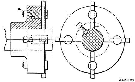
Fig. 6. Cutter-head with Four Boring Tools
A disk-shaped head having four cutters is illustrated in Fig. 6. The cutters are inserted in slots or grooves in the face of the disk and they are held by slotted clamping posts. The shape of these posts is shown by the sectional view. The tool passes through an elongated slot and it is tightly clamped against the disk by tightening nut n. This head is also driven by a key which engages a keyway in the boring-bar.
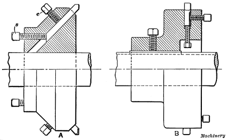
Fig. 7. Cutter-heads equipped with Adjustable Tools
Two other designs of cutter-heads are shown in Fig. 7. The one illustrated at A has three equally spaced cutters which are held in an inclined position. The cutters are clamped by screws c and they can be adjusted within certain limits by screws s. The cutters are placed at an angle so that they will extend beyond the front of the head, thus permitting the latter to be moved up close to a shoulder. The cutter-heads shown in Figs. 5 and 6 can also be moved up close to a shoulder if bent cutters are used as shown in the right-hand view, Fig. 5. The idea in bending the cutters is to bring the cutting edges in advance of the clamping posts so that they will reach a shoulder before the binding posts strike it. The arrangement of cutter-head B (Fig. 7) is clearly shown by the illustration.
[285]Cutter-heads are often provided with two sets of cutters, one set being used for roughing and the other for finishing. It is a good plan to make these cutters so that the ends e (Fig. 6) will rest against the bar or bottom of the slot, when the cutting edge is set to the required radius. The cutters can then be easily set for boring duplicate work. One method of making cutters in sets is to clamp the annealed stock in the cutter-head and then turn the ends to the required radius by placing the head in the lathe. After both sets of cutters have been turned in this way, they are ground to shape and then hardened.
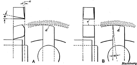
Fig. 8. Boring Tools for Roughing and Finishing Cuts
Boring cutters intended for roughing and finishing cuts are shown in the detail view Fig. 8 at A and B, respectively. The side of the roughing cutter A is ground to a slight angle c to provide clearance for the cutting edge, and the front has a backward slope s to give the tool keenness. This tool is a good form to use for roughing cuts in cast iron. The finishing tool at B has a broad flat edge e and it is intended for coarse feeds and light cuts in cast iron. If a round cutting edge is used for finishing, a comparatively fine feed is required in order to obtain a smooth surface. The corners of tool B are rounded and they should be ground to slope inward as shown in the plan view. The top or ends d of both of these tools are “backed off” slightly [286] to provide clearance. This clearance should be just enough to prevent the surface back of the cutting edge from dragging over the work. Excessive end clearance not only weakens the cutting edge, but tends to cause chattering. As a finishing tool cuts on the upper end instead of on the side, the front should slope backward as shown in the side view, rather than sidewise as with a roughing cutter. The angle of the slope should be somewhat greater for steel than cast iron, unless the steel is quite hard, thus requiring a strong blunt tool.
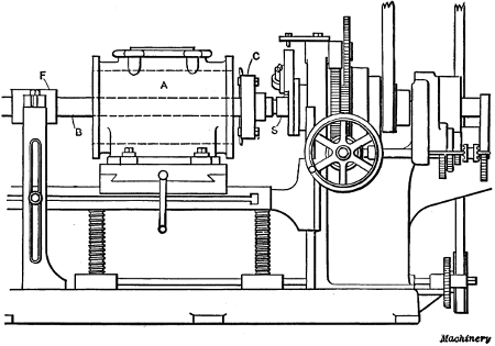
Fig. 9. Cylinder mounted on Horizontal Machine for Boring
Cylinder Boring.—Fig. 9 illustrates the use of a cutter-head for cylinder boring. After the cylinder casting is set on the platen of the machine, the boring-bar with the cutter-head mounted on it is inserted in the spindle. The bar B has a taper shank and a driving tang similar to a drill shank, which fits a taper hole in the end of the spindle. The cutter-head C is fastened to the bar so that it will be in the position shown when the spindle is shifted to the right, as the feeding movement (with this particular machine) is to be in the opposite direction. The casting A should be set central with the bar by adjusting the work-table vertically and laterally, if necessary, and the outer support F should be moved close to the work, to make the bar as rigid as possible.
The cylinder is now ready to be bored. Ordinarily, one or two roughing cuts and one finishing cut would be sufficient, unless the rough bore were considerably below the finish diameter.[287] As previously explained, the speed and feed must be governed by the kind of material being bored and the diameter of the cut. The power and rigidity of the boring machine and the quality of the steel used for making the cutters also affect the cutting speed and feed. As the finishing cut is very light, a tool having a flat cutting edge set parallel to the bar is ordinarily used when boring cast iron. The coarse feed enables the cut to be taken in a comparatively short time and the broad-nosed tool gives a smooth finish if properly ground.
The coarse finishing feed is not always practicable, especially if the boring machine is in poor condition, owing to the chattering of the tool, which results in a rough surface. The last or finishing cut should invariably be a continuous one, for if the machine is stopped before the cut is completed, there will be a ridge in the bore at the point where the tool temporarily left off cutting. This ridge is caused by the cooling and resulting contraction and shortening of the tool during the time that it is stationary. For this reason independent drives are desirable for boring machines.
[288]Facing arms are attached to the bar on either side of the cylinder for facing the flanges after the boring operation. The turning tool of a facing arm is fastened to a slide which is fed outward a short distance each revolution, by a star-wheel that is caused to turn as it strikes against a stationary pin. By facing the flanges in this way, they are finished square with the bore.
When setting a cylinder which is to be bored it should, when the design will permit, be set true by the outside of the flange, or what is even better, by the outside of the cylinder itself, rather than by the rough bore, in order that the walls of the finished cylinder will have a uniform thickness. The position of very large cylinders, while they are being bored, is an important consideration. Such cylinders should be bored in the position which they will subsequently occupy when assembled. For example, the cylinder for a large horizontal engine should be bored while in a horizontal position, as the bore is liable to spring to a slight oval shape when the cylinder is placed horizontal after being bored while standing in a vertical position. If, however, the cylinder is bored while in the position in which it will be placed in the assembled engine, this trouble is practically eliminated.
There is a difference of opinion among machinists as to the proper shape of the cutting point of a boring tool for finishing cuts, some contending that a wide cutting edge is to be preferred, while others advocate the use of a comparatively narrow edge with a reduced feed. It is claimed, that the narrow tool produces a more perfect bore, as it is not so easily affected by hard spots in the iron, and it is also pointed out that the minute ridges left by the narrow tool are an advantage rather than a disadvantage, as they form pockets for oil and aid in lubricating the cylinder. It is the modern practice, however, to use a broad tool and a coarse feed for the light finishing cut, provided the tool does not chatter.
The type of machine tool used for boring cylinders, and also the method of procedure is determined largely by the size of the work and the quantity which is to be machined. The[289] turret lathe, as well as horizontal and vertical boring mills, is used for this work, and in automobile factories or other shops where a great many cylinders are bored, special machines and fixtures are often employed.
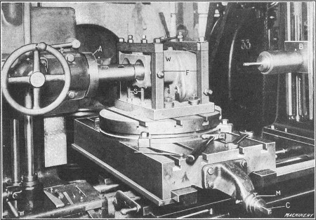
Fig. 10. Boring a Duplex Cylinder on a Horizontal Machine
Boring a Duplex Gasoline Engine Cylinder.—The method of holding work on a horizontal boring machine depends on its shape. A cylinder or other casting having a flat base can be clamped directly to the platen, but pieces of irregular shape are usually held in special fixtures. Fig. 10 shows how the cylinder casting of a gasoline engine is set up for the boring operation. The casting W is placed in a fixture F which is clamped to the machine table. One end of the casting rests on the adjustable screws S and it is clamped by set-screws located in the top and sides of the fixture. There are two cylinders cast integral and these are bored by a short stiff bar mounted in the end of the spindle and having cutters at the outer end. A long bar of the type which passes through the work and is supported by the outboard bearing B, could not be used for this work, because the top of each cylinder is closed.
When one cylinder is finished the other is set in line with the[290] spindle by adjusting the work-table laterally. This adjustment is effected by screw C, and the required center-to-center distance between the two cylinders can be gaged by the micrometer dial M on the cross-feed screw, although positive stops are often used in preference. After the first cylinder is bored, the dial is set to the zero position by loosening the small knurled screw shown, and turning the dial around. The feed screw is then rotated until the dial shows that the required lateral adjustment is made, which locates the casting for boring the second cylinder. The end of the casting is also faced true by a milling cutter. Ordinarily, milling cutters are bolted directly to the spindle sleeve A on this particular machine, which gives a rigid support for the cutter and a powerful drive.
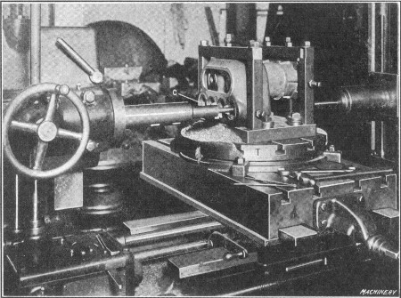
Fig. 11. Cylinder turned around for Machining Valve Seats
The next operation is that of boring and milling the opposite end of the cylinder. This end is turned toward the spindle (as shown in Fig. 11) without unclamping the work or fixture, by simply turning the circular table T half way around. This table is an attachment which is clamped to the main table for holding work that must be turned to different positions for machining the various parts. Its position is easily changed, and[291] as the work remains fixed with relation to the table, the alignment between different holes or surfaces is assured, if the table is turned the right amount. In this case, the casting needs to be rotated one-half a revolution or 180 degrees, and this is done by means of angular graduations on the base of the table. The illustration shows the casting set for boring the inlet and exhaust valve chambers. The different cutters required for boring are mounted on one bar as shown, and the casting is adjusted crosswise to bring each valve chamber in position, by using the micrometer dial. The single-ended cutter c forms a shallow circular recess or seat in the raised pad which surrounds the opening. The cover joint directly back of the cylinders is finished by milling.
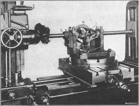
Fig. 12. Boring Differential Gear Casing
Examples of Boring, Radial Facing and Milling.—Another example of boring, in which the circular table is used, is shown in Fig. 12. The work W is a casing for the differential gears of an automobile. It is mounted in a fixture F which is bolted to the table. The casting has round ends, which are clamped in V-blocks, thus aligning the work. This fixture has a guide-bushing[292] G which is centered with the bar and cutter in order to properly locate the casting. There is a bearing at each end of the casing, and two larger ones in the center. These are bored by flat cutters similar to the style illustrated at A in Fig. 3. The cutter for the inner bearings is shown at c.
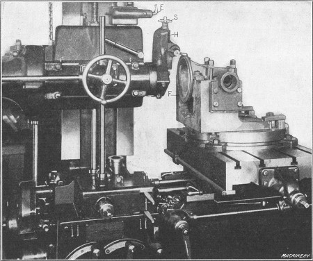
Fig. 13. Facing and Turning Flange of Differential Gear Casing
After the bearings are bored, the circular table is turned 90 degrees and the work is moved closer to the spindle (as shown in Fig. 13) for facing flange F at right angles to the bearings. Circular flanges of this kind are faced in a horizontal boring machine by a special facing-arm or head H. For this particular job this head is clamped directly to the spindle sleeve, but it can also be clamped to the spindle if necessary. The turning tool is held in a slotted toolpost, and it is fed radially for turning the side or face of the flange, by the well-known star feed at S. When this feed is in operation the bent finger E is turned downward so that it strikes one of the star wheel arms for each revolution; this turns the wheel slightly, and[293] the movement is transmitted to the tool-block by a feed-screw. The illustration shows the tool set for turning the outside or periphery of the flange. This is done by setting the tool to the proper radius and then feeding the work horizontally by shifting the work-table along the bed. By referring to Fig. 12 it will be seen that the facing head does not need to be removed for boring, as it is attached to the spindle driving quill and does not interfere with the longitudinal adjustment of the spindle. This facing head is also used frequently for truing the flanges of cylinders which are to be bored, and for similar work.
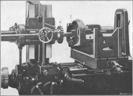
Fig. 14. Example of Work requiring Boring and Milling
Fig. 14 shows another example of work which requires boring and milling. This casting is mounted on a fixture which is bolted to the main table. In this case the circular table is not necessary, because the work can be finished without swiveling it around. After the boring is completed the edge E is trued by the large-face milling cutter M bolted to the spindle sleeve. The irregular outline of the edge is followed by moving the table crosswise and the spindle vertically, as required.
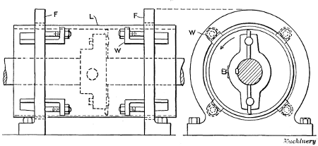
Fig. 15. Cylinder Lining mounted in Fixture for Boring
Fixture for Cylinder Lining or Bushing.—A method of holding a cylinder lining or bushing while it is being bored is shown[294] in Fig. 15. The lining L is mounted in two cast-iron ring-shaped fixtures F. These fixtures are circular in shape and have flat bases which are bolted to the table of the machine. On the inside of each fixture, there are four equally spaced wedges W which fit into grooves as shown in the end view. These wedges are drawn in against the work by bolts, and they prevent the lining from rotating when a cut is being taken. This form of fixture is especially adapted for holding thin bronze linings, such as are used in pump cylinders, because only a light pressure against the wedges is required, and thin work can be held without distorting it. If a very thin lining is being bored, it is well to loosen the wedges slightly before taking the finishing cut, so that the work can spring back to its normal shape.
[295]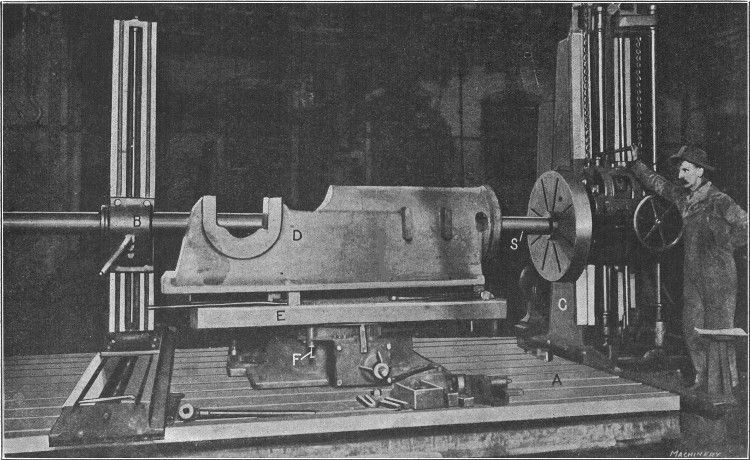
Fig. 16. Detrick & Harvey Horizontal Boring Machine of the Floor Type Boring Engine Bed Casting
Horizontal Boring Machine of Floor Type.—The type of horizontal boring, drilling and milling machine, shown in Fig. 16, is intended for boring heavy parts such as the cylinders of large engines or pumps, the bearings of heavy machine beds and similar work. This machine can also be used for drilling and milling, although it is intended primarily for boring, and the other operations are usually secondary. This design is ordinarily referred to as the “floor type,” because the work-table is low for accommodating large heavy castings. The spindle S which drives the boring-bar, and the spindle feeding mechanism, are carried by a saddle. This saddle is free to move vertically[296] on the face of column C which is mounted on transverse ways extending across the right-hand end of the main bed. This construction permits the spindle to move vertically or laterally (by traversing the column) either for adjusting it to the required position or for milling operations. The spindle also has a longitudinal movement for boring. There is an outer bearing B for supporting the boring-bar, which also has lateral and vertical adjustments, so that it can be aligned with the bar.
The work done on a machine of this type is either clamped directly to the large bed-plate A (which has a number of T-slots for receiving the heads of the clamping bolts) or, in some cases, a special fixture may be used or an auxiliary table. Boring machines of this same general construction are built in many different sizes. The main spindle of the machine illustrated is driven by a motor located at the rear of the vertical column C, the motion being transmitted to the spindle through shafts and gearing. The casting D, shown in this particular illustration, is for a steam engine of the horizontal type, and the operation is that of boring the cylindrical guides or bearings for the crosshead. These bearings have a diameter of 153/4 inches and are 373/4 inches long. In boring them, two roughing cuts and one finishing cut are taken. The end of the casting, which in the assembled engine bears against the cylinder, is then faced by means of a regular facing arm.
After removing the boring-bar the table E of the special fixture on which the casting is mounted is turned one quarter of a revolution. A large milling cutter 24 inches in diameter is next mounted on the spindle of the machine, and one side of the main bearing, as well as the pads for the valve-rod guide-bar brackets, are milled. The table is then revolved and the opposite side of the main bearing is milled in the same way, the table being accurately located in the different positions by an index plunger F which engages holes on the under side. The spindle is now moved upward to allow the table to be turned so as to locate the bearing end of the frame next to the headstock of the machine. The milling cutter is then used to machine[297] the inside and top surfaces of the main bearing. By turning the fixture and not changing the position of the casting after it is bolted into place, the various surfaces are machined in the correct relation to one another without difficulty. This is a good example of the work done on horizontal boring machines of the floor type.
| Page | ||
| Acme flat turret lathe, examples of chuck work | 219 | |
| Acme standard thread and tool for cutting | 159 | |
| Acme standard thread gage | 157 | |
| Acme thread tool, measuring width with vernier caliper | 157, 158 | |
| Accumulation of errors | 105, 106 | |
| Aligning lathe centers for cylindrical turning | 16 | |
| Allowances, average, for forced fits | 130 | |
| for different classes of fits | 131 | |
| for driving fits | 131 | |
| for forced fits of given pressure | 133 | |
| for push fits | 131 | |
| for running fits | 131 | |
| for shrinkage fits | 133 | |
| Aluminum, lubricant for machining | 53 | |
| shape of tools for turning | 53 | |
| speed and feed for machining | 53 | |
| Angle-plate applied to lathe faceplate | 48 | |
| Angles, gage for accurate measurement of | 97 | |
| Apron of lathe | 4, 5 | |
| Arbor or mandrel press | 22 | |
| Arbors or mandrels for lathe work, types of | 19 | |
| use of | 17 | |
| Attachment, application of Hendey relieving | 125 | |
| convex turning for vertical boring mill | 259 | |
| for coarse threading in lathe | 160 | |
| for spherical turning | 113 | |
| for taper turning in lathe | 88 | |
| Hendey relieving | 123 | |
| Automatic chucking and turning machine, Potter & Johnston | 223 | |
| Potter & Johnston, method of “setting-up” | 227 | |
| Potter & Johnston, turning flywheel in | 236 | |
| Back-gears of lathe | 3, 4 | |
| Bardons & Oliver turret lathe, general description | 178 | |
| Bored holes, measuring diameter of | 41 | |
| Boring and reaming tools for vertical mill | 251 | |
| Boring and turning mill, vertical, general description | 242 | |
| vertical, holding and setting work | 247 | |
| vertical, turning in | 249 | |
| turning tools for [300] | 253 | |
| Boring-bar cutters and methods of holding | 280 | |
| Boring cutters for roughing and finishing cuts | 285 | |
| Boring cylinders on horizontal machine | 286 | |
| Boring holes to given center distance in lathe | 51 | |
| Boring in lathe, example of | 39 | |
| Boring large castings in lathe | 49 | |
| Boring large holes, cutter-heads used for | 283 | |
| Boring machine, horizontal | 275 | |
| horizontal, examples of work on | 289-297 | |
| horizontal, floor type | 294 | |
| vertical, multiple-spindle type | 274 | |
| Boring tool, lathe | 40 | |
| Box-tools, different designs and examples of work | 193 | |
| for general turret lathe work | 190 | |
| Bradford belt-driven lathe, general description | 1 | |
| Bradford quick change-gear type of lathe | 173 | |
| Brass, speed for turning | 52 | |
| tool for turning in lathe | 52 | |
| “Bridle” or “hold-back” for lathe | 26, 27 | |
| Bullard vertical turret lathe | 264 | |
| examples of work | 268 | |
| Button method of locating work | 101 | |
| Caliper tool for taper turning | 85 | |
| Calipers, methods of setting | 10, 11 | |
| “Cat-head,” application in lathe work | 25 | |
| Center holes, incorrect and correct forms | 32 | |
| Center indicator, use of | 100 | |
| Centered stock, methods of facing ends | 34 | |
| Centers, lathe, aligning for cylindrical turning | 16 | |
| lathe, grinder for truing | 34 | |
| Centering machine | 30 | |
| Centering parts to be turned | 28 | |
| Centering, precaution for tool steel | 33 | |
| Change gears, calculating for thread cutting | 167 | |
| compound, for thread cutting | 170 | |
| for cutting fractional threads | 171 | |
| for cutting metric pitches | 171 | |
| for thread cutting | 135 | |
| Chasing dial for “catching threads” when screw cutting | 141 | |
| Chuck, inaccuracy from pressure of jaws | 42 | |
| lathe, application of | 37 | |
| setting work in | 42 | |
| universal, independent and combination | 36 | |
| Chucking and turning machine, Potter & Johnston automatic | 223 | |
| Potter & Johnston automatic, method of “setting-up” | 227 | |
| Potter & Johnston automatic, turning flywheel in | 236 | |
| Chucking machine, New Britain, multiple-spindle type | 238 | |
| Clearance angle for turning tools [301] | 66 | |
| Clearance of turning tools, meaning of | 62, 63 | |
| Coarse threading attachment for lathe | 160 | |
| Collapsing tap, Geometric | 202 | |
| Combination chuck for lathe | 36 | |
| Compound rest, applied to screw or thread cutting | 143 | |
| applied to taper turning | 95 | |
| Convex turning attachment for vertical boring mills | 259 | |
| Copper, tool for turning in lathe | 52 | |
| Crankshaft lathe, description of R. K. LeBlond special | 108 | |
| operation of R. K. LeBlond | 110 | |
| Crankshaft turning in engine lathe | 107 | |
| Cross-slide stop for threading | 155 | |
| Cuts, average depth for turning | 75 | |
| roughing and finishing in lathe | 12, 75, 76 | |
| Cutter-heads, for boring, equipped with adjustable tools | 284, 285 | |
| for horizontal boring machine | 283 | |
| Cutters, boring, roughing and finishing types | 285 | |
| for boring-bars | 280 | |
| Cutting lubricants for turning tools | 77 | |
| Cutting speeds, average for turning | 72 | |
| based on Taylor's experiments | 71 | |
| effect of lubricant on | 76 | |
| factors which limit speeds for turning | 72 | |
| rules for calculating | 74 | |
| Cylinder boring machine, multiple-spindle type | 274 | |
| Cylinder boring on horizontal machine | 286 | |
| Cylinder lining, fixture for holding when boring | 293 | |
| Cylindrical turning, simple example of | 6 | |
| Davis turret lathe, turning bevel gear blanks | 212 | |
| turning worm-gear blanks | 211 | |
| Depth of cut for turning, average | 75 | |
| Detrick & Harvey horizontal boring machine, floor type | 294 | |
| Dial for “catching threads” when screw cutting | 141 | |
| Dial gage, testing concentricity of button with | 103, 104 | |
| Die and tap holders, releasing | 199 | |
| Die-heads, self-opening type | 200 | |
| Disk gage, for angles and tapers | 97 | |
| rules for setting | 98, 99 | |
| Dogs or drivers, lathe, application of | 16 | |
| Drill, flat, for lathe | 44 | |
| Drilling and reaming in lathe | 43 | |
| Drivers or dogs, lathe, application of | 16 | |
| Driving fits, allowances for | 131 | |
| Eccentric turning in lathe | 106 | |
| Engine lathe, general description | 1 | |
| Errors, accumulation of | 105, 106 | |
| Faceplate, indexing for multiple-thread cutting [302] | 153 | |
| lathe, application of angle-plate to | 48 | |
| lathe, holding work on | 45 | |
| Facing ends of centered stock, different methods | 34 | |
| Feed and depth of cut for turning, average | 75 | |
| Feeds and speeds for turning based on Taylor's experiments | 71 | |
| Filing and polishing in lathe | 13 | |
| Finishing and roughing cuts in lathe | 75, 76 | |
| Fits, allowances for different classes | 131 | |
| different classes used in machine construction | 129 | |
| driving, allowances for | 131 | |
| forced, allowances for given pressure | 133 | |
| forced, average allowance for | 130 | |
| forced, pressure for | 132 | |
| push, allowances for | 131 | |
| running, allowances for | 131 | |
| shrinkage, allowances for | 133 | |
| Fixture for holding thin lining when boring | 293 | |
| Flat drill and holder for lathe | 44 | |
| Flat turret lathe, Acme, examples of chuck work | 219 | |
| Hartness, example of turning | 213 | |
| Jones & Lamson double-spindle type | 221 | |
| Floating reamer holders | 271 | |
| Flywheel, finishing in one setting in turret lathe | 186 | |
| finishing in two settings in turret lathe | 189 | |
| machining in turret lathe | 184 | |
| turning in Potter & Johnston automatic | 236 | |
| turning in vertical boring mill | 255 | |
| Follow-rest for lathe | 27 | |
| Forced fits, allowances for given pressure | 133 | |
| average allowance for | 130 | |
| pressure generally used in assembling | 132 | |
| Fractional threads, change gears for cutting | 171 | |
| Gage, disk, for angles and tapers | 97 | |
| disk, rules for setting | 98, 99 | |
| for testing V-thread tool | 138 | |
| standard plug, for holes | 42 | |
| thread, Acme standard | 157 | |
| Geometric collapsing tap | 202 | |
| Geometric self-opening die-head | 200 | |
| Gisholt convex attachment for vertical mill | 259 | |
| Gisholt vertical boring mill, general description | 242 | |
| Grinder for truing lathe centers | 34 | |
| Grinding lathe tools | 62 | |
| Hartness flat turret lathe, example of turning | 213 | |
| Hendey relieving attachment | 123 | |
| application of, for relieving taps, cutters and hobs | 125 | |
| “Hold-back” or “bridle” for lathe | 26, 27 [303] | |
| Hollow mills for turret lathe | 198 | |
| Horizontal boring machine | 275 | |
| Detrick & Harvey floor type | 294 | |
| examples of work | 289-297 | |
| Independent chuck for lathe | 36 | |
| Index plate, change gear, for lathe | 137 | |
| Indicator, center, use on lathe | 100 | |
| for “catching threads” when screw cutting | 141 | |
| test, truing buttons with | 102, 103 | |
| thread, for lathe apron, principle of | 142 | |
| Inserted cutter turning tools for lathe | 58 | |
| Internal threading | 154 | |
| Jones & Lamson double-spindle flat turret lathe | 221 | |
| Knurling in lathe and tool used | 122 | |
| Lard oil as a cutting lubricant | 78 | |
| Lathe, boring holes to given center distance in | 51 | |
| boring large castings in | 49 | |
| boring small hole with | 104, 105 | |
| cutting threads in | 135 | |
| drilling small hole with | 104 | |
| general description of Bradford | 1 | |
| LeBlond crankshaft, operation of | 110 | |
| Lo-swing, general description | 115 | |
| method of handling when cutting threads | 138 | |
| quick change-gear type | 173 | |
| R. K. LeBlond special crankshaft | 108 | |
| turret type, general description | 178 | |
| Lathe centers, grinder for truing | 34 | |
| Lathe chucks, application of | 37 | |
| universal, independent and combination | 36 | |
| Lathe faceplate, holding work on | 45 | |
| Lathe follow-rest | 27 | |
| Lathe steadyrest | 23 | |
| application of, when boring | 25 | |
| Lathe taper attachment | 88 | |
| practical application of | 90 | |
| Lathe tool grinding | 62 | |
| Lathe tools, angle of clearance | 66 | |
| angle of keenness | 67 | |
| application of various types | 56 | |
| slope of cutting edge | 66, 67 | |
| Lathe turning tools, inserted-cutter type | 58 | |
| set of tools for general work | 54 | |
| Lead of thread, definition of | 146 | |
| LeBlond, R. K., lathe for crankshaft turning | 108 | |
| Left-hand thread, method of cutting [304] | 148 | |
| Lining, fixture for holding when boring | 293 | |
| Lo-swing lathe, general description | 115 | |
| example of multiple-turning | 117 | |
| Lubricant, effect on cutting speed | 76 | |
| for cooling turning tools | 77 | |
| for machining aluminum | 53 | |
| lard oil as a cutting | 78 | |
| Lucas horizontal boring machine | 275 | |
| Mandrel or arbor press | 22 | |
| Mandrels or arbors for lathe work, types of | 19 | |
| for lathe work, use of | 17 | |
| Metric pitches, change gears for cutting | 171 | |
| Micrometer for measuring threads | 162 | |
| Mills, hollow, for turret lathe | 198 | |
| Multiple-spindle chucking machine, New Britain | 238 | |
| Multiple-thread cutting, indexing faceplate for | 153 | |
| Multiple threads | 146 | |
| method of cutting | 150 | |
| setting tool when cutting | 152 | |
| Multiple-turning in Lo-swing lathe | 117 | |
| New Britain multiple-spindle chucking machine | 238 | |
| Newall Engineering Co's fit allowances | 131 | |
| Pistons, gasoline engine, turning in turret lathe | 204 | |
| Piston rings, attachment for turning in turret lathe | 210 | |
| turning in turret lathe | 206 | |
| Piston turning in Pratt & Whitney turret lathe | 208 | |
| Pitch, metric, change gears for cutting | 171 | |
| Pitch of thread, definition of | 146 | |
| Plug gage, standard | 42 | |
| Polishing and filing in lathe | 13 | |
| Potter & Johnston automatic chucking and turning machine | 223 | |
| method of “setting-up” | 227 | |
| turning flywheel in | 236 | |
| Pratt & Whitney turret lathe, arranged for piston turning | 208 | |
| equipped with piston ring turning attachment | 210 | |
| Press for arbors or mandrels | 22 | |
| Pressure generally used in assembling forced fits | 132 | |
| Push fits, allowances for | 131 | |
| Quick change-gear type of lathe | 173 | |
| Reamer holders, floating type | 271 | |
| Reaming and drilling in lathe | 43 | |
| Releasing die and tap holders | 199 | |
| Relieving attachment, Hendey | 123 | |
| application of [305] | 125 | |
| Relieving hobs or taps having spiral flutes | 128 | |
| Rivett-Dock threading tool | 164 | |
| Roughing and finishing cuts in lathe | 75, 76 | |
| Running fits, allowances for | 131 | |
| Screw cutting, calculating change gears for | 167 | |
| compound gearing for | 170 | |
| in engine lathe | 135 | |
| method of handling lathe | 138 | |
| selecting change gears for | 135 | |
| with compound rest | 143 | |
| Screws, cutting to compensate for shrinkage | 165 | |
| metric, change gears for cutting | 171 | |
| testing size of | 161 | |
| Selecting type of turning machine | 240 | |
| Shrinkage, cutting screws to compensate for | 165 | |
| Shrinkage fits, allowances for | 133 | |
| Side-tool, facing with | 7 | |
| Speeds for turning, average | 72 | |
| based on Taylor's experiments | 71 | |
| effect of lubricant | 76 | |
| factors which limit | 72 | |
| rules for calculating | 74 | |
| Spherical turning | 111 | |
| attachments for | 113 | |
| “Spider” for supporting bushing while turning | 48, 49 | |
| Spiral flutes, method of relieving hobs or taps with | 128 | |
| Square thread and method of cutting | 149, 159 | |
| Steadyrest, application of when boring | 25 | |
| for engine lathe | 23 | |
| Stop for lathe cross-slide when threading | 155 | |
| Tap and die holders, releasing type | 199 | |
| Taper attachment for lathe | 88 | |
| practical application of | 90 | |
| Taper boring with taper attachment | 90 | |
| Taper threading, position of tool for | 154 | |
| Taper turning, adjustment of tailstock center for | 82 | |
| by offset-center method | 80 | |
| examples of | 83 | |
| height of tool for | 94 | |
| in vertical boring mill | 261 | |
| in vertical mill with horizontal and vertical feeds | 262 | |
| setting tailstock center with caliper tool | 85 | |
| setting tailstock center with square | 87 | |
| with compound rest | 95 | |
| with taper attachment | 92, 93 | |
| Tapers, gage for accurate measurement of | 97 | |
| rules for figuring [306] | 97 | |
| Test indicator, truing buttons with | 102, 103 | |
| Test or center indicator for use on lathe | 100 | |
| Thread cutting, calculating change gears for | 167 | |
| compound gearing for | 170 | |
| cross-slide stop used for | 155 | |
| indexing faceplate for multiple threads | 153 | |
| in engine lathe | 135 | |
| internal | 154 | |
| method of handling lathe | 138 | |
| selecting change gears for | 135 | |
| taper, position of tool for | 154 | |
| with compound rest | 143 | |
| Thread gage, Acme standard | 157 | |
| Thread indicator for lathe apron | 141, 142 | |
| Thread micrometer | 162 | |
| Thread tool, Acme, measuring width with vernier caliper | 157, 158 | |
| for cutting V-thread | 138 | |
| Thread tools for standard threads | 159 | |
| Threads, Acme standard, and tool for cutting | 159 | |
| change gears for fractional | 171 | |
| cutting to compensate for shrinkage | 165 | |
| different forms of | 144 | |
| left-hand, method of cutting | 148 | |
| metric, change gears for cutting | 171 | |
| multiple | 146 | |
| multiple, method of cutting | 150 | |
| multiple, setting tool when cutting | 152 | |
| sharp V, and tool for cutting | 159 | |
| square, and method of cutting | 149, 159 | |
| testing size of | 161 | |
| three-wire system for measuring | 163 | |
| U. S. standard, and tool for cutting | 146, 159 | |
| Whitworth standard, and tool for cutting | 158, 159 | |
| worm, and tool for cutting | 159, 160 | |
| Threading attachment, lathe, for coarse threads | 160 | |
| Threading tool, Rivett-Dock | 164 | |
| Tool grinding | 62 | |
| Tools for lathe, set for general turning | 54 | |
| Tools for turning, angle of clearance | 66 | |
| angle of keenness | 67 | |
| inserted-cutter type | 58 | |
| slope of cutting edge | 66, 67 | |
| Tools for turret lathe | 190 | |
| Tools, lathe, application of various types | 56 | |
| Turning, cylindrical, simple example of | 6 | |
| eccentric | 106 | |
| multiple, in Lo-swing lathe | 117 | |
| with front and rear tools | 114 | |
| Turning speeds, average for lathe [307] | 72 | |
| based on Taylor's experiments | 71 | |
| factors which limit | 72 | |
| rules for calculating | 74 | |
| Turning tools, angle of clearance | 66 | |
| angle of keenness | 67 | |
| for aluminum | 53 | |
| for brass | 52 | |
| for copper | 52 | |
| for lathe, position of | 60 | |
| for lathe, set of, for general work | 54 | |
| inserted-cutter type for lathe | 58 | |
| slope of cutting edge | 66, 67 | |
| Turret lathe, Bardons & Oliver, general description | 178 | |
| examples of chuck work in Acme flat | 219 | |
| Hartness flat, example of turning | 213 | |
| Jones & Lamson double-spindle type | 221 | |
| machining flywheels in | 184 | |
| Pratt & Whitney arranged for piston turning | 208 | |
| piston ring turning attachment for | 210 | |
| tools for general work | 190 | |
| turning bevel gear blanks in Davis | 212 | |
| turning gasoline engine pistons in | 204 | |
| turning piston rings in | 206 | |
| turning worm-gear blanks in Davis | 211 | |
| typical example of turret lathe work | 181 | |
| Turret lathe tools, miscellaneous types | 202 | |
| Turret lathe type of vertical boring mill | 264 | |
| Type of turning machine, factors which govern selection | 240 | |
| U. S. standard thread | 159 | |
| method of cutting | 146 | |
| Universal chuck for lathe | 36 | |
| V-thread and tool for cutting | 159 | |
| Vertical boring mill, Bullard turret lathe type | 264 | |
| convex turning attachment | 259 | |
| general description | 242 | |
| holding and setting work | 247 | |
| taper turning in | 261 | |
| taper turning with horizontal and vertical feeds | 262 | |
| tools for boring and reaming | 251 | |
| turning flywheel in | 255 | |
| turning tools for | 253 | |
| Vertical turret lathe, Bullard, examples of work | 268 | |
| Whitworth standard thread and tool for cutting | 158, 159 | |
| Wire system for measuring threads | 163 | |
| Worm thread and tool for cutting | 159, 160 | |
Transcriber's notes:
End of the Project Gutenberg EBook of Turning and Boring, by Franklin D. Jones

*** END OF THIS PROJECT GUTENBERG EBOOK TURNING AND BORING ***

***** This file should be named 34030-h.htm or 34030-h.zip *****
This and all associated files of various formats will be found in:
        https://www.gutenberg.org/3/4/0/3/34030/

Produced by Juliet Sutherland, Harry Lamé and the Online
Distributed Proofreading Team at https://www.pgdp.net


Updated editions will replace the previous one--the old editions
will be renamed.

Creating the works from public domain print editions means that no
one owns a United States copyright in these works, so the Foundation
(and you!) can copy and distribute it in the United States without
permission and without paying copyright royalties.  Special rules,
set forth in the General Terms of Use part of this license, apply to
copying and distributing Project Gutenberg-tm electronic works to
protect the PROJECT GUTENBERG-tm concept and trademark.  Project
Gutenberg is a registered trademark, and may not be used if you
charge for the eBooks, unless you receive specific permission.  If you
do not charge anything for copies of this eBook, complying with the
rules is very easy.  You may use this eBook for nearly any purpose
such as creation of derivative works, reports, performances and
research.  They may be modified and printed and given away--you may do
practically ANYTHING with public domain eBooks.  Redistribution is
subject to the trademark license, especially commercial
redistribution.


*** START: FULL LICENSE ***

THE FULL PROJECT GUTENBERG LICENSE
PLEASE READ THIS BEFORE YOU DISTRIBUTE OR USE THIS WORK

To protect the Project Gutenberg-tm mission of promoting the free
distribution of electronic works, by using or distributing this work
(or any other work associated in any way with the phrase "Project
Gutenberg"), you agree to comply with all the terms of the Full Project
Gutenberg-tm License (available with this file or online at
https://gutenberg.org/license).


Section 1.  General Terms of Use and Redistributing Project Gutenberg-tm
electronic works

1.A.  By reading or using any part of this Project Gutenberg-tm
electronic work, you indicate that you have read, understand, agree to
and accept all the terms of this license and intellectual property
(trademark/copyright) agreement.  If you do not agree to abide by all
the terms of this agreement, you must cease using and return or destroy
all copies of Project Gutenberg-tm electronic works in your possession.
If you paid a fee for obtaining a copy of or access to a Project
Gutenberg-tm electronic work and you do not agree to be bound by the
terms of this agreement, you may obtain a refund from the person or
entity to whom you paid the fee as set forth in paragraph 1.E.8.

1.B.  "Project Gutenberg" is a registered trademark.  It may only be
used on or associated in any way with an electronic work by people who
agree to be bound by the terms of this agreement.  There are a few
things that you can do with most Project Gutenberg-tm electronic works
even without complying with the full terms of this agreement.  See
paragraph 1.C below.  There are a lot of things you can do with Project
Gutenberg-tm electronic works if you follow the terms of this agreement
and help preserve free future access to Project Gutenberg-tm electronic
works.  See paragraph 1.E below.

1.C.  The Project Gutenberg Literary Archive Foundation ("the Foundation"
or PGLAF), owns a compilation copyright in the collection of Project
Gutenberg-tm electronic works.  Nearly all the individual works in the
collection are in the public domain in the United States.  If an
individual work is in the public domain in the United States and you are
located in the United States, we do not claim a right to prevent you from
copying, distributing, performing, displaying or creating derivative
works based on the work as long as all references to Project Gutenberg
are removed.  Of course, we hope that you will support the Project
Gutenberg-tm mission of promoting free access to electronic works by
freely sharing Project Gutenberg-tm works in compliance with the terms of
this agreement for keeping the Project Gutenberg-tm name associated with
the work.  You can easily comply with the terms of this agreement by
keeping this work in the same format with its attached full Project
Gutenberg-tm License when you share it without charge with others.

1.D.  The copyright laws of the place where you are located also govern
what you can do with this work.  Copyright laws in most countries are in
a constant state of change.  If you are outside the United States, check
the laws of your country in addition to the terms of this agreement
before downloading, copying, displaying, performing, distributing or
creating derivative works based on this work or any other Project
Gutenberg-tm work.  The Foundation makes no representations concerning
the copyright status of any work in any country outside the United
States.

1.E.  Unless you have removed all references to Project Gutenberg:

1.E.1.  The following sentence, with active links to, or other immediate
access to, the full Project Gutenberg-tm License must appear prominently
whenever any copy of a Project Gutenberg-tm work (any work on which the
phrase "Project Gutenberg" appears, or with which the phrase "Project
Gutenberg" is associated) is accessed, displayed, performed, viewed,
copied or distributed:

This eBook is for the use of anyone anywhere at no cost and with
almost no restrictions whatsoever.  You may copy it, give it away or
re-use it under the terms of the Project Gutenberg License included
with this eBook or online at www.gutenberg.org

1.E.2.  If an individual Project Gutenberg-tm electronic work is derived
from the public domain (does not contain a notice indicating that it is
posted with permission of the copyright holder), the work can be copied
and distributed to anyone in the United States without paying any fees
or charges.  If you are redistributing or providing access to a work
with the phrase "Project Gutenberg" associated with or appearing on the
work, you must comply either with the requirements of paragraphs 1.E.1
through 1.E.7 or obtain permission for the use of the work and the
Project Gutenberg-tm trademark as set forth in paragraphs 1.E.8 or
1.E.9.

1.E.3.  If an individual Project Gutenberg-tm electronic work is posted
with the permission of the copyright holder, your use and distribution
must comply with both paragraphs 1.E.1 through 1.E.7 and any additional
terms imposed by the copyright holder.  Additional terms will be linked
to the Project Gutenberg-tm License for all works posted with the
permission of the copyright holder found at the beginning of this work.

1.E.4.  Do not unlink or detach or remove the full Project Gutenberg-tm
License terms from this work, or any files containing a part of this
work or any other work associated with Project Gutenberg-tm.

1.E.5.  Do not copy, display, perform, distribute or redistribute this
electronic work, or any part of this electronic work, without
prominently displaying the sentence set forth in paragraph 1.E.1 with
active links or immediate access to the full terms of the Project
Gutenberg-tm License.

1.E.6.  You may convert to and distribute this work in any binary,
compressed, marked up, nonproprietary or proprietary form, including any
word processing or hypertext form.  However, if you provide access to or
distribute copies of a Project Gutenberg-tm work in a format other than
"Plain Vanilla ASCII" or other format used in the official version
posted on the official Project Gutenberg-tm web site (www.gutenberg.org),
you must, at no additional cost, fee or expense to the user, provide a
copy, a means of exporting a copy, or a means of obtaining a copy upon
request, of the work in its original "Plain Vanilla ASCII" or other
form.  Any alternate format must include the full Project Gutenberg-tm
License as specified in paragraph 1.E.1.

1.E.7.  Do not charge a fee for access to, viewing, displaying,
performing, copying or distributing any Project Gutenberg-tm works
unless you comply with paragraph 1.E.8 or 1.E.9.

1.E.8.  You may charge a reasonable fee for copies of or providing
access to or distributing Project Gutenberg-tm electronic works provided
that

- You pay a royalty fee of 20% of the gross profits you derive from
     the use of Project Gutenberg-tm works calculated using the method
     you already use to calculate your applicable taxes.  The fee is
     owed to the owner of the Project Gutenberg-tm trademark, but he
     has agreed to donate royalties under this paragraph to the
     Project Gutenberg Literary Archive Foundation.  Royalty payments
     must be paid within 60 days following each date on which you
     prepare (or are legally required to prepare) your periodic tax
     returns.  Royalty payments should be clearly marked as such and
     sent to the Project Gutenberg Literary Archive Foundation at the
     address specified in Section 4, "Information about donations to
     the Project Gutenberg Literary Archive Foundation."

- You provide a full refund of any money paid by a user who notifies
     you in writing (or by e-mail) within 30 days of receipt that s/he
     does not agree to the terms of the full Project Gutenberg-tm
     License.  You must require such a user to return or
     destroy all copies of the works possessed in a physical medium
     and discontinue all use of and all access to other copies of
     Project Gutenberg-tm works.

- You provide, in accordance with paragraph 1.F.3, a full refund of any
     money paid for a work or a replacement copy, if a defect in the
     electronic work is discovered and reported to you within 90 days
     of receipt of the work.

- You comply with all other terms of this agreement for free
     distribution of Project Gutenberg-tm works.

1.E.9.  If you wish to charge a fee or distribute a Project Gutenberg-tm
electronic work or group of works on different terms than are set
forth in this agreement, you must obtain permission in writing from
both the Project Gutenberg Literary Archive Foundation and Michael
Hart, the owner of the Project Gutenberg-tm trademark.  Contact the
Foundation as set forth in Section 3 below.

1.F.

1.F.1.  Project Gutenberg volunteers and employees expend considerable
effort to identify, do copyright research on, transcribe and proofread
public domain works in creating the Project Gutenberg-tm
collection.  Despite these efforts, Project Gutenberg-tm electronic
works, and the medium on which they may be stored, may contain
"Defects," such as, but not limited to, incomplete, inaccurate or
corrupt data, transcription errors, a copyright or other intellectual
property infringement, a defective or damaged disk or other medium, a
computer virus, or computer codes that damage or cannot be read by
your equipment.

1.F.2.  LIMITED WARRANTY, DISCLAIMER OF DAMAGES - Except for the "Right
of Replacement or Refund" described in paragraph 1.F.3, the Project
Gutenberg Literary Archive Foundation, the owner of the Project
Gutenberg-tm trademark, and any other party distributing a Project
Gutenberg-tm electronic work under this agreement, disclaim all
liability to you for damages, costs and expenses, including legal
fees.  YOU AGREE THAT YOU HAVE NO REMEDIES FOR NEGLIGENCE, STRICT
LIABILITY, BREACH OF WARRANTY OR BREACH OF CONTRACT EXCEPT THOSE
PROVIDED IN PARAGRAPH 1.F.3.  YOU AGREE THAT THE FOUNDATION, THE
TRADEMARK OWNER, AND ANY DISTRIBUTOR UNDER THIS AGREEMENT WILL NOT BE
LIABLE TO YOU FOR ACTUAL, DIRECT, INDIRECT, CONSEQUENTIAL, PUNITIVE OR
INCIDENTAL DAMAGES EVEN IF YOU GIVE NOTICE OF THE POSSIBILITY OF SUCH
DAMAGE.

1.F.3.  LIMITED RIGHT OF REPLACEMENT OR REFUND - If you discover a
defect in this electronic work within 90 days of receiving it, you can
receive a refund of the money (if any) you paid for it by sending a
written explanation to the person you received the work from.  If you
received the work on a physical medium, you must return the medium with
your written explanation.  The person or entity that provided you with
the defective work may elect to provide a replacement copy in lieu of a
refund.  If you received the work electronically, the person or entity
providing it to you may choose to give you a second opportunity to
receive the work electronically in lieu of a refund.  If the second copy
is also defective, you may demand a refund in writing without further
opportunities to fix the problem.

1.F.4.  Except for the limited right of replacement or refund set forth
in paragraph 1.F.3, this work is provided to you 'AS-IS' WITH NO OTHER
WARRANTIES OF ANY KIND, EXPRESS OR IMPLIED, INCLUDING BUT NOT LIMITED TO
WARRANTIES OF MERCHANTIBILITY OR FITNESS FOR ANY PURPOSE.

1.F.5.  Some states do not allow disclaimers of certain implied
warranties or the exclusion or limitation of certain types of damages.
If any disclaimer or limitation set forth in this agreement violates the
law of the state applicable to this agreement, the agreement shall be
interpreted to make the maximum disclaimer or limitation permitted by
the applicable state law.  The invalidity or unenforceability of any
provision of this agreement shall not void the remaining provisions.

1.F.6.  INDEMNITY - You agree to indemnify and hold the Foundation, the
trademark owner, any agent or employee of the Foundation, anyone
providing copies of Project Gutenberg-tm electronic works in accordance
with this agreement, and any volunteers associated with the production,
promotion and distribution of Project Gutenberg-tm electronic works,
harmless from all liability, costs and expenses, including legal fees,
that arise directly or indirectly from any of the following which you do
or cause to occur: (a) distribution of this or any Project Gutenberg-tm
work, (b) alteration, modification, or additions or deletions to any
Project Gutenberg-tm work, and (c) any Defect you cause.


Section  2.  Information about the Mission of Project Gutenberg-tm

Project Gutenberg-tm is synonymous with the free distribution of
electronic works in formats readable by the widest variety of computers
including obsolete, old, middle-aged and new computers.  It exists
because of the efforts of hundreds of volunteers and donations from
people in all walks of life.

Volunteers and financial support to provide volunteers with the
assistance they need are critical to reaching Project Gutenberg-tm's
goals and ensuring that the Project Gutenberg-tm collection will
remain freely available for generations to come.  In 2001, the Project
Gutenberg Literary Archive Foundation was created to provide a secure
and permanent future for Project Gutenberg-tm and future generations.
To learn more about the Project Gutenberg Literary Archive Foundation
and how your efforts and donations can help, see Sections 3 and 4
and the Foundation web page at https://www.pglaf.org.


Section 3.  Information about the Project Gutenberg Literary Archive
Foundation

The Project Gutenberg Literary Archive Foundation is a non profit
501(c)(3) educational corporation organized under the laws of the
state of Mississippi and granted tax exempt status by the Internal
Revenue Service.  The Foundation's EIN or federal tax identification
number is 64-6221541.  Its 501(c)(3) letter is posted at
https://pglaf.org/fundraising.  Contributions to the Project Gutenberg
Literary Archive Foundation are tax deductible to the full extent
permitted by U.S. federal laws and your state's laws.

The Foundation's principal office is located at 4557 Melan Dr. S.
Fairbanks, AK, 99712., but its volunteers and employees are scattered
throughout numerous locations.  Its business office is located at
809 North 1500 West, Salt Lake City, UT 84116, (801) 596-1887, email
business@pglaf.org.  Email contact links and up to date contact
information can be found at the Foundation's web site and official
page at https://pglaf.org

For additional contact information:
     Dr. Gregory B. Newby
     Chief Executive and Director
     gbnewby@pglaf.org


Section 4.  Information about Donations to the Project Gutenberg
Literary Archive Foundation

Project Gutenberg-tm depends upon and cannot survive without wide
spread public support and donations to carry out its mission of
increasing the number of public domain and licensed works that can be
freely distributed in machine readable form accessible by the widest
array of equipment including outdated equipment.  Many small donations
($1 to $5,000) are particularly important to maintaining tax exempt
status with the IRS.

The Foundation is committed to complying with the laws regulating
charities and charitable donations in all 50 states of the United
States.  Compliance requirements are not uniform and it takes a
considerable effort, much paperwork and many fees to meet and keep up
with these requirements.  We do not solicit donations in locations
where we have not received written confirmation of compliance.  To
SEND DONATIONS or determine the status of compliance for any
particular state visit https://pglaf.org

While we cannot and do not solicit contributions from states where we
have not met the solicitation requirements, we know of no prohibition
against accepting unsolicited donations from donors in such states who
approach us with offers to donate.

International donations are gratefully accepted, but we cannot make
any statements concerning tax treatment of donations received from
outside the United States.  U.S. laws alone swamp our small staff.

Please check the Project Gutenberg Web pages for current donation
methods and addresses.  Donations are accepted in a number of other
ways including including checks, online payments and credit card
donations.  To donate, please visit: https://pglaf.org/donate


Section 5.  General Information About Project Gutenberg-tm electronic
works.

Professor Michael S. Hart was the originator of the Project Gutenberg-tm
concept of a library of electronic works that could be freely shared
with anyone.  For thirty years, he produced and distributed Project
Gutenberg-tm eBooks with only a loose network of volunteer support.


Project Gutenberg-tm eBooks are often created from several printed
editions, all of which are confirmed as Public Domain in the U.S.
unless a copyright notice is included.  Thus, we do not necessarily
keep eBooks in compliance with any particular paper edition.


Most people start at our Web site which has the main PG search facility:

     https://www.gutenberg.org

This Web site includes information about Project Gutenberg-tm,
including how to make donations to the Project Gutenberg Literary
Archive Foundation, how to help produce our new eBooks, and how to
subscribe to our email newsletter to hear about new eBooks.