THOMAS A. EDISON
Pioneer Electrical Investigator and Inventor of Numerous Telegraph, Telephone, Lighting, and Other Electrical Devices.
The Project Gutenberg EBook of Cyclopedia of Telephony and Telegraphy,
Vol. 2, by Kempster Miller and George Patterson and Charles Thom and Robert Millikan and Samuel McMeen

This eBook is for the use of anyone anywhere at no cost and with
almost no restrictions whatsoever.  You may copy it, give it away or
re-use it under the terms of the Project Gutenberg License included
with this eBook or online at www.gutenberg.org


Title: Cyclopedia of Telephony and Telegraphy, Vol. 2
       A General Reference Work on Telephony, etc. etc.

Author: Kempster Miller
        George Patterson
        Charles Thom
        Robert Millikan
        Samuel McMeen

Release Date: August 15, 2010 [EBook #33437]

Language: English

Character set encoding: ISO-8859-1

*** START OF THIS PROJECT GUTENBERG EBOOK TELEPHONY AND TELEGRAPHY, VOL 2 ***


Produced by Ronald Holder, Stephen H. Sentoff and the
Online Distributed Proofreading Team at https://www.pgdp.net
THOMAS A. EDISON
Pioneer Electrical Investigator and Inventor of Numerous Telegraph, Telephone,
Lighting, and Other Electrical Devices.
A General Reference Work on
TELEPHONY, SUBSTATIONS, PARTY LINE SYSTEMS, PROTECTION, MANUAL
SWITCHBOARDS, AUTOMATIC SYSTEMS, POWER PLANTS, SPECIAL
SERVICE FEATURES, CONSTRUCTION, ENGINEERING,
OPERATION, MAINTENANCE, TELEGRAPHY, WIRELESS
TELEGRAPHY AND TELEPHONY, ETC.
Prepared by a Corps of
TELEPHONE AND TELEGRAPH EXPERTS, AND ELECTRICAL ENGINEERS OF
THE HIGHEST PROFESSIONAL STANDING
Illustrated with over Two Thousand Engravings
F O U R V O L U M E S
CHICAGO
AMERICAN SCHOOL OF CORRESPONDENCE
1919
COPYRIGHT, 1911, 1912,
BY
AMERICAN SCHOOL OF CORRESPONDENCE
COPYRIGHT, 1911, 1912
BY
AMERICAN TECHNICAL SOCIETY
Entered at Stationers' Hall, London
All Rights Reserved
KEMPSTER B. MILLER, M.E.
Consulting Engineer and Telephone Expert
Of the Firm of McMeen and Miller, Electrical Engineers and Patent Experts, Chicago
American Institute of Electrical Engineers
Western Society of Engineers
GEORGE W. PATTERSON, S.B., Ph.D.
Head, Department of Electrical Engineering, University of Michigan
CHARLES THOM
Chief of Quadruplex Department, Western Union Main Office, New York City
ROBERT ANDREWS MILLIKAN, Ph.D.
Associate Professor of Physics, University of Chicago
Member, Executive Council, American Physical Society
SAMUEL G. McMEEN
Consulting Engineer and Telephone Expert
Of the Firm of McMeen and Miller, Electrical Engineers and Patent
Experts, Chicago
American Institute of Electrical Engineers
Western Society of Engineers
LAWRENCE K. SAGER, S.B., M.P.L.
Patent Attorney and Electrical Expert
Formerly Assistant Examiner, U.S. Patent Office
GLENN M. HOBBS, Ph.D.
Secretary, American School of Correspondence
Formerly Instructor in Physics, University of Chicago
American Physical Society
CHARLES G. ASHLEY
Electrical Engineer and Expert in Wireless Telegraphy and Telephony
A. FREDERICK COLLINS
Editor, Collins Wireless Bulletin
Author of "Wireless Telegraphy, Its History, Theory, and Practice"
FRANCIS B. CROCKER, E.M., Ph.D.
Head, Department of Electrical Engineering, Columbia University
Past-President, American Institute of Electrical Engineers
MORTON ARENDT, E.E.
Instructor in Electrical Engineering, Columbia University, New York
EDWARD B. WAITE
Head, Instruction Department, American School of Correspondence
American Society of Mechanical Engineers
Western Society of Engineers
DAVID P. MORETON, B.S., E.E.
Associate Professor of Electrical Engineering, Armour Institute of
Technology
American Institute of Electrical Engineers
LEIGH S. KEITH, B.S.
Managing Engineer with McMeen and Miller, Electrical Engineers and
Patent Experts Chicago
Associate Member, American Institute of Electrical Engineers
JESSIE M. SHEPHERD, A.B.
Associate Editor, Textbook Department, American School of Correspondence
ERNEST L. WALLACE, B.S.
Assistant Examiner, United States Patent Office, Washington, D. C.
GEORGE R. METCALFE, M.E.
Editor, American Institute of Electrical Engineers
Formerly Head of Publication Department, Westinghouse Elec. &
Mfg. Co.
J. P. SCHROETER
Graduate, Munich Technical School
Instructor in Electrical Engineering, American School of
Correspondence
JAMES DIXON, E.E.
American Institute of Electrical Engineers
HARRIS C. TROW, S.B., Managing Editor
Editor-in-Chief, Textbook Department, American School of Correspondence
The editors have freely consulted the standard technical literature of America and Europe in the preparation of these volumes. They desire to express their indebtedness particularly to the following eminent authorities, whose well-known works should be in the library of every telephone and telegraph engineer.
Grateful acknowledgment is here made also for the invaluable co-operation of the foremost engineering firms and manufacturers in making these volumes thoroughly representative of the very best and latest practice in the transmission of intelligence, also for the valuable drawings, data, suggestions, criticisms, and other courtesies.
ARTHUR E. KENNELY, D.Sc.
Professor of Electrical Engineering, Harvard University.
Joint Author of "The Electric Telephone," "The Electric Telegraph,"
"Alternating Currents," "Arc Lighting," "Electric Heating,"
"Electric Motors," "Electric Railways," "Incandescent Lighting,"
etc.
HENRY SMITH CARHART, A.M., LL.D.
Professor of Physics and Director of the Physical Laboratory,
University of Michigan.
Author of "Primary Batteries," "Elements of Physics," "University
Physics," "Electrical Measurements," "High School Physics," etc.
FRANCIS B. CROCKER, M.E., Ph.D.
Head of Department of Electrical Engineering, Columbia University,
New York; Past-President, American Institute of Electrical
Engineers.
Author of "Electric Lighting;" Joint Author of "Management of
Electrical Machinery."
HORATIO A. FOSTER
Consulting Engineer; Member of American Institute of Electrical
Engineers; Member of American Society of Mechanical Engineers.
Author of "Electrical Engineer's Pocket-Book."
WILLIAM S. FRANKLIN, M.S., D.Sc.
Professor of Physics, Lehigh University.
Joint Author of "The Elements of Electrical Engineering," "The
Elements of Alternating Currents."
LAMAR LYNDON, B.E., M.E.
Consulting Electrical Engineer; Associate Member of American
Institute of Electrical Engineers; Member, American
Electro-Chemical Society.
Author of "Storage Battery Engineering."
ROBERT ANDREWS MILLIKAN, Ph.D.
Professor of Physics, University of Chicago.
Joint Author of "A First Course in Physics," "Electricity,
Sound and Light," etc.
KEMPSTER B. MILLER, M.E.
Consulting Engineer and Telephone Expert; of the Firm of McMeen
and Miller, Electrical Engineers and Patent Experts, Chicago.
Author of "American Telephone Practice."
WILLIAM H. PREECE
Chief of the British Postal Telegraph.
Joint Author of "Telegraphy," "A Manual of Telephony," etc.
LOUIS BELL, Ph.D.
Consulting Electrical Engineer; Lecturer on Power Transmission,
Massachusetts Institute of Technology.
Author of "Electric Power Transmission," "Power Distribution for Electric Railways,"
"The Art of Illumination," "Wireless Telephony," etc.
OLIVER HEAVISIDE, F.R.S.
Author of "Electro-Magnetic Theory," "Electrical Papers," etc.
SILVANUS P. THOMPSON, D.Sc., B.A., F.R.S., F.R.A.S.
Principal and Professor of Physics in the City and Guilds of London Technical College.
Author of "Electricity and Magnetism," "Dynamo-Electric Machinery," "Polyphase
Electric Currents and Alternate-Current Motors," "The Electromagnet," etc.
ANDREW GRAY, M.A., F.R.S.E.
Author of "Absolute Measurements in Electricity and Magnetism."
ALBERT CUSHING CREHORE, A.B., Ph.D.
Electrical Engineer; Assistant Professor of Physics, Dartmouth College; Formerly Instructor
in Physics, Cornell University.
Author of "Synchronous and Other Multiple Telegraphs;" Joint Author of "Alternating
Currents."
J. J. THOMSON, D.Sc., LL.D., Ph.D., F.R.S.
Fellow of Trinity College, Cambridge University; Cavendish Professor of Experimental
Physics, Cambridge University.
Author of "The Conduction of Electricity through Gases," "Electricity and Matter."
FREDERICK BEDELL, Ph.D.
Professor of Applied Electricity, Cornell University.
Author of "The Principles of the Transformer;" Joint Author of "Alternating Currents."
DUGALD C. JACKSON, C.E.
Head of Department of Electrical Engineering, Massachusetts Institute of Technology;
Member, American Institute of Electrical Engineers, etc.
Author of "A Textbook on Electromagnetism and the Construction of Dynamos;"
Joint Author of "Alternating Currents and Alternating-Current Machinery."
MICHAEL IDVORSKY PUPIN, A.B., Sc.D., Ph.D.
Professor of Electro-Mechanics, Columbia University, New York.
Author of "Propagation of Long Electric Waves," and "Wave-Transmission over
Non-Uniform Cables and Long-Distance Air Lines."
FRANK BALDWIN JEWETT, A.B., Ph.D.
Transmission and Protection Engineer, with American Telephone & Telegraph Co.
Author of "Modern Telephone Cable," "Effect of Pressure on Insulation Resistance."
ARTHUR CROTCH
Formerly Lecturer on Telegraphy and Telephony at the Municipal Technical Schools,
Norwich, Eng.
Author of "Telegraphy and Telephony."
JAMES ERSKINE-MURRAY, D.Sc.
Fellow of the Royal Society of Edinburgh; Member of the Institution of Electrical
Engineers.
Author of "A Handbook of Wireless Telegraphy."
A. H. McMILLAN, A.B., LL.B.
Author of "Telephone Law, A Manual on the Organization and Operation of Telephone Companies."
WILLIAM ESTY, S.B., M.A.
Head of Department of Electrical Engineering, Lehigh University.
Joint Author of "The Elements of Electrical Engineering."
GEORGE W. WILDER, Ph.D.
Formerly Professor of Telephone Engineering, Armour Institute of Technology.
Author of "Telephone Principles and Practice," "Simultaneous Telegraphy and Telephony,"
etc.
WILLIAM L. HOOPER, Ph.D.
Head of Department of Electrical Engineering, Tufts College.
Joint Author of "Electrical Problems for Engineering Students."
DAVID S. HULFISH
Technical Editor, The Nickelodeon; Telephone and Motion-Picture Expert; Solicitor of
Patents.
Author of "How to Read Telephone Circuit Diagrams."
J. A. FLEMING, M.A., D.Sc. (Lond.), F.R.S.
Professor of Electrical Engineering in University College, London; Late Fellow and
Scholar of St. John's College, Cambridge; Fellow of University College, London.
Author of "The Alternate-Current Transformer," "Radiotelegraphy and Radiotelephony,"
"Principles of Electric Wave Telegraphy," "Cantor Lectures on Electrical
Oscillations and Electric Waves," "Hertzian Wave Wireless Telegraphy," etc.
F. A. C. PERRINE, A.M., D.Sc.
Consulting Engineer; Formerly President, Stanley Electric Manufacturing Company;
Formerly Professor of Electrical Engineering, Leland Stanford, Jr. University.
Author of "Conductors for Electrical Distribution."
A. FREDERICK COLLINS
Editor, College Wireless Bulletin.
Author of "Wireless Telegraphy, Its History, Theory and Practice," "Manual of Wireless
Telegraphy," "Design and Construction of Induction Coils," etc.
SCHUYLER S. WHEELER, D.Sc.
President, Crocker-Wheeler Co.; Past-President, American Institute of Electrical Engineers.
Joint Author of "Management of Electrical Machinery."
CHARLES PROTEUS STEINMETZ
Consulting Engineer, with the General Electric Co.; Professor of Electrical Engineering,
Union College.
Author of "The Theory and Calculation of Alternating-Current Phenomena," "Theoretical
Elements of Electrical Engineering," etc.
GEORGE W. PATTERSON, S.B., Ph.D.
Head of Department of Electrical Engineering, University of Michigan.
Joint Author of "Electrical Measurements."
WILLIAM MAVER, Jr.
Ex-Electrician Baltimore and Ohio Telegraph Company; Member of the American Institute
of Electrical Engineers.
Author of "American Telegraphy and Encyclopedia of the Telegraph," "Wireless Telegraphy."
JOHN PRICE JACKSON, M.E.
Professor of Electrical Engineering, Pennsylvania State College.
Joint Author of "Alternating Currents and Alternating-Current Machinery."
AUGUSTUS TREADWELL, Jr., E.E.
Associate Member, American Institute of Electrical Engineers.
Author of "The Storage Battery, A Practical Treatise on Secondary Batteries."
EDWIN J. HOUSTON, Ph.D.
Professor of Physics, Franklin Institute, Pennsylvania; Joint Inventor of Thomson-Houston
System of Arc Lighting; Electrical Expert and Consulting Engineer.
Joint Author of "The Electric Telephone," "The Electric Telegraph," "Alternating
Currents," "Arc Lighting," "Electric Heating," "Electric Motors," "Electric Railways,"
"Incandescent Lighting," etc.
WILLIAM J. HOPKINS
Professor of Physics in the Drexel Institute of Art, Science, and Industry, Philadelphia.
Author of "Telephone Lines and their Properties."
![]() The present day development of the "talking wire" has
annihilated both time and space, and has enabled men
thousands of miles apart to get into almost instant
communication. The user of the telephone and the telegraph
forgets the tremendousness of the feat in the simplicity of its
accomplishment; but the man who has made the feat possible
knows that its very simplicity is due to the complexity of the
principles and appliances involved; and he realizes his need of
a practical, working understanding of each principle and its
application. The Cyclopedia of Telephony and Telegraphy presents
a comprehensive and authoritative treatment of the whole
art of the electrical transmission of intelligence.
The present day development of the "talking wire" has
annihilated both time and space, and has enabled men
thousands of miles apart to get into almost instant
communication. The user of the telephone and the telegraph
forgets the tremendousness of the feat in the simplicity of its
accomplishment; but the man who has made the feat possible
knows that its very simplicity is due to the complexity of the
principles and appliances involved; and he realizes his need of
a practical, working understanding of each principle and its
application. The Cyclopedia of Telephony and Telegraphy presents
a comprehensive and authoritative treatment of the whole
art of the electrical transmission of intelligence.
![]() The communication engineer—if so he may be called—requires
a knowledge both of the mechanism of his instruments and of
the vagaries of the current that makes them talk. He requires as
well a knowledge of plants and buildings, of office equipment,
of poles and wires and conduits, of office system and time-saving
methods, for the transmission of intelligence is a business as
well as an art. And to each of these subjects, and to all others
pertinent, the Cyclopedia gives proper space and treatment.
The communication engineer—if so he may be called—requires
a knowledge both of the mechanism of his instruments and of
the vagaries of the current that makes them talk. He requires as
well a knowledge of plants and buildings, of office equipment,
of poles and wires and conduits, of office system and time-saving
methods, for the transmission of intelligence is a business as
well as an art. And to each of these subjects, and to all others
pertinent, the Cyclopedia gives proper space and treatment.
![]() The sections on Telephony cover the installation, maintenance,
and operation of all standard types of telephone systems;
they present without prejudice the respective merits of manual
and automatic exchanges; and they give special attention to
the prevention and handling of operating "troubles." The
sections on Telegraphy cover both commercial service and train
dispatching. Practical methods of wireless communication—both
by telephone and by telegraph—are thoroughly treated.
The sections on Telephony cover the installation, maintenance,
and operation of all standard types of telephone systems;
they present without prejudice the respective merits of manual
and automatic exchanges; and they give special attention to
the prevention and handling of operating "troubles." The
sections on Telegraphy cover both commercial service and train
dispatching. Practical methods of wireless communication—both
by telephone and by telegraph—are thoroughly treated.
![]() The drawings, diagrams, and photographs incorporated into
the Cyclopedia have been prepared especially for this work;
and their instructive value is as great as that of the text itself.
They have been used to illustrate and illuminate the text, and
not as a medium around which to build the text. Both drawings
and diagrams have been simplified so far as is compatible
with their correctness, with the result that they tell their own
story and always in the same language.
The drawings, diagrams, and photographs incorporated into
the Cyclopedia have been prepared especially for this work;
and their instructive value is as great as that of the text itself.
They have been used to illustrate and illuminate the text, and
not as a medium around which to build the text. Both drawings
and diagrams have been simplified so far as is compatible
with their correctness, with the result that they tell their own
story and always in the same language.
![]() The Cyclopedia is a compilation of many of the most valuable
Instruction Papers of the American School of Correspondence,
and the method adopted in its preparation is that which this
School has developed and employed so successfully for many
years. This method is not an experiment, but has stood the
severest of all tests—that of practical use—which has demonstrated
it to be the best yet devised for the education of the
busy, practical man.
The Cyclopedia is a compilation of many of the most valuable
Instruction Papers of the American School of Correspondence,
and the method adopted in its preparation is that which this
School has developed and employed so successfully for many
years. This method is not an experiment, but has stood the
severest of all tests—that of practical use—which has demonstrated
it to be the best yet devised for the education of the
busy, practical man.
![]() In conclusion, grateful acknowledgment is due to the staff
of authors and collaborators, without whose hearty co-operation
this work would have been impossible.
In conclusion, grateful acknowledgment is due to the staff
of authors and collaborators, without whose hearty co-operation
this work would have been impossible.

Manual Switchboards By K. B. Miller and S. G. McMeen[A] Page[B] 11
CHAPTER XXII—Common-Battery Switchboards—Line Signals—Cord Circuit—Lamps—Mechanical Signals—Relays—Jacks—Switchboard Assembly
CHAPTER XXIII—Transfer Switchboard—Transfer Lines—Handling Transfers
CHAPTER XXIV—Multiple Switchboard—Busy Test—Influence of Traffic
CHAPTER XXV—Magneto-Multiple Switchboard—Multiple Boards: Series, Branch-Terminal, Modern Magneto, Common-Battery
CHAPTER XXVI—Western Electric No. 1 Relay Board—Western Electric No. 10 Board—Types of Multiple Boards—Apparatus
CHAPTER XXVII—Trunking—Western Electric and Kellogg Trunk Circuits
Automatic Systems By K. B. Miller and S. G. McMeen Page 135
CHAPTER XXVIII—Automatic vs. Manual—Operation
CHAPTER XXIX—Selecting Switch—Line Switch—Trunking Systems—Two- and Three-Wire Systems—Subscriber's Station Apparatus—First and Second Selector Operation—Connector—Release after Conversation—Multi-Office System—Automatic Sub-Offices—Rotary Connector—Party Lines—Two-Wire Automatic System
CHAPTER XXX—Lorimer System—Central-Office Apparatus—Operation
CHAPTER XXXI—Automanual System—Operation—Subscriber's Apparatus—Operator's Equipment—Switching Equipment—Distribution of Calls—Connection—Speed
Power Plants and Buildings By K. B. Miller and S. G. McMeen Page 227
CHAPTER XXXII—Currents Employed—Types—Operator's Transmitter Supply—Ringing-Current Supply—Auxiliary Signaling Current—Primary Sources—Duplicate Apparatus—Storage Batteries—Power Switchboards—Circuits
CHAPTER XXXIII—Central-Office Building—Arrangement of Apparatus—Manual Offices—Automatic Offices
Special Service Features By K. B. Miller and S. G. McMeen Page 271
CHAPTER XXXIV—Private-Branch Exchanges—Switchboards—Supervision—With Automatic Offices—Battery Supply—Ringing Current
CHAPTER XXXV—Inter-Communicating Systems—Magneto System—Common-Battery Systems—Types
CHAPTER XXXVI—Long-Distance Switching—Operator's Orders—Trunking—Way Stations
CHAPTER XXXVII—Traffic
CHAPTER XXXVIII—Measured Service—Charging—Rates—Toll Service—Local Service
Telegraph and Railway Work By K. B. Miller and S. G. McMeen Page 321
CHAPTER XXXIX—Phantom, Simplex, and Composite Circuits—Ringing—Railway Composite
CHAPTER XL—Telephone Train Dispatching—Railroad Conditions—Transmitting Orders—Apparatus—Telephone Equipment—Types of Circuits—Test Boards—Blocking Sets—Dispatching on Electric Railways
Review Questions Page 359
Index Page 373
[A] For professional standing of authors, see list of Authors and Collaborators at front of volume.
[B] For page numbers, see foot of pages.
GROSSE POINT EXCHANGE RACK
Detroit Home Telephone Company, Detroit, Mich.
The Dean Electric Co.
LINE SIDE OF LARGE MAIN DISTRIBUTING FRAME
PORTION OF TERMINAL ROOM OF LARGE COMMON-BATTERY OFFICE
Prospect Office, New York Telephone Co.
CABLE TURNING SECTIONS, BETWEEN A AND B BOARDS
Cortlandt Office, New York Telephone Co.
CABLE RUN FROM INTERMEDIATE FRAME TO MULTIPLE
Cortlandt Office, New York Telephone Co.
WESTERN ELECTRIC COMPANY TYPICAL CHARGING OUTFIT AT DAWSON, GEORGIA
DEAN HARMONIC CONVERTER
Dry Cell Type for Magneto Exchange.
The Dean Electric Co.
POWER SWITCHBOARD FOR MEDIUM-SIZED OFFICE
Mercury Arc Rectifier Panel and Transformer at Right.
GAS ENGINE AND POWER BOARD
Citizens' Telephone Co., Racine, Wis.
The Dean Electric Co.
POWER MACHINERY
Citizens' Telephone Company, Racine, Wis.
The Dean Electric Co.
POWER APPARATUS FOR COMMON-BATTERY MANUAL OFFICE OF MEDIUM SIZE
THE POWER AND WIRE CHIEF'S ROOM OF THE EXCHANGE AT WEBB CITY, MISSOURI
RINGING AND CHARGING MACHINES AND POWER BOARD
Plaza Office, New York Telephone Co.
POWER PLANT FOR AUTOMATIC SWITCHBOARD EQUIPMENT
Bay Cities Home Telephone Company, Berkeley, Cal.
WESTERN ELECTRIC COMPANY BATTERY ROOM AT MONMOUTH, ILLINOIS
WESTERN ELECTRIC MOTOR-GENERATOR CHARGING SET
WESTERN ELECTRIC RINGING MACHINE
FRONT OF LONG-DISTANCE POWER BOARD
U.S. Telephone Company, Cleveland, Ohio.
The Dean Electric Co.
Advantages of Common-Battery Operation. The advantages of the common-battery system of operation, alluded to in Chapter XIII, may be briefly summarized here. The main gain in the common-battery system of supply is the simplification of the subscribers' instruments, doing away with the local batteries and the magneto generators, and the concentration of all these many sources of current into one single source at the central office. A considerable saving is thus effected from the standpoint of maintenance, since the simpler common-battery instrument is not so likely to get out of order and, therefore, does not have to be visited so often for repairs, and the absence of local batteries, of course, makes the renewal of the battery parts by members of the maintenance department, unnecessary. Another decided advantage in the common-battery system is the fact that the centralized battery stands ready always to send current over the line when the subscriber completes the circuit of the line at his station by removing his receiver from its hook. The common-battery system, therefore, lends itself naturally to the purposes of automatic signaling, since it is only necessary to place at the central office a device in the circuit of each line that will be responsive to the current which flows from the central battery when the subscriber removes his receiver from its hook. It is thus that the subscriber is enabled automatically to signal the central office when he desires a connection; and as will be shown, it is by the same sort of means, associated with the cord circuits used in connecting his line with some other line, that the operator is automatically notified when a disconnection is desired, the cessation of current through the subscriber's line when he hangs up his receiver being made to actuate certain responsive devices which are associated with the cord at that time connected with his line, and which convey the proper disconnect signal to the operator.
Concentration of sources of energy into a single large unit, the simplification of the subscriber's station equipment, and the ready adaptability to automatic signaling from the subscriber to the central office are, therefore, the reasons for the existence of the common-battery system.
Common Battery vs. Magneto. It must not be supposed, however, that the common-battery system always has advantages over the magneto system, and that it is superior to the magneto or local-battery system for all purposes. It is the outward attractiveness of the common-battery system and the arguments in its favor, so readily made by over-zealous salesmen, that has led, in many cases, to the adoption of this system when the magneto system would better have served the purpose of utility and economy.
To say the least, the telephone transmission to be had from common-battery systems is no better than that to be had from local-battery systems, and as a rule, assuming equality in other respects, it is not as good. It is perhaps true, however, that under average conditions common-battery transmission is somewhat better, because whereas the local batteries at the subscribers' stations in the local-battery system are not likely to be in uniformly first-class condition, the battery in a common-battery system will be kept up to its full voltage except under the grossest neglect.
The places in which the magneto, or local-battery, system is to be preferred to the common-battery system, in the opinion of the writers, are to be found in the small rural communities where the lines have a rather great average length; where a good many subscribers are likely to be found on some of the lines; where the sources of electrical power available for charging storage batteries are likely either not to exist, or to be of a very uncertain nature; and where it is not commercially feasible to employ a high-grade class of attendants, or, in fact, any attendant at all other than the operator at the central office.
In large or medium-sized exchanges it is always possible to procure suitable current for charging the storage batteries required in common-battery systems, and it is frequently economical, on account of the considerable quantity of energy that is thus used, to establish a generating plant in connection with the central office for developing the necessary electrical energy. In very small rural [Page 13]places there are frequently no available sources of electrical energy, and the expense of establishing a power plant for the purpose cannot be justified. But even if there is an electric light or railway system in the small town, so that the problem of available current supply does not exist, the establishment of a common-battery system with its storage battery and the necessary charging machinery requires the daily attendance at the central office of some one to watch and care for this battery, and this, on account of the small gross revenue that may be derived from a small telephone system, often involves a serious financial burden.
There is no royal road to a proper decision in the matter, and no sharp line of demarcation may be drawn between the places where common-battery systems are superior to magneto and vice versâ. It may be said, however, that in the building of all new telephone plants having over about 500 local subscribers, the common-battery system is undoubtedly superior to the magneto. If the plant is an old one, however, and is to be re-equipped, the continuance of magneto apparatus might be justified for considerably larger exchanges than those having 500 subscribers.
Telephone operating companies who have changed over the equipment of old plants from magneto to common battery have sometimes been led into rather serious difficulty, owing to the fact that their lines, while serving tolerably well for magneto work, were found inadequate to meet the more exacting demands of common-battery work. Again in an old plant the change from magneto to common-battery equipment involves not only the change of switchboards, but also the change of subscribers' instruments that are otherwise good, and this consideration alone often, in our opinion, justifies the replacing of an old magneto board with a new magneto board, even if the exchange is of such size as to demand a small multiple board.
Where the plant to be established is of such size as to leave doubt as to whether a magneto or a common-battery switchboard should be employed, the questions of availability of the proper kind of power for charging the batteries, the proper kind of help for maintaining the batteries and the more elaborate central-office equipment, the demands and previous education of the public to be served, all are factors which must be considered in reaching the decision.
It is not proper to say that anything like all exchanges having fewer than 500 local lines, should be equipped with magneto service. Where all the lines are short, where suitable power is available, and where a good grade of attendants is available—as, for instance, in the case of private telephone exchanges that serve some business establishment or other institution located in one building or a group of buildings—the common-battery system is to be recommended and is largely used, even though it may have but a dozen or so subscribers' lines. It is for such uses, and for use in those regular public-service exchange systems where the conditions are such as to warrant the common-battery system, and yet where the number of lines and the traffic are small enough to be handled by such a small group of operators that any one of them may reach over the entire face of the board, that the simple non-multiple common-battery system finds its proper field of usefulness.
Line Signals. The principles and means by which the subscriber is enabled to call the central-office operator in a common-battery system have been referred to briefly in Chapter III. We will review these at this point and also consider briefly the way in which the line signals are associated with the connective devices in the subscribers' lines.
Direct-Line Lamp. The simplest possible way is to put the line signal directly in the circuit of the line in series with the central-office battery, and so to arrange the jack of the corresponding line that the circuit through the line signal will be open when the operator inserts a plug into that jack. This arrangement is shown in Fig. 307 where the subscriber's station at the left is indicated in the simplest of its forms. It is well to repeat here that in all common-battery manual systems, the subscriber's station equipment, regardless of the arrangement or type of its talking and signaling apparatus, must have these features: First, that the line shall be normally open to direct currents at the subscriber's station; second, that the line shall be closed to direct currents when the subscriber removes his receiver from its hook in making or in answering a call; third, that the line normally, although open to direct currents, shall afford a proper path for alternating or varying currents through the signal receiving device at the sub-station. The subscriber's station arrangement shown in Fig. 307, and those immediately following, [Page 15]is the simplest arrangement that possesses these three necessary features for common-battery service.
Considering the arrangement at the central office, Fig. 307, the two limbs of the line are permanently connected to the tip and sleeve contacts of the jack. These two main contacts of the jack normally engage two anvils so connected that the tip of the jack is ordinarily connected through its anvil to ground, while the sleeve of the jack is normally connected through its anvil to a circuit leading through the line signal—in this case a lamp—and the common battery, and thence to ground. The operation is obvious. Normally no current may flow from the common battery through the signal because the line is open at the subscriber's station. The removal of the subscriber's receiver from its hook closes the circuit of the line and allows the current to flow through the lamp, causing it to glow. When the operator inserts the plug into the jack, in response to the call, the circuit through the lamp is cut off at the jack and the lamp goes out.
This arrangement, termed the direct-line lamp arrangement, is largely used in small common-battery telephone systems where the lines are very short, such as those found in factories or other places where the confines of the exchange are those of a building or a group of neighboring buildings. Many of the so-called private-branch exchanges, which will be considered more in detail in a later chapter, employ this direct-line lamp arrangement.
Direct-Line Lamp with Ballast. Obviously, however, this direct-line lamp arrangement is not a good one where the lines vary widely in length and resistance. An incandescent lamp, as is well known, must not be subjected to too great a variation in current. If [Page 16]the current that is just right in amount to bring it to its intended degree of illumination is increased by a comparatively small amount, the life of the lamp will be greatly shortened, and too great an increase will result in the lamp's burning out immediately. On the other hand, a current that is too small will not result in the proper illumination of the lamp, and a current of one-half the proper normal value will just suffice to bring the lamp to a dull red glow. With lines that are not approximately uniform in length and resistance the shorter lines would afford too great a flow of current to the lamps and the longer lines too little, and there is always the danger present, unless means are taken to prevent it, that if a line becomes short-circuited or grounded near the central office, the lamp will be subjected to practically the full battery potential and, therefore, to such a current as will burn it out. One of the very ingenious and, we believe, promising methods that has been proposed to overcome this difficulty is that of the iron-wire ballast, alluded to in Chapter III. This, it will be remembered, consists of an iron-wire resistance enclosed in a vacuum chamber and so proportioned with respect to the flow of current that it will be subjected to a considerable heating effect by the amount of current that is proper to illuminate the lamp. As has already been pointed out, carbon has a negative temperature coefficient, that is, its resistance decreases when heated. Iron, on the other hand, has a positive temperature coefficient, its resistance increasing when heated. When such an iron-wire ballast is put in series with the incandescent lamp forming the line signal, as shown in Fig. 308, it is seen that the resistance of the carbon in the lamp filament and of the iron in the ballast will act in opposite ways when the current increases or decreases. An increase of current will tend to heat up the iron wire of the ballast and, therefore, increase its resistance, [Page 17]and the ballast is so proportioned that it will hold the current that may flow through the lamp within the proper maximum and minimum limits, regardless of the resistance of the line in which the lamp is used. This arrangement has not gone into wide use up to the present time.
Line Lamp with Relay. By far the most common method of associating the line lamp with the line is to employ a relay, of which the actuating coil is in the line circuit, this relay serving to control a local circuit containing the battery and the lamp. This arrangement and the way in which these parts are associated with the jack are clearly indicated in Fig. 309. Here the relay may receive any amount of current, from the smallest which will cause it to pull up its armature, to the largest which will not injure its winding by overheat. Relays may be made which will attract their armatures at a certain minimum current and which will not burn out when energized by currents about ten times as large, and it is thus seen that a very large range of current through the relay winding is permissible, and that, therefore, a very great latitude as to line resistance is secured. On the other hand, it is obvious that the lamp circuit, being entirely local, is of uniform resistance, the lamp always being subjected, in the arrangement shown, to practically the full battery potential, the lamp being selected to operate on that potential.
Pilot Signals. In the circuits of Figs. 307, 308, and 309, but a single line and its associated apparatus is shown, and it may not be altogether clear to the uninitiated how it is that the battery shown in those figures may serve, without interference of any function, a larger number of lines than one. It is to be remembered that this battery [Page 18]is the one which serves not only to operate the line signals, but also to supply talking current to the subscribers and to supply current for the operation of the cord-circuit signals after the cord circuits are connected with the lines.
In Fig. 310 this matter is made clear with respect to the association of this common battery with the lines for operating the line signals, and also another important feature of common-battery work is brought out, viz, the pilot lamp and its association with a group of line lamps. Three subscribers' lines only are shown, but this serves clearly to illustrate the association of any larger number of lines with the common battery. Ignoring at first the pilot relay and the pilot lamp, it will be seen that each of the tip-spring anvils of the jacks is connected to a common wire 1 which is grounded. Each of the sleeve-contact anvils is connected through the coil of the line relay to another common wire 2, which connects with the live side of the common battery. Obviously, therefore, this arrangement corresponds with that of Fig. 309, since the battery may furnish current to energize any one of the line relays upon the closure of the circuit of the corresponding line. Each of the relay armatures in Fig. 310 is connected to ground.
Here we wish to bring out an important thing about telephone circuit diagrams which is sometimes confusing to the beginner, but which really, when understood, tends to prevent confusion. The showing of a separate ground for each of the line-relay armatures does not mean that literally each one of these armatures is connected by a separate wire to earth, and it is to be understood that the three separate grounds shown in connection with these relay armatures is meant to indicate just such a set of affairs as is shown in connection with the tip-spring anvils of the jacks, all of which are connected to a common wire which, in turn, is grounded. Obviously, the result is the same, but in the case of this particular diagram it is seen that a great deal of crossing of lines is prevented by showing a separate ground at each one of the relay armatures. The same practice is followed in connection with the common battery. Sometimes it is very inconvenient in a complicated diagram to run all of the wires that are supposed to connect with one terminal of the battery across the diagram to represent this connection. It is permissible, therefore, and in fact desirable, that separate battery symbols be shown [Page 19]wherever by so doing the diagram will be simplified, the understanding being, in the absence of other information or of other indications, that the same battery is referred to, just as the same ground is referred to in connection with the relay armatures in the figure under discussion.
Each line lamp in Fig. 310 is shown connected on one hand to its corresponding line relay contact and on the other hand to a common wire which leads through the winding of the pilot relay to the live side of the battery. It is obvious here that whenever any one of the line relays attracts its armature the local circuit containing the corresponding lamp and the common battery will be closed and the lamp illuminated.
Whenever any line relay operates, the current, which is supplied to its lamp, must come through the pilot-relay winding, and if a number of line relays are energized, then the current flow of the corresponding lamps must flow through this relay winding. Therefore, this relay winding must be of low resistance, so that the drop through its winding may not be sufficient to interfere with the proper burning of the lamps, even though a large number of lamps be fed simultaneously through it. The pilot relay must be so sensitive that the current, even through one lamp, will cause it to attract its armature. When it does attract its armature it causes illumination of the pilot lamp in the same way that the line relays cause the illumination of the line lamps.
The pilot lamp, which is commonly associated with a group of line lamps that are placed on any one operator's position of the switchboard, is located in a conspicuous place in the switchboard cabinet and is [Page 20]provided with a larger lens so as to make a more striking signal. As a result, whenever any line lamp on a given position lights, the pilot lamp does also and serves to attract the attention, even of those located in distant portions of the room, to the fact that a call exists on that position of the board, the line lamp itself, which is simultaneously lighted, pointing out the particular line on which the call exists.
Pilot lamps, in effect, perform similar service to the night alarm in magneto boards, but, of course, they are silent and do not attract attention unless within the range of vision of the operator. They are used not only in connection with line lamps, but also in connection with the cord-circuit lamps or signals, as will be pointed out.
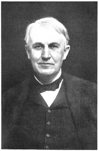
Cord Circuit. Battery Supply. Were it not for the necessity of providing for cord-circuit signals in common-battery switchboards, the common-battery cord circuit would be scarcely more complex than that for magneto working. Stripped of all details, such as signals, ringing and listening keys, and operator's equipment, cord circuits of three different types are shown in Figs. 311, 312, and 313. These merely illustrate the way in which the battery is associated with the cord circuits and through them with the line circuits for supplying current for talking purposes to the subscribers. It is thought that this matter will be clear in view of the discussion of the methods by which current is supplied to the subscribers' transmitters in common-battery systems as discussed in Chapter XIII. While the arrangements in this respect of Figs. 311, 312, and 313 illustrate [Page 21]only three of the methods, these three are the ones that have been most widely and successfully used.
Supervisory Signals. The signals that are associated with the cord circuits are termed supervisory signals because of the fact that by their means the operator is enabled to supervise the condition of the lines during times when they are connected for conversation. The operation of these supervisory signals may be best understood by considering the complete circuits of a simple switchboard and must be studied in conjunction with the circuits of the lines as well as those of the cords.
Complete Circuit. Such complete circuits are shown in Fig. 314. The particular arrangement indicated is that employed by the Kellogg Company, and except for minor details may be considered as typical of other makes also. Two subscribers' lines are shown extending from Station A and Station B, respectively, to the central office. The line wires are shown terminating in jacks in the same manner as indicated in Figs. 307, 308, and 309, and their circuits are normally continued from these jacks to the ground on one side and to the line relay and battery on the other. The jack in this case has three contacts adapted to register with three corresponding [Page 22]contacts in each of the plugs. The thimble of the jack in this case forms no part of the talking circuit and is distinct from the two jack springs which form the line terminals. It and the auxiliary contact 1 in each of the plugs with which it registers, are solely for the purpose of co-operating in the control of the supervisory signals.
The tip and sleeve strands of the cord are continuous from one plug to the other except for the condensers. The two batteries indicated in connection with the cord circuit are separate batteries, a characteristic of the Kellogg system. One of these batteries serves to supply current to the tip and sleeve strand of the cord circuit through the two windings 3 and 4, respectively, of the supervisory relay connected with the answering side of the cord circuit, while the other battery similarly supplies current through the windings 5 and 6 of the supervisory relay associated with the calling side of the cord circuit. The windings of these relays, therefore, act as impedance coils and the arrangement by which battery current is supplied to the cord circuits and, therefore, to the lines of the connected subscribers, is seen to be the combined impedance coil and condenser arrangement discussed in Chapter XIII.
As soon as a plug is inserted into the jack of a line, the line relay will be removed from the control of the line, and since the two strands of the cord circuit now form continuations of the two line conductors, the supervisory relay will be substituted for the line relay and will be under control of the line. Since all of the current which passes to the line after a plug is inserted must pass through the cord-circuit connection and through the relay windings, and since current can only flow through the line when the subscriber's receiver is off its hook, it follows that the supervisory relays will only be energized after the corresponding plug has been inserted into a jack of the line and after the subscriber has removed his receiver. Unlike the line relays, the supervisory relays open their contacts to break the local circuits of the supervisory lamps 7 and 8 when the relay coils are energized, and to close them when de-energized; but the armatures of the supervisory relays do alone control the circuits of the supervisory lamps. These circuits are normally held open in another place, that is, between the plug contacts 1 and the jack thimbles. It is only, therefore, when a plug is inserted into a jack and when the supervisory relay is de-energized, that the supervisory [Page 23]lamp may be lighted. When a plug is inserted into a jack and when the corresponding supervisory relay is de-energized, the circuit may be traced from ground at the cord-circuit batteries through the left-hand battery, for instance, through lamp 7, thence through the contacts of the supervisory relay to the contact 1 of the plug, thence through the thimble of the jack to ground. When a plug is inserted into the jack, therefore, the necessary arrangements are completed for the supervisory lamp to be under the control of the subscriber. Under this condition, whenever the subscriber's receiver is on its hook, the circuit of the line will be broken, the supervisory relay will be de-energized, and the supervisory lamp will be lighted. When, on the other hand, the subscriber's receiver is off its hook, the circuit of the line will be complete, the supervisory relay will be energized, and the supervisory lamp will be extinguished.
Salient Features of Supervisory Operation. It will facilitate the student's understanding of the requirements and mode of operation of common-battery supervisory signals in manual systems, whether simple or multiple, if he will firmly fix the following facts in his mind. In order that the supervisory signal may become operative at all, some act must be performed by the operator—this being usually the act of plugging into a jack—and then, until the connection is taken down, the supervisory signal is under the control of the subscriber, and it is displayed only when the subscriber's receiver is placed on its hook.
Cycle of Operations. We may now trace through the complete cycle of operations of the simple common-battery switchboard, the circuits of which are shown in Fig. 314. Assume all apparatus in its normal condition, and then assume that the subscriber at Station A removes his receiver from its hook. This pulls up the line relay and lights the line lamp, the pilot relay also pulling up and lighting the common pilot lamp which is not shown. In response to this call, the operator inserts the answering plug and throws her listening key L.K. The operator's talking set is thus bridged across the cord circuit and she is enabled to converse with the calling subscriber. The answering supervisory lamp 7 did not light when the operator inserted the answering plug into the jack, because, although the contacts in the lamp circuit were closed by the plug contact 1 engaging the thimble of the jack, the lamp circuit was held open by the [Page 24]attraction of the supervisory relay armature, the subscriber's receiver being off its hook. Learning that the called-for subscriber is the one at Station B, the operator inserts the calling plug into the jack at that station and presses the ringing key R.K., in order to ring the bell. The act of plugging in, it will be remembered, cuts off the line-signaling apparatus from connection with that line. As the subscriber at Station B was not at his telephone when called and his receiver was, therefore, on its hook, the insertion of the calling plug did not energize the supervisory relay coils 5 and 6, and, therefore, that relay did not attract its armature. The supervisory lamp 8 was thus lighted, the circuit being from ground through the right-hand cord-circuit battery, lamp 8, back contacts of the supervisory relay, third strand of the cord to contact 1 of the calling plug, and thence to ground through the thimble of the jack. The lighting of this lamp is continued until the party at Station B responds by removing his receiver from its hook, which completes the line circuit, energizes relay windings 5 and 6, causes that relay to attract its armature, and thus break the circuit of the lamp 8. Both supervisory lamps remain out as long as the two subscribers are conversing, but when either one of them hangs up his receiver the corresponding supervisory relay becomes de-energized and the corresponding lamp lights. When both of the lamps become illuminated, the operator knows that both subscribers are through talking and she takes down the connection.
Countless variations have been worked in the arrangement of the line and cord circuits, but the general mode of operation of this particular circuit chosen for illustration is standard and should be thoroughly mastered. The operation of other arrangements will be readily understood from an inspection of the circuits, once the fundamental mode of operation that is common to all of them is well in mind.
Lamps. The incandescent lamps used in connection with line and supervisory signals are specially manufactured, but differ in no sense from the larger lamps employed for general lighting purposes, save in the details of size, form, and method of mounting. Usually these lamps are rated at about one-third candle-power, although they have a somewhat larger candle-power as a rule. They are manufactured to operate on various voltages, the most usual operating [Page 25]pressures being 12, 24, and 48 volts. The 24-volt lamp consumes about one-tenth of an ampere when fully illuminated, the lamp thus consuming about 2.4 watts. The 12- and 48-volt lamps consume about the same amount of energy and corresponding amounts of current.
Lamp Mounting. The usual form of screw-threaded mounting employed in lamps for commercial lighting was at first applied to the miniature lamps used for switchboard work, but this was found unsatisfactory and these lamps are now practically always provided with two contact strips, one on each side of the glass bulb, these strips forming respectively the terminals for the two ends of the filament within. Such a construction of a common form of lamp is shown in Fig. 315, where these terminals are indicated by the numerals 1 and 2, 3 being a dry wooden block arranged between the terminals at one end for securing greater rigidity between them.
The method of mounting these lamps is subject to a good deal of variation in detail, but the arrangement is always such that the lamp is slid in between two metallic contacts forming terminals of the circuit in which the lamp is to operate. Such an arrangement of springs and the co-operating mounting forming a sort of socket for the reception of switchboard lamps is referred to as a lamp jack. These are sometimes individually mounted and sometimes mounted in strips in much the same way that jacks are mounted in strips. A strip of lamp jacks as manufactured by the Kellogg Company is [Page 26]shown in Fig. 316. The opalescent lens is adapted to be fitted in front of the lamp after it has been inserted into the jack. Fig. 317 gives an excellent view of an individually-mounted lamp jack with its lamp and lens, this also being of Kellogg manufacture. This figure shows a section of the plug shelf which is bored to receive a lamp. In order to protect the lamps and lenses from breakage, due to the striking of the plugs against them, a metal shield is placed over the lens, as shown in this figure, this being so cut away as to allow sufficient openings for the light to shine through. Sometimes instead of employing lenses in front of the lamps, a flat piece of translucent material is used to cover the openings of the lamp, this being protected by suitable perforated strips of metal. A strip of lamp jacks employing this feature is shown in Fig. 318, this being of Dean manufacture. An advantage of this for certain types of work is that the flat translucent plate in front of the lamp may readily carry designating marks, such as the number of the line or something to indicate the character of the line, which marks may be readily changed as required.
In the types made by some manufacturers the only difference between the pilot lamp and the line lamp is in the size of the lens in front of it, the jack and the lamp itself being the same for each, while others use a larger lamp for the pilot. In Fig. 319 are shown two individual lamp jacks, the one at the top being for supervisory lamps and the one at the bottom being provided with a large lens for serving as a pilot lamp.
Mechanical Signals. As has been stated the so-called mechanical signals are sometimes used in small common-battery switchboards instead of lamps. Where this is done the coil of the signal, if it is a line signal, is substituted in the line circuit in place of the relay coil. If the signals are used in connection with cord circuits for supervisory signals, their coils are put in the circuit in place of the supervisory relay coils. (These signals are referred to in Chapter III in connection with Fig. 23.) They are so arranged that the attraction of the armature lifts a target on the end of a lever, and this causes a display of color or form. The release of the armature allows this target to drop back, thus obliterating the display. Such signals, often called visual signals and electromagnet signals, should be distinguished from the drops considered in connection with magneto switchboards in which the attraction of the armature causes the display of the signal by the falling of a drop, the signal remaining displayed until restored by some other means, the restoration depending in no wise on when the armature is released.
Western Electric. The mechanical signal of the Western Electric Company, shown in Fig. 320, has a target similar to that [Page 28]shown in Fig. 254 but without a latch. It is turned to show a different color by the attraction of the armature and allowed to resume its normal position when the armature is released.
Kellogg. Fig. 321 gives a good idea of a strip of mechanical signals as manufactured by the Kellogg Company. This is known as the gridiron signal on account of the cross-bar striping of its target. The white bars on the target normally lie just behind the cross-bars on the shield in front, but a slight raising of the target—about one-eighth of an inch—exposes these white bars to view, opposite the rectangular openings in the front shield.
Monarch. In Fig. 322 is shown the visual signal manufactured by the Monarch Telephone Company.
Relays. The line relays for common-battery switchboards likewise assume a great variety of forms. The well-known type of relay employed in telegraphy would answer the purpose well but [Page 29]for the amount of room that it occupies, as it is sometimes necessary to group a large number of relays in a very small space. Nearly all present-day relays are of the single-coil type, and in nearly all cases the movement of the armature causes the movement of one or more switching springs, which are thus made to engage or disengage their associated spring or springs. One of the most widely used forms of relays has an L-shaped armature hung across the front of a forwardly projecting arm of iron, on the knife-edge corner of which it rocks as moved by the attraction of the magnet. The general form of this relay was illustrated in Fig. 95. Sometimes this relay is made up in single units and frequently a large number of such single units are mounted on a single mounting plate. This matter will be dealt with more in detail in the discussion of common-battery multiple switchboards. In other cases these relays are built en bloc, a rectangular strip of soft iron long enough to afford space for ten relays side by side being bored out with ten cylindrical holes to receive the electromagnets. The iron of the block affords a return path for the lines of force. The L-shaped armatures are hung over the front edge of this block, so that their free ends lie opposite the magnet cores within the block. This arrangement as employed by the Kellogg Company is shown in two views in Figs. 323 and 324.
A bank of line relays especially adapted for small common-battery switchboards as made by the Dean Company, is shown in Fig. 325.
Jacks. The jacks in common-battery switchboards are almost always mounted in groups of ten or twenty, the arrangement being similar to that discussed in connection with lamp strips. Ordinarily in common-battery work the jack is provided with two inner contacts so as to cut off both sides of the signaling circuit when the operator plugs in. A strip of such jacks is shown in Fig. 326.
Ringing and listening keys for simple common-battery switchboards differ in no essential respect from those employed in magneto boards.
Switchboard Assembly. The general assembly of the parts of a simple common-battery switchboard deserves some attention. The form of the switchboard need not differ essentially from that employed in magneto work, but ordinarily the cabinet is somewhat smaller on account of the smaller amount of room required by its lamps and jacks. An excellent idea of the line jacks and lamps, plugs, keys, and supervisory signals may be obtained from Fig. 327, which is a detail view taken from a Kellogg board. In the vertical panel of the board above the plug shelf are arranged the line jacks and the lamps in rows of twenty each, each lamp being immediately beneath its corresponding jack. Such jacks are ordinarily mounted on 1/2-inch centers both vertically and horizontally, so that a group of one hundred lamps and line jacks will occupy a space only slightly over 10 by 5 inches. Such economy of space is not required in the simple magneto board, because the space might easily be made larger without in any way taxing the reach of the operator. The reason for [Page 32]this comparatively close mounting is a result, not of the requirements of the simple non-multiple common-battery board itself, but of the fact that the jack strips and lamp strips, which are required in very large numbers in multiple boards, have to be mounted extremely close together, and as the same lamp strips and jack strips are often available for simple switchboards, an economy in manufacture is effected by adherence to the same general dimensions.
A rear view of a common form of switchboard cabinet, known as the upright type and manufactured by the Dean Company, is shown in Fig. 328. In this all the relays are mounted on a hinged rack, which, when opened out as indicated, exposes the wiring to view for inspection or repairs. Access to both sides of the relays is thus given to the repairman who may do all his work from the rear of the board without disturbing the operator.
Fig. 329 shows a three-position cabinet of Kellogg manufacture, this being about the limit in size of boards that could properly be called simple. Obviously, where a switchboard cabinet must be made of greater length than this, i. e., than is required to accommodate three operators, it becomes too long for the operators to reach all over it without undue effort or without moving from their seats. The so-called transfer board and the multiple board (to be considered in subsequent chapters), constitute methods of relief from such a condition in larger exchanges.
When the traffic originating in a switchboard becomes so great as to require so many operators that the board must be made so long that any one of the operators cannot reach over its entire face, the simple switchboard does not suffice. Either some form of transfer switchboard or of multiple switchboard must be used. In this chapter the transfer switchboard will be briefly discussed.
The transfer switchboard is so named because its arrangement is such that some of the connections through it are handled by means of two operators, the operator who answers the call transferring it to another operator who completes the connection desired.
Limitations of Simple Switchboard. Conceive a number of simple magneto switchboards, or a number of common-battery switchboards, arranged side by side, their number being so great as to form, by their combination, a board too long for the ordinary cords and plugs to reach between its extremities. On each of these simple switchboards, which we will say are each of the one-position type, there terminates a group of subscribers' lines so great in number, considering the traffic on them, that the efforts of one operator will just about be taxed to properly attend to their calls during the busiest hours of the day. If, now, these subscribers would be sufficiently accommodating to call for no other subscribers than those whose lines terminate on the same switchboard section or on one of the immediately adjacent switchboard sections, all would be well, but subscribers will not be so restricted. They demand universal service; that is, they demand the privilege of having their own lines connected with the line of any other person in the exchange. Obviously, in the arrangement just conceived, any operator may answer any call originating at her own board and complete the connection with the desired subscriber if that subscriber's jack terminates on her own section or on one of the adjacent ones. Beyond that she is powerless unless other means are provided.
Transfer Lines. In the transfer board these other means consist in the provision of groups of local trunk lines or transfer lines extending from each switchboard position to each other non-adjacent switchboard position. When an operator receives a call for some line on a non-adjacent position, having answered this call with her answering plug, she inserts the calling plug into the jack of one of these transfer lines that leads to the proper other section. The operator at that section is notified either verbally or by signal, and she completes the connection between the other end of the transfer line and the line of the called subscriber; the connection between the two subscribers thus being effected through the cords of the two operators in question linked together by the transfer line. Such a transfer line as just described, requiring the connection at each of its ends by one of the plugs of the operator's cord pair, is termed a jack-ended trunk or a jack-ended transfer line because each of its ends terminates in a jack.
There is another method of accomplishing the same general result by the employment of the so-called plug-ended trunk or plug-ended transfer line. In this the trunk or transfer line terminates at one end, the answering end, in a jack as before, and the connection is made with it by the answering operator by means of the calling plug of the pair with which she answered the originating call. The other end of this trunk, instead of terminating in a jack, ends in a plug and the second operator involved in the connection, after being notified, picks up this plug and inserts it in the jack of the called subscriber, thus completing the connection without employing one of her regular cord pairs.
Jack-Ended Trunk. In Fig. 330 are shown the circuits of a commonly employed jack-ended trunk for transfer boards. The talking circuit, as usual, is shown in heavy lines and terminates in the tip and sleeve of the transfer jacks at each end. The auxiliary [Page 36]contacts in these jacks and the circuits connecting them are absolutely independent of the talking circuit and are for the purpose of signaling only, the arrangement of the jacks being such that when a plug is inserted, the spring 1 will break from spring 2 and make with spring 3. Obviously, the insertion of a plug in either of the jacks will establish such connections as to light both lamps, since the engagement of spring 1 with spring 3 in either of the jacks will connect both of the lamps in multiple across the battery, this connection including always the contacts 1 and 2 of the other jack. From this it follows that the insertion of a plug in the other end of the trunk will, by breaking contact between springs 1 and 2, put out both the lamps. One plug inserted will, therefore, light both lamps; two plugs inserted or two plugs withdrawn will extinguish both lamps.
If an operator located at one end of this trunk answers a call and finds that the called-for subscriber's line terminates within reach of the operator near the other end of this trunk, she will insert a calling plug, corresponding to the answering plug used in answering a call, into the jack of this trunk and thus light the lamp at both its ends. The operator at the other end upon seeing this transfer lamp illuminated inserts one of her answering plugs into the jack, and by means of her listening key ascertains the number of the subscriber desired, and immediately inserts her calling plug into the jack of the subscriber wanted and rings him in the usual manner. The act of this second operator in inserting her answering plug into the jack extinguishes the lamp at her own end and also at the end where the call originated, thus notifying the answering operator that the call has been attended to. As long as the lamps remain lighted, the operators know that there is an unattended connection on that transfer line. Such a transfer line is called a two-way line or a single-track line, because traffic over it may be in either direction. In Fig. 331 is shown a trunk that operates in a [Page 37]similar way except that the two lamps, instead of being arranged in multiple, are arranged in series.
Plug-Ended Trunk. In Fig. 332 is shown a plug-ended trunk, this particular arrangement of circuits being employed by the Monarch Company in its transfer boards. This is essentially a one-way trunk, and traffic over it can pass only in the direction of the arrow. Traffic in the opposite direction between any two operators is handled by another trunk or group of trunks similar to this but "pointed" in the other direction. For this reason such a system is referred to as a double-track system. The operation of signals is the same in this case as in Fig. 330, except that the switching device at the left-hand end of the trunk instead of being associated with the jack is associated with the plug seat, which is a switch closely associated with the seat of a plug so as to be operated whenever the plug is withdrawn from or replaced in its seat. The operation of this arrangement is as follows: Whenever an operator at the right-hand end of this trunk receives a call for a subscriber whose line terminates within the reach of the operator at the left-hand end of the trunk, she inserts the calling plug of the pair used in answering the calling subscriber into the jack of the trunk, and thus lights both of the trunk lamps. The operator at the other end of the trunk, seeing the trunk lamp lighted, raises the plug from its seat and, having learned the wishes of the calling subscriber, inserts this plug into the jack of the called subscriber without using one of her regular pairs. When she raised the trunk plug from its seat, she permitted the long spring 1 of the plug seat switch to rise, thus extinguishing both lamps and giving the signal to the originating operator that the trunk connection has received attention. On taking down the connection, the withdrawal of the plug from the right hand of the trunk lights both lamps, and the restoring of the trunk plug to its normal seat again extinguishes both lamps.
Plug-Seat Switch. The plug-seat switch is a device that has received a good deal of attention not only for use with transfer systems, but also for use in a great variety of ways with other kinds of manual switching systems. The placing of a plug in its seat or withdrawing it therefrom offers a ready means of accomplishing some switching or signaling operation automatically. The plug-seat switch has, however, in spite of its possibilities, never come into wide use, and so far as we are aware the Monarch Telephone Manufacturing Company is the only company of prominence which incorporates it in its regular output. The Monarch plug-switch mechanism is shown in Fig. 333, and its operation is obvious. It may be stated at this point that one of the reasons why the plug-seat switch has not been more widely adopted for use, is the difficulty that has been experienced due to lint from the switchboard cords collecting on or about the contact points. In the construction given in the detailed cut, upper part, Fig. 333, is shown the means adopted by the Monarch Company for obviating this difficulty. The contact points are carried in the upper portion of an inverted cup mounted on the under side of the switchboard shelf, and are thus protected, in large measure, from the damaging influence of dust and lint.
Methods of Handling Transfers. One way of giving the number of the called subscriber to the second operator in a transfer system [Page 39]is to have that operator listen in on the circuit after it is continued to her position and receive the number either from the first operator or from the subscriber. Receiving it from the first operator has the disadvantage of compelling the first operator to wait on the circuit until the second operator responds; receiving it from the subscriber has the disadvantage of sometimes being annoying to him. This, however, is to be preferred to the loss of time on the part of the originating operator that is entailed by the first method. A better way than either of these is to provide between the various operators working in a transfer system, a so-called order-wire system. An order wire, as ordinarily arranged, is a circuit terminating at one end permanently in the head receiver of an operator, and terminating at the other end in a push button which, when depressed, will connect the telephone set of the operator at that end with the order wire. The operator at the push-button end of the order wire may, therefore, at will, communicate with the other operator in spite of anything that the other operator may do. An order-wire system suitable for transfer switchboards consists in an order wire leading from each operator's receiver to a push button at each of the other operator's positions, so that every operator has it within her power to depress a key or button and establish communication with a corresponding [Page 40]operator. When, therefore, an operator in a transfer system answers a call that must be completed through a transfer circuit, she establishes connection with that transfer circuit and then informs the operator at the other end of that circuit by order wire of the number of the trunk and the number of the subscriber with which that trunk is to be connected. Fig. 334 shows a system of order-wire buttons by means of which each operator may connect her telephone set with that of every other operator in the room, the number in this case being confined to three. Assuming that each pair of wires leading from the lower portion of this figure terminates respectively in the operator's talking apparatus of the three respective operators, then it is obvious that operator No. 1, by depressing button No. 2, will connect her telephone set with that of operator No. 2; likewise that any operator may communicate with any other operator by depressing the key bearing the corresponding number.
Limitations of Transfer System. It may be stated that the transfer system at present has a limited place in the art of telephony. The multiple switchboard has outstripped it in the race for popular approval and has demonstrated its superiority in practically all large manual exchange work. This is not because of lack of effort on the part of telephone engineers to make the transfer system a success in a broad way. A great variety of different schemes, all embodying the fundamental idea of having one operator answer the call and another operator complete it through a trunk line, have been tried. In San Francisco, the Sabin-Hampton system was in fairly successful service and served many thousands of lines for a number of years. It was, however, afterwards replaced by modern multiple switchboards.
Examples of Obsolete Systems. The Sabin-Hampton system was unique in many respects and involved three operators in each connection. It was one of the very first systems which employed automatic signaling throughout and did away with the subscribers' generators. It did not, however, dispense with the subscribers' local batteries.
Another large transfer system, used for years in an exchange serving at a time as many as 5,000, was employed at Grand Rapids, Michigan. This was later replaced by an automatic switchboard.
Field of Usefulness. The real field of utility for the transfer system today is to provide for the growth of simple switchboards that have extended beyond their originally intended limits. By the adding of additional sections to the simple switchboard and the establishment of a comparatively cheap transfer system, the simple boards may be made to do continued service without wasting the investment in them by discarding them and establishing a completely new system. However, switchboards are sometimes manufactured in which the transfer system is included as a part of the original equipment. In Fig. 335 is shown a three-position transfer switchboard, manufactured by the Monarch Telephone Company. At first glance the switchboard appears to be exactly like those described in Chapter XXI, but on close observation, the transfer jacks and signals may [Page 42]be seen in the first and third positions, just below the line jacks and signals. There is no transfer equipment in the second position of this switchboard because the operator at that position is able to reach the jacks of all the lines and, therefore, is able to complete all calls originating on her position without the use of any transfer equipment. Referring to Fig. 301, which illustrates a two-position simple switchboard, it may readily be seen that if the demands for telephone service in the locality in which this switchboard is installed should increase so as to require the addition of more switchboard positions, this switchboard could readily be converted to a transfer switchboard by placing the necessary transfer jacks and signals in the vacant space between the line jacks and clearing-out drops.
Field of Utility. The multiple switchboard, unlike the transfer board, provides means for each operator to complete, without assistance, a connection with any subscriber's line terminating in the switchboard no matter how great the number of lines may be. It is used only where the simple switchboard will not suffice; that is, where the number of lines and the consequent traffic is so great as to require so many operators and, therefore, so great a length of board as to make it impossible for any one operator to reach all over the face of the board without moving from her position.
The Multiple Feature. The fundamental feature of the multiple switchboard is the placing of a jack for every line served by the switchboard within the reach of every operator. This idea underlying the multiple switchboard may be best grasped by merely considering the mechanical arrangement and grouping of parts without regard to their details of operation. The idea is sometimes elusive, but it is really very simple. If the student at the outset will not be frightened by the very large number of parts that are sometimes involved in multiple switchboards, and by the great complexity which is apparent in the wiring and in the action of these parts; and will remember that this apparent complexity results from the great number of repetitions of the same comparatively simple group of apparatus and circuits, much will be done toward a mastery of the subject.
The multiple switchboard is divided into sections, each section being about the width and height that will permit an ordinary operator to reach conveniently all over its face. The usual width of a section brought about by this limitation is from five and one-half to six feet. Such a section affords room for three operators to sit side by side before it. Now each line, instead of having a single jack as in the simple switchboard, is provided with a number of jacks [Page 44]and one of these is placed on each of the sections, so that each one of the operators may have within her reach a jack for each line. It is from the fact that each line has a multiplicity of jacks, that the term multiple switchboard arises.
Number of Sections. Since there is a jack for each line on each section of the switchboard, it follows that on each section there are as many jacks as there are lines; that is, if the board were serving 5,000 lines there would be 5,000 jacks. Let us see now what it is that determines the number of sections in a multiple switchboard. In the final analysis, it is the amount of traffic that arises in the busiest period of the day. Assume that in a particular office serving 5,000 lines, the subscribers call at such a very low rate that even at the busiest time of the day only enough calls are made to keep, say, three operators busy. In this case there would be no need for the multiple switchboard, for a single section would suffice. The three operators seated before that section would be able to answer and complete the connections for all of the calls that arose. But subscribers do not call at this exceedingly low rate. A great many more calls would arise on 5,000 lines during the busiest hour than could be handled by three operators and, therefore, a great many more operators would be required. Space has to be provided for these operators to work in, and as each section accommodates three operators the total number of sections must be at least equal to the total number of required operators divided by three.
Let us assume, for instance, that each operator can handle 200 calls during the busy hour. Assume further that during the busy hour the average number of calls made by each subscriber is two. One hundred subscribers would, therefore, originate 200 calls within this busy hour and this would be just sufficient to keep one operator busy. Since one operator can handle only the calls of one hundred subscribers during the busy hour, it follows that as many operators must be employed as there are hundreds of subscribers whose lines are served in a switchboard, and this means that in an exchange of 5,000 subscribers, 50 operators' positions would be required, or 162/3 sections. Each of these sections would be equipped with the full 5,000 jacks, so that each operator could have a connection terminal for each line.
The Multiple. These groups of 5,000 jacks, repeated on each [Page 45]of the sections are termed multiple jacks, and the entire equipment of these multiple jacks and their wiring is referred to as the multiple. It will be shown presently that the multiple jacks are only used for enabling the operator to connect with the called subscriber. In other words these jacks are for the purpose of enabling each operator to have within her reach any line that may be called for regardless of what line originates the call. We will now consider what arrangements are provided for enabling the operator to receive the signal indicating a call and what provisions are made for her to answer the call in response to such a signal.
Line Signals. Obviously it is not necessary to have the line signals repeated on each section of the board as are the multiple jacks. If a line has one definite place on the switchboard where its signal may be received and its call may be answered, that suffices. Each line, therefore, in addition to having its multiple jacks distributed one on each section of the switchboard, has a line signal and an individual jack immediately associated with it, located on one only of the sections. This signal usually is in the form of a lamp and is termed the line signal, and this jack is termed the answering jack since it is by means of it that the operator always answers a call in response to the line signal.
Distribution of Line Signals. It is evident that it would not do to have all of these line signals and answering jacks located at one section of the board for then they would not be available to all of the operators. They are, therefore, distributed along the board in such a way that one group of them will be available to one operator, another group to another operator, and so on; the number of answering jacks and signals in any one group being so proportioned with respect to the number of calls that come in over them during the busy hour that it will afford just about enough calls to keep the operator at that position busy.
We may summarize these conditions with respect to the jack and line-signal equipment of the multiple switchboard by saying that each line has a multiple jack on each section of the board and in addition to this has on one section of the board an answering jack and a line signal. These answering jacks and line signals are distributed in groups along the face of the board so that each operator will receive her proper quota of the originating calls which she will [Page 46]answer and, by virtue of the multiple jack, be able to complete the connections with the desired subscribers without moving from her position.
Cord Circuits. Each operator is also provided with a number of pairs of cords and plugs with proper supervisory or clearing-out signals and ringing and listening keys, the arrangement in this respect being similar to that already described in connection with the simple switchboard.
Guarding against Double Connections. From what has been said it is seen that a call originating on a given line may be answered at one place only, but an outgoing connection with that line may be made at any position. This fact that a line may be connected with when called for at any one of the sections of the switchboard makes necessary the provision that two or more connections will not be made with the same line at the same time. For instance, if a call came in over a line whose signal was located on the first position of the switchboard for a connection with line No. 1,000, the operator at the first position would connect this calling line with No. 1,000 through the multiple jack on the first section of the switchboard. Assume now that some line, whose signal was located on the 39th position of the switchboard, should call also for line No. 1,000 while that line was still connected with the first calling subscriber. Obviously confusion would result if the operator at the 39th position, not knowing that line No. 1,000 was already busy, should connect this second line with it, thereby leaving both of the calling subscribers connected with line No. 1,000, and as a result all of these three subscribers connected together.
The provisions for suitable means for preventing the making of a connection with a line that is already switched at some other section of the switchboard, has offered one of the most fertile fields for invention in the whole telephone art. The ways that have been proposed for accomplishing this are legion. Fortunately common practice has settled on one general plan of action and that is to so arrange the circuits that whenever a line is switched at one section, such an electrical condition will be established on the forward contacts of all of its multiple jacks that any operator at any other section in attempting to make a connection with that line will be notified of the fact that it is already switched by an audible signal, which she [Page 47]will receive in her head receiver. On the other hand the arrangement is such that when a line is not busy, i. e., it is not switched at any of the positions of the switchboard, the operator on attempting to make a connection with such a line will receive no such guarding signal and will, therefore, proceed with the connection.
We may liken a line in a multiple switchboard to a lane having a number of gates giving access to it. One of these gates—the answering jack—is for the exclusive use of the proprietor of that lane. All of the other gates to the lane—the multiple jacks—are for affording means for the public to enter. But whenever any person enters one of these gates, a signal is automatically put up at all of the other gates forbidding any other person to enter the lane as long as the first person is still within.
Diagram Showing Multiple Board Principle. For those to whom the foregoing description of the multiple board is not altogether clear, the diagram of Fig. 336 may offer some assistance. Five subscribers' lines are shown running through four sections of a switchboard. Each of these lines is provided with a multiple jack on each section of the board. Each line is also provided with an answering jack and a line signal on one of the sections of the board. Thus the answering [Page 48]jacks and the line signals of lines 1 and 2 are shown in Section I, that of line 4 is shown in Section II, that of line 3 in Section III, and that of line 5 in Section IV. At Section I, line 1 is shown in the condition of having made a call and having had this call answered by the operator inserting one of her plugs into its answering jack. In response to the instructions given by the subscriber, the operator has inserted the other plug of this same pair in the multiple jack of line 2, thus connecting these two lines for conversation. At Section III, line 3 is shown as having made a call, and the operator as having answered by inserting one of her plugs into the answering jack. It happens that the subscriber on line 3 requests a connection with line 1, and the condition at Section III is that where the operator is about to apply the tip of the calling plug to the jack of line 1 to ascertain whether or not that line is busy. As before stated, when the contact is made between the tip of the calling plug and the forward contact of the multiple jack, the operator will receive a click in the ear (by means that will be more fully discussed in later chapters), this click indicating to her that line 1 is not available for connection because it is already switched at some other section of the switchboard.
Busy Test. The busy signal, by which an operator in attempting to make a connection is informed that the line is already busy, has assumed a great variety of forms and has brought forth many inventions. It has been proposed by some that the insertion of a plug into any one of the jacks of a line would automatically close a little door in front of each of the other jacks of the line, therefore making it impossible for any other operator to insert a plug as long as the line is in use. It has been proposed by others to ring bells or to operate buzzers whenever the attempt was made by an operator to plug into a line that was already in use. Still others have proposed to so arrange the circuits that the operator would get an electric shock whenever she attempted to plug into a busy line. The scheme that has met with universal adoption, however, is that the operator shall, when the tip of her calling plug touches the forward contact of the jack of a line that is already switched, receive a click in her telephone which will forbid her to insert the plug. The absence of this click, or silence in her telephone, informs her that she may safely make the connection.
Principle. The means by which the operator receives or fails to receive this click, according to whether the line is busy or idle, vary widely, but so far as the writers are aware they all have one fundamental feature in common. The tip of the calling plug and the test contact of all of the multiple jacks of an idle line must be absolutely at the same potential before the test, so that no current will flow through the test circuit when the test is actually made. The test thimbles of all the jacks of a busy line must be at a different potential from the tip of the test plug so that a current will flow and a click result when the test is made.
Potential of Test Thimbles. It has been found an easy matter to so arrange the contacts in the jacks of a multiple switchboard that whenever the line is idle the test thimbles of that line will be a certain potential, the same as that of all the unused calling plug tips. It has also been easy to so arrange these contacts that the insertion of a plug into any one of the jacks will, by virtue of the contacts established, change the potential of all the test thimbles of that line so that they will be at a different potential from that of the tips of the calling plugs. It has not been so easy, however, to provide that these conditions shall exist under all conditions of practice. A great many busy tests that looked well on paper have been found faulty in practice. As is always the case in such instances, this has been true because the people who considered the scheme on paper did not foresee all of the conditions that would arise in practice. Many busy-test systems will operate properly while everything connected with the switchboard and the lines served by it remains in proper order. But no such condition as this can be depended on in practice. Switchboards, no matter how perfectly made and no matter with how great care they may be installed and maintained, will get out of order. Telephone lines will become grounded or short-circuited or crossed or opened. Such conditions, in a faulty busy-test system, may result in a line that is really idle presenting a busy test, and thus barring the subscriber on that line from receiving calls from other lines just as completely as if his line were broken. On the other hand, faulty conditions either in the switchboard or in the line may make a line that is really busy, test idle, and thus result in the confusion of having two or more subscribers connected to the same line at the same time.
Busy-Test Faults. To show how elusive some of the faults of a busy test may be, when considered on paper, it has come within the observation of the writers that a new busy-test system was thought well enough of by a group of experienced engineers to warrant its installation in a group of very large multiple switchboards, the cost of which amounted to hundreds of thousands of dollars, and yet when so installed it developed that a single short-circuited cord in a position would make the test inoperative on all the cords of that position—obviously an intolerable condition. Luckily the remedy was simple and easily applied.
In a well-designed busy-test system there should be complete silence when the test is made of an idle line, and always a well-defined click when the test is made of a busy line. The test on busy lines should result in a uniform click regardless of length of lines or the condition of the apparatus. It does not suffice to have a little click for an idle line and a big click for a busy line, as practice has shown that this results in frequent errors on the part of the operators.
Good operating requires that the tip of the calling plug be tapped against the test thimble several times in order to make sure of the state of the called line.
In some multiple switchboards the arrangement has been such that the jacks of a line would test busy as soon as the subscriber on that line removed his receiver from its hook to make a call, as well as while any plug was in any jack of that line. The advocates of this added feature, in connection with the busy test, have claimed that the receiver, when removed from its hook in making a call, should make the line test busy and that a line should not be connected with when the subscriber's receiver was off its hook any more than it should be when it was already connected with at some other section of the switchboard. While it is true that a line may be properly termed busy when the subscriber has removed his receiver in order to make a call, it is not true that there is any real necessity for guarding against a connection with it while he is waiting for the operator to answer. Leaving the line unguarded for this brief period may result in the subscriber, who intended to make the call, having to defer his call until he has conversed with the party who is trying to reach him. This cannot be said to be a detriment to the service, however, since the second party gets the connection he desires much [Page 51]sooner than he otherwise would, and the first party may still make his first intended call as soon as he has disposed of the party who reached him while he was waiting for his own operator to answer. It may be said, therefore, in connection with this matter of making the line test busy as soon as a subscriber has removed his receiver from the hook, that it is not considered an essential, and in case of those switchboard systems which naturally work out that way it is not considered a disadvantage.
Field of Each Operator. It was stated earlier in this chapter that as each section accommodated three operators, the total number of sections in a switchboard will be at least one-third the total number of required operators. This thought needs further development, for to stop at that statement is to arrive somewhat short of the truth. In order to do this it is necessary to consider the field in the multiple, reached by each operator. The section is of such size, or should be, that an operator seated in the center position of it may, without undue effort, reach all over the multiple. But the operator at the right-hand position cannot reach the extreme left portion of the multiple of that section, nor can the operator at the left reach the extreme right. How then may each operator reach a jack for every line? Remembering that the multiple jacks are arranged exactly the same in each section, each jack always occupying the same relative position, it is easy to see that while the operator at a right-hand position of a section cannot reach the left-hand third of the multiple in her own section, she may reach the left-hand third of the multiple in the section at her right, and this, together with the center and right-hand thirds of her own section, represents the entire number of lines. So it is with the left-hand operator at any section, she reaches two-thirds of all the lines in the multiple of her own section and one-third in that of the section at her left.
End Positions. This makes it necessary to inquire about the operators at the end positions of the entire board. To provide for these the multiple is extended one-third of a section beyond them, so as to supply at the ends of the switchboard jacks for those lines which the end operators cannot reach on their own sections. Sometimes instead of adding these end sections to the multiple for the end operators, the same result is accomplished by using only the full and regular sections of the multiple, and leaving the end positions [Page 52]without operators' equipment, as well as without answering jacks, line signals, and cords and plugs, so that in reality the end operator is at the middle position of the end section. This, in our opinion, is the better practice, since it leaves the sections standard, and makes it easier to extend the switchboard in length, as it grows, by the mere addition of new sections without disturbing any of the old multiple.
Influence of Traffic. We wish again to emphasize the fact that it is the traffic during the busiest time of day and not the number of lines that determine the size of a multiple switchboard so far as its length is concerned. The number of lines determines the size of the multiple in any one section, but it is the amount of traffic, the number of calls that are made in the busiest period, that determines the number of operators required, and thus the number of positions. Had this now very obvious fact been more fully realized in the past, some companies would be operating at less expense, and some manufacturers would have sold less expensive switchboards.
The whole question as to the number of positions boils down to how many answering jacks and line signals may be placed at each operator's position without overburdening the operator with incoming traffic at the busy time of day. Obviously, some lines will call more frequently than others, and hence the proper number of answering jacks at the different positions will vary. Obviously, also, due to changes in the personnel of the subscribers, the rates of calling of different groups of lines will change from time to time, and this may necessitate a regrouping of the line signals and answering jacks on the positions; and changes in the personnel of the operators or in their skill also demand such regrouping.
Intermediate Frame. The intermediate distributing frame is provided for this purpose, and will be more fully discussed in subsequent chapters. Suffice it to say here that the intermediate distributing frame permits the answering jacks and line signals to be shifted about among the operators' positions, so that each position will have just enough originating traffic to keep each of the operators economically busy during the busiest time of the day.
Field of Utility. The principles of the multiple switchboard set forth in the last chapter were all developed long before the common-battery system came into existence, and consequently all of the first multiple switchboards were of the magneto type. Although once very widely used, the magneto multiple switchboard has almost passed out of existence, since it has become almost universal practice to equip exchanges large enough to employ multiple boards with common-battery systems. Nevertheless there is a field for magneto multiple switchboards, and in this field it has recently been coming into increasing favor. In those towns equipped with magneto systems employing simple switchboards or transfer switchboards, and which require new switchboards by virtue of having outgrown or worn out their old ones, the magneto multiple switchboard is frequently found to best fit the requirements of economy and good practice. The reason for this is that by its use the magneto telephones already in service may be continued, no change being required outside of the central office. Furthermore, with the magneto multiple switchboard no provision need be made for a power plant, which, in towns of small size, is often an important consideration. Again, many companies operate over a considerable area, involving a collection of towns and hamlets. It may be that all of these towns except one are clearly of a size to demand magneto equipment and that magneto equipment is the standard throughout the entire territory of the company. If, however, one of the towns, by virtue of growth, demands a multiple switchboard, this condition affords an additional argument for the employment of the magneto multiple switchboard, since the same standards of equipment and construction may be maintained throughout the entire territory of the operating company, a manifest advantage. On the other hand, it may be said that the magneto multiple switchboard has no proper [Page 54]place in modern exchanges of considerable size—say, having upward of one thousand subscribers—at least under conditions found in the United States.
Notwithstanding the obsolescence of the magneto multiple switchboard for large exchanges, a brief discussion of some of the early magneto multiple switchboards, and particularly of one of the large ones, is worth while, in that a consideration of the defects of those early efforts will give one a better understanding and appreciation of the modern multiple switchboard, and particularly of the modern multiple common-battery switchboard, the most highly organized of all the manual switching systems. Brief reference will, therefore, be made to the so-called series multiple switchboard, and then to the branch terminal multiple switchboard, which latter was the highest type of switchboard development at the time of the advent of common-battery working.
Series-Multiple Board. In Fig. 337 are shown the circuits of a series magneto multiple switchboard as developed by the engineers of the Western Electric Company during the eighties. As is usual, two subscribers' lines and a single cord circuit are shown. One side of each line passes directly from the subscriber's station to one side of the drop, and also branches off to the sleeve contact of each of the jacks. The other side of the line passes first to the tip spring of the first jack, thence to the anvil of that jack and to the tip spring of the next jack, and so on in series through all of the jacks belonging in that line to the other terminal of the drop coil. Normally, therefore, the drop is connected across the line ready to be responsive to the signal sent from the subscriber's generator. The cord circuit is of the two-conductor type, the plugs being provided with tip and sleeve contacts, the tips being connected by one of the flexible conductors through the proper ringing and listening key springs, and the sleeve being likewise connected through the other flexible conductor and the other springs of the ringing and listening keys. It is obvious that when any plug is inserted into a jack, the circuit of the line will be continued to the cord circuit and at the same time the line drop will be cut out of the circuit, because of the lifting of the tip spring of the jack from its anvil. Permanently connected between the sleeve side of the cord circuit and ground is a retardation coil 1 and a battery. Another retardation coil 2 is connected between the [Page 55]ground and a point on the operator's telephone circuit between the operator's head receiver and the secondary of her induction coil. These two retardation coils have to do with the busy test, the action of which is as follows: normally, or when a line is not switched at the central office, the test thimbles will all be at substantially ground potential, i. e., they are supposed to be. The point on the operator's receiver circuit which is grounded through the retardation coil 2 will also be of ground potential because of that connection to ground. In order to test, the operator always has to throw her listening key L.K. into the listening position. She also has to touch the tip of the calling plug Pc to a sleeve or jack of the line that is being tested. If, therefore, a test is made of an idle or non-busy line, the touching of the tip of the calling plug with the test thimble of that line will result in no flow of current through the operator's receiver, because there will be no difference of potential anywhere in the test circuit, which test circuit may be traced from the test thimble of the line under test to the tip of the calling plug, thence through the tip strand of the cord to the listening key, thence to the outer anvil of [Page 56]the listening key on that side, through the operator's receiver to ground through the impedance coil 2. If, however, the line had already been switched at some other section by the insertion of either a calling or answering plug, all of the test thimbles of that line would have been raised to a potential above that of the ground, by virtue of the battery connected with the sleeve side of the cord circuit through the retardation coil 1. If the operator had made a test of such a line, the tip of her testing plug would have found the thimble raised to the potential of the battery and, therefore, a flow of current would occur which would give her the busy click. The complete test circuit thus formed in testing a busy line would be from the ungrounded pole of the battery through the impedance coil 1 associated with the cord that was already in connection with the line, thence to the sleeve strand of that cord to the sleeve of the jack at which the line was already switched, thence through that portion of the line circuit to which all of the sleeve contacts were connected, and therefore to the sleeve or test thimble of the jack at which the test is made, thence through the tip of the calling plug employed in making the test through the tip side of that cord circuit to the outer listening key contact of the operator making the test, and thence to ground through the operator's receiver and the impedance coil 2. The resultant click would be an indication to the operator that the line was already in use and that, therefore, she must not make the connection.
The condenser 3 is associated with the operator's talking set and with the extra spring in the listening key L.K. in such a manner that when the listening key is thrown, the tip strand of the cord circuit is divided and the condenser included between them. This is for the purpose of preventing any potentials, which might exist on the line with which the answering plug Pa was connected, from affecting the busy-test conditions.
Operation. The operation of the system aside from the busy-test feature is just like that described in connection with the simple magneto switchboard. Assuming that the subscriber at Station A makes the call, he turns his hand generator, which throws the drop on his line at the central office. The operator, seeing the signal, inserts the answering plug of one of her idle pairs of cords into the answering jack and throws her listening key L.K. This enables [Page 57]the operator to talk with the calling subscriber, and having found that he desires a connection with the line extending to Station B, she touches the tip of her calling plug to the multiple jack of that line that is within her reach, it being remembered that each one of the multiple jacks shown is on a different section. She leaves the listening key in the listening position when she does this. If the line is busy, the click will notify her that she must not make the connection, in which case she informs the calling subscriber that the line is busy and requests him to call again. If, however, she received no click, she would insert the calling plug into the jack, thus completing the connection between the two lines. She would then press the ringing key associated with the calling plug and that momentarily disconnects the calling plug from the answering plug and at the same time establishes connection between the ringing generator and the called line. The release of the ringing key again connects the calling and answering plugs and, therefore, connects the two subscribers' lines ready for conversation. All that is then necessary is that the called subscriber shall respond and remove his receiver from its hook, the calling subscriber already having done this. When the conversation is finished, both of the subscribers (if they remember it) will operate their ringing generators, which will throw the clearing-out drop as a signal to the operator for disconnection. If it should become necessary for the operator to ring back on the line of the calling subscriber, she may do so by pressing the ringing key associated with the calling plug.
Frequently this multiple switchboard arrangement was used with grounded lines, in which case the single line wire extending from the subscriber's station to the switchboard was connected with the tip spring of the first jack, the circuit being continued in series through the jack to the drop and thence to ground through a high non-inductive resistance.
Defects. This series multiple magneto system was used with a great many variations, and it had a good many defects. One of these defects was due to the necessary extending of one limb of the line through a large number of series contacts in the jacks. This is not to be desired in any case, but it was particularly objectionable in the early days before jacks had been developed to their present high state of perfection. A particle of dust or other insulating [Page 58]matter, lodging between the tip spring and its anvil in any one of the jacks, would leave the line open, thus disabling the line to incoming signals, and also for conversation in case the break happened to occur between the subscriber and the jack that was used in connecting with the line. Another defect due to the same cause was that the line through the switchboard was always unbalanced by the insertion of a plug, one limb of the line always extending clear through the switchboard to the drop and the other, when the plug was inserted, extending only part way through the switchboard and being cut off at the jack where the connection was made. The objection will be apparent when it is remembered that the wires in the line circuit connecting the multiple jacks are necessarily very closely bunched together and, therefore, there is very likely to be cross-talk between two adjacent lines unless the two limbs of each line are exactly balanced throughout their entire length.
Again the busy-test conditions of this circuit were not ideal. The fact that the test rings of the line were connected permanently with the outside line circuit subjected these test rings to whatever potentials might exist on the outside lines, due to any causes whatever, such as a cross with some other wire; thus the test rings of an idle line might by some exterior cause be raised to such a potential that the line would test busy. It may be laid down as a fundamental principle in good multiple switchboard practice that the busy-test condition should be made independent of any conditions on the line circuit outside of the central office, and such is not the case in this circuit just described.
Branch-Terminal Multiple Board. The next important step in the development of the magneto multiple switchboard was that which produced the so-called branch-terminal board. This came into wide use in the various Bell operating companies before the advent of the common-battery systems. Its circuits and the principles of operation may be understood in connection with Fig. 338. In the branch-terminal system there are no series contacts in the jacks and no unbalancing of the line due to a cutting off of a portion of the line circuit when a connection was made with it. Furthermore, the test circuits were entirely local to the central office and were not likely to be affected by outside conditions on the line. This switchboard also added the feature of the automatic restoration [Page 59]of the drops, thus relieving the operator of the burden of doing that manually, and also permitting the drops to be mounted on a portion of the switchboard that was not available for the mounting of jacks, and thus permitting a greater capacity in jack equipment.
Each jack has five contacts, and the answering and multiple jacks are alike, both in respect to their construction and their connection with the line. The drops are the electrically self-restoring type shown in Fig. 263. The line circuits extended permanently from the subscriber's station to the line winding of the drop and the two limbs of the line branched off to the tip and sleeve contacts 1 and 2 respectively of each jack. Another pair of wires extended through the multiple parallel to the line wires and these branched off respectively to the contact springs 3 and 4 of each of the jacks. This pair of wires formed portions of the drop-restoring circuit, including the restoring coil 6 and the battery 7, as indicated. The test thimble 5 of each of the jacks is connected permanently with the spring 3 of the corresponding jack and, therefore, with the wire which connects through the restoring coil 6 of the corresponding drop to ground through the battery 7.
The plugs were each provided with three contacts. Two of these were the usual tip and sleeve contacts connected with the two strands of the cord circuit. The third contact 8 was not connected with any portion of the cord circuit, being merely an insulated contact on the plug adapted, when the plug was fully inserted, to connect together the springs 3 and 4. The cord circuit itself is readily understood from the drawing, having two features, however, which merit attention. One is the establishing of a grounded battery connection to the center portion of the winding of the receiver for the purposes of the busy test, and the other is the provision of a restoring coil and restoring circuit for the clearing-out drop, this circuit being closed by an additional contact on the listening key so as to restore the clearing-out drop whenever the listening key was operated.
Operation. An understanding of the operation of this system is easy. The turning of the subscriber's generator, when the line was in its normal condition, caused the display of the line signal. The insertion of the answering plug, in response to this call, did three things: (1) It extended the line circuit to the tip and sleeve strand of the cord circuit. (2) It energized the restoring coil 6 of the drop by establishing the circuit from the contact spring 3 through the plug contact 8 to the other contact spring 4, thus completing the circuit between the two normally open auxiliary wires. (3) The connecting of the springs 3 and 4 established a connection from ground to the test thimbles of all the jacks on a line, the spring 4 being always grounded and the spring 3 being always connected to the test thimble 5.
It is to be noted that on idle lines the test rings are always at the same potential as the ungrounded pole of the battery 7, being connected thereto through the winding 6 of the restoring coil. On all busy lines, however, the test rings are dead grounded through the contact 8 of the plug that is connected with the line.
The tip of the testing plug at the time of making a test will also be at the same potential as that of the ungrounded pole of the battery 7, since this pole of the battery 7 is always connected to the center portion of the operator's receiver winding, and when the listening key is thrown the tip of the calling plug is connected therewith and is at the same potential. When, therefore, the operator touches [Page 61]the tip of the calling plug to the test thimble of an idle line, she will get no click, since the tip of the plug and the test thimble will be at the same potential. If, however, the line has already been switched at another section of the board, there will be a difference of potential, because the test thimble will be grounded, and the circuit, through which the current which causes the click flows, may be traced from the ungrounded pole of the battery 7 to the center portion of the operator's receiver, thence through one-half of the winding to the tip of the calling plug, thence to the test thimble of the jack under test, thence to the spring 3 of the jack on another section at which the connection exists, through the contact 8 on the plug of that jack to the spring 4, and thence to ground and back to the other terminal of the battery 7.
Magnet Windings. Coils of the line and clearing-out drops by which these drops are thrown, are wound to such high resistance and impedance as to make it proper to leave them permanently bridged across the talking circuit. The necessity for cutting them out is, therefore, done away with, with a consequent avoidance, in the case of the line drops, of the provision of series contacts in the jacks.
Arrangement of Apparatus. In boards of this type the line and clearing-out drops were mounted in the extreme upper portion of the switchboard face so as to be within the range of vision of the operator, but yet out of her reach. Therefore, the whole face of the board that was within the limit of the operator's reach was available for the answering and multiple jacks. A front view of a little over one of the sections of the switchboard, involving three complete operator's positions, is shown in Fig. 339, which is a portion of the switchboard installed by the Western Electric Company in one of the large exchanges in Paris, France. (This has recently been replaced by a common-battery multiple board.) In this the line drops may be seen at the extreme top of the face of the switchboard, and immediately beneath these the clearing-out drops. Beneath these are the multiple jacks arranged in banks of one hundred, each hundred consisting of five strips of twenty. At the extreme lower portion of the jack space are shown the answering jacks and beneath these on the horizontal shelf, the plugs and keys. These jacks were mounted on 1/2-inch centers, both vertically and horizontally [Page 62]and each section had in multiple 90 banks of 100 each, making 9,000 in all. Subsequent practice has shown that this involves too large a reach for the operators and that, therefore, 9,000 is too large a number of jacks to place on one section if the jacks are not spaced closer than on 1/2-inch centers. With the jack involving as many parts as that required by this branch terminal system, it was hardly feasible to make them smaller than this without sacrificing their durability, [Page 63]and one of the important features of the common-battery multiple system which has supplanted this branch-terminal magneto system is that the jacks are of such a simple nature as to lend themselves to mounting on 3/8-inch centers, and in some cases on 3/10-inch centers.
Modern Magneto Multiple Board. Coming now to a consideration of modern magneto multiple switchboards, and bearing in mind that such boards are to be found in modern practice only in comparatively small installations and then only under rather peculiar conditions, as already set forth, we will consider the switchboard of the Monarch Telephone Manufacturing Company as typical of good practice in this respect.
Line Circuit. The line and cord circuits of the Monarch system are shown in Fig. 340. It will be seen that each jack has in all five contacts, numbered from 1 to 5 respectively, of which 1 and 4 are the springs which register with the tip and ring contacts of the plug and through which the talking circuit is continued, while 2 and 3 are series contacts for cutting off the line drop when a plug is inserted, [Page 64]and 5 is the test contact or thimble adapted to register with the sleeve contact on the plug when the plug is fully inserted. The line circuit through the drop may be traced normally from one side of the line through the drop coil, thence through all of the pairs of springs 2 and 3 in the jacks of that line, and thence to spring 1 of the last jack, this spring always being strapped to the spring 2 in the last jack, and thence to the other side of the line. All the ring springs 1 are permanently tapped on to one side of the line, and all of the tip springs 4 are permanently tapped to the other side of the line. This system may, therefore, properly be called a branch-terminal system. It is seen that as soon as a plug is inserted into any of the jacks, the circuit through the drop will be broken by the opening of the springs 2 and 3 in that jack. The drop shown immediately above the answering jack is so associated mechanically with that jack as to be mechanically self-restored when the answering plug is inserted into the answering jack in response to a call. The arrangement in this respect is the same as that shown in Fig. 259, illustrating the Monarch combined drop and jack.
Cord Circuit. The cord circuit needs little explanation. The tip and ring strands are the ones which carry the talking current and across these is bridged the double-wound clearing-out drop, a condenser being included in series in the tip strand between the two drop windings in the manner already explained in connection with Fig. 284. The third or sleeve strand of the cord is continuous from plug to plug, and between it and the ground there is permanently connected a retardation coil.
Test. The test is dependent on the presence or absence of a path to ground from the test thimbles through some retardation coil associated with a cord circuit. Obviously, in the case of an idle line there will be no path to ground from the test thimbles, since normally they are merely connected to each other and are insulated from everything else. When, however, a plug is inserted into a multiple or answering jack, the test thimbles of that line are connected to ground through the retardation coil associated with the third strand of the plug used in making the connection. When the operator applies the tip of the calling plug to a test contact of a multiple jack there will be no path to ground afforded if the line is idle, while if it is busy the potential of the tip of the test plug will cause a current [Page 65]to flow to ground through the impedance coil associated with the plug used in making the connection. This will be made clearer by tracing the test circuit. With the listening key thrown this may be traced from the live side of the battery through the retardation coil 6, which is common to an operator's position, thence through the tip side of the listening key to the tip conductor of the calling cord, and thence to the tip of the calling plug and the thimble of the jack under test. If the line is idle there will be no path to ground from this point and no click will result, but if the line is busy, current will flow from the tip of the test plug to the thimble of the jack tested, thence by the test wire in the multiple to the thimble of the jack at which a connection already exists, and thence to ground through the third strand of the cord used in making that connection and the impedance coil associated therewith. The current which flows in this test circuit changes momentarily the potential of the tip side of the operator's telephone circuit, thus unbalancing her talking circuit and causing a click.
If this test system were used in a very large board where the [Page 66]multiple would extend through a great many sections, there would be some liability of a false test due to the static capacity of the test contacts and the test wire running through the multiple. For small boards, however, where the multiple is short, this system has proven reliable. A multiple magneto switchboard employing the form of circuits just described is shown in Fig. 341. This switchboard consists of three sections of two positions each. The combined answering jacks and drops may be seen at the lower part of the face of the switchboard and occupying somewhat over one-half of the jack and drop space. The multiple jacks are above the answering jacks and drops and it may be noted that the same arrangement and number of these jacks is repeated in each section. This switchboard may be extended by adding more sections and increasing the multiple in those already installed to serve 1,600 lines.
Assembly. In connection with the assembly of these magneto multiple switchboards, as installed by the Monarch Company, Fig. 342 shows the details of the cord rack at the back of the board. It shows how the ends of the switchboard cords opposite to the ends that are fastened to the plugs are connected permanently to terminals on the cord rack, at which point the flexible conductors are brought out to terminal clips or binding posts, to which the wires leading from the other portions of the cord circuit are led. In order to relieve the conductors in the cords from strain, the outer braiding of the cord at the rack end is usually extended to form what is called a strain cord, and this attached to an eyelet under the cord rack, so that the weight of the cord and the cord weights will be borne by the braiding rather than by the conductors. This leaves the insulated conductors extending from the ends of the cords free to hang loose without strain and be connected to the terminals as shown. This method of connecting cords, with variations in form and detail, is practically universal in all types of switchboards.
A detail of the assembly of the drops and jacks in such a switchboard [Page 67]is shown in Fig. 343. The single pair of clearing-out drops is mounted in the lower part of the vertical face of the switchboard just above the space occupied by the plug shelf. Vertical stile strips extend above the clearing-out drop space for supporting the drops and jacks. A single row of 10 answering jacks and the corresponding line drops are shown in place. Above these there would be placed, in the completely assembled board, the other answering jacks and line signals that were to occupy this panel, and above these the strips of multiple jacks. The rearwardly projecting pins from the stile strips are for the support of the multiple jack strips, these pins supporting the strips horizontally by suitable multiple clips at the ends of the jack strips; the jack strips being fastened from the rear [Page 68]by means of nuts engaging the screw threads on these pins. This method of supporting drops and jacks is one that is equally adaptable for use in other forms of boards, such as the simple magneto switchboard.
In Fig. 344 is shown a detail photograph of the key shelf wiring in one of these Monarch magneto switchboards. In this the under side of the keys is shown, the key shelf being raised on its hinge for that purpose. The cable, containing all of the insulated wires leading to these keys, enters the space under the key shelf at the extreme left and from the rear. It then passes to the right of this space where a "knee" is formed, after which the cable is securely strapped to the under side of the key shelf. By this construction sufficient flexibility is provided for in the cable to permit the raising and lowering of the key shelf, the long reach of the cable between the "knee" and the point of entry at the left serving as a torsion member, so that the raising of the shelf will give the cable a slight twist rather than bend it at a sharp angle.
Western Electric No. 1 Relay Board. The common-battery multiple switchboard differs from the simple or non-multiple common-battery switchboard mainly in the provision of multiple jacks and in the added features which are involved in the provision for a busy test. The principles of signaling and of supplying current to the subscribers for talking are the same as in the non-multiple common-battery board. For purposes of illustrating the practical workings of the common-battery multiple switchboard, we will take the standard form of the Western Electric Company, choosing this only because it is the standard with nearly all the Bell operating companies throughout the United States.
Line Circuit. We will first consider the line circuit in simplified form, as shown in Fig. 345. At the left in this figure the common-battery circuit is shown at the subscriber's station, and at the right the central-office apparatus is indicated so far as equipment of a single line is concerned. In this simplified diagram no attempt has been made to show the relative positions of the various parts, these having been grouped in this figure in such a way as to give as clear and simple an idea as possible of the circuit arrangements. It is seen at a glance that this is a branch terminal board, the three contacts of each jack being connected by separate taps or legs to three wires running throughout the length of the board, these three [Page 70]wires being individual to the jacks of one line. On this account this line circuit is commonly referred to as a three-wire circuit. By the same considerations it will be seen that the switchboard line circuit of the branch-terminal multiple magneto system, shown in Fig. 338, would be called a four-wire circuit. It will be shown later that other multiple switchboards in wide use have a still further reduction in the number of wires running through the jacks, or through the multiple as it is called, such being referred to as two-wire switchboards.
The two limbs of the line which extend from the subscriber's circuit, beside being connected by taps to the tip and sleeve contacts of the jack respectively, connect with the two back contacts of a cut-off relay, and when this relay is in its normal or unenergized condition, these two limbs of the line are continued through the windings of the line relay and thence one to the ungrounded or negative side of the common-battery and the other to the grounded side. The subscriber's station circuit being normally open, no current flows through the line, but when the subscriber removes his receiver for the purpose of making a call the line circuit is completed and current flows through the coil of the line relay, thus energizing that relay and causing it to complete the circuit of the line lamp. The cut-off relay plays no part in the operation of the subscriber's calling, but merely leaves the circuit of the line connected through to the calling relay and battery. The coil of the cut-off relay is connected to ground on one side and on the other side to the third wire running through the switchboard multiple and which is tapped off to each of the test rings on the jacks. As will be shown later, when the operator plugs into the jack of a line, such a connection is established that the test ring of that jack will be connected to the live or negative pole of the common battery, which will cause current to flow through the coil of the cut-off relay, which will then operate to cut off both of the limbs of the line from their normal connection with ground and the battery and the line relay. Hence the name cut-off relay.
The use of the cut-off relay to sever the calling apparatus from the line at all times when the line is switched serves to make possible a very much simpler jack than would otherwise be required, as will be obvious to anyone who tries to design a common-battery multiple [Page 71]system without a cut-off relay. The additional complication introduced by the cut-off relay is more than offset by the saving in complexity of the jacks. It is desirable, on account of the great number of jacks necessarily employed in a multiple switchboard, that the jacks be of the simplest possible construction, thus reducing to a minimum their first cost and making them much less likely to get out of order.
Cord Circuit. The cord circuit of the Western Electric standard multiple common-battery switchboard is shown in Fig. 346. This cord circuit involves the use of three strands in the flexible cords of both the calling and the answering plugs. Two of these are the ordinary tip and ring conductors over which speech is transmitted to the connected subscriber's wire. The third, the sleeve strand, carries the supervisory lamps and has associated with it other apparatus for the control of these lamps and of the test circuit.
The system of battery feed is the well-known split repeating-coil arrangement already discussed. The tip strand runs straight through to the repeating coil, while the ring strand contains, in each case, the winding of the supervisory relay corresponding to either the calling or the answering plug. In order that the presence in the talking circuit of a magnet winding possessing considerable impedance may not interfere with the talking efficiency, each of these supervisory relay windings is shunted by a non-inductive resistance. In practice the supervisory relay windings have each a resistance of about 20 ohms and the shunt around them each a resistance of about 31 ohms. In the third strand of each cord is placed a 12-volt supervisory lamp, and in series with it a resistance of about 80 ohms. Each supervisory relay is adapted, when energized, to close [Page 72]a 40-ohm shunt about its supervisory lamp. The arrangement and proportion of these resistances is such that when a plug is inserted into the jack of a line the lamp will receive current from a circuit traced from the negative pole of the battery in the center of the cord circuit through the lamp and the 80-ohm series resistance, through the third strand of the cord to the test thimble of the jack, and thence to the positive or grounded pole of the battery through the third conductor in the multiple and the winding of the cut-off relay. This current always flows as long as the plug is inserted, and it is just sufficient to illuminate the lamp when the supervisory relay armature is not attracted. When, however, the supervisory relay armature is attracted, the shunting of the lamp by the 40-ohm resistance cuts down the current to such a degree as to prevent the illumination of the lamp, although some current still flows through it.
The usual ringing and listening key is associated with the calling plug, and in some cases a ring-back key is associated with the answering plug, but this is not standard practice.
Operation. The operation of this cord circuit in conjunction with the line circuit of Fig. 345 may best be understood by reference to Fig. 347. This figure employs a little different arrangement of the line circuit in order more clearly to indicate how the two lines may be connected by a cord; a study of the two line circuits, however, will show that they are identical in actual connections. It is to be remembered that all of the battery symbols shown in this figure represent in reality the same battery, separate symbols being shown for greater simplicity in circuit connections.
We will assume the subscriber at Station A calls for the subscriber at Station B. The operation of the line relay and the consequent lighting of the line lamp, and also the operation of the pilot relay will be obvious from what has been stated. The response of the operator by inserting the answering plug into the answering jack, and the throwing of her listening key so as to bridge her talking circuit across the cord in order to place herself in communication with the subscriber, is also obvious. The insertion of the answering plug into the answering jack completed the circuit through the third strand of the cord and the winding of the cut-off relay of the calling line, and this accomplishes three desirable results. The circuit so completed may be traced from the negative or ungrounded side of [Page 73]the battery to the center portion of the cord circuit, thence through the supervisory lamp 1, resistance 2, to the third conductor on the plug, test thimble on the jack, thence through the winding of the cut-off relay to ground, which forms the other terminal of the battery. The results accomplished by the closing of this circuit are: first, the energizing of the cut-off relay to cut off the signaling portion of the line; second, the flowing of current through the lamp that is almost sufficient to illuminate it, but not quite so because of the closure of the shunt about it, for the reason that will be described; third, the raising of the potential of all the contact thimbles on the jacks from zero to a potential different from that of the ground and equal in amount to the fall of potential through the winding of the cut-off relay. A condition is thus established at the test rings such that some other operator at some other section in testing the line will find it busy and will not connect with it.
The reason why the lamp 1, connected with the answering plug, was not lighted was that the supervisory relay 3, associated with the [Page 74]answering plug, became energized when the operator plugged in, due to the flow of current from the battery through the calling subscriber's talking apparatus, this flow of current being permitted by the removal of the calling subscriber's receiver from its hook. The energizing of this relay magnet by causing the attraction of its armature, closed the shunt about the lamp 1, which shunt contains the 40-ohm resistance 4, and thus prevents the lamp from receiving enough current to illuminate it. Obviously, as soon as the calling subscriber replaces his receiver on its hook, the supervisory relay 3 will be de-energized, the shunt around the lamp will be broken, and the lamp will be illuminated to indicate to the operator the fact that the subscriber with whose line her calling plug is connected has replaced his receiver on its hook.
Testing—Called Line Idle. Having now shown how the operator connects with the calling subscriber's line and how that line automatically becomes guarded as soon as it is connected with, so that no other operator will connect with it, we will discuss how the operator tests the called line and subsequently connects with that line, if it is found proper to do so. If, on making the test with one of the multiple jacks of the line leading to Station B, that line is idle and free to be connected with, its test rings will all be at zero potential because of the fact that they are connected with ground through the cut-off relay winding with no source of current connected with them. The tip of the calling plug will also be at zero potential in making this test, because it is connected to ground through the tip side of the calling-plug circuit and one winding of the cord-circuit repeating coil. As a result no flow of current will occur, the operator will receive no click, and she will know that she is free to connect with the line. As soon as she does so, by inserting the plug, the third strand of the cord will be connected with the test thimble of the calling line and the resulting flow of current will bring about three results, two of which are the same, and one of which is slightly different from those described as resulting from the insertion of the answering plug into the jack of the calling line. First, the cut-off relay will be operated and cut off the line signaling apparatus from the called line; second, a flow of current will result through the calling supervisory lamp 5, which in this case will be sufficient to illuminate that lamp for the reason that the called subscriber has not yet responded, [Page 75]the calling supervisory relay 6 has, therefore, not yet been energized, and the lamp has not, therefore, been shunted by its associated resistance 7; third, the test thimbles of the called line will be raised to a potential above that of the earth, and thus the line will be guarded against connection at another section of the switchboard. As soon as the called subscriber responds to the ringing current sent out by the operator, current will flow over the cord circuit and over his line through his transmitter. This will cause the calling supervisory relay to be energized and the calling lamp to be extinguished. Both lamps 1 and 5 remain extinguished as long as the connected subscribers are in conversation, but as soon as either one of them hangs up his receiver the corresponding lamp will be lighted, due to the de-energization of the supervisory relay and the breaking of the shunt around the lamp. The lighting of both lamps associated with a cord circuit is a signal to the operator for disconnection.
Testing—Called Line Busy. If we now assume that the called line was already busy, by virtue of being connected with at another section, the test rings of that line would accordingly all be raised to a potential above that of the earth. As a result, when the operator applied the tip of her calling plug to a test thimble on that line, current would flow from this test thimble through the tip of the calling plug and tip strand of the cord and through one winding of the cord-circuit repeating coil to ground. This would cause a slight raising of potential of the entire tip side of the cord circuit and a consequent momentary flow of current through the secondary of the operator's circuit bridged across the cord circuit at that time.
Operator's Circuit Details. The details of the operator's talking circuit shown in Fig. 347 deserve some attention. The battery supply to the operator's transmitter is through an impedance coil 9. The condenser 12 is bridged around the transmitter and the two primary windings 10 and 11, which windings are in parallel so as to afford a local circuit for the passage of fluctuating currents set up by the transmitter. The two primary windings 10 and 11 are on separate induction coils, the secondary windings 13 and 14 being, therefore, on separate cores. The winding 15, in circuit with the secondary winding 14 and the receiver, is a non-inductive winding and is supposed to have a resistance about equal to the effective resistance to fluctuating currents of a subscriber's line of average length. Owing [Page 76]to the respective directions of the primary and secondary windings 10 and 11, 13 and 14, the result is that the outgoing currents set up by the operator's transmitter are largely neutralized in the operator's receiver. Incoming currents from either of the connected subscribers, however, pass, in the main, through the secondary coil 13 and the operator's receiver, rather than through the shunt path formed by the secondary 14, and the non-inductive resistance 15. This is known as an "anti-side tone" arrangement, and its object is to prevent the operator from receiving her own voice transmission so loudly as to make her ear insensitive to the feebler voice currents coming in from the subscribers.
Order-Wire Circuits. The two keys 16 and 17, shown in connection with the operator's talking circuit in Fig. 347, play no part in the regular operation of connecting two local lines, as described above. They are order-wire keys, and the circuits with which they connect lead to the telephone sets of other operators at distant central offices, and by pressing either one of these keys the operator is enabled to place herself in communication over these so-called order-wire circuits with such other operators. The function and mode of operation of these order-wire circuits will be described in the next chapter, wherein inter-office connections will be discussed.
Wiring of Line Circuit. The line circuits shown in Figs. 345 and 347 are, as stated, simplified to facilitate understanding, although the connections shown are those which actually exist. The more complete wiring of a single line circuit is shown in Fig. 348. The line wires are shown entering at the left. They pass immediately, upon entering the central office, through the main distributing frame, the functions and construction of which will be considered in detail in a subsequent chapter. The dotted portions of the circuit shown in connection with this main distributing frame indicate the path from the terminals on one side of the frame to those on the other through so-called jumper wires. The two limbs of the line then pass to terminals 1 and 2 on one side of the so-called intermediate distributing frame. Here the circuit of each limb of the line divides, passing, on the one hand, to the tip and sleeve springs of all the multiple jacks belonging to that line; and, on the other hand, through the jumper wires indicated by dotted lines on the intermediate distributing frame, and thence to the tip and ring contacts of the answering [Page 77]jack. A consideration of this connection will show that the actual electrical connections so far as already described are exactly those of Figs. 345 and 347, although those figures omitted the main and intermediate distributing frames. Only two limbs of the line are involved in the main frame. In the intermediate frame the test wire running through the multiple is also involved. This test wire, it will be seen, leads from the test thimbles of all the multiple jacks to the terminal 3 on the intermediate frame, thence through the jumper wire to the terminal 6 of this frame, and to the test thimble of the answering jack. Here again the electrical connections are exactly those represented in Figs. 345 and 347, although those figures do not show the intermediate frame.
The two terminals 4 and 5 of the intermediate frame, besides being connected to the tip and sleeve springs of the answering jack, are connected to the contacts of the cut-off relay, and thence through the coils of the line relay to ground on one side and to battery on the other. Thus the line relay and battery are normally included in the circuit of the line. The contact 6 on the intermediate distributing frame, besides being connected to the test thimble of all the jacks, is connected through the coil of the cut-off relay to ground, thus establishing a path by which current is supplied to the cut-off relay when connection is made to the line at any jack. There is another contact 7 on the intermediate distributing frame which merely forms a terminal for joining one side of the line lamp to the back contact of the line relay.
Functions of Distributing Frames. Since the line circuit thus far described in connection with Fig. 348 is exactly the same as that of Fig. 345 in its electrical connections, it becomes obvious that the main and intermediate distributing frames play no part in the operation of the circuit any more than a binding post of a telephone plays a part in its operation. These frames carry terminals for facilitating the connection of the various wires in the line circuit and, as will be shown later, for facilitating certain changes in the line connection.
Remembering that the dotted lines in Fig. 348 indicate jumper wires of the main and intermediate distributing frames, and that these are in the nature of temporary or readily changeable connections, and that the full lines, whether heavy or light, are permanent [Page 78]connections not readily changeable, it will be seen that the wires leading through the multiple jacks of a certain line are permanently associated with each other, and with certain terminals on the main distributing frame and certain other terminals on the intermediate distributing frame. It will also be seen that the line lamp and the answering jack, together with the cut-off relay and line relay, are permanently associated with each other and with another group of terminals 4, 5, 6, and 7 on the intermediate distributing frame. It will also be apparent that by changing the jumper wires on the main [Page 79]frame, any outside line may be connected with any different set of line switchboard equipment, and also that by making changes in the jumper wires on the intermediate frame, any given answering jack and line lamp with its associated line cut-off relay may be associated with any set of multiple jacks.
Pilot Signals. In a portion of the circuit leading from the battery that is common to a group of line lamps is the winding of the pilot relay, which is common to this group of line lamps. This controls, as already described, the circuit of the pilot lamp common to the same group of line lamps. In addition, a night-bell circuit is sometimes provided, this usually being in the form of an ordinary polarized ringer, the circuit of which is controlled by a night-bell relay common to the entire office. Normally, this relay is shunted out of the circuit of the common portion of the lead to the pilot relay contacts by the key 8, but when the key 8 is opened all current that is fed to the pilot lamps passes through the night-bell relay, and thus, whenever any pilot lamp is lighted, the night-bell relay will attract its armature and thus close the circuit of the calling generator through the night bell.
A study of this figure will make clear to the student how the portions of the circuit that are individual to the line are associated with such things as the battery, that are common to the entire office, and such as the pilot relay and lamp, that are common to a group of lines terminating in one position.
Modified Relay Windings. In some cases, the line relay instead of being double wound, as shown, is made with a single winding, this winding being normally included between the ring side of the cut-off relay and the battery, the tip side of the cut-off relay being run direct to ground. The present practice of the Western Electric Company is towards the double-wound relay, however, and that is considered standard in all of their large No. 1 multiple boards, except where the customer, owing to special reasons, demands a single wound relay on the ring side of the line. The prime reason for the two-winding line relay is the lessened click in the calling-subscriber's receiver which occurs when the operator answers. All line relays prior to 1902 were single-wound, but after that they were made double and used some turns of resistance wire to limit the normal calling current.
Relay Mounting. In the standard No. 1 relay board of the Western Electric Company and, in fact, in nearly all common-battery multiple boards that are manufactured by other companies, the line and cut-off relays are mounted on separate racks outside the switchboard room and adjacent to the main and intermediate distributing frames, the wiring being extended from the relays to the jacks and lamps on the switchboard proper by means of suitable cables. The Western Electric Company has recently instituted a departure from this practice in the case of some of their smaller No. 1 switchboard installations. Where it is thought that the ultimate capacity required by the board will not be above 3,000 lines, the relay rack is dispensed with and all of the line and cut-off relays, as well as the supervisory relays, are mounted in the rear of the switchboard frame. For this purpose the line and cut-off relays are specially made with the view to securing the utmost compactness. In still other cases, in switchboards of relatively small ultimate capacity, they use this small line and cut-off relay mounted on a separate relay rack, in which case the board is the standard No. 1 board except for the type of relays. In all of these modifications of the No. 1 board adapted for the use of the smaller and cheaper relays, the line relay has but a single winding, the small size of the relay winding not lending itself readily to double winding with the added necessary coil terminals.
Capacity Range. The No. 1 Western Electric board is made in standard sizes up to an ultimate capacity of 9,600 lines. For all capacities above 4,900 lines, a 3/8-inch jack, vertical and horizontal face dimensions, is employed. For this capacity the smaller types of cut-off and line relays are not employed. Up to ultimate capacities of 4,900 lines, 1/2-inch jacks are employed, and either the small or the large relays mounted on a separate rack are available. Up to 3,000 lines ultimate capacity, the 1/2-inch jack is employed, and either the small or the large cut-off and line relays are available, but in case the small type is used the purchaser has the option of mounting them on a separate relay rack, as in ordinary practice, or mounting them in the switchboard cabinet and dispensing with the relay rack.
Western Electric No. 10 Board. The No. 1 common-battery multiple switchboard, regardless of its size and type of arrangement [Page 81]of line and cut-off relays, involves two relays for each line, the line relay energized by the taking of the receiver off its hook, and the cut-off relay energized by the act of the operator on plugging in and serving to remove the line relay from the circuit whenever and as long as a plug is inserted into any jack of the line. This seems to involve a considerable expense in relays, but this, as has been stated, is warranted by the greater simplicity in jacks which the use of the cut-off relay makes possible. In addition to this expense of investment in the line and cut-off relays, the amount of current required to hold up the cut-off relays during conversations foots up to a considerable item of expense, particularly as the system of supervisory signals is one in which the supervisory lamp takes current not only while burning, but its circuit takes even more current when the lamp is extinguished during the time of a connection. For all of these reasons, and some other minor ones, it was deemed expedient by the engineers of the Western Electric Company to design a common-battery multiple switchboard for small and medium-sized exchanges in which certain sacrifices might be made to the end of accomplishing certain savings. The result has been a type of switchboard, designated the No. 10, which may be found in a number of Bell exchanges, it being considered particularly adaptable to installations of from 500 to 3,000 lines. Although this board has been subject to a good deal of adverse criticism, and although it seems probable that even for the cheaper boards the No. 1 type with some of the modifications just described will eventually supersede this No. 10 board, yet the present extent of use of the No. 10 board and the instructive features which its type displays warrant its discussion here.
Circuits. The circuits of this switchboard are shown in Fig. 349, this indicating two-line circuits and a connecting cord circuit, together with the auxiliary apparatus employed in connection with the operator's telephone circuit, the pilot and night alarm circuits. The most noticeable feature is that cut-off jacks are employed, the circuit of the line normally extending through the sets of jack springs in the multiple, and answering jacks to the line relay and battery on one side of the line, and to ground on the other side. Obviously, the additional complexity of the jack saves the use of a cut-off relay and the relay equipment of each line consists, therefore, of but a single line relay, which controls the lamp in an obvious manner.
The cord circuit is of the three-conductor type, the two talking strands extending to the usual split repeating-coil arrangement, and battery current for talking purposes being fed through these windings as in the standard No. 1 board. The supervisory relay is included in the ring strand of the cord circuit and is shunted by a non-inductive resistance, so that its impedance will not interfere with the talking currents. The armature of the supervisory relay closes the lamp contact on its back stroke, so that the lamp is always held extinguished when the relay is energized. The supervisory lamp is included in a connection between the back contact of the supervisory relay and ground, this connection including the central-office battery. As a result, the illumination of the supervisory lamp is impossible until a plug has been inserted into a jack, in which case, assuming the supervisory relay to be de-energized, the lamp circuit is completed [Page 83]through the wire connecting all of the test thimbles and the resistance permanently bridged to ground from that wire.
Test. For purposes of the test it is evident that the test rings of an idle line are always at ground potential, due to their connection to ground through the resistance coil. It is also evident that the tip of an unused calling plug will always be at ground potential and, therefore, that the testing of an idle line will result in no click in the operator's receiver. When a line is switched, however, the potential of all the test rings will be raised due to their being connected with the live pole of the battery through the third strand of the cord. When the operator in testing touches the test contact of the jack of a busy line, a current will, therefore, flow from this test contact to the tip strand of the cord and thence to ground through one of the repeating coil windings. The potential of the tip side of the cord will, therefore, be momentarily altered, and this will result in a click in the operator's receiver bridged across the cord circuit at the time. The details of the operator's cord circuit and of the pilot lamp and night alarm circuits will be clear from the diagram.
Operation. A brief summary of the operation of this system is as follows:
The subscriber removes his receiver from its hook, thus drawing up the armature of the line relay and lighting his line lamp. The operator answers. The line lamp is extinguished by the falling back of the line-relay armature, due to the breaking of the relay circuit at the jack contacts. The subscriber then receives current for his transmitter through the cord-circuit battery connections. The supervisory relay connected with the answering cord is not lighted, because, although the lamp-circuit connection is completed at the jack, the supervisory relay is operated to hold the lamp circuit open. Conversation ensues between the operator and the subscriber, after which the operator tests the line called for with the tip of the calling plug of the pair used in answering. If the called line is not busy, no click will ensue, because both the tested ring and the calling plug are at the same potential. Finding no click, the operator will insert the plug and ring by means of the ringing key. When the operator plugs in, the supervisory lamp, associated with the calling plug, becomes lighted because the circuit is completed at the jack and the supervisory relay remains de-energized, since the [Page 84]line circuit is open at the subscriber's station. When the called subscriber responds, the calling supervisory lamp goes out because of the energization of the supervisory relay. Both lamps remain out during the conversation, but when either subscriber hangs up, the corresponding supervisory lamp will be lighted because of the falling back of the supervisory relay armature.
If the called line is busy, a click will be heard, for the reason described, and the operator will so inform the calling subscriber. It goes without saying, that in any multiple-switchboard system a plug may be found in the actual multiple jack that is reached for, in which case, although no test will be made, the busy condition will be reported back to the calling subscriber.
Economy. It has been the belief of the Western Electric engineers that a real economy is accomplished in this type of board by the saving in relay equipment. It is, of course, apparent at a glance that with a switchboard long enough and of sections enough, the cost of extra jack springs and their platinum contacts must become great enough to offset the saving accomplished by omitting the cut-off relay. This makes it apparent that if there is any economy in this type of multiple switchboard, it must be found in the very small boards where there are but few jacks per line and where the extra cost of the cut-off jack is not enough to offset the extra cost of an added relay. It is the growing belief, however, among engineers, that the multiple switchboard must be very small indeed in order that the added complexity of the cut-off jacks and wiring may be able to save anything over the two-relay type of line; and it is believed that where economy is necessary in small boards, it may be best effected by employing cheaper and more compact forms of relays and mounting them, if necessary, directly in the switchboard cabinet.
Note. These two standard types of common-battery multiple switchboards of the Western Electric Company represent the development through long years of careful work on the part of the Western Electric and Bell engineers, credit being particularly due to Scribner, McBerty, and McQuarrie of the Western Electric Company, and Hayes of the American Telephone and Telegraph Company.
Kellogg Two-Wire Multiple Board. The simplicity in the jacks permitted by the use of the cut-off relay in the Western Electric common-battery multiple switchboard for larger exchanges was carried a step further by Dunbar and Miller in the development of [Page 85]the so-called two-wire common-battery multiple switchboard, which for many years has been the standard of the Kellogg Switchboard and Supply Company. The particular condition which led to the development of the two-wire system was the demand at that time on the Kellogg Company for certain very large multiple switchboards, involving as many as 18,000 lines in the multiple. Obviously, this necessitated a small jack, and obviously a jack having only two contacts, a tip spring and a sleeve, could be made more easily and with greater durability of this very small size than a jack requiring three or more contacts. Other reasons that were considered were, of course, cheapness in cost of construction and extreme simplicity, which, other things being equal, lends itself to low cost of maintenance.
Line Circuit. Like the standard Western Electric board for large offices, the Kellogg two-wire board employs two relays for each line, the line relay under the control of the subscriber and in turn controlling the lamp, and a cut-off relay under the control of the operator and in turn controlling the connection of the line relay with the line. The line circuit as originally developed and as widely used by the Kellogg Company is shown in Fig. 350. The extreme simplicity of the jacks is apparent, as is also the fact that but two wires lead through the multiple. Another distinguishing feature is, that all of the multiple and answering jacks are normally cut off from the line at the cut-off relay, but when the cut-off relay operates it serves, in addition to cutting off the line relay, to attach the two limbs of the line to the two wires leading through the multiple and answering jacks. The control of the line relay by the subscriber's switch hook is clear from the figure. The control of the cut-off relay is secured by attaching one terminal of the cut-off relay winding permanently to that wire leading through the multiple which connects with the sleeve contacts of the jack, the other terminal of the cut-off relay being grounded. The way in which this relay is operated will be understood when it is stated that the sleeve contacts of both the answering and calling plugs always carry full battery potential and, therefore, whenever any plug is inserted into any jack, current flows from the sleeve of the jack through the sleeve contact of the jack to ground, through the winding of the cut-off relay, which relay becomes energized and performs the functions just stated. It is seen that the [Page 86]wire running through the multiple to which the sleeve jack contacts are attached, is thus made to serve the double purpose of answering as one side of the talking circuit, and also of performing the functions carried out by the separate or third wire in the three-wire system. It will be shown also that, in addition, this wire is made to lend itself to the purposes of the busy test without any of these functions interfering with each other in any way.
Cord Circuit. The cord circuit in somewhat simplified form is shown in Fig. 351. Here again there are but two conductors to the plugs and two strands to the cords. This greater simplicity is in some measure offset by the fact that four relays are required, two for each plug. This so-called four-relay cord circuit may be most readily understood by considering half of it at a time, since the two relays associated with the answering plug act in exactly the same way as those connected with the calling plug.
Associated with each plug of a pair are two relays 1 and 2, in the case of the answering cord, and 3 and 4 in the case of the calling cord. The coils of the relays 1 and 2 are connected in series and bridged across the answering cord, a battery being included between the coils in this circuit. The coils of the relays 3 and 4 are similarly connected across the calling cord. A peculiar feature of the Kellogg system is that two batteries are used in connection with [Page 87]the cord circuit, one of them being common to all answering cords and the other to all calling cords. The operation of the system would, however, be exactly the same if a single battery were substituted for the two.
Supervisory Signals. Considering the relays associated with the answering cord, it is obvious that these two relays 1 and 2 together control the circuit of the supervisory lamp 5, the circuit of this lamp being closed only when the relay 1 is de-energized and the relay 2 is energized. We will find in discussing the operation of these that the relay 2 is wholly under the control of the operator, and that the relay 1, after its plug has been connected with a line, is wholly under the control of the subscriber on that line. It is through the windings of these two relays that current is fed to the line of the subscriber connected with the corresponding cord.
When a plug—the answering plug, for instance—is inserted into a jack, current at once flows from the positive pole of the left-hand battery through the winding of the relay 2 to the sleeve of the plug, thence to the sleeve of the jack and through the cut-off relay to ground. This at once energizes the supervisory relay 2 and the cut-off relay associated with the line. The cut-off relay acts, as stated, to continue the tip and sleeve wires associated with the jacks to the line leading to the subscriber, and also to cut off the line relay. The supervisory relay 2 acts at the same time to attract its armature and thus complete its part in closing the circuit of the supervisory lamp. Whether or not the lamp will be lighted at this time depends on whether the relay 1 is energized or not, and this, it will be seen, depends on whether the subscriber's receiver is off or on its hook. If off its hook, current will flow through the metallic circuit of the line for energizing the subscriber's transmitter, and as whatever current goes to the subscriber's line must flow through the relay 1, that relay will be energized and prevent the lighting of the supervisory lamp 5. If, on the other hand, the subscriber's receiver is on its hook, no current will flow through the line, the supervisory relay will not be energized, and the lamp 5 will be lighted.
In a nutshell, the sleeve supervisory relay normally prevents the lighting of the corresponding supervisory lamp, but as soon as the operator inserts a plug into the jack of the line, the relay 2 establishes such a condition as to make possible the lighting of the supervisory [Page 88]lamp, and the lighting of this lamp is then controlled entirely by the relay 1, which is, in turn, controlled by the position of the subscriber's switch hook.
Battery Feed. A 2-microfarad condenser is included in each strand of the cord, and battery is fed through the relay windings to the calling and called subscribers on opposite sides of these condensers, in accordance with the combined impedance coil and condenser method described in Chapter XIII. Here the relay windings do double duty, serving as magnets for operating the relays and as retardation coils in the system of battery supply.
Complete Cord and Line Circuits. The complete cord and line circuits of the Kellogg two-wire system are shown in Fig. 352. In the more recent installations of the Kellogg Company the cord and line circuits have been slightly changed from those shown in Figs. 350 and 351, and these changes have been incorporated in Fig. 352. The principles of operation described in connection with the simplified figures remain, however, exactly the same. One of the changes is, that the tip side of the lines is permanently connected to the tips of the jacks instead of being normally cut off by the cut-off relay, as was done in the system as originally developed. Another change is, that the line relay is associated with the tip side of the line, rather than with the sleeve side, as was formerly done. The cord circuit shown in Fig. 352 shows exactly the same arrangement of supervisory relays and exactly the same method of battery feed as in the simplified cord circuit of Fig. 351, but in addition to this the detailed connections of the operator's talking set and of her order-wire keys are indicated, and also the ringing equipment is indicated as being adapted for four-party harmonic work.
In connection with this ringing key it may be stated that the springs 7, 8, 9, and 10 are individually operated by the pressure of one of the ringing key buttons, while the spring 17, connected with the sleeve side of the calling plug, is always operated simultaneously with the operation of any one of the other springs. As a result the proper ringing circuit is established, it being understood that the upper contacts of the springs 7, 8, 9, and 10 lead to the terminals of their respective ringing generators, the other terminals of which are grounded. The circuit is, therefore, from the generator, through the ringing key, out through the tip side of the line, back over [Page 90]the sleeve side of the line, and to ground through the spring 17, resistance 11, and the battery, which is one of the cord-circuit batteries. The object of this coil 11 and the battery connection through it to the ringing-key spring is to prevent the falling back of the cut-off relay when the ringing key is operated. This will be clear when it is remembered that the cut-off relay is energized by battery current fed over the sleeve strand of the cord, and obviously, since it is necessary when the ringing key is operated to cut off the supply wire back of the key, this would de-energize the cut-off relay when the ringing key was depressed, and the falling back of the cut-off relay contacts would make it impossible to ring because the sleeve side of the line would be cut off. The battery supply through the resistance 11 is, therefore, substituted on the sleeve strand of the cord for the battery supply through the normal connection.
Busy Test. The busy test depends on all of the test rings being at zero potential on an idle line and at a higher potential on a busy line. Obviously, when the line is not switched, the test rings are at zero potential on account of a ground through the cut-off relay. When, however, a plug is inserted in either the answering or multiple jacks, the test rings will all be raised in potential due to being connected with the live side of the battery through the sleeve strand of the cord. Conditions on the line external to the central office cannot make an idle line test busy because, owing to the presence of the cut-off relay, the sleeve contacts of all the jacks are disconnected from the line when it is idle. The test circuit from the tip of the calling plug to ground at the operator's set passes through the tip strand of the cord, thence through a pair of normally closed extra contacts on the supervisory relay 4, thence in series through all the ringing key springs 10, 9, 8, and 7, thence through an extra pair of springs 12 and 13 on the listening key—closed only when the listening key is operated—and thence to ground through a retardation coil 14. No battery or other source of potential exists in this circuit between ground and the tip of the calling plug and, therefore, the tip is normally at ground potential. The sleeve ring of the jack being at ground potential if the line is idle, no current will flow and no click will be produced in testing such a line. If, however, the line is busy, the test ring will be at a higher potential and, therefore, current will flow from the tip of the calling plug to ground [Page 91]over the path just traced, and this will cause a rise in potential at the terminal of the condenser 15 and a momentary flow of current through the tertiary winding 16 of the operator's induction coil; hence the click.
Obviously the testing circuit from the tip of the calling plug to ground at the operator's set is only useful during the time when the calling plug is not in a jack, and as the tip strand of the calling plug has to do double duty in testing and in serving as a part of the talking circuit, the arrangement is made that the testing circuit will be automatically broken and the talking circuit through the tip strand automatically completed when the plug is inserted into a jack in establishing a connection. This is accomplished by means of the extra contact on the relay 4, which relay, it will be remembered, is held energized when its corresponding plug is inserted in a jack. During the time when the plug is not inserted, this relay is not energized and the test circuit is completed through the back contact of its right-hand armature. When connection is made at the jack, this relay becomes energized and the tip strand of the cord circuit is made complete by the right-hand lever being pulled against the front contact of this relay. The keys shown to the right of the operator's set are order-wire keys.
Summary of Operation. We may give a brief summary of the operation of this system as shown in Fig. 352. The left-hand station calls and the line relay pulls up, lighting the lamp. The operator inserts an answering plug in the answering jack, thus energizing the cut-off relay which operates to cut off the line relay and to complete the connection between the jacks and the external line. The act of plugging in by the operator also raises the potential of all the test rings so as to guard the line against intrusion by other callers. The supervisory lamp 5 remains unlighted because, although the relay 2 is operated, the relay 1 is also operated, due to the calling subscriber's receiver being off its hook. The operator throws her listening key, communicates with the subscriber, and, learning that the right-hand station is wanted, proceeds to test that line. If the line is idle, she will get no click, because the tip of her calling plug and the tested ring will be at the same ground potential. She then plugs in and presses the proper ringing-key button to send out the proper frequency to ring the particular subscriber on the line—if there be [Page 92]more than one—the current from the battery through the coil 11 and spring 17 serving during this operation to hold up the cut-off relay.
As soon as the operator plugs in with the calling plug, the supervisory lamp 6 lights, assuming that the called subscriber had not already removed his receiver from its hook, due to the fact that the relay 4 is energized and the relay 3 is not. As soon as the called subscriber responds, the relay 3 becomes energized and the supervisory lamp goes out. If the line called for had been busy by virtue of being plugged at another section, the tip of the operator's plug in testing would have found the test ring raised to a potential above the ground, and, as a consequence, current would have flowed from the tip of this plug through the back contact of the right-hand lever of relay 4, thence through the ringing key springs and the auxiliary listening-key springs to ground through the retardation coil 14. This would have produced a click by causing a momentary flow of current through the tertiary winding 16 of the operator's set.
Wiring of Line Circuit. The more complete wiring diagram of a single subscriber's line, Fig. 353, shows the placing in the circuits of the terminals and jumper wires of the main distributing frame and of the intermediate distributing frame, and also shows how the pilot lamps and night-alarm circuits are associated with a group of lines. The main distributing frame occupies the same relative position in this line circuit as in the Western Electric, being located in the main line circuit outside of all the switchboard apparatus. The intermediate distributing frame occupies a different relative position from that in the Western Electric line. It will be recalled by reference to Fig. 348 that the line lamp and the answering jack were permanently associated with the line and cut-off relays, such mutations of arrangement as were possible at the intermediate distributing frame serving only to vary the connection between the multiple of a line and one of the various groups of apparatus consisting of an answering jack and line lamp and associated relays. In the Kellogg arrangement, Fig. 353, the line and cut-off relays, instead of being permanently associated with the answering jack and line lamp, are permanently associated with the multiple jacks, no changes, of which the intermediate or main frames are capable, being able to alter the relation between a group of multiple jacks and its associated [Page 93]line and cut-off relays. In this Kellogg arrangement the intermediate distributing frame may only alter the connection of an answering jack and line lamp with the multiple and its permanently associated relays. The pilot and night alarm arrangements of Fig. 353 should be obvious from the description already given of other similar systems.
Dean Multiple Board. In Fig. 354 are shown the circuits of the multiple switchboard of the Dean Electric Company. The subscriber's station equipment shown at Station A and Station B will be recognized as the Wheatstone-bridge circuit of the Dean Company.
Line Circuit. The line circuit is easily understood in view of what has been said concerning the Western Electric line circuit, the line relay 1 being single wound and between the live side of the battery and the ring side of the line. The cut-off relay 2 is operated whenever a plug is inserted in a jack and serves to sever the connection of the line with the normal line signaling apparatus.
Cord Circuit. The cord circuit is of the four-relay type, but employs three conductors instead of two, as in the two-wire system. The relay 3, being in series between the battery and the sleeve contact on the plug, is energized whenever a plug is inserted in the jack, its winding being placed in series with the cut-off relay of the line with which the plug is connected. This completes the circuit through the associated supervisory lamp unless the relay 4 is energized, the local lamp circuit being controlled by the back contact of relay 4 and the front contact of relay 3. It is through the two windings of the relay 4 that current is fed to the subscriber's station, and, therefore, the armature of this relay is responsive to the movements of the subscriber's hook. As the relay 3 holds the supervisory lamp circuit closed as long as a plug is inserted in a jack of the line, it follows that during a connection the relay 4 will have entire control of the supervisory lamp.
Listening Key. The listening key, as usual, serves to connect the operator's set across the talking strands of the cord circuit, and the action of this in connection with the operator's set needs no further explanation.
Ringing Keys. The ringing-key arrangement illustrated is adapted for use with harmonic ringing, the single springs 5, 6, 7, and 8 each being controlled by a separate button and serving to select the particular frequency that is to be sent to line. The two springs 9 and 10 always act to open the cord circuit back of the ringing keys, whenever any one of the selective buttons is depressed, in order to prevent interference by ringing current with the other operations of the circuit.
Two views of these ringing keys are shown in Figs. 355 and 356. Fig. 356 is an end view of the entire set. In Fig. 355 the listening key is shown at the extreme right and the four selective buttons at the left. When a button is released it rises far enough to cause the disengagement of the contacts, but remains partially depressed to serve as an indication that it was last used. The group of springs at the extreme left of Fig. 355 are the ones represented at 9 and 10 in Fig. 354 and by the anvils with which those springs co-operate.
Test. The test in this Dean system is simple, and, like the Western Electric and Kellogg systems, it depends on the raising of the potential of the test thimbles of all the line jacks of a line when [Page 96]a connection is made with that line by a plug at any position. When an operator makes a test by applying the tip of the calling plug to the test thimble of a busy line, current passes from the test thimble through the tip strand of the cord to ground through the left-hand winding of the calling supervisory relay 4. The drop of potential through this winding causes the tip strand of the cord to be raised to a higher potential than it was before, and as a result the upper plate of the condenser 11 is thus altered in potential and this change in potential across the condenser results in a click in the operator's ear.
Stromberg-Carlson Multiple Board. Line Circuit. In Fig. 357 is shown the multiple common-battery switchboard circuits employed by the Stromberg-Carlson Telephone Manufacturing Company. The subscriber's line circuits shown in this drawing are of the three-wire type and, with the exception of the subscriber's station, are the same as already described for the Western Electric Company's system.
Cord Circuit. The cord circuit employed is of the two-conductor type, the plugs being so constructed as to connect the ring and thimble contacts of the jack when inserted. This cord circuit is somewhat similar to that employed by the Kellogg Switchboard and Supply Company, shown in Fig. 352, [Page 97]except that only one battery is employed, and that certain functions of this circuit are performed mechanically by the inter-action of the armatures of the relays.
Supervisory Signals. When the answering plug is inserted in a jack, in response to a call, the current passing to the subscriber's station and also through the cut-off relay must flow through the relay 1, thus energizing it. As the calling subscriber's receiver is at this time removed from the hook switch, the path for current will be completed through the tip of the jack, thence through the tip of the plug, through relay 2 to ground, causing relay 2 to be operated and to break the circuit of the answering supervisory lamp. The two relays 1 and 2 are so associated mechanically that the armature of 1 controls the armature of 2 in such a manner as to normally hold the circuit of the answering supervisory lamp open. But, however, when the plug is inserted in a jack, relay 1 is operated and allows the operation of relay 2 to be controlled by the hook switch at the subscriber's station. The supervisory relay 3 associated with the calling cord is operated when the calling plug is placed in a jack, and this relay normally holds the armature of relay 4 in an operated position in a similar manner as the armature of relay 1 controlled that of relay 2. Supervisory relay 4 is under the control of the hook switch at the called subscriber's station.
Test. In this circuit, as in several previously described, when a plug is inserted in a jack of a line, the thimble contacts of the jacks associated with that line are raised to a higher potential than that which they normally have. The operator in testing a busy line, of course having previously moved the listening key to the listening position, closes a path from the test thimble of the jack, through the tip of the calling plug, through the contacts of the relay 4, the inside springs of the listening key, thence through a winding of the induction coil associated with her set to ground. The circuit thus established allows current to flow from the test thimble of the jack through the winding of her induction coil to ground, causing a click in her telephone receiver. The arrangement of the ringing circuit does not differ materially from that already described for other systems and, therefore, needs no further explanation.
Multiple Switchboard Apparatus. Coming now to a discussion of the details of apparatus employed in multiple switchboards, it may [Page 99]be stated that much of the apparatus used in the simpler types is capable of doing duty in multiple switchboards, although, of course, modification in detail is often necessary to make the apparatus fit the particular demands of the system in which it is to be used.
Jacks. Probably the most important piece of apparatus in the multiple switchboard is the jack, its importance being increased by the fact that such very large numbers of them are sometimes necessary. Switchboards having hundreds of thousands of jacks are not uncommon. The multiple jacks are nearly always mounted in strips of twenty and the answering jacks usually in strips of ten, the length of the jack strip being the same in each case in the same board and, therefore, giving twice as wide a spacing in the answering as in the multiple jacks. The distance between centers in the multiple jacks varies from a quarter of an inch—which is perhaps the extreme minimum—to half an inch, beyond which larger limit there seems to be no need of going in any case. It is customary that the jack strip shall be made of the same total thickness as the distance between the centers of two of its jacks, and from this it follows that the strips when piled one upon the other give the same vertical distance between jack centers as the horizontal distance.
In Fig. 358 is shown a strip of multiple and a strip of answering jacks of Western Electric make, this being the type employed in the No. 1 standard switchboards for large exchanges. In Fig. 359 are shown the multiple and answering jacks employed in the No. 10 Western Electric switchboard. The multiple jacks in the No. 1 switchboard are mounted on 3/8-inch centers, the jacks having three branch terminal contacts. The multiple jacks of the No. 10 switchboard indicated in Fig. 359 are mounted on 1/2-inch centers, each jack having five contacts as indicated by the requirement of the circuits in Fig. 349.
In Fig. 360 are shown the answering and multiple jacks of the Kellogg Switchboard and Supply Company's two-wire system. The extreme simplicity of these is particularly well shown in the cut of the answering jack, and these figures also show clearly the customary method of numbering jacks. In very large multiple boards it has been the practice of the Kellogg Company to space the multiple jacks on 3/10-inch centers, and in their smaller multiple work, they employ the 1/2-inch spacing. With the 3/10-inch spacing that company [Page 100]has been able to build boards having a capacity of 18,000 lines, that many jacks being placed within the reach of each operator.
In all modern multiple switchboards the test thimble or sleeve contacts are drawn up from sheet brass or German silver into tubular form and inserted in properly spaced borings in strips of hard rubber forming the faces of the jacks. These strips sometimes are reinforced by brass strips on their under sides. The springs forming the other terminals of the jack are mounted in milled slots in another strip of hard rubber mounted in the rear of and parallel to the front strip and rigidly attached thereto by a suitable metal framework. In this way desired rigidity and high insulation between the various parts is secured.
Lamp Jacks. The lamp jacks employed in multiple work need no further description in view of what has been said in connection with lamp jacks for simple common-battery boards. The lamp jack spacing is always the same as the answering jack spacing, so that the lamps will come in the same vertical alignment as their corresponding answering jacks when the lamp strips and answering jack strips are mounted in alternate layers.
Relays. Next in order of importance in the matter of individual parts for multiple switchboards is the relay. The necessity for reliability of action in these is apparent, and this means that they must not only be well constructed, but that they must be protected from dust and moisture and must have contact points of such a nature as not to corrode even in the presence of considerable sparking and of the most adverse atmospheric conditions. Economy of space is also a factor and has led to the almost universal adoption of the single-magnet type of relay for line and cut-off as well as supervisory purposes.
The Western Electric Company employs different types of relays for line, cut-off, and supervisory purposes. This is contrary to the practice of most of the other companies who make the same general type of relay serve for all of these purposes. A good idea of the type of Western Electric line relay, as employed in its No. 1 board, may be had from Fig. 361. As is seen this is of the tilting armature type, the armature rocking back and forth on a knife-edge contact at its base, the part on which it rests being of iron and of such form as to practically complete, with the armature and core, the magnetic circuit. The cut-off relay, Fig. 362, is of an entirely different type. The armature in this is loosely suspended by means of a flexible spring underneath two L-shaped polar extensions, one extending up from the rear end of the core and the other from the front end. When energized this armature is pulled away from the core by these L-shaped pieces and imparts its motion through a hard-rubber pin to the upper pair of springs so as to effect the necessary changes in the circuit.
Much economy in space and in wiring is secured in the type of switchboards employing cut-off as well as line relays by mounting the two relays together and in making of them, in fact, a unitary piece of apparatus. Since the line relay is always associated with the cut-off relay of the same line and with no other, it is obvious that this unitary arrangement effects a great saving in wiring and also secures a great advantage in the matter of convenience of inspection. Such a combined cut-off and line relay, employed in the Western Electric No. 1 relay board, is shown in Fig. 363. These are mounted in banks of ten pairs, a common dust cap of sheet iron covering the entire group.
The Western Electric supervisory relay, Fig. 364, is of the tilting armature type and is copper clad. The dust cap in this case fits on with a bayonet joint as clearly indicated. In Fig. 365 is shown the line relay employed in the Western Electric No. 10 board.
The Kellogg Company employs the type of relay of which the magnetic circuit was illustrated in Fig. 95. In its multiple boards it commonly mounts the line and cut-off relays together, as shown in Fig. 366. A single, soft iron shell is used to cover both of these, thus serving as a dust shield and also as a magnetic shield to prevent cross-talk between adjacent relays—an important feature, since it will be remembered the cut-off relays are left permanently connected with the talking circuit. Fig. 367, which shows a strip of twenty such pairs of relays, from five of which the covers have been removed, is an excellent detail view of the general practice in this respect; obviously, a very large number of such relays may be mounted in a comparatively small space. The mounting strip shown in this cut is of heavy rolled iron and is provided with openings through [Page 105]which the connection terminals—shown more clearly in Fig. 366—project. On the back of this mounting strip all the wiring is done and much of this wiring—that connecting adjacent terminals on the back of the relay strip—is made by means of thin copper wires without insulation, the wires being so short as to support themselves without danger of crossing with other wires. When these wires are adjacent to ground or battery wires they may be protected by sleeving, so as to prevent crosses.
An interesting feature in relay construction is found in the relay of the Monarch Telephone Manufacturing Company shown in Figs. 368 and 369. The assembled relay and its mounting strip and cap are shown in Fig. 368. This relay is so constructed that by the lifting of a single latch not only the armature but the coil may be bodily removed, as shown in Fig. 369, in which the latch is shown in its raised position. As seen, the armature has an L-shaped projection which serves to operate the contact springs lying on the iron plate above the coil. The simplicity of this device is attractive, and it is of convenience not only from the standpoint of easy repairs but also from the standpoint of factory assembly, since by manufacturing standard coils with different characters of windings and standard groups of springs, it is possible to produce without special manufacture almost any combination of relay.
Assembly. The arrangement of the key and jack equipment in complete multiple switchboard sections is clearly shown in Fig. 370, which shows a single three-position section of one of the small multiple switchboards of the Kellogg Switchboard and Supply Company. The arrangement of keys and plugs on the key shelf is substantially the same as in simple common-battery boards. As in the simple switchboards the supervisory lamps are usually mounted on the hinged key shelf immediately in the rear of the listening and ringing keys and with such spacing as to lie immediately in front of the plugs to which they correspond. The reason for mounting the supervisory lamps on the key shelf is to make them easy of access in case of the necessity of lamp renewals or repairs on the wiring. The space at the bottom of the vertical panels, containing the jacks, is left blank, as this space is obstructed by the standing plugs in front of it. Above the plugs, however, are seen the alternate strips of line lamps and answering jacks, the lamps in each case being directly below the corresponding answering jacks. Above the line lamps and answering jacks in the two positions at the right there are blank strips into which additional line lamps and jacks may be placed in case the future needs of the system demand it. The space above these is the multiple jack space, and it is evident [Page 107]from the small number of multiple jacks in this little switchboard that the present equipment of the board is small. It is also evident from the amount of blank space left for future installations of multiple jacks that a considerable growth is expected. Thus, while there are but four banks of 100 multiple jacks, or 400 in all, there is room in the multiple for 300 banks of 100 multiple jacks, or 3,000 in all. The method of grouping the jacks in banks of 100 and of providing for their future growth is clearly indicated in this figure. The next section at the right of the one shown would contain a duplicate set of multiple jacks and also an additional equipment of answering jacks and lamps.
For ordinary local service no operator would sit at the left-hand position of the section shown, that being the end position, since the operator there would not be able easily to reach the extreme right-hand portion of the third position and would have nothing to reach at her left. This end position in this particular board illustrated is provided with toll-line equipment, a practice not uncommon in small multiple boards. To prevent confusion let us assume that the multiple jack space contains its full equipment of 3,000 [Page 108]jacks on each section. The operator in the center position of the section shown could easily reach any one of the jacks on that section. The operator at the third position could reach any jack on the second and third position of her section, but could not well reach multiple jacks in the first position. She would, however, have a duplicate of the multiple jacks in this first position in the section at her right, i. e., in the fourth position, and it makes no difference on what portion of the switchboard she plugs into the multiple so long as she plugs into a jack of the right line.
It has been stated that a single exchange may involve a number of offices, in which case it is termed a multi-office exchange. In a multi-office exchange, switchboards are necessary at each office in which the subscribers' lines of the corresponding office district terminate. Means for intercommunication between the subscribers in one office and those in any other office are afforded by inter-office trunks extended between each office and each of the other offices.
If the character of the community is such that each of the offices has so few lines as to make the simple switchboard suffice for its local connections, then the trunking between the offices may be carried out in exactly the same way as explained between the various simple switchboards in a transfer system, the only difference being that the trunks are long enough to reach from one office to another instead of being short and entirely local to a single office. Such a condition of affairs would only be found in cases where several small communities were grouped closely enough together to make them operate as a single exchange district, and that is rather unusual.
The subject of inter-office trunking so far as manual switchboards are concerned is, therefore, confined mainly to trunking between a number of offices each equipped with a manual multiple switchboard.
Necessity for Multi-Office Exchanges. Before taking up the details of the methods and circuits employed in trunking in multi-office systems, it may be well to discuss briefly why the multi-office exchange is a necessity, and why it would not be just as well to serve all of the subscribers in a large city from a single huge switchboard in which all of the subscribers' lines would terminate. It cannot be denied, when other things are equal, that it is better to have only one operator involved in any connection which means less labor and less liability of error.
The reasons, however, why this is not feasible in really large exchanges are several. The main one is that of the larger investment required. Considering the investment first from the standpoint of the subscriber's line, it is quite clear that the average length of subscriber's line will be very much greater in a given community if all of the lines are run to a single office, than will be the case if the exchange district is divided into smaller office districts and the lines run merely from the subscribers to the nearest office. There is a direct and very large gain in this respect, in the multi-office system over the single office system in large cities, but this is not a net gain, since there is an offsetting investment necessary in the trunk lines between the offices, which of course are separate from the subscribers' lines.
Approaching the matter from the standpoint of switchboard construction and operation, another strong reason becomes apparent for the employment of more than one office in large exchange districts. Both the difficulties of operation and the expense of construction and maintenance increase very rapidly when switchboards grow beyond a certain rather well-defined limit. Obviously, the limitation of the multiple switchboard as to size involves the number of multiple jacks that it is feasible to place on a section. Multiple switchboards have been constructed in this country in which the sections had a capacity of 18,000 jacks. Schemes have been proposed and put into effect with varying success, for doubling and quadrupling the capacity of multiple switchboards, one of these being the so-called divided multiple board devised by the late Milo G. Kellogg, and once used in Cleveland, Ohio, and St. Louis, Missouri. Each of these boards had an ultimate capacity of 24,000 lines, and each has been replaced by a "straight" multiple board of smaller capacity. In general, the present practice in America does not sanction the building of multiple boards of more than about 10,000 lines capacity, and as an example of this it may be cited that the largest standard section manufactured for the Bell companies has an ultimate capacity of 9,600 lines.
European engineers have shown a tendency towards the opposite practice, and an example of the extreme in this case is the multiple switchboard manufactured by the Ericsson Company, and installed in Stockholm, in which the jacks have been reduced to such small dimensions as to permit an ultimate capacity of 60,000 lines.
The reasons governing the decision of American engineers in establishing the practice of employing no multiple switchboards of greater capacity than about 10,000 lines, briefly outlined, are as follows: The building of switchboards with larger capacity, while perfectly possible, makes necessary either a very small jack or some added complexity, such as that of the divided multiple switchboard, either of which is considered objectionable. Extremely small jacks and large multiples introduce difficulties as to the durability of the jacks and the plugs, and also they tend to slow down the work of operators and to introduce errors. They also introduce the necessity of a smaller gauge of wire through the multiple than it has been found desirable to employ. Considered from the standpoint of expense, it is evident that as a multiple switchboard increases in number of lines, its size increases in two dimensions, i. e., in length of board and height of section, and this element of expense, therefore, is a function of the square of the number of lines.
The matter of insurance, both with respect to the risk as to property loss and the risk as to breakdown of the service, also points distinctly in the direction of a plurality of offices rather than one. Both from the standpoint of risk against fire and other hazards, which might damage the physical property, and of risk against interruption to service due to a breakdown of the switchboard itself, or a failure of its sources of current, or an accident to the cable approaches, the single office practice is like putting all one's eggs in one basket.
Another factor that has contributed to the adoption of smaller switchboard capacities is the fact that in the very large cities even a 40,000 line multiple switchboard would still not remove the necessity of multi-office exchanges with the consequent certainty that a large proportion of the calls would have to be trunked anyway.
Undoubtedly, one of the reasons for the difference between American and European practice is the better results that American operating companies have been able to secure in the handling of calls at the incoming end of trunks. This is due, no doubt, in part to the differences in social and economic conditions under which exchanges are operated in this country and abroad, and also in part to the characteristics of the English tongue when compared to some of the other tongues in the matter of ease with which numbers may [Page 112]be spoken. In America it has been found possible to so perfect the operation of trunking under proper operating conditions and with good equipment as to relieve multi-office practice of many of the disadvantages which have been urged against it.
Classification. Broadly speaking there are two general methods that may be employed in trunking between exchanges. The first and simplest of these methods is to employ so-called two-way trunks. These, as their name indicates, may be used for completing connections between offices in either direction, that is, whether the call originates at one end or the other. The other way is by the use of one-way trunks, wherein each trunk carries traffic in one direction only. Where such is the case, one end of the trunk is always used for connecting with the calling subscriber's line and is termed the outgoing end, and the other end is always used in completing the connection with the called subscriber's line, and is referred to as the incoming end. Traffic in the other direction is handled by another set of trunks differing from the first set only in that their outgoing and incoming ends are reversed.
As has already been pointed out, a system of trunks employing two-way trunks is called a single-track system, and a system involving two sets of one-way trunks is called a double-track system. It is to be noted that the terms outgoing and incoming, as applied to the ends of trunks and also as applied to traffic, always refer to the direction in which the trunk handles traffic or the direction in which the traffic is flowing with respect to the particular office under consideration at the time. Thus an incoming trunk at one office is an outgoing trunk at the other.
Two-Way Trunks. Two-way trunks are nearly always employed where the traffic is very small and they are nearly always operated by having the A-operator plug directly into the jack at her end of the trunk and displaying a signal at the other end by ringing over the trunk as she would over an ordinary subscriber's line. The operator at the distant exchange answers as she would on an ordinary line, by plugging into the jack of that trunk, and receives her orders over the trunk either from the originating operator or from the subscriber, and then completes the connection with the called subscriber. Such trunks are often referred to as "ring-down" trunks, and their equipment consists in a drop and jack at each end. In case there [Page 113]is a multiple board at either or both of the offices, then the equipment at each end of the trunk would consist of a drop and answering jack, together with the full quota of multiple jacks. It is readily seen that this mode of operation is slow, as the work that each operator has to do is the same as that in connecting two local subscribers, plus the time that it takes for the operators to communicate with each other over the trunk.
One-Way Trunks. Where one-way trunks are employed in the double-track system, the trunks, assuming that they connect multiple boards, are provided with multiple jacks only at their outgoing ends, so that any operator may reach them for an outgoing connection, and at their incoming ends they terminate each in a single plug and in suitable signals and ringing keys, the purpose of which will be explained later. Over such trunks there is no verbal communication between the operators, the instructions passing between the operators over separate order-wire circuits. This is done in order that the trunk may be available as much as possible for actual conversation between the subscribers. It may be stated at this point that the duration of the period from the time when a trunk is appropriated by the operators for the making of a certain connection until the time when the trunk is finally released and made available for another connection is called the holding time, and this holding time includes not only the period while the subscribers are in actual conversation over it, but also the periods while the operators are making the connection and afterwards while they are taking it down. It may be said, therefore, that the purpose of employing separate order wires for communication between the operators is to make the holding time on the trunks as small as possible and, therefore, for the purpose of enabling a given trunk to take part in as many connections in a given time as possible.
In outline the operation of a one-way trunk between common-battery, manual, multiple switchboards is, with modifications that will be pointed out afterwards, as follows: When a subscriber's line signal is displayed at one office, the operator in attendance at that position answers and finding that the call is for a subscriber in another office, she presses an order-wire key and thereby connects her telephone set directly with that of a B-operator at the proper other office. Unless she finds that other operators are talking over the [Page 114]order wire, she merely states the number of the called subscriber, and the B-operator whose telephone set is permanently connected with that order wire merely repeats the number of the called subscriber and follows this by designating the number of the trunk which the A-operator is to employ in making the connection. The A-operator, thereupon, immediately and without testing, inserts the calling plug of the pair used in answering the call into the trunk jack designated by the B-operator; the B-operator simultaneously tests the multiple jack of the called subscriber and, if she finds it not busy, inserts the plug of the designated trunk into the multiple jack of the called subscriber and rings his bell by pressing the ringing key associated with the trunk cord used. The work on the part of the A-operator in connecting with the outgoing end of the trunk and on the part of the B-operator in connecting the incoming end of the trunk with the line goes on simultaneously, and it makes no difference which of these operators completes the connection first.
It is the common practice of the Bell operating companies in this country to employ what is called automatic or machine ringing in connection with the B-operator's work. When the B-operator presses the ringing key associated with the incoming trunk cord, she pays no further attention to it, and she has no supervisory lamp to inform her as to whether or not the subscriber has answered. The ringing key is held down, after its depression by the operator, either by an electromagnet or by a magnet-controlled latch, and the ringing of the subscriber's bell continues at periodic intervals as controlled by the ringing commutator associated with the ringing machine. When the subscriber answers, however, the closure of his line circuit results in such an operation of the magnet associated with the ringing key as to release the ringing key and thus to automatically discontinue the ringing current.
When a connection is established between two subscribers through such a trunk the supervision of the connection falls entirely upon the A-operator who established it. This means that the calling supervisory lamp at the A-operator's position is controlled over the trunk from the station of the called subscriber, the answering supervisory lamp being, of course, under the control of the calling subscriber as in the case of a local connection. It is, therefore, the A-operator who always initiates the taking down of a trunk connection, [Page 115]and when, in response to the lighting of the two lamps, she withdraws her calling plug from the trunk jack, the supervisory lamp associated with the incoming end of the trunk at the other office is lighted, and the B-operator obeys it by pulling down the plug.
If, upon testing the multiple jack of the called subscriber's line, the B-operator finds the line to be busy, she at once inserts the trunk plug into a so-called "busy-back" jack, which is merely a jack whose terminals are permanently connected to a circuit that is intermittently opened and closed, and which also has impressed upon it an alternating current of such a nature as to produce the familiar "buzz-buzz" in a telephone receiver. The opening and closing of this circuit causes the calling supervisory lamp of the A-operator to flash at periodic intervals just as if the called subscriber had raised and lowered his receiver, but more regularly. This is the indication to the A-operator that the line called for is busy. The buzzing sound is repeated back through the cord circuit of the A-operator to the calling subscriber and is a notification to him that the line is busy.
Sometimes, as is practiced in New York City, for instance, the buzzing feature is omitted, and the only indication that the calling subscriber receives that the called-for line is busy is being told so by the A-operator. This may be considered a special feature and it is employed in New York because there the custom exists of telling a calling subscriber, when the line he has called for has been found busy, that the party will be secured for him and that he, the calling subscriber, will be called, if he desires.
A modification of this busy-back feature that has been employed in Boston, and perhaps in other places, is to associate with the busy-back jack at the B-operator's position a phonograph which, like a parrot, keeps repeating "Line busy—please call again." Where this is done the calling subscriber, if he understands what the phonograph says, is supposed to hang up his receiver, at which time the A-operator takes down the connection and the B-operator follows in response to the notification of her supervisory lamp. The phonograph busy-back scheme, while ingenious, has not been a success and has generally been abandoned.
As a rule the independent operating companies in this country have not employed automatic ringing, and in this case the B-operators [Page 116]have been required to operate their ringing keys and to watch for the response of the called subscriber. In order to arrange for this, another supervisory lamp, termed the ringing lamp, is associated with each incoming trunk plug, the going out of this lamp being a notification to the B-operator to discontinue ringing.
Western Electric Trunk Circuits. The principles involved in inter-office trunking with automatic ringing, are well illustrated in the trunk circuit employed by the Western Electric Company in connection with its No. 1 relay boards. The dotted dividing line through the center of Fig. 371 represents the separating space between two offices. The calling subscriber's line in the first office is shown at the extreme left and the called subscriber's line in the second office is shown at the extreme right. Both of these lines are standard multiple switchboard lines of the form already discussed. The equipment illustrated in the first office is that of an A-board, the cord circuit shown being that of the regular A-operator. The outgoing trunk jacks connecting with the trunk leading to the other office are, it will be understood, multipled through the A-sections of the board and contain no relay equipment, but the test rings are connected to ground through a resistance coil 1, which takes the place of the cut-off relay winding of a regular line so far as test conditions and supervisory relay operation are concerned. The equipment illustrated in the second office is that of a B-board, it being understood that the called subscriber's line is multipled through both the A- and B-boards at that office. The part of the equipment that is at this point unfamiliar to the reader is, therefore, the cord circuit at the B-operator's board. This includes, broadly speaking, the means: (1) for furnishing battery current to the called subscriber; (2) for accomplishing the ringing of the called subscriber and for automatically stopping the ringing when he shall respond; (3) for performing the ordinary switching functions in connection with the relays of the called subscriber's line in just the same way that an A-operator's cord carries out these functions; and (4) for causing the operation of the calling supervisory relay of the A-operator's cord circuit in just the same manner, under control of the connected called subscriber, as if that subscriber's line had been connected directly to the A-operator's cord circuit.
The operation of these devices in the B-operator's cord circuit [Page 118]may be best understood by following the establishment of the connection. Assuming that the calling subscriber in the first office desires a connection with the subscriber's line shown in the second office, and that the A-operator at the first office has answered the call, she will then communicate by order wire with the B-operator at the second office, stating the number of the called subscriber and receiving from that operator in return the number of the trunk to be employed. The two operators will then proceed simultaneously to establish the connection, the A-operator inserting the calling plug into the outgoing trunk jack, and the B-operator inserting the trunk plug into the multiple jack of the called subscriber's line after testing. We will assume at first that the called subscriber's line is found idle and that both of the operators complete their respective portions of the work at the same time and we will consider first the condition of the calling supervisory relay at the A-operator's position.
The circuit of the calling supervisory lamp will have been closed through the resistance coil 1 connected with the outgoing trunk jacks and the lamp will be lighted because, as will be shown, it is not yet shunted out by the operation of its associated supervisory relay. Tracing the circuit of the calling supervisory relay of the A-operator's circuit, it will be found to pass from the live side of the battery to the ring side of the trunk circuit through one winding of the repeating coil of the B-operator's cord; beyond this the circuit is open, since no path exists through the condenser 2 bridged across the trunk circuit or through the normally open contacts of the relay 3 connected in the talking circuit of the trunk. The association of this relay 3 with the repeating coil and the battery of the trunk is seen to be just the same as that of a supervisory relay in the A-operator's cord, and it is clear, therefore, that this relay 3 will not be energized until the called subscriber has responded. When it is energized it will complete the path to ground through the A-operator's calling supervisory relay and operate to shunt out the A-operator's calling supervisory lamp in just the same manner as if the A-operator's calling plug had been connected directly with the line of the calling subscriber. In other words, the called subscriber in the second office controls the relay 3, which, in turn, controls the calling supervisory relay of the A-operator, which, in turn, shunts out its lamp.
The connection being completed between the two subscribers, the B-operator depresses one or the other of the ringing keys 5 or 6, according to which party on the line is called, assuming that it is a two-party line. It will be noticed that the springs of these ringing keys are not serially arranged in the talking circuit, but the cutting off of the trunk circuit back of the ringing keys is accomplished by the set of springs shown just at the left of the ringing keys, which set of springs 7 is operated whenever either one of the ringing keys is depressed. An auxiliary pair of contacts, shown just below the group of springs 7, is also operated mechanically whenever either one of the ringing keys is depressed, and this serves to close one of two normally open points in the circuit of the ringing-key holding magnet 8. This holding magnet 8 is so arranged with respect to the contacts of the ringing key that whenever any one of them is depressed by the operator, it will be held depressed as long as the magnet is energized just the same as if the operator kept her finger on the key. The other normally open point in the circuit of the holding magnet 8 is at the lower pair of contacts of the test and holding relay 9. This relay is operated whenever the trunk plug is inserted in the jack of a called line, regardless of the position of the subscriber's equipment on that line. The circuit may be traced from the live side of the battery through the trunk disconnect lamp 4, coil 9, sleeve strand of cord, and to ground through the cut-off relay of the line. The insertion of the trunk plug into the jack thus leaves the completion of the holding-magnet circuit dependent only upon the auxiliary contact on the ringing key, and, therefore, as soon as the operator presses either one of these keys, the clutch magnet is energized and the key is held down, so that ringing current continues to flow at regular intervals to the called subscriber's station.
The ringing current issues from the generator 10, but the supply circuit from it is periodically interrupted by the commutator 11 geared to the ringing-machine shaft. This periodically interrupted ringing current passes to the ringing-key contacts through the coil of the ringing cut-off relay 12, and thence to the subscriber's line. The ringing current is, however, insufficient to cause the operation of this relay 12 as long as the high resistance and impedance of the subscriber's bell and condenser are in the circuit. It is, however, [Page 120]sufficiently sensitive to be operated by this ringing current when the subscriber responds and thus substitutes the comparatively low resistance and impedance path of his talking apparatus for the previous path through his bell. The pulling up of the ringing cut-off relay 12 breaks a third normally closed contact in the circuit of the holding coil 8, de-energizing that coil and releasing the ringing key, thus cutting off ringing current. There is a third brush on the commutator 11 connected with the live side of the central battery, and this is merely for the purpose of assuring the energizing of the ringing cut-off relay 12, should the subscriber respond during the interval while the commutator 11 held the ringing current cut off. The relay 12 may thus be energized either from the battery, if the subscriber responds during a period of silence of his ringer, or from the generator 10, if the subscriber responds during a period while his bell is sounding; in either case the ringing current will be promptly cut off by the release of the ringing key.
The trunk operator's "disconnect lamp" is shown at 4, and it is to be remembered that this lamp is lighted only when the A-operator takes down the connection at her end, and also that this lamp is entirely out of the control of the subscribers, the conditions which determine its illumination being dependent on the positions of the operators' plugs at the two ends of the trunk. With both plugs up, the lamp 4 will receive current, but will be shunted to prevent its illumination. The path over which it receives this current may be traced from battery through the lamp 4, thence through the coil of the relay 9 and the cut-off relay of the called subscriber's line. This current would be sufficient to illuminate the lamp, but the lamp is shunted by a circuit which may be traced from the live side of battery through the contact of the relay 13, closed at the time, and through the coil of the trunk cut-off relay coil 14. The resistance of this coil is so proportioned to the other parts of the circuit as to prevent the illumination of the lamp just exactly as in the case of the shunting resistances of the lamps in the A-operator's cord. It will be seen, therefore, that the supply of current to the trunk disconnect lamp is dependent on the trunk plug being inserted into the jack of the subscriber's line and that the shunting out of this lamp is dependent on the energization of the relay 13. This relay 13 is energized as long as the A-operator's plug is inserted into the outgoing [Page 121]trunk jack, the path of the energizing circuit being traced from the live side of the battery at the second office through the right-hand winding of this relay, thence over the tip side of the trunk to ground at the first office. From this it follows that as long as both plugs are up, the disconnect lamp will receive current but will be shunted out, and as soon as the A-operator pulls down the connection, the relay 13 will be de-energized and will thus remove the shunt from about the lamp, allowing its illumination. The left-hand winding of the relay 13 performs no operating function, but is merely to maintain the balance of the talking circuit, it being bridged during the connection from the ring side of the trunk to ground in order to balance the bridge connection of the right-hand coil from the live side of battery to the tip side of the trunk circuit.
The relay 14, already referred to as forming a shunt for the trunk disconnect lamp, has for its function the keeping of the talking circuit through the trunk open until such time as the relay 13 operates, this being purely an insurance against unnecessary ringing of a subscriber in case the A-operator should by mistake plug into the wrong trunk. It is not, therefore, until the A-operator has plugged into the trunk and the relay 13 has been operated to cause the energization of the relay 14 that the ringing of the called subscriber can occur, regardless of what the B-operator may have done.
The relay 9 has an additional function to that of helping to control the circuit of the ringing-key holding magnet. This is the holding of the test circuit complete until the operator has tested and made a connection and then automatically opening it. The test circuit of the B-operator's trunk may be traced, at the time of testing, from the thimble of the multiple jack under test, through the tip of the cord, thence through the uppermost pair of contacts of the relay 9 to ground through a winding of the B-operator's induction coil. After the test has been made and the plug inserted, the relay 9, which is operated by the insertion of the plug, acts to open this test circuit and at the same time complete the tip side of the cord circuit.
In the upper portion of Fig. 371 the order-wire connections, by which the A-operator and the B-operator communicate, are indicated. It must be remembered in connection with these that the A-operator only has control of this connection, the B-operator [Page 122]being compelled necessarily to hear whatever the A-operators have to say when the A-operators come in on the circuit.
The incoming trunk circuit employed by the Western Electric Company for four-party line ringing is shown in Fig. 372, it being necessarily somewhat modified from that shown in Fig. 371, which is adapted for two-party line ringing only. In addition to the provision of the four-party line ringing keys, by which positive or negative pulsating current is received over either limb of the line, and to the provision of the regular alternating current ringing key for ringing on single party lines, it is necessary in the ringing cut-off relay to provide for keeping the alternating and the pulsating ringing currents entirely separate. For this reason, the ringing cut-off [Page 123]relay 12 is provided with two windings, that at the right being in the path of the alternating ringing currents that are supplied to the alternating current key, and that at the left being in the ground return path for all of the pulsating ringing currents supplied to the pulsating keys. With this explanation it is believed that this circuit will be understood from what has been said in connection with Fig. 371. The operation of the holding coil 8 is the same in each case, the holding magnet in Fig. 372 serving to hold depressed any one of the five ringing keys that may have been used in calling the subscriber.
The standard four-party line, trunk ringing key of the Western Electric Company is shown in Fig. 373. In this the various keys operate not by pressure but rather by being pulled by the finger of the operator in such a way as to subject the key shaft to a twisting [Page 124]movement. The holding magnet lies on the side opposite to that shown in the figure and extends along the full length of the set of keys, each key shaft being provided with an armature which is held by this magnet until the magnet is de-energized by the action of the ringing cut-off relay.
The standard trunk relays employed by the Western Electric Company in connection with the circuits just described are shown in Figs. 374 and 375. In each case the dust-cap or shield is also shown. The relay of Fig. 374 is similar to the regular cut-off relay and is the one used for relays 9 and 14 of Figs. 371 and 372. The relay of Fig. 375 is somewhat similar to the subscriber's line relay in that it has a tilting armature, and is the one used at 13 in Figs. 371 and 372. The trunk relay 3 in Figs. 371 and 372 is the same as the A-operator's supervisory relays already discussed.
It has been stated that under certain circumstances B-operator's trunk circuits devoid of ringing keys, and consequently of all keys, may be employed. This, so far as the practice of the Bell companies is concerned, is true only in offices where there are no party lines, or where, as in many of the Chicago offices, the party lines are worked on the "jack per station" basis. In "jack per station" working, the selection of the station on a party line is determined by the jack on which the plug is put, rather than by a ringing key, and hence the keyless trunk may be employed.
A keyless trunk as used in New York is shown in Fig. 376. This has no manually operated keys whatever, and the relay 17, when it is operated, establishes connection between the ringing generator and the conductors of the trunk plug. The relays 3, 13, and 12 operate in a manner identical with those bearing corresponding [Page 125]numbers in Fig. 371. As soon as the trunk operator plugs into the multiple jack of the called subscriber, the relay 16 will operate for the same reason that the relay 9 operated in connection with Fig. 371. The trunk disconnect lamp will receive current, but if the operator has already established connection with the other end of the trunk, this lamp will not be lighted because shunted by the relay 17, due to the pulling up of the armature of the relay 13. The relay 15 plays no part in the operation so far described, because of the fact that its winding is short-circuited by its own contacts and those of relay 12, when the latter is not energized. As a result of the operation of the relay 17, ringing current is sent to line, the supply circuit including the coil of the relay 12. As soon as the subscriber responds to this ringing current, the armature of the relay 12 is pulled up, thus breaking the shunt about the relay 15, which, therefore, starts to operate in series with the relay 17, but as its armatures assume their attracted position, the relay 17 is cut out of the circuit, the coil of the relay 15 being substituted for that of the relay 17 in the shunt path around the lamp 4. The relay 17 falls back and cuts off the ringing current. The relay 15 now occupies the place with respect to the shunt around the lamp 4 that the relay 17 formerly did, the continuity of this shunt being determined by the energization of the relay 13. When the A-operator at the distant exchange withdraws the calling plug from the trunk jack, this relay 13 becomes de-energized, breaking the shunt about the lamp 4 and permitting the display of that lamp as a signal to the operator to take down the connection. It may be asked why the falling back of relay 15 will not again energize relay 17 and thus cause a false ring on the called subscriber. This will not occur because both the relays 15 and 17 depend for their energization on the closure of the contacts of the relay 13, and when this falls back the relay 17 cannot again be energized even though the relay 15 assumes its normal position.
Kellogg Trunk Circuits. The provision for proper working of trunk circuits in connection with the two-wire multiple switchboards is not an altogether easy matter, owing particularly to the smaller number of wires available in the plug circuits. It has been worked out in a highly ingenious way, however, by the Kellogg Company, and a diagram of their incoming trunk circuit, together with the associated circuits involved in an inter-office connection, is shown in Fig. 377.
This figure illustrates a connection from a regular two-wire multiple subscriber's line in one office, through an A-operator's cord circuit there, to the outgoing trunk jacks at that office, thence through the incoming trunk circuit at the other office to the regular two-wire multiple subscriber's line at that second office. The portion of this diagram to be particularly considered is that of the B-operator's cord circuit. The trunk circuit terminates in the multipled outgoing trunk jacks at the first office, the trunk extending between offices consisting, of course, of but two wires. We will first consider the control of the calling supervisory lamp in the A-operator's cord circuit, it being remembered that this control must be from the called subscriber's station. It will be noticed that the left-hand armature of the relay 1 serves normally to bridge the winding of relay 2 across the cord circuit around the condenser 3. When, however, the relay 1 pulls up, the coil of relay 4 is substituted in this bridge connection across the trunk. The relay 2 has a very high resistance winding—about 15,000 ohms—and this resistance is so great that the tip supervisory relay of the A-operator's cord will not pull up through it. As a result, when this relay is bridged across the trunk circuit, the tip relay on the calling side of the A-operator's cord circuit is de-energized, just as if the trunk circuit were open, and this results in the lighting of the A-operator's calling supervisory lamp. The winding of the relay 4, however, is of low resistance—about 50 ohms—and when this is substituted for the high-resistance winding of the relay 2, the tip relay on the calling side of the A-operator's cord is energized, resulting in the extinguishing of the calling supervisory lamp. The illumination of the A-operator's calling supervisory lamp depends, therefore, on whether the high-resistance relay 2, or the low-resistance relay 4, is bridged across the trunk, and this depends on whether the relay 1 is energized or not. The relay 1, being bridged from the tip side of the trunk circuit to ground and serving as the means of supply of battery current to the called subscriber, is operated whenever the called subscriber's receiver is removed from its hook. Therefore, the called subscriber's hook controls the operation of this relay 1, which, in turn, controls the conditions which cause the illumination or darkness of the calling supervisory lamp at the distant office.
Assuming that the A-operator has received and answered a call, and has communicated with the B-operator, telling her the number [Page 128]of the called subscriber, and has received, in turn, the number of the trunk to be used, and that both operators have put up the connection, then it will be clear from what has been said that the calling supervisory lamp of the A-operator will be lighted until the called subscriber removes his receiver from its hook, because the tip relay in the A-operator's cord circuit will not pull up through the 15,000-ohm resistance winding of the relay 2. As soon as the subscriber responds, however, the relay 1 will be operated by the current which supplies his transmitter. This will substitute the low-resistance winding of the relay 4 for the high-resistance winding of the relay 2, and this will permit the energizing of the tip supervisory relay of the A-operator and put out the calling supervisory lamp at her position. As in the Western Electric circuit, therefore, the control of the A-operator's calling supervisory lamp is from the called subscriber's station and is relayed back over the trunk to the originating office.
In this circuit, manual instead of automatic ringing is employed, therefore, unlike the Western Electric circuit, means must be provided for notifying the B-operator when the calling subscriber has answered. This is done by placing at the B-operator's position a ringing lamp associated with each trunk cord, which is illuminated when the B-operator places the plug of the incoming trunk into the multiple jack of the subscriber's line, and remains illuminated until the subscriber has answered. This is accomplished in the following manner: when the operator plugs into the jack of the line called, relay 5 is energized but is immediately de-energized by the disconnecting of the circuit of this relay from the sleeve conductor of the cord when the ringing key is depressed, the selection of the ringing key being determined by the particular party on the line desired. These ringing keys have associated with them a set of springs 9, which springs are operated when any one of the ringing keys is depressed. Thus, with a ringing key depressed and the relay 5 de-energized, the ringing lamp will be illuminated by means of a circuit as follows: from the live side of the battery, through the ringing lamp 12, through the back contact and armature of the relay 6, through the armature and contact of relay 4, then through the armature and front contact of relay 2—which at this time is the relay bridged across the trunk and, therefore, energized—and thence through the [Page 129]back contact and armature of relay 5 to ground. When the subscriber removes his receiver from the hook, the relay 1 will become energized as previously described, and will, therefore, operate relay 6 to break the circuit of the ringing lamp. The circuit thus established by the operation of relay 1 is as follows: from the live side of battery, through the winding of relay 6, through the armature and contact of relay 1, through the armature and contact of relay 4, through the armature and front contact of relay 2, thence through the armature and back contact of relay 5 to ground. As soon as the B-operator notes that the ringing lamp has gone out, she knows that no further ringing is required on that line, thus allowing the operation of relay 5 and accomplishing the locking out of the ringing lamp during the remainder of that connection. The relay 6, after having once pulled up, remains locked up through the rear contact of the left-hand armature of relay 5 and ground, until the plug is removed from the jack.
At the end of the conversation, when the A-operator has disconnected her cord circuit on the illumination of the supervisory signals, both relays 2 and 4 will be in an unoperated condition and will provide a circuit for illuminating the disconnect lamp associated with the B-operator's cord. This circuit may be traced as follows: from battery through the disconnect lamp, through the armatures and contacts of relays 2 and 4, thence through the front contact and armature of relay 5 to ground, thus illuminating the disconnect lamp. The ringing lamp will not be re-illuminated at this time, due to the fact that it has been previously locked out by relay 6. The operator then removes the plug from the jack of the line called, and the apparatus in the trunk circuit is restored to normal condition.
In the circuit shown only keys are provided for ringing two parties. This circuit, however, is not confined to the use of two-party lines, but may be extended to four parties by simply duplicating the ringing keys and by connecting them with the proper current for selectively ringing the other stations.
The method of determining as to whether the called line is free or busy is similar to that previously described for the A-operator's cord circuit when making a local connection, and differs only in the fact that in the case of the trunk cord the test circuit is controlled [Page 130]through the contacts of a relay, whereas in the case of the A-operator's cord, the test circuit was controlled through the contacts of the listening key. The function of the resistance 10 and the battery connected thereto is the same as has been previously described.
The general make-up of trunking switchboard sections is not greatly different from that of the ordinary switchboard sections where no trunking is involved. In small exchanges where ring-down trunks are employed, the trunk line equipment is merely added to the regular jack and drop equipment of the switchboard. In common-battery multiple switchboards the A-boards differ in no respect from the standard single office multiple boards, except that immediately above the answering jacks and below the multiple there are arranged in suitable numbers the jacks of the outgoing trunks.
Where the offices are comparatively small, the incoming trunk portions of the B-boards are usually merely a continuance of the A-boards, the subscriber's multiple being continuous with and differing in no respect from that on the A-sections. Instead of the usual pairs of A-operators' plugs, cords, and supervisory equipment, there are on the key and plug shelves of these B-sections the incoming trunk plugs and their associated equipment.
In large offices it is customary to make the B-board entirely separate from the A-board, although the general characteristics of construction remain the same. The reason for separate A- and B-switchboards in large exchanges is to provide for independent growth of each without the growth of either interfering with the other.
A portion of an incoming trunk, or B-board, is shown in Fig. 378. The multiple is as usual, and, of course, there are no outgoing trunk jacks nor regular cord pairs. Instead the key and plug shelves are provided with the incoming-trunk plug equipments, thirty of these being about the usual quota assigned to each operator's position.
In multi-office exchanges, employing many central offices, such, for instance, as those in New York or Chicago, it is frequently found that nearly all of the calls that originate in one office are for subscribers whose lines terminate in some other office. In other words, the number of calls that have to be trunked to other offices is greatly in excess of the number of calls that may be handled through the multiple of the A-board in which they originate. It is [Page 133]not infrequent to have the percentage of trunked calls run as high as 75 per cent of the total number of calls originating in any one office, and in some of the offices in the larger cities this percentage runs higher than 90 per cent.
This fact has brought up for consideration the problem as to whether, when the nature of the traffic is such that only a very small portion of the calls can be handled in the office where they originate, it is worth while to employ the multiple terminals for the subscribers' lines on the A-boards. In other words, if so great a proportion as 90 per cent of the calls have to be trunked any way, is it worth while to provide the great expense of a full multiple on all the sections of the A-board in order to make it possible to handle the remaining 10 per cent of the calls directly by the A-operators?
As a result of this consideration it has been generally conceded that where such a very great percentage of trunking was necessary, the full multiple of the subscribers' lines on each section was not warranted, and what is known as the partial multiple board has come into existence in large manual exchanges. In these the regular subscribers' multiple is entirely omitted from the A-board, all subscribers' calls being handled through outgoing trunk jacks connected by trunks to B-boards in the same as well as other offices. In these partial multiple A-boards, the answering jacks are multipled a few times, usually twice, so that calls on each line may be answered from more than one position. This multipling of answering jacks does not in any way take the place of the regular multipling in full multiple boards, since in no case are the calls completed through the multiple jacks. It is done merely for the purpose of contributing to team work between the operators.
A portion of such a partial multiple A-board is shown in Fig. 379. This view shows slightly more than one section, and the regular answering jacks and lamps may be seen at the bottom of the jack space just above the plugs. Above these are placed the outgoing trunk jacks, those that are in use being indicated with white designation strips. Above the outgoing trunk jacks are placed the multiples of the answering jacks, these not being provided with lamps.
The partial multiple A-section of Fig. 379 is a portion of the switchboard equipment of the same office to which the trunking section [Page 134]shown in Fig. 378 belongs. That this is a large multiple board may be gathered from the number of multiple jacks in the trunking section, 8,400 being installed with room for 10,500. That the board is a portion of an equipment belonging to an exchange of enormous proportions may be gathered from the number of outgoing trunk jacks shown in the A-board, and in the great number of order-wire keys shown between each of the sets of regular cord-circuit keys. The switchboards illustrated in these two figures are those of one of the large offices of the New York Telephone Company on Manhattan Island, and the photographs were taken especially for this work by the Western Electric Company.
Cable Color Code. A great part of the wiring of switchboards requires to be done with insulated wires grouped into cables. In the wiring of manual switchboards as described in the seven preceding chapters, and of automatic and automanual systems and of private branch-exchange and intercommunicating systems described in succeeding chapters, cables formed as follows are widely used:
Tinned soft copper wires, usually of No. 22 or No. 24 B. & S. gauge, are insulated, first with two coverings of silk, then with one covering of cotton. The outer (cotton) insulation of each wire is made of white or of dyed threads. If dyed, the color either is solid red, black, blue, orange, green, brown, or slate, or it is striped, by combining one of those colors with white or a remaining color. The object of coloring the wires is to enable them to be identified by sight instead of by electrical testing.
Wires so insulated are twisted into pairs, choosing the colors of the "line" and "mate" according to a predetermined plan. An assortment of these pairs then is laid up spirally to form the cable core, over which are placed certain wrappings and an outer braid. A widely used form of switchboard cable has paper and lead foil wrappings over the core, and the outer cotton braid finally is treated with a fire-resisting paint.
STANDARD COLOR CODE FOR CABLES
LINE WIRE MATE White Red Black Red-White Black-White Blue 1 21 41 61 81 Orange 2 22 42 62 82 Green 3 23 43 63 83 Brown 4 24 44 64 84 Slate 5 25 45 65 85 Blue-White 6 26 46 66 86 Blue-Orange 7 27 47 67 87 Blue-Green 8 28 48 68 88 Blue-Brown 9 29 49 69 89 Blue-Slate 10 30 50 70 90 Orange-White 11 31 51 71 91 Orange-Green 12 32 52 72 92 Orange-Brown 13 33 53 73 93 Orange-Slate 14 34 54 74 94 Green-White 15 35 55 75 95 Green-Brown 16 36 56 76 96 Green-Slate 17 37 57 77 97 Brown-White 18 38 58 78 98 Brown-Slate 19 39 59 79 99 Slate-White 20 40 60 80 100 The numerals represent the pair numbers in the cable.
The wires of spare pairs usually are designated by solid red with white mate for first spare pair, and solid black with white mate for second spare pair. Individual spare wires usually are colored red-white for first individual spare, and black-white for second individual spare.
Definition. The term automatic, as applied to telephone systems, has come to refer to those systems in which machines at the central office, under the guidance of the subscribers, do the work that is done by operators in manual systems. In all automatic telephone systems, the work of connecting and disconnecting the lines, of ringing the called subscriber, even though he must be selected from among those on a party line, of refusing to connect with a line that is already in use, and informing the calling subscriber that such line is busy, of making connections to trunk lines and through them to lines in other offices and doing the same sort of things there, of counting and recording the successful calls made by a subscriber, rejecting the unsuccessful, and nearly all the thousand and one other acts necessary in telephone service, are performed without the presence of any guiding intelligence at the central office.
The fundamental object of the automatic system is to do away with the central-office operator. In order that each subscriber may control the making of his own connections there is added to his station equipment a call transmitting device by the manipulation of which he causes the central-office mechanisms to establish the connections he desires.
We think that the automatic system is one of the most astonishing developments of human ingenuity. The workers in this development are worthy of particular notice. From occupying a position in popular regard in common with long-haired men and short-haired women they have recently appeared as sane, reasonable men with the courage of their convictions and, better yet, with the ability to make their convictions come true. The scoffers have remained to pray.
Arguments Against Automatic Idea. Naturally there has been a bitter fight against the automatic. Those who have opposed it have contended:
First: that it is too complicated and, therefore, could be neither reliable or economical.
Second: that it is too expensive, and that the necessary first cost could not be justified.
Third: that it is too inflexible and could not adapt itself to special kinds of service.
Fourth: that it is all wrong from the subscribers' point of view as the public will not tolerate "doing its own operating."
Complexity. This first objection as to complexity, and consequent alleged unreliability and lack of economy should be carefully analyzed. It too often happens that a new invention is cast into outer darkness by those whose opinions carry weight by such words as "it cannot work; it is too complicated." Fortunately for the world, the patience and fortitude which men must possess before they can produce meritorious, though intricate inventions, are usually sufficient to prevent their being crushed by any such offhand condemnation, and the test of time and service is allowed to become the real criterion.
It would be difficult to find an art that has gone forward as rapidly as telephony. Within its short life of a little over thirty years it has grown from the phase of trifling with a mere toy to an affair of momentous importance to civilization. There has been a tendency, particularly marked during recent years, toward greater complexity; and probably every complicated new system or piece of apparatus has been roundly condemned, by those versed in the art as it was, as being unable to survive on account of its complication.
To illustrate: A prominent telephone man, in arguing against the nickel-in-the-slot method of charging for telephone service once said, partly in jest, "The Lord never intended telephone service to be given in that way." This, while a little off the point, is akin to the sweeping aside of new telephone systems on the sole ground that they are complicated. These are not real reasons, but rather convenient ways of disposing of vexing problems with a minimum amount of labor. Important questions lying at the very root of the development of a great industry may not be put aside permanently in this offhand way. The Lord has never, so far as we know, indicated just what his intentions were in the matter of nickel service; and no [Page 137]one has ever shown yet just what degree of complexity will prevent a telephone system from working.
It is safe to say that, if other things are equal, the simpler a machine is, the better; but simplicity, though desirable, is not all-important. Complexity is warranted if it can show enough advantages.
If one takes a narrow view of the development of things mechanical and electrical, he will say that the trend is toward simplicity. The mechanic in designing a machine to perform certain functions tries to make it as simple as possible. He designs and re-designs, making one part do the work of two and contriving schemes for reducing the complexity of action and form of each remaining part. His whole trend is away from complication, and this is as it should be. Other things being equal, the simpler the better. A broad view, however, will show that the arts are becoming more and more complicated. Take the implements of the art of writing: The typewriter is vastly more complicated than the pen, whether of steel or quill, yet most of the writing of today is done on the typewriter, and is done better and more economically. The art of printing affords even more striking examples.
In telephony, while every effort has been made to simplify the component parts of the system, the system itself has ever developed from the simple toward the complex. The adoption of the multiple switchboard, of automatic ringing, of selective ringing on party lines, of measured-service appliances, and of automatic systems have all constituted steps in this direction. The adoption of more complicated devices and systems in telephony has nearly always followed a demand for the performance by the machinery of the system of additional or different functions. As in animal and plant life, so in mechanics—the higher the organism functionally the more complex it becomes physically.
Greater intricacy in apparatus and in methods is warranted when it is found desirable to make the machine perform added functions. Once the functions are determined upon, then the whole trend of the development of the machine for carrying them out should be toward simplicity. When the machine has reached its highest stage of development some one proposes that it be required to do something that has hitherto been done manually, or by a separate machine, [Page 138]or not at all. With this added function a vast added complication may come, after which, if it develops that the new function may with economy be performed by the machine, the process of simplification again begins, the whole design finally taking on an indefinable elegance which appears only when each part is so made as to be best adapted in composition, form, and strength to the work it is to perform.
Achievements in the past teach us that a machine may be made to do almost anything automatically if only the time, patience, skill, and money be brought to bear. This is also true of a telephone system. The primal question to decide is, what functions the system is to perform within itself, automatically, and what is to be done manually or with manual aid. Sometimes great complications are brought into the system in an attempt to do something which may very easily and cheaply be done by hand. Cases might be pointed out in which fortunes and life-works have been wasted in perfecting machines for which there was no real economic need. It is needless to cite cases where the reverse is true. The matter of wisely choosing the functions of the system is of fundamental importance. In choosing these the question of complication is only one of many factors to be considered.
One of the strongest arguments against intricacy in telephone apparatus is its greater initial cost, its greater cost of maintenance, and its liability to get out of order. Greater complexity of apparatus usually means greater first cost, but it does not necessarily mean greater cost of up-keep or lessened reliability. A dollar watch is more simple than an expensive one. The one, however, does its work passably and is thrown away in a year or so; the other does its work marvelously well and may last generations, being handed down from father to son. Merely reducing the number of parts in a machine does not necessarily mean greater reliability. Frequently the attempt to make one part do several diverse things results in such a sacrifice in the simplicity of action of that part as to cause undue strain, or wear, or unreliable action. Better results may be attained by adding parts, so that each may have a comparatively simple thing to do.
The stage of development of an art is a factor in determining the degree of complexity that may be allowed in the machinery of that [Page 139]art. A linotype machine, if constructed by miracle several hundred years ago, would have been of no value to the printer's art then. The skill was not available to operate and maintain it, nor was the need of the public sufficiently developed to make it of use. Similarly the automatic telephone exchange would have been of little value thirty years ago. The knowledge of telephone men was not sufficiently developed to maintain it, telephone users were not sufficiently numerous to warrant it, and the public was not sufficiently trained to use it. Industries, like human beings, must learn to creep before they can walk.
Another factor which must be considered in determining the allowable degree of complexity in a telephone system is the character of the labor available to care for and manage it. Usually the conditions which make for unskilled labor also lend themselves to the use of comparatively simple systems. Thus, in a small village remote from large cities the complexity inherent in a common-battery multiple switchboard would be objectionable. The village would probably not afford a man adequately skilled to care for it, and the size of the exchange would not warrant the expense of keeping such a man. Fortunately no such switchboard is needed. A far simpler device, the plain magneto switchboard—so simple that the girl who manipulates it may also often care for its troubles—is admirably adapted to the purpose. So it is with the automatic telephone system; even its most enthusiastic advocate would be foolish indeed to contend that for all places and purposes it was superior to the manual.
These remarks are far from being intended as a plea for complex telephone apparatus and systems; every device, every machine, and every system should be of the simplest possible nature consistent with the functions it has to perform. They are rather a protest against the broadcast condemnation of complex apparatus and systems just because they are complicated, and without regard to other factors. Such condemnation is detrimental to the progress of telephony. Where would the printing art be today if the linotype, the cylinder press, and other modern printing machinery of marvelous intricacy had been put aside on account of the fact that they were more complicated than the printing machinery of our forefathers?
That the automatic telephone system is complex, exceedingly complex, cannot be denied, but experience has amply proven that [Page 140]its complexity does not prevent it from giving reliable service, nor from being maintained at a reasonable cost.
Expense. The second argument against the automatic—that it is too expensive—is one that must be analyzed before it means anything. It is true that for small and medium-sized exchanges the total first cost of the central office and subscribers' station equipment, is greater than that for manual exchanges of corresponding sizes. The prices at which various sizes of automatic exchange equipments may be purchased vary, however, almost in direct proportion to the number of lines, whereas in manual equipment the price per line increases very rapidly as the number of lines increases. From this it follows that for very large exchanges the cost of automatic apparatus becomes as low, and may be even lower than for manual. Roughly speaking the cost of telephones and central-office equipment for small exchanges is about twice as great for automatic as for manual, and for very large exchanges, of about 10,000 lines, the cost of the two for switchboards and telephones is about equal.
For all except the largest exchanges, therefore, the greater first cost of automatic apparatus must be put down as one of the factors to be weighed in making the choice between automatic and manual, this factor being less and less objectionable as the size of the equipment increases and finally disappearing altogether for very large equipments. Greater first cost is, of course, warranted if the fixed charges on the greater investment are more than offset by the economy resulting. The automatic screw machine, for instance, costs many times more than the hand screw machine, but it has largely displaced the hand machine nevertheless.
Flexibility. The third argument against the automatic telephone system—its flexibility—is one that only time and experience has been able to answer. Enough time has elapsed and enough experience has been gained, however, to disprove the validity of this argument. In fact, the great flexibility of the automatic system has been one of its surprising developments. No sooner has the statement been made that the automatic system could not do a certain thing than forthwith it has done it. It was once quite clear that the automatic system was not practicable for party-line selective ringing; yet today many automatic systems are working successfully with this feature; the selection between the parties on a line being [Page 141]accomplished with just as great certainty as in manual systems. Again it has seemed quite obvious that the automatic system could not hope to cope with the reverting call problem, i. e., enabling a subscriber on a party line to call back to reach another subscriber on the same line; yet today the automatic system may do this in a way that is perhaps even more satisfactory than the way in which it is done in multiple manual switchboards. It is true that the automatic system has not done away with the toll operator and it probably never will be advantageous to require it to do so for the simple reason that the work of the toll operator in recording the connections and in bringing together the subscribers is a matter that requires not only accuracy but judgment, and the latter, of course, no machine can supply. It is probable also that the private branch-exchange operator will survive in automatic systems. This is not because the automatic system cannot readily perform the switching duties, but the private branch-exchange operator has other duties than the mere building up and taking down of connections. She is, as it were, a door-keeper guarding the telephone door of a business establishment; like the toll operator she must be possessed of judgment and of courtesy in large degree, neither of which can be supplied by machinery.
In respect to toll service and private branch-exchange service where, as just stated, operators are required on account of the nature of the service, the automatic system has again shown its adaptability and flexibility. It has shown its capability of working in harmony with manual switchboards, of whatever nature, and there is a growing tendency to apply automatic devices and automatic principles of operation to manual switchboards, whether toll or private branch or other kinds, even though the services of an operator are required, the idea being to do by machinery that portion of the work which a machine is able to do better or more economically than a human being.
Attitude of Public. The attitude of the public toward the automatic is one that is still open to discussion; at least there is still much discussion on it. A few years ago it did seem reasonable to suppose that the general telephone user would prefer to get his connection by merely asking for it rather than to make it himself by "spelling" it out on the dial of his telephone instrument. We have studied this [Page 142]point carefully in a good many different communities and it is our opinion that the public finds no fault with being required to make its own connections. To our minds it is proven beyond question that either the method employed in the automatic or that in the manual system is satisfactory to the public as long as good service results, and it is beyond question that the public may get this with either.
Subscriber's Station Equipment. The added complexity of the mechanism at the subscriber's station is in our opinion the most valid objection that can be urged against the automatic system as it exists today. This objection has, however, been much reduced by the greater simplicity and greater excellence of material and workmanship that is employed in the controlling devices in modern automatic systems. However, the automatic system must always suffer in comparison with the manual in respect of simplicity of the subscriber's equipment. The simplest conceivable thing to meet all of the requirements of telephone service at a subscriber's station is the modern common-battery manual telephone. The automatic telephone differs from this only in the addition of the mechanism for enabling the subscriber to control the central-office apparatus in the making of calls. From the standpoint of maintenance, simplicity at the subscriber's station is, of course, to be striven for since the proper care of complex devices scattered all over a community is a much more serious matter than where the devices are centered at one point, as in the central office. Nevertheless, as pointed out, complexity is not fatal, and it is possible, as has been proven, to so design and construct the required apparatus in connection with the subscribers' telephones as to make them subject to an amount of trouble that is not serious.
Comparative Costs. A comparison of the total costs of owning, operating, and maintaining manual and automatic systems usually results in favor of the automatic, except in small exchanges. This seems to be the consensus of opinion among those who have studied the matter deeply. Although the automatic usually requires a larger investment, and consequently a larger annual charge for interest and depreciation, assuming the same rates for each case, and although the automatic requires a somewhat higher degree of skill to maintain it and to keep it working properly than the manual, the elimination of operators or the reduction in their number and the [Page 143]consequent saving of salaries and contributory expenses together with other items of saving that will be mentioned serves to throw the balance in favor of the automatic.
The ease with which the automatic system lends itself to inter-office trunking makes feasible a greater subdivision of exchange districts into office districts and particularly makes it economical, where such would not be warranted in manual working. All this tends toward a reduction in average length of subscribers' lines and it seems probable that this possibility will be worked upon in the future, more than it has been in the past, to effect a considerable saving in the cost of the wire plant, which is the part of a telephone plant that shows least and costs most.
Automatic vs. Manual. Taking it all in all the question of automatic versus manual may not and can not be disposed of by a consideration of any single one of the alleged features of superiority or inferiority of either. Each must be looked at as a practical way of giving telephone service, and a decision can be reached only by a careful weighing of all the factors which contribute to economy, reliability, and general desirability from the standpoint of the public. Public sentiment must neither be overlooked nor taken lightly, since, in the final analysis, it is the public that must be satisfied.
Methods of Operation. In all of the automatic telephone systems that have achieved any success whatever, the selection of the desired subscriber's line by the calling subscriber is accomplished by means of step-by-step mechanism at the central office, controlled by impulses sent or caused to be sent by the acts of the subscriber.
Strowger System. In the so-called Strowger system, manufactured by the Automatic Electric Company of Chicago, the subscriber, in calling, manipulates a dial by which the central-office switching mechanism is made to build up the connection he wants. The dial is moved as many times as there are digits in the called subscriber's number and each movement sends a series of impulses to the central office corresponding in number respectively to the digits in the called subscriber's number. During each pause, except the last one, between these series of impulses, the central-office mechanism operates to shift the control of the calling subscriber's line from one set of switching apparatus at the central office to another.
In case a four-digit number is being selected first, the movement [Page 144]of the dial by the calling subscriber will correspond to the thousands digit of the number being called, and the resulting movement of the central-office apparatus will continue the calling subscriber's line through a trunk to a piece of apparatus capable of further extending his line toward the line terminals of the thousand subscribers whose numbers begin with the digit chosen. The next movement of the dial corresponding to the hundreds digit of the called number will operate this piece of apparatus to again extend the calling subscriber's line through another trunk to apparatus representing the particular hundred in which the called subscriber's number is. The third movement of the dial corresponding to the tens digit will pick out the group of ten containing the called subscriber's line, and the fourth movement corresponding to the units digit will pick out and connect with the particular line called.
Lorimer System. In the Lorimer automatic system invented by the Lorimer Brothers, and now being manufactured by the Canadian Machine Telephone Company of Toronto, Canada, the subscriber sets up the number he desires complete by moving four levers on his telephone so that the desired number appears visibly before him. He then turns a handle and the central-office apparatus, under the control of the electrical conditions thus set up by the subscriber, establishes the connection. In this system, unlike the Strowger system, the controlling impulses are not caused by the movement of the subscriber's apparatus in returning to its normal position after being set by the subscriber. Instead, the conditions established at the subscriber's station by the subscriber in setting up the desired number, merely determine the point in the series of impulses corresponding to each digit at which the stepping impulses local to the central office shall cease, and in this way the proper number of impulses in the series corresponding to each digit is determined.
Magnet- vs. Power-Driven Switches. These two systems differ radically in another respect. In the Strowger system it is the electrical impulses initiated at the subscriber's apparatus that actually cause the movement of the switching parts at the central office, these impulses energizing electromagnets which move the central-office switching devices a step at a time the desired number of steps. In the Lorimer system the switches are all power-driven and the impulses under the control of the subscriber's instrument merely serve [Page 145]to control the application of this power to the various switching mechanisms. These details will be more fully dealt with in subsequent chapters.
Multiple vs. Trunking. It has been shown in the preceding portion of this work that the tendency in manual switchboard practice has been away from trunking between the various sections or positions of a board, and toward the multiple idea of operating, wherein each operator is able to complete the connection with any line in the same office without resorting to trunks or to the aid of other operators. Strangely enough the reverse has been true in the development of the automatic system. As long as the inventors tried to follow the most successful practice in manual working, failure resulted. The automatic systems of today are essentially trunking systems and while they all involve multiple connections in greater or less degree, all of them depend fundamentally upon the extending of the calling line by separate lengths until it finally reaches and connects with the called line.
Grouping of Subscribers. In this connection we wish to point out here two very essential features without which, so far as we are aware, no automatic telephone system has been able to operate successfully. The first of these is the division of the total number of lines in any office of the exchange into comparatively small groups and the employment of correspondingly small switch units for each group. Many of the early automatic systems that were proposed involved the idea of having each switch capable in itself of making connection with any line in the entire office. As long as the number of lines was small—one hundred or thereabouts—this might be all right, but where the lines number in the thousands, it is readily seen that the switches would be of prohibitive size and cost.
Trunking between Groups. This feature made necessary the employment of trunk connections between groups. By means of these the lines are extended a step at a time, first entering a large group of groups, containing the desired subscriber; then entering the smaller group containing that subscriber; and lastly entering into connection with the line itself. The carrying out of this idea was greatly complicated by the necessity of providing for many simultaneous connections through the switchboard. It was comparatively easy to accomplish the extension of one line through a series [Page 146]of links or trunks to another line, but it was not so easy to do this and still leave it possible for any other line to pick out and connect with any other idle line without interference with the first connection. A number of parallel paths must be provided for each possible connection. Groups of trunks are, therefore, provided instead of single trunks between common points to be connected. The subscriber who operates his instrument in making a call knows nothing of this and it is, of course, impossible for him to give any thought to the matter as to which one of the possible paths he shall choose. It was by a realization of these facts that the failures of the past were turned into the successes of the present. The subscriber by setting his signal transmitter was made to govern the action of the central-office apparatus in the selection of the proper group of trunks. The group being selected, the central-office apparatus was made to act at once automatically to pick out and connect with the first idle trunk of such group. Thus, we may say that the subscriber by the act performed on his signal transmitter, voluntarily chooses the group of trunks, and immediately thereafter the central-office apparatus without the volition of the subscriber picks out the first idle one of this group of trunks so chosen. This fundamental idea, so far as we are aware, underlies all of the successful automatic telephone-exchange systems. It provides for the possibility of many simultaneous connections through the switchboard, and it provides against the simultaneous appropriation of the same path by two or more calling subscribers and thus assures against interference in the choice of the paths.
Outline of Action. In order to illustrate this point we may briefly outline the action of the Strowger automatic system in the making of a connection. Assume that the calling subscriber desires a connection with a subscriber whose line bears the number 9,567. The subscriber in making the call will, by the first movement of his dial, transmit nine impulses over his line. This will cause the selective apparatus at the central office, that is at the time associated with the calling subscriber's line, to move its selecting fingers opposite a group of terminals representing the ends of a group of trunk lines leading to apparatus employed in connecting with the ninth thousand of the subscribers' lines.
While the calling subscriber is getting ready to transmit the [Page 147]next digit, the automatic apparatus, without his volition, starts to pick out the first idle one of the group of trunks so chosen. Having found this it connects with it and the calling subscriber's line is thus extended to another selective apparatus capable of performing the same sort of function in choosing the proper hundreds group.
In the next movement of his dial the calling subscriber will send five impulses. This will cause the last chosen selective switch to move its selective fingers opposite a group of terminals representing the ends of a group of trunks each leading to a switch that is capable of making connection with any one of the lines in the fifth hundred of the ninth thousand. Again during the pause by the subscriber, the switch that chose this group of trunks will start automatically to pick out and connect with the first idle one of them, and will thus extend the line to a selective switch that is capable of reaching the desired line, since it has access to all of the lines in the chosen hundred. The third movement of the dial sends six impulses and this causes this last chosen switch to move opposite the sixth group of ten terminals, so that there has now been chosen the nine hundred and fifty-sixth group of ten lines. The final movement of the dial sends seven impulses and the last mentioned switch connects with the seventh line terminal in the group of ten previously chosen and the connection is complete, assuming that the called line was not already engaged. If it had been found busy, the final switch would have been prevented from connecting with it by the electrical condition of certain of its contacts and the busy signal would have been transmitted back to the calling subscriber.
Fundamental Idea. This idea of subdividing the subscribers' lines in an automatic exchange, of providing different groups of trunks so arranged as to afford by combination a number of possible parallel paths between any two lines, of having the calling subscriber select, by the manipulation of his instrument, the proper group of trunks any one of which might be used to establish the connection he desires, and of having the central-office apparatus act automatically to choose and connect with an idle one in this chosen group, should be firmly grasped. It appears, as we have said, in every successful automatic system capable of serving more than one small group of lines, and until it was evolved automatic telephony was not a success.
Testing. As each trunk is chosen and connected with, conditions are established, by means not unlike the busy test in multiple manual switchboards, which will guard that trunk and its associated apparatus against appropriation by any other line or apparatus as long as it is held in use. Likewise, as soon as any subscriber's line is put into use, either by virtue of a call being originated on it, or by virtue of its being connected with as a called line, conditions are automatically established which guard it against being connected with any other line as long as it is busy. These guarding conditions of both trunks and lines, as in the manual board, are established by making certain contacts, associated with the trunks or lines, assume a certain electrical condition when busy that is different from their electrical condition when idle; but unlike the manual switchboard this different electrical condition does not act to cause a click in any one's ear, but rather to energize or de-energize certain electromagnets which will establish or fail to establish the connection according to whether it is proper or improper to do so.
Local and Inter-Office Trunks. The groups of trunks that are used in building up connections between subscribers' lines may be local to the central office, or they may extend between different offices. The action of the two kinds of trunks, local or inter-office, is broadly the same.
Almost wherever automatic telephony is to be found—and its use is extensive and rapidly growing—the so-called Strowger system is employed. It is so named because it is the outgrowth of the work of Almon B. Strowger, an early inventor in the automatic telephone art. That the system should bear the name of Strowger, however, gives too great prominence to his work and too little to that of the engineers of the Automatic Electric Company under the leadership of Alexander E. Keith.
Principles of Selecting Switch. The underlying features of this automatic system have already been referred to in the abstract. A better grasp of its principles may, however, be had by considering a concrete example of its most important piece of apparatus—the selecting switch. The bare skeleton of such a switch, sufficient only to illustrate the salient point in its mode of operation, is shown in Fig. 380. The essential elements of this are a vertical shaft capable of both longitudinal and rotary motion; a pawl and ratchet mechanism actuated by a magnet for moving the shaft vertically a step at a time; another pawl and ratchet mechanism actuated by another magnet for rotating the shaft a step at a time; an arm carrying wiper contacts on its outer end, mounted on and moving with the shaft; and a bank of contacts arranged on the inner surface of a section of a cylinder adapted to be engaged by the wiper contacts on this movable arm.
These various elements are indicated in the merest outline and with much distortion in Fig. 380, which is intended to illustrate the principles of operation rather than the details as they actually are in the system. In the upper left-hand corner of this figure, the magnet shown will, if energized by impulses of current, attract and release its armature and, in doing so, cause the pawl controlled by this magnet to move the vertical shaft of the switch up a step at a time, [Page 150]as many steps as there are impulses of current. The vertical movement of this shaft will carry the wiper arm, attached to the lower end of the shaft, up the same number of steps and, in doing so, will bring the contacts of this wiper arm opposite, but not engaging, the corresponding row of stationary contacts in the semi-cylindrical bank. Likewise, through the ratchet cylinder on the intermediate portion of the shaft, the magnet shown at the right-hand portion of this figure will, when energized by a succession of electrical impulses, rotate the shaft a step at a time, as many steps as there are impulses. This will thus cause the contacts of the wiper arm to move over the successive contacts in the row opposite to which the wiper had been carried in its vertical movement.
At the lower left-hand corner of this figure, there is shown a pair of keys either one of which, when operated, will complete the circuit of the magnet to which it is connected, this circuit including a common battery. In a certain rough way this pair of key switches [Page 151]in the lower left-hand corner of the drawing may be taken as representing the call-transmitting apparatus at the subscriber's station, and the two wires extending therefrom may be taken as representing the line wires connecting that subscriber's station to the central office; but the student must avoid interpreting them as actual representations of the subscriber's station calling apparatus or the subscriber's line since their counterparts are not to be found in the system as it really exists. Here again accuracy has been sacrificed for ease in setting forth a feature of operation.
Still referring to Fig. 380, it will be seen that the bank contacts consist of ten rows, each having ten pairs of contacts. Assume again, for the sake of simplicity, that the exchange under consideration has one hundred subscribers and that each pair of bank contacts represents the terminals of one subscriber's line. Assume further that the key switches in the lower left-hand corner of the figure are being manipulated by a subscriber at that station and that he wishes to obtain a connection with line No. 67. By pressing and releasing the left-hand key six times, he will cause six separate impulses of current to flow through the upper left-hand magnet and this will cause the switch shaft to move up six steps and bring the wiper arm opposite the sixth row of bank contacts. If he now presses and releases his right-hand key seven times, he will, through the action of the right-hand magnet, rotate the shaft seven steps, thus bringing the wipers into contact with the seventh contact of the sixth row and thus into contact with the desired line. As the wiper contacts on the switch arm form the terminals of the calling subscriber's line, it will be apparent that the calling subscriber is now connected through his switch with the line of subscriber No. 67.
As stated, each of the pairs of bank contacts are connected with the line of a subscriber; the line, Fig. 380, is shown so connected to the forty-first pair of contacts, that is to the first contact in the fourth row. The selecting switch shown in Fig. 380 would be for the sole use of the subscriber on the line No. 41. Each of the other subscribers would have a similar switch for his own exclusive use. Since any of the switches must be capable of reaching line No. 67, for instance, when moved up six rows and around seven, it follows that the sixty-seventh pair of contacts in each bank of the entire one hundred switches must also be connected together and to line No. 67. The same is, [Page 152]of course, true of all the contacts corresponding to any other number. Multiple connections are thus involved between the corresponding contacts of the banks, in much the same way as in the corresponding jacks in the multiple of a manual switchboard. As a result of this multiple connection of the bank contacts, any subscriber may move the wiper arm of his selecting switch into connection with the line of any other subscriber.
The "Up-and-Around" Movement. The elemental idea to be grasped by the discussion so far, is the so-called "up-and-around" method of action of the selecting switches employed in this system. This preliminary discussion may be carried a step further by saying that the arrangement is such that when a subscriber presses both his keys and grounds both of the limbs of his line, such a condition is brought about as will cause all holding pawls to be withdrawn from the shaft, and thus allow it to return to its normal position with respect to both its vertical and rotary movements. No attempt has been made in Fig. 380 to show how this is accomplished.
Function of Line Switch. Such a system as has been briefly outlined in the foregoing would require a separate selecting switch for each subscriber's line and would be limited to use in exchanges having not more than one hundred lines. In the modern system of the Automatic Electric Company, the requirement that each subscriber shall have a selective switch, individual to his own line, has been eliminated by introducing what is called an individual line switch by means of which any one of a group of subscribers' lines, making a call, automatically appropriates one of a smaller group of selecting switches and makes it its own only while the connection exists.
Subdivision of Subscribers' Lines. The limitation as to the size of the exchange has been overcome, without increasing the number of bank contacts in any selecting switch, by dividing the subscribers' lines into groups of one hundred and causing selecting switches automatically to extend the calling subscriber's line first into a group of groups corresponding, for instance, to the thousand containing the called subscriber's line, and then into the particular group containing the line, and lastly, to connect with the individual line in that group.
Underlying Feature of Trunking System. It will be remembered that in the chapter on fundamental principles of automatic systems, it was stated that the subscriber, by means of the signal transmitter at his station, was made to govern the action of the central-office apparatus in the selection of a proper group of trunks; and the group being selected, the central-office apparatus was made to act automatically to pick out and connect with the first idle trunk of such group. This selection by the subscriber of a group followed by the automatic selection from among that group forms the basis of the trunking system. It is impossible, by means of any simple diagram, to show a complete scheme of trunking employed, but Fig. 381 will give a fundamental conception of it. This figure shows how a single calling line, indicated at the bottom, may find access into any particular line in an office having a capacity for ten thousand.
Names of Selecting Switches. Selecting switches of the "up-and-around" type are the means by which the calling line selects and connects with the trunk lines required in building up the connection, and finally selects and connects with the line of the called subscriber. Where such a switch is employed for the purpose of selecting a trunk, it is called a selector switch. It is a first selector when it serves to pick out a major group of lines, i. e., a group containing a particular thousand lines or, in a multi-office system, a group represented by a complete central office. It is a second selector when it serves to make the next subdivision of groups; a third selector if further subdivision of groups is necessary; and finally it is a connector when it is employed to pick out and connect with the particular line in the final group of one hundred lines to which the connection has been brought by the selectors. In a single office of 10,000-line capacity, therefore, we would have first and second selectors and connectors, the first selectors picking out the thousands, the second selectors the hundreds, and the connectors the individual line. In a multi-office system we may have first, second, and third selectors and connectors, the first selector picking out the office, the second selector the thousands in that office, the third selector the hundreds, and the connector the individual lines.
The Line Switch. In addition to the selectors and connectors there are line switches, which are comparatively simple, one individual [Page 154]to each line. Each of these has the function, purely automatic, of always connecting a line, as soon as a call is originated on it, to some one of a smaller group of first selectors available to that line. This idea may be better grasped when it is understood that, in the earlier systems of the Automatic Electric Company, there was a first selector permanently associated with each line. By the addition of the comparatively simple line switch, a saving of about ninety per cent of the first selectors was effected, since the number of first selectors was thereby reduced from a number equal to the number of lines in a group to a number equal to the number of simultaneous connections resulting from calls originating in that group. In other words, by the line switch, the number of first selectors is determined by the traffic rather than by the number of lines.
Scheme of Trunking. With this understanding as to the names and broader functions of the things involved, Fig. 381 may now be understood. The line switch of the single line, as indicated here, has only the power of selection among three trunks, but it is to be understood that in actual practice, it would have access to a greater number, usually ten. So, also, throughout this diagram we have shown the apparatus and trunks arranged in groups of three instead of in groups of ten, only the first three thousands groups being indicated and the first three hundreds groups in each thousand. Again only three levels instead of ten are indicated for each selecting switch, it being understood that in the diagram the various levels are represented by concentric arcs of circles, and the trunk contacts by dots on these arcs.
Line-Switch Action. When the subscriber, whose line is shown at the bottom of the figure, begins to make a call, the line switch acts to connect his line with one of the first selector trunks available to it. This selection is entirely preliminary and, except to start it, is in no way under the control of the calling subscriber. The calling line now has under its control a first selector which, for the time being, becomes individual to it. Let it be assumed that the line switch found the first of the first selector trunks already appropriated by some other switch, but that the second one of these trunks was found idle. This trunk being appropriated by the line switch places the center one of the first selectors shown under the control of the subscriber's line. This first selector then acts in response [Page 156]to the first set of selective impulses sent out by his signal transmitter.
First Selector Action. We will assume that the calling subscriber desires to connect with No. 3213. The first movement of the subscriber's signal transmitter will send, therefore, three impulses over the line. These impulses will act on the vertical magnet of the first selector switch to move it up three steps. On this "level" of the contact bank of this switch all of the contacts will represent second selector trunks leading to the third thousand group. The other ends of these trunks will terminate in the wipers and also in the controlling magnets of second selectors serving this thousand. This function on the part of the first selector controlled by the act of the subscriber will have thus selected a group of trunks leading to the third thousand, but the subscriber has nothing to do with which one of the trunks of this group will actually be used. Immediately following the vertical movement of the first selector switch the rotary movement of this switch will start and will continue until the wipers of that switch have found contacts of an idle trunk leading to a second selector. Assuming that the first trunk was the one found idle, the first selector wipers would pause on the first pair of contacts in the third level of its bank, and the trunk chosen may be seen leading from that contact off to the group of second selectors belonging to the third thousand. For clearness, the chosen trunks in this assumed connection are shown heavier than the others.
Second Selector Action. The next movement of the dial by the subscriber in establishing his desired connection will send two impulses, it being desired to choose the second hundred in the third thousand. The first selector will have become inoperative before this second series of impulses is sent and, therefore, only the second selector will respond. Its vertical magnet acting under the influence of these two impulses will step up its wiper contacts opposite the second row of bank contacts, and the subscriber will thus have chosen the group of trunks leading to the second hundred in the third thousand. Here, again, the automatic operation of picking out the first idle one of this chosen group of trunks will take place without the volition of the subscriber, and it will be assumed that the first two trunks on this level of the second selector were found already engaged and that the third was therefore chosen. The [Page 157]connection continues, as indicated by heavy lines in Fig. 381, to the third one of the connectors in the second hundred of the third thousand. Any one of these connectors would have accomplished the purpose but this is assumed to be the first one found idle by the second selector.
Connector Action. The third movement of the subscriber's dial will send but one impulse, this corresponding to the first group of ten in the second hundred in the third thousand. This impulse will move the connector shaft up to the first level of bank contacts; and from now on the action of the connector differs radically from that of the selectors. The connector is not searching for an idle trunk in the group but for a particular line and, therefore, having chosen the group of ten lines in the desired hundred, the connector switch waits for further guidance from the subscriber. This comes in the form of the final set of impulses sent by the subscriber's signal transmitter which, in this case, will be three in number, corresponding to the final digit in the number of the called subscriber. This series of impulses will control the rotary movement of the connector wipers which will move along the first level and stop on the third one. The process is seen to be one of successive selection, first of a large group, then of a smaller, again of a smaller, and finally of an individual.
If the line is found not busy, the connection between the two subscribers is complete and the called subscriber's bell will be rung. If it is found busy, however, the connector will refuse to connect and will drop back to its normal position, sending a busy signal back to the calling subscriber. The details of ringing and the busy-back operation may only be understood by a discussion of drawings, subsequently to be referred to.
Two-Wire and Three-Wire Systems. In most of the systems of the Automatic Electric Company in use today the impulses by which the subscriber controls the central-office apparatus flow over one side of the line or the other and return by ground. The metallic circuit is used for talking and for ringing the called subscriber's bell, while ground return circuits, on one side of the line or the other, are used for sending all the switch controlling impulses.
Recently this company has perfected a system wherein no ground is required at the subscriber's station and no ground return path is used for any purpose between the subscriber and the central [Page 158]office. This later system is known as the "two-wire" system, and in contra-distinction to it, the earlier and most used system has been referred to as the "three-wire." It is not meant by this that the line circuits actually have three wires but that each line employs three conductors, the two wires of the line and the earth. The three-wire system will be referred to and described in detail, and from it the principles of the two-wire system will be readily understood.
Subscriber's Station Apparatus. The detailed operation of the three-wire system may be best understood by considering the subscriber's station apparatus first. The general appearance of the wall set is shown in Fig. 382, and of the desk set in Fig. 383. These instruments embody the usual talking and call-receiving apparatus of a common-battery telephone and in addition to this, the signal transmitter, which is the thing especially to be considered now. The diagrammatic illustration of the signal transmitter and of the relation that its parts bear to the other elements of the telephone set is shown in Fig. 384. It has already been stated that the subscriber manipulates the signal transmitter by rotating the dial on the face of the [Page 159]instrument. A clearer idea of this dial and of the finger stop for it may be obtained from Figs. 382 and 383.
Operation. To make a call for a given number the subscriber removes his receiver from its hook, then places his forefinger in the hole opposite the number corresponding to the first digit of the desired number. By means of the grip thus secured, he rotates the dial until its movement is stopped by the impact of the finger against the stop. The dial is then released and in its return movement it sends the number of impulses corresponding to the first digit in the called number. A similar movement is made for each digit.
In Fig. 384 is given a phantom view of the dial, in order to show more clearly the relation of the mechanical parts and contacts controlled [Page 160]by it. For a correct idea of its mechanical action it must be understood that the shaft 1, the lever 2, and the interrupter segment 3 are all rigidly fastened to the dial and move with it. A coiled spring always tends to move the dial and these associated parts back to their normal positions when released by the subscriber, and a centrifugal governor, not shown, limits the speed of the return movement.
The subscriber's hook switch is mechanically interlocked with the dial so as to prevent the dial being moved from its normal position until the hook is in its raised position. This interlocking function involves also the pivoted dog 4. Normally the lower end of this dog lies in the path of the pin 5 carried on the lever 2, and thus the shaft, dial, and segment are prevented from any considerable movement when the receiver is on the hook. However, when the receiver is removed from its hook, the upwardly projecting arm from the hook engages a projection on the dog 4 and moves the dog out of the path of the pin 5. Thus the dial is free to be rotated by the subscriber. The pin 6 is mounted in a stationary position and serves to limit the backward movement of the dial by the lever 2 striking against it.
Ground Springs:—Five groups of contact springs must be considered, some of which are controlled wholly by the position of the switch hook, others jointly by the position of the switch hook and the dial, others by the movement of the dial itself, and still others by the pressure of the subscriber's finger on a button. The first of these groups consists of the springs 7 and 8, the function of which is to control the continuity of the ground connection at the subscriber's station. The arrangement of these two springs is such that the ground connection will be broken until the subscriber's receiver is removed from its hook. As soon as the receiver is raised, these springs come together in an obvious manner, the dog 4 being lifted out of the way by the action of the hook. The ledge on the lower portion of the spring 7 serves as a rest for the insulated arm of the dog 4 to prevent this dog, which is spring actuated, from returning and locking the dial until after the receiver has been hung up.
Bell and Transmitter Springs:—The second group is that embracing the springs 9, 10, 11, and 12. The springs 10 and 11 are controlled by the lower projection from the switch hook, the [Page 161]spring 11 engaging the spring 12 only when the hook is down. The spring 10 engages the spring 9 only when the hook lever is up and not then unless the dial is in its normal position. While the hook is raised, therefore, the springs 9 and 10 break contact whenever the dial is moved and make contact again when it returns to its normal position. The springs 11 and 12 control the circuit through the subscriber's bell while the springs 9 and 10 control the continuity of the circuit from one side of the line to the other so as to isolate the limbs from each other while the signal transmitter is sending its impulses to the central office.
Impulse Springs:—The third group embraces springs 13, 14, and 15 and these are the ones by which the central-office switches are controlled in building up a connection.
Something of the prevailing nomenclature which has grown up about the automatic system may be introduced at this point. The movements of the selecting switches at the central office are referred to as vertical and rotary for obvious reasons. On account of this the magnet which causes the vertical movement is referred to as the vertical magnet and that which accomplishes the rotary movement as the rotary magnet. It happens that in all cases the selecting impulses sent by the subscriber's station, corresponding respectively to the number of digits in the called subscriber's number, are sent over one side of the line and in nearly all cases these selecting impulses actuate the vertical movements of the selecting switches. For this reason the particular limb of the line over which the selecting impulses are sent is called the vertical limb. The other limb of the line is the one over which the single impulse is sent after each group of selecting impulses, and it is this impulse in every case which causes the selector switch to start rotating in its hunt for an idle trunk. This side of the line is, therefore, called rotary. For the same reasons the impulses over the vertical side of the line are called vertical impulses and those over the rotary side, rotary impulses. The naming of the limbs of the line and of the current impulses vertical and rotary may appear odd but it is, to say the least, convenient and expressive.
Coming back to the functions of the third group of springs, 13, 14, and 15, 15 may be called the vertical spring since it sends vertical impulses; 13, the rotary spring since it sends rotary impulses; [Page 162]and 14, the ground spring since, when the hook is up, it is connected with the ground.
On the segment 3 there are ten projections or cams 16 which, when the dial is moved, engage a projection of the spring 15. When the dial is being pulled by the subscriber's finger, these cams engage the spring 15 in such a way as to move it away from the ground spring and no electrical contact is made. On the return of the dial, however, these cams engage the projection on the spring 15 in the opposite way and the passing of each cam forces this vertical spring into engagement with the ground spring. It will readily be seen, therefore, by a consideration of the spacing of these cams on the segment and the finger holes in the dial that the number of cams which pass the vertical spring 15 will correspond to the number on the hole used by the subscriber in moving the dial.
Near the upper right-hand corner of the segment 3, as shown in Fig. 384, there is another projection or cam 17, the function of which is to engage the rotary spring 13 and press it into contact with the ground spring. Thus, the first thing that happens in the movement of the dial is for the projection 17 to ride over the hump on the rotary spring and press the contact once into engagement with the ground spring; and likewise, the last thing that happens on the return movement of the dial is for the rotary spring to be connected once to the ground spring after the last vertical impulse has been sent.
If both the rotary and vertical sides of the line are connected with the live side of the central-office battery, it follows that every contact between the vertical and the ground spring or between the rotary and the ground spring will allow an impulse of current to flow over the vertical or the rotary side of the line.
We may summarize the action of these impulse springs by saying that whenever the dial is moved from its normal position, there is, at the beginning of this movement, a single rotary impulse over the rotary side of the line; and that while the dial returns, there is a series of vertical impulses over the vertical side of the line; and just before the dial reaches its normal position, after the sending of the last vertical impulse, there is another impulse over the rotary side of the line.
The mechanical arrangements of the interrupter segment 3 and [Page 163]its associated parts have been greatly distorted in Fig. 384 in order to make clear their mode of operation. This drawing has been worked out with great care, with this in mind, at a sacrifice of accuracy in regard to the actual structural details.
Ringing Springs:—The fourth group of springs in the subscriber's telephone is the ringing group and embraces the springs 18, 19, and 20. The springs 19 and 20 are normally closed and maintain the continuity of the talking circuit. When, however, the button attached to the spring 19—which button may be seen projecting from the instrument shown in Fig. 382, and from the base of the one shown in Fig. 383—is pressed, the continuity of the talking circuit is interrupted and the vertical side of the line is connected with the ground. It is by this operation, after the connection has been made with the desired subscriber's line, that the central-office apparatus acts to send ringing current out on that line.
Release Springs:—The fifth set of springs is the one shown at the left-hand side of Fig. 384, embracing springs 21, 22, and 23. The long curved spring 21 is engaged by the projecting lug on the switch hook when it rises so as to press this spring away from the other two. On the return movement of the hook, however, this spring is pressed to the left so as to bring all three of them into contact, and this, it will be seen, grounds both limbs of the line at the subscriber's station. This combination cannot be effected by any of the other springs at any stage of their operation, and it is the one which results in the energization of such a combination of relays and magnets at the central office as will release all parts involved in the connection and allow them to return to their normal positions ready for another call.
Salient Points. If the following things are borne in mind about the operation of the subscriber's station apparatus, an understanding of the central-office operations will be facilitated. First, the selective impulses always flow over the vertical side of the line; they are always preceded and always followed by a single impulse over the rotary side of the line. The ringing button grounds the vertical side of the line and the release springs ground both sides of the line simultaneously.
The Line Switch. The first thing to be considered in connection with the central-office apparatus is the line switch. This, it will [Page 164]be remembered, is the device introduced into each subscriber's line at the central office for the purpose of effecting a reduction of the number of first selectors required at the central office, and also for bringing about certain important functional results in connection with trunking between central and sub-offices. The function of the line switch in connection with the subscriber's line, however, is purely that of reducing the number of first selectors.
The line switches of one hundred lines are all associated to form a single unit of apparatus, which, besides the individual line switches, includes certain other apparatus common to those lines. Such a group of one hundred line switches and associated common apparatus is called a line-switch unit, or frequently, a Keith unit. Confusion is likely to arise in the mind of the reader between the individual line switch and the line-switch unit, and to avoid this we will refer to the piece of apparatus individual to the line as the line switch, and to the complete unit formed of one hundred of these devices as a line-switch unit.
Line and Trunk Contacts. Each line switch has its own bank of contacts arranged in the arc of a circle, and in this same arc are also placed the contacts of each of the ten individual trunks which it is possible for that line to appropriate. The contacts individual to the subscriber's line in the line switch are all multipled together, the arrangement being such that if a wedge or plunger is inserted at any point, the line contacts will be squeezed out of their normal position so as to engage the contacts of the trunk corresponding to the particular position in the arc at which the wedge or plunger is inserted. A small plunger individual to each line is so arranged that it may be thrust in between the contact springs in the line-switch bank in such manner as to connect any one of the trunks with the line terminals represented in that row, the particular trunk so connected depending on the portion of the arc toward which the plunger is pointed at the time it is thrust in the contacts.
These banks of lines and trunk contacts are horizontally arranged, and piled in vertical columns of twenty-five line switches each. The ten trunk contacts are multipled vertically through the line-switch banks, so that the same ten trunks are available to each of the twenty-five lines. We thus have, in effect, an old style, Western Union, cross-bar switchboard, the line contacts being represented [Page 165]in horizontal rows and the trunk contacts in vertical rows, the connection between any line and any trunk being completed by inserting a plunger at the point of intersection of the horizontal and the vertical rows corresponding to that line and trunk.
Trunk Selection. The plungers by which the lines and trunks are connected are, as has been said, individual to the line, and all of the twenty-five plungers in a vertical row are mounted in such manner as to be normally held in the same vertical plane, and this vertical plane is made to oscillate back and forth by an oscillating shaft so as always to point the plungers toward a vertical row of trunk contacts that represent a trunk that is not in use at the time. The to-and-fro movement of this oscillating shaft, called the master bar, is controlled by a master switch and the function of this master switch is always to keep the plungers pointed toward the row of contacts of an idle trunk. The thrusting movement of the individual plungers into the contact bank is controlled by magnets individual to the line and under control of the subscriber in initiating a call. As soon as the plunger of a line has been thus thrust into the contact bank so as to connect the terminals of that line with a given trunk, the plunger is no longer controlled by the master bar and remains stationary. The master bar then at once moves all of the other plungers that are not in use so that they will point to the terminals of another trunk that is not in use. The plungers of all the line switches in a group of twenty-five are, therefore, subject to the oscillating movements of the master bar when the line is not connected to a first selector trunk. As soon as a call is originated on a line, the corresponding plunger is forced into the bank and is held stationary in maintaining the connection to a first selector trunk, and all of the other plungers not so engaged, move on so as to be ready to engage another idle trunk.
Trunk Ratio. The assignment of ten trunks to twenty-five lines would be a greater ratio of trunks than ordinary traffic conditions require. This ratio of trunks to lines is, however, readily varied by multipling the trunk contacts of several twenty-five line groups together. Thus, ten trunks may be made available to one hundred subscribers' lines by multipling the trunks of four twenty-five line switch groups together. In this case the four master bars corresponding to the four groups of twenty-five line switches are all [Page 166]mechanically connected together so as to move in unison under the control of a single master switch. If more than ten and less than twenty-one trunks are assigned to one hundred lines, then each set of ten trunks is multipled to the trunk contacts of fifty line switches, the two master bars of these switches being connected together and controlled by a common master switch.
Structure of Line Switch. The details of the parts of a line switch that are individual to the line are shown in Fig. 385, the line and trunk contact bank being shown in the lower portion of this figure and also in a separate view in the detached figure at the right. A detailed group of several such line switches with the oscillating master bar is shown in Fig. 386. This figure shows quite clearly the relative arrangement of the line and trunk contact banks, the plungers for each bank, and the master bar.
In practice, four groups of twenty-five line switches each are mounted on a single framework and the group of one hundred line switches, together with certain other portions of the apparatus that will be referred to later, form a line-switch unit. A front view of such a unit is shown in Fig. 387. In order to give access to all portions [Page 167]of the wiring and apparatus, the framework supporting each column of fifty line switches is hinged so as to open up the interior of the device as a whole. A line-switch unit thus opened out is shown in Fig. 388.
Circuit Operation. The mode of operation of the line switch may be best understood in connection with Fig. 389, which shows in a schematic way the parts of a line switch that are individual to a subscriber's line, and also those that are common to a group of fifty [Page 170]or one hundred lines. Those portions of Fig. 389 which are individual to the line are shown below the dotted line extending across the page. The task of understanding the line switch will be made somewhat easier if Figs. 385 and 389 are considered together. The individual parts of the line switch are shown in the same relation to each other in these two figures with the exception that the bank of line and trunk springs in the lower right-hand corner of Fig. 389 have been turned around edgewise so as to make an understanding of their circuit connections possible.
The vertical and rotary sides of the subscriber's line are shown entering at the lower left-hand corner of this figure, and they pass to the springs of the contact bank. Immediately adjacent to these springs are the trunk contacts from which the vertical and the rotary limbs of the first selector trunk proceed. The plunger is indicated at 1, it being in the form of a wheel of insulating material. It is carried on the rod 2 pivoted on a lever 3, which, in turn, is pivoted at 4 in a stationary portion of the framework. A spring 5, secured to the underside of the lever 3 and projecting to the left beyond the pivot 4 of this lever, serves always to press the right-hand portion of the lever 3 forward in such direction as to tend to thrust it into the [Page 171]contact bank. The plunger is normally held out of the contact bank by means of the latch 6 carried on the armature 7 of the trip magnet. When the trip magnet is energized it pulls the armature 7 to the left and thus releases the plunger and allows it to enter the contact bank.
The master bar is shown at 8, and a feather on this bar engages a notch in the segment attached to the rear end of the plunger rod 2. This master bar is common to all of the plunger rods and by its oscillatory movement, under the influence of the master switch, it always keeps all of the idle plunger bars pointed toward the contacts of an idle trunk. As soon, however, as the trip magnet is operated to cause the insertion of a plunger into the contact bank, the feather on the master bar is disengaged by the notch in the segment of the plunger rod, and the plunger rod is, therefore, no longer subject to the oscillating movement of the master bar.
When the release magnet is energized, it attracts its armature 9 and this lifts the armature 7 of the trip magnet so that the latch 6 rides on top of the left-hand end of the lever 3. Then, when the release magnet is de-energized, the spring 5, which was put under tension by the latch, moves the entire structure of levers back to its normal position, withdrawing the plunger from the bank of contacts. The notch on the edge of the segment of the plunger rod, when thus released, will probably not strike the feather on the master bar, and the plunger rod will thus not come under the control of the master bar until the master bar has moved, in its oscillation, so that the feather registers with the notch, after which this bar will move with all the others.
If, while the plunger is waiting to be picked up by the master bar, the same subscriber should call again, his line will be connected with the same trunk as before. There is no danger in this, however, that the trunk will be found busy, because the master bar will not have occupied a position which would make it possible for any of the lines to appropriate this trunk during the intervening time.
Master Switch. Associated with each master bar there is a master switch which determines the position in which the master bar shall stop in order that the idle plungers may be pointed always to the contacts of an idle trunk. The arm 10 of this switch is attached to the master bar and oscillates with it and [Page 172]serves to connect the segment 11 successively with the contacts 12, which are connected respectively to the third, or release wire of each first selector trunk. In the figure the arm 10 is shown resting on the sixth contact of the switch and this sixth contact is connected to a spring 13 in the line-switch contact bank that has not yet been referred to. As soon as the plunger is inserted into the contact bank, the spring 14 will be pressed into engagement with the spring 13, and this spring 14 is connected with the live side of the battery through the release magnet winding.
The contact strip 11 on the master switch is thus connected through the release magnet to the battery and from this current flows through the left-hand winding of the master-switch relay. This energizes this relay and causes the closure of the circuit of the locking magnet which magnet unlocks the master bar to permit its further rotation. The unlocking of the master bar brings the spring 15 into engagement with 16 and thus energizes the master magnet, the armature of which vibrates back and forth after the manner of an electric-bell armature, and steps the wheel 17 around. The wheel 17 is mechanically connected to the master bar so that each complete revolution of the wheel will cause one complete oscillation of the master bar. The master bar will thus be moved so as to cause all the idle plungers to sweep through an arc and this movement will stop as soon as the master-switch arm 10 connects the arc 11 with one of the contacts 12 that is not connected to the live side of the battery through the springs 13 and 14 of some other line switch. It is by this means that the plungers of the line switches are always kept pointing at the contacts of an idle trunk. The way in which this feature has been worked out must demand admiration and accounts for the marvelous quickness of this line switch. The fact that the plungers are pointed in the right direction before the time comes for their use, leaves only the simple thrusting motion of the plunger to accomplish the desired connection immediately upon the initiation of a call by the subscriber.
Locking Segment. It will be understood that the locking segment 18 and the master-switch contact finger 10 are both rigidly connected with the master bar 8 and move with it, the locking segment 18 serving always to determine accurately the angular position at which the master bar and the master-switch arm are brought to rest.
Bridge Cut-Off. One important feature of automatic switching, particularly as exemplified in the system of the Automatic Electric Company, is the disconnection, after its use, of each operating magnet of each piece of apparatus involved in making a connection. Since these operating magnets are always bridged across the line at the time of their operation and then cut off after they have performed their function, this feature may be referred to as the bridge cut-off.
Guarding Functions. Still another feature of importance is the means for guarding a line or a piece of apparatus that has already been appropriated or made busy, so that it will not be appropriated or connected with for use in some other connection. For this latter purpose contacts and wires are associated with each piece of apparatus, which are multipled to similar contacts on other pieces of apparatus in much the same way and for a similar purpose that the test thimbles in a multiple switchboard are multipled together. Such wires and contacts in the Automatic Electric Company's apparatus are called private wires and contacts.
The bridge cut-off and guarding functions are provided for in the line switch by a bridge cut-off relay shown in Fig. 389 and also in Fig. 385, it being the upper one of the individual line relays in each of those figures. This bridge cut-off relay is operated as soon as the plunger of the line is thrust into the bank; the contacts 19 and 20, closed by the plunger, serving to complete the circuit of this relay. To make clear the bridge cut-off feature it will be noted that the trip magnet of a line switch is connected in a circuit traced from the rotary side of the line through the contacts 21 and 22 of the bridge cut-off relay, thence through the coil of the trip magnet to the common wire leading to the spring 23 of the master-bar locking device and thence to the live side of the battery. Obviously, therefore, as soon as the bridge cut-off relay operates, the trip magnet becomes inoperative and can cause no further action of the line switch because its circuit is broken between the springs 21 and 22.
The private or guarding feature is taken care of by the action of the plunger in closing contacts 19 and 20, since the private wire leading to the bridge cut-off relay is, as has already been stated, connected to ground when these contacts are closed. This private wire leads off and is multipled to the private contacts on all the connectors that have the ability to reach this line, and the fact that this wire [Page 174]is grounded by the line switch as soon as it becomes busy, establishes such conditions at all of the connectors that they will refuse to connect with this line as long as it is busy, in a way that will be pointed out later on.
Relation of Line Switch and Connectors. The vertical and rotary wires of the subscriber's line are shown leading off to the connector banks at the left-hand side of Fig. 389, and one side of this connection passes through the contacts 24 and 25 of the bridge cut-off relay on the line switch. It is through this path that a connection from some other line through a connector to this line is established and it is seen that this path is held open until the bridge cut-off relay of the line switch is operated. For such a connection to this line the bridge cut-off relay of the line switch is operated over the private wire leading from the connector, and the operation of the bridge cut-off relay at this time serves to render inoperative the line switch, so that it will not perform its usual functions should the called subscriber start to make a call after his line had been seized.
Summary of Line-Switch Operation. To summarize the operation of a line switch when a call is originated on its line, the first movement of the calling subscriber's dial will ground the rotary side of the line and operate the trip magnet. This will cause the plunger to be inserted into the bank, and thus extend the line to the first selector trunk through the closing of the right-hand set of springs shown in the lower right-hand corner of Fig. 389. The insertion of the plunger will also connect the battery through the left-hand winding of the master-switch relay and, by the sequence of operations which follows, cause the master bar to move all of the idle plungers so as to again point them to an idle trunk. The closure of contacts 19 and 20 by the plunger causes the operation of the bridge cut-off relay which opens the circuit of the trip magnet, rendering it inoperative; and also establishes ground potential on all the private wire contacts of that line in the banks of the connectors, so as to guard the line and its associated apparatus against intrusion by others. The line is cut through, therefore, to a first selector and all of the line-switch apparatus is completely cut off from the talking circuit.
It must be remembered that all of the actions of the line switch, which it has taken so long to describe, occur practically instantaneously [Page 175]and as a result of the first part of the first movement of the subscriber's dial. The line switch has done its work and "gone out of business" before the selective impulses of the first digit begin to take place.
Selecting Switches. The first selector is now in control of the calling subscriber. The circuits and elements of the first selector switch are shown in Fig. 390. The general mechanical structure of the first selectors, second selectors, and connectors, is the same and may be referred to briefly here. Fig. 391 shows a rear view of a first selector; Fig. 392, a side view of a second selector; and Fig. 393, a front view of a connector. The arrangement of the vertical and rotary magnets, of the selector shafts, and of the contact banks are identical in all three of these pieces of apparatus and all these switches work on the "up-and-around principle" referred to in connection with Fig. 380. It is thought that with the general structure shown in Figs. 391, 392, and 393 in mind, the actual operation may be understood much more readily from Fig. 390.
Four magnets—the vertical, the rotary, the private, and the release—produce the switching movements of the machine. These magnets are controlled by various combinations brought upon the circuits by three relays—the vertical, the rotary, and the back release. The fourth relay shown, called the off-normal, is purely for signaling purposes, as will be described.
Side Switch. Another important element of the selecting switches is the so-called side switch which might better be called a pilot switch—but we are not responsible for its name. This side switch has for its function the changing of the control of the subscriber's line to successive portions of the selector mechanism, rendering inoperative those portions that have already performed their functions and that, therefore, are no longer needed. This switch may be seen best in Fig. 392 just above the upper bank of contacts. It is shown in Fig. 390 greatly distorted mechanically so as to better illustrate its electrical functions.
The contact levers 1, 2, 3, and 4 of the side switch are carried upon the arm 5 which is pivoted at 6. All of these contact levers, therefore, move about 6 as an axis. The side switch has three positions and it is shown, in Fig. 390, in the first one of these. When the private magnet armature is attracted and released once, the escapement [Page 177]carried by it permits the spring 7 to move the arm 5 so as to bring the wipers of the side switch into its second position; the second pulling up and release of the private magnet armature will cause the movement of the side switch wipers into the third position. It is to be noted that the escapement which releases the side switch arm may be moved either by the private or by the rotary magnet, since the armature of the latter has a finger which engages the private magnet armature.
Functions of Side Switch. The functions of the side switch may be briefly outlined in connection with the first selector, as an example. In the first position it extends the control of the subscriber's signal transmitter through the first selector trunk and line relays to the vertical and private magnets so that these magnets will be responsive to the selecting impulses corresponding to the first digit. In its second position it brings about such a condition of affairs that the rotary magnet will be brought into play and automatically move the wipers over the bank contacts in search of an idle trunk. In its third position, both the vertical and rotary relays are cut off and the line is cut straight through to the second selector trunk, and only those parts of the first selector apparatus are left in an operative state which have to do with the private or guarding circuits and with the release. Similar functions are performed by the side switch in connection with the other selecting switches.
Release Mechanism. Another one of the features of the switch that needs to be considered before a detailed understanding of its operation may be had, is the mechanical relation of the holding and the release dog. This dog is shown at 8 and, in the language of the art, is called the double dog. As will be seen, it has two retaining fingers, one adapted to engage the vertical ratchet and the other, the rotary ratchet on the selector shaft. This double dog is pivoted at 9 and is interlinked in a peculiar way with the armature of the vertical magnet, the armature of the release magnet, and the arm of the side switch. The function of this double dog is to hold the shaft in whatever vertical position it is moved by the vertical magnet and then, when the rotary magnet begins to operate, to hold the shaft in its proper angular position. It will be noted that the fixed dog 10 is ineffective when the shaft is in its normal angular position. But as soon as the shaft is rotated, this fixed dog 10 becomes the real holding pawl so far as the vertical movement is concerned. The double dog 8 is normally held out of engagement with the vertical and the rotary ratchets by virtue of the link connection, shown at 11, between the release magnet armature and the rear end of the double dog. On the previous release of the switch the attraction of the release magnet armature permitted the link 11 to hook over the end of the dog 8 and thus, on its return movement, [Page 179]to pull this dog out of engagement with its ratchets. This movement also resulted in pushing on the link 12 which is pivoted to the side switch arm 5, and thus the return movement of the release magnet is made to restore the side switch to its normal position. In order that the double dog may be made effective when it is required, and in order that the side switch may be free to move under the influence of the private magnet, the double dog is released from its connection with the release magnet armature by the first movement of the vertical magnet in a manner which is clear from the drawing.
First Selector Operation. In discussing the details of operation of the various selectors it will be found convenient to divide the discussion according to the position of the side switch. This will bring about a logical arrangement because it is really the side switch which determines by its position the sequence of operation.
First Position of Side Switch. This is the position shown in Fig. 390, and is the normal position. The vertical and the rotary lines extending from the calling subscriber are continued by the levers 1 and 2 of the side switch through the vertical and the rotary relay coils, respectively, to the live side of battery. The lever 4 of the side switch in this position connects to ground the circuit leading from the line switch through the release trunk, and the winding of the off-normal relay. This winding is thus put in series [Page 180]with the release magnet of the line switch, but on account of high resistance of the off-normal relay no operation of the release magnet is caused. This will, however, permit such current to flow through the release circuit as will energize the sensitive off-normal relay and cause it to attract its armature and light the off-normal lamp. If this lamp remains lighted more than a brief period of time, it will attract notice and will indicate that the corresponding selector has been appropriated by a line switch and that for some reason the selector has gone no further. This lamp, therefore, is an aid in preventing the continuance of this abnormal condition.
The first thing that happens after the line switch has connected the calling subscriber with the first selector is a succession of impulses over the vertical side of the line, this being the set of impulses corresponding in number to the thousands digit or to the office, if there is more than one. It will be understood that here we are considering a single office of ten-thousand-line capacity or thereabouts, and that, therefore, this first set of impulses corresponds to the thousands digit in the called subscriber's line. Each one of these impulses will flow from the battery through the vertical relay and each movement of this relay armature will close the circuit of the vertical magnet and cause the shaft of the selector to be stepped up to the proper level. Immediately following the first series of selecting impulses from the subscriber's station, a single impulse follows over the rotary side of the line. This gives the rotary relay armature one impulse and this in turn closes the circuit of the private magnet once. The single movement of the private magnet armature allows the escapement finger on the arm 5 to move one step and this brings the side switch contacts into the second position.
Second Position of Side Switch. In this position lever 4 of the side switch places a ground on the wire leading through the rotary magnet to a source of interrupted battery current. The impulses which thus flow through the rotary magnet occur at a frequency dependent upon the battery interrupter and this is at a rate of approximately fifteen impulses per second. The rotary magnet will step the selector shaft rapidly around until something occurs to stop these impulses. This something is the finding by the private wiper of an ungrounded private contact in the bank, since all of the contacts corresponding to busy trunks are grounded, as will be explained.
The action of the private magnet enters into this operation in the following way: A circuit may be traced from the battery through the private magnet to the third side switch wiper when in its second position, thence through the back release relay to the private wiper. If the wiper is at the time on the private bank contact of a busy trunk, it will find that contact grounded and the private magnet will be energized. The energizing of this magnet will not, however, cause the release of the side switch. It must be energized and de-energized. The private magnet armature will, therefore, be operated by the finger of the rotary magnet armature on the first rotary step. The private magnet will be energized and hold its armature operated if the private wiper finds a ground on the first bank contact and will stay energized as long as the private wiper is passing over private contacts of busy trunks. Its armature will not be allowed to fall back during the passage of the wiper from one trunk to another, because during that interval the finger of the rotary magnet will hold it operated. As soon, however, as the private wiper reaches the private bank contact of an idle trunk, no ground will be found and the circuit of the private magnet will be left open. When the impulse through the rotary magnet ceases, the private magnet armature will fall back and the side switch will be released to its third position.
Third Position of Side Switch. The first thing to be noted in this position is that the calling line is cut straight through to the second selector trunk, the connection being clean with no magnets bridged across or tapped off. The third wiper of the side switch, when in its third position, is grounded and this connects the release wire of the second selector trunk, on which the switch wipers rest, through the private wiper, the winding of the back release magnet, and the third wiper of the side switch to ground. This establishes a path for the subsequent release current through the back release magnet; and, of equal importance, it places a ground on the private bank contact of that trunk so that the private wiper of any other switch will be prevented from stopping on the contacts of this trunk in the same manner that the wiper of this switch was prevented from stopping on other trunks that were already in use.
The fourth lever on the side switch, when in its third position, serves merely to close the circuit of the rotary off-normal lamp. This [Page 182]lamp is for the purpose of calling attention to any first selector switch that has been brought into connection with some second selector trunk and which, for some reason, has failed in its release. These off-normal lamps are so arranged that they may be switched off manually to avoid burning them during the hours of heaviest traffic. At night they afford a ready means of testing for switches that have been left off-normal, since the manual switches controlling these lamps may then be closed, and any lamps which burn will show that the switches corresponding to them are off-normal. Simple tests then suffice to show whether they are properly or improperly in their off-normal position.
Release of the First Selector. As will be shown later, the normal way of releasing the switches is from the connector back over the release wire. It is sufficient to say at this point that when the proper time for release comes, an impulse of current will come back over the second selector trunk release wire through the private wiper, to the back release relay magnet, and thence to ground through the third wiper of the side switch which is in its third position. It may be asked why the back release magnet was not energized during the previous operations described, when current passed through it. The reason for this is that in those previous operations the private magnet was always included in series in the circuit and on account of the high resistance of the private magnet, sufficient current did not pass through the back release magnet to energize it.
When the back release relay is energized, it closes the circuit of the release magnet and thus, through the link 11, draws the double dog away from its engagement with the shaft ratchets and at the same time, through the link 12, restores the side switch to its normal position. Whenever the release magnet is operated it acts as a relay to close a pair of contacts associated with it and thus to momentarily ground the release wire of the first selector trunk extending back to the line switch. Referring to Fig. 389, it will be seen that this path leads through the contacts 13 and 14 and the release magnet to the battery. It is by this means that the line switch is released, the release impulse being relayed back from the first selector.
Second Selector Operation. For the purpose of considering the action of the second selector, we will go back to the point where the first selector had connected with a second selector trunk and where [Page 183]its side switch had moved into its third position. In this condition, it will be remembered, the trunk line was cut through to a second selector trunk and all first selector apparatus cleared from the talking circuit.
The second selector chosen is one corresponding to the thousands group as determined by the first digit of the called subscriber's number. The circuits of a second selector are shown in Fig. 394 and it must be borne in mind that the mechanical arrangements for producing the vertical and the rotary movement of the shaft and for operating the side switch are practically the same as those of the first selector. As in the first selector, the sequence of operation is controlled by the successive positions of the side switch, the first position permitting the selection of the hundreds corresponding to the vertical impulses, the second position allowing the selector to search for an idle trunk in that hundred, and the third position cutting the trunk through and clearing the circuit of obstructing apparatus.
First Position of Side Switch. The first thing that happens when the subscriber begins to move his dial in the transmission of the second series of selecting impulses is the sending of a preliminary impulse over the rotary side of the line. This, in the case of the second selector, energizes the rotary relay which, in turn, energizes the private magnet; but the private magnet in the case of the second selector can do nothing toward the release of the side switch because the projection 5', on the side switch arm 5, meets a projection on the rear of the selector shaft which thus prevents the movement of the side switch arm 5 until the selector shaft has been moved out of its normal position.
Immediately after the establishment of the connection to the selector, the second set of selecting impulses comes in over the vertical wire from the subscriber's station. These impulses, corresponding in number to the hundreds digit, will energize the vertical relay and cause it, in turn, to energize the vertical magnet, stepping up the selector shaft to the level corresponding to the hundred sought. The single rotary impulse, which follows just before the subscriber's dial reaches its normal position, will energize the rotary relay of the second selector. This, in turn, energizes the private magnet which makes a single movement of its armature and allows the escapement [Page 185]finger on the side switch arm to move one step and bring the side switch contacts into the second position.
Second Position of Side Switch. No detailed discussion of this is necessary, since, with the side switch in its second position, the actions which occur in causing the wipers of the second selector to seek and connect with an idle trunk line, are exactly the same as in the case of the first selector. When the second selector wipers finally reach a resting place on the bank contacts, the private magnet armature, operated during the hunting process, is released and the side switch is thus shifted into the third position.
Third Position of Side Switch. The moving of the side switch into its final position brings about the same state of affairs with respect to the second selector that already exists with respect to the first selector. The trunk line is cut straight through and all bridge circuits or by-paths from it are cut off. The same guarding conditions are established to prevent other lines or other pieces of apparatus from making connections that will interfere with the one being established, and the same provisions are made for working the back release when the proper impulse comes from the connector, and for passing this back release impulse on to the first selector in the same way that the first selector passes it on to the line switch. The line of the calling subscriber has now been extended to a connector, and that connector is one of a group—usually ten—which alone has the ability to reach the particular hundred lines containing the line of the desired subscriber. The selection has, therefore, been narrowed down from one in ten thousand to one in one hundred.
The Connector—Its Functions. It has already been stated that the connector is of the same general type of apparatus as the first and the second selectors. Unlike the first and the second selectors, however, the connector is required to make a double selection under the guidance of the subscriber. The first selector makes a single selection of a group under the guidance of the subscriber and then an automatic selection in that group not controlled by the subscriber. So it is with the second selector. The connector, however, makes a selection of a group of ten under the guidance of the subscriber and then, again under the guidance of the subscriber, it picks out a particular one of that group.
The connector also has other functions in relation to the ringing [Page 186]of the called subscriber and the giving of a busy signal to the calling subscriber in case the line wanted is found busy. It has still other functions in that the talking current, which is finally supplied to connected subscribers, is supplied through paths furnished by it.
Location of the Connectors. Connectors are the only ones of the selecting switches that are in any sense individual to the subscribers' lines. None of them is individual to a subscriber's line, but it may be said that a group of ten connectors is individual to a group of one hundred subscribers' lines. Since each group of one hundred lines has a group of connectors of its own and since each one hundred lines also has a line-switch unit of its own, and since the lines of this group must be multipled through the bank contacts of the connectors of this individual group and through the bank contacts of the line switches of this particular unit, it follows that on account of the wiring problems involved there is good reason for mounting the connectors in close proximity to the line switches representing the same group of lines. Some help in the grasping of this thought may result if it be remembered that the line switch is, so to speak, the point of entry of a call and that the connector is the point of exit, and, in order to reduce the amount of wiring and to economize space, the point of exit and the point of entry are made as close together as possible.
The relative locations and grouping of the line switches and connectors are clearly shown in Fig. 395, which is a rear view of the same line-switch unit that was illustrated in Figs. 387 and 388.
Operation of the Connector. The circuits of the connector are shown in Fig. 396. In addition to the features that have been pointed out in the first and the second selectors, all of which are to be found, with some modifications, perhaps, in the connector, there must be considered the features in the connector of busy-signal operation, of ringing the called subscriber, of battery supply to both subscribers, and of the trunk release operation. These may be best understood by tracing through the operations of the connector from the time it is picked up by a second selector until the connection is finally completed, or until the busy signal has been given in case completion was found impossible. As in the first and the second selectors, the sequence of operations is determined by the position of the side switch.
First Position of Side Switch. The connector in a ten-thousand-line system is the recipient of the impulses resulting from the third and fourth movements of the subscriber's dial. Considering the third movement of the subscriber's dial, the first impulse resulting from it comes over the rotary side of the line and results in the rotary relay attracting its armature once. This results in a single impulse through the private magnet which, however, does nothing because the projection 5' strikes against a projection on the selector shaft. These two projections interfere only when the selector shaft is in its normal position. Then follows the series of impulses from the subscriber's station corresponding to the tens digit in the called subscriber's number. These pass over the vertical side of the line and through the vertical relay, energizing that relay a corresponding number of times.
The vertical magnet, as in the case of the first and the second selectors, is included in the circuit controlled by the vertical relay and this results in the connector shaft being stepped up to the level corresponding to the particular tens group containing the called subscriber's number. It will be noted that the impulses from the vertical side of the line, which cause this selection, pass through one winding 13 of the calling battery supply relay. This relay is operated by these vertical selecting impulses, but in this position of the side switch the closure of its local circuits accomplishes nothing.
Immediately after the tens group of selecting impulses over the vertical side of the line, there follows a single rotary impulse from the subscriber's station which, as in the case of the first and the second selectors, energizes the rotary relay and causes it to give one impulse to the private magnet. This impulse is now able, since the shaft has moved from its normal position, to release the side switch arm one notch, and the side switch, therefore, moves into its second position.
Second Position of Side Switch. It is principally in this second position of the side switch that the connector selecting function differs from that of the first and the second selector. There is no trunk to be hunted, but rather the rotary movement of the connector wipers must be made in response to the impulses, from the subscriber's station, which correspond to the units digit in the selected number. The first impulse corresponding to the fourth movement of the subscriber's [Page 190]dial is a rotary one, and, as usual, it passes through the rotary relay winding and this, in turn, gives an impulse to the private magnet. The private magnet at this time has already released the side switch arm to its second position, but it is unable to release it further because of a feather on the wiper shaft—which projects just far enough to engage the lug 5', when the shaft is in its normal angular position—thus preventing the side switch arm from moving farther than its second position.
Then follows over the vertical side of the line the last set of selecting impulses corresponding to the units digit. This, as before, energizes the vertical relay, but in the second position of the side switch, it is to be noted, that the vertical relay no longer controls the vertical magnet; the side switch has shifted the control of the vertical relay to the rotary magnet. The rotary magnet is, therefore, energized a number of times corresponding to the last digit in the called number and the wipers of the connectors are thus brought to the contacts of the line sought—their final goal. At this point many things may happen, and the things that do happen depend on whether the called subscriber's line is idle or busy.
Called-Line Busy:—It will first be assumed that the called line is busy. The testing operation at the connectors occurs in the second position of the side switch. If the called line is busy, it will be either because it is connected to by some other connector or because it has itself made a call. In the former case the private contacts of that line in the banks of all the connectors serving that hundreds group of lines will be grounded through the private wiper of some other connector. That this is so, may be seen by tracing the circuit from the private wiper on the shaft to the third side switch wiper which is grounded in the third position; the other connector that has already engaged the line will, of course, have its side switch in its final, or third position. Again, if the line called is busy, because a call has already been made from this line to some other line, the private contacts on the connectors corresponding to the line will be grounded, as will be seen by tracing from the private bank contacts, which are shown in Fig. 396, through the private wire to the line switch, which is shown in Fig. 389, and from thence to ground through the springs 19 and 20, which are brought together when the line switch is operated.
In any event, therefore, the determining condition of a busy line is that its private bank contacts on all connectors of its group shall be grounded. Under the present assumed condition, therefore, the connector wipers, which have been brought to the bank contacts of the desired line, will find a ground at the private bank contact. The connector shaft stops for an instant on the contacts of this busy line and immediately there follows over the rotary side of the line the inevitable single rotary impulse. This energizes the rotary relay and this, as usual, energizes the private magnet. Remembering now that the connector side switch is in its second position and that the private wiper of the connector has found a ground, we may trace back from the private wiper through the third side switch wiper to its second contact; thence through the contact springs 14 and 15, closed by the private magnet; thence through the release magnet; thence through the contact springs 16 and 17 of the calling battery supply relay to the live side of the battery. This calling battery supply relay will, at this time, have its core energized because the coil 18 is in series with the rotary relay coil which, as just stated, was energized by the last rotary impulse. This series of operations has led to the energizing of the release magnet, and, as a result, the double dog of the connector is pulled out of the connector shaft ratchets and the shaft and the side switch are restored to their normal position.
Busy-Back Signal:—The connector has dropped back to normal in all respects. The calling subscriber, not knowing this, presses his ringing button. This grounds the vertical side of the line at his station and operates the vertical relay at the connector. This steps the shaft of the connector up one step and causes the closure of the contacts 19 and 20 at the top of the connector shaft. This establishes a connection to a circuit carrying periodically interrupted battery current on which an inductive hum is placed. This circuit may be traced from this source through the springs 20 and 19 to the first wiper of the side switch, thence through the normally closed contacts of the ringing relay to the rotary side of the line, and the varying potential to which this path is subjected produces an inductive flow back to the calling subscriber's telephone, and gives him the necessary signal which consists of a hum or buzzing noise with which all users of automatic systems soon become familiar.
Release on Busy Connection:—The connector, since its last release, has been stepped up one notch and must again be released. When the subscriber hangs up his receiver after receiving the busy signal, he grounds both sides of his line momentarily by the action of the springs 21, 22, and 23 of Fig. 384. This operates the rotary and the vertical relays on the connector simultaneously and brings together for the first time the springs 21 and 22 of Fig. 396. This establishes a connection from the battery through the springs 16 and 17 on the calling battery supply relay, thence through the release magnet of the connector, thence through the springs 22 and 21 of the vertical and the rotary relay, thence through the release trunk back to the second selector. From here the circuit passes through the private wiper of that selector and the back release relay to ground through the third side switch wiper which is in the third position. Considering this circuit in respect to its action on the connector it is obvious that it energizes the release magnet on the connector which restores the connector to normal as before. At the second selector this circuit passed through the back release relay, which closed a circuit through the release magnet and through the back release relay contacts, thence back over the second selector release trunk to the back release relay of the first selector, and through the third wiper of the side switch on that selector to ground, since that side switch also is in its third position. The current through this circuit energizes the release magnet of the second selector and restores it to its normal position and also energizes the back release relay of the first selector. This, in turn, closes the circuit from the battery through the release magnet of the first selector and contacts of the back release relay to ground. This works the release magnet of the first selector and restores that selector to normal. The contacts on the first selector release magnet, shown in Fig. 390, are closed by the action of the release magnet and this closes the path from ground back through the first selector release wire, and through the contacts 13 and 14 of the line switch, through the line switch release magnet to battery, and this restores the line switch to normal.
The reason for the term back release will now be apparent. The release operation at the connector is relayed back to the second selector; that of the second selector back to the first selector; and that of the first selector back to the line switch. Until this plan was [Page 193]adopted, the release magnet of each selector and connector involved in a connection was left bridged across the talking circuit so as to be available for release; and it sometimes occurred that a first selector would be released before a second selector or connector, which latter switches would thus be left off-normal until rescued by an attendant. The back release plan makes it impossible for the connection necessary for the release of a switch to be torn down until the release is actually accomplished.
Called Line Found Idle:—It will be remembered that, before the digression necessary to trace through the operations occurring upon the finding of a busy line, the connector wipers had been brought, by the influence of the calling subscriber's impulses, into engagement with the contacts of the desired line; that the connector side switch was in its second position; and that the final rotary impulse following the last series of selecting impulses had not been sent. The condition now to be assumed is that the called subscriber's line is free and the private wiper, therefore, has found and rests on an ungrounded private bank contact. The final rotary impulse which immediately follows will operate the rotary relay and this, in turn, will operate the private magnet. This happened under the assumed condition that the line was busy, but in that case the release magnet was also operated at the same time and restored all conditions to normal. Under the present condition the operation of the private magnet will perform its usual function and move the side switch of the connector into its third position.
Third Position of Side Switch. When the side switch of the connector moves to its third position, it, as usual, cuts the talking circuit straight through from the vertical and the rotary sides of the trunk leading from the previous selector to the outgoing terminal of the subscriber's line, which may be traced upon Fig. 396 back through the line switch, shown in Fig. 389. Several things are to be noted about the talking circuit so established: First, the inclusion of the condensers in the vertical and the rotary sides of the connector circuit. The purpose of this will be referred to later. Second, the inclusion in this circuit at the connector of a pair of normally closed contacts in the ringing relay. It may be said in passing that the ringing relay corresponds exactly in function to a ringing key in a manual switchboard. Third, the talking circuit leading from [Page 194]the connector to the called subscriber's line passes on one side through the springs 24 and 25 of the bridge cut-off relay of the line switch, which is shown in Fig. 389. These springs are normally open and would prevent the completion of the talking circuit but for the fact that the bridge cut-off relay of the line switch is energized over the private wire leading to the connector bank and then through the connector wiper to the third side switch wiper which, at this time, is in its third position. The talking circuit is thus complete. The operation of this bridge cut-off relay on the line switch has not only completed the talking circuit but it has also opened the circuit of the trip magnet of the line switch so as to prevent the operation of the trip magnet by the subscriber on that line in case he should attempt to make a call during the interval between the time when his line was connected with by the connector and the time when he answers the call.
The third wiper of the connector side switch when moved into its third position, puts the ground on all of the private bank contacts of the line chosen and thus guards that line against connection by others, as already described. It also operates the bridge cut-off relay of the line switch as just mentioned.
The fourth wiper of the side switch, when moved into its third position, establishes such a connection as will place the ringing relay under the control of the vertical relay. This may be seen by tracing from ground to the vertical relay springs 23 and 24, thence through the normally closed upper pair of contacts on the private magnet, thence through the fourth wiper on the side switch to its third contact, thence through the ringing relay magnet, and through the springs 16 and 17 of the calling battery supply relay and to battery. The calling battery supply relay winding being in series with the vertical relay winding, the two operate together and close the two normally open points in the ringing relay circuit. This ringing relay acts as an ordinary ringing key and connects the generator to the called subscriber's line in an obvious manner, at the same time opening the talking circuit back of the ringing relay in order to prevent the ringing current chattering the relays in the circuit back of it. All that remains now is for the called subscriber to respond. When he does he closes the metallic circuit of the line through his talking apparatus.
Battery Supply to Connected Subscriber. Throughout the whole process of building up a connection, it will be remembered that both sides of the calling line are connected through the respective vertical and rotary relays involved in building up the connection with the live side of the battery. At the time when the connection is finally established and the called subscriber rung, both sides of the calling line are connected through various relay windings to the live side of the battery. Such a condition leaves both sides of the line at the same potential and, therefore, there is no tendency for current to flow through the calling subscriber's talking apparatus, even though it is connected across the circuit of the line. It remains, therefore, to be seen how these conditions are so changed after the building up of a connection as to supply the calling subscriber with talking current.
The calling subscriber can get no current until the called subscriber responds. When the connection is first made with the called subscriber's line, battery connection to his line is made from the live side of battery through the normally closed contacts of the calling battery supply relay, thence through the winding 25 of the called battery supply relay to the vertical side of the called line. The grounded side of the battery is connected to the rotary side of his line through the third wiper of the connector and the coil 26 of the called battery supply relay. As a result, this subscriber receives proper talking current through the coils 25 and 26, and this relay is operated by the flow of this current. The operation of this called battery supply relay merely shifts the connection of the rotary side of the calling subscriber's line from its normal battery connection, to ground, and thus the battery is placed straight across the calling subscriber's line so as to supply talking current. This supply circuit to the calling subscriber may be traced from the live side of the battery through the winding 13 of the calling battery supply relay and the winding of the vertical relay to the vertical side of the line, and from the grounded side of battery through the third side switch wiper in its third position to the now closed pair of contacts in the called battery supply relay through the coil 18 of the calling battery supply relay and the coil of the rotary relay to the rotary side of the line.
It will be noted that the system of battery supply is that of the [Page 196]standard condenser and retardation coil scheme largely employed in manual practice; and that aside from the coils through which the battery current is supplied to the connected subscribers, there are no taps from, or bridges across, the two sides of the talking circuit.
Release after Conversation. It remains now only to secure the disconnection of the subscribers after they are through talking. When the calling subscriber hangs up, the whole disconnection is brought about, all of the apparatus, including connector, selectors, and line switch, returning to normal. This is done by the back release system and is accomplished in almost the same way as has already been described in connection with the disconnect after an unsuccessful call. There is this difference, however: after an unsuccessful call when the line called for was found busy, the release was made while the connector side switch was in its normal position. In the present case, the release must be made with the connector side switch in its third position and with the talking battery bridged across the metallic circuit rather than connected between each limb of the line and ground. It must be remembered that the calling battery supply relay, while traversed by current during the conversation, is not magnetically energized because, with the current flowing through the metallic circuit of the line, the two windings exert a differential effect. As soon, however, as the calling subscriber hangs up his receiver, this differential action ceases, due to the grounding of both sides of the line at the subscriber's station. This relay, therefore, operates and cuts off battery from the called battery supply relay and this, in turn, releases its armature and thus changes the connection of the rotary side of the calling line from ground to live side of the battery. The normal condition of the battery connection now being restored, both the vertical and the rotary relays at the connector become operated, due to the ground on both sides of the line at the subscriber's station, and this, as we have seen, is the condition which brings about the operation of the connector release magnet, and the relaying back of the disconnect impulse successively through the selectors to the line switch.
Multi-Office System. In exchanges involving more than one office, the same general principles and mode of operation already outlined apply. If the total number of subscribers in the multi-office [Page 197]exchange is to be less than ten thousand, then four digit numbers suffice, and the first movement of the dial may be made to select the office into which the connection is to go, the subscribers' lines being so numbered with respect to the offices that each office will contain only certain thousands. The choosing of the thousand by the calling subscriber, therefore, takes care in itself of the choice of offices. Where, however, a multi-office exchange is to provide for connections among a greater number of lines than ten thousand and less than one hundred thousand, then it will take five movements of the dial to make the selection—the five movements corresponding either to the five digits in a number or to the name of an office, as indicated on the dial, and the four digits of a smaller number. The lines may all carry five digit numbers or, what is considered better practice, may be designated by an office name followed by a four digit number. In this latter case the numbers of the subscribers' lines will in each case be contained in one or more of the tens of thousands groups, no number having more than four digits. And the first movement of the dial, whether the name or number plan be adopted, will select an office; or, looking at it another way, will select a group of ten thousand and this being done, the next four successive movements of the dial will select the numbers in that ten thousand in just the some way that has been already described.
Certain difficulties arise, however, in multi-office working due to the fact that the three-wire trunks between offices would in most cases be objectionable. As long as the trunks extend between the various groups of apparatus in the same office, it is cheaper to provide three wires for each of them than it is to make any additional complication in the apparatus. Where the trunking is done between offices, however, the system may be so modified as to work over two wire inter-office trunks.
The Trunk Repeater. The purpose of the trunk repeater is to enable the inter-office trunking to be done over two wires. It may be said that the trunk repeater is a device placed in the outgoing trunk circuit at the office in which a call originates, which will do over the two wires of the trunk leading from it to the distant office just the same thing that the subscriber's signal transmitter does over the two wires of the subscriber's lines. It has certain other functions in regard to feeding the battery for talking purposes back [Page 198]to the calling subscriber's line, taking the place in this respect of the calling battery feed relay in the connector in a single office exchange.
The circuits of a trunk repeater are shown in Fig. 397. In considering it, it must be understood that the three wires entering the figure at the left are the vertical, rotary, and release wires of a second selector trunk leading from the first selector banks in the same office. The two wires leading from the right of the figure are those extending to the distant office, and terminate there in second selectors. The vertical and the rotary sides of this trunk as shown at the left will receive the impulses from the subscriber's station coming through the line switch and the first selector, as usual. The vertical impulses will pass through the winding of the vertical relay and through the winding 1 of the calling battery supply relay and thence to battery, the same as on a connector. These impulses will work the armatures of both of these relays in unison. The movements of the vertical relay armature in response to these impulses will cause corresponding impulses to flow over a circuit which may be traced from ground, through the springs 3 and 2 of the vertical relay, the springs 4 and 5 of the bridged relay 6 and thence to the vertical side of the trunk and to the distant office, where it passes into a second selector and through its vertical relay to battery. Thus the vertical impulses are passed on over the two-wire trunk to the second selector at the distant office. It becomes necessary, however, [Page 199]to prevent these impulses from passing back through the winding of the bridge relay 6 and this is done by means of the sluggish relay 7. This relay receives local battery impulses in unison with those sent over the trunk by the vertical relay, these being supplied from the battery at the local office through the contacts 8 and 9 of the calling battery supply relay, which works in unison with the vertical relay. These rapidly recurring impulses are too fast for the sluggish relay 7 to follow. And this relay merely pulls up its armature and cuts off both sides of the trunk leading back to the first selector. The rotary impulses are repeated to the rotary side of the two-wire trunk in a similar way.
Considering now the operation of the trunk repeater in the reverse direction, the action of the bridging relay 6 is of vital importance. Normally both sides of trunk line are connected to the live side of the battery and, therefore, there is no difference of potential between them and no tendency to operate the bridged relay. When the connection has been fully established to the subscriber at the distant office, and that subscriber has responded, the action of his battery supply relay will, as before stated, change the connection of the rotary side of the line from battery to ground, and thus bridge the battery at the distant exchange across the trunk. This action will pull up the bridged relay 6 at the trunk repeater and will perform exactly the same function with respect to the connection of the battery with the calling subscriber's line. In other words, it will change the connection of the rotary side of the calling line from battery to ground, thus establishing the necessary difference in potential to give the calling subscriber the necessary current for transmission purposes. The disconnect feature is about the same as already described. When the calling subscriber hangs up his receiver both the vertical and rotary relays of the trunk repeater operate, which places the ground on both sides of the two-wire trunk to the distant office, which is the condition for releasing all of the apparatus there.
For the purpose of convenience the simplified diagram of Fig. 398 has been prepared, which shows the complete connection from a calling subscriber to a called subscriber in a multi-office exchange, wherein the first movement of the dial is employed to establish the connection to the proper office and the four succeeding movements to make a selection among ten thousand lines in that office. This [Page 200]circuit, therefore, employs at the first office the line switch, the first selector, and the trunk repeater; and at the second office the second selector, third selector, connector, and line switch.
The third selector is omitted from Fig. 398, but this will cause no confusion, since it is exactly like the second selector. The circuits shown are exactly like those previously described but in drawing them the main idea has been to simplify the connections to the greatest possible extent at a sacrifice in the clearness with which the mechanical inter-relation of parts is shown. No correct understanding of the circuits of an automatic system is possible without a clear idea of the mechanical functions performed by the different parts, and, therefore, we have described what are apparently the more complex circuit drawings first. It is believed that the student, in attempting to gain an understanding of this marvel of mechanical and electrical intricacy, will find his task less burdensome if he will refer freely to both the simplified circuit drawing of Fig. 398 and the more complex ones preceding it. By doing so he will often be enabled to clear up a doubtful circuit point from the simpler diagram and a doubtful mechanical point from those diagrams which represent more clearly the mechanical relation of parts.

Automatic Sub-Offices. Obviously, the system of trunking employed in automatic exchanges lends itself with great facility to the subdivision of an exchange into a large number of comparatively small office districts and the establishment of branch offices or sub-offices at the centers of these districts.
The trunking between large offices has already been described. An attractive feature of the automatic system is the establishment of so-called sub-stations or sub-offices. Where there is, in an outlying district, a distinct group of subscribers whose lines may readily be centered at a common point within that district and where the number of such subscribers and lines is insufficient to establish a fully equipped office, it is possible to establish a so-called sub-station or sub-office connected with the main office of that district by trunk lines. At this sub-office there are placed only line switches and connectors. When a call is originated on one of these sub-office lines, the line switch acts instantly to connect that line with one of the trunks leading to the main office of that district, at which this trunk terminates in a first selector. From there on, the connection is the same as that in a system in which no sub-offices are employed. Calls coming into this sub-office over trunk [Page 202]lines from the main office are received on the connectors at the sub-office and the connection is made with the sub-office line by the connector in the usual manner. This arrangement, it is seen, amounts merely to a stretching of the connector trunks for a given group of lines so that they will reach out from a main office to a sub-office, it being more economical to lengthen the smaller number of trunks and by so doing to decrease in length the larger number of subscribers' lines.
The Rotary Connector. For certain purposes it becomes desirable in automatic work to employ a special form of connector which will have in itself a certain ability to make automatic selection of one of a group of previously chosen trunks in much the same manner as the first and second selectors automatically choose the first idle one of a group of trunks.
Such a use is demanded in private branch-exchange working where a given business establishment, for instance, has a plurality of lines connecting its own private switchboard with the central office. The directory number of all these lines is, for convenience, made the same, and it is important, therefore, that when a person attempts to make a connection with this establishment, he will not fail to get his connection simply because the first one of these lines happens to be busy. For such use a given horizontal row of connector terminals or a part of such a row is assigned to the lines leading to the private branch exchange and the connector is so modified as to have a certain "discretionary" power of its own. As a result, when the common number of all these lines is called, the connector will choose the first one, if it is not already engaged by some other connector, but if it is, it will pass on to the next, and so on until an idle one is found. It is only when the connector has hunted through the entire group of lines and found them all busy that it will refuse to connect and will give the busy signal to the calling subscriber.
Party Lines. The description of this system as given above has been confined entirely to direct line working; however, party lines may be and are frequently employed.
The circuits and apparatus used with direct lines are, with slight modifications, applicable to use with party lines.
The harmonic method of ringing is employed and the stations are so arranged with respect to the connectors that those requiring [Page 203]the same frequency for ringing the bells are in groups served by the same set of connectors.
The party lines are operated on the principle commonly known in manual practice as the jack per station arrangement. Each party line will, therefore, have sets of terminals appearing in separate hundreds; the connectors associated with each of these hundreds being so arranged as to impress the proper frequency of ringing current on the line.
From the subscribers' standpoint the operation is the same as for direct lines, as the particular hundreds digit of a number serves to select one of a group of connectors capable of connecting the proper ringing current to the line.
To avoid confusion, which would be caused by a subscriber on a party line attempting to make a call when the line is already in use by some other subscriber, the subscribers' stations are so arranged that when the line is in use all other stations on the line are locked out.
The Two-Wire Automatic System. The two-wire system that has recently been introduced by the Automatic Electric Company brings about the very important result of accomplishing all of the automatic switching over metallic circuit lines without the use of ground or common returns. The system is thus relieved of the disturbing influences to which the three-wire system is sometimes subjected, due to differences in earth potential between various portions of the system, which may add to or subtract from the battery potential and alter the net potential available between two distant points. The introduction of this system has also made possible certain other incidental features of advantage, one of which is a great simplification and reduction in size of the subscriber's station signal-transmitting apparatus.
With the doing away of the ground as a return circuit, it becomes impossible to send vertical impulses over one side of the line and to follow them by single rotary impulses over the other side of the line. [Page 204]Yet it becomes necessary to distinguish between the pure selective impulses and those impulses which dictate a change of function at the central office. The plan has, therefore, been adopted of accomplishing the selection in each case by short and rapidly recurring impulses and of accomplishing those functions formerly brought about by the single impulse over the rotary side of the line by a pause between the respective series of selective impulses. This is accomplished at the central office by replacing the vertical and the rotary relays of the three-wire system by a quick-acting and a sluggish relay, respectively; the quick-acting relay performing the functions previously carried out by the vertical relay, and the sluggish relay acting only during the pauses between the successive series of quick impulses to do the things formerly done by the rotary relay. This has resulted in a delightful simplification of subscriber's apparatus, since it is now necessary only to provide a device which will connect the two sides of the line together the required number of times in quick succession and then allow a pause with the circuit closed while the subscriber is getting ready to transmit another set of impulses corresponding to another digit. The calling device has no mechanical function co-acting with any of the other parts of the telephone and may be considered as a separate mechanical device electrically connected with the line. The transmitting device is not much larger than a large watch and a good idea of it may be had from Fig. 399, which shows the latest wall set, and Fig. 400, which shows the latest desk set of the Automatic Electric Company. We regret the fact that this company has made the request that the complete details of their two-wire system be not published at this time.
The Lorimer automatic telephone system has not been commercially used in this country but is in commercial operation in a few places in Canada. It is interesting from several points of view. It was invented, built, and installed by the Lorimer Brothers—Hoyt, George William, and Egbert—of Brantford, Ontario. These young men without previous telephonic training and, according to their statements, without ever having seen the inside of a telephone office, conceived and developed this system and put it in practical operation. With the struggles and efforts of these young men in accomplishing this feat we have some familiarity, and it impresses us as one of the most remarkable inventive achievements that has come to our attention, regardless of whatever the merits or demerits of the system may be.
The Lorimer system is interesting also from the fact that, in most cases, it represents the mechanical rather than the electrical way of doing things. The switches are power driven and electrically controlled rather than electrically driven and electrically controlled, as in the system of the Automatic Electric Company.
The subscriber's station apparatus consists of the usual receiver, speech transmitter, call bell, and hook switch, and in addition a signal transmitter arranged to be manipulated by the subscriber so as to control the operation of the central-office apparatus in connecting with any desired line in the system.
The central-office apparatus is designed throughout upon the principle of switching by means of power-driven switches which are under the control of the signal transmitters of the calling subscriber's station. The switches employed in making a connection are all so arranged with respect to constantly rotating shafts that the movable member of such switches may be connected to the shafts by means of electromagnets controlled directly or indirectly by relays, which, in turn, are brought under the control of the signal transmitters.
The circuits are so designed in many instances that the changes necessary for the different steps are brought about by the movement of the switches themselves, thus permitting the use of circuits which are rather simple. The switches employed are all of a rotary type; the co-ordinate selection, which is accomplished in the Automatic Electric Company's system by a vertical and rotary movement, being brought about in this system by the independent rotation of two switches.
Subscriber's Station Equipment. A subscriber's desk-stand set, except the call bell, is shown in Fig. 401, and a wall set complete in Fig. 402. In both of these illustrations may be seen the familiar transmitter, receiver, and hook switch, and in the wall set, the call bell. The portion of these telephone sets which is unfamiliar at present is the part which is enclosed in the enlarged base of the desk stand and the protruding device below the speech transmitter in the wall set—the signal transmitter referred to earlier in the chapter. The small push button and small plate through which the number may be seen directly below the transmitter in Fig. 402, are for the purpose of registering calls.
The signal transmitter is a device whose function is to record mechanically the number of the subscriber's station with which connection is desired, and to transmit that record to the central office by a system of electrical impulses over the line conductors. Instead of operating by its own initiative, the signal transmitter is adapted to respond to central-office control in transmitting electrically the number which has been recorded mechanically upon it.
The signal transmitter shown removed from the base of the desk stand at the left in Fig. 403 comprises in part four sets of contact pins having ten pins in each set, one set for each of the digits of a four-digit number. There are also several additional contact pins for signaling and auxiliary controlling purposes. All of these contact pins are arranged upon the circumference of a circle and a movable [Page 207]brush mounted upon a shaft at the center of the circle is adapted to be rotated by a clock spring and to make contact with each of the pins successively. The call is started, after the number desired has been set on the dial, by giving the crank at the right of the signal transmitter a complete turn and thus winding the spring. The shaft carrying the signal transmitter brush carries also an escapement wheel, the pallet of which is directly controlled by an electromagnet.
The four dials with the numerals printed on them are attached to four levers, respectively, and are moved by their levers opposite windows, near the top of the casing. Through each of these windows a single numeral may be seen on the corresponding one of the dials. The dials may be adjusted so that the four numerals seen will read from left to right to correspond to the number of the line with which connection is desired.
The setting of the dials so that the number desired shows at the small circular opening results in connecting the earth or a common return conductor to one pin of each set of ten pins, the pin grounded in each set depending upon the numerical value of the digit for which the dial is set.
The circle of contact pins is set in an insulating disk, the signal transmitting brush operates upon the pins on one side of the disk, and electrical fingers attached to the dials operate upon the pins on the other side of the disk. The escapement wheel is a single toothed disk attached directly to the shaft which carries the signal brush and its pallet is attached rigidly to the magnet armature.
Once a call has been turned in, the entire subscriber's station equipment is locked beyond power of the subscriber to tamper with it in any way, rendering it impossible either to defeat the call which has been started or to prevent the subscriber's station as a whole from returning completely to normal position and thus restoring itself for regular service. The key shown just below the signal transmitter in the case of the desk stand, and at the right in the wall set, is for the purpose of operating a relay at the central office which, in turn, connects ringing current to the line of the subscriber with which connection has been made, and thus actuates the call bell.
As the number set up at the signal transmitter remains in full view until reset for some other number, it is easily checked by inspection and also lessens the labor involved in making a second call for the same line, which is frequently necessary when the line is found busy the first time called.
Central-Office Apparatus. The subscriber's lines are divided into groups of one hundred lines each at the central office, each group being served by a single unit of central-office apparatus. [Page 209]In a central-office unit there is "sectional apparatus" which appears but once for the unit of one hundred lines; "divisional apparatus" which appears a number of times for each unit, depending upon the traffic; and "line apparatus" which appears one hundred times for each unit or once for each line.
The sectional apparatus comprises devices whose duties are, first, to detect a calling line, and second, to assign to the calling line a set of idle divisional apparatus which serves to perform the necessary switching functions and complete the connection.
The sets of divisional apparatus, or, as called in this system, "divisions," are common to a section and are employed in a manner similar to the connecting cords of a manual switchboard. The number of these divisions provided for each section is, therefore, determined by the number of simultaneous connections resulting from calls originating in the section. It has been the custom in building this apparatus to provide each section with seven divisions or connective elements.
The line apparatus comprises one relay, having a single winding, and two pairs of contacts operated by its armature. This device is substantially the well known cut-off relay almost universally employed in common-battery systems. The fixed multiple contacts of the lines in the switching banks of the connecting apparatus are considered as pertaining to the various pieces of apparatus on which they are found rather than to their respective lines. A good idea may be obtained of the arrangement of the sectional and divisional apparatus by referring to Fig. 404, which is one unit of a thousand-line equipment. The apparatus in the vertical row at the extreme left of the illustration is the sectional apparatus, while the remaining seven vertical rows of apparatus are the divisions.
The Section. The sectional apparatus for each unit consists of three separate devices called for convenience a decimal indicator, a division starter, and a decimal-register controller. All of these devices are normally motionless when idle. The energization of the decimal indicator, in response to the inauguration of a call at a subscriber's station, results immediately in an action of the division starter which starts a division to connect with the line calling. It results also in the starting of the decimal-register controller, the remaining unit of sectional apparatus.
It is thus seen that upon the starting of a call by a subscriber, all of the sectional apparatus belonging to his one hundred lines immediately becomes active, the division starter acting to start a division, the decimal indicator becoming energized to indicate the tens group in which the call has appeared, and the decimal-register controller becoming active to adjust the decimal register of the division assigned by the division starter. The division starter having assigned a division for the exclusive use of this particular call, passes to a position from which it may start a similar idle division when the next call is received. The decimal register controller makes its half revolution for the call and comes to rest, awaiting a subsequent call, and the decimal indicator continues energized but only momentarily, since it is released by the action of the cut-off relay when the call is taken in charge by the divisional connective devices.
Calls may follow each other rapidly, the connective devices being entirely independent of each other after having been assigned to the respective calling lines. As has been described, the decimal indicator starts the division starter and the decimal-register controller in quick succession. The division starter, shown at the extreme bottom of the left-hand row of Fig. 404, is a cylinder switch of the same general type as used throughout this system. In it the terminals of a switch in each division appear as fixed contact points in a circle over which move the brushes of the division starter.
The decimal-register controller has the duties of transmitting to the divisional apparatus a series of current impulses corresponding in number to the numerical value of the tens digit of the calling line. This is effected by providing before a movable brush ten contacts from which the brush may receive current. These contacts are normally not connected to battery, so that the brush in passing over them does not receive current from them; however, when the brush has reached the contact corresponding in number to the tens digit of the calling line, a relay associated with the decimal-register controller charges the contacts with the potential of the main battery, and each of the remaining contacts passed over by the brush sends a current impulse to a device designed to indicate on the division selected for the call the tens digit of the calling line.
The Connective Division. The connective division, seven of which are shown in Fig. 404, is an assemblage of switches comprising, [Page 211]as a whole, a set suitable for a complete connection from calling to called subscriber. Each connective division in the unit illustrated is completely equipped to care for a called number of three digits, i. e., each division will connect its calling line with any one of one thousand lines which may be called. By a system of interconnecting between divisions, each division may be equipped with interconnecting apparatus so as to make it possible to complete a call with any one of ten thousand lines. Each connecting division of a ten-thousand-line exchange comprises six major switches. Of the six major switches, one is termed a secondary connector, another an interconnector, and the four remaining are termed the primary portion of the division.
Before taking up the operation of the switches, the mechanical nature of the switches themselves will be described. The switches are built with a contact bank cylindrical in form and with internal movable brushes traveling in a rotary manner in circular paths upon horizontal rows of contacts fixed in the cylindrical banks. For driving these brushes a constantly rotating main power-driven shaft is [Page 212]provided. Between each shaft and the rotating brushes of each major switch is an electric clutch, which, by the movement of an armature, causes the brushes of the switch to partake of the motion of the shaft and by the return of the armature to come again to rest. The motion of the brushes of the major switches, or cylinder switches, as they are frequently called because of their form, is constantly in the same direction. They have a normal position upon a set of the cylinder contacts. They leave their normal position and take any predetermined position as controlled by the magnets of the clutch, and, having served the transient purpose, they return to their normal position by traversing the remainder of their complete revolution and stopping in their position of rest or idleness.
The mechanical construction of each of the cylinder switches is such that it may disengage its clutch and bring its brushes to rest only with the brushes in some one of a number of predetermined positions. The locations of the brushes in these positions of rest, or "stop" positions, as they are called, may differ with the different cylinder switches, according to the nature of the duty required of the switch, and the total number of stop positions also may vary. The primary and secondary connectors, the interconnector selectors, and the interconnectors each have eleven stop positions; the rotary switch has eight stop positions; the signal-transmitter controller has but two.
In the six cylinder switches making up a connective division and required for any conversation, in a ten-thousand-line exchange some of the switches are set to positions which are determined by the control of the calling subscriber and represent by their selective positions the value of some digit of the calling or called subscriber's number. Others are switches controlling the call in its progress and controlling the switches responsive to the call. These latter switches take positions independent of the numbers.
In addition to the major switches, there are upon each division four minor switches termed registers. Each consists of an arc of fixed contacts accompanied by a set of brushes which sweep over the contacts. Instead of being driven by an electromagnet, the register brushes are placed under tension of a spring which tends at all times to draw them forward. They are then restrained by an escapement device similar to a pallet escapement in a clock, the pallet being controlled [Page 213]by the register's magnets. When a series of impulses are received by the register magnets, the pallet is actuated a corresponding number of times and the register brushes are permitted to move forward under tension of their powerful propelling spring. Each register is associated with a major switch, and the register brushes are engaged by a cam upon the associated major switch, and are restored to normal position against the tension of their propelling spring, the force of restoration being obtained from the main shaft.
The electrical clutches which connect and disconnect the movable brushes of the major switches from the main driving shaft are controlled in all instances by circuits local to the central office. In some instances these circuits include relay contacts and are controlled by a relay. In other instances they are formed solely through switch contacts. In all cases the control, when from a distance, is received upon relays suitable for being controlled by the small currents which are adapted to flow over long lines. In all instances the power for moving a brush is derived from the main shaft and only the control of the movement is derived from electromagnets, relays, or other electric sources. In many instances the clutch circuit is closed through contacts of its own switch and, therefore, may be closed only when its switch is in some predetermined position. All of the switches are mechanically powerful and designed particularly to sustain the wear of long-continued and oft-repeated usage. This is true also of the moving parts which carry the brushes and of the journals sustaining those parts.
The Switches of the Connective Division. The six major switches of the connecting division are as follows:
The Primary Connector:—The function of this switch is to connect the conductors of the calling line with the switching devices of the connective division. Associated with this switch is a register termed the decimal register. The one hundred lines of the section are terminated in fixed multiple contacts in the cylinder switch of the primary connector. The calling line is selected and connected with by adjusting the decimal register to a position corresponding to the calling line's tens digit and adjusting the brushes of the cylinder switch to a position corresponding to the calling line's unit digit.
The Rotary Switch:—This is a master switch, or pilot switch, [Page 214]consisting of a cylinder switch without register. Its duty is the control of other switches and the completion of circuits formed in part through other switches. It is the pilot switch and the switch of initiative and control for the entire connective division.
Signal-Transmitter Controller:—The primary function of this switch is the generation of signaling impulses of two classes. Impulses of the first class pass over central-office circuits only and are effective upon magnets of the divers major and minor switches; impulses of the second class pass over a line conductor of the calling line and are effective upon the signal transmitter at the subscriber's station. The impulses sent out over the line to the subscriber's station cause the brush to pass over the contacts and thereby indicate the numerical values of the various digits set by the dials. This switch also enters in an important manner into the circuits involved in the testing of the called line for the busy condition. It is controlled by the rotary switch.
Interconnector Selector:—In an exchange using four digits in the numbers, the register of the interconnector selector is adjusted in each call to a position corresponding to the numerical value of the thousands digit of the called number. The cylinder switch then acts to select an idle trunk. The switch is controlled by the rotary switch in connection with the signal transmitter controller.
Interconnector:—This switch is similar to the interconnector selector in design and in function. It is a cylinder switch with register. The register is adjusted in each call to a position corresponding to the numerical value of the hundreds digit of the number called and the cylinder switch then operates to select an idle trunk. The switch is controlled by the rotary switch in connection with the signal transmitter controller.
Secondary Connector:—This switch contains in its cylinder bank of contacts the multiple points of one hundred subscribers' lines and its function is to connect the conductors of the called line to the conductors of the connective division. This is accomplished by adjusting the register to correspond to the value of the tens digit of the line desired and by adjusting the cylinder brushes to correspond to the value of the units digit of the line. The switch is controlled by the rotary switch in connection with the signal-transmitter controller.
Operation. A brief description of the progress of a call from its institution to the complete connection and subsequent disconnection begins with the adjustment of the dial indicators of the telephone set and the turning of the crank of the signal transmitter one revolution. This act, performed by the calling subscriber, connects one of the line conductors to earth. Immediately the decimal indicator associated with the section in which the calling line terminates is energized and starts the division starter. The division starter instantly starts the rotary switch of an idle division. The rotary switch now starts the decimal-register controller and connects to it the decimal register of the primary connector of the division selected.
All of the above acts in the central office occur practically simultaneously. The impulses generated by the controller are effective upon the decimal register of the started division and, therefore, adjust that register to a position corresponding to the tens value of the calling line.
The rotary switch now disconnects the tens register and starts the cylinder brushes of the primary connector which automatically stop when they encounter the calling line. At this instant the cut-off relay of the line is energized and the decimal indicator is released. The call now is clear of all sectional apparatus and another call may come through immediately, being assigned in charge of another idle division.
The total time in which any call is in charge of the sectional apparatus, i. e., the total time from the grounding of the line conductor at the sub-station until the line has been connected with by the primary connector of some division of that section and the sectional apparatus has been released by the operation of the cut-off relay, approximates two-fifths of a second.
The next operation initiated by the rotary switch is the starting of the signal-transmitter controller of the connective division, which, in turn, adjusts the register of the interconnector selector to a position corresponding to the thousands digit of the number of the called line as indicated by the signal transmitter at the calling station. This selects an interconnector serving the lines of the selected thousand.
This initial selection being completed the rotary switch readjusts the circuits of the connective division in such manner that in the [Page 216]further progress of the signal-transmitter controller, its impulses will be effective upon the register of the selected interconnector. In this manner, the register of the interconnector, which may be upon the same connective division as the rotary switch handling the call, or which may be the interconnector of some other division, as determined by the number of the called subscriber, is adjusted to a position corresponding to the second or hundreds digit of the number called. The cylinder switch of the interconnector then selects and appropriates an idle trunk extending to a secondary connector upon some connective division serving the hundred selected.
The rotary switch again shifts the circuits of the connective division in such manner that the signal-transmitter controller is effective upon the secondary connector, both register and cylinder, and adjusts the register and cylinder, respectively, with their brushes in contact with the tens and units digits, respectively, of the number of the called line.
The conductors of the called line now are connected through the secondary connector, the interconnector, and the interconnector selector to the rotary switch; the conductors of the calling line are connected through the primary connector to the rotary switch; thus completely connecting the lines except at the rotary switch. To effect the connecting together of the two lines, both rotary switch and signal-transmitter controller must pass forward into their next positions, the connection when thus effected being made through conductors containing a repeating coil and main battery connection for supplying talking current to the two lines and containing also ringing and supervisory relays.
The called line is tested to determine if busy during the short interval in which the rotary switch takes a short step to connect the calling and the called lines. In this step of the rotary switch the busy-test relay is connected to the guard wire or busy-test wire of the called line, and if that line be busy, the relay interferes with the control exercised by the rotary switch upon the signal-transmitter controller, and the controller is prevented from taking the step required to connect the line. Thus, when a busy line is encountered, the final step of the rotary switch is taken to set up the conversation conditions, but the signal-transmitter controller does not take its final step; by this failure of the signal-transmitter controller due to [Page 217]the action of the busy-test relay, the calling line is not connected to the called line but is connected to a busy-back tone generator instead.
Whether the line encountered be busy or idle, the connective division remains in its condition as then adjusted until the subscriber hangs his receiver upon the hook switch to obtain disconnection. The ringing of the bell of the called station is done directly by the calling subscriber in pressing the ringing key.
The disconnection is effected, when the receiver of the calling line is hung up, by the supervisory relay in the central office, whose winding is included in the line circuit, and whose contacts act directly to start the rotary switch. In disconnecting, the rotary switch starts the primary and the secondary connectors and thus instantly releases both the calling and the called lines. Thereafter the rotary switch in passing from position to position restores switch after switch of the connective division to normal and finally itself returns to normal in preparation for its assignment to service in answering a subsequent call.
Two systems of telephony are now in common use in this country—the manual system and the automatic. With the growth of the automatic, and the gradually ripening conviction, which is now fully matured in the minds of most telephone engineers, that automatic switching is practical, there has been a growing tendency toward doing automatically many of the things that had previously been done manually. One of the results of this tendency has been the production of the automanual system, the invention of Edward E. Clement, an engineer and patent attorney, of Washington, D. C. In connection with Mr. Clement's name, as inventor, must be mentioned that of Charles H. North, whose excellent work as a designer and manufacturer has contributed much toward the present excellence of this highly interesting system.
Characteristics of System. The name "automanual" is coined from the two words, automatic and manual, and is intended to suggest the idea that the system partakes in part of the features of the automatic system and in part of those of the manual system.
We regret that neither space nor the professional relation which we have had with the development of this system will permit us to make public an extended and detailed description of its apparatus and circuits. Only the general features of the system may, therefore, be dealt with.
The underlying idea of the automanual system is to relieve the subscriber of all work in connection with the building up of his connection, except the asking for it; to complicate the subscriber's station equipment in no way, it being left the same as in the common-battery manual system; to do away with manual apparatus, such as jacks, cords and plugs, at the central office, and to substitute for it automatic switching apparatus which will be guided in its movements, [Page 219]not by the subscriber, but by a very much smaller number of operators than would be necessary to manipulate a manual switchboard.
General Features of Operation. A broad view of the operation of the system is this. The subscriber desiring to make a call takes down his receiver, and this causes a lamp to light in front of an operator. The operator presses a button and is in telephonic communication with the subscriber. Receiving the number desired, the operator sets it up on a keyboard in just about the same way that a typist will set up the letters of a short word on a typewriting machine. The setting up of the number on the keyboard being accomplished, the proper condition of control of the associated automatic apparatus at the central office is established and the operator has no further connection with the call. The automatic switching apparatus guided by the conditions set up on the operator's keyboard proceeds to make the proper selection of trunks and to establish the proper connections through them to build up a talking circuit between the calling subscriber and the called and to ring the called subscriber's bell, or, if his line is found busy, the apparatus refuses to connect with it and sends a busy signal back to the calling subscriber. The operator performs no work in disconnecting the subscribers, that being automatically taken care of when they hang up their receivers at the close of the conversation.
From the foregoing it will be seen that there is this fundamental difference between the automatic and the automanual—the automatic system dispenses entirely with the central-office operator for all ordinary switching functions; the automanual employs operators but attempts to so facilitate their work that they may handle very many more calls than would be possible in a manual system, and at the same time secures the advantages of secrecy which the automatic system secures to its subscribers.
Subscriber's Apparatus. One of the main points in the controversy concerning automatic versus manual systems is whether or not it is desirable to have the subscriber ask for his connection or to have him make certain simple movements with his fingers which will lead to his securing it. The developers of the automanual system have taken the position that the most desirable way, so far as the subscriber is concerned, is to let him ask for it. It is probable [Page 220]that this point will not be a deciding one in the choice of future systems, since it already seems to be proven that the subscribers in automatic systems are willing to go through the necessary movements to mechanically set up the call. The advantage which the automanual system shares with the manual, however, in the greater simplicity of its subscriber's station apparatus, cannot be gainsaid.
Operator's Equipment. The general form of the operator's equipment is shown in Fig. 405. A closer view of the top of one of the key tables is shown in Fig. 406. As will be seen, the equipment on each operator's position consists of three separate sets of push-button keys closely resembling in external appearance the keys of a typewriter or adding machine. Immediately above each set of keys are the signal lamps belonging to that set.
The operator's keys are arranged in strips of ten, placed across rather than lengthwise on the key shelf. One of these strips is shown in Fig. 407. There are as many strips of keys in each set as there are digits in the subscribers' numbers, i. e., three in a system having a capacity of less than one thousand; four in a system of less than ten thousand; and so on. In addition to the number keys of each set is a partial row of keys, including what is called a starting key and also keys for making the party-line selection.
The simplicity of the operator's key equipment is one of its attractive features. Fig. 408 shows one of the key shelves opened so as to expose to view all of the apparatus and wiring that is placed before the operator. The reason for providing more than one key [Page 222]set on each operator's position is, that after a call has been set up on one key set, a few seconds is required before the automatic apparatus controlled by the key set can do its work and release the key set ready for another call. The provision of more than one key set makes it possible for the operator to start setting up another call on another key set without waiting for the first to be released by the automatic apparatus.
Automatic Switching Equipment. A general view of the arrangement of automatic switches in an exchange established by the North Electric Company at Ashtabula, Ohio, is shown in Fig. 409. The desk in the foreground is that of the wire chief. This automatic apparatus consists largely of relays and automatic selecting switches. [Page 223]The switches are of the step-by-step type, having vertical and rotary movements, and an idea of one of them, minus its contact banks, is given in Fig. 410. The control of the automatic switches by the operator's key sets is through the medium of a power-driven, impulse-sending machine. From this machine impulses are taken corresponding to the numbers of the keys depressed.
Automatic Distribution of Calls. A feature of great interest in this system is the manner in which the incoming calls are distributed among the operators. From each key set an operator's trunk is extended to what is called a secondary selector switch, through which it may be connected to a primary selector trunk and calling line. When a subscriber calls by taking down his receiver, his line relay pulls up and causes a primary selector switch to connect his line with an idle local trunk or link circuit, at the same time starting up a secondary selector switch which immediately connects the primary trunk and the calling line to an operator's idle key set. If an operator is at the time engaged in setting up a call on a key set, or if that key set is still acting to control the sending of impulses to the automatic switches, it may be said to be busy, and it is not selected by this preliminary selecting apparatus in response to an incoming call. As soon, however, as the necessary impulses have been taken from the key set by the automatic apparatus, that key set is released and is again ready to receive a call. In this way [Page 224]the calls come before each operator only as that operator is able and ready to receive them.
Setting up a Connection. As soon as the key-set lamp lights, in response to such an incoming call, the operator presses a listening button, receives the number from the subscriber, and depresses the corresponding number buttons on that key set, thereby determining the numbers in each of the series of impulses to be sent to the selector and the connector switches to make the desired connection. The operator repeats this number to the calling subscriber as she sets it up, and then presses the starting button, whereupon her work is done so far as that call is concerned. If, upon repeating the call to the subscriber, the operator finds that she is in error, she may change the number set up at any time before she has pressed the starting button.
Building up a Connection. The keys so set up determine the number of impulses that will be transmitted by the impulse-sending machine to the selector and the connector switches. These switches, impelled by these impulses, establish the connection if the line called for is not already connected to. If a party-line station is called for, the proper station on it will be selectively rung as determined by the party-line key depressed by the operator. If the line is found busy, the connector switch refuses to make the connection and places a busy-back signal on the calling line.
Speed in Handling Calls. This necessarily brief outline gives an idea only of the more striking features of the automanual system. A study of the rapidity with which calls may be handled in actual practice shows remarkable results as compared with manual methods of operating. The operators set up the number keys corresponding to a called number with the same rapidity that the keys of a typewriter are pressed in spelling a word. In fact, even greater speed is possible, since it is noticed that the operators frequently will depress all of the keys of a number at once, as by a single striking movement of the fingers. The rapidity with which this is done defies accurate timing by a stop watch in the hands of an expert. It is practically true, therefore, that the time consumed by the operator in handling any one call is that which is taken in getting the number from the subscriber and in repeating it back to him.
TABLE XI
Total Time Consumed by Operator in Handling Calls on Automanual System
| First 100 Calls | ||
| Longest Individual Period | 12.40 | seconds |
| Average five longest Individual Periods | 7.44 | seconds |
| Average ten longest Individual Periods | 6.34 | seconds |
| Shortest Individual Period | 1.60 | seconds |
| Average five shortest Individual Periods | 1.92 | seconds |
| Average ten shortest Individual Periods | 1.96 | seconds |
| Average Entire 100 Calls | 3.396 | seconds |
| Hourly Rate at which calls were being handled | 1060 | |
| Second 100 Calls | ||
| Longest Individual Period | 7.60 | seconds |
| Average five longest Individual Periods | 5.52 | seconds |
| Average ten longest Individual Periods | 5.34 | seconds |
| Shortest Individual Period | 2.00 | seconds |
| Average five shortest Individual Periods | 2.04 | seconds |
| Average ten shortest Individual Periods | 2.18 | seconds |
| Average Entire 100 Calls | 3.374 | seconds |
| Hourly Rate at which calls were being handled | 1067 | |
| Third 100 Calls | ||
| Longest Individual Period | 5.40 | seconds |
| Average five longest Individual Periods | 5.32 | seconds |
| Average ten longest Individual Periods | 4.44 | seconds |
| Shortest Individual Period | 1.60 | seconds |
| Average five shortest Individual Periods | 1.65 | seconds |
| Average ten shortest Individual Periods | 1.80 | seconds |
| Average Entire 100 Calls | 3.160 | seconds |
| Hourly Rate at which calls were being handled | 1139 | |
Owing to the difficulty of securing accurate traffic data by means of a stop watch, an automatic, electrical timing device, capable of registering seconds and hundredths of a second, has been used in studying the performance of this system in regular operation at Ashtabula Harbor. The operators were not informed that the records were being taken, and the data tabulated represents the work of two operators in handling regular subscribers' calls. The figures in Table XI are given by C. H. North as representing the [Page 226]total time consumed by the operator from the time her line lamp was lighted until her work in connection with the call was finished, and it included, therefore, the pressing of the listening button, the receiving of the number from the subscriber, repeating it back to him, setting up the connection on the keys, and pressing the starting key.
It will be seen that the average time for each 100 calls is quite uniform and is slightly over three seconds. The considerable variation in the individual calls, ranging from a maximum of 12.40 seconds down to a minimum of 1.60 seconds, is due almost entirely to the difference between the subscribers in the speed with which they can give their numbers. These figures indicate that, in each of the tests, calls were being handled at the rate of more than one thousand per hour by each operator.
The test of the subscriber's waiting time, i. e., the time that he waited for the operator to answer, for one hundred calls made without the knowledge of the operator, showed the results as given in Table XII, in which a split second stop watch was used in making the observations.
TABLE XII
Subscribers' Waiting Time
| Number of Calls Tested | 100 | |
| Longest Individual Period | 5.20 | seconds |
| Average 5 Longest Individual Periods | 4.64 | seconds |
| Average 10 Longest Individual Periods | 3.80 | seconds |
| Shortest Individual Period | 1.00 | seconds |
| Average 5 Shortest Individual Periods | 1.28 | seconds |
| Average 10 Shortest Individual Periods | 1.34 | seconds |
| Average Entire 100 Calls | 2.07 | seconds |
The length of time which the subscriber has to wait before receiving an answer from the operator is, of course, one of the factors that enters into the giving of good telephone service, and the times shown by this test are considerably shorter than ordinarily maintained in manual practice. The waiting time of the subscriber is not, of course, a part of the time that is consumed by the operator, and the real economy so far as the operator's time is concerned is shown in the tests recorded in Table XI.
The power plant is an organization of devices to furnish to a telephone system the several kinds of current, at proper pressures, for the performance of the several general electrical tasks within the exchange.
Kinds of Currents Employed. Sources of both direct and alternating current are required and a single exchange may employ these for one or more of the following purposes:
Direct Current. Current which flows always in one direction whether steady or varying, is referred to as direct current, and may be required for transmitters, for relays, for line, supervisory, and auxiliary signals, for busy tests, for automatic switches, for call registers, for telegraphy, and in the form of pulsating current for the ringing of biased bells.
Alternating Current. Sources of alternating current are required for the ringing of bells, for busy-back and other automatic signals to subscribers, for howler signals to attract the attention of subscribers who have left their receivers off their hooks, and for signaling over composite lines.
Types of Power Plants. Clearly the requirements for current supply differ greatly for magneto and common-battery systems. There is, however, no great difference between the power plants required for the automatic and the manual common-battery systems.
In the simplest form of telephone system—two magneto telephones on a private line—the power plant at each station consists of two elements: one, the magneto generator, which is a translating device for turning hand power into alternating current for ringing the bell of the distant station; and the other, a primary battery which furnishes current to energize the transmitter. In such a system, therefore, each telephone has its own power plant. The term power plant, however, as commonly employed in telephone work, refers more particularly to the organization of devices at the central office for furnishing the required kinds of current, and it is to power plants in this sense that this chapter is devoted.
Magneto Systems. If magneto lines be connected to a switchboard, the current for throwing the drop at the switchboard is furnished by the subscriber's generator, and the current for energizing the subscriber's transmitter is furnished by the local battery at his station; but sources of current must be provided for enabling the central-office operator to signal or talk to the subscribers. These are about the only needs for which current must be furnished in an ordinary magneto central office. If a multiple board is employed, direct current is also needed for the purpose of the busy test and also for operating the drop restoring circuits, if the electrical method of restoring the drops is employed.
Common-Battery Systems. In common-battery systems the requirements are very much more extensive. The subscribers' telephones have no power plants of their own, but are provided with a common source of direct current located at the central office for supplying the talking current, and for operating the central-office signals, and the operators are provided with one or more common sources of alternating or pulsating current for ringing the subscribers' bells. Common-battery equipment requires the use of currents of different kinds for a greater number of auxiliary purposes than does magneto equipment. These facts make the power plant in a common-battery office much more important than in a magneto office.
Operators' Transmitter Supply. In a small magneto exchange, the transmitter current may be had from primary batteries, a separate battery being employed for each operator's set. When there are more than three or four operators, however, it is usual, even in magneto offices, to obtain the transmitter current from a common storage battery. A storage battery has the fortunate quality of very low internal resistance, therefore a number of operators' transmitters may be actuated by one source without introducing cross-talk. In other words, a storage battery is a current-furnishing device of good regulation, the variation of consumption in one circuit leading from it causing slight variation in the currents of other circuits leading from it. If this were not so, cross-talk would exist between the telephones of the operators' positions connected to the same battery. This regulating quality enables the multiple feeding of telephone circuits to be carried further than the mere supplying of operators' sets and [Page 229]is the quality which makes possible the successful use of a storage battery as the single source of transmitter current for common-battery central-office equipment.
In furnishing a plurality of operators' transmitters from a common battery, the importance of low resistance and inductance in the portion of the path that is common to all of the circuits must not be overlooked. Not only is a battery of extremely low resistance required, but also conductors leading from it that are common to two or more of the circuits should be of very low resistance and consequently large in cross-section and as short as possible. In common-battery offices there is obviously no need of employing a separate battery for the operators' transmitters, since they may readily be supplied from the common storage battery which supplies direct current to the subscribers' lines.
Ringing-Current Supply. Magneto Generators. As a central-office equipment is required to ring many subscribers' bells, only the small ones find it convenient to ring them by means of hand-operated magneto generators. Small magneto switchboards are usually equipped so that each operator is provided with a hand-generator, but even where such is the case some source of ringing current not manually operated is desirable. In larger switchboards the hand generators are entirely dispensed with.
The magneto generator may be driven by a belt from any convenient constantly moving pulley, and the early telephone exchanges were often equipped with such generators having better bearings and more current capacity than those in magneto telephones. These were adapted to be run constantly from some source of power, delivering ringing current to the operators' keyboards at from 16 to 20 cycles per second.
Pole Changers. Vibrating pole changers were also used in the early exchanges, but passed out of use, partly because of poor design, but more because of the absence of good forms of primary batteries for vibrating them and for furnishing the direct currents to be transformed into alternating line current for ringing the bells. The pole changer was redesigned after the beginning of the great spread of telephony in the United States in 1893. Today it is firmly established as an element of good telephone practice. Fig. 411 illustrates the principle upon which one of the well-known pole changers—the [Page 230]Warner—operates. In this 1 is an electromagnet supplied by a constant-current battery 2 to keep the vibratory system continually in motion. This motor magnet and its battery work in a local circuit and cause vibration in exactly the same manner as the armature of an ordinary electric door bell is caused to vibrate. The battery from which the ringing current is derived is indicated at 3, and the poles of this are connected, respectively, to the vibrating contacts 4 and 5. These contacts are merely the moving members of a pole changing switch, and a study of the action will readily show that when these moving parts engage the right-hand contacts, current will flow to the line supposed to be connected to the terminals 6 and 7 in one direction, while, when these parts engage the left-hand contacts, current will flow to the line in the reverse direction. The circuit of the condenser shown is controlled by the armature of the relay 8.
The winding of this relay is put directly in the circuit of the main battery 3, so that whenever current is drawn from this battery to ring a distant bell, this relay will be operated and will bridge the condenser across the circuit of the line. The purpose of the condenser is to make the impulses flowing from the pole changer less abrupt, and the reason for having its bridged circuit normally broken is to prevent a waste of current from the battery 3, due to the energy which would otherwise be consumed by the condenser if it were left permanently across the line.
Pole changers for ringing bells of harmonic party lines are required to produce alternating currents of practically constant frequencies. The ideal arrangement is to cause the direct currents from a storage battery to be alternated by means of the pole changers, and then transformed into higher voltages required for ringing purposes, the [Page 231]transformer also serving to smooth the current wave, making it more suitable for ringing purposes. In Fig. 412 such an arrangement, adapted to develop currents for harmonic ringing on party lines, is shown. The regular common battery of the central office is indicated at 1, 2 being an auxiliary battery of dry cells, the purpose of which will be presently referred to. At the right of the battery 1 there is shown the calling plug with its associated party-line ringing keys adapted to impress the several frequencies on the subscribers' lines. The method by which the current from the main storage battery passes through the motor magnets of the several vibrators, and by which the primary currents through the transformers are made to alternate at the respective frequencies of these vibrators, will be obvious from the drawing. It is also clear that the secondary currents developed in these transformers are led to the several ringing keys so as to be available for connection with the subscribers' lines at the will of the operator. The condensers are bridged across the primary windings of the transformers for the purpose of aiding in smoothing out the current waves. The use of the auxiliary battery 2 and the retardation coil 3 in the main supply lead is for the purpose [Page 232]of preventing the pulsating currents drawn from the main battery 1 from making the battery "noisy." These two batteries have like poles connected to the supply lead, and the auxiliary battery furnishes no current to the system except when the electromotive force of the impulse flowing from the main battery is choked down by the impedance coil and the deficiency is then momentarily supplied for each wave by the auxiliary battery. This is the method developed by the Dean Electric Company for preventing the pole-changer system from causing disturbances on lines supplied from the same main battery.
Ringing Dynamos. Alternating and pulsating currents for ringing purposes are also largely furnished from alternating-current dynamos similar to those used in commercial power and lighting work, but specially designed to produce ringing currents of proper frequency and voltage. These are usually driven by electric motors deriving their current either from the commercial supply mains or from the central-office battery. In large exchanges harmonic ringers are usually operated by alternating-current generators driven by motors, a separate dynamo being provided to furnish the current of each frequency. Fig. 413 shows a set of four such generators directly connected to a common motor. As no source of commercial power for driving such generators is absolutely uniform, and since the frequency of the ringing current must remain very close to a constant predetermined rate, some means must be employed for holding the generators at a constant speed of revolution, and this is done by means of a governor shown at the right-hand end of the shaft in [Page 233]Fig. 413. The principle of this governor is shown in Fig. 414. A weighted spring acts, by centrifugal force, to make a contact against an adjustable screw, when the speed of the shaft rises a predetermined amount. This spring and its contact are connected to two collector rings 1 and 2 on the motor shaft, and connection is made with these by the brushes 3 and 4. The closing of the governor contact serves, therefore, merely to short-circuit the resistance 5, which is normally included in the shunt field of the motor. This governor is based on the principle that weakening the field increases the speed. It acts to insert the resistance in series with the field winding when the speed falls, and this, in turn, results in restoring the speed to normal.
Auxiliary Signaling Currents. Alternating currents, such as those employed for busy signals to subscribers in automatic systems, those for causing loud tones in receivers which have been left off the hook switch, and those for producing loud tones in calling receivers connected to composite lines, all need to be of much higher frequency than alternating current for ringing bells. The simplest way of producing such tones is by means of an interrupter like that of a vibrating bell; but this is not the most reliable way and it is usual to produce busy or "busy-back" currents by rotating commutators to interrupt a steady current at the required rate. As the usual busy-back signal is a series of recurrent tones about one-half second long, interspersed with periods of silence, the rapidly commuted direct current is required to be further commuted at a slow rate, and this is conveniently done by associating a high-speed commutator with a low-speed one. Such an arrangement may be seen at the left-hand [Page 234]end of the multicyclic alternating machine shown in Fig. 413. This commuting device is usually associated with the ringing machine because that is the one thing about a central office that is available for imparting continuous rotary motion.
Primary Sources. Most telephone power plants consume commercial electric power and deliver special electric current. Usually some translating device, such as a motor-generator or a mercury-arc rectifier, is employed to transform the commercial current into the specialized current required for the immediate uses of the exchange.
Charging from Direct-Current Mains. In some cases commercial direct current is used to charge the storage batteries without the intervention of the translating devices, resistances being used in series with the battery to regulate the amount of current. Commercial direct current usually is available at pressures from 110 volts and upward, while telephone power plants contain storage batteries rarely of pressures higher than 50 volts. To charge a 50-volt storage battery direct from 110-volt mains results in the loss of about half the energy purchased, this lost energy being set free in the form of heat generated in the resistance devices. Notwithstanding this, it is sometimes economical to charge directly from the commercial direct-current power mains, but only in small offices where the total amount of current consumed is not large and where the greatest simplicity in equipment is desirable. It is better, however, in nearly all cases, to convert the purchased power from the received voltage to the required voltage by some form of translating device, such as a rotary converter or a mercury-arc rectifier.
Rotary Converters. Broadly speaking, a rotary converter consists of a motor adapted to the voltage and kind of current received, mechanically coupled to a generator adapted to produce current of the required kind and voltage. The harmonic ringing machine shown in Fig. 413 is an example of this, this particular one being adapted to receive direct current at ordinary commercial pressure and to deliver four different alternating currents of suitable pressures and frequencies. It is to be understood, however, that the conversion may be from direct current to direct current, from alternating to direct, or from direct to alternating. Such a device where the motor is a separate and distinct machine from the generator or generators is called a motor-generator. It is usual to connect the [Page 235]motors and the generators together directly by a coupling having some flexibility, as shown in Fig. 413, so as to prevent undue friction in the bearings.
As an alternative to the converting device made up of a motor coupled to a generator, both motor and generator windings may be combined on the same core and rotate within the same field. Such a rotary converter has been called a dynamotor. As a rule the dynamotor is only suitable for small power-plant work. It has the following objectionable features: (a) It is difficult to regulate its output, since the same field serves for both the motor and the dynamo windings. For this reason its main use is as a ringing machine where the regulation of the output is not an important factor. (b) Furthermore, the fact that the motor and dynamo armature windings are on the same core makes it difficult to guard against breakdowns of the insulation between the two windings, especially when the driving current is of high voltage.
Charging Dynamos. The dynamo for charging the storage battery is, of course, a direct-current machine and may be a part of a motor generator or it may derive its power from some other than an electric motor, such as a gas or steam engine. It should be able to develop a voltage slightly above that of the voltage of the storage battery when at its maximum charge, so as always to be able to deliver current to the charging battery regardless of the state of charge. A 30-volt generator, for example, can charge eleven cells in series economically; a 60-volt generator can charge twenty-five cells in series economically.
Battery-charging generators are controlled as to their output by varying a resistance in series with their fields. Such machines are usually shunt-wound. Sometimes they are compound-wound, but compounding is less important in telephone generators than in some other uses. A feature of great importance in the design of charging generators is smoothness of current. If it were possible to design generators to produce absolutely even or smooth current, the storage battery would not be such an essential feature to common-battery exchanges, because then the generator might deliver its current directly to the bus bars of the office without any storage-battery connection and without causing noise on the lines. Such generators have been built in small units. Even if these smooth current [Page 236]generators were commercially developed to a degree to produce absolutely no noise on the lines, the storage battery would still be used, since its action as a reservoir for electrical energy is important. It not only dispenses with the necessity of running the generators continuously, but it also affords a safeguard against breakdowns which is one of its important uses.
The ability to carry the load of a central office directly on the charging generator without the use of a storage battery is of no importance except in an emergency which takes the storage battery wholly out of service. Since the beginning of common-battery working such emergencies have happened a negligible number of times. Far more communities have lacked telephone service because of accidents beyond human control than because of storage-battery failures.
In power plants serving large offices, the demand upon the storage battery is great enough to require large plate areas in each cell. The internal resistance, therefore, is small and considerable fluctuations may exist in the charging current without their being heard in the talking circuits. The amount of noise to be heard depends also on the type of charging generator. Increasing the number of armature coils and commutator segments increases the smoothness of the charging current. The shape of the generator pole pieces is also a factor in securing such smoothness.
If, with a given machine and storage battery, the talking circuits are disturbed by the charging current, relief may be obtained by inserting a large impedance in the charging circuit. This impedance requires to be of low resistance, because whatever heat is developed in it is lost energy. This means that the best conditions exist when the resistance is low and the inductance large. These conditions are satisfied by using in the impedance coil many turns of large wire and an ample iron core.
Dynamotors are not generally suitable for charging purposes. Not only is the difficulty in regulating their output a disadvantage, but the fact that the primary and secondary windings are so closely associated on the armature core makes them carry into the charging current, not only the commutator noises of the generator end, but of the motor end as well.
Mercury-Arc Rectifiers. In common-battery offices serving a [Page 237]few hundred lines, and where the commercial supply is alternating current, it is good practice to transform it into direct-battery charging current by means of a mercury-arc rectifier. It is a device broadly similar to the mercury-arc lamp produced by Peter Cooper Hewitt. It contains no moving parts and operates at high efficiency without introducing noises into the telephone lines. It requires little care and has good length of life.
The circuit of a mercury-arc rectifier charging outfit is shown in Fig. 415. The mercury-arc rectifier proper consists of a glass bulb containing vacuum and a small amount of mercury. When its terminals are connected, as indicated—the two anodes across an alternating-current source and the cathode with a circuit that is to be supplied with direct current—this device has the peculiarity of action that current will flow alternately from the two anodes always to the cathode and never from it. The cathode, therefore, becomes a source of positive potential and, as such, is used in charging the storage battery through the series reactance coil and the compensating reactances, as indicated. The line transformer shown at the upper portion of Fig. 415, is the one for converting the high-potential alternating current to the comparatively low-potential current required for the action of the rectifier. The transformer below this has a one-to-one ratio, and is called the insulating transformer. Its purpose is to safeguard the telephone apparatus and circuits against abnormal potentials from the line, and also to prevent the ground, which is commonly placed on the neutral wire of transformers on commercial lighting circuits, from interfering with the ground that is commonly placed on the positive pole of the central-office battery.
Provision Against Breakdown. In order to provide against [Page 238]breakdown of service, a well-designed telephone power plant should have available more than one primary source of power and more than one charging unit and ringing unit.
Duplicate Primary Sources. In large cities where the commercial power service is highly developed and a breakdown of the generating station is practically impossible, it is customary to depend on that service alone. In order to insure against loss of power due to an accident to portions of the distributing system, it is the common custom to run two entirely separate power leads into the office, coming, if possible, from different parts of the system so that a breakdown on one section will not deprive the telephone exchange of primary power. In smaller places where the commercial service is not so reliable, it is usual to provide, in addition to the commercial electric-power service, an independent source of power in the form of a gas or steam engine. This may be run as a regular source, the commercial service being employed as an emergency or vice versâ, as economy may dictate. In providing a gas engine for driving charging dynamos, it is important to obtain one having as good regulation as possible, in order to obtain a charging current of practically constant voltage.
Duplicate Charging Machines. The storage batteries of telephone exchanges are usually provided of sufficient capacity to supply the direct-current needs of the office for twenty-four hours after a full charge has been given them. This in itself is a strong safeguard against breakdown. In addition to this the charging machines should be in duplicate, so that a burnt-out armature or other damage to one of the charging units will not disable the plant.
Duplicate Ringing Machines. It is equally important that the ringing machines, whether of the rotary or vibrating type, be in duplicate. For large exchanges the ringing machines are usually dynamos, and it is not unusual to have one of these driven from the commercial power mains and the other from the storage battery. With this arrangement complete failure of all sources of primary power would still leave the exchange operative as long as sufficient charge remains in the storage battery.
Capacity of Power Units. In designing telephone switchboards it is the common practice to so design the frameworks that the space for multiple jacks is in excess of that required for the original [Page 239]installation. In a like manner, the power plant is also designed with a view of being readily increased in capacity to an amount sufficient to provide current for the ultimate number of subscribers' lines for which the switchboard is designed. The motor generators, or whatever means are provided for charging the storage batteries, are usually installed of sufficient size to care for the ultimate requirements of the office. The ringing machines are also provided for the ultimate equipment. However, in the case of the storage battery, it is common practice to provide the battery tanks of sufficient size to care for the ultimate capacity, while the plates are installed for a capacity only slightly in excess of that required for the original installation. As the equipment of subscribers' lines is increased, additional plates may, therefore, be added to the cells without replacing the storage battery as a whole, and without making extraordinary provisions to prevent the interruption of service. It is also customary to provide charging and supply leads from the storage battery of carrying capacity sufficient for the ultimate requirements of the office.
Storage Battery. The storage battery is the power plant element which has made common-battery systems possible. The common-battery system is the element which has made the present wide development of telephony possible.
A storage-battery cell is an electro-chemical device in which a chemical state is changed by the passage of current through the cell, this state tending to revert when a current is allowed to flow in the opposite direction. A storage cell consists of two conductors in a solution, the nature and the relation of these three elements being such that when a direct current is made to pass from one conductor to the other through the solution, the compelled chemical change is proportional to the product of the current and its duration. When the two conductors are joined by a path over which current may flow, a current does flow in the opposite direction to that which charged the cell.
All storage batteries so far in extensive use in telephone systems are composed of lead plates in a solution of sulphuric acid in water called the electrolyte. In charging, the current tends to oxidize the lead of one plate and de-oxidize the other. In discharging, the tendency is toward equilibrium.
The containers, employed in telephone work, for the plates and electrolyte are either of glass or wood with a lead lining, the glass jars being used for the smaller sized plates of small capacity cells, while the lead-lined wooden tanks are employed with the larger capacity cells. The potential of a cell is slightly over two volts and is independent of the shape or size of the plates for a given type of battery. The storage capacity of a cell is determined by the size and the number of plates. Therefore, by increasing the number of plates and the areas of their surfaces, the ampere-hour capacity of the cell is correspondingly increased. The desired potential of the battery is obtained by connecting the proper number of cells in series. Storage-battery cells used in telephone work vary from 2 plates having an area of 12 square inches each, to cells having over 50 plates, each plate having an area of 240 square inches. The ampere-hour capacity of these batteries varies from 6 ampere hours to 4,000 ampere hours, respectively, when used at an average 8-hour discharge rate. In Fig. 416 is illustrated a storage cell employing a glass container and having fifteen plates. Each plate is 11 inches high and 101/2 inches wide, with an area, therefore, of 115.5 square inches. Such a cell has a normal capacity of 560 ampere hours. The type illustrated is one made by the Electric Storage Battery Company of Philadelphia, Pa.[A]
Installation. In installing the glass jars it is customary to place them in trays partially filled with sand. They are, however, at times installed on insulators so designed as to prevent moisture from causing leakage between the cells. The cells using wooden tanks are placed on glass or porcelain insulators, and the tanks are [Page 241]placed with enough clearance between them to prevent the lead lining of adjacent tanks from being in contact and thereby short-circuiting the cells. After the positive and the negative plates have been installed in the tanks, their respective terminals are connected to bus bars, these bus bars being, for the small types of battery, lead-covered clamping bolts, while in the larger types reinforced lead bus bars are employed, to which the plates are securely joined by a process called lead burning. This process consists in melting a portion of the bus bar and the terminal lug of the plate by a flame of very high temperature, thus fusing each individual plate to the proper bus bar. The plates of adjacent cells are connected to the same bus bar, thus eliminating the necessity of any other connection between the cells.
Initial Charge. As soon as the plates have been installed in the tanks and welded to the bus bars, the cell should be filled with electrolyte having a specific gravity of 1.180 to 1.190 to one-half inch above the tops of the plates and then the charge should be immediately started at about the normal rate. In the case of a battery consisting of cells of large capacity, it is customary to place the electrolyte in the cells as nearly simultaneously as possible rather than to completely fill the cells in consecutive order. When the electrolyte is placed in the cells simultaneously, the charge is started at a very much reduced rate before the cells are completely filled, the rate being increased as the cells are filled, the normal rate of charge being reached when the cells are completely filled. Readings should be taken hourly of the specific gravity and temperature of the electrolyte, voltage of the cells, and amperage of charging current. A record or log should be kept of the specific gravity and voltage of each of the cells of the battery regularly during the life of the battery and it is well to commence this record with the initial charge.
The initial charge should be maintained for at least ten hours after the time when the voltage and specific gravity have reached a maximum. If for any reason it is impractical to continue the initial charge uninterrupted, the first period of charging should be at least from twelve to fifteen hours. However, every effort should be made to have the initial charge continuous, as an interruption tends to increase the time necessary for the initial charge, and if the time be too long between the periods of the initial charge, the efficiency and [Page 242]capacity of the cells are liable to be affected. In case of a large battery, precaution should be taken to insure that the ventilation is exceptionally good, because if it is not good the temperature is liable to increase considerably and thereby cause an undue amount of evaporation from the cells.
The object of the temperature readings taken during the charge is to enable corrections to be made to the specific gravity readings as obtained by the hydrometer, in order that the correct specific gravity may be ascertained. This correction is made by adding .001 specific gravity for each three degrees in temperature above 70° Fahrenheit, or subtracting the same amount for each three degrees below 70° Fahrenheit. At the time the cells begin to gas they should be gone over carefully to see that they gas evenly, and also to detect and remedy early in the charging period any defects which may exist. If there is any doubt in regard to the time at which the cells reach a maximum voltage and specific gravity, the charge should be continued sufficiently long before the last ten hours of the charge are commenced to eliminate any such doubt, as in many cases poor efficiency and low capacity of a cell later in its life may be traced to an insufficient initial charge.
Operation. After the battery has been put in commission the periodic charges should be carefully watched, as excessive charging causes disintegration and decreases the life and capacity of the battery; while, on the other hand, undercharging will result in sulphating of the plates and decrease of capacity, and, if the undercharge be great, will result in a disintegration of the plates. It is, therefore, essential that the battery be charged regularly and at the rate specified for the particular battery in question. In order to minimize the chance of either continuously overcharging or undercharging the battery, the charges are divided into two classes, namely, regular charges and overcharges. The regular charges are the periodic charges for the purpose of restoring the capacity of the battery after discharge. The overcharges, which should occur once a week or once in every two weeks, according to the use of the battery, are for the purpose of insuring that all cells have received their proper charge, for reducing such sulphating as may have occurred on cells undercharged, and for keeping the plates, in general, in a healthy condition. The specific gravity of the electrolyte, the [Page 243]voltage of the battery, and the amount of gasing observed are all indications of the amount of charge which the battery has received and should all be considered when practicable. Either the specific gravity or voltage may be used as the routine method of determining the proper charge, but, however, if the proper charge is determined by the voltage readings, this should be frequently checked by the specific gravity, and vice versâ.
During the charging and discharging of a battery the level of the electrolyte in the cells will fall. As the portion of the electrolyte which is evaporated is mainly water, the electrolyte may be readily restored to its normal level by adding distilled water or carefully collected rain water.
Pilot Cell. As the specific gravity of all the cells of a battery, after having once been properly adjusted, will vary the same in all the cells during use, it has been found satisfactory to use one cell, commonly termed the pilot cell, for taking the regular specific gravity readings and only reading the specific gravity of all the cells occasionally or on the overcharge. This cell must be representative of all the cells of the battery, and if the battery is so subdivided in use that several sets of cells are liable to receive different usage, a pilot cell should be selected for each group.
Overcharge. If the battery is charged daily, it should receive an overcharge once a week, or if charged less frequently, an overcharge should be given at least once every two weeks. In making an overcharge this should be done at a constant rate and at a rate specified for the battery. During the overcharge the voltage of the battery and the specific gravity of the pilot cell should be taken every fifteen minutes from the time the gasing begins. The charge should be continued until five consecutive, specific-gravity readings are practically the same. The voltage of the battery should not increase during the last hour of the charge.
As the principal object of the overcharge is to insure that all of the cells have received the proper charge, it must, therefore, be continued long enough to not only properly charge the most efficient cells, but also to properly charge those which are lower in efficiency. The longer the interval between overcharges, the greater will be the variation between the cells and, therefore, it is necessary to continue the overcharge longer when the interval between overcharges is as [Page 244]great as two weeks. Before the overcharge is made the cells should be carefully inspected for short circuits and other abnormal conditions. These inspections may best be made by submerging an electric lamp in the cell, if the cell be of wood, or of allowing it to shine through from the outside, if it be of glass. By this means any foreign material may be readily detected and removed before serious damage is caused. In making these inspections it must be borne in mind that whatever tools or implements are used must be non-metallic and of some insulating material.
Regular Charge. Regular charges are the periodic charges for restoring the capacity of the battery, and should be made as frequently as the use of the battery demands. The voltage of the cells is a good guide for determining when the battery should be recharged. The voltage of a cell should never be allowed to drop below 1.8 volts, and it is usually considered better practice to recharge when the battery has reached 1.9 volts. If a battery is to remain idle for even a short time, it should be left in a completely charged condition.
The regular charges for cells completely equipped with plates should be continued until the specific gravity of the pilot cell has risen to five points below the maximum attained on the preceding overcharge, or, if only partially equipped with plates, until it has risen to three points below the previous maximum. The voltage per cell at this time should be from .05 volts to .1 volts below that obtained on the previous overcharge. At this time all the cells should be gasing, but not as freely as on an overcharge.
Low Cells. An unhealthy condition in a cell usually manifests itself in one of the following ways: Falling off in specific gravity or voltage relative to the rest of the cells, lack of gasing when charged, and color of the plates, either noticeably lighter or darker than those of other cells of the battery. When any of the above conditions are found in a cell, the cell should receive immediate attention, as a delay may mean serious trouble. The cell should be thoroughly inspected to determine if a short-circuit exists, either caused by some foreign substance, by an excess of sediment in the bottom of the tank, or by portions of the plates themselves. If such a condition is found, the cause should be immediately removed and, if the defect has been of short duration, the next overcharge will probably restore it to normal condition. If the defect has existed for some time, it is often [Page 245]necessary to give the cell a separate charge. This may be done by connecting it directly to the charging generator with temporary leads and thus bring it back to its normal condition. It is sometimes found necessary to replace the cell in order to restore the battery to its normal condition.
Sediment. The cells of the battery should be carefully watched to prevent the sediment which collects in the bottom of the jar or tank during use from reaching the bottom of the plates, thereby causing short circuits between them. When the sediment in the cell has reached within one-half inch of the bottom of the plates, it should be removed at once. With small cells using glass jars this can most easily be done directly after an overcharge by carefully drawing off the electrolyte without disturbing the sediment and then removing it from the jar. The plates and electrolyte should be replaced in the jar as soon as convenient to prevent the plates from becoming dry. If the plates are large and in wooden tanks, the sediment can most easily be removed by means of a scoop made especially for the purpose. The preferable time to clean the tanks is just before an overcharge.
Replacing Batteries. There comes a time in the life of nearly every central-office equipment when the storage battery must be completely renewed. This is due to the fact that the life of even the best of storage batteries is not as great as the life of the average switchboard equipment. It may also be due to the necessity for greater capacity than can be secured with the existing battery tanks, usually caused by underestimating the traffic the office will be required to handle. Again, it is sometimes necessary to make extensive alterations in an existing battery, perhaps due to the necessity for changing its location. To change a battery one cell at a time, keeping the others in commission meanwhile, has often been done, but it is always expensive and unsatisfactory and is likely to shorten the life of the battery, due to improper and irregular forming of the plates during the initial charge. The advent of the electric automobile industry has brought with it a convenient means for overcoming this difficulty. Portable storage cells for automobile use are available in almost every locality and may often be rented at small cost. A sufficient number of such cells may be temporarily installed, enough of them being placed in multiple to give the necessary [Page 246]output. By floating a temporary battery so formed across the charging mains and running the generators continuously, a temporary source of current supply may be had at small expense for running the exchange during the period required for alterations. Usually a time of low traffic is chosen for making the changes, such as from Saturday evening to Monday morning. Very large central-office batteries, serving as many as 6,000 lines, have thus been taken out of service and replaced without interfering with the traffic and with the use of but a comparatively few portable cells. One precaution has to be observed in such work, and that is not to subject the portable cells to too great an overcharge, due to the great excess of generator over battery capacity. This is easily avoided by watching the ammeters to see that the input is not in too great excess of the output, and if necessary, by frequently stopping the machines to avoid this.
Power Switchboard. The clearing-house of the telephone power plant is the power board. In most cases, it carries switches, meters, and protective devices.
Switches. The switches most essential are those for opening and closing the motor and the generator circuits of the charging sets and with these usually are associated the starting rheostats of the motors and the field rheostats of the generators. The starting rheostats are adapted to allow resistance to be removed from the motor armature circuit, allowing the armature to gain speed and increase its counter-electromotive force without overheating. The accepted type has means for opening the driving circuit automatically in case its voltage should fall, thus preventing a temporary interruption of driving current from damaging the motor armature on its return to normal voltage.
Meters. The meters usually are voltmeters and ammeters, the former being adapted to read the several voltages of direct currents in the power plant. An important one to be known is the voltage of the generator before beginning a battery charge, so that the generator may not be thrown on the storage battery while generating a voltage less than that of the battery. If this were done, the battery would discharge through the generator armature. The voltmeter enables the voltage of the charging generator to be kept above that of the battery, as the latter rises during charge. It enables the [Page 248]performance of several cells of the battery to be observed. A convenient way is to connect the terminals of the several cells to jacks on the power board and to terminate the voltmeter in a plug.
The ammeter, with suitable connections, enables the battery-charge rate to be kept normal and the battery discharge to be observed. In order to economize power, it is best to charge the battery during the hours of heavy load. The generator output then divides, the switchboard taking what the load requires, the battery receiving the remainder.
In systems requiring the terminal voltage of the equipment to be kept constant within close limits, either it is necessary to use two batteries—never drawing current from a battery during charge—or to provide means of compensating for the rise of voltage while the battery is under charge. The latter is the more modern method and is done either by using fewer cells when the voltage per cell is higher or by inserting counter-electromotive force cells in the discharge leads, opposing the discharge by more or fewer cells as the voltage of the battery is higher or lower. In either method, switches on the power board enable the insertion and removal of the necessary end cells or counter-electromotive force cells.
Protective Devices. The protective devices required on a power board are principally circuit-breakers and fuses. Circuit-breakers are adapted to open motor and generator circuits when their currents are too great, too small, or in the wrong direction. Fuses are adapted to open circuits when the currents in them are too great. The best type is that in which the operation of the fuses sounds or shows an alarm, or both.
Power-Plant Circuits. The circuit arrangement of central-office power plants is subject to wide variation according to conditions. The type of telephone switchboard equipment, whether magneto or common-battery, automatic or manual, will, of course, largely affect the circuit arrangement of the power plant. Fig. 417 shows a typical example of good practice in this respect for use with a common-battery manual switchboard equipment. Besides showing the switches for handling the various machines and the charge-and-discharge leads from the storage battery, this diagram shows how current from the storage battery is delivered to various parts of the central-office equipment.
[A] The instructions given later in this chapter are for batteries of this make, although they are applicable in many respects to all types commonly used in telephone work.
The Central-Office Building. Proper arrangement of the central-office equipment depends largely upon the design of the central-office building. The problem involved should not be solved by the architect alone. The most careful co-operation between the engineer and the architect is necessary in order that the various parts of the telephonic equipment may be properly related, and that the wires connecting them with each other and with the outside lines be disposed of with due regard to safety, economy, and convenience. So many factors enter into the design of a central-office building that it is impossible to lay down more than the most general rules. The attainment of an ideal is often impossible, because of the fact that the building is usually in congested districts, and its very shape and size must be governed by the lot on which it is built, and by the immediate surroundings. Frequently, also, the building must be used for other purposes than those of a telephone office, so that the several purposes must be considered in its design. Again, old buildings, designed for other purposes, must sometimes be altered to meet the requirements of a telephone office, and this is perhaps the most difficult problem of all.
The exterior of the building is a matter that may be largely decided by the architect and owner after the general character of the building has been determined. One important feature, however, and one that has been overlooked in many cases that we know of, is to so arrange the building that switchboard sections and other bulky portions of the apparatus, which are necessarily assembled at the factory rather than on the site, may be brought into the building without tearing down the walls.
Fire Hazard. The apparatus to be housed in a central-office building often represents a cost running into the hundreds of thousands of dollars; but whether of large or small first cost, it is [Page 250]evident that its destruction might incur a very much greater loss than that represented by its replacement value. In guarding the central-office equipment against destruction by fire or other causes, the telephone company is concerned to a very much greater extent than the mere cost of the physical property; since it is guarding the thing which makes it possible to do business. While the cost of the central office and its contents may be small in comparison with the total investment in outside plant and other portions of the equipment, it is yet true that these larger portions of the investment become useless with the loss of the central office.
There is another consideration, and that is the moral obligation of the operating company to the public. A complete breakdown of telephone service for any considerable period of time in a large city is in the nature of a public calamity.
For these reasons the safeguarding of the central office against damage by fire and water should be in all cases a feature of fundamental importance, and should influence not only the character of the building itself, but in many cases the choice of its location.
Size of Building. It goes without saying that the building must be large enough to accommodate the switchboards and other apparatus that is required to be installed. The requirement does not end here, however. Telephone exchange systems have, with few exceptions, grown very much faster than was expected when they were originally installed. Many buildings have had to be abandoned because outgrown. In planning the building, therefore, the engineer should always have in mind its ultimate requirements. It is not always necessary that the building shall be made large enough at the outset to take care of the ultimate requirements, but where this is not done, the way should be left clear for adding to it when necessity demands.
Strength of Building. The major portion of telephone central-office apparatus, whether automatic or manual, is not of such weight as to demand excessive strength in the floors and walls of buildings. Exceptions to this may be found in the storage battery, in the power machinery, especially where subject to vibration, and in certain cases in the cable runs. After the ultimate size of the equipment has been determined, the engineer and the architect should confer on this point, particularly with reference to the heavier portions of the [Page 251]apparatus, to make sure that adequate strength is provided. The approximate weights of all parts of central-office equipments may readily be ascertained from the manufacturers.
Provision for Employes. In manual offices particularly it has been found to be not only humane, but economical to provide adequate quarters for the employes, both in the operating rooms and places where they actually perform their work, and in the places where they may assemble for recreation and rest. The work of the telephone operator, particularly in large cities, is of such a nature as often to demand frequent periods of rest. This is true not only on account of the nervous strain on the operator, but also on account of the necessity, brought about by the demands of economy, for varying the number of operators in accordance with the traffic load. These features accentuate the demand for proper rooms where recreation, rest, and nourishment may be had.
Provision for Cable Runways. In very small offices no special structural provision need be made in the design of the building itself for the entrance of the outside cables, and for the disposal of the cables and wires leading between various portions of the apparatus. For large offices, however, this must necessarily enter as an important feature in the structure of the building itself. It is important that the cables be arranged systematically and in such a way that they will be protected against injury and at the same time be accessible either for repairs or replacement, or for the addition of new cables to provide for growth. Disorderly arrangement of the wires or cables results in disorder indeed, with increased maintenance cost, uneconomical use of space, inaccessibility, liability to injury, and general unsightliness.
The carrying of cables from the basement to the upper floors or between floors elsewhere must be provided for in a way that will not be wasteful of space, and arrangements must be made for supporting the cables in their vertical runs. In the aggregate their weight may be great, and furthermore each individual cable must be so supported that its sheath will not be subject to undue strain. Another factor which must be considered in vertical cable runs is the guarding against such runs forming natural flues through which flames or heated gases would pass, in the event of even an unimportant fire at their lower ends.
Arrangement of Apparatus in Small Manual Offices. Where a common-battery multiple switchboard equipment is used, at least three principal rooms should be provided—one for the multiple switchboard proper; one for the terminal and power apparatus, including the distributing frames, racks, and power machinery; and the third for the storage battery. These should adjoin each other for purposes of convenience and of economy in wiring.
Floor Plans for Small Manual Offices. As was pointed out, there are several plans of disposing of the main and intermediate distributing frames and the line and cut-off relay racks. The one most practiced is to mount the relay rack alongside the main and intermediate distributing frame in the terminal room. A typical floor plan of such an arrangement for a small office, employing as a maximum five sections of multiple switchboards, is shown in Fig. 418. This is an ideal arrangement well adapted for a rectangular floor space and on that account may often be put into effect. It should be noted that the switchboard grows from left to right, and that alternative arrangements are shown for disposing of those sections beyond the second. The cable turning section through which the multiple and answering jacks are led to the terminal frames is placed as close as possible to the terminal frames. This results in a considerable saving in cable. An interesting feature of this floor plan is the arrangement of unitary sections of main and intermediate frames and relay racks, representing recent practice of the Western [Page 253]Electric Company. The iron work of the three racks is built in sections and these are structurally connected across so that the first section of the main frame, the intermediate frame, and the relay rack form one unit, the structural iron work which ties them together forming the runway for the cables between them. But two of these units, including two sections of each frame, are shown installed, the provision for growth being indicated by dotted lines.
The battery room in this case provides for the disposal of the battery cells in two tiers. This room is merely partitioned off from the distributing or terminal room. Where this is done the partition walls should be plastered on both sides so as to prevent, as far as possible, the entrance of any battery fumes into the apparatus rooms.
The wire chief's desk, as will be noted, is located in such a position as to give easy access from it not only to the distributing frames and relay rack, but to the power apparatus as well.
Combined Main and Intermediate Frames. For use in small exchanges, the Western Electric Company has recently put on the market a combined main and intermediate distributing frame. This is constructed about the same as an ordinary main frame, the protectors being on one side and the line and intermediate frame terminals on the other. The lower half of the terminals on each vertical bay is devoted to the outside line terminals and the upper half is devoted to intermediate frame terminals. This arrangement is indicated in the elevation in Fig. 419. With the use of this combined main and intermediate frame, the floor plan of Fig. 418 may be modified, as shown in Fig. 420.
In Fig. 421 is given an excellent idea of terminal-room apparatus carried out in accordance with the more usual plan of employing separate main and intermediate distributing frames. At the extreme right of this figure the protector side of the main frame is shown. [Page 254]It will be understood that the line cables terminate on the horizontal terminal strips on the other side of this frame and are connected through the horizontal and vertical runways of the frame to the protector terminals. The intermediate frame is shown in the central portion of the figure, the side toward the left containing the answering-jack terminals, and the side toward the right the multiple [Page 255]jack terminals, these latter being arranged horizontally. This horizontal and vertical arrangement of the terminals on the main and intermediate distributing frames has been the distinguishing feature between the Bell and Independent practice, the Bell Companies adhering to the horizontal and vertical arrangement, while the Independent Companies have employed the vertical arrangement on both sides. We are informed that in the future the new smaller installations of the Bell Companies will be made largely with the vertical arrangement on both sides. At the left of Fig. 421 is shown the relay rack in two sections of two bays each. This illustration also gives a good idea of the common practice in disposing of the cables between the frames in iron runways just below the ceiling of the terminal room.
Types of Line Circuits. The design of the terminal-room floor plan will depend largely on the arrangement of apparatus in the subscribers' line circuits with respect to the distributing frames and relay racks. The Bell practice in this respect has already been referred to and is illustrated in Fig. 348. In this the line and cut-off relays are permanently associated with the answering jacks and lamps, resulting in the answering-jack equipment being subject to change with respect to the multiple and the line through the jumpers of the intermediate frame. The practice of the Kellogg Company, on the other hand, has been illustrated in Fig. 353, and in this the line and cut-off relays are permanently associated with the multiple and with the line, only the answering jacks and lamps being subject to change through the jumper wires on the intermediate frame. This latter arrangement has led to a very desirable parallel arrangement of the two distributing frames and the relay rack. These are made of equal length so as to correspond bay for bay, and are placed side by side with only enough space between them for the passage of workmen—the relay rack lying between the main and intermediate frames. In this scheme all the multiple and answering-jack cables run from the intermediate distributing frame, and the cabling between the intermediate frame and the relay rack and between the relay rack and the main frame is run straight across from one rack to the other. This results in a great saving of cable within the terminal room, over that arrangement wherein the cabling from one frame to another is necessarily led along the length of the [Page 256]frame to its end and then passes through a single runway to the end of the other frame.
Large Manual Offices. For purposes of illustrating the practice in housing the apparatus in very large offices equipped with manual switchboards, we have chosen the Chelsea office of the New York Telephone Company as an excellent example of modern practice.
The ground plan of the building is U-shaped, in order to provide the necessary light over the rather large floor areas. The plan of the operating floor—the sixth floor of the building—is shown in Fig. 422. As will be seen, this constitutes a single operating room, the A-board being located in the right wing and the B-board in the left. The point from which both boards grow is near the center of the front of the building, the boards coming together at this point in a common cable turning section. The disposal of the various desks [Page 257]for the manager, chief operator, and monitors is indicated. Those switchboard sections which are shown in full lines are the ones at present installed, the provision for growth being indicated in dotted lines.

The fifth floor is devoted to the terminal room and operators' quarters, the terminal room occupying the left-hand wing and the major portion of the front of the building, and the operators' quarters the right-hand wing. The line and the trunk cables come up from the basement of the building at the extreme left, being supported directly on the outside wall of the building. Arriving at the fifth floor, they turn horizontally and are led under a false flooring provided with trap doors, to the protector side of the main frame. The disposal of the cables between the various frames will be more readily understood by reference to the following photographs.
A general view of a portion of the A-board of the Chelsea office is shown in Fig. 424, this view being taken from a point in the left-hand wing looking toward the front. In Fig. 425 is shown a closer view of a smaller portion of the board. Fig. 426 gives an excellent idea of the rear of this switchboard and of the disposal of the cables and wires. The main mass of cables at the top are those of the multiple. Immediately below these may be seen the outgoing trunk cables. The forms of the answering-jack cables lie below these and are not so readily seen, but the cables leading from these forms are led down to the runway at the bottom of the sections, and thence along the length of the board to the intermediate distributing frame on the floor below. The layer of cables, supported on the iron rack immediately above the answering-jack cable runway, shown at the extreme bottom of the view, are those containing the wires leading from the repeating coils to the cord circuits.
An interesting feature of this board is the provisions for protection against injury by fire and water. On top of the boards throughout their entire length there is laid a heavy tarpaulin curtain with straps terminating in handles hanging down from its edges. These may be seen in Fig. 426 and also in Fig. 425. The idea of this is that if the board is exposed to a water hazard, as in the case of fire, the board may be completely covered, front and rear, with this tarpaulin curtain, by merely pulling the straps. The entire force—both operators and repairmen—is drilled to assure the carrying out of this plan.
The rear of the boards is adapted to be enclosed by wooden curtains, similar to those employed in roll-top desks. These are all raised in the rear view of Fig. 426, the housing for the rolled-up curtain being shown at the extreme top of the sections. In order to guard the multiple cables and the multiple jacks against fire which might originate in the cord-circuit wiring, a heavy asbestos partition is placed immediately above the cord racks and is clearly shown in Fig. 426.
A view of the terminal and power room is shown in Fig. 427. In the upper left-hand corner the cables may be seen in their passage downward from the cable turning section between the A- and B-boards. The large group of cables shown at the extreme left is the A-board multiple. This passes down and then along the horizontal [Page 263]shelves of the intermediate frame, which is the frame in the extreme left of this view. The B-board multiple comes down through another opening in the floor, and as is shown, after passing under the A-board multiple joins it in the same vertical run from which it passes to the intermediate frame. The cord-circuit cables lead down through the same opening as that occupied by the A-board multiple and pass off to the right-hand one of the racks shown, which contains the repeating coils. The cables leading from the opening in the ceiling to the right-hand side of the intermediate distributing frame are the answering-jack cables, and from the terminals on this side of this frame other cables pass in smaller groups to the relay terminals on the relay racks which lie between the intermediate frame and the coil rack.
The power board is shown at the extreme right. The fuse panel at the left of the power board contains in its lower portion fuses for the battery supply leads to the operator's position and to private-branch exchanges, and in its upper portion lamps and fuses for the ringing generator circuits for the various operators' positions and also for private-branch exchanges.
At the lower left-hand portion of this view is shown the battery cabinet. It is the practice of the New York Telephone Company not to employ separate battery rooms, but to locate its storage batteries directly in the terminal room and to enclose them, as shown, in a wooden cabinet with glass panels, which is ventilated by means of a lead pipe extending to a flue in the wall.
One unit of charging machines, consisting of motor and generator, is shown in the immediate foreground. A duplicate of this unit is employed but is not shown in this view. The various ringing and message register machines are shown beyond the charging machines. Three of these smaller machines are for supplying ringing current and the remainder are for supplying 30-volt direct current for operating the message registers. One of the machines of each set is wound to run from the main storage battery in case of a failure of the general lighting service from which the current for operating is normally drawn.
Another view of the terminal-room apparatus is given in Fig. 428. This is taken from the point marked B on the floor plan of Fig. 423. At the right may be seen the message registers on which [Page 264]the calls of the subscribers in this office are counted as a basis for the bills for their service. At the extreme left is shown the private-line test board. Through this board run all of the lines leased for private use, and also all of the order wire or call lines passing through this office. The purpose of such an arrangement is to facilitate the testing of such line wires. At the right of this private-line test [Page 265]board is shown a four-position wire chief's desk, upon which are provided facilities for making all of the tests inside and outside.
The main frame is shown at the right of Fig. 428, just to the right of a gallery from which a step-ladder leads. The left-hand side of this frame is the line or protector side, but the portion toward the observer in this picture is unequipped. These equipped protector [Page 267]strips carry 400 pairs of terminals each, and the consequent length of these strips makes necessary the gallery shown, in order that all of them may be readily accessible.
Automatic Offices. There is no great difference in the amount of floor space required in central offices employing automatic and manual equipment. Whatever difference there is, is likely to be in favor of the automatic. The fact that no such rigid requirement exists in the arrangement of automatic apparatus, as that which makes it necessary to place the sections of a multiple board all in one row, makes it possible to utilize the available space more economically with automatic than with manual equipment.
In manual practice it is necessary to place the distributing frames and power apparatus in a separate room from that containing the switchboard, but in an automatic exchange no such necessity exists; in fact, so far as the distributing-frame equipment is concerned, it is considered desirable to have it located in the same room as the automatic switches.
The battery room in an automatic exchange should be entirely separate from the operating room, since the fumes from the battery would be fatal to the proper working of the automatic switches.
Typical Automatic Office. The floor-plan and views of a medium-sized automatic office at Lansing, Michigan, have been chosen as representing typical practice. The floor plan is shown in Fig. 429. The apparatus indicated in full lines represents the present equipment, and that in dotted lines the space that will be required by the expected future equipment.
In Fig. 430 is shown a group of five line-switch units, representing a total of five hundred lines. The length of such a unit is practically fourteen feet and the breadth over all about twenty-two inches.
Fig. 431 shows a general view of this Lansing office, taken from a point of view indicated at A on the floor plan of Fig. 429. Fig. 432 shows the main distributing frame, which is of ordinary type; Fig. 433 shows a closer view of some of the primary line switches; Fig. 434 is a view of the secondary line switches and first selectors, the latter being on the right; Fig. 435 is a view of the frequency selectors and second selectors, the former being used in connection with party-line work; and Fig. 436 is a view of the toll distributing frame and harmonic converters for party-line ringing.
A general view of the main switching room in the Grant Avenue office of the Home Telephone Company of San Francisco is given in Fig. 437, this being taken before the work of installation had been fully completed. The present capacity of the equipment is 6,000 and the ultimate 12,000 lines. This office is one of a number of similar ones recently installed for the Home Telephone Company in San Francisco, the combination of which forms by far the largest automatic exchange yet installed. The scope of the plans is such as to enable 125,000 subscribers to be served without any change in the fundamental design, and by means merely of addition in equipment and lines as demanded by the future subscriptions for telephone service.
Definitions. A telephone exchange devoted to the purely local uses of a private establishment such as a store, factory, or business office, is a private exchange. If, in addition to being used for such local communication, it serves also for communication with the subscribers of a city exchange, it becomes in effect a branch of the city exchange and, therefore, a private branch exchange. The term "P. B. X." has become a part of the telephone man's vocabulary as an abbreviation for private branch exchange.
Private exchanges for purely local use require no separate treatment as any of the types of switching equipments for interconnecting the lines for communication, that have been or that will be described herein, may be used. The problem becomes a special one, however, when communication must also be had with the subscribers of a public exchange, since then trunking is involved in which the conditions differ materially from those encountered in trunking between the several offices in a multi-office exchange.
For such communication one or more trunk lines are led from the private branch office usually to the nearest central office of the public exchange and such trunks are called private branch-exchange trunks. They are the paths for communication between the private exchange and the public exchange. For establishing the connections either between the local lines themselves or between the local lines and the trunks, and for performing other duties that will be referred to, one or more private branch-exchange operators are employed at the switchboard of the private establishment.
The private branch exchange may operate in conjunction with a manual or an automatic public exchange, but whether manual or automatic, the private exchange is usually manually operated, although it is quite possible to make a private branch exchange that is wholly automatic and will, therefore, involve no operator at all.
Functions of the Private Branch-Exchange Operator. It is possible, as just stated, entirely to dispense with the private branch-exchange operator so far as the mere connection and disconnection of the lines is concerned. But the real function of the private branch-exchange operator is a broader one than this and it is for this reason that even in connection with automatic public exchanges, operators are desirable at the private branches. The private branch-exchange operator is, as it were, the doorkeeper of the telephone entrance to the private establishment. She is the person first met by the public in entering this telephone door. There is the same reason, therefore, why she should be intelligent, courteous, and obliging as that the ordinary doorkeeper should possess these characteristics.
As to incoming traffic to a private branch exchange, an intelligent operator may do much toward directing the calls to the proper department or person, even though the person calling may have little idea as to whom he desires to reach. This saves the time of the person who makes the call as well as that of the people at the private branch stations, since it prevents their being unnecessarily called.
The functions of the private branch-exchange operator are no less important with respect to outgoing calls. It is the duty of the operator to obtain connections through the city exchange for the private branch subscriber, who merely asks for a certain connection and hangs up his receiver to await her call when she shall have obtained it. This saving of time of busy people by having the branch-exchange operator make their calls for them has one attending disadvantage, which is that the person in the city exchange who is called does not, when he answers his telephone, find the real party with whom he is to converse, but has to wait until that party responds to the private branch operator's call. This is akin to asking a person to call at one's office and then being out when he gets there. This drawback is greatly accentuated where both the parties that are to be involved in the connection are people high in authority in certain establishments at private branch exchanges. Some business houses have made the rule that the private branch operator shall not connect with their lines until she has actually heard the voice of the proper party at the other end. When two subscribers in two different private branch exchanges where this rule is enforced, attempt to get [Page 273]into communication with each other, the possibilities of trouble are obvious.
All that may be said on this matter is that the person who calls another by telephone should extend that person the same courtesies that he would had he called him in person to his office; and that a person who is called by telephone by another should meet him with the same consideration as if he had received a personal call at his office or home. The arbitrary ruling made by some corporations and persons, which results always in the "other fellow's" doing the waiting, is not ethically correct nor is it good policy.
Private Branch Switchboards. Private branch switchboards may be of common-battery or magneto types regardless of whether they work in conjunction with main office equipments having common-battery or magneto equipments. Usually a magneto private branch exchange works in conjunction with a magneto main office, but this is not always true. There are cases where the private branch equipment of modern common-battery type works in conjunction with main office equipment of the magneto type; and in some of these cases the private branch exchange has a much larger number of subscribers than the main office. This is likely to be true in large summer resort hotels located in small and otherwise unimportant rural districts. In one such case within our knowledge the private branch exchange has a larger number of stations than the total census population of the town, resulting in an apparent telephone development considerably greater than one hundred per cent.
Magneto Type. Where both the private branch and the main office equipments are of the magneto type, the private branch requirements are met by a simple magneto switchboard of the requisite size, and the trunking conditions are met by ring-down trunks extending to the main office. In this case the supervision is that of the ordinary clearing-out drop type, the operators working together as best they may.
Common-Battery Type. The cases where the private branch board is of common-battery type and the main office of magneto type are comparatively so few that they need not be treated here. Where they do occur they demand special treatment because the main portion of the traffic over the trunk lines to the city or town central office is likely to be toll traffic through that office over [Page 274]long-distance lines. The principal reason why the equipment of the town offices under such conditions is magneto rather than common battery is that the traffic conditions are those of short season and heavy toll, and common-battery switching equipment at the main office has no especial advantages for toll work.
For small private branch exchanges the desk type of switch board, shown in Fig. 438, is largely used. The operator frequently has other work to do and the desk is, therefore, a convenience. In larger private exchanges, such as those requiring more than one operator, some form of upright cabinet is employed, and if, as sometimes occurs, the branch exchange is of such size as to demand a multiple board, then the general form of the board does not differ [Page 275]materially from the standard types of multiple board employed in regular central office work. The most common private branch-exchange condition is that of a common-battery branch working into a common-battery main office. In such the main point to be considered is that of supervision of trunk-line connections.
Cord Type. For the larger sizes of branch exchange switchboards, the switching apparatus is practically the same as that of ordinary manual switchboards wherein the connections are made between the various lines by means of pairs of cords and plugs. The private branch-exchange trunk lines usually terminate on the private branch board in jacks but in some cases plug-ended trunks are used.
The line signals may consist in mechanical visual signals or in lamps, the choice between these depending largely on the source of battery supply at the branch exchange, a matter which will be considered later. The trunk-line signals at the private branch board are usually ordinary drops which are thrown when the main-exchange operator rings on the line as she would on an ordinary subscriber's line. Frequently, however, lamp signals are used for this purpose, being operated by locking relays energized when the main-office operator rings or, in some cases, operated at the time when the main-office operator plugs into the trunk-line jack.
Key Type. For small private branch-exchange switchboards, a type employing no cords and plugs has come into great favor during recent years. Instead of connecting the lines by jacks and plugs, [Page 276]they are connected by means of keys closely resembling ordinary ringing and listening keys. Such a switchboard is shown in Fig. 439, this having a capacity of three trunks, seven local lines, and the equivalent of five cord circuits. The drops associated with the three trunks may be seen in the upper left-hand side of the face of the switchboard. Immediately below these in three vertical rows are the keys which are used in connecting the trunks with the "cord circuits" or connecting bus wires. At the right of the drop associated with the trunks are seven visual signals, these being the calling signals of the local lines. The seven vertical rows of keys, immediately to the right of the three trunk-line rows, are the line keys. The throwing of any one of these keys and of a trunk-line key in the same horizontal row in the same direction will connect a line with a trunk through the corresponding bus wires, leaving one of the supervisory visual signals, shown at the extreme top of the board, connected with the circuit. The keys in a single row at the right are those by means of which the operator may bridge her talking set across any of the "cord circuits." The circuits of this particular board are [Page 277]shown in Fig. 440. This is equipped for common-battery working, the battery feed wires being shown at the left.
Supervision of Private Branch Connections. At the main office where common-battery equipment is used, the private branch trunks terminate before the A-operators exactly in the same way as ordinary subscribers' lines, i. e., each in an answering jack and lamp at one position and in a multiple jack on each section. It goes without saying, therefore, that the handling of a private branch call, either incoming or outgoing, should be done by the A-operator in the same manner as a call on an ordinary subscriber's line, and that the supervision of the connection should impose no special duties on the A-operator.
There has been much discussion, and no final agreement, as to the proper method of controlling the supervisory lamp at the main office of a cord that is, at the time, connected to a private branch trunk. Three general methods have been practiced:
The first method is to have the private branch subscriber directly control the supervisory lamp at the main office without producing any effect upon the private branch supervisory signal; this latter signal being displayed only after the connection has been taken down at the main office and in response to the withdrawal of the main office plug from the private branch jack. This is good practice so far as the main-office discipline is concerned but it results in a considerable disadvantage to both the city and private branch subscribers in that it is impossible for the private branch subscriber, when connected to the other, to re-signal the private branch operator without the connection being first taken down.
The second method is to have the private branch subscriber control both the supervisory signal at the private branch board and at the main board. This has the disadvantage of bringing both operators in on the circuit when the private branch subscriber signals.
The third method, and one that seems best, is to place the supervisory lamp of the private branch board alone under the control of the private branch subscriber, so that he may attract the attention of the private branch operator without disturbing the supervisory signal at the main office. The supervisory signal at the main office in this case is displayed only when the private branch operator takes down the connection. This practice results in a method of operation at the main office that involves no special action on the part of the [Page 278]A-operator. She takes down the connection only when the main-office subscriber has hung up his telephone and the private branch subscriber has disconnected from the trunk.
Whatever method is employed, private branch disconnection is usually slow, and for this reason many operating companies instruct the A-operators to disconnect on the lighting of the supervisory lamp of the city subscriber.
With Automatic Offices. Private branch exchanges most used in connection with automatic offices employ manual switchboards, with the cord circuits of which is associated a signal transmitting device by which the operator instead of the subscriber may manipulate the automatic apparatus of the public exchange by impulses sent over the private branch-exchange trunk lines. The subscriber's equipment at the private branch stations may be either automatic or manual. Frequently the same private branch exchange will contain both kinds. With the manual sub-station equipment the operation is exactly the same as in a private branch of a manual exchange, except that the private branch operator by means of her dial makes the central-office connection instead of telling the main-office operator to do so for her. With automatic sub-station equipment at the private branch the subscribers, by removing their receivers from their hooks, call the attention of the private branch operator, who may receive their orders and make the desired central-office connection for them, or who may plug their lines through to the central office and allow the subscribers to make the connection themselves with their own dials.
In automatic equipment of the common-battery type, some change always takes place in the calling line at the time the called subscriber answers. In the three-wire system during the time of calling, both wires are of the same polarity with respect to earth. At the time of the answering of the called subscriber, the two wires assume different polarities, one being positive to the other. Such a change is sufficient for the actuation of devices local to the private exchange switchboard and may be interpreted through the calling supervisory signal in such a way as to allow it to glow during calling and not to glow after the called subscriber has answered. In the two-wire automatic system a similar change can be arranged for, with similar advantageous results.
Secrecy. In private exchanges operating in connection with automatic central offices, the secret feature of individual lines may or may not be carried into the private exchange equipment. Some patrons of automatic exchanges set a high value on the absence of any operator in a connection and transact business over such lines which they would not transact at all over manual lines or would not transact in the same way over manual lines. To some such patrons, the presence of a private exchange operator, even though employed and supervised by themselves, seems to be a disadvantage. To meet such a feeling, it is not difficult to arrange the circuits of a private exchange switchboard so that the operator may listen in upon a cord circuit at any time and overhear what is being said upon it so long as two subscribers are not in communication on that cord circuit. That is, she may answer a call and may speak to the calling person at any time she wishes until the called person answers. When he does answer and conversation can take place, some device operates to disconnect her listening circuit from the cord circuit, not to be connected again until at least one of the subscribers has hung up his receiver. With private exchange apparatus so arranged, the secrecy of the system is complete.
Battery Supply. There are three available methods of supplying direct current for talking and signaling purposes to private branch exchanges, each of which represents good practice under certain conditions. First, by means of pairs of wires extended from the central-office battery; second, by means of a local storage battery at the private branch exchange charged over wires from the central office; and third, by means of a local storage battery at the private exchange charged from a local source.
The choice of these three methods depends always on the local conditions and it is a desirable feature, to be employed by large operating companies, to have all private branch-exchange switchboards provided with simple convertible features contained within the switchboard for adapting it to any one of these methods of supplying current.
If a direct-current power circuit is available at the private branch exchange, it may be used for charging the local storage battery by inserting mere resistance devices in the charging leads. If the local power circuit carries alternating current, a converting device [Page 280]of some sort must be used and for this purpose, if the exchange is large enough to warrant it, a mercury rectifier is an economical and simple device.
The supply of current to private branch exchanges over wires leading to the central-office battery has the disadvantage of requiring one or several pairs of wires in the cables carrying the trunk wires. No special wires are run, regular pairs in the paper insulated line or trunk cables being admirably suited for the purpose. Sufficient conductivity may be provided by placing several such pairs in multiple.
If the amount of current required by the private exchange warrants it, pairs of charging wires from the central office may be fewer if a battery is charged over them than if they are used direct to the bus bars of the private exchange switchboard. If they are used in the latter way, and this is simpler for reasons of maintenance, some means must be provided to prevent the considerable resistance of the supply wires from introducing cross-talk into the circuit of the private exchange. This is accomplished by bridging a considerable capacity across the supply pairs at the private exchange—ten to twelve microfarads usually suffice. This point has already been referred to and illustrated in connection with Fig. 141.
The number of pairs of wires, or, in other words, the amount of copper in the battery lead between the central office and the private branch-exchange switchboard needs to be properly determined not only to eliminate cross-talk when the proper condensers are used with them, but to furnish the proper difference of potential at the private exchange bus bars, so that the line and supervisory signals will receive the proper current. It is a convenience in installing and maintaining private exchange switchboards of this kind to prepare tables showing the number of pairs of No. 19 gauge and No. 22 gauge wires required for a private exchange at a given distance from its central office and of a probable amount of traffic. The traffic may be expressed in the maximum number of pairs of cords which will be in use at one time. With this fact and the distance, the number of pairs of wires required may be determined.
Ringing Current. The ringing current may be provided in two ways: over pairs of wires from the city-office ringing machines or by means of a local hand generator, or both. A key should enable either of these sources of ringing current to be chosen at will.
Marking of Apparatus. All apparatus should be marked with permanent and clear labels. That private exchange switchboard is best at which an almost uninformed operator could sit and operate it at once. It is not difficult to lay out a scheme of labels which will enable such a board to be operated without any detailed instructions being given.
Desirable Features. The board should contain means of connecting certain of the local private exchange lines to the central-office trunks when the board is unattended. Also, it is desirable that it should contain means whereby any local private exchange line may be connected to the trunk so that its station will act as an ordinary subscriber's station. Whether the trunks of the private exchange lead to a manual or an automatic equipment, it often is desired to connect a local line through in that way, either so that the calling person may make his calls without the knowledge of the private exchange operator, because he wishes to make a large number of calls in succession, or because for some other reason he prefers to transact his business directly with or through the exchange than to entrust it to his operator.
Definition. The term "intercommunicating" has been given to a specialized type of telephone system wherein the line belonging to each station is extended to each of the other stations, resulting in all lines extending to all stations. Each station is provided with apparatus by means of which the telephone user there may connect his own telephone with the line of the station with which he wishes to communicate, enabling him to signal and talk with the person at that station.
Limitations. The idea is simple. Each person does his own switching directly, and no operator is required. It is easy to see, however, that the system has limitations. The amount of line wire necessary in order to run each line to each station is relatively great, and becomes prohibitive except in exchanges involving a very small number of subscribers, none of which is remote from the others. Again, the amount of switching apparatus required becomes prohibitive for any but a small number of stations. As a result, twenty-five or thirty stations are considered the usual practical limit for intercommunicating systems.
Types. An intercommunicating system may be either magneto or common-battery, according to whether it uses magneto or common-battery telephones. The former is the simpler; the latter is the more generally used.
Simple Magneto System. The schematic circuit arrangement of an excellent form of magneto intercommunicating system is given in Fig. 441. In this, five metallic circuit lines are led to as many stations, an ordinary two-contact open jack being tapped off of each line at each station. A magneto bell of the bridging type is permanently bridged across each line at the station to which that line belongs. The telephone at each station is an ordinary bridging magneto set except that its bell is, in each case, connected to the [Page 283]line as just stated. Each telephone is connected through a flexible cord to a two-contact plug adapted to fit into any of the jacks at the same station.
The operation is almost obvious. If a person at Station A desires to call Station E, he inserts his plug into the jack of line E at his station and turns his generator crank. The bell of Station E rings regardless of where the plug of that station may be. The person at Station E responds by inserting his own plug in the jack of line E, after which the two parties are enabled to converse over a metallic circuit. It makes no difference whether the persons, after talking, leave these plugs in the jacks or take them out, since the position of the plug does not alter the relation of the bell with the line.
This system has the advantage of great simplicity and of being about as "fool proof" as possible. It is, however, not quite as convenient to use as the later common-battery systems which require no turning of a generator crank.
Common-Battery Systems. In the more popular common-battery systems two general plans of operation are in vogue, one employing a plug and jacks at each station for switching the "home" instrument into circuit with any line, and the other employing merely [Page 284]push buttons for doing the same thing. These may be referred to as the plug type and the push-button type, respectively.
Kellogg Plug Type. The circuits of a plug type of intercommunicating system, as manufactured by the Kellogg Company, are shown in Fig. 442. While only three stations are shown, the method of connecting more will be obvious.
This system requires as many pairs of wires running to all stations as there are stations, and in addition, two common wires for ringing purposes. The talking battery feed is through retardation coils to each line. When all the hooks are down, each call bell is connected between the lower common wire and the tip side of the talking circuit individual to the corresponding station. The ringing buttons at each station are connected between the tip of the plug at that station and the upper common wire. As a result, when a person at one station desires to call another, it is only necessary for him to [Page 285]insert his plug in the jack of the desired station and press his ringing button; the circuit being traced from one pole of the ringing battery through the upper common ringing wire, ringing key of the station making the call, tip of plug, tip conductor of called station's line, bell of called station, and back to the ringing battery through the lower common ringing wire.
Kellogg Push-Button Type. Fig. 443 shows a Kellogg wall-type intercommunicating set employing the push-button method of selecting, and Fig. 444 shows the internal arrangement of this set.
Western Electric System. The method of operation of the push-button key employed in the intercommunicating system of the Western Electric Company is well shown in Fig. 445. When the button is depressed all the way down, as shown in the center cut of Fig. 445, which represents the ringing position of the key, contact is made with the line wires of the station called, and ringing current is placed on the line. When the pressure is released, the button assumes an intermediate position, as shown in the right-hand cut, which represents the talking position of the key and in which the ringing contacts 1 and [Page 286]2 are open, but contact with the line for talking purposes is maintained. The key is automatically held in this intermediate position by locking plate 3 until this plate is actuated by the operation of another button which releases the key so that it assumes its normal position as shown in the left-hand cut. When a button is depressed to call a station, it first connects the called station's line to the calling station through the two pairs of contacts 4 and 5 and then connects the ringing battery to that line by causing the spring 1 to engage the contact 2. The ringing current then passes through the bell at the called station, through the back contacts of the switch hook at that station, over one side of the line, and through the "way-down" contact 1 of the button at the calling station, thence over the other side of the battery line back to the ringing battery, operating the bell at the called station.
The circuits of the Western Electric system are similar to those of Fig. 442, but adapted, of course, to the push-button arrangement of switches. Two batteries are employed, one for ringing and the [Page 287]other for talking, talking current being fed to the lines through retardation coils to prevent interference or cross-talk from other stations which might be connected together at the same time.
Monarch System. As the making of connections in an intercommunicating system is entirely in the hands of the user, it is desirable that the operation be simple and that carelessness on the part of the user result in as few evil effects as possible. For instance, the leaving of the receiver off its hook will, in many systems, result in such a drain on the battery as to greatly shorten its life.
The system of the Monarch Company has certain distinctive features in this respect. It is of the push-button type and as in the system just discussed, one pressure of the finger on one button clears the station of previous connections, rings the station called, and establishes a talking connection between the caller's telephone and the line desired. In addition to this, the system is designed to eliminate battery waste by so arranging the circuits that the battery current does not flow through either called or calling instrument until a complete connection is made—the calling button down at one station, the home button down at the called station, and both receivers off the hook. It does not hurt the batteries, therefore, if one neglects to hang up his receiver.
Three views of the wall set of this system are shown in Fig. 446, which illustrates how both the door and the containing box are separately hinged for easy access to the apparatus and connecting rack. As in the Western Electric and Kellogg push-button systems, each push-button key has three positions, as shown in Fig. 447. The first button shows all the springs open, the normal position of the key. The second button is in the half-way or talking position with all the springs, except the ringing spring, in contact. The third button shows the springs all in contact, the condition which exists when ringing a station.
The mechanical construction of the key is shown in Fig. 448. Each button has a separate frame upon which the springs are mounted. [Page 288]Any one of the frames with its group of contact springs may be removed without interfering with either the electrical or the mechanical operation of the others. This is a convenient feature, making possible the installation of as few stations as are needed at first, and the subsequent addition of buttons as other stations are added.
The restoring feature is a horizontal metal carriage, in construction very much like a ladder—one round pressing against each key frame, due to the tension on the carriage exerted by a single flat spring. The plunger of each button is equipped with a shoulder, which normally is above the round of the ladder. When the button is operated, this shoulder presses against a round of the carriage forcing it over far enough so that the shoulder can slip by. The upper surface of the shoulder is flat, and on passing below the pin, allows the carriage to slip back into its normal position and the pin rests on the top of the shoulder holding the plunger down. This position places the talking springs in contact. The ringing springs are open until the plunger is pressed all the way down, then the ringing contact is made. When the pressure is released, the plunger comes back to the half-way or talking position, leaving the ringing contacts open again.
When another button is pressed, the same operation takes place and, by virtue of the carriage being temporarily displaced, the original key is left free to spring back to its normal position.
Each station is provided with a button for each other station and a "home" button. The salient feature of the system is that before a connection may be established, the button at the calling station corresponding to the station called and also the home button of the station called must be depressed, if it is not already down. The home key at any station, when depressed, transposes the sides of the line with respect to the talking apparatus. The home key also has a spring which changes the normal connection of the line at that station from the negative to the positive side of the talking battery. Unless, therefore, a connection between two stations is made through the calling key at one station and the home key at the other, no current can flow even though both receivers are off their hooks, because in that case no connection will exist with the positive side of the battery. This relation is shown in Fig. 449, which gives a simplified circuit arrangement for two connected stations.
Referring to Fig. 449, when the station called depresses the home button the talking circuit is then completed after the hook switch is raised. This is because the talking battery is controlled by the home key. Conductors from both the negative and the positive sides of the battery enter this key. In the normal position of the springs, the negative side of the battery is in contact with the master spring in the home key and through these springs the negative battery is applied to all the calling keys, and from there on to the hook switch. When, however, the home button is operated, the spring [Page 290]which carries the negative battery to the home key is opened, and the spring which carries the positive battery is closed. This puts the positive battery on at the hook switch instead of the negative battery, as in its normal condition.
In this system it is seen that a separate pair of line wires is used for each station, and in addition to these, two common pairs are run to all stations, one for ringing and one for talking battery connections.
For Private Branch Exchanges. So far the intercommunicating system has been discussed only with respect to its use in small isolated plants. It has a field of usefulness in connection with city exchange work, as it may be made to serve admirably as a private branch exchange. Where this is done, one or more trunk lines leading to an office of the city exchange are run through the intercommunicating system exactly as a local line in that system, being tapped to a jack or push button at every station. A person at any one of the stations may originate a call to the main office by inserting his plug in the trunk jack, or pushing his trunk push button. Also any station, within hearing or sight of the trunk-line signal from the main office, may answer a main-office call in the same way. In order that the convenience of a private branch exchange may be fully realized, however, it is customary to provide an attendant's station at which is placed the drop or bell on which the incoming trunk signal is received. The duty of this attendant during business hours is to answer trunk calls from the main office and finding out what party is desired, call up the proper station on the intercommunicating system. The party at that station may then connect himself with the trunk.
The practice of the Dean Company, for instance, is as follows in regard to trunking between intercommunicating systems and main offices with common-battery equipment. The attendant's station telephone cabinet contains, besides the push-button keys for local and trunk connections, a drop signal and release key, together with relays in each trunk circuit. The latter are used to hold the trunks until the desired party responds.
The main-exchange trunk lines, besides terminating at the attendant's station, are wired through the complete intercommunicating system so that any intercommunicating telephone can be connected direct to the central office by depressing the trunk key, which is provided [Page 291]with a button of distinctive color. The pressing of the trunk key allows the telephone to take its current from the main-office storage battery and to operate the main-office line and supervisory signals direct, without making it necessary to call on the attendant to set up the connection.
Incoming calls from the common-battery main office to the intercommunicating system are all handled by the attendant. The main-office operator signals the intercommunicating system by ringing, the same as for a regular subscriber's line. This will operate a drop in the attendant's station cabinet, and through an armature contact, give a signal on a low-pitched buzzer. This alarm buzzer operates only when the main exchange is ringing and, therefore, does not require that the drop shutter be restored immediately. An extra key may be provided for an extension night-alarm bell, for use where the attendant also does work in a room separate from that containing the attendant's station telephone equipment.
The attendant operator answers the main-line signal by pressing the proper trunk button, as designated by the operated drop on the attendant's cabinet. The answering of the trunk connects a locking relay across the circuit so that the attendant may call the desired party on the intercommunicating system without having to hold the trunk manually. The party desired is then notified which trunk to use and the attendant operator hangs up her receiver, no further attention being necessary on her part.
The trunk-holding relay is automatically released when the desired party (with the telephone receiver off the hook) depresses the proper trunk button, thus clearing the trunk line of all bridged apparatus and making the talking circuit the same as in the regular type of private branch-exchange switchboard.
The most convenient way of installing the wires of an intercommunicating system is to run a cable containing the proper number of pairs to provide for the ultimate number of stations to all the stations, tapping off from the conductors in the cable to the jacks or push buttons at each station. These tap connections are best made by means of junction boxes which contain terminals for all the conductors.
Such a junction box, with the through cable and the tap cable in place, is illustrated in Fig. 450. A schematic lay-out of the various parts of a Dean intercommunicating system, provided with an attendant's station and with trunks to a city office, is given in Fig. 451.
Definitions. Telephone messages between communities are called long-distance messages. They are also called toll messages. Almost all long-distance traffic is handled by message-rate (measured-service) methods of charge. All measured-service messages are toll messages, whether they are completed within a given community or between communities. The term "long-distance," therefore, is more descriptive than the term "toll." The subject of local and long-distance measured service is treated exhaustively in a chapter of its own.
Some telephone-exchange operating companies call their own inter-city business "toll," and use the term "long-distance" for business carried between exchanges for them by another company. The distinction seems to be unwarranted.
Use of Repeating Coil. Most long-distance lines are magneto circuits. If they are switched to grounded circuits, repeating coils need to be inserted. Toll switching equipments contain means of inserting repeating coils in the connecting cords when required. Their use reduces the volume of transmitted speech, but often is essential even in connecting metallic circuit lines, as a quiet local metallic circuit may have a ground upon it which will cause excessive noises when a quiet long-distance line is connected to it.
Switching through Local Board. In the simplest form of long-distance switching, the lines terminate in switchboards with local lines and may be connected with each other and with the local lines through the regular cord circuits, if the equipment be of the magneto type. The waystations on such a line are equipped with magneto generators. These waystations may signal each other by bell ringing; the central office may call any waystation by ringing the proper signal and may supervise in a way all traffic on such lines by noting the calls for other stations than the supervising exchange.
Operators' Orders. By Call Circuits. Where the long-distance traffic between two communities is large, economy requires that the sending of signals by ringing over the line, waiting for an answer, and then reciting the details of the call, be improved upon. If the traffic is large and the distance between communities small, call circuits are established in the same way as between the switchboards in several manual central offices of an exchange. The long-distance operator handling the originating call passes the necessary details to the distant operator by telephone over the call circuit. Such circuits also are known as order circuits. They are accessible to originating operators at keys and are connected directly and permanently to the telephone sets of receiving operators. One call circuit can handle the orders for a large number of actual conversation circuits. The operator at the receiving end designates the conversation circuit which shall be used, the originating operator following that instruction.
By Telegraph. Where traffic and distance are large, conversation lines cost more than in the case last assumed. It then is of greater importance to use all the possible talking circuits for actual conversations in order that the revenue may be as high as possible. A phantom circuit good enough for call circuit purposes would be good enough for actual commercial messages, therefore, it is customary to furnish such originating and receiving operators with Morse telegraph sets. The lines are obtained by applying composite apparatus to the conversation circuits. Two Morse circuits can be had from each long-distance line without impairing any quality of that line except the ability to ring over it. As one Morse circuit can carry information enough between two operators to enable them to keep many telephone circuits busy, they do not need to ring upon the composited lines, so that nothing is lost while revenue is gained.
Two-Number Calls. In cases where the traffic between communities is large, where the rate is small, and where the conversations are short and more on the general order of local calls, it is usual to handle the switches exactly as local calls are trunked between central offices of the same exchange. That is, the subscriber's operator who answers the call trunks it, by the assistance of a call circuit and an incoming trunk operator. The subscriber's operator records only the numbers of the calling and called subscribers. [Page 295]No long-distance operators at all assist in these connections. They are known as "two-number calls." The calling subscriber remains at his telephone until the conversation is finished.
Particular-Party-Calls. In cases where the traffic is smaller, and where the rate is large, it is customary to handle the calls through long-distance operators. The ticket records the particular party wished, and the calls are named "particular party" calls. In such connections the calling patron is allowed to hang up his receiver, after his call is recorded, and is called again when his correspondent is found and is ready to talk. This makes all calls for conversations outgoing ones. Only recording operators receive calls from patrons. Line operators make calls to patrons.
Trunking. Long-distance lines entering a city usually terminate in one office only, no matter how many offices the local exchange may have. It is possible to terminate these long-distance lines on a position of the multiple switchboard for local lines. For a variety of reasons this is not practiced except in special cases. The usual method is to terminate them in a special long-distance board and to provide trunk lines from this board to the one or more local switchboards of the exchange. In common-battery systems these toll trunks are so arranged that the called local subscriber receives transmitter current from the office nearest to him, yet is able to show the long-distance operator the position of his switch hook and is able to be called by the long-distance operator without the intervention of the switching operator in the local office, even though two repeating coils may be in the trunk circuit.
Through Ringing. There is a distinct traffic advantage in having the ringing of the subscriber under the control of the long-distance operator. The latter may call for the subscriber by stating her wish over the call circuit associated with the long-distance trunk. The connection having been made by the switching operator, the long-distance operator may withhold ringing the subscriber's bell until all is in readiness for the conversation.
High-Voltage Toll Trunks. In some systems, the long-distance trunks are further specialized by being enabled to furnish transmitter current to subscribers at a higher voltage than is used in local conversations. With a given construction of transmitters there is a critical maximum current which can be carried by the [Page 296]granular carbon of the instrument without excessive heating, consequent noises, and permanent damage. The shortest lines and the longest lines of an exchange district being served by a source of current common to all, the standard potential of this source must be such as to give the longest lines current enough without giving the shortest lines too much. The very longest local lines, however, do not receive current enough from the standard potential to give maximum efficiency when talking over long distances, though they get enough for local conversations. By providing a battery with a voltage twice that used for local conversations and connecting it into the current supply element of the toll trunk through non-inductive resistances, not too much current may be given to the shortest lines and considerably more than normal current to the longest lines.
Ticket Passing. When only one operator is necessary in a town, her duty being to switch both local and long-distance lines, she may write her own tickets and execute them entire. In larger communities with larger long-distance traffic, the duties need to be specialized. The subscribers' wants as to long-distance connections are given by themselves to recording long-distance operators, who write them on tickets and pass these to operators who get the parties together. The problem of ticket-passing becomes important and many mechanical carriers have been tried, culminating in the system which utilizes vacuum tubes. This is in some ways similar to vacuum or compressed-air tube systems for carrying cash in retail stores. The ticket is carried, however, without any enclosing case and the tubes are flat instead of round, i. e., they are rectangular in section. By suitable means a vacuum is maintained in a large common tube having a tap to a box-like valve at each line operator's position. A ticket tube connects this valve with a distributing table at or near which the tickets are written. The tickets are of uniform size and are so made as to enable a flap to be bent up easily along one edge. The distributing operator has merely to insert the ticket, bent edge foremost, in the open end of the tube, whereupon the air pressure behind it will drive it through to its destination, near by or far away. The tickets travel thirty feet a second. The tube may be bent into almost any required form. The ticket, on arriving at a line operator's position, slides between two springs, breaking a shunt around a relay and allowing the latter to light the lamp.
Waystations. Waystations on long-distance lines may be equipped in several ways. Most of them have magneto sets and can ring each other. Some are equipped with common-battery sets and get all current for signaling and transmission from a terminal central office. In the latter case, there is the advantage that the ringers are in series with condensers, assisting greatly in tests for fault locations. Such tests are hindered by the presence of ringer bridges across the line, as in magneto practice. Condensers can be inserted in series with ringers of magneto sets if the testing advantage is valued highly enough. A disadvantage of the use of common-battery sets in waystations on long-distance lines is the lessened transmission volume of the stations farthest from the current source.
Center Checking. An operating advantage of common-battery sets on long-distance lines is that all calls are forced to be answered by the terminal station. Waystations can not call each other, as they have no calling means. With magneto sets, waystation agents sometimes call each other direct and neglect to record the call and to remit its price. When they can not call each other direct, the revenues of the company increase.
A traffic method which requires all calls from waystations to be made to a central switching office is called a center-checking system. It is so called because all checking for stations so switched is done at the central point instead of each waystation keeping its own records of calls sent and received. In such practice it is usual to bill each station once a month for the messages it sent. Where center checking is not practiced, the agent makes a report and sends a remittance. Center checking comes about naturally for waystations having no ringing equipment.
Center checking originated long before the invention of common-battery systems. It requires merely that no waystation shall have a generator which can ring a bell. The method most widely used is to equip the waystations with magneto generators which produce direct currents only; such a generator cannot operate a polarized ringer. It is not usual to produce the direct current by actually rectifying the alternating current, but merely by omitting half the impulses, sending to the line only alternate half-cycles of the current generated. Any drop or relay adapted to respond to regular ringing current will respond to this modified form of generator.
The term "traffic," with reference to telephone service, has come to mean the gross transaction of communication between telephone users. This traffic may be expressed in whatever terms are found convenient for the particular phase considered.
Unit of Traffic. With reference to payment for local telephone service, the conversation is the unit of traffic. In the daily operations of telephone systems there are fewer conversations than there are connections and fewer connections than there are calls, because lines are found busy and all calls to subscribers are not answered.
For these reasons, in traffic inquiries which have to do with the amount of business which subscribers attempt to transact, the total traffic in a given time usually is considered as so many calls originated by the subscribers in the community. From this condition arises the term "originating calls."
For the reason that the purpose of the switching equipment in a central office is to make connections, the abilities of operators and of equipments frequently are measured in terms of connections per hour or per other unit of time.
For the reason that in charging for service all unavailing calls are omitted, the conversation is the unit of traffic.
Traffic Variations. Telephone-exchange traffic is subject to such general variations as are noted in the way a compass needle points north, the migrations of birds, the blowing of the trade winds, and other natural phenomena. There are variations in traffic which occur each day, others which change with the seasons, and still others which are related to holidays and other special commercial and social events. For instance, the day before Thanksgiving Day, in many regions, is the busiest telephone traffic day in the year.
The daily variations in telephone traffic are closely related to commercial activities and certain general features of this daily [Page 299]variation are common to all telephone systems everywhere. Fig. 452 is a typical graphic record of the traffic of a telephone exchange and represents what happens in almost every town or city. The total calls in this figure are not given as absolute units but would vary to adapt the figure to a particular case. The figure shows principally that the traffic in the night is light; that it rises to its maximum height somewhere between 10 o'clock a.m. and noon; that though it is never as high again during that day, the afternoon peak is over 80 per cent as great; and that two minor peaks appear about the dinner hour and after evening entertainments.
Busy-Hour Ratio. If the story told by Fig. 452 were to be turned into a table of calls per hour, the busiest hour of the day would be found to correspond to the highest portion of the figure, and in that busiest hour of the day, if a number of selected days were to be compared, would be found a very constant traffic. The number of calls made, or the number of connections completed, in that particular hour, day by day, would be found to be much the same. The ratio of the number of units in that hour to the number of units in that [Page 300]entire day would be found to be practically the same ratio day by day. This ratio of busy hour to total day would be found to be much more nearly constant than the gross number of calls per hour or per day.
In a large, busy city, about one-eighth of the total daily calls are in some one hour; in a smaller, less active city, probably one-tenth are so congested. This is reasonable when one remembers that in the larger city the active business of the day begins later and ends earlier.
Importance of Traffic Study. A knowledge of the amount of traffic in an exchange, and its distribution as to time and as to the divisions of the exchange, is important for a number of reasons. Traffic knowledge is essential in order that the equipment may be designed and placed in the proper way and the total load distributed properly on that apparatus and its operators.
For example, in an office equipped with a manual multiple switchboard, the length of the switchboard is governed entirely by the number of operators who must work before it. It is mechanically possible to make a switchboard for ten thousand lines only 15 feet long, seating seven operators. The entire multiple of ten thousand lines could appear three times in such a switchboard. The seven operators could not handle the traffic we know would be originated by ten thousand lines, with any present system of charging for service. Even a rough knowledge of the probable traffic would enable us to approximate the number of operators needed and to equip each position, not only with access to the ten thousand lines to be called, but also with just enough keyboard equipment, serving as tools, and just enough answering jacks, serving as means of bringing the traffic to her. It is foreknowledge of traffic which enables a switchboard to fit the task it is to perform.
Rates of Calling. The rates of calling of different kinds of lines vary. The lines of business stations originate more calls than do the lines of residences. Some kinds of business originate more calls than others. Some kinds of business have a higher rate of calling in one season than in others. Flat-rate lines originate more calls than do message-rate lines. When a line changes from a flat rate to a message rate, the number of originating calls per day decreases. An operator's position, handling message-rate lines only, can serve more lines than if all of them were at flat rates. The number of message-rate [Page 301]or coin-prepayment lines which an operator's position can care for depends not only on the traffic but on the method of charging for service, whether by tickets or meters and upon the kind of meters; or it depends on the method of collecting the coins. In some regions, the rate of calling, on the introduction of a complete measured-service plan, has been reduced to one-fourth of what it was on the flat-rate plan.
In manual switchboards of early types, wherein the position of the subscriber's answering jack was fixed by his telephone number, the inequality of traffic became a serious problem. Most of the subscribers who first installed telephones when the exchange was small, retained their telephones and numbers; as their use of the telephone grew with their business, it was customary to find the positions answering the lower numbers much more busy than the positions answering the higher numbers, the latter belonging to later and usually less active business places.
Functions of Intermediate Distributing Frame. The intermediate distributing board was invented to meet these conditions of unequal traffic upon lines and of variations in traffic with changes of seasons and of charges. The intermediate distributing board enables a line to retain its number and its position in the multiple, but to keep its answering jack and lamp signal in any desired position. If a flat-rate subscriber changes to a message rate, his line may be moved to a message-rate position and be answered, in company with others like it, by an operator serving many more lines than she could serve if all of them were flat rate.
Methods of Traffic Study. The best way to learn traffic facts for the purposes of designing and operating equipment is to conduct systematic series of observations in all exchanges; to record them in company with all related facts; and to compare them from time to time, recording the results of the comparisons. Then when it is required to solve a new problem, the traffic data will enable the probable future conditions to be known with as great exactness as is possible in studies with relation to transportation or any other human activity.
TABLE XIII
Calling Rates
| Kind of Service | Calls per Day with Different Methods of Charge | |
| Flat Rate | Message Rate | |
| Residence | 8 | 4 |
| Business | 12 to 20 | 8 to 14 |
| Private Exchange Trunk | 40 | 25 |
| Hotel Exchange Trunk | 50 | 30 |
| Apartment House Trunk | 30 | 18 |
There are three general ways of observing traffic. A record of originating calls is known as a "peg count," because the counting formerly was done by moving a peg from place to place in a series of [Page 302]holes. The simplest exact way is to provide each operator with a small mechanical counter, the key of which she can depress once for each call to be counted. A second way is to determine a ratio which exists, for the particular time and place, between the number of calls in a given period and the average number of cord circuits in use. Knowing this ratio, the cord circuits can be counted, the ratio applied, and the probable total known. The third method, which is applicable to offices having service meters on all lines, is to associate one master meter per position or group of lines with all the meters of that position or group, so that each time any service meter of that position is operated, the master meter will count one unit. This method applies to either manual or automatic equipments.
Representative Traffic Data. For purposes of comparison, the following are representative facts as to certain traffic conditions.
Calling Rates. The number of calls originated per day by different kinds of lines with different methods of charge are shown in Table XIII.
Operators' Loads. The abilities of subscribers' operators to switch these calls depend on the type of equipment used, on the kind of management exercised, and on the individual skill of operators. With manual multiple equipment of the common-battery type, and good management, the numbers of originating calls per busy hour given in Table XIV can be handled by an average operator. The number of calls per operator per busy hour depends upon the amount of trunking to other offices which that operator is required to do. In a small city, for example, where all the lines are handled by one switchboard, there is no local switching problem except to complete [Page 303]the connection in the multiple before each position. In a large city, where wire economy and mechanical considerations compel the lines to be handled by a number of offices with manual equipment, some portion of the total originating load of each office must be trunked to others. Table XIV shows that an increase of 90 per cent in the amount of out-trunking has decreased the operator's ability to less than 70 per cent of the possible maximum.
TABLE XIV
Effect of Out-Trunking on Operator's Capacity
| Per Cent Originating Calls Trunked To Other Offices | Capacity of Subscribers' Operator's Position in Calls Per Busy Hour |
| 0 | 240 |
| 10 | 230 |
| 30 | 200 |
| 50 | 185 |
| 75 | 170 |
| 90 | 165 |
Trunking Factor. In providing the system of trunks interconnecting the offices, whether the equipment be manual or automatic, it is essential to know not only how much traffic originates in each office, but how much of it will be trunked to each other office and how many trunks will be required. An interesting phase of telephone traffic studies is that it is possible to determine in advance the amount of traffic which can be completed directly in the multiple of that office and how much must be trunked elsewhere. Theoretical considerations would indicate that if the local multiple contains one-eighth of the total lines of the city, one-eighth of the calls originating in that office could be completed locally and seven-eighths would be trunked out. In almost all cases, however, it is found that more than the theoretical percentage of originating calls are for the neighborhood of that office and can be completed in the multiple. This results in the determination of a factor by which the theoretical out-trunking can be multiplied to determine the probable real out-trunking. In most cases, the ratio of actual to theoretical out-trunking is 75 per cent, or approximately that. In special cases, it may be far from 75 per cent.
Trunk Efficiency. The capacities of trunks vary with their methods of operation and with the number of trunks in a group. [Page 304]For example, in the manual system where trunk operators in distant offices are instructed over call circuits and make disconnections in response to lamp signals, such an incoming trunk operator can complete from 250 to 500 connections per busy hour. The actual ability depends upon the number of distant offices served by that operator and upon the amount of work she has to perform on each call.
The number of messages which can be handled by one trunk in the busy hour will depend upon the number of trunks in the group and upon the system employed. It appears that the ability of trunks in this regard is higher in the automatic system than in the manual system. For the latter, Table XV gives representative facts.
TABLE XV
Messages per Trunk in Manual System
| Number of Trunks in Group, Manual System | Messages per Trunk per Busy Hour |
| 5 | 7 |
| 10 | 9 |
| 20 | 12 |
| 40 | 15 |
| 60 | 18 |
Some of the reasons for the higher efficiencies of trunks in the automatic system are not well defined, but unquestionably exist. They have to do partly with the prompter answering observable in automatic systems. The operation of calling being simple, a called subscriber seems to fear that unless he answers promptly the calling party will disconnect and perhaps may call a competitor. The introduction of machine-ringing on automatic lines, where existing in competition with manual ringing on manual lines, seems to encourage subscribers to answer even more promptly. The length of conversation in automatic systems seems to be shorter than in manual systems. Still more important, disconnection in automatic systems is instantaneous during all hours, whereas in manual systems it is less prompt in the busiest and least busy hours than in the hours of intermediate congestion. The practical results of trunk efficiencies in automatic systems are given in Table XVI.
TABLE XVI
Messages per Trunk in Automatic System
| Number of Trunks in Group, Automatic System | Messages per Trunk per Busy Hour |
| 5 | 15 |
| 10 | 22 |
| 20 | 28 |
| 40 | 32 |
| 60 | 34 |
Toll Traffic. Toll or long-distance traffic follows the general laws of local or exchange traffic. Conversations are of greater [Page 305]average length in long-distance traffic. The long-distance line is held longer for an average conversation than is a local-exchange line. The local trunks which connect long-distance lines with exchange lines for conversation are held longer than are the actual long-distance trunks between cities. Knowing the probable traffic to be brought to the long-distance switching center by the long-distance trunks from exchange centers, the number of trunks required may be determined by knowing the capacity of each trunk. These trunk capacities vary with the method of handling the traffic and they vary as do local trunks with the number of trunks in a group. Table XVII illustrates this variation of capacity with sizes of groups.
TABLE XVII
Messages per Trunk in Long-Distance Groups
| Number of Long-Distance Trunks in Group | Messages per Trunk per Busy Hour |
| 5 | 2 |
| 10 | 3 |
| 20 | 3.2 |
| 40 | 3.5 |
| 60 | 4 |
| 100 | 4.6 |
Quality of Service. The quality of telephone service rendered by a particular equipment managed in a particular way depends on a great variety of elements. The handling of the traffic presented by patrons is a true manufacturing problem. The quality of the service rendered requires continuous testing in order that the management may know whether the service is reaching the standard; whether the standard is high enough; whether the cost of producing it can be [Page 306]reduced without lowering the quality; and whether the patrons are getting from it as much value as they might.
In manual systems, the quality of telephone service depends upon a number of elements. The following are some principal ones:
- Prompt answering.
- Prompt disconnection.
- Freedom from errors in connecting with the called line.
- Promptness in connecting with the called line.
- Courtesy and the use of form.
- Freedom from failure by busy lines and failure to answer.
- Clear enunciation.
- Team work.
Answering Time. There is an interrelation between these elements. Team work assists both answering and prompt disconnection. The quality of telephone service can not be measured alone in terms of prompt answering. Formerly telephone service was boasted of as being "three-second service" if most of the originating calls were answered in three seconds. Often such prompt answering reacts to prevent prompt disconnecting. Patient, systematic work is required to learn the real quality of the service.
As to answering, the clearest, truest statement concerning manual service is found by making test calls to each position, dividing them into groups of various numbers of whole seconds each, and comparing the percentage of these groups to the whole number of telephones to that position. For example, assume each of the calls to a given position to have been answered in ten seconds or less, in which
100 per cent are answered in ten seconds or less;
80 per cent in eight seconds or less;
60 per cent in six seconds or less.
It is probable that a reasonably uniform manual service will show only a small percentage answered in three seconds or under. Such percentages may be drawn in the form of curves, so that at a glance one may learn efficiency in terms of prompt answering.
Disconnecting Time. Prompt disconnection was improved enormously by the introduction of relay manual boards. Just before the installation of relay boards in New York City, the average disconnecting time was over seventeen seconds. On the completion [Page 307]of an entire relay equipment, the average disconnecting time was found to be under three seconds. The introduction of relay manual apparatus has led subscribers to a larger traffic and to the making of calls which succeed each other very closely. A most important rule is, that disconnect signals shall be given prompt attention either by the operator who made the connection, by an operator adjacent, or by a monitor who may be assisting; and another, still more important one is, that a flashing keyboard lamp indicating a recall shall be given precedence over all originating and all other disconnect signals.
Accuracy and Promptness. Promptness and accuracy in connecting with the called line are vital, and yet a large percentage of errors in these elements might exist in an exchange having a very high average speed of answering the originating call. Indeed, it seems quite the rule that where the effort of the management is devoted toward securing and maintaining extreme speed of original answering, all the other elements suffer in due proportion.
Courtesy and Form. It goes without saying that operators should be courteous; but it is necessary to say it, and keep saying it in the most effective form, in order to prevent human nature under the most exasperating circumstances from lapsing a little from the standard, however high. The use of form assists both the operators and the subscribers, because in all matters of strict routine it is much easier to secure high speed and great accuracy by making as many as possible of the operations automatic. The use of the word "number" and other well-accepted formalities has assisted greatly in securing speed, clear understanding, and accurate performance. The simple expedient of spelling numbers by repeating the figures in a detached form—as "1-2-5" for 125—has taught subscribers the same expedient, and the percentage of possible error is materially reduced by going one step further and having the operator, in repeating, use always the opposite form from that spoken by the calling subscriber.
Busy and Don't Answer Calls. Notwithstanding the old impression of the public to the contrary, the operator has no control over the "busy line" and "don't answer" situation. It is, however, of high importance that the management should know, by the analysis of repeated and exhaustive tests of the service, to what extent these troubles are degrading it. In addition to improving the service by the elimination of busy reports, there is no means of increasing revenue [Page 308]which is so easy and so certain as that which comes from following up the tabulated results of busy calls.
Enunciation. It must be remembered that clear enunciation for telephone purposes is a matter wholly relative, and the ability of an operator in this regard can be determined only by a close analysis of many observations from the standpoint of a subscriber. A trick of speech rather than a pleasant voice and an easy address has made the answering ability of many an operator captivating to a group of satisfied subscribers.
Team Work. By team work is meant the ability of a group of operators, seated side by side, to work together as a unit in caring for the service brought to them by the answering jacks within their reach. In switchboards of the construction usual today, a call before any operator may be answered by her, or by the operator at either the right or the left of her position. In many exchanges this advantage is wholly overlooked. In the period of general re-design of central-office equipments about fourteen years ago, a switchboard was installed with mechanical visual signals and answering-jacks on a flat-top board, and an arrangement of operators such that the signal of any call was extremely prominent and in easy reach of each one of four or possibly five operators. Associated with the line signals within the reach of such a group was an auxiliary lamp signal which would light when a call was made by any of the lines so terminating. It was found that with this arrangement the calls were answered in a strictly even manner, special rushes being cared for by the joint efforts of the group rather than serving to swamp the operator who happened to be in charge of the particular section affected by the rush.
This principle has been tried out in so many ways that it is astonishing that it is not recognized as being a vital one. The whole matter is accomplished by impressing upon each operator that her duty is, not to answer the calls of a specific number of lines before her, but to answer, with such promptness as is possible, any call which is within the reach of her answering equipment.
Observation of Service. All that is required to be known concerning the form of address and courtesy may be learned by a close observation of the operators' work by the chief operators and monitors, and by the use of listening circuits permanently connected to the operators' sets. It is naturally necessary that the use of these listening [Page 309]circuits by the chief operator or her assistants must not be known to the operators at the times of use, even though they may know of the existence of such facilities.
With a well-designed and properly maintained automatic equipment, the eight elements of good manual service reduce themselves to only one or two. Freedom from failure by busy lines and failure to answer are service-qualities independent of the kind of switching apparatus. Too great a percentage of busy calls for a given line indicates that the telephone facilities for calls incoming to that subscriber are inadequate. The best condition would be for each subscriber to have lines enough so that none of them ever would be found busy. This is the condition the telephone company tries to establish between its various offices.
In manual practice it is possible to keep such records as will enable the traffic department to know when the lines to a subscriber are insufficient for the traffic trying to reach him. As soon as such facts are known, they can be laid before the subscriber so that he may arrange for additional incoming lines. In automatic practice this is not so simple, as the source and destination of traffic in general is not so clearly known to the traffic department. Automatic recorders of busy calls are necessary to enable the facts to be tabulated.
In the commercial relation between the public and a telephone system, the commodity which is produced by the latter and consumed by the former is telephone service. Users often consider that payment is made for rental of telephone apparatus and to some persons the payment per month seems large for the rental of a mere telephone which could be bought outright for a few dollars.
The telephone instrument is but a small part of the physical property used by a patron of a telephone system. Even the entire group of property elements used by a patron in receiving telephone service represents much less than what really is his proportion of the service-rendering effort. What the patron receives is service and its value during a time depends largely on how much of it he uses in that time, and less on the number of telephones he can call.
The cost of telephone service varies as the amount of use. It is just, therefore, that the selling price should vary as the amount of use.
Rates. There are two general methods of charging for telephone service and of naming rates for this charge. These are called flat rates and measured-service rates. The latter are also known as message rates, because the message or conversation is the unit. Flat rates are those which are also known as rentals. The service furnished under flat rates is also known as unlimited service, for the reason that under it a patron pays the same amount each month and is entitled to hold as many conversations—send as many messages and make as many calls—as he wishes, without any additional payment. In the measured-service plan, the amount of payment in a month varies in some way with the amount of use, depending on the plan adopted. The patron may pay a fixed base amount per month, entitling him to have equipment for telephone service and to receive messages, but being required to pay, in addition to this base amount, a sum which is determined by the number of messages which he sends. Or he [Page 311]may pay a base amount per month and be entitled to have the equipment, to receive calls, and to send a certain number of messages, paying specifically in addition only for messages exceeding that certain number.
Whether flat rates or measured-service rates are practiced, the general tendency is to establish lower rates for service in homes than in business places. This is another recognition of the justice of graduating the rates in accordance with the amount of use.
Units of Charging. While both the flat-rate and the measured-rate methods of charging for unlimited and measured service are practiced in local exchanges, long-distance service universally is sold at message rates. The unit of message rates in long-distance service is time. The charge for a message between two points joined by long-distance lines usually is a certain sum for a conversation three minutes long plus a certain sum for each additional minute or fraction of a minute. In local service, the message-rate time charge per message takes less account of the time unit. The conversation is almost universally the unit in exchanges. Some managements restrict messages of multi-party lines to five minutes per conversation, because of the desire to avoid withholding the line from other parties upon it for too long periods. Service sold at public stations similarly is restricted as to time, even though the message be local to the exchange. Three to five minutes local conversation is sold generally for five cents in the United States. The time of the average local message, counting actual conversation time only, is one hundred seconds.
Toll Service. Long Haul. In long-distance service, there are two general methods of handling traffic, as to the relations between the calling and the called stations. For the greater distances, as between cities not closely related because not belonging to one general community, the calling patron calls a particular person and pays nothing unless he holds conversation with that person. In this method, the operator records the name of the person called for; the name, telephone number, or both, of the person calling; the names of the towns where the message originated and ended; the date, the time conversation began, and the length of time it lasted.
Short Haul. Where towns are closely related in commercial and social ways and where the traffic is large and approaches local [Page 312]service in character, and yet where conversations between them are charged at different rates than are local calls within them, a more rapid system of toll charging than that just described is of advantage. In these conditions, patrons are not sold a service which allows a particular party to be named and found, nor is the identity of the calling person required. The operator needs to know merely of these calls that they originate at a certain telephone and are for a certain other. The facts she must record are fewer and her work is simpler. Therefore, the cost of such switching is less than for true long-distance calls and it can be learned by careful auditing just when traffic between points becomes great enough to warrant switching them in this way. Such switching, for example, exists between New York and Brooklyn, between Chicago and suburbs around it which have names of their own but really are part of the community of Chicago, and between San Francisco and other cities which cluster around San Francisco Bay.
Calls of the "long-haul" class are known as "particular person" or "particular party" calls, while "short-haul" calls are known as "two-number" long-distance calls. It is customary to handle particular party calls on long-distance switchboards and to handle two-number calls in manual systems on subscribers' switchboards exactly like local calls, except that the two-number calls are ticketed. It is customary in automatic systems to handle two-number calls by means of the regular automatic equipment plus ticketing by a suburban or two-number operator.
Timing Toll Connections. It formerly was customary to measure the time of long-distance conversations by noting on the ticket the time of its beginning and the time of its ending, the operator reading the time from a clock. For human and physical reasons, such timing seems not to be considered infallible by the patron who pays the charge, and in cases of dispute concerning overtime charges so timed, telephone companies find it wisest to make concessions. The physical cause of error in reading time from a clock is that of parallax; that is, the error which arises from the fact that the minute hand of a clock is some distance from the surface of the dial so that one can "look under it." On an ordinary clock having a large face and its minute hand pointing upward or downward, five people standing in a row could read five different times from it [Page 313]at the same instant. The middle person might see the minute hand pointing at 6, indicating the time to be half-past something; whereas, person No. 1 and person No. 5 in the row might read the time respectively 29 and 31 minutes past something. Operators far to the right or to the left of a clock will get different readings, and an operator below a clock will get different kinds of readings at different times and correct readings at few times.
Timing Machines:—Machines which record time directly on long-distance tickets are of value and machines which automatically compute the time elapsing during a conversation are of much greater value. The calculagraph is a machine of the latter class. The use of some such machine uniformly reduces controversy as to time which really elapsed. Parallax errors are avoided. The record possesses a dignity which carries conviction.
Calculagraph records are shown in Fig. 453. In the one shown in the upper portion of this figure, the conversation began at 10.44 p.m. This is shown by the right-hand dial of the three which constitute the record. The minutes past 10 o'clock are shown by the hand within the dial and the hour 10 is shown by the triangular mark just outside the dial between X and XI.
The duration of the conversation is shown by the middle and the left-hand dials. The figures on both these dials indicate minutes. The middle dial indicates roughly that the conversation lasted [Page 314]for a time between 0 and 5 minutes. The left-hand dial indicates with greater exactness that the conversation lasted one and one-quarter minutes.
The hand of the left-hand dial makes one revolution in five minutes; of the middle dial, one revolution in an hour. The middle dial tells how many full periods of five minutes have elapsed and the left-hand dial shows the excess over the five-minute interval.
The lower portion of Fig. 453 is a similar record beginning at the same time of day, but lasting about five and one-half minutes. As before, the readings of the two dials are added to get the elapsed time.
The right-hand dial, showing merely time of day, stands still while its hands revolve. The dies which print the dials and hands of the middle and the left-hand records rotate together. Examining the machine, one finds that the hands of these dials always point to zero. The middle dial and hand make one complete revolution in an hour; the left-hand dial and hand, one in five minutes. In making the records, the dials are printed at the beginning and the hands at the end of the conversation. Therefore, the hands will have moved forward during the conversation—still pointing to zero in both cases—but when printed the hands will point to some other place than they were pointing when the dials were printed. In this way, their angular distances truly indicate the lapse of time. Fig. 454 shows the relative position of the hands and dials within the machine at all times. It will be noted that the arrow of the left-hand dial does not point exactly to zero. This is due to the fact that the dials and hands are printed by separate operations and cannot be printed simultaneously.
Another method of timing toll connections has been developed [Page 315]by the Monarch Telephone Manufacturing Company. This employs a master clock of great accuracy, which may be mounted on the wall anywhere in the building or another building if desired. A circuit leads from this clock to a time-stamp device on the operator's key shelf, and the clock closes this circuit every quarter minute. The impulses thus sent over the circuit energize the magnet of the time stamp, which steps a train of printing wheels around so as always to keep them set in such position as to properly print the correct time on a ticket whenever the head of the stamp is moved by the operator into contact with the ticket. A large number of such stamps may be operated from the same master clock. By printing the starting time of a connection below the finishing time the computation of lapsed time becomes a matter of subtraction. A typical toll ticket with the beginning and ending time printed by the time stamp in the upper left-hand corner and the elapsed time recorded by hand in the upper right-hand corner is shown in Fig. 455. It is seen that this stamp records in the order mentioned the month, the day, the hour, the minute and quarter minute, the a.m. and p.m. division of the day, and the year.
An interesting feature of this system is that the same master clock may be made in a similar manner to actuate secondary clocks placed at subscribers' stations, the impulses being sent over wires in the same cables as those containing the subscribers' lines. This system, therefore, serves not only as a means for timing the toll tickets and operating time stamps wherever they are required in the business of the telephone company, but also to supply a general clock and time-stamp service to the patrons of the telephone company as a "by-product" of the general telephone business.
Exchange service is measured in terms of conversations without much regard to their length. The payment for the service may be made at the time it is received, as in public stations and [Page 316]at telephones equipped with coin prepayment devices; or the calls from a telephone may be recorded and collection for them made at agreed intervals. In the prepayment method the price per call is uniform. In the deferred payment method the calls are recorded as they are made, their number summed up at intervals, and the amount due determined by the price per call. The price per call may vary with the number of calls sold. A large user may have a lower rate per call than a small user.
Local Service. Ticket Method. Measured local service sometimes is recorded by means of tickets, similarly to the described method of charging long-distance calls, except that the time of day and the duration of conversation are not so important. Where local ticketing is practiced, it is usual to write on the ticket only the number of the calling telephone and the date, and to pass into the records only those tickets which represent actual conversations, keeping out tickets representing calls for busy lines and calls which were not answered.
Meter Method. The requirements of speed in good local service are opposed to the ticketing method. Where measured service is supplied to a substantial proportion of the lines of a large exchange, electro-mechanical service meters are attached to the lines. These service meters register as a consequence of some act on the part of the switchboard operator, or may be caused to register by the answering of the called subscriber.
In manual practice, meters of the type shown in Fig. 456 are associated with the lines as in Fig. 457. The meters are mounted separately from the switchboard, needing only to be connected to the test-strand of the line by cabled wires. If desired, the meter may be mounted on racks in quarters especially devoted to them, and the cases in which the racks are mounted may be kept locked. In such an arrangement the meters are read from time to time through the glass doors of the cases.
The meters are caused to operate by pressure on the meter key MK, associated with the answering cord as in Fig. 458. This [Page 317]increases the normal potential to 30 volts. When the armature of the meter has made a part of its stroke, it closes a contact which places its 40-ohm winding in shunt with its 500-ohm winding, thus furnishing ample power for turning the meter wheels.
Such meters are in common use in large exchanges, notable examples being the cities of New York and London. In London, there is a zone within which the price per call is one penny and between which and other zones the price is twopence. Calls within the zone either are completed by the answering operator directly in the multiple before her or are trunked to other offices in that zone. Calls for points outside of that zone are trunked to other offices and in giving the order the operator finds that the call circuit key lights a special signal lamp before her. This reminds her that the call is at a twopence price, so in recording it she presses the meter key twice. This counts two units on the meter and the units are billed at a penny each.
In automatic systems it is not possible to operate a meter system in which the operator will press a key for each call to be charged, because there is no operator. In such systems—a notable example being the measured-service automatic system in San Francisco—the meter registers only upon the answering of the called subscriber. Calls for lines found busy and calls which are not answered do not register. Calls for long-distance recording operators, two-number ticket operators, information, complaint, and other company departments are not registered. In the Chinatown quarter of San Francisco, where most calls begin and end in the neighborhood, service is sold at an unlimited flat rate for neighborhood calls and [Page 318]at a message rate for other calls. The meter system recognizes this condition and does not register calls from Chinese subscribers for Chinese subscribers, though it does register calls from Chinese subscribers to Caucasian subscribers. The nature of the system is such as to enable it to discriminate as to races, localities, or other peculiarities as may be desired.
In the manual meter circuits of Figs. 457 and 458, the meter windings have no relation to the line conductors. In the automatic arrangement just described, there are meter windings in the line during times of calling, but none in the line during times of conversation. The balance of the line, therefore, is undisturbed at all times wherein balance is of any importance.
In both systems just described, the meters of all lines are in their respective central offices. Meters for use at subscribers' stations have been devised and there is no fundamental reason why the record might not be made at the subscriber's station instead of, or in addition to, a central-office record. Experience has shown that confidence in a meter system can be secured if the meters be positive, accurate, and reliable. The labor of reading the meters is much less when they are kept in central offices. Subscribers may have access to them if they wish.
Prepayment Method. Prepayment measured-service mechanisms permit a coin or token to be dropped into a machine at the subscriber's telephone at the time the conversation is held. A variety of forms of telephone coin collectors are in use, their operations being fundamentally either electrical or mechanical.
Electrically operated coin collectors require either that the coin be dropped into the machine in order to enable the central office to be signaled in manual systems, or the switches to be operated in automatic systems, or they require that the coin be dropped into the machine after calling, but before the conversation is permitted.
Western Electric Company coin collectors, shown in Fig. 459, may be operated in either way in connection with manual systems. The usual way is to require the coin to be dropped before the central-office line lamp can glow. The operator then rings the called subscriber and upon his answering places a sufficient potential upon the calling line to operate the polarized relay and to drop the coin into the cash box. If the called subscriber does not answer or his line is busy, potential is placed on the calling line, moving the polarized relay in the other direction and dropping the coin into a return chute so that the subscriber may take it. If it is preferred that the coin be paid only on the request of the operator, the return feature need not be provided.
In both forms of operation, the Western Electric coin collector is adapted to bridge its polarized relay between one limb of the line and ground during the time a coin rests on the pins, as shown in Fig. 459. When no coin is on the pins—i. e., before calling and after the called station responds—the relay is not so bridged.
The armature of the relay responds only to a high potential and this is applied by the operator. If the coin is to be taken by the company, one polarity is sent; if it is to be returned to the patron, the other polarity is sent. These polarities are applied to a limb of the line proper. It will be recalled that pressures to actuate service meters are applied to the test-strand. If wished, keys may be arranged so as to apply 30 volts to the test-strand and the collecting potential to the line at the same operation. This enables the service meter to count the [Page 320]tokens placed in the cash box of the coin collector, and serves as a valuable check.
In automatic systems, in one arrangement, coin collectors are arranged so that no impulses can be sent unless a coin has been deposited, the coin automatically passing to the cash box when the called subscriber answers, or to the patron if it is not answered. In another arrangement, calls are made exactly as in unlimited service, but a coin must be deposited before a conversation can be held. The calling person can hear the called party speak and may speak himself but can not be heard until the coin is deposited. No coin-return mechanism is required in this method.
Coin collectors of these types usually are adapted to receive only one kind of coin, these, in the United States, being either nickels or dimes. For long-distance service, where the charges vary, it is necessary to signal to an operator just what coins are paid. It is uniformly customary to send these signals by sound, the collector being so arranged that the coins strike gongs. In coin collectors of the Gray Telephone Paystation Company, the coins strike these gongs by their own weight in falling through chutes. In coin collectors of the Baird Electric Company, the power for the signals is provided by hand power, a lever being pulled for each coin deposited. Both methods are in wide use.
Definitions. Phantom circuits are arrangements of telephone wires whereby more working, non-interfering telephone lines exist than there are sets of actual wires. When four wires are arranged to provide three metallic circuits for telephone purposes, two of the lines are physical circuits and one is a phantom circuit.
Simplex and composite circuits are arrangements of wires whereby telephony and telegraphy can take place at the same time over the same wires without interference.
Phantom. In Fig. 460 four wires join two offices. RR are repeating coils, designed for efficient transforming of both talking and ringing currents. The devices marked A in this and the following figures are air-gap arresters. Currents from the telephones connected to either physical pair of wires pass, at any instant, in opposite directions in the two wires of the pair. The phantom circuit uses one of the physical pairs as a wire of its line. It does this by tapping the middle point of the line side of each of the repeating coils. The impedance of the repeating-coil winding is lowered because, [Page 322]all the windings being on the same core, the phantom line currents pass from the middle to the outer connections so as to neutralize each other's influence. The currents of the phantom circuit, unlike those of the physical circuits, are in the same direction in both wires of a pair at any instant. Their potentials, therefore, are equal and simultaneous.
A phantom circuit is formed most simply when both physical lines end in the same two offices. If one physical line is longer than the other, a phantom circuit may be formed as in Fig. 461, wherein the repeating coil is inserted in the longer line where it passes through a terminal station of the shorter.
A circuit may be built up by adding a physical circuit to a phantom. A circuit may be made up of two or more phantom circuits, joined by physical ones. In Fig. 462 a phantom circuit is extended by the use of a physical circuit, while in Fig. 463, two phantom circuits are joined by placing between them a physical circuit.
Transpositions. In phantom circuits formed merely by inserting repeating coils in physical circuits and doing nothing else, an exact balance of the sides of the phantom circuit is lacking. The resistances, insulations, and capacities to earth of the sides may be equal, but the exposures to adjacent telephone and telegraph circuits and to power circuits will not be equal unless the phantom circuits are transposed.
To transpose a set of lines of two physical wires each, is not complicated, though it must be done with care and in accordance with a definite, foreknown plan. Transposing phantom circuits is less simple, however, as four wires per circuit have to be transposed, instead of two.
In Fig. 464, the general spacing of transposition sections is [Page 324]the usual one, 1,300 feet, of the ABCB system widely in use. The pole circuit, on pins 5 and 6 of the upper arm, is transposed once each two miles. The pole circuit of the second arm transposes either once or twice a mile. But neither pole circuit differs in transposition from any other regular scheme except in the frequency of transposition. All the other wires of each arm, however, are so arranged that each wire on either side of the pole circuit moves from pin to pin at section-ends, till it has completed a cycle of changes over all four of the pins on its side. In doing so, each phantom circuit is transposed with proper regard to each of the other three on that twenty-wire line.
The "new transposition" lettering in Fig. 464 is for the purpose of identifying the exact scheme of wiring each transposition pole. The complication of wiring at each transposition pole is increased by the adoption of phantom circuits. Maintenance of all the circuits is made more costly and less easy unless the work at points of transposition is done with care and skill. Phantom circuits, to be always successful, require that the physical circuits be balanced and kept so.
Transmission over Phantom Circuits. Under proper conditions phantom circuits are better than physical circuits, and in this respect it may be noted that some long-distance operating companies instruct their operators always to give preference to phantom circuits, because of the better transmission over them. The use of phantom circuits is confined almost wholly to open-wire circuits; and while the capacity of the phantom circuit is somewhat greater than that of the physical circuit, its resistance is considerably smaller. In the actual wire the phantom loop is only half the resistance of either of the physical lines from which it is made, for it contains twice as much copper. The resistance of the repeating coils, however, is to be added.
Simplex. Simplex telegraph circuits are made from metallic circuit telephone lines, as shown in Fig. 465. The principle is identical with that of phantom telephone circuits. The potentials placed on the telephone line by the telegraph operations are equal and simultaneous. They cause no current to flow around the telephone loop, only along it. If all qualities of the loop are balanced, the telephones will not overhear the telegraph impulses. In the [Page 325]figure, AA are arresters, as before, GG are Morse relays; a 2-microfarad condenser is shunted around the contact of each Morse key F to quench the noises due to the sudden changes on opening the keys between dots and dashes.
A simplex arrangement even more simple substitutes impedance coils for the repeating coils of Fig. 465. The operation of the Morse circuit is the same. An advantage of such a circuit, as shown in Fig. 466, is that the telephone circuit does not suffer from the two repeating-coil losses in series. A disadvantage is, that in ringing on such a line with a grounded generator, the Morse relays are caused to chatter.
The circuit of Fig. 465 may be made to fit the condition of a through telephone line and a way telegraph station. The midway Morse apparatus of Fig. 467 is looped in by a combination of impedance [Page 326]coils and condensers. The plans of Figs. 465 and 466 here are combined, with the further idea of stopping direct and passing alternating currents, as is so well accomplished by the use of condensers.
Composite. Composite circuits depend on another principle than that of producing equal and simultaneous potentials on the two wires of the telephone loop. The opposition of impedance coils to alternating currents and of condensers to direct currents are the fundamentals. The early work in this art was done by Van Rysselberghe, of Belgium. In Fig. 468, one telephone circuit forms two Morse circuits, two wires carrying three services. Each Morse circuit will be seen to include, serially, two 50-ohm impedance coils, and to have shunts through condensers to ground. The 50-ohm [Page 327]coils are connected differentially, offering low consequent impedance to Morse impulses, whose frequency of interruption is not great. As the impedance coils are large, have cores of considerable length, and are wound with two separate though serially connected windings each, their impedance to voice currents is great. They act as though they were not connected differentially, so far as voice currents are concerned.
Because of the condensers serially in the telephone line, voice currents can pass through it, but direct currents can not. Impulses due to discharges of cores, coils, and capacities in the Morse circuit could make sounds in the telephones, but these are choked out, or led to earth by the 30-ohm impedance coils and the heavy Morse condensers.
Ringing. Ringing over simplex circuits is done in the way usual where no telegraph service is added. Both telegraphy and telephony over simplex circuits follow their usual practice in the way of calling and conversing. In composite working, however, ringing by usual methods either is impossible because of heavy grounds and shunts, or if it is possible to get ringing signals through at all, the relays of the Morse apparatus will chatter, interfering with the proper use of the telegraph portion of the service.
It is customary, therefore, either to equip composite circuits with special signaling devices by which high-frequency currents pass over the telephone circuits, operating relays which in turn operate local ringing signals; or to refrain from ringing on composite circuits and to transmit orders for connections by telegraph. The latter is wholly satisfactory over composite lines between points having heavy telegraph traffic, and it is between such points as these that composite practice is most general.
Phantoms from Simplex and Composite Circuits. Phantom and simplex principles are identical, and by adding the composite principle, two simplex circuits may have a phantom superadded, as in Fig. 469. Similarly, as in Fig. 470, two composite circuits can be phantomed. This case gives seven distinct services over four wires: three telephone loops—two physical and one phantom—and four Morse lines.
Railway Composite. The foregoing are problems of making telegraphy a by-product of telephony. With so many telegraph [Page 329]wires on poles over the country, it has seemed a pity not to turn the thing around and provide for telephony as a by-product of telegraphy. This has been accomplished, and the result is called a railway composite system. For the reason that the telegraph circuits are not in pairs, accurately matched one wire against another, and are not always uniform as to material, it has not been possible to secure as good telephone circuits from telegraph wires as telegraph circuits from telephone wires.
Practical results are secured by adaptation of the original principle of different frequencies. A study of Fig. 468 shows that over such a composite circuit the usual method of ringing from station to station over the telephone circuit by an alternating current of a frequency of about sixteen per second is practically impossible. This is because of the heavy short-circuit provided by the two 30-ohm choke coils at each of the stations, the heavy shunt of the large condensers, and the grounding through the 50-ohm choke coils. If high-frequency speech currents can pass over these circuits with a very small loss, other high-frequency circuits should find a good path. There are many easy ways of making such currents, but formerly none very simple for receiving them. Fig. 471 shows one simple observer of such high-frequency currents, it being merely an adaptation of the familiar polarized ringer used in every subscriber's telephone. In either position of the armature it makes contact with one or the other of two studs connected to the battery, so that in all times of rest the relay A is energized. When a high-frequency current passes through this polarized relay, however, there is enough time in which the armature is out of contact with either stud to reduce the total energy through the relay A and allow its armature to fall away, ringing a vibrating bell or giving some other signal.
Fig. 472 shows a form of apparatus for producing the high-frequency [Page 330]current necessary for signaling. It is evident that if a magneto generator, such as is used in ordinary magneto telephones, could be made to drive its armature fast enough, it also might furnish the high-frequency current necessary for signaling through condensers and past heavy impedances.
Applying these principles of high-frequency signals sent and received to a single-wire telegraph circuit, the arrangement shown in Fig. 473 results, this being a type of railway composite circuit. The principal points of interest herein are the insertion of impedances in series with the telegraph lines, the shunting of the telegraph relays by small condensers, the further shunting of the whole telegraph mechanism of a station by another condenser, and thus keeping out of the line circuit changes in current values which would be heard in the telephones if violent, and might be inaudible if otherwise.
A further interesting element is the very heavy shunting of the telephone receiver by means of an inductive coil. This shunt is applied for by-path purposes so that heavy disturbing currents may be kept out of the receiver while a sufficient amount of voice current is diverted through the receiver. It is well to have the inductance of this shunt made adjustable by providing a movable iron [Page 331]core for the shunt winding. When the core is drawn out of the coil, its impedance is diminished because the inductance is diminished. This reduces the amount of disturbing noise in the receiver. The core should be withdrawn as little as the amount of disturbance permits, as this also diminishes the loudness of the received speech.
Because the signaling over lines equipped with this form of composite working results in the ringing of a bell by means of local current, it is of particular advantage in cases where the bell needs to ring loudly. Switch stations, crossings, and similar places where the attendant is not constantly near the telephone can be equipped with this type of composite apparatus and it so offers a valuable substitute for regular railway telegraph equipment, with which the attendant may not be familiar. The success of the local bell-ringing arrangement, however, depends on accurate relay adjustment and on the maintenance of a primary battery. The drain on the ringing battery is greater than on the talking battery.
A good substitute for the bell signal on railway composite circuits is a telephone receiver responding directly to high-frequency currents over the line. The receiver is designed specially for the purpose and is known as a "howler." Its signal can be easily heard through a large room. The condenser in series with it is of small capacity, limiting the drain upon the line. Usually the howler is detached by the switch hook during conversation from a station.
Railway Composite Set. The circuit of a set utilizing such an arrangement together with other details of a complete railway composite set is shown in Fig. 474. The drawing is arranged thus, in the hope of simplifying the understanding of its principles. It will be seen that the induction coil serves as an interrupter as well as for transmission. All of the contacts are shown in the position they have during conversation. The letters Hc1, Hc2, etc., and Kc1, Kc2, etc., refer to hook contacts and key contacts, respectively, of the numbers given. The arrangements of the hook and key springs are shown at the right of the figure. RR represent impedance coils connected serially in the line and placed at terminal stations. The composite telephone sets are bridged from the line to ground at any points between the terminal impedance coils.
The direct currents of telegraphy are prevented from passing to ground through the telephone set during conversation by the 2-microfarad [Page 332]condenser which is in series with the receiver. They are prevented from passing to ground through the telephone set when the receiver is on the hook by a .05 microfarad condenser in series with the howler. The alternating currents of speech and interrupter signaling are kept from passing to ground at terminals by the impedance coils.
Signals are sent from the set by pressing the key K. This operates the vibrator by closing contacts Kc6 and Kc7. The howler is cut off and the receiver is short-circuited by the same operation of the key. The impedance of the coil I is changed by moving its adjustable core.
Applications. A chief use of composite and simplex circuits is for ticket wire purposes. These are circuits over which long-distance operators instruct each other as to connecting and disconnecting lines, the routing of calls, and the making of appointments. One such wire will care for all the business of many long-distance trunks. The public also absorbs the telegraph product of telephone lines. Such telegraph service is leased to brokers, manufacturers, merchants, and newspapers. Railway companies use portable telephone adjuncts to telegraph circuits on trains for service from stations not able to support telegraph attendants, and in a limited degree for the dispatching of trains. Telephone train dispatching, however, merits better equipment than a railway composite system affords.
It has been only within the past three few that the telephone has begun to replace the telegraph for handling train movements. The telegraph and the railroads have grown up together in this country since 1850, and in view of the excellent results that the telegraph has given in train dispatching and of the close alliance that has always naturally existed between the railway and the telegraph, it has been difficult for the telephone, which came much later, to enter the field.
Rapid Growth. The telephone has been in general use among the railroads for many years, but only on a few short lines has it been used for dispatching trains. In these cases the ordinary magneto circuit and instruments have been employed, differing in no respect from those used in commercial service at the present time. Code ringing was used and the number of stations on a circuit was limited by the same causes that limit the telephones on commercial party lines at present.
The present type of telephone dispatching systems, however, differs essentially from the systems used in commercial work, and is, in fact, a highly specialized party-line system, arranged for selective ringing and many stations. The first of the present type was installed by the New York Central and Hudson River Railroad in October, 1907, between Albany and Fonda, New York, a distance of 40 miles. This section of the road is on the main line and has four tracks controlled by block signals.
The Chicago, Burlington, and Quincy Railroad was the second to install train-dispatching circuits. In December, 1907, a portion of the main line from Aurora to Mendota, Illinois, a distance of 46 miles, was equipped. This was followed in quick succession by various [Page 334]other circuits ranging, in general, in lengths over 100 miles. At the present time there are over 20 train-dispatching circuits on the Chicago, Burlington, and Quincy Railroad covering 125 miles of double track, 28 miles of multi-track, and 1,381 miles of single track, and connecting with 286 stations.
Other railroads entered this field in quick order after the initial installations, and at the present time nearly every large railroad system in the United States is equipped with several telephone train-dispatching circuits and all of these seem to be extending their systems.
In 1910, several railroads, including the Delaware, Lackawanna, and Western, had their total mileage equipped with telephone dispatching circuits. The Atchison, Topeka, and Santa Fe Railroad is equipping its whole system as rapidly as possible and already is the largest user of this equipment in this country. From latest information, over 55 railroads have entered this field, with the result that the telephone is now in use in railroad service on over 29,000 miles of line.
Causes of Its Introduction. The reasons leading to the introduction of the telephone into the dispatching field were of this nature: First, and most important, was the enactment of State and Federal Laws limiting to nine hours the working day of railroad employes transmitting or receiving orders pertaining to the movement of trains. The second, which is directly dependent upon the first, was the inability of the railroads to obtain the additional number of telegraph operators which were required under the provisions of the new laws. It was estimated that 15,000 additional operators would be required to maintain service in the same fashion after the new laws went into effect in 1907. The increased annual expense occasioned by the employment of these additional operators was roughly estimated at $10,000,000. A third reason is found in the decreased efficiency of the average railway and commercial telegraph operator. There is a very general complaint among the railroads today regarding this particular point, and many of them welcome the telephone, because, if for no other reason, it renders them independent of the telegrapher. What has occasioned this decrease in efficiency it is not easy to say, but there is a strong tendency to lay it, in part, to the attitude of the telegraphers' organization toward the student operator. It is a fact, too, that the limits which these organizations have placed on student [Page 335]operators were directly responsible for the lack of available men when they were needed.
Advantages. In making this radical change, railroad officials were most cautious, and yet we know of no case where the introduction of the telephone has been followed by its abandonment, the tendency having been in all cases toward further installations and more equipment of the modern type. The reasons for this are clear, for where the telephone is used it does not require a highly specialized man as station operator and consequently a much broader field is open to the railroads from which to draw operators. This, we think, is the most far-reaching advantage.
The telephone method also is faster. On an ordinary train-dispatching circuit it now requires from 0.1 of a second to 5 seconds to call any station. In case a plurality of calls is desired, the dispatcher calls one station after another, getting the answer from one while the next is being called, and so on. By speaking into a telephone many more words may be transmitted in a given time than by Morse telegraphy. It is possible to send fifty words a minute by Morse, but such speed is exceptional. Less than half that is the rule. The gain in high speed, therefore, which is obtained is obvious and it has been found that this is a most important feature on busy divisions. It is true that in the issuance of "orders," the speed, in telephonic train dispatching, is limited to that required to write the words in longhand. But all directions of a collateral character, the receipt of important information, and the instantaneous descriptions of emergency situations can be given and received at a speed limited only by that of human speech.
The dispatcher is also brought into a closer personal relation with the station men and trainmen, and this feature of direct personal communication has been found to be of importance in bringing about a higher degree of co-operation and better discipline in the service.
Telephone dispatching has features peculiar to itself which are important in improving the class of service. One of these is the "answer-back" automatically given to the dispatcher by the waystation bell. This informs the dispatcher whether or not the bell at the station rang, and excuses by the operators that it did not, are eliminated.
Anyone can answer a telephone call in an emergency. The station operator is frequently agent also, and his duties often take him out of hearing of the telegraph sounder. The selector bell used with the telephone can be heard for a distance of several hundred feet. In addition, it is quite likely that anyone in the neighborhood would recognize that the station was wanted and either notify the operator or answer the call.
In cases of emergency the train crews can get into direct communication with the dispatcher immediately, by means of portable telephone sets which are carried on the trains. It is a well-known fact that every minute a main line is blocked by a wreck can be reckoned as great loss to the railroad.
It is also possible to install siding telephone sets located either in booths or on poles along the right-of-way. These are in general service today at sidings, crossings, drawbridges, water tanks, and such places, where it may be essential for a train crew to reach the nearest waystation to give or receive information.
The advantage of these siding sets is coming more and more to be realized. With the telegraph method of dispatching, a train is ordered to pass another train at a certain siding, let us say. It reaches this point, and to use a railroad expression, "goes into the hole." Now, if anything happens to the second train whereby it is delayed, the first train remains tied up at that siding without the possibility of either reaching the dispatcher or being reached by him. With the telephone station at the siding, which requires no operator, this is avoided. If a train finds itself waiting too long, the conductor goes to the siding telephone and talks to the dispatcher, possibly getting orders which will advance him many miles that would otherwise have been lost.
It is no longer necessary for a waystation operator to call the dispatcher. When one of these operators wishes to talk to the dispatcher, he merely takes his telephone receiver off the hook, presses a button, and speaks to the dispatcher.
With the telephone it is a simple matter to arrange for provision so that the chief dispatcher, the superintendent, or any other official may listen in at will upon a train circuit to observe the character of the service. The fact that this can be done and that the operators know it can be done has a very strong tendency to improve the discipline.
The dispatchers are so relieved, by the elimination of the strain of continuous telegraphing, and can handle their work so much more quickly with the telephone, that in many cases it has been found possible to increase the length of their divisions from 30 to 50 per cent.
Railroad Conditions. One of the main reasons that delayed the telephone for so many years in its entrance to the dispatching field is that the conditions in this field are like nothing which has yet been met with in commercial telephony. There was no system developed for meeting them, although the elements were at hand. A railroad is divided up into a number of divisions or dispatchers' districts of varying lengths. These lengths are dependent on the density of the traffic over the division. In some cases a dispatcher will handle not more than 25 miles of line. In other cases this district may be 300 miles long. Over the length of one of these divisions the telephone circuit extends, and this circuit may have upon it 5 or 50 stations, all of which may be required to listen upon the line at the same time.
It will be seen from this that the telephone dispatching circuit partakes somewhat of the nature of a long-distance commercial circuit in its length, and it also resembles a rural line in that it has a large number of telephones upon it. Regarding three other characteristics, namely, that many of these stations may be required to be in on the circuit simultaneously, that they must all be signaled selectively, and that it must also be possible to talk and signal on the circuit simultaneously, a telephone train-dispatching circuit resembles nothing in the commercial field. These requirements are the ones which have necessitated the development of special equipment.
Transmitting Orders. The method of giving orders is the same as that followed with the telegraph, with one important exception. When the dispatcher transmits a train order by telephone, he writes out the order as he speaks it into his transmitter. In this way the speed at which the order is given is regulated so that everyone receiving it can easily get it all down, and a copy of the transmitted order is retained by the dispatcher. All figures and proper names are spelled out. Then after an order has been given, it is repeated to the dispatcher by each man receiving it, and he underlines each [Page 338]word as it comes in. This is now done so rapidly that a man can repeat an order more quickly than the dispatcher can underline. The doubt as to the accuracy with which it is possible to transmit information by telephone has been dispelled by this method of procedure, and the safety of telephone dispatching has been fully established.
Apparatus. The apparatus which is employed at waystations may be divided into two groups—the selector equipment and the telephone equipment. The selector is an electro-mechanical device for ringing a bell at a waystation when the dispatcher operates a key corresponding to that station. At first, as in telegraphy, the selector magnets were connected in series in the line, but today all systems bridge the selectors across the telephone circuit in the same way and for the same reasons that it is done in bridging party-line work. There are at the present time three types of selectors in general use, and the mileage operated by means of these is probably considerably over 95 per cent of the total mileage so operated in the country.
The Western Electric Selector. This selector is the latest and perhaps the simplest. Fig. 475 shows it with its glass dust-proof cover on, and Fig. 476 shows it with the cover removed. This selector is adapted for operating at high speed, stations being called at the rate of ten per second.
The operating mechanism, which is mounted on the front of the selector so as to be readily accessible, works on the central-energy principle—the battery for its operation, as well as for the operation of the bell used in connection with it, both being located at the dispatcher's office. The bell battery may, however, be placed at the waystation if this is desired.
The selector consists of two electromagnets which are bridged in series across the telephone circuit and are of very high impedance. It is possible to place as many of these selectors as may be desired [Page 339]across a circuit without seriously affecting the telephonic transmission. Direct-current impulses sent out by the dispatcher operate these magnets, one of which is slow and the other quick-acting. The first impulse sent out is a long impulse and pulls up both armatures, thereby causing the pawls above and below the small ratchet wheel, shown in Fig. 476, to engage with this wheel. The remaining impulses operate the quick-acting magnet and step the wheel around the proper number of teeth, but do not affect the slow-acting magnet which remains held up by them. The pawl connected to the slow-acting magnet merely serves to prevent the ratchet wheel from turning back. Attached to the ratchet wheel is a contact whose [Page 340]position can be varied in relation to the stationary contact on the left of the selector with which this engages. This contact is set so that when the wheel has been rotated the desired number of teeth, the two contacts will make and the bell be rung. Any selector may thus be adjusted for any station, and the selectors are thus interchangeable. When the current is removed from the line at the dispatcher's office, the armatures fall back and everything is restored to normal. An "answer-back" signal is provided with this selector dependent upon the operation of the bell. When the selector at a station operates, the bell normally rings for a few seconds. The dispatcher, however, can hold this ring for any length of time desired.
The keys employed at the dispatcher's office for operating selectors are shown in Fig. 477. There is one key for each waystation on the line and the dispatcher calls any station by merely giving the corresponding key a quarter turn to the right. Fig. 478 shows the mechanism of one of these keys and the means employed for sending out current impulses over the circuit. The key is adjustable and may be arranged for any station desired by means of the movable cams shown on the rear in Fig. 478, these cams, when occupying different positions, serving to cover different numbers of the teeth of the impulse wheel which operate the impulse contacts.
The Gill Selector. The second type of selector in extensive use throughout the country today is known as the Gill, after its inventor. It is manufactured for both local-battery and central-energy types, the latter being the latest development of this selector. With the local-battery type, the waystation bell rings until stopped by the dispatcher. With the central-energy type it rings a definite length of time and can be held for a longer period as is the case with the Western Electric selector. The selector is operated by combinations of direct-current impulses which are sent out over the line by keys in the dispatcher's office.
The dispatcher has a key cabinet, and calls in the same way as already described, but these keys instead of sending a series of quick impulses, send a succession of impulses with intervals between corresponding to the particular arrangement of teeth in the corresponding waystation selector wheel. Each key, therefore, belongs definitely with a certain selector and can be used in connection with no other.
A concrete example may make this clearer. The dispatcher may operate key No. 1421. This key starts a clockwork mechanism which impresses at regular intervals, on the telephone line, direct-current impulses, with intervals between as follows: 1-4-2-1. There is on the line one selector corresponding to this combination and it alone, of all the selectors on the circuit, will step its wheel clear around so that contact is made and the bell is rung. In all the others, the pawls will have slipped out at some point of the revolution and the wheels will have returned to their normal positions.
The Gill selector is shown in Fig. 479. It contains a double-wound relay which is bridged across the telephone circuit and operates the selector. This relay has a resistance of 4,500 ohms and a high impedance, and operates the selector mechanism which is a special modification of the ratchet and pawl principle. The essential features [Page 342]of this selector are the "step-up" selector wheel and a time wheel, normally held at the bottom of an inclined track.
The operation of the selector magnet pushes the time wheel up the track and allows it to roll down. If the magnet is operated rapidly, the wheel does not get clear down before being pushed back again. A small pin on the side of the pawl, engaging the selector wheel normally, opposes the selector wheel teeth near their outer points. When the time wheel rolls to the bottom of the track, however, the pawl is allowed to drop to the bottom of the tooth. Some of the teeth on the selector wheel are formed so that they will effectually engage with the pawl only when the latter is in normal position, while others will engage only while the pawl is at the bottom position; thus innumerable combinations can be made which will respond to certain combinations of rapid impulses with intervals between. The correct combination of impulses and intervals steps the selector wheel clear around so that a contact is made. The selector wheels at all other stations fail to reach their contact position because at some point or points in their revolution the pawls have slipped out, allowing the selector wheels to return "home."
The "answer-back" is provided in this selector by means of a few inductive turns of the bell circuit which are wound on the selector relay. The operation of the bell through these turns induces an alternating current in the selector winding which flows out on the line and is heard as a distinctive buzzing noise by the dispatcher.
The Cummings-Wray Selector. Both of the selectors already described are of a type known as the individual-call selectors, meaning [Page 343]that only one station at a time can be called. If a plurality of calls is desired, the dispatcher calls one station after another. The third type of selector in use today is of a type known as the multiple-call, in which the dispatcher can call simultaneously as many stations as he desires.
The Cummings-Wray selector and that of the Kellogg Switchboard and Supply Company are of this type and operate on the principle of synchronous clocks. When the dispatcher wishes to put through a call, he throws the keys of all the stations that he desires and then operates a starting key. The bells at all these stations are rung by one operation.
The dispatcher's sending equipment of the Cummings-Wray system is shown in Fig. 480, and the waystation selector in Fig. 481. It is necessary with this system for the clocks at all stations to be wound every eight days.
In the dispatcher's master sender the clock-work mechanism operates a contact arm which shows on the face of the sender in Fig. 480. There is one contact for every station on the line. The clock at this office and the clocks at all the waystation offices start together, and it is by this means that the stations are signaled, as will be described later, when the detailed operation of the circuits is taken up.
Telephone Equipment. Of no less importance than the selective devices is the telephone apparatus. That which is here illustrated is the product of the Western Electric Company, to whom we are indebted for all the illustrations in this chapter.
Dispatcher's Transmitter. The dispatcher, in most cases, uses the chest transmitter similar to that employed by switchboard operators in every-day service. He is connected at all times to the telephone circuit, and for this reason equipment easy for him to wear is essential. In very noisy locations he is equipped with a double head [Page 344]receiver. On account of the dispatcher being connected across the line permanently and of his being required to talk a large part of the time, there is a severe drain on the transmitter battery. For this reason storage batteries are generally used.
Waystation Telephones. At the waystations various types of telephone equipment may be used. Perhaps the most common is the familiar desk stand shown in Fig. 482, which, for railroad service, is arranged with a special hook-switch lever for use with a head receiver.
Often some of the familiar swinging-arm telephone supports are used, in connection with head receivers, but certain special types developed particularly for railway use are advantageous, because in many cases the operator who handles train orders is located in a tower where he must also attend to the interlocking signals, and for such service it is necessary for him to be able to get away from the telephone and back to it quickly. The Western Electric telephone arm developed for this use is shown in Fig. 483. In this the transmitter and the receiver are so disposed as to conform approximately to the shape of the operator's head. When the arm is thrown back out of the way it opens the transmitter circuit by means of a commutator in its base.
Siding Telephones. Two types of sets are employed for siding purposes. The first is an ordinary magneto wall instrument, which embodies the special apparatus and circuit features employed in the standard waystation sets. These are used only where it is possible to locate them indoors or in booths along the line. These sets are permanently connected to the train wire, and since the chances are small that more than one of them will be in use at a time, they are rung by the dispatcher, by means of a regular hand generator, when it is necessary for him to signal a switching.
In certain cases it is not feasible to locate these siding telephone sets indoors, and to meet these conditions an iron weather-proof set is employed, as shown in Figs. 484 and 485. The apparatus in this set is treated with a moisture-proofing compound, and the casing itself is impervious to weather conditions.
Portable Train Sets. Portable telephone sets are being carried regularly on wrecking trains and their use is coming into more and [Page 346]more general acceptance on freight and passenger trains. Fig. 486 shows one of these sets equipped with a five-bar generator for calling the dispatcher. Fig. 487 shows a small set without generator for conductors' and inspectors' use on lines where the dispatcher is at all times connected in the circuit.
These sets are connected to the telephone circuit at any point on the line by means of a light portable pole arranged with terminals at its outer extremity for hooking over the line wires, and with flexible [Page 347]conducting cords leading to the portable set. The use of these sets among officials on their private cars, among construction and bridge gangs working on the line, and among telephone inspectors and repairmen for reporting trouble, is becoming more and more general.
Western Electric Circuits. As already stated, a telephone train-dispatching circuit may be from 25 to 300 miles in length, and upon this may be as many stations as can be handled by one dispatcher. The largest known number of stations upon an existing circuit of this character is 65.
Dispatcher's Circuit Arrangement. The circuits of the dispatcher's station in the Western Electric system are shown in Fig. 488, the operation of which is briefly as follows: When the dispatcher wishes to call any particular station, he gives the key corresponding to that station a quarter turn. This sends out a series of rapid direct-current impulses on the telephone line through the contact of a special telegraph relay which is operated by the key in a local circuit. The telegraph relay is equipped with spark-eliminating condensers around its contacts and is of heavy construction throughout in order to carry properly the sending current.
Voltage. The voltage of the sending battery is dependent on the length of the line and the number of stations upon it. It ranges from 100 to 300 volts in most cases. When higher voltages are required in order successfully to operate the circuit, it is generally customary to install a telegraph repeater circuit at the center of the line, in order to keep the voltage within safe limits. One reason for limiting the voltage employed is that the condensers used in the circuit will not stand much higher potentials without danger of burning out. It is also possible to halve the voltage by placing the dispatcher in the center of the line, from which position he may signal in two directions instead of from one end.
Simultaneous Talking and Signaling. Retardation coils and condensers will be noticed in series with the circuit through which the signaling current must pass before going out on the line. These are for the purpose of absorbing the noise which is caused by high-voltage battery, thus enabling the dispatcher to talk and signal simultaneously. The 250-ohm resistance connected across the circuit through one back contact of the telegraph relay absorbs the discharge of the 6-microfarad condenser.
Waystation Circuit. The complete selector set for the waystations is shown in Fig. 489, and the wiring diagram of its apparatus in Fig. 490. The first impulse sent out by the key in the dispatcher's office is a long direct-current impulse, the first tooth being three or four times as wide as the other teeth. This impulse operates both magnets of the selector and attracts their armatures, which, in turn, cause two pawls to engage with the ratchet wheel, while the remaining quick impulses operate the "stepping-up" pawl and rotate the wheel the requisite number of teeth. Retardation coils are placed in series with the selector in order to choke back any lightning discharges which might come in over the line. The selector contact, when operated, closes a bell circuit, and it will be noted that both the selector and the bell are operated from battery current coming over the main line through variable resistances. There are, of course, a number of selectors bridged across the circuit, and the variable resistance at each station is so adjusted as to give each [Page 349]approximately 10 milliamperes, which allows a large factor of safety for line leakage in wet weather. The drop across the coils at 10 milliamperes is 38 volts. If these coils were not employed, it is clear that the selectors nearer the dispatcher would get most of the current and those further away very little.
A time-signal contact is also indicated on the selector-circuit diagram of Fig. 490. This is common to all offices and may be operated by a special key in the dispatcher's office, thereby enabling him to send out time signals over the telephone circuit.
Gill Circuits. The circuit arrangement for the dispatcher's outfit of the Gill system is shown in Fig. 491. This is similar to that of the Western Electric system just described. The method of operation also is similar, the mechanical means of accomplishing the selection being the main point of difference. In Fig. 492 the wiring of the Gill selector at a waystation for local-battery service is shown. The selector contact closes the bell circuit in the station and a few windings of this circuit are located on the selector magnets, as shown. These provide the "answer-back" by inductive means.
Fig. 493 shows the wiring of the waystation, central-energy Gill selector. In this case, the local battery for the operation of the bell is omitted and the bell is rung, as is the case of the Western Electric selector, by the main sending battery in the dispatcher's office.
The sending keys of these two types of circuits differ, in that with the local-battery selector the key contact is open after the selector has operated, and the ringing of the bell must be stopped by the dispatcher pressing a button or calling another station. Either of these operations sends out a new current impulse which releases the selector and opens its circuit.
With the central-energy selector, however, the contacts of the sending key at the dispatcher's office remain closed after operation for a definite length of time. This is obviously necessary in order that battery may be kept on the line for the operation of the bell. In this case the contacts remain closed during a certain portion of the revolution of the key, and the bell stops ringing when that portion of the revolution is completed. If, however, the dispatcher desires to give any station a longer ring, he may do so by keeping the key contacts closed through an auxiliary strap key as soon as he hears the "answer-back" signal from the called station.
Cummings-Wray Circuits. The Cummings-Wray system, as previously stated, is of the multiple-call type, operating with synchronous clocks. Instead of operating one key after another in order [Page 351]to call a number of stations, all the keys are operated at once and a starting key sets the mechanism in motion which calls all these stations with one operation. Fig. 494 shows the circuit arrangement of this system.
In order to ring one or more stations, the dispatcher presses the corresponding key or keys and then operates the starting key. This starting key maintains its contact for an appreciable length of time to allow the clock mechanism to get under way and get clear of the releasing magnet clutch. Closing the starting key operates the clock-releasing magnet and also operates the two telegraph-line relays. These send out an impulse of battery on the line operating the bridged 2,500-ohm line relays and, in turn, the selector releasing magnets; thus, all the waystation clocks start in unison with the master clock. The second hand arbor of each clock carries an arm, which at each waystation is set at a different angle with the normal position than that at any other station. Each of these arms makes contact precisely at the moment the master-clock arm is passing over the contact corresponding to that station.
If, now, a given station key is pressed in the master sender, the telegraph-line relays will again operate when the master-clock arm reaches that point, sending out another impulse of battery over the line. The selector contact at the waystation is closed at this moment; [Page 352]therefore, the closing of the relay contact operates the ringing relay through a local circuit, as shown. The ringing relay is immediately locked through its own contact, thus maintaining the bell circuit closed until it is opened by the key and the ringing is stopped.
As the master-clock arm passes the last point on the contact dial, the current flows through the restoring relay operating the restoring magnet which releases all the keys. A push button is provided by means of which the keys may be manually released, if desired. This is used in case the dispatcher presses a key by mistake. Retardation coils and variable resistances are provided at the waystation just as with the other selector systems which have been described and for the same reasons.
The circuits of the operator's telephone equipment shown in Fig. 495, are also bridged across the line. This apparatus is of high impedance and of a special design adapted to railroad service. There may be any number of telephones listening in upon a railroad train wire at the same time, and often a dispatcher calls in five or six at once to give orders. These conditions have necessitated the special circuit arrangement shown in Fig. 495.
The receivers used at the waystations are of high impedance and are normally connected, through the hook switch, directly across the line in series with a condenser. When the operator, at a waystation wishes to talk, however, he presses the key shown. This puts the receiver across the line in series with the retardation coil and in parallel with the secondary of the induction coil. It closes the transmitter battery circuit at the same time through the primary of the induction coil.
The retardation coil is for the purpose of preventing excessive side tone, and it also increases the impedance of the receiver circuit, which is a shunt on the induction coil. This latter coil, however, [Page 353]is of a special design which permits just enough current to flow through the receiver to allow the dispatcher to interrupt a waystation operator when he is talking.
The key used to close the transmitter battery is operated by hand and is of a non-locking type. In some cases, where the operators are very busy, a foot switch is used in place of this key. The use of such a key or switch in practical operation has been found perfectly satisfactory, and it takes the operators but a short time to become used to it.
The circuits of the dispatcher's office are similarly arranged, Fig. 495, being designed especially to facilitate their operation. In other words, as the dispatcher is doing most of the work on the circuit, his receiver is of a low-impedance type, which gives him slightly better transmission than the waystations obtain. The key in his transmitter circuit is of the locking type, so that he does not have to hold it in while talking. This is for the reason that the dispatcher does most of the talking on this circuit. Foot switches are also employed in some cases by the dispatchers.
Test Boards. It is becoming quite a general practice among the railroads to install more than one telephone circuit along their rights-of-way. In many cases in addition to the train wire, a message circuit is also equipped, and quite frequently a block wire also operated by telephone, parallels these two. It is desirable on these circuits to be able to make simple tests and also to be able to patch one circuit with another in cases of emergency.
Test boards have been designed for facilitating this work. These consist of simple plug and jack boxes, the general appearance of which is shown in Fig. 496. The circuit arrangement of one of these is shown in Fig. 497. Each wire comes into an individual jack as will be noted on one side of the board, and passes through the inside contact of this jack, out through a similar jack on the opposite side. The selector and telephone set at an office are taken off these inside contacts through a key, as shown. The outside contacts of this key are wired across two pairs of cords. Now, assume the train wire [Page 354]comes in on jacks 1 and 3, and the message wire on jacks 9 and 11. In case of an accident to the train wire between two stations, it is desirable to patch this connection with a message wire in order to keep the all-important train wire working. The dispatcher instructs the operator at the last station which he can obtain, to insert plugs 1 and 2 in jacks 1 and 10, and plugs 3 and 4 in jacks 3 and 12, at the same time throwing the left-hand key. Then, obtaining an operator beyond the break by any available means, he instructs him likewise to insert plugs 1 and 2 in jacks 9 and 2, and plugs 3 and 4 in jacks 11 and 4, similarly throwing the left-hand key. By tracing this out, it will be observed that the train wire is patched over the disabled section by means of the message circuit, and that the selector and the telephone equipment are cut over on to the patched connections; in other words, bridged across the patching cords.
It will also be seen that with this board it is possible to open any circuit merely by plugging into a jack. Two wires can be short-circuited or a loop made by plugging two cords of corresponding [Page 355]colors into the two jacks. A ground jack is provided for grounding any wire. In this way, a very flexible arrangement of circuits is obtained, and it is possible to make any of the simple tests which are all that are usually required on this type of circuit.
Blocking Sets. As was just mentioned, quite frequently in addition to train wires and message circuits, block wires are also operated by telephone. In some cases separate telephone instruments are used for the blocking service, but in others the same man handles all three circuits over the same telephone. The block wire is generally a converted telegraph wire between stations, usually of iron and usually grounded. It seldom ranges in length over six miles.
Where the block wires are operated as individual units with their own instruments, it is unnecessary to have any auxiliary apparatus to be used in connection with them. Where, however, they are operated as part of a system and the same telephone is used on these that is used on the train wire and message wire, additional apparatus, called a blocking set, is required. This blocking set, shown in Figs. 498 and 499, was developed especially for this service by the Western Electric Company. As will be noted, a repeating coil at the top and a key on the front of the set are wired in connection with a pair of train wire cords. This repeating coil is for use in connecting a grounded circuit to a metallic circuit, as, for instance, connecting a block wire to the train wire, and is, of [Page 356]course, for the purpose of eliminating noise. Below the key are three combined jacks and signals. One block wire comes into each of these and a private line may be brought into the middle one. When the next block rings up, a visual signal is displayed which operates a bell in the office by means of a local circuit. The operator answers by plugging the telephone cord extending from the bottom of the set into the proper jack. This automatically restores the signal and stops the bell.
Below these signals appear four jacks. One is wired across the train wire; one across the message wire; and the other two are bridged across the two pairs of patching cords on each side of the set. The operator answers a call on any circuit by plugging his telephone cord into the proper jack.
If a waystation is not kept open in the evening, or the operator leaves it for any reason and locks up, he can connect two blocks together by means of the block-wire cords. These are arranged simply for connecting two grounded circuits together and serve to join two adjacent blocks, thereby eliminating one station. A jack is wired across these cords, so that the waystation operator can listen in on the connection if he so desires.
In some cases not only are the telephone circuits brought into the test board, but also two telegraph wires are looped through this board before going to the peg switchboard. This is becoming quite a frequent practice and, in times of great emergency, enables patches to be made to the telegraph wires as well as to the telephone wires.
Dispatching on Electric Railways. As interurban electric railways are becoming more extended, and as their traffic is becoming heavier, they approximate more closely to steam methods of operation. It is not unusual for an electric railway to dispatch its cars exactly as in the case of a steam road. There is a tendency, however, in [Page 357]this class of work, toward slightly different methods, and these will be briefly outlined.
On those electric railways where the traffic is not especially heavy, an ordinary magneto telephone line is frequently employed with standard magneto instruments. In some cases the telephone sets are placed in waiting rooms or booths along the line of the road. In other cases it is not feasible to locate the telephone indoors and then iron weather-proof sets, such as are shown in Figs. 484 and 485, are mounted directly on the poles along the line of railway. With a line of this character there is usually some central point from which orders are issued and the trainmen call this number when arriving at sidings or wherever they may need to do so.
Another method of installing a telephone system upon electric railways is as follows: Instead of instruments being mounted in booths or on poles along the line, portable telephone sets are carried on the cars and jacks are located at regular intervals along the right-of-way on the poles. The crew of the car wishing to get in touch with the central office or the dispatcher, plugs into one of these jacks and uses the portable telephone set. At indoor stations, in offices or buildings belonging to the railroad, the regular magneto sets may be employed, as in the first case outlined.
On electric railway systems where the traffic is heavy, the train or car movements may be handled by a dispatcher just as on the steam railroad. There is usually one difference, however. On a steam road, the operators who give the train crews their orders and manipulate the semaphore signals are located at regular intervals in the different waystations. No such operators are usually found on electric railways, except, perhaps, at very important points, and, therefore, it is necessary for the dispatcher to be able to signal cars at any point and to get into communication with the crews of these cars. He does this by means of semaphores operated by telephone selectors over the telephone line. The telephone circuit may be equipped with any number of selectors desired, and the dispatcher can operate any particular one without operating any other one on the circuit. Each selector, when operated, closes a pair of contacts. This completes a local circuit which throws the semaphore arm to the "danger" position, at the same time giving the dispatcher a distinctive buzz in his ear, which informs him that the arm has actually [Page 358]moved to this position. He can get this signal only by the operation of the arm.
Each semaphore is located adjacent to a telephone booth in which is also placed the restoring lever, by means of which the semaphore is set in the "clear" position by the crew of the car which has been signaled. The wall-type telephone set is usually employed for this class of service, but if desired, desk stands or any of the various transmitter arms may be used.
It is necessary for the crew of the car which first approaches a semaphore set at "danger," to get out, communicate with the dispatcher, and restore the signal to the "clear" position. The dispatcher can not restore the signal. The signal is set only in order that the train crew may get into telephonic communication with the dispatcher, and in order to do this, it is necessary for them to go into the booth in any case.
[A] We wish particularly to acknowledge the courtesy of the Western Electric Company in their generous assistance in the preparation of this chapter.
REVIEW QUESTIONS
ON THE SUBJECT OF
TELEPHONY
Pages 11—68
REVIEW QUESTIONS
ON THE SUBJECT OF
TELEPHONY
Pages 69—134
REVIEW QUESTIONS
ON THE SUBJECT OF
TELEPHONY
Pages 135—226
REVIEW QUESTIONS
ON THE SUBJECT OF
TELEPHONY
Pages 227—270
REVIEW QUESTIONS
ON THE SUBJECT OF
TELEPHONY
Pages 271—320
REVIEW QUESTIONS
ON THE SUBJECT OF
TELEPHONY
Pages 321—358
The page numbers of this volume will be found at the bottom of the pages; the numbers at the top refer only to the section.
A
Automanual system 218
automatic distribution of calls 223
automatic switching equipment 222
building up a connection 224
characteristics of 218
operation 219
operator's equipment 220
setting up a connection 224
speed in handling calls 224
subscriber's apparatus 219
Automatic desk stand 158
Automatic Electric Company's telephone system 149
automatic sub-offices 201
connector 185
function of 185
location of 186
operation of 186
first selector operation 179
function of line switch 152
line switch 153, 163
bridge cut-off 173
circuit operations 167
guarding functions 173
line and trunk contacts 164
locking segment 172
master switch 171
relation of, to connectors 174
structure of 166
summary of operation 174
trunk ratio 165
trunk selection 165
multi-office system 196
party lines 202
release after conversation 196
rotary connector 202
second selector operation 182
selecting switches 153, 175
release mechanism 178
side switch 175
subdivision of subscribers' lines 152
subscribers' station apparatus 158
operation 160
bell and transmitter springs 160
ground springs 160
impulse springs 161
release springs 163
ringing springs 163
salient points 163
trunking 154
connector action 157
first selector action 156
line switch action 154
second selector action 156
two-wire automatic systems 203
two-wire and three-wire systems 157
underlying feature of trunking system 153
Automatic telephone systems 135
arguments against 135
attitude of public 141
complexity 136
expense 140
flexibility 140
subscriber's station equipment 142
automatic vs. manual 143
comparative costs 142
definition 135
methods of operation 143
fundamental idea 147
grouping of subscribers 145
local and inter-office trunks 148
Lorimer system 144
magnet vs. power-driven switches 144
[Page 374]Automatic telephone systems
methods of operation
multiple vs. trunking 145
outline of action 146
Strowger system 143
testing 148
trunking between groups 145
Automatic wall set 158
B
Blocking sets 355
Busy test 48
busy-test faults 50
potential of test thimbles 49
principle 49
C
Circuits 321
applications 322
composite 326
phantom 321
transmission over 324
transpositions 323
railway composite 327
ringing 327
simplex 324
Common-battery multiple switchboard 69
assembly 106
Dean multiple board 93
cord circuit 94
line circuit 93
listening key 94
ringing keys 94
test 94
Kellogg two-wire multiple board 84
battery feed 88
busy test 90
complete cord and line circuit 88
cord circuit 86
line circuit 85
summary of operation 91
supervisory signals 87
wiring of line circuit 92
multiple switchboard apparatus 97
jacks 99
lamp jacks 100
relays 101
Stromberg-Carlson multiple board 96
cord circuit 96
supervisory signals 97
test 97
Western Electric No. 1 relay board 69
capacity range 80
cord circuit 71
functions of distributing frames 77
line circuit 69
modified relay windings 79
operation 72
operator's circuit detail 75
order-wire circuits 78
pilot signals 79
relay mounting 80
testing—called line busy 75
testing—called line idle 74
wiring of line circuit 76
Western Electric No. 10 board 80
circuits 81
economy 84
operation 83
test 83
Common-battery switchboard 11
advantages of operation 11
common battery vs. magneto 12
cord circuit 20
battery supply 20
complete circuit 21
supervisory signals 21
cycle of operations 23
jacks 30
lamps 24
mounting 25
line signals 14
direct-line lamp 14
direct-line lamp with ballast 15
line lamp with relay 17
pilot signals 17
mechanical signals 27
Kellogg 28
Monarch 28
Western Electric 27
relays 28
switchboard assembly 31
Composite circuits 326
Connector 185
Cord circuit 20
[Page 375]Cord circuit
battery supply 20
complete circuit 21
supervisory signals 21
Cord-rack connectors 66
Cummings-Wray selector 342
D
Dean multiple board 93
Dispatchers' keys 339
Dispatching on electric railways 356
G
Gill selector 341
H
Housing central-office equipment 249
arrangement of apparatus in small manual offices 252
combined main and intermediate frames 253
floor plans for 252
types of line circuits 255
automatic offices 267
typical automatic office 270
central-office building 249
fire hazard 249
provision for cable runways 251
provision for employes 251
size of building 250
strength of building 250
large manual office 256
I
Intercommunicating systems 282
common-battery systems 283
Kellogg plug type 284
Kellogg push-button type 285
Monarch system 287
Western Electric system 285
definition 282
limitations 282
for private-branch exchanges 290
simple magneto system 282
J
Jacks 30
K
Kellogg mechanical signal 28
Kellogg trunk circuits 125
Kellogg two-wire multiple board 84
Keyboard wiring 67
L
Lamp mounting 25
Lamps 24
Line signals 14
direct-line lamp 14
direct-line lamp with ballast 15
line lamp with relay 17
pilot signals 17
Line switch 163
Long-distance switching 293
definitions 293
center-checking 297
operators' orders 294
by call circuits 294
by telegraph 294
particular party calls 295
switching through local board 293
ticket passing 296
trunking 295
high-voltage toll trunks 295
through ringing 295
two-number calls 294
use of repeating coil 293
waystations 297
Lorimer automatic system 144, 205
central-office apparatus 208
connective division 210
sectional apparatus 209
switches 213
interconnector 214
interconnector selector 214
primary connector 213
rotary switch 213
secondary connector 214
signal transmitter controller 214
operation 215
subscriber's station equipment 206
M
Magneto multiple switchboard 53
branch-terminal multiple board 58
arrangement of apparatus 61
magnet windings 61
operation 60
field of utility 53
modern magneto multiple board 63
assembly 66
cord circuit 64
test 62
[Page 376]Magneto multiple switchboard
series-multiple board 54
defects 57
operation 56
Measured service 310
local service 316
meter method 316
prepayment method 318
ticket method 316
rates 310
toll service 311
long haul 311
short haul 311
timing toll connections 312
units of charging 311
Mechanical signals 27
Kellogg 28
Monarch 28
Western Electric 27
Mercury-arc rectifier circuits 237
Monarch visual signal 28
Multi-office exchanges, necessity for 109
Multiple switchboard 43
busy test 48
cord circuits 46
diagram showing principle of 47
double connections 46
field of each operator 51
field of utility 43
influence of traffic 52
line signals 45
multiple feature 43
P
Phantom circuit 321
Pilot signals 17
Plug-seat switch 38
Pole changers for harmonic ringing 231
Power plants 227
auxiliary signaling currents 233
currents employed 227
alternating current 227
direct current 227
operator's transmitter supply 228
power plant circuit 248
power switchboard 246
meters 246
protective devices 248
switches 246
primary sources 234
charging from direct-current mains 234
charging dynamos 235
mercury-arc rectifiers 236
rotary converters 234
provision against breakdown 237
capacity of power units 238
duplicate charging machines 238
duplicate primary sources 238
duplicate ringing machines 238
ringing-current supply 229
magneto generators 229
pole changers 229
ringing dynamos 232
storage battery 239
initial charge 241
installation 240
low cells 244
operation 242
overcharge 243
pilot cell 243
regular charge 244
replacing batteries 245
sediment 245
types 227
common-battery systems 228
magneto systems 228
Power switchboard 246
Private-branch exchanges 271
with automatic offices 278
secrecy 279
battery supply 279
circuits, key-type board 276
definitions 271
desirable features 281
functions of the private-branch exchange operator 272
marking of apparatus 281
private-branch switchboards 273
common-battery type 273
cord type 275
key type 275
magneto type 273
ringing current 280
supervision of private-branch connections 277
[Page 377]
R
Relays 28
Rotary connector 202
S
Selecting switches 175
Selector 175
Simplex circuits 324
Storage battery 239
Storage cell 240
Stromberg-Carlson multiple board 96
Strowger automatic system 143
Subscribers' board 259-261
Switchboard assembly 31
T
Table
automanual system time data 225
automatic systems, messages per trunk in 305
calling rates 302
long-distance groups, messages per trunk in 305
manual system, messages per trunk in 304
out-trunking, effect of, on operator's capacity 303
subscribers' waiting time 226
Telephone traffic 298
importance of traffic study 300
methods of traffic study 301
observation of service 308
quality of service 305
accuracy and promptness 307
answering time 306
busy and don't answer calls 307
courtesy and form 307
disconnecting time 306
enunciation 308
team work 308
rates of calling 300
representative traffic data 302
calling rates 302
operators' loads 302
toll traffic 304
trunk efficiency 303
trunking factor 303
traffic variations 298
busy hour ratio 299
unit of traffic 298
Telephone train dispatching 333
advantages 335
apparatus 338
Cummings-Wray selector 342
dispatcher's transmitter 343
Gill selector 341
portable train sets 345
siding telephones 345
waystation telephones 344
Western Electric selector 338
blocking sets 355
causes of its introduction 334
Cummings-Wray circuits 350
on electric railways 356
Gill circuits 349
railroad conditions 337
rapid growth 333
test boards 353
transmitting orders 337
waystation circuits 348
Western Electric circuits 347
Telephone train-dispatching circuit
Cummings-Wray 350
Gill 349
waystation 348
Western Electric 347
Test boards 353
Transfer switchboard 34
field of usefulness 41
handling transfers 38
limitations 40
plug-seat switch 38
transfer lines 35
jack-ended trunk 35
plug-ended trunk 37
Trunking in multi-office systems 109
classification 112
one-way trunks 103
two-way trunks 112
Kellogg trunk circuits 125
necessity for exchanges 109
Western Electric trunk circuits 116
W
Warner pole changer 230
Waystation telephones 344
Western Electric
mechanical signal 27
selector 338
trunk circuits 116
Spelling variants where it wasn't possible to determine the author's intent were left as is. These include: "clockwork" and "clock-work;" "doorkeeper" and "door-keeper;" "interrelation" and "inter-relation;" "multicyclic" and "multi-cyclic;" "redesign" and "re-design," along with derivatives.
Added closing double quote in Steinmetz entry in list of authorities: "Theoretical Elements of Electrical Engineering."
Changed "switch-hook" to "switch hook" on page 88: "the subscriber's switch hook."
Page 107 says there is room for 300 banks of 100 multiple jacks, but then says this allows for 3,000 multiple jacks in all, rather than 30,000. Based on the figure, 300 banks should be 30 banks, which would correct the arithmetic. However, I did not change this.
Changed "bi-paths" to "by-paths" on page 185: "circuits or by-paths."
Changed "appararus" to "apparatus" on page 209: "The sectional apparatus."
Changed "two number" to "two-number" on page 312: "the two-number calls are ticketed."
On page 333, a paragraph begins with "It has been only within the past three few." Perhaps the author meant "It has been only within the past three years" or "It has been only within the past few years." But since I didn't know, I left is as is.
Changed "them ain" to "the main" on page 333: "on the main line."
Changed "weatherproof" to "weather-proof" on page 357: "iron weather-proof sets."
Changed "interoffice" to "inter-office" three times on page 364, to match the spelling in the body of the document: "meant by inter-office trunking;" "inter-office connection system;" "of the inter-office connection."
Changed "break-down" to "breakdown" on page 367: "provision against breakdown."
Changed "way-station" to "waystation" twice on page 372: "with a waystation set;" and "a waystation on a block wire."
Changed "way stations" to "waystations" on page 375, in the entry for Long-distance switching.
Each page of the Index repeated this text: "Note.—For page numbers see foot of pages." They were removed.
End of the Project Gutenberg EBook of Cyclopedia of Telephony and
Telegraphy, Vol. 2, by Kempster Miller and George Patterson and Charles Thom and Robert Millikan and Samuel McMeen

*** END OF THIS PROJECT GUTENBERG EBOOK TELEPHONY AND TELEGRAPHY, VOL 2 ***

***** This file should be named 33437-h.htm or 33437-h.zip *****
This and all associated files of various formats will be found in:
        https://www.gutenberg.org/3/3/4/3/33437/

Produced by Ronald Holder, Stephen H. Sentoff and the
Online Distributed Proofreading Team at https://www.pgdp.net


Updated editions will replace the previous one--the old editions
will be renamed.

Creating the works from public domain print editions means that no
one owns a United States copyright in these works, so the Foundation
(and you!) can copy and distribute it in the United States without
permission and without paying copyright royalties.  Special rules,
set forth in the General Terms of Use part of this license, apply to
copying and distributing Project Gutenberg-tm electronic works to
protect the PROJECT GUTENBERG-tm concept and trademark.  Project
Gutenberg is a registered trademark, and may not be used if you
charge for the eBooks, unless you receive specific permission.  If you
do not charge anything for copies of this eBook, complying with the
rules is very easy.  You may use this eBook for nearly any purpose
such as creation of derivative works, reports, performances and
research.  They may be modified and printed and given away--you may do
practically ANYTHING with public domain eBooks.  Redistribution is
subject to the trademark license, especially commercial
redistribution.


*** START: FULL LICENSE ***

THE FULL PROJECT GUTENBERG LICENSE
PLEASE READ THIS BEFORE YOU DISTRIBUTE OR USE THIS WORK

To protect the Project Gutenberg-tm mission of promoting the free
distribution of electronic works, by using or distributing this work
(or any other work associated in any way with the phrase "Project
Gutenberg"), you agree to comply with all the terms of the Full Project
Gutenberg-tm License (available with this file or online at
https://gutenberg.org/license).


Section 1.  General Terms of Use and Redistributing Project Gutenberg-tm
electronic works

1.A.  By reading or using any part of this Project Gutenberg-tm
electronic work, you indicate that you have read, understand, agree to
and accept all the terms of this license and intellectual property
(trademark/copyright) agreement.  If you do not agree to abide by all
the terms of this agreement, you must cease using and return or destroy
all copies of Project Gutenberg-tm electronic works in your possession.
If you paid a fee for obtaining a copy of or access to a Project
Gutenberg-tm electronic work and you do not agree to be bound by the
terms of this agreement, you may obtain a refund from the person or
entity to whom you paid the fee as set forth in paragraph 1.E.8.

1.B.  "Project Gutenberg" is a registered trademark.  It may only be
used on or associated in any way with an electronic work by people who
agree to be bound by the terms of this agreement.  There are a few
things that you can do with most Project Gutenberg-tm electronic works
even without complying with the full terms of this agreement.  See
paragraph 1.C below.  There are a lot of things you can do with Project
Gutenberg-tm electronic works if you follow the terms of this agreement
and help preserve free future access to Project Gutenberg-tm electronic
works.  See paragraph 1.E below.

1.C.  The Project Gutenberg Literary Archive Foundation ("the Foundation"
or PGLAF), owns a compilation copyright in the collection of Project
Gutenberg-tm electronic works.  Nearly all the individual works in the
collection are in the public domain in the United States.  If an
individual work is in the public domain in the United States and you are
located in the United States, we do not claim a right to prevent you from
copying, distributing, performing, displaying or creating derivative
works based on the work as long as all references to Project Gutenberg
are removed.  Of course, we hope that you will support the Project
Gutenberg-tm mission of promoting free access to electronic works by
freely sharing Project Gutenberg-tm works in compliance with the terms of
this agreement for keeping the Project Gutenberg-tm name associated with
the work.  You can easily comply with the terms of this agreement by
keeping this work in the same format with its attached full Project
Gutenberg-tm License when you share it without charge with others.

1.D.  The copyright laws of the place where you are located also govern
what you can do with this work.  Copyright laws in most countries are in
a constant state of change.  If you are outside the United States, check
the laws of your country in addition to the terms of this agreement
before downloading, copying, displaying, performing, distributing or
creating derivative works based on this work or any other Project
Gutenberg-tm work.  The Foundation makes no representations concerning
the copyright status of any work in any country outside the United
States.

1.E.  Unless you have removed all references to Project Gutenberg:

1.E.1.  The following sentence, with active links to, or other immediate
access to, the full Project Gutenberg-tm License must appear prominently
whenever any copy of a Project Gutenberg-tm work (any work on which the
phrase "Project Gutenberg" appears, or with which the phrase "Project
Gutenberg" is associated) is accessed, displayed, performed, viewed,
copied or distributed:

This eBook is for the use of anyone anywhere at no cost and with
almost no restrictions whatsoever.  You may copy it, give it away or
re-use it under the terms of the Project Gutenberg License included
with this eBook or online at www.gutenberg.org

1.E.2.  If an individual Project Gutenberg-tm electronic work is derived
from the public domain (does not contain a notice indicating that it is
posted with permission of the copyright holder), the work can be copied
and distributed to anyone in the United States without paying any fees
or charges.  If you are redistributing or providing access to a work
with the phrase "Project Gutenberg" associated with or appearing on the
work, you must comply either with the requirements of paragraphs 1.E.1
through 1.E.7 or obtain permission for the use of the work and the
Project Gutenberg-tm trademark as set forth in paragraphs 1.E.8 or
1.E.9.

1.E.3.  If an individual Project Gutenberg-tm electronic work is posted
with the permission of the copyright holder, your use and distribution
must comply with both paragraphs 1.E.1 through 1.E.7 and any additional
terms imposed by the copyright holder.  Additional terms will be linked
to the Project Gutenberg-tm License for all works posted with the
permission of the copyright holder found at the beginning of this work.

1.E.4.  Do not unlink or detach or remove the full Project Gutenberg-tm
License terms from this work, or any files containing a part of this
work or any other work associated with Project Gutenberg-tm.

1.E.5.  Do not copy, display, perform, distribute or redistribute this
electronic work, or any part of this electronic work, without
prominently displaying the sentence set forth in paragraph 1.E.1 with
active links or immediate access to the full terms of the Project
Gutenberg-tm License.

1.E.6.  You may convert to and distribute this work in any binary,
compressed, marked up, nonproprietary or proprietary form, including any
word processing or hypertext form.  However, if you provide access to or
distribute copies of a Project Gutenberg-tm work in a format other than
"Plain Vanilla ASCII" or other format used in the official version
posted on the official Project Gutenberg-tm web site (www.gutenberg.org),
you must, at no additional cost, fee or expense to the user, provide a
copy, a means of exporting a copy, or a means of obtaining a copy upon
request, of the work in its original "Plain Vanilla ASCII" or other
form.  Any alternate format must include the full Project Gutenberg-tm
License as specified in paragraph 1.E.1.

1.E.7.  Do not charge a fee for access to, viewing, displaying,
performing, copying or distributing any Project Gutenberg-tm works
unless you comply with paragraph 1.E.8 or 1.E.9.

1.E.8.  You may charge a reasonable fee for copies of or providing
access to or distributing Project Gutenberg-tm electronic works provided
that

- You pay a royalty fee of 20% of the gross profits you derive from
     the use of Project Gutenberg-tm works calculated using the method
     you already use to calculate your applicable taxes.  The fee is
     owed to the owner of the Project Gutenberg-tm trademark, but he
     has agreed to donate royalties under this paragraph to the
     Project Gutenberg Literary Archive Foundation.  Royalty payments
     must be paid within 60 days following each date on which you
     prepare (or are legally required to prepare) your periodic tax
     returns.  Royalty payments should be clearly marked as such and
     sent to the Project Gutenberg Literary Archive Foundation at the
     address specified in Section 4, "Information about donations to
     the Project Gutenberg Literary Archive Foundation."

- You provide a full refund of any money paid by a user who notifies
     you in writing (or by e-mail) within 30 days of receipt that s/he
     does not agree to the terms of the full Project Gutenberg-tm
     License.  You must require such a user to return or
     destroy all copies of the works possessed in a physical medium
     and discontinue all use of and all access to other copies of
     Project Gutenberg-tm works.

- You provide, in accordance with paragraph 1.F.3, a full refund of any
     money paid for a work or a replacement copy, if a defect in the
     electronic work is discovered and reported to you within 90 days
     of receipt of the work.

- You comply with all other terms of this agreement for free
     distribution of Project Gutenberg-tm works.

1.E.9.  If you wish to charge a fee or distribute a Project Gutenberg-tm
electronic work or group of works on different terms than are set
forth in this agreement, you must obtain permission in writing from
both the Project Gutenberg Literary Archive Foundation and Michael
Hart, the owner of the Project Gutenberg-tm trademark.  Contact the
Foundation as set forth in Section 3 below.

1.F.

1.F.1.  Project Gutenberg volunteers and employees expend considerable
effort to identify, do copyright research on, transcribe and proofread
public domain works in creating the Project Gutenberg-tm
collection.  Despite these efforts, Project Gutenberg-tm electronic
works, and the medium on which they may be stored, may contain
"Defects," such as, but not limited to, incomplete, inaccurate or
corrupt data, transcription errors, a copyright or other intellectual
property infringement, a defective or damaged disk or other medium, a
computer virus, or computer codes that damage or cannot be read by
your equipment.

1.F.2.  LIMITED WARRANTY, DISCLAIMER OF DAMAGES - Except for the "Right
of Replacement or Refund" described in paragraph 1.F.3, the Project
Gutenberg Literary Archive Foundation, the owner of the Project
Gutenberg-tm trademark, and any other party distributing a Project
Gutenberg-tm electronic work under this agreement, disclaim all
liability to you for damages, costs and expenses, including legal
fees.  YOU AGREE THAT YOU HAVE NO REMEDIES FOR NEGLIGENCE, STRICT
LIABILITY, BREACH OF WARRANTY OR BREACH OF CONTRACT EXCEPT THOSE
PROVIDED IN PARAGRAPH 1.F.3.  YOU AGREE THAT THE FOUNDATION, THE
TRADEMARK OWNER, AND ANY DISTRIBUTOR UNDER THIS AGREEMENT WILL NOT BE
LIABLE TO YOU FOR ACTUAL, DIRECT, INDIRECT, CONSEQUENTIAL, PUNITIVE OR
INCIDENTAL DAMAGES EVEN IF YOU GIVE NOTICE OF THE POSSIBILITY OF SUCH
DAMAGE.

1.F.3.  LIMITED RIGHT OF REPLACEMENT OR REFUND - If you discover a
defect in this electronic work within 90 days of receiving it, you can
receive a refund of the money (if any) you paid for it by sending a
written explanation to the person you received the work from.  If you
received the work on a physical medium, you must return the medium with
your written explanation.  The person or entity that provided you with
the defective work may elect to provide a replacement copy in lieu of a
refund.  If you received the work electronically, the person or entity
providing it to you may choose to give you a second opportunity to
receive the work electronically in lieu of a refund.  If the second copy
is also defective, you may demand a refund in writing without further
opportunities to fix the problem.

1.F.4.  Except for the limited right of replacement or refund set forth
in paragraph 1.F.3, this work is provided to you 'AS-IS' WITH NO OTHER
WARRANTIES OF ANY KIND, EXPRESS OR IMPLIED, INCLUDING BUT NOT LIMITED TO
WARRANTIES OF MERCHANTIBILITY OR FITNESS FOR ANY PURPOSE.

1.F.5.  Some states do not allow disclaimers of certain implied
warranties or the exclusion or limitation of certain types of damages.
If any disclaimer or limitation set forth in this agreement violates the
law of the state applicable to this agreement, the agreement shall be
interpreted to make the maximum disclaimer or limitation permitted by
the applicable state law.  The invalidity or unenforceability of any
provision of this agreement shall not void the remaining provisions.

1.F.6.  INDEMNITY - You agree to indemnify and hold the Foundation, the
trademark owner, any agent or employee of the Foundation, anyone
providing copies of Project Gutenberg-tm electronic works in accordance
with this agreement, and any volunteers associated with the production,
promotion and distribution of Project Gutenberg-tm electronic works,
harmless from all liability, costs and expenses, including legal fees,
that arise directly or indirectly from any of the following which you do
or cause to occur: (a) distribution of this or any Project Gutenberg-tm
work, (b) alteration, modification, or additions or deletions to any
Project Gutenberg-tm work, and (c) any Defect you cause.


Section  2.  Information about the Mission of Project Gutenberg-tm

Project Gutenberg-tm is synonymous with the free distribution of
electronic works in formats readable by the widest variety of computers
including obsolete, old, middle-aged and new computers.  It exists
because of the efforts of hundreds of volunteers and donations from
people in all walks of life.

Volunteers and financial support to provide volunteers with the
assistance they need are critical to reaching Project Gutenberg-tm's
goals and ensuring that the Project Gutenberg-tm collection will
remain freely available for generations to come.  In 2001, the Project
Gutenberg Literary Archive Foundation was created to provide a secure
and permanent future for Project Gutenberg-tm and future generations.
To learn more about the Project Gutenberg Literary Archive Foundation
and how your efforts and donations can help, see Sections 3 and 4
and the Foundation web page at https://www.pglaf.org.


Section 3.  Information about the Project Gutenberg Literary Archive
Foundation

The Project Gutenberg Literary Archive Foundation is a non profit
501(c)(3) educational corporation organized under the laws of the
state of Mississippi and granted tax exempt status by the Internal
Revenue Service.  The Foundation's EIN or federal tax identification
number is 64-6221541.  Its 501(c)(3) letter is posted at
https://pglaf.org/fundraising.  Contributions to the Project Gutenberg
Literary Archive Foundation are tax deductible to the full extent
permitted by U.S. federal laws and your state's laws.

The Foundation's principal office is located at 4557 Melan Dr. S.
Fairbanks, AK, 99712., but its volunteers and employees are scattered
throughout numerous locations.  Its business office is located at
809 North 1500 West, Salt Lake City, UT 84116, (801) 596-1887, email
business@pglaf.org.  Email contact links and up to date contact
information can be found at the Foundation's web site and official
page at https://pglaf.org

For additional contact information:
     Dr. Gregory B. Newby
     Chief Executive and Director
     gbnewby@pglaf.org


Section 4.  Information about Donations to the Project Gutenberg
Literary Archive Foundation

Project Gutenberg-tm depends upon and cannot survive without wide
spread public support and donations to carry out its mission of
increasing the number of public domain and licensed works that can be
freely distributed in machine readable form accessible by the widest
array of equipment including outdated equipment.  Many small donations
($1 to $5,000) are particularly important to maintaining tax exempt
status with the IRS.

The Foundation is committed to complying with the laws regulating
charities and charitable donations in all 50 states of the United
States.  Compliance requirements are not uniform and it takes a
considerable effort, much paperwork and many fees to meet and keep up
with these requirements.  We do not solicit donations in locations
where we have not received written confirmation of compliance.  To
SEND DONATIONS or determine the status of compliance for any
particular state visit https://pglaf.org

While we cannot and do not solicit contributions from states where we
have not met the solicitation requirements, we know of no prohibition
against accepting unsolicited donations from donors in such states who
approach us with offers to donate.

International donations are gratefully accepted, but we cannot make
any statements concerning tax treatment of donations received from
outside the United States.  U.S. laws alone swamp our small staff.

Please check the Project Gutenberg Web pages for current donation
methods and addresses.  Donations are accepted in a number of other
ways including including checks, online payments and credit card
donations.  To donate, please visit: https://pglaf.org/donate


Section 5.  General Information About Project Gutenberg-tm electronic
works.

Professor Michael S. Hart was the originator of the Project Gutenberg-tm
concept of a library of electronic works that could be freely shared
with anyone.  For thirty years, he produced and distributed Project
Gutenberg-tm eBooks with only a loose network of volunteer support.


Project Gutenberg-tm eBooks are often created from several printed
editions, all of which are confirmed as Public Domain in the U.S.
unless a copyright notice is included.  Thus, we do not necessarily
keep eBooks in compliance with any particular paper edition.


Most people start at our Web site which has the main PG search facility:

     https://www.gutenberg.org

This Web site includes information about Project Gutenberg-tm,
including how to make donations to the Project Gutenberg Literary
Archive Foundation, how to help produce our new eBooks, and how to
subscribe to our email newsletter to hear about new eBooks.
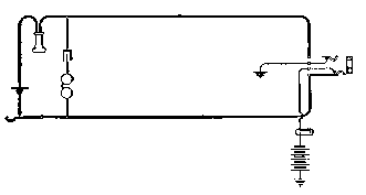

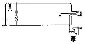

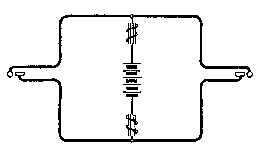
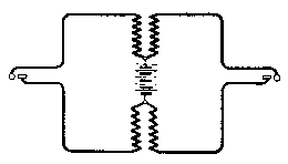
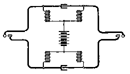

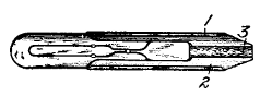

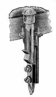
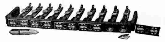


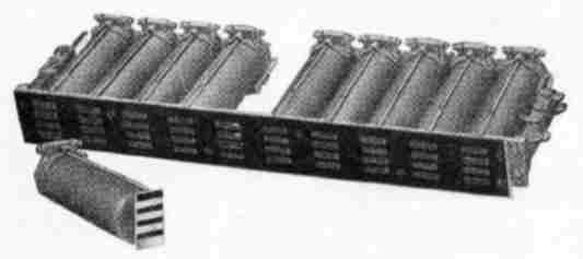
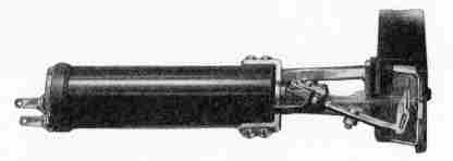


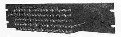

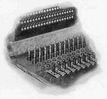
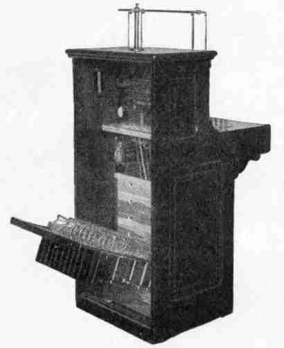
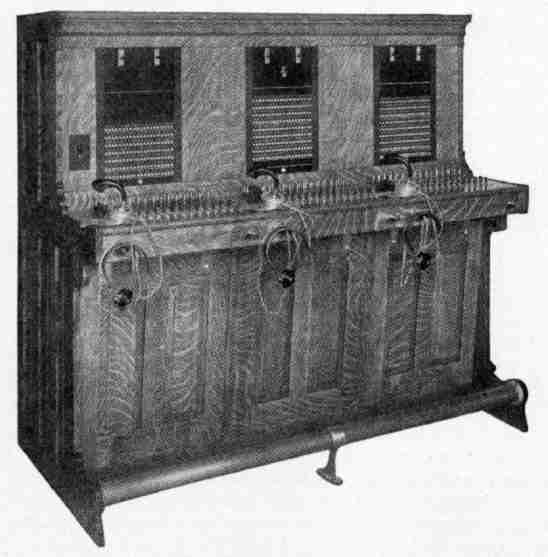
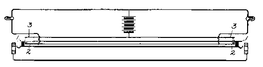

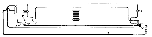


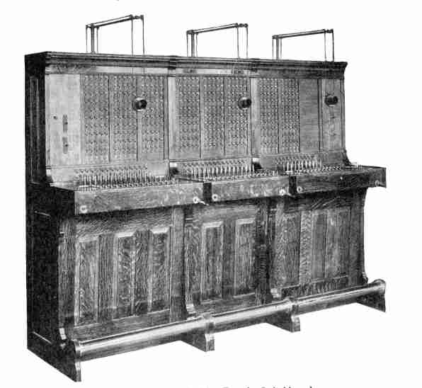
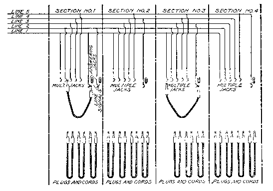
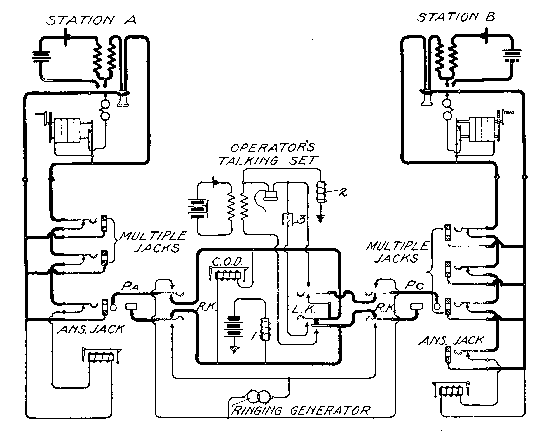
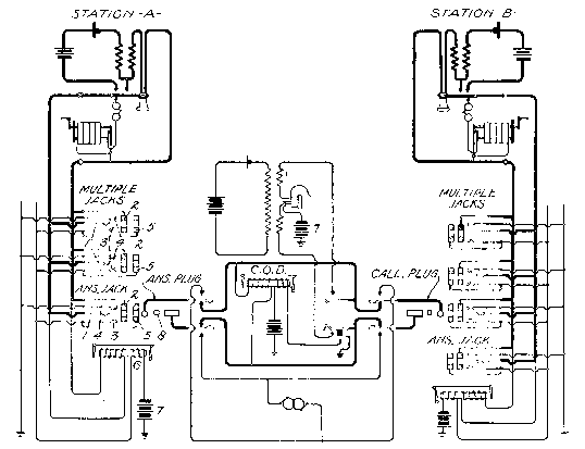
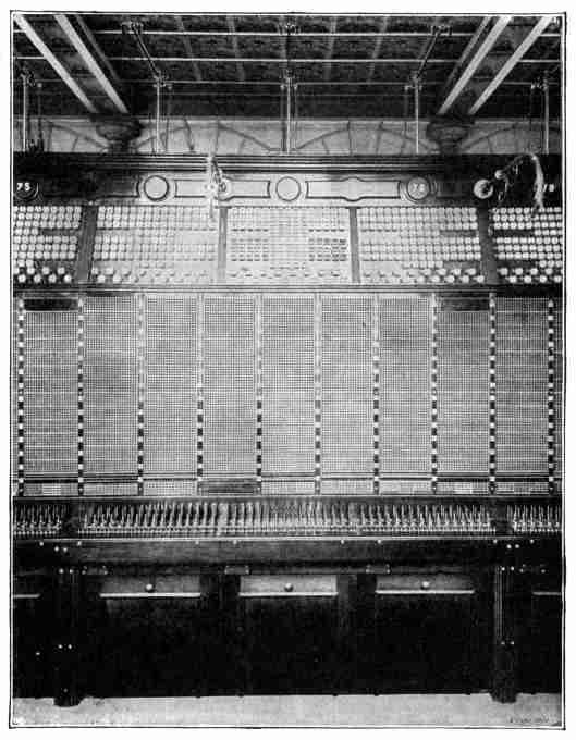


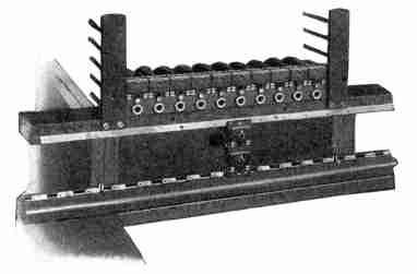


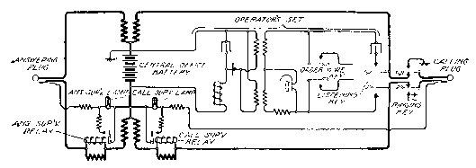
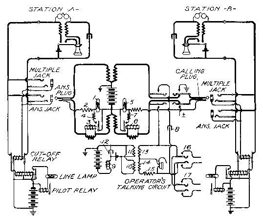
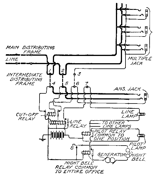

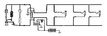
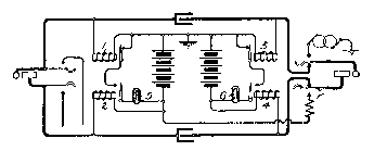
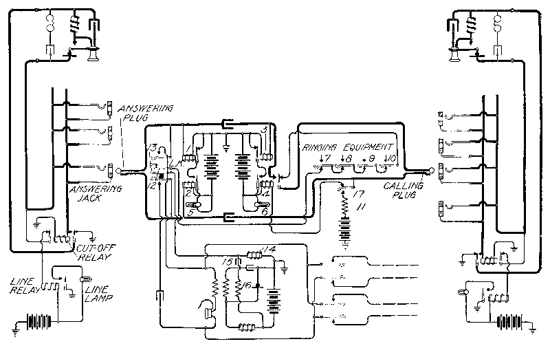
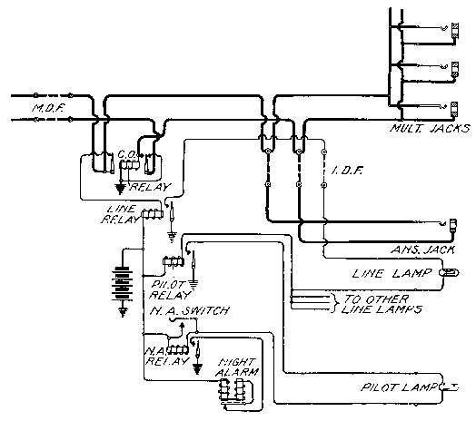
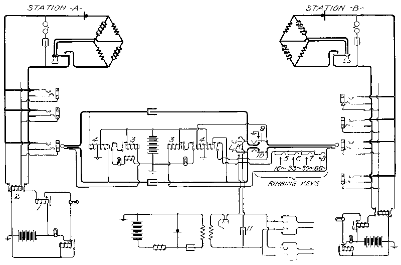
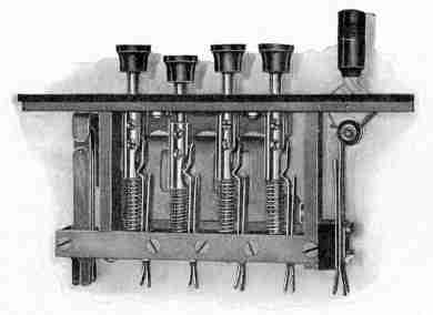

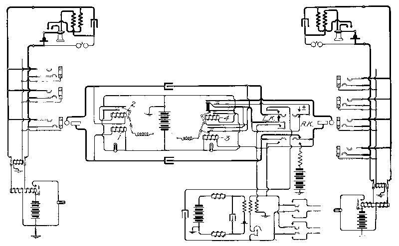

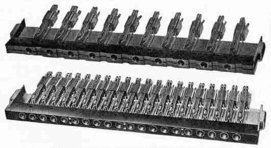
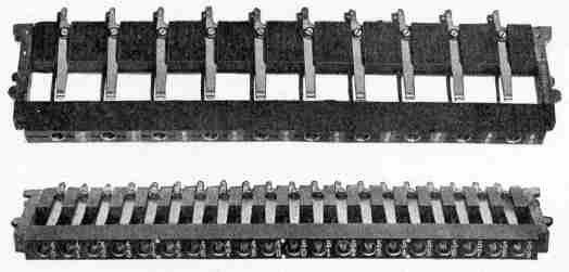
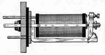
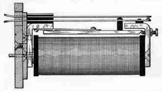
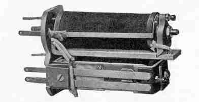
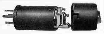
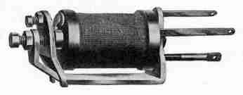
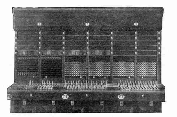
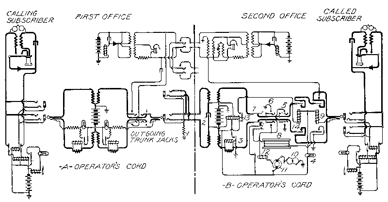
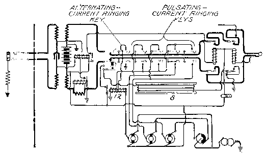

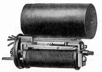


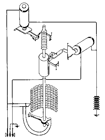
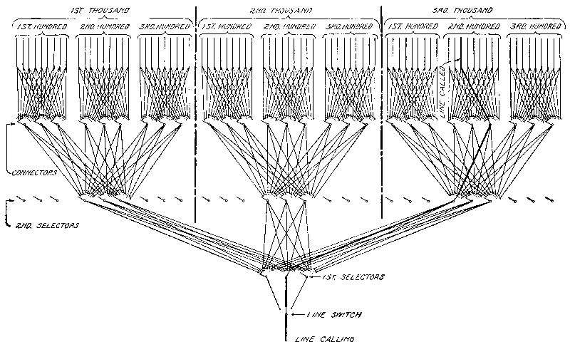
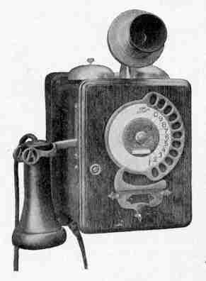
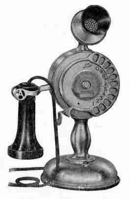


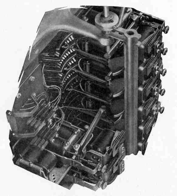
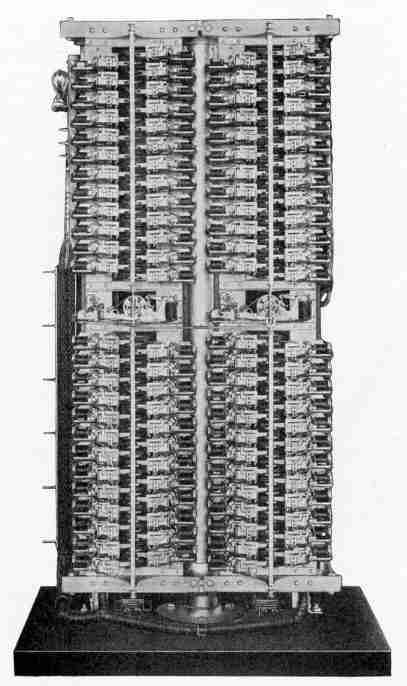
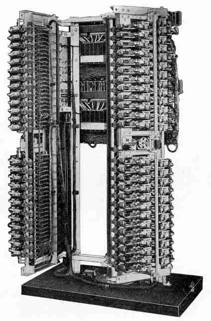

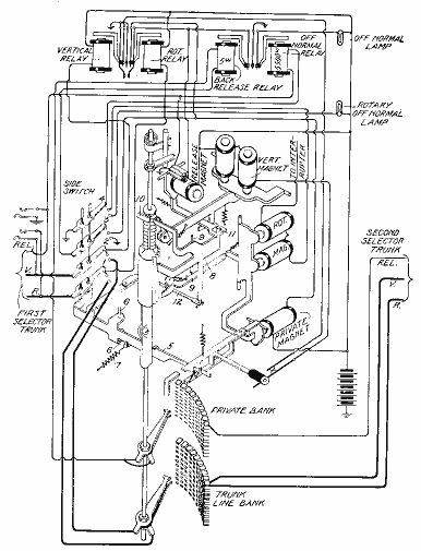
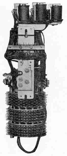

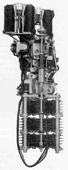

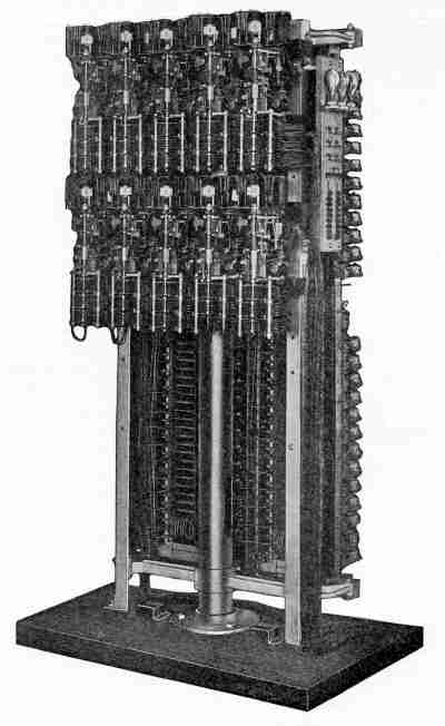

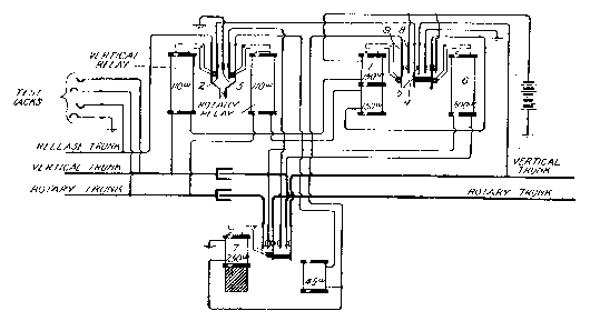
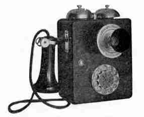
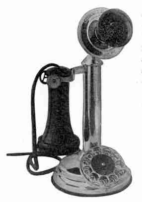
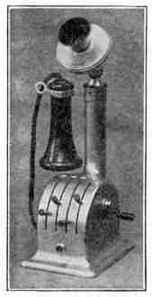
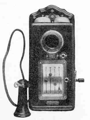
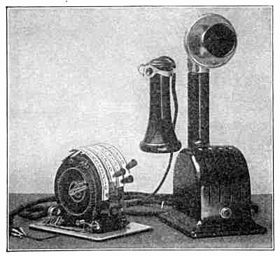
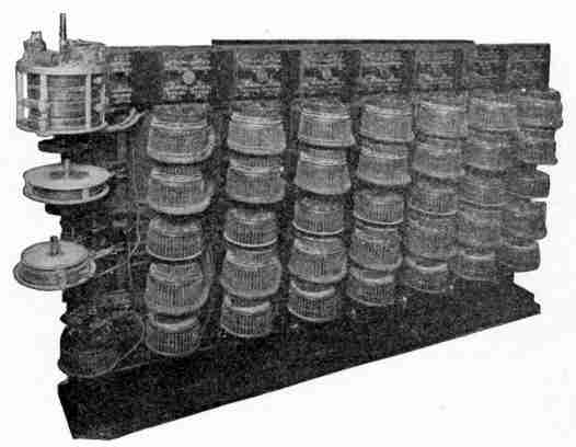


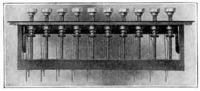
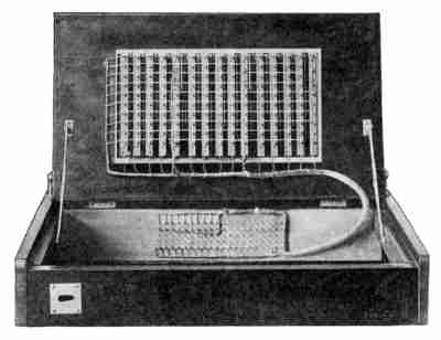
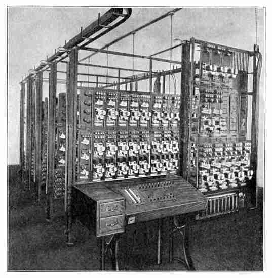
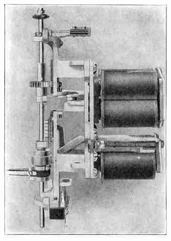
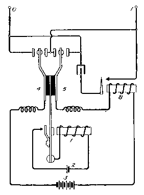
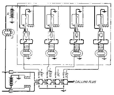
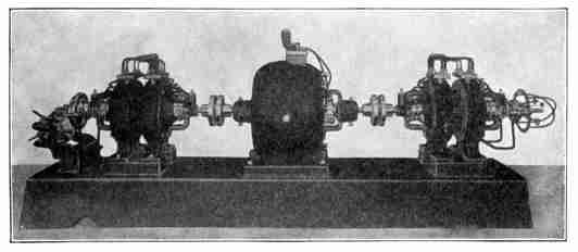
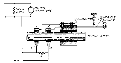
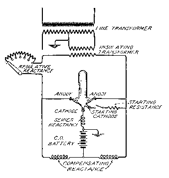


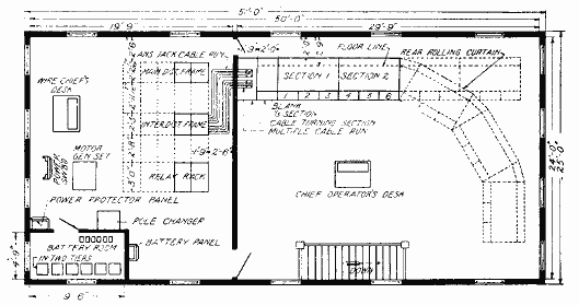
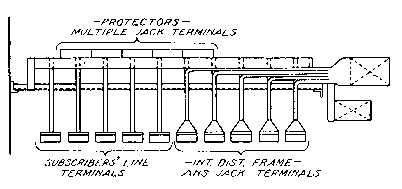


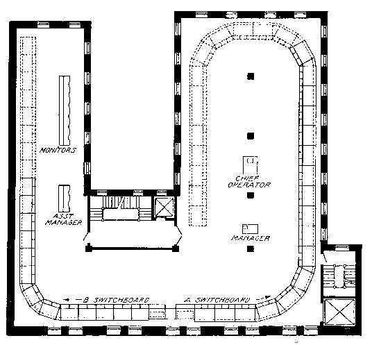
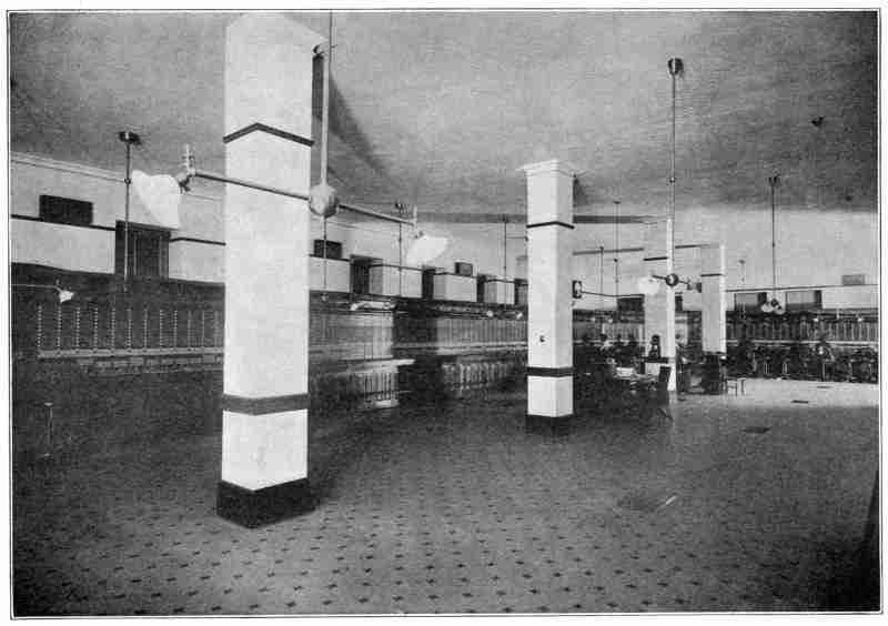


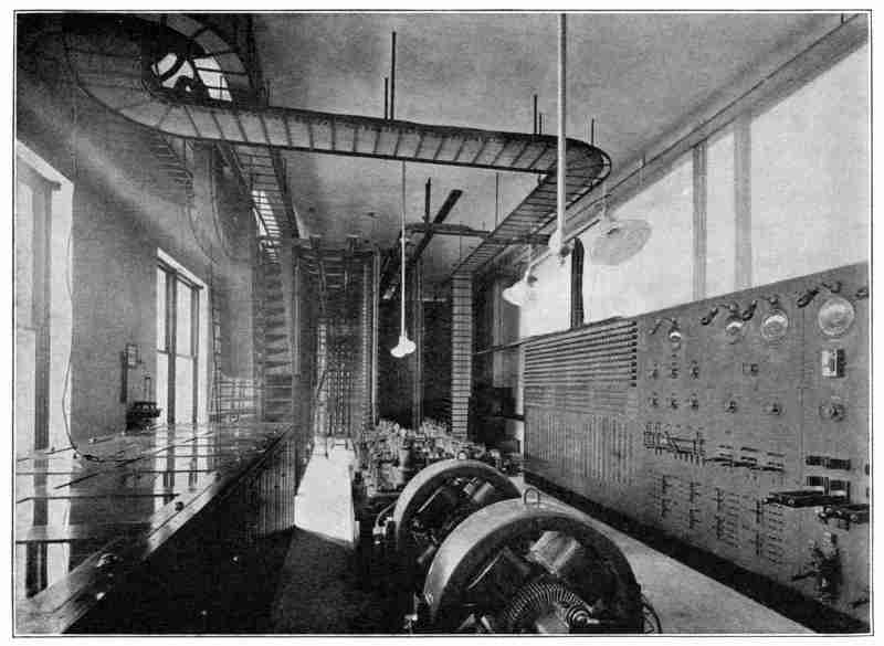
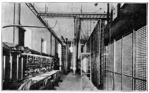

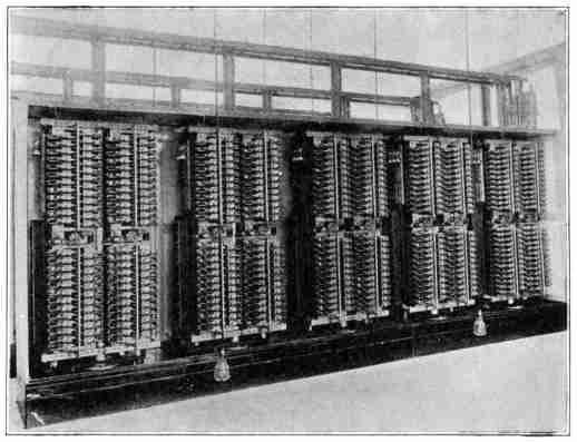

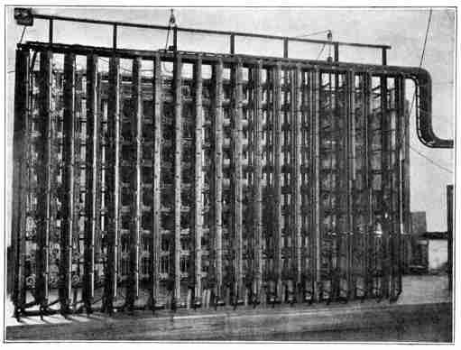

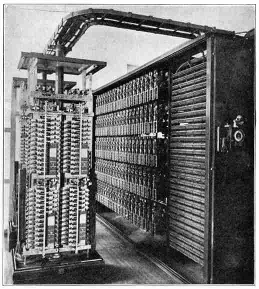
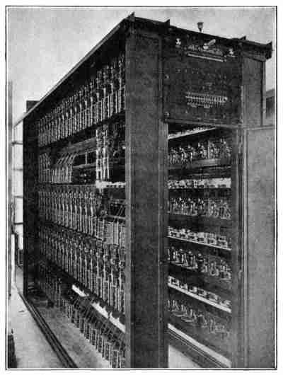
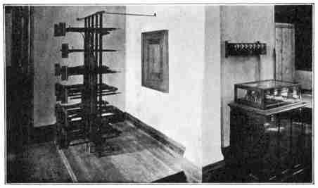

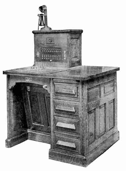
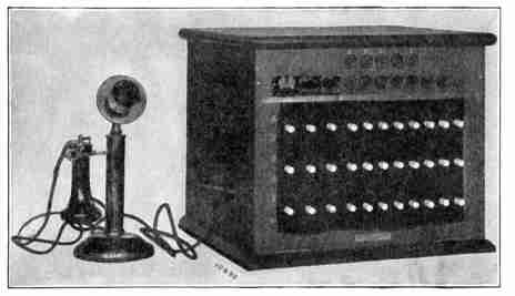
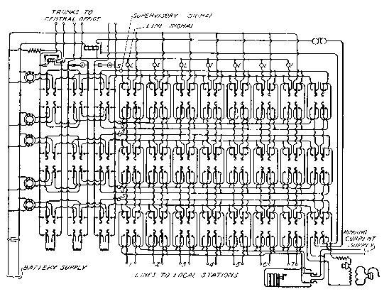


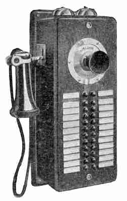
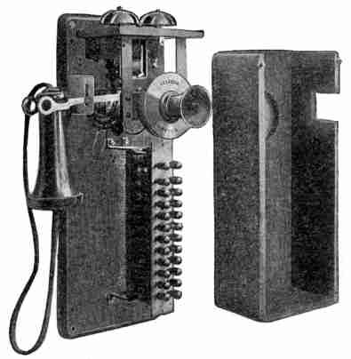

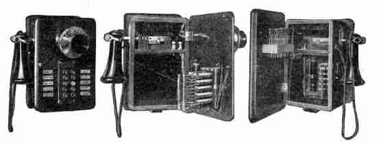
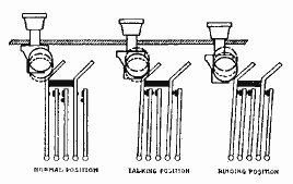


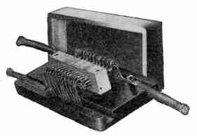
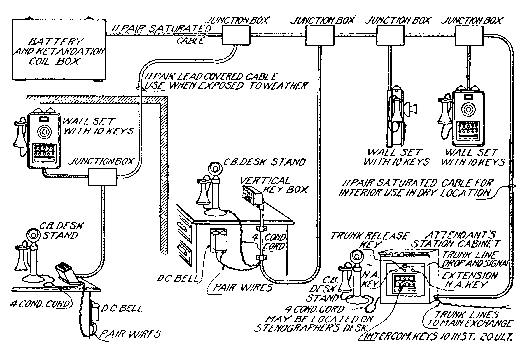
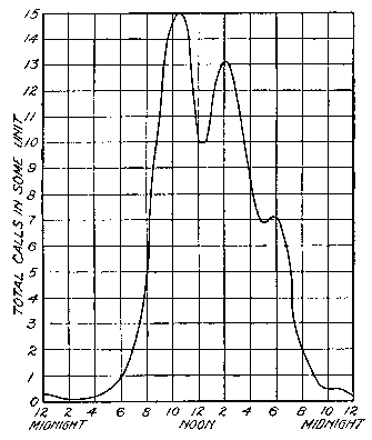

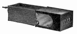
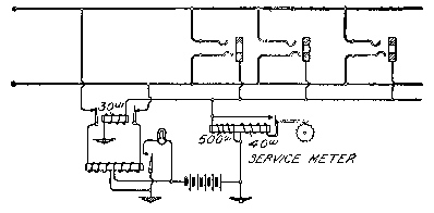

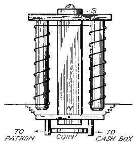
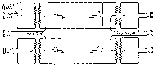
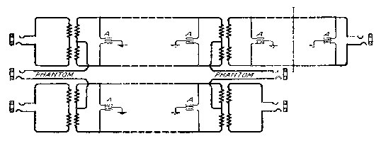


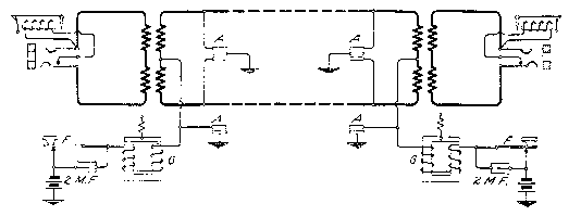
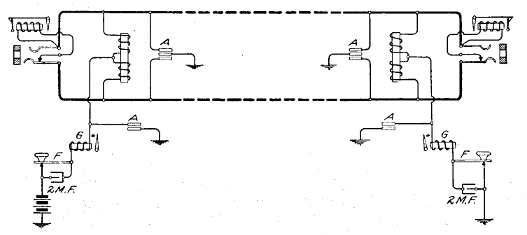
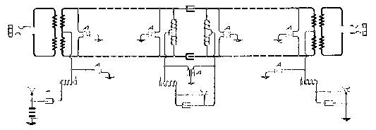
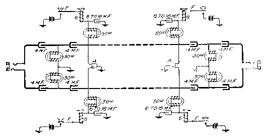


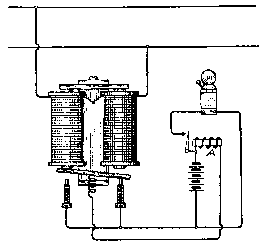

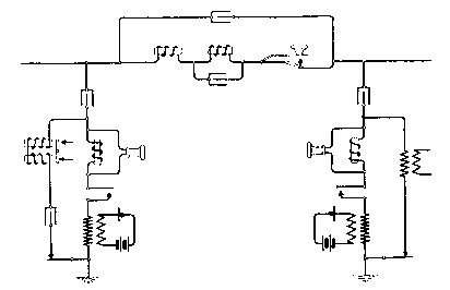
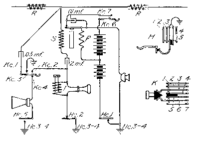
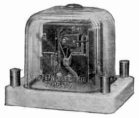

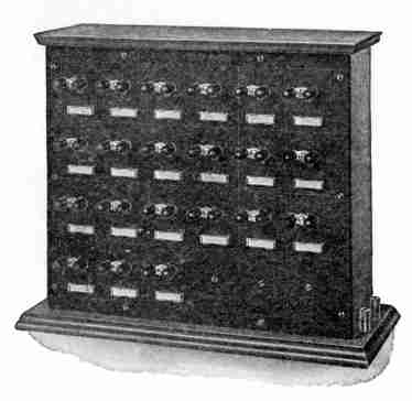
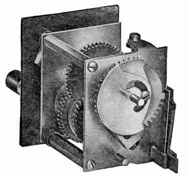
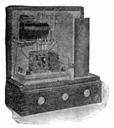
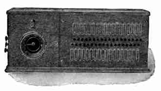
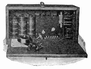
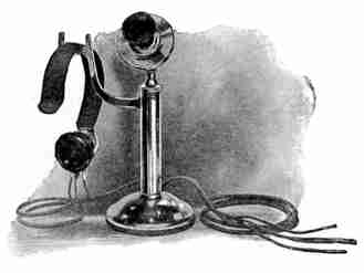

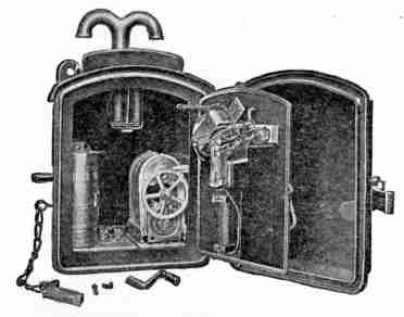
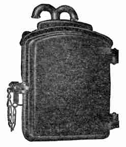
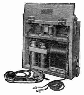


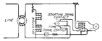
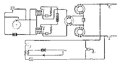

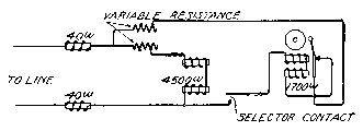
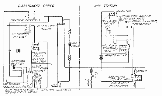
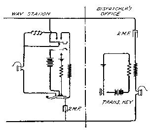
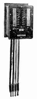
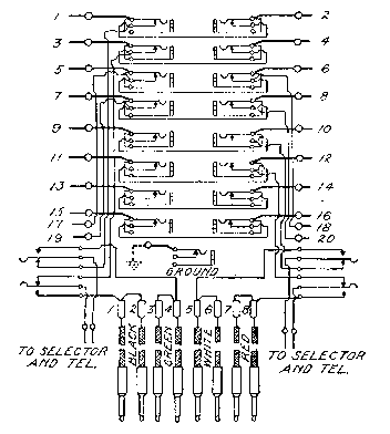
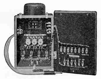

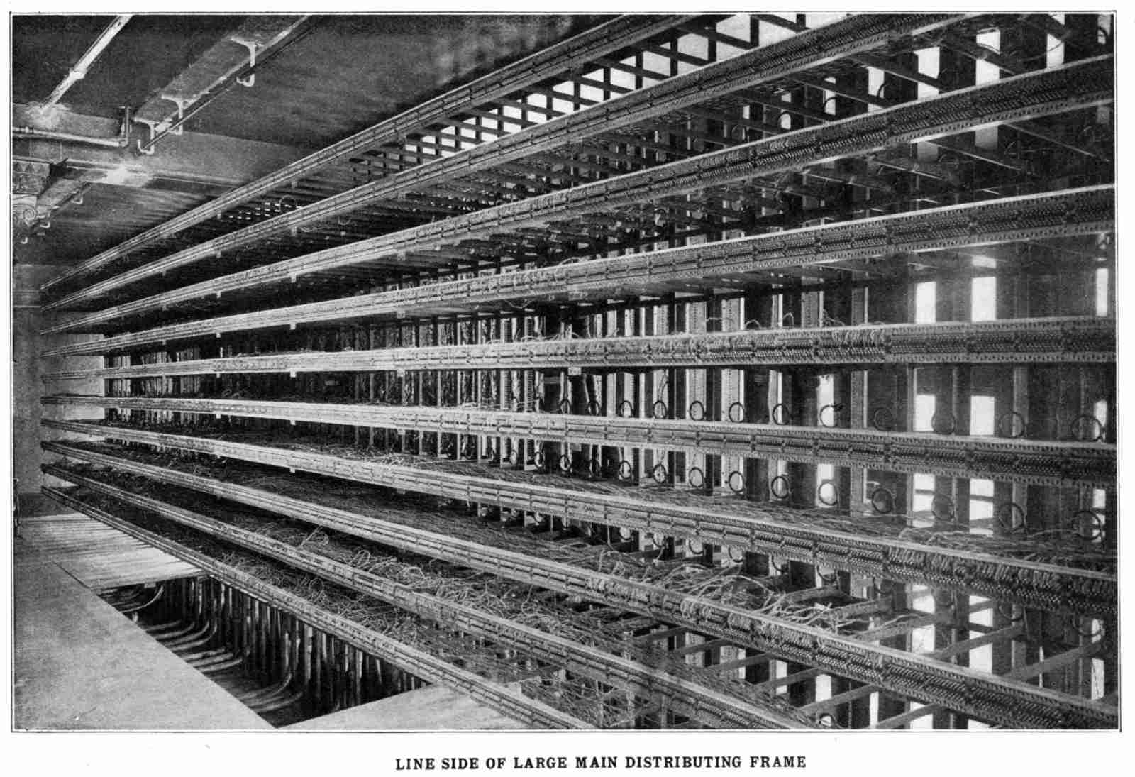
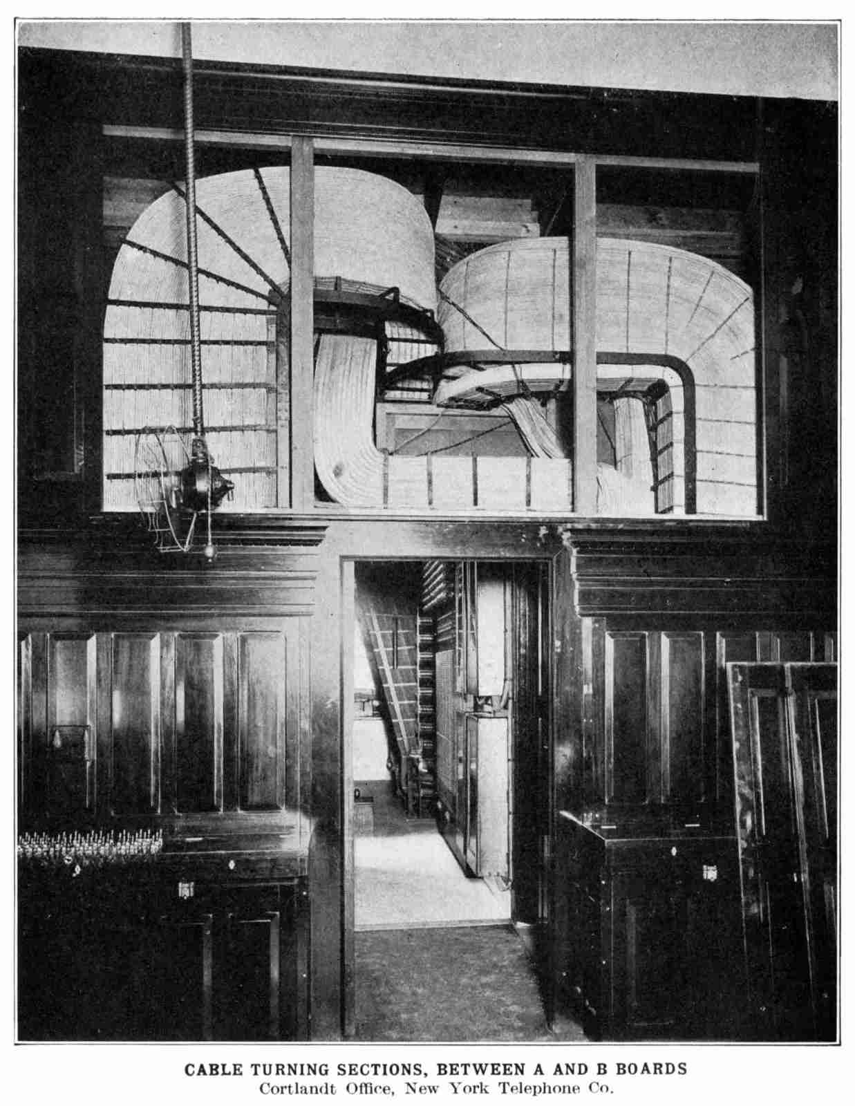
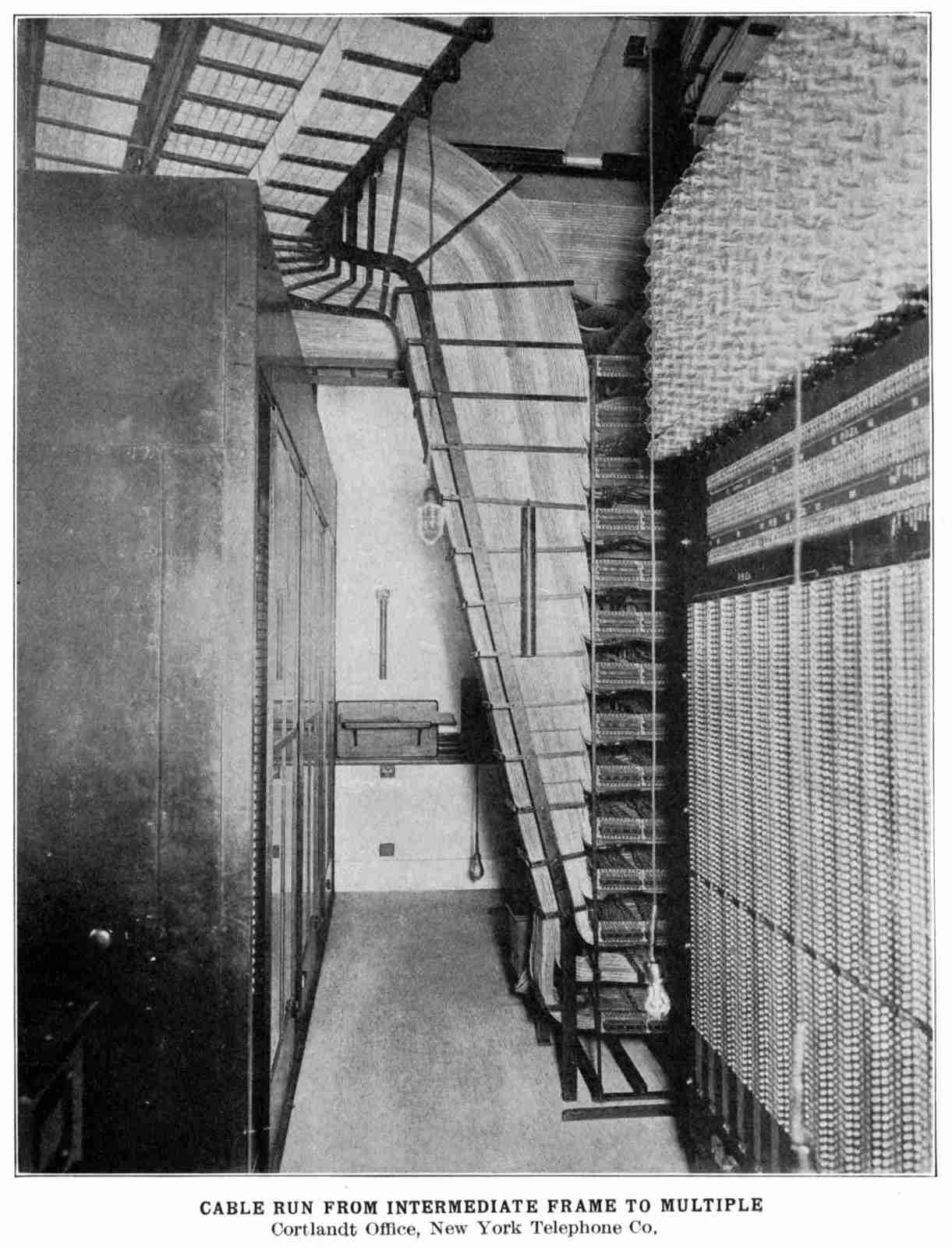
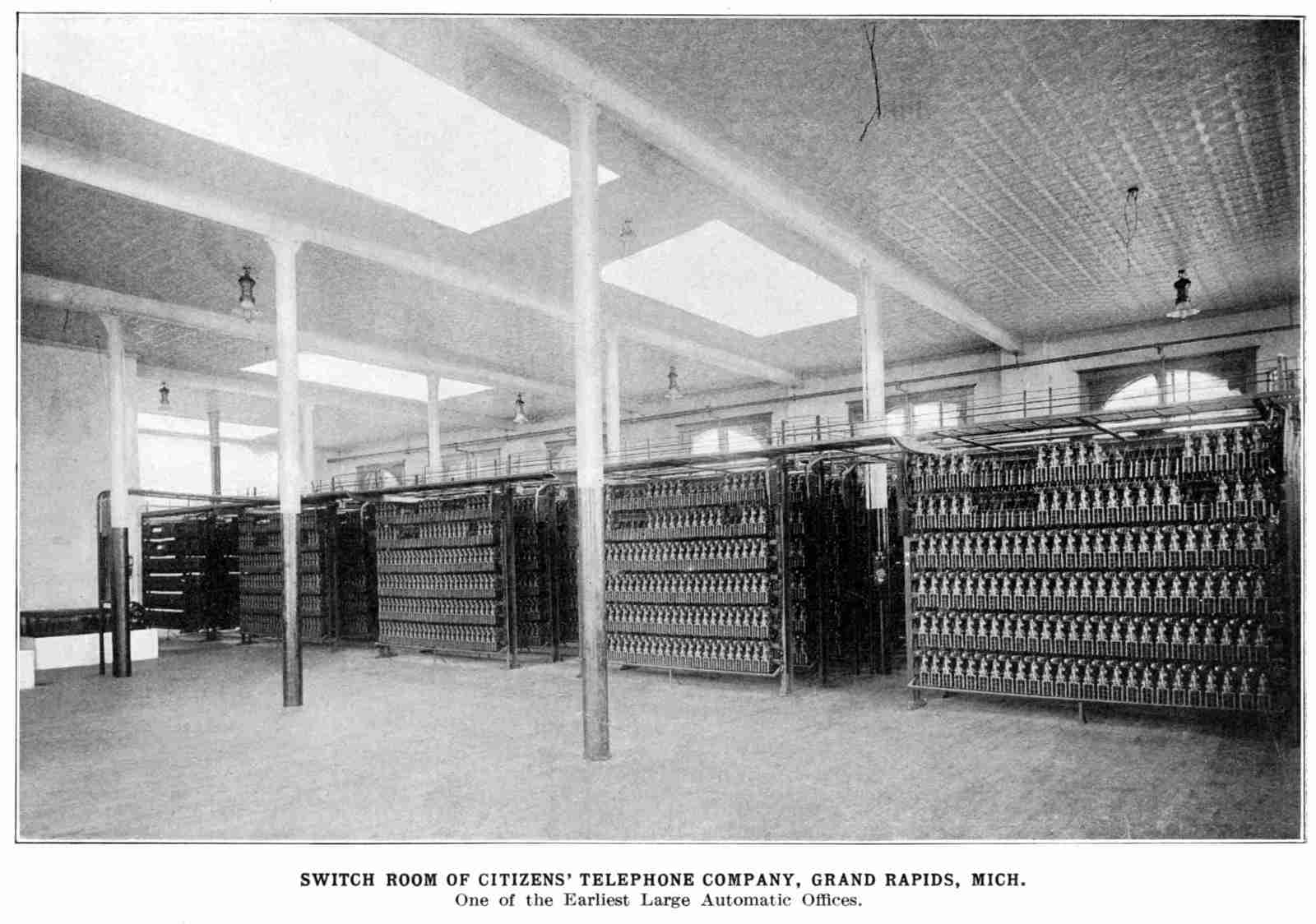
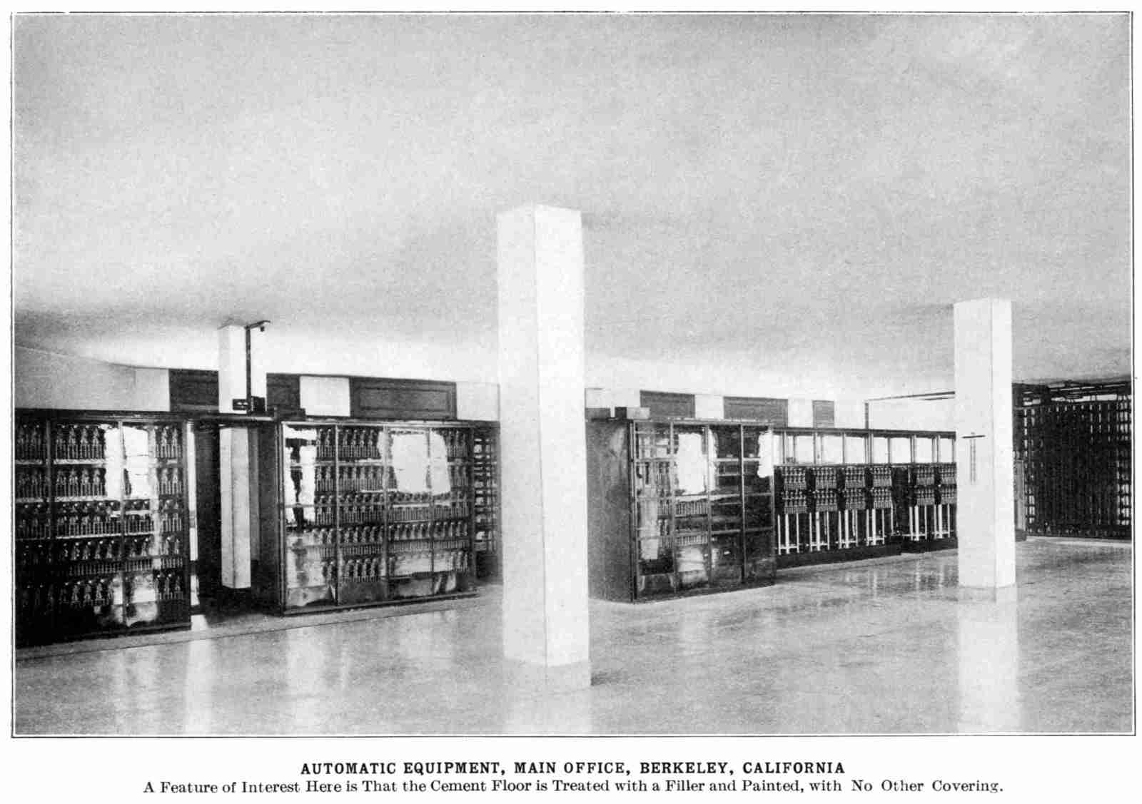
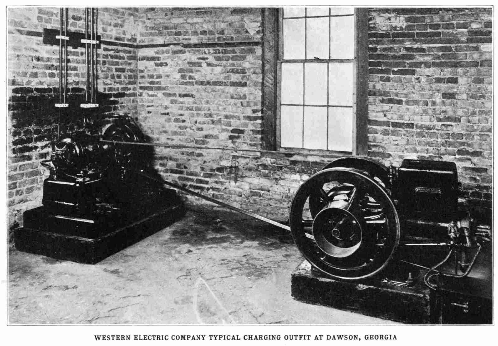
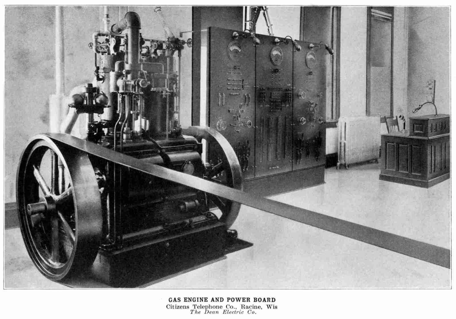
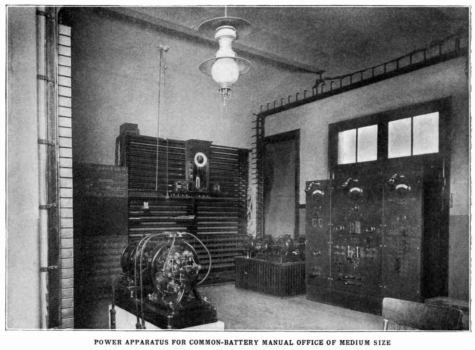
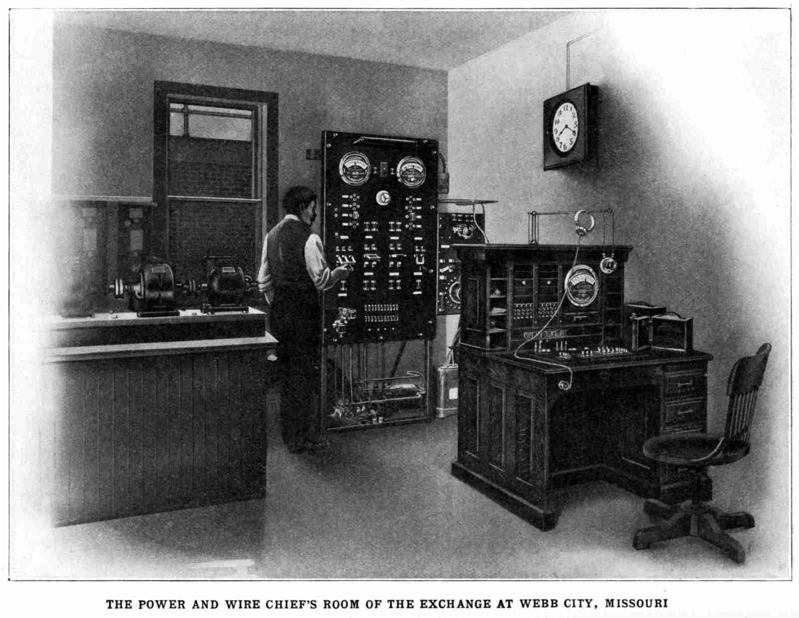
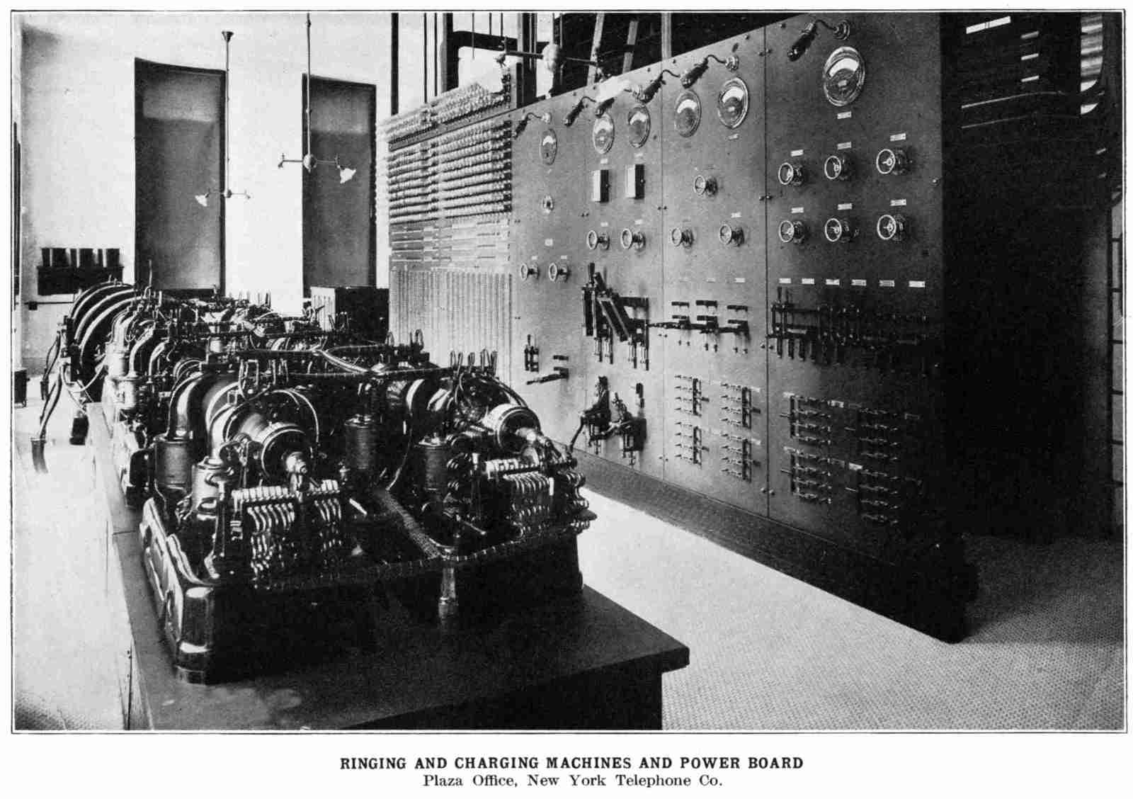
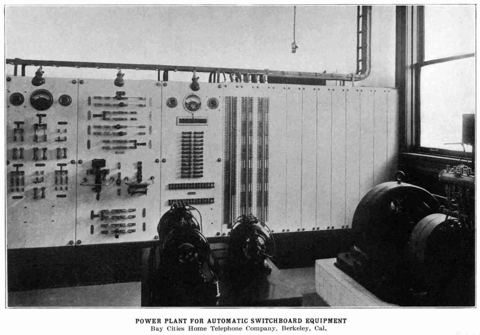
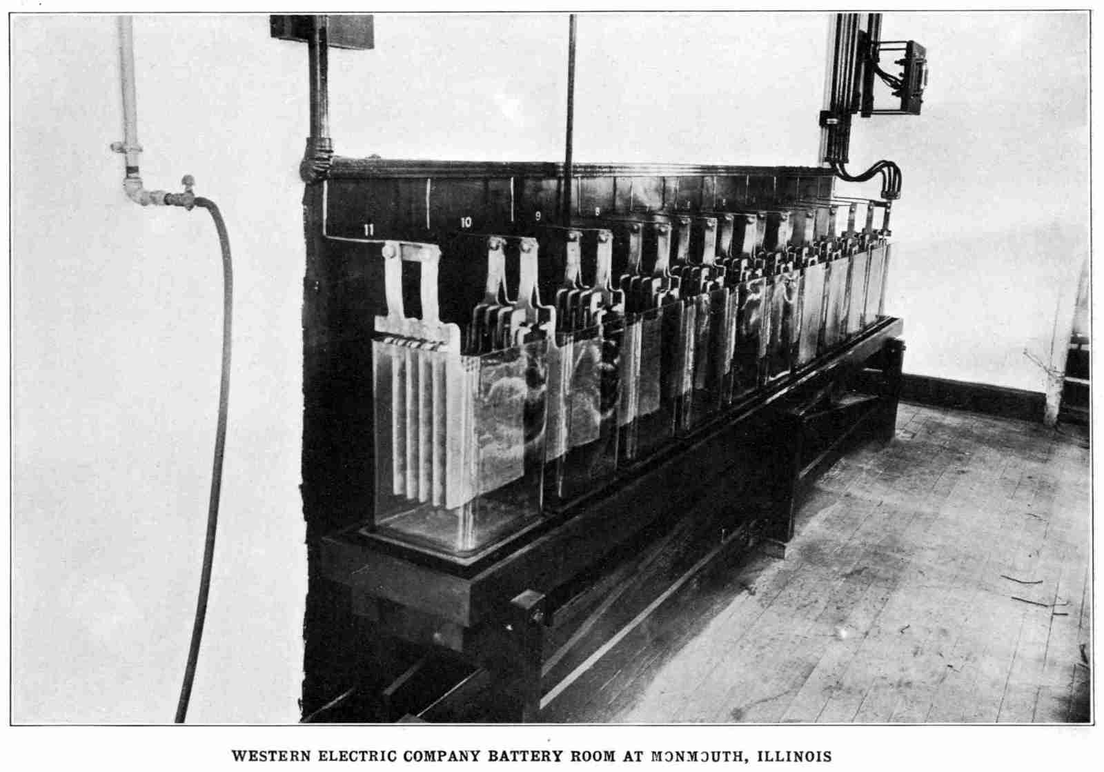
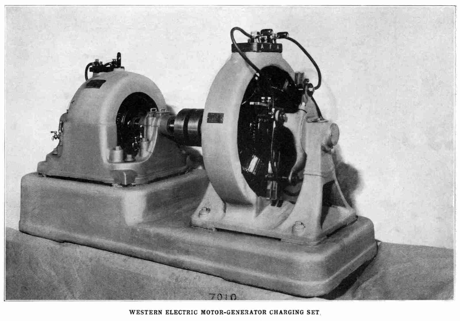
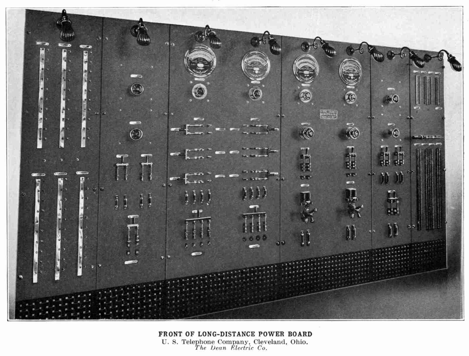
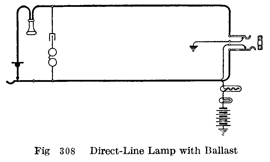
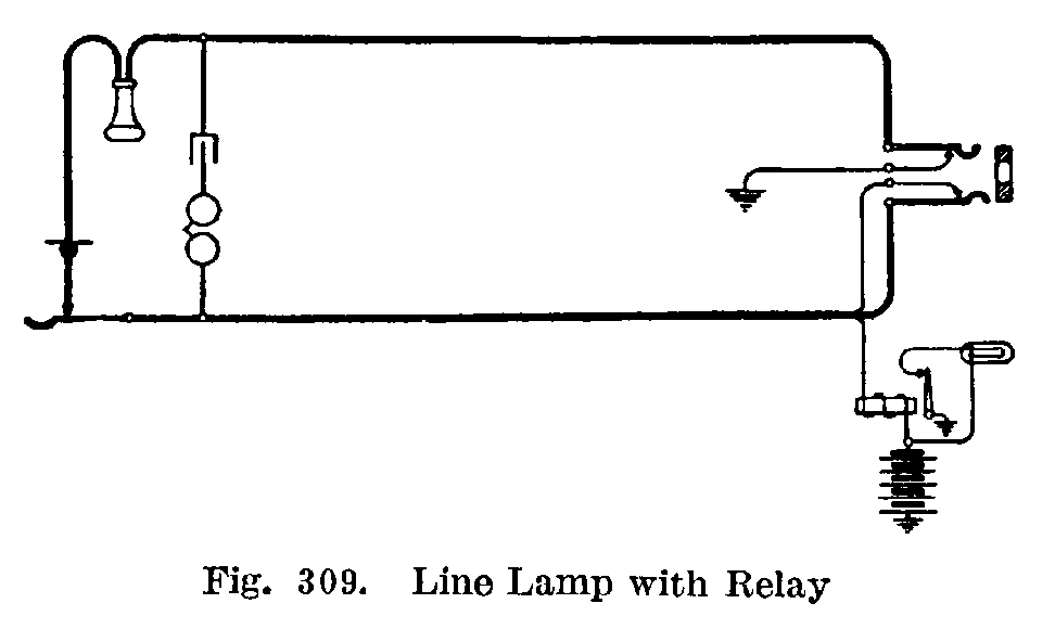
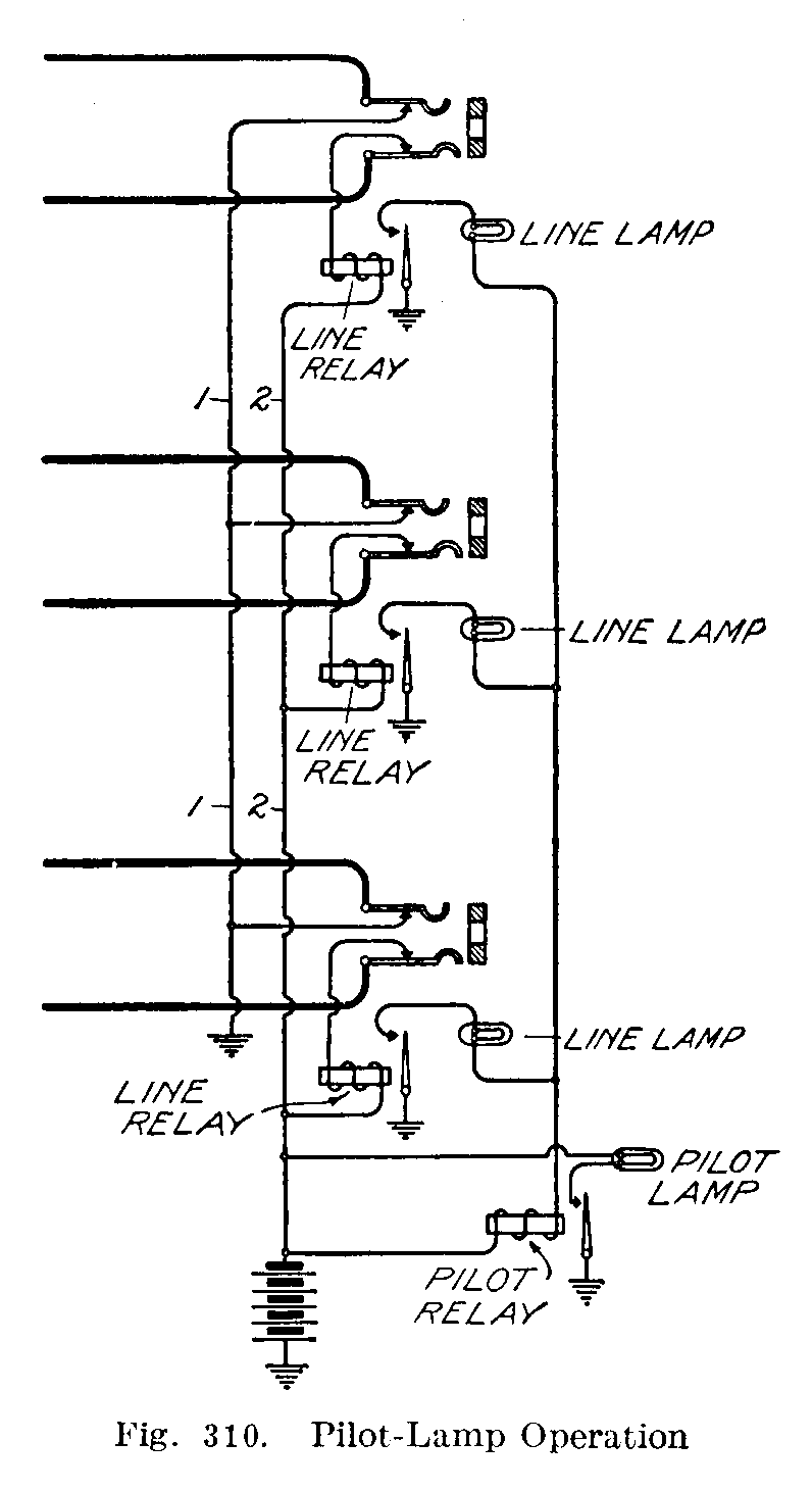
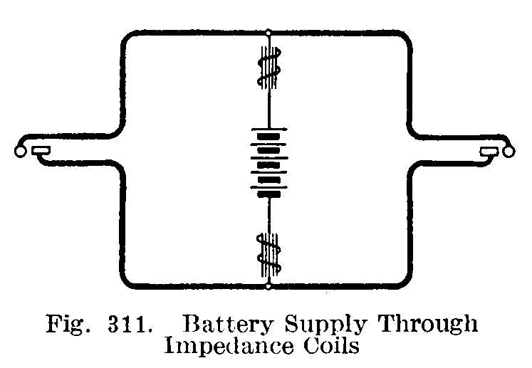
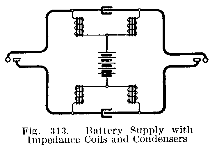
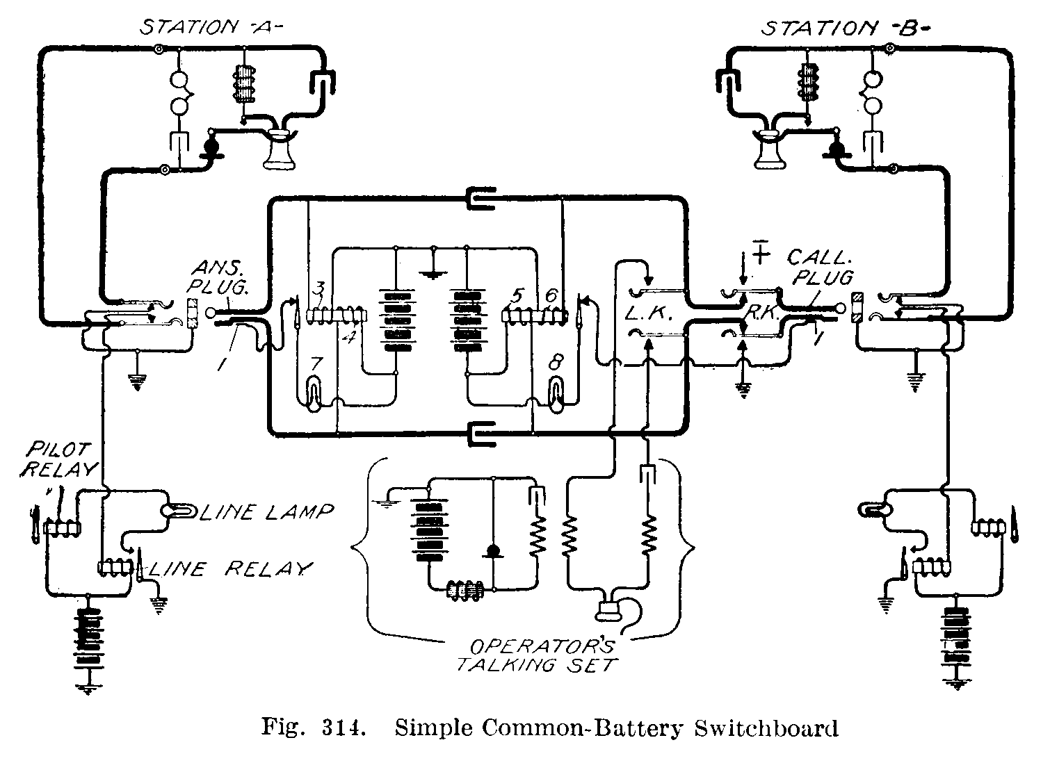
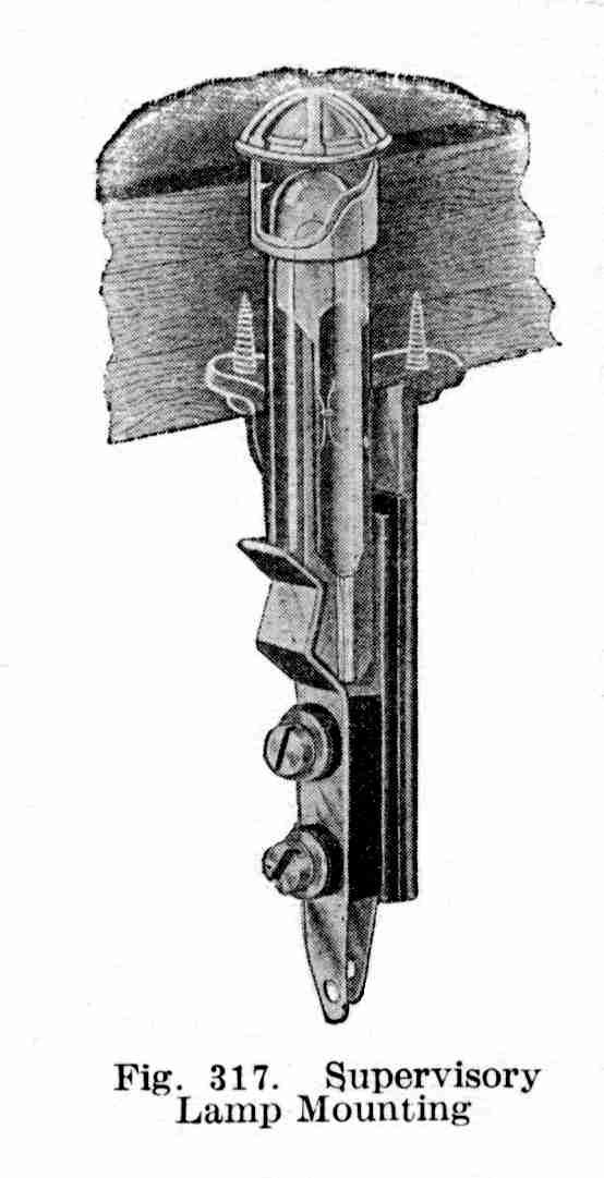
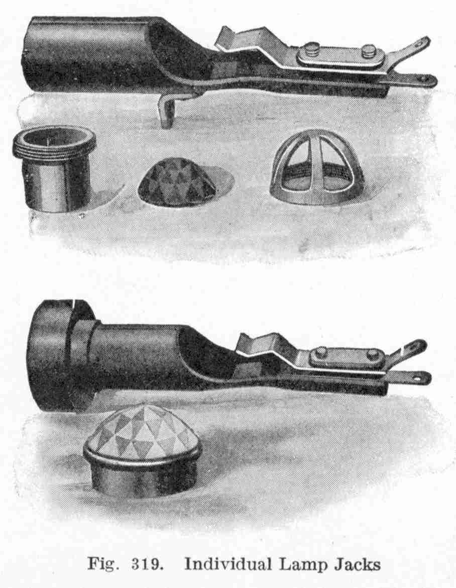
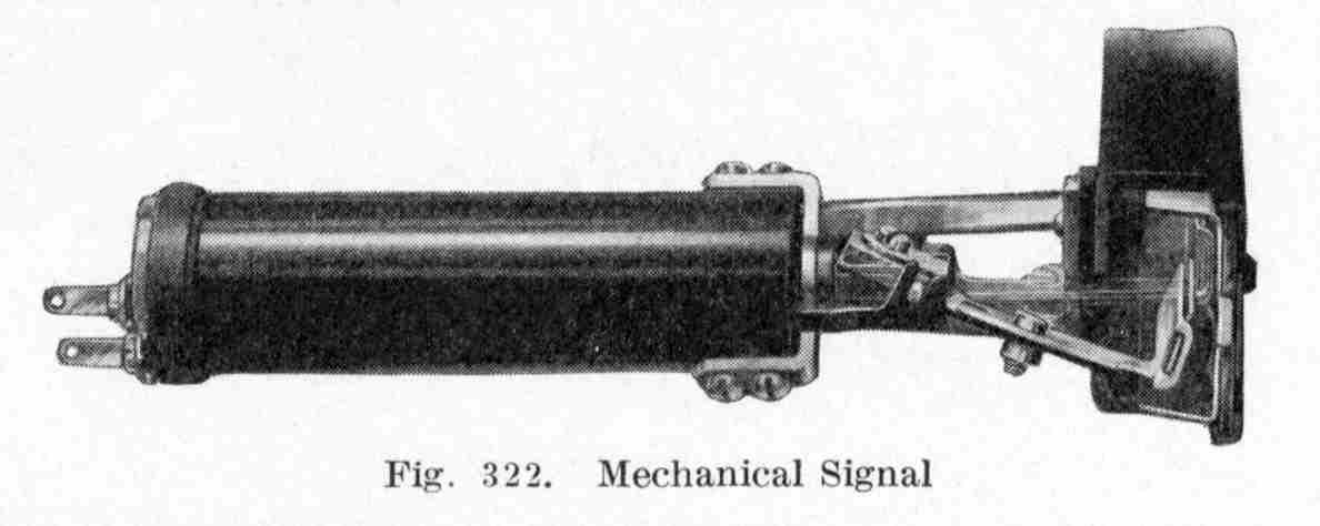
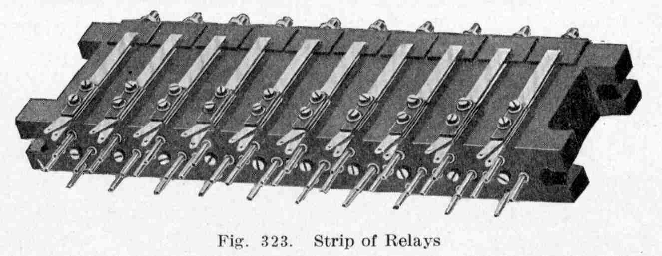
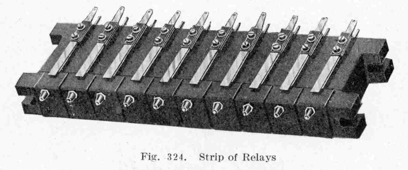
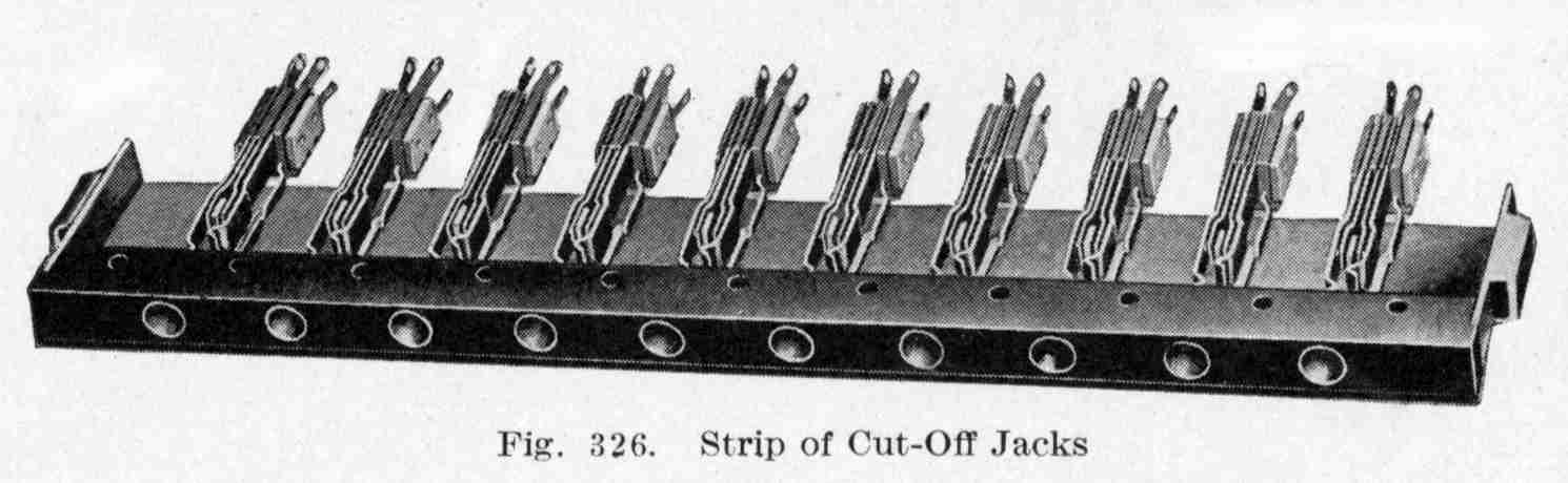
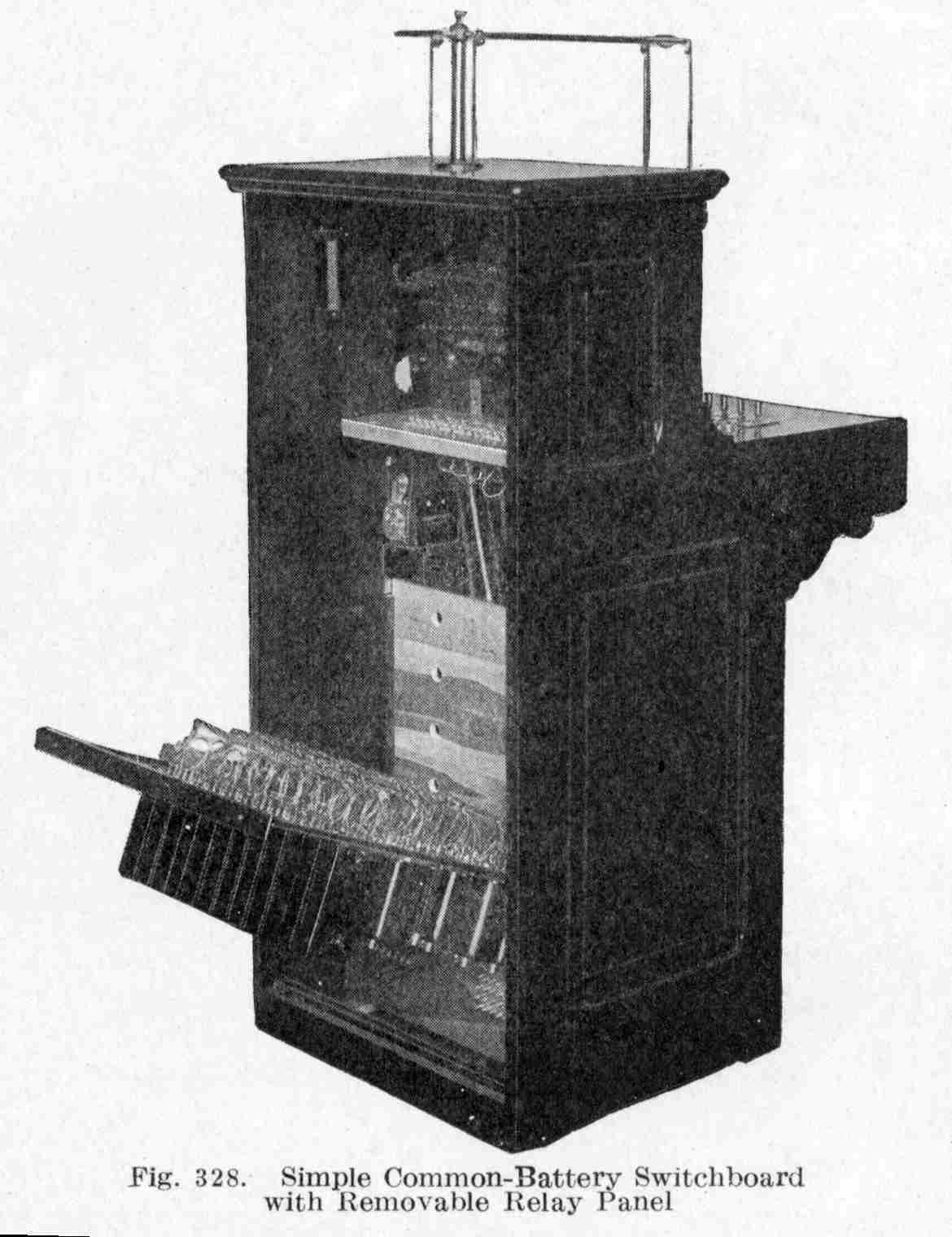
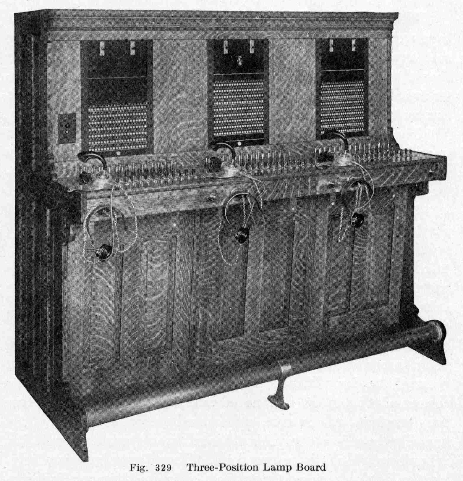
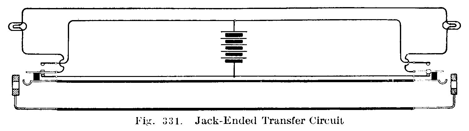
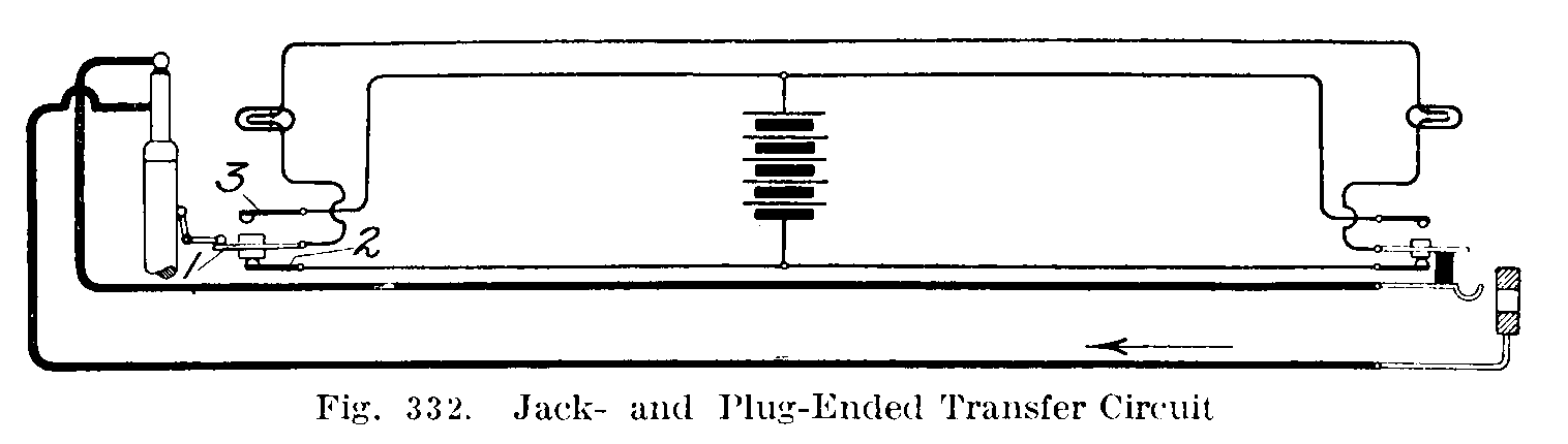
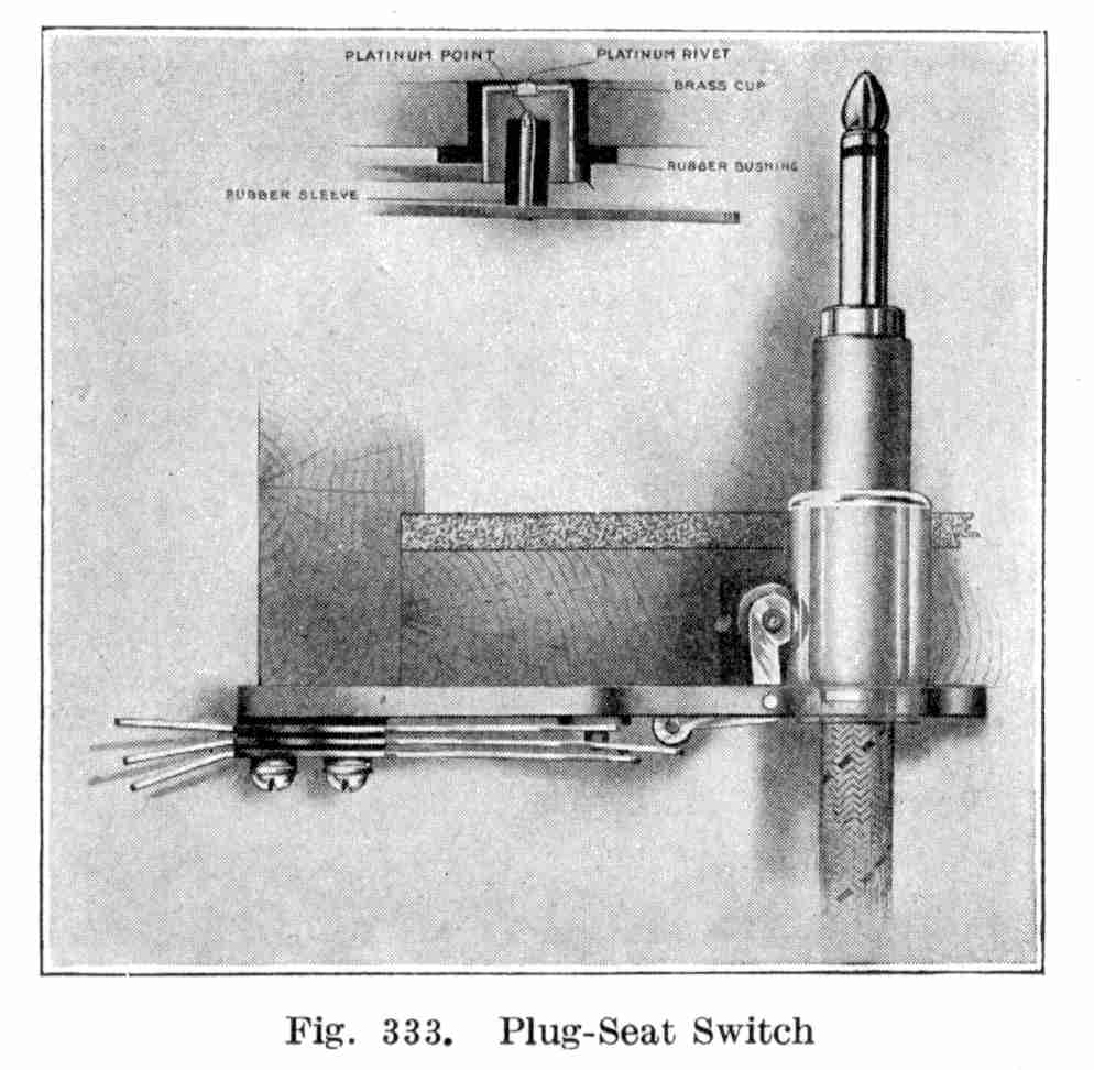
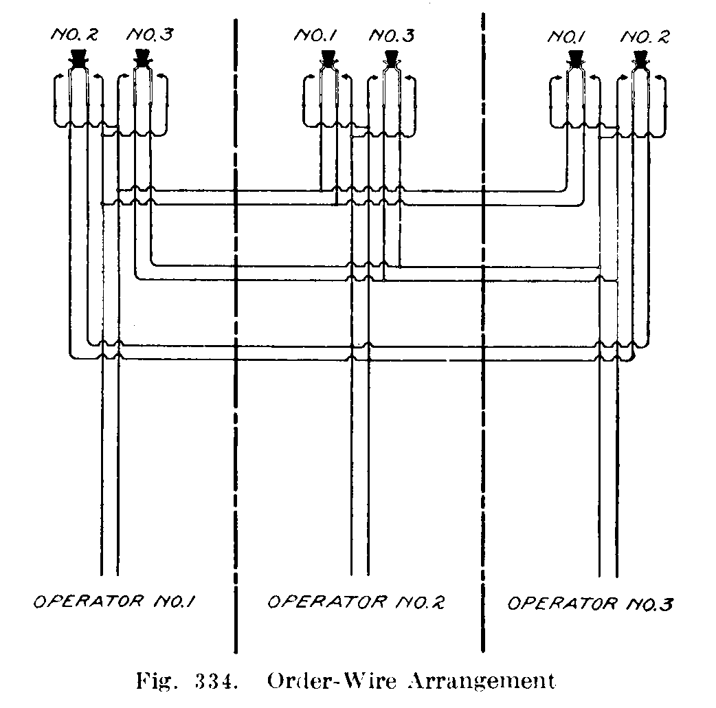
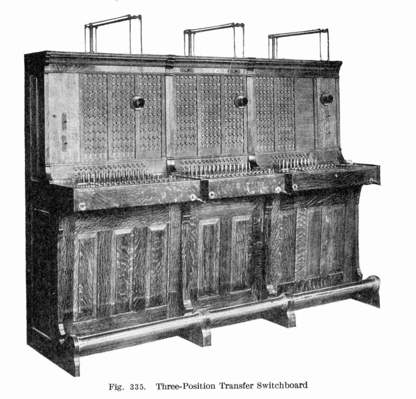
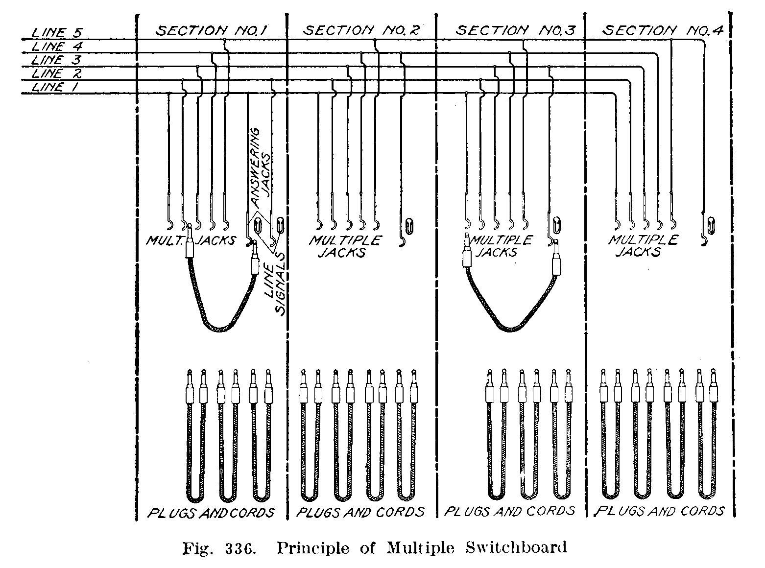
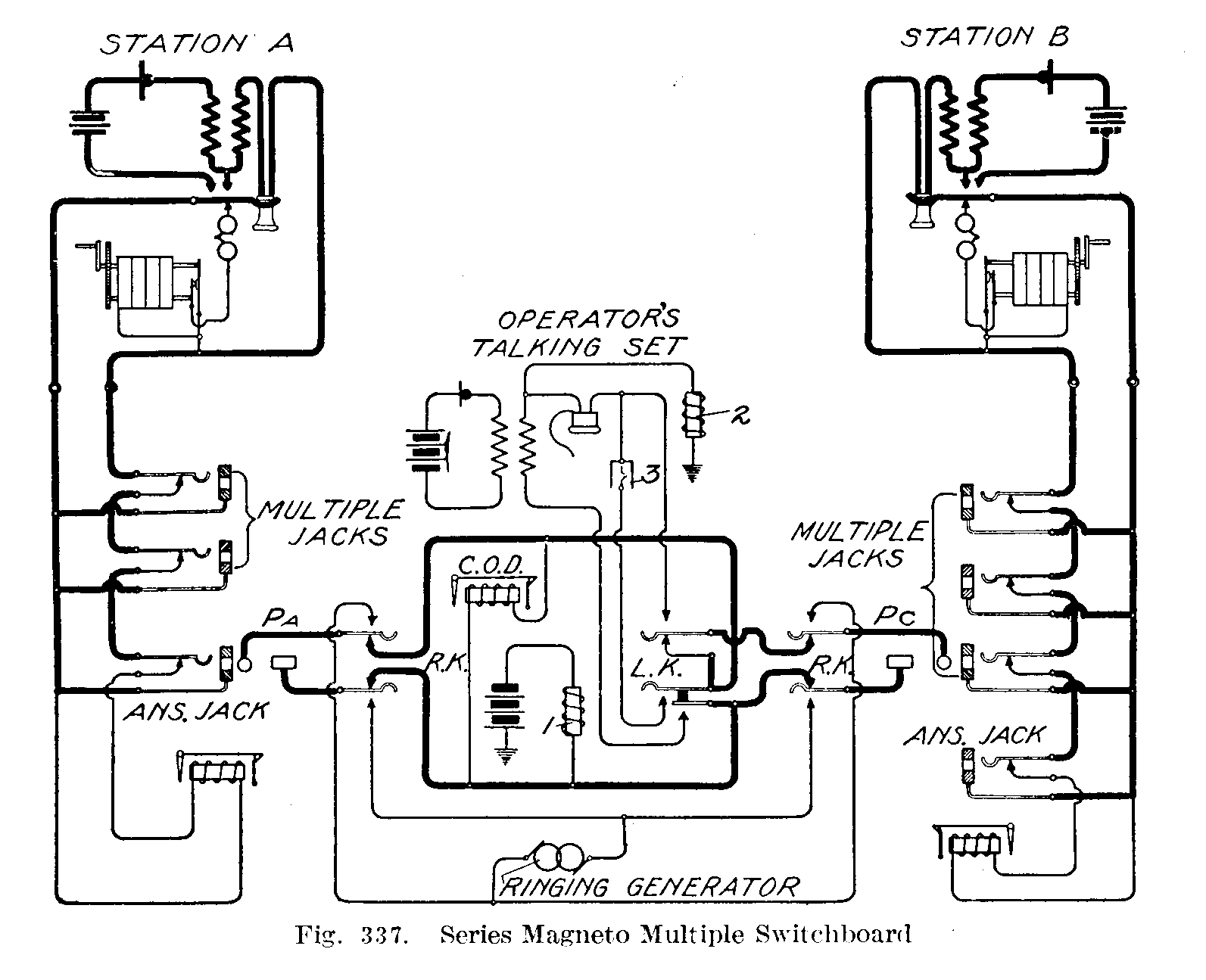
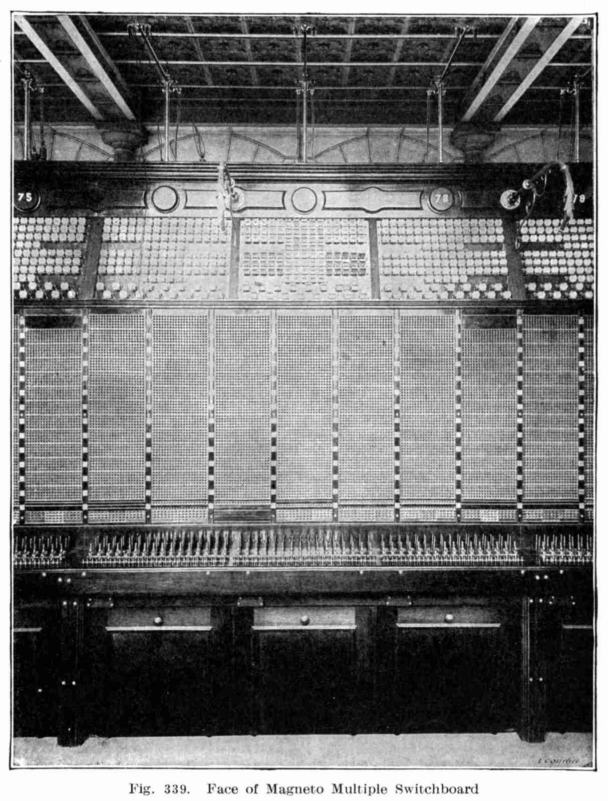
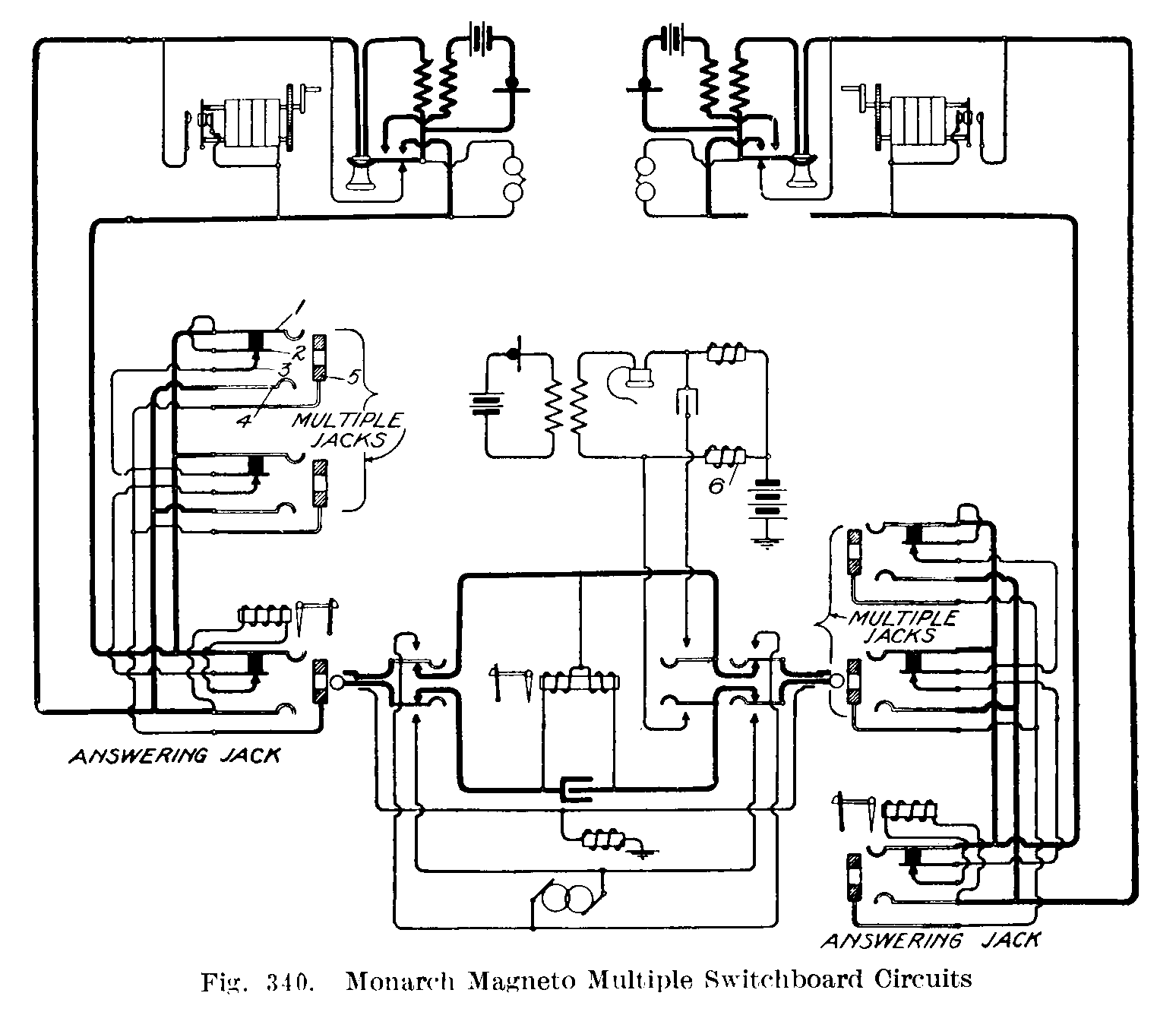
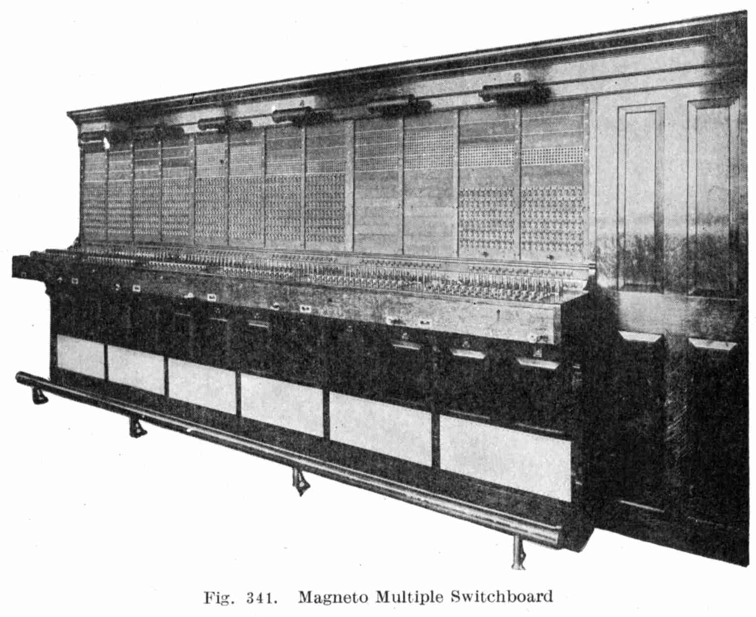
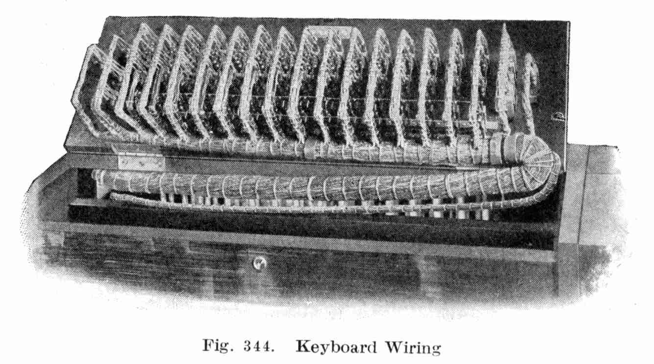
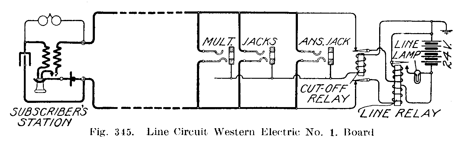
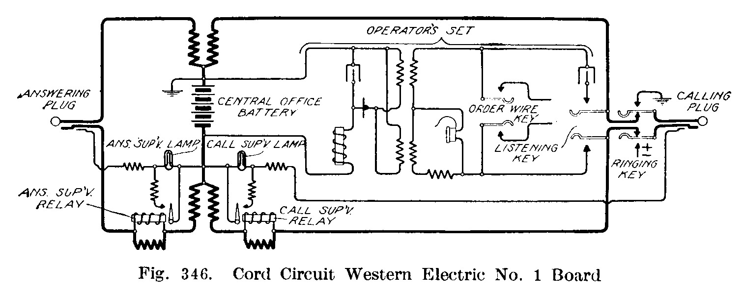
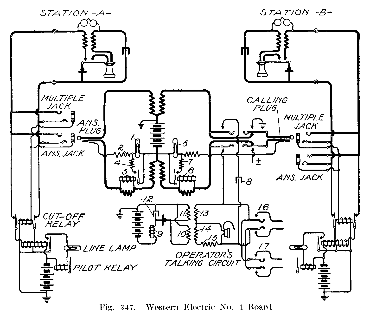
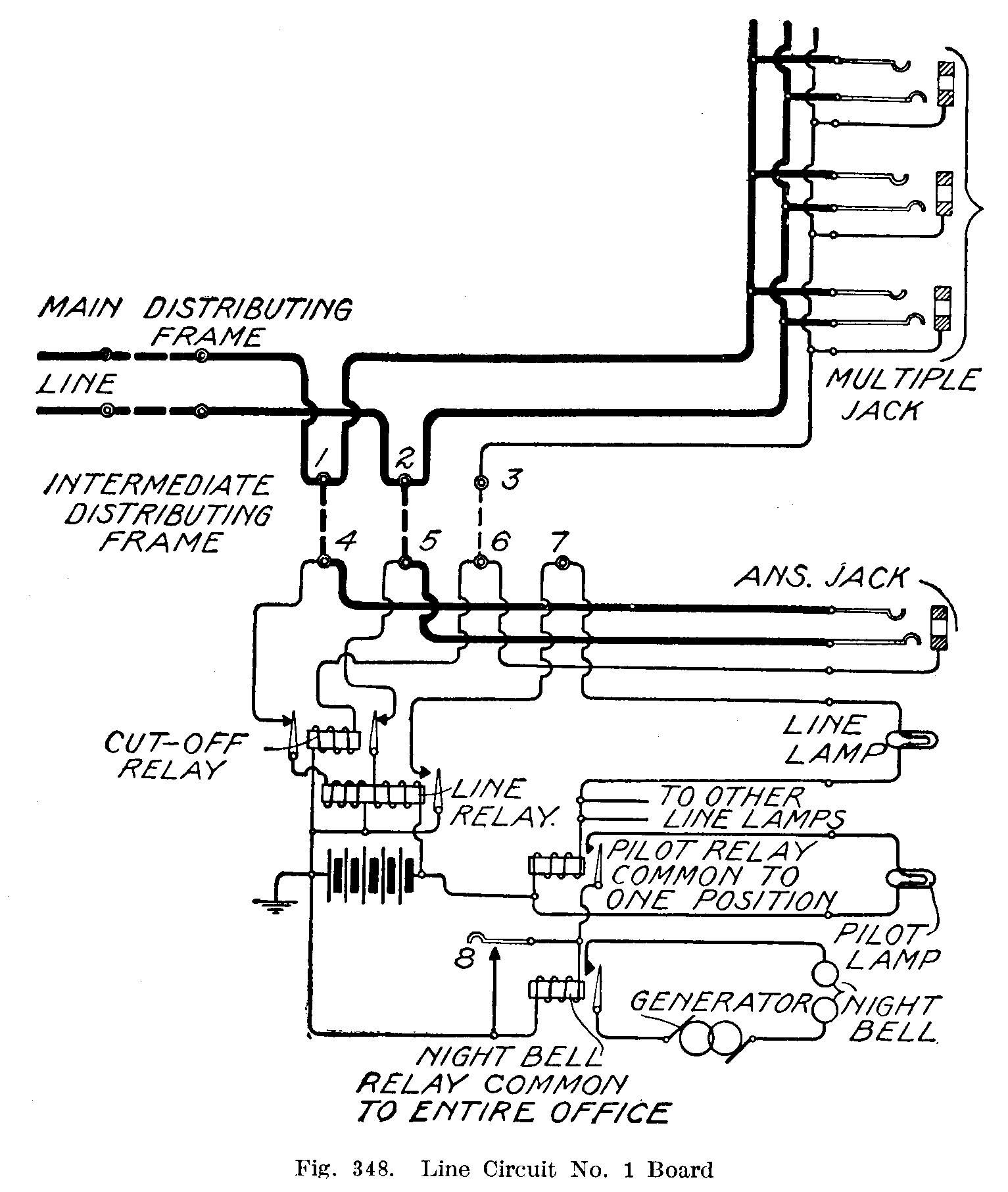
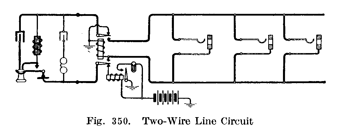
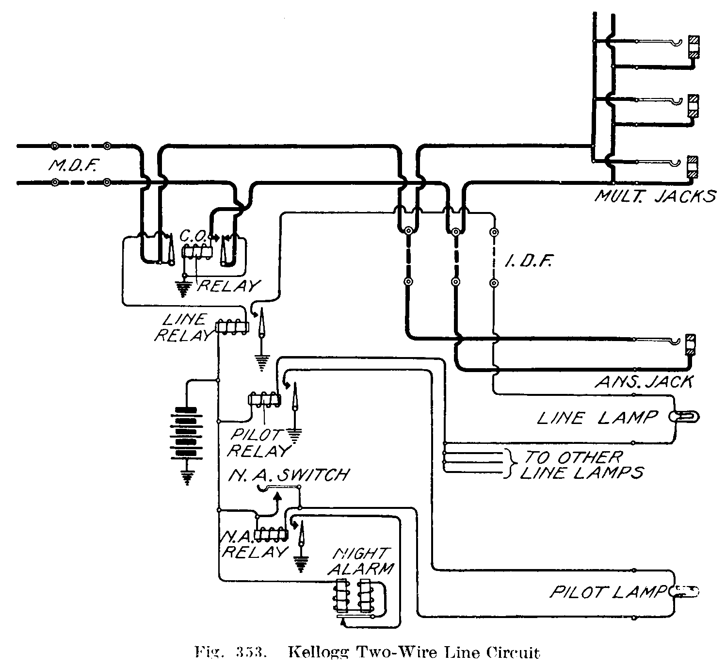
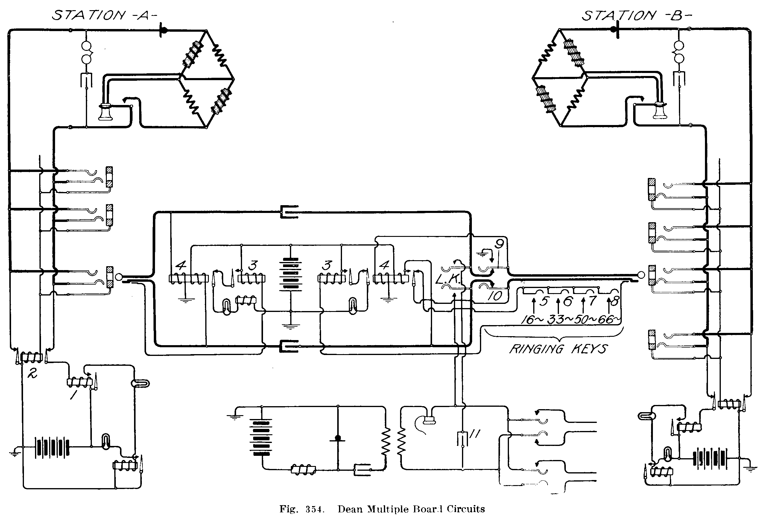
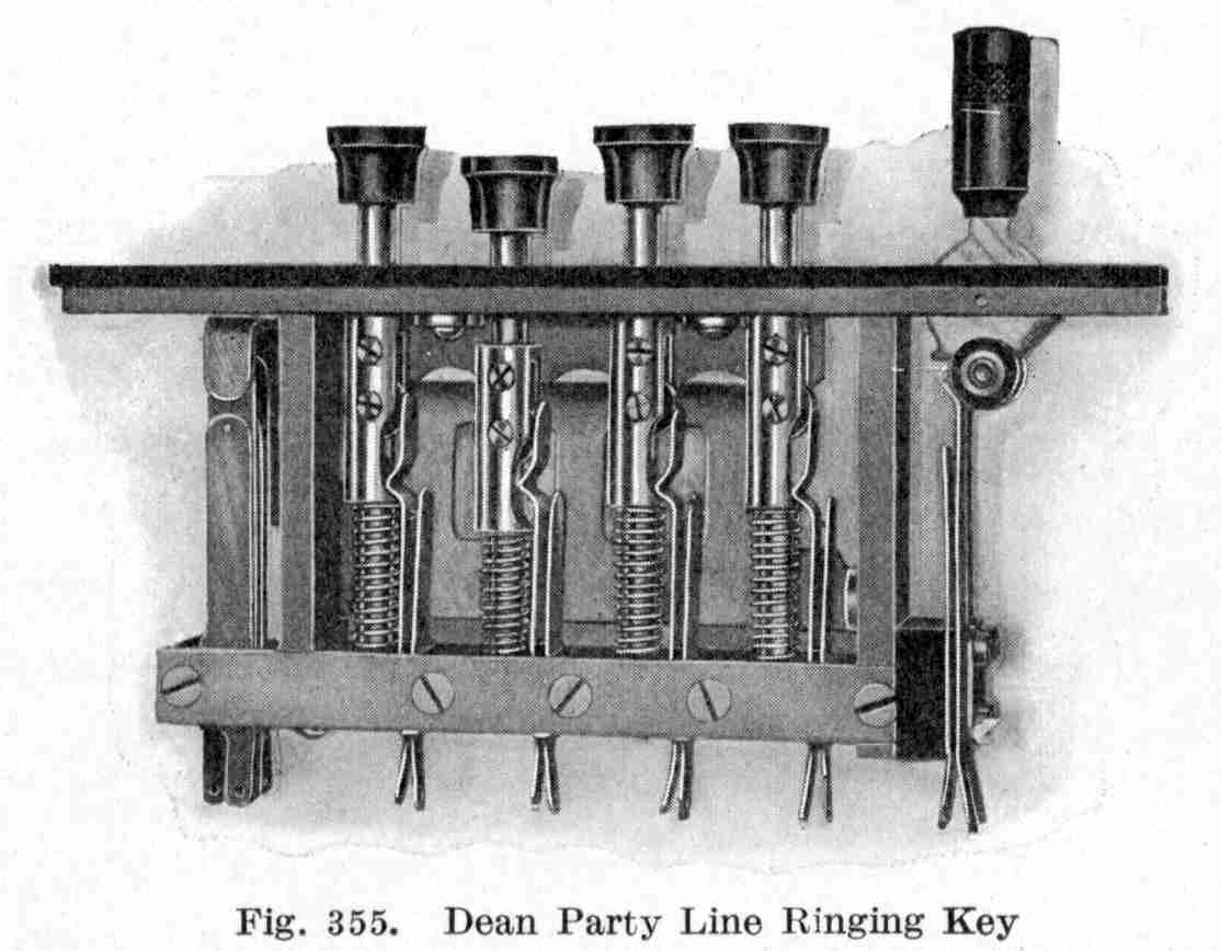
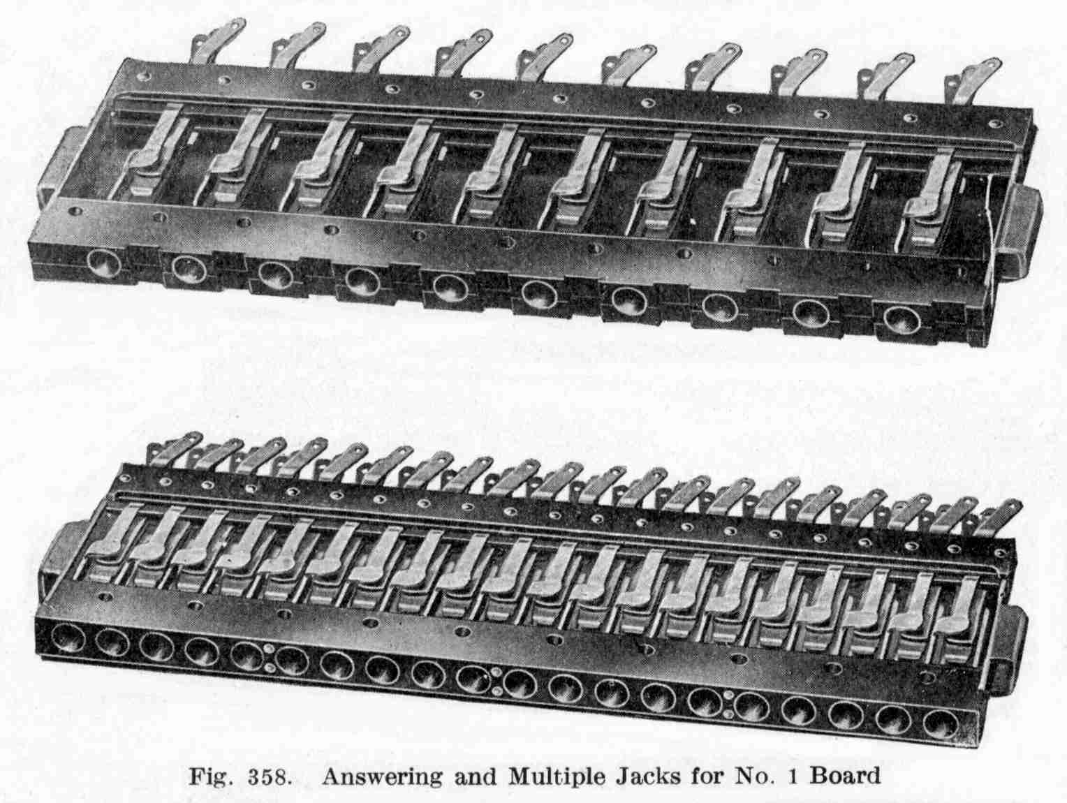
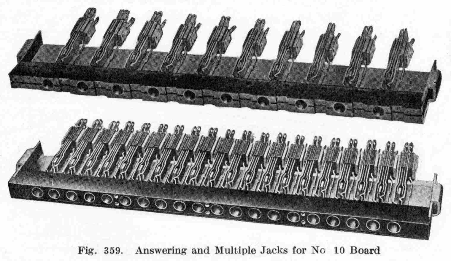
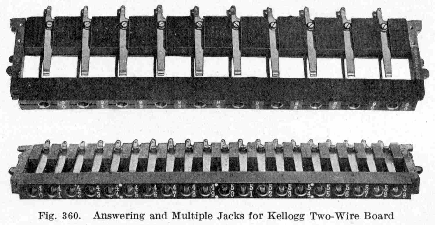
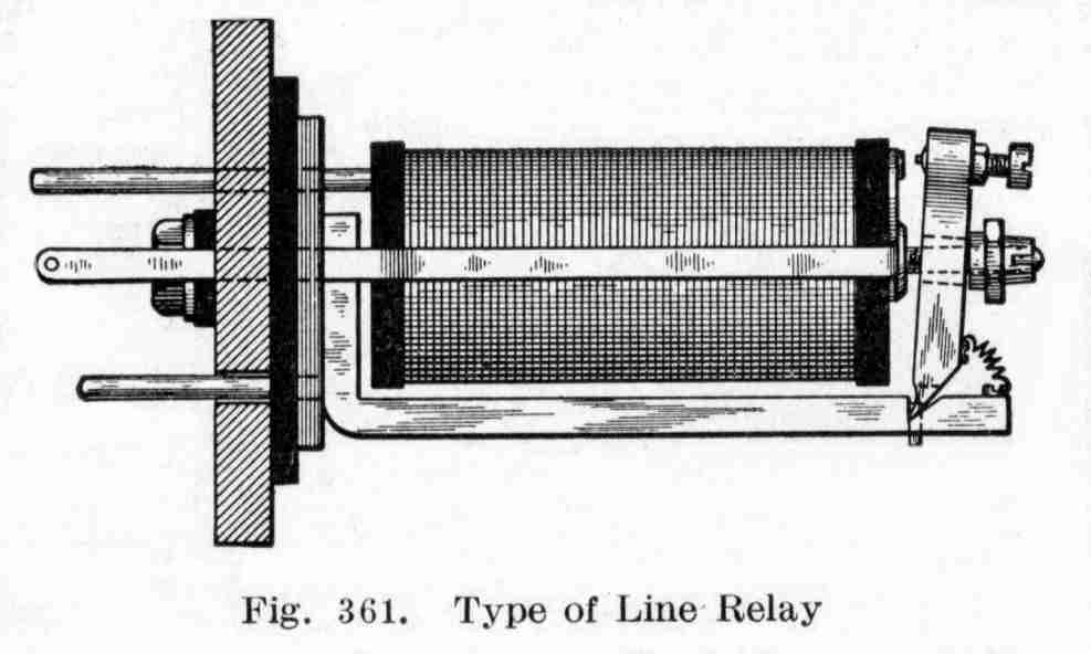
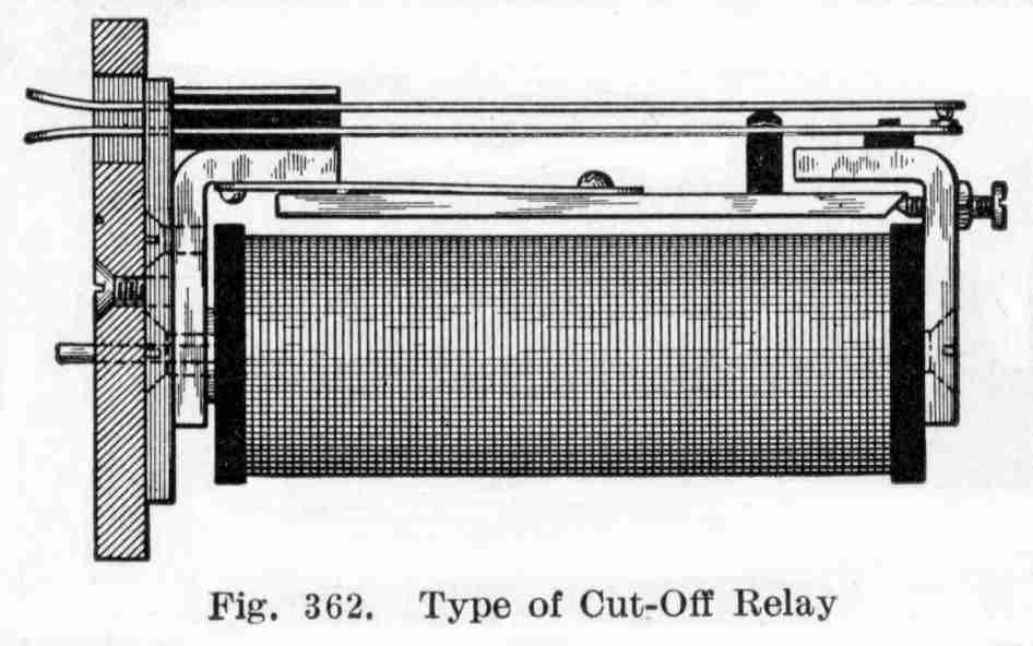
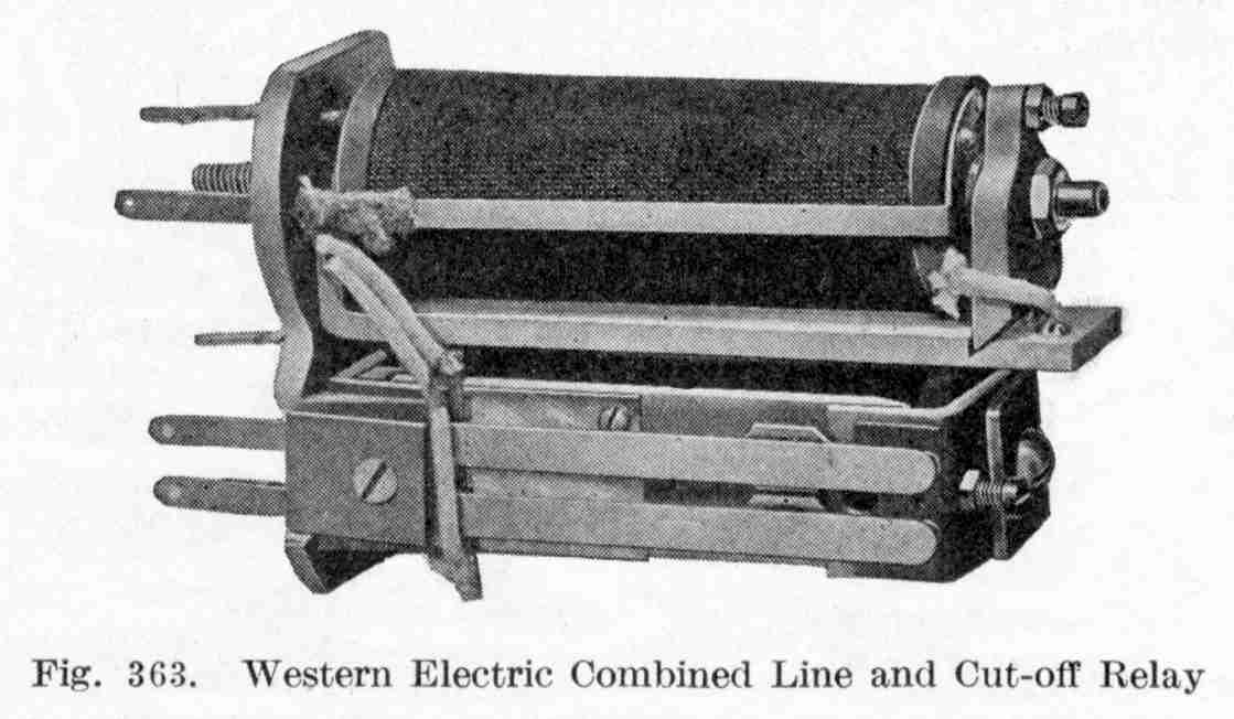
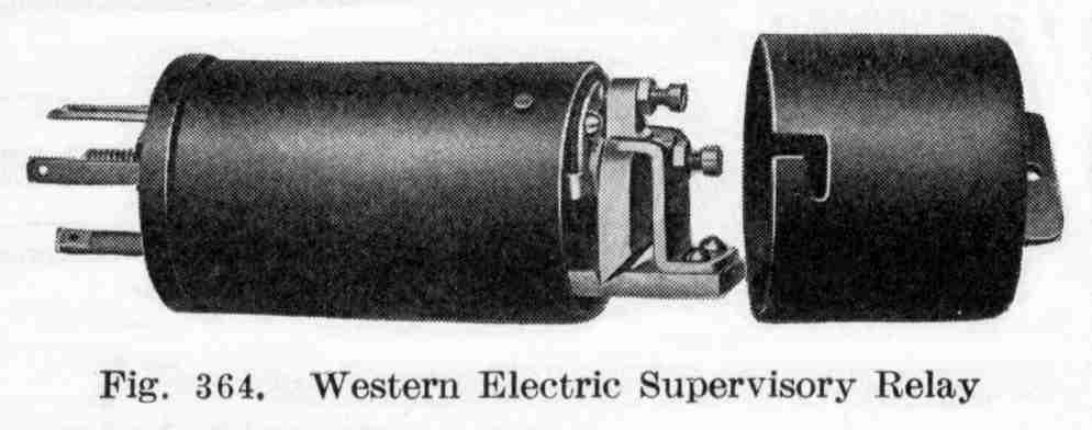
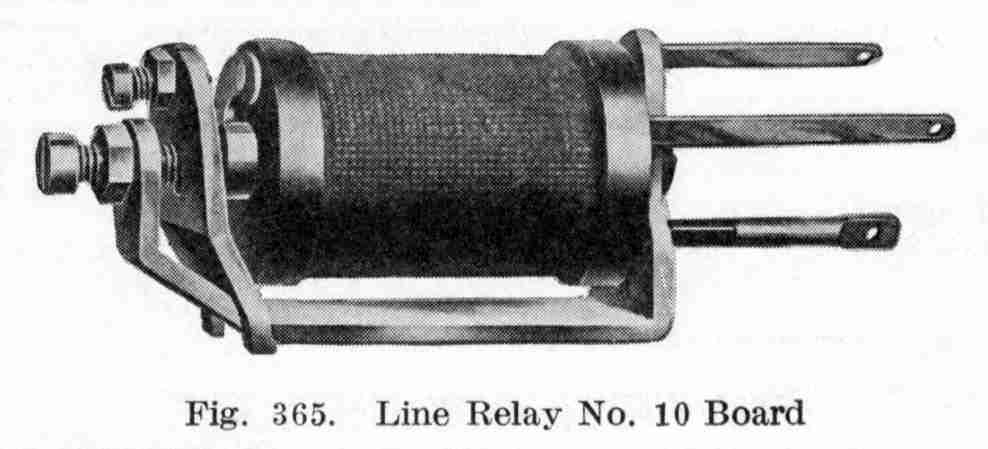
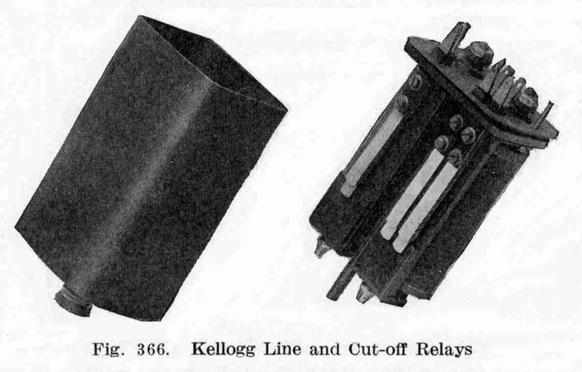
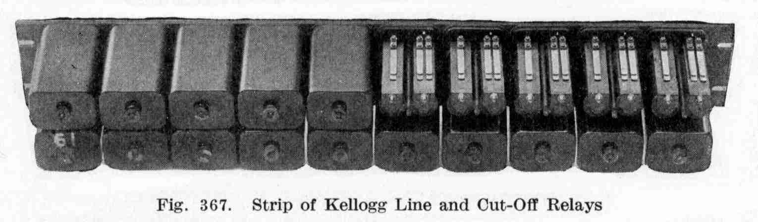
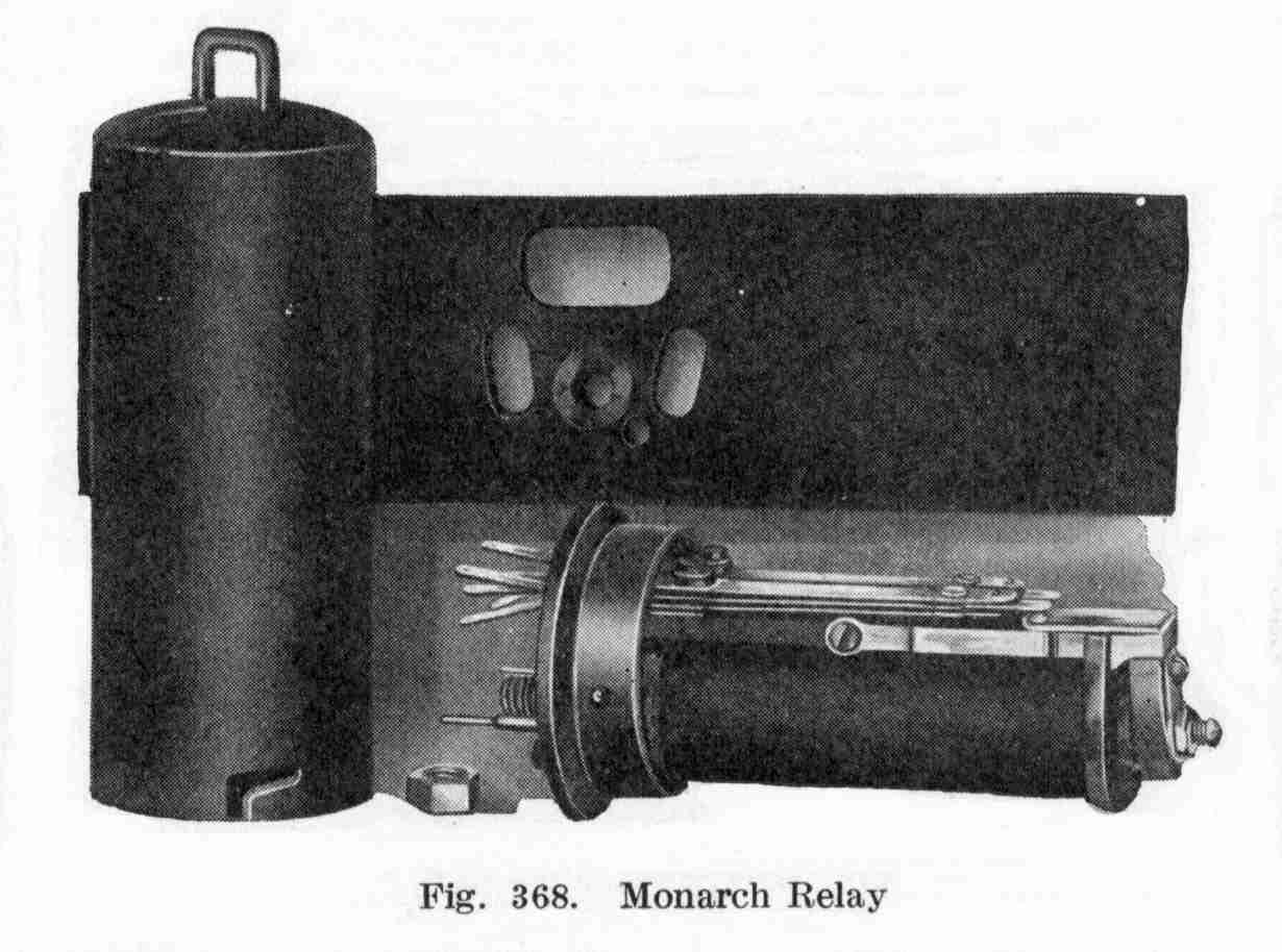
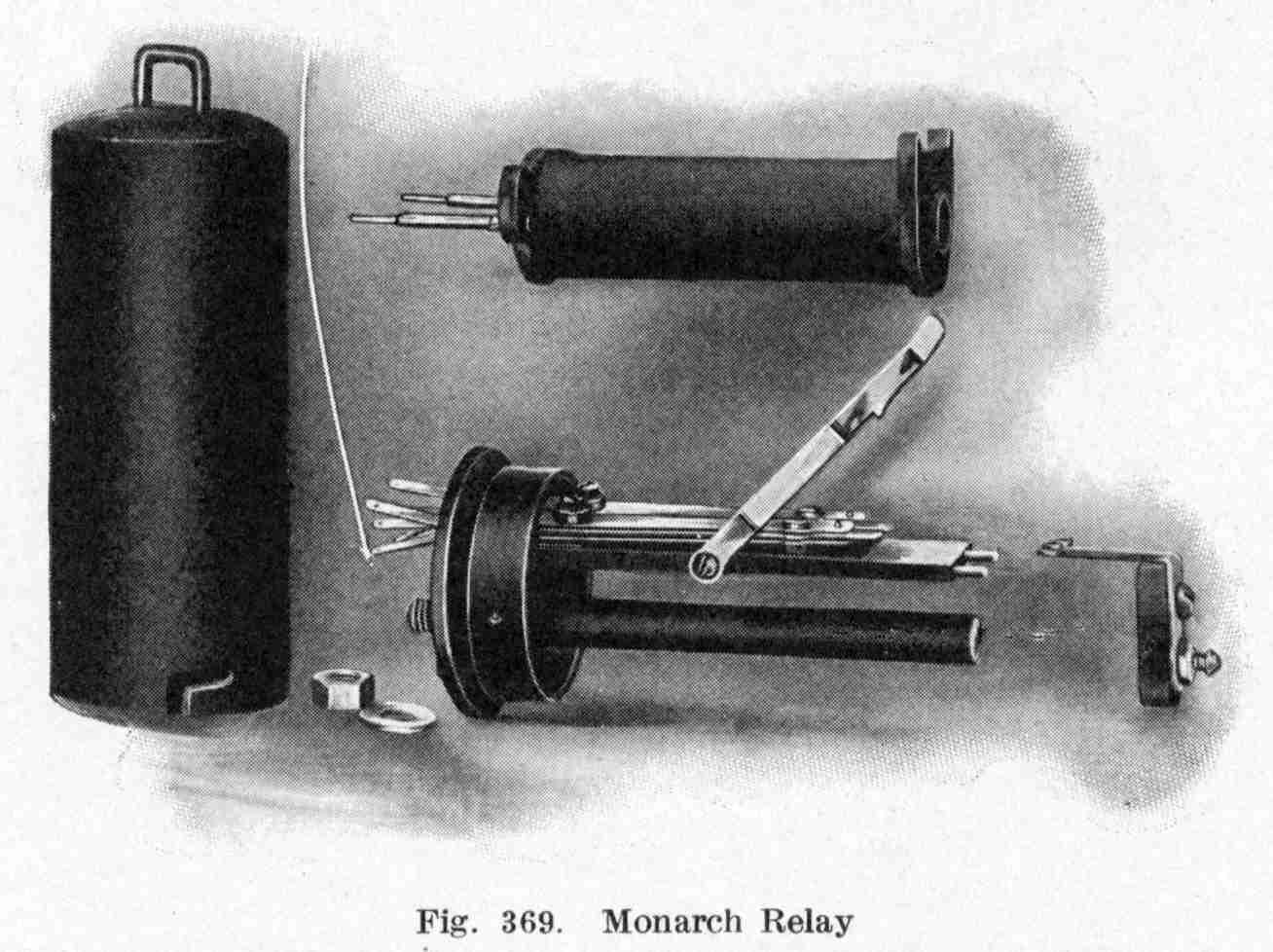
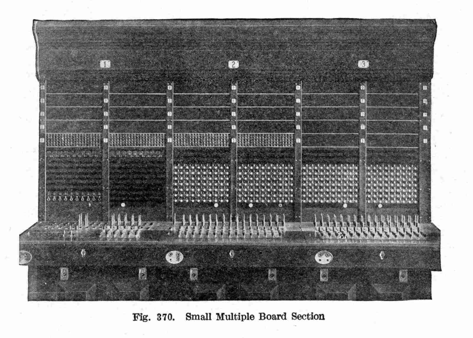
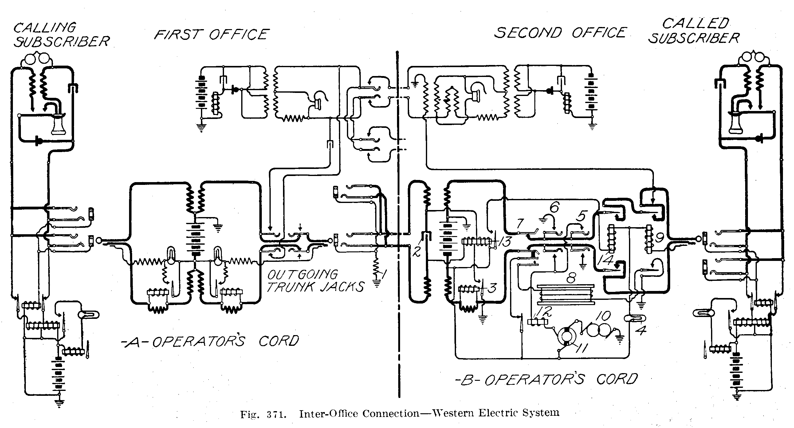
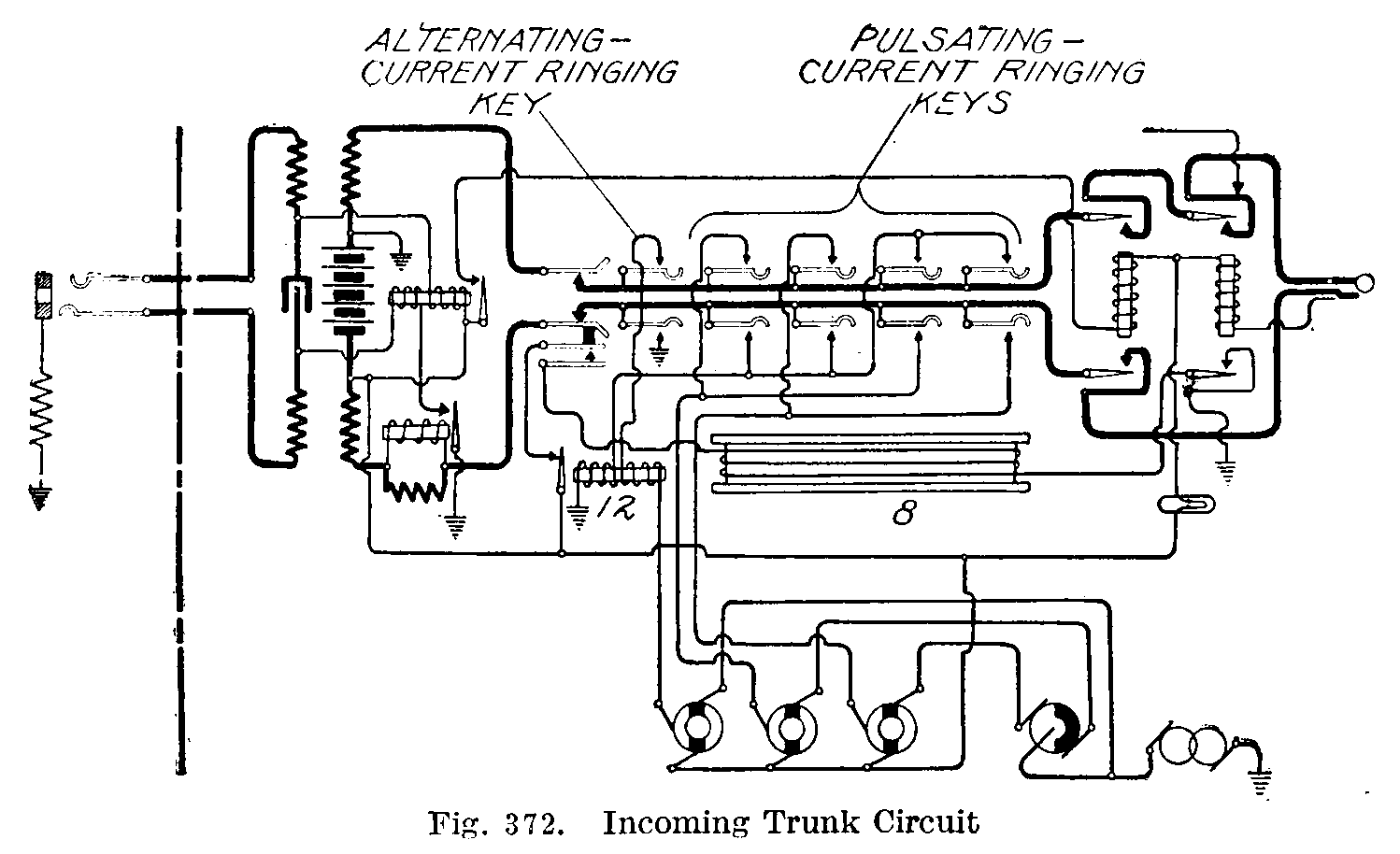
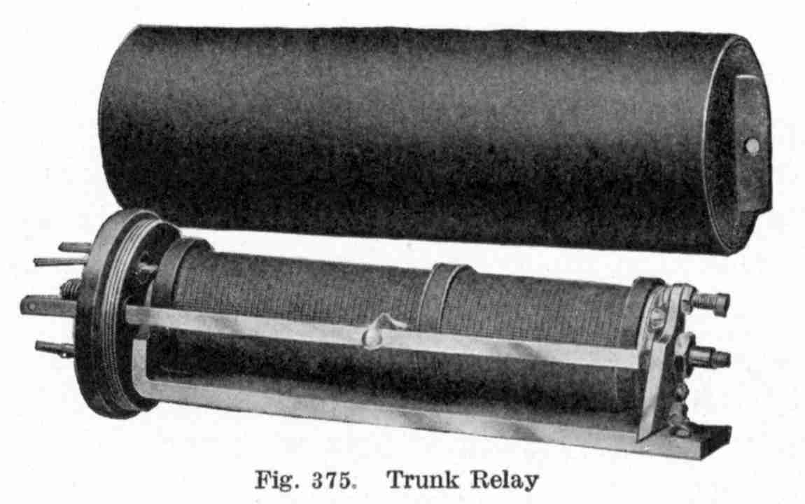
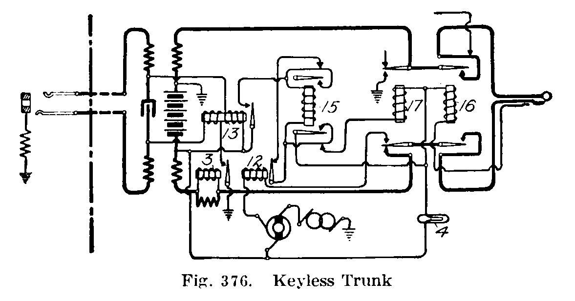
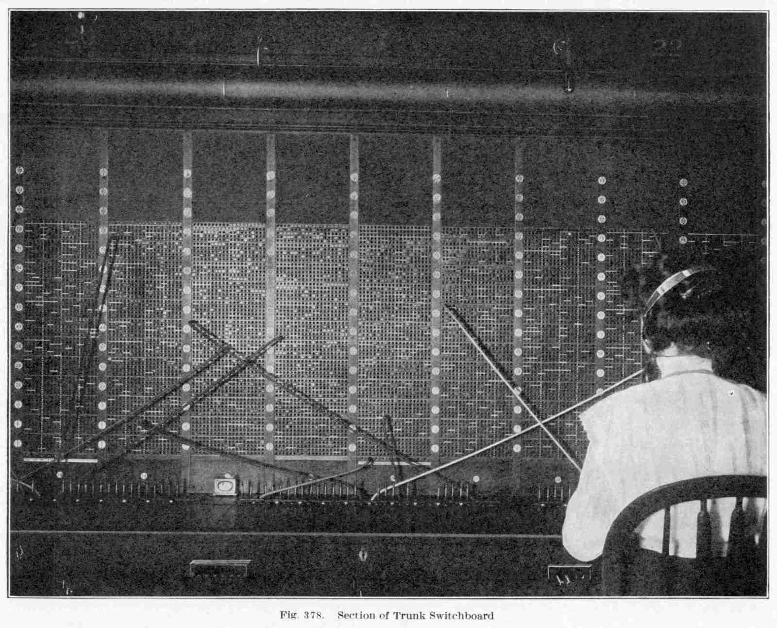
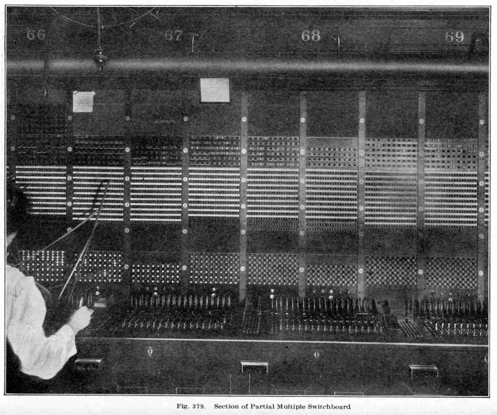
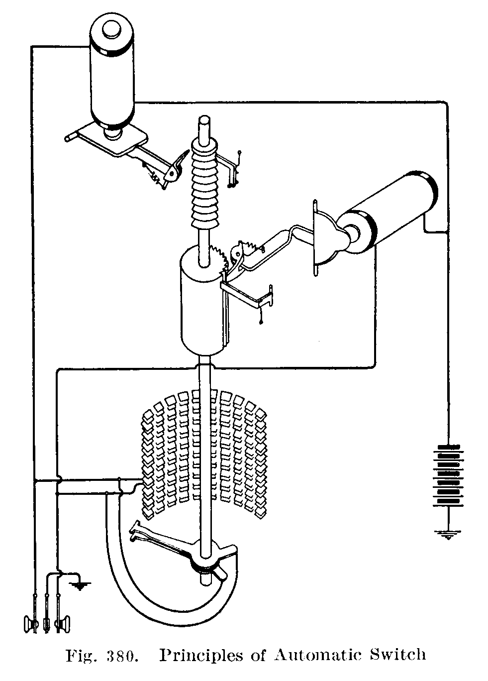
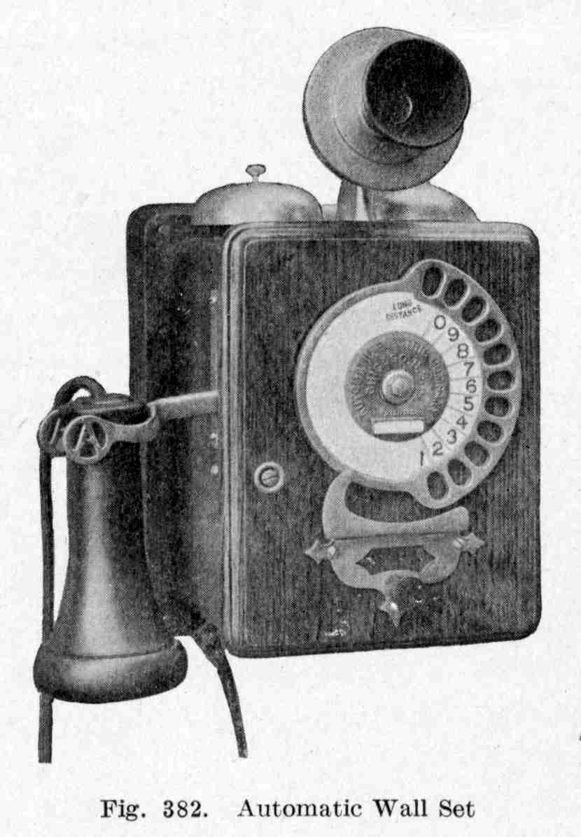
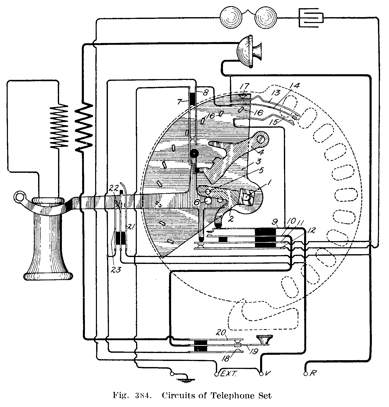
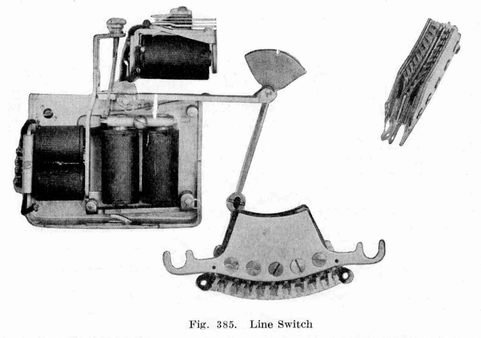
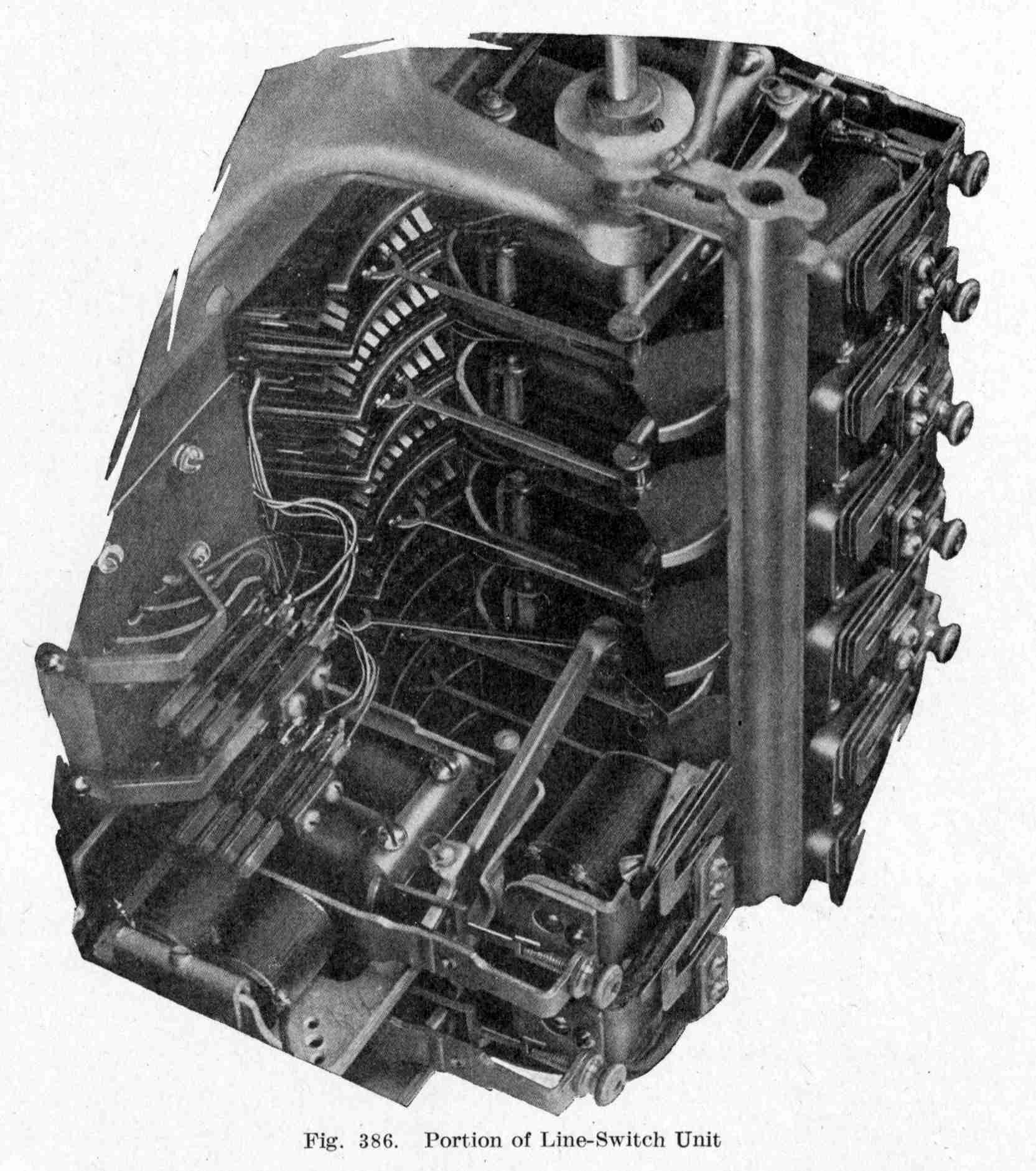
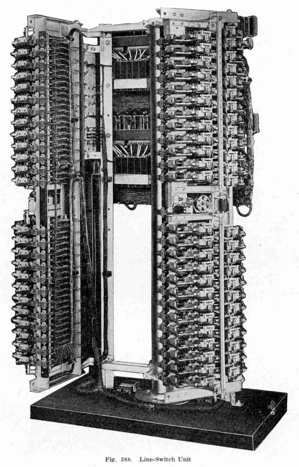
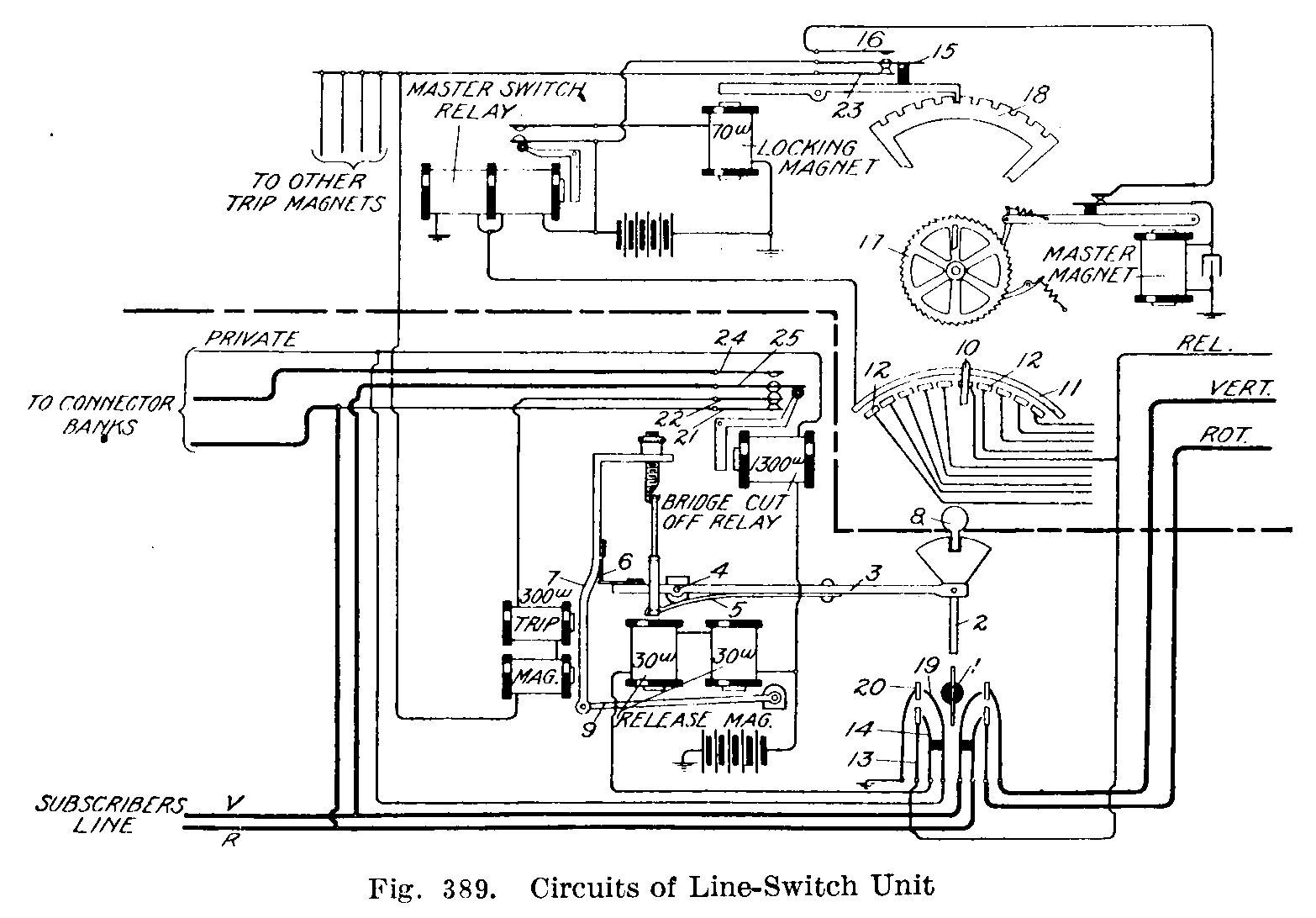
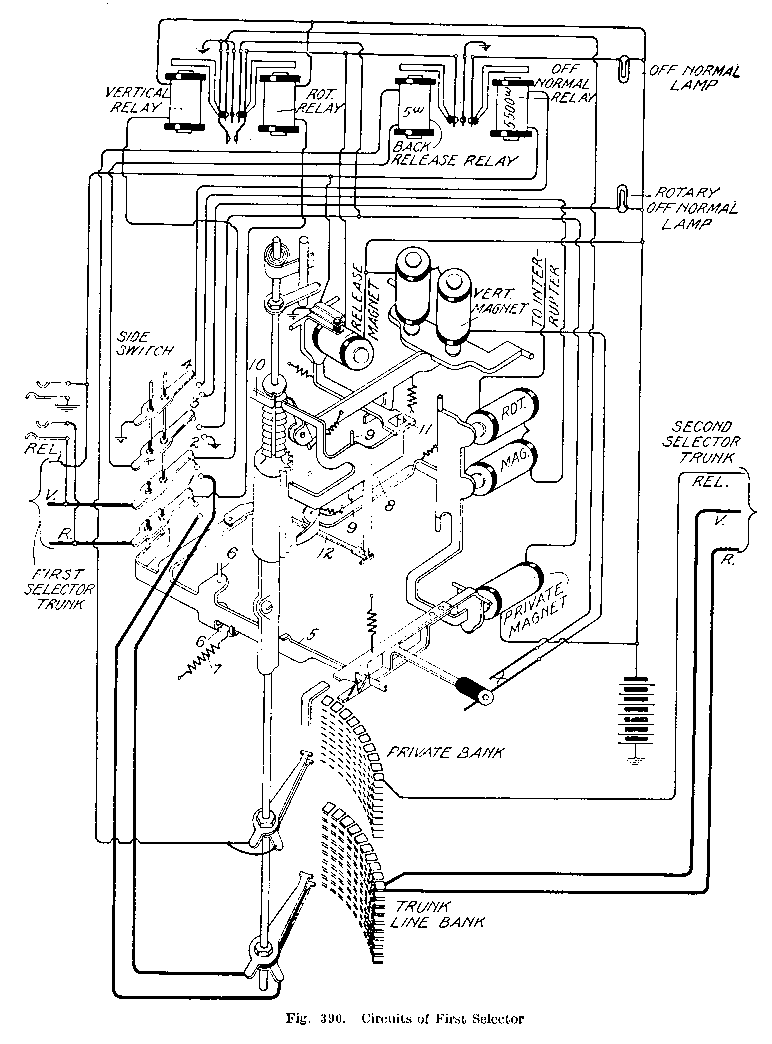
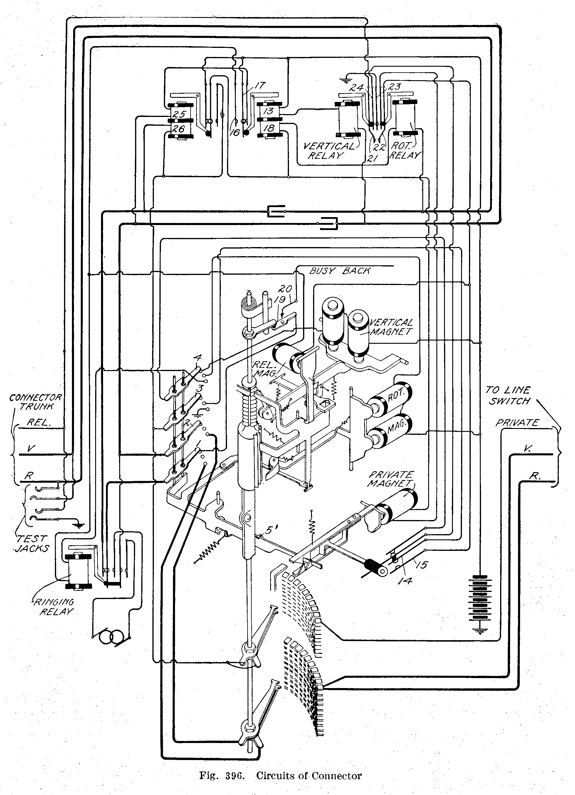
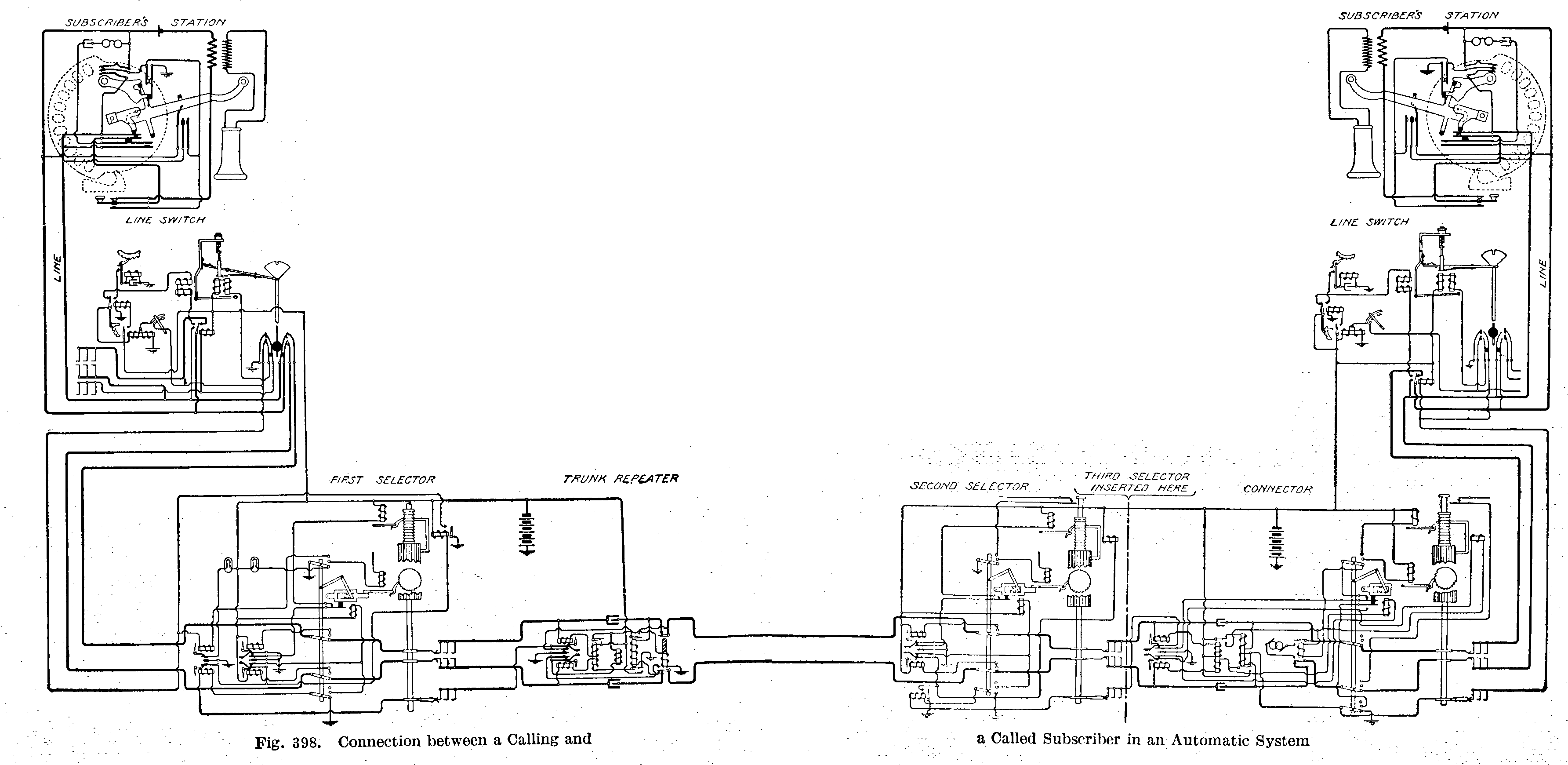
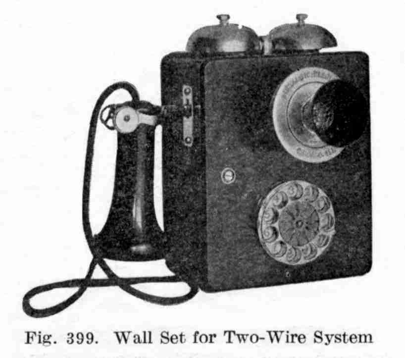
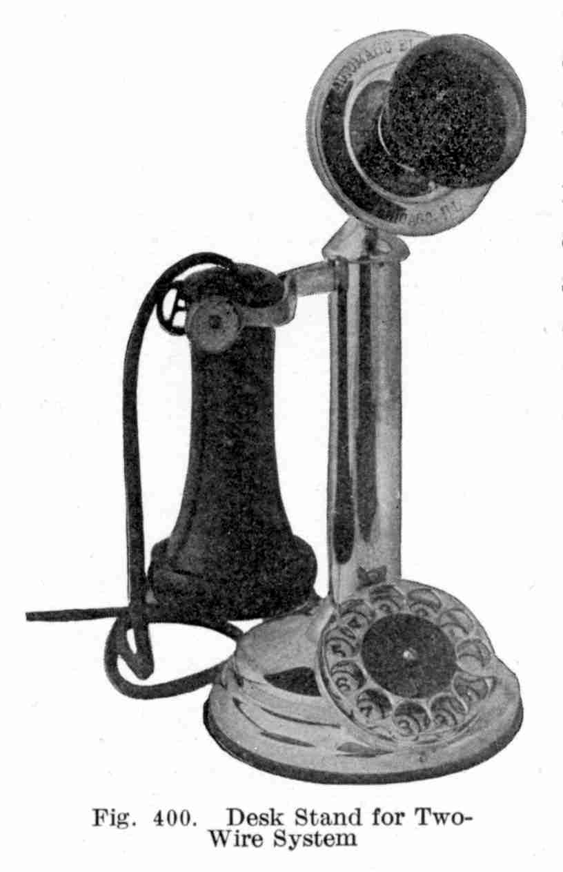
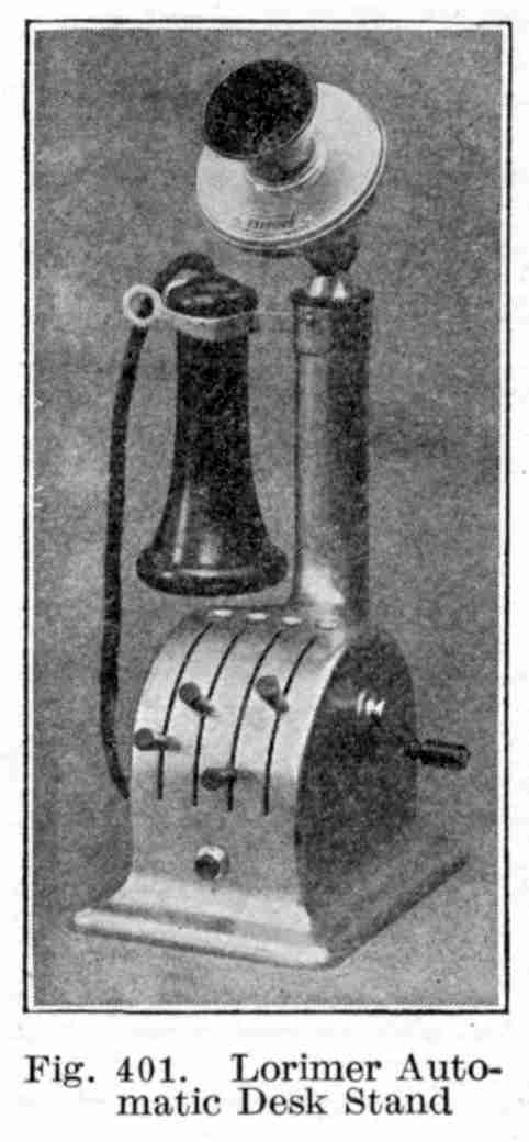
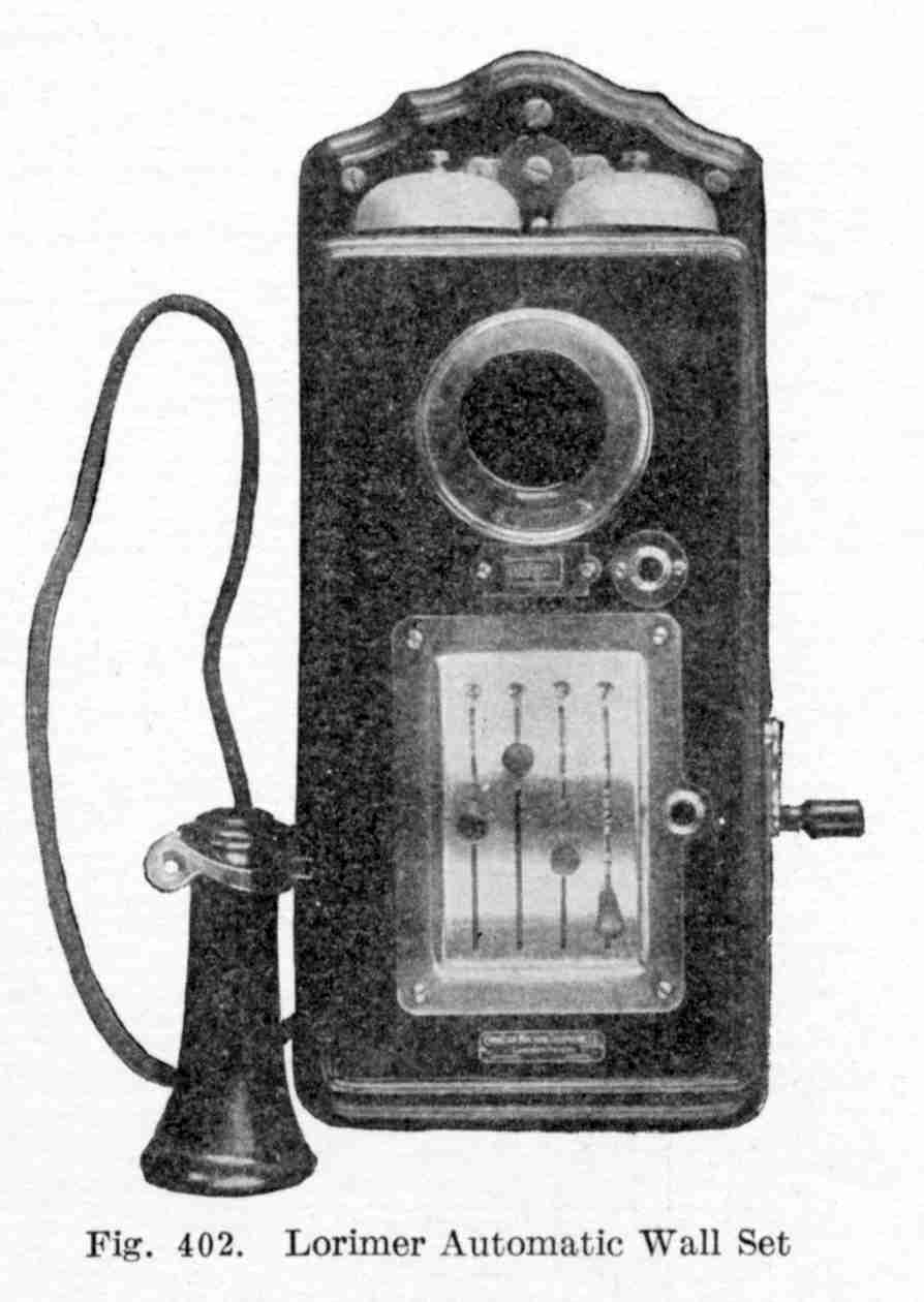
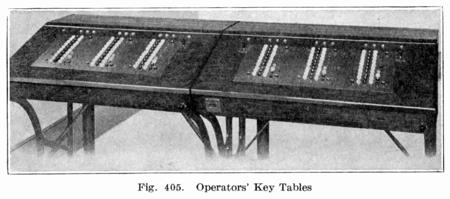
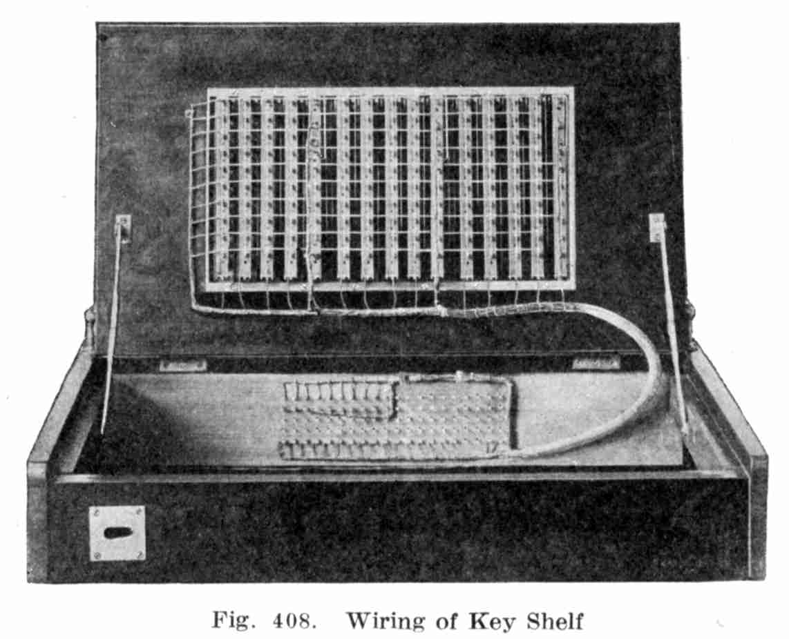
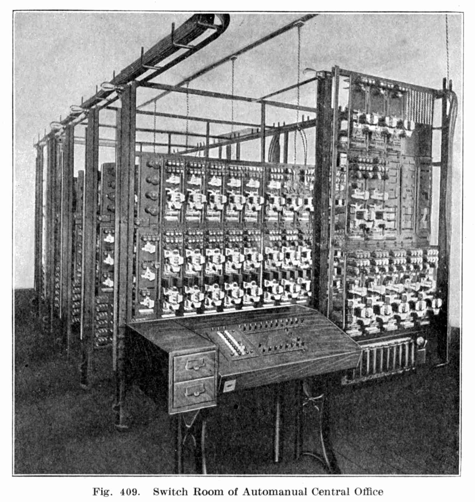
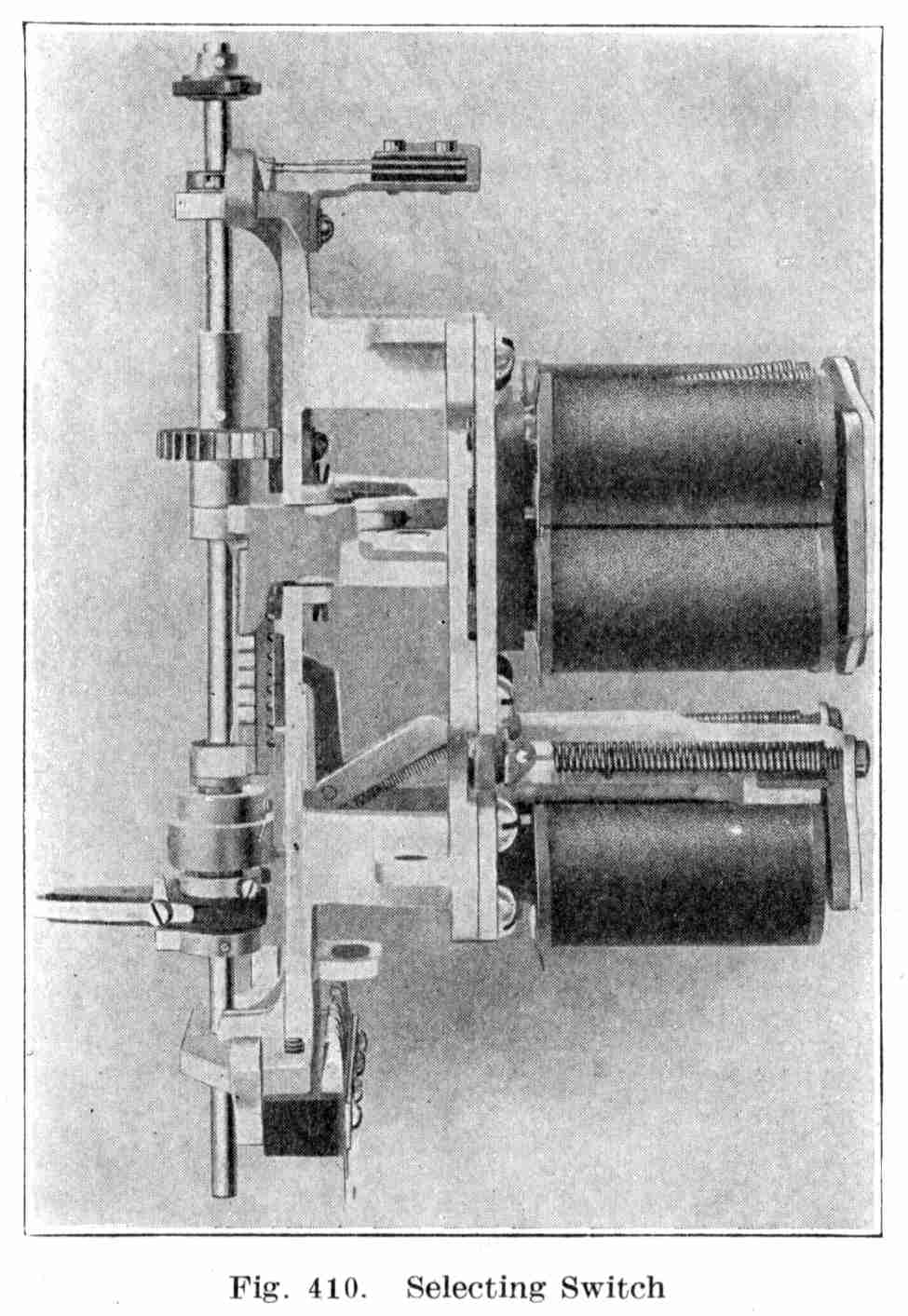
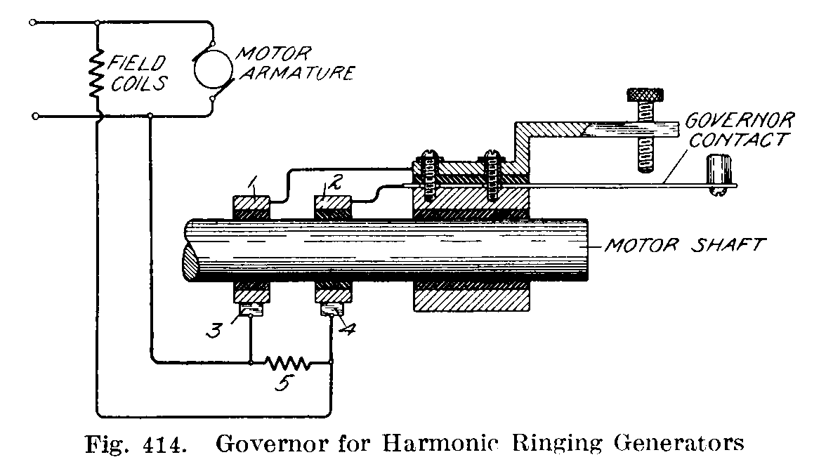
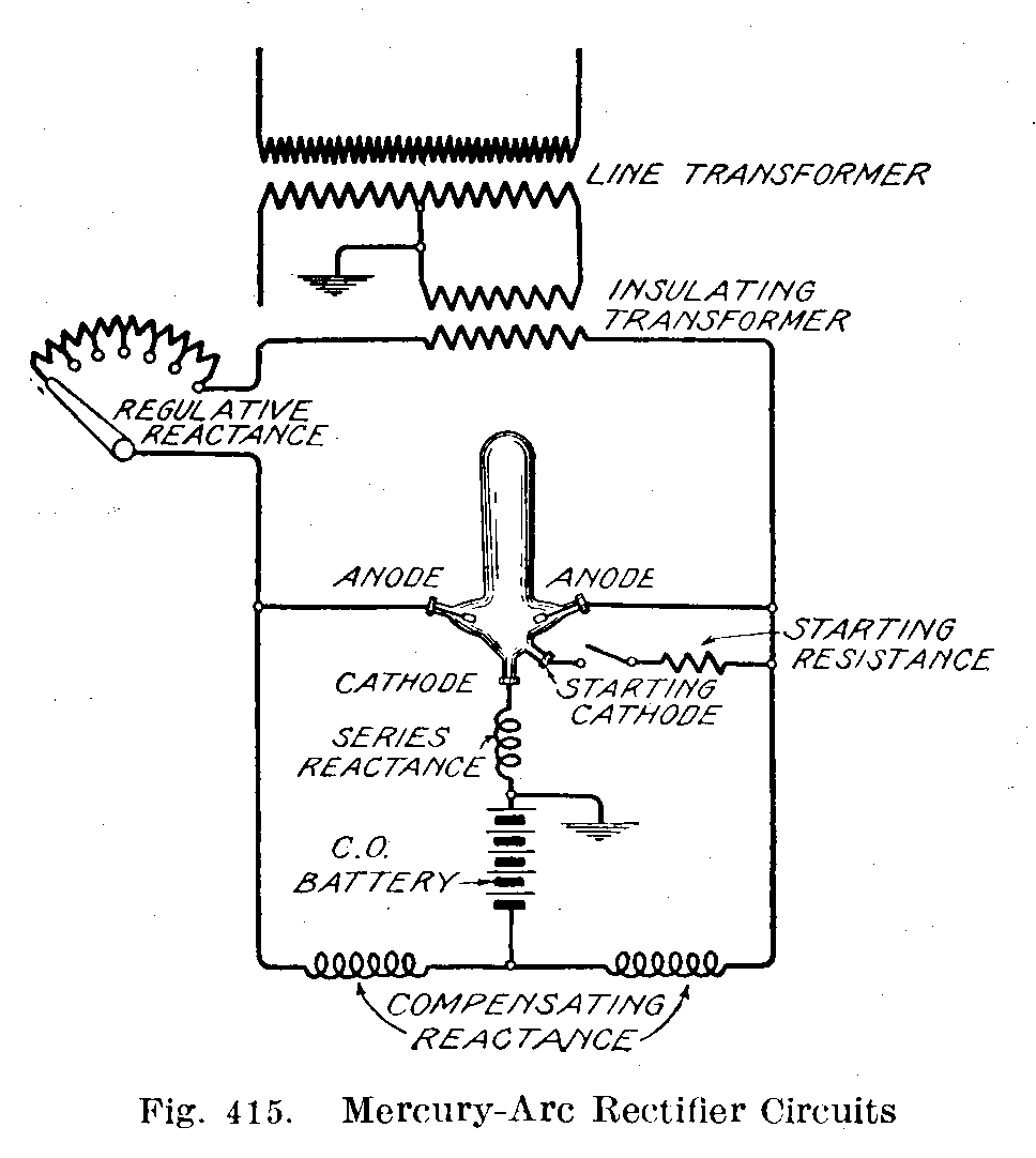
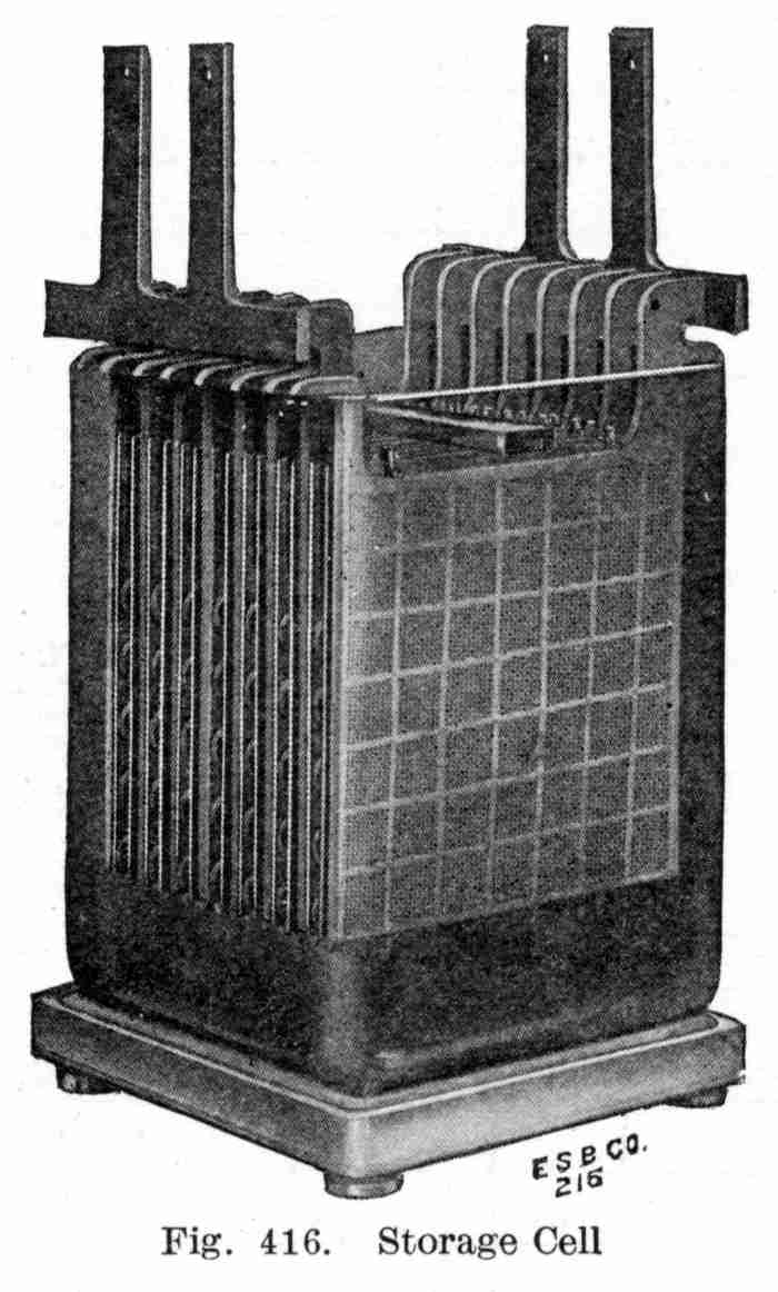
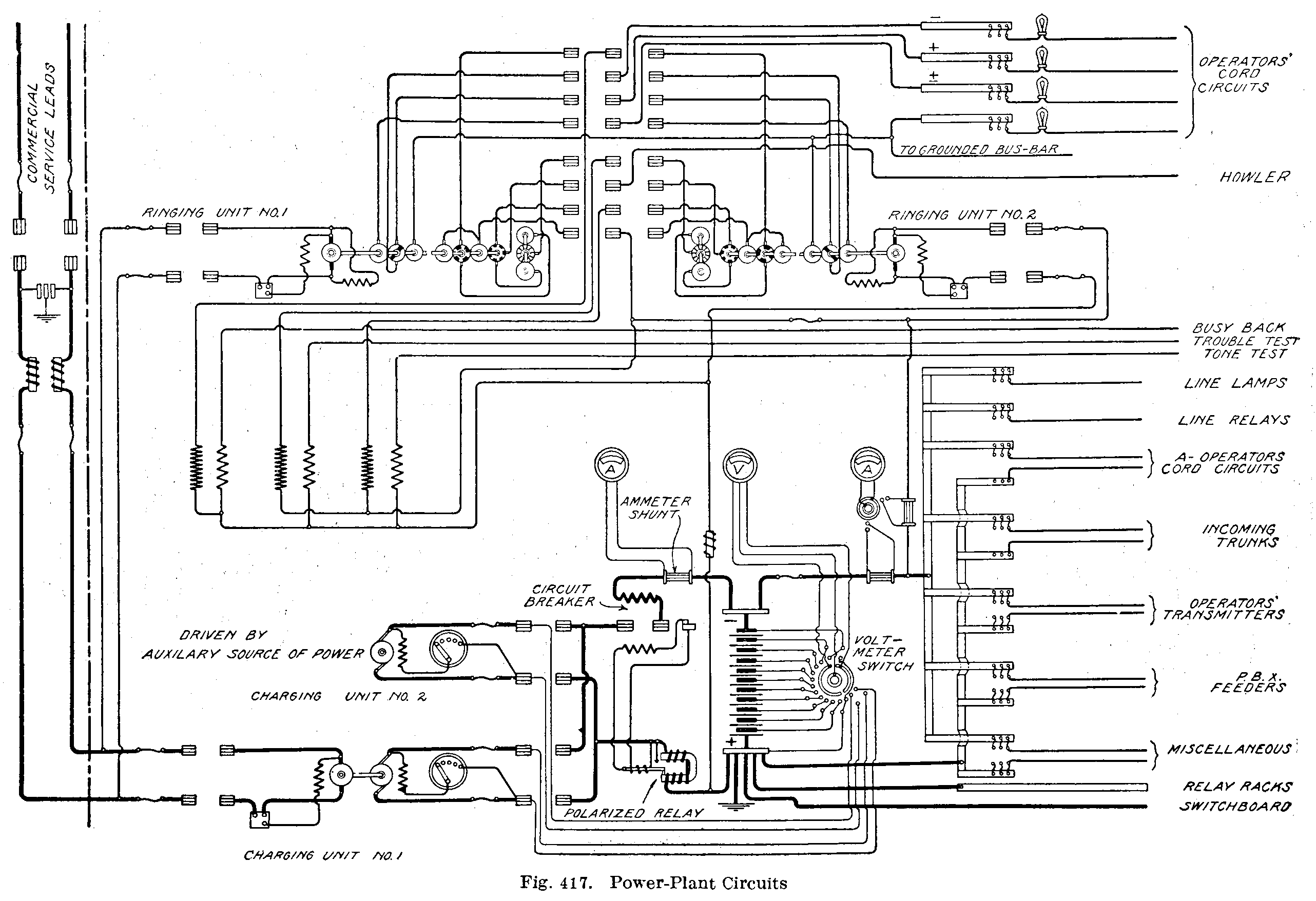
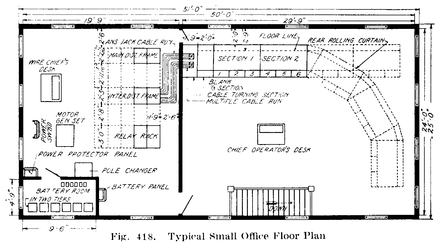
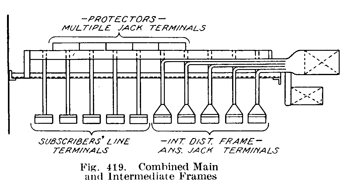
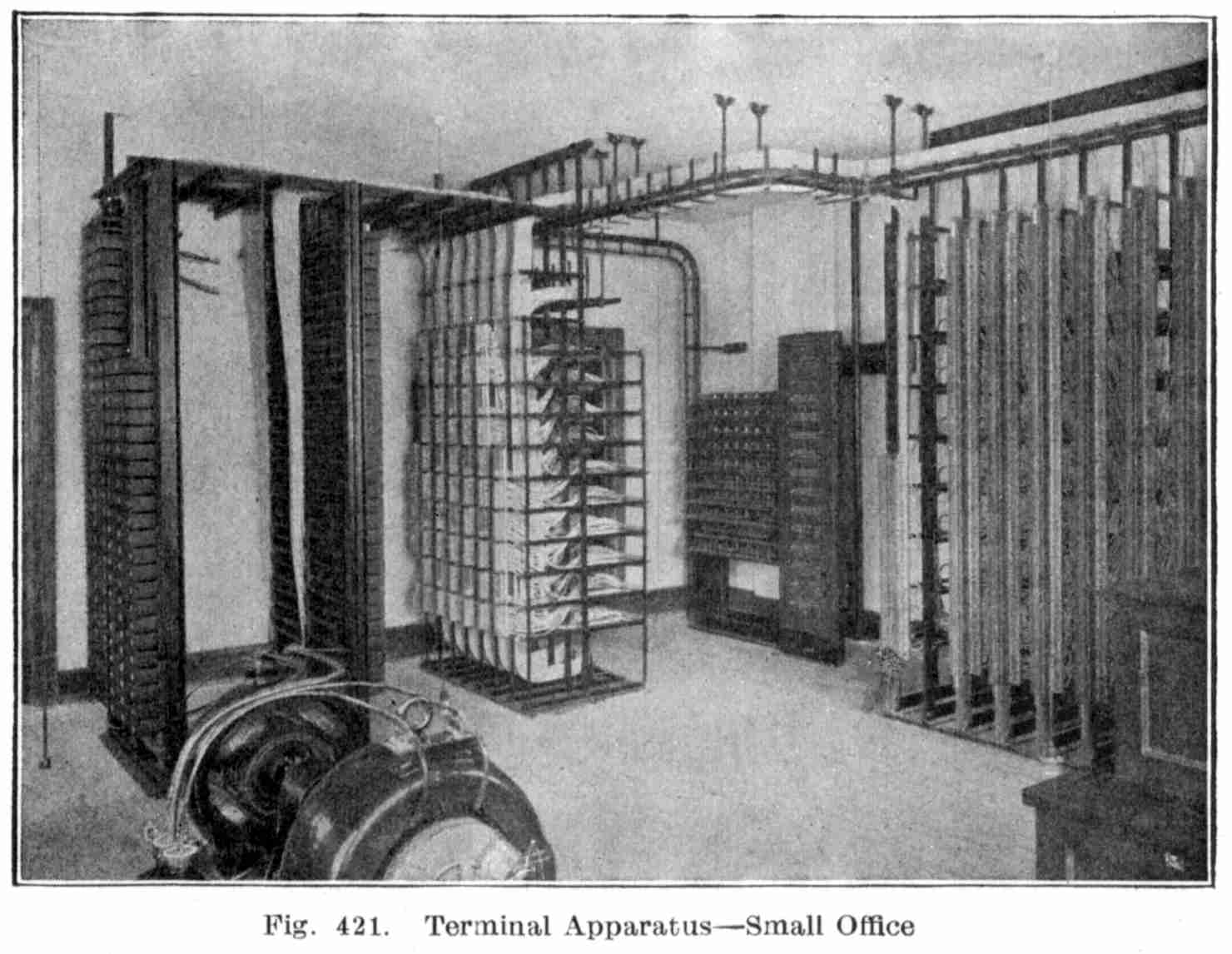
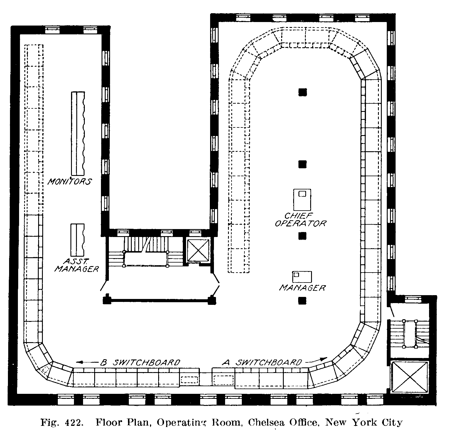
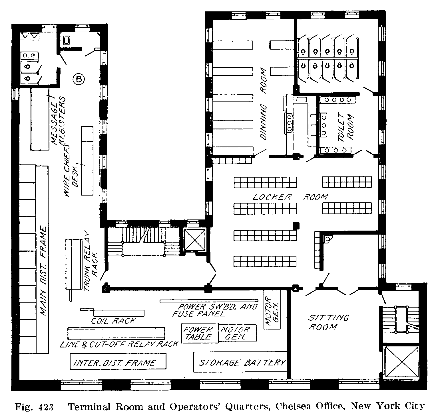
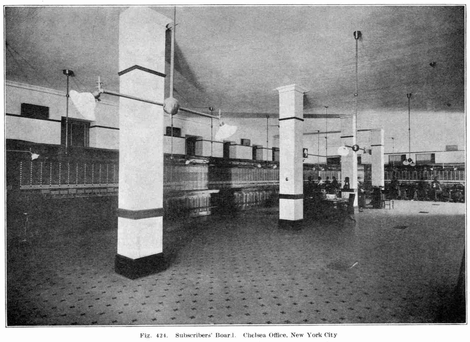
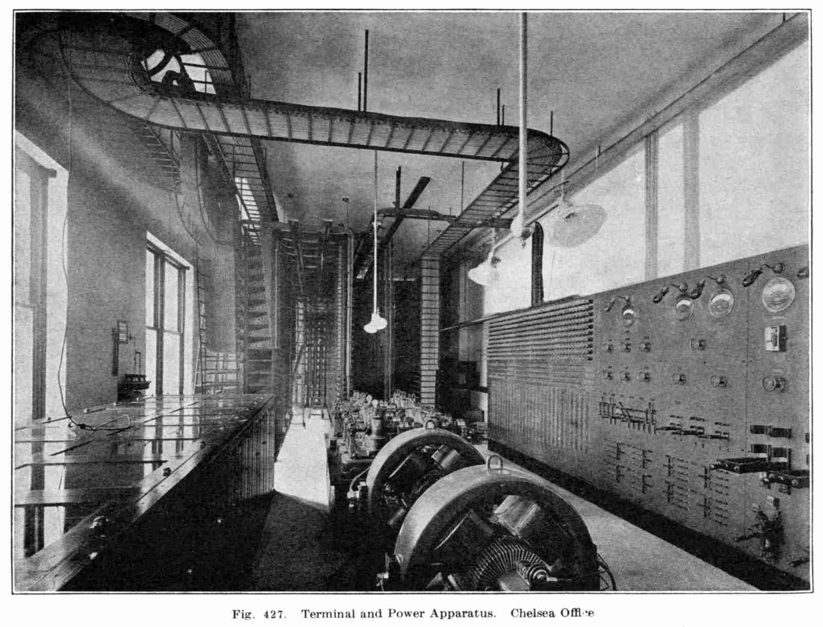
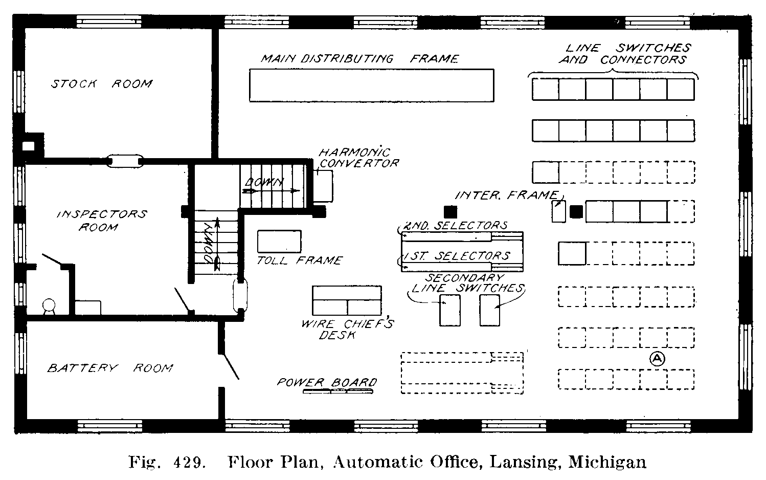
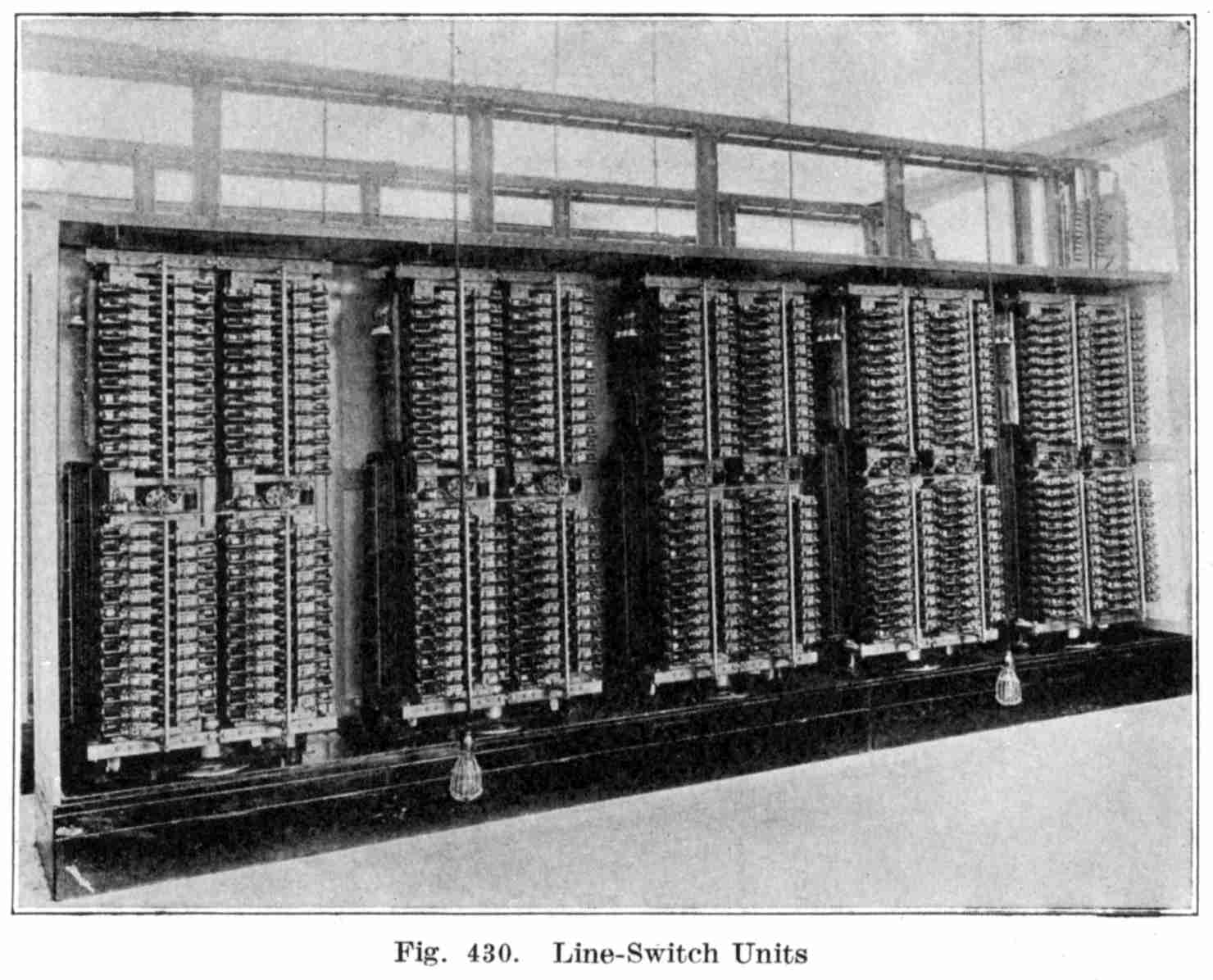
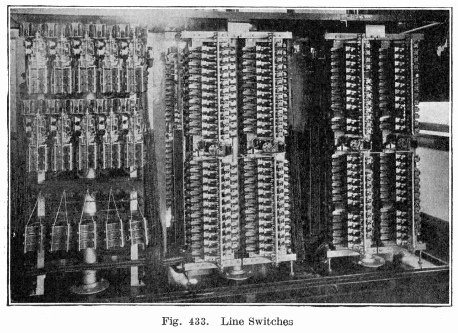
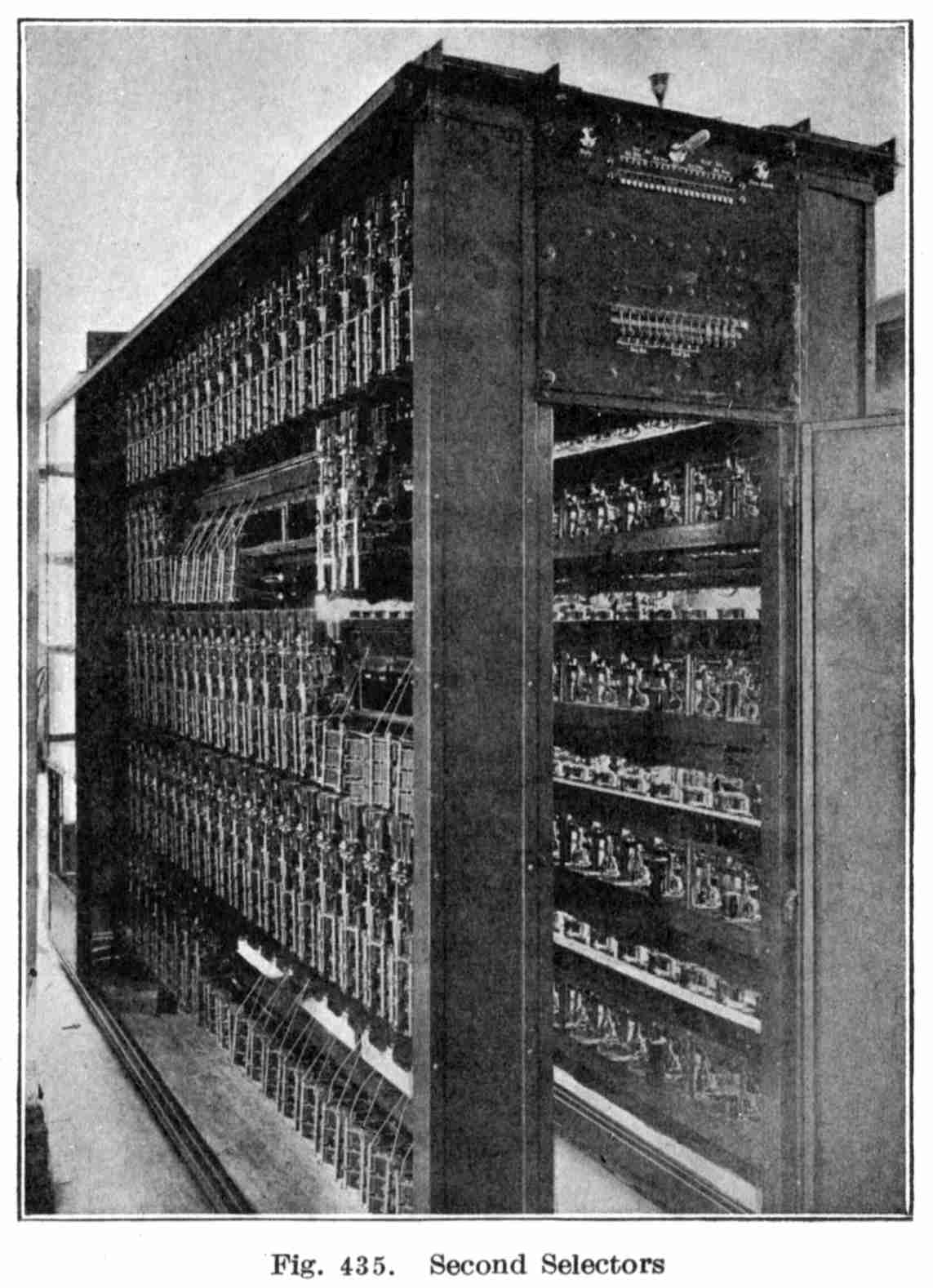
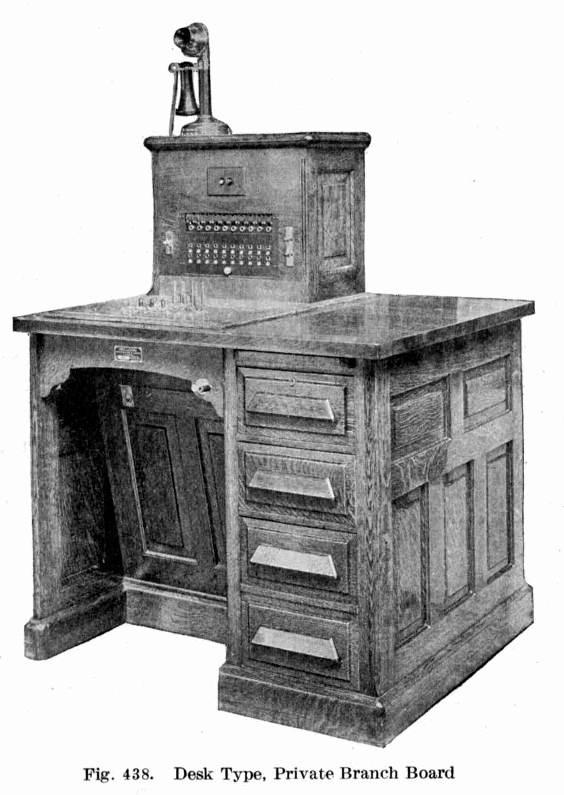
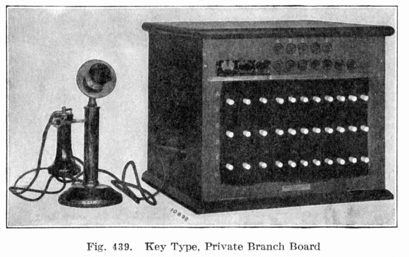
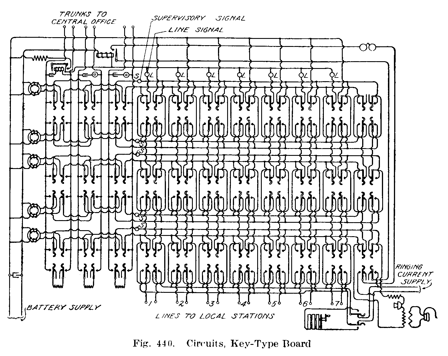
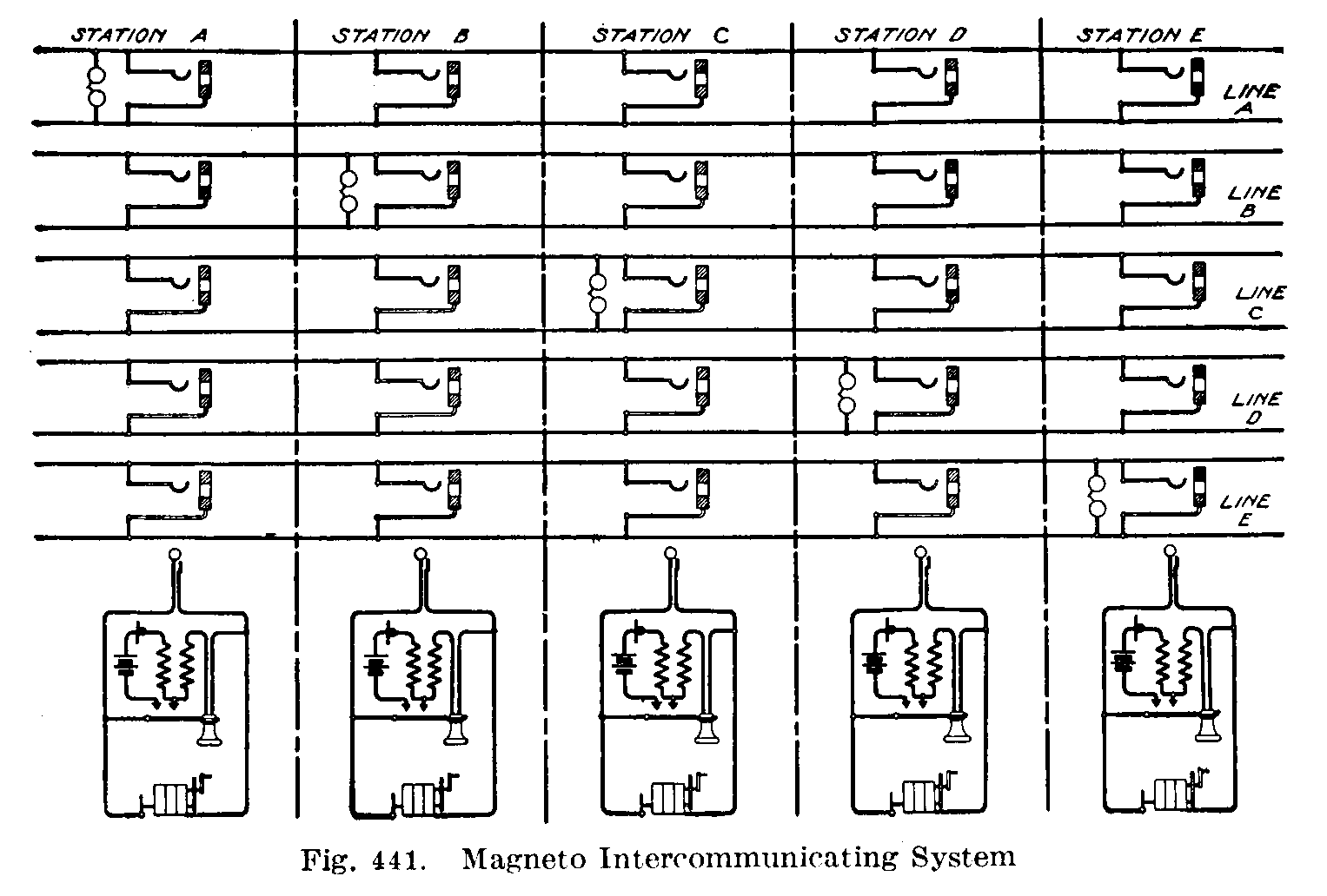
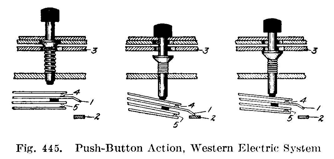
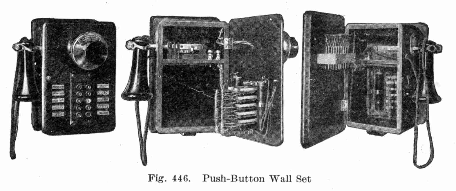
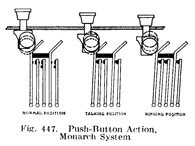
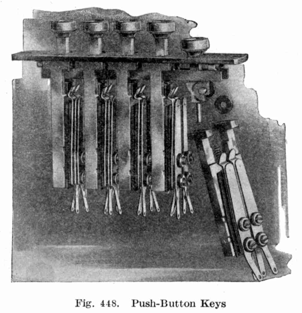
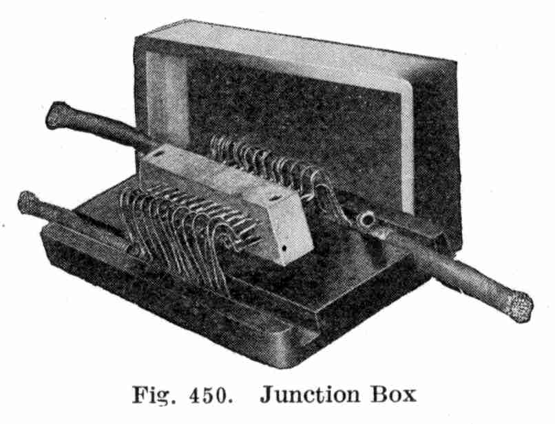
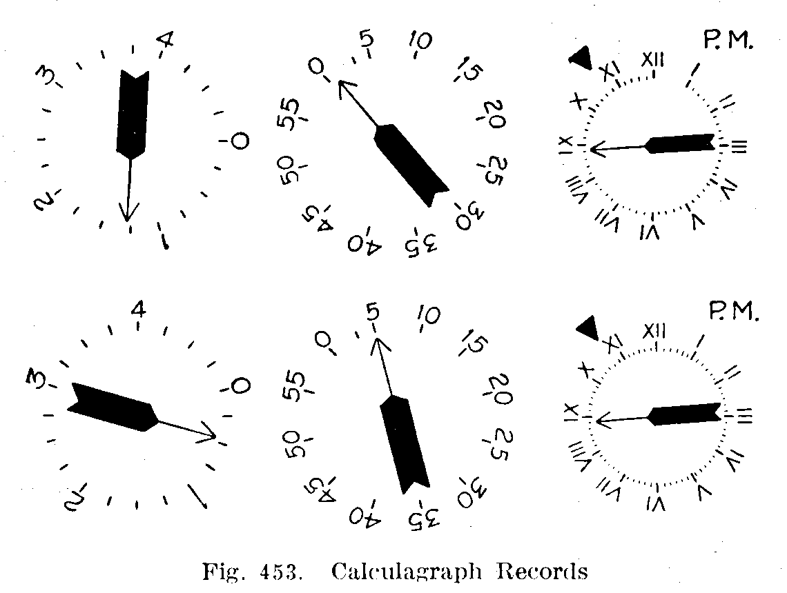
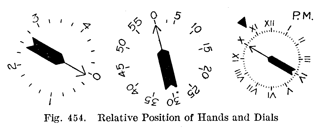
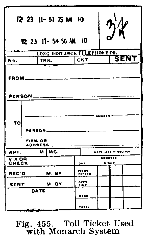
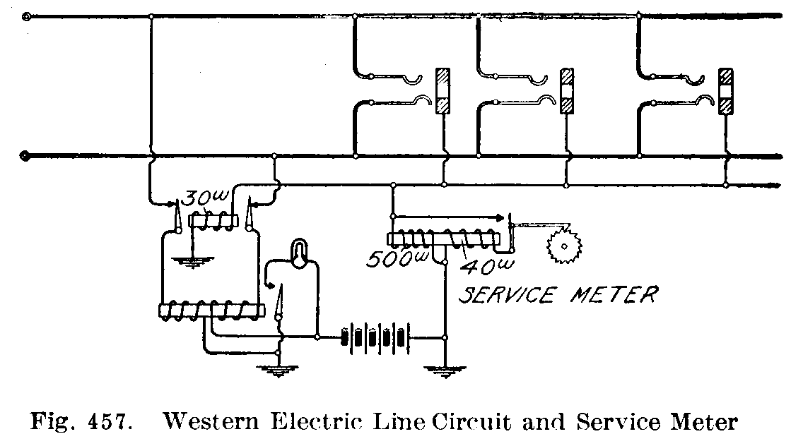
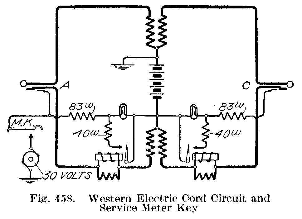
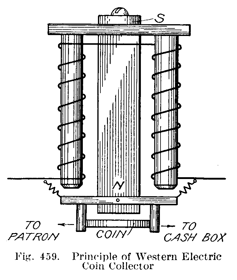
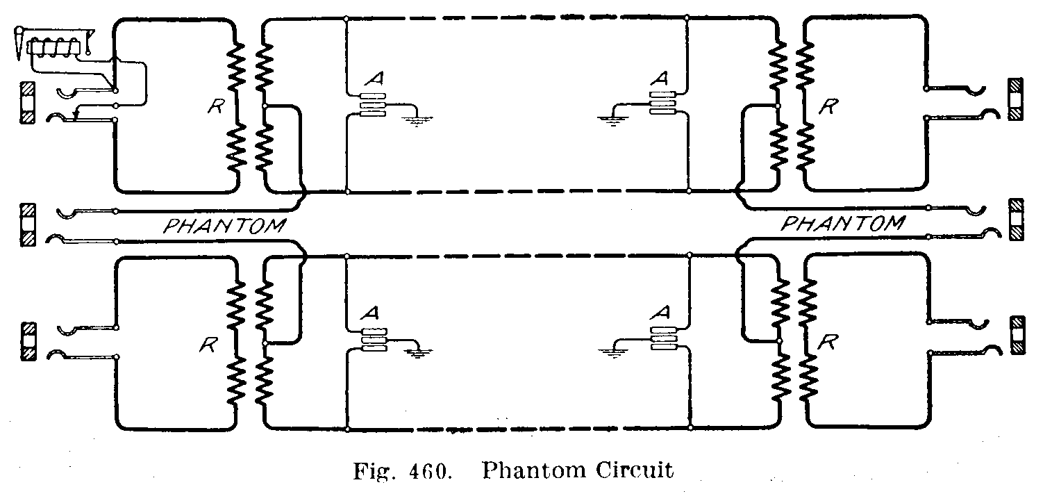
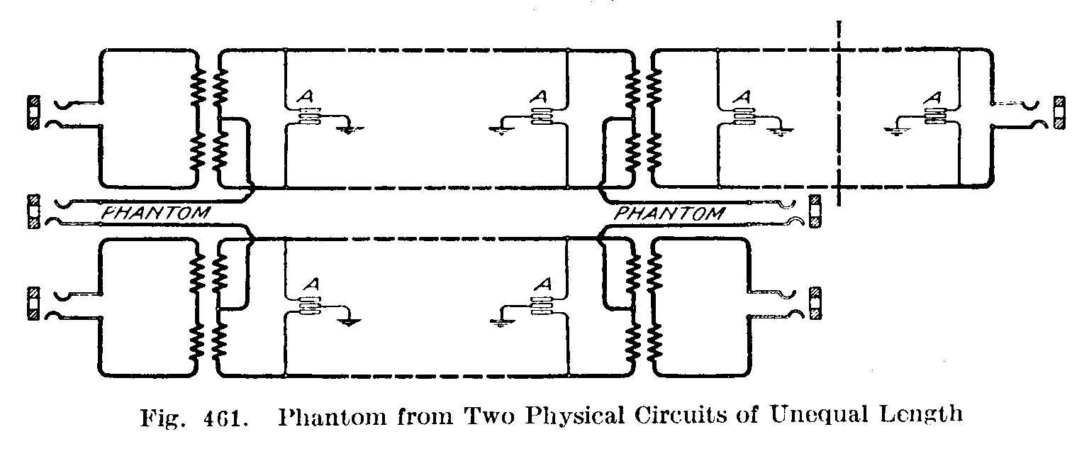
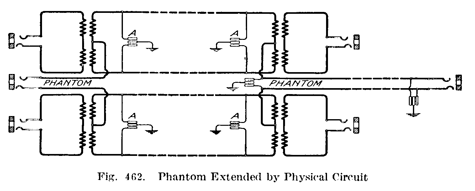
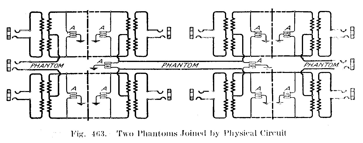
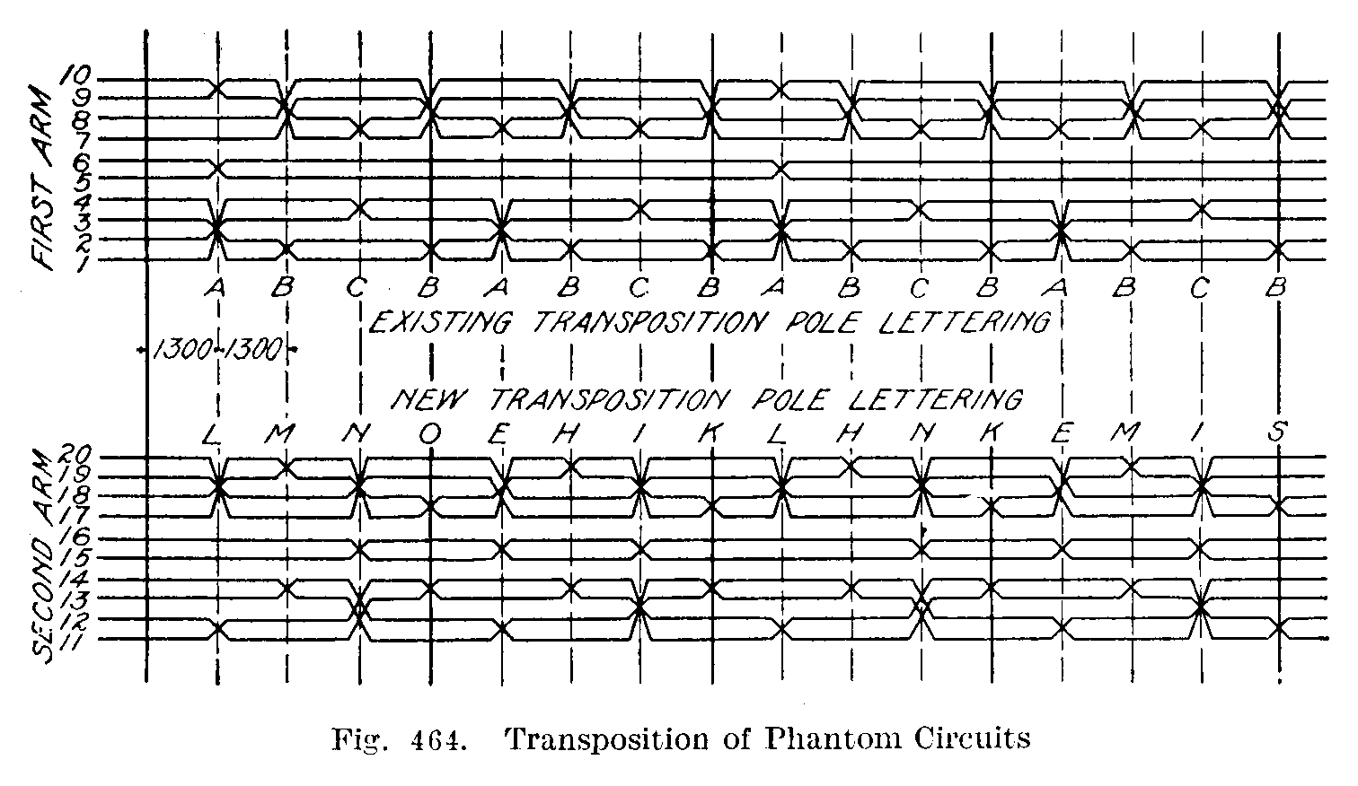
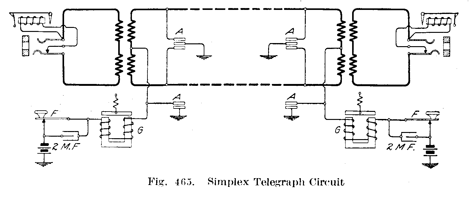
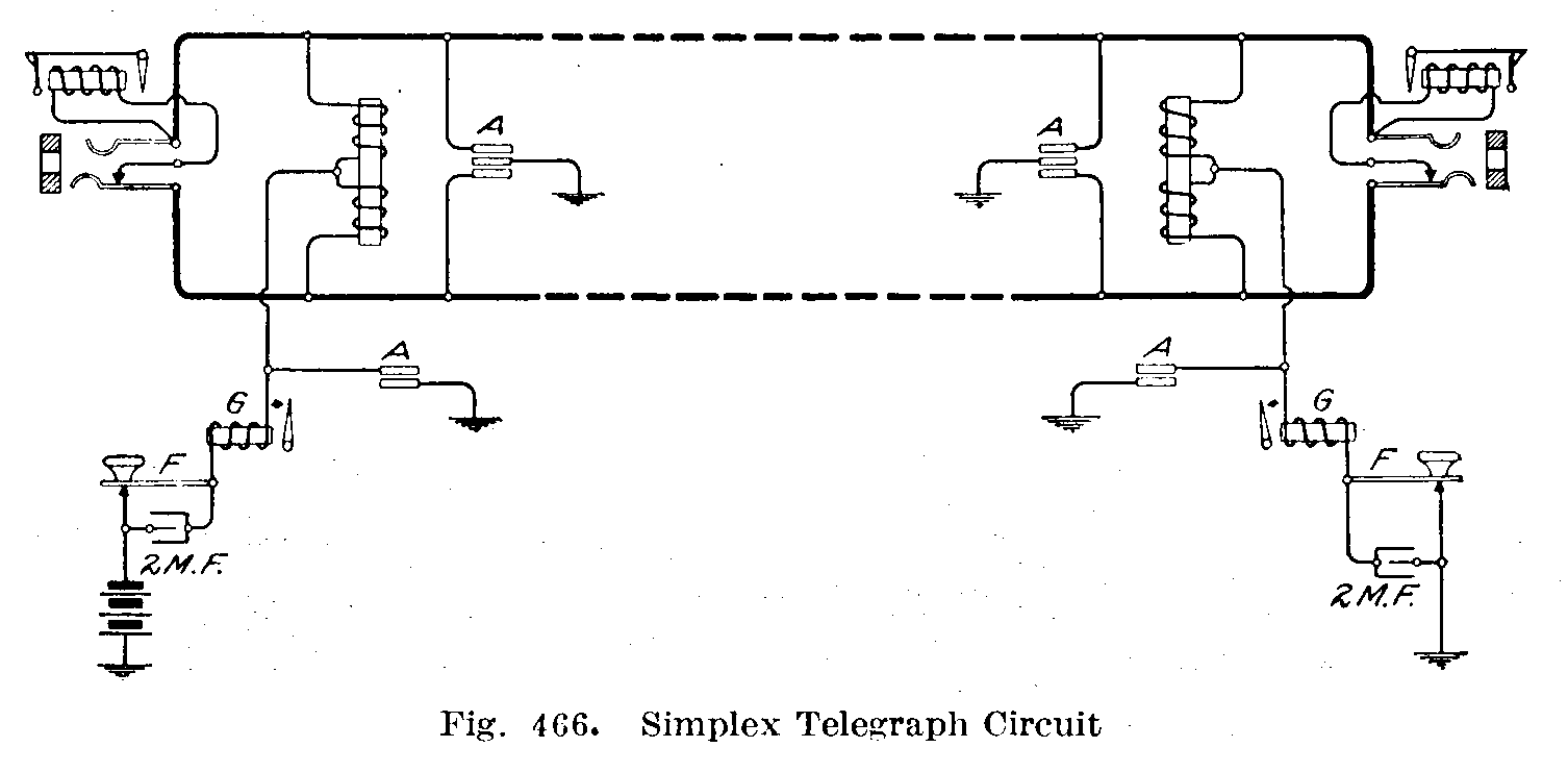
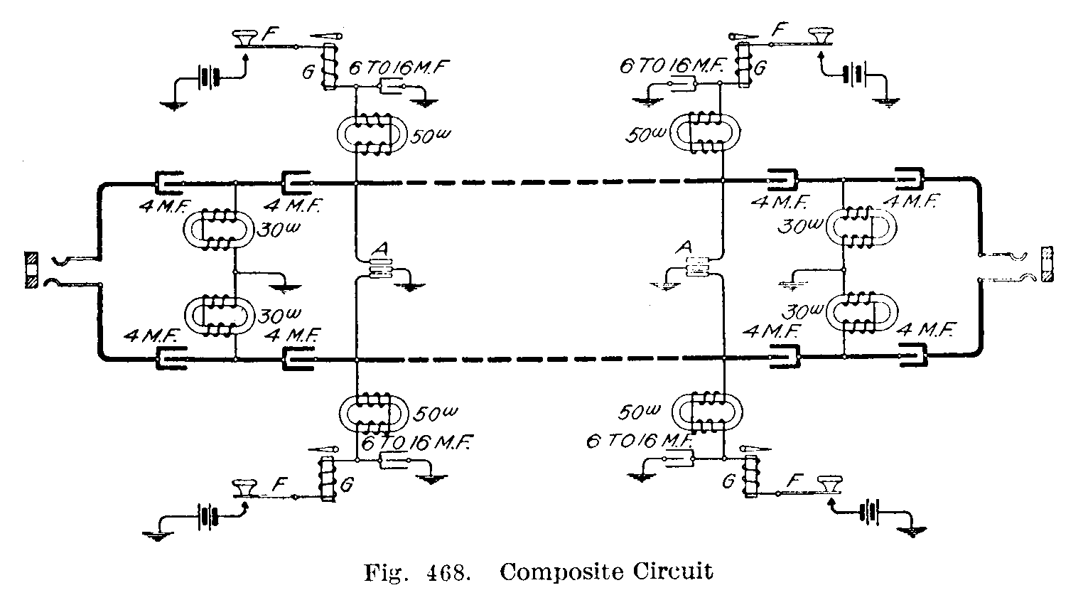
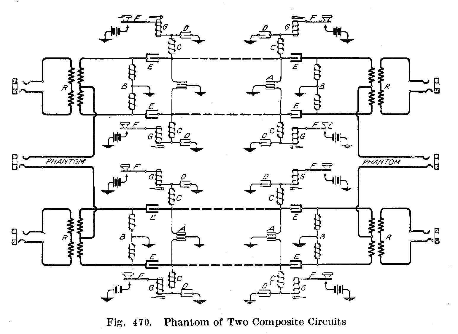
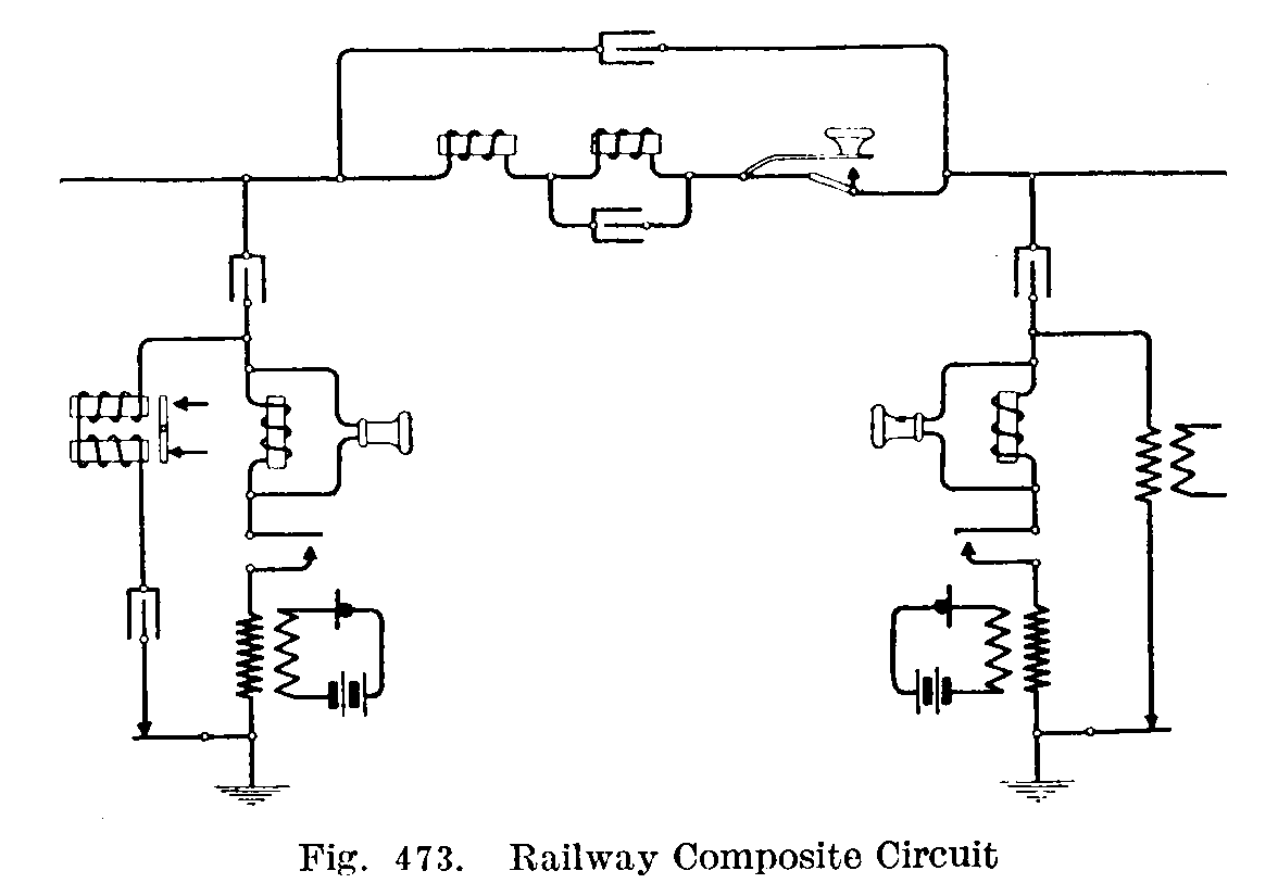
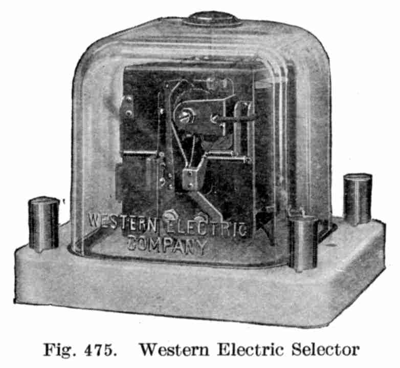
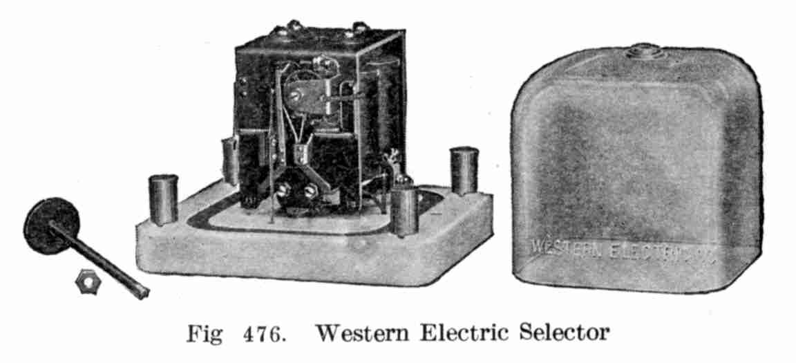
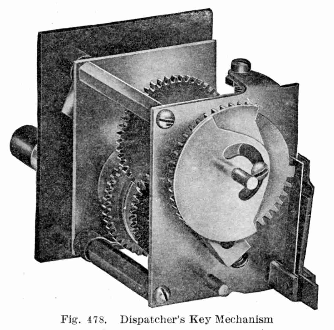
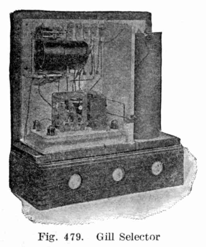
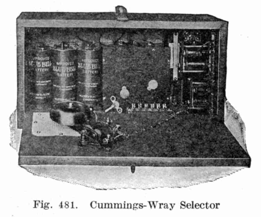
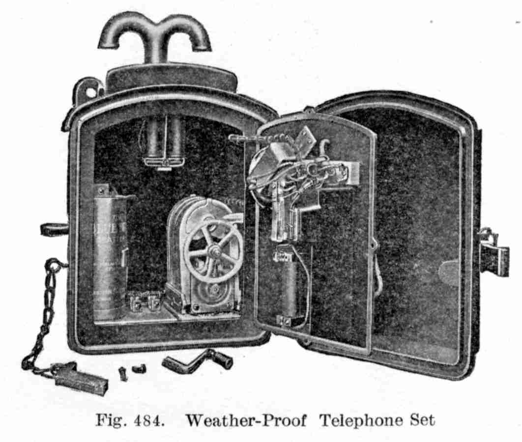
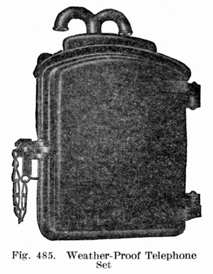
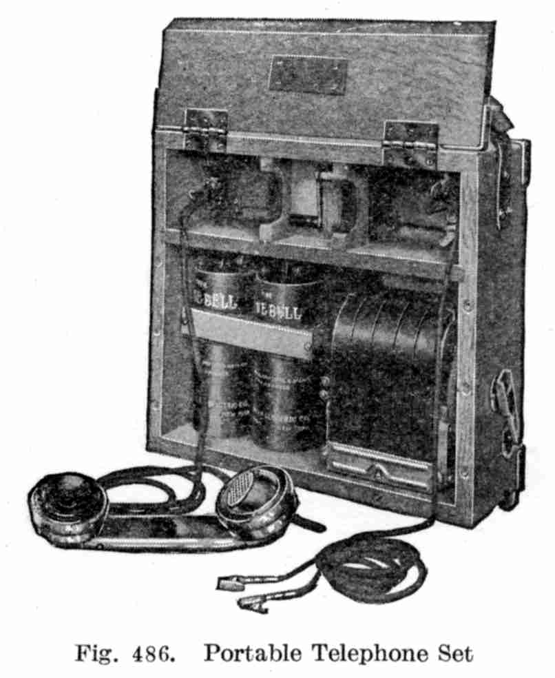
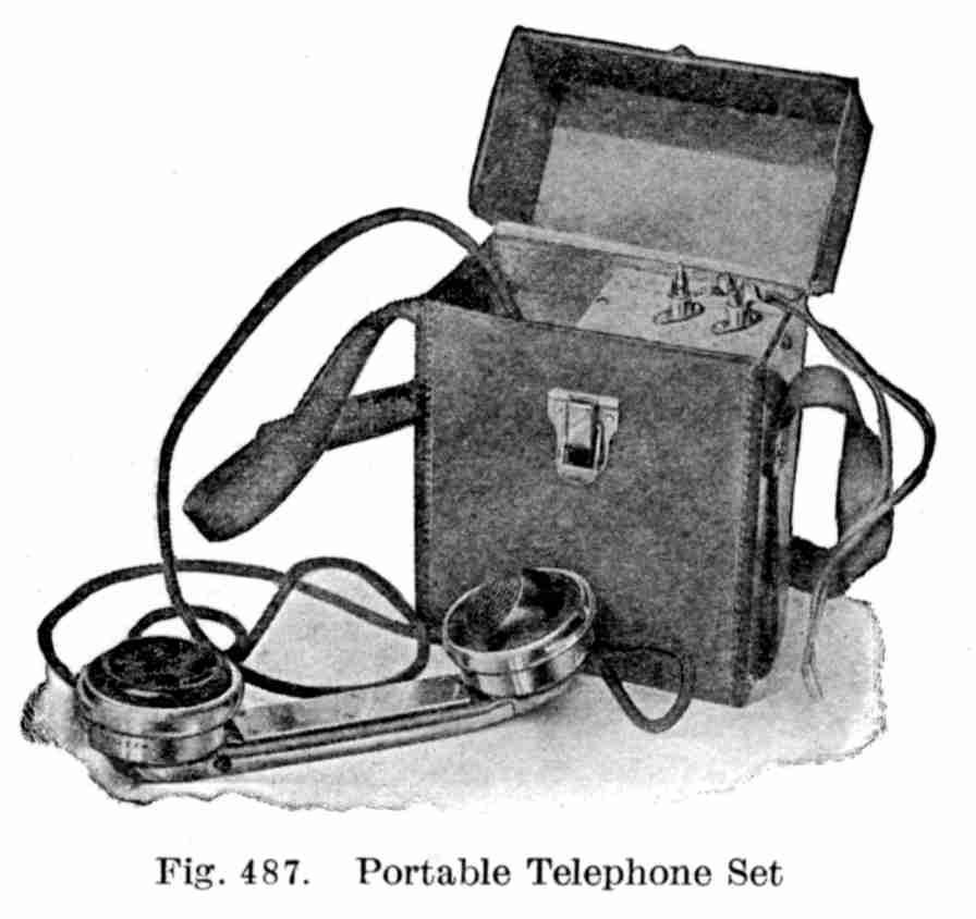
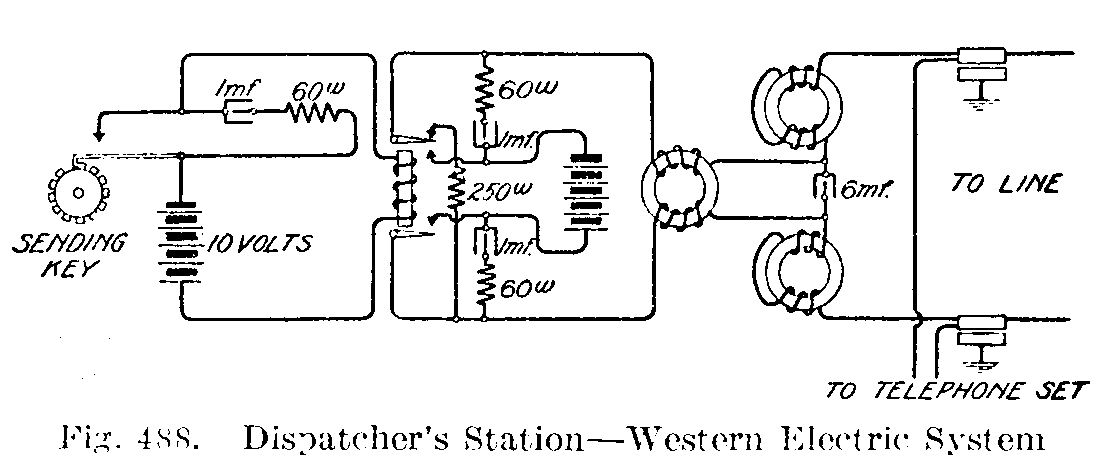
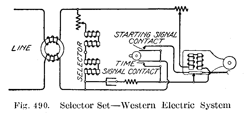
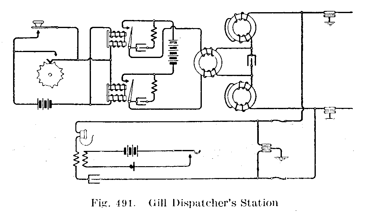
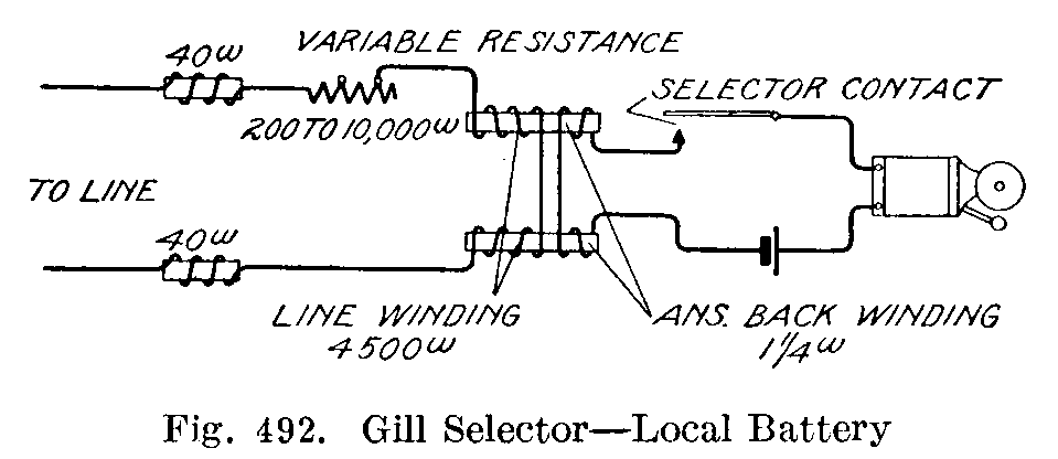
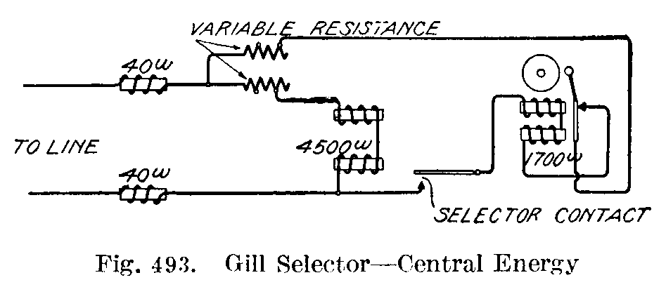
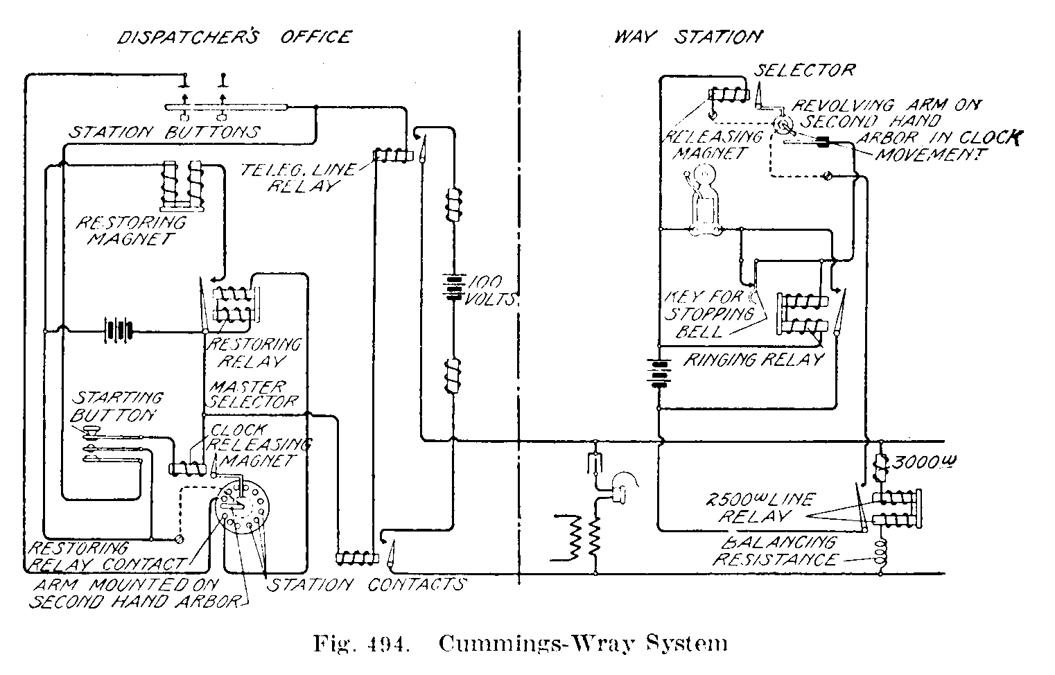
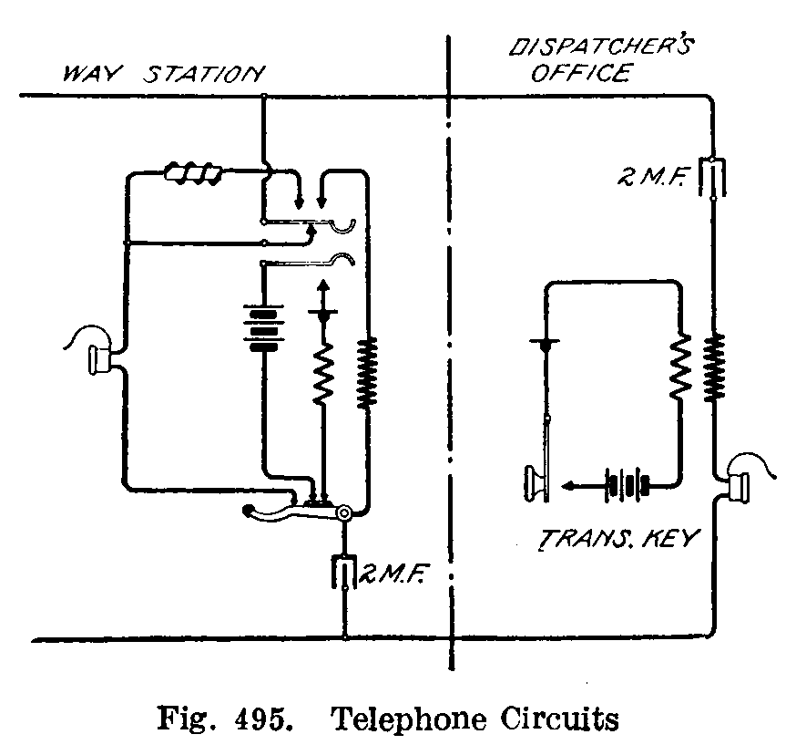
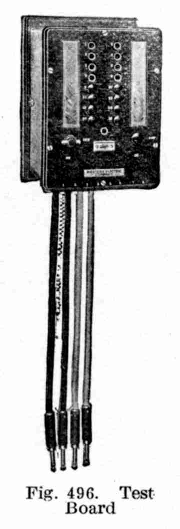
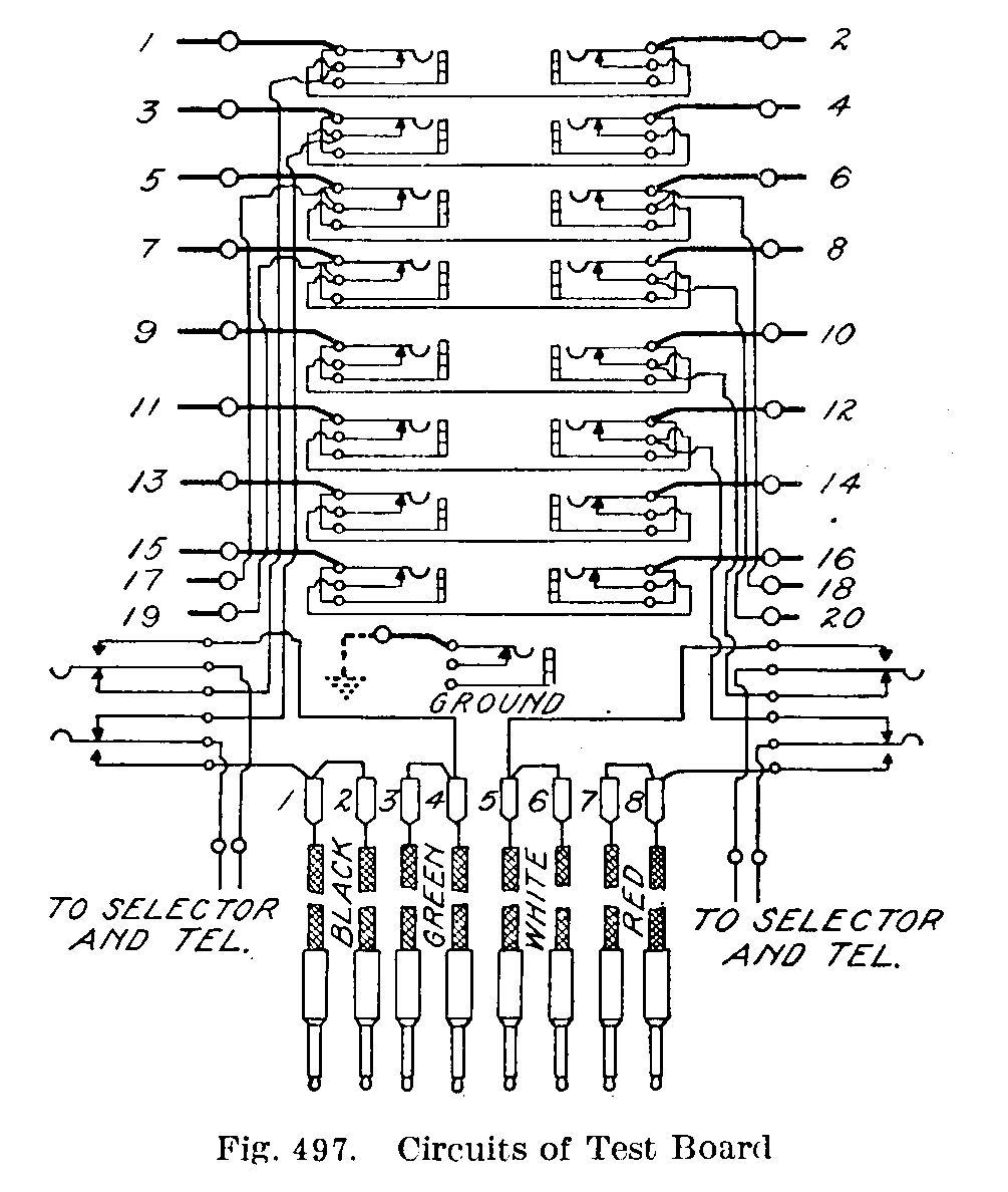
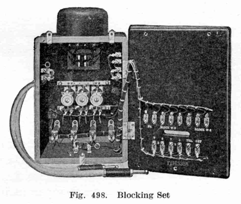
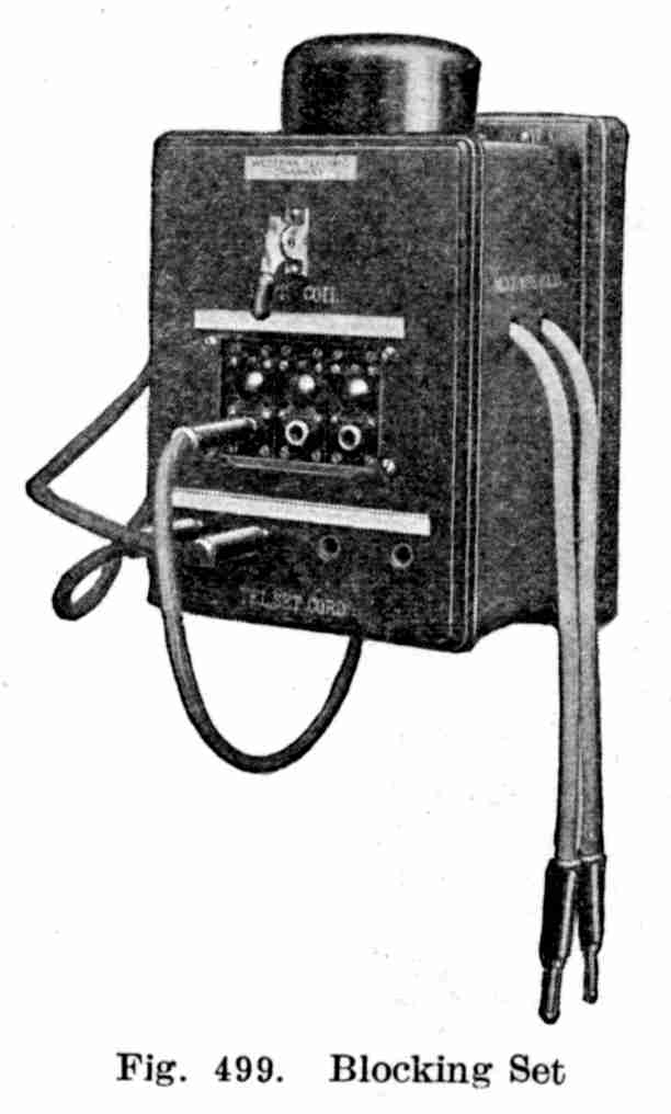