
The Project Gutenberg EBook of Encyclopaedia Britannica, 11th Edition,
Volume 6, Slice 8, by Various

This eBook is for the use of anyone anywhere at no cost and with
almost no restrictions whatsoever.  You may copy it, give it away or
re-use it under the terms of the Project Gutenberg License included
with this eBook or online at www.gutenberg.org


Title: Encyclopaedia Britannica, 11th Edition, Volume 6, Slice 8
       "Conduction, Electric"

Author: Various

Release Date: April 19, 2010 [EBook #32063]

Language: English

Character set encoding: ISO-8859-1

*** START OF THIS PROJECT GUTENBERG EBOOK ENCYC. BRITANNICA, VOL 6, SL 8 ***


Produced by Marius Masi, Don Kretz, Juliet Sutherland, and
the Online Distributed Proofreading Team at
https://www.pgdp.net
| Transcriber's note: |
A few typographical errors have been corrected. They
appear in the text like this, and the
explanation will appear when the mouse pointer is moved over the marked
passage. Sections in Greek will yield a transliteration
when the pointer is moved over them, and words using diacritic characters in the
Latin Extended Additional block, which may not display in some fonts or browsers, will
display an unaccented version. Links to other EB articles: Links to articles residing in other EB volumes will be made available when the respective volumes are introduced online. |
Articles in This Slice
CONDUCTION, ELECTRIC. The electric conductivity of a substance is that property in virtue of which all its parts come spontaneously to the same electric potential if the substance is kept free from the operation of electric force. Accordingly, the reciprocal quality, electric resistivity, may be defined as a quality of a substance in virtue of which a difference of potential can exist between different portions of the body when these are in contact with some constant source of electromotive force, in such a manner as to form part of an electric circuit.
All material substances possess in some degree, large or small, electric conductivity, and may for the sake of convenience be broadly divided into five classes in this respect. Between these, however, there is no sharply-marked dividing line, and the classification must therefore be accepted as a more or less arbitrary one. These divisions are: (1) metallic conductors, (2) non-metallic conductors, (3) dielectric conductors, (4) electrolytic conductors, (5) gaseous conductors. The first class comprises all metallic substances, and those mixtures or combinations of metallic substances known as alloys. The second includes such non-metallic bodies as carbon, silicon, many of the oxides and peroxides of the metals, and probably also some oxides of the non-metals, sulphides and selenides. Many of these substances, for instance carbon and silicon, are well-known to have the property of existing in several allotropic forms, and in some of these conditions, so far from being fairly good conductors, they may be almost perfect non-conductors. An example of this is seen in the case of carbon in its three allotropic conditions—charcoal, graphite and diamond. As charcoal it possesses a fairly well-marked but not very high conductivity in comparison with metals; as graphite, a conductivity about one-four-hundredth of that of iron; but as diamond so little conductivity that the substance is included amongst insulators or non-conductors. The third class includes those substances which are generally called insulators or non-conductors, but which are better denominated dielectric conductors; it comprises such solid substances as mica, ebonite, shellac, india-rubber, gutta-percha, paraffin, and a large number of liquids, chiefly hydrocarbons. These substances differ greatly in insulating power, and according as the conductivity is more or less marked, they are spoken of as bad or good insulators. Amongst the latter many of the liquid gases hold a high position. Thus, liquid oxygen and liquid air have been shown by Sir James Dewar to be almost perfect non-conductors of electricity.
The behaviour of substances which fall into these three classes is discussed below in section I., dealing with metallic conduction.
The fourth class, namely the electrolytic conductors comprises all those substances which undergo chemical decomposition when they form part of an electric circuit traversed by an electric current. They are discussed in section II., dealing with electrolytic conduction.
The fifth and last class of conductors includes the gases. The conditions under which this class of substance becomes possessed of electric conductivity are considered in section III., on conduction in gases.
In connexion with metallic conductors, it is a fact of great interest and considerable practical importance, that, although the majority of metals when in a finely divided or powdered condition are practically non-conductors, a mass of metallic powder or filings may be made to pass suddenly into a conductive condition by being exposed to the influence of an electric wave. The same is true of the loose contact of two metallic conductors. Thus if a steel point, such as a needle, presses very lightly against a metallic plate, say of aluminium, it is found that this metallic contact, if carefully adjusted, is non-conductive, but that if an electric wave is created anywhere in the neighbourhood, this non-conducting contact passes into a conductive state. This fact, investigated and discovered independently by D. E. Hughes, C. Onesti, E. Branly, O. J. Lodge and others, is applied in the construction of the “coherer,” or sensitive tube employed as a detector or receiver in that form of “wireless telegraphy” chiefly developed by Marconi. Further references to it are made in the articles Electric Waves and Telegraphy: Wireless.
International Ohm.—The practical unit of electrical resistance was legally defined in Great Britain by the authority of the queen in council in 1894, as the “resistance offered to an invariable electric current by a column of mercury at the temperature of melting ice, 14.4521 grammes in mass, of a constant cross-sectional area, and a length 106.3 centimetres.” The same unit has been also legalized as a standard in France, Germany and the United States, and is denominated the “International or Standard Ohm.” It is intended to represent as nearly as possible a resistance equal to 10° absolute C.G.S. units of electric resistance. Convenient multiples and subdivisions of the ohm are the microhm and the megohm, the former being a millionth part of an ohm, and the latter a million ohms. The resistivity of substances is then numerically expressed by stating the resistance of one cubic centimetre of the substance taken between opposed faces, and expressed in ohms, microhms or megohms, as may be most convenient. The reciprocal of the ohm is called the mho, which is the unit of conductivity, and is defined as the conductivity of a substance whose resistance is one ohm. The absolute unit of conductivity is the conductivity of a substance whose resistivity is one absolute C.G.S. unit, or one-thousandth-millionth part of an ohm. Resistivity is a quality in which material substances differ very widely. The metals and alloys, broadly speaking, are good conductors, and their resistivity is conveniently expressed in microhms per cubic centimetre, or in absolute C.G.S. units. Very small differences in density and in chemical purity make, however, immense differences in electric resistivity; hence the values given by different experimentalists for the resistivity of known metals differ to a considerable extent.
I. Conduction in Solids
It is found convenient to express the resistivity of metals in two different ways: (1) We may state the resistivity of one cubic centimetre of the material in microhms or absolute units taken between opposed faces. This is called the volume-resistivity; (2) we may express the resistivity by stating the resistance in ohms offered by a wire of the material in question of uniform cross-section one metre in length, and one gramme in weight. This numerical measure of the resistivity is called the mass-resistivity. The mass-resistivity of a body is connected with its volume-resistivity and the density of the material in the following manner:—The mass-resistivity, expressed in microhms per metre-gramme, divided by 10 times the density is numerically equal to the volume-resistivity per centimetre-cube in absolute C.G.S. units. The mass-resistivity per metre-gramme can always be obtained by measuring the resistance and the mass of any wire of 856 uniform cross-section of which the length is known, and if the density of the substance is then measured, the volume-resistivity can be immediately calculated.
If R is the resistance in ohms of a wire of length l, uniform cross-section s, and density d, then taking ρ for the volume-resistivity we have 109R = ρl/s; but lsd = M, where M is the mass of the wire. Hence 109R = ρdl2/M. If l = 100 and M = 1, then R = ρ′= resistivity in ohms per metre-gramme, and 109ρ′ = 10,000dρ, or ρ = 105ρ′/d, and ρ′ = 10,000MR/l2.
The following rules, therefore, are useful in connexion with these measurements. To obtain the mass-resistivity per metre-gramme of a substance in the form of a uniform metallic wire:—Multiply together 10,000 times the mass in grammes and the total resistance in ohms, and then divide by the square of the length in centimetres. Again, to obtain the volume-resistivity in C.G.S. units per centimetre-cube, the rule is to multiply the mass-resistivity in ohms by 100,000 and divide by the density. These rules, of course, apply only to wires of uniform cross-section. In the following Tables I., II. and III. are given the mass and volume resistivity of ordinary metals and certain alloys expressed in terms of the international ohm or the absolute C.G.S. unit of resistance, the values being calculated from the experiments of A. Matthiessen (1831-1870) between 1860 and 1865, and from later results obtained by J. A. Fleming and Sir James Dewar in 1893.
Table I.—Electric Mass-Resistivity of Various Metals at 0° C., or Resistance per Metre-gramme in International Ohms at 0° C. (Matthiessen.)
| Metal. | Resistance at 0° C. in International Ohms of a Wire 1 Metre long and Weighing 1 Gramme. |
Approximate Temperature Coefficient near 20° C. |
| Silver (annealed) | .1523 | 0.00377 |
| Silver (hard-drawn) | .1657 | .. |
| Copper (annealed) | .1421 | 0.00388 |
| Copper (hard-drawn) | .1449 (Matthiessen’s Standard) | .. |
| Gold (annealed) | .4025 | 0.00365 |
| Gold (hard-drawn) | .4094 | .. |
| Aluminium (annealed) | .0757 | .. |
| Zinc (pressed) | .4013 | .. |
| Platinum (annealed) | 1.9337 | .. |
| Iron (annealed) | .765 | .. |
| Nickel (annealed) | 1.0581 | .. |
| Tin (pressed) | .9618 | 0.00365 |
| Lead (pressed) | 2.2268 | 0.00387 |
| Antimony (pressed) | 2.3787 | 0.00389 |
| Bismuth (pressed) | 12.85541 | 0.00354 |
| Mercury (liquid) | 12.8852 | 0.00072 |
The data commonly used for calculating metallic resistivities were obtained by A. Matthiessen, and his results are set out in the Table II. which is taken from Cantor lectures given by Fleeming Jenkin in 1866 at or about the date when the researches were made. The figures given by Jenkin have, however, been reduced to international ohms and C.G.S. units by multiplying by (π/4)×0.9866 × 105 = 77,485.
Subsequently numerous determinations of the resistivity of various pure metals were made by Fleming and Dewar, whose results are set out in Table III.
Table II.—Electric Volume-Resistivity of Various Metals at 0° C., or Resistance per Centimetre-cube in C.G.S. Units at 0° C.
| Metal. | Volume-Resistivity. at 0° C. in C.G.S. Units |
| Silver (annealed) | 1,502 |
| Silver (hard-drawn) | 1,629 |
| Copper (annealed) | 1,594 |
| Copper (hard-drawn) | 1,6303 |
| Gold (annealed) | 2,052 |
| Gold (hard-drawn) | 2,090 |
| Aluminium (annealed) | 3,006 |
| Zinc (pressed) | 5,621 |
| Platinum (annealed) | 9,035 |
| Iron (annealed) | 10,568 |
| Nickel (annealed) | 12,4294 |
| Tin (pressed) | 13,178 |
| Lead (pressed) | 19,580 |
| Antimony (pressed) | 35,418 |
| Bismuth (pressed) | 130,872 |
| Mercury (liquid) | 94,8965 |
Resistivity of Mercury.—The volume-resistivity of pure mercury is a very important electric constant, and since 1880 many of the most competent experimentalists have directed their attention to the determination of its value. The experimental process has usually been to fill a glass tube of known dimensions, having large cup-like extensions at the ends, with pure mercury, and determine the absolute resistance of this column of metal. For the practical details of this method the following references may be consulted:—“The Specific Resistance of Mercury,” Lord Rayleigh and Mrs Sidgwick, Phil. Trans., 1883, part i. p. 173, and R. T. Glazebrook, Phil. Mag., 1885, p. 20; “On the Specific Resistance of Mercury,” R. T. Glazebrook and T. C. Fitzpatrick, Phil. Trans., 1888, p. 179, or Proc. Roy. Soc., 1888, p. 44, or Electrician, 1888, 21, p. 538; “Recent Determinations of the Absolute Resistance of Mercury,” R. T. Glazebrook, Electrician, 1890, 25, pp. 543 and 588. Also see J. V. Jones, “On the Determination of the Specific Resistance of Mercury in Absolute Measure,” Phil. Trans., 1891, A, p. 2. Table IV. gives the values of the volume-resistivity of mercury as determined by various observers, the constant being expressed (a) in terms of the resistance in ohms of a column of mercury one millimetre in cross-section and 100 centimetres in length, taken at 0° C.; and (b) in terms of the length in centimetres of a column of mercury one square millimetre in cross-section taken at 0° C. The result of all the most careful determinations has been to show that the resistivity of pure mercury at 0° C. is about 94,070 C.G.S. electromagnetic units of resistance, and that a column of mercury 106.3 centimetres in length having a cross-sectional area of one square millimetre would have a resistance at 0° C. of one international ohm. These values have accordingly been accepted as the official and recognized values for the specific resistance of mercury, and the definition of the ohm. The table also states the methods which have been adopted by the different observers for obtaining the absolute value of the resistance of a known column of mercury, or of a resistance coil afterwards compared with a known column of mercury. A column of figures is added showing the value in fractions of an international ohm of the British Association Unit (B.A.U.), formerly supposed to represent the true ohm. The real value of the B.A.U. is now taken as .9866 of an international ohm.
Table III.—Electric Volume-Resistivity of Various Metals at 0° C., or Resistance per Centimetre-cube at 0° C. in C.G.S. Units. (Fleming and Dewar, Phil. Mag., September 1893.)
| Metal. | Resistance at 0° C. per Centimetre-cube in C.G.S. Units. |
Mean Temperature Coefficient between 0° C. and 100° C. |
| Silver (electrolytic and well annealed)6 | 1,468 | 0.00400 |
| Copper (electrolytic and well annealed)6 | 1,561 | 0.00428 |
| Gold (annealed) | 2,197 | 0.00377 |
| Aluminium (annealed) | 2,665 | 0.00435 |
| Magnesium (pressed) | 4,355 | 0.00381 |
| Zinc | 5,751 | 0.00406 |
| Nickel (electrolytic)6 | 6,935 | 0.00618 |
| Iron (annealed) | 9,065 | 0.00625 |
| Cadmium | 10,023 | 0.00419 |
| Palladium | 10,219 | 0.00354 |
| Platinum (annealed) | 10,917 | 0.003669 |
| Tin (pressed) | 13,048 | 0.00440 |
| Thallium (pressed) | 17,633 | 0.00398 |
| Lead (pressed) | 20,380 | 0.00411 |
| Bismuth (electrolytic)7 | 110,000 | 0.00433 |
Table IV.—Determinations of the Absolute Value of the Volume-Resistivity of Mercury and the Mercury Equivalent of the Ohm.
| Observer. | Date. | Method. | Value of B.A.U. in Ohms. |
Value of 100 Centimetres of Mercury in Ohms. |
Value of Ohm in Centimetres of Mercury. |
| Lord Rayleigh | 1882 | Rotating coil | .98651 | .94133 | 106.31 |
| Lord Rayleigh | 1883 | Lorenz method | .98677 | .. | 106.27 |
| G. Wiedemann | 1884 | Rotation through 180° | .. | .. | 106.19 |
| E. E. N. Mascart | 1884 | Induced current | .98611 | .94096 | 106.33 |
| H. A. Rowland | 1887 | Mean of several methods | .98644 | .94071 | 106.32 |
| F. Kohlrausch | 1887 | Damping of magnets | .98660 | .94061 | 106.32 |
| R. T. Glazebrook | 1882/8 | Induced currents | .98665 | .94074 | 106.29 |
| Wuilleumeier | 1890 | .98686 | .94077 | 106.31 | |
| Duncan and Wilkes | 1890 | Lorenz | .98634 | .94067 | 106.34 |
| J. V. Jones | 1891 | Lorenz | .. | .94067 | 106.31 |
| Mean value | .98653 | ||||
| Streker | 1885 | An absolute determination | .94056 | 106.32 | |
| Hutchinson | 1888 | of resistance was not | .94074 | 106.30 | |
| E. Salvioni | 1890 | made. The value .98656 | .94054 | 106.33 | |
| E. Salvioni | .. | value .98656 has been used | .94076 | 106.30 | |
| Mean value | .94076 | 106.31 | |||
| H. F. Weber | 1884 | Induced current | Absolute measurements | 105.37 | |
| H. F. Weber | .. | Rotating coil | compared with German | 106.16 | |
| A. Roiti | 1884 | Mean effect of induced current | silver wire coils issued by | 105.89 | |
| F. Himstedt | 1885 | Siemens and Streker | 105.98 | ||
| F. E. Dorn | 1889 | Damping of a magnet | 106.24 | ||
| Wild | 1883 | Damping of a magnet | 106.03 | ||
| L. V. Lorenz | 1885 | Lorenz method | 105.93 | ||
For a critical discussion of the methods which have been adopted in the absolute determination of the resistivity of mercury, and the value of the British Association unit of resistance, the reader may be referred to the British Association Reports for 1890 and 1892 (Report of Electrical Standards Committee), and to the Electrician, 25, p. 456, and 29, p. 462. A discussion of the relative value of the results obtained between 1882 and 1890 was given by R. T. Glazebrook in a paper presented to the British Association at Leeds, 1890.
Resistivity of Copper.—In connexion with electro-technical work the determination of the conductivity or resistivity values of annealed and hard-drawn copper wire at standard temperatures is a very important matter. Matthiessen devoted considerable attention to this subject between the years 1860 and 1864 (see Phil. Trans., 1860, p. 150), and since that time much additional work has been carried out. Matthiessen’s value, known as Matthiessen’s Standard, for the mass-resistivity of pure hard-drawn copper wire, is the resistance of a wire of pure hard-drawn copper one metre long and weighing one gramme, and this is equal to 0.14493 international ohms at 0° C. For many purposes it is more convenient to express temperature in Fahrenheit degrees, and the recommendation of the 1899 committee on copper conductors8 is as follows:—“Matthiessen’s standard for hard-drawn conductivity commercial copper shall be considered to be the resistance of a wire of pure hard-drawn copper one metre long, weighing one gramme which at 60° F. is 0.153858 international ohms.” Matthiessen also measured the mass-resistivity of annealed copper, and found that its conductivity is greater than that of hard-drawn copper by about 2.25% to 2.5% As annealed copper may vary considerably in its state of annealing, and is always somewhat hardened by bending and winding, it is found in practice that the resistivity of commercial annealed copper is about 1¼% less than that of hard-drawn copper. The standard now accepted for such copper, on the recommendation of the 1899 Committee, is a wire of pure annealed copper one metre long, weighing one gramme, whose resistance at 0° C. is 0.1421 international ohms, or at 60° F., 0.150822 international ohms. The specific gravity of copper varies from about 8.89 to 8.95, and the standard value accepted for high conductivity commercial copper is 8.912, corresponding to a weight of 555 lb per cubic foot at 60° F. Hence the volume-resistivity of pure annealed copper at 0° C. is 1.594 microhms per c.c., or 1594 C.G.S. units, and that of pure hard-drawn copper at 0° C. is 1.626 microhms per c.c., or 1626 C.G.S. units. Since Matthiessen’s researches, the most careful scientific investigation on the conductivity of copper is that of T. C. Fitzpatrick, carried out in 1890. (Brit. Assoc. Report, 1890, Appendix 3, p. 120.) Fitzpatrick confirmed Matthiessen’s chief result, and obtained values for the resistivity of hard-drawn copper which, when corrected for temperature variation, are in entire agreement with those of Matthiessen at the same temperature.
The volume resistivity of alloys is, generally speaking, much higher than that of pure metals. Table V. shows the volume resistivity at 0° C. of a number of well-known alloys, with their chemical composition.
Table V.—Volume-Resistivity of Alloys of known Composition at 0° C. in C.G.S. Units per Centimetre-cube. Mean Temperature Coefficients taken at 15° C. (Fleming and Dewar.)
| Alloys. | Resistivity at 0° C. |
Temperature Coefficient at 15° C. |
Composition in per cents. |
| Platinum-silver | 31,582 | .000243 | Pt 33%, Ag 66% |
| Platinum-iridium | 30,896 | .000822 | Pt 80%, Ir 20% |
| Platinum-rhodium | 21,142 | .00143 | Pt 90%, Rd 10% |
| Gold-silver | 6,280 | .00124 | Au 90%, Ag 10% |
| Manganese-steel | 67,148 | .00127 | Mn 12%, Fe 78% |
| Nickel-steel | 29,452 | .00201 | Ni 4.35%, remaining percentage |
| chiefly iron, but uncertain | |||
| German silver | 29,982 | .000273 | Cu5Zn3Ni2 |
| Platinoid9 | 41,731 | .00031 | |
| Manganin | 46,678 | .0000 | Cu 84%, Mn 12%, Ni 4% |
| Aluminium-silver | 4,641 | .00238 | Al 94%, Ag 6% |
| Aluminium-copper | 2,904 | .00381 | Al 94%, Cu 6% |
| Copper-aluminium | 8,847 | .000897 | Cu 97%, Al 3% |
| Copper-nickel-aluminium | 14,912 | .000643 | Cu 87%, Ni 6.5%, Al 6.5% |
| Titanium-aluminium | 3,887 | .00290 |
Generally speaking, an alloy having high resistivity has poor mechanical qualities, that is to say, its tensile strength and ductility are small. It is possible to form alloys having a resistivity as high as 100 microhms per cubic centimetre; but, on the other hand, the value of an alloy for electro-technical purposes is judged not merely by its resistivity, but also by the degree to which its resistivity varies with temperature, and by its capability of being easily drawn into fine wire of not very small tensile strength. Some pure metals when alloyed with a small proportion of another metal do not suffer much 858 change in resistivity, but in other cases the resultant alloy has a much higher resistivity. Thus an alloy of pure copper with 3% of aluminium has a resistivity about 5½ times that of copper; but if pure aluminium is alloyed with 6% of copper, the resistivity of the product is not more than 20% greater than that of pure aluminium. The presence of a very small proportion of a non-metallic element in a metallic mass, such as oxygen, sulphur or phosphorus, has a very great effect in increasing the resistivity. Certain metallic elements also have the same power; thus platinoid has a resistivity 30% greater than German silver, though it differs from it merely in containing a trace of tungsten.
The resistivity of non-metallic conductors is in all cases higher than that of any pure metal. The resistivity of carbon, for instance, in the forms of charcoal or carbonized organic material and graphite, varies from 600 to 6000 microhms per cubic centimetre, as shown in Table VI.:—
Table VI.—Electric Volume-Resistivity in Microhms per Centimetre-cube of Various Forms of Carbon at 15° C.
| Substance. | Resistivity. |
| Arc lamp carbon rod | 8000 |
| Jablochkoff candle carbon | 4000 |
| Carré carbon | 3400 |
| Carbonized bamboo | 6000 |
| Carbonized parchmentized thread | 4000 to 5000 |
| Ordinary carbon filament from glow-lamp | |
| “treated” or flashed | 2400 to 2500 |
| Deposited or secondary carbon | 600 to 900 |
| Graphite | 400 to 500 |
The resistivity of liquids is, generally speaking, much higher than that of any metals, metallic alloys or non-metallic conductors. Thus fused lead chloride, one of the best conducting liquids, has a resistivity in its fused condition of 0.376 ohm per centimetre-cube, or 376,000 microhms per centimetre-cube, whereas that of metallic alloys only in few cases exceeds 100 microhms per centimetre-cube. The resistivity of solutions of metallic salts also varies very largely with the proportion of the diluent or solvent, and in some instances, as in the aqueous solutions of mineral acids; there is a maximum conductivity corresponding to a certain dilution. The resistivity of many liquids, such as alcohol, ether, benzene and pure water, is so high, in other words, their conductivity is so small, that they are practically insulators, and the resistivity can only be appropriately expressed in megohms per centimetre-cube.
In Table VII. are given the names of a few of these badly-conducting liquids, with the values of their volume-resistivity in megohms per centimetre-cube:—
Table VII.—Electric Volume-Resistivity of Various Badly-Conducting Liquids in Megohms per Centimetre-cube.
| Substance. | Resistivity in Megohms per c.c. |
Observer. |
| Ethyl alcohol | 0.5 | Pfeiffer. |
| Ethyl ether | 1.175 to 3.760 | W. Kohlrausch. |
| Benzene | 4.700 | |
| Absolutely pure water approximates probably to | 25.0 at 18° C. | Value estimated by F. Kohlrausch |
| and A. Heydweiler. | ||
| All very dilute aqueous salt solutions having a | 1.00 at 18° C. | From results by F. Kohlrausch |
| concentration of about 0.00001 of an equivalent | and others. | |
| gramme molecule10 per litre approximate to |
The resistivity of all those substances which are generally called dielectrics or insulators is also so high that it can only be appropriately expressed in millions of megohms per centimetre-cube, or in megohms per quadrant-cube, the quadrant being a cube the side of which is 109 cms. (see Table VIII.).
Table VIII.—Electric Volume-Resistivity of Dielectrics reckoned in Millions of Megohms (Mega-megohms) per Centimetre-cube, and in Megohms per Quadrant-cube, i.e. a Cube whose Side is 109 cms.
| Substance. | Resistivity. | Temperature Cent. | |
| Mega-megohms per c.c. |
Megohms per Quadrant-cube. | ||
| Bohemian glass | 61 | .061 | 60° |
| Mica | 84 | .084 | 20° |
| Gutta-percha | 450 | .45 | 24° |
| Flint glass | 1,020 | 1.02 | 60° |
| Glover’s vulcanized indiarubber | 1,630 | 1.63 | 15° |
| Siemens’ ordinary pure vulcanized indiarubber | 2,280 | 2.28 | 15° |
| Shellac | 9,000 | 9.0 | 28° |
| Indiarubber | 10,900 | 10.9 | 24° |
| Siemens’ high-insulating fibrous material | 11,900 | 11.9 | 15° |
| Siemens’ special high-insulating indiarubber | 16,170 | 16.17 | 15° |
| Flint glass | 20,000 | 20.0 | 20° |
| Ebonite | 28,000 | 28. | 46° |
| Paraffin | 34,000 | 34. | 46° |
Effects of Heat.—Temperature affects the resistivity of these different classes of conductors in different ways. In all cases, so far as is yet known, the resistivity of a pure metal is increased if its temperature is raised, and decreased if the temperature is lowered, so that if it could be brought to the absolute zero of temperature (-273° C.) its resistivity would be reduced to a very small fraction of its resistance at ordinary temperatures. With metallic alloys, however, rise of temperature does not always increase resistivity: it sometimes diminishes it, so that many alloys are known which have a maximum resistivity corresponding to a certain temperature, and at or near this point they vary very little in resistance with temperature. Such alloys have, therefore, a negative temperature-variation of resistance at and above fixed temperatures. Prominent amongst these metallic compounds are alloys of iron, manganese, nickel and copper, some of which were discovered by Edward Weston, in the United States. One well-known alloy of copper, manganese and nickel, now called manganin, which was brought to the notice of electricians by the careful investigations made at the Berlin Physikalisch-Technische Reichsanstalt, is characterized by having a zero temperature coefficient at or about a certain temperature in the neighbourhood of 15° C. Hence within a certain range of temperature on either side of this critical value the resistivity of manganin is hardly affected at all by temperature. Similar alloys can be produced from copper and ferro-manganese. An alloy formed of 80% copper and 20% manganese in an annealed condition has a nearly zero temperature-variation of resistance between 20° C. and 100° C. In the case of non-metals the action of temperature is generally to diminish the resistivity as temperature rises, though this is not universally so. The interesting observation has been recorded by J. W. Howell, that “treated” carbon filaments and graphite are substances which have a minimum resistance corresponding to a certain temperature approaching red heat (Electrician, vol. xxxviii. p. 835). At and beyond this temperature increased heating appears to increase their resistivity; this phenomenon may, however, be accompanied by a molecular change and not be a true temperature variation. In the case of dielectric conductors and of electrolytes, the action of rising temperature is to reduce resistivity. Many of the so-called insulators, such as mica, ebonite, indiarubber, and the insulating oils, paraffin, &c., decrease in resistivity with great rapidity as the temperature rises. With guttapercha a rise in temperature from 0° C. to 24° C. is sufficient to reduce the resistivity of one-twentieth part of its value at 0° C., and the resistivity of flint glass at 140° C. is only one-hundredth of what it is at 60° C.
A definition may here be given of the meaning of the term Temperature Coefficient. If, in the first place, we suppose that the resistivity (ρt) at any temperature (t) is a simple linear function of the resistivity (ρ0) at 0° C., then we can write ρt = ρ0(1 + αt), or α = (ρt − ρ0)/ρ0t.
The quantity α is then called the temperature-coefficient, and its reciprocal is the temperature at which the resistivity would become 859 zero. By an extension of this notion we can call the quantity dρ/ρdt the temperature coefficient corresponding to any temperature t at which the resistivity is ρ. In all cases the relation between the resistivity of a substance and the temperature is best set out in the form of a curve called a temperature-resistance curve. If a series of such curves are drawn for various pure metals, temperature being taken as abscissa and resistance as ordinate, and if the temperature range extends from the absolute zero of temperature upwards, then it is found that these temperature-resistance lines are curved lines having their convexity either upwards or downwards. In other words, the second differential coefficient of resistance with respect to temperature is either a positive or negative quantity. An extensive series of observations concerning the form of the resistivity curves for various pure metals over a range of temperature extending from -200° C. to +200° C. was carried out in 1892 and 1893 by Fleming and Dewar (Phil. Mag. Oct. 1892 and Sept. 1893). The resistance observations were taken with resistance coils constructed with wires of various metals obtained in a state of great chemical purity. The lengths and mean diameters of the wires were carefully measured, and their resistance was then taken at certain known temperatures obtained by immersing the coils in boiling aniline, boiling water, melting ice, melting carbonic acid in ether, and boiling liquid oxygen, the temperatures thus given being +184°.5 C., +100° C., 0° C., -78°.2 C. and -182°.5 C. The resistivities of the various metals were then calculated and set out in terms of the temperature. From these data a chart was prepared showing the temperature-resistance curves of these metals throughout a range of 400 degrees. The exact form of these curves through the region of temperature lying between -200° C. and -273° C. is not yet known. As shown on the chart, the curves evidently do not converge to precisely the same point. It is, however, much less probable that the resistance of any metal should vanish at a temperature above the absolute zero than at the absolute zero itself, and the precise path of these curves at their lower ends cannot be delineated until means are found for fixing independently the temperature of some regions in which the resistance of metallic wires can be measured. Sir J. Dewar subsequently showed that for certain pure metals it is clear that the resistance would not vanish at the absolute zero but would be reduced to a finite but small value (see “Electric Resistance Thermometry at the Temperature of Boiling Hydrogen,” Proc. Roy. Soc. 1904, 73, p. 244).
The resistivity curves of the magnetic metals are also remarkable for the change of curvature they exhibit at the magnetic critical temperature. Thus J. Hopkinson and D. K. Morris (Phil. Mag. September 1897, p. 213) observed the remarkable alteration that takes place in the iron resistance temperature curve in the neighbourhood of 780° C. At that temperature the direction of the curvature of the curve changes so that it becomes convex upwards instead of convex downwards, and in addition the value of the temperature coefficient undergoes a great reduction. The mean temperature coefficient of iron in the neighbourhood of 0° C. is 0.0057; at 765° C. it rises to a maximum value 0.0204; but at 1000° C. it falls again to a lower value, 0.00244. A similar rise to a maximum value and subsequent fall are also noted in the case of the specific heat of iron. The changes in the curvature of the resistivity curves are undoubtedly connected with the molecular changes that occur in the magnetic metals at their critical temperatures.
A fact of considerable interest in connexion with resistivity is the influence exerted by a strong magnetic field in the case of some metals, notably bismuth. It was discovered by A. Righi and confirmed by S. A. Leduc (Journ. de Phys. 1886, 5, p. 116, and 1887, 6, p. 189) that if a pure bismuth wire is placed in a magnetic field transversely to the direction of the magnetic field, its resistance is considerably increased. This increase is greatly affected by the temperature of the metal (Dewar and Fleming, Proc. Roy. Soc. 1897, 60, p. 427). The temperature coefficient of pure copper is an important constant, and its value as determined by Messrs Clark, Forde and Taylor in terms of Fahrenheit temperature is
ρt = ρ32 {1 + 0.0023708(t − 32) + 0.0000034548(t − 32)²}.
Time Effects.—In the case of dielectric conductors, commonly called insulators, such as indiarubber, guttapercha, glass and mica, the electric resistivity is not only a function of the temperature but also of the time during which the electromotive force employed to measure it is imposed. Thus if an indiarubber-covered cable is immersed in water and the resistance of the dielectric between the copper conductor and the water measured by ascertaining the current which can be caused to flow through it by an electromotive force, this current is found to vary very rapidly with the time during which the electromotive force is applied. Apart from the small initial effect due to the electrostatic capacity of the cable, the application of an electromotive force to the dielectric produces a current through it which rapidly falls in value, as if the electric resistance of the dielectric were increasing. The current, however, does not fall continuously but tends to a limiting value, and it appears that if the electromotive force is kept applied to the cable for a prolonged time, a small and nearly constant current will ultimately be found flowing through it. It is customary in electro-technical work to consider the resistivity of the dielectric as the value it has after the electromotive force has been applied for one minute, the standard temperature being 75° F. This, however, is a purely conventional proceeding, and the number so obtained does not necessarily represent the true or ohmic resistance of the dielectric. If the electromotive force is increased, in the case of a large number of ordinary dielectrics the apparent resistance at the end of one minute’s electrification decreases as the electromotive force increases.
Practical Standards.—The practical measurement of resistivity involves many processes and instruments (see Wheatstone’s Bridge and Ohmmeter). Broadly speaking, the processes are divided into Comparison Methods and Absolute Methods. In the former a comparison is effected between the resistance of a material in a known form and some standard resistance. In the Absolute Methods the resistivity is determined without reference to any other substance, but with reference only to the fundamental standards of length, mass and time. Immense labour has been expended in investigations concerned with the production of a standard of resistance and its evaluation in absolute measure. In some cases the absolute standard is constructed by filling a carefully-calibrated tube of glass with mercury, in order to realize in a material form the official definition of the ohm; in this manner most of the principal national physical laboratories have been provided with standard mercury ohms. (For a full description of the standard mercury ohm of the Berlin Physikalisch-Technische Reichsanstalt, see the Electrician, xxxvii. 569.) For practical purposes it is more convenient to employ a standard of resistance made of wire.
Opinion is not yet perfectly settled on the question whether a wire made of any alloy can be considered to be a perfectly unalterable standard of resistance, but experience has shown that a platinum silver alloy (66% silver, 33% platinum), and also the alloy called manganin, seem to possess the qualities of permanence essential for a wire-resistance standard. A comparison made in 1892 and 1894 of all the manganin wire copies of the ohm made at the Reichsanstalt in Berlin, showed that these standards had remained constant for two years to within one or two parts in 100,000. It appears, however, that in order that manganin may remain constant in resistivity when used in the manufacture of a resistance coil, it is necessary that the alloy should be aged by heating it to a temperature of 140° C. for ten hours; and to prevent subsequent changes in resistivity, solders containing zinc must be avoided, and a silver solder containing 75% of silver employed in soldering the manganin wire to its connexions.
The authorities of the Berlin Reichsanstalt have devoted considerable attention to the question of the best form for a wire standard of electric resistance. In that now adopted the resistance wire is carefully insulated and wound on a brass cylinder, being doubled on itself to annul inductance as much as possible. In the coil two wires are wound on in parallel, one being much finer than the other, and the final adjustment of the coil to an exact value is made by shortening the finer of the two. A standard of resistance for use in a laboratory now generally consists of a wire of manganin or platinum-silver carefully insulated and enclosed in a brass case. Thick copper rods are connected to the terminals of the wire in the interior of the case, and brought to the outside, being carefully insulated at the same time from one another and from the case. The coil so constructed can be placed under water or paraffin oil, the temperature of which can be exactly observed during the process of taking a resistance measurement. Equalization of the temperature of the surrounding medium is effected by the employment of a stirrer, worked by hand or by a small electric motor. The construction of a standard of electrical resistance consisting of mercury in a glass tube is an operation requiring considerable precautions, and only to be undertaken by those experienced in the matter. Opinions are divided on the question whether greater permanence in resistance can be secured by mercury-in-glass standards of resistance or by wire standards, but the latter are at least more portable and less fragile.
A full description of the construction of a standard wire-resistance coil on the plan adopted by the Berlin Physikalisch-Technische 860 Reichsanstalt is given in the Report of the British Association Committee on Electrical Standards, presented at the Edinburgh Meeting in 1892. For the design and construction of standards of electric resistances adapted for employment in the comparison and measurement of very low or very high resistances, the reader may be referred to standard treatises on electric measurements.
Bibliography.—See also J. A. Fleming, A Handbook for the Electrical Laboratory and Testing Room, vol. i. (London, 1901); Reports of the British Association Committee on Electrical Standards, edited by Fleeming Jenkin (London, 1873); A. Matthiessen and C. Vogt, “On the Influence of Temperature on the Conducting Power of Alloys,” Phil. Trans., 1864, 154, p. 167, and Phil. Mag., 1865, 29, p. 363; A. Matthiessen and M. Holtzmann, “On the Effect of the Presence of Metals and Metalloids upon the Electric Conducting Power of Pure Copper,” Phil. Trans., 1860, 150, p. 85; T. C. Fitzpatrick, “On the Specific Resistance of Copper,” Brit. Assoc. Report, 1890, p. 120, or Electrician, 1890, 25, p. 608; R. Appleyard, The Conductometer and Electrical Conductivity; Clark, Forde and Taylor, Temperature Coefficients of Copper (London, 1901).
II. Conduction in Liquids
Through liquid metals, such as mercury at ordinary temperatures and other metals at temperatures above their melting points, the electric current flows as in solid metals without changing the state of the conductor, except in so far as heat is developed by the electric resistance. But another class of liquid conductors exists, and in them the phenomena are quite different. The conductivity of fused salts, and of solutions of salts and acids, although less than that of metals, is very great compared with the traces of conductivity found in so-called non-conductors. In fused salts and conducting solutions the passage of the current is always accompanied by definite chemical changes; the substance of the conductor or electrolyte is decomposed, and the products of the decomposition appear at the electrodes, i.e. the metallic plates by means of which the current is led into and out of the solution. The chemical phenomena are considered in the article Electrolysis; we are here concerned solely with the mechanism of this electrolytic conduction of the current.
To explain the appearance of the products of decomposition at the electrodes only, while the intervening solution is unaltered, we suppose that, under the action of the electric forces, the opposite parts of the electrolyte move in opposite directions through the liquid. These opposite parts, named ions by Faraday, must therefore be associated with electric charges, and it is the convective movement of the opposite streams of ions carrying their charges with them that, on this view, constitutes the electric current.
In metallic conduction it is found that the current is proportional to the applied electromotive force—a relation known by the name of Ohm’s law. If we place in a circuit with a small electromotive force an electrolytic cell consisting of two platinum electrodes and a solution, the initial current soon dies away, and we shall find that a certain minimum electromotive force must be applied to the circuit before any considerable permanent current passes. The chemical changes which are initiated on the surfaces of the electrodes set up a reverse electromotive force of polarization, and, until this is overcome, only a minute current, probably due to the slow but steady removal of the products of decomposition from the electrodes by a process of diffusion, will pass through the cell. Thus it is evident that, considering the electrolytic cell as a whole, the passage of the current through it cannot conform to Ohm’s law. But the polarization is due to chemical changes, which are confined to the surfaces of the electrodes; and it is necessary to inquire whether, if the polarization at the electrodes be eliminated, the passage of the current through the bulk of the solution itself is proportional to the electromotive force actually applied to that solution. Rough experiment shows that the current is proportional to the excess of the electromotive force over a constant value, and thus verifies the law approximately, the constant electromotive force to be overcome being a measure of the polarization. A more satisfactory examination of the question was made by F. Kohlrausch in the years 1873 to 1876. Ohm’s law states that the current C is proportional to the electromotive force E, or C = kR, where k is a constant called the conductivity of the circuit. The equation may also be written as C = E/R, where R is a constant, the reciprocal of k, known as the resistance of the circuit. The essence of the law is the proportionality between C and E, which means that the ratio E/C is a constant. But E/C = R, and thus the law may be tested by examining the constancy of the measured resistance of a conductor when different currents are passing through it. In this way Ohm’s law has been confirmed in the case of metallic conduction to a very high degree of accuracy. A similar principle was applied by Kohlrausch to the case of electrolytes, and he was the first to show that an electrolyte possesses a definite resistance which has a constant value when measured with different currents and by different experimental methods.
Measurement of the Resistance of Electrolytes.—There are two effects of the passage of an electric current which prevent the possibility of measuring electrolytic resistance by the ordinary methods with the direct currents which are used in the case of metals. The products of the chemical decomposition of the electrolyte appear at the electrodes and set up the opposing electromotive force of polarization, and unequal dilution of the solution may occur in the neighbourhood of the two electrodes. The chemical and electrolytic aspects of these phenomena are treated in the article Electrolysis, but from our present point of view also it is evident that they are again of fundamental importance. The polarization at the surface of the electrodes will set up an opposing electromotive force, and the unequal dilution of the solution will turn the electrolyte into a concentration cell and produce a subsidiary electromotive force either in the same direction as that applied or in the reverse according as the anode or the cathode solution becomes the more dilute. Both effects thus involve internal electromotive forces, and prevent the application of Ohm’s law to the electrolytic cell as a whole. But the existence of a definite measurable resistance as a characteristic property of the system depends on the conformity of the system to Ohm’s law, and it is therefore necessary to eliminate both these effects before attempting to measure the resistance.
The usual and most satisfactory method of measuring the resistance of electrolytes consists in eliminating the effects of polarization by the use of alternating currents, that is, currents that are reversed in direction many times a second.11 The chemical action produced by the first current is thus reversed by the second current in the opposite direction, and the polarization caused by the first current on the surface of the electrodes is destroyed before it rises to an appreciable value. The polarization is also diminished in another way. The electromotive force of polarization is due to the deposition of films of the products of chemical decomposition on the surface of the electrodes, and only reaches its full value when a continuous film is formed. If the current be stopped before such a film is completed, the reverse electromotive force is less than its full value. A given current flowing for a given time deposits a definite amount of substance on the electrodes, and therefore the amount per unit area is inversely proportional to the area of the electrodes—to the area of contact, that is, between the electrode and the liquid. Thus, by increasing the area of the electrodes, the polarization due to a given current is decreased. Now the area of free surface of a platinum plate can be increased enormously by coating the plate with platinum black, which is metallic platinum in a spongy state, and with such a plate as electrode the effects of polarization are diminished to a very marked extent. The coating is effected by passing an electric current first one way and then the other between two platinum plates immersed in a 3% solution of platinum chloride to which a trace of lead acetate is sometimes added. The platinized plates thus obtained are quite satisfactory for the investigation of strong solutions. They have the power, however, of absorbing a certain amount of salt from the solutions and of giving it up again when water or more dilute solution is placed in contact with them. The measurement of very dilute solutions is thus made difficult, but, if the plates be heated to 861 redness after being platinized, a grey surface is obtained which possesses sufficient area for use with dilute solutions and yet does not absorb an appreciable quantity of salt.
Any convenient source of alternating current may be used. The currents from the secondary circuit of a small induction coil are satisfactory, or the currents of an alternating electric light supply may be transformed down to an electromotive force of one or two volts. With such currents it is necessary to consider the effects of self-induction in the circuit and of electrostatic capacity. In balancing the resistance of the electrolyte, resistance coils may be used in which self-induction and the capacity are reduced to a minimum by winding the wire of the coil backwards and forwards in alternate layers.
|
| Fig. 1. |
With these arrangements the usual method of measuring resistance by means of Wheatstone’s bridge may be adapted to the case of electrolytes. With alternating currents, however, it is impossible to use a galvanometer in the usual way. The galvanometer was therefore replaced by Kohlrausch by a telephone, which gives a sound when an alternating current passes through it. The most common plan of the apparatus is shown diagrammatically in fig. 1. The electrolytic cell and a resistance box form two arms of the bridge, and the sliding contact is moved along the metre wire which forms the other two arms till no sound is heard in the telephone. The resistance of the electrolyte is to that of the box as that of the right-hand end of the wire is to that of the left-hand end. A more accurate method of using alternating currents, and one more pleasant to use, gets rid of the telephone (Phil. Trans., 1900, 194, p. 321). The current from one or two voltaic cells is led to an ebonite drum turned by a motor or a hand-wheel and cord. On the drum are fixed brass strips with wire brushes touching them in such a manner that the current from the brushes is reversed several times in each revolution of the drum. The wires from the brushes are connected with the Wheatstone’s bridge. A moving coil galvanometer is used as indicator, its connexions being reversed in time with those of the battery by a slightly narrower set of brass strips fixed on the other end of the ebonite commutator. Thus any residual current through the galvanometer is direct and not alternating. The high moment of inertia of the coil makes the period of swing slow compared with the period of alternation of the current, and the slight periodic disturbances are thus prevented from affecting the galvanometer. When the measured resistance is not altered by increasing the speed of the commutator or changing the ratio of the arms of the bridge, the disturbing effects may be considered to be eliminated.
 | |
| Fig. 2. | Fig. 3. |
The form of vessel chosen to contain the electrolyte depends on the order of resistance to be measured. For dilute solutions the shape of cell shown in fig. 2 will be found convenient, while for more concentrated solutions, that indicated in fig. 3 is suitable. The absolute resistances of certain solutions have been determined by Kohlrausch by comparison with mercury, and, by using one of these solutions in any cell, the constant of that cell may be found once for all. From the observed resistance of any given solution in the cell the resistance of a centimetre cube—the so-called specific resistance—may be calculated. The reciprocal of this, or the conductivity, is a more generally useful constant; it is conveniently expressed in terms of a unit equal to the reciprocal of an ohm. Thus Kohlrausch found that a solution of potassium chloride, containing one-tenth of a gram equivalent (7.46 grams) per litre, has at 18° C. a specific resistance of 89.37 ohms per centimetre cube, or a conductivity of 1.119×10⁻² mhos or 1.119×10⁻¹¹ C.G.S. units. As the temperature variation of conductivity is large, usually about 2% per degree, it is necessary to place the resistance cell in a paraffin or water bath, and to observe its temperature with some accuracy.
Another way of eliminating the effects of polarization and of dilution has been used by W. Stroud and J. B. Henderson (Phil. Mag., 1897 [5], 43, p. 19). Two of the arms of a Wheatstone’s bridge are composed of narrow tubes filled with the solution, the tubes being of equal diameter but of different length. The other two arms are made of coils of wire of equal resistance, and metallic resistance is added to the shorter tube till the bridge is balanced. Direct currents of somewhat high electromotive force are used to work the bridge. Equal currents then flow through the two tubes; the effects of polarization and dilution must be the same in each, and the resistance added to the shorter tube must be equal to the resistance of a column of liquid the length of which is equal to the difference in length of the two tubes.
A somewhat different principle was adopted by E. Bouty in 1884. If a current be passed through two resistances in series by means of an applied electromotive force, the electric potential falls from one end of the resistances to the other, and, if we apply Ohm’s law to each resistance in succession, we see that, since for each of them E = CR, and C the current is the same through both, E the electromotive force or fall of potential between the ends of each resistance must be proportional to the resistance between them. Thus by measuring the potential difference between the ends of the two resistances successively, we may compare their resistances. If, on the other hand, we can measure the potential difference in some known units, and similarly measure the current flowing, we can determine the resistance of a single electrolyte. The details of the apparatus may vary, but its principle is illustrated in the following description. A narrow glass tube is fixed horizontally into side openings in two glass vessels, and an electric current passed through it by means of platinum electrodes and a battery of considerable electromotive force. In this way a steady fall of electric potential is set up along the length of the tube. To measure the potential difference between the ends of the tube, tapping electrodes are constructed, e.g. by placing zinc rods in vessels with zinc sulphate solution and connecting these vessels (by means of thin siphon tubes also filled with solution) with the vessels at the ends of the long tube which contains the electrolyte to be examined. Whatever be the contact potential difference between zinc and its solution, it is the same at both ends, and thus the potential difference between the zinc rods is equal to that between the liquid at the two ends of the tube. This potential difference may be measured without passing any appreciable current through the tapping electrodes, and thus the resistance of the liquid deduced.
Equivalent Conductivity of Solutions.—As is the case in the other properties of solutions, the phenomena are much more simple when the concentration is small than when it is great, and a study of dilute solutions is therefore the best way of getting an insight into the essential principles of the subject. The foundation of our knowledge was laid by Kohlrausch when he had developed the method of measuring electrolyte resistance described above. He expressed his results in terms of “equivalent conductivity,” that is, the conductivity (k) of the solution divided by the number (m) of gram-equivalents of electrolyte per litre. He finds that, as the concentration diminishes, the value of k/m approaches a limit, and eventually becomes constant, that is to say, at great dilution the conductivity is proportional to the concentration. Kohlrausch first prepared very pure water by repeated distillation and found that its resistance continually increased as the process of purification proceeded. The conductivity of the water, and of the slight impurities which must always remain, was subtracted from that of the solution made with it, and the result, divided by m, gave the equivalent conductivity of the substance dissolved. This procedure appears justifiable, for as long as conductivity is proportional to concentration it is evident that each part of the dissolved matter produces its own independent effect, so that the total conductivity is the sum of the conductivities of the parts; 862 when this ceases to hold, the concentration of the solution has in general become so great that the conductivity of the solvent may be neglected. The general result of these experiments can be represented graphically by plotting k/m as ordinates and 3√m as abscissae, 3√m being a number proportional to the reciprocal of the average distance between the molecules, to which it seems likely that the molecular conductivity may be related. The general types of curve for a simple neutral salt like potassium or sodium chloride and for a caustic alkali or acid are shown in fig. 4. The curve for the neutral salt comes to a limiting value; that for the acid attains a maximum at a certain very small concentration, and falls again when the dilution is carried farther. It has usually been considered that this destruction of conductivity is due to chemical action between the acid and the residual impurities in the water. At such great dilution these impurities are present in quantities comparable with the amount of acid which they convert into a less highly conducting neutral salt. In the case of acids, then, the maximum must be taken as the limiting value. The decrease in equivalent conductivity at great dilution is, however, so constant that this explanation seems insufficient. The true cause of the phenomenon may perhaps be connected with the fact that the bodies in which it occurs, acids and alkalis, contain the ions, hydrogen in the one case, hydroxyl in the other, which are present in the solvent, water, and have, perhaps because of this relation, velocities higher than those of any other ions. The values of the molecular conductivities of all neutral salts are, at great dilution, of the same order of magnitude, while those of acids at their maxima are about three times as large. The influence of increasing concentration is greater in the case of salts containing divalent ions, and greatest of all in such cases as solutions of ammonia and acetic acid, which are substances of very low conductivity.
 |
| Fig. 4. |
Theory of Moving Ions.—Kohlrausch found that, when the polarization at the electrodes was eliminated, the resistance of a solution was constant however determined, and thus established Ohm’s Law for electrolytes. The law was confirmed in the case of strong currents by G. F. Fitzgerald and F. T. Trouton (B.A. Report, 1886, p. 312). Now, Ohm’s Law implies that no work is done by the current in overcoming reversible electromotive forces such as those of polarization. Thus the molecular interchange of ions, which must occur in order that the products may be able to work their way through the liquid and appear at the electrodes, continues throughout the solution whether a current is flowing or not. The influence of the current on the ions is merely directive, and, when it flows, streams of electrified ions travel in opposite directions, and, if the applied electromotive force is enough to overcome the local polarization, give up their charges to the electrodes. We may therefore represent the facts by considering the process of electrolysis to be a kind of convection. Faraday’s classical experiments proved that when a current flows through an electrolyte the quantity of substance liberated at each electrode is proportional to its chemical equivalent weight, and to the total amount of electricity passed. Accurate determinations have since shown that the mass of an ion deposited by one electromagnetic unit of electricity, i.e. its electro-chemical equivalent, is 1.036×10⁻⁴×its chemical equivalent weight. Thus the amount of electricity associated with one gram-equivalent of any ion is 104/1.036 = 9653 units. Each monovalent ion must therefore be associated with a certain definite charge, which we may take to be a natural unit of electricity; a divalent ion carries two such units, and so on. A cation, i.e. an ion giving up its charge at the cathode, as the electrode at which the current leaves the solution is called, carries a positive charge of electricity; an anion, travelling in the opposite direction, carries a negative charge. It will now be seen that the quantity of electricity flowing per second, i.e. the current through the solution, depends on (1) the number of the ions concerned, (2) the charge on each ion, and (3) the velocity with which the ions travel past each other. Now, the number of ions is given by the concentration of the solution, for even if all the ions are not actively engaged in carrying the current at the same instant, they must, on any dynamical idea of chemical equilibrium, be all active in turn. The charge on each, as we have seen, can be expressed in absolute units, and therefore the velocity with which they move past each other can be calculated. This was first done by Kohlrausch (Göttingen Nachrichten, 1876, p. 213, and Das Leitvermögen der Elektrolyte, Leipzig, 1898) about 1879.
In order to develop Kohlrausch’s theory, let us take, as an example, the case of an aqueous solution of potassium chloride, of concentration n gram-equivalents per cubic centimetre. There will then be n gram-equivalents of potassium ions and the same number of chlorine ions in this volume. Let us suppose that on each gram-equivalent of potassium there reside +e units of electricity, and on each gram-equivalent of chlorine ions -e units. If u denotes the average velocity of the potassium ion, the positive charge carried per second across unit area normal to the flow is n e u. Similarly, if v be the average velocity of the chlorine ions, the negative charge carried in the opposite direction is n e v. But positive electricity moving in one direction is equivalent to negative electricity moving in the other, so that, before changes in concentration sensibly supervene, the total current, C, is ne(u + v). Now let us consider the amounts of potassium and chlorine liberated at the electrodes by this current. At the cathode, if the chlorine ions were at rest, the excess of potassium ions would be simply those arriving in one second, namely, nu. But since the chlorine ions move also, a further separation occurs, and nv potassium ions are left without partners. The total number of gram-equivalents liberated is therefore n(u + v). By Faraday’s law, the number of grams liberated is equal to the product of the current and the electro-chemical equivalent of the ion; the number of gram-equivalents therefore must be equal to ηC, where η denotes the electro-chemical equivalent of hydrogen in C.G.S. units. Thus we get
n(u + v) = ηC = ηne(u + v),
and it follows that the charge, e, on 1 gram-equivalent of each kind of ion is equal to 1/η. We know that Ohm’s Law holds good for electrolytes, so that the current C is also given by k·dP/dx, where k denotes the conductivity of the solution, and dP/dx the potential gradient, i.e. the change in potential per unit length along the lines of current flow. Thus
| n | (u + v) = kdP/dx; |
| η |
therefore
| u + v = η | k | dP | . | |
| n | dx |
Now η is 1.036×10⁻⁴, and the concentration of a solution is usually expressed in terms of the number, m, of gram-equivalents per litre instead of per cubic centimetre. Therefore
| u + v = 1.036×10⁻¹ | k | dP | . | |
| m | dx |
When the potential gradient is one volt (108 C.G.S. units) per centimetre this becomes
u + v = 1.036×10⁻⁷×k/m.
Thus by measuring the value of k/m, which is known as the equivalent conductivity of the solution, we can find u + v, the velocity of the ions relative to each other. For instance, the equivalent conductivity of a solution of potassium chloride containing one-tenth of a gram-equivalent per litre is 1119×10-13 C.G.S. units at 18° C. Therefore
u + v = 1.036×107×1119×10-13 = 1.159×10-3 = 0.001159 cm. per sec.
In order to obtain the absolute velocities u and v, we must find some other relation between them. Let us resolve u into ½(u + v) in one direction, say to the right, and ½(u − v) to the left. Similarly v can be resolved into ½(v + u) to the left and ½(v − u) to the right. On pairing these velocities we have a combined movement of the ions to the right, with a speed of ½(u − v) and a drift right and left, past each other, each ion travelling with a speed of ½(u + v), constituting the electrolytic separation. If u is greater than v, the combined movement involves a concentration of salt at the cathode, and a corresponding dilution at the anode, and vice versa. The rate at which salt is electrolysed, and thus removed from the solution at each electrode, is ½(u + v). Thus the total loss of salt at the cathode is ½(u + v) − ½(u − v) or v, and at the anode, ½(v + u) − ½(v − u), or u. Therefore, as is explained in the article Electrolysis, by measuring the dilution of the liquid round the electrodes when a current passed, W. Hittorf (Pogg. Ann., 1853-1859, 89, p. 177; 98, p. 1; 103, p. 1; 106, pp. 337 and 513) was able to deduce the ratio of the two velocities, for simple salts when no complex ions are present, and many further 863 experiments have been made on the subject (see Das Leitvermögen der Elektrolyte).
By combining the results thus obtained with the sum of the velocities, as determined from the conductivities, Kohlrausch calculated the absolute velocities of different ions under stated conditions. Thus, in the case of the solution of potassium chloride considered above, Hittorf’s experiments show us that the ratio of the velocity of the anion to that of the cation in this solution is .51 : .49. The absolute velocity of the potassium ion under unit potential gradient is therefore 0.000567 cm. per sec., and that of the chlorine ion 0.000592 cm. per sec. Similar calculations can be made for solutions of other concentrations, and of different substances.
Table IX. shows Kohlrausch’s values for the ionic velocities of three chlorides of alkali metals at 18° C, calculated for a potential gradient of 1 volt per cm.; the numbers are in terms of a unit equal to 10-6 cm. per sec.:—
Table IX.
| KCl | NaCl | LiCl | |||||||
| m | u + v | u | v | u + v | u | v | u + v | u | v |
| 0 | 1350 | 660 | 690 | 1140 | 450 | 690 | 1050 | 360 | 690 |
| 0.0001 | 1335 | 654 | 681 | 1129 | 448 | 681 | 1037 | 356 | 681 |
| .001 | 1313 | 643 | 670 | 1110 | 440 | 670 | 1013 | 343 | 670 |
| .01 | 1263 | 619 | 644 | 1059 | 415 | 644 | 962 | 318 | 644 |
| .03 | 1218 | 597 | 621 | 1013 | 390 | 623 | 917 | 298 | 619 |
| .1 | 1153 | 564 | 589 | 952 | 360 | 592 | 853 | 259 | 594 |
| .3 | 1088 | 531 | 557 | 876 | 324 | 552 | 774 | 217 | 557 |
| 1.0 | 1011 | 491 | 520 | 765 | 278 | 487 | 651 | 169 | 482 |
| 3.0 | 911 | 442 | 469 | 582 | 206 | 376 | 463 | 115 | 348 |
| 5.0 | 438 | 153 | 285 | 334 | 80 | 254 | |||
| 10.0 | 117 | 25 | 92 | ||||||
These numbers show clearly that there is an increase in ionic velocity as the dilution proceeds. Moreover, if we compare the values for the chlorine ion obtained from observations on these three different salts, we see that as the concentrations diminish the velocity of the chlorine ion becomes the same in all of them. A similar relation appears in other cases, and, in general, we may say that at great dilution the velocity of an ion is independent of the nature of the other ion present. This introduces the conception of specific ionic velocities, for which some values at 18° C. are given by Kohlrausch in Table X.:—
Table X.
| K | 66 | × 10-5 cms. | per sec. | Cl | 69 | × 10-5 cms. | per sec. |
| Na | 45 | ” | ” | I | 69 | ” | ” |
| Li | 36 | ” | ” | NO3 | 64 | ” | ” |
| NH4 | 66 | ” | ” | OH | 162 | ” | ” |
| H | 320 | ” | ” | C2H3O2 | 36 | ” | ” |
| Ag | 57 | ” | ” | C3H5O2 | 33 | ” | ” |
Having obtained these numbers we can deduce the conductivity of the dilute solution of any salt, and the comparison of the calculated with the observed values furnished the first confirmation of Kohlrausch’s theory. Some exceptions, however, are known. Thus acetic acid and ammonia give solutions of much lower conductivity than is indicated by the sum of the specific ionic velocities of their ions as determined from other compounds. An attempt to find in Kohlrausch’s theory some explanation of this discrepancy shows that it could be due to one of two causes. Either the velocities of the ions must be much less in these solutions than in others, or else only a fractional part of the number of molecules present can be actively concerned in conveying the current. We shall return to this point later.
Friction on the Ions.—It is interesting to calculate the magnitude of the forces required to drive the ions with a certain velocity. If we have a potential gradient of 1 volt per centimetre the electric force is 108 in C.G.S. units. The charge of electricity on 1 gram-equivalent of any ion is 1/.0001036 = 9653 units, hence the mechanical force acting on this mass is 9653×108 dynes. This, let us say, produces a velocity u; then the force required to produce unit velocity is PA = 9.653×10¹¹/u dynes = 9.84×10⁵/u kilograms-weight. If the ion have an equivalent weight A, the force producing unit velocity when acting on 1 gram is P1 = 9.84×10⁵/Au kilograms-weight. Thus the aggregate force required to drive 1 gram of potassium ions with a velocity of 1 centimetre per second through a very dilute solution must be equal to the weight of 38 million kilograms.
Table XI.
| Kilograms-weight. | Kilograms-weight. | ||||
| PA | P1 | PA | P1 | ||
| K | 15×108 | 38×106 | Cl | 14 108 | 40×106 |
| Na | 22 ” | 95 ” | I | 14 ” | 11 ” |
| Li | 27 ” | 390 ” | NO3 | 15 ” | 25 ” |
| NH4 | 15 ” | 83 ” | OH | 5.4 ” | 32 ” |
| H | 3.1 ” | 310 ” | C2H8O2 | 27 ” | 46 ” |
| Ag | 17 ” | 16 ” | C3H5O2 | 30 ” | 41 ” |
Since the ions move with uniform velocity, the frictional resistances brought into play must be equal and opposite to the driving forces, and therefore these numbers also represent the ionic friction coefficients in very dilute solutions at 18° C.
Direct Measurement of Ionic Velocities.—Sir Oliver Lodge was the first to directly measure the velocity of an ion (B.A. Report, 1886, p. 389). In a horizontal glass tube connecting two vessels filled with dilute sulphuric acid he placed a solution of sodium chloride in solid agar-agar jelly. This solid solution was made alkaline with a trace of caustic soda in order to bring out the red colour of a little phenol-phthalein added as indicator. An electric current was then passed from one vessel to the other. The hydrogen ions from the anode vessel of acid were thus carried along the tube, and, as they travelled, decolourized the phenol-phthalein. By this method the velocity of the hydrogen ion through a jelly solution under a known potential gradient was observed to about 0.0026 cm. per sec, a number of the same order as that required by Kohlrausch’s theory. Direct determinations of the velocities of a few other ions have been made by W. C. D. Whetham (Phil. Trans. vol. 184, A, p. 337; vol. 186, A, p. 507; Phil. Mag., October 1894). Two solutions having one ion in common, of equivalent concentrations, different densities, different colours, and nearly equal specific resistances, were placed one over the other in a vertical glass tube. In one case, for example, decinormal solutions of potassium carbonate and potassium bichromate were used. The colour of the latter is due to the presence of the bichromate group, Cr2O7. When a current was passed across the junction, the anions CO3 and Cr2O7 travelled in the direction opposite to that of the current, and their velocity could be determined by measuring the rate at which the colour boundary moved. Similar experiments were made with alcoholic solutions of cobalt salts, in which the velocities of the ions were found to be much less than in water. The behaviour of agar jelly was then investigated, and the velocity of an ion through a solid jelly was shown to be very little less than in an ordinary liquid solution. The velocities could therefore be measured by tracing the change in colour of an indicator or the formation of a precipitate. Thus decinormal jelly solutions of barium chloride and sodium chloride, the latter containing a trace of sodium sulphate, were placed in contact. Under the influence of an electromotive force the barium ions moved up the tube, disclosing their presence by the trace of insoluble barium sulphate formed. Again, a measurement of the velocity of the hydrogen ion, when travelling through the solution of an acetate, showed that its velocity was then only about the one-fortieth part of that found during its passage through chlorides. From this, as from the measurements on alcohol solutions, it is clear that where the equivalent conductivities are very low the effective velocities of the ions are reduced in the same proportion.
Another series of direct measurements has been made by Orme Masson (Phil. Trans. vol. 192, A, p. 331). He placed the gelatine solution of a salt, potassium chloride, for example, in a horizontal glass tube, and found the rate of migration of the potassium and chlorine ions by observing the speed at which they were replaced when a coloured anion, say, the Cr2O7 from a solution of potassium bichromate, entered the tube at one end, and a coloured cation, say, the Cu from copper sulphate, at the other. The coloured ions are specifically slower than the colourless ions which they follow, and in this case it follows that the coloured solution has a 864 higher resistance than the colourless. For the same current, therefore, the potential gradient is higher in the coloured solution and lower in the colourless one. Thus a coloured ion which gets in front of the advancing boundary finds itself acted on by a smaller force and falls back into line, while a straggling colourless ion is pushed forward again. Hence a sharp boundary is preserved. B. D. Steele has shown that with these sharp boundaries the use of coloured ions is unnecessary, the junction line being visible owing to the difference in the optical refractive indices of two colourless solutions. Once the boundary is formed, too, no gelatine is necessary, and the motion can be watched through liquid aqueous solutions (see R. B. Denison and B. D. Steele, Phil. Trans., 1906).
All the direct measurements which have been made on simple binary electrolytes agree with Kohlrausch’s results within the limits of experimental error. His theory, therefore, probably holds good in such cases, whatever be the solvent, if the proper values are given to the ionic velocities, i.e. the values expressing the velocities with which the ions actually move in the solution of the strength taken, and under the conditions of the experiment. If we know the specific velocity of any one ion, we can deduce, from the conductivity of very dilute solutions, the velocity of any other ion with which it may be associated, a proceeding which does not involve the difficult task of determining the migration constant of the compound. Thus, taking the specific ionic velocity of hydrogen as 0.00032 cm. per second, we can find, by determining the conductivity of dilute solutions of any acid, the specific velocity of the acid radicle involved. Or again, since we know the specific velocity of silver, we can find the velocities of a series of acid radicles at great dilution by measuring the conductivity of their silver salts.
By such methods W. Ostwald, G. Bredig and other observers have found the specific velocities of many ions both of inorganic and organic compounds, and examined the relation between constitution and ionic velocity. The velocity of elementary ions is found to be a periodic function of the atomic weight, similar elements lying on corresponding portions of a curve drawn to express the relation between these two properties. Such a curve much resembles that giving the relation between atomic weight and viscosity in solution. For complex ions the velocity is largely an additive property; to a continuous additive change in the composition of the ion corresponds a continuous but decreasing change in the velocity. The following table gives Ostwald’s results for the formic acid series:—
Table XII.
| Velocity. | Difference for CH2. | ||
| Formic acid | HCO2 | 51.2 | .. |
| Acetic acid | H3C2O2 | 38.3 | -12.9 |
| Propionic acid | H5C3O2 | 34.3 | - 4.0 |
| Butyric acid | H7C4O2 | 30.8 | - 3.5 |
| Valeric acid | H9C5O2 | 28.8 | - 2.0 |
| Caprionic acid | H11C6O2 | 27.4 | - 1.4 |
Nature of Electrolytes.—We have as yet said nothing about the fundamental cause of electrolytic activity, nor considered why, for example, a solution of potassium chloride is a good conductor, while a solution of sugar allows practically no current to pass.
All the preceding account of the subject is, then, independent of any view we may take of the nature of electrolytes, and stands on the basis of direct experiment. Nevertheless, the facts considered point to a very definite conclusion. The specific velocity of an ion is independent of the nature of the opposite ion present, and this suggests that the ions themselves, while travelling through the liquid, are dissociated from each other. Further evidence, pointing in the same direction, is furnished by the fact that since the conductivity is proportional to the concentration at great dilution, the equivalent-conductivity, and therefore the ionic velocity, is independent of it. The importance of this relation will be seen by considering the alternative to the dissociation hypothesis. If the ions are not permanently free from each other their mobility as parts of the dissolved molecules must be secured by continual interchanges. The velocity with which they work their way through the liquid must then increase as such molecular rearrangements become more frequent, and will therefore depend on the number of solute molecules, i.e. on the concentration. On this supposition the observed constancy of velocity would be impossible. We shall therefore adopt as a wording hypothesis the theory, confirmed by other phenomena (see Electrolysis), that an electrolyte consists of dissociated ions.
It will be noticed that neither the evidence in favour of the dissociation theory which is here considered, nor that described in the article Electrolysis, requires more than the effective dissociation of the ions from each other. They may well be connected in some way with solvent molecules, and there are several indications that an ion consists of an electrified part of the molecule of the dissolved salt with an attendant atmosphere of solvent round it. The conductivity of a salt solution depends on two factors—(1) the fraction of the salt ionized; (2) the velocity with which the ions, when free from each other, move under the electric forces.12 When a solution is heated, both these factors may change. The coefficient of ionization usually, though not always, decreases; the specific ionic velocities increase. Now the rate of increase with temperature of these ionic velocities is very nearly identical with the rate of decrease of the viscosity of the liquid. If the curves obtained by observations at ordinary temperatures be carried on they indicate a zero of fluidity and a zero of ionic velocity about the same point, 38.5° C. below the freezing point of water (Kohlrausch, Sitz. preuss. Akad. Wiss., 1901, 42, p. 1026). Such relations suggest that the frictional resistance to the motion of an ion is due to the ordinary viscosity of the liquid, and that the ion is analogous to a body of some size urged through a viscous medium rather than to a particle of molecular dimensions finding its way through a crowd of molecules of similar magnitude. From this point of view W. K. Bousfield has calculated the sizes of ions on the assumption that Stokes’s theory of the motion of a small sphere through a viscous medium might be applied (Zeits. phys. Chem., 1905, 53, p. 257; Phil. Trans. A, 1906, 206, p. 101). The radius of the potassium or chlorine ion with its envelope of water appears to be about 1.2×10⁻⁸ centimetres.
For the bibliography of electrolytic conduction see Electrolysis. The books which deal more especially with the particular subject of the present article are Das Leitvermögen der Elektrolyte, by F. Kohlrausch and L. Holborn (Leipzig, 1898), and The Theory of Solution and Electrolysis, by W. C. D. Whetham (Cambridge, 1902).
III. Electric Conduction through Gases
A gas such as air when it is under normal conditions conducts electricity to a small but only to a very small extent, however small the electric force acting on the gas may be. The electrical conductivity of gases not exposed to special conditions is so small that it was only definitely established in the early years of the 20th century, although it had engaged the attention of physicists for more than a hundred years. It had been known for a long time that a body charged with electricity slowly lost its charge even when insulated with the greatest care, and though long ago some physicists believed that part of the leak of electricity took place through the air, the general view seems to have been that it was due to almost unavoidable defects in the insulation or to dust in the air, which after striking the charged body was repelled from it and went off with some of the charge. C. A. Coulomb, who made some very careful experiments which were published in 1785 (Mém. de l’Acad. des Sciences, 1785, p. 612), came to the conclusion that after allowing for the leakage along the threads which supported the charged body there was a balance over, which he attributed to leakage through the air. His view was that when the molecules of air come into contact with a charged body some of the electricity goes on to the molecules, which are then repelled from the body carrying their charge with them. We shall see later that this explanation is not tenable. C. Matteucci (Ann. chim. phys., 1850, 28, p. 390) in 1850 also came to the conclusion that the electricity from a charged body passes through the air; he was the first to prove 865 that the rate at which electricity escapes is less when the pressure of the gas is low than when it is high. He found that the rate was the same whether the charged body was surrounded by air, carbonic acid or hydrogen. Subsequent investigations have shown that the rate in hydrogen is in general much less than in air. Thus in 1872 E. G. Warburg (Pogg. Ann., 1872, 145, p. 578) found that the leak through hydrogen was only about one-half of that through air: he confirmed Matteucci’s observations on the effect of pressure on the rate of leak, and also found that it was the same whether the gas was dry or damp. He was inclined to attribute the leak to dust in the air, a view which was strengthened by an experiment of J. W. Hittorf’s (Wied. Ann., 1879, 7, p. 595), in which a small carefully insulated electroscope, placed in a small vessel filled with carefully filtered gas, retained its charge for several days; we know now that this was due to the smallness of the vessel and not to the absence of dust, as it has been proved that the rate of leak in small vessels is less than in large ones.
Great light was thrown on this subject by some experiments on the rates of leak from charged bodies in closed vessels made almost simultaneously by H. Geitel (Phys. Zeit., 1900, 2, p. 116) and C. T. R. Wilson (Proc. Camb. Phil. Soc., 1900, 11, p. 32). These observers established that (1) the rate of escape of electricity in a closed vessel is much smaller than in the open, and the larger the vessel the greater is the rate of leak; and (2) the rate of leak does not increase in proportion to the differences of potential between the charged body and the walls of the vessel: the rate soon reaches a limit beyond which it does not increase, however much the potential difference may be increased, provided, of course, that this is not great enough to cause sparks to pass from the charged body. On the assumption that the maximum leak is proportional to the volume, Wilson’s experiments, which were made in vessels less than 1 litre in volume, showed that in dust-free air at atmospheric pressure the maximum quantity of electricity which can escape in one second from a charged body in a closed volume of V cubic centimetres is about 10-8V electrostatic units. E. Rutherford and S. T. Allan (Phys. Zeit., 1902, 3, p. 225), working in Montreal, obtained results in close agreement with this. Working between pressures of from 43 to 743 millimetres of mercury, Wilson showed that the maximum rate of leak is very approximately proportional to the pressure; it is thus exceedingly small when the pressure is low—a result illustrated in a striking way by an experiment of Sir W. Crookes (Proc. Roy. Soc., 1879, 28, p. 347) in which a pair of gold leaves retained an electric charge for several months in a very high vacuum. Subsequent experiments have shown that it is only in very small vessels that the rate of leak is proportional to the volume and to the pressure; in large vessels the rate of leak per unit volume is considerably smaller than in small ones. In small vessels the maximum rate of leak in different gases, is, with the exception of hydrogen, approximately proportional to the density of the gas. Wilson’s results on this point are shown in the following table (Proc. Roy. Soc., 1901, 60, p. 277):—
| Gas. | Relative Rate of Leak. | Rate of Leak. Sp. Gr. |
| Air | 1.00 | 1 |
| H2 | .184 | 2.7 |
| CO2 | 1.69 | 1.10 |
| SO2 | 2.64 | 1.21 |
| CH3Cl | 4.7 | 1.09 |
| Ni(CO)4 | 5.1 | .867 |
The rate of leak of electricity through gas contained in a closed vessel depends to some extent on the material of which the walls of the vessel are made; thus it is greater, other circumstances being the same, when the vessel is made of lead than when it is made of aluminium. It also varies, as Campbell and Wood (Phil. Mag. [6], 13, p. 265) have shown, with the time of the day, having a well-marked minimum at about 3 o’clock in the morning: it also varies from month to month. Rutherford (Phys. Rev., 1903, 16, p. 183), Cooke (Phil. Mag., 1903 [6], 6, p. 403) and M’Clennan and Burton (Phys. Rev., 1903, 16, p. 184) have shown that the leak in a closed vessel can be reduced by about 30% by surrounding the vessel with sheets of thick lead, but that the reduction is not increased beyond this amount, however thick the lead sheets may be. This result indicates that part of the leak is due to a very penetrating kind of radiation, which can get through the thin walls of the vessel but is stopped by the thick lead. A large part of the leak we are describing is due to the presence of radioactive substances such as radium and thorium in the earth’s crust and in the walls of the vessel, and to the gaseous radioactive emanations which diffuse from them into the atmosphere. This explains the very interesting effect discovered by J. Elster and H. Geitel (Phys. Zeit., 1901, 2, p. 560), that the rate of leak in caves and cellars when the air is stagnant and only renewed slowly is much greater than in the open air. In some cases the difference is very marked; thus they found that in the cave called the Baumannshöhle in the Harz mountains the electricity escaped at seven times the rate it did in the air outside. In caves and cellars the radioactive emanations from the walls can accumulate and are not blown away as in the open air.
The electrical conductivity of gases in the normal state is, as we have seen, exceedingly small, so small that the investigation of its properties is a matter of considerable difficulty; there are, however, many ways by which the electrical conductivity of a gas can be increased so greatly that the investigation becomes comparatively easy. Among such methods are raising the temperature of the gas above a certain point. Gases drawn from the neighbourhood of flames, electric arcs and sparks, or glowing pieces of metal or carbon are conductors, as are also gases through which Röntgen or cathode rays or rays of positive electricity are passing; the rays from the radioactive metals, radium, thorium, polonium and actinium, produce the same effect, as does also ultra-violet light of exceedingly short wave-length. The gas, after being made a conductor of electricity by any of these means, is found to possess certain properties; thus it retains its conductivity for some little time after the agent which made it a conductor has ceased to act, though the conductivity diminishes very rapidly and finally gets too small to be appreciable.
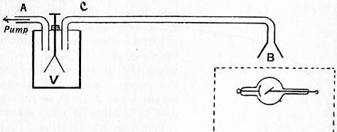 |
| Fig. 5. |
This and several other properties of conducting gas may readily be proved by the aid of the apparatus represented in fig. 5. V is a testing vessel in which an electroscope is placed. Two tubes A and C are fitted into the vessel, A being connected with a water pump, while the far end of C is in the region where the gas is exposed to the agent which makes it a conductor of electricity. Let us suppose that the gas is made conducting by Röntgen rays produced by a vacuum tube which is placed in a box, covered except for a window at B with lead so as to protect the electroscope from the direct action of the rays. If a slow current of air is drawn by the water pump through the testing vessel, the charge on the electroscope will gradually leak away. The leak, however, ceases when the current of air is stopped. This result shows that the gas retains its conductivity during the time taken by it to pass from one end to the other of the tube C.
The gas loses its conductivity when filtered through a plug of glass-wool, or when it is made to bubble through water. This can readily be proved by inserting in the tube C a plug of glass-wool or a water trap; then if by working the pump a little harder the same current of air is produced as before, it will be found that the electroscope will now retain its charge, showing that the conductivity can, as it were, be filtered out of the gas. 866 The conductivity can also be removed from the gas by making the gas traverse a strong electric field. We can show this by replacing the tube C by a metal tube with an insulated wire passing down the axis of the tube. If there is no potential difference between the wire and the tube then the electroscope will leak when a current of air is drawn through the vessel, but the leak will stop if a considerable difference of potential is maintained between the wire and the tube: this shows that a strong electric field removes the conductivity from the gas.
The fact that the conductivity of the gas is removed by filtering shows that it is due to something mixed with the gas which is removed from it by filtration, and since the conductivity is also removed by an electric field, the cause of the conductivity must be charged with electricity so as to be driven to the sides of the tube by the electric force. Since the gas as a whole is not electrified either positively or negatively, there must be both negative and positive charges in the gas, the amount of electricity of one sign being equal to that of the other. We are thus led to the conclusion that the conductivity of the gas is due to electrified particles being mixed up with the gas, some of these particles having charges of positive electricity, others of negative. These electrified particles are called ions, and the process by which the gas is made a conductor is called the ionization of the gas. We shall show later that the charges and masses of the ions can be determined, and that the gaseous ions are not identical with those met with in the electrolysis of solutions.
 |
| Fig. 6. |
One very characteristic property of conduction of electricity through a gas is the relation between the current through the gas and the electric force which gave rise to it. This relation is not in general that expressed by Ohm’s law, which always, as far as our present knowledge extends, expresses the relation for conduction through metals and electrolytes. With gases, on the other hand, it is only when the current is very small that Ohm’s law is true. If we represent graphically by means of a curve the relation between the current passing between two parallel metal plates separated by ionized gas and the difference of potential between the plates, the curve is of the character shown in fig. 6 when the ordinates represent the current and the abscissae the difference of potential between the plates. We see that when the potential difference is very small, i.e. close to the origin, the curve is approximately straight, but that soon the current increases much less rapidly than the potential difference, and that a stage is reached when no appreciable increase of current is produced when the potential difference is increased; when this stage is reached the current is constant, and this value of the current is called the “saturation” value. When the potential difference approaches the value at which sparks would pass through the gas, the current again increases with the potential difference; thus the curve representing the relation between the current and potential difference over very wide ranges of potential difference has the shape shown in fig. 7; curves of this kind have been obtained by von Schweidler (Wien. Ber., 1899, 108, p. 273), and J. E. S. Townsend (Phil. Mag., 1901 [6], 1, p. 198). We shall discuss later the causes of the rise in the current with large potential differences, when we consider ionization by collision.
The general features of the earlier part of the curve are readily explained on the ionization hypothesis. On this view the Röntgen rays or other ionizing agent acting on the gas between the plates, produces positive and negative ions at a definite rate. Let us suppose that q positive and q negative ions are by this means produced per second between the plates; these under the electric force will tend to move, the positive ones to the negative plate, the negative ones to the positive. Some of these ions will reach the plate, others before reaching the plate will get so near one of the opposite sign that the attraction between them will cause them to unite and form an electrically neutral system; when they do this they end their existence as ions. The current between the plates is proportional to the number of ions which reach the plates per second. Now it is evident that we cannot go on taking more ions out of the gas than are produced; thus we cannot, when the current is steady, have more than q positive ions driven to the negative plate per second, and the same number of negative ions to the positive. If each of the positive ions carries a charge of e units of positive electricity, and if there is an equal and opposite charge on each negative ion, then the maximum amount of electricity which can be given to the plates per second is qe, and this is equal to the saturation current. Thus if we measure the saturation current, we get a direct measure of the ionization, and this does not require us to know the value of any quantity except the constant charge on the ion. If we attempted to deduce the amount of ionization by measurements of the current before it was saturated, we should require to know in addition the velocity with which the ions move under a given electric force, the time that elapses between the liberation of an ion and its combination with one of the opposite sign, and the potential difference between the plates. Thus if we wish to measure the amount of ionization in a gas we should be careful to see that the current is saturated.
 |
| Fig. 7. |
The difference between conduction through gases and through metals is shown in a striking way when we use potential differences large enough to produce the saturation current. Suppose we have got a potential difference between the plates more than sufficient to produce the saturation current, and let us increase the distance between the plates. If the gas were to act like a metallic conductor this would diminish the current, because the greater length would involve a greater resistance in the circuit. In the case we are considering the separation of the plates will increase the current, because now there is a larger volume of gas exposed to the rays; there are therefore more ions produced, and as the saturation current is proportional to the number of ions the saturation current is increased. If the potential difference between the plates were much less than that required to saturate the current, then increasing the distance would diminish the current; the gas for such potential differences obeys Ohm’s law and the behaviour of the gaseous resistance is therefore similar to that of a metallic one.
In order to produce the saturation current the electric field must be strong enough to drive each ion to the electrode before it has time to enter into combination with one of the opposite sign. Thus when the plates in the preceding example are far apart, it will take a larger potential difference to produce this current than when the plates are close together. The potential difference required to saturate the current will increase as the square of the distance between the plates, for if the ions are to be delivered in a given time to the plates their speed must be proportional to the distance between the plates. But the speed is proportional to the electric force acting on the ion; hence the electric force must be proportional to the distance between the plates, and as in a uniform field the potential difference is equal to the electric force multiplied by the distance between the plates, the potential difference will vary as the square of this distance.
The potential difference required to produce saturation will, other circumstances being the same, increase with the amount of ionization, for when the number of ions is large and they are crowded together, the time which will elapse before a positive one combines with a negative will be smaller than when the number of ions is small. The ions have therefore to be removed more quickly from the gas when the ionization is great than when it is small; thus they must move at a higher speed and must therefore be acted upon by a larger force.
When the ions are not removed from the gas, they will increase until the number of ions of one sign which combine with ions of the opposite sign in any time is equal to the number produced by the ionizing agent in that time. We can easily calculate the number of free ions at any time after the ionizing agent has commenced to act.
Let q be the number of ions (positive or negative) produced in one cubic centimetre of the gas per second by the ionizing agent, n1, n2, the number of free positive and negative ions respectively per cubic centimetre of the gas. The number of collisions between positive and negative ions per second in one cubic centimetre of the gas is proportional to n1n2. If a certain fraction of the collisions between the positive and negative ions result in the formation of an electrically neutral system, the number of ions which disappear per second on a cubic centimetre will be equal to αn1 n2, where α is a quantity which is independent of n1, n2; hence if t is the time since the ionizing agent was applied to the gas, we have
dn1/dt = q − αn1 n2, dn2/dt = q − αn1 n2.
Thus n1 − n2 is constant, so if the gas is uncharged to begin with, n1 will always equal n2. Putting n1 = n2 = n we have
dn/dt = q − αn2 (1),
the solution of which is, since n = 0 when t = 0,
| n = | k(ε2kαt − 1) | (2), |
| ε2kαt + 1 |
if k2 = q/α. Now the number of ions when the gas has reached a steady state is got by putting t equal to infinity in the preceding equation, and is therefore given by the equation
n0 = k = √ (q/α).
We see from equation (1) that the gas will not approximate to its steady state until 2kαt is large, that is until t is large compared with ½kα or with ½√ (qα). We may thus take ½√ (qα) as a measure of the time taken by the gas to reach a steady state when exposed to an ionizing agent; as this time varies inversely as √q we see that when the ionization is feeble it may take a very considerable time for the gas to reach a steady state. Thus in the case of our atmosphere where the production of ions is only at the rate of about 30 per cubic centimetre per second, and where, as we shall see, α is about 10-6, it would take some minutes for the ionization in the air to get into a steady state if the ionizing agent were suddenly applied.
We may use equation (1) to determine the rate at which the ions disappear when the ionizing agent is removed. Putting q=0 in that equation we get dn/αt = -αn2.
Hence
n = n0/(1 + n0 αt) (3),
where n0 is the number of ions when t = 0. Thus the number of ions falls to one-half its initial value in the time 1/n0α. The quantity α is called the coefficient of recombination, and its value for different gases has been determined by Rutherford (Phil. Mag. 1897 [5], 44, p. 422), Townsend (Phil. Trans., 1900, 193, p. 129), McClung (Phil. Mag., 1902 [6], 3, p. 283), Langevin (Ann. chim. phys. [7], 28, p. 289), Retschinsky (Ann. d. Phys., 1905, 17, p. 518), Hendred (Phys. Rev., 1905, 21, p. 314). The values of α/e, e being the charge on an ion in electrostatic measure as determined by these observers for different gases, is given in the following table:—
| Townsend. | McClung. | Langevin. | Retschinsky. | Hendred. | |
| Air | 3420 | 3380 | 3200 | 4140 | 3500 |
| O2 | 3380 | ||||
| CO2 | 3500 | 3490 | 3400 | ||
| H2 | 3020 | 2940 |
The gases in these experiments were carefully dried and free from dust; the apparent value of α is much increased when dust or small drops of water are present in the gas, for then the ions get caught by the dust particles, the mass of a particle is so great compared with that of an ion that they are practically immovable under the action of the electric field, and so the ions clinging to them escape detection when electrical methods are used. Taking e as 3.5×10⁻¹⁰, we see that α is about 1.2×10⁻⁶, so that the number of recombinations in unit time between n positive and n negative ions in unit volume is 1.2×10⁻⁶n2. The kinetic theory of gases shows that if we have n molecules of air per cubic centimetre, the number of collisions per second is 1.2×10⁻¹⁰n2 at a temperature of 0° C. Thus we see that the number of recombinations between oppositely charged ions is enormously greater than the number of collisions between the same number of neutral molecules. We shall see that the difference in size between the ion and the molecule is not nearly sufficient to account for the difference between the collisions in the two cases; the difference is due to the force between the oppositely charged ions, which drags ions into collisions which but for this force would have missed each other.
Several methods have been used to measure α. In one method air, exposed to some ionizing agent at one end of a long tube, is slowly sucked through the tube and the saturation current measured at different points along the tube. These currents are proportional to the values of n at the place of observation: if we know the distance of this place from the end of the tube when the gas was ionized and the velocity of the stream of gas, we can find t in equation (3), and knowing the value of n we can deduce the value of α from the equation
1/n1 − 1/n2 = α(t1 − t2),
where n1, n2 are the values of n at the times t1, t2 respectively. In this method the tubes ought to be so wide that the loss of ions by diffusion to the sides of the tube is negligible. There are other methods which involve the knowledge of the speed with which the ions move under the action of known electric forces; we shall defer the consideration of these methods until we have discussed the question of these speeds.
In measuring the value of α it should be remembered that the theory of the methods supposes that the ionization is uniform throughout the gas. If the total ionization throughout a gas remains constant, but instead of being uniformly distributed is concentrated in patches, it is evident that the ions will recombine more quickly in the second case than in the first, and that the value of α will be different in the two cases. This probably explains the large values of α obtained by Retschinsky, who ionized the gas by the α rays from radium, a method which produces very patchy ionization.
Variation of α with the Pressure of the Gas.—All observers agree that there is little variation in α with the pressures for pressures of between 5 and 1 atmospheres; at lower pressures, however, the value of α seems to diminish with the pressure: thus Langevin (Ann. chim. phys., 1903, 28, p. 287) found that at a pressure of 1⁄5 of an atmosphere the value of α was about 1⁄5 of its value at atmospheric pressure.
Variation of α with the Temperature.—Erikson (Phil. Mag., Aug. 1909) has shown that the value of α for air increases as the temperature diminishes, and that at the temperature of liquid air -180° C., it is more than twice as great as at +12° C.
Since, as we have seen, the recombination is due to the coming together of the positive and negative ions under the influence of the electrical attraction between them, it follows that a large electric force sufficient to overcome this attraction would keep the ions apart and hence diminish the coefficient of recombination. Simple considerations, however, will show that it would require exceedingly strong electric fields to produce an appreciable effect. The value of α indicates that for two oppositely charged ions to unite they must come within a distance of about 1.5×10⁻⁶ centimetres; at this distance the attraction between them is e2×1012/2.25, and if X is the external electric force, the force tending to pull them apart cannot be greater than Xe; if this is to be comparable with the attraction, X must be comparable with e×1012/2.25, or putting e = 4×10⁻¹⁰, with 1.8×10²; this is 54,000 volts per centimetre, a force which could not be applied to gas at atmospheric pressure without producing a spark.
Diffusion of the Ions.—The ionized gas acts like a mixture of gases, the ions corresponding to two different gases, the non-ionized gas to a third. If the concentration of the ions is not uniform, they will diffuse through the non-ionized gas in such a way as to produce a more uniform distribution. A very valuable series of determinations of the coefficient of diffusion of ions through various gases has been made by Townsend (Phil. Trans., 1900, A, 193, p. 129). The method used was to suck the ionized gas through narrow tubes; by measuring the loss of both the positive and negative ions after the gases had passed through a known length of tube, and allowing for the loss by recombination, the loss by diffusion and hence the coefficient of diffusion could be determined. The following tables give the values of the coefficients of diffusion D on the C.G.S. system of units as determined by Townsend:—
Table I.—Coefficients of Diffusion (D) in Dry Gases.
| Gas. | D for +ions. | D for -ions. | Mean Value of D. | Ratio of D for - to D for +ions. |
| Air | .028 | .043 | .0347 | 1.54 |
| O2 | .025 | .0396 | .0323 | 1.58 |
| CO2 | .023 | .026 | .0245 | 1.13 |
| H2 | .123 | .190 | .156 | 1.54 |
Table II.—Coefficients of Diffusion in Moist Gases.
| Gas. | D for +ions. | D for -ions. | Mean Value of D. | Ratio of D for - to D for +ions. |
| Air | .032 | .037 | .0335 | 1.09 |
| O2 | .0288 | .0358 | .0323 | 1.24 |
| CO2 | .0245 | .0255 | .025 | 1.04 |
| H2 | .128 | .142 | .135 | 1.11 |
It is interesting to compare with these coefficients the values of D when various gases diffuse through each other. D for hydrogen through air is .634, for oxygen through air .177, for the vapour of 868 isobutyl amide through air .042. We thus see that the velocity of diffusion of ions through air is much less than that of the simple gas, but that it is quite comparable with that of the vapours of some complex organic compounds.
The preceding tables show that the negative ions diffuse more rapidly than the positive, especially in dry gases. The superior mobility of the negative ions was observed first by Zeleny (Phil. Mag., 1898 [5], 46, p. 120), who showed that the velocity of the negative ions under an electric force is greater than that of the positive. It will be noticed that the difference between the mobility of the negative and the positive ions is much more pronounced in dry gases than in moist. The difference in the rates of diffusion of the positive and negative ions is the reason why ionized gas, in which, to begin with, the positive and negative charges were of equal amounts, sometimes becomes electrified even although the gas is not acted upon by electric forces. Thus, for example, if such gas be blown through narrow tubes, it will be positively electrified when it comes out, for since the negative ions diffuse more rapidly than the positive, the gas in its passage through the tubes will lose by diffusion more negative than positive ions and hence will emerge positively electrified. Zeleny snowed that this effect does not occur when, as in carbonic acid gas, the positive and negative ions diffuse at the same rates. Townsend (loc. cit.) showed that the coefficient of diffusion of the ions is the same whether the ionization is produced by Röntgen rays, radioactive substances, ultra-violet light, or electric sparks. The ions produced by chemical reactions and in flames are much less mobile; thus, for example, Bloch (Ann. chim. phys., 1905 [8], 4, p. 25) found that for the ions produced by drawing air over phosphorus the value of α/e was between 1 and 6 instead of over 3000, the value when the air was ionized by Röntgen rays.
Velocity of Ions in an Electric Field.—The velocity of ions in an electric field, which is of fundamental importance in conduction, is very closely related to the coefficient of diffusion. Measurements of this velocity for ions produced by Röntgen rays have been made by Rutherford (Phil. Mag. [5], 44, p. 422), Zeleny (Phil. Mag. [5], 46, p. 120), Langevin (Ann. Chim. Phys., 1903, 28, p. 289), Phillips (Proc. Roy. Soc. 78, A, p. 167), and Wellisch (Phil. Trans., 1909, 209, p. 249). The ions produced by radioactive substance have been investigated by Rutherford (Phil. Mag. [5], 47, p. 109) and by Franck and Pohl (Verh. deutsch. phys. Gesell., 1907, 9, p. 69), and the negative ions produced when ultra-violet light falls on a metal plate by Rutherford (Proc. Camb. Phil. Soc. 9, p. 401). H. A. Wilson (Phil. Trans. 192, p. 4O9), Marx (Ann. de Phys. 11, p. 765), Moreau (Journ. de Phys. 4, 11, p. 558; Ann. Chim. Phys. 7, 30, p. 5) and Gold (Proc. Roy. Soc. 79, p. 43) have investigated the velocities of ions produced by putting various salts into flames; McClelland (Phil. Mag. 46, p. 29) the velocity of the ions in gases sucked from the neighbourhood of flames and arcs; Townsend (Proc. Camb. Phil. Soc. 9, p. 345) and Bloch (loc. cit.) the velocity of ions produced by chemical reaction; and Chattock (Phil. Mag. [5], 48, p. 401) the velocity of the ions produced when electricity escapes from a sharp needle point into a gas.
Several methods have been employed to determine these velocities. The one most frequently employed is to find the electromotive intensity required to force an ion against the stream of gas moving with a known velocity parallel to the lines of electric force. Thus, of two perforated plane electrodes vertically over each other, suppose the lower to be positively, the upper negatively electrified, and suppose that the gas is streaming vertically downwards with the velocity V; then unless the upward velocity of the positive ion is greater than V, no positive electricity will reach the upper plate. If we increase the strength of the field between the plates, and hence the upward velocity of the positive ion, until the positive ions just begin to reach the upper plate, we know that with this strength of field the velocity of the positive ion is equal to V. By this method, which has been used by Rutherford, Zeleny and H. A. Wilson, the velocity of ions in fields of various strengths has been determined.
The arrangement used by Zeleny is represented in fig. 8. P and Q are square brass plates. They are bored through their centres, and to the openings the tubes R and S are attached, the space between the plates being covered in so as to form a closed box. K is a piece of wire gauze completely covering the opening in Q; T is an insulated piece of wire gauze nearly but not quite filling the opening in the plate P, and connected with one pair of quadrants of an electrometer E. A plug of glass wool G filters out the dust from a stream of gas which enters the vessel by the tube D and leaves it by F; this plug also makes the velocity of the flow of the gas uniform across the section of the tube. The Röntgen rays to ionize the gas were produced by a bulb at O, the bulb and coil being in a lead-covered box, with an aluminium window through which the rays passed. Q is connected with one pole of a battery of cells, P and the other pole of the battery are put to earth. The changes in the potential of T are due to ions giving up their charges to it. With a given velocity of air-blast the potential of T was found not to change unless the difference of potential between P and Q exceeded a critical value. The field corresponding to this critical value thus made the ions move with the known velocity of the blast.
 |
| Fig. 8. |
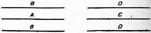 |
| Fig. 9. |
Another method which has been employed by Rutherford and McClelland is based on the action of an electric field in destroying the conductivity of gas streaming through it. Suppose that BAB, DCD (fig. 9) are a system of parallel plates boxed in so that a stream of gas, after flowing between BB, passes between DD without any loss of gas in the interval. Suppose the plates DD are insulated, and connected with one pair of quadrants of an electrometer, by charging up C to a sufficiently high potential we can drive all the positive ions which enter the system DCD against the plates D; this will cause a deflexion of the electrometer, which in one second will be proportional to the number of positive ions which have entered the system in that time. If we charge A up to a high potential, B being put to earth, we shall find that the deflexion of the electrometer connected with DD is less than it was when A and B were at the same potential, because some of the positive ions in their passage through BAB are driven against the plates B. If u is the velocity along the lines of force in the uniform electric field between A and B, and t the time it takes for the gas to pass through BAB, then all the positive ions within a distance ut of the plates B will be driven up against these plates, and thus if the positive ions are equally distributed through the gas, the number of positive ions which emerge from the system when the electric field is on will bear to the number which emerge when the field is off the ratio of 1 − ut/l to unity, where l is the distance between A and B. This ratio is equal to the ratio of the deflexions in one second of the electrometer attached to D, hence the observations of this instrument give 1 − ut/l. If we know the velocity of the gas and the length of the plates A and B, we can determine t, and since l can be easily measured, we can find u, the velocity of the positive ion in a field of given strength. By charging A and C negatively instead of positively we can arrive at the velocity of the negative ion. In practice it is more convenient to use cylindrical tubes with coaxial wires instead of the systems of parallel plates, though in this case the calculation of the velocity of the ions from the observations is a little more complicated, inasmuch as the electric field is not uniform between the tubes.
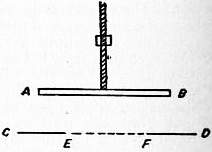 |
| Fig. 10. |
A method which gives very accurate results, though it is only applicable in certain cases, is the one used by Rutherford to measure the velocity of the negative ions produced close to a metal plate by the incidence on the plate of ultra-violet light. The principle of the method is as follows:—AB (fig. 10) is an insulated horizontal plate of well-polished zinc, which can be moved vertically up and down by means of a screw; it is connected with one pair of quadrants of an electrometer, the other pair of quadrants being put to earth. CD is a base-plate with a hole EF in it; this hole is covered with fine wire gauze, through which ultra-violet light passes and falls on the plate AB. The plate CD is connected with an alternating current dynamo, which produces a simply-periodic potential difference between AB and CD, the other pole being put to earth. Suppose that at any instant the plate CD is at a higher potential than AB, then the negative ions from AB will move towards CD, and will continue to do so as long as the potential of CD is higher than that of AB. If, however, the potential difference changes sign before the negative ions reach CD, these ions will go back to AB. Thus AB will not 869 lose any negative charge unless the distance between the plates AB and CD is less than the distance traversed by the negative ion during the time the potential of CD is higher than that of AB. By altering the distance between the plates until CD just begins to lose a negative charge, we find the velocity of the negative ion under unit electromotive intensity. For suppose the difference of potential between AB and CD is equal to a sin pt, then if d is the distance between the plates, the electric intensity is equal to a sin pt/d; if we suppose the velocity of the ion is proportional to the electric intensity, and if u is the velocity for unit electric intensity, the velocity of the negative ion will be ua sin pt/d. Hence if x represent the distance of the ion from AB
| dx | = | ua | sin pt |
| dT | d |
| x = | ua | (1 − cos pt), if x = 0 when t = 0. |
| pd |
Thus the greatest distance the ion can get from the plate is equal to 2au/pd, and if the distance between the plates is gradually reduced to this value, the plate AB will begin to lose a negative charge; hence when this happens
d = 2au/pd, or u = pd2/2a,
an equation by means of which we can find u.
In this form the method is not applicable when ions of both signs are present. Franck and Pohl (Verh. deutsch. physik. Gesell. 1907, 9, p. 69) have by a slight modification removed this restriction. The modification consists in confining the ionization to a layer of gas below the gauze EF. If the velocity of the positive ions is to be determined, these ions are forced through the gauze by applying to the ionized gas a small constant electric force acting upwards; if negative ions are required, the constant force is reversed. After passing through the gauze the ions are acted upon by alternating forces as in Rutherford’s method.
Langevin (Ann. chim. phys., 1903, 28, p. 289) devised a method of measuring the velocity of the ions which has been extensively used; it has the advantage of not requiring the rate of ionization to remain uniform. The general idea is as follows. Suppose that we expose the gas between two parallel plates A, B to Röntgen rays or some other ionizing agent, then stop the rays and apply a uniform electric field to the region between the plates. If the force on the positive ion is from A to B, the plate B will receive a positive charge of electricity. After the electric force has acted for a time T reverse it. B will now begin to receive negative electricity and will go on doing so until the supply of negative ions is exhausted. Let us consider how the quantity of positive electricity received by B will vary with T. To fix our ideas, suppose the positive ions move more slowly than the negative; let T2 and T1 be respectively the times taken by the positive and negative ions to move under the electric field through a distance equal to AB, the distance between the planes. Then if T is greater than T2 all the ions will have been driven from between the plates before the field is reversed, and therefore the positive charge received by B will not depend upon T. Next let T be less than T2 but greater than T1; then at the time when the field is reversed all the negative ions will have been driven from between the plates, so that the positive charge received by B will not be neutralized by the arrival of fresh ions coming to it after the reversal of the field. The number of positive ions driven against the plate B will be proportional to T. Thus if we measure the value of the positive charge on B for a series of values of T, each value being less than the preceding, we shall find that until T reaches a certain value the charge remains constant, but as soon as we reduce the time below this value the charge diminishes. The value of T when the diminution in the field begins is T2, the time taken for a positive ion to cross from A to B under the electric field; thus from T2 we can calculate the velocity of the positive ion in this field. If we still further diminish T, we shall find that we reach a value when the diminution of the positive charge on B with the time suddenly becomes much more rapid; this change occurs when T falls below T1 the time taken for the negative ions to go from one plate to the other, for now when the field is reversed there are still some negative ions left between the plates, and these will be driven against B and rob it of some of the positive charge it had acquired before the field was reversed. By observing the time when the increase in the rate of diminution of the positive charge with the time suddenly sets in we can determine T1, and hence the velocity of the negative ions.
The velocity of the ions produced by the discharge of electricity from a fine point was determined by Chattock by an entirely different method. In this case the electric field is so strong and the velocity of the ion so great that the preceding methods are not applicable. Suppose P represents a vertical needle discharging electricity into air, consider the force acting on the ions included between two horizontal planes A, B. If P is the density of the electrification, and Z the vertical component of the electric intensity, F the resultant force on the ions between A and B is vertical and equal to
∫∫∫ Zρ dxdydz.
Let us suppose that the velocity of the ion is proportional to the electric intensity, so that if w is the vertical velocity of the ions, which are supposed all to be of one sign, w = RZ.
Substituting this value of Z, the vertical force on the ions between A and B is equal to
| 1 | ∫∫∫ wρ dxdydz. |
| R |
But ∫∫ wρdxdy = ι, where ι is the current streaming from the point. This current, which can be easily measured by putting a galvanometer in series with the discharging point, is independent of z, the vertical distance of a plane between A and B below the charging point. Hence we have
| F = | ι | ∫dz = | ι | · z. |
| R | R |
This force must be counterbalanced by the difference of gaseous pressures over the planes A and B; hence if pB and pA denote respectively the pressures over B and A, we have
| pB − pA = | ι | z. |
| R |
Hence by the measurement of these pressures we can determine R, and hence the velocity with which an ion moves under a given electric intensity.
There are other methods of determining the velocities of the ions, but as these depend on the theory of the conduction of electricity through a gas containing charged ions, we shall consider them in our discussion of that theory.
By the use of these methods it has been shown that the velocities of the ions in a given gas are the same whether the ionization is produced by Röntgen rays, radioactive substances, ultra-violet light, or by the discharge of electricity from points. When the ionization is produced by chemical action the ions are very much less mobile, moving in the same electric field with a velocity less than one-thousandth part of the velocity of the first kind of ions. On the other hand, as we shall see later, the velocity of the negative ions in flames is enormously greater than that of even the first kind of ion under similar electric fields and at the same pressure. But when these negative ions get into the cold part of the flame, they move sluggishly with velocities of the order of those possessed by the second kind. The results of the various determinations of the velocities of the ions are given in the following table. The velocities are in centimetres per second under an electric force of one volt per centimetre, the pressure of the gas being 1 atmosphere. V+ denotes the velocity of the positive ion, V- that of the negative. V is the mean velocity of the positive and negative ions.
Velocities of Ions.—Ions produced by Röntgen Rays.
| Gas. | V+. | V-. | V. | Observer. |
| Air | .. | .. | 1.6 | Rutherford |
| Air (dry) | 1.36 | 1.87 | .. | Zeleny |
| ” | 1.60 | 1.70 | .. | Langevin |
| ” | 1.39 | 1.78 | .. | Phillips |
| ” | 1.54 | 1.78 | .. | Wellisch |
| Air (moist) | 1.37 | 1.81 | .. | Zeleny |
| Oxygen (dry) | 1.36 | 1.80 | .. | ” |
| Oxygen (moist) | 1.29 | 1.52 | .. | ” |
| Carbonic acid (dry) | 0.76 | 0.81 | .. | ” |
| ” ” | 0.86 | 0.90 | .. | Langevin |
| ” ” | 0.81 | 0.85 | .. | Wellisch |
| Carbonic acid (moist) | 0.82 | 0.75 | .. | Zeleny |
| Hydrogen (dry) | 6.70 | 7.95 | .. | ” |
| Nitrogen | .. | .. | 1.6 | Rutherford |
| Sulphur dioxide | 0.44 | 0.41 | .. | Wellisch |
| Hydrochloric acid | .. | .. | 1.27 | Rutherford |
| Chlorine | .. | .. | 1.0 | ” |
| Helium (dry) | 5.09 | 6.31 | .. | Franck and Pohl |
| Carbon monoxide | 1.10 | 1.14 | .. | Wellisch |
| Nitrous oxide | 0.82 | 0.90 | .. | ” |
| Ammonia | 0.74 | 0.80 | .. | ” |
| Aldehyde | 0.31 | 0.30 | .. | ” |
| Ethyl alcohol | 0.34 | 0.27 | .. | ” |
| Acetone | 0.31 | 0.29 | .. | ” |
| Ethyl chloride | 0.33 | 0.31 | .. | ” |
| Pentane | 0.36 | 0.35 | .. | ” |
| Methyl acetate | 0.33 | 0.36 | .. | ” |
| Ethyl formate | 0.30 | 0.31 | .. | ” |
| Ethyl ether | 0.29 | 0.31 | .. | ” |
| Ethyl acetate | 0.31 | 0.28 | .. | ” |
| Methyl bromide | 0.29 | 0.28 | .. | ” |
| Methyl iodide | 0.21 | 0.22 | .. | ” |
| Carbon tetrachloride | 0.30 | 0.31 | .. | ” |
| Ethyl iodide | 0.17 | 0.16 | .. | ” |
Ions from Point Discharge.
| Hydrogen | 5.4 | 7.43 | 6.41 | Chattock |
| Carbonic acid | 0.83 | 0.925 | 0.88 | Chattock |
| Air | 1.32 | 1.80 | 1.55 | Chattock |
| Oxygen | 1.30 | 1.85 | 1.57 | Chattock |
It will be seen from this table that the greater mobility of the negative ions is very much more marked in the case of the lighter and simpler gases than in that of the heavier and more complicated ones; with the vapours of organic substances there seems but little difference between the mobilities of the positive and negative ions, indeed in one or two cases the positive one seems slightly but very slightly the more mobile of the two. In the case of the simple gases the difference is much greater when the gases are dry than when they are moist. It has been shown by direct experiment that the velocities are directly proportional to the electric force.
Variation of Velocities with Pressure.—Until the pressure gets low the velocities of the ions, negative as well as positive, vary inversely as the pressure. Langevin (loc. cit.) was the first to show that at very low pressures the velocity of the negative ions increases more rapidly as the pressure is diminished than this law indicates. If the nature of the ion did not change with the pressure, the kinetic theory of gases indicates that the velocity would vary inversely as the pressure, so that Langevin’s results indicate a change in the nature of the negative ion when the pressure is diminished below a certain value. Langevin’s results are given in the following table, where p represents the pressure measured in centimetres of mercury, V+ and V- the velocities of the positive and negative ions in air under unit electrostatic force, i.e. 300 volts per centimetre:—
| Negative Ions. | Positive Ions. | ||||
| p. | V-. | pV-/76. | p. | V+. | pV+/76. |
| 7.5 | 6560 | 647 | 7.5 | 4430 | 437 |
| 20.0 | 2204 | 580 | 20.0 | 1634 | 430 |
| 41.5 | 994 | 530 | 41.5 | 782 | 427 |
| 76.0 | 510 | 510 | 76.0 | 480 | 420 |
| 142.0 | 270 | 505 | 142.0 | 225 | 425 |
The increase in the case of pV- indicates that the structure of the negative ion gets simpler as the pressure is reduced. Wallisch in some experiments made at the Cavendish Laboratory found that the diminution in the value of pV- at low pressures is much more marked in some gases than in others, and in some gases he failed to detect it; but it must be remembered that it is difficult to get measurements at pressures of only a few millimetres, as the amount of ionization is so exceedingly small at such pressures that the quantities to be observed are hardly large enough to admit of accurate measurements by the methods available at higher pressures.
Effect of Temperature on the Velocity of the Ions.—Phillips (Proc. Roy. Soc., 1906, 78, p. 167) investigated, using Langevin’s method, the velocities of the + and − ions through air at atmospheric pressure at temperatures ranging from that of boiling liquid air to 411° C.; R1 and R2 are the velocities of the + and − ions respectively when the force is a volt per centimetre.
| R1. | R2. | Temperature Absolute. |
| 2.00 | 2.495 | 411° |
| 1.95 | 2.40 | 399° |
| 1.85 | 2.30 | 383° |
| 1.81 | 2.21 | 373° |
| 1.67 | 2.125 | 348° |
| 1.60 | 2.00 | 333° |
| 1.39 | 1.785 | 285° |
| 0.945 | 1.23 | 209° |
| 0.235 | 0.235 | 94° |
We see that except in the case of the lowest temperature, that of liquid air, where there is a great drop in the velocity, the velocities of the ions are proportional to the absolute temperature. On the hypothesis of an ion of constant size we should, from the kinetic theory of gases, expect the velocity to be proportional to the square root of the absolute temperature, if the charge on the ion did not affect the number of collisions between the ion and the molecules of the gas through which it is moving. If the collisions were brought about by the electrical attraction between the ions and the molecules, the velocity would be proportional to the absolute temperature. H. A. Wilson (Phil. Trans. 192, p. 499), in his experiments on the conduction of flames and hot gases into which salts had been put, found that the velocity of the positive ions in flames at a temperature of 2000° C. containing the salts of the alkali metals was 62 cm./sec. under an electric force of one volt per centimetre, while the velocity of the positive ions in a stream of hot air at 1000° C. containing the same salts was only 7 cm./sec. under the same force. The great effect of temperature is also shown in some experiments of McClelland (Phil. Mag. [5], 46, p. 29) on the velocities of the ions in gases drawn from Bunsen flames and arcs; he found that these depended upon the distance the gas had travelled from the flame. Thus, the velocity of the ions at a distance of 5.5 cm. from the Bunsen flame when the temperature was 230° C. was .23 cm./sec. for a volt per centimetre; at a distance of 10 cm. from the flame when the temperature was 160° C. the velocity was .21 cm./sec; while at a distance of 14.5 cm. from the flame when the temperature was 105° C. the velocity was only .04 cm./sec. If the temperature of the gas at this distance from the flame was raised by external means, the velocity of the ions increased.
We can derive some information as to the constitution of the ions by calculating the velocity with which a molecule of the gas would move in the electric field if it carried the same charge as the ion. From the theory of the diffusion of gases, as developed by Maxwell, we know that if the particles of a gas A are surrounded by a gas B, then, if the partial pressure of A is small, the velocity u with which its particles will move when acted upon by a force Xe is given by the equation
| u = | Xe | D, |
| (p1/N1) |
where D represents the coefficient of inter-diffusion of A into B, and N1 the number of particles of A per cubic centimetre when the pressure due to A is p1. Let us calculate by this equation the velocity with which a molecule of hydrogen would move through hydrogen if it carried the charge carried by an ion, which we shall prove shortly to be equal to the charge carried by an atom of hydrogen in the electrolysis of solutions. Since p1/N1 is independent of the pressure, it is equal to Π/N, where Π is the atmospheric pressure and N the number of molecules in a cubic centimetre of gas at atmospheric pressure. Now Ne = 1.22×10¹⁰, if e is measured in electrostatic units; Π = 106 and D in this case is the coefficient of diffusion of hydrogen into itself, and is equal to 1.7. Substituting these values we find
u = 1.97×10⁴X.
If the potential gradient is 1 volt per centimetre, X = 1⁄300. Substituting this value for X, we find u = 66 cm./sec, for the velocity of a hydrogen molecule. We have seen that the velocity of the ion in hydrogen is only about 5 cm./sec, so that the ion moves more slowly than it would if it were a single molecule. One way of explaining this is to suppose that the ion is bigger than the molecule, and is in fact an aggregation of molecules, the charged ion acting as a nucleus around which molecules collect like dust round a charged body. This view is supported by the effect produced by moisture in diminishing the velocity of the negative ion, for, as C. T. R. Wilson (Phil. Trans. 193, p. 289) has shown, moisture tends to collect round the ions, and condenses more easily on the negative than on the positive ion. In connexion with the velocities of ions in the gases drawn from flames, we find other instances which suggest that condensation takes place round the ions. An increase in the size of the system is not, however, the only way by which the velocity might fall below that calculated for the hydrogen molecule, for we must remember that the hydrogen molecule, whose coefficient of diffusion is 1.7, is not charged, while the ion is. The forces exerted by the ion on the other molecules of hydrogen are not the same as those which would be exerted by a molecule of hydrogen, and as the coefficient of diffusion depends on the forces between the molecules, the coefficient of diffusion of a charged molecule into hydrogen might be very different from that of an uncharged one.
Wellisch (loc. cit.) has shown that the effect of the charge on the ion is sufficient in many cases to explain the small velocity of the ions, even if there were no aggregation.
Mixture of Gases.—The ionization of a mixture of gases raises some very interesting questions. If we ionize a mixture of two very different gases, say hydrogen and carbonic acid, and investigate the nature of the ions by measuring their velocities, the question arises, shall we find two kinds of positive and two kinds of negative ions moving with different velocities, as we should do if some of the positive ions were positively charged hydrogen molecules, while others were positively charged molecules of carbonic acid; or shall we find only one velocity for the positive ions and one for the negative? Many experiments have been made on the velocity of ions in mixtures of two gases, but as yet no evidence has been found of the existence of two different kinds of either positive or negative ions in such mixtures, although some of the methods for determining the velocities of the ions, especially Langevin’s, ought to give evidence of this effect, if it existed. The experiments seem to show 871 that the positive (and the same is true for the negative) ions in a mixture of gases are all of the same kind. This conclusion is one of considerable importance, as it would not be true if the ions consisted of single molecules of the gas from which they are produced.
Recombination.—Several methods enable us to deduce the coefficient of recombination of the ions when we know their velocities. Perhaps the simplest of these consists in determining the relation between the current passing between two parallel plates immersed in ionized gas and the potential difference between the plates. For let q be the amount of ionization, i.e. the number of ions produced per second per unit volume of the gas, A the area of one of the plates, and d the distance between them; then if the ionization is constant through the volume, the number of ions of one sign produced per second in the gas is qAd. Now if i is the current per unit area of the plate, e the charge on an ion, iA/e ions of each sign are driven out of the gas by the current per second. In addition to this source of loss of ions there is the loss due to the recombination; if n is the number of positive or negative ions per unit volume, then the number which recombine per second is αn2 per cubic centimetre, and if n is constant through the volume of the gas, as will approximately be the case if the current through the gas is only a small fraction of the saturation current, the number of ions which disappear per second through recombination is αn2·Ad. Hence, since when the gas is in a steady state the number of ions produced must be equal to the number which disappear, we have
qAd = iA/e + αn2·Ad,
q = i/ed + αn2.
If u1 and u2 are the velocities with which the positive and negative ions move, nu1e and nu2e are respectively the quantities of positive electricity passing in one direction through unit area of the gas per second, and of negative in the opposite direction, hence
i = nu1e + nu2e.
If X is the electric force acting on the gas, k1 and k2 the velocities of the positive and negative ions under unit force, u1 = k1X, u2 = k2X; hence
n = i/(k1 + k2)Xe,
and we have
| q = | i | + | αi2 | . |
| ed | (k1 + k2)2 e2X2 |
But qed is the saturation current per unit area of the plate; calling this I, we have
| I − i = | dαi2 |
| e(k1 + k2)2X2 |
or
| X2 = | i2·dα | . |
| e(I − i) (k1 + k2)2 |
Hence if we determine corresponding values of X and i we can deduce the value of α/e if we also know (k1 + k2). The value of I is easily determined, as it is the current when X is very large. The preceding result only applies when i is small compared with I, as it is only in this case that the values of n and X are uniform throughout the volume of the gas. Another method which answers the same purpose is due to Langevin (Ann. Chim. Phys., 1903, 28, p. 289); it is as follows. Let A and B be two parallel planes immersed in a gas, and let a slab of the gas bounded by the planes a, b parallel to A and B be ionized by an instantaneous flash of Röntgen rays. If A and B are at different electric potentials, then all the positive ions produced by the rays will be attracted by the negative plate and all the negative ions by the positive, if the electric field were exceedingly large they would reach these plates before they had time to recombine, so that each plate would receive N0 ions if the flash of Röntgen rays produced N0 positive and N0 negative ions. With weaker fields the number of ions received by the plates will be less as some of them will recombine before they can reach the plates. We can find the number of ions which reach the plates in this case in the following way:—In consequence of the movement of the ions the slab of ionized gas will broaden out and will consist of three portions, one in which there are nothing but positive ions,—this is on the side of the negative plate,—another on the side of the positive plate in which there are nothing but negative ions, and a portion between these in which there are both positive and negative ions; it is in this layer that recombination takes place, and here if n is the number of positive or negative ions at the time t after the flash of Röntgen rays,
n = n0/(1 + αn0t).
With the same notation as before, the breadth of either of the outer layers will in time dt increase by X(k1 + k2)dt, and the number of ions in it by X(k1 + k2)ndt; these ions will reach the plate, the outer layers will receive fresh ions until the middle one disappears, which it will do after a time l/X(k1 + k2), where l is the thickness of the slab ab of ionized gas; hence N, the number of ions reaching either plate, is given by the equation
| N = ∫0l/X(k1+k2) | n0X(k1 + k2) | dt = | X(k1 + k2) | log (1 + | n0αl | ). |
| 1 + n0αt | α | X(k1 + k2) |
If Q is the charge received by the plate,
| Q = Ne = | X | log(1 + | Q0ε | ), |
| 4πε | 4πX |
where Q0 = n0le is the charge received by the plate when the electric force is large enough to prevent recombination, and ε = α4πe(R1 + R2). We can from this result deduce the value of ε and hence the value of α when R1 + R2 is known.
Distribution of Electric Force when a Current is passing through an Ionized Gas.—Let the two plates be at right angles to the axis of x; then we may suppose that between the plates the electric intensity X is everywhere parallel to the axis of x. The velocities of both the positive and negative ions are assumed to be proportional to X. Let k1X, k2X represent these velocities respectively; let n1, n2 be respectively the number of positive and negative ions per unit volume at a point fixed by the co-ordinate x; let q be the number of positive or negative ions produced in unit time per unit volume at this point; and let the number of ions which recombine in unit volume in unit time be αn1n2; then if e is the charge on the ion, the volume density of the electrification is (n1 − n2)e, hence
| dX | = 4π(n1 − n2)e (1). |
| dx |
If I is the current through unit area of the gas and if we neglect any diffusion except that caused by the electric field,
n1ek1X + n2ek2X = I (2).
From equations (1) and (2) we have
| n1e = | 1 | ( | I | + | k2 | dX | ) (3), | |
| k1 + k2 | X | 4π | dx |
| n1e = | 1 | ( | I | - | k2 | dX | ) (4), | |
| k1 + k2 | X | 4π | dx |
and from these equations we can, if we know the distribution of electric intensity between the plates, calculate the number of positive and negative ions.
In a steady state the number of positive and negative ions in unit volume at a given place remains constant, hence neglecting the loss by diffusion, we have
| d | (k1n1X) = q − αn1n2 (5). |
| dx |
| - | d | (k2n2X) = q − αn1n2 (6). |
| dx |
If k1 and k2 are constant, we have from (1), (5) and (6)
| d²X² | = 8πe(q − αn1n2)( | 1 | + | 1 | ) (7). |
| dx² | k1 | k2 |
an equation which is very useful, because it enables us, if we know the distribution of X², to find whether at any point in the gas the ionization is greater or less than the recombination of the ions. We see that q − αn1n2, which is the excess of ionization over recombination, is proportional to d²X²/dx². Thus when the ionization exceeds the recombination, i.e. when q − αn1n2 is positive, the curve for X² is convex to the axis of x, while when the recombination exceeds the ionization the curve for X² will be concave to the axis of x. Thus, for example, fig. 11 represents the curve for X² observed by Graham (Wied. Ann. 64, p. 49) in a tube through which a steady current is passing. Interpreting it by equation (7), we infer that ionization was much in excess of recombination at A and B, slightly so along C, while along D the recombination exceeded the ionization. Substituting in equation (7) the values of n1, n2 given in (3), (4), we get
| d²X² | 8πe[q - | α | (I + | k2 | dX² | )(I - | k2 | dX² | )]( | 1 | + | 1 | ) (8). | ||
| dx² | e²X²(k1 + k2)² | 8π | dx | 8π | dx | k1 | k2 |
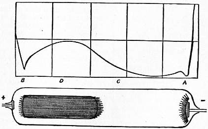 |
| Fig. 11. |
This equation can be solved (see Thomson, Phil. Mag. xlvii. P. 253), when q is constant and k1 = k2. From the solution it appears that if X1 be the value of x close to one of the plates, and X0 the value midway between them,
| X1/X0 = | 1 |
| β2 − 2/β |
where β = 8πek1/α.
Since e = 4×10⁻¹⁰, α = 2×10⁻⁶, and k1 for air at atmospheric pressure = 450, β is about 2.3 for air at atmospheric pressure and it becomes much greater at lower pressures.
Thus X1/X0 is always greater than unity, and the value of the ratio increases from unity to infinity as β increases from zero to infinity. As β does not involve either q or I, the ratio of X1 to X0 is independent of the strength of the current and of the intensity of the ionization.
No general solution of equation (8) has been found when k1 is not equal to k2, but we can get an approximation to the solution when q is constant. The equations (1), (2), (3), (4) are satisfied by the values—
n1 = n2 = (q/α)1/2
| k1n1Xe = | k1 | I, |
| k1 + k2 |
| k2n2Xe = | k2 | I, |
| k1 + k2 |
| X =( | α | )1/2 | I | . |
| q | e(k1 + k2) |
These solutions cannot, however, hold right up to the surface of the plates, for across each unit of area, at a point P, k1I/(k1 + k2)e positive ions pass in unit time, and these must all come from the region between P and the positive plate. If λ is the distance of P from this plate, this region cannot furnish more than qλ positive ions, and only this number if there are no recombinations. Hence the solution cannot hold when qλ is less than k1I/(k1 + k2)e, or where λ is less than k1I/(k1 + k2)qe.
Similarly the solution cannot hold nearer to the negative plate than the distance k2I/(k1 + k2)qe.
The force in these layers will be greater than that in the middle of the gas, and so the loss of ions by recombination will be smaller in comparison with the loss due to the removal of the ions by the current. If we assume that in these layers the loss of ions by recombination can be neglected, we can by the method of the next article find an expression for the value of the electric force at any point in the layer. This, in conjunction with the value X0 = (α/q)1/2 · I/e(k1 + k2) for the gas outside the layer, will give the value of X at any point between the plates. It follows from this investigation that if X1 and X2 are the values of X at the positive and negative plates respectively, and X0 the value of X outside the layer,
| X1 = X0(1 + | k1 | 1 | )1/2, | X2 = X0(1 + | k2 | 1 | )1/2, | ||
| k2 | ε | k1 | ε |
where ε = α/4πe(k1 + k2). Langevin found that for air at a pressure of 152 mm. ε = 0.01, at 375 mm. ε = 0.06, and at 760 mm. ε = 0.27. Thus at fairly low pressures 1/ε is large, and we have approximately
| X1 = X0( | k1 | )1/2 | 1 | , | X2 = X0( | k2 | )1/2 | 1 | . |
| k2 | √ε | k1 | √ε |
Therefore
X1/X2 = k1/k2,
 |
| Fig. 12. |
or the force at the positive plate is to that at the negative plate as the velocity of the positive ion is to that of the negative ion. Thus the force at the negative plate is greater than that at the positive. The falls of potential V1, V2 at the two layers when 1/ε is large can be shown to be given by the equations
| V1 = 8π²( | ε | )3/2k1( | k1 | )1/2i², |
| qα | k2 |
| V2 = 8π²( | ε | )3/2k2( | k2 | )1/2i², |
| qα | k1 |
hence
V1/V2 = k1²/k2²,
so that the potential falls at the electrodes are proportional to the squares of the velocities of the ions. The change in potential across the layers is proportional to the square of the current, while the potential change between the layers is proportional to the current, the total potential difference between the plates is the sum of these changes, hence the relation between V and i will be of the form
V = Ai + Bi².
Mie (Ann. der. Phys., 1904, 13, P. 857) has by the method of successive approximations obtained solutions of equation (8) (i.) when the current is only a small fraction of the saturation current, (ii.) when the current is nearly saturated. The results of his investigations are represented in fig. 12, which represents the distribution of electric force along the path of the current for various values of the current expressed as fractions of the saturation current. It will be seen that until the current amounts to about one-fifth of the maximum current, the type of solution is the one just indicated, i.e. the electric force is constant except in the neighbourhood of the electrodes when it increases rapidly.
Though we are unable to obtain a general solution of the equation (8), there are some very important special cases in which that equation can be solved without difficulty. We shall consider two of these, the first being that when the current is saturated. In this case there is no loss of ions by recombination, so that using the same notation as before we have
| d | (n1k1X) = q, |
| dx |
| d | (n2k2X) = -q. |
| dx |
The solutions of which if q is constant are
| n1k1X = qx, |
| n2k2X = I/e − qx = q(l − x), |
if l is the distance between the plates, and x = 0 at the positive electrode. Since
dX/dx = 4π(n1 − n2)e,
we get
| 1 | dX² | = qx{ | 1 | + | 1 | }- q | l | , | |
| 8π | d²x | k1 | k2 | k2 |
or
| X² | = q | x² | ( | 1 | + | 1 | )- q | lx | + C, |
| 8π | 2 | k1 | k2 | k2 |
where C is a quantity to be determined by the condition that ∫l0 Xdx = V, where V is the given potential difference between the plates. When the force is a minimum dX/dx = 0, hence at this point
| x = | l k1 | , l − x = | l k2 | . |
| k1 + k2 | k1 + k2 |
Hence the ratio of the distances of this point from the positive and negative plates respectively is equal to the ratio of the velocities of the positive and negative ions.
The other case we shall consider is the very important one in which the velocity of the negative ion is exceedingly large compared with the positive; this is the case in flames where, as Gold (Proc. Roy. Soc. 97, p. 43) has shown, the velocity of the negative ion is many thousand times the velocity of the positive; it is also very probably the case in all gases when the pressure is low. We may get the solution of this case either by putting k1/k2 = 0 in equation (8), or independently as follows:—Using the same notation as before, we have
i = n1k1Xe + n2k2Xe,
| d | (n2k2X) = q − αn1n2, |
| dx |
| dX | = 4π (n1 − n2)e. |
| dx |
In this case practically all the current is carried by the negative ions so that i = n2k2Xe, and therefore q = αn1n2.
Thus
n2 = i/k2Xe, n1 = qk2Xe/αi.
Thus
| dX | = | 4πe²k2qX | - | 4πi | , |
| dx | αi | k2X |
or
| dX² | - | 8πe²k2qX² | = - | 8πi | . |
| dx | αi | k2 |
The solution of this equation is
| X² = | α | i² | + Cε 8πe² k2qx/αi. | |
| q | k²2e² |
Here x is measured from the positive electrode; it is more convenient in this case, however, to measure it from the negative electrode. If x be the distance from the negative electrode at which the electric force is X, we have from equation (7)
| X² = | α | i² | + C¹ε 8πe² k2qx/αi. | |
| q | k²2e² |
To find the value of C¹ we see by equation (7) that
| d²X² | k1k2 | 1 | = q − αn1n2; | ||
| dX² | k1 + k2 | 8πe |
hence
| [ | dX² | k1k2 | 1 | ]x1 = ∫x10 (q − αn1n2)dx. | ||
| dX | k1 + k2 | 8πe |
The right hand side of this equation is the excess of ionization over recombination in the region extending from the cathode to x1; it must therefore, when things are in a steady state, equal the excess of the number of negative ions which leave this region over those which enter it. The number which leave is i/e and the number which enter is i0/e, if it is the current of negative ions coming from unit area 873 of the cathode, as hot metal cathodes emit large quantities of negative electricity i0 may in some cases be considerable, thus the right hand side of equation is (i − i0)/e. When x1 is large dX²/dx = 0; hence we have from equation
| C¹ = | αi(i − i0) | k1 + k2 | , | |
| qk1k2e² | k2 |
and since k1 is small compared with k2, we have
| X² = | α i² | (1 + | k2 | i − i0 | ε -8πe² k2 · qx/α · i ). | |
| qk²2 e² | k1 | i |
From the values which have been found for k2 and α, we know that 8πek2/α is a large quantity, hence the second term inside the bracket will be very small when eqx is equal to or greater than i; thus this term will be very small outside a layer of gas next the cathode of such thickness that the number of ions produced on it would be sufficient, if they were all utilized for the purpose, to carry the current; in the case of flames this layer is exceedingly thin unless the current is very large. The value of the electric force in the uniform part of the field is equal to i/k2e · √a/q, while when i0 = 0, the force at the cathode itself bears to the uniform force the ratio of (k1 + k2)1/2 to k11/2. As k1 is many thousand times k2 the force increases with great rapidity as we approach the cathode; this is a very characteristic feature of the passage of electricity through flames and hot gases. Thus in an experiment made by H. A. Wilson with a flame 18 cm. long, the drop of potential within 1 centimetre of the cathode was about five times the drop in the other 17 cm. of the tube. The relation between the current and the potential difference when the velocity of the negative ion is much greater than the positive is very easily obtained. Since the force is uniform and equal to i/k2e · √a/q, until we get close to the cathode the fall of potential in this part of the discharge will be very approximately equal to i/k2e · √(a/q) l, where l is the distance between the electrodes. Close to the cathode, the electric force when i0 is not nearly equal to i is approximately given by the equation
| X = | i | ( | α | )1/2 ε −4π e²k2 qx / αi, |
| e(k1k2)1/2 | q |
and the fall of potential at the cathode is equal approximately to ∫∞0 Xdx, that is to
| i | ( | α | )1/2 | α i | . |
| e(k1k2)1/2 | q | 4πe²k2q |
The potential difference between the plates is the sum of the fall of potential in the uniform part of the discharge plus the fall at the cathode, hence
| V =( | α | )1/2 | i | (il + | i α² | 1 | ). | |
| q | ek2 | 4πe²q | √(k1k2) |
The fall of potential at the cathode is proportional to the square of the current, while the fall in the rest of the circuit is directly proportional to the current. In the case of flames or hot gases, the fall of potential at the cathode is much greater than that in the rest of the circuit, so that in such cases the current through the gas varies nearly as the square root of the potential difference. The equation we have just obtained is of the form
V = Ai + Bi²,
and H. A. Wilson has shown that a relation of this form represents the results of his experiments on the conduction of electricity through flames.
The expression for the fall of potential at the cathode is inversely proportional to q3/2, q being the number of ions produced per cubic centimetre per second close to the cathode; thus any increase in the ionization at the cathode will diminish the potential fall at the cathode, and as practically the whole potential difference between the electrodes occurs at the cathode, a diminution in the potential fall there will be much more important than a diminution in the electric force in the uniform part of the discharge, when the force is comparatively insignificant. This consideration explains a very striking phenomenon discovered many years ago by Hittorf, who found that if he put a wire carrying a bead of a volatile salt into the flame, it produced little effect upon the current, unless it were placed close to the cathode where it gave rise to an enormous increase in the current, sometimes increasing the current more than a hundredfold. The introduction of the salt increases very largely the number of ions produced, so that q is much greater for a salted flame than for a plain one. Thus Hittorf’s result coincides with the conclusions we have drawn from the theory of this class of conduction.
The fall of potential at the cathode is proportional to i − i0, where i0 is the stream of negative electricity which comes from the cathode itself, thus as i0 increases the fall of potential at the cathode diminishes and the current sent by a given potential difference through the gas increases. Now all metals give out negative particles when heated, at a rate which increases very rapidly with the temperature, but at the same temperature some metals give out more than others. If the cathode is made of a metal which emits large quantities of negative particles, (i − i0) will for a given value of i be smaller than if the metal only emitted a small number of particles; thus the cathode fall will be smaller for the metal with the greater emissitivity, and the relation between the potential difference and the current will be different in the two cases. These considerations are confirmed by experience, for it has been found that the current between electrodes immersed in a flame depends to a great extent upon the metal of which the electrodes are made. Thus Pettinelli (Acc. dei Lincei [5], v. p. 118) found that, ceteris paribus, the current between two carbon electrodes was about 500 times that between two iron ones. If one electrode was carbon and the other iron, the current when the carbon was cathode and the iron anode was more than 100 times the current when the electrodes were reversed. The emission of negative particles by some metallic oxides, notably those of calcium and barium, has been shown by Wehnelt (Ann. der Phys. 11, p. 425) to be far greater than that of any known metal, and the increase of current produced by coating the cathodes with these oxides is exceedingly large; in some cases investigated by Tufts and Stark (Physik. Zeits., 1908, 5, p. 248) the current was increased many thousand times by coating the cathode with lime. No appreciable effect is produced by putting lime on the anode.
Conduction when all the Ions are of one Sign.—There are many important cases in which the ions producing the current come from one electrode or from a thin layer of gas close to the electrode, no ionization occurring in the body of the gas or at the other electrode. Among such cases may be mentioned those where one of the electrodes is raised to incandescence while the other is cold, or when the negative electrode is exposed to ultra-violet light. In such cases if the electrode at which the ionization occurs is the positive electrode, all the ions will be positively charged, while if it is the negative electrode the ions will all be charged negatively. The theory of this case is exceedingly simple. Suppose the electrodes are parallel planes at right angles to the axis of x; let X be the electric force at a distance x from the electrode where the ionization occurs, n the number of ions (all of which are of one sign) at this place per cubic centimetre, k the velocity of the ion under unit electric force, e the charge on an ion, and i the current per unit area of the electrode. Then we have dX/dx = 4πne, and if u is the velocity of the ion neu = i. But u = kX, hence we have kX/4π · dX/dx = i, and since the right hand side of this equation does not depend upon x, we get kX²/8π = ix + C, where C is a constant to be determined. If l is the distance between the plates, and V the potential difference between them,
| V =∫l 0 Xdx = | 1 | √ | 8π | [(il + C)3/2 − C3/2 ]. |
| i | k |
We shall show that when the current is far below the saturation value, C is very small compared with il, so that the preceding equation becomes
V² = 8πl³ i/k (1).
To show that for small currents C is small compared with il, consider the case when the ionization is confined to a thin layer, thickness d close to the electrode, in that layer let n0 be the value of n, then we have q = αn0² + i/ed. If X0 be the value of X when x = 0, kX0n0e = i, and,
| C = | kX0² | = | i² | = | α | · | i² | (2). |
| 8π | n0²ke·8π | 8πke² | q + i/ed |
Since α/8πke is, as we have seen, less than unity, C will be small compared with il, if i/(eq + i/d) is small compared with l. If I0 is the saturation current, q = I0/ed, so that the former expression = id/(I0 + i), if i is small compared with I0, this expression is small compared with d, and therefore a fortiori compared with l, so that we are justified in this case in using equation (1).
From equation (2) we see that the current increases as the square of the potential difference. Here an increase in the potential difference produces a much greater percentage increase than in conduction through metals, where the current is proportional to the potential difference. When the ionization is distributed through the gas, we have seen that the current is approximately proportional to the square root of the potential, and so increases more slowly with the potential difference than currents through metals. From equation (1) the current is inversely proportional to the cube of the distance between the electrodes, so that it falls off with great rapidity as this distance is increased. We may note that for a given potential difference the expression for the current does not involve q, the rate of production of the ions at the electrode, in other words, if we vary the ionization the current will not begin to be affected by the strength of the ionization until this falls so low that the current is a considerable fraction of the saturation current. For the same potential difference the current is proportional to k, the velocity under unit electric force of the ion which carries the current. As the velocity of the negative ion is greater than that of the positive, the current when the ionization is confined to the neighbourhood of one of the electrodes will be greater when that electrode is made cathode than when it is anode. Thus the current will appear to pass more easily in one direction than in the opposite.
Since the ions which carry the current have to travel all the way from one electrode to the other, any obstacle which is impervious to these ions will, if placed between the electrodes, stop the current 874 to the electrode where there is no ionization. A plate of metal will be as effectual as one made of a non-conductor, and thus we get the remarkable result that by interposing a plate of an excellent conductor like copper or silver between the electrode, we can entirely stop the current. This experiment can easily be tried by using a hot plate as the electrode at which the ionization takes place: then if the other electrode is cold the current which passes when the hot plate is cathode can be entirely stopped by interposing a cold metal plate between the electrodes.
Methods of counting the Number of Ions.—The detection of the ions and the estimation of their number in a given volume is much facilitated by the property they possess of promoting the condensation of water-drops in dust-free air supersaturated with water vapour. If such air contains no ions, then it requires about an eightfold supersaturation before any water-drops are formed; if, however, ions are present C. T. R. Wilson (Phil. Trans. 189, p. 265) has shown that a sixfold supersaturation is sufficient to cause the water vapour to condense round the ions and to fall down as raindrops. The absence of the drops when no ions are present is due to the curvature of the drop combined with the surface tension causing, as Lord Kelvin showed, the evaporation from a small drop to be exceeding rapid, so that even if a drop of water were formed the evaporation would be so great in its early stages that it would rapidly evaporate and disappear. It has been shown, however (J. J. Thomson, Application of Dynamics to Physics and Chemistry, p. 164; Conduction of Electricity through Gases, 2nd ed. p. 179), that if a drop of water is charged with electricity the effect of the charge is to diminish the evaporation; if the drop is below a certain size the effect the charge has in promoting condensation more than counterbalances the effect of the surface tension in promoting evaporation. Thus the electric charge protects the drop in the most critical period of its growth. The effect is easily shown experimentally by taking a bulb connected with a piston arranged so as to move with great rapidity. When the piston moves so as to increase the volume of the air contained in the bulb the air is cooled by expansion, and if it was saturated with water vapour before it is supersaturated after the expansion. By altering the throw of the piston the amount of supersaturation can be adjusted within very wide limits. Let it be adjusted so that the expansion produces about a sixfold supersaturation; then if the gas is not exposed to any ionizing agents very few drops (and these probably due to the small amount of ionization which we have seen is always present in gases) are formed. If, however, the bulb is exposed to strong Röntgen rays expansion produces a dense cloud which gradually falls down and disappears. If the gas in the bulb at the time of its exposure to the Röntgen rays is subject to a strong electric field hardly any cloud is formed when the gas is suddenly expanded. The electric field removes the charged ions from the gas as soon as they are formed so that the number of ions present is greatly reduced. This experiment furnishes a very direct proof that the drops of water which form the cloud are only formed round the ions.
This method gives us an exceedingly delicate test for the presence of ions, for there is no difficulty in detecting ten or so raindrops per cubic centimetre; we are thus able to detect the presence of this number of ions. This result illustrates the enormous difference between the delicacy of the methods of detecting ions and those for detecting uncharged molecules; we have seen that we can easily detect ten ions per cubic centimetre, but there is no known method, spectroscopic or chemical, which would enable us to detect a billion (1012) times this number of uncharged molecules. The formation of the water-drops round the charged ions gives us a means of counting the number of ions present in a cubic centimetre of gas; we cool the gas by sudden expansion until the supersaturation produced by the cooling is sufficient to cause a cloud to be formed round the ions, and the problem of finding the number of ions per cubic centimetre of gas is thus reduced to that of finding the number of drops per cubic centimetre in the cloud. Unless the drops are very few and far between we cannot do this by direct counting; we can, however, arrive at the result in the following way. From the amount of expansion of the gas we can calculate the lowering produced in its temperature and hence the total quantity of water precipitated. The water is precipitated as drops, and if all the drops are the same size the number per cubic centimetre will be equal to the volume of water deposited per cubic centimetre, divided by the volume of one of the drops. Hence we can calculate the number of drops if we know their size, and this can be determined by measuring the velocity with which they fall under gravity through the air.
The theory of the fall of a heavy drop of water through a viscous fluid shows that v = 2⁄9ga²/μ, where a is the radius of the drop, g the acceleration due to gravity, and μ the coefficient of viscosity of the gas through which the drop falls. Hence if we know v we can deduce the value of a and hence the volume of each drop and the number of drops.
Charge on Ion.—By this method we can determine the number of ions per unit volume of an ionized gas. Knowing this number we can proceed to determine the charge on an ion. To do this let us apply an electric force so as to send a current of electricity through the gas, taking care that the current is only a small fraction of the saturating current. Then if u is the sum of the velocities of the positive and negative ions produced in the electric field applied to the gas, the current through unit area of the gas is neu, where n is the number of positive or negative ions per cubic centimetre, and e the charge on an ion. We can easily measure the current through the gas and thus determine neu; we can determine n by the method just described, and u, the velocity of the ions under the given electric field, is known from the experiments of Zeleny and others. Thus since the product neu, and two of the factors n, u are known, we can determine the other factor e, the charge on the ion. This method was used by J. J. Thomson, and details of the method will be found in Phil. Mag. [5], 46, p. 528; [5], 48, p. 547; [6], 5, p. 346. The result of these measurements shows that the charge on the ion is the same whether the ionization is by Röntgen rays or by the influence of ultra-violet light on a metal plate. It is the same whether the gas ionized is hydrogen, air or carbonic acid, and thus is presumably independent of the nature of the gas. The value of e formed by this method was 3.4×10⁻¹⁰ electrostatic units.
H. A. Wilson (Phil. Mag. [6], 5, p. 429) used another method. Drops of water, as we have seen, condense more easily on negative than on positive ions. It is possible, therefore, to adjust the expansion so that a cloud is formed on the negative but not on the positive ions. Wilson arranged the experiments so that such a cloud was formed between two horizontal plates which could be maintained at different potentials. The charged drops between the plates were acted upon by a uniform vertical force which affected their rate of fall. Let X be the vertical electric force, e the charge on the drop, v1 the rate of fall of the drop when this force acts, and v the rate of fall due to gravity alone. Then since the rate of fall is proportionate to the force on the drop, if a is the radius of the drop, and ρ its density, then
| Xe + 4⁄3πρ ga³ | = | v1 | , |
| 4⁄3π ρga³ | v |
or
Xe = 4⁄3π ρga³ (v1 − v)/v.
But
v = 2⁄9ga²ρ/μ,
so that
| Xe = √ 2 · 9π√ | μ3 | · | v32(v1 − v) | . |
| g ρ | v |
Thus if X, v, v1 are known e can be determined. Wilson by this method found that e was 3.1×10⁻¹⁰ electrostatic units. A few of the ions carried charges 2e or 3e.
Townsend has used the following method to compare the charge carried by a gaseous ion with that carried by an atom of hydrogen in the electrolysis of solution. We have
u/D = Ne/Π,
where D is the coefficient of diffusion of the ions through the gas, u the velocity of the ion in the same gas when acted on by unit electric force, N the number of molecules in a cubic centimetre of the gas when the pressure is Π dynes per square centimetre, and e the charge in electrostatic units. This relation is obtained on the hypothesis that N ions in a cubic centimetre produce the same pressure as N uncharged molecules.
We know the value of D from Townsend’s experiments and the values of u from those of Zeleny. We get the following values for Ne×10-10:—
| Gas. | Moist Gas. | Moist Gas. | ||
| Positive Ions. | Positive Ions. |
Positive Ions. | Positive Ions. | |
| Air | 1.28 | 1.29 | 1.46 | 1.31 |
| Oxygen | 1.34 | 1.27 | 1.63 | 1.36 |
| Carbonic acid | 1.01 | .87 | .99 | .93 |
| Hydrogen | 1.24 | 1.18 | 1.63 | 1.25 |
| Mean | 1.22 | 1.15 | 1.43 | 1.21 |
Since 1.22 cubic centimetres of hydrogen at the temperature 15° C. and pressure 760 mm. of mercury are liberated by the passage through acidulated water of one electromagnetic unit of electricity or 3×10¹⁰ electrostatic units, and since in one cubic centimetre of the gas there are 2.46 N atoms of hydrogen, we have, if E is the charge in electrostatic units, on the atom of hydrogen in the electrolysis of solutions
2.46NE = 3×10¹⁰,
or
NE = 1.22×10¹⁰.
The mean of the values of Ne in the preceding table is 1.24×10¹⁰. Hence we may conclude that the charge of electricity carried by a gaseous ion is equal to the charge carried by the hydrogen atom in the electrolysis of solutions. The values of Ne for the different gases differ more than we should have expected from the probable accuracy of the determination of D and the velocity of the ions: Townsend (Proc. Roy. Soc. 80, p. 207) has shown that when the ionization is produced by Röntgen rays some of the positive ions carry a double charge and that this accounts for the values of Ne being greater for the positive than for the negative ions. Since we know the value of e, viz. 3.5×10⁻¹⁰, and, also Ne, = 1.24×10¹⁰, we find N the number of molecules in a cubic centimetre of gas at standard temperature and pressure to be equal to 3.5×10¹⁹. This method of obtaining N is the only one which does not involve any assumption as to the shape of the molecules and the forces acting between them.
Another method of determining the charge carried by an ion has been employed by Rutherford (Proc. Roy. Soc. 81, pp. 141, 162), in which the positively electrified particles emitted by radium are made use of. The method consists of: (1) Counting the number of α particles emitted by a given quantity of radium in a known time. (2) Measuring the electric charge emitted by this quantity in the same time. To count the number of the α particles the radium was so arranged that it shot into an ionization chamber a small number of α particles per minute; the interval between the emission of individual particles was several seconds. When an α particle passed into the vessel it ionized the gas inside and so greatly increased its conductivity; thus, if the gas were kept exposed to an electric field, the current through the gas would suddenly increase when an α particle passed into the vessel. Although each α particle produces about thirty thousand ions, this is hardly large enough to produce the conductivity appreciable without the use of very delicate apparatus; to increase the conductivity Rutherford took advantage of the fact that ions, especially negative ones, when exposed to a strong electric field, produce other ions by collision against the molecules of the gas through which they are moving. By suitably choosing the electric field and the pressure in the ionization chamber, the 30,000 ions produced by each α particle can be multiplied to such an extent that an appreciable current passes through the ionization chamber on the arrival of each α particle. An electrometer placed in series with this vessel will show by its deflection when an α particle enters the chamber, and by counting the number of deflections per minute we can determine the number of α particles given out by the radium in that time. Another method of counting this number is to let the particles fall on a phosphorescent screen, and count the number of scintillations on the screen in a certain time. Rutherford has shown that these two methods give concordant results.
The charge of positive electricity given out by the radium was measured by catching the α particles in a Faraday cylinder placed in a very highly exhausted vessel, and measuring the charge per minute received by this cylinder. In this way Rutherford showed that the charge on the α particle was 9.4×10⁻¹⁰ electrostatic units. Now e/m for the α particle = 5 ×10³, and there is evidence that the α particle is a charged atom of helium; since the atomic weight of helium is 4 and e/m for hydrogen is 104, it follows that the charge on the helium atom is twice that on the hydrogen, so that the charge on the hydrogen atom is 4.7×10⁻¹⁰ electrostatic units.
Calculation of the Mass of the Ions at Low Pressures.—Although at ordinary pressures the ion seems to have a very complex structure and to be the aggregate of many molecules, yet we have evidence that at very low pressures the structure of the ion, and especially of the negative one, becomes very much simpler. This evidence is afforded by determination of the mass of the atom. We can measure the ratio of the mass of an ion to the charge on the ion by observing the deflections produced by magnetic and electric forces on a moving ion. If an ion carrying a charge e is moving with a velocity v, at a point where the magnetic force is H, a mechanical force acts on the ion, whose direction is at right angles both to the direction of motion of the ion and to the magnetic force, and whose magnitude is evH sin θ, where θ is the angle between v and H. Suppose then that we have an ion moving through a gas whose pressure is so low that the free path of the ion is long compared with the distance through which it moves whilst we are experimenting upon it; in this case the motion of the ion will be free, and will not be affected by the presence of the gas.
Since the force is always at right angles to the direction of motion of the ion, the speed of the ion will not be altered by the action of this force; and if the ion is projected with a velocity v in a direction at right angles to the magnetic force, and if the magnetic force is constant in magnitude and direction, the ion will describe a curve in a plane at right angles to the magnetic force. If ρ is the radius of curvature of this curve, m the mass of the ion, mv²/ρ must equal the normal force acting on the ion, i.e. it must be equal to Hev, or ρ = mv/He. Thus the radius of curvature is constant; the path is therefore a circle, and if we can measure the radius of this circle we know the value of mv/He. In the case of the rapidly moving negative ions projected from the cathode in a highly exhausted tube, which are known as cathode rays, the path of the ions can be readily determined since they make many substances luminous when they impinge against them. Thus by putting a screen of such a substance in the path of the rays the shape of the path will be determined. Let us now suppose that the ion is acted upon by a vertical electric force X and is free from magnetic force, if it be projected with a horizontal velocity v, the vertical deflection y after a time t is ½×et²/m, or if l is the horizontal distance travelled over by the ion in this time we have since l = vt,
| y = ½ | Xe | l² | . | |
| m | v² |
Thus if we measure y and l we can deduce e/mv². From the effect of the magnetic force we know e/mv. Combining these results we can find both e/m and v.
 |
| Fig. 13. |
The method by which this determination is carried out in practice is illustrated in fig. 13. The cathode rays start from the electrode C in a highly exhausted tube, pass through two small holes in the plugs A and B, the holes being in the same horizontal line. Thus a pencil of rays emerging from B is horizontal and produces a bright spot at the far end of the tube. In the course of their journey to the end of the tube they pass between the horizontal plates E and D, by connecting these plates with an electric battery a vertical electric field is produced between E and D and the phosphorescent spot is deflected. By measuring this deflection we determine e/mv². The tube is now placed in a uniform magnetic field, the lines of magnetic force being horizontal and at right angles to the plane of the paper. The magnetic force makes the rays describe a circle in the plane of the paper, and by measuring the vertical deflection of the phosphorescent patch at the end of the tube we can determine the radius of this circle, and hence the value of e/mv. From the two observations the value of e/m and v can be calculated.
Another method of finding e/m for the negative ion which is applicable in many cases to which the preceding one is not suitable, is as follows: Let us suppose that the ion starts from rest and moves in a field where the electric and magnetic forces are both uniform, the electric force X being parallel to the axis of x, and the magnetic force Z parallel to the axis of z; then if x, y, are the co-ordinates of the ion at the time t, the equations of motion of the ion are—
| m | d²x | = Xe − He | dy | , |
| dt² | dt |
| m | d²y | = He | dx | . |
| dt² | dt |
The solution of these equations, if x, y, dx/dt, dy/dt all vanish when t = 0, is
| x = | Xm | {1 − cos( | e | Ht)} |
| eH² | m |
| y = | Xm | { | e | Ht − sin( | e | Ht)}. |
| eH² | m | m |
These equations show that the path of the ion is a cycloid, the generating circle of which has a diameter equal to 2Xm/eH², and rolls on the line x = 0.
Suppose now that we have a number of ions starting from the plane x = 0, and moving towards the plane x = a. The particles starting from x = 0 describe cycloids, and the greatest distance they can get from the plane is equal to the diameter of the generating circle of the cycloid, i.e. to 2Xm/eH². (After reaching this distance they begin to approach the plane.) Hence if a is less than the diameter of the generating circle, all the particles starting from x = 0 will reach the plane x = a, if this is unlimited in extent; while if a is greater than the diameter of the generating circle none of the particles which start from x = 0 will reach the plane x = a. Thus, if x = 0 is a plane illuminated by ultra-violet light, and consequently the seat of a supply of negative ions, and x = a a plane connected with an electrometer, then if a definite electric intensity is established between the planes, i.e. if X be fixed, so that the rate of emission of negative ions from the illuminated plate is given, and if a is less than 2Xm/eH², all the ions which start from x = 0 will reach x = a. That 876 is, the rate at which this plane receives an electric charge will be the same whether there is a magnetic field between the plate or not, but if a is greater than 2Xm/eH², then no particle which starts from the plate x = 0 will reach the plate x = a, and this plate will receive no charge. Thus the supply of electricity to the plate has been entirely stopped by the magnetic field. Thus, on this theory, if the distance between the plates is less than a certain value, the magnetic force should produce no effect on the rate at which the electrometer plate receives a charge, while if the distance is greater than this value the magnetic force would completely stop the supply of electricity to the plate. The actual phenomena are not so abrupt as this theory indicates. We find that when the plates are very near together the magnetic force produces a very slight effect, and this an increase in the rate of charging of the plate. On increasing the distance we come to a stage where the magnetic force produces a great diminution in the rate of charging. It does not, however, stop it abruptly, there being a considerable range of distance, in which the magnetic force diminishes but does not destroy the current. At still greater distances the current to the plate under the magnetic force is quite inappreciable compared with that when there is no magnetic force. We should get this gradual instead of abrupt decay of the current if some of the particles, instead of all starting from rest, started with a finite velocity; in that case the first particles stopped would be those which started from rest. This would be when a = 2Xm/eH². Thus if we measure the value of a when the magnetic force first begins to affect the leak to the electrometer we determine 2Xm/eH², and as we can easily measure X and H, we can deduce the value of m/e.
By these methods Thomson determined the value of e/m for the negative ions produced when ultra-violet light falls on a metal plate, as well as for the negative ions produced by an incandescent carbon filament in an atmosphere of hydrogen (Phil. Mag. [5], 48, p. 547) as well as for the cathode rays. It was found that the value of e/m for the negative ions was the same in all these cases, and that it was a constant quantity independent of the nature of the gas from which the ions are produced and the means used to produce them. It was found, too, that this value was more than a thousand times the value of e/M, where e is the charge carried by an atom of hydrogen in the electrolysis of solutions, and M the mass of an atom of hydrogen. We have seen that this charge is the same as that carried by the negative ion in gases; thus since e/m is more than a thousand times e/M, it follows that M must be more than a thousand times m. Thus the mass of the negative ion is exceedingly small compared with the mass of the atom of hydrogen, the smallest mass recognized in chemistry. The production of negative ions thus involves the splitting up of the atom, as from a collection of atoms something is detached whose mass is less than that of a single atom. It is important to notice in connexion with this subject that an entirely different line of argument, based on the Zeeman effect (see Magneto-Optics), leads to the recognition of negatively electrified particles for which e/m is of the same order as that deduced from the consideration of purely electrical phenomena. These small negatively electrified particles are called corpuscles. The latest determinations of e/m for corpuscles available are the following:—
| Observer. | e/m. |
| Classen (Ber. deut. phys. Ges. 6, p. 700) | 1.7728×10⁷ |
| Bucherer (Ann. der Phys., 28, p. 513) | 1.763×10⁷ |
It follows from electrical theory that when the corpuscles are moving with a velocity comparable with that of light their masses increase rapidly with their velocity. This effect has been detected by Kauffmann (Gött. Nach., Nov. 8, 1901), who used the corpuscles shot out from radium, some of which move with velocities only a few per cent less than that of light. Other experiments on this point have been made by Bucherer (Ann. der Phys. 28, p. 513).
Conductivity Produced by Ultra-Violet Light.—So much use has been made in recent times of ultra-violet light for producing ions that it is desirable to give some account of the electrical effects produced by light. The discovery by Hertz (Wied. Ann. 31, p. 983) in 1887, that the incidence of ultra-violet light on a spark gap facilitates the passage of a spark, led to a series of investigations by Hallwachs, Hoor, Righi and Stoletow, on the effect of ultra-violet light on electrified bodies. These researches have shown that a freshly cleaned metal surface, charged with negative electricity, rapidly loses its charge, however small, when exposed to ultra-violet light, and that if the surface is insulated and without charge initially, it acquires a positive charge under the influence of the light. The magnitude of this positive charge may be very much increased by directing a blast of air on the plate. This, as Zeleny (Phil. Mag. [5], 45, p. 272) showed, has the effect of blowing from the neighbourhood of the plate negatively electrified gas, which has similar properties to the charged gas obtained by the separation of ions from a gas exposed to Röntgen rays or uranium radiation. If the metal plate is positively electrified, there is no loss of electrification caused by ultra-violet light. This has been questioned, but a very careful examination of the question by Elster and Geitel (Wied. Ann. 57, p. 24) has shown that the apparent exceptions are due to the accidental exposure to reflected ultra-violet light of metal surfaces in the neighbourhood of the plate negatively electrified by induction, so that the apparent loss of charge is due to negative electricity coming up to the plate, and not to positive electricity going away from it. The ultra-violet light may be obtained from an arc-lamp, the effectiveness of which is increased if one of the terminals is made of zinc or aluminium, the light from these substances being very rich in ultra-violet rays; it may also be got very conveniently by sparking with an induction coil between zinc or cadmium terminals. Sunlight is not rich in ultra-violet light, and does not produce anything like so great an effect as the arc light. Elster and Geitel, who have investigated with great success the effects of light on electrified bodies, have shown that the more electro-positive metals lose negative charges when exposed to ordinary light, and do not need the presence of the ultra-violet rays. Thus they found that amalgams of sodium or potassium enclosed in a glass vessel lose a negative charge when exposed to daylight, though the glass stops the small amount of ultra-violet light left in sunlight after its passage through the atmosphere. If sodium or potassium be employed, or, what is more convenient, the mercury-like liquid obtained by mixing sodium and potassium in the proportion of their combining weights, they found that negative electricity was discharged by an ordinary petroleum lamp. If the still more electro-positive metal rubidium is used, the discharge can be produced by the light from a glass rod just heated to redness; but there is no discharge till the glass is luminous. Elster and Geitel arrange the metals in the following order for the facility with which negative electrification is discharged by light: rubidium, potassium, alloy of sodium and potassium, sodium, lithium, magnesium, thallium, zinc. With copper, platinum, lead, iron, cadmium, carbon and mercury the effects with ordinary light are too small to be appreciable. The order is the same as that in Volta’s electro-chemical series. With ultra-violet light the different metals show much smaller differences in their power of discharging negative electricity than they do with ordinary light. Elster and Geitel found that the ratio of the photo-electric effects of two metals exposed to approximately monochromatic light depended upon the wave-length of the light, different metals showing a maximum sensitiveness in different parts of the spectrum. This is shown by the following table for the alkaline metals. The numbers in the table are the rates of emission of negative electricity under similar circumstances. The rate of emission under the light from a petroleum lamp was taken as unity:—
| Blue. | Yellow. | Orange. | Red. | |
| Rb | .16 | .64 | .33 | .039 |
| Na | .37 | .36 | .14 | .009 |
| K | .57 | .07 | .04 | .002 |
The table shows that the absorption of light by the metal has great influence on the photo-electric effect, for while potassium is more sensitive in blue light than sodium, the strong absorption of yellow light by sodium makes it more than five times more sensitive to this light than potassium. Stoletow, at an early period, called attention to the connexion between strong absorption and photo-electric effects. He showed that water, which does not absorb to any great extent either the ultra-violet or visible rays, does not show any photo-electric effect, while strongly coloured solutions, and especially solutions of fluorescent substances such as methyl green or methyl violet, do so to a very considerable extent; indeed, a solution of methyl green is more sensitive than zinc. Hallwachs (Wied. Ann. 37, p. 666) proved 877 that in liquids showing photo-electric effects there is always strong absorption; we may, however, have absorption without these effects. Phosphorescent substances, such as calcium sulphide show this effect, as also do various specimens of fluor-spar. As phosphorescence and fluorescence are probably accompanied by a very intense absorption by the surface layers, the evidence is strong that to get the photo-electric effects we must have strong absorption of some kind of light, either visible or ultra-violet.
 |
| Fig. 14. |
If a conductor A is placed near a conductor B exposed to ultra-violet light, and if B is made the negative electrode and a difference of potential established between A and B, a current of electricity will flow between the conductors. The relation between the magnitude of the current and the difference of potential when A and B are parallel plates has been investigated by Stoletow (Journal de physique, 1890, 11, p. 469), von Schweidler (Wien. Ber., 1899, 108, p. 273) and Varley (Phil. Trans. A., 1904, 202, p. 439). The results of some of Varley’s experiments are represented in the curves shown in fig. 14, in which the ordinates are the currents and the abscissae the potentials. It will be seen that when the pressure is exceedingly low the current is independent of the potential difference and is equal to the negative charge carried off in unit time by the corpuscles emitted from the surface exposed to the light. At higher pressures the current rises far above these values and increases rapidly with the potential difference. This is due to the corpuscles emitted by the illuminated surface acquiring under the electric field such high velocities that when they strike against the molecules of the gas through which they are passing they ionize them, producing fresh ions which can carry on additional current. The relation between the current and the potential difference in this case is in accordance with the results of the theory of ionization by collision. The corpuscles emitted from a body under the action of ultra-violet light start from the surface with a finite velocity. The velocity is not the same for all the corpuscles, nor indeed could we expect that it should be: for as Ladenburg has shown (Ann. der Phys., 1903, 12, p. 558) the seat of their emission is not confined to the surface layer of the illuminated metal but extends to a layer of finite, though small, thickness. Thus the particles which start deep down will have to force their way through a layer of metal before they reach the surface, and in doing so will have their velocities retarded by an amount depending on the thickness of this layer. The variation in the velocity of the corpuscles is shown in the following table, due to Lenard (Ann. der Phys., 1902, 8, p. 149).
| Carbon. | Platinum. | Aluminium. | |
| Corpuscles emitted with velocities | |||
| between 12 and 8×107 cm sec. | 0.000 | 0.000 | 0.004 |
| between 8 and 4×107 cm sec. | 0.049 | 0.155 | 0.151 |
| between 4 and 0×107 cm sec. | 0.67 | 0.65 | 0.49 |
| Corpuscles only emitted with the help | |||
| of an external electric field. | 0.28 | 0.21 | 0.35 |
| 1.00 | 1.00 | 1.00 |
If the illuminated surface is completely surrounded by an envelope of the same metal insulated from and completely shielded from the light, the emission of the negative corpuscles from the illuminated surface would go on until the potential difference V between this surface and the envelope became so great that the corpuscles with the greatest velocity lost their energy before reaching the envelope, i.e. if m is the mass, e the charge on a corpuscle, v the greatest velocity of projection, until Ve = ½mv². The values found for V by different observers are not very consistent. Lenard found that V for aluminium was about 3 volts and for platinum 2. Millikan and Winchester (Phil. Mag., July 1907) found for aluminium V = .738. The apparatus used by them was so complex that the interpretation of their results is difficult.
An extremely interesting fact discovered by Lenard is that the velocity with which the corpuscles are emitted from the metal is independent of the intensity of the incident light. The quantity of corpuscles increases with the intensity, but the velocity of the individual corpuscles does not. It is worthy of notice that in other cases when negative corpuscles are emitted from metals, as for example when the metals are exposed to cathode rays, Canal-strahlen, or Röntgen rays, the velocity of the emitted corpuscles is independent of the intensity of the primary radiation which excites them. The velocity is not, however, independent of the nature of the primary rays. Thus when light is used to produce the emission of corpuscles the velocity, as Ladenburg has shown, depends on the wave length of the light, increasing as the wave length diminishes. The velocity of corpuscles emitted under the action of cathode rays is greater than that of those ejected by light, while the incidence of Röntgen rays produces the emission of corpuscles moving much more rapidly than those in the cases already mentioned, and the harder the primary rays the greater is the velocity of the corpuscles.
The importance of the fact that the velocity and therefore the energy of the corpuscles emitted from the metal is independent of the intensity of the incident light can hardly be overestimated. It raises the most fundamental questions as to the nature of light and the constitution of the molecules. What is the source of the energy possessed by these corpuscles? Is it the light, or in the stores of internal energy possessed by the molecule? Let us follow the consequences of supposing that the energy comes from the light. Then, since the energy is independent of the intensity of the light, the electric forces which liberate the corpuscles must also be independent of that intensity. But this cannot be the case if, as is usually assumed in the electromagnetic theory, the wave front consists of a uniform distribution of electric force without structure, for in this case the magnitude of the electric force is proportional to the square root of the intensity. On the emission theory of light a difficulty of this kind would not arise, for on that theory the energy in a luminiferous particle remains constant as the particle pursues its flight through space. Thus any process which a single particle is able to effect by virtue of its energy will be done just as well a thousand miles away from the source of light as at the source itself, though of course in a given space there will not be nearly so many particles to do this process far from the source as there are close in. Thus, if one of the particles when it struck against a piece of metal caused the ejection of a corpuscle with a given velocity, the velocity of emission would not depend on the intensity of the light. There does not seem any reason for believing that the electromagnetic theory is inconsistent with the idea that on this theory, as on the emission theory, the energy in the light wave may instead of being uniformly distributed through space be concentrated in bundles which occupy only a small fraction of the volume traversed by the light, and that as the wave travels out the bundles get farther apart, the energy in each remaining undiminished. Some such view of the structure of light seems to be required to account for the fact that when a plate of metal is struck by a wave of ultra-violet light, it would take years before the corpuscles emitted from the metal would equal in number the molecules on the surface of the metal plate, and yet on the ordinary theory of light each one of these is without interruption exposed to the action of 878 the light. The fact discovered by E. Ladenburg (Verh. d. deutsch. physik. Ges. 9, p. 504) that the velocity with which the corpuscles are emitted depends on the wave length of the light suggests that the energy in each bundle depends upon the wave length and increases as the wave length diminishes.
These considerations illustrate the evidence afforded by photo-electric effects on the nature of light; these effects may also have a deep significance with regard to the structure of matter. The fact that the energy of the individual corpuscles is independent of the intensity of the light might be explained by the hypothesis that the energy of the corpuscles does not come from the light but from the energy stored up in the molecules of the metal exposed to the light. We may suppose that under the action of the light some of the molecules are thrown into an unstable state and explode, ejecting corpuscles; the light in this case acts only as a trigger to liberate the energy in the atom, and it is this energy and not that of the light which goes into the corpuscles. In this way the velocity of the corpuscles would be independent of the intensity of the light. But it may be asked, is this view consistent with the result obtained by Ladenburg that the velocity of the corpuscles depends upon the nature of the light? If light of a definite wave length expelled corpuscles with a definite and uniform velocity, it would be very improbable that the emission of the corpuscles is due to an explosion of the atoms. The experimental facts as far as they are known at present do not allow us to say that the connexion between the velocity of the corpuscles and the wave length of the light is of this definite character, and a connexion such as a gradual increase of average velocity as the wave length of the light diminishes, would be quite consistent with the view that the corpuscles are ejected by the explosion of the atom. For in a complex thing like an atom there may be more than one system which becomes unstable when exposed to light. Let us suppose that there are two such systems, A and B, of which B ejects the corpuscles with the greater velocity. If B is more sensitive to the short waves, and A to the long ones, then as the wave length of the light diminishes the proportion of the corpuscles which come from B will increase, and as these are the faster, the average velocity of the corpuscles emitted will also increase. And although the potential acquired by a perfectly insulated piece of metal when exposed to ultra-violet light would depend only on the velocity of the fastest corpuscles and not upon their number, in practice perfect insulation is unattainable, and the potential actually acquired is determined by the condition that the gain of negative electricity by the metal through lack of insulation, is equal to the loss by the emission of negatively electrified corpuscles. The potential acquired will fall below that corresponding to perfect insulation by an amount depending on the number of the faster corpuscles emitted, and the potential will rise if the proportion of the rapidly moving corpuscles is increased, even though there is no increase in their velocity. It is interesting to compare other cases in which corpuscles are emitted with the case of ultra-violet light. When a metal or gas is bombarded by cathode rays it emits corpuscles and the velocity of these is found to be independent of the velocity of the cathode rays which excite them; the velocity is greater than for corpuscles emitted under ultra-violet light. Again, when bodies are exposed to Röntgen rays they emit corpuscles moving with a much greater velocity than those excited by cathode rays, but again the velocity does not depend upon the intensity of the rays although it does to some extent on their hardness. In the case of cathode and Röntgen rays, the velocity with which the corpuscles are emitted seems, as far as we know at present, to vary slightly, but only slightly, with the nature of the substance on which the rays fall. May not this indicate that the first effect of the primary rays is to detach a neutral doublet, consisting of a positive and negative charge, this doublet being the same from whatever system it is detached? And that the doublet is unstable and explodes, expelling the negative charge with a high velocity, and the positive one, having a much larger charge, with a much smaller velocity, the momentum of the negative charge being equal to that of the positive.
Up to now we have been considering the effects produced when light is incident on metals. Lenard found (and the result has been confirmed by the experiments of J. J. Thomson and Lyman) that certain kinds of ultra-violet light ionize a gas when they pass through. The type of ultra-violet light which produces this effect is so easily absorbed that it is stopped by a layer a few millimetres thick of air at atmospheric pressure.
Ionization by Collision.—When the ionization of the gas is produced by external agents such as Röntgen rays or ultra-violet light, the electric field produces a current by setting the positive ions moving in one direction, and the negative ones in the opposite; it makes use of ions already made and does not itself give rise to ionization. In many cases, however, such as in electric sparks, there are no external agents to produce ionization and the electric field has to produce the ions as well as set them in motion. When the ionization is produced by external means the smallest electric field is able to produce a current through the gas; when, however, these external means are absent no current is produced unless the strength of the electric field exceeds a certain critical value, which depends not merely upon the nature of the gas but also upon the pressure and the dimensions of the vessel in which it is contained. The variation of the electric field required to produce discharge can be completely explained if we suppose that the ionization of the gas is produced by the impact with its molecules of corpuscles, and in certain cases of positive ions, which under the influence of the electric field have acquired considerable kinetic energy. We have direct evidence that rapidly moving corpuscles are able to ionize molecules against which they strike, for the cathode rays consist of such corpuscles, and these when they pass through a gas produce large amounts of ionization. Suppose then that we have in a gas exposed to an electric field a few corpuscles. These will be set in motion by the field and will acquire an amount of energy in proportion to the product of the electric force, their charge, and the distance travelled in the direction of the electric field between two collisions with the molecules of the gas. If this energy is sufficient to give them the ionizing property possessed by cathode rays, then when a corpuscle strikes against a molecule it will detach another corpuscle; this under the action of the electric field will acquire enough energy to produce corpuscles on its own account, and so as the corpuscles move through the gas their number will increase in geometrical progression. Thus, though there were but few corpuscles to begin with, there may be great ionization after these have been driven some distance through the gas by the electric field.
The number of ions produced by collisions can be calculated by the following method. Let the electric force be parallel to the axis of x, and let n be the number of corpuscles per unit volume at a place fixed by the co-ordinate x; then in unit time these corpuscles will make nu/λ collisions with the molecules, if u is the velocity of a corpuscle and λ the mean free path of a corpuscle. When the corpuscles are moving fast enough to produce ions by collision their velocities are very much greater than those they would possess at the same temperature if they were not acted on by electrical force, and so we may regard the velocities as being parallel to the axis of x and determined by the electric force and the mean free path of the corpuscles. We have to consider how many of the nu/λ collisions which take place per second will produce ions. We should expect that the ionization of a molecule would require a certain amount of energy, so that if the energy of the corpuscle fell below this amount no ionization would take place, while if the energy of the corpuscle were exceedingly large, every collision would result in ionization. We shall suppose that a certain fraction of the number of collisions result in ionization and that this fraction is a function of the energy possessed by the corpuscle when it collides against the molecules. This energy is proportional to Xeλ when X is the electric force, e the charge on the corpuscle, and λ the mean free path. If the fraction of collisions which produce ionization is ∫ (Xeλ), then the number of ions produced per cubic centimetre per second is ∫ (Xeλ)nu/λ. If the collisions follow each other with great rapidity so that a molecule has not had time to recover from one collision before it is struck again, the effect of collisions might be cumulative, so that a succession of collisions might give rise to ionization, though none of the collisions would produce an ion by itself. In this case ∫ would involve the frequency of the collisions as well as the energy of the corpuscle; in other words, it might depend on the current through the gas as well as upon the intensity of the electric field. 879 We shall, however, to begin with, assume that the current is so small that this cumulative effect may be neglected.
Let us now consider the rate of increase, dn/dt, in the number of corpuscles per unit volume. In consequence of the collisions, ∫ (Xeλ)nu/λ corpuscles are produced per second; in consequence of the motion of the corpuscles, the number which leave unit volume per second is greater than those which enter it by d/dx · (nu); while in a certain number of collisions a corpuscle will stick to the molecule and will thus cease to be a free corpuscle. Let the fraction of the number of collisions in which this occurs be β. Thus the gain in the number of corpuscles is ∫ (Xeλ)nu/λ, while the loss is d/dx·(nu) + β·nu/λ hence
| dn | ∫(Xeλ) | nu | − | d | (nu) − | βnu | . |
| dt | λ | dx | λ |
When things are in a steady state dn/dt = 0, and we have
| d | (nu) = | 1 | (∫(Xeλ) − β) nu. |
| dx | λ |
If the current is so small that the electrical charges in the gas are not able to produce any appreciable variations in the field, X will be constant and we get nu = Cεαx, where α = {∫ (Xeλ) − β}/λ. If we take the origin from which we measure x at the cathode, C is the value of nu at the cathode, i.e. it is the number of corpuscles emitted per unit area of the cathode per unit time; this is equal to i0/e if i0 is the quantity of negative electricity coming from unit area of the cathode per second, and e the electric charge carried by a corpuscle. Hence we have nue = i0εαx. If l is the distance between the anode and the cathode, the value of nue, when x = l, is the current passing through unit area of the gas, if we neglect the electricity carried by negatively electrified carriers other than corpuscles. Hence i = i0εα l. Thus the current between the plates increases in geometrical progression with the distance between the plates.
By measuring the variation of the current as the distance between the plates is increased, Townsend, to whom we owe much of our knowledge on this subject, determined the values of α for different values of X and for different pressures for air, hydrogen and carbonic acid gas (Phil. Mag. [6], 1, p. 198). Since λ varies inversely as the pressure, we see that α may be written in the form pφ(X/p) or α/X = F(X/p). The following are some of the values of α found by Townsend for air.
| X Volts per cm. | Pressure .17 mm. |
Pressure .38 mm. | Pressure 1.10 mm. |
Pressure 2.1 mm. | Pressure 4.1 mm. |
| 20 | .24 | ||||
| 40 | .65 | .34 | |||
| 80 | 1.35 | 1.3 | .45 | .13 | |
| 120 | 1.8 | 2.0 | 1.1 | .42 | .13 |
| 160 | 2.1 | 2.8 | 2.0 | .9 | .28 |
| 200 | 3.4 | 2.8 | 1.6 | .5 | |
| 240 | 2.45 | 3.8 | 4.0 | 2.35 | .99 |
| 320 | 2.7 | 4.5 | 5.5 | 4.0 | 2.1 |
| 400 | 5.0 | 6.8 | 6.0 | 3.6 | |
| 480 | 3.15 | 5.4 | 8.0 | 7.8 | 5.3 |
| 560 | 5.8 | 9.3 | 9.4 | 7.1 | |
| 640 | 3.25 | 6.2 | 10.6 | 10.8 | 8.9 |
We see from this table that for a given value of X, α for small pressures increases as the pressure increases; it attains a maximum at a particular pressure, and then diminishes as the pressure increases. The increase in the pressure increases the number of collisions, but diminishes the energy acquired by the corpuscle in the electric field, and thus diminishes the change of any one collision resulting in ionization. If we suppose the field is so strong that at some particular pressure the energy acquired by the corpuscle is well above the value required to ionize at each collision, then it is evident that increasing the number of collisions will increase the amount of ionization, and therefore α, and α cannot begin to diminish until the pressure has increased to such an extent that the mean free path of a corpuscle is so small that the energy acquired by the corpuscle from the electric field falls below the value when each collision results in ionization.
The value of p, when X is given, for which α is a maximum, is proportional to X; this follows at once from the fact that α is of the form X·F(X/p). The value of X/p for which F(X/p) is a maximum is seen from the preceding table to be about 420, when X is expressed in volts per centimetre and p in millimetres of mercury. The maximum value of F(X/p) is about 1⁄60. Since the current passing between two planes at a distance l apart is i0εαl or i0εXlF(X/p), and since the force between the plates is supposed to be uniform, Xl is equal to V, the potential between the plates; hence the current between the plates is i0εV·F(X/p), and the greatest value it can have is i0εV/60. Thus the ratio between the current between the plates when there is ionization and when there is none cannot be greater than εV/60, when V is measured in volts. This result is based on Townsend’s experiments with very weak currents; we must remember, however, that when the collisions are so frequent that the effects of collisions can accumulate, α may have much larger values than when the current is small. In some experiments made by J. J. Thomson with intense currents from cathodes covered with hot lime, the increase in the current when the potential difference was 60 volts, instead of being e times the current when there was no ionization, as the preceding theory indicates, was several hundred times that value, thus indicating a great increase in α with the strength of the current.
Townsend has shown that we can deduce from the values of α the mean free path of a corpuscle. For if the ionization is due to the collisions with the corpuscles, then unless one collision detaches more than one corpuscle the maximum number of corpuscles produced will be equal to the number of collisions. When each collision results in the production of a corpuscle, α = 1/λ and is independent of the strength of the electric field. Hence we see that the value of α, when it is independent of the electric field, is equal to the reciprocal of the free path. Thus from the table we infer that at a pressure of 17 mm. the mean free path is 1⁄325 cm.; hence at 1 mm. the mean free path of a corpuscle is 1⁄19 cm. Townsend has shown that this value of the mean free path agrees well with the value 1⁄21 cm. deduced from the kinetic theory of gases for a corpuscle moving through air. By measuring the values of α for hydrogen and carbonic acid gas Townsend and Kirby (Phil. Mag. [6], 1, p. 630) showed that the mean free paths for corpuscles in these gases are respectively 1⁄11.5 and 1⁄29 cm. at a pressure of 1 mm. These results again agree well with the values given by the kinetic theory of gases.
If the number of positive ions per unit volume is m and v is the velocity, we have nue + mve = i, where i is the current through unit area of the gas. Since nue = i0εnx and i = i0εnl, when l is the distance between the plates, we see that
nu / mv = εnx / (εnl − εnx),
| n | = | v | · | εnx | . |
| m | u | εne − εnx |
Since v/u is a very small quantity we see that n will be less than m except when εnl - εnx is small, i.e. except close to the anode. Thus there will be an excess of positive electricity from the cathode almost up to the anode, while close to the anode there will be an excess of negative. This distribution of electricity will make the electric force diminish from the cathode to the place where there is as much positive as negative electricity, where it will have its minimum value, and then increase up to the anode.
The expression i = i0εαl applies to the case when there is no source of ionization in the gas other than the collisions; if in addition to this there is a source of uniform ionization producing q ions per cubic centimetre, we can easily show that
| i = i0εαl + | qe | (eαl − 1). |
| α |
With regard to the minimum energy which must be possessed by a corpuscle to enable it to produce ions by collision, Townsend (loc. cit.) came to the conclusion that to ionize air the corpuscle must possess an amount of energy equal to that acquired by the fall of its charge through a potential difference of about 2 volts. This is also the value arrived at by H. A. Wilson by entirely different considerations. Stark, however, gives 17 volts as the minimum for ionization. The energy depends upon the nature of the gas; recent experiments by Dawes and Gill and Pedduck (Phil. Mag., Aug. 1908) have shown that it is smaller for helium than for air, hydrogen, or carbonic acid gas.
If there is no external source of ionization and no emission of corpuscles from the cathode, then it is evident that even if some corpuscles happened to be present in the gas when the electric field were applied, we could not get a permanent current by the aid of collisions made by these corpuscles. For under the electric field, the corpuscles would be driven from the cathode to the anode, and in a short time all the corpuscles originally present in the gas and those produced by them would be driven from the gas against the anode, and if there was no source from which fresh corpuscles could be introduced into the gas the current would cease. The current, however, could be maintained indefinitely if the positive ions in their journey back to the cathode also produced ions by collisions, for then we should have a kind of regenerative process by which the supply of corpuscles could be continually renewed. To maintain the current it is not necessary that the ionization resulting from the positive ions should be anything like as great as that from the negative, as the investigation given below shows a very small amount of ionization by the positive ions will suffice to maintain the current. The existence of ionization by collision with positive ions has been proved by Townsend. Another method by which the current could be and is maintained is by the anode emitting corpuscles under the impact of the positive ions driven against it by the electric field. J. J. Thomson has shown by direct experiment that positively 880 electrified particles when they strike against a metal plate cause the metal to emit corpuscles (J. J. Thomson, Proc. Camb. Phil. Soc. 13, p. 212; Austin, Phys. Rev. 22, p. 312). If we assume that the number of corpuscles emitted by the plate in one second is proportional to the energy in the positive ions which strike the plate in that second, we can readily find an expression for the difference of potential which will maintain without any external ionization a current of electricity through the gas. As this investigation brings into prominence many of the most important features of the electric discharge, we shall consider it in some detail.
Let us suppose that the electrodes are parallel plates of metal at right angles to the axis of x, and that at the cathode x = 0 and at the anode x = d, d being thus the distance between the plates. Let us also suppose that the current of electricity flowing between the plates is so small that the electrification between the plates due to the accumulation of ions is not sufficient to disturb appreciably the electric field, which we regard as uniform between the plates, the electric force being equal to V/d, where V is the potential difference between the plates. The number of positive ions produced per second in a layer of gas between the planes x and x + dx is αnu·dx. Here n is the number of corpuscles per unit volume, α the coefficient of ionization (for strong electric field α = 1/λ′, where λ′ is the mean free path of a corpuscle), and u the velocity of a corpuscle parallel to x. We have seen that nu = i0εαx, where i0 is the number of corpuscles emitted per second by unit area of the cathode. Thus the number of positive ions produced in the layer is αi0εαx dx. If these went straight to the cathode without a collision, each of them would have received an amount of kinetic energy Vex/d when they struck the cathode, and the energy of the group of ions would be Vex/d·αi0εdx dx. The positive ions will, however, collide with the molecules of the gas through which they are passing, and this will diminish the energy they possess when they reach the cathode.
The diminution in the energy will increase in geometrical proportion with the length of path travelled by the ion and will thus be proportional to ε−βx, β will be proportional to the number of collisions and will thus be proportional to the pressure of the gas. Thus the kinetic energy possessed by the ions when they reach the cathode will be
ε−βx·V(ex/d) · α i0εαx dx,
and E, the total amount of energy in the positive ions which reach the cathode in unit time, will be given by the equation
| E = ∫d0 ε−βx · V(ex/d) · α i0εαx dx = | Veα i0 | ∫d0 ε−(β−α)x x dx |
| d |
| = | Veα i0 | { | 1 | − ε−(β−α)d{ | 1 | + | d | }} (1). |
| d | (β − α)² | (β − α)² | (β − α) |
If the number of corpuscles emitted by the cathode in unit time is proportional to this energy we have i0 = kE, where k is a constant; hence by equation (1) we have
| V = | (β − α)² | · | d | , |
| ke α | I |
where
I = 1 − ε−(β−α)d (1 + d (β − α)).
Since both β and α are proportional to the pressure, I and (β − α)²d/α are both functions of pd, the product of the pressure and the spark length, hence we see that V is expressed by an equation of the form
| V = | 1 | ∫ (pd) (2), |
| ke |
where ∫ (pd) denotes a function of pd, and neither p nor d enter into the expression for V except in this product. Thus the potential difference required to produce discharge is constant as long as the product of the pressure and spark length remains constant; in other words, the spark potential is constant as long as the mass of the gas between the electrodes is constant. Thus, for example, if we halve the pressure the same potential difference will produce a spark of twice the length. This law, which was discovered by Paschen for fairly long sparks (Annalen, 37, p. 79), and has been shown by Carr (Phil. Trans., 1903) to hold for short ones, is one of the most important properties of the electric discharge.
We see from the expression for V that when (β − α)d is very large
V = (β − α)²d/keα.
Thus V becomes infinite when d is infinite. Again when (β − α)d is very small we find
V = 1/keαd;
thus V is again infinite when d is nothing. There must therefore be some value of d intermediate between zero and infinity for which V is a minimum. This value is got by finding in the usual way the value of d, which makes the expression for V given in equation (1) a minimum. We find that d must satisfy the equation
1 = ε−(β−α)d {1 + (β − α)d + (β − α·d)²}.
We find by a process of trial and error that (β − α)d = 1.8 is approximately a solution of this equation; hence the distance for minimum potential is 1.8/(β − α). Since β and α are both proportional to the pressure, we see that the critical spark length varies inversely as the pressure. If we substitute this value in the expression for V we find that V, the minimum spark potential, is given by
| V = | β − α | · | 2.2 | . |
| α | ke |
Since β and α are each proportional to the pressure, the minimum potential is independent of the pressure of the gas. On this view the minimum potential depends upon the metal of which the cathode is made, since k measures the number of corpuscles emitted per unit time by the cathode when struck by positive ions carrying unit energy, and unless β bears the same ratio to α for all gases the minimum potential will also vary with the gas. The measurements which have been made of the “cathode fall of potential,” which as we shall see is equal to the minimum potential required to produce a spark, show that this quantity varies with the material of which the cathode is made and also with the nature of the gas. Since a metal plate, when bombarded by positive ions, emits corpuscles, the effect we have been considering must play a part in the discharge; it is not, however, the only effect which has to be considered, for as Townsend has shown, positive ions when moving above a certain speed ionize the gas, and cause it to emit corpuscles. It is thus necessary to take into account the ionization of the positive ions.
Let m be the number of positive ions per unit volume, and w their velocity, the number of collisions which occur in one second in one cubic centimetre of the gas will be proportional to mwp, where p is the pressure of the gas. Let the number of ions which result from these collisions be γmw; γ will be a function of p and of the strength of the electric field. Let as before n be the number of corpuscles per cubic centimetre, u their velocity, and αnu the number of ions which result in one second from the collisions between the corpuscles and the gas. The number of ions produced per second per cubic centimetre is equal to αnu + γmw; hence when things are in a steady state
| d | (nu) = αnu + γ mw, |
| dx |
and
e(nu + mw) = i,
where e is the charge on the ion and i the current through the gas. The solution of these equations when the field is uniform between the plates, is
enu = Cε(α−γ)x − γi / (α − γ), emw = -Cε(α−γ)x + αi / (α − γ),
where C is a constant of integration. If there is no emission of positive ions from the anode enu = i, when x = d. Determining C from this condition we find
| enu = | i | {αε (α−γ) (x−d) − γ }, emw = | αi | {1 − ε (α−γ) (x−d) }. |
| α − γ | α − γ |
If the cathode did not emit any corpuscles owing to the bombardment by positive ions, the condition that the charge should be maintained is that there should be enough positive ions at the cathode to carry the current i.e. that emw = i; when x = 0, the condition gives
| i | { αε−(α−γ)d − γ} = 0 |
| α − γ |
or
ε αd/α = ε γd/γ.
Since α and γ are both of the form p∫ (X/p) and X = V/d, we see that V will be a function of pd, in agreement with Paschen’s law. If we take into account both the ionization of the gas and the emission of corpuscles by the metal we can easily show that
| α − γε(α−γ)d | = | kαVe | [ | 1 | − ε−(β+γ−α)d{ | 1 | + | d | }], |
| α − γ | d | (β + γ − α)² | (β + γ − α)² | β + γ − α |
where k and β have the same meaning as in the previous investigation. When d is large, ε(α−γ)d is also large; hence in order that the left-hand side of this equation should not be negative γ must be less than α/ε(α−γ)d; as this diminishes as d increases we see that when the sparks are very long discharge will take place, practically as soon as γ has a finite value, i.e. as soon as the positive ions begin to produce fresh ions by their collisions.
In the preceding investigation we have supposed that the electric field between the plates was uniform; if it were not uniform we could get discharges produced by very much smaller differences of potential than are necessary in a uniform field. For to maintain the discharge it is not necessary that the positive ions should act as ionizers all along their path; it is sufficient that they should do so in the neighbourhood of cathode. Thus if we have a strong field close to the cathode we might still get 881 the discharge though the rest of the field were comparatively weak. Such a distribution of electric force requires, however, a great accumulation of charged ions near the cathode; until these ions accumulate the field will be uniform. If the uniform field existing in the gas before the discharge begins were strong enough to make the corpuscles produce ions by collision, but not strong enough to make the positive ions act as ionizers, there would be some accumulation of ions, and the amount of this accumulation would depend upon the number of free corpuscles originally present in the gas, and upon the strength of the electric field. If the accumulation were sufficient to make the field near the cathode so strong that the positive ions could produce fresh ions either by collision with the cathode or with the gas, the discharge would pass though the gas; if not, there will be no continuous discharge. As the amount of the accumulation depends on the number of corpuscles present in the gas, we can understand how it is that after a spark has passed, leaving for a time a supply of corpuscles behind it, it is easier to get a discharge to pass through the gas than it was before.
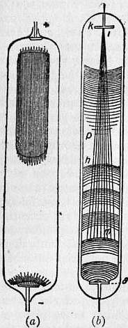 |
| Fig. 15. |
The inequality of the electric field in the gas when a continuous discharge is passing through it is very obvious when the pressure of the gas is low. In this case the discharge presents a highly differentiated appearance of which a type is represented in fig. 15. Starting from the cathode we have a thin velvety luminous glow in contact with the surface; this glow is often called the “first cathode layer.” Next this we have a comparatively dark space whose thickness increases as the pressure diminishes; this is called the “Crookes’s dark space,” or the “second cathode layer.” Next this we have a luminous position called the “negative glow” or the “third cathode layer.” The boundary between the second and third layers is often very sharply defined. Next to the third layer we have another dark space called the “Faraday dark space.” Next to this and reaching up to the anode is another region of luminosity, called the “positive column,” sometimes (as in fig. 15, a) continuous, sometimes (as in fig. 15, b) broken up into light or dark patches called “striations.” The dimensions of the Faraday dark space and the positive column vary greatly with the current passing through the gas and with its pressure; sometimes one or other of them is absent. These differences in appearances are accompanied by great difference in the strength of the electric field. The magnitude of the electric force at different parts of the discharge is represented in fig. 16, where the ordinates represent the electric force at different parts of the tube, the cathode being on the right. We see that the electric force is very large indeed between the negative glow and the cathode, much larger than in any other part of the tube. It is not constant in this region, but increases as we approach the cathode. The force reaches a minimum either in the negative glow itself or in the part of the Faraday dark space just outside, after which it increases towards the positive column. In the case of a uniform positive column the electric force along it is constant until we get quite close to the anode, when a sudden change, called the “anode fall,” takes place in the potential.
 |
| Fig. 16. |
The difference of potential between the cathode and the negative glow is called the “cathode potential fall” and is found to be constant for wide variations in the pressure of the gas and the current passing through. It increases, however, considerably when the current through the gas exceeds a certain critical value, depending among other things on the size of the cathode. This cathode fall of potential is shown by experiment to be very approximately equal to the minimum potential difference. The following table contains a comparison of the measurements of the cathode fall of potentials in various gases made by Warburg (Wied. Ann., 1887, 31, p. 545, and 1890, 40, p. 1), Capstick (Proc. Roy. Society, 1898, 63, p. 356), and Strutt (Phil. Trans., 1900, 193, p. 377), and the measurements by Strutt of the smallest difference of potential which will maintain a spark through these gases.
| Gas. | Cathode fall in Volts. | Least potential difference required to maintain a Spark. | |||
| Platinum Electrodes. | Aluminium Electrodes. | ||||
| Warburg. | Capstick. | Strutt. | Warburg. | Strutt. | |
| Air | 340-350 | .. | .. | .. | 341 |
| H2 | about 300 | 298 | .. | 168 | 302-308 |
| O2 | .. | 369 | .. | .. | .. |
| N2 | 230 if free | 232 | .. | 207 | 251 |
| from oxygen | |||||
| Hg vapour | 340 | .. | .. | .. | .. |
| Helium | .. | .. | 226 | .. | 261-326 |
| H2O | .. | 469 | .. | .. | .. |
| NH3 | .. | 582 | .. | .. | .. |
Thus in the cases in which the measurements could be made with the greatest accuracy the agreement between the cathode fall and the minimum potential difference is very close. The cathode fall depends on the material of which the terminals are made, as is shown by the following table due to Mey (Verh. deutsch. physik. Gesell., 1903, 5, p. 72).
| Gas. | Electrode. | ||||||||||
| Pt | Hg | Ag | Cu | Fe | Zn | Al | Mg | Na | Na-K | K | |
| O2 | 369 | .. | .. | .. | .. | .. | .. | .. | .. | .. | .. |
| H2 | 300 | .. | 295 | 280 | 230 | 213 | 190 | 168 | 185 | 169 | 172 |
| N2 | 232 | 226 | .. | .. | .. | .. | .. | 207 | 178 | 125 | 170 |
| He | 226 | .. | .. | .. | .. | .. | .. | .. | 80 | 78.5 | 69 |
| Argon | 167 | .. | .. | .. | .. | .. | 100 | .. | .. | .. | .. |
The dependence of the minimum potential required to produce a spark upon the metal of which the cathode is made has not been clearly established, some observers being unable to detect any difference between the potential required to spark between electrodes of aluminium and those of brass, while others thought they had detected such a difference. It is only with sparks not much longer than the critical spark length that we could hope to detect this difference. When the current through the gas exceeds a certain critical value depending among other things on the size of the cathode, the cathode fall of potential increases rapidly and at the same time the thickness of the dark 882 spaces diminishes. We may regard the part of the discharge between the cathode and the negative glow as a discharge taking place under minimum potential difference through a distance equal to the critical spark length. An inspection of fig. 16 will show that we cannot regard the electric field as constant even for this small distance; it thus becomes a matter of interest to know what would be the effect on the minimum potential difference required to produce a spark if there were sufficient ions present to produce variations in the electric field analogous to those represented in fig. 16. If the electric force at a distance x from the cathode were proportional to ε-px we should have a state of things much resembling the distribution of electric force near the cathode. If we apply to this distribution the methods used above for the case when the force was uniform, we shall find that the minimum potential is less and the critical spark length greater than when the electric force is uniform.
Potential Difference required to produce a Spark of given Length.—We may regard the region between the cathode and the negative glow as a place for the production of corpuscles, these corpuscles finding their way from this region through the negative glow. The parts of this glow towards the anode we may regard as a cathode, from which, as from a hot lime cathode, corpuscles are emitted. Let us now consider what will happen to these corpuscles shot out from the negative glow with a velocity depending on the cathode fall of potential and independent of the pressure. These corpuscles will collide with the molecules of the gas, and unless there is an external electric field to maintain their velocity they will soon come to rest and accumulate in front of the negative glow. The electric force exerted by this cloud of corpuscles will diminish the strength of the electric field in the region between the cathode and the negative glow, and thus tend to stop the discharge. To keep up the discharge we must have a sufficiently strong electric field between the negative glow and the anode to remove the corpuscles from this region as fast as they are sent into it from the cathode. If, however, there is no production of ions in the region between the negative glow and the anode, all the ions in this region will have come from near the cathode and will be negatively charged; this negative electrification will diminish the electric force on the cathode side of it and thus tend to stop the discharge. This back electric field could, however, be prevented by a little ionization in the region between the anode and glow, for this would afford a supply of positive ions, and thus afford an opportunity for the gas in this region to have in it as many positive as negative ions; in this case it would not give rise to any back electromotive force. The ionization which produces these positive ions may, if the field is intense, be due to the collisions of corpuscles, or it may be due to radiation analogous to ultra-violet, or soft Röntgen rays, which have been shown by experiment to accompany the discharge. Thus in the most simple conditions for discharge we should have sufficient ionization to keep up the supply of positive ions, and an electric field strong enough to keep the velocity of the negative corpuscle equal to the value it has when it emerges from the negative glow. Thus the force must be such as to give a constant velocity to the corpuscle, and since the force required to move an ion with a given velocity is proportional to the pressure, this force will be proportional to the pressure of the gas. Let us call this force ap; then if l is the distance of the anode from the negative glow the potential difference between these points will be alp. The potential difference between the negative glow and the cathode is constant and equals c; hence if V is the potential difference between the anode and cathode, then V = c + alp, a relation which expresses the connexion between the potential difference and spark length for spark lengths greater than the critical distance. It is to be remembered that the result we have obtained applies only to such a case as that indicated above, where the electric force is constant along the positive column. Experiments with the discharge through gases at low pressure show the discharge may take other forms. Thus the positive column may be striated when the force along it is no longer uniform, or the positive column may be absent; the discharge may be changed from one of these forms to another by altering the current. The relation between the potential and the distance between the electrodes varies greatly, as we might expect, with the current passing through the gas.
The connexion between the potential difference and the spark length has been made the subject of a large number of experiments. The first measurements were made by Lord Kelvin in 1860 (Collected Papers on Electrostatics and Magnetism, p. 247); subsequent experiments have been made by Baille (Ann. de chimie et de physique, 5, 25, p. 486), Liebig (Phil. Mag. [5], 24, p. 106), Paschen (Wied. Ann. 37, p. 79), Peace (Proc. Roy. Soc., 1892, 52, p. 99), Orgler (Ann. der Phys. 1, p. 159), Strutt (Phil. Trans. 193, p. 377), Bouty (Comptes rendus, 131, pp. 469, 503), Earhart (Phil. Mag. [6], 1, p. 147), Carr (Phil. Trans., 1903), Russell (Phil. Mag. [5], 64, p. 237), Hobbs (Phil. Mag. [6], 10, p. 617), Kinsley (Phil. Mag. [6], 9, 692), Ritter (Ann. der Phys. 14, p. 118). The results of their experiments show that for sparks considerably longer than the critical spark length, the relation between the potential difference V and the spark length l may be expressed when the electrodes are large with great accuracy by the linear relation V = c + blp, where p is the pressure and c and b are constants depending on the nature of the gas. When the sparks are long the term blp is the most important and the sparking potential is proportional to the spark length. Though there are considerable discrepancies between the results obtained by different observers, these indicate that the production of a long spark between large electrodes in air at atmospheric pressure requires a potential difference of 30,000 volts for each centimetre of spark length. In hydrogen only about half this potential difference is required, in carbonic acid gas the potential difference is about the same as in air, while Ritter’s experiments show that in helium only about one-tenth of this potential difference is required.
In the case when the electric field is not uniform, as for example when the discharge takes place between spherical electrodes, Russell’s experiments show that the discharge takes place as soon as the maximum electric force in the field between the electrodes reaches a definite value, which he found was for air at atmospheric pressure about 38,000 volts per centimetre.
Very Short Sparks.—Some very interesting experiments on the potential difference required to produce exceedingly short sparks have been made by Earhart, Hobbs and Kinsley; the length of these sparks was comparable with the wave length of sodium light. With sparks of these lengths it was found that it was possible to get a discharge with less than 330 volts, the minimum potential difference in air. The results of these observers show that there is no diminution in the minimum potential difference required to produce discharge until the spark length gets so small that the average electric force between the electrodes amounts to about one million volts per centimetre. When the force rises to this value a discharge takes place even though the potential difference is much less than 330 volts; in some of Earhart’s experiments it was only about 2 volts. This kind of discharge is determined not by the condition that the potential difference should have a given value, but that the electric force should have a given value. Another point in which this discharge differs from the ordinary one is that it is influenced entirely by the nature of the electrodes and not by the nature or pressure of the gas between them, whereas the ordinary discharge is in many cases not affected appreciably by changes in the metal of the electrodes, but is always affected by changes in the pressure and character of the gas between them. Kinsley found that when one of these small sparks passed between the electrodes a kind of metallic bridge was formed between them, so that they were in metallic connexion, and that the distance between them had to be considerably increased before the bridge was broken. Almy (Phil. Mag., Sept. 1908), who used very small electrodes, was unable to get a discharge with less than the minimum spark potential even when the spark length was reduced to one-third of the wave length of sodium light. He suggests that the discharges obtained with larger electrodes for smaller voltages are 883 due to the electrodes being dragged together by the electrostatic attraction between them.
Constitution of the Electric Spark.—Schuster and Hemsalech (Phil. Trans. 193, p. 189), Hemsalech (Comptes Rendus, 130, p. 898; 132, p. 917; Jour. de Phys. 3. 9, p. 43, and Schenck, Astrophy. Jour. 14, p. 116) have by spectroscopic methods obtained very interesting results about the constitution of the spark. The method employed by Schuster and Hemsalech was as follows: Suppose we photograph the spectrum of a horizontal spark on a film which is on the rim of a wheel rotating about a horizontal axis with great velocity. If the luminosity travelled with infinite speed from one electrode to the other, the image on the film would be a horizontal line. If, however, the speed with which the luminosity travelled between the electrodes was comparable with the speed of the film, the line would be inclined to the horizontal, and by measuring the inclinations we could find the speed at which the luminosity travelled. In this way Schuster and Hemsalech showed that when an oscillating discharge passed between metallic terminals in air, the first spark passes through the air alone, no lines of the metal appearing in its spectrum. This first spark vaporizes some of the metal and the subsequent sparks passing mainly through the metallic vapour; the appearance of the lines in the film shows that the velocity of the luminous part of the vapour was finite. The velocity of the vapour of metals of low atomic weight was in general greater than that of the vapour of heavier metals. Thus the velocity of aluminium vapour was 1890 metres per second, that of zinc and cadmium only about 545. Perhaps the most interesting point in the investigation was the discovery that the velocities corresponding to different lines in the spectrum of the same metal were in some cases different. Thus with bismuth some of the lines indicated a velocity of 1420 metres per second, others a velocity of only 550, while one (λ = 3793) showed a still smaller velocity. These results are in accordance with a view suggested by other phenomena that many of the lines in a spectrum produced by an electrical discharge originate from systems formed during the discharge and not from the normal atom or molecule. Schuster and Hemsalech found that by inserting a coil with large self induction in the primary circuit they could obliterate the air lines in the discharge.
Schenck, by observing the appearance presented when an alternating current, produced by discharging Leyden jars, was examined in a rapidly rotating mirror, found it showed the following stages: (1) a thin bright line, followed in some cases at intervals of half the period of the discharge by fainter lines; (2) bright curved streamers starting from the negative terminal, and diminishing rapidly in speed as they receded from the cathode; (3) a diffused glow lasting for a much longer period than either of the preceding. These constituents gave out quite different spectra.
The structure of the discharge is much more easily studied when the pressure of the gas is low, as the various parts which make up the discharge are more widely separated from each other. We have already described the general appearance of the discharge through gases at low pressures (see p. 657). There is, however, one form of discharge which is so striking and beautiful that it deserves more detailed consideration. In this type of discharge, known as the striated discharge, the positive column is made up of alternate bright and dark patches known as striations. Some of these are represented in fig. 17, which is taken from a paper by De la Rue and Müller (Phil. Trans., 1878, Pt. 1). This type of discharge only occurs when the current and the pressure of the gas are between certain limits. It is most beautifully shown when a Wehnelt cathode is used and the current is produced by storage cells, as this allows us to use large currents and to maintain a steady potential difference between the electrodes. The striations are in consequence very bright and steady. The facts which have been established about these striations are as follows: The distance between the bright parts of the striations is greater at low pressures than at high; it depends also upon the diameter of the tube, increasing as the diameter of the tube increases. If the discharge tube is wide at one place and narrow in another the striations will be closer together in the narrow parts than in the wide. The distance between the striations depends on the current through the tube. The relation is not a very simple one, as an increase of current sometimes increases while under other circumstances it decreases the distance between the striations (see Willows, Proc. Camb. Phil. Soc. 10, p. 302). The electric force is not uniform along the striated discharge, but is greater in the bright than in the dark parts of the striation. An example is shown in fig. 16, due to H. A. Wilson, which shows the distribution of electric force at every place in a striated discharge. In experiments made by J. J. Thomson (Phil. Mag., Oct. 1909), using a Wehnelt cathode, the variations in the electric force were more pronounced than those shown in fig. 16. The electric force in this case changed so greatly that it actually became negative just on the cathode side of the bright part of the striation. Just inside the striation on the anode side it rose to a very high value, then continually diminished towards the bright side of the next striation when it again increased. This distribution of electric force implies that there is great excess of negative electricity at the bright head of the striation, and a small excess of positive everywhere else. The temperature of the gas is higher in the bright than in the dark parts of the striations. Wood (Wied. Ann. 49, p. 238), who has made a very careful study of the distribution of temperature in a discharge tube, finds that in those tubes the temperature varies in the same way as the electric force, but that this temperature (which it must be remembered is the average temperature of all the molecules and not merely of those which are taking part in the discharge) is by no means high; in no part of the discharge did the temperature in his experiments exceed 100° C.
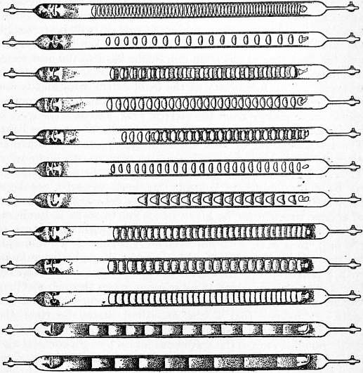 |
| Fig. 17. |
Theory of the Striations.—We may regard the heaping up of the negative charges at intervals along the discharge as the fundamental feature in the striations, and this heaping up may be explained as follows. Imagine a corpuscle projected with considerable velocity from a place where the electric field is strong, such as the neighbourhood of the cathode; as it moves towards the anode through the gas it will collide with the molecules, ionize them and lose energy and velocity. Thus unless the corpuscle is acted on by a field strong enough to supply it with the energy it loses by collision, its speed will gradually diminish. Further, when its energy falls below a certain value it will unite with a molecule and become part of a negative ion, instead of a corpuscle; at this stage there will be a sudden and 884 very large diminution in its velocity. Let us now follow the course of a stream of corpuscles starting from the cathode and approaching the anode. If the speed falls off as the stream proceeds, the corpuscles in the rear will gain on those in front and the density of the stream in the front will be increased. If at a certain place the velocity receives a sudden check by the corpuscles becoming loaded with a molecule, the density of the negative electricity will increase at this place with great rapidity, and here there will be a great accumulation of negative electricity, as at the bright head on the cathode side of a striation. Now this accumulation of negative electricity will produce a large electric force on the anode side; this will drive corpuscles forward with great velocity and ionize the gas. These corpuscles will behave like those shot from the cathode and will accumulate again at some distance from their origin, forming the bright head of the next striation, when the process will be repeated. On this view the bright heads of the striations act like electrodes, and the discharge passes from one bright head to the next as by a number of stepping stones, and not directly from cathode to anode. The luminosity at the head of the striations is due to the recombination of the ions. These ions have acquired considerable energy from the electric field, and this energy will be available for supplying the energy radiated away as light. The recombination of ions which do not possess considerable amounts of energy does not seem to give rise to luminosity. Thus, in an ionized gas not exposed to an electric field, although we have recombination between the ions, we need not have luminosity. We have at present no exact data as to the amount of energy which must be given to an ion to make it luminous on recombination; it also certainly varies with the nature of the ion; thus even with hot Wehnelt cathodes J. J. Thomson has never been able to make the discharge through air luminous with a potential less than from 16 to 17 volts. The mercury lamps, however, in which the discharge passes through mercury vapour are luminous with a potential difference of about 12 volts. It follows that if the preceding theory be right the potential difference between two bright striations must be great enough to make the corpuscles ionize by collision and also to give enough energy to the ions to make them luminous when they recombine. The difference of potential between the bright parts of successive striations has been measured by Hohn (Phys. Zeit. 9, p. 558); it varies with the pressure and with the gas. The smallest value given by Hohn is about 15 volts. In some experiments made by J. J. Thomson, when the pressure of the gas was very low, the difference of potential between two adjacent dark spaces was as low as 3.75 volts.
The Arc Discharge.—The discharges we have hitherto considered have been characterized by large potential differences and small currents. In the arc discharge we get very large currents with comparatively small potential differences. We may get the arc discharge by taking a battery of cells large enough to give a potential difference of 60 to 80 volts, and connecting the cells with two carbon terminals, which are put in contact, so that a current of electricity flows round the circuit. If the terminals, while the current is on, are drawn apart, a bright discharge, which may carry a current of many amperes, passes from one to the other. This arc discharge, as it is called, is characterized by intense heat and by the brilliant luminosity of the terminals. This makes it a powerful source of light. The temperature of the positive terminal is much higher than that of the negative. According to Violle (Comptes Rendus, 115, p. 1273) the temperature of the tip of the former is about 3500° C, and that of the latter 2700° C. The temperature of the arc itself he found to be higher than that of either of its terminals. As the arc passes, the positive terminal gets hollowed out into a crater-like shape, but the negative terminal remains pointed. Both terminals lose weight.
The appearance of the terminals is shown in fig. 18, given by Mrs Ayrton (Proc. Inst. Elec. Eng. 28, p. 400); a, b represent the terminals when the arc is quiet, and c when it is accompanied by a hissing sound. The intrinsic brightness of the positive crater does not increase with an increase in the current; an increased current produces an increase in the area of the luminous crater, but the amount of light given out by each unit of area of luminous surface is unaltered. This indicates that the temperature of the crater is constant; it is probably that at which carbon volatilizes. W. E. Wilson (Proc. Roy. Soc. 58, p. 174; 60, p. 377) has shown that at pressures of several atmospheres the intrinsic brightness of the crater is considerably diminished.
 |
| Fig. 18. |
 |
| Fig. 19. |
The connexion between V, the potential difference between the terminals, and l, the length of the arc, is somewhat analogous to that which holds for the spark discharge. Fröhlich (Electrotech. Zeit. 4, p. 150) gives for this connexion the relation V = m + nl, where m and n are constants. Mrs Ayrton (The Electric Arc, chap. iv.) finds that both m and n depend upon the current passing between the terminals, and gives as the relation between V and l, V = α + β/I + (γ + δ/I)l, where α, β, γ, δ are constants and I the current. The relation between current and potential difference was made the subject of a series of experiments by Ayrton (Electrician, 1, p. 319; xi. p. 418), some of whose results are represented in fig. 19. For a quiet arc an increase in current is accompanied by a fall in potential difference, while for the hissing arc the potential difference is independent of the current. The quantities m and n which occur in Fröhlich’s equation have been determined by several experimenters. For carbon electrodes in air at atmospheric pressure m is about 39 volts, varying somewhat with the size and purity of the carbons; it is diminished by soaking the terminals in salt solution. The value of n given by different observers varies considerably, ranging from .76 to 2 volts when l is measured in millimetres; it depends upon the current, diminishing as the current increases. When metallic terminals are used instead of carbons, the value of m depends upon the nature of the metal, m in general being larger the higher the temperature at which the metal volatilizes. Thus v. Lang (Wied. Ann. 31, p. 384) found the following values for m in air at atmospheric pressure:—C = 35; Pt = 27.4; Fe = 25; Ni = 26.18; Cu = 23.86; Ag = 15.23; Zn = 19.86; Cd = 10.28. Lecher (Wied. Ann. 33, p. 609) gives Pt = 28, Fe = 20, Ag = 8, while Arons (Wied. Ann. 31, p. 384) found for Hg the value 12.8; in this case the fall of potential along the arc itself was abnormally small. In comparing these values it is important to remember that Lecher (loc. cit.) has shown that with Fe or Pt terminals the arc discharge is intermittent. Arons has shown that this is also the case with Hg terminals, but no intermittence has been detected with terminals of C, Ag or Cu. The preceding measurements refer to mean potentials, and no conclusions as to the actual potential differences at any time can be drawn when the discharge is discontinuous, unless we know the law of discontinuity. The ease with which an arc is sustained depends greatly on the nature of the electrodes; when they are brass, zinc, cadmium, or magnesium it is exceedingly difficult to get the arc.
 | |
| Fig. 20. | Fig. 21. |
The potential difference between the terminals is affected by the pressure of the gas. The most extensive series of experiments on this point is that made by Duncan, Rowland, and Tod (Electrician, 885 31, p. 60), whose results are represented in fig. 20. We see from these curves that for very short arcs the potential difference increases continuously with the pressure, but for longer ones there is a critical pressure at which the potential difference is a minimum, and that this critical pressure seems to increase with the length of arc. The nature of the gas also affects the potential difference. The magnitude of this effect may be gathered from the following values given by Arons (Ann. der Phys. 1, p. 700) for the potential difference required to produce an arc 1.5 mm. long, carrying a current of 4.5 amperes, between terminals of different metals in air and pure nitrogen.
| Terminal. | Air. | Nitrogen. | Terminal. | Air. | Nitrogen. |
| Ag | 21 | ? | Pt | 36 | 30 |
| Zn | 23 | 21 | Al | 39 | 27 |
| Cd | 25 | 21 | Pb | .. | 18 |
| Cu | 27 | 30 | Mg | .. | 22 |
| Fe | 29 | 20 |
Thus, with the discharge for an arc of given length and current, the nature of the terminals is the most important factor in determining the potential difference. The effects produced by the pressure and nature of the surrounding gas, although quite appreciable, are not of so much importance, while in the spark discharge the nature of the terminals is of no importance, everything depending upon the nature and pressure of the gas.
The potential gradient in the arc is very far from being uniform. With carbon terminals Luggin (Wien. Ber. 98, p. 1192) found that, with a current of 15 amperes, there was a fall of potential of 33.7 close to the anode, and one 8.7 close to the cathode, so that the curve representing the distribution of potential between the terminals would be somewhat like that shown in fig. 21. We have seen that a somewhat analogous distribution of potential holds in the case of conduction through flames, though in that case the greatest drop of potential is in general at the cathode and not at the anode. The difference between the changes of potential at the anode and cathode is not so large with Fe and Cu terminals as with carbon ones; with mercury terminals, Arons (Wied. Ann. 58, p. 73) found the anode fall to be 7.4 volts, the cathode fall 5.4 volts.
The case of the arc when the cathode is a pool of mercury and the anode a metal wire placed in a vessel from which the air has been exhausted is one which has attracted much attention, and important investigations on this point have been made by Hewitt (Electrician, 52, p. 447), Wills (Electrician, 54, p. 26), Stark, Retschinsky and Schnaposnikoff (Ann. der Phys. 18, p. 213) and Pollak (Ann. der Phys. 19, p. 217). In this arrangement the mercury is vaporized by the heat, and the discharge which passes through the mercury vapour gives an exceedingly bright light, which has been largely used for lighting factories, &c. The arrangement can also be used as a rectifier, for a current will only pass through it when the mercury pool is the cathode. Thus if such a lamp is connected with an alternating current circuit, it lets through the current in one direction and stops that in the other, thus furnishing a current which is always in one direction.
Theory of the Arc Discharge.—An incandescent body such as a piece of carbon even when at a temperature far below that of the terminals in an arc, emits corpuscles at a rate corresponding to a current of the order of 1 ampere per square centimetre of incandescent surface, and as the rate of increase of emission with the temperature is very rapid, it is probably at the rate of many amperes per square centimetre at the temperature of the negative carbon in the arc. If then a piece of carbon were maintained at this temperature by some external means, and used as a cathode, a current could be sent from it to another electrode whether the second electrode were cold or hot. If, however, these negatively electrified corpuscles did not produce other ions either by collision with the gas through which they move or with the anode, the spaces between cathode and anode would have a negative charge, which would tend to stop the corpuscles leaving the cathode and would require a large potential difference between anode and cathode to produce any considerable current. If, however, there is ionization either in the gas or at the anode, the positive ions will diffuse into the region of the discharge until they are sensibly equal in number to the negative ions. When this is the case the back electromotive force is destroyed and the same potential difference will carry a much larger current. The arc discharge may be regarded as analogous to the discharge between incandescent terminals, the only difference being that in the arc the terminals are maintained in the state of incandescence by the current and not by external means. On this view the cathode is bombarded by positive ions which heat it to such a temperature that negative corpuscles sufficient to carry the current are emitted by it. These corpuscles bombard the anode and keep it incandescent. They ionize also, either directly by collision or indirectly by heating the anode, the gas and vapour of the metal of which the anode is made, and produce in this way the supply of positive ions which keep the cathode hot.
Discharge from a Point.—A very interesting case of electric discharge is that between a sharply pointed electrode, such as a needle, and a metal surface of considerable area. At atmospheric pressures the luminosity is confined to the immediate neighbourhood of the point. If the sign of the potential of the point does not change, the discharge is carried by ions of one sign—that of the charge on the pointed electrode. The velocity of these ions under a given potential gradient has been measured by Chattock (Phil. Mag. 32, p. 285), and found to agree with that of the ions produced by Röntgen or uranium radiation, while Townsend (Phil. Trans. 195, p. 259) has shown that the charge on these ions is the same as that on the ions streaming from the point. If the pointed electrode be placed at right angles to a metal plane serving as the other electrode, the discharge takes place when, for a given distance of the point from the plane, the potential difference between the electrodes exceeds a definite value depending upon the pressure and nature of the gas through which the discharge passes; its value also depends upon whether, beginning with a small potential difference, we gradually increase it until discharge commences, or, beginning with a large potential difference, we decrease it until the discharge stops. The value found by the latter method is less than that by the former. According to Chattock’s measurements the potential difference V for discharge between the point and the plate is given by the linear relation V = a + bl, where l is the distance of the point from the plate and a and b are constants. From v. Obermayer’s (Wien. Ber. 100, 2, p. 127) experiments, in which the distance l was greater than in Chattock’s, it would seem that the potential for larger distances does not increase quite so rapidly with l as is indicated by Chattock’s relation. The potential required to produce this discharge is much less than that required to produce a spark of length l between parallel plates; thus from Chattock’s experiments to produce the point discharge when l = .5 cm. in air at atmospheric pressure requires a potential difference of about 3800 volts when the pointed electrode is positive, while to produce a spark at the same distance between plane electrodes would require a potential difference of about 15,000 volts. Chattock showed that with the same pointed electrode the value of the electric intensity at the point was the same whatever the distance of the point from the plane. The value of the electric intensity depended upon the sharpness of the point. When the end of the pointed electrode is a hemisphere of radius a, Chattock showed that for the same gas at the same pressure the electric intensity ∫ when discharge takes place is roughly proportioned to a−0.8. The value of the electric intensity at the pointed electrode is much greater than its value at a plane electrode for long sparks; but we must remember that at a distance from a pointed electrode equal to a small multiple of the radius of curvature of its extremity the electric intensity falls very far 886 below that required to produce discharge in a uniform field, so that the discharge from a pointed electrode ought to be compared with a spark whose length is comparable with the radius of curvature of the point. For such short sparks the electric intensity is very high. The electric intensity required to produce the discharge from a gas diminishes as the pressure of the gas diminishes, but not nearly so rapidly as the electric intensity for long sparks. Here again the discharge from a point is comparable with short sparks, which, as we have seen, are much less sensitive to pressure changes than longer ones. The minimum potential at which the electricity streams from the point does not depend upon the material of which the point is made; it varies, however, considerably with the nature of the gas. The following are the results of some experiments on this point. Those in the first two columns are due to Röntgen, those in the third and fourth to Precht:—
| Gas. | Discharge Potential. Point +. | Pressure 760. | ||
| Pressure 205. | Pressure 110. | Point +. | Point −. | |
| Volts. | Volts. | Volts. | Volts. | |
| H2 | 1296 | 1174 | 2125 | 1550 |
| O2 | 2402 | 1975 | 2800 | 2350 |
| CO | 2634 | 2100 | .. | .. |
| CH4 | 2777 | 2317 | .. | .. |
| NO | 3188 | 2543 | .. | .. |
| CO2 | 3287 | 2655 | 3475 | 2100 |
| N2 | .. | .. | 2600 | 2000 |
| Air | .. | .. | 2750 | 2050 |
We see from this table that in the case of the discharge from a positively electrified point the greater the molecular weight of the gas the greater the potential required for discharge. Röntgen concluded from his experiments that the discharging potential from a positive point in different gases at the same pressure varies inversely as the mean free path of the molecules of the gas. In the same gas, however, at different pressures the discharging potential does not vary so quickly with the pressure as does the mean free path. In Precht’s experiments, in which different gases were used, the variations in the discharging potential are not so great as the variations in the mean free path of the gases.
The current of electrified air flowing from the point when the electricity is escaping—the well-known “electrical wind”—is accompanied by a reaction on the point which tends to drive it backwards. This reaction has been measured by Arrhenius (Wied. Ann. 63, p. 305), who finds that when positive electricity is escaping from a point in air the reaction on the point for a given current varies inversely as the pressure of the gas, and for different gases (air, hydrogen and carbonic acid) inversely as the square root of the molecular weight of the gas. The reaction when negative electricity is escaping is much less. The proportion between the reactions for positive and negative currents depends on the pressure of the gas. Thus for equal positive and negative currents in air at a pressure of 70 cm. the reaction for a positive point was 1.9 times that of a negative one, at 40 cm. pressure 2.6 times, at 20 cm. pressure 3.2 times, at 10.3 cm. pressure 7 times, and at 5.1 cm. pressure 15 times the reaction for the negative point. Investigation shows that the reaction should be proportional to the quotient of the current by the velocity acquired by an ion under unit potential gradient. Now this velocity is inversely proportional to the pressure, so that the reaction should on this view be directly proportional to the pressure. This agrees with Arrhenius’ results when the point is positive. Again, the velocities of an ion in hydrogen, air and carbonic acid at the same pressure are approximately inversely proportional to the square roots of their molecular weights, so that the reaction should be directly proportional to this quantity. This also agrees with Arrhenius’ results for the discharge from a positive point. The velocity of the negative ion is greater than that of a positive one under the same potential gradient, so that the reaction for the negative point should be less than that for a positive one, but the excess of the positive reaction over the negative is much greater than that of the velocity of the negative ion over the velocity of the positive. There is, however, reason to believe that a considerable condensation takes place around the negative ion as a nucleus after it is formed, so that the velocity of the negative ion under a given potential gradient will be greater immediately after the ion is formed than when it has existed for some time. The measurements which have been made of the velocities of the ions relate to those which have been some time in existence, but a large part of the reaction will be due to the newly-formed ions moving with a greater velocity, and thus giving a smaller reaction than that calculated from the observed velocity.
With a given potential difference between the point and the neighbouring conductor the current issuing from the point is greater when the point is negative than when it is positive, except in oxygen, when it is less. Warburg (Sitz. Akad. d. Wissensch. zu Berlin, 1899, 50, p. 770) has shown that the addition of a small quantity of oxygen to nitrogen produces a great diminution in the current from a negative point, but has very little effect on the discharge from a positive point. Thus the removal of a trace of oxygen made a leak from a negative point 50 times what it was before. Experiments with hydrogen and helium showed that impurities in these gases had a great effect on the current when the point was negative, and but little when it was positive. This suggests that the impurities, by condensing round the negative ions as nuclei, seriously diminish their velocity. If a point is charged up to a high and rapidly alternating potential, such as can be produced by the electric oscillations started when a Leyden jar is discharged, then in hydrogen, nitrogen, ammonia and carbonic acid gas a conductor placed in the neighbourhood of the point gets a negative charge, while in air and oxygen it gets a positive one. There are two considerations which are of importance in connexion with this effect. The first is the velocity of the ions in the electric field, and the second the ease with which the ions can give up their charges to the metal point. The greater velocity of the negative ions would, if the potential were rapidly alternating, cause an excess of negative ions to be left in the surrounding gas. This is the case in hydrogen. If, however, the metal had a much greater tendency to unite with negative than with positive ions, such as we should expect to be the case in oxygen, this would act in the opposite direction, and tend to leave an excess of positive ions in the gas.
The Characteristic Curve for Discharge through Gases.—When a current of electricity passes through a metallic conductor the relation between the current and the potential difference is the exceedingly simple one expressed by Ohm’s law; the current is proportional to the potential difference. When the current passes through a gas there is no such simple relation. Thus we have already mentioned cases where the current increased as the potential increased although not in the same proportion, while as we have seen in certain stages of the arc discharge the potential difference diminishes as the current increases. Thus the problem of finding the current which a given battery will produce when part of the circuit consists of a gas discharge is much more complicated than when the circuit consists entirely of metallic conductors. If, however, we measure the potential difference between the electrodes in the gas when different currents are sent through it, we can plot a curve, called the “characteristic curve,” whose ordinates are the potential differences between the electrodes in the gas and the abscissae the corresponding currents. By the aid of this curve we can calculate the current produced when a given battery is connected up to the gas by leads of known resistance.
For let E0 be the electromotive force of the battery, R the resistance of the leads, i the current, the potential difference between the terms in the gas will be E0 − Ri. Let ABC (fig. 22) be the “characteristic curve,” the ordinates being the potential difference between the terminals in the gas, and the abscissae the current. Draw the line LM whose equation is E = E0 − Ri, then the points where this line cuts the characteristic curves will give possible values of i and E, the current through the discharge tube and the potential difference between the terminals. Some of these points may, however, correspond to an unstable position and be impossible to realize. The following method gives us a criterion by which we can distinguish the stable from the unstable positions. If the current 887 is increased by δi, the electromotive force which has to be overcome by the battery is Rδi + (dE/di)δi. If R + dE/di is positive there will be an unbalanced electromotive force round the circuit tending to stop the current. Thus the increase in the current will be stopped and the condition will be a stable one. If, however, R + dE/di is negative there will be an unbalanced electromotive force tending to increase the current still further; thus the current will go on increasing and the condition will be unstable. Thus for stability R + dE/di must be positive, a condition first given by Kaufmann (Ann. der Phys. 11, p. 158). The geometrical interpretation of this condition is that the straight line LM must, at the point where it cuts the characteristic curve, be steeper than the tangent to characteristic curve. Thus of the points ABC where the line cuts the curve in fig. 22, A and C correspond to stable states and B to an unstable one. The state of things represented by a point P on the characteristic curve when the slope is downward cannot be stable unless there is in the external circuit a resistance greater than that represented by the tangent of the inclination of the tangent to the curve at P to the horizontal axis.
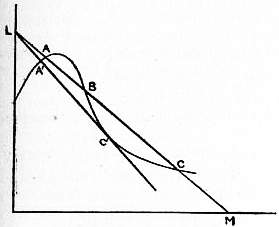 |
| Fig. 22. |
If we keep the external electromotive force the same and gradually increase the resistance in the leads, the line LM will become steeper and steeper. C will move to the left so that the current will diminish; when the line gets so steep that it touches the curve at C’, any further increase in the resistance will produce an abrupt change in the current; for now the state of things represented by a point near A’ is the only stable state. Thus if the BC part of the curve corresponded to a luminous discharge and the A part to a dark discharge, we see that if the electromotive force is kept constant there is a minimum value of the current for the luminous discharge. If the current is reduced below this value, the discharge ceases to be luminous, and there is an abrupt diminution in the current.
Cathode Rays.—When the gas in the discharge tube is at a very low pressure some remarkable phenomena occur in the neighbourhood of the cathode. These seem to have been first observed by Plücker (Pogg. Ann. 107, p. 77; 116, p. 45) who noticed on the walls of the glass tube near the cathode a greenish phosphorescence, which he regarded as due to rays proceeding from the cathode, striking against the sides of the tube, and then travelling back to the cathode. He found that the action of a magnet on these rays was not the same as the action on the part of the discharge near the positive electrode. Hittorf (Pogg. Ann. 136, p. 8) showed that the agent producing the phosphorescence was intercepted by a solid, whether conductor or insulator, placed between the cathode and the sides of the tube. He regarded the phosphorescence as caused by a motion starting from the cathode and travelling in straight lines through the gas. Goldstein (Monat. der Berl. Akad., 1876, p. 24) confirmed this discovery of Hittorf’s, and further showed that a distinct, though not very sharp, shadow is cast by a small object placed near a large plane cathode. This is a proof that the rays producing the phosphorescence must be emitted almost normally from the cathode, and not, like the rays of light from a luminous surface, in all directions, for such rays would not produce a perceptible shadow if a small body were placed near the plane. Goldstein regarded the phosphorescence as due to waves in the ether, for whose propagation the gas was not necessary. Crookes (Phil. Trans., 1879, pt. i. p. 135; pt. ii. pp. 587, 661), who made many remarkable researches in this subject, took a different view. He regarded the rays as streams of negatively electrified particles projected normally from the cathode with great velocity, and, when the pressure is sufficiently low, reaching the sides of the tube, and by their impact producing phosphorescence and heat. The rays on this view are deflected by a magnet, because a magnet exerts a force on a charged moving body.
These rays striking against glass make it phosphorescent. The colour of the phosphorescence depends on the kind of glass; thus the light from soda glass is a yellowish green, and that from lead glass blue. Many other bodies phosphoresce when exposed to these rays, and in particular the phosphorescence of some gems, such as rubies and diamonds, is exceedingly vivid. The spectrum of the phosphorescent light is generally continuous, but Crookes showed that the phosphorescence of some of the rare earths, such as yttrium, gives a spectrum of bright bands, and he founded on this fact a spectroscopic method of great importance. Goldstein (Wied. Ann. 54, p. 371) discovered that the haloid salts of the alkali metals change colour under the rays, sodium chloride, for example, becoming violet. The coloration is a surface one, and has been traced by E. Wiedemann and Schmidt (Wied. Ann. 54, p. 618) to the formation of a subchloride. Chlorides of tin, mercury and lead also change colour in the same way. E. Wiedemann (Wied. Ann. 56, p. 201) discovered another remarkable effect, which he called thermo-luminescence; he found that many bodies after being exposed to the cathode rays possess for some time the power of becoming luminous when their temperature is raised to a point far below that at which they become luminous in the normal state. Substances belonging to the class called by van ’t Hoff solid solutions exhibit this property of thermo-luminescence to a remarkable extent. They are formed when two salts, one greatly in excess of the other, are simultaneously precipitated from a solution. A trace of MnSO4 in CaSO4 shows very brilliant thermo-luminescence. The impact of cathode rays produces after a time perceptible changes in the glass. Crookes (Phil. Trans. pt. ii. 1879, p. 645) found that after glass has been phosphorescing for some time under the cathode rays it seems to get tired, and the phosphorescence is not so bright as it was initially. Thus, for example, when the shadow of a Maltese cross is thrown on the walls of the tube as in fig. 23, if after the discharge has been going on for some time the cross is shaken down or a new cathode used whose line of fire does not cut the cross, the pattern of the cross will still be seen on the glass, but it will now be brighter instead of darker than the surrounding portion. The portions shielded by the cross, not being tired by being made to phosphoresce for a long time, respond more vigorously to the stimulus than those portions which have not been protected. Skinner (Proc. Camb. Phil. Soc. ix. p. 371) and Thomson found on the glass which had been exposed to the rays gelatinous filaments, apparently silica, resulting from the reduction of the glass. A reducing action was also noticed by Villard (Journ. de phys. 3, viii. p. 140) and Wehnelt (Wied. Ann. 67, p. 421). It can be well shown by letting the rays fall on a plate of oxidized copper, when the part struck by the rays will become bright. The rays heat bodies on which they fall, and if they are concentrated by using as a cathode a portion of a spherical surface, the heat at the centre becomes so great that a piece of platinum wire can be melted or a diamond charred. Measurements of the heating effects of the rays have been made by Thomson (Phil. Mag. [5], 44, p. 293) and Cady (Ann. der Phys. 1, p. 678). Crookes (Phil. Trans., 1879, pt. i. p. 152) showed that a vane mounted as in a radiometer is set in rotation by the rays, the direction of the rotation being the same as would be produced by a stream of particles proceeding from the cathode. The movement is not due to the momentum imparted to the vanes by the rays, but to the difference in temperature between the sides of the vanes, the rays making the side against which they strike hotter than the other.
 |
| Fig. 22. |
Effect of a Magnet.—The rays are deflected by a magnet, so that the distribution of phosphorescence over the glass and the shape and position of the shadows cast by bodies in the tube are altered by the proximity of a magnet. The laws of magnetic deflection of these rays have been investigated by Plücker (Pogg. 888 Ann. 103, p. 88), Hittorf (Pogg. Ann. 136, p. 213), Crookes (Phil. Trans., 1879, pt. 1, p. 557), and Schuster (Proc. Roy. Soc. 47, p. 526). The deflection is the same as that of negatively electrified particles travelling along the path of the rays. Such particles would in a magnetic field be acted on by a force at right angles to the direction of motion of the particle and also to the magnetic force, the magnitude of the force being proportional to the product of the velocity of the particle, the magnetic force, and the sine of the angle between these vectors. In this case we have seen that if the particle is not acted on by an electrostatic field, the path in a uniform magnetic field is a spiral, which, if the magnetic force is at right angles to the direction of projection of the particle, becomes a circle in the plane at right angles to the magnetic force, the radius being mv/He, where m, v, e are respectively the mass, velocity and charge on the particle, and H is the magnetic force. The smaller the difference of potential between the electrodes of the discharge tube the greater the deflection produced by a magnetic field of given strength, and as the difference of potential rapidly increases with diminution of pressure, after a certain pressure has been passed, the higher the exhaustion of the tube the less the magnetic deflection of the rays. Birkeland (Comptes rendus, 1896, p. 492) has shown that when the discharge is from an induction coil the cathode rays produced in the tube at any one time are not equally deflected by a magnet, but that a narrow patch of phosphorescence when deflected by a magnet is split up into several distinct patches, giving rise to what Birkeland calls the “magnetic spectrum.” Strutt (Phil. Mag. 48, p. 478) has shown that this magnetic spectrum does not occur if the discharge of a large number of cells is employed instead of the coil. Thomson (Proc. Camb. Phil. Soc. 9, p. 243) has shown that if the potential difference between the electrodes is kept the same the magnetic deflection is independent of the nature of the gas filling the discharge tube; this was tested with gases so different as air, hydrogen, carbonic acid and methyl iodide.
Charge of Negative Electricity carried by the Rays.—We have seen that the rays are deflected by a magnet, as if they were particles charged with negative electricity. Perrin (Comptes rendus, 121, p. 1130) showed by direct experiment that a stream of negative electricity is associated with the rays. A modification made by Thomson of Perrin’s experiment is sketched in fig. 24 (Phil. Mag. 48, p. 478).
 |
| Fig. 24. |
The rays start from the cathode A, and pass through a slit in a solid brass rod B fitting tightly into the neck of the tube. This rod is connected with earth and used as the anode. The rays after passing through the slit travel through the vessel C. D and E are two insulated metal cylinders insulated from each other, and each having a slit cut in its face so as to enable the rays to pass into the inside of the inner cylinder, which is connected with an electrometer, the outer cylinder being connected with the earth. The two cylinders are placed on the far side of the vessel, but out of the direct line of fire of the rays. When the rays go straight through the slit there is only a very small negative charge communicated to the inner cylinder, but when they are deflected by a magnet so that the phosphorescent patch falls on the slit in the outer cylinder the inner cylinder receives a very large negative charge, the increase coinciding very sharply with the appearance of the phosphorescent patch on the slit. When the patch is so much deflected by the magnet that it falls below the slit, the negative charge in the cylinder again disappears. This experiment shows that the cathode rays are accompanied by a stream of negative electrification. The same apparatus can be used to show that the passage of cathode rays through a gas makes it a conductor of electricity. For if the induction coil is kept running and a stream of the rays kept steadily going into the inner cylinder, the potential of the inner cylinder reaches a definite negative value below which it does not fall, however long the rays may be kept going. The cylinder reaches a steady state in which the gain of negative electricity from the cathode rays is equal to the loss by leakage through the conducting gas, the conductivity being produced by the passage of the rays through it. If the inner cylinder is charged up initially with a greater negative charge than corresponds to the steady state, on turning the rays on to the cylinder the negative charge will decrease and not increase until it reaches the steady state. The conductivity produced by the passage of cathode rays through a gas diminishes rapidly with the pressure. When rays pass through a gas at a low pressure, they are deflected by an electric field; when the pressure of the gas is higher the conductivity it acquires when the cathode rays pass through it is so large that the potential gradient cannot reach a sufficiently high value to produce an appreciable deflection.
Thus the cathode rays carry a charge of negative electricity; the experiment described on page 875 (fig. 13) shows that they are deflected by an electric field as if they were negatively electrified, and are acted on by a magnetic force in just the way this force would act on a negatively electrified body moving along the path of the rays. There is therefore every reason for believing that they are charges of negative electricity in rapid motion. By measuring the deflection produced by magnetic and electric fields we can determine the velocity with which these particles moved and the ratio of the mass of the particle to the charge carried by it.
We may conclude from the experiments that the value of m/e for the particles constituting the cathode rays is of the order 1/1.7×107, and we have seen that m/e has the same value in all the other cases of negative ions in a gas at low pressure for which it has been measured—viz. for the ions produced when ultra-violet light falls on a metal plate, or when an incandescent carbon filament is surrounded by a gas at a low pressure, and for the β particles given out by radio-active bodies. We have also seen that the value of the charge on the gaseous ion, in all cases in which it has been measured—viz. the ions produced by Röntgen and uranium radiation, by ultra-violet light, and by the discharge of electrification from a point—is the same in magnitude as the charge carried by the hydrogen atom in the electrolysis of solutions. The mass of the hydrogen alone is, however, 10-4 times this charge, while the mass of the carriers of negative electrification is only 1/1.7×107 times the charge; hence the mass of the carriers of the negative electrification is only 1⁄1700 of the mass of the hydrogen atom. We are thus, by the study of the electric discharge, forced to recognize the existence of masses very much smaller than the smallest mass hitherto recognized.
Direct determinations of the velocity of the cathode rays have been made by J. J. Thomson (Phil. Mag. 38, p. 358), who measured the interval between the appearance of phosphorescence on two pieces of glass placed at a known distance apart, and by Maiorana (Nuovo Cimento, 4, 6, p. 336) and Battelli and Stefanini (Phys. Zeit. 1, p. 51), who measured the interval between the arrival of the negative charge carried by the rays at two places separated by a known distance. The values of the velocity got in this way are much smaller than the values got by the indirect methods previously described: thus J. J. Thomson at a fairly high pressure found the velocity to be 2×107 cm./sec. Maiorana found values ranging between 107 and 6×107 cm./sec, and Battelli and Stefanini values ranging from 6×10⁶ to 1.2×10⁷. In these methods it is very difficult to eliminate the effect of the interval which elapses between the arrival of the rays and the attainment by the means of detection, such as the phosphorescence of the glass or the deflection of the electrometer, of sufficient intensity to affect the senses.
 |
| Fig. 25. |
Transmission of Cathode Rays through Solids—Lenard Rays.—It was for a long time believed that all solids were absolutely opaque to these rays, as Crookes and Goldstein had proved that very thin glass, and even a film of collodion, cast intensely black shadows. Hertz (Wied. Ann. 45, p. 28), however, showed that behind a piece of gold-leaf or aluminium foil an appreciable amount of phosphorescence occurred on the glass, and that the phosphorescence moved when a magnet was brought near. A most important advance was next made by Lenard (Wied. Ann. 51, p. 225), who got the cathode rays to pass from the inside of a discharge tube to the air outside. For this purpose he used a tube like that shown in fig. 25. The cathode K is an aluminium disc 1.2 cm. in diameter fastened to a stiff wire, which is surrounded by a glass tube. The anode A is a brass strip partly 889 surrounding the cathode. The end of the tube in front of the cathode is closed by a strong metal cap, fastened in with marine glue, in the middle of which a hole 1.7 mm. in diameter is bored, and covered with a piece of very thin aluminium foil about .0026 mm. in thickness. The aluminium window is in metallic contact with the cap, and this and the anode are connected with the earth. The tube is then exhausted until the cathode rays strike against the window. Diffuse light spreads from the window into the air outside the tube, and can be traced in a dark room for a distance of several centimetres. From the window, too, proceed rays which, like the cathode rays, can produce phosphorescence, for certain bodies phosphoresce when placed in the neighbourhood of the window. This effect is conveniently observed by the platino-cryanide screens used to detect Röntgen radiation. The properties of the rays outside the tube resemble in all respects those of cathode rays; they are deflected by a magnet and by an electric field, they ionize the gas through which they pass and make it a conductor of electricity, and they affect a photographic plate and change the colour of the haloid salts of the alkali metals. As, however, it is convenient to distinguish between cathode rays outside and inside the tube, we shall call the former Lenard rays. In air at atmospheric pressure the Lenard rays spread out very diffusely. If the aluminium window, instead of opening into the air, opens into another tube which can be exhausted, it is found that the lower the pressure of the gas in this tube the farther the rays travel and the less diffuse they are. By filling the tube with different gases Lenard showed that the greater the density of the gas the greater is the absorption of these rays. Thus they travel farther in hydrogen than in any other gas at the same pressure. Lenard showed, too, that if he adjusted the pressure so that the density of the gas in this tube was the same—if, for example, the pressure when the tube was filled with oxygen was 1⁄16 of the pressure when it was filled with hydrogen—the absorption was constant whatever the nature of the gas. Becker (Ann. der Phys. 17, p. 381) has shown that this law is only approximately true, the absorption by hydrogen being abnormally large, and by the inert monatomic gases, such as helium and argon, abnormally small. The distance to which the Lenard rays penetrate into this tube depends upon the pressure in the discharge tube; if the exhaustion in the latter is very high, so that there is a large potential difference between the cathode and the anode, and therefore a high velocity for the cathode rays, the Lenard rays will penetrate farther than when the pressure in the discharge tube is higher and the velocity of the cathode rays smaller. Lenard showed that the greater the penetrating power of his rays the smaller was their magnetic deflection, and therefore the greater their velocity; thus the greater the velocity of the cathode rays the greater is the velocity of the Lenard rays to which they give rise. For very slow cathode rays the absorption by different gases departs altogether from the density law, so much so that the absorption of these rays by hydrogen is greater than that by air (Lenard, Ann. der Phys. 12, p. 732). Lenard (Wied. Ann. 56, p. 255) studied the passage of his rays through solids as well as through gases, and arrived at the very interesting result that the absorption of a substance depends only upon its density, and not upon its chemical composition or physical state; in other words, the amount of absorption of the rays when they traverse a given distance depends only on the quantity of matter they cut through in the distance. McClelland (Proc. Roy. Soc. 61, p. 227) showed that the rays carry a charge of negative electricity, and M’Lennan measured the amount of ionization rays of given intensity produced in different gases, finding that if the pressure is adjusted so that the density of the different gases is the same the number of ions per cubic centimetre is also the same. In this case, as Lenard has shown, the absorption is the same, so that with the Lenard rays, as with uranium and probably with Röntgen rays, equal absorption corresponds to equal ionization. A convenient method for producing Lenard rays of great intensity has been described by Des Coudres (Wied. Ann. 62, p. 134).
Diffuse Reflection of Cathode Rays.—When cathode rays fall upon a surface, whether of an insulator or a conductor, cathode rays start from the surface in all directions. This phenomenon, which was discovered by Goldstein (Wied. Ann. 62, p. 134), has been investigated by Starke (Wied. Ann. 66, p. 49; Ann. der Phys. 111, p. 75), Austin and Starke (Ann. der Phys. 9, p. 271), Campbell-Swinton (Proc. Roy. Soc. 64, p. 377), Merritt (Phys. Rev. 7, p. 217) and Gehrcke (Ann. der Phys. 8, p. 81); it is often regarded as analogous to the diffuse reflection of light from such a surface as gypsum, and is spoken of as the diffuse reflection of the cathode rays. According to Merritt and Austin and Starke the deviation in a magnetic field of these reflected rays is the same as that of the incident rays. The experiments, however, were confined to rays reflected so that the angle of reflection was nearly equal to that of incidence. Gehrcke showed that among the reflected rays there were a large number which had a much smaller velocity than the incident ones. According to Campbell-Swinton the “diffuse” reflection is accompanied by a certain amount of “specular” reflection. Lenard, who used slower cathode rays than Austin and Starke, could not detect in the scattered rays any with velocities comparable with that of the incident rays; he obtained copious supplies of slow rays whose speed did not depend on the angle of incidence of the primary rays (Ann. der Phys. 15, p. 485). When the angle of incidence is very oblique the surface struck by the rays gets positively charged, showing that the secondary rays are more numerous than the primary.
Repulsion of two Cathode Streams.—Goldstein discovered that if in a tube there are two cathodes connected together, the cathodic rays from one cathode are deflected when they pass near the other. Experiments bearing on this subject have been made by Crookes and Wiedemann and Ebert. The phenomena may be described by saying that the repulsion of the rays from a cathode A by a cathode B is only appreciable when the rays from A pass through the Crookes dark space round B. This is what we should expect if we remember that the electric field in the dark space is far stronger than in the rest of the discharge, and that the gas in the other parts of the tube is rendered a conductor by the passage through it of the cathode rays, and therefore incapable of transmitting electrostatic repulsion.
Scattering of the Negative Electrodes.—In addition to the cathode rays, portions of metal start normally from the cathode and form a metallic deposit on the walls of the tube. The amount of this deposit varies very much with the metal. Crookes (Proc. Roy. Soc. 50, p. 88) found that the quantities of metal torn from electrodes of the same size, in equal times, by the same current, are in the order Pd, Au, Ag, Pb, Sn, Pt, Cu, Cd, Ni, In, Fe.... In air there is very little deposit from an Al cathode, but it is abundant in tubes filled with the monatomic gases, mercury vapour, argon or helium. The scattering increases as the density of the gas diminishes. The particles of metal are at low pressures deflected by a magnet, though not nearly to the same extent as the cathode rays. According to Grandquist, the loss of weight of the cathode in a given time is proportional to the square of the current; it is therefore not, like the loss of the cathode in ordinary electrolysis, proportional to the quantity of current which passes through it.
 |
| Fig. 26. |
Positive Rays or “Canalstrahlen.”—Goldstein (Berl. Sitzungsb. 39, p. 691) found that with a perforated cathode certain rays occurred behind the cathode which were not appreciably deflected by a magnet; these he called Canalstrahlen, but we shall, for reasons which will appear later, call them “positive rays.”
Their appearance is well shown in fig. 26, taken from a paper by Wehnelt (Wied. Ann. 67, p. 421) in which they are represented at B. Goldstein found 890 that their colour depends on the gas in which they are formed, being gold-colour in air and nitrogen, rose-colour in hydrogen, yellowish rose in oxygen, and greenish gray in carbonic acid.
The colour of the luminosity due to positive rays is not in general the same as that due to anode rays; the difference is exceptionally well marked in helium, where the cathode ray luminosity is blue while that due to the positive rays is red. The luminosity produced when the rays strike against solids is also quite distinct. The cathode rays make the body emit a continuous spectrum, while the spectrum produced by the positive rays often shows bright lines. Thus lithium chloride under cathode rays gives out a steely blue light and the spectrum is continuous, while under the positive rays the salt gives out a brilliant red light and the spectrum shows the red helium line. It is remarkable that the lines on the spectra of the alkali metals are much more easily produced when the positive rays fall on the oxide of the metal than when they fall on the metal itself. Thus when the positive rays fall on a pool of the liquid alloy of sodium and potassium the specks of oxide on the surface shine with a bright yellow light while the untarnished part of the surface is quite dark.
W. Wien (Wied. Ann. 65, p. 445) measured the values of e/m for the particles forming the positive rays. Other measurements have been made by Ewers (Wied. Ann. 69, p. 167) and J. J. Thomson (Phil. Mag. 13, p. 561). The differences between the values of e/m for the cathode and positive rays are very remarkable. For cathode rays whose velocity does not approach that of light, e/m is always equal to 1.7×10⁸, while for the positive rays the greatest value of this quantity yet observed is 104, which is also the value of e/m for the hydrogen ions in the electrolysis of dilute solutions. In some experiments made by J. J. Thomson (Phil. Mag., 14, p. 359) it was found that when the pressure of the gas was not too low the bright spot produced by the impact of a pencil of these rays on a phosphorescent screen is deflected by electric and magnetic forces into a continuous band extending on both sides of the undeflected position. The portion on one side is in general much fainter than that on the other. The direction of this deflection shows that it is produced by particles charged with negative electricity, while the brighter band is due to particles charged with positive electricity. The negatively electrified particles which produce the band c.c are not corpuscles, for from the electric and magnetic deflections we can find the value of e/m. As this proves to be equal to 104, we see that the mass of the carrier of the negative charge is comparable with that of an atom, and so very much greater than that of a corpuscle. At very low pressures part of the phosphorescence disappears, while the upper portion breaks up into two patches (fig. 27). For one of these the maximum value of e/m is 104 and for the other 5×10³. At low pressures the appearance of the patches and the values of e/m are the same whether the tube is filled originally with air, hydrogen or helium. In some of the experiments the tube was exhausted until the pressure was too low to allow the discharge to pass. A very small quantity of the gas under investigation was then admitted into the tube, just sufficient to allow the discharge to pass, and the deflection of the phosphorescent patch measured. The following gases were admitted into the tube, air, carbonic oxide, oxygen, hydrogen, helium, argon and neon, but whatever the gas the appearance of the phosphorescence was the same; in every case there were two patches, for one of which e/m = 104 and for the other e/m = 5×10³. In helium at higher pressures another patch was observed, for which e/m = 2.5×10⁸. The continuous band into which the phosphorescent spot is drawn out when the pressure is not exceedingly low, which involves the existence of particles for which the mean value of e/m varies from zero to 104, can be explained as follows. The rays on their way to the phosphorescent screen have to pass through gas which is ionized by the passage through it of the positive rays; this gas will therefore contain free corpuscles. The particles which constitute the rays start with a charge of positive electricity. Some of these particles in their journey through the gas attract a corpuscle whose negative charge neutralizes the positive charge on the particle. The particles when in this neutral state may be ionized by collision and reacquire a positive charge, or by attracting another particle may become negatively charged, and this process may be repeated several times on their journey to the phosphorescent screen. Thus some of the particles, instead of being positively charged for the whole of the time they are exposed to the electric and magnetic forces, may be for a part of that time without a charge or even have a negative charge. The deflection of a particle is proportional to the average value of its charge whilst under the influence of the deflecting forces. Thus if a particle is without a charge for a part of the time, its deflection will be less than that of a particle which has retained its positive charge for the whole of its journey, while the few particles which have a negative charge for a longer time than they have a positive will be deflected in the opposite direction to the main portion and will produce the tail (fig. 27).
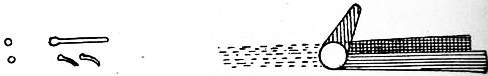 |
| Fig. 27. |
A similar explanation will apply to the positive rays discovered by Villard (Comptes rendus, 143, p. 674) and J. J. Thomson (Phil. Mag. 13, p. 359), which travel in the opposite direction to the rays we have been considering, i.e. they travel away from the cathode and in the direction of the cathode’s rays; these rays are sometimes called “retrograde” rays. These as far as has been observed have always the same maximum value of e/m, i.e. 104, and there are a considerable number of negative ones always mixed with them. The maximum velocity of both the positive and retrograde rays is about 2×108 cm./sec. and varies very little with the potential difference between the electrodes in the tube in which they are produced (J. J. Thomson, Phil. Mag., Dec. 1909).
The positive rays show, when the pressure is not very low, the line spectrum of the gas through which they pass. An exceedingly valuable set of observations on this point have been made by Stark and his pupils (Physik. Zeit. 6, p. 892; Ann. der Phys. 21, pp. 40, 457). Stark has shown that in many gases, notably hydrogen, the spectrum shows the Doppler effect, and he has been able to calculate in this way the velocity of the positive rays.
Anode Rays.—Gehrcke and Reichenhein (Ann. der Phys. 25, p. 861) have found that when the anode consists of a mixture of sodium and lithium chloride raised to a high temperature either by the discharge itself or by an independent heating circuit, very conspicuous rays come from the anode when the pressure of the gas in the discharge tube is very low, and a large coil is used to produce the discharge. The determination of e/m for these rays showed that they are positively charged atoms of sodium or lithium, moving with very considerable velocity; in some of Gehrcke’s experiments the maximum velocity was as great as 1.8×107 cm./sec. though the average was about 107 cm./sec. These velocities are less than those of the positive rays whose maximum velocity is about 2×108 cm./sec.
1 The values for nickel and bismuth given in the table are much higher than later values obtained with pure electrolytic nickel and bismuth.
2 The value here given, namely 12.885, for the electric mass-resistivity of liquid mercury as determined by Matthiessen is now known to be too high by nearly 1%. The value at present accepted is 12.789 ohms per metre-gramme at 0° C.
3 The value (1630) here given for hard-drawn copper is about ¼% higher than the value now adopted, namely, 1626. The difference is due to the fact that either Jenkin or Matthiessen did not employ precisely the value at present employed for the density of hard-drawn and annealed copper in calculating the volume-resistivities from the mass-resistivities.
4 Matthiessen’s value for nickel is much greater than that obtained in more recent researches. (See Matthiessen and Vogt, Phil. Trans., 1863, and J. A. Fleming, Proc. Roy. Soc., December 1899.)
5 Matthiessen’s value for mercury is nearly 1% greater than the value adopted at present as the mean of the best results, namely 94,070.
6 The samples of silver, copper and nickel employed for these tests were prepared electrolytically by Sir J. W. Swan, and were exceedingly pure and soft. The value for volume-resistivity of nickel as given in the above table (from experiments by J. A. Fleming, Proc. Roy. Soc., December 1899) is much less (nearly 40%) than the value given by Matthiessen’s researches.
7 The electrolytic bismuth here used was prepared by Hartmann and Braun, and the resistivity taken by J. A. Fleming. The value is nearly 20% less than that given by Matthiessen.
8 In 1899 a committee was formed of representatives from eight of the leading manufacturers of insulated copper cables with delegates from the Post Office and Institution of Electrical Engineers, to consider the question of the values to be assigned to the resistivity of hard-drawn and annealed copper. The sittings of the committee were held in London, the secretary being A. H. Howard. The values given in the above paragraphs are in accordance with the decision of this committee, and its recommendations have been accepted by the General Post Office and the leading manufacturers of insulated copper wire and cables.
9 Platinoid is an alloy introduced by Martino, said to be similar in composition to German silver, but with a little tungsten added. It varies a good deal in composition according to manufacture, and the resistivity of different specimens is not identical. Its electric properties were first made known by J. T. Bottomley, in a paper read at the Royal Society, May 5, 1885.
10 An equivalent gramme molecule is a weight in grammes equal numerically to the chemical equivalent of the salt. For instance, one equivalent gramme molecule of sodium chloride is a mass of 58.5 grammes. NaCl = 58.5.
11 F. Kohlrausch and L. Holborn, Das Leitvermögen der Elektrolyte (Leipzig, 1898).
12 It should be noticed that the velocities calculated in Kohlrausch’s theory and observed experimentally are the average velocities, and involve both the factors mentioned above; they include the time wasted by the ions in combination with each other, and, except at great dilution, are less than the velocity with which the ions move when free from each other.
End of the Project Gutenberg EBook of Encyclopaedia Britannica, 11th
Edition, Volume 6, Slice 8, by Various

*** END OF THIS PROJECT GUTENBERG EBOOK ENCYC. BRITANNICA, VOL 6, SL 8 ***

***** This file should be named 32063-h.htm or 32063-h.zip *****
This and all associated files of various formats will be found in:
        https://www.gutenberg.org/3/2/0/6/32063/

Produced by Marius Masi, Don Kretz, Juliet Sutherland, and
the Online Distributed Proofreading Team at
https://www.pgdp.net


Updated editions will replace the previous one--the old editions
will be renamed.

Creating the works from public domain print editions means that no
one owns a United States copyright in these works, so the Foundation
(and you!) can copy and distribute it in the United States without
permission and without paying copyright royalties.  Special rules,
set forth in the General Terms of Use part of this license, apply to
copying and distributing Project Gutenberg-tm electronic works to
protect the PROJECT GUTENBERG-tm concept and trademark.  Project
Gutenberg is a registered trademark, and may not be used if you
charge for the eBooks, unless you receive specific permission.  If you
do not charge anything for copies of this eBook, complying with the
rules is very easy.  You may use this eBook for nearly any purpose
such as creation of derivative works, reports, performances and
research.  They may be modified and printed and given away--you may do
practically ANYTHING with public domain eBooks.  Redistribution is
subject to the trademark license, especially commercial
redistribution.


*** START: FULL LICENSE ***

THE FULL PROJECT GUTENBERG LICENSE
PLEASE READ THIS BEFORE YOU DISTRIBUTE OR USE THIS WORK

To protect the Project Gutenberg-tm mission of promoting the free
distribution of electronic works, by using or distributing this work
(or any other work associated in any way with the phrase "Project
Gutenberg"), you agree to comply with all the terms of the Full Project
Gutenberg-tm License (available with this file or online at
https://gutenberg.org/license).


Section 1.  General Terms of Use and Redistributing Project Gutenberg-tm
electronic works

1.A.  By reading or using any part of this Project Gutenberg-tm
electronic work, you indicate that you have read, understand, agree to
and accept all the terms of this license and intellectual property
(trademark/copyright) agreement.  If you do not agree to abide by all
the terms of this agreement, you must cease using and return or destroy
all copies of Project Gutenberg-tm electronic works in your possession.
If you paid a fee for obtaining a copy of or access to a Project
Gutenberg-tm electronic work and you do not agree to be bound by the
terms of this agreement, you may obtain a refund from the person or
entity to whom you paid the fee as set forth in paragraph 1.E.8.

1.B.  "Project Gutenberg" is a registered trademark.  It may only be
used on or associated in any way with an electronic work by people who
agree to be bound by the terms of this agreement.  There are a few
things that you can do with most Project Gutenberg-tm electronic works
even without complying with the full terms of this agreement.  See
paragraph 1.C below.  There are a lot of things you can do with Project
Gutenberg-tm electronic works if you follow the terms of this agreement
and help preserve free future access to Project Gutenberg-tm electronic
works.  See paragraph 1.E below.

1.C.  The Project Gutenberg Literary Archive Foundation ("the Foundation"
or PGLAF), owns a compilation copyright in the collection of Project
Gutenberg-tm electronic works.  Nearly all the individual works in the
collection are in the public domain in the United States.  If an
individual work is in the public domain in the United States and you are
located in the United States, we do not claim a right to prevent you from
copying, distributing, performing, displaying or creating derivative
works based on the work as long as all references to Project Gutenberg
are removed.  Of course, we hope that you will support the Project
Gutenberg-tm mission of promoting free access to electronic works by
freely sharing Project Gutenberg-tm works in compliance with the terms of
this agreement for keeping the Project Gutenberg-tm name associated with
the work.  You can easily comply with the terms of this agreement by
keeping this work in the same format with its attached full Project
Gutenberg-tm License when you share it without charge with others.

1.D.  The copyright laws of the place where you are located also govern
what you can do with this work.  Copyright laws in most countries are in
a constant state of change.  If you are outside the United States, check
the laws of your country in addition to the terms of this agreement
before downloading, copying, displaying, performing, distributing or
creating derivative works based on this work or any other Project
Gutenberg-tm work.  The Foundation makes no representations concerning
the copyright status of any work in any country outside the United
States.

1.E.  Unless you have removed all references to Project Gutenberg:

1.E.1.  The following sentence, with active links to, or other immediate
access to, the full Project Gutenberg-tm License must appear prominently
whenever any copy of a Project Gutenberg-tm work (any work on which the
phrase "Project Gutenberg" appears, or with which the phrase "Project
Gutenberg" is associated) is accessed, displayed, performed, viewed,
copied or distributed:

This eBook is for the use of anyone anywhere at no cost and with
almost no restrictions whatsoever.  You may copy it, give it away or
re-use it under the terms of the Project Gutenberg License included
with this eBook or online at www.gutenberg.org

1.E.2.  If an individual Project Gutenberg-tm electronic work is derived
from the public domain (does not contain a notice indicating that it is
posted with permission of the copyright holder), the work can be copied
and distributed to anyone in the United States without paying any fees
or charges.  If you are redistributing or providing access to a work
with the phrase "Project Gutenberg" associated with or appearing on the
work, you must comply either with the requirements of paragraphs 1.E.1
through 1.E.7 or obtain permission for the use of the work and the
Project Gutenberg-tm trademark as set forth in paragraphs 1.E.8 or
1.E.9.

1.E.3.  If an individual Project Gutenberg-tm electronic work is posted
with the permission of the copyright holder, your use and distribution
must comply with both paragraphs 1.E.1 through 1.E.7 and any additional
terms imposed by the copyright holder.  Additional terms will be linked
to the Project Gutenberg-tm License for all works posted with the
permission of the copyright holder found at the beginning of this work.

1.E.4.  Do not unlink or detach or remove the full Project Gutenberg-tm
License terms from this work, or any files containing a part of this
work or any other work associated with Project Gutenberg-tm.

1.E.5.  Do not copy, display, perform, distribute or redistribute this
electronic work, or any part of this electronic work, without
prominently displaying the sentence set forth in paragraph 1.E.1 with
active links or immediate access to the full terms of the Project
Gutenberg-tm License.

1.E.6.  You may convert to and distribute this work in any binary,
compressed, marked up, nonproprietary or proprietary form, including any
word processing or hypertext form.  However, if you provide access to or
distribute copies of a Project Gutenberg-tm work in a format other than
"Plain Vanilla ASCII" or other format used in the official version
posted on the official Project Gutenberg-tm web site (www.gutenberg.org),
you must, at no additional cost, fee or expense to the user, provide a
copy, a means of exporting a copy, or a means of obtaining a copy upon
request, of the work in its original "Plain Vanilla ASCII" or other
form.  Any alternate format must include the full Project Gutenberg-tm
License as specified in paragraph 1.E.1.

1.E.7.  Do not charge a fee for access to, viewing, displaying,
performing, copying or distributing any Project Gutenberg-tm works
unless you comply with paragraph 1.E.8 or 1.E.9.

1.E.8.  You may charge a reasonable fee for copies of or providing
access to or distributing Project Gutenberg-tm electronic works provided
that

- You pay a royalty fee of 20% of the gross profits you derive from
     the use of Project Gutenberg-tm works calculated using the method
     you already use to calculate your applicable taxes.  The fee is
     owed to the owner of the Project Gutenberg-tm trademark, but he
     has agreed to donate royalties under this paragraph to the
     Project Gutenberg Literary Archive Foundation.  Royalty payments
     must be paid within 60 days following each date on which you
     prepare (or are legally required to prepare) your periodic tax
     returns.  Royalty payments should be clearly marked as such and
     sent to the Project Gutenberg Literary Archive Foundation at the
     address specified in Section 4, "Information about donations to
     the Project Gutenberg Literary Archive Foundation."

- You provide a full refund of any money paid by a user who notifies
     you in writing (or by e-mail) within 30 days of receipt that s/he
     does not agree to the terms of the full Project Gutenberg-tm
     License.  You must require such a user to return or
     destroy all copies of the works possessed in a physical medium
     and discontinue all use of and all access to other copies of
     Project Gutenberg-tm works.

- You provide, in accordance with paragraph 1.F.3, a full refund of any
     money paid for a work or a replacement copy, if a defect in the
     electronic work is discovered and reported to you within 90 days
     of receipt of the work.

- You comply with all other terms of this agreement for free
     distribution of Project Gutenberg-tm works.

1.E.9.  If you wish to charge a fee or distribute a Project Gutenberg-tm
electronic work or group of works on different terms than are set
forth in this agreement, you must obtain permission in writing from
both the Project Gutenberg Literary Archive Foundation and Michael
Hart, the owner of the Project Gutenberg-tm trademark.  Contact the
Foundation as set forth in Section 3 below.

1.F.

1.F.1.  Project Gutenberg volunteers and employees expend considerable
effort to identify, do copyright research on, transcribe and proofread
public domain works in creating the Project Gutenberg-tm
collection.  Despite these efforts, Project Gutenberg-tm electronic
works, and the medium on which they may be stored, may contain
"Defects," such as, but not limited to, incomplete, inaccurate or
corrupt data, transcription errors, a copyright or other intellectual
property infringement, a defective or damaged disk or other medium, a
computer virus, or computer codes that damage or cannot be read by
your equipment.

1.F.2.  LIMITED WARRANTY, DISCLAIMER OF DAMAGES - Except for the "Right
of Replacement or Refund" described in paragraph 1.F.3, the Project
Gutenberg Literary Archive Foundation, the owner of the Project
Gutenberg-tm trademark, and any other party distributing a Project
Gutenberg-tm electronic work under this agreement, disclaim all
liability to you for damages, costs and expenses, including legal
fees.  YOU AGREE THAT YOU HAVE NO REMEDIES FOR NEGLIGENCE, STRICT
LIABILITY, BREACH OF WARRANTY OR BREACH OF CONTRACT EXCEPT THOSE
PROVIDED IN PARAGRAPH F3.  YOU AGREE THAT THE FOUNDATION, THE
TRADEMARK OWNER, AND ANY DISTRIBUTOR UNDER THIS AGREEMENT WILL NOT BE
LIABLE TO YOU FOR ACTUAL, DIRECT, INDIRECT, CONSEQUENTIAL, PUNITIVE OR
INCIDENTAL DAMAGES EVEN IF YOU GIVE NOTICE OF THE POSSIBILITY OF SUCH
DAMAGE.

1.F.3.  LIMITED RIGHT OF REPLACEMENT OR REFUND - If you discover a
defect in this electronic work within 90 days of receiving it, you can
receive a refund of the money (if any) you paid for it by sending a
written explanation to the person you received the work from.  If you
received the work on a physical medium, you must return the medium with
your written explanation.  The person or entity that provided you with
the defective work may elect to provide a replacement copy in lieu of a
refund.  If you received the work electronically, the person or entity
providing it to you may choose to give you a second opportunity to
receive the work electronically in lieu of a refund.  If the second copy
is also defective, you may demand a refund in writing without further
opportunities to fix the problem.

1.F.4.  Except for the limited right of replacement or refund set forth
in paragraph 1.F.3, this work is provided to you 'AS-IS' WITH NO OTHER
WARRANTIES OF ANY KIND, EXPRESS OR IMPLIED, INCLUDING BUT NOT LIMITED TO
WARRANTIES OF MERCHANTIBILITY OR FITNESS FOR ANY PURPOSE.

1.F.5.  Some states do not allow disclaimers of certain implied
warranties or the exclusion or limitation of certain types of damages.
If any disclaimer or limitation set forth in this agreement violates the
law of the state applicable to this agreement, the agreement shall be
interpreted to make the maximum disclaimer or limitation permitted by
the applicable state law.  The invalidity or unenforceability of any
provision of this agreement shall not void the remaining provisions.

1.F.6.  INDEMNITY - You agree to indemnify and hold the Foundation, the
trademark owner, any agent or employee of the Foundation, anyone
providing copies of Project Gutenberg-tm electronic works in accordance
with this agreement, and any volunteers associated with the production,
promotion and distribution of Project Gutenberg-tm electronic works,
harmless from all liability, costs and expenses, including legal fees,
that arise directly or indirectly from any of the following which you do
or cause to occur: (a) distribution of this or any Project Gutenberg-tm
work, (b) alteration, modification, or additions or deletions to any
Project Gutenberg-tm work, and (c) any Defect you cause.


Section  2.  Information about the Mission of Project Gutenberg-tm

Project Gutenberg-tm is synonymous with the free distribution of
electronic works in formats readable by the widest variety of computers
including obsolete, old, middle-aged and new computers.  It exists
because of the efforts of hundreds of volunteers and donations from
people in all walks of life.

Volunteers and financial support to provide volunteers with the
assistance they need are critical to reaching Project Gutenberg-tm's
goals and ensuring that the Project Gutenberg-tm collection will
remain freely available for generations to come.  In 2001, the Project
Gutenberg Literary Archive Foundation was created to provide a secure
and permanent future for Project Gutenberg-tm and future generations.
To learn more about the Project Gutenberg Literary Archive Foundation
and how your efforts and donations can help, see Sections 3 and 4
and the Foundation web page at https://www.pglaf.org.


Section 3.  Information about the Project Gutenberg Literary Archive
Foundation

The Project Gutenberg Literary Archive Foundation is a non profit
501(c)(3) educational corporation organized under the laws of the
state of Mississippi and granted tax exempt status by the Internal
Revenue Service.  The Foundation's EIN or federal tax identification
number is 64-6221541.  Its 501(c)(3) letter is posted at
https://pglaf.org/fundraising.  Contributions to the Project Gutenberg
Literary Archive Foundation are tax deductible to the full extent
permitted by U.S. federal laws and your state's laws.

The Foundation's principal office is located at 4557 Melan Dr. S.
Fairbanks, AK, 99712., but its volunteers and employees are scattered
throughout numerous locations.  Its business office is located at
809 North 1500 West, Salt Lake City, UT 84116, (801) 596-1887, email
business@pglaf.org.  Email contact links and up to date contact
information can be found at the Foundation's web site and official
page at https://pglaf.org

For additional contact information:
     Dr. Gregory B. Newby
     Chief Executive and Director
     gbnewby@pglaf.org


Section 4.  Information about Donations to the Project Gutenberg
Literary Archive Foundation

Project Gutenberg-tm depends upon and cannot survive without wide
spread public support and donations to carry out its mission of
increasing the number of public domain and licensed works that can be
freely distributed in machine readable form accessible by the widest
array of equipment including outdated equipment.  Many small donations
($1 to $5,000) are particularly important to maintaining tax exempt
status with the IRS.

The Foundation is committed to complying with the laws regulating
charities and charitable donations in all 50 states of the United
States.  Compliance requirements are not uniform and it takes a
considerable effort, much paperwork and many fees to meet and keep up
with these requirements.  We do not solicit donations in locations
where we have not received written confirmation of compliance.  To
SEND DONATIONS or determine the status of compliance for any
particular state visit https://pglaf.org

While we cannot and do not solicit contributions from states where we
have not met the solicitation requirements, we know of no prohibition
against accepting unsolicited donations from donors in such states who
approach us with offers to donate.

International donations are gratefully accepted, but we cannot make
any statements concerning tax treatment of donations received from
outside the United States.  U.S. laws alone swamp our small staff.

Please check the Project Gutenberg Web pages for current donation
methods and addresses.  Donations are accepted in a number of other
ways including including checks, online payments and credit card
donations.  To donate, please visit: https://pglaf.org/donate


Section 5.  General Information About Project Gutenberg-tm electronic
works.

Professor Michael S. Hart was the originator of the Project Gutenberg-tm
concept of a library of electronic works that could be freely shared
with anyone.  For thirty years, he produced and distributed Project
Gutenberg-tm eBooks with only a loose network of volunteer support.


Project Gutenberg-tm eBooks are often created from several printed
editions, all of which are confirmed as Public Domain in the U.S.
unless a copyright notice is included.  Thus, we do not necessarily
keep eBooks in compliance with any particular paper edition.


Most people start at our Web site which has the main PG search facility:

     https://www.gutenberg.org

This Web site includes information about Project Gutenberg-tm,
including how to make donations to the Project Gutenberg Literary
Archive Foundation, how to help produce our new eBooks, and how to
subscribe to our email newsletter to hear about new eBooks.