Project Gutenberg's The Auburndale Watch Company, by Edwin A. Battison

This eBook is for the use of anyone anywhere at no cost and with
almost no restrictions whatsoever.  You may copy it, give it away or
re-use it under the terms of the Project Gutenberg License included
with this eBook or online at www.gutenberg.org


Title: The Auburndale Watch Company
       First American Attempt Toward the Dollar Watch

Author: Edwin A. Battison

Release Date: September 8, 2009 [EBook #29934]

Language: English

Character set encoding: ISO-8859-1

*** START OF THIS PROJECT GUTENBERG EBOOK THE AUBURNDALE WATCH COMPANY ***


Produced by Chris Curnow, ronnie sahlberg, Joseph Cooper
and the Online Distributed Proofreading Team at
http://www.pgdp.net
Possible printer errors have been retained as they appear in the original book.
The words (above) and (right) in illustration captions have been retained although in this ebook they have no relevance.
Contributions from
The Museum of History and Technology:
Paper 4
The Auburndale Watch Company
Edwin A. Battison
By Edwin A. Battison
THE AUBURNDALE WATCH COMPANY:
First American Attempt Toward the Dollar Watch
The life of the pioneer has always been arduous. Not all succeed, and many disappear leaving no trace on the pages of history. Here, painstaking search has uncovered enough of the record to permit us to review the errors of design and manufacture that brought failure to the first attempt to produce a really cheap pocket watch.
This paper is based on a study of the patent model of the Auburndale rotary and other products of the company in the collections of the National Museum, and of other collections, including that of the author. The study comprises part of the background research for the hall of timekeeping in the Museum of History and Technology.
The Author: Edwin A. Battison is associate curator of mechanical and civil engineering, Museum of History and Technology, in the Smithsonian Institution’s United States National Museum.
The idea of a machine-made watch with interchangeable parts had been in the minds of many men for a long time. Several attempts had been made to translate this conception into a reality. Success crowned the efforts of those working near Boston, Massachusetts, in the 1850’s. The work done there formed the basis on which American watch making grew to such a point that by the 1870’s watches of domestic manufacture had captured nearly all the home market and were reaching out and capturing foreign markets as well. In spite of this great achievement there remained a large untapped potential market for a watch which would combine the virtues of close time keeping and a lower selling price. Only a radical departure in design could achieve this. Rivalry between the several existing companies had already produced an irreducible minimum price on watches of conventional design.
The great obstacle to close rate in a modestly priced watch is the balance wheel. This wheel requires careful adjustment for temperature error and for poise. Of these two disturbing factors poise is the most annoying to the owner because lack of it makes the watch a very erratic timekeeper. A watch in which the parts are not poised is subject to a different rate for every position it is placed in. This position error, as it is called, can and often does cause a most erratic and unpredictable rate. Abraham-Louis Breguet, the celebrated Swiss-French horologist of Paris is credited with the invention, in 1801,[1] of his tourbillon, a clever way to circumvent this error.
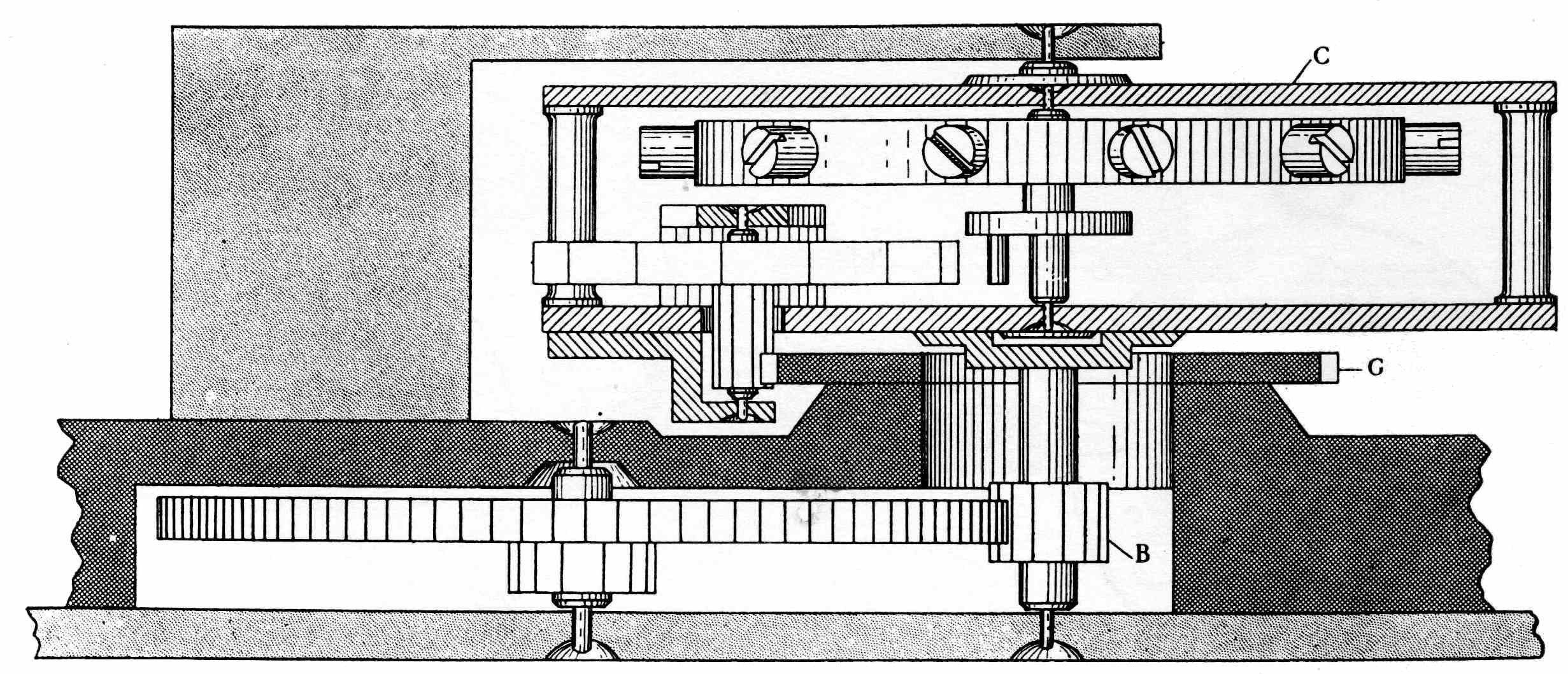
Figure 1.—Breguet’S Tourbillon. At C is shown the carriage which revolves with pinion B carrying the escapement and balance around the stationary wheel G. (After G. A. Baillie, Watches, their history, decoration, and mechanism, London, Methuen, n.d.)
His solution was to mount the escapement in a frame or “chariot” which revolved, usually once a 51 minute, so that with each revolution all possible positions were passed through (fig. 1). This gave the watch an average rate which was constant except for variations within the period of revolution of the chariot. Only a very skillful workman could, however, work with the delicacy necessary to produce such a mechanism. The result was that few were made and these were so expensive that it continued to be more practical to poise the parts in a conventional movement. The idea of revolving the entire train of a watch, including the escapement, seems to have evolved surprisingly slowly from Breguet’s basic invention of the revolving escapement. In constructing a watch wherein the entire train revolves, no such delicate or precise workmanship is required as in the tourbillon. Due to the longer train of gears involved the period of revolution is much slower. Position errors average out as certainly if not as frequently. In Bonniksen’s “Karrusel” watch of 1893[2] the duration of a cycle is 52.5 minutes[3] while in the Auburndale Rotary which we are about to discuss the period of each revolution is 2-1/2 hours.
The patent model of Jason R. Hopkins’ revolving watch, now in the U. S. National Museum,[4] was not the first in which the entire train revolved but it was a very novel conception intended to reduce greatly the number of parts usually associated with any watch. This may be seen from figures 2 and 3, where everything shown inside the ring gear revolves slowly as the main spring runs down. This spring is prevented from running down at its own speed by the train pinion seen in mesh with the ring gear. Through this pinion motion is imparted to the escape wheel and balance, where the rate of the watch is controlled. The balance, being planted at the center of revolution, travels around its own axis, as in the tourbillon, at the speed with which the entire train revolves around the barrel arbor. This arbor turns only during winding. No dial or dial gearing is shown in the patent or exists in the patent model. The patent merely says, casually, “By means of dial wheels the motion of the barrel may be communicated to hands and the time indicated in the usual manner.” No fine finish or jeweling has been lavished on the model, the only jewels present being in the balance cock which was utilized as it came from its original watch with only minor modification to the shape of its foot. Apparently the balance wheel itself is also a relic of the same or a similar conventional watch. There is no jeweling in the escapement or on the other end of the balance staff. In spite of this the model runs very actively and will overbank if wound up very far. The beat of the escapement is two per second and the movement revolves once in 20 minutes.
There are two great faults in the model. First is the lack of an adequate bearing for the barrel to turn on. There is only one very short bearing a long way removed from the point of engagement between 52 the pinion and internal gear, and no adequate support is given the barrel, with the result that it tends to deflect from the ideal or true position and to bind. This condition is aggravated by the fact that the ring gear was made by cutting its teeth on an angle to the axis around which it is to revolve, using only a saw of appropriate width. The teeth were then rounded-up to form by hand in a separate operation which by its very nature means that the teeth are not exactly alike. This lack of uniformity of the ring gear coupled with an entirely inadequate bearing for the barrel contributes to rather erratic transfer of power. These irregular teeth would not, of course, be a factor in factory-made watches where suitable machinery would be available for the work.
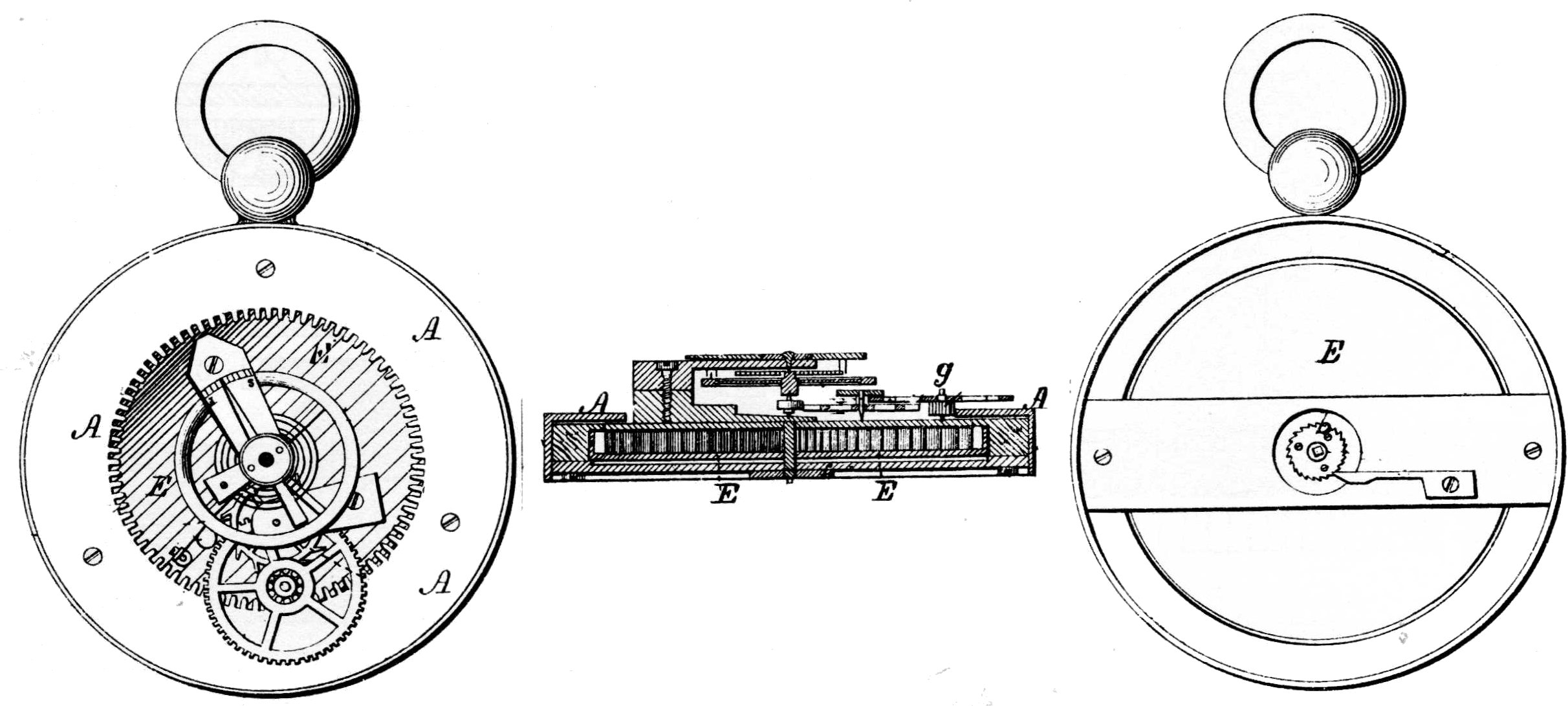
Figure 2.—Patent Drawing of the Hopkins Watch. The mainspring barrel E, of a very large diameter in proportion to the diameter of the watch, occupies nearly the full diameter of the movement. The spring itself, narrower and much longer than usual, is made in the patent model by riveting two ordinary springs together end to end. Over this barrel and attached to the stationary frame of the watch is placed a large thin ring A, cut on its inner diameter with 120 teeth. Near its edge the barrel E carries a stud g on which runs a pinion of 10 in mesh with the ring gear A. On this pinion is a wheel of 80 driving a pinion of 6 on the escape-wheel arbor. The 15-tooth escape wheel locks on a spring detent and gives impulse to the balance in one direction only, being a conventional chronometer escapement. The intermediate wheel and pinion, balance wheel, and balance cock have been adapted from a Swiss bar movement of the time.
The second fault is in the ratio between the time of one revolution and the number of revolutions necessary for a day’s run. Three turns of the spring are, of course, required to run the watch for an hour, since the barrel and train revolve three times in that length of time. If we choose to have the watch run for 30 hours on a winding, and this leaves but a small safety 53 factor, then we see that this will require 90 turns of the main spring, a manifest impossibility in view of the space available.[5]

Figure 3.—Original Patent Model of the Hopkins Watch, U. S. Patent 161513, July 20, 1875, now in the U. S. National Museum (cat. no. 309025).
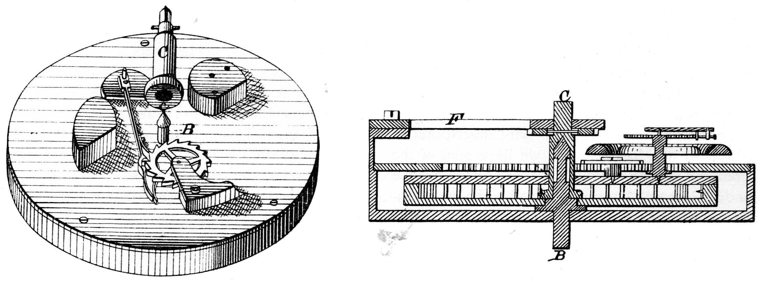
Figure 4.—Drawing from U. S. Patent 165831, showing Hopkins’ first design improvement, an arbor for the barrel and train to turn on and the balance displaced from center.
Probably no attempt was made to produce a finished and practical watch at this time, although Hopkins, the inventor, was an actual watchmaker as well as a retail jeweler, with premises virtually in the shadow of the Patent Office. He was a native of Maine[6] and had been established in Washington since 1863, or perhaps some time in 1862.[7]

Figure 5.—Hopkins’ Balance Arresting Device, the subject of U. S. patent 165830. This and the device illustrated in figure 4 originally were submitted together to the Patent Office on June 9, 1875, and later were divided into two patents.
Edward A. Locke had long been seeking a simple watch adapted to easy manufacture and a selling price of three to four dollars. While on a trip to Washington his attention was drawn to the Hopkins watch by William D. Colt of Washington.[8] A result of this meeting appears to have been the issuance to Jason 54 R. Hopkins of two patents,[9] in both of which half rights were assigned to William D. Colt. Patent 165831, relates to a barrel arbor for watches. The arbor will be seen (fig. 4) to consist of two parts, one telescoped within the other and the composite arbor B-C supported at each end by the frame of the watch. The patent text limits itself to a bare description of the arbor. In the light of what we have seen of the shortcomings of the original model, however, the patent drawings tell that much more had been accomplished on the general design of a more workable rotary watch.
A square on arbor C at the back of the watch permits winding the main spring, which attaches to the largest diameter of C, a ratchet or winding click being supplied just under support F. The inner or front part B of the composite arbor projects from the front of the movement and revolves at the speed of the barrel arbor, which speed is not specified. Also, looking at the perspective view, we see that while the chronometer escapement has been retained, the balance has been placed eccentrically to make room for the center arbor. The balance now describes an orbit around the center of revolution. No driving train is shown, it being irrelevant to the patent, but there seems to be ample room for two intermediate wheels and their pinions between the escape wheel and the train cock boss, seen at the upper right in the perspective view of figure 4. Adding one more wheel and pinion to the train would have the effect of reducing the number of revolutions required of the spring barrel. We have seen from examination of the patent model of the Hopkins rotary that this was necessary not only to reduce the number of turns of the main spring and barrel but also to reduce the force transmitted to the escapement. There seems little reason from the foregoing observations and considerations to doubt that these modifications had been realized by the time of this patent. Again no dial gearing is shown. If the need for special gearing existed at this time it seems strange that it was not covered by patent as was done in the later patent[10] assigned to William B. Fowle. The only way to avoid special gearing would be to revolve the barrel and train each hour so that the minute hand could travel with them as it travels with the center wheel in conventional watches. Once this condition was set up, the usual dial gearing would apply.
Companion patent 165830 (see fig. 5) covers a mechanism to prevent overbanking of the balance wheel, primarily of a chronometer escapement. This, of course, was aimed at making it possible to use the escapement in connection with a mainspring of greatly varying power. We have seen that this condition of uneven power existed in the first Hopkins watch. While the condition was greatly improved in the second model (seen in fig. 4), it was surely present to some extent, as it is associated with every spring. Overbanking protection may well have continued to be necessary, particularly if the gear ratio between escapement and barrel was low enough to permit hourly rotation of the barrel. The features covered by this patent were originally submitted as part of what later became patent 165831. Examination of the original manuscript patent file[11] shows that the patent application was separated into two on the suggestion of the patent examiner, who pointed out that two distinct and separate mechanisms were involved, either of which could be used without the other.
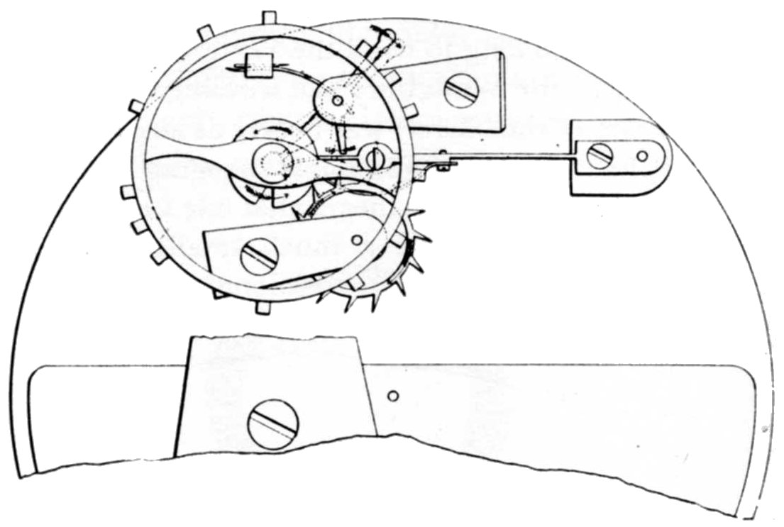
Figure 6.—Drawing from U. S. Patent 179019 showing Hopkins’ device to prevent the tripping of a chronometer escapement.
These two patents, which actually started out as one, appear to represent the watch as it was when Hopkins went to Waterbury, Connecticut, where he again met Edward A. Locke. They submitted this improved watch model to the Benedict and Burnham Manufacturing Co., which advised not manufacturing it until it was further developed. Hopkins went with his watch from there to Boston, where he conferred with George Merritt who, like Locke, was interested 55 in getting into the manufacture of a low-priced watch. Merritt may have been the senior member of the Locke-Merritt team or may simply have had more faith than his associates in Hopkins and his watch. At any rate, he advanced expense money while further efforts at improvement were made.[12] Hopkins’ absence from the Washington city directory of 1877 is perhaps explained by this work he was doing on his patent. While this was completed to Hopkins’ satisfaction, it still fell short of Merritt’s idea of practicality, and the latter abandoned the idea of manufacturing the watch;[13] what had started out as a very simple watch of few parts grew, with every effort to make it workable, more and more complicated by involved and expensive detail. It appears that Hopkins did not possess the rare gift of improvement by simplification. This is a rare gift, and one seldom possessed by an individual very closely and intensely involved in the minute details of a given problem.
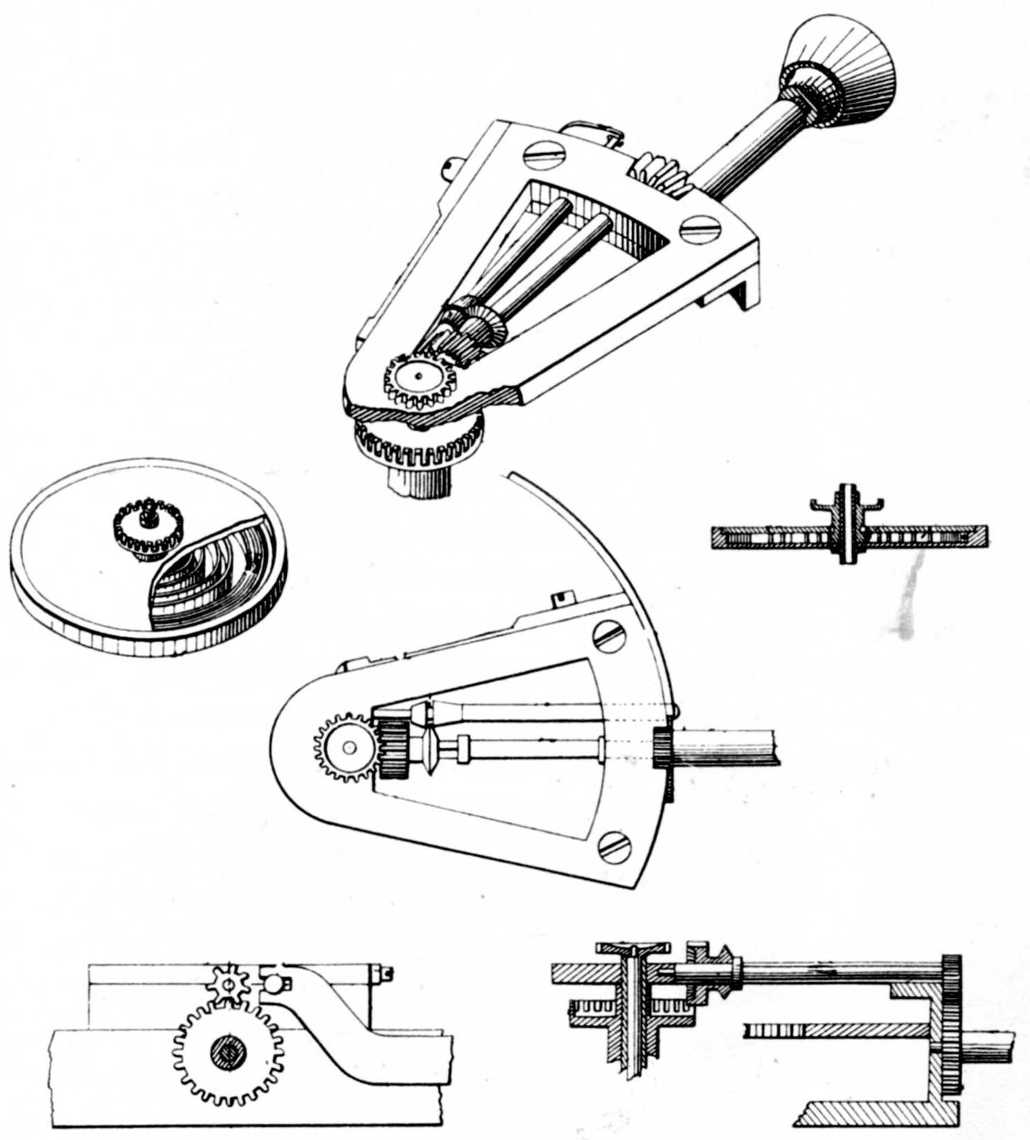
Figure 7.—Part of the Drawings from U. S. Patent 186838, showing the winding and setting mechanism very nearly as it was applied in the Auburndale rotary.
How long this period of development and experimentation required is unreported. It could hardly have started before early June of 1875, when application was made for the patent (165830) to prevent overbanking. The cash book of William B. Fowle of Auburndale, Massachusetts,[14] tells us that he bought half of William D. Colt’s half-interest in the Hopkins rotary in March 1876, partly for cash but including a royalty on each watch made. Half this royalty was to go to Hopkins, a quarter to William D. Colt, and a quarter to William B. Fowle. Does patent 179019, issued June 20, 1876, to Hopkins, who assigned it on June 10, 1876, to Fowle,[15] represent the last improvement offered to Merritt? It covers a device actuated by a spur on a balance staff to lock the detent against tripping when in one position and to permit normal operation of the chronometer escapement when in the other position (see fig. 6). Another patent applied 56 for on January 12, 1876, was in prospect and finally issued as no. 186838 on January 30, 1877, assigned to William B. Fowle on November 21, 1876.[16] This is much the most practical and useful patent in the series. A comparison of these (see figs. 7 and 8) with the Auburndale rotary watch (see fig. 9) shows a remarkable similarity between the inventor’s conception and the product eventually manufactured. A practical center arbor to support and guide the entire rotating mechanism is here combined with a stem-winding and lever-setting mechanism and dial gearing in a well thought out arrangement.
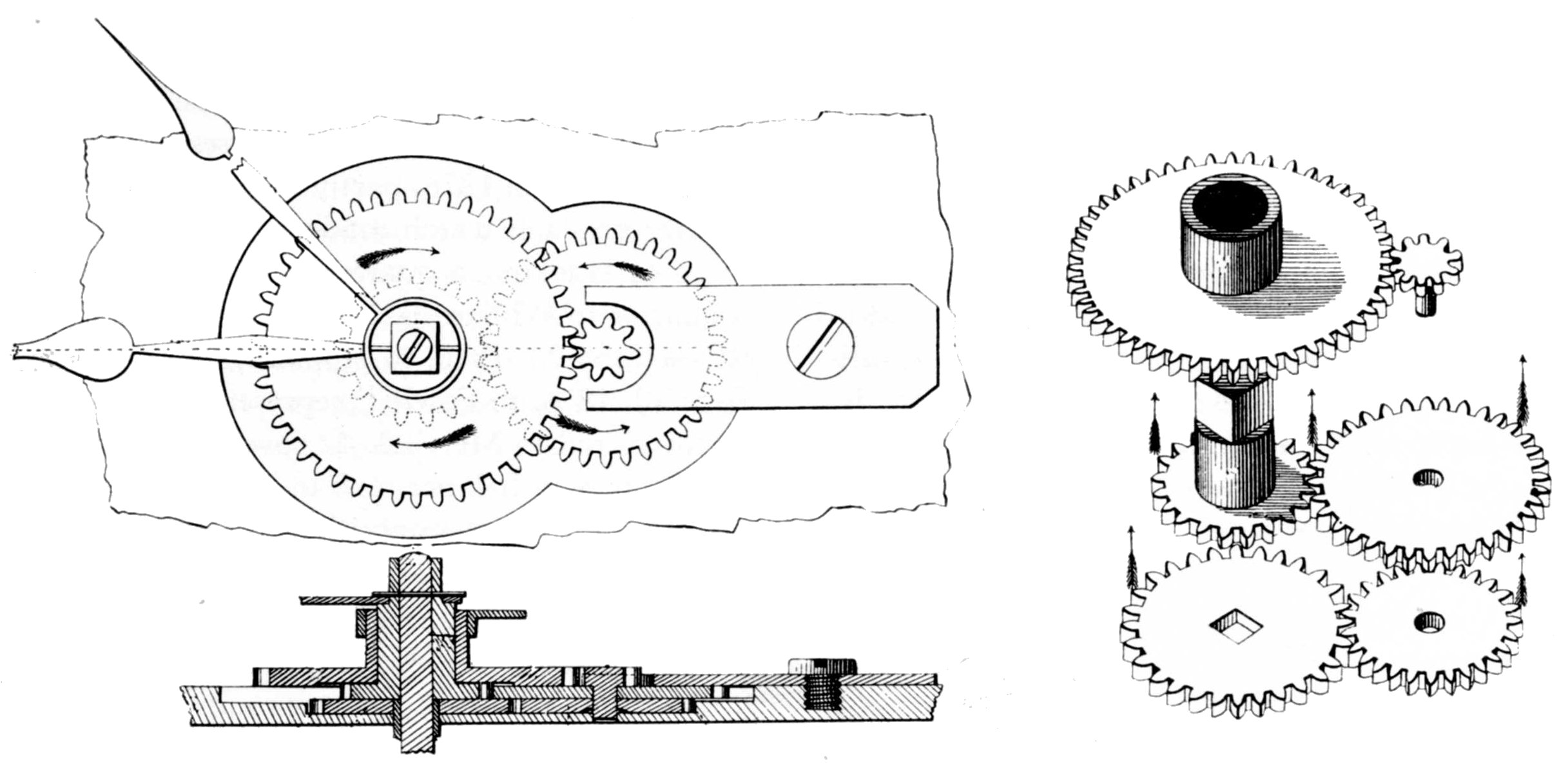
Figure 8.—Remaining Drawings from U. S. Patent 186838, showing the dial gearing used in the Auburndale rotary.
Here, where the story of the Hopkins watch diverges from the interests who later brought out the rival Waterbury watch, it seems appropriate to call the reader’s attention to the basic points of novelty and merit in the Hopkins watch which carried over to what became the Waterbury, somewhat as an hereditary characteristic passes from generation to generation. Previous writers have realized that one of these watches led to the other and have grouped them together because of the rotating feature which they shared in common. Beyond this point they have treated the watches as though they had nothing in common. Actually several basic features of the Hopkins watch existed in both: the long narrow spring in a barrel approximately filling one side of the watch case, a train rotating in the center of the watch and driven by a planetary pinion in mesh with a gear fixed to the stationary part of the watch, a slow beat escapement, and probably the hourly rotation of the train and escapement. When these details appeared in the first watches manufactured for Messrs. Locke and Merritt by the Benedict and Burnham Manufacturing Co. and later the Waterbury Watch Co., they were vastly changed in detail and much better adapted to mass production, although still basically the same.
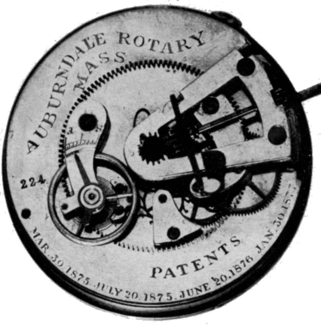
Figure 9.—Auburndale Rotary Watch Movement.
(In the author’s collection.)
The story of Hopkins’ rotary watch now enters an entirely new setting with new financial backing which, however, had no apparent experience or background 57 in mechanical work, much less watch manufacturing. Those with watchmaking experience who were brought into this new organization unquestionably did their best, based on past experience confined to conventional watches of much higher grade. Judging from the products turned out, however, they had great difficulty in making a clean break with their past and in producing a satisfactory low-priced watch of new and radical concept. The market for watches, which had been depressed, was at this time reviving a little. The Newton Journal,[17] referring to the American Watch Co. at Waltham reported: “The hands employed in the caseroom and the machinists have been called in. All the works are to be started the first of September.”

Figure 10.—William B. Fowle, sponsor of the Auburndale Watch Co., after an engraving in S. F. Smith, History of Newton, Massachusetts (Boston, 1880).
William Bentley Fowle (fig. 10), new partner with Hopkins and Colt in the watch, was born in Boston, Massachusetts on July 27, 1826. His father, William B. Fowle, Senior, a well-known Boston teacher and 58 educator, had variously been a bookseller and conductor of a “Female Monitorial School.”[18] The junior William B. Fowle we have first located as a ticket master with the Boston and Worcester Railroad in 1848,[19] and he retained this listing in the directory through 1851. Starting in 1852 and continuing through 1862, with no indication of employer or occupation, he had an office at 9 Merchants Exchange. In 1860 and 1862 he was a member of the Boston Common Council, and was president of that body in 1865. In 1862, after the second battle of Bull Run, he raised an infantry company for the 43rd Massachusetts Volunteers and was mustered in, September 24, 1862, with the rank of captain. From December 7, 1862, to March 4, 1863, he was commandant of the military post at Beaufort, North Carolina. He then reported to his regiment. On June 24, 1863, he was left sick at New Bern, North Carolina, by his company bound for Fortress Monroe. On July 21 he rejoined his company at Boston, Massachusetts, in time to be mustered out on July 30 at the expiration of his nine months’ enlistment.[20]

Figure 11.—The Two Lever Escapements Used in the Auburndale Rotary. Note, in addition to the escapement, the absence of banking pins and the metal balance jewel in the escapement at the left, which is from watch No. 176. (Both watches in the author’s collection.)
In the 1864 Boston directory we find him listed as treasurer of the Bear Valley Coal Co., and the North Mountain Coal Co., with an office at 38 City Exchange. This association with the coal business continued with changes unimportant to our story through the directories until 1877, in which year the name is dropped from the Boston directory, not to reappear until the directory of 1880, where he is listed at “Herald Building, watches and timers.” This was apparently the sales office. The Newton directory of 1877 drops its previous listing of coal after Mr. Fowle’s name and first mentions the Auburndale Watch Co.[21] In 1866 Mr. Fowle established his home, Tanglewood, in Auburndale, a village in Newton not far from his boyhood home at West Newton and on the bank of the Charles River about two miles upstream from the Waltham Watch Co. He served the town of Newton as selectman from 1869 through 1871, was an alderman in 1877, and mayor in 1878 and 1879.[22]

Figure 12.—A 24-Hour Dial for the rotary watch.
(In the author’s collection.)
William Atherton Wales of New York is credited with introducing Mr. Fowle to the Hopkins watch. No clue has come to light on what connection there was between Hopkins and Wales, who had been a partner in the large watch-importing house of Giles, Wales and Co., in New York and later a large stockholder in the United States Watch Co. of Marion, New Jersey, which had only ceased operation in 1874. A patent[23] had been issued to Fayette S. Giles of New York, the leading figure in the United States Watch Co., for an improvement in stem-winding watches. This had presumably been available to his company. In this winding mechanism a crown pinion driven by a clutch on the stem engages with a large ring gear, having 110 internal teeth, which in turn drives a gear on the barrel arbor. The author has seen no watch, except the patent model,[24] containing this device, but the pillar plate of many of the United States Watch Co. movements were cut out, apparently to receive this ring gear.
The expense of cutting so many internal teeth in steel seems reason enough to explain why this patent did not become the basis for all their stem-wound models. Steel is far more difficult to cut than brass, resulting in a much greater consumption of time and cutters, both of which represent money to the manufacturer. In the patent model these ring-gear teeth have been cut by a milling cutter which did not pass 59 through the ring and across the face of the teeth. This produced a gear somewhat resembling an internal bevel gear, one which could have only the merest contact with its mating pinion. To make a durable gear for this application it would be necessary to pass the cutter through the ring in line with the gear axis. This would require a special or, at least, radically modified gear-cutting machine with a cutter arbor shorter than the inside diameter of the gear. Into this short space the spindle bearings and means of driving the spindle would have to be crowded, along with the cutter. Hopkins faced a problem similar to this in cutting the ring gear for his watch, except that the brass gear needed for the rotary watch could be cut far more easily and quickly. This may be the link which brought Wales and the defunct United States Watch Co. into the Auburndale picture. Another plausible link between Fowle and Wales involves a patent[25] Wales received for a pulley. This, the now familiar device of interlocking conical sections so commonly used in variable speed V-belt drives, was assigned to G. E. Lincoln of Boston, Massachusetts. George E. Lincoln was treasurer of the Mammoth Vein Consolidated Coal Co. at Boston in 1865, with an office adjoining that of Fowle. In addition he boarded for many years at Auburndale,[26] and he apparently owned the buildings about to be converted into a watch factory. Thus we see that Lincoln may very well have been the one who brought Fowle and Wales together.
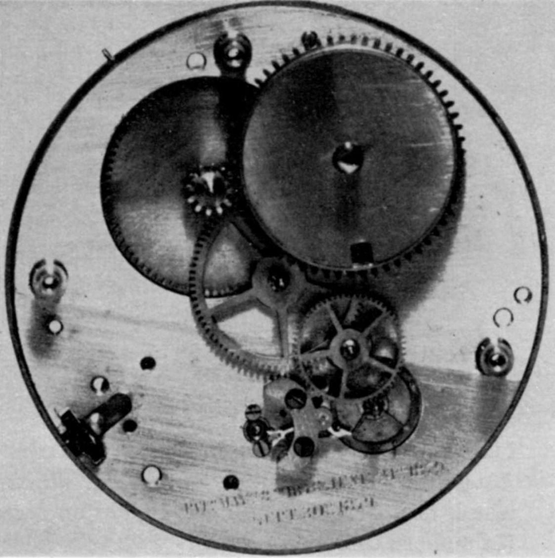
Figure 13.—The Auburndale Timer with top plate, balance, and control mechanism removed to show the train. The conventional barrel has 66 teeth that drive a pinion on the so-called 10-minute staff. This staff carries on the dial end the pointer, which revolves in 10 minutes, as indicated on the dial. Also on this staff is an unspoked wheel of 80 driving the center, or minute, staff through a pinion of 8. In addition to the sweep hand (or hands in the case of the split model) indicating seconds up to a duration of one minute, there is a wheel of 80 driving a pinion of 8 on an intermediate staff. A wheel of 60 on this staff drives a pinion of 10 on the escape-wheel staff. A pointer on this last staff also carries the hand that indicates fractions of a second. (In the author’s collection.)
William B. Fowle’s cash book shows, on July 14, 1876, payment to Geo. E. Lincoln “For large building used $200” and “For small building used $30.” On July 21 is an entry “Milo Lucas bal. of Building Contract $1605.25.” These with an entry on the preceding June 30, “Milo Lucas on a/c Contract for Building” seem, with a July 25 entry “W. E. C. Fowler, Painting Factory $64.91,” to cover the expense for the bare factory. The buildings, two stories high and measuring 40 x 20 and 32 x 20 feet, respectively, were located on the Weston bank of the Charles River, opposite Fowle’s home, from which they could be reached by a private ferry. This pleasant bucolic location was not far upstream from that originally sought by the Boston Watch Co. when that firm was looking for a spot to move to from Roxbury in 1854. The situation of the factory was described as a wild and secluded glen.[27]
Another account[28] says:
The well appointed little steamer White Swan, owned and commanded by a Captain Gibbs, veteran of the last war, now plies regularly between Waltham and Auburndale Bridge, carrying picnic parties, etc.... Along the banks of the river are located the summer residences of Messrs. Cutter and Merrill, the elegant residence of R. M. Pulsifer, Mayor of Newton, the splendid mansion of Ex-Mayor Fowle, the Benyon mansion and others.... At sunset the river is alive with canoes, row-boats, shells and sailboats filled with ladies and gentlemen adding, with the delightful music, greatly to the natural charm of the scenery.
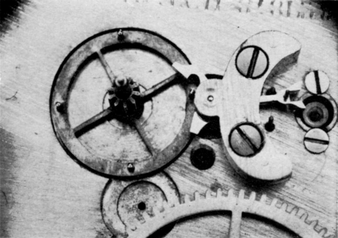
Figure 14.—Escape Wheel and Pallets of an Auburndale timer. With four pins in the escape wheel, this particular one beats eighths of a second. (In author’s collection.)
This idyllic pastoral setting surely must have been a joy to all connected with the little watch factory. It seems to typify the atmosphere of wealth and leisure into which the infant industry was brought without adequate study of the problems it would be called upon to surmount.
The Auburndale machinery came from the United States Watch Co. factory at Marion, New Jersey, which, as we have seen, was closed in 1874. William A. Wales, who was associated with Fowle in the Auburndale “adventure,” had been secretary, treasurer, and director of this company. Most of the machinery came from George E. Hart and Co., of Newark, which had taken over much of the Company’s equipment, eventually selling it to other factories. Warren E. Ray, a neighbor of Mr. Fowle’s, commenced as manager of the factory in July 1876, and died suddenly of heart disease about October 1 of that year. He was soon succeeded by Mr. James H. Gerry, who had gone from Waltham to Newark in 1863 to superintend the building of the original machines for the United States factory.
The employees were chiefly drawn from other factories, principally the neighboring American Watch Co. at Waltham, and the defunct United States Watch Co., while some who needed no specific watchmaking skills perhaps never had worked in a watch factory before. Names, not already mentioned, that have been preserved are: George H. Bourne, L. C. Brown, Abraham Craig, Frederick H. Eaves, Henry B. Fowle, Benjamin F. Gerry, William H. Guest, Jose Guinan, Sadie Hewes, Isaac Kilduff (the watchman), Justin Hinds, E. Moebus, James O’Connell (the stationary engineer), Edwin H. Perry, Frank N. Robbins, John Rose, Thomas W. Shephard, William H. A. Simmons, Alfred Simpson, Thomas Steele, Oscar L. Strout, and George Wood. These, compiled from several sources,[29] represent only a few of the men who contributed their knowledge and skill to the enterprise; they are listed in alphabetical order because it has been found impossible to arrange them accurately according to position, magnitude of contribution, or length of service.
Of the five Hopkins patents[30] the first and the last are the ones covering the essential elements used in the Auburndale product. The two patents assigned in half to William D. Colt apparently were never used, nor does the device shown in figure 6 seem to have been used, although these unused patents are listed on the Auburndale movements. Now that the watch was in the hands of men accustomed to making watches, some modifications dictated by their experience and 61 by considerations of expediency in manufacture were made. The movement that issued was 18 size, rather thick, cased at the factory in a nickel case made by the Thiery Watch Case Co. of Boston, Massachusetts. In the winding and setting mechanisms, some changes in details were made with respect to those shown in figure 7. The dial is mounted by means of a rim which snaps over the edge of the movement as on a high-grade Swiss watch of the same era. The usual dial feet, if used, would have interfered with the rotation of the movement. For the same reason, of course, there is no dial indicating seconds.

Figure 15.—Verge and Lever for an Auburndale timer. The one on the left beats eighths of a second; that on the right beats quarters. (In author’s collection.)
Five jewels are found in most instances, two cap jewels and two hole jewels for the balance staff and a jeweled impulse pin. One of the faults of the movement is that the cap and hole jewels on the balance are not separable for cleaning. After the jewels were inserted part of the setting was spun down over them, making the assembly permanent. A few movements with only one jewel are known, the cap and hole jewels being metal “jewels” likewise set under a spun-over rim. Whether or not the impulse jewel found in these last-mentioned movements is original or a later intrusion remains undetermined. It is easy to conceive that the factory would see no more necessity for an impulse jewel than for other jewels.
The lever escapement is the only one known to have been used, but two varieties of this are found (see fig. 11). One is a standard club-tooth lever with banking pins, the other, much more interesting because unconventional, has pointed pallets and all the lift on the escape wheel, which has very short stubby teeth, very much like the wheel of a pin-pallet escapement. No banking pins are used, the banking taking place between the pallets and the wheel. An examination of a number of these watches, with serial numbers ranging from 46 to 507,[31] reveals no correlation between the serial number and the style of escapement, from which one may conclude that the pointed pallet escapement was originally used; later four balance jewels were added and the escapement changed to the conventional club-tooth pattern. As complaints came in about the defective running of the watch these changes were apparently substituted at the factory in customers’ watches. The movements with the pointed-pallet escapement seldom show much wear; on the other hand, watch no. 224,[32] which has the conventional escapement and five jewels, is very much worn and must have run for many years.
These watches are stem wound by turning opposite to the usual direction and are set through the winding crown after actuating a setting lever located under the front bezel. The plates, bridges, and ring gear are nickel-plated and highly buffed, making a very showy movement, the only instances of such a finish on watches in the author’s experience. In figure 12 is shown a 24-hour dial to fit the movement. Special dial gearing would be required for the hour hand to accompany this dial.
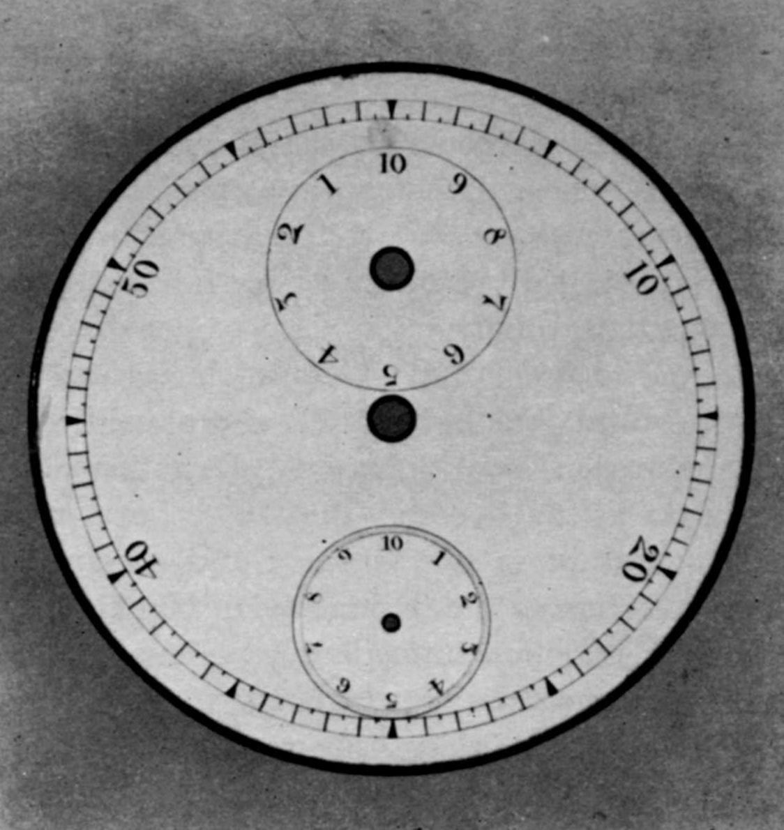
Figure 16.—Dial for 1/10-Second Model Auburndale timer. (In author’s collection.)
The first of these watches were placed on the market in 1877, priced at $10.00 to the trade. Soon complaints came in that they were defective in operation and many were returned. We have seen from the specimens examined that there seems to have been no established model produced in quantity. The dial and the number of jewels varied, as well as the escapement, suggesting that the owners were groping for a salable variant of the design for which they had tooled the factory. Probably the pointed pallet escapement was used first, it being the less expensive of the two. 62 In addition to the saving effected by not requiring banking pins, the escape wheel was much cheaper to cut, as the teeth were very short and strong (see fig. 11). Since the banking took place between the pallets and the escape wheel, there was no adjustment for the amount of slide; and since the watches were not made to close tolerances, the slide was necessarily excessive and consequently power consuming. The conventional club-tooth escapement was probably substituted as less troublesome, although the banking pins were fixed and could only be adjusted by bending them. The pallets remained solid steel, without adjustable stone inserts.
At this stage of affairs approximately $140,000 had been invested in the venture, the market was already glutted with conventional watches which enjoyed the confidence of retailers, and the Auburndale Rotary had won a bad reputation. The success of any watch depends largely on the confidence the retail dealers have in it. They are looking for a product easy to sell at an attractive profit as well as one that will stay sold and create a satisfied customer. Fowle was of course very much disappointed; before going into the venture he had been advised that he could expect to produce 200 watches per day on an expenditure of $16,000.[33] The watches reached the market at a time, the fall of 1877, almost coincidental with application by D. Azro A. Buck for patents on what was to become the Waterbury rotary. These patents represented a new and economically sound expression of the basic ideas of Hopkins. The Waterbury associates immediately commenced work aimed at getting their watch on the market by June 1878.[34] News of this certainly reached Auburndale where they were not only well aware of the cost of producing their rotary but were also aware of the strict cost and performance studies which Locke and Merritt would apply to any watch before they would invest in it. Knowledge of this very able and well organized rival, coupled with the troubles experienced in manufacturing and selling the Auburndale Rotary, seem to account for the decision to abandon it. It was unfortunate that the timing of events happened just as it did for a little more work on the Auburndale and the tools for making it would probably have placed it on a firm footing in the trade, although obviously it could never compete with what eventually became the low-priced watch, really a scaled-down alarm clock minus the alarm mechanism.
It is said that about one thousand of the “Rotaries” were made. The highest serial number to come to the author’s attention, 507, may indicate that only a part of the watches started were finished.
Accounts agree[35] that the next product of the factory was a “Timer” containing a novel escapement patented on May 28, 1878,[36] by William A. Wales. Early specimens are marked “Pat. Applied For,” but one with the serial number 996[37] bears no reference at all to a patent, presumably because issuance of the patent or patents was imminent. Apparently the timer was in full production before the patent was issued on May 28. Specimens with higher serial numbers are stamped with three patent dates, May 28, 1878,[38] June 24, 1879, and September 30, 1879, as seen in figure 13, which also shows the arrangement of the train. In this escapement the escape wheel (fig. 14) carries in the rim any suitable number of steel pins all on the same radius from, and parallel to, the axis of wheel rotation. In all cases the wheel makes one revolution per second. The verge (figs. 14 and 15) is so proportioned that the distance between the points of repose on the entrance and exit pallets will stop the wheel at intervals equal to half the angular distance between the pins.
In other words, with two pins in the escape wheel the escapement will beat quarters of a second, because starting from a point of repose the wheel will be arrested on the other point of repose after turning through 90°. With four pins in the escape wheel and a suitably proportioned verge the escape wheel advances in steps of 45° and beats eighths of a second. The growing trend in this period to standardize the 63 timing of sporting events in intervals of fifths of a second is reflected in still another model having five pins in the escape wheel and beating tenths of a second. By the nature of the verge in this escapement, it will be seen that the number of beats must be twice the number of pins in the escape wheel, leaving no way to secure an odd number of beats per second, hence the 1/10-second model. This must have been a less desirable form because of the much smaller verge required, plus the problem of accelerating so much mass from a dead stop 600 times per minute.
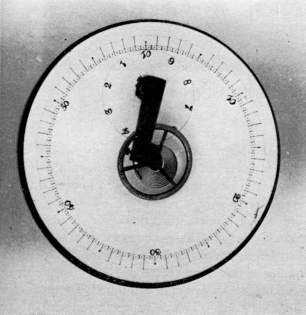
Figure 17.—A Timer Dial that is probably either experimental or very early. Note that the fractions of a second (quarters) are shown on the outside dial instead of on a separate dial. This dial was converted at the factory for use as the base of a hairspring vibrating stand. A dial different from this but having the same arrangement of circles is known. (In author’s collection.)
Figure 16 illustrates a dial for this 1/10-second model which the author found in a lot of unused parts left over when the factory closed. The watch had an 18-size 3/4-plate movement with grained nickel finish. The escapement is special, as we have seen, but the fork, roller, and balance action are conventional. There are five jewels, four to support the balance staff and an impulse jewel. The barrel arbor comes through the top plate with a square, as in a keywind watch, but is fitted with a winding handle, so that a key is unnecessary. This handle appears to be an afterthought, because on the earlier models (those with serial numbers below 1,000), the barrel arbor is short, barely long enough to attach the winding handle; later this arbor was made longer. Patent 204274 issued to Benjamin Wormelle of Brighton, Massachusetts, on May 28, 1878, the same date as Wales’ escapement patent, may have suggested this winding handle. On watches with higher serial numbers, there are two arrows on the handle to show the direction to wind.
The earliest of these timers had a slide on the side of the case to stop the movement by means of a piece of thin spring steel applied roughly tangentially to the smooth rim of the three-arm, solid steel balance wheel. When this action is reversed to start the movement, the spring, in retracting from the wheel rim, starts the wheel swinging. Soon this slide on the case was dispensed with by fitting a curved sheet-metal rack into a groove turned in the edge of the balance cock. Engaging this rack was a pinion with a square hole through which the square stem could slide to set the hands back to zero as it had from the beginning, while turning the stem now would actuate the pinion and rack to start and stop the movement, as the slide in the case had originally done.
Various minor changes, dictated by experience and the need for economy in manufacture, were made in these movements. After about the first thousand the diameter of the balance was reduced from approximately .700 to about .530 inch. This smaller wheel was, of course, much more suitable to vibrate at the faster speeds required on the models beating eighths and tenths of a second. At some time between the manufacture of watches bearing serial numbers 3135 and 3622, the formerly separate winding pawl and spring were combined into one piece that could be entirely made in a punch press. Another economy move was to stamp the name and patents in place of hand engraving. For a long time hand engraving was used, although stamping had been used from the beginning on the earlier rotary watch.
The case was very similar to that used on the rotary. The dial, of white enamel with snap rim fastened by a screw,[39] carried three graduated circles, an outer circle graduated in seconds up to sixty surrounding two smaller subsidiary dials. The top one of these smaller dials recorded minutes elasped up to ten and the lower one recorded fractions of a second. The 64 same dial was used on movements indicating quarters and eighths of seconds, all being graduated in eighths. A dial without provision for indicating the fractions of a second on a separate small dial may be seen in figure 17. This last has been made into a stand for hair spring work and is shown with balance and spring just as it came from the Auburndale factory with balance spring and wheel for a timer still in place.
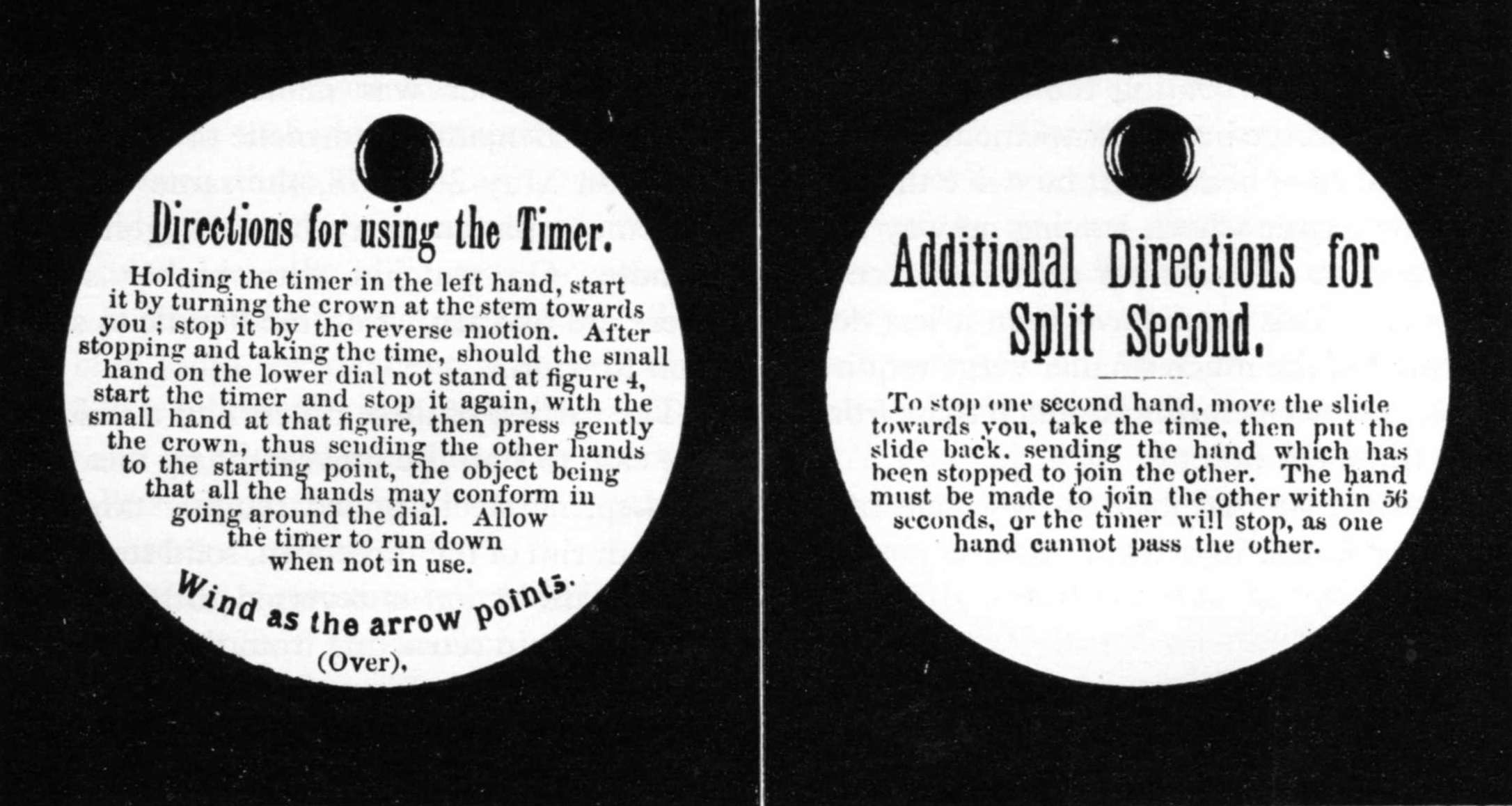
Figure 18.—Tag Displaying Directions for Use of the Auburndale Timer.
(In author’s collection.)
The sweep second hand and the minute register hand are attached to heart-shaped cams friction driven from their respective staffs. They are reset by a bar pivoted beneath the dial and actuated by the stem through pressure on the crown. An original instruction tag as sent from the factory with these timers is seen in figure 18.
Figure 19 shows the mechanism of the split-second model as represented in U. S. patent 220195 of September 30, 1879, issued to William A. Wales and assigned to William B. Fowle.[40] A split-second mechanism is used to time the finish of two horses in the same race or any other similar event. In usual watches of this nature the watch will run along indefinitely with the extra or split second hand stopped although this hand will not record more than a difference of one minute from the main sweep hand. This was not true of the Auburndale, as pointed out in the instructions. The reason for this is that motion is conveyed to this hand through a hair spring which would be damaged if allowed to overwind. To prevent this a stop is interposed which will halt the entire watch unless directions are followed. The serrated wheel F, of hardened steel, driving the second sweep hand, is cut on the edge with 120 serrations; stopping of this hand therefore is only to the nearest half second regardless of how minutely the escapement is dividing time. This is rather a serious defect as, if timing a horse race as an example, the time of the fastest horse is taken on this hand which registers a lesser degree of accuracy than the time recorded on the second and less important horse. A general view of one of these watches is seen in figure 20.
It would be pleasant to report that after the fiasco of the rotary model these timers were a financial success, but the facts indicate otherwise. They were well built and reliable, so that the trade was pleased to stock and promote them. The public responded well when in the market for a timer, as might be expected, since no other stop watch with fractional second dial or split-second hand was made in the country. Those imported from abroad were many times as expensive. Unfortunately the demand was seasonal. Sometimes, during the racing season, 65 demand would reach 400 per month, while at other seasons of the year practically none at all were sold. Some remained in stock during the remaining life of the company, as is shown by the following advertisement,[41] which was accompanied by an illustration of the watch:
The old reliable Auburndale Chronograph Timers, for sale by Edward H. Brown, No. 16 Maiden Lane, New York. The manufacture of these watches having been discontinued for reasons entirely apart from their value and reliability, the stock in existence is very limited, and is now in the hands of Mr. Edward H. Brown, No. 16 Maiden Lane, New York City, the well known and reliable dealer in Watches, Diamonds and Jewelry. The Auburndale timer has been in the hands of a number of competent judges, and has always been found to be accurate. It is of convenient size, and is contained in a German silver case, nickel plated. The timers are manufactured in two qualities, without split seconds for $15 and with the split second for $25. They all have minute, second and lightning hands. We recommend all desiring a cheap and reliable timer to apply at once to Mr. Brown, No. 16 Maiden Lane, New York.
A steadier market was sought with the introduction of a low priced 3/4-plate, back-setting, 18-size watch to compete, it was hoped, with the full-plate watches of similar price made by the established companies. Nearly all these watches had seven jewels, some few had more. The majority were key wind and set with a folding winding key permanently attached to the barrel arbor, as in figure 21. These were named “Lincoln” for Mr. Fowle’s son, Lincoln A. Fowle,[42] and had a solid steel balance with screws and the general appearance of a compensated balance. A stem-wound, lever-set edition of the same basic watch was named “Bentley” for Bentley D. Fowle, another son.[43] This had a cut bimetallic balance and higher finish. Conventional gilt finish was used on both of these models, although one isolated specimen found in factory remainders[44] has a bright nickel finish comparable with the rotary watch. These watches were designed by Chauncey Hartwell,[45] after J. H. Gerry had removed to Lancaster, where the Lancaster Watch Co., organized in August 1877, was attempting to bring a line of watches onto the market although beset by acute financial woes similar to those building up at Auburndale. To return to our 3/4-plate watches, it may be said that they were well made for the price, reliable, and successful from a manufacturing point of view but could not be sold at a figure high enough to return a profit on the manufacture.
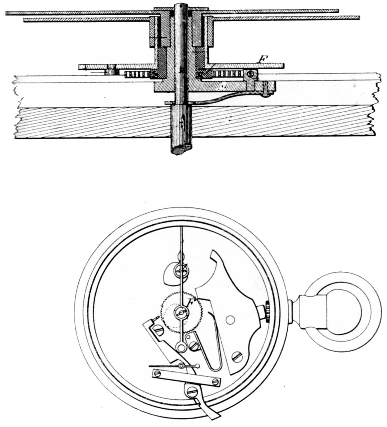
Figure 19.—Split Second Mechanism of the Auburndale timer, as shown in drawings from U. S. patent 220195, issued September 30, 1879.
Up to this time, about November 1, 1879, the Auburndale Watch Co., had existed as a private company; now it was incorporated with a book value of $500,000, and William B. Fowle, who at this point had invested about $250,000 (mostly unrecoverable) in the enterprise, was elected president, and George H. Bourne was elected secretary and treasurer.
After a quantity of these Lincoln and Bentley watches had been manufactured[46] and it had become clear that they could not be attractively priced to the trade, the company sought a product adapted to their factory equipment for which a constant market could be found. The product chosen was a line of metallic thermometers.[47] Two patents, 240058 and 240059, 66 were issued to William A. Wales, assignor to the Auburndale Watch Co., of Weston, Massachusetts, on April 12, 1881. Whether these patents represent the first thermometers made at Auburndale or reflect the result of experience gained in making conventional models is not clear. The earliest evidence dating the appearance of the thermometer is the 1881 Boston directory which appeared on July 1. This illustrates the same model of thermometer seen in figure 22. The patents cover means of eliminating springs of any sort from the mechanism, so that the hand or dial pointer is entirely under the influence of the fused bimetallic thermal strips. Manufacture of the timers was carried along with thermometer manufacture at first, but production of the timer was finally dropped, as the stock on hand was constantly increasing, and for a while the factory was at last operated at a profit, on thermometers alone. These were furnished in cases from 20 inches in diameter down to the size of a ten cent piece, according to the advertising.
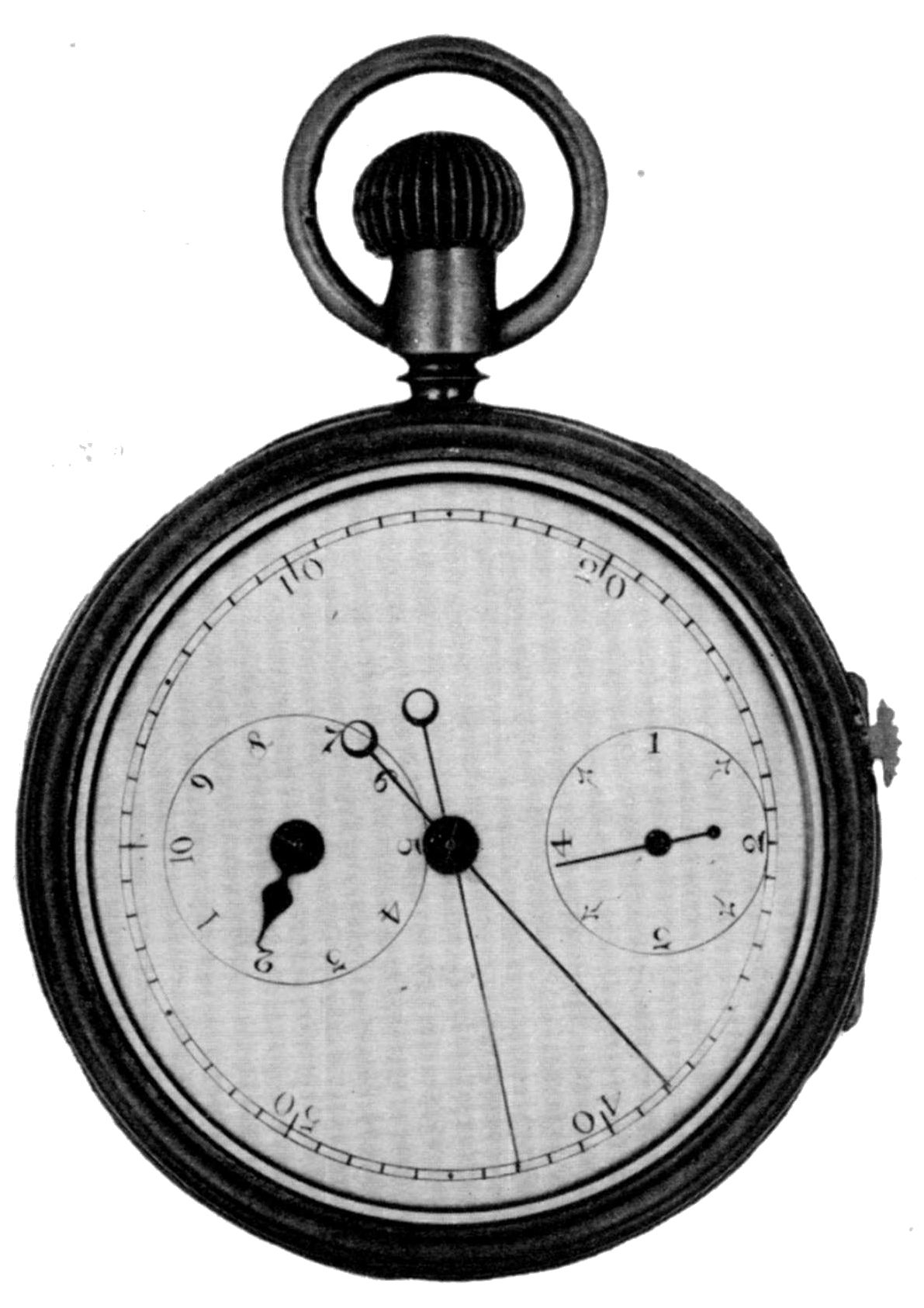
Figure 20 (left).—Auburndale Timer With Split Second Hand. Note the stop and start lever for the “split” hand at the side of the case. (In author’s collection.)

Figure 21 (above).—Auburndale Three-Quarter Plate Watch, typical of both Lincoln and Bentley grades. (In author’s collection.)
Unfortunately Mr. Fowle had suffered so much loss through the watch venture and from other investments that he was forced to make an assignment of his personal estate. The watch company, without his support, was carrying too large a burden of debt to be self-supporting. In the fall of 1883 a voluntary assignment was made and the equipment was sold in February 1884.[48] The Newton directory of 1885 lists W. B. Fowle as a thermometer manufacturer on Woodbine Street, “house near.” His home, “Tanglewood,” was on Woodbine Street and perhaps the thermometer business was operating in one of the outbuildings. William A. Wales assigned to the Auburndale Watch Co. patent 276101, of December 4, 1883, covering details of a unit counter for keeping score in games, and for similar work. Among the relics in the author’s collection is a box bearing the label “Auburndale Counter, W. B. Fowle & Son, Auburndale, Mass.” These counters were packed two in a box, the box just mentioned being suitable to contain counters the size of the thermometer in figure 22. Figure 23 shows a larger counter measuring 4-1/2 inches in diameter. From this and the fact that Fowle as late as 1887, is carried in the Newton directory as a manufacturer of metallic thermometers, it seems that some attempt was made after dissolution of the watch company to carry on manufacturing, 67 or perhaps only the assembly on a small scale of parts previously manufactured. The Directory of 1889 lists Fowle as an accountant on Ash Street, Auburndale. He had bought this property in 1887, presumably after disposing of “Tanglewood” which now would be too large for his needs. In the editions of 1891 and 1893 he is listed as United States collector of internal revenue, with an office at the Post Office building, Boston. In 1895 he appears as an accountant at the same address and from then to his death in 1902 he is listed as an accountant at his home address in Auburndale.
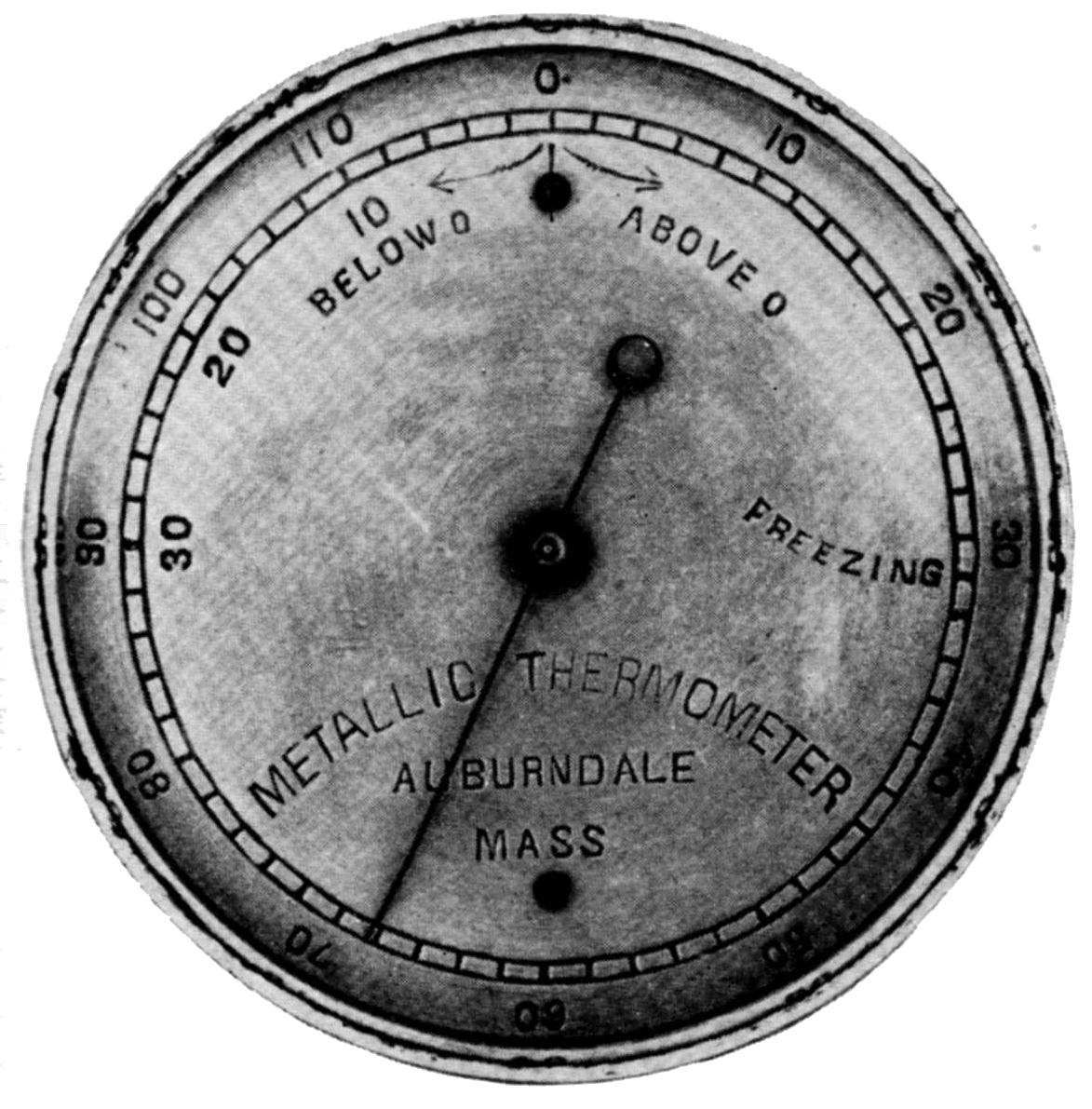
Figure 22 (above).—Auburndale Thermometer, about 1-3/4 inches in diameter. (In author’s collection.)
Jason R. Hopkins, inventor of the first Auburndale product, passed away in Washington late the same year, 1902, having spent all the intervening years as a watchmaker.
The life of a pioneer has always been arduous. The story we have just reviewed illustrates this. Hopkins was a successful workman with clever and novel ideas. Fowle had been very successful in an entirely unrelated field. Wales had been very successful in importing and selling watches but the watch factory which he had owned in part had failed, the fault more probably that of the times than of the man. The various superintendents and foremen were first-class men with ample background in making conventional watches. At the time no one could have had experience in manufacturing exactly the grade and type of watch being attempted, for this was the pioneer effort.

Figure 23 (right).—Auburndale Counter. Pressure on the projecting stem indexes the inner dial, showing through the window, at the same time ringing a bell. This dial is numbered from zero through six. The outside hand is held in place by friction and is manually set as desired. There is no connection with the inner mechanism.
The country was in the grip of a long, lingering depression following the Civil War. Money was tight. The Auburndale Rotary was conceived as a very low priced watch which would at the same time include the desirable and unusual feature of close timekeeping. Could these ideals have been adhered to, there is little reason to question that it would have found a market, even in hard times.
We have seen that every effort to improve the original watch added to its cost, and here lies the real reason why it failed to win acceptance. By the time it reached the market it was no longer priced below conventional watches and at least some specimens were not reliable in performance. To make matters even worse, the best features of Hopkins’ rotary watch had been incorporated by Locke and Merritt into a competing rotary watch much better engineered for cheap mass production.
At this point the only hope for the factory seemed to be the manufacture of some other watch or similar small mechanism. The Auburndale timer, with the exception perhaps of the split-second model, was a triumph mechanically and it returned a profit, but not enough to meet the financial needs of its sponsors. Much the same may be said of all the later Auburndale products.
The rotary had been of doubtful value when Flowe bought it, and the new organization was not able to contribute the necessary manufacturing engineering to make it a successful product. By the time this necessity was recognized, debts had mounted to the point where later products, which might have been successful on their own, were not able to carry the burden. The whole affair can be viewed as a very expensive educational adventure from which the students were not able to salvage enough to put their education to any use.
Surely they received a clear illustration of how dangerous it can be to engage in an enterprise without sufficient background or a long and careful study of design, manufacturing processes, costs, and market and sales analysis. For although numerous fortunes have been made in watch manufacturing, many more have been lost, and often those who put every effort at their command into such ventures came away with only sad experience as their reward. Thus ended the story of the Auburndale Watch Company.
Those who have seen the Waterbury watch, which developed from this design, may be drawn to the conclusion that this explains why it took so long to wind the Waterbury. Such is not really the case; in the Waterbury the winding wheel (which is on the outer rim of the barrel) was nearly as large as the inside diameter of the case while the pinion engaging with it was of only nominal diameter. This meant that one turn of the winding crown wound the barrel a much smaller fraction of a revolution than in a watch of conventional design.
Hopkins is not in the Washington and Georgetown directory of 1860 or 1862, and 1861 was not available to check. Starting with 1863 he is listed each year through 1871. Starting with 1872 Boyd’s Directory of the District of Columbia lists Hopkins as a resident each year (including 1902, the year of his death at 84 years) except 1877, when he was out of the city in connection with the exploitation of his rotary watch patents. Carl W. Drepperd, American clocks and clockmakers (Garden City, N.Y., 1947), in referring to Hopkins, says, “Lincoln, Me. 1840’s-1850’s: Bangor, Me., to 1862. Inventor of the Auburndale Watch. Also manufactured pianos and clock cases.”
Chas. S. Crossman, “A complete history of watch and clock making in America,” Jewelers Circular and Horological Review, January 1888, pp. 400, 401. This history ran as a continuing series of short articles appearing over a period of years. In his sketch of the Waterbury Watch Co., Crossman gives the name as William D. Coates, a name not found in Boyd’s Directory of the District of Columbia for 1875. The directory does, however, contain the name of William D. Colt, a patent attorney.
William B. Fowle’s “Cash book,” commenced January 1, 1873, and closed February 21, 1882, plus “Cash Book #5 Leaves 1 to 20 inclusive. All that were used up to my failure on August 4, 1883,” are in the author’s possession. They contain many entries on the “Watch Adventure” and later “Aub Watch Co.” mixed in with other entries referring to everything from killing pigs to extensive stock, bond, and real estate transactions.
U. S. Patent Office digest of assignments, vol. H9V, p. 13, stored at Franconia, Virginia, Accession no. 57A393.
August 26, 1876, p. 2., under the heading of Waltham Items, “Signs of a revival of business at the Watch Works in Waltham.”
Records of Veterans Administration, pension application 666 675, National Archives, Washington, D. C.
U. S. patent 65208, issued May 28, 1867, all rights assigned to Giles, Wales and Co., March 4, 1867 and recorded March 8, 1867, at U. S. Patent Office, liber G9, p. 100.
The sources used were Crossman, op. cit. (footnote 8), December 1887; Henry G. Abbot, Watch factories of America, Chicago, 1888, pp. 93-95; Newton directory for 1875, 1877, 1879, 1881, 1883, 1884-85, and 1885; Waltham-Watertown directory for 1877-78, 1880, 1882, 1884; and William B. Fowle, “Cash book” (see footnote 14).
U. S. patents 161513, applied for November 13, 1873, issued March 30, 1875; 165830, applied for July 14, 1875, issued July 20, 1875; 165831, applied for June 9, 1875, issued July 20, 1875; 179019, applied for May 25, 1876, issued June 20, 1876; and 186838, applied for January 12, 1876, issued January 30, 1877. A French patent was issued to Hopkins on September 12, 1876, and a Belgian patent on September 30, 1876. For lack of records neither has been positively identified but presumably they are for the same device covered in U. S. patent 179019.
No. 46 courtesy of the late C. A. Ilbert (this watch is now in the Science Museum, South Kensington, London); 124, 176, 224, 241 in the author’s collection; 161 Abbot, op cit. (footnote 29); 250 Henry Ford Museum, Dearborn, Michigan; 361 F. Earl Hackett; 387 Dr. Alfred G. Cossidente; 403 Dr. W. B. Stephens; 423 Crossman, op cit. (footnote 8); and an unnumbered movement illustrated in American Jeweler, December 1898, vol. 17, no. 12, p. 371.
U. S. patent 204400. The text of this patent speaks of dividing the second into “halves, quarters, eighths, etc.” and in the summation of claims of “an escape wheel, A, provided with one or more pairs of pins...” showing that measuring tenths of a second with a five-pin escape wheel was not conceived at this time. It is interesting to note that in referring to the drawings shown in figure 12 the text states “In the present instance two pairs of pins are used to denote quarter seconds.” Only one pair of pins is shown, which is correct. This seems, however, to reflect carelessness on the part of patent attorneys and examiners, as the error exists in the original manuscript patent application preserved in the National Archives, Washington, D. C.
U. S. patent 216917, issued to William A. Wales and assigned to William B. Fowle, was applied for on November 1, 1878, after the device was already in use on earlier specimens of these watches.
The mechanism was also covered by British patent 3893, issued September 27, 1879, to Philip Syng Justice on behalf of William B. Fowle.
Records of Veterans Administration, pension application WE 666 675 of Mary E. Fowle (widow of William B. Fowle).
Each model of watch made at Auburndale was numbered in its own series, starting at number 1, contrary to the usual watch factory practice where blocks of serial numbers are assigned to different models. Other Auburndale products seem not to have borne serial numbers.
End of Project Gutenberg's The Auburndale Watch Company, by Edwin A. Battison

*** END OF THIS PROJECT GUTENBERG EBOOK THE AUBURNDALE WATCH COMPANY ***

***** This file should be named 29934-h.htm or 29934-h.zip *****
This and all associated files of various formats will be found in:
        http://www.gutenberg.org/2/9/9/3/29934/

Produced by Chris Curnow, ronnie sahlberg, Joseph Cooper
and the Online Distributed Proofreading Team at
http://www.pgdp.net


Updated editions will replace the previous one--the old editions
will be renamed.

Creating the works from public domain print editions means that no
one owns a United States copyright in these works, so the Foundation
(and you!) can copy and distribute it in the United States without
permission and without paying copyright royalties.  Special rules,
set forth in the General Terms of Use part of this license, apply to
copying and distributing Project Gutenberg-tm electronic works to
protect the PROJECT GUTENBERG-tm concept and trademark.  Project
Gutenberg is a registered trademark, and may not be used if you
charge for the eBooks, unless you receive specific permission.  If you
do not charge anything for copies of this eBook, complying with the
rules is very easy.  You may use this eBook for nearly any purpose
such as creation of derivative works, reports, performances and
research.  They may be modified and printed and given away--you may do
practically ANYTHING with public domain eBooks.  Redistribution is
subject to the trademark license, especially commercial
redistribution.


*** START: FULL LICENSE ***

THE FULL PROJECT GUTENBERG LICENSE
PLEASE READ THIS BEFORE YOU DISTRIBUTE OR USE THIS WORK

To protect the Project Gutenberg-tm mission of promoting the free
distribution of electronic works, by using or distributing this work
(or any other work associated in any way with the phrase "Project
Gutenberg"), you agree to comply with all the terms of the Full Project
Gutenberg-tm License (available with this file or online at
http://gutenberg.org/license).


Section 1.  General Terms of Use and Redistributing Project Gutenberg-tm
electronic works

1.A.  By reading or using any part of this Project Gutenberg-tm
electronic work, you indicate that you have read, understand, agree to
and accept all the terms of this license and intellectual property
(trademark/copyright) agreement.  If you do not agree to abide by all
the terms of this agreement, you must cease using and return or destroy
all copies of Project Gutenberg-tm electronic works in your possession.
If you paid a fee for obtaining a copy of or access to a Project
Gutenberg-tm electronic work and you do not agree to be bound by the
terms of this agreement, you may obtain a refund from the person or
entity to whom you paid the fee as set forth in paragraph 1.E.8.

1.B.  "Project Gutenberg" is a registered trademark.  It may only be
used on or associated in any way with an electronic work by people who
agree to be bound by the terms of this agreement.  There are a few
things that you can do with most Project Gutenberg-tm electronic works
even without complying with the full terms of this agreement.  See
paragraph 1.C below.  There are a lot of things you can do with Project
Gutenberg-tm electronic works if you follow the terms of this agreement
and help preserve free future access to Project Gutenberg-tm electronic
works.  See paragraph 1.E below.

1.C.  The Project Gutenberg Literary Archive Foundation ("the Foundation"
or PGLAF), owns a compilation copyright in the collection of Project
Gutenberg-tm electronic works.  Nearly all the individual works in the
collection are in the public domain in the United States.  If an
individual work is in the public domain in the United States and you are
located in the United States, we do not claim a right to prevent you from
copying, distributing, performing, displaying or creating derivative
works based on the work as long as all references to Project Gutenberg
are removed.  Of course, we hope that you will support the Project
Gutenberg-tm mission of promoting free access to electronic works by
freely sharing Project Gutenberg-tm works in compliance with the terms of
this agreement for keeping the Project Gutenberg-tm name associated with
the work.  You can easily comply with the terms of this agreement by
keeping this work in the same format with its attached full Project
Gutenberg-tm License when you share it without charge with others.

1.D.  The copyright laws of the place where you are located also govern
what you can do with this work.  Copyright laws in most countries are in
a constant state of change.  If you are outside the United States, check
the laws of your country in addition to the terms of this agreement
before downloading, copying, displaying, performing, distributing or
creating derivative works based on this work or any other Project
Gutenberg-tm work.  The Foundation makes no representations concerning
the copyright status of any work in any country outside the United
States.

1.E.  Unless you have removed all references to Project Gutenberg:

1.E.1.  The following sentence, with active links to, or other immediate
access to, the full Project Gutenberg-tm License must appear prominently
whenever any copy of a Project Gutenberg-tm work (any work on which the
phrase "Project Gutenberg" appears, or with which the phrase "Project
Gutenberg" is associated) is accessed, displayed, performed, viewed,
copied or distributed:

This eBook is for the use of anyone anywhere at no cost and with
almost no restrictions whatsoever.  You may copy it, give it away or
re-use it under the terms of the Project Gutenberg License included
with this eBook or online at www.gutenberg.org

1.E.2.  If an individual Project Gutenberg-tm electronic work is derived
from the public domain (does not contain a notice indicating that it is
posted with permission of the copyright holder), the work can be copied
and distributed to anyone in the United States without paying any fees
or charges.  If you are redistributing or providing access to a work
with the phrase "Project Gutenberg" associated with or appearing on the
work, you must comply either with the requirements of paragraphs 1.E.1
through 1.E.7 or obtain permission for the use of the work and the
Project Gutenberg-tm trademark as set forth in paragraphs 1.E.8 or
1.E.9.

1.E.3.  If an individual Project Gutenberg-tm electronic work is posted
with the permission of the copyright holder, your use and distribution
must comply with both paragraphs 1.E.1 through 1.E.7 and any additional
terms imposed by the copyright holder.  Additional terms will be linked
to the Project Gutenberg-tm License for all works posted with the
permission of the copyright holder found at the beginning of this work.

1.E.4.  Do not unlink or detach or remove the full Project Gutenberg-tm
License terms from this work, or any files containing a part of this
work or any other work associated with Project Gutenberg-tm.

1.E.5.  Do not copy, display, perform, distribute or redistribute this
electronic work, or any part of this electronic work, without
prominently displaying the sentence set forth in paragraph 1.E.1 with
active links or immediate access to the full terms of the Project
Gutenberg-tm License.

1.E.6.  You may convert to and distribute this work in any binary,
compressed, marked up, nonproprietary or proprietary form, including any
word processing or hypertext form.  However, if you provide access to or
distribute copies of a Project Gutenberg-tm work in a format other than
"Plain Vanilla ASCII" or other format used in the official version
posted on the official Project Gutenberg-tm web site (www.gutenberg.org),
you must, at no additional cost, fee or expense to the user, provide a
copy, a means of exporting a copy, or a means of obtaining a copy upon
request, of the work in its original "Plain Vanilla ASCII" or other
form.  Any alternate format must include the full Project Gutenberg-tm
License as specified in paragraph 1.E.1.

1.E.7.  Do not charge a fee for access to, viewing, displaying,
performing, copying or distributing any Project Gutenberg-tm works
unless you comply with paragraph 1.E.8 or 1.E.9.

1.E.8.  You may charge a reasonable fee for copies of or providing
access to or distributing Project Gutenberg-tm electronic works provided
that

- You pay a royalty fee of 20% of the gross profits you derive from
     the use of Project Gutenberg-tm works calculated using the method
     you already use to calculate your applicable taxes.  The fee is
     owed to the owner of the Project Gutenberg-tm trademark, but he
     has agreed to donate royalties under this paragraph to the
     Project Gutenberg Literary Archive Foundation.  Royalty payments
     must be paid within 60 days following each date on which you
     prepare (or are legally required to prepare) your periodic tax
     returns.  Royalty payments should be clearly marked as such and
     sent to the Project Gutenberg Literary Archive Foundation at the
     address specified in Section 4, "Information about donations to
     the Project Gutenberg Literary Archive Foundation."

- You provide a full refund of any money paid by a user who notifies
     you in writing (or by e-mail) within 30 days of receipt that s/he
     does not agree to the terms of the full Project Gutenberg-tm
     License.  You must require such a user to return or
     destroy all copies of the works possessed in a physical medium
     and discontinue all use of and all access to other copies of
     Project Gutenberg-tm works.

- You provide, in accordance with paragraph 1.F.3, a full refund of any
     money paid for a work or a replacement copy, if a defect in the
     electronic work is discovered and reported to you within 90 days
     of receipt of the work.

- You comply with all other terms of this agreement for free
     distribution of Project Gutenberg-tm works.

1.E.9.  If you wish to charge a fee or distribute a Project Gutenberg-tm
electronic work or group of works on different terms than are set
forth in this agreement, you must obtain permission in writing from
both the Project Gutenberg Literary Archive Foundation and Michael
Hart, the owner of the Project Gutenberg-tm trademark.  Contact the
Foundation as set forth in Section 3 below.

1.F.

1.F.1.  Project Gutenberg volunteers and employees expend considerable
effort to identify, do copyright research on, transcribe and proofread
public domain works in creating the Project Gutenberg-tm
collection.  Despite these efforts, Project Gutenberg-tm electronic
works, and the medium on which they may be stored, may contain
"Defects," such as, but not limited to, incomplete, inaccurate or
corrupt data, transcription errors, a copyright or other intellectual
property infringement, a defective or damaged disk or other medium, a
computer virus, or computer codes that damage or cannot be read by
your equipment.

1.F.2.  LIMITED WARRANTY, DISCLAIMER OF DAMAGES - Except for the "Right
of Replacement or Refund" described in paragraph 1.F.3, the Project
Gutenberg Literary Archive Foundation, the owner of the Project
Gutenberg-tm trademark, and any other party distributing a Project
Gutenberg-tm electronic work under this agreement, disclaim all
liability to you for damages, costs and expenses, including legal
fees.  YOU AGREE THAT YOU HAVE NO REMEDIES FOR NEGLIGENCE, STRICT
LIABILITY, BREACH OF WARRANTY OR BREACH OF CONTRACT EXCEPT THOSE
PROVIDED IN PARAGRAPH F3.  YOU AGREE THAT THE FOUNDATION, THE
TRADEMARK OWNER, AND ANY DISTRIBUTOR UNDER THIS AGREEMENT WILL NOT BE
LIABLE TO YOU FOR ACTUAL, DIRECT, INDIRECT, CONSEQUENTIAL, PUNITIVE OR
INCIDENTAL DAMAGES EVEN IF YOU GIVE NOTICE OF THE POSSIBILITY OF SUCH
DAMAGE.

1.F.3.  LIMITED RIGHT OF REPLACEMENT OR REFUND - If you discover a
defect in this electronic work within 90 days of receiving it, you can
receive a refund of the money (if any) you paid for it by sending a
written explanation to the person you received the work from.  If you
received the work on a physical medium, you must return the medium with
your written explanation.  The person or entity that provided you with
the defective work may elect to provide a replacement copy in lieu of a
refund.  If you received the work electronically, the person or entity
providing it to you may choose to give you a second opportunity to
receive the work electronically in lieu of a refund.  If the second copy
is also defective, you may demand a refund in writing without further
opportunities to fix the problem.

1.F.4.  Except for the limited right of replacement or refund set forth
in paragraph 1.F.3, this work is provided to you 'AS-IS' WITH NO OTHER
WARRANTIES OF ANY KIND, EXPRESS OR IMPLIED, INCLUDING BUT NOT LIMITED TO
WARRANTIES OF MERCHANTIBILITY OR FITNESS FOR ANY PURPOSE.

1.F.5.  Some states do not allow disclaimers of certain implied
warranties or the exclusion or limitation of certain types of damages.
If any disclaimer or limitation set forth in this agreement violates the
law of the state applicable to this agreement, the agreement shall be
interpreted to make the maximum disclaimer or limitation permitted by
the applicable state law.  The invalidity or unenforceability of any
provision of this agreement shall not void the remaining provisions.

1.F.6.  INDEMNITY - You agree to indemnify and hold the Foundation, the
trademark owner, any agent or employee of the Foundation, anyone
providing copies of Project Gutenberg-tm electronic works in accordance
with this agreement, and any volunteers associated with the production,
promotion and distribution of Project Gutenberg-tm electronic works,
harmless from all liability, costs and expenses, including legal fees,
that arise directly or indirectly from any of the following which you do
or cause to occur: (a) distribution of this or any Project Gutenberg-tm
work, (b) alteration, modification, or additions or deletions to any
Project Gutenberg-tm work, and (c) any Defect you cause.


Section  2.  Information about the Mission of Project Gutenberg-tm

Project Gutenberg-tm is synonymous with the free distribution of
electronic works in formats readable by the widest variety of computers
including obsolete, old, middle-aged and new computers.  It exists
because of the efforts of hundreds of volunteers and donations from
people in all walks of life.

Volunteers and financial support to provide volunteers with the
assistance they need, are critical to reaching Project Gutenberg-tm's
goals and ensuring that the Project Gutenberg-tm collection will
remain freely available for generations to come.  In 2001, the Project
Gutenberg Literary Archive Foundation was created to provide a secure
and permanent future for Project Gutenberg-tm and future generations.
To learn more about the Project Gutenberg Literary Archive Foundation
and how your efforts and donations can help, see Sections 3 and 4
and the Foundation web page at http://www.pglaf.org.


Section 3.  Information about the Project Gutenberg Literary Archive
Foundation

The Project Gutenberg Literary Archive Foundation is a non profit
501(c)(3) educational corporation organized under the laws of the
state of Mississippi and granted tax exempt status by the Internal
Revenue Service.  The Foundation's EIN or federal tax identification
number is 64-6221541.  Its 501(c)(3) letter is posted at
http://pglaf.org/fundraising.  Contributions to the Project Gutenberg
Literary Archive Foundation are tax deductible to the full extent
permitted by U.S. federal laws and your state's laws.

The Foundation's principal office is located at 4557 Melan Dr. S.
Fairbanks, AK, 99712., but its volunteers and employees are scattered
throughout numerous locations.  Its business office is located at
809 North 1500 West, Salt Lake City, UT 84116, (801) 596-1887, email
business@pglaf.org.  Email contact links and up to date contact
information can be found at the Foundation's web site and official
page at http://pglaf.org

For additional contact information:
     Dr. Gregory B. Newby
     Chief Executive and Director
     gbnewby@pglaf.org


Section 4.  Information about Donations to the Project Gutenberg
Literary Archive Foundation

Project Gutenberg-tm depends upon and cannot survive without wide
spread public support and donations to carry out its mission of
increasing the number of public domain and licensed works that can be
freely distributed in machine readable form accessible by the widest
array of equipment including outdated equipment.  Many small donations
($1 to $5,000) are particularly important to maintaining tax exempt
status with the IRS.

The Foundation is committed to complying with the laws regulating
charities and charitable donations in all 50 states of the United
States.  Compliance requirements are not uniform and it takes a
considerable effort, much paperwork and many fees to meet and keep up
with these requirements.  We do not solicit donations in locations
where we have not received written confirmation of compliance.  To
SEND DONATIONS or determine the status of compliance for any
particular state visit http://pglaf.org

While we cannot and do not solicit contributions from states where we
have not met the solicitation requirements, we know of no prohibition
against accepting unsolicited donations from donors in such states who
approach us with offers to donate.

International donations are gratefully accepted, but we cannot make
any statements concerning tax treatment of donations received from
outside the United States.  U.S. laws alone swamp our small staff.

Please check the Project Gutenberg Web pages for current donation
methods and addresses.  Donations are accepted in a number of other
ways including checks, online payments and credit card donations.
To donate, please visit: http://pglaf.org/donate


Section 5.  General Information About Project Gutenberg-tm electronic
works.

Professor Michael S. Hart is the originator of the Project Gutenberg-tm
concept of a library of electronic works that could be freely shared
with anyone.  For thirty years, he produced and distributed Project
Gutenberg-tm eBooks with only a loose network of volunteer support.


Project Gutenberg-tm eBooks are often created from several printed
editions, all of which are confirmed as Public Domain in the U.S.
unless a copyright notice is included.  Thus, we do not necessarily
keep eBooks in compliance with any particular paper edition.


Most people start at our Web site which has the main PG search facility:

     http://www.gutenberg.org

This Web site includes information about Project Gutenberg-tm,
including how to make donations to the Project Gutenberg Literary
Archive Foundation, how to help produce our new eBooks, and how to
subscribe to our email newsletter to hear about new eBooks.