Gasoline and electricity have made possible the modern automobile. Each has its work to do in the operation of the car, and if either fails to perform its duties, the car cannot move. The action of the gasoline, and the mechanisms that control it are comparatively simple, and easily understood, because gasoline is something definite which we can see and feel, and which can be weighed, or measured in gallons. Electricity, on the other hand, is invisible, cannot be poured into cans or tanks, has no odor, and, therefore, nobody knows just what it is. We can only study the effects of electricity, and the wires, coils, and similar apparatus in which it is present. It is for this reason that an air of mystery surrounds electrical things, especially to the man who has not made a special study of the subject.
Without electricity, there would be no gasoline engine, because gasoline itself cannot cause the engine to operate. It is only when the electrical spark explodes or "ignites" the mixture of gasoline and air which has been drawn into the engine cylinders that the engine develops power. Thus an electrical ignition system has always been an essential part of every gasoline automobile.
The first step in the use of electricity on the automobile, in addition to the ignition system, consisted in the installation of an electric lighting system to replace the inconvenient oil or gas lamps which were satisfactory as far as the light they gave was concerned, but which had the disadvantage of requiring the driver to leave his seat, and light each lamp separately, often in a strong wind or rain which consumed many matches, time, and frequently spoiled his temper for the remainder of the evening. Electric lamps have none of these disadvantages. They can be controlled from the driver's seat, can be turned on or off by merely turning or pushing a switch-button, are not affected by wind or rain, do not smoke up the lenses, and do not send a stream of unpleasant odors back to the passengers.
The apparatus used to supply the electricity for the lamps consisted of a generator, or a "storage" battery, or both. The generator alone had the disadvantage that the lamps could be used only while the engine was running. The battery, on the other hand, furnished light at all times, but had to be removed from the car frequently, and "charged." With both the generator and battery, the lights could be turned on whether the engine was running or not, and, furthermore, it was no longer necessary to remove the battery to "charge," or put new life into it. With a generator and storage battery, moreover, a reliable source of electricity for ignition was provided, and so we find dry batteries and magnetos being discarded in a great many automobiles and "battery ignition" systems substituted.
The development of electric lighting systems increased the popularity of the automobile, but the motor car still had a great drawback-cranking. Owing to the peculiar features of a gasoline engine, it must first be put in motion by some external power before it will begin to operate under its own power. This made it necessary for the driver to "crank" the engine, or start it moving, by means of a handle attached to the engine shaft. Cranking a large engine is difficult, especially if it is cold, and often results in tired muscles, and soiled clothes and tempers. It also made it impossible for the average woman to drive a car because she did not have the strength necessary to "crank" an engine.
The next step in the perfection of the automobile was naturally the development of an automatic device to crank the engine, and thus make the driving of a car a pleasure rather than a task. We find, therefore, that in 1912, "self-starters" began to be used. These were not all electrical, some used tanks of compressed air, others acetylene, and various mechanical devices, such as the spring starters. The electrical starters, however, proved their superiority immediately, and filled such a long felt want that all the various makes of automobiles now have electric starters. The present day motor car, therefore, uses gasoline for the engine only, but uses electricity for ignition, starting, lighting, for the horn, cigar lighters, hand warmers on the steering wheel, gasoline vaporizers, and even for shifting speed changing gears, and for the brakes.
On any car that uses an electric lighting and starting system, there are two sources of electricity, the generator and the battery, These must furnish the power for the starting, or "cranking" motor, the ignition, the lights, the horn, and the other devices. The demands made upon the generator are comparatively light and simple, and no severe work is done by it. The battery, on the other hand is called upon to give a much more severe service, that of furnishing the power to crank the engine. It must also perform all the duties of the generator when the engine is not running, since a generator must be in motion in order to produce electricity.
A generator is made of iron, copper, carbon, and insulation. These are all solid substances which can easily be built in any size or shape, and which undergo very little change as parts of the generator. The battery is made mainly of lead, lead compounds, water and sulphuric acid. Here we have liquids as well as solids, which produce electricity by changes in their composition, resulting in complicated chemical as well as electrical actions.
The battery is, because of its construction and performance, a much abused, neglected piece of apparatus which is but partly understood, even by many electrical experts, for to understand it thoroughly requires a study of chemistry as well as of electricity. Knowledge of the construction and action of a storage battery is not enough to make anyone an expert battery man. He must also know how to regulate the operating conditions so as to obtain the best service from the battery, and he must be able to make complete repairs on any battery no matter what its condition may be.
CHAPTER 2.
BATTERIES IN GENERAL
There are two ways of "generating" electricity on the car: 1. Magnetically, 2. Chemically. The first method is that used in a generator, in which wires are rotated in a "field" in which magnetic forces act. The second method is that of the battery, and the one in which we are now interested.
If two unlike metals or conducting substances are placed in a liquid which causes a greater chemical change in one of the substances than in the other, an electrical pressure, or "electromotive" force is caused to exist between the two metals or conducting substances. The greater the difference in the chemical action on the substances, the greater will be the electrical pressure, and if the substances are connected together outside of the liquid by a wire or other conductor of electricity, an electric current will flow through the path or "circuit" consisting of the liquid, the two substances which are immersed in the liquid, and the external wire or conductor.
As the current flows through the combination of the liquid, and the substances immersed in it, which is called a voltaic "cell," one or both of the substances undergo chemical changes which continue until one of the substances is entirely changed. These chemical changes produce the electrical pressure which causes the current to flow, and the flow will continue until one or both of the substances are changed entirely. This change due to the chemical action may result in the formation of gases, or of solid compounds. If gases are formed they escape and are lost. If solids are formed, no material is actually lost.
Assuming that one of the conducting substances, or "electrodes," which are immersed in the liquid has been acted upon by the liquid, or "electrolyte," until no further chemical action can take place, our voltaic cell will no longer be capable of causing a flow of electricity. If none of the substances resulting from the original chemical action have been lost as gases, it may be possible to reverse the entire set of operations which have taken place. That is, suppose we now send a current through the cell from an outside source of electricity, in a direction opposite to that in which the current produced by the chemical action between the electrodes and electrolyte flowed. If this current now produces chemical actions between electrodes and electrolyte which are the reverse of those which occurred originally, so that finally we have the electrodes and electrolyte brought back to their original composition and condition, we have the cell just as it was before we used it for the production of an electrical pressure. The cell can now again be used as a source of electricity as long as the electrolyte acts upon the electrodes, or until it is "discharged" and incapable of any further production of electrical pressure. Sending a current through a discharged cell, so as to reverse the chemical actions which brought about the discharged conditions, is called "charging" the cell.
Cells in which an electrical pressure is produced as soon as the electrodes are immersed in the electrolyte are called it "primary" Cells. In these cells it is often impossible, and always unsatisfactory to reverse the chemical action as explained above. Cells whose chemical actions are reversible are called "storage" or "secondary" cells. In the "storage" cells used today, a current must first be sent through the cell in order to cause the chemical changes which result in putting the electrodes and electrolyte, in such a condition that they will be capable of producing an electrical pressure when the chemical changes caused by the current are complete. The cell now possesses all the characteristics of a primary cell, and may be used as a source of electricity until "discharged." It may then be "charged" again, and so on, the chemical action in one case causing a flow of current, and a reversed flow of current causing reversed chemical actions.
We see from the above that the "storage" battery does not "store" electricity at all, but changes chemical into electrical energy when "discharging," and changes electrical into chemical energy when "charging," the two actions being entirely reversible. The idea of "storing" electricity comes from the fact that if we send a current of electricity through the cell for a certain length of time, we can at a later time draw a current from the cell for almost the same length of time.
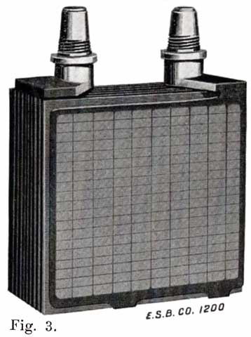
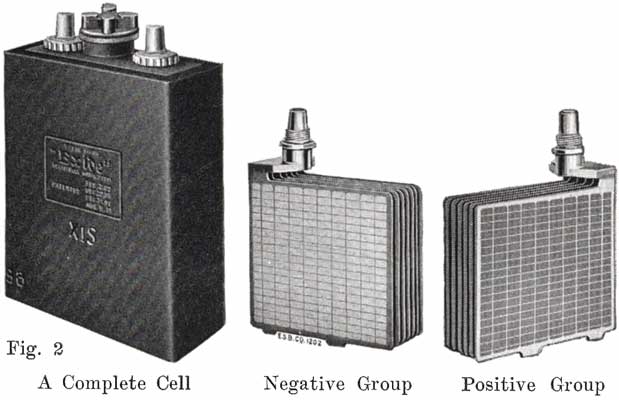
Fig. 3. A complete element, consisting of a positive and negative group of plates and seperators ready for placing in the har rubber jars.
Three things are therefore required in a storage cell, the liquid or "electrolyte" and two unlike substances or electrodes, through which a current of electricity can pass and which are acted upon by the electrolyte with a chemical action that is greater for one substance than the other. In the storage cell used on the automobile today for starting and lighting, the electrodes are lead and peroxide of lead, and the electrolyte is a mixture of sulphuric acid and water. The peroxide of lead electrode is the one upon which the electrolyte has the greater chemical effect, and it is called the positive or "+" electrode, because when the battery is sending a. current through an external circuit, the current flows from this electrode through the external circuit, and back to the lead electrode, which is called the negative, or electrode.
When starting and lighting systems were adopted in 1912, storage batteries had been used for many years in electric power stations. These were, however, large and heavy, and many difficult problems of design had to be solved in order to produce a battery capable of performing the work of cranking the engine, and yet be portable, light, and small enough to occupy only a very limited space on the automobile. As a result of these conditions governing the design, the starting and lighting battery of today is in reality "the giant that lives in a box." The Electric Storage Battery Company estimates that one of its types of batteries, which measures only 12-5/8 inches long, 7-3/8 wide, and 9-1/8 high, and weighs only 63-1/2 pounds, can deliver enough energy to raise itself to a height of 6 miles straight up in the air. It must be able to do its work quickly at all times, and in all sorts of weather, with temperatures ranging from below 0° to 100° Fahrenheit, or even higher.
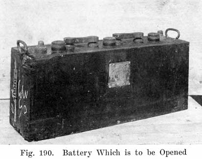
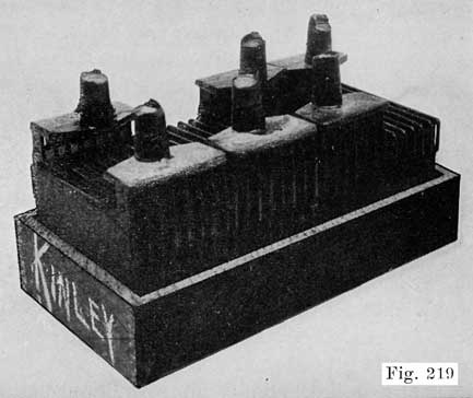
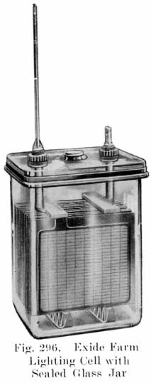
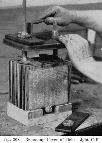
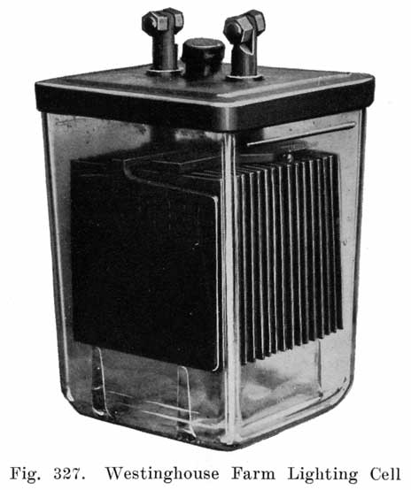
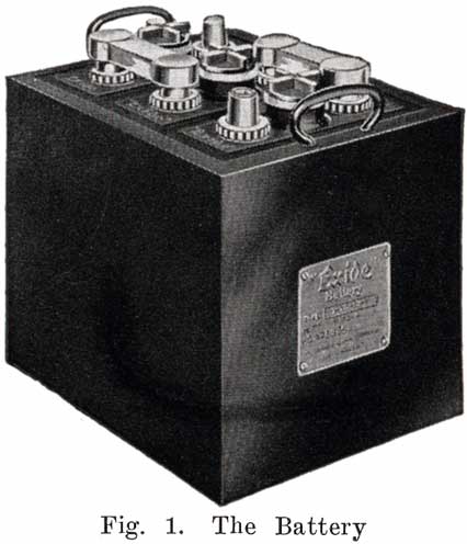
The starting and lighting battery has therefore been designed to withstand severe operating conditions. Looking at such a battery on a car we see a small wooden box in which are placed three or more "cells," see Fig. 1. Each "cell" has a hard, black rubber top through which two posts of lead project. Bars of lead connect the posts of one cell to those of the next. To one of the posts of each end cell is connected a cable which leads into the car, and through which the current leaves or enters the battery. At the center of each cell is a removable rubber plug covering an opening through which communication is established with the inside of the cell for the purpose of pouring in water, removing some of the electrolyte to determine the condition of the battery, or to allow gases formed within the cell to escape. Looking down through this opening we can see the things needed to form a storage battery: the electrolyte, and the electrodes or "plates" as they are called. If we should remove the lead bars connecting one cell to another, and take off the black cover, we should find that the posts which project out of the cells are attached to the plates which are broad and flat, and separated by thin pieces of wood or rubber., If we lift out the plates we find that they are connected alternately to the two lead posts, and that the two outside ones have a gray color. If we pull the plates out from each Other, we find that the plates next to the two outside ones, and all other plates connected to the same lead post as these have a chocolate-brown color. If we remove the jar of the cell, we find that it is made of hard rubber. Pouring out the electrolyte we find several ridges which hold the plates off the bottom of the jar. The pockets formed by these ridges may contain some soft, muddy substance. Thus we have exposed all the elements of a cell, —posts, plates, "separators," and electrolyte. The gray colored plates are attached to the "negative" battery post, while the chocolate-brown colored ones are connected to the "positive" battery post. Examination will show that each of the plates consists of a skeleton metallic framework which is filled with the brown or gray substances. This construction is used to decrease the weight of the battery. The gray filler material is pure lead in a condition called "spongy lead." The chocolate-brown filler substance is peroxide of lead.
We have found nothing but two sets of plates — one of pure lead, the other of peroxide of lead, and the electrolyte of sulphuric acid and water. These produce the heavy current necessary to crank the engine. How this is done, and what the chemical actions within the cell are, are described in Chapter 4.
CHAPTER 3.
MANUFACTURE OF STORAGE BATTERIES.
To supply the great number of batteries needed for gasoline automobiles, large companies have been formed. Each company has its special and secret processes which it will not reveal to the public. Only a few companies, however, supply batteries in any considerable quantities, the great majority of cars being supplied with batteries made by not more than five or six manufacturers. This greatly reduces the number of possible different designs in general use today.
The design and dimensions of batteries vary considerably, but the general constructions are similar. The special processes of the manufacturers are of no special interest to the repairman, and only a general description will be given here.
A starting and lighting battery consists of the following principal parts:
| 1. Plates | 5. Covers |
| 2. Separators | 6. Cell Connectors and |
| 3. Electrolyte | Terminals |
| 4. Jars | 7. Case |
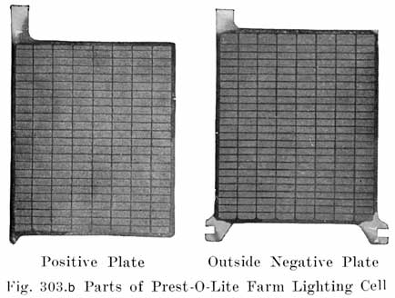
Plates
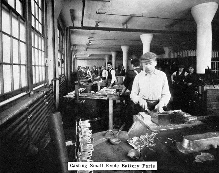
Of the two general types of battery plates, Faure and Plante, the Faure, or pasted type, is universally used on automobiles. In the manufacture of pasted plates there are several steps which we shall describe in the order in which they are carried out.
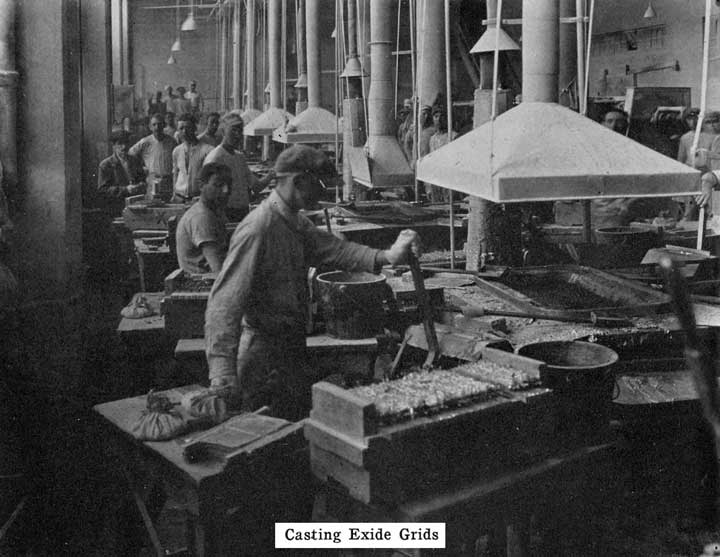
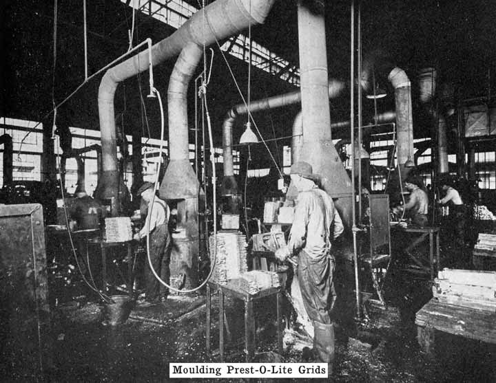
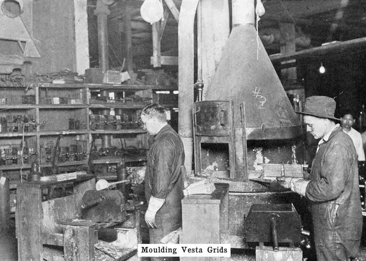
Casting the Grid. The grid is the skeleton of the plate. It performs the double function of supporting the mechanically weak active material and of conducting the current. It is made of a lead antimony alloy which is melted and poured into a mould. Pure lead is too soft and too easily attacked by the electrolyte, and antimony is added to give stiffness, and resistance to the action of the electrolyte in the cell. The amount of antimony used varies in different makes but probably averages 8 to 10%.
The casting process requires considerable skill, the proper composition of the metal and the temperature of both metal and moulds being of great importance in securing perfect grids, which are free from blowholes, and which have a uniform structure and composition. Some manufacturers cast two grids simultaneously in each mould, the two plates being joined to each other along the bottom edge.
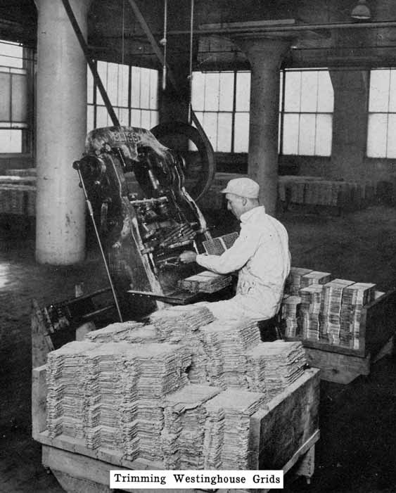
Trimming the Grids. When the castings have cooled, they are removed from the moulds and passed to a press or trimming machine which trims off the casting gate and the rough edges. The grids are given a rigid inspection, those having shrunken or missing ribs or other defects being rejected. The grids are now ready for pasting.
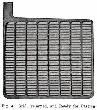
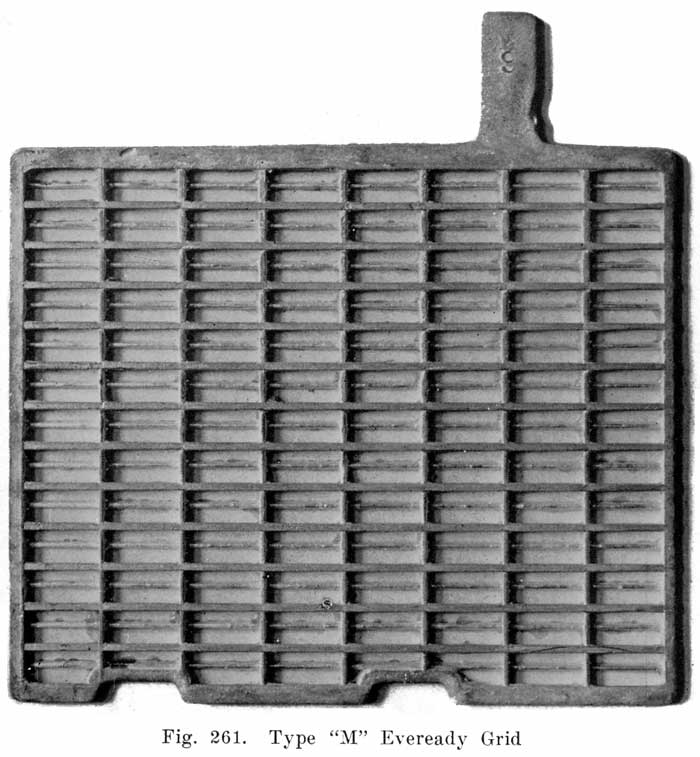
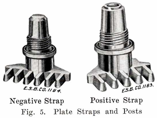
Fig. 4 shows a grid ready for pasting. The heavy lug at one upper corner is the conducting lug, for carrying the current to the strap, Fig. 5, into which the lugs are burned when the battery is assembled. The straps are provided with posts, to which the intercell connectors and terminal connectors are attached. The vertical ribs of the grids extend through the plate, providing mechanical strength and conductivity, while the small horizontal ribs are at the surface and in staggered relation on opposite faces. Both the outside frames and the vertical ribs are reinforced near the lug, where the greatest amount of current must be carried.
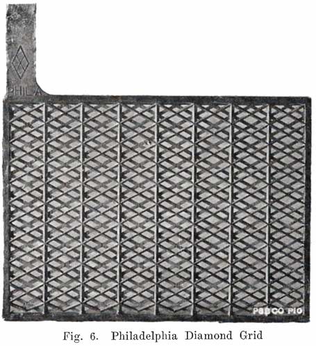
The rectangular arrangement of ribs, as shown in Fig. 4, is most generally used, although, there are other arrangements such as the Philadelphia "Diamond" grid in which the ribs form acute angles, giving diamond shaped openings, as shown in Fig. 6.
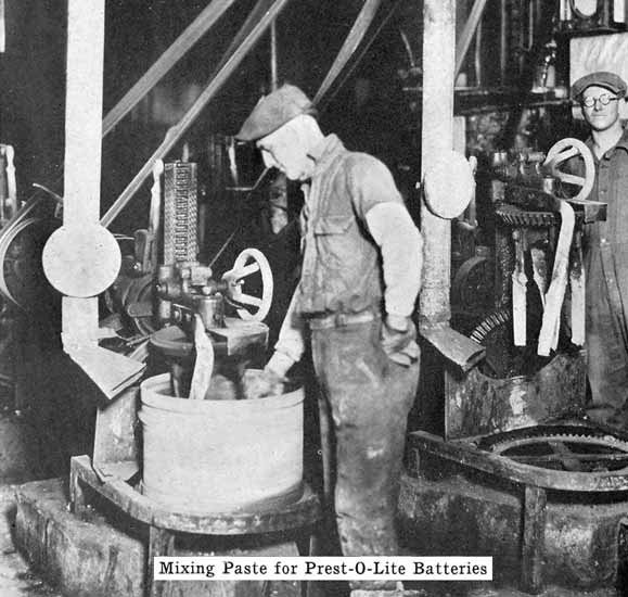
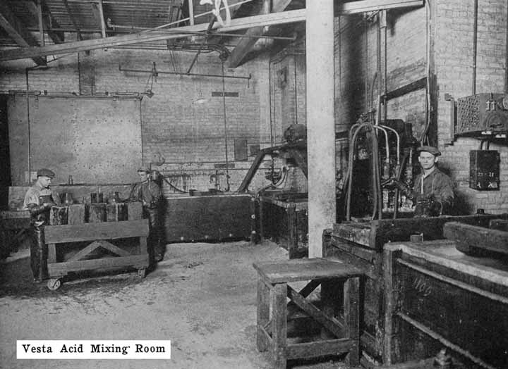
Pastes. There are many formulas for the pastes, which are later converted into active material, and each is considered a trade secret by the manufacturer using it. The basis of all, however, is oxide of lead, either Red Lead (Pb30 4), Litharge (PbO), or a mixture of the two, made into a paste with a liquid, such as dilute sulphuric acid. The object of mixing the oxides with the liquid is to form a paste of the proper consistency for application to the grids, and at the same time introduce the proper amount of binding, or setting agent which will give porosity, and which will bind together the active material, especially in the positive plate. Red lead usually predominates in the positive paste, and litharge in the negative, as this combination requires the least energy in forming the oxides to active material.
The oxides of lead used in preparing the pastes which are applied to the grids are powders, and in their dry condition could not be applied to the grids, as they would fall out. Mixing them with a liquid to make a paste gives them greater coherence and enables them to be applied to the grids. Sulphuric acid puts the oxides in the desired pasty condition, but has the disadvantage of causing a chemical action to take place which changes a considerable portion of the oxides to lead sulphate, the presence of which makes the paste stiff and impossible to apply to the grids. When acid is used, it is therefore necessary to work fast after the oxides are mixed with sulphuric acid to form the paste.
In addition to the lead oxides, the pastes may contain some binding material such as ammonium or magnesium sulphate, which tends to bind the particles of the active material together. The paste used for the negatives may contain lamp black to give porosity.
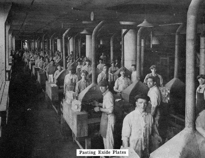
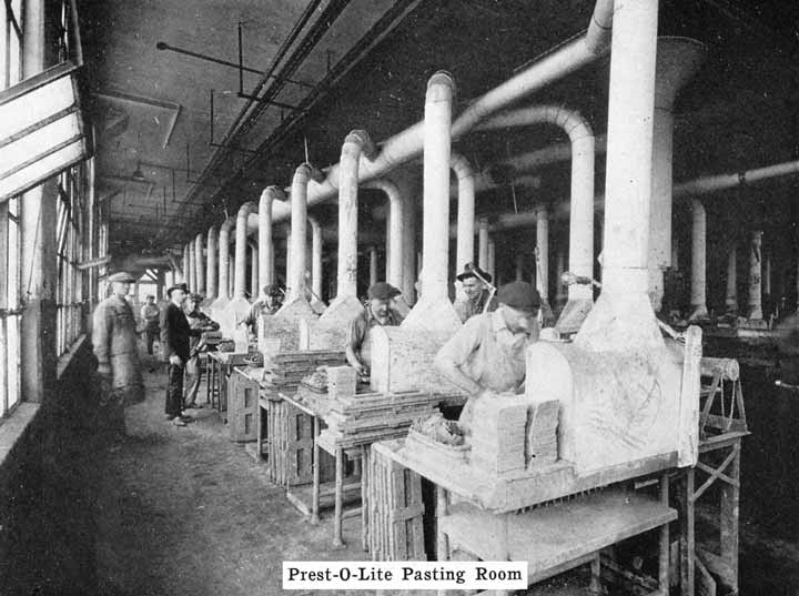
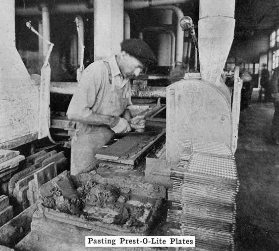
Applying the Paste. After the oxides are mixed to a paste they are applied to the grids. This is done either by hand, or by machine In the hand pasting process, the pastes are applied from each face of the grid by means of a wooden paddle or trowel, and are smoothed off flush with the surface of the ribs of the grid. This work is done quickly in order that the pastes may not stiffen before they are applied.
U. S. L. plates are pasted in a machine which applies the paste to the grid, subjecting it at the same time to a pressure which forces it thoroughly into the grid, and packs it in a dense mass.
Drying the Paste. The freshly pasted plates are now allowed to dry in the air, or are dried by blowing air over them. In any case, the pastes set to a hard mass, in which condition the pastes adhere firmly to the grids. The plates may then be handled without a loss of paste from the grids.
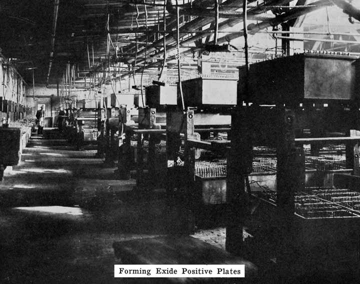
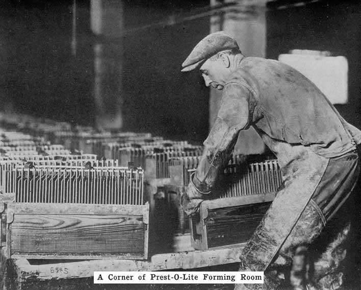
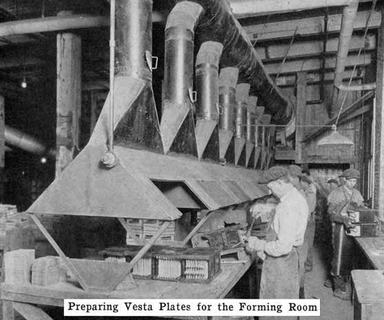
Forming. The next step is to change the paste of oxides into the active materials which make a cell operative. This is called "forming" and is really nothing but a prolonged charge, requiring several days. In some factories the plates are mounted in tanks, positive and negative plates alternating as in a cell. The positives are all connected together in one group and the negatives in another, and current passed through just as in charging a battery. In other factories the positives and negatives are formed in separate tanks against "dummy" electrodes.
The passing of the current slowly changes the mixtures of lead oxide and lead sulphate, forming brown peroxide of lead (PbO2), on the positive plate and gray spongy metallic lead on the negative. The formation by the current of lead peroxide and spongy lead on the positive and negative plates respectively would take place if the composition of the two pastes were identical. The difference in the composition of the paste for positive and negative plates is for the purpose of securing the properties of porosity and physical condition best suited to each.
![Fig. 7 Formed plate, ready to be burned to plate connecting strap]](images/fig007.jpg)
When the forming process is complete, the plates are washed and dried, and are then ready for use in the battery. If the grids of two plates have been cast together, as is done by some manufacturers, these are now cut apart, and the lugs cut to the proper height. The next step is to roll, or press the negatives after they are removed from the forming bath so as to bring the negative paste, which has become roughened by gassing that occurred during the forming process, flush with the surface of the ribs of the grid. A sufficient amount of sulphate is left in the plates to bind together the active material. Without this sulphate the positive paste would simply be a powder and when dry would fall out of the grids like dry dust. Fig. 7 shows a formed plate ready to be burned to the strap.
Separators
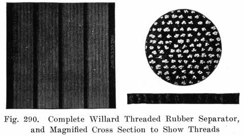
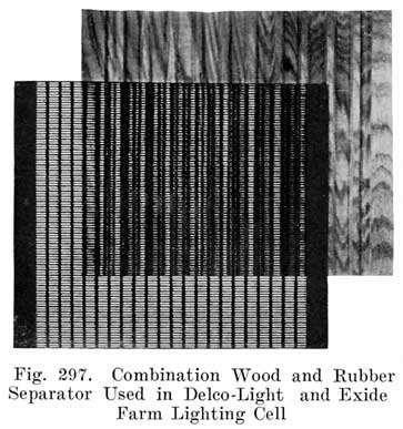
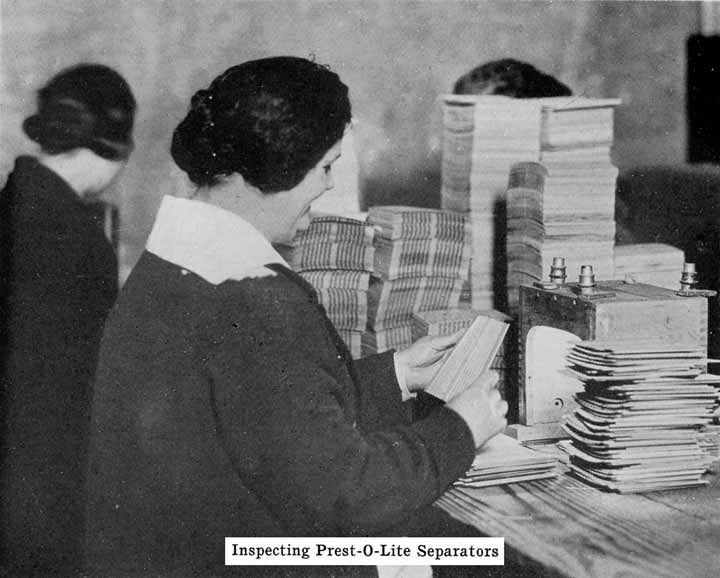
In batteries used both for starting and for lighting, separators made of specially treated wood are largely used. See Fig. 8. The Willard Company has adopted an insulator made of a rubber fabric pierced by thousands of cotton threads, each thread being as long as the separator is thick. The electrolyte is carried through these threads from one side of the separator to the other by capillary action, the great number of these threads insuring the rapid diffusion of electrolyte which is necessary in batteries which are subjected to the heavy discharge current required in starting.
In batteries used for lighting or ignition, sheets of rubber in which numerous holes have been drilled are also used, these holes permitting diffusion to take place rapidly enough to perform the required service satisfactorily, since the currents involved are much smaller than in starting motor service.
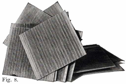
Fig 8. A Pile of Prepared Wooden Seperators Ready to be Put Between the Positive and Negative Plates to Form the Complete Element.
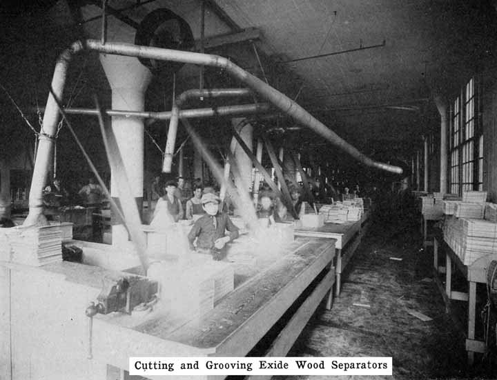
For the wooden separators, porous wood, such as Port Orford cedar, basswood, cypress, or cedar is used. Other woods such as redwood and cherry are also used. The question is often asked "which wood makes the best separators?" This is difficult to answer because the method of treating the wood is just as important as is the kind of wood. The wood for the separators is cut into strips of the correct thickness. These strips are passed through a grooving machine which cuts the grooves in one side, leaving the other side smooth. The strips are next sawed to the correct size, and are then boiled in a warm alkaline solution for about 24 hours to neutralize any organic acid, such as acetic acid, which the wood naturally contains. Such acids would cause unsatisfactory battery action and damage to the battery.
The Vesta separator, or "impregnated mat," is treated in a bath of Barium salts which form compounds with the wood and which are said to make the separators strong and acid-resisting.
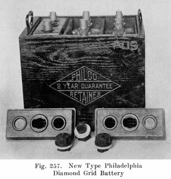
Some batteries use a double separator, one of which is the wooden separator, while the other consists of a thin sheet of hard rubber containing many fine perforations. This rubber sheet is placed between the positive plate and the wooden separator. A recent development in the use of an auxiliary rubber separator is the Philco slotted retainer which is placed between the separators and the positives in Philadelphia Diamond Grid Batteries. Some Exide batteries also use slotted rubber separators. The Philco slotted retainer consists of a thin sheet of slotted hard rubber as shown in Fig. 9. The purpose of the retainer is to hold the positive active material in place and prevent the shedding which usually occurs. The slots in the retainer are so numerous that they allow the free passage of electrolyte, but each slot is made very narrow so as to hold the active material in the plates.
Electrolyte
Little need be said here about the electrolyte, since a full description is given elsewhere. See page 222. Acid is received by the battery manufacturer in concentrated form. Its specific gravity is then 1.835. The acid commonly used is made by the "contact" process, in which sulphur dioxide is oxidized to sulphur trioxide, and then, with the addition of water, changed to sulphuric acid. The concentrated acid is diluted with distilled water to the proper specific gravity.
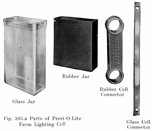
Jars
The jars which contain the plates, separators, and electrolyte are made of a tough, hard rubber compound. They are made either by the moulding process, or by wrapping sheets of rubber compound around metal mandrels. In either case the jar is subsequently vulcanized by careful heating at the correct temperature.
The battery manufacturers do not, as a rule, make their own jars, but have them made by the rubber companies who give the jars a high voltage test to detect any flaws, holes, or cracks which would subsequently cause a leak. The jars as received at the battery maker's factory are ready for use.
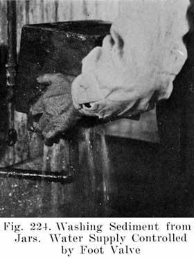
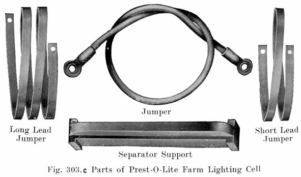
Across the bottom of the jar are several stiff ribs which extend up into the jar so as to provide a substantial support for the plates, and at the same time form several pockets below the plates in which the sediment resulting from shedding of active material from the plates accumulates.
Covers
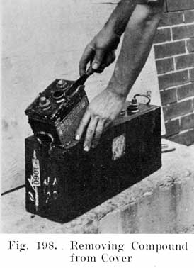
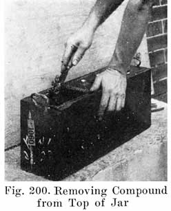
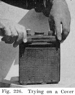
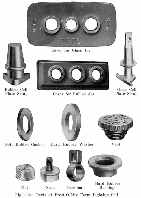
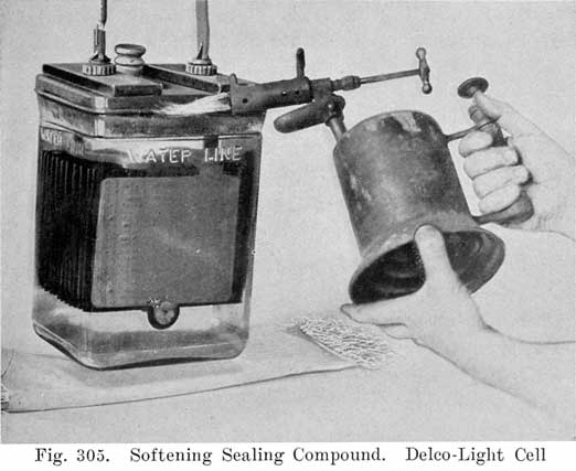
No part of a battery is of greater importance than the hard rubber cell covers, from the viewpoint of the repairman as well as the manufacturer. The repairman is concerned chiefly with the methods of sealing the battery, and no part of his work requires greater skill than the work on the covers. The manufacturers have developed special constructions, their aims being to design the cover so as to facilitate the escape of gas which accumulates in the upper part of a cell during charge, to provide space for expansion of the electrolyte as it becomes heated, to simplify inspection and filling with pure water, to make leak proof joints between the cover and the jar and between the cover and the lead posts which project through it, and to simplify the work of making repairs.
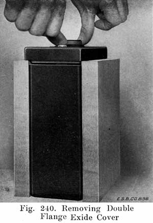
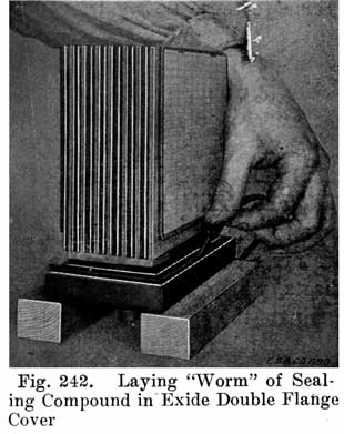
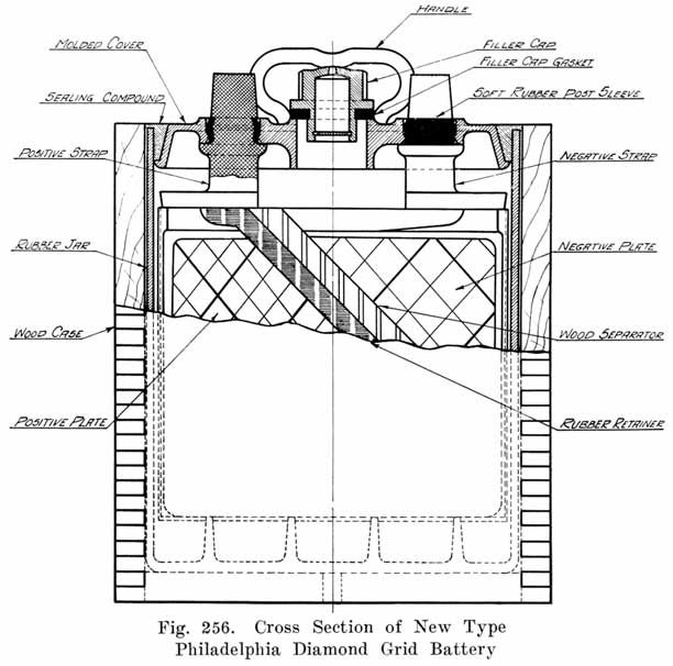
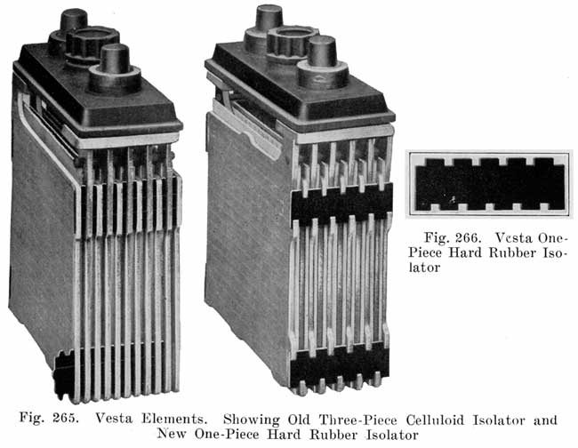
Single and Double Covers. Modern types of batteries have a single piece cover, the edges of which are made so as to form a slot or channel with the inside of the jar, into which is poured sealing compound to form a leak proof joint. This construction is illustrated. in Exide, Fig. 1.5; Vesta, Fig. 264; Philadelphia Diamond Grid, Fig. 256; U. S. L., Figs. 11 and 244; and Prest-0-Lite, Fig. 247, batteries. Exide batteries are also made with a double flange cover, in which the top of the jar fits between the two flanges. In single covers, a comparatively small amount of sealing compound is used, and repair work is greatly simplified.
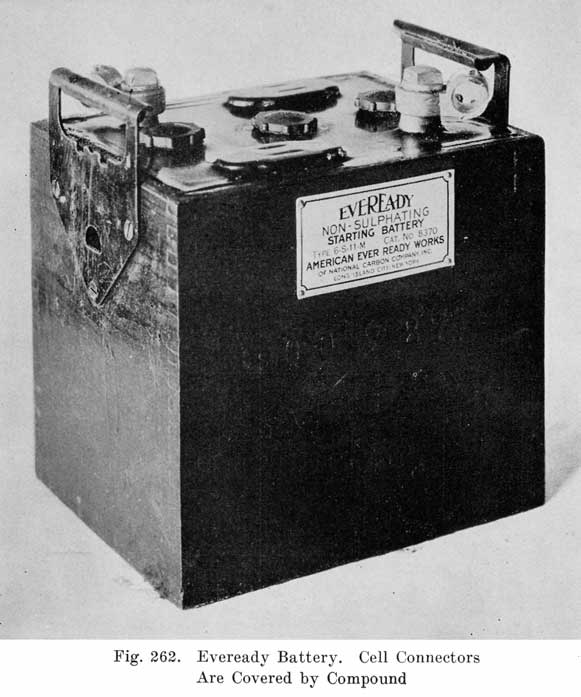
In the Eveready battery, Fig. 262, compound is poured over the entire cover instead of around the edges. This method requires a considerable amount of sealing compound.
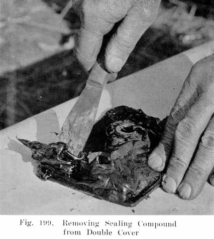
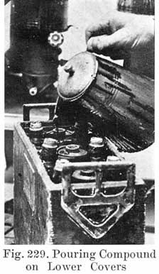
The use of double covers is not as common as it was some years ago. This construction makes use of two flat pieces of hard rubber. In such batteries a considerable amount of sealing compound is used. This compound is poured on top of the lower cover to seal the battery, the top cover serving to cover up the compound and brace the posts. Fig. 10 illustrates this construction.
Sealing Around the Posts. Much variety is shown in the methods used to secure a leak proof joint between the posts and the cover. Several methods are used. One of these uses the sealing compound to make a tight joint. Another has lead bushings which are screwed up into the cover or moulded in the cover, the bushings being burned together with the post and cell connector. Another method has a threaded post, and uses a lead alloy nut with a rubber washer to make a tight joint. Still another method forces a lead collar down over the post, and presses the cover down on a soft rubber gasket.
Using Sealing Compound. Some of the batteries which use sealing compound to make a tight joint between the cover and the post have a hard rubber bushing shrunk over the post. This construction is used in Gould batteries, as shown in Fig. 10, and in the old Willard double cover batteries. The rubber bushing is grooved horizontally to increase the length of the sealing surface.
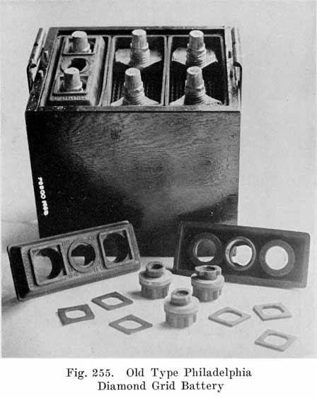
Other batteries that use sealing compound around the posts have grooves or "petticoats" cut directly in the post and have a well around the post into which the sealing compound is poured. This is the construction used in the old Philadelphia Diamond Grid battery, as shown in Fig. 254.
Using Lead Bushings. U. S. L. batteries have a flanged lead bushing which is moulded directly into the cover, as shown in Fig. 11. In assembling the battery, the cover is placed over the post, and the cell connector is burned to both post and bushing.
In older type U. S. L. batteries a bushing was screwed up through the cover, and then burned to the post and cell connector.
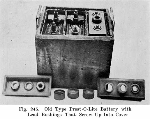
An old type Prest-O-Lite battery used a lead bushing which screwed up through the cover similarly to the U. S. L. batteries. Fig. 12 illustrates this construction. The SJWN and SJRN Willard Batteries used a lead insert. See page 424.
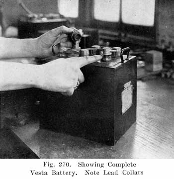
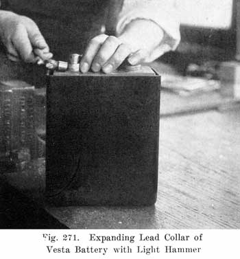
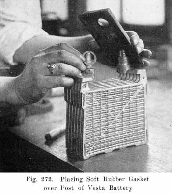
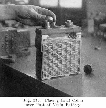
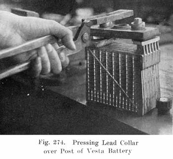
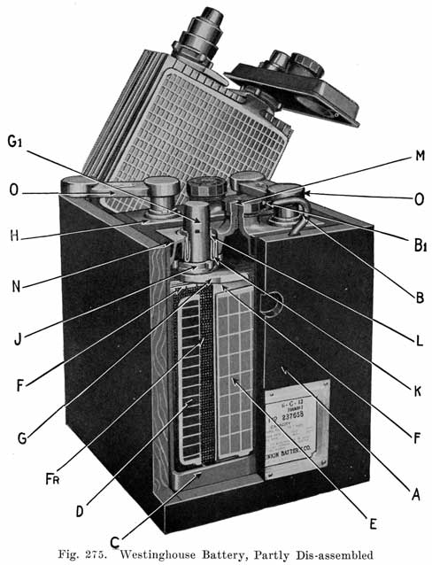
The modern Vesta batteries use a soft rubber gasket under the cover and force a lead collar over the post, which pushes the cover down on the gasket. The lead collar and post "freeze" together and make an acid proof joint. See page 413. The Westinghouse battery uses a three part seal consisting of a lead washer which is placed around the post, a U shaped, soft gum washer which is placed between the post and cover, and a tapered lead sleeve, which presses the washer against the post and the cover. See page 417.
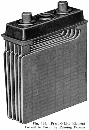
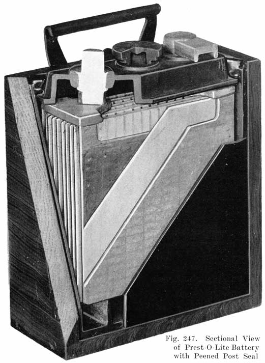
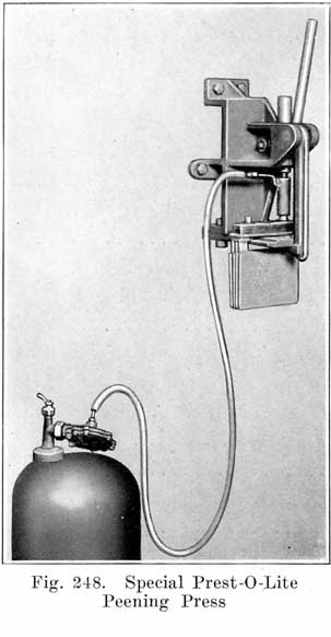
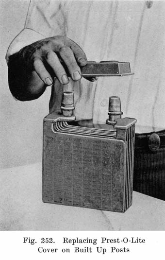
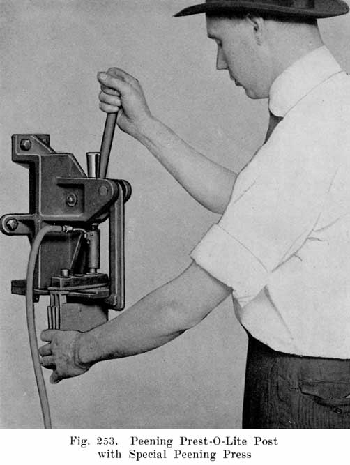
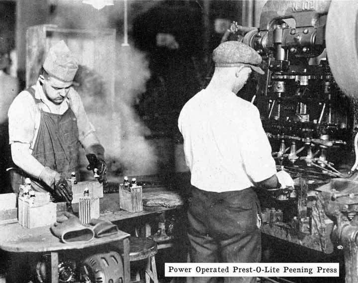
The Prest-O-Lite Peened Post Seal. All Prest-O-Lite batteries designated as types WHN, RHN, BHN and JFN, have a single moulded cover which is locked directly on to the posts. This is done by forcing a solid ring of lead from a portion of the post down into a chamfer in the top of the cover. This construction is illustrated in Fig. 247.
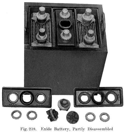
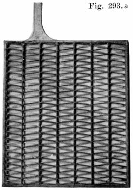
Batteries Using Sealing Nuts. The Exide batteries have threaded posts. A rubber gasket is placed under the cover on a shoulder on the post. The nut is then turned down on the post to force the cover on the gasket. This construction is illustrated in Fig. 239. The Titan battery uses a somewhat similar seal, as shown in Fig. 293.
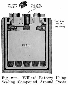
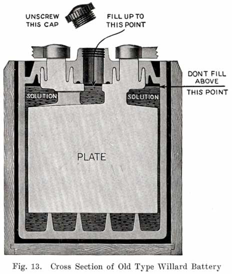
Some of the older Willard batteries have a chamfer or groove in the under, side of the cover. The posts have a ring of lead in the base which fits up into the groove in the cover to make a tight joint. This is illustrated in Fig. 13. The later Willard constructions, using a rubber gasket seal and a lead cover insert, are illustrated in Figs. 278 and 287.
Filling Tube or Vent Tube Construction. Quite a number of designs have been developed in the construction of the filling or vent tube. In double covers, the tube is sometimes a separate part which is screwed into the lower cover. In other batteries using double covers, the tube is an integral part of the cover, as shown in Fig. 10. In all single covers, the tube is moulded integral with the cover.
Several devices have been developed to make it impossible to overfill batteries. This has been done by the U. S. L. and Exide companies on older types of batteries, their constructions being described as follows:
In old U. S. L. batteries, a small auxiliary vent tube is drilled, as shown in Fig. 14. When filling to replace evaporation, this vent tube prevents overfilling.
A finger is placed over the auxiliary vent tube shown in Fig. 14. The water is then poured in through the filling or vent tube. When the water reaches the bottom of the tube, the air imprisoned in the expansion chamber can no longer escape. Consequently the water can rise no higher in this chamber, but simply fills up the tube. Water is added till it reaches the top of the tube. The finger is then removed from the vent tube. This allows the air to escape from the expansion chamber. The water will therefore fall in the filling or vent tube, and rise slightly in the expansion chamber. The construction makes it impossible to overfill the battery, provided that the finger is held on the vent hole as directed.
Figure 15 shows the Non-Flooding Vent and Filling Plug used in the older type Exide battery, and in the present type LXRV. The new Exide cover, which does not use the non-flooding feature, is also shown. The old construction is described as follows:
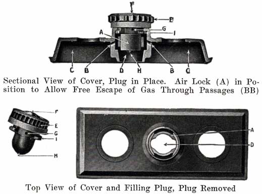
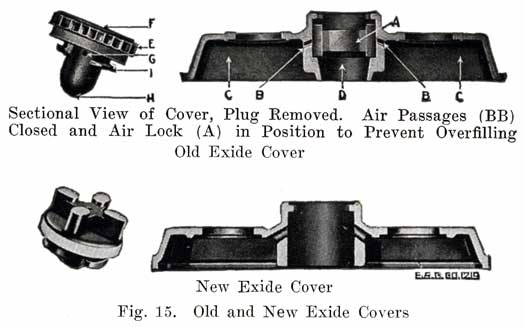
From the illustrations of the vent and filling plug, it will be seen that they provide both a vented stopper (vents F, G, H), and an automatic device for the preventing of overfilling and flooding. The amount of water that can be put into the cell is limited to the exact amount needed to replace that lost by evaporation. This is accomplished by means of the hard rubber valve (A) within the cell cover and with which the top of the vent plug (E) engages, as shown in the illustrations. The action of removing the plug (E) turns this valve (A), closing the air passage (BB), and forming an air tight chamber (C) in the top of the cell. When water is poured in, it cannot rise in this air space (C) so as to completely fill the cell. As soon as the proper level is reached, the water rises in the filling tube (D) and gives a positive indication that sufficient water has been added. Should, however, the filling be continued, the excess will be pure water only, not acid. On replacing the plug (E), valve (A) is automatically turned, opening the air passages (BB), leaving the air chamber (C) available for the expansion of the solution, which occurs when the battery is working.
Generally the filling or vent tube is so made that its lower end indicates the correct level of electrolyte above the plates, In adding water, the level of the electrolyte is brought up to the bottom of the filling tube. By looking down into the tube, it can be seen when the electrolyte reaches the bottom of the tube.
Vent Plugs, or Caps. Vent plugs, or caps, close up the filling or vent tubes in the covers. They are made of hard rubber, and either screw into or over the tubes, or are tightened by a full or partial turn, as is done in Exide batteries. In the caps are small holes which are so arranged that gases generated within the battery may escape, but acid spray cannot pass through these holes. It is of the utmost importance that the holes in the vent caps be kept open to allow the gases to escape.
Case
The wooden case in which the cells are placed is usually made of kiln dried white oak or hard maple. The wood is inspected carefully, and all pieces are rejected that are weather-checked, or contain worm-holes or knots. The wood is sawed into various thicknesses, and then cut to the proper lengths and widths. The wood is passed through other machines that cut in the dovetails, put the tongue on the bottom for the joints, stamp on the part number, drill the holes for the screws or bolts holding the handles, cut the grooves for the sealing compound, etc. The several pieces are then assembled and glued together. The finishing touches are then put on, these consisting of cutting the cases to the proper heights, sandpapering the boxes, etc. The cases are then inspected and are ready to be painted.
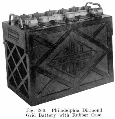
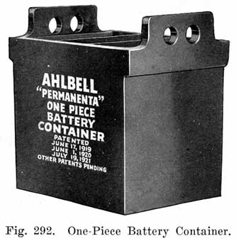
A more recent development in case construction is a one-piece hard rubber case, in which the jars and case are made in one piece, the cell compartments being formed by rubber partitions which form an integral part of the case. This construction is used in several makes of Radio "A" batteries, and to some extent in starting batteries.
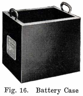
Asphaltum paint is generally used for wooden cases, the bottoms and tops being given three, coats, and the sides, two. The number of coats of paint varies, of course, in the different factories. The handles are then put on by machinery, and the case, Fig. 16, is complete, and ready for assembling.
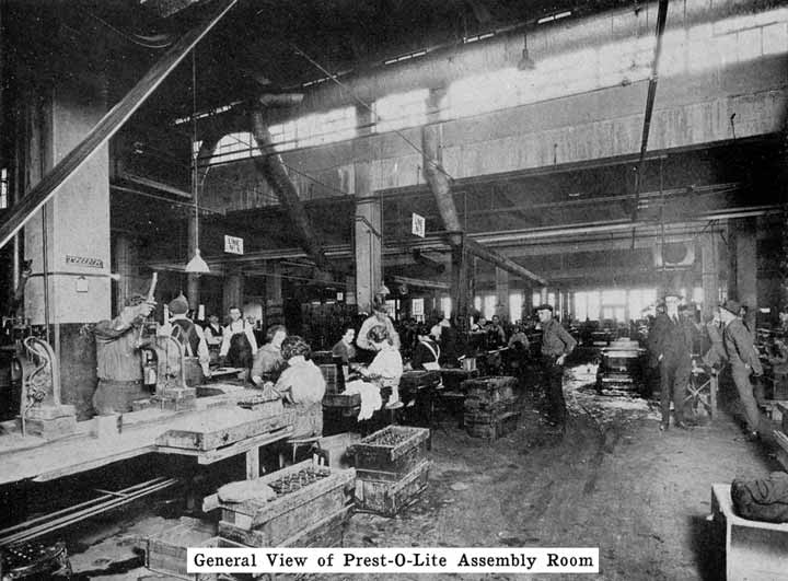
Assembling and Sealing
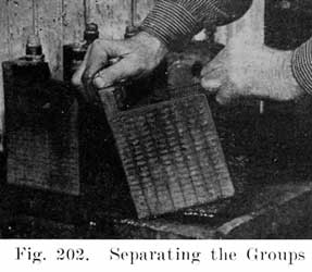
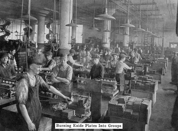
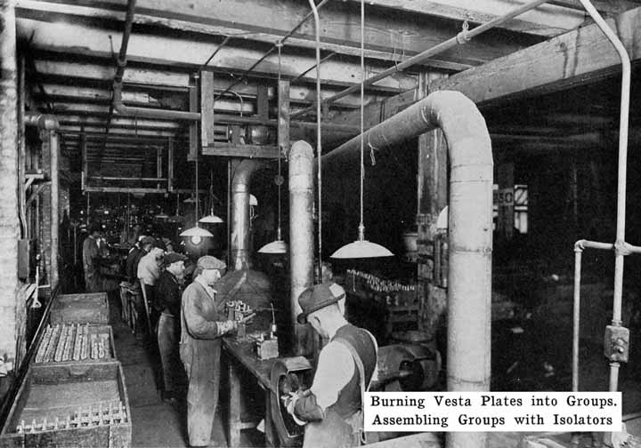
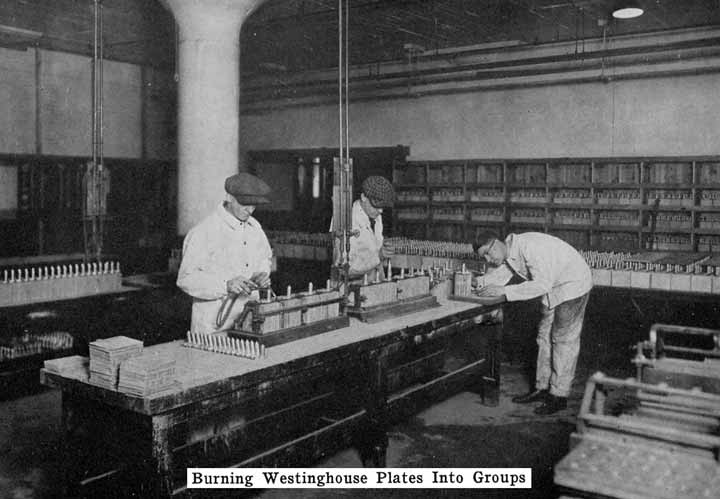
The first step in assembling a battery is to burn the positive and negative plates to their respective straps, Fig. 5, forming the positive and negative "groups," Fig. 2. This is done by arranging a set of plates and a strap in a suitable rack which holds them securely in proper position, and then melting together the top of the plate lugs and the portion of the strap into which they fit with a hot flame.
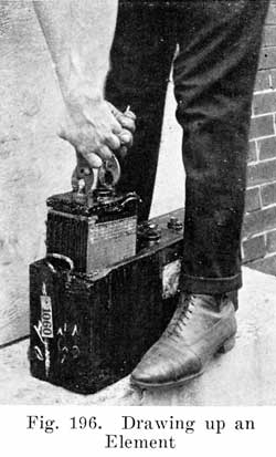
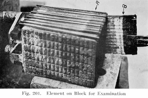
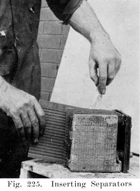
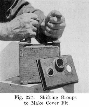
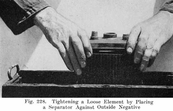
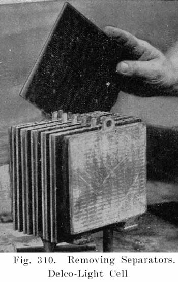
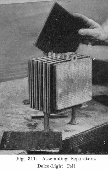
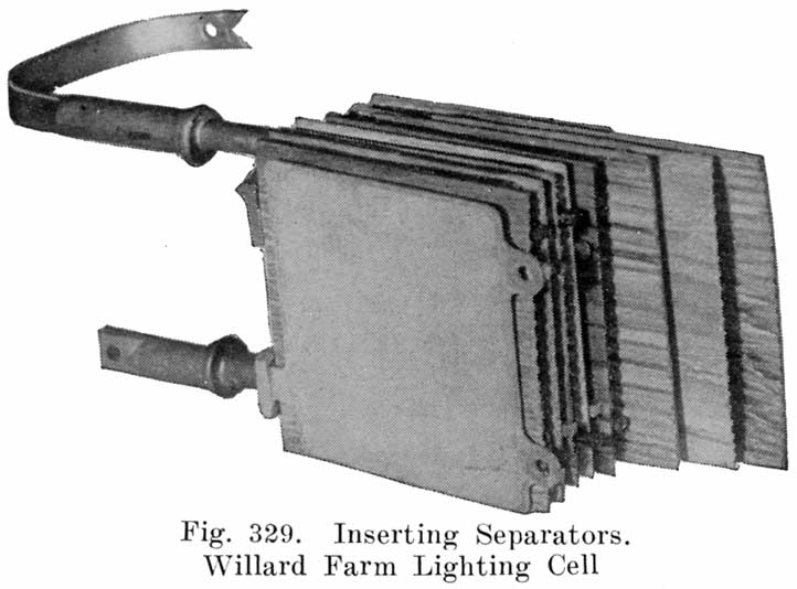
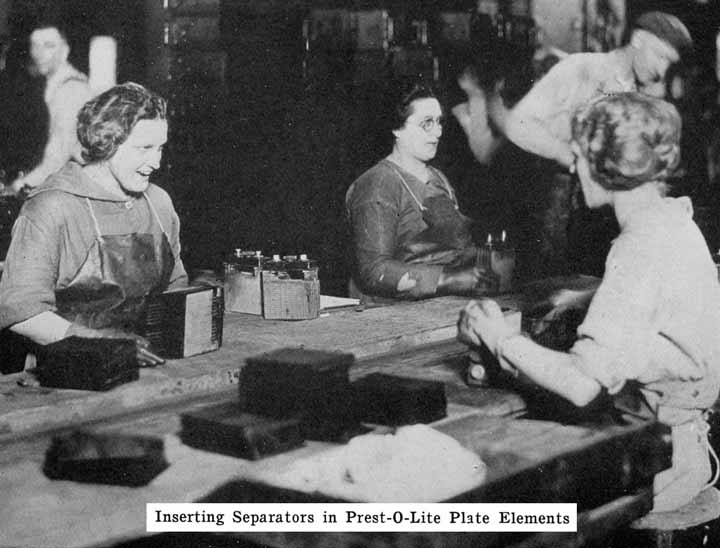
A positive and a negative group are now slipped together and the separators inserted. The grooved side of the wood separator is placed toward the positive plate and when perforated rubber sheets are used these go between the positive and the wood separator. The positive and negative "groups" assembled with the separators constitute the "element," Fig. 3.
Before the elements are placed in the jars they are carefully inspected to make sure that no separator has been left out. For this purpose the "Exide" elements are subjected to an electrical test which rings a bell if a separator is missing, this having been found more infallible than trusting to a man's eyes.
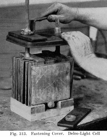
In some batteries, such as the Exide, Vesta, and Prest-O-Lite batteries, the cover is placed on the element and made fast before the elements are placed in the jars. In other batteries, such as the U. S. L. and Philadelphia batteries, the covers are put on after the elements are placed in the jars.
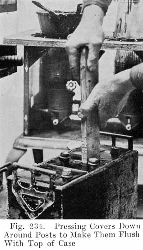
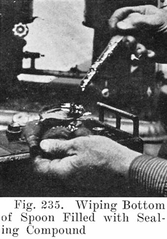
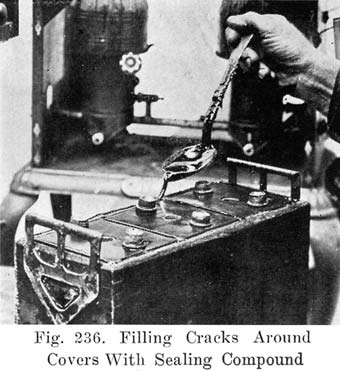
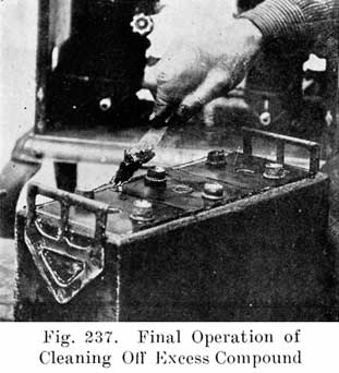
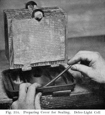
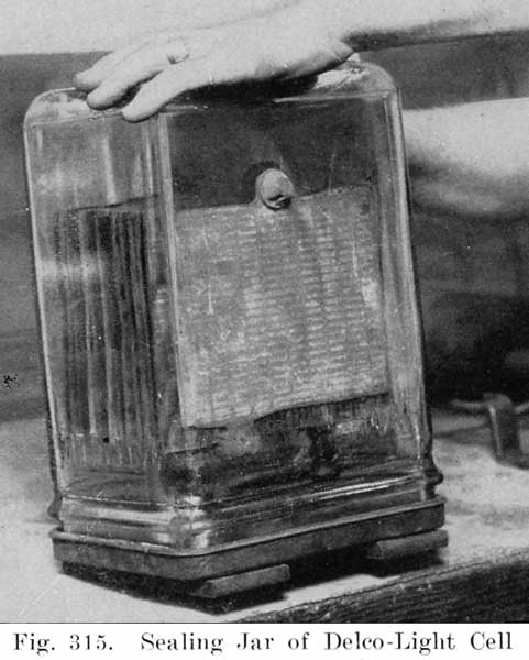
After the element is in the jar and the cover in position, sealing compound is applied hot so as to make a leak proof joint between jar and cover.
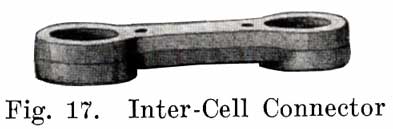
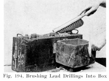
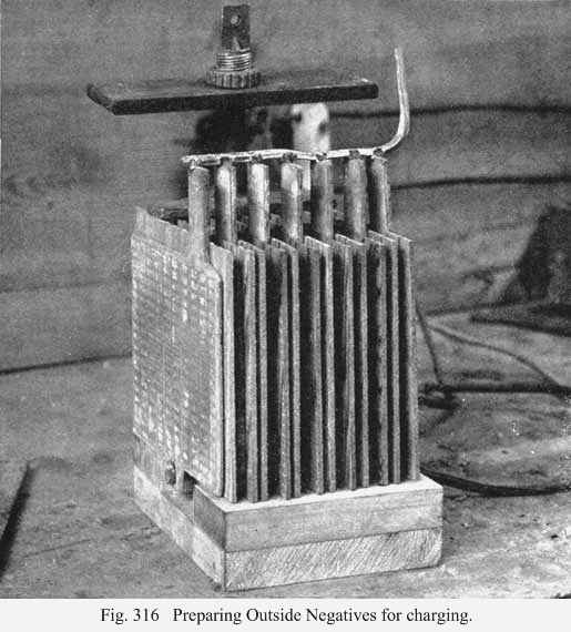
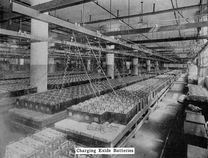
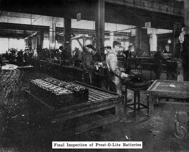
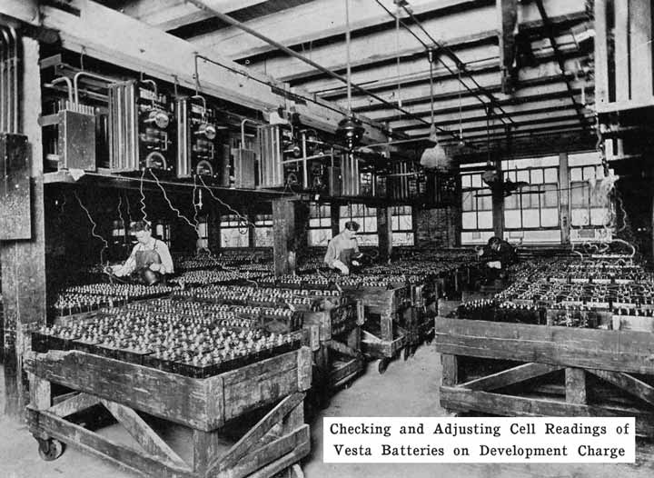
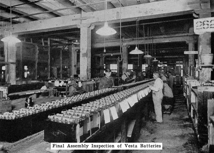
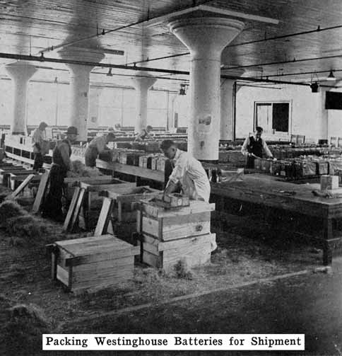
The completed cells are now assembled in the case and the cell connectors, Fig. 17, burned to the strap posts. After filling with electrolyte the battery is ready to receive its "initial charge," which may require from one day to a week. A low charging rate is used, since the plates are generally in a sulphated condition when assembled. The specific gravity is brought up to about 1.280 during this charge. Some makers now give the battery a short high rate discharge test (see page 266), to disclose any defects, and just before sending them out give a final charge. The batteries are often "cycled" after being assembled, this consisting in discharging and recharging the batteries several times to put the active material in the best working condition. If the batteries are to be shipped "wet," they are ready for shipping after the final charge and inspection. Batteries which are shipped "dry" need to have more work done upon them.
Preparing Batteries for Dry Shipment
There are three general methods of "dry" shipment. The first method consists of sending cases, plates, covers, separators, etc., separately, and assembling them in the service stations. Sometimes these parts are all placed together, as in a finished battery, but without the separators, the covers not being sealed, or the connectors and terminals welded to the posts. This is a sort of "knock-down" condition. The plates used are first fully charged and dried.
The second method consists of assembling a battery complete with plates, separators, and electrolyte, charging the battery, pouring out the electrolyte, rinsing with distilled water, pouring out the water and screwing the vent plugs down tight. The vent holes in these plugs are sealed to exclude air. The moisture left in the battery when the rinsing water was poured out cannot evaporate, and the separators are thus kept in a moistened condition.
The third method is the Willard "Bone Dry" method, and consists of assembling the battery complete with dry threaded rubber separators and dry plates, but without electrolyte. The holes in the vent plugs are not sealed, since there is no moisture in the battery. Batteries using wooden separators cannot be shipped "bone-dry," since wooden separators must be kept moist.
Terminal Connections
When the battery is on the car it is necessary to have some form of detachable connection to the car circuit and this is accomplished by means of "terminal connectors," Fig. 18, of which there are many types.
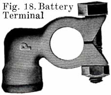
Many types of terminals are in two parts, one being permanently attached to the car circuit and the other mounted permanently on the battery by welding it to the terminal post, the two parts being detachably joined by means of a bolted connection.
In another type of terminal, the cable is soldered directly to the terminal which is lead burned to the cell post. In this construction there is very much less chance of corrosion taking place, and it is therefore a good design.
HOMEMADE BATTERIES
The wisest thing for the battery shop owner to do is to get a contract as official service station for one of the well known makes of batteries. The manufacturers of this battery will stand behind the service station, giving it the benefits of its engineering, production, and advertising departments, and boost the service station's business, helping to make it a success.
Within the past year or so, however, some battery repairmen have conceived the idea that they do not need the backing of a well organized factory, and have decided to build up their own batteries. Some of them merely assemble batteries from parts bought from one or more manufacturers. If all the parts are made by the same company, they will fit together, and may make a serviceable battery. Often, however, parts made by several manufacturers are assembled in the same battery. Here is where trouble is apt to develop, because it is more than likely that jars may not fit well in the case; plates may not completely fill the jars, allowing too much acid space, with the results that specific gravity readings will not be reliable, and the plates may be overworked; plate posts may not fit the cover holes, and so on. If such a "fabricated" battery goes dead because of defective material, there is no factory back of the repairman to stand the loss.
If the repairman wishes to assemble batteries, he should be very careful to buy the parts from a reliable manufacturer, and he should be especially careful in buying separators, as improperly treated separators often develop acetic acid, which dissolves the lead of the plates very quickly and ruins the battery. Batteries made in this way are good for rental batteries, or "loaners." These batteries are assembled and charged just as are batteries which have been in dry storage, see page 241.
If the repairman who "fabricates" batteries takes chances, the man who attempts to actually make his own battery plates is certainly risking his business and reputation. There are several companies which sell moulds for making plate grids. One even sells cans of lead oxides to enable the repairman to make his own plate paste. Even more foolhardy than the man who wishes to mould plate grids is the man who wishes to mix the lead oxides himself. Many letters asking for paste formulas have been received by the author. Such formulas can never be given, for the author does not have them. Paste making is a far more difficult process than many men realize. The lead oxides which are used must be tested and analyzed carefully in a chemical laboratory and the paste formulas varied according to the results of these tests. The oxides must be carefully weighed, carefully handled, and carefully analyzed. The battery service station does not have the equipment necessary to do these things, and no repairman should ever attempt to make plate paste, as trouble is bound to follow such attempts. A car owner may buy a worthless battery once, but the next time he will go to some other service station and buy a good battery.
No doubt many repairmen are as skillful and competent as the workers in battery factories, but the equipment required to make grids and paste is much too elaborate and expensive for the service station, and without such equipment it is impossible to make a good battery.
The only battery parts which may safely be made in the service station are plate straps and posts, intercell connectors, and cell terminals. Moulds for making such parts are on the market, and it is really worth while to invest in a set. The posts made in such moulds are of the plain tapered type, and posts which have special sealing and locking devices, such as the Exide, Philadelphia, and Titan cannot be made in them.
CHAPTER 4.
CHEMICAL CHANGES.
Before explaining what happens within one storage cell, let us look into the early history of the storage battery, and see what a modest beginning the modern heavy duty battery had. Between 1850 and 1860 a man named Plante began his work on the storage battery. His original cell consisted of two plates of metallic lead immersed in dilute sulphuric acid. The acid formed a thin layer of lead sulphate on each plate which soon stopped further action on the lead. If a current was passed through the cell, the lead sulphate on the "anode" or lead plate at which the current entered the cell was changed into peroxide of lead, while the sulphate on the other lead plate or "cathode" was changed into pure lead in a spongy form. This cell was allowed to stand for several days and was then "discharged," lead sulphate being again formed on each plate. Each time this cell was charged, more "spongy" lead and peroxide of lead were formed. These are called the "active" materials, because it is by the chemical action between them and the sulphuric acid that the electricity is produced. Evidently, the more active materials the plates contained, the longer the chemical action between the acid and active materials could take place, and hence the greater the "capacity," or amount of electricity furnished by the cell. The process of charging and discharging the battery so as to increase the amount of active material, is called "forming" the plates.
Plante's method of forming plates was very slow, tedious, and expensive. If the spongy lead, and peroxide of lead could be made quickly from materials which could be spread over the plates, much time and expense could be saved. It was Faure who first suggested such a plan, and gave us the "pasted" plate of today, which consists of a skeleton framework of lead, with the sponge lead and peroxide of lead filling the spaces between the "ribs" of the framework. Such plates are known as "pasted" plates, and are much lighter and more satisfactory, for automobile work than the heavy solid lead plates of Plante's. Chapter 3 describes more fully the processes of manufacturing and pasting the plates.
We know now what constitutes a storage battery, and what the parts are that "generate" the electricity. How is the electricity produced? Theoretically, if we take a battery which has been entirely discharged, so that it is no longer able to cause a flow of current, and examine and test the electrolyte and the materials on the plates, we shall find that the electrolyte is pure water, and both sets of plates composed of white lead sulphate. On the other hand, if we make a similar test and examination of the plates and electrolyte of a battery through which a current has been sent from some outside source, such as a generator, until the current can no longer cause chemical reactions between the plates and electrolyte, we will find that the electrolyte is now composed of water and Sulphuric acid, the acid comprising about 30%, and the water 70% of the electrolyte. The negative set of plates will be composed of pure lead in a spongy form, while the positive will consist of peroxide of lead.
The foregoing description gives the final products of the chemical changes that take place in the storage battery. To understand the changes themselves requires a more detailed investigation. The substances to be considered in the chemical actions are sulphuric acid, water, pure lead, lead sulphate, and lead peroxide. With the exception of pure lead, each of these substances is a chemical compound, or composed of several elements. Thus sulphuric acid is made up of two parts of hydrogen, which is a gas; one part of sulphur, a solid, and four parts of oxygen, which is also a gas; these combine to form the acid, which is liquid, and which is for convenience written as H2SO 4, H2 representing two parts of hydrogen, S one part of sulphur, and 04, four parts oxygen. Similarly, water a liquid, is made up of two parts of hydrogen and one part of oxygen, represented by the symbol H2O. Lead is not a compound, but an element whose chemical symbol is Pb, taken from the Latin name for lead. Lead sulphate is a solid, and consists of one part of lead, a solid substance, one part of sulphur, another solid substance, and four parts of oxygen, a gas. It is represented chemically by Pb SO4. Lead peroxide is also a solid, and is made up of one part of lead, and two parts of oxygen. In the chemical changes that take place, the compounds just described are to a certain extent split up into the substances of which they are composed. We thus have lead (Pb), hydrogen (H), oxygen (0), and sulphur (S), four elementary substances, two of which are solids, and two gases. The sulphur does not separate itself entirely from the substances with which it forms the compounds H2SO4 and Pb SO4. These compounds are split into H2 and SO4 and Pb and SO4 respectively. That is, the sulphur always remains combined with four parts of oxygen.
Let us now consider a single storage cell made up of electrolyte, one positive plate, and one negative plate. When this cell is fully charged, or in a condition to produce a current of electricity, the positive plate is made up of peroxide of lead (PbO2), the negative plate of pure lead (Pb), and the electrolyte of dilute sulphuric acid (H 2SO4). This is shown diagrammatically in Fig. 19. The chemical changes that take place when the cell is discharging and the final result of the changes are as follows:
(a). At the Positive Plate: Lead peroxide and sulphuric acid produce lead sulphate, water, and oxygen, or:
(b). At the Negative Plate: Lead and sulphuric acid produce lead sulphate and Hydrogen, or:
The oxygen of equation (a) and the hydrogen of equation (b) combine to form water, as may be shown by adding these two equations, giving one equation for the entire discharge action:
In this equation we start with the active materials and electrolyte in their original condition, and finish with the lead sulphate and water, which are the final products of a discharge. Examining this equation, we see that the sulphuric acid of the electrolyte is used up in forming lead sulphate on both positive and negative plates, and is therefore removed from the electrolyte. This gives us the easily remembered rule for remembering discharge actions, which, though open to question from a strictly scientific viewpoint, is nevertheless convenient:
During discharge the acid goes into the plates.
The chemical changes described in (a), (b), and (c) are not instantaneous. That is, the lead, lead peroxide, and sulphuric acid of the fully charged cell are not changed into lead sulphate and water as soon as a current begins to pass through the cell. This action is a gradual one, small portions of these substances being changed at a time. The greater the current that flows through the cell, the faster will the changes occur. Theoretically, the changes will continue to take place as long as any lead, lead peroxide, and sulphuric acid remain. The faster these are changed into lead sulphate and water, the shorter will be the time that the storage cell can furnish a current, or the sooner it will be discharged.
Taking the cell in its discharged condition, let us now connect the cell to a generator and send current through the cell from the positive to the negative plates. This is called "charging" the cell. The lead sulphate and water will now gradually be changed back into lead, lead peroxide, and sulphuric acid. The lead sulphate which is on the negative plate is changed to pure lead; the lead sulphate on the positive plate is changed to lead peroxide, and sulphuric acid will be added to the water. The changes at the positive plate may be represented as follows:
Lead sulphate and water produce sulphuric acid, hydrogen and lead peroxide, or:
The changes at the negative plate may be expressed as follows: Lead sulphate and water produced sulphuric acid, oxygen, and lead, or:
The hydrogen (H2) produced at the positive plate, and the oxygen (0) produced at the negative plate unite to form water, as may be shown by the equation:
Equation (f) starts with lead sulphate and water, which, as shown in equation (c), are produced when a battery is discharged. It will be observed that we start with lead sulphate and water. Discharged plates may therefore be charged in water. In fact, badly discharged negatives may be charged better in water than in electrolyte. The electrolyte is poured out of the battery and distilled water poured in. The acid remaining on the separators and plates is sufficient to make the water conduct the charging current.
In equation (f), the sulphate on the plates combines with water to form sulphuric acid. This gives us the rule:
During charge, acid is driven out of the plates.
This rule is a convenient one, but, of course, is not a strictly correct statement.
The changes produced by sending a current through the cell are also gradual, and will take place faster as the current is made greater. When all the lead sulphate has been used up by the chemical changes caused by the current, no further charging can take place. If we continue to send a current through the cell after it is fully charged, the water will continue to be split up into hydrogen and oxygen. Since, however, there is no more lead sulphate left with which the hydrogen and oxygen can combine to form lead, lead peroxide, and sulphuric acid, the hydrogen and oxygen rise to the surface of the electrolyte and escape from the cell. This is known as "gassing," and is an indication that the cell is fully charged.
Relations Between Chemical Actions and Electricity.
We know now that chemical actions in the battery produce electricity and that, on the other hand, an electric current, sent through the battery from an outside source, such as a generator, produces chemical changes in the battery. How are chemical changes and electricity related? The various chemical elements which we have in a battery are supposed to carry small charges of electricity, which, however, ordinarily neutralize one another. When a cell is discharging, however, the electrolyte, water, and active materials are separated into parts carrying negative and positive charges, and these "charges" cause what we call an electric current to flow in the apparatus attached to the battery.
Similarly, when a battery is charged, the charging current produces electrical "charges" which cause the substances in the battery to unite, due to the attraction of position and negative charges for one another. This is a brief, rough statement of the relations between chemical reactions and electricity in a battery. A more thorough study of the subject would be out of place in this book. It is sufficient for the repairman to remember that the substances in a battery carry charges of electricity which become available as an electric current when a battery discharges, and that a charging current causes electric charges to form, thereby "charging" the battery.
CHAPTER 5.
WHAT TAKES PLACE DURING DISCHARGE.
Considered chemically, the discharge of a storage battery consists of the changing of the spongy lead and lead peroxide into lead sulphate, and the abstraction of the acid from the electrolyte. Considered electrically, the changes are more complex, and require further investigation. The voltage, internal resistance, rate of discharge, capacity, and other features must be considered, and the effects of changes in one upon the others must be studied. This proceeding is simplified considerably if we consider each point separately. The abstraction of the acid from the electrolyte gives us a method of determining the condition of charge or discharge in the battery, and must also be studied.
Voltage Changes During Discharge. At the end of a charge, and before opening the charging circuit, the voltage of each cell is about 2.5 to 2.7 volts. As soon as the charging circuit is opened, the cell voltage drops rapidly to about 2.1 volts, within three or four minutes. This is due to the formation of a thin layer of lead sulphate on the surface of the negative plate and between the lead peroxide and the metal of the positive plate. Fig. 21 shows how the voltage changes during the last eight minutes of charge, and how it drops rapidly as soon as the charging circuit is opened. The final value of the voltage after the charging circuit is opened is about 2.15-2.18 volts. This is more fully explained in Chapter 6. If a current is drawn from the battery at the instant the charge is stopped, this drop is more rapid. At the beginning of the discharge the voltage has already had a rapid drop from the final voltage on charge, due to the formation of sulphate as explained above. When a current is being drawn from the battery, the sudden drop is due to the internal resistance of the cell, the formation of more sulphate, and the abstracting of the acid from the electrolyte which fills the pores of the plate. The density of this acid is high just before the discharge is begun. It is diluted rapidly at first, but a balanced condition is reached between the density of the acid in the plates and in the main body of the electrolyte, the acid supply in the plates being maintained at a lowered density by fresh acid flowing into them from the main body of electrolyte. After the initial drop, the voltage decreases more slowly, the rate of decrease depending on the amount of current drawn from the battery. The entire process is shown in Fig. 22.
Lead sulphate is being formed on the surfaces, and in the body of the plates. This sulphate has a higher resistance than the lead or lead peroxide, and the internal resistance of the cell rises, and contributes to the drop in voltage. As this sulphate forms in the body of the plates, the acid is used up. At first this acid is easily replaced from the main body of the electrolyte by diffusion. The acid in the main body of the electrolyte is at first comparatively strong, or concentrated, causing a fresh supply of acid to flow into the plates as fast as it is used up in the plates. This results in the acid in the electrolyte growing weaker, and this, in turn, leads to a constant decrease in the rate at which the fresh acid flows, or diffuses into the plates. Furthermore, the sulphate, which is more bulky than the lead or lead peroxide fills the pores in the plate, making it more and more difficult for acid to reach the interior of the plate. This increases the rate at which the voltage drops.
The sulphate has another effect. It forms a cover over the active material which has not been acted upon, and makes it practically useless, since the acid is almost unable to penetrate the coating of sulphate. We thus have quantities of active material which are entirely enclosed in sulphate, thereby cutting down the amount of energy which can be taken from the battery. Thus the formation of sulphate throughout each plate and the abstraction of acid from the electrolyte cause the voltage to drop at a constantly increasing rate.
Theoretically, the discharge may be continued until the voltage drops to zero, but practically, the discharge should be stopped when the voltage of each cell has dropped to 1.7 (on low discharge rates). If the discharge is carried on beyond this point much of the spongy lead and lead peroxide have either been changed into lead sulphate, or have been covered up by the sulphate so effectively that they are almost useless. Plates in this condition require a very long charge in order to remove all the sulphate.
The limiting value of 1.7 volts per cell applies to a continuous discharge at a moderate rate. At a very high current flowing for only a very short time, it is not only safe, but advisable to allow a battery to discharge to a lower voltage, the increased drop being due to the rapid dilution of the acid in the plates.
The cell voltage will rise somewhat every time the discharge is stopped. This is due to the diffusion of the acid from the main body of electrolyte into the plates, resulting in an increased concentration in the plates. If the discharge has been continuous, especially if at a high rate, this rise in voltage will bring the cell up to its normal voltage very quickly on account of the more rapid diffusion of acid which will then take place.
The voltage does not depend upon the area of the plate surface but upon the nature of the active materials and the electrolyte. Hence, although the plates of a cell are gradually being covered with sulphate, the voltage, measured when no current is flowing, will fall slowly and not in proportion to the amount of energy taken out of the cell. It is not until the plates are pretty thoroughly covered with sulphate, thus making it difficult for the acid to reach the active material, that the voltage begins to drop rapidly. This is shown clearly in Fig. 22, which shows that the cell voltage has dropped only a very small amount when the cell is 50% discharged. With current flowing through the cell, however, the increased internal resistance causes a marked drop in the voltage. Open circuit voltage is not useful, therefore to determine how much energy has been taken from the battery.
Acid Density. The electrolyte of a lead storage battery is a mixture of chemically pure sulphuric acid, and chemically pure water, the acid forming about 30 per cent of the volume of electrolyte when the battery is fully charged. The pure acid has a "specific gravity" of 1.835, that is, it is 1.835 times as heavy as an equal volume of water. The mixture of acid and water has a specific gravity of about 1.300. As the cell discharges, acid is abstracted from the electrolyte, and the weight of the latter must therefore grow less, since there will be less acid in it. The change in the weight, or specific gravity of the electrolyte is the best means of determining the state of discharge of a cell, provided that the cell has been used properly. In order that the value of the specific gravity may be used as an indication of the amount of energy in a battery, the history of the battery must be known. Suppose, for instance, that in refilling the battery to replace the water lost by the natural evaporation which occurs in the use of a battery, acid, or a mixture of acid and water has been used. This will result in the specific gravity being too high, and the amount of energy in the battery will be less than that indicated by the specific gravity. Again, if pure water is used to replace electrolyte which has been spilled, the specific gravity will be lower than it should be. In a battery which has been discharged to such an extent that much of the active material has been covered by a layer of tough sulphate, or if a considerable amount of sulphate and active material has been loosened from the plates and has dropped to the bottom of the cells, it will be impossible to bring the specific gravity of the electrolyte up to 1.300, even though a long charge is given. There must, therefore, be a reasonable degree of certainty that a battery has been properly handled if the specific gravity readings are to be taken as a true indication of the condition of a battery. Where a battery does not give satisfactory service even though the specific gravity readings are satisfactory, the latter are not reliable as indicating the amount of charge in the battery.
As long as a discharge current is flowing from the battery, the acid within the plates is used up and becomes very much diluted. Diffusion between the surrounding electrolyte and the acid in the plates keeps up the supply needed in the plates in order to, carry on the chemical changes. When the discharge is first begun, the diffusion of acid into the plates takes place rapidly because there is little sulphate clogging the pores in the active material, and because there is a greater difference between the concentration of acid in the electrolyte and in the plates than will exist as the discharge progresses. As the sulphate begins to form and fill up the pores of the plates, and as more and more acid is abstracted from the electrolyte, diffusion takes place more slowly.
If a battery is allowed to stand idle for a short time after a partial discharge, the specific gravity of the electrolyte will decrease because some, of the acid in the electrolyte will gradually flow into the pores of the plates to replace the acid used up while the battery was discharging. Theoretically the discharge can be continued until all the acid has been used up, and the electrolyte is composed of pure water. Experience has shown, however, that the discharge of the battery should not be continued after the specific gravity of the electrolyte has fallen to 1.150. As far as the electrolyte is concerned, the discharge may be carried farther with safety. The plates determine the point at which the discharge should be stopped. When the specific gravity has dropped from 1.300 to 1.150, so much sulphate has been formed that it fills the pores in the active material on the plates. Fig. 23 shows the change in the density of the acid during discharge.
Changes at the Negative Plate. Chemically, the action at the negative plate consists only of the formation of lead sulphate from the spongy lead. The lead sulphate is only slightly soluble in the electrolyte and is precipitated as soon as it is formed, leaving hydrogen ions, which then go to the lead peroxide plate to form water with oxygen ions released at the peroxide plate. The sulphate forms more quickly on the surface of the plate than in the inner portions because there is a constant supply of acid available at the surface, whereas the formation of sulphate in the interior of the plate requires that acid diffuse into the pores of the active materials to replace that already used up in the formation of sulphate. In the negative plate, however, the sulphate tends to form more uniformly throughout the mass of the lead, because the spongy lead is more porous than the lead peroxide, and because the acid is not diluted by the formation of water as in the positive plate.
Changes at the Positive Plate. In a fully charged positive plate we have lead peroxide as the active material. This is composed of lead and oxygen. From this fact it is plainly evident that during discharge there is a greater chemical activity at this plate than at the negative plate, since we must find something to combine with the oxygen in order that the lead may form lead sulphate with the acid. In an ideal cell, therefore, the material which undergoes the greater change should be more porous than the material which does not involve as great a chemical reaction. In reality, however, the peroxide is not as porous as the spongy lead, and does not hold together as well.
The final products of the discharge of a positive plate are lead sulphate and water. The lead peroxide must first be reduced to lead, which then combines with the sulphate from the acid to form lead sulphate, while the oxygen from the peroxide combines with the hydrogen of the acid to form water. There is, therefore, a greater activity at this plate than at the lead plate, and the formation of the water dilutes the acid in and around the plate so that the tendency is for the chemical actions to be retarded.
The sulphate which forms on discharge causes the active material to bulge out because it occupies more space than the peroxide. This causes the lead peroxide at the surface to begin falling, to the bottom of the jar in fine dust-like particles, since the peroxide here holds together very poorly.
CHAPTER 6.
WHAT TAKES PLACE DURING CHARGE.
Voltage. Starting with a battery which has been discharged until its voltage has decreased to 1.7 per cell, we pass a current through it and cause the voltage to rise steadily. Fig. 24 shows the changes in voltage during charge. Ordinarily the voltage begins to rise immediately and uniformly. If, however, the battery has been left in a discharged condition for some time, or has been "over discharged," the voltage rises very rapidly for a fraction of the first minute of charge and then drops rapidly to the normal value and thereafter begins to rise steadily to the end of the charge. This rise at the beginning of the charge is due to the fact that the density of the acid in the pores of the plates rises rapidly at first, the acid thus formed being prevented from diffusing into the surrounding electrolyte by the coating of sulphate. As soon as this sulphate is broken through, diffusion takes place and the voltage drops.
As shown in Fig. 24, the voltage remains almost constant between the points M and N. At N the voltage begins to rise because the charging chemical reactions are taking place farther and farther in the inside parts of the plate, and the concentrated acid formed by the chemical actions in the plates is diffusing into the main electrolyte. This increases the battery voltage and requires a higher charging voltage.
At the point marked 0, the voltage begins to rise very rapidly. This is due to the fact that the amount of lead sulphate in the plates is decreasing very rapidly, allowing the battery voltage to rise and thus increasing the charging voltage. Bubbles of gas are now rising through the electrolyte.
At P, the last portions of lead sulphate are removed, acid is no longer being formed, and hydrogen and oxygen gas are formed rapidly. The gas forces the last of the concentrated acid out of the plates and in fact, equalizes the acid concentration throughout the whole cell. Thus no further changes can take place, and the voltage becomes constant at R at a voltage of 2.5 to 2.7.
Density of Electrolyte. Discharge should be stopped when the density of the electrolyte, as measured with a hydrometer, is 1.150. When we pass a charging current through the battery, acid is produced by the chemical actions which take place in the plates. This gradually diffuses with the main electrolyte and causes the hydrometer to show a higher density than before. This increase in density continues steadily until the battery begins to "gas" freely.
The progress of the charge is generally determined by the density of the electrolyte. For this purpose in automobile batteries, a hydrometer is placed in a glass syringe having a short length of rubber tubing at one end, and a large rubber bulb at the other. The rubber tube is inserted in the cell and enough electrolyte drawn up into the syringe to float the hydrometer so as to be able to obtain a reading. This subject will be treated more fully in a later chapter.
Changes at Negative Plate. The charging current changes lead sulphate into spongy lead, and acid is formed. The acid is mixed with the diluted electrolyte outside of the plates. As the charging proceeds the active material shrinks or contracts, and the weight of the plate actually decreases on account of the difference between the weight and volume of the lead sulphate and spongy lead. If the cell has had only a normal discharge and the charge is begun soon after the discharge ended, the charge will proceed quickly and without an excessive rise in temperature. If, however, the cell has been discharged too far, or has been in a discharged condition for some time, the lead sulphate will not be in a finely divided state as it should be, but will be hard and tough and will have formed an insulating coating over the active material, causing the charging voltage to be high, and the charge will proceed slowly. When most of the lead sulphate has been reduced to spongy lead, the charging current will be greater than is needed to carry on the chemical actions, and will simply decompose the water into hydrogen and oxygen, and the cell "gasses." Spongy lead is rather tough and coherent, it, and the bubbles of gas which form in the pores of the negative plate near the end of the charge force their way to the surface without dislodging any of the active material.
Changes at the Positive Plate. When a cell has been discharged, a portion of the lead peroxide has been changed to lead sulphate, which has lodged in the pores of the active material and on its surface. During charge, the lead combines with oxygen from the water to form lead peroxide, and acid is formed. This acid diffuses into the electrolyte as fast as the amount of sulphate will permit. If the discharge has been carried so far that a considerable amount of sulphate has formed in the pores and on the surface of the plate, the action proceeds very slowly, and unless a moderate charging current is used, gassing begins before the charge is complete, simply because the sulphate cannot absorb the current. The gas bubbles which originate in the interior of the plate force their way to the surface, and in so doing cause numerous fine particles of active material to break off and fall to the bottom of the jar. This happens because the lead peroxide is a granular, non-coherent substance, with the particles held together very loosely, and the gas breaks off a considerable amount of active material.
The capacity of a storage battery is the product of the current drawn from a battery, multiplied by the number of hours this current flows. The unit in which capacity is measured is the ampere-hour. Theoretically, a battery has a capacity of 40 ampere hours if it furnishes ten amperes for four hours, and if it is unable, at the end of that time, to furnish any more current. If we drew only five amperes from this battery, it should be able to furnish this current for eight hours. Thus, theoretically, the capacity of a battery should be the same, no matter what current is taken from it. That is, the current in amperes, multiplied by the number of hours the battery, furnished this current should be constant.
In practice, however, we do not discharge a battery to a lower voltage than 1.7 per cell, except when the rate of discharge is high, such as is the case when using the starting motor, on account of the increasing amount of sulphate and the difficulty with which this is subsequently removed and changed into lead and lead peroxide. The capacity of a storage battery is therefore measured by the number of ampere hours it can furnish before its voltage drops below 1.7 per cell. This definition assumes that the discharge is a continuous one, that we start with a fully charged battery and discharge it continuously until its voltage drops to 1.7 per cell.
The factors upon which the capacity of storage batteries depend may be grouped in two main classifications:
- 1. Design and Construction of Battery
- 2. Conditions of Operation
Design and Construction.
Each classification may be subdivided. Under the Design and Construction we have:
- (a) Area of plate surface.
- (b) Quantity, arrangement, and porosity of active materials.
- (c) Quantity and strength of electrolyte.
- (d) Circulation of electrolyte.
These sub-classifications require further explanation. Taking them in order:
(a) Area of Plate Surface. It is evident that the chemical and electrical activity of a battery are greatest at the surface of the plates since the acid and active material are in intimate contact here, and a supply of fresh acid is more readily available to replace that which is depleted as the battery is discharged. This is especially true with high rates of discharge, such as are caused in starting automobile engines. Therefore, the capacity of a battery will be greater if the surface area of its plates is increased. With large plate areas a greater amount of acid and active materials is available, and an increase in capacity results.
(b) Quantity, Arrangement, and Porosity of Active Materials. Since the lead and lead peroxide are changed to lead sulphate on discharge, it is evident that the greater the amount of these materials, the longer can the discharge continue, and hence the greater the capacity.
The arrangement of the active materials is also important, since the acid and active materials must be in contact in order to produce electricity. Consequently the capacity will be greater in a battery, all of whose active materials are in contact with the acid, than in one in which the acid reaches only a portion of the active materials. It is also important that all parts of the plates carry the same amount of current, in order that the active materials may be used evenly. As a result of these considerations, we find that the active materials are supported on grids of lead, that the plates are made thin, and that they have large surface areas. For heavy discharge currents, such as starting motor currents, it is essential that there be large surface areas. Thick plates with smaller surface areas are more suitable for low discharge rates.
Since the inner portions of the active materials must have a plentiful and an easily renewable supply of acid, the active materials must be porous in order that diffusion may be easy and rapid.
(c) Quantity and Strength of Electrolyte. It is important that there be enough electrolyte in order that the acid may not become exhausted while there is still considerable active material left. An insufficient supply of electrolyte makes it impossible to obtain the full capacity from a battery. On the other hand, too much electrolyte, due either to filling the battery too full, or to having the plates in a jar that holds too much electrolyte, results in an increase in capacity up to the limit of the plate capacity. There is a danger present, however, because with an excess of electrolyte the plates will be discharged before the specific gravity of the electrolyte falls to 1.150. This results in over discharge of the battery with its attendant troubles as will be described more fully in a later chapter.
It is a universal custom to consider a battery discharged when the specific gravity of the electrolyte has dropped to 1.150, and that it is fully charged when the specific gravity of the electrolyte has risen to 1.280-1.300. This is true in temperate climates. In tropical countries, which may for this purpose be defined as those countries in which the temperature never falls below the freezing point, the gravity of a fully charged cell is 1.200 to 1.230. The condition of the plates is, however, the true indicator of charged or discharged condition. With the correct amount of electrolyte, its specific gravity is 1.150 when the plates have been discharged as far as it is considered safe, and is 1.280-1.300 when the plates are fully charged. When electrolyte is therefore poured into a battery, it is essential that it contains the proper proportion of acid and water in order that its specific gravity readings be a true indicator of the condition of the plates as to charge or discharge, and hence show accurately how much energy remains in the cell at any time.
A question which may be considered at this point is why in automobile, work a specific gravity of 1.280-1.300 is adopted for the electrolyte of a fully charged cell. There are several reasons. The voltage of a battery increases as the specific gravity goes up. Hence, with a higher density, a higher voltage can be obtained. If the density were increased beyond this point, the acid would attack the lead grids and the separators, and considerable corrosion would result. Another danger of high density is that of sulphation, as explained in a later chapter. Another factor which enters is the resistance of the electrolyte. It is desirable that this be as low as possible. If we should make resistance measurements on various mixtures of acid and water, we should find that with a small percentage of acid, the resistance is high. As the amount of acid is increased, the resistance will grow less up to a certain point. Beyond this point, the resistance will increase again as more acid is added to the mixture. The resistance is lowest when the acid forms 30% of the electrolyte. Thus, if the electrolyte is made too strong, the plates and also the separators will be attacked by the acid, and the resistance of the electrolyte will also increase. The voltage increases as the proportion of acid is increased, but the other factors limit the concentration. If the electrolyte is diluted, its resistance rises, and the amount of acid is insufficient to give much capacity. The density of 1.280-1.300 is therefore a compromise between the various factors mentioned above.
(d) Circulation of Electrolyte. This refers to the passing of electrolyte from one plate to another, and depends upon the ease with which the acid can pass through the pores of the separators. A porous separator allows more energy to be drawn from the battery than a nonporous one.
Operating Conditions.
Considering now the operating conditions, we find several items to be taken into account. The most important are:
- (e) Rate of discharge.
- (f) Temperature.
(e) Rate of Discharge. As mentioned above, the ampere hour rating of a battery is based upon a continuous discharge, starting with a specific gravity of 1.280-1.300, and finishing with 1.150. The end of the discharge is also considered to be reached when the voltage per cell has dropped to 1.7. With moderate rates of discharge the acid is abstracted slowly enough to permit the acid from outside the plates to diffuse into the pores of the plates and keep up the supply needed for the chemical actions. With increased rates of discharge the supply of acid is used up so rapidly that the diffusion is not fast enough to hold up the voltage. This fact is shown clearly by tests made to determine the time required to discharge a 100 Amp. Hr., 6 volt battery to 4.5 volts. With a discharge rate of 25 amperes, it required 160 minutes. With a discharge rate of 75 amperes, it required 34 minutes. From this we see that making the discharge rate three times as great caused the battery to be discharged in one fifth the time. These discharges were continuous, however, and if the battery were allowed to rest, the voltage would soon rise sufficiently, to burn the lamps for a number of hours.
The conditions of operation in automobile work are usually considered severe. In starting the engine, a heavy current is drawn from the battery for a few seconds. The generator starts charging the battery immediately afterward, and the starting energy is soon replaced. As long as the engine runs, there is no load on the battery, as the generator will furnish the current for the lamps, and also send a charge into the battery. If the lamps are not used, the entire generator output is utilized to charge the battery, unless some current is furnished to the ignition system. Overcharge is quite possible.
When the engine is not running, the lamps are the only load on the battery, and there is no charging current. Various drivers have various driving conditions. Some use their starters frequently, and make only short runs. Their batteries run down. Other men use the starter very seldom, and take long tours. Their batteries will be overcharged. The best thing that can be done is to set the generator for an output that will keep the battery charged under average conditions.
From the results of actual tests, it may be said that modem lead-acid batteries are not injured in any way by the high discharge rate used when a starting motor cranks the engine. It is the rapidity with which fresh acid takes the place of that used in the pores of the active materials that affects the capacity of a battery at high rates, and not only limitation in the plates themselves. Low rates of discharge should, in fact, be avoided more than the high rates. Battery capacity is affected by discharge rates, only when the discharge is continuous, and the reduction in capacity caused by the high rates of continuous discharge does not occur if the discharge is an intermittent one, such as is actually the case in automobile work. The tendency now is to design batteries to give their rated capacity in very short discharge periods. If conditions should demand it, these batteries would be sold to give their rated capacity while operating intermittently at a rate which would completely discharge them in three or four minutes. The only change necessary for such high rates of discharge is to provide extra heavy terminals to carry the heavy current.
The present standard method of rating starting and lighting batteries, as recommended by the Society of Automotive Engineers, is as follows:
"Batteries for combined lighting and starting service shall have two ratings. The first shall indicate the lighting ability, and shall be the capacity in ampere hours of the battery when discharged continuously at the 5 hour rate to a final voltage of not less than 1.7 per cell, the temperature of the battery beginning such discharge being 80°F. The second rating shall indicate the starting ability and shall be the capacity in ampere-hours when the battery is discharged continuously at the 20-minute rate to a final voltage of not less than 1.5 per cell, the temperature of the battery beginning such discharge being 80°F."
The discharge rate required under the average starting conditions is higher than that specified above, and would cause the required drop in voltage in about fifteen minutes. In winter, when an engine is cold and stiff, the work required from the battery is even more severe, the discharge rate being equivalent in amperes to probably four or five times the ampere-rating of the battery. On account of the rapid recovery of a battery after a discharge at a very high rate, it seems advisable to allow a battery to discharge to a voltage of 1.0 per cell when cranking an engine which is extremely cold and stiff.
(f) Temperature. Chemical reactions take place much more readily at high temperatures than at low. Furthermore, the active materials are more porous, the electrolyte lighter, and the internal resistance less at higher temperatures. Opposed to this is the fact that at high temperatures, the acid attacks the grids and active materials, and lead sulphate is formed, even though no current is taken from the battery. Other injurious effects are the destructive actions of hot acid on the wooden separators used in most starting and lighting batteries. Greater expansion of active material will also occur, and this expansion is not, in general, uniform over the surface of the plates. This results in unequal strains and the plates are bent out of shape, or "buckled." The expansion of the active material will also cause much of it to fall from the plates, and we then have "shedding."
When sulphuric acid is poured into water, a marked temperature rise takes place. When a battery is charged, acid is formed, and when this mixes with the diluted electrolyte, a temperature rise occurs. In discharging, acid is taken from the electrolyte, and the temperature has a tendency to drop. On charging, therefore, there is danger of overheating, while on discharge, excessive temperatures are not likely. Fig. 25 shows the theoretical temperature changes on charge and discharge. The decrease in temperature given-in the curve is not actually obtained in practice, because the tendency of the temperature to decrease is balanced by the heat caused by the current passing through the battery.
Age of Battery.
Another factor which should be considered in connection with capacity is the age of the battery. New batteries often do not give their rated capacity when received from the manufacturer. This is due to the methods of making the plates. The "paste" plates, such as are used in automobiles, are made by applying oxides of lead, mixed with a liquid, which generally is dilute sulphuric acid, to the grids. These oxides must be subjected to a charging current in order to produce the spongy lead and lead peroxide. After the charge, they must be discharged, and then again charged. This is necessary because not all of the oxides are changed to active material on one charge, and repeated charges and discharges are required to produce the maximum amount of active materials. Some manufacturers do not charge and discharge a battery a sufficient number of times before sending it out, and after a battery is put into use, its capacity will increase for some time, because more active material is produced during each charge.
Another factor which increases the capacity of a battery after it is put into use is the tendency of the positive active material to become more porous after the battery is put through the cycles of charge and discharge. This results in an increase in capacity for a considerable time after the battery is put into use.
When, a battery has been in use for some time, a considerable portion of the active material will have fallen from the positive plates, and, a decrease in capacity will result. Such a battery will charge faster than a new one because the amount of sulphate which has formed when the battery is discharged is less than in a newer battery. Hence, the time required to reduce this sulphate will be less, and the battery will "come up" faster on charge, although the specific gravity of the electrolyte may not rise to 1.280.
The resistance offered by a storage battery to the flow of a current through it results in a loss of voltage, and in heating. Its value should be as low as possible, and, in fact, it is almost negligible even I in small batteries, seldom rising above 0.05 ohm. On charge, it causes the charging voltage to be higher and on discharge causes a loss of voltage. Fig. 26 shows the variation in resistance.
The resistance as measured between the terminals of a cell is made up of several factors as follows:
1. Grids. This includes the resistance of the terminals, connecting links, and the framework upon which the active materials are pasted. This is but a small part of the total resistance, and does not undergo any considerable change during charge and discharge. It increases slightly as the temperature of the grids rises.
2. Electrolyte. This refers to the electrolyte between the plates, and varies with the amount of acid and with temperature. As mentioned in the preceding chapter, a mixture of acid and water in which the acid composes thirty per cent of the electrolyte has the minimum resistance. Diluting or increasing the concentration of the electrolyte will both cause an increase in resistance from the minimum I value. The explanation probably lies in the degree to which the acid is split up into "ions" of hydrogen (H), and sulphate (SO4). These "ions" carry the current through t he electrolyte. Starting with a certain amount of acid, let us see how the ionization progresses. With very concentrated acid, ionization does not take place, and hence, there are no ions to carry current. As we mix the acid with water, ionization occurs. The more water used, the more ions, and hence, the less the resistance, because the number of ions available to carry the current increases. The ionization in creases to a certain maximum degree, beyond which no more ions are formed. It is probable that an electrolyte containing thirty per cent of acid is at its maximum degree of ionization and hence its lowest resistance. If more water is now added, no more ions are formed. Furthermore, the number of ions per unit volume of electrolyte will now decrease on account of the increased amount of water. There Will therefore be fewer ions per unit volume to carry the current, and the resistance of the electrolyte increases.
With an electrolyte of a given concentration, an increase of temperature will cause a decrease in resistance. A decrease in temperature will, of course, cause an increase in resistance. It is true, in general, that the resistance of the electrolyte is about half of the total resistance of the cell. The losses due to this resistance generally form only one per cent of the total losses, and area practically negligible factor.
3. Active Material. This includes the resistance of the active materials and the electrolyte in the pores of the active materials. This varies considerably during charge and discharge. It has been found that the resistance of the peroxide plate changes much more than that of the lead plate. The change in resistance of the positive plate is especially marked near the end of a discharge. The composition of the active material, and the contact between it and the grid affect the resistance considerably.
During charge, the current is sent into the cell from an external source. The girds therefore carry most of the current. The active material which first reacts with the acid is that near the surface of the plate, and the acid formed by the charging current mixes readily with the main body of electrolyte. Gradually, the charging action takes place in the inner portions of the plate, and concentrated acid is formed in the pores of the plate. As the sulphate is removed, however, the acid has little difficulty in mixing with the main body of electrolyte. The change in resistance on the charge is therefore not considerable.
During discharge, the chemical action also begins at the surface of the plates and gradually moves inward. In this case, however, sulphate is formed on the surface first, and it becomes increasingly difficult for the fresh acid from the electrolyte to diffuse into the plates so as to replace the acid which has been greatly diluted there by the discharge actions. There is therefore an increase in resistance because of the dilution of the acid at the point of activity. Unless a cell is discharged too far, however, the increase in resistance is small.
If a battery is allowed to stand idle for a long time it gradually discharges itself, as explained in Chapter 10. This is due to the formation of a tough coating of crystallized lead sulphate, which is practically an insulator. These crystals gradually cover and enclose the active material. The percentage change is not high, and generally amounts to a few per cent only. The chief damage caused by the excessive sulphation is therefore not an increase in resistance, but consists chiefly of making a poor contact between active material and grid, and of removing much of the active material from action by covering it.
The manufacturers of Starting and Lighting Equipment have designed their generators, cutouts, and current controlling devices so as to relieve the car owner of as much work as possible in taking care of batteries. The generators on most cars are automatically connected to the battery at the proper time, and also disconnected from it as the engine slows down. The amount of current which the generator delivers to the battery is automatically prevented from exceeding a certain maximum value. Under the average conditions of driving, a battery is kept in a good condition. It is impossible, however, to eliminate entirely the need of attention on the part of the car owner, and battery repairman.
The storage battery requires but little attention, and this is the very reason why many batteries are neglected. Motorists often have the impression that because their work in caring for a battery is quite simple, no harm will result if they give the battery no attention whatever. If the battery fails to turn over the engine when the starting switch is closed, then instruction books are studied. Thereafter more attention is paid to the battery. The rules to be observed in taking care of the battery which is in service on the car are not difficult to observe. It is while on the car that a battery is damaged, and the damage may be prevented by intelligent consideration of the battery's housing and living conditions, just as these conditions are made as good as possible for human beings.
1. Keep the Interior of the Battery Box Clean and Dry. On many cars the battery is contained in an iron box, or under the seat or floorboards. This box must be kept dry, and frequent inspection is necessary to accomplish this. Moisture condenses easily in a metal box, and if not removed will cause the box to become rusty. Pieces of rust may fall on top of the battery and cause corrosion and leakage of current between terminals.
Occasionally, wash the inside of the box with a rag dipped in ammonia, or a solution of baking soda, and then wipe it dry. A good plan is to paint the inside of the box with asphaltum paint. This will prevent rusting, and at the same time will prevent the iron from being attacked by electrolyte which may be spilled, or may leak from the battery.
Some batteries are suspended from the car frame under the floor boards or seat. The iron parts near such batteries should be kept dry and free from rust. If the battery has a roof of sheet iron placed above it, this roof should also be kept clean, dry and coated with asphaltum paint.
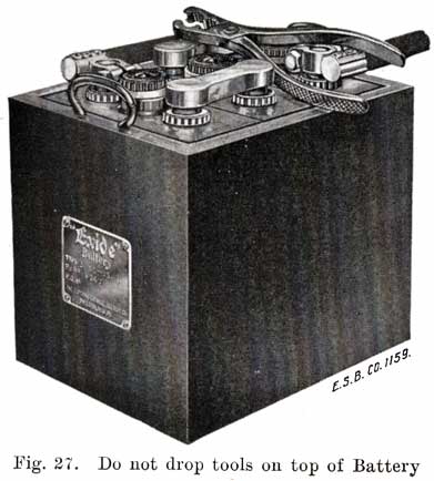
2. Put Nothing But the Battery in the Battery Box. If the battery is contained in an iron box, do not put rags, tools, or anything else of a similar nature in the battery box. Do not lay pliers across the top of the battery, as shown in Fig. 27. Such things belong elsewhere. The battery should have a free air space all around it, Fig. 28. Objects made of metal will short-circuit the battery and lead to a repair bill.
3. Keep the battery clean and dry. The top of the battery should be kept free of dirt, dust, and moisture. Dirt may find its way into the cells and damage the battery. A dirty looking battery is an unsightly object, and cleanliness should be maintained for the sake of the appearance of the battery if for no other reason.
Moisture on top of the battery causes a leakage of current between the terminals of the cells and tends to discharge the battery. Wipe off all moisture and occasionally go over the tops of the cell connectors, and terminals with a rag wet with ammonia or a solution of baking soda. This will neutralize any acid which may be present in the moisture.
The terminals should be dried and covered with vaseline. This protects them from being attacked by acid which may be spilled on top of the battery. If a deposit of a grayish or greenish substance is found on the battery terminals, handles or cell connectors, the excess should be scraped off and the parts should then be washed with a hot solution of baking soda (bicarbonate of soda) until all traces of the substance have been removed. In scraping off the deposit, care should be taken not to scrape off any lead from terminals or connectors. After washing the parts, dry them and cover them with vaseline. The grayish or greenish substance found on the terminals, connectors, or handles is the result of "corrosion," or, in other words, the result of the action of the, sulphuric acid in the electrolyte upon some metallic substance.
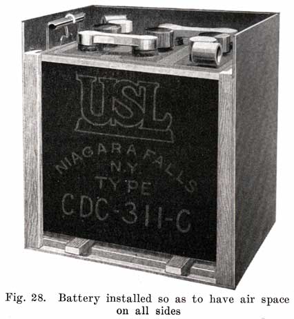
The acid which causes the corrosion may be spilled on the battery when hydrometer readings are taken. It may also be the result of filling the cells too full, with subsequent expansion and overflowing as the temperature of the electrolyte increases during charge. Loose vent caps may allow electrolyte to be thrown out of the cell by the motion of the car on the road. A poorly sealed battery allows electrolyte to be thrown out through the cracks left between the sealing compound and the jars or posts. The leaks may be caused by the battery cables not having sufficient slack, and pulling on the terminals.
The cap which fits over the vent tube at the center of the top of each cell is pierced by one or more holes through which gases formed within the cell may escape. These holes must be kept open; otherwise the pressure of the gases may blow off the top of the cell. If these holes are found to be clogged with dirt they should be cleaned out thoroughly.
The wooden battery case should also be kept clean and dry. If the battery is suspended from the frame of the car, dirt and mud from the road will gradually cover the case, and this mud should be scraped off frequently. Occasionally wash the case with a rag wet with ammonia, or hot baking soda solution. Keep the case, especially along the top edges, coated with asphaltum or some other acid proof paint.
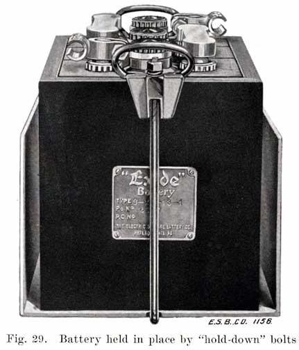
4. The battery must be held down firmly. If the battery is contained in an iron box mounted on the running-board, or in a compartment in the body of the car having a door at the side of the running-board, it is usually fastened in place by long bolts which hook on the handles or the battery case. These bolts, which are known as "hold-downs," generally pass through the running board or compartment, Fig. 29, and are generally fastened in place by nuts. These nuts should be turned up so that the battery is held down tight.
Other methods are also used to hold the battery in place, but whatever the method, it is vital to the battery that it be held down firmly so that the jolting of the car cannot cause it to move. The battery has rubber jars which are brittle, and which are easily broken. Even if a battery is held down firmly, it is jolted about to a considerable extent, and with a loosely fastened battery, the jars are bound to be cracked and broken.
5. The cables connected to the battery must have sufficient slack so that they will not pull on the battery terminals, as this will result in leaks, and possibly a broken cover.
The terminals on a battery should be in such a position that the cables may be connected to them easily, and without bending and twisting them. These cables are heavy and stiff, and once they are bent or twisted they are put under a strain, and exert a great force to straighten themselves. This action causes the cables to pull on the terminals, which become loosened, and cause a leak, or break the cover.
6. Inspect the Battery twice every month in Winter, and once a week in Summer, to make sure that the Electrolyte covers the plates. To do this, remove the vent caps and look down through the vent tube. If a light is necessary to determine the level of the electrolyte, use an electric lamp. Never bring an open flame, such as a match or candle near the vent tubes of a battery. Explosive gases are formed when a battery "gasses," and the flame may ignite them, with painful injury to the face and eyes of the observer as a result. Such an explosion may also ruin the battery.
During the normal course of operation of the battery, water from the electrolyte will evaporate. The acid never evaporates. The surface of the electrolyte should be not less than one-half inch above the tops of the plate. A convenient method of measuring the height of the electrolyte is shown in Fig. 30. Insert one end of a short piece of a glass tube, having an opening not less than one-eighth inch diameter, through the filling hole, and allow it to rest on the upper edge of the plates. Then place your finger over the upper end, and withdraw the tube. A column of liquid will remain in the lower end of the tube, as shown in the figure, and the height of this column is the same as the height of the electrolyte above the top of the plates in the cell. If this is less than one-half inch, add enough distilled water to bring the electrolyte up to the proper level. Fig. 31 shows the correct height of electrolyte in an Exide cell.
Never add well water, spring water, water from a stream, or ordinary faucet water. These contain impurities which will damage the battery, if used. It is essential that distilled water be used for this purpose, and it must be handled carefully so as to keep impurities of any kind out of the water. Never use a metal can for handling water or electrolyte for a battery, but always use a glass or porcelain vessel. The water should be stored in glass bottles, and poured into a porcelain or glass pitcher when it is to be used.
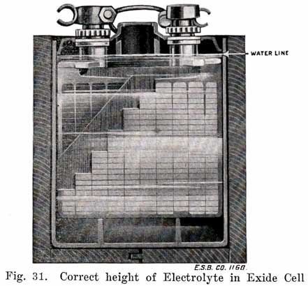
A convenient method of adding the water to the battery is to draw some up in a hydrometer syringe and add the necessary amount to the cell by inserting the rubber tube which is at the lower end into the vent hole and then squeezing the bulb until the required amount has been put into the cell.
In the summer time it makes no difference when water is added. In the winter time, if the air temperature is below freezing (32° F), start the engine before adding water, and keep it running for about one hour after the battery begins to "gas." A good time to add the water is just before starting on a trip, as the engine will then usually be run long enough to charge the battery, and cause the water to mix thoroughly with the electrolyte. Otherwise, the water, being lighter than the electrolyte, will remain at the top and freeze. Be sure to wipe off water from the battery top after filling. If battery has been wet for sometime, wipe it with a rag dampened with ammonia or baking soda solution to neutralize the acid.
Never add acid to a battery while the battery is on the car. By "acid" is meant a mixture of sulphuric acid and water. The concentrated acid, is of course, never used. The level of the electrolyte falls because of the evaporation of the water which is mixed with the acid in the electrolyte. The acid does not evaporate. It is therefore evident that acid should not be added to a cell to replace the water which has evaporated. Some men believe that a battery may be charged by adding acid. This is not true, however, because a battery can be charged only by passing a current through the battery from an outside source. On the car the generator charges the battery.
It is true that acid is lost, but this is not due to evaporation, but to the loss of some of the electrolyte from the cell, the lost electrolyte, of course, carrying some acid with it. Electrolyte is lost when a cell gasses; electrolyte may be spilled; a cracked jar will allow electrolyte to leak out; if too much water is added, the expansion of the electrolyte when the battery is charging may cause it to run over and be lost, or the jolting of the car may cause some of it to be spilled; if a battery is allowed to become badly sulphated, some of the sulphate is never reduced, or drops to the bottom of the cell, and the acid lost in the formation of the sulphate is not regained.
If acid or electrolyte is added instead of water, when no acid is needed, the electrolyte will become too strong, and sulphated plates will be the result. If a battery under average driving conditions never becomes fully charged, it should be removed from the car and charged from an outside source as explained later. If, after the specific gravity of the electrolyte stops rising, it is not of the correct value, some of the electrolyte should be drawn off and stronger electrolyte added in its place. This should be done only in the repair shop or charging station.
Care must be taken not to add too much water to a cell, Fig. 32. This will subsequently cause the electrolyte to overflow and run over the top of the battery, due to the expansion of the electrolyte as the charging current raises its temperature. The electrolyte which overflows is, of course, lost, taking with it acid which will later be replaced by water as evaporation takes place. The electrolyte will then be too weak. The electrolyte which overflows will rot the wooden battery case, and also tend to cause corrosion at the terminals.
If it is necessary to add water very frequently, the battery is operating at too high a temperature, or else there is a cracked jar. The high temperature may be due to the battery being charged at too high a rate, or to the battery being placed near some hot part of the engine or exhaust pipe. The car manufacturer generally is careful not to place the battery too near any such hot part. The charging rate may be measured by connecting an ammeter in series with the battery and increasing the engine speed until the maximum current is obtained. For a six volt battery this should rarely exceed 14 amperes. If the charging, current does not reach a maximum value and then remain constant, or decrease, but continues to rise as the speed of the engine, is increased, the regulating device is out of order. An excessive charging rate will cause continuous gassing if it is much above normal, and the temperature of the electrolyte will be above 100° F. In this way an excessive charging current may be detected.
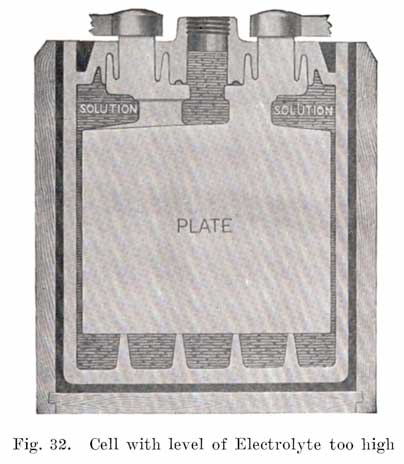
In hot countries or states, the atmosphere may have such a high temperature that evaporation will be more rapid than in temperate climates, and this may necessitate more frequent addition of water.
If one cell requires a more frequent addition of water than the others, it is probable that the jar of that cell is cracked. Such a cell will also show a low specific gravity, since electrolyte leaks out and is replaced by water. A battery which has a leaky jar will also have a case which is rotted at the bottom and sides. A battery with a leaky jar must, of course, be removed from the car for repairs.
"Dope" Electrolytes
From time to time within the past two years, various solutions which are supposed to give a rundown battery a complete charge within five or ten minutes have been offered to the public. The men selling such "dope" sometimes give a demonstration which at first sight seems to prove their claims. This demonstration consists of holding the starting switch down (with the ignition off) until the battery can no longer turn over the engine. They then pour the electrolyte out of the battery, fill it with their "dope," crank the engine by hand, run it for five minutes, and then get gravity readings of 1.280 or over. The battery will also crank the engine. Such a charge is merely a drug-store charge, and the "dope" is generally composed mainly of high gravity acid, which seemingly puts life into a battery, but in reality causes great damage, and shortens the life of a battery. The starting motor test means nothing. The same demonstration could be given with any battery. The high current drawn by the motor does not discharge the battery, but merely dilutes the electrolyte which is in the plates to such an extent that the voltage drops to a point at which the battery can no longer turn over the starting motor. If any battery were given a five minutes' charge after such a test, the diluted electrolyte in the plates would be replaced by fresh acid from the electrolyte and the battery would then easily crank the engine again. The five minutes of running the engine does not put much charge into the battery but gives time for the electrolyte to diffuse into the plates.
Chemical analysis of a number of dope electrolytes has shown that they consist mainly of high gravity acid, and that this acid is not even chemically pure, but contains impurities which would ruin a battery even if the gravity were not too high. The results of some of the analyses are as follows:
No. 1. 1.260 specific gravity sulphuric acid, 25 parts iron, 13.5 parts chlorine, 12.5, per cent sodium sulphate, 1 per cent nitric acid.
No. 2. 1.335 specific gravity sulphuric acid, large amounts of organic matter, part of which consisted of acids which attack lead.
No. 3. 1.340 specific gravity sulphuric acid, 15.5 per cent sodium sulphate.
No. 4. 1.290 specific gravity sulphuric acid, 1.5 per cent sodium sulphate.
No. 5. 1.300 specific gravity sulphuric acid.
If such "dope" electrolytes are added to a discharged battery, the subsequent charging of the battery will add more acid to the electrolyte, the specific gravity of which will then rise much higher than it should, and the plates and separators are soon ruined.
Do not put faith in any "magic" solution which is supposed to work wonders. There is only one way to charge a battery, and that is to send a current through it, and there is only one electrolyte to use, and that is the standard mixture of distilled water and chemically pure sulphuric acid.
7. The specific gravity of the electrolyte should be measured every two weeks and a permanent record of the readings made for future reference.
The specific gravity of the electrolyte is the ratio of its weight to the weight of an equal volume of water. Acid is heavier than water, and hence the heavier the electrolyte, the more acid it, contains, and the more nearly it is fully charged. In automobile batteries, a specific gravity of 1.300-1.280 indicates a fully charged battery. Generally, a gravity of 1.280 is taken to indicate a fully, charged cell, and in this book this will be done. Complete readings are as follows:
1.300-1.280--Fully charged.
1.280-1.200--More than half charged.
1.200-1.150--Less than half charged.
1.150 and less--Completely discharged.
For determining the specific gravity, a hydrometer is used. This consists of a small sealed glass tube with an air bulb and a quantity of shot at one end, and a graduated scale on the upper end. This scale is marked from 1.100 to 1.300, with various intermediate markings as shown in Fig. 33. If this hydrometer is placed in a liquid, it will sink to a certain depth. In so doing, it will displace a certain volume of the electrolyte, and when it comes to rest, the volume displaced will just be equal to the weight of the hydrometer. It will therefore sink farther in a light liquid than in a heavy one, since it will require a greater volume of the light liquid to equal the weight of the hydrometer. The top mark on the hydrometer scale is therefore 1.100 and the bottom one 1.300. Some hydrometers are not marked with figures that indicate the specific gravity, but are marked with the words "Charged," "Half Charged," "Discharged," or "Full," "Half Full," "Empty," in place of the figures.
The tube must be held in a vertical position, Fig. 35, and the stem of the hydrometer must be vertical. The reading will be the number on the stem at the surface of the electrolyte in the tube, Fig. 36. Thus if the hydrometer sinks in the electrolyte until the electrolyte comes up to the 1.150 mark on the stem, the specific gravity is 1.150.
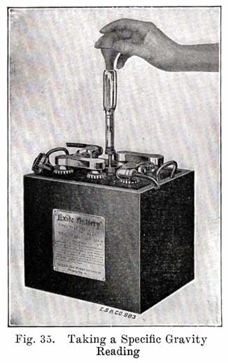
For convenience in automobile work, the hydrometer is enclosed in a large tube of glass or other transparent, acid proof material, having a short length of rubber tubing at its lower end, and a large rubber bulb at the upper end. The combination is called a hydrometer-syringe, or simply hydrometer. See Figure 34. In measuring the specific gravity of the electrolyte, the vent cap is removed, the bulb is squeezed (so as to expel the air from it), and the rubber tubing inserted in the hole from which the cap was removed. The pressure on the bulb is now released, and electrolyte is drawn up into the glass tube. The rubber tubing on the hydrometer should not be withdrawn from the cell. When a sufficient amount of electrolyte has entered the tube, the hydrometer will float. In taking a reading, there should be no pressure on the bulb, and the hydrometer should be floating freely and not touching the walls of the tube. The tube must not be so full of electrolyte that the upper end of the hydrometer strikes any part of the bulb.
The tube must be held in a vertical position, Fig. 35, and the stem of the hydrometer must be vertical. The reading will be the number on the stem at the surface of the electrolyte in the tube, Fig. 36. Thus if the hydrometer sinks in the electrolyte until the electrolyte comes up to the 1.150 mark on the stem, the specific gravity is 1.150.
If the battery is located in such a position that it is impossible to hold the hydrometer straight up, the rubber tube may be Pinched shut with the fingers, after a sufficient quantity of electrolyte has been drawn from the cell and the hydrometer then removed and held in a vertical position.
Specific gravity readings should never be taken soon after distilled water has been added to the battery. The water and electrolyte do not mix immediately, and such readings will give misleading results. The battery should be charged several hours before the readings are taken. It is a good plan to take a specific gravity reading before adding any water, since accurate results can also be obtained in this way.
Having taken a reading, the bulb is squeezed so as to return the electrolyte to the cell.
Care should be taken not to spill the electrolyte from the hydrometer syringe when testing the gravity. Such moisture on top of the cells tends to cause a short circuit between the terminals and to discharge the battery.
In making tests with the hydrometer, the electrolyte should always be returned to the same cell from which it was drawn.
Failure to do this will finally result in an increased proportion of acid in one cell and a deficiency of acid in others.
The specific gravity of all cells of a battery should rise and fall together, as the cells are usually connected in series so that the same current passes through each cell both on charge and discharge.
If one cell of a battery shows a specific gravity which is decidedly lower than that of the other cells in series with it, and if this difference gradually increases, the cell showing the lower gravity has internal trouble. This probably consists of a short circuit, and the battery should be opened for inspection. If the electrolyte in this cell falls faster than that of the other cells, a leaky jar is indicated. The various cells should have specific gravities within fifteen points of each other, such as 1.260 and 1.275.
If the entire battery shows a specific gravity below 1.200, it is not receiving enough charge to replace the energy used in starting the engine and supplying current to the lights, or else there is trouble in the battery. Use starter and lights sparingly until the specific gravity comes up to 1.280-1.300. If the specific gravity is less than 1.150 remove the battery from the car and charge it on the charging bench, as explained later. The troubles which cause low gravity are given on pages 321 and 322.
It is often difficult to determine what charging current should be delivered by the generator. Some generators operate at a constant voltage slightly higher than that of the fully charged battery, and the charging current will change, being higher for a discharged battery than for one that is almost or fully charged. Other generators deliver a constant current which is the same regardless of the battery's condition.
In the constant voltage type of generator, the charging current automatically adjusts itself to the condition of the battery. In the constant current type, the generator current remains constant, and the voltage changes somewhat to keep the current constant. Individual cases often require that another current value be used. In this case, the output of the generator must be changed. With most generators, a current regulating device is used which may be adjusted so as to give a fairly wide range of current, the exact value chosen being the result of a study of driving conditions and of several trials. The charging current should never be made so high that the temperature of the electrolyte in the battery remains above 90° F. A special thermometer is very useful in determining the temperature. See Fig. 37. The thermometer bulb is immersed in the electrolyte above the plates through the filler hole in the tops of the cells.
Batteries used on some of the older cars are divided into two or more sections which are connected in parallel while the engine is running, and in such cases the cables leading to the different sections should all be of exactly the same length, and the contacts in the switch which connect these sections in parallel should all be clean and tight. If cables of unequal length are used, or if some of the switch contacts are loose and dirty, the sections will not receive equal charging currents, because the resistances of the charging circuits will not be equal. The section having the greatest resistance in its circuit will receive the least amount of charge, and will show lower specific gravity readings than for other sections. In a multiple section battery, there is therefore a tendency for the various sections to receive unequal charges, and for one or more sections to run down continually. An ammeter should be attached with the engine running and the battery charging, first to one section and then to each of the others in turn. The ammeter should be inserted and removed from the circuit while the engine remains running and all conditions must be exactly the same; otherwise the comparative results will not give reliable indications. It would be better still to use two ammeters at the same time, one on each section of the battery. In case the amperage of charge should differ by more than 10% between any two sections, the section receiving the low charge rate should be examined for proper height of electrolyte, for the condition of its terminals and its connections at the starting switch, as described. Should a section have suffered considerably from such lack of charge, its voltage will probably have been lowered. With all connections made tight and clean and with the liquid at the proper height in each cell, this section may automatically receive a higher charge until it is brought back to normal. This high charge results from the comparatively low voltage of the section affected.
In case the car is equipped with such a battery, each section must carry its proper fraction of the load and with lamps turned on or other electrical devices in operation the flow from the several sections must be the same for each one. An examination should be made to see that no additional lamps, such as trouble lamps or body lamps, have been attached on one side of the battery, also that the horn and other accessories are so connected that they draw from all sections at once.
Some starting systems have in the past not been designed carefully in this respect, one section of the battery having longer cables attached to it than the others. In such systems it is impossible for these sections to receive as much charging current as others, even though all connections and switches are in good condition. In other systems, all the cells of the battery are in series, and therefore must receive the same charging current, but have lighting wires attached to it at intermediate points, thus dividing the battery into sections for the lighting circuits. If the currents taken by these circuits are not equal, the battery section supplying the heavier current will run down faster than others. Fortunately, multiple section batteries are not being used to any great extent at present, and troubles due to this cause are disappearing.
The temperature of the electrolyte affects the specific gravity, since heat causes the electrolyte to expand. If we take any battery or cell and heat it, the electrolyte will expand and its specific gravity will decrease, although the actual amount of acid is the same. The change in specific gravity amounts to one point, approximately, for every three degrees Fahrenheit. If the electrolyte has a gravity of 1.250 at 70°F, and the temperature is raised to 73°F, the specific gravity of the battery will be 1.249. If the temperature is decreased to 67°F, the specific gravity will be 1.251. Since the change of temperature does not change the actual amount of acid in the electrolyte, the gravity readings as obtained with the hydrometer syringe should be corrected one point for every three degrees change in temperature. Thus 70°F is considered the normal temperature, and one point is added to the electrolyte reading for every three degrees above 70°F. Similarly, one point is subtracted for every three degrees below 70°F. For convenience of the hydrometer user, a special thermometer has been developed by battery makers. This is shown in Fig. 37. It has a special scale mounted beside the regular scale. This scale shows the corrections which must be made when the temperature is not 70°F. Opposite the 70° point on the thermometer is a "0" point on the special scale. This indicates that no correction is to be made. Opposite the 67° point on the regular scale is a -1, indicating that 1 must be subtracted from the hydrometer reading to find what the specific gravity would be if the temperature were 70°F. Opposite the 73° point on the regular scale is a +1, indicating that 1 point must be added to reading on the hydrometer, in order to reduce the reading of specific gravity to a temperature of 70°F.
8. Storage batteries are strongly affected by changes in temperature. Both extremely high and very low temperatures are to be avoided. At low temperatures the electrolyte grows denser, the porosity of plates and separators decreases, circulation and diffusion of electrolyte are made difficult, chemical actions between plates and acid take place very slowly, and the whole battery becomes sluggish, and acts as if it were numbed with cold. The voltage and capacity of the battery are lowered.
As the battery temperature increases, the density of the electrolyte decreases, the plates and separators become more porous, the internal resistance decreases, circulation and diffusion of electrolyte take place much more quickly, the chemical actions between plates and electrolyte proceed more rapidly, and the battery voltage and capacity increase. A battery therefore works better at high temperatures.
Excessive temperatures, say over 110° F, are, however, more harmful than low temperatures. Evaporation of the water takes place very rapidly, the separators are attacked by the hot acid and are ruined, the active materials and plates expand to such an extent that the active materials break away from the grids and the grids warp and buckle. The active materials themselves are burned and made practically useless. The hot acid also attacks the grids and the sponge lead and forms dense layers of sulphate. Such temperatures are therefore extremely dangerous.
A battery that persistently runs hot, requiring frequent addition of water, is either receiving too much charging current, or has internal trouble. The remedy for excessive charge is to decrease the output of the generator, or to burn the lamps during the day time. Motorists who make long touring trips in which considerable day driving is done, with little use of the starter, experience the most trouble from high temperature. The remedy is either to decrease the charging rate or burn the lamps, even in the day time.
Internal short-circuits cause excessive temperature rise, both on charge and discharge. Such short circuits usually result from buckled plates which break through the separators, or from an excessive amount of sediment. This sediment consists of active material or lead sulphate which has dropped from the positive plate and fallen to the bottom of the battery jar. All battery jars are provided with ridges which keep the plates raised an inch or more from the bottom of the jar, and which form pockets into which the materials drop. See Fig. 10. If these pockets become filled, and the sediment reaches the bottom of the plates, internal short circuits result which cause the battery to run down and cause excessive temperatures.
If the electrolyte is allowed to fall below the tops of the plates, the parts of the plates above the acid become dry, and when the battery is charged grow hot. The parts still covered by the acid also become hot because all the charging current is carried by these parts, and the plate surface is less than before. The water will also become hot and boil away. A battery which is thus "charged while dry" deteriorates rapidly, its life being very short.
If a battery is placed in a hot place on the car, this heat in addition to that caused by charging will soften the plates and jars, and shorten their life considerably.
In the winter, it is especially important not to allow the battery to become discharged, as there is danger of the electrolyte freezing. A fully charged battery will not freeze except at an extremely low temperature. The water expands as it freezes, loosening the active materials, and cracking the grids. As soon as a charging current thaws the battery, the active material is loosened, and drops to the bottom of the jars, with the result that the whole battery may disintegrate. Jars may also be cracked by the expansion of the water when a battery freezes.
To avoid freezing, a battery should therefore be kept charged, The temperatures at which electrolyte of various specific gravities freezes are as follows:
| Specific Gravity | Freezing Pt. | Specific Gravity | Freezing Pt. | |
|---|---|---|---|---|
| 1.000 | 32°F | 1.200 | -16°F | |
| 1.050 | 26°F | 1.250 | -58°F | |
| 1.100 | 18°F | 1.280 | -92°F | |
| 1.150 | 5°F | 1.300 | -96°F |
9. Care of Storage Battery When Not in Service. A storage battery may be out of service for a considerable period at certain times of the year, for example, when the automobile is put away during the winter months, and during this time it should not be allowed to stand without attention. When the battery is to be out of service for only three or four weeks, it should be kept well filled with distilled water and given as complete a charge as possible the last few days, the car is in service by using the lamps and starting motor very sparingly. The specific gravity of the electrolyte in each cell should be tested, and it should be somewhere between 1.280 and 1.300. All connections to the battery should be removed, as any slight discharge current will in time completely discharge it, and the possibilities of such an occurrence are to be avoided. If the battery is to be put out of service for several months, it should be given a complete charge by operating the generator on the car or by connecting it to an outside charging circuit. During the out-of-service period, water should be added to the cells every six or eight weeks and the battery given what is called a freshening charge; that is, the engine should be run until the cells have been gassing for perhaps one hour, and the battery may then be allowed to stand for another similar period without further attention. Water should be added and the battery fully charged before it is put back into service. It is desirable to have the temperature of the room where the battery is stored fairly constant and as near 70 degrees Fahrenheit as possible.
The Storage Battery is a most faithful servant, and if given even a fighting chance, will respond instantly to the demands made upon it. Given reasonable care and consideration, it performs its duties faithfully for many months. When such care is lacking, however, it is soon discovered that the battery is subject to a number of diseases, most of which are "preventable," and all of which, if they do not kill the battery, at least, greatly impair its efficiency.
In discussing these diseases, we may consider the various parts of which a battery is composed, and describe the troubles to which they are subject. Every battery used on an automobile is composed of:
- 1. Plates
- 2. Separators
- 3. Jars in which Plates, Separators, and Electrolyte are placed
- 4. Wooden case
- 5. Cell Connectors, and Terminals
- 6. Electrolyte
Most battery diseases are contagious, and if one part fails, some of the other parts are Affected. These diseases may best be considered in the order in which the parts are given in the foregoing list.
PLATE TROUBLES
Plates are the "vitals" of a battery, and their troubles affect the life of the battery more seriously than those of the other parts. It is often difficult to diagnose their troubles, and the following descriptions are given to aid in the diagnosis.
1. Over discharge. Some battery men say that a battery is suflphated whenever anything is wrong with it. Sulphation is the formation of lead sulphate on the plates. As a battery of the lead acid type discharges, lead sulphate must form. There can be no discharge of such a battery without the formation of lead sulphate, which is the natural product of the chemical reactions by virtue of which current may be drawn from the battery. This sulphate gradually replaces the lead peroxide of the positive plate, and the spongy lead of the negative plate. When a battery has been discharged until the voltage per cell has fallen to the voltage limits, considerable portions of the lead peroxide and spongy lead remain on the plates. The sulphate which is then present is in a finely divided, porous condition, and can readily be changed back to lead peroxide and spongy lead by charging the battery.
If the discharge is continued after the voltage has fallen to the voltage limits, an excessive amount of sulphate forms. It fills up the pores in the active materials, and covers up much of the active material which remains, so that it is difficult to change the sulphate back to active material. Moreover, the expansion of active material which takes place as the sulphate forms is then so great that it causes the active material to break off from the plate and drop to the bottom of the jar.
2. Allowing a Battery to Stand Idle. When lead sulphate is first formed, it is in a finely divided, porous condition, and the electrolyte soaks through it readily. If a battery which has been discharged is allowed to stand idle without being charged, the lead sulphate crystals grow by the combination of the crystals to form larger crystals. The sulphate, instead of having a very large surface area, upon which the electrolyte may act in changing the sulphate to active material, as it does when it is first formed, now presents only a very small surface to the electrolyte, and it is therefore only with great difficulty that the large crystals of sulphate are changed to active material. The sulphate is a poor conductor, and furthermore, it covers up much of the remaining active material so that the electrolyte cannot reach it.
A charged battery will also become sulphated if allowed to stand idle, because it gradually becomes discharged, even though no wires of any kind are attached to the battery terminals. How this takes place is explained later. The discharge and formation of sulphate continue until the battery is completely discharged. The sulphate then gradually forms larger crystals as explained in the preceding paragraph, until all of the active material is either changed to sulphate, or is covered over by the sulphate so that the electrolyte cannot reach it. The sulphate thus forms a high resistance coating which hinders the passage of charging current through the battery and causes heating on charge. It is for this reason that sulphated plates should be charged at a low rate. The chemical actions which are necessary to change the sulphate to active material can take place but very slowly, and thus only a small current can be absorbed. Forcing a large current through a sulphated battery causes heating since the sulphate does not form uniformly throughout the plate, and the parts which are the least sulphated will carry the charging current, causing them to become heated. The heating damages the plates and separators, and causes buckling, as explained later.
If batteries which have been discharged to the voltage limits are allowed to stand idle without being charged, they will, of course, continue to discharge themselves just as fully charged batteries do when allowed to stand idle.
3. Starvation. If a battery is charged and discharged intermittently, and the discharge is greater than the charge, the battery will never be fully charged, and lead sulphate will always be present. Gradually this sulphate forms the large tough crystals that cover the active material and remove it from action. This action continues until all parts of the plate are covered with the crystalline sulphate and we have the same condition that results when a battery is allowed to stand idle without any charge.
4. Allowing Electrolyte to Fall Below Tops of Plates. If the electrolyte is allowed to fall below the tops of the plates, so that the active materials are exposed to the air, the parts thus exposed will gradually become sulphated. The spongy lead of the negative plate, being in a very finely divided state, offers a very large surface to the oxygen of the air, and is rapidly oxidized, the chemical action causing the active material to become hot. The charging current, in passing through the parts of the plates not covered by the electrolyte also heats the active materials. The electrolyte which occasionally splashes over the exposed parts of the plates and which rises in the pores of the separators, is heated also, and since hot acid attacks the active materials readily, sulphation takes place quickly. The parts above the electrolyte, of course, cannot be charged and sulphate continues to form. Soon the whole exposed parts are sulphated as shown in Fig. 209.
As the level of the electrolyte drops, the electrolyte becomes stronger, because it is only the water which evaporates, the acid remaining and becoming more and more concentrated. The remaining electrolyte and the parts of the plates covered by it become heated by the current, because there is a smaller plate area to carry the current, and because the resistance of the electrolyte increases as it grows more concentrated. Since hot acid attacks the active materials, sulphation also takes place in the parts of the plates still covered by the electrolyte.
The separators in a battery having the electrolyte below the tops of the plates suffer also, as will be explained later. See page 346.
5. Impurities. These are explained later. See page 76.
6. Adding Acid Instead of Water. The sulphuric acid in the electrolyte is a heavy, oily liquid that does not evaporate. It is only the water in the electrolyte which evaporates. Therefore, when the level of the electrolyte falls, only water should be added to bring the electrolyte to the correct height. There are, however, many car owners who still believe that a battery may be charged by adding acid when the level of the electrolyte falls. Batteries in which this is done then contain too much acid. This leads to two troubles. The first is that the readings taken with a hydrometer will then be misleading. A specific gravity of 1.150 is always taken to indicate that a battery is discharged, and a specific gravity of 1.280 that a battery is charged. These two values of specific gravity indicate a discharged and charged condition of the battery ONLY WHEN THE PROPORTION OF ACID IN THE ELECTROLYTE IS CORRECT. It is the condition of the plates, and not the specific gravity of the electrolyte which determines when a battery is either charged or discharged. With the correct proportion of acid in the electrolyte, the specific gravity of the electrolyte is 1.150 when the plates are discharged and 1.280 when the plates are charged, and that is why specific gravity readings are generally used as an indication of the condition of the battery.
If there is too much acid in the electrolyte, the plates will be in a discharged condition before the specific gravity of the electrolyte drops to 1.150, and will not be in a charged condition until after the specific gravity has risen beyond the usual value. As a result of these facts a battery may be over-discharged, and never fully charged, this resulting in the formation of sulphate.
The second trouble caused by adding acid to the electrolyte is that the acid will then be too concentrated and attacks both plates and separators. This will cause the plates to become sulphated, and the separators rotted.
7. Overheating. This was explained in Chapter 9. See page 66.
Buckling
Buckling is the bending or twisting of plates due to unequal expansion of the different parts of the plate, Figs. 207 and 208. It is natural and unavoidable for plates to expand. As a battery discharges, lead sulphate forms. This sulphate occupies more space than the lead peroxide and spongy lead, and the active materials expand. Heat expands both active materials and grids. As long as all parts of a plate expand equally, no buckling will occur. Unequal expansion, however, causes buckling.
1. Over discharge. If discharge is carried too far, the expansion of the active material on account of the formation of lead sulphate will bend the grids out of shape, and may even break them.
2. Continued Operation with Battery in a Discharged Condition. When a considerable amount of lead sulphate has, formed, and current is still drawn from the battery, those portions of the plate which have the least amount of sulphate will carry most of the current, and will therefore become heated and expand. The parts covered with sulphate will not expand, and the result is that the parts that do expand will twist the plate out of shape. A normal rate of discharge may be sufficient to cause buckling in a sulphated plate.
3. Charging at High Rates. If the charging rate is excessive, the temperature will rise so high that excessive expansion will take place. This is usually unequal in the different parts of the plate, and buckling results. With a battery that has been over discharged, the charging current will be carried by those parts of the plates which are the least sulphated. These parts will therefore expand while others will not, and buckling results.
4. Non-Uniform Distribution of Current Over the Plates. Buckling may occur in a battery which has not been over-discharged, if the current carried by the various parts of the plate is not uniform on account of faulty design, or careless application of the paste. This is a fault of the manufacturers, and not the operating conditions.
5. Defective Grid Alloy. If the metals of which the grids are composed are not uniformly mixed throughout the plate, areas of pure lead may be left here and there, with air holes at various points. The electrolyte enters the air holes, attacks the lead and converts the grid partly into active material. This causes expansion and consequent distortion and buckling.
Buckling will not necessarily cause trouble, and batteries with buckled plates may operate satisfactorily for a long time. If, however, the expansion and twisting has caused much of the active material to break away from the grid, or has loosened the active material from the grids, much of the battery capacity is lost. Another danger is that the lower edges of a plate may press against the separator with sufficient force to cut through it, touch the next plate, and cause a short-circuit.
Shedding, or Loss of Active Material
The result of shedding, provided no other troubles occur, is simply to reduce the capacity of the plates. The positives, of course, suffer more from shedding than the negatives do, shedding being one of the chief weaknesses of the positives. There is no remedy for this condition. When the shedding has taken place to such an extent that the capacity of the battery has fallen very low, new plates should be installed. After a time, the sediment space in the bottom of the jar becomes filled with sediment, which touches the plates. This short-circuits the cell, of course, and new plates must be installed, and the jars washed out thoroughly.
1. Normal Shedding. It is natural and unavoidable for the positives to shed. Lead Peroxide is a powder-like substance, the particles of which do not hold together. A small amount of sulphate will cement the particles together to a considerable extent. At the surface of the plate, however, this sulphate is soon changed to active material, and the peroxide loses its coherence. Particles of peroxide drop from the plates and fall, into the space in the bottom of the jar provided for this purpose.
Bubbles of gas which occur at the end of a charge blow some of the peroxide particles from the plate. The electrolyte moving about as the battery is jolted by the motion of the car washes particles of peroxide from the positive plates. Any slight motion between positive plates and separators rubs some peroxide from the plates. It is therefore entirely natural for shedding to occur, especially at the positives. The spongy lead of the negatives is much more elastic than the peroxide, and hence very little shed. ding occurs at the negative plates. The shedding at the positives explains why the grooved side of the separator is always placed against the positive plate. The grooves, being vertical, allow the peroxide to fall to the bottom of the jar, where it accumulates as sediment, or "mud."
2. Excessive Charging Rate, or Overcharging. If a battery is charged at too high a rate, only part of the current is used to produce the chemical actions by which the battery is charged. The balance of the current decomposes the water of the electrolyte into hydrogen and oxygen, causing gassing. As the bubbles of gas force their way out of the plates, they blow off particles of the active material.
When a battery is overcharged, the long continued gassing has the same effect as described in the preceding paragraph.
3. Charging Sulphated Plates at too High a Rate. In sulphated plates, the chemical actions which take place as a battery is charged can proceed but very slowly, because the sulphate, besides being a poor conductor, has formed larger crystals which present only a small surface for the electrolyte to act upon, and has also covered up much of the remaining active material. Since the chemical actions take place slowly, the charging current must be kept at a low value. If too heavy a charging current is used, the battery will be overheated, and some of the current will simply cause gassing as explained in No. 2 above. The gas bubbles will break off pieces of the sulphate, which then fall to the bottom of the jars as "mud."
4. Charging Only a Part of the Plate. If the electrolyte falls below the tops of the plates, and the usual charging current is sent into the battery, the current will be too great for the plate area through which it passes, and hence gassing and shedding will result as already explained.
The same condition exists in a battery in which one or more plates have been broken from the strap, either because of mechanical vibration or because of impurities such as acetic acid in improperly treated separators. The remaining plates are called upon to do more work, and carry the entire charging current. Gassing and shedding will result.
5. Freezing. If a battery is given any care whatever, there is little danger of freezing. The electrolyte of a fully charged battery with a specific gravity of 1.280 freezes at about 92° below zero. With a specific gravity of 1.150, the electrolyte freezes at about 5° above zero. A frozen battery therefore indicates gross neglect.
As the electrolyte freezes, the water of the electrolyte expands. Since there is electrolyte in all the inner parts of the plate, the expansion as the water in the paste freezes forces the pastes out of the grids. The expansion also cracks the rubber jars, and sometimes bulges out the ends of the battery case.
Loose Active Material
This refers to a condition in which the active materials are no longer in contact with the grid. Corrosion, or sulphation, of the grids themselves is generally present at the same time, since the chemical actions are shifted from the active material to the grids themselves.
1. Over discharge. As a battery discharges, the lead sulphate which forms causes an expansion of the active material. If a battery is repeatedly over-discharged, this results in the positives shedding. In the negatives, the spongy lead is puffed out, resulting in the condition known as "bulged negatives" as illustrated in Fig 122.
2. Buckling. As a plate grid is bent out of shape, the active material, especially the peroxide, breaks loose from the grid, since the peroxide cannot bend as much as the grids. This occurs in the negatives also, though not to such an extent as in the positives.
If the plates are buckled to such an extent that the element will not go back into the jar, the positives should be discarded. If the positives are buckled, the negatives will be also, but not to the extent that the positives are.
In the case of the positives, there is no remedy, and the plates should be discarded. The negatives, however, may be fully charged, and then straightened, and the active material forced back flush with the grids by pressings, as described in Chapter 15.
Impurities
Impurities may be divided into two general classes. The first class includes those which do not attack the separators or grids, but merely cause internal self-discharge. The second class includes those which attack the grids or separators.
1. Impurities Which Merely Cause Self-discharge. This includes metals other than lead. If these metals are in solution in the electrolyte, they deposit on the negative plate, during charge, in their ordinary metallic state, and form small cells with the spongy lead. These small cells discharge as soon as the charging circuit is opened, and some of the lead is changed to lead sulphate. This, of course, causes a loss in capacity. Free hydrogen is given off by this local discharge, and so much of it is at times given off that the hydrogen bubbles give the electrolyte a milky appearance.
Silver, gold, and platinum are the most active in forming small local cells. These metals form local cells which have comparatively high voltages, and which take away a considerable portion of the energy of a cell. Platinum is especially active, and a small amount of platinum will prevent a negative plate from taking a charge. Gradually, however, the spongy lead covers up the foreign metal and prevents it from forming local cells.
Iron also forms local cells which rob the cell of a considerable portion of its capacity. This may be brought into the cell by impure acid or water. Iron remains in solution in the electrolyte, and is not precipitated as metallic iron. The iron in solution travels from the positive to the negative plate, and back again, causing a local discharge at each plate. It is, moreover, very difficult to remove the iron, except by pouring out all of the electrolyte. Manganese acts the same as the iron.
2. Impurities Which Attack the Plates. In general, this class includes acids other than sulphuric acid, compounds formed from such acids, or substances which will readily form acids by chemical action in the cell. Nitric acid, hydrochloric or muriatic acid, and acetic acid belong in this class of impurities. Organic matter in a state of decomposition attacks the lead grids readily.
Impurities in the second class dissolve the lead grids, and the plate disintegrates and falls to pieces, since its backbone is destroyed. When a battery which contains these impurities is opened, it will be found that the plates crumble and fall apart at the slightest touch. See Fig. 210.
Separators which have not been treated properly introduce acetic acid into a cell. The acetic acid attacks and rots the lead, especially the lugs projecting above the electrolyte, and the plate connecting straps. The plates will generally be found broken from the connecting strap, with the plate lugs broken and crumbled.
As for remedies, there is not much to be done. Impurities in the first class merely decrease the capacity of the battery. If the battery is fully charged, and the negatives then washed thoroughly, some of the impurities may be removed. Impurities of the second class have generally damaged the plates beyond repairs by the time their presence is suspected.
The best thing to do is to keep impurities out of the battery. This means that only distilled water, which is known to be absolutely free from impurities should be used.
Impurities which exist in the separators or acid cannot be detected readily, but in repairing a battery, separators furnished by one of the reliable battery makers should be used. Pure acid should also be used. This means that only chemically pure, or "C. P." acid, also known as battery acid should be used. In handling the acid in the shop, it should always be kept in its glass bottle, and should be poured only into a glass, porcelain, earthenware, lead, or rubber vessel. Never use a vessel made of any other material.
Corroded Grids
When the grids of a plate are attacked chemically, they become thin and weak, and may be spoken of as being corroded.
1. Impurities. Those impurities which attack the lead grids, such as acids other than sulphuric acid, compounds formed from these acids, or substances which will readily form acids dissolve some of the lead which composes the grids. The grids gradually become weakened. The decrease in the amount of metal in the grids increases the internal resistance of the cell and give a tendency for temperatures to be higher in the cell. The contact between grids and active material is in time made poor. If the action of the impurities continues for any length of time, the plate becomes very weak, and breaks at the slightest touch.
2. High Temperatures. Anything that raises the temperature of the electrolyte, such as too high a charging rate, causes the acid to attack the grids and form a layer of sulphate on them. The sulphate is changed to active material on charge, and the grids are thereby weakened.
3. Age. Grids gradually become weak and brittle as a battery remains in service. The acid in the electrolyte, even though the electrolyte has the correct gravity and temperature, has some effect upon the grids, and in time this weakens them. During the life of a battery it is at times subjected to high temperatures, impurities, sulphation, etc., the combined effects of which result in a gradual weakening of the grids.
Granulated Negatives
1. Age. The spongy lead of the negative plate gradually assumes a "grainy" or "granulated" appearance. The lead then seems to be made up of small grains, like grains of sand, instead of being a smooth paste. This action is a natural one, and is due to the gradual increase in the size of the particles of the lead. The plate loses its porosity, the particles cementing together and closing the pores in the lead. The increase in the size of the particles of the spongy lead decreases the amount of surface exposed to the action of the electrolyte, and the plate loses capacity. Such plates should be thrown away, as charging and discharging will not bring the paste back to its original state.
2. Heat will also cause the paste to become granulated, and its surface to become rough or even blistered.
Heating of Negatives Exposed to the Air
When charged negatives are exposed to the air, there is a decided increase in their temperature. Spongy lead is in an extremely finely divided state, the particles of lead being very minute, and forming a very porous mass. When the plate is exposed to the air, rapid oxidation takes place because the oxygen of the air has a very large surface to act upon. The oxidation causes the lead to become heated. The heating, of course, raises the temperature of the electrolyte, and the hot acid attacks both grids and lead.
Fully charged negatives should therefore be watched carefully when removed from a battery. When they become heated and begin to steam, they should be dipped in water until they have cooled. They may then be removed from the water, but should be dipped whenever they begin to steam. After they no longer heat, they may be left exposed to the air.
This method of dipping the negatives to prevent overheating has always been followed. However, the Electric Storage Battery Company, which makes the Exide batteries, does not take any steps to prevent the heating of the negatives when exposed to the air, stating that their plates are not injured by the heating which takes place.
Negatives With Very Hard Active Material
This is the characteristic condition of badly sulphated negatives. The active material may be as hard as a stone. The best method of treating such negatives is to charge them in distilled water. See Chapter 15.
Bulged Negatives
This is a characteristic of a repeatedly over-discharged negative. The lead sulphate which forms as a battery discharges is bulkier than the spongy lead, and the lead expands and bulges out between the ribs of the grid.
Negative With Soft, Mushy Active Material
1. High Gravity. Gravity above 1.300 causes the acid to act upon the spongy lead and soften it.
2. Heat will soften the spongy lead also. The softened spongy lead is loosened and falls from the grids, as shown in Fig. 211. Little can be done for such negatives.
Negatives With Roughened Surface
This is caused by slight overheating, and is not a serious condition.
Frozen Positives
A battery which is allowed to stand in a cold place while completely discharged will freeze. The water in the electrolyte expands as it freezes, cracking the rubber jars and bulging out the end of the wooden case. As the electrolyte which fills the pores of the positive plates freezes and expands, it breaks the active material loose from the grids. When the battery thaws, the active material does not go back into the grids. When such a battery is opened, and the groups separated, the positive active material sticks to the separators in large pieces, Fig. 112, and that remaining in the grids falls out very easily. The active material has a pinkish color and is badly shrunken.
Rotted, Disintegrated Positives
1. Impurities. This has already been discussed. See page 76.
2. Overheating. The hot electrolyte dissolves the lead of the grids and that which is dissolved is never converted back to lead. Continued overheating wears out the grids, and the active material also, and the plate falls to pieces at the slightest pressure.
3. Age. Positives gradually disintegrate due to the prolonged action of the electrolyte on the grids, an occasional overheating, occasional use of impure water, etc.
Positives which are rotted and disintegrated are, of course, hopeless, and must be junked.
Buckled Positives
As previously described, buckling is caused by unequal expansion. If the buckling is only slight, the plates may be used as they are. If the plates are badly buckled, the active material will be found to be loose, and the plates cannot be straightened. Such positives should be discarded.
Positives That Have Lost Considerable Active Material
This is the result of continued shedding, the causes of which have already been given. If the shedding is only slight, and the plate is good otherwise, it may be used again. If such active material has been lost, the plates must be discarded.
Positives With Soft Active Material
Continued operation at high temperatures, will soften the peroxide, and make the plates unfit for further use. Old positives are soft, clue to the natural deterioration of the paste with age.
Positives With Hard, Shiny Active Material
This condition is found in batteries that have been charged with the acid below the tops of the plates. The part of the plate above the acid is continually being heated by the charging current. It becomes hard and shiny, and has cracks running through it. The peroxide becomes orange or brick colored, and the grid deteriorates. The part of the plate below the electrolyte suffers also, as explained more fully on page 71. Such plates should be discarded if any considerable portion of the plates is affected. Plates in which 1/2 to 1 inch of the upper parts are affected may be used again if otherwise in good condition.
Plates Which Have Been Charged in Wrong Direction
Such plates have been partly reversed, so that there is lead peroxide and spongy lead on both positive and negative plates, and such plates are generally worthless. If the active materials have not become loosened from the grids, and the grids have not been disintegrated and broken, the plates may sometimes be reversed by a long charge at a low rate in the right direction. If this does not restore the plates, discard them.
SEPARATOR TROUBLES
Separators form the weakest part of a battery, but at the same time perform a very important duty. New separators should therefore be installed whenever a battery is opened for repairs. Repairs should never be attempted on separators.
1. Not Properly Expanded Before Installation. Separators in stock must be kept moist. This not only prevents them from becoming dry and brittle, but keeps them fully expanded. If separators which have been kept dry in stock are installed in a battery, they do their expanding inside the battery. This causes them to project beyond the edges of the plates. The crowding to which they are subjected causes them to crack. Cracked separators permit "treeing" between plates, with a consequent short circuit.
2. Not Properly Treated. Separators which have not been given the proper chemical treatment are likely to develop Acetic acid after they are in the battery. Acetic acid dissolves the lead grids, the plate lugs, and the plate connecting straps rapidly. If the plate lugs are found broken, and crumble easily, acetic acid is very likely present, especially if an odor like that of vinegar is noticeable. Improperly treated separators will cause a battery to show low voltage at high rates of discharge, particularly in cold weather, and will also cause the negatives to give poor cadmium readings, which may lead the repairman to conclude that the negatives are defective. The separators of batteries which have been shipped completely assembled without electrolyte and with moistened plates and separators will sometimes have the same effect.
3. Cracked. Separators should be carefully "candled" — placed in front of a light and looked through. Cracks, resinous streaks, etc., mean that the separator should not be used, as it will breed trouble.
4. Rotted and Carbonized. This may be the result of old age, overheating, or high gravity electrolyte.
5. Pores Clogged. Impurities, dirt from impure water, and lead sulphate fill the pores of a separator and prevent the proper circulation of the electrolyte. The active material of frozen positives also fills up the pores of a separator.
6. Edges Chiseled Off. A buckling plate will cut through the lower edge of a separator and short circuit the cell. Holes will be cut through any part of a separator by a buckling plate, or a negative with bulged active material.
JAR TROUBLES
Battery jars are made of hard rubber, and are easily broken. They are not acted upon by the electrolyte, or any of the impurities which may be found in the jar. Their troubles are all mechanical, and consist of being cracked, or having small holes through the walls. Jars are softened by high temperatures, but this does no particular harm unless they are actually burned by an open flame or red hot metal. The causes of jar troubles are as follows:
1. Rough Handling. By far the most common cause of jar breakage is rough handling by careless or inexperienced persons. If one end of a battery rests on the floor, and the other is allowed to drop several inches, broken jars will probably result from the severe impact of the heavy lead plates. Storage batteries should be handled as if made of glass. When installed on a car, the springs protect the battery from shock to a considerable extent, but rough roads or exceptionally severe jolts may break jars.
2. Battery Not Properly Fastened. In this case a battery is bumped around inside the battery compartment, and damage is very likely to result.
3. Any Weight Placed on Top of the Battery is transmitted from the links to the plates, and by them to the bottom of the jars. Batteries should always be stored in racks, and not one on top of another. The practice of putting any weight whatever on top of a battery should be promptly discouraged.
4. Freezing. This condition has already been explained. It causes a great many broken jars every winter.
5. Groups Not Properly Trimmed. The outside negative plates in a cell come just inside the jar, and the strap ends must be carefully trimmed off flush with the plates, to prevent them from breaking the top of the jars. Jars have slightly rounded corners, and are somewhat narrower at the extreme ends than nearer the center. A group may therefore go into a jar quite readily when moved toward the other end of the jar to that into which the post strap must go when in proper position for the cover. When the group is forced back into its proper position the strap may break the jar. It is a good plan not only to trim the ends of the negative straps perfectly flush, but to round the strap corners where they go into the jar corners.
6. Defective Jars. (a) A jar not properly vulcanized may come apart at the scam. (b) A small impurity in the rubber may dissolve in the acid and leave a minute pinhole. All jars are carefully tested at the factory and the likelihood of trouble from defective jars is extremely small.
7. Explosion in Cell. (a) Hydrogen and oxygen gases evolved during charging make a very explosive mixture. An open flame brought near a battery on charge or freshly charged, will probably produce an explosion resulting in broken jars and jar covers. (b) An open circuit produced inside a cell on charge in the manner described on page 86 under the heading "Open Circuits," will cause a spark at the instant the circuit is broken, with the same result as bringing a flame near the battery. (c) The small holes in the vents must be kept free for the escape of the gases. These holes are usually sealed in batteries shipped with moistened plates and separators, to keep air out of the cells. The seals must be removed when the battery is prepared for service. If the vents remain plugged, the pressure of the gases formed during charge will finally burst the covers of jars.
BATTERY CASE TROUBLE
1. Ends Bulged Out. This may be due to a battery having been frozen or to hold-downs being screwed down too tight, or some similar cause. Whether the case can be repaired depends on the extent of the bulging. This can best be determined by the repairman.
2. Rotted. If the case is rotted around the top, it is evidence that: (a) Too much water was added, with subsequent overflowing when electrolyte warmed up during charge. (b) The tops were poorly sealed, resulting in leaks between the covers and the, jars. (c) Battery has not been fastened down properly, and acid has been thrown out of the jars by the jolting of the car on the road. (d) The vent plugs have not been turned down tightly. (e) Electrolyte has been spilled in measuring specific gravity.
If the case is rotted around the lower part it indicates that the jars are cracked or contain holes. Instructions for making repairs on battery cases are given on page 360.
TROUBLE WITH CONNECTORS AND TERMINALS
1. Corroded. This is a very common trouble, and one which should be guarded against very carefully. Corrosion is indicated by the presence of a grayish or greenish substance on the battery terminals, especially the positive. It is due to several causes:
(a) Too much water added to cells. The electrolyte expands on charge and flows out on the top of the battery.
(b) Battery not fastened firmly. The jolting caused by the motion of the car on the road will cause electrolyte to be thrown out of the vent caps.
(c) Battery poorly sealed. The electrolyte will be thrown out on the cover by the motion of the car through the leaks which result from poor sealing.
(d) Vent caps loose. This also allows electrolyte to be thrown out on the battery top.
(e) Electrolyte spilled on top of battery in measuring specific gravity.
(f) Battery cables damaged, or loose. The cables attached to the battery terminals are connected to lugs which are heavily coated with lead. The cables are insulated with rubber, upon which sulphuric acid has no effect. Care should be taken that the lead coating is not worn off, and that the rubber insulation is not broken or cut so as to allow electrolyte, which is spilled on the battery top as explained in (a), (b), (c), (d) and (e), to reach the bare copper conductors of the cable. The terminal parts are always so made that when the connections are kept tight no acid can come into contact with anything but lead and rubber, neither of which is attacked by sulphuric acid.
(g) Attaching wires directly to battery terminals. There should be no exposed metal except lead at the battery terminals. No wires of any other metal should be attached to the battery terminals. Such wires should be connected to the rubber covered cables which are attached to battery, and the connections should be made far enough away from the battery to prevent electrolyte from coming in contact with the wire. Car manufacturers generally observe this rule, but the car owner may, through ignorance, attach copper wires directly to the battery terminals. The positive terminal is especially subject to corrosion, and should be watched carefully. To avoid corrosion it is necessary simply to keep the top of the battery dry, keep the terminal connections tight, and coat the terminals with vaseline. The rule about connecting wires directly to the battery terminals must of course be observed also.
2. Loose. Loose terminal connections cause a loss of energy due to their resistance, and all such connections must be well made. If the inter-cell connectors are loose, it is due to a poor job of lead burning. This is also true of burned on terminals, and in either case, the connections should be drilled off, cleaned and re-burned.
Terminals sometimes become so badly corroded that it is impossible to disconnect the cables front the battery. Stitch terminals should be drilled off and soaked in boiling soda water.
ELECTROLYTE TROUBLES
(1) Low Gravity.See page 321.
(2) High Gravity. See page 323.
(3) Low Level. See page 323.
(4) High Level. This condition is due to the addition of too much water. It leads to corrosion as already explained. It also causes a loss of acid. The Electrolyte which overflows is lost, this of course, causing a loss of acid. The condition of Low Gravity then arises, as described on page 321.
(5) Specific gravity will not rise during charge. See page 204.
(a) Lead Sulphate in Battery Acid. It sometimes happens that sulphuric acid contains some lead sulphate in solution. This sulphate is precipitated when water is added to the acid in mixing electrolyte, and gives the electrolyte a milky appearance. This sulphate settles if the electrolyte is allowed to stand.
(b) Gassing. The most common cause of the milky appearance, however, is the presence of minute gas bubbles in large quantities. These may be the result of local action caused by the presence of metallic impurities in the battery. The local action will stop when the battery is put on charge, but will begin as soon as the battery is taken off charge. The impurities are gradually covered by lead or lead sulphate, and the local action is thus stopped.
Excessive gassing in a cell which contains no impurities may also cause the electrolyte to have a milky appearance. The gas bubbles are very numerous and make the electrolyte look milky white.
(c) Impurities in the electrolyte will also give it a milky appearance.
GENERAL TROUBLES
Open Circuits
1. Poor Burning of Connectors to Posts. Unless a good burned connection is made between each connector and post, the joint may melt under high discharge rates, or it may offer so much resistance to the passage of current that the starting motor cannot operate. Sometimes the post is not burned to the connector at all, although the latter is well finished off on top. Under such conditions the battery may operate for a time, due to frictional contact between the post and connector, but the parts may become oxidized or sulphated, or vibration may break the connection, preventing the flow of current. Frequently, however, the circuit is not completely open, and the poor connection acts simply as a high resistance. Under such a condition the constant current generator automatically increases its voltage, and forces charging current through the battery, although the latter, having only a low fixed voltage, cannot force out the heavy current required for starting the engine.
2. Terminals Broken Off. Inexperienced workmen frequently pound on the terminals to loosen the cable lugs, or pry on them sufficiently to break off the battery terminals. If the terminals and lugs are kept properly greased, they will come apart easily. A pair of terminal tongs is a very convenient tool. These exert a pressure between the terminal and the head of the terminal screw, which is first unscrewed a few turns.
3. Acid on Soldered Joints. Amateurs sometimes attempt to make connections by the use of a soldering iron and solder. Solder is readily dissolved by acid, not only spoiling the joint, but endangering the plates if any gets into the cells. Solder must never be used on a battery except for sweating the cables into the cable lugs, and the joint even here must be well protected by rubber tape.
4. Defective Posts. Posts withdrawn from the post mould before they are cool enough may develop cracks. Bubbles sometimes occur in the posts. Either trouble may reduce the current carrying capacity or mechanical strength of the post and result in a broken or burned-out spot.
5. Plates Improperly Burned. As previously explained, this is not likely to cause immediate trouble, but by imposing extra work on the balance of the plates, causes them to wear out quickly.
Battery Discharged
1. Due to excessive use of starting motor and lamps.
2. Failure of generator.
3. Defective switches, which by being grounded, or failing to open allow battery to discharge.
4. Defective cutout, allowing battery to discharge into generator.
5. Addition of accessories, or use of too large lamps.
6. Defective wiring, causing grounds or short-circuits.
7. Insufficient charging rate.
8. Battery allowed to remain idle.
Dead Cells
1. Worn out Separators. The duties of separators are to prevent the plates from touching each other, and to prevent "treeing," or growth of active material from the negative to the positive plates. If they fail to perform these duties, the battery will become short-circuited internally. The separator troubles described on page 81 eventually lead to short-circuited cells.
2. Foreign Material. If a piece of lead falls between plates so as to later punch a hole through a separator, a short circuit will result. Great care should be taken in burning plates on the straps to prevent lead from running down between plates, as this lead will cause a short circuit by punching through the separator.
3. Accumulation of Sediment. The active material which drops from the plates accumulates in the "mud" space in the bottom of the jar. If this rises until it touches the bottom of the plates, a short-circuit results. Usually it is advisable to renew the positives in a battery which has become short-circuited by sediment, since the sediment comes largely from the positives, and if they have lost enough active material to completely fill the sediment space, they are no longer fit for use.
4. Badly sulphated plates and separators, impurities which attack the plates.
Loss of Capacity
A battery loses capacity due to a number of causes. Some of them have already been considered.
1. Impurities in the Electrolyte. These have already been discussed.
2. Sulphation. This also has been described.
3. Loose Active Material, as already described. The active materials which are not in contact with the grids cannot do their work.
4. Incorrect Proportions of Acid and Water in the Electrolyte. In order that all the active material in the plates may be utilized, there must be enough acid in the electrolyte, and also enough water. If there is not enough acid, the battery will lack capacity. If there is too much acid, the acid when the battery is fully charged will be strong enough to attack and seriously damage the plates and separators. Insufficient amount of acid may be due to replacing, with water, electrolyte which has been spilled or which has leaked out. Too much acid results from an incorrect proportion of acid and water in the electrolyte, or from adding acid instead of water to bring the electrolyte above the plate tops, and causes sulphation, corroded plates, and carbonized separators.
The remedy for incorrect proportions of acid and water in the electrolyte is to give the battery a full charge and adjust the gravity by drawing off some of the electrolyte and replacing it with water, or 1.400 specific gravity electrolyte, as the case may require.
5. Separators Clogged. The pores of the separators may become filled with sulphate or impurities, and thus prevent the proper circulation of the electrolyte. New separators must be put in.
6. Shedding. The capacity of a battery naturally decreases as the active material falls from the plates, since the amount of active material which can take part in the chemical actions that enable us to draw current from the battery decreases.
7. Low Level of Electrolyte. Aside from the loss of capacity which results from the sulphation caused by low electrolyte, there is a loss of capacity caused by the decrease in the useful plate area when the electrolyte is below the tops of the plates. Only that part of the plate surface which is below the electrolyte does any work, and the area of this part gradually decreases as the electrolyte falls.
8. Reversal of Plates. If one cell of a battery has an internal short circuit, or some other defect which causes it to lose its charge, the cell will be discharged before the others which are in series with it, and when this cell is completely discharged, the other cells will send a current through it in a discharge direction, and the negative plates will have a coating of lead peroxide formed on them, and will assume the characteristics of positive plates. The positives will be reversed also.
This reversal may also be the result of charging a battery in the wrong direction, on account of reversed charging connections. The remedy for reversed plates, provided they have not become disintegrated, is to give them a long charge in the right direction at a low rate.
9. Effect of Age. A battery gradually loses capacity due to its age. This effect is independent of the loss of capacity due to the other causes. In the negatives, the size of the grain increases its size, giving the plates a granulated appearance. Stitch plates are called "granulated" negatives. The spongy lead cements together and loses porosity.
Loss of Charge in An Idle Battery
It has been found that if a charged battery is allowed to stand idle, and is not charged, and no current is drawn from it, the battery will gradually become completely discharged and must be given an occasional "freshening" charge.
Now, as we have learned, when a battery discharges lead sulphate forms on each plate, and acid is taken from the electrolyte as the sulphate forms. In our idle battery, therefore, such actions must be taking place. The only difference in this case is that the sulphate forms without any current passing through the battery.
At the lead peroxide plate we have lead peroxide paste, lead grid, and sulphuric acid. These are all the element-, needed to produce a storage battery, and as the lead peroxide and the lead are touching each other, each lead peroxide plate really forms a short circuited cell. Why does this plate not discharge itself completely? A certain. amount of discharge does take place, and results in a layer of lead sulphate forming between the lead peroxide and the grid. The sulphate, having high resistance then protects the lead grid and prevents any further action. This discharge action therefore does not continue, but causes a loss of a certain part of the charge.
At the negative plate, we have pure spongy lead, and the grid. This grid is not composed entirely of lead, but contains a percentage of antimony, a metal which makes the grid harder and stronger. There is but very little difference of potential between the spongy lead and the grid. A small amount of lead sulphate does form, however, on the surface of the negative plate. This is due to the action between the spongy lead and the electrolyte.
Some of the lead combines with the acid to form lead sulphate, but after a small amount has been formed the action is stopped because a balanced chemical condition is soon obtained.
Thus only a small amount of lead sulphate is formed at each plate, and the cell thereby loses only a small part of its charge. In a perfectly constructed battery the discharge would then stop. The only further action which would take place would be the slow evaporation of the water of the electrolyte. The loss of charge which actually occurs in an idle charged battery is greater than that due to the formation of the small amounts of sulphate on the plates, and the evaporation of the water from the electrolyte.
Does an idle cell discharge itself by decomposing its electrolyte? We have a difference of potential of about two volts between the lead and lead peroxide plate. Why is the electrolyte not decomposed by this difference? At first it might seem that the water and acid should be separated into its parts, and hydrogen liberated at the negative plate. As a matter of fact, very little hydrogen gas is set free in an idle charged cell because to do so would require a voltage of about 2.5. At two volts, so little gas is formed that the loss of charge due to it may be neglected entirely.
The greatest loss of charge in an idle battery results from conditions arising from the processes of manufacture, internal troubles, and leakage between terminals. The grids of a cell are an alloy of lead and antimony. These are mixed while in a molten condition, and are then allowed to cool. If the cooling is not done properly, or if a poor grade of antimony is used, the resulting grid is not a uniform mixture of antimony and lead. There will be areas of pure lead, with an air hole here and there. The lack of uniformity in the grid material results in a local discharge in the grid. This causes some loss of charge.
If the active material completely fills the spaces between the grids, the acid formed as the cell is charged may not be able to diffuse into the main body of the electrolyte, but forms a small pocket of acid in the plate. This acid will cause a discharge between paste and grid and a coating of lead sulphate forms on the arid, resulting in a certain loss of charge.
In general any metallic impurity in a cell will cause a loss at the lead plate. When a cell is charged, the current causes the metals to deposit on the lead plate. Local cells are formed by the metallic impurity, the lead plate, and the acid, and these tiny cells will discharge completely, causing a loss of charge. This has already been described on page 76.
Another cause of loss of charge in an idle cell is leakage of current between the terminals on the outside of the battery. During charge, the bubbles of gas which escape from the electrolyte carry with them minute quantities of acid which may deposit on the top of the battery and gradually form a thin conducting layer of electrolyte through which a current will flow from the positive to the negative terminals. This danger may be avoided by carefully wiping any moisture from the battery. Condensation of moisture from the air, on the top or sides and bottom of a battery will cause the same condition. This will be especially noticeable if a battery is kept in a damp place.
The tendency for crystals of lead to "tree" over from the negative to the positive plates is well known. An idle battery is one in which this action tends to take place. Treeing will occur through the pores of the separators and as there is no flow of electrolyte in or out of the plates, the lead "trees" are not disturbed in their growth. A freshening charge causes this flow to take place, and break up the "trees" which would otherwise gradually short circuit the cells.
Section II
Shop Equipment
Shop Methods
Any man who goes into the battery repair business will gradually learn by experience what equipment he finds necessary for his work. Some men will be able to do good work with comparatively little equipment, while others will require a somewhat elaborate layout.
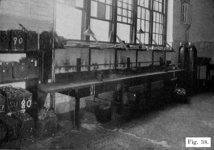
Fig. 38. Typical Work Room Showing Bench About 34 Inches High, Lead Burning Outfit, Hot Plates for Melting Sealing Compound and Hand Drill-Press for Drilling off Inter-Cell Connectors.
There are some things, however, which are necessary, and the following lists are given to help the repairman select his equipment. The man with limited capital will be unable to buy a complete equipment at the start, but he should add to his equipment as fast as his earnings will permit. The repairman may be able to "get-by" with crude equipment when his business is very small, but to make his business grow he must absolutely have good equipment.
The following list gives the various articles in the order of their importance. The first seven are absolutely necessary, even for the poorest beginner. The others are also essential, but may be bought as soon, as the money begins to come in. Some of the tools must also be bought before opening doors for business, such as the putty knife, screwdrivers, pliers, and so on. Each article, which requires explanation, is described in detail, beginning on page 100.
Equipment Which is Absolutely Necessary
1. Charging Outfit, such as a motor-generator set, rectifier, or charging resistance where direct current is available.
2. Charging Bench and Accessories. With the charging bench must go the following:
- A syringe-hydrometer for measuring specific gravity of electrolyte, for drawing off electrolyte and for adding water to cells.
- A special battery thermometer for measuring temperature of electrolyte.
- A voltmeter to measure cell, battery, and cadmium voltages.
- An ammeter to measure charging current.
- A glass bottle for distilled water. Also one for electrolyte.
- A number of eighteen inch lengths of No. 12 flexible wire fitted with lead coated test clips, for connecting batteries in series while on charge.
3. Work bench with vise.
4. Sink or wash tank and water supply.
5. Lead-burning outfit. (This should properly be called a lead welding outfit, since it is used to melt lead parts so that they will be welded together.)
6. For handling sealing compound, the following are necessary.
- Stove.
- Pot in which compound is melted.
- An iron ladle for dipping up the melted compound.
- One or two old coffee pots for pouring compound.
7. Shelving or racks for batteries waiting to be repaired, batteries which have been repaired, rental batteries, new batteries, battery boxes, battery jars, battery plates, etc.
8. Bins for battery parts, such as covers, inter-cell connectors, plate straps, terminals, handles, vent plugs, hold down bolts, separator hold-downs, and so on.
Equipment Needed In Opening Batteries
9. A battery steamer for softening sealing-compound and making covers limp, for softening compound around defective jars which are to be removed, for softening jars which are to be set in a battery box, and so on.
10. Putty knife to remove softened scaling compound.
11. One ratchet brace with set of wood bits or square shank drills of the following sizes: 3/8, 5/8, 3/4, 13/16, and 7/8 inch, for drilling off terminals and inter-cell connectors. A power drill press, or a portable electric drill will save time and labor in drilling off the terminals and connectors.
12. Center punch for marking terminals and connectors before drilling.
13. Ten inch screwdriver for prying off connectors and terminals which have been drilled. The screwdriver may, of course, be used on various other kinds of work also.
14. A ten-inch length of 3/4 inch angle iron to protect upper edge of case when prying off the connectors and terminals which have been drilled.
15. Two pairs of standard combination pliers for lifting elements out of jars. A pair of six or eight inch gas pliers will also do for this work.
16. Machinist hammer. This is, of course, also used for other purposes.
17. Terminal tongs for removing taper lugs from terminals.
18. Pair of long, fiat nosed pliers for pulling out separators and jars.
19. Open-end wrench for use in removing taper lugs from terminals.
Equipment for Lead Burning (Welding)
In addition to the lead burning-outfit, the following tools are needed:
20. A plate burning rack for setting up plates which are to be burned to a plate strap.
21. A plumber's or tinner's triangular scraper for cleaning surfaces which are to be welded together. A pocketknife will do in a pinch.
22. Steel wire brush for cleaning surfaces which are to be welded together. This may also be used for general cleaning of lead parts.
23. Coarse files, vixen, round, and flat, for filing lead parts.
24. Set of burning, collars to be used in burning inter-cell connectors to posts.
25. Moulds for casting sticks of burning lead. A pot for melting lead is needed with the mould, and mould compound is also needed.
26. Set of post builders-moulds used for building up posts which have been drilled short in removing terminals and intercell connectors.
27. Pair of blue or smoked glasses to be worn when using lead burning outfit.
Equipment for General Work on Cell Connectors and Terminals
28. Set of moulds for casting inter-cell connectors, terminals, terminal screws, taper lugs, plate straps and posts, etc.
29. Set of reamers to ream holes in terminals and connectors.
30. Set of hollow reamers for reducing posts.
Equipment for Work on Cases
31. Cans of asphaltum paint for painting cases. May also be used for acid-proofing work benches, floor, shelves, charging bench, and so on.
32. Paint brushes, one wide and several narrow.
33. Battery turntable.
34. Several wood chisels of different sizes.
35. Small wood-plane for smoothing up top edges of case.
36. Large glazed earthenware jars of washing or baking soda solution for soaking cases to neutralize acid.
Tools and Equipment for General Work
37. One pair of large end cutting nippers for cutting connectors, posts, plate lugs, and so on.
38. One pair of 8 inch side cutting pliers.
39. One pair of 8 inch diagonal cutting pliers.
40. Several screwdrivers.
41. Adjustable hacksaw frame with set of coarse blades.
42. Gasoline torch.
42. Soldering iron, solder and flux.
44. Separator cutter.
45. Plate press for pressing bulged, spongy lead of negative plates flush with surface of grids.
46. Battery carrier.
47. Battery truck.
48. Lead lined box for storing separators. A large glazed earthenware jar may be used for this purpose, and is much cheaper, although it will not hold as many separators, on account of its round shape, as the lead lined box.
49. Several old stew pans for boiling acid soaked terminals, connectors, covers, etc., in a solution of washing soda.
50. Set of metal lettering stamps, for stamping POS and NEG on battery terminals, repairman's initials, date battery was repaired, and nature of repairs, on inter-cell connectors.
51. Cadmium test set.
52. High rate discharge testers.
53. Pair of rubber gloves to protect hands when handling acid.
54. Rubber apron to protect clothing from acid.
55. Pair of rubber sleeve protectors.
56. Rubbers to protect shoes, or pair of low rubber boots.
57. Tags for tagging repair and rental batteries, batteries in storage, etc.
58. Pot of paraffine which may be heated, and paper tags dipped after date has been written on tag in pencil. A 60-watt lamp hung in the can may be used for heating the compound. In this way the tag is protected from the action of acid, and the writing on the tag cannot be rubbed off or made illegible.
59. A number of wooden boxes, about 12 inches long, 8 inches wide, and 4 inches deep, in which are placed terminals, inter-cell connectors, covers, vent plugs, etc., of batteries being repaired.
60. Several large glazed earthenware jars are convenient for waste acid, old separators, and general junk, which would otherwise litter up the shop.
Stock
61. A supply of spare parts, such as cases, jars, covers, plate straps, inter-cell connectors, plates, vent plugs, etc., should be kept.
62. A supply of sealing compound is necessary.
63. A carboy of pure acid, and carboys of 1.400 electrolyte ready for use should be on hand. A 16 oz. and a 32 or 64 oz. graduate are very useful in measuring out acid and water.
64. A ten gallon bottle of distilled water is necessary for use in making up electrolyte, for addition to cell electrolyte to bring electrolyte up to proper level, and so on. If you wish to distill water yourself, buy a water still.
65. A supply of pure vaseline is necessary for coating terminals to prevent corrosion.
Special Tools
Owing to special constructions used oil sonic of the standard makes of batteries, special tools are required, and such tools should be obtained if work is done oil these batteries. Some of these tools are as follows:
66. Special wrenches for turning sealing nuts on Exide batteries.
67. Two hollow reamers (post-freeing tools) for cutting lead seal around posts of Prest-O-Lite batteries. There are two sizes, large and small, see page 389.
68. Style "B" peening press for sealing posts of Prest-O-Lite batteries to covers, see page 390.
69. Pressure tongs for forcing lead collar oil posts of Vesta batteries, see page 415.
70. Special wrench for tightening sealing nut oil Titan batteries.
71. Special reamer for cutting sealing ring oil Universal batteries.
The list of special tools is not intended to be complete, and the repairman will probably find other special tools necessary from time to time. In any case, it is best to buy from the battery manufacturer such special tools as are necessary for the batteries that come in for repairs. It is sometimes possible to get along without the special tools, but time and labor will be saved by using them.
DESCRIPTIONS OF TOOLS AND EQUIPMENT NAMED IN FOREGOING LIST
Charging Equipment
A battery is charged by sending a direct current through it, this "charging" current entering the battery at, the positive terminal and passing out at the negative terminal. To send this current through the battery, a voltage of about 7.5 volts is applied to each battery.
Two things are therefore necessary in charging a battery:
- We must have a source of direct current.
- The voltage impressed across each battery must be, about 2.5 per cell. The charging voltage across each six volt battery must therefore be 7.5, and for each twelve volt battery the charging voltage must be about 15 volts.
With the battery on the car, there are two general methods of charging, i. e., constant potential (voltage) and constant current. Generators having a constant voltage regulator have a constant voltage of about 7.5, the charging current depending upon the condition of the battery. A discharged battery thus receives a high charging current, this current gradually decreasing, or "tapering" as the battery becomes more fully charged. This system has the desirable characteristic that a discharged battery receives a heavy charging current, and a fully charged battery receives a small charging current. The time of charging is thereby decreased.
With a constant-current charging system, the generator current output is maintained at a certain value, regardless of the state of charge of the battery. The disadvantage of this system is that a fully charged battery is charged at as high a rate and in most cases at a higher rate than a discharged battery.
In the shop, either the constant-potential, or the constant-current system of charging may be used. Up to the present time, the constant current system has been used in the majority of shops. The equipment for constant current charging uses a lamp bank or rheostat to regulate the charging current where direct current is available, and a rectifier or motor-generator set where only alternating current is available. Recently, the Hobart Brothers Company of Troy, Ohio, has put on the market a constant potential motor-generator set which gives the same desirable "tapering" charge as does the constant voltage generator on the car. This set will be described later.
Where a 110-volt direct current supply is available, fifteen 6-volt batteries may be connected in series across the line without the use of any rheostat or lamp bank, only an ammeter being required in the circuit to indicate the charging current. The charging rate may be varied by cutting out some of the batteries, or connecting more batteries in the circuit. This method is feasible only where many batteries are charged, since not less than fifteen 6-volt batteries may be charged at one time.
Constant Current Charging
Using Lamp Banks, or Rheostats
Figures 39 and 40 show the wiring for a "bank" of twenty 100-watt lamps for battery charging from a 110 volt line. Figure 39 shows the wiring to be used when the positive side of the line is grounded, while Figure 40 shows the wiring to be used when the negative side of the line is grounded. In either case, the "live" wire connects to the lamp bank. The purpose of this is to eliminate the possibility of a short-circuit if any part of the charging line beyond the lamp bank is accidentally grounded.
Figures 41 and 42 show the wiring of two charging rheostats which may be used instead of the lamp banks shown in Figures 39 and 40. In these two rheostats the live wire is connected to the rheostat resistances in order to prevent short-circuits by grounding any part of the circuit beyond the rheostats. These rheostats may be bought ready for use, and should not be "homemade." The wiring as shown in Figures 41 and 42 is probably not the same as will be found on a rheostat which may be bought, but when installing a rheostat, the wiring should be examined to make sure that the "live" wire is connected to the rheostat resistance and does not connect directly to the charging circuit. If necessary, change the wiring to agree with Figures 41 and 42.
Figures 43 and 44 show the wiring of the charging circuits. In Figure 43 each battery has a double pole, double throw knife switch. This is probably the better layout, since any battery may be connected in the circuit by throwing down the knife switch, and any battery may be cut out by throwing the switch up. With this wiring layout, any number of batteries from one to ten may be cut-in by means of the switches. Thus, to charge five batteries, switches 1 to 5 are thrown down, and switches 5 to 10 are thrown up, thereby short-circuiting them.
Figure 44 shows a ten-battery charging circuit on which the batteries are connected in series by means of jumpers fitted with lead coated test clips, as shown. This layout is not as convenient as that shown in Figure 43, but is less expensive.
Using Motor-Generator Sets
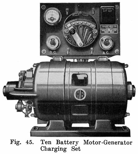
Where no direct current supply is available, a motor-generator or a rectifier must be installed. The motor-generator is more expensive than a rectifier, but is preferred by some service stations because it is extremely flexible as to voltage and current, is easily operated, is free from complications, and has no delicate parts to cause trouble.
Motor-Generator sets are made by a number of manufacturers. Accompanying these sets are complete instructions for installation and operation, and we will not attempt to duplicate such instructions in this book. Rules to assist in selecting the equipment will, however, be given.
Except in very large service stations, a 40 volt generator is preferable. It requires approximately 2.5 volts per cell to overcome the voltage of a battery in order to charge it, and hence the 40 volt generator has a voltage sufficient to charge 15 cells in series on one charging line. Five 6 volt batteries may therefore be charged at one time on each line. With a charging rate of 10 amperes, each charging line will require 10 times 40, or 400 watts. The size of the generator will depend on the number of charging lines desired. With 10 amperes charging current per line, the capacity of the generator required will be equal to 400 watts multiplied by the number of charging lines. One charging line will need a 400 watt outfit. For two charging lines 800 watts are required. Each charging line is generally provided with a separate rheostat so that its charging rate may be adjusted to any desired value. This is an important feature, as it is wrong to charge all batteries at the same rate, and with separate rheostats the current on each line may be adjusted to the correct value for the batteries connected to that line. Any number of batteries up to the maximum may be charged on each line.
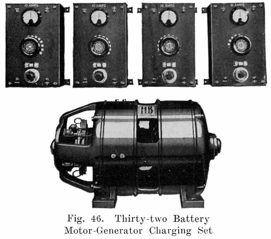
In choosing a charging outfit, it is important not to get one which is too large, as the outfit will operate at a loss when running under a minimum load. It is equally important not to get one which is too small, as it will not be able to take care of the batteries fast enough, and there will be a "waiting list" of batteries which cannot be charged until others are taken off charge. This will prevent the giving of good service. Buy an outfit that will care for your needs in the future, and also operate economically at the present time. Most men going into the battery business make the mistake of underestimating their needs, and getting equipment which must soon be discarded because of lack of capacity.
The manufacturers each make a number of sizes, and the one which will best fill the requirements should be chosen. In selecting an outfit the manufacturer's distributor or dealer should be consulted in deciding what size outfit to obtain. The particular outfit will depend on the voltage and frequency of the alternating current power circuits, the maximum charging current desired (10 amperes per line is ample), and the greatest number of batteries to be charged at one time.
For the beginner, a 500 watt ten battery outfit, as shown in Fig. 45, is suitable. For the medium sized garage that specializes in battery charging, or for the small battery service station, a one kilowatt outfit is most satisfactory. Two charging panels are generally furnished with this outfit, and two charging lines may thus be used. This is an important feature, as one line may be used in starting a charge at 10 amperes, and the other for charging the batteries, that have begun to gas, at a reduced rate. Fig. 46 shows a 2 K. W. four-circuit, 32 battery motor-generator set. Each circuit is provided with a separate rheostat and ammeter. The two terminals near the top of each rheostat are connected to one charging circuit. The two terminals near the lower end of each rheostat are connected to the generator.
The 2 kilowatt set is suitable for a city garage, or a battery service station in a medium sized town. A beginner should not purchase this large set, unless the set can be operated at at least one-fourth capacity continuously. As a service station grows, a 5 kilowatt set may be needed. The 1, 2 and 5 kilowatt sets should not be used on anything but city power lines. Single phase, or lighting lines are not satisfactory for handling these sets.
A few suggestions on Motor-Generator Sets
1. Installation. Set the motor-generator on as firm a foundation as possible. A good plan is to bolt it to a heavy bench, in which position it is easily inspected and adjusted, and is also less likely to be hit by acid spray, water, etc.
Set the motor-generator at some distance from the batteries so that acid spray and fumes will not reach it. Sulphuric acid will attack any metal and if you are not careful, your motor-generator may be damaged seriously. The best plan is to have the motor generator set outside of the charging room, so as to have a wall or partition between the motor-generator and the batteries. The charging panels may be placed as near the batteries as necessary for convenience, but should not be mounted above the batteries. Figure 47 shows a convenient layout of motor-generator, charging panels, and charging benches. Note that the junipers used in connecting the batteries together are run through the upper holes of the wire porcelain insulating cleats, the lower hole of each insulator supporting the wire from the charging panel which runs to the end of the bench.
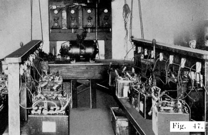
Fig. 47. Convenient Arrangement of Motor-Generator, Charging Panels, and Charging Benches
Instructions for the wiring connections to the power lines generally come with each outfit, and they should be followed carefully. Fuses in both the motor and generator circuits are especially important, as they protect the machines from damage due to overloads, grounds, or short-circuits. The generator must be driven in the proper direction or the generator will not build up. The rotation of a three-phase motor may be reversed by reversing, and Charging Benches any two of the cables. To reverse a two-phase motor, reverse the cables of either phase. Before putting a motor-generator set into operation, be sure to check all connections to make sure that everything checks with the instructions furnished by the manufacturer.
Operating the Charging Circuits
A generator operates most efficiently when delivering its rated output. Therefore, keep the generator as fully loaded as possible at all times. When you do not have enough batteries to run the generator at full load, run each charging circuit at full load, and use as few circuits as possible. This will reduce your power bill, since there is a loss of power in the rheostat of each charging circuit, this loss being the greatest when only one battery is on the circuit, and a minimum when the circuit is fully loaded.
With several charging circuits, it is also possible to put batteries which are in the same condition on one circuit and adjust the charging rate to the most suitable value. Thus, badly sulphated batteries, which must be charged at a low rate, may be put on the same circuit, while batteries which have had only a normal discharge may be put oil another circuit and charged at a higher rate. As each battery becomes almost fully charged, it may be removed from the circuit and put on another circuit and the charge completed at the finishing rate. This is a good practice, since some batteries will begin to gas sooner than others, and if the charging rate is not reduced, the batteries which have begun to gas will have active material blown out by the continued gassing. A careful study of such points will lead to a considerable saving in power costs.
Care of Motor-Generator Set
A. Machine will not build up or generate. This may be due to:
- Machine rotating in wrong direction.
- Brushes not making good contact. Clean commutator with fine sandpaper.
- Wrong connections of field rheostat-check connections with diagram.
- Open circuit in field rheostat. See if machine will build up with field rheostat cut out.
B. Excessive heating of the commutator. This may be due to:
- Overload — Check your load and compare it with nameplate reading. Add the total amperes on all the panels and see that it does not exceed the ampere reading on the nameplate.
- Wrong setting of the brush rocker arm. This causes sparking, which soon will cause excessive heating.
- Rough commutator. This will cause the brushes to chatter, be noisy and spark. Caused many times by allowing copper to accumulate on the bottom of the brushes.
- Insufficient pressure on brushes, resulting in sparking. This may be due to brushes wearing down to the point where the brush lead screw rests on the brush holder.
- Dirt and grease accumulating between the brush and brush holder causing brush to stick;brush must always move freely in the holder.
- Brush holder may have come loose, causing it to slip back, relieving brush press-Lire.
- Brush spring may have become loosened, releasing the tension.
- Watch commutator carefully and keep it in the best of condition. There will not be excessive heating without sparking. Excessive sparking may raise the temperature so high as to cause throwing of solder. You can avoid all this by taking proper care of the commutator.
C. Ammeters on Panels Read Reverse: This is caused by improperly connecting up batteries, which has reversed the polarity of the generator. This generally does no harm, since in most cases the batteries will automatically reverse the polarity of the generator. Generally the condition may be remedied by stopping the machine, reversing the batteries and starting the machine again. If this is unsuccessful raise the brushes on the machine. Connect five or six batteries in series in the correct way to one panel, while the machine is not in operation. Turn on the panel switch. When the machine is started, it will then build up in the right direction. If it does not do so, repeat the above, using a larger number of batteries.
D. Machine Refuses to Start. If there is a humming noise when you try to start the motor, and the outfit does not start, one of the fuses needs replacing. The outfit will hum only on two or three phase current. Never leave the power turned on with any of the fuses out.
Constant-Potential Charging
In the Constant-Potential system of battery charging, the charging voltage is adjusted to about 7.5, and is held constant throughout the charge. With this system a discharged battery receives a heavy current when it is put on charge. This current gradually decreases as the battery charges, due to the increasing battery voltage, which opposes, or "bucks" the charging voltage, and reduces the voltage which is effective in sending current through the batteries. Such a charge is called "tapering" charge because the charging current gradually decreases, or "tapers" off.
The principle of a "tapering" charge is, of course, that a discharged battery may safely be charged at a higher rate than one which is only partly discharged, because there is more lead sulphate in the discharged battery which the action of the current changes back to active material. As the battery charges, the amount of lead sulphate decreases and since there is less sulphate for the current to act upon, the charging rate should be reduced gradually. If this is not done, excessive gassing will occur, resulting in active material being blown from the grids.
A battery which has been badly sulphated, is of course, in a discharged condition, but is not, of course, able to absorb a heavy charging rate, and in handling such batteries on a constant potential system, care must be taken that the charging rate is low. Another precaution to be observed in all constant potential charging is to watch the temperature of batteries while they are drawing a heavy charging current. A battery which gasses soon after it is put oil charge, and while still in a discharged condition, should be taken off the line, or the charging line voltage reduced. With constant potential charging, as with constant current charging, the two things to watch are temperature and gassing. Any charging rate which does not cause an excessive temperature or early gassing is safe, and conversely any charging rate which causes an excessive battery temperature, or causes gassing while the battery is still less than three-fourths charged, is too high.
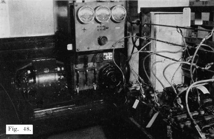
Fig. 48. Hobart Bros. Co. 3 K. W. Constant Potential Motor-Generator Charging Set
The Constant-Potential Charging Set manufactured by the Hobart Bros. Co., consists of a 3 K.W. generator rated at 7.5 volts, and 400 amperes. This generator is direct connected to a 5 H.P. motor, both machines being mounted oil the same base plate. Figure 48 shows this outfit. Note that for the charging line there are three bus-bars to which the batteries are connected. Twelve volt batteries are connected across the two outside bus-bars, while six volt batteries are connected between the center bus-bar and one of the outer ones.
The Tungar Rectifier
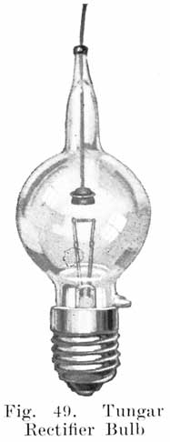
All rectifiers using oil are operated on the principle that current can pass through them in one direction only, due to the great resistance offered to the flow of current in the opposite direction. It is, of course, not necessary to use mercury vapor for the arc. Some rectifiers operate on another principle. Examples of such rectifiers are the Tungar made by the General Electric Co., and the Reetigon, made by the Westinghouse Electric and Manufacturing Co. The Tungar Rectifier is used extensively and will therefore be described in detail.
The essential parts of a Tungar Rectifier are: A bulb, transformer, reactance, and the enclosing case and equipment.
The bulb is the most important of these parts, since it does the rectifying. It is a sort of check valve that permits current to flow through the charging circuit in one direction only. In appearance the bulb, see Figure 49, resembles somewhat an ordinary incandescent bulb. In the bulb is a short tungsten filament wound in the form of a tight spiral, and supported between two lead-in wires. Close to the filament is a graphite disk which serves as one of the electrodes. Figure 50 shows the operating principle of the Tungar. "B" is the bulb, containing the filament "F" and the graphite electrode "A." To serve as a rectifier the bulb filament "F" must be heated, this being done by the transformer "T." The battery is connected as shown, the positive terminal directly to one side of the alternating current supply, and the negative terminal to the graphite electrode "A."
To understand the action which takes place, assume an instant when line wire C is positive. The current then flows through the battery, through the rheostat and to the graphite electrode. The current then flows through the are to the filament and to the negative side of the line, as indicated by the arrows.
During the next half cycle when line wire D is positive, and C is negative, current tends to flow through the bulb from the filament to the graphite, but as the resistance offered to the flow of current in this direction is very high, no current will flow through the bulb and consequently none through the battery.
The rectifier shown in Figure 50 is a "half-wave" rectifier. That is, only one-half of each alternating current wave passes through it to the battery. If two bulbs are used, as shown ill Figure 51, each half of the alternating current wave is used in charging the battery. To trace the current through this rectifier assume an instant when line wire C is positive. Current will then flow to the graphite electrode of tube A, through the secondary winding of the transformer S to the center tap, through the rheostat, to the positive battery terminal, through the battery to the center of the primary transformer winding P, and through part of the primary winding to D. When D is positive, current will flow through tube B from the graphite electrode to the filament, to the center of transformer winding S, through the rheostat and battery to the center of transformer winding P, and through part of this winding to line wire C. In the actual rectifiers the rheostat shown in Figures 50 and 51 are not used, regulation being obtained entirely by means of other windings.
From the foregoing description it will be seen that if the alternating current supply should fail, the batteries cannot discharge into the line, because in order to do so, they would have to heat up the filament and send current through the bulb from the filament to the graphite electrode. This the batteries cannot do, because the connections are such that the battery cannot send a current through the complete filament circuit and because, even if the batteries could heat the filament they could not send a current from the filament to the graphite, since current cannot flow in this direction.
As soon as the alternating line is made alive again, the batteries will automatically start charging again. For these reasons night charging with the Tungar is entirely feasible, and no attendant is required to watch the batteries during the night. The Tungar Rectifier is made in the following sizes:
A. Two Ampere Rectifier
Catalogue No. 195529
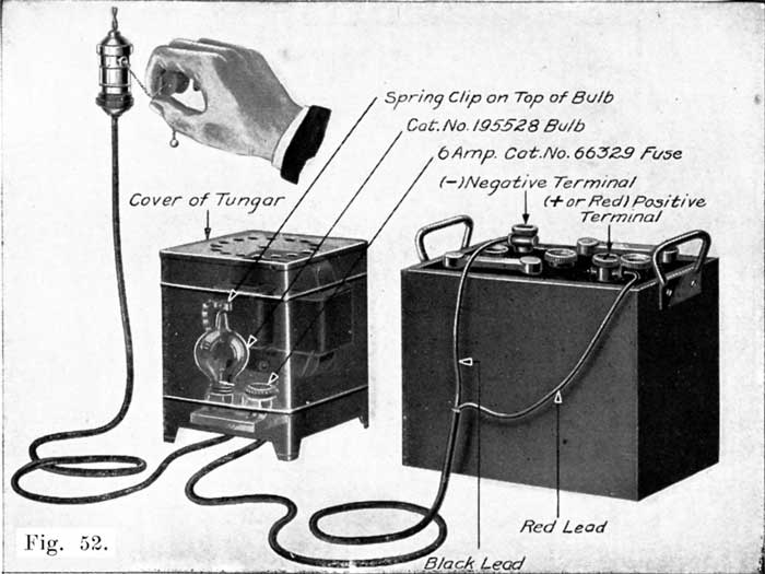
Fig. 52. The Two Ampere Tungar Rectifier
This is the smallest Tungar made. Figure 52 shows the complete rectifier. Figure 53 shows the internal wiring. This Tungar will charge a 6 volt battery at two amperes, a 12 volt battery at one ampere and eight cells at 0.75 ampere. It is suitable for charging a lighting battery, or for a quick charge of a motorcycle or ignition battery. It will also give a fairly good charge over night to a starting battery. Another use for this rectifier is to connect it to a run-down starting battery to prevent it from freezing over night. Of course, a battery should not be allowed to run down during cold weather, but if by chance a battery does run down, this Tungar will prevent it from freezing during the night.
The two ampere Tungar is, of course, more suitable for the car owner than for a garage or service station. It is also very suitable for charging one Radio "A" battery. The two ampere Tungar is normally made for operation on a sixty cycle circuit, at 115 volts. It may also be obtained for operation on 25-30, 40-50, and 125-133 cycles alternating supply line. See table on Page 130.
B. The One Battery Rectifier
Catalogue No. 219865
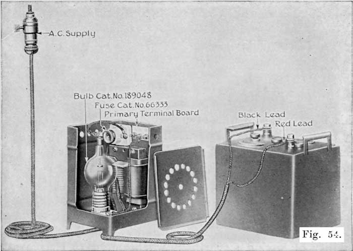
Fig. 54. The One Battery Tungar Rectifier
This Tungar will charge a 6 volt battery at five amperes, or a 12 volt battery at three amperes. Figure 54 shows this Tungar, with part of the casing cut away to show the internal parts.
To take care of variations in the voltage of the alternating current supply from 100 to 130, a set of connections is provided which are numbered 105, 115, and 125. For most supply voltages, the 115 volt tap is used, for lower voltage the 105 volt tap is used, and for higher voltage the 125 volt tap is used. This Tungar is designed for 60 cycle circuits, but on special order it may be obtained for operation on other frequencies.
This Tungar is most suitable for a car owner, is satisfactory for charging a radio "A" battery, and a six volt starting and lighting battery at one time.
C. The Two Battery Rectifier
Catalogue No. 195530
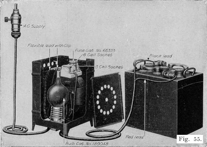
Fig. 55. The Two Battery Tungar Rectifier
This Tungar is shown in Figure 55, with part of the casing cut away to show the internal parts. It was formerly sold to the car owner, but the one battery Tungar is now recommended for the use of the car owner. The two-battery Tungar is therefore recommended for the very small service station, or for department stores for taking care of one or two batteries. The four battery Tungar, which is the next one described, is recommended in preference to the two-battery outfit where there is the slightest possibility of having more than two batteries to charge at one time.
The two-battery rectifier will charge two 6-volt batteries, or one 12-volt battery at six amperes, or one 18-volt battery at three amperes. It has a double-pole fuse block mounted on the auto transformer core, which has one fuse plug only. Figure 55 shows the fuse plug in the position for charging a 6-volt battery. When it is desired to charge a 12-volt battery or an 18-volt battery, the fuse is removed from the first receptacle and is screwed into the second receptacle.
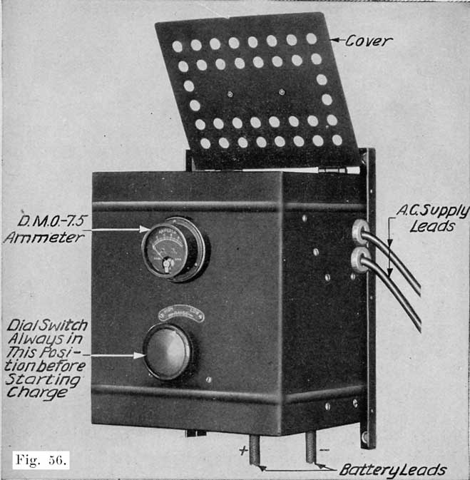
Fig. 56. The Four Battery Tungar Rectifier Complete
The two-battery rectifier is designed to operate on a 115-volt, 60-cycle line, but oil special order may be obtained for operation on 25-30, 40-50, and 125-133 cycle lines.
D. The Four Battery Tungar
Catalogue No. 193191
This Tungar is shown complete in Figure 56. In Figure 57 the top has been raised to show the internal parts. Figure 58 gives the internal wiring connections for a four battery Tungar designed for operation on a 115 volt line.
The four battery Tungar will charge from one to four 6 volt batteries at 5 amperes or less. It is designed especially for garages having very few batteries to charge. These garages generally charge their boarders batteries rather than send them to a service station, and seldom have more than four batteries to charge at one time. The four battery Tungar is also suitable for the use of car dealers who wish to keep the batteries on their cars in good shape, and is convenient for preparing for service batteries as they come from the car manufacturer.
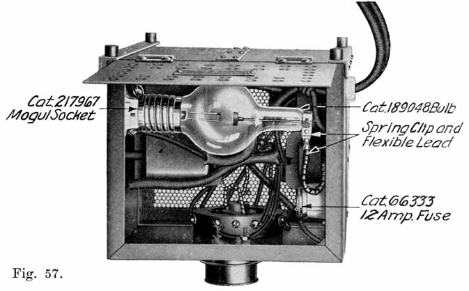
Fig. 57. The Four Battery Tungar Rectifier, with Top Raised to Show Internal Parts.
The four battery Tungar is designed for operation on a 60-cycle line at 115 or 230 volts. On special order this Tungar may be obtained for operation on other frequencies.
E. The Ten Battery Rectifier
Catalogue No. 179492
This is the Tungar which is most popular in the service stations, since it meets the charging requirements of the average shop better than the smaller Tungars. It will charge from one to ten 6 volt batteries, or the equivalent at six amperes or less. Where more than ten batteries are generally to be charged at one time, two or more of the ten battery Tungars should be used. Large service stations use as many as ten of these Tungars.
The efficiency of the ten battery Tungar at full load is approximately 75 per cent, which compares favorably with that of a mercury-are rectifier, or motor-generator of the same size. This makes the ten battery Tungar a very desirable piece of apparatus for the service station.
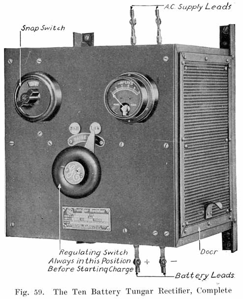
Figure 59 shows the complete ten battery Tungar, Figure 60 gives a side view without the door to show the internal parts.
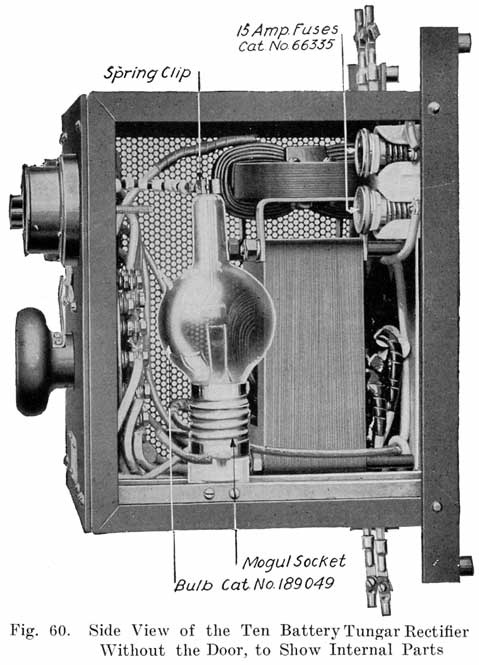
Figure 61 shows the internal connections for use on a 115-volt A.C. line and Figure 62 the internal connections for use on a 230-volt line. This Tungar is made for a 60-cycle circuit, 25-30, 40-50, and 125-133 cycle circuits.
F. The Twenty Battery Tungar
Catalogue No. 221514
This Tungar will charge ten 6-volt batteries at 12 amperes, or twenty 6-volt batteries at six amperes. Figure 63 shows the complete rectifier, and Figure 64 shows the rectifier with the side door open to show the internal parts. This rectifier will do the work of two of the ten battery Tungars. It is designed for operation on 60 cycles, 230-volts. On special order it may be obtained for operation on 115 volts and also for other frequencies.
The twenty battery Tungar uses two bulbs, each of which is the same as that used in the ten battery Tungar, and has two charging circuits, having an ammeter and regulating switch for each circuit. One snap switch connects both circuits to the supply circuit. The two charging circuits are regulated independently. For example, one circuit may be regulated to three amperes while the other circuit is delivering six amperes. It is also possible, by a system of connections to charge the equivalent of three circuits. For instance, five batteries could be charged at six amperes, five batteries at four amperes, and five batteries at ten amperes. Other corresponding combinations are possible also.
General Instructions and Information on Tungars
Life of Tungar Bulbs. The life of the Tungar Bulb is rated at 600 to 800 hours, but actually a bulb will give service for 1,200 to 3,000 hours if the user is careful not to overload the bulb by operating it at more than the rated current.
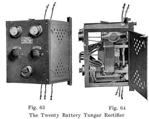
Instructions. Complete instructions are furnished with each Tungar outfit, the following being those for the ten battery Tungar.
Installation
A Tungar should be installed in a clean, dry place in order to keep the apparatus free from dirt and moisture. To avoid acid fumes, do not place the Tungar directly over the batteries. These precautions will prevent corrosion of the metal parts and liability of poor contacts.
Fasten the Tungar to a wall by four screws, if the wall is of wood, or by four expansion bolts if it is made of brick or concrete.
Though the electrical connections of the outfit are very simple, it is advisable (when installing the apparatus) to employ an experienced wireman familiar with local requirements regarding wiring.
Line Connections
The two wires extending from the top of the Tungar should be connected to the alternating current supply of the same voltage and frequency, as stamped on the name plate attached to the front panel. These connections should be not less than No. 12 B. & S. gauge wire and should be firmly soldered to the copper lugs.
External fuses are recommended for the alternating-current circuit, as follows:
With 115-volt line use 15-ampere capacity fuses.
With 230-volt line use 10 ampere capacity fuses.
One of the bulbs (Cat. No. 189049) should now be firmly screwed into its socket. Squeeze the spring clip attached to the beaded cable and slip this clip over the wire protruding from the top of the bulb. Do not bend the wire.
Battery Connections
In making battery connections have the snap-switch in the "Off" position.
The two wires extending from the bottom of the Tungar should be connected to the batteries. The wire on the left, facing the front panel, is marked + (positive) and the other wire - (negative). The positive wire should be connected to the positive terminal of the battery and the negative wire to the negative terminal.
The two flexible battery cables are sometimes connected directly to the two wires projecting from the bottom of the Tungar. These cables should be securely cleated to the wall about six inches below the outfit. This arrangement will relieve the strain on the Tungar wires when cables are changed to different batteries.
When two or more batteries are to be charged, they should be connected in series. The positive wire of the Tungar should be connected to the positive terminal of battery No. 1, the negative terminal of this battery of the positive terminal of battery No. 2, the negative terminal of battery No. 2 to the positive terminal of battery No. 3, and so on, according to the number of batteries in circuit. Finally the negative terminal of the last battery should be connected to the negative wire from the Tungar.
Reverse connections on one battery is likely to damage the plates; and reverse connections oil all the batteries will blow one or more fuses.
Operation
A Tungar is operated by means of a snap-switch in the upper left-hand corner and a regulating switch in the center. Before starting the apparatus, the regulating switch should be in the "low" position.
The Tungar is now ready to operate. Turn the snap-switch to the right to the "On" position, and the bulb will light. Then turn the regulating switch slowly to the right, and, as soon as the batteries commence to charge, the needle on the ammeter will indicate the charging current. This current may be adjusted to whatever value is desired within the limits of the Tungar. The normal charging rate is six amperes, but a current of as high as seven amperes may be obtained without greatly reducing the life of the bulb. Higher charging rates reduce its life to a considerable extent. Lower rates than normal (six amperes) will increase the life of the bulb.
Turn the snap-switch to the "Off" position when the charging of one battery or of all the batteries is completed; or when it is desired to add more batteries to the line.
The Tungar should be operated only by the snap-switch and not by any other external switch in either line or battery circuits.
When the snap-switch is turned, the batteries will be disconnected from the supply line, and then they may be handled without danger of shock.
Immediately after turning the snap-switch, move the regulating handle back to the "Low" position. This prevents any damage to the bulb from the dial switch being in an improper position for the number of batteries next charged.
Troubles
If on turning on the alternating-current switch the bulb does not glow:
- See whether the alternating-current supply is on.
- Examine the supply line fuses. If these are blown, or are defective, replace them with 15 ampere fuses for a 115-volt line or with 10-ampere fuses for a 220-volt line.
- Make sure that the bulb is screwed well into the socket.
- Examine the contacts inside the socket. If they are tarnished or dirty, clean them with sandpaper.
- Try a new bulb, Cat. No. 189049. The old bulb may be defective.
If the bulb lights but no current shows on the ammeter:
- Examine the connections to the batteries, and also the connections between them. Most troubles are caused by imperfect battery connections.
- Examine the fuses inside the case. If these are blown or are defective, replace them with 15 ampere fuses, Cat. No. 6335.
- See that the clip is on the wire of the bulb.
- The bulb may have a slow leak and not rectify. Try a new bulb, Cat. No. 189049.
- Have the switch arm make good contact on the regulating switch.
If the current on the ammeter is high and cannot be reduced:
- The ammeter pointer may be sticking; tap it lightly with the hand. The ammeter will not indicate the current correctly if the pointer is not on the zero line when the Tungar is not operating. The pointer may be easily reset by turning slightly the screw on the lower part of the instrument.
- Be sure that the batteries are not connected with reversed polarity.
- The alternating-current supply may be abnormally high. If only one three-cell battery is being charged, and the alternating-current supply is slightly high, then the current on the ammeter may be high. The simplest remedy is to connect in another battery or a small amount of resistance.
A spare bulb should always be kept on hand and should be tested for at least one complete charge before being placed in reserve. All Tungar bulbs are made as nearly perfect as possible, but occasionally one is damaged in shipment. It may look perfect and yet not operate. For this reason all bulbs should be tried out on receipt. If any bulb is found defective, the tag which accompanies it should be filled out, and bulb and tag should be returned to your dealer or to the nearest office of the General Electric Company, transportation prepaid.
Tungar Rectifiers
(The following columns omitted from the table below: Catalog Numbers, Dimensions, Net Weight, and Shipping Weight.)
| Name | No. 6V Bats |
No. 12V Bats. |
D.C. Amps |
D.C. Volts |
A.C. Volts |
Freq. |
|---|---|---|---|---|---|---|
2 Amp. Tungar |
1 (2 amps.) | 1 (1 amps.) | 1-2 | 7.5-15 | 115 | 60 |
2 Amp. Tungar |
1 (2 amps.) | 1 (1 amps.) | 1-2 | 7.5-15 | 115 | 60 |
2 Amp. Tungar |
1 (2 amps.) | 1 (1 amps.) | 1-2 | 7.5-15 | 115 | 40-50 |
2 Amp. Tungar |
1 (2 amps.) | 1 (1 amps.) | 1-2 | 7.5-15 | 115 | 25-30 |
2 Amp. Tungar |
1 (2 amps.) | 1 (1 amps.) | 1-2 | 7.5-15 | 115 | 125-133 |
1 Battery Tungar |
1 (5 amps.) | 1 (3 amps.) | 1-5 | 7.5-15 | 115 | 60 |
2 Battery Tungar |
2 (6 amps.) | 1 (6 amps.) | 1-6 | 7.5-15 | 115 | 60 |
2 Battery Tungar |
2 (6 amps.) | 1 (6 amps.) | 1-6 | 7.5-15 | 115 | 40-50 |
2 Battery Tungar |
2 (6 amps.) | 1 (6 amps.) | 1-6 | 7.5-15 | 115 | 25-30 |
2 Battery Tungar |
2 (6 amps.) | 1 (6 amps.) | 1-6 | 7.5-15 | 115 | 125-130 |
4 Battery Tungar |
4 (5 amps.) | 2 (5 amps.) | 1-5 | 7.5-30 | 115 | 60 |
4 Battery Tungar |
4 (5 amps.) | 2 (5 amps.) | 1-5 | 7.5-30 | 115 | 40-50 |
4 Battery Tungar |
4 (5 amps.) | 2 (5 amps.) | 1-5 | 7.5-30 | 115 | 25-30 |
4 Battery Tungar |
4 (5 amps.) | 2 (5 amps.) | 1-5 | 7.5-30 | 115 | 125-133 |
4 Battery Tungar |
4 (5 amps.) | 2 (5 amps.) | 1-5 | 7.5-30 | 230 | 60 |
4 Battery Tungar |
4 (5 amps.) | 2 (5 amps.) | 1-5 | 7.5-30 | 230 | 40-50 |
10 Battery Tungar |
10 | 5 | 1-6 | 7.5-75 | 115 | 60 |
10 Battery Tungar |
10 | 5 | 1-6 | 7.5-75 | 115 | 40-50 |
10 Battery Tungar |
10 | 5 | 1-6 | 7.5-75 | 115 | 25-30 |
10 Battery Tungar |
10 | 5 | 1-6 | 7.5-75 | 115 | 125-133 |
10 Battery Tungar |
10 | 5 | 1-6 | 7.5-75 | 230 | 60 |
10 Battery Tungar |
10 | 5 | 1-6 | 7.5-75 | 230 | 40-50 |
20 Battery Tungar |
10 (12A.) 20 (6A.) |
10 (6A.) | 1-12 | 7.5-75 | 230 | 60 |
20 Battery Tungar |
10 (12A.) 20 (6A.) |
10 (6A.) | 1-12 | 7.5-75 | 230 | 40-50 |
20 Battery Tungar |
10 (12A.) 20 (6A.) |
10 (6A.) | 1-12 | 7.5-75 | 230 | 25-30 |
Bulb (all |
,,,,,,,, | ,,,,,,,, | ,,,,,,,, | ,,,,,,,, | ,,,,,,,, | ,,,,,,,, |
Bulb (all 10 and |
,,,,,,,, | ,,,,,,,, | ,,,,,,,, | ,,,,,,,, | ,,,,,,,, | ,,,,,,,, |
Bulb (all 2 |
,,,,,,,, | ,,,,,,,, | ,,,,,,,, | ,,,,,,,, | ,,,,,,,, | ,,,,,,,, |
Bulb (all 1-2 |
,,,,,,,, | ,,,,,,,, | ,,,,,,,, | ,,,,,,,, | ,,,,,,,, | ,,,,,,,, |
Mercury Arc Rectifier
The operation of the mercury are rectifier depends upon the fact that a tube containing mercury vapor under a low pressure and provided with two electrodes, one of mercury and the other of some other conductor, offers a very high resistance to a current tending to pass through the tube from the mercury electrode to the other electrode, but offers a very low resistance to a current tending to pass through the tube in the opposite direction. Current passes from the metallic electrode to the mercury electrode through an are of mercury vapor which is established in the tube by tilting it so the mercury bridges the gap between the mercury and an auxiliary electrode just for an instant.
The absence of moving parts to got out of order is an advantage possessed by this rectifier over the motor-generator. The charging current from the rectifier cannot, however, be reduced to as low a value as with the motor-generator, and this is a disadvantage. This rectifier is therefore more suitable for larger shops, especially where electric truck and pleasure cars are charged.
Mechanical Rectifiers
Mechanical rectifiers have a vibrating armature which opens and closes the charging circuit. The circuit is closed during one half of each alternating current cycle, and open during the next half cycle. The circuit is thus closed as long as the alternating current is flowing in the proper direction to charge the battery, and is open as long as the alternating current is flowing in the reverse direction. These rectifiers therefore charge the battery during half the time the battery is on charge, this also being the case in some of the are rectifiers.
The desired action is secured by a combination of a permanent magnet and an electromagnet which is connected to the alternating current supply. During half of the alternating current cycle, the alternating current flowing through the winding of the electromagnet magnetizes the electromagnet so that it strengthens the magnetism of the permanent magnet, thus causing the vibrator arm to be drawn against the magnet. The vibrator arm carries a contact which touches a stationary contact point when the arm is drawn against the magnet, thus closing the charging circuit.
During the next half of the alternating current cycle, or wave, the current through the electromagnet coil is reversed, and the magnetism of the electromagnet then weakens the magnetism of the permanent magnet, and the vibrator arm is drawn away from the magnet and the charging circuit is thus opened. During the next half of the alternating current cycle the vibrator arm is again drawn against the magnet, and so on, the contact points being closed and opened during half of each alternating current cycle.
Mechanical rectifiers are operated from the secondary windings of transformers which reduce the voltage of the alternating current line to the voltage desired for charging. Each rectifier unit may have its own complete transformer, or one large transformer may operate a number of rectifier units by having its secondary, or low tension winding divided into a number of sections, each of which operates one rectifier.
The advantages of the mechanical rectifier are its simplicity, cheapness and portability. This rectifier also has the advantage of opening the charging circuit when the alternating current supply fails, and starting again automatically when the line is made alive again. Any desired number of independent units, each having its own charging line, may be used. The charging current generally has a maximum value of 6 amperes. Each rectifier unit is generally designed to charge only one or two six volt batteries at one time.
Stahl Rectifier
This is a unique rectifier, in which the alternating current is rectified by being sent through a commutator which is rotated by a small alternating current motor, similar to the way the alternating current generated in the armature of a direct current generator is rectified in the commutator of the machine. The Stahl rectifier supplies the alternating current from a transformer instead of generating it as is done in a direct current generator. Brushes which bear on the commutator lead to the charging circuit.
The Stahl rectifier is suitable for the larger service stations. It gives an interrupted direct current. It is simple in construction and operation, and is free of delicate parts.
Other Charging Equipment
If there is no electric lighting in the shop, it will be necessary to install a generator and a gas, gasoline, or steam engine, or a waterwheel to drive it. A 10 battery belt driven generator may be used in such a shop, and may also, of course, be used with a separate motor. The generator should, of course, be a direct current machine. The size of the generator will depend upon the average number of batteries to be charged, and the amount of money available. Any of the large electrical manufacturers or supply houses will give any information necessary for the selection of the type and size of the outfit required.
If an old automobile engine, and radiator, gas tank, etc., are on hand, they can be suitably mounted so as to drive the generator.
CHARGING BENCH
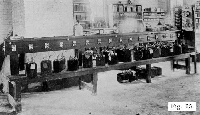
Fig. 65. Charging Bench with D.P.D.T. Switch for Each Battery
Figures 47 and 65 show charging benches in operation. Note that they are made of heavy stock, which is of course necessary on account of the weight of the batteries. The top of the charging bench should be low, to eliminate as much lifting of batteries as possible. Figure 66 is a working drawing of the bench illustrated in Figure 65. Note the elevated shelf extending down the center. This is convenient for holding water bottle, acid pitcher, hydrometer. Note also the strip "D" on this shelf, with the voltmeter hung from an iron bracket. With this arrangement the meter may be moved to any battery for voltage, cadmium, and high rate discharge readings. It also has the advantage of keeping the volt meter in a convenient and safe place, where it is not liable to have acid spilled on it, or to be damaged by rough handling. In building the bench shown in Figure 66, give each part a coat of asphaltum paint before assembling. After assembling the bench give it two more coats of asphaltum paint.
Figures 67, 68, 69 and 70 show the working plans for other charging benches or tables. The repairman should choose the one which he considers most suitable for his shop. In wiring these benches, the elevated shelf shown in Figure 66 may be added and the double pole, double throw switches used. Instead of these switches, the jumpers shown on the benches illustrated in Figure 47 may be used. If this is done, the elevated shelf should also be installed, as it is a great convenience for the hydrometer, voltmeter, and so on, as already described.
As for the hydrometer, thermometer, etc., which were listed on page 96 as essential accessories of a charging bench, the Exide vehicle type hydrometer is a most excellent one for general use. This hydrometer has a round bulb and a straight barrel which has projections on the float to keep the hydrometer in an upright position when taking gravity readings. The special thermometer is shown in Figure 37. A good voltmeter is shown in Figure 121. This voltmeter has a 2.5 and a 25 volt scale, which makes it convenient for battery work. It also gives readings of a .2 and 2.0 to the left of the zero, and special scale markings to facilitate the making of Cadmium tests as described on page 174. As for the ammeter, if a motor-generator set, Tungar Rectifier or a charging-rheostat is used, the ammeter is always furnished with the set. If a lamp bank is used, a switchboard type meter reading to about 25 amperes is suitable. With the constant potential system of charging, the ammeters are furnished with the motor-generator set. They read up to 300 amperes.
The bottles for the distilled water and electrolyte are not of special design and may be obtained in local stores, There are several special water bottles sold by jobbers, and they are convenient, but not necessary. Figure 133 shows a very handy arrangement for a water or acid bottle.
WORK BENCH
A work bench is more of a standard article than the charging bench, and there should be no trouble in building one. Figure 38 illustrates a good bench in actual use. A vise is, of course, necessary, and the bench should be of solid construction, and should be given several coats of asphaltum paint.
Figure 71 shows a single work bench which may be placed against a wall. Figures 72 and 73 show double work benches. Note that each bench has the elevated shelf, which should not, under any consideration be omitted, as it is absolutely necessary for good work. The tool drawers are also very convenient.
It is best to have a separate "tear down" bench where batteries are opened, as such a bench will be a wet, sloppy place and would not be suitable for anything else. It should be placed near the sink or wash tank, as shown in the shop layouts illustrated in Figures 136 to 142.
SINK OR WASH TANK
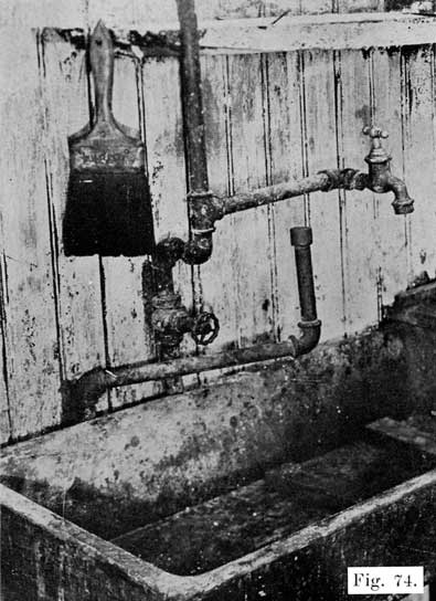
An ordinary sink may be used, as shown in Figure 74. This figure also shows a convenient arrangement for washing out jars. This consists of a three-fourths inch pipe having a perforated cap screwed over its upper end. Near the-floor is a valve which is normally held closed by a spring, and which has attached to it a foot operated lever. In washing sediment out of jars, the case is inverted over the pipe, and the water turned on by means of the foot lever. A number of fine, sharp jets of water are thrown up into the jar, thereby washing out the sediment thoroughly.
If an ordinary sink is used, a settling tank should be placed under it, as shown in Figure 75. Otherwise, the drain pipe may become stopped up with sediment washed out of the jars. Pipe B is removable, which is convenient in cleaning out the tank. When the tank is to be cleaned, lift pipe B up very carefully and let the water drain out slowly. Then scoop out the sediment, rinse the tank with water, and replace pipe B. In some places junk men will buy the sediment, or "mud," as it is called.
Fig. 74. Sink with Faucet, and Extra Swinging Arm Pipe for
Washing Out Jars. Four Inch Paint Brush for Washing Battery
Cases
Figures 76 and 77 give the working drawings for more elaborate wash tanks. The water supply shown in Figure 74 may be used here, and the drain pipe arrangement shown in Figure 75 may be used if desired.
LEAD BURNING (WELDING) OUTFIT
In joining the connectors and terminals to the positive and negative posts, and in joining plate straps to form a "group," the parts are joined or welded together, melting the surfaces to be joined, and then melting in lead from sticks called "burning lead." The process of joining these parts in this manner is known as "lead burning." Directions for "lead burning" are given on page 210.
There are various devices by means of which the lead is melted during the "lead burning" process. The most satisfactory of these use a hot, pointed flame. Where such a flame is not obtainable, a hot carbon rod is used.
The methods are given in the following list in the order of their efficiency:
1. Oxygen and Acetylene Under Pressure in Separate Tanks. The gases are sent through a mixing valve to the burning tip. These gases give the hottest flame.
2. Oxygen and Hydrogen Under Pressure in Separate Tanks, Fig. 78. The flame is a very hot one and is very nearly as satisfactory as the oxygen and acetylene.
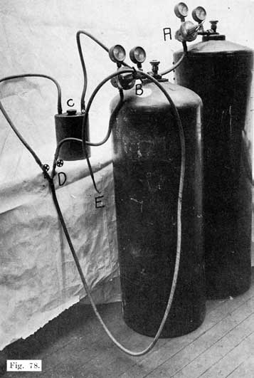
Fig. 78. Hydrogen-Oxygen Lead Burning Outfit. A and B are Regulating Valves. C is the Safety Flash Back Tank. D is the Mixing Valve. E is the Burning Tip.
3. Oxygen and Illuminating Gas. This is a very satisfactory method, and one that has become very popular. In this method it is absolutely necessary to have a flash back tank (Fig. 79) in the gas line to prevent the oxygen from backing up into the gas line and making a highly explosive mixture which will cause a violent explosion that may wreck the entire shop.
To make such a trap, any strong walled vessel may be used, as shown in Figure 79. A six to eight inch length of four inch pipe with caps screwed over the ends will make a good trap. One of the caps should have a 1/2 inch hole drilled and tapped with a pipe thread at the center. This cap should also have two holes drilled and tapped to take a 1/4 inch pipe, these holes being near the inner wall of the large pipe, and diametrically opposite one another.
Into one of these holes screw a short length of 1/4 inch pipe so Fig. 79. Flash-Back Tank for Lead Burning Outfit that it comes flush with the inner face of the cap. This pipe should lead to the burning outfit.
Into the other small hole screw a length of 1/4 inch pipe so that its lower end comes within 1/2 inch of the bottom of the trap. This pipe is to be connected to the illuminating gas supply.
To use the trap, fill within one inch of top with water, and screw a 1/2 inch plug into the center hole. All connections should be airtight.
4. Acetylene and Compressed Air. The acetylene is bought in tanks, and the air compressed by a pump.
5. Hydrogen and Compressed Air. This is the method that was very popular several years ago, but is not used to any extent at present because of the development of the first three methods. A special torch and low pressure air supply give a very satisfactory flame.
6. Wood Alcohol Torch. A hand torch with a double jet burner gives a very clean, nonoxidizing flame. The flame is not as sharp as the oxygen flame, and the torch is not easily handled without the use of burning collars and moulds. The torch has the advantage of being small, light and portable. A joint may be burned without removing the battery from the car.
7. Gasoline Torch. A double jet gasoline torch may be used, provided collars or moulds are used to prevent the lead from running off. The torch gives a broad flame which heats the parts very slowly, and the work cannot be controlled as easily as in the preceding methods.
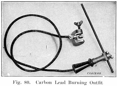
8. Carbon Arc. This is a very simple method, and requires only a spare 6 volt battery, a 1/4 inch carbon rod, carbon holder, cable, and clamp for attaching to battery. This outfit is shown in Fig. 80. It may be bought from the American Bureau of Engineering, Inc., Chicago, Ill. This outfit is intended to be used only when gas is not available, and not where considerable burning is to be done.
In using this outfit, one terminal of an extra 6 volt battery is connected by a piece of cable with the connectors to be burned. The contact between cable and connector should be clean and tight. The cable which is attached to the carbon rod is then connected to the other terminal of the extra battery, if the battery is not fully charged, or to the connector on the next cell if the battery is fully charged. The number of cells used should be such that the carbon is heated to at least a bright cherry red color when it is touching the joint which is to be burned together.
Sharpen the carbon to a pencil point, and adjust its position so that it projects from the holder about one inch. Occasionally plunge the holder and hot carbon in a pail of water to prevent carbon from overheating. After a short time, a scale will form on the surface of the carbon, and this should be scraped off with a knife or file.
In burning in a connector, first melt the lead of the post and connector before adding the burning lead. Keep the carbon point moving over all parts to be joined, in order to insure a perfectly welded joint.
9. Illuminating Gas and Compressed Air. This is the slowest method of any. Pump equipment is required, and this method should not be used unless none of the other methods is available.
The selection of the burning apparatus will depend upon individual conditions as well as prices, and the apparatus selected should be one as near the beginning of the foregoing list as possible. Directions for the manipulation of the apparatus are given by the manufacturers.
The most convenient arrangement for the lead burning outfit is to run pipes from one end of the work bench to the other, just below the center shelf. Then set the gas tanks at one end of the bench and connect them to the pipes. At convenient intervals have outlets for attaching the hoses leading to the torch.
EQUIPMENT FOR HANDLING SEALING COMPOUND
(a) Stove. Where city gas is available, a two or three burner gas stove or hot-plate should be used. Where there is no gas supply, the most satisfactory is perhaps an oil stove. It is now possible to get an odorless oil stove which gives a hot smokeless flame which is very satisfactory. In the winter, if a coal stove is used to heat the shop, the stove may also be used for heating the sealing compound, but it will be more difficult to keep the temperature low enough to prevent burning the compound.
(b) Pot or Kettle. An iron kettle is suitable for use in heating compound. Special kettles, some of which are non-metallic, are on the market, and may be obtained from the jobbers.
(c) An iron ladle should be obtained for dipping up compound, and for pouring compound when sealing a battery. Figure 81 shows a convenient form of ladle which has a pouring hole in the bottom. A taper pin, which is raised by the extra handle allows a very fine stream of compound to be poured.
The exact size of the ladle is not important, but one which is too heavy to be held in one hand should not be used.
(d) Several old coffee pots are convenient, and save much time in sealing batteries.
Sealing compound is a combination of heavy residues produced by the fractional distillation of petroleum. It is not all alike-that accepted for factory use and distribution to Service Stations must usually conform to rigid specifications laid down by the testing laboratories governing exact degrees of brittleness, elongation, strength and melting point. For these qualities it is dependent upon certain volatile oils which may be driven off from the compound if the temperature of the molten mass is raised above the comparatively low points where some of these oils begin to volatilize off as gaseous vapor or smoke.
Compound from which certain of these valuable constituent oils have been driven off or "burned out" through overheating is recognized through too great BRITTLENESS and SHRINKAGE on cooling, causing "CRACKED COMPOUND" with all of its attending difficulties.
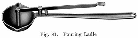
Do not put too much cold compound in the kettle to begin with. It is not advisable to carry much more molten compound in the kettle at any time than can easily be dipped out-cold compound may be added during the day as needed. When there is considerable cold compound in the kettle, and the heating flame is applied, the lower bottom part of the mass next to the surface of the iron is brought to a melting point first-heat must be conveyed from this already hot part of the compound upward throughout the whole mass-so that before the top part of it is brought to a molten condition the lower inside layers are very hot indeed. If there is too much in the kettle these lower layers are necessarily raised in temperature beyond the point where they lose some of their volatile oils-they are "burned" before the whole mass of compound can be brought to a molten state.
Do not use too large a heating flame under the kettle for the same reasons. A flame turned on "full blast" will certainly "burn" the bottom layers before the succeeding layers above are brought to the fusion point. USE A SLOW FLAME and TAKE TIME IN MELTING UP THE COMPOUND. It PAYS in the resulting jobs.
The more compound is heated, the thinner it becomes—it should never be allowed to become so hot that it flows too freely—it should never exceed the viscosity of medium molasses. It should flow freely enough to run in all narrow spaces but NOT freely enough to flow THROUGH them before it cools.
Stir the kettle frequently during the day. It is advisable about once a week to work as much compound out of the kettle as possible, empty that still remaining, clean the kettle out, and start with fresh compound.
NEVER USE OLD COMPOUND OVER AGAIN — that is, do not throw compound that has been dug out of used batteries into the kettle with the new compound. The old compound is no doubt acid soaked, and this acid will work through the whole molten mass, making a satisfactory job a very doubtful matter indeed.
Cold weather hardens sealing compound, of course, and renders it somewhat brittle and liable to crack. This tendency could be overcome by using a softer compound, but, on the other hand, compound so soft that it would have no tendency to crack in cold weather would be so soft in warm weather that it would fail to hold the assembly with the necessary firmness and security. It is far better policy to run the risk of developing a few cracks in the winter than a loose assembly in summer. Surface cracks developed in cold weather may be easily remedied by stripping off the compound around the crack with a heated tool, flashing with the torch and quickly re-sealing according to the above directions.
It is not practical to work any oil agent, such as paraffin or castor oil, into the compound in an effort to soften it for use in cold weather.
SHELVING AND RACKS
The essential things about shelving in a battery shop are, that it must be covered with acid-proof paint, and must be made of heavy lumber if it is to carry complete batteries. Figure 82 shows the heavy shelving required in a stock-room, while Figure 83 shows the lighter shelving which may be used for parts, such as jars, cases, extra plates, and so on.
Fig. 82. Typical Stockroom, Showing Heavy Shelving Necessary for Storing Batteries.
BINS
Figure 90 gives the dimensions for equipment bins suitable for covers, terminals, inter-cell connectors, jars, cases, and various other parts. These bins can be made with any desired number of sections, and additional sections built as they are needed.
Fig. 83. Corner of Workshop, Showing Lead Burning Outfit, Workbench and Vises.
Figures 84 and 85 show two receiving racks for batteries which come in for repairs. In many shops batteries are set on the floor while waiting for repairs. If there is plenty of floor space, this practice is not objectionable. In any case, however, it improves the looks of the shop, and makes a better impression on the customer to have racks to receive such batteries. Note that the shelves are arranged so as to permit acid to drain off. Batteries often come in with wet, leaky cases, and this shelf construction is suitable for such batteries.
The racks shown in Figures 86 and 87 are for repaired batteries, new batteries, rental batteries, batteries in dry storage, and for any batteries which do not have wet leaky cases.

Figures 88 and 89 show racks suitable for new batteries which have been shipped filled with electrolyte, batteries in "wet" or "live" storage, rental batteries, and so on. Note that these racks are provided with charging circuits so that the batteries may be given a low charge without removing them from the racks. Note. also that the shelves are spaced two feet apart so as to be able to take hydrometer readings, voltage readings, add water, and so on, without removing the batteries from the racks.
Figure 90 gives the dimensions for equipment bins suitable for covers, terminals, inter-cell connectors, jars, cases, and various other parts. These bins can be made with any desired number of sections, and additional sections built as they are needed.
BATTERY STEAMER
Steaming is the most satisfactory method of softening sealing compound, making covers and jars limp and pliable. An open flame should never be used for this work, as the temperature of the flame is too high and there is danger of burning jars and covers and making them worthless. With steam, it is impossible to damage sealing compound or rubber parts.
A soft flame from a lead burning torch is used to dry out the channels in the covers before sealing, and is run over the compound quickly to make the compound flow evenly and unite with the jars and covers. But in such work the flame is used for only a few seconds and is not applied long enough to do any damage.
With a steaming outfit, it is also possible to distill water for use in mixing electrolyte and replacing evaporation in the cells. The only additional equipment needed is a condenser to condense the steam into water.
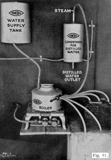
Fig. 91. Battery Steamer, with Steam Hose for Each Cell
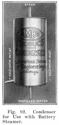
Figure 91 shows a steaming outfit mounted on a wall, and shows the rubber tube connections between the several parts. The boiler is set on the stove, water being supplied from the water supply tank which is hung above the boiler to obtain gravity feed. The water supply tank is open at the top, and is filled every morning with faucet water. This tank is suitable for any shop, even though a city water supply is available. A water pipe from the city lines may be run to a point immediately above the tank and a faucet or valve attached. Where there is no city water supply, the tank may, of course, be filled with a pail or pitcher.
The boiler is equipped with a float operated valve which maintains a one to one and one-half inch depth of water. As the water boils away, the float lowers slightly and allows water to enter the boiler. In this way, the water is maintained at the proper level at all times. A manifold is fitted to the boiler and has six openings to which lengths of rubber tubing are attached. These tubes are inserted in the vent holes of the battery which is to be steamed. Any number of the steam outlets may be opened by drawing out the manifold plunger valve to the proper point. When distilling water, a tube is attached to one of the steam outlets as shown, and connected to the condenser as shown. A bottle is placed under the distilled water outlet to collect the distilled water.
Cooling water enters the condenser through the tubing shown attached to the condenser at the lower right-hand edge. The other end of this tube is attached to the water faucet, or other cooling water supply. The cooling water outlet is shown at the lower left hand edge of the condenser. The cooling water inlet and outlet are shown in Figure 92.
If there is no city water supply, a ten or twenty gallon tank may be mounted above the condenser and attached by means of a rubber tube to the cooling water inlet shown at the lower right hand edge of the condenser in Figure 92. A similar tank is placed under the cooling water outlet. The upper tank is then filled with water. When the water has run out of the upper tank through the condenser and into the lower tank, it is poured back into the upper tank. In this way a steady supply of cooling water is obtained.
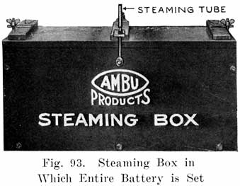
Another type of steamer uses a steaming box, Figure 93. The battery is placed in the box and steam is sent in through the cover. The boiler has only one steam outlet, and this is connected to the box by means of a hose.
If desired, a special bench may be made for the steaming outfit, as shown in Figure 94.
The other tools needed for opening batteries, as given in the list on page 97 are standard articles, and may be obtained at any hardware store, except the terminal tongs, which should be purchased from a battery supply house.
Figure 95 illustrates the use of terminal tongs. Battery terminals usually stick so tight that they must be forced out with pliers or other tools. Here is shown a pair of tongs that makes easy work of the job. One end has a fork and the other is shaped to come between the fork. It is placed on the battery terminal, as shown, and when the handles are brought together the terminal attached to the battery lead is forced out without marring any of the parts.
EQUIPMENT FOR LEAD BURNING (WELDING)
Plate Burning Rack
The plates which compose a "group" are joined to the plate connecting strap to which the post is attached. The plates are "burned" to the strap, and this must be done in such a manner that the plates are absolutely parallel, that the distance between plates is correct, and that the top surface of the strap is at right angles to the surface of the plates. These conditions are necessary in order that the positive and negative groups may mesh properly, that the complete element, consisting of the plates and separators may fit in the jar properly, and that the cell covers may fit over the posts easily.
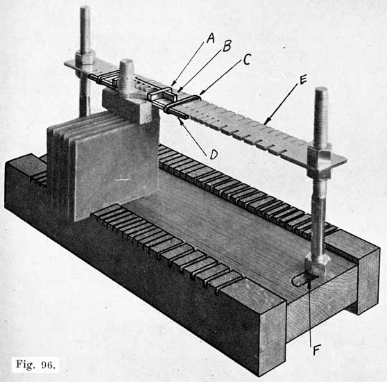
Fig. 96. Universal Plate Burning Rack. Will Hold Three Groups of Plates at One Time. Designed for Standard and Special Plates
In order to secure these conditions, plates that are to be burned to the strap are set in a "burning rack," shown in Figs. 96 and 97, which consists mainly of a base upon which the plate rest, and a slotted bar into which the lugs on the plates fit. The distance between successive slots is equal to the correct distance between the plates of the group. An improved form of burning rack has a wooden base which has slots along the side. The plates are set into these slots and are thus held in the correct position at both top and bottom.
Fig. 97 shows a rack for use with 1/8 inch and 7-64 inch plates. Fig. 96 shows a "Universal" rack which may be used with both the 1/8 and 7-64 inch plates, and also many special plates.
The guide-bar, or "comb," E, has slots along two sides, the base having corresponding slots, as shown. To accommodate different sized plates, the comb may be raised or lowered, and the uprights may be moved back and forth in two slots, one of which is shown at F. In using this rack, the plates are set in position, with their lower edges in the slots of the base, and their lugs in the slots in the comb. The plates are in this way held at opposite corners, and are absolutely straight and parallel.
Special fittings are provided to simplify the work of burning. A bar, D, fits along the edge of the comb, and holds the lugs of the plates firmly in the slots. This bar is movable to any part of the comb, being held by two spring clips, C. Two bars, A and B, which are adjustable, make a form around the plate lugs which will prevent the hot lead from running off while burning in the plates.
Instructions for burning on plates are given on page 217.
The triangular scraper, steel wire brush, coarse files and smoked or blue glasses are all standard articles and may be obtained from any supply house. The burning collars are made of iron, and are set over the end of inter-cell connectors when burning these to the posts, see Figure 98. Experienced repairmen generally do not use them, but those who have trouble with the whole end of the connector melting and the lead running off should use collars to hold in the lead.
The Burning Lead Mould
In every shop there is an accumulation of scrap lead from post drillings, old connecting straps, old plate straps, etc. These should be kept in a special box provided for that purpose, and when a sufficient amount has accumulated, the lead should be melted and run off into moulds for making burning-lead.
The Burning Lead Mould is designed to be used for this purpose. As shown in Fig. 99, the mould consists of a sheet iron form which has been pressed into six troughs or grooves into which the melted lead is poured. This sheet iron form is conveniently mounted on a block of wood which has a handle at one end, making it possible to hold the mould while hot without danger of being burned. A sheet of asbestos separates the iron form from the wood, thus protecting the wood from the heat of the melted lead. A hole is drilled in the end of the handle to permit the mould being hung on a nail when not in use. The grooves in the iron form will produce bars of burning lead 15 inches long, 5-16 inch thick, 3/8 inch wide at the top, and 1/4 inch wide at the bottom.
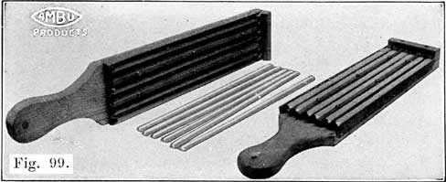
Fig. 99. Burning-Lead Moulds, and Burning Sticks Cast in Them
The advantage of this type of Burning Lead Mould over a cast iron mould is obvious. The form, being made of sheet iron, heats up very quickly, and absorbs only a very small amount of heat from the melted lead. The cast-iron mould, on the other hand, takes so much heat from the melted lead that the latter cools very quickly, and is hard to handle.
An iron pot that will hold at least ten pounds of molten lead should be used in melting up lead scraps for burning sticks.
When the metal has become soft enough to stir with a clean pine stick skim off the dross. Continue heating metal until slightly yellow on top.
With a paddle or ladle drop in a cleaning compound of equal parts of powdered rosin, borax and flower of sulphur. Use a teaspoonful for a ten-pound melting and make sure the compound is perfectly dry.
Stir a little and if metal is at proper heat there will be a flare, flash or a little burning. A sort of tinfoil popcorn effect will be noticed floating on top of the metal. Stir until this melts down. Have your ladle hot and skim off soft particles. Dust the mould with mould compound, a powder which makes the lead fill the entire grooves, and not become cool before it does.
When everything is ready, fill the ladle and pour the lead into one of the grooves. Hold the ladle above one end of the groove while pouring, and do not move it along the groove. Fill the other grooves in a similar manner.
Post Builders. These are moulds which are set over the stumps of posts which have been drilled short in removing the inter-cell connectors. Lead is then melted in with a burning flame to build the post up to the proper height. Figure 100 shows a set of post-builders, and Figure 101 illustrates their use.
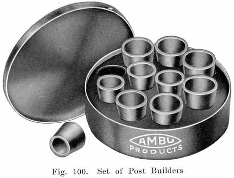
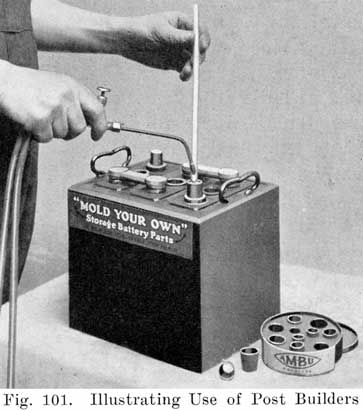
EQUIPMENT FOR GENERAL WORK ON CONNECTORS AND
TERMINALS
Moulds for Casting Inter-Cell Connectors, Terminals, Terminal
Screws, Taper Lugs, Plate Straps, Etc.
Figure 102 shows a plate strap mould with which three straps and posts may be cast in one minute. It has a sliding movable tooth rack for casting an odd or even number of teeth on the strap.
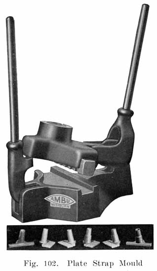
Figure 103 shows a Link Combination Mould which casts five inter-cell connectors for use on standard 7, 9, 11, 13 and 15 plate batteries, four end connectors (two Dodge tapers, and standard tapers, negative and positive), one end connector with 3/8 inch cable used on 12 volt Maxwell battery and on all other cars a wire cable, and one small wire to connect with end post on batteries requiring direct connection. It also casts two post support rings to fit standard size rubber covers and to fit posts cast with plate strap mould, and two washers which are often needed when installing needed when installing new or rental batteries.
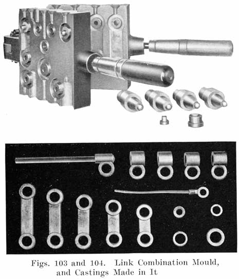
Figure 104 shows the parts which may be made with this mould.
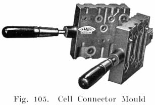
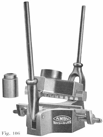
Figure 105 shows a cell connector mould which casts practically all the cell connectors used on standard 7, 9, 11, 13 and 15 plate batteries. This mould is similar to the Link Combination Mould shown in Figure 103.
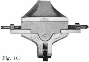
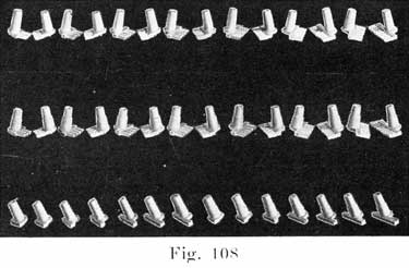
Figure 106 shows a production type strap mould which is designed to be used by large battery shops. Forty-two styles of straps are, cast by this mould. This mould has an indexing device as shown in Figure 107, which is adjusted by means of a screw for moulding the straps for any number of plates from seven to nineteen. Figure 109 shows some of the castings which are made with this mould.
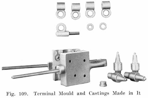
Figure 109 shows a Terminal Mould which casts five reversible end terminal connectors, a cable connector, such as is used on the Maxwell battery, and two washers often needed in making a tight connection.
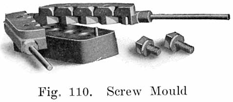
Figure 110 shows a Screw Mould which casts standard square lead leads on four screws in one operation, two 5/8 inch and two 3/8 inch. This mould has a screw adjustment in the base which makes each cavity adaptable to any length screw.
EQUIPMENT FOR WORK ON CASES
The acid proof asphaltum paint, paint brushes, wood chisels, wood plane, and earthenware jars are all standard articles.
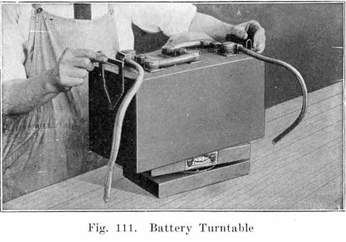
Figure 111 shows a battery turntable which is very convenient when painting cases, lead burning, etc.
TOOLS FOR GENERAL WORK
Most of the articles in this list require no explanation. Some of them, however, are of special construction.
Separator Cutter. Some battery supply houses sell special separator cutters, but a large size photograph trimmer is entirely satisfactory.
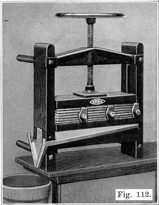
Fig. 112. Plate Press for Pressing Swollen,
Bulged Negatives (After Plates Have Been Fully
Charged)
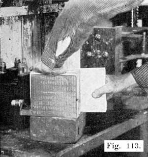
Fig. 113. Inserting Plate Press Boards Between
Negatives Preparatory to Pressing
Plate Press. Figure 112 shows a special plate press in which the plates are pressed between wooden jaws. No iron can come into contact with the plates. This is a very important feature, since iron in solution causes a battery to lose its charge very quickly. This press is made of heavy hardwood timbers, and may be set on a bench or mounted on the wall. A set of lead coated troughs carry away the acid which is squeezed from the plates.
This press is designed for pressing negative plates, the active material of which has become bulged or swollen. A plate in this condition has a low capacity and cannot give good service. Swollen negatives often make it impossible to replace the plates in a jar. When negatives are found to be bulged or swollen, the battery must be fully charged, and the negatives then pressed. To do this, plate press boards, which are of acid proof material, and of the proper thickness are inserted between the negatives, as shown in Figure 113, and the plates are then set in the press is shown in Figure 114.
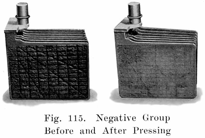
Figure 115 shows a group before and after pressing. Note that pressing has forced the active material back into the grid where it must be if the plates are to give good service. Never send out a battery with swollen or bulged negatives.
Slightly buckled negatives may also be straightened out in the Plate Press. Positives do not swell or bulge as they discharge, but shed the active material. They are therefore not pressed Positives buckle, of course, but should never be pressed to straighten them. The lead peroxide of the positive plates is not elastic like the spongy the negatives, and if positives are pressed to straighten them the paste will crack and break from the grid. Slightly buckled positives may be used, but if they are so badly buckled that it is impossible to reassemble the element or put the element back into the jars, they should be discarded.
Battery Carrier. Figure 116 shows a very convenient battery carrier, having a wooden handle with two swinging steel hooks for attaching to the battery to be carried. With this type of carrier no strain is put on the handle, as is the case if a strap is used.
Battery Truck. When a battery must be moved any considerable distance, a truck, such as that shown in Figure 117 should be used. This truck may easily be made in the shop, or may be made at a reasonable cost in a carpenter shop. The rollers should be four inches or more in diameter and should preferably be of the ball-bearing type. Rubber tires on the rollers are a great advantage, since the rubber protects the rollers from acid and also eliminates the very disagreeable noise which iron wheels make, especially in going over a concrete floor or sidewalk. The repairman need not make his truck exactly like that shown in Figure 117, which is merely shown to give a general idea of how such a truck should be constructed.
The truck shown in Figure 117 was made from a heavy wooden box. With this construction lifting batteries is largely eliminated, which is most desirable, since a battery is not the lightest thing in the world. The battery is carried in a horizontal position and the truck is small enough to be wheeled between cars in the shop.
Another form of battery truck is shown in Figure 118, although this, is not as good as that shown in Figure 117.
CADMIUM TEST SET AND HOW TO MAKE THE TEST
As the cell voltage falls while the battery is on discharge, the voltage of the positive plates, and also the voltage of the negative plates falls. When the battery is charged again the voltages of both positive and negative plates rise. If a battery gives its rated ampere-hour capacity on discharge, we do not care particularly how the voltages of the individual positive and negative groups change. If, however, the battery fails to give its rated capacity, the fault may be due to defective positives or defective negatives.
If the voltage of a battery fails to come up when the battery is put on charge, the trouble may be due to either the positives or negatives. Positives and negatives may not charge at the same rate, and one group may become fully charged before the other group. This may be the case in a cell which has had a new positive group put in with the old negatives. Cadmium tests made while the battery is on charge will tell how fully the individual groups are charged.
Since the voltages of the positives and negatives both fall as a battery is discharged, and rise as the battery is charged, if we measure the voltages of the positives and negatives separately, we can tell how far each group is charged or discharged. If the voltage of each cell of a battery drops to 1.7 before the battery has given its rated capacity, we can tell which set of plates has become discharged by measuring the voltages of positives and negatives separately. If the voltage of the positives show that they are discharged, then the Positives are not up to capacity. Similarly, negatives are not up to capacity if their voltage indicates that they are discharged before the battery has given its rated capacity.
Cadmium readings alone do not give any indication of the capacity of a battery, and the repairman must be careful in drawing conclusions from Cadmium tests.
In general it is not always safe to depend upon Cadmium tests on a battery which has not been opened, unless the battery is almost new. Plates having very little active material, due to shedding, or due to the active material being loosened from the grid, will often give good Cadmium readings, and yet a battery with such plates will have very little capacity. Such a condition would be disclosed by an actual examination of the plates, or by a capacity discharge test.
How Cadmium Tests Are Made
To measure the voltages of the positives and negatives separately, Cadmium is used. The Cadmium is dipped in the electrolyte, and a voltage reading is taken between the Cadmium and the plates which are to be tested. Thus, if we wish to test the negatives, we take a voltage reading between the Cadmium and the negatives, as shown in Fig. 119. Similarly, if we wish to test the positives, we take a voltage reading between the Cadmium and the positives, as shown in Fig. 120.
In dipping the Cadmium into the electrolyte, we make two cells out of the battery cell. One of these consists of the Cadmium and the positives, while the other consists of the Cadmium and the negatives. If the battery is charged, the Cadmium forms the negative element in the Cadmium-Positives cell, and is the positive element in the Cadmium-Negatives cell. The voltage of the Cadmium does not change, and variations in the voltage readings obtained in making Cadmium tests are due to changes in the state of charge of the negative and positive plates which are being tested.
What Cadmium Is: Cadmium is a metal, just like iron, copper, or lead. It is one of the chemical elements; that is, it is a separate and distinct substance. It is not made by mixing two or more substances, as for instance, solder is made by mixing tin and lead, but is obtained by separating the cadmium from the compounds in which it is found in nature, just as iron is obtained by treatment of iron ore in the steel mill.
When Cadmium Readings Should Be Made
1. When the battery voltage drops to 1.7 per cell on discharge before the battery has delivered its rated ampere-hour capacity, at the 5-hour rate when a discharge test is made.
2. When a battery on charge will not "come up," that is, if its voltage will not come up to 2.5-2.7 per cell on charge, and its specific gravity will not come up to 1.280-1.300.
3. Whenever you charge a battery, at the end of the charge, when the voltage and specific gravity no longer rise, make Cadmium tests to be sure that both positives and negatives are fully charged.
4. When you put in a new group, charge the battery fully and make Cadmium tests to be sure that both the new and old groups are fully charged.
5. When a 20-minute high rate discharge test is made. See page 267.
That Cadmium Readings should be taken only while a battery is in action; that is, while it is on discharge, or while it is on charge.
Cadmium Readings taken on a battery which is on open circuit are not reliable.
When you are not using the Cadmium, it should be put in a vessel of water and kept there. Never let the Cadmium become dry, as it will then give unreliable readings.
Open Circuit Voltage Readings Worthless
Voltage readings of a battery taken while the battery is on open circuit; that is, when no current is passing through the battery, are not reliable. The voltage of a normal, fully charged cell on open circuit is slightly over 2 volts. If this cell is given a full normal discharge, so that the specific gravity of its electrolyte drops to 1.150, and is allowed to stand for several hours after the end of the discharge, the open circuit voltage will still be 2 volts. Open circuit voltage readings are therefore of little or no value, except when a cell is "dead," as a dead cell will give an open circuit voltage very much less than 2, and it may even give no voltage at all.
What the Cadmium Test Set Consists of
The Cadmium Tester consists of a voltmeter, Fig. 121, and two pointed brass prods which are fastened in wooden handles, as shown in Fig. 122. A length of flexible wire having a terminal at one end is soldered to each prod for attachment to the voltmeter. Fastened at right angles to one of the brass prods is a rod of pure cadmium.
Cadmium tests may be made with any accurate voltmeter which gives readings up to 2.5 volts in divisions of .05 volt.
The instructions given below apply especially to the special AMBU voltmeter but these instructions may also be used in making cadmium tests with any voltmeter that will give the correct reading.
The AMBU Cadmium Voltmeter
Fig. 121 is a view of the special AMBU Voltmeter, which is designed to be used specially in making Cadmium tests. Fig. 122 shows the Cadmium leads. The four red lines marked "Neg. Charged," "Neg. Discharged," "Pos. Charged," and "Pos. Discharged," indicate the readings that should be obtained. Thus, in testing the positives of a battery on charge, the pointer will move to the line which is marked "Pos. Charged," if the positive plates are fully charged. In testing the negatives, the pointer will move to the line marked "Neg. Charged," which is to the left of the "0" line, if the negatives are fully charged, and so on. Figs. 123, 124, 125 and 126 show the pointer in the four positions on the scale which it takes when testing fully charged or discharged plates. In each figure the pointer is over one of the red lines on the scale. These figures also show the readings, in volts, obtained in making the cadmium tests on fully charged or completely discharged plates.
If Pointer Is Not Over the "0" Line: It sometimes happens, in shipping the instrument, and also in the use of it, that the pointer does not stand over the "0" line, but is a short distance away. Should you find this to be the case, take a small screwdriver and turn the screw which projects through the case, and which is marked "Correct Zero," so as to bring the pointer exactly over the "0" line on the scale while the meter has no wires connected to its binding posts.
Connections of Cadmium Leads: In making Cadmium Tests, connect the prod which has the cadmium fastened to it to the negative voltmeter binding post. Connect the plain brass prod to the positive voltmeter binding post. The connections to the AMBU Cadmium Voltmeter are shown in Fig. 127.
Testing a Battery on Discharge
The battery should be discharging continuously, at a constant, fixed rate, see page 265.
Generally, on a starting ability test (see page 267), the positive Cadmium readings will start at about 2.05 volts for a hard or very new set of positives, and at 2.12 volts or even higher for a set of soft or somewhat developed positives, and will drop during the test, ending at 1.95 volts or less. The negative Cadmium readings will start at 0.23 volt or higher, up to 0.30, and will rise gradually, more suddenly toward the end if the plates are old, ending anywhere above 0.35 and up to 0.6 to 0.7 for poor negatives.
Short Circuited Cells: In cases of short circuited cells, the voltage of the cell will be almost down to zero. The Cadmium readings would therefore be nearly zero also for both positives and negatives. Such a battery should be opened for inspection and repairs.
Testing a Battery on Charge
The Battery should be charging at the finishing rate. (This i's usually stamped on the battery box.) Dip the cadmium in the electrolyte as before, and test the negatives by holding the plain prod on the negative post of the cell. See Fig. 119. Test the positives in a similar manner. See Fig. 120. The cell voltage should also be measured. If the positives are fully charged, the positive cadmium reading will be such that the pointer will move to the red line marked "Pos. Charged." See Fig. 125. If you are using an ordinary voltmeter, the meter will give a reading of from 2.35 to 2.42 volts. The negatives are then tested in a similar manner. The negative-cadmium reading on an ordinary voltmeter will be from .175 to .2 to the left of the "0" line; that is, the reading is a reversed one. If you are using the special ABM voltmeter, the pointer will move to the red line marked "Neg. Charged." See Fig. 123. The cell voltage should be the sum of the positive-cadmium and the negative cadmium readings.
If the voltage of each cell will not come up to 2.5 to 2.7 volts on charge, or if the specific gravity will not rise to 1.280 or over, make the cadmium tests to determine whether both sets of plates, or one of them, give readings indicating that they are fully charged. If the positives will not give a reading of at least 2.35 volts, or if the negatives will not give a reversed reading of at least 0.1 volt, these plates lack capacity.
In case of a battery on charge, if the negatives do not give a minus Cadmium reading, they may be lacking in capacity, but, on the other hand, a minus negative Cadmium reading does not prove that the negatives are up to hill capacity. A starting ability discharge test (page 267) is the only means of telling whether a battery is up to capacity.
Improperly treated separators will cause poor negative-Cadmium readings to be obtained. The charging rate should be high enough to give cell voltages of 2.5-2.7 when testing negatives. Otherwise it may not be possible to get satisfactory negative-Cadmium reading. Separators which have been allowed to become partly dry at any time will also make it difficult to obtain satisfactory negative-Cadmium readings.
HIGH RATE DISCHARGE TESTERS
(See page 265 for directions for making tests.)
Figure 128 shows a high rate discharge cell tester. It consists of a handle carrying two heavy prongs which are bridged by a length of heavy nichrome wire. When the ends of the prongs are pressed down on the terminals of a cell, a current of 150 to 200 amperes is drawn from the cell. A voltage reading of the cell, taken while this discharge current is flowing is a means of determining the condition of the cell, since the heavy discharge current duplicates the heavy current drawn by the starting motor. Each prong carries a binding post, a low reading voltmeter being connected to these posts while the test is made. This form of discharge tester is riot suitable for making starting ability discharge tests, which are described on page 267.
Other forms of high rate discharge testers are made, but for the shop the type shown in Figure 128 is most convenient, since it is light and portable and has no moving parts, and because the test is made very quickly without making any connections to the battery. Furthermore, each cell is tested separately and thus six or twelve volt batteries may be tested without making any change in the tester.
For making starting ability discharge tests at high rates, a carbon plate or similar rheostat is most suitable, and such rheostats are on the market.
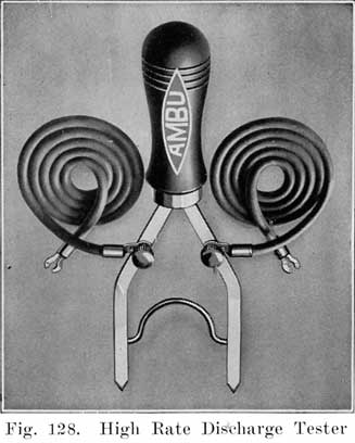
PARAFFINE DIP POT
Paper tags are not acid proof, and if acid is spilled on tags tied to batteries which are being repaired, the writing on the tags is often obliterated so that it is practically impossible to identify the batteries. An excellent plan to overcome this trouble is to dip the tags in hot paraffine after they have been properly filled out. The writing on the tags can be read easily and since paraffine is acid proof, any acid which may be spilled on the paraffine coated tags will not damage the tags in any way.
Figure 129 shows a paraffine dip pot. A small earthenware jar is best for this purpose. Melt the paraffine slowly on a stove, pour it into the pot, and partly immerse a 60-watt carbon lamp in the paraffine as shown. The lamp will give enough heat to keep the paraffine melted, without causing it to smoke to any extent. After filling out a Battery Card, dip it into the Paraffine, and hold the card above the pot to let the excess paraffine run off. Let the paraffine dry before attaching the tag to the battery, otherwise the paraffine may be scratched off.
WOODEN BOXES FOR BATTERY PARTS
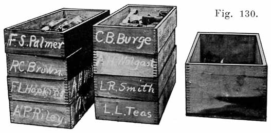
Fig. 130. Boxes for Holding Parts of Batteries Being Prepaired
Figure 130 shows a number of wooden boxes, about 12 inches long, 8 inches wide, and 4 inches deep. These boxes are very useful for holding the terminals inter-cell connectors, covers, plugs, etc., of batteries which are dismantled for repairs. Write the name of the owner with chalk on the end of the box, and rub the name off after the battery has been put together again. The boxes shown in Figure 130 had been used for plug tobacco, and served the purpose very well. The larger box shown in Figure 130 may be used for collecting old terminals, inter-cell connectors, lead drillings, etc.
EARTHENWARE JARS
The twenty gallon size is very convenient for waste acid, old separators, and any junk parts which are wet with acid. The jars are acid proof and will help keep the shop floor dry and anything which will help in this is most desirable.
ACID CARBOYS
Acid is shipped in large glass bottles around each of which a wooden box is built to prevent breakage, the combination being called a "carboy." Since the acid is heavy, some means of drawing it out of the bottle is necessary. One method is illustrated in Figure 131, wooden rockers being screwed to the box in which the bottle is placed.
A very good addition to the rockers shown in Figure 131 is the inner tube shown in Figure 132. In this illustration the rockers are not shown, but should be used. The combination of the rockers with the inner tube gives a very convenient method of pouring acid from a carboy, since the heavy bottle need not be lifted, and since it helps keep the floor and the top of the box dry.
The rubber tube shown in Figure 132 is a piece of 4 inch inner tube which is slit down one side to make it lie flat. Near one end is cut a hole large enough to fit tightly over the neck of the acid bottle. Slip this rubber over the neck of the bottle and allow the long end to hang a few inches over the side of the carboy bottle or box. This is for pouring acid from a carboy when it is too full to allow the contents to be removed without spilling. This device will allow the contents of the carboy to be poured into a crock or other receptacle placed on the floor without spilling, and also prevents dirt that may be laying on top of the carboy from falling into the crock.
Figure 133 shows a siphon method for drawing acid from a bottle, although this method is more suitable for distilled water than for acid. "A" is the bottle, "B" a rubber stopper, "C" and "D" are 3/8 inch glass or hard rubber tubes, "E" is a length of rubber tubing having a pinch clamp at its lower end. To use this device, the stopper and tubes are inserted in the bottle, and air blown or pumped in at "C," while the pinch clamp is open, until acid or water begins to run out of the lower end of tubing "E." The pinch clamp is then released. Whenever acid or water is to be drawn from the bottle the pinch clamp is squeezed so as to release the pressure on the tube. The water or acid will flow down the tube automatically as long as the pinch clamp is held open. The clamp may be made of flat or round spring brass or bronze. This is bent round at (a). At (c) an opening is made, through which the part (b) is bent. The clamp is operated by pressing at (d) and (e). The rubber tubing is passed through the opening between (b) and (c).
This method is a very good one for the small bottle of distilled water placed on the charging bench to bring the electrolyte up to the proper height. The lower end of tube (e) is held over the vent hole of the cell. The pinch clamp is then squeezed and water will flow. Releasing the clamp stops the flow of water instantly. If tube (e) is made long enough, the water bottle may be set on the elevated shelf extending down the center of the charging bench.
Figure 134 shows another arrangement, using a tire pump. D and E are 3/8 inch hard rubber tubes. D is open at both ends and has a "T" branch to which the pump tubing is attached. To operate, a finger is held over the upper end of D, and air is pumped into the acid bottle, forcing the acid into the vessel F. To stop the flow of acid, the finger is removed from D. This stops the flow instantly. This method is the most satisfactory one when fairly large quantities of acid or water are to be drawn off.
SHOP LAYOUTS
The degree of success which the battery repairman attains depends to a considerable extent upon the workshop in which the batteries are handled. It is, of course, desirable to be able to build your shop, and thus be able to have everything arranged as you wish. If you must work in a rented shop, select a place which has plenty of light and ventilation. The ventilation is especially important on account of the acid fumes from the batteries. A shop which receives most of its light from the north is the best, as the light is then more uniform during the day, and the direct rays of the sun are avoided. Fig. 38 shows a light, well ventilated workroom.
The floor should be in good condition, since acid rots the wood and if the floor is already in a poor condition, the acid will soon eat through it. A tile floor, as described below, is best. A wooden floor should be thoroughly scrubbed, using water to which baking soda has been added. Then give the floor a coat of asphaltum paint, which should be applied hot so as to flow into all cracks in the wood. When the first coat is dry, several more coats should be given. Whenever you make a solution of soda for any purpose, do not throw it away when you are through with it. Instead, pour it on the floor where the acid is most likely to be spilled. This will neutralize the acid and prevent it from rotting the wood.
If you can afford to build a shop, make it of brick, with a floor of vitrified brick, or of tile which is not less than two inches thick, and is preferably eight inches square. The seams should not be less than one-eighth inch wide, and not wider than one fourth. They should be grouted with asphaltum, melted as hot and as thin as possible (not less than 350° F.). This should be poured in the seams. The brick or tile should be heated near the seams before pouring in the asphaltum. When all the seams have been filled, heat them again. After the second heating, the asphaltum may shrink, and it may be necessary to pour in more asphaltum.
If possible, the floor should slope evenly from one end of the room to the other. A lead drainage trough and pipe at the lower end of the shop will carry off the acid and electrolyte.
It is a good plan to give all work benches and storage racks and shelves at least two coatings of asphaltum paint. This will prevent rotting by the acid.
The floor of a battery repair shop is, at best, a wet, sloppy affair, and if a lead drainage trough is too expensive, there should be a drain in the center of the floor if the shop is small, and several if the shop is a large one. The floor should slope toward the drains, and the drain-pipes should be made of glazed tile.
To keep the feet as dry as possible, rubbers, or even low rubber boots should be worn. Sulphuric acid ruins leather shoes, although leather shoes can be protected to a certain extent by dipping them in hot paraffine.
A good plan is to lay a wooden grating over the floor as shown in Figure 135. Water and acid will run down between the wooden strips, leaving the walking surface fairly dry. If such a grating is made, it should be built in sections which may be lifted easily to be washed, and to permit washing the floor. Keep both the grating and the floor beneath covered with asphaltum paint to prevent rotting by acid. Once a week, or oftener, if necessary, sweep up all loose dirt and then turn the hose on the floor and grating to wash off as much acid as possible. When the wood has dried, a good thing to do is to pour on the floor and grating several pails of water in which washing soda or ammonia has been dissolved.
Watch your floor. It will pay-in better work by yourself and by the men working for you. Have large earthenware jars set wherever necessary in which lead drillings, old plates, old connectors, old separators, etc., may be thrown. Do not let junk cases, jars, separators, etc., accumulate. Throw them away immediately and keep your shop clean. A clean shop pleases Your customers, —and satisfied customers mean success.
On the following pages a number of shop layouts are given for both large and small shops. The beginner, of course, may not be able to rent even a small shop, but he may rent part of an established repair shop, and later rent an entire shop. A man working in a corner of an established service must arrange his equipment according to the space available. Later on, when he branches out for himself, he should plan his shop to got the best working arrangement. Figure 136 shows a suggested layout for a small shop. Such a layout may have to be altered because of the size and shape of the shop, and the location of the windows.
As soon as growth of business permits, a shop should have a drive-in, so that the customer may bring his car off the street. Without a drive-in all testing to determine what work is necessary will have to be done at the curb, which is too public for many car owners. A drive-in is also convenient if a customer leaves his car while his battery is being repaired. To a certain extent, the advantages of a drive-in may be secured by having a vacant lot next to the shop, with a covering of cinders. As soon as possible, however, a shop which is large enough to have a drive-in should be rented or built.
Figure 137 shows a 24 x 60 shop with space for three cars. The shop equipment is explained in the table.
Figure 138 shows a 40 x 75 shop with room for six cars and a drive-in and drive-out. This facilitates the handling of the cars.
Figure 139 shows a 30 x 100 shop in a long and somewhat narrow building. It also has a drive-in and drive-out.
Another arrangement for the same sized shop as shown in the preceding illustration is shown in Figure 140. Here the drive-out is at the side and this layout is, therefore, suitable for a building located on a corner, or next to an alley.
Figure 141 shows a larger shop, which may be used after the business has grown considerably.
Figure 142 shows a layout suitable for the largest station.
Somewhere between Figures 136 and 142 is a layout for any service station. The thing to do is to select the one most suitable for the size of the business, and to fit local conditions, If a special building is put up, local conditions are not so important.
If a shop is rented, it may not be possible to follow any of the layouts shown in Figs. 136 to 142. However, the layout which is best adapted for the actual shop should be selected as a guide, and the equipment shown obtained. This should then be arranged as nearly like the pattern layout as the shop arrangement will permit.
Concerning Light
Light is essential to good work, so you must have plenty of good light and at the right place. For a light that is needed from one end of a bench to the other, to look into each individual battery, or to take the reading of each individual battery, there is nothing better than a 60 Watt tungsten lamp under a good metal shade, dark on outside and white on inside.
A unique way to hang a light and have it movable from one end of the bench to the other, is to stretch a wire from one end of the bench to the other. Steel or copper about 10 or 12 B & S gauge may be used. Stretch it about four or five feet above top of bench directly above where the light is most needed. If You have a double charging bench, stretch the wire directly above middle of bench. Before fastening wire to support, slip an old fashioned porcelain knob (or an ordinary thread spool) on the wire. The drop cord is to be tied to this knob or spool at whatever height you wish the light to hang (a few inches lower than your head is the right height).
Put the ceiling rosette above center of bench; cut your drop cord long enough so that you can slide the light from one end of bench to the other after being attached to rosette. Put vaseline on the wire so the fumes of gas will not corrode it. This will also make the spool slide easily. This gives you a movable, flexible light, with which you will reach any battery on bench for inspection. The work bench light can be rigged up the same way and a 75 or 100 Watt nitrogen lamp used.
Fig. 137 and 138: A-Receiving Rack. B-Portable Electric Drill, or Hand Drill. C-Wash Tank, D-Tear Down Bench. E-Hot Water Pan. F-Waiting Rack (5 Shelves). G-Repair Bench (6 ft. by 2 ft. 3 in.). H-Charging Table (3 Circuits). I-Electrolyte(10 Gal. Crocks). J-Separator Rack. K-Generator. L-Switchboard. M-Stock Bins, N-New Batteries, O-Live storage. P-Sealing Compound. R-Ready Rack (5-Shelves). S-Dry Storage. (S is not in Fig. 137.)
Fig. 139, 140 and 141: A-Receiving Rack. B-Power Drill. C-Wash Tank. D-Tear Down Bench. E-Hot Water Pan. F-Waiting Rack (6 Shelves). G-Repair Bench. H-Charging Table (3 Circuits). I-Electrolyte (10 Gal. Crocks). J-Separator Rack. K-Generator. L-Switchboard. M-Stock Bins. N-New Batteries. O-Live storage. P-Sealing Compound. R-Ready Rack (5-Shelves). S-Dry Storage. T-Torn Down Parts. (O and T in 141, not in 139 and 140.)
Fig. 142: A-Receiving Rack. B-Power Drill. C-Wash Tank. D-Tear Down Bench. E-Hot Water Pan. F-Waiting Rack (6 Shelves). G-Repair Bench. H-Charging Table. I-Electrolyte (10 Gal. Crocks). J-Separator Rack. K-Generator. L-Switchboard. M-Stock Bins. N-New Batteries. O-Live storage. P-Sealing Compound. R-Ready Rack. S-Dry Storage. T-Torn Down Parts.
The equipment for charging batteries, instructions for building and wiring charging benches have already been given. What we shall now discuss is the actual charging. The charge a battery receives on the charging bench is called a "bench charge."
Battery charging in the service station may be divided into two general classes:
1. Charging batteries which have run down, but which are otherwise in good condition, and which do not require repairs.
2. Charging batteries during or after the repair process.
The second class of charging is really a part of the repair process and will-be described in the chapter on "Rebuilding the Battery." Charging a battery always consists of sending a direct current through it, the current entering the battery at the positive terminal and leaving it at the negative terminal, the charging current, of course, passing through the battery in the opposite direction to the current which the battery produces when discharging. When a battery discharges chemical changes take place by means of which electrical energy is produced. When a battery is on charge, the charging current causes chemical changes which are the reverse of those which take place on discharge and which put the active materials and electrolyte in such a condition that the battery serves as a source of electricity when replaced in the car.
Batteries are charged not only in a repair shop but also in garages which board automobiles, and in car dealers' shops. No matter where a battery is charged, however, the same steps must be taken and the same precautions observed.
When a Bench Charge is Necessary:
(a) When a battery runs down on account of the generator on the car not having a sufficient output, or on account of considerable night driving being done, or on account of frequent use of the starting motor, or on account of neglect on the part of the car owner.
(b) Batteries used on cars or trucks without a generator, or batteries used for Radio work should, of course, be given a bench charge at regular intervals.
(c) When the specific gravity readings of all cells are below 1.200, and these readings are within 50 points of each other.
Should the gravity reading of any cell be 50 points lower or higher than that of the other cells, it is best to make a 15-seconds high rate discharge test (see page 266) to determine whether the cell is defective or whether electrolyte has been lost due to flooding caused by over-filling and has been replaced by water or higher gravity electrolyte. If any defect shows up during the high rate test, the battery should be opened for inspection. If no defect shows up, put the battery on charge.
(d) When the lamps burn dimly while the engine is running.
(e) When the lamps become very dim when the starting switch is closed.
If a battery is tested by turning on the lights and then closing the starting switch, make sure that there is no short-circuit or ground in the starting motor circuits. Such trouble will cause a very heavy current to be drawn from the battery, resulting in a drop in the voltage of the battery.
(f) When the voltage of the battery has fallen below 1.7 volts per cell, measured while all the lights are turned on.
(g) When the owner has neglected to add water to the cells regularly, and the electrolyte has fallen below the tops of the plates.
(h) When a battery has been doped by the addition of electrolyte or acid instead of water, or when one of the "dope" electrolytes which are advertised to make old, worn out batteries charge up in a ridiculously short time and show as much life and power as a new battery. Use nothing but a mixture of distilled water and sulphuric acid for electrolyte. The "dope" solutions are not only worthless, but they damage a battery considerably and shorten its life. Such a "doped" battery may give high gravity *readings and yet the lamps will become very dim when the starting motor cranks the car, the voltage per cell will be low when the lights are burning, or low voltage readings (1.50 per cell) will be obtained if a high rate discharge test is made.
Every battery which comes in for any reason whatsoever, or any battery which is given a bench charge whenever necessary should also be examined for other defects, such as poorly burned on connectors and terminals, rotted case, handles pulled off, sealing compound cracked, or a poor sealing job between the covers and jars, or covers and posts. A slight leakage of electrolyte through cracks or imperfect joints between the covers and jars or covers and posts is very often present without causing any considerable trouble. If any of the other troubles are found, however, the battery needs repairing.
Arrangement of Batteries on Charging Bench. If a battery comes in covered with dirt, set it on the wash rack or in the sink and clean it thoroughly before putting it on charge. In setting the batteries on the charging bench, place all of them so that the positive terminal is toward the right as you face the bench. The positive terminal may be found to be painted red, or may be stamped "+", "P", or "POS". If the markings on one of the terminals has been scratched or worn off, examine the other terminal. The negative terminal may be found to be painted black, or be stamped "-", "N" or "NEG".
If neither terminal is marked, the polarity may be determined with a voltmeter, or by a cadmium test. To make the voltmeter test, hold the meter wires on the battery terminals, or the terminals of either end cell. When the voltmeter pointer moves to the right of the "0" line on the scale, the wire attached to the "+" terminal of the meter is touching the positive battery terminal, and the wire attached to the "-" terminal of the meter is touching the negative battery terminal. If this test is made with a meter having the "0" line at the center of the scale, be sure that you know whether the pointer should move to the left or right of the "0" line when the wire attached to the "+" meter terminal is touching the positive battery terminal.
Another method of determining which is the positive terminal of the battery is to use the cadmium test. When a reading of about two volts is obtained, the prod held on one of the cell terminals is touching the positive terminal. When a reading of almost zero is obtained, that is, when the needle of the meter just barely moves from the "0" line, or when it does not move at all, the prod held on one of the cell terminals is touching the negative terminal. This test, made while the battery is on open-circuit, is not a regular cadmium test, but is made merely to determine the polarity of the battery.
The polarity of the charging line will always be known if the bench is wired permanently. The positive charging wire should always be to the right. If a separate switch is used for each battery (Figures 43 and 65), the wire attached to the right side of the switch is positive. If the batteries are connected together by means of jumpers (Figures 44 and 47), the positive charging wire should be at the right hand end of the bench as seen when facing the bench. If a constant-potential charging circuit is used as shown in Figure 48, the positive bus-bar should be at the top and the neutral in the center, and the negative at the bottom.
If the polarity of the charging line wires is not known, it may be determined by a voltmeter, in the same way as the batter-, polarity is determined. If this is done, care should be taken to use a meter having a range sufficient to measure the line voltage. If no such voltmeter is available, a simple test is to fill a tumbler with weak electrolyte or salt water and insert two wires attached to the line. The ends of these wires should, of course, be bare for an inch or more. Hold these wires about an inch apart, with the line alive. Numerous fine bubbles of gas will collect around the negative wire.
With the polarities of all the batteries known, arrange them so that all the positive terminals are at the right. Then connect them to the individual switches (see Figure 43), or connect them together with jumpers (see Figure 44), being sure to connect the negative of one battery to the positive of the next. Connect the positive charging line wire to the positive terminal of the first battery, and the negative line wire to the negative terminal of the last battery. See page 105.
With all connections made, and before starting to charge, go over all the batteries again very carefully. You cannot be too careful in checking the connections, for if one or more batteries are connected reversed, they will be charged in the wrong direction, and will most likely be severely damaged.
As a final check on the connections of the batteries on the line, measure the total voltage of these batteries and see if the reading is equal to two times the total number of cells on the line.
Now inspect the electrolyte in each cell. If it is low, add distilled water to bring the electrolyte one-half inch above the plates. Do not wait until a battery is charged before adding water. Do it now. Do not add so much water that the electrolyte comes above the lower end of the vent tube. This will cause flooding.
Charging, Rate. If you connect batteries of various sizes together on one circuit, charge at the rate which is normal for the smallest battery. If the rate used is the normal one for the larger batteries, the smaller batteries will be overheated and "boiled" to death, or they may gas so violently as to blow a considerable portion of the active material from the plates.
It is quite possible to charge 6 and 12 volt batteries in series. The important point is not to have the total number of cells too high. For instance, if the 10 battery Tungar is used, ten 6-volt batteries (30 cells), or any combination which gives 30 cells or less may be used. For instance, five 12-volt batteries (30 cells), or six 6-volt batteries (18 cells) and two 12-volt batteries (12 cells), or any other combination totaling 30 cells may be used. The same holds true for motor-generators.
The charging rate is generally determined by the size of the charging outfit. The ten battery Tungar should never have its output raised above 6 amperes. A charging rate of 6 amperes is suitable for all but the very smallest batteries. In any case, whether you are certain just what charging rate to use, or not, there are two things which will guide you, temperature and gassing.
1. Temperature. Have a battery thermometer (Figure 37) on hand, and measure the temperature of the electrolyte of each cell on the line. If you note that some particular cell is running hotter than the others, keep the thermometer in that cell and watch the temperature. Do not let the temperature rise above 110 degrees Fahrenheit, except for a very short time. Should the highest of the temperature of the cells rise above 110 degrees, reduce the charging rate.
2. Gassing. Near the end of a charge and when the specific gravity has stopped rising, or is rising very slowly, bubbles of gas will rise from the electrolyte, this being due to the charging current decomposing the water of the electrolyte into hydrogen and oxygen. If this gassing is too violent, a considerable amount of active material will be blown from the plates. Therefore, when this gassing begins, the charging rate should be reduced, unless the entire charging has been done at a low rate, say about five amperes.
If gassing begins in any cell soon after the charge is started, or before the specific gravity has reached its highest point, reduce the charging rate to eliminate the gassing.
If one battery or one cell shows a high temperature and the others do not, or begins gassing long before the others do, remove that battery from the charging line for further investigation and replace it with another so as not to slow up the charge of the other batteries which are acting normally.
As long as excessive temperatures and too-early gassing are avoided, practically any charging rate may be used, especially at the start. With a constant potential charging set, as shown in Figure 48, the charge may start at as high a rate as 50 amperes. If this system of charging is used, the temperature must be watched very carefully and gassing must be looked for. With the usual series method of charging, a charge may, in an emergency, be started at 20 amperes or more. As a general rule do not use a higher rate than 10 amperes. A five ampere rate is even better, but more time will be required for the charge.
Time Required for a Charge. The time required is not determined by the clock, but by the battery. Continue the charge until each cell is gassing freely (not violently) and for five hours after the specific gravity has stopped rising. The average condition of batteries brought in for charge permits them to be fully charged in about 48 hours, the time being determined as stated above. Some batteries may charge fully in less time, and some may require from four days to a week, depending entirely upon the condition of the batteries. Do not give any promise as to when a recharge battery will be ready. No one can tell how long it will take to charge.
Specific Gravity at the End of the Charge. The specific gravity of the electrolyte in a fully charged cell should be from 1.280 to 1.300. If it varies more than 10 points above or below these values, adjust it by drawing off some of the electrolyte with a hydrometer and adding water to lower the gravity, or 1.400 acid to raise the gravity. After adjusting the gravity charge for one hour more.
Battery Voltage at End of Charge. The voltage of a fully charged cell is from 2.5 to 2.7 when the temperature of the electrolyte is 80 degrees Fahrenheit; 2.4 to 2.6 when the temperature of the electrolyte is 100 degrees Fahrenheit, and 2.35 to 2.55 volts when the temperature of the electrolyte is 120 degrees Fahrenheit, and this voltage, together with hydrometer readings of 1.280-1.300 indicate that the battery is fully charged.
Just before putting a battery which has been charged into service, give it a 15 seconds high rate discharge test, see page 266.
Painting. Before returning a battery to the owner wipe it perfectly clean and dry. Then wipe the covers, terminals, connectors and handles with a rag wet with ammonia. Next give the case a light coat of black paint which may be made by mixing lamp black and shellac. This paint dries in about five minutes and gives a good gloss. The customer may not believe that you are returning the battery which he brought in but he will most certainly be pleased with your service and will feel that if you take such pains with the outside of his battery you will certainly treat the inside with the same care when repairs are necessary. The light coat of paint costs very little for one battery, but may bring you many dollars worth of work.
Level of Electrolyte. During charge the electrolyte will expand, and will generally flow out on the covers. This need not be wiped off until the end of the charge. When the electrolyte has cooled after the battery is taken off charge, it must be about 1/2 inch above the plates. While the electrolyte is still warm it will stand higher than this, but it should not be lowered by drawing off some of it, as this will probably cause it to be below the tops of the plates and separators when it cools.
TROUBLES
If all goes well, the charging process will take place as described in the preceding paragraphs. It frequently happens, however, that all does not go well, and troubles arise. Such troubles generally consist of the following:
Specific gravity will not rise to 1.280. This may be due to the plates not taking a full charge, or to water having been used to replace electrolyte which has been spilled. To determine which of these conditions exist, make cadmium test (see page 174) on the positives and negatives, also measure the voltage of each cell. If these tests indicate that the plates are fully charged (cell voltage 2.5 to 2.7, Positive-Cadmium 2.4 volts, Negative-Cadmium minus 0.15 to 0.20 volts), you will know that there is not enough acid in the electrolyte. The thing to do then is to dump out the old electrolyte, refill with 1.300 electrolyte and continue the charge until the specific gravity becomes constant. Some adjustment may then have to be made by drawing off some of the electrolyte with a hydrometer and adding water to lower the gravity, or 1.400 acid to bring it up. Remember that specific gravity readings tell you nothing about the plates, unless it is known that the electrolyte contains the correct proportions of water and acid. The cadmium test is the test which tells you directly whether or not the plates are charged and in charging a battery the aim is to charge the plates, and not merely to bring the specific gravity to 1.280.
If the specific gravity will not rise to 1.280 and cadmium tests show that the plates will not take a full charge, then the battery is, of course, defective in some way. If the battery is an old one, the negatives are probably somewhat granulated, the positives have probably lost much of their active material, resulting in a considerable amount of sediment in the jars, and the separators are worn out, carbonized, or clogged with sediment. Such a battery should not be expected to give as good service as a new one, and the best thing to do if the tests show the battery to be more than half charged, is to put it back on the car, taking care to explain to the owner why his battery will not "come up" and telling him that he will soon need a new battery. Remember that improperly treated separators, or defective separators will cause poor Negative-Cadmium readings to be obtained.
If a fairly new battery will not take a full charge, as indicated by hydrometer readings and cadmium tests, some trouble has developed due to neglect, abuse, or defect in manufacture. If all cells of a fairly new battery fail to take a full charge within 48 hours, the battery has probably been abused by failing to add water regularly, or by allowing battery to remain in an undercharged condition. Such a battery should be kept on the line for several days more, and if it then still will not take a full charge the owner should be told what the condition of the battery is, and advised to have it opened for inspection.
If one cell of a battery fails to take a charge, but the other cells charge satisfactorily, and cadmium tests show that the plates of this cell are not taking a charge, the cell should be opened for inspection. If one cell of a battery charges slowly, cut the other cells out of the line, and charge the low cell in series with the other batteries on the charging line.
If all cells of a battery, whether new or old, will not take even half a charge, as indicated by hydrometer readings (1.200), the battery should be opened for inspection.
If the gravity of a battery on charge begins to rise long before the voltage rises, and if the gravity rises above 1.300, there is too great a proportion of acid in the electrolyte. The remedy is to dump out the electrolyte, refill with pure water and continue the charge at a lower rate than before, until the specific gravity stops rising. Then charge for ten hours longer, dump out the water (which has now become electrolyte by the acid formed by the charging current), refill with about 1.350 electrolyte and continue the charge, balancing the gravity if necessary at the end of the charge.
If a battery becomes very hot while on charge at a rate which is not normally too high for the battery, it indicates that the battery is badly sulphated, or has a partial short-circuit. Gassing generally goes with the high temperature.
If you can detect a vinegar-like odor rising from the vent holes, you may be absolutely sure that the separators used in that battery have developed acetic acid due to not having received the proper treatment necessary to prepare them for use in the battery. The electrolyte should be dumped from such a battery immediately and the battery should be filled and rinsed with water several times. Then the battery should be opened without loss of time, to see whether, by removing the separators and washing the plates thoroughly, the plates may be saved. If the acetic acid has been present for any length of time, however, the plates will have been ruined beyond repair, the lead parts being dissolved by the acid.
If the electrolyte of a battery on charge has a white, milky look, there may be impurities which cause numerous minute bubbles to form, such bubbles giving the electrolyte its milky appearance. The milky appearance may be due to the use of "hard" water in refilling, this water containing lime.
The electrolyte as seen with the acid of an electric lamp or flashlight should be perfectly clear and colorless. Any scum, particles of dirt, any color whatsoever shows that the electrolyte is impure. This calls for dumping out the electrolyte, filling and rinsing with pure water, refilling with new electrolyte and putting the battery back on the charging line. Of course, this may not cause the battery to charge satisfactorily, which may be due to the troubles already described.
Should it ever happen that it is impossible to send a current through a charging circuit go over all the connections to make sure that you have good contact at each battery terminal, and that there are no loose inter-cell connectors. If all connections to the batteries are good, and there are no loose inter-cell connectors, cut out one battery at a time until you start the current flowing, when you cut out some particular battery. This battery should then be opened without further tests, as it is without a doubt in a bad condition.
The conditions which may exist when a battery will not charge, as shown especially by cadmium tests, are as follows:
(a) The battery may have been allowed to remain in a discharged condition, or the owner may have neglected to add water, with the result that the electrolyte did not cover the plates. In either case a considerable amount of crystallized sulphate will have formed in the plates. Plates in such a condition will require a charge of about a week at a low rate and will then have to be discharged and recharged again. Several such cycles of charge and discharge may be necessary. It may even be impossible to charge such a battery, no matter how many cycles of charge and discharge are given. If the owner admits that his battery has been neglected and allowed to stand idle for a considerable time, get his permission to open the battery.
(b) The battery may have been overheated by an excessive charging rate, or by putting it on a car in a sulphated condition. The normal charging rate of the generator on the car will over heat a sulphated battery. Overheated plates buckle their lower edges cut through the separators, causing a short-circuit between plates.
(c) The pockets in the bottoms of the jars may have become filled with sediment, and the sediment may be short-circuiting the plates.
(d) Impurities may have attacked the plates and changed the active materials to other substances which do not form a battery. Such plates may be so badly damaged that they are brittle and crumbled. Acetic acid from improperly treated separators will dissolve lead very quickly, and may even cause an open circuit in the cell.
(e) The conditions described in (a), (b), and (c) will permit a charging current to pass through the battery, but the plates will not become charged. It is possible, of course, but not probable, that a condition may exist in which all the plates of one or both groups of a cell may be broken from the connecting straps, or inter-cell connectors may be making no contact with the posts. In such a case, it would be impossible to send a charging current through the battery. Acetic acid from improperly treated separators, and organic matter introduced by the use of impure water in refilling will attack the lead of the plates, especially at the upper surface of the electrolyte, and may dissolve all the plate lugs from the connecting straps and cause an open-circuit.
(f) The separators may be soggy and somewhat charred and blackened, or they may be clogged up with sulphate, and the battery may need new separators.
(g) The spongy lead may be bulged, or the positives may be buckled. The active material is then not making good contact with the grids, and the charging current cannot get at all the sulphate and change it to active material. The remedy in such a case is to press the negatives so as to force the active material back into the grids, and to put in new positives if they are considerably buckled.
(h) One of the numerous "dope" electrolytes which are offered to the trustful car owner may have been put in the battery. Such "dopes" might cause very severe damage to the plates. Tell your customers to avoid using such "dope."
The conditions which may exist when the plates of a battery take a charge, as indicated by cadmium tests, but the gravity will not come up to 1.280 are as follows:
(a) There may be considerable sediment in the jars but not enough to short circuit the plates. If the battery has at some time been in a sulphated condition and has been charged At too high a rate, the gassing that resulted will have caused chips of the sulphate to drop to the bottom of the jars. When this sulphate was formed, some of the acid was taken from the electrolyte, and if the sulphate drops from the plates, this amount of acid cannot be recovered no matter how long the charge is continued. If the owner tells you that his battery has stood idle for several months at some time, this is a condition which may exist. The remedy is to wash and press the negatives, wash the positives, put in new separators, pour out the old electrolyte and wash out the jars, fill with 1.400 acid, and charge the battery.
(b) Impurities may have used up some of the acid which cannot be recovered by charging. If the plates are not much damaged the remedy is the same as for (a). Damaged plates may require renewal.
(c) Electrolyte may have been spilled accidentally and replaced by water.
(d) Too much water may have been added, with the result that the expansion of the electrolyte due to a rise in temperature on charge caused it to overflow. This, of course, resulted in a loss of some of the acid.
The causes given in (c) and (d) may have resulted in the top of the battery case being acid-eaten or rotted. The remedy in these two instances is to draw off some of the electrolyte, add some 1.400 acid and continue the charge. If plates and separators look good and there is but little sediment, this is the thing to do.
If Battery will not hold a Charge. If a battery charges properly but loses its charge in a week or less, as indicated by specific gravity readings, the following troubles may exist:
(a) Impurities in the cells, due to the use of impure water in the electrolyte, or in the separators. Some impurities (see page 76) do not attack the plates, but merely cause self-discharge. The remedy is to dump out the old electrolyte, rinse the jars with pure water, fill with new electrolyte of the same gravity as the old and recharge. If this does not remove impurities, the battery should be opened, the plates washed, jars cleaned out, new separators put in, and battery reassembled and charged.
(b) There may be a slow short-circuit, due to defective separators or excessive amount of sediment. If preliminary treatment in (a) does not cause battery to hold charge, the opening of battery and subsequent treatment will remove the cause of the slow short-circuit.
Suggestions
1. Make sure every battery is properly tagged before going on line.
2. Determine as quickly as possible from day to day, those batteries that will not charge. Call owner and get permission to open up any such battery and do whatever is necessary to put it in good shape.
3. As soon as a battery charges to 1.280-1.300, the voltage is 2.5-2.7 per cell and the cadmium readings are 2.4 or more for the positives and -0.15 to -0.20 for the negatives and the gravity voltage and cadmium readings do not change for five hours, remove it from the line as finished and replace it with another if possible. Go over your line at least three times a day and make gravity, temperature, and cadmium tests.
4. Make a notation, with chalk, of the gravity of each cell each morning. Do not trust to memory.
5. Remove from the line as soon as possible any battery that has a leaky cell and neutralize with soda the acid that has leaked out.
6. Batteries that are sloppers, with rotten cases, and without handles are sick and need a doctor. Go after the owner and get permission to repair.
7. Keep the bench orderly and clean.
8. Remember that if you have a line only partly full and have other batteries waiting to be charged you are losing money by not keeping a full line.
9. Leave the Vent Plugs in When Charging. The atmosphere in many service stations, where the ventilation is poor, is so filled with acid fumes that customers object to doing business there.
The owners of these places may not notice these conditions, being used to it, or rather glory in being able to breathe such air without coughing or choking, but it certainly does not invite a customer to linger and spend his money.
The remedy for such a condition is to leave the vent plugs in place on the batteries that are charging so that the acid spray in the gas from the battery condenses out as it strikes these plugs and drips back into the cells, while the gas passes out through the small openings in the plug.
The plugs need only be screwed into the openings by one turn, or only set on top of the vent openings to accomplish the result.
This takes no additional time and more than repays for itself in the saving of rusted tools and improved conditions in the battery room and surroundings. In charging old Exide batteries, be sure to replace the vent plugs and turn them to open the air passages which permit the escape of gases which form under the covers. If you wish to keep these air passages open without replacing the plugs, which may be done for convenience, give the valve (see page 21) a quarter turn with a screwdriver or some other tool.
10. If the electrolyte from a battery rises until it floods over the top of the jar, it shows that too much water was added when the battery was put on charge, the water rising to the bottom of the vent tube, thereby preventing gases formed (except those directly below the vent hole) from escaping. This gas collects under the covers, and its pressure forces the electrolyte up into the vent hole and over the top of the battery. In charging old U.S.L. batteries it is especially necessary to keep the air vent (see page 20) open to prevent flooding, since the lower end of the vent tube is normally a little below the surface of the electrolyte.
Remember, do not have the electrolyte come up to the lower end of the vent tube.
NOTE: To obtain satisfactory negative cadmium readings, the charging rate should be high enough to give a cell voltage of 2.5-2.7.
Improperly treated separators, or separators which have been allowed to become partly dry at any time will make it impossible to obtain satisfactory negative cadmium readings.
LEAD BURNING (WELDING)
Lead cannot be "burned" in the sense that it bursts into flame as a piece of paper does when a match is applied to it. If sufficient heat is applied, the lead will oxidize and feather away into a yellow looking dust, but it does not burn. The experienced battery man knows that by "lead burning" is meant the heating of lead to its melting point, so that two lead surfaces will weld together. This is a welding and not a "burning" process, and much confusion would be avoided if the term "lead welding" were used in place of the term "lead burning."
The purpose of welding lead surfaces together is to obtain a joint which offers very little resistance to the flow of current, it being absolutely necessary to have as low a resistance as possible in the starting circuit. Welding also makes joints which are strong mechanically and which cannot corrode or become loose as bolted connections do. Some earlier types of starting and lighting batteries had inter-cell connectors which were bolted to the posts, but these are no longer used.
The different kinds of lead-burning outfits are listed on page 143 The oxygen-acetylene and the oxygen-hydrogen flames give extremely high temperatures and enable you to work fast. Where city gas is available, the oxygen illuminating gas combination will give a very good flame which is softer than the oxygen acetylene, oxygen-hydrogen outfits. Acetylene and compressed air is another good combination.
There are two general classes of lead-welding:
(a) Welding connecting bars, called "cell" connectors, top connectors, or simply "connectors," to the posts which project up through the cell covers, and welding terminals to the end posts of a battery.
(b) Welding plates to "straps" to form groups. The straps, of course, have joined to them the posts which project through the cell covers and by means of which cells are connected together, and connections made to the electrical system of the car.
In addition to the above, there are other processes in which a burning (welding) flame is used:
(c) Post-building, or building posts, which have been drilled or cut short, up to their original size.
(d) Extending plate lug. If the lug which connects a plate to the plate strap is too short, due to being broken, or cut too short, the lug may be extended by melting lead into a suitable iron form placed around the lug.
(e) Making temporary charging connections between cells by lightly welding lead strips to the posts so as to connect the cells together.
(f) A lead-burning (welding) flame is also used to dry out the channel in cell covers before pouring in the sealing compound, in re-melting sealing compound which has already been poured, so as to assure a perfect joint between the compound cover and jar, and to give the compound a smooth glossy finish. These processes are not welding processes and will not be described here.
General Lead Burning Instructions
Flame. With all the lead burning outfits, it is possible to adjust the pressures of the gases so as to get extremely hot, medium, and soft flames. With the oxygen-acetylene, or oxygen-hydrogen flame, each gas should have a pressure of about two pounds. With the oxygen-illuminating gas flame, the oxygen should have a pressure of 8 to 10 pounds. The city gas then does not need to have its pressure increased by means of a pump, the normal pressure (6 to 8 ounces) being satisfactory.
Various makes of lead-burning outfits are on the market, and the repairman should choose the one which he likes best; since they all give good results. All such outfits have means of regulating the pressures of the gases used. With some the gases are run close to the burning tip before being mixed, and have an adjusting screw where the gases mix. Others have a Y shaped mixing valve at some distance from the burning tip, as shown in Figure 78. Still others have separate regulating valves for each gas line.
With these adjustments for varying the gas pressure, extremely hot, hissing flames, or soft flames may be obtained. For the different welding jobs, the following flames are suitable:
1. A sharp, hissing flame, having a very high temperature is the one most suitable for the first stage in welding terminals and connectors to the posts.
2. A medium flame with less of a hiss is suitable for welding plates to strips and lengthening plate lugs.
3. A soft flame which is just beginning to hiss is best for the finishing of the weld between the posts and terminals or connectors. This sort of a flame is also used for finishing a sealing job, drying out the cover channels before sealing, and so on.
In adjusting the burning flame, 4 the oxygen is turned off entirely, a smoky yellow flame is obtained. Such a flame gives but little heat. As the oxygen is gradually turned on the flame becomes less smoky and begins to assume a blue tinge. It will also be noticed that a sort of a greenish cone forms in the center portion of the flame, with the base of the cone at the torch and the tip pointed away from the torch. At first this inner-cone is long and of almost the same color as the outer portion of the flame. As the oxygen pressure is increased, this center cone becomes shorter and of a more vivid color, and its tip begins to whip about. When the flame is at its highest temperature it will produce a hissing sound and the inner cone will be short and bright. With a softer flame, which has a temperature suitable for welding plates to a strap, the inner cone will be longer and less vivid, and the hissing will be greatly diminished.
The temperature of the different parts of the flame varies considerably, the hottest part being just beyond the end of the inner cone. Experience with the particular welding outfit used will soon show how far the tip of the torch should be held from the lead to be melted.
Cleanliness. Lead surfaces which are to be welded together must be absolutely free from dirt. Lead and dirt will not mix, and the dirt will float on top of the lead. Therefore, before trying to do any lead welding, clean the surfaces which are to be joined. The upper ends of plate lugs may be cleaned with a flat file, knife., or wire brush. The posts and inter-cell connectors should be cleaned with a knife, steel wire brush, or triangular scraper. Do not clean the surfaces and then wait a long time before doing the lead burning. The lead may begin to oxidize if this is done and make it difficult to do a good job.
The surfaces which are to be welded together should also be dry. If there is a small hole in the top of a post which is to be welded to a connector or terminal, and this hole contains acid, a shower of hot lead may be thrown up by the acid, with possible injury to the operator.
Do not try to save time by attempting to weld dirty or wet lead surfaces, because time cannot be saved by doing so, and you run the risk of being injured if hot lead is thrown into your face. Remove absolutely every speck of dirt — you will soon learn that it is the only way to do a good job.
Safety Precautions. Remove the vent plugs and blow down through the vent holes to remove any gases which may have collected above the surface of the electrolyte. An explosion may result if this is not done. To protect the rubber covers, you may cover the whole top of the battery except the part at which the welding is to be done, with a large piece of burlap or a towel which has been soaked in water. The parts covered by the cloth must be dried thoroughly if any welding on them. Instead of using a wet cloth, a strip of asbestos may be laid over the vent holes, or a small square of asbestos may be laid over each vent hole.
Burning on the Cell Connectors and Terminals
Have the posts perfectly clean and free from acid. Clean the tops, bottoms and sides of the connectors with a wire brush, Figure 143. Finish the top surfaces with a coarse file, Figure 144. With a pocket knife clean the inside surfaces of the connector holes. Place the connectors and terminals in their proper positions on the posts, and with a short length of a two by two, two by one, or two by four wood pound them snugly in position, Figure 145. Be sure that the connectors are perfectly level and that the connectors are in the correct position as required on the car on which the battery is to be used. The top of the post should not come flush with the top of the connector. Note, from Figure 146, that the connector has a double taper, and that the lower tapered surface is not welded to the post. If the post has been built up too high it should be cut down with a pair of end cutting nippers so that the entire length of the upper taper in the connector is in plain sight when the connector is put in position on the post. This is shown in Figure 146. With the connectors in place, and before welding them to the posts, measure the voltage of the whole battery to be sure that the cells are properly connected, as shown by the voltage reading being equal to two times the number of cells. If one cell has been reversed, as shown by a lower voltage reading now is the time to correct the mistake.
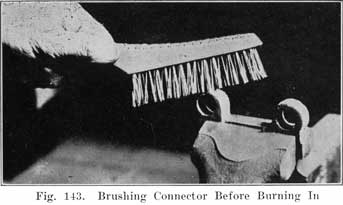
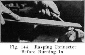
The connectors and terminals are now ready to be welded to the posts. Before bringing any flame near the battery be sure that you have blown out any gas which may have collected under the covers. Then cover the vents with asbestos or a wet cloth as already described. You will need strips of burning lead, such as those made in the burning lead mould described on page 164.
Use a hot, hissing flame for the first stage. With the flame properly adjusted, hold it straight above the post, and do not run it across the top of the battery. Now bring the flame straight down over the center of the post, holding it so that the end of the inner cone of the flame is a short distance above the post. When the center of the post begins to melt, move the flame outward with a circular motion to gradually melt the whole top of the post, and to melt the inner surface of the hole in the connector. Then bring the lower end of your burning lead strip close to and over the center of the hole, and melt in the lead, being sure to keep the top of the post and the inner surface of the hole in the connector melted so that the lead you are melting in will flow together and unite. Melt in lead until it comes up flush with the upper surface of the connector. Then remove the flame. This completes the first stage of the welding process. Now repeat the above operation for each post and terminal.
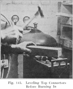
It is essential that the top of the post and the inner surface of the hole in the connector be kept melted as long as you are running in lead from the strip of burning lead. This is necessary to have all parts fuse together thoroughly. If you allow the top of the post, or the inner surface of the hole in the connector to chill slightly while you are feeding in the lead, the parts will not fuse, and the result will be a poor joint, which will heat up and possibly reduce the current obtained from the battery when the starting switch is closed. This reduction may prevent the starting motor from developing sufficient torque to crank the engine.
When the joint cools, the lead will shrink slightly over the center of the posts. To finish the welding, this lead is to be built up flush or slightly higher than the connector. Brush the tops of the post and connector thoroughly with a wire brush to remove any dirt which may have been floating in the lead. (Dirt always floats on top of the lead.) Soften the burning flame so that it is just barely beginning to hiss. Bring the flame down over the center of the post. When this begins to melt, move the flame outward with a circular motion until the whole top of post and connector begins to melt and fuse. If necessary run in some lead from the burning lead strip. When the post and connector are fused, clear to the outer edge of the connector, raise the flame straight up from the work.
You will save time by doing the first stage of the burning on all posts first, and then finish all of them. This is quicker than trying to complete both stages of burning on each post before going to the next post. The object in the finishing stage is to melt a thin layer of the top of post and connector, not melting deep enough to have the outer edge of the connector melt and allow the lead to run off. All this must be done carefully and dexterously to do a first-class job, and you must keep the flame moving around over the top and not hold it in any one place for ally length of time, so as not to melt too deep, or to melt the outer edge and allow the lead to run off and spoil the job. Sometimes the whole mass becomes too hot and the top cannot be made smooth with the flame. If this occurs wait until the connector cools, soften the flame, and try again. Figure 147 shows the welding completed.
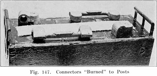
Burning Plates to Strap and Post
First clean all the surfaces which are to be welded together. Take your time in doing this because you cannot weld dirty surfaces together.
Plates which compose a group are welded to a "strap" to which a post is attached, as shown in Figure 5. The straps shown in Figure 5 are new ones, as made in the factory. Plate lugs are set in the notches in the straps and each one burned in separately. In using old straps from a defective group, it is best to cut the strap close to the post, thus separating all the plates from the post in one operation, as was done with the post shown in Figure 96. If only one or two plates are to be burned on, they are broken or cut off and slots cut in the strap to receive the lugs of the new plates, as shown in Figures 148 and 149.
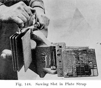
Set the plates in a plate burning rack, as shown in Figure 96, placing the adjustable form around the lugs and strap as shown in this figure. Be sure to set the post straight, so that the covers will fit. A good thing is to try a cover over the post to see that the post is set up properly. The post must, of course, be perpendicular to the tops of the plates. If the slotted plate strap shown in Figure 5 is used, or if one or two plates have been cut off, melt the top of the lug of one of the plates which are to be burned oil, and the surfaces of the strap to which the plate is to be welded. Melt in lead from a burning-lead strip to bring the metal up flush with the surface of the strap. Proceed with each plate which is to be burned on.
If all the plates have been sawed from the strap, leaving the post with a short section of the strap attached, as shown in Figure 96, melt the edge of the strap, and the top of one or two of the end plate lugs and run in lead from the burning strip to make a good joint. Proceed in this way until all the lugs are joined to the strap and then run the flame over the top of the entire strap to make a smooth uniform weld. Be sure to have the lower edge of the strap fuse with the plate lugs and then run in lead to build the strap up to the proper thickness. Raise the flame occasionally to see that all parts are fusing thoroughly and to prevent too rapid heating.
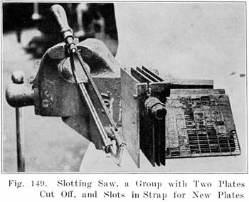
When enough lead has been run in to build the strap tip to the correct thickness and the plate lugs are thoroughly fused with the strap, raise the flame straight up from the work. Allow the lead to "set" and then remove the adjustable form and lift the group from the burning rack. Turn the group up-side-down and examine the bottom of the strap for lead which ran down the lugs during the welding process. Cut off any such lead with a saw, as it may cause a short-circuit when the plates are meshed with the other group.
Post Building
In drilling down through the inter-cell connectors to separate them from the posts in opening a battery, the posts may be drilled too short. In reassembling the battery it is then necessary to build the posts up to their original height. This is done with the aid of post-builders, shown in Figure 100.
Clean the stub of the post thoroughly and also clean the inside of the post builder. Then set the post builder carefully over the stub post, so that the upper surface of the post builder is parallel to the upper surface of the plate strap. The built up post will then be perpendicular to the surface of the strap, which is necessary, in order to have the covers and connectors fit properly.
With the post builder set properly adjust the burning torch to get a sharp, hissing flame. Bring the flame straight down on the center of the post stub. When the center of the post stub begins to melt, move the flame outward with a circular motion until the whole top of the stub begins to melt. Then run in lead from a burning lead strip, Figure 101, at the same time keeping the flame moving around on the top of the post to insure a good weld. In this way build up the post until the lead comes up to the top of the post builder. Then lift the flame straight up from the post. Allow the lead to set, and then remove the post builder, grasping it with a pair of gas or combination pliers and turn the post builder around to loosen it.
Extending Plate Lugs
It sometimes happens that a good plate is broken from a strap, thus shortening the lug. Before the plate may be used again, the lug must be extended to its original length. To do this, clean the surfaces of the lug carefully, lay the plate on a sheet of asbestos, and place an iron form having a slot of the correct width, length, and thickness, as shown in Figure 150. Use a medium hissing flame, and melt the upper edge of the lug, and then run in lead from the lead burning strip to fill the slot in the iron form. The plate may then be used again.
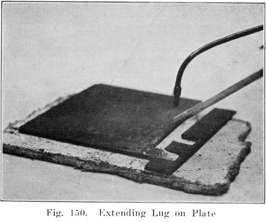
Making Temporary Charging Connections
After a battery has been opened it is often desired to charge a battery without burning on the intercell connectors. Temporary connections may be made between cells by placing a short length of a burning lead strip from post to post and applying a flame for an instant to spot-weld the strip to the top of the post.
MOULDING LEAD PARTS
In using special moulds for casting inter-cell connectors, plate straps with posts, terminals, etc., follow the special instructions furnished by the manufacturers as to the manipulation of the special moulds made by them.
Aside from the special instructions for the use of moulds, there are general rules for the melting of lead and handling it after it is melted, which must be observed if good castings are to be made.
Raw Materials. In every battery repair shop a supply of old terminals, cell connectors, posts, and straps, will gradually accumulate. These should not be thrown away or sold as junk, but should be kept in a box or jar provided for that purpose. Old plates should not be saved, since the amount of lead in the grid is small and it is often covered with sulphate. The lugs connecting the plates to the straps may, however, be used. Before using the scrap lead as much dirt as possible should be brushed off, and all moisture must be dried off thoroughly. Scrap lead contains some antimony, which is metal used to give stiffness to the parts. Using miscellaneous scrap sometimes gives castings which do not contain the proper percentage of antimony. If there is too much antimony present, cracked castings will be the result. To remedy this condition, bars of pure lead should be purchased from some lead manufacturing company. Adding pure lead will reduce the percentage of antimony. Bars of pure antimony should also be kept oil hand in case the castings are too soft.
Lead Melting Pots are standard articles which may be purchased from jobbers. A pot having a 25 pound capacity is suitable for small shops and for larger shops a 125-pound size is best. Before melting any lead in such pots, have them thoroughly free from dirt, grease, or moisture, not merely in order to get clean castings, but also to avoid melted lead being thrown out of the pot on account of the presence of moisture. Severe burns may be the result of carelessness in this respect.
In starting with an empty melting pot, turn oil the heat before putting in any lead, and let the pot become thoroughly heated in order to drive off any moisture. With the pot thoroughly hot, drop in the lead, which must also be dry. When the metal has become soft enough to stir with a clean pine stick, skim off the dirt and dross which collects on top and continue heating the lead until it is slightly yellow oil top. Dirt and lead do not mix, and the dirt rises to the top of the metal where it may readily be skimmed off.
With a paddle or ladle, drop in a cleaning compound of equal parts of powdered rosin, borax, and flower of sulphur. Use a teaspoonful of this compound for each ten pounds of metal, and be sure that the compound is absolutely dry. Stir the metal a little, and if it is at the proper temperature, there will be a flare, flash, or a little burning. A sort of tinfoil popcorn effect will be noticed oil top of the lead. Stir until this melts down.
Have the ladle with which you dip up the melted lead quite dry. When dipping up some of the lead, skim back the dark skin which forms oil top of the lead and dip up the clean bright lead for pouring.
In throwing additional lead into a pot which is partly filled with melted lead, be sure that the lead which is thrown in the pot is dry, or else hot lead may be spattered in your face.
Have the moulds clean and dry. The parts with which the lead comes into contact should be dusted with a mould compound which fills in the rough spots in the metal so that the flow of lead will not be obstructed, and the lead will fill the mould quickly. Dip tip enough lead to fill the part of the mould you use. When you once start pouring do not, under any circumstance, stop pouring until the lead has completely filled the mould. Lead cools very quickly after it is poured into the mould, and if you stop pouring even for all instant, you will have a worthless casting.
In a shop having an ordinary room temperature, it is generally unnecessary to heat the moulds before making up a number of castings. If it is found, however, that the first castings are defective due to the cold mould chilling the lead, the mould should be heated with a soft flame. After a few castings have been made, the mould will become hot enough so that there will be no danger of the castings becoming chilled.
When the castings have cooled sufficiently to be removed, strike the mould a few blows with a wooden mallet or a rawhide hammer to loosen, the castings before opening the mould. The castings may then be removed with a screwdriver.
Cracked castings indicate that the mould was opened before the castings had cooled sufficiently, or that there is too much antimony in the castings. The remedy is to let the castings cool for a longer time, or to add pure lead to the melting pot.
HANDLING AND MIXING ACID
The electrolyte used in the battery is made by mixing chemically pure concentrated Sulphuric Acid with chemically pure water. The concentrated acid, or "full strength" acid cannot be used, not only because it would destroy the plates, but also because water is needed for the chemical actions which take place as a cell charges and discharges. The water therefore serves, not only to dilute the acid, but also to make possible the chemical reactions of charge and discharge.
The full strength acid has a specific gravity of 1.835, and is mixed with the water to obtain the lower specific gravity which is necessary in the battery. The simplest scheme is to use only 1.400 specific gravity acid. This acid is used in adjusting the specific gravity of a battery on charge in case the specific gravity fails to rise to a high enough value. It is also used in filling batteries that have been repaired.
Acid is received from the manufacturer in ten gallon glass bottles enclosed in wooden boxes, these being called "carboys." Distilled water comes in similar bottles. When distilled in the shop, the water should be collected in bottles also, although smaller ones may be used.
Neither the acid nor the water should ever be placed in any vessels but those made of lead, glass, porcelain, rubber, or glazed earthenware. Lead cups, tanks, and funnels may be used in handling electrolyte, but the electrolyte must not be put in containers made of any metal except lead. Lead is rather expensive for making such containers, and the glass bottles, porcelain, rubber, or glazed earthenware may be used.
In mixing acid with water, pour the water in the bottle, pitcher or jar, and then add the acid to the water very slowly. Do not pour the acid in quickly, as the mixture will become very hot, and may throw spray in your face and eyes and cause severe burns. Never add the water to the acid, as this might cause an explosion and burn your face and eyes seriously. Stir the mixture thoroughly with a wooden paddle while adding the acid. A graduate, such as is used in photography, is very useful in measuring out the quantities of acid and water. The graduate may be obtained in any size up to 64 ounces, or two quarts. In using the graduate for measuring both acid and water, be sure to use the following table giving the parts of water by volume. Although the graduate is marked in ounces, it is for ounces of water only. If, for instance, the graduate were filled to the 8 ounce mark with acid, there would be more than eight ounces of acid in the graduate because the acid is heavier than the water. But if the proportions of acid and water are taken by volume, the graduate may be used.
A convenient method in making up electrolyte, is to have a 16 ounce graduate for the acid, and a 32 or 64 ounce graduate for the water. In the larger graduate pour the water up to the correct mark. In the 16 ounce graduate, pour 1.400 acid up to the 10 ounce mark. Then add the acid directly to the water in the graduate, or else pour the water into a bottle or pitcher, and add the acid to that. For instance, if we have a 32 ounce graduate, and wish to make up some 1.280 acid, we fill this graduate with water up to the 5-1/2 ounce mark. We then fill the 16 ounce graduate with 1.400 acid up to the 10 ounce mark. Then we slowly pour the 1.400 acid into the graduate containing the water, giving us 1.280 acid. In a similar manner other specific gravities are obtained, using the same amount of 1.400 acid in each case, but varying the amount of water according to the figures given in the last column of the next to the last table.
The following table shows the number of parts of distilled water to one part of 1.400 specific gravity electrolyte to prepare electrolyte of various specific gravities. The specific gravity of the mixture must be taken when the temperature of the mixture is 70° F. If its temperature varies more than 5 degrees above or below 70°F, make the corrections described on page 65 to find what the specific gravity would be if the temperature were 70° F.
BY WEIGHT
For 1.300 specific gravity use 5 ounces of distilled water for each pound of 1.400 electrolyte.
For 1.280 specific gravity use 6-1/2 ounces of distilled water for each pound of 1.400 electrolyte.
For 1.275 specific gravity use 6-3/4 ounces distilled water for each pound of 1.400 electrolyte.
For 1.260 specific gravity use 7-1/2 ounces distilled water for each pound of 1.400 electrolyte.
BY VOLUME
For 1.300 specific gravity use 3-1/2 pints distilled water for each gallon of 1.400 electrolyte.
For 1.280 specific gravity use 4-1/2 pints distilled water for each gallon of 1.400 electrolyte.
For 1.275 specific gravity use 5 pints distilled water for each gallon of 1.400 electrolyte.
For 1.260 specific gravity use 5-1/4 pints distilled water for each gallon of 1.400 electrolyte.
In case you wish to use other measuring units than those given in the above table, this table may be written as follows, giving the number of parts distilled water to 10 parts of 1.400 specific gravity electrolyte:
| Specific Gravity Desired | Parts by Weight | Parts by Volume |
|---|---|---|
| 1.300 | 3 | 4-1/4 |
| 1.280 | 4 | 5-1/4 |
| 1.275 | 4-1/6 | 6 |
| 1.260 | 4-7/10 | 6-1/2 |
The next table gives the number of parts of distilled water to 10 parts of concentrated sulphuric acid (which has a specific gravity of 1.835) to prepare electrolyte of various specific gravities:
| Specific Gravity Desired | Parts by Weight | Parts by Volume |
|---|---|---|
| 1.400 | 8-1/2 | 15-8/10 |
| 1.300 | 13-1/2 | 15-8/10 |
| 1.300 | 13-1/2 | 25 |
| 1.280 | 15 | 27 |
| 1.270 | 16 | 28 |
| 1.260 | 17 | 30 |
PUTTING NEW BATTERIES INTO SERVICE
New batteries are received (a) fully charged and ready for service, (b) fully assembled with moistened plates and separators, but without electrolyte, (c) in a "knockdown" condition, with dry plates and without separators, (d) fully assembled with "bone dry" plates and rubber separators, and without electrolyte.
Those received fully charged should be put on a car as soon as possible. Otherwise they will grow old on the shelf. Every month on the shelf is a month less of life. If the battery cannot be sold, put it into dry-storage. Batteries received in condition (b) should not be kept in stock for more than six months. Batteries received with dry plates and without separators or with rubber separators may be stored indefinitely without deteriorating.
Batteries Shipped Fully Charged, or "Wet." All Makes
Unpack the battery, keeping the packing case right side up to avoid spilling electrolyte.
Brush off all excelsior and dirt, and examine the battery carefully to see if it has been damaged during shipment. If any damage has been done, claim should be made against the express or railroad company.
1. Remove the vent caps from the cells and determine the height of the electrolyte. It should stand from three-eighths to one-half inch above the tops of the plates. The level may be determined with a glass tube, as shown in Fig. 30. If the electrolyte is below the tops of the plates, it has either been spilled, or else there is a leaky jar. If all cells have a low level of electrolyte, it is probable that the electrolyte has been spilled.
2. Next measure the specific gravity of the electrolyte of each cell with the hydrometer, and then add water to bring the electrolyte up to the correct level, if this is necessary. Should the temperature of the air be below freezing, charge the battery for an hour if water is added no matter what the specific gravity readings are. This will cause the water to mix thoroughly with the electrolyte. If the battery were not charged after water is added, the water, being lighter than the electrolyte, would remain on top and freeze. For this one hour charge, use the "starting" rate, as stamped on the nameplate.
3. If the specific gravity of the electrolyte reads below 1.250, charge the battery until the specific gravity reads between 1.280 and 1.300. For this charge use the normal bench charging rates.
4. After this charge place the battery on a clean, dry spot for twenty-four hours as an extra test for a leaky jar. If there is any dampness under the battery, or on the lower part of the battery case, a leaky jar is indicated. An inspection of the level of the electrolyte, which even though no dampness shows, will show the leaky jar.
5. Just before putting the battery on the car, make the high rate discharge test on it. See page 266.
BATTERIES SHIPPED "DRY"
Exide Batteries
Storing. 1. Keep the battery in a dry, clean place, and keep the room temperature above 32 degrees, and below 110 degrees Fahrenheit.
2. Put the battery into service before the expiration of the time limit given on the tag attached to the battery. The process of putting the battery into service will require about five days.
3. If the battery has been allowed to stand beyond the time limit, open up one of the cells just before beginning the process necessary to put the battery into service. If the separators are found to be cracked, split, or warped, throw away all the separators from all the cells and put in new ones. If the separators are in good condition, reassemble the cell and put the battery into service.
Putting Battery into Service. 1. Fill the cells with electrolyte of the correct specific gravity. To do this, remove the vent plugs and pour in the electrolyte until it rises to the bottom of the vent tubes. The correct specific gravities of the electrolyte to be used are as follows:
(a) For Types DX, XC, XE, XX and XXV, use 1.360 electrolyte. In tropical countries use 1.260 electrolyte.
(b) For Types LX, LXR, LXRE, LXRV, use 1.340 electrolyte. In tropical countries use 1.260 electrolyte.
(c) For Types MHA and PHC, use 1.320 electrolyte. In tropical countries use 1.260 electrolyte.
(d) For Types KXD and KZ, use 1.300 electrolyte. In tropical countries use 1.240 electrolyte.
2. After filling with the electrolyte, allow the battery to stand ten to fifteen hours before starting the initial charge. This gives the electrolyte time to cool.
3. No sooner than ten to fifteen hours after filling the battery with electrolyte, add water to bring the electrolyte up to the bottom of the vent tubes, if the level has fallen. Replace the vent caps and turn them to the right.
Start charging at the rates shown in the following table. Continue charging at this rate for at least 96 hours (4 days).
Table of Initial and Repair Charging Rates
| Type and Size of Cell | Charging Rate, Amperes |
Minimum Ampere Hours |
|---|---|---|
| KZ-3 | 1/2 | 50 |
| LX-5, LXR-5, LXRE-5 | 1-1/2 | 145 |
| KXD-5 | 2 | 190 |
| XC-9, XX-9 | 2-1/2 | 240 |
| DX-11, KXD-7, LXR-9, LXRE-9, XC-11, XE-11 | 3 | 290 |
| DX-13, KXD-9, LXR-11, XC-13, XE-13, XX-13 | 4 | 385 |
| LXR-13, LXRE-13, XC-15, XE-15, XX-15 | 4-1/2 | 430 |
| KXD-11, XC-17, XE-17 | 5 | 480 |
| LXRV-15, LXR-15, LXRE-15 | 5-1/2 | 525 |
| LX-17, LXR-17, LXRE-17, XC-19, XE-19, XXV-19 | 6 | 575 |
| MHA-11, PHC-13 | 6 | 575 |
| XC-21, XE-21 | 6-1/2 | 625 |
| XC-23 | 7 | 675 |
| XC-25 | 7-1/2 | 720 |
4. Occasionally measure the temperature of the electrolyte. Do not allow the temperature to rise above 110° Fahrenheit (120° Fahrenheit in tropical countries). Should the temperature reach 110°, stop the charge long enough to allow the temperature to drop below 100°.
5. At the end of the charge, the specific gravity of the electrolyte should be between 1.280 and 1.300 (1.210 and 1.230 in tropical countries). If it is not between these limits adjust it by drawing off some of the electrolyte with the hydrometer and replacing with water if the specific gravity is too high, or with electrolyte of the same specific gravity used in filling the battery, if the specific gravity is too low.
6. Wipe off the top and sides of the battery case with a rag dampened with ammonia to neutralize any electrolyte which may have been spilled.
7. Just before putting the battery into service, give it a high rate discharge test. See page 266.
Vesta Batteries
1. Remove vent caps from each cell and fill with electrolyte of 1.300 specific gravity. This electrolyte should not have a temperature greater than 75° Fahrenheit when added to the cells.
2. After the addition of this acid, the battery will begin to heat and it should be left standing from 12 to 24 hours or until it has cooled off.
3. Battery should then be put on charge at the finish charging rate stamped on the name plate. Continue charging at this rate for approximately 48 to 72 hours or until the gravity and voltage readings of each cell stop rising.
4. Care should be taken to see that the temperature of battery does not rise above 110° Fahrenheit. If this occurs., the charging rate should be cut down.
5. The acid in each cell will undoubtedly have to be equalized.
6. At the finish of this developing charge the gravity should read 1.280 in each cell. If below this, equalize by putting in 1.400 specific gravity acid, or if the contrary is the case and the acid is above 1.280 add sufficient distilled water until the gravity reads 1.280.
7. After the acid has been equalized and it has stopped rising in density the voltage of each cell while still on charge at the finishing rate should read at least 2.5 volts per cell or better.
8. The battery is then ready for service. Just before putting battery into service, make a high rate discharge test on it. See page 266.
Philadelphia Diamond Grid Batteries
1. Remove the vent plugs and immediately fill the cells With electrolyte until the level is even with the bottom of the vent tube in the cover. Do not fill with electrolyte whose temperature is above 90° Fahrenheit. The specific gravity of the electrolyte to be used in starting batteries varies with the number of plates in each cell, the correct values being as follows:
Charging Rates
Fill batteries listed in Table No. 1 with 1.270 sp. gr. acid.
TABLE — No. 1
| No. of Plates | LL-LLR and LH |
LM LMR |
LT LTR |
LS LSR |
LG | LT | LSF |
|---|---|---|---|---|---|---|---|
| 9 | 2.0 | 2.5 | 2.0 | 2.5 | 3.0 | ||
| 11 | 2.5 | 3.0 | 2.5 | 3.5 | 4.0 | ||
| 13 | 3.0 | 3.5 | 3.0 | 4.0 | 2.5 | ||
| 15 | 3.5 | 4.0 | 3.5 | 4.5 | 5.5 | ||
| 17 | 4.0 | 5.0 | 4.0 | 5.5 | 6.0 | ||
| 19 | 4.5 | 5.5 | 4.5 | 6.0 |
Special Battery: 136 USA................6. 0 amps.
TABLE NO.2
Fill batteries listed in Table No. 2 with 1.250 sp. gr. acid.
| No. of Plates | LL-LLR and LLH |
LM LMR |
LT LTR |
LS LSR |
S SH |
ST | LSF |
|---|---|---|---|---|---|---|---|
| 5 | 1.0 | 1.0 | 2.0 | 1.5 | |||
| 7 | 1.5 | 1.5 | 1.5 | 2.0 | 3.0 | 2.0 | 1.5 |
| 9 | 4.0 | ||||||
| 11 | 5.0 |
Special Batteries: 330 AA ............ 1.0 amps.
524 STD-H2 ............ 1.0 amps.
7 6 SPN ............ 1.5 amps.
The number of plates per cell is; indicated in the first numeral of the type name. For instance, 712 LLA-1 is a 7 plate LL. For all lighting batteries, types S and ST. use 1.210 electrolyte.
2. Allow the battery to stand for one or two hours.
3. Remove the seal from the top of the vent caps, and open by blowing through the cap.
4. Insert vent plugs in the vent tubes.
5. Put the battery on charge at the rate given in the table on page 228. To determine the rate to use, see type name given on the battery nameplate and find correct rate in the table. Keep the battery charging at this rate throughout the charge.
6. Continue the charge until the battery voltage and the specific gravity of the electrolyte stop rising, as shown by readings taken every four hours. From three and one-half to four days of continuous charging will be required to fully charge the battery.
7. Watch the temperature of the electrolyte, and do not allow it to rise above 110° Fahrenheit. If the temperature rises to 110° F., stop the charge and allow battery to cool. Extend the time of charging by the length of time required for the battery to cool.
8. After the specific gravity of the electrolyte stops rising, adjust the electrolyte to a specific gravity of 1.280 at a temperature of 70° Fahrenheit. If the temperature is not 70°, make temperature corrections as described on page 65.
9. The battery is now ready to be installed on the car. Just before installing the battery, make a high rate discharge test on it.
Willard Bone-Dry Batteries
A Willard Threaded Rubber insulated battery is shipped and carried in stock "bone-dry." It is filled with electrolyte and charged for the first time when being made ready for delivery.
Threaded Rubber Insulated Batteries received bone-dry must be prepared for service, as follows:
1. Mix electrolyte to a density of 1.275.
2. Remove the vent plugs and fill to the top of the vent hole with 1.275 electrolyte. Be sure that the electrolyte is thoroughly mixed by stirring and that its temperature is not above 90 degrees Fahrenheit.
3. A portion of the solution will be absorbed by the plates and insulation because they have been standing dry without any liquid in the cells. The volume is thus decreased, necessitating the addition of electrolyte after first filling.
Wait five minutes and then again fill to the top of the vent hole with 1.275 electrolyte.
4. The battery must now stand at least twelve hours and not more than twenty-four hours before charging. After it has been filled an increase in temperature of the battery solution will take place. This is caused by the action of the acid in the solution penetrating the plates mid reacting with the active material, but does no injury. Since the acid in the solution joins the active material in the plates the density of the solution becomes proportionately lower. This is to be expected and should cause no concern.
In order that the entire plate volume of active material may be in chemical action during charge, the battery should stand before being placed on charge—until the solution has bad time to penetrate the entire thickness of the plates. This requires at least twelve hours, but not more than twenty-four hours.
5. Just before charging the battery, again fill with 1.275 electrolyte to 3/8 inch over the top of the separators. After this, do not add anything but distilled water to the battery solution.
6. The battery should then be put on charge at the finish rate until the gravity stops rising. At the end of this period the specific gravity should be between 1.280 and 1.300. It may take from 36 to 72 hours before this density is reached.
Care should be taken not to prolong the charging unduly, for that may cause active material to fall out of the grids, thus injuring the plates beyond repair.
7. Because of the evaporation of water in the solution during the charging process, it is necessary to add distilled water from time to time in order to keep the solution above the tops of the separators.
The temperature of the battery while on charge should never exceed 110 degrees Fahrenheit. If the temperature rises above this point the charging must be discontinued for a time or the rate decreased.
If at any time during the initial charging the density rises above 1.300 some of the solution should immediately be drawn off with a syringe and distilled water added. This must be done as often as is necessary to keep the density below 1.300.
If the specific gravity does not change after two successive readings and does not then read within the limits of 1.280 to 1.300 it should be adjusted to read correctly. If the reading is less than 1.280 it should be adjusted by drawing off as much solution as can be taken out with a syringe and electrolyte of 1.400 specific gravity added. The battery must then be placed on charge for at least four hours and another reading taken. If it is again found to be less than 1.280 this operation should be repeated as many times as necessary to bring the density up to 1.280.
9. The height of solution when taking the battery off charge should be 5/8 of an inch above the top of the separators. After the battery has been off charge long enough to permit the solution to cool to normal temperature, draw off the excess to a final height of 3/8 inch above separators. Replace the vent plugs and battery is ready for service.
Unfilled Willard Wood Insulated Batteries
Unfilled, wood-insulated batteries have not had an initial charge and require a treatment similar to batteries with threaded rubber insulation. When shipment is made in this manner, such batteries should be placed in service before the date indicated on the tag attached to the battery.
To prepare such a battery for service:
1. Remove the vent plugs and fill each cell with 1.335 specific gravity electrolyte (one part of concentrated sulphuric acid by volume to two parts of distilled water by volume) to 3/8 inch above the tops of the separators.
2. Wait 5 minutes and then fill each cell again with 1.335 specific gravity electrolyte to 3/8 inch above the tops of the separators.
3. The battery must then stand from 10 to 15 hours before placing on charge.
4. After standing for this length of time, fill each cell again, if necessary, with 1.335 specific gravity electrolyte to bring the level of the electrolyte 3/8 inch above the tops of the separators before charging.
5. Place the battery on charge at the finish rate marked on the name plate until the gravity and cell voltage stop rising. This charging will require at least 48 hours.
6. If, after a charge of 48 hours or longer the specific gravity does not rise for two consecutive hours, the gravity should be between 1.280 and 1.300. If it is not between these limits, the specific gravity should be adjusted to these values at the end of the charge.
7. If, during the charge, the temperature exceeds 110 degrees Fahrenheit, the charge rate should be reduced so as to keep the temperature below 110 degrees Fahrenheit and the time of charging lengthened proportionately.
Preparing Westinghouse Batteries for Service
(These batteries are prepared for shipment in what is known as export condition.)
1. Remove vent plugs and discard soft rubber caps.
2. Fill all cells with 1.300 specific gravity sulphuric acid until top of connecting straps, as seen through vent holes are completely covered. Temperature of filling acid should never be above 90 degrees Fahrenheit.
Note: The aim is to fill the cells with acid of such a Specific gravity that the electrolyte, at the end of charge, will need very little adjusting to bring it to the proper specific gravity.
1.300 specific gravity acid has been found to be approximately correct for this purpose. However, if after several batteries have been prepared for service using 1.300 specific gravity acid, considerable adjusting at the end of charge is necessary, it is permissible to use a slightly different specific gravity of filling acid, but the use of acid above 1.325 specific gravity or below 1,250 specific gravity is not recommended.
3. Allow batteries to stand after filling for from two to three hours before putting on charge.
4. Put on charge at finish charge rate shown on name plate of battery.
Note: If temperature of electrolyte in battery reaches 100 degrees Fahrenheit (determined by inserting special thermometer through vent hole in cover), the charging rate should be immediately reduced, as continued charging at a temperature above 100 degrees Fahrenheit is injurious to both separators and plates.
5. Continue charging until all cells are gassing freely and individual cell voltage and specific gravity of electrolyte have shown no decided rise for a period of five hours.
Note: The length of time required to completely charge a new battery depends largely upon the time the battery has been in stock, varying from twelve to twenty-four hours for a comparatively fresh battery to four or five days for a battery six months or more old.
6. Keep level of electrolyte above tops of separators at all times, while charging by adding distilled water to replace that lost by evaporation.
7. After battery is completely charged the specific gravity of electrolyte in all cells should be adjusted to 1.285 at 70 degrees Fahrenheit, and the level of electrolyte adjusted so that after battery is taken off charge the height of electrolyte stands 1/8 inch above tops of connecting straps.
Note: Corrections for temperature if temperature of electrolyte is above or below 70 degrees Fahrenheit the correction is one point of gravity for each three degrees of temperature. See page 65.
If specific gravity of electrolyte is above 1.285, a portion of the electrolyte should be removed and replaced with distilled water.
If the specific gravity is below 1.285, a portion of electrolyte should be removed and replaced with 1.400 specific gravity sulphuric acid. Acid of higher gravity than 1.400 should never be put in batteries.
Batteries should always be charged for several hours after adjusting gravity to insure proper mixing of the electrolyte and to see that the correct specific gravity of 1.285 has been obtained.
8. After first seven sections have been followed examine vent plugs to see that gas passage is Dot obstructed and screw back in place. Battery is now ready for service.
The Prest-O-Lite Assembled Green Seal Battery
This type of battery is made up of the same sort of plates as the old partly assembled green seal battery. The elements are, however, completely assembled will wood separators and sealed in the jars and box in the same manner as a wet battery to be put into immediate service; the cell connectors are burned in place.
How to Store It. A room of ordinary humidity, one in which the air is never dryer for any reason than the average, should be used to store these batteries. They should be shielded from direct sunlight.
Examine the vents-they should be securely inserted and remain so during the entire storage period.
If these precautions are observed, this type battery may be stored for at least a year.
To Prepare Battery for Use. 1. Prepare sufficient pure electrolyte of 1.300 specific gravity. If during the mixing considerable heat is evolved, allow electrolyte to cool down to 90 degrees Fahrenheit. Never pour electrolyte, that is warmer than 90 degrees Fahrenheit, into cells.
2. Remove the vents and lay them aside until the final charging operation has been completed.
Within 15 minutes from the time the vents are removed fill all cells to the bottom of vent openings with the electrolyte prepared, as stated above.
3. Allow the electrolyte to remain in the cells, not less than one hour. At the end of this time, should the electrolyte level fall below the tops of the separators, add enough electrolyte to bring level at least one-half inch above separators. If the temperature in the cells does not rise above 100 degrees Fahrenheit, proceed immediately (before two hours have elapsed) with the initial charging operation. If the temperature remains above 100 degrees Fahrenheit, allow the battery to stand until the electrolyte cools down to 100 degrees Fahrenheit. Then proceed immediately with the charge. It is important that the acid does not stand in the cells for more than two hours, unless it is necessary to allow the acid to cool.
4. Initial Charging Operation. Place the battery on charge at the ampere rate given in the following table. The total initial charge must be for fifty-two hours, but at no time permit the electrolyte temperature to rise above 115 degrees Fahrenheit. If the temperature should reach 115 degrees Fahrenheit, take the battery off the line and allow the electrolyte to cool, but be sure that the total of fifty-two hours actual charging at the ampere rate specified is completed.
Initial Charge---52 Hours
| Plates per Cell |
Type of Plate | ||||||||
|---|---|---|---|---|---|---|---|---|---|
| AHS | WHN | RHN | SHC | BHN | JFN | GM | CLN | KPN | |
| 3 | 1.5 | ||||||||
| 5 | 2 | 2 | 2.5 | 3 | |||||
| 7 | 3 | 3 | 3.5 | 4 | 3 | 5 | |||
| 9 | 4 | 4 | 5 | 5 | 7 | ||||
| 11 | 5 | 5 | 6 | 7 | 7.5 | 5 | 9 | ||
| 13 | 6 | 6 | 7 | 8 | 9 | 6 | 10.5 | 10.5 | |
| 15 | 7 | 7 | 9 | 9.5 | 10.5 | 7 | 12 | ||
| 17 | 10 | 12 | 9 | ||||||
| 19 | 9 | 9 | 11 | 12 | 9 | ||||
The nominal battery voltage and the number of plates per cell is indicated by the Prest-O-Lite type designations, i. e.: 613 RHN denotes 6 volts, 13 plates per cell or 127 SHC denotes 12 volts, 7 plates per cell.
5. The electrolyte density at the end of fifty-two hours charge should be near 1.290 specific gravity. A variation between 1.285 and 1.300 is permissible. If, after fifty hours of the initial charge, the electrolyte density of any of the cells is outside these limits, adjustment should be begun while still charging. For those cells in which the density is higher than 1.300 specific gravity replace some of the electrolyte with distilled water. In those cells where the density is lighter than 1.285 specific gravity replace some of the electrolyte with previously prepared electrolyte of 1.400 specific gravity. Wait until the cells have charged one hour before taking readings to determine the effect of adjustment, which, if not accomplished, should be attempted again as before. Practice Will enable the attendant to estimate the amount of electrolyte necessary to replace in order to accomplish the proper density desired-at the end of initial charge.
6. Following the completion of the fifty-two hour charge, if there is time to do so, it is good practice to put the battery through a development cycle, i. e., to discharge it at about the four-hour rate and then put it on the charging line again at the normal rate until a condition of full charge is again reached. The objects gained by this discharge are:
(a) Further development of the plates.
(b) Adjustment or stabilization of the electrolyte.
(c) Checking the assembly by noting the failure of any cell or cells to act uniformly and satisfactorily during discharge.
The four-hour discharge rate is, of course, like the normal rate of Initial Charge, dependent upon the size and number of plates per cell in any particular battery; the number of cells determines the voltage only and has nothing to do with the battery's charge or discharging rating. These four-hour discharge rates are as follows:
| Plates per Cell |
Type of Plate | ||||||||
|---|---|---|---|---|---|---|---|---|---|
| AHS | WHN | RHN | SHC | BHN | JFN | GM | CLN | KPN | |
| 3 | 3 | ||||||||
| 5 | 5 | 5 | 5.5 | 6.5 | |||||
| 7 | 7.5 | 7.5 | 8 | 10 | 7.5 | 13.5 | |||
| 9 | 10 | 10 | 11 | 13 | 18 | ||||
| 11 | 12.5 | 12.5 | 14 | 16 | 19 | 12.5 | 22.5 | ||
| 13 | 15 | 15 | 16.5 | 19.5 | 22.5 | 15 | 27 | 27 | |
| 15 | 17.5 | 17.5 | 19 | 23 | 26 | 17.5 | 31.5 | ||
| 17 | 22 | 26 | |||||||
| 19 | 22.5 | 22.5 | 25 | 29 | 22.5 | ||||
Immediately at the end of the four-hour discharge, put the battery on the line and charge it at the normal rate prescribed in the Initial Charge rate table until a state of complete charge, as noted by cell voltage and gravity is reached. This charging time should be about sixteen hours.
Any adjustments of electrolyte found necessary at the end of this charging period in the same manner prescribed in paragraph No. 5, for such adjustments made just before the completion of the initial fifty-two hour charge.
(TRANSCRIBER'S NOTE: No item number 7. in original publication.)
8. At the end of the fifty-two hour charge, or, if the Development discharge has been given, at the end of the Development Cycle Charge, replace the vent plugs, wash all exterior surfaces with clean water and dry quickly. The battery is then ready for service.
INSTALLING A BATTERY ON A CAR
A battery must be installed carefully on the car if it is to have any chance to give good service. Careless installation of a battery which is in good working order will invariably lead to trouble in a very short time. On the other hand, a properly installed battery is, nine times out of ten, a good working and long lived battery.
After you have removed the old battery, scrape all rust and corrosion from the inside of the battery box or compartment in which the battery is placed. This can best be done with a putty knife and wire brush. If you find that electrolyte has been spilled in the box, pour a saturated solution of baking soda on the parts affected so as to neutralize the acid. Then wipe the inside of the box dry and paint it with a good acid proof paint.
Next take out the hold down bolts. Clean them with a wire brush, and oil the threads on the bolt and in the nut to make them work easily. It is very important that this oiling be done, as the oil protects the bolts from corrosion, and to remove the nuts from a corroded bolt is an extremely difficult and aggravating piece of work, often resulting in the bolts being broken. Should such bolts become loose while the car is in use, it is hard to tighten them.
Wooden strips found in the battery box should be thoroughly cleaned and scraped, and then painted with acid proof paint. When you lower the battery into its box, lower it all the way gently. Do not lower it within an inch or so of the bottom of the case and then drop it. This will result in broken jars and plate lugs. Turn the hold downs tight, but not so tight as to break the sealing compound at the ends of the battery, thereby causing electrolyte to leak out, and battery to become a "slopper".
Cables and connectors should be scraped bright with a knife and brushed thoroughly with the wire brush to remove all corrosion. Old tape which has become acid soaked should be removed and the cable or wire underneath cleaned. Before applying new tape, take a small round bristle brush and paint Vaseline liberally over the exposed cable immediately back of the taper terminal. Then cover the Vaseline with tape, which Should be run well back from the terminal. The Vaseline prevents the corrosion of the cable and the tape holds the Vaseline in place. After the tape has been applied, paint it with acid proof paint. Cover the terminals of the battery with Vaseline. Cables must have enough slack to prevent strains from being put on the battery terminals.
By following these directions, you will not only have a properly installed battery, which will have a good chance to give good service, but will have a neat looking job which is most pleasing to the eye of the car owner.
Remove all dirt from the battery and cable terminals and thoroughly clean the surfaces which are to connect together, but do not scrape off the lead coating. Apply a heavy coating of pure Vaseline to these surfaces and tighten the connection perfectly, squeezing out the Vaseline. Then give the whole connection a heavy coating of Vaseline. This is very important in order to prevent connection trouble.
If battery is installed in an enclosing box, be sure that none of the ventilating holes are clogged.
STORING BATTERIES
When a battery is not in active use on a car it should be put into storage. Storage is necessary:
1. When a car is to stand idle for a considerable period, such as is the case when it is held for future delivery.
2. When a car is laid up for the winter.
3. When batteries are kept in stock.
Batteries may be stored "wet," i.e., completely assembled and filled with electrolyte, or "dry," i.e., in a dry disassembled condition, without electrolyte. In deciding whether a battery should be stored "wet" or "dry," two things are to be considered, i.e. the length of time the battery is to be in storage, and the condition of the battery. If a battery is to be out of commission for a year or more, it should be put into "dry" storage. If it is to be in storage for less than one year, it may be put into "wet" storage if it is in a good condition. If the condition of the battery is such that it will need to be dismantled soon for repairs, it should be put into "dry" storage, even though it is to be out of service for less than one year.
Batteries in "dry" storage require no attention while they are in storage, but they must be dismantled before being put into storage and reassembled when put back into service.
When a battery is brought in to be stored, note its general condition carefully.
(a) Its General Appearance-condition of case, handles, terminals, sealing compound, and so on.
(b) Height and specific gravity of the electrolyte in each cell.
(c) Age of Battery. Question owner as to length of time he has had battery. Read date marks on battery if there are any, or determine age by the age code. See page 243. If a battery is less than a year old, is in good condition, and is to be stored for less than one year, it may be put into "wet" storage. If it is more than a year old, put it into dry storage, unless it is in first class shape and is to be stored for only several months.
After making your general observations, clean the battery, add distilled water to bring the electrolyte up to the proper level, put the battery on charge and keep it on the line until it is fully charged. Watch for any abnormal condition during the charge, such as excessive temperature rise, failure of voltage to come up, failure of specific gravity to come up, and gassing before gravity becomes constant.
If no abnormal conditions develop during the charge, put the battery on discharge at a rate which will cause the voltage to drop to 1.7 volts per cell in about four hours. Measure the cell voltages at regular intervals during the discharge test. If the voltage of any cell drops much more rapidly than that of the other cells, that cell is defective in some way, and should be opened for inspection. If the voltage of all cells drops to 1.7 in three hours or less, the battery should be put into dry storage.
After completing the discharge test, recharge it fully, no matter whether it is to be put into wet or dry storage.
If no trouble developed during the charge or discharge, the battery may be put into "wet" storage. If trouble did develop, the battery should be put into "dry" storage.
If dry storage is found to be necessary the owner should be informed that the condition of his battery would cause it to deteriorate in wet storage and necessitate much more expensive repairs when put into use again than will be necessary in the thorough overhauling and rejuvenation of dry storage. He should be advised that dry storage involves dismantling, drying out elements and reassembling with the needed repairs and new separators in the Spring. Be sure that the customer understands this. If it is evident that repairs or new parts, involving costs additional to storage charges, will be necessary, tell him so. Do not leave room for a complaint about costs in the Spring.
To avoid any misunderstanding, it is highly advisable to have the customer put his signature on a STORAGE AGREEMENT which states fully the terms under which the battery is accepted for storage. The storage cost may be figured on a monthly basis, or a price for the entire storage period may be agreed upon. The monthly rate should be the same as the regular price for a single battery recharge. If a flat rate is paid for the entire storage period, $2.00 to $3.00 is a fair price.
"Wet" Storage
1. Store the batteries on a bench or shelf in a convenient location and large enough to allow a little air space around each battery.
2. Place each battery upon wooden strips in order to keep the bottom of the battery clear of the bench or shelf.
3. Apply Vaseline freely to the battery terminals, and to exposed copper wires in the battery cables if the cables are burned directly to the battery terminals. If the cables are not burned on, remove them from the battery.
4. If convenient, install the necessary wiring, switches, etc., so that batteries may be connected up and charged where they stand. Otherwise the batteries must be charged occasionally oil the charging bench.
5. Batteries in wet storage may be charged by the Exide "Trickle" charge method, or may be given a bench charge at regular intervals.
6. Bench Charge Method. — Once every month, add distilled water to replace evaporation. Then give battery a bench charge. See page 198. Before putting battery into service repeat this process and just before putting the battery into service, make the high rate discharge test on it. See page 266.
7. Trickle Charge Method. — This consists of charging the batteries in storage continuously at a very low rate, which is so low that no gassing occurs, and still gives enough charge to maintain the batteries in good condition. In many cases the "Trickle" Charge method will be found more convenient than the bench charge method, and it has the advantage of keeping the batteries in condition for putting into service on short notice. It should, however, be used only where direct current lighting circuits are available.
In the "Trickle" method, the batteries are first given a complete bench charge, and are then connected in series across a charging circuit with one or several incandescent lamps in series with the batteries to limit the current. In Fig. 151, an example of connections for a "Trickle" charge is given. The charging current for different sized batteries varies from 0.05 to 0.15 ampere. The following table gives the lamps required to give the desired current on 110 volt circuit.
In each case, the lamps are connected in series with the batteries. The "2-25 watt, (lamps), in parallel" listed in the table are to be connected in parallel with each other and then in series with the batteries. The same is true of the "3-25 watt (lamps), in series" listed in the table.
Series on 115 Volt Line
| Amp. Hours Capacity 5 Amp. Rate |
Amperes Approximate |
No. of Cells in Series on Line 115-Volt |
No. 115 Volt Lamps Required 115-Volt |
|---|---|---|---|
| 50 or less | 0.05 | 3 | 5-15 watt, in series |
| 50 or less | 0.05 | 30 | 2-15 watt, in series |
| 50 or less | 0.05 | 45 | 1-15 watt, in series |
| 50-100 | 0.10 | 3 | 3-25 watt, in series |
| 50-100 | 0.10 | 3 | 1-25 watt, in series |
| 50-100 | 0.10 | 45 | 2-25 watt, in parallel |
| 100 or over | 0.15 | 3 | 2-25 watt, in series |
| 100 or over | 0.15 | 30 | 1-25 watt, in series |
| 100 or over | 0.15 | 45 | 3-25 watt, in parallel |
Every two months interrupt the trickle charge long enough to add water to bring the electrolyte up to the proper level. When this has been done, continue the trickle charge.
Before putting the batteries into service, see that the electrolyte is up to the correct level, and that the specific gravity of the electrolyte is 1.280-1.300. If necessary, give a short charge on the charging bench to bring the specific gravity up to the correct value.
Dry Storage
1. Give the battery a complete charge. Pour out the electrolyte, and separate the groups. If the negatives have bulged active material, press them in the plate press. In batteries such as the Prest-OLite in which it is difficult to remove the plates from the cover, the groups need not be separated unless the negatives have badly bulged active material. It may not be necessary to separate the groups even then, provided that the positives are not buckled to any noticeable extent. If only a very slight amount of buckling exists, the entire element may be pressed by putting thin boards between the plates in place of the separators.
2. Immerse the negatives in distilled water for ten to twelve hours. If positives and negatives cannot be separated, wash each complete element in a gentle stream of water.
3. Remove plates from water and allow them to drain thoroughly and dry. The negatives will heat up when exposed to the air, and when they do so they should be immersed in the water again to cool them. Repeat this as long as they tend to heat up. Then allow them to dry thoroughly.
4. Throw away the old separators. Rubber separators may be saved if in good condition. Clean the covers and terminals., wash out the jars, and turn the case up side down to drain out the water. Examine the box carefully. It is advisable to wash with a solution of baking soda, rinsing the water in order to neutralize as far as possible the action of acid remaining on the box. If this is not done, the acid may start decomposition of the box while in storage, in which case the owner of the battery may insist on its renewal before acceptance at the end of the storage period.
5. When, the plates are perfectly dry, nest the positives and negatives together, using dry cardboard instead of separators, and replace them in the jars in their proper positions.
6. Replace the covers and vent plugs, but, of course, do not use any sealing compound on them.
7. Tie the terminals and top connectors to the handle on the case with a wire.
8. Tag the battery with the owner's name and address, using the tag on which you made the sketch of the arrangement of the terminals and top connections.
9. Store the battery in a dry place, free from dust, until called for.
10. When the battery is to be put into service again, put in new separators, put the elements in the jars, seal the covers, and burn on the top connectors and terminals (if these are of the burned-on type). Fill the cells with electrolyte of about 1.310 specific gravity and allow the battery to stand for ten to twelve hours in order to cool. Then put the battery on charge at one-half the normal charging rate and charge until the specific gravity of the electrolyte stops rising and remains stationary for five hours. The total time required for this development charge will be about four days. Watch the temperature of the electrolyte carefully, and if it should rise to 110° Fahrenheit, stop the charge until it cools.
11. The specific gravity will fall during the first part of the charge, due to the new separators; at the end of the charge, the specific gravity should be 1.280-1.300. If it is not within these limits, adjust it by withdrawing some electrolyte with the hydrometer and adding water if the gravity is high, or 1.400 electrolyte if the gravity is low.
12. Clean the case thoroughly and give it a coat of asphaltum paint.
13. Just before putting the battery into service, give it a high rate discharge test. See page 266.
DETERMINING AGE OF BATTERY
Battery manufacturers use codes to indicate the age of their batteries. These codes consist of letters, figures, or combinations of letters and figures, which are stamped on the inter-cell connectors or on the nameplate. The codes may also be burned on the case.
The codes of the leading makes of batteries follow. In addition to determining the age of a battery by means of the code, the owner should be questioned as to the time the battery was installed on his car. If the battery is the original one which came with the car, the dealer's or car manufacturer's records will help determine the battery's age. If a new battery has been installed to replace the one that came with the car, the battery distributor's records will help determine the age of the battery.
Familiarity with the different makes and types of battery will also help in determining a battery's age. Manufacturers make improvements in the construction of their batteries from time to time, and by keeping up-to-date on battery constructions, it is often possible to approximate the age of a battery by such changes.
If a battery was kept "dry" while in stock, its age should be figured from the time it was prepared for service and placed on the car, since batteries in dry storage do not deteriorate. Some batteries are shipped from the factory "wet," i.e., filled with electrolyte and fully charged and the age of such batteries should be figured from the time they were shipped from the factory, because deterioration begins as soon as a battery is filled with electrolyte. When batteries are "dry" no chemical action can take place, and the battery does not deteriorate, while in a "wet" battery, chemical action takes place which gradually causes a battery to deteriorate.
Exide Age Code.
Since October, 1917, the date of shipment of Exide batteries from the factory, or from Exide Deposts has been stamped on the top of the first inter-cell connector from the negative end of the batter instead of on the nameplate figures are used to indicate the dates, as follows:
All Philadelphia batteries shipped prior to April 1, 1920 and all batteries shipped from depot stock after this date carry double letter branding. The first battery is the factory date and the second letter in this code indicates latest month during which the guarantee may begin.
Batteries sold direct from Philadelphia to all classes of customers after April 1, 1920, carry the single letter branding code, indicating month of manufacture.
The letters used in the double letter age code are selected from the table given above, and the second letter is the important one, since it gives the latest date from which adjustment can be made. If a Philadelphia battery with a double letter age code comes in, therefore, the foregoing table should be consulted in determining the age of the battery.
If a Philadelphia battery with a single letter age code comes in, the following table should be consulted in determining the age of the battery:
Prest-O-Lite Age Code.
All Prest-O-Lite batteries carry a date letter stamped on the cell-connectors. This letter indicates the month and year in which the battery was manufacture. The letter is preceeded by a number which represents the factory at which the battery was built.
Prest-O-Lite Factory Marks.
Indianapolis—50 Cleveland—7 San Francisco—23
For example: "50-K" indicates that the battery was manufactured at Indianopolis in January, 1920.
In addition to the above, each "Wet" Prest-O-Lite battery is branded in the side with a date, as "9-19," indicating October, 1919. This date is really sixty days ahead of the actual building date, to allow time for shipping, etc., before the guarentee starts. The branded "9-19" was actually built in August, 1919.
Titan Age Code.
The age of Titan batteries is indicated by a number stamped on one of the inter-cell connectors, this number indicating the month the battery was hipped from the factory.
RENTAL BATTERIES
Rental batteries are those which are put on a customer's car while his own is being repaired or recharged. They are usually rebuilt batteries turned in when a new battery is bought. They may also be made of the good parts of batteries which are junked. By carefully saving good parts, such as plates, jars, covers, and cases, a stock of parts will gradually be acquired from which rental batteries may be made. Rental batteries may also be bought from the battery manufacturers.
A supply of rental batteries should, of course, be kept ready to go out at any time. The number of such batteries depends upon the size of the business. 25 batteries for each 1000 cars in the territory served is a good average. Do not have too many rental batteries of the same type. Many of them will be idle most of the time and thus will not bring in any money. Rentals should be made to fit those makes of cars of which there are the greatest number in the territory served by the repair shop. Sufficient parts should be kept on hand to make up other rentals on short notice.
Terminals for Rental Batteries
There are several combination terminals on the market which allow rental batteries equipped with them to be easily connected to several of the various types of cable terminals that are in use. Yet it is a universal experience for the average service station always to have calls for rental batteries with just the type of terminals which are not on hand. When the station has many batteries with the clamp type straight posts the call always seems to be for the taper plug type and vice versa.
Most of us will agree that the clamp type post terminal is the cause of much trouble. It is almost impossible to prevent corrosion at the positive post and many a car owner has found that this has been his trouble when his lights burn all right but the battery seemingly does not have power enough to turn over the engine and yet every cell tests 1.280. Service Station men should not scrape and clean up a corroded clamp type terminal and put it back on again, but should cut it off and put on either a taper plug or, preferably, a lead-plated copper terminal lug. Of course either of these terminal connections necessitates changing the battery terminals to correspond.
For rental batteries it will be found that short cable terminals with lead-plated copper lugs at the end will enable a battery man to connect most any type of cable terminal on any car. It is true that such connections must be taped up, but the prompt service rendered more than offsets a little tape. Figures 152 to 158 illustrate how these connections can be made to the taper plug and clamp types which are used on most cars.
Fig. 155. Showing method of connecting rental batteries with cable terminals, to cars with clamp type terminals. In Fig. 155 the cable insulation is stripped for a space of an inch and the strands are equally divided with an awl. A bolt is passed through the opening and a washer and nut complete the connection.
Two methods of connecting a clamp type terminal to taper plug terminals. In Fig. 156 a taper plug is inserted and screwed tight. The projecting part of the plug has been turned down to fit the clamp type terminal which is clamped to it. In Fig. 157 a bolt is passed through and the clamp type terminal tightened to the plug type terminal with a washer and nut.
Fig. 158 shows a simple means of putting on a lead-plated copper terminal lug without solder. These lugs should be soldered on whenever possible, but it is often a difficult job to put one on in the confined space of some battery compartments. In such places, a quick and lasting job can be made with a band vise and a short piece of round iron. This latter is laid across the lug and the vise screwed up, making a crimp across the lug which firmly grips down upon the bared cable strands that have been inserted into the lug.
New batteries sold to replace other batteries should be installed with cable connections, as illustrated in Figure 152. This method of connecting a battery is superior to any other method and will never cause trouble. It will usually be found that the old taper plugs or clamp terminals that have been in use have started to corrode and that a new battery works increasingly at a disadvantage from the day it is installed until the corrosion becomes so great that the car cannot be started and then the customer kicks about his new battery. The best connection possible will pay handsome dividends to all concerned, in the end.
Marking Rental Batteries. Rental batteries should be marked in a mariner which enables them to be recognized quickly. Painting the cases a red color is a good way. The service station's name should appear somewhere on the battery. A good plan is to have a lead tag, which is attached to the handle at the negative end of the battery, or is tacked to the case. The name may also be painted on the case. Each battery should be given a number which should preferably be painted in large white figures on the end or side of each case. The number may also be stamped on a lead tag tied to the handle at the negative end.
A service station which sells a certain make of battery should not use cases of some other make if the name of the other make appears on the case. Such names may give a wrong impression to the customer, which will not be fair either to the service station or to the manufacturer whose name appears on the case. If the service station sells, another make of battery, the customer may get the impression that the service station man does not have enough confidence in the make which he sells, and must use some other make for his rentals. If the rental battery does not give good service, the customer will get the impression that the manufacturer whose name appears on the case does not turn out good batteries, when as a matter of fact, the plates, covers, jars, and other parts used in the rental battery may not have been made by this manufacturer. Some battery men would, perhaps, consider the failure of a rental battery as an opportunity to "knock" the manufacturer whose name appears on the case. Such an action may have the desired effect on a very few customers, but the great majority of men have no use for any one who "knocks" a competitor's products.
Keeping a Record of Rental Batteries. A careful record should be kept of all rental batteries. The more carefully such a record is kept, the less confusion there will be in knowing just where every rental battery is. A special rack for rental batteries, such as those shown in Figures 88 and 89 should be provided, and all rental batteries which are in the shop should be kept there, except when they are on charge or are being overhauled. Have them fully charged and ready to go out immediately, without keeping a customer waiting around, when he is in a hurry to go somewhere else.
General Rental Policy. No service station should make a practice of installing rental batteries on any car unless the owner leaves his own battery to be repaired or recharged. The purpose of having a stock of rental batteries is to enable customers to have the use of their cars while their own batteries are being repaired by the battery man who furnishes the rental battery and not to furnish batteries to car owners who may be taking their batteries to some other station to be repaired. It is, of course, a good thing to be generous and accommodating, but every battery repairman should think of his own business first, before he helps build up the business of a competitor.
The customer must have some inducement to bring in your rental battery and get his own. A rental charge of 25 cents-per day serves as a reminder to most customers. However, some customers are forgetful and the battery man must telephone or write to any owner who fails to call for his battery. If, due to failure to keep after the owner, a rental battery is out for several weeks, there is likely to be an argument when the rental bill is presented to the owner. If the delay in calling in a rental battery is due to failure to repair the customer's battery, the rental charge should be reduced.
A rental battery should not be put in place of a battery which is almost ready for the junk pile. The thing to do is to sell the customer a new battery. Repairs on an almost worn out battery are expensive and the results may not be satisfactory.
RADIO BATTERIES
The wide-awake battery man will not overlook the new and rapidly growing field which has been opened for him by the installation of hundreds of thousands of radio-phone receiving sets in all parts of the country. The so-called radio "craze" has affected every state, and every battery repairman can increase his income to a considerable extent by selling, charging, and repairing radio storage batteries.
The remarkable growth of the radio-phone has, of course, been due to the radio broadcasting stations which have been established in all parts of the country, and from which concerts, speeches, market reports, baseball reports, news reports, children's stories and religious services are sent out. These broadcasting stations have sending ranges as high as 1,000 miles. The fact that a service station is not located near a broadcasting station is therefore no reason why it should not have its share of the radio battery business, because the broadcasting stations are scattered all over the United States, and receiving sets may be made powerful enough to "pick up" the waves from at least one of the broadcasting stations.
Radio receiving sets may be divided into two general classes, the "Crystal" sets and the "Bulb" sets. "Crystal" sets use crystals of galena (lead sulphide), silicon (a crystalline form of silicon, one of the chemical elements), or carborundum (carbide of silicon) to "detect" or, in other words, to rectify the incoming radio waves so that they may be translated into sound by the telephone receivers. Receiving sets using these crystals do not use a battery, but these sets are not very sensitive, and cannot "pick up" weak waves. This means that crystal receiving sets must be used near the broadcasting stations, before the waves have been weakened by traveling any considerable distance.
As a general rule, the radio-listener's first receiving set uses a crystal detector. Very often it is difficult to obtain good results with such a set, and a more elaborate set is obtained. Moreover, even if a crystal set does give good results, the owner of such a set soon hears of friends who are able to hear concerts sent out from distance stations. This gives him the desire to be able to hear such stations also and he then buys a receiving set which uses the "audion-bulb" for detecting, or rectifying the incoming waves.
The audion-bulb resembles an ordinary incandescent lamp. It contains three elements:
1. In the center of the bulb is a short tungsten filament, the ends of which are brought out to two terminals in the base of the bulb. This filament must be heated to incandescence, and a storage battery is required for this purpose, because it is necessary to have a very steady current in order to obtain clear sounds in the receiver. Lately plans have been suggested for using a direct current lighting line, and even an alternating current lighting line for heating the filament, but at present such plans have not been perfected, and the battery will undoubtedly continue to be used with the majority of sets.
2. Surrounding the filament but not touching it is a helix of wire, only one end of which is brought out to a terminal in the base of the bulb. This helix is called the "grid." In some bulbs the grid is not made in the form of a helix, but is made of two flat gridlike structures, one on each side of the filament.
3. Surrounding the "grid" is the "plate" which is sometimes in the shape of a hollow metallic cylinder. Some plates are not round, but may be oval, or they may be two flat plates joined together at some point, and one placed on either side of the grid. The plate has one terminal in the base of the bulb.
The action of an audion-bulb is quite complex, but a simpler explanation, though one which may not be exactly correct from a purely technical point of view, is as follows, referring to Figure 159:
The "A" battery heats the filament, causing a stream of electrically charged particles to flow out from the filament in all directions. These electrons act as a conductor, and close the circuit which consists of the plate, the "B" battery, and the telephone receivers, one end of this circuit being connected to one side of the filament circuit. Current then flows from the positive terminal of the "B" battery to the plate, then to the filament by means of the stream of electrons emitted by the filament, along one side of the filament, through the wire connected to the positive terminal of the "A" battery to the telephone receivers, through the receivers to the negative terminal of the "B" battery.
As long as the filament remains lighted a steady current flows through the above circuit. The "grid" is connected to the aerial wire to intercept the radio waves. These waves produce varying electrical charges on the grid. Since the stream of charged particles emitted by the filament must pass through the grid to reach the plate, the charges which the radio waves produce on the grid strengthen or weaken the stream of electrons emitted by the filament, and thus vary the current flowing in the telephone receiver circuit. The changes in this current cause the receiver diaphragm to vibrate, the vibrations causing sounds to be heard. Since the variation in the telephone receiver circuit is caused by electrical charges produced by the radio waves, and since the radio waves change according to the sounds made at the transmitting station, the variations in the telephone receiver current produces the same sounds that are sent out at the transmitting station. In this way concerts, speeches, etc., are reproduced in the receivers.
The modern radio receiving set includes various devices, such as variable condensers, variocouplers, loose-couplers, variometers, the purpose of which is to "tune" or adjust the receiving set to be capable of receiving the radio waves. An explanation of such devices is not within the scope of this book, but there are numerous reasonably priced books and pamphlets on the market which describes in a simple manner all the component parts of a radio-receiving set.
From the foregoing remarks it is seen that a six-volt storage battery is required with each receiving set which uses the audionbulb type detector. The filament current of an audion-bulb averages about one ampere. If additional bulbs are used to obtain louder sounds, each such bulb also draws one ampere from the storage battery. The standard audion-bulb receiving set does not use more than three bulbs, and hence the maximum current drawn from the battery does not exceed three amperes.
The automobile battery manufacturers have built special radio batteries which have thick plates and thick separators to give longer life. The thick plates are much stronger and more durable than the thin plates used in starting and lighting work, but do not have the heavy current capacity that the starting and lighting battery plates have. A high current capacity is, of course, not necessary for radio work, and hence thick plates are used.
Batteries used for radio work do not operate under the severe conditions which exist on automobiles, and trouble is much less likely to develop. However, the owner of the radio set rarely has any means of keeping his battery charged, and his battery gradually discharges and must then be recharged. It is in the sale of batteries for radio work and in the recharging of them that the battery man can "cash-in" on the radio phone "craze."
This business rightfully belongs to the automobile battery man and he should go after it as hard as he can. A little advertising by the service station man, stating that he sells radio batteries, and also recharges them should bring in: very profitable business. The battery man who calls for and delivers the radio batteries which need recharging and leaves rental batteries in their place so that there is no interruption in the reception of the evening concerts is the one who will get the business.
As already stated, radio storage batteries have thick plates and thick separators. Perforated rubber sheets are also used in addition to the separators. Large sediment spaces are also generally provided to allow a considerable amount of sediment to accumulate without causing short-circuits. The cases are made of wood or hard rubber. Since radio batteries are used in homes and are, therefore, used with handsomely finished cabinets containing the radio apparatus, the manufacturers give the cases of some of their radio batteries a pleasing varnished or mahogany finish. Before returning radio batteries which have been recharged, the entire batteries should be cleaned and the cases polished. Returning radio batteries in a dirty condition, when they were received clean, and polished, will drive the radio recharging business to some other service station.
VESTA RADIO BATTERIES
The Vesta Battery Corporation manufacturers three special types of "A" batteries for radio work, as follows:
1. The 6EA battery, made in capacities of 60, 80, and 100 ampere hours. Fig. 160.
2. The V6EA7 battery, having a capacity of 80 ampere hours. Fig. 161.
3. The R6EA battery, having a capacity of 100 ampere hours. Fig. 162.
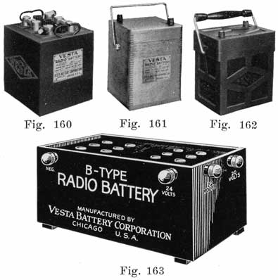
Vesta Radio Batteries. Fig. 160 shows the 6EA Series, "A" Battery. Fig. 161 shows the V6EA Series, "A" Battery. Fig. 162 shows the R6EA (Rubber Case) Series, "A" Battery. Fig. 163 shows the "B" Battery.
These batteries have 5, 7, 9 plates per cell, respectively. The plates are each 5 inches high, 5 7/8 inches wide, and 5/32 inches thick. The cases for these batteries are furnished in three designs — plain black boxes (all sizes), finished maple boxes (7 plate size only), and hard rubber boxes (9 plate size only). These Vesta batteries are the "A" batteries used for heating the filaments of the audion bulbs. The Vesta Radio "B" battery, Fig. 163, is a 12 cell, 24 volt battery, with a 22 and a 20 volt tap.
EXIDE RADIO BATTERIES

The Exide Radio "A" battery, Fig. 164, is made in four sizes, the capacities ranging from 20 to 120 ampere-hours. The design and construction of these batteries are similar to the Exide starting batteries. The over-all height of these batteries is approximately 95/8 inches, the width 7-5/16 inches, while the length varies with the number of the plates.
| Type | Cat. No. | Length | Weight | Capacity |
|---|---|---|---|---|
| 3-LXL-3 | 13735 | 4-9/16 | 15-1/2 lbs. | 20 amp. hrs. |
| 3-LXL-5 | 13736 | 5-11/16 | 24-1/2 lbs. | 40 amp. hrs. |
| 3-LXL-9 | 13737 | 9-1/16 | 42-1/2 lbs. | 80 amp. hrs. |
| 3-LXL-13 | 13750 | 12-7/16 | 59-1/2 lbs. | 120 amp. hrs. |
WILLARD RADIO BATTERIES
The Willard Storage Battery Co. manufactures both "A" and "B" storage batteries. The Willard "A" battery, Fig. 165, is an all-rubber battery. The case is a rubber "Monobloc" construction, that is, the entire case is pressed into shape at one time. There are no separate jars for the cells, there being rubber partitions which form integral parts of the case. The case is, therefore, really a solid, one piece, three compartment jar. The ribs at the bottoms of the compartments are parts of the one-piece block, and are higher than those found in the usual starting and lighting battery. Embedded in each side wall of the case is a bronze button which holds the handle in place. Soft rubber gaskets of pure gum rubber surround the post to make an acid proof seal to prevent electrolyte from seeping from the cells. The separators are the standard Willard "Threaded Rubber" separators.
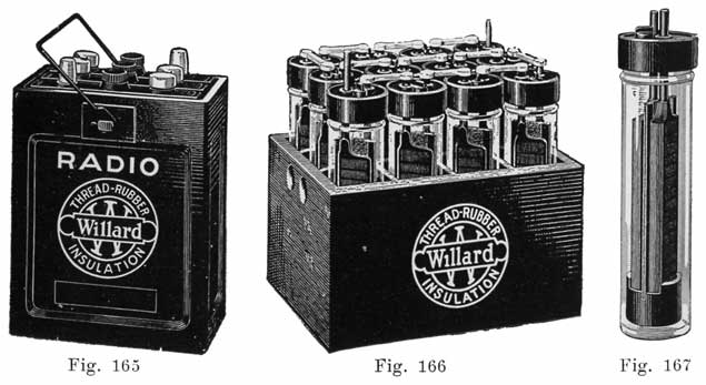
Willard Radio Batteries. Fig. 165 shows the All-Rubber "A" Battery. Fig. 166 shows the complete "B" Battery. Fig. 167 shows one cell of the "B" Battery.
The Willard "A" battery comes in five sizes, type WRR97 (20 ampere hours capacity), type WRRO (50 ampere hours capacity), type WRR1 (89 ampere hours capacity), type WRR2 (100 ampere hours capacity), and type WRR3 (125 ampere hours capacity).
The Willard "B" storage battery, type CBR124, Figs. 166 and 167, is a twelve cell battery, each cell consisting of a round glass container having one negative and one positive plate insulated from each other by a small "Threaded Rubber" separator. The plates and separators rest on a hard rubber "bottom rest" which consists of a short length of hard rubber tube, so formed as to support the plates and separators and at the same time hold them together. The cells are assembled in a case which has a separate compartment for each cell. As seen from Fig, 166, the upper parts of the cells project above the top of the case, which simplifies inspection.
WESTINGHOUSE RADIO BATTERIES
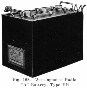
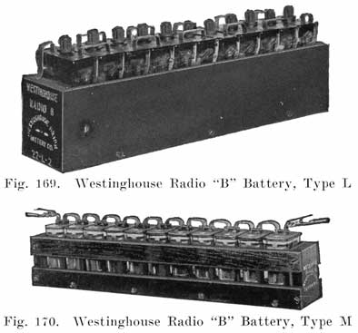
The Westinghouse Union Battery Co. manufactures both "A" and "B" storage batteries. Their "ER" type, Fig. 168, is the "A" battery, and their "L" and "M" types, Figs. 169 and 170, are the "B" batteries. The HR battery has 3/16 inch thick plates, high rests to provide ample mud and acid space, and thick separators. Rubber sheets are placed on both sides of the positive plates. Rubber covered cables are moulded into the terminals to minimize corrosion at the positive terminal. The "HR" batteries are made in six and eight volt sizes, with 3 plates per cell, 5 plates per cell, 9 plates per cell, and 13 plates per cell.
The Westinghouse Radio "B" batteries are made in two sizes. Type 22-M-2, Fig. 170, has a capacity of 1.2 ampere hours at 0.04 ampere. It is designed to operate a receiving set having one detector and two amplifier bulbs for three to five weeks between charges. The type 22-L-2 battery, Fig. 169, has a capacity of 4.5 ampere hours at 0.25 ampere.
| Part No. | Type | Volts | Amp. Hours at 3 Amps. Intermittent Rate |
Weight |
|---|---|---|---|---|
| 100110 | 6-HR-5 | 6 | 54 A.H. | 30 Lbs. |
| 100111 | 6-HR-9 | 6 | 108 A.H. | 46 Lbs. |
| 100112 | 6-HR-13 | 6 | 162 A.H. | 65 Lbs. |
| 100135 | 8-HR-5 | 8 | 54 A.H. | 40 Lbs. |
| 100136 | 8-HR-9 | 8 | 108 A.H. | 60 Lbs. |
| 100137 | 8-HR-13 | 8 | 162 A.H. | 87 Lbs. |
| 100145 | 6-HR-3 | 6 | 27 A.H. | 20 Lbs. |
| Part No. | Type | Volts | Capacity | Weight |
|---|---|---|---|---|
| 100148 | 22-M-2 | 22 | 1.2 A.H. at .04 Amps. | 6-1/4 Lbs. |
| 100140 | 22-L-2 | 22 | 1.2 A.H. at 25 Amps. | 19-3/4 Lbs. |
PHILADELHIA RADIO BATTERIES
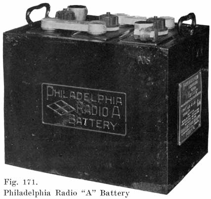
The Philadelphia Storage Battery Co. makes both "A" and "B" Radio batteries. The "A" battery, Fig. 171, uses the standard diamond-grid plates, and the "Philco Slotted Retainer" used in Philadelphia starting batteries. The cases of the "A" batteries are made of hardwood, finished in an ebonite black. Soft rubber insulating feet on the bottom of the case prevent scratching any table or varnished floor on which the battery may be set. The instructions for preparing the Philadelphia "A" battery for service are similar to those given for the starting and lighting batteries, given on page 228. For the initial filling, 1.220 electolyte is used, and the battery charged at the following rates:
Initial and Recharge Charging Rate
| Type | Initial Rate | Recharge Rate |
|---|---|---|
| 56LAR | 1.0 | 2 |
| 56RAR | 2.0 | 3 |
| 76RAR | 3.0 | 4.5 |
| 96RAR | 4.0 | 6 |
| 116RAR | 5.6 | 7.5 |
| 136RAR | 6.0 | 9 |
The final gravity of the electrolyte should be 1.250. However, if the owner insists on getting maximum capacity, the battery may be filled with 1.250 electrolyte and balanced to 1.290 at the end of the charge.
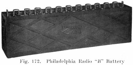
The Philadelphia Radio "B" battery, type 224-RB, Fig. 172, has 12 cells contained in a one-piece rubber case. It is shipped dry, and requires no initial charge. To prepare it for service, the soft rubber vent caps are removed and 25 c. c. of 1.250 electrolyte poured into each cell.
U. S. L. RADIO BATTERY
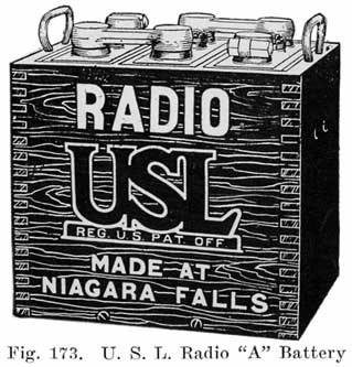
The U. S. L. Radio "A" battery, Fig. 173, uses 1/4 inch positives, with 3/16 inch intermediate and 1/8 inch outside negatives. Port Orford cedar separators are used which are four times as thick as the usual starting battery separator. The case is made of hardwood, and is varnished to match cabinet work. The electrolyte has a specific gravity of 1.220. The heavy plates and separators and the low gravity of the electrolyte are designed to give long life.
| Type | Plates per Cell |
Ampere Hour Capacity @ 3 Amperes |
Ampere Hour Capacity @ 1 Amperes (or intermittent use) |
Dimensions | Weight |
|---|---|---|---|---|---|
| DXA-303-X | 3 | 12 | 20 | 5-3/16 x 7-1/4 x 9-1/4 | 18 |
| DXA-305-X | 5 | 40 | 60 | 9-1/8 x 7-1/4 x 9-1/4 | 39 |
| DXA-307-X | 7 | 70 | 85 | 11-3/4 x 7-7/16 x 9-1/4 | 48 |
| DXA-309-X | 9 | 98 | 115 | 14-3/8 x 7-7/16 x 9-1/4 | 59 |
PREST-O-LITE RADIO BATTERIES
The Prest-O-Lite Co. makes two lines of Radio "A" Batteries. First, an inexpensive battery, Fig. 174, and a deluxe battery, Fig. 175, which has a better finish and appearance. Both types have a mahogany finished case with rubber feet to prevent damaging furniture. A bail handle simplifies the carrying of the battery. Capacities range from 47 ampere-hours to 127 ampere-hours at a one ampere discharge rate.
Table of Prest-O-Lite Radio Batteries
Type |
Hours Discharge at Rate of: | ||||
|---|---|---|---|---|---|
| 1 Amp. | 2 Amps. | 3 Amps. | 5 Amps. | 10 Amps. | |
| 67 WHNR | 47.5 | 21.7 | 13.6 | 7.5 | 3.0 |
| 69 WHNR | 66 | 30 | 18.9 | 10.5 | 4.5 |
| 611 WHNR | 82.8 | 38.5 | 24.3 | 13.5 | 6.0 |
| 67 KPNR | 95 | 44.2 | 27.8 | 15.0 | 6.5 |
| 69 KPNR | 127 | 61.5 | 38.5 | 21.5 | 9.5 |
UNIVERSAL RADIO BATTERIES
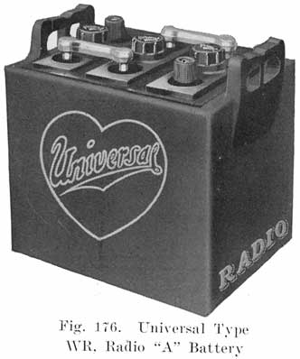
The Universal Battery Co. manufacture three types of Radio "A" storage batteries. Type WR, Fig. 176, has three sealed hard rubber jars assembled in a hardwood case which is stained and finished in mahogany. The separators are made of Port Orford cedar and are 1/8 inch thick, about twice the thickness of the separator used in starting and lighting batteries. The plates also are much thicker than the standard starting and lighting battery plate. The type WR battery comes in three sizes. Types WR-5, WR-7, and WR-9, having capacities of 60, 85, and 105 ampere hours, respectively, at a 3 ampere rate.
The Universal type RR radio "A" battery, Fig. 177, is assembled in a hard rubber combination case, which is a solid piece of rubber divided into three compartments. This gives a compact, acid proof case. This battery also comes in three sizes, types RR-5, RR-7, and RR-9, having capacities of 60, 85 and 105 ampere hours, respectively, at a three ampere discharge rate.
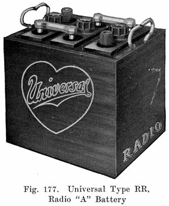
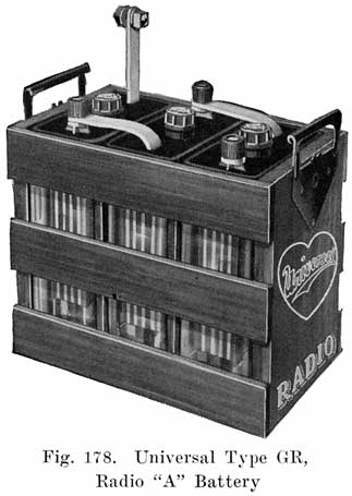
The Universal type GR radio "A" battery, Fig. 178, is assembled in three sealed glass jars which are placed in a mahogany finished wooden crate. This construction makes the cell interiors visible, enabling the owner to detect troubles and to watch the action of the cells on charge and discharge. The GR battery comes in two sizes, GR-5 and GR-Jr., having respective capacities of 60 and 16 ampere hours at a 3 ampere discharge rate.
"DRY" STORAGE BATTERIES
During the past year or two, so-called "dry" starting and lighting storage batteries have appeared on the market. This class includes batteries having "dry," "semi-dry," and "jelly" electrolytes. The claims made for these batteries are that there is nothing to evaporate and that the periodical addition of water is therefore unnecessary, that spilling and slopping of electrolyte is impossible, and that injurious sulphation does not take place.
The "dry" storage battery is not a new idea, for as much as thirty-five years ago, the Oerlikon Company of Switzerland manufactured "dry" electrolyte storage batteries in commercial quantities. These batteries were for a long time a distinct success for work requiring only low rates of discharge. For high rates of discharge the lack of diffusion, due to the absence of a liquid electrolyte, reduces the capacity. The lack of diffusion will cause a rapid drop in voltage when cranking the engine! and a slow recovery after the engine begins to run under its own power.
The manufacturers of the "dry" storage batteries, of course, claim that their batteries are more efficient and satisfactory than the standard "wet" battery, but it has been impossible to get sufficient data from the manufacturers to go into detail on the subject.
Several of the largest of "wet" battery manufacturers formerly made "dry" storage batteries for lighting and ignition service, but when starting motors came into use, discarded the "dry" batteries in favor of the present "wet" storage batteries.
DISCHARGE TESTS
Discharge tests may be divided into four general classes:
(a) Brief High Rate Discharge Tests to determine condition of battery. These tests are made for 15 seconds at a high rate.
(b) Lighting Ability Discharge Tests.
(c) Starting Ability Discharge Tests.
(d) "Cycling" Discharge Tests.
The 15 Seconds High Rate Discharge Test
The 15 seconds high rate discharge test is a valuable aid in determining the condition of a battery, particularly where the hydrometer readings give false indications, such as is the case when electrolyte or acid is added to a cell instead of water to replace evaporation. Only two or three percent of the battery capacity is consumed by the test, and it is not usually necessary to recharge the battery after making the test. The test must be made in conjunction with hydrometer readings, as otherwise it might give false indications itself. Both incoming and outgoing batteries may be tested, and the method of testing depends upon whether the battery is coming in for repairs, or is going out after having been charged, repaired, or worked on in any way. In either case, the test consists of discharging the battery at a high rate for a short time, and taking voltage readings and making observations while the battery is discharging.
Rates of Discharge. It is not necessary to have any definitely fixed discharge rate. The rate should merely be high enough to reveal any improperly burned joints, short-circuited cells, or cells low in capacity for any reason. The discharge tester is suitable for all batteries used on cars and trucks.
For an Incoming Battery. Take a hydrometer reading of each cell. If the readings are all below 1.200 and are within 50 points of each other, most likely all the battery needs is a bench charge, with a possible adjustment of the gravity of the electrolyte at the end of the charge. The discharge test should in this case be made after the battery has been fully charged.
If the gravity readings are all above 1.200, or if the reading of one cell differs from the others by 50 points or more, make the discharge test, as shown in Fig. 179.
After fifteen seconds, read the voltage of each cell. If the cells are uniformly low in voltage; that is, below 1.5 volts per cell, the battery needs recharging. If the voltage readings of the cells differ by 0.1.0 volt or more and the battery is fairly well charged, there is something wrong in the cell having the low reading, and the battery should be opened and examined. With a discharged battery the difference in cell voltage will be greater, depending on the extent of the discharge, and only experience can guide in drawing correct conclusions. A short-circuited cell will give a very low voltage reading. Remember that the actual voltage reading is not as important in indicating a defective cell as the difference between the voltage readings of the cells. A cell which gives a voltage which is 0.1 volt or more less than the others is generally defective.
For Outgoing New, Charged, or Repaired Batteries. Just before putting the battery into service, make the test as a check on the internal condition of the battery, particularly if the battery has been repaired or has stood for sometime since being charged. (It is assumed that the battery has been charged and the gravity of the electrolyte properly adjusted when the test is made.)
The battery should not show more than 0.10 volt difference between any two cells at the end of 15 seconds, and no cell should show a voltage less than 1.75 volts, and the voltage should remain fairly constant during the test. If every cell reads below 1.75 volts, the battery has not been completely charged. If one cell is more than 0.10 volt lower than the others, or if its voltage falls off rapidly, that cell still needs repairs, or is insufficiently charged, or else the top connectors are not burned on properly. Top connectors which heat up during the test are not burned on properly.
Lighting Ability Discharge Tests
These are tests continuing for 5 hours to a final voltage of 1.7 per cell. These tests are not of as great an interest as the Starting Ability Tests, description of which follows:
Starting Ability Discharge Tests
The Society of Automotive Engineers recommends two ratings for starting and lighting batteries:
"Batteries for combined lighting and starting service shall have two ratings. The first shall indicate the lighting ability and be the capacity in ampere-hours of the battery when discharged continuously at the 5 hour rate to a final voltage of not less than 1.7 per cell, the temperature of the battery beginning such a discharge being 80 deg. Fahr. The second rating shall indicate the starting ability and shall be the capacity in ampere-hours when the battery is discharged continuously at the 20 minute rate to a final voltage of not less than 1.50 per cell, the temperature of the battery beginning such discharge being 80 deg. Fahr."
The capacity in ampere-hours given by manufacturers is for a continuous discharge for 5 hours. In the battery shop, however, the "starting-ability" discharge test is the test which should be made, though the conditions of the test are changed somewhat. To make this test, the battery should be fully charged. Connect a rheostat to the battery terminals and adjust the rheostat to draw about 100 amperes from an 11 plate battery, 120 amperes from a 13 plate battery, 135 amperes from a 15 plate battery, 155 amperes from a 17 plate battery, 170 amperes from a 19 plate battery and so on. Continue the discharge for 20 minutes, keeping the discharge current constant, and taking voltage readings of each cell at the start, and at the end of 5, 10, 15, and 20 minutes. At the end of 20 minutes, if the battery is in good condition, the voltage of each cell should not be less than 1.5, and the temperature of the electrolyte in any cell should not exceed 95 degrees Fahrenheit, provided that the temperature at the start was about 80 degrees.
The cell voltages should drop slowly during the test. If the voltage begins to drop rapidly during the test, as shown by the current falling off so rapidly that it is difficult to keep it at 100 amperes, measure the cell voltages quickly to see which cells are dropping rapidly. An example of a 100 ampere test on a good rebuilt cell with eleven plates is as follows:
Voltage immediately after start of discharge, 1.88. After 5 minutes, 1.86 volts. After 10 minutes, 1.80 volts. After 15 minutes, 1.72 volts. After 20 minutes, 1.5 volts.
If the voltage of a cell begins to fall off rapidly before the twenty minutes are up, but not before 15 minutes, the cell needs "cycling" (charging and discharging) to bring it up to capacity.
If the voltage drops rapidly before the end of 15 minutes, the plates are low in capacity, due to age, or some defect. It is not safe to expect very good service from a cell which will not stand up for 20 minutes before de voltage begins to drop rapidly.
If the rapid voltage drop begins very much before 20 minutes, it is very doubtful whether the battery will give good service. Comparisons of the results of tests with the service which the battery gives after installed on the car will soon enable the repairman to tell from the results of the tests just what to expect from any battery.
The "starting-ability" test should be made on all batteries which have been rebuilt whenever there is time to do so and on all batteries about which there is any doubt as to what service they will give. After the test, the batteries should be put on the line again and charged before sending them out.
The rates of discharge given here for the "starting-ability" tests may be varied if experience with a particular make of battery shows some other rate to be better. The important thing is to use the same rate of discharge for the same make and type of battery at all times. In this way the repairman will soon be able to distinguish between good and bad batteries of a particular make and type.
Cadmium Tests may be made during the Starting Ability Discharge Tests. See page 174.
"Cycling" Discharge Tests
New batteries, or rebuilt batteries which have had new plates installed, or sulphated batteries which will not "come up" on charge, should be discharged when they have "come-up," as far as they will go. In some cases it is necessary to charge and discharge them several times before they will be ready for service. This charging and discharging is often called "cycling" the battery.
New batteries are generally "cycled" at the factory before sending them out. The forming charge generally does not convert all the pastes into active material and the battery using plates which have been treated in the forming room is put through several discharges and charges after the battery is fully assembled. In service on a car, the battery is being "cycled" constantly and there is generally an increase in capacity after a battery is put on a car. Positive plates naturally increase in capacity, sometimes up to the very clay when they fall to pieces, while negatives tend to lose capacity with age.
Batteries which are assembled in the service station, using new plates, generally require several cycles of charge and discharge before the specific gravity will rise to 1.280 before the positives will give 2.4-2.5 volts on a Cadmium test, before the negatives will give a reversed voltage reading of 0.175 to 0.20 volt on a Cadmium test, and before a satisfactory "starting-ability" or "breakdown" test can be made.
A battery which has been abused by failing to add water to replace evaporation, by allowing to remain in a partially or completely discharged condition for sometime, or which has been allowed to become sulphated in any other way, will generally require "cycling" before it will "come-up" to a serviceable condition.
The rates for a "cycling" discharge should be such that the battery will be discharged during the daytime, the discharge being started in the morning, and the battery being put back oil the charging line in the evening in order that it may be charging during the night. The rate of discharge should be somewhat higher than the rate used when the plates are formed. Two or three amperes per positive plate in each cell will generally be satisfactory.
Discharge Apparatus
A simple discharge rheostat is shown in Fig. 180. The terminal on the end of the cable attached to the right hand terminal of the battery shown in the illustration is movable, and it may be clamped at any point along the coils of wire so as to give various currents. The wire should be greased lightly to prevent rusting.
Another simple apparatus consists of a board on which are mounted six double contact automobile lamp sockets which are all connected in parallel. A pair of leads having test clips attached is brought out from the sockets for fastening to the battery terminals. Lamps of various candlepower may be turned into the sockets to obtain different currents.
Discharge tests are helpful in the case of a battery that has lost capacity. The battery is first fully charged, and is then discharged at the 5 hour rate. When the voltage of the battery has fallen to 1.7 volts per cell (measured while the battery is discharging) a Cadmium test is made to determine whether the positives or negatives are causing the lack of capacity. For further descriptions of the Cadmium Test see Page 174.
In reviving sulphated batteries, it is sometimes necessary to charge and discharge the battery several times to put the active material in a healthy condition.
Discharge tests at a high rate are very valuable in diagnosing the condition of a battery. A description of such tests will be found on Page 267. For making the heavy discharge tests a rheostat of the carbon plate type is suitable. With such a rheostat currents from 25 to more than 200 may be drawn from a six volt battery, and a smooth, even variation of a current may be obtained from the minimum to the maximum values. Such a rheostat is on the market and may be purchased complete with ammeter and leads for attaching to the battery.
PACKING BATTERIES FOR SHIPPING
Batteries which are shipped without electrolyte need merely have plenty of excelsior placed around them in a strong crate for protection from mechanical injury.
Batteries which are shipped filled with electrolyte must be protected from mechanical injury and must also be packed so that it is difficult to turn the crate upside down and thus allow the electrolyte to run out. A very popular crate has been the so-called "dog-house," with a gable roof such as is actually used on dog-houses. The idea of such a roof is that it is impossible to place the crate with the roof down, since it will tip over if this is done. However, if these crates are placed side by side, it is a very simple matter to put a second row of crates on top of them, turning the second row up-side-down, as shown in Fig. 181, and allowing the electrolyte to run out. The men who load freight or express-cars have often shown great skill and cunning in packing "dog-house" crates in other ways so as to damage the batteries. Many have attained a high degree of perfection in breaking the crates.
Some sort of a roof on a battery crate is required by law, the idea being to make it difficult to turn the crate up-side-down. Perhaps the best crate would be one with a flat top marked "This Side Up," but such a crate would not comply with the law.
A better form of crate than the "dog-house" and one which complies with the law, is shown in Fig. 182. The top of each end piece is cut at an angle, the peak on one end being placed opposite the low point of the opposite end piece. Fig. 182 shows the steps in the construction of the crate.
1. The case should be built of strong lumber (11/2 inch preferably), and of ample size to allow packing with excelsior top, bottom, sides and ends to a thickness of two or three inches. Nail strongly.
2. When the case is complete (except cover) place a thick, even layer of excelsior (or packing straw) in the bottom and set in *he battery right side up. Lay paper (preferably paraffined) over top of battery to keep it clean, then pack tightly with excelsior sides and ends.
3. Now lay sufficient packing material on top of the battery so that cover will compress it tightly, stuffing it under cover boards as they are put on.
The extended boards at bottom, and the gable roof are provided to prevent the battery from being tipped over; extensions of sides for carrying. Box should be plainly labeled: "HANDLE WITH CARE. DAMAGES CLAIMED IF TIPPED ON SIDE." In addition to the address of destination, as given in shipping instructions be sure to mark with name of shipper for identification upon arrival. When shipping by freight, the proper freight classification in the United States is "Electric Storage Batteries, Assembled." When shipping by express in the United States, "Acid" caution labels must be attached to each package.
STORING SEPARATORS
Separators which have been given the chemical treatment necessary to remove the substances which would cause trouble in the battery, and to make the wood porous, must be kept wet and never be allowed to become dry. A lead lined box, or large earthenware jars may be used as containers. Put the separators in the container and then pour in enough very weak electrolyte to cover the separators. This electrolyte may be made of I part of 1.220 electrolyte to 10 parts of distilled water, by volume. Be very careful to have the container absolutely clean and to use chemically pure acid and distilled water in making the weak electrolyte. Remember that impurities which are picked up by the separators will go into the battery in which the separators are placed. Therefore, keep the separator tank in a clean place and keep a cover on it. Have your hands clean when you take separators out of the tank to place in a battery, and do not put the separators on a dirty bench before inserting them between plates. The best thing to do is to hold the separators in one hand and insert them with the other, and not lay them on any bench at all.
REINSULATION
Separators are the weakest part of a battery and wear out while the other parts of a battery are still in good condition. Good plates are often ruined by weakened separators causing short-circuits. Many batteries which have to be junked after being in service about a year would have given considerable service if they had been reinsulated.
Generally the separators of one cell wear out before those of the other cells. Do not, however, reinsulate that cell alone. The separators in the other cells are as old as those which have worn out, and are very near the breaking down point. If you reinsulate only one cell, the owner will naturally assume that the other cells are in good condition. What happens? A month or so later one of the other cells "goes dead." This does not have a very soothing effect on the owner, who will begin to lose confidence in you and begin to look around for another service station.
If you explain frankly that it is useless to reinsulate only one cell of a battery and that the other cells will break down in a short time, the customer will want you to reinsulate all the cells. A somewhat higher bill for reinsulating all the cells at once will be more agreeable than having the cells break down one at a time within a month or two.
In the case of the customers who come in regularly for testing and filling service, you will be able to tell when the separators are wearing out. When you find that a battery which has been in service about a year begins to run down frequently, and successive tests made in connection with testing and filling service show that the generator is not able to keep the battery charged, advise the owner to have the battery reinsulated. Do not wait for the battery to have a dead cell. Sell the owner on the idea that reinsulation will prevent the possibility of his battery breaking down when he may be out on a tour, and when it may be necessary to have his car towed in to a service station. If you allow the battery to remain on the car when it begins to lose its charge, the owner will not, of course, suspect that anything is wrong, and if his battery one day breaks down suddenly, lie will very likely lose confidence both in you and the battery, since he has been bringing in his car regularly in order to have his battery kept in good shape. The sudden failure of his battery will, therefore, make him believe that you do not know your business, or that the battery is a poor one.
New separators will give every battery which is a year old a new lease on life. If you explain to a customer that he will get a much longer period of service from his battery if he has it reinsulated when the battery is a year old, you should have no trouble in getting the job, and the subsequent performance of the battery will show that you knew what you were talking about.
SAFETY FIRST FOR THE BATTERY REPAIRMAN
1. Do not work on an empty stomach-you can then absorb lead easily.
2. Keep your fingers out of your mouth when at work.
3. Keep your finger nails short and clean.
4. Do not chew tobacco while at work. In handling tobacco, the lead oxides are carried to your mouth. Chewing tobacco does not prevent you from swallowing lead.
5. When you leave the shop at night, and before eating, wash your face, hands, and arms with soap, and clean your nose, mouth, and finger nails.
6. Do not eat in the repair shop.
7. Drink plenty of good milk. It prevents lead poisoning.
8. Use Epsom Salts when constipated. This is very important.
9. Bathe frequently to prevent lead poisoning.
10. Leave your working clothes in the shop.
11. It is better not to wear a beard or mustache. Keep your hair covered with a cap.
12. Before sweeping the shop dampen the floor to keep down the dust.
13. Do not drink beer or whisky, or any other alcoholic liquors. These weaken your system and make you more susceptible to lead poisoning.
14. In handling lead, wear gloves as much as possible, and wash and dry the gloves every day that you wear them.
15. Wear goggles to keep lead and acid out of your eyes.
16. When melting lead in a hydrogen flame, as in burning on the top connectors, the fumes given off may be blown away by a stream of air. The air supply to the flame may be tapped for this purpose.
17. The symptoms of lead poisoning are: gums darken or become blue, indigestion, colic, constipation, loss of appetite, muscular pain. In the later stages there is muscular weakness and paralysis. The hands become limp and useless.
18. Wear rubber shoes or boots. Leather shoes should be painted with a hot mixture of equal parts of paraffine and beeswax.
19. Wear woolen clothes if possible. Cotton clothing should be dipped in a strong solution of baking soda and dried. Wear a flannel apron covered with sacking.
20. Keep a bottle of strong ammonia handy. If you should spill acid on your clothes, apply some of the ammonia immediately to neutralize the acid, which will otherwise burn a hole in your clothes.
21. Keep a stone, earthenware, or porcelain jar filled with a solution of washing soda or baking soda (bicarbonate of soda). Rinse your hands in this solution occasionally to prevent the acid from irritating them.
22. If you should splash acid in your eye, wash it out immediately with warm water, and drop olive oil on the eye. If you have no olive oil at hand, do not wait to get some, but use any, lubricating oil, or vaseline.
TESTING THE ELECTRICAL SYSTEM
"Out of sight, out of mind," is a familiar saying. But when does it hold true?
What about the battery repairman? Are the batteries he repairs "out of sight, out of mind?" Does his responsibility end when he has installed a battery on a car? Suppose he put a battery in first class shape, installs it on a car, and, after a week or two the battery comes back, absolutely dead? Is the battery at fault, or is the repairman to blame for neglecting to make sure that the battery would be given a reasonably good chance to give good service and receive fair treatment from the other part of the electrical system?
The actual work on the battery is finished when the battery cables are fastened to the battery terminals. But real battery SERVICE does not end there. The battery is the most important part of the electrical system of a car, but it is only one part, and a good battery cannot be expected to give satisfactory service when it is connected to the other parts of the electrical system without making sure that these parts are working properly, any more than a man wearing new, shoes can step into a mud puddle and not have his shoes covered with dirt.
The battery functions by means of the current which flows through it by way of the cables which are connected to its terminals. A battery is human in many respects. It must have both food and exercise and there must be a proper balance between the food and the exercise. Too much food for the amount of exercise, or too much exercise for the amount of food consumed will both lead to a lowering of efficiency, and disease frequently results. A battery exercises when it turns over the starting motor, furnishes energy to the lamps, or operates the a ignition system. It receives food when it is charged. Proper attention to the electrical system will result in a correct balance between food and exercise, or in other words, charge and discharge.
The electrical equipment of a car consists of five principal parts:
1. The Battery.
2. The Ignition System.
3. The Starting Motor.
4. The Generator.
5. The Lighting System.
The normal course of operation of this system is as follows:
Starting. The ignition switch is closed, and connects the ignition system to the battery. The starting switch is then closed, connecting the starting motor to the battery. The battery sends a heavy current through the starting motor, causing the motor to turn over, or "crank" the engine. The motion of the engine pistons draws a mixture of air and gasoline vapor into the cylinders. At the proper instant sparks are made to jump between the points of the spark plugs, igniting the air and gasoline vapor mixture, forming a large amount of gas. This gas expands, and in doing so puts the engine into motion. The engine begins to run under its own power and the starting switch is opened, since the starting motor has performed the work required of it, and has nothing further to do as long as the engine runs.
The engine now operates the generator. The generator begins to build up a voltage as the engine speed increases. When the voltage of the generator has risen to about 7-7.5, the generator is automatically connected to the battery by the cutout (also known as reverse-current relay, cut-out relay, or relay). The voltage of the generator being higher than that of the battery, the generator sends a current through the battery, which "charges" the battery. As long As the engine continues to run above the speed at which the generator develops a voltage higher than that of the battery, a charging current will normally flow through the battery. When the ignition switch is opened the engine can no longer develop any power and consequently stops running. When the decreasing engine speed causes the generator speed to drop to a point at which the generator voltage is less than that of battery, the battery sends a reverse, or discharge current through the cutout and generator, thereby causing the cutout to open and disconnect the generator from the battery.
Lights. When the engine is not running, the battery furnishes current to the lights. This is a discharge current. When the engine runs at a speed which is greater than that at which the the cutout closes, the generator furnishes current for the lights, and also for the ignition system, in addition to sending a charging current through the battery.
From the foregoing description, we see that the battery is at rest, is discharging, or charging under the following conditions:
Engine Not Running, Lamps Off, Ignition Off. Under these conditions all switches are open, and hence no current should be passing through the battery. If a current is found to be passing through the battery under these conditions, it is a discharge current which is not doing any work and is caused by a defective cutout, defective switches, or grounds and short-circuits in the wires, cables, or apparatus connected to the battery.
Starting the Engine. A heavy discharge current is drawn from the battery. This current should not flow more than 10 seconds. If the starting motor does not crank the engine or cranks it too slowly, the motor or the cables and switch connecting the motor to the battery are defective, assuming that the battery is large enough and is in a good condition. If the starting motor cranks the engine, but the engine does not begin to run under its own power within ten seconds, the starting system is not at fault, and the starting switch should be opened.
Engine Not Running, All Lamps On. A discharge current flows from the battery which is equal to the sum of the currents drawn by lamps when connected to the battery separately. If the current is greater than this sum, trouble is present.
Engine Running, Lamps Off. The generator sends a charging current into the battery and also supplies current to the ignition system (except when a magneto is used). If the generator does not send a charging current through the battery there is trouble in the generator, or in the parts connecting the generator to the battery (assuming the battery to be in a good condition). If the generator sends a current through the battery, it may be of the correct value, it may be insufficient, or it may be excessive. A normal current is one which keeps the battery fully charged, but does not overheat it or cause excessive gassing. An insufficient current is one which fails to keep the battery charged. An excessive charging current is one which keeps the battery charged, but which at the same time overheats the battery and causes excessive gassing. The excessive current may also overheat the generator, while a normal or insufficient charging current will not injure the generator.
It is possible, but not probable, that the generator may be sending current through the battery in the wrong direction, so as to discharge it instead of charging it. This will happen if a very badly discharged battery is installed with the connections reversed. If a fully or even partly charged battery is installed with its connections reversed, the battery will generally reverse the polarity of the generator automatically, and the battery will be charged in the proper direction, although the current flow in the charging circuit is actually reversed.
Engine Running, Lamps On. Under these conditions, the generator should supply the current for the lights, and still send a charging current of 3 to 5 amperes through the battery. This means that the current drawn from the battery when the engine is not running and the lights are all turned on should be at least several amperes less than the charging current which the generator sends into the battery when the engine is running and the lamps are turned off.
Tests to Be Made by the Repairman
The battery repairman can, and always should, make a few simple tests which will tell him whether the various conditions of operation are normal. This should be done as follows:
1. Install the battery carefully (see page 236), and connect the negative battery cable to the negative battery terminal. Now tap the positive battery cable on the positive battery terminal. If a snappy spark is obtained when this is done, some of the switches are open or are defective, the cutout is stuck in the closed position, or there are grounds or short-circuits in the parts which are permanently connected to the battery.
Even though no spark is obtained when you tap the positive battery cable on the positive battery terminal, there may be some trouble which draws enough current from the battery to cause it to run down in a short time. To detect such trouble, connect a voltmeter (which has sufficient range to indicate the battery voltage) between the positive battery cable and the positive battery terminal. (Cable is disconnected from the terminal.) If the voltmeter now gives a reading equal to the voltage of the battery, there is some condition causing a current leakage from the battery, such as a cutout stuck in the closed position, defective switches which do not break the circuits when in the open position, or grounds or short-circuits in the cables and wires connected to the battery.
If the voltmeter pointer does not move from the "0" line on the scale, complete the battery connections by fastening the positive battery cable to the positive battery terminal, and make the test described in Section 2. If the voltmeter pointer moves from the "0" line, and gives a reading equal to the battery voltage, connect the voltmeter permanently between the positive battery cable and the positive battery terminal and make a general inspection of the wiring, looking for cut or torn insulation which allows a wire or cable to come in contact with the frame of the car, or with some other wire or cable, thereby causing a ground or short-circuit. Old, oil-soaked insulation on wires and cables will often cause such trouble. If a general inspection does not reveal the cause of the current leakage, proceed as follows:
Closed Cutout, or Defective Cutout Windings. (a) If the cutout is mounted outside the generator, remove the cover from it and see if the points are stuck together. If they are, separate them and see if the voltmeter pointer returns to the "0" line. If it does, you have found the trouble. The points should be made smooth with 00 sandpaper. See that the moving arm of the cutout moves freely and that the spring which tends to hold the arm in the open position is not weak or broken.
If the voltmeter pointer does not return to the "0" line when the cutout points are separated, or if the points were not found to be stuck together, disconnect from the cutout the wire which goes to the ammeter or battery. If this causes the voltmeter pointer to return to the "0" line, the cutout is defective and a new one should be installed, unless the trouble can be found by inspection and repaired.
If the voltmeter pointer does not return to the "0" line when the battery or ammeter wire is disconnected from the cutout, see paragraph (d)
(b) If the cutout is mounted inside the generator, disconnect from the generator the wire which goes to the ammeter or indicator. If this causes the voltmeter pointer to return to the "0" line, the cutout points are stuck together or the cutout is defective, and the generator should be taken apart for inspection. If this does not cause the voltmeter pointer to return to the "0" line, replace the wire and see paragraph (d).
(c) If no cutout is used and connections between the generator (or motor- generator) and the battery are made by closing the ignition or starting switch, such as is the case on Delco and Dyneto motor-generators, and some Delco generators, disconnect from the generator or motorgenerator the wire that goes to the ammeter or indicator. If this causes the voltmeter pointer to return to the "0" line, the switch which connects the generator or motor-generator to the ammeter or indicator is defective. If the voltmeter pointer does not return to the "0" line, replace the wire and consult paragraph (d).
(d) Defective Starting Switch. Disconnect from the starting switch the cable that goes to the battery. If one or more smaller wires are connected to the same terminal as the heavy cable, disconnect them also and hold their bare ends on the bare end of the heavy cable. If this causes the voltmeter pointer to return to the "0" line, the starting switch is defective. If the voltmeter pointer does not return to the "0" line, replace the cable and wires on the starting switch terminal and proceed as follows:
Defective Switches. See that the ignition and lighting switches are in their "OFF" positions. If they are not, open them and see if the voltmeter pointer returns to the "0" line. If it does, you have found the trouble. If it does not, disconnect from the switch (or switches, if there are separate lighting and ignition switches), the feed wire which supplies current to the switch from the battery. If this causes the voltmeter pointer to return to the "0" line, the switches are defective. If the pointer does not return to the "0" line, replace the wires on the switch and consult the next paragraph.
If there are other switches which control a spot light, or special circuits, such as tonneau lamps, or accessories, such as gasoline vaporizers, electric primers, etc., make the same tests on these switches. If no trouble has been found, see paragraph (e).
(e) Grounds or Short-Circuits in Wiring. Disconnect from each terminal point in the wiring system the wires which are connected together at that point. Also remove fuses from the fuse blocks. If the voltmeter pointer returns to the "0" line when a certain wire or fuse is removed, there is a ground or short-circuit in the wire or in the circuit to which the fuse is connected.
(f) Turn on the Lights. Remove the voltmeter and complete the battery connection. Note how much current is indicated on the ammeter mounted on the instrument panel of the car as the different lamps are turned on. In each case the ammeter should indicate "discharge." Should the ammeter indicate "charge" the battery connections have been reversed, or the ammeter connections are reversed. The driver will tell you whether the ammeter has been reading "charge" or "discharge" when the lamps were turned on. This is a good way to check your battery connections.
If the car has no ammeter, or has an indicator which is marked "ON" or "OFF," or "Charge" or "Discharge," an ammeter may be connected in series with the battery by disconnecting the cable from the positive battery terminal and connecting the ammeter to the cable and to the terminal, and the readings obtained from this meter.
The amperes indicated on the ammeter should be the greatest when the main headlamps are burning bright. By comparing the readings obtained when the different lighting combinations are turned on, it is sometimes possible to detect trouble in some of the lighting lines.
3. Start the Engine. Before you do this, be sure that the cables are connected directly to the battery terminals, and that no ammeter or voltmeter is connected in series with the battery, as the heavy current drawn by the starting motor would ruin the instruments very quickly. An ammeter may be left connected in series with the battery, providing that a switch is used to short-circuit the meter while starting the engine. A meter having a 500 ampere scale may be left connected in series with the battery while the engine is being started, but for the tests which are to be made a 25 ampere scale should be used.
The engine should start within ten seconds after the starting switch is closed. If more time than this is required, carburetor adjustments, position of the choke lever, etc., should be looked after. Continued cranking of the engine will run the battery down very quickly, and the chances are that the car will not be run long enough to allow the generator to recharge the battery. Make whatever adjustments are necessary to reduce the cranking time to ten seconds, or advise the owner to have them made, warning him that otherwise you will not be responsible if the battery runs down very quickly.
4. When the engine has started, set the throttle lever so that the engine runs As slowly as possible. The ammeter (either that on the instrument panel, or a special test ammeter connected in series with the battery) will indicate several amperes discharge, this being the current taken by the ignition system.
Now speed up the engine gradually. At an engine speed corresponding to a car speed of 7 to 10 miles per hour in "high" (if there is any difficulty in estimating this speed, drive the car around the block while making this and the following tests) the ammeter pointer should move back to, or slightly past, the "0" line, showing that the cutout has closed. If the ammeter needle jumps back and forth and the cutout opens and closes rapidly, the polarity of the battery and that of the generator are not the same. This condition may be remedied by holding the cutout points closed for several seconds, or by short-circuiting the "Battery" terminal on the cutout with the "Generator" terminal on the cutout.
After a slight movement of the ammeter pointer indicates that the cutout has closed, speed up the engine gradually. When the engine speed corresponds to a car speed of 18-25 miles per hour in "high," the current indicated on the ammeter should reach its maximum value and the pointer should then stop moving, or should begin to drop back toward the "0" line as the speed is increased.
For average driving conditions, the maximum charging current should not exceed 12 to 14 amperes for a 6 volt, 11 to 13 plate battery, and 6 to 7 amperes for a 12 volt battery. (These currents should be obtained if "constant-current" generators, such as the "third brush," "reversed-series," or vibrating current regulators are used. The "third brush" type of generator is used on more than 99 per cent of the modern cars. Some cars use a "constant-voltage" regulated generator, such as the Bijur generator, having a voltage regulator carried in a box mounted on the generator. On all cars using a "constant-voltage" generator, the charging rate when the battery is fully charged should not exceed five amperes for a six volt generator). If the generator has a thermostat, such as is used on the Remy generators, the charging rate will be as high as 20 amperes until the generator warms up, and then the charging rate will drop to 10-12 amperes, due to the opening of the thermostat points, which inserts a resistance coil in series with the shunt field.
If the charging current reaches its maximum value at 18-25 miles per hour, and shows no increase at higher speeds, decrease the engine speed. When the engine is running at a speed corresponding to a car speed of about 7 miles per hour, or less, the cutout should open, indicated by the ammeter indicating several amperes discharge, in addition to the ignition current, for an instant, and then dropping back to the amount taken by the ignition system.
Now turn on the headlights (and whatever lamps are turned on at the same time) and speed the engine up again. The ammeter should indicate some charging current at engine speeds corresponding to the usual speed at which the car is driven. If it does not, the charging current should be increased or smaller lamps must be installed.
Troubles
The operation of the electrical system when the engine is running may not be as described in the foregoing paragraphs. Troubles may be found as follows:
1. Cutout does not close until engine reaches a speed in excess of 10 miles per hour. This trouble may be due to the cutout or to the generator. If the ammeter shows a charging current of three amperes or more as soon as it closes, the cutout is at fault. The thing to do in such a case is to adjust the cutout. First see that the movable armature of the cutout moves freely and does not bind at the pivot. If no trouble is found here, the thing to do is to decrease the air gap which exists between the stationary and movable cutout points when the cutout is open., or to decrease the tension of the spring which tends to keep the points open. On most cutouts there is a stop which the cutout armature strikes when the cutout opens. By bending this stop the air-gap between the points may be decreased. This is the adjustment which should be made to have the cutout close earlier, rather than to decrease the spring tension. Some cutouts have a spiral spring attached to the cutout armature. Others have a flat spring. On still others, the spring forms the connection between the armature and the cutout frame. In the first two types, the spring tension may be decreased, but wherever possible the air-gap adjustment should be made as described.
If the cutout closes late, and only about an ampere of charging current is indicated on the ammeter, and the cutout points are fairly clean and smooth, the trouble is generally in the generator.
The generator troubles which are most likely to exist are:
a. Dirty commutator.
b. Dirty brush contact surface.
c. Loose brushes.
d. Brushes bearing on wrong point of commutator (to set brushes properly, remove all outside connections from generator, open the shunt field circuit, and apply a battery across the main brushes. Shift the brushes until the armature does not tend to rotate in either direction. This is, of course, a test which must be made with the generator on the test bench).
e. Loose connections in the shunt field circuit.
The foregoing conditions are the ones which will generally be found. More serious troubles will generally prevent the generator from building up at all.
2. Cutout does hot open when engine stops. This condition is shown by a discharge current of about 5 amperes when the engine has stopped. (In Delco systems which have no cutout, an even greater discharge will be noted as long as the ignition switch remains closed.) This trouble is generally due to cutout points stuck together, a broken cutout spring, or a bent or binding cutout armature.
3. Cutout does not open until ammeter indicates a discharge of three or more amperes (in addition to the ignition discharge). This may be remedied by increasing the spring tension of the cutout, or removing any trouble which causes the cutout armature to bind. On many cutouts the armature does not actually touch the core of the cutout winding when the points are closed, there being a small piece of copper or other non-magnetic metal on the armature which touches the end of the cutout and maintains a small air gap between the core and armature, even when the points are closed. The opening action of the cutout may be changed by filing this piece of non-magnetic material so as to decrease the air gap, or pinching it with heavy pliers so as to make it stand farther out from the cutout armature and thus increase the air gap between the armature and core when the points are closed.
Decreasing this air gap will cause the cutout to open late, and increasing it will cause the cutout to open early.
4. Cutout will not close at any engine speed. If cutout does not close the first time the engine speed is increased, stop the engine. This condition may be due to a defective cutout, an open-circuit in the charging line, a ground or short-circuit between the cutout and the generator, or a defective generator. To determine whether the cutout is defective, remove the wires from it and hold together the ends of the wires coming from the generator, and the one going to the ammeter. Start the engine. If no other trouble exists, the ammeter will indicate a charging current at speeds above 8-10 miles per hour. If no current is obtained, stop the engine. If the cutout trouble consisted of an open circuit in one of its windings, or in the points not closing, due to dirt or a binding armature, or if there is an open-circuit in the charging line, the generator will, of course, have been running on open-circuit. This will cause the fuse in the shunt field circuit to blow if there is such a fuse, and if there is no such fuse, the shunt field coils may be burned open, or the insulation on the field coil wires may have become overheated to a point at which it burns and carbonizes, and causes a short-circuit between wires. Such troubles will, of course, prevent a generator from building up when the cutout wires are disconnected and their ends held together.
If there is a ground in the cutout, or between the cutout and the generator, the generator will very likely be unable to generate (if a "one-wire" system is used on the car). If there is some defect in the generator-such as dirty commutator, high mica, brushes not touching, commutator dirty, or loose brushes, brushes too far from neutral, grounded brushes, brushes not well ground in, wrong type of brushes, grounded commutator or armature windings, short-circuited commutator or armature windings, open-circuited armature windings, grounded field windings, short-circuited field windings, open-circuit or poor connections in field circuit, one or more field coil connections reversed, wrong type of armature or field coils used in repairing generator, generator drive mechanism broken-then the generator will not build up.
If no charging current is, therefore, obtained when the generator and ammeter wires are disconnected from the cutout and their ends held together, there may be a ground or short-circuit in the cutout windings or in the circuit between the generator and the cutout, or the generator may be defective, due to having been operated on open-circuit, or due to troubles as described in the foregoing paragraph. The presence of a ground or short in the circuit between the generator and cutout or in the cutout may be determined by disconnected the wire from the generator, disconnecting the battery (or ammeter) wire from the cutout, and running a separate extra wire from the generator to the wire removed from the cutout. Then start the engine again. If a charging current is obtained, there is a ground or short either in the cutout or in the circuit between the cutout and the generator. (It is also possible that the failure of the generator to build up was due to poor brush contact in the generator. The use of the extra wire connected the generator directly to the battery, thus magnetizing the generator fields and causing generator to build up. If poor brush contact prevented the generator from building up, closing the cutout by hand will often cause the generator to start charging. If you can therefore cause the generator to build up by holding the cutout points closed by hand, or by shorting across from the generator terminal to the battery terminal of the cutout, it is probable that the generator brushes are not making good contact). The cutout may be tested by stopping the engine, replacing the battery (or ammeter) wire on the cutout, and holding the end of the extra wire on the generator terminal of the cutout. If a charging current is then obtained, the cutout is 0. K. and the trouble is between the cutout and the generator.
5. An excessive current is obtained. If a third brush generator is used, look for loose or dirty connections in the charging line, dirty cutout points, dirty commutator, dirty brushes (especially the brush, or brushes, which is Dot connected to one end of the field winding), brushes loose, brushes not well ground in, and any other conditions which will cause a high resistance in the charging line. It is characteristic of third brush generators that their current output increases if there is an increase in resistance in the charging circuit. If no troubles such as those enumerated above are found, the third brush may need adjusting.
Generators using vibrating current or voltage regulators will give an excessive output if the points need adjusting or if the regulating resistance is short-circuited.
Generators using reversed series regulation will give an excessive output if there is a short-circuit in the series field coils.
6. Low charging current is obtained. This may be due to adjustment of the regulating device, to high resistance in the shunt field circuit in case of a third brush generator. In case of generators using other kinds of regulation, loose connections, dirty commutator and brushes, etc., will cause low charging current.
7. Generator charges up to a certain speed and then stops charging. The trouble is caused by some condition which causes the brushes to break contact with the commutator, especially in the case of a "third" brush. High mica, loose brush spring, or a commutator which has been turned down off-center may cause the trouble. This trouble most frequently occurs on cars using third brush motor-generators having a 3 to 1 or more speed ratio between them and the engine. These motor-generators operate at such high speeds that high mica and a commutator which is even slightly off center have a much greater effect than the same conditions would cause in separate generators which operate at much lower speeds. The remedy for this trouble is to keep the mica under-cut, and to be very careful to center the armature in the lathe when taking a cut from the armature. In turning down the commutators of high speed motor-generators, special fittings should be made by means of which the armature may be mounted in its own ball-bearings while the commutator is turned down.
ADJUSTING GENERATOR OUTPUTS
The repairman should be very slow in adjusting generator outputs. Most cases of insufficient or excessive charging current are due to the troubles enumerated in the foregoing paragraphs, and not due to incorrect adjustment of the regulating device. Before changing the adjustment of any generator, therefore, be sure that everything is in good condition. The third brush generator, for instance, will have an excessive output if the brushes are dirty, loose, or not well seated on the commutator. The use of a third brush which is too wide, for instance, will change the output considerably. A high resistance third brush will decrease the output, while a low resistance brush will increase the output. On the other hand, an increase in the resistance of the charging circuit will cause an increase in the output of a third brush generator, which is just the opposite to what is ordinarily expected. Such an increase in resistance may be due to loose or dirty connections, dirty cutout contact points, corroded battery terminals and so on. Remember also that the third brush generator sends a higher current into a fully charged battery than it sends into a discharged battery. It is, therefore, essential that a fully charged battery be on the car when the output of a third brush generator is adjusted.
There are two things which determine whether any change should be made in the charging rate on the car, viz: Driving, Conditions and the Season of the Year.
Driving Conditions. A car which makes short runs, with numerous stops, requires that the starting motor be used frequently. This tends to run the battery down very quickly. Moreover, such a car usually does not have its engine running long enough to give the generator an opportunity to keep the battery charged, and to accomplish this, the charging rate should be increased.
A car which is used mostly at night may need a higher charging rate, especially if short runs are made, and if the car stands at the curb with its lights burning. Long night runs will generally call for only a normal charging rate, since the long charging periods are offset by the continuous use of the lamps.
A car used on long daylight runs should generally have the charging rate reduced, because the battery is charged throughout such runs with no discharge into lamps or starting of motor to offset the continued charge. If the lamps are kept lighted during such runs, the normal charge rate will be satisfactory, because the lamp current will automatically reduce the current sent into the battery.
In the winter time, engines must be cranked for a longer time before they will start, the battery is less efficient than in warm weather, and lights are burning for a greater length of time than in summer. Such conditions require an increase in the charging rate, especially if the car is used on short runs. Oil long runs in the winter time, the normal charging rate will generally be satisfactory because the long charging period will offset the longer cranking period.
In the summer time, engines start more easily than in winter, and hence require less cranking. The lamps are used for only short periods and the battery is more efficient than in winter. A lower charging rate will, therefore, keep the battery charged. Long tours in the summer time are especially likely to result in overcharged, overheated batteries, and a reduced charging rate is called for.
How and When to Adjust Charging Rates
A correct charging rate is one which keeps a battery fully charged, but does not overcharge it, and which does not cause either the generator or the battery to become overheated. The only way to determine whether a certain charging rate is correct on any particular car is to make an arrangement with the car owner to bring in his car every two weeks. On such occasions hydrometer readings should be taken and water added, if necessary, to bring the surface of the electrolyte up to the proper level. The hydrometer readings will show whether the generator is keeping the battery charged, and if a change in the charging rate is necessary, the necessary adjustments may be made. If a customer does not bring in his car every two weeks, call him up on the phone or write to him. The interest which you show in his battery by doing this will generally result in the customer giving you all his repair business, and he will also tell his acquaintances about your good service. This will give you considerable "word of mouth" advertising, which is by far the best form of advertising and which cannot be bought. It must be earned by good battery service.
Adjusting a third brush generator. The best rule to remember for changing the output of a third brush machine is that to increase the output, move the third brush in the direction in which the commutator rotates, and to decrease the output, move the third brush in the opposite direction. Move the third brush only 1/16 inch and then sandpaper the brush seat with 00 sandpaper. Allow the generator to run for about twenty minutes to "run-in" the brush. Then vary the speed to see what the maximum charging rate is. If the change in the charging rate is not sufficient, move the third brush another 1/16 inch and proceed as before until the desired charging rate is obtained.
Adjusting Vibrating Regulators. The output of generators which use a vibrating regulator is adjusted by changing the tension of the spring fastened to the regulator arm. In many cases this adjustment is made by means of a screw which is turned up or down to change the spring tension. In other cases a hook or prong is bent to change the spring tension. Where a coil spring is used, lengthening the spring will decrease the tension and lower the output, while shortening the spring will increase the tension and raise the output.
Vibrating regulators are of the "constant" current or the "constant-voltage" types. The constant current regulator has a winding of heavy wire which carries the charging current. When the charging current reaches the value for which the regulator is set, the electromagnet formed by the coil and the core on which it is wound draws the regulator armature toward it and thereby separates the regulator points, which are in series with the shunt field. A resistance coil, which is connected across the regulator points and which is short-circuited when the points are closed, is put in series with the shunt field when the points separate. This reduces the shunt field current, causing a decrease in generator voltage and hence current output. As the current decreases, the pull of the electromagnet on the regulator armature weakens and the spring overcomes the pull of the electromagnet and closes the regulator points. This short-circuits the resistance coil connected across the regulator points and allows the shunt field current to increase again, thereby increasing the generator output. This cycle is repeated at a high rate of speed, causing the regulator points to vibrate rapidly.
The action of a vibrating "constant-voltage" regulator is exactly the same as that of the "constant current" regulator, except that the coil is connected across the generator brushes. The action of this coil therefore depends on the generator voltage, the regulator points vibrating when the generator voltage rises to the value for which the regulator is set.
Adjusting Reverse-Series Generators. The regulation of the output of this type of generator is accomplished by means of a field winding which is in series with the armature, and which therefore carries the charging current. These series field coils are magnetically opposed to the shunt field coils, and an increase in charging current results in a weakening of the field flux. A balanced condition is reached at which no increase of flux takes place as the generator speed increases, the tendency of the increased shunt field current to increase the total flux being counterbalanced by the weakening action of the flux produced by the series field current.
To increase the output of a reverse series generator, it is necessary to weaken the opposing series field flux. The only way of doing this is to short-circuit the series field coils, or connect a resistance across them. To decrease the output of a reverse series generator, a resistance coil may be connected in series with the shunt field winding. Neither of these schemes is practicable, and hence the reverse series generator may be considered as a "non-adjustable" machine. Under-charging may be prevented by using the starting motor and lights as little as possible, or by giving the battery a bench charge occasionally. Over-charging may be prevented by burning the lights whenever the engine is running, or leaving the lights turned on over night.
Other forms of regulation have been used on the older cars, but the majority of the cars now in use use one of the four forms of regulation described in the foregoing paragraphs. If adjustments need to be made on some car having a system of-regulation with which the battery man is not familiar, the work should be done in a service station doing generator work.
If generator outputs are changed because of some special operating condition, such as summer tours, the rate should be changed to normal as soon as the usual driving conditions are resumed.
TESTING AND FILLING SERVICE
Every man expects to be paid for his work, since his purpose in working is to get money. Yet there are numerous instances in every line of work requiring work to be done for which no money is received. The term "Free Service" is familiar to every repairman, and it has been the cause of considerable discussion and dispute, since it is often very difficult to know where to draw the Tine between Free Service and Paid Service.
The term "Free Service" might be abolished with benefit to all concerned. In the battery business "Free Inspection" service is a familiar term. It is intended to apply to the regular addition of distilled water by the repairman and to tests made at the time the water is added. Since the term "Inspection" might be Misinterpreted and taken to apply to the opening of batteries for examination, the term "Testing and Filling Service" should be used instead of "Free Inspection Service."
Battery makers furnish cards for distribution to car owners. These cards entitle the holder to bring in his battery every two weeks to have distilled water added if necessary, and to have his battery tested without paying for it. This service requires very little time, and should be given cheerfully by every service man.
"Testing and Filling Service" is an excellent means of becoming acquainted with car owners. Be as pleasant and courteous to the "Testing and Filling" customer as you are to the man who brings in a battery that needs repairs. For this customer will certainly give you his repair business if you have been pleasant in giving the Testing and Filling Service.
A thoroughly competent battery man should be put in charge of the Testing and Filling Service, since this man must meet the car owners, upon whom the service station depends for its income. Customers are impressed, not by an imposing array of repair shop equipment, but by the manner of the men who meet them. These men will increase the number of your customers, or will drive trade to competitors, depending on the impression they leave in the minds of the car owners.
Every service station owner should persuade all the car owners in the vicinity of the station to come in regularly for the free testing and filling service, and when they do come in they should be given cheerful, courteous service. Each "testing" and "filling" customer is a prospective paying customer, for it is entirely natural that a car owner will give his repair work to the battery man who has been taking care of the testing and filling work Oil his battery. When a new battery is needed, the "testing" and "filling" customer will certainly buy it from the man who has been relieving him of the work of keeping his batteries in good shape.
Car owners who depend on your competitor for their "testing and filling" service will not come to you when their battery needs repairing, or when they need a new battery. You may be convinced that you handle a better make of battery than your competitor does, but your competitor's word will carry far more weight than yours with the man who has been coming to him for testing and filling. Good testing and filling service is, therefore, the best method of advertising and building up your business. The cost of this service to you is more than offset by the paying business it certainly brings, and by the saving in money spent for advertising. Remember that a boost by a satisfied customer is of considerably greater value to your business than newspaper advertising.
A careful record should be kept of every battery which is brought in regularly for testing and filling service. If a test shows that one or more cells are low in gravity, say about 1.220, this fact should be recorded. If the gravity is still low when the battery comes in again for test, remove the battery and give it a bench charge. The customer should, of course, pay for the bench charge and for the rental battery which is put on the car in the meantime.
Battery manufacturers generally furnish cards to be used in connection with the testing and filling service, such cards being issued to the customers. A punch mark is made every time the battery is brought in, If the owner neglects to come in, this is indicated by the absence of a punch mark, and puts the blame for any trouble caused by this neglect on the owner. if any cell shows low gravity, a notation of that fact may be made opposite the punch mark for the date on which the low gravity was observed. If the low gravity is again found the next time the battery is brought in, the battery should be removed and given a bench charge. If the bench charge puts the battery in good shape, and the subsequent gravity readings are high, no trouble is present. If, however, the low gravity readings begin to drop off again, it is probable that new separators are required, especially if the battery is about a year old.
The logical course of events in the testing and filling service is to keep the battery properly filled (at no cost to the customer), give the battery an occasional bench charge (for which the customer pays), reinsulate the battery when it is about a year old (for which the customer pays), and sell the customer a new battery when the old one is worn out. If some trouble develops during the lifetime of the battery which is not due to lack of proper attention, the customer should pay to have the repairs made. From this the battery man will see how the Testing and Filling Service pays. The way to get business is to have people come to your shop. Become acquainted with them, treat them right, and you need not wonder where the money is to come from.
SERVICE RECORDS
In order to run a repair shop in an orderly, business-like manner, it is necessary to have an efficient system of Service Records. Such a system will protect both the repairman and the customer, and simplify the repairman's bookkeeping. For a small service station a very simple system should be adopted. As the business grows, the service record system must necessarily become more complicated, since each battery will pass through several persons' hands. Battery manufacturers generally furnish service record sheets and cards to their service stations, and the repairman who has a contract with a manufacturer generally adopts them. The manufacturers' service record systems are often somewhat complicated, and require considerable bookkeeping.
For the smaller service station a single sheet or card is most suitable, there being only one for each job, and carbon sheets and copies being unnecessary. Such a service record has three essential parts: (a) The customer's claim check. (b) The battery tag. (c) The record card. Fig. 183 shows a service record card which is suitable for the average repair shop. Part No. I is the customer's claim check, Part No. 2 the battery tag, and part No. 3 the record card, and is 5 inches by 8 inches in size. The overall size of the entire card is 5 inches by 12 inches. Parts I and 2 are torn off along the perforated lines marked (A).
When a battery comes in the three parts are given the same number to identify them when they have been torn apart. The number may be written in the "No." space shown on each part, or the numbers may be stamped on the card. The record should not be made out as soon as a customer comes in, but after the battery has been examined and tested and the necessary work determined. Put the customer's name on parts 2 and 3. Record the address, telephone, etc., in the proper spaces on part 3. Having determined by test and inspection what is to be done, fill out the "WORKCOSTS" table on part 3, putting a check mark in the first column to indicate the work to be done and the material needed. Figure up the cost while the customer waits, if this is possible. Explain the costs to the customer, and have him sign Contract No. 1. If you do this there can never be any argument about the bill you hand the customer later If the customer cannot wait, or if he is well known to you and you know lie will not question your bill, have him sign Contract No. 2. In either case, the terms printed on the back of the card authorize the repairman to make whatever repairs he finds to be necessary, and bind the customer to pay for them. Find out whether the customer will call, whether you are to deliver the battery, or whether you are to ship it, and put a check mark in the proper space at the right of the "WORK-COSTS" table. Mark the battery with the chalk whose color is indicated, and you will know how to dispose of the battery when the repairs are completed.
Fill out the claim check and give it to the customer, tearing it off along the perforated lines. Fill out the battery tag, indicating after "Instructions" just what is to be done.
Make a sketch of the top of the battery in the space provided, dip the tag in the paraffine dip pot (see page 182) and tack the card on the battery. File part 3 in a standard 5 by 8 card index file. To the right of the "WORK-COSTS" table are spaces for entering the date on which the work is completed, the date the customer is notified and the date the battery goes out. These dates are useful in keeping a record of the job. When the job is finished and the rental comes in, enter the costs in the "COSTS" table, and note the date the bill was paid, in the space marked "PAID."
File all the 5 by 8 cards (Part 3) in alphabetical order in a "dead" ticket file, in either alphabetical or numerical order. With this file you can build up an excellent mailing list of your customers. You can note how many new customers you are securing and how many customers are not coming back. The latter information is very valuable, as it enables you to find out what customers have quit, and you can go after them to get their repair business again.
When a rental is put on a card, the card shown in Fig. 184 may be tied to the car where it is easily seen. This will serve as a reminder to the customer and will help advertise your shop to those who ride in the car.
Each rental battery should have a number painted on it in large white letters, or should have attached to it at all times a lead tag on which is stamped a number to identify the battery. To keep a record of the rental batteries, a card or sheet similar to that shown in Fig. 185 may be used. Each time the rental is put on a car, a record is made of this fact on the card. Each rental battery has its own card, and reference to this card will show at once where the battery is. Each card thus gives a record of the battery. The number of the rental is also written on the Stock Card shown in Fig. 183, but the purpose of putting the number on these cards is merely to make sure that the battery is returned when the customer's battery is replaced on the car and to be able to figure out the rental cost quickly and add it to the time and material costs in repairing the customer's battery.
The Record Card shown in Fig. 183 does not help you locate any particular rental battery. For instance, suppose that rental battery No. 896 is out and you wish to know who is using it. You may, of course, look over the "Battery Tags" which are tied to the batteries which are being repaired in the shop, or you may examine the file containing the record cards, but this would take too much time. But if you refer to the rental file you can determine immediately where rental battery No. 896 is, since the cards in this file should be arranged numerically.
The rack on which rental batteries are placed should have a tag bearing the same number as the rental battery tacked to the shelf below the place provided for the battery. Each rental battery should always be placed in the same place on the shelf. You can then tell at a glance which batteries are out.
A good plan, and one which will save space, is to write the number of the rental battery on the customer's claim check, and when repairs on his own battery are completed, to set his battery in the place provided on the rental rack for the rental which he is using. When he comes in for his battery, you can tell at a glance whether his battery is ready by looking at the place where the rental he is using is normally placed on the rental rack. If a battery is there you will know that it is his battery, and that it is ready for him.
You could, of course, look through the batteries on the "Ready Rack," but this would take more time, since the numbers of the batteries on this rack will always be different, and you would have to look through all the batteries on the "Ready Rack" before you would be able to tell whether any particular battery were ready. By putting a customer's battery in place of the rental he is using, you will have only one place to look at in order to know whether his battery is ready.
CHAPTER 13.
BUSINESS METHODS.
Success in this day and age cannot be attained without a well thought-out plan of action. There is no business which does not demand some sort of system of management. The smallest business must have it, and will go to ruin without it. Hence every battery service station proprietor should see to it that his affairs are systematized — arranged according to a carefully studied method. Most men look upon "red-tape" with contempt and in the sense of a mere monotonous and meaningless routine, it merits all the contempt poured upon it. Hard, fast and iron-clad rules, which cease to be a means, and become an end, prove a hindrance rather than a help. But an intelligent method, which adapts itself to the needs of the business, is one of the most powerful instruments of business. The battery man who despises it will never do anything well. It does not matter how clever he is, how good a workman he is, how complete his knowledge of batteries, if he attempts to run his business without a plan, he will eventually come to grief.
Purchasing Methods.
Every battery service station proprietor is eager to build up his business, and improve the character of his trade, because this in turn means that he will be assured of larger sales to a good class of customers. And it is at once evident that there are a number of requirements that affect this question of building up a business, one of the first in importance being that of purchasing.
One of the first things with which the battery man is faced is the question of what, where, and in what quantities to purchase. The philosophy of correct purchasing consists in getting the right materials, in proper quantities, at a low price, and with as little cost for the doing of it as possible. The purchasing problem should be a most interesting and important subject to the proprietor of every service station, because the policy pursued with regard to purchasing will not only largely govern the economy of all his expenditures, except rent and payroll, but it will also control his selling policies. Goods are sold, and services rendered only because some one wants to buy. The customer's purchasing problems govern the proprietor's selling problems. To sell properly, it is necessary to meet the requirements of those who buy.
Correct purchasing is not merely a matter of "buying." The buying itself has but little to do, after all, with the question of real economy in this part of the business. The proprietor's purchasing policy should not cease when the purchase order is

made out, but should continue after the goods have been delivered, received and inspected. He should see that they are properly stored, that they are put to the use intended, and that they are used efficiently. This can be accomplished to good advantage by the use of the Stock Record illustrated in Fig. 186.
When goods are received, each item should be entered on these Stock Record cards, keeping in mind always that the requirements of a "perpetual" or "going" inventory of this kind are that a separate account be kept with each kind or class of stock, and not alone with each class, but with each grade of each class.
For example, if a quantity of batteries were received, it would not suffice to have one card only for the entire quantity, unless they should happen to be all of the same type and make. It should be understood that these cards are a record of all articles coming into stock, and all articles going out of stock in the way of sales or otherwise, with an individual card for each kind, grade, style or size of stock carried on hand.
From the purchase invoices covering stock received, an entry is made in the column headed "Received", to the proper account, showing date, order number, quantity and price.
Each sales tag is used to make the entries in the columns headed "Disbursed", in which the date, tag number, quantity, price, and the balance quantity on hand are shown.
If this is done daily, for all the sales tags of the particular day, and the cards on which the "disbursed" entries were made are kept separate from the balance of the cards, it is an easy matter to arrive at the cost of all sales for each day, The advantage of having this daily information will be explained and illustrated in following paragraphs.
The Use and Abuse of Credit.
The question of the proper use of credit is closely allied with the purchasing of goods. A great many business failures can be traced directly to overexpanded credit. Any battery service station proprietor who does not place a voluntary limit on the amount of credit for which he asks is, to say the least, running a very great business risk. The moment he expands his credit to the limit, he leaves himself with no margin of safety, and a sudden change in business conditions may place him in a serious situation.
Commercial agencies usually call this condition a lack of capital. The real cause, however, is not so much lack of capital as it is too much business on credit. This does not mean that credit should not be sought; or that all business should be done on the capital actually invested in the concern. Credit is necessary to commercial life. Very few business concerns are so strong financially as to be able to do without credit.
Credit should be sought and used intelligently, and it is not a hard matter for any battery service station proprietor to keep his credit good. All that is necessary is to take a few precautions, and observe in general the principles of good business. The first requisite, of course, is to accept no more credit than the business will stand. Sometimes it is possible to secure enough credit to ruin a business. Its present condition and future prospects may appear so good as to warrant securing all the credit possible under the circumstances.
It requires courage to limit the growth and the temporary prosperity of a business by keeping down the credit accepted. It is very hard to refuse business. It is difficult not to make extensions when there is enough business in sight to pay for the extensions. But the acid test of whether or not you should extend and borrow is not the amount of business that can be done, but the amount of money that can be spared. The mere fact that you have the money or can get it does not in the least mean that it should be spent.
And the reason for this is that, in order to keep your credit good, you must meet all obligations promptly. Nothing has a more chilling effect on any business than failure to meet all indebtedness when due. As soon as additional time is requested in which to meet obligations, your credit rating begins to contract; and if, at the same time, your credit has been overexpanded the business is placed in a most difficult position. More than one concern has gone to the wall when faced with this combination.
Proper Bookkeeping Records.
The principal difficulty in this matter of the proper use of credit will lie in poor bookkeeping records, making it impossible for the proprietor to know very much about his financial position or operating condition day by day and week by week and month by month.
Many service station proprietors figure what they owe once a year only, when they inventory, and many do not keep a permanent record even then; and usually those who are neglectful in this regard are the ones who owe the most, proportionately, who do not take their discounts, and who do not progress.
The following table covers the average discounts allowed in various lines. If you study it, and find out how much it costs you to lose discounts, you will at once realize the necessity for the proper sort of bookkeeping records.
- 1% cash, 30 days net . . . . . . . . . . . . . . . . . . . 12 % per year
- 2% cash, 30 days net . . . . . . . . . . . . . . . . . . . 24 % per year
- 3% cash, 30 days net . . . . . . . . . . . . . . . . . . . 36 % per year
- 5% cash, 30 days net . . . . . . . . . . . . . . . . . . . 60 % per year
- 8% cash, 30 days net . . . . . . . . . . . . . . . . . . . 96 % per year
- 1% 10 days, 30 days net. . . . . . . . . . . . . . . . . 18 % per year
- 2% 10 days, 30 days net. . . . . . . . . . . . . . . . . 36 % per year
- 3% 10 days, 30 days net. . . . . . . . . . . . . . . . . 54 % per year
- 5% 10 days, 30 days net. . . . . . . . . . . . . . . . . 90 % per year
- 8% 10 days, 30 days net. . . . . . . . . . . . . . . . 144 % per year
- 1% 10 days, 60 days net. . . . . . . . . . . . . . . . . 14.4 % per year
- 2% 10 days, 60 days net. . . . . . . . . . . . . . . . . 28.8 % per year
- 3% 10 days, 60 days net. . . . . . . . . . . . . . . . . 43.2 % per year
- 5% 10 days, 60 days net. . . . . . . . . . . . . . . . . 72 % per year
- 8% 10 days, 60 days net. . . . . . . . . . . . . . . . .115.2 % per year
Then there is the matter of expenses; rent, wages, insurances, taxes, depreciation, freight and express, and all the other miscellaneous items that go to make up the total of your cost of doing business. Expenses eat up a business unless controlled. They ought to be so analyzed that you are able to place your finger on items which appear too large, or uncalled for, or which need explanation.
A Daily Exhibit of Your Business.
In order to accomplish this, you ought to keep a record similar to that shown by Fig. 187 — a Daily Exhibit of your business.
The advantage of this record is that it will give any battery man daily information as to the following facts of his business:
1. The amount of stock on hand.
2. The amount of gross profit.
3. The percentage of gross profit.
It will give monthly information as to:
1. The expense and percentage of expense.
2. The actual net profit.
3. The percentage of net profit.
Such information will help you to locate exactly when and where your losses come; during what months and from what causes. It will enable you to turn losing months this year into profitable months next year; to tell whether your losses were due to a too great expense account, or to too low gross profits.
The percentage columns on the sheet are the most important, because only by percentages can you make proper comparisons, and know just how your business is headed. You cannot guess percentages; you must have a way of knowing continually what they are, in order to be certain of getting the right return on your investment.
In analyzing this Daily Exhibit, you will note that it is ruled for five weeks and two extra days, in order to provide for any one and all months of the year. The various columns are provided so that the entries in them will give a clear-cut story of the actual state of your affairs, daily, weekly, and monthly. Each column will be considered in the order in which it appears on the form.
First Column — "Merchandise on Hand."
In starting this record the first day, the figures entered in this column must be an actual physical inventory of your stock on hand, priced and extended at cost. Do not total this column.
Second Column — "New Goods Added to Stock."
The figures entered in this column should be the total value of all new goods received from manufacturers or jobbers on the particular day. If you return any articles to the seller immediately upon receipt, and before putting them into your stock, deduct such goods from the invoices and enter only the net amount in this column. This column should be totaled every week and every month.
Third Column — "Goods Returned by Customers; — Deduct from Sales."
The total value of all goods returned by customers extended at the prices charged customers should be entered in this column daily. Every week and every month this column is totaled.
Fourth Column — "Cost of Goods Returned; — Deduct from Cost of Goods Sold."
The cost of all goods returned by customers should be entered in this column. The cost prices can always be secured from the Stock Record cards, as previously explained. Total this column every week and every month.
Fifth Column — "Goods Returned to Manufacturers."
Sometimes there is occasion to return merchandise after it has been put into stock. In such cases, the money value of the articles sent back to manufacturers or jobbers should be entered in this column. This does not mean such goods as were returned on the day received, and were deducted from the seller's invoice, and at no time have appeared in the second column, "New Goods Added to Stock," but only to such merchandise as was originally entered in the second column, and later returned to the manufacturer. This column should be totaled every week and every month.
Sixth Column — "Goods Sold, Less Goods Returned."
Enter here total of selling prices on sales tags for each day, after deducting amount in the third column. Total this column every week and every month.
Seventh Column — "Cost of Goods Sold, Less Cost of Goods Returned."
The total of the sales extended at cost prices for each day, minus the amount showing in the fourth column, should be entered in this column. It should be totaled every week and every month.
Eighth Column — "Gross Profits."
To arrive at the figures to be entered in this column deduct the amount in the seventh column from the amount in the sixth column. Total this column every week and every month.
Ninth Column — "Per Cent to Sales."
This percentage should be figured every day, and every week and every month, and is arrived at by dividing the figures in the eighth column by the figures in the sixth column. It will pay you to watch this column closely. You will be astonished at the way it varies from day to day, week to week, and month to month. If you watch it closely enough, you will soon learn a great deal more about your business than you ever knew before. You do not need to total this column.
Tenth Column — "Accounts Receivable."
On the day the Daily Exhibit is first started, the figures for this column must be taken from whatever records you have kept in the past. Do not total this column.
Eleventh Column — "Collections."
Every day you collect any money from those customers who run charge accounts with you, enter the amount collected in this column. Total it every week and every month.
Twelfth Column — "Cash Sales."
Every day enter the amount of cash sales in this column, and total it every week and every month.
Thirteenth Column — "Charge Sales."
The amount of daily sales made to those customers who do not pay cash but run a charge account should be entered in this column. Every week and every month this column should be totaled.
General Calculations.
To arrive at the amount of "Merchandise on Hand" after the first day, which is, as has been previously explained, an actual physical inventory, add the amounts showing in the first and second columns, and deduct from this total the sum of the fifth and seventh columns. Enter this result in the first column for the next succeeding day. Continue as above throughout the entire month.
After the first day the figures in "Accounts Receivable" column are obtained by adding together the amounts showing in the tenth and thirteenth column and deducting from this total the amount in the eleventh column. This balance will be entered in the tenth column for the next day, the same procedure being followed for each day thereafter.
"Merchandise on Hand" after the close of business on the last day of the month should be entered in the first column on the line marked "Month Total." This same amount will br carried forward to the first column of next month's sheet and entered on the line of the particular day of the week on which the first of the month falls.
Following the "Month Total" are the "Year to Date" and "Last Year to Date." These figures are important for purposes of comparison. Arrive at total for "Year to Date" by adding the total for the present month to the total for "Year to Date" found on the previous month's sheet. The figures for "Last Year to Date" are taken directly from the sheet kept for the same month last year. It is, of course, evident that this cannot be done until one year's records have been completed.
Expenses and Profits.
Under the heading "Summary" at the bottom of the sheet, provision has been made for finding out how much net profit YOU have made for the month.
On the line marked "Gross Profits" enter the "Month Total" figures in the eighth column. Below this enter all the various items of expense as follows:
(1) Advertising: By advertising is meant such copy, signs, etc., which may be prepared and used for the purpose of keeping the public informed as to your ability to serve them—in other words, any space which is used for general publicity purposes, such as for instance, your card in the classified telephone directory, or blotters, folders, dodgers which you may have printed up and distributed.
Do not load this account with church programs, contributions to the ball team, tickets to the fireman's ball and the like. These are donations, and not advertising.
(2) Electricity: All bills for electrical current will be charged to this account.
(3) Freight: Charges for all freight and express will be made to this account.
(4) Insurance: The total yearly insurance should be divined by twelve, to obtain the amount to be charged to this account monthly.
(5) Proprietor's salary: Many battery service station proprietors do not charge their own living as an expense. That's a serious mistake, of course. If those same men should hire a manager to run their service station, the manager's salary would naturally be charged to expense. The amount of money withdrawn from the business by the proprietor should therefore be charged to expense.
(6) Rent: The amount of money you pay monthly for rent should be charged to this account. If, on the other hand, you own your own building, charge the business with rent, the same as if you were paying it to someone else. Every business should stand rent; besides, the building itself should show itself a profitable investment. Charge yourself just as much as you would anyone else; don't favor your business by undercharging, nor handicap it by overcharging.
(7) Supplies: The cost of all supplies, small tools and miscellaneous articles which are bought for use in the business and not for sale should be charged to this account.
(8) Taxes: The yearly amount of taxes paid should be divided by twelve, in order to arrive at the monthly proportion to be charged to this account.
(9) Wages: The amount of wages paid to employees should be charged to this account. Care should be taken to determine the actual amount for the month, if wages are paid on a daily or weekly wage rate.
(10) Miscellaneous: Any expenses of the business not listed above will be charged to this account. This may include such items as donations, loss on bad accounts, and such like items of expense. You may itemize these into as many headings as you desire, but for the purposes of the Daily Exhibit combine all of them under "Miscellaneous Expense."
All these expense items are then added together, and this total is entered on the line marked "Total Expenses."
Deduct "Total Expenses" from "Gross Profit" to arrive at "Net Profit."
To arrive at the totals for "This Year to Date," carry the figures forward from the previous month's sheet and add figures for present month.
The figures for "Last Year to Date" will be found on the sheet for the corresponding month of last year, and are copied in this column.
All percentages should be figured on sales. The figures shown on each line in the "Amount" columns under the headings "This Month," "This Year to Date" and "Last Year to Date" should be divided by the "Month Total" of the sixth column, shown above, i. e., "Goods Sold, Less Goods Returned."
When you take inventory, the amount of stock should equal "Merchandise on Hand," as shown by the Daily Exhibit. But there will generally be a discrepancy, varying with the size of your stock, and that discrepancy will represent the amount of goods gone out of your station without being paid for; sold for cash and not accounted for; sold on credit and not charged, and the like. It's worth something to know exactly what this amounts to. The place for this information is under "Inventory Variations" on the sheet.
The space headed "Accounts Payable" is provided for recording, on the last day of every month, just what you owe for accounts and for notes, and also the same information for the corresponding date of last year.
Invaluable Monthly Comparative Information.
You see now that by the use of the Daily Exhibit you have a running history of your business by days, weeks and months. But this is hardly sufficient for a clear view of your business, since you will want some record which will tell you what the year's business has been, and how it varied from month to month.

Figure 188. Statistical and Comparative Record.
This is provided for in the Statistical and Comparative Record, illustrated by Fig. 188, on which the amount of sales, cost of sales, gross profit, expenses and net profit are entered for each month of the year. All the figures for entry in this record are taken directly from the Daily Exhibit at the end of the month, which makes the work of compiling it a very easy task.
The advantages of a record of this kind can hardly be overstated. The figures in the upper part of this statement will show which months have been profit payers and which have not, while from the figures in the lower part of the report you are able to determine the percentage any group of expenses bears to sales, and are thus in position to subsequently control such items.
Do not let the fear of doing a little bookkeeping work prevent you from keeping these records. They should go a long way toward solving the problems which the average proprietor faces today:
1. Selling his goods and services without a profit.
2. Failure to show sufficient net profit at the end of the year.
3. Constantly increasing cost of doing business.
You may think at first glance that it will require a great deal of extra work to keep these records, but in this you are mistaken. They are very simple and easy to operate. The American Bureau of Engineering, Inc., will advise you where to obtain these forms.
When a man does not feel well, he visits a doctor. When he has trouble on his car, he takes the car to a service station. What connection is there between these two cases? None whatever, you may say. And yet in each instance the man is seeking service. The term "Service Station" generally suggests a place where automobile troubles are taken care of. That does not mean, however, that the term may not be used in other lines of business. The doctor's office is just as much a "Service Station" as the automobile repair shop. The one is a "Health Service Station" and the other is an "Automobile Service Station." The business of each is to eliminate trouble.
The battery repairman may think that he cannot learn anything from a doctor which will be of any use to his battery business, but, as a matter of fact, the battery man can learn much that is valuable from the doctor's methods of handling trouble. The doctor greets a patient courteously and always waits for him to tell what his symptoms are. He then examines the patient, asking questions based on what the patient tells him, to bring out certain points which will help in making an accurate diagnosis. Very often such questioning will enable the doctor to determine just what the nature of the illness is. But he does not then proceed to write out a prescription without making an examination. If he did, the whole case might just as well have been handled over the telephone. No competent physician will treat patients from a distance. Neither will he write out a prescription without making a physical examination of the patient. The questioning of the patient and the physical examination always go together, some questions being asked before an examination is made to give an approximate idea of what is wrong and some during the examination to aid the doctor in making an accurate diagnosis.
The patient expects a doctor to listen to his description of the symptoms and to be guided by them in the subsequent examination, but not to arrive at a conclusion entirely by the description of the symptoms. A patient very often misinterprets his pains and aches, and tells the doctor that he has a certain ailment. Yet the doctor makes his examination and determines what the trouble is, and frequently find a condition which is entirely different from what the patient suspected. He then prescribes a treatment based on his own conclusions and not on what the patient believes to be wrong.
Calling for Batteries. A doctor treats many patients in his office, but also makes his daily calls on others. Similarly, the battery repairman should have a service truck for use in calling for customers' batteries, especially where competition is keen. Some car owners cannot bring their cars to the repair shop during working hours, and yet if they knew that they could have their battery called for and have a rental battery installed, they would undoubtedly have their battery tested and repaired more frequently. In some instances a battery will be so badly run down that the car cannot be started, and the car is allowed to stand idle because the owner does not care to remove his battery, carry it to a service station and carry a rental battery with him. Batteries are heavy and generally dirty and wet with acid, and few people wish to run the risk of ruining their clothes by carrying the battery to a shop. The wise battery mail will not overlook the business possibilities offered by the call for and deliver service, especially when business is slow. A Ford roadster with a short express body will furnish this service, or any old chassis may be fitted up for it at a moderate cost. Of course, you must advertise this service. Do not wait for car owners to ask whether you will call for their batteries. Many of them may not think of telephoning for such service, and even if they do, they might call up some other service station.
When Batteries Come In
What does a man expect when he brings his battery to the battery service-station? Obviously lie expects to be greeted courteously and to be permitted to tell the symptoms of trouble which he has observed. He furthermore expects the repairman to examine and test the battery carefully before deciding what repairs are necessary and not to tell him that he needs new positives, new separators, or an entirely new battery without even looking at the battery.
When a car is brought to your shop, you are the doctor. Sonic part of the mechanism is in trouble, and it is your duty to put yourself in charge of the situation. Listen to what the customer hp to say. He has certainly noticed that something is wrong, or he would not have come to you. Ask him what he has observed.
He has been driving the car, starting the engine, and turning on the lights, and certainly has noticed whether everything. has been operating as it should. The things he has noticed were caused by the trouble which exists. He may not know what sort of trouble they indicate, but you, as the battery doctor can generally make a fairly accurate estimate of what the trouble is. You should, of course, do more than merely listen to what the customer says. You can question him as to how the car has been used, just as the doctor, after listening to what a patient has to say, asks questions to give him a clue to what has caused such symptoms.
The purpose of the preliminary questioning and examination is not merely to make an accurate diagnosis of the troubles, but to establish a feeling of confidence on the part of the customer. A man who owns a car generally possesses an average amount of intelligence and likes to have it recognized and respected. Your questioning and examination will either show the customer that you know your business and know what should be done, or it will convince him that you are merely putting up a bluff to hide your ignorance.
What the customer wants to know is how much the repairs will cost, and how soon lie may have his battery again. Estimate carefully what the work, will cost, and tell him. If a considerable amount of work is required and you cannot estimate how much time and material will be needed, tell the customer that you will let him know the approximate cost later, when you have gone far enough with the work to be able to make an estimate. If you find that the battery should be taken off, take it off without any loss of time and put on a rental battery. If there is something wrong outside of the battery, however, it will be necessary to eliminate the trouble before the car leaves the shop otherwise the same battery trouble will occur again. If there is no actual trouble outside the battery, and if the driving conditions have been such that the battery is not charged sufficiently while on the car, no actual repairs are necessary on the electrical system. The customer should be advised to drive in about every two weeks to have his battery tested, and occasionally taken off and given a bench charge. It is better to do this than to increase the charging rate to a value which might damage the generator or battery.
Adopt a standard method of procedure in meeting, a customer and in determining what is wrong and what should be done. If the customer is one who brings his car in regularly to have the battery filled and tested, you will: be able to detect any trouble as soon as it occurs, and will be able to eliminate it before the battery is seriously damaged. A change in the charging rate, cleaning of the generator commutator or cutout contact points, if done in time, will often keep everything in good shape.
With a new customer who has had his battery for sometime, you must, however, ask questions and make tests to determine what is wrong. Before sending the customer away with a new, rental, or repaired battery, test the electrical system as described on page 276.
The most important transaction and one which will save you considerable argument and trouble is to get everything down in black and white. Always try to have the customer wait while you test the battery. If you find it necessary to open the battery do this in his presence. When he leaves there should be no question as to what he shall have to pay for. If more time is required to determine the necessary work, do not actually do the work without getting in touch with the owner and making a written agreement as to what is to be done and how much the cost will be. The Service Record shown in Fig. 183 may be used for this purpose.
The following method of procedure is suggested as a standard. Follow it closely if possible, though in some cases, where the nature of the trouble is plainly evident, this will not be necessary any more than a doctor who sees blood streaming from a severe cut needs to question the patient to find out what is wrong.
It may not always be necessary to ask all the questions which follow, or to ask them in the order given, but they cover points which the repairman should know in order to work intelligently. Some of the information called for in the questions may often be obtained without questioning the customer. Do not, however, hesitate to ask any and all questions covering points which you wish to know.
1. Greet the customer with a smile.
Your manner and appearance are of great importance. Be polite and pleasant. Do not lose your temper, no matter how much cause the customer gives you to do so. A calm, courteous manner will generally cool the anger of an irate customer and make it possible to gain his confidence and good will. Do not argue with your customers, Your business is to get the job and do it in an agreeable manner. If you make mistakes admit it and your customer will come again. Keep your clothes neat and clean and have your face and hands clean. Remember that the first glimpse the customer has of the man who approaches him will influence him to a very considerable extent in giving you his business or going elsewhere. Do not have a customer wait around a long time before he receives any attention. If he grows impatient because nobody notices him when he comes in, it will be hard to gain his confidence, no matter how well you may afterwards do the work.
Let the customer tell you his story. While listening, try to get an idea of what may be wrong. When he has given you all the information he can, question him so that you will be able to get a better idea of what is wrong.
(a) How long have you had the battery? See page 242.
(b) Was it a new battery when you bought it?
(c) How often has water been added?
(d) Has distilled water been used exclusively, or has faucet, well, or river water ever been used? Impure water may introduce substances which will damage or even ruin a battery.
(e) Has too much water been added? If this is done, the electrolyte will flood the tops of the jars and may rot the upper parts of the wooden case.
(f) How fast is car generally driven? The speed should average 15 M. P. H. or more to keep battery charged.
(g) How long must engine be cranked before it starts? This should not require more than about 10 seconds. If customer is in doubt, start the engine to find out. If starting motor cranks engine at a fair speed, engine should start within 10 seconds. If starting motor cranks engine at a low speed, a longer cranking time may be required. The low cranking speed may be due to a run-down or defective battery, to trouble in the starting motor or starting circuit, or to a stiff engine. To determine if battery is at fault, see "Battery Tests," below.
(h) Has the car been used regularly, or has it been standing idle for any length of time? An idle battery discharges itself and often becomes damaged. If car has been standing idle in cold weather, the battery has probably been frozen.
(i) Has it been necessary to remove the battery occasionally for a bench charge?
(j) Has battery ever been repaired? See page 322.
Battery Tests
1. Remove the vent plugs and inspect electrolyte. If the electrolyte covers the plates and separators to a sufficient depth, measure the specific gravity of the electrolyte. If the electrolyte is below the tops of the plates and separators, see following section No. 2.
If all cells read 1.150 or less, remove the battery and give it a bench charge.
If the specific gravity readings of all cells are between 1.150 and 1.200, and if no serious troubles have been found up to this point, advise the owner to use his lights and starting motor as little as possible until the gravity rises to 1.280-1.300. If this is not satisfactory to him, remove the battery and give it a bench charge.
If the specific gravity readings are all above 1.200, or if the gravity reading of one cell is 50 points (such as the difference between 1.200 and 1.250, which is 50 "points") lower or higher than the others (no matter what the actual gravity readings may be), make the 15 seconds high rate discharge test on the battery. See page 266. If this test indicates that the internal condition of the battery is bad, the battery should be removed from the car and opened for inspection. If the test indicates that the internal condition of the battery is good, the specific gravity of the electrolyte needs adjusting. The difference in specific gravity readings in the cells is due to one of the following, causes:
(a) Water added to the cell or cells which have low gravity to replace electrolyte which had been spilled or lost in some other manner.
(b) Electrolyte added to the cell or cells which have high gravity to replace the water which naturally evaporates from the electrolyte.
(c) Trouble inside the cell or cells which have low gravity. The high rate discharge test will show whether there is any internal trouble.
If any cell shows a gravity above 1.300, remove the battery, dump out all the electrolyte, fill battery with distilled water and put the battery on charge.
If the gravity of one or more cells is 50 points less than the others, water has been used to replace electrolyte which has been spilled or lost in some other manner, or else one or more jars are cracked. A battery with one or more cracked jars usually has the bottom parts of its wooden case rotted by the electrolyte which leaks from the jar. If you are not certain whether the battery has one or more cracked jars, see that the electrolyte covers the plates in all the cells one-half inch or so, and then let the battery stand. If the electrolyte sinks below the tops of the plates in one or more cells within twenty-four hours, those cells have leaky jars and the battery must be opened, and new jars put in.
If the low gravity is not caused by leaky jars, give the battery a bench charge and adjust the level of the electrolyte.
2. If you found electrolyte to be below tops of plates in all the cells, the battery has been neglected, or there mail be leaky jars. Add distilled water until the electrolyte covers the plates to a depth of about one-half inch.
(a) If it requires only a small amount of water to bring up the level of the electrolyte, remove the battery and give it a bench charge. See page 198. Only a brief charge may be necessary. Ask the driver when water was added last. If more than 1 month has passed since the last filling, the upper parts of the plates may be sulphated, and the battery should be charged at a low rate.
(b) If it requires a considerable amount of water to bring up the level of the electrolyte, and the bottom of the wooden battery case shows no signs of being rotted, the battery has been neglected and has been dry for a long time, and the plates are mostly likely badly damaged. Open the battery for inspection.
(c) If only one cell requires a considerable amount of water to bring up the level of its electrolyte, and the bottom of the wooden battery ease shows no sign of being rotted, that cell is probably "dead," due to in internal short-circuit. To test for "dead" cells, turn on the lamps and measure the voltage of each cell. A dead cell will not give any voltage on test, may give a reversed voltage reading, or at the most will give a very low voltage. A battery with a dead cell should be opened for inspection.
(d) If the bottom part of the wooden battery case is rotted, and a considerable amount of water had to be added to any or all cells to bring up the level of the electrolyte, the battery has leaky jars and must be opened to have the leaky jars replaced by good ones.
If there is any doubt in your mind as to whether any or all jars are leaking, fill the cells with distilled water and let the battery stand for twelve to twenty-four hours. If at or before the end of that time the electrolyte has, fallen below the tops of the plates in any or all cells, these cells have leaky Jars and the battery must be opened and the leaky jars replaced with good ones. The electrolyte which leaks out will wet the bench or on which the battery is placed and this is another indication of a leaky jar.
General Inspection
In addition to the tests which have been described, a general inspection as outlined below will often be a great help in deciding what must be done.
1. Is battery loose? A battery which is not held down firmly may have broken jars, cracked sealing compound around posts or between posts and separators, and active material shaken out of the grids. There may also be corrosion at the terminals.
2. Are cables loose? This will cause battery to be in a run down condition and cause failure to crank engine.
3. Is there corrosion at the terminals? This will cause battery to be in a run-down condition and cause failure to start engine. Corrosion is caused by electrolyte attacking terminals. A coating of vaseline on the terminals prevents corrosion.
4. Is top of battery wet? This may be due to addition of too much water, overheating of battery, cracks around posts and between posts and cover, electrolyte thrown out of vents because of battery being loose, or electrolyte or water spilled on battery. Such a condition causes battery to run down.
5. Is top of case acid soaked? This is caused by leaks around posts or between covers and jars, flooding of electrolyte due to overheating or due to addition of too much water, or by electrolyte spilled on covers.
6. Is lower part of case acid soaked? This is caused by leaky jars.
7. Are ends of case bulged out? This may be due to battery having been frozen.
This general inspection of the battery can be made in a few seconds, and often shows what the condition of the battery is.
Operation Tests
Two simple tests may be made which will help considerably in the diagnosis.
Turn on the lights. If they burn dim, battery is run down (and may be defective) and battery needs bench charge or repairs. If they burn bright battery is probably in a good condition.
With the lights burning, have the customer or a helper step on the starting switch. If the lights now become very dim, the battery is run down (and may also be defective), or else the starting motor is drawing too much current from the battery.
Trouble Charts
For the convenience of the repairman, the battery troubles which may be found when a car is brought in, are summarized in the following tables:
All Cells Show Low Gravity or Low Voltage
A. Look for the following conditions:
1. Loose or dirty terminals or cell connectors. This may reduce charging rate, or open charging circuit entirely. Remedy: Tighten and clean connections.
2. Corrosion on terminals or cell connectors caused by acid on top of battery due to over-filling, flooding, defective sealing, lead scraped from lead-coated terminals, and copper wires attached directly to battery. A badly corroded battery terminal may cause the generator, ignition coil, and lamps to burn out because of the high resistance which the corroded terminal causes in the charging line. It may reduce charging rate, or open charging circuit entirely. Remedy: Remove cause of corrosion. Clean corroded parts and give coating of vaseline.
3. Broken terminals or cell connectors. These may reduce charging rate or open charging circuit entirely. Remedy: Install new parts.
4. Generator not charging. Remedy: Find and remove cause of generator not charging (see page 284).
5. Charging rate too low. Remedy: If due to generator trouble, repair generator. If due to incorrect generator setting change setting. If due to driving conditions increase charging rate.
6. Acid or moisture on top of battery due to defective sealing, flooding, spilling electrolyte in taking gravity readings, loose vent plugs. This causes corrosion and current leakage. Remedy: Find and remove cause.
7. Tools or wires on battery causing short-circuits. Remedy: Tell customer to keep such things off the battery.
8. Short-circuits or grounds in wiring. Remedy: Repair wiring.
9. Cutout relay closing late, resulting in battery not being charged at ordinary driving speeds. Remedy: Check action of cutout. See page 282.
10. Excessive lighting current, due to too many or too large lamps. Remedy: Check by turning on all lamps while engine is running. Ammeter should show three to five amperes charge with lamps burning. In winter the charging rate may have to be increased.
B. Question Driver as to following causes of low gravity and low voltage:
1. Has water been added regularly?
2. Has impure water, such as faucet, well, or river water ever been added to battery?
3. Has too much water been added?
4. Has electrolyte been spilled and replaced by water?
5. Has battery been idle, or stored without regular charging?
6. Is car used more at night than in daytime? Considerable night driving may prevent battery from being fully charged.
7. Is starter used frequently?
8. What is average driving speed? Should be over 15 M. P. 11.
9. How long is engine usually cranked before starting-? Cranking period should not exceed 10 seconds.
C. If battery has been repaired. The trouble may be due to:
1. Improperly treated separators used.
2. Grooved side of separators put against negatives instead of positives.
3. Separator left out.
4. Cracked separator.
5. Positives used which should have been discarded.
6. Bulged, swollen negatives used.
7. Poor joints due to improper lead-burning.
D. Battery Troubles which may exist:
1. Sulfated plates.
2. Buckled Plates.
3. Internal Short-circuits.
4. Cracked Jars.
5. Clogged Separators.
Gravity Readings Unequal
1. Acid or moisture on top of battery, due to defective sealing, flooding, spilling electrolyte, loose vent plugs. This causes current leakage. Remedy: Find and remove cause.
2. Tools or wires on battery, causing short-circuits. Remedy: Tell driver to keep such things off the battery.
3. Electrolyte or acid added to cells giving the high gravity readings.
4. Electrolyte spilled and replaced by water in cells giving low readings.
5. Grooved side of separators placed against negatives in cells giving the low readings.
6. Separator left out, cracked separator used, hole worn through separator by buckled plate or swollen negatives, or separators in some cells and new ones in others.
7. Old plates used in some cells and new ones in others.
8. Impurities in cells showing low gravity.
9. Shorted cell, due to plates cutting through separators.
10. Cracked jar.
11. Oil some of the older cars a three wire lighting system was used. If the lights are arranged so that more are connected between one of the outside wires and the center, than between the other outside wire and the center, the cells carrying the heavier lighting load will show low gravity.
12. On some of the older cars, the battery is made of two or more sections which are connected in series for starting and in parallel for charging. Oil such cars the cells in one of the sections may show lower gravity than other cells due to longer connecting cables, poor connections, corroded terminals, and so on. Such a condition AN-ill often be found in the old two section Maxwell batteries used previous to 1918.
High Gravity
This is a condition in which the hydrometer readings would indicate that a battery is almost or fully-charged, but the battery may fail to operate the starting motor. If the lights are burning while the starting switch is closed, they will become very dim. The gravity readings may be found to be above 1.300.
The probable causes of this condition are:
1. Electrolyte or concentrated acid added instead of water.
2. One of the numerous "dope" solutions which have been advertised extensively within the past two years. Never use them. If customer admits having used such a "dope" warn him not to do so again.
Low Electrolyte
Probable Causes:
1. Water not added.
2. Electrolyte replaced in wrong cell after taking gravity readings.
3. Cracked jars.
4. Battery overcharged, causing loss of water by overheating and excessive gassing.
Probable Results:
1. Sulfated Plates.
2. Carbonized, dry, cracked separators.
3. Considerable shedding.
Battery Overheats
Probable Causes:
1. Water not added regularly.
2. Impure water used.
3. Impure acid used.
4. Battery on hot place on car.
5. Alcohol or other anti-freeze preparation added.
6. Excessive charging rate.
7. Improperly treated separators.
8. Battery over-charged by long daylight runs.
Probable Results:
1. Sulfated Plates.
2. Burned, Carbonized Separators.
3. Buckled Plates.
4. Excessive Shedding.
Electrolyte Leaking Out at Top
Probable Causes:
1. Too much water added.
2. Battery loose in box.
3. Cracks in sealing compound due to poor sealing, or cables pulling on terminals, or due to poor quality of sealing compound, or good quality compound which has been burned.
4. Vent plugs loose.
Probable Results:
1. Upper portion of case rotted by acid.
2. Electrolyte low.
3. Plates sulphated.
4. Upper parts of separators dry.
Summary
1. When May a Battery Be Left on the Car?
(a) When you find that the specific gravity of all cells is more than 1.150, the voltage of each cell is at least 2, the voltage doe's not drop when the lights are turned on, or the lights do not become very dim when the engine is cranked with the starting motor, there are no loose terminals or connectors, the sealing compound is not broken or cracked so as to cause a "slopper," the electrolyte covers the plates, the box is not rotted by acid, and there are no broken jars.
These conditions will exist only if battery has been well taken care of, and some trouble has suddenly and recently arisen, such as caused by a break in one of the battery cables, loosening of a cable connection at the battery or in the line to the starting motor.
2. When Should a Battery Be Removed From Car?
(a) When you find broken sealing compound, causing the battery to be a "slopper."
(b) When you find inter-cell connectors and terminals loose, corroded, or poorly burned on.
(c) When you find box badly rotted by acid, or otherwise defective.
(d) When you find a cracked jar, indicated by lower part of case being acid soaked, or by low electrolyte, or find that electrolyte level falls below the tops of the plates soon after adding water.
(e) When you find a dead cell, indicated by very low or no voltage, even on open circuit.
(f) When specific gravity of electrolyte is less than 1.150, or gravity readings of cells vary considerably.
(g) When battery voltage drops to about 1.7 or less per cell when lamps are turned on, or lamps become very dim when the starting motor is cranking the engine, or the high rate discharge test shows that there is trouble in the cells.
(h) When you find that electrolyte is below tops of plates, and it requires considerable water to bring it up to the correct height.
(i) When battery overheats on charge, or discharge, although battery is not located in hot place, charging rate is not too high and lamps and accessories load is normal.
(j) When battery is more than a year old and action is not satisfactory.
(k) When a blacksmith, tinsmith or plumber has tried his hand at rebuilding the battery. Such a battery is shown in Fig. 189.
(1) When ends of care are bulged out.
3. When Is It Unnecessary to Open a Battery?
(a) When the only trouble is broken sealing compound. The battery should be resealed.
(b) When loose, corroded, or poorly burned on terminals and connectors have merely resulted in keeping battery only partly charged and no internal troubles exist. The remedy is to drill off the connectors, or terminals, and re-burn them.
(c) When the external condition of battery is good, and a bench charge, see page 198 (with several charge and discharge cycles if necessary) puts battery in a good condition, as indicated by voltage, cadmium, and 20 minute high rate discharge test.
4. When Must a Battery Be Opened?
(a) When prolonged charging (72 hours or more) will not cause gravity or voltage to rise. Such trouble is due to defective plates and separators.
(b) When battery case is badly acid soaked. A slightly acid soaked case need not be discarded, but if the damage caused by the acid has been excessive, a new case is needed. Plates may also be damaged.
(c) When one or more jars are cracked. New jars are needed. The plates may also be damaged.
(d) When one or more cells are "dead," as indicated by little or no voltage, even on open circuit. New plates (positives at least) may be required.
(e) When battery is more than a year old and action is unsatisfactory. (Battery will not hold its charge.) Battery may have to be junked, or new separators may be required. Every battery should be reinsulated at least once during its lifetime.
(f) When a blacksmith, tinsmith, or plumber have tried to repair a case, Fig. 189.
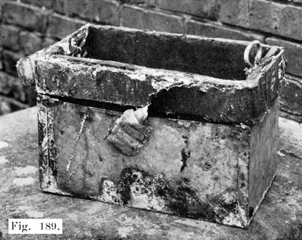
Fig. 189. A Blacksmith and Tinsmith Tried Their Hands on This Case, Lower Part Enclosed in Tin, Strap Iron, Covered with Friction Tape, Around The Top.
(g) When the ends of case are bulged. A new case is needed. If the battery has been frozen it should generally be junked. There are some cases on record of a frozen battery having been thawed out and put in serviceable condition by a long charge at a low rate followed by several cycles of discharge and recharge. Generally, at least, a new case, jars, and positives are required.
NOTE: New separators should always be installed, whenever a battery is opened for repairs, unless the separators already in the battery are new, and the trouble for which the battery was opened consists of a leaky jar, a separator left out, or some other trouble which does not require pulling the plates out of mesh.