
SYSTEM BLOCK DIAGRAM
FIGURE 1
The Project Gutenberg EBook of Preliminary Specifications: Programmed Data
Processor Model Three (PDP-3), by Digital Equipment Corporation

This eBook is for the use of anyone anywhere at no cost and with
almost no restrictions whatsoever.  You may copy it, give it away or
re-use it under the terms of the Project Gutenberg License included
with this eBook or online at www.gutenberg.org


Title: Preliminary Specifications: Programmed Data Processor Model Three (PDP-3)
       October, 1960

Author: Digital Equipment Corporation

Release Date: July 20, 2009 [EBook #29461]

Language: English

Character set encoding: ISO-8859-1

*** START OF THIS PROJECT GUTENBERG EBOOK PDP MODEL THREE (PDP-3) ***


Produced by Gerard Arthus, Katherine Ward, and the Online
Distributed Proofreading Team at https://www.pgdp.net
———
PROGRAMMED DATA PROCESSOR
MODEL THREE
(PDP-3)
———
October, 1960
Digital Equipment Corporation
Maynard, Massachusetts
| INTRODUCTION | 1 | |||
| General Description | 1 | |||
| System Block Diagram | 1 | |||
| Electrical Description | 4 | |||
| Mechanical Description | 4 | |||
| Environmental Requirements | 5 | |||
| CENTRAL PROCESSOR | 6 | |||
| Operating Speeds | 6 | |||
| Instruction Format | 6 | |||
| Number System | 7 | |||
| Indexing | 8 | |||
| Indirect Addressing | 8 | |||
| Instruction List | 9 | |||
| Manual Controls | 20 | |||
| STORAGE | 22 | |||
| STANDARD INPUT-OUTPUT | 23 | |||
| Paper Tape Reader | 23 | |||
| Paper Tape Punch | 24 | |||
| Typewriter | 24 | |||
| OPTIONAL INPUT-OUTPUT | 26 | |||
| Sequence Break System | 26 | |||
| High Speed In-Out Channel | 26 | |||
| Magnetic Tape | 27 | |||
| CRT Display | 33 | |||
| Real Time Clock | 33 | |||
| Line Printer | 34 | |||
| UTILITY PROGRAMS | 35 | |||
| FRAP System | 35 | |||
| DECAL System | 35 | |||
| Floating Point Subroutines | 36 | |||
| Maintenance Routines | 37 | |||
| Miscellaneous Routines | 37 | |||
The DEC Programmed Data Processor Model Three (PDP-3) is a high performance, large scale digital computer featuring reliability in operation together with economy in initial cost, maintenance and use. This combination is achieved by the use of very fast, reliable, solid state circuits coupled with system design restraint. The simplicity of the system design excludes many marginal or superfluous features and thus their attendant cost and maintenance problems.
The average internal instruction execution rate is about 100,000 operations per second with a peak rate of 200,000 operations per second. This speed, together with its economy and reliability, recommends PDP-3 as an excellent instrument for complex real time control applications and as the center of a modern computing facility.
PDP-3 is a stored program, general purpose digital computer. It is a single address, single instruction machine operating in parallel on 36 bit numbers. It features multiple step indirect addressing and indexing of addresses. The main memory makes 511 registers available as index registers.
The main storage is coincident current magnetic core modules of 4096 words each. The computer has a built-in facility to address 8 modules and can be expanded to drive 64 modules. The memory has a cycle time of five microseconds.
The flow of information between the various registers of PDP-3 is shown in the System Block Diagram (Fig. 1). There are four registers of 36 bit length. Their functions are described below.
The Memory Buffer is the central switching register. The word coming from or going to memory is retained in this register. In arithmetic operations it holds the addend, subtrahend, multiplicand, or divisor. The left 6 bits of this register communicate with the Instruction Register. The address portion of the Memory Buffer Register communicates with the Index Adder, the Memory Address Register,-2- and the Program Counter. In certain instructions, the address portion of the control word does not refer to memory but specifies variations of an instruction, thus, the address portion of the Memory Buffer is connected to the Control Element.
The Accumulator is the main register of the Arithmetic Element. Sums and differences are formed in the Accumulator. At the completion of multiplication it holds the high order digits of the product. In division it initially contains the high order digits of the dividend and is left with the remainder.
The logical functions AND, inclusive OR, and exclusive OR, are formed in the Accumulator.
The Carry Storage Register facilitates high-speed multiply and is properly part of the Accumulator.
The In-Out Register is the main path of communication with external equipment. It is also part of the Arithmetic Element. In multiplication it ends with the low order digits of the product. In division it starts with the low order parts of the dividend and ends with the quotient.
The In-Out Register has a full set of shifting properties, (arithmetic and logical).
There are three registers of 15 bit length which deal exclusively with addresses. The design allows for expansion to 18 bits. These registers are:
The Memory Address Register holds the number of the memory location that is currently being interrogated. It receives this number from the Program Counter, the Index Adder or the Memory Buffer.
The Program Counter holds the memory location of the next instruction to be executed.
The Index Adder is a 15 bit ring accumulator. The sum of an instruction base address, Y, and the contents of an index register, C(x), are formed in this register. This register holds the previous content of the Program Counter in the "jump and save Program Counter," jps, instruction. The Index Adder also serves as the step counter in shift, multiply, and divide.
The Control Element contains two six bit registers and several miscellaneous flip-flops. The latter deal with indexing, indirect addressing, memory control, etc. The six bit registers are:
The Instruction Register receives the first six bits of the Memory Buffer Register during the cycle which obtains the instruction from memory (cycle zero). This information is the primary input to the Control Element.
The six Program Flags act as convenient program switches. They are used to indicate separate states of a program. The program can set, clear, or sense the individual flip-flops. The program can also sense or make the state "All Flags ZERO." They can also be used to synchronize various input devices which occur at random times (see Input-Output, Typewriter Input).
Three toggle switch registers are connected to the Central Processor (see Manual Controls).
The fifteen Test Address Switches are used to indicate start points and to select memory registers for manual examination or change.
The thirty-six Test Word Switches indicate a new number for manual deposit into memory. They may also be used for insertion of constants while a program is operating by means of the operate instruction.
The six Sense Switches allow the operator to manually select program options or cause a jump to another program in memory. The program can sense individual switches or the state "All Switches ZERO."
The PDP-3 circuitry is the static type using saturating transistor flip-flops and, for the most part, transistor switch elements. The primary active elements are Micro-Alloy and Micro-Alloy-Diffused transistors. The flip-flops have built-in delay so that a logic net may be sampled and changed simultaneously.
Machine timing is performed by a delay line chain. Auxiliary delay line chains time the step counter instructions (multiply, divide, etc.). The machine is thus internally synchronous with step counter instructions being asynchronous. The machine is asynchronous for in-out operations, that is, the completion of an in-out operation initiates the following instruction.
The PDP-3 consists of two mechanical assemblies, the Console and the Equipment Frame. Fig. 3 is a photograph of PDP-1 which is an 18 bit version of PDP-3.
The Console is a desk approximately seven feet long. It contains the controls and indicators necessary for operation and maintenance of the machine. A cable connects the Console to the Equipment Frame.
The Equipment Frame is approximately six feet high and two feet deep. The length is a function of the amount of optional features included. The Central Processor requires a length of five and one half feet. The power cabinet is twenty-two inches long. A memory cabinet is thirty-two inches long and will hold three memory modules (12,288 words per cabinet). Memory cabinets may be added at any time.
Magnetic tape units require twenty-two inches per transport. A tape unit cabinet may be connected as an extension of the Equipment Frame or may be a free-standing frame.
The PDP-3 requires no special room preparation. The computer will operate properly over the normal range of room temperature.
The Central Processor and memory together require thirty amperes of 110 volts single phase 60 cycle ac. Each inactive tape transport requires two amperes and the one active transport requires 10 amperes.
The Central Processor of PDP-3 contains the Control Element, the Memory Buffer Register, the Arithmetic Element, and the Memory Addressing Element. The Control Element governs the complete operation of the computer including memory timing, instruction performance, and the initiation of input-output commands. The Arithmetic Element, which includes the Accumulator, the In-Out Register, and the Carry Storage Register, performs the arithmetic operations. The Memory Addressing Element which includes the Index Adder, the Program Counter, and the Memory Address Register, performs address bookkeeping and modification.
Operating times of PDP-3 instructions are normally multiples of the memory cycle of 5 microseconds. Two cycle instructions refer twice to memory and thus require 10 microseconds for completion. Examples of this are add, subtract, deposit, load, etc. One cycle instructions do not refer to memory and require 5 microseconds. Examples of the latter are the jump instructions, the skip instructions, and the operate group. The operating times of variable cycle instructions depend upon the instruction. For example, the operating time for a shift or rotate instruction is 5 +0.2N microseconds, where N is the number of shifts performed. The operating times for multiply and divide are functions of the number of ones in the multiplier and in the quotient, respectively. Maximum time for multiply is 25 microseconds. This includes the time necessary to get the multiply instruction from memory. Divide takes 90 microseconds maximum.
In-Out Transfer instructions that do not include the optional wait function require 5 microseconds. If the in-out device requires a wait time for completion, the operating time depends upon the device being used.
If an instruction includes reference to an index register, an additional 5 microseconds is required. Each step of indirect addressing also requires an additional 5 microseconds.
The instructions for PDP-3 may be divided into three classes:-7-
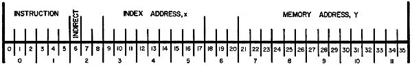
The layout of the instruction word is shown in Fig. 2.
The octal digits 0 and 1 define the instruction code, thus, there are 64 possible instruction codes, not all of which are used. The first bit of octal digit 2 is the indirect address bit. If this bit is a ONE, indirect addressing occurs.
The index address, X, is in octal digits 3, 4, and 5. These digits address an index register for memory-type instructions. If these digits are all ZERO, indexing will not take place. In main memory, 511 of the registers can be used as automatic index registers.
The instruction base address, Y, is in octal digits 7 through 11. These digits are sufficient to address 32,768 words of memory. Octal digit 6 is reserved for further memory expansion. Space is available in the equipment frame for this expansion, should it prove desirable.
In those instructions which do not refer to memory, the memory address digits, Y, and in some cases the index address digits also, are used to specify the variations in any group of instructions. An example of this is in the shift and rotate instructions in which the memory address digits determine the number of shifts.
The PDP-3 is a "fixed" point machine using binary arithmetic. Negative numbers are represented as the 1's complement of the positive numbers. Bit 0 is the sign bit which is ZERO for positive numbers. Bits 1 to 35 are magnitude bits with bit 1 being the most significant and bit 35 being the least significant.
The actual position of the binary point may be arbitrarily assigned to best suit the problem in hand. Two common conventions in the placement of the binary point are:
-8- The conversion of decimal numbers into the binary system for use by the machine may be performed automatically by subroutines. Similarly the output conversion of binary numbers into decimals is done by subroutine. Operations for floating point numbers are handled by programming. The utility program system provides for automatic insertion of the routines required to perform floating point operations and number base conversion (see Utility Programs).
In PDP-3, 511 registers of the main magnetic core memory are available for use as automatic index registers. Their addresses are specified by octal digits 3 to 5 of the instruction word. These registers are memory locations 001-777 (octal). Address 000 specifies that no index register is to be used with the instructions. The contents of octal digits 7 through 11 of the selected index register are added to the unmodified address (octal digits 7 through 11 of the instruction).
This sum is used to locate the operand. The addition is done in the Index Adder which is a 15 bit 1's complement adder. The contents of the Accumulator and the In-Out Register are unaffected by the indexing process. An instruction which has used indexing is retained in memory with its original address unmodified. Memory registers 1-777 (octal) are available for use as normal memory registers if they are not being used as index registers. The left half of these registers is available for the storage of constants, tables, etc., when octal digits 7 through 11 act as index registers.
Three special instructions snx, spx and lir, are available to facilitate resetting, advancing, and sampling of the index registers. Since the index registers are normal memory registers, their contents can also be manipulated by the standard computer instructions.
An instruction which is to use an indirect address will have a ONE in bit six of the instruction word. The original address, Y, of the instruction will not be used to locate the operand of the instruction, as is the normal case. Instead, it is used to locate a memory register whose contents in octal digits 7 through 11 will be used as the address of the original instruction. This new address is known as the indirect address for the instruction and will be used -9-to locate the operand. If the memory register containing the indirect address also has a 1 in bit six, the indirect addressing procedure is repeated again and a third address is located. There is no limit to the number of times this process can be repeated.
Index registers may be used in conjunction with indirect addressing. In this case, the address after being modified by the selected index register is used to locate the indirect address.
The indirect address can be acted on by an index register and deferred again if desired. Each use of an index register or an indirect address extends the operating time of the original instruction by 5 microseconds.
This list includes the title of the instruction, the normal execution time of the instruction, i.e., the time with no indexing and no deferring, the mnemonic code of the instruction, and the operation code number. The notation used requires the following definitions. The contents of a register Q are indicated as C(Q). The address portion of the instruction is indicated by Y. The index register address of an instruction is indicated by x. The effective address of an operand is indicated by Z. Z may be equal to Y or it may be Y as modified by deferring or by indexing.
Add(10 usec.)
add x Y Operation Code 40
The new C(AC) are the sum of C(Z) and the original C(AC). The C(Z) are unchanged. The addition is performed with 1's complement arithmetic.
If the sum exceeds the capacity of the Accumulator Register, the overflow flip-flop will be set (see Skip Group instructions).
Subtract(10 usec.)
sub x Y Operation Code 42
The new C(AC) are the original C(AC) minus the C(Z). The C(Z) are unchanged. The subtraction is performed using 1's complement arithmetic.
-10- If the difference exceeds the capacity of the Accumulator, the overflow flip-flop will be set (see Skip Group instructions).
Multiply(approximately 25 usec.)
mul x Y Operation Code 54
The C(AC) are multiplied by the C(Z). The most significant digits of the product are left in the Accumulator and the least significant digits in the In-Out Register. The previous C(AC) are lost.
Divide(approximately 90 usec.)
div x Y Operation Code 56
The Accumulator and the In-Out Register together form a 70 bit dividend. The high order part of the dividend is in the Accumulator. The low order part of the dividend is in the In-Out Register. The divisor is (Z).
Upon completion of the division, the quotient is in the In-Out Register. The remainder is in the Accumulator. The sign of the remainder is the same as the sign of the dividend. If the dividend is larger than C(Z), the overflow flip-flop will be set and the division will not take place.
Logical AND(10 usec.)
and x Y Operation Code 02
The bits of C(Z) operate on the corresponding bits of the Accumulator to form the logical AND. The result is left in the Accumulator. The C(Z) are unaffected by this instruction.
Logical AND Function Table
| AC Bit | C(Z) Bit | Result |
| 0 | 0 | 0 |
| 0 | 1 | 0 |
| 1 | 0 | 0 |
| 1 | 1 | 1 |
Exclusive OR(10 usec.)
xor x Y Operation Code 06
-11- The bits of C(Z) operate on the corresponding bits of the Accumulator to form the exclusive OR. The result is left in the Accumulator. The C(Z) are unaffected by this order.
Exclusive OR Table
| AC Bit | C(Z) Bit | Result |
| 0 | 0 | 0 |
| 0 | 1 | 1 |
| 1 | 0 | 1 |
| 1 | 1 | 0 |
Inclusive OR(10 usec.)
ior x Y Operation Code 04
The bits of C(Z) operate on the corresponding bits of the Accumulator to form the inclusive OR. The result is left in the Accumulator. The C(Z) are unaffected by this order.
Inclusive OR Table
| AC Bit | C(Z) Bit | Result |
| 0 | 0 | 0 |
| 0 | 1 | 1 |
| 1 | 0 | 1 |
| 1 | 1 | 1 |
Load Accumulator(10 usec.)
lac x Y Operation Code 20
The C(Z) are placed in the Accumulator. The C(Z) are unchanged. The original C(Z) are lost.
Deposit Accumulator(10 usec.)
dac x Y Operation Code 24
The C(AC) replace the C(Z) in the memory. The C(AC) are left unchanged by this instruction. The original C(Z) are lost.
-12-
Deposit Address Part(10 usec.)
dap x Y Operation Code 26
Octal digits 6 through 11 of the Accumulator replace the corresponding digits of memory register Z.
C(AC) are unchanged as are the contents of octal digits 0 through 5 of Z. The original contents of octal digits 6 through 11 of Z are lost.
Deposit Instruction Part(10 usec.)
dip x Y Operation Code 30
Octal digits 0 through 5 of the Accumulator replace the corresponding digits of memory register Z. The Accumulator is unchanged as are digits 6 through 11 of Z. The original contents of octal digits 0 through 5 of Z are lost.
Load In-Out Register(10 usec.)
lio x Y Operation Code 22
The C(Z) are placed in the In-Out Register. C(Z) are unchanged. The original C(IO) are lost.
Deposit In-Out Register(10 usec.)
dio x Y Operation Code 32
The C(IO) replace the C(Z) in memory. The C(IO) are unaffected by this instruction. The original C(Z) are lost.
Jump(5 usec.)
jmp x Y Operation Code 60
The Program Counter is reset to address Z. The next instruction that will be executed will be taken from memory register Z. The original contents of the Program Counter are lost.
Jump and Save Program Counter(5 usec.)
jsp x Y Operation Code 62
The contents of the Program Counter are transferred to the Index Adder. When the transfer takes place, the Program Counter holds the address of the instruction following the jsp. The Program Counter is then reset to address Z. The next instruction that will be executed will be taken from memory register Z.
-13-
Skip if Accumulator and Z differ(10 usec.)
sad x Y Operation Code 50
The C(Z) are compared with the C(AC). If the two numbers are different, the Program Counter is indexed one extra position and the next instruction in the sequence is skipped. The C(AC) and the C(Z) are unaffected by this operation.
Skip if Accumulator and Z are the same(10 usec.)
sas x Y Operation Code 52
The C(Z) are compared with C(AC). If the two numbers are identical, the Program Counter is indexed one extra position and the next instruction in the sequence is skipped. The C(AC) and C(Z) are unaffected by this operation.
These instructions have the same word format as the indexable instructions. Since they operate on the index register location, x, they cannot be indexed.
Skip on Negative index(10 usec.)
snx x Y Operation Code 46
The number in octal digits 7 through 11 of the instruction word is added to the C(x). This addition is done in the 15 bit Index Adder using 1's complement arithmetic. If, after the addition, the sum is negative, the Program Counter is advanced one extra position and the next instruction in the sequence is skipped. The contents of octal digits 0-5 of the index register location are unaffected by this instruction.
Skip on Positive index(10 usec.)
spx x Y Operation Code 44
The number in octal digits 7 through 11 of the instruction word is added to the C(x). This addition is done in the 15 bit Index Adder using 1's complement arithmetic.
If, after the addition, the sum is positive, the Program Counter is advanced one extra position and the next instruction in the sequence is skipped. The contents of octal digits 0-5 of the index register location are unaffected by this instruction.
-14-
Load Index Register(10 usec.)
lir x Y Operation Code 14
The octal digits 7 through 11 (Y) of the instruction will replace the corresponding digits of the memory register specified by x. Octal digit 6 of the memory register will be left clear. Digits 0-5 of the memory register are unchanged.
Deposit Index Adder(10 usec.)
dia x Y Operation Code 16
The C(IA) replace the octal digits 7 through 11 of memory location Y. Octal digit 6 of Y is cleared. Digits 0 through 5 of Y are left unchanged. The x portion of the instruction is ignored.
This group of instructions will rotate or shift the Accumulator and/or the In-Out Register. When the two registers operate combined, the In-Out Register is considered to be a 36 bit magnitude extension of the right end of the Accumulator.
Rotate is a non-arithmetic cyclic shift. That is, the two ends of the register are logically tied together and information is rotated as though the register were a ring.
Shift is an arithmetic operation and is in effect multiplication of the number in the register by 2+N, where N is the number of shifts. Shift or rotate instructions involving more than 33 steps can be used for simulating time delays. 36 rotate steps of the Accumulator will return all information to its original position.
Rotate Accumulator Right(13 usec. maximum for 36 shifts)
rar N Operation Code 671
This instruction will rotate the bits of the Accumulator right N positions, where N is octal digits 7-11 of the instructions word.
-15-
Rotate Accumulator Left(13 usec. maximum for 36 shifts)
ral N Operation Code 661
This instruction will rotate the bits of the Accumulator left N Positions, where N is octal digits 7-11 of the instruction word.
Shift Accumulator Right(13 usec. maximum for 36 shifts)
sar N Operation Code 675
This instruction will shift the contents of the Accumulator right N positions, where N is octal digits 7-11 of the instruction word.
Shift Accumulator Left(13 usec. maximum for 36 shifts)
sal N Operation Code 665
This instruction will shift the contents of the Accumulator left N positions, where N is octal digits 7-11 of the instruction word.
Rotate In-Out Register Right(13 usec. maximum for 36 shifts)
rir N Operation Code 672
This instruction will rotate the bits of the In-Out Register right N positions, where N is octal digits 7-11 of the instruction word.
Rotate In-Out Register Left(13 usec. maximum for 36 shifts)
ril N Operation Code 662
This instruction will rotate the bits of the In-Out Register left N positions, where N is octal digits 7-11 of the instruction word.
Shift In-Out Register Right(13 usec. maximum for 36 shifts)
sir N Operation Code 676
This instruction will shift the contents of the In-Out Register right N positions, where N is octal digits 7-11 of the instruction word.
Shift In-Out Register Left(13 usec. maximum for 36 shifts)
sil N Operation Code 666
-16- This instruction will shift the contents of the In-Out Register left N positions, where N is octal digits 7-11 of the instruction word.
Rotate AC and IO Right(13 usec. maximum for 36 shifts)
rcr N Operation Code 673
This instruction will rotate the bits of the combined register right in a single ring N positions, where N is octal digits 7-11 of the instruction word.
Rotate AC and IO Left(13 usec. maximum for 36 shifts)
rcl N Operation Code 663
This instruction will rotate the bits of the combined register left in a single ring N position, where N is octal digits 7-11 of the instruction word.
Shift AC and IO Right(13 usec. maximum for 36 shifts)
scr N Operation Code 677
This instruction will shift the contents of the combined register right N positions, where N is octal digits 7-11 of the instruction word.
Shift AC and IO Left(13 usec. maximum for 36 shifts)
scl N Operation Code 667
This instruction will shift the contents of the combined registers left N positions, where N is octal digits 7-11 of the instruction word.
Skip Group(5 usec.)
skp Y Operation Code 64
This group of instructions senses the state of various flip-flops and switches in the machine. It does not require any reference to memory. The address portion of the instruction selects the particular function to be sensed. All members of this group have the same operation code.
Skip on ZERO Accumulator(5 usec.)
sza Address 100
-17- If the Accumulator is equal to plus ZERO (all bits are ZERO) the Program Counter is advanced one extra position and the next instruction in the sequence is skipped.
Skip on Plus Accumulator(5 usec.)
spa Address 200
If the sign bit of the Accumulator is ZERO, the Program Counter is advanced one extra position and the next instruction in the sequence is skipped.
Skip on Minus Accumulator(5 usec.)
sma Address 400
If the sign bit of the Accumulator is ONE, the Program Counter is advanced one extra position and the next instruction in the sequence is skipped.
Skip on ZERO Overflow(5 usec.)
szo Address 1000
If the overflow flip-flop is a ZERO the Program Counter is advanced one extra position and the next instruction in the sequence will be skipped. The overflow flip-flop is cleared by this instruction. This flip-flop is set by addition, subtraction, or division that exceeds the capacity of the Accumulator. The overflow flip-flop is not cleared by arithmetic operations which do not cause an overflow. Thus, a whole series of arithmetic operations may be checked for correctness by a single szo. The overflow flip-flop is cleared by the "Start" Switch.
Skip on Plus In-Out Register(5 usec.)
spi Address 2000
If the sign digit of the In-Out Register is ZERO the Program Counter is indexed one extra position and the next instruction in the sequence is skipped.
Skip on ZERO Switch(5 usec.)
szs Addresses 10, 20, ... 70
If the selected Sense Switch is ZERO, the Program Counter is advanced one extra position and the next instruction in the-18- sequence will be skipped. Address 10 senses the position of Sense Switch 1, Address 20 Switch 2, etc. Address 70 senses all the switches. If 70 is selected all 6 switches must be ZERO to cause the skip to occur.
Skip on ZERO Program Flag(5 usec.)
szf Addresses 0 to 7 inclusive
If the selected program flag is a ZERO, the Program Counter is advanced one extra position and the next instruction in the sequence will be skipped. Address 0 is no selection. Address 1 selects program flag one, etc. Address 7 selects all programs flags. All flags must be ZERO to cause the skip.
The instructions in the One Cycle Skip group may be combined to form the inclusive OR of the separate skips. Thus, if address 3000 is selected, the skip would occur if the overflow flip-flop equals ZERO or if the In-Out Register is positive. The combined instruction would still take 5 microseconds.
Operate Group(5 usec.)
opr Y Operation Code 76
This instruction group performs miscellaneous operations on various Central Processor Registers. The address portion of the instruction specifies the action to be performed.
Clear In-Out Register(5 usec.)
cli Address equal 4000
This instruction clears the In-Out Register.
Load Accumulator from Test Word(5 usec.)
lat Address 2000
This instruction forms the inclusive OR of the C(AC) and the contents of the Test Word. This instruction is usually combined with address 200 (clear Accumulator), so that C(AC) will equal the contents of the Test Word Switches.
Complement Accumulator(5 usec.)
cma Address 1000
This instruction complements (makes negative) the contents of the Accumulator.
-19-
Halt
hlt Address 400
This instruction stops the computer.
Clear Accumulator(5 usec.)
cla Address 200
This instruction clears (sets equal to plus 0) the contents of the Accumulator.
Clear Selected Program Flag(5 usec.)
clf Address 01 to 07 inclusive
The selected program flag will be cleared. Address 00 selects no program flag, 01 clears program flag 1, 02 clears program flag 2, etc. Address 07 clears all program flags.
Set Selected Program Flag(5 usec.)
stf Address 11 to 17 inclusive
In-Out Transfer Group(5 usec. without in-out wait)
iot x Y Operation Code 72
The variations within this group of instructions perform all the in-out control and information transfer functions. If bit six (normally the Indirect Address bit) is a ONE, the computer will halt and wait for the completion pulse from the device activated. When this device delivers its completion, the computer will resume operation of the instruction sequence.
An incidental fact which may be of importance in certain scientific or real time control applications is that the time origin of operations following an in-out completion pulse is identical with the time of that pulse.
Most in-out operations require a known minimum time before completion. This time may be utilized for programming. The appropriate In-Out Transfer is given with no in-out wait (bit six a ZERO). The instruction sequence then continues. This sequence must include an iot instruction which performs nothing but the in-out wait. This last instruction must occur before the safe minimum time. A table of minimum times for all in-out devices is delivered with-20- the computer. It lists minimum time before completion pulse and minimum In-Out Register free time.
The details of the In-Out Transfer variations are listed under Input-Output.
The mnemonic codes and addresses for the standard equipment are:
Read Paper Tape Alphanumeric Mode
rpa Address 1
Read Paper Tape Binary Mode
rpb Address 2
Typewriter Output
tyo Address 3
Typewriter Input
tyi Address 4
Punch Paper Tape Alphanumeric Mode
ppa Address 5
Punch Paper Tape Binary Mode
ppb Address 6
The Console of PDP-3 has controls and indicators for the use of the operator. Fig. 4 is a close-up of the control panel of PDP-1, the 18 bit version of PDP-3. All computer flip-flops have indicator lights on the Console. These indicators are primarily for use when the machine has stopped or when the machine is being operated one step at a time. While the machine is running, the brightness of an indicator bears some relationship to the relative duty factor of that particular flip-flop.
Three registers of toggle switches are available on the Console. These are the Test Address (15 bits), the Test Word (36 bits), and the Sense Switches (6 bits). The first two are used in conjunction with the operating push buttons. The Sense Switches are present for manual intervention. The use of these switches is determined by the program (see System Block Diagram and Skip Group Instructions).
Start — When this switch is operated, the computer will start. The first instruction comes from the memory location indicated in the Test Address Switches.
Stop — The computer will come to a halt at the completion of the current memory cycle.
Continue — The computer will resume operation starting at the state indicated by the lights.
Examine — The contents of the memory register indicated in the Test Address will be displayed in the Accumulator and the Memory Buffer lights.
Deposit — The word selected by the Test Word Switches will be put in the memory location indicated by the Test Address Switches.
Read-In — When this switch is operated, the photoelectric paper tape reader will start operating in the Read-In mode. (see Input-Output).
In addition to the operating push buttons, there are several separate toggle switches.
Single Cycle Switch — When the Single Cycle Switch is on, the computer will halt at the completion of each memory cycle. This switch is particularly useful in debugging programs. Repeated operation of the Continue Switch button will step the program one cycle at a time. The programmer is thus able to examine the machine states at each step.
Test Switch — When the Test Switch is on, the computer will perform the instruction indicated in the Test Address location. It will repeat this instruction either at the normal speed rate or at a single cycle rate if the Single Cycle Switch is up. This switch is primarily useful for maintenance purposes.
Sense Switches — There are six switches on the Console which are present for manual intervention.
The internal Memory System for PDP-3 consists of modules of 4096 words of coincident current magnetic core storage. Each word has 36 bits. The memory modules operate with a read-rewrite cycle time of 5 microseconds. The driving currents of the memory are automatically adjusted to compensate for normal room temperature variations.
Each core memory module consists of the memory stack, the required X and Y switches, the X and Y current sources and sense amplifiers for that stack.
The Memory Address Register, the Memory Buffer Register, and the Memory Timing Controls are considered to be part of the Central Processor. The standard PDP-3 Memory Address Register configuration is built to allow up to 8 modules of core memory (32,768 words). There is a space in the addressing section of the machine to allow expansion of the addressing by a factor of eight for a total addressing capacity of 262,144 memory registers.
The Core Memory may be supplemented by Magnetic Tape Storage. This is described under Input-Output.
The PDP-3 is designed to accommodate a variety of input-output equipment. Standard input-output units include a Paper Tape Reader, Paper Tape Punch and an Electric Typewriter.
A single instruction, In-Out Transfer (see Central Processor), performs all in-out operations through the 36 bit In-Out Register. The address portion of this instruction specifies the in-out function. One bit of the instruction selects an in-out halt as required.
The Paper Tape Reader of the PDP-3 is a photoelectric device capable of reading 300 lines per second. Six lines form the standard 36 bit word when reading binary punched eight hole tape. Five, six and seven hole tape may also be read.
The reader will operate in one of two basic modes or in a third special mode.
Alphanumeric Mode
rpa iot 1
In this mode, one line of tape is read for each In-Out Transfer. All eight holes of the line are read. The information is left in the right eight bits of the In-Out Register, the remainder of the register being left clear. The standard PDP alphanumeric paper tape code includes an odd parity bit which may be checked by the program. Tape of non-standard width would be read in this mode.
Binary Mode
rpb iot 2
For each In-Out Transfer instruction, six lines of paper tape are read and assembled in the In-Out Register to form a full computer word. For a line to be recognized in this mode, the eighth hole must be punched; i.e., lines with no eighth hole will be skipped over. The seventh hole is ignored. The pattern of holes in the binary tape is arranged so as to be easily interpreted visually in terms of machine instruction.
-24- Read-In Mode
This is a special mode activated by the "Read-In" Switch on the Console. It provides a means of entering programs which neither rely on read-in programs in memory nor require a plug board. Pushing the "Read-In" Switch starts the reader in the binary mode. The first group of six lines and alternate succeeding groups of six lines are interpreted as "Read-In" mode instructions. Even-numbered groups of 6 lines are data. The "Read-In" mode instructions must be either "deposit in-out" (dio Y) or "jump" (jmp Y). If the instruction is dio Y, the next group of six binary lines will be stored in memory location Y and the reader continues moving. If the instruction is jmp Y, the "Read-In" mode is terminated and the computer will commence operation at the address of the jump instruction.
The standard PDP-3 Paper Tape Punch has a nominal speed of 20 lines per second. It can operate in either the alphanumeric mode or the binary mode.
Alphanumeric Mode
ppa iot 5
For each In-Out Transfer instruction one line of tape is punched. In-Out Register bit 35 conditions hole #1. Bit 34 conditions hole #2, etc. Bit 28 conditions hole #8.
Binary Mode
ppb iot 6
For each In-Out Transfer instruction one line of tape is punched. In-Out Register bit five conditions hole #1. Bit four conditions hole #2, etc. Bit zero conditions hole #6. Hole #7 is left blank. The #8 hole is always punched in this mode.
The Typewriter will operate in the input mode or the output mode.
-25-
Output Mode
tyo iot 3
For each In-Out Transfer instruction one character is typed. The character is specified by the right six bits of the In-Out Register.
Input Mode
tyi iot 4
This operation is completely asynchronous and is therefore handled differently than any of the preceding in-out operations.
When a Typewriter key is struck, Program Flag Number One is set. At the same time the code for the struck key is presented to gates connected to the right six bits of the In-Out Register. This information will remain at the gate for a relatively long time by virtue of the slow mechanical action. A program designed to accept typed-in data would periodically check the status of Program Flag One. If at any time Program Flag One is found to be set, an In-Out Transfer instruction with address four must be executed for information to be transferred. This In-Out Transfer normally should not use the optional in-out halt. The information contained in the Typewriter's coder is then read into the right six bits of the In-Out Register.
The PDP-3 is designed to accommodate a variety of input-output equipment. Of particular interest is the ease with which new, and perhaps unusual, external equipment can be added to the machine. Optional in-out devices include Cathode Ray Tube Display, Magnetic Tape, Real Time Clock, Line Printer and Analog to Digital Converters. The method of operation of PDP-3 with these optional devices is similar to the standard input-output equipment.
An optional in-out control is available for PDP-3. This control, termed the Sequence Break System, allows concurrent operation of several in-out devices and the main sequence. The system has, nominally, 16 automatic interrupt channels arranged in a priority chain.
A break to a particular sequence may be initiated by the completion of an in-out device, the program, or an external signal. If this sequence has priority, the C(AC), C(IO), C(PC), and C(IA) are stored in three fixed memory locations unique to that sequence. Since the C(PC) and C(IA) are eighteen bits each, these two registers are stored in one memory location. The next instruction is taken from a fourth location. This instruction is usually a jump to a suitable routine. The program is now operating in the new sequence. This new sequence may be broken by a higher priority sequence. A typical program loop for handling an in-out sequence would contain 3 to 5 instructions, including the appropriate iot. These are followed by load AD and load IO from the fixed locations and a special indirect jump through the location of the previous C(PC). This special jump also loads the IA. This last instruction terminates the sequence.
The device connected to an in-out channel communicates directly with memory through the Memory Buffer Register. At the completion of each machine instruction, a check is made to see if the in-out channel has a word for, or needs a word from, the memory. When necessary, a memory cycle is taken to serve the channel. The operation is initiated by an in-out command. The in-out transfer command indicates the nature of the transfer. The left half of-27- the In-Out Register must contain the starting address of the transfer, and the right half must contain the number of words to be transferred. If the Sequence Break System is connected, the completion of the transfer will signal the proper sequence. If no Sequence Break System is connected, the completion of the in-out channel transfer sets a program flag.
The system consists of tape units connected to the PDP-3 through a tape control (TC). This tape is read or written in IBM 729I format. Two hundred characters, each having 6 bits plus a parity bit, are written on each inch of tape and the tape moves at 75 inches/sec. The tape control has the job of connecting a specific unit to the PDP-3 and is a switch. It also has the function of controlling the format of information that is read or written on tape. In-out class commands instruct TC to the type of information transfer and select the tape unit. Another IOT command synchronizes the transfer of information through the TC to the computer.
The IOT order to select the unit and function is decoded as follows: 1) Three bits specify the function of TC. 2) The remaining 6 bits select the unit.
IOT Motion Commands for Magnetic Tape Units
| IOT Code | Abbreviation | Function |
| 73....nn 60 | mrb | Read a binary record. |
| 73....nn 61 | mra | Read an alphanumeric (BCD) record. |
| 73....nn 62 | mbb | Backspace a binary record. |
| 73....nn 63 | mba | Backspace an alphanumeric record. |
| 73....nn 64 | mwb | Write a binary record. |
| 73....nn 65 | mwa | Write an alphanumeric record. |
| 73....nn 66 | mlp | Move tape to lead point (rewind). |
Where the octal digits, nn, specify the unit number.
The motion commands have the deferred bit, thus, the program halts. If the TC is free, the command will be transferred to the tape control for action and the program restarts immediately. If the tape control is currently busy with an instruction, i.e., it hasn't finished a previous command, the motion command is held up until TC is free to execute the new command.
-28- The transfer of information from the computer to the TC is accomplished with the pause and skip command, MPS or IOT 70. This command has the deferred bit and halts a program until the TC can handle the transfer. On completion, the transfer occurs and the program restarts. This is used exclusively to synchronize the flow of information between a tape unit and the computer. This command normally skips the following instruction. If a flag is set in the TC, indicating incorrect information flow, the skip does not take place.
The TC contains a 36 bit buffer which holds a complete word while information is read or written. When an MPS order is given and the unit is reading, the TC buffer is read into the IO. The MPS order given during writing causes the IO to be transferred to the TC buffer.
Various conditions occurring in the TC cause the no-skip condition, when an MPS is given. Tape control flags are examined by the command, examine and clear flags, MEC or IOT 71. When MEC is given, the flags are put into the IO for program interrogation, and the flags cleared. The flags are: parity, end of tape, an end of record flag, and reading-writing check.
The parity flag is set if the parity condition is not met while the tape is being read (during MWA, MWB, MRA, or MRB).
The end of tape flag is set when the tape comes to the end of tape, moving in either direction.
Three conditions set the read-write check flag: 1) If TC is inactive, i.e., no unit or function selected, and an MPS instruction is given. The MPS becomes a no-operation, no-halt instruction. 2) When reading information and not emptying the TC buffer, by giving an MPS before more information arrives from tape. 3) A unit becomes unavailable during a normal sequence.
The end of record flag is set during reading or backspacing when the tape comes to an end of record gap.
Writing a Record of Information
Information is written on the tape by giving a MWB or MWA command. This sets a write binary or a write alphanumeric into the TC and-29- selects the unit. A motion select command is executed immediately if the TC is free, otherwise, the command waits until it can be executed. Normal programming can continue after the MWA or MWB is given for approximately 5 milliseconds. At this time, an MPS order is given and the program pauses until information can be written. When the MPS is restarted, information is transferred to the TC buffer from the IO. If no flags have been set, the following instruction is skipped.
Three-quarter inches of blank tape is written by giving either the MWA or MWB order. An end of file is written as follows: 1) Four MWA commands write three inches of blank tape. 2) Then end of file character is written by giving the MPS order.
Information is read and checked for correct parity while writing.
If too many program steps are given between the motion select command, MWA or MWB and the first MPS, the unit will deselect (or disconnect). The MPS is then a no-operation command.
Writing Program
As an example, a program to write k words in binary format from storage beginning in register A, using tape unit number 04, is shown. The following program is written in standard FRAP language. The program begins in register enterwrite.
| enterwrite | mec | ,clear flags initially |
| mwb 400 | ,73000000464 | |
| lir x/-k+1 | ,initialize index register x | |
| b | lio x/a+k-1 | ,begin loop |
| mps | ,wait for TC then write C(Z) | |
| jmp c | ,error | |
| spx x/1 | ,add 1 to index register x | |
| jmp b | ,return of loop | |
| jmp done | ,record written | |
| c | mec | ,tape error |
| ril 1 | ||
| spi | ||
| jmp rwcstop | ,read-write error or tape fault | |
| ril 1 | ||
| spi | ||
| jmp b+3 | ,tape end | |
| hlt | ,tape parity | |
| done | ,resume programming |
Reading Information
Information is read by giving the MRA or MRB order. Almost 10 ms. is available after a read order is given before information actually enters the TC buffer.
To read a record of unknown length, the read order is first given. The MPS order halts the program until six characters are assembled in the TC information buffer. The next instruction after the MPS, a jump instruction, transfers control from the loop when any flag is set. The next instruction deposits the IO. The record length is determined by not skipping after the MPS order on the setting of the end of record flag. The read-write check flag or the end of record flag is then interrogated to see that the tape is actually at the end of record. If a tape is not at the end of record, then the tape is either at the end of the reel, or a parity check has occurred.
Reading Program
Program to read j binary words into storage beginning in register d, using tape unit 10, j is unknown. The program begins in register enteread.
| enteread | mec | ,clear flags initially |
| mrb 1000 | ,730000001060 | |
| dzm x | ,put zero in memory location x | |
| e | mps | |
| jmp outcheck | ||
| dio x/d | ,store in location modified by x | |
| snx x/+1 | ,add 1 to C(x) | |
| jmp e | ||
| outcheck | mec | ,examine flags |
| spi | ,end of record? | |
| jmp recordend | ,yes | |
| hlt | ,error | |
| recordend | snx x/+1 | ,to find value of j |
| " | ,resume programming C(IA) = j | |
| " | ||
| " | ||
| " |
Forward Spacing
Forward spacing is done by giving an MRB or MRA order. This moves the tape forward with the read-write head positioned at the end of the following record. If n read orders are given, the tape is spaced forward n records. By giving the MEC order, parity flags are examined to see that information on tape has been read correctly.
Backspacing
By giving an MBA or MBB order the tape is moved backwards a record with the read-write heads positioned in the previous end of record gap. The end of record flag is set when the tape has moved backwards a record.
Rewinding
Rewinding is accomplished by giving the rewind order, move tape to load point, MLP. The rewind order starts a unit rewinding and does not tie up the TC. If a motion command is given which calls for a unit that is rewinding, the command is executed, but the action will not take place until the unit is available.
Unit Availability
A unit is unavailable to the program under the following conditions:
A selected but unavailable unit holds up the TC if a motion order is given for the unit. The TC will be held up until the unit is ready.
-32- Flag Positions
| IO Bit | Flag |
| 0 | EOR — End of record |
| 1 | RWF — Read-Write |
| 2 | EOT — End of Tape |
| 3 | Parity |
Connection with High Speed Channel
The high speed channel directs the tape control, and word transfer, just as a program would. A unit is first started reading or writing. The high speed channel is given the memory location of the information, and the number of registers the words read or written will occupy. The channel effects the information transfer. Thus, a high speed channel connected to a tape control handles the programming for the unit word transfers.
Completion of the block transfer is signified by either setting a program flag, or entering the sequence break.
Connection with Sequence Break System
When the TC is connected to the Sequence Break System, the program is automatically interrupted each time an MPS command needs to be given.
Programming is unaffected during reading and a record may be read with no flags set. The TC initiates breaks so that an MPS may be given in time.
Similarly, the break is initiated during writing each time an MPS needs to be given.
Motion Command Summary
| Time before first MPS | Time between MPS's | Time after End of Record to deselect | Flags that may be set | |
| MWA MWB |
3 ms. | 400 us. (longer time causes deselection) |
10 ms. | RWF (if unit is deselected and MPS given, or unit becomes unavailable), Parity, EOT. |
| MRA MRB |
7 ms. | 400 us. (longer time misses information, and rwc set) |
5 ms. | RWF, (if information is missed, or unit becomes unavailable), EOT, EOR, Parity. |
| MBA MBB |
— | — | 10 ms. | RWF (if unit becomes unavailable), EOR, EOT. |
The PDP-3 Cathode Ray Tube Display is useful for presentation of graphical or tabular information to the operator. It uses a 16 inch round tube with magnetic deflection. For each In-Out transfer order, one point is displayed at the position indicated by the In-Out Register. Bits 0-9 of the IO indicate the X coordinate of the position, and bits 18-27 indicate the Y coordinate. The display takes 60 microseconds.
An additional display option is a Light Pen. By use of this device the computer is signaled that the operator is interested in the last point displayed. Thus the program can take appropriate action such as changing the display or shifting operation to another program.
A smaller display is available. This display uses a five inch, high resolution cathode ray tube. The tube is equipped with a mounting bezel to accept a camera or photomultiplier device. The operation of this display is similar to that of the 16 inch, except that 12 bits are decoded for each axis.
A special input register may be connected to operate as a Real Time Clock. This is a counting register operated by a crystal controlled oscillator. The clock can be reset to zero by manual operation. A toggle switch interlock prevents an accidental reset. The state of this counter may be read at any time by the appropriate In-Out Transfer instruction.
A 72 column Anelex printer and control are available as an option for PDP-3. The control contains a one line buffer. This buffer is cleared by the completion of an order to space the paper one position (psp). The buffer is filled from the In-Out Register by a succession of 12 load buffer orders (plb). The first plb will put the six characters represented by C(IO) in the leading (left-hand) column positions of the buffer. After the buffer is loaded, the order, print (pnt), is given.
An assembler or compiler prepares a machine language tape suitable for direct interpretation by the computer from a program tape in operator language. Generally speaking, one statement accepted by FRAP produces one instruction for the machine. A single statement written for the PDP-3 compiler, DECAL-3, may cause several instructions to be written. Thus, FRAP causes a 1 for 1 mapping of instructions for statements while DECAL may produce many instructions from one statement.
In addition to allowing program tapes to be prepared with off line equipment, an assembly program has other functions. Normally, the machine would require 36 bits or 12 octal digits to be written for each instruction used in the machine. FRAP allows mnemonic symbols to be used for the instructions. These mnemonic symbols aid the programmer by representing the instruction in an easily remembered form.
In addition to allowing mnemonic symbols to represent the instructions, variable length sequences of alphanumeric characters may be used to represent memory addresses in symbolic form. The assembly program does the address bookkeeping for the programmer. A short example of a FRAP program is on Page 29.
Since few characters limit or control the format of instructions written in FRAP-3 language, it is possible to write instructions in almost any format or style.
FRAP-3 may also be used to prepare tapes for interpretive programming, since arbitrary definitions for operation code symbols are permitted.
A feature useful both for ease of programming and for machine simulation is the ability to call for a series of instructions (macro-instruction) to be written. Frequently used instruction sequences thus need only to be defined once.
DECAL-3 (Digital Equipment Compiler, Assembler, and Linking loader for PDP-3) is an integrated programming system for PDP-3. It-36- incorporates in one system all of the essential features of advanced assemblers, compilers, and loaders.
DECAL is both an assembler and compiler. It combines the one-to-one translation facilities of an assembler, and the one-to-many translation facilities of a formula translation compiler. Problem oriented language statements may be freely intermixed with symbolic machine language instructions. A flexible loader is available to allow the specification of program location at load time. The programmer may specify that certain variables and constants are "systems" variables and constants. The symbols so defined are universally used in a system of many routines. Thus, communications between parts of a major program is facilitated even though these parts may be compiled separately. Storage requirements for a large program are lessened by this technique.
DECAL is an open-ended programming system and can be modified without a detailed understanding of the internal operation. This is achieved by means of a recursive definition facility based on a skeleton compiler with a small set of logical capabilities. The skeleton compiler acts as a bootstrap for introducing more sophisticated facilities.
The compiler will be delivered with a fully defined subset of formula translation operators. Additional subsets may be defined by the user to best fit his source language.
A set of subroutines are provided with the PDP-3 to perform floating point arithmetic. In these, the PDP-3 36 bit word is divided to form a 27 bit mantissa, a, and 9 bit exponent, b. Numbers, thus, appear in the form: k = ax2b where, a, is considered to be in fractional form in the range ½ ≤ a < 1, and b is an integer, 0 ≤ b < 29. This gives number, k, the range 10-76 < k < 10+76.
The subroutines are called with one operand in the accumulator. After the subroutine has been executed, the accumulator contains the answer. Thus floating point numbers are essentially handled as regular logical works. The format of the number allows magnitude comparisons to be made by conventional arithmetic as bit 0 is the sign of the number, bits 1 to 9 the exponent, and the remaining 26 bits, together with the sign bit, the mantissa in-37- ones complement arithmetic. The arithmetic subroutines are: add, subtract, multiply, divide, convert a floating point number to binary, convert a binary number to a floating number. Additional routines form: √x, ex, ln x, sine(π⁄2)x, cos(π⁄2)x, tan-1x. There are also programs to convert between floating decimal numbers and PDP-3 floating numbers.
Routines which require two operands, e.g., add, subtract, multiply and divide, require an index register to specify the address of the second operand. An index register also specifies parameters in data conversions, e.g., the position of the binary point when converting a binary number to a standard floating number.
Using the floating point subroutines, additional routines may be written which handle complex floating numbers and vector and matrix algebra.
Maintenance Routines are used exclusively to check the operation of the machine. These routines are operated while varying the bias supply voltages, and thus a check is made on possible degradation of all components which would affect the operation of the machine.
A variety of additional programs are provided with PDP-3.
One of the more important programs is the Typewriter Interrogator Program (TIP). TIP allows the typewriter to be used most effectively as an input-output link by which programs and data are examined and modified. The features include request for printing of a series of registers, interrogation and modification of the contents of registers, and the ability to request new tapes after programs have been suitably modified. Communication is done completely via the typewriter in either octal numbers, decimal numbers, or alphanumeric codes. Register contents are presented in similar form.
Other miscellaneous routines handle arithmetic processes, e.g., number conversions, and communication with the input or output devices. These routines include various format print outs, paper tape and magnetic tape read in programs, and display subroutines.
SYSTEM BLOCK DIAGRAM
FIGURE 1
INSTRUCTION FORMAT
FIGURE 2
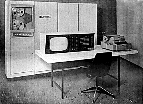
FIGURE 3
Transcriber's Notes
Figure 4 is referred to in the text, but a copy could not be located.
C (X) and C(X) standardized to C(X).
Other changes from the original text are highlighted.
End of the Project Gutenberg EBook of Preliminary Specifications: Programmed
Data Processor Model Three (PDP-3), by Digital Equipment Corporation

*** END OF THIS PROJECT GUTENBERG EBOOK PDP MODEL THREE (PDP-3) ***

***** This file should be named 29461-h.htm or 29461-h.zip *****
This and all associated files of various formats will be found in:
        https://www.gutenberg.org/2/9/4/6/29461/

Produced by Gerard Arthus, Katherine Ward, and the Online
Distributed Proofreading Team at https://www.pgdp.net


Updated editions will replace the previous one--the old editions
will be renamed.

Creating the works from public domain print editions means that no
one owns a United States copyright in these works, so the Foundation
(and you!) can copy and distribute it in the United States without
permission and without paying copyright royalties.  Special rules,
set forth in the General Terms of Use part of this license, apply to
copying and distributing Project Gutenberg-tm electronic works to
protect the PROJECT GUTENBERG-tm concept and trademark.  Project
Gutenberg is a registered trademark, and may not be used if you
charge for the eBooks, unless you receive specific permission.  If you
do not charge anything for copies of this eBook, complying with the
rules is very easy.  You may use this eBook for nearly any purpose
such as creation of derivative works, reports, performances and
research.  They may be modified and printed and given away--you may do
practically ANYTHING with public domain eBooks.  Redistribution is
subject to the trademark license, especially commercial
redistribution.


*** START: FULL LICENSE ***

THE FULL PROJECT GUTENBERG LICENSE
PLEASE READ THIS BEFORE YOU DISTRIBUTE OR USE THIS WORK

To protect the Project Gutenberg-tm mission of promoting the free
distribution of electronic works, by using or distributing this work
(or any other work associated in any way with the phrase "Project
Gutenberg"), you agree to comply with all the terms of the Full Project
Gutenberg-tm License (available with this file or online at
https://gutenberg.org/license).


Section 1.  General Terms of Use and Redistributing Project Gutenberg-tm
electronic works

1.A.  By reading or using any part of this Project Gutenberg-tm
electronic work, you indicate that you have read, understand, agree to
and accept all the terms of this license and intellectual property
(trademark/copyright) agreement.  If you do not agree to abide by all
the terms of this agreement, you must cease using and return or destroy
all copies of Project Gutenberg-tm electronic works in your possession.
If you paid a fee for obtaining a copy of or access to a Project
Gutenberg-tm electronic work and you do not agree to be bound by the
terms of this agreement, you may obtain a refund from the person or
entity to whom you paid the fee as set forth in paragraph 1.E.8.

1.B.  "Project Gutenberg" is a registered trademark.  It may only be
used on or associated in any way with an electronic work by people who
agree to be bound by the terms of this agreement.  There are a few
things that you can do with most Project Gutenberg-tm electronic works
even without complying with the full terms of this agreement.  See
paragraph 1.C below.  There are a lot of things you can do with Project
Gutenberg-tm electronic works if you follow the terms of this agreement
and help preserve free future access to Project Gutenberg-tm electronic
works.  See paragraph 1.E below.

1.C.  The Project Gutenberg Literary Archive Foundation ("the Foundation"
or PGLAF), owns a compilation copyright in the collection of Project
Gutenberg-tm electronic works.  Nearly all the individual works in the
collection are in the public domain in the United States.  If an
individual work is in the public domain in the United States and you are
located in the United States, we do not claim a right to prevent you from
copying, distributing, performing, displaying or creating derivative
works based on the work as long as all references to Project Gutenberg
are removed.  Of course, we hope that you will support the Project
Gutenberg-tm mission of promoting free access to electronic works by
freely sharing Project Gutenberg-tm works in compliance with the terms of
this agreement for keeping the Project Gutenberg-tm name associated with
the work.  You can easily comply with the terms of this agreement by
keeping this work in the same format with its attached full Project
Gutenberg-tm License when you share it without charge with others.

1.D.  The copyright laws of the place where you are located also govern
what you can do with this work.  Copyright laws in most countries are in
a constant state of change.  If you are outside the United States, check
the laws of your country in addition to the terms of this agreement
before downloading, copying, displaying, performing, distributing or
creating derivative works based on this work or any other Project
Gutenberg-tm work.  The Foundation makes no representations concerning
the copyright status of any work in any country outside the United
States.

1.E.  Unless you have removed all references to Project Gutenberg:

1.E.1.  The following sentence, with active links to, or other immediate
access to, the full Project Gutenberg-tm License must appear prominently
whenever any copy of a Project Gutenberg-tm work (any work on which the
phrase "Project Gutenberg" appears, or with which the phrase "Project
Gutenberg" is associated) is accessed, displayed, performed, viewed,
copied or distributed:

This eBook is for the use of anyone anywhere at no cost and with
almost no restrictions whatsoever.  You may copy it, give it away or
re-use it under the terms of the Project Gutenberg License included
with this eBook or online at www.gutenberg.org

1.E.2.  If an individual Project Gutenberg-tm electronic work is derived
from the public domain (does not contain a notice indicating that it is
posted with permission of the copyright holder), the work can be copied
and distributed to anyone in the United States without paying any fees
or charges.  If you are redistributing or providing access to a work
with the phrase "Project Gutenberg" associated with or appearing on the
work, you must comply either with the requirements of paragraphs 1.E.1
through 1.E.7 or obtain permission for the use of the work and the
Project Gutenberg-tm trademark as set forth in paragraphs 1.E.8 or
1.E.9.

1.E.3.  If an individual Project Gutenberg-tm electronic work is posted
with the permission of the copyright holder, your use and distribution
must comply with both paragraphs 1.E.1 through 1.E.7 and any additional
terms imposed by the copyright holder.  Additional terms will be linked
to the Project Gutenberg-tm License for all works posted with the
permission of the copyright holder found at the beginning of this work.

1.E.4.  Do not unlink or detach or remove the full Project Gutenberg-tm
License terms from this work, or any files containing a part of this
work or any other work associated with Project Gutenberg-tm.

1.E.5.  Do not copy, display, perform, distribute or redistribute this
electronic work, or any part of this electronic work, without
prominently displaying the sentence set forth in paragraph 1.E.1 with
active links or immediate access to the full terms of the Project
Gutenberg-tm License.

1.E.6.  You may convert to and distribute this work in any binary,
compressed, marked up, nonproprietary or proprietary form, including any
word processing or hypertext form.  However, if you provide access to or
distribute copies of a Project Gutenberg-tm work in a format other than
"Plain Vanilla ASCII" or other format used in the official version
posted on the official Project Gutenberg-tm web site (www.gutenberg.org),
you must, at no additional cost, fee or expense to the user, provide a
copy, a means of exporting a copy, or a means of obtaining a copy upon
request, of the work in its original "Plain Vanilla ASCII" or other
form.  Any alternate format must include the full Project Gutenberg-tm
License as specified in paragraph 1.E.1.

1.E.7.  Do not charge a fee for access to, viewing, displaying,
performing, copying or distributing any Project Gutenberg-tm works
unless you comply with paragraph 1.E.8 or 1.E.9.

1.E.8.  You may charge a reasonable fee for copies of or providing
access to or distributing Project Gutenberg-tm electronic works provided
that

- You pay a royalty fee of 20% of the gross profits you derive from
     the use of Project Gutenberg-tm works calculated using the method
     you already use to calculate your applicable taxes.  The fee is
     owed to the owner of the Project Gutenberg-tm trademark, but he
     has agreed to donate royalties under this paragraph to the
     Project Gutenberg Literary Archive Foundation.  Royalty payments
     must be paid within 60 days following each date on which you
     prepare (or are legally required to prepare) your periodic tax
     returns.  Royalty payments should be clearly marked as such and
     sent to the Project Gutenberg Literary Archive Foundation at the
     address specified in Section 4, "Information about donations to
     the Project Gutenberg Literary Archive Foundation."

- You provide a full refund of any money paid by a user who notifies
     you in writing (or by e-mail) within 30 days of receipt that s/he
     does not agree to the terms of the full Project Gutenberg-tm
     License.  You must require such a user to return or
     destroy all copies of the works possessed in a physical medium
     and discontinue all use of and all access to other copies of
     Project Gutenberg-tm works.

- You provide, in accordance with paragraph 1.F.3, a full refund of any
     money paid for a work or a replacement copy, if a defect in the
     electronic work is discovered and reported to you within 90 days
     of receipt of the work.

- You comply with all other terms of this agreement for free
     distribution of Project Gutenberg-tm works.

1.E.9.  If you wish to charge a fee or distribute a Project Gutenberg-tm
electronic work or group of works on different terms than are set
forth in this agreement, you must obtain permission in writing from
both the Project Gutenberg Literary Archive Foundation and Michael
Hart, the owner of the Project Gutenberg-tm trademark.  Contact the
Foundation as set forth in Section 3 below.

1.F.

1.F.1.  Project Gutenberg volunteers and employees expend considerable
effort to identify, do copyright research on, transcribe and proofread
public domain works in creating the Project Gutenberg-tm
collection.  Despite these efforts, Project Gutenberg-tm electronic
works, and the medium on which they may be stored, may contain
"Defects," such as, but not limited to, incomplete, inaccurate or
corrupt data, transcription errors, a copyright or other intellectual
property infringement, a defective or damaged disk or other medium, a
computer virus, or computer codes that damage or cannot be read by
your equipment.

1.F.2.  LIMITED WARRANTY, DISCLAIMER OF DAMAGES - Except for the "Right
of Replacement or Refund" described in paragraph 1.F.3, the Project
Gutenberg Literary Archive Foundation, the owner of the Project
Gutenberg-tm trademark, and any other party distributing a Project
Gutenberg-tm electronic work under this agreement, disclaim all
liability to you for damages, costs and expenses, including legal
fees.  YOU AGREE THAT YOU HAVE NO REMEDIES FOR NEGLIGENCE, STRICT
LIABILITY, BREACH OF WARRANTY OR BREACH OF CONTRACT EXCEPT THOSE
PROVIDED IN PARAGRAPH F3.  YOU AGREE THAT THE FOUNDATION, THE
TRADEMARK OWNER, AND ANY DISTRIBUTOR UNDER THIS AGREEMENT WILL NOT BE
LIABLE TO YOU FOR ACTUAL, DIRECT, INDIRECT, CONSEQUENTIAL, PUNITIVE OR
INCIDENTAL DAMAGES EVEN IF YOU GIVE NOTICE OF THE POSSIBILITY OF SUCH
DAMAGE.

1.F.3.  LIMITED RIGHT OF REPLACEMENT OR REFUND - If you discover a
defect in this electronic work within 90 days of receiving it, you can
receive a refund of the money (if any) you paid for it by sending a
written explanation to the person you received the work from.  If you
received the work on a physical medium, you must return the medium with
your written explanation.  The person or entity that provided you with
the defective work may elect to provide a replacement copy in lieu of a
refund.  If you received the work electronically, the person or entity
providing it to you may choose to give you a second opportunity to
receive the work electronically in lieu of a refund.  If the second copy
is also defective, you may demand a refund in writing without further
opportunities to fix the problem.

1.F.4.  Except for the limited right of replacement or refund set forth
in paragraph 1.F.3, this work is provided to you 'AS-IS' WITH NO OTHER
WARRANTIES OF ANY KIND, EXPRESS OR IMPLIED, INCLUDING BUT NOT LIMITED TO
WARRANTIES OF MERCHANTIBILITY OR FITNESS FOR ANY PURPOSE.

1.F.5.  Some states do not allow disclaimers of certain implied
warranties or the exclusion or limitation of certain types of damages.
If any disclaimer or limitation set forth in this agreement violates the
law of the state applicable to this agreement, the agreement shall be
interpreted to make the maximum disclaimer or limitation permitted by
the applicable state law.  The invalidity or unenforceability of any
provision of this agreement shall not void the remaining provisions.

1.F.6.  INDEMNITY - You agree to indemnify and hold the Foundation, the
trademark owner, any agent or employee of the Foundation, anyone
providing copies of Project Gutenberg-tm electronic works in accordance
with this agreement, and any volunteers associated with the production,
promotion and distribution of Project Gutenberg-tm electronic works,
harmless from all liability, costs and expenses, including legal fees,
that arise directly or indirectly from any of the following which you do
or cause to occur: (a) distribution of this or any Project Gutenberg-tm
work, (b) alteration, modification, or additions or deletions to any
Project Gutenberg-tm work, and (c) any Defect you cause.


Section  2.  Information about the Mission of Project Gutenberg-tm

Project Gutenberg-tm is synonymous with the free distribution of
electronic works in formats readable by the widest variety of computers
including obsolete, old, middle-aged and new computers.  It exists
because of the efforts of hundreds of volunteers and donations from
people in all walks of life.

Volunteers and financial support to provide volunteers with the
assistance they need are critical to reaching Project Gutenberg-tm's
goals and ensuring that the Project Gutenberg-tm collection will
remain freely available for generations to come.  In 2001, the Project
Gutenberg Literary Archive Foundation was created to provide a secure
and permanent future for Project Gutenberg-tm and future generations.
To learn more about the Project Gutenberg Literary Archive Foundation
and how your efforts and donations can help, see Sections 3 and 4
and the Foundation web page at https://www.pglaf.org.


Section 3.  Information about the Project Gutenberg Literary Archive
Foundation

The Project Gutenberg Literary Archive Foundation is a non profit
501(c)(3) educational corporation organized under the laws of the
state of Mississippi and granted tax exempt status by the Internal
Revenue Service.  The Foundation's EIN or federal tax identification
number is 64-6221541.  Its 501(c)(3) letter is posted at
https://pglaf.org/fundraising.  Contributions to the Project Gutenberg
Literary Archive Foundation are tax deductible to the full extent
permitted by U.S. federal laws and your state's laws.

The Foundation's principal office is located at 4557 Melan Dr. S.
Fairbanks, AK, 99712., but its volunteers and employees are scattered
throughout numerous locations.  Its business office is located at
809 North 1500 West, Salt Lake City, UT 84116, (801) 596-1887, email
business@pglaf.org.  Email contact links and up to date contact
information can be found at the Foundation's web site and official
page at https://pglaf.org

For additional contact information:
     Dr. Gregory B. Newby
     Chief Executive and Director
     gbnewby@pglaf.org


Section 4.  Information about Donations to the Project Gutenberg
Literary Archive Foundation

Project Gutenberg-tm depends upon and cannot survive without wide
spread public support and donations to carry out its mission of
increasing the number of public domain and licensed works that can be
freely distributed in machine readable form accessible by the widest
array of equipment including outdated equipment.  Many small donations
($1 to $5,000) are particularly important to maintaining tax exempt
status with the IRS.

The Foundation is committed to complying with the laws regulating
charities and charitable donations in all 50 states of the United
States.  Compliance requirements are not uniform and it takes a
considerable effort, much paperwork and many fees to meet and keep up
with these requirements.  We do not solicit donations in locations
where we have not received written confirmation of compliance.  To
SEND DONATIONS or determine the status of compliance for any
particular state visit https://pglaf.org

While we cannot and do not solicit contributions from states where we
have not met the solicitation requirements, we know of no prohibition
against accepting unsolicited donations from donors in such states who
approach us with offers to donate.

International donations are gratefully accepted, but we cannot make
any statements concerning tax treatment of donations received from
outside the United States.  U.S. laws alone swamp our small staff.

Please check the Project Gutenberg Web pages for current donation
methods and addresses.  Donations are accepted in a number of other
ways including including checks, online payments and credit card
donations.  To donate, please visit: https://pglaf.org/donate


Section 5.  General Information About Project Gutenberg-tm electronic
works.

Professor Michael S. Hart was the originator of the Project Gutenberg-tm
concept of a library of electronic works that could be freely shared
with anyone.  For thirty years, he produced and distributed Project
Gutenberg-tm eBooks with only a loose network of volunteer support.


Project Gutenberg-tm eBooks are often created from several printed
editions, all of which are confirmed as Public Domain in the U.S.
unless a copyright notice is included.  Thus, we do not necessarily
keep eBooks in compliance with any particular paper edition.


Most people start at our Web site which has the main PG search facility:

     https://www.gutenberg.org

This Web site includes information about Project Gutenberg-tm,
including how to make donations to the Project Gutenberg Literary
Archive Foundation, how to help produce our new eBooks, and how to
subscribe to our email newsletter to hear about new eBooks.