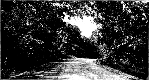
 Frontispiece
The Project Gutenberg EBook of American Rural Highways, by T. R. Agg

This eBook is for the use of anyone anywhere at no cost and with
almost no restrictions whatsoever.  You may copy it, give it away or
re-use it under the terms of the Project Gutenberg License included
with this eBook or online at www.gutenberg.org


Title: American Rural Highways

Author: T. R. Agg

Release Date: July 16, 2009 [EBook #29420]

Language: English

Character set encoding: ISO-8859-1

*** START OF THIS PROJECT GUTENBERG EBOOK AMERICAN RURAL HIGHWAYS ***


Produced by Tom Roch, Richard J. Shiffer and the Online
Distributed Proofreading Team at https://www.pgdp.net (This
file was produced from images produced by Core Historical
Literature in Agriculture (CHLA), Cornell University)
Transcriber's Note
Every effort has been made to replicate this text as faithfully as possible, including obsolete and variant spellings and other inconsistencies. Text that has been changed to correct an obvious error is noted at the end of this ebook.
Frontispiece
American Rural Highways was written for use as a text or reference in courses dealing with rural highways and intended for agricultural engineers, students in agriculture and for short courses and extension courses. The reader is assumed to have familiarity with drawing and surveying, but the text is adapted primarily for students who do not receive training along the lines of the usual course in Highway or Civil Engineering.
The text is intended to familiarize the student with the relation of highway improvement to national progress, to indicate the various problems of highway administration and to set forth the usual methods of design and construction for rural highways in sufficient detail to establish a clear understanding of the distinguishing characteristics and relative serviceability of each of the common types of roadway surface.
Experience with classes made up of students in agriculture or agricultural engineering and with trade school students in road making served as a guide in the selection and arrangement of the material. Detailed discussion of tests of materials and of the theory of design has to a considerable extent been eliminated as being outside of the scope of the course for which the text is intended.
In the preparation of American Rural Highways reference was had to many books on highway subjects and to current periodical literature. Wherever direct extracts were made from such source, appropriate acknowledgment appears in the text.
Ames, Iowa
August 18, 1920.
vii
THE PURPOSE AND UTILITY OF HIGHWAYS
Transportation Problem—National in Scope—Development in Traffic—Location or Farm to Market Traffic—Farm to Farm Traffic—Inter-City Traffic—Inter-County and Inter-State Traffic—Rural Education—Rural Social Life—Good Roads and Commerce
1-12
HIGHWAY ADMINISTRATION
Township Administration—County Administration—State Administration—Federal Administration—Special Assessments—Zone Method of Assessing—General Taxation—Vehicle Taxes—Sinking Fund Bonds—Annuity Bonds—Serial Bonds—Comparison of Methods of Issuing Bonds—Desirability of Road Bonds
13-28
DRAINAGE OF ROADS
The Necessity for Drainage—Importance of Design—Surface Drainage—Run-off—Ordinary Design of Ditches—Underground Water—Tile Drains—Lying Tile—Culverts—Length of Culvert—Farm Entrance Culverts—Metal Pipe—Clay and Cement Concrete Pipe—Concrete Pipe—Endwalls for Culverts—Reinforced Concrete Box Culverts—Drop Inlet Culverts
29-41
ROAD DESIGN
Necessity for Planning—Road Plans—Problems of Design—Preliminary Investigations—Road Surveys—Alignment—Intersections—Superelevation—Tractive Resistance—Rolling Resistance—Internal Resistance—Air Resistance—Effect of Trades—Energy Loss on Account of Grades—Undulating Roads—Guard Railing—Width of Roadway—Cross Section—Control of Erosion—Private Entrances—Æsthetics
42-62
EARTH ROADS
Variations in Soils—Variation in Rainfall—Cross Sections Elevating Grader—Maney Grader—Slip Scraper—Fresno Scraper—Elevating Grader Work—Use of Blade Grader—Costs—Maintenance—Value of Earth Roads
63-73
SAND-CLAY AND GRAVEL ROADS
The Binder—Top-soil or Natural Mixtures—Sand-clay on Sandy Roads—Sand-clay on Clay or Loam—Characteristics—Natural Gravel—The Ideal Road Gravel—Permissible Size of Pebbles—Wearing Properties—Utilizing Natural Gravels—Thickness of Layer—Preparation of the Road—Trench Method—Surface Method—Maintenance
74-88
BROKEN STONE ROAD SURFACES
Design—Properties of the Stone—Kinds of Rocks used for Macadam—Sizes of Stone—Earth Work—Foundation for the Macadam—Telford Foundation—Placing the Broken Stone—Rolling—Spreading Screenings—Bituminous Surfaces—Maintenance Characteristics
89-97
CEMENT CONCRETE ROADS
Destructive Agencies—Design—Concrete Materials—Fine Aggregate—Proportions—Measuring Materials—Preparation of the Earth Foundation—Placing Concrete for Two-course Road—Curing the Concrete—Expansion Joints—Reinforcing—Bituminous Coatings on Concrete Surfaces—Characteristics—Maintenance
98-105
VITRIFIED BRICK ROADS
Vitrified Brick—Paving Brick—Repressed Brick—Vitrified Fiber Brick—Wire-cut-lug Brick—Tests for Quality—Other Tests—Foundation—Sand Bedding Course—Sand Mortar Bedding Course—Green Concrete Bedding Course—Bituminous Fillers—Mastic Fillers—Marginal Curb
106-115
BITUMINOUS ROAD MATERIALS AND THEIR USE
Classes of Bituminous Materials—Coal Tar—Water Gas Tar—Natural Asphalt—Petroleum Asphalt—Mixtures—Classification According to Consistency—Road Oils—Liquid Asphalts—Asphalt Cements—Fillers—Bitumen—Specifications—Surface Treatments—Applying the Bituminous Binder—Finishing the Surface—Patching—Penetration Macadam—Foundation—Upper or Wearing Course—Patching Characteristics—Hot Mixed Macadam—Foundation—Sizes of Stone—Mixing the Wearing Stone—Placing and Wearing Surface—Seal Coat—Characteristics—Asphaltic Concrete—Bitulithic or Warrenite—Topeka Asphaltic Concrete—Foundation—Placing the Surface—Characteristics
116-129
MAINTENANCE OF HIGHWAYS
Petrol Maintenance—Gang Maintenance—Maintenance of Earth, Sand-clay, Gravel and Macadam Roads
130-134
135
Transportation Problem.—Public highways, like many other familiar things, are utilized constantly with little thought of how indispensable they are to the conduct of the business of a nation or of the intimate relation they bear to the everyday life of any community. The degree to which a nation or a community perfects its transportation facilities is an index of its industrial progress and public highways constitute an important element in the national transportation system. It is to be expected that the average citizen will think of the public highway only when it affects his own activities and that he will concern himself but little with the broad problem of highway improvement unless it be brought forcibly to his attention through taxation or by publicity connected with the advancement of specific projects.
National in Scope.—The improvement and extension of the highway system is of national importance just as is development and extension of railways, and concerted action throughout a nation is a prerequisite to an adequate policy in regard to either. It is inconceivable that any community in a nation can prosper greatly without some benefit accruing to many other parts of the country. Increased consumption, which always accompanies material[Pg 2] prosperity, means increased production somewhere, and people purchase from many varied sources to supply the things that they want. Good transportation facilities contribute greatly to community prosperity and indirectly to national prosperity, and the benefits of highly improved public highways are therefore national in scope. This fact has been recognized in Europe, notably in England, France and Belgium, where the public highways are administered largely as national utilities.
Until recent years, highway improvement in the United States has been subordinated to other more pressing public improvements, but during the World War the inadequacy of the transportation system of the United States became apparent. While such an unprecedented load upon transportation facilities may not recur for many years, it has become apparent that more rapid progress in highway improvement is necessary and in the United States the subject is now likely to receive attention commensurate with its importance.
Development of Traffic.—The character and extent of the highway improvement needed in any locality is dependent entirely on the demands of traffic. In sparsely settled areas, particularly those that are semi-arid or arid, the amount of traffic on local roads is likely to be small and the unimproved trails or natural roads adequate. But as an area develops either on account of agricultural progress or the establishment of industrial enterprises, the use of the public highways both for business and for pleasure increases and the old trails are gradually improved to meet, at least to some degree, the new demands of traffic. In sparsely settled areas, it is possible for the public to accommodate its use of the highways to the physical condition thereof, and business is more or less regulated according to the condition of the roads. This is not always pleasant or economical but is the only possible arrangement. In populous districts, with diversified activities, it becomes[Pg 3] imperative to have year-round usable roads in order to transact with reasonable dispatch the regular business of the industries. Anything less will handicap normal community progress.
The advent of the motor driven vehicle in the United States has resulted in a greatly increased use of the public highways of agricultural areas, even of those that are sparsely populated, because of the convenience of the motor vehicle both for passenger and for freight service. Probably in excess of 90 per cent of the tonnage passing over the rural highways in the United States is carried by motor vehicles. This class of traffic has really just developed and no one can predict what it will be in ten years, yet it has already introduced into the highway problem an element that has revolutionized methods of construction and maintenance.
A different set of traffic conditions exists in those parts of the United States where large areas are devoted primarily to industrial pursuits, the agricultural development being of secondary importance. Public highways connecting the industrial centers are indispensable adjuncts to the business facilities in such communities and are ordinarily subjected to a very large volume and tonnage of traffic consisting principally of motor vehicles. The roads first selected for improvement will not be those serving the agricultural interests of the district, but rather those serving the industrial centers. Inter-city roads of great durability and relatively high cost are necessary for such traffic conditions.
Not infrequently the transportation needs will require a system of both inter-city and rural highways in the same community. There are few areas in the United States where there is no agricultural development. It is apparent therefore that the nature of the highway systems and the administrative organization under which they are built and maintained will differ in various states or areas according[Pg 4] to the nature of development of that area agriculturally and industrially. In planning improvements of highway systems, it is recognized that one or more of several groups of traffic may be encountered and that the extent and nature of the improvement must be such as will meet the requirements of all classes of traffic, the most important being first provided for, and that of lesser importance as rapidly as finances permit.
Local or Farm to Market Traffic.—In strictly agricultural communities the principal use of the highways will pertain to agricultural activities and most of it will be between the farm and the most convenient market center. In the ordinary state, the number of rural families will not average more than six to eight per square mile, but in some districts it may reach twenty families per square mile. The travel from the district around a market center will originate in this rather sparsely populated area and converge onto a few main roads leading to market. The outlying or feeder roads will be used by only a few families, but the density of traffic will increase nearer the market centers and consequently the roads nearer town will be much more heavily traveled than the outlying ones. It is apparent therefore that considerable difference may exist in the kind of construction adequate for the various sections of road where farm traffic is the principal consideration. This traffic is made up of horse drawn wagons, transporting farm products and of horse drawn and motor passenger vehicles, the motor traffic comprising 80 per cent or more of the volume of traffic and a greater per cent of the tonnage. Motor trucks are now employed to some extent for marketing farm products and, where surfaced highways have been provided, this class of traffic is superseding horse drawn traffic.[Pg 5]
Farm to Farm Traffic.—In the ordinary prosecution of farming operations, a considerable amount of neighborhood travel is inevitable. Farmers help each other with certain kinds of work, exchange commodities such as seed, machinery and farm animals and visit back and forth both for business and pleasure. To accommodate this traffic, it is desirable to provide good neighborhood roads. Traffic of this sort follows no particular route and can to some extent accommodate itself to the condition of the highways without entailing financial loss, although some discomfort and some inconvenience may result from inadequate highway facilities. This traffic will be partly motor and partly horse drawn, but the proportion of motor driven is large.
Inter-city Traffic.—In strictly agricultural districts there is a large amount of travel between towns, both for business and for pleasure. The pleasure travel is mostly in motor vehicles and a considerable part of the business traffic is the same, although horse drawn vehicles are employed to some extent.
In industrial districts there is a large volume of this class of traffic consisting of motor passenger vehicles used for business and for pleasure and of motor freight vehicles used for general business purposes. In addition, there is certain to be a large amount of motor truck freight traffic incident to the particular industrial pursuits of the cities. Where adequate public highways connect industrial centers, there is invariably a very large amount of inter-city traffic, due in part to the needs of industry and in part to concentration of population in industrial centers.
Inter-County and Inter-State Traffic.—Automobile touring is a popular means of relaxation, especially on the part of those who live in the cities, although it is by no means confined to them. Traffic of this kind follows the routes where roads are best and passes entirely across a county, attracted by some public gathering. Often it is inter-state in character, made up of tourists who are traveling[Pg 6] to distant pleasure resorts. Such traffic at present constitutes a relatively small part of the travel on public highways, except on certain favorable routes, but as the wealth of the country increases and good touring roads are numerous, long distance travel will increase and will eventually necessitate the construction of a number of well maintained national highways, located with reference to the convenience of the automobile tourist.
It is well to recognize the intimate relation public highways bear to the economic progress of a nation. Normal development of all of the diverse activities of a people depends very largely upon the highway policy that is adopted and whether the actual construction of serviceable roads keeps pace with transportation needs.
Rural Education.—It has become increasingly apparent during the World War that the demand upon North America for food stuffs is to become more and more insistent as the years pass. Already the consumption in the United States has approached quite closely to the average production and yet the population is constantly increasing. The time is not far distant when greater production will be required of the agricultural area in North America in order to meet the home demand for foodstuffs, and many thousands of tons will be needed for export. This need can only be met by agricultural methods that will increase greatly the present yield of the soil. The adoption of better agricultural methods must of necessity be preceded by the technical training of the school children who will be the farmers of the next generation, which can best be accomplished in graded schools with well equipped laboratories and with suitably trained teachers. The problem of providing such schools in rural communities has, in some instances, been solved by consolidating a number of rural[Pg 7] school districts and constructing a well equipped building to accommodate the students from an area several miles square. An educational system of this sort can reach its highest usefulness only when adequate public highways facilitate attendance of pupils. The whole trend of rural educational progress is toward a system which is predicated upon a comprehensive highway policy in the district.
Rural Social Life.—Closely allied to the rural educational problem is the rural social problem. Motor cars and good roads do a great deal to eliminate the isolation and lack of social opportunity that has characterized rural life in the United States. A high order of citizenship in rural communities is essential to the solution of many problems of rural economics, and such citizens will not live away from the social opportunities of modern life. The rural school house and the rural church may become social centers and local plays, moving picture shows and lectures and entertainments of other kinds made available to those who live in the country. Their enjoyment of these social opportunities will be much more general if the public highways are at all times in a condition to be traveled in comfort. Good homes and good schools on good roads are prerequisites to the solution of many rural problems.
If there is opportunity for those who live in the cities to get some adequate idea of rural life and the conditions under which farming operations are carried on it will correct many misunderstandings of the broad problems of food production and distribution. Reference has frequently been made to the seeming desire on the part of city people to get into the country, and, by facilitating the realization of this desire, a great social service is rendered.
Good Roads and Commerce.—That good highways are almost as necessary as are railroads to the commercial development of a nation is recognized but, unlike the railroads,[Pg 8] the highways are not operated for direct profit and the responsibility of securing consideration of the demand for improvements is not centralized. Therefore, sentiment for road improvement has been of slow growth, and important projects are often delayed until long after the need for them was manifest. Movements to secure financial support for highway improvement must go through the slow process of legislative enactment, encountering all of the uncertainties of political action, and the resulting financial plan is likely to be inadequate and often inequitable.
The whole commercial structure of a nation rests upon transportation, and the highways are a part of the transportation system. The highway problem can never receive adequate consideration until public highways are recognized as an indispensable element in the business equipment of a nation.
During the World War all transportation facilities were taxed to the limit, and motor trucks were utilized for long distance freight haulage to an extent not previously considered practicable. As a result, the interest in the motor truck as an addition to the transportation equipment of the nation, has been greatly stimulated. Many haulage companies have entered the freight transportation field, delivering commodities by truck to distances of a hundred miles or more.
The part the motor truck will play in the future can only be estimated, but it seems clear that the most promising field is for shipments destined to or originating in a city of some size and a warehouse or store not on a railroad spur, and especially when the shipments are less than car load lots. The delays and expense incident to handling small shipments of freight through the terminals of a large city and carting from the unloading station to the warehouse or other destination constitute a considerable item in the cost of transportation.[Pg 9]
Mr. Charles Whiting Baker, Consulting Editor of Engineering News-Record, states:[1]
"It costs today as much to haul a ton of farm produce ten miles to a railway station as it does to haul it a thousand miles over a heavy-traffic trunk-line railway. It often costs more today to transport a ton of merchandise from its arrival in a long train in the freight yard on the outskirts of a great city to its deposit in the warehouse of a merchant four or five miles away than it has cost to haul it over a thousand miles of railway line."
[1] Engineering News Record, July 10, 1919.
Nevertheless it seems probable that new methods of operating the motor truck transport, and possibly new types of trucks or trucks and trailers will be developed so that freight traffic over many roads will be of considerable tonnage and an established part of the transportation system of the nation. In the article above referred to are given the following data relative to the cost of hauling on improved roads by motor truck and these cost estimates are based on the best information available at this time. They should be considered as approximate only, but serve to indicate the limitations of the truck as a competitor of the steam railway.
| A | B | C | D | E | F | Average Total | ||
| Driver | $5.00 | $5.20 | $5.00 | $5.00 | $5.17 | $5.50 | $5.13 | |
| Tires | 3.00 | 3.75 | 2.00 | 2.00 | 2.00 | 3.00 | 2.68 | |
| Oil, etc. | .30 | ... | .30 | .50 | .25 | .25 | .35 | |
| Gasoline | 3.00 | 4.00 | 3.50 | 4.65 | 2.08 | 3.75 | 3.50 | |
| $11.66 |
| A | B | C | D | E | F | Average Total | ||
| Depreciation | $3.50 | $4.19 | $3.60 | $3.40 | $3.67 | $4.00 | $3.77 | |
| Interest | 1.20 | 1.26 | 1.08 | 1.22 | 1.10 | 1.00 | 1.15 | |
| Insurance | 1.50 | 2.54 | 1.26 | 2.10 | .86 | .50 | 1.47 | |
| Garage | 1.00 | 1.20 | 1.00 | 1.00 | .89 | 1.00 | 1.01 | |
| Maintenance | .50 | ... | .50 | ... | 1.00 | ... | .75 | |
| Overhaul | 1.33 | 2.75 | 1.80 | 1.60 | 2.00 | 3.00 | 2.07 | |
| License | .17 | .27 | .20 | .20 | .20 | .20 | .20 | |
| Body upkeep | .25 | ... | .30 | .10 | .40 | ... | .27 | |
| $10.69 | ||||||||
| Supervision | .50 | 2.93 | 2.05 | 1.90 | ... | ... | 1.90 | 1.90 |
| Lost time | 2.20 | ... | 1.67 | 3.40 | 2.50 | 1.97 | 2.57 | 2.57 |
| 23.45 | 28.09 | 24.26 | 28.07 | 22.12 | 24.17 | 26.82 |
| Driver's wages[1] | $1500 |
| Depreciation (20% on $6000 investment) | 1200 |
| Interest (6% on $6000 investment) | 360 |
| Insurance | 450 |
| Garage (rental, upkeep, etc.) | 300 |
| Maintenance, minor repairs and supplies, tire chains, tools, lamps, springs, equipment, etc. (estimated | 300 |
| Complete overhaul once a year | 600 |
| License fee | 60 |
| Body upkeep, repairs, painting, etc. | 90 |
| Supervision | 696 |
| Total per annum | $5556 |
| Overhead charges per day for 240 days in the year, actual operation | $23.15 |
| Overhead charges per mile for 50 miles per day | .463 |
[1] In the above table the driver's wages have been placed under overhead charges because the driver is paid by the month and his wages continue even though the truck is idle because of repairs, bad weather or lack of business, unless, of course, the idleness should be of long duration, when the driver might be laid off.[Pg 11]
| Cost per day | Cost per mile | |
| Tires (based on present tire guarantee) | $3.00 | $0.06 |
| Lubricants | .50 | .01 |
| Gasoline (3½ miles per gal., 14 gal. at 25c) | 3.50 | .07 |
| 7.00 | 0.14 |
| Total of overhead and direct charges for 240 days per year operation, per day | $30.15 |
| Per mile | .603 |
| Cost per ton-mile for full loads one way and empty returning | .2412 |
| Cost per ton-mile for full loads one way and half load returning | .16 |
The significance of these figures becomes apparent when they are compared with the cost of hauling freight over trunk-line railways with heavy traffic where the cost per ton-mile, including terminal charges, ranges from 1.7 mills per ton-mile to 4.4 mills per ton-mile.
In view of these facts it seems reasonable to suppose that motor vehicles for use on the public highways are more likely to be employed to supplement the rail transport than to compete with it. To the actual cost of operation of motor trucks given in Table 2, there should be added the proportionate cost of maintaining the highway for the use of the truck, which is partly covered by the item "License Fee" in the table. The license fee would necessarily be considerably larger if it were to compensate adequately for the wear on the highways over which the trucks operate. This will still further increase the cost of hauling by motor truck.
Motor trucks are employed for many kinds of hauling where their speed and consequently their daily capacity is an advantage over team hauling that is decidedly worth[Pg 12] while. It probably could be shown that for many kinds of hauling, teams are more economical than motor trucks, but when promptness and speed and the consequent effect on dependent activities are considered, the motor truck often has a distinct advantage, and the use of the truck to replace horse drawn vans is progressing rapidly. This is true not only in the cities, but also in the smaller towns and in the country. Motor trucks have been adopted in a great many communities for delivery of farm products to market, and this use of the truck is certain to increase rapidly. But trucks in this service will use the secondary roads as well as the main or primary roads.
These observations emphasize the extent to which the highway policy of the nation must be predicated on the use of the highways by motor vehicles.
The systems of highway administration extant in the various political units in the United States present a patchwork of overlapping authority and undetermined responsibility. Highway laws are being constantly revised by state legislatures and with each revision there is some change in administrative methods and often the changes are revolutionary in character. In most states, the trend is away from county and township administration and toward state administration, with provision for considerable participation by the federal government.
It will be pertinent to consider briefly the present functions of each of the administrative authorities having duties in connection with highway work in the United States, although these duties vary greatly in the several states and change periodically with the action of legislatures.
Township Administration.—Township or "Town" authority is a survival of the old New England town government and the town board consists of three or more trustees who hold office for fixed terms. The usual term is three years, but is less in some states. The incumbent is generally a man who has other responsibilities of a public or private nature and who gives but little of his time to highway matters. In some states the pay is a fixed annual salary and in others a per diem with some limitation on the amount that may be drawn in any one year, which limitation may be statutory or may be by common consent.
The township highway commissioners or trustees have jurisdiction over certain of the roads in the township,[Pg 14] usually best described as all roads not by law placed under the jurisdiction of some other authority. In certain instances, the township authorities have charge of all of the roads in the township, which would mean that no "county" or "state" roads happened to be laid out in that township. It is a matter of general observation that the trend of legislation is toward removing from the jurisdiction of the township officials all roads except those upon which the traffic is principally local in character. The actual mileage of roads in the United States that is at present administered by township officials is large, probably constituting not less than seventy per cent of the total mileage.
In most states the township officials are responsible for the maintenance of the roads under their jurisdiction and also supervise such new construction as is undertaken. This includes the construction of culverts and bridges as a rule, but in some states the county board of supervisors is responsible for all of the bridge and culvert work on the township roads. In other states, the township board is responsible only for bridges or culverts that cost less than a certain amount specified by law (usually about $1000) and the county board provides for the construction and upkeep of the more expensive bridges and culverts.
Funds for the work carried out by the township road officials are obtained by general taxation, the amount that may be levied being limited by statute and the actual levy being any amount up to the maximum that the township board deems necessary for its purposes. It is the general observation that the tax levy is usually the maximum permitted by law.
In many states, township officials are permitted to issue bonds for road construction, almost invariably, however, with the restriction that each issue must be approved by the voters of the township. There is always a provision that the total amount of bonds outstanding must not exceed the constitutional limit in force in the state. In[Pg 15] several states, the townships have large amounts of road bonds outstanding.
County Administration.—In some states the county is the smallest administrative unit in the road system. A county board, called the board of county supervisors or board of county commissioners consisting of from three to fifteen members, is the administrative authority. Its members are elected for fixed terms which vary in length from one to five years. The county board usually has many public responsibilities other than highway administration, and is generally made up of men with considerably more business ability than the average township board.
The county board has jurisdiction over all of the highways in the county in some states, and in others it has charge of only the more important highways. In most states, the laws set forth specifically what highways shall be under the jurisdiction of the county authorities.
In addition to having direct supervision of the improvement and maintenance of the roads assigned to county administration, the county boards in some states arrange for the construction of all culverts and bridges on the roads that are under township supervision, or at least the more expensive bridges and culverts on such roads. Sometimes this is accomplished by granting county aid for township bridges, under which system the county pays a part of the cost of the construction of bridges on the township roads. The amount of aid varies, but is generally about one-half of the cost, and the township and county officials jointly assume the responsibility of arranging for the construction by contract or otherwise.
The county board obtains funds for road work through a direct tax on all property in the county, the maximum rate being limited by statute. County boards are also authorized to issue bonds for road construction under statutory restrictions and limitations similar to those effective in the township as to total amount issued, and many millions[Pg 16] of dollars' worth of highway bonds have been issued by county authorities in the United States.
State Administration.—In a state, the administrative authority in highway matters is vested in a board of commissioners usually consisting of three or more members. In a few states, the administrative authority is delegated to a single commissioner. Where the authority is vested in a board, that board is usually appointed by the governor. In several states one or more members of the commission hold that position ex officio; for example, in several states the governor is by law a member of the commission, in others the secretary of state or the dean of engineering at the State University or the state geologist is a member of the commission. Where the administrative authority is a single commissioner he may be elected along with other state officers, but this is the case in only a few states.
The authority of the state highway department varies in the several states, but in general the departments serve in the dual capacity of general advisers to the county and township authorities on road matters and as the executive authority responsible for the construction of those highways that are built entirely or in part from state or federal funds.
State highway departments consist of the commission or commissioner, and the technical and clerical staff required to perform the duties imposed on the state organization. To some extent the state highway departments are able to encourage economical and correct construction of highways by the township and county authorities by furnishing them standard plans and specifications and by formulating regulations to govern the character of construction, but such efforts are likely to be more or less ineffective unless the state authority has supervision of the allotment of state or federal funds to the various counties and townships. Nevertheless, most state highway departments do a great deal of advisory work in connection[Pg 17] with the highway construction carried out by county and township authorities.
State highway departments are supported by funds obtained in various ways, laws differing greatly in this respect. The necessary support is in some states appropriated from funds obtained by general taxation, and is in others obtained from automobile license fees. In still others, the funds are secured by a combination of the two methods mentioned above. In addition to these support funds, a certain part of the money obtained as federal aid may be employed for the engineering and inspection costs on federal aid roads. The above mentioned funds are required to maintain the state highway department. In addition, the departments have supervision of the expenditures of construction funds which can be used for road construction and maintenance, and may not be expended for salaries or other overhead expense.
In a number of states, automobile license fees are set aside for financing road construction and maintenance, and the work paid for from the fees is carried out under the supervision of the state highway department.
In a number of instances, state bonds have been issued for road construction, and the expenditure of the proceeds of the sale of road bonds has usually been supervised by the state highway department.
All federal aid funds allotted to a state must be expended under the direction of the state highway department.
Federal Administration.—Federal authority in highway work is vested in the Bureau of Public Roads of the United States Department of Agriculture. The official head is the Secretary of Agriculture, but the administrative head is the Director of the Bureau. In this Bureau are the various instrumentalities needed for carrying on investigations and furnishing information to the various states on highway subjects. The Bureau also supervises the construction of federal aid roads in a general way through[Pg 18] district engineers, each of whom looks after the work in several states.
Funds for the support of the Bureau of Public Roads are obtained from congressional appropriations to the Department of Agriculture and from a percentage of the funds appropriated for federal aid.
Federal aid is money appropriated by Congress to be distributed to the various states to stimulate road construction. It is granted to the states on the condition that the states will expend at least an equal amount on the projects involved. The states in turn usually give a suitable part of the state allotment to each county. There are various limitations as to the amount of federal aid per mile of road and the type of construction that may be employed, but these are matters of regulation that change from time to time.
It will be seen that each of the administrative authorities, except the Bureau of Public Roads, is to some extent subservient to a higher authority, and the Bureau of Public Roads is supervised by the United States Congress. Considerable diplomacy is required on the part of any administrative authority if his contact with other officials is to be without friction. This is especially true in connection with the formulation of a policy regarding the types of construction to be adopted for an improvement. The responsibility for the selection is variously placed on the township, county or state authority, the laws not being uniform in this respect. If state or federal funds are allotted to an improvement, the state authority either makes the selection of the type of construction or the selection is made by some subordinate authority subject to the approval of the state highway department. Where the improvement is paid for exclusively with township or county funds, the selection is often made by the township or county authority without review by higher authority. Many abuses have crept into highway administration through[Pg 19] the unscrupulous methods of promoters of the sale of road materials or road machinery. A great deal of the selling activity of the agents for these commodities is entirely irreproachable, but it is well known that such is not always the case. As a result, the tendency of legislation is to require the state highway department to approve contracts for materials or construction entered into by the township or county authorities. The state highway departments can secure the requisite technical experts to determine the merits of materials and equipment and, in spite of some glaring examples of inefficiency or worse, have made a good record for impartiality and integrity as custodians of the funds for which they are responsible.
The paramount problem in highway administration is the development of an adequate financial plan for carrying on road improvement. The necessary expenditures are enormous, although the money so expended is probably much less than the actual benefit resulting from the improvements.
Special Assessments.—There is presumed to be a direct and recognized benefit conferred on farm lands by the construction of improved highways adjacent thereto. Therefore, it is equitable to charge a part of the cost against the lands so benefited.
The principle of paying for public improvements by a special assessment upon private property has been long established and a large proportion of the public improvements in the cities and towns have been made financially possible through the medium of special assessments on abutting and adjacent property. The same principle has been applied to the financing of drainage projects for reclaiming farm lands. Recently the special assessment method has come into limited use in financing rural highway[Pg 20] improvements. The policy in such cases is to assess the abutting and adjacent property in a zone along the improved road for a percentage of the cost of the improvement. The amount so assessed does not ordinarily exceed one-fourth of the total cost of the improvement and may be considerably less. The assessment is spread over an area extending back from one to six miles from the improved road. The assessment area is generally divided into about four zones parallel to the road. The zone next the road is assessed at a rate arbitrarily determined as a fair measure of the benefit, and each succeeding zone is assessed at a somewhat lower rate. Generally about three-fourths of the total assessment is placed on the half of the assessment area lying next to the road.
Many systems of making assessments have been proposed which are mechanical in application after the area and rate of distribution of benefit have been established, but in practice it is always found necessary to make adjustments on individual parcels of land because of variation in benefits received and it is impossible to eliminate the exercise of human judgment in equalizing the assessments.
Zone Method of Assessing.—The area to be assessed on each side of the improved road is divided into zones usually four in number, but a larger or smaller number of zones may be adopted. The rate for each zone is then arbitrarily determined. For a typical case, the first of four zones would receive an assessment of 50 per cent of the amount to be borne by the area; the second zone 25 per cent, the third 15 per cent and the fourth 10 per cent. Other percentages sometimes adopted are 45, 25, 20 and 10 and 60, 20, 15 and 5. The set of percentages first mentioned seems to insure the most equitable distribution for an area all of which is substantially equally productive.
When a road, for the improvement of which an assessment is being made, lies on two or more sides of a parcel of land all of which is within the assessment area, the rate[Pg 21] is arbitrarily reduced to relieve that parcel of land somewhat, or the assessment is first spread as above outlined and afterward equalized as judgment dictates.
In applying the zone method some difficulty is encountered in determining an equitable distribution on those parcels of land lying partly in one zone and partly in another, but the rate may be arrived at with reasonable accuracy by pro-rating in accordance with the exact conditions.
In. Fig. 1, let it be assumed that the assessment area is to be two miles wide, one mile on each side of the road and the various ownerships to be indicated by the parcels of land numbered 1 to 8, as shown. Each zone for the assessment of the 3¼ mile section is ¼ mile wide and the rates for the several zones are 50, 25, 15 and 10 per cent respectively. Let it be assumed that the portion of the cost of the 3¼ miles of road to be assessed on the area shown is $20,000. The assessment would then be as follows:
| Parcel | Rate | Rate × frontage on improved road = assessment units | Amount of Assessment per unit[1] | Assessment | ||
| 1 | 2 | 3 | 4 | 5 | ||
| 1 | a 50 | 50 × 2640 | = | 132,000 | $0.016655 | $1558.46 |
| b 75 | 75 × 1320 | = | 99,000 | 1153.90 | ||
| 2 | 40 | 40 × 2640 | = | 105,600 | 1230.77 | |
| 3 | 10 | 10 × 2640 | = | 26,400 | 307.69 | |
| 4 | 25 | 25 × 1320 | = | 33,000 | 384.66 | |
| 5 | [2]85 | 85 × 5280 | = | 448,800 | 5230.88 | |
| 6 | 15 | 15 × 5280 | = | 79,200 | 923.08 | |
| 7 | [2]65 | 65 × 7920 | = | 514,800 | 6000.00 | |
| 8 | 35 | 35 × 7920 | = | 277,200 | 3230.77 | |
| 1,716,000 | $20000.00 | |||||
[1] The assessment per unit is obtained by dividing the total assessment by the total of column three.
[2] On these two parcels, it is decided that more than half of the zone rate should apply to the half of the zone toward the improved road, but some modification of the rates adopted might be justified.[Pg 22]
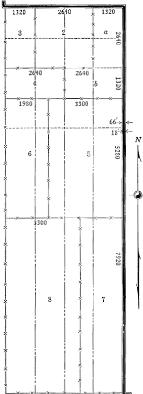 Fig. 1
The assessment of the cost of the east and west one-mile section of road is made up in like manner, and let it be assumed that the portion of the cost of this road that is to be assessed on the area shown is $5500. The assessment area will be one mile wide and each zone one-fourth mile in width and the rates for each zone the same as before.
| Parcel | Rate | Rate × frontage on improved road = assessment units | Amount of Assessment per unit | Assessment | ||
| 1 | a 75 | 75 x 1320 | = | 99,000 | $0.010417 | $1031.25 |
| b 15 | 15 x 2640 | = | 39,600 | 412.49 | ||
| 2 | 75 | 75 x 2640 | = | 198,000 | 2062.53 | |
| 3 | 50 | 50 x 1320 | = | 66,000 | 687.51 | |
| 4 | a 25 | 25 x 1320 | = | 33,000 | 756.25 | |
| b 15 | 15 x 2640 | = | 39,600 | |||
| 5 | 10 | 10 x 3300 | = | 33,000 | 343.73 | |
| 6 | 10 | 10 x 1980 | = | 19,800 | 206.24 | |
| 528,000 | 5500.00 | |||||
It will be noted that the combined assessment for the two sections of road is especially heavy on parcels 1, 2 and 3. In order to prevent unjust charges against such properties, laws usually limit the total assessment against any parcel of land to a fixed percentage of a fair market value or of the assessed value. The assessment on these parcels would be reduced as seemed expedient and the deficit would be distributed over the remainder of the area in the same manner as the original assessment was spread. In practice such re-distribution is ordinarily made by the arbitrary adjustment in accordance with what the authorized officials consider to be fair and equitable. The method outlined is merely a mechanical means of securing distribution and must not be considered as an infallible method of making the assessment. It is always necessary to review the results in the light of the actual benefits to be presumed for[Pg 24] each parcel of land. Nevertheless, the method outlined will prove equitable in a majority of cases.
General Taxation.—There is a general community benefit derived from the construction of good roads in that the actual cost of marketing farm products is lessened with a resulting lowering of the price to the consumer. The benefit also accrues from the greater facility with which all community business may be conducted. The introduction of better opportunities for social, religious and educational activities in the rural districts which results from improved highways is also a community benefit of no mean importance. A part of the cost of road improvement may therefore be equitably paid from funds obtained by general taxation.
A considerable portion of the current expense of maintaining the township and county highway work and at least a part of the cost of maintaining state highway activities is met from funds obtained by general taxation. Likewise, the funds required for the amortization of bond issues are often obtained from general taxation although vehicle license fees are sometimes used for that purpose.
General taxes are levied on all taxable property in a political unit under statutory provisions regulating the amount of the levy and the purpose for which the revenue is to be used. In the aggregate, the road taxes are large but in the township or county the rate is generally small compared to some other taxes, such as the school tax.
Vehicle Taxes.—The great direct benefit derived by those who actually operate vehicles over the roads justifies the policy of requiring a vehicle to pay a license fee in lieu of other taxes, the funds so obtained to be used for the construction and maintenance of public highways. In practice, this method has already been applied to motor vehicles in most states and has proven to be an important source of revenue. Its application to horse-drawn vehicles has not been attempted, due probably to the fact that such[Pg 25] horse-drawn vehicles as use the public highways are also employed about the farm or in the towns and the determination of an equitable basis for taxation involves many difficulties.
The rate of the fee for motor vehicles should be based on their destructive effect on the road so far as that is possible. The scale of fees should therefore take account of weight and speed of vehicle and if the license is in lieu of all other taxes, it should also be graduated with the cost of the vehicle.
When funds are thus derived, every precaution should be taken to insure that the money is used judiciously for construction and especially for maintenance on those roads most useful to motor traffic.
Highway Bonds.—Bond issues for road improvement afford a means of constructing roads and paying for them while they are being used. A very large volume of such bonds are outstanding in the United States. Road bonds should be issued only for durable types of improvement and the life of the bond should be well within the probable useful life of the road surface. It is customary and highly desirable that the general nature and extent of the improvement be established before the bonds are issued. It is desirable that bond issues be subject to approval by referendum before issue and that is provided in every instance.
Highway bonds are of three classes known as Sinking Fund, Annuity and Serial Bonds, respectively. The earlier bonds issued were almost all of the sinking fund class, but in recent years the serial bond has been widely employed and is probably the most satisfactory to administer.
Sinking Fund Bonds.[1]—When this type of bond is employed, the amount of the expenditure for road improvement[Pg 26] is determined upon and the length of the period during which tax payments shall be made is settled. To employ a concrete example, it may be assumed that $100,000 is to be expended for road work and is to be paid at the end of ten years. The interest rate on the bonds will vary with the condition of the bond market and the stability of the political unit issuing the bonds, but is usually about 5 per cent. Knowing these factors, the amount to be added to the sinking fund each year is computed. In order to pay the interest on the bonds, a tax of suitable rate is levied, and in order to retire the bonds at the end of the period, a sum is set aside each year which is supposed to be invested and draw interest which will be added to the principle, and the principle and interest comprise the sinking fund. The principle of the sinking fund is obtained by tax levies, a sum being added to the principle of the sinking fund each year.
[1] For a more detailed discussion of highway bonds see Bulletin 136, U. S. Dept. of Agriculture, which is the basis of this discussion.
The success of this method of financing depends upon the proper administration of the sinking fund. It must be invested with fidelity and the fund be kept intact. Usually the sinking fund cannot be invested at as high a rate of interest as the bonds bear and there is some loss as a result. Road bonds bearing 5 per cent interest can usually be sold at par while the sinking fund will usually net about 3 or 3½ per cent interest. The total cost of a bond issue will be greater by the sinking fund method than by either of the other methods described.
Annuity Bonds.—Annuity bonds are drawn in such a manner that the amount of the payment for principle and interest is the same each year during the life of the bond. When the amount of the issue and the rate of interest has been determined and the amount of the desired annual payment has been determined, the number of years the bonds must run is computed.
This method is convenient in that the amount of the tax to be levied each year remains constant.[Pg 27]
Serial Bonds.—Serial bonds are drawn so that a uniform amount of the principle is retired each year after retirement starts and the total interest payments decrease each year after the first bonds are retired. The first bond may not be retired for a number of years after the issue of the bonds, but when it once starts retirement proceeds at a constant rate annually.
Comparison of Methods of Issuing Bonds.—The relative costs of financing by either of the three methods depends upon the rate of interest in each case and the net rate secured on the sinking fund provided for retiring sinking fund bonds.
For comparative purposes, some typical examples are given in Table 3. These illustrate the differences in total cost of securing $100,000 by each of the three methods at various interest rates.
| Annual Interest on Bonds | Sinking Fund Compounded Annually at | Annuity | Serial | ||
| 3 per cent | 3½ per cent | 4 per cent | |||
| 4 | $154,431 | $150,722 | $147,163 | $147,163 | $142,000 |
| 4½ | 164,431 | 160,722 | 157,163 | 153,752 | 147,250 |
| 5 | 174,431 | 170,722 | 167,163 | 160,485 | 152,500 |
| 5½ | 184,431 | 180,722 | 177,163 | 167,359 | 157,750 |
| 6 | 194,431 | 190,722 | 187,163 | 174,369 | 163,000 |
Desirability of Road Bonds.—In theory the bond method of financing enables the highway authorities to construct a large mileage of roads in a few years and spreads the cost over the period during which the public is being benefited. Better prices are obtained on contracts for a[Pg 28] large mileage than for smaller jobs, and the community can receive the benefit more quickly than where construction proceeds piecemeal with current funds. The vital consideration is to insure that the term of the bonds is well within the useful life of the road, and that ample provision is made to maintain the roads during that period. Under proper restrictions the bond method of financing is to be commended. The bonds are an attractive investment and readily marketable on satisfactory terms.
The Necessity for Drainage.—The importance of drainage for all roads subject to the effects of storm or underground water has always been recognized by road builders, but during recent years constantly increasing attention has been given to this phase of road construction. It is unfortunate that there has in the past been some tendency to consider elaborate drainage provisions less necessary where rigid types of surfaces were employed. It has become apparent, from the nature of the defects observed in all sorts of road surfaces, that to neglect or minimize the importance of drainage in connection with either earth roads or any class of surfaced roads is to invite rapid deterioration of some sections of the roadway surface and to add to maintenance costs.
The degree to which lack of drainage provisions affect the serviceability of the road surface varies with the amount of precipitation in the locality and the manner in which it is distributed throughout the year. In the humid areas of the United States, which are, roughly, those portions east of a north and south line passing through Omaha and Kansas City, together with the northern part of the Pacific slope, precipitation is generally in excess of 30 inches per year and fairly well distributed throughout the year, but with seasonal variations in rate. In these areas, the effect of the precipitation, both as regards its tendency to lower the stability of soils and as an eroding agent, must be carefully provided against in highway design.[Pg 30]
Outside of the areas mentioned above, the precipitation is much less than 30 inches per year and its effect as an agent of erosion is of greatest significance, although in restricted areas there may be short periods when the soil is made unstable by ground water.
Importance of Design.—The drainage system for a proposed road improvement ought to be designed with as much care as any other element, and, to do so, a study must be made of all factors that have any bearing on the drainage requirements and the probable effectiveness of the proposed drainage system. The well established principles of land drainage should be followed so far as applicable.
The basic principle of road drainage is to minimize the effect of water to such an extent that there will always be a layer of comparatively dry soil of appreciable thickness under the traveled part of the road. This layer should probably never be less than two feet thick and for soils of a structure favorable to capillary action it should be at least three feet thick. The means employed to accomplish the requisite drainage will be as various as the conditions encountered.
Surface Drainage.—The drainage method which is by far the most nearly general in application is that which utilizes open ditches, and the system which employs these ditches is usually referred to as surface drainage. The full possibilities of this method of minimizing the effects of storm water are rarely fully utilized in road construction. Very frequently, deterioration of a road surface is directly attributable to failure to provide adequately for the removal of the storm water or water from the melting of snow that has fallen on the road, or water that flows to the road from land adjacent thereto. Surface water can usually most cheaply and expeditiously be carried away in open ditches, although special conditions are occasionally encountered which require supplementary tile drains.[Pg 31] The cross section commonly adopted for roads lends itself naturally to the construction of drainage ditches at the sides of the traveled way, and these are usually the principal dependence for the disposal of storm water.
Run-off.—The capacity required of side ditches to insure satisfactory surface drainage will be affected by the amount and nature of the precipitation in the region where the road is built. The annual rainfall in a region may amount to several feet, but may be well distributed throughout the year with an absence of excessive rainfall for short periods, that is, flood conditions may rarely occur. In other areas, the annual rainfall may be comparatively small but the precipitation occurs at a very high rate, that is, flood conditions may be common, or it may be at a low rate extending over a considerable period. These peculiarities must be known before an adequate drainage system can be planned.
It is almost universally true in the United States that precipitation at a very high rate will be for a relatively short duration, and during these short periods, which usually do not exceed thirty minutes, a portion of the water that falls on the areas adjacent to the road and that drains to the road ditches will soak into the soil and therefore not reach the ditches along the road. The extent to which the water is taken up by the soil will vary with the porosity and slope of the land and the character of the growth thereon. Cultivated land will absorb nearly all of the water from showers up to fifteen or twenty minutes duration; grass land a somewhat smaller percentage; and hard baked or other impervious soil will absorb a comparatively small amount. Rocky ground and steep slopes will absorb very little storm water.
The surface of the road is designed to turn water rapidly to the ditches, but when the material is the natural soil, there is always considerable absorption of storm water. Surfaces such as sandclay, gravel and macadam do not[Pg 32] absorb to exceed 10 per cent of the precipitation during short showers. Bituminous surfaces, brick and concrete pavements, do not absorb an appreciable amount of storm water.
Generally it is best to assume that if a rain lasts for forty-five minutes or more, all of the water will run off, as the soil will reach a state of saturation in that time. This is not true of deep sand, but is for nearly all other soils.
The ditch capacity needed will therefore depend upon the area drained, the character of the soil, the slopes and the rainfall characteristics of the region, and upon the nature of the road surface.
For a required capacity, the cross section area of the ditch will vary inversely as the grade, because the velocity of flow increases with an increase in the grade of the ditch. If the surface water must be carried along the road for distances exceeding five or six hundred feet, the ditch must be constructed of increasing capacity toward the outlet in order to accommodate the accumulated volume of water.
The velocity of flow varies not only with the grade, but with the shape of the cross section, cleanness of the channel, the depth of the water in the channel, alignment of the channel and the kind of material in which the channel is formed. It is not necessary to go to great refinement in the design of the side ditches for the ordinary case where the water is carried along the road for only a few hundred feet. The ditches are made of ample capacity by using the commonly accepted cross section for a road, which will be discussed in a later paragraph. But where large areas must be drained by the road ditches, it is desirable carefully to design the side ditches. The basis for that design is too lengthy to be included herein, and reference should be made to a standard treatise on the subject.
Ordinary Design of Ditches.—For grades of one per cent or less on roads in the humid area, the bottom of the ditch should be at least three and one-half feet lower than[Pg 33] the traveled surface of the road, except for very sandy soil. For grades greater than one per cent, this depth may be decreased one foot, and for grades of four per cent and upward, the depth may be still less. These general rules for depth are susceptible of variation but are believed to be the minimum except in arid or semi-arid climates. It is far better to be too liberal in ditch allowance than to be too conservative. In arid or semi-arid regions, the ditch design will be based on the necessity of providing for flood flow and preventing damage through erosion. Ordinary drainage requirements will be satisfactory with the ditch about one foot deep.
If the topography is such that it is evident considerable storm water will flow from the adjacent land to the road ditches, the design must be modified to take this into account. Sometimes such water can be diverted by ditches well back from the road, and thus prevented from flowing into the side ditches along the roadway. It is especially desirable to divert water, which would otherwise flow down the slope of a cut, by means of a ditch on the hill-side above the upper edge of the slope of the cut.
Ditches are not effective unless they afford a free flow throughout their length and have an outlet to a drainage channel of ample capacity. Therefore, ditch grades should be established by survey, especially if the gradient is less than one per cent, and the construction work should be checked to insure that the ditch is actually constructed as planned. A few high places in the ditch will greatly reduce the effectiveness, although these may appear at the time of construction to be slight. Constricted places, such as might be due to a small amount of loose earth left in the ditch, are always to be avoided.
Where the side ditch passes from a cut to the berm alongside a fill, the ditch should be excavated throughout in the undisturbed natural soil, five feet or more from the toe of the slope of the fill, and along the filled portion of the[Pg 34] road there should be a berm of three or four feet between the toe of the slope of the fill and the near edge of the ditch.
Underground Water.—In a preceding paragraph, mention was made of the fact that only a part of the storm water runs off over the surface of the ground, the larger part being absorbed by the soil. The water thus absorbed flows downward through the pores in the soil until it is deflected laterally by some physical characteristic of the soil structure. The movement of underground water is affected by many circumstances, but only two conditions need be discussed herein.
Underground water, like surface water, tends to attain a level surface, but in so doing it may need to flow long distances through the pores of the soil, and to overcome the resistance incident to so doing some head will be required. That is to say, the water will be higher at some places than at others. If a cut is made in grading the road, the road surface may actually be lower than the ground water level in the land adjoining the road. As a result, the water will seep out of the side slopes in the cut and keep the ditches wet, or even furnish enough water to occasion a flow in the ditch. Similarly, the higher head of the underground water near the top of a hill may result in ground water coming quite close to the surface some distance down the hill. The remedy in both cases is tile underdrains alongside the road to lower the ground water level so that it cannot affect the road surface.
Sometimes the ground water encounters an impervious stratum as it flows downward through the soil, or one that is less pervious than the surface soil. When such is the case, the water will follow along this stratum, and should there be an outcrop of the dense stratum, a spring will be found at that place. This may be on a highway. The impervious stratum may not actually outcrop but may lie only a few feet under the surface of the road, in which[Pg 35] case, the road surface will be so water soaked as to be unstable. The so-called "seepy places" so often noted along a road are generally the result of this condition. This condition can be corrected by tile laid so as to intercept the flow at a depth that precludes damage to the road. Commonly, the tile will be laid diagonally across the road some distance above the section where the effect of the water is noted, and will be turned parallel to the road at the ditch line and carried under one of the side ditches to an outlet.
Tile Drains.—Where the soil and climatic conditions are such that the roadway at times becomes unstable because of underground water rising to a level not far below the road surface, the ground water level is lowered by means of tile underdrains. The function of the tile drains in such cases is precisely the same as when employed in land drainage; to lower the ground water level.
Laying Tile.—The tile lines are usually laid in trenches parallel to the center line of the road near the ditch line and at least 4 feet deep so as to keep the ground water level well down. They must be carefully laid to line and grade. A good outlet must be provided and the last few joints of pipe should be bell-and-spigot sewer pipe with the joints filled with cement mortar. The opening of the tile should be covered with a coarse screen to prevent animals from nesting in the tile.
It is frequently necessary to lay a line of tile at the toe of the slope in cuts to intercept water that will percolate under the road from the banks at the sides. In some cases, it is desirable to back-fill the tile trench with gravel or broken stone to insure rapid penetration of surface water to the tile. In other instances, it is advantageous to place catch basins about every three or four hundred feet. These may be of concrete or of tile placed on end or may be blind catch basins formed by filling a section of the trench with broken stone. When a blind catch basin is used, the top[Pg 36] should be built up into a mound, and for a tile or concrete catch basin, a grating of the beehive type should be used, so that flow to the tile will not be obstructed by weeds and other trash that is carried to the catch basin.
Culverts.—Culverts and bridges are a part of the drainage system and the distinction between the two is merely a matter of size. Generally, structures of spans less than about eight feet are classed as culverts, but the practice is not uniform. In this discussion culverts will be defined as of spans of 8 feet or less.
Numerous culverts are required to afford passage for storm water and small streams crosswise of the road, and their aggregate cost is a large item in the cost of road improvement. The size of the waterway of a culvert required in any location will be estimated by an inspection of the stream and existing structure, and by determining the extent and physical characteristics of the drainage area. Sometimes there is sufficient evidence at the site to indicate quite closely the size required, but this should always be checked by run-off computations. The drainage area contributing water to the stream passing through the culvert under consideration is computed from contour maps or from a survey of the ground, and the size of culvert determined by one of the empirical formulas applicable to that purpose. In these formulas, the solution depends upon the proper selection of a factor "C" which varies in accordance with the nature of the drainage area. Two of these that are quite widely used are as follows:
Myers' Formula: a = CA
Where a = area of cross section of culvert in square feet. A = area in acres of the drainage area above culvert. C a factor varying from 1 for flat country to 4 for mountainous country or rocky soil, the exact value to be selected after an inspection of the drainage area.[Pg 37]
Talbot's Formula: Area of waterway in square feet =
| C = √ | (Drainage area in acres)3 |
C being variable according to circumstances thus:
"For steep and rocky ground C varies from 2/3 to 1. For rolling agricultural country, subject to floods at times of melting snow, and with length of valley three or four times its width, C is about 1/3, and if stream is longer in proportion to the area, decrease C. In districts not affected by accumulated snow, and where the length of valley is several times its width, 1/5 or 1/6 or even less may be used. C should be increased for steep side slopes, especially if the upper part of the valley has a much greater fall than the channel at the culvert. The value of C to be used in any case is determined after an inspection of the drainage area."
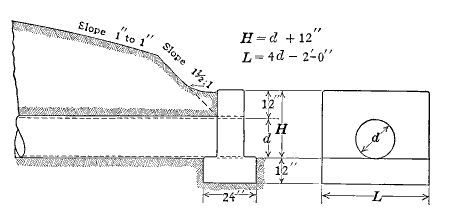 Fig. 2. Design of Pipe Culvert and Bulkhead
Length of Culvert.—The clear length between end walls on a culvert should be at least equal to the width of the roadway between ditches. This is a minimum of 20 feet for secondary roads and ranges from 24 to 30 feet for main roads. The headwall to the culvert should not be a monument, but should be no higher than needed to prevent vehicles from leaving the roadway at the culvert.
Farm Entrance Culverts.—At farm entrances, culverts are required to carry the farm driveway across the side[Pg 38] ditch of the road. These culverts are usually about 16 feet along, and should be of a size adequate to take the flow of the side ditch. The farm entrance culvert should be of such design that it can be easily removed to permit cleaning out the ditches with a road grader.
Culverts constructed of concrete and poured in place are called box culverts because of the rectangular form of the cross section. Culverts of pre-cast pipe are known as pipe culverts. Several forms of pipe culvert are in general use.
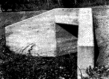 Fig. 3.—Typical Concrete Box Culvert
Metal Pipe.—These may be of cast iron, steel or wrought iron. The cast iron pipe is very durable but expensive and heavy to handle and is not widely used in highway construction. Steel pipe has been employed to a limited extent but its durability is questioned. At least it is known that the pipe made from uncoated, light sheet steel is not very durable. Sheet iron and sheets made[Pg 39] from alloy iron coated with spelter have been extensively used and seem to be durable, especially when laid deep enough to eliminate possibility of damage from heavy loads. To insure reasonable resistance to corrosion, the metal sheets should be coated with at least one and one-half ounces of spelter per square foot of sheet and the sheets should not be lighter than 16 gauge for small sizes and should be heavier for the larger sizes.
Clay and Cement Concrete Pipe.—The ordinary burned clay bell and spigot pipe that is employed for sewer construction is sometimes used for culverts. It must be very carefully bedded, preferably on a concrete cradle and the joints filled with cement mortar. Culverts of this type have a tendency to break under unusual loads, such as traction engines or trucks. They may be damaged by the pressure from freezing water, particularly when successive freezing and thawing results in the culvert filling with mushy snow, which subsequently freezes.
Concrete Pipe.—Reinforced concrete pipe is a satisfactory material for culverts, if the pipe is properly designed. The pipe should be carefully laid on a firm earth bed with earth carefully back-filled and tamped around the pipe. The joints in the pipe should be filled with cement mortar, or should be of a design that will be tight.
Endwalls for Culverts.—A substantial retaining wall is placed at each end of the culvert barrel, whatever the type. This is to prevent the end of the culvert from becoming choked with earth and to retain the roadway at the culvert. It also indicates to the drivers the location of the end of the culvert. The endwall extends a foot or more below the floor of the culvert to prevent water from cutting under the barrel. Plain concrete or stone masonry are most commonly used for culvert endwalls.
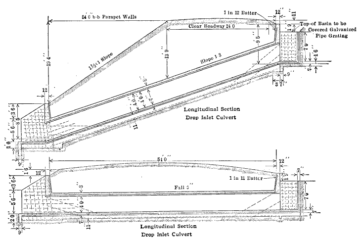 Fig. 4.—Two Types of Drop Inlet Culvert
Reinforced Concrete Box Culverts.—The pipe culvert is limited in application to the smaller waterways. Reinforced concrete is extensively used for culverts of all sizes,[Pg 41] but especially for the larger ones. These are usually constructed with endwalls integral with the barrel of the culvert. Culverts of this type must be designed for the loads anticipated to insure suitable strength and stability, and must be constructed of a good quality of concrete. Figs. 2 and 3 show designs for pipe and box culverts.
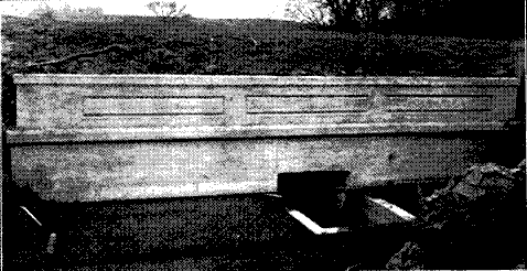 Fig. 5.—Drop Inlet Culvert
Drop Inlet Culverts.—In some locations erosion has begun in the fields adjacent to a culvert and it will probably continue until the stream above the culvert has eroded to about the level of the floor of the culvert. This is a reason for placing the culvert as high as the roadway will permit, so long as the area above the culvert will be properly drained. Considerable reclamation of land is possible if the culvert is constructed with a box at the inlet and as shown in Fig. 4. The area up-stream from the culvert will not erode below the level of the top of the box at the inlet end.
Where the stream crossing the road has eroded to considerable depth or has considerable fall, as would sometimes be the case on side hill roads, the culvert barrel would follow the general slope of the ditch but should have a drop inlet. This type of culvert is shown in Fig. 5.
Necessity for Planning.—Sometimes highway improvement is the result of spasmodic and carelessly directed work carried out at odd times on various sections of a road, finally resulting in the worst places being at least temporarily bettered. The grade on the steepest hills is probably reduced somewhat and some of the worst of the low lying sections are filled in and thereby raised. Short sections of surfacing such as gravel or broken stone may be placed here and there. From the standpoint of the responsible official, the road has been "improved," but too often such work does not produce an improvement that lasts, and sometimes it is not even of any great immediate benefit to those who use the roads. In nearly every instance such work costs more in money and labor that it is worth.
Lasting improvement of public highways can be brought about only through systematic and correlated construction carried on for a series of years. In other words, there must be a road improvement policy which will be made effective through some agency that is so organized that its policies will be perpetuated and is clothed with enough authority to be capable of enforcing the essential features of good design and of securing the proper construction of improvements.
Details of highway construction and design must vary with many local conditions and types of surface. The limits of grades and the many other details of design may properly be adopted for a specific piece of work only after an adequate investigation of the local requirements and[Pg 43] in the light of wide experience in supervising road improvement.
New ideas are constantly being injected into the art of road building, but these are disseminated somewhat slowly, so that valuable devices and improvements in methods remain long unknown except to the comparatively few who have the means for informing themselves of all such developments.
It follows then that the logical system of conducting road improvement is through an agency of continuing personnel which will supervise the preparation of suitable plans and direct the construction in accordance with the most recent experience.
Road Plans.—The information shown on the plans prepared for road improvement varies somewhat with the design and with the ideas of the engineer as to what constitutes necessary information, but in general the plans show the existing road and the new construction contemplated in an amount of detail depending principally upon the character of the construction. Simple plans suffice for grade reduction or reshaping an earth road surface, while for the construction of paved roads, the plans must be worked out in considerable detail. The essential requirement is that there be given on the plans all information necessary to enable the construction to be carried out according to the intentions of the engineer, that all parts of the work fit together, that the culverts are of the proper size and located at the proper places, ditches drain properly, grades are reduced to the predetermined rate, that excavated material is utilized and that an exact record of the work done is retained. Plans are indispensable to economical road construction and the preparation of the plans is the work of the expert in road design, that is, the highway engineer.
Problem of Design.—The problem of road design is to prepare plans for a road improvement with the various[Pg 44] details so correlated as to insure in the road constructed in accordance therewith the maximum of safety, convenience and economy to the users thereof. The degree to which the design will be effective will depend to a considerable extent upon the financial limitations imposed upon the engineer, but skill and effort on the plans will do a great deal to offset financial handicap and no pains should be spared in the preparation of the plans. Moreover, the plans must afford all of the information needed by the contractor in preparing a bid for the work.
Preliminary Investigation.—The first step in road improvement is to secure an adequate idea of the existing conditions on the road or roads involved. The detail to which this information need go will depend entirely upon the purpose of the preliminary investigation, for before a definite plan is prepared, it may be necessary to choose the best from among several available routes. For this purpose, it is not always necessary to make an actual instrument survey of the several routes. A hasty reconnaissance will usually be sufficient. This is made by walking or riding over the road and noting, in a suitable book or upon prepared blanks, the information needed. The items of information recorded will usually be as follows: distances, grades, type of soil on the road and nature of existing surface, character of drainage, location of bridges and culverts and the type of each with notes as to its condition, location of railway crossings and notes as to type, location of intersecting roads, farm entrances, and all similar features that have a bearing on the choice of routes. These data can be obtained in a comparatively short time by a skilled observer who may drive over the road in a motor car. Sometimes it may be desirable to make a more careful study of some certain sections of road and this may be done by waking over the section in question in order to make a more deliberate survey of the features to be considered than is possible when riding in a motor car.[Pg 45]
Factors other than relative lengths of routes will obviously determine the cost of improvement and the comparative merits of the improved roads. Some special characteristic of a road, such as bad railroad crossings or a few bad hills, may eliminate a route, or availability of materials along a route may offset disadvantages of alignment or grade.
In special cases, complete surveys of routes may be required finally to select the best route, but these instances are few in number.
Road Surveys.—When a road has been definitely selected for improvement, a careful survey is made to furnish information for the preparation of the plans. This will consist of a transit survey and a level survey.
The transit survey is made by running a line between established corners following the recorded route of the road, or if no records are available or the road is irregular in alignment, by establishing arbitrary reference points and running a line along the center line of the existing road or parallel thereto. The topography is referenced to this line in such completeness that it can be reproduced on the plans. The level survey consists in taking levels on cross sections of the road at one hundred foot intervals, and oftener if there are abrupt changes in grade. Special level determinations are made at streams, railroad crossings, intersecting roads or lanes and wherever it appears some special features of the terrain should be recorded.
From the surveys and such other information as has been assembled relative to the project, a plan is prepared which embodies a design presumed to provide for an improvement in accordance with the best highway practice.
It will be convenient to consider separately the components of a road design, although in the actual design the[Pg 46] consideration of these cannot be separated because all parts of the plan must fit together.
Alignment.—The alignment of the road is determined to a considerable extent by the existing right-of-way, which may follow section lines, regardless of topography, as is the case with many roads in the prairie states, or it may follow the valleys, ridges, or other favorable location in hilly country. In many places the roads of necessity wind around among the hills in order to avoid excessive grades. In designing an improvement, it is generally desirable to follow the existing right-of-way so far as possible. But the element of safety must not be lost sight of, and curves should not preclude a view ahead for sufficient distance to insure safety to vehicles. The necessary length of clear view ahead is usually assumed to be 250 feet, but probably 200 feet is a satisfactory compromise distance when a greater distance cannot be obtained at reasonable cost. To secure suitable sight distance, the curves must be of long radii, and where possible the right-of-way on the inside of the curve should be cleared of trees or brush that will obstruct the view. Where the topography will not permit a long radius curve and the view is obstructed by an embankment or by growing crops or other growth, it is desirable to separate the tracks around the curve to eliminate the possibility of accidents on the curve. This is readily accomplished if the road is surfaced, but if it is not surfaced, the same end is accomplished by making the earth road of ample width at the curve.
Relocations should be resorted to whenever they shorten distances or reduce grades sufficiently to compensate for the cost.
Intersections.—At road intersections, it is always difficult to design a curve that entirely meets the requirements of safety because there is not enough room in the right-of-way, and enough additional right-of-way must be secured[Pg 47] to permit the proper design. It is not necessary to provide an intersection that is adapted to high speed traffic, where main roads cross, but, on the contrary, a design that automatically causes traffic to slow up has distinct advantages.
Where a main route, improved with a hard surface, crosses secondary roads, it is satisfactory to continue the paved surface across the intersecting road at normal width and make no provision for the intersecting road traffic other than a properly graded approach at the intersection.
Superelevation.—On all curved sections of road, other than intersections, account is taken of the tendency of motor cars to skid toward the outside of the curve. This tendency is counteracted by designing the cross section with superelevation.
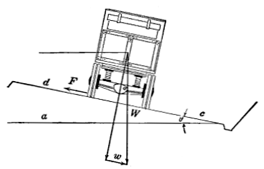 Fig. 6
In Fig. 6, F represents the tangential force that tends to cause skidding. W represents the weight of the vehicle in pounds, θ = the angle of superelevated surface c-d, with the horizontal c-a. R represents the radius of the curve upon which the vehicle is moving. w is the component of the weight parallel to the surface c-d, v = velocity[Pg 48] of the vehicle in feet per second. m = mass of vehicle = W⁄g θ
w = W tan θ
| F = | mv2 | = | wv2 |
| R | gR |
If F = w there will be no tendency to skid; hence the rate of superelevation necessary in any case is as follows:
| W tan θ = | Wv2 |
| gR |
| tan θ = | v2 |
| gR |
The amount of superelevation required, therefore, varies as the square of the velocity and inversely as the radius of the curve.
Theoretically, the amount of the superelevation should increase with a decrease in the radius of the curve and should also increase as the square of the speed of the vehicle. On account of the variation in speeds of the vehicles, the superelevation for curves on a highway can only be designed to suit the average speed. At turns approaching ninety degrees, the curve is likely to be of such short radius that it is impossible to maintain the ordinary road speed around the curve, even with the maximum superelevation permissible. It is good practice to provide the theoretical superelevation on all curves having radii greater than 300 feet for vehicle speeds of the maximum allowed by law, which is generally about 25 miles per hour. Where the radii are less than 300 feet, the theoretical superelevation for the maximum vehicle speeds gives a superelevation too great for motor trucks and horse drawn vehicles and generally no charge is made in superelevation for radii less than 300 feet, but all such curves are constructed with the same superelevation as the curve with 300 foot radius.[Pg 49]
The diagram in Fig. 7 shows the theoretical superelevation for various curve radii.
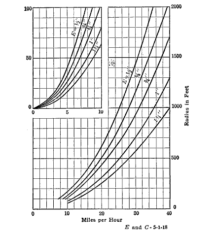 Fig. 7. Curves showing Theoretical Superelevation for
Various Degrees of Curve for Various Speeds of Vehicle
Fig. 7. Curves showing Theoretical Superelevation for
Various Degrees of Curve for Various Speeds of Vehicle
At the intersection of important highways, the problem is complicated by the necessity for providing for through traffic in both directions and for traffic which may turn in either direction and the engineer must provide safe roadways for each class of traffic.
Tractive Resistance.—The adoption of a policy regarding the grades on a road involves an understanding of the effect of variation in the character of the surface and in rate of grade upon the energy required to transport a load[Pg 50] over the highway. The forces that oppose the movement of a horse drawn vehicle are fairly well understood and their magnitude has been measured by several observers, but comparatively little is known about the forces opposing translation of rubber tired self-propelled vehicles.
The resistance to translation of a vehicle is made up of three elements: resistance of the road surface to the rolling wheel, resistance of the air to the movement of the vehicle and internal friction in the vehicle itself.
Rolling Resistance.—When the wheel of a vehicle rolls over a road surface, both the wheel and the surface are distorted. If the wheel has steel tires and the road surface is plastic, there will be considerable distortion of the road surface and very little of the wheel. A soft rubber tire will be distorted considerably by a brick road surface. Between these extremes there are innumerable combinations of tire and road surface encountered, but there is always a certain amount of distortion of either road surface or wheel, or of both, which has the same effect upon the force necessary for translation as a slight upward grade. When both the tire and the road surface strongly resist distortion (as steel tires on vitrified brick paving), the resistance to translation is low but the factor of impact is likely to be introduced. Where impact is present, energy is used up in the pounding and grinding of the wheels on the surface, and this factor increases as the speed of translation, and may be a considerable item. Impact is especially significant on rough roads with motor vehicles, particularly trucks, traveling at high speed. These two factors (impact and rolling resistance) combined constitute the major part of the resistance to translation for horse drawn vehicles.
Internal Resistance.—For horse drawn vehicles, the internal resistance consists of axle friction, which is small in amount. For self-propelled vehicles, the internal resistance consists of axle friction and friction in the driving[Pg 51] mechanism, of which gear friction and the churning of oil in the gear boxes is a large item. Internal friction is of significance in all self-propelled vehicles and especially so at high speeds.
Air Resistance.—At slow speeds, the resistance of still air to translation is small, but as the speed increases, the air resistance increases rapidly and at the usual speed of the passenger automobile on the road becomes a very considerable part of the total resistance to translation. This factor has no significance in connection with horse drawn vehicles, but is to be taken into account when dealing with self-propelled vehicles at speeds in excess of five miles per hour.
Many determinations of tractive resistance with horse drawn vehicles have been made from time to time and these show values that are fairly consistent when the inevitable variations in surfaces of the same type are taken into account. Table 4 is a composite made up of values selected from various reliable sources and Table 5 is from experiments by Professor J. B. Davidson on California highways.
| Surface | Tractive force per ton |
| Earth packed and dry | 100 |
| Earth dusty | 106 |
| Earth muddy | 190 |
| Sand loose | 320 |
| Gravel good | 51 |
| Gravel loose | 147 |
| Cinders well-packed | 92 |
| Oiled road—dry | 61 |
| Oiled road—wet | 108 |
| Macadam—very good | 38 |
| Macadam—average | 46 |
| Sheet asphalt | 38 |
| Asphaltic concrete | 40 |
| Vitrified brick—new | 56 |
| Wood block—good | 33 |
| Wood block—poor | 42[Pg 52] |
| Cobblestone | 54 |
| Granite tramway | 27 |
| Asphalt block | 52 |
| Granite block | 47 |
| Test No. | Kind of Road | Condition of Road | Tractive Total lb. | Resistance per ton lb. |
| 29-30-31 | Concrete (unsurfaced) | Good, excellent | 83.0 | 27.6 |
| [2]11-12 | Concrete (unsurfaced) | Good, excellent | 90.0 | 30.0 |
| 26-27-28 | Concrete 3/8-in. surface asphaltic oil and screenings | Good, excellent | 147.6 | 49.2 |
| 13-14 | Concrete 3/8-in. surface asphaltic oil and screenings | Good, excellent | 155.0 | 51.6 |
| 9-10 | Macadam, water-bound | Good, excellent | 193.0 | 64.3 |
| 22-23 | Topeka on concrete | Good, excellent | 205.5 | 68.5 |
| 8 | Gravel | Compact, good condition | 225.0 | 75.0 |
| [3]45-48 | Oil macadam | Good, new | 234.5 | 78.2 |
| [4]46-47 | Oil macadam | Good, new | 244.0 | 81.3 |
| 38 | Gravel | Packed, in good condition | 247.0 | 82.3 |
| 18-19-20 | Topeka on plank | Good condition, soft, wagon left marks | 265.0 | 88.3 |
| 34 | Earth road | Firm, 1½-in. fine loose dust | 276.0 | 92.0 |
| 24-25 | Topeka on plank | Good condition, but soft | 278.0 | 92.6 |
| 1-2-5 | Earth road | Dust ¾ to 2 in. | 298.0 | 99.3 |
| 3-3 | Earth | Mud, stiff, firm underneath | 654.0 | 218.0 |
| 6-7 | Gravel | Loose, not packed | 789.0 | 263.0 |
[1] Prof. J. B. Davidson in Engineering News-Record, August 17, 1918.
[2] Graphic record indicates that the load was being accelerated when test was started.
[3] Drawn with motor truck at 2½ miles per hour.
Comparatively few data are available showing the tractive resistance of motor vehicles, but the following tables are based on sufficient data to serve to illustrate the general trend.
These data on the tractive resistances of an electric truck with solid rubber tires on asphalt and bitulithic, wood, brick and granite block, water-bonded and tar macadam, cinder and gravel road surfaces were obtained by A. E. Kennelly and O. R. Schurig in the research division of the electrical engineering department of the Massachusetts Institute of Technology, and are published in Bulletin No. 10 of the division.
An electric truck was run over measured sections, ranging from 400 to 2600 feet in length, surfaced with these various materials, at certain speeds per hour, ranging from about 8 to about 15.5 miles per hour. The result of the observations of speeds, tractive resistances, conditions of surfaces, etc., were collected and studied in various combinations.
| Type of Surface | Condition of Surface | Tractive Resistance in lbs. per ton 10 miles per hr. | Tractive Resistance in lbs. per ton 12.4 miles per hr. |
| Asphalt | Good | 20.4 | |
| Asphalt | Poor | 22.6 | 25.5 |
| Wood block | Good | 24.2 | 25.3 |
| Brick block | Good | 24.6 | 26.6 |
| Granite block | Good | 40.3 | 45.75 |
| Brick block | Slightly worn | 25.1 | 28.0 |
| Granite block with cement joints | Good | 25.5 | 30.2 |
| Macadam, water bonded | Dry and hard | 23.3 | 25.8 |
| Macadam, water bonded | Fair, heavily oiled | 35.9 | 38.7 |
| Macadam, water bonded | Poor, damp, some holes | 36.3 | 41.6 |
| Tar macadam | Good | 25.7 | 28.0 |
| Tar macadam | Very soft | 36.8 | 38.7 |
| Tar macadam | Many holes, soft, extremely poor | 52.4 | 60.6 |
| Cinder | Fair, hard | 27.5 | 30.6 |
| Gravel | Fair, dusty | 30.4 | 33.0 |
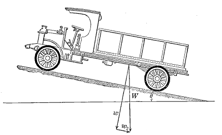 Fig. 8
Effect of Grades.—Grades increase or decrease the resistance to translation due to the fact that there is a component of the weight of the vehicles parallel to the road surface and opposite in direction to the motion when the load is ascending the hill and in the same direction when the vehicle is descending. In Fig. 8 W represents the weight of the vehicle, acting vertically downward, w is the component of the weight perpendicular to the road surface and W2 is the component parallel to the road surface.
| W2 | = | W tan θ. |
| tan θ | = | 0.01 × per cent of grade. |
| W2 | = | 0.01 W × per cent grade. |
| W2 | = | 0.01 × 2000 × per cent of grade, for each ton of weight of vehicle. |
| Hence W2 | = | 20 lbs. per ton of load for each one per cent of grade. |
The gravity force acting upon a vehicle parallel to the surface on a grade is therefore 20 lbs. per ton for each one per cent of grade and this force tends either to retard or to accelerate the movement of the vehicle.[Pg 55]
Let F = the sum of all forces opposing the translation of a vehicle.
F = fr + fi + fp + fa + fg (1)
where
fr = rolling resistance of road surface.
fi = resistance due to internal friction in the vehicle.
fp = resistance due to impact of the road surface.
fa = resistance due to air.
fg = resistance due to grade, which is positive when
ascending and negative when descending.
All of the above in pounds per ton of 2000 lbs.
Let T = the tractive effort applied to the vehicle by any means.
T >= must be greater than F in order to move the vehicle.
By an inspection of (1), it will be seen that for a given vehicle and any type of road surface, all terms are constant except fa and fg. fa varies as the speed of the vehicle and the driver can materially decrease fa by reducing speed. fg varies with the rate of grade. For any vehicle loaded for satisfactory operation on a level road with the power available, the limiting condition is the factor fg. If the load is such as barely to permit motion on a level road, any hill will stall the vehicle. Therefore, in practice the load is always so adjusted that there is an excess of power on a level road. If draft animals are employed the load is usually about one fourth of that which the animals could actually move by their maximum effort for a short period. With motor vehicles, the excess power is provided for by gearing.
If it be assured a load of convenient size is being moved on a level road by draft animals, there is a limit to the rate of grade up which the load can be drawn by the maximum effort of the animals.
Tests indicate that the horse can pull at a speed of 2½[Pg 56] miles per hour, an amount equal to 1/8 to 1/10 of its weight, and for short intervals can pull ¾ of its weight. The maximum effort possible is therefore six times the average pull, but this is possible for only short intervals. A very short steep hill would afford a condition where such effort would be utilized. But for hills of any length, that is, one hundred feet or more but not to exceed five hundred feet, it is safe to count on the draft animal pulling three times his normal pulling power for sustained effort.
The limiting grade for the horse drawn vehicle is therefore one requiring, to overcome the effect of grade, or fg, a pull in excess of three times that exerted on the level.
A team of draft animals weighing 1800 lbs. each could exert a continuous pull of about 1/10 of their weight or 360 lbs. If it be assumed that the character of the vehicle and the road surface is such that fr + fi + fp + fa = 100 lbs. per gross ton on a level section of road, then the gross load for the team would be 3.6 tons. The same team could for a short time exert an additional pull of three times 360 lbs. or 1080 lbs. For each 1 per cent of grade a pull of 20 lbs. per ton would be required or fg for the 3.6 tons load would be 72 lbs. for each per cent of grade. At that rate, the limiting grade for the team would be fifteen per cent.
If, however, the character of the vehicle and the road surface were such that fr + fi + fp + fa = 60 lbs. per gross ton on a level section of road, the gross load for the team on the level would be 6 tons, and the limiting grade 9 per cent.
The above discussion serves to illustrate the desirability of adopting a low ruling or limiting grade for roads to be surfaced with a material having low tractive resistance and the poor economy of adopting a low ruling grade for earth roads or roads to be surfaced with material of high tractive resistance.
It may be questioned whether horse drawn traffic should be the limiting consideration for main trunk line highways,[Pg 57] but it is certain that for a number of years horse drawn traffic will be a factor on secondary roads.
In the case of motor vehicles, excess power is provided by means of gears and no difficulty is encountered in moving vehicles over grades up to 12 or 15 per cent, so that any grade that would ordinarily be tolerated on a main highway will present no obstacle to motor vehicles, but the economy of such design is yet to be investigated.
Energy Loss on Account of Grades.—Whether a vehicle is horse drawn or motor driven, energy has been expended in moving it up a hill. A part of this energy has been required to overcome the various resistances other than grade, and that has been dissipated, but the energy required to translate the vehicle against the resistance due to grade has been transformed into potential energy and can be partially or wholly recovered when the vehicle descends a grade, provided the physical conditions permit its utilization. If the grade is so steep as to cause the vehicle to accelerate rapidly, the brakes must be applied and loss of energy results. The coasting grade is dependent upon the character of the surface and the nature of the vehicle. In the cases discussed in the preceding paragraph, the coasting grades would be five per cent and three per cent respectively. For horse drawn vehicles then the economical grades would be three and five per cent, which again emphasizes the necessity of lower grades on roads that are surfaced than on roads with no wearing surface other than the natural soil.
The theory of grades is somewhat different when motor vehicles are considered, since it is allowable to permit considerably higher speed than with horse drawn vehicles before applying the brakes and the effect of grade can be utilized not only in translating the vehicle down the grade, but also in overcoming resistances due to mechanical friction and the air. On long grades, a speed might be attained that would require the use of the brake or the same[Pg 58] condition might apply on very steep short grades. There is at present insufficient data on the tractive resistance and air resistance with motor vehicles to permit the establishing of rules relative to grade, but experience indicates a few general principles that may be accepted.
If a hill is of such rate of grade and of such length that it is not necessary to use the brake it may be assumed that no energy loss results so far as motor vehicles are concerned. Where there is no turn at the bottom of the hill and the physical condition of the road permits speeds up to thirty-five or forty miles per hour grades of five per cent are permissible if the length does not exceed five hundred feet and grades of three per cent one thousand feet long are allowable. It is a rather settled conviction among highway engineers that on trunk line highways the maximum grade should be six per cent, unless a very large amount of grading is necessary to reach that grade.
Undulating Roads.—Many hills exist upon highways, the grade of which is much below the maximum permissible. If there are grades ranging from 0 to 4 per cent, with a few hills upon which it is impracticable to reach a grade of less than six per cent, it is questionable economy to reduce the grades that are already lower than the allowable maximum. It is especially unjustifiable to incur expense in reducing a grade from two per cent to one and one-half per cent on a road upon which there are also grades in excess of that amount. The undulating road is not uneconomical unless the grades are above the allowable maximum or are exceptionally long or the alignment follows short radius curves.
Safety Considerations.—On hills it is especially desirable to provide for safety and curves on hills are always more dangerous than on level sections of road. Therefore, it is desirable to provide as flat grades as possible at the curves and to cut away the berm at the side of the road so as to give a view ahead for about three hundred feet.[Pg 59] Whether a road be level or on a hill, safety should always be considered and the most important safety precaution is to provide a clear view ahead for a sufficient distance to enable motor vehicle drivers to avoid accidents.
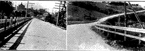 Fig. 9.—Types of Guard Rails
Guard Railing.—When a section of road is on an embankment, guard rails are provided at the top of the side slope to serve as warnings of danger, and to prevent vehicles from actually going over the embankment in case of skidding, or if for any reason the driver loses control. These are usually strongly built, but would hardly restrain a vehicle which struck at high speed. But they are adequate for the protection of a driver who uses reasonable care. A typical guard rail is shown in Fig. 9, but many other designs of similar nature are employed. At very dangerous turns a solid plank wall six or eight feet high is sometimes built of such substantial construction as to withstand the severest shock without being displaced.
Trees, shrubs and the berms at the side of the road in cuts are particularly likely to obstruct the view and should be cleared or cut back so far as is necessary to provide the proper sight distance.
Width of Roadway.—For roads carrying mixed traffic, 9 feet of width is needed for a single line of vehicles and 18 feet for 2 lines of vehicles. In accordance with the above, secondary roads, carrying perhaps 25 to 50 vehicles[Pg 60] per day, may have an available traveled way 18 feet wide. Those more heavily traveled may require room for three vehicles to pass at any place and therefore have an available traveled way 30 feet wide. Greater width is seldom required on rural highways, and 20 feet is the prevailing width for main highways.
Cross Section.—The cross section of the road is designed to give the required width of traveled way, and, in addition, provide the drainage channels that may be needed. In regions of small rainfall the side ditches will be of small capacity or may be entirely omitted, but usually some ditch is provided. The transition from the traveled way to ditch should be a gradual slope so as to avoid the danger incident to abrupt change in the shape of the cross section. The depth of ditch may be varied without changing to width or slope of the traveled part of the road as shown in Fig. 10.
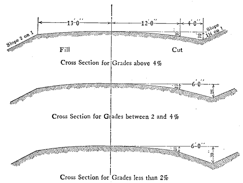 Fig. 10
Control of Erosion.—The construction of a highway may be utilized to control general erosion to some extent, particularly when public highways exist every mile or two and are laid out on a gridiron system, as is the case in many of the prairie states. The streams cross the highways at frequent intervals and the culverts can be placed so as effectually to prevent an increase in depth of the stream. This will to some extent limit the erosion above the culvert and if such culverts are built every mile or two along the stream, considerable effect is produced.
Where small streams have their origin a short distance from a culvert under which they pass, it is sometimes advisable to provide tile for carrying the water under the road, instead of the culvert, and, by continuing the tile into the drainage area of the culvert, eliminate the flow of surface water and reclaim considerable areas of land.
Erosion in the ditches along a highway can be prevented by constructing weirs across the ditch at frequent intervals, thus effectually preventing an increase in the depth of the ditch.
Wherever water flows at a velocity sufficient to produce erosion or where the drainage channel changes abruptly from a higher to a lower level, paved gutters, tile or pipe channels should be employed to prevent erosion.
Private Entrances.—Entrance to private property along the highway is by means of driveways leading off the main road. These should always be provided for in the design so as to insure easy and convenient access to the property. The driveways will usually cross the side ditch along the road and culverts will be required to carry the water under the driveway. Driveways that cross a gutter by means of a pavement in the gutter are usually unsatisfactory, and to cross the gutter without providing a pavement is to insure stoppage of the flow at the crossing. The culvert at a driveway entrance must be large enough to take the ditch water readily or it will divert the water to the roadway[Pg 62] itself. Generally end walls on such culverts are not required as in the case of culverts across a highway.
Aesthetics.—Much of the traffic on the public highways is for pleasure and relaxation and anything that tends to increase the attractiveness of the highways is to be encouraged. Usually the roadside is a mass of bloom in the fall, goldenrod, asters and other hardy annuals being especially beautiful. In some states wild roses and other low bushes are planted to serve the two-fold purpose of assisting to prevent erosion and to beautify the roadside. In humid areas trees of any considerable size shade the road surface and are a distinct disadvantage to roads surfaced with the less durable materials such as sand-clay or gravel. It is doubtful if the same is true of paved surfaces, but the trees should be far enough back from the traveled way to afford a clear view ahead. Shrubs are not objectionable from any view-point and are to be encouraged for their beauty, so long as they do not obstruct the view at turns.
Highways constructed without the addition of surfacing material to the natural soil of the right-of-way are usually called earth roads. But if the natural soil exhibits peculiar characteristics or is of a distinct type, the road may be referred to by some distinctive name indicating that fact. Hence, roads are referred to as clay, gumbo, sandy or caliche roads as local custom may elect. In each case, however, the wearing surface consists of the natural soil, which may have been shaped and smoothed for traffic or may be in its natural state except for a trackway formed by the vehicles that have used it.
Variations in Soils.—The nature of the existing soil will obviously determine the serviceability and physical characteristics of the road surface it affords. That is to say that even under the most favorable conditions some earth roads will be much more serviceable than others, due to the better stability of the natural soil. Some soils are dense and somewhat tough when dry and therefore resist to a degree the tendency of vehicles to grind away the particles and dissipate them in the form of dust. Such soils retain a reasonably smooth trackway in dry weather even when subjected to considerable traffic. Other soils do not possess the inherent tenacity and stability to enable them to resist the action of wheels and consequently grind away rapidly. Roads on such soils become very dusty. These are the extremes and between them are many types of soils or mixtures of soils possessing varying degrees of stability, and, in consequence, differing rates of wear.[Pg 64] Similarly the various soils exhibit different degrees of stability when wet.
It is to be expected that soils will differ with the geographical location, for it is well known that there is a great variation in soils in the various parts of the world. But wide differences are also encountered in the soil on roads very near each other and even on successive stretches of the same road. It is for this reason that earth roads often exhibit great differences in serviceability even in a restricted area.
Variation in Rainfall.—The stability of a soil and its ability to support the weight of vehicles varies greatly with the amount of water in the soil. A certain small amount of moisture in the soil is beneficial in that practically every soil compacts more readily when moist than when dry because the moisture aids in binding together the particles. But most soils also become unstable when the amount of water present is in excess of that small amount referred to above and the stability decreases very rapidly as the amount of water in the soil increases.
The serviceability of an earth road will change continually as the moisture content of the soil changes and consequently the general utility of the earth road system in any locality is dependent to a considerable extent upon the amount and seasonal distribution of precipitation. The methods of maintaining earth roads appropriate to any locality must of necessity be adapted to the climatic conditions, and the amount of work required to give the highest possible degree of serviceability will be exceedingly variable from season to season and from place to place. In regions of great humidity, earth roads may be expected to have a low average of serviceability, while in arid regions they may possess sufficient durability for a considerable volume of traffic. The design adopted for earth roads and the methods of maintenance followed should therefore be carefully evolved to meet the soil and climate conditions[Pg 65] where the roads are located. These will differ greatly throughout a state or even a county.
Cross Sections.—The general principles of road design were set forth in Chapter IV. In Fig. 11 are shown typical cross sections for earth roads adapted to various conditions as indicated. It is not apparent that one form of ditch is particularly preferable to the other and since some engineers prefer the V section and others the trapezoidal section both are shown. It would appear that the V shaped ditch is somewhat the easier to construct with the blade grader while the trapezoidal is readily excavated with the slip or fresno scraper. The ditch capacity required and consequently the dimensions will depend upon the drainage requirements, as was pointed out in Chapter III.
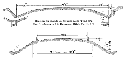 Fig. 11. Cross Section for Earth Roads
In the zones where the annual precipitation exceeds 30 inches distributed over several months, earth roads will be unserviceable for a considerable period each year unless they are constructed so as to minimize the effect of water. This is done by providing for the best possible drainage[Pg 66] and by adopting a method of maintenance that will restore the surface to a smooth condition as quickly as possible after a period of rainy weather or after the "frost comes out" in the spring.
Before the construction of the desired cross section is undertaken, all of the grade reduction should be completed, except for minor cuts which can be handled with the elevating grader in the manner that will be described presently.
Where any considerable change in grade is to be effected, the earth can be moved in several ways and of these the most economical cannot be readily determined. Ordinarily a contractor or a county will use the equipment that happens to be at hand even though some other might be more advantageous.
Elevating Grader.—Where the topography is such as to permit its use, the elevating grader is employed in grade reduction to load the earth into dump wagons in which it is hauled to the fill or waste bank. The elevating grader consists essentially of a heavy shear plow or disc plow which loosens the earth and deposits it on a moving canvas apron. The apron carries the material up an incline and deposits it into a wagon which is driven along under the end of the apron. When the wagon is loaded, the grader is stopped while the loaded wagon is hauled out and an empty one drawn into position. The motive power for the elevating grader is either a tractor or five or six teams of mules. For many kinds of work, particularly where frequent turning is necessary or where the ground is yielding, mules are preferable to a tractor. The apron is operated by gearing from the rear wheels of the grader. Generally four mules are hitched to a pusher in the rear of the grader and six or eight in the lead. This method of grade reduction is particularly advantageous when the material must be hauled a distance of 500 yards or more, because wagon hauling in such cases is the most economical method to employ. A tractor may be used to draw the elevating[Pg 67] grader and one having a commercial rating of 30 to 45 horsepower is required.
Maney Grader.—If the haul is long and the nature of the cut will not permit the use of the elevating grader because of excessive grades or lack of room for turning, a grader of the Maney type may be used. This consists of a scoop of about one cubic yard capacity, suspended from a four-wheel wagon gear. When loading, the scoop is let down and filled in the same manner as a two-wheeled scraper or "wheeler." The pull required to fill a Maney grader is so great that a tractor is ordinarily employed in place of a "snap" team. The tractor is hitched at the end of the tongue, without interfering with the team drawing the grader. One team readily handles the grader after it is loaded. For this service a tractor having a commercial rationing of 25 to 30 horsepower is required.
Wheel Scraper.—For moving earth for distances between 150 and 500 yards, the wheel scraper of a capacity of about 1½ yards is quite generally employed. The soil must be loosened with a plow before it can conveniently be loaded into the wheeler and a heavy plow is ordinarily employed for that purpose. Two furrows with the plow will loosen a strip of earth about as wide as the scoop of the scraper and if more is loosened it will be packed down by the scrapers wheeling in place to load. A helper or "snap" team is employed to assist in loading, after which the wheel scraper is handled by one team.
Slip Scraper.—The slip scraper differs from the wheel scraper in that the scoop is not suspended from wheels but is dragged along the ground. It is drawn by one team and the capacity is two to five cubic feet, but the material spills out to some extent as the scraper is dragged along and the method is not suitable for long hauls, 100 feet being about the economical limit.
Fresno Scraper.—The Fresno scraper is one form of slip scraper requiring four horses or mules for efficient[Pg 68] work. It differs somewhat from the ordinary slip scraper in shape and is of larger capacity, but is a drag type of scraper much favored in the western states.
If a road has been graded so that the profile is satisfactory or if the existing profile of the location is satisfactory, and the surface is to be shaped to a prescribed cross section, either the elevating grader or the blade grader may be employed.
Elevating Grader Work.—If the elevating grader is used in shaping the earth road, the apron will be lowered and the material will be excavated at the sides of the road and deposited on the middle portion. If slight changes in grade are desired, wagons will accompany the grader and catch under the apron at the high places and haul the material to the low places. After the earth has been deposited it must be worked over to secure the correct cross section and be made passable for vehicles. This requires that clods be broken, weeds and grass that are mixed with the earth be removed by harrowing and forking and that the surface be carefully smoothed with a blade grader. This latter operation will have to be repeated several times before a satisfactory surface is secured. But this miscellaneous work is highly important and under no circumstances ought to be neglected. Nothing so detracts from an otherwise creditable piece of work as failure to provide a smooth surface for the use of vehicles. It is especially uncomfortable for the users of a highway if sods and weeds in quantity are left in the road after it has been graded. The humus that will be left in the soil as the vegetable matter decays increases the porosity of the road surface making it more absorbent than soil without humus. This increases the susceptibility to softening from storm water or ground water.[Pg 69]
The tractor can advantageously be used to draw the elevating grader on this class of work, but will be greatly handicapped if there are wet sections along the road, through which the tractor must be driven. In many cases its use is prohibited by such conditions and for all-round service of this character, mules are preferred for motive power.
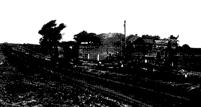 Fig. 12.—Tractor-grader Outfit
Use of Blade Grader.—Heavy blade graders designed to be drawn by a tractor are suitable for shaping the earth road. Some of these have blades 12 feet long and excellent control for regulating the depth of cutting. Often two such graders are operated tandem. These machines have a device which permits the operator to steer the grader independently of the tractor. Thus the grader can be steered off to the side to cut out the ditches, while the tractor continues to travel on the firm part of the road. Earth moved with the blade grader is usually fairly free from large lumps and can readily be smoothed to a satisfactory surface for the use of traffic. The sods and weeds will be drawn into the road along with the earth just as they are when the elevating grader is employed. Precaution must therefore be taken to eliminate them before the vegetable[Pg 70] matter decays, and to smooth the surface for the use of traffic.
Costs.—The cost of shaping an earth road in the manner described above will vary through rather wide limits because the nature and amount of work to be done varies so greatly. Some roads can be graded satisfactorily for $300.00 per mile, while others will cost $700.00. But $425.00 per mile may be taken as an average for blade or elevating grader work plus a moderate amount of grade reduction in the way of removing slight knolls. For the amount of grade reduction necessary in rolling country, followed by grader shaping, $1000.00 to $1800.00 per mile will be required. The method is not adapted to rolling country where the roads are undulating and require some grade reduction on every hill. For hilly roads one of the methods described for grade reduction will be required and the cost will obviously depend upon the amount of earth moved. Averages of cost figures mean nothing in such cases as the cost may reach $10,000.00 per mile, or may be as low as $2000.00 per mile.
Maintenance.—Regardless of the care with which an earth road has been graded, it will be yielding and will readily absorb water for a long time after the completion of the work. The condition of the surface will naturally deteriorate rapidly during the first season it is used unless the road receives the constant maintenance that is a prerequisite to satisfactory serviceability. The road drag is generally recommended for this purpose, and if a drag is properly used it will serve to restore the shape of the surface as fast as it is destroyed by traffic.
Good results with the drag depend upon choosing the proper time to drag and upon doing the work in the right way when using the drag. The best time to drag is as soon after a rain as the road has dried out enough to pack under traffic. If the work is done while the road is too wet, the first vehicles traveling the road after it has been dragged[Pg 71] will make ruts and to a considerable extent offset the good done by the drag. If the road is too dry, the drag will not smooth the irregularities. A little observation will be required to determine the proper time for dragging on any particular soil, but usually after a rain or thaw there is a period lasting a day or two when conditions are about right.
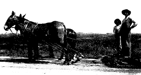 Fig. 13.—Road Drag
The drag is used merely to restore the shape of the surface and to do so a small amount of material is drawn toward the middle of the road. But there must not be a ridge of loose material left in the middle after the work is completed. Some patrolmen start at one side of the road and gradually work across the road on successive trips, finally finishing up at the side opposite that at which the start was made. The next dragging should start on the opposite side from the first if that method is followed.
By shifting his weight on the drag, the operator can adjust the cutting edge so that very little loose material is moved crosswise of the road and that is the proper method to pursue. In that case no ridge will remain at the middle[Pg 72] of the road. If a slight one is left it should be removed by a final trip with the drag.
In addition to the dragging, weeds must be cut along the road about twice a year, the ditches must be kept cleaned out and culverts open.
All of the maintenance for 10 miles of earth road can be accomplished by one man giving his entire time to the work, and that is the only method that has proven adequate to the problem.
In areas where the rainfall is less than 18 inches per year, and especially where it is 10 inches or less, an entirely different road problem exists. The effect of precipitation is of significance primarily from the standpoint of erosion, and the design of cross section and ditches and the culvert provisions are entirely different from those necessary in humid regions.
Frequently the rainfall in semi-arid regions will be seasonal and provision must be made to care for a large volume of water during the rainy season, but, in general, road design is adapted to prevention of erosion rather than to elimination of ground water effects, or the softening effects of surface water. Generally the rainy period does not last long enough to warrant expensive construction to eliminate its general effects. In fact, the saturation of the soil is more likely to be a benefit than otherwise.
Earth roads are likely to be satisfactory except where the traffic is sufficient to grind the surface into dust to such an extent that an excessive dust layer is produced. In such locations the problem is one of providing a durable surface unaffected by long continued dry weather.
Grade reduction will have the same importance as in humid areas and will be carried out in the same way.
Maintenance will consist in repairing the damage from occasional floods and in removing or preventing accumulations[Pg 73] of drifting sand or dust. Crude petroleum oils have been satisfactory for maintenance in such locations when used on stable soils.
Value of Earth Roads.—The serviceability of the earth road depends to a large extent upon the care exercised in its maintenance. The only part of earth road construction that is permanent is the grade reduction. The cross section that is so carefully shaped at considerable cost may flatten out in one or two years, especially if the road goes through unusually wet periods. Traffic will continually seek a new track during the period when the road is muddy and is as likely to cross the ditch to the sod near the fence as to use any other part of the road. Continual and persistent maintenance is therefore essential to even reasonable serviceability. At best the earth road will be a poor facility for a considerable period each year in the regions of year-around rainfall. In most localities, roads of distinctly minor importance are of necessity only earth roads and for the comparatively small territory they serve and the small amount of traffic, they probably serve the purpose. For roads of any importance in the humid areas of the United States, the earth road cannot carry satisfactorily the traffic of a prosperous and busy community.
In Chapter IV, mention was made of the variation in serviceability of road surfaces composed of the natural soil existing on the right-of-way of the road. It has been found that soils of a clayey nature in which there is a considerable percentage of sand usually afford a serviceable road surface for light or moderate traffic, especially in areas where climatic conditions are favorable. A study of these soils, together with the construction of experimental roads of various mixtures of sand and clay, has led to a fairly comprehensive understanding of the principles of construction and range of capacity of this type of road surface, which is known as the sand-clay road.
The sand-clay road surface consists of a natural or artificial mixture of sand and clay, in which the amount of clay is somewhat greater than sufficient to fill the voids in the dry sand. It may be assumed that the sand contains 40 per cent of voids and that at least 45 per cent of clay is required to fill the voids and bind the sand grains together, because the clay spreads the sand grains apart during the mixing, thus having the effect of increasing the voids. As a matter of experiment, it is found to be impractical to secure by available construction methods mixtures of sufficient uniformity to render it necessary to exercise great exactness in proportioning the components, but reasonable care in proportioning the materials is desirable.
Successful utilization of this type of surface requires considerable study of available materials and investigations of their behavior when combined. Extensive and exhaustive[Pg 75] experiments have been conducted with sand-clay mixtures in various places where they are widely used for road surfaces and the following general principles have been deduced.
The Binder.—In the sand-clay road, stability is obtained by utilizing the bonding properties possessed to some degree by all soils. Naturally this characteristic may be expected to vary widely with the several types of soil. It is generally considered to be a common property of clay, but the term clay is a general one that is often applied to soils differing greatly in physical characteristics and the term therefore loses its significance in this connection. Those soils that are properly and technically called clay are decidedly sticky when wet and are the best materials for sand-clay construction. Of the clays, those that produce a tough sticky mud are best. This can be tested by mixing a small quantity into a stiff mud and molding it into a ball and immersing in water. If the ball retains its shape for some little time, it is likely to prove a very satisfactory binder, but, if it becomes plastic and loses its shape, it will be an inferior binder, as a general rule. The ball clay, as the former is called, may be of any color common to soils, not necessarily yellow or reddish as is sometimes supposed. Likewise, balls of mixtures containing varying percentages of sand and the binder to be used may be made up and immersed in water. The mixture that holds its shape longest is of course the best combination of the materials and indicates the mixture to use in the construction.
An ideal, or even a fairly satisfactory soil for a binder may not exist in the vicinity of a proposed improvement, and consequently an inferior binder is frequently the only material available.
Sometimes deposits of clay or gravel contain a considerable percentage of gypsum which serves as a binder and is particularly effective when used in combination with clay and sand or gravel.[Pg 76]
In many places a soil of the type used for adobe and called "caliche" may be found and this is an excellent binder for sand or gravel.
Top-Soil or Natural Mixtures.—Deposits consisting of a natural mixture of sand and clay in which the ingredients happen to exist in about the correct relative proportions for sand-clay road surfaces are found in many localities. These mixtures are commonly referred to as top-soil. If the deposits are somewhat deficient either in sand or clay, they can be utilized if the proper corrections in the proportions are made during construction. Very satisfactory road surfaces are sometimes constructed with mixtures that appear to be far from ideal in composition, but experience and frequent trials are needed to determine the best way in which to handle these mixtures.
Sand-Clay Surfaces on Sandy Roads.—Sand-clay surfaces may be constructed on naturally sandy roads either by adding clay and mixing it with the sand to secure the desired composition, or a layer of a natural sand-clay mixture, caliche or sand-clay-gypsum may be placed on top of the sand.
The most widely used method is to mix clay or other binder with the sand. Since there is no need to provide for ditches to carry storm water on a deep sand soil, the sand is graded off nearly flat across the road and no ditches are provided. The clay is dumped on the road in a layer about 8 inches thick and is then mixed into the sand. It is desired to mix enough sand with the clay to produce a mixture composed of approximately 1/3 clay and 2/3 sand. The mixing is accomplished in various ways, the most common being to use a heavy plow at first and to follow this with a heavy disc harrow. The mixing is a tedious and disagreeable process, but its thorough accomplishment is indispensable. The mixing is most readily done when the materials are saturated with water and in practice it is customary to depend upon rain for the water, although in[Pg 77] the final stages water may be hauled and sprinkled on the road to facilitate final completion of the mixing. After the mixing has been completed, the surface is smoothed with the blade grader and is kept smooth until it dries out. Repeated dragging will be required, during the first year especially, and to some extent each year in order to keep the surface smooth, but the dragging can be successfully accomplished only when the road is wet.
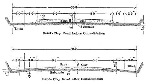 Fig. 14.—Cross Sections for Sand-Clay Roads
In regions where several months of continued hot, dry weather is to be expected each year, the sand-clay mixture is likely to break through unless it is of considerable thickness and generally the surface layer is made much thicker than for regions where the annual rainfall is fairly well distributed. This is especially necessary when the binder is of inferior quality. It is not uncommon in such cases to make the sand-clay surface as much as two feet thick.
As the mixing progresses it may appear that patches here and there are deficient in either clay or sand and the mixture in these places is corrected by the addition of a little sand or clay as may be required.[Pg 78]
If the top-soil is used it is deposited on the sand in the required quantity and is remixed in place to insure uniformity. If either sand or clay is needed to give a satisfactory mixture, the proper material is added and mixed in as the work progresses. The surface is finally smoothed by means of the grader and drag.
Sand-Clay on Clay or Loam.—If the existing road is of clay or loam, ample drainage will be required as discussed in Chapter IV. The surface may be constructed of a natural sand-clay mixture or of a sand mixed with the natural soil. If the former, the surface of the existing road is prepared by grading so as to insure good drainage and the natural mixture is then deposited and the surface completed as described in the preceding section.
If the surface is formed by mixing sand with the existing soil, the sands may be deposited in a layer about six inches thick which will gradually mix with the soil as the road is used. A second application of sand may follow in a year or two if it is needed. Such a road surface will lack uniformity of composition and it seems preferable to mix the sand with the soil by plowing and discing as previously described.
Characteristics.—Sand-clay road surfaces do not have sufficient durability for heavily traveled highways, but will be satisfactory for a moderate amount of traffic. These surfaces have maximum serviceability when moist, not wet, and consequently are not as durable in dry climates as in humid areas. They are likely to become sticky and unstable in continued wet weather and to become friable and wear into chuck holes in long continued dry weather. At their best, they are dustless, somewhat resilient and of low tractive resistance.[Pg 79]
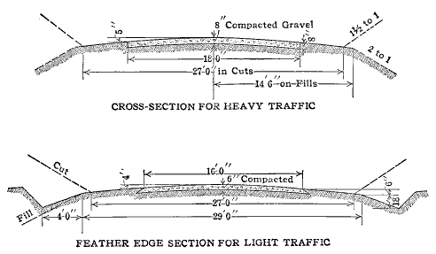 Fig. 15.—Cross Sections for Gravel Highways
Natural Gravel.—Gravel is the name given to a material consisting of a mixture of more or less rounded stones, sand and earthy material, which is found in natural deposits. These deposits exist in almost every part of North America, being especially numerous in the glaciated areas, but by no means confined to them. Gravel deposits consist of pieces of rock varying in size from those of a cubic yard or more in volume to the finest stone dust, but with pieces ranging in size from that which will pass a 3-inch ring down to fine sand predominating. The larger pieces are usually more or less rounded and the finer particles may be rounded or may be angular. Many varieties of rocks are to be found among the gravel pebbles, but the rocks of igneous origin and possessing a considerable degree of hardness generally predominate. Intermixed with the pieces of rock there is likely to be clay or other soil, the quantity varying greatly in different deposits and even in various places in the same deposits.[Pg 80]
Often there are found deposits of material which are by the layman termed gravel, which are really clayey sand or sand containing a few pebbles, but which are of value to the road builder for the sand clay type of surfacing. The term gravel is exceedingly general and unless specifically defined, gives little indication of the exact nature of to which it is applied.
| Per Cent Clay by Weight | Cementing Value | |
| As Received | Washed | |
| 4.4 | 276 | 43 |
| 6.4 | 105 | 285 |
| 5.1 | 241 | 70 |
| 14.5 | 500 | 279 |
| 8.5 | 500 | 112 |
| 10.1 | 300 | 267 |
| 14.8 | 500 | 107 |
| 7.5 | 184 | 198 |
| 16.5 | 500 | 428 |
| 2.0 | 185 | 239 |
| 1.5 | 500 | 500 |
| 4.5 | 212 | 204 |
| 2.5 | 116 | 363 |
The value of any gravel for road surfacing depends upon the degree to which it possesses the properties of an ideal gravel for road surfacing. Ideal gravel is seldom encountered, but a consideration of its characteristics serves to establish a measure by which to estimate the probable value of any deposit.
The Ideal Road Gravel.—The ideal road gravel is a mixture of pebbles, sand and earthy material, the pieces varying from coarse to fine in such a manner that when the gravel is compacted into a road surface the spaces[Pg 81] between the larger pebbles are filled with the finer material. The pebbles are of a variety of rock that is highly resistant to wear so that the road surface made from the gravel will have the quality of durability. The gravel possesses good cementing properties, insuring that the pieces will hold together in the road surface. The cementing property may be due to the rock powder in the deposit or to earthy material mixed with the rock particles, or to both. Table 7 shows the results of a number of tests made upon gravels and indicates that the cementing property of the gravel does not always depend upon the clay content.
Permissible Size of Pebbles.—The larger pebbles in the gravel are less likely to crush under loads than smaller pebbles of the same sort of rock, but if the rock is of some of the tougher varieties such as trap, there is very little likelihood of even the smaller pebbles crushing. If the pebbles are of rock of medium toughness, the smaller pebbles might be crushed under the heavier loads. It is the usual practice to permit gravel to be used for the foundation course in which the pebbles are as large as will pass a 3½-inch circular screen opening, and for the wearing course, as large as will pass a 2½-inch circular screen opening. If larger pebbles are allowed in the wearing course, the surface is certain to become rough after a time. If the gravel is to be placed in a single course as is a very common practice, then the maximum size should not exceed that which will pass a 2½-inch circular screen opening.
The Wisconsin Highway Commission has constructed a very large mileage of excellent gravel roads and the sizes specified for their roads are as follows:
"Bottom Course Gravel.—Bottom course shall consist of a mixture of gravel, sand and clay with the proportions and various sizes as follows:
"All to pass a two-inch screen and to have at least sixty and not more than seventy-five per cent retained on a quarter-inch screen; at least twenty-five and not more than seventy-five per cent of the total coarse aggregate to be retained on a one-inch screen; at least sixty-five and not[Pg 82] more than eighty-five per cent of the total fine aggregate to be retained on a two hundred-mesh sieve."
"Top Course Gravel.—Top course shall consist of a mixture of gravel, sand and clay with the proportions of the various sizes as follows:
"All to pass a one-inch screen and to have at least fifty and not more than seventy-five per cent retained on a quarter-inch screen; at least twenty-five and not more than seventy-five per cent of the total coarse aggregate (material over one-fourth inch in size) to be retained on a one-half-inch screen; at least sixty-five and not more than eighty-five per cent of the total fine aggregate (material under one-fourth inch in size) to be retained on a two hundred-mesh sieve."
"Screened Gravel and Sand Mixtures.—Where it is impossible to obtain run of bank gravel containing the necessary binder in its natural state, screened gravel shall be used and the necessary sand and clay binder added as directed by the engineer. Gravel and sand shall be delivered on the work separately. Clay binder shall be obtained from approved pits and added as directed by the engineer."
"Run of Bank Gravel.—When run of bank gravel is permitted either for one course or two course work, the size shall not exceed that specified for bottom or top course. If necessary, the contractor shall pass all the material through a two-inch screen for the bottom course, and through a one-inch screen for the top course. When the work consists of only one course, the material shall be of the sizes as specified for the top course. The necessary binder shall be contained in the material in its natural state, excepting that a small percentage of clay binder may be added as directed by the Engineer."
Wearing Properties.—A certain amount of grinding action takes place on the road surface under the direct action of wheels, especially those with steel tires. Where rubber tired traffic predominates, this action is much less severe than where steel tired vehicles predominate, but the tendency exists on all roads. In addition, there is distortion of the layer of gravel under heavy loads which causes the pieces of stone in the surface to rub against each other and to wear away slowly.
The gravel road in the very best condition is slightly uneven but there is comparatively little jar imparted to vehicles, and, consequently, little impact on the surface. When somewhat worn, the impact becomes a factor of some[Pg 83] importance and the pounding of vehicles has a very destructive action on the surface. Soft pebbles will be reduced to dust in a comparatively short time.
The degree to which any gravel resists the destructive action of traffic depends upon the varieties of rock represented by the pebbles in the gravel. If the pebbles are mostly from rocks of good wearing properties, that quality will be imparted to the road surface. If mostly from rocks of little durability, the same characteristic will be imparted to the road surface. A very good general notion of the probable durability of gravel can therefore be obtained by a careful visual examination of the material and classification of the rock varieties represented by the pebbles.
Utilizing Natural Gravels.—Gravel road construction is advantageous only when it can be accomplished at low first cost. This usually presupposes a local supply of gravel that can be utilized, or at any rate a supply that need not be shipped a long distance. In the nature of things, such deposits are likely to be deficient in some of the desirable characteristics, and may be deficient in most of them. By various means, the defects in the materials can be partially corrected while constructing the road.
If the gravel deposit consists of layers of varying composition as regards size and clay content, the material may be loosened from the exposed face and allowed to fall to the bottom of the pit thereby becoming mixed to a sufficient extent to produce a reasonably uniform product. If deficient in clay, it often proves feasible to add a small part of the clay over-burden, thereby insuring enough binder. Sometimes adjoining deposits will consist one of relatively fine material, the other of relatively coarse. These may be mixed on the work by first placing the coarse material in a layer about 5 inches thick and adding the finer material in a similar layer. The two will mix very rapidly during the operations of spreading and shaping.[Pg 84]
When deposits contain pebbles larger than will pass a 3½-inch ring, these larger stones will prove to be undesirable if placed on the road, as they are almost sure to work to the surface of the gravel layer and become a source of annoyance to the users of the road. Oversize stone can be removed while loading the gravel or while spreading it, if care is exercised and not too large a proportion is oversize. It is preferable however to remove the oversize by means of screens at the pit. Usually on large jobs the oversize is crushed and mixed with the supply so as to utilize what is really the best part of the material.
Gravels deficient in bonding material are often encountered in deposits where there is insufficient overburden to give enough additional binder or where the overburden is of a material unsuitable for binder. Such materials may be utilized by adding binder in the form of clay after the gravel has been placed on the road.
Almost any gravel deposit can be utilized in some way if the material is of a durable nature, regardless of other characteristics. The serviceability of a gravel road will depend largely on how nearly the gravel approaches the ideal, but variations in the manipulations will do much to overcome deficiencies in materials.
Thickness of Layer.—The thickness of the layer of gravel required depends both upon the type of soil upon which it is placed and the nature of the traffic to which the road will be subjected. Gravel surfaces should not ordinarily be constructed on highways carrying heavy truck traffic, but if gross loads of three or four tons are the heaviest anticipated, the gravel will be reasonably stable. On such roads, a layer of well compacted gravel ten inches thick will support the loads if a well drained earth foundation is provided. If but little truck traffic is anticipated and loads up to three tons on steel tires are the average, a layer 8 inches thick will be sufficient. In dry climates, a[Pg 85] layer six inches thick will be adequate if it can be kept from raveling.
On secondary roads, carrying principally farm-to-market traffic, and not a great volume of that, the above thicknesses may be reduced about one-fourth.
The exact thickness needed for any particular road is a matter for special study on account of the variations in the gravels and in the supporting power of the soil upon which they are placed.
Preparation of the Road.—The roadway that is to be surfaced with gravel is first brought to the desired grade and cross section. It would be advantageous if this could be done a year before the gravel is placed so that no settlement of the earth foundation would occur after the gravel surface is completed. But if that is impractical, the grading may be done just prior to placing the gravel, providing appropriate methods are adopted for securing compacted fills.
Trench Method.—Two distinct methods of placing the gravel are in general use, known as the trench method and the surface or feather edge method respectively. The method to adopt for any particular road will depend largely on certain conditions that will be explained later.
In the trench method, a trench of the proper width and depth for receiving the gravel is excavated in the earth road surface and the gravel is placed therein.
The trench is formed by plowing a few furrows and scraping out the loosened earth with a blade grader. The loose material is generally moved out laterally to build up earth berms or "shoulders" alongside the gravel. Into this trench the gravel is dumped in the proper quantity to give the required thickness after being compacted.
The greatest care must be exercised in spreading the[Pg 86] gravel to eliminate unevenness where the loads were deposited. An ordinary blade grader is one of the best and most economical implements to use for spreading the gravel. When the gravel has been deposited in the trench for a distance of a thousand feet or more, the spreading is accomplished by dragging the surface repeatedly with the blade grader, the work being continued until all waviness disappears. The gravel is then thoroughly and repeatedly harrowed with a heavy stiff tooth harrow to mix thoroughly the fine and coarse gravel so as to produce as nearly a uniform mixture as may be. The gravel is then finally smoothed with the blade grader.
The gravel may be compacted by rolling or may be allowed to pack from the action of traffic. The former is greatly to be preferred where practicable. The rolling is performed with a three-wheeled self-propelled roller weighing about 8 tons and must be done while the gravel is wet. Generally a sprinkling wagon is used to wet down the gravel, but advantage is always taken of rains to facilitate the work. The gravel must be spread in layers not over 5 or 6 inches thick to get the desired results, which means that for an ordinary gravel road about 10 inches thick, the gravel will be placed in two layers of about equal thickness, each of which will be rolled.
The gravel will compact slowly even if it is not rolled, but generally does not become stable until the material is thoroughly soaked by rains. Then it will begin to pack, but will become badly rutted and uneven during the process. During this period the surface must be kept smooth by means of the blade grader. The drag does not suffice for this purpose, tending to accentuate the unevenness rather than to correct it.
If gravel is placed in a trench in dense soil and rainy weather ensues, sufficient water will be held in the trench to cause unevenness from foundation settlement and the gravel will become mixed with the soil to some extent and[Pg 87] be thereby wasted. Trenches cut from the road bed upon which the gravel is placed, to the side ditches, will relieve this condition by affording an outlet for the surplus water. Nevertheless some difficulty may be expected if the trench method is used and wet weather prevails. If it is possible to close the road against traffic until the road is dry the method is applicable. Moreover, in long-continued dry weather, the dispersion and loss of considerable gravel from the action of automobile traffic is avoided because the gravel is held between substantial earth berms and the gravel will pack better and hold its shape longer when constructed by the trench method than otherwise.
Surface Method.—The surface method is one in which the gravel is placed on the graded earth road surface without earth shoulders to hold the gravel in place. It is also sometimes called the feather-edge method. Except for the manner of placing as just mentioned, the several operations are conducted in the same general manner as for the trench method. The gravel does not compact as quickly as in the trench method and a considerable loss of material is likely to result from the effect of automobile traffic while the gravel is loose. But it has the advantage of being free from difficulties in wet weather and in some locations is therefore preferable to the trench method. It is particularly applicable to those projects on which the placing of gravel continues throughout the winter, the gravel being dumped and spread, to be finally smoothed and finished in the early summer.
Bonding.—Where gravels deficient in binder are utilized, clay for binder is sometimes added as the gravel is placed on the road. This may be done by spreading the clay on top of the lower course of gravel, placing the upper layer and sprinkling and rolling until the clay squeezes up through the surface layer. It may also be accomplished by spreading dry clay on the upper course before it is harrowed and then harrowing to mix it with the gravel. Both[Pg 88] methods are practiced, but the former is believed to be preferable. A third method is to separate the sand and pebbles and to mix the clay binder with the sand and then spread the sand on top of the pebbles and mix by harrowing.
Maintenance.—Gravel surfaces require careful maintenance, especially during the first season the road is used. The gravel will compact slowly and during the process will be rutted and otherwise disturbed by traffic. It is important during this period to restore the shape once a week or at least twice a month. The light blade grader is usually employed for the purpose so long as the gravel is somewhat loose. Later a drag of the type known as the planer will prove to be the most effective. Figure 16 shows a type of drag that is very satisfactory for use on gravel roads.
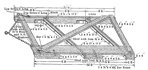 Fig. 16.—Road Planer
The broken stone road surface, or macadam road as it is usually termed, consists of a layer of broken stone, bonded or cemented together by means of stone dust and water. The surface may or may not be coated with some bituminous material.
Design.—It has been an accepted assumption that the macadam road surface is somewhat more stable than the gravel road surface of equal thickness, and since this is probably the consensus of opinion of engineers familiar with both types, it may be accepted until experimental data are available on the subject.
The thickness of the layer of macadam required for a road will depend upon the same factors that were considered in connection with the thickness of the gravel surface, i.e., kind of stone used, character of earth foundation and nature of the traffic.
The standard macadam surface where good earth foundation is to be had and where the loads do not exceed about four tons has for years been eight inches thick. For heavier loads or inferior foundation, a somewhat greater thickness would be employed, but the best practice would probably provide a foundation course of the Telford type for doubtful foundation conditions, especially for the extremely uncertain cases. For soils of very good supporting strength such as very sandy loam or deep sand or for arid regions where stable foundation is always assured the thickness of the macadam might be reduced to six inches. It should be borne in mind that the broken stone road is not adapted[Pg 90] to the traffic carried by trunk line highways in populous districts, but is rather a type permissible on secondary roads and usually adequate for local roads. It should never be employed for roads carrying any considerable volume of passenger automobile traffic or motor truck traffic. If surfaced with a bituminous material it will carry up to 1200 passenger automobiles per day, but not to exceed fifty trucks.
Properties of the Stone.—The stone employed for the broken stone road should possess the qualities of hardness and toughness and should be capable of resisting abrasion sufficiently well to have reasonable life under the traffic to which it is subjected. Since the traffic may vary from very light on some roads to far beyond the limit of the economical capacity of this type of pavement on others, it follows that any particular deposit of stone might be durable enough for some roads, while for others it might be entirely inadequate. As a general rule it has been found that stone that wears away at a moderate rate will, when used for water-bound macadam surface, result in a smoother trackway than one that will wear very slowly. It is not therefore altogether certain that the most durable stone to be had should be selected for a particular road. This is especially true now that the water-bound macadam surface has been largely superseded for trunk line highways and other heavily traveled roads, and is employed in locations where service conditions are not severe.
The stone employed for the water-bound macadam surface must possess good cementing properties, because the surface depends for stability primarily upon the bonding action of the dust from the broken stone. This is in contrast to the gravel road, where little dependence is placed upon the bonding effect of the rock dust. In preparing the stone for macadam surfaces, the ledge rock is crushed and screened, and in that way a supply of the finer particles, which are a part of the output of the crusher, is obtained[Pg 91] for use in bonding the surface. This finely broken material, usually called screenings, is essential to the construction of the water-bound type of surface. Rocks vary considerably in the cementing properties of the dust, but usually the rocks classed as "trap," such as andesite, gabbro and rhyolite, and schist and basalt possess good cementing properties. Limestones usually possess good cementing properties, but some of the dolomitic limestones are of low cementing value. Quartz, sandstone and the granites are of low cementing value.
Kinds of Rocks Used for Macadam.—Limestone and chert are the two sedimentary rocks, employed most extensively for broken stone roads. These rocks are found in widely distributed areas and vary in physical characteristics from very soft material of no use to the road builder to materials possessing considerable durability. It is desirable to carefully test out the deposits of these materials before using to ascertain the probable value of the rock, for the construction of the road surface.
Of the igneous rocks, those classed as trap are best known to the road builder and many of the deposits of trap rock afford an excellent material for broken stone roads where the severest conditions of traffic are encountered. The trap rocks are tough and durable and generally possess excellent cementing properties.
Granite and sandstone are seldom used for water-bound macadam as they possess poor cementing properties and a binder of some kind must be added to cement the pieces together. For this purpose clay or the screenings from some other variety of stone may be utilized.
Some other materials are occasionally employed for the construction of macadam surfaces. Of these, oyster or marine shells, burnt shale, and slag are most common.
Shells and slag are of rather low durability but possess good cementing properties. Shale is a makeshift suitable only for very light traffic roads.[Pg 92]
Sizes of Stone.—The stone for the wearing course of a macadam road should be as large as practicable, because the larger the pieces the more durable the surface. If the individual stones are too large it is difficult to secure a smooth surface, and large stones will be readily loosened by tipping as the wheels roll over them. These considerations limit the size to a maximum of that which will pass a 2½-inch screen. Stone of excellent wearing qualities may be somewhat smaller, but never less than that which will just pass a 1½-inch screen.
For the lower course, the size is not particularly important except where the earth foundation is such as to require special construction. It is not uncommon to use the same size of stone for both upper and lower course and yet in many instances stone up to that which will just pass a 3½-inch screen is used for the lower course. Stone much smaller in size may also be used successfully, but if the stone is broken to a smaller size than is required, unnecessary expense is incurred.
The bonding material is the finer portion of the product of the crusher, which is called screenings. This material may be so finely crushed as to pass a one-fourth inch screen, or may be so coarse as to just pass a one-half inch screen, but in any case must contain all of the dust and fine material produced by the crusher.
Where the soil and drainage conditions demand an especially stable foundation course, the Telford type is used. The Telford foundation consists of a layer of stones of various dimensions that can be laid so as to give a thickness of 8 inches. These large stones are placed by hand and therefore the size requirements are not rigid. Stones having one dimension about 8 inches and the others not over 10 or 12 inches are satisfactory.
Earth Work.—A thoroughly drained and stable earth foundation is essential to success with the macadam type of surface. Before placing the stone, the road must be[Pg 93] shaped to the proper cross section and all grade reduction work completed. Preferably heavy fills should have a year to settle before the macadam surface is placed. Side ditches, necessary culverts and tile drains should be constructed as required for drainage. The earth work is often carried out in connection with the construction of the macadam surface, being completed just ahead of the surfacing. In that case, the fills must be carefully rolled as they are placed. The road bed may be shaped in connection with the other earthwork. If the road has been brought to a satisfactory grade some time prior to placing the macadam, the road bed for the broken stone will be prepared as needed for placing the stone.
Foundation for the Macadam.—Macadam surfaces are quite generally placed in a trench as described in the trench method for placing gravel. It is an almost universal practice to compact the layer of stone by rolling with an 8- or 10-ton power roller, and if the stone is not held between substantial earth berms or shoulders, the rolling merely serves to spread the stone out over the road bed instead of compacting it. If an attempt is made to roll broken stone which has been placed on a yielding foundation, no benefit results, but on the contrary the stone is likely to be forced down into the soil. To insure that the layer of broken stone can be compacted by rolling, it is first necessary to roll the earth foundation until it becomes hard and unyielding. If soft or yielding places appear during the rolling these should be corrected by tile drains or by removing the earth from the spongy place and back-filling with material that will compact when rolled.
It is not always easy to determine why these soft places exist in what appears to be a well drained roadway, especially since they are as likely to be found on fills as anywhere else. Apparently they are due to local pockets of porous soil held by denser soil so that the water does not readily drain away. It is usually true that such places[Pg 94] are observed during the season of frequent precipitation more often than during other seasons of the year.
In dry climates, the difficulties of securing suitable foundations for the broken stone road are largely eliminated, but it may be observed that this type of surface is not suitable for such climates unless some sort of bituminous binder is employed to hold the stones in place. The cementing power of the stone dust is inadequate when the surface is continually dry.
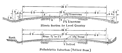 Fig. 17.—Cross Section for Macadam
Telford Foundation.—When the Telford type of foundation is employed, the earth subgrade is prepared and then the Telford stone placed carefully by hand. The spaces between the large stones are filled with the spalls broken from the larger stones in fitting them in place. When completed the base is rolled with a heavy roller to secure a firm unyielding layer. The thickness is generally about eight inches. Any fairly sound stone may be used for the Telford base.
Placing the Broken Stone.—It has been found impracticable properly to roll a greater thickness than about 5 or 6 inches of loose stone, therefore, the stone for the macadam surface is usually placed in two layers, the first or lower layer being rolled before the next layer is placed.[Pg 95] The stone is hauled in dump wagons, trucks or dump cars, dumped on the road bed and spread by hand rakes or by means of a blade grader and is then rolled. To insure the proper thickness the loads are accurately spaced to spread to the proper thickness.
Rolling.—A three-wheeled or "macadam" type of roller, of the self-propelled type, is best for compacting the broken stone road. The weight varies from eight to fifteen tons, but for most conditions the ten or twelve ton size seems to be preferable. On Telford base construction, a heavier machine is desirable and for very hard stone it may be successfully employed.
The first trip with the roller is made along the edge of the stone and each successive trip is made a little nearer the middle until finally one half of the strip of stone has been rolled. The roller is then taken to the opposite side of the roadway and the operation repeated on the other half. The rolling is continued until the stone is thoroughly compacted, which is evidenced by the fact that the roller makes but a slight track in the surface.
The second layer of stone is then placed and rolled in the same manner as the first.
Spreading Screenings.—After the upper course has been rolled, the screenings are spread on it from piles alongside the road, enough being used to fill the voids in the layer of stone and furnish a slight excess. As the screenings are spread they are rolled to work them into the voids. When these are filled, the surface is sprinkled thoroughly by means of an ordinary street sprinkling cart and again rolled. In this way the dust and water are mixed into a mortar which fills the crevices between the stones. This mortar hardens in a few days, giving a bond that is weak, but sufficient for the purpose if the traffic is not too heavy. A broken stone road finished in this way is called a water-bound macadam, and is ready for traffic in three or four days after completion.[Pg 96]
Bituminous Surfaces.—On account of the inadequacy of the water-bound macadam when subjected to motor traffic and to obviate the tendency of broken stone surfaces to loosen in dry weather, there has been developed a method of covering the surface with a bituminous material such as tar or asphalt. This will be described in detail in a later chapter.
Maintenance.—Even under favorable conditions as regards kind and amount of traffic the macadam road requires constant maintenance. The first effect of traffic will be to brush away the fine materials used for bonding the surface, thus exposing the larger stones in such a way that they are rather easily loosened and removed from the surface by wheels and the hoofs of animals. This finer material must be replaced as fast as it is removed so as to protect the surface. Either stone dust or clayey sand may be used, but clay if used alone is likely to be sticky when wet and prove to be worse than the condition it was expected to correct. In time, ruts and depressions will appear, either as the gradual effect of wear, which will inevitably effect some portions of the surface more than others, or on account of subsidence of the foundation. Uneven places are repaired by first loosening the stone, then restoring the cross section by adding new material and tamping or rolling it in place.
If a bituminous coating has been applied, it will eventually peel off in places and these places must be recoated as soon as practicable.
Eventually the surface will be worn to such an extent that an entirely new wearing surface must be added. This is done by loosening the entire surface to a depth of 3 or 4 inches and then adding a new layer of broken stone. The loosening is sometimes accomplished by means of heavy spikes inserted in the roller wheels, and at others by means of a special tool known as a scarifier.
The new surface is placed and rolled in precisely the same[Pg 97] manner as the wearing surface of the original construction, but the layer may not be as thick as the original wearing course. A new course will not bond to the old surface unless the old macadam has been thoroughly broken up first.
Characteristics.—The water-bound macadam is a dusty, somewhat rough surface of low durability for rubber tired vehicles. It has long been the standard rural highway for steel tired vehicles, but cannot carry any considerable amount of motor traffic. It is easily repaired. When finished with a bituminous surface its durability is greatly increased and the dust is eliminated. It does not seem to be sufficiently rigid for truck traffic, unless placed on exceptionally good foundation.
The cement concrete road is one of the later developments in highway construction, but the type has had sufficient use to show that it is one of the satisfactory types for heavy mixed traffic, and, where the proper materials are available, it is one of the economical types of construction.
Destructive Agencies.—It is well to have clearly in mind at the outset that the concrete in a road surface is subjected to certain destructive agencies not usually significant in connection with the use of concrete, and these are so often disregarded that the average serviceability of the concrete road surface is sometimes much lower than it would be if built with due regard for the effect of traffic on concrete surfaces. In most structural uses of concrete, its strength in compression only is utilized, and the factor of safety is such as to eliminate to some extent failures due to inferior materials or workmanship.
The concrete road surface is subjected to compression under wheel loads, to bending, causing tension in the concrete, to abrasion from wheels, and to tension and compression due to effect of temperature. The weight of the wheel loads may cause sufficient distortion of the road slab to produce rupture. The aggregates may be crushed under wheel loads if the material is too soft. Abrasion from steel tired vehicles wears away the concrete unless it is hard and durable. Changes in dimension due to the effect of change in temperature introduce tension or compression into the road slab and may result in cracks. Freezing and thawing[Pg 99] in the subgrade subjects the slab to vertical movement and discontinuous support with the result that longitudinal and transverse cracks occur.
The foregoing indicates the importance of securing good concrete for road surfacing, and that is accomplished by using suitable aggregates, by proper design of the road surface and by following established construction methods.
Design.—The widths usually adopted for concrete roads are: for single track roads, 9 or 10 feet, and for double track roads, 18 or 20 feet. The thickness is 6 to 8 inches at the middle, varying with climatic conditions and with the kind of soil upon which the concrete is laid. The thickness at the edge is 1 inch less than at the middle except that 6-inch surfaces are usually of uniform thickness, the total crown being 2 inches. The thickness of the two course pavement is the same as would be used for a single course pavement in the same location. The surface of either width has a total crown of one or two inches to insure water running off the surface. The earth foundation is often flat, the crown being obtained by making the slab thicker at the middle than at the edge. Fig. 18 shows cross section for concrete roads.
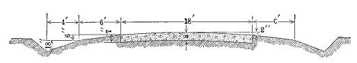 Fig. 18.—Cross Section for Concrete Highway
In the state of California, concrete roads four or five inches thick and surfaced with a bituminous carpet mat have been successfully constructed. Similar designs have been used in a few other places, but for general practice it is unsafe to depend upon such a thin slab. Climatic and soil conditions probably account for the success of the thin roads in California.[Pg 100]
Concrete Materials.—The coarse aggregate for the concrete may be broken stone or pebbles screened from natural gravel. Durability is necessary, but it is also important to have uniformity in the concrete so that the road surface will wear uniformly and consequently keep smooth. Supplies of broken stone are likely to contain a small percentage of soft pieces and such of these as are at the surface when the concrete is finished will crush under traffic, leaving a pit in the surface. Pebbles screened from gravel are also likely to be variable in durability and should be carefully inspected if they are to be used as aggregate for concrete roads. The harder limestones, some sandstones, pebbles from many of the gravel deposits and practically all of the igneous rocks make satisfactory aggregates for the concrete road.
Sometimes none of the coarse aggregates readily available are sufficiently durable or uniform for the wearing surface of the concrete road, but a suitable aggregate may be obtained at relatively high price by shipping considerable distances. In such cases what is known as the two course type of concrete road is employed. The wearing course usually is about 2 inches thick and is constructed with selected aggregates of good quality shipped in for the purpose. The lower course is constructed of aggregates which do not possess the desired qualities for a wearing course, but which are satisfactory for concrete not subjected to abrasion. The aggregates for the wearing course will be selected with the same regard for uniformity and durability that would be the case if they were for the one course pavement.
Bank run gravel, or run of the crusher stone, is generally not sufficiently uniform as regards proportion of fine and coarse material to produce uniformity in the concrete, and the use of aggregates of that character is not permissible for the wearing course, but under proper inspection they may be used for the lower course of two course pavements.[Pg 101]
Fine Aggregate.—The fine aggregate is generally natural sand, but a mixture of natural sand and stone screenings is sometimes employed. The fine aggregate of whatever character must be clean, free from organic matter and sand, must contain no appreciable amount of mica, feldspar, alkali, shale or similar deleterious substances and not exceed two and one-half per cent of clay and silt. The sand is of such a range of sizes that all will pass the one-fourth-inch sieve and that not exceeding about five per cent will pass the 100-mesh sieve.
Proportions.—Various mixtures for the concrete are employed because these may properly vary to some extent with the exact character and grading of the aggregates. Experience seems to have shown that the concrete used for the wearing surface should have a crushing strength of at least 2500 pounds per square inch, and the mixture adopted is based on the requirements that will give the desired crushing strength. The common mixture for the one course pavement is one part cement, two parts sand and three and one-half parts coarse aggregate. For the wearing course of the two-course type of pavement, a mixture of the same kind is very often specified.
While these are perhaps the most widely adopted proportions, many others have been used, especially where the aggregates exhibit peculiarities or the traffic conditions are unusual. It is desired to emphasize that the purpose is to obtain concrete of the desired strength and there can be no such thing as "standard" proportions.
Measuring Materials.—In considering the methods employed for measuring aggregates, emphasis should be placed on the futility of rigid requirements for the aggregates, both as regards quality and range of sizes, if the materials are carelessly proportioned at the mixer. If even reasonably near uniform wearing qualities are to be secured throughout the entire area of the concrete road surface, successive batches of concrete must be alike, and[Pg 102] to insure that, the aggregates including the water in each batch of concrete must be mixed in exactly the same proportions. The aggregates are measured in various ways, all essentially alike in that the intent is to insure exactly the same amount of each ingredient for each batch of concrete.
One method is to place bottomless boxes in wheelbarrows, fill the boxes level full and then lift off the box. Another is to use a wheelbarrow with a bed of such shape that the contents will be a multiple of 1 cubic foot when level full. For the larger jobs, the aggregates are hauled in industrial cars, each having sufficient capacity for a batch of concrete. The car body is provided with a partition so as to separate the fine and coarse material.
The water is measured in a tank which automatically refills to the same level each time it is emptied and when adjusted for a mixture will introduce the proper amount of water for each batch. It is highly important to use the least amount of water that will produce workable concrete.
Preparation of the Earth Foundation.—The concrete road is generally placed directly on the natural soil which has been brought to the proper cross section. Some engineers advocate that in preparing the subgrade, the earth be thoroughly rolled; others prefer not to roll the subgrade. If fills of considerable depth are constructed, they should either be rolled as built or else should be allowed to settle for some months before the concrete road is placed, preferably the latter.
Placing the Concrete.—The concrete is placed between substantial side forms of a height equal to the thickness of the concrete road slab at the edge, and is shaped roughly by means of shovels.
Various methods have been developed for striking the surface to the exact shape desired and smoothing it. If hand finishing methods are employed, a plank template is cut to the prescribed cross section and the concrete is[Pg 103] shaped by drawing the template along the side forms. Sometimes the template is used as a tamper, being moved along very slowly accompanied by an up and down motion that tends to tamp the concrete. The template is then drawn along a second time to smooth the surface finally.
After the surface has been struck off by hand, it is finally smoothed, first by rolling crosswise with a slight hand roller about 8 inches in diameter and 30 inches long. The final finish is effected by dragging a piece of web belting back and forth across the surface.
Machines designed to tamp the concrete and strike it off to the required cross section are also employed for finishing. The machine is power operated and is carried on wheels that run on the side forms, and the machine moves slowly along as the tamping progresses. The concrete is tamped, struck off to shape and smoothed with the belt at one operation. This method of finishing produces denser and stronger concrete than can be produced by hand finishing methods.
Placing Concrete for Two-course Road.—The methods employed for the two-course concrete road are much the same as for the one-course road. The concrete for the lower course is placed and struck off by means of hand tools, and after that course has progressed a few feet, the upper course is placed and finished as has been described for the one-course road.
Curing the Concrete.—The setting action of cement is a chemical process, not merely a drying out of the water introduced in mixing the concrete. The chemical action is progressive for a long time, but is more rapid during the first few hours than during the later periods, and the concrete reaches about three-fourths of its maximum strength at the end of seven days. During the setting period and particularly during the first few days, plenty of water must be available to the cement.[Pg 104]
To prevent too rapid loss of water from the concrete during the setting period, the surface must be protected from the wind and sun. This is accomplished by first covering with canvas as soon as the concrete has hardened sufficiently and by later covering with earth, to a depth of two inches. The earth covering is kept wet for about ten days and is left in place for about one month.
In some places the ponding method of curing is adopted. The surface is divided into sections by earthen dikes and the space inside the dikes filled with water to a depth of two or three inches. The water covering is maintained for two weeks or longer.
No traffic is permitted on the surface for one month, and in cold weather traffic may be kept off the surface for a longer period.
Expansion Joints.—To permit the concrete slab to accommodate itself to changes in dimension due to temperature changes, expansion joints ½ inch wide are placed about every thirty feet. These consist of a sheet of some prepared bituminous material placed in position as the concrete is poured.
Experience seems to indicate that in spite of the expansion joints, the concrete will crack more or less and many engineers think it advisable to omit expansion joints in constructing the pavement and when cracks develop to pour bituminous material into them, thus forming expansion joints.
The prevailing practice in rural highway construction is to omit the expansion joints, but they are commonly adopted in city pavements.
Reinforcing.—To minimize the cracking, either bar or wire mesh reinforcing is used in the concrete. If bars are used they are placed in the concrete as it is poured so as to form a belt around each section about 15 feet square. If the mesh type is employed, a part of the layer of concrete is placed and smoothed off and a strip of the mesh[Pg 105] laid in place. Additional concrete is then poured on top of the mesh to bring the slab to the required thickness.
Bituminous Coatings on Concrete Surfaces.—The concrete road surface is sometimes coated with a layer of bituminous material and stone chips or gravel pebbles. This is particularly advisable where no really satisfactory aggregates are available and the concrete surface would not possess sufficient durability. The bituminous material is applied hot to the surface and is then covered with stone chips or gravel pebbles, ranging in size from ¾ inch down to ¼ inch, the resulting coating being about ¾ inch thick. Many failures of this type of surface have been recorded due to the difficulty of securing adhesion to the concrete. This seems to be due in part to inability to get the proper bituminous materials and in part to climatic effects. Considerable progress has been made in developing this type of surface and it may eventually become a satisfactory maintenance method.
Characteristics.—The concrete road is of a granular texture and is not slippery. It is of course rigid and noisy for steel tired vehicles. It is an excellent automobile road and its low tractive resistance makes it a desirable surface for horse drawn vehicles. It possesses a high degree of durability if properly constructed. It is likely to crack indiscriminately but as a general rule the cracks are not a serious defect.
Maintenance.—The cracks that appear in the concrete surface are filled once or twice a year, tar or asphalt being employed. The dust and detritus is cleaned out of the cracks and the hot filler poured in, with enough excess overflowing to protect the edges.
Vitrified brick roads consist of a foundation course of Portland cement concrete, broken stone or slag macadam, or of brick laid flat, the first named being by far the most generally used, and a wearing course of vitrified brick.
Vitrified Brick.—Vitrified brick are made from clay of such a character that when heated to the required temperature they will fuse into a glassy texture. Brick roads are constructed on roads carrying the severest of traffic and the brick must therefore be tough and of high resistance to wear.
Not all of the clays from which brick may be manufactured will produce a product suitable for road construction, and paving brick, even though truly vitrified, are of different degrees of durability, depending upon the nature of the clay and the care exercised in the manufacture.
Paving brick are manufactured by the stiff mud process, which means that the clay is molded into form in a relatively dry condition. To accomplish this, considerable pressure is exerted in forcing the column of clay through the dies, which form the prism from which the brick are cut. If the clay is unsuitable in character or is not properly ground and mixed, the brick will possess planes of weakness between the various layers of clay which have been pressed together, and these planes, called laminations, are a source of weakness if too marked. It is usual to specify that the brick used for road surfaces shall be free from marked laminations.[Pg 107]
If the brick is not properly burned it will be only partly vitrified and therefore not of maximum durability. It is customary to specify that the brick shall show a glassy fracture indicating complete vitrification.
Various defects of a minor nature occasionally develop in the brick during the successive steps in the manufacturing process. Check cracks resulting from the burning or from too rapid cooling are often encountered, but unless these are deep, that is 3/16 inch or more, they do not impair the wearing quality of the brick, nor indicate structural weakness. Kiln marks are formed on some of the brick due to the weight of the brick above in the kiln. These depressions are not objectionable unless the brick are so distorted that they will not lie evenly in the pavement.
Spacing lugs or raised letters are formed on one face of the brick to insure sufficient space between the brick for the filler. These lugs or letters are not less than 1/8 inch nor more than ¼ inch high and of such design that they will not obstruct the free flow of filler into the joints between the brick.
Several varieties of paving brick are to be had, the difference being principally in the design or size.
Repressed Brick.—In this type of brick the spacing lugs are formed by pressing the green brick, after it has been cut to size, into a mold on one face of which are recessed letters or other devices into which the clay is pressed, thus forming the spacing lugs.
Vertical Fiber Brick.—These brick are designed to be laid with one wire-cut face up and spacing is provided by two or more beads on the side of the brick. Sometimes the vertical fiber brick has no spacing lug, it being contended that the irregularities of the brick are such as to provide all of the space required. In practice this does not always work out, as the brick are so regular in shape that when laid there is too little space between the brick to permit the introduction of a suitable filler. The use of brick[Pg 108] without spacing lugs is just beginning and is not yet a generally accepted practice.
Wire-cut-lug Brick.—This is a type of non-repressed brick which has spacing lugs provided by cutting one face in a special manner which provided lugs for spacing. In this type the wire cut face is the one between the brick as they are laid in the pavement.
Tests for Quality.—The standard test for quality of paving brick is the rattler test. The brick rattler consists of a barrel of 14 sides 24 inches long, mounted so as to rotate at a speed between 29.5 and 30.5 revolutions per minute. The duration of a test is 1800 revolutions. Ten brick constitute a charge and these are placed in the rattler along with 300 lbs. of cast iron spheres. The spheres are of two sizes, the smaller being 1-7/8 inch in diameter when new, and the larger 3¾ inches in diameter when new. Ten of the larger spheres are used and the balance of the charge is made up of the small size.
When tested in the standard manner the loss allowable for the several classes of service are as follows:
| Traffic | Average Loss | Maximum Loss for any Brick |
| Heavy | 20 per cent | 24 per cent |
| Medium | 22 per cent | 26 per cent |
| Light | 25 per cent | 28 per cent |
Other Tests.—Sometimes the absorption test is specified for paving brick, but it is rarely a vitrified brick that will pass the rattler tests which fails to pass a reasonable absorption test. Absorption of water in an amount exceeding 4 per cent indicates incomplete vitrification and failure of such brick is almost certain during the rattler tests.
The cross breaking test is also sometimes employed, but[Pg 109] generally only to check the general quality of the brick. Failure in service more frequently occurs from excessive wear than from any other cause and the cross breaking test has little significance, except for brick less than 3 inches thick, which are to be laid on a sand bedding course.
Foundation.—The foundation for brick roads is usually of Portland cement concrete, the thickness varying with the nature of the traffic and the kind of soil upon which the pavement is built. For well drained soils and normal highway traffic, 5 inches is the ordinary thickness of foundation. Under favorable conditions such as locations with sandy soils or in semi-arid or arid regions where the soil is always stable, the foundation may be four inches thick, and a considerable mileage of brick road has been built with concrete foundations less than four inches thick.
In other locations the soil and traffic conditions require a base six inches or more in thickness, and the proper thickness can be determined only after all of the factors involved are known and have been analyzed. It is impractical to adopt a standard thickness of foundation that will be equally economical for all locations and all kinds of traffic. As the brick pavement is essentially a heavy traffic type of surface, the design cannot be varied greatly with similar foundation conditions because the weight of individual loads is the significant factor and this does not vary so much as the volume of traffic. A variation in volume of traffic may be compensated for by a variation in the quality of the brick as already set forth.
The mixtures for the concrete foundation vary widely because of the variation in the aggregates employed. If the fine and coarse aggregate for the concrete are of good quality a mixture of one part cement, two and one-half parts sand and five parts of coarse aggregate would insure concrete of adequate strength. A somewhat leaner mixture is sometimes employed and would be satisfactory if the aggregates were of exceptional concrete making quality.[Pg 110] Mixtures of sand and pebbles (unscreened gravel) may also be used if care is exercised to secure a mixture of adequate strength. The proportion will of necessity vary with each particular material and the discussion of the various considerations involved may be obtained from various standard works on concrete and concrete materials.
Broken stone macadam is sometimes utilized for the foundation course of the brick pavement and such foundations are constructed as water-bound, which is described in a previous chapter. The thickness, like that of the concrete foundation, varies with the soil conditions and the weight of the loads that are expected to use the road. The macadam is placed in a single layer and is rolled and bonded with screenings as described in the chapter dealing with water-bound macadam. Six inches is a common thickness for the macadam base. This type of foundation should be employed only where the soil is quite stable and where material costs are such as to insure that the macadam base is materially cheaper than one of concrete. This would usually be in locations where the cost of cement is high because of long hauls and where suitable macadam materials may be obtained close at hand.
Old macadam roads are sometimes utilized for the foundation for the brick surface, but the instances where this is permissible are comparatively few in number. When an old macadam is to be used it is reshaped to the proper cross section and re-rolled and bonded so as to afford a stable foundation of the proper cross slope.
In order to equalize the variations in size and shape of the brick, they are laid on a bedding course composed of material into which the brick may be forced by rolling. In this way the upper surfaces of all brick can be brought to the proper elevation to insure smoothness and easy riding[Pg 111] qualities. Several kinds of bedding course are now employed.
Sand Bedding Course.—The sand bedding course has been referred to as a sand cushion, but as a matter of experience the cushion effect is slight, although sometimes pavements have become uneven because the brick have pushed down into the sand after the pavement was used for a time. The sand for the bedding course should preferably be fine grained, all particles passing the eight mesh sieve, but ordinary concrete sand is satisfactory. The sand need not be clean, as a comparatively large percentage of silt or clay does not impair the usefulness of the material.
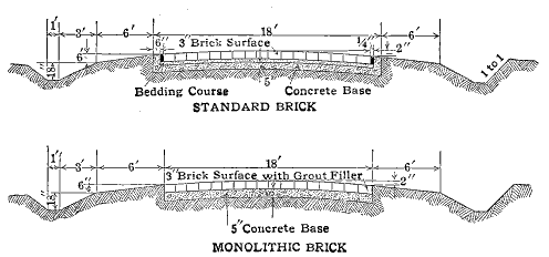 Fig. 19.—Cross Sections for Brick Highways
Sand Mortar Bedding Course.—In order to eliminate the tendency for the straight sand bedding course to shift because of the impact of traffic on the brick, a lean cement mortar is sometimes employed rather than the straight sand. Sand and cement in the ratio of one part cement to four or five parts of sand are mixed dry, and after the brick have been rolled, is moistened to furnish water to hydrate the cement. The sand employed is ordinary clean concrete sand.
Green Concrete Bedding Course.—In the monolithic[Pg 112] type of brick road construction, the brick are laid directly on the green concrete base before the concrete has taken a set and the irregularities of the brick are taken up by rolling them until bedded in concrete.
The spaces between the brick are filled with some material that will prevent the brick from being displaced and prevent water getting to the bedding course. A suitable filler must adhere to the brick and fill completely the spaces between them. It must withstand traffic so as to remain intact in the joints and when in place it must be rigid enough to prevent displacement of the brick.
Cement Grout Filler.—One of the most commonly used fillers for brick pavements consists of a grout composed of Portland cement and fine sand. When properly mixed and applied the grout filler meets all requirements for a filler except that it is non-elastic and some means must be adopted for caring for pavement expansion.
Bituminous Fillers.—Asphaltic materials and tars are widely used as fillers for brick pavements. Such fillers are of high melting point and consequently solid at ordinary temperature. They are poured into the joints hot and when they cool are firm enough to comply with the requirements for a filler. In addition, they have enough ductility to accommodate the expansion of the pavement due to temperature changes.
Mastic Fillers.—Mastic consists of a mixture of about equal volumes of fine sand and a solid bituminous material. The mixture is prepared at high temperature and is worked into the joints between the brick while hot. When cool it resembles the straight bituminous filler except that the mastic is somewhat more resistant to wear than the straight bituminous filler.[Pg 113]
It is recognized that brick will expand and contract with changes in temperature. When a bituminous or mastic filler is employed there is sufficient yield to the filler to accommodate the change in dimension in the brick, but when the grout filler is used either the expansion joint must be provided or the pavement must be designed to withstand the compression due to expansion of the brick. Expansion joints may consist of a sheet of bituminous mastic prepared for the purpose and set in place in the pavement. The sheet of joint material is simply inserted between courses of brick at the proper place.
Another method of forming an expansion joint consists in placing a strip of wood between courses of brick at the place where a joint is required. After the pavement has been grouted, the wooden strip is pulled out and the joint is filled with a suitable bituminous filler.
Marginal Curb.—If the sand bedding course is employed, it is necessary to provide curbing along the sides of the brick to hold the bedding course in place. The curb is usually constructed integral with the base and of concrete of the same mixture as the base. The width of the curb is usually six inches and the top of the curb is at the same elevation as the edge of brick surface.
Before the construction of a brick surface should be undertaken on a road, the drainage should be provided for even more completely than for a less costly type of surface since it does not pay to jeopardize the stability of the pavement by failure to provide adequately for the stability of the supporting soil. Grades should also be reduced to the economical limit.
The earth subgrade is brought to the proper elevation[Pg 114] and cross section and is thoroughly rolled. If there are places where the soil will not compact properly under rolling, these places are corrected by taking out the material and back filling with new material that will properly compact under the roller.
The aggregates for the concrete may be distributed along on the prepared subgrade or may be stored in stock piles or bins at convenient points. If stored on the subgrade, a traction mixer is employed which is drawn along the road as the work progresses, the materials being placed directly in the mixer. If stored at a central point, they may be transported to the mixer on the road and dumped directly into the mixer, or the mixer may be set up at the storage piles and the concrete hauled in trucks to the road where it is deposited and shaped.
The concrete is spread to the proper thickness and tamped either by hand or by machinery. If the marginal curb is to be employed, it is constructed immediately after the concrete for the base has been finished but before the cement begins to set.
After the foundation concrete has set, the bedding course is spread and struck off to the proper thickness. When the bedding course consists of sand-cement mortar, the sand and cement are mixed dry and spread to prescribed thickness. It is considered to be desirable to roll the sand bedding course with a light hand roller before the brick are placed, but the sand-cement bedding course is not rolled. The bedding course must be carefully shaped by means of a templet or strike board before the brick are placed.
The brick are laid in straight courses across the pavement, with the spacing lugs all in the same direction if brick with spacing lugs are employed, and with the lugs in contact with the brick of adjoining courses. If brick without spacing lugs are used they are laid loosely so that there will be room for the filler between the brick of adjoining courses.[Pg 115]
After the brick have been laid they are rolled to bed them in the sand or sand-mortar bedding course and thus secure a smooth surface. For this purpose a light, power driven, tandem roller is used and the rolling is continued until the brick are thoroughly bedded. Any defective brick that are noted are removed and replaced with good brick and after this culling has been completed the surface is once more thoroughly rolled. If a cement-sand bedding course is employed, the surface is sprinkled just after the final rolling so that water will flow down between the brick and moisten the bedding course sufficiently to cause the cement to set. In some cases, the sand-cement bedding course is sprinkled just before the brick are laid but in warm weather the setting would take place before the brick could be rolled if that were done. In cool weather the setting is sufficiently slow to permit rolling before the bedding course hardens.
The filler is applied to the surface after the rolling. If the bituminous type of filler is employed, the hot filler is poured onto the surface and worked into the joints by means of squeegees, with comparatively little material left on the surface. In some instances cone-shaped pouring pots are employed and the material is poured directly into the joints.
The cement grout filler is applied in the same general manner as the bituminous filler. The grout, consisting of equal parts of sand and cement, is mixed to a thin consistency and poured onto the surface and is then worked into the joints with squeegees. Two or more applications are usually required to effect a complete filling of the joints. The surface should be covered with sand and be kept moist until the cement grout has set.
Tars and asphaltic materials of various kinds are widely used for road construction and maintenance, especially for road surfaces subjected to motor traffic. Materials of this character that are employed in highway work possess varying degrees of adhesiveness, and while they may be semi-solid or viscous liquids at air temperature, they melt on the application of heat and can be made sufficiently fluid to mix with the mineral aggregates that may be used in the road surface. Upon cooling, the bituminous materials return to the previous state and impart a certain amount of plasticity to the mixture, at the same time serving as a binding or cementing agent, which is sufficiently stable for many classes of road construction.
Classes of Bituminous Materials.—Bituminous materials may be classified, according to the source from which they are obtained, as coal tars, water gas tars, native or natural asphalts and oil or petroleum asphalts.
Coal Tar.—Coal tar is obtained as a by-product in the manufacture of illuminating gas from coal. It is also obtained in the manufacture of coke from coal. The tar thus obtained is manufactured into products that are used for dust layers on gravel or macadam roads, binders for macadam and gravel surfaces, fillers for brick, wood block and stone block pavements and for expansion joints. These various materials differ mainly in their consistency at air temperature. (They may differ widely in chemical composition, but that need not be considered herein.)[Pg 117]
Water Gas Tar.—Water gas tar is obtained as a by-product in the manufacture of illuminating gas from crude petroleum. It is used for the same kinds of construction as coal tar, and the products utilized for the several purposes, like the coal tars, differ mainly in consistency.
Natural Asphalt.—Natural asphalt is found in deposits at many places in the world, existing in beds or pools where it has exuded from the earth or as veins in cavities in the rocks. It is of varying composition and consistency, but those kinds in most general use are solid or very viscous liquids at air temperature. Of the deposits that have been developed on a commercial scale, the Trinidad lake in the British West Indies and Bermudez deposit in Venezuela are best known. Both of these materials are too hard in the natural state to be used for road construction, and are softened, or fluxed as it is called, with fluid petroleum oil before being used.
Petroleum Asphalt.—Petroleum asphalt is a residue remaining after the fluid products have been distilled from petroleum. Residues of this sort are not always suitable for road construction, but a number of brands of road material are obtained from this source. Oil asphalts are used for dust layers, for binders for macadam roads, for asphalt cements for sheet pavement surfaces, and for fillers for block pavements and expansion joints.
Mixtures.—Water gas tars and asphalts are sometimes mixed to produce road materials, and likewise native asphalts and residues obtained from petroleum are sometimes mixed to produce asphalt cements for paving mixtures.
Classification according to Consistency.—The various bituminous materials may be classified according to consistency in discussing the various uses to which they may be put.
Road Oils.—Road oils are fluid petroleum oils of such consistency that they may be applied cold or by heating[Pg 118] slightly. They are used as dust layers on earth, gravel and macadam surfaces. Their efficacy depends upon the binding properties of the small amount of asphaltic material that is contained in the oil.
Liquid Asphalts.—These are somewhat less fluid than the road oils, and must always be heated before application, but are viscous liquids at ordinary temperature. These materials are obtained from crude petroleum or semi-solid native bitumens, in which case they are usually called malthas. Both coal tars and water gas tars of semi-solid consistency are also employed for the same class of construction as the liquid asphalts.
These materials are used for carpeting mediums on macadam roads and as cementing agents in the construction of hot-mixed macadam.
Asphalt Cements.—The solid asphaltic materials used for hot-mixed types of construction are called asphalt cements. They may be petroleum residues or native asphalts fluxed with petroleum oils. They are solids at ordinary temperature and must be heated to a temperature in excess of two hundred and fifty degrees before they are sufficiently fluid to use. Asphalt cements are used for sheet asphalt and asphaltic concrete construction and for hot-mixed bituminous macadam.
Fillers.—Fillers are solid asphalts or tars that are used for filling expansion joints in rigid pavements and for filling the spaces between the blocks in brick, wood block and stone block pavements.
Bitumen.—Bituminous materials are all soluble to a greater or lesser extent in carbon disulphide and the soluble portion is called bitumen. It is the bitumen that gives to the materials the cementing properties utilized in road construction. Mixtures of mineral aggregates and bituminous materials for various purposes are proportioned with bitumen as a basis. Therefore, less of an asphalt containing one hundred per cent bitumen will be used than[Pg 119] of one containing less than one hundred per cent of bitumen.
| Material | Specific Gravity | Consistency | Solubility in CS2, Per Cent | Solubility of Bitumen in CCl4, Per Cent | Solubility of Bitumen in 86° Naphtha, Per Cent | Fixed Carbon, Per Cent | Flash Point | Ductility |
| Mexican oil asphalts | 1.03-1.05 | As desired | 99.5-99.9 | 99.5-99.9 | 70-80 | 13-16 | 200°C. up | 60-100 |
| California oil asphalts | 1.02-1.04 | As desired | 99.9 | 99.9 | 75-80 | 10-12 | 200°C. up | 100+ |
| Texas oil asphalts | 1.01-1.03 | As desired | 99.9 | 99.9 | 75-80 | 12-14 | 200°C. up | 50-100 |
| Bermudez natural asphalt | 1.07 | 25 | 95 | 99+ | 68-70 | 13-14 | ... | ... |
| Trinidad natural asphalt | 1.40 | 7 | 56-57 | 100 | 64-65 | 10-11 | ... | ... |
| Bermudez asphalt cement | 1.04-1.06 | Up to 135 | 95-97 | 99.5 or more | 77-80 | 11-12 | 175-200 | 25-50 |
Specifications.—Some properties of bituminous materials can be varied in the process of manufacture, while others are inherent in the material and cannot be changed in the process of manufacture. Specifications must therefore be drawn with care to insure that the requirements can be met by satisfactory materials. But certain properties, such as specific gravity, may vary greatly among materials equally satisfactory for construction purposes. One should not be misled by apparent differences in the characteristics of materials, because these may simply be natural peculiarities which have no bearing on the usefulness of the material. There are given in Table 8 the properties of some of the commonly used bituminous materials and the[Pg 120] properties that can be varied in the process of manufacture are indicated with an asterisk. A variation in these properties will usually result in some change of other properties, but generally not a great change.
Attention has been directed to the rapid deterioration of water-bound macadam when subjected to passenger automobile traffic.
In water-bound macadam the stones are held in place by a weak cement composed of stone dust and water, and this cement is not sufficiently strong to hold the stones in place when they are subjected to the shear of automobile tires. In finishing the water-bound macadam surface, the spaces between the stones are filled with screening and in addition a layer about one-fourth inch thick is left on the surface.
The automobile traffic first brushes aside all of the screenings and smaller particles of rock, exposing the larger stones. These gradually loosen as the road is used and are brushed aside. When this effect begins, the road is said to be raveling. Various lengths of time may elapse from the time the road is first finished until raveling begins, depending upon the character of the stone, the weather and the amount of motor traffic. During the period before raveling starts, it is comparatively easy to restore the road surface at any time by the addition of screenings or clay and sand. Usually there will be a few small areas of the surface that, on account of faulty construction, will ravel or become rutted much earlier than the remainder of the surface. These can be repaired by the methods described in the chapter on "Water-bound Macadam Construction." When the surface begins to ravel seriously, maintenance becomes much more difficult and in order to[Pg 121] prevent raveling and the difficulties of maintenance thereafter, the macadam surface is often coated with a bituminous material.
 Fig. 20.—Oiling a Gravel Road
If there is any dust or screenings on the road surface, the bituminous material will not adhere to the stones and will soon flake off under traffic. The surface of the macadam must therefore be thoroughly cleaned before the bituminous material is applied. The usual practice is to finish the road as water-bound macadam, and permit traffic on it for a sufficient length of time to show any weak places in the surface and at the same time thoroughly to season the surface. If any defective places appear, they are repaired and when the surface exhibits satisfactory stability, but before it begins to ravel, the bituminous surface is applied. There will ordinarily be some stone dust and some screenings remaining on the surface at the time bituminous treatment is undertaken, and there may also be some caked mud or other foreign material. All of this must be removed so as to expose the stones throughout.[Pg 122]
Applying the Bituminous Binder.—The bituminous binder may be delivered in tank cars, which is desirable if the work is near a railroad siding, or ample tank wagon service is available for long hauls so that the tank will not be held up too long. Often it is desirable to purchase the binder in barrels and haul these to the site of the work in advance of beginning the construction of the surface.
The bituminous material may be applied by means of hand spreading cans not unlike an ordinary garden watering pot, except that a slotted nozzle is substituted for the ordinary perforated one. If hand methods are employed for spreading, the bituminous material is heated in open kettles and then spread on the surface, the quantity required usually being about one-half gallon per square yard of surface. The temperature of the binder should be great enough to insure fluidity and the road should be dry at the time of the application. As soon as the material has been spread, the surface is finished with a dressing of chips.
Finishing the Surface.—For surface dressing the best material is stone chips ranging in size from about 1 inch down to one-fourth inch. But the chips must be of durable material, or they will quickly grind into dust. They must be free from dust when applied, as the presence of any considerable amount of dust interferes with the proper finishing of the surface. The stone chips are rolled into the surface, a sufficient quantity being used to just cover the surface.
Patching.—It almost always happens that some small areas will not be properly cleaned or that for some unknown reason the coating peels off the surface. Such places must be promptly patched to prevent them enlarging under the action of traffic. This work is usually done by patrolmen, who inspect the road at frequent intervals and make the necessary repairs. The patrolman is equipped with a small heating kettle, a spreading can and the necessary[Pg 123] brushes, tampers and miscellaneous tools needed for the repair work. The place to be patched is carefully cleaned, coated with bituminous binder and stone chips and tamped until dense and solid. Repairs made in this way are exceedingly important in that they arrest deterioration in its early stages and maintain a high degree of serviceability.
A considerable mileage of macadam has been constructed in which an attempt was made to eliminate the difficulties of maintenance by a method of construction that involves applying a bituminous binder in such a manner as to permit it to penetrate two inches or more into the surface. It is expected that the binder will coat the stones to such an extent as to increase materially the stability of the bituminous macadam over the surface treated one. It is also expected that less difficulty will be encountered in maintaining a surface of bituminous material and stone chips on this type of road than on the water-bound macadam. The extent to which these expectations have been realized has varied to a marked degree and although some excellent surfaces have been constructed by this method, the results have as a rule been neither uniform nor entirely satisfactory. It seems to be apparent that good results cannot be obtained unless the materials are entirely suitable and the construction is carried out with unusual skill.
Foundation.—The foundation or lower course consists of a layer of broken stone six inches thick placed on a well drained and thoroughly rolled earth subgrade. In exceptional cases, the Telford type of foundation might be employed.
The lower course of broken stone is finished in the same manner as water-bound macadam, being bonded with stone screenings or with fine gravel of high clay content.
Since this course is in reality the foundation of the surface,[Pg 124] it is necessary to secure stability by appropriate construction methods, exactly as in constructing water-bound macadam.
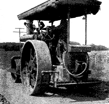 Fig. 21.—Type of Roller used on Gravel and Macadam
Roads
Fig. 21.—Type of Roller used on Gravel and Macadam
Roads
Upper or Wearing Course.—The wearing course consists of a layer of stone about two and one-half inches thick. The stone is placed and rolled and the spaces between the stones partially filled with some suitable bituminous material. The bituminous material is usually applied by means of a mechanical spreading device connected to a tank wagon. The bituminous materials employed for this class of construction are semi-solid in character and must be heated to give them sufficient fluidity for application. They may be heated in the tank wagon which is used for the application or they may be heated in separate tanks and transferred to the distributing wagon for spreading. Some kind of a nozzle or group of nozzles is employed for spreading the material so that it can be delivered in the[Pg 125] form of a spray or at least in a thin fan-shaped stream and can be distributed in a fairly uniform layer over the stone. The binder will cool rather rapidly after it is applied, but meanwhile will flow into the openings between the stones and will form over the surface stones a coating of slight thickness.
The surface of the macadam is next covered with a layer of chips of tough rock, similar to the material used for the final dressing in surface treatments. These are carefully brushed into the openings between the larger stones by means of heavy brush brooms. This is an exceedingly important part of the work and often a much neglected part of the construction.
The surface is then covered with a second application of bituminous material, somewhat less in quantity than required for the first treatment and the surface again covered with stone chips and brushed.
The surface is then thoroughly rolled and is ready for traffic.
Patching.—As in the case of surface treatments, there are likely to be places that, on account of defects in the construction, will fail soon after the road is placed under traffic. These will quickly enlarge unless they are repaired promptly. The repairs are made by loosening the stone in the area affected and adding new stone as needed and then pouring on the necessary amount of bituminous material to coat the stones. Allowance must be made for the compression of the material by tamping so that a depression does not result. The stones are carefully tamped to place and covered with chips which are also tamped.
Characteristics.—The penetration macadam is a surface well adapted to motor traffic if the individual vehicles are not too heavy. It is likely to squeeze out of shape under motor truck traffic, becoming seriously uneven and uncomfortable for traffic. Its durability is materially affected by the construction methods followed.[Pg 126]
The wearing course of the mixed macadam is composed of graded broken stone or gravel and a bituminous binder. Usually the bituminous material only is heated prior to the mixing, but sometimes the stone is also heated.
Foundation.—The lower course, which serves as the foundation, is either broken stone macadam, gravel or concrete.
Where a foundation of broken stone is used, it is constructed of the materials and in the manner described for the foundation of the penetration macadam. Quite often a badly worn macadam or gravel road is used for the foundation and a new wearing course provided by adding a mixed macadam surface. If such is the case, the old surface is worked over so as to restore the shape sufficiently and to insure that it is everywhere of sufficient thickness.
Portland cement concrete is sometimes used as a foundation for the mixed macadam, but not often. Usually if the traffic is of a character requiring a concrete foundation, it is desirable to use a better wearing course than the mixed macadam, and the asphaltic concrete or sheet asphalt type of surface is employed. It is necessary to finish the surface of the concrete base with some device that will leave the surface rough to prevent the macadam from creeping. A knobbed tamper which leaves numerous irregular depressions about 2 inches in diameter and three-fourths inch deep is often employed.
Sizes of Stone.—For the wearing surface, stone ranging in size from 2 inches down to one-fourth inch is usually employed. If the stone is of good quality the maximum size may be but 1½ inches, but soft or even medium stone of that size are likely to crush under traffic. The stone for the base course should preferably be from 3 inches down, but any available size will be satisfactory if the layer is well rolled and bonded. The base course is constructed[Pg 127] in the same manner as water-bound macadam and any material satisfactory for the base course of macadam will serve for the base course of mixed macadam. Screenings having good bonding properties will also be required for the base course.
Mixing and Wearing Surface.—Several methods are employed in mixing the wearing surface. The simplest is to mix by hand with shovels. The aggregates are heated in improvised heaters which may consist of nothing more than a metal pipe two or three feet in diameter, around which the stone is piled. The mixing platform is usually a metal plate sometimes arranged so that it can be heated by means of a fire underneath. The bituminous material is heated in kettles. For some mixtures, the stone is not heated, but the bituminous material is always heated. The batch of stone is placed on the mixing platform, the bituminous material added and the materials mixed by hand.
Machine mixing is practiced much more extensively than hand mixing, being both more rapid and cheaper. The mixer is similar to a concrete mixer except that the drum is arranged so that it can be heated. The hot stone and the bituminous binder are put into the drum and mixed for the requisite length of time. Sometimes the stone is mixed cold, the bituminous material only being heated.
Placing the Wearing Surface.—The hot mixture is carted to the road and spread to such thickness that after rolling the wearing surface will be not less than two inches thick. The hot mixture is dumped and then spread by means of shovels to the approximate thickness and the spreading completed by means of rakes. The surface is then rolled either with a tandem or a three-wheeled roller until thoroughly compressed.
Seal Coat.—After the rolling has been completed, the surface is covered with hot bituminous cement and dressed with pea gravel or stone chips and again rolled. Traffic may be permitted in twenty-four hours.[Pg 128]
Characteristics.—The mixed macadam is a somewhat resilient surface of excellent riding qualities and considerable durability for medium traffic. It is likely to creep and become uneven when subjected to heavy loads. The seal coat will wear off in two or three years and will require replacing.
Asphaltic concrete is a name given to a road surface mixture which is composed of graded stone, graded sand and asphalt cement. This type is designated as asphaltic concrete because of the analogy of the mixture to Portland cement concrete.
Asphaltic concrete is of two general types known as bitulithic, or Warrenite, and Topeka asphaltic concrete, respectively, the differences being in the nature of the mixture.
Bitulithic or Warrenite.—The stone employed for these types is graded down from a size about equal to one-half of the thickness of the wearing course, and stone passing a 1¼ or 1½-inch screen is usually specified. From the maximum size the stone is graded down to the finest particles produced by the crusher. The range of sizes of stone will vary with the source of the supply, and in order to secure the desired density in the mixture, varying amounts of graded sand and mineral dust, such as ground limestone or Portland cement, are added to the broken stone. Usually the resulting mixture contains less than fifteen per cent of voids, and to this carefully graded mineral aggregate there is added enough asphalt cement to bind together the particles.
Topeka Asphaltic Concrete.—In this type of asphaltic concrete, the mineral aggregate consists of a mixture of carefully graded sand and of broken stone of such size that all will pass a one-half-inch screen and graded down to the fine dust produced by the crusher. To this mixture is added about nine per cent of Portland cement or limestone dust.[Pg 129] The voids in the mixture are usually about twenty-five per cent.
It will be seen that the essential differences between the Bitulithic and Topeka types are these: the Topeka type contains a larger percentage of voids and stone of a smaller maximum size than the Bitulithic. Both types have been extensively employed for city paving, but the Bitulithic and Warrenite types have also been used to some extent for rural highways. The Topeka type has been used but little for rural highways.
Foundation.—The foundation for the asphaltic concrete may be an old macadam road, a base course constructed of broken stone or Portland cement concrete, the latter being used much more extensively than either of the other types.
Sometimes asphaltic concrete is used for resurfacing water-bound macadam or gravel roads when the traffic has increased to the point where the cost of maintenance of the water-bound macadam has become excessive. The existing surface is repaired and the cross section is restored, or possibly flattened somewhat.
Placing the Surface.—The stone, sand and asphalt cement are heated to the required temperature and combined in the proper proportions and are then thoroughly mixed by a mechanical mixer. The mixture is hauled directly to the road and is dumped and spread by means of rakes. It is then rolled thoroughly while still hot, a three-wheeled roller being most satisfactory. After rolling, a seal coat of hot asphalt cement is spread over the surface and covered with hot stone chips about ¼ inch in size. The surface can be opened to traffic immediately after the surface has been completed.
Characteristics.—The asphaltic concrete surface is of excellent riding properties, is easily repaired and of moderate durability. It is a particularly desirable surface for pleasure automobile riding and for horse drawn traffic.
Proper maintenance of highways is equally important with proper construction. With nearly all types of road construction, the need for maintenance arises soon after the surface is placed under traffic and is continuous thereafter. The nature and amount of maintenance work varies greatly among the several types of surface and the organization suitable for a system of highways will depend to a considerable extent upon the kinds of surfaces that are to be maintained.
The upkeep of a road may be conveniently considered as of two kinds, viz., (1) that which has to do with the wearing surface and earth shoulders or berms upon which there is some traffic and (2) that which has to do with the side ditches and drainage structures and keeping the roadside in presentable condition. Both kinds of work are usually carried out by the same organization, but whereas the nature of the work indicated under (1) will vary with the type of wearing surface and with all variations in traffic, that which is indicated under (2) will be nearly constant in any locality.
Maintenance of highways is preferably under the administration of the same authority as construction and when an improvement is undertaken under the jurisdiction of a State Highway Department, the completed improvement is ordinarily maintained under the state[Pg 131] authority. If the improvement is made by county authorities, the maintenance is also carried out under county authority.
The nature of the organization of maintenance forces is dependent upon the kind of roads to be cared for and must of necessity be varied in any instance as conditions demand. In general, either maintenance gangs or patrolmen are employed and often both are used on the same road system.
Patrol Maintenance.—Where this system is in operation, the highway system is divided into patrol districts of from six to eighteen miles of highway and a single patrolman is placed in charge of each district. He is provided with all of the necessary tools and materials required in his district and performs all of the work required in the ordinary upkeep of the highway. He should work under the direction of the county engineer or the district engineer for the state highway department, because his work involves the use of materials and processes requiring technical supervision.
Gang Maintenance.—The maintenance gang may be employed for some types of road surface in lieu of the patrolman or with other types of surface may be employed to supplement the work of the patrolman. The maintenance gang consists of three to ten men and is furnished all of the tools and materials required for the particular kind of work they do. Ordinarily the gang goes over the roads assigned to it once each season and performs those repair operations requiring more work than the patrolman can find time for. The work of the maintenance gang like that of the patrolman should be under engineering supervision.
Maintenance of Earth, Sand-clay, Gravel and Macadam Roads.—The ordinary upkeep of earth, sand-clay, gravel and macadam surfaces is most readily accomplished by the patrol method, since constant care is required to keep the roads in a condition of maximum service ability.[Pg 132]
The tools required for each patrolman may include the following:
| 1 shovel | 1 spade |
| 1 stone rake | 1 pick |
| 1 scythe | 1 tamper |
| 1 or more road drags | 1 mowing machine for cutting weeds (sometimes) |
| 1 wheelbarrow | 1 small kit carpenter's tools |
| 1 light truck |
The work of the patrolman consists in keeping the surface of the road smooth by dragging, repairing chuck holes by tamping in fresh material of the appropriate kind, keeping the ditches and culverts free from obstruction, cutting weeds and repairing bridge floors if they are of plank construction. Removal of snow drifts is sometimes a part of the patrolman's duty, but more often that is done by special gangs. Usually the patrolman is authorized to hire teams for dragging and cutting weeds.
When an earth road requires to be re-graded so as to restore the cross-section and deepen the ditches, a gang is sent in to perform that work, as it is obviously impossible for the patrolman to perform work, of that kind.
If the gravel road is being maintained with a bituminous carpet coat, the patrolman will be furnished the necessary tools to enable him to patch the surface with bituminous material as necessity requires.
When the surface deteriorates to such an extent that a new carpet coat is required, the gang system is employed for all work connected with resurfacing, instead of attempting to have the work done by patrolmen.
The maintenance of the macadam road is carried out in much the same manner as that of the gravel road. The binder of stone dust or clayey sand is renewed as often as it is swept off by traffic. Depressions or ruts are repaired by first loosening the surface with a pick and then adding broken stone and screenings to restore the surface.
When the macadam reaches the stage where entire resurfacing[Pg 133] is needed, the work is performed by gangs organized and equipped for the purpose; and likewise when the surface is being maintained with a bituminous carpet, the renewal of the carpet coat is performed by special gangs, but the ordinary upkeep of the surface by patching is handled by a patrolman.
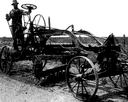 Fig. 22.—Scarafier used in Gravel Road Maintenance
These types of surface can be kept in satisfactory condition if they are carefully repaired once or twice each season. This work requires considerable experience and some special equipment, not ordinarily supplied to patrolmen. A gang is organized for the work and supplied with the proper equipment. They go over the roads and patch all worn places, generally first removing the wearing surface entirely in the area affected.[Pg 134]
The wearing surface mixture is then prepared and tamped or rolled into place. If the area affected is small, tamping is satisfactory, and when the area is considerable, rolling is employed. The upkeep of the side roads may be accomplished by the same gang but is preferably taken care of by patrolmen, who do not attempt any but minor repairs to the wearing surface.
On brick and concrete roads, the principal work on the wearing surface consists in filling the cracks with a suitable bituminous material. This work is done by patrolmen or by special gangs and generally will be done once each year. The upkeep of the side roads is cared for by patrolmen who drag the side roads and cut the weeds as occasion requires.
Transcriber's Notes
The transcriber made these changes to the text to correct obvious errors:
   1. p.   5, accomodate --> accommodate
   2. p.  39, guage --> gauge
   3. p.  46, enbankment --> embankment
   4. p.  63, tought --> tough
   5. p.  68, absorbant --> absorbent
   6. p.  73, persistant --> persistent
   7. p.  77, indispensible --> indispensable
   8. p. 119, aspealt --> asphalt
   9. p. 127, repaid --> rapid
  10. p. 130, Vetrified brick; 105 -->
                           Vitrified brick; 106
  11. p. 130, Virtical --> Vertical
End of the Project Gutenberg EBook of American Rural Highways, by T. R. Agg

*** END OF THIS PROJECT GUTENBERG EBOOK AMERICAN RURAL HIGHWAYS ***

***** This file should be named 29420-h.htm or 29420-h.zip *****
This and all associated files of various formats will be found in:
        https://www.gutenberg.org/2/9/4/2/29420/

Produced by Tom Roch, Richard J. Shiffer and the Online
Distributed Proofreading Team at https://www.pgdp.net (This
file was produced from images produced by Core Historical
Literature in Agriculture (CHLA), Cornell University)


Updated editions will replace the previous one--the old editions
will be renamed.

Creating the works from public domain print editions means that no
one owns a United States copyright in these works, so the Foundation
(and you!) can copy and distribute it in the United States without
permission and without paying copyright royalties.  Special rules,
set forth in the General Terms of Use part of this license, apply to
copying and distributing Project Gutenberg-tm electronic works to
protect the PROJECT GUTENBERG-tm concept and trademark.  Project
Gutenberg is a registered trademark, and may not be used if you
charge for the eBooks, unless you receive specific permission.  If you
do not charge anything for copies of this eBook, complying with the
rules is very easy.  You may use this eBook for nearly any purpose
such as creation of derivative works, reports, performances and
research.  They may be modified and printed and given away--you may do
practically ANYTHING with public domain eBooks.  Redistribution is
subject to the trademark license, especially commercial
redistribution.


*** START: FULL LICENSE ***

THE FULL PROJECT GUTENBERG LICENSE
PLEASE READ THIS BEFORE YOU DISTRIBUTE OR USE THIS WORK

To protect the Project Gutenberg-tm mission of promoting the free
distribution of electronic works, by using or distributing this work
(or any other work associated in any way with the phrase "Project
Gutenberg"), you agree to comply with all the terms of the Full Project
Gutenberg-tm License (available with this file or online at
https://gutenberg.org/license).


Section 1.  General Terms of Use and Redistributing Project Gutenberg-tm
electronic works

1.A.  By reading or using any part of this Project Gutenberg-tm
electronic work, you indicate that you have read, understand, agree to
and accept all the terms of this license and intellectual property
(trademark/copyright) agreement.  If you do not agree to abide by all
the terms of this agreement, you must cease using and return or destroy
all copies of Project Gutenberg-tm electronic works in your possession.
If you paid a fee for obtaining a copy of or access to a Project
Gutenberg-tm electronic work and you do not agree to be bound by the
terms of this agreement, you may obtain a refund from the person or
entity to whom you paid the fee as set forth in paragraph 1.E.8.

1.B.  "Project Gutenberg" is a registered trademark.  It may only be
used on or associated in any way with an electronic work by people who
agree to be bound by the terms of this agreement.  There are a few
things that you can do with most Project Gutenberg-tm electronic works
even without complying with the full terms of this agreement.  See
paragraph 1.C below.  There are a lot of things you can do with Project
Gutenberg-tm electronic works if you follow the terms of this agreement
and help preserve free future access to Project Gutenberg-tm electronic
works.  See paragraph 1.E below.

1.C.  The Project Gutenberg Literary Archive Foundation ("the Foundation"
or PGLAF), owns a compilation copyright in the collection of Project
Gutenberg-tm electronic works.  Nearly all the individual works in the
collection are in the public domain in the United States.  If an
individual work is in the public domain in the United States and you are
located in the United States, we do not claim a right to prevent you from
copying, distributing, performing, displaying or creating derivative
works based on the work as long as all references to Project Gutenberg
are removed.  Of course, we hope that you will support the Project
Gutenberg-tm mission of promoting free access to electronic works by
freely sharing Project Gutenberg-tm works in compliance with the terms of
this agreement for keeping the Project Gutenberg-tm name associated with
the work.  You can easily comply with the terms of this agreement by
keeping this work in the same format with its attached full Project
Gutenberg-tm License when you share it without charge with others.

1.D.  The copyright laws of the place where you are located also govern
what you can do with this work.  Copyright laws in most countries are in
a constant state of change.  If you are outside the United States, check
the laws of your country in addition to the terms of this agreement
before downloading, copying, displaying, performing, distributing or
creating derivative works based on this work or any other Project
Gutenberg-tm work.  The Foundation makes no representations concerning
the copyright status of any work in any country outside the United
States.

1.E.  Unless you have removed all references to Project Gutenberg:

1.E.1.  The following sentence, with active links to, or other immediate
access to, the full Project Gutenberg-tm License must appear prominently
whenever any copy of a Project Gutenberg-tm work (any work on which the
phrase "Project Gutenberg" appears, or with which the phrase "Project
Gutenberg" is associated) is accessed, displayed, performed, viewed,
copied or distributed:

This eBook is for the use of anyone anywhere at no cost and with
almost no restrictions whatsoever.  You may copy it, give it away or
re-use it under the terms of the Project Gutenberg License included
with this eBook or online at www.gutenberg.org

1.E.2.  If an individual Project Gutenberg-tm electronic work is derived
from the public domain (does not contain a notice indicating that it is
posted with permission of the copyright holder), the work can be copied
and distributed to anyone in the United States without paying any fees
or charges.  If you are redistributing or providing access to a work
with the phrase "Project Gutenberg" associated with or appearing on the
work, you must comply either with the requirements of paragraphs 1.E.1
through 1.E.7 or obtain permission for the use of the work and the
Project Gutenberg-tm trademark as set forth in paragraphs 1.E.8 or
1.E.9.

1.E.3.  If an individual Project Gutenberg-tm electronic work is posted
with the permission of the copyright holder, your use and distribution
must comply with both paragraphs 1.E.1 through 1.E.7 and any additional
terms imposed by the copyright holder.  Additional terms will be linked
to the Project Gutenberg-tm License for all works posted with the
permission of the copyright holder found at the beginning of this work.

1.E.4.  Do not unlink or detach or remove the full Project Gutenberg-tm
License terms from this work, or any files containing a part of this
work or any other work associated with Project Gutenberg-tm.

1.E.5.  Do not copy, display, perform, distribute or redistribute this
electronic work, or any part of this electronic work, without
prominently displaying the sentence set forth in paragraph 1.E.1 with
active links or immediate access to the full terms of the Project
Gutenberg-tm License.

1.E.6.  You may convert to and distribute this work in any binary,
compressed, marked up, nonproprietary or proprietary form, including any
word processing or hypertext form.  However, if you provide access to or
distribute copies of a Project Gutenberg-tm work in a format other than
"Plain Vanilla ASCII" or other format used in the official version
posted on the official Project Gutenberg-tm web site (www.gutenberg.org),
you must, at no additional cost, fee or expense to the user, provide a
copy, a means of exporting a copy, or a means of obtaining a copy upon
request, of the work in its original "Plain Vanilla ASCII" or other
form.  Any alternate format must include the full Project Gutenberg-tm
License as specified in paragraph 1.E.1.

1.E.7.  Do not charge a fee for access to, viewing, displaying,
performing, copying or distributing any Project Gutenberg-tm works
unless you comply with paragraph 1.E.8 or 1.E.9.

1.E.8.  You may charge a reasonable fee for copies of or providing
access to or distributing Project Gutenberg-tm electronic works provided
that

- You pay a royalty fee of 20% of the gross profits you derive from
     the use of Project Gutenberg-tm works calculated using the method
     you already use to calculate your applicable taxes.  The fee is
     owed to the owner of the Project Gutenberg-tm trademark, but he
     has agreed to donate royalties under this paragraph to the
     Project Gutenberg Literary Archive Foundation.  Royalty payments
     must be paid within 60 days following each date on which you
     prepare (or are legally required to prepare) your periodic tax
     returns.  Royalty payments should be clearly marked as such and
     sent to the Project Gutenberg Literary Archive Foundation at the
     address specified in Section 4, "Information about donations to
     the Project Gutenberg Literary Archive Foundation."

- You provide a full refund of any money paid by a user who notifies
     you in writing (or by e-mail) within 30 days of receipt that s/he
     does not agree to the terms of the full Project Gutenberg-tm
     License.  You must require such a user to return or
     destroy all copies of the works possessed in a physical medium
     and discontinue all use of and all access to other copies of
     Project Gutenberg-tm works.

- You provide, in accordance with paragraph 1.F.3, a full refund of any
     money paid for a work or a replacement copy, if a defect in the
     electronic work is discovered and reported to you within 90 days
     of receipt of the work.

- You comply with all other terms of this agreement for free
     distribution of Project Gutenberg-tm works.

1.E.9.  If you wish to charge a fee or distribute a Project Gutenberg-tm
electronic work or group of works on different terms than are set
forth in this agreement, you must obtain permission in writing from
both the Project Gutenberg Literary Archive Foundation and Michael
Hart, the owner of the Project Gutenberg-tm trademark.  Contact the
Foundation as set forth in Section 3 below.

1.F.

1.F.1.  Project Gutenberg volunteers and employees expend considerable
effort to identify, do copyright research on, transcribe and proofread
public domain works in creating the Project Gutenberg-tm
collection.  Despite these efforts, Project Gutenberg-tm electronic
works, and the medium on which they may be stored, may contain
"Defects," such as, but not limited to, incomplete, inaccurate or
corrupt data, transcription errors, a copyright or other intellectual
property infringement, a defective or damaged disk or other medium, a
computer virus, or computer codes that damage or cannot be read by
your equipment.

1.F.2.  LIMITED WARRANTY, DISCLAIMER OF DAMAGES - Except for the "Right
of Replacement or Refund" described in paragraph 1.F.3, the Project
Gutenberg Literary Archive Foundation, the owner of the Project
Gutenberg-tm trademark, and any other party distributing a Project
Gutenberg-tm electronic work under this agreement, disclaim all
liability to you for damages, costs and expenses, including legal
fees.  YOU AGREE THAT YOU HAVE NO REMEDIES FOR NEGLIGENCE, STRICT
LIABILITY, BREACH OF WARRANTY OR BREACH OF CONTRACT EXCEPT THOSE
PROVIDED IN PARAGRAPH F3.  YOU AGREE THAT THE FOUNDATION, THE
TRADEMARK OWNER, AND ANY DISTRIBUTOR UNDER THIS AGREEMENT WILL NOT BE
LIABLE TO YOU FOR ACTUAL, DIRECT, INDIRECT, CONSEQUENTIAL, PUNITIVE OR
INCIDENTAL DAMAGES EVEN IF YOU GIVE NOTICE OF THE POSSIBILITY OF SUCH
DAMAGE.

1.F.3.  LIMITED RIGHT OF REPLACEMENT OR REFUND - If you discover a
defect in this electronic work within 90 days of receiving it, you can
receive a refund of the money (if any) you paid for it by sending a
written explanation to the person you received the work from.  If you
received the work on a physical medium, you must return the medium with
your written explanation.  The person or entity that provided you with
the defective work may elect to provide a replacement copy in lieu of a
refund.  If you received the work electronically, the person or entity
providing it to you may choose to give you a second opportunity to
receive the work electronically in lieu of a refund.  If the second copy
is also defective, you may demand a refund in writing without further
opportunities to fix the problem.

1.F.4.  Except for the limited right of replacement or refund set forth
in paragraph 1.F.3, this work is provided to you 'AS-IS' WITH NO OTHER
WARRANTIES OF ANY KIND, EXPRESS OR IMPLIED, INCLUDING BUT NOT LIMITED TO
WARRANTIES OF MERCHANTIBILITY OR FITNESS FOR ANY PURPOSE.

1.F.5.  Some states do not allow disclaimers of certain implied
warranties or the exclusion or limitation of certain types of damages.
If any disclaimer or limitation set forth in this agreement violates the
law of the state applicable to this agreement, the agreement shall be
interpreted to make the maximum disclaimer or limitation permitted by
the applicable state law.  The invalidity or unenforceability of any
provision of this agreement shall not void the remaining provisions.

1.F.6.  INDEMNITY - You agree to indemnify and hold the Foundation, the
trademark owner, any agent or employee of the Foundation, anyone
providing copies of Project Gutenberg-tm electronic works in accordance
with this agreement, and any volunteers associated with the production,
promotion and distribution of Project Gutenberg-tm electronic works,
harmless from all liability, costs and expenses, including legal fees,
that arise directly or indirectly from any of the following which you do
or cause to occur: (a) distribution of this or any Project Gutenberg-tm
work, (b) alteration, modification, or additions or deletions to any
Project Gutenberg-tm work, and (c) any Defect you cause.


Section  2.  Information about the Mission of Project Gutenberg-tm

Project Gutenberg-tm is synonymous with the free distribution of
electronic works in formats readable by the widest variety of computers
including obsolete, old, middle-aged and new computers.  It exists
because of the efforts of hundreds of volunteers and donations from
people in all walks of life.

Volunteers and financial support to provide volunteers with the
assistance they need are critical to reaching Project Gutenberg-tm's
goals and ensuring that the Project Gutenberg-tm collection will
remain freely available for generations to come.  In 2001, the Project
Gutenberg Literary Archive Foundation was created to provide a secure
and permanent future for Project Gutenberg-tm and future generations.
To learn more about the Project Gutenberg Literary Archive Foundation
and how your efforts and donations can help, see Sections 3 and 4
and the Foundation web page at https://www.pglaf.org.


Section 3.  Information about the Project Gutenberg Literary Archive
Foundation

The Project Gutenberg Literary Archive Foundation is a non profit
501(c)(3) educational corporation organized under the laws of the
state of Mississippi and granted tax exempt status by the Internal
Revenue Service.  The Foundation's EIN or federal tax identification
number is 64-6221541.  Its 501(c)(3) letter is posted at
https://pglaf.org/fundraising.  Contributions to the Project Gutenberg
Literary Archive Foundation are tax deductible to the full extent
permitted by U.S. federal laws and your state's laws.

The Foundation's principal office is located at 4557 Melan Dr. S.
Fairbanks, AK, 99712., but its volunteers and employees are scattered
throughout numerous locations.  Its business office is located at
809 North 1500 West, Salt Lake City, UT 84116, (801) 596-1887, email
business@pglaf.org.  Email contact links and up to date contact
information can be found at the Foundation's web site and official
page at https://pglaf.org

For additional contact information:
     Dr. Gregory B. Newby
     Chief Executive and Director
     gbnewby@pglaf.org


Section 4.  Information about Donations to the Project Gutenberg
Literary Archive Foundation

Project Gutenberg-tm depends upon and cannot survive without wide
spread public support and donations to carry out its mission of
increasing the number of public domain and licensed works that can be
freely distributed in machine readable form accessible by the widest
array of equipment including outdated equipment.  Many small donations
($1 to $5,000) are particularly important to maintaining tax exempt
status with the IRS.

The Foundation is committed to complying with the laws regulating
charities and charitable donations in all 50 states of the United
States.  Compliance requirements are not uniform and it takes a
considerable effort, much paperwork and many fees to meet and keep up
with these requirements.  We do not solicit donations in locations
where we have not received written confirmation of compliance.  To
SEND DONATIONS or determine the status of compliance for any
particular state visit https://pglaf.org

While we cannot and do not solicit contributions from states where we
have not met the solicitation requirements, we know of no prohibition
against accepting unsolicited donations from donors in such states who
approach us with offers to donate.

International donations are gratefully accepted, but we cannot make
any statements concerning tax treatment of donations received from
outside the United States.  U.S. laws alone swamp our small staff.

Please check the Project Gutenberg Web pages for current donation
methods and addresses.  Donations are accepted in a number of other
ways including including checks, online payments and credit card
donations.  To donate, please visit: https://pglaf.org/donate


Section 5.  General Information About Project Gutenberg-tm electronic
works.

Professor Michael S. Hart was the originator of the Project Gutenberg-tm
concept of a library of electronic works that could be freely shared
with anyone.  For thirty years, he produced and distributed Project
Gutenberg-tm eBooks with only a loose network of volunteer support.


Project Gutenberg-tm eBooks are often created from several printed
editions, all of which are confirmed as Public Domain in the U.S.
unless a copyright notice is included.  Thus, we do not necessarily
keep eBooks in compliance with any particular paper edition.


Most people start at our Web site which has the main PG search facility:

     https://www.gutenberg.org

This Web site includes information about Project Gutenberg-tm,
including how to make donations to the Project Gutenberg Literary
Archive Foundation, how to help produce our new eBooks, and how to
subscribe to our email newsletter to hear about new eBooks.