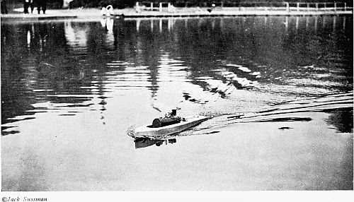
 A TWO-FOOT STEAMBOAT
Making her way across the park pond. Ten miles an hour is a common speed for a boat of this type
Project Gutenberg's Boys' Book of Model Boats, by Raymond Francis Yates

This eBook is for the use of anyone anywhere at no cost and with
almost no restrictions whatsoever.  You may copy it, give it away or
re-use it under the terms of the Project Gutenberg License included
with this eBook or online at www.gutenberg.org


Title: Boys' Book of Model Boats

Author: Raymond Francis Yates

Release Date: June 7, 2009 [EBook #29064]

Language: English

Character set encoding: ISO-8859-1

*** START OF THIS PROJECT GUTENBERG EBOOK BOYS' BOOK OF MODEL BOATS ***


Produced by Chris Curnow, Emmy and the Online Distributed
Proofreading Team at https://www.pgdp.net (This file was
produced from images generously made available by The
Internet Archive)
A TWO-FOOT STEAMBOAT
The author was an ardent boat-builder, and he well remembers how he combed the Children's Department of the local library in search of a book that would tell him something about boats, and especially for information regarding the construction of models. He found books on model airplanes, toys, electricity, radio, and chemistry, but alas! nothing about model boats. He vowed then that when he became a man he would write a book on model boats—a book that would contain all the treasured information he had accumulated during his boat-building years.
This book is the result of that vow, and the author earnestly hopes that it will gladden the heart of every boy who builds and sails a boat. There are probably few happier moments in a boy's life than when he sees his little model steamer proudly make her way across the park pond, or his little sail-boat respond to the summer breeze.
The author takes this opportunity to thank his wife, who acted as his amanuensis in the preparation of this manuscript.
| CHAPTER | PAGE | |
| I | Why a Boat Floats | 3 |
| II | The Hull | 12 |
| III | How to Make Simple Boats, with and without Power Drive | 26 |
| IV | Steam and Electric Propulsion | 42 |
| V | An Electric Launch | 66 |
| VI | A Steam Launch | 75 |
| VII | An Electrically Driven Lake Freighter | 91 |
| VIII | An Electric Submarine-Chaser | 98 |
| IX | Boat Fittings | 107 |
| X | The Design of Model Steam-Engines | 126 |
| XI | A Model Floating Dry-Dock | 135 |
| XII | Operation of Flash Steam Power Plants for Model Boats | 149 |
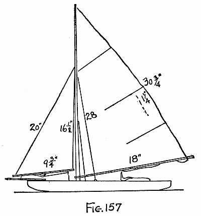
| XIII | Sailing Yachts | 164 |
| XIV | Two-Foot Sailing Yacht | 184 |
| Appendix | 207 | |
| A two-foot steam boat | Frontispiece |
| FACING PAGE | |
| Getting ready for a trip | 72 |
| All ready to go | 73 |
| A powerful gasolene blow-torch | 112 |
| Just after the race | 113 |
| A twin-cylinder steam engine for model marine use | 168 |
| A cup-winning model sail boat | 169 |
"How does a steel boat float?" is a question that many boys ask. The reason they usually designate a steel boat is probably because steel is so much heavier than water. But many things heavier than water can be[4] made to float if they are in the form of a boat. Concrete, for instance, is now being used in ship construction, and this substance, when reinforced with steel rods, is very much heavier than water.
Before learning how a boat floats, what is known as "specific gravity" must be thoroughly understood. Gravity is a force that is continuously "pulling" everything toward the center of the earth. It is gravity that gives a body "weight." Some substances are heavier than others; or, to be more correct, it is said that the specific gravity of one substance is greater than that of another. It will be well to keep in mind that specific gravity merely refers to weight. It is simply a scientific term. The specific gravity of a substance is always expressed by a figure that tells how much heavier any substance is than water, because water has been chosen as a standard.
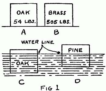
The specific gravity of water is 1. The specific gravity of gold is 19.26, meaning that it is about 191/4 times heavier than water. The specific gravity of a piece of oak is 0.86, which shows that it is not quite so heavy[5] as water. One cubic foot of water weighs 62.42 pounds. It will be understood that a cubic foot of gold would weight 19.26 x 62.42, because it is 19.26 times heavier than water. A cubic foot of oak, however, would weigh only 54 pounds, because it has been found that it has a specific gravity of only 0.86 which is less than water.
A cubic foot of oak (see Fig. 1), with a weight of 54 pounds, will float when placed in water. The cubic foot of brass (B), however, will not float, because it weights 8.1 times as much as water. For the present, then, it can be said that a substance lighter than water will float in water, but that substances heavier than water, such as iron, lead, gold, silver, etc., will not float. If the[6] cubic foot of oak (A) were placed in water, it would sink to the depth shown at C. When the block sinks into the water, a certain amount of water will be forced away or "displaced"; that is, the block in sinking occupies a space that was previously occupied or filled with water. The oak block sinks to within a short distance of the top because the oak is really just a trifle lighter than water. If a pine block were placed in the water it would sink only to the distance shown at D, since the weight of pine is less than oak, or only 34.6 pounds per cubic foot. A pine block will, then, displace only about 34.6 pounds of water, which leaves nearly half of the block out of the water. Thus, it will be seen that for a given volume (size) a cubic foot of wood will sink to a depth corresponding to its weight. Different kinds of wood have different weights.
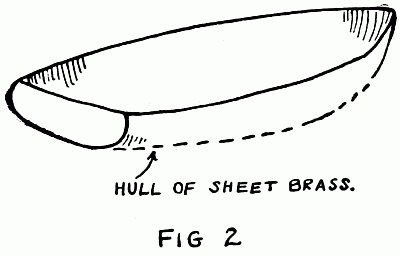
If a cubic foot of brass is placed in water, it will sink rapidly to the bottom, because the brass is much heavier than water. How is it, then, that an iron or concrete ship will float? If the cubic foot of brass is rolled or flattened out in a sheet, and formed or[7] pressed into the shape of a boat hull, as shown in Fig. 2, it will float when placed upon the surface of the water. Why is it that brass is caused to float in this way, when it sank so rapidly in the form of a solid square?
It will be remembered that the pine and oak block were caused to float because they displaced a greater weight of water than their own weight. This is just what causes the brass boat-hull to float. If the amount of water actually displaced by the hull could be weighed, it would be found that the weight of the water would be greater than the weight of the hull. It will be understood that the space occupied by the brass boat-hull is far greater than the space occupied by the block of brass before it was rolled out and formed into a hull. What is true of[8] brass holds true of iron, steel, etc. A block of steel will not float, because the water it displaces does not weigh nearly as much as the block. If this block, however, were rolled out into a sheet and the sheet formed into a hollow hull, the hull would float, because it would displace a volume of water that would more than total the weight of the steel in the hull.
In the case of the brass boat-hull, it would be found that a greater portion of the hull would remain out of the water. The hull, then, could be loaded until the top of it came within a safe distance from the water. As the load is increased, the hull sinks deeper and deeper. The capacity of big boats is reckoned in tons. If a boat had a carrying capacity of ten tons it would sink to what is called its "load water-line" (L.W.L.) when carrying ten tons. As a load or cargo is removed from a vessel it rises out of the water.
What if the hull of a boat has a hole in it? If the hole is below the water-line, water will leak in and in time completely fill the inside of the hull, causing the boat to[9] sink. Also, if too great a load or cargo were placed in a boat, it would sink. It must be understood that water leaking into a boat increases its load, and if it is not stopped it will cause the boat to sink.
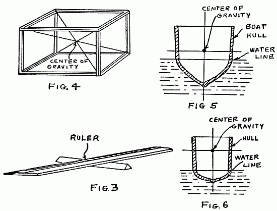
The center of gravity of a boat is a very important matter. First, attention will be directed to the meaning of "center of gravity." If a one-foot ruler is made to balance (as shown in Fig. 3) at the six-inch mark, the point at which it balances will be very close to the center of gravity. The real center, however, will be in the middle of the wood of which the rule is composed. It should constantly be kept in mind that this "center of gravity" is a purely imaginary point.
Look at Fig. 4. If wires are arranged in a wooden frame, as shown, the point where the wires cross will be the center of gravity if the square formed by the wooden strips is solid. Every body, no matter what its shape, has a center of gravity. The center of gravity is really an imaginary point in a body, at the center of its mass. Oftentimes engineers are heard saying that the[10] center of gravity of a certain object is too high or too low. Fig. 5 shows the center of gravity in a boat. If the center of gravity in a boat is too high (as illustrated in Fig. 6) the boat is said to be topheavy and unsafe. When a boat is topheavy or its center of gravity is too high, the boat is liable to capsize. In fact, some very serious marine accidents have been caused by this fault.
The center of gravity (or center of weight) in a boat should be as low as possible. A boat with a low center of gravity will be very stable in the water and difficult[11] to capsize. This is true of model boats just as much as it is true of large boats. The model boat builder must keep the weight of his boat as near the bottom as possible. For instance, if a heavy cabin were built on a frail little hull, the boat would be very unstable and would probably capsize easily.
Cutting a model boat-hull from a solid piece of wood is by no means a simple or easy task, especially for beginners. Of course, after several hulls have been produced in this fashion, the worker becomes practised in cutting them out.
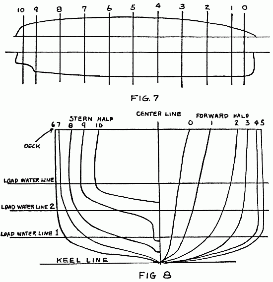
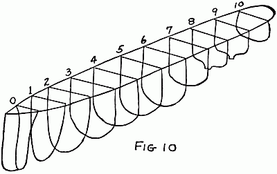
The construction of hulls on the built-up principle will be described first. For the sake[13] of convenience, the drawings of the boat-hull shown in Figs. 7 and 8 will be followed out. Before going further it will be well to understand drawings of boat-hulls; that is, how to know the lines of a boat from a drawing. By the "lines" is meant its shape. Marine architects employ a regular method in drawing boat-hulls. Fig. 7 shows the side of a[14] boat and half of the deck plan. It will be seen that this drawing does not tell much about the real shape of the boat, and if a hull were to be produced according to the shape given, the builder would have to use his own judgment as to the outline of the hull at different places. For convenience, the boat is divided into ten sections, represented by the lines 0 to 10. It will be seen that the shape of the hull at section 2 will be different from the shape of the hull at section 8. Again, section 0 will be much narrower than section 5.
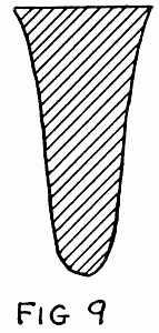
Now look at Fig. 8. Note the shape of the cross-section of the hull at the different sections. For instance, the line at section 1 in Fig. 8 represents the shape of the hull at section 1 in Fig. 7. It must be remembered, however, that this is only half of the section, and that the line 1 in Fig. 8 would have to be duplicated by another line to show the true shape. The cross-section of the boat at section 0 is shown in Fig. 9. One half of the drawing in Fig. 8 represents the forward half of the hull, and the other half represents the stern half of the hull. If the[15] shape of the boat at section 10 is desired, the line 10 in Fig. 8 could be traced on a piece of tissue paper. The paper could then be folded in half and the line first made traced on the second half. This would then produce the section of the boat at point 10. Thus, by closely examining Fig. 8 the shape of the entire hull can be seen.
If pieces of wire could be used to form the lines of the hull at the various sections, it would appear as shown in Fig. 10 when assembled.
Notice that in Fig. 8 there is a load water-line,[16] which the vessel sinks to when loaded, and the second and first load water-line, which the vessel sinks to when only partially loaded or when carrying no load aside from its regular necessary equipment. The keel line of the boat is the line that runs along the bottom from bow to stern. (The bow of the boat is the front and the stern the back.)
Motor-boating and marine magazines often publish the lines of different boats, and if the young boat-builder understands how to read boat drawings he will be able to make a model of any boat that is so described.
Directions will now be given regarding the method of producing a boat-hull similar to the lines shown in Figs. 7 and 8, by the built-up method of construction.
First, it will be necessary to procure the lumber. Several clean white pine boards will be very suitable to work with, and will not require much skill in handling. Let us assume that the boat-hull is to measure 22 inches in length, with a depth of 4 inches. The beam, which is the width of the boat at its widest point, will be 5 inches. (It will be well to remember what the term "beam"[17] means, since the term will be used constantly throughout the book.)
On a piece of heavy wrapping-paper draw the deck plan full size, that is, 22 inches long by 5 inches at its widest point. Next cut out along the pencil line with a pair of shears. Now lay the paper outline on a plank and mark out the pattern on the wood. Repeat this process with three more planks. When this is done, cut out the boards with a keyhole saw.
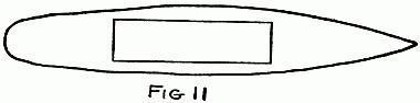
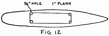
After the boards are cut out mark them as shown in Fig. 11. The space marked out on the board must be sawed out in two of the boards, to form the inside of the hull, if the boat is to carry some form of power, such as a battery-motor, or steam-engine. After the lines are marked out, make a hole with a 3/4-inch bit, as shown in Fig. 12. Insert the point of the keyhole saw in one of these holes to start it and cut out the piece.[18] Treat the second board in the same way. The third board must have a smaller portion cut out of the center, owing to the fact that this board is nearer the bottom of the hull, where the width of the boat is narrower. The width of the piece cut out in the third board should not be more than 2 inches.
When this work is done, a very thin layer of glue is placed over the boards, and they are then laid one on top of another. The boards are then placed in a vise or clamp and allowed to remain there over night. In applying the glue, the builder should be careful not to put too much on the boards. Too much glue is worse than not enough. It should be merely a thin film.
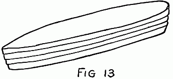
After the boards have been glued together the crude hull will appear, as shown in Fig. 13 .
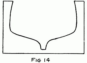
At this point the hull sections from 0 to 10[19] must be marked off. By referring again to Fig. 7 it will be seen that the sections 0 to 1 and 9 to 10 are not so far apart as the other sections. Section 0 is 1 inch from the bow of the boat and section 1 is 1 inch from section 0. Sections 2, 3, 4, 5, 6, 7, and 8 are all 1 inch apart. Section 9 is 1 inch from 10 and 10 is 1 inch from the stern. Lines should be drawn across the deck to correspond with these sections, which can be measured off with a ruler. It will now be necessary to cut some templates, or forms, from cardboard to guide the builder in bringing the hull to shape. It will be an easy matter to make these templates by following Fig. 8. A template of section 9 is shown in Fig. 14. It will be necessary to make eleven templates, corresponding to the sections 0 to[20] 10. The templates should be cut from heavy cardboard so they will hold their shapes.
The hull of the boat is now placed in a vise and roughly brought to shape with a draw-knife. After it has been brought to shape by this means a spoke-shave is used. This little tool has an adjustable blade by means of which it is possible to regulate the cut. When the builder starts to use the spoke-shave he should also start to use his templates or forms, applying them sectionally to determine how much more wood he will have to remove to bring the hull to shape. For instance, when he is working in the vicinity of sections 5, 6, and 7 he will apply these forms at the proper points occasionally to determine when enough wood has been removed.[21] This procedure is followed out the entire length of the boat, care being taken to see that both sides are the same and that too much wood is not removed, since there is no remedy for this mistake. The builder who proceeds carefully and is not in too great a hurry to finish the work need not make this mistake.
Of course, it will not be possible to bring the hull to a perfect finish with a spoke-shave. This can be done, however, by the use of a coarse file and sandpaper. The coarse file is used to take the rough marks of the spoke-shave away, and the marks left by the file are in turn removed by the sandpaper. The sandpaper must be applied unsparingly and always with the grain. It will be necessary to use considerable "elbow grease" to obtain a good finish.
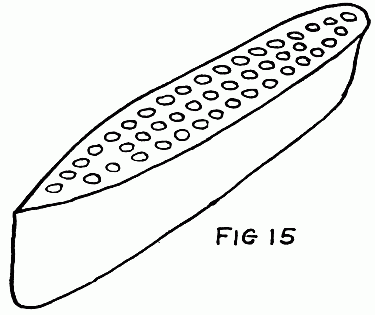
Boat-hulls can also be hewn to shape from a solid block, but it will be understood that this method involves more work than the one just described. Of course, the procedure of bringing the hull to shape by the aid of the draw-knife, spoke-shave, and templates is the same, but the hollowing out of the inside[22] of the hull will be a much more difficult job. However, with a couple of good sharp chisels and a gouge the work will not be so difficult as at first appears. The use of an auger and bit will greatly aid in the work. After the outside of the hull is brought to shape the wooden form is drilled with holes, as shown in Fig. 15. This will make it much easier to chip the wood away. After the major portion of the wood has been taken out with the chisel, the gouge is brought into use. The gouge should be used very carefully, since it will easily go through the entire hull if it is not handled properly. For the beginner it is not safe to make a hull less than 1/2 inch in thickness. Of course, it is not[23] necessary to carefully finish the inside of the hull, since it is covered up with the deck and cabin.
The solid hull has one advantage over the built-up hull. It is not affected by moisture and it is therefore not so liable to warp and lose its shape. It will also stand more rough usage.
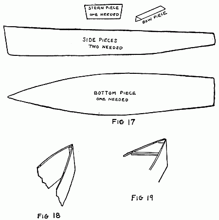
There is still another method of producing a boat-hull. This hull is known as the Sharpie type. A Sharpie hull is shown in Fig. 16. The method of producing a hull of this type will be seen quite clearly by reference to Fig. 17, which shows the boards and parts cut out ready to assemble. The boards are made from 1/8-inch mahogany, which can be obtained at any lumber-yard. First, the bow piece is cut to shape and carefully finished. Then the two side pieces are fastened to it, as shown in Fig. 18. The screws used should be brass, since iron[24] screws will rust and cause trouble. Three screws should be used for each side board, and they should be driven into the bow piece so that the screws on one side will not interfere with those on the other. The first cross-piece is then screwed in place, as shown in Fig. 19. The second and third cross-pieces are then screwed in place and the back or stern piece attached. The bottom[25] of the boat is then carefully put in place with small screws. It will be noticed that the bottom board of the boat is cut to fit the inside of the bottom. It is held in place with small brass brads. The crevices or seams along the bottom of the boat should be carefully covered with pitch or marine glue to prevent leakage when the boat is in the water. The bow of the boat should be finished off nicely to a point with a heavy file or a wood-rasp.
This type of hull is extremely easy to produce and it is capable of carrying a considerable load. However, it is not a good type to use for all kinds of boats. It makes a splendid little pleasure yacht or submarine-chaser, but for a torpedo-boat destroyer or a freighter it would not be suitable.
The young model boat builder is advised not to try to construct hulls from metal. This is a very difficult task even for the thoroughly experienced mechanic. Wood is much easier to work with and will produce the same results.
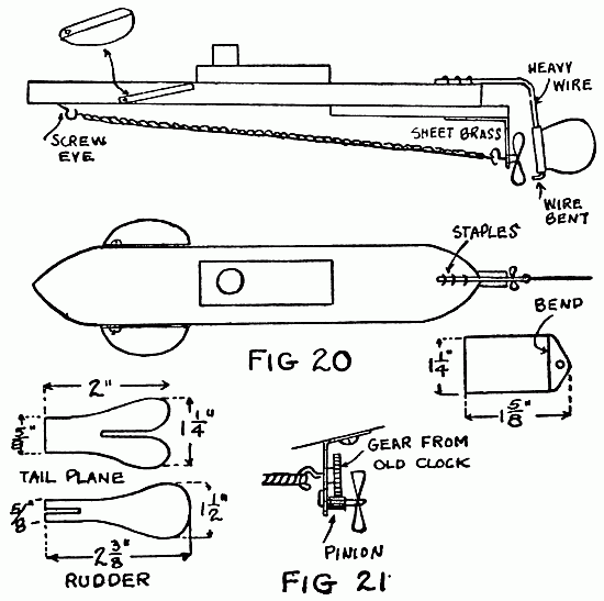
The first boat described is a submarine. This is shown in Fig. 20. Four blocks of wood form the basis of its construction, and these are cut from 1-inch stock, as shown in the drawing. Such a submarine can be[27] made practically any size up to 12 inches in length. Beyond this size they begin to look out of proportion and they are more difficult to propel. After nailing the blocks together as shown in the drawing, a small piece of sheet brass is bent at right angles and tacked to the stern piece. This is to act as a bearing for the propeller.
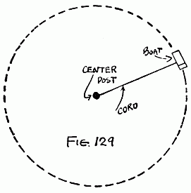
The propeller-shaft is bent into a hook over which rubber bands are placed. The opposite end of the rubber bands are fastened to a screw-eye driven into the under side of the bow. A heavy piece of copper wire is fastened to the stern of the boat by staples, and bent as shown. A rudder is then cut from thin sheet brass, and the end of it is bent around a piece of wire larger in diameter than the wire used for the rudder-post. It is then taken from this wire and slipped over the wire on the boat. It should be pinched in place by a pair of pliers, so that it will stay in any position in which it is put. The end of the wire is bent over so that the rudder will not slip off. The boat can be steered in a circle or it can be made to go straight, depending upon the position of the propeller.
The horizontal rudders are mounted forward, as shown. They are made from thin sheet brass bent as indicated in the little insertion. A hole is drilled in them as shown, and a screw is placed through these to hold the rudders to the side of the craft. The screws should be tightened so that the rudders[29] will stay at any angle at which they are put. If the boat is to be submerged the rudders are pointed as shown. If the boat is to travel on the surface of the water the rudders are brought up into a horizontal position or parallel with the deck. A little gray paint placed on this model will greatly improve its appearance.
Another submarine, more complicated than the one just described, is shown in Fig. 21 . The body of this submarine is formed by a part of a broomstick or shovel-handle. This submarine is truer to type and can be made with very little trouble. The piece of broomstick or shovel-handle is cut 22 inches in length. It is pointed at each end, and part of it is planed off to form the upper deck. When this is done, a small flat piece is cut as shown, and nailed or screwed to the flat portion. The conning-tower and periscope are placed on the upper deck, as shown. The rudder on this craft is not made adjustable, so that it always travels in a perfectly straight line. The horizontal rudders however, are made adjustable, and the boat is therefore able to travel upon the surface or[30] submerge, depending upon the position of the rudder.
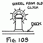
The power plant of this boat is made up of rubber bands. The power transmission to the propeller is a little different than the one previously described. A gear and a pinion are salvaged from the works of an old alarm-clock, and mounted on a piece of brass, as shown. A little soldering will be necessary here to make a good job. By using the gear meshing with the pinion a considerable increase in the speed of the propeller is obtained, and therefore the speed of the boat is considerably increased. The method of holding the power plant to the bottom of the boat is made very clear. In order to bring the boat down to the proper level in the water, a strip of sheet lead can be tacked to the bottom. The builder should take care to get a piece of lead just the correct weight to leave the surface of the deck awash. A coat of gray paint will also greatly improve the appearance of this craft.
Attention is directed to the construction of boats of different types made without power plants. Many interesting little crafts[32][31] can be produced in this way, and the energetic model-builder can produce a whole model harbor or dock-yard by constructing a number of boats of different types according to the following instructions.
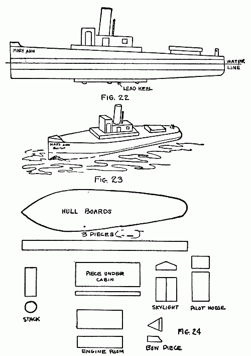
The first boat described will be the tug Mary Ann shown in Fig. 22 and Fig. 23. The blocks necessary to construct this boat are shown in Fig. 24. The hull of the boat is produced by three pieces of wood sawed out to the same shape with a keyhole saw and glued together. After the glue is dry the blocks are placed in a vise and the top one or deck block is planed down as shown. It will be seen that the deck inclines slightly toward the stern of the boat. When this is done the hull is turned upside down and the bottom of the stern planed off as illustrated. The outside of the hull can be finished up with a sharp knife and a jack-plane.
The little bow piece can also then be tacked in place. After this the pieces that form the hull can be nailed together from the bottom and from the top. This is quite necessary, for glue will not hold them in place after[33] the boat has become thoroughly soaked with water.
The cabin and engine-room are shown very clearly in the illustration and little need be said about erecting this part of the craft. The two doors and window on the side of the cabin are made by cutting out small pieces of cigar-box wood and gluing them to the cabin and engine-room. A good substitute for the wood can be found in tin, but of course this would have to be tacked on. The little skylight on the back of the tug is made by a single block covered by two pieces of cigar-box wood.
In order to stabilize the craft and to bring her down to the proper water-line, a lead keel must be nailed to the bottom. The weight of this keel will have to be adjusted until the boat rests properly in the water. The reader will notice that no dimensions have been given for this boat. This is because most boys will wish to build different sized boats, and therefore it has not been deemed advisable to dimension the boats described in this Chapter. What the author[34] desires to do is to impart the principles of construction, so that every boy may use his own ingenuity in regard to size and proportion of length to beam.
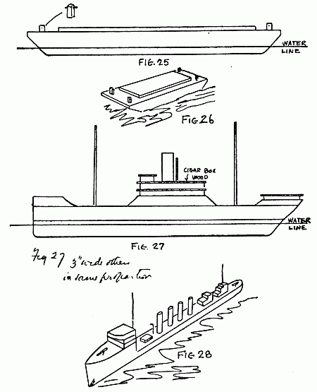
If tugs are constructed according to the design outlined above, the model boat builder will also desire to have something that the tug can haul. A very simple barge for this purpose is outlined in Figs. 25 and 26. This is formed of a single slab with the ends cut at an angle as illustrated. A square flat piece is then tacked to the upper deck, which acts as a cover. Four posts are then put in place in the same way as those on the tug. One is placed in each corner. A boat or a scow like this is generally painted red, and the model described can be made to look much more realistic by painting it this color.
These barges are so easy to construct that the model-builder should make three or four of them at a time. If the pieces for several are cut out at the same time, the construction will be just that much easier. If the boat does not sink far enough into the water, a piece of lead should be placed on the bottom to bring it down. This piece of lead should[35] be placed as near the center as it is possible to get it. Otherwise the boat will list or tip at one end or the other. With a little patience and care the weight can be so adjusted on the bottom as to bring the scow to a perfectly level position. The reader will[36] understand that the water-line of a scow or any boat made according to the directions in this book will depend largely upon the nature of the wood. In the first Chapter of the book it was pointed out that the specific gravity of different woods varies, and therefore the buoyancy will vary.
A model freighter is shown in Fig. 27. The hull of this boat can be formed by two 11/2-inch planks. These will require a little hard work to cut out; but, on the other hand, the effort will be entirely justified by the pleasing appearance of the little craft that can be produced in this way. A bow and stern block to raise the deck are cut out and nailed in place, as shown. A cabin is also placed on the stern of the craft, and this is formed by a block with a piece of cigar-box wood placed on the top. The cigar-box wood should project a little over the edges to form a canopy. The center of the deck can be raised by a third block; and three independent blocks, two large ones and a small one, form the main cabin. Sandwiched in between these blocks are three pieces of cigar-box wood. The remaining details of[37] the craft are so simple that they may easily be made by following the diagram.
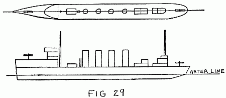
Let us turn our attention to model war-ships. A torpedo-boat destroyer is clearly illustrated in Figs. 28 and 29. This is very simple to construct and makes a pleasing craft when finished. The hull is formed by two blocks. One of these forms the raised deck on the bow of the boat. The cabin is built up on this raised deck. It will be seen that the part of the hull that rests in the water is formed by one block. In building boats of this nature the constructor should be careful to keep them long and slender, since torpedo-boat destroyers are always of this type. They are high-speed craft, and their displacement must therefore be as small as possible. Some of these boats carry four[38] stacks and some two. The author prefers four stacks as giving the boat a better appearance than two. The two little cabins near the stern of the boat are placed there merely to take away the plainness of construction. The guns mounted forward and aft are merely round pieces of wood with a piece of wire bent around them and forced into a hole in the deck.
The boat-builder should not be satisfied with one or two of these craft; he should make a whole fleet. This will afford the[39] average boy a great amount of pleasure, since he can add to his fleet from time to time and have official launchings. Each boat can also be given a name and a number. A little gray paint on the hull of these boats and black on the stacks gives them a very presentable appearance.
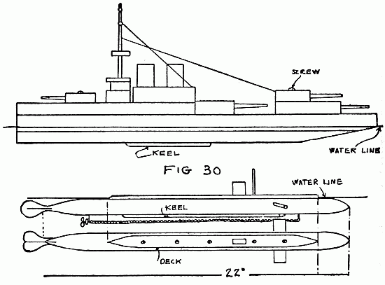
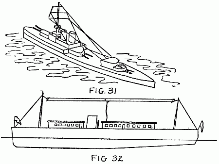
A battleship is shown in Fig. 30. A battleship should be at least twice as long as a torpedo-boat destroyer. A view of the battleship as it will look in the water is shown in Fig. 31. By carefully examining this drawing the builder will be able to see just[40] the number and shape of the blocks that enter into the construction of the craft. The battleship is provided with four main batteries mounted in turrets, one forward and three aft. A mast is also built, and strings run from it to the top of the main cabin and to the end of one of the turrets mounted aft. A screw is placed through the centers of the fore and aft turrets, so they can be turned to any position. Battleships should be painted gray. It will be necessary to place rather a heavy keel on the boat just described in order to bring it down to the proper depth in the water. Otherwise it will be topheavy and will capsize very easily. A fleet of battleships and battle-cruisers can easily be made according to the foregoing instructions, and the builder should not be satisfied with producing only one.
A pleasure yacht is illustrated in Fig. 32. The hull of this craft is formed by two boards nailed together. The cabins are very simple, being formed by a solid block of wood with a piece of cigar-box wood tacked to the top. The windows and doors are marked in place with a soft lead-pencil, and[41] the stack is mounted midway between the two cabins. A wireless antenna should be placed on the boat, with a few guy-wires from the masts run to various parts of the deck. A lead-in wire also runs down into one of the cabins. The hull of this boat should be painted pure white. The deck can be left its natural color, while the stack should be painted black and the cabins white with green trimmings.
Almost any type of boat can be produced by the use of simple blocks of wood and other miscellaneous pieces easily brought to shape from ordinary materials. This method of construction offers a wonderful opportunity for the boy to exercise his creative faculties.
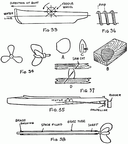
The paddle-wheel really acts as a continuous oar. Such a wheel is shown in Fig. 33 . As the wheel goes around the paddle dips into the water and pushes the boat forward. If the direction of the boat is to be reversed, the rotation of the paddle-wheels is reversed.
Before passing onto the screw, it may be well to explain just how a paddle-wheel causes a boat to move. When a man gets into a rowboat, he generally pushes himself off by placing his oar against the dock or shore and pushing on it. That is just what the paddle does in the water. It dips into[43] the water and pushes against it. It must be remembered, however, that water is unlike a solid substance and it "gives." When a man places his oar against the bank and pushes it, the bank does not move, and all of the man's energy is used in starting the[44] boat. Water, however, does not remain stationary when the paddles push against it, and therefore all of the power it not utilized in moving the boat—part is used in moving the water.
The paddle-wheel is not so efficient in moving a boat as the more modern propeller—or screw, as it is more often called. The screw receives its name from the ordinary metal screw, because its theory of operation is exactly the same. A wood screw, when turned, forces itself into wood. A propeller, when turned, forces itself (and thereby the boat) through the water. A small propeller is illustrated in Fig. 34. This is an ordinary three-blade propeller. (The writer prefers the word propeller instead of screw.)
From the drawing, it will be seen that the propeller-blades are mounted at an angle. This angle of the blades causes them to force water back as they cut through it when the propeller is revolving. This forcing of the water back tends to produce a forward motion of the propeller, and in this way the boat on which the propeller is mounted moves through the water. The propeller is[45] caused to revolve by a steam-engine, steam-turbine, or gasolene-engine, as shown in Fig. 35 . Longer boats have more than one propeller. A boat that has two propellers is called a twin-screw boat. A boat driven with four propellers is called a quadruple-screw boat.
When a machine screw is turned around just once, it moves forward a certain distance, as a glance at Fig. 36 will show. The distance the screw moves forward will depend entirely upon the distance between the threads. The distance between the threads is called the pitch of the thread. If the threads are 1/32 inch apart, then the screw will move 1/32 inch every time it revolves.
If a propeller acts in the same way as a screw, then it too must have a pitch. The pitch, or the distance that a propeller will advance in one revolution, is measured in inches. A propeller with a pitch of ten inches should move ten inches through the water at each revolution. However, there is a certain amount of "slip," and a propeller does not actually advance the distance that it should theoretically. The pitch of a propeller[46] is really the distance it would advance in one revolution if it were revolving in an unyielding or solid substance.
To make a simple propeller, first cut out of thin sheet brass three blades as shown at A, Fig. 37. Sheet brass with a thickness of 1/32 inch is very suitable for this purpose. Next, a block, as shown at B, is carefully carved out so that the propeller can be hammered down into the depression. The same block is used for the three blades, so that each will have the same curvature. The block should be cut from oak, since this wood will not split or lose its shape when the forming is done.
The hub is made next. This is shown at C, Fig. 37. The hub, of brass, is made according to the stream-line method. It is filed to shape from a piece of round brass stock. A hole runs lengthwise in the brass, as shown, and a set-screw is used to hold the hub of the propeller-shaft. The method of cutting the slots in the hub is shown at D, Fig. 37. The hub is clamped between two boards placed in the vise, and a hacksaw is used to cut a slot in the hub. The hub is[47] then turned around one third of a revolution, and another slot cut, using the same saw-marks in the boards, so that the angle of the second slot will be the same as the first one. The third slot is cut in the same manner. The three blades that were cut out are now fastened in these slots and held there by solder. This completes the propeller and it is now ready to be fastened upon the propeller-shaft.
Let us consider the general method of putting the propeller-shaft in place. The young boat-builder will readily understand that it would be very impractical merely to bore a hole in the hull of the boat to put the propeller-shaft through. In this way water would surely leak into the hull and the boat would sink in a short time. Some method must be evolved to keep the water out of the hull, and yet allow the propeller-shaft to revolve freely.
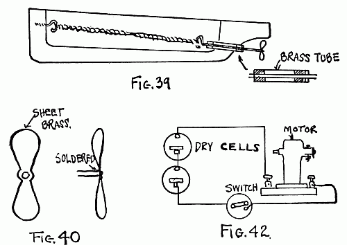
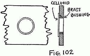
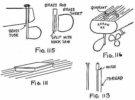
The propeller-shaft is arranged within a brass tube, as shown at Fig. 38. The brass tube should be about 1/8 inch larger in diameter than the propeller-shaft. A little brass bushing must also be arranged at each end,[48] as shown. When the propeller-shaft is mounted in place in the tube, there will be a space between it and the tube. Before the propeller-shaft is put in place it is well smeared with vaseline, and when it is placed in the tube the space between the shaft and the tube will be completely filled with it. This will prevent water from entering. Owing to the fact that vaseline is a soft, greasy substance, it will not prevent the rotation of the propeller-shaft. The brass tube is placed through a hole bored in the hull of the boat. The hole should be a trifle smaller than the diameter of the brass tube, so that the tube can be forced into the hole.
One of the simplest methods of propelling a boat is by means of rubber bands. Such a boat is shown in Fig. 39. This is a small wooden hull fitted with a two-blade propeller. The propeller is shown at Fig. 40. It is cut in a single piece and held to the propeller-shaft merely by a drop of solder since there will not be much strain upon it owing to the low power of the rubber-band motor. The opposite end of the propeller-shaft is bent[49] into a hook, and the rubber bands run from this to another hook placed at the bow of the boat. The rubber bands may be similar to those employed by model airplane builders. The motor, of course, must be wound up by turning the propeller around until the bands become twisted into little knots, as shown at Fig. 39. Boats driven by rubber bands cannot be very large unless a great number of rubber bands are used. Even then the power is short-lived. However, building a few small boats driven by rubber-band motors[50] will do much to teach the young boat-builder some valuable lessons in boat construction.
Probably the best method of propelling model boats is the electric method. By building a boat large enough to accommodate two dry batteries or a small storage battery and a little power motor, a very reliable method of propulsion is made possible. The boat must have sufficient displacement to accommodate the weight of the dry-cells and storage battery. A boat two feet long, with a beam of 41/2 inches, is large enough to accommodate one dry-cell and a small motor, providing the fittings of the boat are not too heavy.
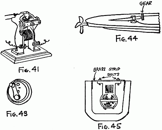
A suitable power motor for small boats, which will run with either one or two dry-cells, is shown in Fig. 41. The connections for the motor are given clearly in Fig. 42, and a suitable switch to control the motor is shown at Fig. 43.
Owing to its greater power, the storage battery is to be preferred. Dry-cells are extremely heavy and occupy considerable space. They are also costly, since they do[51] not last long and cannot be worked too hard unless they polarize.
A very suitable method of mounting an electric motor is illustrated in Figs. 44 and 45. It will be noticed that the motor is inverted. A small pinion or gear is mounted upon the armature-shaft of the motor. A larger gear (about three times the diameter of the small one) is placed upon the propeller-shaft. This gives a speed reduction[52] of three to one. It will be seen that the propeller-tube is strapped within a strip of brass to a small cross-piece nailed to the bottom board of the hull. The hull is of the built-up type, and the other three boards that go to make it up are not shown. When the three boards are glued in place, a brass strip is run across the top board and the base of the motor is screwed to this. This holds the motor rigidly in place so that it will not move when the power is turned on. The brass strip used should have sufficient thickness to hold the motor rigid. It will also be seen that the motor is tipped slightly so that it will come in line with the propeller-shaft.
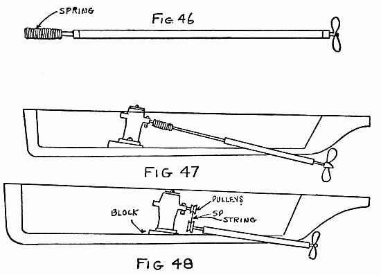
It is not always possible to obtain small gears. For this reason the model boat builder may find it necessary to use a different method of fastening the propeller-shaft to the motor. A very good method of doing this is shown in Fig. 46. Here a coiled wire spring is used. This is wound to shape on a rod, and a drop of solder holds it to the propeller and motor shafts. In the method of propulsion shown in Fig. 44 the armature-shaft of the motor must be perfectly in line[53] with the propeller-shaft, or the gears will bind and unsatisfactory operation of the motor will result. With the little spring the motor will not have to be mounted exactly[54] in line with the shaft, and it will also be possible to mount the motor standing up. Of course, if the motor is mounted in this way it will be necessary to make the propeller-shaft longer, as is shown in Fig. 47.
Still another method of driving the propeller is illustrated in Fig. 48. This method is so simple that the author feels explanation to be unnecessary.
Clockwork can often be employed for propulsion purposes, but this method is not very satisfactory. It is also very difficult to obtain suitable clockworks to install in a boat. Oftentimes it will be possible to salvage the works of an old alarm-clock, providing the main-spring is intact. It is a very easy matter to mount the clock-spring and connect it to the propeller. Any one of the aforementioned methods can be employed.
Steam propulsion has its advantages; but, on the other hand, the writer is not inclined to recommend it as strongly as the electric method for reliability. Of course, steam is a more powerful agency in the propulsion of small boats and thereby greater speed is attainable by its use.[55]
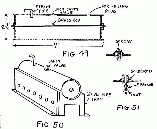
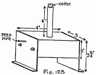
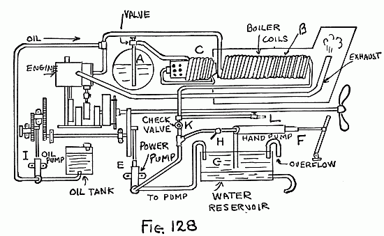
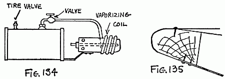
Here is a very simple small power plant suitable for driving boats up to 31/2 feet in length. The boiler is shown in Figs. 49 and 50. The method of assembling the boiler is pictured clearly in Fig. 49. A brass or copper tube about 21/2 inches in diameter is used. Two end pieces are cut to shape and forced into the boiler ends. A hole is drilled in the center of these pieces before they are put in place. After the end pieces are forced[56] in place solder is carefully flowed around their edges. The brass rod is then threaded at each end and placed concentrically within the boiler, as shown in Fig. 49. A nut is placed on each end of this rod and tightened. The nut is then soldered in place. This brass rod, called a stay-rod, prevents the end of the boiler from blowing out when the steam pressure has reached its maximum value. Three holes are drilled in the brass tube, as shown. One is to accommodate the steam feed-pipe that goes to the engine; another is for the safety-valve, and still another for the filling plug. The safety-valve and filling plug are both shown in Fig. 51. The little spring on the safety-valve is adjustable, so that the valve can be regulated in order to prevent it from blowing off at pressures lower than that at which the engine operates.
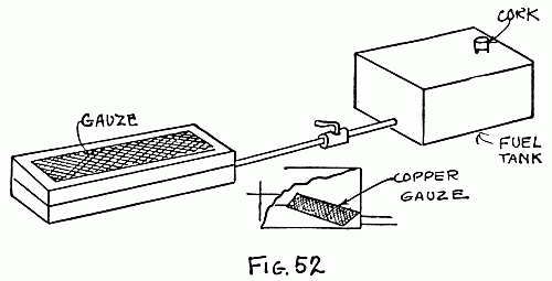
A suitable firebox for the boiler is shown clearly in Fig. 52. This is cut to shape from stovepipe iron and held together with small rivets. Holes should be punched or drilled in the side of the firebox to give the burner a sufficient supply of air. The burner is[57] illustrated clearly in Fig. 52. The fuel-tank can be made from an ordinary tin can with the cover soldered on, and a hole made for a cork by means of which it is filled with denatured alcohol. A little pipe runs from the fuel-tank to the burner. It is advisable, if possible, to place a small valve in this pipe to cut off the fuel supply when necessary. The only other method of putting the burner out would be to stand it on its end. The burner consists of a rectangular tin box with a top cut out as illustrated. A piece of brass or copper gauze is placed in the top. Asbestos wool is used to fill the can, and the alcohol is drawn into the wool by capillary attraction, where it burns with a steady hot flame at the surface of the copper gauze. In[58] the corner of the can near the feed-pipe another small piece of copper gauze is soldered as shown. This covers up the feed-pipe entrance so that the asbestos will not plug up the pipe.
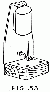
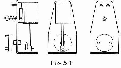
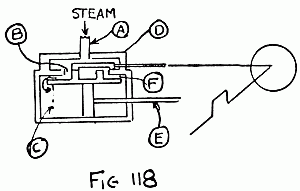
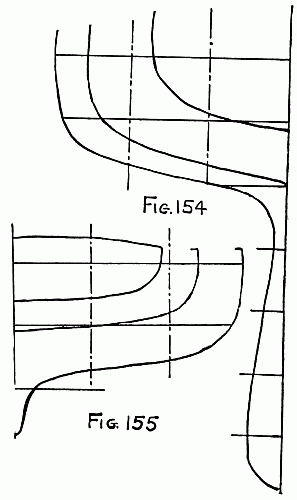
The engine to be used in connection with the boiler just described is shown in Fig. 53. This is a very simple engine of the oscillation type, and there should be little trouble in making it. A more mechanical drawing of the engine is shown in Fig. 54. The details of the engine are shown in Fig. 55.[59]
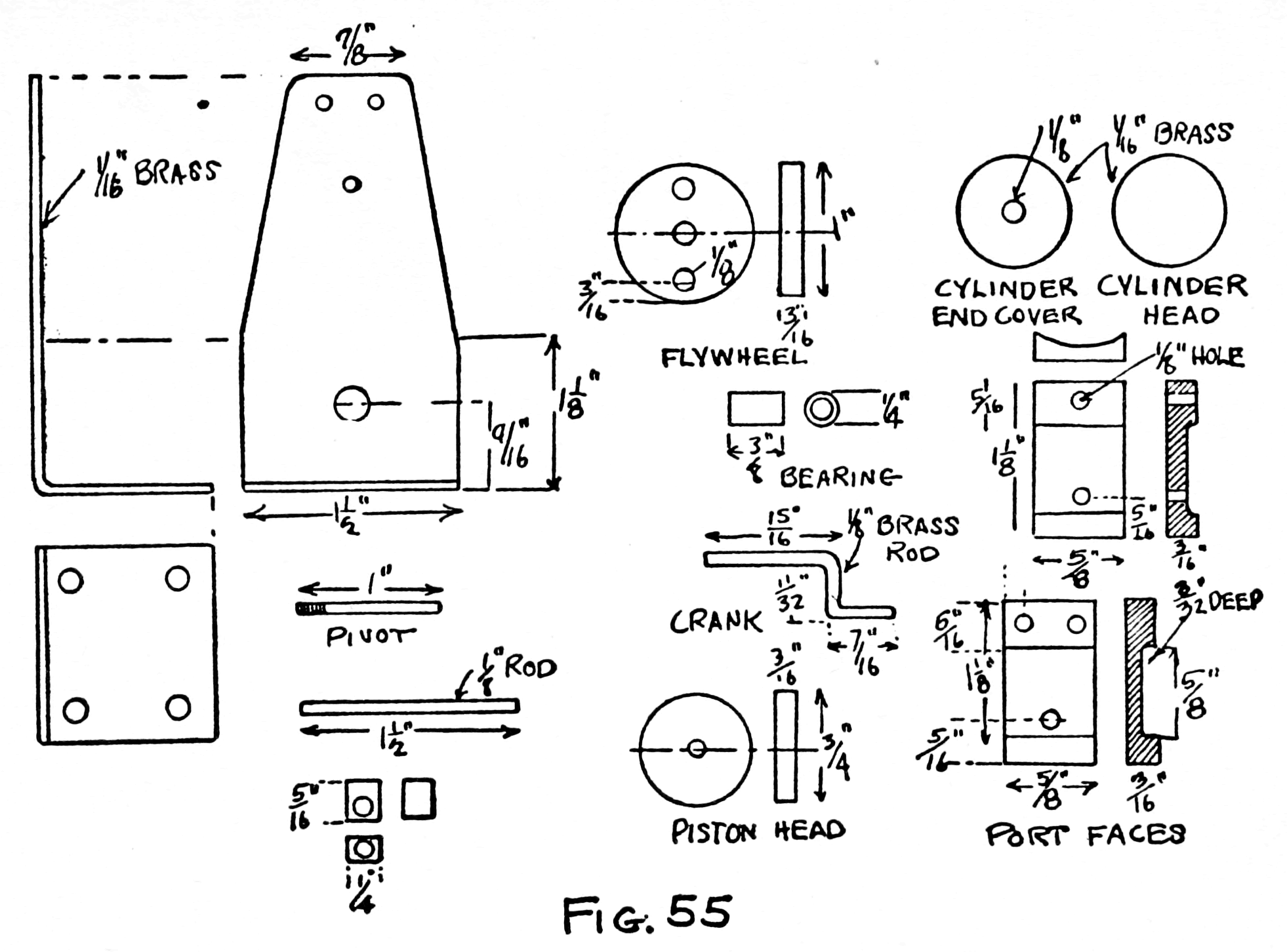
The cylinder of the engine should be made first. This is made from a piece of brass tubing with an internal diameter of 3/4 inch. Two end pieces, or a cylinder-end cover and[60] cylinder head, must be cut to fit inside the cylinder. These should be cut to shape from 1/16 inch brass, and a hole drilled in the cylinder head 1/8 inch in diameter to accommodate the piston-rod. The cylinder head is then soldered in place. The cylinder-end cover should be left until the piston-rod and piston are made.
The piston head is cut to shape from a piece of 3/16-inch sheet brass, or it can be cut from a piece of 3/4-inch round brass with a hacksaw. The piston-rod is soldered into a hole in the piston-head. A small square piece of brass is placed on the opposite end of the piston-rod to act as a bearing. This little piece is cut and drilled as shown in the drawing. Before it is soldered in place on the piston-rod the cylinder-end cover should be placed on the rod. Both the piston and the cylinder-end cover can then be placed inside the cylinder, and the piston-end cover is soldered in place. Before final assembling the piston should be made to fit nicely into the cylinder. This can be brought about by applying emery cloth to the piston-head until it slips nicely into the cylinder with little or[61] no play. Thus a steam-tight fit is made, and this contributes greatly to the efficiency and power of the engine.
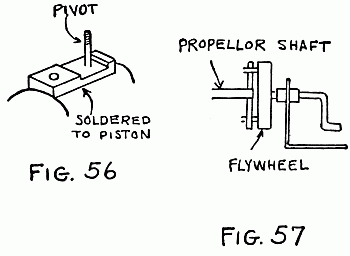
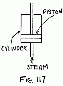
The cylinder blocks are shown in Fig. 55. These are cut and brought to shape with a hacksaw and file. With a half-round file one side of one of the blocks is filed slightly concave, so that it will fit on the outside of the cylinder. Two 1/8-inch holes are drilled in this piece as shown in the drawing. The hole at the top is the steam entrance and exhaust for the engine; that is, when the cylinder is at one side steam enters this hole, and when the crank throws the cylinder over to the other side steam leaves through the same hole after having expanded in the cylinder.[62] This cylinder block is soldered to the piston as shown in Fig. 56. The pivot upon which the cylinder swings is then put in place in the hole at the bottom of the block. Solder is flowed around the pivot to hold it securely in place.
The second cylinder block is now finished according to the drawing. This has two holes 1/8 inch in diameter bored in it. One of these holes is the steam inlet and the other the exhaust. When the cylinder is at one side of its stroke the hole that was bored in the top of the steam block which was soldered on the cylinder is in line with the inlet hole in the block under consideration. Steam then enters the cylinder and forces the piston down. This turns the crank around, and the crank in turn pulls the piston over to the opposite side, so that the hole in the first piston block of the cylinder now comes in line with the exhaust hole on the second cylinder block. The steam in the cylinder escapes and the same operation is repeated over again. Of course, it must be understood that this steam admission and exhaust takes place very rapidly. The hole in the second[63] cylinder block, which goes over the pivot, must be made a trifle more than 1/8 inch in diameter, so that it will slide freely over the pivot.
The engine is mounted on a very simple frame, which is a piece of 1/16-inch brass cut and bent as illustrated. After it is cut and bent to shape the second cylinder block is soldered in place. The cylinder can then be mounted. It will be seen that the pivot goes through both the second cylinder block and the engine standard. A small spring is placed over the protruding end of the pivot and a nut put in place. By turning this nut the pressure on the face of the two cylinder blocks can be adjusted, and the model engineer must always remember that the pressure on these springs must be greater than the steam pressure in the feed-pipe. Otherwise the steam pressure will force the cylinder-block faces apart and steam leakage will result. On the other hand, the pressure of the spring should not be too great, since that would interfere with the free movement of the engine cylinder.
Nothing now remains to be made except[64] the crank and the flywheel. The crank revolves in a small brass bearing which is soldered in place on the engine standard. It will be seen that the sheet brass that makes up the engine standard is not thick enough to offer a good bearing for the crank. The crank is bent to shape from a piece of 1/8-inch brass rod, and the author advises the builder to heat the brass rod red-hot while the bending is done. This will prevent it from fracturing, and will also permit a sharp bend to be made.
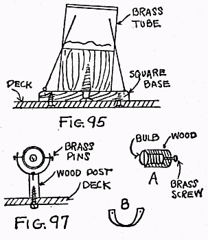
The flywheel is a circular piece of brass 1 inch in diameter. Its center is drilled out and it is soldered to the crank as illustrated in Fig. 54. Two other holes 1/8 inch in diameter are drilled in the flywheel as illustrated, and two small brass pins are cut out from 1/8-inch brass rod and forced into these holes and then soldered. These provide a method of driving the propeller-shaft that is shown very clearly at Fig. 57.
The steam feed-pipe that runs from the boiler to the engine can be of small copper tubing. It may be necessary to mount the[65] engine on a small block, as shown in Fig. 53. After the steam in the boiler has reached a sufficient pressure the engine crank should be given a couple of twists in order to start it. Before operating the engine a little lubricating oil should be run into the cylinder through the inlet or exhaust ports. The cylinder should always be kept well lubricated. The contacting faces of the cylinder blocks should also be kept lubricated.
Caution. Always keep water in the boiler. Never permit it to run dry, as this would cause a boiler explosion. When the engine is started and cannot be made to run, take the burner from under the boiler so that steam will cease to be generated. With the safety-valve the model boat builder need have little fear of an explosion. Nevertheless the foregoing directions should be carefully adhered to.
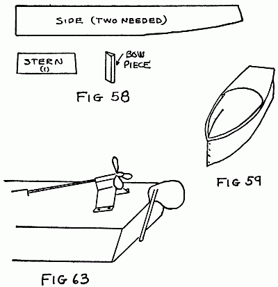
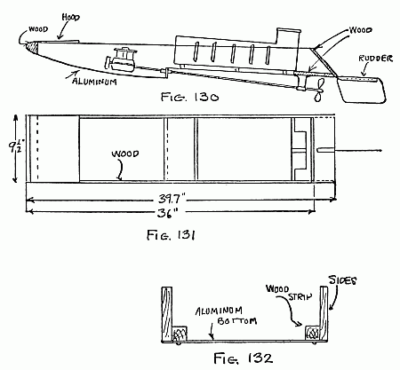
The general appearance of the boat and hull will be gathered from the drawings. The pieces necessary to assemble the hull are shown in Fig. 58. Only five pieces are necessary: two side pieces, a stern piece, a bow piece, and a bottom piece. The length of the boat over all is 40 inches with a 7-inch beam. The widest part of the boat is 1 foot 10 inches from the bow.[67]
After the pieces that form the hull are cut they are thoroughly sandpapered to produce a smooth surface. The heavy imperfections in the wood can be taken out with coarse paper, and the finishing can be done with a finer paper. It is understood that sandpapering should always be done with the grain, never across the grain. The sides of the boat are cut about 1/4 inch thick, but they are planed thinner in places where the bend is most pronounced. The side pieces are 23/4 inches deep at the stern and 21/4 inches at the stern. There is a gradual curve from the bow to the stern, which is more marked toward the head.
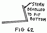
The stern piece is thicker than the side pieces, being made of 1/2-inch wood. It is cut to the shape shown at Fig. 58, and beveled along the bottom edge to enable it to be fixed on the slant. The bow piece is a triangle 23/4 inches in length.
After the parts are thoroughly finished with sandpaper the stern piece is fixed in position. In making all the joints on the boat the builder should see that plenty of fairly thick paint is run in while the joint is[68] being screwed up. This will help greatly in making the boat water-tight. Plenty of 3/4-inch brass wood-screws are used in assembling the hull. All the holes for the wood-screws should be countersunk so that the heads will come flush with the surface of the hull. Now one of the sides should be screwed to the stern piece, at the same time bending the bottom and side to meet. This is done gradually, inch by inch, and screws are put in place at equal distances. When the bow is reached, the side piece is beveled to fit the bow piece, which should already have been screwed into place. The other side of the boat is treated in a similar manner, and the young worker should take care to keep the side and bow piece perfectly square and upright. This may sound easy on paper, but it will be found that a good deal of care must be exercised to produce this result.
After the hull has been assembled it is given a good coat of paint inside and out. When the first coat is dry the holes left by the screw-heads are carefully puttied over, and the hull is given a second coat of paint.[69] This procedure will produce a perfectly water-tight hull.
The stern tube is 3/8 inch, outside diameter. A hole is bored in the bottom of the boat to receive the stern tube. This job must be done cautiously; otherwise the bottom of the boat may be ruined. It is best to screw a substantial block to the inside of the boat. This block should be cut to fit the bottom and will act as a support for drilling. It[70] will also help greatly to make a water-tight joint around the tube. The distance from the point where the stern tube passes through the bottom to the stern should be about 121/2 inches. The stern tube should be mounted as nearly parallel with the bottom as possible, since on this depends the speed of the boat. As the angle of the propeller-shaft increases, the speed of the boat will decrease. In drilling the hole the boat-builder should be careful to keep the drill running along the central line of the boat.
As before mentioned, the stern tube is a piece of brass tubing 3/8 inch in diameter and 8 inches long. It is filed square at both ends, and a brass plug is fastened with solder in each end. The tube is then filled with melted vaseline, which is allowed to cool. The hole in the hull around the tube is then well smeared with thick paint. When this is done, a layer of red lead or putty is placed around the joint both on the inside and the outside of the boat.
While the putty is drying the spray-hood or turtle-deck can be made. This is bent to shape from a piece of tinplate and extends[71] half way down the boat. When the turtle-deck is finished, it is best to lay it aside, before finally fastening it in place, until the entire boat is completed.
The wooden part of the deck is made of 1/8-inch wood and scribed with a sharp knife to represent planking. This method of producing planking was described in detail in Chapter II.
Toward the stern of the boat and just behind the motor a hatchway is fitted to give access to the batteries and starting switch.
The finished Sharpie hull without its driving batteries or motor should weigh about 1 pound 3 ounces. The hull being finished, let us consider the electric propelling equipment.
A 1/8-inch cold-rolled steel driving or propeller-shaft is used. The shaft is 13 inches long and a gear-wheel 1 inch in diameter is fixed to one end of this shaft. This gear-wheel meshes with a brass pinion on the motor-shaft. This forms a 31/2 to 1 reduction gear, which produces a greatly increased speed of the boat. The other end of the propeller-shaft rests in the skeg bearing. In[72] this present case this consists of a tube about 1/2 inch long, which is made for a revolving fit on the propeller-shaft and supported by a sheet-metal bracket. This is shown in Fig. 63 . The end of the propeller also revolves adjacent to the bearing in the skeg.
The propeller is a three-blade affair with a diameter of 21/4 inches. It is attached to the propeller-shaft with a set-screw. The motor is a very simple type obtainable in the open market. It is similar to one shown in Fig. 41. As before mentioned, either dry or storage batteries may be used as a source of current. The writer strongly advises the use of storage batteries if possible. The initial cost of these batteries is greater than that for dry batteries; but, on the other hand, the small storage battery can be charged repeatedly and will outlast many dry batteries. If the boat is used much the storage battery will probably be the more economical of the two.
The steering gear of the boat is very simple. The rudder works in a bearing that is screwed to the stern piece. The end of the rudder-shaft is tapped, and a brass screw is[73] used to clamp it in position after setting it with the fingers. The rudder-shaft is a 3/4-inch brass rod. The lower end of this rod is slit with a hacksaw and the rudder is placed in this. Solder is then flowed along the joint.
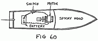
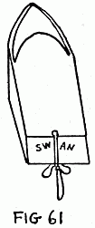
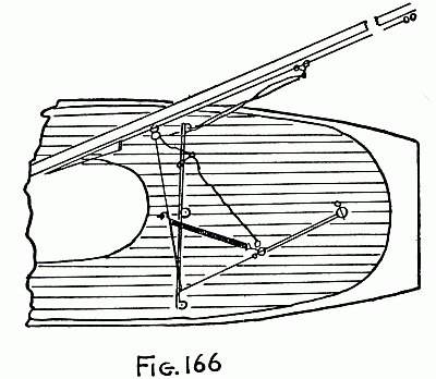
Of course, the builder may paint his boat whatever color he may select; but a maroon hull with a white-enameled spray-hood or turtle-deck makes a very pleasing combination. Fig. 60 shows a rough plan of the general arrangement of the power machinery. Figs. 61, 62 and 63 will do much to give the reader a clear idea of the method of construction which could not be gained by reading a description.
The general appearance of the boat can be[74] improved materially in many ways. For instance, a little stack or ventilator may be added to the turtle-deck, and a little flag-stick carrying a tiny flag may be placed on the bow and on the stern.
The motor current should be turned on only when necessary, for dry-cells deteriorate rapidly when in use, and small storage batteries quickly lose their charge, although they will last much longer than dry-cells and give much better service.
The following materials are necessary to construct the Nancy Lee:
The actual expense necessary to construct the boat is very small.[76]
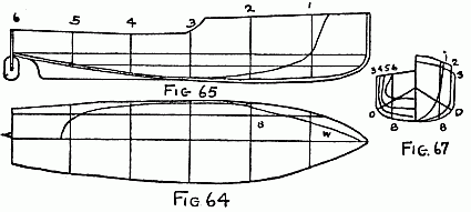
Having obtained the block for the hull, you are ready to start work. The hull, when planed on all sides, should be 30 inches long, 61/2 inches wide, and 33/4 inches deep. A center line is drawn down the length of the hull, and five cross-section lines are drawn at right angles to the center line 5 inches apart. On these lines the builder should mark off the greatest lengths of the boat, taking the dimensions from the half-breadth drawing shown in Fig. 64. It will be noted that the deck is wider than the L. W. L. forward and narrower than the L. W. L. at the stern. The block should be cut to the widest line on the half-breadth part.
The half-widths in Fig. 64 are drawn each side of the center line on the block. The block will be cut out to this line and[77] planed up as true as possible. The builder should then project the section lines with a set square on each side of the boat, mark off the profile from the sheer plan, Fig. 65, and cut the block to this line, afterward planing it up true.
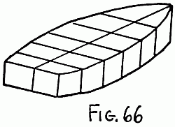
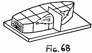
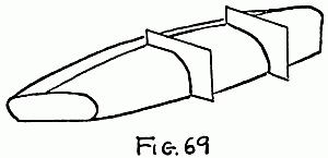
The blocks should now appear as sketched in Fig. 66. It is now ready for the shaping of its exterior. A plane, a chisel, and a draw-knife are the only tools necessary to bring the hull to the correct shape. The cardboard templates must be cut, one for each half-section, as shown in the body plan, Fig. 67. These templates serve to show the proper outside shape of the hull. The block for the hull must be cut away until each one of these templates fits properly into place. The various stages are indicated in Figs. 68 and 69.[78]
The interior of the board is gouged out with a gouging chisel, and if the builder desires a uniform result he should make inside templates. In gouging out the interior of the hull the chisel or gouge should be handled very carefully; otherwise it is liable to slip and spoil the entire hull.
The next job is to cut and properly fit the raised portion or forecastle. A piece of wood 11/4 inches thick, 15 inches long, and 61/4 inches wide must be prepared and laid in place on the hull. The shape of the hull is marked off with a pencil and the wood sawed[79] along this line. The inner portion is also cut out, thus making a V-shaped piece which must be glued and screwed in place, as shown in Fig. 70.
The oval air-vents shown in the drawing can be cut at this time. The hull is neatly finished by cutting in the sheer or curvature of the hull and sandpapering it all over. A cross-beam or support, C, Fig. 70, is cut and fitted as illustrated. This particular piece supports the fore-deck, and also carries the main-deck, as well as bracing the boat together. This piece should be 3/16 inch thick and cut from solid oak.[80]
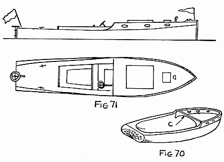
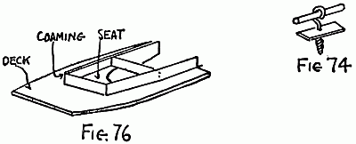
The decks can be made of a good quality of white pine. The builder should select clean pieces, free from knots and blemishes. It only requires to be cut to shape and then fixed to the hull with a few brads. The edge should be cleaned up flush with the hull by the aid of a plane. The opening for the cock-pit, shown in the drawing in Fig. 71, is to be cut in the deck. The coamings and seats are cut to the sizes indicated in the drawings. They are then glued and pinned together. When fitted to the deck the result will be somewhat as shown in Fig. 71.
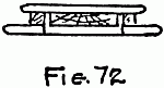
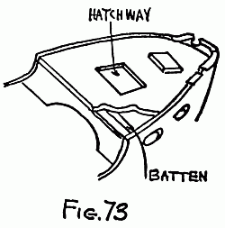
The fore-deck is prepared in a similar manner; but, since this is to be removable, two battens must be fitted to the under side to keep it in place. The openings for the hatchways can be cut and the hatch-covers made by cutting another piece of wood 3/16 inch thick to form an edging. A cover piece to go over the small pieces, removed from cutting out the hatch opening, is shown at Fig. 72 . A coping-saw will be found very useful for this work. The covers are neatly rounded on the edge and nicely finished.
Fig. 73 will give the reader a very good idea of the appearance of the boat at this stage. It will be seen that the sketch shows the deck broken away so as to render the cross-batten visible, which also shows the fair-lead at F, Fig. 73. This is cut from two small pieces of 3/16-inch stuff, glued and pinned in place. The forward deck is completed by the addition of cowl-ventilators, cut from hard wood and screwed in place. The flag-mast is made from a short piece of 1/16-inch wire. The details of the mooring-cleats are shown in Fig. 74. They are fashioned by using a small screw-eye and soldering a short piece of brass wire through[82] the eye. An oblong metal plate is then cut and a central hole drilled. This plate is soldered to the shank of the screw-eye and the cleat is complete. One of these devices is to be fitted to the fore-deck and two on the main-deck and stern.
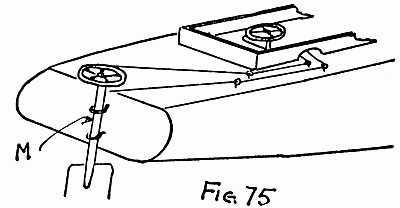
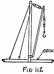
The rudder and steering gear will be considered next. Fig. 75 shows the stern of the boat with the rudder gear mounted in place. It will be noted that the rudder-blade is merely a piece of sheet brass cut to shape and soldered into the rudder-post M, which is slit to accommodate it. The rudder-post is hung in two screw-eyes on the stern of the boat. A small wheel about 1 inch in diameter, with an edge filed in it, is soldered to the top of the rudder-post. A fine cord or string, well stretched and oiled, is attached[83] to the wheel and led through two screw-eyes on the deck. From this it is led through an opening in the coaming to a drum on the steering column, which is turned by another small wheel similar to that used on the rudder-post, but with a round edge. The steering column is merely a piece of 1/8-inch wire, held in place by two small screw-eyes fixed in the coaming and with a tube-brush soldered on to keep the wire in position. The drum is simply a hard-wood bushing driven tightly in place.
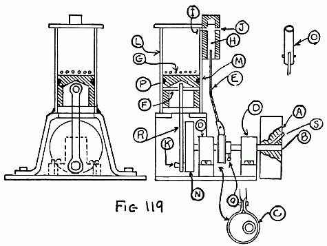
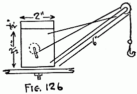
The power machinery for the Nancy Lee must be considered at this time. This is really one of the most interesting parts of the construction. The general appearance of the power plant can be seen by referring to Fig. 77, which is a view of the complete boiler and engine mounted together on the same base. The boiler is shown at A and the safety-valve and filler at L. The base or firebox B protects the burner from stray drafts of air, and also supports the boiler.
The lamp or burner consists of a receptacle C for containing the denatured alcohol. The denatured alcohol is inserted through[84] the filler-tube E, which is kept closed with a cork. The upright tube D is fitted so that air can go into the receptacle containing the alcohol. Three burners are necessary to fire the boiler. These are fitted as shown in F, and they give sufficient heat to produce steam enough to drive the cylinder G. The steam is conducted to the cylinder through the short pipe K. The steam-cylinder has the usual piston and rod, which drives the circular crank H. This crank is mounted on a crankshaft carried on the metal tube M. As will be noticed, the cylinder is of the simple oscillating type mounted on a standard, formed as part of the boiler casing, and stiffened by two angle-plates L.
A heavy flywheel, J, is now fitted to the inside end of the crankshaft. This wheel should be a lead casting, and as heavy as possible. A heavy flywheel contributes much to the operating efficiency of the engine. The propeller-shaft and crank are shown at N in the insert.
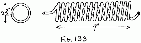
The boiler is made from a strong tin can about 13/4 inches in diameter and 41/2 inches long. It is cleaned inside and out, and all[85] the seams are double-soldered. The lid is also soldered on the can. This little boiler, although not elaborately made, will be found capable of standing up under considerable steam-pressure, and so no fear need be had of accidents by explosion.
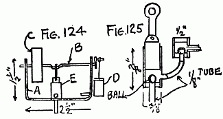
A little safety-valve and filler-plug suitable[86] for use on the boiler are shown clearly in Fig. 78. A piece of sheet tin is cut out to the size and shape illustrated in Fig. 79 at A. The piece is bent up at the dotted lines and the seams are soldered. Two angle-plates, B, are then cut and fitted and soldered in place. Next a piece of brass tube with a 1/8-inch bore and 1 inch long is cut and soldered in place for the bearing of the crankshaft. A lead flywheel 11/4 inches in diameter and 1/2 inch thick is then mounted firmly on a piece of straight steel wire 13/4 inches long, which acts as a shaft.
The shaft is made to run freely in the crankshaft bearing that was previously soldered in place. The cylinder is shown in section in Fig. 80. If the reader will refer back to the construction of the engine described in Chapter 4 he will readily understand the operation and construction of this particular engine.
A little crank must be cut from 1/16-inch brass, and soldered to the crankshaft after fitting a wire crank-pin to the outer edge. This crank-pin should be of such a size that the joint on the end of the piston-rod shown[87] at A, Fig. 80, turns on it easily. The throw should be only half the stroke of the engine, which is 3/8 of an inch.
The boiler is now fixed in place by bending the lugs B, Fig. 79, so that they just support the boiler nicely. They are then soldered in place. Next fit the short steam-pipe K between the boiler and the steam block on the cylinder. The builder should take care to keep the steam-pipe well up to the top of the boiler.
The lamp should be built at this time. The container for the denatured alcohol is made from a well soldered tin box of suitable size. It can also be made by cutting a sheet of tin to the size and shape shown in Fig. 81. The corner joints are soldered and then a tin lid is soldered in place. The builder should not forget to make the filler-tube E and air-tube D, as shown in Fig. 77, before soldering the top piece in place. The burners should be made as high as the container, and these should be made from little pieces of tin bent to shape and soldered on to a bottom pipe, as shown in Fig. 77. The builder should also remember to cut the holes[88] through this pipe so that the alcohol can get into the burner-tubes, and also to solder the open end of the bottom or feed tube. Before the wicks are put into the lamps, the container should be tested by filling it with alcohol to see that it is perfectly tight at all joints. If it is not the container should be gone over again with solder to assure its being leak-proof.
Before operating the engine with steam, it can be tested with a small bicycle pump through the opening for the safety-valve. The engine should turn over briskly at every stroke of the pump, providing it does not come to rest at "dead center." If it does come to rest at "dead center," where no air can enter the piston, the crankshaft should be given a little twist and the engine will then start. Before steam is applied it will be well to experiment until the engine runs with the air-pump.
Having made the engine run smoothly with air, steam can be generated in the boiler. The wicks should not be placed too tightly in the burners. After they are in place the container may be filled with denatured[89] alcohol, and the burners lighted and placed under the boiler. In a very few minutes steam will be up. At the first indication of pressure in the boiler the engine should be given a twist with the fingers until it starts and goes of its own accord. The constructor should remember to keep his engine well lubricated.
The propeller-shaft is merely a piece of steel wire, perfectly straight and fitted with a crank A, Fig. 82. This crank is similar to the one fitted to the engine, but with a small slot cut out for the crank-pin to fit into. This is done so that, as the crank-pin on the engine turns around, it also turns a slotted crank on the propeller-shaft.
A short piece of tube, C, is now fitted to a flat brass plate, D. The plate is mounted at an angle to the tube, so that when it is in place on the stern of the boat the propeller-shaft will be in line with the crankshaft of the engine.
A clearance hole is now drilled through the hull, so that the propeller-shaft can be put in place. Solder the tube to the plate, and punch four small holes in the plate, so[90] that it can be screwed firmly to the hull. Solder a short piece of tube, as shown at B, Fig. 82, to keep the propeller-shaft in position.
The propeller must now be made. This is easily done by cutting out a disk of brass 11/2 inches in diameter, as shown in Fig. 83. The shaded portions of the brass disk are cut away. The blades are bent to shape, care being taken to see that they are all alike. This done, the propeller is soldered to the propeller-shaft.
The only part of the job that remains is to screw the boiler in place under the fore-deck of the boat. This done, the Nancy Lee is ready for her trial. The fore-deck should be made removable by fitting it with pins or screws with the heads cut off, so that the deck only needs pushing into place. This little boat should be capable of attaining a speed of from four to five miles an hour if it is made carefully and according to the directions outlined in this Chapter.
The lines of the boat may be seen very clearly in Fig. 84.
The hull of the model freighter measures four feet over all, and the beam at the water-line is 8 inches. The extreme draft will be in the neighborhood of 5 inches. This model, when completed, will be capable of carrying considerable weight; in fact, it is able to accommodate thirty-five pounds in weight when used in fresh water. This will give the builder an opportunity to install a[92] very substantial power equipment with little regard for weight.
The hull is made according to the built-up principle, and the constructor will have to cut his templates before attempting the shaping of the hull. Owing to the depth of the model, it will be necessary to use about ten planks. The plank that is used to form the bottom of the boat is not gouged out. Every other plank is gouged out with a saw and chisel.[93]
The bottom plank is shaped with a knife to conform to the lines of the boat. In building up the hull with the planks, they should first be smeared with glue, and when put in place a few brass brads should be driven in. As mentioned in an earlier part of this book, iron nails should not be used in work of this nature, owing to the fact that they will rust and cause trouble. The brass brads are placed about one inch apart the entire length of the boards. The hull is finished with a plane and sandpaper, and after it has been brought to shape in this way and finished, a coat of paint is applied. Black with dark red trimmings makes a very good combination for a boat of this type.
The deck is made from a piece of 1/4-inch pine board. Seven hatches are added to the deck. Six of these hatches can be made by merely gluing a square piece of 1/4-inch wood to the deck. The seventh hatch should be made with a hole cut in the deck, so that access can be had to the power motor.
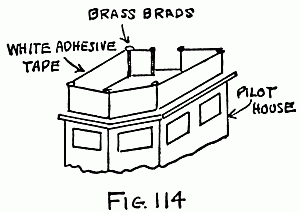
The deck-house, wheel-house, and chart-house, as well as the bridge, should be constructed of tin, which may be salvaged from[94] clean tin cans. The bridge is provided with spray-cloths made from white adhesive tape, as outlined in Chapter 9. The port-holes in the deck-house and hull are made by little pieces of brass forced in place over a small piece of mica. The life-boats, which are carried on top of the engine-house, are whittled out of a solid piece of wood and painted white. Life-boats are always painted white, regardless of the color of the boat upon which they are used. The life-boats are held by means of string and small dummy pulleys to davits made of heavy stovepipe wire. A rub-streak made of a piece of 1/4-inch square pine is tacked to each side of the hull just below the sheer-line. The rub-streak should be tacked in place with nails such as those used on cigar-boxes.
The funnel measures 1 inch in diameter by 4 inches long. A small exhaust steam pipe, which can be made from a piece of brass tubing, is mounted directly aft of the funnel. The forward deck fittings consist mainly of a steering-boom, two bollards, two fair-heads, and four life-buoys mounted on the bridge. The main-deck is equipped with[95] six bollards and two covered ventilators, each 1/2 inch in diameter. The foremast is properly stayed in the deck, and should be fitted with rat-lines. The rat-lines can be made with black thread and finished with varnish, which when dry will tend to hold the threads in shape.
The rudder is cut from a piece of sheet brass to the shape shown, and fitted with a quadrant. The engine cabin can be made from cigar-box wood. The windows and doors can either be painted in place, or the windows can be cut and backed up with sheet celluloid. A good substitute for painted doors will be found in small pieces of tin painted a different color from the cabin. The same procedure may be followed in fitting the windows and doors to the forward cabin.
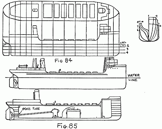
We are now ready to consider the power plant. Owing to the large displacement of the boat, it will carry a fairly heavy storage battery. The electric motor and storage battery are mounted in the manner shown in Fig. 85, which will also give the reader an idea of the appearance of the finished[96] model. As the drawing indicates, it will not be necessary to tilt the motor to any great degree in order to bring the propeller to the proper depth. This is because of the depth of the boat. Instead of a string or belt to connect the motor with the propeller, the shaft of the motor is taken out and replaced by a longer steel rod that will serve both as a motor-shaft and a propeller-shaft. The propeller-shaft extends from the motor through the stern-tube. The propeller used for this model is a three-blade affair, 3 inches in diameter. It must be of this size in order to propel a boat of these dimensions at a consistent speed.
Care must be taken in mounting the motor in this way. If it is not mounted directly in line with the stern-tube the propeller-shaft will have a tendency to bind. However, with a little care no trouble should be experienced from this source. The storage battery used should be of the four-volt forty-ampere hour variety. This boat will be capable of carrying such a battery and this weight should just bring the craft down to her load water-line. The whole deck is[97] made removable, so that the storage battery can be taken in and out at times when it is necessary to recharge it. A battery of this capacity, however, will drive a small motor similar to the type used on the boat for some time.
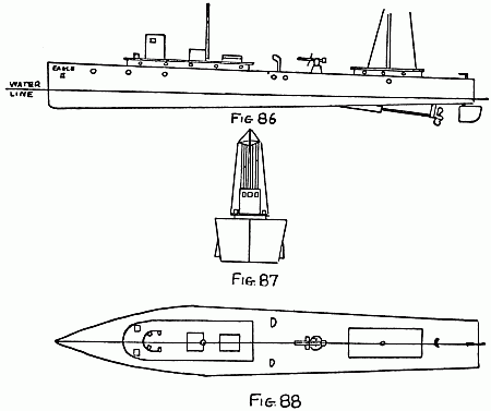
The general outline of the boat can be gathered from Figs. 86, 87, and 88. Fig. 86 gives a side view of the craft; Fig. 87 shows the bow, while Fig. 88 gives the deck-plan.
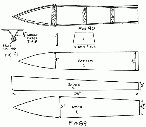
Notice first the construction of the hull. This is made according to the Sharpie type, but the lines are changed to give the boat a more graceful appearance. This is done by changing the shape of the deck and the bottom[99] pieces. Fig. 89 shows the various pieces necessary to construct the hull. It will be seen that the forward portion of the bottom piece is narrower than the deck piece, and broadens out so that it is wider at the stern than the deck piece. The deck piece has a maximum width of 5 inches, while the bottom piece has a width of 4 inches at the forward section. The deck measures 31/2 inches at the stern, while the bottom piece measures 41/2 inches at the stern. This produces a half-inch taper on each side of the stern. A[100] half-inch taper is also produced on the bow portion.
The hull of the boat can be made from 1/8-inch mahogany. If this is not available, choose some other close-grained wood, free from knots and blemishes. Paper patterns are made to correspond with the general shape of the pieces that form the hull as given in Fig. 89. The pieces, after being marked, are cut to shape with a keyhole-saw.[101] After this is done their edges should be trimmed neatly with a jack-plane.
The two sides pieces are now screwed to the bow piece by small brass screws. After this is done the bottom piece is fastened to the side pieces the entire length of the boat. Next the first cross-piece, as shown in Fig. 90 , is screwed in place. This cross-piece should be 43/4 inches in length, so that the width of the hull at this point is just 5 inches. The next cross-piece should correspond to the width of the deck piece at the section of the hull where it is placed. The same holds true for the third cross-piece. When the third cross-piece has been screwed in place, the stern piece is put in position.
The joints of the hull should then be smeared with either pitch or bath-tub enamel or a thick mixture of white lead may be used.
After having made sure that the hull is perfectly water-tight the worker can proceed to install the power equipment. This consists of a small battery motor driven with two dry cells. The design and installation of such things as stern-tubes and propeller-shafts[102] have been taken up in detail in an earlier part of this book. The strut that holds the propeller-shaft is shown in Fig. 91 . This consists merely of a brass bushing held in a bracket made of a strip of brass 1/2 inch wide. The brass strip is wound around the bushing and soldered. It is held to the bottom of the hull by means of two 8-32 brass machine screws. These screws should be tightened to prevent leakage. It would be inadvisable to use wood-screws for this purpose, owing to the fact that the bottom piece of the boat is thin.
The two dry batteries for the motor are held in two tin troughs, as illustrated in Fig. 92 . These troughs are fastened to the side of the boat by means of small bolts. They[103] will prevent the boat from shifting its cargo; in other words, they hold the batteries in place and thereby prevent the boat from listing.
The deck and deck fittings should now be furnished. The construction of the forward cabin is shown in Fig. 93. The sides and back are formed with cigar-box wood, while the curved front can best be made with a piece of tin. The top is also cut to shape from cigar-box wood, and should overlap about 1/4 inch. The pilot-house is simplicity itself, being made of a piece of curved tin with three windows cut in it. Four little lugs cut in the tin are bent on the inside and each provided with a hole. These lugs are used to tack the pilot-house to the deck. A small skylight is produced from a solid piece of wood and tacked in place as illustrated in the drawing.
The builder is cautioned not to destroy the appearance of his boat by making the mast too large. After the mast has been nicely sandpapered, a little wire frame is bent to shape and fastened to the top, as shown in Fig. 87. The little wire railing[104] that is placed in front of the mast is then bent to shape, and this and the mast are put in their permanent position. The mast can be held to the deck by boring a hole a little under size and smearing the bottom of the mast with a little glue before it is forced in. Pieces of black thread are run from the top of the mast to the railing at the bottom, as shown. These threads are used to hoist signal flags. Two little angle-pieces are placed on the forward deck, one on each side of the pilot-house. These are for the harbor lights. One should be painted green and one red.
This finishes the forward cabin. It should be placed in the center of the deck and the position it occupies should be marked out with a pencil. This portion of the deck should be carefully cut out with a coping-saw. The cabin is then forced into the opening. The fit should be fairly tight, so that it will not be necessary to employ nails or glue, as this is the only way in which the interior of the hull is made accessible.
Two ventilators are placed just back of the forward cabin. Between the forward[105] cabin and the cabin aft there is placed a rapid-fire gun. The details of this gun are given in Fig. 94. The barrel of the gun is made of a piece of brass rod. A hole is drilled through this rod with a small drill and a piece of copper wire is inserted. A square piece of brass for the breech is then drilled out to receive the barrel. One end of the barrel is placed in this hole and held with a drop of solder. A drop of solder should also be used on the copper wire that runs through the barrel. The bearing and shield of the gun are made from thin sheet brass, as illustrated. Three holes are drilled in the bearing bracket, two through which the wire passes and one through which the small nail is placed to hold the bearing to the wooden standard. The shield is forced over the barrel and held in place with a drop of solder. When the barrel is mounted in the bearing, a drop of solder should be put in place to prevent the barrel of the gun from tipping.
The cabin which is placed aft on the boat, is of very simple construction. It is made up entirely of cigar-box wood tacked together, and the top should overlap 1/4 inch. The cabin is then tacked to the deck of the boat. The mast should be only three-fourths as high as the forward mast, and a tiny hole is drilled near the top. Into this hole a small piece of soft wire is placed, and from this wire a thread runs to the cabin. A small flag can then be placed on the thread, as illustrated in Fig. 86.
Six port-holes are now bored in each side of the hull with a 1/2-inch bit. These can be backed up with mica or celluloid. Five smaller port-holes made with a 1/4-inch drill are then bored in each side of the forward cabin. Three are placed in the aft cabin.
With the exception of painting, the hull is now ready to be launched. Before finally applying the paint the hull should be given a thorough rubbing with sandpaper. A battleship gray with maroon trimmings makes a pleasing color combination for this boat.
Using a little care, it is possible to make presentable fittings by utilizing odds and ends found about the household and shop. In this Chapter the author will describe the construction of the more important fittings necessary to model boats, such as stacks, searchlights, bollards, cowl-ventilators, davits, and binnacles.
The smokestack is probably one of the easiest things to produce. A very suitable method of producing a smokestack is shown in Fig. 95. The stack itself is cut from a piece of thin brass tubing. It is also possible to use a small tin can of the proper diameter.[108] In both cases, of course, paint must be applied to improve the appearance of the brass or tin. If the stack is painted either gray or white a red band near the top of the stack produces a good finish and makes it look more shipshape.
The method of anchoring the stack to the deck of the boat is shown very clearly. First a block of wood is cut about the same diameter as the internal diameter of the stack. This block of wood is then forced up into the stack. A small square base is then cut, and fastened to the block on the inside of the stack with a wood-screw. It might be mentioned[109] here that it is often necessary to drill a hole with a small hand drill before driving the screw in, to prevent splitting the wood.
After the base piece is fastened to the stack, the base in turn is held to the deck of the boat by two small screws driven up from beneath. The guy-wires can then be fastened on. The guy-wires should be made of very fine wire, since heavy wire would be entirely out of proportion. The wire can be fastened on the stack by drilling a tiny hole through the stack. A knot is then tied in one end of the wire, and the opposite end threaded through the hole. Small screw-eyes driven into the base piece are used to anchor the guy-wires.
Ventilators are a very important part of the boat. The model-builder will encounter considerable trouble if he attempts to make his cowl-ventilator from metal, unless he is very experienced in drawing copper out by hand. The writer has found a method of producing cowl-ventilators by the use of clay pipes. Clay pipes can be purchased for a few cents each, and when cut down as shown in Fig. 96 they form very suitable ventilators.[110] The pipe can be cut as shown by the use of a file. The ventilator is held to the deck of the boat by being forced into a hole in the deck that is just a trifle under size. Of course, the forcing will have to be done carefully to prevent the stem from cracking. The inside of the ventilator should always be painted red, and the outside should be the same color as the boat. Ventilators made in this way absolutely defy detection and do much toward bettering the general appearance of the craft upon which they are used.
A simple searchlight, easily made by the[111] model boat builder, is shown in Fig. 97. This is an electric light, and the batteries used to propel the boat can be used for the light. First a small circular piece of wood is cut out, as shown at A, Fig. 97. The center of this is drilled out to accommodate a small flashlight bulb. A tiny brass screw is then driven into the piece of wood, so that it will come in contact with the center of the base of the flashlight bulb. This little screw forms one of the electrical contacts, and one of the wires from the battery is attached to it.
A little strip of brass is then cut as shown in B, Fig. 97, and provided with three holes, one hole at each end and one in the middle. The brass is bent into a semicircular shape, so that it will be just a little larger in diameter than the outside of the wooden piece in which the flashlight bulb is mounted. This little piece is then fastened to a wooden post with a small brass pin, as shown in Fig. 97. Two more pins are used to hold the wooden piece to the searchlight proper. One of these pins is driven through the wooden piece until it comes in contact with the base of the[112] flashlight bulb. This forms the other electrical connection, and the second feed wire from the battery can be attached to the little brass piece that holds the searchlight. Both the feed wires from the battery can come up through a hole in the deck close to the wooden post upon which the searchlight is mounted.
Bollards are very easily made. Reference to Fig. 98 will make this clear. First a little strip of brass is cut, and this is drilled as shown with two holes, one at each end and two smaller holes in the center. Two little circular pieces of wood are then cut, with a hole through the center. A brass screw passes through these and into the deck of the boat. The brass screw should not be driven in too far, since the bollards should be free to revolve. It is also possible to use brass tubing instead of wood if the proper size is in the model-builder's shop.
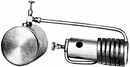 A POWERFUL GASOLENE BLOW-TORCH
A word will be said here about finishing the deck of a model boat. It is a very tedious job to cut separate planks to form the deck. In fact, this job is quite beyond the ability, to say nothing of the patience, of the[113] average young model-builder. A very simple method of producing imitation planking is shown in Fig. 99. A sharp knife and a straight-edge are the only tools for this work. The straight-edge is merely used to guide the knife. The cuts should not be made too deep, and they should be made a uniform distance apart. When the deck is finished in this manner and varnished over, a very pleasing effect is produced. In fact, if the work is done carefully, the deck looks very much as if it were planked.
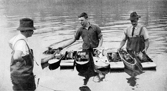 JUST AFTER THE RACE
A small life-boat is shown in Fig. 100. This can easily be carved to shape from a[114] small piece of soft white pine. The center is gouged out, and tiny little seats made of thin strips of wood are glued in place. Two small screw-eyes are placed in the boat, for fastening it to the davits. The davits are shown in Fig. 101, at A and B. They are made by bending a piece of small brass rod, as shown. One end of the rod is hammered flat, and a hole is made in it with a[115] very small drill. Holes a little under size are drilled in the deck, and the davits are forced into these. The method of suspending the life-boat from the davits is shown at B, Fig. 101. The little blocks of wood are glued on to a thread to represent pulleys, and they are, of course, only imitation or dummy pulleys.
The method of producing port-holes is shown in Fig. 102. A hole is first bored through the wood with a bit of the proper size. The size of the port-holes depends entirely upon the size of the boat. A piece of brass tubing is then cut off with a hacksaw to form a brass bushing. The outside diameter of this tubing should be the same as the size of the bit used. For instance, if a 1/2-inch bit is used, brass tubing 1/2 inch in[116] diameter should be purchased. Such tubing can be obtained from any hardware store. Celluloid, such as that used for windows in automobile curtains, is glued to the inside of the port-holes. This makes a splendid substitute for glass. It can be obtained at garages and automobile supply stores for a few cents a square foot. The model boat builder can also use either mica or glass for this purpose, although thick glass looks somewhat out of place.
A binnacle is shown in Fig. 103. This is made from a solid piece of wood cut with a semi-spherical top. The steering-wheel is made of a wheel from an old alarm clock. The teeth of the wheel should be filed off. Tiny pieces of wire are then soldered in place on the wheel, as shown. A pin driven through the center of the steering-wheel is used to fasten it to the binnacle. The binnacle itself can be held to the deck either by glue or by a small screw.
A torpedo-tube for use on model destroyers and battleships is shown in Fig. 104.[117] First two disks of wood are cut. Then a circular piece is cut, as shown. Two brass nails are then driven through this piece into one of the disks. An upholstering tack is driven into the end of the circular piece, as pictured. The method of attaching the torpedo-tube to the deck is clearly illustrated in Fig. 104 and no further directions need be given. If the model-builder has a small piece of brass tube on hand suitable for use in this case, it will make a much better appearing tube than the piece of wood illustrated.
A wireless antenna is shown at Fig. 105. This is a fitting that will do much toward improving the appearance of any craft. Very fine copper wire is used for the aërial. The little spreaders are cut to shape from wood, and a tiny hole is punched through them through which the wire is placed. Black beads slipped on the wire serve very well as insulators. The lead-in wire which drops to the wireless cabin is attached to the aërial by winding it around each one of the aërial waves. The aërial should be suspended between the masts of the vessel. A[118] few words should be said about masts in general. If there is one way in which a model-builder can destroy the appearance of a model boat, it is by using badly proportioned masts. The average boy seems inclined to use a mast of too great a diameter, which makes it out of proportion with the rest of the boat. It is better to have a mast too small rather than too large.
The method of producing railing is shown in Fig. 106. The same small brass rod that was used for the davits can be used for the rail stanchions. One end of the stanchions is hammered flat and drilled out. The stanchions are fastened to the deck by first drilling small holes and forcing them into it. Thread or very fine wire is used for the railing. Fine wire is preferred owing to the fact that it will not break so easily under strain.
Fig. 107 shows a good method of producing stairs. It must be remembered that stairs are often used in model-boat construction. First a strip of tin is bent as shown. Then two more strips, which act as side pieces, are cut. One of these strips is[120][119] soldered to each side of the stairs. Then six stanchions, which can be made from heavy copper wire, are soldered to the side pieces, as shown. The railing can be made from copper wire or black thread.
Fig. 108 shows a small skylight placed on the deck. This is easily made from cigar-box-wood glued together. The holes in the top pieces for the windows are cut with a very sharp knife. It will be necessary to use a little patience in this, to prevent the piece from splitting and to prevent cracks. A piece of celluloid is glued underneath the top pieces before they are finally glued in place.
A small quick-firing deck-gun is shown in Fig. 109. This is a very simple fitting and can be made with very little difficulty. The base of the gun is formed by cutting a thread-spool in half. A piece of small brass tubing is used to form the barrel. A little piece of sheet tin is looped over the back of the gun to represent the breech. A tiny piece of wire is held to the side of the breech with a drop of solder, to represent a handle. The shield of the gun is cut from a piece of[121] tin, as shown. A hole is made in the bottom of this, so that the nail that passes through the barrel of the gun will also pass through this hole and into the spool. The center of the spool should be plugged to hold the nail. After the gun is painted gray or black it will appear very businesslike, considering the small amount of labor spent in producing it.
Anchors are more or less difficult to make (Fig. 110), and unless the builder is endowed with a great amount of patience he will not be able to file them out of solid metal. A dummy anchor can be easily cut out of wood, however, and when painted black it will answer instead of a metal one. The anchor shown at A is a very simple type made out of a solid piece of wood. The one at B, however, is made out of two pieces of wood fastened together with a pin, as shown. The bottom piece of the anchor shown at B should be rather thick to get the proper effect, and the two points should be tapered nicely. The center of the bottom piece should be hollowed out to accommodate the vertical piece.[122]
A common hatch is shown at Fig. 111. This can be made in the form of an open box from cigar-box wood, and glued to the deck. It is not necessary to cut a hole in the deck for this purpose.
A cargo-hoist for use on model freight-boats is shown in Fig. 112. This is a very simple piece of work and will need little description. Several stay-wires should be fastened to the main-mast and held to the deck with small screw-eyes. The boom should be made a trifle smaller in diameter than the mast. The pulleys are dummy, like[123] those on the life-boat. A little hook bent to shape from copper wire is placed on the end of the thread, as shown.
Fig. 113 shows a method of making a whistle and an engine exhaust. The engine exhaust is made of a piece of wood, and the furled top is produced by an eyelet such as those used in shoes. The engine exhaust is always placed immediately back of the last[124] smokestack. The whistle is a simple device made almost entirely of wood. The whistle-cord is of thread attached to the small piece of wire, as shown.
Fig. 114 shows the method of making spray-cloths for the top of the pilot-house. Small brass brads are driven into the top of the pilot-house, and white adhesive tape is placed on the brads, as pictured. Advantage can be taken of the adhesive substance on the tape which holds it in place on the brads.
A rudder is shown in Fig. 115. The rudder-post should be a piece of brass rod so thick that it can be split with a hacksaw. The sheet brass that forms the rudder proper is placed in this split and soldered. In the case of an ornamental boat the rudder can be fixed as shown in Fig. 115. It will be seen that it is quite impossible to keep the rudder in adjustment in this way.
If the rudder is to be kept in a certain adjustment a quadrant is necessary. This is made by using a semicircular piece of heavy sheet brass and filing little notches in it. The lever of the rudder rests in these[125] notches, and by this means the rudder can be held in any one position, so that the boat will either turn in a circle or go straight. Fig. 116 illustrates such an arrangement.
Notice Fig. 117. This is a cylinder into which is fitted a piston. If steam is forced into the cylinder the piston will be forced to the opposite end of the cylinder. If some means is then provided so that the steam can escape and the piston come back, another impulse can be given it by admitting more steam, and thus a continuous motion may be produced. This is how the steam-engine works.
Having learned how motion is imparted to the piston by the expansion of steam under pressure, attention is directed to what is known as the "D" slide-valve. This slide-valve permits steam to enter the cylinder and to exhaust at proper intervals. See Fig. 118. Steam enters the steam-chest through the pipe A. The slide-valve is shown at D. When the slide-valve is in the position shown, steam enters the cylinder, and by the time the cylinder has arrived in the position[128] shown by the dotted line C, the slide-valve moves over, closing the passage B. The steam under pressure forces the piston to the opposite end of the cylinder. When the piston reaches the opposite end of the cylinder, steam that has entered through the passage F again forces the piston back to its original position. This is caused by the slide-valve shifting its position, because of the impulse it received at the opposite end of the cylinder. Thus it will be seen that when the piston is at one end of the cylinder the opposite end is exhausting. By carefully studying Fig. 118 the action of the D valve will be understood. The connecting-rod E is connected to the crankshaft and in this way the engine is caused to revolve.
A cylinder similar to that shown in Fig. 118 is called a double-acting cylinder. This[129] is because the steam acts on both sides of the piston. Single-acting cylinders are cylinders in which the steam expands on only one side of the piston. In the single-acting engines the D valve is modified.
The "stroke" of a steam-engine depends upon the length of the cylinder; really, the stroke is the distance travelled by the piston. In model engines it ranges from 3/8 of an inch to 11/2 inches. The bore of a cylinder is its internal diameter. The bore is usually a trifle smaller than the stroke. Thus it is common to have a stroke of 7/8 inch and a cylinder-bore of 3/4 inch.
At this juncture the author would caution the more inexperienced young mechanics not to build double-acting engines. The valve mechanism is somewhat intricate and very difficult to regulate. The construction is also much more complicated, and this also holds true of the designing. On the other hand, single-acting engines, while not so powerful for a given size, will do very nicely in driving model boats, and will deliver sufficient power for all ordinary purposes.[130]
Your attention is directed to Fig. 119. This shows a design for a model single-cylinder, single-acting steam-engine. The reader should carefully study each drawing before continuing to digest the following matter. The cylinder L can be made from a piece of tubing. This can be either brass or copper. Aluminum should not be used, owing to the fact that it is difficult to solder and difficult to work with. The piston is made so that it will fit nicely into the cylinder and move up and down without binding. It will be seen that a groove, M, is cut around[131] the piston near the top. String soaked in oil is placed in this groove. This is called packing, and the presence of this packing prevents steam leakage between the piston and the cylinder walls and thereby materially increases the efficiency of the engine.
In this case the connecting-rod R is made in a circular piece. It is attached to the piston by a pin, F. The connecting-rod must be free to revolve upon this pin. The engine shown has a stroke of 7/8 inch. Therefore, the crank-pin K on the crank-disk N must be placed 1/2 of 7/8 or 7/16 inch from the center of the disk N, so that when this disk makes one revolution, the piston will move 7/8 inch in the cycle. Thus it will be seen that the distance of the crank-pin K from the center of the crank disk N will depend entirely upon the stroke of the engine. It may be well to mention here that the worker should always start designing his engine by first determining the bore and stroke. Everything depends upon these two factors. It is also well to mention here that the piston should never travel completely to the top of the cylinder—a small space must always[132] be left for the steam to expand. One eighth of an inch is plenty of space to leave.
It will be noticed that the valve mechanisms on the particular engine shown bear no resemblance to the D valve previously described. The holes G which are bored around the cylinder are the exhaust ports. It will be seen that when the piston is at the end of its downward stroke it uncovers these exhaust ports and permits the steam to escape. The momentum of the flywheel A pushes the piston upward, closing these holes. As these holes are closed the valve H uncovers the entrance I and permits steam to enter from the boiler through J. By the time the piston has reached the upward limit of its stroke a considerable steam pressure has developed on top of the cylinder, and this again forces the piston downward. Thus the same cycle of movement is gone through repeatedly.
The valve on this little engine is extremely simple. It consists of a circular piece of brass drilled out, as shown. A hole (I and J) is drilled transversely through this. The little cylinder shown in the insert at O slides[133] in the larger hole, and when it is at its upper limit it cuts off the steam. At the proper intervals the valve is pulled down by the eccentric C. It will be seen that the moving parts, i.e., the valve and the piston, must be properly timed. That is, the eccentric C must be mounted on the crank-shaft B so that the valve will close and open at proper intervals. When the engine is made, the eccentric can be shifted about by means of a set-screw, Q, until the engine operates satisfactorily. This set-screw is used to hold the eccentric to the crank-shaft. The word eccentric merely means "off center." Thus the eccentric in this case is formed by a little disk of brass with the hole drilled off center. The distances these holes are placed off center will depend entirely upon the motion of the valve. It will be seen that the valve is connected to the eccentric by means of the valve-rod E. The valve-rod, in turn, is held to a circular strap which is placed around the eccentric. A groove should be cut in the surface of the eccentric, so that this strap will not slip off. If the strap is not put on too tightly and the eccentric is free[134] to revolve within it, the valve will be forced up and down as the eccentric revolves.
The crank-shaft B revolves in two bearings, D D. The flywheel is held to the crank-shaft by means of a set-screw S.
Most small engines with a bore under one inch will operate nicely on from 20 to 30 pounds of steam, and this pressure can easily be generated in the boiler that was described in the chapter on model-boat power plants.
The dry-dock here described is a model that is towed to a disabled vessel. It is then sunk until it passes under the boat. The sinking is brought about by filling the dry-dock with water. After it has sunk to the proper depth it is passed under the boat to[136] be repaired, the water is pumped out, and the dry-dock rises, lifting the disabled boat with it. Repairs can then be made very easily.
The model here described does not possess all the fittings and additions of the original. However, it is able to rise or sink as required, carrying the machinery necessary to bring about these functions.
A general view of the completed model is shown in Fig. 120. The first part to construct is the framework for the hull. Four pieces of wood will be required for this, and they should be cut to the shape and size shown in Fig. 121. To make this it is best[137] to cut the two side parts first, as indicated by the dotted lines. This done, the bottom piece can be clamped on from behind by means of pieces of lath. These are for the two end pieces. The other two pieces are made in the same way, except that they contain holes for the water to pass through, as shown at B. The wood for these frames, or ribs, should be not less than 1/4 inch thick in order to accommodate the pieces used in the construction of the remainder of the hull.
When the builder has made the four ribs, he should proceed to construct the lower deck, which consists of a single piece of wood nicely planed and finished, measuring 141/2 inches long by 8 inches wide and 1/8 inch thick. This piece must be nailed to the bottom of each of the ribs, one at each end, and the other two containing the holes at equal distances apart. Tiny nails, similar to those used on cigar-boxes, will be found very suitable for this work. Some old cigar-boxes may be broken apart to obtain the nails for this purpose. Before nailing on the board it should be marked out to present ordinary[138] deck-boards. The reader is referred back to Chapter 9 which describes this process, using a straight-edge and knife.
When this board is nailed in place, the next requirement will be two pieces for the sides the bottom edges, of which must rest on the top of the deck-board. These boards are the same length as the deck. They should reach to the top of the ribs, and be fastened in the same way as the bottom deck. It is good practice, when doing this, to place a little white lead on the bottom edge before finally driving the nails in place. This will tend to produce a water-tight joint. This done, three pieces of wood 5/8 inch square must be screwed in place, flush with the bottom ends of the ribs, to form a flat keel. They should be firmly fixed since a lead keel is afterward screwed on the bottom of the boat. Attention should now be directed to fitting the two middle decks. These are placed 4 inches from the top and are 4 inches wide. In this space the engine and pumps are placed. Therefore, the top deck is made in the form of a lid, and the outside plate made to draw out. In this way the mechanism[139] below the deck can be made very accessible.
The framework of the dry-dock is now completed, and the builder can proceed to fix on the side plates. These are made from sheet tin with a width of 141/2 inches. The length must be sufficient to reach from the top of one side, around the bottom of the hull, to the top of the other side. Having cut the tin to the required size, one side is put in place with small nails, spacing them an equal distance apart.
Before securing the opposite side, the builder must first arrange the inlet-valve. This particular member is constructed as follows. First, obtain an old gas-pipe union which measures about 5/8 inch in diameter and 3/4 inch long. With a hacksaw this is cut off in a sloping direction with an angle to correspond with the slope in the bottom of the dry-dock. When this is done, a lid must be fitted to the top by means of a long rod, as clearly shown in Fig. 122. On the under side of this lid a small piece of sheet rubber should be glued, so that when the lid is screwed down the valve will be made water-tight.[140] The valve must now be soldered to the inside of the hull. It is placed in such a position that it will rest just under the center of one of the upper decks when the controlling rod is upright.
The top end of the rod must contain a thread for about 1 inch, and a round plate made to screw on. This plate should be about 3/4 inch in diameter, and contain three small holes around the edge. These holes are used in fastening the plate to the deck. The top of the rod is fitted with a small crank-handle, which is used in turning the rod in either direction. In this way the valve can be either opened or closed. At the bottom of the rod a small swivel should be provided, as indicated in Fig. 122.
The plate or sheet of tin on this side of the hull can now be permanently fixed in place. When this is done a light hammer should be used around the edges to turn the tin into the wood.
With the plates secured in place, the[141] builder must next fix a flat wood keel along the bottom of the dry-dock. This should be screwed to the inside keel, screws passing through the tin plate. A lead keel is then screwed to the wooden keel, and when this is done the dry-dock can be launched. If the foregoing instructions have been carried out carefully the dry-dock should ride lightly on the water.
As a trial the inlet-valve is now unscrewed and water is permitted to enter the hull. When the water rushes in, the hull will begin to sink. The water should be allowed to enter until the hull sinks to within an inch of the lower or inside deck. The valve should then be closed. The exact position of the water should now be found, and a line drawn all around the hull, which can afterward be painted in.
The engine and boilers must now be constructed and placed on the dry-dock, so that the water that was permitted to enter may be pumped out. As a temporary arrangement, a thin rubber tubing is inserted through a hole in the lower deck and allowed to hang outside the water-level. The siphon can[142] then be formed by simply drawing the water up by suction with the lips. A continuous flow will result, emptying the hull within a short time.
Attention is now directed to the construction of the boiler and pumps. The boiler, which is rectangular in shape, is made of thin sheet copper, and measures 4 inches long by 3 inches wide by 2 inches deep. A hole is made in the top, and a brass or copper tube 6 inches long and about 3/4 inch in diameter is soldered in position, as depicted in Fig. 123. This tube acts as a chimney on the dry-dock, but it is really used for filling the boiler, and the top is supplied with a tightly fitting cork.[143]
The ends of the boiler also act as supports, and they are made 4 inches long. The bottom edge is turned up for about 1/4 inch to enable the boiler to be screwed firmly to the lower deck. The boiler occupies a position at one end of the hull, and should fit easily in between decks. A small spirit-lamp is used to furnish heat, and no description need be given of this particular part of the equipment. Before the boiler is firmly fixed in place a small hole should be made near the top at one end. The feed steam-pipe is inserted in this, and soldered in place.
Two small oscillating cylinders, similar to those made for the engine on the Nancy Lee (Chapter 6), should be made. They should not be more than 3/4 inch in length, with a 3/8-inch bore. If the builder has any old model steam-engines in the shop, he may take the cylinders from them instead of constructing new ones for the dry-dock.
The engine is set up as shown in Fig. 124. The first job is to make the frame or standards, and this is in one piece. Two pieces of brass (A), measuring 51/2 inches long by 1/2 inch wide and 1/16 inch in thickness, are[144] cut. Next the builder should mark off 11/2 inches from either end, and carefully bend at right angles, after which holes are drilled to accommodate the crank-axle B. Two holes must also be made for screws to enable the machine to be screwed to the deck.
The flywheel should be 11/2 inches in diameter, while the bent crank has a throw of 3/16 inch. The steam-cylinder is fixed on the outside of one of the uprights, and the steam-pipe must, of course, be fitted from the inside.
The pump-cylinder is composed of a small piece of brass tube 1 inch long and 3/8 inch in diameter. The plunger is 1/2 inch long, and the diameter is just sufficient to enable it to work freely up and down inside the brass tube. One end is shaped as shown in Fig. 125 . This contains a saw cut that enables[145] the pump-rod to be placed between and connected with a pin. The bottom end of the cylinder is now fitted with a brass disk in which a hole is made and a 3/32-inch tube soldered in place. The inside surface of this piece of brass should be countersunk, and the piece is then soldered into the end of the cylinder. Before the plunger is inserted a small lead shot is dropped in, which should be larger than the hole at the bottom of the cylinder, thereby covering it. A hole is drilled in at the side of the cylinder, and a small bent pipe fixed in it. At the top of this pipe a short piece of 3/8-inch brass tube is fixed in place, as indicated. This piece of tubing is closed at both ends. The bottom end is treated like that of the pump-barrel and supplied with a large shot. An outlet-pipe is soldered into the side of the delivery-valve chamber and leads to the side of the hull.
The pump E is fixed at the bottom midway between the engine uprights as indicated in Fig. 124. The suction-pipe passes through a hole and down through the deck nearly to the bottom of the hull. After the[146] engine and boiler are connected, a trial can be made. If the foregoing instructions have been carried out, the engine will run at a good speed and a continuous flow of water will be pumped out of the hull. All parts of the engine and pump should be carefully oiled and water should be poured into the pump in order to prime it before its start.
It is understood that two complete boilers and pump units are made for the model, and one is mounted on each side. If the builder desires to increase the capacity of the pumps and install a more powerful boiler and engine, only one pump will be necessary. Otherwise the water will not be pumped from the hull very rapidly.
When the builder has finished the pump units, he should turn his attention to the remainder of the fittings. Two small cranes are made, and one is placed at each side of the hull. They are made of tin. The cab of each crane measures 21/2 inches high by 2 inches long by 13/4 inches wide. A small roof is fitted on, and a piece of wood fitted to the bottom to serve as a floor. The jib[147] measures 6 inches long by 3/4 inch at the base, and tapers to 1/2 inch. It has 1/4 inch turned down at each side, thus adding considerable strength. The jib is fitted to the cab by means of a wire passed through the sides, and two guy-ropes are arranged as shown. A small piece is now cut out at the top, and a pulley wheel fixed in position by means of a pin passed through the sides.
The winding-drum can be made of either tin or wood. The axle passes through both sides of the cab, the crank being attached to the outside. Fig. 126 shows the completed crane, which is held to the deck by means of a small bolt and nut. A washer should be placed between the bottom of the crane and the deck, to allow the crane to turn freely with little friction.[148]
A hand-rail, made of fine brass wire, is placed around the deck.
Dummy port-holes are fixed to the sides of the dry-dock for the purpose of lighting up the interior of the engine-room. These are furnished from top rings taken from gas-mantles. Anchor-chains are fixed at each end of the dry-dock. The whole dry-dock is painted with two coats of gray paint and the water-line painted in bright red.
Fig. 127 shows the dry-dock with a model boat in position.
A considerable equipment of tools and not a little mechanical ingenuity are required to produce and assemble a workable flash steam plant. However, such plants have gained great popularity in the past few years, and all of the hydroplane racing craft are propelled with such outfits. These power plants are capable of delivering such a tremendous power that speeds as high as thirty-five[150] miles an hour have been reached by boats measuring 40 inches long.
The illustration, Fig. 128, shows a flash steam plant and its various parts. Each part and its function will be described in this Chapter in detail. The gasolene tank A is used to hold the fuel, which is fed to the gasolene burner C. The gasolene burner operates on the principle of the ordinary gasolene torch. First the tank is filled about three-quarters full with gasolene. An air-pressure is then produced in the tank with a bicycle pump. The pipe leading from the gasolene-tank at the top is coiled around the burner, and the free end of it is bent and provided with a nipple, so that the gasolene vapor will be blown through the center of the helix of the coil formed by the pipe bent around the burner. This is quite clearly shown in the drawing.
The cylinder is merely a piece of stovepipe iron bent to shape and provided with several air-holes at the burner end. To start the burner, the vaporizing coils must first be heated in an auxiliary flame. The flame of an ordinary blow-torch is suitable for this[152][151] purpose. After the coils have become sufficiently hot the valve at the top of the gasolene-tank is opened, and this causes a stream of gasolene vapor to issue at the nipple. This produces a hot flame at the center of the vaporizing coils, and in this way the coils are kept hot. The purpose of heating these coils is further to vaporize the gasolene as it passes through them on the way to the burner. Once started, the action of the burner is entirely automatic. The vaporizing coils are made of Shelby steel tubing with an internal diameter of 1/8 inch.
It will be seen that the flame from the gasolene-torch is blown through the center of the boiler coils B. Thus, any water passing through these boiler coils is instantly converted into steam. In other words, the water "flashes" into steam. The heat of the blow-torch is so great that most of the boiler coils are maintained at red heat even while the water is passing through them.
Notice the water-tank G. A little scoop, formed by a pipe of small diameter, protrudes through the bottom of the boat, so that the forward motion of the boat will[153] cause water to rise in the tank G. An overflow is also provided, so that, should the water not be sucked out of the tank quickly enough, it will not flood the boat. The overflow pipe hangs off the side of the boat.
The water pump E sucks water from the tank, and pumps it through the check-valve K (this valve permits water to pass in one direction only) into the boiler coils. The boiler coils, being red-hot, cause the water to flash into steam the instant it reaches them. By the time the steam has reached the opposite end of the boiler coils, it is no longer steam, but a hot, dry gas at a terrific pressure. From the boiler coils the steam passes into the steam-chest of the engine, and thence into the cylinder, where it expands, delivering its energy to the piston.
It will be seen that the water-pump E is geared to the engine. Owing to this, it is necessary to start the water circulating through the boiler coils by the hand pump F. This hand pump forces water through the boiler coils just as the power pump does. After the hand pump is started the engine[154] is turned over a few times until it starts. The valve H is then closed, which cuts the starting pump F entirely out of the system, because when the engine starts it also drives the water pump E, and therefore the action becomes entirely automatic.
The relief-cock L is placed in the system to be used if the engine stalls. By opening the relief-cock the pressure in the complete system is immediately relieved. At all other times the relief-cock is closed.
A second pump, I, is also included in the system. This, like the water-pump, is geared to the engine and driven by it. It is the duty of this pump to convey oil from the lubricating tank M into the steam feed-pipe just before it enters the steam-chest. In this way the live superheated steam carries a certain amount of lubricating oil with it in the cylinder.
Owing to the high temperature of the superheated steam, it is impossible to use brass cylinders on the steam-engines employed with flash steam systems. Steel seems to be the only cheap metal that is capable of withstanding the attack of flash steam. Brass[155] is out of the question, since its surface will pit badly after it is in use a short time.
The boiler of a flash steam plant is covered with sheet iron so as to prevent drafts of air from deflecting the flame from the center of the boiler coils. The cover is provided with ventilators, so that the burner will not be smothered. If enough oxygen does not enter the interior of the boiler coils, poor combustion will result, and the gasolene flame will not develop its maximum heat. Upon referring again to the diagram, it will be seen that the exhaust steam pipe from the engine discharges into the stack of the boiler covering. This discharge greatly facilitates the circulation of air through the boiler coils.
After a flash steam plant has been started it will work automatically, providing all the parts are in good running order. Flash steam plants, however, are difficult to get in the proper adjustment, and once adjusted they are easily disturbed by minor causes. Owing to the fact that every square inch of surface in the flash coils is heating surface, the amount of water supplied to the boiler[156] must be exactly what is needed. The heat must also be regulated so that the temperature of the steam will just meet the engine's needs. Many times an increase in heat causes the steam to reach such a temperature that it will burn up the lubricating oil before it reaches the cylinder of the engine. This is liable to cause trouble, because sticking is apt to occur.
Model power boats with speeds as high as thirty-five miles an hour have been made in America. Such high-speed boats must be assembled with infinite care, owing to the fact that the mechanism they carry is more or less erratic in its action, and unless it is well made results cannot be expected.
There are probably few sports more interesting than that of model power-boat racing. The Central Park Model Yacht Club of New York city is one of the most progressive clubs in America, and its members not only have a sail-boat division, but they also have a power-boat division. The members of the power-boat section have races regularly once a week, and the most lively competition is shown. It is indeed amusing[157] to watch these little high-speed boats dash across the pond, their bows high in the air and their little engines snorting frantically. Owing to the difficulty of keeping these small racing boats in a straight line, they are tied to a wire or heavy cord and allowed to race around a pole anchored in the center of the pond, as illustrated in Fig. 129 . The top of the pole should be provided with a ball-bearing arranged so that the cord to which the boat is fastened will not wind around the post. In this way the boats are caused to travel in a circle, and as the cord to which they are fastened represents the radius of the circle, the circumference can readily be found by multiplying the[158] radius by 2, which will give the diameter. The diameter is then multiplied by 3.1416 to obtain the circumference. If the boats were permitted to travel wild they would run into the bank, a fatal procedure when they are running at high speed.
Speed boat hulls are usually of the hydroplane or sea-sled type. This type of hull is extremely easy to make. Such a hull is shown in Fig. 130. It will be seen that it has an aluminum bottom. The propeller and propeller strut will be noticed in this illustration.
The drawing for the particular hull shown in Fig. 130 is given in Fig. 131. First the two side pieces are cut out to the shape shown. In this particular instance the over-all length of the sides is 391/3 inches. This is called a meter boat, and is built with this length to conform with the English racing rules. Next a bow piece is cut out, and this is produced from solid wood. Only two materials are used in the construction of this hull, aluminum and mahogany. Square mahogany strips are cut out and fastened inside of the side pieces by means[159] of shellac and 3/8-inch brass brads. The bottom of the hull is made of 22-gage sheet aluminum. This is fastened to the square mahogany strips, since the sides of the boat are entirely too thin for this purpose. The method of fastening the strips of aluminum will be made evident by referring to Fig. 132 . The aluminum bottom does not run completely over the bow piece, but merely overlaps it sufficiently to be fastened by brass brads, as illustrated in Fig. 135. The single[160] step in the bottom of the boat is fastened by a mahogany strip, through which the stern-tube runs and the water-scoop. The back of the boat is made up of mahogany. A small aluminum hood is bent to shape, and this is fastened to the bow of the boat and prevents the boat from shipping water.
In building a hull of this nature the mechanic should exercise care to see that it is in perfect balance, and that the sides are finished and varnished as smoothly as possible. This will cut down both air and water resistance. The position of the propeller strut and stern-tube will be seen by referring to the drawing of the hull in Fig. 131.
The propeller of a high-speed boat is of a high pitch and generally of the two-blade type. It should be at least 3 inches in diameter and with a pitch of about 10 inches. By this it is meant that the propeller theoretically should advance 10 inches through the water for one revolution. The rudder is generally fastened in one position, in case the boat is not used on a string and pole. It will be found advisable, however, always to run the boat in this way, and in such cases[161] the rudder can be entirely dispensed with.
The boiler of a flash steam plant is extremely simple. Such a boiler is shown in Fig. 133. It consists merely of a coil of copper or Shelby steel tubing with an internal diameter of 1/4 inch. The boiler coils should be wound around a circular form of wood about 23/4 inches in diameter. In the case of copper it will not be found very difficult to do this, providing the copper is heated before being wound on the wooden form. If the copper is heated it is advisable to wind the wood with a layer of sheet asbestos before the copper tube is wound on. It is almost necessary to do this winding with a lathe, but if the mechanic does not have access to such a tool he may have to find other means of doing it, or possibly he can take it to a local machine shop and have[162] the work done for a few cents. The boiler coil should be wound about 9 inches long.
A casing of Russian sheet iron is made to slip over the boiler, leaving sufficient space between. Ventilating holes or slots are cut in the cover to permit of a free circulation of air. The boiler covering is also provided with a funnel through which the exhaust gases from the blow-lamp pass.
The blow-lamp used operates on the same principle as the ordinary blow-torch. The details of such a lamp are given in Fig. 134, and a finished torch is shown in Fig. 135. Instead of making the valves necessary for the blow-torch, it is advisable to purchase them, for they are very difficult to make accurately. The valve at the back of the torch regulates the gasolene supply that passes through the nipple. The hole in the[163] nipple should be about twenty thousandths of an inch. Owing to the fact that the copper coil wound about the burner is short, the tube can be filled with molten resin before it is bent. In this way the tube will not kink or lose its shape while being wound. After it is wound it is placed in the fire and the molten resin forced out with a bicycle-pump. Such a blow-torch produces a tremendous heat and throws a hot flame far up into the boiler coils.
Sailing yachts are made in four principal types. There is the cutter rig, yawl rig, sloop rig, and the ketch rig. The cutter rig is shown in Fig. 136. It consists of four sails so arranged that the top-sail may be either removed altogether or replaced by sails of smaller area. In all yachts it is necessary to haul the sails up into position by ropes known as halyards. The halyards must be led down to the deck. The model-builder, however, can dispense with much of the gear used on larger boats.[165]
A sloop rig is illustrated in Fig. 137. By studying the drawing the worker will see that the sloop rig differs from the cutter rig only in that she carries a single sail forward of her mast.
The yawl rig (See Fig. 138) is similar to a cutter rig, but has a small sail set up on another mast abaft the mainsail. The sheet is led aft to a spar that projects beyond the counter. The mast upon which the smaller sail is set is known as the mizzenmast. In this rig it will be seen that the main boom must be made considerably shorter than was[166] the case in the cutter rig. This is done so that it will not follow the mizzenmast when it swings from one position to another.
The ketch rig differs greatly from the yawl rig. The mizzenmast always occupies a position forward of the rudder-post. In the yawl the mizzenmast is always stepped aft of the rudder-post. This will be seen by referring to the drawings of the two boats. The ketch rig is illustrated in Fig. 139.
The prettiest rig of all is the schooner; but, owing to the fact that it is difficult to get them to go well to windward unless the[167] hull is perfectly rigged, the author has decided not to deal with this type of boat. When the reader becomes proficient in building and sailing the simpler types described in this book, he may turn his attention to the construction and sailing of more complicated types.
The submerged portion of a yacht is, as in all other boats, termed the hull. The backbone of the hull is called the keelson. Attached to the keelson is a piece of lead, which is put in place to give the boat stability and power to resist the heeling movement created by the wind-pressure upon the sails. This is known as the keel.
Yachts always have an opening in the deck giving access to the interior of the hull. These openings are known as hatchways. When sailing in rough weather the hatchway is closed by a hatch to prevent the yacht from shipping water.
The extreme forward end of a yacht hull is called the stern, while the portions forward[168] and aft of the midships section are known as the fore and after-body respectively.
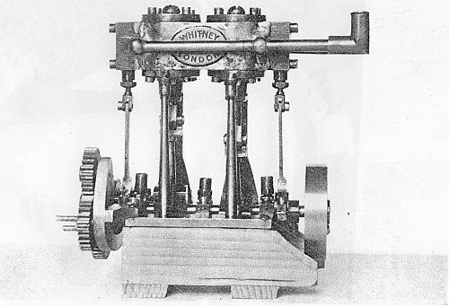 A TWIN CYLINDER STEAM ENGINE FOR MODEL MARINE USE
In all yachts a portion of the hull extends out over the water. These portions are known as overhangs. The overhang aft is sometimes called the counter-stern. The sides of the hull that rise above the deck are called bulwarks, and the part of the bulwarks that cross the stern is called the taffrail. The taffrail is always pierced with holes to allow water to run off the deck quickly, so that the additional weight will not in any way affect the course of the boat. It is understood that yachts raise great quantities of water upon their decks when traveling in rough sea.
The bowsprit is passed through a ring at the top of the stern, and this ring is termed the gammon iron. Its end is secured in a socket or between a pair of uprights called the bowsprit bits. These are fixed to the deck. Metal bars are fixed a short distance above the deck to take rings attached to the sheets. This is done so that the sails may swing freely from one side of the boat to the[169] other. Metal eyes are screwed into the sides to take the shrouds, and are called chain-plates. The eye in the stern is called the bobstay plate. In the stern-post are two eyes called gudgeons. The rudder is hooked to this by means of two hooks called pintles. The bar or lever that is fixed to the top of the rudder-post is called a tiller.
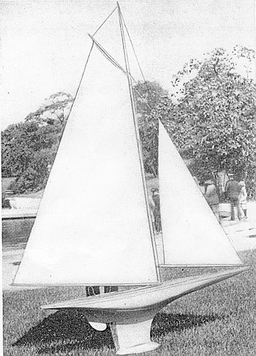 A CUP-WINNING MODEL SAIL BOAT
The parts and fittings of a mast follow: the step, the head, the caps, crosstrees, truck, topmast, boom, and gaff. The part of the gaff that rests on the mast is called the throat; the end of the gaff is called the peak. The jib-boom is a term used only in connection with model yachts. In larger boats the jib-boom is an extension of the bowsprit. The small boom that projects over the stern of a yawl is called the bumpkin. The spar is rather a general term applied to practically all wooden supports of sails. The spar of a lug-sail is called the yard. It is different from a boom or gaff, by reason of its lying against the mast instead of having one end butting on the mast. Anything belonging to the mainmast should be distinguished by the prefix main. Thus, there are the[170] mainsail, the mainboom, main-topsail, etc.
A sail for a model cutter-rigged yacht is shown in Fig. 140. The bowsprit and masts are, when necessary, given support by ropes that are stretched tightly to some point where they can be conveniently anchored to the hull. The following are those largely used on model yachts: topmast stay, bobstay, topmast shrouds, and forestay.
The sails are pulled up and fastened by ropes termed halyards. The halyards are fastened to the upper portions of the sail, and they are named according to the sail to which they are attached. For instance,[171] there is the jib halyard and the foresail halyard. A mainsail carried by a gaff has two halyards, the throat and peak. The movement of the sails is controlled by ropes, called sheets, which take their names from the sails they control. There is a mainsheet, a jibsheet, and a foresheet. The reader should take note of this term and refrain from confusing it with the sails.
The sailing of model yachts is a real art, and the author warns the reader that he cannot hope to become a proficient yachtsman by merely digesting the information given in this book. His real knowledge must be earned by experience in handling a model yacht on the water. However, there are few sports that will afford more pleasure than that of sailing model yachts. Being an outdoor sport it is very healthful.
In sailing a model yacht the sails are set, or "trimmed," so that she will continue to sail along the course previously decided upon by the yachtsman. She must do this in as[172] speedy a manner as possible and with as little deviation from her original course as possible. The trim of the sails will depend upon the wind. If the boat is to sail against the wind, that is termed "beating to windward"; with the wind is called "scudding." With the wind sideways it is called "reaching." If the boat is sailed with the wind blowing midway between one of the sides and the stern in such a way that it sweeps from one side of the stern across the deck, this is called "three-quarter sailing" in a "quartering" wind. A model yacht will continue for a great distance on a reach or while scudding; but, on the other hand, it will not be possible for her to sail directly against the wind. If a yachtsman is to make headway against the wind, he must sail his boat as near dead against the wind as it will go.
The cutter type of yacht will move against a wind that is blowing at a very small angle on her bowsprit. As soon as she reaches the limit of her course, the yachtsman turns her bow at a small angle so as to bring the wind on the opposite side of the vessel, and[173] in this way a second course is started. These courses are repeated in a zigzag fashion until the yacht arrives at her destination. This zigzagging, or "tacking," as it is called, is illustrated in Fig. 141. It will be seen that the yacht starts at B, and makes 3 tacks before she arrives at her destination, A. Each time she touches the shore she is "put about" and set upon a new course, or "tack."
It will be understood that tacking is slow work, and a greater distance must be traveled than would be covered by a power-boat, which would be able to go in a straight line. However, with wind-propelled craft this is the only way in which progress can be made against the wind. The left-hand side of a yacht viewed from the stern is called the port side, while the right-hand side is called[174] the starboard side. Thus a yacht sailing with the wind blowing on her port side is on the port tack, while if the wind is blowing on the starboard side she is said to be on the starboard tack. From this the reader will see that Fig. 142 shows an impossible case.
The sails in front of the mast that are placed nearest the stern of the yacht act in such a manner as to turn the bows in the direction of the arrow, as illustrated in Fig.[175] 146, and the sail or sails abaft the mast turn the boat in the direction of the arrow A. The boat thus revolves upon the center of the mast much as a weathercock revolves upon its pivot. If there is more than one mast, all the sails carried abaft the mainmast serve to turn the boat in the direction A. The work of sailing depends greatly upon the skill in balancing these two effects so that the boat will progress in a straight line. To do this the sails are set in a greater or less angle in relation to the center line of the boat. The less the angle that a sail makes with the center line of the boat, the greater is its power to determine in which direction the boat will steer. The more the yachtsman slackens out his jib and foresail, or the smaller he makes these sails, the less their power will be to turn the boat in the direction B. On the other hand, the larger they are and the more tightly they are pulled in, the greater will be their power. When the mainsail and all of the sails abaft the mainsail are slackened out and the smaller they are made, the less their power will be to swing the boat in the direction A.[176]
The influence of a sail upon the speed of a boat also increases with the angle that it makes with the center line of the hull. The more the yachtsman slackens out his sail, the more it will help the boat along. The reader will see that these two conditions interfere with each other, and therefore the trimming of the sails becomes a compromise. It is good for the young yachtsman to remember to sail his boat with the sails as slack as possible, as long as she keeps a good course. He should also remember not to overload her with sails, since the nearer to an upright position she maintains the faster she will go.
It is not possible to depend entirely upon the trim of the sails to keep a model in a given course. This is because the strength of the wind varies so that the sails are in balance one moment and out of balance the next. The sails abaft the mainmast overpower the sails before it when the wind increases. The result of this is that the bow of the boat will be repeatedly turned in the direction A, Fig. 146.
Some form of automatic rudder is therefore[177] generally used to overcome this tendency of the yacht to "luff" in the wind. Fig. 147 shows the course of a yacht reaching from A to B. The dotted lines show the course she should follow. The full line shows the effect of puffs of wind, which repeatedly[178] take her out of her course. Many times she may completely turn around and make a similar course back to the starting-point, as in Fig. 148. There is also the danger of her being taken back when pointing directly against the wind—the wind will force her backward stern first for some distance, as illustrated in Fig. 149. She will do this until she manages to get around on one tack or the other.
The dotted line B illustrates the course in which she would be driven under these conditions. It is not practical to sail a model yacht dead before the wind without an automatic rudder. With the use of an automatic rudder the erratic movements shown in Fig. 148 can be entirely overcome. The action of the rudder is such that every time the boat leans over to luff up into the wind, the weight of the rudder causes it to swing out, and thus prevents her from losing her course. As a different type of rudder is required, according to the course in which the yacht is sailing, the weight should be adjustable if the same rudder is used.
Let us consider scudding before the wind.[179] For scudding the heaviest rudder should be used, or the weight on a loaded tiller should be in its position of maximum power. All the sails abaft the foremast should be slackened out as far as they will go, which will bring the booms almost at right angles with the center line of the boat. If the craft is a cutter or yawl with a light weight, the yachtsman should rig the spinnaker. The head-sails may be left slack or can be tightened. Fig. 150 shows the position of the[180] booms when scudding with a schooner and yawl. The yawl is shown scudding goose winged. The cutter is illustrated with the spinnaker set. The other craft is a two-mast lugger with balanced lugs.
Attention is now directed to "reaching." For this particular work the yachtsman should put on a medium rudder. When using a weighted tiller the weight should be put in a midway position. The head-sails should be pulled in fairly tight and the aft-sails made slack. The yachtsman, however, should not slacken them as for scudding. Fig. 151 shows a schooner reaching. The thick black lines represent the booms of the sails. If the wind is very light a spinnaker-jib may be set or a jib-topsail in light or moderate breezes. In the case of a wind[181] that comes over the stern quarter, as indicated by the arrow A, the next heavier rudder, or its equivalent in weighted tiller, should be put in operation, and the sails slackened out a little more than before. The boat is then said to be free and sailing on the starboard tack. If the wind is coming in the direction B the jib and foresail may require slackening and the aft sails pulled in more than when sailing with the wind in the direction C. A still lighter rudder can be used as the course gets near to beating windward, and the yacht is said to be close-hauled on the starboard tack.
In beating to windward, if a rudder is used at all, it should be as light as possible, just heavy enough to keep the boat steady. However, this is just the condition of sailing when a boat can dispense with a rudder. It depends entirely upon the characteristics of the particular yacht being sailed, and for this the yachtsman must depend upon his own experience. The jib-topsail should not be used in a case like this, and if the wind is fairly strong a smaller jib should be set than that used for reaching. It is advisable[182] to slacken the jib and foresail out and pull the aft-sails in somewhat tightly. Fig. 152 shows a cutter beating to windward on a port tack. In this case she will have to pay out to starboard a bit before her sails fill.
In sailing the weather must be watched very closely, and the amount of sail carried will depend entirely upon the weather conditions. A yacht should never be overloaded with sail. If she has more than she can comfortably carry she will heel over and drag her sails in the water. Not only this, but she will also drift to leeward when beating to windward. When sailing a new boat, her best trim for various points of sailing and force of wind must be found by painstaking experiments. The boat should always be sailed with her sails as slack as she will take them and keep in her course. In this way she will move faster than when the sails are pulled in close.
The model yachtsman should always watch the wind and note whether it shifts its direction or alters its force. The boat is trimmed accordingly when the boat is put about. Easing or tightening the jib or[183] main-sheet slightly will make a very noticeable difference.
By taking down the top-sail or setting a jib-head top-sail in place of a jack yard top-sail, the yacht will be caused to ride easier in puffs of wind. In case she does not point well to windward when beating, the yachtsman should try a smaller jib, or he can slacken the foresail-sheet. If she runs off regularly to leeward on one tack only, while keeping well to windward on the other, she has some defect in construction or a bent keel.
In order that the reader may realize the obstacles to be surmounted in designing a model yacht that will sail in a straight line to windward, irrespective of the different pressure that the wind may expend on the sails, it must be pointed out that the boat is continuously altering the shape of the submerged part of her hull: therefore, unless the hull is so designed that harmony is retained at every angle to which the pressure of wind on the sails may heel it, the model's path through the water will be, more or less, an arc of a circle. Whether the boat sails toward the wind, or, in other words, in a curve the[185] center of the circle of which is on the same side of the boat as the wind, or in a curve the center of the circle of which is on the opposite or leeward side, will depend upon the formation of the boat.
As these notes are intended to first initiate the reader into the subject of model yacht building and construction, the design supplied is one in which all things, as far as shape is concerned, have been considered.
It is the endeavor of every designer to produce the most powerful boat possible for a given length—that is, one that can hold her sail up in resistance to the wind-pressure best. Of course, the reader will easily realize that breadth and weight of keel will be the main features that will enable the model to achieve this object; but, as these two factors are those that tend to make a design less slender, if pushed to extremes, the designer has to compromise at a point when the excess of beam and buoyancy are detrimental to the speed lines of the hull.
But the question of design pure and simple is a complex one, and we do not intend to weary the reader just now with anything of that kind, so we will now proceed to build the hull. In order that we may correctly interpret the shape shown in the design without being expert woodcarvers, we must use our ingenuity and by mechanical means achieve our object, at the same time saving ourselves a large amount of labor, such as we should have to[186] expend if we made this boat from a solid block of wood.
Now, as regards understanding the drawings: it is essential to remember that a line which in one view is a curve is always a straight line in the other two views. Those lines which are drawn parallel to the water-line are known as water-lines, and it will be seen that the curves shown on the deck plan represent the actual shapes of the hull at the corresponding water-lines above, below, and exactly on the load water-line. In other words, if after the hull is made it were sunk down to these various levels, the shapes of the hole made in the surface of the water would be as shown in the plan.
Therefore, instead of making our boat from a solid block of wood, we will make our block up from several layers, the thickness of each layer being equal to the space between the water-lines; but before gluing these layers together we will cut them out to the exact shape that the boat will be at their various positions.
It will not be necessary to have a separate piece of wood for each layer, as some layers below the actual water-line will be cut from the pieces of wood that have been cut out from the layers above.
In this case, the boat being 24 inches long, the top layer will be the same length and breadth as the boat, and 1 inch in thickness.
Draw down the center of the board a straight[187] line, and other lines square to it, representing the position of the cross-sections as shown in the drawing. You have now to transfer the deck line to this board, and this is done by marking the breadth at the various sections and drawing a curve through the spots, a thin strip of straight-grained wood being used as a rule, the latter being held down by such weights as are available. For the purpose of laying off the water-lines truly, lines spaced at 11/2 inches are shown; the first, it will be noticed, is half a section or 3/4 inch from the stem head.
The material required will be a board of pine about 6 feet long, 8 inches wide, and 1 inch finished thickness.
Nearly all wood-yards stock first-quality pine, but it is in planks 3 inches thick. You can no doubt pick up a short length about 4 feet long.
If so, take it to a sawmill and have two boards 11/4 inches thick cut and then machine-planed down to a dead inch. Perhaps you can purchase a board that is already cut, and is fully 1 inch thick, to allow for planing.
Prepare one edge of the board straight with a plane, seeing that it is square to the surface.
As a planing-machine always leaves a series of ridges across the board, varying according to the quality of the machine, it is necessary before transferring the lines to the wood to just skim the surface with a nicely sharpened plane, and set so as to just skim the wood.
The lengths required are: A, plank 24 inches long; B, plank 24 inches; C, plank 181/2 inches.
The D plank will be cut from the center of B, but will have to be shifted two sections forward.
Having transferred the various shapes from the drawing on to their respective layers, you saw out each carefully with a bow or a keyhole-saw, care being taken not to cut inside the lines. It is better to cut full, and trim down to the lines with a chisel or plane. A good deal of trouble can be saved by the expenditure of a few cents for having them machine-sawed, in which case ask the sawyer to use his finest-toothed saw.
Having cut out layers A, B, C, and D, fresh lines are marked, as shown by the dotted lines in the plan. These indicate the shape of the inside of each layer when the boat is carved out, and save labor.
These may as well be sawed out now as carved out later. It will also facilitate gluing up, as it will allow the superfluous glue to be squeezed out, and also decrease the breadth of the joint.
In order to get these various layers glued together dead true to their positions as indicated in the design, you must choose a section about amidships, say section 11, and with a square draw a line from that section, which is, of course, still showing on the surface of the layer, down the edge on either side, joining up with a line across the opposite face. Also vertical lines at each end of the[190] midships line must be drawn on the wood, great care being taken to get the midships line on the under face of the layers dead opposite each other.
If your outfit contains half a dozen carpenter's hand screws, these can be used; but if not, it will be necessary to purchase from a hardware store[191] eight seven-inch bolts and nuts 3/8 inch in diameter, with one washer for each, and to make up four clamps, as shown in Fig. 156.
You will start by gluing layer C to layer D, blocks being placed between the surface of the layers and the clamps to prevent bruising the wood. These two are then glued to layer B, and when this is thoroughly set they are glued to the layer A. The best glue to use for this job is marine glue, which does not dry too quickly, and so gives plenty of time to see that the layers have not shifted. In every case one clamp should be placed at each extreme end of the shorter layer, so as to insure the ends making contact, the other two being placed equidistant.
While waiting for the glue to set, you can be preparing the four layers (shown below D) for the lead keel pattern. The lines must be cut out, in this case, with a chisel, as it will be noticed that the[192] lower faces must be left wide enough to receive the top face of the layer beneath it.
It will be noticed that the under face of each of these layers extends beyond the top face aft, and allowance must be made for this. On laying off the lines on the fin layers, do not join up with a point each end, but leave about 1/8 inch thickness, as shown on the drawing.
These layers must be drilled through to take the keel-bolts, which are made from two motorcycle spokes, twelve-gage. These should be cut to a length of 51/2 or 6 inches. Great care should be taken to insure that the midship lines are exactly vertical over each other when these layers are glued up.
Before gluing these four layers on to the hull proper, they should be held in position by means of the spokes, in which position they can be sawed to shape for the keel pattern. First, with a small plane or sharp chisel cut down roughly, then a rasp and different grades of sandpaper are used, working across the joints.
It will be realized that, if the pattern for the keel were cut off dead on the line indicated on the design, there would be a loss of wood through the saw cut. In order to obviate this, another line 3/16 inch below the proper lead line is drawn, and the saw cut made between these two lines. You will now plane down each face that is left rough by the saw, straight and square to each of these lines.[193] On the top face of the pattern for the lead, glue or tack a piece 3/16 inch thick along the face, and cut down the edges flush.
You will by this means have made up for the amount of wood carried away by the saw. You will no doubt find a difficulty in holding the pieces of wood for planing in the ordinary way, but it is simple enough if you set the plane nicely, grip it in a vise or bench screw upside down, and push the work over the plane's face, instead of vice versa. But be careful of your fingers!
Take the pieces left from the spokes when cutting down to length, and put these in the holes in the keel pattern. These are for cores, and if you take your pattern to a foundry they will cast it for a small amount, with the holes in it.
Shoot the top face of the lead in the manner before described, and fit on. The hull is now ready for carving out. Screw on your bench two pieces of wood about 18 inches in length and 4 inches wide, so that they project over the edge of the bench about 10 inches. These should be about 15 inches apart. Place your hull upside down on them, and fix it by nailing upward into the top layer. After cutting off the corners of the layers roughly with a chisel you use a small plane set fairly fine, and work all over the hull evenly, taking care not to cut below any of the joints. A small gouge will be required to clear the wood from the region of the after fin, a round rasp—sandpaper being[194] wrapped around a small stick—being used for smoothing down afterward.
Templates of the cross-sections should now be made from thick white paper. This is done by pricking through the design to transfer their shape onto the paper. The cross-sections have on this account been produced here actual size. If cross-lines representing the water-lines are drawn, you will have an excellent guide for fitting, as these lines will, of course, come opposite each glued joint.
Try your templates now and again as you work, and do not try to finish one spot, but keep the whole at an even stage, and you will see the hull gradually grow into shape.
The topsides (which is the name given to that part of the vessel's hull above the water-line) are responsible for the boat's appearance when afloat, and until the top sheer is cut off the boat looks very disappointing. The cross-lines being still on the upper layer, draw square lines from them down the topsides and from the drawing mark the points through which the sheer-line runs. The thickness of the deck must be allowed for, and as this will be just over 1/16 inch, the line must be drawn this much below the finished sheer-line. The arch of the transom must be marked, and the hull cut down to the sheer. To avoid the risk of splitting, a number of fine saw cuts are made down each section line and two or three at the transom.
You now proceed to carve out the inside. Pad[195] your bench bearers and rest your hull upon them. A curved wood gouge with a fairly flat edge is the best tool. Get it nicely sharpened, and work all over the inside of hull until it is about 3/16 inch thick, the top edge being left 3/8 inch wide.
Keep holding up to the light until it is showing a blood-red color, and smooth down the gouge marks with coarse sandpaper.
The hole for the stern-tube must now be drilled, and the tube made and fitted. The hole should be 1/4 inch in diameter. First drill a smaller hole, and then with a 1/4-inch rat-tail file slowly open it out, at the same time rubbing a groove down the stern-post. The stern-tube is made from a piece of light-gage brass tube, it being cut away with a piercing saw to leave a strip the length of the stern-post. Drill three holes in the strip at equal distance and large enough to take a 1/4 inch brass screw, No. 0 size. Temporarily screw the tube in position, and from a piece of thin brass make a plate for the inside. An oval hole will have to be made in the plate to enable it to seat flat over the tube. Solder this while in position. Then remove the whole, and replace, after white-leading where wood touches brass.
The deck-beams, three in number and 1/4 inch square in section, must now be fitted. The sheer edge which we left 3/8 inch wide must be recessed to receive the beams, the recess being made with a 1/4-inch chisel.[196]
Before gluing beams in, three coats of good varnish must be applied to the inside of shell.
The deck should now be prepared and fitted. You will require a piece of pine of ample length and breadth, 1/8 inch in thickness, and after planing finely and sand-papering, pieces of the same stuff should be glued on the under face to reinforce it where the bowsprit, keel-plate, hatch rim, and mast will be fitted. Cut these pieces to shape before gluing on.
Before doing the latter, apply a coat of clear size to the upper face of the deck; this will bring up the grain, so paper it down when dry. This process should be repeated three times.
Three coats of varnish should be given to the under side of the deck after the pieces have been glued on, and when dry the deck can be fitted, 3/8-inch veneer pins being used for fixing on, and care being taken to get it true to position. A center line is drawn down the under side of the deck, and marks made to correspond at the stern and transom on the shell.
The planking lines on the deck can be drawn to suit your fancy, India ink and a draftsman's ruling pen being used to do it, afterward applying two coats of carriage varnish.
To paint the hull, white lead and dryers, in the proportion of 5 to 1 by weight respectively, should be dissolved in turpentine, a few drops of linseed oil being mixed to make it work freely. Have this[197] about the consistency of milk, and, after straining, give the hull about eight coats, one every twenty-four hours, rubbing each down when dry with No. 00 sandpaper. Keep the joint representing the load water-line always in sight by penciling over after each coat of paint is dry. When a sufficient body of paint has been applied, the colors can be applied. Enamel is best for this. Stick strips of gummed paper around the hull at the water-line, and paint up to the edge. When the paint is dry the paper can be soaked off, the paper being again applied, but reversed for the other color. If you can use a lining brush the paper is not necessary for the second color.
While the painting is going on, spars, sails, and fittings can be made. As the spars have to be varnished, it is best to make them first. Pine should be used, and after cutting strips of suitable length and diameter, plane them square in section. With the batten draw on the face the amount of taper to be given, and plane down to this line, still keeping the spar square in section. This having been done, the corners are planed off carefully until the spar is octagonal in section, when it is easy to make it perfectly round with sandpaper by rubbing with the paper rolled around the stick. The diameter of our mast is 1/2 inch parallel until the hoist of the fore triangle is reached, tapering from there to 1/4 inch at the masthead or truck. The boom is 1/4 inch at the gooseneck, thickening to 3/8 inch where[198] the main-sheet is attached, down to 1/4 inch at the outboard end. The jib-boom is slightly less than 1/4 inch parallel.
All spars should be treated with clear size and fine sandpaper before varnishing. This will prevent discoloring by the latter, and will also allow the India ink markings to be made, which latter will be a guide for the trimming of the sails.
In order that any yacht, model or otherwise, may be able to perform her best, it is essential that she should have well setting sails. In fact, in a model a badly setting sail will sometimes even be enough to prevent her going to windward at all. By well setting sails we mean sails that are naturally flat and not made so by straining them out on the spars. Light material, such as cambric or light union silk, is best for this purpose, but not a material that has any dressing in it.
This particular sail plan is very easy to mark out. Lay your material out on a table or smooth surface and pin it down with drawing-pins, sufficiently stretching it so as to pull out any creases. The length of the back edge of the mainsail (which is called the leech) is measured off 11/4 inches inside the edge of the cloth, and a curve struck as illustrated. The other two sides of the mainsail are then laid off and pencil lines drawn. You will note that allowance must be made for hemming the back edge of the mainsail. If your sewing-machine has a hemmer, find out how wide a hem it makes (the[199] smaller the better), and make allowance accordingly, twice the width of the hem being necessary. Much depends upon the tension at which the machine is set, so be careful that the latter is sufficiently slack so that it does not draw up the material.
The jib is marked out in the same manner, and, as illustrated, the lines representing the positions of the batten sleeves are drawn. The batten sleeves are small pockets into which thin pieces of cane (called battens) are inserted to help the sail to set nicely. Unless the sail is a good cut to begin with, however, the insertion of these battens will never make it right. The sails should now be cut out with a sharp penknife or scissors, care being taken not to pull the cloth, and especially not along the edges that run across the threads. You then hem the backs and also the foot of the jib. The batten sleeves (which should be of white satin ribbon about 3/8 inch in width) should now be sewn on by stitching down along the extreme edge to the line drawn, and then down the other edge, the ends being left open. A strip of narrow tape is sewn across the foot of the jib-sail to take the strain of the pull, the part of the jib contained by the curve of the foot and the tape being known as the bonnet of the jib.
To prevent the edges of the sails (other than those hemmed) being stretched, you bind them with good tape. The tape is first folded and creased by[200] rubbing over an edge. The end of the tape is then turned in. Take a corner of the sail and place it inside the fold of the tape, care being taken to get the raw edge right up against the crease. The needle of the machine should then be lowered through it as near to the edge of the tape as practicable, taking care that it goes through both edges. Keeping a slight pull on the binding, arrange the cloth in it without pulling the edge. Put the foot of the machine down and sew it, afterward raising the foot again and proceeding as before right around the raw edges of the sail, leaving the needle down each time the foot is raised. Do not sew where a batten sleeve passes under the binding, as you will require the former left open to allow the batten to pass into the fold of the binding. The rings for putting up the luffs of the jib- and main-sail are made by winding a piece of thin brass or German silver wire around a steel rod (the spokes used in the keel being suitable for the latter) and sawing down to divide them. A small eyelet should be put in each corner of the sails, and others spaced evenly at about 21/2 inches apart along the boom and about 5 inches apart along the mast, for lacing on. An extra row of stitching may be run down the outer edge of the binding to smooth it down.
The simpler the fittings of a model that is required for practical sailing, the better. They should be as light as practical. Aluminum is not advisable[201] for fittings when the boat is to be sailed in salt water.
The bowsprit fittings, which are known as the gammon iron and heel plate (Figs. 157, 158), are made by soldering pieces of brass tube (cut to suitable size and shape) onto pieces of triangular sheet brass, as illustrated. The horses can either be of wire with the ends turned to suitable shape and fitted with one screw, or they can have plates for two screws, in which case the wire is either threaded[202] and screwed into the plate or silver-soldered to it. Silver-soldering is done with a blow-pipe. The flux used is borax made into a thin paste with water. Silver-solder is bought in small sheets, and a few cents' worth will go a long way if used properly. Cut small pieces about 1/8 inch by 1/16 inch, and, after painting the part to be soldered with your paste borax with a very small brush, pick up the solder with the tip of the brush and put it in position. It will then run around the joint when the metal is raised to sufficient heat.
The hatch-rim is made by cutting a strip of thin brass 1/4 inch in width, the length being the circumference of the oval. The two ends are brought together and silver-soldered. Cut out the oval in a piece of very thin brass and fit in your oval strip so that the flat is just in the center of it. This[203] can then be sweated around with an ordinary soldering-iron, the flat being trimmed down afterward with the shears to leave a flange 1/4 inch in width, the latter being drilled to take 1/4 inch No. 0 round-head screws.
The deck fitting for the mast, (Fig. 159) is made in much the same way, a piece of tube being used instead of cutting a strip of brass. To receive the heel of the mast a fitting known as the mast-step must be made and fitted. This, of course, must be done before the deck is put on. The step is made from two pieces of brass, each about 1/32 inch in thickness, 1 inch long and 1/2 inch wide. One is hard-soldered on edge down the center of the other to form something like a T girder. A slot, as illustrated, is cut in the upright piece with a ward file, and holes drilled in the flat for screwing down on the inside of the boat. A ferrule of brass tube is fitted to the heel of the mast, a cut of suitable size being made in it to receive the upright[204] of the step. A hole should be drilled through the heel of the mast at right angles to the slot, and a wire passed through and riveted, the latter being of suitable thickness to be received by the slot in the step.
The rudder-blade (Fig. 162) is made from a piece of sheet brass fitted to a tube, the latter being an easy fit into the stern-tube already fitted. The blade can be soldered onto the tube. The pintle on which the rudder fits and swings is a strip of brass, the width of the after fin, a wire pin being hard-soldered in to fit up into the rudder.
The pintle (Fig. 163) should be fitted before the painting is started.
In the steering gear, instead of a quadrant, as[205] the fitting on the rudder-head of the "Braine" gear is called, you fit an ordinary tiller (Fig. 164) by bending a wire to suit your fancy and soldering it on to a collar made from a piece of tube that will just sleeve on the outside of the rubber-tube, which latter is fixed by drilling a hole right through it and the rudder head, and fitting a tapered pin.
The steering-gear rack (Fig. 165) by which the amount of helm is adjusted is made from a strip of brass cut with lugs which are bent up at right angles as illustrated. This need only be of thin sheet metal, as the strain is very small.[206]
For running before the wind, separate lines are used, two in number, as illustrated, and the amount of helm is governed by the distance away from midships that the lead is moved. For instance, if the lead is placed amidships, the pull will simply keep the rudder dead straight, whereas if placed on the deck edge it will allow the maximum amount of angle.
Your bowsers can be made from pieces of toothbrush handle or from brass or German-silver wire. Very efficient bowsers can be made from aluminum tube cut in sections about 3/16 inch long, with three holes drilled in each piece around its periphery.
Plaited bobbin cotton should be used for the cordage, as it does not curl up when wet.
If you decide to fit the Braine steering gear, a spur or bumpkin, as it is termed, must be fitted to take the rubber centering line.
Obvious punctuation errors repaired.
Fig. 55 and Fig. 82 have been linked to a larger versions to allow better reading of the fractions.
The remaining corrections made are indicated by dotted lines under the corrections. Scroll the mouse over the word and the original text will appear.
End of Project Gutenberg's Boys' Book of Model Boats, by Raymond Francis Yates

*** END OF THIS PROJECT GUTENBERG EBOOK BOYS' BOOK OF MODEL BOATS ***

***** This file should be named 29064-h.htm or 29064-h.zip *****
This and all associated files of various formats will be found in:
        https://www.gutenberg.org/2/9/0/6/29064/

Produced by Chris Curnow, Emmy and the Online Distributed
Proofreading Team at https://www.pgdp.net (This file was
produced from images generously made available by The
Internet Archive)


Updated editions will replace the previous one--the old editions
will be renamed.

Creating the works from public domain print editions means that no
one owns a United States copyright in these works, so the Foundation
(and you!) can copy and distribute it in the United States without
permission and without paying copyright royalties.  Special rules,
set forth in the General Terms of Use part of this license, apply to
copying and distributing Project Gutenberg-tm electronic works to
protect the PROJECT GUTENBERG-tm concept and trademark.  Project
Gutenberg is a registered trademark, and may not be used if you
charge for the eBooks, unless you receive specific permission.  If you
do not charge anything for copies of this eBook, complying with the
rules is very easy.  You may use this eBook for nearly any purpose
such as creation of derivative works, reports, performances and
research.  They may be modified and printed and given away--you may do
practically ANYTHING with public domain eBooks.  Redistribution is
subject to the trademark license, especially commercial
redistribution.


*** START: FULL LICENSE ***

THE FULL PROJECT GUTENBERG LICENSE
PLEASE READ THIS BEFORE YOU DISTRIBUTE OR USE THIS WORK

To protect the Project Gutenberg-tm mission of promoting the free
distribution of electronic works, by using or distributing this work
(or any other work associated in any way with the phrase "Project
Gutenberg"), you agree to comply with all the terms of the Full Project
Gutenberg-tm License (available with this file or online at
https://gutenberg.org/license).


Section 1.  General Terms of Use and Redistributing Project Gutenberg-tm
electronic works

1.A.  By reading or using any part of this Project Gutenberg-tm
electronic work, you indicate that you have read, understand, agree to
and accept all the terms of this license and intellectual property
(trademark/copyright) agreement.  If you do not agree to abide by all
the terms of this agreement, you must cease using and return or destroy
all copies of Project Gutenberg-tm electronic works in your possession.
If you paid a fee for obtaining a copy of or access to a Project
Gutenberg-tm electronic work and you do not agree to be bound by the
terms of this agreement, you may obtain a refund from the person or
entity to whom you paid the fee as set forth in paragraph 1.E.8.

1.B.  "Project Gutenberg" is a registered trademark.  It may only be
used on or associated in any way with an electronic work by people who
agree to be bound by the terms of this agreement.  There are a few
things that you can do with most Project Gutenberg-tm electronic works
even without complying with the full terms of this agreement.  See
paragraph 1.C below.  There are a lot of things you can do with Project
Gutenberg-tm electronic works if you follow the terms of this agreement
and help preserve free future access to Project Gutenberg-tm electronic
works.  See paragraph 1.E below.

1.C.  The Project Gutenberg Literary Archive Foundation ("the Foundation"
or PGLAF), owns a compilation copyright in the collection of Project
Gutenberg-tm electronic works.  Nearly all the individual works in the
collection are in the public domain in the United States.  If an
individual work is in the public domain in the United States and you are
located in the United States, we do not claim a right to prevent you from
copying, distributing, performing, displaying or creating derivative
works based on the work as long as all references to Project Gutenberg
are removed.  Of course, we hope that you will support the Project
Gutenberg-tm mission of promoting free access to electronic works by
freely sharing Project Gutenberg-tm works in compliance with the terms of
this agreement for keeping the Project Gutenberg-tm name associated with
the work.  You can easily comply with the terms of this agreement by
keeping this work in the same format with its attached full Project
Gutenberg-tm License when you share it without charge with others.

1.D.  The copyright laws of the place where you are located also govern
what you can do with this work.  Copyright laws in most countries are in
a constant state of change.  If you are outside the United States, check
the laws of your country in addition to the terms of this agreement
before downloading, copying, displaying, performing, distributing or
creating derivative works based on this work or any other Project
Gutenberg-tm work.  The Foundation makes no representations concerning
the copyright status of any work in any country outside the United
States.

1.E.  Unless you have removed all references to Project Gutenberg:

1.E.1.  The following sentence, with active links to, or other immediate
access to, the full Project Gutenberg-tm License must appear prominently
whenever any copy of a Project Gutenberg-tm work (any work on which the
phrase "Project Gutenberg" appears, or with which the phrase "Project
Gutenberg" is associated) is accessed, displayed, performed, viewed,
copied or distributed:

This eBook is for the use of anyone anywhere at no cost and with
almost no restrictions whatsoever.  You may copy it, give it away or
re-use it under the terms of the Project Gutenberg License included
with this eBook or online at www.gutenberg.org

1.E.2.  If an individual Project Gutenberg-tm electronic work is derived
from the public domain (does not contain a notice indicating that it is
posted with permission of the copyright holder), the work can be copied
and distributed to anyone in the United States without paying any fees
or charges.  If you are redistributing or providing access to a work
with the phrase "Project Gutenberg" associated with or appearing on the
work, you must comply either with the requirements of paragraphs 1.E.1
through 1.E.7 or obtain permission for the use of the work and the
Project Gutenberg-tm trademark as set forth in paragraphs 1.E.8 or
1.E.9.

1.E.3.  If an individual Project Gutenberg-tm electronic work is posted
with the permission of the copyright holder, your use and distribution
must comply with both paragraphs 1.E.1 through 1.E.7 and any additional
terms imposed by the copyright holder.  Additional terms will be linked
to the Project Gutenberg-tm License for all works posted with the
permission of the copyright holder found at the beginning of this work.

1.E.4.  Do not unlink or detach or remove the full Project Gutenberg-tm
License terms from this work, or any files containing a part of this
work or any other work associated with Project Gutenberg-tm.

1.E.5.  Do not copy, display, perform, distribute or redistribute this
electronic work, or any part of this electronic work, without
prominently displaying the sentence set forth in paragraph 1.E.1 with
active links or immediate access to the full terms of the Project
Gutenberg-tm License.

1.E.6.  You may convert to and distribute this work in any binary,
compressed, marked up, nonproprietary or proprietary form, including any
word processing or hypertext form.  However, if you provide access to or
distribute copies of a Project Gutenberg-tm work in a format other than
"Plain Vanilla ASCII" or other format used in the official version
posted on the official Project Gutenberg-tm web site (www.gutenberg.org),
you must, at no additional cost, fee or expense to the user, provide a
copy, a means of exporting a copy, or a means of obtaining a copy upon
request, of the work in its original "Plain Vanilla ASCII" or other
form.  Any alternate format must include the full Project Gutenberg-tm
License as specified in paragraph 1.E.1.

1.E.7.  Do not charge a fee for access to, viewing, displaying,
performing, copying or distributing any Project Gutenberg-tm works
unless you comply with paragraph 1.E.8 or 1.E.9.

1.E.8.  You may charge a reasonable fee for copies of or providing
access to or distributing Project Gutenberg-tm electronic works provided
that

- You pay a royalty fee of 20% of the gross profits you derive from
     the use of Project Gutenberg-tm works calculated using the method
     you already use to calculate your applicable taxes.  The fee is
     owed to the owner of the Project Gutenberg-tm trademark, but he
     has agreed to donate royalties under this paragraph to the
     Project Gutenberg Literary Archive Foundation.  Royalty payments
     must be paid within 60 days following each date on which you
     prepare (or are legally required to prepare) your periodic tax
     returns.  Royalty payments should be clearly marked as such and
     sent to the Project Gutenberg Literary Archive Foundation at the
     address specified in Section 4, "Information about donations to
     the Project Gutenberg Literary Archive Foundation."

- You provide a full refund of any money paid by a user who notifies
     you in writing (or by e-mail) within 30 days of receipt that s/he
     does not agree to the terms of the full Project Gutenberg-tm
     License.  You must require such a user to return or
     destroy all copies of the works possessed in a physical medium
     and discontinue all use of and all access to other copies of
     Project Gutenberg-tm works.

- You provide, in accordance with paragraph 1.F.3, a full refund of any
     money paid for a work or a replacement copy, if a defect in the
     electronic work is discovered and reported to you within 90 days
     of receipt of the work.

- You comply with all other terms of this agreement for free
     distribution of Project Gutenberg-tm works.

1.E.9.  If you wish to charge a fee or distribute a Project Gutenberg-tm
electronic work or group of works on different terms than are set
forth in this agreement, you must obtain permission in writing from
both the Project Gutenberg Literary Archive Foundation and Michael
Hart, the owner of the Project Gutenberg-tm trademark.  Contact the
Foundation as set forth in Section 3 below.

1.F.

1.F.1.  Project Gutenberg volunteers and employees expend considerable
effort to identify, do copyright research on, transcribe and proofread
public domain works in creating the Project Gutenberg-tm
collection.  Despite these efforts, Project Gutenberg-tm electronic
works, and the medium on which they may be stored, may contain
"Defects," such as, but not limited to, incomplete, inaccurate or
corrupt data, transcription errors, a copyright or other intellectual
property infringement, a defective or damaged disk or other medium, a
computer virus, or computer codes that damage or cannot be read by
your equipment.

1.F.2.  LIMITED WARRANTY, DISCLAIMER OF DAMAGES - Except for the "Right
of Replacement or Refund" described in paragraph 1.F.3, the Project
Gutenberg Literary Archive Foundation, the owner of the Project
Gutenberg-tm trademark, and any other party distributing a Project
Gutenberg-tm electronic work under this agreement, disclaim all
liability to you for damages, costs and expenses, including legal
fees.  YOU AGREE THAT YOU HAVE NO REMEDIES FOR NEGLIGENCE, STRICT
LIABILITY, BREACH OF WARRANTY OR BREACH OF CONTRACT EXCEPT THOSE
PROVIDED IN PARAGRAPH F3.  YOU AGREE THAT THE FOUNDATION, THE
TRADEMARK OWNER, AND ANY DISTRIBUTOR UNDER THIS AGREEMENT WILL NOT BE
LIABLE TO YOU FOR ACTUAL, DIRECT, INDIRECT, CONSEQUENTIAL, PUNITIVE OR
INCIDENTAL DAMAGES EVEN IF YOU GIVE NOTICE OF THE POSSIBILITY OF SUCH
DAMAGE.

1.F.3.  LIMITED RIGHT OF REPLACEMENT OR REFUND - If you discover a
defect in this electronic work within 90 days of receiving it, you can
receive a refund of the money (if any) you paid for it by sending a
written explanation to the person you received the work from.  If you
received the work on a physical medium, you must return the medium with
your written explanation.  The person or entity that provided you with
the defective work may elect to provide a replacement copy in lieu of a
refund.  If you received the work electronically, the person or entity
providing it to you may choose to give you a second opportunity to
receive the work electronically in lieu of a refund.  If the second copy
is also defective, you may demand a refund in writing without further
opportunities to fix the problem.

1.F.4.  Except for the limited right of replacement or refund set forth
in paragraph 1.F.3, this work is provided to you 'AS-IS' WITH NO OTHER
WARRANTIES OF ANY KIND, EXPRESS OR IMPLIED, INCLUDING BUT NOT LIMITED TO
WARRANTIES OF MERCHANTIBILITY OR FITNESS FOR ANY PURPOSE.

1.F.5.  Some states do not allow disclaimers of certain implied
warranties or the exclusion or limitation of certain types of damages.
If any disclaimer or limitation set forth in this agreement violates the
law of the state applicable to this agreement, the agreement shall be
interpreted to make the maximum disclaimer or limitation permitted by
the applicable state law.  The invalidity or unenforceability of any
provision of this agreement shall not void the remaining provisions.

1.F.6.  INDEMNITY - You agree to indemnify and hold the Foundation, the
trademark owner, any agent or employee of the Foundation, anyone
providing copies of Project Gutenberg-tm electronic works in accordance
with this agreement, and any volunteers associated with the production,
promotion and distribution of Project Gutenberg-tm electronic works,
harmless from all liability, costs and expenses, including legal fees,
that arise directly or indirectly from any of the following which you do
or cause to occur: (a) distribution of this or any Project Gutenberg-tm
work, (b) alteration, modification, or additions or deletions to any
Project Gutenberg-tm work, and (c) any Defect you cause.


Section  2.  Information about the Mission of Project Gutenberg-tm

Project Gutenberg-tm is synonymous with the free distribution of
electronic works in formats readable by the widest variety of computers
including obsolete, old, middle-aged and new computers.  It exists
because of the efforts of hundreds of volunteers and donations from
people in all walks of life.

Volunteers and financial support to provide volunteers with the
assistance they need are critical to reaching Project Gutenberg-tm's
goals and ensuring that the Project Gutenberg-tm collection will
remain freely available for generations to come.  In 2001, the Project
Gutenberg Literary Archive Foundation was created to provide a secure
and permanent future for Project Gutenberg-tm and future generations.
To learn more about the Project Gutenberg Literary Archive Foundation
and how your efforts and donations can help, see Sections 3 and 4
and the Foundation web page at https://www.pglaf.org.


Section 3.  Information about the Project Gutenberg Literary Archive
Foundation

The Project Gutenberg Literary Archive Foundation is a non profit
501(c)(3) educational corporation organized under the laws of the
state of Mississippi and granted tax exempt status by the Internal
Revenue Service.  The Foundation's EIN or federal tax identification
number is 64-6221541.  Its 501(c)(3) letter is posted at
https://pglaf.org/fundraising.  Contributions to the Project Gutenberg
Literary Archive Foundation are tax deductible to the full extent
permitted by U.S. federal laws and your state's laws.

The Foundation's principal office is located at 4557 Melan Dr. S.
Fairbanks, AK, 99712., but its volunteers and employees are scattered
throughout numerous locations.  Its business office is located at
809 North 1500 West, Salt Lake City, UT 84116, (801) 596-1887, email
business@pglaf.org.  Email contact links and up to date contact
information can be found at the Foundation's web site and official
page at https://pglaf.org

For additional contact information:
     Dr. Gregory B. Newby
     Chief Executive and Director
     gbnewby@pglaf.org


Section 4.  Information about Donations to the Project Gutenberg
Literary Archive Foundation

Project Gutenberg-tm depends upon and cannot survive without wide
spread public support and donations to carry out its mission of
increasing the number of public domain and licensed works that can be
freely distributed in machine readable form accessible by the widest
array of equipment including outdated equipment.  Many small donations
($1 to $5,000) are particularly important to maintaining tax exempt
status with the IRS.

The Foundation is committed to complying with the laws regulating
charities and charitable donations in all 50 states of the United
States.  Compliance requirements are not uniform and it takes a
considerable effort, much paperwork and many fees to meet and keep up
with these requirements.  We do not solicit donations in locations
where we have not received written confirmation of compliance.  To
SEND DONATIONS or determine the status of compliance for any
particular state visit https://pglaf.org

While we cannot and do not solicit contributions from states where we
have not met the solicitation requirements, we know of no prohibition
against accepting unsolicited donations from donors in such states who
approach us with offers to donate.

International donations are gratefully accepted, but we cannot make
any statements concerning tax treatment of donations received from
outside the United States.  U.S. laws alone swamp our small staff.

Please check the Project Gutenberg Web pages for current donation
methods and addresses.  Donations are accepted in a number of other
ways including including checks, online payments and credit card
donations.  To donate, please visit: https://pglaf.org/donate


Section 5.  General Information About Project Gutenberg-tm electronic
works.

Professor Michael S. Hart was the originator of the Project Gutenberg-tm
concept of a library of electronic works that could be freely shared
with anyone.  For thirty years, he produced and distributed Project
Gutenberg-tm eBooks with only a loose network of volunteer support.


Project Gutenberg-tm eBooks are often created from several printed
editions, all of which are confirmed as Public Domain in the U.S.
unless a copyright notice is included.  Thus, we do not necessarily
keep eBooks in compliance with any particular paper edition.


Most people start at our Web site which has the main PG search facility:

     https://www.gutenberg.org

This Web site includes information about Project Gutenberg-tm,
including how to make donations to the Project Gutenberg Literary
Archive Foundation, how to help produce our new eBooks, and how to
subscribe to our email newsletter to hear about new eBooks.