 Fig. 1.—General Arrangement of a Gas Engine and
Accessories.
Fig. 1.—General Arrangement of a Gas Engine and
Accessories.
The Project Gutenberg EBook of Gas and Oil Engines, Simply Explained, by
Walter C. Runciman

This eBook is for the use of anyone anywhere at no cost and with
almost no restrictions whatsoever.  You may copy it, give it away or
re-use it under the terms of the Project Gutenberg License included
with this eBook or online at www.gutenberg.org


Title: Gas and Oil Engines, Simply Explained
       An Elementary Instruction Book for Amateurs and Engine Attendants

Author: Walter C. Runciman

Release Date: November 17, 2008 [EBook #27286]

Language: English

Character set encoding: ISO-8859-1

*** START OF THIS PROJECT GUTENBERG EBOOK GAS AND OIL ENGINES ***


Produced by Steven Gibbs, Greg Bergquist and the Online
Distributed Proofreading Team at https://www.pgdp.net
An Elementary Instruction Book for Amateurs
and Engine Attendants
BY
WALTER C. RUNCIMAN
FULLY ILLUSTRATED
LONDON
Model Engineer Series. The "Model Engineer"
Series, no. 26.
1905
| CHAP. | PAGE | |
| PREFACE | 5 | |
| I. | INTRODUCTORY | 7 |
| II. | THE COMPONENT PARTS OF AN ENGINE | 13 |
| III. | HOW A GAS ENGINE WORKS | 22 |
| IV. | IGNITION DEVICES | 33 |
| V. | MAGNETO IGNITION | 47 |
| VI. | GOVERNING | 51 |
| VII. | CAMS AND VALVE SETTINGS | 63 |
| VIII. | OIL ENGINES | 81 |
My object in placing this handbook before the reader is to provide him with a simple and straightforward explanation of how and why a gas engine, or an oil engine, works. The main features and peculiarities in the construction of these engines are described, while the methods and precautions necessary to arrive at desirable results are detailed as fully as the limited space permits. I have aimed at supplying just that information which my experience shows is most needed by the user and by the amateur builder of small power engines. In place of giving a mere list of common engine troubles and their remedies, I have thought it better to endeavour to explain thoroughly the fundamental principles and essentials of good running, so that should any difficulty arise, the engine attendant will be able to reason out for himself the cause of the trouble, and will thus know the proper remedy to apply. This will give him a command over his engine which should render him equal to any emergency.
WALTER C. RUNCIMAN.
London, E.C.
[Pg 6]
The history of the gas engine goes back a long way, and the history of the internal combustion engine proper further still. It will be interesting to recount the main points in the history of the development of the class of engine we shall deal with in the following pages, in order to show what huge strides were made soon after the correct and most workable theory had been formulated.
In 1678 Abbé Hautefeuille explained how a machine could be constructed to work with gunpowder as fuel. His arrangement was to explode the gunpowder in a closed vessel provided with valves, and cool the products of combustion, and so cause a partial vacuum to be formed. By the aid of such a machine, water could be raised. This inventor, however, does not seem to have carried out any experiments.
In 1685 Huyghens designed another powder machine; and Papin, in 1688, described a similar machine, which was provided with regular valves, as devised by himself, in the Proceedings of the Leipsic Academy, 1688. From this time until 1791, when John Barber took out a patent for the production of force by the combustion of hydrocarbon in air, practically no advancement was made. The latter patent, curiously enough, comprised a very primitive form of rotary engine. Barber proposed to turn coal, oil, or other combustible stuff into gas by means of external firing, and then to mix the gases so produced with air in a vessel called the exploder. This mixture was then ignited as it issued from the vessel, and the ensuing flash caused a paddle-wheel to rotate. Mention is also made that it was an object to inject a little water into the exploder, in order to strengthen the force of the flash.
Robert Street's patent of 1794 mentions a piston engine, in the cylinder of which, coal tar, spirit, or turpentine was vaporised, the gases being ignited by a light burning outside the cylinder. The piston in this engine was thrown upwards, this in turn forcing a pump piston down which did work in raising water. This was the first real gas engine, though it was crude and very imperfectly arranged.
In 1801 Franzose Lebon described a machine to be driven by means of coal-gas. Two pumps were used to compress air and gas, and the mixture was fired, as recommended by the inventor, by an electric spark, and drove a piston in a double-working cylinder.
The atmospheric engine of Samuel Brown, 1823, had a piston working in a cylinder into which gas was introduced, and the latter, being ignited, expanded the air in cylinder whilst burning like a flame. The fly-wheel carried the piston up to the top of its stroke, then water was used to cool the burnt gases, which also escaped through valves, the latter closing when the piston had reached the top of its stroke. A partial vacuum was formed, and the atmospheric pressure did work on the piston on its down stroke. A number of cylinders were required in this engine, three being shown in the specification all connected to the same crank-shaft. According to the Mechanic's Magazine, such an engine with a complete gas generating plant was fitted to a boat which ran as an experiment upon the Thames.
A two-cylinder engine working on to a beam was built in Paris, but no useful results were obtained.
Wright's engine of 1833 used a mixture of combustible gas and air, which operated like steam in a steam engine. This engine had a water-jacket, centrifugal governor, and flame ignition. In 1838 Barnett applied the principle of compression to a single-acting engine. He also employed a gas and air pump, which were placed respectively on either side of the engine cylinder, communication being established between the receiver into which the pumps delivered and the working cylinder as the charge was fired. The double-acting engines which Barnett devised later were not so successful.
From this time to about 1860 very few practical[Pg 10] developments are recorded. A number of French and English patents were taken out, referring to hydrogen motors, but are not of much practical value.
Lenoir's patent, dating from 24th January 1860, refers to a form of engine which received considerable commercial support, and consequently became very popular. A manufacturer, named Marinoni, built several of these engines, which were set to work in Paris in a short time. Then, due to sudden demand, the Lenoir Company was formed to undertake the manufacture of these engines. It was claimed that a 4-horse-power engine could be run at a cost of 3·4 shillings per day, or just one half the cost of a steam engine using 9·9 pounds of coal per horse-power per hour. Many similar exaggerated accounts of their economy in consumption were circulated, and the public, on the strength of these figures, bought.
It was understood that 17·6 cubic ft. of gas were required per horse-power per hour, but it was found that as much as 105 cubic ft. were often consumed. The discrepancy between the stated figures and the actual performance of the engine was a disappointment to the using public, and, as a result, the Lenoir engine got a bad name.
Hugon, director of the Parisian gas-works, who, together with Reithmann, a watchmaker of Münich, hotly contested Lenoir's priority to this invention, brought out a modification of this engine. He cooled the cylinder by injecting water as well as using[Pg 11] a water-jacket, and used flame instead of electric ignition. The consumption was now brought down to 87·5 cubic ft.
At the second Parisian International Exhibition, 1867, an atmospheric engine, invented by Otto & Langen about this time, was shown. In this engine a free piston was used in a vertical cylinder, the former being thrown up by the force of the explosion. The only work done on the up-stroke was that to overcome the weight of the piston and piston rod, and the latter being made in the form of a rack, engaged with a toothed wheel on the axle as the piston descended, causing the fly-wheel and pulley to rotate.
Barsanti and Matteucci were engaged in devising and experimenting with an engine very similar to this some years before, but Otto & Langen, no doubt, worked quite independently. Barsanti's engine never became a commercial article; while Otto & Langen's firm, it is said, held their own for ten years, and turned out about 4000 engines. In 1862 the French engineer, Beau de Rochas, laid down the necessary conditions which must prevail in order to obtain maximum efficiency. His patent says there are four conditions for perfectly utilising the force of expansion of gas in an engine.
(1) Largest possible cylinder volume contained by a minimum of surface.
(2) The highest possible speed of working.
(3) Maximum expansion.
(4) Maximum pressure at beginning of expansion.
These are the conditions and principles, briefly stated, that combine to form the now well-known cycle upon which most gas engines work at the present time.
It was not until 1876, fifteen years after these principles had been enumerated, that Otto carried them into practical effect when he brought out a new type of engine, with compression before ignition, higher piston speed, more rapid expansion, and a general reduction of dimensions for a given power. Due to this achievement, the cycle above referred to has always been termed the "Otto" cycle.
Having recounted very briefly the chief points in the development of the gas engine from its beginning, we may proceed to deal with matters of perhaps more practical interest to those who we are assuming have had little or no actual experience in making or working internal combustion engines.
The modern gas engine comprises comparatively few parts. Apart from the two main castings—the bed and cylinder—a small engine, generally speaking, consists of four fundamental members, viz., the valves and their operating mechanism, the cams and levers; the ignition device for firing the charge; and the governing mechanism for regulating the supply and admission of the explosive charge. There are innumerable designs of each one of these parts, and no two makes are precisely alike in detail, as every maker employs his own method of achieving the same end, namely, the production of an engine which comprises maximum efficiency with a minimum of wear and tear and attention.
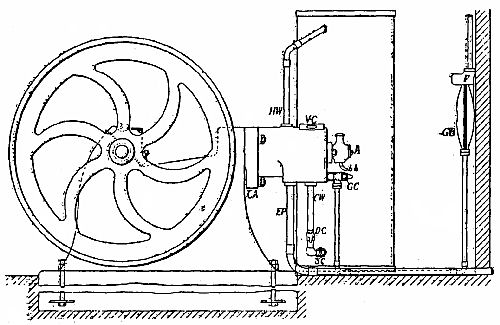
Therefore, before dealing with each of these primary parts in an arbitrary manner, and with the cycle of operations in detail, we propose to make the reader familiar with the general arrangement and method of working which usually obtains in the smaller power engines. In the following illustrations these parts are shown. A (fig. 1) is the ignition device which carries the ignition tube to fire the charge. H and I (fig. 2) are the main valves, and GC (fig. 1.) is the gas-cock. The side or cam shaft N (sometimes called the 2 to 1 shaft), the cams which move the levers M, the latter in turn operating the valves, and causing them to open and close at the proper time, are shown in fig. 11. A bracket bolted up to the side of cylinder forms a bearing for one end of the side shaft, and also carries a spindle at its lower end on which the levers oscillate, transmitting the motion imparted to them by the cams to the valves. The main cylinder casting and the bed need no description. In some cases the bed is in two portions, though now a great many makers are discarding the lower portion altogether, having found that it is cheaper, and quite as satisfactory, to use a built-up foundation instead, and, if necessary, to cut a trough for the fly-wheel to run it. This arrangement, however, only obtains where larger engines are concerned. A half-compression handle by which the exhaust cam is moved laterally on the side shaft as required is not needed on very small engines.
Fig. 1.—General Arrangement of a Gas Engine and
Accessories.
Further reference will be made to this in another chapter, and, although this is not a necessity on a small engine, it is always employed on engines over 2 B.H.P. In fig. 1, HW is the cooling water outlet and CW the inlet. A small drain cock is shown at DC, through which the water in the cylinder water-jacket may be drawn off when required. The pipes leading to the inlet and outlet of this supply are connected to the cooling water tank by means of a couple of broad, flat nuts and lead washers, one inside and the other outside the tank, the latter, when clamped up well, making a perfectly water-tight joint. The outlet pipe making an acute angle with the side of tank, the washers used there should be wedge-shape in section. It is also desirable to fit a stop-cock SC, so that the pipes can be disconnected from the engine entirely, or the water-jacket emptied without running the whole of the water out of the tank. The exhaust pipe EP is made up of gas-barrel. It should lead from the engine to the silencer or exhaust box (if one is found to be necessary) as directly as possible, i.e., with no more bends than are needed, and what there are should not be acute. The silencer can be inside or outside the engine-room, whichever is most convenient; but both it and the exhaust piping should be kept from all direct contact with wood-work, and at the same time in a readily accessible position.
Beyond the exhaust-pipe and box and the water-tank, the gas bag GB and gas meter (where small powers are concerned, the ordinary house or workshop lighting meter may be used without inconvenience) are the only other accessories which are included in a small installation.
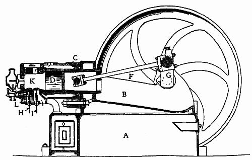 Fig. 2.—A Section of a Gas Engine.
Fig. 2 gives a sectional view, showing the cylinder and liner. The latter is a very desirable feature in any type of gas engine, but especially in the larger sizes; for at any future time, should it be found necessary to re-bore the liner, it can be removed with comparative ease, and is, moreover, more readily dealt with in the lathe than the whole cylinder casting would be.
The liner is virtually a cast-iron tube, with a specially shaped flange at either end. At the back end the joint between it and the cylinder casting has to be very carefully made. This is a water and explosion joint; hence it has not only to prevent water entering the cylinder from the water-jacket, but also to be sufficiently strong to withstand the pressure generated in the cylinder when the charge is fired. For this purpose specially prepared coppered asbestos rings are used, which will stand both water and intense heat. Sometimes a copper ring alone is employed to make the joint. At the front end the liner is just a good fit, and enters the bed easily, and a couple of bolts fitted in corresponding lugs on the liner, pass through the back end of cylinder casting, so that by tightening up these the joint at back end is made secure. A small groove is cut on a flange, and a rubber ring, of about 1⁄4-in. sectional diameter, is inserted here when the liner is fitted into the cylinder casting. This makes the water-jacket joint at the front end.
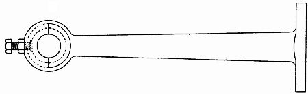 Fig. 3.
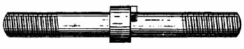 Fig. 5.
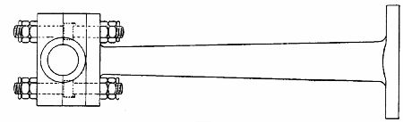 Fig. 4.
Lugs are provided on the bed and cylinder castings, and are bored to receive steel bolts—three are sufficient, provided the metal in and around these lugs is not pinched. In some cases a continuous flange is provided on both bed and cylinder, and a number of bolts inserted all the way round. This, however, is unnecessary, and has a somewhat clumsy appearance. When these bolts are tightened up, the cylinder and liner are clamped firmly to the bed; but the liner being free at the open end, can expand longitudinally without causing stresses in the cylinder casting.
The combustion chamber K is virtually part of the cylinder, and has approximately equal to one-fourth the total volume of the cylinder. The shape varies somewhat in different makes of engines; in some it is rectangular, with all the corners well rounded off; in others it is practically a continuation of the cylinder, i.e., it is circular in cross-section, with the back end more or less spherical; while, again, it is made slightly oval in cross-section; but in every case the corners should be well curved and rounded off, so that there is no one part which is liable to become heated disproportionately with the rest of the casting; in fact, in the whole cylinder casting there should be no sudden change, but a uniformity in the thickness of the metal employed. This point should be carefully remembered, although it applies more particularly to those parts of the casting subjected to higher temperatures than the rest.
The main bearings are usually of brass or [Pg 21]gun-metal, and are adjusted for running in the same manner as any steam or other engines would be. The "brasses" are in halves, and are held down by the cast-iron caps, as shown in fig. 1.
These bearings require extremely little attention, and do not show the wear and tear of running nearly so soon as the connecting-rod brasses. These, too, are usually of brass or gun-metal; but there are various forms of construction employed in connection with the back end or piston pin bearings. On very small engines the connecting rod is swollen at the back end in the forging, and then machined up and drilled, as shown in fig. 3. In this hole the brasses are inserted after being scraped up to a good fit on the piston pin.
A flat is cut on one of the brasses, and a set screw is fitted, as shown, to prevent any movement of the latter after the final adjustment has been made. A lock nut should be used in conjunction with this set screw. Another method, and one more generally used on larger engines, is shown in fig. 4. In this case the brasses are larger than in the former, where they are virtually a split bush; here they have holes drilled in them to take the bolts, the latter usually and preferably being turned up to the shape shown in fig. 5.
The gas engine of the present day, although from a structural point of view is very different to the early engine, or even that of fifteen years ago, is, in respect to the principle upon which it works, very similar. The greater number of smaller power engines in use in this country work on what is known as the Otto or four-cycle principle; and it is with this class of engine we propose to deal.
Reference to the various diagrams in the text will help considerably, and make it an easy matter for any reader hitherto totally unacquainted with such engines to see why and how they work.
Coal-gas consists primarily of five other gases, mixed together in certain proportions, these proportions varying slightly in different parts of the country:—Hydrogen (H), 50; marsh gas (CH4), 38; carbon-monoxide, 4; olefines (C6H4), 4; nitrogen (N), 4.
Gas alone is not explosive; and before any practical use can be made of it, a considerable quantity of[Pg 23] air has to be added, diluting it down to approximately ten parts air to one of pure gas. This mixture is now highly explosive.
The reader will do well to bear these facts constantly in mind, especially when he is repairing, adjusting, or experimenting with a gas engine. We wish to emphasise this at the outset, because a consideration of these facts will keep cropping up throughout all our dealings with the gas engine, and if once a fairly clear conception is obtained of how gas will behave under certain and various conditions, half, or even more than half, our "troubles" will disappear; the cry that the gas engine has "gone wrong" will be heard less often, and users would soon learn that the gas engine is in reality as worthy of their confidence as any other form of power generator in common use.
But to revert to the explanation of the cycle of operations. The cycle is completed in four strokes of the piston, i.e., two revolutions of the crank shaft.
At the commencement of the first out-stroke (the charging or suction stroke) gas and air are admitted to the cylinder through the respective valves (fig. 6), and continue to be drawn in by what may be termed the sucking action of the piston, until the completion of this stroke (the precise position of the closing and opening of the valves will be referred to later on). The next stroke (fig. 7) is the compression stroke. All the valves are closed whilst the piston moves inwards, compressing the gases, until at the end of this stroke, and at the instant of maximum [Pg 24]compression, the highly explosive charge is fired by means of the hot tube or an electric spark, as the case may be. The ensuing stroke—the second out-stroke of the cycle—is the result of the explosion, the expanding gases driving the piston rapidly before them; this, then, is the expansion, or working stroke (fig. 8.)
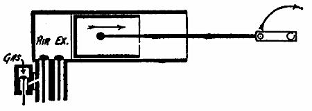 Fig. 6.—Commencement of first out-stroke suction or
charging stroke. Gas and air valve about to open.
Fig. 6.—Commencement of first out-stroke suction or
charging stroke. Gas and air valve about to open.
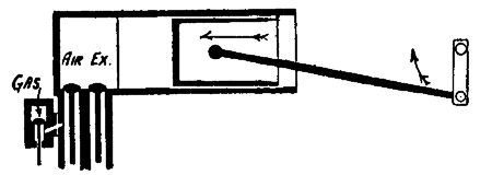 Fig. 7.—Compression stroke, during which all valves
remain closed.
Fig. 7.—Compression stroke, during which all valves
remain closed.
During the last—the second inward—stroke (fig. 9) the exhaust valve is opened, and the returning piston sweeps all the burnt gases (the product of combustion) out into the exhaust pipe and so into the atmosphere. This completes the cycle, and the piston, crank, and valves are in the same relative positions as formerly, and the same series of operations is repeated again and again. Of course, it is not always the case that both air and gas valve are opened on the charging stroke; that depends upon[Pg 25] the method employed to govern the speed of the engine. Supposing it were governed on the hit and miss principle (to be explained hereafter), the gas valve would be allowed to remain closed during the charging stroke, and air alone would be drawn into the cylinder, then compressed, but not being explosive would simply expand again on the working stroke, giving back nearly all the energy which was absorbed in compressing it, and finally be exhausted in the same manner as the burnt gases are.
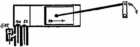 Fig. 8.—Second out stroke, showing position of valves
during working stroke.
Fig. 8.—Second out stroke, showing position of valves
during working stroke.
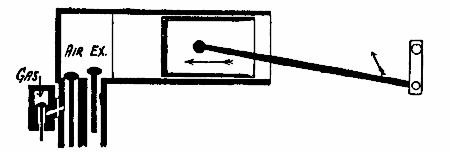 Fig. 9.—Second inward stroke, showing position of valves
during the exhaust stroke.
Fig. 9.—Second inward stroke, showing position of valves
during the exhaust stroke.
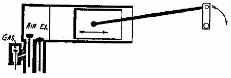 Fig. 10.—First out-stroke, showing position of valves
during the charging stroke.
Fig. 10.—First out-stroke, showing position of valves
during the charging stroke.
Fig. 10 shows diagrammatically the position of crank, piston, and valves during the charging stroke.
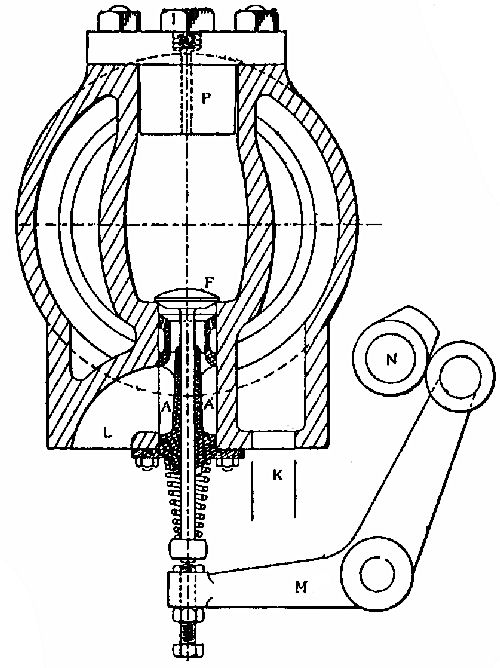 Fig. 11.—Cross Section of Cylinder.
In figs. 1 and 2 we gave drawings of two gas engines, which are typical examples of modern practice. Huge strides have been made in recent years in gas-engine work, as regards both workmanship and efficiency, so that to-day we have in the gas engine a machine whose mechanical efficiency compares favourably with that of any other power generator, and whose thermal efficiency is very much greater.
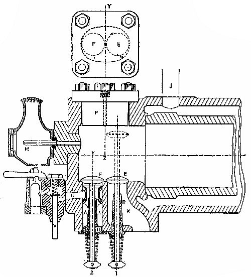 Fig. 12.—Longitudinal Section of Cylinder.
Figs. 11 and 12 show respectively a sectional end and side elevation of the cylinder, from which it will not be difficult for the reader, however unacquainted he may be with gas-engine work, to see how the various requirements and peculiarities of the engine should be considered and provided for.
A most important desideratum in any machine or engine is that it shall be as simple in construction as ever possible; complicated mechanism should only be introduced when such addition or complication compensates adequately for what must necessarily be a higher first cost, and incidentally the greater wear and tear and attention involved. Figs. 11 and 12 show what has been done to simplify the construction of the gas engine in recent years. The main feature in this case is the very get-at-able position of the two main valves—the air valve F and the exhaust E. These valves, as may be seen from the drawing, are capable of withdrawal after the cover of the combustion chamber has been removed. The latter is an iron casting, shaped and faced up to make an absolutely tight joint; no asbestos or any packing is used to make this joint—and is held in place by four studs, as shown. Thus, all that is necessary is to remove the four nuts, lift the cover off, then pull out the pins which keep the spiral springs in position, and withdraw the valves. The latter are seated direct on to the metal of the cylinder casting, the[Pg 29] gun-metal bushes A and B acting as guides. Further reference to A (the mixer), which serves a twofold purpose, will be made later on.
The gas valve and cock are mounted in a separate casting, which is carried by a couple of studs, the joint between this and cylinder being made with a piece of rubber insertion. The gas enters at the gas-cock, passes through the valve and port G, and round the annular space in the bush or "mixer" A, previously mentioned, and thence through a number of small holes in same, immediately below the seat of the air valve F. At the same time, pure air is drawn in via the air box (as explained hereafter), through port L (fig. 11), and thence up the centre of bush A and over the small holes through which the gas is flowing. The two then thoroughly mix and enter the combustion chamber together as the air valve F is opened. This device produces a perfectly homogeneous mixture, which conduces in no small measure to perfect combustion when the explosion takes place, and upon which, to a very great extent, depends the efficiency of the engine. Besides possible loss in this direction, however, there is another source of waste which cannot be eliminated, and that is the heat taken away by the cooling water which surrounds the cylinder. As this loss is inevitable, the best thing we can do is to make it as small as possible. Theoretically, it would be no small advantage if we could work at very much higher temperatures than we do at the present time, and it is only certain mechanical difficulties which bar the way and so effectually[Pg 30] prevent the already high thermal efficiency of the engine being greatly increased.
It is no easy matter to overcome these difficulties completely, but improvements in this direction are continually being made, so that troubles which attended the gas-engine user years ago no longer exist.
All that we require of the cooling water is that it shall keep certain working parts of the engine at a reasonable temperature; for instance, the cylinder must not be so hot as to deprive the lubricating oil of its property to lubricate, neither must the exhaust valve become so hot as to cause it to seize in the bush and stick up; but, beyond such considerations as these, the higher the temperature is at the commencement of each explosion the more efficient will the engine be. The object, then, is to do as little cooling as possible, and to apply the cooling effect at the right parts; hence the passages and chambers through which the cooling water circulates should be so arranged that those which require to be kept at a low temperature are in close proximity to the cooling water. On some of the engines of days gone by, the exhaust valve was carried in a large iron casting, this in turn being bolted to the cylinder casting and communicating with the combustion chamber by means of a port. Such an arrangement was found to be not only clumsy but inefficient; the water passages were small and difficult to get at; they readily furred up; and moreover, the joint between this casting and the cylinder was[Pg 31] necessarily a water and explosion joint, and the fewer we have of these the better.
The method—if it may be called a method—of overcoming or preventing the exhaust valve becoming too hot is, in the case of figs. 11 and 12, simply one of judicious arrangement and design. The cooling water enters by the inlet K (fig. 11), and circulates round the exhaust valve port X and valve E immediately, before becoming heated, thus keeping the hottest of the working parts of the engine at a suitable temperature; and the valve seat, being in direct metallic communication with the cold water, does not become burnt or pitted. On the other side of the exhaust valve we have the air valve and its passages, through which cool air is continually being drawn; this also helps to keep the exhaust valve cool.
From this, then, we may conclude that overheating of the cylinder will not occur under normal conditions, given an engine of good design; but, if this trouble does arise, we may safely look first of all for some defect in the cooling water circulation. Some waters contain a greater amount of impurities than others, and consequently the water space may furr up more rapidly in one district than in another. But this deposit, even under the worst conditions, accumulates very slowly, and the operation of cleaning out the water-jacket is a very infrequent necessity. The exhaust valve, however, may become overheated if it is allowed to get into bad condition, i.e., leaky. Its seat should be well looked after, or[Pg 32] the hot gases will blow past when it is presumably shut; and if this defect, slight though it may be to begin with, is allowed to develop, both the seat, the valve head, and the spindle will become burnt away and pitted, perhaps badly, due to the excessive heat.
The ignition devices commonly employed may be divided into three main classes—the metal tube, the porcelain tube, and the electric ignition. These again may be subdivided: The first being either iron or nickel (hecknum as they are sometimes called); the second are of two kinds—single-ended and double-ended; and the third takes many forms which many of my readers are possibly well acquainted with, such as the magneto, the induction coil and trembler, and the high-tension magneto ignition, the latter device having been used successfully on various occasions, though not yet universally adopted.
The first-named have one or two advantages over the nickel tube. They are very inexpensive, and are easily heated to the required temperature; moreover, they can be made at home, should occasion demand. On the other hand, they are not so durable, have a very uncertain life, and consequently need renewing frequently—their average life being[Pg 34] not more than 60 working hours. Fig. 13 gives an outline drawing of an iron tube, with its burner and chimney fixed in position. The tube is very similar to a piece of 1⁄4-in. gas-barrel, closed up at one end and a taper thread (1⁄4-in. gas) cut on the other; in fact, gas-barrel may be used for making these tubes at home—and measure about 7 or 8 in. over all It is screwed into a firing block, which in turn is screwed into the combustion chamber end, so that when right home it is in such position that the tube stands quite vertical. The section of the tube, fig. 13, shows the condition it gets into after having been in use some time. The bore, it will be seen, has become almost completely closed up, so that there is practically no communication between the hot part of the tube and the combustion chamber. This closing up of the bore is very gradual, and[Pg 35] it is in the early stages of this process that erratic firing is likely to occur; sometimes the charge will be successfully fired and sometimes not. It may be as well to mention here that the length of the tube, although to a certain extent immaterial, should neither be excessively long nor abnormally short, the precise length varying with the size of the engine. A 1⁄4-in. tube, 8 ins. long, may be used successfully on engines ranging from 1⁄2 to 6 horse-power, provided a suitable burner is fitted enabling the tube to be heated at any required spot. After the first charge has been fired, and the exhaust takes place, practically all the burnt gases are cleared out of the cylinder, but a small amount of these will generally remain in the tube and the bore of the[Pg 36] firing block. On the ensuing compression stroke these inert gases are compressed to the far end of the tube, thus making way for the explosive mixture to reach the hot portion, and explode, thus sending a jet of flame into the main volume of the mixture which is immediately ignited. Hence there is no advantage in having a tube too long, while, on the other hand, it must not be too short.
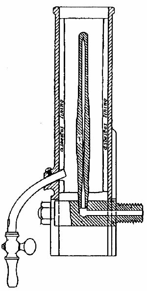 Fig. 13.
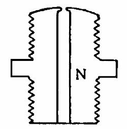 Fig. 14.
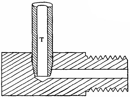 Fig. 15.
The asbestos lining, shown in fig. 13, may be of various thicknesses, according to the size of the chimney and the tube; the reason for this will be apparent to many; but being a most important factor in the heating of the tube, and consequently the working of the engine, it will be advisable to deal with this point more fully.
Due mainly to the peculiar behaviour of iron tubes under heat and internal pressure, it is always advisable to look to them first of all when the engine shows signs of missing fire; and to always examine the bore of a fresh one, and ascertain that it is perfectly clear before putting it in. The adjustment of the ignition tube, although one of the most important and necessary to be made on the whole engine, is in itself a perfectly simple matter. It must be understood that the ignition tube cannot, with the ordinary means at our disposal, be kept at too high a temperature; but it must not be assumed that either the size of the flame, or the time the flame has been alight, is conclusive evidence that the tube is, or ought to be, sufficiently hot to fire the charge successfully. It is an uncommon[Pg 37] thing to hear a man exclaim—after it has been pointed out that his tube is practically cold—"Why, it's been alight for hours!"
If such is the case with you, reader, you may very rightly assume that the burner is not properly adjusted, and so does not give the right kind of flame.
In order to get the hottest possible flame, the quantity of gas and air must be mixed in the right proportions. A common fault is that there is too much gas allowed to flow through the nipple, compared with the amount of air being drawn in at the air aperture, fig. 13. The result is, we get a flame of great length, but one which is not at all suited to our requirements; and instead of giving up its heat to the tube and the asbestos lining of the chimney, a large amount of gas we are presumably burning in the chimney is not being burnt there at all, for, on applying a light just above the chimney top, a quantity of this gas we are wasting will be seen to burn with a flickering blue flame.
To put matters right, it is necessary to do one of two things—either cut down the supply of gas or increase the air-supply. Providing the air aperture is normal, i.e., the same size as it was originally, it is better to adjust the gas, which may be done by tapping up the nipple N, as indicated in the enlarged sketch, fig. 14, until just the right amount of gas can flow.
As a rule, if there is too much air, the flame will burn with a loud roaring noise, and is liable to fire back. The nipple should then be opened out with[Pg 38] a small reamer—the tang of a small file, ground to a long taper point, makes an admirable tool for this purpose. Whether the burner is of the ordinary bunsen type, or the ring or stove type, the above remarks apply, as in every case the flow of gas is governed by the size of the orifice through which it flows.
There is no need to use anything beyond a touch of oil when putting in a new tube, in order to make a perfectly tight joint; white or red lead are quite unnecessary, and are liable to make it a troublesome matter to remove the tube on future occasions. Neither should undue force be applied when putting in new tubes; it is liable to wear the thread in the firing block, which results in a partial stoppage of the ignition hole, as indicated in fig. 15. This is especially the case if we happen to get hold of a tube with its screwed part slightly smaller than usual.
The asbestos with which the chimney is lined should be about 1⁄8 in. thick, and, when renewing, the same thickness should be used as originally. A thicker board will reduce the annular space round the tube, and will have a choking effect on the flame—much the same as referred to above, when there is too much gas and not enough air. A simple method of lining the chimney is to cut a block of wood to the inside dimensions of the chimney, less 1⁄4 in. in width and thickness, then soften the asbestos cardboard by immersing in water, and bend it round the wood, cutting off to the required size, i.e., till the two edges form a neat butt joint. It can be allowed[Pg 39] to remain on the mould until dry—when it will retain its shape—or can be put into the chimney straight away, if it is wanted for use immediately. In the latter case, however, it will be some fifteen minutes or so before the tube will attain its working temperature. Asbestos linings gradually become worn and ragged, and small flakes are apt to detach themselves and fall down into the burner, which, of course, prevents the flame playing as it should around the tube. In such cases it is not always necessary to fit a new lining; if the chimney is removed, the loose flakes shaken out and the asbestos well damped and patted down with a wooden or steel foot-rule or other suitably shaped tool, it will be fit for another long spell of work.
The nickel or hecknum tubes are treated in the same manner as the iron, but, as we mentioned before, are more durable, but require more heating to get them up to a workable temperature. Their greater first cost is compensated to some extent by makers in some cases guaranteeing them for six months.
Of the porcelain ignition devices, we will deal with the double-ended tube first, it being the more commonly used of the two in this country. This form of tube is usually about 3 in. long, 1⁄2 in. diameter, and open at both ends. It may be mounted in a metal casting, in form not unlike the small gas stoves for heating soldering irons. It is heated the greater part of its length by a couple of rows of gas jets, and is frequently surrounded by[Pg 40] an asbestos lining. The whole arrangement is in reality a tiny furnace. When in position for working, one end of the tube is open to the ignition passage leading and communicating with the combustion chamber, while the other end is sealed, through butting up against a metal cap or plate. An asbestos washer is interposed between the tube at each end and the metal it bears against, thus making a more or less flexible joint. A thumb screw is arranged at the outside end of the tube, by means of which pressure can be applied to clamp it up between the washers to the desired extent. Some care has to be exercised in adjusting this form of tube for running. When heated to the working temperature it, of course, expands, so that, if tightened up too much when cold, it is under a fairly high compression; and when the engine is started, and the explosion takes place, it not infrequently bursts, if there is not sufficient "give" in the washers to allow for the expansion. On the other hand, if not clamped up sufficiently tight to start with, when the explosion occurs, the washer at one or each end is blown out. This adjustment has to be made to a nicety, and, although a somewhat difficult matter, success may be attained after one or two trials. It is advisable, after a new tube has been put in, to start up the engine gently, i.e., with less than the normal supply of gas, and increase to the full amount gradually whilst running. This may be done by simply opening the gas-cock on engine partially in the first place.
The single-ended porcelain tube is not so well known here as on the continent; why, we cannot say; certainly it is preferable in every way. We give a few illustrations, showing the method of using this tube.
Figs. 16 and 17 show the general arrangement of tube and chimney and the manner in which they are fixed to the cylinder. The device consists primarily of three parts—the body or chimney B, the cover C, and the tube itself T. The body is a light iron casting, carried by a couple of studs SS, which are either screwed into the firing block F, or direct into the metal of the cylinder casting if no firing-block is used; the latter may very well be dispensed with in the smaller-sized engines.
The tube is made of thin porcelain, slightly bell-mouthed at its open end, and is mounted in a thick metal washer W, as shown in fig. 18 in section, the joint being made with a little asbestos paper, moistened.
The block F and the face of the body B (fig. 16) are recessed to take the washer W easily, but the depth of both recesses taken together must be about 1⁄16 in. less than the thickness of the washer W; thus, when the tube is placed in position between the body B and the block F, and the former screwed up by means of the two nuts, as shown in the figure 16, the effect is to clamp the washer which carries the tube, but not the porcelain tube itself.
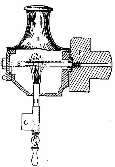 Fig. 16.
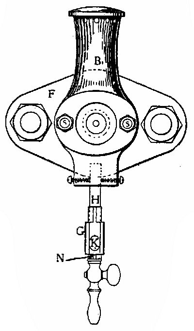 Fig. 17.
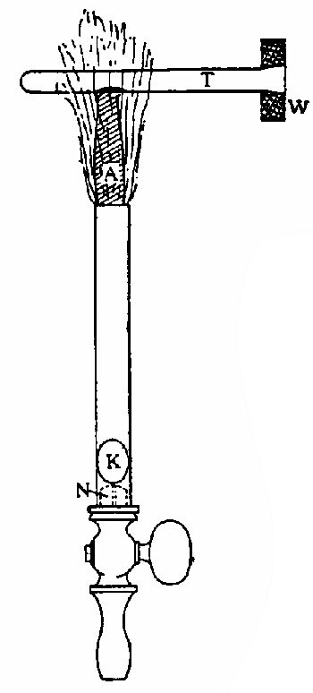 Fig. 18.
The latter is left perfectly free to expand; and yet, owing to its particular shape, the pressure in the cylinder during the compression and explosion stroke only tends to make the joint between the tube and washer more secure. The action of this ignition device depends upon the tube heater H, which is merely a small bunsen burner, the flame of which impinges on the tube at one particular spot, raising it to a very high temperature—almost white heat. Most of my readers will know the formation of the bunsen flame. It in composed of two distinct zones. The inner one, marked A in fig. 18, is a perfectly cold part of the flame, and appears to be a pale-blue coloured cone.
It is the outer zone which is the hot portion of the flame, hence this part only must be allowed to play on the tube. The tip of the blue cone A must be kept about 1⁄4 in. below the tube, in order to ensure the hottest part of the flame impinging precisely where the heat is required.
The total length of the whole flame is, to a certain extent, immaterial; but, generally speaking, it should be adjusted so that the length of the inner cone A is about 1 in. or 1-1⁄4 in. The same methods which we described in the early part of this chapter can be employed in the adjustment of this burner, but some care should be exercised to get the correct flame length.
The result of allowing the cold part of the flame to impinge on the tube is observable in fig. 18. The black spot indicated on the drawing actually appears as a black or sooty spot when looking at the tube under these conditions; but in reality no discoloration whatever takes place, the spot [Pg 44]disappearing immediately the cone A is made shorter, or the burner H lowered in the chimney B, so that the tip of A is just below, and does not touch the tube at all.
The adjustment of the length of cone A may be accomplished in two ways—(1) by keeping the supply of gas constant, and varying the amount of air admitted at aperture K, fig. 18; (2) by keeping the supply of air constant, and varying the amount of gas admitted through nipple N. The first method is to be preferred when it is necessary to make any slight adjustment due to the variation of gas pressure during the day, and may be accomplished by fitting a small sliding shield G, as shown in the figs. 16 and 17, and moving it round so that it covers, more or less, the aperture K. Thus the length of cone A may be adjusted to a nicety in a very few seconds. This shield keeps all draughts and puffs of wind from the fly-wheel away from the aperture, and helps the flame to burn very steadily. In the first place, of course, the flame will be regulated by opening out or tapping up the nipple N (an enlarged sketch of which is given in fig. 14), so that cone A is just about 1-1⁄4 in. long when air aperture is full open; but once this is done, any future adjustment can be made by throttling the air-supply, or raising or lowering the burner bodily, the set screw keeping it in any desired position (see fig. 17).
From the foregoing remarks it will be seen that the most noteworthy features of this form of ignition[Pg 45] are the ease and certainty with which the tube can be fixed in a few moments; that when the two nuts on the studs SS have been tightened up there is no likelihood of the joints being "blown," for, as we said before, only the metal washer is clamped up, the porcelain tube itself being as free to expand as it was before. It is also at once obvious when any adjustment of the flame is necessary; there need be no uncertainty as to whether the tube is hot enough or not.
The third form of ignition we have to deal with is the electric.
There are a great number of different types made and used, but for gas-engine use perhaps that known as the magneto ignition is the most satisfactory. With this form, neither accumulators, dry batteries, or spark coils are required, and consequently a greater simplicity is arrived at than would otherwise be the case.
In fig. 19 we show diagrammatically the ordinary form of magneto machine. Virtually it is a small dynamo which is fixed to the side of cylinder casting, and is operated in the manner shortly to be described. As we do not propose to enter into more than a brief explanation of why and how this apparatus generates current to produce the required spark, perhaps a simple analogy will make matters most intelligible to any reader not well acquainted with electrical phenomena. We know that when a current of electricity is flowing in a wire, and the wire be[Pg 47] suddenly broken, a spark will occur at the point of breakage. This fact may be observed in an ordinary electric bell when ringing; at the tip of the contact breaker a number of tiny sparks may be seen to occur, due to the rapid make and break of the current flowing in the circuit. Precisely the same action takes place in our magneto-igniter, but, instead of a multitude of tiny sparks, we produce one at a time, at definite intervals, viz., at the commencement of each explosion stroke.
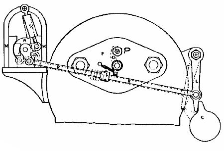 Fig. 19.
In the later form of magneto machines there is a soft iron sleeve between the magnet poles and the armature. The former is connected to a system of levers by which a reciprocating motion is imparted to it by means of a suitably arranged cam on the side shaft. It has been found that better results are obtained by causing the magnetic field to move[Pg 48] relative to the armature winding than to move the latter through a stationary field. Reference to the diagrams, figs. 20 and 21, will make this clear.
In fig. 19 the cam C is shown just on the point of allowing the lever L to fly back into its normal position, due to the action of the springs comprising a dashpot S. As the cam rotates, it pushes the lever L to the left, the sleeve (or virtually the armature A) is also rotated through a portion of a revolution comparatively slowly; but as soon as L is released, the sleeve (or armature) flies back again almost instantaneously and for the moment is generating a current in the same manner as would any ordinary continuous current dynamo.
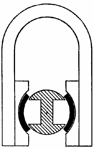 Fig. 20.
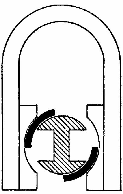 Fig. 21.
At the instant the maximum current is being generated, the circuit is broken by means of the contact breaker D, fig. 19, which we show in detail in fig. 22. The latter is mounted on the end of the combustion chamber, and consists of two parts, D and P.
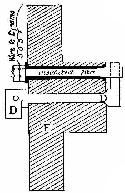 Fig. 22.
D is an easy fit in the hole bored to receive it, and has a mushroom valve head and seating, as shown, so that it moves readily when struck by the projection E on the rod R (fig. 19); but yet, acting in the manner of a non-return valve, it allows no gas to[Pg 50] escape when the explosion takes place in the cylinder. D is therefore in direct metallic communication with the engine frame and earth.
P is a fixed metal pin, carefully insulated from all contact with the engine frame and earth. To this pin one end of the armature winding is connected, whilst the other end is connected to the engine frame.
Thus a closed circuit is formed, and when the current is generated it flows from one terminal of magneto through wire to pin P, on to D, through D to earth (i.e., engine frame), and so back to other terminal on magneto.
And as the circuit is broken between D and P, we obtain a spark, as previously explained, which may be timed to take place by adjusting the position of cam C on side shaft relatively to the position of piston.
It may be said that the position of the magneto-igniter is immaterial; it will be fixed in different positions on different types of engines, and so long as the operating mechanism is simple and effective, i.e., as direct as is practicable, it works well, and requires little attention. The timing of the spark will be dealt with in the chapter on Cams and Valve Settings.
The devices for governing the speed of the engine may be divided, broadly speaking, into two classes—the inertia or hit and miss governor, and the centrifugal. Of the latter type we will give an instance first. In figs. 23 and 24 the governor gear is shown diagrammatically, consisting of a couple of weights WW suspended from a vertical spindle. These fly apart when caused to revolve by the bevel wheel gearing BB, and raise the sleeve S to a greater or lesser extent. A recess in the latter engages a lever arm L, through which the vertical movement of the sleeve S is converted into a horizontal movement of the sleeve T. The latter is carried by the valve lever P, and is virtually a roller which engages with one or other of the steps of the cam C, according to the speed of the engine. The object of this arrangement is to keep the ratio of air to gas uniform throughout all variations of load. The gas and air valve are shown as both being operated by the same lever P, the accurate timing of the latter being obtained by means of set screws.
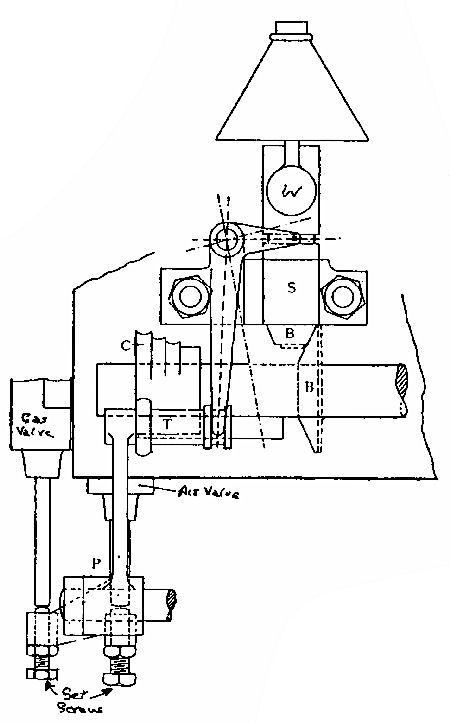 Fig. 23.
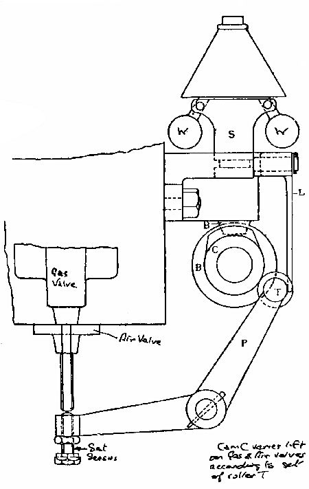 Fig. 24.
Messrs Dougill & Co.'s engines are fitted with a step down cam and governor such as this. The centrifugal governor is often arranged so that instead of the charge being merely reduced in volume, the whole charge is cut out, and no explosion whatever takes place. (In this respect the same results are obtained as when a hit and miss governor is used, and the latter form therefore is to be preferred, especially on small engines, where the difference between the indicated power and the brake power is always, even under the best conditions, fairly great.)
In this case the governor lever only operates the gas valve; the air valve being opened on every charging or suction stroke, whether gas is admitted or not.
Another application of the centrifugal governor is to suspend a distance piece on the end of the governor lever, so that at normal speed this distance piece is interposed between the gas valve spindle and the lever operating it. In that case the gas valve will be opened. But if the speed is above the normal, the distance piece will be raised clear of the valve spindle, and the opening mechanism (driven by a cam on the side shaft) will simply move forward and recede again without ever touching the gas valve.
There are any number of movements which have been, and there are many more which could be, devised to give the same result; and it depends principally upon the form of engine in question which device we adopt.
The simplest and most direct action is, however,[Pg 55] always the best; complicated mechanism is to be deprecated, especially on small engines. For this reason is the inertia governor more generally fitted to such engines.
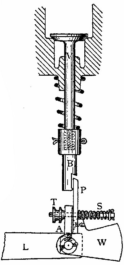 Fig. 25.
A simple form of this governor is shown in fig. 25. The gas valve V is shown on its seating. It is screwed into a pecker block B, and pinned as shown. The latter should be of cast steel, tempered to a straw colour; or if mild steel or iron is used, it must be well case-hardened, in order to resist wear. The pecker P (also tempered hard) is mounted on the cast-iron weight W, which in turn is pivoted on the valve lever L. It will be seen that the weight W (which is only held in the position shown by the spring S) will tend to lag behind when a sudden upward motion is imparted to the lever L.[Pg 56] Thus it depends upon the degree of suddenness with which L moves whether the pecker P remains in the same relative position to the lever as the latter travels upwards and engages with the pecker block B, or whether it misses it and simply slides over the face of the block. The adjustment of the spring S is effected by screwing up or slacking out the milled nuts T; and on the degree to which this spring is compressed depends the sensitiveness of the governor, and consequently the speed of the engine. To obtain accurate and steady governing with this type of mechanism it is essential that the weight be perfectly free on its spindle, and that nothing but the spring S holds, or tends to hold, it in the position shown. On this account it is advisable to provide a "lip" on the pecker block, as shown, to keep the area of contact as small as possible. This effectually prevents any sticking, should a superfluity of oil happen to get on either block or pecker. For similar reasons there should be some clearance between A and the pecker, i.e., the latter should only bear at one point and not bed flat against A.
Another form of inertia governor is shown in fig. 26 of the hit and miss type, which is employed by Messrs Capel & Co. on many of their engines.
It consists of three main parts—the brass arm L carried on a stud D, on which it is free to move; the weight W, which carries the pecker P pivoted at the upper end of L; and the pecker block B, which engages the pecker when the engine requires a charge of gas.
The governing action is dependent upon the shape of the operating cam from X to Y. (In the case already dealt with, the lever L serves to operate both air and gas valves, and so one cam only is necessary; but in this instance the gas valve is operated by a separate cam, and a greater nicety of adjustment is obtainable.)
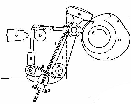 Fig. 26.
If the speed of the engine is sufficiently high, the arm L is thrust forward at such a rate that the weight W tends to lag behind, with the result that P is raised above the notch in B, as shown by the dotted lines in drawing. On the other hand, when the speed is too low, the arm L will not be thrust forward with so great a degree of suddenness, the[Pg 58] weight W will have time to move with L, and the relative position of W and P to L will remain the same. Hence, in the first case, when a further forward movement is given to L by the cam, the pecker P is clear of B, and omits to open the gas valve V; in the second case, P engages with B, and the gas valve is held open during the time the portion of cam Y to Z is passing over the roller R on arm L.
The great drawback to some forms of governors is not that they fail to govern well when new, but that no provision is made to ensure them working steadily when a bit worn. The shape of the cam has everything to do with the regular working of this form of governor.
Supposing our cam was of the shape shown in fig. 27, i.e., the governing and opening portion all in one curve, it would cause the pecker to move both forward and in an upward direction at the same time, so that at the moment of engaging B, P might still be moving in an upward direction, which would cause uncertainty of action, especially if the tips of the engaging members were at all blunt through wear; and, in all probability, P would fly off B after partially opening the gas valve.
This behaviour is very undesirable, as the small quantity of gas so admitted to the cylinder is quite useless, and a sheer waste is incurred. With the governing arrangement shown in fig. 26, this trouble does not exist. The cam is so designed that the first rise from X to A determines whether or not the valve is to be opened; the curve from A to Y is[Pg 59] struck from the centre of the side shaft; thus, during that portion of the revolution the arm L is stationary, and the pecker at the same instant takes up a definite position either in the notch in B or on top of it, and is ready to open the valve if the speed of the engine is such as to require an explosion, or simply to slide over the top of B, allowing the valve to remain closed. It is most interesting to observe the action of this governor; when an engine fitted with one is running very slowly, the three distinct movements of the pecker P may be clearly discerned as the respective portions of the cam pass over the small roller R.
 Fig. 27.
With the gas, as with any other kind of engine, the valve settings are of primary importance. On very small engines it is often the case that only the exhaust valve is operated mechanically.
Again, there are several well-known makes which operate the gas and exhaust mechanically while the air valve is opened by suction alone. Though opinions differ as to which is the best course to take, there can be little doubt that, with all three valves mechanically operated, a greater nicety of adjustment is obtainable than would be otherwise possible. And provided the working parts are neatly made and finished, they will take but little power to drive them; and such loss would be compensated by the additional power and efficiency obtained from the engine, due to satisfactory and correct adjustment.
In fig. 28 we give a diagram showing the exact positions of the crank when the gas, air, and exhaust valves open and close respectively, under normal conditions of working. The solid circle represents[Pg 61] the first revolution of the crank shaft, starting from the commencement of the suction stroke, and the dotted circle the second revolution, during which the explosion and exhaust strokes take place; the dotted horizontal line shows the position of crank at the back and front dead centres.
As a clear conception of why certain things happen under certain conditions is most desirable, we will first describe the operation of marking off the cams which operate the respective valve levers, and then discuss the effect of various "settings" of the valves on the running of the engine.
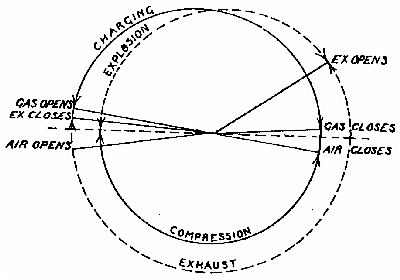 Fig. 28.
Assuming that we are still dealing with the Otto cycle engine, the cam or side shaft will revolve at precisely half the speed of the crank shaft. This 2 to 1 motion is obtained by means of toothed[Pg 62] wheels, or a screw gear. In the former case, where plain or bevel cog-wheels are employed, the one fixed on the crank shaft must be exactly half the diameter of the one on the side shaft, i.e., it must have one half the number of teeth. On the other hand, if a screw gear is used, the relative diameters of the two wheels may vary, but the pitch of the teeth on the one must be twice that of the other. These wheels sometimes have the teeth or thread formed in the casting, and sometimes they are cut after a plain casting has been made. The latter kind are, needless to say, better than the former, which often require filing up in order to make every tooth alike, and ensure sweet running.
We know already in what positions our crank has to be at the opening and closing of the three valves, and with the aid of the diagram, fig. 28, we can determine the size of the cams. In fig. 29, S is the side shaft to which the cams have to be keyed, R the roller on valve lever, the latter being represented by the centre lines LL, as all we require to find is the motion this lever will transmit to the valve, the spindle of which is shown at V.
Fig. 30 shows diagrammatically the position of crank at the opening and closing of the air valve. From this we see that the angle through which the crank travels during the time the air valve is open is equal to the obtuse angle ABC. Now, as the side shaft S revolves at half the speed of crank, it is obvious that the former will travel through only half that angle in the same space of time, i.e.,[Pg 63] through an angle equal to ABD. We can now transfer this angle on to S, fig. 29, and draw two lines SE, SF, cutting a circle GHJ, representing the back of the cam, which latter passes in front of the roller R without causing any movement of the lever L.
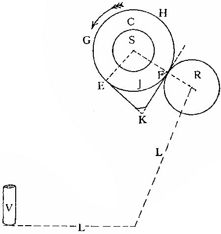 Fig. 29.
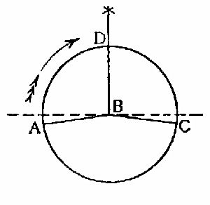 Fig. 30.
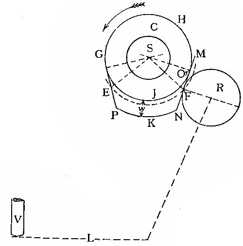 Fig. 31.
It will be seen that by drawing a line forming a tangent to the circle GHJ at F and another at E, and producing these, they will meet at point K. Consequently, as the side shaft rotates in the direction indicated, the lever L will begin to open the valve V when the cam is in the position shown in fig. 29, reach a maximum opening at K, and finally close when the cam has moved so that point E is now where F was. With a cam of this shape, however, a considerable portion of the stroke would have passed before the valve was raised any appreciable[Pg 65] distance off its seat; it would only be fully open for an instant, viz., when K was passing over R, and would begin to close again directly.
Moreover, if the engine were running at even a slow speed, the motion imparted to lever L would be indefinite; and this, especially if the governor is fitted to the air valve lever, as in fig. 25, is very undesirable. Therefore, to obtain a definite opening we must set out the cam, as shown in fig. 31. In this diagram the roller is shown standing clear of the back of cam by about 1⁄16 in. A line MN is then drawn, forming a tangent to both roller R and circle GHJ at points F and O respectively. This gives us the opening portion of cam. Then from the centre S with radius SF describe the arc FE (shown dotted in fig. 31), and set off the angle required (ABD, fig. 30), as previously explained. Through point E draw a line forming a tangent to circle GHJ, and produce it towards P. This line gives us the closing portion of cam. The distance W is of course variable, according to the amount of lift we give the valve. By comparing these two diagrams it will be seen that in both cases the valve will be opened the same length of time, but in first case the motion will be indefinite and uncertain. In practice the corners are rounded off somewhat, in order to obtain a steady motion; and when the air cam is also the governing cam, it is advisable to round off the opening face, as indicated in fig. 32. Upon the shape of this face both the sensitiveness and the life of the governor gear depends. If it[Pg 66] is nicely rounded off, giving a gradual rise, very little tension (or compression, as the case may be) of the controlling spring will be necessary to give the required speed to engine; whereas, if the rise is sudden, the spring will have to be screwed up tighter, and, if uneven and lumpy (i.e., not a fair curve), the result will, of course, be erratic governing.
 Fig. 32.
A certain amount of clearance should always be provided between the roller and the back of cam[Pg 67] (compare figs. 29 and 31), that is, the roller should not bear against the cam, except during that portion of the stroke in which it is actually operating the valve, viz., from F to E (fig. 31). A small stop interposed between the lever and some convenient part of the engine, such as the side-shaft bracket bearing, answers this purpose.
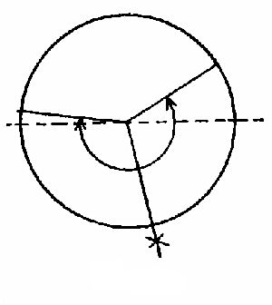 Fig. 33.
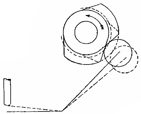 Fig. 34.
The size and shape of the exhaust cam is found in the same manner as above described; the angle through which it operates is greater than that of the air cam, and is shown in fig. 33. A fair margin should be allowed for filing or machining these castings up; the shape and sizes arrived at by the above described method being finished measurements.[Pg 68] Fig. 34 gives the outline of an exhaust cam worked out from the setting diagram, fig. 33.
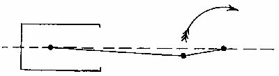 Fig. 35.
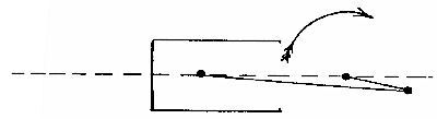 Fig. 37.
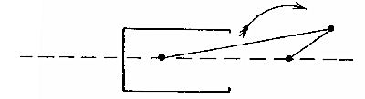 Fig. 41.
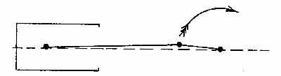 Fig. 42.
We may now consider the relative positions these two cams will occupy when keyed up on the side shaft. Assuming that we have both cams finished to the proper shape and size, and the keyway cut in the side shaft, we can commence to mark off the position of keyway in the air cam. With the crank in the position shown in fig. 35, the air cam is[Pg 69] slipped on to the side shaft and brought to the position shown in fig. 32. The keyway being already cut in the side shaft, the position for that in the cam may be scribed off, as shown by dotted lines (fig. 32), the cam removed, and the keyway cut. It is as well, however, to check this mark by turning the crank round to position shown in fig. 37, i.e., the closing of air valve. The side shaft will also turn through exactly half this angle, so that when the cam is again slipped on the latter, the scriber marks and keyway in shaft should be exactly in line, as they were in fig. 32, and the fall of the cam—the closing portion—should just be touching roller R, but not sufficient to keep the valve open (see fig. 38). The slightest movement of the crank from this point in a forward direction should result in a little play[Pg 70] being felt in the lever L, assuming that the cam is also moved just enough to keep the scriber marks in line with the existing keyway.
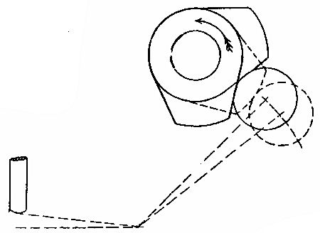 Fig. 36.
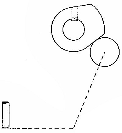 Fig. 38.
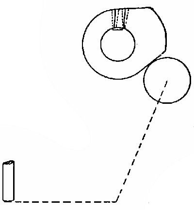 Fig. 39.
By these operations it will be at once evident whether the cam is too large or too small. Supposing it is too small, we will obtain two sets of marks indicating the position of keyway, as shown in fig. 39, and it is obvious that we must give the lever less play by screwing up the set screws shown in fig. 11. The effect of this is to cause the valve to open earlier and close later than it would if the play were greater; as it would were the operating portion of cam larger. A minimum amount of play must always be allowed, however. When two sets of marks are obtained, the mean must be taken and the keyway cut as shown by the thick lines in fig.[Pg 71] 39. The exhaust cam in larger engines is usually made with a swelling on the opening portion, as shown in fig. 40, so that the valve is very slightly opened some time before the crank has reached the position shown in fig. 41. Fig. 42 shows position of crank at the close of exhaust valve, and the two last-mentioned diagrams correspond with the two positions in which the exhaust cam is shown in fig. 34. The small lump on the back of exhaust cam, fig. 40, is only required on engines above 3 B.H.P. to relieve the compression on the compression stroke when starting up. By moving the roller R on valve lever longitudinally, so that it engages both parts of cam as they pass in front of it, the exhaust valve is held open during a small portion of the compression stroke, usually closing when the crank has reached the bottom centre.
Referring again to fig. 26, this gas or governor cam may be set out, and the keyway marked on the same principle as already described for the air and exhaust valves. An end view of the three cams keyed up on the side shaft is given in fig. 40A. In small engines it is convenient to have the air and exhaust cams made in one casting, when one key only will be required. On some engines, instead of employing a movable roller or valve lever, the exhaust cam is fitted on side shaft with a "feather"—i.e., a headless key—and the cam being capable of longitudinal movement, such movement being controlled by a small lever or handle, called the half-compression lever.
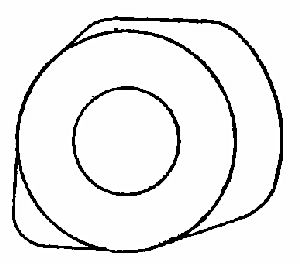 Fig. 40
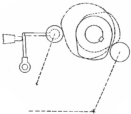 Fig. 40a
Having once thoroughly grasped the important part the cams play in the working of the engine, it will be an easy matter to adjust the valve settings, and to keep them adjusted correctly. The effect of a wrong setting will then be strikingly apparent. On small engines a separate cam to operate the gas valve is not a necessity; and the practice of fitting[Pg 73] the gas valve spindle (or the pecker, the effect would be the same) with a device for increasing or diminishing its length, is also unnecessary and unsound.
The wear on a well-designed gas valve operating mechanism is practically nil; and even if there was wear, the effect would be to cause the valve to open a trifle later and close sooner than it would otherwise, i.e., it would remain open a shorter time during each charging stroke. This in turn (other conditions remaining the same) would give us a weaker mixture; and although too weak a mixture is preferable to a too rich one, we should have to adopt some means of increasing the richness of the mixture; otherwise the maximum power of the engine would soon be seen to diminish.
To get the mixture normal again we must either enlarge the gas inlet or cut down the air-supply somewhat, and so keep the proportions the same. That is to say, the quality of the mixture is dependent upon the relative dimension of the gas and air inlets. We know by actual trial that if at the completion of the charging stroke the pressure in the cylinder is approximately that of the atmosphere, better results are obtained than when the pressure is considerably below that of the atmosphere. Thus, the larger we make the inlet ports (but still retaining correct relative dimensions) the more readily will the mixture be drawn into the cylinder as the piston moves forward, tending to create a vacuum. Of the two courses open to us to retain a good mixture it is preferable to open out the gas-supply, for by cutting[Pg 74] down the air-supply, and sucking the gas in, due to the partial vacuum being formed, we should be keeping the proportions correct at the expense of reducing the total volume of the explosive mixture (more strictly speaking, the density of the charge) admitted to the cylinder.
Under normal conditions it is not necessary to create a high vacuum to suck the gas into the cylinder, but it is as well to understand what results we would tend to produce, did we work on these lines. Of course, with small high-speed engines fitted with suction air valve, the vacuum is higher than it would be in slow-speed engines with mechanically operated valves. If we take an extreme case as an example, where, to get any gas to speak of into the cylinder the air-supply would have to be cut down or throttled to an abnormal extent, we will realise at once that such a small quantity of both air and gas would have been drawn in, and consequently the mixture would be so rarefied that on the compression stroke the pressure would possibly be extremely low and totally inadequate to produce efficient working. Moreover, working at such a high vacuum as this would not only prevent us obtaining a normal explosion in the cylinder, but would upset the working of the exhaust valve. The latter being held down on its seat during the suction stroke by means of a spiral spring would be lifted off its seat by suction (the partial vacuum in the cylinder), and any burnt gases which happened to be hanging about in the exhaust port or pipe would be drawn into the[Pg 75] cylinder again, and tend to damp the ensuing explosion. Too early closing of the exhaust should be avoided almost as rigorously as too late. The latter will affect the working in a similar way to the exhaust being lifted on the charging stroke by suction; on the other hand, if it closes too soon, the entire volume of burnt gases will not have been swept out of the cylinder, and the effect will again be to damp the following explosion.
The gas valve opens just after the crank is above the back centre and closes just before the front centre is reached, that is, opening a little after the air valve and closing a shade before it, thus every particle of gas is used in the cylinder, due to a draught of air being drawn in after the gas valve has been closed.
The settings of the valve being of primary importance, no matter what size engine we are dealing with, and being also the most confusing matter for anyone unacquainted with gas engines to grasp, it will not be out of place to suggest a simple method of checking these settings.
Let us begin by pulling the fly-wheel round backwards until we feel the piston is on the compression stroke, then from this point—the crank being about 45° above the front centre—pull the wheel round until the crank is in the position for the exhaust opening (see fig. 28). In this position there should be but the slightest play in the exhaust lever, showing that the valve is just on point of opening; and by keeping one's hand on the lever whilst the fly-wheel[Pg 76] is pulled round very slowly (it is a good plan to get some one else to do the pulling round), it is possible to ascertain the precise point at which the valve opens. Next pull round till the crank is in the position for the air valve opening, and observe that it is set correctly. Then go on to a trifle above the back centre, where the exhaust valve should close, and so on till the opening and closing of each valve has been checked. It will be noticed that the air, and sometimes the gas, valve opens before the exhaust closes. This overlap is necessary; and it will be found that the smaller the engine and the higher the speed the greater this overlap will be to obtain good results, although a good deal of individual judgment must be used in settling the exact amount of overlap, as the requisite amount may, to get the best results, vary in different engines of precisely the same dimensions and type.
When dealing with engines which have no separate gas valve—the gas being admitted with the air, which is sometimes the case with very small engines—the above notes referring to the gas setting independently, will, of course, not hold good.
It may be mentioned with regard to the lump on the opening side of the exhaust cam, that this if overdone is found to be detrimental on large engines, and even on small ones. If it is too large, it will cause both exhaust valve and seat to become burnt and pitted, due to the surface being exposed to the exceedingly high temperature of the expanding gases. If it is too large, it is equivalent to opening the exhaust valve too early, and the effect is the same, viz., a waste of power and damage to the valve and its seat.
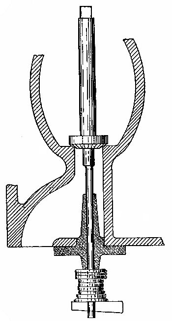 Fig. 43.
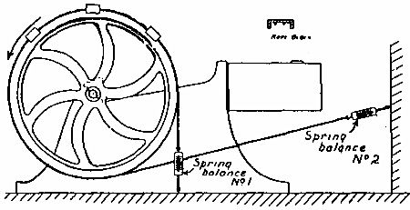 Fig. 44.—Brake Testing.
The method of grinding in the valves to their seats with emery powder and oil is so well known that no further description is needed here. We give, however, in fig. 43 a sketch showing a very expeditious way of dealing with very badly worn or burnt seats. The sketch explains itself. Such a tool is readily made; even the cutter could be turned and filed up to shape and then hardened at home. By lightly tapping in the taper cotter pin little by little, sufficient pressure is put on the cutter to make it an easy matter to completely re-face an old seat or form a new one. A T-wrench or "tommy" can be used to work the cutter spindle. The lower part of the latter must be the same diameter as the existing valve spindle; the bush acts as a guide; and as the bevel of the cutter[Pg 79] should be the same as that of the valve, a very little grinding in with emery powder is required to finish the job off.
In fig. 44 we give a diagram showing the method of testing for Brake H.P. of engine, as it is frequently interesting to make such a simple test after any alterations or adjustments have been made.
Two spring balances and a rope or cord (according to the size of the engine), fitted with a few wood blocks as shown in section, fig. 44, to keep the rope on the rim of fly-wheel, is all that is required for this test. The following formula may be used for arriving at the B.H.P.:—
B.H.P. = (S1 − S2) 3·14 × D x R / 33000
S1 = Reading in lbs. of spring balance No. 1.
S2 = Reading in lbs. of spring balance No. 2.
D = Diameter of fly-wheel and diameter of brake rope in feet.
R = Revolutions of fly-wheel per minute.
As 3·14 × D / 33000 will always remain the same for any given engine and gear, we may call that expression C; then the B.H.P. may be written—
B.H.P. = (S1 − S2) C R.
The small oil engine is practically the same as the gas engine, with the addition of a vaporiser for converting the oil into gas, or vapour, to be exploded in the cylinder; consequently the one may be converted into the other in many cases without much trouble. The difficulty of producing an efficient oil engine lies principally in devising a satisfactory and reliable vapouriser—one which will work equally well under all loads. The heat supplied to the chamber must be sufficient to vaporise the oil, but not great enough to decompose it. There are various methods of vaporising the oil, and many types of vaporisers are employed to attain the same end. There are some in which a charge of oil is drawn by suction into a hot chamber in which it is converted into vapour and at the same time mixed with a small quantity of hot air; this rich mixture is then passed into the combustion chamber of the engine, in the same manner as coal-gas would be, where it is further diluted with more[Pg 81] air drawn in through the air valve. Other arrangements cause a jet of oil to be injected into a chamber containing hot air, in the form of spray, which immediately converts the oil into vapour, and is then passed into the cylinder, compressed, and fired. Then, again, we can pump oil through a spraying nipple into the vapouriser (which is kept at a suitable temperature) whilst the cylinder is being filled with air on the suction stroke. On the following compression stroke the air is driven into the vapouriser, which communicates with the cylinder through a narrow neck, and mixes intimately with the oil vapour. Gradually, as the pressure rises, due to compression, the charge becomes more and more explosive, until at the completion of this stroke it has attained the proper proportions of air and oil vapour, and is fired by the temperature of the vapouriser and that caused by a high compression; that is, the charge is fired automatically; and once the engine is running, no heating lamp is required to keep the vapouriser at the correct temperature. It is necessary, however, to raise it to the workable temperature at starting. This is known as the Hornsby-Akroyd method.
Capel's arrangement is also simple and efficient, and has the additional advantage of being capable of being fitted to their existing gas engines, the conversion being made in a very short time. This vapouriser consists primarily of a tubular casting A, on the outside of which are formed a series of vertical ribs, shown in plan, fig. 46, running[Pg 82] to within a short distance of the flange at one end, as shown in the section, fig. 45, thus providing an annular space C between the upper ends of the ribs and the flange. This casting is enclosed by an outer[Pg 83] casing B, which fits well over the inner tube. It has also a number of small holes drilled near the lower end communicating with the channels between the ribs. Thus it will be seen that when the gas valve is opened and suction takes place, air is drawn in through these holes, passes up into the annular space C below the top flange, from there travels to the opposite side of vapouriser, and mixes with the oil which is also being drawn in through a small nipper at N, fig. 45. Both then pass between a series of pegs, where they become thoroughly mixed, and finally pass on to the inlet valve V, fig. 47, and so into the cylinder, where the complete charge is mixed up and compressed and fired in the usual manner. Iron ignition tubes may be used, and one heating lamp serves a double purpose in keeping the tube and vapouriser hot at the same time. This lamp is fed by means of a pump actuated from the side shaft. The plunger of the pump is loaded with a spiral spring, which may be adjusted to give any desired pressure, and is kept constant and steady by means of an air vessel. This pump is shown in fig. 48. It is actuated by means of a rod and lever from the side shaft of engine. The plunger P works in a barrel B, which is carried by a small reservoir R, the latter being in communication with the main oil tank by means of the pipe H.
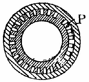 Fig. 46.
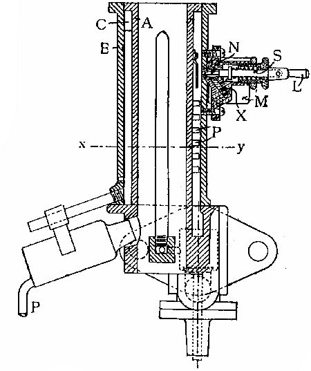 Fig. 45.
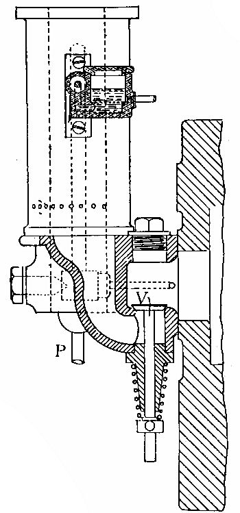 Fig. 47.
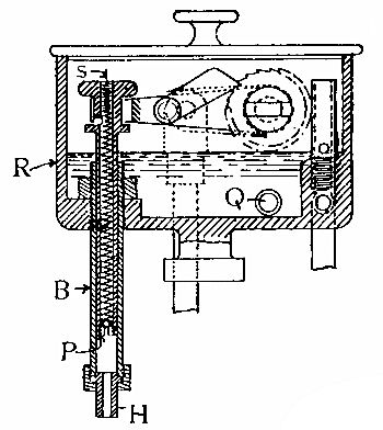 Fig. 48.
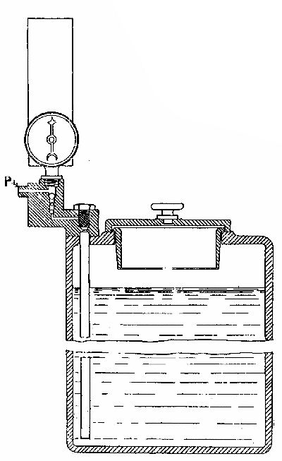 Fig. 49.
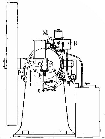 Fig. 50.
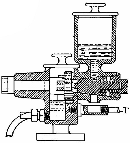 Fig. 51.
The plunger is loaded with a spiral spring, and has a ball valve, as shown. Intermediate between this small reservoir and the main oil tank is another set of valves, shown in fig. 49. It will be seen that the suction of the pump will draw the oil up, the small and lower ball valve, of course, allowing it to pass freely. On the down stroke the lower valve will be automatically closed, and the oil will be put under pressure, this being determined by the load on the plunger valve, which is adjustable by means of the screw S, fig. 48. When the required pressure in[Pg 87] the pipe P, figs. 45 and 49, has been attained, the plunger valve lifts on each stroke and the surplus oil flows through the plunger into the small reservoir R. The latter is at about the same level as another still smaller reservoir M (shown in figs. 47 and 50), a flow of oil being established between the two by means of a pipe Q (see figs. 48 and 50). In the reservoir R is fitted an overflow pipe, so that the oil cannot rise beyond a certain level; hence the head of oil in the smaller one M is always constant. On the suction stroke a partial vacuum is formed in the engine cylinder, consequently the pressure in the vapouriser drops somewhat below that of the atmosphere,[Pg 88] and this small difference in pressure is enough to cause the oil to rise in the small passage X, fig. 45, beyond its normal level, and overflow into the vapourising chamber, as previously described. The valve or nipper N is shown open in the diagram, fig. 45, and all that is required to stop the engine when running is to drop the small handle L, fig. 45, when the valve will close, due to the spring S. The air vessel shown in fig. 49 is in communication with the pipe leading to the blow lamp. A pressure gauge can also be fitted, although it is not in any way a necessity.
The ratchet wheel and pawl shown in fig. 48 are part of the lubricator. The wheel drives a brass or gun-metal plug, producing an intermittent rotary motion. The plug has a small hole in its periphery, which becomes filled with oil when it is at the upper part of its travel, and empties the oil out into a discharge pipe T, when it is inverted, and is then led away and applied to the piston at the required spot. Fig. 51 shows this arrangement in section.
End of the Project Gutenberg EBook of Gas and Oil Engines, Simply Explained, by
Walter C. Runciman

*** END OF THIS PROJECT GUTENBERG EBOOK GAS AND OIL ENGINES ***

***** This file should be named 27286-h.htm or 27286-h.zip *****
This and all associated files of various formats will be found in:
        https://www.gutenberg.org/2/7/2/8/27286/

Produced by Steven Gibbs, Greg Bergquist and the Online
Distributed Proofreading Team at https://www.pgdp.net


Updated editions will replace the previous one--the old editions
will be renamed.

Creating the works from public domain print editions means that no
one owns a United States copyright in these works, so the Foundation
(and you!) can copy and distribute it in the United States without
permission and without paying copyright royalties.  Special rules,
set forth in the General Terms of Use part of this license, apply to
copying and distributing Project Gutenberg-tm electronic works to
protect the PROJECT GUTENBERG-tm concept and trademark.  Project
Gutenberg is a registered trademark, and may not be used if you
charge for the eBooks, unless you receive specific permission.  If you
do not charge anything for copies of this eBook, complying with the
rules is very easy.  You may use this eBook for nearly any purpose
such as creation of derivative works, reports, performances and
research.  They may be modified and printed and given away--you may do
practically ANYTHING with public domain eBooks.  Redistribution is
subject to the trademark license, especially commercial
redistribution.


*** START: FULL LICENSE ***

THE FULL PROJECT GUTENBERG LICENSE
PLEASE READ THIS BEFORE YOU DISTRIBUTE OR USE THIS WORK

To protect the Project Gutenberg-tm mission of promoting the free
distribution of electronic works, by using or distributing this work
(or any other work associated in any way with the phrase "Project
Gutenberg"), you agree to comply with all the terms of the Full Project
Gutenberg-tm License (available with this file or online at
https://gutenberg.org/license).


Section 1.  General Terms of Use and Redistributing Project Gutenberg-tm
electronic works

1.A.  By reading or using any part of this Project Gutenberg-tm
electronic work, you indicate that you have read, understand, agree to
and accept all the terms of this license and intellectual property
(trademark/copyright) agreement.  If you do not agree to abide by all
the terms of this agreement, you must cease using and return or destroy
all copies of Project Gutenberg-tm electronic works in your possession.
If you paid a fee for obtaining a copy of or access to a Project
Gutenberg-tm electronic work and you do not agree to be bound by the
terms of this agreement, you may obtain a refund from the person or
entity to whom you paid the fee as set forth in paragraph 1.E.8.

1.B.  "Project Gutenberg" is a registered trademark.  It may only be
used on or associated in any way with an electronic work by people who
agree to be bound by the terms of this agreement.  There are a few
things that you can do with most Project Gutenberg-tm electronic works
even without complying with the full terms of this agreement.  See
paragraph 1.C below.  There are a lot of things you can do with Project
Gutenberg-tm electronic works if you follow the terms of this agreement
and help preserve free future access to Project Gutenberg-tm electronic
works.  See paragraph 1.E below.

1.C.  The Project Gutenberg Literary Archive Foundation ("the Foundation"
or PGLAF), owns a compilation copyright in the collection of Project
Gutenberg-tm electronic works.  Nearly all the individual works in the
collection are in the public domain in the United States.  If an
individual work is in the public domain in the United States and you are
located in the United States, we do not claim a right to prevent you from
copying, distributing, performing, displaying or creating derivative
works based on the work as long as all references to Project Gutenberg
are removed.  Of course, we hope that you will support the Project
Gutenberg-tm mission of promoting free access to electronic works by
freely sharing Project Gutenberg-tm works in compliance with the terms of
this agreement for keeping the Project Gutenberg-tm name associated with
the work.  You can easily comply with the terms of this agreement by
keeping this work in the same format with its attached full Project
Gutenberg-tm License when you share it without charge with others.

1.D.  The copyright laws of the place where you are located also govern
what you can do with this work.  Copyright laws in most countries are in
a constant state of change.  If you are outside the United States, check
the laws of your country in addition to the terms of this agreement
before downloading, copying, displaying, performing, distributing or
creating derivative works based on this work or any other Project
Gutenberg-tm work.  The Foundation makes no representations concerning
the copyright status of any work in any country outside the United
States.

1.E.  Unless you have removed all references to Project Gutenberg:

1.E.1.  The following sentence, with active links to, or other immediate
access to, the full Project Gutenberg-tm License must appear prominently
whenever any copy of a Project Gutenberg-tm work (any work on which the
phrase "Project Gutenberg" appears, or with which the phrase "Project
Gutenberg" is associated) is accessed, displayed, performed, viewed,
copied or distributed:

This eBook is for the use of anyone anywhere at no cost and with
almost no restrictions whatsoever.  You may copy it, give it away or
re-use it under the terms of the Project Gutenberg License included
with this eBook or online at www.gutenberg.org

1.E.2.  If an individual Project Gutenberg-tm electronic work is derived
from the public domain (does not contain a notice indicating that it is
posted with permission of the copyright holder), the work can be copied
and distributed to anyone in the United States without paying any fees
or charges.  If you are redistributing or providing access to a work
with the phrase "Project Gutenberg" associated with or appearing on the
work, you must comply either with the requirements of paragraphs 1.E.1
through 1.E.7 or obtain permission for the use of the work and the
Project Gutenberg-tm trademark as set forth in paragraphs 1.E.8 or
1.E.9.

1.E.3.  If an individual Project Gutenberg-tm electronic work is posted
with the permission of the copyright holder, your use and distribution
must comply with both paragraphs 1.E.1 through 1.E.7 and any additional
terms imposed by the copyright holder.  Additional terms will be linked
to the Project Gutenberg-tm License for all works posted with the
permission of the copyright holder found at the beginning of this work.

1.E.4.  Do not unlink or detach or remove the full Project Gutenberg-tm
License terms from this work, or any files containing a part of this
work or any other work associated with Project Gutenberg-tm.

1.E.5.  Do not copy, display, perform, distribute or redistribute this
electronic work, or any part of this electronic work, without
prominently displaying the sentence set forth in paragraph 1.E.1 with
active links or immediate access to the full terms of the Project
Gutenberg-tm License.

1.E.6.  You may convert to and distribute this work in any binary,
compressed, marked up, nonproprietary or proprietary form, including any
word processing or hypertext form.  However, if you provide access to or
distribute copies of a Project Gutenberg-tm work in a format other than
"Plain Vanilla ASCII" or other format used in the official version
posted on the official Project Gutenberg-tm web site (www.gutenberg.org),
you must, at no additional cost, fee or expense to the user, provide a
copy, a means of exporting a copy, or a means of obtaining a copy upon
request, of the work in its original "Plain Vanilla ASCII" or other
form.  Any alternate format must include the full Project Gutenberg-tm
License as specified in paragraph 1.E.1.

1.E.7.  Do not charge a fee for access to, viewing, displaying,
performing, copying or distributing any Project Gutenberg-tm works
unless you comply with paragraph 1.E.8 or 1.E.9.

1.E.8.  You may charge a reasonable fee for copies of or providing
access to or distributing Project Gutenberg-tm electronic works provided
that

- You pay a royalty fee of 20% of the gross profits you derive from
     the use of Project Gutenberg-tm works calculated using the method
     you already use to calculate your applicable taxes.  The fee is
     owed to the owner of the Project Gutenberg-tm trademark, but he
     has agreed to donate royalties under this paragraph to the
     Project Gutenberg Literary Archive Foundation.  Royalty payments
     must be paid within 60 days following each date on which you
     prepare (or are legally required to prepare) your periodic tax
     returns.  Royalty payments should be clearly marked as such and
     sent to the Project Gutenberg Literary Archive Foundation at the
     address specified in Section 4, "Information about donations to
     the Project Gutenberg Literary Archive Foundation."

- You provide a full refund of any money paid by a user who notifies
     you in writing (or by e-mail) within 30 days of receipt that s/he
     does not agree to the terms of the full Project Gutenberg-tm
     License.  You must require such a user to return or
     destroy all copies of the works possessed in a physical medium
     and discontinue all use of and all access to other copies of
     Project Gutenberg-tm works.

- You provide, in accordance with paragraph 1.F.3, a full refund of any
     money paid for a work or a replacement copy, if a defect in the
     electronic work is discovered and reported to you within 90 days
     of receipt of the work.

- You comply with all other terms of this agreement for free
     distribution of Project Gutenberg-tm works.

1.E.9.  If you wish to charge a fee or distribute a Project Gutenberg-tm
electronic work or group of works on different terms than are set
forth in this agreement, you must obtain permission in writing from
both the Project Gutenberg Literary Archive Foundation and Michael
Hart, the owner of the Project Gutenberg-tm trademark.  Contact the
Foundation as set forth in Section 3 below.

1.F.

1.F.1.  Project Gutenberg volunteers and employees expend considerable
effort to identify, do copyright research on, transcribe and proofread
public domain works in creating the Project Gutenberg-tm
collection.  Despite these efforts, Project Gutenberg-tm electronic
works, and the medium on which they may be stored, may contain
"Defects," such as, but not limited to, incomplete, inaccurate or
corrupt data, transcription errors, a copyright or other intellectual
property infringement, a defective or damaged disk or other medium, a
computer virus, or computer codes that damage or cannot be read by
your equipment.

1.F.2.  LIMITED WARRANTY, DISCLAIMER OF DAMAGES - Except for the "Right
of Replacement or Refund" described in paragraph 1.F.3, the Project
Gutenberg Literary Archive Foundation, the owner of the Project
Gutenberg-tm trademark, and any other party distributing a Project
Gutenberg-tm electronic work under this agreement, disclaim all
liability to you for damages, costs and expenses, including legal
fees.  YOU AGREE THAT YOU HAVE NO REMEDIES FOR NEGLIGENCE, STRICT
LIABILITY, BREACH OF WARRANTY OR BREACH OF CONTRACT EXCEPT THOSE
PROVIDED IN PARAGRAPH F3.  YOU AGREE THAT THE FOUNDATION, THE
TRADEMARK OWNER, AND ANY DISTRIBUTOR UNDER THIS AGREEMENT WILL NOT BE
LIABLE TO YOU FOR ACTUAL, DIRECT, INDIRECT, CONSEQUENTIAL, PUNITIVE OR
INCIDENTAL DAMAGES EVEN IF YOU GIVE NOTICE OF THE POSSIBILITY OF SUCH
DAMAGE.

1.F.3.  LIMITED RIGHT OF REPLACEMENT OR REFUND - If you discover a
defect in this electronic work within 90 days of receiving it, you can
receive a refund of the money (if any) you paid for it by sending a
written explanation to the person you received the work from.  If you
received the work on a physical medium, you must return the medium with
your written explanation.  The person or entity that provided you with
the defective work may elect to provide a replacement copy in lieu of a
refund.  If you received the work electronically, the person or entity
providing it to you may choose to give you a second opportunity to
receive the work electronically in lieu of a refund.  If the second copy
is also defective, you may demand a refund in writing without further
opportunities to fix the problem.

1.F.4.  Except for the limited right of replacement or refund set forth
in paragraph 1.F.3, this work is provided to you 'AS-IS' WITH NO OTHER
WARRANTIES OF ANY KIND, EXPRESS OR IMPLIED, INCLUDING BUT NOT LIMITED TO
WARRANTIES OF MERCHANTIBILITY OR FITNESS FOR ANY PURPOSE.

1.F.5.  Some states do not allow disclaimers of certain implied
warranties or the exclusion or limitation of certain types of damages.
If any disclaimer or limitation set forth in this agreement violates the
law of the state applicable to this agreement, the agreement shall be
interpreted to make the maximum disclaimer or limitation permitted by
the applicable state law.  The invalidity or unenforceability of any
provision of this agreement shall not void the remaining provisions.

1.F.6.  INDEMNITY - You agree to indemnify and hold the Foundation, the
trademark owner, any agent or employee of the Foundation, anyone
providing copies of Project Gutenberg-tm electronic works in accordance
with this agreement, and any volunteers associated with the production,
promotion and distribution of Project Gutenberg-tm electronic works,
harmless from all liability, costs and expenses, including legal fees,
that arise directly or indirectly from any of the following which you do
or cause to occur: (a) distribution of this or any Project Gutenberg-tm
work, (b) alteration, modification, or additions or deletions to any
Project Gutenberg-tm work, and (c) any Defect you cause.


Section  2.  Information about the Mission of Project Gutenberg-tm

Project Gutenberg-tm is synonymous with the free distribution of
electronic works in formats readable by the widest variety of computers
including obsolete, old, middle-aged and new computers.  It exists
because of the efforts of hundreds of volunteers and donations from
people in all walks of life.

Volunteers and financial support to provide volunteers with the
assistance they need, is critical to reaching Project Gutenberg-tm's
goals and ensuring that the Project Gutenberg-tm collection will
remain freely available for generations to come.  In 2001, the Project
Gutenberg Literary Archive Foundation was created to provide a secure
and permanent future for Project Gutenberg-tm and future generations.
To learn more about the Project Gutenberg Literary Archive Foundation
and how your efforts and donations can help, see Sections 3 and 4
and the Foundation web page at https://www.pglaf.org.


Section 3.  Information about the Project Gutenberg Literary Archive
Foundation

The Project Gutenberg Literary Archive Foundation is a non profit
501(c)(3) educational corporation organized under the laws of the
state of Mississippi and granted tax exempt status by the Internal
Revenue Service.  The Foundation's EIN or federal tax identification
number is 64-6221541.  Its 501(c)(3) letter is posted at
https://pglaf.org/fundraising.  Contributions to the Project Gutenberg
Literary Archive Foundation are tax deductible to the full extent
permitted by U.S. federal laws and your state's laws.

The Foundation's principal office is located at 4557 Melan Dr. S.
Fairbanks, AK, 99712., but its volunteers and employees are scattered
throughout numerous locations.  Its business office is located at
809 North 1500 West, Salt Lake City, UT 84116, (801) 596-1887, email
business@pglaf.org.  Email contact links and up to date contact
information can be found at the Foundation's web site and official
page at https://pglaf.org

For additional contact information:
     Dr. Gregory B. Newby
     Chief Executive and Director
     gbnewby@pglaf.org


Section 4.  Information about Donations to the Project Gutenberg
Literary Archive Foundation

Project Gutenberg-tm depends upon and cannot survive without wide
spread public support and donations to carry out its mission of
increasing the number of public domain and licensed works that can be
freely distributed in machine readable form accessible by the widest
array of equipment including outdated equipment.  Many small donations
($1 to $5,000) are particularly important to maintaining tax exempt
status with the IRS.

The Foundation is committed to complying with the laws regulating
charities and charitable donations in all 50 states of the United
States.  Compliance requirements are not uniform and it takes a
considerable effort, much paperwork and many fees to meet and keep up
with these requirements.  We do not solicit donations in locations
where we have not received written confirmation of compliance.  To
SEND DONATIONS or determine the status of compliance for any
particular state visit https://pglaf.org

While we cannot and do not solicit contributions from states where we
have not met the solicitation requirements, we know of no prohibition
against accepting unsolicited donations from donors in such states who
approach us with offers to donate.

International donations are gratefully accepted, but we cannot make
any statements concerning tax treatment of donations received from
outside the United States.  U.S. laws alone swamp our small staff.

Please check the Project Gutenberg Web pages for current donation
methods and addresses.  Donations are accepted in a number of other
ways including including checks, online payments and credit card
donations.  To donate, please visit: https://pglaf.org/donate


Section 5.  General Information About Project Gutenberg-tm electronic
works.

Professor Michael S. Hart was the originator of the Project Gutenberg-tm
concept of a library of electronic works that could be freely shared
with anyone.  For thirty years, he produced and distributed Project
Gutenberg-tm eBooks with only a loose network of volunteer support.


Project Gutenberg-tm eBooks are often created from several printed
editions, all of which are confirmed as Public Domain in the U.S.
unless a copyright notice is included.  Thus, we do not necessarily
keep eBooks in compliance with any particular paper edition.


Most people start at our Web site which has the main PG search facility:

     https://www.gutenberg.org

This Web site includes information about Project Gutenberg-tm,
including how to make donations to the Project Gutenberg Literary
Archive Foundation, how to help produce our new eBooks, and how to
subscribe to our email newsletter to hear about new eBooks.