
The Project Gutenberg EBook of Woodworking Tools 1600-1900, by Peter C. Welsh

This eBook is for the use of anyone anywhere at no cost and with
almost no restrictions whatsoever.  You may copy it, give it away or
re-use it under the terms of the Project Gutenberg License included
with this eBook or online at www.gutenberg.org


Title: Woodworking Tools 1600-1900

Author: Peter C. Welsh

Release Date: November 12, 2008 [EBook #27238]

Language: English

Character set encoding: ISO-8859-1

*** START OF THIS PROJECT GUTENBERG EBOOK WOODWORKING TOOLS 1600-1900 ***


Produced by Chris Curnow, Joseph Cooper, Greg Bergquist
and the Online Distributed Proofreading Team at
https://www.pgdp.net
Cover design after engraving from Diderot.
Contributions From
The Museum of History and Technology:
Paper 51
Woodworking Tools, 1600–1900
Peter C. Welsh
Peter C Welsh
This history of woodworking hand tools from the 17th to the 20th century is one of a very gradual evolution of tools through generations of craftsmen. As a result, the sources of changes in design are almost impossible to ascertain. Published sources, moreover, have been concerned primarily with the object shaped by the tool rather than the tool itself. The resulting scarcity of information is somewhat compensated for by collections in museums and restorations.
In this paper, the author spans three centuries in discussing the specialization, configuration, and change of woodworking tools in the United States.
The Author: Peter C. Welsh is curator, Growth of the United States, in the Smithsonian Institution's Museum of History and Technology.
In 1918, PROFESSOR W.M.F. PETRIE concluded a brief article on "History in Tools" with a reminder that the history of this subject "has yet to be studied," and lamented the survival of so few precisely dated specimens. What Petrie found so discouraging in studying the implements of the ancient world has consistently plagued those concerned with tools of more recent vintage. Anonymity is the chief characteristic of hand tools of the last three centuries. The reasons are many: first, the tool is an object of daily use, subjected while in service to hard wear and, in some cases, ultimate destruction; second, a tool's usefulness is apt to continue through many years and through the hands of several generations of craftsmen, with the result that its origins become lost; third, the achievement of an implement of demonstrated proficiency dictated against radical, and therefore easily datable, changes in shape or style; and fourth, dated survivals needed to establish a range of firm control specimens for the better identification of unknowns, particularly the wooden elements of tools—handles, moldings, and plane bodies—are frustratingly few in non-arid archaeological sites. When tracing the provenance of American tools there is the additional problem of heterogeneous origins and shapes—that is, what was the appearance of a given tool prior to its standardization in England and the United States? The answer requires a brief summary of the origin of selected tool shapes, particularly those whose form was common to both the British Isles and the Continent in the 17th century. Beyond this, when did the shape of English tools begin to differ from the shape of tools of the Continent? Finally, what tool forms predominated in American usage and when, if in fact ever, did any of these tools achieve a distinctly American character? In the process of framing answers to these questions, one is confronted by a constantly diminishing literature, coupled with a steadily increasing number of tool types.[1]
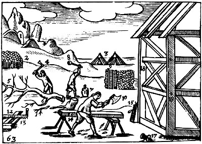 Figure 1.—1685: The principal tools that the carpenter
needed to frame a house, as listed by Johann Amos Comenius in his Orbis
Sensualium Pictus were the felling axe (4), wedge and beetle (7 and 8),
chip axe (10), saw (12), trestle (14), and pulley (15). (Charles Hoole
transl., London, 1685. Courtesy of the Folger Shakespeare Library.)
Figure 1.—1685: The principal tools that the carpenter
needed to frame a house, as listed by Johann Amos Comenius in his Orbis
Sensualium Pictus were the felling axe (4), wedge and beetle (7 and 8),
chip axe (10), saw (12), trestle (14), and pulley (15). (Charles Hoole
transl., London, 1685. Courtesy of the Folger Shakespeare Library.)
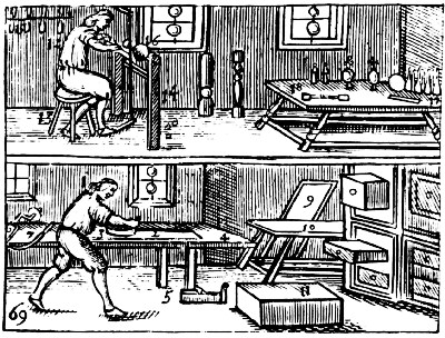 Figure 2.—1685: The boxmaker and turner as pictured by
Comenius required planes (3 and 5), workbench (4), auger (6), knife (7),
and lathe (14). (From Johann Amos Comenius, Orbis Sensualium Pictus.
Courtesy of the Folger Shakespeare Library.)
Figure 2.—1685: The boxmaker and turner as pictured by
Comenius required planes (3 and 5), workbench (4), auger (6), knife (7),
and lathe (14). (From Johann Amos Comenius, Orbis Sensualium Pictus.
Courtesy of the Folger Shakespeare Library.)
The literature of the subject, both new and old, is sparse, with interest always centering upon the object shaped by the craftsman's tool rather than upon the tool itself. Henry Mercer's Ancient Carpenters' Tools, first published in 1929, is an exception. It remains a rich source of information based primarily on the marvelous collections preserved by the Bucks County Historical Society. Since 1933, the Early American Industries Association, both through collecting and through its Chronicle, has called attention to the vanishing trades, their tools and techniques; the magazine Antiques has occasionally dealt with this subject. Historians of economic and industrial development usually neglect the tools of the woodcrafts, and when considering the toolmakers, they have reference only to the inventors and producers of machine tools. The dearth of written material is somewhat compensated for by the collections of hand tools in American museums and restorations, notably those at Williamsburg, Cooperstown, Old Sturbridge Village, Winterthur, the Henry Ford Museum, and Shelburne; at the latter in particular the extensive collection has been bolstered by Frank H. Wildung's museum pamphlet, "Woodworking Tools at Shelburne Museum." The most informative recent American work on the subject is Eric Sloane's handsomely illustrated A Museum of Early American Tools, published in 1964. Going beyond just the tools of the woodworker, Sloane's book also includes agricultural implements. It is a delightful combination of appreciation of early design, nostalgia, and useful fact.
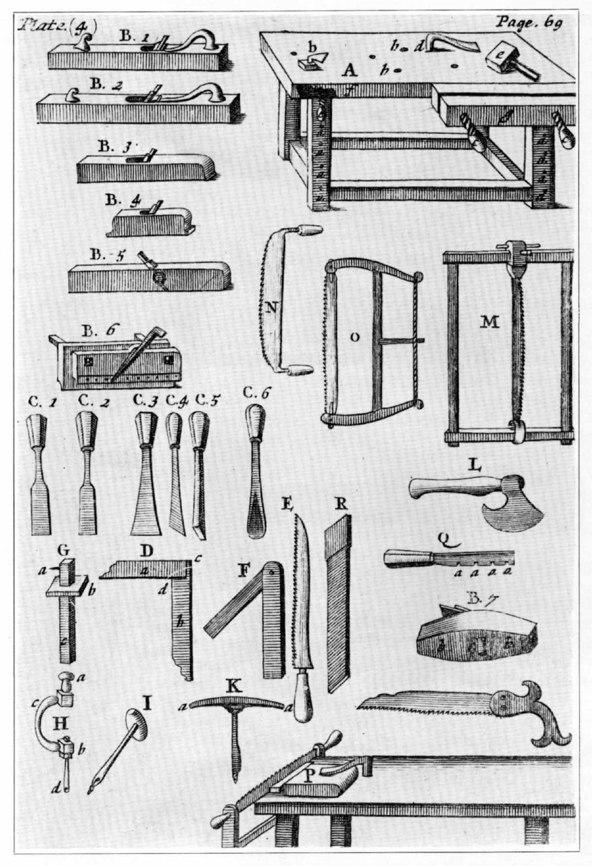 Figure 3.—1703: The tools of the joiner illustrated by
Moxon are the workbench (A), fore plane (B. 1), jointer (B. 2),
strike-block (B. 3), smoothing plane (B. 4 and B. 7), rabbet plane (B.
5), plow (B. 6), forming chisels (C. 1 and C. 3), paring chisel (C. 2),
skew former (C. 4), mortising chisel (sec. C. 5), gouge (C. 6), square
(D), bevel (F), gauge (G), brace and bit (H), gimlet (I), auger (K),
hatchet (L), pit saw (M), whipsaw (N), frame saw (O), saw set (Q),
handsaw (unmarked), and compass saw (E). (Joseph Moxon, Mechanick
Exercises ..., 3rd ed., London, 1703. Library of Congress.)
Figure 3.—1703: The tools of the joiner illustrated by
Moxon are the workbench (A), fore plane (B. 1), jointer (B. 2),
strike-block (B. 3), smoothing plane (B. 4 and B. 7), rabbet plane (B.
5), plow (B. 6), forming chisels (C. 1 and C. 3), paring chisel (C. 2),
skew former (C. 4), mortising chisel (sec. C. 5), gouge (C. 6), square
(D), bevel (F), gauge (G), brace and bit (H), gimlet (I), auger (K),
hatchet (L), pit saw (M), whipsaw (N), frame saw (O), saw set (Q),
handsaw (unmarked), and compass saw (E). (Joseph Moxon, Mechanick
Exercises ..., 3rd ed., London, 1703. Library of Congress.)
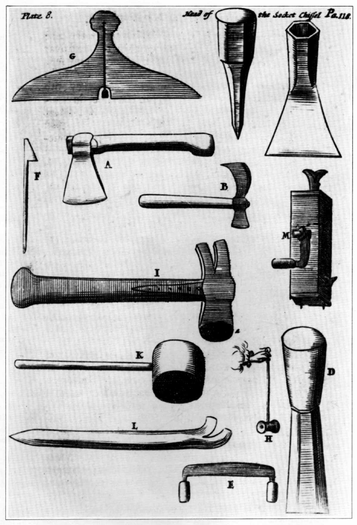 Figure 4.—1703: Only the principal tools used in
carpentry are listed by Moxon: the axe (A), adz (B), socket chisel (C),
ripping chisel (D), drawknife (E), hookpin (F), bevel (G), plumb line
(H), hammer (I), commander (K), crow (L), and jack (M). (Moxon,
Mechanick Exercises ..., 1703. Library of Congress.)
Figure 4.—1703: Only the principal tools used in
carpentry are listed by Moxon: the axe (A), adz (B), socket chisel (C),
ripping chisel (D), drawknife (E), hookpin (F), bevel (G), plumb line
(H), hammer (I), commander (K), crow (L), and jack (M). (Moxon,
Mechanick Exercises ..., 1703. Library of Congress.)
Charles Hummel's forthcoming With Hammer in Hand: The Dominy Craftsmen of East Hampton—to be published by the Yale University Press—will be a major contribution to the literature dealing with Anglo-American woodworking tools. Hummel's book will place in perspective Winterthur Museum's uniquely documented Dominy Woodshop Collection. This extensive collection of tools—over a thousand in number—is rich in attributed and dated examples which range from the early 18th through the mid-19th century. The literature of the subject has been greatly enhanced by the English writer, W.L. Goodman. Extending a series of articles that first appeared in the Journal of The Institute of Handicraft Teachers, Goodman has put together a well-researched History of Woodworking Tools (London, 1964), one particularly useful for its wealth of illustration from antiquity and the Middle Ages.
Given the limitations of precise dating, uncertain provenance, and an uneven literature, what can be learned about woodworking tools after 1600? In some instances, design change can be noted and documented to provide at least a general criteria for dating. Frequently, the original appearance of tools can be documented. For some hand tools, characteristics can be established that denote a national origin. Not infrequently a tool's style, decorative motif, or similarity to other objects that coexisted at a given time can suggest, even in relatively modern times, the values of the society that produced it. The source of such information derived from the hand tool is generally visual, recorded in the tool itself or in pictures of it and supported by manuscript and printed material.
Survey the principal printed sources of the 17th, 18th, and 19th centuries. The first thing that is apparent is a remarkable proliferation of tool types without any significant change in the definition and description of the carpenter's or joiner's task. Begin in 1685 with Charles Hoole's translation of Johann Amos Comenius' Orbis Sensualium Pictus for use as a Latin grammar. Among the occupations chosen to illustrate vocabulary and usage were the carpenter (fig. 1), the boxmaker (cabinetmaker), and the turner (fig. 2). "The Carpenter," according to Hoole's text, "squareth Timber with a Chip ax ... and saweth it with a Saw" while the more specialized "Box-maker, smootheth hewen-Boards with a Plain upon a Work-board, he maketh them very smooth with a little plain, he boarth them thorow with an Augre, carveth them with a Knife, fasteneth them together with Glew, and Cramp-irons, and maketh Tables, Boards, Chests &c." Hoole repeated Comenius' plates with the result that the craftsman's tools and his work have the same characteristic medieval flavor as the text.[2]
Joseph Moxon in his well-quoted work on the mechanic arts defined joinery as "an Art Manual, whereby several Pieces of Wood are so fitted and join'd together by Straight-line, Squares, Miters or any Bevel, that they shall seem one intire Piece." Including the workbench, Moxon described and illustrated 30 tools (fig. 3) needed by the joiner. The carpenter's tools were less favored by illustration; only 13 were pictured (fig. 4). The tools that the carpenter used were the same as those of the joiner except that the carpenter's tools were structurally stronger. The axe serves as a good example of the difference. The joiner's axe was light and short handled with the left side of the cutting edge bezeled to accommodate one-handed use. The carpenter's axe, on the other hand, was intended "to hew great Stuff" and was made deeper and heavier to facilitate the squaring and beveling of timbers.[3] By mid-18th century the craft of joiner and carpenter had been completely rationalized in Diderot's Encyclopédie and by André Roubo in his L'Art du menuisier, a part of Duhamel's Descriptions des arts et métiers. Diderot, for example, illustrates 14 bench planes alone, generally used by the joiner (fig. 5), while Roubo suggests the steady sophistication of the art in a plate showing the special planes and irons required for fine molding and paneling (fig. 6).
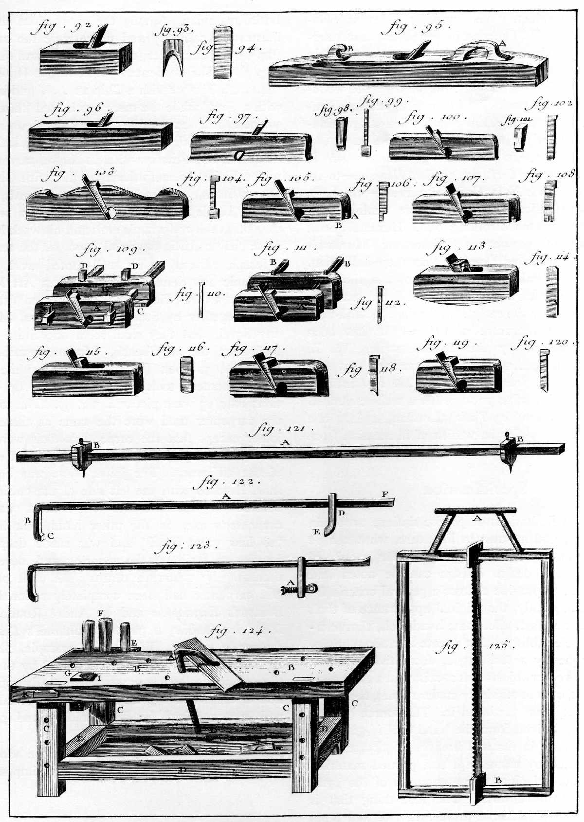 Figure 5.—1769: The bench planes of the joiner increased
in number, but in appearance they remained much the same as those
illustrated by Moxon. (Denis Diderot, Recueil de planches sur les
science et les arts libéraux, Paris, 1769, vol. 7, "Menuiserie."
Smithsonian photo 56630.)
Figure 5.—1769: The bench planes of the joiner increased
in number, but in appearance they remained much the same as those
illustrated by Moxon. (Denis Diderot, Recueil de planches sur les
science et les arts libéraux, Paris, 1769, vol. 7, "Menuiserie."
Smithsonian photo 56630.)
Despite such thoroughness, without the addition of the several plates it would be almost impossible to visualize, through the descriptive text alone, the work of the carpenter and joiner except, of course, in modern terms. This is particularly true of the numerous texts on building, such as Batty Langley's The Builder's Complete Assistant (1738) and Francis Price's The British Carpenter (1765), where building techniques are well described but illustration of tools is omitted. This inadequacy grows. In two 19th-century American editions of British works, The Book of Trades, printed at Philadelphia in 1807, and Hazen's Panorama of the Professions and Trades (1838), the descriptions of the carpenter's trade are extremely elementary.
Thomas Martin's Circle of the Mechanical Arts (1813), although far more thorough than many texts, still defined carpentry "as the art of cutting out, framing, and joining large pieces of wood, to be used in building" and joinery as "small work" or what "is called by the French, menuiserie." Martin enumerated 16 tools most useful to the carpenter and 21 commonly used by the joiner; in summary, he noted, as had Moxon, that "both these arts are subservient to architecture, being employed in raising, roofing, flooring and ornamenting buildings of all kinds" (fig. 7).[4]
In Peter Nicholson's The Mechanic's Companion (figs. 8, 9, and 10), the all-too-familiar definition of carpentry as "the art of employing timber in the construction of buildings" suggests very little of the carpenter's actual work or the improvement in tool design that had occurred since Moxon's Exercises. From Nicholson's list of the tools required by the carpenter—"a ripping saw, a hand saw, an axe, an adze, a socket chisel, a firmer chisel, a ripping chisel, an auguer, a gimlet, a hammer, a mallet, a pair of pincers, and sometimes planes"—there would seem at first glance slight advance since the 1600's. The enumeration of the joiner's tools, however, indicates a considerable proliferation, particularly when compared to earlier writers. By the early 19th century, the more refined work of joinery required over 50 tools.
The bench planes [instructed Nicholson] are, the jack plane, the fore plane, the trying plane, the long plane, the jointer, and the smoothing plane; the cylindric plane, the compass and forkstaff planes; the straight block, for straightening short edges. Rebating planes are the moving fillister, the sash fillister, the common rebating plane, the side rebating plane. Grooving planes are the plough and dado grooving planes. Moulding planes are sinking snipebills, side snipebills, beads, hollows and rounds, ovolos and ogees. Boring tools are: gimlets, bradawls, stock, and bits. Instruments for dividing the wood, are principally the ripping saw, the half ripper, the hand saw, the panel saw, the tenon saw, the carcase saw, the sash saw, the compass saw, the keyhole saw, and turning saw. Tools used for forming the angles of two adjoining surfaces, are squares and bevels. Tools used for drawing parallel lines are gauges. Edge tools are the firmer chisel, the mortise chisel, the socket chisel, the gouge, the hatchet, the adze, the drawing knife. Tools for knocking upon wood and iron are, the mallet and hammer. Implements for sharpening tools are the grinding stone, the rub stone, and the oil or whet stone.[5]
Reflecting what the text writers listed, toolmakers by the end of the 18th century gave buyers a wide choice. The catalogue of Sheffield's Castle Hill Works offered 20 combinations of ready-stocked tool chests; the simplest contained 12 carpenter's tools and the most complex, 39, plus, if desired, an additional assortment of gardening implements (fig. 11). In 1857, the Arrowmammett Works of Middletown, Connecticut, producers of bench and molding planes, published an illustrated catalogue that offered 34 distinct types that included everything from hollows and rounds to double jointers and hand-rail planes (fig. 12).[6]
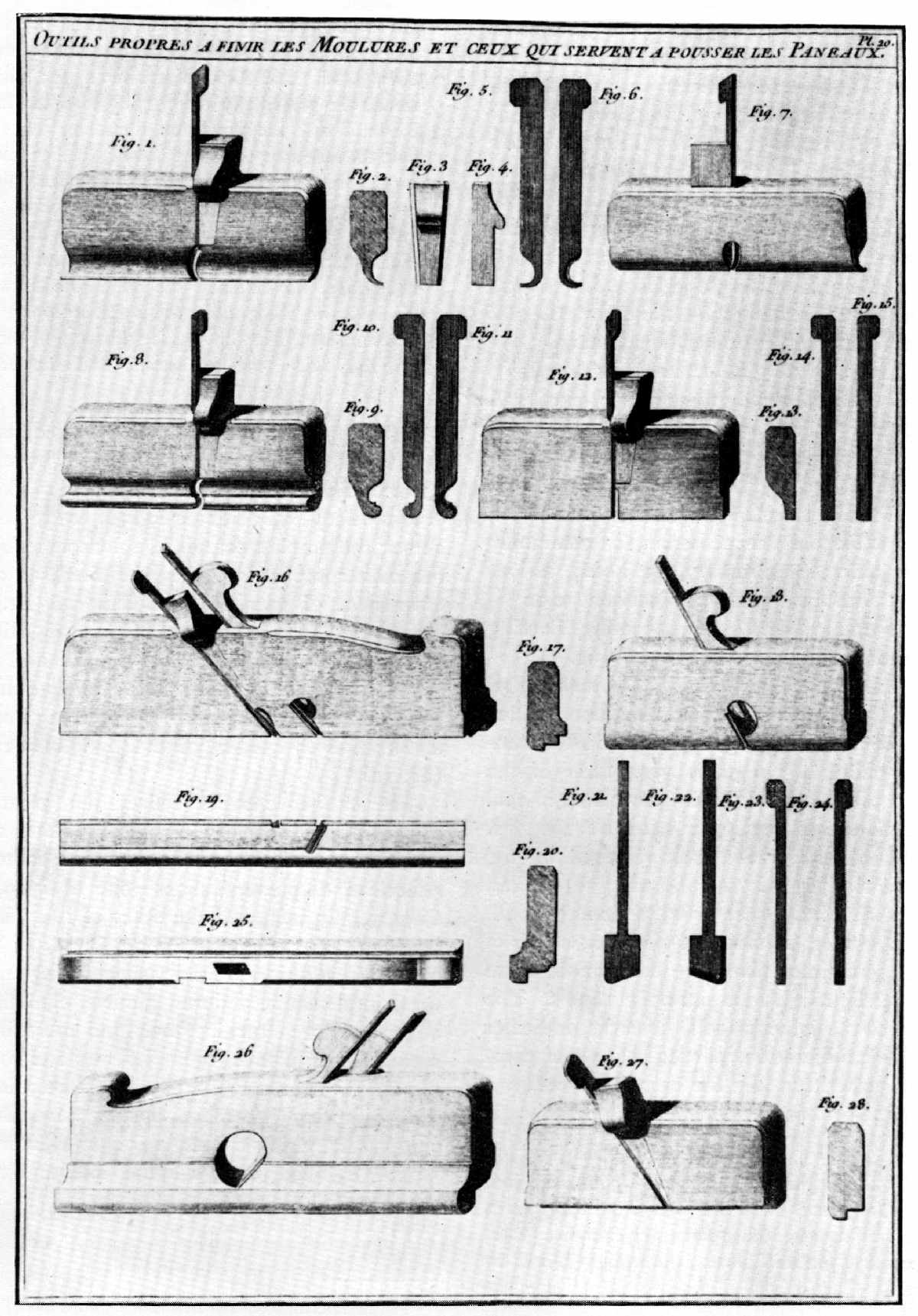 Figure 6.—1774: André Roubo's L'Art du menuisier
contains detailed plates and descriptions of the most specialized of
woodworking planes: those used to cut panel moldings. The conformation
of these tools was still distinctly in keeping with the Moxon type and
suggests that, at least in Europe, no remarkable change had yet occurred
in the shape of planes. (André-Jacob Roubo, L'Art du menuisier:
Troisième partie, troisième section, l'art du menuisier ébéniste [Paris,
1774]. Smithsonian photo 49790-D.)
Figure 6.—1774: André Roubo's L'Art du menuisier
contains detailed plates and descriptions of the most specialized of
woodworking planes: those used to cut panel moldings. The conformation
of these tools was still distinctly in keeping with the Moxon type and
suggests that, at least in Europe, no remarkable change had yet occurred
in the shape of planes. (André-Jacob Roubo, L'Art du menuisier:
Troisième partie, troisième section, l'art du menuisier ébéniste [Paris,
1774]. Smithsonian photo 49790-D.)
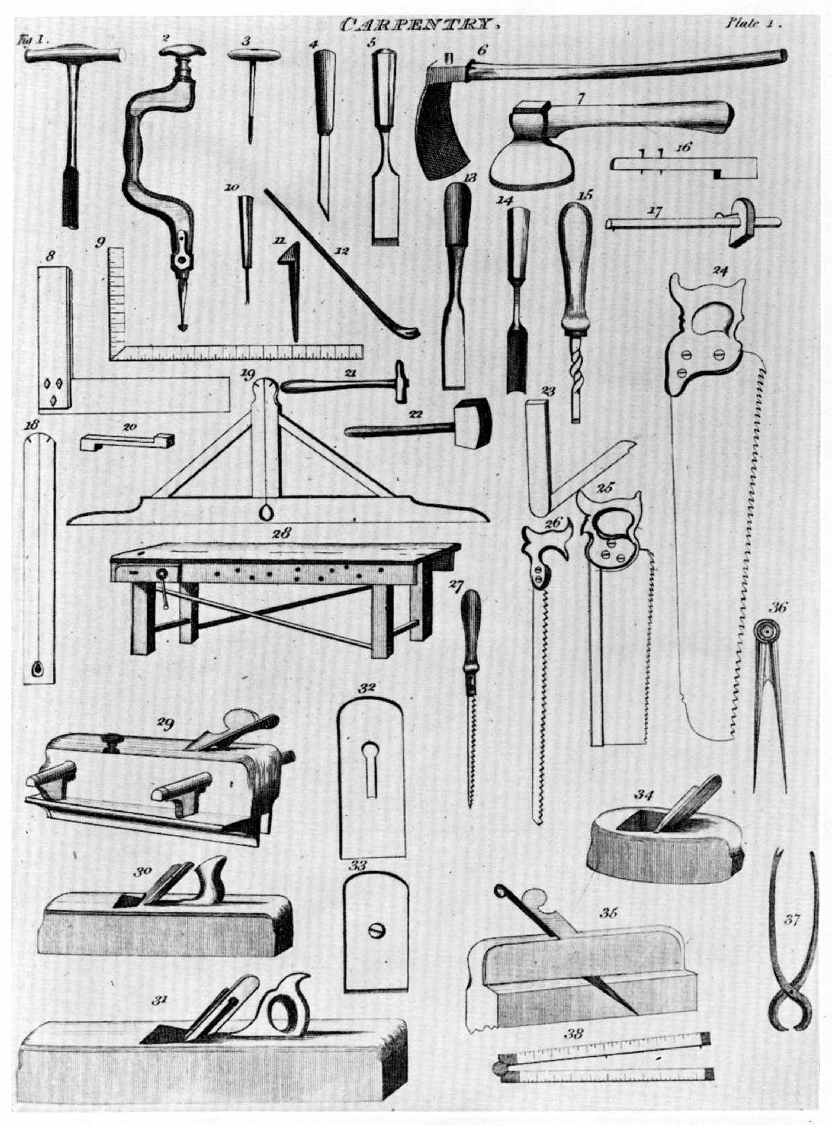 Figure 7.—1813: Thomas Martin illustrated on one plate
the tools of the carpenter and joiner dividing them as follows: the
tools most useful to the carpenter, the axe (7), adz (6), saw (24),
socket chisel (13), firmer chisel (5), auger (1), gimlet (3), gauge
(16), square (9), compass (36), hammer (21), mallet (22), hookpin (11),
crow (12), plumb rule (18), and level (19); and the tools most often
associated with joinery, the jack plane (30), trying plane (31),
smoothing plane (34), tenon saw (25), compass saw (26), keyhole saw
(27), square (8), bevel (23), gauge (17), mortise chisel (4), gouge
(14), turnscrew (15), plow plane (29), molding plane (35), pincers (37),
bradawl (10), stock and bit (2), sidehook (20), workbench (28), and rule
(38). The planes are of particular interest since they show clearly a
change in form from those previously illustrated. (Thomas Martin, The
Circle of the Mechanical Arts, London, 1813.)
Figure 7.—1813: Thomas Martin illustrated on one plate
the tools of the carpenter and joiner dividing them as follows: the
tools most useful to the carpenter, the axe (7), adz (6), saw (24),
socket chisel (13), firmer chisel (5), auger (1), gimlet (3), gauge
(16), square (9), compass (36), hammer (21), mallet (22), hookpin (11),
crow (12), plumb rule (18), and level (19); and the tools most often
associated with joinery, the jack plane (30), trying plane (31),
smoothing plane (34), tenon saw (25), compass saw (26), keyhole saw
(27), square (8), bevel (23), gauge (17), mortise chisel (4), gouge
(14), turnscrew (15), plow plane (29), molding plane (35), pincers (37),
bradawl (10), stock and bit (2), sidehook (20), workbench (28), and rule
(38). The planes are of particular interest since they show clearly a
change in form from those previously illustrated. (Thomas Martin, The
Circle of the Mechanical Arts, London, 1813.)
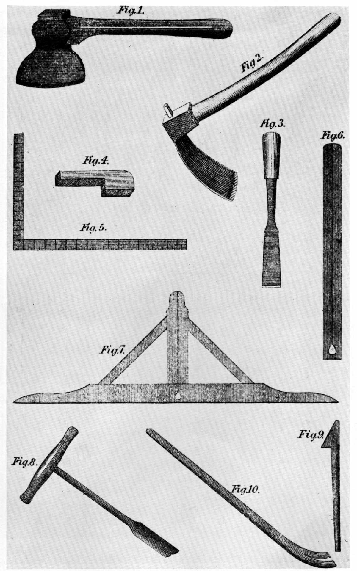 Figure 8.—1832: Peter Nicholson illustrated an
interesting mixture of old and new forms. An updating of Moxon,
Nicholson's carpenter required an axe (1), adz (2), socket chisel (3),
mortise and tenon gauge (4), square (5), plumb rule (6), level (7),
auger (8), hookpin (9), and crow (10). (Peter Nicholson, The Mechanic's
Companion. 1st American ed., Philadelphia, 1832. Smithsonian photo
56633.)
Figure 8.—1832: Peter Nicholson illustrated an
interesting mixture of old and new forms. An updating of Moxon,
Nicholson's carpenter required an axe (1), adz (2), socket chisel (3),
mortise and tenon gauge (4), square (5), plumb rule (6), level (7),
auger (8), hookpin (9), and crow (10). (Peter Nicholson, The Mechanic's
Companion. 1st American ed., Philadelphia, 1832. Smithsonian photo
56633.)
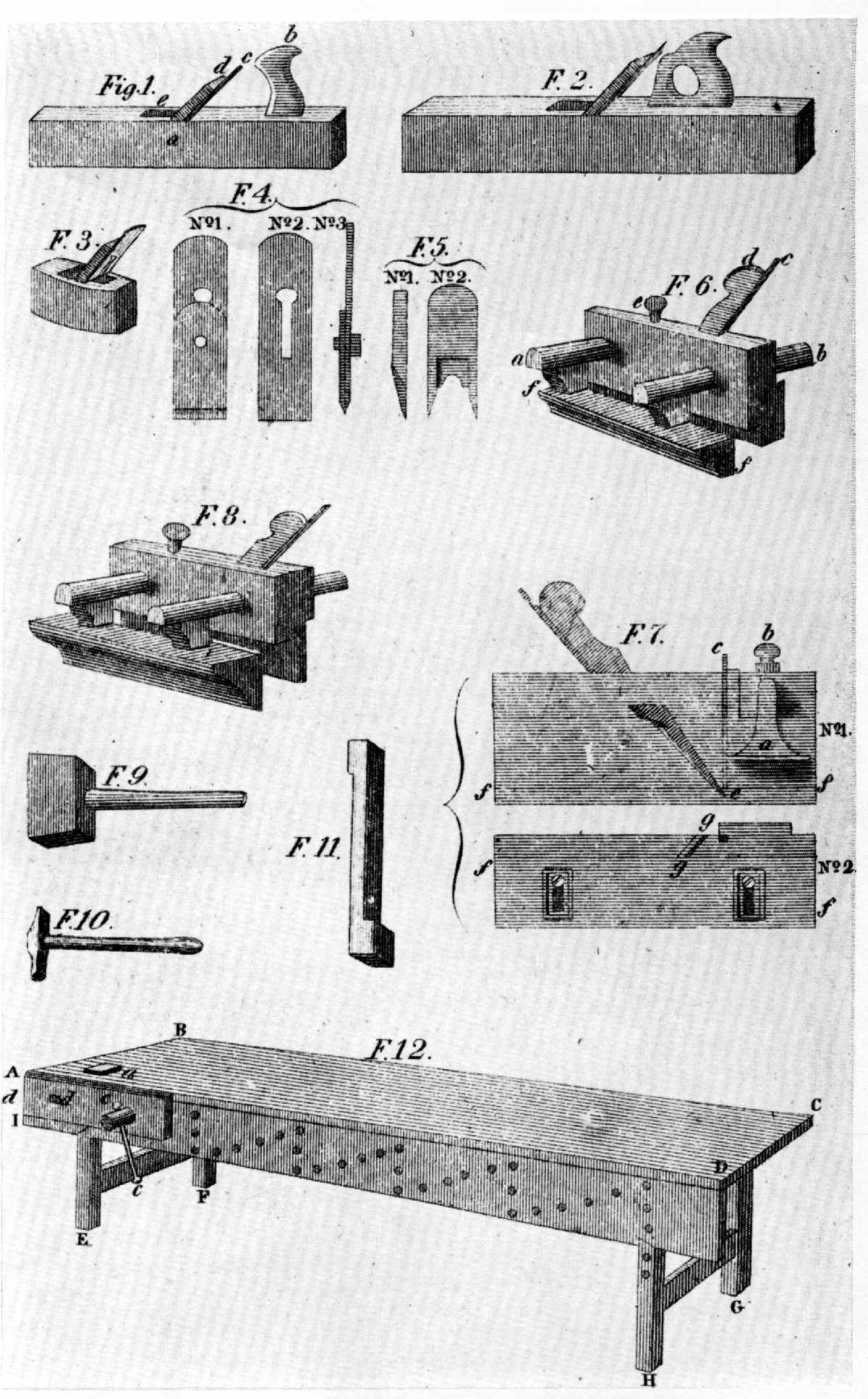 Figure 9.—1832: The workbench delineated by Nicholson
was little improved over Moxon's, although the planes—jack (1), trying
plane (2), smoothing plane (3), sash fillister (7), and plow
(8)—followed the form seen in Martin (fig. 7). The inception of this
shape occurred in the shops of Sheffield toolmakers in the last half of
the 18th century, and it persisted until replaced by metallic versions
patented by American innovators during the last quarter of the 19th
century. (Nicholson, The Mechanic's Companion. Smithsonian photo
56631.)
Figure 9.—1832: The workbench delineated by Nicholson
was little improved over Moxon's, although the planes—jack (1), trying
plane (2), smoothing plane (3), sash fillister (7), and plow
(8)—followed the form seen in Martin (fig. 7). The inception of this
shape occurred in the shops of Sheffield toolmakers in the last half of
the 18th century, and it persisted until replaced by metallic versions
patented by American innovators during the last quarter of the 19th
century. (Nicholson, The Mechanic's Companion. Smithsonian photo
56631.)
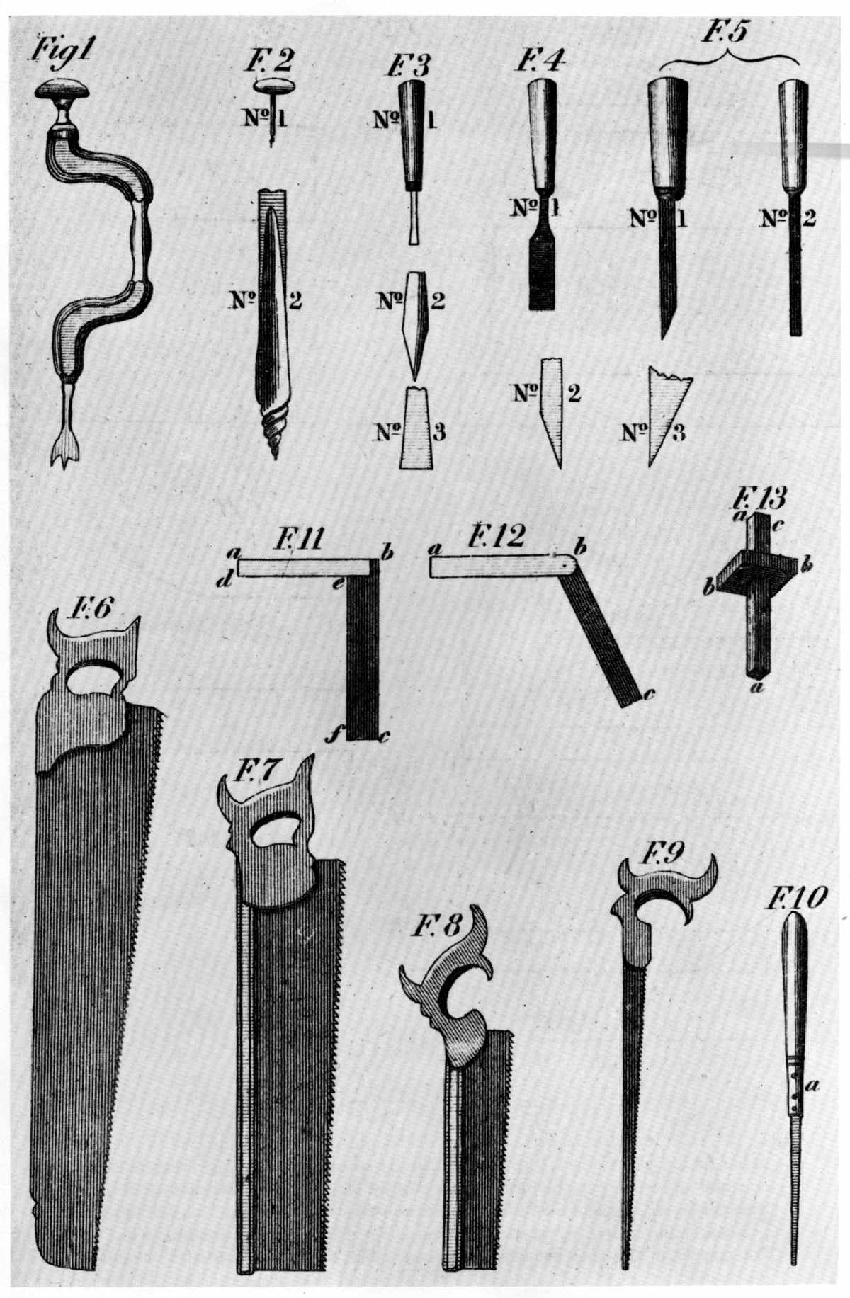 Figure 10.—1832: The brace and bit, gimlet, chisels, and
saws, having achieved a standard form distinctly different than those of
Moxon's vintage, were, like the plane, slow to change. The metallic
version of the brace did not replace the standard Sheffield type (1) in
the United States until after 1850. For all intent and purpose the saw
still retains the characteristics illustrated in Nicholson. Of interest
is Nicholson's comment regarding the saws; namely, that the double
handle was peculiar to the hand (6) and tenon saws (7), while the
compass (9) and the sash saws (8) had the single handle. In addition the
tenon saw was generally backed in iron and the sash saw in brass.
(Nicholson, The Mechanic's Companion. Smithsonian photo 56632.)
Figure 10.—1832: The brace and bit, gimlet, chisels, and
saws, having achieved a standard form distinctly different than those of
Moxon's vintage, were, like the plane, slow to change. The metallic
version of the brace did not replace the standard Sheffield type (1) in
the United States until after 1850. For all intent and purpose the saw
still retains the characteristics illustrated in Nicholson. Of interest
is Nicholson's comment regarding the saws; namely, that the double
handle was peculiar to the hand (6) and tenon saws (7), while the
compass (9) and the sash saws (8) had the single handle. In addition the
tenon saw was generally backed in iron and the sash saw in brass.
(Nicholson, The Mechanic's Companion. Smithsonian photo 56632.)
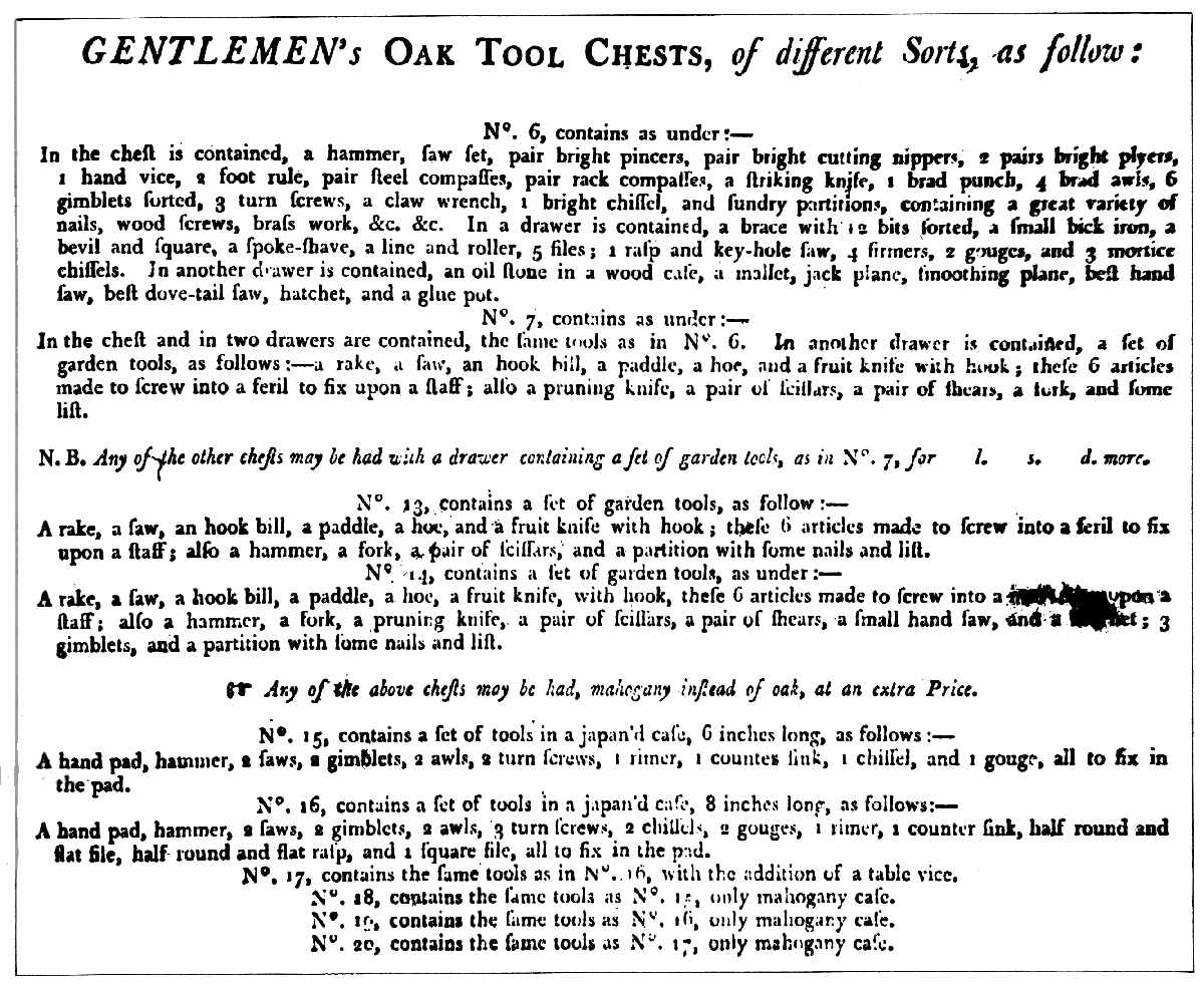 Figure 11.—Early 19th century: The advertisements of
toolmakers indicated the diversity of production. The Castle Hill Works
at Sheffield offered to gentlemen 20 choices of tool chests designed to
appeal to a wide variety of users and purses. The chest was available in
either oak or mahogany, depending on the gentleman's tastes (fig. 49).
(Book 87, Cutler and Company, Castle Hill Works, Sheffield. Courtesy of
the Victoria and Albert Museum.)
Figure 11.—Early 19th century: The advertisements of
toolmakers indicated the diversity of production. The Castle Hill Works
at Sheffield offered to gentlemen 20 choices of tool chests designed to
appeal to a wide variety of users and purses. The chest was available in
either oak or mahogany, depending on the gentleman's tastes (fig. 49).
(Book 87, Cutler and Company, Castle Hill Works, Sheffield. Courtesy of
the Victoria and Albert Museum.)
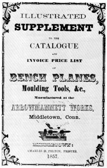 Figure 12.—1857: The diversity of tools available to
buyers made necessary the illustrated trade catalogue. Although few in
number in the United States before 1850, tool catalogues became
voluminous in the last half of the century as printing costs dropped.
(Smithsonian Institution Library. Smithsonian photo 49790.)
Figure 12.—1857: The diversity of tools available to
buyers made necessary the illustrated trade catalogue. Although few in
number in the United States before 1850, tool catalogues became
voluminous in the last half of the century as printing costs dropped.
(Smithsonian Institution Library. Smithsonian photo 49790.)
American inventories reflect the great increase suggested by the early technical writers and trade catalogues cited above. Compare the content of two American carpenters' shops—one of 1709, in York County, Virginia, and the other of 1827, in Middleborough, Massachusetts. John Crost, a Virginian, owned, in addition to sundry shoemaking and agricultural implements, a dozen gimlets, chalklines, bung augers, a dozen turning tools and mortising chisels, several dozen planes (ogees, hollows and rounds, and plows), several augers, a pair of 2-foot rules, a spoke shave, lathing hammers, a lock saw, three files, compasses, paring chisels, a jointer's hammer, three handsaws, filling axes, a broad axe, and two adzes. Nearly 120 years later Amasa Thompson listed his tools and their value. Thompson's list is a splendid comparison of the tools needed in actual practice, as opposed to the tools suggested by Nicholson in his treatise on carpentry or those shown in the catalogues of the toolmakers.[7] Thompson listed the following:
| 1 | set bench planes | $6.00 |
| 1 | Broad Axe | 3.00 |
| 1 | Adze | 2.25 |
| 1 | Panel saw | 1.50 |
| 1 | Panel saw | 1.58 |
| 1 | fine do— | 1.58 |
| 1 | Drawing knife | .46 |
| 1 | Trying square | .93 |
| 1 | Shingling hatchet | .50 |
| 1 | Hammer | .50 |
| 1 | Rabbet plane | .83 |
| 1 | Halving do | .50 |
| 1 | Backed fine saw | 1.25 |
| 1 | Inch augre | .50 |
| 1 | pr. dividers or compasses— | .71 |
| 1 | Panel saw for splitting | 2.75 |
| 1 | Tennon gauge | 1.42 |
| 1 | Bevel | .84 |
| 1 | Bradd Hammer | .50 |
| 1 | Architect Book | 6.50 |
| 1 | Case Mathematical Instruments | 3.62-1⁄2 |
| 1 | Panel saw | 2.75 |
| 1 | Grafting saw | 1.00 |
| 1 | Bench screw | 1.00 |
| 1 | Stamp | 2.50 |
| 1 | Double joint rule | .62-1⁄2 |
| 1 | Sash saw | 1.12-1⁄2 |
| 1 | Oil Can | .17 |
| 1 | Brace & 36 straw cold bits | 9.00 |
| 1 | Window Frame tool | 4.00 |
| 1 | Blind tool | 1.33 |
| 1 | Glue Kettle | .62-1⁄2 |
| 1 | Grindstone without crank | 1.75 |
| 1 | Machine for whetting saws | .75 |
| 1 | Tennoning machine | 4.50 |
| Drafting board and square Bevel— | 1.25 | |
| 1 | Noseing sash plane with templets & copes | 4.50 |
| 1 | pr. clamps for clamping doors | 2.17 |
| 1 | Set Bench Planes—double irons.— | 7.50 |
| 1 | Grindstone 300 lbs @ | 6.25 |
| 1 | Stove for shop—$7.25, one elbow .37 & 40 | |
| lbs second hand pipe $4.00 | 11.62 | |
| 1 | Bed moulding | 2.00 |
| 1 | Pr. shears for cutting tin.— | .17 |
| 1 | Morticing Machine | 10.75 |
| 1 | Grecian Ovilo | 1.13 |
| 1-3⁄16 | beed | .67 |
| 1 | Spirit level | 2.25 |
| 1 | Oil stone | .42 |
| 1 | Small trying square | .48 |
| 1 | pareing chisel | .37 |
| 1 | Screw driver | .29 |
| 1 | Bench screw | .75 |
| 1 | Box rule | .50 |
| 1-3⁄4 | Augre | .41 |
| 11 | Gouges | 1.19 |
| 13 | Chisels | 1.17 |
| 1 | small iron vice | .52 |
| 1 | pr. Hollow Rounds | .86 |
| 4 | Framing chisels | 1.05 |
| 1 | Grove plough & Irons—Sold at 4.50 | 5.00 |
| 1 | Sash plane for 1-1⁄4 stuff | 1.50 |
| 1 | Copeing plane | .67 |
| 1 | Bead 1⁄4— | .75 |
| 1 | Bead 3⁄4 | 1.00 |
| 1 | Rabbet (Sold at .92) | .92 |
| 1 | Smooth plane | 1.50 |
| 1 | Strike Block | .92 |
| 1 | Compass saw | .42 |
| 6 | Gauges | 1.83 |
| 1 | Dust brush | .25 |
| 1 | Rasp, or wood file | .25 |
| 1 | Augre 2 in. | .76 |
| 1 | Augre 1 in. | .40 |
| 1 | Do 3⁄4 | .30 |
| 1 | Spoke shave | .50 |
| 1 | Bevel— | .25 |
| 1 | Box rule | .84 |
| 1 | Iron square | 1.42 |
| 1 | Box rule | 1.25 |
| 1 | Spur Rabbet (Sold—1.17) | 1.33 |
| 1 | Pannel plane | 1.25 |
| 1 | Sash plane | 1.25 |
| 1 | pr. Match planes | 2.25 |
| 1 | Two inch chisel or firmer— | .42 |
| 1 | Morticing chisel 3⁄8 | .25 |
| 1 | Large screw driver | 1.00 |
| 1 | Pr. small clamps | .50 |
| 1 | pr. Spring dividers | .92 |
| 1 | do-nippers | .20 |
| 1 | Morticing chisel 1⁄2 in. | .28 |
| 1 | Ovilo & Ostrigal 3⁄4— | 1.25 |
| 1 | Scotia & Ostrigal 5⁄8— | 1.08 |
| 1 | Noseing— | 1.08 |
| 1 | Pr. Hollow & rounds | 1.33 |
| 1 | Ogee— 1⁄2 inch | 1.00 |
| 1 | Ostrigal 7⁄8 inch | 1.00 |
| 1 | Bit— | .15 |
| 1 | Beed 1⁄2 inch | .83 |
| 1 | Claw hammer | .67 |
| 1 | Fillister | 2.50 |
| 2 | Beeds at 5⁄8 | 1.83 |
| 1 | Pair Quirk tools | 1.50 |
| 1 | Side Rabbet plane | .83 |
| 1 | Large steel tongued sq. | 1.71 |
| 1 | Saw & Pad | .67 |
| 1 | pr. fire stones | .50 |
| 1 | small trying sq. | .50 |
| 1 | Set Bench planes double ironed without smooth plane | 6.00 |
| 1 | Bench screw | .75 |
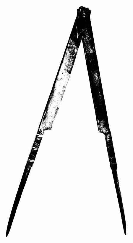 Figure 13.—Early 18th century: In addition to their
special function and importance as survivals documenting an outmoded
technology, the hand tool often combines a gracefulness of line and a
sense of proportion that makes it an object of great decorative appeal.
The dividers of the builder or shipwright illustrated here are of French
origin and may be valued as much for their cultural significance as for
their technical importance. (Smithsonian photo 49792-G.)
Figure 13.—Early 18th century: In addition to their
special function and importance as survivals documenting an outmoded
technology, the hand tool often combines a gracefulness of line and a
sense of proportion that makes it an object of great decorative appeal.
The dividers of the builder or shipwright illustrated here are of French
origin and may be valued as much for their cultural significance as for
their technical importance. (Smithsonian photo 49792-G.)
By 1900, the carpenter's tool chest, fully stocked and fit for the finest craftsman, contained 90 or more tools. Specialization is readily apparent; the change in, and achievement of, the ultimate design of a specific tool is not so easily pinpointed. Only by comparing illustrations and surviving examples can such an evolution be appreciated and in the process, whether pondering the metamorphosis of a plane, a brace and bit, or an auger, the various stages of change encountered coincide with the rise of modern industrial society.
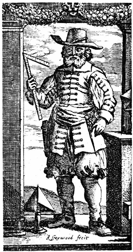 Figure 14.—1688: Frontispiece From John Brown, The
Description and Use of the Carpenter's Rule, London, 1688. (Library of
Congress.)
Figure 14.—1688: Frontispiece From John Brown, The
Description and Use of the Carpenter's Rule, London, 1688. (Library of
Congress.)
Hand tools are often neglected in the search for the pleasing objects of the past. Considered too utilitarian, their decorative appeal—the mellow patina of the wood plane or the delicately tapered legs of a pair of dividers—often goes unnoticed. Surprisingly modern in design, the ancient carpenter's or cabinetmaker's tool has a vitality of line that can, without reference to technical significance, make it an object of considerable grace and beauty. The hand tool is frequently a lively and decorative symbol of a society at a given time—a symbol, which, according to the judges at London's Crystal Palace Exhibition in 1851, gives "indications of the peculiar condition and habits of the people whence they come, of their social and industrial wants and aims, as well as their natural or acquired advantages."[8] The hand tool, therefore, should be considered both as an object of appealing shape and a document illustrative of society and its progress.
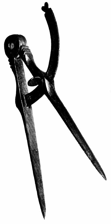 Figure 15.—18th century: Cabinetmaker's dividers of
English origin. (Private collection. Smithsonian photo 49789-B.)
Figure 15.—18th century: Cabinetmaker's dividers of
English origin. (Private collection. Smithsonian photo 49789-B.)
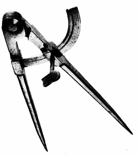 Figure 16.—1783: Cabinetmaker's dividers of English
manufacture, dated, and marked T. Pearmain. See detail, figure 17.
(Smithsonian photo 49792-C.)
Figure 16.—1783: Cabinetmaker's dividers of English
manufacture, dated, and marked T. Pearmain. See detail, figure 17.
(Smithsonian photo 49792-C.)
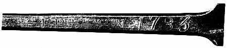 Figure 17.—1783: Detail of cabinetmaker's dividers
showing name and date.
Figure 17.—1783: Detail of cabinetmaker's dividers
showing name and date.
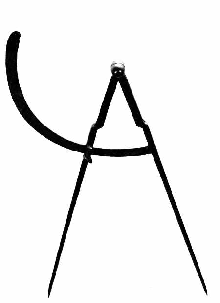 Figure 18.—18th century: Carpenter's dividers of English
origin, undated. (Smithsonian photo 49792-B.)
Figure 18.—18th century: Carpenter's dividers of English
origin, undated. (Smithsonian photo 49792-B.)
On first sight, it is the conformation rather than any facet of its technical or social significance that strikes the eye; perhaps the most decorative of tools are early dividers and calipers which, prior to their standardization, existed in seemingly endless variety. The great dividers used by the shipbuilder and architect for scribing and measuring timbers not only indicate building techniques (accession 61.548) but also document 17th-and early 18th-century decorative metalwork, as seen in figure 13. Well before the 17th century, artists and engravers recognized them as intriguing shapes to include in any potpourri of instruments, either in cartouches or the frontispieces of books (fig. 14).
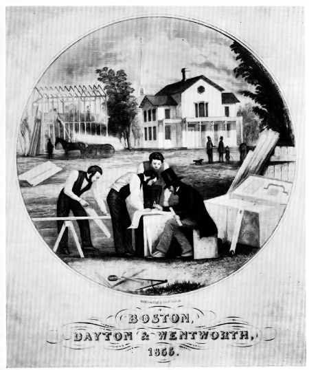 Figure 19.—1855: The frontispiece from Edward Shaw, The
Modern Architect (Boston, 1855), shows the carpenter's dividers in the
foreground unchanged in form from those illustrated in figure 18. Of
further interest in Shaw's plate is the dress of the workmen and the
balloon frame of the house under construction. (Smithsonian photo
49792-A.)
Figure 19.—1855: The frontispiece from Edward Shaw, The
Modern Architect (Boston, 1855), shows the carpenter's dividers in the
foreground unchanged in form from those illustrated in figure 18. Of
further interest in Shaw's plate is the dress of the workmen and the
balloon frame of the house under construction. (Smithsonian photo
49792-A.)
The two pairs of cabinetmaker's dividers illustrated in figures 15 and 16 suggest significant changes in the design of a basic tool. The dividers shown in figure 15 are English and would seem to be of early 18th-century origin, perhaps even earlier. They are Renaissance in feeling with decorated legs and a heart-shaped stop on the end of the slide-arm. In character, they are like the great dividers shown in figure 13: functional, but at the same time preserving in their decoration the features common to a wide variety of ironwork and wares beyond the realm of tools alone. The dividers pictured in figure 16 are a decided contrast. Dated 1783, they are strongly suggestive of Sheffield origin. Gone is the superfluous decoration; in its place is the strong, crisp line of a tool that has reached nearly the ultimate of function and manufacture, a device which both in general appearance and precise design is very modern in execution. Equally intriguing are the smaller, more slender dividers (accession 319557) of the 18th-century house-builder as seen in figure 18, a form that changed very little, if at all, until after 1850—a fact confirmed by the frontispiece of Edward Shaw's The Modern Architect, published in Boston in 1855 (fig. 19). The double calipers of the woodturner (fig. 20) have by far the most appealing and ingenious design of all such devices. Designed for convenience, few tools illustrate better the aesthetic of the purely functional than this pair of 19th-century American calipers.
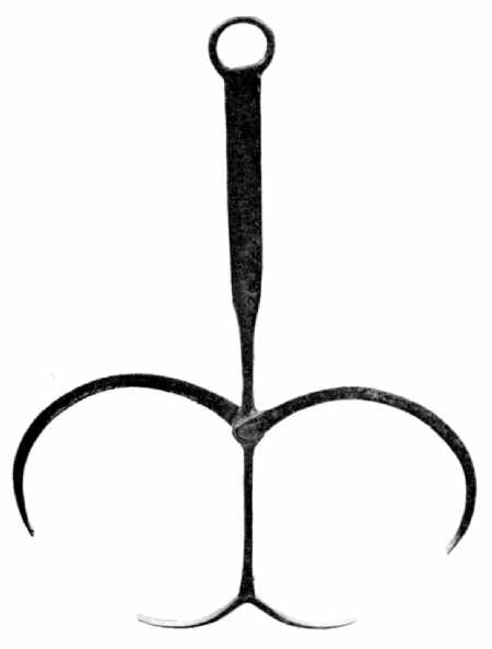 Figure 20.—Early 19th century: The double calipers of
the woodturner permitted double readings to be taken without changing
the set of the tool. Inherent in this practical design is a gracefulness
of line seldom surpassed. (Private collection. Smithsonian photo
49793-C.)
Figure 20.—Early 19th century: The double calipers of
the woodturner permitted double readings to be taken without changing
the set of the tool. Inherent in this practical design is a gracefulness
of line seldom surpassed. (Private collection. Smithsonian photo
49793-C.)
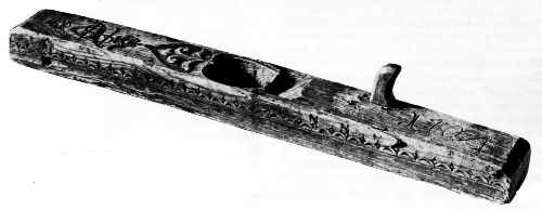 Figure 21.—1704: The floor plane or long joiner of
Norwegian origin exhibits the characteristic decoration of the stock and
mouth, patterns common on tools of northern European and Scandinavian
origin. (Courtesy of the Norsk Folkemuseum, Oslo, Norway.)
Figure 21.—1704: The floor plane or long joiner of
Norwegian origin exhibits the characteristic decoration of the stock and
mouth, patterns common on tools of northern European and Scandinavian
origin. (Courtesy of the Norsk Folkemuseum, Oslo, Norway.)
Intended to establish proportion and to insure precision, it seems a natural consequence that dividers and calipers should in themselves reflect the same sense of balance and grace that they were designed to govern. Still, even the most prosaic examples of woodworking tools, completely divorced from the quasi-mathematical devices of measure and proportion, have this quality and can be admired solely as decorative objects. This is most evident in the three European bench planes illustrated in figures 21, 22, and 23: one Norwegian, dated 1704; one Dutch (accession 319562), dated 1756; and one German, dated 1809. The Norwegian and German examples, with their elaborately carved bodies and heart-shaped mouths, are typical of the type that Swedish and German colonists in America might have used in the 17th and 18th centuries. They are important for that reason. Also, all three exhibit elaboration found on other material survivals from these countries in their respective periods. For example, the incised rosette of the Dutch plane (fig. 22) is especially suggestive of the rosettes found on English and American furniture of the 1750's and 1760's, specifically on high chests.
The decorative motifs that characterized European tools of the 17th and 18th centuries obscured technical improvement. By contrast, in England and America, tools gained distinction through the directness of their design. Following English patterns, tools of American make were straightforward. Only later, in new tool types, did they imitate the rococo flourish of their European predecessors. In America, as in England, the baroque for things functional seemingly had little appeal. This is particularly true of woodworking planes on which, unlike their continental cousins, embellishment is rarely seen. Exemplifying this tradition are three early 19th-century American planes: a plow, for cutting channels of various widths on board edges, marked "G. White, Philda" (fig. 24); a rabbet, for notching the margin of boards; made by E.W. Carpenter of Lancaster, Pennsylvania (fig. 25); and a jack or foreplane, for rough surfacing (accession 61.547), made by A. Klock and dated 1818 as seen in figure 26.
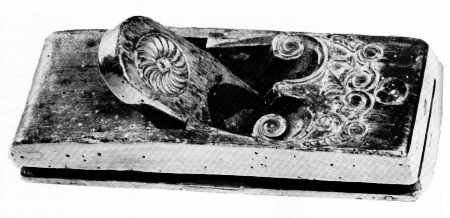 Figure 22.—1756: The highly elaborated stock and
rosette-incised wedge of the smoothing plane recall the decoration on
furniture of the period. The plane is of Dutch origin. (Smithsonian
photo 49792-F.)
Figure 22.—1756: The highly elaborated stock and
rosette-incised wedge of the smoothing plane recall the decoration on
furniture of the period. The plane is of Dutch origin. (Smithsonian
photo 49792-F.)
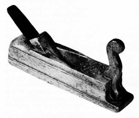 Figure 23.—1809: This bench plane of German origin is
dated 1809. It is of a traditional form that persists to the present
day. The planes pictured in figures 21, 22, and 23 are similar to the
type brought to North America by non-English colonists. (Private
collection. Smithsonian photo 49793-F.)
Figure 23.—1809: This bench plane of German origin is
dated 1809. It is of a traditional form that persists to the present
day. The planes pictured in figures 21, 22, and 23 are similar to the
type brought to North America by non-English colonists. (Private
collection. Smithsonian photo 49793-F.)
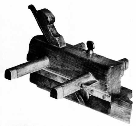 Figure 24.—About 1818: This plow plane, used to cut
narrow channels on the edges of boards, was made by G. White of
Philadelphia in the early 19th century. It is essentially the same tool
depicted in the catalogues of Sheffield manufactures and in the plates
from Martin and Nicholson. The pattern of the basic bench tools used in
America consistently followed British design, at least until the last
quarter of the 19th century. (Private collection. Smithsonian photo
49794-E.)
Figure 24.—About 1818: This plow plane, used to cut
narrow channels on the edges of boards, was made by G. White of
Philadelphia in the early 19th century. It is essentially the same tool
depicted in the catalogues of Sheffield manufactures and in the plates
from Martin and Nicholson. The pattern of the basic bench tools used in
America consistently followed British design, at least until the last
quarter of the 19th century. (Private collection. Smithsonian photo
49794-E.)
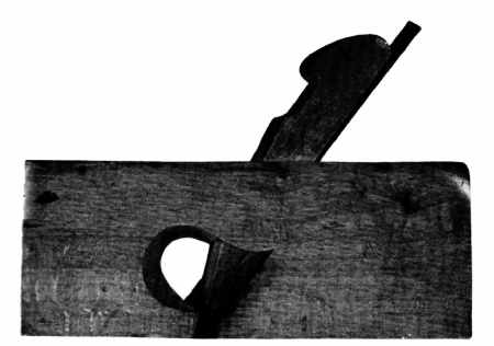 Figure 25. 1830–1840: The design of the rabbet plane,
used to cut a groove of fixed width and depth on the edge of a board,
was not improved upon in the 19th century. The carpenter's dependence on
this tool lessened only after the perfection of multipurpose metallic
planes that could be readily converted to cut a "rabbet." (Private
collection. Smithsonian photo 494789-H).
Figure 25. 1830–1840: The design of the rabbet plane,
used to cut a groove of fixed width and depth on the edge of a board,
was not improved upon in the 19th century. The carpenter's dependence on
this tool lessened only after the perfection of multipurpose metallic
planes that could be readily converted to cut a "rabbet." (Private
collection. Smithsonian photo 494789-H).
The question of dating arises, since only the Klock piece is firmly fixed. How, for example, is the early 19th-century attribution arrived at for the planes inscribed White and Carpenter? First, the nature of the stamped name "G. White" is of proper character for the period. Second, G. White is listed in the Philadelphia city directories as a "plane-maker" between the years 1818 and 1820, working at the back of 5 Filbert Street and later at 34 Juliana Street. Third, internal evidence on the plane itself gives a clue. In this case, the hardware—rivets and furrels—is similar if not identical to that found on firearms of the period, weapons whose dates of manufacture are known. The decorative molding on the fence of this plane is proper for the period; this is not a reliable guide, however, since similar moldings are retained throughout the century. Finally, the plane is equipped with a fence controlled by slide-arms, fixed with wedges and not by adjustable screw arms. After 1830, tools of high quality, such as White's, invariably have the screw arms. The rabbet plane, made by Carpenter, is traceable via another route, the U.S. Patent Office records. Carpenter, self-designated "toolmaker of Lancaster," submitted patents for the improvement of wood planes between 1831 and 1849. Examples of Carpenter's work, always stamped as shown in figure 27, survive, both dated and undated. There are several of his planes in the collections of the Bucks County Historical Society, and dated pieces are known in private collections.
Inherent in the bench planes is a feeling of motion, particularly in the plow and the rabbet where basic design alone conveys the idea that they were meant to move over fixed surfaces. Of the three examples, only the brass tippings and setscrew of the plow plane suggest any enrichment, and of course these were not intended for decoration; in later years, however, boxwood, fruitwood, and even ivory tips were added to the more expensive factory models. Also unintentional, but pleasing, is the distinctive throat of the rabbet plane—a design that developed to permit easy discharge of shavings, and one that mass manufacture did not destroy.
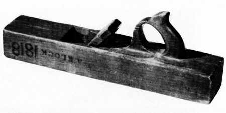 Figure 26.—1818: The jack plane, used first by the
carpenter for rapid surfacing, is distinguished primarily by the bezeled
and slightly convex edge of its cutting iron. As with the plow and the
rabbet, its shape is ubiquitous. Dated and marked A. Klock, this
American example follows precisely those detailed in Sheffield pattern
books. (Smithsonian photo 49794-C.)
Figure 26.—1818: The jack plane, used first by the
carpenter for rapid surfacing, is distinguished primarily by the bezeled
and slightly convex edge of its cutting iron. As with the plow and the
rabbet, its shape is ubiquitous. Dated and marked A. Klock, this
American example follows precisely those detailed in Sheffield pattern
books. (Smithsonian photo 49794-C.)
 Figure 27.—1830–1840: Detail of the rabbet plane (fig.
25) showing the characteristic stamp of E.W. Carpenter. (Smithsonian
photo 49794-D.)
Figure 27.—1830–1840: Detail of the rabbet plane (fig.
25) showing the characteristic stamp of E.W. Carpenter. (Smithsonian
photo 49794-D.)
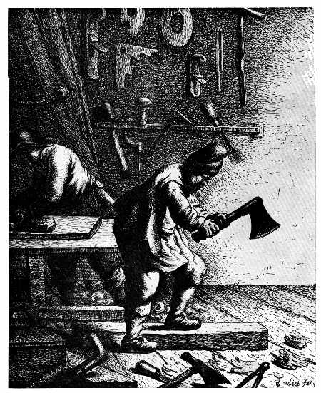 Figure 28.—About 1631: The preceding illustrations
emphasize the divergent appearance of European and Anglo-American tools.
This, however, was not always the case. The woodworker's shop by the
Dutch engraver Jan Van Vliet suggests the similarity between English and
European tool types in the 17th century. Note in particular the planes,
axe, brace, and auger as compared to Moxon. (Library of Congress,
Division of Prints and Photographs.)
Figure 28.—About 1631: The preceding illustrations
emphasize the divergent appearance of European and Anglo-American tools.
This, however, was not always the case. The woodworker's shop by the
Dutch engraver Jan Van Vliet suggests the similarity between English and
European tool types in the 17th century. Note in particular the planes,
axe, brace, and auger as compared to Moxon. (Library of Congress,
Division of Prints and Photographs.)
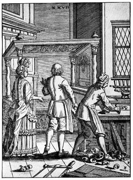 Figure 29.—1690: The cabinetmaker's shop from Elias
Pozelius, Orbus Pictus nach Zeichnugen der Susanna Maria Sandrart,
Nürnberg, 1690. (Library of Congress.)
Figure 29.—1690: The cabinetmaker's shop from Elias
Pozelius, Orbus Pictus nach Zeichnugen der Susanna Maria Sandrart,
Nürnberg, 1690. (Library of Congress.)
 Figure 30.—1568: The woodworker's shop from Hans Sachs,
Eygentliche Beschrerbung Aller Stande ... mit Kunstreichen Figuren [by
Jost Amman], Frankfurt, 1568. (Library of Congress.)
Figure 30.—1568: The woodworker's shop from Hans Sachs,
Eygentliche Beschrerbung Aller Stande ... mit Kunstreichen Figuren [by
Jost Amman], Frankfurt, 1568. (Library of Congress.)
The divergence from European to an Anglo-American hand-tool design and the approximate date that it occurred can be suggested by a comparison of contemporary illustrations. The change in the wooden bench plane can be followed from the early 17th century through its standardization at the end of the 18th century. Examine first the planes as drawn in the 1630's by the Dutchman Jan Van Vliet (fig. 28), an etcher of Rembrandt's school at Leiden, and also the examples illustrated by Porzelius (fig. 29) and by Jost Amman (fig. 30). Compare them to Moxon's plate (fig. 31) from the Mechanick Exercises (3rd ed., 1703) and to the splendid drawing of the bench plane from André-Jacob Roubo's L'Art du menuisier, published in 1769 (fig. 32). In all of them, the rounded handle, or tote, and the fore-horn appear, characteristics of both European and English planes of the period before 1750. The similarity ends with the mass production of hand tools from the shops of the English toolmaking centers, principally Sheffield. An illustration from a pattern and design book of the Castle Hill Works, Sheffield, dating from the last quarter of the 18th century (fig. 33), shows the achieved, familiar form of the bench planes, as well as other tools. The use of this form in America is readily documented in Lewis Miller's self-portrait while working at his trade in York, Pennsylvania, in 1810 (fig. 34) and by the shop sign carved by Isaac Fowle in 1820 for John Bradford (fig. 35). In each example, the bench plane clearly follows the English prototype.
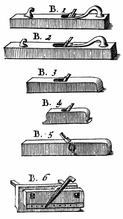 Figure 31.—1703: Detail of the bench planes from Moxon's
Mechanick Exercises.
Figure 31.—1703: Detail of the bench planes from Moxon's
Mechanick Exercises.
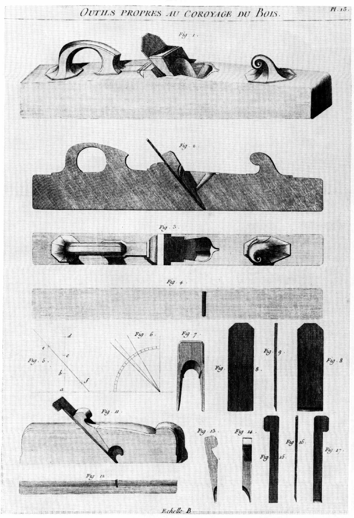 Figure 32.—1769: André-Jacob Roubo's precise rendering
of the bench plane retains the essential features shown by Moxon—the
rounded tote or handle and the curved fore-horn. (André-Jacob Roubo,
L'Art du menuisier, 1769.)
Figure 32.—1769: André-Jacob Roubo's precise rendering
of the bench plane retains the essential features shown by Moxon—the
rounded tote or handle and the curved fore-horn. (André-Jacob Roubo,
L'Art du menuisier, 1769.)
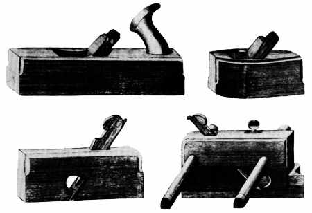 Figure 33.—Early 19th century: The bench plane
illustrated in Roubo or Moxon is seldom seen in American tool
collections. The bench planes, smoothing planes, rabbets, and plows
universally resemble those shown in this illustration from the pattern
book of the Castle Hill Works, Sheffield. (Book 87, Cutler and Company,
Castle Hill Works, Sheffield. Courtesy of the Victoria and Albert
Museum.)
Figure 33.—Early 19th century: The bench plane
illustrated in Roubo or Moxon is seldom seen in American tool
collections. The bench planes, smoothing planes, rabbets, and plows
universally resemble those shown in this illustration from the pattern
book of the Castle Hill Works, Sheffield. (Book 87, Cutler and Company,
Castle Hill Works, Sheffield. Courtesy of the Victoria and Albert
Museum.)
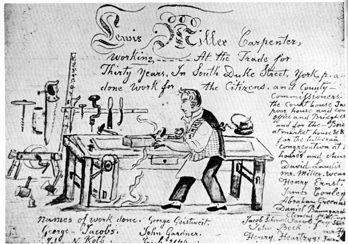 Figure 34.—About 1810: Lewis Miller working at his bench
in York, Pa. In a predominantly Pennsylvania-German settlement, the
plane used by Miller conforms to the Sheffield type illustrated in the
catalogue of the Castle Hill Works as shown in figure 33. (York County
Historical Society, York, Pa.)
Figure 34.—About 1810: Lewis Miller working at his bench
in York, Pa. In a predominantly Pennsylvania-German settlement, the
plane used by Miller conforms to the Sheffield type illustrated in the
catalogue of the Castle Hill Works as shown in figure 33. (York County
Historical Society, York, Pa.)
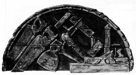 Figure 35.—1820: John Bradford's shop sign carved by
Isaac Fowle is a unique documentary of early 19th-century tool shapes
and is in the Bostonian Society, Boston, Mass. (Index of American
Design, The National Gallery, Washington, D.C.)
Figure 35.—1820: John Bradford's shop sign carved by
Isaac Fowle is a unique documentary of early 19th-century tool shapes
and is in the Bostonian Society, Boston, Mass. (Index of American
Design, The National Gallery, Washington, D.C.)
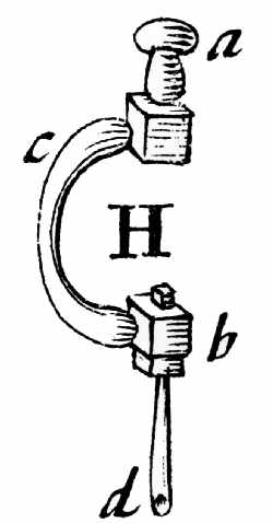 Figure 36.—1703: The joiner's brace and bit—a detail
from Moxon, Mechanick Exercises ..., London, 1703. (Library of
Congress, Smithsonian photo 56635.)
Figure 36.—1703: The joiner's brace and bit—a detail
from Moxon, Mechanick Exercises ..., London, 1703. (Library of
Congress, Smithsonian photo 56635.)
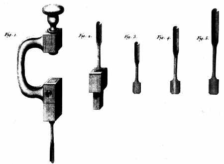 Figure 37.—1769: Roubo's illustration of the brace and
bit differs from Moxon's only in the precision of the delineation.
Contrast this form with that of the standard Sheffield version in figure
38 and the metallic braces illustrated in figures 40 through 44. From
these plates can be seen the progression of the bitstock toward its
ultimate perfection in the late 19th century. (André-Jacob Roubo, L'Art
du menuisier, 1769.)
Figure 37.—1769: Roubo's illustration of the brace and
bit differs from Moxon's only in the precision of the delineation.
Contrast this form with that of the standard Sheffield version in figure
38 and the metallic braces illustrated in figures 40 through 44. From
these plates can be seen the progression of the bitstock toward its
ultimate perfection in the late 19th century. (André-Jacob Roubo, L'Art
du menuisier, 1769.)
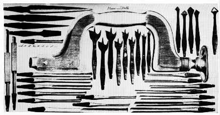 Figure 38.—Early 19th century: The mass-produced version
of the wooden brace and bit took the form illustrated in Book 87 of
Cutler's Castle Hill Works. (Courtesy of the Victoria and Albert
Museum.)
Figure 38.—Early 19th century: The mass-produced version
of the wooden brace and bit took the form illustrated in Book 87 of
Cutler's Castle Hill Works. (Courtesy of the Victoria and Albert
Museum.)
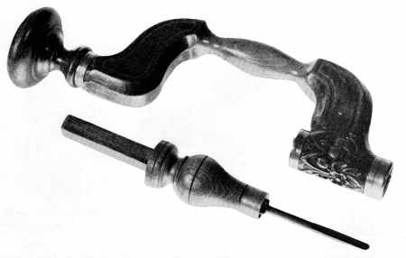 Figure 39.—18th century: The transitional form of the
wooden brace and bit incorporated the overall shape of the mass-produced
version but retained the archaic method of fastening the bit to the
chuck. The tool is of Dutch origin and suggests the influence of
Sheffield design on European tools. (Smithsonian photo 49792-E.)
Figure 39.—18th century: The transitional form of the
wooden brace and bit incorporated the overall shape of the mass-produced
version but retained the archaic method of fastening the bit to the
chuck. The tool is of Dutch origin and suggests the influence of
Sheffield design on European tools. (Smithsonian photo 49792-E.)
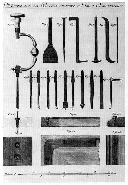 Figure 40.—1769: Roubo illustrated the metallic brace
and, in addition, suggested its use as a screwdriver. (André-Jacob
Roubo, L'Art du menuisier,1769.)
Figure 40.—1769: Roubo illustrated the metallic brace
and, in addition, suggested its use as a screwdriver. (André-Jacob
Roubo, L'Art du menuisier,1769.)
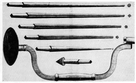 Figure 41.—About 1775: Ford, Whitmore and Brunton made
and sold clockmaker's braces of metal with a sweep and shank that was
imitated by American patentees in the 19th century. (Catalogue of Ford,
Whitmore and Brunton, Birmingham, England. Courtesy of the Birmingham
Reference Library.)
Figure 41.—About 1775: Ford, Whitmore and Brunton made
and sold clockmaker's braces of metal with a sweep and shank that was
imitated by American patentees in the 19th century. (Catalogue of Ford,
Whitmore and Brunton, Birmingham, England. Courtesy of the Birmingham
Reference Library.)
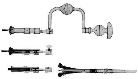 Figure 42.—1852: Nearly one hundred years after Roubo's
plate appeared, Jacob Switzer applied for a patent for an "Improved Self
Holding Screw Driver." The similarity of Switzer's drawing and Roubo's
plate is striking. (Original patent drawing 9,457, U.S. Patent Office,
Record Group 241, the National Archives.)
Figure 42.—1852: Nearly one hundred years after Roubo's
plate appeared, Jacob Switzer applied for a patent for an "Improved Self
Holding Screw Driver." The similarity of Switzer's drawing and Roubo's
plate is striking. (Original patent drawing 9,457, U.S. Patent Office,
Record Group 241, the National Archives.)
 Figure 43.—1866: The simplicity and strength of the
brace proposed by J. Parker Gordon is in sharp contrast to the heavily
splinted sides of the wooden brace commonly used in mid-19th-century
America. (Original patent drawing 52,042, U.S. Patent Office, Record
Group 241, the National Archives.)
Figure 43.—1866: The simplicity and strength of the
brace proposed by J. Parker Gordon is in sharp contrast to the heavily
splinted sides of the wooden brace commonly used in mid-19th-century
America. (Original patent drawing 52,042, U.S. Patent Office, Record
Group 241, the National Archives.)
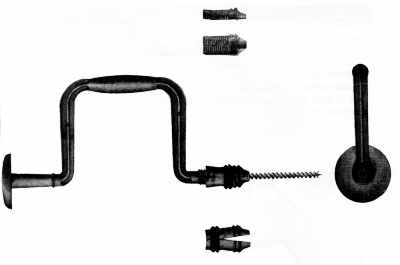 Figure 44.—1865: Milton nobles' patent perfecting the
chuck which held the auger bit was an important step along the path
which led ultimately to the complete acceptance of the metallic brace.
Barber's ratchet brace shown in figure 66 completes the metamorphosis of
this tool form in the United States. (Original patent drawing 51,660,
U.S. Patent Office, Record Group 241, the National Archives.)
Figure 44.—1865: Milton nobles' patent perfecting the
chuck which held the auger bit was an important step along the path
which led ultimately to the complete acceptance of the metallic brace.
Barber's ratchet brace shown in figure 66 completes the metamorphosis of
this tool form in the United States. (Original patent drawing 51,660,
U.S. Patent Office, Record Group 241, the National Archives.)
The carpenter's brace is another instance of divergent design after a common origin. Refer again to Van Vliet's etching of the woodworker's shop (fig. 28), to the detail from Moxon (fig. 36), and from Roubo (fig. 37). All show the brace in a form familiar since the Middle Ages, a shape common to both delineators and craftsmen of the Continent and the British Isles. But, as the plane changed, so changed the brace. The standard form of this tool as it was used and produced in the United States in the 19th century can be seen in another plate from the catalogue of the Castle Hill Works at Sheffield (fig. 38). This English influence on American tool design is no surprise, since as early as 1634 William Wood in New England's Prospect suggested that colonists take to the New World "All manner of Ironwares, as all manner of nailes for houses ... with Axes both broad and pitching ... All manners of Augers, piercing bits, Whip-saws, Two handed saws, Froes ..., rings for Bettle heads, and Iron-wedges."
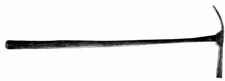 Figure 45.—19th century: The upholsterer's hammer is an
unknown; it is not dated, its maker is anonymous, as is its user. It is
of American origin, yet of a style that might have been used in England
or on the Continent. This lack of provenance need not detract from its
significance as a material survival. This hammer, the brace (fig. 46),
the bevel (fig. 47), and the compass saw (fig. 48) are sufficiently
provocative in their design to conjure some image of a technology
dependent upon the skilled hand of craftsmen working in wood and of the
relationship between the hand, the tool, and the finished product.
(Smithsonian photo 49793-A.)
Figure 45.—19th century: The upholsterer's hammer is an
unknown; it is not dated, its maker is anonymous, as is its user. It is
of American origin, yet of a style that might have been used in England
or on the Continent. This lack of provenance need not detract from its
significance as a material survival. This hammer, the brace (fig. 46),
the bevel (fig. 47), and the compass saw (fig. 48) are sufficiently
provocative in their design to conjure some image of a technology
dependent upon the skilled hand of craftsmen working in wood and of the
relationship between the hand, the tool, and the finished product.
(Smithsonian photo 49793-A.)
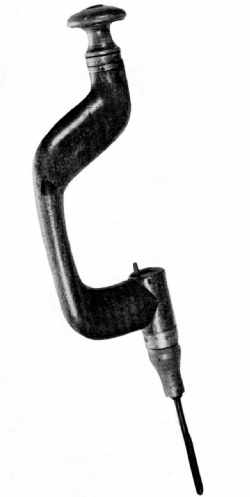 Figure 46.—18th century: The brace and bit in its
nonfactory form conforms to a general design pattern in which none of
the components are ever precisely alike. This aspect of variety of
detail—sophistication, crudeness, decorative qualities or the
like—reflects something of the individuality of the toolmaker, a
quality completely lost in the standardization of the carpenter's brace.
(Smithsonian photo 49794-A.)
Figure 46.—18th century: The brace and bit in its
nonfactory form conforms to a general design pattern in which none of
the components are ever precisely alike. This aspect of variety of
detail—sophistication, crudeness, decorative qualities or the
like—reflects something of the individuality of the toolmaker, a
quality completely lost in the standardization of the carpenter's brace.
(Smithsonian photo 49794-A.)
English tool design in the 18th century also influenced the continental toolmakers. This can be seen in figure 39 in a transitional-type bitstock (accession 319556) from the Low Countries. Adopting an English shape, but still preserving the ancient lever device for holding the bit in place, the piece with its grapevine embellishment is a marked contrast to the severely functional brass chucks on braces of English manufacture. No less a contrast are metallic versions of the brace. These begin to appear with some regularity in the U.S. patent specifications of the 1840's; their design is apparently derived from 18th-century precedents. Roubo (fig. 40) illustrated a metal bitstock in 1769, as did Ford, Whitmore & Brunton, makers of jewelers' and watchmakers' tools, of Birmingham, England, in their trade catalogue of 1775 (fig. 41). Each suggests a prototype of the patented forms of the 1840's. For example, in 1852, Jacob Switzer of Basil, Ohio, suggested, as had Roubo a hundred years earlier, that the bitstock be used as a screwdriver (fig. 42); but far more interesting than Switzer's idea was his delineation of the brace itself, which he described as "an ordinary brace and bit stock" (U.S. pat. 9,457). The inference is that such a tool form was already a familiar one among the woodworking trades in the United States. Disregarding the screwdriver attachment, which is not without merit, Switzer's stock represents an accurate rendering of what was then a well-known form if not as yet a rival of the older wooden brace. Likewise, J. Parker Gordon's patent 52,042 of 1866 exemplifies the strengthening of a basic tool by the use of iron (fig. 43) and, as a result, the achievement of an even greater functionalism in design. The complete break with the medieval, however, is seen in a drawing submitted to the Commissioner of Patents in 1865 (pat. 51,660) by Milton V. Nobles of Rochester, New York.[9] Nobles' creation was of thoroughly modern design and appearance in which, unlike earlier types, the bit was held in place by a solid socket, split sleeve, and a tightening ring (fig. 44). In three centuries, three distinct design changes occurred in the carpenter's brace. First, about 1750, the so-called English or Sheffield bitstock appeared. This was followed in the very early 19th century by the reinforced English type whose sides were splinted by brass strips. Not only had the medieval form largely disappeared by the end of the 18th century, but so had the ancient lever-wedge method of fastening the bit in the stock, a device replaced by the pressure-spring button on the side of the chuck. Finally, in this evolution, came the metallic stock, not widely used in America until after the Civil War, that embodied in its design the influence of mass manufacture and in its several early versions all of the features of the modern brace and bit.
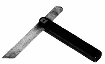 Figure 47.—18th century: The visually pleasing qualities
of walnut and brass provide a level of response to this joiner's bevel
quite apart from its technical significance. (Private collection.
Smithsonian photo 49793-B.)
Figure 47.—18th century: The visually pleasing qualities
of walnut and brass provide a level of response to this joiner's bevel
quite apart from its technical significance. (Private collection.
Smithsonian photo 49793-B.)
 Figure 48.—18th century: The handle of the compass saw,
characteristically Dutch in shape, is an outstanding example of a
recurring functional design, one which varied according to the hand of
the sawer. (Smithsonian photo 49789-C.)
Figure 48.—18th century: The handle of the compass saw,
characteristically Dutch in shape, is an outstanding example of a
recurring functional design, one which varied according to the hand of
the sawer. (Smithsonian photo 49789-C.)
Henry Ward Beecher, impressed by the growing sophistication of the toolmakers, described the hand tool in a most realistic and objective manner as an "extension of a man's hand." The antiquarian, attuned to more subjective and romantic appraisals, will find this hardly sufficient. Look at the upholsterer's hammer (accession 61.35) seen in figure 45: there is no question that it is a response to a demanding task that required an efficient and not too forceful extension of the workman's hand. But there is another response to this implement: namely, the admiration for an unknown toolmaker who combined in an elementary striking tool a hammerhead of well-weighted proportion to be wielded gently through the medium of an extremely delicate handle. In short, here is an object about whose provenance one need know very little in order to enjoy it aesthetically. In a like manner, the 18th-century bitstock of Flemish origin (fig. 46), the English cabinetmaker's bevel of the same century (fig. 47), and the compass saw (accession 61.52, fig. 48) capture in their basic design something beyond the functional extension of the craftsman's hand. The slow curve of the bitstock, never identical from one early example to another, is lost in later factory-made versions; so too, with the coming of cheap steel, does the combination of wood (walnut) and brass used in the cabinetmaker's bevel slowly disappear; and, finally, in the custom-fitted pistol-like grip of the saw, there is an identity, in feeling at least, between craftsman and tool never quite achieved in later mass-produced versions.
 Figure 49.—Early 19th century: The designation
"gentleman's tool chest" required a chest of "high-style" but
necessitated no change in the tools it held. (Book 87, Cutler and
Company, Castle Hill Works, Sheffield. Courtesy of the Victoria and
Albert Museum.)
Figure 49.—Early 19th century: The designation
"gentleman's tool chest" required a chest of "high-style" but
necessitated no change in the tools it held. (Book 87, Cutler and
Company, Castle Hill Works, Sheffield. Courtesy of the Victoria and
Albert Museum.)
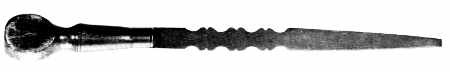 Figure 50.—19th century: The screwdriver, which began to
appear regularly on the woodworker's bench after 1800, did not share the
long evolution and tradition of other Anglo-American tool designs. The
screwdriver in its early versions frequently had a scalloped blade for
no other purpose than decoration. (Smithsonian photo 49794.)
Figure 50.—19th century: The screwdriver, which began to
appear regularly on the woodworker's bench after 1800, did not share the
long evolution and tradition of other Anglo-American tool designs. The
screwdriver in its early versions frequently had a scalloped blade for
no other purpose than decoration. (Smithsonian photo 49794.)
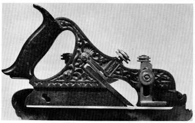 Figure 51.—1870: The use of a new material prompted a
departure from the traditional in shape and encouraged surface
elaboration. The tendency, however, was short lived and the
mass-produced metallic plane rapidly achieved a purity of design as
pleasing as its wooden predecessors. (Private collection. Smithsonian
photo 49789.)
Figure 51.—1870: The use of a new material prompted a
departure from the traditional in shape and encouraged surface
elaboration. The tendency, however, was short lived and the
mass-produced metallic plane rapidly achieved a purity of design as
pleasing as its wooden predecessors. (Private collection. Smithsonian
photo 49789.)
Occasionally, ruling taste is reflected in the design of the carpenter's equipment. Notable is the "gentleman's tool chest" (fig. 49) advertised in the pattern book of the Castle Hill Works. The bracket feet, brass pulls, and inlaid keyholes imitate the style of the domestic chest of drawers of the period 1790 to 1810—undoubtedly, features included by the manufacturer to appeal to a gentleman of refined taste. In contrast to this Sheffield product is the plate from Shaw's The Modern Architect. The concept of the builder-carpenter as a gentleman still prevails, although the idea in this American scene is conveyed in the mid-19th century through fashionable dress. The tools and in particular the tool chest reflect only the severest of functional lines (fig. 19, p. 196).
In deference to ruling taste, some tools lost for a time the clean lines that had long distinguished them. The screwdriver, simple in shape (accession 61.46) but in little demand until the 1840's, occasionally became most elaborate in its factory-made form (fig. 50) and departed noticeably from the unadorned style of traditional English and American tools. The scalloped blade, influenced by the rival styles rather than a technical need, seemed little related to the purpose of the tool.[10] No less archaic in decoration was the iron-bodied version of the plow plane (fig. 51). The Anglo-American tradition seems completely put aside. In its place is a most functional object, but one elaborately covered with a shell and vine motif! Patented in 1870 by Charles Miller and manufactured by the Stanley Rule and Level Company, this tool in its unadorned version is of a type that was much admired by the British experts at Philadelphia's Centennial Exhibition in 1876. What prompted such superfluous decoration on the plow plane? Perhaps it was to appeal to the flood of newly arrived American craftsmen who might find in the rococo something reminiscent of the older tools they had known in Europe. Perhaps it was simply the transference to the tool itself of the decorative work then demanded of the wood craftsmen. Or was it mainly a compulsion to dress, with little effort, a lackluster material that seemed stark and cold to Victorians accustomed to the ornateness being achieved elsewhere with the jigsaw and wood? Whatever the cause, the result did not persist long as a guide to hand-tool design. Instead, the strong, plain lines that had evolved over two centuries won universal endorsement at the Centennial Exhibition. The prize tools reflected little of the ornateness apparent in the wares of most of the other exhibitors. American makers of edge tools exhibiting at the Centennial showed the world not only examples of quality but of attractiveness as well.
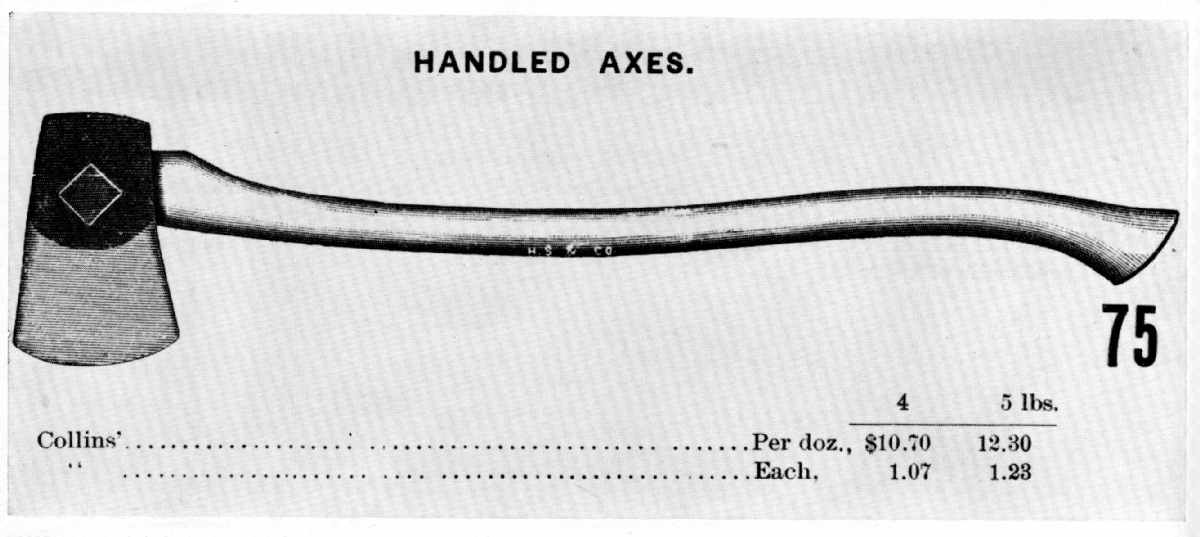 Figure 52.—19th century: The American axe was unexcelled
in design and ease of use. European observers praised it as distinctly
American. At the Centennial Exhibition in 1876 Collins and Company of
New York City was singled out as one of the outstanding manufacturers
exhibiting these axes, a reputation that persisted. (Tools for all
Trades, Hammacher, Schlemmer and Company, New York, 1896. Smithsonian
photo 56625.)
Figure 52.—19th century: The American axe was unexcelled
in design and ease of use. European observers praised it as distinctly
American. At the Centennial Exhibition in 1876 Collins and Company of
New York City was singled out as one of the outstanding manufacturers
exhibiting these axes, a reputation that persisted. (Tools for all
Trades, Hammacher, Schlemmer and Company, New York, 1896. Smithsonian
photo 56625.)
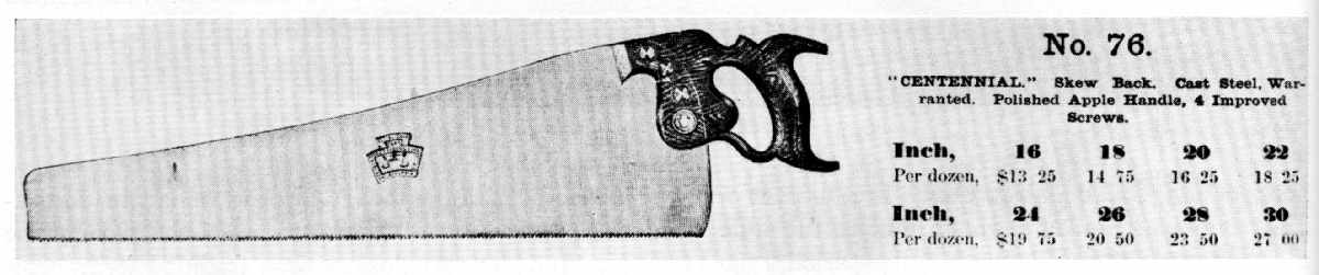 Figure 53.—1876: Disston and Sons long continued to
remind prospective buyers of the company's success at the Philadelphia
Centennial Exhibition by retaining the "Centennial Saw, No. 76" as a
brand name. (Illustrated Catalogue, Baldwin, Robbins and Company,
Boston, 1894. Smithsonian photo 56627.)
Figure 53.—1876: Disston and Sons long continued to
remind prospective buyers of the company's success at the Philadelphia
Centennial Exhibition by retaining the "Centennial Saw, No. 76" as a
brand name. (Illustrated Catalogue, Baldwin, Robbins and Company,
Boston, 1894. Smithsonian photo 56627.)
American hand tools in 1876 did not achieve the popular acclaim accorded the Corliss engine, yet few products shown by American exhibitors were more highly praised by foreign experts. It seems justified to suggest that American edge tools displayed at the Centennial had reached their high point of development—a metamorphosis that began with the medieval European tool forms, moved through a period of reliance on English precedents, and ended, in the last quarter of the 19th century, with the production of American hand tools "occupying an enviable position before the world."[11]
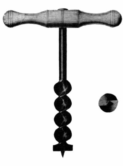 Figure 54.—1809: The introduction of the gimlet-pointed
auger followed Ezra L'Hommedieu's patent of 1809. From this date until
its general disuse in the early 20th century, the conformation of the
tool remained unchanged, although the quality of steel and the precision
of the twist steadily improved. (Wash drawing from the restored patent
drawings awarded July 31, 1809, U.S. Patent Office, Record Group 241,
the National Archives. Smithsonian photo 49790-A.)
Figure 54.—1809: The introduction of the gimlet-pointed
auger followed Ezra L'Hommedieu's patent of 1809. From this date until
its general disuse in the early 20th century, the conformation of the
tool remained unchanged, although the quality of steel and the precision
of the twist steadily improved. (Wash drawing from the restored patent
drawings awarded July 31, 1809, U.S. Patent Office, Record Group 241,
the National Archives. Smithsonian photo 49790-A.)
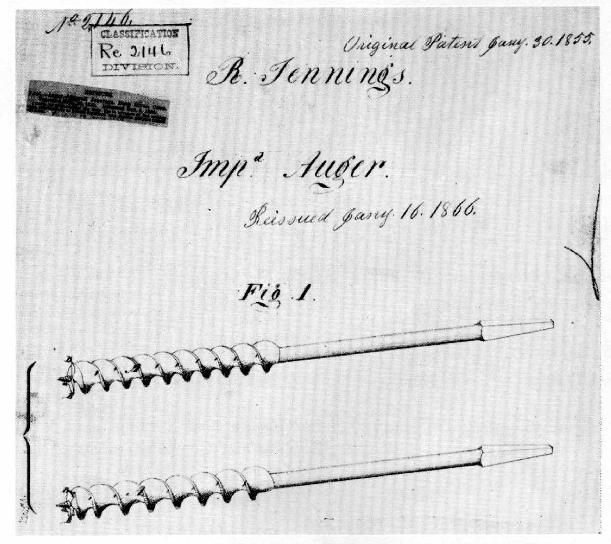 Figure 55.—1855: Russell Jennings' improved auger bits,
first patented in 1855, received superior citation at the Philadelphia
Centennial; in the years following, the trade name "Jennings" was seldom
omitted from trade catalogues. (Original wash drawing, patent drawing
submitted by R. Jennings, U.S. Patent Office, Record Group 241, the
National Archives.)
Figure 55.—1855: Russell Jennings' improved auger bits,
first patented in 1855, received superior citation at the Philadelphia
Centennial; in the years following, the trade name "Jennings" was seldom
omitted from trade catalogues. (Original wash drawing, patent drawing
submitted by R. Jennings, U.S. Patent Office, Record Group 241, the
National Archives.)
The tool most highly praised at Philadelphia was the American felling axe (fig. 52) "made out of a solid piece of cast steel" with the eye "punched out of the solid." When compared to other forms, the American axe was "more easily worked," and its shape permitted an easier withdrawal after striking.[12]
Sawmakers, too, were singled out for praise—in particular Disston & Sons (fig. 53) for "improvements in the form of the handles, and in the mode of fixing them to the saw." The Disston saw also embodied an improved blade shape which made it "lighter and more convenient by giving it a greater taper to the point." Sheffield saws, once supplied to most of the world, were not exhibited at Philadelphia, and the British expert lamented that our "monopoly remains with us no longer."[13]
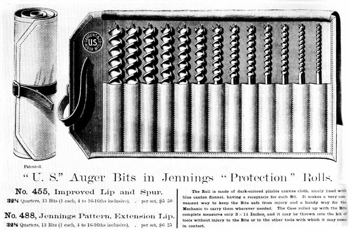 Figure 56.—1894: The Persistence of "jennings" As a
Trade Name is suggested by the vignette from the "Illustrated Catalogue"
of Baldwin, Robbins and Company, published in 1894. (Smithsonian photo
56628.)
Figure 56.—1894: The Persistence of "jennings" As a
Trade Name is suggested by the vignette from the "Illustrated Catalogue"
of Baldwin, Robbins and Company, published in 1894. (Smithsonian photo
56628.)
Augers, essential to "the heavier branches of the building trade ... [and] in the workshops of joiners, carpenters, cabinetmakers, turners, carvers, and by amateurs and others," were considered a "most important exhibit" at the Centennial. The auger had attained a perfection in "the accuracy of the twist, the various forms of the cutters, the quality of the steel, and fine finish of the twist and polish." The ancient pod or shell auger had nearly disappeared from use, to be replaced by "the screwed form of the tool" considerably refined by comparison to L'Hommedieu's prototype, patented in 1809 (fig. 54). Russell Jennings' patented auger bits (figs. 55–56) were cited for their "workmanship and quality," and, collectively, the Exhibition "fully established the reputation of American augers."[14] Likewise, makers of braces and bits were commended for the number of excellent examples shown. Some were a departure from the familiar design with "an expansive chuck for the bit," but others were simply elegant examples of the traditional brace, in wood, japanned and heavily reinforced with highly polished brass sidings. An example exhibited by E. Mills and Company, of Philadelphia, received a certification from the judges as being "of the best quality and finish" (fig. 57). The Mills brace, together with other award-winning tools of the company—drawknives, screwdrivers, and spokeshaves—is preserved in the collections of the Smithsonian Institution (accession 319326). Today as a group they confirm "the remarkably fine quality of ... both iron and steel" that characterized the manufacture of American edge tools in the second half of the 19th century.[15]
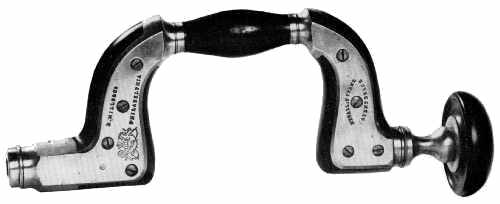 Figure 57.—1876: Japanned and splinted with heavy brass,
this brace was among the award-winning tools exhibited at the Centennial
by E. Mills and Company of Philadelphia. (Smithsonian photo 49792-D.)
Figure 57.—1876: Japanned and splinted with heavy brass,
this brace was among the award-winning tools exhibited at the Centennial
by E. Mills and Company of Philadelphia. (Smithsonian photo 49792-D.)
 Figure 58.—1827: The bench planes exhibited at
Philadelphia in 1876 were a radical departure from the traditional. In
1827 H. Knowles patented an iron-bodied bench plane that portended a
change in form that would witness a substitution of steel for wood in
all critical areas of the tool's construction, and easy adjustment of
the cutting edge by a setscrew, and an increased flexibility that
allowed one plane to be used for several purposes. (Wash drawing from
the restored patent drawings, August 24, 1827, U.S. Patent Office,
Record Group 241, the National Archives.)
Figure 58.—1827: The bench planes exhibited at
Philadelphia in 1876 were a radical departure from the traditional. In
1827 H. Knowles patented an iron-bodied bench plane that portended a
change in form that would witness a substitution of steel for wood in
all critical areas of the tool's construction, and easy adjustment of
the cutting edge by a setscrew, and an increased flexibility that
allowed one plane to be used for several purposes. (Wash drawing from
the restored patent drawings, August 24, 1827, U.S. Patent Office,
Record Group 241, the National Archives.)
 Figure 59.—1857: The addition of metallic parts to
critical areas of wear as suggested by M.B. Tidey did not at first
radically alter the design of the bench plane. (Wash drawing from U.S.
Patent Office, March 24, 1857, Record Group 241, the National
Archives.)
Figure 59.—1857: The addition of metallic parts to
critical areas of wear as suggested by M.B. Tidey did not at first
radically alter the design of the bench plane. (Wash drawing from U.S.
Patent Office, March 24, 1857, Record Group 241, the National
Archives.)
It is the plane, however, that best exemplifies the progress of tool design. In 1876, American planemakers were enthusiastically credited with having achieved "an important change in the structure of the tool."[16] Although change had been suggested by American patentees as early as the 1820's, mass production lagged until after the Civil War, and the use of this new tool form was not widespread outside of the United States. Hazard Knowles of Colchester, Connecticut, in 1827, patented a plane stock of cast iron which in many respects was a prototype of later Centennial models (fig. 58).[17] It is evident, even in its earliest manifestation, that the quest for improvement of the bench plane did not alter its sound design. In 1857, M.B. Tidey (fig. 59) listed several of the goals that motivated planemakers:
First to simplify the manufacturing of planes; second to render them more durable; third to retain a uniform mouth; fourth to obviate their clogging; and fifth the retention of the essential part of the plane when the stock is worn out.[18]
By far the greatest number of patents was concerned with perfecting an adjustable plane iron and methods of constructing the sole of a plane so that it would always be "true." Obviously the use of metal rather than the older medium, wood, was a natural step, but in the process of changing from the wood to the iron-bodied bench plane there were many transitional suggestions that combined both materials. Seth Howes of South Chatham, Massachusetts, in U.S. patent 37,694, specified:
This invention relates to an improvement in that class of planes which are commonly termed "bench-planes," comprising the foreplane, smoothing plane, jack plane, jointer, &c.
The invention consists in a novel and improved mode of adjusting the plane-iron to regulate the depth of the cut of the same, in connection with an adjustable cap, all being constructed and arranged in such a manner that the plane-iron may be "set" with the greatest facility and firmly retained in position by the adjustment simply of the cap to the plane-iron, after the latter is set, and the cap also rendered capable of being adjusted to compensate for the wear of the "sole" or face of the plane stock.
The stock of Howes' plane was wood combined with metal plates, caps, and screws. Thomas Worrall of Lowell was issued patent 17,657 for a plane based on the same general principle (fig. 60). Worrall claimed in his specifications of June 23, 1857:
the improved manufacture of [the] carpenter's bench plane or jointer as made with its handle, its wooden stock to which said handle is affixed, and a separate metallic cutter holder, and cutter clamping devices arranged together substantially as specified.
Finally patentees throughout the 19th century, faced with an increasing proliferation of tool types, frequently sought to perfect multipurpose implements of a type best represented later by the ubiquitous Stanley plane. The evolution of the all-purpose idea, which is incidentally not peculiar to hand tools alone, can be seen from random statements selected from U.S. patents for the improvement of bench planes. In 1864 Stephen Williams in the specifications of his patent 43,360 stated:
I denominate my improvement the "universal smoothing plane," because it belongs to that variety of planes in which the face is made changeable, so that it may be conveniently adapted to the planing of curved as well as straight surfaces. By the use of my improvement surfaces that are convex, concave, or straight may be easily worked, the face of the tool being readily changed from one form to another to suit the surface to which it is to be applied.
The announced object of Theodore Duval's improved grooving plane (pat. 97,177) was "to produce in one tool all that is required to form grooves of several different widths." None was more appealing than Daniel D. Whitker's saw-rabbet plane (pat. 52,478) which combined "an adjustable saw with an adjustable fence or gage, both being attached to a stock with handle similar to a plane, forming together a tool combining the properties of the joiner's plow and fillister" (fig. 61). Nor was Whitker's idea simply a drawing-board exercise. It was produced commercially and was well advertised, as seen in the circular reproduced in figure 62.
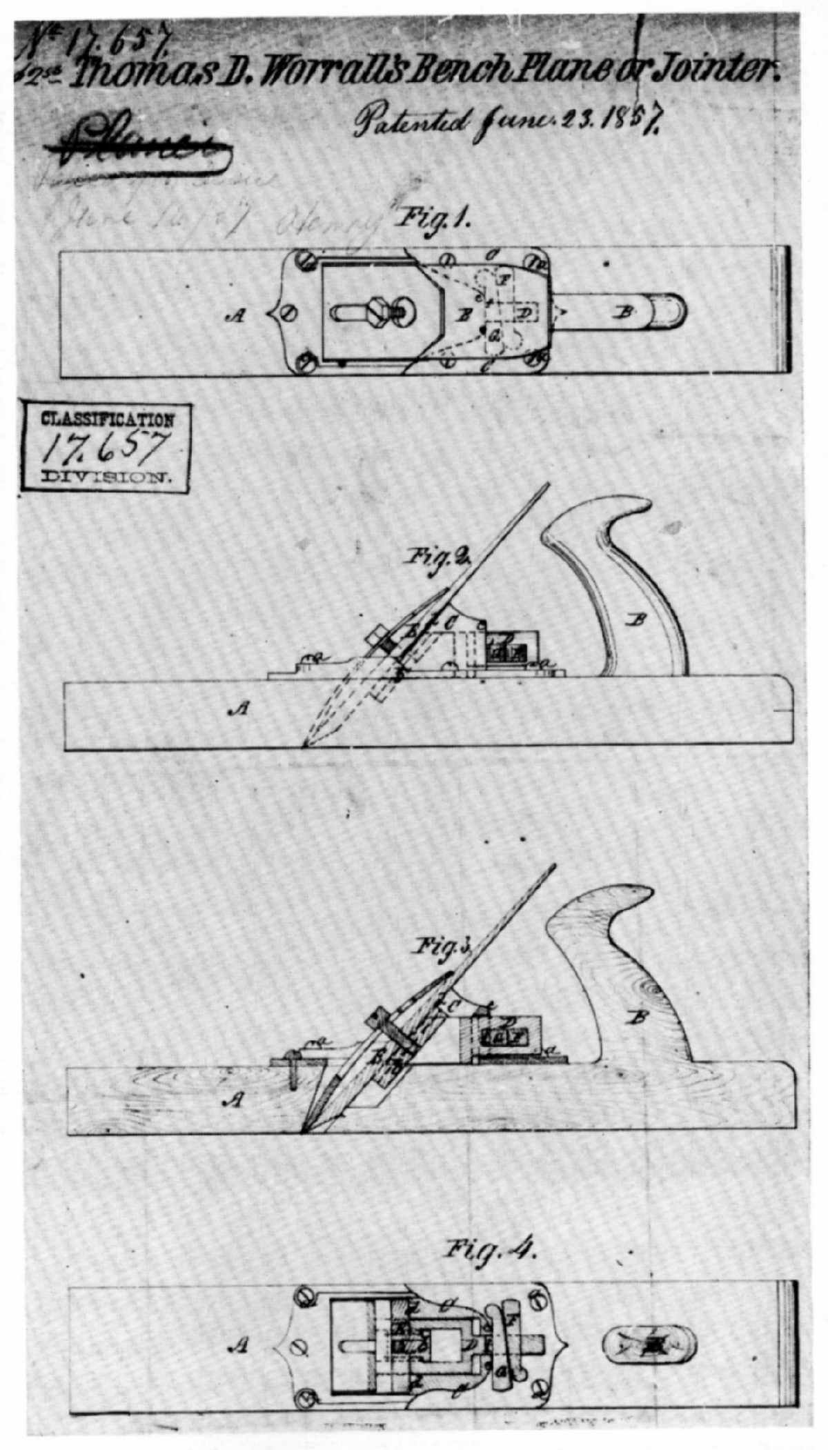 Figure 60.—1857: In a variety of arrangements, the
addition of metal plates, caps, and screws at the mouth of the plane, as
shown in Thomas Worrall's drawing, proved a transitional device that
preserved the ancient shape of the tool and slowed the introduction of
bench planes made entirely of iron. (Wash drawing from U.S. Patent
Office, June 23, 1857, Record Group 241, the National Archives.)
Figure 60.—1857: In a variety of arrangements, the
addition of metal plates, caps, and screws at the mouth of the plane, as
shown in Thomas Worrall's drawing, proved a transitional device that
preserved the ancient shape of the tool and slowed the introduction of
bench planes made entirely of iron. (Wash drawing from U.S. Patent
Office, June 23, 1857, Record Group 241, the National Archives.)
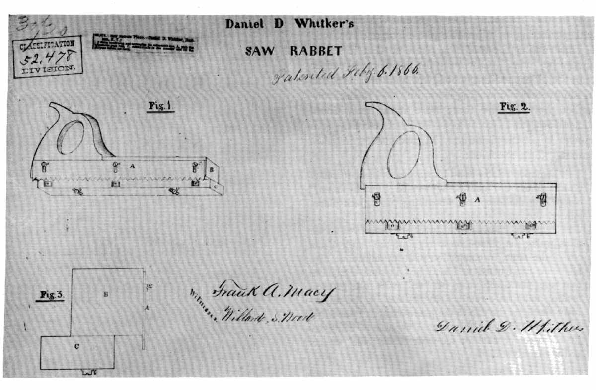 Figure 61.—1865: Not all multipurpose innovations
resulted from the use of new materials. Daniel D. Whitker patented a
combination saw and rabbet plane little different from one illustrated
by André-Jacob Roubo in his L'Art du menuisier in 1769. (Wash drawing
from U.S. Patent Office, October 4, 1865, Record Group 241, the National
Archives.)
Figure 61.—1865: Not all multipurpose innovations
resulted from the use of new materials. Daniel D. Whitker patented a
combination saw and rabbet plane little different from one illustrated
by André-Jacob Roubo in his L'Art du menuisier in 1769. (Wash drawing
from U.S. Patent Office, October 4, 1865, Record Group 241, the National
Archives.)
In sum, these ideas produced a major break with the traditional shape of the bench plane. William Foster in 1843 (pat. 3,355), Birdsill Holly in 1852 (pat. 9,094), and W.S. Loughborough in 1859 (pat. 23,928) are particularly good examples of the radical departure from the wooden block. And, in the period after the Civil War, C.G. Miller (discussed on p. 213 and in fig. 63), B.A. Blandin (fig. 64), and Russell Phillips (pat. 106,868) patented multipurpose metallic bench planes of excellent design. It should be pointed out that the patentees mentioned above represent only a few of the great number that tried to improve the plane. Only the trend of change is suggested by the descriptions and illustrations presented here. The cumulative effect awaited a showcase, and the planemakers found it at the Centennial Exhibition of 1876 held in Philadelphia.
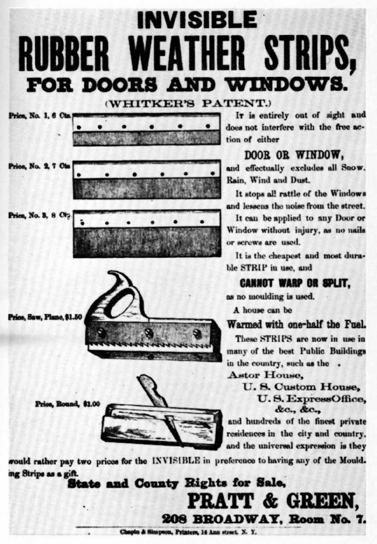 Figure 62.—About 1865: The progress of an idea from an
18th-century encyclopedia through an American patentee to commercial
reality can be seen in this flier advertising Whitker's saw-rabbet.
(Smithsonian Institution Library. Smithsonian photo 56629.)
Figure 62.—About 1865: The progress of an idea from an
18th-century encyclopedia through an American patentee to commercial
reality can be seen in this flier advertising Whitker's saw-rabbet.
(Smithsonian Institution Library. Smithsonian photo 56629.)
The impact of these new planes at the Exhibition caused some retrospection among the judges:
The planes manufactured in Great Britain and in other countries fifty years ago were formed of best beech-wood; the plane irons were of steel and iron welded together; the jointer plane, about 21 inches long, was a bulky tool; the jack and hand planes were of the same materials. Very little change has been made upon the plane in Great Britain, unless in the superior workmanship and higher quality of the plane iron.[19]
The solid wood-block plane, varying from country to country only in the structure of its handles and body decoration, had preserved its integrity of design since the Middle Ages. At the Centennial, however, only a few examples of the old-type plane were exhibited. A new shape dominated the cases. Designated by foreign observers as the American plane, it received extended comment. Here was a tool
constructed with a skeleton iron body, having a curved wooden handle; the plane iron is of the finest cast-steel; the cover is fitted with an ingenious trigger at the top, which, with a screw below the iron, admits of the plane iron being removed for sharpening and setting without the aid of the hammer, and with the greatest ease. The extensive varieties of plane iron in use are fitted for every requirement; a very ingenious arrangement is applied to the tools for planing the insides of circles or other curved works, such as stair-rails, etc. The sole of the plane is formed of a plate of tempered steel about the thickness of a handsaw, according to the length required, and this plate is adapted to the curve, and is securely fixed at each end. With this tool the work is not only done better but in less time than formerly. In some exhibits the face of the plane was made of beech or of other hard wood, secured by screws to the stock, and the tool becomes a hybrid, all other parts remaining the same as in the iron plane.[20]
The popularity of Bailey's patented planes (fig. 65), the type so praised above, was by no means transitory. In 1884 the Boston firm of Goodnow & Wightman, "Importers, Manufacturers and Dealers in Tools of all kinds," illustrated the several planes just described and assured prospective buyers that
These tools meet with universal approbation from the best Mechanics. For beauty of style and finish they are unequalled, and the great convenience in operating renders them the cheapest Planes in use; they are SELF-ADJUSTING in every respect; and each part being made INTERCHANGEABLE, can be replaced at a trifling expense.[21]
By 1900 an advertisement for Bailey's planes published in the catalogue of another Boston firm, Chandler and Farquhar, indicated that "over 900,000" had already been sold.[22]
Other mass-produced edge tools—axes, adzes, braces and bits, augers, saws, and chisels—illustrated in the trade literature of the toolmakers became, as had the iron-bodied bench plane, standard forms. In the last quarter of the 19th century the tool catalogue replaced Moxon, Duhamel, Diderot, and the builders' manuals as the primary source for the study and identification of hand tools. The Centennial had called attention to the superiority of certain American tools and toolmakers. The result was that until the end of the century, trade literature faithfully drummed the products that had proven such "an attraction to the numerous artisans who visited the Centennial Exhibition from the United States and other countries."[23]
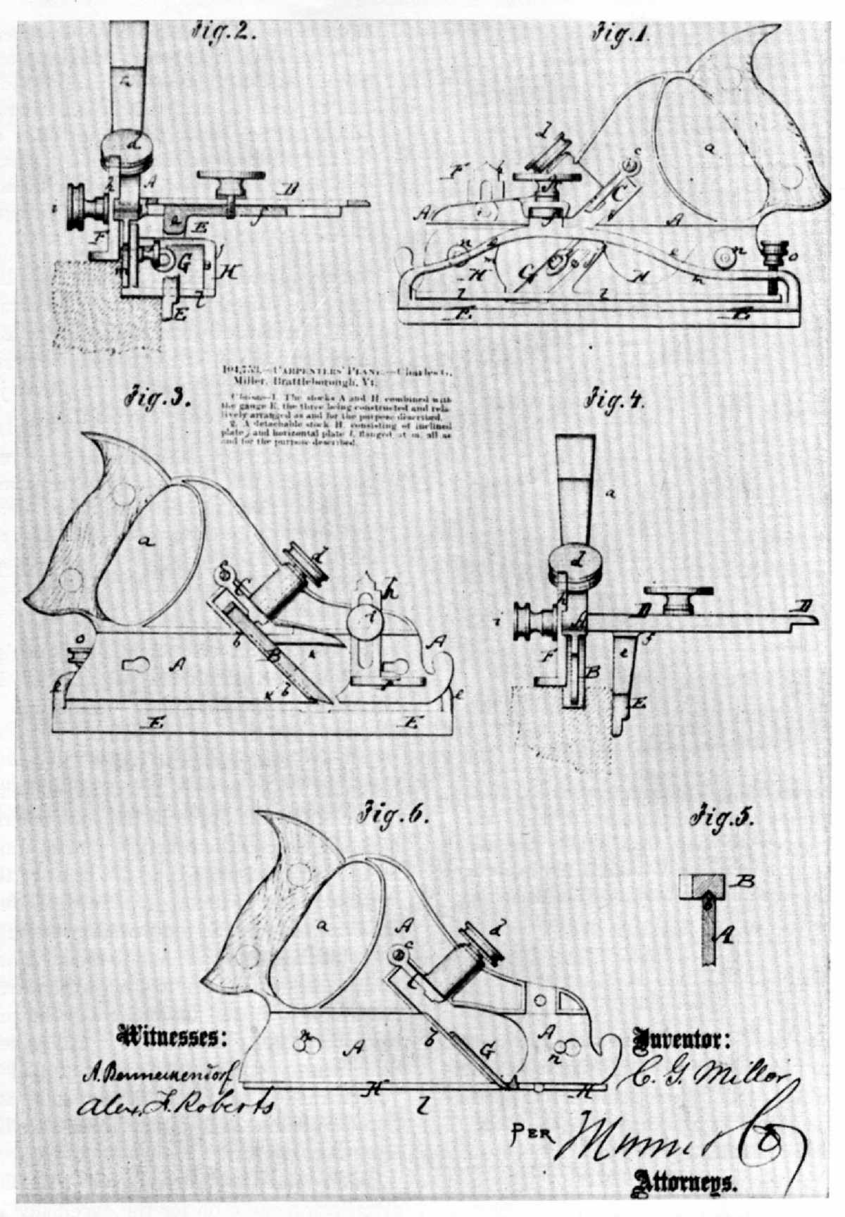 Figure 63.—1870: The metallic version of the plow plane
later produced by Stanley and Company was patented by [Charles] G.
Miller as a tool readily "convertible into a grooving, rabbeting, or
smoothing plane." In production this multipurpose plow gained an
elaborate decoration (fig. 51) nowhere suggested in Miller's
specification. (Wash drawing from U.S. Patent Office, June 28, 1870,
Record Group 241, the National Archives.)
Figure 63.—1870: The metallic version of the plow plane
later produced by Stanley and Company was patented by [Charles] G.
Miller as a tool readily "convertible into a grooving, rabbeting, or
smoothing plane." In production this multipurpose plow gained an
elaborate decoration (fig. 51) nowhere suggested in Miller's
specification. (Wash drawing from U.S. Patent Office, June 28, 1870,
Record Group 241, the National Archives.)
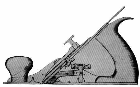 Figure 64.—1867: The drawing accompanying B.A. Blandin's
specification for an "Improvement in Bench Planes" retained only the
familiarly shaped handle or tote of the traditional wood-bodied plane.
This new shape rapidly became the standard form of the tool with later
variations chiefly related to the adjustability of the plane-iron and
sole. (Wash drawing from U.S. Patent Office, May 7, 1867, Record Group
241, the National Archives.)
Figure 64.—1867: The drawing accompanying B.A. Blandin's
specification for an "Improvement in Bench Planes" retained only the
familiarly shaped handle or tote of the traditional wood-bodied plane.
This new shape rapidly became the standard form of the tool with later
variations chiefly related to the adjustability of the plane-iron and
sole. (Wash drawing from U.S. Patent Office, May 7, 1867, Record Group
241, the National Archives.)
Collins and Company of New York City had been given commendation for the excellence of their axes; through the end of the century, Collins' brand felling axes, broad axes, and adzes were standard items, as witness Hammacher, Schlemmer and Company's catalogue of 1896.[24] Disston saws were a byword, and the impact of their exhibit at Philadelphia was still strong, as judged from Baldwin, Robbins' catalogue of 1894. Highly recommended was the Disston no. 76, the "Centennial" handsaw with its "skew back" and "apple handle." Jennings' patented auger bits were likewise standard fare in nearly every tool catalogue.[25] So were bench planes manufactured by companies that had been cited at Philadelphia for the excellence of their product; namely, The Metallic Plane Company, Auburn, New York; The Middletown Tool Company, Middletown, Connecticut; Bailey, Leonard, and Company, Hartford; and The Sandusky Tool Company, Sandusky, Ohio.[26]
An excellent indication of the persistence of the Centennial influence, and of the tool catalogue as source material, is seen in Chandler and Farquhar's illustrated pamphlet of 1900. Their advertisement for Barber's improved ratchet brace (fig. 66), a tool much admired by the Centennial judges, amply illustrates the evolution of design of a basic implement present in American society since the first years of settlement. The Barber brace represents the ultimate sophistication of a tool, achieved through an expanded industrial technology rather than by an extended or newly found use for the device itself. It is a prime example of the transition of a tool from Moxon to its perfected form in the 20th century:
These Braces possess the following points of superiority: The Sweep is made from Steel; the Jaws are forged from Steel; the Wood Handle has brass rings inserted in each end so it cannot split off; the Chuck has a hardened Steel antifriction washer between the two sockets, thus reducing the wear. The Head has a bearing of steel balls, running on hard steel plates, so no wear can take place, as the friction is reduced to the minimum. The Brace is heavily nickel-plated and warranted in every particular. We endeavor to make these goods as nearly perfection as is possible in durability, quality of material and workmanship, and fineness and beauty of finish.[27]
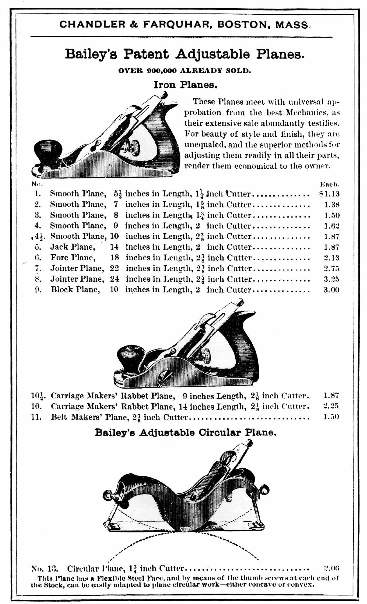 Figure 65.—1900: American planemakers had been cited at
the Philadelphia Centennial as having introduced a dramatic change in
the nature of the tool. Although wood-bodied planes continued to be
used, they were outdated and in fact anachronistic by the close of the
19th century. From the 1870's forward, it was the iron-bodied plane,
most frequently Bailey's, that enlivened the trade literature.
(Catalogue of Chandler and Farquhar, Boston, 1900. Smithsonian photo
55798.)
Figure 65.—1900: American planemakers had been cited at
the Philadelphia Centennial as having introduced a dramatic change in
the nature of the tool. Although wood-bodied planes continued to be
used, they were outdated and in fact anachronistic by the close of the
19th century. From the 1870's forward, it was the iron-bodied plane,
most frequently Bailey's, that enlivened the trade literature.
(Catalogue of Chandler and Farquhar, Boston, 1900. Smithsonian photo
55798.)
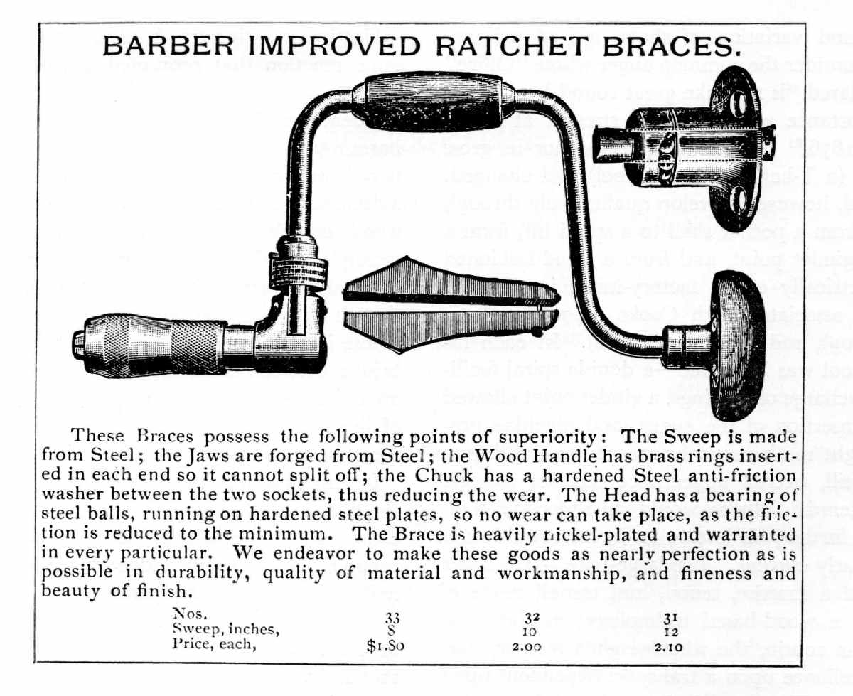 Figure 66.—1900: Few tools suggest more clearly the
influence of modern industrial society upon the design and construction
of traditional implements than Barber's ratchet brace. It is not without
interest that as the tools of the wood craftsman became crisply
efficient, his work declined correspondingly in individuality and
character. The brace and the plane, as followed from Moxon through the
trade literature of the late 19th century, achieved perfection in form
and operation at a time when their basic functions had been usurped by
machines. (Catalogue of Chandler and Farquhar, Boston, 1900. Smithsonian
photo 56626.)
Figure 66.—1900: Few tools suggest more clearly the
influence of modern industrial society upon the design and construction
of traditional implements than Barber's ratchet brace. It is not without
interest that as the tools of the wood craftsman became crisply
efficient, his work declined correspondingly in individuality and
character. The brace and the plane, as followed from Moxon through the
trade literature of the late 19th century, achieved perfection in form
and operation at a time when their basic functions had been usurped by
machines. (Catalogue of Chandler and Farquhar, Boston, 1900. Smithsonian
photo 56626.)
The description of Barber's brace documents a major technical change: wood to steel, leather washers to ball bearings, and natural patina to nickel plate. It is also an explanation for the appearance and shape of craftmen's tools, either hand forged or mass produced. In each case, the sought-after result in the form of a finished product has been an implement of "fineness and beauty." This quest motivated three centuries of toolmakers and brought vitality to hand-tool design. Moxon had advised:
He that will a good Edge win,
Must Forge thick and Grind thin.[28]
If heeded, the result would be an edge tool that assured its owner "ease and delight."[29] Throughout the period considered here, the most praiseworthy remarks made about edge tools were variations of either "unsurpassed in quality, finish, and beauty of style" or, more simply, commendation for "excellent design and superior workmanship."[30] The hand tool thus provoked the same value words in the 19th as in the 17th century.
The aesthetics of industrial art, whether propounded by Moxon or by an official at the Philadelphia Centennial, proved the standard measure by which quality could be judged. Today these values are particularly valid when applied to a class of artifacts that changed slowly and have as their prime characteristics anonymity of maker and date. With such objects the origin, transition, and variation of shape are of primary interest. Consider the common auger whose "Office" Moxon declared "is to make great round holes" and whose importance was so clearly stressed at Philadelphia in 1876.[31] Neither its purpose nor its gross appearance (a T-handled boring tool) had changed. The tool did, however, develop qualitatively through 200 years, from a pod or shell to a spiral bit, from a blunt to a gimlet point, and from a hand-fashioned to a geometrically exact, factory-made implement: innovations associated with Cooke (1770), L'Hommedieu (1809), and Jennings (1850's). In each instance the tool was improved—a double spiral facilitated the discharge of shavings, a gimlet point allowed the direct insertion of the auger, and machine precision brought mathematical accuracy to the degree of twist. Still, overall appearance did not change. At the Centennial, Moxon would have recognized an auger, and, further, his lecture on its uses would have been singularly current. The large-bore spiral auger still denoted a mortise, tenon, and trenail mode of building in a wood-based technology; at the same time its near cousin, the wheelwright's reamer, suggested the reliance upon a transport dependent upon wooden hubs. The auger in its perfected form—fine steel, perfectly machined, and highly finished—contrasted with an auger of earlier vintage will clearly show the advance from forge to factory, but will indicate little new in its method of use or its intended purpose.
Persons neither skilled in the use of tools nor interested in technical history will find that there is another response to the common auger, as there was to the upholsterer's hammer, the 18th-century brace, or the saw with the custom-fitted grip. This is a subjective reaction to a pleasing form. It is the same reaction that prompted artists to use tools as vehicles to help convey lessons in perspective, a frequent practice in 19th-century art manuals. The harmony of related parts—the balance of shaft and handle or the geometry of the twist—makes the auger a decorative object. This is not to say that the ancient woodworker's tool is not a document attesting a society's technical proficiency—ingenuity, craftsmanship, and productivity. It is only to suggest again that it is something more; a survival of the past whose intrinsic qualities permit it to stand alone as a bridge between the craftsman's hand and his work; an object of considerable appeal in which integrity of line and form is not dimmed by the skill of the user nor by the quality of the object produced by it.
In America, this integrity of design is derived from three centuries of experience: one of heterogeneous character, the mid-17th to the mid-18th; one of predominately English influence, from 1750 to 1850; and one that saw the perfection of basic tools, by native innovators, between 1850 and the early 20th century. In the two earlier periods, the woodworking tool and the products it finished had a natural affinity owing largely to the harmony of line that both the tool and finished product shared. The later period, however, presents a striking contrast. Hand-tool design, with few exceptions, continued vigorous and functional amidst the confusion of an eclectic architecture, a flurry of rival styles, the horrors of the jigsaw, and the excesses of Victorian taste. In conclusion, it would seem that whether seeking some continuous thread in the evolution of a national style, or whether appraising American contributions to technology, such a search must rest, at least in part, upon the character and quality of the hand tools the society has made and used, because they offer a continuity largely unknown to other classes of material survivals.
[1] W.M. Flinders Petrie, "History in Tools," Annual Report Smithsonian Institution, 1918, pp. 563–572 [reprint].
[2] Johann Amos Comenius, Orbis Sensualium Pictus, transl. Charles Hoole (London, 1685), pp. 130, 143.
[3] Joseph Moxon, Mechanick Exercises or the Doctrine of Handy-Works, 3rd. ed. (London, 1703), pp. 63, 119.
[4] Martin, Circle of the Mechanical Arts (1813), p. 123.
[5] Peter Nicholson, The Mechanic's Companion (Philadelphia, 1832), pp. 31, 89–90.
[6] Catalog, Book 87, Cutler and Co., Castle Hill Works, Sheffield [in the collections of the Victoria and Albert Museum, London]; and Illustrated Supplement to the Catalogue of Bench Planes, Arrowmammett Works (Middletown, Conn., 1857) [in the Smithsonian Institution Library].
[7] York County Records, Virginia Deeds, Orders, and Wills, no. 13 (1706–1710), p. 248; and the inventory of Amasa Thompson in Lawrence B. Romaine, "A Yankee Carpenter and His Tools," The Chronicle of the Early American Industries Association (July 1953), vol. 6, no. 3, pp. 33–34.
[8] Reports by the Juries: Exhibition of the Works of Industry of All Nations, 1851 (London, 1852), p. 485.
[9] U.S. patent specifications cited in this paragraph may be found at the U.S. Patent Office, Washington, D.C.
[10] In 1865 George Parr in his application for an improved screwdriver stated categorically that the scalloped blade served no purpose other than decoration. See U.S. patent 45,854, dated January 10, 1865.
[11] Francis A. Walker, ed., United States Centennial Commission, International Exhibition, 1876, Reports and Awards, Group XV (Philadelphia, 1877), p. 5.
[12] Ibid., p. 6.
[13] Ibid., pp. 9–10.
[14] Ibid., pp. 11–12.
[15] Ibid., pp. 14, 44, 5.
[16] Ibid., p. 13.
[17] Restored patent 4,859X, August 24, 1827, National Archives, Washington, D.C.
[18] U.S. pat. 16,889, U.S. Patent Office, Washington, D.C. The numbered specifications that follow may be found in the same place.
[19] Walker, ed., Reports and Awards, group 15, p. 13.
[20] Ibid.
[21] Tools (Boston, 1884), p. 54 [in the Smithsonian Institution Library].
[22] Tools and Supplies (June 1900), no. 85 [in the Smithsonian Institution Library].
[23] Walker, op. cit. (footnote 19), p. 14.
[24] Tools for All Trades (New York, 1896), item 75 [in the Smithsonian Institution Library].
[25] See Baldwin, Robbins & Co.: Illustrated Catalogue (Boston, 1894), pp. 954, 993 [in the Smithsonian Institution Library].
[26] Walker, op. cit. (footnote 19), p. 14.
[27] Tools and Supplies, op. cit. (footnote 22).
[28] Mechanick Exercise ..., p. 62.
[29] Ibid., p. 95.
[30] Walker, op. cit. (footnote 19), pp. 31–49.
[31] Mechanick Exercises ..., p. 94.
Book of trades, or library of the useful arts. 1st Amer. ed. Whitehall, N.Y., 1807.
Boy's book of trades. London, 1866.
The cabinetmaker in eighteenth-century Williamsburg. (Williamsburg Craft Series.)
Williamsburg, Va., 1963.
Comenius, Johann Amos. Orbis sensualium pictus. Transl. Charles Hoole. London,
1664, 1685, 1777, et al.
Cotter, John L. Archeological excavations at Jamestown, Virginia. (No. 4 in Archeological
Research Series.) Washington: National Park Service, 1958.
Diderot, Denis. L'encyclopédie, ou dictionnaire raisonné des sciences, des arts et des métiers.
Paris, 1751–1765.
Early American Industries Association. Chronicle. Williamsburg, Va., 1933+.
Gillispie, Charles Coulston, ed. A Diderot pictorial encyclopedia of trades and industry.
New York: Dover Publications, Inc., 1959.
Goodman, W.L. The history of woodworking tools. London: G. Bell and Sons, Ltd.,
1964.
Holtzapffel, Charles. Turning and mechanical manipulations. London [1846].
Knight, Edward Henry. Knight's American mechanical dictionary. New York, 1874–1876.
Martin, Thomas. The circle of the mechanical arts. London, 1813.
Mercer, Henry C. Ancient carpenters' tools. Doylestown, Pennsylvania: The Bucks
County Historical Society, 1951.
Moxon, Joseph. Mechanick exercises. 3rd ed. London, 1703.
Nicholson, Peter. The mechanic's companion. Philadelphia, 1832.
Petersen, Eugene T. Gentlemen on the frontier: A pictorial record of the culture of Michilimackinac.
Mackinac Island, Mich., 1964.
Petrie, Sir William Matthew Flinders. Tools and weapons illustrated by the Egyptian
collection in University College, London. London, 1917.
Roubo, André-Jacob. L'art du menuisier. (In Henri-Louis Duhamel du Monceau,
Descriptions des arts et métiers.) Paris, 1761–1788.
Sachs, Hans. Das Ständebuch: 114 Holzschnitte von Jost Amman, mit Reimen von Hans
Sachs. Leipzig: Insel-Verlag, 1934.
Singer, Charles, et al. A history of technology. 5 vols. New York and London:
Oxford University Press, 1954–1958.
Sloane, Eric. A museum of early American tools. New York: Wilfred Funk, Inc.,
1964.
Tomlinson, Charles. Illustrations of trades. 2nd ed. London, 1867.
Welsh, Peter C. "The Decorative Appeal of Hand Tools," Antiques, vol. 87, no. 2,
February 1965, pp. 204–207.
---- U.S. patents, 1790–1870: New uses for old ideas. Paper 48 in Contributions
from the Museum of History and Technology: Papers 45–53 (U.S. National
Museum Bulletin 241), by various authors; Washington: Smithsonian Institution,
1965.
Wildung, Frank H. Woodworking tools at Shelburne Museum. (No. 3 in Museum
Pamphlet Series.) Shelburne, Vermont: The Shelburne Museum, 1957.
U.S. Government Printing Office: 1966
For sale by the Superintendent of Documents, U.S. Government Printing Office
Washington, D.C., 20402—Price 70 cents
Paper 51, pages 178–228, from UNITED STATES NATIONAL MUSEUM BULLETIN
CONTRIBUTIONS FROM
THE MUSEUM OF HISTORY
AND TECHNOLOGY
SMITHSONIAN INSTITUTION · WASHINGTON, D.C.
End of Project Gutenberg's Woodworking Tools 1600-1900, by Peter C. Welsh

*** END OF THIS PROJECT GUTENBERG EBOOK WOODWORKING TOOLS 1600-1900 ***

***** This file should be named 27238-h.htm or 27238-h.zip *****
This and all associated files of various formats will be found in:
        https://www.gutenberg.org/2/7/2/3/27238/

Produced by Chris Curnow, Joseph Cooper, Greg Bergquist
and the Online Distributed Proofreading Team at
https://www.pgdp.net


Updated editions will replace the previous one--the old editions
will be renamed.

Creating the works from public domain print editions means that no
one owns a United States copyright in these works, so the Foundation
(and you!) can copy and distribute it in the United States without
permission and without paying copyright royalties.  Special rules,
set forth in the General Terms of Use part of this license, apply to
copying and distributing Project Gutenberg-tm electronic works to
protect the PROJECT GUTENBERG-tm concept and trademark.  Project
Gutenberg is a registered trademark, and may not be used if you
charge for the eBooks, unless you receive specific permission.  If you
do not charge anything for copies of this eBook, complying with the
rules is very easy.  You may use this eBook for nearly any purpose
such as creation of derivative works, reports, performances and
research.  They may be modified and printed and given away--you may do
practically ANYTHING with public domain eBooks.  Redistribution is
subject to the trademark license, especially commercial
redistribution.


*** START: FULL LICENSE ***

THE FULL PROJECT GUTENBERG LICENSE
PLEASE READ THIS BEFORE YOU DISTRIBUTE OR USE THIS WORK

To protect the Project Gutenberg-tm mission of promoting the free
distribution of electronic works, by using or distributing this work
(or any other work associated in any way with the phrase "Project
Gutenberg"), you agree to comply with all the terms of the Full Project
Gutenberg-tm License (available with this file or online at
https://gutenberg.org/license).


Section 1.  General Terms of Use and Redistributing Project Gutenberg-tm
electronic works

1.A.  By reading or using any part of this Project Gutenberg-tm
electronic work, you indicate that you have read, understand, agree to
and accept all the terms of this license and intellectual property
(trademark/copyright) agreement.  If you do not agree to abide by all
the terms of this agreement, you must cease using and return or destroy
all copies of Project Gutenberg-tm electronic works in your possession.
If you paid a fee for obtaining a copy of or access to a Project
Gutenberg-tm electronic work and you do not agree to be bound by the
terms of this agreement, you may obtain a refund from the person or
entity to whom you paid the fee as set forth in paragraph 1.E.8.

1.B.  "Project Gutenberg" is a registered trademark.  It may only be
used on or associated in any way with an electronic work by people who
agree to be bound by the terms of this agreement.  There are a few
things that you can do with most Project Gutenberg-tm electronic works
even without complying with the full terms of this agreement.  See
paragraph 1.C below.  There are a lot of things you can do with Project
Gutenberg-tm electronic works if you follow the terms of this agreement
and help preserve free future access to Project Gutenberg-tm electronic
works.  See paragraph 1.E below.

1.C.  The Project Gutenberg Literary Archive Foundation ("the Foundation"
or PGLAF), owns a compilation copyright in the collection of Project
Gutenberg-tm electronic works.  Nearly all the individual works in the
collection are in the public domain in the United States.  If an
individual work is in the public domain in the United States and you are
located in the United States, we do not claim a right to prevent you from
copying, distributing, performing, displaying or creating derivative
works based on the work as long as all references to Project Gutenberg
are removed.  Of course, we hope that you will support the Project
Gutenberg-tm mission of promoting free access to electronic works by
freely sharing Project Gutenberg-tm works in compliance with the terms of
this agreement for keeping the Project Gutenberg-tm name associated with
the work.  You can easily comply with the terms of this agreement by
keeping this work in the same format with its attached full Project
Gutenberg-tm License when you share it without charge with others.

1.D.  The copyright laws of the place where you are located also govern
what you can do with this work.  Copyright laws in most countries are in
a constant state of change.  If you are outside the United States, check
the laws of your country in addition to the terms of this agreement
before downloading, copying, displaying, performing, distributing or
creating derivative works based on this work or any other Project
Gutenberg-tm work.  The Foundation makes no representations concerning
the copyright status of any work in any country outside the United
States.

1.E.  Unless you have removed all references to Project Gutenberg:

1.E.1.  The following sentence, with active links to, or other immediate
access to, the full Project Gutenberg-tm License must appear prominently
whenever any copy of a Project Gutenberg-tm work (any work on which the
phrase "Project Gutenberg" appears, or with which the phrase "Project
Gutenberg" is associated) is accessed, displayed, performed, viewed,
copied or distributed:

This eBook is for the use of anyone anywhere at no cost and with
almost no restrictions whatsoever.  You may copy it, give it away or
re-use it under the terms of the Project Gutenberg License included
with this eBook or online at www.gutenberg.org

1.E.2.  If an individual Project Gutenberg-tm electronic work is derived
from the public domain (does not contain a notice indicating that it is
posted with permission of the copyright holder), the work can be copied
and distributed to anyone in the United States without paying any fees
or charges.  If you are redistributing or providing access to a work
with the phrase "Project Gutenberg" associated with or appearing on the
work, you must comply either with the requirements of paragraphs 1.E.1
through 1.E.7 or obtain permission for the use of the work and the
Project Gutenberg-tm trademark as set forth in paragraphs 1.E.8 or
1.E.9.

1.E.3.  If an individual Project Gutenberg-tm electronic work is posted
with the permission of the copyright holder, your use and distribution
must comply with both paragraphs 1.E.1 through 1.E.7 and any additional
terms imposed by the copyright holder.  Additional terms will be linked
to the Project Gutenberg-tm License for all works posted with the
permission of the copyright holder found at the beginning of this work.

1.E.4.  Do not unlink or detach or remove the full Project Gutenberg-tm
License terms from this work, or any files containing a part of this
work or any other work associated with Project Gutenberg-tm.

1.E.5.  Do not copy, display, perform, distribute or redistribute this
electronic work, or any part of this electronic work, without
prominently displaying the sentence set forth in paragraph 1.E.1 with
active links or immediate access to the full terms of the Project
Gutenberg-tm License.

1.E.6.  You may convert to and distribute this work in any binary,
compressed, marked up, nonproprietary or proprietary form, including any
word processing or hypertext form.  However, if you provide access to or
distribute copies of a Project Gutenberg-tm work in a format other than
"Plain Vanilla ASCII" or other format used in the official version
posted on the official Project Gutenberg-tm web site (www.gutenberg.org),
you must, at no additional cost, fee or expense to the user, provide a
copy, a means of exporting a copy, or a means of obtaining a copy upon
request, of the work in its original "Plain Vanilla ASCII" or other
form.  Any alternate format must include the full Project Gutenberg-tm
License as specified in paragraph 1.E.1.

1.E.7.  Do not charge a fee for access to, viewing, displaying,
performing, copying or distributing any Project Gutenberg-tm works
unless you comply with paragraph 1.E.8 or 1.E.9.

1.E.8.  You may charge a reasonable fee for copies of or providing
access to or distributing Project Gutenberg-tm electronic works provided
that

- You pay a royalty fee of 20% of the gross profits you derive from
     the use of Project Gutenberg-tm works calculated using the method
     you already use to calculate your applicable taxes.  The fee is
     owed to the owner of the Project Gutenberg-tm trademark, but he
     has agreed to donate royalties under this paragraph to the
     Project Gutenberg Literary Archive Foundation.  Royalty payments
     must be paid within 60 days following each date on which you
     prepare (or are legally required to prepare) your periodic tax
     returns.  Royalty payments should be clearly marked as such and
     sent to the Project Gutenberg Literary Archive Foundation at the
     address specified in Section 4, "Information about donations to
     the Project Gutenberg Literary Archive Foundation."

- You provide a full refund of any money paid by a user who notifies
     you in writing (or by e-mail) within 30 days of receipt that s/he
     does not agree to the terms of the full Project Gutenberg-tm
     License.  You must require such a user to return or
     destroy all copies of the works possessed in a physical medium
     and discontinue all use of and all access to other copies of
     Project Gutenberg-tm works.

- You provide, in accordance with paragraph 1.F.3, a full refund of any
     money paid for a work or a replacement copy, if a defect in the
     electronic work is discovered and reported to you within 90 days
     of receipt of the work.

- You comply with all other terms of this agreement for free
     distribution of Project Gutenberg-tm works.

1.E.9.  If you wish to charge a fee or distribute a Project Gutenberg-tm
electronic work or group of works on different terms than are set
forth in this agreement, you must obtain permission in writing from
both the Project Gutenberg Literary Archive Foundation and Michael
Hart, the owner of the Project Gutenberg-tm trademark.  Contact the
Foundation as set forth in Section 3 below.

1.F.

1.F.1.  Project Gutenberg volunteers and employees expend considerable
effort to identify, do copyright research on, transcribe and proofread
public domain works in creating the Project Gutenberg-tm
collection.  Despite these efforts, Project Gutenberg-tm electronic
works, and the medium on which they may be stored, may contain
"Defects," such as, but not limited to, incomplete, inaccurate or
corrupt data, transcription errors, a copyright or other intellectual
property infringement, a defective or damaged disk or other medium, a
computer virus, or computer codes that damage or cannot be read by
your equipment.

1.F.2.  LIMITED WARRANTY, DISCLAIMER OF DAMAGES - Except for the "Right
of Replacement or Refund" described in paragraph 1.F.3, the Project
Gutenberg Literary Archive Foundation, the owner of the Project
Gutenberg-tm trademark, and any other party distributing a Project
Gutenberg-tm electronic work under this agreement, disclaim all
liability to you for damages, costs and expenses, including legal
fees.  YOU AGREE THAT YOU HAVE NO REMEDIES FOR NEGLIGENCE, STRICT
LIABILITY, BREACH OF WARRANTY OR BREACH OF CONTRACT EXCEPT THOSE
PROVIDED IN PARAGRAPH F3.  YOU AGREE THAT THE FOUNDATION, THE
TRADEMARK OWNER, AND ANY DISTRIBUTOR UNDER THIS AGREEMENT WILL NOT BE
LIABLE TO YOU FOR ACTUAL, DIRECT, INDIRECT, CONSEQUENTIAL, PUNITIVE OR
INCIDENTAL DAMAGES EVEN IF YOU GIVE NOTICE OF THE POSSIBILITY OF SUCH
DAMAGE.

1.F.3.  LIMITED RIGHT OF REPLACEMENT OR REFUND - If you discover a
defect in this electronic work within 90 days of receiving it, you can
receive a refund of the money (if any) you paid for it by sending a
written explanation to the person you received the work from.  If you
received the work on a physical medium, you must return the medium with
your written explanation.  The person or entity that provided you with
the defective work may elect to provide a replacement copy in lieu of a
refund.  If you received the work electronically, the person or entity
providing it to you may choose to give you a second opportunity to
receive the work electronically in lieu of a refund.  If the second copy
is also defective, you may demand a refund in writing without further
opportunities to fix the problem.

1.F.4.  Except for the limited right of replacement or refund set forth
in paragraph 1.F.3, this work is provided to you 'AS-IS' WITH NO OTHER
WARRANTIES OF ANY KIND, EXPRESS OR IMPLIED, INCLUDING BUT NOT LIMITED TO
WARRANTIES OF MERCHANTIBILITY OR FITNESS FOR ANY PURPOSE.

1.F.5.  Some states do not allow disclaimers of certain implied
warranties or the exclusion or limitation of certain types of damages.
If any disclaimer or limitation set forth in this agreement violates the
law of the state applicable to this agreement, the agreement shall be
interpreted to make the maximum disclaimer or limitation permitted by
the applicable state law.  The invalidity or unenforceability of any
provision of this agreement shall not void the remaining provisions.

1.F.6.  INDEMNITY - You agree to indemnify and hold the Foundation, the
trademark owner, any agent or employee of the Foundation, anyone
providing copies of Project Gutenberg-tm electronic works in accordance
with this agreement, and any volunteers associated with the production,
promotion and distribution of Project Gutenberg-tm electronic works,
harmless from all liability, costs and expenses, including legal fees,
that arise directly or indirectly from any of the following which you do
or cause to occur: (a) distribution of this or any Project Gutenberg-tm
work, (b) alteration, modification, or additions or deletions to any
Project Gutenberg-tm work, and (c) any Defect you cause.


Section  2.  Information about the Mission of Project Gutenberg-tm

Project Gutenberg-tm is synonymous with the free distribution of
electronic works in formats readable by the widest variety of computers
including obsolete, old, middle-aged and new computers.  It exists
because of the efforts of hundreds of volunteers and donations from
people in all walks of life.

Volunteers and financial support to provide volunteers with the
assistance they need, is critical to reaching Project Gutenberg-tm's
goals and ensuring that the Project Gutenberg-tm collection will
remain freely available for generations to come.  In 2001, the Project
Gutenberg Literary Archive Foundation was created to provide a secure
and permanent future for Project Gutenberg-tm and future generations.
To learn more about the Project Gutenberg Literary Archive Foundation
and how your efforts and donations can help, see Sections 3 and 4
and the Foundation web page at https://www.pglaf.org.


Section 3.  Information about the Project Gutenberg Literary Archive
Foundation

The Project Gutenberg Literary Archive Foundation is a non profit
501(c)(3) educational corporation organized under the laws of the
state of Mississippi and granted tax exempt status by the Internal
Revenue Service.  The Foundation's EIN or federal tax identification
number is 64-6221541.  Its 501(c)(3) letter is posted at
https://pglaf.org/fundraising.  Contributions to the Project Gutenberg
Literary Archive Foundation are tax deductible to the full extent
permitted by U.S. federal laws and your state's laws.

The Foundation's principal office is located at 4557 Melan Dr. S.
Fairbanks, AK, 99712., but its volunteers and employees are scattered
throughout numerous locations.  Its business office is located at
809 North 1500 West, Salt Lake City, UT 84116, (801) 596-1887, email
business@pglaf.org.  Email contact links and up to date contact
information can be found at the Foundation's web site and official
page at https://pglaf.org

For additional contact information:
     Dr. Gregory B. Newby
     Chief Executive and Director
     gbnewby@pglaf.org


Section 4.  Information about Donations to the Project Gutenberg
Literary Archive Foundation

Project Gutenberg-tm depends upon and cannot survive without wide
spread public support and donations to carry out its mission of
increasing the number of public domain and licensed works that can be
freely distributed in machine readable form accessible by the widest
array of equipment including outdated equipment.  Many small donations
($1 to $5,000) are particularly important to maintaining tax exempt
status with the IRS.

The Foundation is committed to complying with the laws regulating
charities and charitable donations in all 50 states of the United
States.  Compliance requirements are not uniform and it takes a
considerable effort, much paperwork and many fees to meet and keep up
with these requirements.  We do not solicit donations in locations
where we have not received written confirmation of compliance.  To
SEND DONATIONS or determine the status of compliance for any
particular state visit https://pglaf.org

While we cannot and do not solicit contributions from states where we
have not met the solicitation requirements, we know of no prohibition
against accepting unsolicited donations from donors in such states who
approach us with offers to donate.

International donations are gratefully accepted, but we cannot make
any statements concerning tax treatment of donations received from
outside the United States.  U.S. laws alone swamp our small staff.

Please check the Project Gutenberg Web pages for current donation
methods and addresses.  Donations are accepted in a number of other
ways including including checks, online payments and credit card
donations.  To donate, please visit: https://pglaf.org/donate


Section 5.  General Information About Project Gutenberg-tm electronic
works.

Professor Michael S. Hart was the originator of the Project Gutenberg-tm
concept of a library of electronic works that could be freely shared
with anyone.  For thirty years, he produced and distributed Project
Gutenberg-tm eBooks with only a loose network of volunteer support.


Project Gutenberg-tm eBooks are often created from several printed
editions, all of which are confirmed as Public Domain in the U.S.
unless a copyright notice is included.  Thus, we do not necessarily
keep eBooks in compliance with any particular paper edition.


Most people start at our Web site which has the main PG search facility:

     https://www.gutenberg.org

This Web site includes information about Project Gutenberg-tm,
including how to make donations to the Project Gutenberg Literary
Archive Foundation, how to help produce our new eBooks, and how to
subscribe to our email newsletter to hear about new eBooks.