The Project Gutenberg EBook of Kinematics of Mechanisms from the Time of
Watt, by Eugene S. Ferguson

This eBook is for the use of anyone anywhere at no cost and with
almost no restrictions whatsoever.  You may copy it, give it away or
re-use it under the terms of the Project Gutenberg License included
with this eBook or online at www.gutenberg.org


Title: Kinematics of Mechanisms from the Time of Watt

Author: Eugene S. Ferguson

Release Date: October 31, 2008 [EBook #27106]

Language: English

Character set encoding: ISO-8859-1

*** START OF THIS PROJECT GUTENBERG EBOOK KINEMATICS OF MECHANISMS ***


Produced by Chris Curnow, Viv, Joseph Cooper and the Online
Distributed Proofreading Team at http://www.pgdp.net
Eugene S. Ferguson
| JAMES WATT, KINEMATIC SYNTHESIST | 187 |
| TO DRAW A STRAIGHT LINE | 199 |
| SCHOLARS AND MACHINES | 209 |
| MECHANICIANS AND MECHANISMS | 216 |
| MECHANISMS IN AMERICA, 1875-1955 | 223 |
| ADDITIONAL REFERENCES | 229 |
In an inventive tour de force that seldom, if ever, has been equalled for its brilliance and far-reaching consequences, James Watt radically altered the steam engine not only by adding a separate condenser but by creating a whole new family of linkages. His approach was largely empirical, as we use the word today.
This study suggests that, despite the glamor of today's sophisticated methods of calculation, a highly developed intuitive sense, reinforced by a knowledge of the past, is still indispensable to the design of successful mechanisms.
THE AUTHOR: Eugene S. Ferguson, formerly curator of mechanical and civil engineering in the United States National Museum, Smithsonian Institution, is now professor of mechanical engineering at Iowa State University of Science and Technology.
In engineering schools today, a student is introduced to the kinematics of mechanisms by means of a course of kinematic analysis, which is concerned with principles underlying the motions occurring in mechanisms. These principles are demonstrated by a study of mechanisms already in existence, such as the linkage of a retractable landing gear, computing mechanisms, mechanisms used in an automobile, and the like. A systematic, if not rigorous, approach to the design of gears and cams also is usually presented in such a course. Until recently, however, no serious attempt was made to apply the principles developed in kinematic analysis to the more complex problem of kinematic synthesis of linkages. By kinematic synthesis is meant the designing of a linkage to produce a given series of motions for a particular purpose.
That a rational—numerical or geometrical—approach to kinematic synthesis is possible is a relatively recent idea, not yet fully accepted; but it is this idea that is responsible for the intense scholarly interest in the kinematics of mechanisms that has occurred in this country within the last 10 years.
This scholarly activity has resulted in the rediscovery of many earlier works on the subject, and nearly all the scholars now working in this field have acknowledged in one way or another their debt to those who arrived on the scene at an earlier time than they. There have been occasional reviews of the sequence and nature of developments, but the emphasis naturally has been upon the recent past. It seems to me that there is something to be gained in looking beyond our own generation, or even beyond the time of Franz Reuleaux (1829-1905), who is generally credited with originating many of our modern concepts of mechanism analysis and design, and to inquire into the ideas that made possible Reuleaux's contributions.
Take to Kinematics. It will repay you. It is
more fecund than geometry; it adds a fourth dimension to
space.
—Chebyshev to Sylvester, 1873
While no pretense of completeness is made, I have tried in this paper to trace the high points in the development of kinematic analysis and synthesis, both in academic circles and in the workshop, noting where possible the influence of one upon the other. If I have devoted more space to particular people and episodes than is warranted by their contributions to the modern treatment of the subject, it is because I have found that the history of kinematics of mechanisms, like the history of any other branch of engineering, is more interesting and more plausible if it is recognized that its evolutionary development is the result of human activity. This history was wrought by people like us, no less intelligent and no less subject than we are to environment, to a subjective way of looking at things, and to a heritage of ideas and beliefs.
I have selected the period from the time of Watt because modern mechanisms originated with him, and I have emphasized the first century of the period because by 1885 many of the ideas of modern kinematics of mechanisms were well developed. Linkages are discussed, to the virtual exclusion of gears and cams, because much of the scholarly work in kinematic synthesis is presently directed toward the design of linkages and because linkages provide a convenient thread for a narrative that would have become unnecessarily complex if detailed treatment of gears and cams had been included. I have brought the narrative down to the present by tracing kinematics as taught in American engineering schools, closing with brief mention of the scholarly activity in kinematics in this country since 1950. An annotated list of additional references is appended as an encouragement to further work in the history of the subject.
James Watt (1736-1819), improver of the steam engine, was a highly gifted designer of mechanisms, although his background included no formal study of mechanisms. Indeed, the study of mechanisms, without immediate regard to the machines in which they were used, was not introduced until after Watt's important work had been completed, while the actual design of mechanisms had been going on for several centuries before the time of Watt.
Mechanisms that employed screws, cams, and gears were certainly in use by the beginning of the Christian era. While I am not aware of unequivocal evidence of the existence of four-bar linkages before the 16th century, their widespread application by that time indicates that they probably originated much earlier. A tantalizing 13th-century sketch of an up-and-down sawmill (fig. 1) suggests, but does not prove, that the four-bar linkage was then in use. Leonardo da Vinci (1452-1519) delineated, if he did not build, a crank and slider mechanism, also for a sawmill (fig. 2). In the 16th century may be found the conversion of rotary to reciprocating motion (strictly speaking, an oscillation through a small arc of a large circle) and vice versa by use of linkages of rigid members (figs. 3 and 4), although the conversion of rotary to reciprocating motion was at that time more frequently accomplished by cams and intermittent gearing. Nevertheless, the idea of linkages was a firmly established part of the repertory of the machine builder before 1600. In fact one might have wondered in 1588, when Agostino Ramelli published his book on machines,[1] whether linkages had not indeed reached their ultimate stage of development. To illustrate my point, I have selected the plate of Ramelli that most appeals to me (fig. 5), although the book exhibits more than 200 other machines of comparable complexity and ingenuity.
[1] Agostino Ramelli, Le Diverse et Artificiose Machine, Paris, 1588.
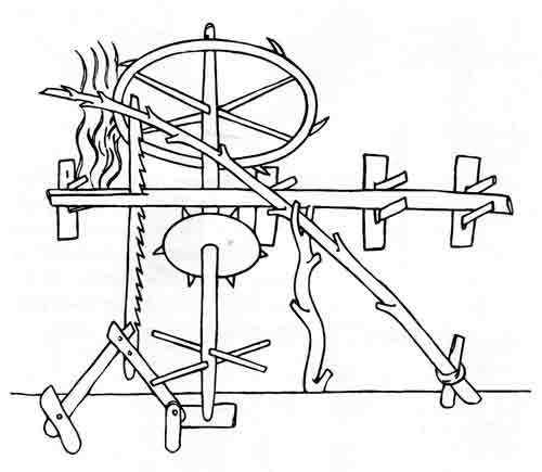
Figure 1.—Up-and-down sawmill of the 13th century. The guide mechanism at lower left, attached to the saw blade, appears to be a 4-bar linkage. After Robert Willis, trans. and ed., Facsimile of the Sketch-Book of Wilars de Honecort (London, 1859, pl. 43).
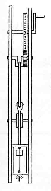
Figure 2.—Slider-crank mechanism of Leonardo da Vinci (1452-1519), redrawn from his manuscript notebooks. A frame saw is depicted at the lower end of the guides. From Theodor Beck, Beiträge zur Geschichte des Maschinenbaues (Berlin, 1899, p. 323).
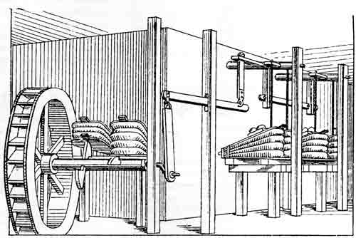
Figure 3.—Blowing engine by Vanuccio Biringuccio, about 1540, showing conversion of motion of the waterwheel shaft from rotation to oscillation. From Theodor Beck, Beiträge zur Geschichte des Maschinenbaues (Berlin, 1899. p. 120).
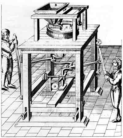
Figure 4.—Grain mill, 1588, showing conversion of motion of the operating bars from oscillation to rotation. Note the fly-weights, predecessors of the flywheel. From Agostino Ramelli, Le Diverse et Artificiose Machine (Paris, 1588, pl. opposite p. 199).
Figure 5.—Machine for raising water. Such a machine was built in Spain during the 16th century and was operated for some 80 years. From Agostino Ramelli, Le Diverse et Artificiose Machine (Paris, 1588, p. 199).
There was a vast difference, both in conception and execution, between the linkages of Ramelli and those of James Watt some 200 years later. Watt was responsible for initiating profound changes in mechanical technology, but it should be recognized that the mechanic arts had, through centuries of slow development, reached the stage where his genius could flourish. The knowledge and ability to provide the materials and tools necessary for Watt's researches were at hand, and through the optimism and patient encouragement of his partner, Matthew Boulton, they were placed at his disposal.
Watt's genius was nowhere more evident than in his synthesis of linkages. An essential ingredient in the success of Watt's linkages, however, was his partner's appreciation of the entirely new order of refinement that they called for. Matthew Boulton, who had been a successful manufacturer of buttons and metal novelties long before his partnership with Watt was formed, had recognized at once the need for care in the building of Watt's steam engine. On February 7, 1769, he had written Watt:[2] "I presumed that your engine would require money, very accurate workmanship and extensive correspondence to make it turn out to the best advantage and that the best means of keeping up the reputation and doing the invention justice would be to keep the executive part of it out of the hands of the multitude of empirical engineers, who from ignorance, want of experience and want of necessary convenience, would be very liable to produce bad and inaccurate workmanship; all of which deficiencies would affect the reputation of the invention." Boulton expected to build the engines in his shop "with as great a difference of accuracy as there is between the blacksmith and the mathematical instrument maker." The Soho Works of Boulton and Watt, in Birmingham, England, solved for Watt the problem of producing "in great" (that is, in sizes large enough to be useful in steam engines) the mechanisms that he devised.[3]
[2] Henry W. Dickinson, James Watt, Craftsman & Engineer, Cambridge, Cambridge University Press, 1936, pp. 52-53.
[3] James P. Muirhead, The Origin and Progress of the Mechanical Inventions of James Watt, London, 1854, vol. 1, pp. 56, 64. This work, in three volumes, contains letters, other documents, and plates of patent specification drawings.
The contributions of Boulton and Watt to practical mechanics "in great" cannot be overestimated. There were in the 18th century instrument makers and makers of timekeepers who had produced astonishingly accurate work, but such work comprised relatively small items, all being within the scope of a bench lathe, hand tools, and superb handwork. The rapid advancement of machine tools, which greatly expanded the scope of the machine-building art, began during the Boulton and Watt partnership (1775-1800).
In April 1775 the skirmish at Concord between American colonists and British redcoats marked the beginning of a war that was to determine for the future the course of political events in the Western Hemisphere.
Another event of April 1775 occurring in Birmingham now appears to have been one that marked the beginning of a new era of technological advance. It was near the end of this month that Boulton, at the Soho Works, wrote to his partner and commented upon receiving the cast iron steam engine cylinder that had been finished in John Wilkinson's boring mill:
... it seems tolerably true, but is an inch
thick and weighs about
10 cwt. Its diameter is about as much above 18
inches as the tin
one was under, and therefore it is become
necessary to add a brass
hoop to the piston, which is made almost two
inches broad.[4]
[4] Ibid., vol. 2, p. 84.
This cylinder indeed marked the turning point in the discouragingly long development of the Watt steam engine, which for 10 years had occupied nearly all of Watt's thoughts and all the time he could spare from the requirements of earning a living. Although there were many trials ahead for the firm of Boulton and Watt in further developing and perfecting the steam engine, the crucial problem of leakage of steam past the piston in the cylinder had now been solved by Wilkinson's new boring mill, which was the first large machine tool capable of boring a cylinder both round and straight.
The boring mill is pertinent to the development of linkages "in great," being the first of a new class of machine tools that over the next 50 or 60 years came to include nearly all of the basic types of heavy chip-removing tools that are in use today. The development of tools was accelerated by the inherent accuracy required of the linkages that were originated by Watt. Once it had been demonstrated that a large and complex machine, such as the steam engine, could be built accurately enough so that its operation would be relatively free of trouble, many outstanding minds became engaged in the development of machines and tools. It is interesting, however, to see how Watt and others grappled with the solutions of problems that resulted from the advance of the steam engine.
During the 1770's the demand for continuous, dependable power applied to a rotating shaft was becoming insistent, and much of Boulton's and Watt's effort was directed toward meeting this demand. Mills of all kinds used water or horses to turn "wheel-work," but, while these sources of power were adequate for small operations, the quantity of water available was often limited, and the use of enormous horse-whims was frequently impracticable.
The only type of steam engine then in existence was the Newcomen beam engine, which had been introduced in 1712 by Thomas Newcomen, also an Englishman. This type of engine was widely used, mostly for pumping water out of mines but occasionally for pumping water into a reservoir to supply a waterwheel. It was arranged with a vertical steam cylinder located beneath one end of a large pivoted working beam and a vertical plunger-type pump beneath the other end. Heavy, flat chains were secured to a sector at each end of the working beam and to the engine and pump piston rods in such a way that the rods were always tangent to a circle whose center was at the beam pivot. The weight of the reciprocating pump parts pulled the pump end of the beam down; the atmosphere, acting on the open top of the piston in the steam cylinder, caused the engine end of the beam to be pulled down when the steam beneath the piston was condensed. The chains would of course transmit force from piston to beam only in tension.
It is now obvious that a connecting rod, a crank, and a sufficiently heavy flywheel might have been used in a conventional Newcomen engine in order to supply power to a rotating shaft, but contemporary evidence makes it clear that this solution was by no means obvious to Watt nor to his contemporaries.
At the time of his first engine patent, in 1769, Watt had devised a "steam wheel," or rotary engine, that used liquid mercury in the lower part of a toroidal chamber to provide a boundary for steam spaces successively formed by flap gates within the chamber. The practical difficulties of construction finally ruled out this solution to the problem of a rotating power source, but not until after Boulton and Watt had spent considerable effort and money on it.[5]
[5] Henry W. Dickinson and Rhys Jenkins, James Watt and the Steam Engine, Oxford, Clarendon Press, 1927, pp. 146-148, pls. 14, 31. This work presents a full and knowledgeable discussion, based on primary material, of the development of Watt's many contributions to mechanical technology. It is ably summarized in Dickinson, op. cit. (footnote 2).
In 1777 a speaker before the Royal Society in London observed that in order to obtain rotary output from a reciprocating steam engine, a crank "naturally occurs in theory," but that in fact the crank is impractical because of the irregular rate of going of the engine and its variable length of stroke. He said that on the first variation of length of stroke the machine would be "either broken to pieces, or turned back."[6] John Smeaton, in the front rank of English steam engineers of his time, was asked in 1781 by His Majesty's Victualling-Office for his opinion as to whether a steam-powered grain mill ought to be driven by a crank or by a waterwheel supplied by a pump. Smeaton's conclusion was that the crank was quite unsuited to a machine in which regularity of operation was a factor. "I apprehend," he wrote, "that no motion communicated from the reciprocating beam of a fire engine can ever act perfectly equal and steady in producing a circular motion, like the regular efflux of water in turning a waterwheel." He recommended, incidentally, that a Boulton and Watt steam engine be used to pump water to supply the waterwheel.[7] Smeaton had thought of a flywheel, but he reasoned that a flywheel large enough to smooth out the halting, jerky operation of the steam engines that he had observed would be more of an encumbrance than a pump, reservoir, and waterwheel.[8]
[6] John Farey, A Treatise on the Steam Engine, London, 1827, pp. 408-409.
[7] Reports of the Late John Smeaton, F.R.S., London, 1812, vol. 2, pp. 378-380.
[8] Farey, op. cit. (footnote 6), p. 409.
The simplicity of the eventual solution of the problem was not clear to Watt at this time. He was not, as tradition has it, blocked merely by the existence of a patent for a simple crank and thus forced to invent some other device as a substitute.
Matthew Wasbrough, of Bristol, the engineer commonly credited with the crank patent, made no mention of a crank in his patent specification, but rather intended to make use of "racks with teeth," or "one or more pullies, wheels, segments of wheels, to which are fastened rotchets and clicks or palls...." He did, however, propose to "add a fly or flys, in order to render the motion more regular and uniform." Unfortunately for us, he submitted no drawings with his patent specification.[9]
[9] British Patent 1213, March 10, 1779.
James Pickard, of Birmingham, like Boulton, a buttonmaker, in 1780 patented a counterweighted crank device (fig. 6) that was expected to remove the objection to a crank, which operated with changing leverage and thus irregular power. In figure 6, the counterweighted wheel, revolving twice for each revolution of the crank (A), would allow the counterweight to descend while the crank passed the dead-center position and would be raised while the crank had maximum leverage. No mention of a flywheel was made in this patent.[10]
[10] British Patent 1263, August 23, 1780.
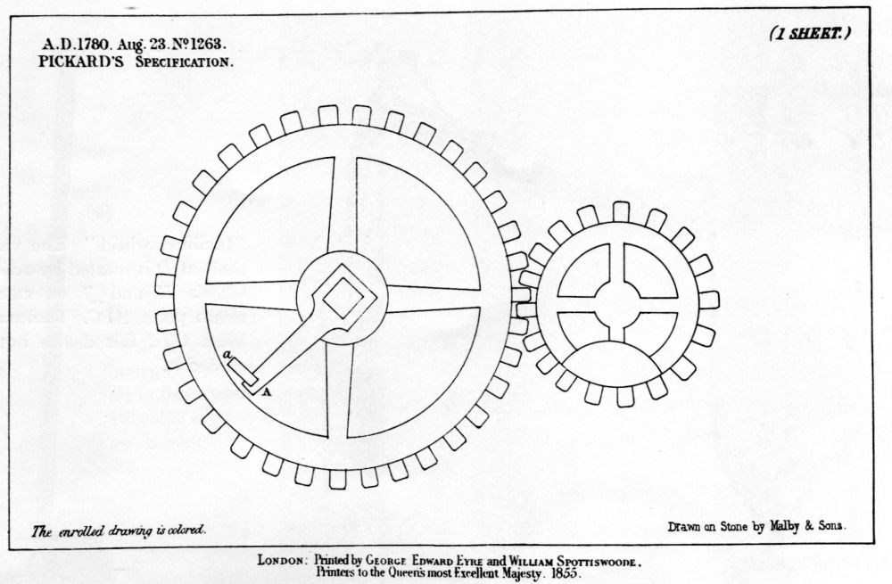
Figure 6.—One of the steam engine "Crank Patents" that hindered James Watt's progress. This patent, granted to James Pickard in 1780, claimed only the arrangement of counterweights, not the crank. The crank pin to which the connecting rod was attached is at Aa. From British Patent 1263, August 23, 1780.
Wasbrough, finding that his "rotchets and clicks" did not serve, actually used, in 1780, a crank with a flywheel. Watt was aware of this, but he remained unconvinced of the superiority of the crank over other devices and did not immediately appreciate the regulating ability of a flywheel.[11] In April 1781 Watt wrote to Boulton, who was then out of town: "I know from experiment that the other contrivance, which you saw me try, performs at least as well, and has in fact many advantages over the crank."[12] The "other contrivance" probably was his swash wheel which he built and which appeared on his next important patent specification (fig. 7a). Also in this patent were four other devices, one of which was easily recognizable as a crank, and two of which were eccentrics (fig. 7a, b). The fourth device was the well-known sun-and-planet gearing (fig. 7e).[13] In spite of the similarity of the simple crank to the several variations devised by Watt, this patent drew no fire from Wasbrough or Pickard, perhaps because no reasonable person would contend that the crank itself was a patentable feature, or perhaps because the similarity was not at that time so obvious. However, Watt steered clear of directly discernible application of cranks because he preferred to avoid a suit that might overthrow his or other patents. For example, if the Wasbrough and Pickard patents had been voided, they would have become public property; and Watt feared that they might "get into the hands of men more ingenious," who would give Boulton and Watt more competition than Wasbrough and Pickard.[14]
[11] Dickinson and Jenkins, op. cit. (footnote 5), pp. 150, 154.
[12] Ibid., p. 154.
[13] William Murdock, at this time a Boulton and Watt erector, may have suggested this arrangement. Ibid., p. 56.
[14] Muirhead, op. cit. (footnote 3), vol. 3, note on p. 39.
Figure 7.—James Watt's five alternative devices for the conversion of reciprocating motion to rotary motion in a steam engine. (British Patent 1306, October 25, 1781). From James P. Muirhead, The Origin and Progress of the Mechanical Inventions of James Watt (London, 1854, vol. 3, pls. 3-5, 7).
(a) "Inclined wheel." The vertical shaft at D is rotated by action of wheels H and J on cam, or swash plate, ABC. Boulton and Watt tried this device but discarded it.
(b) Counterweighted crank wheel.
(c) "Eccentric wheel" with external yoke hung from working beam. The wheel pivots at C.
(d) "Eccentric wheel" with internal driving wheel hung from working beam. Wheel B is pivoted at center of shaft A.
(e) Sun-and-planet gearing. This is the idea actually employed in Boulton and Watt engines. As the optional link JK held the gearwheel centers always equidistant, the annular guide G was not used.
The sun-and-planet arrangement, with gears of equal size, was adopted by Watt for nearly all the rotative engines that he built during the term of the "crank patents." This arrangement had the advantage of turning the flywheel through two revolutions during a single cycle of operation of the piston, thus requiring a flywheel only one-fourth the size of the flywheel needed if a simple crank were used. The optional link (JK of fig. 7e) was used in the engines as built.
From the first, the rotative engines were made double-acting—that is, work was done by steam alternately in each end of the cylinder. The double-acting engine, unlike the single-acting pumping engine, required a piston rod that would push as well as pull. It was in the solution of this problem that Watt's originality and sure judgment were most clearly demonstrated.
A rack and sector arrangement (fig. 8) was used on some engines. The first one, according to Watt, "has broke out several teeth of the rack, but works steady."[15] A little later he told a correspondent that his double-acting engine "acts so powerfully that it has broken all its tackling repeatedly. We have now tamed it, however."[16]
[15] James Watt, March 31, 1783, quoted in Dickinson and Jenkins, op. cit. (footnote 5), p. 140.
[16] Watt to De Luc, April 26, 1783, quoted in Muirhead, op. cit. (footnote 3), vol. 2, p. 174.
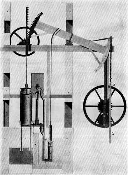
Figure 8.—Watt engine of 1782 (British Patent 1321, March 12, 1782) showing the rack and sector used to guide the upper end of the piston rod and to transmit force from piston to working beam. This engine, with a 30-inch cylinder and an 8-foot stroke, was arranged for pumping. Pump rod SS is hung from sector of the working beam. From James P. Muirhead, The Origin and Progress of the Mechanical Inventions of James Watt (London, 1854, vol. 3, pl. 15).
It was about a year later that the straight-line linkage[17] was thought out. "I have started a new hare," Watt wrote to his partner. "I have got a glimpse of a method of causing the piston-rod to move up and down perpendicularly, by only fixing it to a piece of iron upon the beam, without chains, or perpendicular guides, or untowardly frictions, arch-heads, or other pieces of clumsiness.... I have only tried it in a slight model yet, so cannot build upon it, though I think it a very probable thing to succeed, and one of the most ingenious simple pieces of mechanism I have contrived...."[18]
[17] Watt's was a four-bar linkage. All four-bar straight-line linkages that have no sliding pairs trace only an approximately straight line. The exact straight-line linkage in a single plane was not known until 1864 (see p. 204). In 1853 Pierre-Frédéric Sarrus (1798-1861), a French professor of mathematics at Strasbourg, devised an accordion-like spatial linkage that traced a true straight line. Described but not illustrated (Académie des Sciences, Paris, Comptes rendus, 1853, vol. 36, pp. 1036-1038, 1125), the mechanism was forgotten and twice reinvented; finally, the original invention was rediscovered by an English writer in 1905. For chronology, see Florian Cajori, A History of Mathematics, ed. 2, New York, 1919, p. 301.
[18] Muirhead, op. cit. (footnote 3), vol. 2, pp. 191-192.
Watt's marvelously simple straight-line linkage was incorporated into a large beam engine almost immediately, and the usually pessimistic and reserved inventor was close to a state of elation when he told Boulton that the "new central perpendicular motion answers beyond expectation, and does not make the shadow of a noise."[19] This linkage, which was included in an extensive patent of 1784, and two alternative devices are illustrated here (fig. 9). One of the alternatives is a guided crosshead (fig. 9, top right).
[19] Ibid., p. 202.
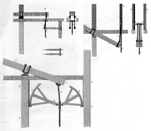
Figure 9.—Watt's mechanisms for guiding the upper end of the piston rod of a double-acting engine (British Patent 1432, April 28, 1784). Top left, straight-line linkage; top right, crosshead and guide arrangement; lower left, piston rod A is guided by sectors D and E, suspended by flexible cords. From James P. Muirhead, The Origin and Progress of the Mechanical Inventions of James Watt (London, 1854, vol. 3, pls. 21, 22).
Brilliant as was the conception of this linkage, it was followed up by a synthesis that is very little short of incredible. In order to make the linkage attached to the beam of his engines more compact, Watt had plumbed his experience for ideas; his experience had yielded up the work done much earlier on a drafting machine that made use of a pantograph.[20] Watt combined his straight-line linkage with a pantograph, one link becoming a member of the pantograph.
[20] "It has only one fault," he had told a friend on December 24, 1773, after describing the drafting machine to him, "which is, that it will not do, because it describes conic sections instead of straight lines." Ibid., p. 71.
The length of each oscillating link of the straight-line linkage was thus reduced to one-fourth instead of one-half the beam length, and the entire mechanism could be constructed so that it would not extend beyond the end of the working beam. This arrangement soon came to be known as Watt's "parallel motion" (fig. 10).[21] Years later Watt told his son: "Though I am not over anxious after fame, yet I am more proud of the parallel motion than of any other mechanical invention I have ever made."[22]
[21] Throughout the 19th century the term "parallel motion" was used indiscriminately to refer to any straight-line linkage. I have not discovered the origin of the term. Watt did not use it in his patent specification, and I have not found it in his writings or elsewhere before 1808 (see footnote 22). The Cyclopaedia (Abraham Rees, ed., London, 1819, vol. 26) defined parallel motion as "a term used among practical mechanics to denote the rectilinear motion of a piston-rod, &c. in the direction of its length; and contrivances, by which such alternate rectilinear motions are converted into continuous rotatory ones, or vice versa...." Robert Willis in his Principles of Mechanism (London, 1841, p. 399) described parallel motion as "a term somewhat awkwardly applied to a combination of jointed rods, the purpose of which is to cause a point to describe a straight line...." A. B. Kempe in How to Draw a Straight Line (London, 1877, p. 49) wrote: "I have been more than once asked to get rid of the objectionable term 'parallel motion.' I do not know how it came to be employed, and it certainly does not express what is intended. The expression, however, has now become crystallised, and I for one cannot undertake to find a solvent."
[22] Muirhead, op. cit. (footnote 3), vol. 3, note on p. 89.
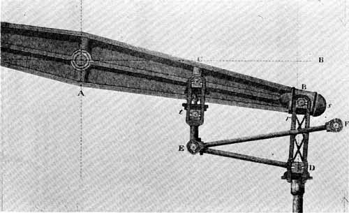
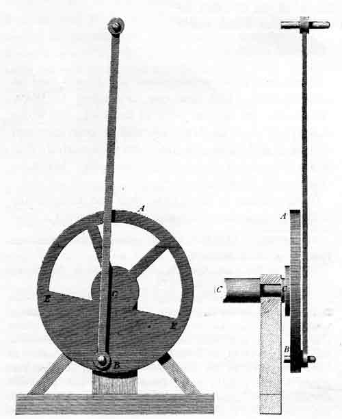
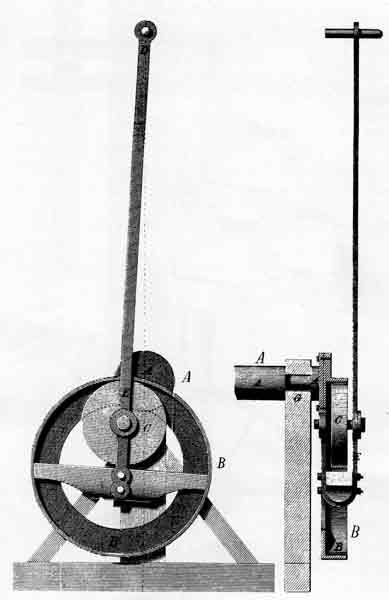
Figure 10.—Watt's "parallel motion." Engine's working beam is pivoted at A. Pivot F is attached to the engine frame. From Dyonysius Lardner, The Steam Engine (Philadelphia, 1852), pl. 5 (American ed. 5 from London ed. 5).
The Watt four-bar linkage was employed 75 years after its inception by the American Charles B. Richards when, in 1861, he designed his first high-speed engine indicator (fig. 11). Introduced into England the following year, the Richards Indicator was an immediate success, and many thousands were sold over the next 20 or 30 years.[23]
[23] Charles T. Porter, Engineering Reminiscences, New York, 1908, pp. 58-59, 90.
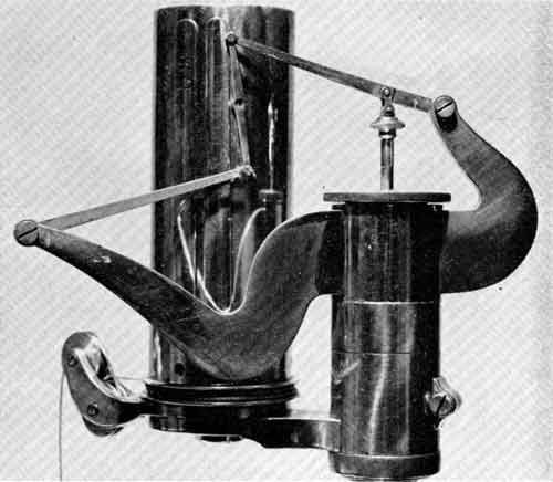
Figure 11.—Richards high-speed engine indicator of 1861, showing application of the Watt straight-line linkage. (USNM 307515; Smithsonian photo 46570).
In considering the order of synthetic ability required to design the straight-line linkage and to combine it with a pantograph, it should be kept in mind that this was the first one of a long line of such mechanisms.[24] Once the idea was abroad, it was only to be expected that many variations and alternative solutions should appear. One wonders, however, what direction the subsequent work would have taken if Watt had not so clearly pointed the way.
[24] At least one earlier straight-line linkage, an arrangement later ascribed to Richard Roberts, had been depicted before Watt's patent (Pierre Patte, Mémoirs sur les objets les plus importants de l'architecture, Paris, 1769, p. 229 and pl. 11). However, this linkage (reproduced here in figure 18) had no detectable influence on Watt or on subsequent practice.
In 1827 John Farey, in his exhaustive study of the steam engine, wrote perhaps the best contemporary view of Watt's work. Farey as a young man had several times talked with the aging Watt, and he had reflected upon the nature of the intellect that had caused Watt to be recognized as a genius, even within his own lifetime. In attempting to explain Watt's genius, Farey set down some observations that are pertinent not only to kinematic synthesis but to the currently fashionable term "creativity."
In Farey's opinion Watt's inventive faculty was far superior to that of any of his contemporaries; but his many and various ideas would have been of little use if he had not possessed a very high order of judgment, that "faculty of distinguishing between ideas; decomposing compound ideas into more simple elements; arranging them into classes, and comparing them together...."
Farey was of the opinion that while a mind like Watt's could produce brilliant new ideas, still the "common stock of ideas which are current amongst communities and professions, will generally prove to be of a better quality than the average of those new ideas, which can be produced by any individual from the operation of his own mind, without assistance from others." Farey concluded with the observation that "the most useful additions to that common stock, usually proceed from the individuals who are well acquainted with the whole series."[25]
[25] Farey, op. cit. (footnote 6), pp. 651, 652.
During most of the century after James Watt had produced his parallel motion, the problem of devising a linkage, one point of which would describe a straight line, was one that tickled the fancies of mathematicians, of ingenious mechanics, and of gentlemanly dabblers in ideas. The quest for a straight-line mechanism more accurate than that of Watt far outlasted the pressing practical need for such a device. Large metal planing machines were well known by 1830, and by midcentury crossheads and crosshead guides were used on both sides of the Atlantic in engines with and without working beams.
By 1819 John Farey had observed quite accurately that, in England at least, many other schemes had been tried and found wanting and that "no methods have been found so good as the original engine; and we accordingly find, that all the most established and experienced manufacturers make engines which are not altered in any great feature from Mr. Watt's original engine...."[26]
[26] In Rees, op. cit. (footnote 21), vol. 34 ("Steam Engine"). John Farey was the writer of this article (see Farey, op. cit., p. vi).
Two mechanisms for producing a straight line were introduced before the Boulton and Watt monopoly ended in 1800. Perhaps the first was by Edmund Cartwright (1743-1823), who is said to have had the original idea for a power loom. This geared device (fig. 12), was characterized patronizingly by a contemporary American editor as possessing "as much merit as can possibly be attributed to a gentleman engaged in the pursuit of mechanical studies for his own amusement."[27] Only a few small engines were made under the patent.[28]
[27] Emporium of Arts and Sciences, December 1813, new ser., vol. 2, no. 1, p. 81.
[28] Farey, op. cit. (footnote 6), p. 666.
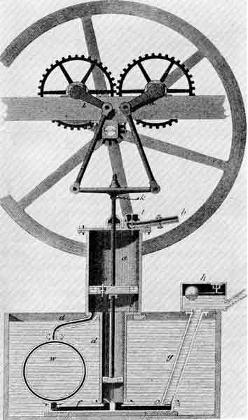
Figure 12.—Cartwright's geared straight-line mechanism of about 1800. From Abraham Rees, The Cyclopaedia (London, 1819, "Steam Engine," pl. 5).
The properties of a hypocycloid were recognized by James White, an English engineer, in his geared design which employed a pivot located on the pitch circle of a spur gear revolving inside an internal gear. The diameter of the pitch circle of the spur gear was one-half that of the internal gear, with the result that the pivot, to which the piston rod was connected, traced out a diameter of the large pitch circle (fig. 13). White in 1801 received from Napoleon Bonaparte a medal for this invention when it was exhibited at an industrial exposition in Paris.[29] Some steam engines employing White's mechanism were built, but without conspicuous commercial success. White himself rather agreed that while his invention was "allowed to possess curious properties, and to be a pretty thing, opinions do not all concur in declaring it, essentially and generally, a good thing."[30]
[29] H. W. Dickinson, "James White and His 'New Century of Inventions,'" Transactions of the Newcomen Society, 1949-1951, vol. 27, pp. 175-179.
[30] James White, A New Century of Inventions, Manchester, 1822, pp. 30-31, 338. A hypocycloidal engine used in Stourbridge, England, is in the Henry Ford Museum.
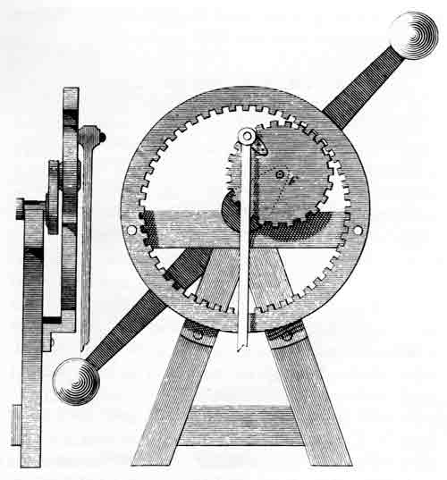
Figure 13.—James White's hypocycloidal straight-line mechanism, about 1800. The fly-weights (at the ends of the diagonal arm) functioned as a flywheel. From James White, A New Century of Inventions (Manchester, 1822, pl. 7).
The first of the non-Watt four-bar linkages appeared shortly after 1800. The origin of the grasshopper beam motion is somewhat obscure, although it came to be associated with the name of Oliver Evans, the American pioneer in the employment of high-pressure steam. A similar idea, employing an isosceles linkage, was patented in 1803 by William Freemantle, an English watchmaker (fig. 14).[31] This is the linkage that was attributed much later to John Scott Russell (1808-1882), the prominent naval architect.[32] An inconclusive hint that Evans had devised his straight-line linkage by 1805 appeared in a plate illustrating his Abortion of the Young Steam Engineer's Guide (Philadelphia, 1805), and it was certainly used on his Columbian engine (fig. 15), which was built before 1813. The Freemantle linkage, in modified form, appeared in Rees's Cyclopaedia of 1819 (fig. 16), but it is doubtful whether even this would have been readily recognized as identical with the Evans linkage, because the connecting rod was at the opposite end of the working beam from the piston rod, in accordance with established usage, while in the Evans linkage the crank and connecting rod were at the same end of the beam. It is possible that Evans got his idea from an earlier English periodical, but concrete evidence is lacking.
[31] British Patent 2741, November 17, 1803.
[32] William J. M. Rankine, Manual of Machinery and Millwork, ed. 6, London, 1887, p. 275.
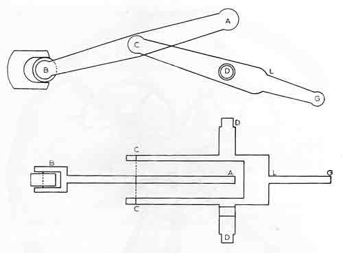
Figure 14.—Freemantle straight-line linkage, later called the Scott Russell linkage. From British Patent 2741, November 17, 1803.
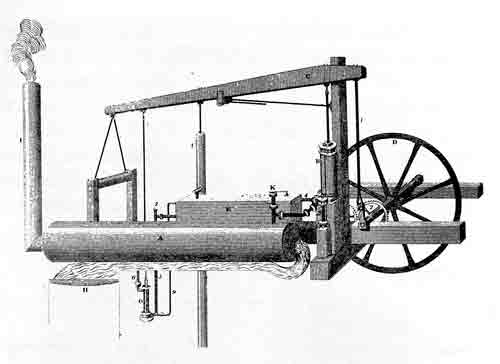
Figure 15.—Oliver Evans' "Columbian" engine, 1813, showing the Evans, or "grasshopper," straight-line linkage. From Emporium of Arts and Sciences (new ser., vol. 2, no. 3, April 1814, pl. opposite p. 380).
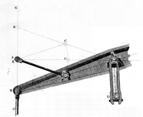
Figure 16.—Modified Freemantle linkage, 1819, which is kinematically the same as the Evans linkage. Pivots D and E are attached to engine frame. From Abraham Rees, The Cyclopaedia (London, 1819, "Parallel Motions," pl. 3).
If the idea did in fact originate with Evans, it is strange that he did not mention it in his patent claims, or in the descriptions that he published of his engines.[33] The practical advantage of the Evans linkage, utilizing as it could a much lighter working beam than the Watt or Freemantle engines, would not escape Oliver Evans, and he was not a man of excessive modesty where his own inventions were concerned.
[33] Greville and Dorothy Bathe, Oliver Evans, Philadelphia, 1935, pp. 88, 196, and passim.
Another four-bar straight-line linkage that became well known was attributed to Richard Roberts of Manchester (1789-1864), who around 1820 had built one of the first metal planing machines, which machines helped make the quest for straight-line linkages largely academic. I have not discovered what occasioned the introduction of the Roberts linkage, but it dated from before 1841. Although Roberts patented many complex textile machines, an inspection of all of his patent drawings has failed to provide proof that he was the inventor of the Roberts linkage.[34] The fact that the same linkage is shown in an engraving of 1769 (fig. 18) further confuses the issue.[35]
[34] Robert Willis (op. cit. [footnote 2] p. 411) credited Richard Roberts with the linkage. Roberts' 15 British patent drawings exhibit complex applications of cams, levers, guided rods, cords, and so forth, but no straight-line mechanism. In his patent no. 6258 of April 13, 1832, for a steam engine and locomotive carriage, Roberts used Watt's "parallel motion" on a beam driven by a vertical cylinder.
[35] This engraving appeared as plate 11 in Pierre Patte's 1769 work (op. cit. footnote 24). Patte stated that the machine depicted in his plate 11 was invented by M. de Voglie and was actually used in 1756.
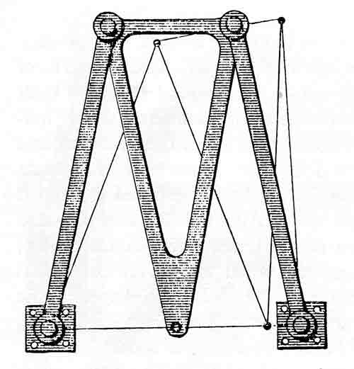
Figure 17.—Straight-line linkage (before 1841) attributed to Richard Roberts by Robert Willis. From A. B. Kempe, How to Draw a Straight Line (London, 1877, p. 10).
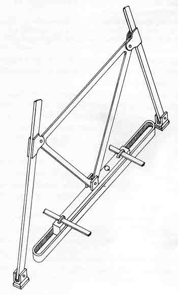
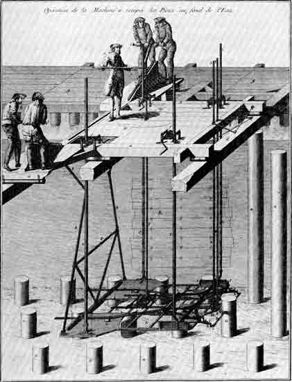
Figure 18.—Machine for sawing off pilings under water, about 1760, designed by De Voglie. The Roberts linkage operates the bar (Q in detailed sketch on left) at the rear of the machine below the operators. The significance of the linkage apparently was not generally recognized. A similar machine depicted in Diderot's Encyclopédie, published several years later, did not employ the straight-line linkage. From Pierre Patte, Memoirs sur les objets plus importants de l'architecture (Paris, 1769, pl. 11).
The appearance in 1864 of Peaucellier's exact straight-line linkage went nearly unnoticed. A decade later, when news of its invention crossed the Channel to England, this linkage excited a flurry of interest, and variations of it occupied mathematical minds for several years. For at least 10 years before and 20 years after the final solution of the problem, Professor Chebyshev,[36] a noted mathematician of the University of St. Petersburg, was interested in the matter. Judging by his published works and his reputation abroad, Chebyshev's interest amounted to an obsession.
[36] This is the Library of Congress spelling
Pafnutïĭ L'vovich Chebyshev was born in 1821, near Moscow, and entered the University of Moscow in 1837. In 1853, after visiting France and England and observing carefully the progress of applied mechanics in those countries, he read his first paper on approximate straight-line linkages, and over the next 30 years he attacked the problem with new vigor at least a dozen times. He found that the two principal straight-line linkages then in use were Watt's and Evans'. Chebyshev noted the departure of these linkages from a straight line and calculated the deviation as of the fifth degree, or about 0.0008 inch per inch of beam length. He proposed a modification of the Watt linkage to refine its accuracy but found that he would have to more than double the length of the working beam. Chebyshev concluded ruefully that his modification would "present great practical difficulties."[37]
[37] Oeuvres de P. L. Tchebychef, 2 vols., St. Petersburg, 1899-1907, vol. 1, p. 538; vol. 2, pp. 57, 85.
At length an idea occurred to Chebyshev that would enable him to approach if not quite attain a true straight line. If one mechanism was good, he reasoned, two would be better, et cetera, ad infinitum. The idea was simply to combine, or compound, four-link approximate linkages, arranging them in such a way that the errors would be successively reduced. Contemplating first a combination of the Watt and Evans linkages (fig. 19), Chebyshev recognized that if point D of the Watt linkage followed nearly a straight line, point A of the Evans linkage would depart even less from a straight line. He calculated the deviation in this case as of the 11th degree. He then replaced Watt's linkage by one that is usually called the Chebyshev straight-line mechanism (fig. 20), with the result that precision was increased to the 13th degree.[38] The steam engine that he displayed at the Vienna Exhibition in 1873 employed this linkage—the Chebyshev mechanism compounded with the Evans, or approximate isosceles, linkage. An English visitor to the exhibition commented that "the motion is of little or no practical use, for we can scarcely imagine circumstances under which it would be more advantageous to use such a complicated system of levers, with so many joints to be lubricated and so many pins to wear, than a solid guide of some kind; but at the same time the arrangement is very ingenious and in this respect reflects great credit on its designer."[39]
[38] Ibid., vol. 2, pp. 93, 94.
[39] Engineering, October 3, 1873, vol. 16, p. 284.
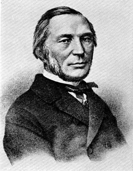
Figure 19.—Pafnutïĭ L'vovich Chebyshev (1821-1894), Russian mathematician active in analysis and synthesis of straight-line mechanisms. From Ouvres de P. L. Tchebychef (St. Petersburg, 1907, vol. 2, frontispiece).
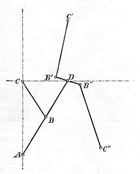
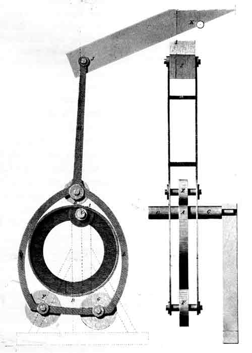
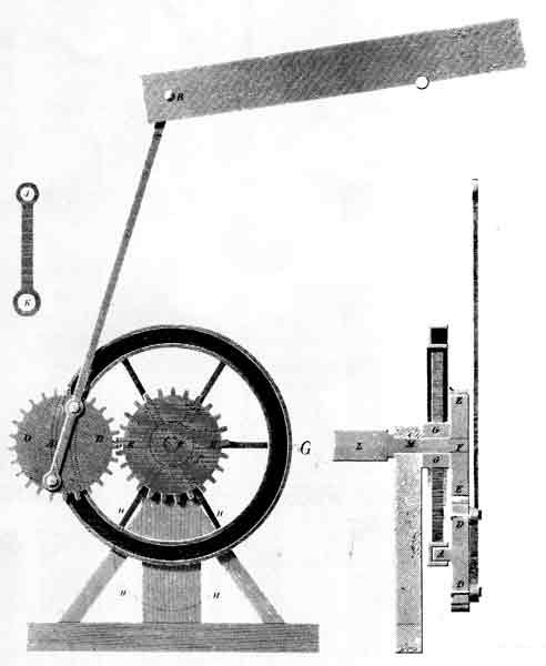
Figure 20.—Chebyshev's combination (about 1867) of Watt's and Evans' linkages to reduce errors inherent in each. Points C, C', and C" are fixed; A is the tracing point. From Oeuvres de P. L. Tchebychef (St. Petersburg, 1907, vol. 2, p. 93).
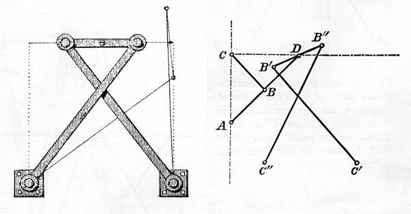
Figure 21.—Left: Chebyshev straight-line linkage, 1867; from A. B. Kempe, How to Draw a Straight Line (London, 1877, p. 11). Right: Chebyshev-Evans combination, 1867; from Oeuvres de P. L. Tchebychef (St. Petersburg, 1907, vol. 2, p. 94). Points C, C', and C" are fixed. A is the tracing point.
There is a persistent rumor that Professor Chebyshev sought to demonstrate the impossibility of constructing any linkage, regardless of the number of links, that would generate a straight line; but I have found only a dubious statement in the Grande Encyclopédie[40] of the late 19th century and a report of a conversation with the Russian by an Englishman, James Sylvester, to the effect that Chebyshev had "succeeded in proving the nonexistence of a five-bar link-work capable of producing a perfect parallel motion...."[41] Regardless of what tradition may have to say about what Chebyshev said, it is of course well known that Captain Peaucellier was the man who finally synthesized the exact straight-line mechanism that bears his name.
[40] La Grande Encyclopédie, Paris, 1886 ("Peaucellier").
[41] James Sylvester, "Recent Discoveries in Mechanical Conversion of Motion," Notices of the Proceedings of the Royal Institution of Great Britain, 1873-1875, vol. 7, p. 181. The fixed link was not counted by Sylvester; in modern parlance this would be a six-link mechanism.
Figure 22.—Peaucellier exact straight-line linkage, 1873. From A. B. Kempe, How to Draw a Straight Line (London, 1877, p. 12).
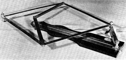
Figure 23.—Model of the Peaucellier "Compas Composé," deposited in Conservatoire National des Arts et Métiers, Paris, 1875. Photo courtesy of the Conservatoire.
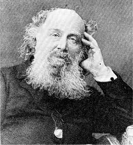
Figure 24.—James Joseph Sylvester (1814-1897), mathematician and lecturer on straight-line linkages. From Proceedings of the Royal Society of London (1898, vol. 63, opposite p. 161).
Charles-Nicolas Peaucellier, a graduate of the Ecole Polytechnique and a captain in the French corps of engineers, was 32 years old in 1864 when he wrote a short letter to the editor of Nouvelles Annales de mathématiques (ser. 2, vol. 3, pp. 414-415) in Paris. He called attention to what he termed "compound compasses," a class of linkages that included Watt's parallel motion, the pantograph, and the polar planimeter. He proposed to design linkages to describe a straight line, a circle of any radius no matter how large, and conic sections, and he indicated in his letter that he had arrived at a solution.
This letter stirred no pens in reply, and during the next 10 years the problem merely led to the filling of a few academic pages by Peaucellier and Amédée Mannheim (1831-1906), also a graduate of Ecole Polytechnique, a professor of mathematics, and the designer of the Mannheim slide rule. Finally, in 1873, Captain Peaucellier gave his solution to the readers of the Nouvelles Annales. His reasoning, which has a distinct flavor of discovery by hindsight, was that since a linkage generates a curve that can be expressed algebraically, it must follow that any algebraic curve can be generated by a suitable linkage—it was only necessary to find the suitable linkage. He then gave a neat geometric proof, suggested by Mannheim, for his straight-line "compound compass."[42]
[42] Charles-Nicholas Peaucellier, "Note sur une question de geométrie de compas," Nouvelles Annales de mathématiques, 1873, ser. 2, vol. 12, pp. 71-78. A sketch of Mannheim's work is in Florian Cajori, A History of the Logarithmic Slide Rule, New York, about 1910, reprinted in String Figures and Other Monographs, New York, Chelsea Publishing Company, 1960.
On a Friday evening in January 1874 Albemarle Street in London was filled with carriages, each maneuvering to unload its charge of gentlemen and their ladies at the door of the venerable hall of the Royal Institution. Amidst a "mighty rustling of silks," the elegant crowd made its way to the auditorium for one of the famous weekly lectures. The speaker on this occasion was James Joseph Sylvester, a small intense man with an enormous head, sometime professor of mathematics at the University of Virginia, in America, and more recently at the Royal Military Academy in Woolwich. He spoke from the same rostrum that had been occupied by Davy, Faraday, Tyndall, Maxwell, and many other notable scientists. Professor Sylvester's subject was "Recent Discoveries in Mechanical Conversion of Motion."[43]
[43] Sylvester, op. cit. (footnote 41), pp. 179-198. It appears from a comment in this lecture that Sylvester was responsible for the word "linkage." According to Sylvester, a linkage consists of an even number of links, a "link-work" of an odd number. Since the fixed member was not considered as a link by Sylvester, this distinction became utterly confusing when Reuleaux's work was published in 1876. Although "link" was used by Watt in a patent specification, it is not probable that he ever used the term "link-work"—at any rate, my search for his use of it has been fruitless. "Link work" is used by Willis (op. cit. footnote 21), but the term most likely did not originate with him. I have not found the word "linkage" used earlier than Sylvester.
Remarking upon the popular appeal of most of the lectures, a contemporary observer noted that while many listeners might prefer to hear Professor Tyndall expound on the acoustic opacity of the atmosphere, "those of a higher and drier turn of mind experience ineffable delight when Professor Sylvester holds forth on the conversion of circular into parallel motion."[44]
[44] Bernard H. Becker, Scientific London, London, 1874, pp. 45, 50, 51.
Sylvester's aim was to bring the Peaucellier linkage to the notice of the English-speaking world, as it had been brought to his attention by Chebyshev—during a recent visit of the Russian to England—and to give his listeners some insight into the vastness of the field that he saw opened by the discovery of the French soldier.[45]
[45] Sylvester, op. cit. (footnote 41), p. 183; Nature, November 13, 1873, vol. 9, p. 33.
"The perfect parallel motion of Peaucellier looks so simple," he observed, "and moves so easily that people who see it at work almost universally express astonishment that it waited so long to be discovered." But that was not his reaction at all. The more one reflects upon the problem, Sylvester continued, he "wonders the more that it was ever found out, and can see no reason why it should have been discovered for a hundred years to come. Viewed a priori there was nothing to lead up to it. It bears not the remotest analogy (except in the fact of a double centring) to Watt's parallel motion or any of its progeny."[46]
[46] Sylvester, op. cit. (footnote 41), p. 181.
It must be pointed out, parenthetically at least, that James Watt had not only had to solve the problem as best he could, but that he had no inkling, so far as experience was concerned, that a solvable problem existed.
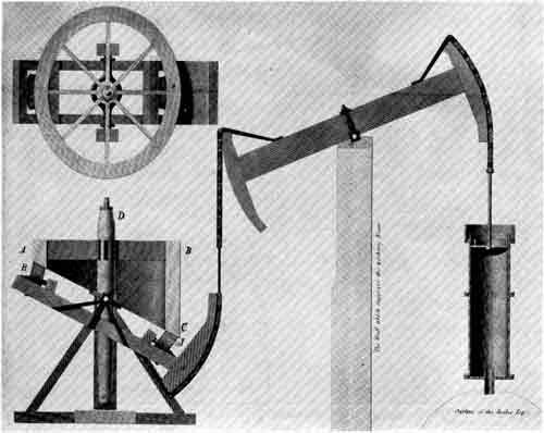
Sylvester interrupted his panegyric long enough to enumerate some of the practical results of the Peaucellier linkage. He said that Mr. Penrose, the eminent architect and surveyor to St. Paul's Cathedral, had "put up a house-pump worked by a negative Peaucellier cell, to the great wonderment of the plumber employed, who could hardly believe his senses when he saw the sling attached to the piston-rod moving in a true vertical line, instead of wobbling as usual from side to side." Sylvester could see no reason "why the perfect parallel motion should not be employed with equal advantage in the construction of ordinary water-closets." The linkage was to be employed by "a gentleman of fortune" in a marine engine for his yacht, and there was talk of using it to guide a piston rod "in certain machinery connected with some new apparatus for the ventilation and filtration of the air of the Houses of Parliament." In due course, Mr. Prim, "engineer to the Houses," was pleased to show his adaptation of the Peaucellier linkage to his new blowing engines, which proved to be exceptionally quiet in their operation (fig. 25).[47] A bit on the ludicrous side, also, was Sylvester's 78-bar linkage that traced a straight line along the line connecting the two fixed centers of the linkage.[48]
[47] Ibid., pp. 182, 183, 188, 193.
[48] Kempe, op. cit. (footnote 21), p. 17.
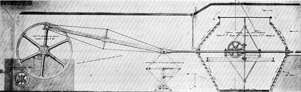
Figure 25.—Mr. Prim's blowing engine used for ventilating the House of Commons, 1877. The crosshead of the reciprocating air pump is guided by a Peaucillier linkage shown at the center. The slate-lined air cylinders had rubber-flap inlet and exhaust valves and a piston whose periphery was formed by two rows of brush bristles. Prim's machine was driven by a steam engine. Photograph by Science Museum, London.
Before dismissing with a smile the quaint ideas of our Victorian forbears, however, it is well to ask, 88 years later, whether some rather elaborate work reported recently on the synthesis of straight-line mechanisms is more to the point, when the principal objective appears to be the moving of an indicator on a "pleasing, expanded" (i.e., squashed flat) radio dial.[49]
[49] Machine Design, December 1954, vol. 26, p. 210.
But Professor Sylvester was more interested, really, in the mathematical possibilities of the Peaucellier linkage, as no doubt our modern investigators are. Through a compounding of Peaucellier mechanisms, he had already devised square-root and cube-root extractors, an angle trisector, and a quadratic-binomial root extractor, and he could see no limits to the computing abilities of linkages as yet undiscovered.[50]
[50] Sylvester, op. cit. (footnote 41), p. 191.
Sylvester recalled fondly, in a footnote to his lecture, his experience with a little mechanical model of the Peaucellier linkage at an earlier dinner meeting of the Philosophical Club of the Royal Society. The Peaucellier model had been greeted by the members with lively expressions of admiration "when it was brought in with the dessert, to be seen by them after dinner, as is the laudable custom among members of that eminent body in making known to each other the latest scientific novelties." And Sylvester would never forget the reaction of his brilliant friend Sir William Thomson (later Lord Kelvin) upon being handed the same model in the Athenaeum Club. After Sir William had operated it for a time, Sylvester reached for the model, but he was rebuffed by the exclamation "No! I have not had nearly enough of it—it is the most beautiful thing I have ever seen in my life."[51]
[51] Ibid., p. 183.
The aftermath of Professor Sylvester's performance at the Royal Institution was considerable excitement amongst a limited company of interested mathematicians. Many alternatives to the Peaucellier straight-line linkage were suggested by several writers of papers for learned journals.[52]
[52] For a summary of developments and references, see Kempe, op. cit. (footnote 21), pp. 49-51. Two of Hart's six-link exact straight-line linkages referred to by Kempe are illustrated in Henry M. Cundy and A. P. Rollett, Mathematical Models, Oxford, Oxford University Press, 1952, pp. 204-205. Peaucellier's linkage was of eight links.
In the summer of 1876, after Sylvester had departed from England to take up his post as professor of mathematics in the new Johns Hopkins University in Baltimore, Alfred Bray Kempe, a young barrister who pursued mathematics as a hobby, delivered at London's South Kensington Museum a lecture with the provocative title "How to Draw a Straight Line."[53]
[53] Kempe, op. cit. (footnote 21), p. 26.
In order to justify the Peaucellier linkage, Kempe belabored the point that a perfect circle could be generated by means of a pivoted bar and a pencil, while the generation of a straight line was most difficult if not impossible until Captain Peaucellier came along. A straight line could be drawn along a straight edge; but how was one to determine whether the straight edge was straight? He did not weaken his argument by suggesting the obvious possibility of using a piece of string. Kempe had collaborated with Sylvester in pursuing the latter's first thoughts on the subject, and one result, that to my mind exemplifies the general direction of their thinking, was the Sylvester-Kempe "parallel motion" (fig. 26).
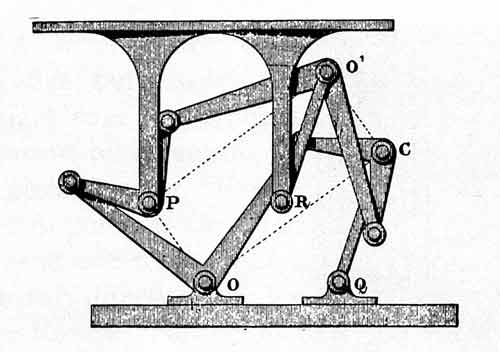
Figure 26.—Sylvester-Kempe translating linkage, 1877. The upper and lower plates remain parallel and equidistant. From A. B. Kempe, How to Draw a Straight Line (London, 1877, p. 37).
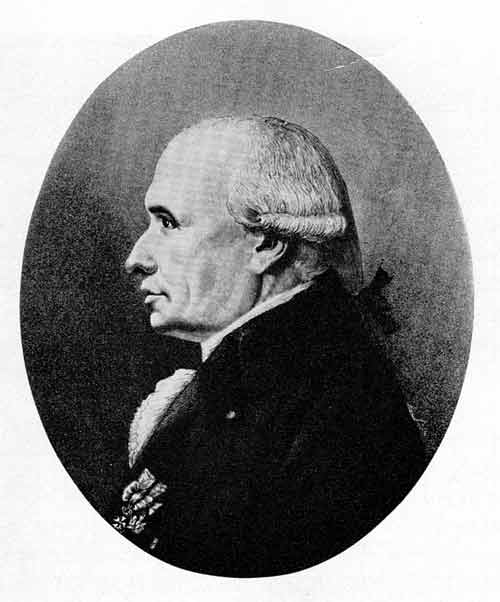
Figure 27.—Gaspard Monge (1746-1818), professor of mathematics at the Ecole Polytechnique from 1794 and founder of the academic discipline of machine kinematics, From Livre du Centenaire, 1794-1894, Ecole Polytechnique (Paris, 1895, vol. 1, frontispiece).
Enthusiastic as Kempe was, however, he injected an apologetic note in his lecture. "That these results are valuable cannot I think be doubted," he said, "though it may well be that their great beauty has led some to attribute to them an importance which they do not really possess...." He went on to say that 50 years earlier, before the great improvements in the production of true plane surfaces, the straight-line mechanisms would have been more important than in 1876, but he added that "linkages have not at present, I think, been sufficiently put before the mechanician to enable us to say what value should really be set upon them."[54]
[54] Ibid.,, pp. 6-7. I have not pursued the matter of cognate linkages (the Watt and Evans linkages are cognates) because the Roberts-Chebyshev theorem escaped my earlier search, as it had apparently escaped most others until 1958. See R. S. Hartenberg and J. Denavit, "The Fecund Four-Bar," Transactions of the Fifth Conference on Mechanisms, Cleveland, Penton Publishing Company, 1958, pp. 194-206, reprinted in Machine Design, April 16, 1959, vol. 31, pp. 149-152. See also A. E. R. de Jonge, "The Correlation of Hinged Four-Bar Straight-Line Motion Devices by Means of the Roberts Theorem and a New Proof of the Latter," Annals of the New York Academy of Sciences, March 18, 1960, vol. 84, art. 3, pp. 75-145 (published separately).
It was during this same summer of 1876, at the Loan Exhibition of Scientific Apparatus in the South Kensington Museum, that the work of Franz Reuleaux, which was to have an important and lasting influence on kinematics everywhere, was first introduced to English engineers. Some 300 beautifully constructed teaching aids, known as the Berlin kinematic models, were loaned to the exhibition by the Royal Industrial School in Berlin, of which Reuleaux was the director. These models were used by Prof. Alexander B. W. Kennedy of University College, London, to help explain Reuleaux's new and revolutionary theory of machines.[55]
[55] Alexander B. W. Kennedy, "The Berlin Kinematic Models," Engineering, September 15, 1876, vol. 22, pp. 239-240.
When, in 1829, André-Marie Ampère (1775-1836) was called upon to prepare a course in theoretical and experimental physics for the Collège de France, he first set about determining the limits of the field of physics. This exercise suggested to his wide-ranging intellect not only the definition of physics but the classification of all human knowledge. He prepared his scheme of classification, tried it out on his physics students, found it incomplete, returned to his study, and produced finally a two-volume work wherein the province of kinematics was first marked out for all to see and consider.[56] Only a few lines could be devoted to so specialized a branch as kinematics, but Ampère managed to capture the central idea of the subject.
[56] André-Marie Ampère, Essai sur la philosophie des sciences, une exposition analytique d'une classification naturelle de toutes les connaissances humaines, 2 vols., Paris, 1838 (for origin of the project, see vol. 1, pp. v, xv).
Cinématique (from the Greek word for movement) was, according to Ampère, the science "in which movements are considered in themselves [independent of the forces which produce them], as we observe them in solid bodies all about us, and especially in the assemblages called machines."[57] Kinematics, as the study soon came to be known in English,[58] was one of the two branches of elementary mechanics, the other being statics.
[57] Ibid., vol. 1, pp. 51-52.
[58] Willis (op. cit. footnote 21) adopted the word "kinematics," and this Anglicization subsequently became the standard term for this branch of mechanics.
In his definition of kinematics, Ampère stated what the faculty of mathematics at the Ecole Polytechnique, in Paris, had been groping toward since the school's opening some 40 years earlier. The study of mechanisms as an intellectual discipline most certainly had its origin on the left bank of the Seine, in this school spawned, as suggested by one French historian,[[59] by the great Encyclopédie of Diderot and d'Alembert.
[59] G. Pinet, Histoire de l'Ecole Polytechnique, Paris, 1887, pp. viii-ix. In their forthcoming book on kinematic synthesis, R. S. Hartenberg and J. Denavit will trace the germinal ideas of Jacob Leupold and Leonhard Euler of the 18th century.
Because the Ecole Polytechnique had such a far-reaching influence upon the point of view from which mechanisms were contemplated by scholars for nearly a century after the time of Watt, and by compilers of dictionaries of mechanical movements for an even longer time, it is well to look for a moment at the early work that was done there. If one is interested in origins, it might be profitable for him to investigate the military school in the ancient town of Mézières, about 150 miles northeast of Paris. It was here that Lazare Carnot, one of the principal founders of the Ecole Polytechnique, in 1783 published his essay on machines,[60] which was concerned, among other things, with showing the impossibility of "perpetual motion"; and it was from Mézières that Gaspard Monge and Jean Hachette[61] came to Paris to work out the system of mechanism classification that has come to be associated with the names of Lanz and Bétancourt.
[60] Lazare N. M. Carnot, Essai sur les machines en général, Mézières, 1783 (later published as Principes fondamentaux de l'equilibre et du mouvement, Paris, 1803).
[61] Biographical notices of Monge and Hachette appear in Encyclopaedia Britannica, ed. 11. See also L'Ecole Polytechnique, Livre du Centenaire, Paris, 1895, vol. 1, p. 11ff.
Gaspard Monge (1746-1818), who while a draftsman at Mézières originated the methods of descriptive geometry, came to the Ecole Polytechnique as professor of mathematics upon its founding in 1794, the second year of the French Republic. According to Jean Nicolas Pierre Hachette (1769-1834), who was junior to Monge in the department of descriptive geometry, Monge planned to give a two-months' course devoted to the elements of machines. Having barely gotten his department under way, however, Monge became involved in Napoleon's ambitious scientific mission to Egypt and, taking leave of his family and his students, embarked for the distant shores.
"Being left in charge," wrote Hachette, "I prepared the course of which Monge had given only the first idea, and I pursued the study of machines in order to analyze and classify them, and to relate geometrical and mechanical principles to their construction." Changes of curriculum delayed introduction of the course until 1806, and not until 1811 was his textbook ready, but the outline of his ideas was presented to his classes in chart form (fig. 28). This chart was the first of the widely popular synoptical tables of mechanical movements.[62]
[62] Jean N. P. Hachette, Traité élémentaire des machines, Paris, 1811, p. v.
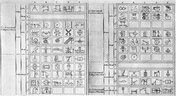
Figure 28.—Hachette's synoptic chart of elementary mechanisms, 1808. This was the first of many charts of mechanical movements that enjoyed wide popularity for over 100 years.
From Jean N. P. Hachette, Traité Élémentaire des Machines (Paris, 1811, pl. 1).
Hachette classified all mechanisms by considering the conversion of one motion into another. His elementary motions were continuous circular, alternating circular, continuous rectilinear, and alternating rectilinear. Combining one motion with another—for example, a treadle and crank converted alternating circular to continuous circular motion—he devised a system that supplied a frame of reference for the study of mechanisms. In the U.S. Military Academy at West Point, Hachette's treatise, in the original French, was used as a textbook in 1824, and perhaps earlier.[63]
[63] This work was among the books sent back by Sylvanus Thayer when he visited France in 1816 to observe the education of the French army cadets. Thayer's visit resulted in his adopting the philosophy of the Ecole Polytechnique in his reorganization of the U.S. Military Academy and, incidentally, in his inclusion of Hachette's course in the Academy's curriculum (U.S. Congress, American State Papers, Washington, 1832-1861, Class v, Military Affairs, vol. 2, p. 661: Sidney Forman, West Point, New York, 1950, pp. 36-60). There is a collection of miscellaneous papers (indexed under Sylvanus Thayer and William McRee, U.S. National Archives, RG 77, Office, Chief of Engineers, Boxes 1 and 6) pertaining to the U.S. Military Academy of this period, but I found no mention of kinematics in this collection.
Lanz and Bétancourt, scholars from Spain at the Ecole Polytechnique, plugged some of the gaps in Hachette's system by adding continuous and alternating curvilinear motion, which doubled the number of combinations to be treated, but the advance of their work over that of Hachette was one of degree rather than of kind.[64]
[64] Phillipe Louis Lanz and Augustin de Bétancourt, Essai sur la composition des machines, Paris, 1808. Hachette's chart and an outline of his elementary course on machines is bound with the Princeton University Library copy of the Lanz and Bétancourt work. This copy probably represents the first textbook of kinematics. Bétancourt was born in 1760 in Teneriffe, attended the military school in Madrid, and became inspector-general of Spanish roads and canals. He was in England before 1789, learning how to build Watt engines, and he introduced the engines to Paris in 1790 (see Farey, op. cit.,, p. 655). He entered Russian service in 1808 and died in St. Petersburg in 1826 (J. C. Poggendorff, Biographisches-literarisches Handwörterbuch für Mathematik ..., Leipzig, 1863, vol. 1.
Figure 29.—Robert Willis (1800-1875), Jacksonian Professor, Cambridge University, and author of Principles of Mechanism, one of the landmark books in the development of kinematics of mechanisms. Photo courtesy Gonville and Caius College, Cambridge University.
Giuseppe Antonio Borgnis, an Italian "engineer and member of many academies" and professor of mechanics at the University of Pavia in Italy, in his monumental, nine-volume Traité complet de méchanique appliquée aux arts, caused a bifurcation of the structure built upon Hachette's foundation of classification when he introduced six orders of machine elements and subdivided these into classes and species. His six orders were récepteurs (receivers of motion from the prime mover), communicateurs, modificateurs (modifiers of velocity), supports (e.g., bearings), regulateurs (e.g., governors), and operateurs, which produced the final effect.[65]
[65] Giuseppe Antonio Borgnis, Théorie de la mécanique usuelle in Traité complet de mécanique appliquée aux arts, Paris, 1818, vol. 1, pp. xiv-xvi.
The brilliant Gaspard-Gustave de Coriolis (1792-1843)—remembered mainly for a paper of a dozen pages explaining the nature of the acceleration that bears his name[66]—was another graduate of the Ecole Polytechnique who wrote on the subject of machines. His book,[67] published in 1829, was provoked by his recognition that the designer of machines needed more knowledge than his undergraduate work at the Ecole Polytechnique was likely to give him. Although he embraced a part of Borgnis' approach, adopting récepteurs, communicateurs, and operateurs, Coriolis indicated by the title of his book that he was more concerned with forces than with relative displacements. However, the attractively simple three-element scheme of Coriolis became well fixed in French thinking.[68]
[66] Gaspard-Gustave de Coriolis, "Memoire sur les equations du mouvement relatif des systèmes de corps," Journal de l'Ecole Polytechnique, 1835, vol. 15, pp. 142-154.
[67] Gaspard-Gustave de Coriolis, De Calcul de l'effet des machines, Paris, 1829. In this book Coriolis proposed the now generally accepted equation, work = force × distance (pp. iii, 2).
[68] The renowned Jean Victor Poncelet lent weight to this scheme. (See Franz Reuleaux, Theoretische Kinematik: Grundzüge einer Theorie des Maschinenwesens, Braunschweig, 1875, translated by Alexander B. W. Kennedy as The Kinematics of Machinery: Outlines of a Theory of Machines, London, 1876, pp. 11, 487. I have used the Kennedy translation in the Reuleaux references throughout the present work.)
Michel Chasles (1793-1880), another graduate of the Ecole Polytechnique, contributed some incisive ideas in his papers on instant centers[69] published during the 1830's, but their tremendous importance in kinematic analysis was not recognized until much later.
[69] The instant center was probably first recognized by Jean Bernoulli (1667-1748) in his "De Centro Spontaneo Rotationis" (Johannis Bernoulli ... Opera Omnia ..., Lausanne, 1742, vol. 4, p. 265ff.).
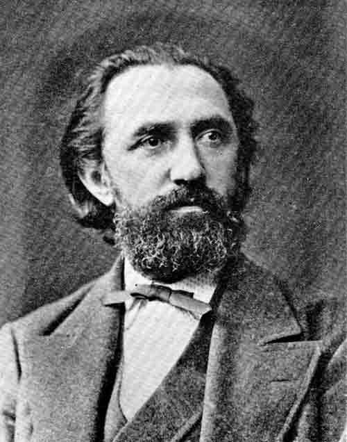
Figure 30.—Franz Reuleaux (1829-1905). His Theoretische Kinematik, published in 1875, provided the basis for modern kinematic analysis. Photo courtesy Deutsches Museum, Munich.
Acting upon Ampère's clear exposition of the province of kinematics and excluding, as Ampère had done, the consideration of forces, an Englishman, Robert Willis, made the next giant stride forward in the analysis of mechanisms. Willis was 37 years old in 1837 when he was appointed professor of natural and experimental philosophy at Cambridge. In the same year Professor Willis—a man of prodigious energy and industry and an authority on archeology and architectural history as well as mechanisms—read his important paper "On the Teeth of Wheels" before the Institution of Civil Engineers[[70] and commenced at Cambridge his lectures on kinematics of mechanisms that culminated in his 1841 book Principles of Mechanism.[71]
[70] Robert Willis, "On the Teeth of Wheels," Transactions of the Institution of Civil Engineers of London, 1838, vol. 2, pp. 89-112.
[71] Willis, op. cit. (footnote 21). Through the kindness of its owner (Mr. Warren G. Ogden of North Andover, Massachusetts), I have had access to Willis' own copy of his 1841 edition of Principles of Mechanism. The book is interleaved, and it contains notes made by Willis from time to time until at least 1870, when the second edition was issued. Corrections, emendations, notations of some of his sources (for example, the De Voglie linkage mentioned in footnote 35 above), notes to himself to "examine the general case" and "examine the modern forms" of straight-line devices are interspersed with references to authors that had borrowed from his work without acknowledgment. Of one author Willis writes an indignant "He ignores my work."
It seemed clear to Willis that the problem of devising a mechanism for a given purpose ought to be attacked systematically, perhaps mathematically, in order to determine "all the forms and arrangements that are applicable to the desired purpose," from which the designer might select the simplest or most suitable combination. "At present," he wrote, "questions of this kind can only be solved by that species of intuition which long familiarity with a subject usually confers upon experienced persons, but which they are totally unable to communicate to others."
In analyzing the process by which a machine was designed, Willis observed: "When the mind of a mechanician is occupied with the contrivance of a machine, he must wait until, in the midst of his meditations, some happy combination presents itself to his mind which may answer his purpose." He ventured the opinion that at this stage of the design process "the motions of the machine are the principal subject of contemplation, rather than the forces applied to it, or the work it has to do." Therefore he was prepared to adopt without reservation Ampère's view of kinematics, and, if possible, to make the science useful to engineers by stating principles that could be applied without having to fit the problem at hand into the framework of the systems of classification and description that had gone before. He appraised the "celebrated system" of Lanz and Bétancourt as "a merely popular arrangement, notwithstanding the apparently scientific simplicity of the scheme." He rejected this scheme because "no attempt is made to subject the motions to calculation, or to reduce these laws to general formulas, for which indeed the system is totally unfitted."
Borgnis had done a better job, Willis thought, in actually describing machinery, with his "orders" based upon the functions of machine elements or mechanisms within the machine, but again there was no means suggested by which the kinematics of mechanisms could be systematically investigated.
Although Willis commenced his treatise with yet another "synoptical table of the elementary combinations of pure mechanism," his view shifted quickly from description to analysis. He was consistent in his pursuit of analytical methods for "pure mechanism," eschewing any excursions into the realm of forces and absolute velocities. He grasped the important concept of relative displacements of machine elements, and based his treatment upon "the proportions and relations between the velocities and directions of the pieces, and not upon their actual and separate motions."[72]
[72] Ibid., pp. iv, x-xii, xxi, 15.
That he did not succeed in developing the "formulas" that would enable the student to determine "all the forms and arrangements that are applicable to the desired purpose"—that he did not present a rational approach to synthesis—is not to be wondered at. Well over a century later we still are nibbling at the fringes of the problem. Willis did, nonetheless, give the thoughtful reader a glimpse of the most powerful tool for kinematic synthesis that has yet been devised; namely, kinematic analysis, in which the argument is confined to the relative displacements of points on links of a mechanism, and through which the designer may grasp the nature of the means at his disposal for the solution of any particular problem.
As remarked by Reuleaux a generation later, there was much in Professor Willis's book that was wrong, but it was an original, thoughtful work that departed in spirit if not always in method from its predecessors. Principles of Mechanism was a prominent landmark along the road to a rational discipline of machine-kinematics.
A phenomenal engineer of the 19th century was the Scottish professor of civil engineering at the University of Glasgow, William John MacQuorn Rankine. Although he was at the University for only 17 years—he died at the age of 52, in 1872—he turned out during that time four thick manuals on such diverse subjects as civil engineering, ship-building, thermodynamics, and machinery and mill-work, in addition to literally hundreds of papers, articles, and notes for scientific journals and the technical press. Endowed with apparently boundless energy, he found time from his studies to command a battalion of rifle volunteers and to compose and sing comic and patriotic songs. His manuals, often used as textbooks, were widely circulated and went through many editions. Rankine's work had a profound effect upon the practice of engineering by setting out principles in a form that could be grasped by people who were dismayed by the treatment usually found in the learned journals.
When Rankine's book titled A Manual of Machinery and Millwork was published in 1869 it was accurately characterized by a reviewer as "dealing with the principles of machinery and millworks, and as such it is entirely distinct from [other works on the same subject] which treat more of the practical applications of such principles than of the principles themselves."[73]
[73] Engineering, London, August 13, 1869, vol. 8, p. 111.
Rankine borrowed what appeared useful from Willis' Principles of Mechanism and from other sources. His treatment of kinematics was not as closely reasoned as the later treatises of Reuleaux and Kennedy, which will be considered below. Rankine did, however, for the first time show the utility of instant centers in velocity analysis, although he made use only of the instant centers involving the fixed link of a linkage. Like others before him, he considered the fixed link of a mechanism as something quite different from the movable links, and he did not perceive the possibilities opened up by determining the instant center of two movable links.
Many other books dealing with mechanisms were published during the middle third of the century, but none of them had a discernible influence upon the advance of kinematical ideas.[74] The center of inquiry had by the 1860's shifted from France to Germany. Only by scattered individuals in England, Italy, and France was there any impatience with the well-established, general understanding of the machine-building art.
[74] Several such books are referred to by Reuleaux, op. cit. (footnote 68), pp. 12-16.
In Germany, on the other hand, there was a surge of industrial activity that attracted some very able men to the problems of how machines ought to be built. Among the first of these was Ferdinand Redtenbacher (1809-1863), professor of mechanical engineering in the polytechnic school in Karlsruhe, not far from Heidelberg. Redtenbacher, although he despaired of the possibility of finding a "true system on which to base the study of mechanisms," was nevertheless a factor in the development of such a system. He had young Franz Reuleaux in his classes for two years, from 1850. During that time the older man's commanding presence, his ability as a lecturer, and his infectious impatience with the existing order influenced Reuleaux to follow the scholar's trail that led him to eminence as an authority of the first rank.[75]
[75] See Carl Weihe, "Franz Reuleaux und die Grundlagen seiner Kinematik," Deutsches Museum, Munich, Abhandlung und Berichte, 1942, p. 2; Friedrich Klemm, Technik: Eine Geschichte ihrer Probleme, Freiburg and Munich, Verlag Karl Alber, 1954, translated by Dorothea W. Singer as A History of Western Technology, New York, Charles Scribner's Sons, 1959, p. 317.
Before he was 25 years old Franz Reuleaux published, in collaboration with a classmate, a textbook whose translated title would be Constructive Lessons for the Machine Shop.[76] His several years in the workshop, before and after coming under Redtenbacher's influence, gave his works a practical flavor, simple and direct. According to one observer, Reuleaux's book exhibited "a recognition of the claims of practice such as Englishmen do not generally associate with the writings of a German scientific professor."[77]
[76] See Weihe, op. cit. (footnote 75), p. 3; Hans Zopke, "Professor Franz Reuleaux," Cassier's Magazine, December 1896, vol. 11, pp. 133-139; Transactions of the American Society of Mechanical Engineers, 1904-1905, vol. 26, pp. 813-817.
[77] Engineering, London, September 8, 1876, vol. 22, p. 197.
Reuleaux's original ideas on kinematics, which are responsible for the way in which we look at mechanisms today, were sufficiently formed in 1864 for him to lecture upon them.[78] Starting in 1871, he published his findings serially in the publication of the Verein zur Beförderung des Gewerbefleisses in Preussen (Society for the Advancement of Industry in Prussia), of which he was editor. In 1875 these articles were brought together in the book that established his fame—Theoretische Kinematik....[79]
[78] A. E. Richard de Jonge, "What is Wrong with Kinematics and Mechanisms?" Mechanical Engineering, April 1942, vol. 64, pp. 273-278 (comments on this paper are in Mechanical Engineering, October 1942, vol. 64, pp. 744-751); Zopke, op. cit. (footnote 76), p. 135.
[79] Reuleaux, op. cit. (footnote 68). This was not the last of Reuleaux's books. His trilogy on kinematics and machine design is discussed by De Jonge, op. cit. (footnote 78).
In the introduction of this book, Reuleaux wrote:
In the development of every exact science, its
substance having
grown sufficiently to make generalization
possible, there is a time
when a series of changes bring it into
clearness. This time has
most certainly arrived for the science of
kinematics. The number of
mechanisms has grown almost out of measure,
and the number of ways
in which they are applied no less. It has
become absolutely
impossible still to hold the thread which can
lead in any way
through this labyrinth by the existing
methods.[80]
[80] Reuleaux, op. cit. (footnote 68), p. 23.
Reuleaux's confidence that it would be his own work that would bring order out of confusion was well founded. His book had already been translated into Italian and was being translated into French when, only a year after its publication, it was presented by Prof. Alexander B. W. Kennedy in English translation.[81]
[81] Ibid.,, p. iii.
The book was enthusiastically reviewed by the weekly London journal Engineering,[82] and it was given lengthy notice by the rival journal, The Engineer. The editor of The Engineer thought that the mechanician would find in it many new ideas, that he would be "taught to detect hitherto hidden resemblances, and that he must part—reluctantly, perhaps—with many of his old notions." "But," added the editor with considerable justice, "that he [the mechanician] would suddenly recognize in Professor Reuleaux's 'kinematic notation,' 'analysis,' and 'synthesis,' the long-felt want of his professional existence we do not for a moment believe."[83] Indeed, the fresh and sharp ideas of Reuleaux were somewhat clouded by a long (600-page) presentation; and his kinematic notation, which required another attempt at classification, did not simplify the presentation of radically new ideas.[84]
[82] Engineering, loc. cit. (footnote 77).
[83] The Engineer, London, March 30 and April 13, 1877, vol. 43, pp. 211-212, 247-248.
[84] It is perhaps significant that the first paper of the First Conference on Mechanisms at Purdue University was Allen S. Hall's "Mechanisms and Their Classification," which appeared in Machine Design, December 1953, vol. 25, pp. 174-180. The place of classification in kinematic synthesis is suggested in Ferdinand Freudenstein's "Trends in Kinematics of Mechanisms," Applied Mechanics Reviews, September 1959, vol. 12, pp. 587-590.
Figure 31.—Alexander Blackie William Kennedy (1847-1928), translator of Reuleaux' Theoretische Kinematik and discoverer of Kennedy's "Law of Three Centers." From Minutes of the Proceedings of the Institution of Civil Engineers (1907, vol. 167, frontispiece).
Nevertheless, no earlier author had seen the problem of kinematic analysis so clearly or had introduced so much that was fresh, new, and of lasting value.
Reuleaux was first to state the concept of the pair; by his concept of the expansion of pairs he was able to show similarities in mechanisms that had no apparent relation. He was first to recognize that the fixed link of a mechanism was kinematically the same as the movable links. This led him to the important notion of inversion of linkages, fixing successively the various links and thus changing the function of the mechanism. He devoted 40 pages to showing, with obvious delight, the kinematic identity of one design after another of rotary steam engines, demolishing for all time the fond hopes of ingenious but ill-informed inventors who think that improvements and advances in mechanism design consist in contortion and complexity.
The chapter on synthesis was likewise fresh, but it consisted of a discussion, not a system; and Reuleaux stressed the idea that I have mentioned above in connection with Willis' book, that synthesis will be successful in proportion to the designer's understanding and appreciation of analysis. Reuleaux tried to put the designer on the right track by showing him clearly "the essential simplicity of the means with which we have to work" and by demonstrating to him "that the many things which have to be done can be done with but few means, and that the principles underlying them all lie clearly before us."[85]
[85] Reuleaux, op. cit. (footnote 68), p. 582.
It remained for Sir Alexander Blackie William Kennedy (1847-1928) and Robert Henry Smith (1852-1916) to add to Reuleaux's work the elements that would give kinematic analysis essentially its modern shape.
Kennedy, the translator of Reuleaux's book, became professor of engineering at the University College in London in 1874, and eventually served as president both of the Institution of Mechanical Engineers and of the Institution of Civil Engineers. Smith, who had taught in the Imperial University of Japan, was professor of engineering at Mason College, now a part of Birmingham University, in England.
While Reuleaux had used instant centers almost exclusively for the construction of centrodes (paths of successive positions of an instant center), Professor Kennedy recognized that instant centers might be used in velocity analysis. His book, Mechanics of Machinery, was published in 1886 ("partly through pressure of work and partly through ill-health, this book appears only now"). In it he developed the law of three centers, now known as Kennedy's theorem. He noted that his law of three centers "was first given, I believe, by Aronhold, although its previous publication was unknown to me until some years after I had given it in my lectures."[86] In fact, the law had been published by Siegfried Heinrich Aronhold (1819-1884) in his "Outline of Kinematic Geometry," which appeared in 1872 alongside Reuleaux's series in the journal that Reuleaux edited. Apparently Reuleaux did not perceive its particular significance at that time.[87]
[86] Alexander B. W. Kennedy, The Mechanics of Machinery, ed. 3, London, 1898, pp. vii, x.
[87] Siegfried Heinrich Aronhold, "Outline of Kinematic Geometry," Verein zur Beförderung des Gewerbefleisses in Preussen, 1872, vol. 51, pp. 129-155. Kennedy's theorem is on pp. 137-138.
Figure 32.—Robert Henry Smith (1852-1916), originator of velocity and acceleration polygons for kinematic analysis. Photo courtesy the Librarian, Birmingham Reference Library, England.
Kennedy, after locating instant centers, determined velocities by calculation and accelerations by graphical differentiation of velocities, and he noted in his preface that he had been unable, for a variety of reasons, to make use in his book of Smith's recent work. Professor Kennedy at least was aware of Smith's surprisingly advanced ideas, which seem to have been generally ignored by Americans and Englishmen alike.
Professor Smith, in a paper before the Royal Society of Edinburgh in 1885, stated clearly the ideas and methods for construction of velocity and acceleration diagrams of linkages.[88] For the first time, velocity and acceleration "images" of links (fig. 33) were presented. It is unfortunate that Smith's ideas were permitted to languish for so long a time.
[88] Robert H. Smith, "A New Graphic Analysis of the Kinematics of Mechanisms," Transactions of the Royal Society of Edinburgh, 1882-1885, vol. 32, pp. 507-517, and pl. 82. Smith used this paper as the basis for a chapter in his Graphics or the Art of Calculating by Drawing Lines, London, 1889, pp. 144-162. In a footnote of his paper, Smith credited Fleeming Jenkin (1833-1885) with suggesting the term "image." After discarding as "practically useless" Kennedy's graphical differentiation, Smith complained that he had "failed to find any practical use" for Reuleaux's "method of centroids, more properly called axoids." Such statements were not calculated to encourage Kennedy and Reuleaux to advertise Smith's fame; however, I found no indication that either one took offense at the criticism. Smith's velocity and acceleration diagrams were included (apparently embalmed, so far as American engineers were concerned) in Encyclopaedia Britannica, ed. 11, 1910, vol. 17, pp. 1008-1009.
Figure 33.—Smith's velocity image (the two figures at top), and his velocity, mechanism, and acceleration diagrams, 1885. The image of link BACD is shown as figure bacd. The lines pa, pb, pc, and pd are velocity vectors. This novel, original, and powerful analytical method was not generally adopted in English or American schools until nearly 50 years after its inception. From Transactions of the Royal Society of Edinburgh (1882-1885, vol. 32, pl. 82).
By 1885 nearly all the tools for modern kinematic analysis had been forged. Before discussing subsequent developments in analysis and synthesis, however, it will be profitable to inquire what the mechanician—designer and builder of machines—was doing while all of this intellectual effort was being expended.
While the inductive process of recognizing and stating true principles of the kinematics of mechanisms was proceeding through three generations of French, English, and finally German scholars, the actual design of mechanisms went ahead with scant regard for what the scholars were doing and saying.
After the demonstration by Boulton and Watt that large mechanisms could be wrought with sufficient precision to be useful, the English tool builders Maudslay, Roberts, Clement, Nasmyth, and Whitworth developed machine tools of increasing size and truth. The design of other machinery kept pace with—sometimes just behind, sometimes just ahead of—the capacity and capability of machine tools. In general, there was an increasing sophistication of mechanisms that could only be accounted for by an increase of information with which the individual designer could start.
Reuleaux pointed out in 1875 that the "almost feverish progress made in the regions of technical work" was "not a consequence of any increased capacity for intellectual action in the race, but only the perfecting and extending of the tools with which the intellect works." These tools, he said, "have increased in number just like those in the modern mechanical workshop—the men who work them remain the same." Reuleaux went on to say that the theory and practice of machine-kinematics had "carried on a separate existence side by side." The reason for this failure to apply theory to practice, and vice versa, must be sought in the defects of the theory, he thought, because "the mechanisms themselves have been quietly developed in practical machine-design, by invention and improvement, regardless of whether or not they were accorded any direct and proper theoretical recognition." He pointed out that the theories had thus far "furnished no new mechanisms."[89]
[89] Reuleaux, op. cit. (footnote 68), p. 8.
It is reasonable, therefore, to ask what was responsible for the appearance of new mechanisms, and then to see what sort of mechanisms had their origins in this period.
It is immediately evident to a designer that the progress in mechanisms came about through the spread of knowledge of what had already been done; but designers of the last century had neither the leisure nor means to be constantly visiting other workshops, near and far, to observe and study the latest developments. In the 1800's, as now, word must in the main be spread by the printed page.
Hachette's chart (fig. 28) had set the pattern for display of mechanical contrivances in practical journals and in the large number of mechanical dictionaries that were compiled to meet an apparent demand for such information. It is a little surprising, however, to find how persistent were some of Hachette's ideas that could only have come from the uppermost superficial layer of his cranium. See, for example, his "anchored ferryboat" (fig. 34). This device, employed by Hachette to show conversion of continuous rectilinear motion into alternating circular motion, appeared in one publication after another throughout the 19th century. As late as 1903 the ferryboat was still anchored in Hiscox's Mechanical Movements, although the tide had changed (fig. 35).[90]
[90] Gardner D. Hiscox, ed., Mechanical Movements, ed. 10, New York, 1903, p. 151. The ferryboat did not appear in the 1917 edition.
Figure 34.—Hachette's ferryboat of 1808, a "machine" for converting continuous rectilinear motion into alternating circular motion. From Phillipe Louis Lanz and Augustin de Bétancourt, Essai sur la composition des machines (Paris, 1808, pl. 2).
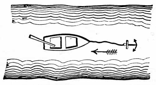
Figure 35.—Ferryboat from Gardner D. Hiscox, ed., Mechanical Movements (ed. 10, New York, 1903, p. 151).
During the upsurge of the Lyceum—or working-man's institute—movement in the 1820's, Jacob Bigelow, Rumford professor of applied science at Harvard University, gave his popular lectures on the "Elements of Technology" before capacity audiences in Boston. In preparing his lecture on the elements of machinery, Bigelow used as his authorities Hachette, Lanz and Bétancourt, and Olinthus Gregory's mechanical dictionary, an English work in which Hachette's classification scheme was copied and his chart reproduced.[91]
[91] Jacob Bigelow, Elements of Technology, ed. 2, Boston, 1831, pp. 231-256; Olinthus Gregory, A Treatise of Mechanics, 3 vols., ed. 3, London, 1815.
A translation of the work of Lanz and Bétancourt[92] under the title Analytical Essay on the Construction of Machines, was published about 1820 at London by Rudolph Ackermann (for whom the Ackermann steering linkage was named), and their synoptic chart was reprinted again in 1822 in Durham.[93] In the United States, Appleton's Dictionary of Machines[94] (1851) adopted the same system and used the same figures. Apparently the wood engraver traced directly onto his block the figures from one of the reprints of Lanz and Bétancourt's chart because the figures are in every case exact mirror images of the originals.
[92] Rudolph Ackermann, Analytical Essay on the Construction of Machines, London, about 1820, a translation of Lanz and Bétancourt, op. cit. (footnote 64).
[93] Thomas Fenwick, Essays on Practical Mechanics, ed. 3, Durham, England, 1822.
[94] Appleton's Dictionary of Machines, Mechanics, Engine-Work, and Engineering, 2 vols., New York, 1851 ("Motion").
In the Dictionary of Engineering[95] (London, 1873), the figures were redrawn and dozens of mechanisms were added to the repertory of mechanical motions; the result was a fair catalog of sound ideas. The ferryboat still tugged at its anchor cable, however.[[96] Knight's American Mechanical Dictionary,[97] a classic of detailed pictorial information compiled by a U.S. patent examiner, contained well over 10,000 finely detailed figures of various kinds of mechanical contrivances. Knight did not have a separate section on mechanisms, but there was little need for one of the Hachette variety, because his whole dictionary was a huge and fascinating compendium of ideas to be filed away in the synthetic mind. One reason for the popularity and usefulness of the various pictorial works was the peculiar ability of a wood or steel engraving to convey precise mechanical information, an advantage not possessed by modern halftone processes.
[95] E. F. and N. Spon, Dictionary of Engineering, London 1873, pp. 2421-2452.
[96] Ibid., p. 2447.
[97] Edward H. Knight, Knight's American Mechanical Dictionary, 3 vols., New York 1874-1876.
Figure 36.—Typical mechanisms from E. F. and N. Spon, Dictionary of Engineering (London, 1873, pp. 2426, 2478).
Many patent journals and other mechanical periodicals concerned with mechanics were available in English from the beginning of the 19th century, but few of them found their way into the hands of American mechanicians until after 1820. Oliver Evans (1755-1819) had much to say about "the difficulties inventive mechanics labored under for want of published records of what had preceded them, and for works of reference to help the beginner."[98] In 1817 the North American Review also remarked upon the scarcity of engineering books in America.[99]
[98] George Escol Sellers in American Machinist, July 12, 1884, vol. 7, p. 3.
[99] North-American Review and Miscellaneous Journal, 1819, new ser., vol. 8, pp. 13-15, 25.
The Scientific American, which appeared in 1845 as a patent journal edited by the patent promoter Rufus Porter, carried almost from its beginning a column or so entitled "Mechanical Movements," in which one or two mechanisms—borrowed from an English work that had borrowed from a French work—were illustrated and explained. The American Artisan began a similar series in 1864, and in 1868 it published a compilation of the series as Five Hundred and Seven Mechanical Movements, "embracing all those which are most important in dynamics, hydraulics, hydrostatics, pneumatics, steam engines ... and miscellaneous machinery."[100] This collection went through many editions; it was last revived in 1943 under the title A Manual of Mechanical Movements. This 1943 edition included photographs of kinematic models.[101]
[100] Henry T. Brown, ed., Five Hundred and Seven Mechanical Movements, New York, 1868.
[101] Will M. Clark, A Manual of Mechanical Movements, Garden City, New York, 1943.
Many readers are already well acquainted with the three volumes of Ingenious Mechanisms for Designers and Inventors,[102] a work that resulted from a contest, announced by Machinery (vol. 33, p. 405) in 1927, in which seven prizes were offered for the seven best articles on unpublished ingenious mechanisms.
[102] Ingenious Mechanisms for Designers and Inventors (vols. 1 and 2 edited by F. D. Jones, vol. 3 edited by H. L. Horton), New York, Industrial Press, 1930-1951.
There was an interesting class of United States patents called "Mechanical Movements" that comprised scores of patents issued throughout the middle decades of the 19th century. A sampling of these patents shows that while some were for devices used in particular machines—such as a ratchet device for a numbering machine, a locking index for unmaking machinery, and a few gear trains—the great majority were for converting reciprocating motion to rotary motion. Even a cursory examination of these patents reveals an appalling absence of sound mechanical sense, and many of them appear to be attempts at "perpetual motion," in spite of an occasional disclaimer of such intent.
Typical of many of these patented devices was a linkage for "multiplying" the motion of a flywheel, proposed in 1841 by Charles Johnson of Amity, Illinois (fig. 37). "It is not pretended that there is any actual gain of power," wrote Mr. Johnson; and probably he meant it. The avowed purpose of his linkage was to increase the speed of a flywheel and thus decrease its size.[103]
[103] U.S. Patent 2295, October 11, 1841.
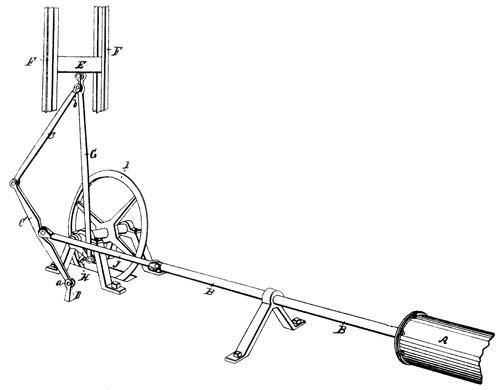
Figure 37.—Johnson's "converting motion," 1841. The linkage causes the flywheel to make two revolutions for each double-stroke of the engine piston rod B. From U.S. Patent 2295, October 11, 1841.
An Englishman who a few years earlier had invented a "new Motion" had claimed that his device would supersede the "ordinary crank in steam engines," the beam, parallel motion, and "external flywheel," reduce friction, neutralize "all extra contending power," and leave nothing for the piston to do "but the work intended to be done."
A correspondent of the Repertory of Patent Inventions made short work of this device: "There is hardly one assertion that can be supported by proof," he wrote, "and most of them are palpable misstatements." The writer attacked "the 'beetle impetus wheel,' which he [the inventor] thinks us all so beetle-headed, as not to perceive to be a flywheel," and concluded with the statement: "In short the whole production evinces gross ignorance either of machinery, if the patentee really believed what he asserted, or of mankind, if he did not."[104]
[104] Repertory of Patent Inventions, ser. 3, October 1828, vol. 7, pp. 196-200, and December 1828, vol. 7, pp. 357-361.
Although many of the mechanisms for which patents were taken out were designed by persons who would make no use of the principles involved even if such principles could at that time have been clearly stated, it is a regrettable fact that worthless mechanisms often got as much space as sound ones in patent journals, and objections such as the one above were infrequent. The slanted information thus conveyed to the young mechanician, who was just accumulating his first kinematic repertory, was at times sadly misleading.
From even this sketchy outline of the literature on the subject, it should be fairly evident that there has been available to the mechanician an enormous quantity of information about mechanical linkages and other devices. Whatever one may think of the quality of the literature, it has undoubtedly had influence not only in supplying designers with information but in forming a tradition of how one ought to supply the background that will enable the mind to assemble and synthesize the necessary mechanism for a given purpose.[105]
[105] Some additional catalogs of "mechanical movements" are listed in the selected references at the end of this paper.
Some of the mechanisms that have been given names—such as the Watt straight-line linkage and the Geneva stop—have appeared in textbook after textbook. Their only excuse for being seems to be that the authors must include them or risk censure by colleagues. Such mechanisms are more interesting to a reader, certainly, when he has some idea of what the name has to do with the mechanism, and who originated it. One such mechanism is the drag link.
After I had learned of the drag link (as most American engineering students do), I wondered for awhile, and eventually despaired of making any sense out of the term. What, I wanted to know, was being dragged? Recently, in Nicholson's Operative Mechanic and British Machinist (1826), I ran across the sketch reproduced here as figure 38. This figure, explained Mr. Nicholson (in vol. 1, p. 32) "represents the coupling link used by Messrs. Boulton and Watt in their portable steam engines. A, a strong iron pin, projecting from one of the arms of the fly-wheel B; D, a crank connected with the shaft C; and E, a link to couple the pin A and the crank D together, so the motion may be communicated to the shaft C." So the drag link was actually a link of a coupling. Nothing could be more logical. A drag link mechanism now makes sense to me.
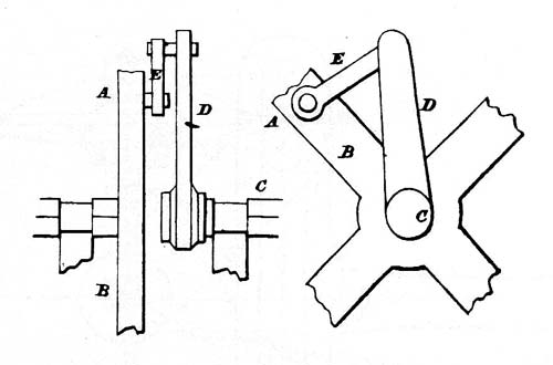
Figure 38.—Drag link coupling used on Boulton and Watt portable engines. The link E drags one shaft when the other turns. From John Nicholson, The Operative Mechanic, and British Machinist (Philadelphia, 1826, vol. I, pl. 5).
Directly related to the drag link coupling were the patents of John Oldham (1779-1840), an Irish engineer who is remembered mainly for the coupling that bears his name (fig. 39). His three patents, which were for various forms of steamboat feathering paddle wheels, involved linkages kinematically similar to the drag link coupling, although it is quite unlikely that Oldham recognized the similarity. However, for his well-known coupling, which employs an inversion of the elliptical trammel mechanism, I have found no evidence of a patent. Probably it was part of the machinery that he designed for the Bank of Ireland's printing house, of which Oldham was manager for many years. "Mr. Oldham and his beautiful system" were brought to the Bank of England in 1836, where Oldham remained until his death in 1840.[106]
[106] Oldham's paddle-wheel patents were British Patents 4169 (October 10, 1817), 4429 (January 15, 1820), and 5445 (February 1, 1827). Robert Willis (op. cit. footnote 21, p. 167) noticed the existence of the coupling. Drawings or descriptions of the banknote machinery apparently have not been published though they probably still exist in the banks' archives. The quotation is from Frederick G. Hall, The Bank of Ireland 1783-1946, Dublin, 1949. John Francis in his History of the Bank of England (London, 1848, vol. 2, p. 232) wrote: "The new machinery for printing the notes, which was introduced by Mr. Oldham ... is well worthy of a visit, but would be uninteresting to delineate."
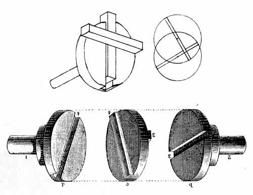
Figure 39.—Top, Original Oldham coupling built before 1840, using a cross (instead of a center disk), as sketched by Robert Willis in personal copy of his Principles of Mechanism (London, 1841, p. 167). Bottom, Oldham coupling as illustrated in Alexander B. W. Kennedy, Kinematics of Machinery, a translation of Franz Reuleaux' Theoretische Kinematik (London, 1876, pp. 315-316).
The Geneva stop mechanism (fig. 40) was properly described by Willis as a device to permit less than a full revolution of the star wheel and thus to prevent overwinding of a watch spring. It was called Geneva stop because it was used in Geneva watches. The Geneva wheel mechanism, which permits full rotation of the star wheel and which is frequently used for intermittent drives, was improperly called a Geneva stop in a recent textbook probably because the logical origin of the term had been lost.
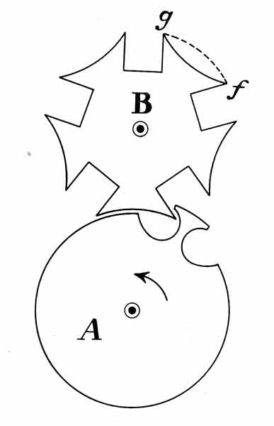
Figure 40.—Geneva stop mechanism first used in Geneva watches to prevent overwinding. The starwheel B had one convex surface (g-f, dotted) so the wheel could be turned less than a full revolution. After Robert Willis, Principles of Mechanism (London, 1841, p. 266).
The name for the Scotch yoke seems to be of fairly recent origin, the linkage being called by a Scotsman in 1869 a "crank and slot-headed sliding rod" (fig. 41). I suppose that it is now known as a Scotch yoke because, in America at least, a "Scotch" was a slotted bar that was slipped under a collar on a string of well-drilling tools to support them while a section was being added (fig. 42).
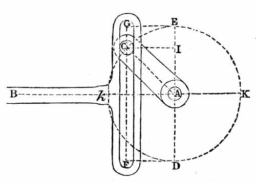
Figure 41.—Scotch yoke, described as a "crank and slot-headed sliding rod." From W. J. M. Rankine, A Manual of Machinery and Millwork (ed. 6, London, 1887, p. 169).
Figure 42.—A "Scotch" supporting the top member of a string of well-drilling tools while a section is being added, 1876. From Edward H. Knight, Knight's American Mechanical Dictionary (New York, 1876, p. 2057).
It was surprising to me to find that the Ackermann steering linkage, used today on most automobiles, was patented in 1818 when Detroit was still a frontier town.[107] Furthermore, the man who took out the patent described himself as Rudolph Ackermann, publisher and printseller. I thought I had the necessary clue to the linkage's origin when I noticed that the first English translation of the Lanz and Bétancourt treatise was published by Ackermann, but the connection finally proved to be more logical, if less direct. Ackermann (1764-1834), son of a Bavarian coach builder, had spent a number of years designing coaches for English gentlemen in London, where he made his home. One of his more notable commissions was for the design of Admiral Nelson's funeral car in 1805. The Ackermann steering linkage was not actually Ackermann's invention, although he took out the British patent in his name and promoted the introduction of the running gear of which the linkage was a part (fig. 43). The actual inventor was Ackermann's friend George Lankensperger of Munich, coachmaker to the King of Bavaria. The advantage of being able to turn a carriage around in a limited area without danger of oversetting was immediately obvious, and while there was considerable opposition by English coachmakers to an innovation for which a premium had to be paid, the invention soon "made its way from its own intrinsic merit," as Ackermann predicted it would.[108]
[107] British Patent 4212, January 27, 1818.
[108] Rudolph Ackermann, Observations on Ackermann's Patent Moveable Axles, London, 1819. It was interesting to me to note an abstract of W. A. Wolfe's paper "Analytical Design of an Ackermann Steering Linkage" in Mechanical Engineering, September 1958, vol. 80, p. 92.
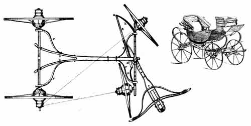
Figure 43.—Ackermann steering linkage of 1818, currently used in automobiles. This linkage was invented by George Lankensperger, coachmaker to the King of Bavaria. From Dinglers Polytechnisches Journal (1820, vol. 1, pl. 7).
The Whitworth quick-return mechanism (fig. 44) was first applied to a slotter, or vertical shaper, in 1849, and was exhibited in 1851 at the Great Exhibition in London.[109] Willis' comments on the mechanism are reproduced in figure 44. I hope that Sir Joseph Whitworth (1803-1887) will be remembered for sounder mechanical contrivances than this.
[109] The quick-return mechanism (British Patent 12907, December 19, 1849) was perhaps first publicly described in Charles Tomlinson, ed., Cyclopaedia of Useful Arts and Manufactures, London, 1854, vol. 1, p. cxliv.
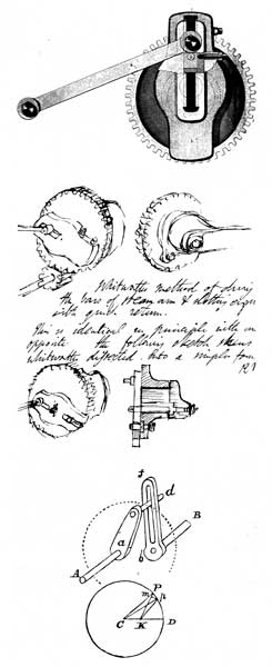
Figure 44.—Quick-return mechanism. Top, Early representation of the quick-return mechanism patented by Whitworth in 1849, from William Johnson, ed., The Imperial Cyclopaedia of machinery (Glasgow, about 1855, pl. 88). Middle, Sketch by Robert Willis from his copy of Principles of Mechanism (London, 1841, p. 264), which "shews Whitworth dissected into a simpler form"; it is as obscure as most subsequent attempts have been to explain this mechanism without a schematic diagram. Bottom, Linkage that is kinematically equivalent to Whitworth's, from Robert Willis, Principles of Mechanism (London, 1841, p. 264).
Engineering colleges in the United States were occupied until the late 1940's with extending, refining, and sharpening the tools of analysis that had been suggested by Willis, Rankine, Reuleaux, Kennedy, and Smith. The actual practice of kinematic synthesis went on apace, but designers often declined such help as the analytical methods might give them and there was little exchange of ideas between scholars and practitioners.
The capability and precision of machine tools were greatly enhanced during this period, although, with the exception of the centerless grinder, no significant new types of tools appeared. The machines that were made with machine tools increased in complexity and, with the introduction of ideas that made mass production of complex mechanical products economically feasible, there was an accelerating increase in quantity. The adoption of standards for all sorts of component parts also had an important bearing upon the ability of a designer economically to produce mechanisms that operated very nearly as he hoped they would.
The study of kinematics has been considered for nearly 80 years as a necessary part of the mechanical engineer's training, as the dozens of textbooks that have been published over the years make amply clear. Until recently, however, one would look in vain for original work in America in the analysis or rational synthesis of mechanisms.
One of the very earliest American textbooks of kinematics was the 1883 work of Charles W. MacCord (1836-1915), who had been appointed professor of mechanical drawing at Stevens Institute of Technology in Hoboken after serving John Ericsson, designer of the Monitor, as chief draftsman during the Civil War.[110] Based upon the findings of Willis and Rankine, MacCord's Kinematics came too early to be influenced by Kennedy's improvements upon Reuleaux's work.
[110] A biographical notice and a bibliography of MacCord appears in Morton Memorial: A History of the Stevens Institute of Technology, Hoboken, 1905, pp. 219-222.
When the faculty at Washington University in St. Louis introduced in 1885 a curriculum in "dynamic engineering," reflecting a dissatisfaction with the traditional branches of engineering, kinematics was a senior subject and was taught from Rankine's Machinery and Millwork.[111]
[111] Transactions of the American Society of Mechanical Engineers, 1885-1886, vol. 7, p. 757.
At Massachusetts Institute of Technology, Peter Schwamb, professor of machine design, put together in 1885 a set of printed notes on the kinematics of mechanisms, based on Reuleaux's and Rankine's works. Out of these notes grew one of the most durable of American textbooks, first published in 1904.[112] In the first edition of this work, acceleration was mentioned only once in passing (on p. 4). Velocities in linkages were determined by orthogonal components transferred from link to link. Instant centers were used only to determine velocities of various points on the same link. Angular velocity ratios were frequently noted. In the third edition, published in 1921, linear and angular accelerations were defined, but no acceleration analyses were made. Velocity analyses were altered without essential change. The fourth edition (1930) was essentially unchanged from the previous one. Treatment of velocity analysis was improved in the fifth edition (1938) and acceleration analysis was added. A sixth edition, further revised by Prof. V. L. Doughtie of the University of Texas, appeared in 1947.
[112] Peter Schwamb and Allyne L. Merrill, Elements of Mechanism, New York, 1904. In addition to the work of Reuleaux and Rankine, the authors acknowledged their use of the publications of Charles MacCord, Stillman W. Robinson, Thomas W. Goodeve, and William C. Unwin. For complete titles see the list of selected references.
Before 1900, several other books on mechanisms had been published, and all followed one or another of the patterns of their predecessors. Professors Woods and Stahl, at the Universities of Illinois and Purdue, respectively, who published their Elementary Mechanism in 1885, said in their preface what has been said by many other American authors and what should have been said by many more. "We make little claim to originality of the subject-matter," wrote Woods and Stahl, "free use having been made of all available matter on the subject.... Our claim to consideration is based almost entirely on the manner in which the subject has been presented." Not content with this disclaimer, they continued: "There is, in fact, very little room for such originality, the ground having been almost completely covered by previous writers."[113]
[113] Arthur T. Woods and Albert W. Stahl, Elementary Mechanism, New York, 1885.
The similarity and aridity of kinematics textbooks in this country from around 1910 are most striking. The generation of textbook writers following MacCord, Woods and Stahl, Barr of Cornell, Robinson of Ohio State, and Schwamb and Merrill managed to squeeze out any remaining juice in the subject, and the dessication and sterilization of textbooks was nearly complete when my generation used them in the 1930's. Kinematics was then, in more than one school, very nearly as it was characterized by an observer in 1942—"on an intellectual par with mechanical drafting."[114] I can recall my own naïve belief that a textbook contained all that was known of the subject; and I was not disabused of my belief by my own textbook or by my teacher. I think I detect in several recent books a fresh, less final, and less tidy treatment of the kinematics of mechanisms, but I would yet recommend that anyone who thinks of writing a textbook take time to review, carefully and at first hand, not only the desk copies of books that he has accumulated but a score or more of earlier works, covering the last century at least. Such a study should result in a better appreciation of what constitutes a contribution to knowledge and what constitutes merely the ringing of another change.
[114] Mechanical Engineering, October 1942, vol. 64, p. 745.
The author of the contentious article that appeared in Mechanical Engineering in 1942 under the title "What is Wrong with Kinematics and Mechanisms?" made several pronouncements that were questioned by various readers, but his remarks on the meagerness of the college courses of kinematics and the "curious fact" that the textbooks "are all strangely similar in their incompleteness" went unchallenged and were, in fact, quite timely.[115]
[115] De Jonge, op. cit. (footnote 78).
It appears that in the early 1940's the general classroom treatment of accelerations was at a level well below the existing knowledge of the subject, for in a series of articles by two teachers at Purdue attention was called to the serious consequences of errors in acceleration analysis occasioned by omitting the Coriolis component.[116] These authors were reversing a trend that had been given impetus by an article written in 1920 by one of their predecessors, Henry N. Bonis. The earlier article, appearing in a practical-and-proud-of-it technical magazine, demonstrated how the acceleration of a point on a flywheel governor might be determined "without the use of the fictitious acceleration of Coriolis." The author's analysis was right enough, and he closed his article with the unimpeachable statement that "it is better psychologically for the student and practically for the engineer to understand the fundamentals thoroughly than to use a complex formula that may be misapplied." However, many readers undoubtedly read only the lead paragraph, sagely nodded their heads when they reached the word "fictitious," which confirmed their half-formed conviction that anything as abstruse as the Coriolis component could have no bearing upon a practical problem, and turned the page to the "practical kinks" section.[117]
[116] A. S. Hall and E. S. Ault, "How Acceleration Analysis Can Be Improved," Machine Design, February 1943, vol. 15, pp. 100-102, 162, 164; and March 1943, vol. 15, pp. 90-92, 168, 170. See also A. S. Hall, "Teaching Coriolis' Law," Journal of Engineering Education, June 1948, vol. 38, pp. 757-765.
[117] Henry N. Bonis, "The Law of Coriolis," American Machinist, November 18, 1920, vol. 53, pp. 928-930. See also "Acceleration Determinations," American Machinist, November 25 and December 2, 1920, vol. 53, pp. 977-981 and 1027-1029.
Less than 20 years ago one might have read in Mechanical Engineering that "Practical machinery does not originate in mathematical formulas nor in beautiful vector diagrams." While this remark was in a letter evoked by an article, and was not a reflection of editorial policy, it was nevertheless representative of an element in the American tradition of engineering. The unconscious arrogance that is displayed in this statement of the "practical" designer's creed is giving way to recognition of the value of scholarly work. Lest the scholar develop arrogance of another sort, however, it is well to hear the author of the statement out. "A drafting machine is a useful tool," he wrote. "It is not a substitute for a draftsman."[118]
[118] Mechanical Engineering, October 1942, vol. 64, p. 746.
The scholarly interest in a subject is fairly represented by the papers that are published in the transactions of professional societies and, more recently, by original papers that appear in specialized magazines. From 1900 to 1930 there were few papers on mechanisms, and most of those that did appear were concerned with descriptions of new "mechanical motions." In the 1930's the number of papers reported in Engineering Index increased sharply, but only because the editors had begun to include foreign-language listings.
There has been in Germany a thread of continuity in the kinematics of mechanisms since the time of Reuleaux. While most of the work has had to do with analysis, the teasing question of synthesis that Reuleaux raised in his work has never been ignored. The developments in Germany and elsewhere have been ably reviewed by others,[119] and it is only to be noted here that two of the German papers, published in 1939 in Maschinenbau, appear to have been the sparks for the conflagration that still is increasing in extent and intensity. According to summaries in Engineering Index, R. Kraus, writing on the synthesis of the double-crank mechanism, drew fire from the Russian Z. S. Bloch, who, in 1940, discussed critically Kraus's articles and proceeded to give the outline of the "correct analysis of the problem" and a general numerical solution for the synthesis of "any four-bar linkage."[120] Russian work in mechanisms, dating back to Chebyshev and following the "Chebyshev theory of synthesis" in which algebraic methods are used to determine paths of minimum deviation from a given curve, has also been reviewed elsewhere,[121] and I can add nothing of value.
[119] Grodzinski, Bottema, De Jonge, and Hartenberg and Denavit. For complete titles see list of selected references.
[120] My source, as noted, is Engineering Index. Kraus's articles are reported in 1939 and Bloch's in 1940, both under the section heading "Mechanisms."
[121] A. E. Richard de Jonge, "Are the Russians Ahead in Mechanism Analysis?" Machine Design, September 1951, vol. 23, pp. 127, 200-208; O. Bottema, "Recent Work on Kinematics," Applied Mechanics Reviews, April 1953, vol. 6, pp. 169-170.
When, after World War II, some of the possibilities of kinematic synthesis were recognized in the United States, a few perceptive teachers fanned the tinder into an open flame.
The first publication of note in this country on the synthesis of linkages was a practical one, but in conception and undertaking it was a bold enterprise. In a book by John A. Hrones and G. L. Nelson, Analysis of the Four Bar Linkage (1951), the four-bar crank-and-rocker mechanism was exhaustively analyzed mechanically and the results were presented graphically. This work was faintly praised by a Dutch scholar, O. Bottema, who observed that the "complicated analytical theory of the three-bar [sic] curve has undoubtedly kept the engineer from using it" and who went on to say that "we fully understand the publication of an atlas by Hrones and Nelson containing thousands of trajectories which must be very useful in many design problems."[122] Nevertheless, the authors furnished designers with a tool that could be readily, almost instantly, understood (fig. 45), and the atlas has enjoyed wide circulation.[123] The idea of a geometrical approach to synthesis has been exploited by others in more recent publications,[124] and it is likely that many more variations on this theme will appear.
[122] Bottema, op. cit. (footnote 121).
[123] In 1851 Robert Willis had designed a coupler-point path-generating machine (fig. 46) that could have been used to produce a work similar to that of Hrones and Nelson.
[124] R. S. Hartenberg and J. Denavit, "Systematic Mechanism Design," Machine Design, September 1954, vol. 26, pp. 167-175, and October 1954, vol. 26, pp. 257-265; A. S. Hall, A. R. Holowenko, and H. G. Laughlin, "Four-Bar Lever Crank Mechanism," Design News, September 15, 1957, vol. 12, pp. 130-139, October 1, 1957, vol. 12, pp. 145-154, and October 15, 1957, vol. 12, pp. 132-141. For a nomographic approach, with particular application to computers, see Antonin Svoboda, Computing Mechanisms and Linkages, New York, 1948.
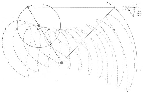
Figure 45.—Paths of 11 points on the coupler (horizontal) link are plotted through one cycle. Dashes indicate equal time intervals. From John A. Hrones and G. L. Nelson, Analysis of the Four Bar Linkage (New York, 1951, p. 635).
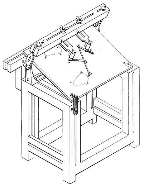
Figure 46.—Coupler-point path-generating machine for four-bar linkage. This device, built by Professor Willis as a teaching aid for demonstrating straight-line linkages, could have been adapted to produce a plate like the one shown in figure 45. From Robert Willis, A System of Apparatus for the Use of Lecturers and Experimenters ... (London 1851, pl. 3).
Pursuit of solutions to the "complicated analytical theory" of linkages was stimulated by publication of Ferdinand Freudenstein's "Analytical Approach to the Design of Four-Link Mechanisms" in 1954,[125] and an increasing interest in the problem is indicated by the extensive literature that has appeared in the last five years.
[125] Transactions of the American Society of Mechanical Engineers, 1954, vol. 76, pp. 483-492. See also Transactions of the American Society of Mechanical Engineers, 1955, vol. 77, pp. 853-861, and 1956, vol. 78, pp. 779-787.
The proper role of rational methods in the synthesis of mechanisms is not yet clear. "While we may talk about kinematic synthesis," wrote two of today's leaders in the field, "we are really talking about a hope for the future rather than a great reality of the present."[126] When the mental equipment and the enthusiasm of scholars who are devoting their time to the problems of kinematic synthesis are considered, however, it is difficult to see how important new ideas can fail to be produced.
[126] R. S. Hartenberg and J. Denavit, "Kinematic Synthesis," Machine Design, September 6, 1956, vol. 28, pp. 101-105.
An annual Conference on Mechanisms, sponsored by Purdue University and Machine Design, was inaugurated in 1953 and has met with a lively response. Among other manifestations of current interest in mechanisms, the contributions of Americans to international conferences on mechanisms reflects the growing recognition of the value of scholarly investigation of the kind that can scarcely hope to yield immediately tangible results.
While we look to the future, one may ask how a lengthy view of the past can be justified. It seems to me that there is inherent in the almost feverish activity of the present the danger of becoming so preoccupied with operational theory that the goals may become clouded and the synthesis (let us put it less elegantly: the design) of mechanisms may never quite come into focus. If one knows nothing of the past, I wonder how he can with any confidence decide in what direction he must turn in order to face the future.
Acknowledgment
I am grateful to Professors Richard S. Hartenberg and Allen S. Hall, Jr., for reading the manuscript, making helpful comments, and suggesting material that I had not found. The errors, however, are mine.
The following list of additional reference material on kinematics may be of help to readers who desire to do independent research. The material is listed according to the section headings in the text of the present article.
KEMPE, A. B. How to Draw a Straight Line. London, 1877.
Contains a useful bibliography. Reprinted in Squaring the Circle and Other Monographs, New York, Chelsea Publishing Company, 1953.
Much attention has been given to straight-line mechanisms since the time of Kempe; at least a half dozen articles have appeared in the United States since 1950, but I did not investigate the literature published after 1877.
BECK, THEODOR. Beiträge zur Geschichte des Maschinenbaues. Berlin, 1899.
Reviews of early works, such as those by Leonardo a Vinci, Biringuccio, Besson, Zonca, etc.
BORGNIS, GIUSEPPE ANTONIO. Traité complet de mécanique appliquée aux arts. Paris, 1818-1821, 9 vols.
Contains several hundred finely detailed plates of machines.
LABOULAYE, CHARLES. Traité de cinématique ou théorie des mécanismes. Paris, 1861 (ed. 2).
This work was quoted frequently by Laboulaye's contemporaries.
ROYAL SOCIETY OF LONDON. Catalogue of Scientific Papers, 1800-1900, Author Index. London, 1867-1902, and Cambridge, 1914-1925.
----. Catalogue of Scientific Papers, 1800-1900, Subject Index. London, 1909, vol. 2.
This subject index was started in 1908, and by 1914 three volumes (the third in two parts) had been published; however, this subject index was never completed. Volume 2, titled Mechanics, has some 200 entries under "Linkages." It is interesting to note that both of the Royal Society's monumental catalogs grew out of a suggestion made by Joseph Henry at a British Association meeting in Glasgow in 1855.
WEISBACH, JULIUS. The Mechanics of the Machinery of Transmission, vol. 3, pt. 1, sec. 2 of Mechanics of Engineering and Machinery, translated by J. F. Klein. New York, 1890 (ed. 2).
BARBER, THOMAS W. Engineer's Sketch-Book. London, 1890 (ed. 2).
HERKIMER, HERBERT. Engineer's Illustrated Thesaurus. New York, 1952.
PERIODICALS. Artizan, from 1843; Practical Mechanic and Engineer's Magazine, from 1841; Repertory of Arts and Manufactures, from 1794; Newton's London Journal of Arts and Science, from 1820. (The preceding periodicals have many plates of patent specification drawings.) The Engineer, November 10, 1933, vol. 156, p. 463, and Engineering, November 10, 1933, vol. 136, p. 525. (Recent English views questioning the utility of kinematics.)
TATE, THOMAS. Elements of Mechanism. London, 1851.
Contains figures from Lanz and Bétancourt (1808).
WYLSON, JAMES. Mechanical Inventor's Guide. London, 1859.
Contains figures from Henry Adcock, Adcock's Engineers' Pocket-Book, 1858.
ALBERT, CALVIN D., AND ROGERS, F. D. Kinematics of Machinery. New York, 1931.
Contains a bibliography that includes works not mentioned in the present paper.
BARR, JOHN H. Kinematics of Machinery. New York, 1899.
An early textbook. The author taught at Cornell University.
BEGGS, JOSEPH S. Mechanism. New York, 1955.
Contains an extensive and useful bibliography.
BOTTEMA, O. "Recent Work on Kinematics," Applied Mechanics Reviews, April 1953, vol. 6, pp. 169-170.
This conference was sponsored by Purdue University and Machine Design. Transactions of the first two conferences appeared as special sections in Machine Design, December 1953, vol. 25, pp. 173-220, December 1954, vol. 26, pp. 187-236, and in collected reprints. Papers of the third and fourth conferences (May 1956 and October 1957) appeared in Machine Design over several months following each conference and in collected reprints. Papers of the fifth conference (October 1958) were collected and preprinted for conference participants; subsequently, all papers appeared in Machine Design. Collected reprints and preprints are available (May 1960) from Penton Publishing Company, Cleveland, Ohio.
DE JONGE, A. E. RICHARD. "Kinematic Synthesis of Mechanisms," Mechanical Engineering, July 1940, vol. 62, pp. 537-542.
----. "A Brief Account of Modern Kinematics," Transactions of the American Society of Mechanical Engineers, 1943, vol. 65, pp. 663-683.
GOODEVE, THOMAS M. The Elements of Mechanism. London, 1903.
An early textbook.
GRODZINSKI, PAUL, AND MCEWEN, EWEN. "Link Mechanisms in Modern Kinematics," Journal and Proceedings of the Institution of Mechanical Engineers, 1954, vol. 168, pp. 877-896.
This article evoked interesting discussion. It is unfortunate that Grodzinski's periodical, Mechanism, An International Bibliography, which was published in London in 1956-1957 and which terminated shortly after his death, has not been revived. Grodzinski's incisive views and informative essays are valuable and interesting.
HARTENBERG, R. S. "Complex Numbers and Four-Bar Linkages," Machine Design, March 20, 1958, vol. 30, pp. 156-163.
This is an excellent primer. The author explains complex numbers in his usual lucid fashion.
HARTENBERG, R. S., AND DENAVIT, J. "Kinematic Synthesis," Machine Design, September 6, 1956, vol. 28, pp. 101-105.
MACCORD, CHARLES. Kinematics. New York, 1883.
An early textbook.
ROBINSON, STILLMAN W. Principles of Mechanism. New York, 1896.
An early textbook. The author taught at Ohio State University.
UNWIN, WILLIAM C. The Elements of Machine Design. New York, 1882 (ed. 4).
An early textbook. The author taught at Royal Indian Engineering College, in England.
GOVERNMENT PRINTING OFFICE: 1962
For sale by the Superintendent of Documents, U.S. Government Printing Office Washington 25, D. C.—Price 40 cents
End of the Project Gutenberg EBook of Kinematics of Mechanisms from the Time
of Watt, by Eugene S. Ferguson

*** END OF THIS PROJECT GUTENBERG EBOOK KINEMATICS OF MECHANISMS ***

***** This file should be named 27106-h.htm or 27106-h.zip *****
This and all associated files of various formats will be found in:
        http://www.gutenberg.org/2/7/1/0/27106/

Produced by Chris Curnow, Viv, Joseph Cooper and the Online
Distributed Proofreading Team at http://www.pgdp.net


Updated editions will replace the previous one--the old editions
will be renamed.

Creating the works from public domain print editions means that no
one owns a United States copyright in these works, so the Foundation
(and you!) can copy and distribute it in the United States without
permission and without paying copyright royalties.  Special rules,
set forth in the General Terms of Use part of this license, apply to
copying and distributing Project Gutenberg-tm electronic works to
protect the PROJECT GUTENBERG-tm concept and trademark.  Project
Gutenberg is a registered trademark, and may not be used if you
charge for the eBooks, unless you receive specific permission.  If you
do not charge anything for copies of this eBook, complying with the
rules is very easy.  You may use this eBook for nearly any purpose
such as creation of derivative works, reports, performances and
research.  They may be modified and printed and given away--you may do
practically ANYTHING with public domain eBooks.  Redistribution is
subject to the trademark license, especially commercial
redistribution.


*** START: FULL LICENSE ***

THE FULL PROJECT GUTENBERG LICENSE
PLEASE READ THIS BEFORE YOU DISTRIBUTE OR USE THIS WORK

To protect the Project Gutenberg-tm mission of promoting the free
distribution of electronic works, by using or distributing this work
(or any other work associated in any way with the phrase "Project
Gutenberg"), you agree to comply with all the terms of the Full Project
Gutenberg-tm License (available with this file or online at
http://gutenberg.org/license).


Section 1.  General Terms of Use and Redistributing Project Gutenberg-tm
electronic works

1.A.  By reading or using any part of this Project Gutenberg-tm
electronic work, you indicate that you have read, understand, agree to
and accept all the terms of this license and intellectual property
(trademark/copyright) agreement.  If you do not agree to abide by all
the terms of this agreement, you must cease using and return or destroy
all copies of Project Gutenberg-tm electronic works in your possession.
If you paid a fee for obtaining a copy of or access to a Project
Gutenberg-tm electronic work and you do not agree to be bound by the
terms of this agreement, you may obtain a refund from the person or
entity to whom you paid the fee as set forth in paragraph 1.E.8.

1.B.  "Project Gutenberg" is a registered trademark.  It may only be
used on or associated in any way with an electronic work by people who
agree to be bound by the terms of this agreement.  There are a few
things that you can do with most Project Gutenberg-tm electronic works
even without complying with the full terms of this agreement.  See
paragraph 1.C below.  There are a lot of things you can do with Project
Gutenberg-tm electronic works if you follow the terms of this agreement
and help preserve free future access to Project Gutenberg-tm electronic
works.  See paragraph 1.E below.

1.C.  The Project Gutenberg Literary Archive Foundation ("the Foundation"
or PGLAF), owns a compilation copyright in the collection of Project
Gutenberg-tm electronic works.  Nearly all the individual works in the
collection are in the public domain in the United States.  If an
individual work is in the public domain in the United States and you are
located in the United States, we do not claim a right to prevent you from
copying, distributing, performing, displaying or creating derivative
works based on the work as long as all references to Project Gutenberg
are removed.  Of course, we hope that you will support the Project
Gutenberg-tm mission of promoting free access to electronic works by
freely sharing Project Gutenberg-tm works in compliance with the terms of
this agreement for keeping the Project Gutenberg-tm name associated with
the work.  You can easily comply with the terms of this agreement by
keeping this work in the same format with its attached full Project
Gutenberg-tm License when you share it without charge with others.

1.D.  The copyright laws of the place where you are located also govern
what you can do with this work.  Copyright laws in most countries are in
a constant state of change.  If you are outside the United States, check
the laws of your country in addition to the terms of this agreement
before downloading, copying, displaying, performing, distributing or
creating derivative works based on this work or any other Project
Gutenberg-tm work.  The Foundation makes no representations concerning
the copyright status of any work in any country outside the United
States.

1.E.  Unless you have removed all references to Project Gutenberg:

1.E.1.  The following sentence, with active links to, or other immediate
access to, the full Project Gutenberg-tm License must appear prominently
whenever any copy of a Project Gutenberg-tm work (any work on which the
phrase "Project Gutenberg" appears, or with which the phrase "Project
Gutenberg" is associated) is accessed, displayed, performed, viewed,
copied or distributed:

This eBook is for the use of anyone anywhere at no cost and with
almost no restrictions whatsoever.  You may copy it, give it away or
re-use it under the terms of the Project Gutenberg License included
with this eBook or online at www.gutenberg.org

1.E.2.  If an individual Project Gutenberg-tm electronic work is derived
from the public domain (does not contain a notice indicating that it is
posted with permission of the copyright holder), the work can be copied
and distributed to anyone in the United States without paying any fees
or charges.  If you are redistributing or providing access to a work
with the phrase "Project Gutenberg" associated with or appearing on the
work, you must comply either with the requirements of paragraphs 1.E.1
through 1.E.7 or obtain permission for the use of the work and the
Project Gutenberg-tm trademark as set forth in paragraphs 1.E.8 or
1.E.9.

1.E.3.  If an individual Project Gutenberg-tm electronic work is posted
with the permission of the copyright holder, your use and distribution
must comply with both paragraphs 1.E.1 through 1.E.7 and any additional
terms imposed by the copyright holder.  Additional terms will be linked
to the Project Gutenberg-tm License for all works posted with the
permission of the copyright holder found at the beginning of this work.

1.E.4.  Do not unlink or detach or remove the full Project Gutenberg-tm
License terms from this work, or any files containing a part of this
work or any other work associated with Project Gutenberg-tm.

1.E.5.  Do not copy, display, perform, distribute or redistribute this
electronic work, or any part of this electronic work, without
prominently displaying the sentence set forth in paragraph 1.E.1 with
active links or immediate access to the full terms of the Project
Gutenberg-tm License.

1.E.6.  You may convert to and distribute this work in any binary,
compressed, marked up, nonproprietary or proprietary form, including any
word processing or hypertext form.  However, if you provide access to or
distribute copies of a Project Gutenberg-tm work in a format other than
"Plain Vanilla ASCII" or other format used in the official version
posted on the official Project Gutenberg-tm web site (www.gutenberg.org),
you must, at no additional cost, fee or expense to the user, provide a
copy, a means of exporting a copy, or a means of obtaining a copy upon
request, of the work in its original "Plain Vanilla ASCII" or other
form.  Any alternate format must include the full Project Gutenberg-tm
License as specified in paragraph 1.E.1.

1.E.7.  Do not charge a fee for access to, viewing, displaying,
performing, copying or distributing any Project Gutenberg-tm works
unless you comply with paragraph 1.E.8 or 1.E.9.

1.E.8.  You may charge a reasonable fee for copies of or providing
access to or distributing Project Gutenberg-tm electronic works provided
that

- You pay a royalty fee of 20% of the gross profits you derive from
     the use of Project Gutenberg-tm works calculated using the method
     you already use to calculate your applicable taxes.  The fee is
     owed to the owner of the Project Gutenberg-tm trademark, but he
     has agreed to donate royalties under this paragraph to the
     Project Gutenberg Literary Archive Foundation.  Royalty payments
     must be paid within 60 days following each date on which you
     prepare (or are legally required to prepare) your periodic tax
     returns.  Royalty payments should be clearly marked as such and
     sent to the Project Gutenberg Literary Archive Foundation at the
     address specified in Section 4, "Information about donations to
     the Project Gutenberg Literary Archive Foundation."

- You provide a full refund of any money paid by a user who notifies
     you in writing (or by e-mail) within 30 days of receipt that s/he
     does not agree to the terms of the full Project Gutenberg-tm
     License.  You must require such a user to return or
     destroy all copies of the works possessed in a physical medium
     and discontinue all use of and all access to other copies of
     Project Gutenberg-tm works.

- You provide, in accordance with paragraph 1.F.3, a full refund of any
     money paid for a work or a replacement copy, if a defect in the
     electronic work is discovered and reported to you within 90 days
     of receipt of the work.

- You comply with all other terms of this agreement for free
     distribution of Project Gutenberg-tm works.

1.E.9.  If you wish to charge a fee or distribute a Project Gutenberg-tm
electronic work or group of works on different terms than are set
forth in this agreement, you must obtain permission in writing from
both the Project Gutenberg Literary Archive Foundation and Michael
Hart, the owner of the Project Gutenberg-tm trademark.  Contact the
Foundation as set forth in Section 3 below.

1.F.

1.F.1.  Project Gutenberg volunteers and employees expend considerable
effort to identify, do copyright research on, transcribe and proofread
public domain works in creating the Project Gutenberg-tm
collection.  Despite these efforts, Project Gutenberg-tm electronic
works, and the medium on which they may be stored, may contain
"Defects," such as, but not limited to, incomplete, inaccurate or
corrupt data, transcription errors, a copyright or other intellectual
property infringement, a defective or damaged disk or other medium, a
computer virus, or computer codes that damage or cannot be read by
your equipment.

1.F.2.  LIMITED WARRANTY, DISCLAIMER OF DAMAGES - Except for the "Right
of Replacement or Refund" described in paragraph 1.F.3, the Project
Gutenberg Literary Archive Foundation, the owner of the Project
Gutenberg-tm trademark, and any other party distributing a Project
Gutenberg-tm electronic work under this agreement, disclaim all
liability to you for damages, costs and expenses, including legal
fees.  YOU AGREE THAT YOU HAVE NO REMEDIES FOR NEGLIGENCE, STRICT
LIABILITY, BREACH OF WARRANTY OR BREACH OF CONTRACT EXCEPT THOSE
PROVIDED IN PARAGRAPH F3.  YOU AGREE THAT THE FOUNDATION, THE
TRADEMARK OWNER, AND ANY DISTRIBUTOR UNDER THIS AGREEMENT WILL NOT BE
LIABLE TO YOU FOR ACTUAL, DIRECT, INDIRECT, CONSEQUENTIAL, PUNITIVE OR
INCIDENTAL DAMAGES EVEN IF YOU GIVE NOTICE OF THE POSSIBILITY OF SUCH
DAMAGE.

1.F.3.  LIMITED RIGHT OF REPLACEMENT OR REFUND - If you discover a
defect in this electronic work within 90 days of receiving it, you can
receive a refund of the money (if any) you paid for it by sending a
written explanation to the person you received the work from.  If you
received the work on a physical medium, you must return the medium with
your written explanation.  The person or entity that provided you with
the defective work may elect to provide a replacement copy in lieu of a
refund.  If you received the work electronically, the person or entity
providing it to you may choose to give you a second opportunity to
receive the work electronically in lieu of a refund.  If the second copy
is also defective, you may demand a refund in writing without further
opportunities to fix the problem.

1.F.4.  Except for the limited right of replacement or refund set forth
in paragraph 1.F.3, this work is provided to you 'AS-IS' WITH NO OTHER
WARRANTIES OF ANY KIND, EXPRESS OR IMPLIED, INCLUDING BUT NOT LIMITED TO
WARRANTIES OF MERCHANTIBILITY OR FITNESS FOR ANY PURPOSE.

1.F.5.  Some states do not allow disclaimers of certain implied
warranties or the exclusion or limitation of certain types of damages.
If any disclaimer or limitation set forth in this agreement violates the
law of the state applicable to this agreement, the agreement shall be
interpreted to make the maximum disclaimer or limitation permitted by
the applicable state law.  The invalidity or unenforceability of any
provision of this agreement shall not void the remaining provisions.

1.F.6.  INDEMNITY - You agree to indemnify and hold the Foundation, the
trademark owner, any agent or employee of the Foundation, anyone
providing copies of Project Gutenberg-tm electronic works in accordance
with this agreement, and any volunteers associated with the production,
promotion and distribution of Project Gutenberg-tm electronic works,
harmless from all liability, costs and expenses, including legal fees,
that arise directly or indirectly from any of the following which you do
or cause to occur: (a) distribution of this or any Project Gutenberg-tm
work, (b) alteration, modification, or additions or deletions to any
Project Gutenberg-tm work, and (c) any Defect you cause.


Section  2.  Information about the Mission of Project Gutenberg-tm

Project Gutenberg-tm is synonymous with the free distribution of
electronic works in formats readable by the widest variety of computers
including obsolete, old, middle-aged and new computers.  It exists
because of the efforts of hundreds of volunteers and donations from
people in all walks of life.

Volunteers and financial support to provide volunteers with the
assistance they need, is critical to reaching Project Gutenberg-tm's
goals and ensuring that the Project Gutenberg-tm collection will
remain freely available for generations to come.  In 2001, the Project
Gutenberg Literary Archive Foundation was created to provide a secure
and permanent future for Project Gutenberg-tm and future generations.
To learn more about the Project Gutenberg Literary Archive Foundation
and how your efforts and donations can help, see Sections 3 and 4
and the Foundation web page at http://www.pglaf.org.


Section 3.  Information about the Project Gutenberg Literary Archive
Foundation

The Project Gutenberg Literary Archive Foundation is a non profit
501(c)(3) educational corporation organized under the laws of the
state of Mississippi and granted tax exempt status by the Internal
Revenue Service.  The Foundation's EIN or federal tax identification
number is 64-6221541.  Its 501(c)(3) letter is posted at
http://pglaf.org/fundraising.  Contributions to the Project Gutenberg
Literary Archive Foundation are tax deductible to the full extent
permitted by U.S. federal laws and your state's laws.

The Foundation's principal office is located at 4557 Melan Dr. S.
Fairbanks, AK, 99712., but its volunteers and employees are scattered
throughout numerous locations.  Its business office is located at
809 North 1500 West, Salt Lake City, UT 84116, (801) 596-1887, email
business@pglaf.org.  Email contact links and up to date contact
information can be found at the Foundation's web site and official
page at http://pglaf.org

For additional contact information:
     Dr. Gregory B. Newby
     Chief Executive and Director
     gbnewby@pglaf.org


Section 4.  Information about Donations to the Project Gutenberg
Literary Archive Foundation

Project Gutenberg-tm depends upon and cannot survive without wide
spread public support and donations to carry out its mission of
increasing the number of public domain and licensed works that can be
freely distributed in machine readable form accessible by the widest
array of equipment including outdated equipment.  Many small donations
($1 to $5,000) are particularly important to maintaining tax exempt
status with the IRS.

The Foundation is committed to complying with the laws regulating
charities and charitable donations in all 50 states of the United
States.  Compliance requirements are not uniform and it takes a
considerable effort, much paperwork and many fees to meet and keep up
with these requirements.  We do not solicit donations in locations
where we have not received written confirmation of compliance.  To
SEND DONATIONS or determine the status of compliance for any
particular state visit http://pglaf.org

While we cannot and do not solicit contributions from states where we
have not met the solicitation requirements, we know of no prohibition
against accepting unsolicited donations from donors in such states who
approach us with offers to donate.

International donations are gratefully accepted, but we cannot make
any statements concerning tax treatment of donations received from
outside the United States.  U.S. laws alone swamp our small staff.

Please check the Project Gutenberg Web pages for current donation
methods and addresses.  Donations are accepted in a number of other
ways including checks, online payments and credit card donations.
To donate, please visit: http://pglaf.org/donate


Section 5.  General Information About Project Gutenberg-tm electronic
works.

Professor Michael S. Hart is the originator of the Project Gutenberg-tm
concept of a library of electronic works that could be freely shared
with anyone.  For thirty years, he produced and distributed Project
Gutenberg-tm eBooks with only a loose network of volunteer support.


Project Gutenberg-tm eBooks are often created from several printed
editions, all of which are confirmed as Public Domain in the U.S.
unless a copyright notice is included.  Thus, we do not necessarily
keep eBooks in compliance with any particular paper edition.


Most people start at our Web site which has the main PG search facility:

     http://www.gutenberg.org

This Web site includes information about Project Gutenberg-tm,
including how to make donations to the Project Gutenberg Literary
Archive Foundation, how to help produce our new eBooks, and how to
subscribe to our email newsletter to hear about new eBooks.