The Project Gutenberg EBook of Scientific American Supplement, No. 1082,
September 26, 1896, by Various

This eBook is for the use of anyone anywhere at no cost and with
almost no restrictions whatsoever.  You may copy it, give it away or
re-use it under the terms of the Project Gutenberg License included
with this eBook or online at www.gutenberg.org


Title: Scientific American Supplement, No. 1082, September 26, 1896

Author: Various

Release Date: January 15, 2008 [EBook #24323]

Language: English

Character set encoding: ISO-8859-1

*** START OF THIS PROJECT GUTENBERG EBOOK SCIENTIFIC AMERICAN ***


Produced by Juliet Sutherland, Priscilla Walmsley, and the
Online Distributed Proofreading Team at www.pgdp.net
The sudden death on August 25 of Sultan Hamid bin Thwain, the ruler of Zanzibar, the attempted usurpation by Seyyid Khalid, and the bombardment of the palace by the British warships, have directed public attention to this comparatively little known but important city on the east coast of Africa.
The Zanzibar dominions achieved their independence some forty years ago under Seyyid Majid, whose father was Seyyid Said, the Sultan of Muscat and Zanzibar. The dominions formerly extended from Warsheik south to Tanghi Bay. In 1890 the coast line from Ruvuma to Wanga, with the island of Mafia, was ceded to Germany, by which partition the country was reduced to two islands, Zanzibar and Pemba, containing about a thousand square miles with 165,000 inhabitants, a strip of coast line ten miles long, together with three smaller islands and five seaports. Zanzibar is a British protectorate, as are also the Zanzibar dominions on the mainland as far north as the mouth of the Juba. The remainder of the mainland dominions to the south are leased to an Italian company.
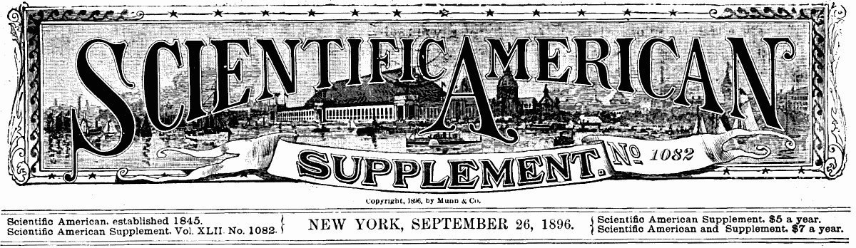
 PALACE SQUARE, ZANZIBAR: TROOPS ASSEMBLED IN FRONT OF
GOVERNMENT HOUSE; PALACE, WITH THE LATE SULTAN IN THE GALLERY, TO THE
RIGHT HAND; HAREM TO THE LEFT.
PALACE SQUARE, ZANZIBAR: TROOPS ASSEMBLED IN FRONT OF
GOVERNMENT HOUSE; PALACE, WITH THE LATE SULTAN IN THE GALLERY, TO THE
RIGHT HAND; HAREM TO THE LEFT.
The island of Zanzibar, together with the neighboring islands of Pemba and Mafia, to the north and south, is generally of coral formation, with here and there hills of a reddish clay, which rise in the south to an elevation of 450 feet and in the north develop into a range of hills which runs parallel to the shore at a height of over 1,000 feet. The dense forests which originally covered the island have been cut down, and the soil, which is of unusual fertility, is under thorough cultivation, yielding heavy crops of corn and manioc, which latter forms the staple food of the people.
The soil and climate are specially suited to the clove, which is raised in great quantities, the crop forming four-fifths of the total clove crop of the world. The seaboard lying opposite the island of Zanzibar is level and swampy, and the many rivers which flow from the escarpment of the great inland plateau have brought down a vast deposit of rich alluvial matter, upon which, aided by the moist, warm climate, a dense growth of tropical vegetation flourishes. A native growth of this region is the copal tree, famous as yielding the best gum known to commerce. Rice, maize, millet, the cocoa nut and the oil palm are cultivated, and the whole country is well adapted to the raising of sugar, coffee, cotton, indigo, and the various spices.
Of the original races of the island of Zanzibar only a few representatives survive. These live on the east side, and are known as Wa-Hadimu Bantus. The main population is a strange mixture of "full blood and half-caste Arabs, Indian 'Canarians' (that is, half-caste Portuguese from Kanara on the Malabar coast of India), Swahili of every shade, slaves or freedmen from all parts of East Africa," with a small sprinkling of Americans and Europeans.
The city of Zanzibar is next to Alexandria and Tunis, the largest city on the coast of Africa, and contains a population variously estimated at from 80,000 to 100,000 souls. It is easily separable into two quarters, the trading quarter, which lies along the beach and contains the palace of the Sultan, and the eastern outlying suburb in which live the lower class. The view of Zanzibar from the sea is picturesque, the palace, forts and towers, the Mission Cathedral and the successive white buildings of varied outline, making a pleasing panorama. But when the visitor passes into the heart of the city he loses himself in a tangle of foul and narrow streets, where filth and immorality abound.
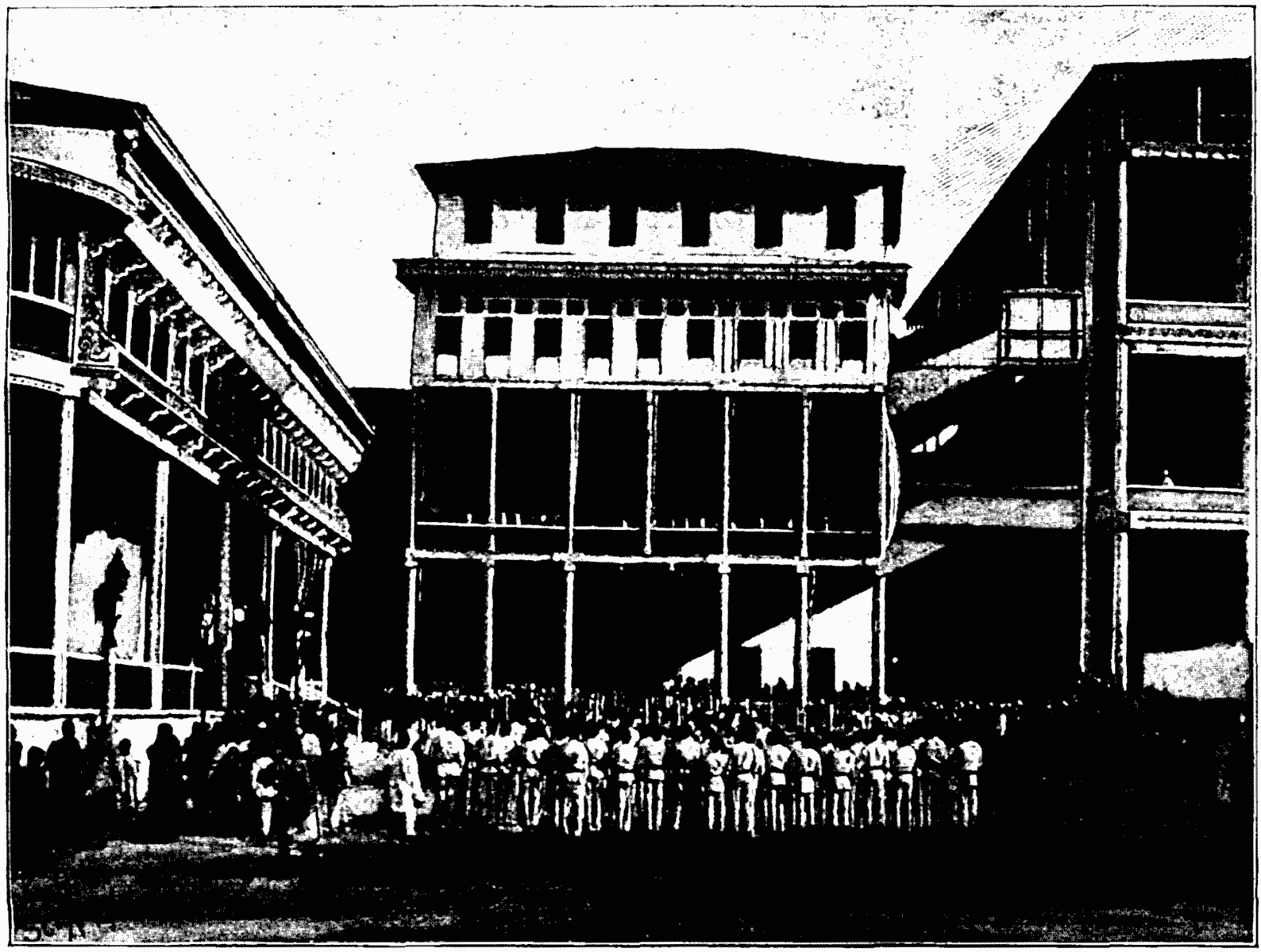
 THE LATE SULTAN OF ZANZIBAR AND HIS MINISTERS.
The palace, which is the central point of the city's life, is thus described by a former resident, Mr. Charles L. Lyons: "A low, rambling structure divided into three parts. The higher portion is of stone, and surrounded by verandas of carved teak wood, which are very ornate and elaborate specimens of eastern decorative art work. Adjoining this is the section occupied as living apartments, and the third section is occupied by the harem, which, under the late Sultan, comprised about twenty-five Circassian women.
"The palace was a curious combination of magnificence and tawdriness. The reception room, which is about 250 ft. square, was hung with beautiful draperies embroidered in real gold. In many places the walls were inlaid with precious stones curiously and indiscriminately mingled. Next to a valuable uncut sapphire or a ruby one would find a carbuncle or some valueless stone. Many of the chairs in the finer apartments were of gold inlaid with precious stones, and about many of the rooms were inscriptions from the Koran applied in solid gold." Other conspicuous buildings as seen from the water are the Government House, the Custom House, the Signal Tower, and the Mission Cathedral.
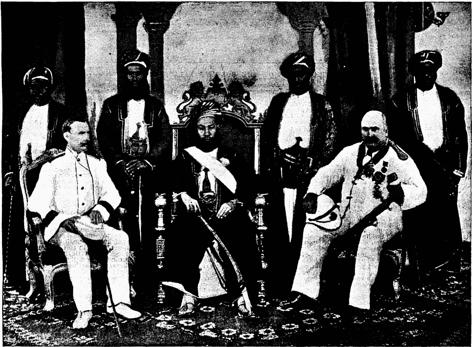
 EXTERIOR VIEW OF THE SULTAN'S PALACE, ZANZIBAR.
The harbor affords a fine anchorage for shipping, and is well worthy to be the central shipping point of the east coast of Africa. The total imports for 1894 were valued at over $6,000,000 and the exports at about $5,500,000. British India controls the greater share of the import trade, sending over large cargoes of grain, rice, and piece goods from Bombay, the yearly value of the trade being $1,675,000. The German trade amounts to $340,000, and a large amount of cotton goods and kerosene oil is imported from America.
The law of succession to the throne of Zanzibar does not recognize the right of the eldest son or the son of the eldest brother deceased. In the eyes of the Mohammedan Council of State Seyyid Khalid, the late usurper, has no stronger claim to the throne than his cousin, the present Sultan Hamid bin Mohammed bin Seyyid. Khalid is spoken of as "a rash and willful young man of twenty-five," and Hamid as "an elderly gentleman, fifty or sixty years of age, respected for his prudent and peaceable conduct, acceptable to the better class of Mussulman townsfolk, and trusted as a ruler likely to preserve the traditional policy of the realm." Immediately upon the interment of the late Sultan, however, which took place two short hours after his suspicious death, Khalid proclaimed himself ruler. He gathered the palace guards together, placed barricades in the palace square, trained the guns upon the British warships, and awaited developments. They came the next morning in the shape of an ultimatum from Admiral Rawson of the St. George, a first class cruiser of 7,700 tons, which, together with four smaller cruisers and gunboats, lay off the city in the harbor, summoning Khalid to surrender, leave the palace, and make his soldiers pile their arms in front of it. If he failed to do this, the palace would be bombarded within two hours after the dispatch of the ultimatum.
As Khalid's reply was to further strengthen his defense, at the appointed time the bombardment began. Meanwhile the loyal Zanzibar troops, with a detachment of British marines and seamen, attacked the barricades. The palace was knocked to pieces and set on fire by the shells, and Khalid, driven from the shelter, fled to the German consulate for safety.
Hamid was proclaimed Sultan by General Matthews, Mr. Cave, the consul, and Admiral Rawson, and order was at once restored to the city.
At the time of the bombardment it was freely predicted that the annexation of Zanzibar would speedily follow; but it now appears that the government considers that no advantages are to be gained by such a step, the cost of a direct administration being much greater than the native administration, which under the present protectorate is working satisfactorily.
We are indebted for our illustrations to the Illustrated London News and to Black and White.
Scientific research, interpreting the observations of practical life, implies that several errors are common in the use of food.
First, many people purchase needlessly expensive kinds of food, doing this under the false impression that there is some peculiar virtue in the costlier materials, and that economy in our diet is somehow detrimental to our dignity or our welfare. And, unfortunately, those who are most extravagant in this respect are often the ones who can least afford it.
Secondly, the food which we eat does not always contain the proper proportions of the different kinds of nutritive ingredients. We consume relatively too much of the fuel ingredients of food, such as the fats of meat and butter, the starch which makes up the larger part of the nutritive material of flour and potatoes and sugar and sweetmeats. Conversely, we have relatively too little of the protein of flesh-forming substances, like the lean of meat and fish and the gluten of wheat, which make muscle and sinew and which are the basis of blood, bone and brain.
Thirdly, many people, not only the well-to-do, but those in moderate circumstances, use needless quantities of food. Part of the excess, however, is simply thrown away with the wastes of the table and the kitchen; so that the injury to health, great as it may be, is doubtless much less than if all were eaten. Probably the worst sufferers from this evil are well-to-do people of sedentary occupations—brain workers as distinguished from hand workers.
Finally, we are guilty of serious errors in our cooking. We waste a great deal of fuel in the preparation of our food, and even then a great deal of the food is very badly cooked. A reform in these methods of cooking is one of the economic demands of our time.
Cheap vs. Dear Food.—We cannot judge of the nutritive value of food by the quantity. There is as much nutriment in a pound of wheat flour as in 3½ quarts of oysters, which weigh 7 pounds. There is still less connection between nutritive value and price. In buying at ordinary market rates we get as much material to build up our bodies, repair their wastes, and give strength for work in 5 cents' worth of flour or beans or codfish as 50 cents or $1 will pay for in tenderloin, salmon or lobsters.
Round steak at 15 cents a pound is just as digestible and is fully as nutritious as tenderloin at 50. Mackerel has as high nutritive value as salmon, and costs from an eighth to half as much. Oysters are a delicacy. If one can afford them, there is no reason for not having them, but 25 cents invested in a pint would bring only about an ounce of protein and 230 calories of energy. The same 25 cents spent for flour at $6 a barrel, or 3 cents a pound, would pay for nine-tenths of a pound of protein and 13,700 calories of energy. When a day laborer buys bread at 7½ cents a pound, the actual nutritive material costs him three times as much as it does his employer, who buys it in flour at $6 a barrel.
Illustrations of the prejudice of people, especially those in moderate circumstances, against the less expensive kinds of food are very common.
Mr. Lee Meriwether, who has given much attention to this special subject, cites a case in point, that of a coal laborer, who boasted: "No one can say that I do not give my family the best flour, the finest of sugar, the very best quality of meat." He paid $156 a year for the nicest cuts of meat, which his wife had to cook before six in the morning or after half past six at night, because she worked all day in a factory. When excellent butter was selling at 25 cents a pound he paid 29 cents for an extra quality. He spent only $108 a year for clothing for his family of nine, and only $72 a year for rent in a close tenement house, where they slept in rooms without windows or closets. He indulged in this extravagance in diet, when much less expensive food materials, such as regularly come upon the tables of men of wealth, would have been just as nutritious, just as wholesome, and in every way just as good, save in the gratification to pride and palate. He was committing an immense economic blunder. Like thousands of others, he did so in the belief that it was wise and economical.
The sad side of the story is that the poor are the ones who practice the worst economy in the purchase as well as the use of food. The Massachusetts Bureau of Labor, in collecting the dietaries above referred to, made numerous inquiries of tradesmen regarding the food of the poor in Boston, meaning by poor "those who earn just enough to keep themselves and families from want." The almost universal testimony was, "They usually want the best and pay for it, and the most fastidious are those who can least afford it." The costliest kind of meat, the finest flour, and very highest priced butter were demanded, and many scorned the less expensive meats and groceries such as well-to-do and sensible people were in the habit of buying.
I have taken occasion to verify these observations by personal inquiry in Boston markets. One intelligent meat man gave his experience with a poor seamstress, who insisted on buying tenderloin steak at 60 cents per pound. He tried to persuade her that other parts of the meat were just as nutritive, as they really are, but she would not believe him; and when he urged the wiser economy of using them, she became angry at him for what she regarded as a reflection upon her dignity. "My wealthy customers," said he, "take our cheaper cuts, but I have got through trying to sell these economical meats to that woman and others of her class."
I am told that people in the poorer parts of New York City buy the highest priced groceries, and that the meat men say they can sell the coarser cuts of meat to the rich, but that people of moderate means refuse them. I hear the same thing in Washington and other cities.
One-sidedness of Our Dietary.—I have said that our diet is one-sided, that the food which we actually eat has relatively too little protein and too much fat, starch, and sugar. In other words, it is relatively deficient in the materials which make muscle and bone and contains a relative excess of the fuel ingredients. This is due partly to our large consumption of sugar and partly to our use of such large quantities of fat meats.
Overeating—Injury to Health.—But the most remarkable thing about our food consumption is the quantity. The American dietaries examined in this inquiry were of people living at the time in Massachusetts and Connecticut, though many came from other parts of the country. It would be wrong to take their eating habits as an exact measure of those of people throughout the United States. For that matter, a great deal of careful observation will be needed to show precisely what and how much is used by persons of different classes in different regions. Just this kind of study in different parts of the country is greatly needed. But such facts as I have been able to gather seem to imply that the figures obtained indicate in a general way the character of our food consumption. Of the over 50 dietaries of reasonably well-to-do people thus far examined the smallest is that of a mechanic's family. In this the potential energy per man per day was about 3,000 calories. The next smallest was that of the family of a chemist who had been studying the subject and had learned something of the excessive amounts of food which many people with light muscular labor consume. This dietary supplied 3,200 calories of energy per man a day. The largest was that of brickmakers at very severe work in Massachusetts. They lived in a boarding house managed by their employers, who had evidently found that men at hard muscular work out of doors needed ample nourishment to do the largest amount of work. The food supplied 8,850 calories per day.
Voit's standard for a laboring man at moderate work, which is based upon the observation of the food of wage workers, who are counted in Germany as well paid and well fed, allows 118 grammes of protein and 3,055 calories of energy. The standards proposed by myself, in which the studies of American dietaries have been taken into account, allow 125 grammes of protein and 3,500 calories of energy for a man at moderately hard muscular work. The dietaries of Massachusetts and Connecticut factory operatives, day laborers and mechanics at moderate work averaged about 125 grammes of protein and 4,500 calories of energy. For a man at "severe" work, Voit's standard calls for 145 grammes of protein and 3,370 calories of energy.
The Massachusetts and Connecticut mechanics at "hard" and "severe" work had from 180 to 520 grammes of protein and from 5,000 to 7,800 calories of potential energy, and in one case they rose to the 8,500 just quoted. In the dietary standards proposed by myself it did not seem to me permissible to assign less than 4,000 calories to that for a working man at "hard," and 5,700 for a man at "severe" work.1
Now it is not easy to see why these men required so much more than was sufficient to nourish abundantly men of like occupation, but unlike temptation to overeating, in Europe. Difference in climate cannot account for it. We are a little more given to muscular exercise here, which is very well for us, but it cannot justify our eating so much.... I think the answer to this question is found in the conditions in which we live. Food is plenty. Holding to a tradition which had its origin where food was less abundant, that the natural instinct is the measure of what we should eat, we follow the dictates of the palate. Living in the midst of abundance, our diet has not been regulated by the restraints which obtain with the great majority of the people of the Old World, where food is dear and incomes are small.
Indeed, the very progress which we are making in our civilization brings with it increased temptation to overeating. The four quarters of the earth are ransacked to supply us with the things which will most tempt our appetites, and the utmost effort of cooks and housewives is used in the same direction. It is all the more fitting, therefore, that information as to our excesses and the ways of avoiding them should come at the same time.
How much harm is done to health by our one-sided and excessive diet no one can say. Physicians tell us that it is very great. Of the vice of overeating, Sir Henry Thompson, a noted English physician and authority on the subject, says:
"I have come to the conclusion that more than half the disease which embitters the middle and latter part of life is due to avoidable errors in diet, ... and that more mischief in the form of actual disease, of impaired vigor, and of shortened life accrues to civilized man ... in England and throughout central Europe from erroneous habits of eating than from the habitual use of alcoholic drink, considerable as I know that evil to be."
This is in the fullest accord with the opinions of physicians and hygienists who have given the most attention to the subject, and these opinions are exactly parallel with the statistics here cited.
Waste of Food in American Households.—The direct waste of food occurs in two ways, in eating more than is needed and in throwing away valuable material in the form of kitchen and table refuse. That which is thrown away does no harm to health, and in so far as part of it may be fed to animals or otherwise utilized, it is not an absolute loss. That which we consume in excess of our need of nourishment is worse than wasted, because of the injury it does to health. A few instances taken from the investigations mentioned above will help to illustrate the waste of food.
One of the dietaries examined by the Massachusetts Labor Bureau was that of a machinist in Boston, who earned $3.25 per day. In food purchased the dietary furnished 182 grammes of protein and 5,640 calories of energy per man per day, at a cost of 47 cents. One-half the meats, fish, lard, milk, butter, cheese, eggs, sugar, and molasses would have been represented by 57 grammes of protein, 1,650 calories, and 19 cents. If these had been subtracted, the record would have stood at 125 grammes, 3,990 calories, and 28 cents. This family might have dispensed with one-half of all their meats, fish, eggs, dairy products, and sugar, saved 40 per cent. of the whole cost of their food, and still have had all the protein and much more energy than is called for by a standard which is supposed to be decidedly liberal.
In the instance just cited no attempt was made to learn how much of the food purchased was actually consumed and how much was rejected. In some of the dietaries published by the Massachusetts bureau such estimates were made. That of a students' club in a New England college will serve as an example.
The young men of the club, some 25 in number, were mostly from the Northern and Eastern States, and coming from the class of families whose sons go to college, it seems fair to assume that their habits of eating formed at home would not differ materially from those of the more intelligent classes of people in that part of the country. While the diet of the club was substantial and wholesome, it was plain, as was, indeed, necessary, because several of the members were dependent upon their own exertions and the majority had rather limited means. Though fond of athletic sports they could hardly be credited with as much muscular exercise as the average "laboring man at moderate work." The matron, a very intelligent, capable New England woman, had been selected because of her especial fitness for the care of such an establishment. The steward who purchased the food was a member of the club, and had been chosen as a man of business capacity. He thought that very little of the food was left unconsumed. "All of the meat and other available food that was not actually served to the men at the table," said he, "was carefully saved and made over into croquettes. Men who work their way through college cannot afford to throw away their food." But actual examination showed the waste to be considerable. The estimates of the quantities of nutrients were based upon the quantities of food materials for a term of three months and upon the table and kitchen refuse for a week. The results were as follows: In food purchased, protein, 161 grammes; energy, 5,345 calories. In waste, protein, 23 grammes; energy, 520 calories. In food consumed, protein, 138 grammes; energy, 4,825 calories. One-eighth of the protein and one-tenth of the energy were simply thrown away.
During the succeeding term a second examination of the dietary of the same club was made. Another steward was then in charge. He had learned of the excessive amounts of food in the former dietary, and planned to reduce the quantities. This was done largely by diminishing the meats. He stated that he did not apprise the club of the change, and that it was not noticed. As he put it, "The boys had all they wanted, and were just as well pleased as if they had more." Estimates as before but with more care in determining the waste, showed in food purchased, protein, 115 grammes; energy, 3,875 calories. In waste, protein, 11 grammes; energy, 460 calories. In food consumed, protein, 104 grammes; energy, 3,415 calories. One-tenth of the nutritive material of the food this time was thrown away. The young men were amply nourished with three-fifths of the nutrients they had purchased in the previous term.
How much food is required on the average by men whose labor is mainly intellectual is a question to which physiology has not yet given a definite answer, but it is safe to say that the general teaching of the specialists who have given the most attention to the subject would call for little more than the 104 grammes of protein and very much less than the 3,400 calories of energy in the food estimated to be actually consumed by these young men when the second examination was made. They could have dispensed with half of all the meats, fish, oysters, eggs, milk, butter, cheese, and sugar purchased for the first dietary and still have had more nutritive material than they consumed in the second. Not only was one-tenth or more of the nutrients thrown away in each of the two cases, but what makes the case still worse pecuniarily, the rejected material was very largely from the animal foods in which it is the most expensive.
The estimates of the quantities of food in the two dietaries just quoted were made from tradesmen's bills and the composition was calculated from analyses of similar materials rather than of those actually used. The figures are therefore less reliable than if the foods and wastes had been actually weighed and analyzed. In some dietaries lately examined in Middletown, Conn., all the food has been carefully weighed and portions have been analyzed, and the same has been done with the table and kitchen refuse. The results, therefore, show exactly how much was purchased, consumed and thrown away. One dietary so investigated was that of a boarding house. The boarders were largely mechanics of superior intelligence and skill, and earning good wages; the mistress was counted an excellent housekeeper and the boarding house a very good one. About one-ninth of the total nutritive ingredients of the food was left in the kitchen and table refuse. The actual waste was worse than this proportion would imply, because it consisted mostly of the protein and fats, which are more costly than the carbohydrates. The waste contained nearly one-fifth of the total protein and fat, and only one-twentieth of the total carbohydrates of the food. Or to put it in another way, the food purchased contained about 23 per cent. more protein, 24 per cent. more fats, and 6 per cent. more carbohydrates than were eaten. And worst of all for the pecuniary economy, or lack of economy, the wasted protein and fats were mostly from the meats which supply them in the costliest form.
In another dietary, that of a carpenter's family, also in Middletown Conn., 7.6 per cent. of the total food purchased was left in the kitchen and table wastes. The total waste was somewhat worse than this proportion would imply, because it consisted mostly of the protein and fats, which are more costly than the carbohydrates. The waste contained about one-tenth of the total protein and fat and only one-twenty-fifth of the total carbohydrates of the food. At the rate in which the nutrients were actually eaten in this dietary, the protein and fats in the waste would have each supplied one man for a week and the carbohydrates for three days.
These cases are probably exceptional; at least it is to be hoped that they are. Among eight dietaries lately studied in Middletown those above named showed the largest proportion of material thrown away. In the rest it was much less. In two cases there was almost none. It is worth noting, however, that the people in these two had the largest incomes of all. In other words the best-to-do families were the least wasteful.
This form of bad economy is not confined to the kitchen, but begins in the market.... The common saying that "the average American family wastes as much food as a French family would live upon" is a great exaggeration, but the statistics cited show that there is a great deal of truth in it. Even in some of the most economical families the amount of food wasted, if it could be collected for a month or a year, would prove to be very large, and in many cases the amounts would be little less than enormous.—W.O. Atwater, Charities Review.
[1] Statistics are also given showing that the professional men of certain European countries live comfortably and have good health on much less than Americans of the same occupation.—ED.
Mr. Havelock Ellis has made (Contemporary Review, May) an interesting study of the color terms used by imaginative writers, which is a real contribution to scientific æsthetics. The fact that the Greeks did not name green and blue does not, of course, indicate (as Mr. Gladstone and others have alleged) that they could not see the more refrangible rays of the spectrum, but it does show a lack of interest in these colors. Mr. Ellis' statistics are given in the annexed table, the number of times each of the colors is used by the author in selected passages being reduced to percentages.
| White. | Yellow. | Red. | Green. | Blue. | Black. | PREDOMINANT | |
| Mountain of Chant | 28 | 13 | 3 | ... | 19 | 37 | Black, white. |
| Wooing of Emer | 34 | 3 | 48 | ... | ... | 14 | Red, white. |
| Volsunga Saga | 14 | ... | 71 | ... | 14 | ... | Red. |
| Isaiah, Job, Song of Songs | 18 | 4 | 29 | 33 | ... | 15 | Green, red. |
| Homer | 21 | 21 | 7 | 2 | ... | 49 | Black, white-yellow. |
| Catullus | 40 | 21 | 17 | 9 | 4 | 8 | White, yellow. |
| Chaucer | 34 | 10 | 28 | 14 | 1 | 13 | White, red. |
| Marlowe | 19 | 21 | 19 | 6 | 6 | 28 | Black, yellow. |
| Shakespeare | 22 | 17 | 30 | 7 | 4 | 20 | Red, white. |
| Thomson | 9 | ... | 18 | 27 | 9 | 36 | Black, green. |
| Blake | 17 | 17 | 13 | 16 | 7 | 29 | Black, white-yellow. |
| Coleridge | 21 | 7 | 17 | 25 | 14 | 16 | Green, white. |
| Shelley | 17 | 19 | 11 | 21 | 21 | 11 | Green-blue. |
| Keats | 14 | 23 | 24 | 29 | 8 | 1 | Green, red. |
| Wordsworth | 14 | 18 | 10 | 35 | 11 | 12 | Green, yellow. |
| Poe | 8 | 32 | 20 | 12 | 4 | 24 | Yellow, black. |
| Baudelaire | 11 | 9 | 19 | 10 | 16 | 34 | Black, red. |
| Tennyson | 22 | 15 | 27 | 15 | 10 | 11 | Red, white. |
| Rossetti | 30 | 22 | 22 | 9 | 7 | 10 | White, yellow. |
| Swinburne | 28 | 18 | 28 | 16 | 6 | 4 | Red, white. |
| Whitman | 25 | 10 | 26 | 14 | 8 | 16 | Red, white. |
| Pater | 43 | 19 | 11 | 11 | 9 | 7 | White, yellow. |
| Verlaine | 20 | 15 | 24 | 9 | 14 | 18 | Red, white. |
| Olive Schreiner | 38 | 12 | 25 | 3 | 19 | 2 | White, red. |
| D'Annunzio | 15 | 11 | 46 | 7 | 14 | 6 | Red, white. |
Mr. Ellis makes a number of acute psychological and literary suggestions and concludes that a numerical study of color vision "possesses at least two uses in the precise study of literature. It is, first, an instrument for investigating a writer's personal psychology, by defining the nature of his æsthetic color vision. When we have ascertained a writer's color formula and his colors of prediction we can tell at a glance, simply and reliably, something about his view of the world which pages of description could only tell us with uncertainty. In the second place, it enables us to take a definite step in the attainment of a scientific æsthetic, by furnishing a means of comparative study. By its help we can trace the colors of the world as mirrored in literature from age to age, from country to country, and in finer shades among the writers of a single group. At least one broad and unexpected conclusion may be gathered from the tables here presented. Many foolish things have been written about the 'degeneration' of latter-day art. It is easier to dogmatize when you think that you are safe from the evidence of precise tests. But here is a reasonably precise test. And the evidence of this test, at all events, by no means furnishes support for the theory of decadence. On the contrary, it shows that the decadence, if anywhere, was at the end of the last century, and that our own vision of the world is fairly one with that of classic times, with Chaucer's and with Shakespeare's. At the end of the nineteenth century we can say this for the first time since Shakespeare died."—Science.
It was recently announced that the committee sitting under the presidency of Minister Lely, at the Hague, had determined to reclaim the Zuider Sea, and that for this purpose a dam is to be constructed from the peninsula of North Holland to the opposite coast of Friesland.
This announcement brings back to recollection the proud old Dutch proverb: "God created the sea, the Hollander the coast."
The proposal is to construct a dam from Ewyk, on the northeastern point of North Holland, to the island of Wieringen, and then from the eastern point of this island another dam, 18½ miles long, to the coast of Friesland, by the shortest route.
The Hollanders, in their great reclamation works, the Sea of Harlem, for instance, prepare the entire foundation first and then gradually raise the dam on it. The watercourse is not narrowed during the progress of the work, as the dam is raised uniformly throughout the whole length; the current therefore passes slowly over it, and the dam is not subject to damage from flood waters. These deposit enormous quantities of sand and mud within the intercepted area, and after a few years the land shows above the surface of the water; the land while still in course of formation is locally known as "Heller," and the reclaimed land as "Polder."
As soon as the land has attained the required height, the dam is built sufficiently high, and also strong enough, to answer the purposes of a dike and to withstand the force of the largest tidal waves.
In constructing these dams, enormous rafts are made on the shore and then floated to the works, where they are weighted by stones and sunk in the required position. Within a few weeks large quantities of silt and mud accumulate, and the whole forms an exceedingly tough and strong elevation under the water; the currents grow weaker, and deposits are lodged also outside the dam, the base of which is of course of great width.
The Zuider Sea is one of the strongest evidences we have of the power of the sea over the land. Its formation commenced as far back as the twelfth century, prior to which it was only an inland lake. On December 14, 1287, during a terrific storm, the sea broke through the dividing shore line and widened the lake into a wide bay (Southern Sea, Dutch, Zuider Sea) of the North Sea; 80,000 persons lost their lives on that occasion. The same storm also did enormous damages in other localities.
This was, however, not the first occasion on which the sea had made inroads into the coast lands. Before the works of destruction commenced a narrow isthmus connected Great Britain with the Continent. The North Sea was then—comparatively speaking—calm; vast chains of sandy downs ran parallel to the coast, and stretched from this isthmus to the coast of Jutland; they were of considerable height, those on the west coast of Schleswig attaining an altitude of 200 feet. Behind these downs enormous swamps are formed, in which the rivers, with few exceptions, disappeared; but the deposits they brought down formed those rich agricultural lands now known locally as "Marschland."
The destruction of the shores commenced from the date that the narrow isthmus above referred to was carried away by the tidal waves which broke the English Channel during westerly gales. Traces, found far inland, show that this catastrophe occurred when the locality was inhabited, in fact a legend, in circulation to this day, relates that an English queen, to revenge herself on a Danish king, had the dam which connected England with France pierced, and so destroyed Denmark. When the Romans appeared on the scene the work of destruction was in progress, the chain of downs had been broken, and its place taken by many islands, far larger and more numerous than at present.
The first historical accounts of the storm tidal waves is referred to by Strabo as having occurred in 113 B.C., this, he relates, drove the Cimbers and Teutons from their homes and was the cause of their threatening Rome. Many other floods occurred which are known as "Manntranke" (man drowning). In the flood of 1216, for instance, 10,000 persons lost their lives, and three years later the "Marcellus" flood caused similar destruction. In 1300 the second "Marcellus" flood broke 12 feet over the highest dikes and Schleswig alone lost 7,600 persons in the waves.
Heligoland was at that time a large island, 46 miles long and 24 miles wide, it contained a monastery, many churches, large villages, extensive cultivations and forests; the island was all but destroyed by this inundation. Before that disastrous occurrence the island could be seen from the shores of Friesland, which in the days of Charles the Great was twice as large as now. The Friesland of to-day is only the southern and poorest remnant of the magnificent lands which were completely destroyed on October 11, 1684; 20 parishes and 150,000 persons disappeared beneath the waves, which broke through the dikes simultaneously in twenty-four places.
To relate all inundations would lead too far, but the most serious may be mentioned as showing the struggles in which the inhabitants of the North Sea coast are engaged. That of 1421, which swallowed 21 parishes and 100,000 persons; then the most terrible of which there is any record, and which is known as the "All Saints' Day" flood of 1570; the sea raged along the whole of the coast from Holland to Jutland for forty-eight hours, carried away all the dikes and caused the loss of 400,000 lives; the whole country lay waste for years, for the want of population to rebuild the dikes.
The Christmas flood of 1717 also visited the whole coast and 15,000 lives were lost.
During the present century the destruction by the sea has been minimized, as the dikes are now built strong and high enough to withstand the heaviest seas. The various islands along the coast act as breakwaters and protect, to a great extent, the coast line; the various governments are endeavoring to strengthen the islands by vegetation, but it appears to be only a question of time when they will disappear altogether.
Although the sea has, during the past 1,000 years, robbed the Dutch of great tracts of land, yet they have, by enduring perseverance, recovered a great deal, and there appears no doubt that they will succeed to form the Zuider Sea into rich agricultural lands, just as they have already dried up the Harlem Sea and converted it into waving cornfields.
Ground is also gained yearly in other directions, by continually extending the dikes; the richest lands on the coasts of Holland and Germany have thus been reclaimed from the ocean, and they are protected by means which secure the coasts against future encroachment.
[Continued from Supplement, No. 1080, page 17263.]
It was with a vehicle of the kind described in our last article that Messrs. De Dion and Bouton obtained a conspicuous success in 1894. In this competition they were the first to arrive at Mantes, doing the 36 miles in 3 hours, so that they made an average of 12 miles an hour; they were followed very closely by the Peugeot and Panhard-Levassor carriages. In spite of a series of difficult hills and bad roads, and an unintentional detour, they traversed the 48 miles between Mantes and Rouen in 4 hours 10 minutes. They recorded a speed of 15 miles an hour on some of the level roads, and on several occasions touched a maximum of 19 miles. The fact that they were able to ascend gradients of 1 in 10 at a speed of from 6 to 12 miles an hour sufficiently proved the efficiency of the machine.
The same constructors ran another vehicle in this competition of a somewhat similar design, but not adapted for a traction engine; this carried six passengers, and weighed about 3,000 lb. in working order. It was mounted on a rectangular and strongly braced frame, and was furnished with a boiler similar to that already described, but having only some 14 square feet of heating surface, a capacity of about 6 gallons of water, and 18 rows of tubes. The ratio of gearing was 4.06; the small cylinder was 3.54 in. in diameter and the low pressure cylinder 5.51 in., the stroke being 3.94 in. About the same time Messrs. De Dion and Bouton built for one of their clients a carriage in which the driving wheels were entirely independent, each of them being driven direct by a separate steam engine without any intermediate gear.
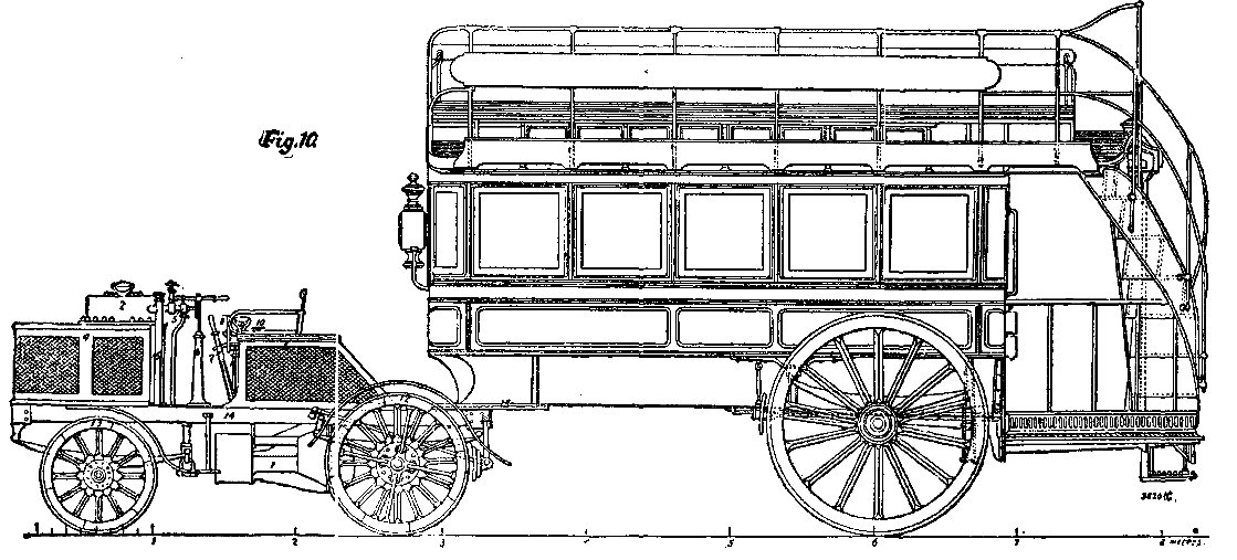 Fig. 10.
The Count de Dion was one of the most enthusiastic organizers of the Paris to Bordeaux competition in 1895, and naturally his firm took part in the trials. They entered three vehicles for competition; one of these, called No. 1, was the traction engine which had taken part in the 1894 trials, and which we have already described. For the second time this machine gave very excellent results, as it made the distance from Paris to Angoulème (280 miles) in 30 hours, but on account of various mishaps it had to run very slowly from Angoulème to Bordeaux (84 miles), taking, in fact, 31 hours for this part of the journey, and not arriving until long after it had been ruled out of the competition.
Their second vehicle, No. 2, was a four seated brake which was, in fact, a modified traction engine. The boiler, which was of the De Dion and Bouton type, had a heating surface of 36 square feet, and was registered at 200 lb. per square inch; it weighed 550 lb. As to the motor, it was a Woolfe engine, the moving parts of which were carefully counterbalanced. The cranks were set at an angle of 180°; the diameter of the high pressure cylinder was 2.95 in., and that of the low pressure 5.90 in.; the low pressure cylinder was steam jacketed. This motor, which weighed 330 lb., developed 11 horse power at a speed of 800 revolutions. The engine was coupled direct to the shaft of the differential motion, on which were mounted two pinions for changing the speed, and which could be moved to and fro on the shaft; the movement of the differential gear was transmitted to the wheels by articulated shafts, such as those we have already referred to in describing the traction engine; sufficient water and coke could be carried for a run of 45 miles, and on a good road a speed of more than 25 miles an hour was obtained.
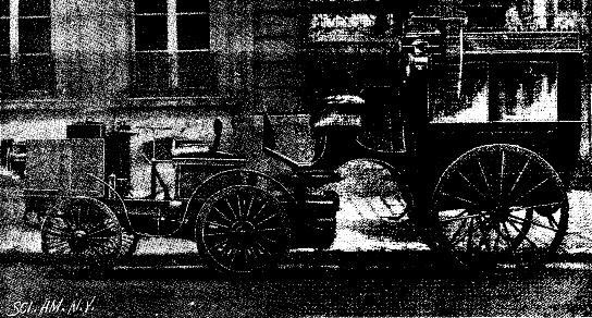 Fig. 11.
Messrs. De Dion and Bouton anticipated great things from this carriage, and for the long run from Paris to Bordeaux they had provided only three changes of drivers, in order that the machine might be in as few hands as possible. Their hopes, however, were not realized, for although it made a better start than any of the other competitors, it only succeeded in running for 125 miles; after having passed Blois the transmission shaft broke, and the brake was useless for the time being, but the machine did enough to satisfy the constructors of the soundness of their idea; it ran the 34.5 miles between Versailles and Etampes in 2 hours and 16 minutes, making an average speed of 15 miles an hour over difficult country; between Versailles and Blois the speed touched nearly 18 miles.
The vehicle No. 3 was a tricycle driven by a petroleum motor; this was not seriously entered for competition, but rather to show a first effort of a new departure which the constructors have since followed with some success. At the present time Messrs. De Dion and Bouton are making preparations to take part in the competition which is to be arranged for the autumn of the present year. They have a traction engine with considerable modifications in its design, with which they, expect to run from Paris and Marseilles, and they have the intention of hauling with it one of the 40-seat omnibuses of the Paris Company, which is usually drawn by three horses. Fig. 10 is a general view of the engine attached to the omnibus. This type of vehicle is furnished with a compound engine, which can be worked up to 30 horse power, and which is to be capable of hauling a load of 5 tons at a speed of 12.5 miles; the principal points of difference between this machine and the other, which we have already described, lie in the great care which has been bestowed on the details, the precautions taken to secure the moving parts from dust, and the oil bath in which the engine works. The water supply carried is sufficient for a run of 25 miles over an average road with a load of 3 tons; the manufacturers state that the cost of hauling this load amounts to 1d. per kilometer.
Great care has been taken as to the quality of the steel employed in the frame and other parts of the machine. By reference to Fig. 10 it will be seen that the boiler (2) is surrounded by the fuel tank, while the water reservoir forms a seat; the motor (1) is placed beneath the platform as usual. The driver has all the controlling levers conveniently at hand; the starting lever is shown at 9, while at 5 is a small wheel controlling the steam admission; the reversing gear is actuated by the lever, 7. The vehicle is steered by means of a turning bar, similar to those of hand brakes on some wagons; the feed pump is started and stopped by a small wheel marked 10, while 8 and 11 are the hand and steam brakes respectively.
We referred just now to the tricycle made by Messrs. De Dion and Bouton, and shown by them at the competition of 1895, although it was not entered for the race. Since that time they have made two types of this class of vehicle, of which we give engravings in Figs. 12 and 13. In the former the motor is attached to the back of the frame by a suspended connection. It will be seen that the frame is not a little complex, and necessarily so, in order that it may carry the different parts of the mechanism. The motor has a single cylinder and is quite inclosed in a casing that is kept filled with oil; the moving parts of the engine are within this casing; the main shaft drives, by means of a pinion, the differential gear that is mounted on the axle. It will be seen from the illustration that the builders do not rely wholly on the motor, but have provided the usual cycle pitched chain so that, in the event of a breakdown, the rider can propel his machine with the pedals. Indeed, this is always necessary in starting, though a few strokes with the pedals suffice, and as soon as the engine is started the pedal clutch is thrown out of gear. In mounting a steep gradient the pedals are also useful as an auxiliary to the motor. The mechanical power provided is sufficient to drive the machine on a good and level road at the rate of 20 kilometers an hour. It can also travel up grades of 1 in 20 or 25; the weight of the machine in working order is only 100 lb.
On referring to the engraving there will be seen attached to the frame beneath the saddle a rectangular reservoir that contains the gasoline, the capacity being sufficient for a six hours' run. To the reservoir is attached the carburetor, which is connected to the motor by a pipe. The explosive mixture in the cylinder is fired electrically, and for this purpose a compact and reliable battery is hung to the forward part of the frame almost beneath the steering bar. This battery will give 100 hours of work without recharging; it supplies current to a Ruhmkorff coil placed beneath the rear bar of the frame in a metal case that can be seen in the engraving; the other cylinder near it is a pressure reducer into which the gases from the cylinder are exhausted before they pass into the air. The second type of tricycle, illustrated by Fig. 13, is an improvement on the first. It will be seen that the frame is much simpler; the total weight is reduced; the gasoline reservoir is triangular, in order to economize space. The motor employed is very ingenious, and appears to be efficient; we have seen it in operation at the works of MM. De Dion and Bouton. It can be run easily at a speed of 2,500 revolutions, although in practice the rate is limited to 700 revolutions, in order to reduce the wear of the moving parts. In this, as in the earlier type, the use of water for cooling the cylinder is avoided, the outside of the latter being made with a number of wings that are intended to keep the cylinder cool by contact with the air. The method of igniting the gases has also been changed, in so far as the arrangement of the battery is concerned. The four cells used for this purpose are carried in a leather case hung to one of the frames of the machine. An interesting detail is that the exact moment for producing the spark is regulated by the motor itself, and the Ruhmkorff coil is suppressed. The contact breaker has been placed on the motor, and a cylindrical cam is mounted on the shaft that controls the exhaust valve. In this cam there is formed a recess into which the blade of the contact breaker, which is fixed on an insulated mount, falls at the proper instant; at the same moment the spark is produced, the blade being raised as it leaves the recess in the cam. It is, of course, necessary to regulate exactly the relative positions of the blade and the cam, so that the spark may take place when the mixture has to be exploded. The frame of the motor is of aluminum, by which considerable saving in weight is effected; as in the earlier model, the moving parts of the motor are immersed in an oil bath. The pedals are employed to start, or as an auxiliary, or in the event of a breakdown. When not required for propulsion, they are thrown out of gear, when they serve as foot rests, and also as a means for actuating an emergency brake. The carburetor is no longer attached to the gasoline reservoir, but is separate; the explosions in the cylinder are regulated by a lever close to the steering bar.
The greatest credit must be accorded to MM. De Dion and Bouton for the perseverance and ingenuity they have shown in the design and construction of the types of power vehicle they have made their own. As to their larger carriages, experience has proved their practical value; they have expended even more trouble on their power cycles, but it appears to us that ingenuity and skill are largely wasted in this direction, since the raison d'etre of the cycle in all its forms lies in the fact that it should give perfect freedom to the rider and leave him dependent for his progress upon his own efforts.—Engineering.
The rowboat Fox, of the port of New York, manned by George Harbo, thirty-one years of age, captain of a merchantman, and Frank Samuelson, twenty-six years of age, left New York for Havre on the 6th of June. Ten days later the boat was met by the German trans-atlantic steamer Fürst Bismarck proceeding from Cherbourg to New York. On the 8th, 9th and 10th of July, the Fox was cast by a tempest upon the reefs of Newfoundland. The two men jumped into the sea, and thanks to the watertight compartments provided with air chambers fore and aft, it was possible for them to right the boat; but the unfortunates lost their provisions and their supply of drinking water. On the 15th they met the Norwegian three masted vessel Cito, which supplied them with food and water. The captains of the vessels met with signed the log book and testified that the boat had neither sail nor rudder. The Fox reached the Scilly Islands on the 1st of August, having at this date been on the ocean fifty-five days. It arrived at Havre on the 7th of August.
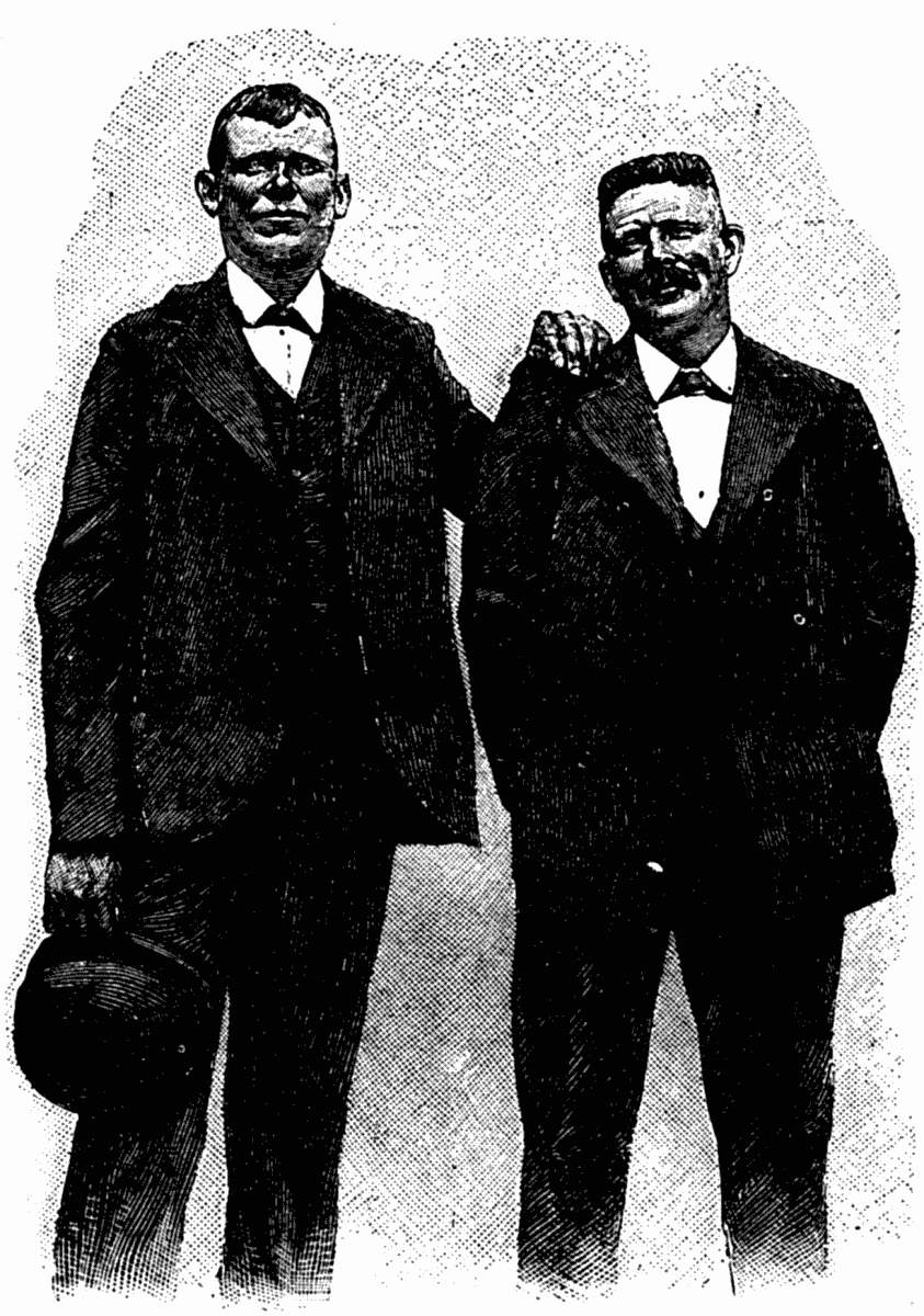
Cost what it might, the men were bent upon reaching this port in order to gain the reward promised by Mr. Fox, of the Police Gazette. Thanks to the wind and a favorable current, they made 125 miles in 24 hours. One slept three hours while the other rowed. Their skins and faces were tumefied by the wind, salt water and sun; the epidermis of their hands was renewed three times; their legs were anchylosed; and they were worn out.
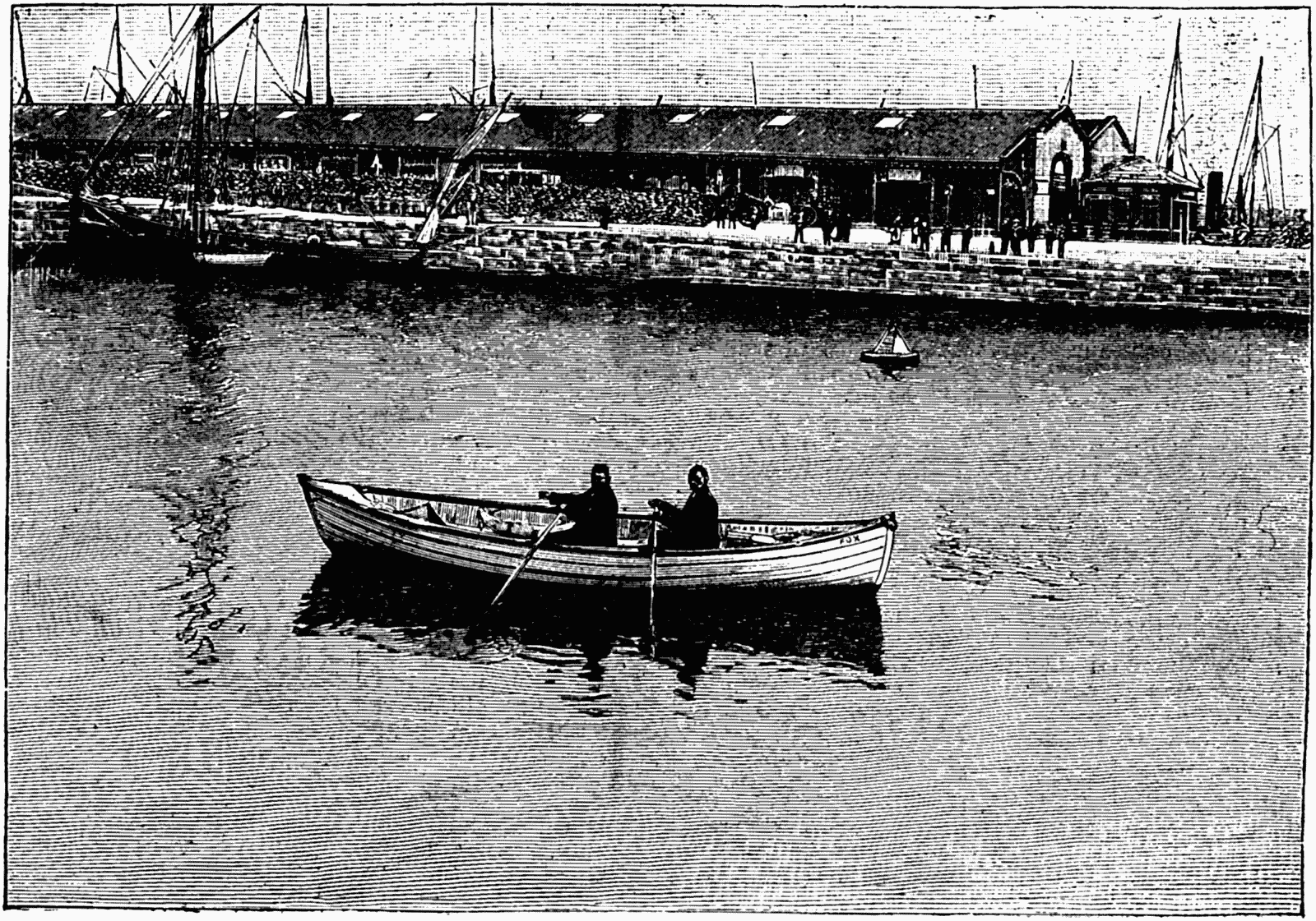
The boat was 18 feet in length, 5 in breadth, and 23 inches in depth, and carried a small kerosene stove for cooking.—L'Illustration.
Burdensome as are the restrictions imposed upon shipowners by legislation, considerable justification is found for them when we compare the percentage of British vessels lost at sea with that of foreign-owned vessels. The great shipping countries, that is, those which have more than 1,000,000 tons afloat, are the United Kingdom, the British colonies, the United States of America, France, Germany and Norway. Of these six the United Kingdom suffered the least comparative loss in its mercantile fleet in 1895. Under all the heads of abandoned at sea, broken up or condemned, burnt, collision, foundered, lost, missing and wrecked, the total loss was 2.99 per cent. of the vessels owned and 2.36 per cent. of the tonnage owned. No other of the countries named has less than 3 per cent. of loss, while only the British colonies have less than 4, as the subjoined table shows.
| Flag. | Vessels Owned. | Percentage Lost. | ||
|---|---|---|---|---|
| No. | Tons.1 | Vessels Owned. | Tonnage Owned. | |
| United Kingdom. | 9227 | 12,117,957 | 2.99 | 2.36 |
| British Colonies. | 2307 | 1,124,682 | 3.38 | 3.70 |
| United States of America. | 3220 | 2,164,753 | 4.72 | 4.06 |
| French. | 1164 | 1,094,752 | 6.01 | 4.02 |
| German. | 1730 | 1,886,812 | 6.76 | 4.38 |
| Norwegian. | 3041 | 1,659,012 | 7.43 | 6.46 |
When we turn from the contemplation of the complete fleets, and differentiate between steam and sail, we find that the United Kingdom no longer holds the premier position, being surpassed, as regards steam, both by the colonies and by the United States. Steam vessels are safer than sailing craft all over the world, partly, of course, because their average age is less. The losses they suffered last year are as follows:
| Flag. | Vessels Owned. | Percentage Lost. | |||
|---|---|---|---|---|---|
| No. | Net. | Gross. | Vessels Owned. | Tonnage Owned. | |
| United Kingdom. | 6446 | 5,993,666 | 9,695,976 | 3.33 | 2.13 |
| British Colonies. | 874 | 329,845 | 542,025 | 1.72 | 1.69 |
| United States of America. | 626 | 660,784 | 920,672 | 2.23 | 1.93 |
| French. | 571 | 467,553 | 903,105 | 4.20 | 3.42 |
| German. | 953 | 910,567 | 1,343,357 | 3.04 | 2.64 |
| Norwegian. | 586 | 285,349 | 446,384 | 2.56 | 2.87 |
The United Kingdom here stands third in the list, and curiously it only stands second under the head of number of sailing ships lost, while it is first as regards sailing tonnage lost. The sailing tonnage of the United Kingdom is only about 20 per cent. of the total, while in the colonies it is about 52 per cent. The following are the figures:
| Flag. | Vessels Owned. | Percentage Lost. | ||
|---|---|---|---|---|
| No. | Tons. | Vessels Owned. | Tonnage Owned. | |
| United Kingdom. | 2781 | 2,421,981 | 4.53 | 3.27 |
| Colonies. | 1435 | 582,657 | 4.39 | 5.56 |
| United States of America. | 2594 | 1,244,081 | 5.32 | 5.63 |
| French. | 593 | 191,647 | 7.76 | 6.83 |
| German. | 777 | 543,455 | 11.33 | 8.66 |
| Norwegian. | 2455 | 1,212,628 | 8.59 | 7.78 |
The losses of sailing vessels are very serious among the Continental nations, especially in Germany, where more than one in nine was lost or condemned last year. This is greatly due to the fact that our old ships are largely sold to the foreigner when they will no longer comply with legislative conditions of this country. We break up a few, but only 0.75 per cent., against 1.75 per cent. for Norway and 2.5 per cent. for France and Germany. We are more chary of breaking up our steamers; last year only 0.46 per cent. met this fate here, 0.34 per cent. in the colonies, 0.32 per cent. in the United States, 0.86 per cent. in France, 0.31 per cent. in Germany, while Norway did not lose a single steamer in this way.
Turning now to the present year we find that in the first quarter the vessels lost, condemned or reported missing before August 7 were, according to returns made out by Lloyd's Register of British and Foreign Shipping, 282 vessels, of an aggregate of 195,480 tons. These figures are respectively 23 per cent. and 24 per cent. of the total losses last year, thus showing a favorable beginning, for the winter losses are naturally the heaviest. The materials of the vessels lost were: Steel, 24 vessels of 40,474 tons; iron, 74 vessels of 78,314 tons; and wood and composite, 184 vessels of 76,692 tons. The United Kingdom shows best under the heads of total losses and losses of sailing vessels, but in steamers it actually comes last among the six nationalities we have selected for comparison. It must be remembered, however, that the British fleet is large enough for a very fair average to be attained in three months, while in all other fleets a single loss, more or less, makes a great difference to the figures of merit. The steam tonnage of the United Kingdom is more than seven times greater than that of Germany, which is our chief competitor. In sailing tonnage we do not hold this immense superiority, our amount being only about double that of the United States and of Norway respectively.
When we examine the various causes of loss of vessels at sea, we find nearly 43 per cent. of the tonnage under the head of "wrecked," which includes vessels lost through stranding, or through striking rocks, sunken wrecks, etc. Next come 22 per cent. broken up or condemned; 14 per cent. lost, missing; 8 per cent. lost by collision; 4.3 per cent. burnt; 5 per cent. abandoned at sea; and 3.6 per cent. foundered. The following table shows the mercantile marine of the world, according to Lloyd's Register, at the end of March, 1896:
| Flag. | Steam and Sailing Vessels Owned. | ||
|---|---|---|---|
| No. | Tons. | ||
| British. | United Kingdom. | 9227 | 12,117,957 |
| Colonies. | 2309 | 1,124,682 | |
| America, United States of. | 3220 | 2,164,753 | |
| Austro-Hungarian. | 309 | 304,970 | |
| Danish. | 812 | 356,714 | |
| Dutch. | 458 | 446,861 | |
| French. | 1164 | 1,094,752 | |
| German. | 1730 | 1,886,812 | |
| Italian. | 1239 | 778,941 | |
| Norwegian. | 3041 | 1,659,012 | |
| Russian. | 1086 | 487,681 | |
| Spanish. | 748 | 554,238 | |
| Swedish. | 1432 | 497,877 | |
| Other European countries. | .... | ......... | |
| Central and South America. | .... | ......... | |
| Asia. | .... | ......... | |
| Other countries. | .... | ......... | |
—Engineering.
[1] Gross tonnage for steamers; net for sailing vessels.
During recent years an interesting change has been gradually brought about in the various methods of building construction employed in France, and more especially at Paris, where the size and importance of public buildings and the many-storied houses divided up into flats necessitate special systems of construction, which possess the advantages of combining economy in cost with strength and durability. Parisian architects and builders, although far from approving the extremes to which their American confrères go in the employment of iron for the construction of their somewhat exaggerated sky-scraping buildings, in which the style of architecture employed is often scarcely logical or consistent with the modern methods of construction, are nevertheless obliged to own to the necessity and the utility of employing iron in moderation for the framework of their buildings. Up to the present the use of iron in its ordinary form has chiefly been confined to floors, partitions, and roofs, where, as a rule, its presence is masked by coverings of cement, wood, or stone, except in recent examples of the new style of buildings destined for brasseries or drinking halls, where the iron construction is left visible, and emphasized by means of bronze or color painting and mosaic work, or, again, in the few examples of well known work where the architect has endeavored to obtain a decorative effect by means of iron lintels and columns. But where the use of iron is fast finding favor at Paris is in its employment in combination with other materials such as cement or concrete, and in a special form known as the cement armé systems, in which iron or steel is employed in the form of thick wire, trellis, or light bars embedded in cement or concrete. This method of construction, of which there are three different systems, has for some time been employed in the construction of various buildings of more or less importance, and has given proof of its strength and practical use as well as its advantages when employed for floors, partitions, walls and roof, both as regards its conveniences for internal arrangements, its economy, and as regards the manner in which it lends itself to modern schemes of polychrome decoration.
Two of these systems have been employed by the architect of the new building now being constructed in the Rue Blanche for the Society of Civil Engineers of France. The third system is much employed by M. De Baudot in various buildings designed by this architect, an advocate of rational construction and design and the logical employment of modern building materials. It will be interesting to examine the merits of each system as employed in these buildings, together with any other points of construction worthy of remark.
The building for the Society of Civil Engineers is remarkable from several points of view as regards construction and the arrangement of plan. The façade and plans will appear in the Building News as soon as the work is completed, and will form an interesting subject for comparison with the building recently completed for the English Society of Engineers, and with that about to be commenced at New York for the American Society.
Before entering into a detailed description of the system employed, a summary idea of the plan and general scheme of construction will not be uninteresting. The architect, M. Fernand Delmas, has endeavored to construct the building on economical lines, employing to a large extent iron and those modern materials which have been tried and found fitting as regards suitability and economy; the building will cost £22,000, and it has been made a sine qua non that all the contractors shall be members of the Society of Engineers.
The length of the façade is 100 ft.; the total depth of the building is nearly equal to the frontage; the height from pavement to cornice is 60 ft. The façade is built of solid stonework throughout its length and height. The thickness of the masonry is 24 in. at the lower stories and 18 in. at the upper portion. The façade wall is really the only portion of solid masonry work in the whole building, and forms a decorative mask to the body of the building, which is constructed of a framework of iron. The chief supports of the building proper consist of four framed iron uprights, 16 in. by 16 in. rising from the basement to the roof. These uprights are solidly trussed and held together at the floor levels by strong iron girders supporting the iron joists of the upper floors and the light partitions which divide up each story. This system is at once economical and practical. The whole building is thus self-supporting, and the thick walls which would otherwise be necessary for carrying the upper floors are thus avoided.
The façade wall is built according to the system always employed at Paris, and is formed of blocks of stone roughly cut at the quarries to the outside dimensions of the proposed moulding and decorative work. As soon as the whole front is erected the work of cutting it into shape will commence, the mouldings, pilasters, and all carving work being done while the interior is being prepared. The buildings at Paris are by this means erected much more rapidly than when the stone is dressed or moulded before being put into place. Greater facilities are thus given for studying the general ensemble of the façade and the proper scale to be given to the mouldings and decoration. The stone is as a rule soft when first from the quarries, but becomes hard and durable after dressing and exposure to the air. The courtyard wall of the building is formed of light brick or metallic fillings between the iron uprights and the party walls.
The ground floor comprises a large entrance hall or vestibule, 40 ft. by 44 ft., forming, with the cloakroom, the principal staircase, the rooms for the concierge, and the area, the whole front of the building. This large vestibule is vaulted over by means of one of the systems of cement armé to be described. The floor is constructed on another similar system, and will be paved with mosaic work. The ground floor of the courtyard will be occupied by the conference hall, 50 ft. by 50 ft., to hold 300 seats. An annex, 50 ft. by 20 ft., adjoining this hall, will open on the same by a large arched bay, and may be separated from the larger hall by means of a special system of wooden soundproof roller shutters. The floor of the large hall will be a movable one, to be raised or lowered by an ingenious system of hydraulics, and capable of being placed in an inclined position for conference meetings, or raised to a horizontal position for ball room purposes.
The entresol floor will comprise a large room for meeting, smoking and conversation rooms, and a reading room, to be used as a club for the members of the society. The first floor will contain the offices of the society, a large committee room, and all conveniences. The second floor will be devoted entirely to the purposes of the important library, comprising the library proper, a room 45 ft. by 25 ft. by 17 ft. high, rising to the ceiling of the low story above, and lighted by a large semicircular bay at either end: the surrounding rooms of the height of the second floor will be destined for the librarian, catalogues, drawing office, and library offices. The third floor will be devoted entirely to the purpose of storing the books of the library, in low rooms communicating by means of the gallery overlooking the library below, which will be crossed by means of a light, iron bridge. The bookcases will be suspended from the upper floor, and will be arranged in vertical tiers hung on rollers, after the system employed at the British Museum. The roof story will be divided up into an apartment for the chief secretary, and reached by a private staircase from the ground floor. The large basement, occupying the whole of the ground surface of the building, will be used for storing the records of the society, and will contain the heating apparatus, stores, etc. A hydraulic lift will afford access to the landings of each floor. The chief feature of the façade, which is simple in style, is the wide arched bay, 24 ft. across, rising from the pavement to above the cornice; this bay will be filled in with an open decorative framework of wrought and cast iron.
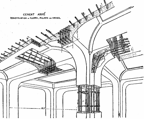
Some of the most interesting points of the construction, besides the large use of iron, are the systems employed in the construction of the floor. The ground floor is built after the Coignet system, composed of light iron bars and cement; the first floor and its supporting pillars and arches is constructed after the Hennebique system of cement armé; the upper floors are formed of iron joists, filled in either with the system of light supports and plaster, much employed at Paris, or with terracotta fillings between joints. The roof is lined internally with agglomerated cork bricks, affording protection from excessive heat or cold, and the walls of the area will be lined with opaline, a vitreous material of a bluish white color, which in this case will insure cleanliness, and afford additional light; the lavatories and water closets will also be lined with the same material.
Speaking of the Hennebique system of cement armé, employed for the arches and floor of the first story, it will be interesting to illustrate the method by a few sketches, explaining the theory of this system, which has been put to practical proofs in a large number of buildings, chiefly for industrial purposes, in the north of France. The perspective section will give an idea of the construction as employed in the building for the civil engineers, a system which holds its ground well against its rivals of other methods of cement armé.—The Building News.
Belleek porcelain (frequently pronounced "Bleak" by those who do not know the derivation of the name) is a thin eggshell ware of great lightness and translucency, characterized by a creamy, or sometimes grayish, tint, and usually covered with a delicate pearly or lustrous glaze. It is in reality a variety of Parian ware, being formed in the same manner by the process called casting, or pouring diluted clay or slip of the consistency of cream into plaster moulds, which, by absorbing a part of the moisture from the portion of the liquid preparation in direct contact, retain a thin shell of partially dried clay after the superfluous contents are taken out. After standing a few minutes the thin cast can be liberated from the mould. The thickness of the walls, of course, depends upon the length of time the slip is allowed to remain in the mould before the surplus is removed. By this ingenious method cups, saucers and other forms of ware can be made almost as thin as an egg shell or a piece of heavy paper, and after being allowed to become thoroughly dry can be safely burned in the kiln. It can readily be understood that it would not be possible to make such fragile pieces by the usual processes with plastic clay, which must be of the consistency of putty or dough, on the potter's wheel or by pressing in moulds.
Belleek ware was first made at Stoke upon Trent by the eminent potter William Henry Goss, who invented the body or composition some thirty-five years ago; but it was not then known by this name. Soon after its introduction Messrs. McBirney & Armstrong induced some of Mr. Goss' workmen, including his manager, William Bromley, to join them at their porcelain works, then recently started (in 1863) in the town of Belleek, County Fermanagh, Ireland, and the art was established so successfully there that the name of the village was given to the ware which has since become so noted. The distinguishing characteristic of this beautiful product is its lustrous glazing, which varies in form from white to yellow and through graded tints to a dark leaden hue.
Mr. Goss has continued to manufacture this dainty variety of porcelain until the present time, and his factory has become one of the most noted in the British empire. Among the most popular of his productions in this body are loving cups and little cream jugs, cups and saucers, and fairy tea sets embellished with beautifully colored crests and coats of arms of the different English cities and of prominent personages, such as Queen Elizabeth, Sir Walter Raleigh, King Henry of Navarre, Queen Victoria, the Prince of Wales, Shakespeare, Sir Walter Scott, and Robert Burns.
Of more interest, perhaps, to Americans are the porcelain tumblers which have just been produced at the same factory, bearing on the front a faithful duplication in blue and yellow enamels of the insignia of the society of Sons of the Revolution, which were made at the suggestion of a member of the society in Pennsylvania. The soft, satiny Belleek body seems to be particularly well adapted to show off to advantage the rich designs of these badges, and this suggestion will doubtless be followed by other patriotic hereditary societies in the United States.
John Hart Brewer, of Trenton, first attempted the manufacture of Belleek ware in this country. He commenced his experiments in this line in 1882, and in the following year brought over from England William Bromley and his son from the Belleek works in Ireland. Subsequently the elder Bromley joined the Willets Manufacturing Company, of the same place, and introduced the manufacture of eggshell porcelain there, and at the present time there are no less than five or six establishments in Trenton where the same class of ware is made.
Among many specialties recently introduced is a new style of decoration which has been worked out by Miss Kate Sears, a Kansas girl who studied modeling in Boston. Going to Trenton for the purpose of pursuing her studies in this direction, one day in 1891, while engaged in working over the wet Belleek, the idea of carving delicate designs in the dry clay occurred to her, and after conducting a series of experiments her efforts were crowned with success. The process of modeling which Miss Sears has originated is as follows: A vase or other piece which has been formed in the wet clay and dried is taken before it has been in the kiln, and with knives or other tools the design is cut or chiseled so as to leave the background as thin and transparent as possible when finished. As the dry Belleek, besides being thin, is extremely brittle, and crumbles easily, the carving is an exceedingly difficult operation. It is necessarily a very slow process, since at any moment the knife is liable to cut through the wall and ruin the piece.
The result of this process is a clear cut, chiseled effect, which cannot be obtained by moulding or casting, a moonlight effect of fairy like character, most beautiful in conception, and possessing marked originality. While sometimes several weeks are consumed in executing a single piece of the carved ware, Miss Sears has produced a large number of such designs, each one of which is a perfect work of art, reflecting credit upon the artist and the manufacturers.
The marks which appear on the various productions of Belleek porcelain are of considerable interest to collectors and admirers of this beautiful ware. Mr. Gross has adopted as a factory mark his family crest, a falcon rising ducally gorged, which is printed on each piece in black. The mark of the Belleek factory in Ireland, consists of the four Irish emblems, the watch tower, the hound, the harp of Erin, and the shamrock, and is printed on the ware in green or black. At the Etruria Pottery, formerly operated by Messrs. Ott & Brewer, now known as the Cook Pottery Company, the mark used on Belleek ware was a crescent bearing the name with the initials of the proprietors, "O. & B." The Willets Manufacturing Company uses for a factory mark on its decorated Belleek pieces the figure of a serpent looped in the form of a W, which is printed in red. On similar ware produced by the Ceramic Art Company is printed in red a design composed of a painter's palette and a circle inclosing the monogram C. A. C., while Messrs. Morris and Willmore, of the Columbian Art Pottery, employ a shield with the initials of the firm name, M. W.
The manufacture of Belleek ware was introduced into this country by English potters who had learned the processes at the potteries in England and Ireland, and we cannot, therefore, lay claim to originality so far as the product itself is concerned; yet, in a measure, the ware as made in America differs materially from the foreign in many respects, and has been developed in new directions, so that it has come to have distinctive characteristics of its own which entitle it to be ranked with original American productions. While our potters, perhaps, have not yet reached the high degree of elaborate modeling which characterizes some of the imported Belleek, they have already surpassed the foreign manufacturers in the simplicity and elegance of their forms and the artistic quality of their decorations, while in delicacy of coloring, in the excellence and lightness of body, the American products are not surpassed. A visit to the showrooms of the Trenton potteries will prove a revelation to those who still believe that no artistic china is made in this country.—Edwin Atlee Barber, in China, Glass and Lamps.
The instrument we are about to describe is an improvement on the hatchet planimeter and is due to Prof. Goodman, of Leeds. One form of the instrument is intended for the measurement of areas of surfaces, and the other form for the measurement of the mean height of a figure such as an indicator diagram.
London Engineering, to which we are indebted for the cuts and copy, describes the instruments as follows: The method of using the two instruments is practically the same, but for the present we shall confine our remarks to the instrument for measuring areas. In order to familiarize oneself with the peculiar action of the instrument, it will be well to get a large sheet of paper on a drawing board or a large blotting pad, and holding the instrument vertical to the paper, grasp the tracing leg very lightly indeed between the forefinger and thumb of the right hand, with the hatchet toward the left hand, as shown in Fig. 1. Then by moving the tracing point round and round an imaginary figure and allowing the hatchet to go where it pleases, it will be seen that the hatchet moves to and fro along zigzag lines, and travels sideways—the side travel being nearly proportional to the area of the figure described by the tracing point. If the tracing point be too tightly grasped, the hatchet will not move freely, and, will have a side slip. When this occurs the side travel of the hatchet ceases to be proportional to the area traced out. A loose weight is hung on the hatchet to prevent this side slip, but as soon as a little skill is attained in the use of the instrument, this weight may be dispensed with.
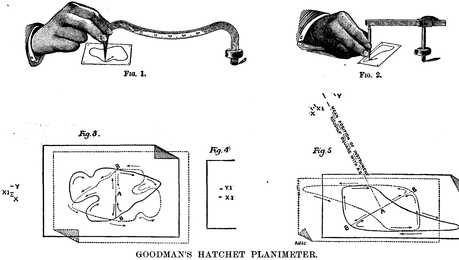
When measuring the area of such a surface as that inclosed by the boundary line shown in Fig. 3, a point, A, is chosen somewhat near the center of the figure; the exact position is, however, immaterial. From the point, A, a line, AB, is drawn in any direction to the boundary; the tracing point of the planimeter is now placed at A, with the hatchet at X, Fig. 3, that is, with the instrument roughly square with AB. The hatchet is now lightly pressed in order to mark its position on the paper by making a slight dent, then leaving the hatchet free to move as shown in Fig. 1, the tracing point is caused to traverse the line, AB, and the boundary line in a clockwise direction, as shown by the arrows, returning to A via AB. The hatchet will now be found to have taken up a new position, Y, which must be marked by again pressing the hatchet to make a slight dent in the paper. If the figure under measurement be on a separate sheet of paper, the paper must now be revolved about the point, A, through about 180 deg. (by eye), using the tracing point of the instrument as a center, care being taken that neither the point nor the hatchet be shifted while the paper is being turned. The line, AB, will again be roughly at right angles to the instrument, but in the reverse direction (see dotted lines in Fig. 3). Again cause the tracing point to traverse the line, AB, and the boundary line as before, but this time in a contra-clockwise direction. The hatchet after this backward motion will take up the new position, X1, which may or may not coincide with X; if not, prick a central point between X and X1, as shown, then, of course, the distance of this point from Y is the mean side shift of the hatchet; this distance measured from the zero of the scale on the back of the instrument is the area of the figure in square inches. The scale is read in exactly the same manner as a geometrical scale on a drawing, the whole numbers being read to the right of the zero and the decimals to the left. The instrument does not profess to give results nearer than one-tenth of a square inch.
In some cases on large maps, for example, the figure cannot be turned round as indicated above; in that case the instrument itself must be turned round through 180° and two fresh dents, X¹Y¹, obtained; the area of the figure is then the mean of the two readings, XY and X¹Y¹.
When the area is large the instrument will move through a large angle, and consequently, if square with AB to start with, it will be considerably out of square at the finish. In such a case it is only necessary to see that the mean position of the instrument is square with AB.
By carefully examining the scale it will be observed (see Fig. 1) that the divisions are not equal, but that they gradually increase from zero upward; herein consists the improvement of this instrument over the ordinary hatchet planimeter invented by Knudsen, of Copenhagen, who shows in a pamphlet published by him that
| c1 + c2 | ||
| I = | ——— | p [1 - (R / 2p)²] |
| 2 |
Where I = the area traced out by the pointer in square inches.
c1 = the distance between the dents, X and Y, in inches.
c2 = the distance between the dents, X1 and Y, in inches.
p = the length of the instrument from center of hatchet to point in inches.
R² = the mean square of the radii of the figure.
The making of such a calculation for every area measured is, of course, quite out of the question. The labor involved would be as great as calculating the area by the ordinate or by Simpson's method; hence it is usual to neglect that part of the formula inclosed within the square brackets, which amounts to assuming the area to be equal to the product of the mean side shift of the hatchet by the length of the instrument; this, however, involves an error too big to be neglected, and, moreover, one that is not a constant fraction of the area measured, thus:
| Area of circle, square inches. | 10 | 20 | 30 | 40 |
| Error per cent. | 0.8 | 1.6 | 2.4 | 3.2 |
These errors are, however, compensated for in Goodman's improved instrument by making the scale with constantly and regularly increasing divisions. If, however, the area dealt with be not a circle, the error involved in assuming that its R² is equal to the R² of a circle of equal area is so small that it is quite inappreciable on a scale which only reads to one-tenth of a square inch. If the R² for any given area were say 5 per cent. greater than that of the equivalent circle, the error involved would be 0.0016 of the whole quantity when measuring an area of 40 square niches, or 0.064 square inch, a quantity which cannot be measured on the scale. It has been proposed to use a roller and vernier to enable the readings between the dents to be measured with a greater degree of accuracy, but it will be readily seen that the instrument is not reliable to the second place of decimals, hence such refinements are only imaginary. Even with this special scale that we have described above, the inventor does not profess to get as good results as with an Amsler planimeter; he regards his instrument as equivalent to a foot rule in comparison with a micrometric gage as representing Amsler's instrument; but for a great number of purposes the foot rule is sufficiently accurate, and only when great accuracy is required will a micrometer be used, so with the two forms of planimeter. The rougher instrument has some advantages, however; there are no delicate moving parts to get out of order, and the cost is but one-fourth.
In order to ascertain the relative accuracy of various methods of measuring areas, Prof. Goodman has had a large number of irregular areas measured by his first year students within a week or so of their entering the department, before they have attained to any degree of skill in using instruments. The results were as follows. Amsler's planimeter was taken as the standard, the area measured by it being independently checked by an assistant.
| Method. | Measurement of Areas Reduced to 100. |
|---|---|
| Amsler planimeter | 100 |
| Goodman " | 100 + or - 0.6 |
| Simpson's rule. | 100 + or - 1.0 |
| Mean ordinates. | 100 + or - 2.4 |
| Cutting out in cardboard and weighing against piece of known area. | 100 + or - 4.4 |
| Equalizing curved edges by drawing straight lines along boundary and calculating by triangles. | 100 + or - 7.0 |
In the averaging instrument for getting mean heights of figures, the length of the instrument between the hatchet and the pointer is variable. The length is set to the length of the diagram (see Fig. 2); it is then used in precisely the same manner as the planimeter described above. From what we have already said, our diagram in Fig. 5 will be perfectly clear. The mean distance between the dents is in this case the mean height of the diagram, measured on an ordinary scale, or the mean pressure in the case of an indicator diagram measured on a scale to suit the indicator spring.
Knudsen's formula given above applies equally well to this averaging instrument. Neglecting for the moment the quantity in the square brackets, we have I = c p where c = (c1 + c2)/2 but we also have I = h l where h is the mean height and l the length of the figure, therefore h l = c p; but in this instrument we make p = l. Hence h = c, or the mean height of the figure is equal to the mean distance between the dents. The quantity in the brackets is too great to be neglected, however. If we were always dealing with circles, the ratio (R/2p)² would be a constant, and numerically equal to 1/16 or 6.25 per cent. Then all we should have to do would be to use a scale 6.25 per cent. longer than the true scale. But with a long narrow figure such as an indicator diagram, this ratio is much smaller. The measurement of a large number of diagrams gave a mean value of 1/60 for diagrams 4 in. long. It is obvious that, if a diagram be shortened, this ratio will increase, for the value of R does not decrease as rapidly as p, and vice versa; hence this ratio varies approximately inversely as the length of the diagram. Taking the value of 1/60 for the 4 in. diagram, this is equivalent to saying that there is an error of 1 in 60, or 1.67 per cent., in the result, and from the formula it will be seen that the result is too great by this amount; hence, if we make the length, l, between the legs of the instrument 1.67 per cent. of 4 in., or 0.067 in. less than the length from the tracing point to the center of the hatchet, p, we shall compensate for the error on a diagram 4 in. long. But the ratio of this constant quantity 0.067 in. to the length of the diagram also varies inversely as the length in just the same manner as the ratio R/2p, hence this method of correcting the instrument is approximately right for all lengths of diagrams. It must be remembered that if this correction were entirely neglected, it would not exceed two per cent.; hence any inaccuracy in this correction is an exceedingly small quantity, well under 1 per cent.
Whenever errors have been attributed to the instrument, on examination it has always been found that they were due to carelessness in setting the length to the diagram, or to the tracing leg having been grasped so tightly as to cause side slip.
The accuracy of the instrument may be easily demonstrated by drawing a rectangle, say about 4 in. long and 2 in. high, and finding the mean height by the averager, then by doubling the paper over and comparing its height with the mean distance between the dents, it will be found that they agree if the instrument has been carefully used.
In many quarters we know that there is a great deal of prejudice against instruments of this kind. We are quite sure, however, that if only draughtsmen and others would spend half an hour in trying them over, they would save themselves many hours of tedious labor in calculating areas by methods which are seldom as accurate as the results obtained by a planimeter in the same number of minutes.
We give herewith, from Le Genie Civil, illustrations and brief descriptions of some of the more prominent apparatus used for the manufacture of acetylene gas.
Trouvé Apparatus (Fig. 1).—The principle of the gas generator is that of the hydrogen briquet already applied by Mr. Trouvé in his portable lamp. It consists of two vessels, one entering the other. The internal vessel is provided at the bottom with a discharge pipe communicating, through a cock, with the gasometer. It carries a suspended open work basket containing the carbide of calcium. The bottom of this vessel is provided with an aperture through which it communicates with the external vessel containing the water. The latter is brought to a level in the two vessels and attacks the carbide. The acetylene formed is disengaged and enters the gasometer. At the same time, the excess of pressure forces back the water into the external vessel in suppressing its contact with the carbide. The latter, nevertheless, continues to be attacked slowly through the action of the aqueous vapor. If the cock of the apparatus now be closed, the gas will accumulate in the interior vessel and will soon escape through the aperture in the bottom in raising the column of water. Mr. Trouvé has endeavored to remedy this inconvenience by arranging the pieces of carbide in the basket in distinct layers separated by disks of glass. He has, besides, provided his apparatus with an electric alarm, designed to give warning when the holder is too full or when it is on the point of being empty.
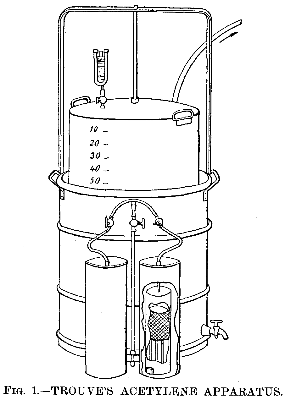
Clauzolles Apparatus (Fig. 2).—This apparatus consists of a gas generator, A, hermetically closed and containing the carbide, of a water reservoir, B, communicating with A through a cock, H, and of a gasometer, D, connected with A by the tube and cock, A. The cock, H, is provided with a lever fixed by its extremity to a chain that follows the motions of the holder. When the latter rises or descends, it causes the cock, H, to close or open.

The receptacle, A, is held by a cover fixed by means of four nuts which are removed when it becomes necessary to renew the carbide. The receptacle is removed and replaced by a duplicate one, after the cock, K, has been closed so as to keep the gas in the gasometer.
Bon Apparatus (Figs. 3 and 4).—The acetylene is produced by the reaction of the water falling in small quantity upon the carbide contained in the gas generator, A. The latter is divided into compartments, F, which, filled with carbide, are reached by the water only successively and progressively. When the carbide of the first compartment is exhausted, the water enters the second, and so on. The dimensions and numbers of these departments vary with the size of the apparatus. Each of them contains from ½ lb. to 4.5 lb. of carbide. The box with compartments, F, is covered by a rectangular holder, H, which enters a flat-bottomed receptacle, E, opened above and filled about two-thirds full of water. The latter serves as a hydraulic joint, and, at the same time, as a refrigerator. The holder, H, carries a lead pipe, G', terminating in a funnel into which falls the water from the reservoir, C, led by the pipe, G. This water flows through the extremity, i, of the pipe, G', into the first compartment. Each of the compartments carries, upon the top of the partition that separates it from the following, an aperture through which the water enters the adjoining compartment as soon as the gas in the preceding compartment has made its exit from the gasometer, and so on until the last in the order of the numbers of the compartments.
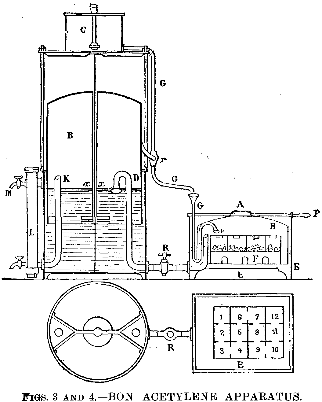
The flow of the water through the pipe, G, is regulated automatically by a cock, r', with counterpoise. The holder, in rising, closes this cock and gradually cuts off the entrance of the water. The gas produced, once consumed, the holder descends in opening the cock, and the water begins to flow again.
The disengaged acetylene enters the gasometer, B, through the pipe, D. The extremity of the latter is bent into the form of a swan's neck. The gas is thus forced to bubble up through about 2 in. of water, in which it is cooled and freed from all traces of the ammonia that it may contain. The cock, R, in the pipe, D, is a three-way one. The first opens and the second intercepts communication between the gas generator and the gasometer, while the third puts these two parts of the apparatus in communication with the atmosphere.
The total capacity of the gasometer is so calculated that the acetylene produced by a single one of the compartments, F, may be stored up therein upon its exit from the gasometer through the pipe, K. The acetylene traverses a purifying column, I, filled with pumice stone saturated with a solution of sulphate of copper and surmounted by a thin layer of carbide of calcium. The object of the sulphate of copper is to free the gas from phosphorus and arseniuret of hydrogen. The layer of carbide serves to dry it.
It is well to use salt water for the gasometer, as acetylene is but slightly soluble therein.
Lequeux-Wiesnegg Apparatus (Figs. 5, 6, and 7).—The apparatus represented in Fig. 5 is capable of being used in lecture courses. It consists of a tank, B, and a holder, A, which is provided at the top with a wide aperture closed by a hydraulic plug, F. When the apparatus is at the bottom of its travel and ready to be filled with acetylene, the plug, F, as well as the basket, D, and the bucket, E, are removed. The quantity of carbide necessary to fill the gasometer is introduced into the basket. After care has been taken to put a certain quantity of water into the gutter forming the hydraulic joint of the plug, F, the parts, E, D, F, are introduced into the tube, C, in operating rapidly enough to prevent the loss of gas. The holder immediately rises as a consequence of the production of acetylene. The gas redescends through a tube to the bottom of the tank and rises laterally in a column by serving as a guide to the holder and as a support to the cocks designed to send the gas to the points of utilization. A cock, H, placed at the lower part of the apparatus, permits of clearing the piping in case a condensation of water occurs.

The apparatus represented in Figs. 6 and 7 is continuous. It consists of an apparatus with two holders, that is to say, so arranged as to put the least liquid possible in contact with the gas produced, and to thus prevent absorptions and losses. This gasometer consists of a tank, A, of a movable holder, C, and of a stationary holder, B. The generator, E, is formed of a cylinder, at the bottom of which there is a bucket, F, designed for the reception of the greater part of the lime resulting from the reaction. It is closed by a cover, G, arranged with a simple or multiple joint, according to the precision that it is desired to obtain and that may reach 30 centimeters of water. The figure represents the holder at the bottom of its travel.
Mr. Edward N. Dickerson's Apparatus (Figs. 8 to 13).—Mr. Dickerson, of New York in June, 1895, patented several arrangements permitting of automatically regulating the production of acetylene in measure as it is consumed. In the apparatus represented in Fig. 8 the water is led from a sufficiently high reservoir, A, through the pipe, B, into the gas generator, D, and over the carbide, C, placed upon a grate, O. The acetylene forms when the water reaches the carbide, and its disengagement ceases when the pressure forces the water back. The gas passes through the intermedium of a cock, e, into the pipe, W, provided with a cock, Z, into the automatic regulator, G, and then into the gasometer, P R. Between the regulator, G, and the gasometer, Mr. Dickerson interposes an arrangement consisting of an engine, H, actuating an air pump, K, through the pressure of the gas when it is desired to introduce a mixture of acetylene and air into the gasometer. This arrangement is evidently useless when it is desired to collect the acetylene alone. The gas upon making its exit from the gasometer flows through the pipe, T, to the burners, V.
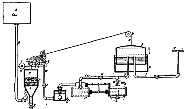
When the holder, R, is filled, the cord or chain, a, passing over the pulley, b, revolves the sector, c, until the pin, g, meets the counterpoised lever, d, of the stopcock, e. In the return of the chain, the other pin, o, carries the lever back to the position shown in the figure.
The gas generator, D, is provided with a discharge cock, E, and a charging aperture, m.
Figs. 9 to 13 show another of Mr. Dickerson's apparatus that permits of an intermittent automatic distribution either of the water upon the carbide or of the carbide in the water in regulating such distribution through the displacement of the holder of a gasometer that collects the excess of gas necessary for the consumption.
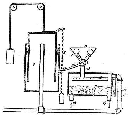
Mr. Dickerson rightly remarks that it is disadvantageous to directly control the distribution of the water upon the carbide by means of the holder of the gasometer. In fact, the water cock may remain open before the holder has moved, and there may thus fall upon the carbide an excess of water, giving rise to a production of acetylene greater than the capacity of the holder warrants.
The object of the Dickerson apparatus is to prevent such overproduction and to furnish water or carbide to the gas generator only as long as the gasometer will have been emptied of the desired quantity of gas.
Fig. 10 shows a modification of the gas generator relative to the introduction of the carbide into the water; but the same letters designate the same parts. We shall describe the operations corresponding to the figures.
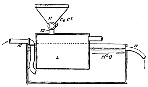
1 represents the gasometer; 4, the gas generator; 11, the funnel through which the water is introduced into the generator through the pipe, 13; 12, the pipe that connects the generator with the gasometer; 5, a stopcock with counterpoise that alternately opens and closes the communication between the funnel and the generator; 10, a lever connected with the cock, 5; 2, a chain that moves with the holder and maneuvers the lever, 10.
The plug, 6, of the cock, 5, is provided with two conduits, 7 and 8, at right angles. This plug turns 90 degrees, when it is maneuvered by the chain of the gasometer. In the position shown in Fig. 13 the holder is at the top of its travel, and the counterpoise, 9, of the cock is in the position marked by dotted lines in Fig. 9.
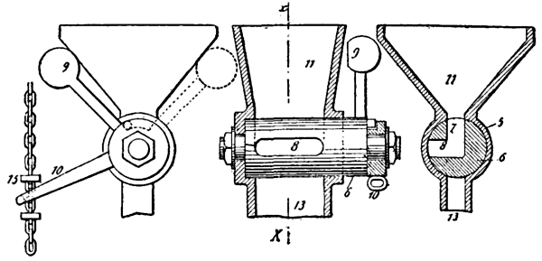
In this case, a charge of water fills the chamber 7 and 8 of the cock. This chamber may be oblong, as shown in Fig. 12, in order to increase its capacity. On the contrary, in the position of the counterpoise, 9, marked in continuous lines in Figs. 9 and 11, the channel, 8, communicates with the pipe, 13; the charge of water of chamber, 7 and 8, has fallen upon the carbides, but another quantity of water has not been able to enter, because the revolution of the cock has cut off all communication between the funnel, 11, and the generator, 4.
The acetylene produced by the reaction of the water upon the carbide raises the gasometer holder, which then actuates the plug, 6, of the cock, 5, and allows a new charge of water to enter the chambers, 7, 8. It is only when the holder descends anew to the position, 1, that the water in the chamber, 7, 8, can fall upon the carbide. The quantity of water that the cock is capable of containing is not sufficient to produce a quantity of gas exceeding the capacity of the gasometer, and, as it is impossible to introduce another quantity of water as long as the gasometer has not been emptied anew, any overproduction of gas is thus rendered impossible.
Fig. 10 applies to the introduction of the carbide into the water. It is necessary in this case that the carbide shall have been previously reduced to powder. The funnel, 11, is then closed by a cover, 21, in order to prevent any accidental escape of the gas. The carbide falls into the generator, the bottom of which is open. The latter enters a tank into which flows a current of water, escaping through the waste pipe, 19, in carrying along the lime formed. The height of the water in the tank is sufficient to furnish the pressure necessary to allow the gas to enter the gasometer through the pipe, 12.
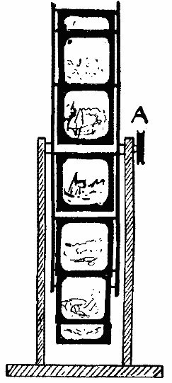
Those who would wish to have a little extra shop window attraction by way of displaying slides for the season now at hand might do worse than resort to something of the following style. The appliance can hold any number of slides, according to the diameter of the wheel portion, but in the diagram herewith it is for holding a dozen. The slides can be changed readily, hence a little time would be expended in making a complete change at least once a day.
The relative portions of the sketch being to scale, particulars as to the making of the revolving wheel need not be entered into, as any mechanic could grasp the whole idea at a glance. The edge of the wheel should, of course, be placed facing the window, and a band on the pulley wheel, A, attached to a clockwork or electric motor would supply all the driving power necessary.
In order to get good illumination on the slides, it will be necessary to have a piece of white cardboard or opal glass, B, hung on the axle, the lower side being the heavier, so that although the wheel revolves, it will remain stationary.
Various devices may be resorted to for hanging the slides on the cross rods, but perhaps the method shown at C will prove as simple as any, and consists of small springs which grip the slide at both sides.
By the judicious arrangement of shielded lights placed at side of reflector, a pretty effect is produced as each slide is gradually brought to view.—The Optical Magic Lantern Journal and Photographic Enlarger.
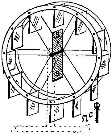
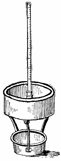
The selling price of beets naturally depends upon their yield in sugar, and what gives potatoes their value is their yield in fecula or starch, a product that serves to nourish man and animals and that is also used in the manufacture of alcohol and glucose. No account, however, is taken of this important coefficient in business transactions, potatoes containing proportions of starch varying from 13 to 23 per cent. being sold at the same price. Nevertheless, it is of the greatest interest to cultivators to make such measurements, since, in order to increase the value of their product, they might thereby be led to make a judicious selection in their planting.
Mr. A. Allard, starting from the fact that the richness in starch increases along with the density, has constructed a simple apparatus that gives both these data at once, with sufficient precision, and without calculations, tables, etc. It is, upon the whole, a large areometer with constant weight and variable volume that is plunged into a cylindrical vessel 0.5 m. in depth and 0.3 m. in diameter, filled with water. The instrument itself consists of three parts: (1) A lower receptacle in which is placed a weight to assure the equilibrium; (2) a central float into which is put a kilogramme of very clean and very dry potatoes; and (3) a rod graduated for density and feculometric richness. The deeper the apparatus sinks, the more valuable is the potato. How much more?
The degree to which the rod sinks shows this. The same principle and the same instrument might be applied to the determination of the density of various agricultural products, such as beets, cider fruits, grain, etc. It would suffice to graduate a special scale each time.
For each variation of a thousandth in density, the areometer sinks about 5 millimeters—that is to say, it presents a sensitiveness that is more than sufficient in practice.—Le Monde Illustré.
There is no more eager contest than that which has been going on for some time between gas and electricity. Which of these two systems of lighting will triumph? Will electricity suppress gas, as gas has dethroned the oil lamp? A few years ago, the answer to this question would not have been doubtful, and it seemed as if gas in such contest must play the role of the earthen pot against the iron one. At present the case is otherwise.
The Auer burner has re-established the equilibrium, and the Denayrouse burner is perhaps going to decide the fate of electricity.
As naturalists say, the function creates the organ, and it is truly interesting to observe that in measure as the need of an intenser and cheaper light grows with us, science makes it possible for us to satisfy it by giving us new systems of lighting or by improving those that we already have at our disposal.
What a cycle traversed in twenty years! What progress made! Let us remember that the electric light scarcely became industrial until the time of the Exposition (1878), and that the Auer burner obtained the freedom of the city only five or six years ago. Is there any need of recalling the advantages of these two lights? In the first, a feeble disengagement of caloric, automatic lighting and a steadier light; in the second, a better utilization of the gas, which gives more light and less heat.
A description of the Auer burner will not be expected from us. It is now so widely employed as to render a new description useless. As an offset we think that our readers will be more interested in a description of the Denayrouse burner, the industrial application of which has but just begun. This burner has been constructed in view of the best possible utilization of the gas, in approaching a complete theoretical combustion. In order that it may give its entire illuminating power, gas, as we know, must be burned in five and a half times its volume of air. In the Denayrouse burner the gas burns in four and four-tenths its volume of air. The result reached is, consequently, very appreciable.
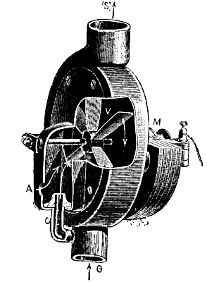
The apparatus consists essentially of a bronze or brass box in which revolves a fan keyed upon an axle that passes through the box. The axle is revolved by means of a small electro-magnetic machine mounted upon one of the external sides of the box. The motor may also be a hydraulic or compressed air one. Upon the axle is arranged a speed regulator. The air enters at the bottom of the box and the gas at the center. The exit of the mixture takes place through a chimney arranged at the top and to which is fixed a luminous mantle. The apparatus operates as follows: The motor causes the fan to make about 1,200 revolutions a minute. There is thus formed a strong draught of air, which mixes with the gas that enters at the side. The ignition occurs at the upper aperture of the chimney.
Although in this competition of gas and electricity the intensity of the light and, its quality are important factors, it is certain that what will decide the victory will be the price. This is why we are going to establish the net cost of the different lights; for, although up to the present the contest has seemed to be limited to gas and electricity (oil and kerosene not being capable of having any other pretension than to preserve their position), a new competitor—acetylene—will perhaps soon put gas manufacturers and electricians in accord, to the great benefit of the public, by furnishing a brilliant light at a price that defies competition.
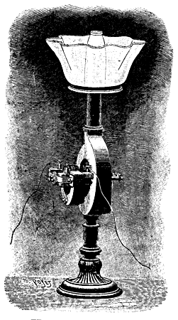 THE DENAYROUSE LAMP
In all systems of lighting, save electricity, the unit of light is the carcel. This represents the light produced for one hour by 10 wax candles, or, better still, it is the illuminating power given by the combustion of 42 grammes of pure colza oil for one hour in what is called a carcel lamp.
In electricity we count by watts. The watt, like the kilogrammeter, of which it represents nearly a tenth, is not a unit of light, but a unit of energy. What is called a kilogrammeter is the force capable of lifting 1 kilogramme to 1 meter in height during 1 second. Further along we shall estimate the watts in carcels.
This stated, let us ascertain the net cost of the unit of light in each system of lighting. We shall take as a basis the Paris prices, which are generally higher than those of other countries, owing to taxes, and shall confine our researches to the eight following systems:
Electricity (incandescent and arc lamps), gas (butterfly, Auer and Denayrouse burners), lamp oil, kerosene and acetylene.
1. Oil Lamp.—This method of lighting has become more and more neglected because it is the most troublesome. The mean price of the kilo is 1.6 francs. As the carcel hour consumes 42 grammes, it consequently amounts to 0.06, say 6 centimes.
2. The Incandescent Lamp.—In the scale of prices one of the oldest processes of lighting is closely followed by one of the most recent—the incandescent lamp. We shall base our calculations upon the Edison 16 candle electric lamp, which is the one most widely used. In this it takes 35 watts to obtain a carcel. As the hectowatt, the mean price of which is 15 centimes, gives approximately 3 carcels, the price of the carcel will, consequently, be 5 centimes.
3. Gas.—Gas, with the butterfly burner, burns from 125 to 130 liters to furnish the carcel. As the price of a cubic meter is 30 centimes, the carcel will cost 0.39, that is to say, 4 centimes.
4. Kerosene, the decline of which is perhaps beginning, costs about 0.75 centime per kilo. The consumption per carcel is nearly 40 grammes. It amounts, therefore, to 3 centimes.
5. The arc lamp is of very varied model. We shall take as a type those used for lighting the large boulevards. They are of 8 amperes and 50 volts; that is to say, of 4 hectowatts, and are presumed to give an illuminating power of 300 carcels. The carcel is consequently obtained with 13 watts and its net cost is 0.0195, or, approximately, 2 centimes.
6. Acetylene.—This new system of lighting has hardly as yet made its exit from the laboratory. So we must not be greatly astonished at the variations in the price at which it is claimed that it can be obtained on the two sides of the Atlantic. As a kilo of carbide of calcium gives 300 liters of acetylene, and as the minimum price of the carbide is 40 centimes per kilo in France, a cubic meter of the gas costs 1.35 franc. As it requires about 7.5 liters to give the carcel, the latter will consequently amount to 0.01; say 1 centime.
7. The Denayrouse Burner.—This burns nearly 300 liters of gas to produce 30 carcels, normally. As the photometric experiments are recent, let us suppose that it gives but 25 carcels. As 300 liters of gas represent an approximate expense of 10 centimes, we shall obtain the carcel at the price of 0.004, or at less than half a centime.
8. The Auer Burner.—This burns nearly 115 liters of gas to produce 5 carcels. The expense per carcel, with the cubic meter of gas at 30 centimes, is therefore 0.0069; say 0.7 of a centime.
Finally, in the United States, thanks to particularly favorable hydraulic installations, it is claimed that it is possible to produce acetylene at a very low price, say at 33 centimes per cubic meter. Under such conditions, the carcel would cost no more than 0.0025, say ¼ of a centime. It seems, however, that these are hypotheses as yet. If they chanced to be realized, it is certain that acetylene would be the light of the future; but those who are best informed in the matter assert that they never will be realized.
In order to establish still more accurately the net cost of each of these systems of lighting, it is necessary to take into account the wear of the mantles of the incandescent lamps and the carbons of the arc ones. As regards these latter, it is customary to estimate the wear of the carbons at 8 centimeters an hour.
As for the mantles, we shall base our calculations upon the data furnished by those interested; say 1,000 hours for the Edison lamp, 1,200 for the Auer burner and 400 hours for the Denayrouse burner. It must be remarked that in practice such duration generally drops to a half. The price of the mantles in these different systems is approximately 2.5 francs.
1. As the Edison 16 candle lamp gives 1.6 carcels and its filament burns 1,000 hours, the wear will increase the price of the carcel by 0.0015.
2. As the Auer burner gives 5 carcels and its mantle burns 1,200 hours, the wear will increase the price of the carcel by 0.0004.
3. As the Denayrouse burner gives 25 parcels, and its mantle burns but 400 hours, the wear will increase the price of the carcel by 0.0002.
Finally, if we compare the butterfly, Auer and Denayrouse burners with each other, in taking into account the cost of replacing the mantles of the two latter and the actuating of the Denayrouse burner, we find the following figures per carcel hour:
| Butterfly burner, | consumption | 0.04 |
| Auer burner, | consumption | 0.0069 |
| wear of mantle | 0.0004 | |
| Denayrouse burner, | consumption | 0.04 |
| wear of mantle | 0.0002 | |
| expense of motor | 0.0003 |
| Say | 4 | centimes | per | carcel hour | Butterfly | burner. |
| 0.7 | " | " | " | Auer | " | |
| 4.5 | " | " | " | Denayrouse | " |
For the same sum, the Auer burner, therefore, burns six times more and the Denayrouse nine times more than the butterfly. These figures may give an idea of the surprising intensity of the Denayrouse light.
Upon the whole, if the experiments that are being made publicly at this moment confirm the data of the laboratory, the Denayrouse burner will be destined to play a considerable role in the lighting of public gardens, streets and buildings, for the very intensity of the light that it gives renders it unfitted for private use. Moreover, it must not be forgotten that it requires a motor to actuate its fan, and everyone has not the necessary motive power in his house.
This new burner will likewise prove very valuable for the righting of theaters.—L'Illustration.
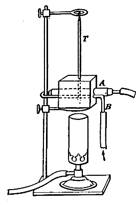
This has been found useful for drying substances at temperatures above 100° C. It is usually difficult to obtain a temperature much above, say, 120° in the ordinary air oven without using a large burner, which is generally difficult to regulate. The temperature also varies considerably at different heights in the oven. If the substance is attacked by air at high temperatures or gives off other substances than water, an estimation of the water is difficult.
The apparatus figured—which is made from a square "tin" or copper box, with a lid perforated at the top to take a thermometer (T), the bulb of which is level with the tubes (A and B) passing through the sides of the box—is heated by an Argand burner and supported on a retort stand. Dry air (or other gas) passes through the tube, B, where it undergoes a preliminary heating, and then through the drying tube, A. The substance to be dried is placed in a porcelain boat, or in a tube passing through the cork of A (by the latter means precipitates on filter tubes can be dried). It is usually sufficient to estimate the loss in weight of the substance in the boat; but, if necessary, drying tubes can be used to collect the water, or special absorbing apparatus for other volatile substances.
A temperature of over 200° C. can be easily obtained with an ordinary Argand flame and maintained fairly constant. When a thermometer was placed inside as well as one outside the drying tube, it was found that the temperatures only differed by a few degrees when a water pump was drawing air through the system at the rate of about 8 liters per hour. If this bath is protected from draught, any temperature can be maintained within a few degrees easily.—Journal of the Society of Chemical Industry.
In a previous paper2 a description was given of the experimental gallery at the St. William pit of the Kaiser-Ferdinands-Nordbahn Colliery at Mahrisch-Ostrau (Moravia). In the present article a similar experimental station, designed for the same purpose, but presenting certain considerable advantages on the score of economy by reason of the moderate expense of its installation, will be described.
Some few years ago the Société des Explosifs Favier obtained permission from the proprietors of the Marchienne-au-Pont, near Charleroi, Belgium, to construct there an experimental station for testing the explosives manufactured by the company. Though of but modest proportions, this station is well designed, and many valuable researches and tests have been made on the explosives used in the fiery pits of Belgium, thanks to which investigations one is able to readily determine in a practical manner the degree of security offered by any explosive intended for use in pits containing coal-dust in suspension or firedamp.
In order to avoid the expense of constructing a large gallery above ground, recourse was had to the cylindrical shell of a disused boiler of large dimensions—some 5 m. in length by 1½ m. internal diameter—one end of which was taken out, and the shell made to do duty for a testing gallery. With this object it was mounted on two settings of brickwork (Fig. 2), and the further end backed by a brick wall of very substantial construction, being 1½ m. thick and 2 m. in height, and forming the base of a high bank of earth. The boiler, as may be seen in Figs. 1 and 2, was let into the ground a little, in order that in case of an explosion there might be less chance of the debris being projected to a distance. On one side the boiler was pierced by six rectangular openings 20 cm. in height fitted with thick glass panes in caoutchouc frames, to prevent their becoming fractured by the aerial vibrations resulting from explosions. These windows enable the operators to observe the phenomena occurring within the chamber at the moment the explosion is produced. At the top of the boiler, two circular apertures, each 50 cm. diameter, were made for the purpose of acting as safety valves. By means of two rabbets, one fixed at the open end of the gallery and the other in the center, the testing chamber could be made either large or small by means of paper disks pasted on to the first or second rabbet. The capacity of the large chamber was double that of the smaller one, and the cubical area of each was known beforehand.

In the backing wall was fitted a large mortar of cast steel, which in carrying out the tests served to replace the borehole used in actual mining operations. A pipe for conveying the gas and another for steam were laid on the floor of the chamber, the latter for heating purposes, in order to ascertain whether, in certain cases, an increase in temperature exerts any sensible influence on the inflammability of the explosive mixture. The temperature of the chamber is read off from a thermometer placed at the top of the boiler, its position being indicated by T in Fig. 2.
In view of the possibility of the boiler, notwithstanding its strength, bursting, in the event of a violent explosion of the gas, it became necessary to make special arrangements for allowing the operators to observe everything occurring in the testing chamber without being themselves exposed to the consequences of any accident that might ensue. A special shelter was, therefore, erected for occupation by the operators at the moment of the explosion. This shelter, at about a dozen yards away from the boiler, consisted of a chamber protected on the side next the gallery by a stout bank of earth, in which a longitudinal aperture was provided (by means of a lining of boards) at about the height of the face, through which the operators could observe the progress of the tests, without danger. It may be stated, however, that hitherto no accident has occurred, the boiler effectually resisting the force of the explosions. The chamber of shelter likewise contained the gasometer for regulating the supply of gas to the testing apparatus, and the electrical machine for firing the cartridges under test.
There being no continuous current of firedamp at disposal, use was made of illuminating gas in preparing the explosive mixtures for the tests. The borehole is charged with the explosive to be fired, and the temperature is regulated by means of the steam pipe. The entrance of the chamber and the two safety apertures in the roof having been closed by disks of paper fastened by paste, the gas is turned on until the desired percentage, has been introduced; the mixture of the air and gas takes merely a short time to effect by diffusion, the difference in density causing the gas to rise on issuing from the jet, which is on the floor of the chamber. The detonating cap is then ignited by the passage of the electric current and the shot fired. The operator, placed in his shelter, can observe, by means of the small lateral windows, whether any flame is produced, and indeed, a little experience will enable him to determine by the sound alone, whether an explosion has ignited the mixture or not.
Fig. 1 is a front view of the testing chamber with transverse section of the shelter. Fig. 2 is a longitudinal section of the chamber along CD, and Fig. 3 a view, half in plan, half in section, along AB. The following are the references: M, backing wall; C, boiler; G, gas pipe; V, steam pipe; M, mortar; E, electric wires; A, shelter; RG, gasometer; ME, electrical machine; R', protective bank; R", backing of earth; R, glazed windows; S, apertures serving as valves; T, thermometer.
[1] H. Schmerber, Genie Civil, xxix, No. 11.—From the Colliery Guardian.
[2] Reproduced in the Colliery Guardian, vol. lxxi, p. 317.
When a negative happens to be of larger size than a quarter plate, it rarely happens that we can print a small portion by contact on a lantern plate without spoiling the composition of the picture. This is assuming, of course, that the operator has composed a picture and not put his camera down anywhere. There is no great difficulty in making lantern slides by reduction; the exposure is the only bugbear, as usual.
There are two distinct methods of reduction: (1) daylight; (2) artificial light. There is nothing to choose between them, and the question of time and opportunity must decide which is to be adopted. The apparatus required is not expensive. It can be made in odd moments for a few pence, and is applicable to day and artificial light. It consists of a printing frame the size of the large negative, four pieces of bamboo a quarter of an inch in diameter, some black twill, the ordinary camera and lens, and a carrier to take lantern plates 3¼ X 3¼ inches.
The negative is placed in the printing frame upside down and kept in position by four little slips of wood, or better still, a frame such as the gold slip used in picture frames, which will fit tightly into the frame and hold the negative securely. Of course, brads may be driven into two sides of the frame and the negative slipped behind them, but in this case it is necessary to safe edge the negative. This is done by cutting strips of tinfoil just wide enough to cover the rabbet of the negative so that no clear glass can be seen; these should be pasted and stuck on the glass of negative round the four sides. The strips of bamboo are either nailed to the printing frame or merely fastened together by stout copper wire, the shape being exactly that of the printing frame. The other end of the bamboos are tied with stout string to a piece of cardboard tube, postal tube, which slips over the lens. The length of the bamboos depends upon the focus of the lens and the amount of reduction. It will sometimes be found convenient to have the bamboo in two lengths; thus, supposing we want as a general rule 36 inches, two pieces, 24 inches each, should be obtained, and by fastening these together in the middle by two loose rings of copper wire we can extend them to 48 inches or reduce them to 24 inches.
The black twill or the focusing cloth (or even a dark table cloth may be used) must also depend for its size on the length of bamboo, but sufficient should be obtained to completely cover over the space between lens and negative, and hang down on each side.
Of course, two laths of wood can be used, merely resting them on the top of printing frame and camera, but the other plan is preferable, the arrangement being more complete and adaptable to both day and artificial light, and also more rigid, especially when the camera is sloped toward the sky.
The ordinary camera may be used, but a carrier to take lantern plates must be used in the dark slide. The ordinary lens may be used unless of inordinately long focus, when it becomes inconvenient on account of the great distance between negative and lens. To find the required distance there is a simple rule, which is as follows:
(a) Divide the longer base of the plate by the longer base of the image required, to the quotient add 1, and multiply by the focus of lens used; the result will be the distance between negative and lens.
(b) Divide the distance found as above by the quotient obtained in the first rule, and the result will be the distance between lens and plate.
Example.—What are the relative distances in reducing a whole plate negative, 8½ X 6½ inches, to lantern, size with an 8 inch focus lens?
Now that the whole of the lantern plate is not used, we reckon that 3 inches is all that can be used, because of the mask, hence:
| (a) | 8½ ÷ 3 = 17/6 = the amount of reduction. |
| 17/6 + 1 × 8 = 23/6 × 8 = 30⅔ inches. | |
| (b) | 30⅔ ÷ 17/6 = 11 inches (practically). |
Therefore, if we place our lens about 30 inches from the negative and rack the camera out to about 11 inches, we shall have an image on the ground glass which merely requires a little adjustment of the camera screw to be sharp and of the right size. In focusing, it is always advisable to temporarily affix to the outside of the focusing screen a square mark, this being, of course, accurately placed as regards the center of the screen, and to use a focusing magnifier to obtain critical sharpness.
Having satisfactorily arranged our image as regards composition by shifting the camera nearer to or farther from the negative—because it will be obvious that the nearer the lens to the negative, the less of the negative we shall include, and vice versa—we fill our dark slide and are ready for exposure.
For daylight work the arrangement of frame and camera should be placed near a window, and if anything but sky is seen opposite the negative, place outside the window a large sheet of white cardboard at an angle of 45°. This will reflect equal skylight through all parts of the negative. Now cover over the space between negative and lens, insert your dark slide, in front of the negative place an opaque card, draw the shutter of the dark slide, and remove the opaque card from negative and expose.
Very little assistance can really be given as to exposure, but with a negative of average density, which will give a good silver print, and using a lens working at F/11 and a Mawson lantern plate at midday in May, ten seconds will give a good black slide.
There is but one little point that has been missed—the diaphragm; always use the largest diaphragm which will give satisfactory definition, this will usually be F/11 or F/16.
Be very careful while exposing not to shake the camera—it is quite sufficient for anyone weighing about eleven or twelve stones to walk across the room to give double outlines.
Daylight is not a constant quantity, and although visually the same on two different days, the actinic power of the light varies enormously; therefore we prefer artificial light.
Precisely the same apparatus can be used for artificial light with one or two additions. In some such arrangement in use the printing frame containing the negative is fastened to the side of a cube sugar box in which a hole is cut.
Opposite to the negative on the other side of the box is placed a sheet of white cardboard bent slightly to the arc of a circle. The lights, etc.—two incandescent gas burners do well with tin reflectors behind them—are placed one on each side of the negative inside the box, so that the light is reflected on to the card and thence on to the negative, and no direct light reaches the negative. Absolutely even illumination, even of a large negative, is thus obtained, and the exposure, using the same conditions as stated for daylight, is only twenty seconds.
Of course, the light may be placed directly behind the negative, but in this case a diffuser, such as a sheet of opal glass, must be placed between light and negative, and even then, unless great care is exercised, uneven illumination of the negative and consequent unequal density of the slide must ensue.
We may use magnesium ribbon, and a diffuser of opal is then necessary, and the ribbon must be kept in motion the whole of the time. Magnesium is objectionable because the particles of magnesia form a voluminous cloud, which tastes and smells unpleasantly and settles down on everything. Still, for those who wish to work with this substance, about 18 inches burnt close to the opal and moved about all over it will be about sufficient to obtain good results under above mentioned conditions. An ordinary oil lamp or gas may also be used, provided the light is diffused.
Only the bromide lantern plates are suitable for reduction, the exposure, especially with the chloride emulsions, being so long as to place them out of court. The chloro-bromide may be used for daylight and magnesium ribbon.
After development and fixing, which may be performed in the developers recommended by the makers of the plates used, the lantern slide must be well washed and cleared in an alum and acid bath, then again well washed and finally given a gentle rub with a piece of cotton wool under the tap, and set up to dry.
The finishing off of a slide is not a difficult matter, but one which wants doing properly. Place the slide film downward upon a piece of white paper, and with a box of assorted masks try various shapes till the one most suitable to the picture is found, and frequently a mask with a comparatively small opening will give the best results pictorially. Having found the most suitable mask, lay it on the slide, on the top of this a cover glass well cleaned, and it is ready for binding. Binding strips can be purchased commercially in long strips, but personally we prefer to use 3¼ strips, as somewhat easier to apply. Wet 3¼ in. of the strip, lay it flat on the table, pick up the slide and cover glass and adjust on the wetted slip so that there is an equal width on either side; now press the glasses firmly on to the strip and lift from the table and with a handkerchief or soft duster wipe the strip on to the glass of the slide and cover, taking care that these do not slip; when it adheres firmly, that is, does not immediately rise up, lay the whole on one side and go on with next slide; by the time half a dozen have been thus treated a second side may be stuck down, and thus with the third and fourth. By working in this way a far neater and safer job is made of it than if all four sides are bound at once.
The final operation is tilting and spotting. There are several makes of masks on the market on which a blank white space is left for the title, and it is just as well to write the title on the mask, as it is then protected by the cover glass. If the ordinary masks are used, Chinese white may be used for the titles.
"Spotting" the slides is affixing to them two marks, by means of which the lantern operator can tell which side is to be placed next the lantern, and these marks usually take the form of two white circles. Such "spots" can be bought commercially already gummed, or postage stamp edging may be used.
A few minutes' thought will show that the projecting lens of the lantern will reverse an image just as the lens of the camera does, so that we must insert the slide into the lantern carrier upside down and wrong way round, and as the spots are used to indicate this, they must be placed at the top of the slide, when the view appears to us as we saw it in nature. If it be a subject with lettering in it, the spots must be placed at the top of the slide, when we can read the lettering the right way as the slide is looked at against a piece of white paper.
The object which I have proposed to myself in these two lectures is to consider, not the history nor the artistic interest of precious stones, but simply some of their curious properties. In the first place, then, I will ask you to accompany me in the inquiry as to those characters of precious stones to which they owe their beauty and their value, and next to pursue the inquiry a little farther and to see how, by means of these characters, the same stones may be studied, and hence, also, identified with accuracy.
From the earliest times certain minerals, which are conspicuous for their beauty, have been prized for decorative purposes; the brilliant green hue of malachite, the deep blue of lapis lazuli and the rich color of red jasper would naturally attract early attention. But these particular minerals are not numbered among the true precious stones; they do not possess the remarkable qualities which endow the diamond, the ruby or the topaz with their peculiar attractiveness. The two essential qualities, namely, brilliancy and hardness, are only possessed by certain rare minerals; a brilliancy which makes them unrivaled for ornamental purposes and a hardness which protects them from wear and tear and makes them practically indestructible.
It is difficult in a town like London, where every jeweler's shop is ablaze with diamonds, to realize that large and good stones possessing these qualities are so rare; that thousands of natives are toiling in the river beds of India, Burma and Ceylon washing out from the gravel or the sand the little blue and red pebbles which are to be converted by the lapidary's art into brilliant jewels of sapphire and ruby. Even in that wonderful pit at Kimberley, where half the diamonds of the world seem to have been crowded together for the use of man, although, perhaps, ten tons of diamonds, worth more than £50,000,000, have been extracted in twenty-five years, yet those which weigh more than an ounce each may be counted on the fingers.
It is in the qualities of hardness and brilliancy that such minerals as malachite and lapis lazuli fail; owing to their comparative softness, they would not, if cut and polished, possess the sharp edges and brilliant surface of the emerald or sapphire, and would soon become dull and rounded by friction, even by the friction of ordinary dust. Again, since they are opaque, they can never flash like the sapphire or the emerald; and yet it is quite a mistake to suppose that the necessary qualities are confined to those few stones which are familiar to everyone, such as the diamond, ruby, sapphire, emerald, garnet and amethyst. There are many others, though they are not so well known. I think we may fairly assert that such minerals as tourmaline, jargoon, peridote, spinel and chrysoberyl, though their names may be familiar, are not stones which would be recognized by any but those who are in some sense experts; while other minerals, such as sphene, andalusite, axinite, idocrase and diopside, are possibly almost unknown to most people, even by reputation. Yet all these minerals possess qualities of transparency, hardness and beauty of color which render them extraordinarily interesting and attractive as precious stones. (A number of faceted stones cut from the less known minerals were thrown upon the screen by reflected light.)
Take first the hardness. A few years ago the hardness of stones was a very important character in the eyes of the mineralogist; it was one of the characters by which they were invariably identified, and a distinguished German mineralogist drew up a table by means of which the hardness of minerals can be compared. Any stone is said to be harder than the minerals of this scale which it can scratch, and softer than those by which it can be scratched. In the right hand column the gem stones are arranged according to their hardness.
| 1. Talc. | ||
| 2. Gypsum. | ||
| 3. Calcite. | ||
| 4. Fluor. | ||
| 5. Apatite. | Sphene. Opal. | |
| 6. Feldspar. | Diopside. Moonstone. | |
| Epidote. Idocrase. Peridote. Axinite. | ||
| 7. Quartz. | Quartz. Tourmaline. Cordierite. Garnet. | |
| Andalusite. Zircon. Emerald. Phenacite. | ||
| 8. Topaz. | Spinel. Topaz. Chrysoberyl. | |
| 9. Corundum. | Ruby. Sapphire. | |
| 10. Diamond. | Diamond. | |
Among precious stones diamond stands out pre-eminent as the hardest of all known substances. Ruby and sapphire are scratched by diamond alone, while chrysoberyl, topaz and spinel scratch all the remaining stones, although they do themselves yield to the scratch of ruby and sapphire. The hardness is a character still generally utilized by the expert when he is in doubt; in experienced hands it has some value. By long practice it is possible to form a very close estimate of the hardness of a given stone, and that often, not by the scratch of the other minerals in the scale, but by the feel of the stone against a file; the resistance offered by the stone to the file is taken as a measure of its hardness. It is not a character capable of any accurate measurement, neither is it to be recommended for use by inexperienced persons.
I hope to show, as I go on, that we have now accurate methods of testing at our disposal which render the trial of hardness quite unnecessary. But, none the less, the character is one of great importance, as investing the stone with durability. All the precious stones, except moonstone, opal and sphene, have at least the hardness of quartz, and can barely be scratched by metals, even by hard steel.
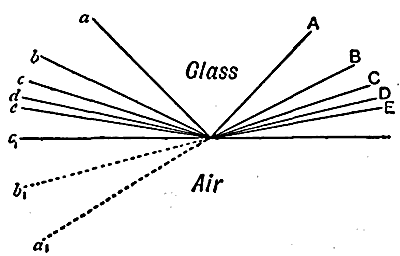
Take next the quality of brilliancy. This depends upon two things—first, the manner in which rays of light are affected when they enter or leave the stone, and, secondly, the manner in which this action can be intensified by the art of the lapidary.
When light passes from one transparent substance to another it is bent or refracted, as every one knows from the bent appearance of a stick plunged into water. Consider, now, a ray of light falling upon the surface of a transparent stone; a portion of the light is reflected, but a portion enters the stone. In passing from air into the stone it is refracted inward. When, on the other hand, it passes from a transparent stone into air, its course is reversed and the emerging ray is refracted outward or toward the surface. It is, however, with the emerging as with the entering light, the beam is subdivided, only a portion is refracted out, another portion of the light is reflected within the stone.
Consider next successive rays within a piece of glass or a stone which are about to emerge with different inclinations. (See Fig. 1.) As their course approaches more nearly to the surface, so will the emerging rays issue more nearly along the surface of the stone; but the obliquity of the emerging rays increases much more rapidly than that of the internal rays, until for one ray in the series the direction of the light (C in the figure) refracted out coincides with that surface. What, then, will happen to the light within the stone, which falls still more obliquely? It cannot be refracted out, and, as a fact, it is entirely reflected within the stone. Imagine, then, how much greater is the brilliancy of the beam of light, c, e, d, which is completely reflected, than that of the intermediate portion of the reflected light, a, b, c, which has lost a large part of its rays by refraction. The difference is easily seen by looking at a glass of water held above the head; the brilliant silvery appearance of the surface, when viewed obliquely, is due to total reflection. The light, c, d, e, is said to have been totally reflected; and half the angle between C and c is called the "angle of total reflection." This angle depends upon the refractive power of the stone. The angle of total reflection for diamond is about 25°; in no other stone is the corresponding angle less than 30°; for most of them it is much greater; while for heavy glass it is about 40°. Light striking the internal surface more obliquely is reflected without losing any of its rays by refraction.
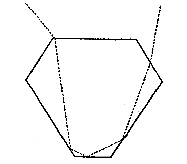
It is very clear, then, that of the light traveling in directions within a diamond, a far larger proportion is internally reflected than is the case with any other stone. We shall see presently that it is this property which gives the diamond its consummate brilliancy.
Another effect produced by refraction is, as every one knows, the separation of ordinary light into rays of different colors—it is seen in any prism of glass. This property is known as the "dispersion" of light; and a stone which possesses great dispersion will exhibit a beautiful play of spectral colors—will exhibit a high degree of what is called fire. In this respect again the diamond is pre-eminent; its dispersion is nearly twice as great as that of other stones.
All these optical properties are beautifully shown by those unworked jewels of which the smooth facets have been produced by nature; I mean the crystals of the various minerals. The beauty of natural crystals of transparent minerals is largely due to the optical effects which I have just been describing.
The beautiful specimens of rock crystal, calc spar, topaz, emerald, and other stones which adorn mineral collections are sufficient evidence of these properties. But it is very certain that natural crystals, although they possess a beauty of form which is all their own, are not by a long way so brilliant as the faceted stones which are cut from them by the art of the lapidary; that a natural diamond is not so lustrous as a faceted brilliant.
In fact, many of the finest gem stones present a very mean and sordid aspect before they have passed through the hands of the lapidary; one has only to compare the dull and unattractive appearance of a parcel of rough rubies, sapphires or rough diamonds with the finished jewels displayed in the jewelers' windows to see how much these owe to the lapidary's art.
In recutting the Koh-i-noor it was thought advisable to spend £8,000 on the process and to reduce its weight from 186 to 106 carats. When the great Pitt diamond was cut, its weight was reduced from 410 carats to 137; and the fragments and dust removed were valued at £8,000; but the extent to which the stone was improved is indicated in the fact that having been purchased for £20,000, it was after cutting sold for £135,000.
To understand how the cutting of a precious stone adds to its brilliancy, we have only to trace the course of the rays within the stone, and consider how it can best be faceted in order that the light which enters in various directions on the upper side, or crown, may be reflected internally from facet to facet on the under side of the stone with as little loss as possible, and may be thrown out from the front of the stone. For this purpose the facets must be so arranged that as much of the light as possible within the crystal shall meet the facets at an inclination exceeding the angle of total reflection. A brilliant with its 58 facets is one of the forms which experience has shown to be best adapted for the purpose. How little of the light gets through a stone so faceted, and, therefore, how much of it is totally reflected internally, is easily shown by holding the stone in a strong beam of light; first so that the light is so reflected, and then so that the light shall, if possible, be transmitted. In the latter case, the stone merely throws a dark shadow, indicating that little light, if any, has passed through it.
A faceted stone is always cut from a single crystal, and not from an ordinary lump of the mineral, which is generally a mass of crystals. The chief reason why jewels are cut from natural crystals is that these, by virtue of their crystalline nature, are remarkably homogeneous, and therefore clear and limpid when free from cracks and flaws. A stone which is not homogeneous can never have the purity and limpid brilliancy of a single crystal, for at every point of contact of one part with another reflection takes place. Among minerals used as precious stones which are not crystals may be mentioned the opal. The opal probably owes its peculiar beauty to the very fact that it is filled with minute cracks or cavities, each of which contributes some tint of color by reason of its extreme thinness, just as the colors of the soap bubble are due to the thinness of its film.
Or take the agate. Here the stone consists of layers of different materials differently colored. Its beauty is of a different nature from that of clear crystals, which it can never rival in brilliancy. Stones like the agate are generally classed apart as semi-precious stones, and their interest depends upon beauty of structure or color, or possibly to a large extent upon their rarity. The turquois, for example, is a very rare stone, which is apparently absolutely uncrystallized, but possesses great beauty of color, and is therefore much prized. The same is true of carnelian. On the present occasion we are not concerned with those opaque or curiously structured minerals whose beauty resides almost solely in their color.
Those who have had no practical acquaintance with minerals have little idea how variable and accidental are their colors. They may scarcely realize that the ruby and the sapphire are the same mineral, and that this mineral also occurs, and is used in jewelry, absolutely colorless, when it is known as lux sapphire, green as the so-called Oriental emerald, and yellow as the so-called Oriental topaz; that topaz itself may be yellow, brown, blue, or colorless; that zircons range from colorless through almost all conceivable shades of brown and green, and that even diamond has been found green, red and blue.
When we come to consider the properties by which precious stones are recognized, I shall say little or nothing about color, for it is of little value as a criterion. There are, for example, certain red stones which the most skillful experts cannot by their color alone refer with certainty to ruby, garnet or spinel. It might be expected that a noteworthy difference in chemical composition would accompany this difference of color, or that the pigment could be ascertained by analysis. In reality this is scarcely ever the case. It is fairly certain that the emerald owes its color to the presence of chromium, but the variation in the analyses of precious stones cannot generally be attributed to anything indicated by the variation of color.
The chemical composition, though of great general importance in mineralogy, is of little practical value in the discrimination of precious stones, since it is usually impossible to sacrifice a sufficient quantity for chemical analysis. If we are dealing with a faceted stone, not even the smallest portion can be utilized, for fear of injuring it.
There is, however, one remarkable optical property, which is ultimately related to the chemical composition. As is well known, many substances possess the property of absorbing certain rays of light. When the solar spectrum produced by admitting ordinary daylight through a slit, and transmitting it through a prism, is passed through the glowing vapor of certain substances, particular rays of light are absorbed, and their absence from the emerging fight is manifested by corresponding dark bands in the spectrum. The instrument by which the observations are made is the spectroscope. It is well known to most people that the solar spectrum itself contains certain dark bands of this sort, which are produced by vapors that can be identified by the position of the bands in the spectrum; and thus it is possible to ascertain something regarding the chemical constitution of the sun and certain of the heavenly bodies. Now, a precisely similar effect is produced by certain elements if present in a mineral, by merely transmitting the light through a piece of it. Thus, transparent minerals which contain the rare element didymium betray the presence of that element as soon as they are viewed through a spectroscope by ordinary daylight; the spectrum is seen to be traversed by black bands in the green, which are quite characteristic.
Among gem stones there are two which possess this curious property. One is the variety of red garnet known as almandine, and the other is the jargoon. The almandine produces characteristic bands in the green and the jargoon in the red, green and blue portion of the spectrum. To see these remarkable absorption spectra, to which attention was first called, I think, by my friend, Prof. Church, it is not necessary to look through the stone, it is quite sufficient to place it in a strong light, and look at it through an ordinary pocket spectroscope; the light which enters the instrument consists largely of rays which have penetrated the stone, and been reflected from the facets at the back. These rays produce the absorption spectrum. In this way we are enabled to identify a jargoon or an almandine merely by looking at it. There is no test so simple or so easy of application. It is curious that the almandine, or iron aluminum garnet, is the only garnet which presents an absorptive spectrum, and it is not yet certain to what element the bands are due. In the case of jargoon, they are supposed to be caused by the presence of some uranium compound in the mineral. All the almandine garnets which I have examined, and nearly all the jargoons, show these characteristic absorption spectra.
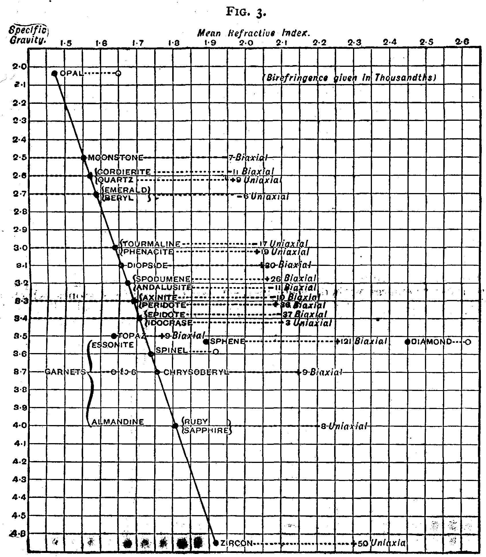
By way of summary, I have thought it desirable to indicate the general characters of precious stones in a diagram, which exhibits some of their relationships and also some of their differences in a graphic manner.
Opal, which is a comparatively light mineral, has a low refractive power; zircon or jargoon is a heavy mineral, and has a high refractive power. Let now the refractive power of any mineral (as measured by its refractive index for yellow light) be represented by a corresponding length set off from left to right, and let its density (as measured by its specific gravity) be represented by a corresponding length measured downward. Fixing in this way a point corresponding to opal, and another representing the character of zircon, draw a straight line from the one to the other. It will then be found that the points which, by their position on the diagram, represent the specific gravity and refractive index of the various minerals will be very nearly upon this line; that is to say, as the refractive index of precious stones increases, so also does their density, and the two increase together in a remarkably regular manner.
It appears from this table that those minerals which, by their high refractive power, possess the greatest brilliancy, possess also the highest specific gravity or weightiness; that the precious stones are therefore all heavy minerals. There is also a rough general correspondence between these characters and the hardness of the stones; the brilliant heavy minerals are also generally speaking hard.
Two remarkable exceptions display themselves. Sphene lies far to the right of the position which it should occupy according to its specific gravity; it possesses an extraordinarily high refractive index, and is, therefore, an extremely brilliant gem stone. On the other hand, a glance at the scale of hardness shows that it is, unfortunately, one of the softest of the possible gem stones, and that in this respect it is not very well fitted for jewelry.
Diamond is still more remarkable; its refractive index places it at the extreme right of the diagram, with a refractive power, and therefore a brilliancy, greater than that of any other stone; at the same time its hardness exceeds that of any mineral, and this combination of qualities renders it the chief among gem stones, unequaled for brilliancy and durability, although not a heavy mineral. Moreover, in dispersion, and therefore in fire, it stands alone. Minerals which are heavier than zircon, such as the metallic sulphides and iron glance, are unsuitable for gem stones, since they are nearly opaque, but they follow the same law, and possess a refractive power still greater than that of zircon or even diamond.
There is one other stone which is exceptional, but in less degree and in the other direction, namely, topaz, whose refractive index is not 1.7, as it should be by its position on the line due to the specific gravity, but 1.62; the point corresponding to topaz must therefore be placed a short distance to the left of the line. It is curious that these three exceptional stones lie on the same horizonal line, having all the same specific gravity, 3.5.
In mentioning the specific gravity I have introduced a property which is not essential to win esteem for a precious stone, but one which is of great value in its identification.
We have next then to consider those properties by which precious stones may in practice be most readily recognized. The table shows very clearly that specific gravity is one such property. The meaning of specific gravity is easily explained. A piece of tourmaline of any size weighs three times as much as an equal volume of pure water at 4° C., the specific gravity of tourmaline is therefore said to be 3; a piece of almandine garnet of any size weighs four times as much as an equal volume of water under the same conditions, and the specific gravity of garnet is therefore 4.
Now any substance immersed in water loses in weight by an amount exactly equal to that of the water displaced. Hence, to ascertain the specific gravity it is only necessary to suspend the stone by a fine thread to the beam of a balance and weigh it first in air, and then immersed in water. The first weighing gives the weight of the stone itself, the difference between the first weighing and the second gives the weight of the displaced water; hence the specific gravity is found at once by dividing the weight of the stone by this difference. For very small stones, where the weights concerned are slight, it is necessary to use a refined chemical balance. But for ordinary stones a well made Westphal balance is sufficient.
The Westphal balance is constructed on the principle of the common steelyard. At one end of the beam is a counterweight, at the other end the stone is suspended; the beam is divided into ten equal parts. A weight can be suspended on the beam, and its action, of course, varies with its position on the beam; at the tenth division from the center it has a value ten times as great as at the first division.
The specific gravity is then found as follows: First, counterpoise the counterweight. Let this require a weight, A, on the right hand side of the beam. Next, find the weight necessary to restore equilibrium when the stone is suspended from the beam. Let this be B. Then A-B is the weight of the stone in air. Next raise the vessel of distilled water below the stone until it is immersed. If C be the weight now required to restore equilibrium, C-B is the loss of weight in water, and, finally, the specific gravity is (A-B)/(C-B).
This process is known as "hydrostatic weighing," and can be applied to any stone, except such as are very small. Great precautions must be taken, in order to determine the specific gravity with accuracy. Especially it is necessary to free the stone from all adhering bubbles of air. For this reason the process of hydrostatic weighing is a somewhat laborious one.
Now, in order to identify a mineral, it ought to be unnecessary to determine exactly the specific gravity, provided that means can be devised for showing that its specific gravity is the same as that of some known substance. For purposes of identification, a comparative method is often quite as efficacious, and much more easy than actual measurement. This may now be done by means of certain heavy liquids.
Wood floats in water because it is lighter than water; iron sinks because it is heavier; but a substance which possessed exactly the specific gravity of water would neither float nor sink, but would remain suspended in the water like a balloon in midair. Taken, then, a liquid which is heavy—the most convenient is methylene iodide, whose specific gravity is 3.3—a fragment of zircon will sink in this, and a fragment of tourmaline will float, but a fragment of the mineral augite, whose specific gravity is also 3.3, will remain exactly suspended.
This liquid, then, enables one to say with certainty whether a given stone has a specific gravity greater or less than 3.3; in the one case it will sink, in the other it will float.
But methylene iodide further possesses the valuable property of mixing easily with benzene, which is a very light liquid. Every drop of benzene added reduces the specific gravity of the mixture, which can thus easily be made to range between that of chrysolite and that of opal.
To identify any one of the stones which lie between those limits on the diagram, it is only necessary to drop it into a test tube or small vessel containing methylene iodide—the stone will float—benzene is added drop by drop, the mixture being kept well stirred until a point is reached at which the stone neither sinks nor floats. Then different fragments of mineral possessing specific gravities between 3.3 and 2.5 are taken in order of increasing density and dropped into the liquid; the stone under examination possesses a specific gravity between that of the last which floated and the first which sinks, and the limits may, if necessary, be further narrowed by comparing it with other mineral fragments of known density intermediate between those two. One great advantage of this method is that the size of the fragment does not affect the result; a minute fragment only just large enough to be visible is equally convenient; in fact, more convenient than a larger one.
If a stone in the rough is under examination, a minute chip can easily be taken from it, and used for the experiment in the most satisfactory manner. The method is, moreover, extremely sensitive; a mere drop of benzene added to a considerable volume of the liquid is sufficient to send to the bottom a stone which was previously floating.
So much for stones whose density is less than that of chrysolite. As regards the denser minerals, it was until a short time back impossible to test them by any such method; they all sank in the heaviest liquid available. But now, thanks to the fortunate discovery by Dr. Retgers of the remarkable properties of thallium silver nitrate, all the known gem stones may be distinguished by a similar process.
This salt, which may be prepared by fusing together in equal molecular proportions nitrate of silver and nitrate of thallium, possesses the remarkable property of fusing at a temperature far below that of either of its constituents, and well below that of boiling water, while at the same time the fused salt possesses a specific gravity greater than that of zircon. The salt fuses at 75° C. to a clear colorless liquid in which zircon just floats; it further possesses the useful property of being miscible in all proportions with water, so that the specific gravity can be reduced to any desired extent by adding water, just as that of methylene iodide, was reduced by adding benzene. The substance can be kept liquid by maintaining it at a temperature above 75° C., and this may easily be done by immersing the vessel in which it is contained in water heated to near the boiling point.
In these two liquids then we have the means of producing a liquid of any required density for the discrimination of gem stones, since we can obtain from one or the other a liquid in which any precious stone will be exactly suspended.
The nitrate might be used by itself to include the whole series, but it is more convenient to use the methylene iodide when possible, both because it can be employed at ordinary temperatures and because it is cheaper than the nitrate.
Both substances darken on exposure to light, and should be both kept and used in the dark as far as possible: they are easily freed from the liquid employed to dilute them. The benzene readily evaporates spontaneously from the methylene iodide, and the water can be driven off from the diluted thallium silver nitrate by boiling.
(To be continued.)
[1] Lecture delivered before the Society of Arts, from the Journal of the Society.
My experiments on the liquefaction of helium were carried out with a sample of that gas, sent to me by Prof. Ramsay from London, in a sealed glass tube holding about 140 c. cm. I take this opportunity of rendering him my most sincere thanks. In his letter Prof. Ramsay informed me that the gas had been obtained from the mineral clevite, and that it was quite free from nitrogen and other impurities, which could be removed by circulation over red hot magnesium, oxide of copper, soda lime, and pentoxide of phosphorus. The density of the gas was 2.133 and the ratio of its specific heats (Cp/Cv) 1.652, the latter figure indicating that the molecule of helium was monatomic, as had already been found to be the case with argon. Prof. Ramsay further informed me that the gas was only very slightly soluble in water, 100 c. cm. of water dissolving scarcely 0.7 c. cm. of helium.
From the results of my earlier experiments I had been led to expect that it would be only possible to liquefy helium at a very low temperature; the small values obtained for the density and solubility of the gas, together with the fact that its molecule is monatomic, indicating a very low boiling point. For this reason I did not consider it necessary to use liquid ethylene as a preliminary cooling agent, but proceeded directly to conduct my experiments at the lowest temperature that could be produced by means of liquid air. The apparatus employed in these investigations is figured in the accompanying diagram.
The helium was contained in the glass tube, c, of the Cailletet's apparatus, C. The tube, c, reached to the bottom of a glass vessel, a, which was intended to contain the liquid air. The vessel, a, was surrounded by three glass cylinders, b, b' and b", closed at the bottom and separated from one another. The outer vessel, b", was made just large enough to fit into the brass collar, o, which supported the lid, u, of the apparatus. The tube, a, fitted into an opening in the center of the lid; the tube, t, connected with an apparatus delivering liquid oxygen, passed through a hole on the right. The vessel, b, was also connected with a mercury manometer and air pump by means of a T tube, p, v, one arm of which passed through the third hole in the lid of the apparatus. The tube, a, was closed by a stopper, through which passed the tube, c, of the Cailletet's apparatus, a tube connected with the drying apparatus, u, u', and one limb of a T tube, by means of which the manometer and air pump could be put in connection with the interior of the vessel. The lower part of the whole apparatus was inclosed in a thick walled vessel, e, containing a layer of phosphorus pentoxide.
By turning the valve, k, the vessel, b, could be partially filled with liquid oxygen, which, under a pressure of 10 mm. of mercury, boiled at about -210° C. Almost immediately the gaseous air began to condense and collect in the tube, a; a supply of fresh air was constantly maintained through the drying tubes, u and u', which were filled with sulphuric acid and soda lime respectively. When the quantity of liquid air ceased to increase, the tap on the U tube, u, was closed, the T tube, p' v', was connected with the manometer and air pump, and the liquid air was made to boil under a pressure of 10 mm. of mercury. In order to protect the liquid air from its warmer surroundings, a very thin, double wall tube, f, reaching to the level of the liquid in the outer vessel, was placed inside the tube, a. When, as in some of my experiments, liquid oxygen was used in the inner vessel, this part of the apparatus was dispensed with.

Using the apparatus I have just described, I carried out two series of experiments, in which liquid air and liquid oxygen were employed as cooling agents. The tube of the Cailletet's apparatus was thoroughly exhausted by means of a mercury pump, and then carefully filled with dry helium. In the first series of experiments the helium, confined under a pressure of 125 atmospheres, was cooled to the temperature of oxygen boiling, first under atmospheric pressure (-182.5°), and then under a pressure of 10 mm. of mercury (-210°). The helium did not condense under these conditions, and even when, as in subsequent experiments, I expanded the gas till the pressure fell to twenty atmospheres, and in some cases to one atmosphere, I could not detect the slightest indication that liquefaction had taken place. The first time that I compressed the gas I had, indeed, noticed that a small quantity of a white substance separated out and remained at the bottom of the tube when the pressure was released. Possibly this may have been due to the presence of a small trace of impurity in the helium, but it could not have constituted more than 1 per cent. of the total volume of the gas.
In the second series of experiments I employed liquid air, boiling under a pressure of 10 mm. of mercury. The helium was first confined under a pressure of 140 atmospheres, and then allowed to expand till the pressure fell to twenty atmospheres, or, in some cases, to one atmosphere. The results of these experiments were also negative, the gas remained perfectly clear during the expansion, and not the slightest trace of liquid could be detected. The boiling point of liquid air was taken, from my previous determination, to be -220° C. (Comptes Rendus, 1885, p. 238). This number cannot, however, be taken as a constant, as the liquid air, boiling under reduced pressure, becomes gradually poorer in nitrogen. Further, the quantity of nitrogen lost by the liquid air on partial evaporation varies not only with the rate of boiling, but even according to the manner in which it has been liquefied.
If air, under high pressure, be cooled first to the temperature of boiling ethylene, and then to -150° C., it liquefies, and, on reducing the pressure slowly, liquid air is obtained boiling under atmospheric pressure. During the process a considerable quantity of the liquid air evaporates, and the proportion of nitrogen to oxygen in the remaining liquid is less than in air liquefied under high pressure. If the liquid air obtained by this process be made to boil under a pressure of 10 mm. of mercury, the proportion of nitrogen in the mixture continues to decrease, but, on account of the large quantity of oxygen present, the liquid does not solidify, although its temperature is some six degrees below the freezing point of nitrogen. When, as in some of my former experiments, the air was liquefied under normal pressure by means of liquid oxygen boiling under a pressure of 10 mm. of mercury, the ratio of nitrogen to the oxygen in the liquid air was the same as in the gaseous air from which it had been produced. The liquid air, obtained by direct condensation at normal pressure, appeared to lose oxygen and nitrogen with about equal rapidity, and at the end of the experiment a considerable quantity of liquid nitrogen remained behind in the apparatus. On reducing the pressure to 10 mm. of mercury the nitrogen solidified. Prof. Dewar has stated that liquid air solidifies as such, the solid product containing a slightly smaller percentage of nitrogen than is present in the atmosphere. My experiments have proved this statement to be incorrect; liquid oxygen does not solidify even when boiling under a pressure of 2 mm. of mercury.
After carrying these experiments to a successful conclusion, I found that it was yet necessary to prove that, on reducing the vapor pressure of boiling oxygen, to a minimum, no corresponding fall of temperature takes place. The vessel, e, was partially filled with liquid oxygen, and, by means of a small siphon, a small quantity of the liquid was allowed to flow into the tube, a. The inner vessel, a, was then connected with the air pump and manometer, and the pressure was reduced to 2 mm. of mercury. The oxygen remained liquid and quite clear. In a second experiment the temperature of the liquid oxygen, boiling under 2 mm. of mercury pressure, was measured by means of a thermometer. The temperature indicated lay above -220° C., a temperature easily arrived at by means of liquid air. I, therefore, concluded that liquid air was a much more efficient cooling agent than liquid oxygen, and that it would be quite unnecessary to make further experiments on the liquefaction of helium.
In every single instance I have obtained negative results, and, as far as my experiments go, helium remains a permanent gas, and apparently much more difficult to liquefy than even hydrogen. The small quantity of the gas at my disposal, and, indeed, the extreme rarity of the minerals from which it is obtained, compelled me to carry out my investigation on a very small scale. Using a larger apparatus, and working at a much higher pressure, I could have submitted the gas to greater expansion. Further, I should have been able to measure the temperature of the gas at the moment of expansion by means of a platinum thermometer, as I did when working with hydrogen; but to make such experiments I should have required 10, if not 100, liters of the gas. As I was unable to determine the temperatures to which I cooled the gas, by any experimental means, I have been obliged to calculate them from Laplace's and Poisson's formula for the change of temperature in a gas during adiabatic expansion.
T/T1 = (p/p1)k – 1/k.
Where:
T, p are the initial temperature and pressure of the gas.
T1, p1 are the final temperature and pressure of the gas.
k is the ratio (cp/cv) which, for a monatomic gas, is 1.66.
In the first series of experiments the gas, under a pressure of 128 atmospheres, was cooled down to -210° C.
| p | T | p1 | T1 | |
|---|---|---|---|---|
| At. | Deg. | At. | Deg. | Deg. |
| 125 | -210 C. | 50 | -229.3 C. | 43.7 A. |
| ... | ... | 20 | -242.7 C. | 30.3 A. |
| ... | ... | 10 | -250.1 C. | 22.9 A. |
| ... | ... | 5 | -255.6 C. | 17.4 A. |
| ... | ... | 1 | -263.9 C. | 9.1 A. |
The results of these calculations tend to show that the boiling point of helium lies below -264° C., at least 20° lower than the value I have found for the boiling point of hydrogen. If the boiling point of a gas be taken as a simple function of its density, helium, which, according to Prof. Ramsay's determination, has a density of 2.133, more than double that of hydrogen, should liquefy at a much higher temperature. Both argon and helium have much lower boiling points than might be expected, judging from their densities. This anomalous condition may be accounted for by the fact that in each case the molecular structure is monatomic, as shown by the values obtained for the ratios of their specific heats.
The permanent character of helium might be taken advantage of in its application to the gas thermometer. The helium thermometer could be used to advantage in the determination of the critical temperature and boiling point of hydrogen. To determine whether the hydrogen thermometer is of any value at temperatures below -198° C. I carried out a series of experiments, in which I measured the temperature of liquid oxygen boiling under reduced pressure. I made use of the identical thermometer tube employed by T. Estreicher (Phil. Mag. [5] 40, 54, 1898) as a hydrogen thermometer for the same purpose, and applied the same corrections as were made in his experiments.
| Pressure | Temperature. | |
|---|---|---|
| Helium Thermometer. | Hydrogen Thermometer. | |
| Mm. | Deg. | Deg. |
| 741 | -182.6 C. | -182.6 C. |
| 240 | -191.8 C. | -191.85 C. |
| 90.4 | -198.7 C. | -198.75 C. |
| 12 | -209.3 C. | -209.2 C. |
| 9 | -210.57 C. | -210.6 C. |
The results of these experiments prove that the coefficient of expansion of hydrogen does not change between these limits of temperature, and that the hydrogen thermometer is a perfectly trustworthy instrument even when employed to measure the very lowest temperatures.
I have already pointed out (Wied. Ann., Bd. xxxi, 869, 1887) that the gas thermometer can be used to measure temperatures which lie even below the critical point of the gas with which the instrument is filled. For instance, the critical temperature of hydrogen, which I have found to be -234.5° C. (Wied. Ann., 56, 133; Phil. Mag. [5] 40, 202, 1898) can be determined by means of a hydrogen thermometer. The helium thermometer could be used at much lower temperatures, and would probably give a more exact value for the boiling point of hydrogen than it is possible to obtain by means of a platinum thermometer.
[1] Translated from the original paper, by Prof. K. Olszewski, in the Bulletin de l'Academie des Sciences de Cracovie for June, 1896, "Ein Versuch, das Helium zu verflunigen," by Morris Travers, and published in Nature.
The instinct of spiders in at once attacking a vital part of their antagonist—as in the case of a theridion butchering a cockroach by first binding its legs and then biting the neck—is most remarkable; but they do not always have it their own way. A certain species of mason wasp selects a certain spider as food for its larvæ, and, entombing fifteen or sixteen in a tunnel of mud, fastens them down in a paralyzed state as food for the prospective grubs.
Perhaps the most entertaining points in connection with spiders are their concentration of energy, their amazing rapidity of action, and their inscrutable methods of transition and flotation.
During the past autumn large numbers of these creatures appeared at intervals. Thus I observed a vast network of lines that seemed to have descended over the town of Whitstable, in Kent, and which were not visible the day before or the day after. Many were fifteen to twenty feet long; they stretched from house to lamppost, from tree to tree, from bush to bush; and within six or seven feet of the ground I counted, in a garden, twenty-four or more parallel strands. The rapidity with which spiders work may be gathered from the fact that, while moving about in my room, I found their lines strung from the very books I had, a moment before, been using.
Insect life, as might have been expected after so mild a winter and so dry a spring and summer, is (1896) intensely exuberant. The balance is preserved by a corresponding number of Arachnida. On May 25 and 26 the east wall of the vicarage of Burgh-by-sands was coated with a tissue of web so delicate that it required a very close scrutiny to detect it. I could find none of the spinners. Every square inch of the building appeared coated with filmy lines, crossing in places, but mostly horizontal, from north to south.
Walking by the edge of a wheatfield in Suffolk on May 14, I observed all over the path, which was cracked with the drought, dark objects flitting to and fro. They were spiders—mostly of the hunting order. Tens of thousands must have occupied a moderate space of the field, and the cracks in the parched soil afforded them a handy retreat.
In reference to the visitation of spiders at Whitstable during the autumn and winter of 1895-6, it is right to note that the people of that place regard them as a sign of an east wind. In this connection we can note the fact of the phenomenal clouds of flies occurring at times on the east coast of England; and it would be interesting if observers could ascertain whether spiders ever cross the Channel and accompany such visitations of insects.
The production of the flotation line, and its method of attachment, are the two points to which I ask the attention of observers.
Is it not evident that air (and probably at a high temperature) must be inclosed within the meshes of the substance forming the line when it passes from the spinnerets into the atmosphere? The creature with this substance within its body drops to the ground at once by force of gravitation; yet, when emitted, the very same substance lifts it into the air. It has been usual to explain the ascent by the kite principle, i.e., the mechanical force of the contiguous atmosphere. But air movements, especially on a small scale, are so capricious and uncontrollable that, without a directive force, the phenomena seem quite inexplicable.
Moreover, all my own observations lead me to accept the theory of a direct propelling force, and I can hardly accept the conclusions on this point of Mr. Blackwall, though he is an authority on the subject. The intense rapidity with which the initial movements are made cannot be reconciled with any theory of simple atmospheric convection; and illustrations such as the following go to prove that spiders possess the faculty of weighting or condensing the ends of their threads, and throwing them, within limited distances, to a point fixed upon.
I was writing, and had two sheets of quarto before me. Perceiving a small spider on the paper I rose and went to the window to observe it. To test its power of passing through the air, I held another sheet about a foot from that on which the creature was running. It ascended to the edge, and vanished; but in a moment I saw it landing upon the other sheet through midair in a horizontal direction, and picking up the thread as it advanced.
In this case there was no air movement to facilitate, nor any time to throw a line upward, which, indeed, would not have solved the difficulty. Propulsion appears the only explanation.
The next illustration is more marvelous, and seems to indicate that some species, at any rate, have the power of movement through the air in any direction at will.
Some years ago, at a dinner party in Kent, four candles being lighted on the table, I noticed a thread strung from the tip of one of the lighted candles close to the flame, and attached to another candle about a yard off; and all the four lights were connected in this way, and that by a web drawn quite tight. No little surprise was caused among the guests on finding that the diamond form of the web was complete.
No satisfactory explanation of this has been offered, and I can only suggest that the spinner was suspended at first by a vertical line from above, and thus swayed itself to and fro, from tip to tip of the candles. It was certain that the spider could not have ascended from the table; and it was equally certain that aerial flotation of the line from a fixed point was impossible, as it involved floating in four opposite directions. I have seen a creature of this or a nearly allied species moving laterally through the air of a room in this way.—Knowledge.
Austria is turning out a new variety of Mannlicher repeating rifle for its army, which is the lightest rifle in the world, weighing 3.3 kilogrammes, seven pounds and four ounces, instead of 4.4 kilogrammes, nine pounds eleven ounces, the weight of the old pattern. All the individual parts in the new rifle, including the locking box, the magazine and the barrel, are lighter than in the old. The bayonet and sheath are also made lighter.
A trolley express car system is now in successful operation in Brooklyn, N.Y. The trolley system of Brooklyn is one of the most extensive in the world, and many of the outlying districts are now served with great dispatch. Parcels are collected by wagons, they are then brought to the cars, and, after being carried to the nearest express station to their destination, they are then transported again by wagons. On Sundays the cars are run to carry bicycles.
In Stanislau oil gas is being a good deal used for incandescent lighting, says the Gas World. The gas is used at a pressure of from 1.1 in. to 1.2 in. When 1.7 cubic feet per hour is used the Welsbach mantle gives 69½ candles at first, 65 candles after 120 hours, 48¼ candles after 500 hours. The fall in lighting power is comparatively slow with oil gas, and the mantles are not so much worn by lighting the gas, for the kind of oil gas is not as explosive as that of coal gas. The mantles are found to last from 400 to 600 hours.
During the construction of the Simplon tunnel every possible alleviation will be made for the workmen employed, says the Railway Review. On leaving the tunnel when they are hot and wet through they will go at once to the douche and bathrooms provided for their accommodation, where, after a refreshing shower bath, they will resume their dry clothes. The sheds from which the workmen leave the tunnel are to be covered in and closed at the sides so as to protect them from cold. Water will be taken at intervals to the workmen who may require it, either from the pipe which feeds the drills or from that which brings water for cooling. No provision has been made as regards workmen's lodgings, because it is supposed that they will easily find accommodation in the neighborhood. As it is believed that the temperature of the rock of the Simplon tunnel may reach a maximum of 104° F., costly measures will have to be taken to cool the air in many parts where the works are to be carried on.
"Recent Developments in Lighthouse Engineering" was the title of a paper read recently at the Institution of Civil Engineers, by Mr. N.G. Gedye, says the Colliery Guardian. The author pointed out the marked development which has of late years taken place in the direction of reducing the length of flash emitted by lighthouse apparatus to a minimum, and the consequent increase obtained in intensity. The apparatus now being erected at Cape Leeuwin, Western Australia, gives a flash of one-fifth of a second duration every five seconds. It is the most powerful oil light in the world, the flash being over 145,000 candle power emitted from a pair of dioptric lenses mounted on a mercury float revolving once every ten seconds. Each of the two lenses is 8 feet in diameter. The powers of these oil lights are far exceeded by electric lighthouse lights, there being several in France up to 23,000,000 candle power, while there has recently been established at Fire Island, at the entrance to New York Harbor, an electric light, of French design and construction, of 123,000,000 candle power; this is the most powerful lighthouse light in the world.
Discussing the use of potassium cyanide for steel-hardening purposes, T.R. Almond, of Brooklyn, N.Y., suggests that this salt assists the hardening process because of its powerful deoxidizing properties, and also because it forms a liquid film on the surface of the steel, which causes a more perfect contact between the steel and the water, thereby permitting a more rapid abstraction of heat. The inevitable formation of a thin coat of oxide is unfavorable to the process of rapid cooling; and as rapid cooling seems to be the one thing necessary for success in hardness, any means used for the removal of a bad conductor of heat, like the black oxide, will be of advantage, and more especially if this means also results in the formation of a liquid film on the steel surface having the affinity for water which, it is well known, is peculiar to potassium cyanide. Mr. Almond recommends the removal of all scale or oxide from the surfaces of steel to be hardened, either by pickling or by the cyanide. Steel covered with a very thin film of oxide will take the heat less quickly when immersed in hot lead than if the steel be bright before being immersed. This being the case, it would seem to follow that, because of a film of oxide, heat will leave steel more slowly when being cooled by water.
The gigantic wheel, now being erected on the site of the old bowling green in a corner of the Winter Gardens, Blackpool, was commenced on December 1, 1895, says the Building News. The work of erecting the supports was not finished until the third week in March, and then the most difficult portion of the work, viz., that of hoisting the axle, was commenced. The axle, a steel forging weighing over 28 tons and measuring nearly 41 ft. long and 26 in. in diameter, was forged at the works of Messrs. W. Beardmore & Company, of Glasgow. The axle and bearings being fixed complete, the work of building the rims of the wheel will be pushed forward rapidly under the direction of Mr. Walter B. Basset, who also built the Earl's Court wheel. The carriages, thirty in number, and each capable of carrying forty persons, are rapidly approaching completion in the works of Messrs. Brown, Marshall & Company, of Birmingham. The driving engines and most of the intermediate gearing are already in position in the engine house. These engines will operate two steel wire ropes, one on either side of the rim of the wheel, and arrangements have been made and provided for in such gearing to enable the wheel to be turned at a quicker speed than that at Earl's Court. The Blackpool wheel will be able to carry more passengers per hour than its predecessor in London. The particulars of the great wheel are: Total height above sea level, 250 ft.; total diameter (across centers of pins), 200 ft.; total weight, 1,000 tons. The solid axle is of a diameter through the journals of 2 ft. 2 in., a diameter across the flanges of 5 ft. 3 in., length over all 41 ft., and weight 28 tons.
Portraits of Morse and Fulton are printed on the reverse of the new two dollar silver certificate, affording a relief to the dreary monotony of ex-presidents, generals and statesmen.
A monster electric elevator is to be erected at Allegheny, Pa. It will be large enough to carry up several wagons at once. The new elevator will save a trip of a mile and a quarter.
An excursion trolley car on the Milwaukee Street Railway has 700 incandescent lights. The car is 32 feet over all. The platforms are 5 foot. The floor of the car is carpeted and a few tables for refreshments are provided.
Amsterdam will have next year an international exhibition of hotel arrangements and accommodations for travelers. Among the features of the exhibition will be an "electric restaurant," without waiters, in which visitors will be served automatically with a complete dinner on pressing an electric button.
Prof. Fleming has shown by experiments that with a 2,000 volt alternating current with a water resistance, that the latter is quite non-inductive, and that the readings of the amperes may be taken, says the Electrical World, as a measurement of the voltage, and the product of the volts and amperes will represent correctly the power consumed.
Our contemporary, The Engineer, suggests doing away with windsails on board steamers entirely and substituting electric fans. In warships the fan ought to be placed where room can be found for it low down in the ship, far below the water line. An electrically driven horizontal fan, with its motor, can be got into the thickness of a deck with its beams, if needs be. This would clearly be better than depending on a flimsy construction, which would certainly be greatly damaged, if not entirely shot away, in action. If clear decks are wanted, the windsail is about as inconvenient as it is ugly, and that is saying a great deal.
Since January 1, last, a new and reduced telephone tariff has been in force in Switzerland, and from reports to hand it appears to have worked satisfactorily all round. The former charge per annum for a telephone, with an annual limit of 800 conversations, was 80 francs (£3 4s.) The new tariff now in force is 40 francs (£1 12s.) per annum, plus an additional charge of 5 centimes for each local connection. The charges for interurban connections, with a time limit of three minutes, are as follows: Up to a distance of thirty-one miles, 3 d.; up to sixty-two miles, 5 d.; and above sixty-two miles, 7½ d. The telephone system throughout Switzerland is owned by the government, and the service, says the Electrician, is first class in every respect.
"There are three ways by which high temperature may be measured," says the Electrical Engineer, London. "The first uses an air thermometer of refractory material; the second depends on the change in the resistance of a platinum wire with change in temperature; and the third is based on the employment of a thermo couple of relatively infusible metals. According to Messrs. Holborn and W. Wein, in a paper published in Wiedemann's Annalen, the air thermometer method was valueless until recently, as suitable vessels could not be made. But now these are produced from refractory clays, and permit of measurements up to 1,500° C. (2,732° F.) The results are, however, vitiated by the effects of capillarity in the interior of the vessel. The resistance method has also its disadvantages. At high temperatures the resistance generally increases, but the temperature coefficient is irregular. The presence of free hydrogen also affects the resistance. The third or thermopile method is favored by the authors, who prefer a circuit of platinum and an alloy of platinum with ten per cent. of rhodium. Temperatures up to 1,600° C. (2,912° F.) can be measured by it, and it is remarkably constant under various conditions."
The London Electrician states that at a special meeting of the South African Philosophical Society held on August 2, a lecture on the above subject was delivered by Mr. A.P. Trotter, Government Electrician and Inspector. Toward the end of the lecture the lecturer rang up the Capetown Telephone Exchange, and asked if any of the longer post office telegraph lines were clear. The Port Elizabeth line was then connected up, and by means of a Wheatstone bridge on the lecture table, the resistance of the line was measured. The lecturer then observed that, with the extremely sensitive instrument used in the Government Electrical Laboratory, it was not necessary to use ordinary electric batteries for signaling to such a distance as to Port Elizabeth. He disconnected the battery, and, plunging a steel knife and silver fork into an orange, sent signals by means of the feeble current thus generated. He then asked the front row of the audience to join hands, and, putting them in the circuit, sent signals through their bodies to Port Elizabeth and back by means of the orange cell. As a concluding experiment an omelette was made "under some disadvantages," and the cost of the electrical energy was stated to be only two cents.
"The question of injury to the eyes from the electric light is being prominently discussed by scientists, oculists, and laymen throughout the country," says the American Journal of Photography. "While opinion widely differs as to the ultimate injury likely to result from the rapidly increasing use of electricity, the consensus of opinion is that light from uncovered or uncolored globes is working damage to eyesight of humanity. In a discussion of the subject a London electric light journal in defending its trade feels called upon to make some important admissions. It says: 'It is not customary to look at the sun, and not even the most enthusiastic electrician would suggest that naked arcs and incandescent filaments were objects to be gazed at without limit. But naked arc lights are not usually placed so as to come within the line of sight, and when they do so accidentally, whatever may result, the injury to the eye is quite perceptible. The filament of a glow lamp, on the other hand, is most likely to meet the eye, but a frosted bulb is an extremely simple and common way of entirely getting over that difficulty. The whole trouble can be easily remedied by the use of properly frosted or colored glass globes. In any case, however, the actual permanent injury to the eye by the glowing filament is no greater than that due to an ordinary gas flame.'"
Rubber trees are reported found growing in Manatee County, Fla.
Japan proposes to build up her commercial navy by giving subsidies to ship builders on every ton above 1,000, and to ship owners for ships of 1,000 tons that can make ten knots an hour, the subsidy being increased for every 500 tons additional burden or every knot additional speed.
Rosa Bonheur began to work seriously at painting when she was about fifteen, and donned male attire so that she could go about without attracting attention. She wore it so naturally that no one ever suspected her of being a girl, and found it so comfortable that she has worn it ever since to work in. She and Mme. Dieulafoy, the wife of the explorer, are the only two women in France who are legally authorized to appear in public in men's clothes.
A device for permitting the unsophisticated guest to blow out the gas in his bedroom at the city hotel without inconvenience to himself or anybody else has been devised. The gas burner is made of a metal having great expansive and contractive properties. The gas is turned on in the regular way and a small screw is turned which admits a small flow of gas through the burner. The gas is lighted, and the heat expands the metal and automatically opens a valve permitting a full flow of gas. The gas can be turned off in the ordinary way, but if the gas is blown out the metal contracts, closing the valve, and all the gas that escapes is the very small quantity admitted by the screw valve.
A movement is on foot in Europe having for its object the securing of a complete census of the inhabitants of all the civilized countries of the world. With this end in view the several governments are to be approached with the request that they will endeavor to decide upon a mutual date for counting the people under their various jurisdictions. Heretofore the different countries have taken their census on different dates, and it has been impossible to obtain accurate statistics in regard to the world's population at any one particular period. It is suggested that the last year of the present century or the first year of the coming century would be the most appropriate date for obtaining statistics.
Of the 376 suicides who ended their lives in New York last year, by far the greater number were divorced people, says the Medical Review. From a table prepared for the year 1895, it is shown that there were in Germany during that year 2,834 suicides of men either divorced or separated from their wives and 948 suicides of widowers, as against only 286 suicides of married men. It is also shown that 343 women separated from their husbands and 124 widows died by their own hands, in contrast with 61 married women and 87 unmarried. In Wurtemburg, to every million inhabitants, there are 1,540 lunatics among divorcés or women separated from their husbands and 338 among the widows, while there are only 224 among unmarried women. There are 1,484 lunatics among the men who are divorced or separated from their wives, 338 among the widowers, and only 236 among the bachelors.
The quarterly list of American tin plate works, which was published in the Metal Worker a short time ago, shows that on July 1 there were thirty-six complete tin plate plants rolling their own black plates in actual operation in the United States and three in course of construction. The active plants possessed an aggregate of 179 tin mills, having an estimated yearly capacity of about 5,500,000 boxes of tin plates. In addition to these establishments there were thirty-one tin plate dipping works, without rolling mills, possessing an aggregate of 169 tinning sets. At the end of June the production of American tin plate is estimated to have been going on at the rate of over 4,000,000 boxes yearly. During the last quarter the New Castle Steel and Tin Plate Company, of New Castle, Pa., has completed large extensions to its works, making it an eighteen-mill plant. This gives the United States the largest and most complete tin plate works in the world. Its annual capacity is three-quarters of a million boxes.
The Moniteur Vinicole has recently published a statement showing the wine production of the various countries of the world. From this statement it appears the yield in France amounted in the years 1895 and 1894 to 587,127,000 gallons and 859,162,000 gallons respectively; in Algeria to 83,549,000 and 80,124,000 gallons; Tunis, 3,956,000 and 3,936,000: Italy, 469,555,000 and 539,000,000; Spain 379,500,000 and 528,000,000; Portugal, 43,890,000 and 33,000,000; Azores, Canaries, and Madeira, 4,620,000 and 2,640,000; Austria, 66,000,000 and 88,000,000; Hungary, 63,030,000 and 46,103,000; and Germany, 80,190,000 and 110,000,000 gallons. In Turkey and Cyprus the production last year amounted to 52,800,000 gallons, and this compares with an average yield of 40,000,000 gallons. In Bulgaria the yield was 26,400,000 gallons; Servia, 17,600,000; Greece, 35,200,000; Roumania, 68,640,000; Switzerland, 27,500,000; the United States, 89,700,000; Mexico, 1,980,000; Argentine Republic, 29,700,000; Chile, 33,000,000, Brazil, 7,700,000; Cape of Good Hope, 2,420,000; Persia, 594,000; and Australia, 3,300,000 gallons.
The Historical Museum of Hesse Cassel, in Germany, says the Carpenter and Builder, contains a most remarkable collection of curiosities. It is in the form of a wooden library, composed of five hundred and forty volumes of folio and quarto sizes. The books are made of the different specimens of trees found in the famous park of Wilhelmshoehe. On the back of each of these singular books is pasted a large shield of red morocco, which bears the popular and scientific names of the tree and the family to which it belongs. Each label is inlaid with some of the bark of the tree, the moss and lichen, and a drop or two of the resin, if the tree produces it. The upper edge of the book shows the tree in its youth, cut from a horizontal section, with the sap in the center and the eccentric circles. The same method prevails with the lower edge, showing the changes that have taken place. The interior of the book, in the shape of a box, contains in manuscript the history of the tree, with numerous hints as to its treatment, capsules filled with seeds, buds, roots, leaves, and so on. The inner sides show the diverse transformations which take place from bloom to fruit.
Ambrosia Sirup.—
| Raspberry sirup | 8 vol. |
| Vanilla sirup | 8 " |
| Hock wine | 1 " |
Amycose.—
| Shaved ice | ½ tumblerful. |
| Raspberry juice | 1 fl. oz. |
| Orange sirup | 2 " |
| Juice of half an orange. |
Shake well, add soda water, and before serving add a small, thin slice of orange or pineapple. Serve with two straws in a 14 oz. tumbler.
Banana Sirup.—
Cut the fruit in slices and place them in a jar; sprinkle with sugar and cover the jar, which is then enveloped in straw and placed in cold water, and the latter is heated to the boiling point. The jar is then removed, allowed to cool, and the juice is poured into bottles.
Banana Cream.—
| Shaved ice | ½ tumblerful. |
| Banana sirup | 2 fl. oz. |
| Cream of milk | 8 " |
Shake well, add a few pieces of banana, and fill with soda water, using the fine stream, and serve in a 12 oz. tumbler with a spoon and straws.
Charlotte Russe.—
| Shaved ice | ½ tumblerful. |
| Vanilla sirup | 1 fl. oz. |
| Cream | 6 " |
| One egg. |
Shake and fill with soda water, using the fine stream. Serve in a 14 oz. tumbler with a spoon; it will have a head like a charlotte russe.
Chocolate Sirup.—
| Best chocolate | ½ lb. |
| Gelatin | 3 oz. |
| Water | 4 pts. |
| Sugar | 7 lb. |
The chocolate and gelatin are dissolved in the water by boiling, and then the sugar is added and stirred until dissolved; or,
| Chocolate | ½ lb. |
| Glycerin | 12 fl. oz. |
Heat together on hot water bath until the chocolate is melted, constantly stirring, and then add enough sirup to make 1 gallon. The sirup must be added in small portions at first, under constant stirring, and the result will be a superior sirup. Extract of vanilla may be added if it is desired to further improve the taste.
Clam Juice Shake.—
| Clam juice | 1½ fl. oz. |
| Milk | 2 " |
| Soda water | 5 " |
Add a pinch of salt and a little white pepper to each glass; shake well.
Coffee Sirup.—
| Mocha coffee | ½ lb. |
| Java coffee | ½ " |
| Boiling water | 1 gal. |
| Granulated sugar | 10 lb. |
Boil together, or pass through a suitable filter coffee pot, until one gallon of infusion is obtained; let it settle and add the sugar.
Egg Lemonade.—
| Shaved ice | ½ tumblerful. |
| One egg. | |
| Juice of one large lemon. | |
| Powdered sugar | 3 teaspoonfuls. |
| Water | 6 fl. oz. |
Shake thoroughly. Draw a small quantity of soda water, fine stream only, and grate a little nutmeg on top.
Egg Phosphate.—
Draw into a thin 9 oz. tumbler, 2 oz. of Maltese (red) orange sirup, and add an egg, a few squirts of acid phosphate, and a small piece of ice; shake well, fill shaker with soda water—using the large stream only—and strain.
Orange Phosphate.—
| RED ORANGE PHOSPHATE. | |
| Red orange sirup | 6 pints. |
| Orange wine | 1 " |
| Pineapple sirup | 1 " |
| Acid solution phosphates | 8 fl. oz. |
| TANGERINE PHOSPHATE. | |
| Tangerine sirup | 7 pints. |
| Pineapple sirup | ½ " |
| Muscatel | ½ " |
| Acid solution of phosphates | 8 fl. oz. |
—Montreal Pharmaceutical Journal.
American Metal Polishing Paste.—
| Bohemian Tripoli powder | 1 pound. |
| Spanish whiting | 1 " |
| Commercial red oxide of iron | ½ " |
| Common petrolin-burning oil | 1 ounce. |
| Glycerine | q. s. |
| Water | q. s. |
| Oil of citronella | ½ ounce. |
Thoroughly mix the powders, then add the petrolin, etc.—Mag. Pharmacy.
Cement for Porcelain Letters.—
| Solution sodium silicate | 30 parts. |
| Slaked lime | 45 " |
Mix, and add:
| Litharge | 30 parts. |
| Glycerine | quantities sufficient. |
Make a paste, and use immediately.
More than 1,250,000 tons of coal are consumed yearly by the famous Krupp works at Essen, Westphalia, commenced in 1810 by Peter Friedrich Krupp, and now in the possession of Herr Friedrich Krupp, member of the Reichstag. The establishment consists, according to the Eisen Zeitung, of two steel works, with 15 Bessemer converters; four steelworks, with Siemens-Martin open hearth furnaces; iron, steel and brass foundries; puddling, melting, reheating and annealing furnaces; draw benches; a hardening and tempering department; file manufactory; rolling mills for plates, rails and tires; railway spring and wheel manufactory; steam hammers, forges, axle turning shop, boiler shop, engineering and repair shop. Besides the above and many other departments, at Essen, connected with the making of cannons, there are steel works at Annen, in Westphalia, three collieries in Westphalia, besides participation in several others; 547 iron mines in Germany; various iron mines at Bilboa, in Spain; four iron works, including one at Duisburg, one at Engers, one at Neuwid, and one at Sahn; various quarries of clay, sandstone, etc.; four steamers, and artillery ground at Meppen, Hanover. The property owned extends over 974 hectares, and the number of hands employed in the mines and steelworks is 25,301. There are altogether 1,500 furnaces of various kinds, 3,000 engines and machine tools, 22 roll trains, 111 steam hammers, 2 hydraulic presses, 263 stationary boilers, 421 steam engines, representing together a force of 33,139 horse power, and 430 cranes, including travelers, having a collective lifting power of 4,662 tons. The total length of the shafting is 8.8 kiloms. (5½ miles), and that of railways, standard and small gage, 85 kiloms. (53 miles), worked by 32 regular trains, with 33 locomotives. The annual consumption of coal amounts to 1,253,161 tons, and that of lighting gas to 12,000,000 cubic meters, while there are 573 arc and 1,804 incandescent electric lamps.
The Chain and the String.—To the extremity of a string about 18 in. in length attach a chain about 15 in. in length, the extremities of which are united. Holding the string vertically between the fingers, give it a rapid rotary motion. The chain will first open out as seen at A of the figure. Upon increasing the velocity of rotation, it will be thrown out farther and farther until it finally forms a circle in a horizontal plane. In this motion, the string forms a sort of conoidal surface, distended by centrifugal force.
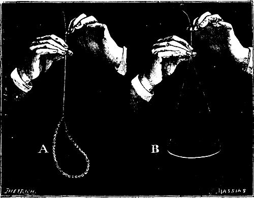
B of the figure gives the exact aspect that the arrangement offers to the eye during the revolution. In the same way, a penholder attached by one of its extremities to a string assumes an almost horizontal position.
This experiment illustrates the principle of centrifugal force.
A Coin Rolling Upon a Parasol.—In treatises upon physics and mechanics inertia is defined as follows: No particle of matter in a state of rest possesses within itself the power of putting itself in motion; or, if it be moving, of bringing itself to a state of rest.
As an example of this principle, we may recall here the trick performed by certain jugglers, and that consists in making a coin roll over the top of a Japanese paper parasol. The parasol is revolved very rapidly, and, to the eyes of the spectator, the coin seems to remain immovable. It is, in reality, the parasol that revolves under the coin.
Breaking Stones with the Fist.—It is through the live force acquired, or inertia at rest, that stones are broken by a blow of the fist. This experiment is performed as follow: The right hand being properly bandaged with a handkerchief, the stone to be broken is taken with the left and allowed to rest upon a larger stone or upon an anvil. Then the stone to be broken is struck with the right fist, while care is taken to raise it a slight distance above the anvil just before the fist touches it. The stone then takes on the velocity of the fist that strikes it, and coming into violent contact with its support, is very promptly broken.
As simple as this experiment is, it always surprises the spectators.
Experiment on Inertia.—It is not impossible to remove from a table set for a guest a large napkin employed in lieu of a table cloth, without disarranging the objects placed upon it. To this effect, it suffices to give the napkin a quick horizontal jerk in stiffening the edges held by the hands.
We recommend our readers to try this experiment only with table ware of slight value, for one cannot always be sure of succeeding immediately. Tinware may be employed very advantageously.
The Dice and the Dice Box.—A dice box and two dice are held in the hand, and the question is to throw one die into the air and catch it in the box. This is not difficult, but the difficulty is to cause the second to enter, for if this be thrown into the air, the first, which is already in the box, will fly into the air likewise and fall outside. In order to make the second enter while the first is already in the box, it must not be thrown into the air, but the hand and the box must be quickly lowered in freeing it, so that the first die, which is in the box, shall be at a less height than the second, which is in the fingers. The dice fall less quickly than the hand and the box.
PUBLISHED WEEKLY.
Terms of Subscription, $5 a Year.
Sent by mail, postage prepaid, to subscribers in any part of the United States or Canada. Six dollars a year, sent, prepaid, to any foreign country.
All the back numbers of THE SUPPLEMENT, from the commencement, January 1, 1876, can be had. Price, 10 cents each.
All the back volumes of THE SUPPLEMENT can likewise be supplied. Two volumes are issued yearly. Price of each volume, $2.50 stitched in paper, or $3.50 bound in stiff covers.
COMBINED RATES.—One copy of SCIENTIFIC AMERICAN and one copy of SCIENTIFIC AMERICAN SUPPLEMENT, one year, postpaid, $7.00.
A liberal discount to booksellers, news agents, and canvassers.
MUNN & CO., Publishers,
361 Broadway, New York, N.Y.
OF THE
Those who contemplate building should not fail to subscribe.
Each number contains elevations and plans of a variety of country houses; also a handsome
MUNN & CO., 361 Broadway, New York.
A Catalogue of Valuable Papers contained in SCIENTIFIC AMERICAN SUPPLEMENT during the past ten years, sent free of charge to any address; also, a comprehensive catalogue of useful books by different authors, on more than fifty different subjects, has recently been published for free circulation, at the office of this paper. Subjects classified with names of authors. Persons desiring a copy have only to ask for it, and it will be mailed to them. Address
MUNN & CO., 301 Broadway, New York.
MESSRS. MUNN & CO., in connection with the publication of the SCIENTIFIC AMERICAN, continue to examine improvements, and to act as Solicitors of Patents for Inventors.
In this line of business they haw had nearly fifty years' experience, and now have unequalled facilities for the preparation of Patent Drawings, Specifications, and the prosecution of Applications for Patents in the United States, Canada, and Foreign Countries. Messrs. Munn & Co. also attend to the preparation of Caveats, Copyrights for Books, Labels, Reissues, Assignments, and Reports on Infringements of Patents. All business intrusted to them is done with special care and promptness, on very reasonable terms.
A pamphlet sent free of charge, on application, containing full information about Patents and how to procure them: directions concerning Labels, Copyrights, Designs, Patents, Appeals, Reissues, Infringements, Assignments, Rejected Cases, Hints on the Sale of Patents, etc.
We also send, free of charge, a Synopsis of Foreign Patent Laws, showing the cost and method of securing patents in all the principal countries of the world.
MUNN & CO., Solicitors of Patents
361 Broadway, New York.
BRANCH OFFICES.—No. 622 and 624 F Street, Pacific Building near 7th Street, Washington, D.C.
End of the Project Gutenberg EBook of Scientific American Supplement, No.
1082, September 26, 1896, by Various

*** END OF THIS PROJECT GUTENBERG EBOOK SCIENTIFIC AMERICAN ***

***** This file should be named 24323-h.htm or 24323-h.zip *****
This and all associated files of various formats will be found in:
        http://www.gutenberg.org/2/4/3/2/24323/

Produced by Juliet Sutherland, Priscilla Walmsley, and the
Online Distributed Proofreading Team at www.pgdp.net


Updated editions will replace the previous one--the old editions
will be renamed.

Creating the works from public domain print editions means that no
one owns a United States copyright in these works, so the Foundation
(and you!) can copy and distribute it in the United States without
permission and without paying copyright royalties.  Special rules,
set forth in the General Terms of Use part of this license, apply to
copying and distributing Project Gutenberg-tm electronic works to
protect the PROJECT GUTENBERG-tm concept and trademark.  Project
Gutenberg is a registered trademark, and may not be used if you
charge for the eBooks, unless you receive specific permission.  If you
do not charge anything for copies of this eBook, complying with the
rules is very easy.  You may use this eBook for nearly any purpose
such as creation of derivative works, reports, performances and
research.  They may be modified and printed and given away--you may do
practically ANYTHING with public domain eBooks.  Redistribution is
subject to the trademark license, especially commercial
redistribution.


*** START: FULL LICENSE ***

THE FULL PROJECT GUTENBERG LICENSE
PLEASE READ THIS BEFORE YOU DISTRIBUTE OR USE THIS WORK

To protect the Project Gutenberg-tm mission of promoting the free
distribution of electronic works, by using or distributing this work
(or any other work associated in any way with the phrase "Project
Gutenberg"), you agree to comply with all the terms of the Full Project
Gutenberg-tm License (available with this file or online at
http://gutenberg.org/license).


Section 1.  General Terms of Use and Redistributing Project Gutenberg-tm
electronic works

1.A.  By reading or using any part of this Project Gutenberg-tm
electronic work, you indicate that you have read, understand, agree to
and accept all the terms of this license and intellectual property
(trademark/copyright) agreement.  If you do not agree to abide by all
the terms of this agreement, you must cease using and return or destroy
all copies of Project Gutenberg-tm electronic works in your possession.
If you paid a fee for obtaining a copy of or access to a Project
Gutenberg-tm electronic work and you do not agree to be bound by the
terms of this agreement, you may obtain a refund from the person or
entity to whom you paid the fee as set forth in paragraph 1.E.8.

1.B.  "Project Gutenberg" is a registered trademark.  It may only be
used on or associated in any way with an electronic work by people who
agree to be bound by the terms of this agreement.  There are a few
things that you can do with most Project Gutenberg-tm electronic works
even without complying with the full terms of this agreement.  See
paragraph 1.C below.  There are a lot of things you can do with Project
Gutenberg-tm electronic works if you follow the terms of this agreement
and help preserve free future access to Project Gutenberg-tm electronic
works.  See paragraph 1.E below.

1.C.  The Project Gutenberg Literary Archive Foundation ("the Foundation"
or PGLAF), owns a compilation copyright in the collection of Project
Gutenberg-tm electronic works.  Nearly all the individual works in the
collection are in the public domain in the United States.  If an
individual work is in the public domain in the United States and you are
located in the United States, we do not claim a right to prevent you from
copying, distributing, performing, displaying or creating derivative
works based on the work as long as all references to Project Gutenberg
are removed.  Of course, we hope that you will support the Project
Gutenberg-tm mission of promoting free access to electronic works by
freely sharing Project Gutenberg-tm works in compliance with the terms of
this agreement for keeping the Project Gutenberg-tm name associated with
the work.  You can easily comply with the terms of this agreement by
keeping this work in the same format with its attached full Project
Gutenberg-tm License when you share it without charge with others.

1.D.  The copyright laws of the place where you are located also govern
what you can do with this work.  Copyright laws in most countries are in
a constant state of change.  If you are outside the United States, check
the laws of your country in addition to the terms of this agreement
before downloading, copying, displaying, performing, distributing or
creating derivative works based on this work or any other Project
Gutenberg-tm work.  The Foundation makes no representations concerning
the copyright status of any work in any country outside the United
States.

1.E.  Unless you have removed all references to Project Gutenberg:

1.E.1.  The following sentence, with active links to, or other immediate
access to, the full Project Gutenberg-tm License must appear prominently
whenever any copy of a Project Gutenberg-tm work (any work on which the
phrase "Project Gutenberg" appears, or with which the phrase "Project
Gutenberg" is associated) is accessed, displayed, performed, viewed,
copied or distributed:

This eBook is for the use of anyone anywhere at no cost and with
almost no restrictions whatsoever.  You may copy it, give it away or
re-use it under the terms of the Project Gutenberg License included
with this eBook or online at www.gutenberg.org

1.E.2.  If an individual Project Gutenberg-tm electronic work is derived
from the public domain (does not contain a notice indicating that it is
posted with permission of the copyright holder), the work can be copied
and distributed to anyone in the United States without paying any fees
or charges.  If you are redistributing or providing access to a work
with the phrase "Project Gutenberg" associated with or appearing on the
work, you must comply either with the requirements of paragraphs 1.E.1
through 1.E.7 or obtain permission for the use of the work and the
Project Gutenberg-tm trademark as set forth in paragraphs 1.E.8 or
1.E.9.

1.E.3.  If an individual Project Gutenberg-tm electronic work is posted
with the permission of the copyright holder, your use and distribution
must comply with both paragraphs 1.E.1 through 1.E.7 and any additional
terms imposed by the copyright holder.  Additional terms will be linked
to the Project Gutenberg-tm License for all works posted with the
permission of the copyright holder found at the beginning of this work.

1.E.4.  Do not unlink or detach or remove the full Project Gutenberg-tm
License terms from this work, or any files containing a part of this
work or any other work associated with Project Gutenberg-tm.

1.E.5.  Do not copy, display, perform, distribute or redistribute this
electronic work, or any part of this electronic work, without
prominently displaying the sentence set forth in paragraph 1.E.1 with
active links or immediate access to the full terms of the Project
Gutenberg-tm License.

1.E.6.  You may convert to and distribute this work in any binary,
compressed, marked up, nonproprietary or proprietary form, including any
word processing or hypertext form.  However, if you provide access to or
distribute copies of a Project Gutenberg-tm work in a format other than
"Plain Vanilla ASCII" or other format used in the official version
posted on the official Project Gutenberg-tm web site (www.gutenberg.org),
you must, at no additional cost, fee or expense to the user, provide a
copy, a means of exporting a copy, or a means of obtaining a copy upon
request, of the work in its original "Plain Vanilla ASCII" or other
form.  Any alternate format must include the full Project Gutenberg-tm
License as specified in paragraph 1.E.1.

1.E.7.  Do not charge a fee for access to, viewing, displaying,
performing, copying or distributing any Project Gutenberg-tm works
unless you comply with paragraph 1.E.8 or 1.E.9.

1.E.8.  You may charge a reasonable fee for copies of or providing
access to or distributing Project Gutenberg-tm electronic works provided
that

- You pay a royalty fee of 20% of the gross profits you derive from
     the use of Project Gutenberg-tm works calculated using the method
     you already use to calculate your applicable taxes.  The fee is
     owed to the owner of the Project Gutenberg-tm trademark, but he
     has agreed to donate royalties under this paragraph to the
     Project Gutenberg Literary Archive Foundation.  Royalty payments
     must be paid within 60 days following each date on which you
     prepare (or are legally required to prepare) your periodic tax
     returns.  Royalty payments should be clearly marked as such and
     sent to the Project Gutenberg Literary Archive Foundation at the
     address specified in Section 4, "Information about donations to
     the Project Gutenberg Literary Archive Foundation."

- You provide a full refund of any money paid by a user who notifies
     you in writing (or by e-mail) within 30 days of receipt that s/he
     does not agree to the terms of the full Project Gutenberg-tm
     License.  You must require such a user to return or
     destroy all copies of the works possessed in a physical medium
     and discontinue all use of and all access to other copies of
     Project Gutenberg-tm works.

- You provide, in accordance with paragraph 1.F.3, a full refund of any
     money paid for a work or a replacement copy, if a defect in the
     electronic work is discovered and reported to you within 90 days
     of receipt of the work.

- You comply with all other terms of this agreement for free
     distribution of Project Gutenberg-tm works.

1.E.9.  If you wish to charge a fee or distribute a Project Gutenberg-tm
electronic work or group of works on different terms than are set
forth in this agreement, you must obtain permission in writing from
both the Project Gutenberg Literary Archive Foundation and Michael
Hart, the owner of the Project Gutenberg-tm trademark.  Contact the
Foundation as set forth in Section 3 below.

1.F.

1.F.1.  Project Gutenberg volunteers and employees expend considerable
effort to identify, do copyright research on, transcribe and proofread
public domain works in creating the Project Gutenberg-tm
collection.  Despite these efforts, Project Gutenberg-tm electronic
works, and the medium on which they may be stored, may contain
"Defects," such as, but not limited to, incomplete, inaccurate or
corrupt data, transcription errors, a copyright or other intellectual
property infringement, a defective or damaged disk or other medium, a
computer virus, or computer codes that damage or cannot be read by
your equipment.

1.F.2.  LIMITED WARRANTY, DISCLAIMER OF DAMAGES - Except for the "Right
of Replacement or Refund" described in paragraph 1.F.3, the Project
Gutenberg Literary Archive Foundation, the owner of the Project
Gutenberg-tm trademark, and any other party distributing a Project
Gutenberg-tm electronic work under this agreement, disclaim all
liability to you for damages, costs and expenses, including legal
fees.  YOU AGREE THAT YOU HAVE NO REMEDIES FOR NEGLIGENCE, STRICT
LIABILITY, BREACH OF WARRANTY OR BREACH OF CONTRACT EXCEPT THOSE
PROVIDED IN PARAGRAPH F3.  YOU AGREE THAT THE FOUNDATION, THE
TRADEMARK OWNER, AND ANY DISTRIBUTOR UNDER THIS AGREEMENT WILL NOT BE
LIABLE TO YOU FOR ACTUAL, DIRECT, INDIRECT, CONSEQUENTIAL, PUNITIVE OR
INCIDENTAL DAMAGES EVEN IF YOU GIVE NOTICE OF THE POSSIBILITY OF SUCH
DAMAGE.

1.F.3.  LIMITED RIGHT OF REPLACEMENT OR REFUND - If you discover a
defect in this electronic work within 90 days of receiving it, you can
receive a refund of the money (if any) you paid for it by sending a
written explanation to the person you received the work from.  If you
received the work on a physical medium, you must return the medium with
your written explanation.  The person or entity that provided you with
the defective work may elect to provide a replacement copy in lieu of a
refund.  If you received the work electronically, the person or entity
providing it to you may choose to give you a second opportunity to
receive the work electronically in lieu of a refund.  If the second copy
is also defective, you may demand a refund in writing without further
opportunities to fix the problem.

1.F.4.  Except for the limited right of replacement or refund set forth
in paragraph 1.F.3, this work is provided to you 'AS-IS' WITH NO OTHER
WARRANTIES OF ANY KIND, EXPRESS OR IMPLIED, INCLUDING BUT NOT LIMITED TO
WARRANTIES OF MERCHANTIBILITY OR FITNESS FOR ANY PURPOSE.

1.F.5.  Some states do not allow disclaimers of certain implied
warranties or the exclusion or limitation of certain types of damages.
If any disclaimer or limitation set forth in this agreement violates the
law of the state applicable to this agreement, the agreement shall be
interpreted to make the maximum disclaimer or limitation permitted by
the applicable state law.  The invalidity or unenforceability of any
provision of this agreement shall not void the remaining provisions.

1.F.6.  INDEMNITY - You agree to indemnify and hold the Foundation, the
trademark owner, any agent or employee of the Foundation, anyone
providing copies of Project Gutenberg-tm electronic works in accordance
with this agreement, and any volunteers associated with the production,
promotion and distribution of Project Gutenberg-tm electronic works,
harmless from all liability, costs and expenses, including legal fees,
that arise directly or indirectly from any of the following which you do
or cause to occur: (a) distribution of this or any Project Gutenberg-tm
work, (b) alteration, modification, or additions or deletions to any
Project Gutenberg-tm work, and (c) any Defect you cause.


Section  2.  Information about the Mission of Project Gutenberg-tm

Project Gutenberg-tm is synonymous with the free distribution of
electronic works in formats readable by the widest variety of computers
including obsolete, old, middle-aged and new computers.  It exists
because of the efforts of hundreds of volunteers and donations from
people in all walks of life.

Volunteers and financial support to provide volunteers with the
assistance they need, is critical to reaching Project Gutenberg-tm's
goals and ensuring that the Project Gutenberg-tm collection will
remain freely available for generations to come.  In 2001, the Project
Gutenberg Literary Archive Foundation was created to provide a secure
and permanent future for Project Gutenberg-tm and future generations.
To learn more about the Project Gutenberg Literary Archive Foundation
and how your efforts and donations can help, see Sections 3 and 4
and the Foundation web page at http://www.pglaf.org.


Section 3.  Information about the Project Gutenberg Literary Archive
Foundation

The Project Gutenberg Literary Archive Foundation is a non profit
501(c)(3) educational corporation organized under the laws of the
state of Mississippi and granted tax exempt status by the Internal
Revenue Service.  The Foundation's EIN or federal tax identification
number is 64-6221541.  Its 501(c)(3) letter is posted at
http://pglaf.org/fundraising.  Contributions to the Project Gutenberg
Literary Archive Foundation are tax deductible to the full extent
permitted by U.S. federal laws and your state's laws.

The Foundation's principal office is located at 4557 Melan Dr. S.
Fairbanks, AK, 99712., but its volunteers and employees are scattered
throughout numerous locations.  Its business office is located at
809 North 1500 West, Salt Lake City, UT 84116, (801) 596-1887, email
business@pglaf.org.  Email contact links and up to date contact
information can be found at the Foundation's web site and official
page at http://pglaf.org

For additional contact information:
     Dr. Gregory B. Newby
     Chief Executive and Director
     gbnewby@pglaf.org


Section 4.  Information about Donations to the Project Gutenberg
Literary Archive Foundation

Project Gutenberg-tm depends upon and cannot survive without wide
spread public support and donations to carry out its mission of
increasing the number of public domain and licensed works that can be
freely distributed in machine readable form accessible by the widest
array of equipment including outdated equipment.  Many small donations
($1 to $5,000) are particularly important to maintaining tax exempt
status with the IRS.

The Foundation is committed to complying with the laws regulating
charities and charitable donations in all 50 states of the United
States.  Compliance requirements are not uniform and it takes a
considerable effort, much paperwork and many fees to meet and keep up
with these requirements.  We do not solicit donations in locations
where we have not received written confirmation of compliance.  To
SEND DONATIONS or determine the status of compliance for any
particular state visit http://pglaf.org

While we cannot and do not solicit contributions from states where we
have not met the solicitation requirements, we know of no prohibition
against accepting unsolicited donations from donors in such states who
approach us with offers to donate.

International donations are gratefully accepted, but we cannot make
any statements concerning tax treatment of donations received from
outside the United States.  U.S. laws alone swamp our small staff.

Please check the Project Gutenberg Web pages for current donation
methods and addresses.  Donations are accepted in a number of other
ways including checks, online payments and credit card donations.
To donate, please visit: http://pglaf.org/donate


Section 5.  General Information About Project Gutenberg-tm electronic
works.

Professor Michael S. Hart is the originator of the Project Gutenberg-tm
concept of a library of electronic works that could be freely shared
with anyone.  For thirty years, he produced and distributed Project
Gutenberg-tm eBooks with only a loose network of volunteer support.


Project Gutenberg-tm eBooks are often created from several printed
editions, all of which are confirmed as Public Domain in the U.S.
unless a copyright notice is included.  Thus, we do not necessarily
keep eBooks in compliance with any particular paper edition.


Most people start at our Web site which has the main PG search facility:

     http://www.gutenberg.org

This Web site includes information about Project Gutenberg-tm,
including how to make donations to the Project Gutenberg Literary
Archive Foundation, how to help produce our new eBooks, and how to
subscribe to our email newsletter to hear about new eBooks.