The Project Gutenberg EBook of Woodwork Joints, by William Fairham

This eBook is for the use of anyone anywhere at no cost and with
almost no restrictions whatsoever.  You may copy it, give it away or
re-use it under the terms of the Project Gutenberg License included
with this eBook or online at www.gutenberg.org


Title: Woodwork Joints
       How they are Set Out, How Made and Where Used.

Author: William Fairham

Release Date: May 19, 2007 [EBook #21531]

Language: English

Character set encoding: ISO-8859-1

*** START OF THIS PROJECT GUTENBERG EBOOK WOODWORK JOINTS ***


Produced by Chris Curnow and the Online Distributed
Proofreading Team at http://www.pgdp.net
| WOODWORK JOINTS. |
| CABINET CONSTRUCTION. |
| STAINING AND POLISHING. |
| WOODWORK TOOLS. |
| PRACTICAL UPHOLSTERY. |
| WOOD TURNING. |
| WOODCARVING. |
| TIMBERS FOR WOODWORK. |
| FURNITURE REPAIRING AND RE-UPHOLSTERY. |
| HOUSEHOLD REPAIRS AND RENOVATIONS. |
| CARPENTRY FOR BEGINNERS. |
| KITCHEN FURNITURE DESIGNS. |
| BUREAU AND BOOKCASE DESIGNS. |
| LIGHT CARPENTRY DESIGNS. |
| DOORMAKING. |
To be successful in woodwork construction the possession of two secrets is essential—to know the right joint to use, and to know how to make that joint in the right way. The woodwork structure or the piece of cabinet-work that endures is the one on which skilful hands have combined to carry out what the constructive mind planned. And it is just here that the present Volume will help, not alone the beginner who wishes preliminary instruction, but also the expert who desires guidance over ground hitherto unexplored by him.
In the preparation of this new edition the Publishers have secured the services of Mr. William Fairham, by whom the chapters have been carefully revised and re-illustrated. Although intended for the practical man, and not professing to be a graded course of "educational woodwork," the Volume is one which Handicraft Instructors will find of the greatest value in conducting woodwork classes. No book hitherto published contains such a variety of illustrations of joints, almost all of which will form suitable exercises of practical educational importance in a woodworking course.
J. C. S. B.
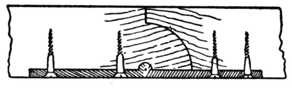
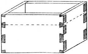
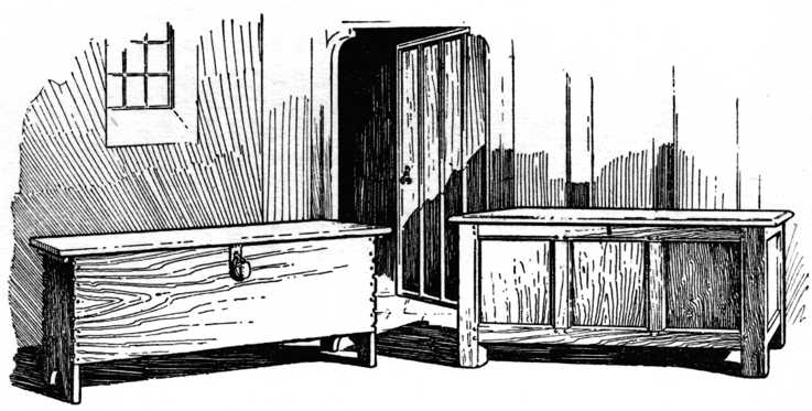 Old Oak Chests, showing the Method of Structure
which forms the origin of most of our English Furniture.
Old Oak Chests, showing the Method of Structure
which forms the origin of most of our English Furniture.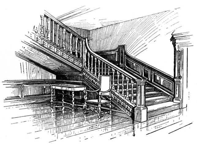 Staircase of the Second Half of Seventeenth Century.
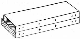
The glued joint in its various forms is in use in every country in the world, and is frequently met with in mummy cases and other examples of ancient woodwork. Alternative names under which it is known are the butt joint, the rubbed joint, the slipped joint, whilst in certain localities it is known as the slaped (pronounced slayped) joint.
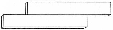
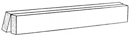
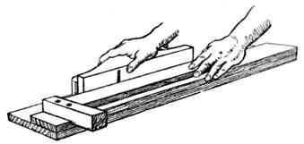
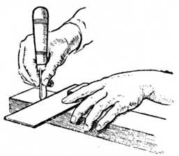
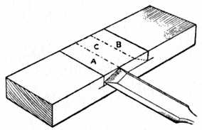
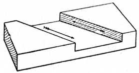
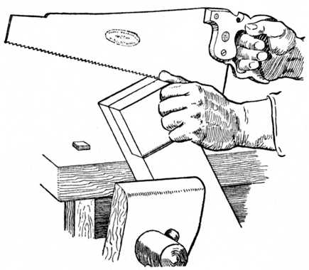
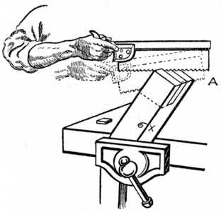
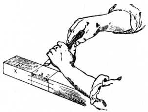
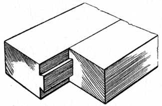
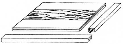
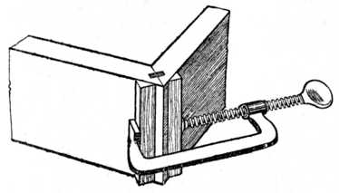
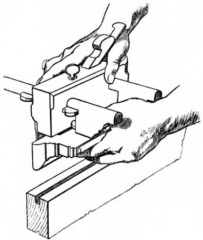
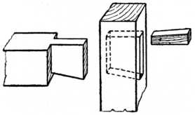
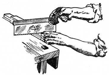
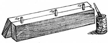
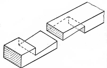
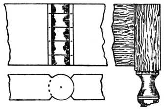
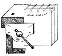
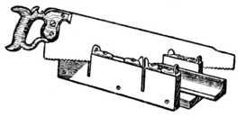
The glued joint is made by planing two pieces of timber so that when placed together they are in contact with each other at every point; they are then usually united with glue. Fig. 1 shows a sketch of a butt joint in its simplest form. In Fig. 2 is indicated the method of holding the joint whilst being glued; the upright portion is held rigid in the bench vice, thus leaving the left hand to hold the piece which is to be jointed, whilst the right hand operates the glue brush. The pieces of wood which form a butt joint may be glued together with or without the aid of cramps or artificial pressure. If the joint is to be made without cramping, the two surfaces of the timber are warmed so as not to chill the[Pg 2] glue. The surfaces are then glued and put together and rubbed backwards and forwards so as to get rid of the superfluous glue. They are then put aside to dry.
Glueing.—The better the glue penetrates into the pores of the wood, the stronger the joint will be; for this reason timber of the loose-fibred variety, such as pine, etc., will hold up at the joint better than hardwoods like teak and rosewood. The glue used for jointing should be neither too thick nor too thin; the consistency of cream will be found suitable for most purposes. It should be nice and hot, and be rapidly spread over the surface of the wood.
If light-coloured woods, such as pine, satinwood, sycamore, etc., have to be jointed, a little flake white should be procured and mixed into the liquid glue. This will prevent the glue showing a thin black line on the joint.
Broad surfaces of close-grained hardwood having a shiny surface are usually carefully roughened with a fine toothing plane blade previous to glueing.
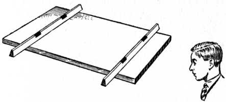
Supporting the Joint.—The jointed boards should not be reared up against a "bench leg" or wall without having any support in the centre, as dotted line at Fig. 5, because in all probability they will fracture before the glue has time to set; and, when we go to take them up to renew working operations, we shall be[Pg 3] annoyed to find that they have assumed a position similar to that at Fig. 5 (shown exaggerated), and this will, of course, necessitate re-jointing.
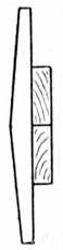
Fig. 3.—Correct Jointing. |
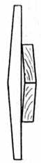
Fig. 4.—Faulty Jointing. |
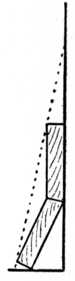
Fig. 5.—Boards unsupported. |
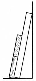
Fig. 6.—Boards supported. |
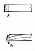
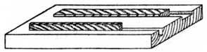
Fig. 7.—(A) Glued Slip, (B) Glued Moulding. |
Fig. 8.—Grain alternating. |
A correct method to adopt is seen at Fig. 6. Here we have supported the joint by rearing up against the wall[Pg 4] a couple of pieces of batten, one at each end of the board, thus supporting it throughout its entire width until the glue is thoroughly set. The two or more pieces of timber in a butt joint adhere by crystallisation of the glue and atmospheric pressure. A well-fitted joint made with good quality glue is so strong that, when boards of 3 feet and upwards are jointed together by this method, the timber in most cases will break with the grain sooner than part at the joint.
Butt joints may be cramped up, if desired, and it is customary to warm them as previously stated. In the absence of the usual iron cramp, the amateur may make an excellent wooden arrangement out of any odd pieces of timber that happen to be handy. Two blocks of hardwood are screwed on the base board at a suitable distance for the work in hand; the boards to be jointed are glued and placed in position between the blocks; and the two hardwood wedges are inserted and hammered in opposite directions to each other, thus exerting the desired pressure. An example of this method of cramping is shown in Fig. 25, which also indicates the use of iron "dogs."
When jointing, care should be taken to first plane up the boards true on one side—i.e., take them out of winding. The method of testing for this is shown at Fig. 9, and it may with advantage be used when jointing the edges of the boards. Two laths or strips of wood are planed up to exactly the same width, having their edges straight and parallel. One edge of each lath may, if desired, be bevelled a little. The method of using these "twist sticks" or "winding laths" is to put them on the board as indicated, and sight along their top edges. The winding laths, being much longer than the width of the board, show up the irregularity greatly pronounced.[Pg 5]
The Tools generally used for making the butt joints are:—
The jack plane, for roughing the edges, etc.
The wooden trying plane (or iron jointing plane) for trueing up the work.
The try square for testing purposes.
The winding laths and straight edge.
The Method of Work is as follows: Each board is in turn put in the vice and planed straight lengthwise; it is then tested with winding laths and a try square (the latter method is shown at Fig. 22).
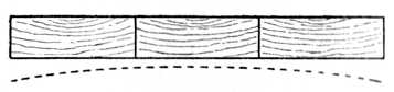
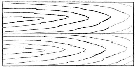
The boards are then put on the top of one another as at Fig. 1 and tested with a straight edge; they should appear true as shown at Fig. 3; if they show faulty as at Fig. 4 the joints must be again fitted until the required degree of accuracy is obtained. Difficulties may be avoided by care in selecting timber suitable for jointing, and it must be remembered that timber shrinks circumferentially (the heart side becoming curved) as dotted lines in Fig. 10. If the timber be jointed with all the heart side one way as at Fig. 10, the tendency will be for it to cast as shown by the[Pg 6] dotted line. If the timber be alternated as at Fig. 11, the tendency will be to cast wavy, whereas if quartered timber can be obtained it will stand practically straight as the tendency to shrink is in thickness only. The grain of quartered timber is shown in Fig. 12.
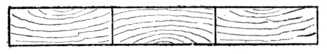
Fig. 11.—Heart side of Timber shown alternated. |
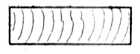
Fig. 12.—Grain of Quartered Timber. |
Judgment should also be exercised to avoid jointing in which one piece of timber is wild and large in the grain, and the adjoining piece of a mild-grained nature. Jointed boards should always be glued up with the[Pg 7] grain running in the same direction if possible; this we show at Fig. 13, and nothing looks worse than a dressing chest end or similar piece of work in which the grain runs haphazard. When jointing thin timber (say, 1⁄4-in., 3⁄8-in., 1⁄2-in. and 5⁄8-in. boards) the best method is to use a shooting board (Fig. 26). It must be noted, however, that a shooting board and plane practically never give a true right angle, owing to wear and the grinding of the blade. Therefore, the boards should not all be laid with the "face mark" on the shooting board whilst the edges are shot, because any inequality would be multiplied by the number of pieces jointed. A better method is to alternate the boards, face side up, then face side down, whilst shooting the edges; this will prevent convexity or concavity on the face of the jointed board, because any slight error in the angle is neutralised (see Fig. 8).
Applications of the Joint.—The following show various applications of the butt or glued joint:—
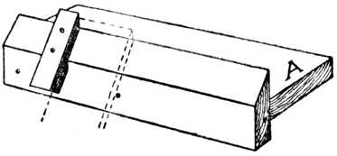
Fig. 7A shows a mahogany or other hardwood slip glued on the edge of a cheaper wood, such as pine or whitewood, as is the case on bookcase shelves when only the front edge is seen and polished.
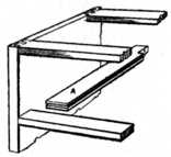
Fig. 7B shows a moulding glued on a shelf, both mould and shelf in this instance being of polished hardwood. A shelf of this type might be used in a recess, the object of the overhanging moulding being to hide a small 3⁄8-in. iron rod which would carry the curtain[Pg 8] rings and heading of the curtain which covers the recess. The shelf would be fixed about 3 ft. 9 ins. to 4 ft. 3 ins. from the floor.
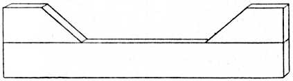
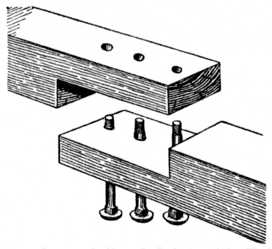
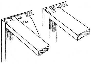
Fig. 14 shows the wing pieces glued on the top bearer of carcase work. The application of this bearer in its position will be shown in the chapter on Dovetailing.
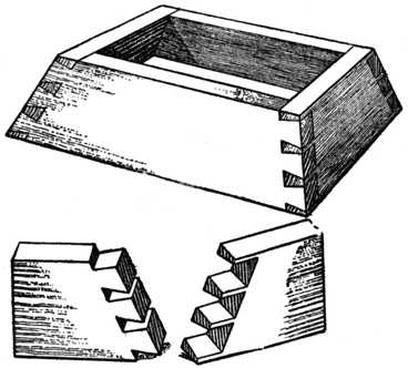
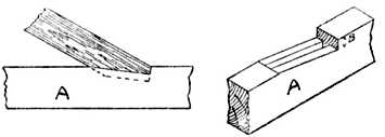
Fig. 15 shows a butt joint planed at an angle of 45 degrees (commonly called a mitre), used for box feet, etc.
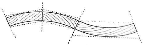
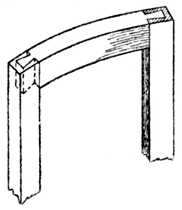
Fig. 16 shows jointing up of an ogee-shaped panel. The dotted lines indicate the thickness of the timber previous to its being worked up to the finished shape. Bow-fronted and semicircular panels are jointed in a similar manner.
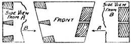
Fig. 17 shows timber jointed at right angles to the upright piece, and at an angle of 30 degrees.[Pg 9]
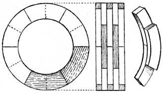
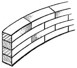
Fig. 18 indicates quarter-circle jointing, as used in round-cornered chests of drawers, wardrobes, cupboards, etc.
Fig. 19 is similar to Fig. 18, but with hollow (or concave) corners.
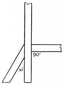
Fig. 17.—Jointed Timber at 30° and 90° angles. |
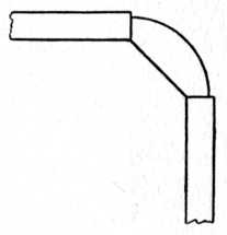
Fig. 18.—Convex Corner. |
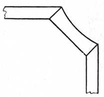
Fig. 19.—Concave Corner. |
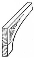
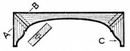
Fig. 20.—Jointing a shaped Spandrel. |
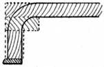
Fig. 21.—Building up Case of Piano Front. |
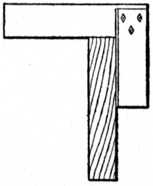
Fig. 22.—Use of the Try-square for Testing Edge. |
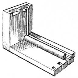
Fig. 24.—Glueing Ploughslips to Drawer. |
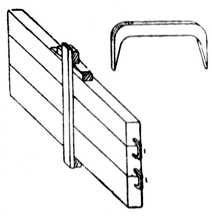
Fig. 25.—Method of holding Glued Joints with Iron Dogs. |
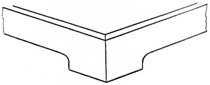
Fig. 20 gives us the jointing up of a shaped spandrel to the required width. In a case of this description suitably grained and coloured wood should be selected, otherwise the bad match will at once draw attention to the joint.
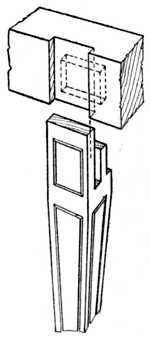
Fig. 21 shows the application of butt or glued jointing to the building up of the core of a piano fall previous to shaping up and veneering.
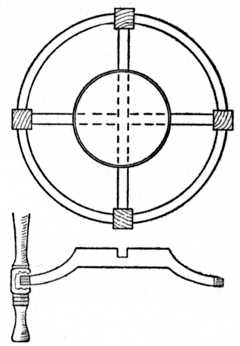
Fig. 23.—Laminated work—the building up of circular rims for cabinet and joinery work. Plan and elevation show rim pattern of a pulley as used in the pattern-making trade.
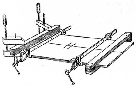 Fig. 27.—Cramping Glued Joints: Handscrews and
Batten shown at left; temporary Batten at right to
keep the wood flat.
Fig. 27.—Cramping Glued Joints: Handscrews and
Batten shown at left; temporary Batten at right to
keep the wood flat.
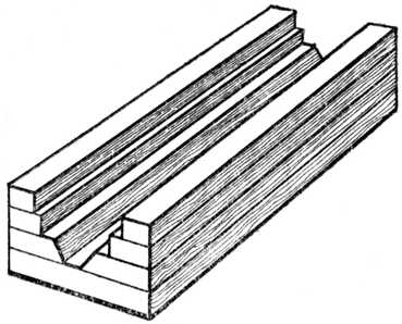
Fig. 24.—The glueing of a ploughslip to a drawer side is seen here, the ploughslip being used to carry the drawer bottom.
Fig. 26 shows the method of jointing with shooting board and trying plane; the right hand operates the[Pg 12] plane whilst the left hand holds the wood firm upon the shooting board.
Owing to the importation of narrow and faulty timber the necessity of jointing is greater to-day than ever it was, wide timber of course meaning higher cost for raw material.
The method of using iron dogs is illustrated in Fig. 25, and it will be observed that owing to the wedge-like formation of each fang (see enlarged sketch) the dog exerts the necessary pressure to close the joint. At the centre of this illustration is suggested the home-made hardwood blocks, baseboard and wedges referred to on page 4.
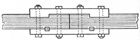
Fig. 27 shows how the iron sash cramps are used to apply pressure to the joint. As this method is in some cases apt to bend and distort thin boards it is wise practice to fix (as a temporary measure) a stout piece of straight wood on to the board to be joined by using two handscrews as shown at the left hand of the illustration. At the right hand of the sketch a wooden cramping arrangement of the box type is given, and by wedging up the boards are closed together. It is obvious that if this type of box cramp be used it will prevent the boards buckling and the handscrew method at the left may be dispensed with.[Pg 13]
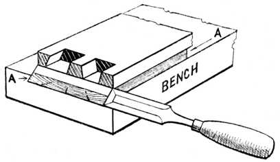
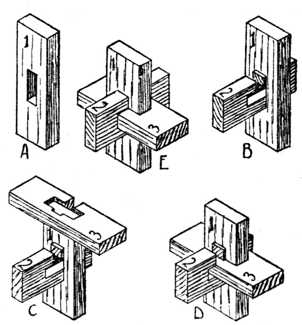
T he halved joint is frequently known as half-lapping, and sometimes as checking and half-checking. In the majority of cases it is made by halving the two pieces, i.e., by cutting half the depth of the wood away. There are, however, exceptions to this rule, as in the case of "three-piece halving" (or, as it is sometimes called, "third lapping") and in the halving of timber with rebated or moulded edges. Halving is one of the simplest methods of connecting two pieces of timber, especially where it is desired to make frames and bracket supports for either inside or outside use.
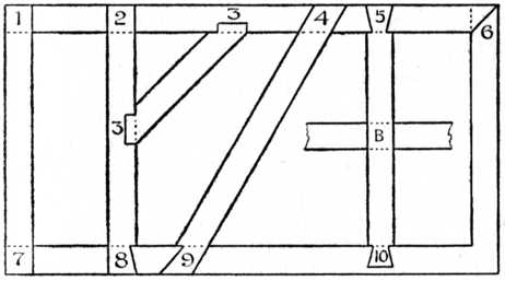 Fig. 28.—Frame, with various halved joints. These joints,
numbered 1, 2, 3, etc., are shown in detail in Figs.
29 to 38.
Fig. 28.—Frame, with various halved joints. These joints,
numbered 1, 2, 3, etc., are shown in detail in Figs.
29 to 38.
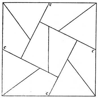
Fig. 28 shows the elevation of an imaginary frame which is indicated as made up of a number of halving joints; it shows also the application of the various joints to this class of work. Each joint used in the construction of this frame may be dealt with separately. The numbers marked on Fig. 28 refer to the individual joints, shown separately in Figs. 29 to 38.
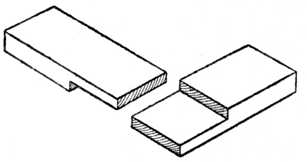
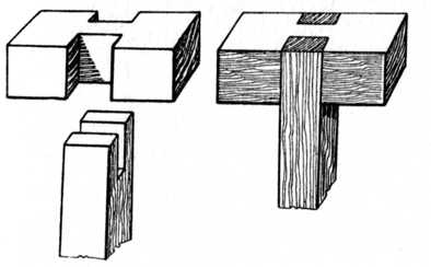
Fig. 29.—Halved Corner Joint. |
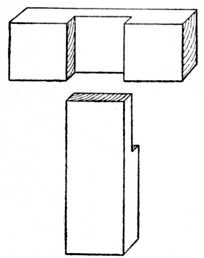
Fig. 30.—Halved T Joint. |
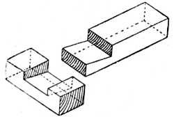
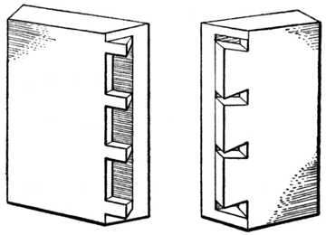
Fig. 29 shows the "Halved Joint" at the corner of the frame where the two pieces form a right angle (see Fig. 28, 1). Each piece is halved and shouldered at opposite sides, thus forming a perfect fit one with the other and giving a strong joint with a minimum amount of labour. For inside work the joint would be glued and screwed together, the screw heads being countersunk so as not to come in contact with the cutting iron of the plane when levelling off the work. For outside work, in exposed positions where the work will have to withstand the weather, the alternative method of smearing the joint with paint or with a mixture of varnish and white lead would be advisable, the joint[Pg 15] being nailed or screwed. Fig. 29 shows the two pieces separated.
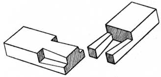
Fig. 30 shows a similar joint to the above, but in this case the top rail runs through and it is generally spoken of as a "Halved T Joint" (Fig. 28, 2). It may be used in nearly all cases where a top or bottom rail runs through an upright. The method of securing the joint is as before. Fig. 30 shows a sketch of the joint separated.
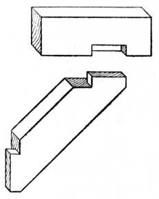
Fig. 31.—Oblique Halving with Shoulder. |
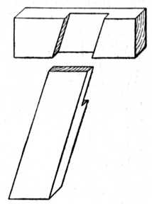
Fig. 32.—Oblique Halving. |
At Fig. 31 is shown an "Oblique Halving Joint," where the oblique piece, or strut, does not run through (Fig. 28, 3). This type of joint is used for strengthening framings and shelf brackets; an example of the latter is shown at Fig. 48. A strut or rail of this type prevents movement or distortion to a frame diagonally (generally spoken of in the trade as "racking"). Fig. 31 shows the joint apart.
Fig. 32 is an example of Oblique Halving with the upper piece running through (Fig. 28, 4). This joint is[Pg 16] used in similar positions to Fig. 31, and has in some cases the disadvantage of showing end grain at the top of the frame. The sketch shows the two pieces separated.
Fig. 33 is "Dovetail Halving," the dovetail running through the top piece (Fig. 28, 5). This is a strong joint, used where outside strain is likely to occur in the top piece, the dovetail preventing the rail from being drawn away from the shoulder. The two pieces are shown separate.
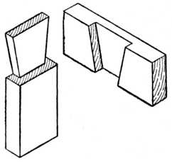
Fig. 33.—Dovetail Halving. |
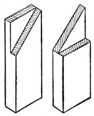
Fig. 34.—Mitre Halving. |
At Fig. 34 is seen "Mitred Halving," a somewhat weak joint, but necessary in mirror frames, etc., where good appearance is required on the face side (Fig. 28, 6). Its use is obvious if the face of the frame be moulded with beads or other sections which require to intersect one with the other. This also applies if the frame be moulded on its face edges.
Fig. 35 is a halved joint with one side of the piece dovetailed (Fig. 28, 8). This joint is used in similar positions to Fig. 33, and rather less labour is required in the making. The two pieces are shown separate for clearness.[Pg 17]
Fig. 36 indicates the "Halved Joint," the pieces at one end showing a double dovetail (Fig. 28, 7). This particular joint is seldom used except for Manual Training purposes. The illustration shows a sketch of the joint apart.
Fig. 37 is "Oblique Dovetail Halving," one side of the piece being dovetailed. The joint is used to prevent "racking," and as a cross brace to framing. It is occasionally made with both its sides dovetailed as shown at Fig. 33. (For reference, see Fig. 28, 9).
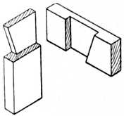
Fig. 35.—Halved Joint with one side Dovetailed. |
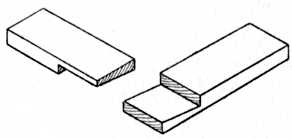
Fig. 36.—Halved Joint with Double Dovetail. |
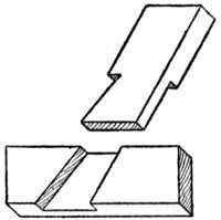
Fig. 37.—Oblique Dovetail Halving. |
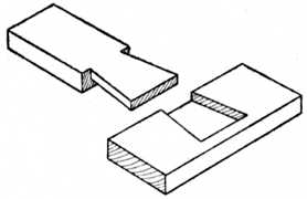
Fig. 38.—Stopped Dovetail Halving. |
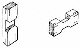
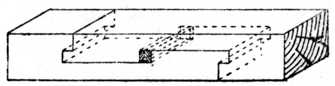
Fig. 38 shows "Stopped Dovetail Halving." In this[Pg 18] case the dovetail is similar to Fig. 33, with the exception that it does not run through the bottom rail. This is an advantage if the bottom edge of the rail is in evidence, or if it is required to glue a moulding or hardwood facing slip on the lower edge. The glue adheres better with the grain than it would end way of the grain, and if slight shrinkage occurs across the width of the bottom rail the moulding would not be forced away by the upright (see example at Fig. 28, 10).
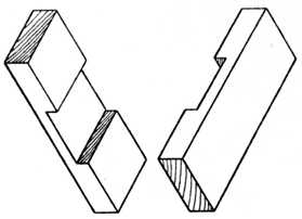
Fig. 39.—Cross Halving Joint. |
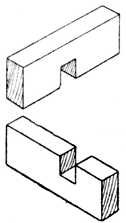
Fig. 40.—Cross Halving Joint Edgeways. |
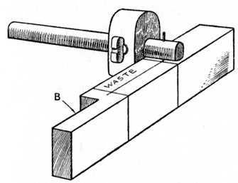
The joint lettered B in Fig. 28 is a "Cross Halving Joint" where each piece runs through the other. Fig. 39[Pg 19] shows this joint separated, and Fig. 40 shows a similar joint separated where the joint is made edgeways.
Fig. 41 shows a "Tee Halving Joint" with a dovetail cut on the edge. This is seldom used except as a woodwork exercise.
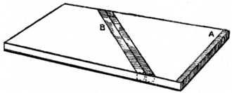
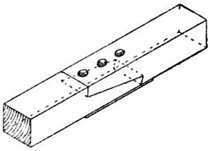
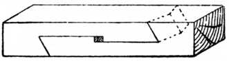
Fig. 42 is a "Dovetailed Halving Joint" used for lengthening timber, and is also a favourite Manual Training model. It might also come under the heading of scarf joint, although rarely used in actual practice as such. As a practical woodwork exercise it calls for accurate marking out and careful fitting.
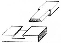
Fig. 43.—Dovetailed and Halved Joint. |
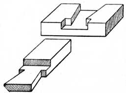
Fig. 44.—Dovetailed Halved Joint with Shoulders. |
Fig. 43 shows a combination of a halved joint dovetailed edgeways, whilst Fig. 44 shows a dovetailed[Pg 20] halved joint with the shoulders housed. This latter is seldom used in actual work.
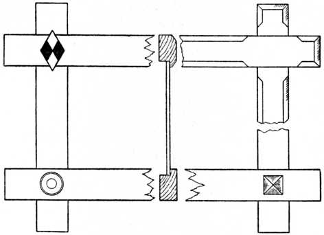
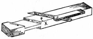
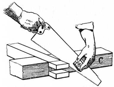
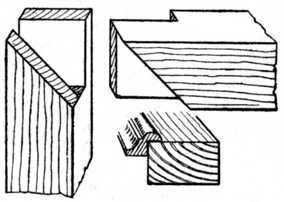
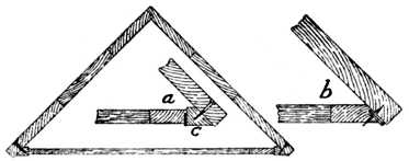
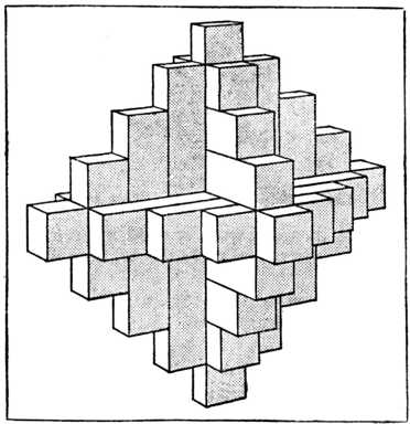
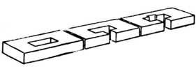
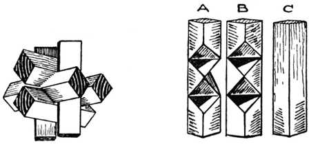
At Fig. 45 we have the application of halving joints when constructing a barrow wheel. The centre portion is an example of three pieces half-lapped or, as it is sometimes called, one-third lapped. A sketch of the three pieces separated is shown at L, B, C, Fig. 46.
This joint is extensively used in the pattern making trade for lap-jointing the arms of pulley patterns, etc. It is probably the most difficult of the halving joints to mark out and construct with the desired degree of accuracy.
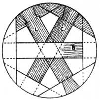
Fig. 45.—Halved Joints on Barrow Wheels. |
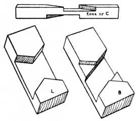
Fig. 46.—Detail of Halved Joints in Fig. 45. |
Fig. 47 shows a combination of a bevelled dovetail half-lapped joint. This is only used as a puzzle joint. When neatly constructed and glued together it is apparently impossible to make it, showing as it does a half lap on one side and a dovetailed half lap on the reverse side.
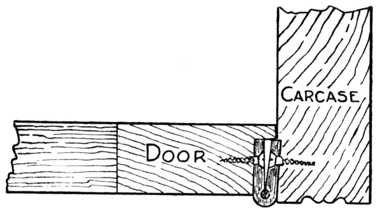
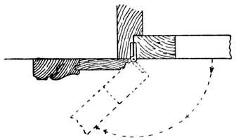
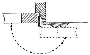
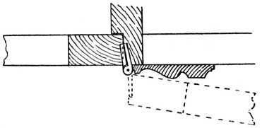
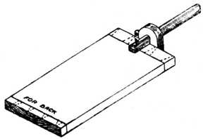
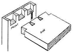
Fig. 48 is the end view of a kitchen table with drop leaf, showing the skirting board scribed to the solid side. A table of this type is fastened to the wall with two iron holdfasts which engage the ends of the table.[Pg 21]
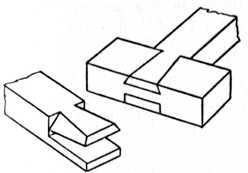
Fig. 47.—Bevelled Dovetailed Half Lap. |
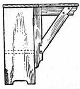
Fig. 48.—Bracket of Drop Table. |
[Pg 22] The hinged bracket frame shows the application of the halving joint to bracket supports for this and similar purposes, such as brackets to support shelving, etc. In this example the hinged brackets turn underneath the table top, and allow the leaf to drop out of the way when not required. The dotted lines show the position of a shelf for boots and shoes.
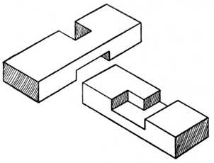
Fig. 52.—Manual Training Halved Exercise Joint. |
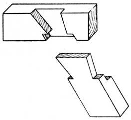
Fig. 53.—Exercise Dovetail Joint. |
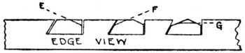
Figs. 49 and 50 indicate the halving of cross pieces which have their edges moulded; the pieces are shown separately, the moulding being omitted to give a clearer representation of the method of construction.
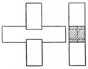
Fig. 55.—Cross Halving Joint with Housed Corners. |
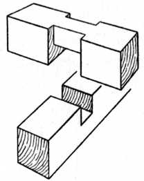
Fig. 56.—The parts of Fig. 55 shown separate. |
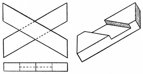
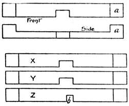
Fig. 51 is an "Oblique Cross Halving Joint" where the two pieces are not at right angles. A plan and elevation of the joint are shown at the left, whilst a sketch of one piece of the joint is given in the right-hand illustration.
Figs. 52 and 53 are principally used as Manual Training models, and call for patience and manual dexterity.
Fig. 54 is used in carpentry and joinery where a tie or cross piece ties joists or beams at an angle.
Fig. 55 shows the elevation and end view of a "Cross Halving Joint" with housed or notched shoulders. This joint is seldom used in actual practice. The separate parts are given in Fig. 56.
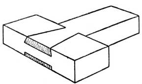
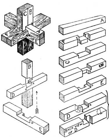
At Fig. 57 are shown two cross rails and an upright halved together. This type of joint is used where three[Pg 24] pieces meet, as is the case in building the framing of a poultry house. The joint is nailed together.
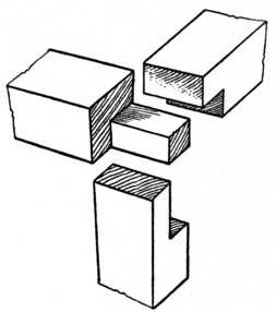
Fig. 57.—Cross Rail and Upright Halved Joint. |
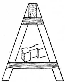
Fig. 58.—Workshop Trestle Joint. |
Fig. 58 is the end view of an ordinary workshop trestle, showing the application of dovetailed halving[Pg 25] where the legs have a tendency to strain outwards. The inset sketch of joint shows the housing of the top rail to receive the legs.
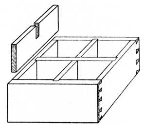
Fig. 59 shows a deep drawer, generally known as a cellarette, and used in a sideboard to accommodate wine bottles. Here we have a good example of halving the cross pieces so as to form compartments. The part shown separately illustrates the method of construction. The ends of these pieces engage the housings or grooves of the drawer sides. Pigeon holes or compartments in stationery cases, bookcases and writing bureaux are constructed in a similar manner, although the method of housing, or combined halving and housing, is to be preferred in some cases.
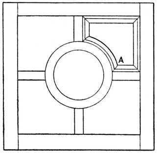
At Fig. 60 is the plan of a circular table having a small circular shelf with the top removed. The rims or[Pg 26] framing are built by the method known as laminating (see Fig. 23 in chapter on the The Glued Joint), after which they are veneered on the face sides. The application[Pg 27] of the halving joint to the shaped bottom rails, which in this case carry and support the small shelf, is shown in the part elevation.
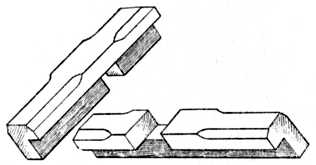
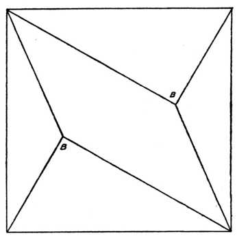
Fig. 61 (B).—Halved Joint of Oxford Frame with front edges champered. |
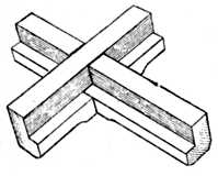
Fig. 61 (C).—Back view of Oxford Frame. |
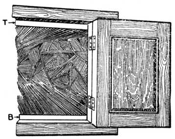
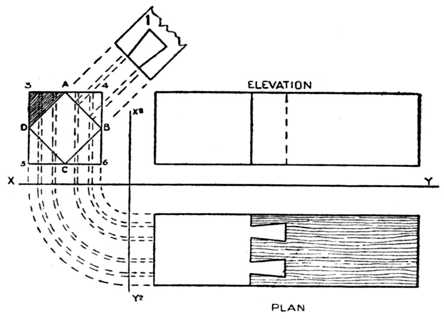
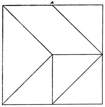
Fig. 61 (A) shows the well-known "Oxford frame," illustrating halved joints when the edge is rebated. Figs. 61 (B) and 61 (C) make clear the construction of this type of joint. Alternative suggestions are shown for the treatment of the corners, the simple inlay being black and white (ebony and holly or boxwood). Frames of this type are made in various widths and sizes and are used for pictures, mirrors, etc.
The tools used for making joints of the above class are: planes, the gauge, tenon or other saw, chisels, try square, and in some cases a joiner's bevel to obtain and mark the necessary angles, pencil and marking knife.
Plane up the face side and face edge of the timber, gauge and plane to both thickness and width; mark shoulders with pencil or marking knife; gauge to the thickness of the required halving; saw waste portions away; pare up with chisel to a good fit; glue or glue and screw, or use paint as previously mentioned, and then level off the surfaces.[Pg 28]
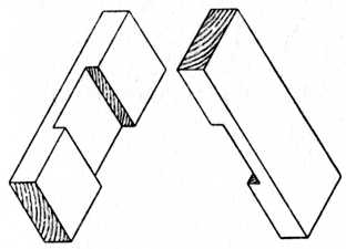
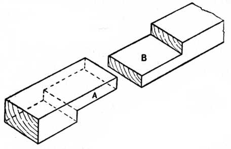
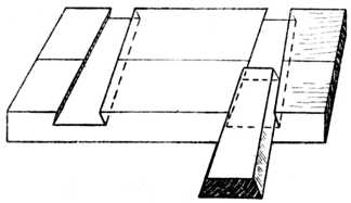
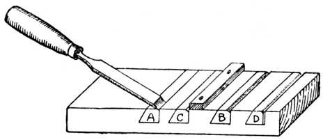
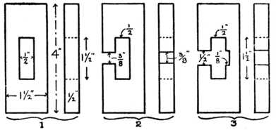
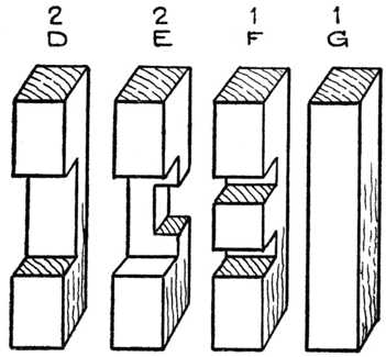
Setting out the Halved Joint.—Although at first sight the halved joint may appear to be a very easy item of construction, it requires much care and attention in marking out and sawing. Fig. 62 shows the two pieces which form the joint separated, and it will be noticed that each piece of wood has half its thickness cut away, so as to accommodate the other piece. This type of joint is used where two pieces of wood cross each other at right angles, or at an angle as shown in Fig. 51. The halving joint is used also for joining two pieces of wood at their ends, as, for instance, the corner of a frame, one half of this joint being shown at Fig. 65 (B).
To make the joint, the timber should be carefully[Pg 29] planed to its exact width and thickness. The two pieces may then be placed upon the bench (as shown at Fig. 63) or fixed in the vice.
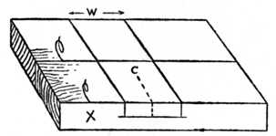
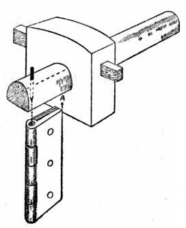
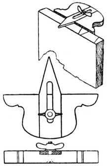
Find the centre of the timber, C, Fig. 63, and set out half the width of the wood on each side of the dotted centre line. Thus, suppose the wood (W) to be 2 ins. wide, then set 1 in. on each side of the centre line. Take a square as at Fig. 64, and with a sharp penknife blade score or cut a line all round each piece of timber.
Next take up a marking gauge, and set the marking point to half the thickness of the wood. The distance may be measured, and its exactness tested, by pricking a small hole from each side of the wood with the marking gauge and carefully noting that the pricked holes coincide. The gauge mark is clearly shown in the various illustrations. Now, take a pencil and scribble or mark "waste" on the parts you intend to cut away. This will save trouble later on, especially if you are making several joints at once. Take your sharp penknife or marking knife blade, and cut fairly deeply into the marked line on the portion you are going to pare away.[Pg 30]
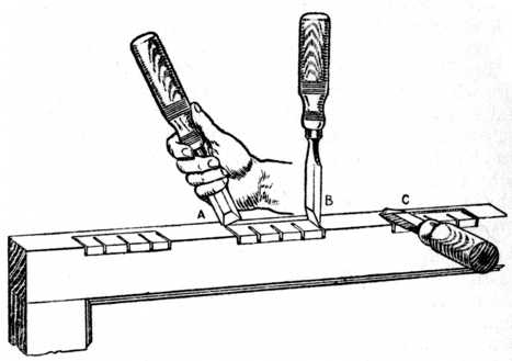
Fix the wood firmly in your vice, or against your cutting board or bench stop, as may be more convenient to you, and with a sharp chisel cut away the wood up to the marked line, as at Fig. 66. The channel in the sketch is exaggerated, so as to show the method clearly. The object of using a penknife or marking knife to mark your work, instead of using a pencil, will[Pg 31] be obvious. Owing to the knife having scored about 1⁄16 in. deep across the fibres of the wood, the timber will come away cleanly when the chisel is used, as at Fig. 66. The small channel thus made will form a guide in which to start your tenon or dovetail saw; it prevents the saw cutting on the wrong side of the marked line and thus making the halving too wide.
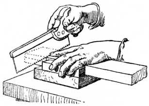
Sawing.—Lay the work on the cutting board as at Fig. 67; or, if you prefer, put the work in the vice. Carefully saw down the work until you just touch the gauge line. Do not press heavily with the saw; use it lightly; the weight of the back iron which is fixed on the saw will ensure the saw feeding into the work quite fast enough. If the saw is newly sharpened it will, in fact, be an advantage to slightly ease the weight of the[Pg 32] saw from off the wood, owing to the keenness of its edge. If the halving is a very wide one, additional cuts may be sawn between the outside marks, and these will greatly facilitate the removal of the waste wood when paring it away. For sawing the joint reference may be made to the chapter on Dovetailing.
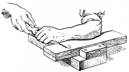
Paring away the waste material with a chisel is the next step, and this is shown at Fig. 68. The work may be chiselled either in a vertical or a horizontal position. The horizontal position is the easiest for the amateur who has a vice or handscrew, because he may hold the work securely with a mechanical device and so avoid the unnecessary risk to his fingers.
Take the chisel and cut away A, Fig. 68; now turn[Pg 33] the chisel and cut away B; after which keep the chisel horizontal and cut off "the top of the hill," as it were, C. Repeat the three operations until you gradually pare the wood away exactly to the gauge line. When chiselling, if you find a tendency for the work to chip or crumble at the back edge owing to the forward pressure of the chisel, turn your wood round and begin to cut from the other edge, allowing the chisel to finish paring at the centre.
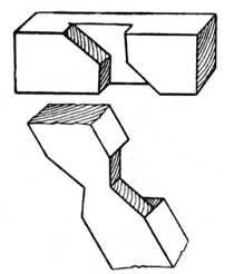
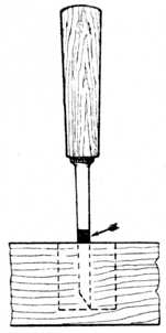
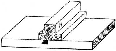
Joints Other than a Right Angle.—If the halving joint is at an angle similar to the sketch shown at Fig. 69, great care will have to be exercised in the use of the chisel, owing to the change in the direction of the grain of the wood. The arrow marks in this sketch distinctly indicate the direction in which the chiselling must be done so as to give a smooth result. This change of direction for cutting also applies to the bottom of the halving joint.
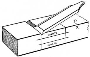
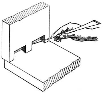
Cutting Joint at End of Timber (Fig. 70).—Should the halving joint be used at the end of a piece of wood, as at Fig. 30, the waste material may be roughly sawn away and the flat surface trimmed up with a chisel.
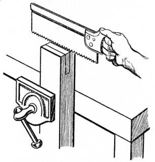
To saw out this type of halving joint, proceed to work the shoulder line as already described; then place the piece of wood obliquely in the vice as shown (Fig. 70) and proceed to saw down the vertical line, carefully watching the gauge line to see that you saw on the waste side of the lines. Then turn the piece of timber with its opposite edge towards you, and again use the saw as illustrated. You will this time only have to watch the gauge mark on the edge of the wood, because the saw will readily follow in the saw kerf already made. Now place the wood vertically in the vice, and keeping the saw in a horizontal position, saw down to the shoulder line.
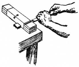
Halving joints properly made and fitted should knock together with the weight of the clenched fist; the use of a heavy mallet or hammer will deface the work.[Pg 34]
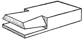
A bridle joint is often defined as the reverse of a mortise and tenon, and is chiefly used in the carpentry and joinery trades. The name probably originated from the fact that it bears some resemblance to the manner in which a bit slips into the horse's mouth and is fastened to the bridle. There are fewer varieties of the bridle joint than of the halved or the mortise and tenon; and this being the case we may take the opportunity of giving a few detailed directions, with explanatory illustrations, on the setting out and the making.
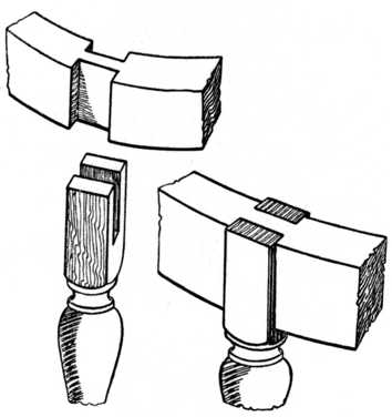
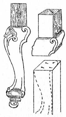
Fig. 72 shows a bridle joint in what is perhaps its simplest form, the separate pieces being given at the left and the completed joint at the right. A joint of[Pg 36] this type may be applied in nearly all cases where a halved or a mortise and tenon joint could be used. Bridle joints have an advantage as regards appearance over the mortise and tenoned variety in cases such as Fig. 73, which shows an occasional table leg fitted to the circular top framing. The bridle joint here allows the grain of the leg to run through to the top, and gives a better and more workmanlike appearance to the completed article.
Fig. 74 is a "Mitred bridle joint," the part a showing the upright portion separated. This is a most useful joint for positions similar to that shown in the small glass frame, Fig. 75. The wood framing in this case is only 13⁄8 in. in width, and if a mortise were used it would have to[Pg 37] be exceptionally small. The shaped rail at the bottom of this frame again shows the application of the bridle joint.
Fig. 76 shows an "Oblique bridle joint," used in many instances as a brace, or strut, to prevent framing from racking. (See also Figs. 31 and 32.)
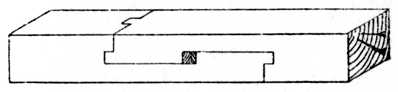
Fig. 77 is a "Stopped bridle joint," used in positions where the top or bottom edge of the work meets the eye, and where, if the rail were allowed to run through, the end grain would appear unsightly.
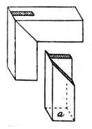
Fig. 74.—Mitre Bridle Joint. |

Fig. 75.—Mirror Frame with Bridle Joints. |
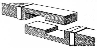
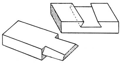
Fig. 78 is a so-called bridle-joint at the corner of a frame. This is also called an "Open slot mortise and tenon joint," a good strong, serviceable joint which can be used instead of the closed mortise and tenon type, its advantage being that less labour is required in the making. (See also Fig. 169.)
Fig. 79 is an "Oblique angle bridle joint," used in similar positions to the above, but when the two pieces meet at an acute angle at the end of a frame.
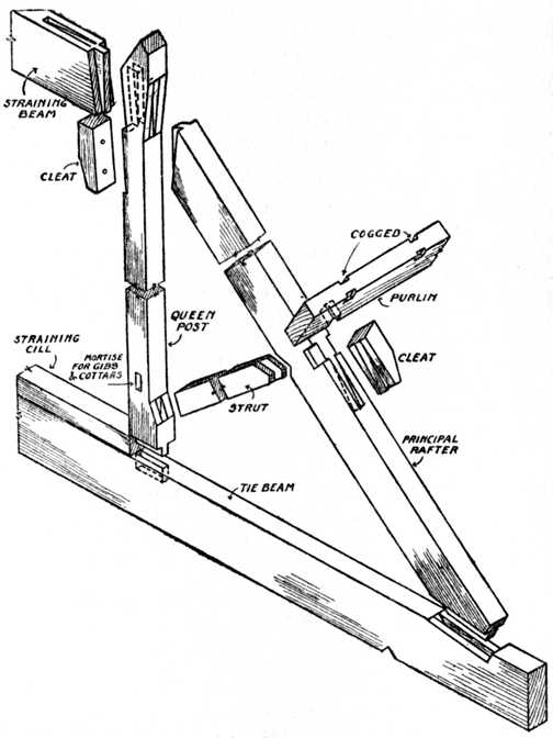
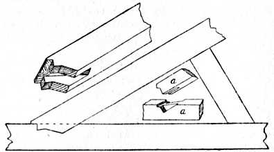
Fig. 80 shows the application of the bridle joint to a roof truss. Two sketches are shown at the joining of the tie beam and the principal rafter. The joint a is the type generally used. (See also Fig. 71 for the joints in a queen post roof.)[Pg 38]
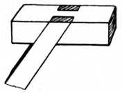
Fig. 76.—Oblique Bridle Joint. |
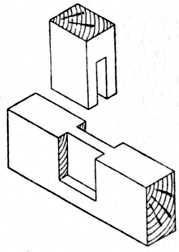
Fig. 77.—Stopped Bridle Joint. |
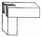
Fig. 78.—Bridle Joint at Corner of Frame. |
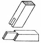
Fig. 79.—Oblique Angle Bridle Joint. |
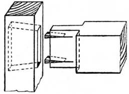
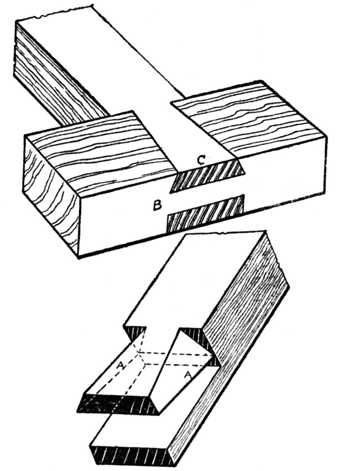
Setting Out and Marking.—It is a safe rule, when setting out a bridle joint, to divide the thickness of the timber into three equal parts. This will leave the timber on each side of the tongue equal to the thickness of the tongue, thus giving uniform strength to the joint. The bridle joint is chiefly used for connecting the internal parts of wooden frames. It is stronger than the halving joint, and, owing to its peculiar construction, requires little in the way of pegs, screws or nails to secure it in position. Fig. 81 illustrates the joint, both open and closed.
To understand the method of setting out and marking, glance at the sketch, Fig. 81. It is not necessary that the bridle piece A be the same width as the cross piece B; but it must be remembered when setting out the joint with the marking knife or pencil that the width marked W on piece B must be equal to the width W on the piece A. The timber should be fairly accurately sawn or planed to the same thickness, and all edges should be square and true.
The wood is placed upon the bench, and the joint marked out by using a marking knife or penknife blade and the try square. A knife blade is much better than a pencil, as the sharp edge severs the fibres of the wood and gives a finer line than the pencil. It is not always necessary to exactly square and trim the end of piece A; it may with advantage in many cases be left at least 1⁄4 in. longer than necessary and levelled off with the saw, plane and chisel after the joint is put together. (See Method of Cutting in Fig. 92, page 47.)
When the piece A has to have a bridle joint fitted at each end, it is customary to cut the timber about 3⁄8 in. longer than necessary, and mark the shoulder lines C to the exact length, after which the joints are cut. This leaves the ends standing over the horizontal[Pg 40] rails, and, after fixing the complete frame together, the small projecting ends are levelled off flush with the cross rails.
Gauging.—After squaring all the shoulder lines round the timber with the knife and try square, the mortise gauge should be set so as to strike the two gauge lines marked G, Figs. 83 and 84, at one operation. If the worker does not possess a mortise gauge the lines may be marked at two distinct operations with the aid of the marking gauge (Fig. 82). The gauge should be adjusted so as to mark the wood into thirds, and the stock of the gauge (the portion of the gauge containing the thumb screw in Fig. 82) must be used from the face side of the timber when gauging up the whole of the pieces forming a frame. The face mark on the work is indicated by a glorified comma, and the edge mark is shown by X, as in the various illustrations. Fig. 82 shows the method of holding the gauge in the right hand whilst gauging the lines on the work.
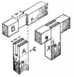
Fig. 81.—Bridle Joint, open and closed. |
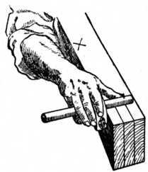
Fig. 82.—Gauging the Timber. |
The joint, when marked out, will appear as at[Pg 41] Figs. 83 and 84, and the portions which are to be cut away may be shaded with a pencil as indicated; this will prevent mistakes arising whilst cutting the work, especially by one who is not thoroughly familiar with the joint.
The distance A B, in Fig. 84, must not be less than the distance A B in Fig. 83.
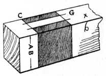
Fig. 83. |
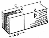
Fig. 84. |
The Two Parts of the Joint Marked.
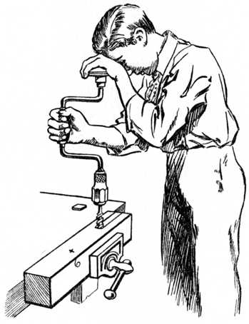
Boring Away Waste.—Examine Fig. 84; the shaded portion in the centre has to be cut away, and it will greatly facilitate the removal of this waste piece by boring a hole with a twist bit at the position shown. The twist bit should be about 1⁄8 in. less in diameter than the width between the gauge lines G. The easiest method of boring out this hole is shown at Fig. 85, which gives the correct position of the worker.
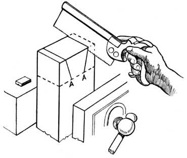
Sawing.—The wood should be put in the vice as Fig. 86. Taking up a saw, with the index finger on the side of the handle, commence sawing, and proceed until you come to the position indicated by the dotted hand and saw A; this will leave a saw kerf or cut running diagonally from the shoulder line to corner of the wood. Release the vice and refix the wood so that it leans in exactly the opposite direction to Fig. 86; then reverse your own position and repeat the sawing, so as to cut[Pg 42] another diagonal saw cut from the shoulder line to the corner. Fix the wood upright, as shown at Fig. 87, and saw as shown, when you will find that the saw has no tendency to run out of the guide cuts already formed by the method used at Fig. 86. Remember, when commencing to saw at Fig. 86, that it is necessary to saw inside the gauge line; otherwise the joint will be too slack, owing to the amount of sawdust removed by the thickness of the saw blade. The index finger on the side of the saw, pointing in the direction of the saw cut,[Pg 43] will greatly help the worker to saw in a straight line, as it is natural to point with this finger to any object that is to be aimed at.
Cut down the other line in a similar manner, and then with a chisel of suitable width carefully chop away the waste material. The wood may be placed edge way upon the bench, or in the vice, and the chisel should be held vertically. The hole which has been bored with the twist bit will allow the chips which are cut away to offer little or no resistance to the chisel blade. The chiselling should not all be done from one side, or a chipped under-edge will be the result; it is better to chisel the work until half-way through and then turn the other edge of the wood uppermost and again begin to chisel from the top. This method will finish the cutting in the centre of the work and prevent burred and ragged or chipped edges at the shoulder.[Pg 44]
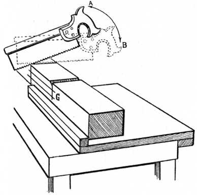
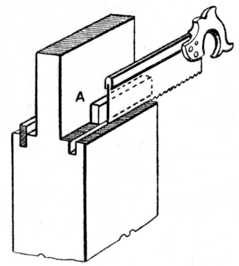
Cutting the Shoulders.—With regard to working the piece B, Fig. 81, place the wood against the bench stop or in the vice, and taking up a 3⁄4-in. chisel carefully cut away a small channel, as shown at Fig. 88; treat the other shoulder lines in a similar manner. If the[Pg 45] marking knife or penknife blade has been used with a fair amount of pressure so as to score the fibres of the wood, this small channel, which is to form a guide for the saw, will quickly and easily be cut. Next place the wood in the vice or on the cutting board as shown at Fig. 89, and begin by sawing lightly at the back edge as shown. When the saw has entered the wood 1⁄4 in. gradually bring the handle down from position A to position B (dotted lines) whilst the saw is in motion. Continue sawing until just on the gauge line; then treat the other shoulder lines in a similar manner.
Chiselling away Waste.—Fix your wood firmly in any suitable manner, vice or otherwise, and, holding[Pg 46] your chisel tilted as at Fig. 90, pare away the blacked portion 1; then pare away the blacked portion 2; after which hold the chisel flat and by gradual operations pare away the dotted lines 3, until you come down to the gauge line; then repeat the method of cutting on the opposite side of the wood. If any difficulty be experienced by chipped or ragged edges whilst chiselling, it can easily be overcome by chiselling alternately from the outside of the wood, so that the finish of the chisel cut takes place in the centre of the work. Some prefer to chisel away the waste by placing the wood on its edge and using the chisel vertically instead of horizontally. The same methods (1, 2 and 3) hold good in this case.
Joints Other than at 90°.—The two pieces forming a bridle joint are not always at right angles, as at Fig. 81; in many instances it is necessary that the joint be at other than 90 degrees. The work, however, is treated in a similar manner, with the exception that an adjustable joiner's bevel is used instead of a try[Pg 47] square to mark out the shoulder lines, and that a change of direction in the grain of the wood will occur when chiselling out the work. Fig. 91 indicates the change in the grain of the wood, and the adjustable joiner's bevel is also shown.
T he tongued and grooved joint is used in one form or another throughout the whole of the woodworking trades, covering, as it does, a great variety of work from the laying of flooring boards to the construction of dressers, bookcases and other cabinet work.
Flooring and match boarding generally have the tongues worked on the solid board, and examples of a few of the various types are shown as follows:—
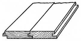
Fig. 94. |
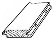
Fig. 95. |
Method of Nailing Hardwood Floors.
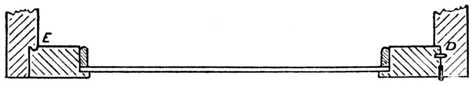
Fig. 93 shows the end view of the ordinary 7⁄8-in. "Tongued and Grooved Flooring board," as used in the construction of floors for mills, workshops and cottage[Pg 49] property. This type of flooring is nailed to the joists in the ordinary manner, no attempt being made to conceal the nails used.
Fig. 94 is a section of flooring which is generally made of hardwood, such as maple, oak, or jarrah. It is used in positions such as ballroom and skating rink floors, etc., the tongue and groove being worked in such a manner that the joint covers the nails as shown. Each nail is driven into its position at one edge of the board, the groove holding the next board and hiding the nail (Fig. 95).
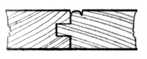
Fig. 96.—Tongued and Grooved Matchboarding, with Bead on One Side. |
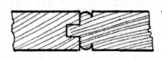
Fig. 97.—Tongued and Grooved Matchboarding, with Bead at Each Side. |
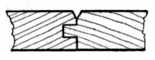
Fig. 98.—Matchboarding, Tongued, Grooved and Vee'd. |
Fig. 96 shows an example of matchboarding known as "Tongued, Grooved and Beaded" on one side only, and Fig. 97 shows a similar type tongued, grooved and beaded on both sides. This variety of matchboarding is known in the trade as "T. G. and B." It is used for nailing on framing to form partitions for rooms, offices, etc., for panelling corridors, etc., and for making framed and ledged doors, building tool houses, cycle sheds and other outhouses.
Fig. 98 is an example of matchboarding that is tongued, grooved and vee'd on one side, and Fig. 99 shows tongued, grooved and vee'd both sides. These are used for similar purposes to Figs. 96 and 97, and many prefer the V matchboarding variety because it is more easily painted than the beaded variety.[Pg 50]
The object of working a bead or beads on matchboarding is to break the jointing of the various pieces and to aim at ornamental effect; also to prevent unsightliness should the timber shrink slightly. When a moderate amount of shrinkage takes place, as is nearly always the case, the joint at the side of the bead appears to the casual observer to be the fillet or channel worked at the side of the bead. If the tongues are not painted before the work is put together, the shrinkage will cause the raw wood to show and thus make the joint too much in evidence.
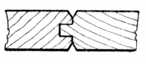
Fig. 99.—Matchboarding Vee'd Both Sides. |
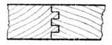
Fig. 100.—Double-tongued Matchboarding. |
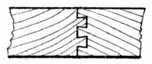
Fig. 101.—Double-dovetailed, Tongued and Grooved. |
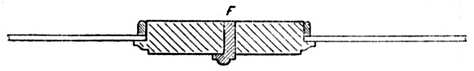
Fig. 100 shows a "Double tongued and grooved" joint used in the wholesale cabinet factories. It is preferred for the jointing of cabinet stock, and the amateur can make a similar joint by working two grooves and inserting loose tongues.
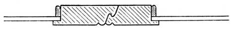
Fig. 101 is the end view of a "Double-dovetailed, tongued and grooved" joint, and Fig. 102 is a sketch of a similar joint having only one dovetailed tongue.
From a constructional point of view Fig. 101 is far and away the best joint that has yet been produced. Unfortunately, however, there is not at the present time any hand tool that will economically produce it, owing probably to the fact that the joint is the subject of a patent. The dovetail tongue tapers slightly throughout its entire length, gripping the joint on the principle of the wedge and squeezing the glue into the pores of the wood.[Pg 51]
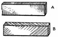
Fig. 103.—(A) Cross Tongue. (B) Feather Tongue. |
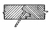
Fig. 104.—Method of Secret-nailing Hardwood Flooring Boards. |
Cabinet-work Joints.—With regard to tongued and grooved joints which apply more particularly to the jointing of cabinet work, Fig. 93 is produced by planes which are specially made for the purpose. One plane makes the tongue and another the groove. The handiest sizes to buy are those which joint 3⁄8 in., 5⁄8 in., and 3⁄4 in. timber, it being usual to dowel or loose-tongue thicker boards. The 3⁄8 in. partitions (or, as they are sometimes called, dustboards) between the drawers of a sideboard or dressing chest are in good work jointed in this manner. The 5⁄8 in. and 3⁄4 in. ends and tops of[Pg 52] pine or American whitewood dressing tables, wardrobes, etc., call for the larger sized plane.
Loose Tongues.—There are two methods of jointing with loose tongues, viz., the use of the cross tongue, Fig. 103 A, and the use of the feather tongue, Fig. 103 B. Cross tongues are the stronger when glued in their position and can be used very much thinner than feather tongues. Feather tongues are cut diagonally across the grain as illustrated.
Fig. 105 is a cradle for planing up loose tongues to the required width (generally 7⁄8 in.). Two grooves are made in a piece of 11⁄4 in. hardwood; one groove is used for planing the width way of the tongue and the other for planing the edge way. These tongues can be cut to accurate size on a circular saw bench if power and machinery are at hand.
Applications of the Joint.—Fig. 106 is a sketch of a portion of a sideboard top, showing the plough groove ready worked out to receive the tongue; the other half of the top is treated in a similar manner. It will be noticed that the groove is not worked through the full length of the board, but stopped about 11⁄4 in. from each end; this leaves a square joint at each end of the top on which the moulding is worked. If the groove be run through the board it looks very unsightly when the mould is finished.
Fig. 107 is a shaped spandrel, such as is fixed in the[Pg 53] recess of a sideboard or cupboard or shop window fitment. It is of such a width that, were it cut from a wide board, the shaped portion would be apt to break off owing to the short grain at C. The shaping is therefore built up out of three separate pieces, the grain running as indicated. The loose tongue is represented by the dotted line and a section is shown of the joint at the line A B. At the opposite corner the tongue is left blind, i.e., not run through the edge. This is the method that should be used when the shaping is above the level of the eye.
Fig. 108 shows part of a carcase of a dressing table. The drawer runner A is shown grooved across the end to receive a cross tongue; this cross tongue engages a[Pg 54] similar groove in the front bearer. This method of fastening the runner to the bearer is in everyday use.
Fig. 109 is a writing table top. The centre boards are first jointed and glued up, after which the ends and sides are grooved ready to receive the cross tongues. The hardwood margins are shown at one end and at the front, and the grooves are arranged so that, on completion, the marginal frame stands above the top just the amount of the thickness of the leather which will cover the table. In some cases the margin at the end runs the same way of the grain as the top, thus allowing for slight shrinkage. Cross tongues would of course be used in this case.[Pg 55]
Fig. 110 is a sketch showing one-quarter of a barred or tracery cabinet door. An enlarged section of the astragal mould which is grooved to fit on the bar which forms the rebate is also shown.
Fig. 111 is a "Combing or corner locking" joint, a method of making boxes by means of a continuous use of tongues and grooves instead of dovetails. This type of joint is generally machine made. The amateur, however, who is not proficient to undertake a dovetailed box frequently uses this method.
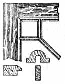
Fig. 110.—Corner of Barred Door. |
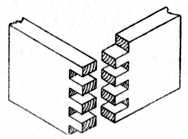
Fig. 111.—Combing or Locking Joint. |
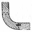
Fig. 112.—Single Loose Tongue and Double-tongue Joint. |
Corner Joints.—Fig. 112 shows both a single loose tongue and a double solid tongue. Both are methods used to connect circular cornered work, such as a counter end, to the front framing.
Fig. 113 indicates a tongued and grooved joint suitable for edge or end jointing, such as fitting matchboarding round a chimney breast, making small jewel drawers, etc.
Fig. 114 is a tongued and grooved joint with a bead worked on same to hide the joint, sometimes called a staff-bead. It would be used in positions such as[Pg 56] boarding around an upright iron pillar, etc., the bead giving a neat finish at each corner.
Fig. 115 is a similar joint, but at an obtuse angle. An example of its use is in fixing boarding around an octagonal column of brickwork.
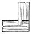
Fig. 113. |
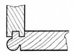
Fig. 114. |
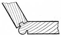
Fig. 115. |
Examples of Tongued and Grooved Corner Joints.
Fig. 116 shows a tongued and grooved mitre as used for strengthening the corners of cabinet work, such as tea caddies, small boxes, plinths, etc. Two pieces of wood are glued in position and allowed to set prior to glueing and cramping the joint proper. These pieces are afterwards planed away, thus leaving a clear surface to the box sides.
Fig. 117 shows the method of working the groove in the above joints. The pieces are turned back to back, the mitres thus making a right angle. The guide on the grooving plane thus works against each face of the joint, and this ensures correct jointing.
Fig. 118 is somewhat similar to Fig. 113, but with a quarter circle mould to hide the joint.
Fig. 119 indicates the building up of a double skirting mould. C represents the brickwork, A the oak-framed panelling, and B the packing and fixing block. A wide skirting of this type is made in two portions for convenience in working the moulding and to prevent undue shrinkage.[Pg 57]
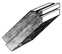
Fig. 117.—Working a Groove. |
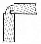
Fig. 118.—Corner Joint with Corner Mould. |
Fig. 120 illustrates the use of a tongued and grooved joint for fixing together the sides of a corner bracket, and the same method holds good when jointing a corner cupboard. A capping mould or top shelf will conceal the joint; it then has the appearance of a glued butt joint, but is of course considerably stronger. No screws or nails are required if this joint be used.[Pg 58]
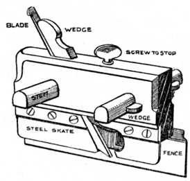
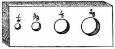
Ploughing.—When grooves have to be worked in the edge or face of a board to receive tongues, the process is generally called ploughing, and it is usually accomplished by a special tool called a plough (or, as it is occasionally spelt, "plow"). When a plough plane is bought it is usual to procure eight plough bits or blades of various sizes to fit the plane. In Fig. 121 is given the sketch of a plough plane with the names of the various parts lettered thereon.
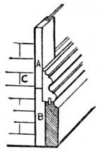
Fig. 119.—Double Skirting Mould. |
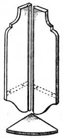
Fig. 120.—Joint for Corner Bracket or Cupboard. |
The board or boards which it is desired to groove are first planed straight and true, exactly as though it were desired to make a glued or butt joint. One of the boards is now placed edge way up in the vice and with the face side to the worker.
Take the plough plane and select a suitably-sized[Pg 59] blade; fix it in the plane in the usual way, allowing the cutting edge to project beyond the steel skate about 1⁄32 in., and securely drive up the wedge. Next loosen the small boxwood wedges at the side of each stem, and adjust the plane by tapping the stems with a hammer until the cutting iron is in the desired position; then knock up the small wedges nice and tight. When setting the fence to or from the blade it is a wise precaution to measure the distance from the fence to the skate at each end of the plane; this will ensure the skate being parallel to the fence. The neglect of this is a source of annoyance to many amateurs. Now adjust the depth stop by turning the screw at the top of the plane, measuring the depth of the required groove from the edge of the blade to the stop, and carefully lock the screw which adjusts this stop.
The plane is now ready for use. Hold the fence close up to the side of the timber, the hands in position as shown at Fig. 122, the position of the body being that[Pg 60] generally assumed in planing. Move the plane backwards and forwards in the usual manner, beginning the cut at the end of the board nearest to the vice jaws (the front), and proceed with the planing until the depth stop is in contact with the wood. Then take a step backwards and repeat the process until the whole length of the groove is ploughed. Care must be taken to force the fence up to the board with the left hand, whilst the right hand thrusts the plane backwards and forwards, and the plane must be kept vertical.
Tongueing.—The grooves having been completed, the tongues have to be made. Fig. 123 shows a sketch of a board and the method of marking out cross tongues (A) and feather tongues (B). The usual procedure for making cross tongues is to plane the end of the board and use a cutting gauge to give a line the required distance from the end (see sketch). The board is sawn with a tenon or panel saw, and the piece of timber for the tongue is thus procured. If a feather tongue is to be used it is cut diagonally from the board (B) and the ends cut square as shown by the dotted line.
Feather tongues can be obtained in fairly long lengths out of narrow boards, whilst on the other hand cross tongues are limited by the width of the board. After cutting off the tongues, they require planing with nicety to fit the grooves, and the advantage of a grooved board (Fig. 105) will be appreciated. A glue spoon similar to a plumber's ladle is generally used to pour the glue into the grooves, and it is customary to glue the tongue into one board first; after allowing this to set, the joint is completed in the usual manner.
Tongueing Planes.—Fig. 124 shows the end view of a tongueing plane for working matched joints out of[Pg 62] the solid. The method of holding and using the plane is similar to the directions given for using the plough. The part lettered F (in front) represents the fence, which in this case is not adjustable.
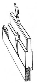
Fig. 124. |
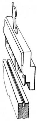
Fig. 125. |
End Views of Tongueing and Grooving Planes.
In description Fig. 125 is similar to Fig. 124. The steel skate runs in the groove and supports the cutting blade similar to that in the plough plane, and provided a grooving plane of this type is of suitable width it may be used for making grooves for loose tongues. There is on the market a metal plane which is specially[Pg 63] designed with handles at both ends. This plane carries a grooving iron on one side and a tongueing iron on the other side; thus with one plane both the tongue and the groove can be worked.
Fig. 126 shows the method of tongueing the shoulders of tenons as used in thick timber which is to be veneered on the face. A temporary piece of wood (A) is put between the tenon cheek and the saw, thus forming a guide for the latter. After cutting one saw kerf a thicker piece is made and a second saw kerf cut; the waste between the saw kerfs is now removed with an 1⁄8 in. chisel and this completes the groove. A tongue of this type acts as an extra tenon and prevents the joint from "lipping" (becoming uneven) on the face side.[Pg 64]
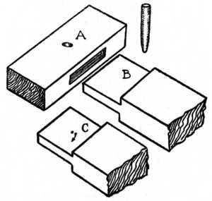
A mortise and tenon joint is the method of joining timber by working a solid rectangular projection in the one piece and cutting a corresponding cavity to receive it in the adjoining piece. The projection is called the tenon, and the cavity the mortise. Joints of this type are secured in various ways. Small wedges, wooden dowels, metal dowel pins, glue and paint are frequently used, and prior to the introduction of glue we have examples of Egyptian furniture in which the mortise and tenon joints were united by a composition of cheese.
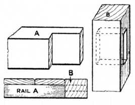
Fig. 127.—Barefaced Tenon Joint. |
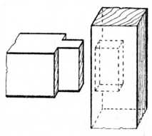
Fig. 128.—Stub Tenon. |
Barefaced Tenons.—Fig. 127 illustrates the joint in its simplest form and shows a tenon having only one shoulder. This is called a barefaced tenon, and it will[Pg 65] be noticed that the portion which carries the mortise is thicker than the rail on which the tenon is cut. The joint is therefore level (or flush as it is called) on one side only, and it should never be used at the corner of a frame. It is a useful interior joint for framing that has to be covered on the back side with matchboarding, and allows the work to finish level at the back when the boarding has been applied (see plan, Fig. 127).
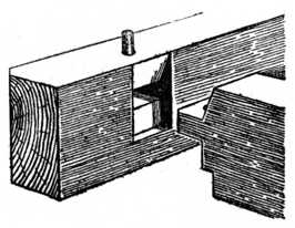
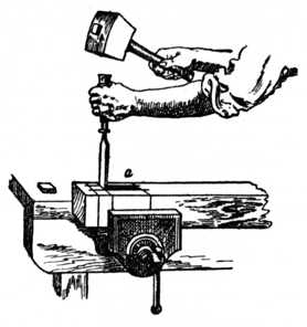
Stub or Stump Tenon (Fig. 128; also occasionally called a joggle tenon).—The illustration shows a tenon as used in the interior of a frame. The tenon is not allowed to run through the stile, and unslightliness on the edge is thus avoided. This type of tenon is often used at the corner of a frame, and it then requires to be haunched. A good workshop method of gauging the depth of the mortise for a stub tenon is shown in Fig. 129; a piece of gummed stamp paper is stuck on the side of the mortise chisel, indicating the desired depth of the mortise. This greatly facilitates the work, as it is not necessary to be constantly measuring.
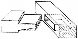
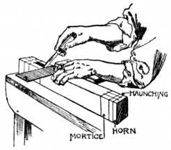
A Haunched Tenon as used at the end of a door frame is shown at Fig. 130.—In this case it will be seen that the width of the tenon is reduced, so that sufficient timber will be left at the end of the stile to resist the pressure of the tenon when the joint is driven together. The short portion (A) which is left on the tenon is called the haunch, and the cavity it engages is termed the haunching. The haunch and haunching prevent the two pieces of timber lipping, or becoming uneven on the face side, as would be the result if it were cut away entirely up to the shoulder.
Fig. 131 shows the type of tenon and haunch used when the stile or upright rail is grooved to receive[Pg 66] a panel. In this and similar cases the haunch is made[Pg 67] the same width and the same depth as the groove; the groove therefore acts as the haunching. An application of this joint is shown in the top rail of the door frame, Fig. 132.
This type of joint is also used to connect the rail to the leg of an ordinary kitchen table (see Fig. 167).
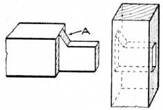
Fig. 130.—Haunched Tenon used at end of Door Frame. |
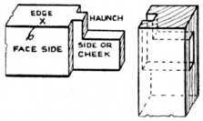
Fig. 131.—Haunched Tenon used when Stile is Grooved for Panel. |
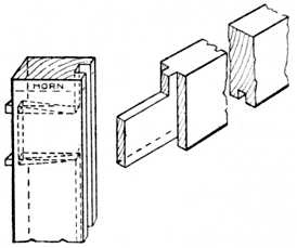
Fig. 132.—Application of Haunched Tenon Joint to Door Frame. |
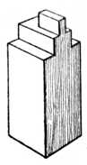
Fig. 133.—Occasional Stump Tenon. |
Fig. 133 is a variation of the stump tenon, occasionally used where the work in hand demands a thin tenon and a stout stump to take heavy strains.
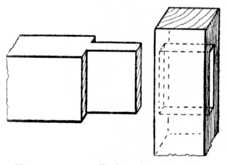
Fig. 134.—Joint for Inside Framing. |
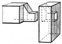
Fig. 135.—Haunched Barefaced Tenon. |
A joint used for inside framing is seen at Fig. 134. The rails may be used as shown, but in the case of a door frame (as Fig. 132) they would have the inside edges grooved to receive the panels; the tenons would therefore be slightly narrower than shown, owing to the groove at each edge.
A Haunched Barefaced Tenon, used in similar positions to Fig. 131, is shown at Fig. 135. The door or frame in this case would be made of matchboarding nailed on the back as shown in the plan at Fig. 127.
Wedges.—Fig. 136 shows the method of cutting wedges which are to be used to wedge the tenons; this avoids waste of material. Some workers cut the wedges[Pg 68] from the pieces left out of the haunching of the lock rail, or the bottom rail.
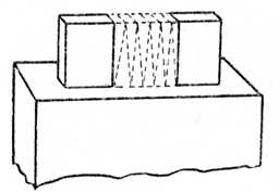
Fig. 136.—Cutting Wedges from Waste of Haunching. |
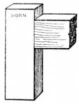
Fig. 137.—Stile and Cross Rail with Horn. |
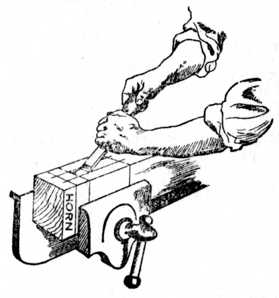
A Stile and Cross Rail, framed together, are shown at Fig. 137. The portion above the rail is called the horn, and it is usual to leave sufficient length of stile to project above and below the cross rails, so that there will be no tendency for the stile to burst out at the end whilst the cramping and wedging of the frame is in progress. On completing the framing the horn is cut away.
In Fig. 138 we have a type of joint frequently used for garden gates. The illustration shows the method of tenoning the three pieces to the top rail, barefaced tenons being employed.
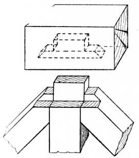
Fig. 138.—Joint used for Garden Gates. |
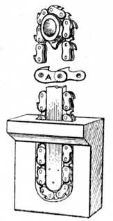
Fig. 139.— Sprocket Wheel. |
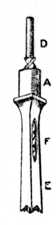
Fig. 140.— Boring Tool. |
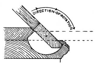
Sprocket Wheel.—At Fig. 139 are shown the guide bar and chain of a chain-mortising machine, two enlarged links of the chain being indicated at A. The chain is similar in construction to the driving chain of a bicycle, with the exception that it is provided with teeth which cut away the timber as the chain revolves.[Pg 69] When using a chain mortiser the portion of the machine carrying the chain is fed downwards into the timber, thus cutting a clean and true mortise. If, however, a stump mortise is required it is necessary to pare away a certain amount of timber by hand, because the machine obviously leaves a semicircular bottom to the mortise. To overcome this difficulty the latest types of mortising machines have a square hole-boring attachment fixed alongside the chain. This tool, the working portion of which is illustrated in Fig. 140, consists of a square hollow chisel (E), which is sharpened from the inside, and a revolving twist bit (D) fitted with spurs or nickers, but without a point (one spur can be seen at the bottom of the illustration). This bit revolves inside the shell like a chisel, and bores away the superfluous timber,[Pg 70] whilst the pressure exerted on the chisel causes the corners to be cut away dead square. A mortise 3⁄8 in. square by 6 ins. in depth may thus be cut. The portion marked A is the shank of the chisel (Fig. 140), where it is fixed into the body of the machine, and the hole at E allows the boring bit to free itself.
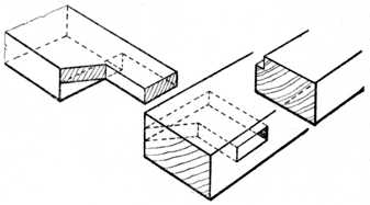
Fig. 142.—Haunched Tenon for Skylight or Garden Frame. |
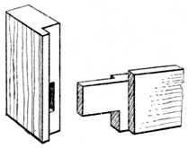
Fig 143.—Long and Short Shouldered Tenon. |
Fig. 141 indicates the method of fixing an interior leg to a table having a circular or straight top rail. The inlaid leg in this case is stump-tenoned into the top rail, and the inlaid portion of the leg is allowed to run through the rail, thus giving continuity of design.
Fig. 142 shows the application of the haunched tenon[Pg 71] (Fig. 135) to the making of a skylight or garden frame. In this and similar cases the side rails are rebated as shown in the section, and the bottom rail is thinner than the side rails to allow the glass to finish level upon it.
Long and Short Shouldered Joint.—Fig. 143 shows a haunched mortise and tenon joint having a long and short shoulder. This is a fairly common joint in framed partitions for offices, framing for greenhouses, tool sheds, etc., and is a frequent source of annoyance to the amateur. It is necessary to use this joint when both the stiles and uprights are rebated, and it calls for accurate marking out and great care in the making.
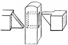
Fig. 144.—Joint for Fencing. |
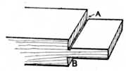
Fig. 145.—Example of Faulty Tenon. |
Fig. 144 shows the upright and rails of common garden or field fencing. The tenons are bevelled to fit and wedge each other in the mortise. The illustration gives both cross rails as shouldered, but in many cases shoulders are omitted when the rails are not thick enough to carry them.
Fig. 145 indicates faulty methods of working a tenon. At A the saw has been allowed to run too far when cutting the shoulder, thus greatly weakening the tenon. At B faulty sawing has again occurred, and to remedy this defect the worker has resorted to paring the shoulder with a chisel. Had the chisel been used[Pg 72] vertically an undercut shoulder (as at B) would not have occurred. The trouble now is that the slightest amount of shrinkage in the width of the stile will show an open joint. The result will be the same if it is necessary to remove a shaving or two when planing or levelling up the face of the frame.
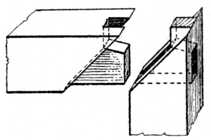
Fig. 146.—Self-wedging Japanese Tenon Joint. |
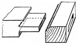
Fig. 147.—Tenoned and Scribed Joint. |
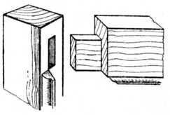
Fig. 148.—Mitred and Moulded Tenon Joint. |
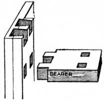
Fig. 149.—Twin Tenons. |
A Japanese Tenoned Joint, little known and rarely used in this country, is shown at Fig. 146. For clearness the two parts are here shown separate. The joint is self-wedging and will be of interest to Handicraft Instructors.
A Tenoned and Scribed Joint is seen at Fig. 147. The cross rail is cut at the shoulder, so as to fit the moulding[Pg 73] which is worked on the stile. This is a good joint in everyday use.
Mitred and Moulded Joint.—Fig. 148 shows a type of joint largely used in light cabinet work. The method of mitreing the moulding and tenoning the stile to rail is indicated.
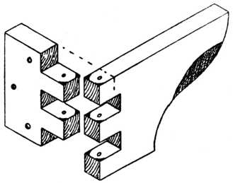
Twin Tenons (Fig. 149).—The method of tenoning the bearers which carry the drawers, or the midfeather between two drawers, in a dressing table or similar carcase is here shown. On completion, the tenons on the midfeather are wedged diagonally.
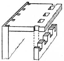
Fig 150.—Method of Pinning. |
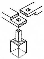
Fig. 151.—Joining Top Rails to Upright Post. |
Pinning.—Fig. 150 shows the tenoning of the inside end of a wardrobe to the top of the carcase. This is also called pinning. The tenons should be wedged diagonally. The tenons and the distance between the tenons are more satisfactory if made equidistant, because if slight shrinkage occurs this is partially equalised. The width between the tenons should in no case exceed 3 ins.
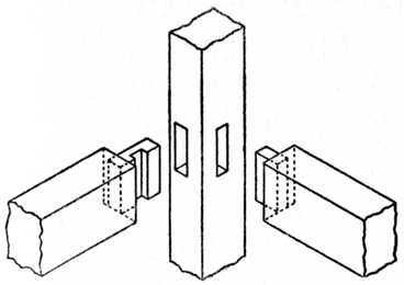
Top Rails.—At Fig. 151 is shown the method of joining the top rails to the post of a tool shed or similar outhouse. The two rails, which are at right angles to[Pg 74] each other, are half-lapped and mortised; the tenon on the post runs entirely through them.
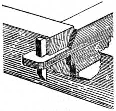
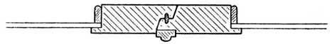
A Tusk Tenon Joint, with wedge, as used to secure the binder to the girder when making floors, is indicated at Fig. 153. The tenon here is narrow and engages the mortise, which is situated in the compressional fibres immediately adjoining the neutral layer. Fig. 152 shows a tusk tenon furnished with a drawbore pin.
Fig. 154 is a variation of Fig. 152.[Pg 75]
Fig. 155 shows tusk and wedged tenons as used when making a portable book or medicine cabinet. The shelf is housed into the end, and the tenons run through the end and are secured by wedges. This allows the article to be quickly and easily taken to pieces for removal or re-polishing. The dotted line in Fig. 155 indicates that the shelf may be shaped if desired.
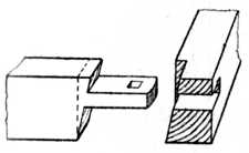
Fig. 154.—Another Type of Tusk Tenon. |
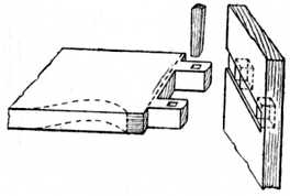
Fig. 155.—Tusk Tenon and Wedge. |
In Fig. 156 a self-wedging mortise and tenon joint used by wheelwrights is shown. The dotted line (left-hand diagram) will indicate the amount of taper given to the mortise.
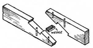
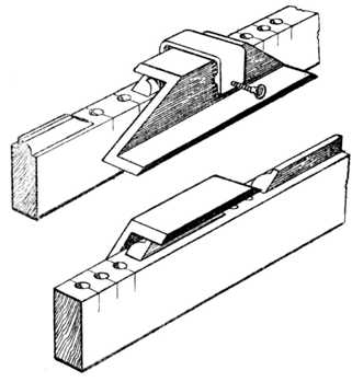
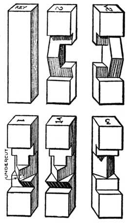
Dovetailed and Wedged Tenon (Fig. 157).—When two pieces such as the cross rail and leg of a carpenter's[Pg 76] bench are required to be held together by a mortise and tenon, and to be readily taken apart, the tenon is dovetailed on one side and the mortise is made of sufficient width to permit the widest part of the dovetailed tenon to pass into it. When the tenon is in its position a hardwood wedge is driven in above the tenon, as shown.
Fox Wedged Tenon (Fig. 158).—This is the method of securing a stub tenon by small wedges. The mortise is slightly dovetailed and two saw cuts are made in the tenon about 3⁄16 in. from each side. Into each saw kerf a wedge is inserted and the joint glued up. The cramping operation forces the wedges into the saw cuts, thus causing the end of the tenon to spread and tightly grip the mortise.[Pg 77]
Mortise and Tenon with Mitred Face (Fig. 159).—This is a useful method of jointing framing which has square edges as shown; and it is equally useful even if the face edges have moulds worked upon them. If the joint has square edges a rebate may be formed to accommodate a panel by fixing a bolection moulding around the frame. A section of the bolection mould planted on the frame is shown in the lower figure.
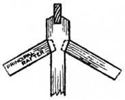
Fig. 160.—Rafter Joint. |
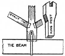
Fig. 161.—Roof Joints. |
Roof Joints.—Fig. 160 shows the method of tenoning the principal rafter to the king post, whilst Fig. 161 illustrates the tenoning of the struts to the king post, and the king post to the tie beam. Both these examples are used in roof work. (See also Fig. 71.)[Pg 78]
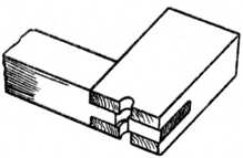
Fig. 163. |
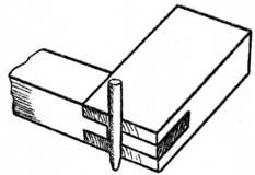
Fig. 164. |
Operation of Pegs in Drawbore Pinning.
Drawbore Pinning.—At Fig. 162 is seen the method of securing a tenon by drawbore pinning, employed when it is not convenient to obtain the necessary pressure by using a cramp. The joint is made in the usual manner, and a 3⁄8-in. twist bit is used to bore a hole through piece A. The tenon is driven home and the hole is marked on the side of the tenon (B); the tenon is then withdrawn and the hole bored about 1⁄8 in. nearer to the shoulder than as marked on the separate diagram[Pg 79] at C. When the tenon is finally inserted the holes will not register correctly, and if a hardwood pin be driven into the joint it will draw the shoulders of the tenon to a close joint and effectually secure the parts.
Sash Bars.—Fig. 165 shows how to tenon a moulded sash bar to the rebated cross rail. In this illustration both shoulders of the moulded bar are shown square, but in the best class work these shoulders may be slightly housed into the cross rail to prevent side play. This type of joint is used for horticultural buildings, etc. If the lower rail be moulded with the same members as the sash bar, the end of the sash bar will have to be scribed on to it to make a fit.
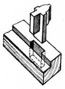
Fig. 165.—Tenoning Moulded Sash Bar. |
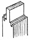
Fig. 166.—Tenon with Tongued and Grooved Shoulder. |
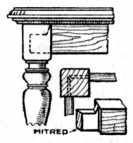
Fig. 167.—Detail of Table Framing. |
Tenon with Tongued and Grooved Shoulders (Fig. 166).—The object of the tongues and grooves here is to prevent the face of the work casting, or becoming warped, and thus spoiling the appearance of the surface of the work. If framing is to be veneered on the face side this is an exceptionally good method.
Table Framing.—Fig. 167 indicates the framing of a rail to a dining-table leg. In cases similar to this the tenons run into the leg and almost touch each other.[Pg 80] They are therefore mitred on the end as shown in the inset. Chair frames often call for similar treatment.
Twin Tenons with haunch, as used when the timber is of great thickness, are shown in Fig. 168.
An Open Slot Mortise at the end of a right-angled frame is seen in Fig. 169. Fig. 170 shows an open slot mortise and tenon joint at the end of a frame of 60°. Both these joints are occasionally called end bridle joints.
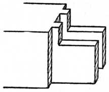
Fig. 168.—Twin Tenons for Thick Timber. |
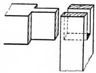
Fig. 169.—The Open-slot Mortise Joint. |
Hammer Head Tenons.—At Fig. 171 is shown the method of jointing framing having semicircular or segmental heads. The left-hand diagram indicates the method of wedging the joint so as to draw up the shoulders; the right-hand view shows the tongueing of the shoulders, which is necessary if thick timber has to be wrought. The sketch depicts the stile when taken apart from the shaped head of the frame.
Clamping.—Fig. 172 shows the method of tenoning drawing boards, desk tops and secretaire falls. This is commonly called clamping. The method is used to prevent wide surfaces from winding. A variation of the joint is shown at the left-hand side, the corners in this[Pg 81] example not being mitred. Fig. 173 shows the tenoning of a wide to a narrow rail when the joint is at an angle.
Inserted Tenons (Fig. 174).—Where two pieces of timber run together at an acute angle it becomes necessary to use inserted tenons. Both pieces of the timber are mortised and the inserted tenons are secured into the widest piece. On the left is shown the inserted tenon, secured by the method known as fox-wedging; on the right the inserted tenon has been let into the wide rail from the edge. The narrow rail is secured by wedging the tenons from the outside edge in the ordinary manner.
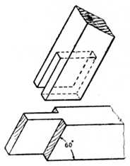
Fig. 170.—Open-Slot Mortise at 60 degrees. |
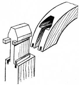
Fig. 171.—Hammer-Head Tenon Joint. |
Dreadnought File.—At Fig. 175 is a sketch of a portion of a dreadnought file. This has superseded the old-fashioned home-made float used to clean out the sides of a mortise.[Pg 82]
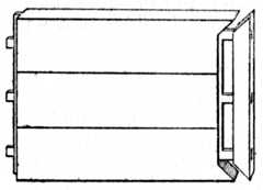
Fig. 172.—Clamping. |
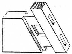
Fig. 173.—Tenoning Narrow Rail. |
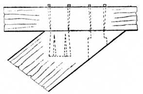
Fig. 174.—Inserted Tenons. |
Fig. 175.— Dreadnought File. |
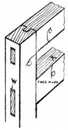
Fig. 176.—External and Internal Joints. |
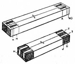
Fig. 177.—Setting out Stiles and Rails for Tenoning. |
General Rule.—In practically all cases where a single tenon is used the thickness of the tenon should be one-third the thickness of the timber. This leaves the timber at each side of the mortise the same strength as the tenon.
Mortise and tenon joints for inside work may be united with glue. If, however, the work has to stand the weather a better method is to unite the joint with white lead, which is run down to the required consistency with good outside varnish.
Setting Out the Joint.—The principal use of the[Pg 83] mortise and tenon joint is in the construction of various types of framing, such as door and window frames. In one or other of its many and varied forms it may be classed as the most important joint in the general woodworking trade. The joint may be used as an internal one, as shown at the lower rail, Fig. 176, or as an external joint, as the upper rail of the same illustration.
Whatever type of framing has to be made, it is necessary that the face side of the wood be planed up straight and out of winding, and the face mark (as shown in Fig. 176) pencilled upon it. The best edge of the timber should next be planed up true in length, and square to the face side, and the edge mark (X) clearly placed upon it.
The marking gauge is now set to the desired width, and gauge lines are marked on the wood, after which the waste wood is planed off until the timber is the required width. The thickness is gauged and treated in a similar manner, except in such cases where the finished work is to be of a rough and ready character.
The Two Stiles (or uprights) have their faces turned to touch each other, as shown at Fig. 177, and their length may be anything from 1 in. to 3 ins. longer than[Pg 84] the required finished size. This waste wood at each end of the stiles (see arrow HO) is of importance to the work, as it prevents to a great extent the bursting of the mortise whilst cutting the hole or when knocking together[Pg 85] the work. The small projection is called the "horn," and it is cut off after the frame has been put together.
The two Cross Rails (Fig. 177), have their faces placed together as shown in the sketch. These rails may with advantage be left 1⁄2 in. longer than the finished size, and the portion of the tenon (which will protrude through the stile 1⁄4 in. at each end) may be cut off after the work is put together. (See Fig. 92.)
Set out the stiles with a marking knife or penknife and a try square, as shown at Fig. 178. In this sketch only one stile is shown for clearness of representation, but two or more stiles (as at Fig. 177) may be marked out at the same time, provided a 12-in. try square be used; in fact, marking out the stiles in pairs is to be recommended, as all cross lines will be exact owing to their being marked at the same operation. The cut made by the marking knife should be lightly carried all round the work as the mortising is cut from each edge of the stile, the cutting of the mortising being finished in the centre. The lettering on Fig. 177 is as follows:—HO, horn; M, position of mortise; H, position of haunching; A, inside line, or sight size, as it is occasionally called.
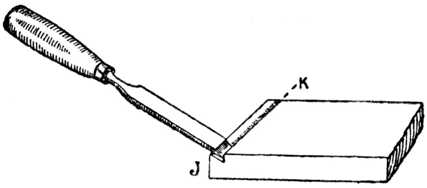
Set out the cross rails as at Fig. 177, lower sketch. The lettering in this figure is as follows:—T, tenons; the small piece of the tenon lettered J is called the haunch, and the shaded portion H is cut away to allow the haunch J to fit the haunching of the stile.
The Tenons (as already stated) are generally one-third the thickness of the timber, thus leaving the same amount of substance at each side of the tenon as the tenon itself is composed of. The mortise gauge is set to the required distance and used as in the case of the marking gauge (Fig. 82).[Pg 86]
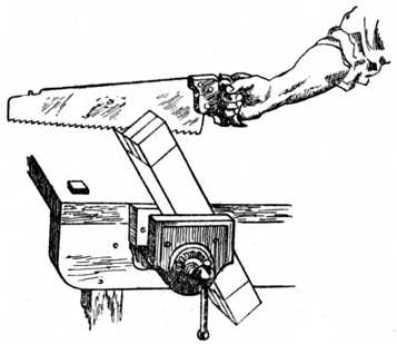
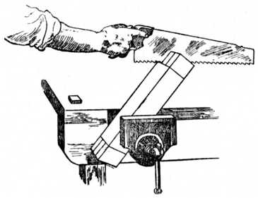
To saw the tenons, place the rail in the vice as at Fig. 179 and, with a panel, tenon, or hand saw, according to the size of the work, cut down the outside of the tenon line as shown. Reverse your position and cut as shown at Fig. 180, then place the rail in a vertical position, and you will find little or no difficulty in sawing down square with the shoulder line. Repeat the above methods of sawing until all the tenons are sawn.
Next saw out the pieces at the side of the tenon by the following procedure. Place the rail against the bench stop, or in the vice, and cut a small channel in which to run your tenon saw as shown at Fig. 181. If you have scored the line deeply with your knife when you were marking out the work, you will have little difficulty in removing a small portion with the chisel. The amount removed in the illustration is, of course, exaggerated. In the small channel thus made place the tenon saw and, guiding the saw blade with the finger so as to keep it upright or square (Fig. 182), saw away the waste material. Remove the waste material at the sides of the tenons in a similar way, and then saw out the portion marked H, Fig. 177, lower sketch.
The Mortising of the stiles may next be taken in hand by putting the stiles edgeways in the vice and boring away the bulk of the waste wood from the mortise with a suitable-sized twist bit and brace. This method will save a great amount of noise, as to a great extent it does away with the use of the mallet. Take the mallet and chisel and chop down about 3⁄8 in. as shown at Fig. 183; then turn the chisel to the position shown at Fig. 184 and remove the small piece as shown. Continue these two operations until you are about half-way through the wood and then start in a similar manner at the line a, Fig. 183, after which turn the other edge of the timber uppermost and repeat the methods shown.[Pg 88]
Fig. 185 shows the sketch of a mortise which has its side removed so as to show the method of successive cuts with a chisel when removing the core from a mortise; this, in conjunction with the other sketches,[Pg 89] clearly shows the methods of working. In many woodwork examinations the examiners insist that the mortise shall be removed by successive cuts with the chisel, but we certainly advise the removal of much of the waste wood with a boring bit, provided the worker can keep straight and well within the limitations of his gauge lines.
Removing Haunching.—After removing the mortise hole, the small portion which is called the haunching will require to be removed with a chisel. This calls for no special remark, as it is clearly shown in Figs. 187 and 188. Fig. 186 shows an everyday type of mortise and tenon joint separated; it is used in cases where a straight joint is required on the upper or lower edge of the work, whereas the upper rail of Fig. 176 shows the full haunch on the top edge. In cases such as Figs 187 and 188, where the edges of the frames are grooved to receive panels, etc., the width of the tenon is reduced by the width of the groove.[Pg 90]
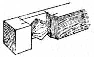
Fig. 185.—Mortise with Side Removed. |
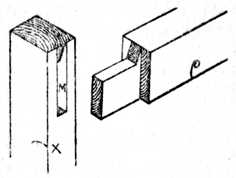
Fig. 186.—The Joint Separated. |
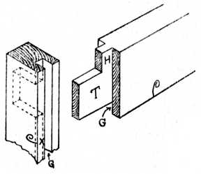
Fig. 187.—Removal of Haunching. |
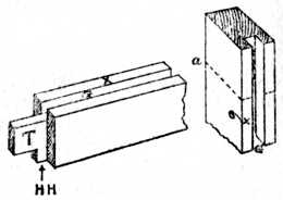
Fig. 188.—Haunching with Groove above. |
This must be remembered by the worker when marking out his stiles with the marking knife. Fig. 187 (right-hand sketch) shows the haunch, tenon, and groove G at the bottom. Fig. 188 (left-hand illustration) shows G (groove) at top, and HH (the haunch) at the bottom. Tenons may be glued together and[Pg 91] wedged as shown at Fig. 176 if for inside work; but if for outside work they are generally smeared with thick paint and wedged up. For light-class cabinet work it is usual to cut the mortise about seven-eighths of the distance through the stile and make the tenon to match it; the edge of the finished work does not then show any indication of the joint, and it leaves a nice clean surface at the edge of the work for polishing or varnishing.
Interlocking Chair Joint.—A joint designed with a view to strengthening the construction of chairs at the point where they are weakest is shown in Fig. 189. The joint is an interlocking one so arranged that, once the chair is glued up, no motion of the side rail can be possible. The groove in the side rail tenon is cut in such a manner that, on the insertion of the back rail tenon, the joint actually draws up and, having done so, is locked in position. The exact location of this groove is obtained in a similar manner to that used in marking[Pg 92] out tenons for drawbore pinning, i.e., the tenon is inserted in its mortise and the position of the back rail mortise transferred to it, after which the lines are set back by 1⁄64 in. (approximately) to cause the joint to draw.
From the illustration the construction of the joint should be clear. The method is particularly adapted to a section of rectangular form where one side is longer than the other, such as the back leg of a chair, as this shape allows for the accommodation of the extra length of tenon required.[Pg 93]
Dowelling is the term generally given to the method of jointing timber and other materials by wooden or metal pegs, which are called dowels. For cabinet-making and similar work straight-grained beechwood dowels are mostly used; these may be bought by the gross, in lengths of about 36 ins., and of any desired diameter.
Making Dowels.—Many, however, prefer to make what they require for the work in hand, and the following is the method that is generally employed. Pieces of straight-grained wood are wrought to a square section, after which the corners are planed away to form an octagonal section. The sharp corners are now planed away, and the roughly formed dowel is driven through a steel dowel plate, Fig. 190, by the aid of a heavy hammer, thus giving the necessary roundness and finish to the dowels. When hammering dowels through a plate the hammer should on no account be allowed to come in contact with the face of the dowel plate, or the cutting edge of the hole will be spoilt.[Pg 94] Simply drive the dowel to within 1⁄8 in. of the plate and knock it out with the next dowel.
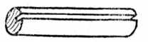
Fig. 192.—Dowel with Groove. |
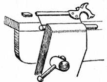
Fig. 193.—Sawing Groove in Dowel. |
To plane off the corners a "cradle" (Fig. 191) is made and kept for the purpose. The advantage of this cradle is obvious, preventing as it does any tendency of the partly-formed dowel to slip or wobble. A jig, or cradle, is easily made by bevelling the edges of two separate pieces of wood and then glueing and screwing them together as at Fig. 191. A small block of wood is inserted to act as a stop whilst the planing operation is in progress. It is usual to bevel both edges of the[Pg 95] timber from which the cradle is formed, thus accommodating all sizes of dowels from 1⁄4 in. to 5⁄8 in. in diameter.
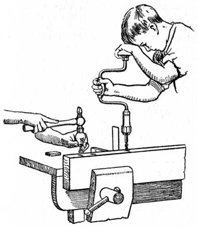 Fig. 194.—Pricking the Centres ready for Boring.
Also showing how Brace is used in conjunction
with Try Square.
Fig. 194.—Pricking the Centres ready for Boring.
Also showing how Brace is used in conjunction
with Try Square.
Fig. 192 shows a completed dowel with a small groove running along its entire length. The object of this groove is to allow the air and superfluous glue to escape and thus avoid splitting the work on hand; the groove also secretes a certain amount of glue, which increases its hold on the timber.[Pg 96]
Fig. 198 illustrates the method of marking out and gauging two boards for dowelling. The edges of the boards are first shot to a true joint; then the face sides are placed together and the lines for the dowels are marked across the edges with a fine pencil and the aid of a try square. The boards are then gauged from the face side, thus giving the points indicated in the sketch.
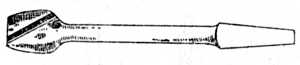 Fig. 196.—Dowel Rounder.
To start the twist bit (Fig. 197) it is a good plan to prick the board at the point of intersection of the marked lines with a sharp, circular-pointed marking awl. This obviates any tendency of the boring bit to run out of truth and thus cause unevenness on the face side of the jointed board. (See Fig. 194.)
A safe rule for the spacing of dowels when jointing sideboard tops, dressing table and wardrobe ends, etc., is to place the dowels 9 ins. to 10 ins. apart, and place two dowels at each end as shown at Fig. 198. The length of the dowels should be about 7⁄8 in. to 11⁄4 in. long.
Fig. 199 shows the two boards prepared ready for[Pg 97] glueing. The back one is bored to receive the dowels, and the front one shows the dowels glued in position. It is customary to warm the edges of the boards before spreading the glue, and cramps are required to squeeze the joint tight. These should be left on the jointed board from one to four hours according to the state of the weather. In cases where thick timber (say 2-in. or 21⁄2-in. boards) is to be jointed, two rows of dowels may be used, the position of the dowels being as Fig. 200.
Fig. 201 shows the plan of a 3-in. cornice pole made to fit a bay window; the straight portions of the pole are generally turned in the lathe, the corner portions being afterwards jointed and worked up to the required shape. To avoid any difficulty in the setting out of the dowels, a disc of cardboard or sheet metal is made to the same[Pg 98] diameter as that of the cornice pole; this disc is called a template. The positions of the dowels are set out geometrically, and the centres are pricked through with a fine-pointed marking awl (see sketch of template, a, Fig. 201). The template is put on the ends of the straight pole, and the dowel centres are pricked into the wood. The process is repeated on the ends of the corner block (b, Fig. 201), and if the holes be now bored at the centres indicated a true fit will be obtained.
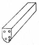
Fig. 200.—Method of Dowelling Thick Timber. |
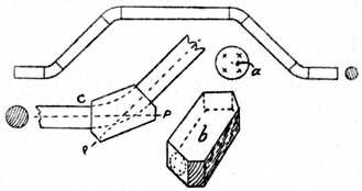
Fig. 201.—Method of Dowelling Cornice Pole by Means of Template. |
Fig. 201 c shows two portions of the circular pole jointed up to a corner block, and the dotted lines P indicate the direct line of pressure and shows the position for the cramp. When the glue is thoroughly set the corner block is sawn and spokeshaved to the desired shape as shown by the dotted line. This method is illustrated to show that, by the use of a suitable template, dowels may be exactly set out even when there is no straight or square face from which to use a marking gauge, and the method may, of course, be applied to many other examples of dowelling at the discretion of the workman.
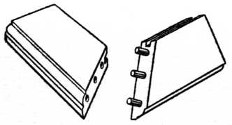
Fig. 202.—Dowelling a Mitred Frame. |
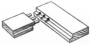
Fig. 203.—Method of Frame Dowelling. (Long and Short Shoulders.) |
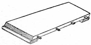
Fig. 204.—Table Leaf with Dowels. |

Fig. 205.— Block for Twist Bit. |
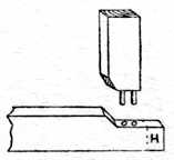
Fig. 206.—Dowelling for Moulded Frame. |
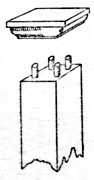
Fig. 207.— Cap. [Pg 99] |
Fig. 202 shows one corner of a mitred and dowelled[Pg 100] frame. It needs little or no explanation beyond the fact that the dowels should be at right angles to the line of joint, and consequently the dowel at the outside edge of the frame will have to be much shorter than the others. This gives a strong and serviceable joint, suitable for many purposes.
Frame Dowelling.—Fig. 203 shows one corner of a frame with long and short shoulders, such as occurs when the upright is rebated through its entire length. The holes in both pieces are bored for the dowels before they are rebated. This avoids any difficulty in endeavouring to bore with only one side of the twist bit in the wood. A similar type of joint is used on nearly all kinds of glass and door frames in cabinet work.
Fig. 204 is a leaf for the screw type of table. Circular dowels are shown at one end, and rectangular wooden pegs at the other; both methods are equally good, and, of course, the dowels are only glued into one leaf. The object of these dowels is to guide the table leaf into its proper position when the leaf engages the table proper, and to make the flat surface of the table top and leaf register correctly and thus ensure a level surface.
Fig. 205 is a wooden block made in two portions and held together by screws; it is used to fasten around a twist bit, the object being to ensure that all the dowel holes are of uniform depth. It may be adjusted as desired and firmly screwed round the twist bit; if the hole is made 1⁄4 in. in diameter it will clip round a 1⁄4-in. or 3⁄8-in. bit and will answer a dual purpose. It is a preventative for bad dowelling.
Fig. 206 is an example of dowelling framing when the moulding on the edge has to be mitred. It is necessary to cut the shoulders away so as to allow the members of the moulding to intersect. The section of the mould is not shown in the sketch for clearness of representation.[Pg 101] The portion marked H is called the "horn," and it is not cut off until after the frame is glued up; its object is to prevent the rail splitting or bursting when knocking up the frame or during the cramping process.
Fig. 207 shows the method of dowelling a moulded cap to the top of a wooden bedstead post or similar pillar where it is desired to avoid any unsightliness.
Fig. 208 is a dining-table leg and portion of the framing, showing the method of dowelling the frame to the leg. Chairs, couch frames, etc., are made in a similar manner.
Fig. 209 shows the top portion of a table leg and a home-made dowel gauge. The gauge is made of any hardwood, and steel wire pins are driven through at the required positions and sharpened similar to the spur of a marking gauge. The legs are sawn and planed up true and square, and the advantage of the gauge is that all legs are marked exactly alike and are therefore interchangeable until glued up. A gauge of this type is easily and quickly made and may be kept for its specific purpose or altered for other work.
Fig. 210 indicates the Queen Anne type of leg, a sketch of same broken below the knee also being given. Here we have another type of irregular setting out, which is accomplished in the following manner. Saw and plane the broken portion of the leg true as shown; take the timber which is to be jointed and treat it in a similar manner; now place four ordinary pins on the lower portion. Carefully place the top portion to the required position and smartly give it one tap with the hammer; this will cause the pin-heads to leave indentations, and if these be taken as centres for boring, accurate work will result. The new portion of the leg is afterwards sawn and wrought to the desired shape.
This is an example of work where it is next to impossible[Pg 102] to use a gauge, and as only one joint is required it is not worth the time taken to make a template.
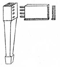
Fig. 208.—Dowelling a Dining-Table Leg. |
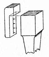
Fig. 209.—Dowel Gauge for Legs. |
The tools used in dowelling are: Brace, countersink, dowel-rounder, twist bit, try-square, marking-awl, and the usual bench tools. The first four are illustrated at Figs. 194, 195, 196 and 197 respectively.
The method of working is: Plane up, mark out, bore holes, countersink, glue dowels and complete joints.[Pg 103]
The method known as "scarfing" is used for the joining of timber in the direction of its length, enabling the workman to produce a joint with a smooth or flush appearance on all its faces. One of the simplest forms of scarfed joint is known as the half lap, in which a portion is cut out at the end of each beam or joist, equal in depth to half the full depth of the beam, and of equal length to the required scarf.
The two pieces before they are placed together form a joint as shown at Fig. 211, the projecting part (A) fitting into the recessed portion marked B and the two pieces being secured in their respective positions by screws.
Fig. 212 shows a dovetailed scarf joint. This is a variation of Fig. 211, the length of the dovetail lap being from 6 ins. to 8 ins. in length.
Fig. 213 is an illustration of a joint designed to resist a cross strain. The face side is left flush, whilst the underside is assisted by an iron plate. The joint is secured with nuts, bolts, and washers. This type of joint is frequently used for joining purlins in roof work; the iron plate on the underside is in this case omitted.
Fig. 214 is designed to resist both tension and compression and is an excellent joint for all purposes. The joint is brought together by using folding wedges as shown in the centre.
Fig. 215 is a variation of Fig. 214, and it will be noticed that tenons are provided on the face and underside[Pg 104] to resist cross strain. Probably this is one of the best varieties of the scarfed joint. Unfortunately, however, its production is somewhat costly, and this may[Pg 105] be the reason that it is not more universally used. Folding wedges are used to secure the two pieces in position.
Fig. 216 is a scarfed joint with undercut vee'd ends which prevent the joint from lipping up or down or sideways. It is a useful joint, calling for careful setting out and accurate craftsmanship. Folding wedges are used in this case to draw up and secure the joint.
Fig. 217 is a "fished joint," and the following difference between a scarfed and fished joint should be noted. A fished joint need not necessarily reduce the total length of the beams to be joined, and fish plates of wood or iron (or a combination of both) are fastened at[Pg 106] each side of the joint. In a scarf joint all surfaces are flush. In Fig. 217 the beams are butt-jointed and secured by wooden plates and iron bolts. The upper plate is let into each beam, and the lower plate is provided with two wooden keys to prevent the beams sliding (or "creeping") upon the lower plate. Iron nuts, bolts, and washers are used to complete the joint.
In the case of the scarfed joint at Fig. 218 (used for purlins) the length of the scarf is usually made about four times that of the depth of tie beam. It has two hardwood keys which force the pieces together and thus tighten the joint.
The methods of scarfing and fish-jointing are many and varied, and, in selecting a joint, the nature of the pieces to be joined and the direction and the amount of the load should be carefully taken into consideration.
The above joints come under the heading of carpentry,[Pg 107] and the ordinary tools such as the saw, plane, boring-bit and chisels are all that are requisite and necessary to produce a sound and serviceable joint. Scarfed joints are generally of large size, and they are usually made by placing the work upon sawing trestles owing to the bench being too small to accommodate the large timbers.
Fig. 219 is a tabled scarf joint which admirably resists tension and compression. It is very easy to[Pg 108] make and fit, and is not materially affected by shrinkage. The rectangular wrought iron straps are knocked up over the joint after the two pieces engage. The length of the joint should be approximately five times its thickness.
Fig. 220 is an example of a lapped scarf joint which is secured with nuts and bolts. It effectively resists compressional stress in vertical posts and it may, if required, be strengthened by the addition of wrought iron fish plates. It is quite a serviceable joint for all general purposes, such as shed or garage building where fairly heavy timbers are used.[Pg 109]
One of the most common forms of hinged joint in use to-day is that formed by using the "butt" hinge, and many troubles experienced by the amateur, such as "hinge-bound," "stop-bound," and "screw-bound" doors, etc., are due to a lack of knowledge of the principles of hingeing. Hinges call for careful gauging and accurate fitting, otherwise trouble is certain to occur.
A "Bound" door or box lid is said to be hinge-bound when the recess which contains the hinge is cut too deep. The frame and the body portion engage too tightly when closed, the result being that the door has always a tendency to open a little. This fault may be in many cases remedied by packing behind the hinge with one or two thicknesses of good stiff brown paper. For packing purposes such as this paper will be found to be of much more value than thin strips of wood or knife-cut veneer, the latter always having a great tendency to split when a screw or bradawl is inserted.
A stop-bound door is the name applied when the door is not finished to exactly the same thickness as originally intended. This causes the door to bind on the stops at the back, as shown at Fig. 221. The difficulty may be remedied by thinning the door a little at the back, or slightly rounding away the portion which[Pg 110] binds.
Screw-bound is a common fault often overlooked by the amateur. It is caused by using screws of which the[Pg 111] heads are too large for the countersunk holes in the hinge, and may be avoided by slightly sinking the holes in the brasswork with a countersink or rose-bit.
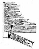
Fig. 221.—Stop-bound Door. |
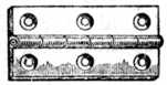
Fig. 222.—Butt Hinge. |
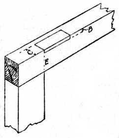
Fig. 224.—Marking for Recess. |
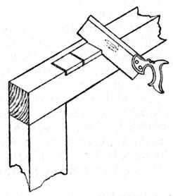
Fig. 225.—Sawing for the Recess. |
Alignment.—Another fault that is fairly common is having the axes of the hinges out of alignment. Especially is this the case when three hinges are used to hang a wardrobe or other large door. It is absolutely necessary in all cases that the exact centres of the pivot-pins of the hinges should be in a straight line.
Particular attention to alignment is necessary when the body and the door frame are shaped on the face side. A familiar example that every reader may inspect for himself is the curved side of a railway carriage body and railway carriage door, where he will notice that a specially wide hinge has to be used at the bottom of the door to give the necessary alignment. Hinges fixed on work with their centres out of truth are often overlooked by the inexperienced worker, and this is a frequent cause of creaking.
Gauging.—Fig. 222 is a sketch of a brass butt hinge, open. Fig. 223 illustrates a similar hinge closed, and shows the gauge set so that the point of the marker is exactly to the centre of the pivot-pin. This distance we will call C. Now turn to Fig. 224. The distance C has been gauged from the face side of the frame. The gauge is then set to the thickness of the hinge at its thickest portion, and to prevent "hinge-bind" see that the gauge is set on the fine side. Remember that the tapered point of the steel spur or marking awl will part the fibres of the timber a little more than the fine point, and give you a wider gauge line than was anticipated when you set the gauge. The inexperienced worker nearly always overlooks this. The result is a hinge-bound door, the cause of which is not discovered by the[Pg 112] worker because he is so sure that he has set the gauge correctly. The distance B, Fig. 226, shows the line gauged for the thickness of the hinge.
Position of Hinges.—Another difficulty to the beginner is the position for his hinges, and it may here be stated that the general rule is to carry a line across the face of the work from the inside of the cross rail and place the hinge at E, as Fig. 224.
Sawing for the Recess.—After marking out for the hinge, as shown at Fig. 224, take a fine-toothed saw (a dovetail saw is considered the best) and saw down as shown at Fig. 225, care being taken not to cut beyond the gauge lines. In this sketch three intermediate saw kerfs are shown, but if the hinge is of great length, say 5 or 6 ins., the removal of the waste wood will be[Pg 113] greatly facilitated by the addition of more intermediate saw kerfs. These cuts sever the cross fibres and allow the timber to be easily pared away in short lengths.
In Fig. 226 we see the tool operation when paring out the hinge recess. At the left of the drawing the recess is shown marked. Take a 3⁄4 in. chisel and, using it as a knife (see A), deepen the gauge lines. Then stab the chisel downwards, as at B, to deepen the end lines. Next, take the chisel and pare away the back of the recess as at C. The work may then be completed by paring neatly till the bottom of the recess is flat.
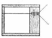
Fig. 227. |
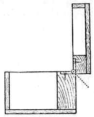
Fig. 228. |
The Hingeing of a Box Lid.
Stopped Hinged Joints for Box Work.—Fig. 227 is a section through a small box similar to a lady's work-box (the back of the box in the illustration is enlarged in thickness to clearly show the position of the hinge). In this case the knuckle of the hinge is let into the woodwork until it is flush with the back of the box, and the gauge would have to be set to the total width of the hinge. The back edges of the lid and the back edge of[Pg 114] the lower portion of the box are planed away at an angle of 45 degrees as indicated by the dotted lines.
Fig. 228 shows the same box with the lid open, and it will be observed that the chamfered edges come together and form a stop which prevents the lid falling backwards and breaking the box. This method of letting-in the knuckle flush is a useful one for box work because the ordinary stock brass butt hinge can be used. Attention may, however, be called to the "stopped butt-hinge," which is specially made to answer the above purpose; in its action a similar mechanical principle as the one applied to the box is used.
Fig. 229.—Strap Hinge. |
Fig. 230.—Reversible or Double-folding Screen Hinge. |
Fig. 231.—Pivot Hinge for Screens. |
Fig. 232.—Non-reversible Screen Hinge. |
Types of Hinges.—Fig. 229 is an elongated variety of the butt hinge, known in the trade as "strap hinge," "desk hinge," or "bagatelle hinge." As its name indicates, it is used on folding bagatelle tables, small writing desks, and other types of work that have but a narrow margin on which to fix the hinges. The long, narrow plates are sunk flush into the wood, the knuckle or rounded portion projecting.[Pg 115]
Fig. 233.—Back Flap Hinge. |
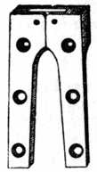
Fig. 234.—Card Table Hinge. |
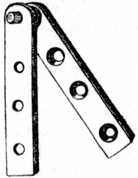
Fig. 235.—Pivot Hinge. |
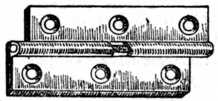
Fig. 236.—Rising Butt Hinge. |
Fig. 230 is an illustration of the reversible or double-folding screen hinge. Half the thickness of this hinge is let into each wing of the draught screen, allowing the screen to be folded either way. The hinge is costly, but effective in use.[Pg 116]
Fig. 231 is a type of pivot hinge which is used to fix at the top and bottom of a screen.
Fig. 232 is the non-reversible screen hinge and, as its name implies, will only fold in one direction.
Fig. 233 is a back flap hinge with a specially wide wing, used for the fall-down leaf of small tables and similar articles.
Fig. 234 is a card table hinge. This is let into the edges of the table, so that all is flush or level both above and below the surface.
Centre or Pivot Hinges.—Fig. 235 is a centre or pivot hinge, used on the top and bottom of wardrobe doors, more particularly the interior door of a three-winged wardrobe where the method of fixing is confined to the cornice and plinth. The flange carrying the pins or pivot is let into the top and bottom of the door, the remaining flange being let into the cornice and plinth respectively.
Rising Butt Hinges.—Fig. 236 is the rising butt hinge, used on dining and drawing-room doors, so that when the door is opened the door rises sufficiently to clear the thickness of the carpet. This hinge has also an advantage over the ordinary butt hinge in that it is self-closing, i.e., the weight of the door plus the bevel on the hinge joint causes the door to close. Band and hook hinges and other ordinary varieties are too well known to require illustrating.
Acute Angle Hingeing.—Fig. 237 is a sectional plan of a corner cupboard showing a good method of hingeing the door. The inset a shows an enlarged view of the corner carrying the hinge, also the adaptor piece c, which is fitted to the inside edge of the cupboard so that the hinged edges are at 90 degrees to the face. This is a far better and stronger method than that shown at b,[Pg 117] which is often attempted with disastrous results. The incorrect method b allows insufficient wood for fixing purposes, and in nearly all cases the thin edge of the door breaks away during the making and fitting, or soon after completion. The adaptor piece may have a face mould worked upon it to give a pilaster-like appearance if fancy so dictates.
Inside Hingeing.—When a door is being hung inside the carcase (that is, not hinged over the ends) it is permissible, in the case of light work, to let the whole thickness of the hinge into the door; and when screwing the door to the carcase it is usual to fix the knuckle of the[Pg 118] hinge flush with the face of the carcase, thus allowing the door frame to stand back, making a break of about 1⁄8 in. with the face. The marking gauge should be set to the full width of the hinge; the mark, gauged on the[Pg 119] inside of the carcase end, thus forms a line to guide the worker whilst fixing the door. To successfully fix a door it generally requires two persons, one to hold the door in position, whilst the other bores the holes and fixes the screws.
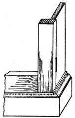
Fig. 240.—Outside Hingeing. |

Fig. 241.—Section. |
Fig. 238 shows the correct method of fitting butt hinges on high-class work. One wing of the hinge is let into the door, and the other wing is let into the carcase or door jamb, thus distributing a proportion of the weight to the carcase end instead of allowing the whole of the weight to be carried by the screws as would be the case in a, Fig. 237. The method of sinking each portion of the hinge into the door and carcase respectively is costly; hence it is not the general practice in cheap work. In Fig. 239 the top and bottom of carcase (T and B) are shown set back to allow the door to close.
Outside Hingeing.—Fig. 240 illustrates the portion of a door frame and carcase end when the door is hung on the face of the carcase. The correct method of letting in the hinge is shown in the enlarged section (Fig. 241), but, as previously mentioned, the hinge may have its entire thickness let into the door frame where it is of a light character. The door frame projects slightly over the carcase end, and occasionally a bead mould is worked on the edge of the door so as to give a finish and partly hide the joint. The bead would, of course, be the same size as the diameter of the knuckle of the hinge; and the knuckle, therefore, will form a continuation of the bead and give a workmanshiplike finish.
Fall Fronts.—Fig. 242 is a sectional view of a fall front writing bureau fitted with centre or pivot [Pg 120]hinges and arranged so that the edges form a stop when the desk front is turned to a horizontal position. The position for the fitting of the brass plates carrying the[Pg 121] pivot-pin is somewhat awkward; but, by first sinking the plates into the carcase ends, and then slotting the edges of the fall, it will be found that the fall front may be put in from its horizontal position, and that sufficient room is left to enable the screwdriver to be manipulated without inconvenience.
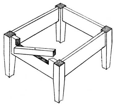
Fig. 243.—Revolving Fly Rail for Table. See Pivoted Fly or Front Rail. |
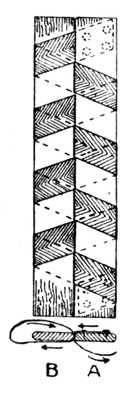
Fig. 244.— Draught Screen Tape Hinge. |
Fly Rail.—Fig. 243 is a sketch of a small table with the top removed. A revolving fly rail is shown pivoted upon a piece of 1⁄4-in. wire. The object of this fly rail is to form a support to the small hinged drop-leaf of the table. This method is suitable for small occasional tables and similar articles.
Draught Screens.—Fig. 244 illustrates the end elevation and plan of a draught screen which is constructed of a light framework and covered with baize or American cloth. The reversible double-folding hinge (Fig. 230) would answer admirably for such a screen. Cases occur, however, where it is desired to hinge a screen to be used for an invalid's bedside, and it is then important that all draught should be excluded through the jointed edges. The double reversible hinge will not fulfil these conditions, and the following method is therefore adopted.
In the plan, Fig. 244, A and B, two laths of hardwood (beech, birch or mahogany answer splendidly) are shown. They are made the same length and the same width as the edges of the screen, the corners being slightly rounded away.
A double-folding, draught-proof hinge is then made as follows: Procure good fine webbing, about 11⁄4 in. wide, and the necessary large-headed tacks. Lay the laths side by side as shown in Fig. 244, and proceed to web them as shown. Commence with the web under the lath A; bring it between the laths and over B; now[Pg 122] take it round the left-hand edge of B, and round the back and between the laths and over A, continuing this method of wrapping the laths until the lower end is reached, and then fastening the webbing as indicated by the dotted lines which represent the tacks. This self-contained hinge is then fixed to the edges of the screen by boring suitable holes through the laths and[Pg 123] using countersunk screws. This is a cheap and efficient method of overcoming the difficulty. A similar method is used for the household clothes horse.
Finger Joint Hinge.—Fig. 245 is a finger joint—a movable interlocking joint used to support the leaf of a Pembroke table. The small portion is screwed to the table rail and the shaped bracket swings out to support the drop leaf. The shaded portion of the bracket shows the timber chamfered away so that the fingers may be easily put behind the bracket to manipulate it. Note that the corners are slightly rounded off, as indicated by the black portion of the sketch, and that the mortises are cut about 1⁄4 in. deeper than the thickness of the timber used. This joint has now been almost superseded by a cheap stamped galvanised iron bracket of exactly the same pattern. The joint, however, is still used for repair work and in cases where a stamped metal bracket has not sufficient overhang.
Knuckle Joint Hinge.—Fig. 246 is a similar type of joint to the above, and is called the knuckle joint. This arrangement of hingeing allows the table leg to swing in an angle of 180 degrees and is much neater in its appearance. It is often used to connect a movable[Pg 124] table leg to the framing, where it is necessary for the table leg and rail to swing outwards and support a drop leaf. The pivot is formed by a piece of 1⁄8-in. or 1⁄4-in. round iron rod running through the centre of the joint.
Open Joint Hingeing.—The next three illustrations apply more particularly to the hanging of the ordinary household door.
Fig. 247 is termed "open joint hanging," from the fact that when the door is open a certain amount of open space exists between the edge of the door and the doorpost. This open space varies according to the position in which the butt hinge is fixed. A section is shown at which the pin of the hinge is let in level with[Pg 125] the face of the door. This will allow the door to open as shown by the dotted line, and it will not clear the architrave moulding.
Fig. 248 indicates the position of the hinge fixed so as to allow the door to open and lay flat back to the architrave moulding. In this instance the butts are made with wider wings, and they are generally provided to take three screws (see Fig. 233, right-hand wing of hinge).
To determine the position of the centre pin of the hinge the following rule is observed. The centre of the pivot pin of the hinge must be half the distance between the face of the door, when closed, and the outside of the architrave moulding.
Close Joint Hanging.—The method known as "close joint hanging" ensures the joint at the hanging stile being in close proximity to the hanging rail; this is shown at Fig. 249. The first member of the architrave moulding is generally a bead of the same diameter as the knuckle of the hinge. The butt hinge is let in as shown in the illustration, and the door when opened forms a close-fitting joint.
The Rule Joint Hinge is used to connect the top and the drop leaf of a table in cases where continuity of design is desired, so that the edge of the top and the leaf will show an ovolo moulding when the table is either open or closed. To the inexperienced worker it presents several difficulties and, if it is a first effort, it is[Pg 126] advisable to try out a sample joint on a couple of odd pieces of timber.
Fig. 250 illustrates the joint when the leaf is opened or in a horizontal position. At Fig. 252 we have the joint when the leaf is let down to a vertical position. It should be observed in the latter figure that the edge A of the drop leaf is in alignment with the axis of the hinge. Steel or brass back-flap hinges (Fig. 233) are generally used and they are sunk into the table as suggested.
Set out the work full size as at Fig. 251, and mark point 1, which is to be the position of the joint. Draw 1, 2, at right angles to the table top. Mark point 3 on the vertical line for the centre of the hinge, and mark point 4 approximately as shown.
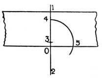
Fig. 251.—Setting Out for Rule Joint Hinge. |
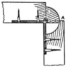
Fig. 252.—The Rule Joint with Leaf Down. |
With compass point on 3 and radius 3 to 4, describe an arc 4 to 5. This gives us the true joint line (1, 4, 5). The distance 0 to 3 is usually determined by the hinge. The knuckle of the back flap hinge is always let into the under side of the wood and the further it is inserted into the wood the more the joint will overlap at A (Fig. 252) which shows the joint when the flap or leaf is down.[Pg 127]
This chapter deals with the joint made by the upright rail of a door frame which carries the lock, or handle, generally called the "slamming stile." Many and varied are the methods used to make a draught and air-tight joint at the meeting of the slamming stile and the carcase end, and our sketches illustrate some of the simplest and also some of the best and most expensive methods.
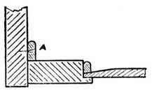
Fig. 253.—Shutting Stile of Cupboard Door. |
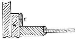
Fig. 254.—Showing Cupboard End Thicknessed (see B). |
Fig. 253 is a part plan of the end of a simple cupboard of which the carcase end is all of one thickness (i.e., not lined up in thickness). A small strip of wood (A) is glued and screwed on the end to form a stop to[Pg 128] the door and to prevent the access of dust to the interior of the cupboard.
Fig. 254 illustrates a similar method; the stop (C) is seen, as in the previous illustration, but it will be noticed also that the carcase end in this case is lined up (see B) to give a pilaster-like appearance to the end, and the moulding is selected on account of its suitability to hide the joint of the lining piece.
Fig. 255 is of a more intricate type, and is often used on jewellers' showcases. The end at the right hand is slightly rebated to receive the frame, and both the rail and the end are grooved with a plough plane. A separate bead is made and glued into the groove of the door frame (D), engaging the groove in the carcase end when the door is closed. The shutting stile and the end are worked with a hook joint (E), and if carefully made they are practically dust-tight.
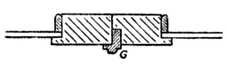
Fig. 257.—Door Rebated for Astragal. |
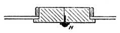
Fig. 258.—Door with Brass Astragal. |
Fig. 256 shows the meeting of two doors which open outwards, a separate piece of timber being made to form a rebated astragal mould (F) and glued to the right-hand door. This method gives a neat and effective finish.
Fig. 257 is similar to the above, with the exception that the rail of the door is rebated (G) to receive the[Pg 129] astragal moulding. This method is preferred on the best class of work, because it shows no unsightly joint at the inside of the door frame.
Fig. 258 illustrates the type of joint made by using a brass astragal mould (H) as employed on high-class work, frequently seen on French furniture of the Louis periods. In Fig. 259 is shown a piece of brass astragal moulding, which may be procured from any cabinetmaker's ironmonger in suitable lengths. It is fixed in position by slightly rebating the edge of the door and fastening with ordinary countersunk brass screws.
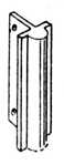
Fig. 259.—Brass Astragal. |
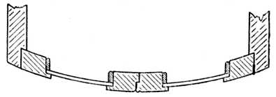
Fig. 260.—Curved Cupboard Doors with Rebated Meeting Joint. |
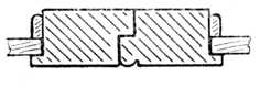
Fig. 261.—Rebated Meeting Joint. |
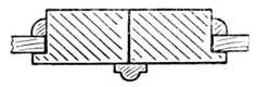
Fig. 262.—Meeting Joint with applied Astragal. |
Fig. 260 is a rebated joint, broken at the front by a bead moulding. The illustration shows its application to a circular-fronted cupboard, and it will be noticed that the hinged rails are received in a rebate which is worked on the carcase ends. The rebated joint at the centre of the two doors is worked slightly on the bevel, so as to allow for clearance when opening the door.[Pg 130]
Two of the commonest meeting joints of doors are seen in Figs. 261 and 262. In the former case the stiles are rebated (as already shown in Fig. 260), whilst at Fig. 262 an astragal bead is glued to the right-hand stile. In Fig. 261 a bead is worked on the right-hand stile to mask the joint.
Fig. 263 is the hook joint used on good-class joinery and cabinet work. A pair of special wood planes are required to make the joint in a cheap and efficient manner. The cost of a pair of 5⁄8-in. hook joint planes is from 6s. to 8s. They are of similar size and general appearance to the ordinary ovolo moulding plane.
Fig. 264 is a special type of hook joint as used on larger work. The joint may be made by using the plough plane, the rebate plane and a suitably-sized bead plane, the loose tongues being inserted as shown and fastened by screws and glue.
Fig. 265 is a rebated joint with loose tongue-slip and astragal mould, suitable for frames over 11⁄4 in. in thickness.[Pg 131] The loose tongue-slip is glued into the right-hand door frame.
Fig. 266 shows a shutting joint used to prevent permeation of dust to the interior of a drawer. The drawer front is grooved and engages a suitably-formed slip which is screwed to the bearer as indicated in the illustration. Occasionally some difficulty is experienced when fitting the slip to a narrow drawer, but this can always be overcome by putting in the screws from the top of the bearer instead of from underneath.
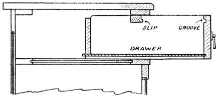 Fig. 266.—Dust-proof Drawer, showing the Front grooved
to engage a Slip which is screwed to the Bearer Rail.
Fig. 266.—Dust-proof Drawer, showing the Front grooved
to engage a Slip which is screwed to the Bearer Rail.
Shutting joints which are required to be "light-tight," such as those used in photographic work, are generally formed by slightly grooving the frame and inserting a strip of black velvet. The friction of the high pile of the velvet prevents the filtration of light through the joint.
When making air-tight showcases, one of the best and simplest tests is to place a lighted candle in the case and close all the doors; if the candle goes out within three minutes you have accomplished your object.[Pg 132]
Nothing definite is known as to the origin of dovetailing, but a quaint and pleasing little story which is well worth repeating runs as follows: A farmer had called in the local "joyner" to do sundry repairs at the homestead. One day, whilst enjoying a humble meal, he sat watching some doves as they hopped about the yard. Struck by the movement of their wedge-shaped tails, it occurred to him to joint his timber by the interlocking method; hence we have dovetails.
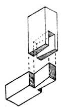
Fig. 267.—A Single Through Dovetail. |
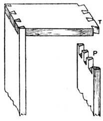
Fig. 268.—Through Dovetails on Carcase Work (P, Pins; T, Tails). |
Through Dovetailing.—One of the simplest forms of the dovetail joint is shown in Fig. 267, where two pieces[Pg 133] of timber are joined by the method known as "through" dovetailing. This method is used in everyday practice for joining the corners of frames, bracket trusses, and a hundred and one other articles.
Figs. 268 and 269 show the method of through dovetailing as applied to the making of boxes, plinths, and general carcase work; it is used in positions where no objection can be taken to the end grain showing on each side of the finished work. In the case of plinths and furniture cornices the foundation frame is made of yellow pine or other cheap wood, and the more expensive and rare timbers are glued and mitred around in various thicknesses and shapes, thus saving the more costly material and strengthening the construction by the method known as laminating. In many cases all that is necessary is to veneer the face sides, thus covering and hiding any unsightliness.
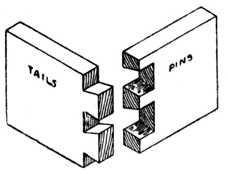
Fig. 269.—Dovetails for Boxes, etc. |
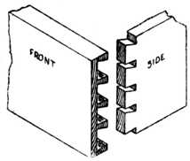
Fig. 270.—Lap-dovetailing for Drawers. |
Lap-dovetailing.—Fig. 270 is an example of lap-dovetailing, such as is used where a drawer side joins with the drawer front. It is not permissible to allow the end grain of the timber to show at the front of a drawer, and this is why resort is had to the lap-dovetail.[Pg 134] As the most general use of the dovetail is for this and similar purposes, we shall therefore deal fully with the methods of marking out and the making of this class of joint.
Angles.—A most important point in the construction of a dovetail is to avoid having the angles of the pins and tails too acute. An inclination of one in eight is considered correct; no hard and fast rule need be obeyed, but the variation should on no account be less than one in six.
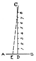
Fig. 271.—How to obtain Correct Angles for Dovetail Template. |
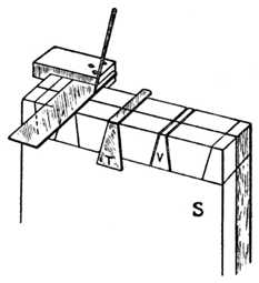
Fig. 272.—Squaring and use of Template. |
Fig. 271 shows a simple method to obtain the correct angle. Take a piece of timber and plane up the face edge (A, B) true and straight; mark out a line (C, D) at right angles to the face edge and space off 8 ins. as shown; now measure a distance of 1 in. (D, E), and join E to point eight. This will give the correct angle for the dovetails, and it may then be transferred to the[Pg 135] joiners' bevel. Many workers who are constantly on dovetail work make a zinc template to the exact angle and keep it specially for the purpose (Fig. 272).
Squaring.—Another important point to remember is that the drawer sides must be true and squared to an exact length and planed up to thickness; otherwise the finished drawer will be in winding and out of truth.
To true and square the ends of drawer sides, drawer backs and drawer front, a most useful little machine is the mitre trimmer; failing this, excellent results can be obtained by using the shooting board.
Gauging.—After squaring up the timber accurate gauging of the ends is another important point. The gauge used should be a cutting gauge, so that the line is incised about 1⁄32 in. in depth, thus effectually cutting the cross fibres of the timber.
Fig. 273 shows the method of using the cutting gauge. The stock of the gauge must be held well up to the end of the timber. The gauge is a most difficult tool for the novice to use, and his trouble is generally caused by holding it too flat. Tilt the gauge a little so that the[Pg 136] thumbscrew shown in the illustration goes nearer to the floor; the blade will then not bite so keenly, and better results will be obtained. The dotted lines indicate the positions which the dovetails will occupy when marked out.
The gauge is set a trifle less than the thickness of the drawer sides to allow for the thickness of the steel cutter, and a gauge line is marked on the inside of the front and all round the drawer back. The gauge is now readjusted so as to leave a 1⁄4-in. lap on the front, and a line marked on the ends of the front and all round the ends of the sides which will engage the drawer front. A glance at Figs. 270 and 273 will make this clear.
The dovetail pins on drawer part and back are spaced out and marked on the end with the aid of the joiners' bevel, the lines being then squared down to the gauge[Pg 137] line by the method shown at Fig. 272—that is, by using the try-square and marking awl.
The drawer front is now put into the bench vice, and the pins are cut as indicated in Fig. 274. The drawer back is treated in a similar manner, but of course in this case it is not "lap" but "through" dovetailing, and the saw kerf goes through the timber and down to the gauge line.
We now come to the point where it is necessary to remove the superfluous material. Fig. 274 shows a method commonly adopted and known as sawing out the waste; the saw is held at an angle and part of the inside portion of the dovetail is cut away as shown. This is a good plan for the amateur, because it shows him at the commencement of his chopping out which will be the pin and which the tail.[Pg 138]
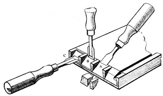 Fig. 276.—Showing the Vertical and Horizontal Chisel
Operations in Lap-dovetailing. A: The Preliminary Roughing-out.
B: Vertical Chiselling; note that the first stab should be just outside
the Gauge Line. C: Marking the Horizontal Cut.
Fig. 276.—Showing the Vertical and Horizontal Chisel
Operations in Lap-dovetailing. A: The Preliminary Roughing-out.
B: Vertical Chiselling; note that the first stab should be just outside
the Gauge Line. C: Marking the Horizontal Cut.
Fig. 276 (A) shows another method that answers well for soft woods such as pine, American whitewood and[Pg 139] satin walnut. The drawer front is laid flat on the bench after it has been sawn, and with a mallet and sharp chisel the corner of the dovetail is knocked off as shown. This takes the bulk of the material away and the dovetail is then pared out square in the usual way. The illustration (Fig. 276) also shows how the chisel is held for vertical paring (B) and for horizontal paring (C).
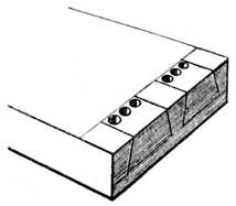
Fig. 277.—Roughing-out by Boring. |
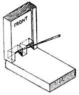
Fig. 278.—Marking Pins on Drawer Side. |
A third method is shown at Fig. 277. With hard,[Pg 140] curly timbers, such as tobacco mahogany and satinwood, it is a laborious process to carefully chop away the timber in small pieces, and to overcome this difficulty we occasionally see the workman take a twist-bit and bore a series of holes as shown. A great portion of the timber may then be split away by inserting the chisel end-way into the grain, after which it is pared to a finish.
As dovetailing is chiefly used for drawer making, it will be of interest to give several illustrations of variations of the joint and its uses.
Fig. 278 indicates the method of marking the position[Pg 141] of the holes in the drawer side. When the paring out of the dovetails is completed the drawer front is turned over on to the side as shown, and the position of the recesses which will engage the pin portions are marked with the marking awl as illustrated.
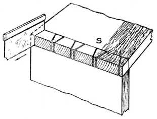
Fig. 279.—Marking by means of Saw Blade. |
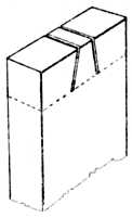
Fig. 280.—Gauge Lines, Scores and Saw Cuts. |
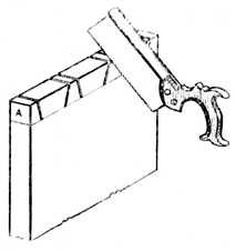
Fig. 281.—Sawing the Drawer Side. |
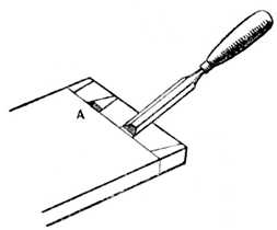
Fig. 282.——Position of Chisel for Cutting Channel. |
The completed drawer back is marked on the sides in an exactly similar manner.
Another method of marking through dovetails is shown at Fig 279. The side is held in position on the end, and the dovetail saw is inserted and drawn out of the saw kerf, thus leaving the exact mark on the drawer-back.
Other workers prefer a pounce-bag instead of a saw. A pounce-bag consists of a piece of fairly open woven muslin filled with a mixture of French chalk and finely-powdered whiting; the muslin is tied up with a piece of thin twine like the mouth of a flour sack. All that is necessary is to place the timber in position and bang the bag on the top of the saw-cuts, when sufficient powder will pass through the bag and down the saw kerf to mark the exact positions of the lines.
Sawing the Dovetails.—After marking out the pins on the drawer sides, we proceed with the next operation, that is, sawing the dovetails ready for chopping out the waste material. The drawer side is taken and firmly secured in the bench screw and sawn as at Fig. 281; it is most important that the saw kerf is kept inside the line which has been scratched by the marking awl. See Fig. 280, where the dotted line represents the gauge line and the outside lines indicate the scores of the marking awl. Failure to observe this condition will result in faulty dovetailing, and it will also prove the necessity for using a finely-toothed and thin-bladed dovetail saw.
To cut out the waste wood (or core), the usual procedure is to saw away the half-dovetails as at Fig. 275. With care, this can be accomplished with the dovetail saw, thus avoiding unnecessary labour and the use of the paring chisel.[Pg 142]
After sawing, the drawer side is placed flat upon the bench, one end in contact with the bench to prevent the drawer side from slipping away; a chisel (preferably bevelled edged) of suitable width is now taken and a small channel is cut as at A, Fig. 282. The method of cutting this channel is shown in the same illustration. The chisel-cut is started about 1⁄8 in. from the gauge line; the cut is made right up to the gauge line, which (when gauging) was made 1⁄32 in. deep so as to cut the cross fibres of the timber. A small piece of waste wood will therefore come away as at A.
The object of cutting this small channel is so that, when the chisel is held vertically on the gauge line and struck with the mallet, the chisel will have no tendency to force its way backward and overshoot the gauge line. The waste or core is now removed by holding the chisel approximately vertical and applying sufficient power to drive it half-way through the timber. The drawer side is now turned over, the operation repeated, and the core pushed out. Care must be exercised whilst cutting away the core to ensure the chisel being held nearly perpendicular; if too much lead (or bevel) be given, a faulty and undercut dovetail will be the result. Undercut dovetails prevent a proper grip of the glue; they give a weak joint, and often cause the face of the drawer side to be splintered whilst driving up the joint. If it be necessary to ease one or two shavings from off the drawer side whilst fitting the completed drawer in the carcase, the joint will show a greater gap as each succeeding shaving is removed.
In common work, especially in soft timbers, many workers allow the pins of a drawer back to run through the sides about 1⁄16 in. and hammer down the pins of the dovetail. This is called "bishoping the dovetails," and is unnecessary if the work be properly made and fitted.[Pg 143]
An alternative method of dovetailing is that of cutting the dovetails first, as shown at Fig. 283. Four or six drawer sides are placed in the vice and the dovetails are sawn at one operation. A little lead (or bevel) from front to back is given whilst sawing, and if this method be used care must be taken to see that the parts of the drawer sides which will be on the inside of the completed drawer are towards the worker, or the lead will be given to the dovetails in the wrong direction.
After sawing the dovetails in this manner the sides are placed in their respective positions on the drawer fronts or backs, and marked with a pounce-bag or by using the saw-blade method. The pins are then cut in the usual way, care being taken that the saw kerf be on the outside of the marks, otherwise the pins will finish too slack to engage with the tails.
Frame Dovetails.—Fig. 284 is a sketch of a constructional frame such as is used for building up a cornice or plinth. At the joint marked A an edge barefaced dovetail is shown. From the separated sketches of the joint (B) it will be seen that the dovetail[Pg 144] can be put together either from the top or the bottom of the framing as all its edges are parallel; glue is relied upon to hold it in position. The centre stretcher rail at Fig. 284 is similar, except that in this case it is a complete dovetail in place of a barefaced one.
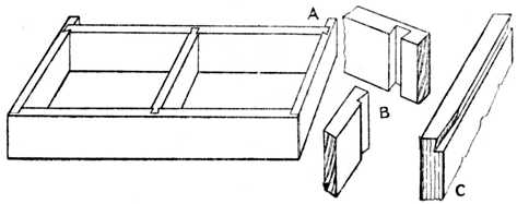 Fig. 284.—Constructional Frame (as for Plinth or Cornice)
showing application of the Dovetail Joint.
Fig. 284.—Constructional Frame (as for Plinth or Cornice)
showing application of the Dovetail Joint.
Some workers, when making either of the above joints, prefer to give a slight bevel to the dovetail, so that it drives tightly into the housing when put together.
A variation of this type of dovetail is frequently used to joint internal uprights to the horizontal shelves of writing desks, cabinets, and bookcases, etc. The dovetailed portion is parallel for about three-fourths of its width; the remaining part is tapered towards the front edge and notched away at the face so as to conceal the method of construction. An illustration of the top portion of a division 14 ins. wide is shown at Fig. 284, C. The other portion is of course dovetailed to fit it.[Pg 145]
Blind Lap-Dovetailing.—At Fig. 285 is shown a type of blind lap-dovetailing. This makes a good, sound joint, but it has the disadvantage of showing a small portion of the timber of the front rail end-way of the grain. Joints of this kind are used for cornices, boxes, etc., and also for painted furniture.
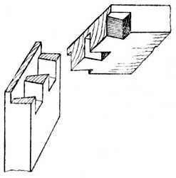
Fig. 285.—Blind Lap-Dovetailing. |
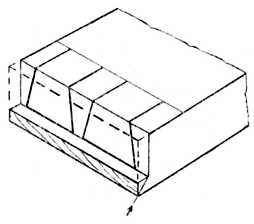
Fig. 286.—Housed and Mitred Dovetail. |
Housed and Mitred Dovetail.—Fig. 286 is another form of dovetail—commonly called a housed and mitred or rebated and mitred dovetail. In this instance we see that a small portion is mitred at top and bottom edges, and when used in plinth or cornice work, or for making tea-caddies, etc., the edges are (when completing the work) covered either with the moulding, which is planted on the cornice or plinth, or with the top and bottom of the box or tea-caddy.
The method of making a housed and mitred dovetail joint is seen in Fig. 286. The ends to be joined are[Pg 146] planed up true and square and then rebated as shown. The dotted lines indicate the portion which has been worked away. The dovetails are now sawn and pared out in the usual way and the part denoted by the arrow is afterwards cut away with a chisel and finally finished to a smooth surface with a rebate plane; the method of working is shown at Fig. 287, where the dovetail pins are seen with the waste portions cut away.
Fig. 287 also shows the method of cutting away the mitred part. A temporary piece of wood is planed to a true mitre and placed underneath the dovetailed piece to form a template. Both pieces of the timber are now secured to the bench with a handscrew or cramp; the template A will form a guide for the chisel and rebate plane and allow a sharp edge or arris to be worked on the mitre.
A Secret Mitred Dovetail joint is illustrated at Fig. 288; it is used in all the better class of cabinet[Pg 147] and box work. Fig. 288 shows the pieces separated; note the mitre at the top and bottom edge.
Dovetail Keying.—Fig. 289 is a method used to prevent wide boards such as signboards, wide and shaped pediments, etc., from casting or warping. It is[Pg 148] called dovetail keying. Beyond calling attention to the fact that the angles at the edges of the keys, where they are bevelled, should be at or about 75 degrees, nothing further need be said, as the drawing is self-explanatory. Angle dovetail keying is shown at Figs. 290 and 291.
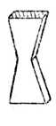
Fig. 290.—Dovetail Key. |
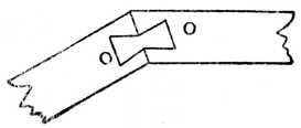
Fig. 291.—Dovetail Keying on the Angle. |
Other Varieties.—At Fig. 292 we have an everyday method of jointing circular-fronted cabinet door frames. Great care must be taken in setting out and making, or a twisted frame will result.[Pg 149]
Then at Fig. 293 are shown two familiar examples of dovetailing the bearer to the carcase end of a dressing table or washstand.
Fig. 294.—Lap-dovetailing the top of a wardrobe to the carcase end. Other examples, such as the top of a bookcase to the sides, will suggest themselves.
Fig. 295.—Side view of a jewel drawer with a moulded drawer front as used on dressing tables, etc. This shows the necessity of bevelled dovetailing in order that the drawer front may be kept as thin and light as possible.
Fig. 296.—Bevelled dovetailing when pins are at right angles to the end cut.
Fig. 297.—Bevelled dovetailing when the centre line of the pins is parallel to the edges of the work, used for making "hoppers," food troughs, knife boxes, etc. One corner of the box shows the joint separated.[Pg 150]
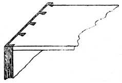
Fig. 294.—Lap-Dovetailing. |
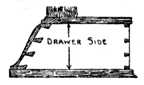
Fig. 295.—Jewel Drawer Side. |
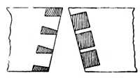
Fig. 296.—Bevelled Dovetailing. |
Fig. 298.—An example of oblique dovetailing, as used on "hoppers" when one piece is vertical and the other piece is inclined.
Fig. 299.—Method of dovetailing small boxes. The box is dovetailed in one width and the top and bottom glued on; the sides and ends are then cut along the dotted line, thus forming the lid. It will be noticed that a specially wide dovetail pin must be left so as to form part of the lid and part of the lower portion.
Setting out the Joint.—For constructing a dovetail joint at the corner of a frame, as Fig. 300, it is necessary at the outset to trim up the ends of the timber square and true. This may be accomplished by neatly sawing to the line and paring the end of the wood with[Pg 152] a sharp chisel, or by bringing the wood to a finish with a finely-set plane, such as an iron-faced smoothing plane. The ends of the wood must be perfectly square when tested from either the face side or from the marked edge.
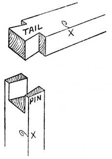
Fig. 300.—Corner Dovetail. |
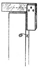
Fig. 301.—Squaring. |
Take a cutting gauge and set it to equal the thickness of the timber, and, holding it as already shown at Fig. 273, strike the gauge lines on the wood as illustrated at Fig. 302, G. Proceed to mark out the dovetail pins, as at Fig. 303; in this illustration G again shows the gauge line. The inclination of the lines across the end of the wood should not be too great, or the joint will be a weak one, and the edges of the dovetails will be liable to crumble away when the work is knocked together.[Pg 153]
Dovetailing Template.—Many workers who are constantly engaged upon dovetail joints make a small wooden template, as shown at Fig. 304. This template is generally of hardwood, such as beech or walnut. The method of obtaining the correct angles of such a template has already been given on p. 134. Notice that the lines bb (Fig. 303) of the dovetail pins do not bevel; they are parallel to the sides of the wood and at right angles to the end of the wood as shown.
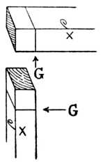
Fig. 302.—Gauging. |
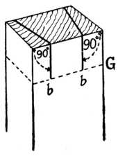
Fig. 303.—Marking the Pins. |
Chisel Work.—After marking out, as shown at Fig. 303, place the wood on the bench and proceed to chop away the centre portion in the following manner. Hold the chisel on the bevel and cut out a small piece to form a channel at the gauge line. Now hold the chisel in a vertical position, and with a mallet strike it so as to make a cut about 1⁄8 in. deep. Then hold the chisel on the bevel again and cut away more waste wood; proceed alternately, first forcing the chisel down vertically, and then paring the wood away with[Pg 154] the chisel held obliquely, until you have cut half-way through the thickness of the wood.
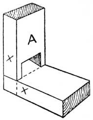
Fig. 305.—Testing. |
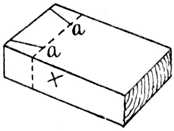
Fig. 306.—The Marked Piece. |
Turn the wood over and repeat the various operations until the core, or waste piece, is removed. Pare away any little irregularities which may be left in the corners with an 1⁄8-in. chisel, thus leaving all smooth and neat. Lay the piece of wood which is to have the dovetail marked on it flat upon the bench, and take the piece with the dovetail pins cut upon it and place in the position shown at Fig. 305.[Pg 155]
Saw Work.—Take a marking awl, or a knitting needle which has had its end sharpened, and mark the lines of the dovetail in a similar manner to that shown at Fig. 307. Remove the piece A, Fig. 305, and the lower piece shown at Fig. 305 will clearly show the marks aa as they appear in Fig. 306. Place the piece (Fig. 306) in the vice, and saw outside the lines AA, as shown in Fig. 308.
After sawing down the lines AA, Fig. 308, place the wood in the vice and, guiding the saw blade with the index finger of the left hand, cut away the small piece at the side (see Fig. 275). Repeat the operation as may be necessary, and the completed joint will be similar to that shown at Fig. 300. If the sawing is not neatly done it may be found necessary to pare the shoulder with a sharp chisel.[Pg 156]
Drawers.—When dovetailing drawers or boxes it is necessary to square up the ends of all the stock and gauge them, as shown at Fig. 273. This illustration shows how to gauge the lines on a drawer side; the dovetailed joint in this case, however, does not run through the drawer front and leave the work unsightly, as the joint at Fig. 300 would do. The method used is shown at Fig. 309, and it is commonly known as lap-dovetailing. Most workers cut the dovetail pins on the drawer fronts and the drawer backs first, after which they mark the drawer sides with the marking awl. The dovetailing of the drawer back is shown at Fig. 310. This is the type known as "through dovetailing," the method being similar in regard to tool operations as the single joint shown at Fig. 300.
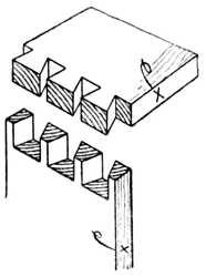
Fig. 310.—Through Dovetailing. |
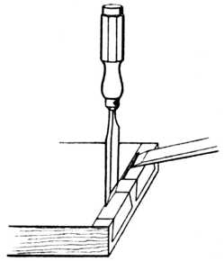
Fig. 311.—Chipping Waste of Lap Dovetail. |
When the pins on the drawer front have been sawn, the waste material is cut away, as at Fig. 311.[Pg 157] First stab down with the vertical chisel, which must make the cut about 1⁄32 in. in front of the gauge line (see illustration). This commencing of the cut slightly in front of the gauge line is a very important feature. The chisel may be likened to a wedge, and if the chisel[Pg 158] edge be placed exactly upon the gauge line and force be applied to the handle, it will force the timber away equally on each side of the gauge line, and the finished depth of the hole will therefore be too deep for the thickness of the drawer side; in other words, it will press itself over the gauge line on both sides.
By taking the first vertical cut on the waste side of the gauge line, and then removing a small piece with the chisel held obliquely, as at Fig. 311, the wood is removed and less resistance is offered to the chisel when the next vertical cut is made. This overshooting the gauge line is a common fault with the beginner, who is puzzled at the result because he is certain he had his chisel exactly on the gauge line when he commenced his vertical cut. It is especially noticeable in soft-grained woods.
To cut away the waste of a lap-dovetail (Fig. 311), the vertical and oblique cuts are repeated until the final trimming up is required, and now is the time to finish both the vertical and the horizontal cuts exactly on the gauge lines.
Some workers prefer to cut the drawer sides first, and if this method is preferred (and it has its advantages for cheap work) several drawer sides are cut at once by placing four or six behind one another in the vice and sawing them all at one operation.
The drawer front is placed in the vice, and the drawer side held upon it, whilst the saw blade is placed in the saw kerf and drawn smartly forward. This will give the required marks at the exact position desired. It must be remembered, however, to saw just inside these dovetail-pin lines, otherwise the finished joint will be too slack, owing to the removal of the sawdust, which is practically equal to the thickness of the saw blade.[Pg 159]
Machine-made Dovetails.—As a general rule machine-made drawer and box dovetails show both the pins and the tails of exactly the same size. The reason is obvious after an inspection of Fig. 314, which shows the position in which the pieces are held during the machining operations. In spite of a certain amount of prejudice they are satisfactory and thoroughly reliable and have their place in modern shop and office fittings.
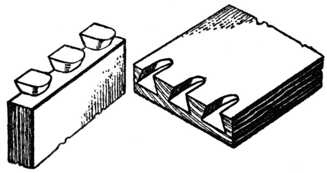 Fig. 312.—Machine-made Drawer Front
and Side, Apart.
Fig. 312.—Machine-made Drawer Front
and Side, Apart.
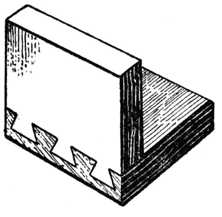
Fig. 313.—The Parts Together. |
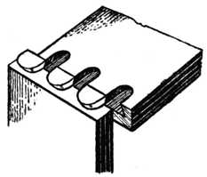
Fig. 314.—Position when Machined. |
The dovetail housing joint should first be carefully[Pg 160] marked out with a marking knife, so as to cut across the fibres of the wood. For obtaining the bevel on the edge of the wood a joiner's bevel may be used, and the angle should not be too acute. (See previous chapter.) Take a chisel and pare away a small channel as at A, Fig. 315, to form a small shoulder to guide the saw.
With a fine tenon or dovetail saw, cut the saw kerf as at Fig. 316. If any difficulty is experienced in cutting the kerf true and square, you may resort to the method shown at C, Fig. 315; a small temporary piece of timber has been screwed on the top of the work to form a guide for the saw.
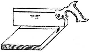
Fig. 316.—Cutting the Saw Kerf. |
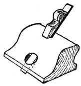
Fig. 317.—Old Woman's Tooth Plane. |
Fig. 315, B, shows the small channel formed by the chisel prior to the sawing operation. The sawing of[Pg 161] the bevelled side is worked in a similar manner; but occasionally we find amateurs who adopt the method shown at Fig. 318. A block of wood (H) is first made by boring a 11⁄4-in. hole through its entire length, and afterwards making a saw cut at the desired bevel. The object of this block, which is kept specially for the purpose, is to form a guide for those who have not full control of the dovetail saw; the back of the saw clears the hole, and the required bevel is obtained. When a saw cut has been made at each side of the groove, the[Pg 162] surplus timber is pared away in the following manner: Cut away portion E, Fig. 319; then cut away portion F, and lastly cut away the apex portion marked G. Continue by this method of paring until the approximate depth is reached. To ensure a correct depth throughout the entire groove, the router plane (or, as it is often called, "the old woman's tooth plane," Fig. 317) is used.
With regard to cutting the alternate piece, it is necessary to first plane the end of the shelf true and square. With a cutting gauge strike the line K, Fig. 320; the required bevel on the edge (J) is then set out, and with the chisel a small channel is again formed. With the tenon or dovetail saw cut down the line K to the required depth, and carefully pare away the wood with a sharp chisel to the correct shape.[Pg 163]
Although mitreing is used in everyday woodwork, it comes last in our list of regular joints simply because it has been partly dealt with in almost every previous chapter. For example, we have mitre halving in Fig. 34, a mitre bridle joint in Fig. 74, a tongued and grooved mitre in Fig. 116, mitred mortise and tenon joints in Figs. 148 and 159, a dowelled mitre frame in Fig. 202, and a mitred dovetail in Fig. 286.
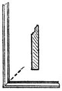
Fig. 321.— Mitred Skirting. |
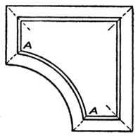
Fig. 322.— Curved Mitre. |
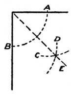
Fig. 323.— Halving the Angle. |
Mitreing.—The term mitreing is generally used to denote the type of joint used at the corner of a picture frame; or where two pieces of wood are bevelled away so as to fit each other, as the skirting or plinth mould at Fig. 321. In these cases the timber is cut so that the joint is at 45 degrees to the face, and the two[Pg 164] pieces, when placed together, form an angle of 90 degrees (a right angle).
The term mitreing, however, is not confined to the fitting of timber around a right angle; it may be justly applied to the fitting of a moulding around an angle irrespective of the number of its degrees.
One often hears such terms as "a half mitre," used to denote the fitting of a moulding around an octagonal column or pedestal, and probably it would be more correct to describe the joint as a mitre cut at 221⁄2 degrees. Mitreing consists of halving the angle and making each piece to fit the line of bisection. Should the angle be bounded by straight lines, as at Fig. 321, then the mitred joint will be a straight line, but should the angle be bounded by a curved and a straight line, as at Fig. 322, A, or by two curved lines, then the mitred joint will have to be a curved line if the mouldings are to be of the same section.
Finding the Angle.—For straight mitres, the mitre joint line is found by bisecting the angle, as shown in the various examples, and the following instructions are given to enable the reader to follow the diagram (Fig. 323). Take a pair of compasses, or dividers,[Pg 165] and with any convenient opening strike out the arc A, B. Put the point of the compasses on A, and mark another arc C; then, without altering the distance between the points of the compass, put the point on B, and mark the arc D. Draw the line E from the corner, so that it cuts through the intersection made by the arcs C and D. The angle A B is now halved by the line E, and this method may be applied to any angle.
Sawing Block.—For sawing mouldings, etc., to their approximate shape, a home-made sawing block is generally used, as shown at Fig. 324. Two pieces of wood are glued one on the top of the other, the required angle is transferred thereto, and the saw kerf made. In the sketch the saw kerfs are shown at 45 degrees, right and left, and other angles and kerfs may be made where desired.
Planing.—After sawing the piece to approximately the correct angle, it is necessary on high-class work to plane the cut end so as to give a perfect finish and enable a glued joint to be made. This may be accomplished by using the plane on the shooting board, as shown at Fig. 325, and, if the worker is constantly using mitres of various angles, it is an easy matter to make new angle blocks and fix them on to the board. Other workers prefer the screw mitre trap shown at Fig. 326. This apparatus takes wide plinth or cornice moulds, and the angle may be altered by fitting temporary packing pieces under the work so as to tilt the moulding to the desired angle. The method of using the plane is indicated in the illustration.
Another method in everyday use by those workers who are constantly mitreing wide pieces of stock at 45 degrees is the "donkey's ear" shooting board illustrated at Fig. 327. The plane is laid on its side on the[Pg 166] surface of the board marked A, and used in a similar manner to that shown at Fig. 325.
A simple method and one that should always be remembered because it is handy when working without a shooting board is shown at Fig. 328. Set the marking or cutting gauge to the thickness of the wood to be[Pg 167] mitred at 45 degrees; then gauge this distance on the wood, as shown at B; draw from the line to the edge, as shown, and saw and plane to a finish. The diagonals of a square give 45 degrees, and this is the method used to mark out the work. The end of the wood must, of course, be square with its edges before marking out in this manner.
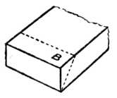
Fig. 328.—Gauging for Mitres. |
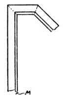
Fig. 329.—Narrow Inner Moulding. |
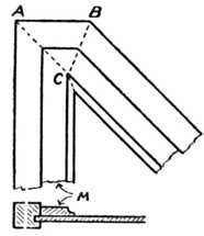
Fig. 330.—Wide Mitred Moulding. |
Fig. 329 shows a bevelled framing into which has been mitred a narrow moulding M so as to show a correct margin around the panel.[Pg 168]
Fig. 330 shows a similar framing, but with a wide moulding M mitred around it. To obtain a correct intersection of this moulding, the angles A and B are bisected. The bisection of the angles meets before the width of the moulding is cleared, therefore the angle C will again have to be bisected, and the finished joint will appear as shown. One of the simplest of mouldings with a large flat face has been chosen to illustrate this. The moulding could be all in one width, as shown, or it could be built into the framing in separate pieces, the wide flat and the piece carrying the mould.
Curved Mitres.—We now come to what are probably the most difficult of all mitres, viz., curved mitres, and the writer well remembers in his apprenticeship days his first experience of attempting to fit the mouldings around the door shown at Fig. 331 by using straight mitres at A. This, of course, is impossible if the mouldings are of the same section and it is desired to make all the members correctly intersect. If straight mitres are used the section of the curved moulding will have to be of a different shape from the section of the straight moulding, and in these days of machine-made mouldings this method is seldom resorted to. It is better, cheaper, and easier to make curved mitres when the necessary machinery is at hand.
To Set out a Curved Mitre (see Fig. 332).—Draw a section of the moulding full size, A, as shown at the left hand of the illustration, and project lines round the framing, as shown V, W, X, Y and Z. Where the lines V, W, X, Y and Z intersect at the corner D, it clearly shows that a straight mitre will not cut all the points of intersection. A curved line will cut all the intersections, and a template made of cardboard, sheet zinc, or veneer, should be made to this shape. At the[Pg 170] left-hand side the geometrical setting out is shown for obtaining the curve without having to resort to drawing it freehand.
Take half the width of the moulding, as shown by dotted line A, and where it cuts the approximation of the curved mitre place the point of the compasses and strike out a circle as shown; with the same radius place the compass point on B—that is, the inside point of the mitre, and cut the circle on the right and left with the small arcs shown at aa. With the same radius put the compass point at the junction of the circle and mitre line, C V, and cut the circle at right and left, viz., ee.
Now rule a line through aa, and another line through ee, and where these lines cut each other it will give the[Pg 171] correct radius of the curved mitre. The advantage of knowing the correct radius of a curved mitre is of great benefit to the skilled machinist, as it enables him to set up his machine so as to give a definite result.
Mitreing a Moulded Door Frame.—Fig. 333 illustrates the method of mitreing the moulded portion of a door frame where the joint is dowelled, not tenoned. A small wooden template is made out of beech or other hardwood, having its ends cut at 45 degrees. This template is placed on the rail, as shown, and held in position by placing both the rail and the template in the vice. The face of the template forms a guide for a wide chisel, and enables the worker to gradually pare away the moulding to the correct angle.
For sawing the mitres on large mouldings such as are used on the lid of a gramophone or wireless cabinet, a mitre sawing box and a panel saw may be used as indicated at Fig. 334.[Pg 172]
Fig. 335 shows a circular frame made up in two thicknesses, the segments being screwed to each other and the joints crossed in two layers. This is a very strong method, and it is used for making circular frames and curbs up to 15 ft. in diameter. The segments can be either long or short, the only important condition being that they must be marked out and sawn to the correct radius. Fig. 337 shows a board marked out in segments for this class of work. The longer the boards the better will they cut up, as it gives more opportunities of cutting one piece out of the other as at A A.
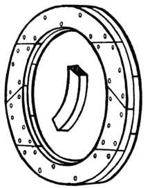
Fig. 335.—Circular Frame in Two Thicknesses. |
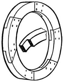
Fig. 336.—Circular Rim in Halved Segments. |
Fig. 338 shows how to begin to put the work together.[Pg 173] To continue this, fit other segments in position and screw them to D and E respectively. The completed work is illustrated at Fig. 335.
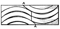
Fig. 337.—Board Marked for Circular Jointing. |
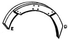
Fig. 338.—Putting Circular Work Together. |
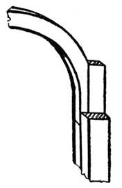
Fig. 339. |
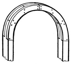
Fig. 340. |
Method of Building up Semicircular Head of Door Frame.
Fig. 336 shows a circular rim, or curb, made of segments which are halved together. This method is suitable for heavy work, where the timbers are of considerable size. The halvings are cut on the ends of[Pg 174] the segments to any convenient shape or bevel, each one being marked so as to fit its fellow.
When extra length is required, semicircular or circular work is built up out of four or five thicknesses of[Pg 175] wood, and the method is called laminating. The method of building up the semicircular head of a door frame by this method is shown at Figs. 339 and 340.
The shaped framing for kidney-shaped writing tables and similar classes of work is built up by laminating pieces of 3⁄4-in. or 1-in. wood, after which the face side is veneered so as to hide the glued joints. Fig. 341 shows a sketch of one quarter of an elliptical table frame levelled up and ready for applying the veneer.
Lamination.—If we apply to the dictionary for the word "lamination," we find that lamellar structure is the arrangements in thin plates or layers one over the other, usually having the end joints alternating, and it is a condition which allows of cleavage in one direction only. This method is used for nearly all descriptions of free or irregular curves, such as sweeps, bends, ogee shapes, and segments of circles. The timber is marked out in suitable lengths, rough-sawn and then planed true on the face, glued together, and when set the sides are cleaned up to the required shape. It is one of the strongest methods of construction, and necessarily costly. Pulleys, pulley rims, and a hundred and one other jobs are built by this method.
Fig. 342 shows one half of a core box built by this method, ready to be worked to the required shape.[Pg 176]
Weather boards.—For outdoor buildings, such as garages, garden sheds, toolhouses, etc., "weatherboarding" is often preferred to ordinary matchboarding, chiefly because of the facility with which it throws off the rain. The boarding can be bought ready prepared. Three methods of jointing are shown in the sections at Fig. 343. The method indicated at A shows one of the most satisfactory types, its boards being planed and moulded as shown. The other two examples are more common. The boarding at B is rebated, whilst[Pg 177] at C each board overhangs its lower neighbour. The boards for C and D are always cut tapered as indicated.
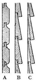
Fig. 343.— Weather Boards. |
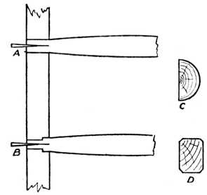
Fig. 344.—Ladder Rungs. |
The end grain is usually protected by nailing on a strip of timber, chamfered on both edges.
Ladders.—Fig. 344 illustrates the method of fastening the rung (or stave) of a ladder to the side. At A the common method is shown, the stave being simply driven into the hole and wedged. At B a much better but more expensive method of construction is given. The stave here is socketed and the pin turned to a smaller diameter. In both cases the rung, or stave, is painted before being driven into the side and wedged.
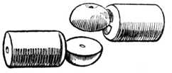
Fig. 345.—Cornice Pole Joint. |
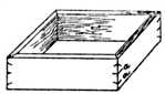
Fig. 346.—Veneer Keying. |
Ladder sides are made in two distinct ways. One method is known as "a plank side," the side being cut from a plank as shown at the section D; the other method is called "a pole side," and is constructed by cutting a straight larch pole in half and using half of the pole for each side of the ladder, as at section C.
Hinged Cornice Poles.—Fig. 345 shows a hinged joint for cornice poles and should be of interest to those who are frequently removing from house to house. The joint will adapt itself to fit any bay window (even a square bay) and it is formed by turning and cutting the two pieces shown. To fix a cornice pole to a bay window one of these joints is required for each angle of the bay, the pole being cut into suitable lengths and fixed to the hinged joints by the use of the dowel screw[Pg 178] and a little hot glue. It is perhaps needless to remark that the diameter of the joint should be of the same diameter as the cornice pole, to enable the rings to easily slide over the surface.
For fastening a turned ornament (or "finial") to the end of a cornice pole a double pointed screw (known in the trade as a "dowel screw") is used, one half of which is screwed into each part of the pieces to be joined.
Veneer Keying.—Fig. 346 illustrates the method of strengthening the corners of boxes which are made of 1⁄4-in. or 3⁄8-in. timber, by securing the corners with veneer keys. The box is mitred and glued in the usual manner, and after allowing sufficient time for the glue to set, saw kerfs are made as shown at a a. A piece of thin saw-cut veneer is afterwards glued into the saw kerfs, and when dry the face is levelled off flush. This method is often used previous to veneering the face side of the box with rare veneers, and it is also useful for repair work. Note that the saw cuts are made at an angle. Small picture frames are sometimes keyed instead of nailed.
Muntin and Skirting Joint.—In the case of panelled rooms it is usually necessary to scribe the muntins (or uprights) to the skirting. The method is shown in Fig. 347. The bead moulding of the skirting is only partly removed, as indicated, leaving a solid portion to which the muntin is skew-nailed.
Cot Joint.—At Fig. 348 is shown an interesting joint used largely in the making of Indian cots. The illustrations indicate how the cross bar and end bar are mortised into the leg. A turned hardwood peg fits into a suitably provided hole and locks the tenons, which are dry jointed (not glued) in position. The head of this[Pg 179] peg forms an ornament (A) at the top of the leg and should fit tightly in position. At B are seen the end and cross bars in their relative positions when apart from the leg. C shows the end bar and cross bar when the cot is fixed, but in this illustration the leg is purposely left out of the drawing for a clear representation. D shows the joints of the leg portion when the part of the leg above the line at A is sawn off. The hardwood peg is shown at E.
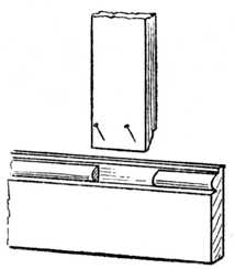
Fig. 347.—Fixing Muntin to Skirting. |

Fig. 348.—Joint for Home-made Cot. |
Sideboard Pillars, etc. (Fig. 349).—For economy, sideboard pillars are sometimes built up as indicated, the "shaft," the "base," and the "swell" being made up of three distinct pieces. Turned pins are left on the shaft and the base, and these are secured at the joint by the use of a double-pointed screw called a dowel screw. This does away with the necessity of reducing the squares at the top of the wood and thus getting the turning out of a large piece of wood.[Pg 180]
Notched Joints.—Fig. 350 is a "notched joint," where two joists, or scantlings, cross each other, the object of the joint being to prevent the joists moving from their position without materially weakening them. For an end notch, see Fig. 352.
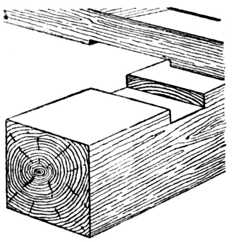
Fig. 350.—Notched Joint. |
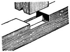
Fig. 351.—The Saddle Joint. |
The "saddle joint" (Fig. 351) is used for connecting[Pg 181] upright posts to heads or sills of framing, and undoubtedly takes its name from its similarity to the way in which the saddle fits the horse. It does not weaken the framing as does a mortise and tenon joint, and shrinkage has little effect upon the joint. The "cogged joint," used for connecting purlins to rafter and joists to girders, is illustrated in Fig. 353.
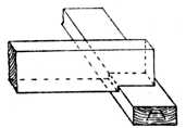
Fig. 352.—End Notch. |
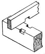
Fig. 353.—Cogged Joint. |
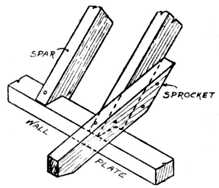
Fig. 354.—Birdsmouth Joint. |
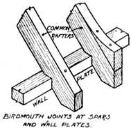
Fig. 355.—Another type of Birdsmouth Joint. |
Birdsmouth Joints.—Fig. 354 is a "birdsmouth joint," a simple joint which can be readily made by the handsaw, used when a spar fits on the wall plate. A nail is shown securing it in position.[Pg 182]
Fig. 355 shows the birdsmouth joint where the spar runs over the outside of the wall plate, thus allowing a fixing for an ornamental finish.
Rafter Joint.—Fig. 356 shows an everyday joint, as used at the juncture of the principal rafter and the tie-beam in roof truss work. A sketch of piece A is shown separated, and it should be noted that the depth of the cut portion B should not be more than one-fourth of the total width of the tie-beam.
Pelleting.—Fig. 357 indicates the method of pelleting and screwing the corner of a picture frame. The mitre[Pg 183] joint is first screwed and a pellet of the same timber is made to fill the hole which has been bored to receive the screw head. The pellet is glued in position and levelled off.
Patera Covers.—In cases where the style of ornament permits of it, patera covers are used instead of pelleting. Fig. 358 shows the jointing of shaped spandrails, etc., to carcase ends of light portable cabinet work, etc. A hole is bored about 3⁄8 in. deep into the end, and a screw is used to hold the shaping in position. After fixing the rail a small turned button, called a turned patera, is inserted in the hole, thus giving an ornamental finish, as shown in the front view. The turned patera is driven fairly tightly into the hole, but not glued. When it is required to take the article apart a chisel is carefully inserted under the edge of the patera to remove it, and the screw can then be taken out. This method is often used for the construction of light hanging bookcases and similar objects. For a bookcase having an end 8 ins. wide three of these turned buttons and three screws would be used to secure the[Pg 184] shelf to the end. Pateras in different styles may be purchased from any dealer in woodworking sundries.
Buttoning.—The tops of tables, sideboards, etc., should not be fixed with screws in the ordinary way. At the front, screws can be driven upwards through the top rail, but at the sides and back, buttons should be employed, as in Fig. 359, so that the top is free to shrink. It is otherwise liable to split if immovably fixed. The tops of kitchen tables are usually fixed in this way, to allow for shrinkage.
Frames for Oil Paintings.—The method of making joints for frames on which the canvas is stretched for oil paintings is shown at Fig. 360. They are generally mitred at the corners and fitted with loose wedges. The four parts of the frame can be held temporarily by a piece of thin board while the canvas is being tacked to the edges of the frame. In the accompanying illustrations Fig. 360 shows the action of the wedges when[Pg 185] tightening up the frame, the result being to open the mitre joint. Fig. 361 shows the position of the saw cuts for receiving the hardwood wedges. Note that the parallel groove is carried the full length of the material for greater convenience in cutting. The other groove is taken from the outer angle of the mitre joint inwards. The cut finishes with due regard to the necessary taper; see the dotted lines showing taper in Fig. 360. The grooves will be wide enough after being cut with an ordinary hand-rip saw, but for large work they are usually grooved on the circular saw bench.
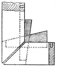
Fig. 360. |
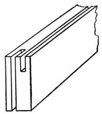
Fig. 361. |
Joint and Method of Wedging the Frames of Oil Paintings.
Corrugated Steel Fasteners.—It is now many years ago since the steel saw-edge fastener first appeared on the market, but probably 80 per cent. of amateur woodworkers have never yet sampled its advantages.
In appearance it resembles a miniature corrugated galvanised sheet such as is used for roofing purposes, with the exception, however, that the corrugations are[Pg 186] divergent instead of being parallel and that one end is ground down to a cutting edge (see Fig. 363, A). They are made in various sizes from 1⁄4 in. to 1 in. in length, whilst in regard to width they are classed by the number of corrugations and not by their measurement.
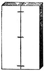
Fig. 362.—Jointing Boards. |

Fig. 363.—Jointing a Frame. |
The Use of Saw-edge Corrugated Steel Fasteners.
To use the fastener no special tools are required; it is simply driven in with a hammer exactly as though it were a nail; once in position, however, to get it out is worse than drawing teeth. The corrugations add to the strength of the device, the wood fibres closing around them, age and rust but emphasising their grip.
Wall Plugs.—At Fig. 364 four types of wall plugs are shown: a, the ordinary rectangular tapered wall plug to drive between the joints of the brickwork; b, the circular tapered wall plug as used to plug a wall after a star-shaped brick drill has been used; d, a twisted wall plug used for similar purposes to the wedge a, but considered[Pg 187] to be superior in holding power owing to its twisted formation; c is another type of wall plug considered to have great tenacity by reason of its corrugations. Wall plugs are required in nearly all cases where it is necessary to joint woodwork to brickwork, as, for instance, heavily-framed silvered mirrors to the walls of shops.
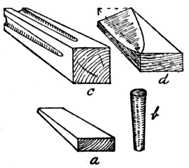
Fig. 364.—Wall Plugs, Four Varieties. |
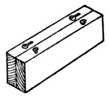
Fig. 365.— Slot Screwing. |
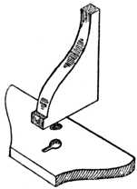
Fig. 366.—Slot Screwing a Bracket. |
Slot Screwing, or Keyhole Screwing, is a most useful way of joining light woodwork in such a manner that the fixing method is not exposed to the eye. A stout screw is inserted to within 3⁄8 in. of the head, as at Fig. 365. In the adjoining piece a hole is bored with a centre bit and a slot is cut with an 1⁄8 in. chisel. The two pieces of timber are placed together, and by sliding the upper piece forward the screw runs up into the slot or keyhole and secures the joint. Fig. 366 shows the application of the joint fixing a shaped bracket to the shaped shelf; the bracket and shelf are inverted in the illustration to clearly show the method of jointing. For heavy work special brass plates are obtainable for this[Pg 188] purpose; one plate is let flush into the upper piece and the other plate into the lower piece.
Battening (Fig. 367).—A good method of joining cross battens to drawing boards and other wide surfaces is shown here. After boring for the screws, slots are cut so as to allow the screws to move along the slots when shrinkage takes place. In Fig. 368 a similar method is applied to secure the drawer bottom to the drawer back. If shrinkage takes place in the drawer bottom and it leaves the groove in the drawer front, the screws are slackened, the drawer bottom is knocked up into the groove, and the screws again inserted. For drawing boards, etc., specially made elliptical-shaped slotted brass socket cups are made to receive the screw heads.
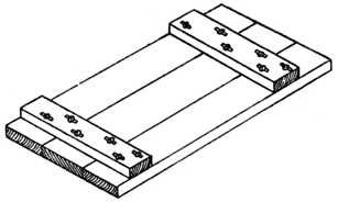
Fig. 367.—Battening. |
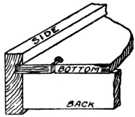
Fig. 368.—Drawer Bottom Joint. |
Puzzle Joints are not only interesting in[Pg 189] themselves, but are often excellent studies in craftsmanship. The majority of them, if to be satisfactory as puzzles, call for very careful setting out and cutting, entailing the same degree of skill that is demanded for high-class cabinet work. For this reason several examples may well find a place in a volume dealing with woodwork joints. As[Pg 190] a rule, these puzzles should be made in hardwood, such as dark walnut or beech, as in whitewood the joints are soon liable to wear.
Chinese Puzzle.—The ingenious puzzle of the Chinese type shown in Fig. 369 is probably older than many of us could guess, but as it is one that can be made by any woodworker we give full directions as to how it may be constructed. The complete article may be called, in form, a six-pointed pyramid. It is made up of twenty-one different pieces, each cut from wood 1⁄2 in. wide and 1⁄2 in. thick; 3⁄8 in. wood may be used if preferred. For the purpose either sycamore or white maple is the most useful.
Fig. 370. |
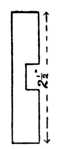
Fig. 371. |

Fig. 372. |
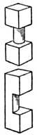
Fig. 373. |
The Three Cross Pieces. Key Piece.
The pieces required are as follows:—
Fig. 370.—Six pieces, 31⁄2 ins. long, with a half slot cut in the centre as shown. This slot must be exactly the width of the wood's thickness, and cut exactly half way through, so that, if two pieces are placed across by means of the halved joint, their surfaces will be flush. The slot must also be exactly in the centre.[Pg 191]
Fig. 371.—Six pieces, size 21⁄2 ins. long, with a half-cut centre slot similar to that of Fig. 370.
Fig. 372.—Six required, these being 11⁄2 ins. in length, and with slots in the middle as before.
Fig. 373.—One of these last six requires special treatment, as it forms the key block of the puzzle. After its slot has been cut, one half of the narrow part must be sawn away, as shown in Fig. 373. The inner edge must also be gently rounded. The special use of this vital piece, which we will call the "key," will be fully explained presently.
Fig. 374.—Then, in addition to these, there are three central bars to make. Like the other parts they are 1⁄2 in. by 1⁄2 in., but are each 41⁄2 ins. long, and are cut as shown in Fig. 374. The end projections a are 1⁄2 in. long, and the cut-away part is exactly half the depth of the wood. Two of the three pieces (X and Y in Fig. 374) are similar, but the slot b of the third one (Z) is only 1⁄4 in. wide instead of 1⁄2 in. As will be noticed, this 1⁄4-in. slot is not in the centre, but corresponds with the right-hand half of the larger slots of X and Y.
In making these twenty-one pieces, what should be[Pg 192] borne in mind is that the different parts fit closely into each other. Consequently the slots, in width, must be cut so as to grip the thickness of the wood; in depth they must be exactly half this thickness.
Fitting the Puzzle.—The three central bars must first be joined, as those form the skeleton framework of the structure. Fig. 375 shows them in position, but as it is a puzzle in itself as to how they can be got thus some explanation is necessary.
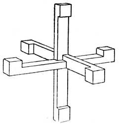
Fig. 375.—The Three Central Bars in Position. |
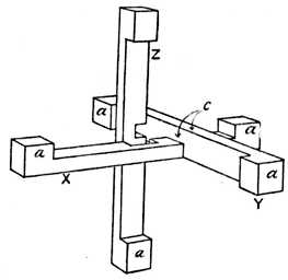
Fig. 376.—How to Adjust the Bars. (Note position of projecting ends, a.) |
First Stage.—First take the bars X and Y (see Fig. 374) and arrange them as shown in Fig. 376. It is most important that the projections a of X face upwards, and that the projections a of Y face towards the centre. Then take the bar Z and bring it flat into the slot of X. The little slot of Z, however, must remain above the slot of X. Then slide the bar Y along to the centre, so that the part lettered c slips into the little slot of bar Z.[Pg 193]
This may seem confusing to read, but it is easy to follow when the pieces are in one's hand. The result of this rather clever arrangement is that the six arms of Fig. 375 are all exactly the same length, width, and thickness. They are also arranged so that in each arm may be clasped one piece each of Figs. 370, 371, and 372. The three central arms may, of course, be set up in a different order, and here we have merely chosen the way that is the most simple to describe and illustrate.
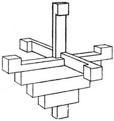
Fig. 377.—Beginning to place on the Cross Pieces. |
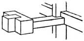
Fig. 378.—Placing the Key Piece to overlap end projection of Central Bar. |
Second Stage.—In the remaining part of the work the chief difficulty is to keep the puzzle from falling to pieces before the key finally locks it. Take the longer cross parts, Fig. 370, and clasp one to each arm. The six need not all be put on meanwhile, but only those which are most easily handled. The next size (Fig. 371) may then be put on.
In the ordinary course each arm could be completed with its three cross pieces till the sixth was attempted, and here the reader would find that, at the last moment,[Pg 194] his attempt was frustrated. He could not get the last small piece in, as other bars lock the puzzle. Here it is that the "key" comes in.
The Key Piece.—When the writer fits up the puzzle he finds that three of the arms may straight away be fitted complete with their three cross parts. These are the ones where the longer cross piece (Fig. 370) lies flush with the back of the central bar (see Fig. 377). This is easily found out when at work on the puzzle. In the case of the other three arms there is, of course, a gap caused by the long slots of the central bars. Adjust the parts on the first-named three arms, and then deal with the fourth arm, putting in all three cross parts. For the little one here, use the "key."
By placing the "key" so that it overlaps the end projection of the arm (see Fig. 378) a space is left at the centre, and means is thus afforded for getting in the three cross parts on the remaining two arms.
This practically ends the puzzle. While the "key" is in its overlapping position the parts may be separated, but if it is turned round on its narrow neck, so that it is in exactly the same position as the other five small cross parts, it locks the whole thing so tightly that nothing but sheer force could loosen the twenty-one pieces.
So far as the order of putting together is concerned, there are many equally satisfactory ways, these being determined by the ease or difficulty that one experiences in holding the half-finished puzzle. It all comes to the same in the end, and the "key" must be placed on one bar before the last three arms can be completed. The "key," moreover, must be on one of the bars where a gap is left at the centre, and not on one where Fig. 370 lies flush against the central arm as in Fig. 377.[Pg 195]
Undoing the Puzzle.—To take the puzzle to pieces all that is required is to turn the "key" half round and push the other two cross bars on that arm towards the outer point. The cross bars below may then be removed, and the whole structure falls to pieces.
The double dovetail puzzle (Fig. 379) consists of two pieces of wood (usually one dark and the other light) which, upon examination, appear to be dovetailed together from each face. This interlocking arrangement is obviously impossible, and the solution of the puzzle is only apparent on examining Fig. 380, where it will be seen that the joint fits together diagonally.
At Fig. 381 are given the diagrams for setting out. Draw the outline of the elevation, plan and end view. The end view in the first instance is indicated by 3, 4, 5 and 6, and it measures 17⁄8 ins. square. A 17⁄8-ins. square is simply used because 2-ins. wood generally finishes this size after it is planed up. Set out a square (A, B, C, D) which stands corner-ways in the larger square (3, 4, 5, 6). Project the lines D A and C B upwards as at 1, and on to this drawing (1), set out the dovetail according to your own idea of length, width and bevel. Project the four points of your dovetail downwards into the end view, and where these lines cut A, B, and D, C draw them downwards and rebate them into your original plan. This will give the true shape of the two dovetails and it is to this shape that you will cut your joint.
The joint is in due course glued up, and next day you will plane and waste off the four corners of your model. The end view shows one corner shaded D, 3, A; this and the other three corners are wasted away. The result is that the dovetails are thrown into a plane different from that in which they were made, showing as Fig. 379.[Pg 196]
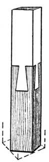
Fig. 379.— Double Dovetail Puzzle. |
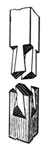
Fig. 380.— The Two Parts Separated. |
(Note that dovetail is cut on slant, the thickness at front being less than at back. See dotted line on plan below.)[Pg 198]
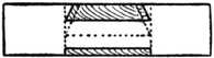 Fig. 384.—Plan, looking upwards.
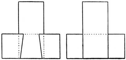 Fig. 385A.—Front Elevation. Fig. 385B.—Back Elevation.
The model calls for very accurate workmanship and the joints must not be undercut during the sawing and chiselling operations. The completed model measures 6 to 7 ins.
The Dovetail Puzzle joint illustrated at Fig. 382 has perhaps caused more argument and controversy amongst woodworkers than any wooden joint. It may be neatly made in maple, walnut, or mahogany, and afterwards glued up. The question everyone asks is: How was it put together?
Take two pieces of wood such as mahogany, walnut or birch, about 6 ins. long by 17⁄8 ins. wide and 11⁄4 ins. thick. Truly plane them up and then set out and make the tenon and dovetailed piece (Fig. 383). Next mark out and cut the cross bar to fit its corresponding piece. The joint will go together in a somewhat diagonal direction as it is pushed into position from the back; when closed it will appear as at Fig. 382. For guidance, a plan, part elevation and back elevation are added.
An improvement after you have gained experience in the making of this joint is to make a similar joint, leaving the face (B, Fig. 386) blind; it then does not show the bevelling of the dovetail at the end C. In other words, keep the line C, say, 1⁄4 in. back from the face of B. The joint should be glued up and it will then appear to the average worker that it is an impossible proposition. (See Fig. 401, page 208.)
Carefully note that the edges A, A are parallel to each other in spite of the fact that they slope in one direction.
A further variation of the puzzle is seen in Fig. 387. Here the joint is much simpler, and can easily be followed from the illustration.[Pg 200]
Cross Puzzle.—Fig. 388 illustrates a six-piece puzzle joint, similar in some respects to Fig. 369, but very much simpler. Both a back and front view of the piece D is shown for clearness of illustration. The method of assembling the pieces is as follows: Hold piece B upright, and fit piece D across; at the same time note that the small x marks are opposite each other. Take piece E and, holding it as shown, slide[Pg 201] it up the piece B (see arrow) until E engages D and the small o marks are opposite each other. Piece C is now fitted behind D, and then piece F will slide in position and push downwards. The key-piece A is now put in position, and the puzzle is completed.
Mortising Puzzle.—The ordinary mortising exercise is, after the first two or three attempts, generally voted as uninteresting, but, although the simple puzzle shown in Fig. 389 is practically an exercise in mortising, yet, forming as it does a puzzle, it becomes a fascinating piece of work.
The puzzle is composed of three pieces of wood, each 4 ins. long, 11⁄2 ins. wide, and 1⁄2 in. thick. In each piece a mortise 11⁄2 ins. by 1⁄2 in. should be cut as shown at 1, Fig. 390. In one piece, marked 2, a groove is cut on[Pg 202] one side, 3⁄8 in. wide, and in another piece (3) a similar slot, but 1⁄2 in. wide, is cut, and this is continued on the other side of the groove to a depth of 1⁄8 in. The three pieces should be set out on a 13-ins. by 11⁄2-ins. by 1⁄2-in. length of wood, as shown at Fig. 391, and when ready sawn apart.
The puzzle is put together as shown at Fig. 389. In the first place, hold No. 1 piece upright as shown at A, then take No. 2 piece with slot uppermost and push it through the opening in No. 1 piece until the nearest side of the slot projects 1⁄8 in. as indicated at B. Next place No. 3 piece on with the slot at the back as shown at C, and push it down until it touches the bottom of the opening in No. 2 piece as illustrated at D. The only[Pg 203] thing to do now is to push No. 2 piece as far as it will go to make the figure as shown at E.
In this puzzle the parts should fit together fairly tight, but should not be too stiff.
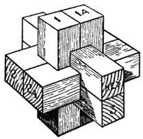
Fig. 392.—Chinese Cross Puzzle. |
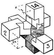
Fig. 393.—Method of Putting Together. |
Chinese Cross.—Fig. 392 shows a variation of the Chinese cross, which is perhaps the most fascinating of all woodwork puzzles. Take six pieces of hardwood[Pg 204] (Fig. 394) and accurately plane and saw them so that each piece will measure 4 ins. by 1 in. by 1 in. Bearing in mind that all the cuts are multiples of 1⁄2 in., set out, saw and chisel five of the pieces to agree with the sketches 1, 1A, 2, 2A and 3. Leave the key piece intact. The puzzle is of course to fit all the six pieces together so as to form the Chinese cross or block given at Fig. 392. As a clue to the method of assembly we give another sketch (Fig. 393) showing four of the pieces fixed together. The reader can, if he so desires, make the puzzle to a smaller scale by using six pieces of wood each measuring 2 ins. long by 1⁄2 in. by 1⁄2 in.
Diagonal Chinese Cross.—At Fig. 395 is given a sketch of a completed Chinese block or cross puzzle in which the various pieces of wood go together diagonally. Plane up a piece of hardwood (which may be about 14 ins. or 15 ins. long) so that it measures on its end 1⁄2 in. square. Cut the wood into six pieces which measure about 21⁄4 ins. long, and then proceed to mark out, saw and pare up with the chisel two pieces like[Pg 205] sketch A, three pieces like B, and one key piece as C. Now fit these together to make the completed cross. The solution is left to the reader.
Fig. 396 shows a combination of six pieces which, when fitted together, will make the Chinese cross similar to Fig. 392. Plane up the strip of hardwood (birch preferred) so that it measures 1⁄2 in. square at the end and proceed to mark out and make two pieces[Pg 206] like D, two like E, one like F, and one piece like G. Put the pieces together to form the Chinese cross. Again the reader is left to solve the problem of fitting.[Pg 207]
Square Puzzles are of endless variety. Four of these are shown, all simple to make, but not equally simple to solve. The only material required for each is a[Pg 208] 5-ins. square piece of 1⁄8-in. fretwood or plywood; or, if preferred, pieces of different colour may be used. The diagrams are given exactly half size, and the lines may be set out direct on the wood. It will be noticed that all four puzzles are strictly geometrical in character.
Fig. 397 is made up of six pieces and is the simplest of the group to solve. Although containing only five pieces, Fig. 398 will be found to give more trouble.
Fig. 399, with ten pieces, is undoubtedly the most trying puzzle, and will be found as baffling as many jig-saw pictures. Fig. 400, again, presents only moderate difficulties.
If the reader prefers, he may cut the squares to the size illustrated instead of enlarging them.
Angle, mitre, 163, 164
Angles for dovetails, 134
Astragals, 128, 129
Back flap hinges, 115, 116
Barefaced (see under Tenon).
Barred door joint, 55
Barrow-wheel joints, 20
Battening, 188
Bevelled dovetailing, 149
Bevelling, guide block for, 161
Birdsmouth joints, 181
Blind lap-dovetailing, 145
Boards, weather, 176
Bolts for scarf joint, 107, 108
Boring away waste, 41, 42
Box, laminated core, 175
Box lid, hingeing, 113
Boxes, dovetails for, 133
Brace and bit, use of, 41, 42
Brass astragal, 129
Bridle joint, mitred, 36, 37
Bridle joint, oblique, 37, 38
Bridle joints, 35
Bridle joints, setting out, 39
Butt hinge, 110, 111
Butt hinge, rising, 115, 116
Butting mitred joint, 8
Buttoning, 184
Carcase work, dovetailing, 149
Card table hinges, 115, 116
Chair joint, interlocking, 91
Chinese cross puzzle, 203
Chinese cross puzzle, diagonal, 204
Chinese puzzle, 189, 190
Chisel used in dovetailing, 137, 138, 153
Chiselling (bridle joints), 45
Chiselling (halved joints), 30, etc.
Chiselling (mortise and tenon joints), 89, etc.
Circular frames, 172
Clamping, 80, 82
Close joint hingeing, 125
Cogged joints, 181
Column joints, 179
Combing joint, 55
Core box, laminated, 175
Corner dovetail, 152
Corner joints, halved, 14
Corner tongued joints, 55, 56
Cornice frame dovetailed, 143, 144
Cornice pole, dowelling, 97, 98
Cornice pole joints, 177
Corrugated steel fasteners, 185
Cot joints, 178
Countersink bit, 96
Cradle for planing, 52
Cradle for planing dowels, 94
Cramping glued joints, 11, 12
Cramping tongued and grooved mitre joint, 56, 57
Cross halving joints, 18, 23
Cross puzzle, 200
Cross puzzle, Chinese, 203
Cross puzzle, diagonal, 204
Cross tongues, 51, 52
Curved work, joints for, 172
Diagonal cross puzzle, 204
[Pg 210]
Dogs, iron, 10, 11
Donkey's ear shooting board, 167
Door frames, semicircular head, 173, 175
Door joints, barred, 55
Doors, "bound," 109
Doors, hingeing, 116-119
Doors, shutting joints of, 127, 129
Dovetail angle template, 134, 154
Dovetail, corner, 152
Dovetail grooving, 160
Dovetail halved joints, 17, 19, 20
Dovetail, housed and mitred, 145
Dovetail joint, the 132
Dovetail puzzles, 195, 196, 197, 198, 199
Dovetail, secret mitred, 146
Dovetail-wedged tenon joint, 75
Dovetailed keys, 147, 148
Dovetailed scarf joint, 103, 104
Dovetailing, bevelled, 149
Dovetailing, blind lap, 145
Dovetailing, lap, 133
Dovetailing, oblique, 151
Dovetailing, through, 132
Dovetails, frame, 143
Dovetails, machine made, 159
Dovetails, sawing, 141, 155
Dovetails, setting out, 151
Dowel cradle for planing, 94
Dowel plate, steel, 93
Dowel rounder, 96
Dowel with groove, 94, 95
Dowelling frames, 100
Dowelling joints, 93
Dowelling table legs, 101
Dowels, making, 93
Drawbore pinning, 78
Drawer bottom joint, 188
Drawer joints, dust-proof, 131
Drawer ploughslips, 10, 11
Drawers, dovetailing, 133, etc., 156
Dreadnought file, 81, 82
Drop table joint, 20
Dust-proof drawer joints, 131
Fall fronts, hingeing, 119
Fasteners, corrugated steel, 185
Feather tongues, 51, 52
Fencing, joint for, 71
File, dreadnought, 81, 82
Finger joint hinge, 122, 123
Fished joint, 105, 106
Flap (back) hinges, 115, 116
Floor boards, 48
Fly rails, 120, 121
Fox-wedging, 76
Frame dovetails, 143
Frame joints, Oxford, 26, 27
Frame, mirror, with bridle joints, 37
Frames, circular, 172
Frames, dowelling, 100
Frames for oil paintings, 184
Gate joint, 68, 69
Gauge, marking, 28, 29, 40
Gauge, marking dovetails with cutting, 135
Gauging boards for dowelling, 97, 98
Gauging for hinges, 110, 111
Glued joint, the, 1
Glueing dowelled joints, 97
Glueing rubbed joints, 2
Grooved joints (see Tongued and Grooved), 48
Grooves, ploughing, 58
Grooving, dovetail, 160
Halved and dovetailed joints, 17, 19, 20
Halved and mitred joints, 16
Halved joint, the, 13,
Halved joints, setting out, 28
Halved scarf joint, 103, 104
Halving joints, cross, 18, 23
Hammer head tenons, 80
Handscrews, 11, 12
Haunched tenons, 65
Hinge, butt, 110, 111
Hinge, finger joint, 122, 123
[Pg 211]
Hinge, knuckle joint, 122, 123
Hinge recesses, 112
Hinge, rule joint, 125
Hinged cornice pole, 177
Hinged joints, 109
Hingeing box lid, 113
Hingeing, close joint, 125
Hingeing doors, 116-119
Hingeing draught screens, 121
Hingeing fall fronts, 119
Hingeing, open joint, 124
Hinges, gauging for, 110, 111
Hinges, various, 110, 114, 115, 116
Hook joints, 130
Housed and mitred dovetail, 145
Interlocking chair joint, 91
Iron dogs, 10, 11
Japanese self-wedging tenon joint, 72
Joint, drawer bottom, 188
Joint, fished, 105, 106
Joint, interlocking chair, 91
Joint, tabled scarf, 107
Joint, tie beam scarf, 106
Joints,
barefaced tenon, 64
barred door, 55
barrow wheel, 20
battened, 188
birdsmouth, 181
bridle, 35
butting mitred, 8
cogged, 181
column and pillar, 179
combing or locking, 55
cornice pole, 177
cot, 178
cross halving, 18, 23
dovetail, 132
dovetailed and wedged tenon, 75
dowelling, 93
dust-proof drawer, 131
fencing, 71
for curved work, 172
garden gate, 68, 69
glued, 1
halved, 13
halved and dovetailed, 17, 19, 20
haunched tenon, 65
hinged, 109
hook, 130
ladder, 177
laminated, 10, 11, 172, 175
lap, 13
light-tight, 131
meeting, 129
miscellaneous, 176
mitre-faced tenon, 77
mitre bridle, 36, 37
mitre halved, 16
mitred, 163
mitred and tenoned, 72, 73
mitred and tongued, 56, 57
mortise and tenon, 64
notched, 180
oblique bridle, 37, 38
oblique halved, 15, 23
ogee-shaped, 8
open slot mortise, 80
partition, 24, 25
ploughing for tongued and grooved, 58
puzzle, 189
rafter and tie beam, 182
rafter (tenon), 77
rebated door, 129
roof, 34, 37, 38
roof (tenon), 77
rubbed, 1
saddle, 180
sash bar, 79
scarf, 103
screen, 114, 121
scribed and tenoned, 72
setting out bridle, 39
setting out halved, 28
setting out tenon, 83
shouldered tenon, 70, 71, 79
shutting, 127
skirting and muntin, 178
T, 14, 18
tie, 22, 23
[Pg 212]tongued and grooved, 48
tongued corner, 55, 56
trestle, 24
tusk tenon, 74, 75
weather board, 176
wheelwright's self-wedging tenon, 75
Keyhole screwing, 187
Keying, dovetail, 147
Keying, veneer, 178
Keys, dovetailed, 147
Knuckle joint hinge, 122, 123
Ladder joints, 177
Laminated joints, 10, 11
Lamination, 175
Lap dovetailing, 133
Lap dovetailing, blind, 145
Lap joints, 13
Laths, winding, 3
Lid, hingeing box, 113
Light-tight joints, 131
Locking (inter) chair joint, 91
Locking joint, 55
Marking gauge, 28, 29, 40
Matchboarding, 49
Meeting joints, 129
Mirror frame with bridle joints, 37
Mitre box, saw used in, 171
Mitre bridle joint, 36, 37
Mitre, curved, 163, 164, 168, 169
Mitre faced tenon joint, 77
Mitre halved joints, 16
Mitre sawing block, 165
Mitre, setting out a curved, 168, 169
Mitre template, 170
Mitre trap, screw, 165, 166
Mitred and housed dovetail, 145
Mitred and tenoned joint, 72, 73
Mitred butting joint, 8
Mitred dovetail, secret, 146
Mitred frames, dowelling, 99, 100
Mitred joint, the, 163
Mitred tongued joints, 56, 57
Mitres, curved, 169
Mortise and tenon joints, 64
Mortise, open slot, 80
Mortising, 87
Mortising puzzle, 201
Mouldings, mitreing, 165, 171
Muntin joint, 178
Notched joints, 180
Oblique bridle joint, 37, 38
Oblique dovetailing, 151
Oblique joints, halved, 15, 23
Ogee-shaped joint, 8
Open-joint hingeing, 124
Open slot mortise, 80
Oxford frame, halved joints for, 26, 27
Partition joints, 24, 25
Patera covers, 183
Pelleting, 182
Piano front joint, 9, 11
Pinning, 73
Pinning, drawbore, 78
Pins, dovetail, 136
Pivot hinges, 114, 115, 116
Plane, old woman's tooth, 161, 162
Plane, the plough, 58, 59, 60
Planes, tongueing and grooving, 61
Planing, cradle for, 52
Planing mitred work, 165
Plinth frame dovetailed, 143, 144
Plough plane, the, 58, 59, 60
Ploughing for tongued and grooved joints, 58
Ploughslips, glueing, 10, 11
Plugging, 186
Pole joints, cornice, 177
[Pg 213]
Puzzle, Chinese cross, 203
Puzzle, cross, 200
Puzzle, diagonal Chinese cross, 204
Puzzle joints, 189
Puzzle, mortising, 201
Puzzles, dovetail, 195, 196, 197, 198, 199, 208
Puzzles, square, 205
Rafter and tie beam joints, 182
Rafter joint (tenon), 77
Rebated door joints, 129
Reversible screen hinge, 114, 115
Rising butt hinge, 115, 116
Roof joints, 34, 37, 38
Roof joints (tenon), 77
Roof work, scarfed joints used in, 103, 104, 106
Rubbed joint, 1
Rule joint hinge, 125
Saddle joints, 180
Sash bar joints, 79
Sawing block for mitreing, 165
Sawing (bridle joints), 41, etc.
Sawing dovetails, 141, 155
Sawing for hinge recesses, 112
Sawing (halved joints), 30, 31, etc.
Sawing (tenons), 84, etc.
Scarf joint, fished, 105, 106
Scarf joint for heavy timber, lapped and bolted, 107, 108
Scarf joint, tabled, with straps, 107
Scarf joints, 103
Scarf joints, tie beam, 106
Screen hinges, 114, 115, 116
Screens, hingeing draught, 121
Screwing, slot or keyhole, 187
Screws, hiding with pateras, 183
Scribed tenon joint, 72
Secret mitred dovetail, 146
Setting out dovetails, 151
Shooting board, 7, 10, 11
Shooting board for mitreing, 165, 166, 167
Shoulders, 14, etc., 19, 23
Shoulders of tenons, tongueing, 63
Shoulders, sawing, 45
Shoulders (tenon), 70, 71, 79
Shoulders, tenon with tongued and grooved, 79
Shutting joints, 127
Sideboard pillar joints, 179
Skirting and muntin joint, 178
Skirting, mitred, 163
Skirting mould, double, 56, 58
Slot screwing, 187
Spandrel, jointing shaped, 9, 11
Spandrel with tongued joint, 52, 53
Sprocket wheel, 68
Square puzzles, 205
Steel fasteners, corrugated, 185
Stiles, shutting and meeting, 128
Stopped bridle joint, 37, 38
Stopped dovetail halving, 17
Strap hinge, 114, 115
Straps for scarf joints, 107, 108
Stump tenons, 65
T joints, halved, 14, 18
Table (card) hinges, 115, 116
Table frame, laminated, 174, 175
Table framing, 79
Table joint, drop, 20
Table leg with bridle joint, 36
Table legs, dowelled, 101
Table tops buttoned, 184
Table with circular rim, joint for, 25
Tabled scarf joint, 107
Template, dovetail angle, 134, 154
Template for mitreing, 170
Tenon (and mortise) joints, 64
Tenon joint, dovetailed and wedged, 75
Tenon joint, mitred and moulded, 72, 73
Tenon joint, scribed, 72
Tenon joint, self-wedging, 72
[Pg 214]
Tenon joint with mitred face, 77
Tenon joint with tongued and grooved shoulders, 79
Tenon joints, barefaced, 64
Tenon joints, drawbore pinning for, 78
Tenon joints, setting out, 83
Tenon joints, shouldered, 70, 71, 79
Tenon joints, tusk, 74, 75
Tenoned scarf joint, 103, 105
Tenons, hammer head, 80
Tenons, haunched, 65
Tenons, inserted, 81, 82
Tenons, stump or stub, 65
Tenons, tongueing shoulders of, 63
Tenons, twin, 72, 73, 80
Through dovetailing, 132
Tie beam and rafter joints, 182
Tie beam scarf joint, 106
Tie joint, 22, 23
Tongue slips, 130
Tongued and grooved joints, applications of, 52
Tongued and grooved joints, 48
Tongued and grooved joints, ploughing for, 58
Tongued joints, corner, 55, 56
Tongueing and grooving planes, 61
Tongues, cross and feather, 51, 52
Tongues, loose, 55
Toothing plane, 161, 162
Trestle joint, 24
Try square, 9, 28
Tusk tenon joints, 74, 75
Twin tenons, 72, 73, 80
Twist bit, 96
Vee'd matchboarding, 49, 50
Vee'd scarf joint, 105
Veneer keying, 178
Wall plugs, 186
Weatherboards, 176
Wedges for tenon joints, 67
Wedging, fox, 76
Wedging frames, 184
Wheel joints, barrow, 20
Wheel, sprocket, 68
Wheelwright's self-wedging tenon joint, 75
Winding laths, 3
PRINTED IN GREAT BRITAIN BY THE WHITEFRIARS PRESS, LTD.,
LONDON AND TONBRIDGE.
[Pg 215]
WOODWORK JOINTS: HOW MADE AND WHERE USED (Revised Edition). With 400 Illustrations and Index. 3/6 net.
CABINET CONSTRUCTION (Revised Edition). With 25 Plates, over 300 Illustrations and Index. 3/6 net.
CARPENTRY FOR BEGINNERS. With over 300 Illustrations and Index. 3/6 net.
PRACTICAL UPHOLSTERY. With over 100 Illustrations and Index. 3/6 net.
STAINING AND POLISHING (Revised Edition). Illustrated, and with Appendix of Recipes and Index. 3/6 net.
FURNITURE REPAIRING AND RE-UPHOLSTERY. With 175 Illustrations, 30 Photographic Plates and Index. 3/6 net.
WOOD TURNING. Fully Illustrated (with enlarged details) and with Index. 3/6 net.
WOOD CARVING. With over 200 Illustrations and Index. 3/6 net.
PERIOD FURNITURE. 200 Illustrations and Index. 3/6 net.
HOUSEHOLD REPAIRS AND RENOVATIONS (Revised Edition). Illustrated. 3/6 net.
TIMBERS FOR WOODWORK. Illustrated, with Index. 3/6 net.
WOODWORK TOOLS, AND HOW TO USE THEM (Revised Edition). With 275 Illustrations and Index. 3/6 net.
FURNITURE DESIGNS (New Series). 46 pages of Designs. 2/6 net.
DINING ROOM FURNITURE DESIGNS (New Series). 2/6 net.
BEDROOM FURNITURE DESIGNS (New Series). 46 pages of Designs. 2/6 net.
MODERN BEDROOM SUITE DESIGNS (New Series). 2/6 net.
LIVING-ROOM FURNITURE DESIGNS. 24 Designs. 2/6 net.
CABINET DESIGNS (New Series). Over 50 Designs. 2/6 net.
TABLE DESIGNS. 46 pages of Designs. 2/6 net.
BUREAU AND BOOKCASE DESIGNS (New Series). 2/6 net.
LIGHT CARPENTRY DESIGNS (New Series). 46 pages of Designs. 2/6 net.
TOY AND MODEL DESIGNS. 46 pages of Designs. 2/6 net.
OUTDOOR WOODWORK DESIGNS. 46 pages of Designs. 2/6 net.
DOOR MAKING. Fully Illustrated, and with a series of Special Designs. 2/6 net.
THE WOODWORKER. 6d. monthly. Free specimen sent on application.
EVANS BROTHERS LIMITED, MONTAGUE HOUSE.
RUSSELL SQUARE, LONDON, W.C.1
A Free Specimen Copy sent on receipt of postcard
In this Magazine the man who does bench work at home will find month by month the precise guidance he needs for efficient, economical work. The principal features include practical directions, illustrated by working drawings, for the construction of plain and ornamental furniture and all kinds of indoor and outdoor woodwork. Joint making, tool manipulation, staining and polishing, repairing, craft problems and everyday difficulties are also regular features dealt with in an eminently practical way.
The contributors to The Woodworker are expert craftsmen who know exactly where the home woodworker's difficulties lie, and who, from long experience, are able to impart their knowledge to others.
If you have not yet seen The Woodworker, send a postcard for a specimen copy.
(Free Specimen Copy sent on receipt of postcard)
The Woodworker Annual Volume, 370 pages, 6s. 6d. net
From any newsagent or direct from
Evans Bros., Ltd., Montague House, Russell Square, London, W.C.1
End of the Project Gutenberg EBook of Woodwork Joints, by William Fairham

*** END OF THIS PROJECT GUTENBERG EBOOK WOODWORK JOINTS ***

***** This file should be named 21531-h.htm or 21531-h.zip *****
This and all associated files of various formats will be found in:
        http://www.gutenberg.org/2/1/5/3/21531/

Produced by Chris Curnow and the Online Distributed
Proofreading Team at http://www.pgdp.net


Updated editions will replace the previous one--the old editions
will be renamed.

Creating the works from public domain print editions means that no
one owns a United States copyright in these works, so the Foundation
(and you!) can copy and distribute it in the United States without
permission and without paying copyright royalties.  Special rules,
set forth in the General Terms of Use part of this license, apply to
copying and distributing Project Gutenberg-tm electronic works to
protect the PROJECT GUTENBERG-tm concept and trademark.  Project
Gutenberg is a registered trademark, and may not be used if you
charge for the eBooks, unless you receive specific permission.  If you
do not charge anything for copies of this eBook, complying with the
rules is very easy.  You may use this eBook for nearly any purpose
such as creation of derivative works, reports, performances and
research.  They may be modified and printed and given away--you may do
practically ANYTHING with public domain eBooks.  Redistribution is
subject to the trademark license, especially commercial
redistribution.


*** START: FULL LICENSE ***

THE FULL PROJECT GUTENBERG LICENSE
PLEASE READ THIS BEFORE YOU DISTRIBUTE OR USE THIS WORK

To protect the Project Gutenberg-tm mission of promoting the free
distribution of electronic works, by using or distributing this work
(or any other work associated in any way with the phrase "Project
Gutenberg"), you agree to comply with all the terms of the Full Project
Gutenberg-tm License (available with this file or online at
http://gutenberg.org/license).


Section 1.  General Terms of Use and Redistributing Project Gutenberg-tm
electronic works

1.A.  By reading or using any part of this Project Gutenberg-tm
electronic work, you indicate that you have read, understand, agree to
and accept all the terms of this license and intellectual property
(trademark/copyright) agreement.  If you do not agree to abide by all
the terms of this agreement, you must cease using and return or destroy
all copies of Project Gutenberg-tm electronic works in your possession.
If you paid a fee for obtaining a copy of or access to a Project
Gutenberg-tm electronic work and you do not agree to be bound by the
terms of this agreement, you may obtain a refund from the person or
entity to whom you paid the fee as set forth in paragraph 1.E.8.

1.B.  "Project Gutenberg" is a registered trademark.  It may only be
used on or associated in any way with an electronic work by people who
agree to be bound by the terms of this agreement.  There are a few
things that you can do with most Project Gutenberg-tm electronic works
even without complying with the full terms of this agreement.  See
paragraph 1.C below.  There are a lot of things you can do with Project
Gutenberg-tm electronic works if you follow the terms of this agreement
and help preserve free future access to Project Gutenberg-tm electronic
works.  See paragraph 1.E below.

1.C.  The Project Gutenberg Literary Archive Foundation ("the Foundation"
or PGLAF), owns a compilation copyright in the collection of Project
Gutenberg-tm electronic works.  Nearly all the individual works in the
collection are in the public domain in the United States.  If an
individual work is in the public domain in the United States and you are
located in the United States, we do not claim a right to prevent you from
copying, distributing, performing, displaying or creating derivative
works based on the work as long as all references to Project Gutenberg
are removed.  Of course, we hope that you will support the Project
Gutenberg-tm mission of promoting free access to electronic works by
freely sharing Project Gutenberg-tm works in compliance with the terms of
this agreement for keeping the Project Gutenberg-tm name associated with
the work.  You can easily comply with the terms of this agreement by
keeping this work in the same format with its attached full Project
Gutenberg-tm License when you share it without charge with others.

1.D.  The copyright laws of the place where you are located also govern
what you can do with this work.  Copyright laws in most countries are in
a constant state of change.  If you are outside the United States, check
the laws of your country in addition to the terms of this agreement
before downloading, copying, displaying, performing, distributing or
creating derivative works based on this work or any other Project
Gutenberg-tm work.  The Foundation makes no representations concerning
the copyright status of any work in any country outside the United
States.

1.E.  Unless you have removed all references to Project Gutenberg:

1.E.1.  The following sentence, with active links to, or other immediate
access to, the full Project Gutenberg-tm License must appear prominently
whenever any copy of a Project Gutenberg-tm work (any work on which the
phrase "Project Gutenberg" appears, or with which the phrase "Project
Gutenberg" is associated) is accessed, displayed, performed, viewed,
copied or distributed:

This eBook is for the use of anyone anywhere at no cost and with
almost no restrictions whatsoever.  You may copy it, give it away or
re-use it under the terms of the Project Gutenberg License included
with this eBook or online at www.gutenberg.org

1.E.2.  If an individual Project Gutenberg-tm electronic work is derived
from the public domain (does not contain a notice indicating that it is
posted with permission of the copyright holder), the work can be copied
and distributed to anyone in the United States without paying any fees
or charges.  If you are redistributing or providing access to a work
with the phrase "Project Gutenberg" associated with or appearing on the
work, you must comply either with the requirements of paragraphs 1.E.1
through 1.E.7 or obtain permission for the use of the work and the
Project Gutenberg-tm trademark as set forth in paragraphs 1.E.8 or
1.E.9.

1.E.3.  If an individual Project Gutenberg-tm electronic work is posted
with the permission of the copyright holder, your use and distribution
must comply with both paragraphs 1.E.1 through 1.E.7 and any additional
terms imposed by the copyright holder.  Additional terms will be linked
to the Project Gutenberg-tm License for all works posted with the
permission of the copyright holder found at the beginning of this work.

1.E.4.  Do not unlink or detach or remove the full Project Gutenberg-tm
License terms from this work, or any files containing a part of this
work or any other work associated with Project Gutenberg-tm.

1.E.5.  Do not copy, display, perform, distribute or redistribute this
electronic work, or any part of this electronic work, without
prominently displaying the sentence set forth in paragraph 1.E.1 with
active links or immediate access to the full terms of the Project
Gutenberg-tm License.

1.E.6.  You may convert to and distribute this work in any binary,
compressed, marked up, nonproprietary or proprietary form, including any
word processing or hypertext form.  However, if you provide access to or
distribute copies of a Project Gutenberg-tm work in a format other than
"Plain Vanilla ASCII" or other format used in the official version
posted on the official Project Gutenberg-tm web site (www.gutenberg.org),
you must, at no additional cost, fee or expense to the user, provide a
copy, a means of exporting a copy, or a means of obtaining a copy upon
request, of the work in its original "Plain Vanilla ASCII" or other
form.  Any alternate format must include the full Project Gutenberg-tm
License as specified in paragraph 1.E.1.

1.E.7.  Do not charge a fee for access to, viewing, displaying,
performing, copying or distributing any Project Gutenberg-tm works
unless you comply with paragraph 1.E.8 or 1.E.9.

1.E.8.  You may charge a reasonable fee for copies of or providing
access to or distributing Project Gutenberg-tm electronic works provided
that

- You pay a royalty fee of 20% of the gross profits you derive from
     the use of Project Gutenberg-tm works calculated using the method
     you already use to calculate your applicable taxes.  The fee is
     owed to the owner of the Project Gutenberg-tm trademark, but he
     has agreed to donate royalties under this paragraph to the
     Project Gutenberg Literary Archive Foundation.  Royalty payments
     must be paid within 60 days following each date on which you
     prepare (or are legally required to prepare) your periodic tax
     returns.  Royalty payments should be clearly marked as such and
     sent to the Project Gutenberg Literary Archive Foundation at the
     address specified in Section 4, "Information about donations to
     the Project Gutenberg Literary Archive Foundation."

- You provide a full refund of any money paid by a user who notifies
     you in writing (or by e-mail) within 30 days of receipt that s/he
     does not agree to the terms of the full Project Gutenberg-tm
     License.  You must require such a user to return or
     destroy all copies of the works possessed in a physical medium
     and discontinue all use of and all access to other copies of
     Project Gutenberg-tm works.

- You provide, in accordance with paragraph 1.F.3, a full refund of any
     money paid for a work or a replacement copy, if a defect in the
     electronic work is discovered and reported to you within 90 days
     of receipt of the work.

- You comply with all other terms of this agreement for free
     distribution of Project Gutenberg-tm works.

1.E.9.  If you wish to charge a fee or distribute a Project Gutenberg-tm
electronic work or group of works on different terms than are set
forth in this agreement, you must obtain permission in writing from
both the Project Gutenberg Literary Archive Foundation and Michael
Hart, the owner of the Project Gutenberg-tm trademark.  Contact the
Foundation as set forth in Section 3 below.

1.F.

1.F.1.  Project Gutenberg volunteers and employees expend considerable
effort to identify, do copyright research on, transcribe and proofread
public domain works in creating the Project Gutenberg-tm
collection.  Despite these efforts, Project Gutenberg-tm electronic
works, and the medium on which they may be stored, may contain
"Defects," such as, but not limited to, incomplete, inaccurate or
corrupt data, transcription errors, a copyright or other intellectual
property infringement, a defective or damaged disk or other medium, a
computer virus, or computer codes that damage or cannot be read by
your equipment.

1.F.2.  LIMITED WARRANTY, DISCLAIMER OF DAMAGES - Except for the "Right
of Replacement or Refund" described in paragraph 1.F.3, the Project
Gutenberg Literary Archive Foundation, the owner of the Project
Gutenberg-tm trademark, and any other party distributing a Project
Gutenberg-tm electronic work under this agreement, disclaim all
liability to you for damages, costs and expenses, including legal
fees.  YOU AGREE THAT YOU HAVE NO REMEDIES FOR NEGLIGENCE, STRICT
LIABILITY, BREACH OF WARRANTY OR BREACH OF CONTRACT EXCEPT THOSE
PROVIDED IN PARAGRAPH F3.  YOU AGREE THAT THE FOUNDATION, THE
TRADEMARK OWNER, AND ANY DISTRIBUTOR UNDER THIS AGREEMENT WILL NOT BE
LIABLE TO YOU FOR ACTUAL, DIRECT, INDIRECT, CONSEQUENTIAL, PUNITIVE OR
INCIDENTAL DAMAGES EVEN IF YOU GIVE NOTICE OF THE POSSIBILITY OF SUCH
DAMAGE.

1.F.3.  LIMITED RIGHT OF REPLACEMENT OR REFUND - If you discover a
defect in this electronic work within 90 days of receiving it, you can
receive a refund of the money (if any) you paid for it by sending a
written explanation to the person you received the work from.  If you
received the work on a physical medium, you must return the medium with
your written explanation.  The person or entity that provided you with
the defective work may elect to provide a replacement copy in lieu of a
refund.  If you received the work electronically, the person or entity
providing it to you may choose to give you a second opportunity to
receive the work electronically in lieu of a refund.  If the second copy
is also defective, you may demand a refund in writing without further
opportunities to fix the problem.

1.F.4.  Except for the limited right of replacement or refund set forth
in paragraph 1.F.3, this work is provided to you 'AS-IS' WITH NO OTHER
WARRANTIES OF ANY KIND, EXPRESS OR IMPLIED, INCLUDING BUT NOT LIMITED TO
WARRANTIES OF MERCHANTIBILITY OR FITNESS FOR ANY PURPOSE.

1.F.5.  Some states do not allow disclaimers of certain implied
warranties or the exclusion or limitation of certain types of damages.
If any disclaimer or limitation set forth in this agreement violates the
law of the state applicable to this agreement, the agreement shall be
interpreted to make the maximum disclaimer or limitation permitted by
the applicable state law.  The invalidity or unenforceability of any
provision of this agreement shall not void the remaining provisions.

1.F.6.  INDEMNITY - You agree to indemnify and hold the Foundation, the
trademark owner, any agent or employee of the Foundation, anyone
providing copies of Project Gutenberg-tm electronic works in accordance
with this agreement, and any volunteers associated with the production,
promotion and distribution of Project Gutenberg-tm electronic works,
harmless from all liability, costs and expenses, including legal fees,
that arise directly or indirectly from any of the following which you do
or cause to occur: (a) distribution of this or any Project Gutenberg-tm
work, (b) alteration, modification, or additions or deletions to any
Project Gutenberg-tm work, and (c) any Defect you cause.


Section  2.  Information about the Mission of Project Gutenberg-tm

Project Gutenberg-tm is synonymous with the free distribution of
electronic works in formats readable by the widest variety of computers
including obsolete, old, middle-aged and new computers.  It exists
because of the efforts of hundreds of volunteers and donations from
people in all walks of life.

Volunteers and financial support to provide volunteers with the
assistance they need, is critical to reaching Project Gutenberg-tm's
goals and ensuring that the Project Gutenberg-tm collection will
remain freely available for generations to come.  In 2001, the Project
Gutenberg Literary Archive Foundation was created to provide a secure
and permanent future for Project Gutenberg-tm and future generations.
To learn more about the Project Gutenberg Literary Archive Foundation
and how your efforts and donations can help, see Sections 3 and 4
and the Foundation web page at http://www.pglaf.org.


Section 3.  Information about the Project Gutenberg Literary Archive
Foundation

The Project Gutenberg Literary Archive Foundation is a non profit
501(c)(3) educational corporation organized under the laws of the
state of Mississippi and granted tax exempt status by the Internal
Revenue Service.  The Foundation's EIN or federal tax identification
number is 64-6221541.  Its 501(c)(3) letter is posted at
http://pglaf.org/fundraising.  Contributions to the Project Gutenberg
Literary Archive Foundation are tax deductible to the full extent
permitted by U.S. federal laws and your state's laws.

The Foundation's principal office is located at 4557 Melan Dr. S.
Fairbanks, AK, 99712., but its volunteers and employees are scattered
throughout numerous locations.  Its business office is located at
809 North 1500 West, Salt Lake City, UT 84116, (801) 596-1887, email
business@pglaf.org.  Email contact links and up to date contact
information can be found at the Foundation's web site and official
page at http://pglaf.org

For additional contact information:
     Dr. Gregory B. Newby
     Chief Executive and Director
     gbnewby@pglaf.org


Section 4.  Information about Donations to the Project Gutenberg
Literary Archive Foundation

Project Gutenberg-tm depends upon and cannot survive without wide
spread public support and donations to carry out its mission of
increasing the number of public domain and licensed works that can be
freely distributed in machine readable form accessible by the widest
array of equipment including outdated equipment.  Many small donations
($1 to $5,000) are particularly important to maintaining tax exempt
status with the IRS.

The Foundation is committed to complying with the laws regulating
charities and charitable donations in all 50 states of the United
States.  Compliance requirements are not uniform and it takes a
considerable effort, much paperwork and many fees to meet and keep up
with these requirements.  We do not solicit donations in locations
where we have not received written confirmation of compliance.  To
SEND DONATIONS or determine the status of compliance for any
particular state visit http://pglaf.org

While we cannot and do not solicit contributions from states where we
have not met the solicitation requirements, we know of no prohibition
against accepting unsolicited donations from donors in such states who
approach us with offers to donate.

International donations are gratefully accepted, but we cannot make
any statements concerning tax treatment of donations received from
outside the United States.  U.S. laws alone swamp our small staff.

Please check the Project Gutenberg Web pages for current donation
methods and addresses.  Donations are accepted in a number of other
ways including checks, online payments and credit card donations.
To donate, please visit: http://pglaf.org/donate


Section 5.  General Information About Project Gutenberg-tm electronic
works.

Professor Michael S. Hart is the originator of the Project Gutenberg-tm
concept of a library of electronic works that could be freely shared
with anyone.  For thirty years, he produced and distributed Project
Gutenberg-tm eBooks with only a loose network of volunteer support.


Project Gutenberg-tm eBooks are often created from several printed
editions, all of which are confirmed as Public Domain in the U.S.
unless a copyright notice is included.  Thus, we do not necessarily
keep eBooks in compliance with any particular paper edition.


Most people start at our Web site which has the main PG search facility:

     http://www.gutenberg.org

This Web site includes information about Project Gutenberg-tm,
including how to make donations to the Project Gutenberg Literary
Archive Foundation, how to help produce our new eBooks, and how to
subscribe to our email newsletter to hear about new eBooks.