The Project Gutenberg EBook of Scientific American Supplement, No. 365,
December 30, 1882, by Various

This eBook is for the use of anyone anywhere at no cost and with
almost no restrictions whatsoever.  You may copy it, give it away or
re-use it under the terms of the Project Gutenberg License included
with this eBook or online at www.gutenberg.org


Title: Scientific American Supplement, No. 365, December 30, 1882

Author: Various

Release Date: July 6, 2006 [EBook #18763]

Language: English

Character set encoding: ISO-8859-1

*** START OF THIS PROJECT GUTENBERG EBOOK SCIENTIFIC AMERICAN ***


Produced by David King, Juliet Sutherland and the Online
Distributed Proofreading Team at http://www.pgdp.net
The apparatus employed at present for making gaseous beverages are divided into two classes—intermittent apparatus based on chemical compression, and continuous ones based on mechanical compression.
The first are simple in appearance and occupy small space, but their use is attended with too great inconveniences and losses to allow them to be employed in cases where the manufacture is of any extent, so the continuous apparatus are more and more preferred by those engaged in the industry.
Continuous apparatus, however, other than those that we now propose to occupy ourselves with, are not without some defects, for the gas is produced in them intermittingly and at intervals, and more rapidly than it is used, thus necessitating the use of a gasometer, numerous and large washers, complicated piping, and, besides, of an acid cock.
To get rid of such drawbacks, it became necessary to seek a means of rendering the production of the gas continuous, and of regulating it automatically without the aid of the operator. Mr. Mondollot has obtained such a result through a happy modification of the primitive system of the English engineer Bramah. He preserves the suction and force pump but, while applying it to the same uses, he likewise employs it, by the aid of a special arrangement, so as to distribute the sulphuric acid automatically over the chalk in the generator, and to thus obtain a regular and continuous disengagement of carbonic acid gas. The dangers and difficulties in the maneuver of an acid cock are obviated, the gasometer and its cumbersome accessories are dispensed with, and the purification is more certain, owing to the regularity with which the gas traverses the washers.
 APPARATUS FOR MANUFACTURING GASEOUS BEVERAGES.
In the accompanying plate we have figured three types of these apparatus. The first that we shall describe is arranged for the use of bicarbonate of soda. This apparatus consists (1) of a generator, C D, (2) of a double washer G G, (3) of a suction pump, P, and (4) of a saturator, S (See Figs 1 to 9).
The Generator.—This consists of a cylindrical leaden receptacle, D, on the bottom of which rests a leaden bell containing apertures, c, at its base. A partition, c, into which is screwed a leaden tube, C, containing apertures divides the interior of the bell into two compartments. The upper of these latter is surmounted by a mouth, B, closed by a clamp, and through which the bicarbonate of soda is introduced. A definite quantity of water and sulphuric acid having been poured into the receptacle, D, a level tends to take place between the latter and the bell, C, the liquid passing through the apertures. But the acidulated water, coming in contact with the soda, sets free carbonic acid gas, which, having no exit, forces the water back and stops the production of gas until the apparatus is set in motion. At this moment, the suction of the pump causes a new inflow of acidulated water upon the soda, from whence another disengagement of gas, and then a momentary forcing of the water, whose level thus alternately rises and falls and causes a continuous production of gas proportionate with the suction of the pump.
The consumption of soda and acid is about 2 kilogrammes each for charging 100 siphons or 150 bottles. The bicarbonate is known to be used up when the liquid in the generator is seen to descend to the bottom of the water level, n, fixed to the vessel, D.
The Washer (Figs 1 and 4)—The gas, on leaving the generator, enters the washer through a bent copper pipe, R. The washer is formed of two ovoid glass flasks G G, mounted on a bronze piece, L, to which they are fixed by screw rings, l, of the same metal. The two flasks, G G, communicate with each other only through the tinned-copper tube q, which is held in the mounting q, of the same metal. This latter is screwed into the piece, L, and contains numerous apertures, through which the gas coming in from the pipe, R, passes to reach the upper flask, G. The gas is washed by bubbling up through water that has been introduced through the cock, R. After it has traversed both flasks, it escapes through the copper pipe, p, into which it is sucked by the pump, P.
The Pump (Figs 1, 5 and 6)—This consists of a cylindrical chamber, P, of bronze, bolted to a bracket on the frame, and cast in a piece, with the suction valve chamber, P, in which the valve, p, plays. It is surmounted by the distributing valve chamber P2. This latter is held by means of two nuts screwed on to the extremity of the rods, p3, connected with the shell, E, of the distributing-cock, E. In the shell, E, terminates, on one side, the pipe, p, through which enters the gas from the washer, and, on the other, the pipe i, that communicates with a feed-reservoir not shown in the cuts. The cock E, permits of the simultaneous regulation of the entrance of the gas and water. Its position is shown by an index e, passing over a graduated dial, e. From the distributing valve chamber, P2 the pipe, s, leads the mixture of water and gas under pressure into
The Saturator, S (Figs 1, 7 and 9)—This consists of a large copper vessel, s, affixed to the top of the frame through the intermedium of a bronze collar h, and a self closing bottom H. This latter is provided with two pipes, one of which, s, leads the mixture of water and carbonic acid forced by the pump, and the other, b, communicates with the siphons or bottles to be filled. The pipe, b, is not affixed directly to the bottom, but is connected therewith through the intermedium of a cock, r. The object of the broken form of this pipe is to cause the pressure to act according to the axis of the screw, r, which is maneuvered by the key, r2.
The water under pressure, having been forced into the vessel, S, is submitted therein to an agitation that allows it to dissolve a larger quantity of gas. Such agitation is produced by two pairs of paddles, J J, mounted at the extremity of an axle actuated by the wheel, A, through the intermedium of gearings, g and g.
The course of the operation in the saturator may be followed by an inspection of the water level, n, seen at the front and side in Figs. 2 and 3. This apparatus, in which the pressure reaches 4 to 6 atmospheres in the manufacture of Seltzer water or gaseous lemonade in bottles, and from 10 to 12 atmospheres in that of Seltzer water in siphons, is provided also with a pressure gauge, m, and a safety valve, both screwed, as is also the tube, n2, into a sphere, S, on the top of the saturator.
Apparatus for Using Carbonate of Lime (Figs 2, 3, and 10)—When chalk is acted upon by sulphuric acid, there is formed an insoluble sulphate which, by covering the chalk, prevents the action of the acid from continuing if care be not taken to constantly agitate the materials. This has led to a change in the arrangement of the generator in the apparatus designed for the use of chalk.
It consists in this case of a leaden vessel, D, having a hemispherical bottom set into a cylindrical cast iron base, K, and of an agitator similar to that shown in Fig. 11, for keeping the chalk in suspension in the water. These latter materials are introduced through the mouth, B (Fig. 3). Then a special receptacle, C, of lead, shown in detail in Fig. 10, and the cock, c, of which is kept closed, is filled with sulphuric acid. The acid is not introduced directly into the vessel, C, but is poured into the cylinder, C, whose sides contain numerous apertures which prevent foreign materials from passing into the siphon tube c, and obstructing it.
To put the apparatus in operation, the acid cock, c, is opened and the wheel, A, is turned, thus setting in motion both the pump piston, P, and the agitator, within S and D. Then the play of the pump produces a suction in the washers and from thence in the generator and causes the acid in the vessel, C, to flow into the generator through the leaden siphon tubes, c. Coming in contact with the chalk in suspension, the acid produces a disengagement of gas which soon establishes sufficient pressure to stop the flow of the acid and drive it back into the siphon tube. The play of the pump continuing, a new suction takes place and consequently a momentary flow of acid and a new disengagement of gas. Thus the production of the latter is continuous, and is regulated by the very action of the pump, without the operator having to maneuver an acid-cock. The latter he only has to open when he sets the apparatus in operation, and to close it when he stops it.
The arrangement of the washer is the same as in the preceding apparatus, save that a larger cylindrical copper reservoir, G', is substituted for the lower flask. The pump and saturator offer nothing peculiar.
A bent tube, u, which communicates with the generator, D, on one side, and with a cylindrical tube, V, ending in a glass vessel on the other, serves as a safety-valve for both the generator and the acid vessel.
The consumption of chalk is about 2.5 kilogrammes, and the same of acid, for charging 100 siphons or 150 bottles. The apparatus shown in the figure is capable of charging 600 siphons or 900 bottles per day.
An Apparatus Completely Mechanical in Operation (Fig. 11).—This apparatus consists of two very distinct parts. The saturator, pump, and driving shaft are supported by a hollow base, in whose interior are placed a copper washer and the water-inlet controlled by a float-cock. This part of the apparatus is not shown in the plate. The generator, partially shown in Fig. 11, is placed on a base of its own, and is connected by a pipe with the rest of the apparatus. It consists of two similar generators, D, made of copper lined with lead, and working alternately, so as to avoid all stoppages in the manufacture when the materials are being renewed. The pipe, d, connecting the two parts of the apparatus forks so as to lead the gas from one or the other of the generators, whence it passes into the copper washer within the base, then into the glass indicating washer, and then to the pump which forces it into the saturator.
Each of the generators communicates by special pipes, a, with a single safety vessel, V, that operates the same as in the preceding apparatus. The agitator, Q, is of bronze, and is curved as shown in Fig. 11.
The production of this type of apparatus is dependent upon the number of siphons that can be filled by a siphon filler working without interruption.—Machines, Outils et Appareils.
Until quite recently we have had no accurate method for the determination of fusel oil in alcohol or brandy. In 1837 Meurer suggested a solution of one part of silver nitrate in nine parts of water as a reagent for its detection, stating that when added to alcohol containing fusel oil, a reddish brown color is produced, and in case large quantities are present, a dark brown precipitate is formed. It was soon found, however, that other substances than amyl alcohol produce brown colored solutions with silver nitrate; and Bouvier1 observed that on adding potassium iodide to alcohol containing fusel oil, the solution is colored yellow, from the decomposition of the iodide. Subsequently Böttger2 proved that potassium iodide is not decomposed by pure amyl alcohol, and that the decomposition is due to the presence of acids contained in fusel oil. More accurate results are obtained by using a very dilute solution of potassium permanganate, which is decomposed by amyl alcohol much more rapidly than by ethyl alcohol.
Depré3 determines fusel oil by oxidizing a definite quantity of the alcohol in a closed vessel with potassium bichromate and sulphuric acid. after removal of excess of the oxidizing reagents, the organic acids are distilled, and, by repeated fractional distillation, the acetic acid is separated as completely as possible. The remaining acids are saturated with barium hydroxide, and the salts analyzed; a difference between the percentage of barium found and that of barium in barium acetate proves the presence of fusel oil, and the amount of difference gives some idea of its quantity. Betelli4 dilutes 5 c.c. of the alcohol to be tested with 6 to 7 volumes of water, and adds 15 to 20 drops of chloroform and shakes thoroughly. If fusel oil is present, its odor may be detected by evaporating the chloroform; or, by treatment with sulphuric acid and sodium acetate, the ether is obtained, which can be readily recognized. Jorissen5 tests for fusel oil by adding 10 drops of colorless aniline and 2 to 3 drops of hydrochloric acid to 10 c.c. of the alcohol. In the presence of fusel oil a red color is produced within a short time, which can be detected when not more than 0.1 per cent. is present. But Foerster6 objects to this method because he finds the color to be due to the presence of furfurol, and that pure amyl alcohol gives no color with aniline and hydrochloric acid.
Hager7 detects fusel oil as follows: If the spirit contains more than 60 per cent. of alcohol, it is diluted with an equal volume of water and some glycerine added, pieces of filter paper are then saturated with the liquid and exposed to the After the evaporation of the alcohol, the odor of the fusel oil can be readily detected. For the quantitative determination he distills 100 c.c. of the alcohol in a flask of 150 to 200 c.c. capacity connected with a condenser, and so arranged that the apparatus does not extend more than 20 cm. above the water bath. This arrangement prevents the fusel oil from passing over. If the alcohol is stronger than 70 per cent., and the height of the distillation apparatus is not more than 17 cm., the residue in the flask may be weighed as fusel oil. With a weaker alcohol, or an apparatus which projects further out of the water bath, the residual fusel oil is mixed with water. It can, however, be separated by adding strong alcohol and redistilling, or by treating with ether, which dissolves the amyl alcohol, and distilling, the temperature being raised finally to 60°.
Marquardt,8 like Betelli, extracts the fusel oil from alcohol by means of chloroform, and by oxidation converts it into valeric acid. From the quantity of barium valerate found he calculates the amount of amyl alcohol present in the original solution; 150 c.c. of the spirit, which has been diluted so as to contain 12 to 15 per cent. of alcohol, are shaken up thoroughly with 50 c.c. of chloroform, the aqueous layer drawn off, and shaken with a fresh portion of chloroform. This treatment is repeated several times. The extracts are then united, and washed repeatedly with water. The chloroform, which is now free from alcohol and contains all the fusel oil, is treated with a solution of 5 grammes of potassium bichromate in 30 grammes of water and 2 grammes of sulphuric acid, and then heated in a closed flask for six hours on a water bath at 85°. The contents of the flask are then distilled, the distillate saturated with barium carbonate, and the chloroform distilled; the residue is evaporated to a small volume, the excess of barium carbonate filtered off, and the filtrate evaporated to dryness and weighed. The residue is dissolved in water, a few drops of nitric acid added, and the solution divided into two portions. In the first portion the barium is determined; in the second the barium chloride. The total per cent. of barium minus that of barium chloride gives the amount present as barium valerate, from which is calculated the per cent. of amyl alcohol. By this process the author has determined one part of fusel oil in ten thousand of alcohol. To detect very minute quantities of fusel oil, the chloroform extracts are treated with several drops of sulphuric acid and enough potassium permanganate to keep the solution red for twenty-four hours. If allowed to stand in a test tube, the odor of valeric aldehyde will first be noticed, then that of amyl valerate, and lastly that of valeric acid.—Amer. Chem. Journal.
Zeitschrift f. Anal. Chem. xi., 343.
Dingler's Polytech. Jour., ccxii., 516.
Pharm. J. Trans. [3] vi., 867.
Berichte d. Deutschen Chem. Gesellsch., viii., 72.
Pharm. Centralhalle, xxii., 3.
Berichte d. Deutsch. Chem. Gesellsch., xv., 230.
Pharm. Centralhalle, xxii., 236.
Berichte d. Deutsch. Chem. Gesellsch., xv., 1,370 and 1,663.
It is known that platinum heated in a forge fire, in contact with carbon, becomes fusible. Boussingault has shown that this is due to the formation of a silicide of platinum by means of the reduction of the silica of the carbon by the metal. MM. P. Schützenberger and A. Colson have produced the same phenomenon by heating to white heat a slip of platinum in the center of a thick layer of lampblack free from silica.
The increase in weight of the metal and the augmentation of its fusibility were found to be due, in this case also, to a combination with silicon. As the silicon could not come directly from the carbon which surrounded the platinum, MM. Schützenberger and Colson have endeavored to discover under what form it could pass from the walls of the crucible through a layer of lampblack several centimeters in thickness, in spite of a volatility amounting to almost nothing under the conditions of the experiment. They describe the following experiments as serving to throw some light upon the question:
1. A thin slip of platinum rolled in a spiral is placed in a small crucible of retort carbon closed by a turned cover of the same material. This is placed in a second larger crucible of refractory clay, and the intervening space filled with lampblack tightly packed. The whole is then heated to white heat for an hour and a half in a good wind furnace. After cooling, the platinum is generally found to have been fused into a button, with a marked increase in weight due to taking up silicon, which has penetrated in the form of vapor through the walls of the interior crucible.
2. If, in the preceding experiment, the lampblack be replaced by a mixture of lampblack and rutile in fine powder, the slip of platinum remains absolutely intact, and does not change in weight. Thus the titaniferous packing recommended by Sainte-Claire Deville for preventing the access of nitrogen in experiments at high temperatures also prevents the passage of silicon. A mixture of carbon and finely divided iron is, on the contrary, ineffectual. These facts seem to indicate that nitrogen plays a part in the transportation of the silicon, as this is only prevented by the same means made use of in order to prevent the passage of nitrogen.
3. The volatility of free silicon at a high temperature is too slight to account for the alteration of the platinum at a distance. This can be shown by placing several decigrammes of crystallized silicon on the bottom of a small crucible of retort carbon, covering the silicon with a small flat disk of retort carbon upon which is placed the slip of platinum. The crucible, closed by its turned cover, is then enveloped in a titaniferous packing and kept at a brilliant white heat for an hour and a half. The metal is found to have only very slightly increased in weight, and its properties remain unaltered. This experiment was repeated several times with the same result. If, however, the crystallized silicon be replaced by powdered calcined silica, the platinum, placed upon the carbon disk, fuses and increases in weight, while the silica loses weight. The theory of these curious phenomena is very difficult to establish on account of the high temperatures which are necessary for their manifestation, but it may be concluded, at present, that nitrogen and probably oxygen also play some part in the transportation of the silicon across the intervening space, and that the carbosilicious compounds recently described by MM. Schützenberger and Colson also take part in the phenomenon.—Comptes Rendus, xciv., 1,710.—Amer. Chem. Journal.
At the Royal Powder Works at Spandau, Prussia, frequent ignition of the powder at a certain stage of the process led to an examination of the machinery, when it was found that where, at certain parts, bronze pieces which were soldered were in constant contact with the moist powder, the solder was much corroded and in part entirely destroyed, and that in the joints had collected a substance which, on being scraped out with a chisel, exploded with emission of sparks. It was suspected that the formation of this explosive material was in some way connected with the corrosion of the solder, and the subject was referred for investigation to Rudolph Weber, of the School of Technology, at Berlin. The main results of his investigation are here given.
The explosive properties of the substance indicated a probable nitro-compound of one of the solder metals (tin and lead), and as the lead salts are more stable and better understood than those of tin, it was resolved to investigate the latter, in hope of obtaining a similar explosive compound. Experiments on the action of moist potassium nitrate on pure tin led to no result, as no explosive body was formed. Stannous nitrate, Sn(NO3)2, formed by the action of dilute nitric acid on tin, has long been known, but only in solution, as it is decomposed on evaporating. By adding freshly precipitated moist brown stannous oxide to cool nitric acid of sp. gr. 1.20, as long as solution occurred, and then cooling the solution to -20°, Weber obtained an abundance of crystals of the composition Sn(NO3)2 + 20H2O. They resemble crystals of potassium chlorate. They cannot be kept, as they liquefy at ordinary temperatures. An insoluble basic salt was obtained by digesting an excess of moist stannous oxide in solution of stannous nitrate, or by adding to a solution of stannous nitrate by degrees, with constant stirring, a quantity of sodium carbonate solution insufficient for complete precipitation. Thus obtained, the basic salt, which has the composition Sn2N2O7, is a snow-white crystalline powder, which is partially decomposed by water, and slowly oxidized by long exposure to the air, or by heating to 100°. By rapid heating to a higher temperature, as well as by percussion and friction, it explodes violently, giving off a shower of sparks. This compound is also formed when a fine spray of nitric acid (sp. gr. 1.20) is thrown upon a surface of tin or solder. It is also formed when tin or solder is exposed to the action of a solution of copper nitrate, and thus formed presents the properties already described.
In this, then, we have a probable cause of the explosions occurring in the powder works; but the explanation of the formation of the substance is wanting, as potassium nitrate was shown not to give an explosive substance with tin. A thin layer of a mixture of sulphur and potassium nitrate was placed between sheets of tin and copper foil, and allowed to stand, being kept constantly moist. After a time the copper was found to have become coated with sulphide, while the tin was largely converted into the explosive basic nitrate. The conditions are obviously the same as those found in the powder machinery, where bronze and tin solder are constantly in contact with moist gunpowder. The chemical action is probably this: the sulphur of the powder forms, with the copper of the bronze, copper sulphide; this is oxidized to sulphate, which reacts with the niter of the powder, forming potassium sulphate and copper nitrate; the latter, as shown above, then forms with the tin of the solder the explosive basic nitrate, which, being insoluble, gradually collects in the joints, and finally leads to an explosion.—Journal für Praktische Chemie.
The density of thorium as obtained by reducing the anhydrous chloride by means of sodium was found by Chydenius, 7.657 to 7.795. The author has obtained metallic thorium by heating sodium with the double anhydrous thorium potassium chloride, in presence of sodium chloride in an iron crucible. After treating the residue with water there remains a grayish, heavy, sparkling powder, which under the microscope appears to consist of very small crystals. Metallic thorium is brittle and almost infusible; the powder takes a metallic luster under pressure, is permanent in the air at temperatures up to 120°, takes fire below a red heat either in air or oxygen, and burns with a dazzling luster, leaving a residue of perfectly white thoria. If heated with chlorine, bromine, iodine, and sulphur, it combines with them with ignition. It is not attacked by water, cold or hot. Dilute sulphuric acid occasions the disengagement of hydrogen, especially if heated, but the metal is acted on very slowly. Concentrated sulphuric acid with the aid of heat attacks the metal very slightly, evolving sulphurous anhydride. Nitric acid, strong or weak, has no sensible action. Fuming hydrochloric acid and aqua regia attack thorium readily, but the alkalies are without action. The metal examined by the author behaves with the reagents in question the same as did the specimens obtained by Berzelius. The mean specific gravity of pure thorium is about 11. Hence it would seem that the metal obtained by Chydenius must have contained much foreign matter. The specific gravity of pure thoria is 10.2207 to 10.2198. The equivalent and the density being known, we may calculate the atomic volume. If we admit that the metal is equivalent to 4 atoms of hydrogen, we obtain the value 21.1. This number coincides with the atomic volumes of zirconium (21.7), cerium (21.1), lanthanum (22.6), and didymium (21.5). This analogy is certainly not due to chance; it rather confirms the opinion which I have put forward in connection with my researches on the selenites, on certain chloro-platinates and chloro-platinites, etc., that the elements of the rare earths form a series of quadrivalent metals.
[AMERICAN CHEMICAL JOURNAL.]
No one but a chemist can appreciate the full significance of the brief message which came to us a month ago without warning—"Wöhler is dead!" What need be added to it? No chemist was better known or more honored than Wöhler, and none ever deserved distinction and honor more than he. His life was made up of a series of brilliant successes, which not only compelled the admiration of the world at large, but directed the thoughts of his fellow workers, and led to results of the highest importance to science.
It is impossible in a few words to give a correct account of the work of Wöhler, and to show in what way his life and work have been of such great value to chemistry. Could he himself direct the preparation of this notice, the writer knows that his advice would be, "Keep to the facts." So far as any one phrase can characterize the teachings of Wöhler, that one does it; and though enthusiasm prompts to eulogy, let us rather recall the plain facts of his life, and let them, in the main, speak for themselves.1
He was born in the year 1800 at Eschersheim, a village near Frankfort-on-the-Main. From his earliest years the study of nature appears to have been attractive to him. He took great delight in collecting minerals and in performing chemical and physical experiments. While still a boy, he associated with a Dr. Buch, of Frankfort, and was aided by this gentleman, who did what he could to encourage in the young student his inclination toward the natural sciences. The first paper which bears the name of Wöhler dates from this period, and is upon the presence of selenium in the iron pyrites from Kraslitz. In 1820 he went to the University of Marburg to study medicine. While there he did not, however, neglect the study of chemistry. He was at that time particularly interested in an investigation on certain cyanogen compounds. In 1821 he went to Heidelberg, and in 1823 he received the degree of Doctor of Medicine. L. Gmelin became interested in him, and it was largely due to Gmelin's influence that Wöhler gave up his intention of practicing medicine, and concluded to devote himself entirely to chemistry. For further instruction in his chosen science, Wöhler went to Stockholm to receive instruction from Berzelius, in whose laboratory he continued to work from the fall of 1823 until the middle of the following year. Only a few years since, in a communication entitled "Jugenderinnerungen eines Chemikers," he gave a fascinating account of his journey to Stockholm and his experiences while working with Berzelius. On his return to Germany, he was called to teach chemistry in the recently founded municipal trade school (Gewerbschule) at Berlin. He accepted the call, and remained in Berlin until 1832, when he went to Cassel to live. In a short time he was called upon to take part in the direction of the higher trade school at Cassel. He continued to teach and work in Cassel until 1836, when he was appointed Professor of Chemistry in Göttingen. This office he held at the time of his death, September 23, 1882.
In 1825 Wöhler became acquainted with Liebig, and an intimate friendship resulted, which continued until the death of Liebig, a few years ago. Though they lived far apart, they met during the vacations at their homes, or traveled together. Many important investigations were conceived by them as they talked over the problems of chemistry, and many papers appeared under both their names, containing the results of their joint work. Among such papers may be mentioned: "On Cyanic Acid" (1830); "On Mellithic Acid" (1830); "On Sulphotartaric Acid" (1831); "On Oil of Bitter Almonds, Benzoic Acid, and Related Compounds" (1832); "On the Formation of Oil of Bitter Almonds from Amygdalin" (1837); and "On Uric Acid" (1837).
Of the papers included in the above list, the two which most attract attention are those "On the Oil of Bitter Almonds" and "On Uric Acid." In the former it was shown for the first time that in analogous carbon compounds there are groups which remain unchanged, though the compounds containing them may, in other respects, undergo a variety of changes. This is the conception of radicals or residues as we use it at the present day. It cannot be denied that this conception has done very much to simplify the study of organic compounds. The full value of the discovery was recognized at once by Berzelius, who, in a letter to the authors of the paper, proposed that they should call their radical proin or orthrin (the dawn of day), for the reason that the assumption of its existence might be likened to the dawn of a new day in chemistry. The study of this paper should form a part of the work of every advanced student of chemistry. It is a model of all that is desirable in a scientific memoir. The paper on uric acid is remarkable for the number of interesting transformation products described in it, and the skill displayed in devising methods for the isolation and purification of the new compounds. Comparatively little has been added to our knowledge of uric acid since the appearance of the paper of Liebig and Wöhler.
It would lead too far to attempt to give a complete list of the papers which have appeared under the name of Wöhler alone. In 1828 he made the remarkable discovery that when an aqueous solution of ammonium cyanate, CNONH4, is evaporated, the salt is completely transformed into urea, which has the same percentage composition. It would be difficult to exaggerate the importance of this discovery. That a substance like urea, which up to that time had only been met with as a product of processes which take place in the animal body, should be formed in the laboratory out of inorganic compounds, appeared to chemists then to be little less than a miracle. To-day such facts are among the commonest of chemistry. The many brilliant syntheses of well-known and valuable organic compounds which have been made during the past twenty years are results of this discovery of Wöhler.
In 1823 he published a paper on secretion, in the urine, of substances which are foreign to the animal organism, but which are brought into the body. He discovered the transformation of neutral organic salts into carbonates by the process of assimilation.
In 1832 he investigated the dimorphism of arsenious acid and antimony oxide. In 1841 he made the discovery that dimorphous bodies have different fusing points, according as they are in the crystallized or amorphous condition.
Among the more remarkable of his investigations in inorganic chemistry are those on methods for the preparation of potassium (1823); on tungsten compounds (1824); the preparation of aluminum (1827); of glucinum and yttrium (1828). In 1856, working with Ste. Claire Deville, he discovered crystallized boron.
Analytical methods were improved in many ways, and excellent new methods were introduced by him. Further, he did a great deal for the improvement of the processes of applied chemistry.
With Liebig he was associated in editing the "Annalen der Chemie and Pharmacie" and the "Handwörterbuch der Chemie." He wrote a remarkably useful and popular "Grundriss der Chemie." The part relating to inorganic chemistry appeared first in 1831, and was in use until a few years ago, when Fittig wrote his "Grundriss" on the same plan, a work which supplanted its prototype.
The above will serve to give some idea of the great activity of Wöhler's life, and the fruitfulness of his labors. While thus contributing largely by his own work directly to the growth of chemistry, he did perhaps as much in the capacity of teacher. Many of the active chemists of the present day have enjoyed the advantages of Wöhler's instruction, and many can trace their success to the impulse gathered in the laboratory at Göttingen. The hand of the old master appears in investigations carried on to-day by his pupils.
Wöhler's was not a speculative mind. He took very little part in the many important discussions on chemical theories which engaged the attention of such men as Dumas, Gerhardt, Berzelius, and Liebig, during the active period of his life. He preferred to deal with the facts as such; and no one ever dealt with the facts of chemistry more successfully. He had a genius for methods which has never been equaled. The obstacles which had baffled his predecessors were surmounted by him with ease. He was in this respect a truly great man.
Personally, Wöhler was modest and retiring. His life was simple and unostentatious. He had a kindly disposition, which endeared him to his students, to which fact many American chemists who were students at Göttingen during the time of Wöhler's activity can cordially testify. In short, it may be said deliberately that Wöhler, as a chemist and as a man, was a fit model for all of us and for those who will come after us. Though he has gone, his methods live in every laboratory. His spirit reigns in many; could it reign in all, the chemical world would be the better for it.
I.R.
See Kopp's "Geschichte der Chemie," iv., 440.
It is now already a year that the locomotive has been rolling over the St. Gothard road, crossing at a flash the distance separating Basle from Milan, and passing rapidly from the dark and damp defiles of German Switzerland into the sun lit plains of Lombardy. Our neighbors uproariously fêted the opening of this great international artery, which they consider as their personal and exclusive work, as well from a technical point of view as from that of the economic result that they had proposed to attain—the creation of a road which, in the words of Bismarck, "glorifies no other nation." As regards the piercing of the Gothard, the initiative does, in fact, belong by good right to the powerful "Iron Chancellor," so we have never dreamed of robbing Germany of the glory (and it is a true glory) of having created the second of the great transalpine routes, that open to European products a new gate to the Oriental world. It seems to us, however, that in the noisy concert of acclamations that echoed during the days of the fêtes over the inauguration of the line, a less modest place might have been made for those who, with invincible tenacity and rare talent, directed the technical part of the work, and especially those 15 kilometers of colossal boring—the great St. Gothard Tunnel, which ranks in the history of great public works side by side with the piercing of the Frejus, and the marvelous digging of Suez and Panama.
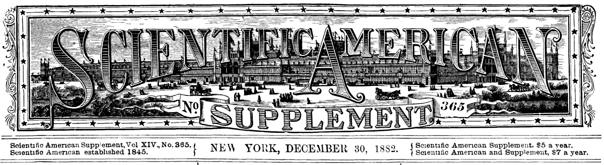
We recall just now the names of those who, during nearly ten years, have contributed with entire disinterestedness to the completion of this colossal work. Over all stands a figure of very peculiar originality—that of M. Louis Favre, the general contractor of the great tunnel, whose name will remain attached to the creation of this work through the Helvetian Alps, like that of Sommeiller to the great tunnel of the Frejus, and that of De Lesseps to the artificial straits that henceforward join the oceans. Having myself had the honor of occupying the position of general secretary of the enterprise under consideration, I have been enabled to make a close acquaintance with the man who was so remarkable in all respects, and who, after passing his entire life in great public works, died like a soldier on the field of honor—in the depths of the tunnel.
 LOUIS FAVRE.
|
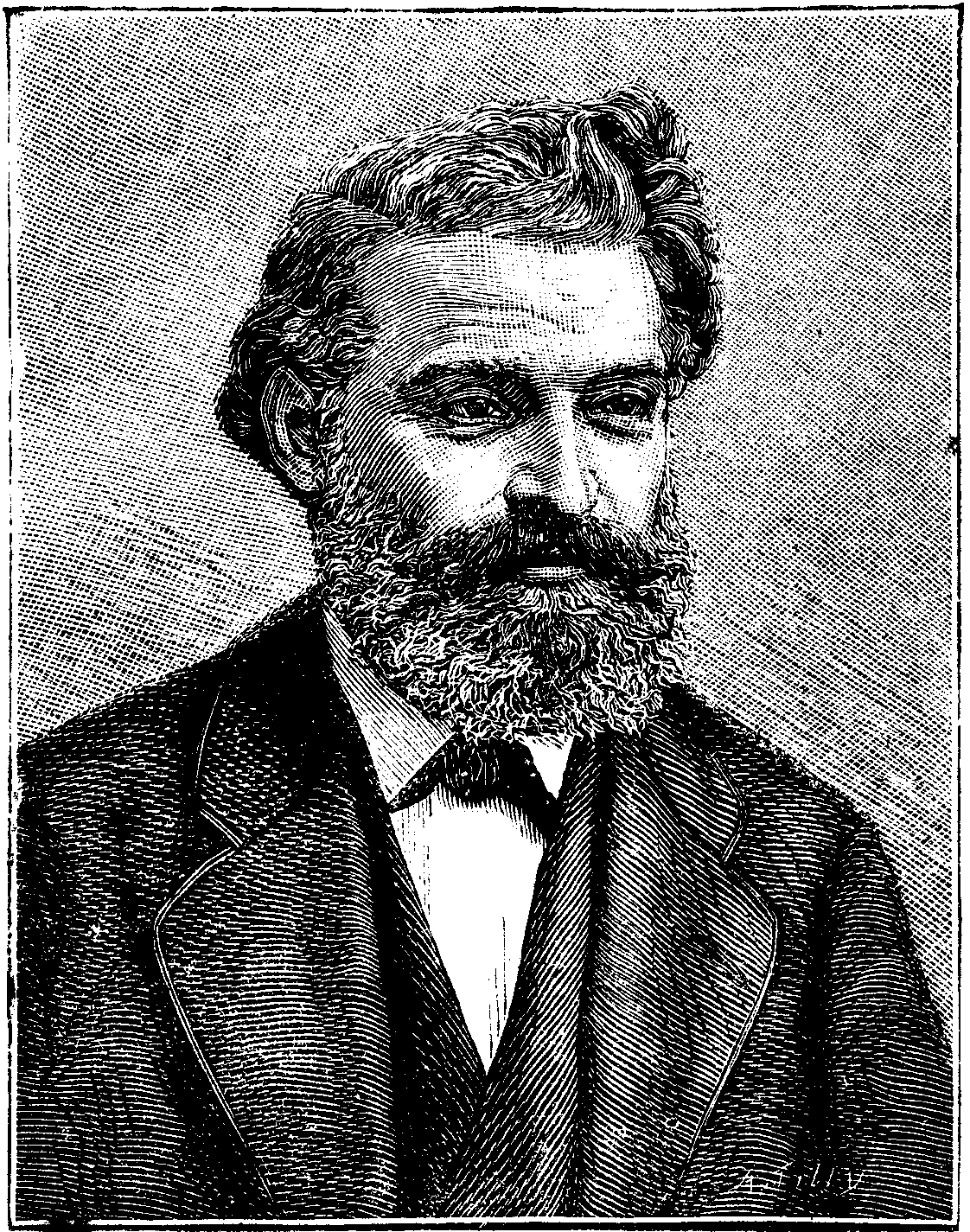
 THE DOWNFALL OF THE TITANS, CONQUERED BY THE GENIUS OF MAN. (Monument at
Turin to Commemorate the Tunneling of the Alps.)
THE DOWNFALL OF THE TITANS, CONQUERED BY THE GENIUS OF MAN. (Monument at
Turin to Commemorate the Tunneling of the Alps.)
|
I saw Favre, for the first time, in Geneva, in 1872, a few days after he had assumed the responsibility of undertaking the great work. He had been living since the war on his magnificent Plongeon estate, on the right bank of the lake. There was no need of dancing attendance in order to reach the contractor of the greatest work that has been accomplished up to the present time, for M. Favre was easy of access. We had scarcely passed five minutes together than we we were conversing as we often did later after an acquaintance of six years. After making known to him the object of my visit, the desire of being numbered among the personnel of his enterprise, the conversation quickly took that turn of mirthfulness that was at the bottom of Favre's character. "This is the first time," said he to me, laughing, "that I ever worked with Germans, and I had not yet struck the first blow of the pick on the Gothard when they began to quibble about our contract of the 8th of last August. Ah! that agreement of August 8th! How I had to change and re-change it, later on. If this thing continues, we shall have a pretty quarrel, considering that I do not understand a word of the multiple interpretations of their charabia. I ought to have mistrusted this. But you see I have remained inactive during the whole of this unfortunate war. I was not made for promenading in the paths of a garden, and I should have died of chagrin if such inaction had had to be prolonged. When one lives, as I have, for thirty years around lumber yards, it is difficult to accustom one's self to the sedentary and secluded life that I have led here for nearly two years."
As he said, with just pride, Louis Favre had, indeed, before becoming the first contractor of public works in the world, lived for a long time in lumber yards. The years that so many other better instructed but less learned persons, who were afterward to gladly accept his authority, had given up to their studies, Favre had passed in the humble shop of his father, a carpenter at Chêne, a small village at a half league from Geneva. It soon becoming somewhat irksome for him in the village, he left the paternal workbench to start on what is called the "tour of France." He was then eighteen years of age. Three years afterward, he was undertaking small works. It was not long ere he was remarked by the engineers conducting the latter, and he was soon called to give his advice on all difficult questions. Between times, Favre had courageously studied the principal bases of such sciences as were to be useful to him. In the evening, he made up at the public school what was lacking in his early instruction; not that he hoped to make a complete study for an engineer, but only to learn the indispensable. He was, before all things, a practical man, who made up for the enforced insufficiency of his technical knowledge by a coup d'œil of surprising accuracy. Here it may be said to me that the piercing of the great St. Gothard Tunnel was accompanied by considerable loss. That is true, but it must be recalled also that this colossal work was accomplished amid the most insurmountable difficulties which ever presented themselves. In spite of this, the cost of the tunnel per running foot was also a third less than that of the great Mont Cenis Tunnel.
When Favre undertook the St. Gothard, he already reckoned to his credit numerous victories in the domain of public works, especially in the construction of subterranean ones. The majority of tunnels of any length which, since the beginning of the establishment of railways, have been considered as works of some proportions (the Blaisy Tunnel, for instance), were executed by him, in addition to other open air works. So Favre reached the St. Gothard full of hope. The battle with the colossus did not displease him, and his courage and his confidence in the success of the work seemed to increase in measure as the circumstances surrounding the boring became more difficult. In the presence of the terrible inundation of the gallery of Airolo and the falling of aquiferous rocks, creating in the subterranean work so desperate a situation that a large number of very experienced engineers almost advised the abandonment of the works, Favre remained impassive. Amid the general apprehension, which, it may be readily comprehended, was felt in such a situation he made his confident and cheerful voice heard, reviving the ardor of all, and speaking disdainfully of "that insignificant Gothard, which would come out all right." The personnel of the enterprise were not the only ones, however, who were uneasy over the constantly occurring difficulties in the way of the work, for the company itself and the Swiss Federal Council made known to Favre their fears that the execution of the work would be delayed. He, however, calmed their fears, and exposed his projects to them, and the seances always ended by a vote of confidence in the future of the undertaking. Favre certainly did not dissimulate the difficulties that he should have to conquer, but he execrated those who were timorous and always tried to put confidence into those who surrounded him. But, singular phenomenon, he ended by deceiving himself and, at certain times, it would not have been easy to prove to him that the St. Gothard was not the most easy undertaking in the world. Those who have lived around him know the jokes that he sometimes made at the expense of poor Gothard, which paid him back with interest, however, and did not allow itself to be pierced so easy after all.
Such confidence as existed in the first years, however, was not to exist for ever. The tunnel advanced, the heading deepened, but at the price of what troubles, and especially of how many expenses! Day by day one could soon count the probable deficit in the affair and the silent partners began to get a glimpse of the loss of the eight millions of securities that had had to be deposited with the Swiss Federal Council. For Favre personally the failure of the enterprise would have been ruin for his fortune was not so large as has been stated. To fears which Favre possessed more on account of the associates that he had engaged in the enterprise than for himself, came to join themselves those troubles with the Germans that he had spoken to me about on the first day. The St. Gothard Company, whose troubles are so celebrated, and whose inactivity lasted until the reconstruction of the affair, was seemingly undertaking to make Favre, who was directing the only work then in activity, bear all the insults that it had itself had to endure. And yet, amid these multiple cares, the contractor of the tunnel did not allow himself to become disheartened. Constantly at the breach he lived at his works, going from the gigantic adit of Goschenen to the inundated one of Anolo, constantly on the mountain, having no heed of the icy and perilous crossing, and passing days in the torrential rain that was flooding the tunnel. Who of us does not picture him in mind as he reached the inn at night, with his high boots still soaking wet, and his gray beard full of icicles to take his accustomed seat at the table, and, between courses, to tell some story full of mirth, some joke from the other works whence he had come, which made us laugh immoderately, and brought a smile to the faces of the German engineers.
It is a singular coincidence that this confidence in his own work, despite all the struggles borne, was shared likewise by another man than Favre—by Germano Sommeiller, the creator of the Mont Cenis Tunnel. When the work of the first piercing of the Alps was yet in the period of attacks and incredulity, Sommeiller wrote his brother the following letter: "Always keep me posted my dear Leander, as to what the laughers are saying and remember the proverb that 'he will laugh well who laughs last!' The majority of the people, even engineers, are rubbing their hands in expectation of the colossal fiasco that awaits us, and it is for that that the envious keep somewhat silent. I will predict to you that as soon as success is assured everybody will mount to the house tops and say 'I told you so! It was an idea of my own!' What great geniuses are going to spring from the earth! I am in haste, so adieu, courage, energy, silence and especially cheerfulness! And especially cheerfulness!" Perhaps this cheerfulness of strong minds is the invincible weapon of those who, like Sommeiller and Favre, fight against apathy or the bad faith of their adversaries! Like Favre however Sommeiller had not the pleasure of being present at the consecration of his glory, for at the Mont Cenis banquet as at the St. Gothard the place reserved for the creator of the great work was empty.
As disastrous as was the enterprise from a financial point of view what a triumph for Favre would have been the day on which he traversed from one end to the other that 15 kilometers of tunnel that he had walked over step by step since the first blow of the pick had struck the rock of the St. Gothard! But such a satisfaction was not to be reserved for him. Suddenly, on the 19th of July, 1879, less than seven years after the beginning of the work, and six months before the meeting of the adits, in the course of one of his visits to the tunnel Favre was carried off by the rupture of a blood vessel. A year before that epoch, I had left the enterprise, Favre having confided to me the general supervision over the manufacture of dynamite that he had undertaken at Varallo Pombia for the needs of his tunnel, but my friend M. Stockalper, engineer in chief of the Goschenen section, who accompanied Favre on his fatal subterranean excursion, has many a time recounted to me the sad details of his sudden death.
For months before it must be said Favre had been growing old. The man of broad shoulders and with head covered with thick hair in which here and there a few silver threads showed themselves, and who was as straight as at the age of twenty years, had begun to stoop, his hair had whitened and his face had assumed an expression of sadness that it was difficult for him to conceal. As powerful as it was this character had been subjugated. The transformation had not escaped me. Often during the days that we passed together he complained of a dizziness that became more and more frequent. We all saw him rapidly growing old. On the 19th of July, 1879, he had entered the tunnel with one of his friends, a French engineer who had come to visit the work, accompanied by M. Stockalper. Up to the end of the adit he had complained of nothing, but, according to his habit, went along examining the timbers, stopping at different points to give instructions, and making now and then a sally at his friend, who was unused to the smell of dynamite. In returning he began to complain of internal pains. "My dear Stockalper," said he, "take my lamp, I will join you." At the end of ten minutes not seeing him return, M. Stockalper exclaimed, "Well! M. Favre, are you coming?" No answer. The visitor and engineer retraced their steps, and when they reached Favre he was leaning against the rocks with his head resting upon his breast. His heart had already ceased to beat. A train loaded with excavated rock was passing and on this was laid the already stiff body of him who had struggled up to his last breath to execute a work all science and labor. A glorious end, if ever there was one!
Favre died in the full plenitude of his forces at less than fifty four years of age, and I can say, without fear of contradiction, that he was universally and sincerely regretted by all those who had worked at his side. Still at the present time when a few of us old colleagues of Goschenen, Airolo or Altorf meet, it is not without emotion that we recall the old days, the joyful reunions at which he cheered the whole table with his broad and genial laugh.—Maxime Helene, in La Nature.
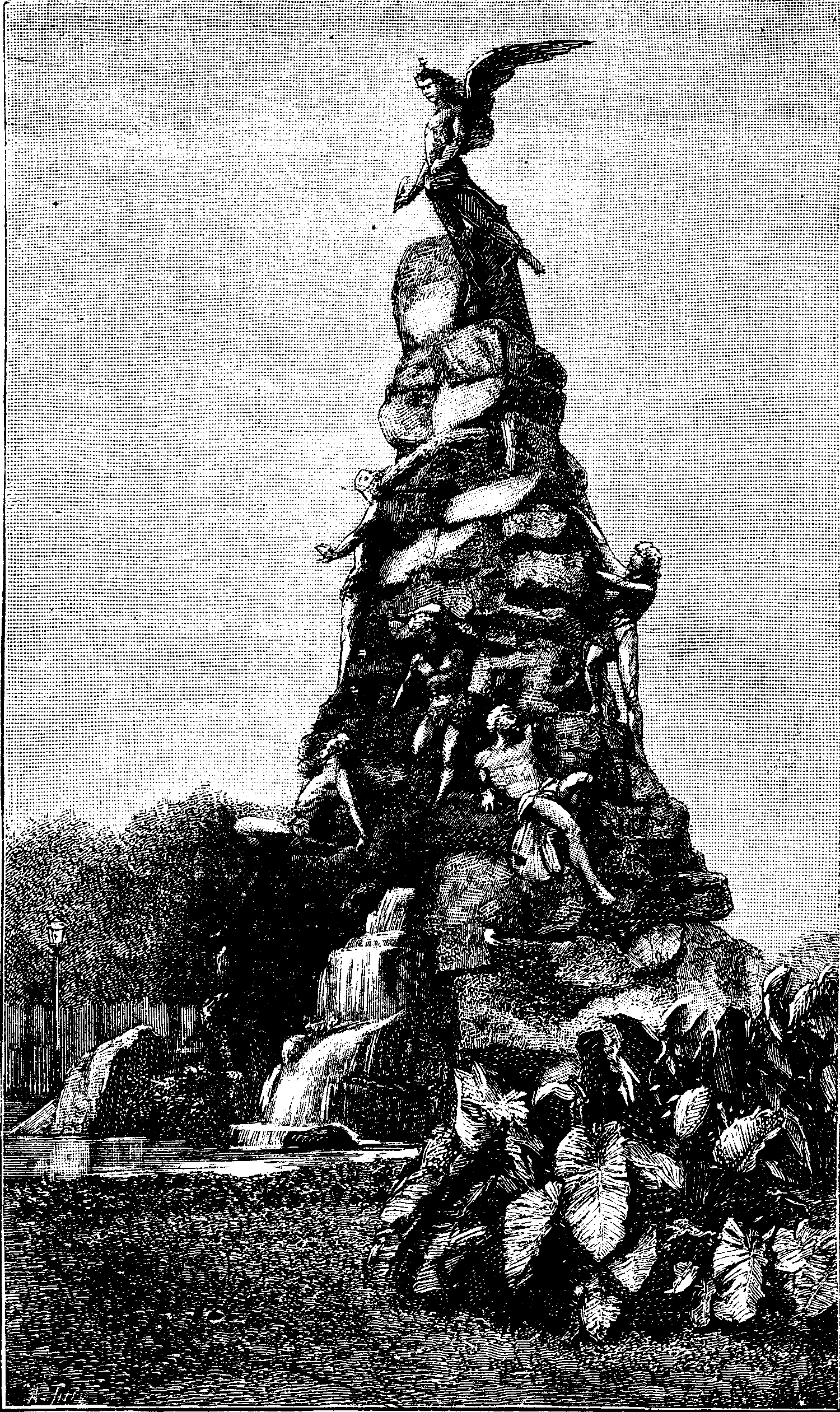
Besides the enormous engineering work of rendering navigable one of the mouths of the Mississippi Delta, and the continuous labor of developing the more original and still bolder project for an Isthmian ship railway, Mr. James B. Eads has been engaged in the design of new and extensive harbor works at Vera Cruz, which, when completed, will secure for that city a commodious and secure port. The accompanying plan shows the natural features of the locality, as well as the new works. The harbor is formed by the coast line from the Punta de la Caleta to the Punta de Hornos, and by La Gallega reef. From the first named point a coral reef, nearly dry at low water, extends out about 300 yards into the gulf, and a similar one of about the same length runs out from the Punta de Hornos. Between these is a bay 2,000 meters wide, and at its northwest end lies the city of Vera Cruz. The bay is partly inclosed by an island or reef—La Gallega—which, on the harbor front, has a length of 1,200 meters. Beyond this, and to the southeast, is another small island—the Lavendera reef. Between the end of this reef and that projecting from the Punta de Hornos is 320 meters wide. As will be seen from the plan the natural harbor is exposed to the gale from the north and northwest, while the formation affords general protection from the northeast and southeast thanks to five large coral reefs. Not unfrequently, however, heavy seas sweep through the wide channels between these small islands interfering seriously with vessels lying alongside the present limited wharfage. Northeast, La Gallega and Gallaguilla reefs run northward from the harbor for 3,300 meters and these with the main coast line, form a bay exposed to the full fury of the winds from the north, and when northern winds prevail rough water is driven through the passage between La Gallega and Caleta reefs with great violence, and sets up a rapid and dangerous current into the harbor.
From the foregoing it will be seen that, while presenting some advantages, the natural harbor of Vera Cruz possesses many drawbacks and dangers which the design of Mr. Eads will completely remove. The leading features of the works about to be carried out are indicated on the plan. They comprise
1. The construction of a sea wall between La Gallega and the Lavendera reefs, with an extension over the latter.
2. The construction of a sea wall from Punta de la Caleta to La Gallega. This part of the work will be begun after the completion of the first wall to a height of at least 3 ft. above low water.
3. A dike connecting the northern ends of the first two dikes with each other, and stretching across the southern part of La Gallega, to prevent the seas which sometimes break over this reef from entering the harbor. The wall between La Gallega and Lavendera will not only cut off the rough water during northerly gales, but will also effectually prevent the deposition of sand in the harbor, because the through passage to the northwest will be stopped. Passages closed by sluice gates will be formed through this wall at about low water level, so that at any time the harbor may be flushed out and stagnation prevented.
4. After the construction of the inclosing walls the harbor will be dredged out and cleared of coral to a depth of 25ft. below low water.
5. Following these works of primary importance comes the construction of a wooden roadway from the Hornos reef to the northwestern dike. This roadway will form the south front of the harbor, and the excavated material will be deposited on the space between the roadway and the existing bottom, so as ultimately to make it a permanent work with a masonry retaining wall fronting the harbor. The land between the roadway and the city would also be reclaimed to the extent of more than 740,000 square yards.
6. The construction of wooden piers at right angles to the roadway, which would be extended to run around the harbor as trade required it, for ships to be alongside for loading and unloading. The construction of these short piers would be similar to those used in New York and other United States ports, and they might afterward be replaced by masonry if the increase in trade justified so large an expenditure.
7. The erection of a lighthouse, at or near the eastern end of the Lavendera sea wall of a second on the eastern side of La Gallaguilla reef, and of another on the west side of La Blanquilla reef. These houses will be furnished with distinctive signals to enable steamers running in before another to run with safety between La Gallaguilla and La Blanquilla as soon as the Lavendera light is seen between the other two.
The width of deep water at the entrance between the Lavendera and Hornos reefs will be 1,000 ft. The estimated cost of these extensive works is ten millions of dollars, a large sum for the Mexican Republic to expend in harbor improvements at one port but it will doubtless be found a profitable investment as it will tend greatly to promote trade, and so increase indefinitely the commerce of the port.
Mr. Eads' plan having been approved by the Mexican Government the work was formally commenced on the 14th of last August. Plans were also furnished by him at the request of the Government, for deepening the mouth of the Panuco River upon which is located the city of Tampico, the Gulf terminus of the Mexican central railway system.—Engineering.
The following estimate of the cost of the power required to manufacture a barrel of flour is taken from the Miller. The calculation would hardly hold good in this country owing to difference in cost of fuel attendance etc., but is nevertheless of interest.
"The cost of a steam motor per 20 stone (280 lb.) sack of flour depends entirely on local circumstances. It depends first, on the amount of power expended in the production of a sack of flour, that is on its mode of manufacture, and it depends, secondly, on the cost of the necessary amount of power, that is, on the cost of fuel burned per horse power The average consumption of coal of first class steam engines may be taken at 2 lb. per hour per indicated horse power.
"Supposing a mill with six pairs of stones, two pairs of porcelain roller mills, and the necessary dressing, purifying, and wheat cleaning machinery to require a steam motor of 100 indicated horse power to drive it, then the average consumption of fuel in this mill would be 200 lb. of coal per hour. Such a mill working day and night will turn out about 400 sacks of flour per week of, say, 130 hours, so that 200 × 13 = 26,000 lb. of coal would be required to manufacture 400 sacks of flour. The cost of this quantity of coal may be taken at, say, £12 (about $58.32), and for cost of attending engine and boiler, cost of oil, etc., another £3 (about $14.58) per week may be added; so that, in this case, the manufacture of 400 sacks of flour would cause an expenditure of £15 ($72.90) for the steam motor. Therefore the cost of the steam motor per 20-stone sack of flour may be taken at 9d. (about 18 cents) per sack, if an improved low grinding system is used.
"In this case it is supposed that about 55 per cent. of flour is obtained in the first run, leaving about 30 per cent. of middlings and about 12 per cent. of bran, which is finished in a bran duster. The middlings are purified, ground over one pair of middling stones, then dressed through a centrifugal and the tailings of the latter are passed over one of the porcelain roller mills, whereas the other porcelain roller mill treats the second quality of middlings coming from the purifier. The products from the two porcelain roller mills are dressed through a second centrifugal, and the whole flour is mixed into one straight grade. Four pairs of stones are supposed to work on wheat, one on middlings, and one pair is sharpening. The first run is supposed to be dressed through two long silk reels. Of course, not every steam motor has so low a consumption of coal as two pounds per hour per horse power; it often amounts to three, four, and five pounds per hour. In that case, of course, the cost of steam power per sack is much greater than 9d. per sack. A greater number of breaks does not necessarily increase the cost of steam power per sack of flour. Although more machines may be employed, each of them may require less horse power; so that the total amount of power required for manufacturing an equal amount of flour may not be greater in the case of gradual reduction.
"As, however, the cost of maintenance may be slightly greater in the latter case, on account of a greater number of more elaborate machines, the cost of manufacturing a sack of flour may be a little greater when gradual reduction is employed, taking into account the total expenses of the mill and interest on the capital employed.
"Water motors are generally a much cheaper source of energy than steam motors, but they are not so reliable and constant as the latter. The very irregular supply of water sometimes causes stoppages of the mill, and often a reserve steam engine has to be provided in order to assist the water motor when the quantity of water decreases during the summer months. Wind motors were formerly extensively used for milling purposes, but they are now gradually disappearing. They are too irregular and unreliable, although they utilize a very cheap motive power. It is not advantageous to expend a large amount of capital for a mill which often is unable to work at the very time when there are favorable opportunities for doing profitable business. Animal motors are too dear. They are only suitable for driving very small mills in out of the way localities."
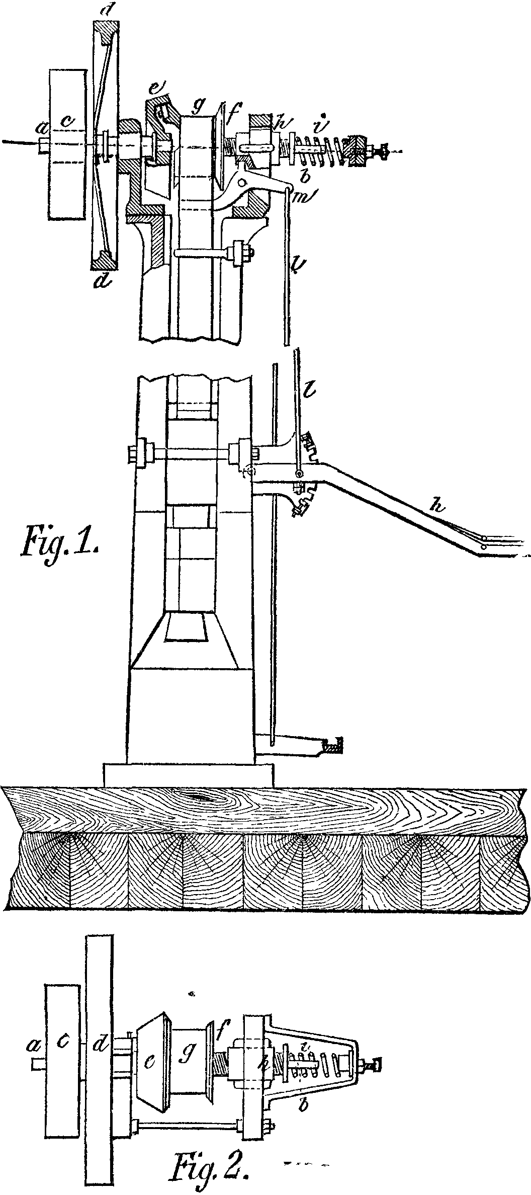
A very interesting system of driving gear for lift hammers was applied in an apparatus exhibited at Frankfort in 1881 by Mr. Meier of Herzen. The arrangement of the mechanism is shown in Figs. 1 and 2. In the upper part of the hammer-frame there is a shaft which is possessed of a continuous rotary motion, and, with it, there is connected by a friction coupling a drum that receives the belt from which is suspended the hammer. In the apparatus exhibited, the mechanism is so arranged that the hammer must always follow the motion of the controlling lever in the same direction; but a system may likewise be adopted such that the hammer shall continue to operate automatically, when and so long as a lever prepared for such purpose is lowered.
ab is the shaft having a continuous rotary motion, and upon which are fixed the pulley, c, the fly-wheel, d, and the friction-disk, e. Upon one of the extremities of the driving shaft is fixed an elongated sleeve, formed of the drum, g, and of the screw, f, carried by the nut, h. This latter is supported in the frame in such a way that it cannot turn, but can move easily in the direction of the axis. Such motion may be produced by the spring, i, and its extent is such that the drum, g, is brought in contact with the friction-disk, e.
The hand-lever, k, rod, l, and bent lever, m, serve to bring about a motion in the opposite direction, and which disengages the drum, g, from the disk, e, and lets the hammer fall; the drum being then able to turn freely. If the lever, k, be afterward raised again, the spring, i, will act anew and couple the drum with the driving-shaft, so that the hammer will be lifted. In this rotary motion the screw, f, turns or re-enters into its nut, which it displaces toward the left, since it cannot itself move in that direction until the rectilinear motion be wiped out, and the power of the spring be thus overcome. At the same moment, the screw should naturally also make this rectilinear movement forward, that is to say, the coupling would be disengaged, if, at the least lateral motion toward the right, the spring, i, did not push the system toward the left. There is thus produced a state of equilibrium such that there is just enough friction between the disk, e, and the drum, g, to keep the hammer at rest and suspended. Through the action of an external force which lowers the lever, K, the hammer at once falls, and the screw issues anew from its nut and brings the parts into their former positions.
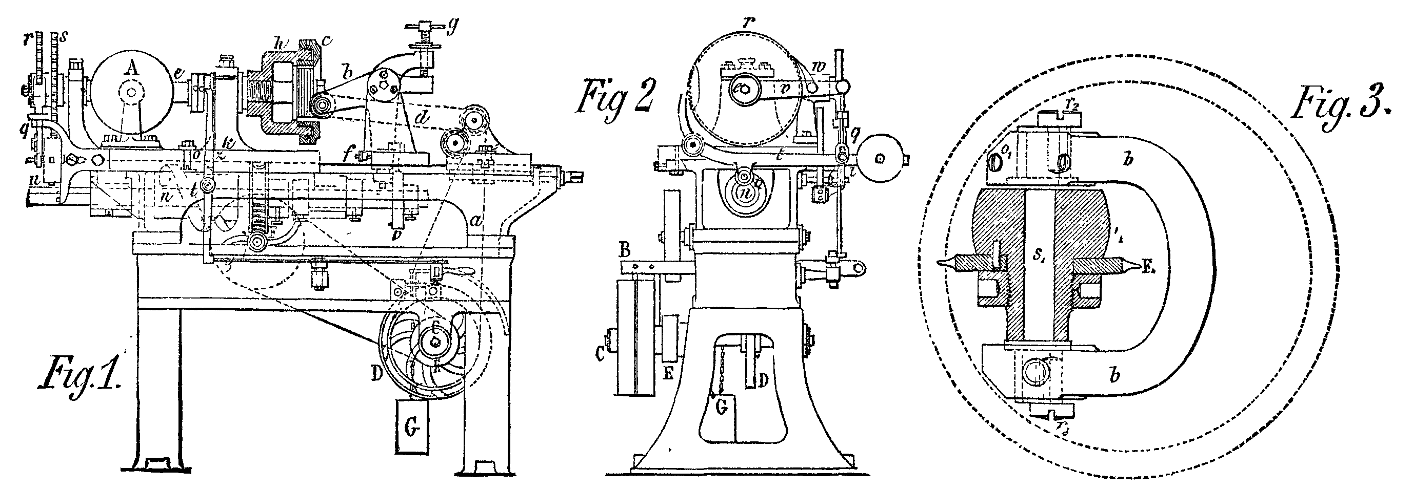
The machine shown in Figs. 1, 2, and 3 has been devised by Messrs. Junker & Ruh, of Carlsruhe, for cutting internally-toothed gear-wheels. The progress of the work is such that the wheel is pushed toward the tool by a piece, n, provided with a curve guide, and that the tool is raised and separated from the wheel after a tooth has been cut, in order to allow the wheel to revolve one division further.
The tool is placed in a support, b, which is fixed to the upright, d, in such away that it may revolve; and this support is connected to the frame, a, of the machine. A strong flat spring, f, constantly presses the tool-carrier, b, toward the upright, d, as much as the screw, g, will permit; and this pressure and the tension of the belt draw the tool downward. The screws, g, determine the depth of the cut, and compensate for the differences in the diameter of the tool.
 MACHINE FOR CUTTING ANNULAR WHEELS.
The wheels to be cut are set by pressure into a wrought iron ring, with which they are placed in a sleeve or support, h. The connection between the two is assured by means of a nut, c. The axle of the support, h, is held in the upright of the carriage, k, which receives from a piece, l, placed on the driving-shaft, n, a slow forward motion toward the tool, and a rapid motion backward. The trajectory curve or groove of special form of the piece, l, in which moves the conducting roller, o, of the carriage, is not closed everywhere on the two sides, in that the guides that limit it extend only on the part strictly necessary. This arrangement permits of the roller being made to leave the trajectory in order that the carriage may be drawn back to a sufficient distance from the tool when the wheel is finished, so as to replace the latter by another.
One hollow is cut during each forward travel of the carriage; and, when such travel is finished, a cam-disk, p, placed on the shaft, n, lifts the tool-carrier, b, and thus draws the cutting-tool out of the hollow cut by it, so that the carriage cam can then move back without restraint. In the interim, the sleeve, h, which supports the wheel, revolves one tooth through the following arrangement: On the axis, e, of this sleeve there are two ratchet-wheels, r and s, the number of whose teeth is equal to that of the teeth to be cut in the wheel. The wheel, r, produces the rotation of the sleeve, h, and the wheel, s, keeps the shaft stationary during the operation. The two wheels are set in motion by a lever, t, or by its click, this lever being raised at the desired moment on the free extremity of the driving shaft, n, by a wedge, u. The short arm of the lever, t, engages, through its point of appropriate shape, with the teeth of the wheel, s, so as to keep this latter stationary while the tool is cutting out the interspace between the teeth. When the lever, t, is raised, this point is at first disengaged from the wheel, s; and the raising of the lever being prolonged, the button, i, places itself against the upper curve of the slot in the lever, q, and raises that likewise. q is connected with the lever, v, which revolves about the axis, e, and v carries the click, w, so that when the lever, v, is raised, the wheel, r, turns forward by one tooth. When the lever, t, is lowered, as the wedge, u, turns more, its click holds the wheel, s, stationary. This series of operations is repeated until the last interspace between the teeth has been cut, when the machine stops automatically as follows: A cam of the disk, A, which receives from the shaft, n, through cone-wheels, a motion corresponding to that of the wheels, r and s, abuts against the two-armed lever, z, and this latter then disengages the rod, y, so that the weight, G, can move the fork, B, in such a way that the belt shall pass from the fast to the loose pulley.
Motion is communicated to the machine as a whole by the shaft, C, which is provided with a fast and loose pulley. As shown in the engraving, the pulley, D, moves the tool, and the pulley, E, causes the revolution of the shaft, n, through a helicoidal gearing, F.
The construction of the tool carrier is represented in detail in Fig. 3. The cutting tool, F, rests on a sleeve forming part of the pulley, r1, against which it is pressed by a nut, while its position is fixed by a key. The axle, s1, of the tool is held in two boxes, in which it is fixed by screws. In order that the tool may be placed exactly in the axis of the wheel to be toothed, and that also the play produced by lateral wear of the pulley, r1, may be compensated for, two screws, r2, are arranged on the sides. All rotation of the shaft, s1, is prevented by a screw, o, which traverses the cast iron stirrup, C, and the steel axle box.
At a late meeting of the Institution of Civil Engineers, the paper read was on "Recent Hydraulic Experiments," by Major Allan Cunningham, R.E.
This paper was mainly a general account of some extensive experiments on the flow of water in the Ganges Canal, lasting over four years—1874-79. Their principal object was to find a good mode of discharge measurements for large canals, and to test existing formulæ. There are about 50,000 velocity, and 600 surface-slope measurements, besides many special experiments. The Ganges Canal, from its great size, from the variety of its branches abounding in long straight reaches, and from the power of control over the water in it, was eminently suited for such experiments. An important feature was the great range of conditions, and, therefore, also of results obtained. Thus the chief work was done at thirteen sites in brickwork and in earth, some being rectangular and others trapezoidal, and varying from 193 ft. to 13 ft. in breadth, and from 11 ft. to 7 in. in depth, with surface-slopes from 480 to 24 per million, velocities from 7.7 ft. to 0.6 ft. per second, and discharges from 7,364 to 114 cubic feet per second. For all systematic velocity measurements, floats were exclusively used, viz., surface floats, double floats, and loaded rods. Their advantages and disadvantages had been fully discussed in the detailed treatise "Roorkee Hydraulic Experiments"—1881. They measured only "forward velocity," the practically useful part of the actual velocity. The motion of water, even when tranquil to the eye, was found to be technically "unsteady;" it was inferred that there is no definite velocity at any point, and that the velocity varies everywhere largely, both in direction and in magnitude. The average of, say, fifty forward velocity measurements at any one point was pretty constant, so that there must be probably average steady motion. Hence average forward velocity measurements would be the only ones of much practical use. To obtain these would be tedious and costly, and special arrangements would be required to obviate the effects of a change in the state of water, which often occurred in a long experiment, as when velocities at many points were wanted.
As to surface-slope its measurement—from nearly 600 trials—was found to be such a delicate operation that the result would be of doubtful utility. This would affect the application of all formulas into which it entered. The water surface was ascertained, on the average of its oscillations, to be sensibly level across, not convex, as supposed by some writers. There were 565 sets of vertical velocity measurements combined into forty-six series. The forty-six average curves were all very flat and convex down stream—except near an irregular bank—and were approximately parabolas with horizontal axes; the data determined the parameters only very roughly; the maximum velocity line was usually below the service, and sank in a rectangular channel, from the center outward down to about mid-depth near the banks. Its depression seemed not to depend on the depth, slope, velocity, or wind; probably the air itself, being a continuous source of surface retardation, would permanently depress the maximum velocity, while wind failed to effect this, owing to its short duration. On any vertical the mid-depth velocity was greater than the mean, and the bed velocity was the least. The details showed that the mid-depth velocity was nearly as variable from instant to instant as any other, instead of being nearly constant, as suggested by the Mississippi experimenters.
The measurement of the mean velocity past a vertical was thought to be of fundamental importance. Loaded rods seemed by far the best for both accuracy and convenience in depths under 15 ft. They should be immersed only 0.94 of the full depth. The chief objection to their use, that—from not dipping into the slack water near the bed—they moved too quickly, was thus for the first time removed. A double float with two similar sub-floats at depths of 0.211 and 0.789 of the full depth would also give this mean with more accuracy and convenience than any instrument of its class; this instrument is new. Measurement of the velocity at five eighths depth would also afford a fair approximation.
One hundred and fourteen average transverse velocity curves were prepared from 714 separate curves. These average curves were all very flat, and were convex down stream—over a level or concave bed—and nearly symmetric in a symmetric section. The velocity was greatest near the center, or deepest channel, decreased very slowly at first toward both banks, more rapidly with approach to the banks or with shallowing of the depth, very rapidly close to the banks, and was very small at the edges, possibly zero. The figure of the curve was found to be determined by the figure of the bed, a convexity in the bed producing a concavity in the curve and vice versa, and more markedly in shallow than in deep water. Curves on the same transversal, at the same site, and with similar conditions, but differing in general velocity, were nearly parallel projections. At the edges there was a strong transverse surface flow from the edge toward mid-channel, decreasing rapidly with distance from the edge. The discussion showed that it was almost hopeless to seek the geometric figure of the curves from mere experiment.
Five hundred and eighty-one cubic discharges were measured under very varied conditions. The process adopted contained three steps: (1) Sounding along about fifteen float courses, scattered across the site in eight cross sections; time, say four hours. (2) Measurement of the mean velocities through the full depths in those float courses, each thrice repeated; time, say four hours. (3) Computation, say two hours. This process was direct and wholly experimental; each step was done in a time which gave some chance of a constant state of water. From an extended comparison of all results under similar conditions, it appeared that the above process yielded, under favorable circumstances, results not likely to differ more than 5 per cent. The sequel showed that in a channel with variable regimen, a discharge table for a given site must be of at least double entry, as dependent on the local gauge-reading, and on the velocity or surface-slope.
Special attention was paid to rapid approximations to mean sectional velocity. The mean velocity past the central vertical, the central surface velocity, and Chézy's quasi-velocity—i.e.,
100 × √( R × S )
where R=the hydraulic mean depth, and S=surface slope—were tried in detail; thus 100, 76, and 83 average values thereof respectively were taken from 581, 313, and 363 detail values. The ratios of these three velocities to the mean velocity were taken out, and compared in detail with Bazin's and Cutter's coefficients. Other formulæ were contrasted also in slight detail. Kutter's alone seemed to be of general applicability; when the surface slope measurement is good, and the rugosity coefficient known for the site—both doubtful matters—it would probably give results within 7½ per cent. of error. Improvement in formulæ could at present be obtained only by increased complexity, and the tentative research would be excessively laborious. Now the first two ratios varied far less than the third; thus their use would probably involve less error than the third, or approximation would be more likely from direct velocity measurement than from any use of surface slope. The connection between velocities was probably a closer one than between velocity and slope; the former being perhaps only a geometric, and the latter a physical one. The mean velocity past the central vertical was recommended for use, as not being affected by wind; the reduction coefficient could at present only be found by special experiment for each site. Three current meters were tried for some time with a special lift, contrived to grip the meter firmly parallel to the current axis, so as to register only forward velocity, and with a nearly rigid gearing wire. No useful general results were obtained. Ninety specimens of silt were collected, but no connection could be traced between silt and velocity; it seemed that the silt at any point varied greatly from instant to instant, and that the quantity depended not on the mean velocity, but probably on the silt in the supply water. Forty measurements of the evaporation from the canal surface were made in a floating pan, during twenty five months. The average daily evaporation was only about 1/10 in. The smallness of this result seemed to be due to the coldness of the water—only 63 deg. in May, with 165 deg. in the sun and 105 deg. in shade. Lastly, it must suffice to say that great care was taken to insure accuracy in both fieldwork and computation.
There seems to have sprung up within a few mouths a tendency to revive the discussion on that hackneyed question, "Shall the germ be retained in the flour?" This question has been more than once answered in the negative by both scientific and practical men, but recently certain prominent persons have come to the conclusion that every one has been wrong on this point, and the miller should by all means retain the germ. Now the nutritive value of the germ cannot be disputed, but there are two circumstances which condemn it us an ingredient of flour. The first is that the albuminoids which it contains are largely soluble, and this means that good light bread from germy flour is impossible. I have not time to go into a detailed explanation of the chemical reasons for this, but they may be found in a series of articles which appeared in The Milling World about a year ago. In the next place, the oil contained in the germ not only discolors the flour, but seriously interferes with its keeping qualities. Now color is only a matter of taste, and if that were the only objection to the germ, it might be admitted, but we certainly do not want anything in our flour to interfere with making light, sweet bread, and will render it more liable to spoil. If our scientists can discover some method of obviating these objections, it will then be time enough to talk about retaining the germ. Meanwhile millers know that germy flour is low priced flour, and they are not very likely to reduce their profits by retaining the germ.—Milling World.
There was considerable complaint last season, on the part of wheat raisers in sections tributary to Minneapolis, on account of the rigid standard of grading adopted by the millers of that city. It was asserted that the differentiation of prices between the grades was unjustly great and out of proportion to the actual difference of value. In order to ascertain whether this was the case or not, the Farmers' Association of Blue Earth County, Minn., decided to have samples of each grade analyzed by a competent chemist in order to determine their relative value. Accordingly specimens were secured, certified to by the agent of the Millers' Association of Minneapolis, and sent to the University of Minnesota for analysis. The analysis was conducted by Prof. Wm. A. Noyes, Ph.D., an experienced chemist, who has recently reported as follows:
"The analyses of wheat given below were undertaken for the purpose of determining whether the millers' grades of wheat correspond to an actual difference in the chemical character of the wheat. For this purpose samples of wheat were secured, which were inspected and certified to by M. W. Trexa on April 13th of this year. The inspection cards contained no statement except the grade of the wheat and the weight per bushel, but the samples were all of Fife, for the purpose of a better comparison. The analyses of the wheat were made during October in this laboratory. In each case the wheat was carefully separated from any foreign substances before analysis. The results of analysis were as follows:
| Grade No. 1 | Grade No. 2 | Grade No. 3 | |
| Weight per bushel | 59 lb. | 56½ lb. | 55 lb. |
| Grains to weigh 10 grains | 366 Per ct. | 474 Per ct. | 491 Per ct. |
| Foreign matter (seeds, etc.) | 0.41 | 0.20 | 1.57 |
| Nitrogen | 2.09 | 2.08 | 2.17 |
| Phosphorus | 0.35 | 0.46 | 0.46 |
| Water | 12.34 | 11.31 | 11.85 |
| Ash | 1.59 | 1.92 | 1.97 |
| Albuminoids (nitrogen multiplied by 6¼) | 13.06 | 13.00 | 13.56 |
| Cellulose | 2.03 | 2.37 | 2.50 |
| Starch, sugar, fat, etc. | 70.98 | 71.40 | 70.12 |
"The analyses require but little comment. The only substances in which there is evident connection between the results of analysis and the grades of wheat are the cellulose, ash, and phosphorus. As regards the last substance, grades two and three seem to have the greatest food value. But it seems quite probable from the results that greater difference would be found between different varieties of wheat of the same kind than is shown here between different grades of the same variety of wheat. However, it does not necessarily follow from this that the different grades of wheat are of nearly equal value to the miller for the purpose of making flour. That is a question which can be best answered by determining accurately the amount and character of the flour which can be made from each grade of wheat. If possible, the investigation will be continued in that direction."
As Prof. Noyes justly remarks, the value of the different grades of wheat can best be determined by a comparison of the results of reducing them to flour, but an intelligent study of the table given above would of itself be sufficient to indicate the justness of the grading. In the first place, even were the percentages of the different components exactly the same in each grade, still the difference in weight would of itself be sufficient to justify a marked difference in price. This requires no proof, for, other things being equal, fifty-nine pounds is worth more than fifty-five pounds. Again, the figures show that No. 3 contained nearly four times as much foreign matter as No. 1. Millers certainly should not be expected to pay for foreign seeds or other substances valueless for their purpose, at the price of wheat. Finally, if the analysis proves anything, it proves that the lower grades contain a decidedly larger percentage of components which it is generally agreed, whether directly or the reverse, ought not to be incorporated with the flour, and are, therefore, of comparatively little value to the miller. This is shown by the relative amounts of cellulose, ash, and phosphorus present. Cellulose, as every one knows, is the woody, indigestible substance which is found in the bran, and the greater the amount of cellulose, the heavier will be the bran in proportion to the flour producing elements. According to the figures presented, No. 3 contained nearly one-quarter more cellulose than No. 1, while the amount in No. 2 was slightly less than in No. 3. The ash, too, which represents the mineral constituents of the wheat, is directly dependent upon the quantity of bran. Here, too, the lowest grade is shown to yield about one-quarter more than the highest. The larger percentage of phosphorus in the lower grades is suggested by the analyst to indicate their greater food value in this respect. So it would, were we in the habit of boiling our wheat and heating it whole, or of using "whole wheat meal." But, fortunately or unfortunately, the bread reformers have not yet succeeded in inoculating any considerable portion of the community with their doctrines, and hence the actual food value of any sample of wheat must be ascertained, not directly from the composition of the wheat, but from the composition of the flour made therefrom. Now, as already stated, phosphorus, like the other mineral components, is found almost entirely in the bran. Its presence in greater quantity, therefore, simply adds to the testimony that a larger proportion of the low grade wheat must be rejected than of the higher grade. It should be evident to the complaining farmers that the millers were in the right of the question, on this occasion at least.
It is expected that further analysis will be made, this time of the flour made from the different grades of wheat. If these investigations be properly conducted, we have no doubt that they will simply confirm the evidence of the wheat tests. A chemical analysis alone, however, will not be sufficient. The quantity of flour obtained from a given amount of wheat must also be ascertained and its quality further tested by means best known to millers, as regards "doughing-up," keeping qualities, color, etc. And then the result can be no less than to show what millers already knew—that the best quality of flour, commanding the top prices in the market, cannot be obtained from an inferior quality of wheat.—Milling World.
The blue process is well known to the members of the society, and I need not take time to describe it; but with the ordinary blue process printing frame the results are sometimes unsatisfactory, and now that the process has come to be so commonly used I have thought that an account of an inexpensive but efficient printing frame would be of interest. The essential parts of the apparatus are its frame, its glass, its pad or cushion, its clamps, and the mechanism by which the surface of the glass can easily be made to take a position that is square with the direction of the sun's rays.
The Blue Process Printing Frame in Common Use.—Its Defects.—The pad of the apparatus in common use consists of several thicknesses of blanketing stretched upon a back board. The sensitized paper and the negative are placed between the pad and the plate glass, and the whole is squeezed together by pressure applied at the periphery of the glass and of the back-board. Both the glass and the back-board spring under the pressure, and it results that the sensitized paper is not so severely pressed against the negative near the center of the glass as it is near the edges. If at any point the sensitized paper is not pressed hard up against the negative, a bluish tinge will appear where a white line or surface was expected. With an efficient printing frame and suitable negatives, these blue lines will never appear, and it was to prevent the production of defective work that I undertook to improve the pad of the printing frame.
The Printing Frame Used in Ordinary Photography.—Very naturally, I first examined the printing frame used in ordinary photography. This frame is extremely simple, and is very well adapted to its use. It is, undoubtedly, the best frame for blue process printing, when the area of the glass is not too large. The glass is set in an ordinary wooden frame, while the back-board is stiff and divided into two parts. A flat, bow-shaped spring is attached by a pivot to the center of each half of the back-board. The two halves of the back-board are hinged together by ordinary butts. Four lugs are fastened to the back of the frame, and, when the back-board is placed in position, the springs may be swung around, parallel to the line of the hinges, and pressed under the lugs, so that the back of the back-board is pressed most severely at the center of each half, while the glass is prevented from springing away from the back-board by the resistance of the frame at its edges. Unless the frame is remarkably stiff, it will resist the springing of the glass more perfectly in the neighborhood of the lugs than elsewhere. It will now be seen that, on account of the manner in which the pressure is applied, the back-board tends to become convex toward the glass, while the adjacent surface of the glass tends to become concave toward the back-board; and that with such a frame, the pressure upon all parts of the sensitized paper is more nearly uniform than when the pressure is applied in the manner before described. With a small frame of this description, a piece of ordinary cotton flannel is used between the back-board and the sensitized paper, and, with larger sizes, one or more thicknesses of elastic woolen blanket are substituted for the cotton flannel. There is an advantage in having a hinged back-board like that which has been described, because, when the operator thinks that the exposure to sunlight has been sufficiently prolonged, he can turn down either half of the back and examine the sensitized paper, to see if the process has been carried far enough. If it has not, the back-board can be replaced, and the exposure continued, without any displacement of the sensitized paper with respect to the negative. This is an important advantage.
An Efficient Blue Process Frame, for Printing from Large Negatives, or for Printing Simultaneously from many Small Ones.—In order to be efficient, such a frame must be capable of keeping the sensitized paper everywhere tightly pressed against the negative. Again, such a frame, being large, is necessarily somewhat heavy. It should be so mounted that it can be handled with ease; and, in order that it may print quickly, it should be so arranged that it can be turned without delay, at any time, into a position that is square with the direction of the sun's rays.
Undoubtedly, if a sufficiently thick plate of glass should be used, the ordinary photographic printing frames would answer the purpose, whatever the size, but very thick plate glass is both heavy and expensive. Commercial plate glass varies in thickness from one-fourth to three eighths of an inch, and the thicker plates are rather rare. A large plate of it is easily broken by a slight uniformly distributed pressure. But the pressure that is required for the blue process printing, although slight, is much greater than is used in the ordinary photographic process. For the sensitized paper that is used in the blue process printing is, comparatively, very thick and stiff, and it may cockle more or less, while the paper that is used in ordinary photography is thin and does not cockle. Now, it is easy to see that a pressure severe enough to flatten all cockles must be had at every part of the sensitized paper, and that, if the comparatively thin, inexpensive, light weight, commercial plate glass is to be used, it is desirable to have the pressure nowhere much greater than is needed for that purpose, lest the fragile glass should be fractured by it. In each of my large frames I use the commercial plate glass; instead of the cushion of cotton flannel, or of flannel, I use a cushion filled with air of sufficiently high pressure to flatten all cockles, and to press all parts of the sensitized paper closely against the negative; and instead of the hinged back-board I use a back-board made in one piece and clamped to the frame of the glass at its edges. Connected with the cushion is a pressure gauge, and a tube with a cock, for charging the cushion with air from the lungs. Experience shows what pressure is necessary with any given paper, and the gauge enables one to know that the pressure is neither deficient nor in excess of that which is safe for the glass.
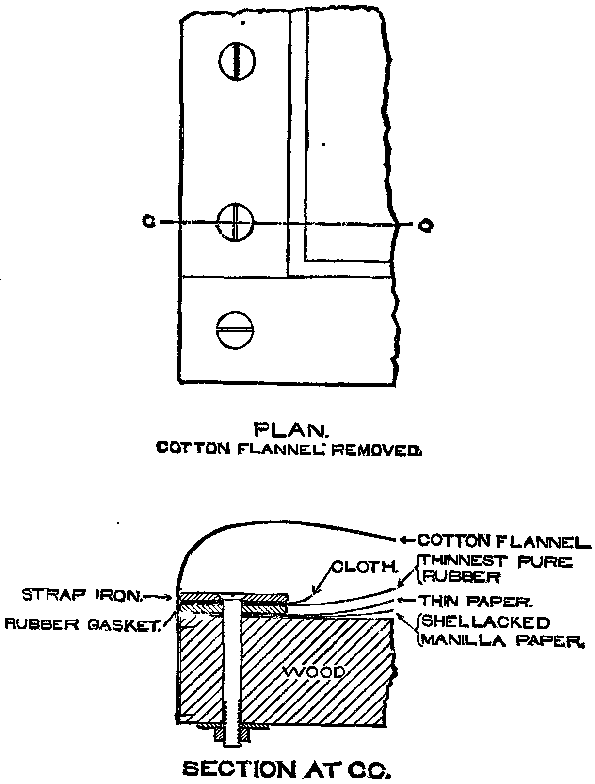
The Construction of the Air-Cushion.—The expense of such an air-cushion seemed at first likely to prevent its being used; but a method of construction suggested itself, the expense of which proved to be very slight. The wooden back-board, as constructed, is made in one piece containing no wide cracks. It has laid upon it some thick brown Manila paper, the upper surface of which has been previously shellacked to make it entirely air-tight. Upon this shellacked surface is laid a single thickness of thin paper of any kind; even newspaper will answer. Its object is simply to prevent the sheet rubber, which forms the top of the air-cushion, from sticking to the shellacked paper. The heat of the sun is often sufficient to bring the shellac to a sticky state. It would probably answer as well to shellac the under side of the paper, and to use but one sheet, but I have not tried this plan. Around the periphery of the pad, there is laid a piece of rubber gasket about one and a half inches wide, and about one-eighth of an inch thick. In order that the gasket may not be too expensive, it is cut from two strips about three inches wide. One of them is as long as the outside length of the frame, and the other is as long as the outside width of the frame. Each of these strips is cut into two L-shaped pieces, an inch and a half in width, with the shorter leg of each L three inches long. When the four pieces are put together a scarf joint is made near each corner, having an inch and one-half lap. It is somewhat difficult to cut such a scarf joint as perfectly as one would wish, and it is best to use rubber cement at the joints. Over the gasket is laid a sheet of the thinnest grade of what is called pure rubber or elastic gum. Above this, and over the gasket, is placed a single thickness of cotton cloth, of the same dimensions as the gasket, and yet above this are strips of ordinary strap iron, an inch and a half wide and nearly one eighth of an inch thick. These strips are filed square at the ends and butt against each other at right angles. As the edges of the strips are slightly rounded, they are filed away sufficiently to form good joints wherever the others butt against them. The whole combination is bound together by ordinary stove bolts, one quarter of an inch in diameter, placed near the center of the width of the iron strips, and at a distance apart of about two and one-half inches. Their heads are countersunk into the strap iron. In making the holes for the stove bolts through the thin rubber, care should be taken to make them sufficiently large to enable the bolt to pass through without touching the rubber, otherwise the rubber may cling to the bolts, and if they are turned in their holes the rubber may be torn near the bolts and made to leak. A rough washer, under each nut, prevents it from cutting into the back-board. For the purpose of introducing air to, or removing air from, the pad, a three-eighths of an inch lock nut nipple is introduced through the back-board, the shellacked paper, and its thin paper covering. Without the back-board a T connects with the nipple. One of its branches leads, by a rubber tube, to the pressure gauge, which is a U-tube of glass containing mercury. The other branch has upon it an ordinary plug cock, and, beyond this, a rubber tube terminating in a glass mouth-piece. When it is desired to inflate the air-cushion, it is only necessary to blow into the mouth-piece. A pressure of one inch of mercury is sufficient for any work that I have yet undertaken. With particularly good paper, a lower pressure is sufficient. Upon the top of the pad is laid a piece of common cotton flannel with the nap outward, and with its edges tacked along the under edge of the back-board. The cotton flannel is not drawn tight across the top of the pad. The reason for employing a cotton flannel covering is this: When the sheet rubber has been exposed for a few days to the strong sunlight, it loses its strength and becomes worthless. The cotton flannel is a protection against the destruction of the rubber by the sunlight. I first observed this destruction while experimenting with a cheap and convenient form of gauge. I used, as an inexpensive gauge, an ordinary toy balloon, and I could tell, with sufficient accuracy, how much pressure I had applied, by the swelling of the balloon. This balloon ruptured from some unknown cause, and I made a substitute for it out of a round sheet of thin flat rubber, gathered all around the circumference. I made holes about one-quarter of an inch apart, and passing a string in and out drew it tight upon the outside of a piece of three eighths of an inch pipe, I then wound a string tightly over the rubber, on the pipe, and found the whole to be air-tight. This served me for some time, but one day, on applying the pressure, I found a hole in the balloon which looked as if it had been cut with a very sharp knife. That it had been so cut was not to be imagined, and on further examination I found that the fracture had occured at a line which separated a surface in the strong sunlight from a surface in the shade, at a fold in the rubber. I saw that all of the rubber which had been continuously exposed to the intense sunlight had changed color and had become whiter than before, and that that portion of the balloon had lost its strength. I then returned to the use of the mercury gauge, and took the precaution to cover my pad with cotton flannel, as a protection from the light and from other sources of destruction. This pad is upon the roof of the Institute; and is exposed to all weathers. As a protection from the rain and the snow, the whole is covered again with a rubber blanket. It has withstood the exposure perfectly well for a year, without injury. The gauge, made from flat rubber, is altogether so cheap and so convenient that I am now experimenting with one of this description having a black cloth covering upon the outside. The balloon is of spherical shape, the black cloth covering is of cylindrical shape, and I hope that this device will serve every necessary purpose. A sectional view of the air-cushion is offered as a part of this communication.
The Frame, which Contains the Plate Glass, is made of thick board or plank, with the broad side of the board at right angles to the surface of the glass. A rabbet is made for the reception of the glass, and four strips of strap iron, overlapping both the glass, and the wood, and screwed to the wood, keep the glass in position. Strips of rubber are interposed between the glass and the wood and between the glass and the iron. The frame is hinged to the back-board by separable hinges, so that the glass can be unhinged from the pad without removing the screws. Hooks, such as are used for foundry flasks, connect the frame with the pad upon the opposite side. A frame made in this manner is very stiff and springs but little, and its depth serves an excellent purpose. The air-cushion and the frame are so mounted that they can be easily turned to make the surface of the glass square with the direction of the sun's rays. It is necessary to have a tell tale connected with the apparatus, which will show when the surface of the glass has been thus adjusted. The shadow of the deep frame is an inexpensive tell-tale, and enables the operator to know when the adjustment is right. I have now described, in detail, the construction of the air-cushion with its back-board, as well as that of the frame which holds the plate glass, and I think it will be evident that the first cost of the materials of which they are made is comparatively little, and that the workmanship required to produce it is reduced to a minimum. It will also, I think, be evident that a uniform pressure, of any desired intensity, can be had all over the surface of the sensitized paper for the purpose of securing perfect contact between it and the negative. The blue copies that are taken with this apparatus are entirely free from blue lines when the negatives, chemicals, and paper are good.
The Mechanism for Adjusting the Surface of the Glass, until it shall be Perpendicular to the Direction of the Sun's Rays.—I have found many uses for the blue copying process in connection with the work of instruction at the Massachusetts Institute of Technology. Notes printed by it are far better and less costly than those printed by papyrograph. I will not detain you now with an account of the uses that I have made of it. I will merely say that more than a year ago I found that my frame, which has a glass 3 feet x 4 feet, was wholly inadequate to the work in hand, and I tried to increase the production from it by diminishing the time of printing. The glass of this frame was horizontal, except when one of its ends was tilted off from the slides which guided it when pushed out of the window; and I knew that it took three or four times as long to print when the sun was low as it did when the sun was near the meridian. I made plans for mounting this frame upon a single axis, about which it could be turned after it had been pushed through the window, but I saw that no movement about a single axis would give a satisfactory adjustment for all times of the year, and I considered what arrangement of two axes would permit a rapid and perfect adjustment, at all times, with the least trouble to the operator. It was evident that when the sun was in the equatorial plane, the surface of the glass should contain a line which was parallel to the axis of the earth; and further, that if such a glass was firmly attached to an axis which was parallel to that of the earth, it would fulfill the desired purpose. For the glass, being once in adjustment, is only thrown out of position by the rotation of the earth, and if the glass is rotated sufficiently about its own axis, in a direction opposite to that of the earth, it will retain its adjustment. In order to have the adjustment equally good when the sun was either north or south of the equatorial plane, it was sufficient to mount a secondary axis upon the primary one and at right angles to it. About this the glass could be turned through an angle of 23½°, either way, from the position which it should have when the sun was in the equatorial plane.
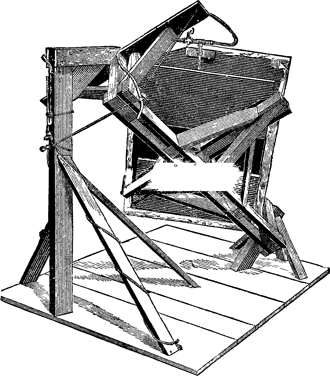
The Construction of the Adjusting Mechanism.—I desired to have the mechanism as compact and inexpensive as possible, and to have the frame well balanced about the primary axis, in every position. I also desired to have a rotation of nearly 180° about the principal axis. The plan adopted will be most easily understood by referring to the drawing which illustrates it. The axes are composed chiefly of wood. They are built up from strips which are 3 inches x 7/8 inch, and from small pieces of 2 inch plank. They are stiffly braced. A pair of ordinary hinges permit the secondary rotation to occur, while a pair of cast iron dowel pins with their sockets, such as are used in foundry flasks, serve as pivots during the primary rotation.
The Adjustments.—The adjustment about the secondary axis does not need to be made more frequently than once a week, or once a fortnight. In order to prevent rotation about this axis when in adjustment, two cords lead from points which are beneath the back board, and as far removed from the secondary axis as is convenient. Each cord passes forward and backward through four parallel holes in a wooden block which is attached to the primary axis. The cords can be easily slipped in the holes by pulling their loops, but the friction is so great that they cannot be slipped by pulling at either end. It takes about twice as long to make the adjustment as would be necessary if a more expensive device had been used; but this device is at once so cheap, so secure, and has so seldom to be used, that it was thought to be best adapted for the purpose. To prevent rotation from occurring about the primary axis when it is not desired, a bar parallel to the secondary axis is attached by its middle point to the primary axis near one end. A cord passes from either end of this bar through cam shaped clamps, which were originally designed for clamping the cords of curtains with spring fixtures. These clamps are cheap. They are easily and quickly adjusted, and are very secure.
The whole apparatus can be located upon the roof of a building, or, if convenient, it can be mounted upon slides, and pushed through an open window when it is to be exposed to the light. If it is to be used upon a roof, a small hut, or shelter of some sort, near by is a great convenience to the operator, particularly in winter.
An Inexpensive Drying Case for Use in Coating the Paper.—When the apparatus is in continuous use, time may be saved by having a convenient arrangement for drying the sheets that have been coated with the sensitizing liquid. I have made an inexpensive drying case which serves the purpose very well. It consists simply of a light-tight rectangular case of drawers. There are twenty-five drawers in all. They are constructed in an inexpensive manner, and are the only parts of the case that are worth describing. They are very shallow, being but 1-7/8 inches deep, and as it appeared that the principal expense would be for the materials of which the bottoms of the drawers should be composed, it was decided to make the bottoms of cotton cloth. This cloth is stretched upon a frame, the dimensions of which are greater than that of the paper to be dried. The stock of which the frame is made is pine, 1¼ inches wide, and three-eighths of an inch thick. The corners are simply mitered together and attached to each other by means of the wire staples that are commonly used for fastening together pages of manuscript, and which are called "novelty staples." Eight staples are used at each miter, four above and four below the joint. Two of the staples, at the top and near the ends of the joint, are set square across it, and two others, at the top and near the middle of the joint, are placed diagonally across it. The staples at the bottom are similarly placed. The joint is quite firm and strong, and is likely to hold for an indefinite period with fair usage. The cloth, stretched upon the frame, is fastened to it by means of similar staples. A dark colored cloth not transparent to light is to be preferred. A strip of pine, 1-13/16 inches wide, and three eighths of an inch thick, forms the vertical front of the drawer, and prevents the admission of much light from the front while the sheet is drying. Two triangular knee pieces, three-quarters of an inch thick, serve to connect the front board with the frame, and four small screws with a few brads are used in attaching them. The lower edge of the front board drops one-quarter of an inch below the bottom of the drawer. My case stands in a poorly lighted room, and paper dried in this case and removed to a portfolio as soon as it is dry does not seem to be injured by the light that reaches it. With the case in a well lighted room, I should prefer to have outer doors to the case, made of ordinary board six or eight inches wide, hinged to one end, and arranged to swing horizontally across the front of the case. These would more completely prevent the admission of light. The opening of any one of the doors would allow three or four of the drawers to be filled, while the rest of the case would be comparatively dark at the same time.2
The Portfolio for Protecting the Sensitized Paper from Exposure to Light.—The sensitized paper is very well protected from exposure to light, if kept in a portfolio or book, the brown paper leaves of which are considerably larger than the sensitized sheets. The sheets may be returned to such a book after exposure, and washed at the convenience of the operator. They can be washed more quickly and perfectly if two water-tanks are provided in which to wash them. A few minutes' soaking will remove nearly all of the sensitizing preparation which has not been fixed by the exposure. If the soaking is too long continued in water that is much discolored by the sensitizing preparation, the sheets become saturated with the diluted preparation, and they may become slightly colored by after exposure. If the first soaking is not too long continued, and if the sheets are transferred at once to a second bath of clean water, which is kept slowly changing from an open faucet, they may remain there until the soluble chemicals have been entirely extracted, and there will be no risk of staining by after exposure. Washing in two tanks is of more consequence when the ground is white and the lines blue, than when the ground is blue and the lines white.
The Grades of Paper that are well Adapted for Blue Process Work.—I have tested many grades of paper, to ascertain if they were well adapted for blue process work. Some grades of brown Manila are very good; others have little specks embedded in their surfaces which refuse to take on a blue tint; still others, when printed upon, have white lines that are wider than the corresponding black lines of the negative. The blue obtained upon bond paper appears to be particularly rich, and the whites remain pure; but bond paper cockles badly, and the cockles remain in the finished print. Weston's linen record is an excellent paper. It is strong, cockles but little, and dries very smooth. A paper that is used by Allen & Rowell, for carbon printing, is comparatively cheap, and is an excellent paper. It is not so stiff as the linen record, and the whites are quite as pure. It does not cockle, neither does it curl while being sensitized. It comes in one hundred pound rolls, and is about thirty inches wide. The best papers are those that are prepared for photographic work. The plain Saxe and the plain Rives both give excellent results. Blue lines on a pure white ground can be obtained on these papers, from photographic negatives, without difficulty. None of the hard papers of good grade require the use of gum in the sensitizing liquid. The liquid penetrates the more porous papers too far when gum is not used, and without it good whites are seldom obtained upon porous paper.
The Best Chemicals for this Work are the recrystallized red prussiate of potash and the citrate of iron and ammonia, which is manufactured by Powers & Wightman, of Philadelphia. If the red prussiate has not been recrystallized, the whites will be unsatisfactory and the samples of citrates of iron and ammonia which have come to us from other chemists than those named, have all proved unreliable for this process.
The Sensitizing Liquid.—Its Proportions.—The blue process was originally introduced from France, by the late Mr. A. L. Holley. I was indebted to Mr. P. Barnes, who was with Mr. Holley at the time, for an early account of it, and I had the first blue process machine that was in use in New England. Since 1876, instruction in the use of the blue process has been given to the students of mechanical engineering of the Massachusetts Institute of Technology, and they have caused its introduction into many draughting offices. The proportions of the sensitizing liquid, as originally given me by Mr Barnes, were as follows:
| Red prussiate of potash | 8 parts. |
| Citrate of iron and ammonia | 8 parts. |
| Gum arabic | 1 part. |
| Water | 80 parts. |
Results of Experiments.—In our use, it first appeared that the gum might be omitted from the preparation when sufficiently hard papers were used. Next, that a preparation containing
| Red prussiate of potash | 2 | parts. |
| Citrate of iron and ammonia | 3 | " |
| Water | 20 | " |
printed more rapidly. This preparation I continue to use when much time may elapse between sensitizing and printing; but, when the paper is to be printed immediately after sensitizing, I use a larger proportion of citrate of iron and ammonia. Before arriving at the conclusion that these proportions were the best to be used, I made a series of purely empirical experiments, beginning with the proportions:
| Red prussiate of potash | 10 parts. |
| Citrate of iron and ammonia | 1 part. |
| Water | 50 parts. |
and ending with the proportions:
| Red prussiate of potash | 1 | part. |
| Citrate of iron and ammonia | 10 | parts. |
| Water | 50 | " |
I found the best plan for conducting these experiments to be: To coat a sheet of the paper with a given mixture; to cut the sheet into strips before exposure; to expose all the strips of the sheet, at the same time, to the direct sunlight without an intervening negative; and to withdraw them, one after another, at stated intervals. I found that with each mixture there was a time of exposure which would produce the deepest blue, that with over-exposure the blue gradually turned gray, and that if a curve should be plotted, the abscissas of which should represent the time of exposure, and the ordinates of which should represent the intensity of the blue the curves drawn would have approximately an elliptical form, so that if one knew the exact time of exposure which would give the best result with any mixture, one might deviate two or three minutes either way from that time without producing a noticeable result. I have found that, with the same paper, the same blue results with any good proportions of the chemicals named, provided a sufficient weight of both chemicals is applied to the surface; that an excess of the red prussiate of potash renders the preparation less sensitive to light, and very much lengthens the necessary time of exposure; that the prints are finer with some excess of the red prussiate; that an excess of the citrate of iron and ammonia hastens the time of printing materially; that a greater excess of the citrate causes the whites to become badly stained by the iron, while a still greater excess of the citrate, in a concentrated solution causes the sensitized paper to change without exposure to light, and to produce a redder blue or purple, which does not adhere to the paper, but may be washed off with a sponge. I have found that the cheapest method of reproducing inked drawings that have been made on thick paper is not to trace them, but to print the blues from a photographic glass negative; and also, that the dry plate process is well adapted to such work in offices, when one has become sufficiently experienced. Printed matter can also most easily and inexpensively be reproduced by the same means, when a small issue is required on each successive year. For the reproduction of manuscript by the blue process, the best plan that I have found has been to write the manuscript upon the thinnest blue tinted French note-paper, with black opaque ink—the stylographic ink is very good—and, afterward, to dip the paper into melted paraffine, and to dry the paper at the melting temperature. This operation, if cheaply done, requires special apparatus. For positive printing from the glass negative, I use a multiple frame, by the aid of which I can print from 16 negatives at the same time, upon a single sheet of paper. This frame is interchangeable with the one that contains the plate glass. The negatives are so arranged in the frame that the sheets can be cut and bound, as in the ordinary process of book binding. The time required for exposure, when printing from glass negatives, varies with the negative; and, in order to secure satisfactory results with the multiple frame it is necessary to stop the exposure of some, while the exposure of others is continued. I insert wooden or cloth stoppers into the frame for the purpose of stopping the exposure of certain negatives. When paraffined manuscript is to be printed from, I find it convenient to have it written on sheets of small size, and to have these mounted upon an opaque frame of brown Manila paper, printing sixteen or more at a time, depending upon the size of the printing frame. Many small tracings may be similarly mounted upon a brown paper multiple frame, and may be printed together upon a single sheet.
Read June 21, 1882, before the Boston Society of Civil Engineers.
Since this paper was read, I have seen in the office of the City Engineer of Boston a drying case which is similar in some respects to the one that I have devised. It has been longer in use than my own. The drawers are simply the ordinary mosquito netting frames covered with cotton netting. They have no fronts, but a door covers the front of the case, and shuts out the light.
At a recent meeting of the London Physical Society, Prof. Rowland, of Baltimore, exhibited a number of his new concave gratings for giving a diffraction spectrum. He explained the theory of their action. Gratings can be ruled on any surface, if the lines are at a proper distance apart and of the proper form. The best surface, however, is a cylindrical or spherical one. The gratings are solid slabs of polished speculum metal ruled with lines equidistant by a special machine of Prof. Rowland's invention. An account of this machine will be published shortly. The number of lines per inch varied in the specimens shown from 5,000 to 42,000, but higher numbers can be engraved by the cutting diamond. The author has designed an ingenious mechanical arrangement for keeping the photographic plates in focus. In this way photographs of great distinctness can be obtained. Prof. Rowland exhibited some 10 inches long, which showed the E line doubled, and the large B group very clearly. Lines are divided by this method which have never been divided before, and the work of photographing takes a mere fraction of the time formerly required. A photographic plate sensitive throughout its length is got by means of a mixture of eosene, iodized collodion, and bromized collodion. Prof. Rowland and Captain Abney, R.E., are at present engaged in preparing a new map of the whole spectrum with a focus of 18 feet.
In reply to Mr. Hilger, F.R.A.S., the author stated that if the metal is the true speculum metal used by Lord Rosse, it would stand the effects of climate, he thought; but if too much copper were put in, it might not.
In reply to Mr. Warren de la Rue, Prof. Rowland said that 42,000 was the largest number of lines he had yet required to engrave on the metal.
Prof. Guthrie read a letter from Captain Abney, pointing out that Prof. Rowland's plates gave clearer spectra than any others; they were free from "ghosts," caused by periodicity in the ruling, and the speculum metal had no particular absorption.
Prof. Dewar, F.R.S., observed that Prof. Liveing and he had been engaged for three years past in preparing a map of the ultra-violet spectrum, which would soon be published. He considered the concave gratings to make a new departure in the subject, and that they would have greatly facilitated the preparation of his map.
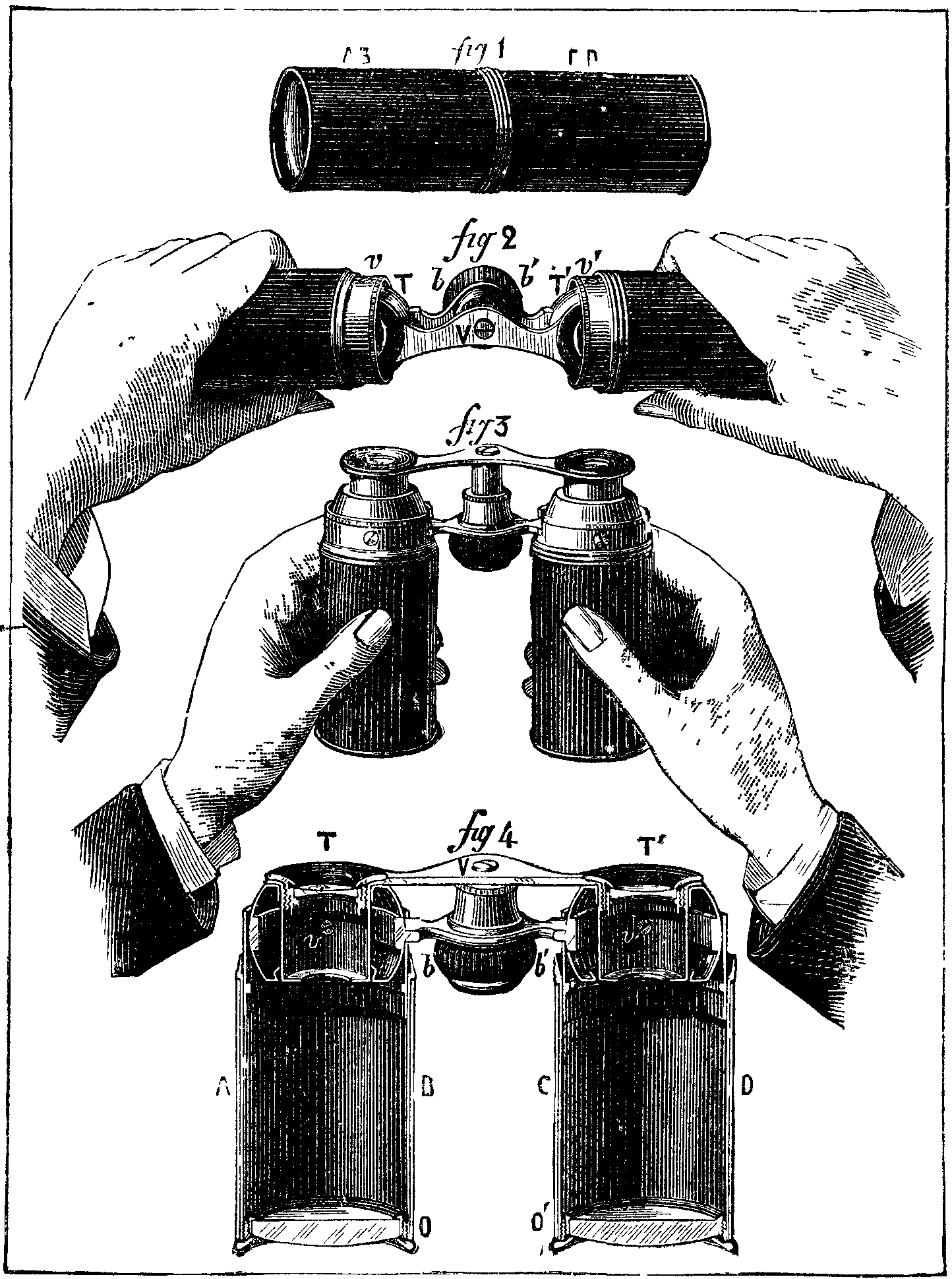
Inasmuch as high power combined with small size is usually required in an opera glass, manufacturers have always striven to unite these two features in their instruments, and have succeeded in producing glasses which, although sufficiently small to be carried in the waistcoat pocket, are nevertheless powerful enough to allow quite distant objects to be clearly distinguished. Recently, a Parisian optician has succeeded in constructing an instrument of this kind that is somewhat of a novelty in its way, since its mechanism allows it to be closed in such a manner as to take up no more space than a package of cigarettes (Fig. 1.) It is constructed as follows:
AB and CD (Fig. 1) are two metallic tubes, in which slide with slight friction two other tubes. Into the upper part of the latter are inserted two hollow elliptical eye-pieces, which move therein with slight friction, and which are united by the two supports tor the wheel, bb (Fig. 4), and endless screw that serve for focusing the instrument. The eyepieces, TT, are held in the tube by means of two screws, vv (Figs. 2 and 4), in such a way that they can revolve around the latter as axes. The lenses of the eye-piece are fixed therein by means of a copper ring. The object glasses are placed in the ends of the tubes, AB and CD, at oo.
When the instrument is closed, it forms a cylinder 35 millimeters in diameter by 11 centimeters in length. To open it, it is grasped by the extremities and drawn apart horizontally so as to bring it into the position shown in Fig. 2. Then it is turned over so that the screw, V, points upward, while at the same time the two tubes are pressed gently downward. This causes the eye-pieces to revolve around their axes, vv, and brings the two tubes parallel with each other.—La Nature.
A lecture on ancient Greek painting was lately delivered by Professor C.T. Newton, C.B., at University College, London. The lecturer began by reminding his audience of the course of lectures on Greek sculpture, from the earliest times to the Roman period, which he completed this year. The main epochs in the history of ancient sculpture had an intimate connection with the general history of the Greeks, with their intellectual, political, and social development. We could not profitably study the history of ancient sculpture except as part of the collateral study of ancient life as a whole, nor could we get a clear idea of the history of ancient sculpture without tracing out, so far as our imperfect knowledge permits, the characteristics and successive stages of ancient painting. Between these twin sister arts there had been in all times, and especially in Greek antiquity, a close sympathy and a reciprocal influence. The method in dealing with the history of Greek painting in this course would be similar to that adopted in the course on sculpture. The evidence of ancient authors as to the works and characteristics of Greek painters would be first examined, then the extant monuments which illustrate the history of this branch of art would be described. In the case of painting, the extant monuments were few and far between, but we might learn much by the careful study of the mural paintings from the buried Campanian cities, Pompeii, Herculaneum, and those found in the tombs near Rome and Etruria. The paintings on Greek vases would enable us to trace the history of what is called ceramographic art from B.C. 600 for nearly five centuries onward.
After noticing the traditions preserved by Pliny and others as to the earliest painters, the lecturer passed on to the period after the Persian war. Polygnotos of Thasos was the earliest Greek painter of celebrity. He flourished B.C. 480-460. At Athens he decorated with paintings the portico called the Stoa Poikile, the Temple of the Dioscuri, the Temple of Theseus, and the Pinakotheke on the Akropolis. At Delphi he painted on the walls of the building called Lesche two celebrated pictures, the taking of Troy and the descent of Ulysses into Hades. All these were mural paintings; the subjects were partly mythical, partly historical. Thus in the Stoa Poikile were represented the taking of Troy, the battle of Theseus with the Amazons, the battle of Marathon. In the Temple of Theseus came the battle of the Lapiths and Centaurs and the battle of the Amazons again. In the other two Athenian temples he treated mythological subjects. These great public works were executed during the administration of Kimon, to whom Polygnotos stood in the same relation us Phidias did to Perikles, the successor of Kimon. The paintings in the Stoa Poikile were executed by Polygnotos gratuitously, for which service the Athenians rewarded him with the freedom of their city. His greatest and probably his earliest works were the two pictures in the Lesche at Delphi. Of these there was a very full description in Pausanias. The building called Lesche was thought to have been of elliptical form, with a colonnade on either side, separated by a wall in the middle, and to have been about 90 ft in length. The figures were probably life size.
According to the list given by Pausanias, there were upward of seventy in each of the two pictures. In that representing the taking of Troy Polygnotos had brought together many incidents described in the Cyclic epics: Menelaos Agamemnon, Ulysses, Nestor, Neoptolemos, Antenor, Helen, Andromache, Kassandra, and many other figures, with which the Homeric poems have made us familiar, all appeared united in one skillful composition, arranged in groups. The other picture, the descent of Ulysses into Hades to interrogate Teiresias, might be called a pictorial epic of Hades. On one side was the entrance, indicated by Charon's boat crossing: the Acheron, and the evocation of Teiresias by Ulysses, besides the punishment of Tityos and other wicked men; on the other side were Tantalos and Sisyphos. Between these scenes, on the flanks, were various groups of heroes and heroines from the Trojan and other legends. From the remarks of ancient critics, it might be inferred that the genius of Polygnotos, like that of Giotto, was far in advance of his technical skill. Aristotle called him the most ethical of painters, and recommended the young artist to study his works in preference to those of his contemporary Pauson, who was ignobly realistic, or those of Zeuxis, who had great technical merit, but was deficient in spiritual conception. The course will comprise four more lectures, as follows—November 17, "Greek Painters from B.C. 460 to Accession of Alexander the Great B.C. 336—Apollodoros, Zeuxis, Parrhasios, Pamphilos, Aristides;" November 24, "Greek Painters from Age of Alexander to Augustan Age—Apelles, Protogenes, Theon;" December 1, "Pictures on Greek Fictile Vases;" December 15, "Mural Paintings from Pompeii, Herculaneum, and other Ancient sites."
The new Iowa State Capitol has thus far cost $2,000,000, and it will require $500,000 to finish it. It is 365 feet long fron north to south, and measures 274 feet from the sidewalk to the top of the central dome.
I.
Man is prone to idealization. He cannot accept as final the phenomena of the sensible world, but looks behind that world into another which rules the sensible one. From this tendency of the human mind, systems of mythology and scientific theories have equally sprung. By the former the experiences of volition, passion, power, and design, manifested among ourselves, were transplanted, with the necessary modifications, into an unseen universe from which the sway and potency of those magnified human qualities were exerted. "In the roar of thunder and in the violence of the storm was felt the presence of a shouter and furious strikers, and out of the rain was created an Indra or giver of rain." It is substantially the same with science, the principal force of which is expended in endeavoring to rend the veil which separates the sensible world from an ultra-sensible one. In both cases our materials, drawn from the world of the senses, are modified by the imagination to suit intellectual needs. The "first beginnings" of Lucretius were not objects of sense, but they were suggested and illustrated by objects of sense. The idea of atoms proved an early want on the part of minds in pursuit of the knowledge of nature. It has never been relinquished, and in our own day it is growing steadily in power and precision.
The union of bodies in fixed and multiple proportions constitutes the basis of modern atomic theory. The same compound retains, for ever, the same elements, in an unalterable ratio. We cannot produce pure water containing one part, by weight, of hydrogen and nine of oxygen, nor can we produce it when the ratio is one to ten; but we can produce it from the ratio of one to eight, and from no other. So also when water is decomposed by the electric current, the proportion, as regards volumes, is as fixed as in the case of weights. Two volumes of hydrogen and one of oxygen invariably go the formation of water. Number and harmony, as in the Pythagorean system, are everywhere dominant in this under-world.
Following the discovery of fixed proportions we have that of multiple proportions. For the same compound, as above stated, the elementary factors are constant; but one elementary body often unites with another so as to form different compounds. Water, for example, is an oxide of hydrogen; but a peroxide of that substance also exists, containing exactly double the quantity of oxygen. Nitrogen also unites with oxygen in various ratios, but not in all. The union takes place, not gradually and uniformly, but by steps, a definite weight of matter being added at each step. The larger combining quantities of oxygen are thus multiples of the smaller ones. It is the same with other combinations.
We remain thus far in the region of fact: why not rest there? It might as well be asked why we do not, like our poor relations of the woods and forests, rest content with the facts of the sensible world. In virtue of our mental idiosyncrasy, we demand why bodies should combine in multiple proportions, and the outcome and answer of this question is the atomic theory. The definite weights of matter, above referred to, represent the weights of atoms, indivisible by any force which chemistry has hitherto brought to bear upon them. If matter were a continuum—if it were not rounded off, so to say, into these discrete atomic masses—the impassable breaches of continuity which the law of multiple proportions reveals, could not be accounted for. These atoms are what Maxwell finely calls "the foundation stones of the material universe," which, amid the wreck of composite matter, "remain unbroken and unworn."
A group of atoms drawn and held together by what chemists term affinity is called a molecule. The ultimate parts of all compound bodies are molecules. A molecule of water, for example, consists of two atoms of hydrogen, which grasp and are grasped by one atom of oxygen. When water is converted into steam, the distances between the molecules are greatly augmented, but the molecules themselves continue intact. We must not, however, picture the constituent atoms of any molecule as held so rigidly together as to render intestine motion impossible. The interlocked atoms have still liberty of vibration, which may, under certain circumstances, become so intense as to shake the molecule asunder. Most molecules—probably all—are wrecked by intense heat, or in other words by intense vibratory motion; and many are wrecked by a very moderate heat of the proper quality. Indeed, a weak force, which bears a suitable relation to the constitution of the molecule, can, by timely savings and accumulations, accomplish what a strong force out of relation fails to achieve.
We have here a glimpse of the world in which the physical philosopher for the most part resides. Science has been defined as "organized common sense;" by whom I have forgotten; but, unless we stretch unduly the definition of common sense, I think it is hardly applicable to this world of molecules. I should be inclined to ascribe the creation of that world to inspiration rather than to what is currently known as common sense. For the natural history sciences the definition may stand—hardly for the physical and mathematical sciences.
The sensation of light is produced by a succession of waves which strike the retina in periodic intervals; and such waves, impinging on the molecules of bodies, agitate their constituent atoms. These atoms are so small, and, when grouped to molecules, are so tightly clasped together, that they are capable of tremors equal in rapidity to those of light and radiant heat. To a mind coming freshly to these subjects, the numbers with which scientific men here habitually deal must appear utterly fantastical; and yet, to minds trained in the logic of science, they express most sober and certain truth. The constituent atoms of molecules can vibrate to and fro millions of millions of times in a second. The waves of light and of radiant heat follow each other at similar rates through the luminiferous ether. Further, the atoms of different molecules are held together with varying degrees of tightness—they are tuned, as it were, to notes of different pitch. Suppose, then, light-waves, or heat-waves, to impinge upon an assemblage of such molecules, what may be expected to occur? The same as what occurs when a piano is opened and sung into. The waves of sound select the strings which respectively respond to them—the strings, that is to say, whose rates of vibration are the same as their own—and of the general series of strings these only sound. The vibratory motion of the voice, imparted first to the air, is here taken up by the strings. It may be regarded as absorbed, each string constituting itself thereby a new center of motion. Thus also, as regards the tightly locked atoms of molecules on which waves of light or radiant heat impinge. Like the waves of sound just adverted to, the waves of ether select those atoms whose periods of vibration synchronize with their own periods of recurrence, and to such atoms deliver up their motion. It is thus that light and radiant heat are absorbed.
And here the statement, though elementary, must not be omitted, that the colors of the prismatic spectrum, which are presented in an impure form in the rainbow, are due to different rates of atomic vibration in their source, the sun. From the extreme red to the extreme violet, between which are embraced all colors visible to the human eye, the rapidity of vibration steadily increases, the length of the waves of ether produced by these vibrations diminishing in the same proportion. I say "visible to the human eye," because there may be eyes capable of receiving visual impression from waves which do not affect ours. There is a vast store of rays, or more correctly waves, beyond the red, and also beyond the violet, which are incompetent to excite our vision; so that could the whole length of the spectrum, visible and invisible, be seen by the same eye, its length would be vastly augmented.
I have spoken of molecules being wrecked by a moderate amount of heat of the proper quality: let us examine this point for a moment. There is a liquid called nitrite of amyl—frequently administered to patients suffering from heart disease. The liquid is volatile, and its vapor is usually inhaled by the patient. Let a quantity of this vapor be introduced into a wide glass tube, and let a concentrated beam of solar light be sent through the tube along its axis. Prior to the entry of the beam, the vapor is as invisible as the purest air. When the light enters, a bright cloud is immediately precipitated on the beam. This is entirely due to the waves of light, which wreck the nitrite of amyl molecules, the products of decomposition forming innumerable liquid particles which constitute the cloud. Many other gases and vapors are acted upon in a similar manner. Now the waves that produce this decomposition are by no means the most powerful of those emitted by the sun. It is, for example, possible to gather up the ultra-red waves into a concentrated beam, and to send it through the vapor, like the beam of light. But, though possessing vastly greater energy than the light waves, they fail to produce decomposition. Hence the justification of the statement already made, that a suitable relation must subsist between the molecules and the waves of ether to render the latter effectual.
A very impressive illustration of the decomposing power of the waves of light is here purposely chosen; but the processes of photography illustrate the same principle. The photographer, without fear, illuminates his developing room with light transmitted through red or yellow glass; but he dares not use blue glass, for blue light would decompose his chemicals. And yet the waves of red light, measured by the amount of energy which they carry, are immensely more powerful than the waves of blue. The blue rays are usually called chemical rays—a misleading term; for, as Draper and others have taught us, the rays that produce the grandest chemical effects in nature, by decomposing the carbonic acid and water which form the nutriment of plants, are not the blue ones. In regard, however, to the salts of silver, and many other compounds, the blue rays are the most effectual. How is it then that weak waves can produce effects which strong waves are incompetent to produce? This is a feature characteristic of periodic motion. In the experiment of singing into an open piano already referred to, it is the accord subsisting between the vibrations of the voice and those of the string that causes the latter to sound. Were this accord absent, the intensity of the voice might be quintupled, without producing any response. But when voice and string are identical in pitch, the successive impulses add themselves together, and this addition renders them, in the aggregate, powerful, though individually they may be weak. It some such fashion the periodic strokes of the smaller ether waves accumulate, till the atoms on which their timed impulses impinge are jerked asunder, and what we call chemical decomposition ensues.
Savart was the first to show the influence of musical sounds upon liquid jets, and I have now to describe an experiment belonging to this class, which bears upon the present question. From a screw-tap in my little Alpine kitchen I permitted, an hour ago, a vein of water to descend into a trough, so arranging the flow that the jet was steady and continuous from top to bottom. A slight diminution of the orifice caused the continuous portion of the vein to shorten, the part further down resolving itself into drops. In my experiment, however, the vein, before it broke, was intersected by the bottom of the trough. Shouting near the descending jet produced no sensible effect upon it. The higher notes of the voice, however powerful, were also ineffectual. But when the voice was lowered to about 130 vibrations a second, the feeblest utterance of this note sufficed to shorten, by one half, the continuous portion of the jet. The responsive drops ran along the vein, pattered against the trough, and scattered a copious spray round their place of impact. When the note ceased, the continuity and steadiness of the vein were immediately restored. The formation of the drops was here periodic; and when the vibrations of the note accurately synchronized with the periods of the drops, the waves of sound aided what Plateau has proved to be the natural tendency of the liquid cylinder to resolve itself into spherules, and virtually decomposed the vein.
I have stated, without proof, that where absorption occurs, the motion of the ether-waves is taken up by the constituent atoms of molecules. It is conceivable that the ether-waves, in passing through an assemblage of molecules, might deliver up their motion to each molecule as a whole, leaving the relative positions of the constituent atoms unchanged. But the long series of reactions, represented by the deportment of nitrite of amyl vapor, does not favor this conception; for, were the atoms animated solely by a common motion, the molecules would not be decomposed. The fact of decomposition, then, goes to prove the atoms to be the seat of the absorption. They, in great part, take up the energy of the ether-waves, whereby their union is severed, and the building materials of the molecules are scattered abroad.
Molecules differ in stability; some of them, though hit by waves of considerable force, and taking up the motions of these waves, nevertheless hold their own with a tenacity which defies decomposition. And here, in passing, I may say that it would give me extreme pleasure to be able to point to my researches in confirmation of the solar theory recently enunciated by my friend the President of the British Association. But though the experiments which I have made on the decomposition of vapors by light might be numbered by the thousand, I have, to my regret, encountered no fact which prove that free aqueous vapor is decomposed by the solar rays, or that the sun is reheated by the combination of gases, in the severance of which it had previously sacrificed its heat.
II.
The memorable investigations of Leslie and Rumford, and the subsequent classical reasearches of Melloni, dealt, in the main, with the properties of radiant heat; while in my investigations, radiant heat, instead of being regarded as an end, was employed as a means of exploring molecular condition. On this score little could be said until the gaseous form of matter was brought under the dominion of experiment. This was first effected in 1859, when it was proved that gases and vapors, notwithstanding the open door which the distances between their molecules might be supposed to offer to the heat waves, were, in many cases, able effectually to bar their passage. It was then proved that while the elementary gases and their mixtures, including among the latter the earth's atmosphere, were almost as pervious as a vacuum to ordinary radiant heat, the compound gases were one and all absorbers, some of them taking up with intense avidity the motion of the ether-waves.
A single illustration will here suffice. Let a mixture of hydrogen and nitrogen, in the proportion of three to fourteen by weight, be inclosed in a space through which are passing the heat rays from an ordinary stove. The gaseous mixture offers no measurable impediment to the rays of heat. Let the hydrogen and nitrogen now unite to form the compound ammonia. A magical change instantly occurs. The number of atoms present remains unchanged. The transparency of the compound is quite equal to that of the mixture prior to combination. No change is perceptible to the eye, but the keen vision of experiment soon detects the fact that the perfectly transparent and highly attenuated ammonia resembles pitch or lampblack in its behavior to the rays of heat.
There is probably boldness, if not rashness, in the attempt to make these ultra-sensible actions generally intelligible, and I may have already transgressed the limits beyond which the writer of a familiar article cannot profitably go. There may, however, be a remnant of readers willing to accompany me, and for their sakes I proceed. A hundred compounds might be named which, like the ammonia, are transparent to light, but more or less opaque—often, indeed, intensely opaque—to the rays of heat from obscure sources. Now the difference between these latter rays and the light rays is purely a difference of period of vibration. The vibrations in the case of light are more rapid, and the ether waves which they produce are shorter, than in the case of obscure heat. Why, then, should the ultra-red waves be intercepted by bodies like ammonia, while the more rapidly recurrent waves of the whole visible spectrum are allowed free transmission? The answer I hold to be that, by the act of chemical combination, the vibrations of the constituent atoms of the molecules are rendered so sluggish as to synchronize with the motions of the longer waves. They resemble loaded piano strings, or slowly descending water jets, requiring notes of low pitch to set them in motion.
The influence of synchronism between the "radiant" and the "absorbent" is well shown by the behavior of carbonic acid gas. To the complex emission from our heated stove, carbonic acid would be one of the most transparent of gases. For such waves olefiant gas, for example, would vastly transcend it in absorbing power. But when we select a radiant with whose waves the atoms of carbonic acid are in accord, the case is entirely altered. Such a radiant is found in a carbonic oxide flame, where the radiating body is really hot carbonic acid. To this special radiation carbonic acid is the most opaque of gases.
And here we find ourselves face to face with a question of great delicacy and importance. Both as a radiator and as an absorber, carbonic acid is, in general, a feeble gas. It is beaten in this respect by chloride of methyl, ethylene, ammonia, sulphurous acid, nitrous oxide, and marsh gas. Compared with some of these gases, its behavior, in fact, approaches that of elementary bodies. May it not help to explain their neutrality? The doctrine is now very generally accepted that atoms of the same kind may, like atoms of different kinds, group themselves to molecules. Affinity exists between hydrogen and hydrogen and between chlorine and chlorine, as well as between hydrogen and chlorine. We have thus homogeneous molecules as well as heterogeneous molecules, and the neutrality so strikingly exhibited by the elements may be due to a quality of which carbonic acid furnishes a partial illustration. The paired atoms of the elementary molecules may be so out of accord with the periods of the ultra red waves—the vibrating periods of these atoms may, for example, be so rapid—as to disqualify them both from emitting those waves, and from accepting their energy. This would practically destroy their power, both as radiators and absorbers. I have reason to know that a distinguished authority has for some time entertained this hypothesis.
We must, however, refresh ourselves by occasional contact with the solid ground of experiment, and an interesting problem now lies before us awaiting experimental solution. Suppose two hundred men to be scattered equably throughout the length of Pall Mall. By timely swerving now and then, a runner from St. James's Palace to the Athenæum Club might be able to get through such a crowd without much hinderance. But supposing the men to close up so as to form a dense file crossing Pall Mall from north to south; such a barrier might seriously impede, or entirely stop, the runner. Instead of a crowd of men, let us imagine a column of molecules under small pressure, thus resembling the sparsely distributed crowd. Let us suppose the column to shorten, without change in the quantity of matter, until the molecules are so squeezed together as to resemble the closed file across Pall Mall. During these changes of density, would the action of the molecules upon a beam of heat passing among them at all resemble the action of the crowd upon the runner?
We must answer this question by direct experiment. To form our molecular crowd we place, in the first instance, a gas or vapor in a tube 38 inches long, the ends of which are closed with circular windows, air-tight, but formed of a substance which offers little or no obstruction to the calorific waves. Calling the measured value of a heat beam passing through this tube 100, we carefully determine the proportionate part of this total absorbed by the molecules in the tube. We then gather precisely the same number of molecules into a column 10.8 inches long, the one column being thus three and a half times the length of the other. In this case also we determine the quantity of radiant heat absorbed. By the depression of a barometric column, we can easily and exactly measure out the proper quantities of the gaseous body. It is obvious that one mercury inch of vapor, in the long tube, would represent precisely the same amount of matter—or, in other words, the same number of molecules—as 3½ inches in the short one; while 2 inches of vapor in the long tube would be equivalent to 7 inches in the short one.
The experiments have been made with the vapors of two very volatile liquids, namely, sulphuric ether and hydride of amyl. The sources of radiant heat were, in some cases, an incandescent lime cylinder, and in others a spiral of platinum wire, heated to bright redness by an electric current. One or two of the measurements will suffice for the purposes of illustration. First, then, as regards the lime light; for 1 inch of pressure in the long tube, the absorption was 18.4 per cent. of the total beam; while for 3.5 inches of pressure in the short tube, the absorption was 18.8 per cent., or almost exactly the same as the former. For 2 inches pressure, moreover, in the long tube, the absorption was 25.7 per cent.; while for 7 inches in the short tube it was 25.6 per cent. of the total beam. Thus closely do the absorptions in the two cases run together—thus emphatically do the molecules assert their individuality. As long as their number is unaltered, their action on radiant heat is unchanged. Passing from the lime light to the incandescent spiral, the absorptions of the smaller equivalent quantities, in the two tubes, were 23.5 and 23.4 per cent.; while the absorptions of the larger equivalent quantities were 32.1 and 32.6 per cent., respectively. This constancy of absorption, when the density of a gas or vapor is varied, I have called "the conservation of molecular action."
But it may be urged that the change of density, in these experiments, has not been carried far enough to justify the enunciation of a law of molecular physics. The condensation into less than one-third of the space does not, it may be said, quite represent the close file of men across Pall Mall. Let us therefore push matters to extremes, and continue the condensation till the vapor has been squeezed into a liquid. To the pure change of density we shall then have added the change in the state of aggregation. The experiments here are more easily described than executed; nevertheless, by sufficient training, scrupulous accuracy, and minute attention to details, success may be insured. Knowing the respective specific gravities, it is easy, by calculation, to determine the condensation requisite to reduce a column of vapor of definite density and length to a layer of liquid of definite thickness. Let the vapor, for example, be that of sulphuric ether, and let it be introduced into our 38 inch tube till a pressure of 7.2 inches of mercury is obtained. Or let it be hydride of amyl, of the same length, and at a pressure of 6.6 inches. Supposing the column to shorten, the vapor would become proportionally denser, and would, in each case, end in the production of a layer of liquid exactly one millimeter in thickness.1 Conversely, a layer of liquid ether or of hydride of amyl, of this thickness, were its molecules freed from the thrall of cohesion, would form a column of vapor 38 inches long, at a pressure of 7.2 inches in the one case, and of 6.6 inches in the other. In passing through the liquid layer, a beam of heat encounters the same number of molecules as in passing through the vapor layer: and our problem is to decide, by experiment, whether, in both cases, the molecule is not the dominant factor, or whether its power is augmented, diminished, or otherwise overridden by the state of aggregation.
Using the sources of heat before mentioned, and employing diathermanous lenses, or silvered minors, to render the rays from those sources parallel, the absorption of radiant heat was determined, first for the liquid layer, and then for its equivalent vaporous layer. As before, a representative experiment or two will suffice for illustration. When the substance was sulphuric ether, and the source of radiant heat an incandescent platinum spiral, the absorption by the column of vapor was found to be 66.7 per cent. of the total beam. The absorption of the equivalent liquid layer was next determined, and found to be 67.2 per cent. Liquid and vapor, therefore, differed from each only 0.5 per cent.; in other words, they were practically identical in their action. The radiation from the lime light has a greater power of penetration through transparent substances than that from the spiral. In the emission from both of these sources we have a mixture of obscure and luminous rays; but the ratio of the latter to the former, in the lime light is greater than in the spiral; and, as the very meaning of transparency is perviousness to the luminous rays, the emission in which these rays are predominant must pass most freely through transparent substances. Increased transmission implies diminished absorption; and accordingly, the respective absorption of ether vapor and liquid ether, when the lime light was used, instead of being 66.7 and 67.2 per cent., were found to be
| Vapor | 33.3 | per cent. |
| Liquid | 33.3 | " |
no difference whatever being observed between the two states of aggregation. The same was found true of hydride of amyl.
This constancy and continuity of the action exerted on the waves of heat when the state of aggregation is changed, I have called "the thermal continuity of liquids and vapors." It is, I think, the strongest illustration hitherto adduced of the conservation of molecular action.
Thus, by new methods of search, we reach a result which was long ago enunciated on other grounds. Water is well known to be one of the most opaque of liquids to the waves of obscure heat. But if the relation of liquids to their vapors be that here shadowed forth, if in both cases the molecule asserts itself to be the dominant factor, then the dispersion of the water of our seas and rivers, as invisible aqueous vapor in our atmosphere, does not annul the action of the molecules on solar and terrestrial heat. Both are profoundly modified by this constituent; but as aqueous vapor is transparent, which, as before explained, means pervious to the luminous rays, and as the emission from the sun abounds in such rays, while from the earth's emission they are wholly absent, the vapor screen offers a far greater hinderance to the outflow of heat from the earth toward space than to the inflow from the sun toward the earth. The elevation of our planet's temperature is therefore a direct consequence of the existence of aqueous vapor in our air. Flimsy as that garment may appear, were it removed terrestrial life would probably perish through the consequent refrigeration.
I have thus endeavored to give some account of a recent incursion into that ultra-sensible world mentioned at the outset of this paper. Invited by my publishers, with whom I have now worked in harmony for a period of twenty years, to send some contribution to the first number of their new Magazine, I could not refuse them this proof of my good will.
J. TYNDALL
Alp Lusgen, September 4, 1882
The millimeter is 1-25th of an inch.
The German empire has now about 34,000,000 acres of forest, valued at $400,000,000, and appropriates $500,000 even year to increase and maintain the growth of trees.
Electro Tuning Forks and their Uses.—On a former occasion I described an instrument to which, in 1873, I gave the name Electro-Tuning Fork, and which is nothing else than a tuning fork whose motion is kept up electrically in such a way as to last indefinitely, provided that the elements of the pile are renewed gradually, and that from time to time the metallic contact is changed, which causes, at every oscillation, the current to pass from the pile into the magnet, which keeps up the vibration.
We reproduce herewith, in Fig. 1, a cut showing in projection one of the simplest forms of the apparatus.
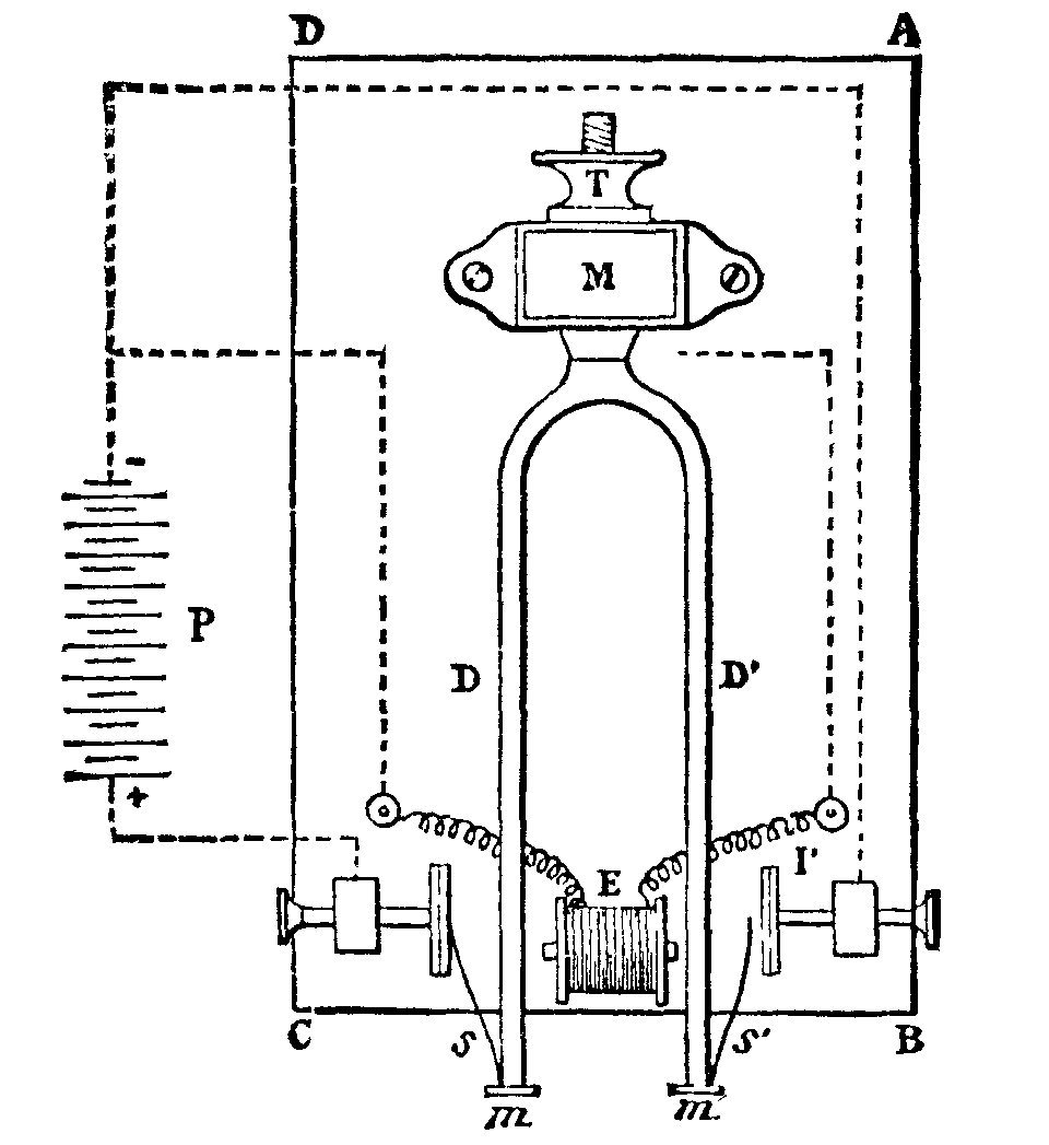
If we imagine the platinum or steel style, s, of the figure to be done away with, as well as the platinized plate, I, and its communication with the negative pole of the pile, P, we shall have the ordinary instrument kept in operation electrically by the aid of the electro-magnet, E, the style, s, the interrupting plate, I, and the pile.
If we preserve the parts above mentioned, the instrument will possess the property of having vibrations of a constant amplitude if sufficient energy be kept up in the pile. In fact, when the amplitude is sufficiently great to cause the style, s, to touch the plate, I, it will be seen that at such a moment the current no longer passes through the electromagnet, and the vibration is no longer maintained. The amplitude cannot exceed an extent which shall permit the style, s, to touch I.
Under such conditions, the duration of the vibrations remains exactly constant, as does also the vibratory intensity of the entire instrument. The measurement of time, then, by an instrument of this kind is, indeed, as perfect as it could well be.
This complication in the arrangement of the apparatus has no importance as regards those tuning forks the number of whose vibrations exceeds a hundred per second, for in such a case these are given an amplitude of a few millimeters only; but it would be of importance with regard to instruments whose number of vibrations is very small, and to which it might be desirable to give great amplitude; for then, as I have long ago shown, the duration of the oscillation would depend a little on the amplitude, but a very little, it is true.
I shall not refer now to the applications of these instruments in chronography, but will rather point out first the applications in which they are destined to produce an effective power.
For this purpose it is necessary to make them pretty massive. The number of the vibrations depends upon such massiveness, and it is necessity to know the relation which exists between these two quantities in order to be able to construct an instrument under determinate conditions. I made in former years such a research with regard to tuning forks of prismatic form, that is to say, of a constant rectangular section continuing even into the bent portion where the parallel branches are united by a semicylinder, at the middle of which is the wrought iron rod as well as the branches. The thickness of the instrument is the dimension parallel to the vibrations; its width is the dimension which is perpendicular to them, and its length is reckoned from the extremity of the branches up to the middle of the curved portion.
It is found that the number of vibrations is independent of the width, proportional to the thickness, and very nearly inverse ratio of the square of the length, provided the latter exceeds ten centimeters.
If we represent the length by l, the thickness by e, and the number of vibrations by n, we shall have the following formula:
n = k × (e / l2)
in which k is a constant quantity whose value depends upon the nature of the metal of which the tuning fork is made.
This constant varies very little from steel to malleable cast iron, and it may be taken as equal to 818270.
Thus, then, we have a means of constructing a tuning fork in which two of the three quantities, n, e, l, are given in advance. Experience proves that no errors are committed exceeding one or two per cent.
It is seen from this that there is a means of increasing the mass of the instrument without changing anything in the thickness, the length or, consequently, the number of vibrations, and this is by increasing the breadth.
It is in this way that I have succeeded in having long massive tuning forks made of malleable iron, giving no more than 12 to 15 vibrations per second, and vibrating with perfect regularity. Fig. 2, annexed, shows one of these instruments of about 55 centimeters length, whose breadth, E, is from 5 to 6 centimeters, and which makes about fifteen double vibrations per second only.
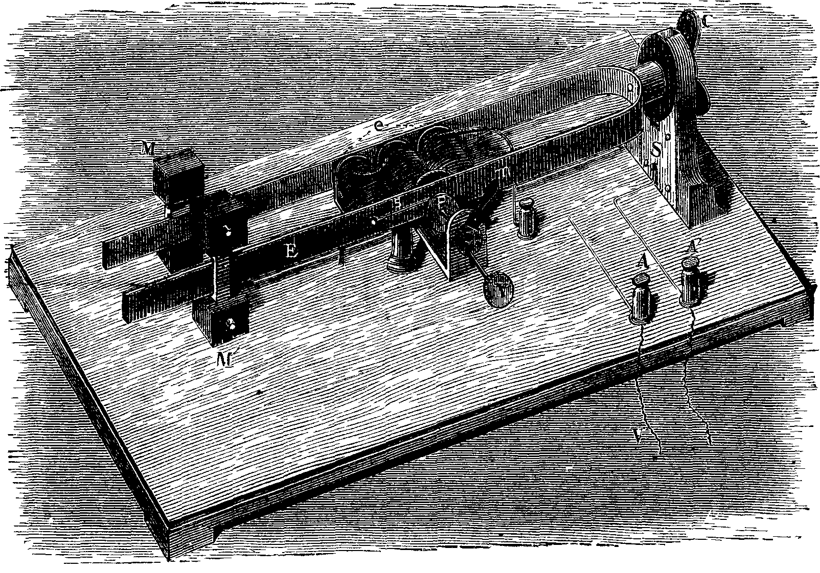 FIG. 2.—THE ELECTRICAL TUNING FORK.
This number might be still further reduced, but at the expense of our being led to exaggerate the longitudinal dimensions of the apparatus in such a way as to make it inconvenient. The object may be attained more simply by loading the branches with slides supporting leaden weights, M, of 500 grammes each. By fixing these slides at different points on the branches, the number of vibrations can be made to vary from simple to double, and even triple. Thus, by fixing them at the extremity of the branches the number of the vibrations is reduced to 5 or 6.
There will be seen in the figure the electro-magnet which keeps up the vibration. This is formed of three simple electro-magnets, whose bobbins have a resistance of no more than 10 ohms, and which are united in series. The interrupting plate, P, against which the style, s, rests at each vibration, is capable of a forward movement, or one of recoil, by the aid of a screw, V, and of an eccentric movement which is produced by a small handle, m, and during which its plane remains invariable. This arrangement permits the point of contact of the style and plate to be varied without changing the precision with which the contact takes place, and all the points of the plate to be slowly used in succession before replacing it. The motion is produced by means of a relatively weak pile, whose poles are connected to the terminals, A and A'. Three Callaud elements of triple surface, renewed one after the other every month at the most, are sufficient to keep up the vibrations continuously, day and night, without interruption, and that too even when the instrument is employed in producing a small mechanical power, as we shall see further on.
We have now seen how electro-tuning forks may be constructed of large dimensions, of large mass, and giving a small number of vibrations per second.
Such instruments are well fitted to perform the role of electrical interrupters, and it was in such a character that one of them figured in the Exhibition of the Upper School of Telegraphy as a type of an interrupter for testing piles.
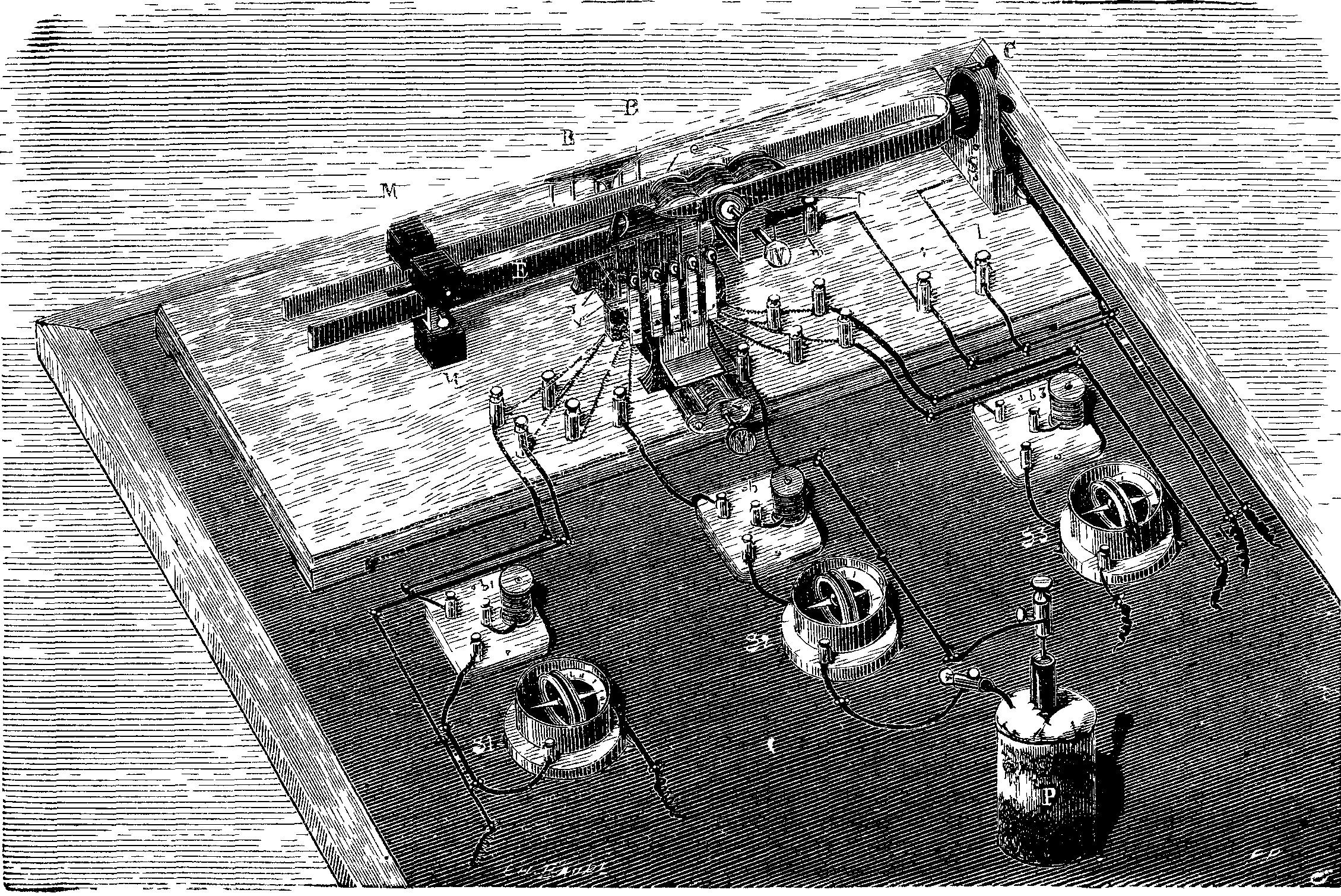 FIG. 3.—ARRANGEMENT FOR TESTING ELECTRIC PILES.
When it is desired to test a pile to ascertain the practicability of employing it in telegraphy, it is necessary to make it perform a work which shall be as nearly as possible identical with that which it will be called on to do, until it is used up, to estimate the duration of such work, to measure regularly the constants of the pile, the electro-motive power, and the internal resistance. Usually, in telegraphy, this work consists in sending over a line of a certain resistance intermittent currents, through the intermedium of suitable manipulators. It suffices then to cause the branches of the electro tuning fork to play the role of one of these manipulators. For doing this the tuning fork carries two insulating ebonite or ivory strips, B B (Fig. 3), which, at every oscillation, abut against vertical brass springs, r. Each of these latter is located in front of the platinized point of a screw, v, which is affixed to a small metallic tongue. The springs and tongues are insulated from each other, and are mounted on a piece which may be moved by a screw, V, so as to cause the springs of the strips, B B', to approach or recede according to the amplitude of the instrument's vibrations. Each spring and tongue is connected with terminals affixed to the base of the apparatus. One of the poles of one element, P, of the pile is connected with the tongue and corresponding screw, while the other pole is connected with the screw in front of it through the intermedium of a galvanometer, g2, which gives the intensity of the intermittent current, and of a resistance coil, b2, which performs the role of an artificial telegraph line. The apparatus being set in operation, it will be seen that the current from the pile is emitted once at every vibration.
Thus there may be exhausted as many pile elements as there are springs, and that, too, simultaneously; and the contacts of the screws and springs can be regulated in such a way that the duration of the emissions shall be the same for all.
At the laboratory of the School of Telegraphy one of these instruments has operated without interruption, day and night, during eighteen months.
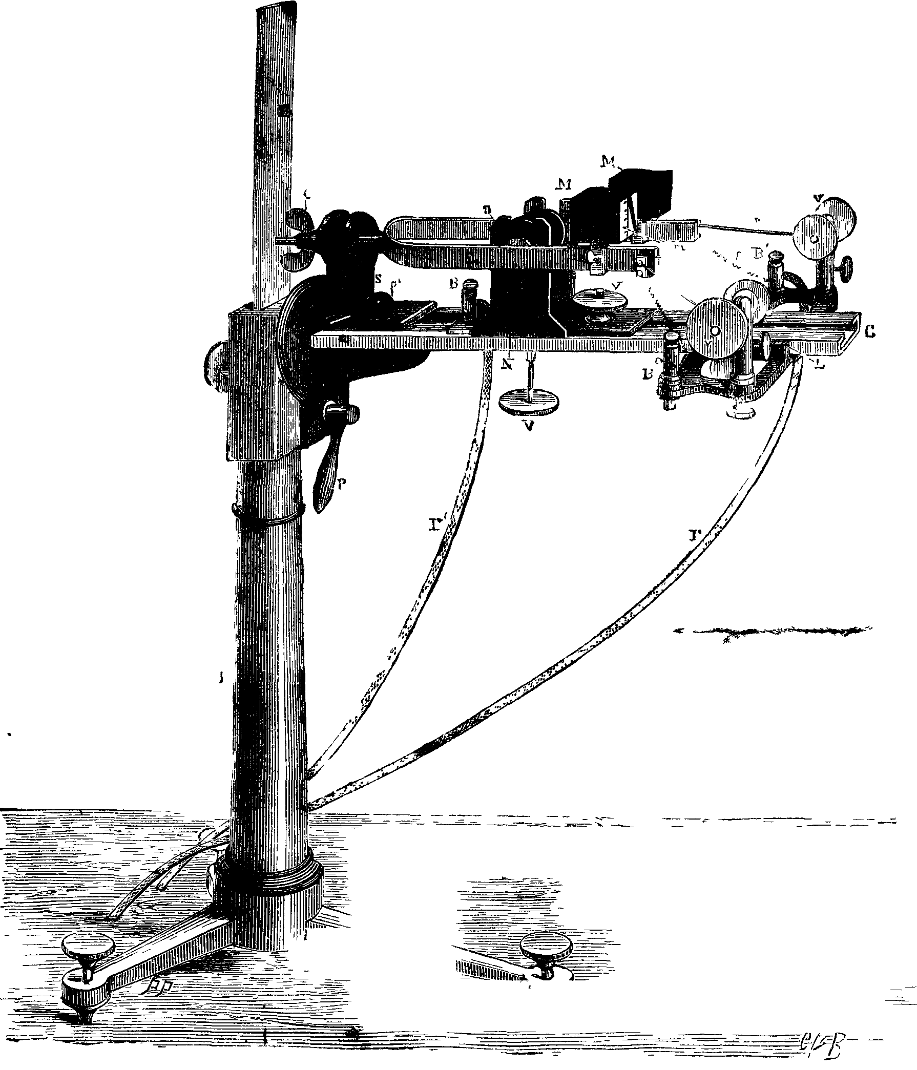
The apparatus shown in Fig. 4 is also an interrupting electro-tuning fork, but it makes a much greater number of vibrations than the preceding, and may serve for other electric tests.
The operation of the tuning fork is kept up electrically by the aid of the screw, v, and the corresponding plate; of the style, s, and of the fine wire spiral spring, f, both insulated from the fork, from the electro-magnet, N, and from the two wires, F F', which communicate with a pile.
The interrupting system is symmetrical with the first. It consists of the style, s, of the spiral spring, f, of the screw, v, and of the plate that this carries at its extremity. The terminal, B, which carries the spring, f, and the rod which carries the screw being insulated from each other, it is only necessary to cause to terminate therein the extremities of a circuit comprising one pile, in order to produce in the circuit a number of interruptions equal to that of the tuning fork's vibrations. Provided the lengths of the springs, f and f', are proper, such vibrations will not be altered.
Moreover, the instrument is so arranged as to produce vibrations whose duration can be varied at pleasure and kept constant during the whole time the experiments last. This is done by modifying the amplitude of the vibrations; for the greater the amplitude, the longer likewise the duration of the contact of the style, s, on the corresponding plate, and the shorter the duration of the interruption. In order to modify the amplitude, the action of the electro-magnet on the branches of the apparatus is made to vary. To effect this, the electro-magnet is made movable perpendicularly by the aid of a screw, V, between two slides, so that the core, N, may be moved with respect to the median line of the branches, and even be raised above them. Its action diminishes, necessarily, while it is being raised, and the amplitude of the vibrations likewise diminishes gradually and continuously. It may thus be made, without difficulty, to vary from two to three tenths of a millimeter to three or four millimeters or more.
But it is not sufficient to cause the amplitude to vary; it is necessary to measure it and to keep it constant at the value desired.
The measurement is effected by the aid of a very simple apparatus that I have before described under the name of the vibrating micrometer. This is a small square of paper carrving a design like that shown in Fig. 5, and which is seen in Fig. 4 glued to one of the masses, M, which serve to vary the number of the instrument's vibrations. This figure is in fact, an angle, one of whose sides is graduated into millimeters, for example, and the other forms the edge of a wide black band. The apex of the angle is above and the divided side is perpendicular to the direction of the vibrations.
Under such conditions, when the fork is vibrating, the apex of the angle, by virtue of the persistence of impressions upon the retina, seems to advance along the graduation in measure as the amplitude of the vibrations increases. If an angle has been drawn such that the slope of one of its sides to the other is one-tenth, it is easy to see that for each millimeter passed over apparently by the apex of the angle, the amplitude will increase by two-tenths of a millimeter.
This is the way, then, that the amplitude is measured. On another hand, it suffices to keep the apex of the angle of the micrometer immovable, in order to be sure of the constancy of the tuning fork's amplitude; and this is done, when necessary, by causing the screw, V, to move slightly.
The instrument represented in Fig. 4 is, moreover, fixed to a support devised by Mr. A. Duboscq, so as to make it possible to give the tuning fork every position possible with respect to a vertical plane; to raise it or lower it, and to move it backward or forward so that it may be employed for chimography, and in all those experiments in which electro-tuning folks are used.
E. MERCADIER.
[LONGMAN'S MAGAZINE.]
There seems to be a manifest desire in some quarters to anticipate the looked for and, by some, hoped-for proofs of our descent, or rather ascent, from the ape.
In the September issue of the Fortnightly Review a writer cites, in this relation, the "Neanderthal skull, which possesses large bosses on the forehead, strikingly suggestive of those which give the gorilla its peculiarly fierce appearance;" and he proceeds: "No other human skull presents so utterly bestial a type as the Neanderthal fragment. If one cuts a female gorilla-skull in the same fashion, the resemblance is truly astonishing, and we may say that the only human feature in the skull is its size."1
In testing the question as between Linnæus and Cuvier of the zoological value of the differences between lowest man and highest ape, a naturalist would not limit his comparison of a portion of the human skull with the corresponding one of a female ape, but would extend it to the young or immature gorilla, and also to the adult male; he would then find the generic and specific characters summed up, so far, at least, as a portion or "fragment" of the skull might show them. What is posed as the "Neanderthal skull" is the roof of the brain-case, or "calvarium" of the anatomist, including the pent-house overhanging the eye-holes or "orbits." There is no other part of the fragment which can be supposed to be meant by the "large bosses" of the above quotation. And, on this assumption, I have to state that the super-orbital ridge in the calvarium in question is but little more prominent than in certain human skulls of both higher and lower races, and of both the existing and cave-dwelling periods. It is a variable cranial character, by no means indicative of race, but rather of sex.
Limiting the comparison to that on which the writer quoted bases his conclusions—apparently the superficial extent of the roof plate—its greater extent as compared with that of a gorilla equaling, probably, in weight the entire frame of the individual from the Neanderthal cave, is strongly significant of the superiority of size of brain in the cave-dweller. The inner surface moreover indicates the more complex character of the soft organ on which it was moulded; the precious "gray substance" being multiplied by certain convolutions which are absent in the apes. But there is another surface which the unbiased zoologist finds it requisite to compare. In the human "calvarium" in question, the mid-line traced backward from the super-orbital ridge runs along a smooth track. In the gorilla a ridge is raised from along the major part of that tract to increase the surface giving attachment to the biting muscles. Such ridge in this position varies only in height in the female and the male adult ape, as the specimens in the British Museum demonstrate. In the Neanderthal individual, as in the rest of mankind, the corresponding muscles do not extend their origins to the upper surface of the cranium, but stop short at the sides forming the inner wall or boundary of what are called the "temples," defined by Johnson as the "upper part of the sides of the head," whence our "biting muscles" are called "temporal," as the side-bones of the skull to which they are attached are also the "temporal bones." In the superficial comparison to which Mr. Grant Allen has restricted himself in bearing testimony on a question which perhaps affects our fellow-creatures, in the right sense of the term, more warmly than any other in human and comparative anatomy, the obvious difference just pointed out ought not to have been passed over. It was the more incumbent on one pronouncing on the paramount problem, because the "sagittal ridge in the gorilla," as in the orang, relates to and signifies the dental character which differentiates all Quadrumana from all Bimana that have ever come under the ken of the biologist. And this ridge much more "strikingly suggests" the fierceness of the powerful brute-ape than the part referred to as "large bosses." Frontal prominences, more truly so termed, are even better developed in peaceful, timid, graminivorous quadrupeds than in the skulls of man or of ape. But before noticing the evidence which the teeth bear on the physical relations of man to brute, I would premise that the comparison must not be limited to a part or "fragment" of the bony frame, but to its totality, as relating to the modes and faculties of locomotion.
Beginning with the skull—and, indeed, for present aim, limiting myself thereto—I have found that a vertical longitudinal section brings to light in greatest number and of truest value the differential characters between lowest Homo and highest Simia. Those truly and indifferently interested in the question may not think it unworthy their time—if it has not already been so bestowed—to give attention to the detailed discussions and illustrations of the characters in question in the second and third volumes of the "Transactions of the Zoological Society."2 The concluding memoir, relating more especially to points of approximation in cranial and denial structure of the highest Quadrumane to the lowest Bimane, has been separately published.
I selected from the large and instructive series of human skulls of various races in the Museum of the Royal College of Surgeons that which was the lowest, and might be called most bestial, in its cranial and dental characters. It was from an adult of that human family of which the life-characters are chiefly but truly and suggestively defined in the narrative of Cook's first voyage in the Endeavor.3
Not to trespass further on the patience of my readers, I may refer to the "Memoir on the Gorilla," 4to, 1865. Plate xii. gives a view, natural size, of the vertical and longitudinal section of an Australian skull; plate xi. gives a similar view of the skull of the gorilla. Reduced copies of these views may be found at p. 572, figs. 395, 396, vol. ii, of my "Anatomy of Vertebrates."
As far as my experience has reached, there is no skull displaying the characters of a quadrumanous species, as that series descends from the gorilla and chimpanzee to the baboon, which exhibits differences, osteal or dental, on which specific and generic distinctions are founded, so great, so marked, as are to be seen, and have been above illustrated, in the comparison of the highest ape with the lowest man.
The modification of man's upper limbs for the endless variety, nicety, and perfection of their application, in fulfillment of the behests of his correspondingly developed brain—actions summed up in the term "manipulation"—testify as strongly to the same conclusion. The corresponding degree of modification of the human lower limbs, to which he owes his upright attitude, relieving the manual instruments from all share in station and terrestrial locomotion—combine and concur in raising the group so characterized above and beyond the apes, to, at least, ordinal distinction. The dental characters of mankind bear like testimony. The lowest (Melanian), like the highest (Caucasian), variety of the bimanal order differs from the quadrumanal one in the order of appearance, and succession to the first set of teeth, of the second or "permanent" set. The foremost incisor and foremost molar are the earliest to appear in that scries; the intermediate teeth are acquired sooner than those behind the foremost molar.4
In the gorilla and chimpanzee, the rate or course of progress is reversed; the second true molar, or the one behind the first, makes its appearance before the bicuspid molars rise in front of the first; and the third or last of the molars behind the first comes into place before the canine tooth has risen. This tooth, indeed, which occupies part of the interval between the foremost incisor and foremost molar, is the last of the permanent set of teeth to be fully developed in the Quadrumana; especially in those which, in their order, rank next to the Bimana. To this differential character add the breaks in the dental series necessitated for the reception of the crowns of the huge canines when the gorilla or chimpanzee shuts its mouth.
But the superior value of developmental over adult anatomical characters in such questions as the present is too well known in the actual phase of biology to need comment.
In the article on "Primeval Man," the author states that the Cave-men "probably had lower foreheads, with high bosses like the Neanderthal skull, and big canine teeth like the Naulette jaw."5
The human lower jaw so defined, from a Belgian cave, which I have carefully examined, gives no evidence of a canine tooth of a size indicative of one in the upper jaw necessitating such vacancy in the lower series of teeth which the apes present. There is no such vacancy nor any evidence of a "big canine tooth" in that cave specimen. And, with respect to cave specimens in general, the zoological characters of the race of men they represent must be founded on the rule, not on an exception, to their cranial features. Those which I obtained from the cavern at Bruniquel, and which are now exhibited in the Museum of Natural History, were disinterred under circumstances more satisfactorily determining their contemporaneity with the extinct quadrupeds those cave-men killed and devoured than in any other spelæan retreat which I have explored. They show neither "lower foreheads" nor "higher bosses" than do the skulls of existing races of mankind.
Present evidence concurs in concluding that the modes of life and grades of thought of the men who have left evidences of their existence at the earliest periods hitherto discovered and determined, were such as are now observable in "savages," or the human races which are commonly so called.
The industry and pains now devoted to the determination of the physical characters of such races, to their ways of living, their tools and weapons, and to the relations of their dermal, osteal, and dental modifications to those of the mammals which follow next after Bimana in the descensive series of mammalian orders, are exemplary.
The present phase of the quest may be far from the bourn to yield hereafter trustworthy evidence of the origin of man; but, meanwhile, exaggerations and misstatements of acquired grounds ought especially to be avoided.
Grant Allen, "On Primitive Man," p. 314.
"Oseteological Contributions to the Natural History of the Orangs (Pithecus) and Chimpanzees (Troglodites niger and Trog. gorilla)."
Hawkesworth's 4th ed., vol. iii., 1770, pp. 86, 137, 229. The skull in question is No 5,394 of the "Catalogue of the Osteology" in the above Museum, 4to, vol. ii, p. 823, 1853.
"Odontography," 4to, 1840-44, p. 454, plates 117, 118, 119.
Fortnightly Review, September, p. 321.
Among the many luxuriant and magnificent forest trees of equatorial West Africa, none can surpass, for general beauty and symmetry, that which is called by the natives the "aba." When growing alone and undisturbed, its conical outline and dark green foliage remind one very much of the white maples of the northern United States, by a distant view, but, on a nearer approach, a dissimilarity is observed. Wherever, in ravines or near the banks of rivers, the soil is moist the most part of the year, there the aba chooses to grow, and during the months of June and July the falling fruits permeate the atmosphere with a delicious fragrance not similar to any other. This, in form, size, and general appearance, is very much like mango apples, so that the natives call mangoes the "white man's aba;" but the wild aba is not much eaten as a fruit, one or two being sufficient for the whole season. The kernel, or seed, is the important and useful part.
When the fallen fruit covers the ground, much as apples do in America, the natives go in canoes to gather it, and the number harvested will be in proportion to the industry of the women. The aba plum is about the size of a goose's egg, of a flattened, ovoid shape, and, when ripe, a beautiful golden color. It consists of three distinct parts: the rind, the pulp, and the seed. The pulp consists of a mass extensively interwoven with strong filaments, which apparently grow out of the seed and are with great difficulty separated from it. The seed, reniform in shape, is bivalved, and constitutes about two-thirds of the bulk of the entire plum, and the inner kernel two-thirds the bulk of the seed.
In consequence of it being such a high tree and growing in such inconvenient places, I have been unable to procure a specimen of the flowers.
As soon as the fruit is brought to the village, all the inhabitants assemble with cutlasses and engage in the work of opening the plums and removing the kernels. The former are thrown away as useless. The seeds are evenly spread on the top of a rack of small sticks, under which a fire is built in the morning, and subjected to the smoke and heat of an entire day. Toward evening the heat is greatly augmented, and in a couple of hours the process is completed. The kernels are now soft, and the oil oozing from them, and while yet in this condition they are thrown into an immense trough and throughly beaten and mashed with a pestle.
Baskets, with banana leaves spread in the inside to prevent the escape of the product, are in readiness, and it is put into them and pressed down. The next day these baskets are suspended in the sun, and at night are brought into the houses to congeal. The process is now finished. The cakes are removed by inversion of the baskets and "bushrope" tied around them, by which the pieces are carried. As thus prepared, odika is highly esteemed by the natives as an article of food, being made into a kind of thick gravy and eaten with boiled plantains.
While at an interior mission station on the Ogowe River, I made some experiments in soap making. With palm oil I succeeded very well, using for an alkali the old-fashioned lye of ashes. But I was disappointed with the odika, though I learned some peculiar characteristics of it as a grease. By boiling the crude odika, I was unable, as I hoped, to separate the oleaginous from the extraneous matter, of which it contains a large proportion, but when the above-mentioned lye was used instead of water, the mass, instead of saponifying, merely separated; the grease, resembling very much in all particulars ordinary beef tallow, rising to the top of the caldron, while the refuse was precipitated.
After clarifying this, it answers instead of oil of theobroma very nicely, and I have used it considerably in making ointments and suppositories with pleasing results.
Gaboon, W. Africa, Aug., 1882.—New Remedies.
The incense cedar (Libocedius decurrens) is one of the valued trees of the California coast and mountains. It is eminently noted for great rapidity of growth, wonderful lightness, stiffness, and extraordinary durability. A thousand uses have sprung up and are multiplying around this interesting cedar as its most inestimable qualities become better known. Fortunately it is one of the most extensively distributed trees of the Pacific—found from the coast range north, south to San Diego, Sierra Nevada, southern Oregon, and most of the interior mountain region from 2,000 to 4,000 feet, and it even thrives quite well at 6,600 feet altitude, but seeming to give out at 7,000 feet, though said to extend to 8,500 feet, which is questionable. As usual with the sylva, flora, and fauna, this also is found lowest along the coast, where it finds the requisite temperature and other essentials, with combined moisture. The base and lower trunk somewhat resembles the Western juniper (J. occidentalis). It is to be noted in general that trees of such broad, outwardly sweeping, or expanded bases seldom blow over, and to the perceptive and artistic eye their significant character is one of firmness and stability. One hundred to two hundred feet high, six to nine feet in diameter (rarely larger) the shaft is often clear of limbs 80 to 100 feet, and although the lower limbs, or even dry branches, may encumber the middle portion, pin-knots do not damage the timber. The massive body tapers more rapidly above than redwood, and is less eccentric than juniper, yet its general port resembles most the best specimens of the latter. The light cinnamon bark is thick and of shreddy-fibered texture, but so concretely compacted as to render the surface evenly ridged by very long, big bars of bark. These sweep obliquely down on the long spiral twist of swift water lines. The top is conic, the foliage is in compressed, flattened sprays, upright, thickened, and somewhat succulent; if not a languid type, at least in no sense rigid. It bears some resemblance to the great Western arborvitæ (Thuja gigantea), but the tiny leaf-scales are opposite and quite awl-pointed. The general hue of the foliage is light yellowish green, warmly tinted, golden and bead tipped, with tiny, oblong male catkins, as the fruit ripens in October and November. The cones are pendulous from the tips of twigs, oblong, and seldom over three-quarters of an inch long, little more than one-third as thick, and for the most part a trifle compressed. The wood is a pale cream-tint in color—a delicate salmon shade. This would hardly warrant the name white cedar, sometimes applied to it, as well as the giant arborvitæ. The extreme lightness of the lumber and its sweetness for packing boxes will commend it for express and commercial purposes, for posts and fencing, and especially railway ties, for sleepers, stringers, and ground timbers of all varieties, and for unnumbered uses, a tithe of which cannot be told in a brief notice. Formerly these trees were cut away and burned up, to clear the track for redwood, tamarack, and ponderous pith-pines, etc.; now all else is superseded by this incense cedar. Thus is seen how hasty and ill-advised notions give place to genuine merit.
A fungus (dædalus) attacks and honeycombs it; and riddled as it may occasionally be, still, if spike or nail finds substance enough to hold, or sufficient solidity to resist crushing, then, for many purposes, even such lumber is practically as good as the soundest timber; because when the tree dies the fungus dies, and thenceforth will absorb no more moisture than the soundest part, and is alike imperishable, contrary to common experience in similar cases. This is a timber nearly as lasting as solid granite. For ship or boat lumber, the clear stuff from sound wood is so exceedingly light, stiff, and durable, and so plenty and available, that few timbers excel it, unless the yellow cedar or cyprus (Cupressus nutkaensis) is excepted, which is a little tougher, stronger, perhaps more elastic, and equally durable, if judged apart from thorough tests and careful data, which, it has been remarked, the apathy or ignorance of some governments appear to deem unworthy their sublime attention. There are said to be in California a thousand times more and better kinds of naval timbers on government lands as important to preserve as the live oaks of the South Atlantic States. It has been asserted as probable that, after due investigation, California would be found to possess a vast amount of the best naval timber in the world, a hundredfold more lasting than the best now in use, if a few woods are excepted, of which there is understood to be no very adequate supply.
The great Washington cedar (Sequoia gigantea) is another important California tree. The great sequoian timber belt lies along the Sierras, upon the first exposed mountain side—moraines of recent retiring glaciers—that face the Pacific, from Calaveras on the north to near the head of Deer Creek on the south—a distance of 200 miles, or a little above 38 degrees north to a little below 36 degrees; altitude 5,000 to 8,000 feet, and rarely 8,400 feet. The belt is broken by two gaps, each 40 miles wide, caused by manifest topographical and glacial reasons, one gap between Calaveras and Tuolumne, the other between Fresno and King's River; thence the vast forest trends south, across the broad basins of Kaweah and Tule, a distance of 70 miles, on fresh moraine soil, ground from high mountain flanks by glaciers. The inscriptions are scarcely marred by post glacial agents, and the contiguous water-worn marks are often so slight in the rock-bound streams as to be measured by a few inches. Rarely does one of these sound and vigorous cedars fall, and those that do will lie 800 to 1,000 years, scarcely less perishable than the granite on which they grew. The great sequoian ditches, dug at a blow by their fall, and the tree tumuli, always turned up beside the deep root-bowls, remain; but, scientists assert, not a vestige of one outside the present forests has yet presented itself, hence the area has not been diminished during the last 8,000 or 10,000 years, and probably not at all in post glacial times. These colossal sequoias rise 275, 300, and even 400 feet aloft; are 20 to 30, and in some rare cases 40 feet in diameter, looking like vast columnar pillars of the skies. No known trees of the world compare with them and their kin, the redwoods, for the focused proximity of such a marvelous amount of timber within limited areas—as it were, the highest standard of timber-land capacity. The stage coach passes through one; 120 children and a piano crowd inside another; a trunk furnishes a house for cotillon parties to dance "stout on stumps;" a horse and rider travel within the burnt-out hollows of others, and so on. A single tree would furnish a two-rail fence, 20 to 30 miles long. The tree has great value for wood and lumber.—N.W. Lumberman.
A catalogue containing brief notices of many important scientific papers heretofore published in the SUPPLEMENT, may be had gratis at this office.
PUBLISHED WEEKLY.
Terms of Subscription, $5 a Year.
Sent by mail, postage prepaid, to subscribers in any part of the United States or Canada. Six dollars a year, sent, prepaid, to any foreign country.
All the back numbers of The Supplement, from the commencement, January 1, 1876, can be had. Price, 10 cents each.
All the back volumes of The Supplement can likewise be supplied. Two volumes are issued yearly. Price of each volume, $2.50, stitched in paper, or $3.50. bound in stiff covers.
Combined rates—One copy of Scientific American and one copy of Scientific American Supplement, one year, postpaid, $7.00.
A liberal discount to booksellers, news agents, and canvassers.
MUNN & CO., Publishers,
261 Broadway, New York, N.Y.
In connection with the Scientific American, Messrs. Munn & Co are Solicitors of American and Foreign Patents, have had 35 years experience, and now have the largest establishment in the world. Patents are obtained on the best terms.
A special notice is made in the Scientific American of all Inventions patented through this Agency, with the name and residence of the Patentee. By the immense circulation thus given, public attention is directed to the merits of the new patent, and sales or introduction often easily effected.
Any person who has made a new discovery or invention can ascertain, free of charge, whether a patent can probably be obtained, by writing to Munn & Co.
We also send free our Hand Book about the Patent Laws. Patents, Caveats, Trade Marks, their costs, and how procured, with hints for procuring advances on inventions. Address
Munn & Co., 261 Broadway, New York.
Branch Office, cor. F and 7th Sts., Washington, D.C.
End of the Project Gutenberg EBook of Scientific American Supplement, No.
365, December 30, 1882, by Various

*** END OF THIS PROJECT GUTENBERG EBOOK SCIENTIFIC AMERICAN ***

***** This file should be named 18763-h.htm or 18763-h.zip *****
This and all associated files of various formats will be found in:
        http://www.gutenberg.org/1/8/7/6/18763/

Produced by David King, Juliet Sutherland and the Online
Distributed Proofreading Team at http://www.pgdp.net


Updated editions will replace the previous one--the old editions
will be renamed.

Creating the works from public domain print editions means that no
one owns a United States copyright in these works, so the Foundation
(and you!) can copy and distribute it in the United States without
permission and without paying copyright royalties.  Special rules,
set forth in the General Terms of Use part of this license, apply to
copying and distributing Project Gutenberg-tm electronic works to
protect the PROJECT GUTENBERG-tm concept and trademark.  Project
Gutenberg is a registered trademark, and may not be used if you
charge for the eBooks, unless you receive specific permission.  If you
do not charge anything for copies of this eBook, complying with the
rules is very easy.  You may use this eBook for nearly any purpose
such as creation of derivative works, reports, performances and
research.  They may be modified and printed and given away--you may do
practically ANYTHING with public domain eBooks.  Redistribution is
subject to the trademark license, especially commercial
redistribution.


*** START: FULL LICENSE ***

THE FULL PROJECT GUTENBERG LICENSE
PLEASE READ THIS BEFORE YOU DISTRIBUTE OR USE THIS WORK

To protect the Project Gutenberg-tm mission of promoting the free
distribution of electronic works, by using or distributing this work
(or any other work associated in any way with the phrase "Project
Gutenberg"), you agree to comply with all the terms of the Full Project
Gutenberg-tm License (available with this file or online at
http://gutenberg.org/license).


Section 1.  General Terms of Use and Redistributing Project Gutenberg-tm
electronic works

1.A.  By reading or using any part of this Project Gutenberg-tm
electronic work, you indicate that you have read, understand, agree to
and accept all the terms of this license and intellectual property
(trademark/copyright) agreement.  If you do not agree to abide by all
the terms of this agreement, you must cease using and return or destroy
all copies of Project Gutenberg-tm electronic works in your possession.
If you paid a fee for obtaining a copy of or access to a Project
Gutenberg-tm electronic work and you do not agree to be bound by the
terms of this agreement, you may obtain a refund from the person or
entity to whom you paid the fee as set forth in paragraph 1.E.8.

1.B.  "Project Gutenberg" is a registered trademark.  It may only be
used on or associated in any way with an electronic work by people who
agree to be bound by the terms of this agreement.  There are a few
things that you can do with most Project Gutenberg-tm electronic works
even without complying with the full terms of this agreement.  See
paragraph 1.C below.  There are a lot of things you can do with Project
Gutenberg-tm electronic works if you follow the terms of this agreement
and help preserve free future access to Project Gutenberg-tm electronic
works.  See paragraph 1.E below.

1.C.  The Project Gutenberg Literary Archive Foundation ("the Foundation"
or PGLAF), owns a compilation copyright in the collection of Project
Gutenberg-tm electronic works.  Nearly all the individual works in the
collection are in the public domain in the United States.  If an
individual work is in the public domain in the United States and you are
located in the United States, we do not claim a right to prevent you from
copying, distributing, performing, displaying or creating derivative
works based on the work as long as all references to Project Gutenberg
are removed.  Of course, we hope that you will support the Project
Gutenberg-tm mission of promoting free access to electronic works by
freely sharing Project Gutenberg-tm works in compliance with the terms of
this agreement for keeping the Project Gutenberg-tm name associated with
the work.  You can easily comply with the terms of this agreement by
keeping this work in the same format with its attached full Project
Gutenberg-tm License when you share it without charge with others.

1.D.  The copyright laws of the place where you are located also govern
what you can do with this work.  Copyright laws in most countries are in
a constant state of change.  If you are outside the United States, check
the laws of your country in addition to the terms of this agreement
before downloading, copying, displaying, performing, distributing or
creating derivative works based on this work or any other Project
Gutenberg-tm work.  The Foundation makes no representations concerning
the copyright status of any work in any country outside the United
States.

1.E.  Unless you have removed all references to Project Gutenberg:

1.E.1.  The following sentence, with active links to, or other immediate
access to, the full Project Gutenberg-tm License must appear prominently
whenever any copy of a Project Gutenberg-tm work (any work on which the
phrase "Project Gutenberg" appears, or with which the phrase "Project
Gutenberg" is associated) is accessed, displayed, performed, viewed,
copied or distributed:

This eBook is for the use of anyone anywhere at no cost and with
almost no restrictions whatsoever.  You may copy it, give it away or
re-use it under the terms of the Project Gutenberg License included
with this eBook or online at www.gutenberg.org

1.E.2.  If an individual Project Gutenberg-tm electronic work is derived
from the public domain (does not contain a notice indicating that it is
posted with permission of the copyright holder), the work can be copied
and distributed to anyone in the United States without paying any fees
or charges.  If you are redistributing or providing access to a work
with the phrase "Project Gutenberg" associated with or appearing on the
work, you must comply either with the requirements of paragraphs 1.E.1
through 1.E.7 or obtain permission for the use of the work and the
Project Gutenberg-tm trademark as set forth in paragraphs 1.E.8 or
1.E.9.

1.E.3.  If an individual Project Gutenberg-tm electronic work is posted
with the permission of the copyright holder, your use and distribution
must comply with both paragraphs 1.E.1 through 1.E.7 and any additional
terms imposed by the copyright holder.  Additional terms will be linked
to the Project Gutenberg-tm License for all works posted with the
permission of the copyright holder found at the beginning of this work.

1.E.4.  Do not unlink or detach or remove the full Project Gutenberg-tm
License terms from this work, or any files containing a part of this
work or any other work associated with Project Gutenberg-tm.

1.E.5.  Do not copy, display, perform, distribute or redistribute this
electronic work, or any part of this electronic work, without
prominently displaying the sentence set forth in paragraph 1.E.1 with
active links or immediate access to the full terms of the Project
Gutenberg-tm License.

1.E.6.  You may convert to and distribute this work in any binary,
compressed, marked up, nonproprietary or proprietary form, including any
word processing or hypertext form.  However, if you provide access to or
distribute copies of a Project Gutenberg-tm work in a format other than
"Plain Vanilla ASCII" or other format used in the official version
posted on the official Project Gutenberg-tm web site (www.gutenberg.org),
you must, at no additional cost, fee or expense to the user, provide a
copy, a means of exporting a copy, or a means of obtaining a copy upon
request, of the work in its original "Plain Vanilla ASCII" or other
form.  Any alternate format must include the full Project Gutenberg-tm
License as specified in paragraph 1.E.1.

1.E.7.  Do not charge a fee for access to, viewing, displaying,
performing, copying or distributing any Project Gutenberg-tm works
unless you comply with paragraph 1.E.8 or 1.E.9.

1.E.8.  You may charge a reasonable fee for copies of or providing
access to or distributing Project Gutenberg-tm electronic works provided
that

- You pay a royalty fee of 20% of the gross profits you derive from
     the use of Project Gutenberg-tm works calculated using the method
     you already use to calculate your applicable taxes.  The fee is
     owed to the owner of the Project Gutenberg-tm trademark, but he
     has agreed to donate royalties under this paragraph to the
     Project Gutenberg Literary Archive Foundation.  Royalty payments
     must be paid within 60 days following each date on which you
     prepare (or are legally required to prepare) your periodic tax
     returns.  Royalty payments should be clearly marked as such and
     sent to the Project Gutenberg Literary Archive Foundation at the
     address specified in Section 4, "Information about donations to
     the Project Gutenberg Literary Archive Foundation."

- You provide a full refund of any money paid by a user who notifies
     you in writing (or by e-mail) within 30 days of receipt that s/he
     does not agree to the terms of the full Project Gutenberg-tm
     License.  You must require such a user to return or
     destroy all copies of the works possessed in a physical medium
     and discontinue all use of and all access to other copies of
     Project Gutenberg-tm works.

- You provide, in accordance with paragraph 1.F.3, a full refund of any
     money paid for a work or a replacement copy, if a defect in the
     electronic work is discovered and reported to you within 90 days
     of receipt of the work.

- You comply with all other terms of this agreement for free
     distribution of Project Gutenberg-tm works.

1.E.9.  If you wish to charge a fee or distribute a Project Gutenberg-tm
electronic work or group of works on different terms than are set
forth in this agreement, you must obtain permission in writing from
both the Project Gutenberg Literary Archive Foundation and Michael
Hart, the owner of the Project Gutenberg-tm trademark.  Contact the
Foundation as set forth in Section 3 below.

1.F.

1.F.1.  Project Gutenberg volunteers and employees expend considerable
effort to identify, do copyright research on, transcribe and proofread
public domain works in creating the Project Gutenberg-tm
collection.  Despite these efforts, Project Gutenberg-tm electronic
works, and the medium on which they may be stored, may contain
"Defects," such as, but not limited to, incomplete, inaccurate or
corrupt data, transcription errors, a copyright or other intellectual
property infringement, a defective or damaged disk or other medium, a
computer virus, or computer codes that damage or cannot be read by
your equipment.

1.F.2.  LIMITED WARRANTY, DISCLAIMER OF DAMAGES - Except for the "Right
of Replacement or Refund" described in paragraph 1.F.3, the Project
Gutenberg Literary Archive Foundation, the owner of the Project
Gutenberg-tm trademark, and any other party distributing a Project
Gutenberg-tm electronic work under this agreement, disclaim all
liability to you for damages, costs and expenses, including legal
fees.  YOU AGREE THAT YOU HAVE NO REMEDIES FOR NEGLIGENCE, STRICT
LIABILITY, BREACH OF WARRANTY OR BREACH OF CONTRACT EXCEPT THOSE
PROVIDED IN PARAGRAPH F3.  YOU AGREE THAT THE FOUNDATION, THE
TRADEMARK OWNER, AND ANY DISTRIBUTOR UNDER THIS AGREEMENT WILL NOT BE
LIABLE TO YOU FOR ACTUAL, DIRECT, INDIRECT, CONSEQUENTIAL, PUNITIVE OR
INCIDENTAL DAMAGES EVEN IF YOU GIVE NOTICE OF THE POSSIBILITY OF SUCH
DAMAGE.

1.F.3.  LIMITED RIGHT OF REPLACEMENT OR REFUND - If you discover a
defect in this electronic work within 90 days of receiving it, you can
receive a refund of the money (if any) you paid for it by sending a
written explanation to the person you received the work from.  If you
received the work on a physical medium, you must return the medium with
your written explanation.  The person or entity that provided you with
the defective work may elect to provide a replacement copy in lieu of a
refund.  If you received the work electronically, the person or entity
providing it to you may choose to give you a second opportunity to
receive the work electronically in lieu of a refund.  If the second copy
is also defective, you may demand a refund in writing without further
opportunities to fix the problem.

1.F.4.  Except for the limited right of replacement or refund set forth
in paragraph 1.F.3, this work is provided to you 'AS-IS' WITH NO OTHER
WARRANTIES OF ANY KIND, EXPRESS OR IMPLIED, INCLUDING BUT NOT LIMITED TO
WARRANTIES OF MERCHANTIBILITY OR FITNESS FOR ANY PURPOSE.

1.F.5.  Some states do not allow disclaimers of certain implied
warranties or the exclusion or limitation of certain types of damages.
If any disclaimer or limitation set forth in this agreement violates the
law of the state applicable to this agreement, the agreement shall be
interpreted to make the maximum disclaimer or limitation permitted by
the applicable state law.  The invalidity or unenforceability of any
provision of this agreement shall not void the remaining provisions.

1.F.6.  INDEMNITY - You agree to indemnify and hold the Foundation, the
trademark owner, any agent or employee of the Foundation, anyone
providing copies of Project Gutenberg-tm electronic works in accordance
with this agreement, and any volunteers associated with the production,
promotion and distribution of Project Gutenberg-tm electronic works,
harmless from all liability, costs and expenses, including legal fees,
that arise directly or indirectly from any of the following which you do
or cause to occur: (a) distribution of this or any Project Gutenberg-tm
work, (b) alteration, modification, or additions or deletions to any
Project Gutenberg-tm work, and (c) any Defect you cause.


Section  2.  Information about the Mission of Project Gutenberg-tm

Project Gutenberg-tm is synonymous with the free distribution of
electronic works in formats readable by the widest variety of computers
including obsolete, old, middle-aged and new computers.  It exists
because of the efforts of hundreds of volunteers and donations from
people in all walks of life.

Volunteers and financial support to provide volunteers with the
assistance they need, is critical to reaching Project Gutenberg-tm's
goals and ensuring that the Project Gutenberg-tm collection will
remain freely available for generations to come.  In 2001, the Project
Gutenberg Literary Archive Foundation was created to provide a secure
and permanent future for Project Gutenberg-tm and future generations.
To learn more about the Project Gutenberg Literary Archive Foundation
and how your efforts and donations can help, see Sections 3 and 4
and the Foundation web page at http://www.pglaf.org.


Section 3.  Information about the Project Gutenberg Literary Archive
Foundation

The Project Gutenberg Literary Archive Foundation is a non profit
501(c)(3) educational corporation organized under the laws of the
state of Mississippi and granted tax exempt status by the Internal
Revenue Service.  The Foundation's EIN or federal tax identification
number is 64-6221541.  Its 501(c)(3) letter is posted at
http://pglaf.org/fundraising.  Contributions to the Project Gutenberg
Literary Archive Foundation are tax deductible to the full extent
permitted by U.S. federal laws and your state's laws.

The Foundation's principal office is located at 4557 Melan Dr. S.
Fairbanks, AK, 99712., but its volunteers and employees are scattered
throughout numerous locations.  Its business office is located at
809 North 1500 West, Salt Lake City, UT 84116, (801) 596-1887, email
business@pglaf.org.  Email contact links and up to date contact
information can be found at the Foundation's web site and official
page at http://pglaf.org

For additional contact information:
     Dr. Gregory B. Newby
     Chief Executive and Director
     gbnewby@pglaf.org


Section 4.  Information about Donations to the Project Gutenberg
Literary Archive Foundation

Project Gutenberg-tm depends upon and cannot survive without wide
spread public support and donations to carry out its mission of
increasing the number of public domain and licensed works that can be
freely distributed in machine readable form accessible by the widest
array of equipment including outdated equipment.  Many small donations
($1 to $5,000) are particularly important to maintaining tax exempt
status with the IRS.

The Foundation is committed to complying with the laws regulating
charities and charitable donations in all 50 states of the United
States.  Compliance requirements are not uniform and it takes a
considerable effort, much paperwork and many fees to meet and keep up
with these requirements.  We do not solicit donations in locations
where we have not received written confirmation of compliance.  To
SEND DONATIONS or determine the status of compliance for any
particular state visit http://pglaf.org

While we cannot and do not solicit contributions from states where we
have not met the solicitation requirements, we know of no prohibition
against accepting unsolicited donations from donors in such states who
approach us with offers to donate.

International donations are gratefully accepted, but we cannot make
any statements concerning tax treatment of donations received from
outside the United States.  U.S. laws alone swamp our small staff.

Please check the Project Gutenberg Web pages for current donation
methods and addresses.  Donations are accepted in a number of other
ways including checks, online payments and credit card donations.
To donate, please visit: http://pglaf.org/donate


Section 5.  General Information About Project Gutenberg-tm electronic
works.

Professor Michael S. Hart is the originator of the Project Gutenberg-tm
concept of a library of electronic works that could be freely shared
with anyone.  For thirty years, he produced and distributed Project
Gutenberg-tm eBooks with only a loose network of volunteer support.


Project Gutenberg-tm eBooks are often created from several printed
editions, all of which are confirmed as Public Domain in the U.S.
unless a copyright notice is included.  Thus, we do not necessarily
keep eBooks in compliance with any particular paper edition.


Most people start at our Web site which has the main PG search facility:

     http://www.gutenberg.org

This Web site includes information about Project Gutenberg-tm,
including how to make donations to the Project Gutenberg Literary
Archive Foundation, how to help produce our new eBooks, and how to
subscribe to our email newsletter to hear about new eBooks.