The Project Gutenberg EBook of Scientific American Supplement, No. 315,
January 14, 1882, by Various

This eBook is for the use of anyone anywhere at no cost and with
almost no restrictions whatsoever.  You may copy it, give it away or
re-use it under the terms of the Project Gutenberg License included
with this eBook or online at www.gutenberg.org


Title: Scientific American Supplement, No. 315,  January 14, 1882

Author: Various

Release Date: May 8, 2006 [EBook #18345]

Language: English

Character set encoding: ISO-8859-1

*** START OF THIS PROJECT GUTENBERG EBOOK SCIENTIFIC AMERICAN ***


Produced by Juliet Sutherland and the Online Distributed
Proofreading Team at www.pgdp.net
In admiring the recent developments of electric science as evidenced by the number of important inventions which have during the past few years been given to the world, especially in those branches of applied science which deal more particularly with the generation of electricity and the production of the electric light, there is often too great a tendency to forget, or, at least, to pass over in comparative silence the claims which the great pioneer workers and discoverers undoubtedly have to a large share of the merit of this scientific development.
It is, of course, obviously impossible in anything approaching a retrospect of the science of magneto-electric induction or its application to illumination to pass slightly over the names of Oersted, of Ampère, of Davy, and of Faraday, but, in other respects, their work is too often lost sight of in the splendid modern developments of their discoveries. Again, there is another group of discoverer-inventors who occupy an intermediate position between the abstract discoverers above named and the inventors and adapters of still more recent times. To this group belong the names of Pixii and Saxton, Holmes and Nollet, Wilde, Varley, Siemens, Wheatstone, and Pacinotti, who was the first to discover a means of constructing a machine capable of giving a continuous current always in the same direction, and which has since proved itself to be the type of nearly all the direct current electric machines of the present day, and especially those such as the Gramme and Brush and De Meritens machines, in which the rotating armature is of annular form; and when it is considered what a large number of the well known electric generators are founded upon this discovery, it must be a matter of general gratification that the recent International Jury of the Paris Exhibition of Electricity awarded to Dr. Antonio Pacinotti one of their highest awards.
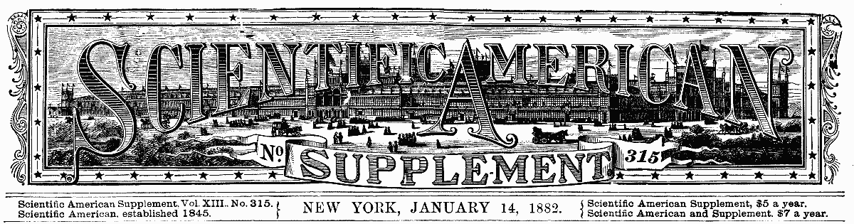
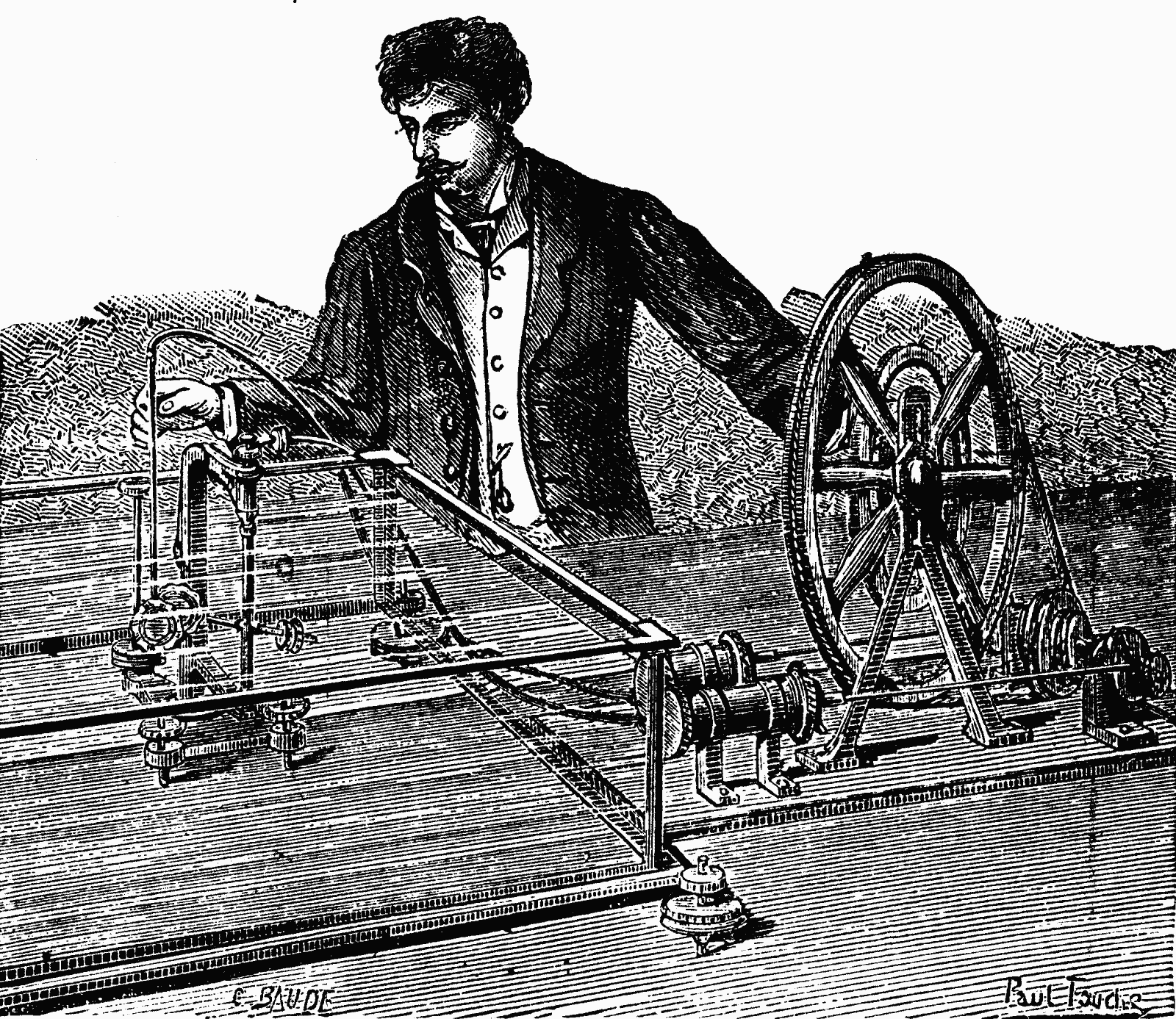
The original machine designed by Dr. Pacinotti in the year 1860, and which we illustrate on the present page, formed one of the most interesting exhibits in the Paris Exhibition, and conferred upon the Italian Section a very distinctive feature, and we cannot but think that while all were interested in examining it, there must have been many who could not help being impressed with the fact that it took something away from the originality of design in several of the machines exhibited in various parts of the building.
This very interesting machine was first illustrated and described by its inventor in the Nuovo Cimento in the year 1864, under the title "A Description of a Small Electro-Magnetic Machine," and to this description we are indebted for the information and diagrams contained in this notice, but the perspective view is taken from the instrument itself in the Paris Exhibition.
In this very interesting historical communication the author commences by describing a new form of electro-magnet, consisting of an iron ring around which is wound (as in the Gramme machine) a single helix of insulated copper wire completely covering the ring, and the two ends of the annular helix being soldered together, an annular magnet is produced, enveloped in an insulated helix forming a closed circuit, the convolutions of which are all in the same direction. If in such a system any two points of the coil situated at opposite ends of the same diameter of the ring be connected respectively with the two poles of a voltaic battery, the electric current having two courses open to it, will divide into two portions traversing the coil around each half of the ring from one point of contact to the other, and the direction of the current, in each portion will be such as to magnetize the iron core, so that its magnetic poles will be situated at the points where the current enters and leaves the helix, and a straight line joining these points may be looked upon as the magnetic axis of the system. From this construction it is clear that, by varying the position of the points of contact of the battery wires and the coil, the position of the magnetic axis will be changed accordingly, and can be made to take up any diametrical position with respect to the ring, of which the two halves (separated by the diameter joining the points of contact of the battery wires with the coil) may be regarded as made up of two semicircular horseshoe electro-magnets having their similar poles joined. To this form of instrument the name "Transversal electro magnet" (Eletro calamita transversale) was given by its inventor, to whom is undoubtedly due the merit of having been the first to construct an electro-magnet the position of whose poles could be varied at will by means of a circular commutator.
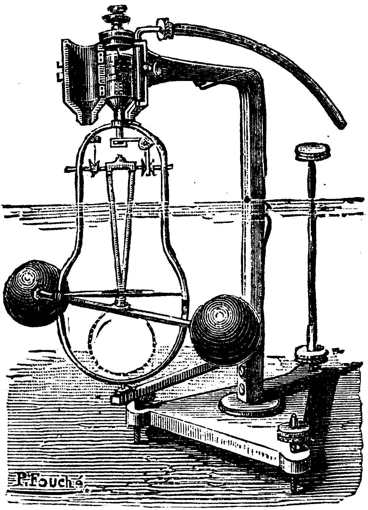
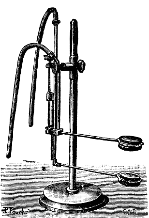
By applying the principle to an electro-magnetic engine, Dr. Pacinotti produced the machine which we illustrate on the present page. The armature consists of a turned ring of iron, having around its circumference sixteen teeth of equal size and at equal angular distance apart, as shown in Fig. 1, forming between them as many spaces or notches, which are filled up by coiling within them helices of insulated copper wire, r r r, in a similar manner to that adopted in winding the Brush armature, and between them are fixed as many wooden wedges, m m, by which the helices are firmly held in their place. All the coils are wound round the ring in the same direction, and the terminating end of each coil is connected to the commencing end of the next or succeeding helix, and the junctions so made are attached to conducting wires which are gathered together close to the vertical shaft on which the armature ring is fixed, passing through holes at equal distances apart in a wooden collar fixed to the same shaft, and being attached at their lower extremities to the metallic contact pieces of the commutator, c, shown at the lower part of Fig. 3, which is an elevation of the machine, while Fig. 4 is a plan of the same apparatus.
The commutator consists of a small boxwood cylinder, carrying around its cylindrical surface two rows of eight holes, one above the other, in which are fitted sixteen contact pieces of brass which slightly project above the surface of the wood, the positions of those in the upper circle alternating or "breaking joint" with those in the lower, and each contact piece is in metallic connection with its corresponding conducting wire, and, therefore, with the junction of two of the helices on the armature. Against the edge of the commutator are pressed by means of adjustable levers two small brass contact rollers, k k, which are respectively connected with the positive and negative poles of the voltaic battery (either through or independent of the coils of a fixed electro-magnet, to which we shall presently refer), and the magnetic axis of the ring will lie in the same plane as the line joining the points of contact of the battery and rotating helix, this axis remaining nearly fixed notwithstanding the rotation of the iron ring in which the magnetism is induced.
In the apparatus figured in Figs. 3 and 4, the armature rotates between the two vertical limbs, A B, of a fixed electro-magnet furnished with extended pole pieces, A A, B B (Fig. 4), each of which embraces about six of the armature coils. The fixed electro-magnet is constructed of two vertical iron cylindrical bars, A and B, united at their lower extremities by a horizontal iron bar, F F, the one being rigidly and permanently attached to it, while the other is fastened to it by a screw, G, passing through a slot so that the distance of the pole pieces from one another and from the armature ring is capable of adjustment.
The connections of the machine, which are shown in Fig. 3, are made as follows: The positive current, entering by the attachment screw, h, passes by a wire to the right hand commutator screw, l, to the right-hand roller, k, through the commutator to the ring, around which it traverses to the left-hand roller, k¹, and screw, l¹, to the magnet coil, A, and thence through the coil of the magnet, B, to the terminal screw, h, on the right hand of the figure. This method of coupling up is of very great historical interest, for it is the first instance on record of the magnet coils and armature of a machine being included in one circuit, giving to it the principle of construction of a dynamo-electric machine, and antedating in publication, by two years, the interesting machines of Siemens, Wheatstone, and Varley, and preceding them in construction by a still longer period.
With this apparatus Dr. Pacinotti made the following interesting experiments with the object of determining the amount of mechanical work produced by the machine (when worked as an electro-magnetic engine), and the corresponding consumption of the elements of the battery: Attached to the spindle of the machine was a small pulley, Q Q (Fig. 3), for the purpose of driving, by means of a cord, another pulley on a horizontal spindle carrying a drum on which was wound a cord carrying a weight, and on the same spindle was also a brake and brake-wheel, the lever of which was loaded so as just to prevent the weight setting into motion the whole system, consisting of the two machines, when no current was flowing. In this condition, when the machine was set in motion by connecting the battery, the mechanical work expended in overcoming the friction of the brake was equal to that required to raise the weight; and, in order to obtain the total work done, all that was necessary was to multiply the weight lifted by the distance through which it was raised. The consumption of the battery was estimated at the same time by interposing in the circuit a sulphate of copper voltameter, of which the copper plate was weighed before and after the experiment. The following are some of the results obtained by Dr. Pacinotti in experimenting after the manner just described. With the current from a battery of four small Bunsen elements, the machine raised a weight of 3.2812 kilos to a height of 8.66 m. (allowing for friction), so that the mechanical work was represented by 28.45 m. During the experiment the positive plate of the voltameter lost in weight 0.224 gramme, the negative gaining 0.235 gramme, giving an average of chemical work performed in the voltameter of 0.229 gramme, and multiplying this figure by the ratio between the equivalent of zinc to that of copper, and by the number of the elements of the battery, the weight of zinc consumed in the battery was computed at 0.951 gramme, so that to produce one kilogrammeter of mechanical work 33 milligrammes of zinc would be consumed in the battery. In another experiment, made with five elements, the consumption of zinc was found to be 36 milligrammes for every kilogrammeter of mechanical work performed. In recording these experiments, Dr. Pacinotti points out that although these results do not show any special advantage in his machine over those of other construction, still they are very encouraging, when it is considered that the apparatus with which the experiments were made were full of defects of workmanship, the commutator, being eccentric to the axis, causing the contacts between it and the rollers to be very imperfect and unequal.
In his communication to the Nuovo Cimento, Dr. Pacinotti states that the reasons which induced him to construct the apparatus on the principle which we have just described, were: (1) That according to this system the electric current is continuously traversing the coils of the armature, and the machine is kept in motion not by a series of intermittent impulses succeeding one another with greater or less rapidity, but by a constantly acting force producing a more uniform effect. (2) The annular form of the revolving armature contributes (together with the preceding method of continuous magnetization) to give regularity to its motion and at the same time reduces the loss of motive power, through mechanical shocks and friction, to a minimum. (3) In the annular system no attempt is made suddenly to magnetize and demagnetize the iron core of the rotating armature, as such changes of magnetization would be retarded by the setting up of extra currents, and also by the permanent residual magnetism which cannot be entirely eliminated from the iron; and with this annular construction such charges are not required, all that is necessary being that each portion of the iron of the ring should pass, in its rotation, through the various degrees of magnetization in succession, being subjected thereby to the influence of the electro-dynamic forces by which its motion is produced. (4) The polar extension pieces of the fixed electro-magnet, by embracing a sufficiently large number of the iron projecting pieces on the armature ring, continue to exercise an influence upon them almost up to the point at which their magnetization ceases when passing the neutral axis. (5) By the method of construction adopted, sparks, while being increased in number, are diminished in intensity, there being no powerful extra currents produced at the breaking of the circuit, and Dr. Pacinotti points out that when the machine is in rotation a continuous current is induced in the circuit which is opposed to that of the battery; and this leads to what, looked at by the light of the present state of electric science, is by far the most interesting part of Dr. Pacinotti's paper, published, as it was, more than seventeen years ago.
In the part to which we refer, Dr. Pacinotti states that it occurred to him that the value of the apparatus would be greatly increased if it could be altered from an electro-magnetic to a magneto-electric machine, so as to produce a continuous current. Thus, if the electro-magnet, A B (Figs. 3 and 4), be replaced by a permanent magnet, and the annular armature were made to revolve, the apparatus would become a magneto-electric generator, which would produce a continuous induced current always in the same direction, and in analyzing the action of such a machine Dr. Pacinotti observes that, as the position of the magnetic field is fixed, and the iron armature with its coils rotates within it, the action may be regarded as the same as if the iron ring were made up of two fixed semicircular horseshoe magnets with their similar poles joined, and the coils were loose upon it and were caused to rotate over it, and this mode of expressing the phenomenon was exactly what we adopted when describing the Gramme machine, without having at that time seen what Dr. Pacinotti had written fifteen years before.
In explanation of the physical phenomena involved in the induction of the electric currents in the armature when the machine is in action as a generator, Dr. Pacinotti makes the following remarks: Let us trace the action of one of the coils in the various positions that it can assume in one complete revolution; starting from the position marked N, Fig. 2, and moving toward S, an electric current will be developed in it in one direction while moving through the portion of the circle, N a, and after passing the point, a, and while passing through the arc, a S, the induced current will be in the opposite direction, which direction will be maintained until the point, b, is reached, after which the currents will be in the same direction as between N and a; and as all the coils are connected together, all the currents in a given direction will unite and give the combined current a direction indicated by the arrows in Fig. 2, and in order to collect it (so as to transmit it into the external circuit), the most eminent position for the collectors will be at points on the commutator at opposite ends of a diameter which is perpendicular to the magnetic axis of the magnetic field. With reference to Fig. 2, we imagine either that the two arrows to the right of the figure are incorrectly placed by the engraver, or that Dr. Pacinotti intended this diagram to express the direction of the current throughout the whole circuit, as if it started from a, and after traversing the external circuit entered again at b, thus completing the whole cycle made up of the external and internal circuits.
Dr. Pacinotti calls attention to the fact that the direction of the current generated by the machine is reversed by a reversal of the direction of rotation, as well as by a shifting of the position of the collectors from one side to the other of their neutral point, and concludes his most interesting communication by describing experiments made with it in order to convert it into a magneto-electric machine. "I brought," he says, "near to the coiled armature the opposite poles of two permanent magnets, and I also excited by the current from a battery the fixed electro-magnets (see Figs. 3 and 4), and by mechanical means I rotated the annular armature on its axis. By both methods I obtained an induced electric current, which was continuous and always in the same direction, and which, as was indicated by a galvanometer, proved to be of considerable intensity, although it had traversed the sulphate of copper voltameter which was included in the circuit."
Dr. Pacinotti goes on to show that there would be an obvious advantage in constructing electric generating machines upon this principle, for by such a system electric currents can be produced which are continuous and in one direction without the necessity of the inconvenient and more or less inefficient mechanical arrangements for commutating the currents and sorting them, so as to collect and combine those in one direction, separating them from those which are in the opposite; and he also points our the reversibility of the apparatus, showing that as an electro-magnetic engine it is capable of converting a current of electricity into mechanical motion capable of performing work, while as a magneto-electric machine it is made to transform mechanical energy into an electric current, which in other apparatus, forming part of its external circuit, is capable of performing electric, chemical, or mechanical work.
All these statements are matters of everyday familiarity at the present day, but it must be remembered that they are records of experiments made twenty years ago, and as such they entitle their author to a very distinguished place among the pioneers of electric science, and it is somewhat remarkable that they did not lead him straight to the discovery of the "action and reaction" principle of dynamo-electric magnetic induction to which he approached so closely, and it is also a curious fact that so suggestive and remarkable a paper should have been written and published as far back as 1864, and that it should not have produced sooner than it did a revolution in electric science.—Engineering.
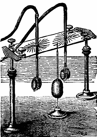
We lately published a short description of a very interesting apparatus which may be considered in some sense as a prototype of the Gramme machine, although it has very considerable, indeed radical differences, and which, moreover, was constructed for a different purpose, the Elias machine being, in fact, an electromotor, while the Gramme machine is, it is almost unnecessary to say, an electric generator. This apparent resemblance makes it, however, necessary to describe the Elias machine, and to explain the difference between it and the Gramme. Its very early date (1842), moreover, gives it an exceptional interest. The figures on the previous page convey an exact idea of the model that was exhibited at the Paris Electrical Exhibition, and which was contributed by the Ecole Polytechnique of Delft in the Dutch Section. This model is almost identical with that illustrated and described in a pamphlet accompanying the exhibit. The perspective illustrations show the machine very clearly, and the section explains the construction still further. The apparatus consists of an exterior ring made of iron, about 14 in. in diameter and 1.5 in wide. It is divided into six equal sections by six small blocks which project from the inner face of the ring, and which act as so many magnetic poles. On each of the sections between the blocks is rolled a coil, of one thickness only, of copper wire about 0.04 in. in diameter, inclosed in an insulating casing of gutta percha, giving to the conductor thus protected a total thickness of 0.20 in.; this wire is coiled, as shown in the illustration. It forms twenty-nine turns in each section, and the direction of winding changes at each passage in front of a pole piece. The ends of the wire coinciding with the horizontal diameter of the ring are stripped of the gutta percha, and are connected to copper wires which are twisted together and around two copper rods, which are placed vertically, their lower ends entering two small cavities made in the base of the apparatus. The circuit is thus continuous with two ends at opposite points of the same diameter. The ring is about 1.1 in. thick, and is fixed, as shown, to two wooden columns, B B, by two blocks of copper, a.
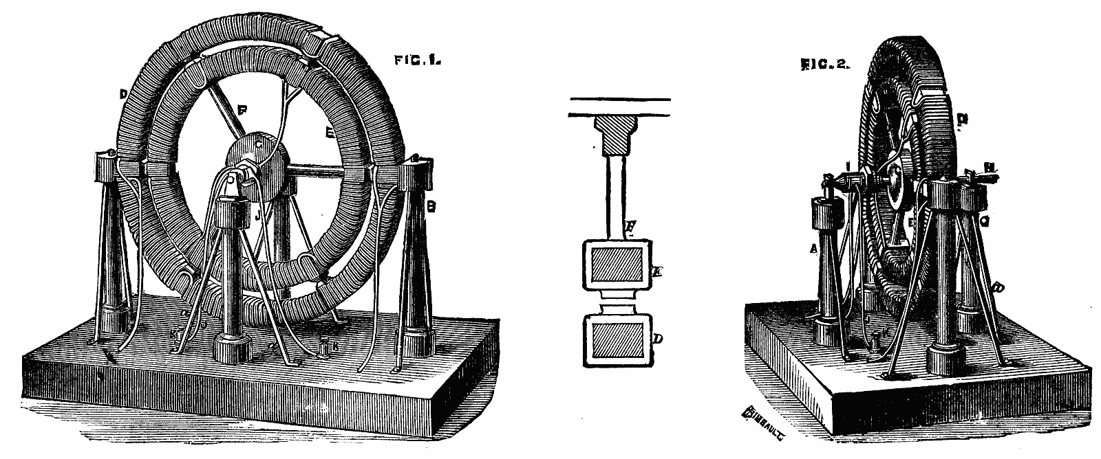
It will be seen from the mode of coiling the wire on this ring, that if a battery be connected by means of the copper rods, the current will create six consecutive poles on the various projecting blocks. The inner ring, E, is about 11 in. in outside diameter, and is also provided with a series of six projecting pieces which pass before those on the exterior ring with very little clearance. Between these projections the space between the inner face of the outer, and the outer face of the inner ring, is 0.40 in. The latter is movable, and is supported by three wooden arms, F, fixed to a boss, G, which is traversed by a spindle supported in bearings by the columns, A and C. A coil is rolled around the ring in exactly the same way as that on the outer ring, the wire being of the same size, and the insulation of the same thickness. The ends of the wire are also bared at points of the diameter opposite each other, and the coil connected in pairs so as to form a continuous circuit. At the two points of junction they are connected with a hexagonal commutator placed on the central spindle, one end corresponding to the sides 1, 3, and 5, and the other to the sides 2, 4, and 6. Two copper rods, J, fixed on the base to two plates of copper furnished with binding screws, are widened and flattened at their upper ends to rest against opposite parallel sides of the hexagon. It will be seen that if the battery is put in circuit by means of the binding screws, the current in the interior ring will determine six consecutive poles, the names of which will change as the commutator plates come into contact successively with the sides of the hexagon. Consequently, if at first the pole-pieces opposite each other are magnetized with the same polarity, a repulsion between them will be set up which will set the inner ring in motion, and the effect will be increased on account of the attraction of the next pole of the outer ring. At the moment when the pole piece thus attracted comes into the field of the pole of opposite polarity, the action of the commutator will change its magnetization, while that of the pole-piece on the fixed ring always remains the same; the same phenomenon of repulsion will be produced, and the inner ring will continue its movement in the same direction, and so on. To the attractive and repulsive action of the magnetic poles has to be added the reciprocal action of the coils around the two rings, the action of which is similar. From this brief explanation the differences between the Elias machine and the Gramme will be understood. The Dutch physicist did not contemplate the production of a current; he utilized two distinct sources of electricity to set the inner ring in motion, and did not imagine that it was possible, by suppressing one of the inducing currents and putting the ring in rapid rotation, to obtain a continuous current. Moreover, if ever this apparent resemblance had been real, the merit of the Gramme invention would not have been affected by it. It has happened very many times that inventors living in different countries, and strangers to one another, have been inspired with the same idea, and have followed it by similar methods, either simultaneously or at different periods, without the application having led to the same results. It does not suffice even for the seed to be the same; it must have fallen in good ground, and be cultivated with care; here it scarcely germinates, there it produces a vigorous plant and abundant fruit.—Engineering.
As a general thing, too much trust should not be placed in words. In the first place, it frequently happens that their sense is not well defined, or that they are not understood exactly in the same way by everybody, and this leads to sad misunderstandings. But even in case they are precise, and are received everywhere under a single acceptation, there still remains one danger, and that is that of passing from the word to the idea, and of being led to believe that, because there is a word, there is a real thing designated by this word.
Let us take, for example, the word electricity. If we understand by this term the common law which embraces a certain category of phenomena, it expresses a clear and useful idea; but as for its existence, it is not permitted to believe a priori that there is a distinct agent called electricity which is the efficient cause of the phenomena. We ought never, says the old rule of philosophy, to admit entities without an absolute necessity. The march of science has always consisted in gradually eliminating these provisory conceptions and in reducing the number of causes. This fact is visible without going back to the ages of ignorance, when every new phenomenon brought with it the conception of a special being which caused it and directed it. In later ages they had spirits in which there was everything: volatile liquids, gases, and theoretical conceptions, such as phlogiston. At the end of the last century, and at the beginning of our own, ideas being more rational, the notion of the "fluid" had been admitted, a mysterious and still vague enough category (but yet an already somewhat definite one) in which were ranged the unknown and ungraspable causes of caloric, luminous, electric, etc., phenomena. Gradually, the "fluid" has vanished, and we are left (or rather, we were a short time ago) at the notion of forces—a precise and mathematically graspable notion, but yet an essentially mysterious one. We see this conception gradually disappearing to leave finally only the elementary ideas of matter and motion—ideas, perhaps, which are not much clearer philosophically than the others, particularly that of matter taken per se, but which, at least, are necessary, since all the others supposed them.
Among those notions that study and time are reducing to other and simpler ones, that of electricity should be admitted; for it presents itself more and more as one of the peculiar cases of the general motion of matter. It will be to the eternal honor of Fresnel for having introduced into science and mathematically constituted the theory of undulations (already proposed before him, however), thus giving the first example of the notion of motion substituted for that of force. Since the principle of the conservation of energy has taken the eminent place in science that it now occupies, and we have seen a continual transformation of one series of phenomena into another, the mind is at once directed to the aspect of a new fact toward an explanation of this kind. Still, it is certain that these hypotheses are difficult of justification; for those motions that are at present named molecular, and that we cannot help presuming to be at the base of all actions, are per se ungraspable and can only be demonstrated by the coincidence of a large number of results. There is, however, another means of rendering them probable, and that is by employing analogy. If, by vibrations which are directly ascertainable, we can reproduce the effects of electricity, there will be good reason for admitting that the latter is nothing else than a system of vibration differing only, perhaps, in special qualities, such as dimensions, direction, rapidity, etc.
Such is the result that is attained by the very curious experiments that are due to Mr. Bjerknes. These constitute an ensemble of very striking results, which are perfectly concordant and exhibit very close analogies with electrical effects, as we shall presently see.
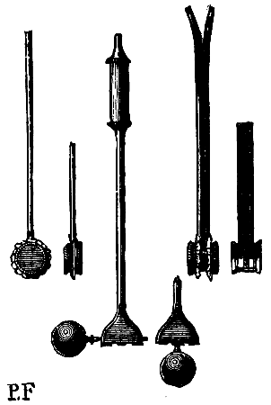
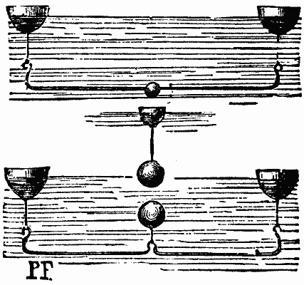
They are based on the presence of bodies set in vibration in a liquid. The vibrations produced by Mr. Bjerknes are of two kinds—pulsations and oscillations. The former of these are obtained by the aid of small drums with flexible ends, as shown to the left in Fig. 1. A small pump chamber or cylinder is, by means of a tube, put in communication with one of these closed drums in which the rapid motion of a piston alternately sucks in and expels the air. The two flexible ends are successively thrust outward and attracted toward the center. In an apparatus of this kind the two ends repulse and attract the liquid at the same time. Their motions are of the same phase; if it were desired that one should repulse while the other was attracting, it would be necessary to place two drums back to back, separated by a stiff partition, and put them in connection with two distinct pump chambers whose movements were so arranged that one should be forcing in while the other was exhausting. A system of this nature is shown to the right in Fig. 1.
The vibrations are obtained by the aid of small metal spheres fixed in tubular supports by movable levers to which are communicated the motions of compression and dilatation of the air in the pump chamber. They oscillate in a plane whose direction may be varied according to the arrangement of the sphere, as seen in the two apparatus of this kind shown in Fig. 1. Fig. 2 will give an idea of the general arrangement. The two pistons of the air-pumps are connected to cranks that may be fixed in such a way as to regulate the phases as may be desired, either in coincidence or opposition. The entire affair is put in motion by a wheel and cord permitting of rapid vibrations being obtained. The air is let into the apparatus by rubber tubing without interfering with their motions.
We may now enter into the details of the experiments:
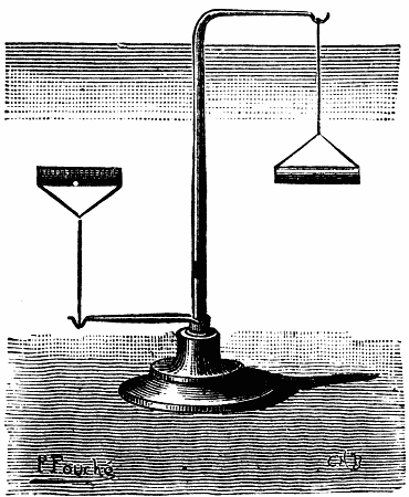
The first is represented in Fig. 2. In a basin of water there is placed a small frame carrying a drum fixed on an axle and capable of revolving. It also communicates with one of the air cylinders. The operator holds in his hand a second drum which communicates with the other cylinder. The pistons are adjusted in such a way that they shall move parallel with each other; then the ends of the drums inflate and collapse at the same time; the motions are of the same phase; but if the drums are brought near each other a very marked attraction occurs, the revolving drum follows the other. If the cranks are so adjusted that the pistons move in an opposite direction, the phases are discordant—there is a repulsion, and the movable drum moves away from the other. The effect, then, is analogous to that of two magnets, with about this difference, that here it is the like phases that attract and the different phases that repel each other, while in magnets like poles repel and unlike poles attract each other.
It is necessary to remark that it is indifferent which face of the drum is presented, since both possess the same phase. The drum behaves, then, like an insulated pole of a magnet, or, better, like a magnet having in its middle a succeeding point. In order to have two poles a double drum must be employed. The experiment then becomes more complicated; for it is necessary to have two pump chambers with opposite phases for this drum alone, and one or two others for the revolving drum. The effects, as we shall see, are more easily shown with the vibrating spheres.
This form has the advantage that the vibrating body exhibits the two phases at the same time; relatively to the liquid, one of its ends advances while the other recedes. Thus with a vibrating sphere presented to the movable drum, there may be obtained repulsion or attraction, according as the side which is approached is concordant or discordant with the end of the drum that it faces.
With the arrangement shown in Fig. 3 there may be performed an interesting series of experiments. The two spheres supported by the frame are set in simultaneous vibration, and the frame, moreover, is free to revolve about its axis. The effect is analogous to that which would be produced by two short magnets carried by the same revolving support; on presenting the vibrating sphere to the extremities the whole affair is attracted or repulsed, according to its phase and according to the point at which it is presented; on replacing the transverse support by a single sphere (as indicated in the figure by a dotted line) we obtain the analogue of a short magnet carried on a pivot like a small compass needle. This sphere follows the pole of a vibrating sphere which is presented to it, as the pole of a magnet would do, with this difference always, that in the magnet, like poles repel, while in oscillating bodies like phases attract.
In all the preceding experiments the bodies brought in presence were both in motion and the phenomena were analogous to those of permanent magnetism. We may also reproduce those which result from magnetism by induction. For this purpose we employ small balls of different materials suspended from floats, as shown in Fig. 4 (a, b, c). Let us, for example, take the body, b, which is a small metal sphere, and present to it either a drum which is caused to pulsate, on an oscillating sphere, and it will be attracted, thus representing the action of a magnet upon a bit of soft iron. A curious experiment may serve to indicate the transition between this new series and the preceding. If we present to each other two drums of opposite phases, but so arranged that one of them vibrates faster than the other, we shall find, on carefully bringing them together, that the repulsion which manifested itself at first is changing to attraction. On approaching each other the drum having the quicker motion finally has upon the other, the same action as if the latter were immovable; and the effect is analogous to that which takes place between a strong and weak magnet presented by their like poles.
By continuing these experiments we arrive at a very important point. Instead of the body, b (Fig. 4), let us take c. As the figure shows, this is a sphere lighter than water, kept in the liquid by a weight. If we present to it the vibrating body, it will be repelled, and we shall obtain the results known by the name of diamagnetism. This curious experiment renders evident the influence of media. As well known, Faraday attributed such effects to the action of the air; and he thought that magnetic motions always resulted from a difference between the attraction exerted by the magnet upon the body under experiment, and the attraction exerted by the air. If the body is more sensitive than the air, there is direct magnetism, but if it is less so, there is diamagnetism. Water between the bodies, in the Bjerknes experiments, plays the same role; it is this which, by its vibration, transmits the motions and determines the phases in the suspended body. If the body is heavier than water its motion is less than that of the liquid, and, consequently, relatively to the vibrating body, it is of like phase; and if it is lighter, the contrary takes place, and the phases are in discordance. These effects may be very well verified by the aid of the little apparatus shown in Fig. 5, and which carries two bars, one of them lighter and the other heavier than water. On presenting to them the vibrating body, one presents its extremity and takes an axial direction, while the other arranges itself crosswise and takes the equatorial direction. These experiments may be varied in different ways that it is scarcely necessary to dwell upon in this place, as they may be seen at the Electrical Exhibition.
Very curious effects are also obtained with the arrangement shown in Fig. 6. Between the two drums there is introduced a body sustained by a float such as represented at a, Fig. 4. Various results may, then, be obtained according to the combinations adopted. Let us suppose that the phases are alike, and that the interposed body is heavier than water; in this case it is repelled as far as the circumference of the drums, at which point it stops. If the phases are different, the influenced body behaves in the opposite manner and stops at the center. If the body is lighter than water the effects are naturally changed. Placed between two like phases, it is attracted within a certain radius and repelled when it is placed further off; if the phases are unlike, it is always repelled. We may easily assure ourselves that these effects are analogous to those which are produced on bodies placed between the poles of wide and powerful magnets. It is useless to repeat that the analogies are always inverse.
Mr. Bjerknes has carried the examination of these phenomena still further in studying experimentally the actions that occur in the depths of the liquid; and for this purpose he has made use of the arrangement shown in Fig. 7. By the side of the vibrating body there is placed a light body mounted on a very flexible spring. This assumes the motion of that portion of the fluid in which it is immersed, and, by the aid of a small pencil, its direction is inscribed upon a plate located above it. By placing this registering apparatus in different directions the entire liquid may be explored. We find by this means figures that are perfectly identical with magnetic phantoms. All the circumstances connected with these can be reproduced, the vibrating sphere giving the phantom of a magnet with its two poles. We may even exhibit the mutual action of two magnets. The figures show with remarkable distinctness—much more distinct, perhaps, than those that are obtained by true magnets.
However, it must not be thought that these so interesting facts are the result of groping in the dark and the outcome of some fortunate experiment; for they have, on the contrary, been foreseen and predetermined. Mr. Bjerknes is especially a mathematician, and it was a study, through calculation, of the vibratory motion of a body or system of bodies in a medium that led him to the results that he afterwards materialized.
After the production, by Mr. Lejeune, of his solutions, Mr. Bjerknes in 1865 entered upon a complete study of the subject, and recognized the fact that the result of such motions was the production of regular mechanical actions. He calculated the directions of these, and, along about 1875, perceived the possibility of reproducing the effects of permanent magnetism. More recently, in 1879, he saw that magnetism by derivation might likewise be explained by those hypotheses, and figured by actions of this kind. It was not till then that he performed the experiments, and submitted a body to the results of calculation.
The same process has led him to the conclusion that the action of currents might be represented in the same manner; only, instead of bodies in vibration, it would require bodies in alternating rotation. The effects are much more difficult to ascertain, since it is necessary to employ viscid liquids.
Meanwhile, the experiments have been performed. Up to the present time attractions and repulsions have not been shown, and I do not know whether Mr. Bjerknes has obtained them. But, by the process pointed out, the lines of action (electric phantoms, if I may so express myself) have been traced, and they are very curious. By supposing the current perpendicular to the plate, and in the presence of the pole of a magnet, the influences produced around it are very well seen, and the figures are very striking, especially in the case of two currents. Mr. Bjerknes does not appear as yet to have obtained from these experiments all that he expects from them. And yet, such as they are, they have already led him to important conclusions. Thus, calculation, confirmed by application, has led him to renounce the formula proposed by Ampère and to adopt that of Regnard as modified by Clausius. Is he right? This is what more prolonged experimentation will allow to be seen.
These researches, however, are beset with difficulties of a special nature, and the use of viscid liquids is a subject for discussion. Mr. Bjerknes desired to employ them for reproducing the effects that he had obtained from water, but he found that the lines of force were no longer the same, and that the phenomena were modified. It is necessary, then, to hold as much as possible to liquids that are perfect. The experimenter is at present endeavoring to use these liquids by employing cylinders having a fluted surface; but it is clear that this, too, is not without its difficulties.
This series of experiments offers a rare example of the verification of algebraic calculation by direct demonstration. In general, we may employ geometry, which gives a graphic representation of calculation and furnishes a valuable control. Sometimes we have practical application, which is a very important verification in some respects, but only approximate in others. But it is rare that we employ, as Mr. Bjerknes has done, a material, direct, and immediate translation, which, while it brings the results into singular prominence, permits of comparing them with known facts and of generalizing the views upon which they are based.
Hypotheses as to the nature of electricity being as yet only tolerably well established, we should neglect nothing that may contribute to give them a solid basis. Assuming that electricity is a vibratory motion (and probably there is no doubt about it), yet the fact is not so well established with regard to it as it is to that of light. Every proof that comes to support this idea is welcome, and especially so when it is not derived from a kind of accident, but is furnished by a calculated and mathematical combination. Viewed from this double standpoint, the experiments of Mr. Bjerknes are very remarkable, and, I may add, they are very curious to behold, and I recommend all visitors to the Exhibition to examine them.—Frank Geraldy, in La Lumiere Electrique.
I shall experience one difficulty in addressing you this evening, which is, that although I do not wish to take up your time with purely elementary matter, I wish to make the subject clear to those who may not be familiar with its earlier struggles.
If we begin at the beginning we have to go back to the time when Faraday made the discovery that light could be produced by the separation of two carbon rods conducting a current of considerable tension. That is the historical point when electric lighting first loomed up as a giant possibility of the near future. This occurred about the year 1846. In some experiments he found that although the circuit could not be interrupted by any considerable interval when metallic terminals were used without breaking the current, when carbon was substituted the interval could be largely increased, and a light of dazzling brilliancy appeared between the points.
This remarkable effect appears to be produced by the rarefaction of the air, due to the great heat evolved by the combustion of the carbon, and also to the passage of incandescent particles of carbon from pole to pole, thus reducing the resistance, otherwise too great for the current tension.
That was the beginning of electric lighting; and perhaps it will be well to bridge the long and comparatively uninteresting interval which elapsed between this discovery and the equally important one which alone gave it commercial value—I refer to the production of suitable currents by mechanical means. That is to say, the substitution of energy obtained from coal in the form of steam power reduced the cost to a fraction of what it necessarily was when the galvanic elements were used. Here is the point; the cost of zinc today is something over fifty times that of coal, while its energy as a vitalizing agent is only about five times greater, leaving a very large margin in favor of the "black diamonds." This is not the only advantage, for the resulting impulse in the case of mechanical production is much more uniform in action, and therefore better suited to the end in view, while the amount of adjustment and attention required is beyond comparison in favor of the latter means.
The machines adopted were of the magneto variety, and many ingenious machines of this class were operated with more or less success, being, however, quickly abandoned upon the introduction of the dynamo-machine, which gave currents of much greater electromotive force from the same amount of material, the advantage being chiefly due to the large increase of magnetic intensity in the field magnets. At this period lights of enormous power were produced with ease and by the use of costly lamps. With complicated mechanism a new era in artificial illumination seemed close at hand, but a grave difficulty stood in the way—namely, the proper distribution or subdivision of the light. It was quickly found that the electric difficulty of subdividing the light, added to the great cost of the lamps then made, was an apparently insurmountable obstacle to its general adoption, and the electric light was gradually taking its place as a brilliant scientific toy, when the world was startled by the introduction of the Jablochkoff candle, which may fairly claim to have given a greater impetus to the new light than any previous invention, a stimulus without which it is even probable that electric lighting might have slumbered for another decade.
The Jablochkoff candle embodies a very beautiful philosophical principle, and though its promises have not been fulfilled in general practice, we must not forget that we owe it much for arousing scientific men from a dangerous lethargy.
Up to this time the light had always been produced by approximation of carbon rods with their axes in the same plane; but the Jablochkoff candle consisted of like rods arranged parallel to each other and about one-eighth of an inch apart, the intervening space being filled with plaster of Paris, and the interval at the top bridged by a conducting medium. The object of the plaster, which is a fairly good insulating material at ordinary temperatures, is to prevent the passage of the current except at the top, where the conducting material just referred to assisted the formation of the arc at that point, and the resulting intense heat maintained the plaster in a moderately conducting state until the whole carbon was consumed. Here, then, was literally an electric "candle," which could be operated without the costly and unsteady lamps, and fortunately its birthplace was Paris—then the center of philosophical research; from that period the future of electric lighting was assured.
When we reflect that owing to the greater disruptive energy of the positive terminal, the carbon so connected to an ordinary dynamo machine is consumed very much faster than the negative—sometimes in the ratio of 3 to 1—it will be clear that some other means of consuming the Jablochkoff candle had to be used, since the arc would cease to exist in a very short time by reason of the unequal consumption of the carbons, and the subsequent increase of the intervening space beyond the limit of the current tension.
This difficulty M. Gramme overcame with characteristic ingenuity by adding to the ordinary system a "distributer" capable of delivering plus and minus currents alternately, thus equalizing the consumption, besides being able to supply a large number of candles on the multiple circuit system, each circuit supporting four or five lamps. Thus it will be seen that a result was attained which at least gave such men as Siemens, Gramme, and their peers, if such there be, confidence in the future and a courage which quickly placed the new science safely beyond the limits of the laboratory. I will not occupy your time by stating the apparent reasons why the Jablochkoff candle has not fully sustained its brilliant promise—it will, perhaps, be sufficient to state that it is now superseded practically, though it must always occupy an honorable place in scientific annals.
Let us now for a few moments consider what the electric light really accomplished at about this period, I mean from an economical standpoint. It appears from some data furnished by an engineer commissioned by the French Government that the machines were then capable of maintaining a light equal to from 220 to 450 candles, measured by comparison with the Carcel burner, per horse power absorbed—a very good showing considering the youth of the discovery, but presenting rather a gloomy aspect when we consider that according to Joule's mechanical equivalent of heat, which is 772 foot pounds, or the power required to raise one pound of water one degree—and for lack of anything better, we are obliged to accept that at this moment—the whole force contained in one pound of coal would maintain a light equal to 13,000 candles for one hour! That is the ultimate force, and what we are now able to accomplish is but a small fraction of this amount.
Unfortunately we are but common mortals, and cannot, like Mr. Keely, lightly throw off the trammels of natural law; we must, therefore, endeavor to close this gap by patient study and experiment.
The limited time at my disposal, and a keen consideration for your feelings, will not permit me to follow the long series of struggles between mind and matter immediately following Jablochkoff's brilliant invention; suffice it to say, that the few years just passed have yielded beyond comparison the most marvelous results in the scientific history of the world, and it will be superfluous to remind you that a great part of this has undoubtedly been due to the researches made in an effort to reduce electric lighting to a commercial basis. To say that this has been fully accomplished is but to repeat a well known fact; and in proof of this I quote a high scientific authority by stating that a result so high as 4,000 candles evolved for 40,000 foot-pounds absorbed has recently been obtained—an efficiency six or seven times greater than the record of six years ago. In accepting this statement we must not lose sight of the extreme probability that such effects were evolved under conditions rarely if ever found in common practice. Of course, I now refer to the arc system. The volume of light so generated is incomparably greater than by any other known method, though in subdivision the limit is sooner reached.
Mr. Hawkesworth—Let me ask you a question, please. Supposing that it required a one-horse power to produce an arc light of, say, 2,000 candles, would it be possible to produce ten arc lights of 200 candles each?
Mr. Daft—No, sir; I will tell you why. It would, if no other element than the simple resistance of the arcs opposed the passage of a current; then a machine that would produce an inch arc in one light, if placed on a circuit of sixteen lamps would give to each an arc one-sixteenth of an inch long naturally; but another difficulty here presents itself in the shape of a resisting impulse of considerable electromotive force in the opposite direction, apparently caused by the intense polarity of the two terminals. The resistance of the arc itself varies much according to the volume of current used being usually small with a large quantity of current, and greater with a current of tension; but this opposing element is always found, and appears to be the only real obstacle in the way of infinite subdivision.
Almost every objection which human ingenuity could suggest has been urged against lighting by electricity, but fortunately electricians have been able in most cases either to meet the difficulty or prove it groundless.
In this connection I am led to speak of the common idea that electric light is injurious to the eyes, first, because of its unsteady character, and secondly, by reason of the great excess of the more refrangible rays. Both objections undoubtedly hold good where the alleged causes exist; but we can now show you a light which is certainly as steady as the ordinary gaslight—indeed more steady in an apartment where even feeble currents of air circulate; and I am sure you will readily acknowledge that the latter objection is disposed of when I assure you that our light presents the only example with which I am acquainted of an exact artificial reproduction of the solar light, as shown by decomposition. The two spectra, placed side by side, show in the most conclusive manner the identity in composition of our light with that of the sun.
The remarkable coolness of the electric light, as compared with its volume by gas, is also due in a great measure to the conspicuous absence of that large excess of less refrangible, or heat-radiating principle, which distinguishes almost equally all other modes of artificial illumination. After the foregoing statement it may seem a paradox to claim that the electric arc develops the greatest heat with which we have yet had to deal, but this is so; and the heat has an intensity quite beyond the reach of accurate measurement by any instrument now known—it has been variously estimated anywhere between 5,000° and 50,000° F. It is sufficient for our present purpose to know that the most refractory substances quickly disappear when brought under its influence—even the imperial diamond must succumb in a short time. In order to reconcile this fact with its coolness as an illuminating agent, we have to take into consideration the extreme smallness of the point from which the light radiates in the electric arc. A light having the power of many thousand candles will expose but a fraction of the surface for heat radiation which is shown by one gas-jet, and, as I have endeavored to explain, these rays contain very much less of the heating principle than those from gas or other artificial light.
The purity of electric light has another important aspect, which can scarcely be overestimated—namely, the facility with which all the most delicate shades of color can be distinguished. I understand from persons better skilled than myself in such matters that this can be done almost as readily by electric as by day light, and I have little doubt that the slight difference in this respect will entirely disappear when people become somewhat more familiar with the different conditions—the effect of such shades viewed by electric light being more like that with comparatively feeble direct sunlight than the subdued daylight usually prevailing in stores and warehouses.
Again, it has frequently been urged that persons working by electric light have thus induced inflammation of the eyes. No doubt this is so with light containing the highly refrangible rays in excess; but it is difficult to see how such an effect can occur with light composed as is the light with which the eyes are constructed to operate in perfect harmony.
As you are aware, there are other methods of obtaining light by electric energy, and in order to make a fair comparison of one which has lately attracted a great deal of attention and capital, I will relate to you the result of observations made during a recent visit to the office of an eminent electrician. The light was that known as incandescent—a filament of carbon raised to a light-emitting heat in vacuo. The exclusion of the air is necessary to prevent the otherwise rapid destruction of the carbon by combination with oxygen. At the time of my visit there were 62 lamps in circuit. According to their statement each lamp was of 16-candle power—I accept their statement as correct; this will give us an aggregate of 992 candles. The generator was vitalized by an engine rated by the attendants in charge at 6-horse power. I found that it was a 5×7 cylinder, working with very little expansion 430 revolutions per minute, with 90 pounds of live steam, in a boiler not 15 feet from the engine. I have every reason to believe that the steam was delivered at the cylinder with an almost inappreciable loss on 90 pounds. Under those conditions I think it is perfectly fair to assume (you have the data, so that you can calculate it afterwards) that 750,000 foot pounds were consumed in producing those 60 lights, aggregating 992 candles. In the kind of engine they had, 750,000 foot pounds requires a consumption of about 100 pounds of coal per hour. It was an ordinary high speed engine. That 750,000 foot pounds, I assume, required 100 pounds of coal. That is the only weak point in my data; I do not know that to be true; but I never saw an engine of that form yet capable of delivering 1-horse power with less consumption than four to five pounds of coal per horse power per hour. I want to be as fair as I can in the matter. I wish to compare this, as they have taken particular pains to compare it, with gas, at the present cost of gas.
The hundred pounds of coal will produce 400 feet of gas; 400 feet of gas will evolve the effect of 1,500 candles. So you see the position we are in. In consuming that coal directly by destructive distillation you can produce 1,500 candles light; by converting it into power, and then again into light by incandescence, you produce 992! Expressing this in other words, we may say that in producing the light from coal by the incandescent system you lose one-third of the power as compared with gas, by actually converting the coal into gas, and delivering it in the ordinary manner. Those are facts. It has been suggested to me that I am too liberal in my estimate of coal consumed—that those engines consume more than four or five pounds per horse power per hour; but I prefer to give them the benefit of the doubt.
Mr. Rothschild—If I understood you correctly, this electric light costs more than gas?
Mr. Daft—Must do by this system. You cannot do better, so far as our philosophy goes. But this whole system of illumination, as now practiced is a financial fallacy.
Mr. Rothschild—That is what Professor Sawyer says.
Mr. Daft—The same amount of energy converted into light by our arc system will produce 30,000 candles. We are perfectly willing to demonstrate that at any time. I am free to admit that the minute subdivision obtained by the Edisonian, Swan, or Fox system—they do not differ materially—is a great desideratum; but this cannot bridge the financial gulf.
Mr. Lendrum—Now please state what we have accomplished.
Mr. Daft—Certainly; and in so doing I prefer to give our results as actually occurring in everyday work; and in this connection let me remind you that in no branch of physics are the purely experimental effects so well calculated to deceive, if not fairly conditioned. As we have seen, it is claimed on excellent authority that the equivalent of 4,000 candles appeared in an arc by expending 40,000 foot pounds of energy at the generator, but with everyday conditions it is at present idle to expect such efficiency. Commercially we can give by our own system 3,000 candles for 40,000 foot pounds absorbed; this may be done for an indefinite length of time and leave nothing to be desired on the score of steadiness. Unfortunately there is no unit of photometric measurement generally recognized in this country, each electrician having so far adopted one to suit his own convenience; but in making the foregoing statement I wish it to be understood that our efficiency would appear still greater if measured by some of the methods now employed. For our own satisfaction we have endeavored to be at least approximately accurate, at the same time wishing to avoid the affectation of extreme precision, such, for example, as adding twenty or thirty candles to measurements of so many thousands, and we are satisfied that the most critical expert tests will prove our claim to be within the mark. The limit of subdivision is only reached when the difficulty of further increasing the electromotive force of the machines, involving great care in insulation and a host of other troubles arising, so to speak, at very high pressure, is balanced by the objections to working in multiple arc; this appears to occur now at something below 40 lights, but will in all probability be greatly extended within a short time. The machines are so constructed that the local currents, usually productive of dangerous heating, are turned to useful account, so that the point where radiation exceeds production is soon reached, and provided the machines are not speeded beyond the proper limit, they may be run continuously without the slightest indication of lost vitality. I need scarcely remind you that this is a most important feature, and by no means a common one.
The lamps used in our system I believe to be the simplest known form of regulator; indeed it seems scarcely possible that anything less complicated could perform the necessary work; as a matter of fact we may confidently assert that it cannot be made less liable to derangement. It has frequently been placed on circuit by persons totally inexperienced in such matters, and still has yielded results which we are quite willing to quote at any time.
I will not now trespass on your patience further than will enable me to state that experiments now in hand indicate conclusively that domestic electric lighting of the immediate future will be accomplished in a manner more beautiful and wondrous than was ever shadowed in an Arabian Night's dream. I hesitate somewhat to make these vague allusions, since so many wild promises, for which I am not responsible, remain unfulfilled, but the time is surely near at hand when a single touch will illuminate our homes with a light which will combine all the elements of beauty, steadiness, softness, and absolute safety, to a degree as yet undreamed of. I do not ask you to accept this without question, but only to remember that within the last decade wires have been taught to convey not only articulate sounds, but the individual voices you know amidst a thousand, and even light and heat have each been made the medium of communicating our thoughts to distant places!
Not the least remarkable phenomenon in this connection is the intellectual condition of the people who have welcomed these marvelous achievements and allowed them to enter into their everyday life, thus removing the greatest barriers of the past and paving the way for that philosophical millennium inevitably awaiting those who may be fortunate enough to survive the next decade.
A recent address before the New York Electric Light Association.
The travel over the elevated steam street railways of New York city for month of October, 1881, was the heaviest yet recorded, aggregating 7,121,961 passengers, as against 5,881,474, for the corresponding month of 1880, an increase of 1,240,487, representing just about the entire population of the city.
We illustrate a very curious and interesting form of electric regulator which is exhibited in the Paris Exhibition of Electricity by Mr. Killingworth Hedges, whose name will be known to our readers as the author of a little book on the electric light. Mr. Hedges' lamp belongs to the same category of electric regulators as the lamp of M. Rapieff, and to one form of M. Reynier's lamp, that is to say, the position of the ends of the carbons, and therefore of the arc, is determined not by clockwork or similar controlling mechanism, but by the locus of the geometrical intersection of the axes of the carbon rods, the positions of which axes being determined by simple mechanical means.
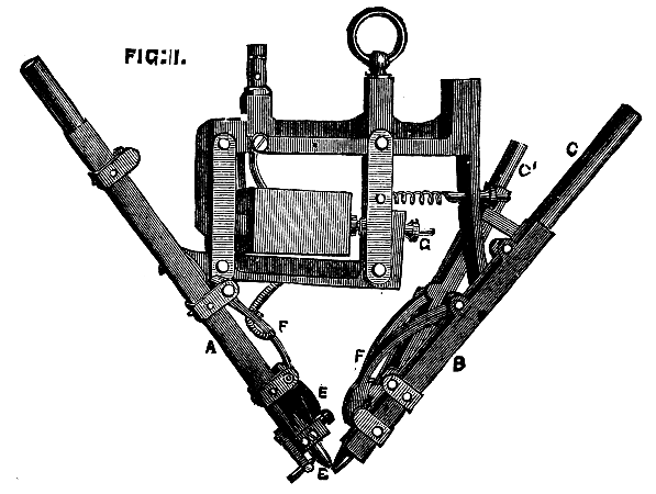
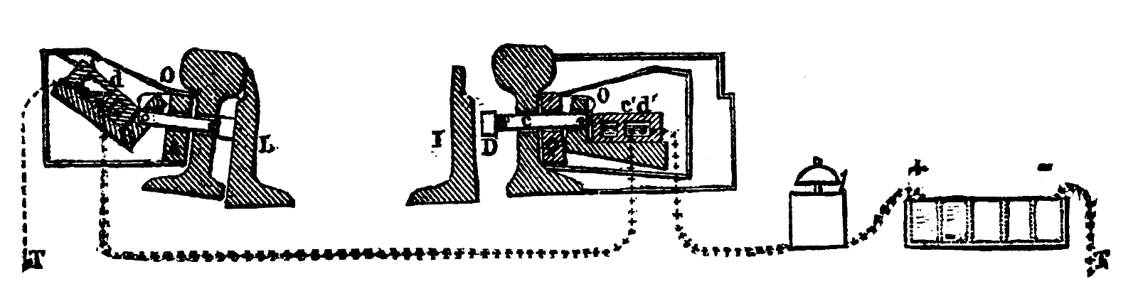
Referring to Fig. 1, A and B are two troughs rectangular in cross section attached to the supports in such positions that their axes are inclined to one another so as to form the letter V, as shown in the figure. Within these troughs slide freely the two carbon pencils, which are of circular cross section, meeting, when no current is passing, at the lower point, E. The carbon-holder, B, to the right of the figure, is rigidly attached to the framing of the lamp, but the trough, A, which carries the negative carbon, is attached to the framing by a pivot shown in the figure, and on this pivot the carbon holder can rock, its motion being controlled by the position of the armature of an electro-magnet, M, the coils of which are included in the circuit of the apparatus. By this means, the moment the current is established through the lamp, the armature is attracted, and the points of the two carbons are separated, thus forming the arc. The positive carbon, B, is held from sliding and dropping through the trough by the gentle pressure against it of the smaller carbon rod, C¹, which also slides in a trough or tube fixed in such a position that the point of contact between the two rods is sufficiently near the arc for the smaller rod to be slowly consumed as the other is burnt away; the latter in that way is permitted to slide gradually down the trough as long as the lamp is in action. The negative carbon-holder, A, is provided with a little adjustable platinum stop, E, which by pressing against the side of the conical end of the negative carbon, holds the latter in its place and prevents it sliding down the trough except under the influence of the slow combustion of the cone during the process of producing the arc. The position of the stop with respect to the conical end is determined by a small adjusting screw shown in the figure. This arrangement of stop is identical in principle with that adopted by Messrs. Siemens Brothers in their "abutment pole" lamp, and is found to work very well in practice on the negative electrodes, but is inapplicable on the positive carbons on account of the higher temperature of the latter, which is liable to destroy the metallic stop by fusion, and it is for this reason that the positive carbon in Mr. Hedges' lamp is controlled by the method we have already described. For alternating currents, however, the abutment stop may be used on both electrodes.
In order to maintain a good electrical contact between the fixed conducting portions of the lamp and the sliding carbons, Mr. Hedges fits to each carbon-holder a little contact piece, F F, hinged to its respective trough at its upper end, and carrying at its lower or free end a somewhat heavy little block of brass grooved out to fit the cylindrical side of the carbon, against which it presses with an even pressure. This arrangement offers another advantage, namely, that the length of that portion of the carbon rods which is conveying the current is always the same notwithstanding the shortening of their total length by combustion; the resistance of the carbon electrodes is, therefore, maintained constant, and, for the reason that the contact piece presses against the rods very near their lower ends, that resistance is reduced to a minimum. In this way very long carbons, such, for instance, as will burn for ten or sixteen hours, can be used without introducing any increase of resistance into the circuit. The length of the arc can be determined by the adjustment of the screw, G, by which the amount of movement of the armature is limited.
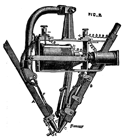
Fig. 2 represents a modified form of Mr. Hedges' lamp designed for installation when it is desirable to burn a number of lamps in series. In this arrangement the carbons are separated by the attractive influence of a solenoid upon an iron plunger, to which is attached (by a non-magnetic connection) the armature of an electro-magnet, the coils (which are of fine wire) forming a shunt circuit between the two terminals of the lamp, and so disposed with respect to the armature as to influence it in an opposite direction to that of the solenoid. When the circuit of the lamp is completed with the electric generator the carbons are drawn apart by the action of the solenoid on the plunger, and the distance to which they are separated is determined by the difference of attractive force exercised upon the armature by the solenoid and the magnet; but as the latter forms a short circuit to that of the arc, it follows that should the resistance of the arc circuit increase either through the arc becoming too long or through imperfection in the carbons or contacts, a greater percentage of current will flow through the magnet coils, and the arc will be shortened, thereby reducing its resistance and regulating it to the strength of the current. In other words, the distance between the carbons, that is to say, the length of the arc, is determined by the position of the armature of the electro-magnet between its magnets and the solenoid, which position is in its turn determined by the difference between the strength of current passing through the coil of the solenoid and that of the magnet.
Mr. Killingworth Hedges exhibits also a third form of his lamp, in most respects similar to the lamp figured in Fig. 1, but in which the ends of the two carbons rest against the side of a small cylinder of fireclay or other refractory material, which is mounted on a horizontal axis and can be rotated thereon by a worm and worm-wheel actuated by an endless cord passing over a grooved pulley. In the lamp one of the carbon-holders is rigidly fixed to the framing of the apparatus, and the other is mounted on a point so as to enable the length of the arc playing over the clay cylinder to be regulated by the action of an electro-magnet attracting an armature in opposition to the tension of an adjustable spring.
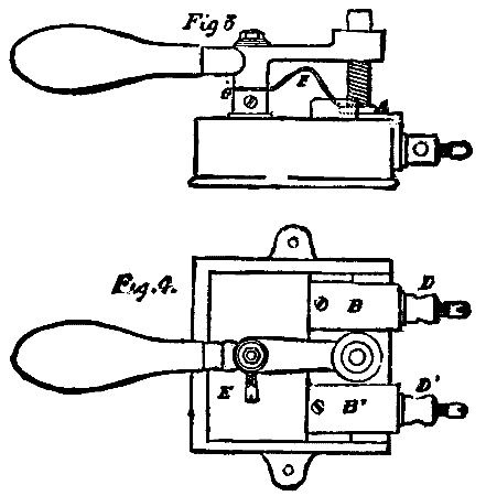
In the same exhibit will be found specimens of Mr. Hedges' two-way switches, which have been designed to reduce the tendency to sparking and consequent destruction which so often accompanies the action of switches of the ordinary form. The essential characteristic of this switch, which we illustrate in elevation in Fig. 3 and in plan in Fig. 4, lies first in the circular form of contact-piece shown in Fig. 4, and next in the fact that the space between the two fixed contact-pieces is filled up with a block composed of compressed asbestos, the surface of which is flush with the upper surfaces of the two contact-pieces. The circular contact-piece attached to the switch lever can be turned round so as to present a fresh surface when that which has been in use shows indications of being worn, and a good firm contact with the fixed contact-pieces is insured by the presence of a spiral spring shown in the upper figure, and which, owing to an error in engraving, appears more like a screw than a spring. In order to prevent bad connection through dust or other impurities collecting within the joint, the electrical connection between the fulcrum of the switch lever and the circular contact-piece is made through the bent spring shown edgeways in Fig. 3.—Engineering.
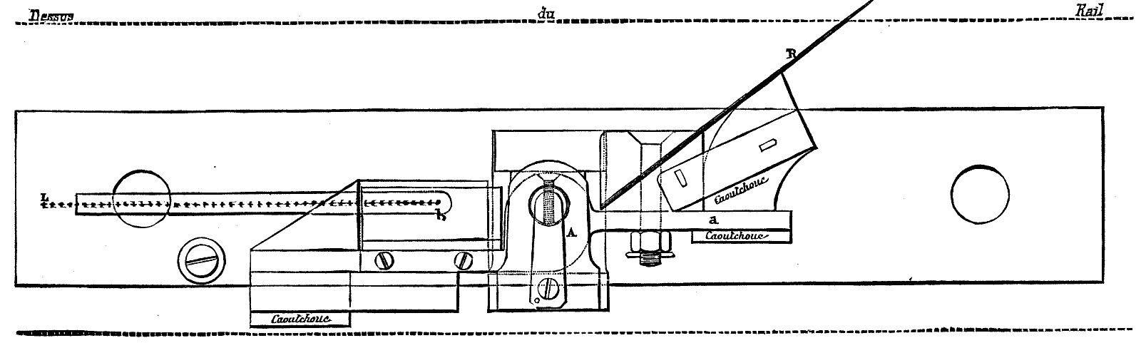
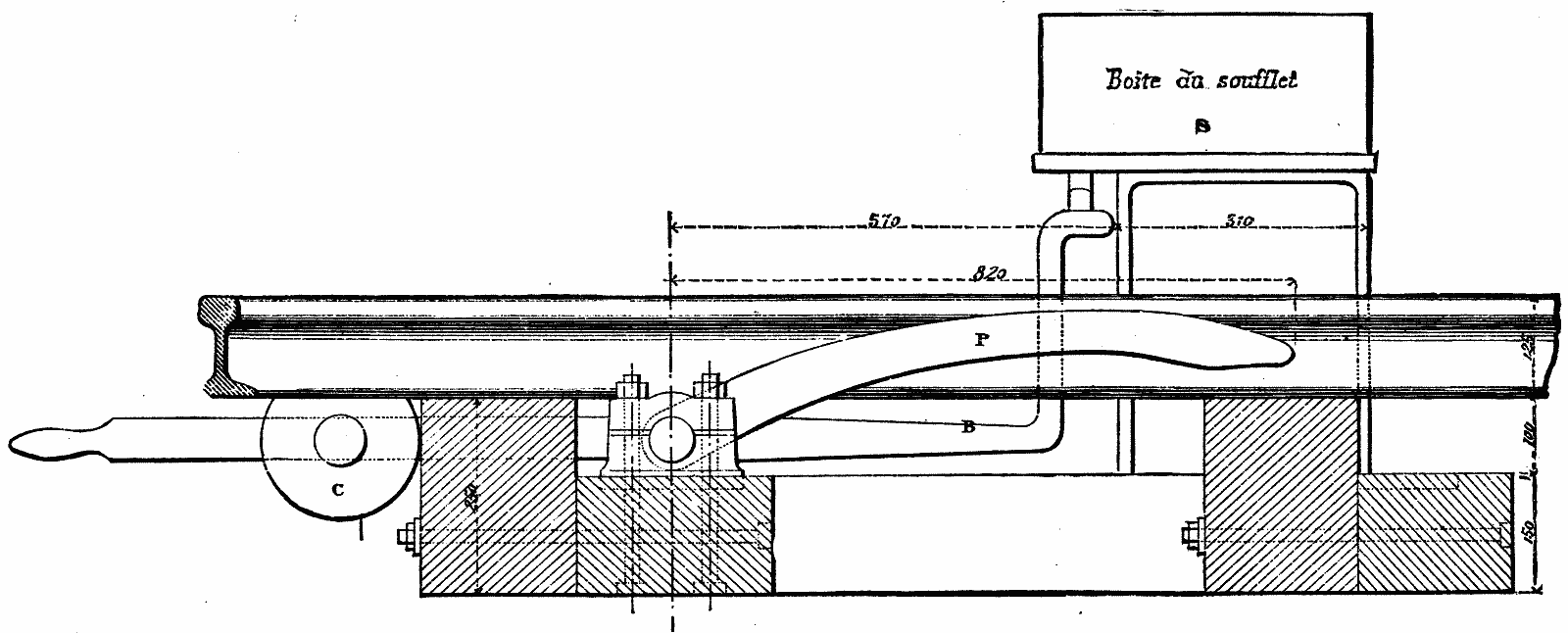
Lartigue's Switch Controller.—The object of this apparatus is to warn the switch tender in case the switch does not entirely respond to the movement of the maneuvering lever.
The apparatus, which is represented in the accompanying Figs. 1, 2, 3, and 4, consists of the following parts:
(1.) A mercurial commutator, O, which is fixed on a lever, B, connected with a piece, A, which is applied against the external surface of the web of the main rails, opposite the extremity of the switch plates;
(2.) A bar, C, which traverses the web of the rail and projects on the opposite side, and which carries a nut, D, against which the switch plate abuts;
(3.) An electrical alarm and a pile, located near the switch lever. As long as one of the two plates of the switch is applied against the rail, one of the two commutators is inclined and no current passes. A space of one millimeter is sufficient to bring the commutator to a horizontal position and to cause the electric alarm to ring continuously. If the apparatus gets out of order, it is known at once; for if the alarm does not work during the maneuver of the switch, the tender will be warned that the electric communications are interrupted, and that he must consequently at once make known the position of his switch until the necessary repairs have been made.
Pedals for Transmitting Signals to Crossings.—On railways having a double track and doing a large amount of business it becomes very necessary to announce to the flagmen at railway crossings the approach of trains, so as to give them time to stop all crossing of the tracks. On railway lines provided with electro-semaphores there may be used for this purpose those small apparatus that have been styled semaphore repeaters.
Mr. Lartigue has invented two automatic apparatus, by means of which the train itself signals its approach.
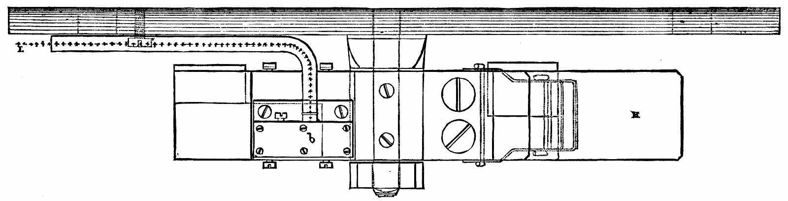
1. The first of these, which is generally placed at about 6,000 feet from the point to be covered, consists (Figs. 5, 6, 7, and 8) of a very light pedal fixed to the inside of the rail, and acting upon a mercurial commutator. A spring, R, carried upon the arm, a, of a lever, A, projects slightly above the level of the rail, while the other arm, b, carries a commutator.
The spring, R, on being depressed tilts the box containing the mercury, closes the circuit, and causes an alarm, S, located at the crossing, to immediately ring. In this alarm (Fig. 8) a piece, P, is disconnected by the passage of the current into the electro-magnet, E, which attracts the armature, a, and, a permanent current being set up, the apparatus operates like an ordinary alarm, until the piece, P, is placed by hand in its first position again.
2. The second apparatus, exhibited by the Railway Company of the North, and also the invention of Mr. Lartigue, bears the name of the "Bellows Pedal." It consists (Figs. 9 and 10) of a pedal, properly so called, P, placed along the rail, one of its extremities forming a lever and the other being provided with a counterpoise, C. When a train passes over the pedal, the arm, B, fixed to its axle, on falling closes the circuit of an ordinary electrical alarm, and at the same time the bellows, S, becomes rapidly filled with air, and, after the passage of the train, is emptied again very slowly under the action of the counterpoise. The contact is thus kept up for some few minutes. This apparatus works very satisfactorily, but is cumbersome and relatively high-priced.
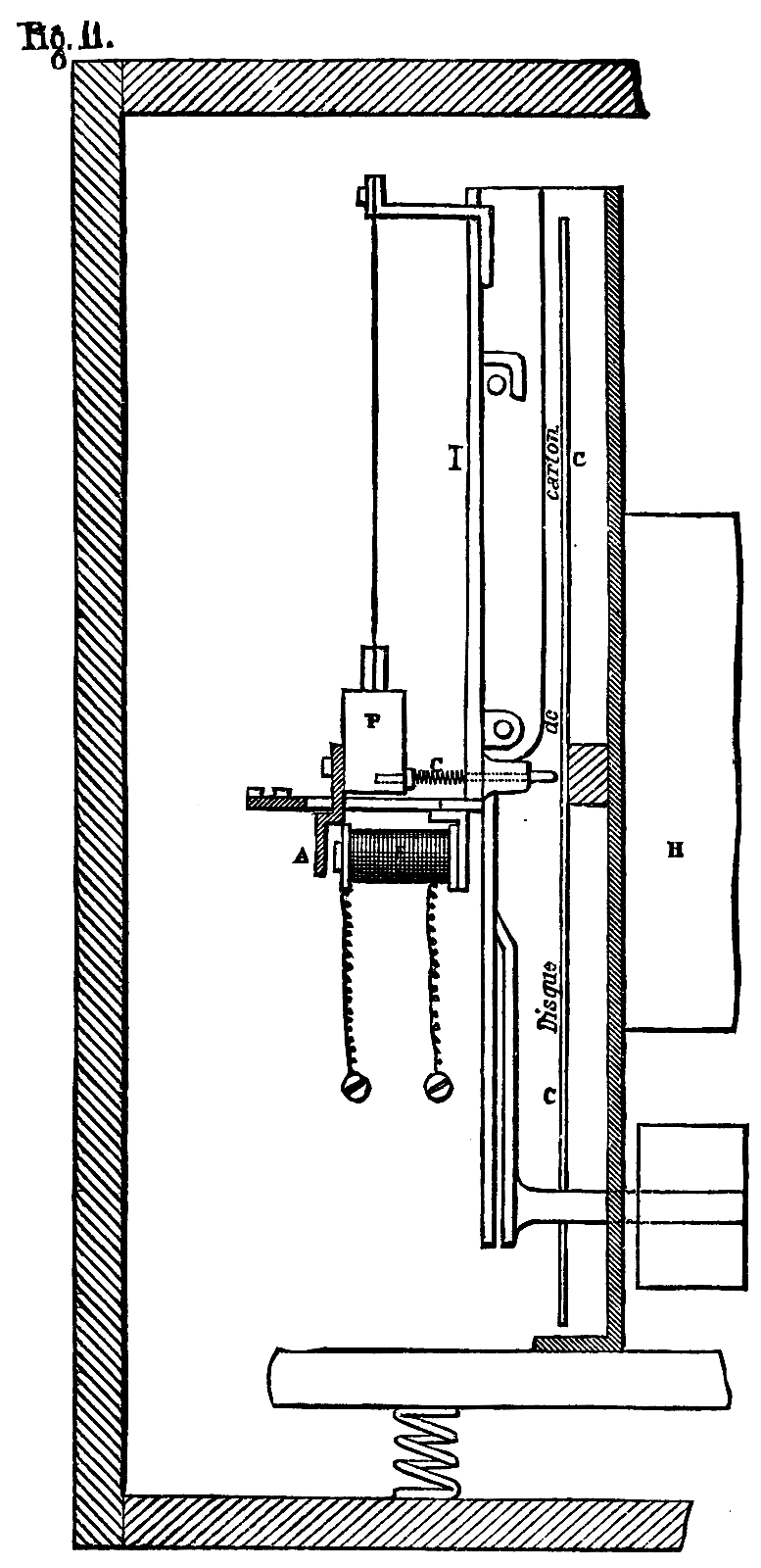
The Brunot Controller as a Controller of the Passage of Trains.—The Brunot Controller, which has been employed for several years on the Railway of the North, is designed to control the regularity of the running of trains, and to make automatically a contradictory verification of the figures on the slips carried by the conductors. In Fig. 11 we give a longitudinal section of the apparatus. It consists of a wooden case containing a clockwork movement, H, upon the axle of which is mounted a cardboard disk, C, divided into hours and minutes, and regulated like a watch, that is to say, making one complete revolution in twelve hours. The metallic pencil, c, which is capable of displacing itself on the cardboard in a horizontal direction opposite a groove on the other side of the disk, traces, when pressure is brought to bear on it, a spiral curve. The transverse travel of the pencil is effected in ninety-six hours. The displacement of the pencil is brought about by means of a cam. Under the influence of the jarring of the train in motion, a weight, P, suspended from a flexible strip, l, strikes against the pencil, c, which traces a series of points. During stoppages there is, of course, an interruption in the tracing of the curve.
Up to this point no electricity is involved—the apparatus is simply a controller of regularity. Mr. Brunot has conceived the idea of utilizing his apparatus for controlling the passage of trains at certain determined points on the line; for example, at the top of heavy grades. For this purpose it has only been necessary to add to the apparatus that we have just described an electro-magnet, E, connected electrically with a fixed contact located on the line. When the current passes, that is to say, at the moment the circuit is closed by the passage of a train, the armature, A, is attracted, and the pencil marks a point on the cardboard disk. This modification of the apparatus has not as yet been practically applied.
Electrical Corresponding Apparatus.—The object of these apparatus is to quickly transmit to a distance a certain number of phrases that have been prepared in advance. The Company of the North employs two kinds of correspondence apparatus—the Guggemos and the annunciator apparatus.
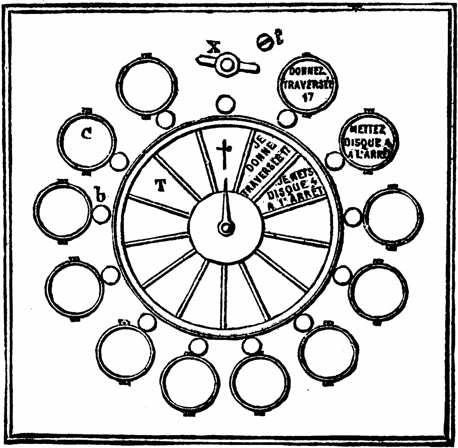
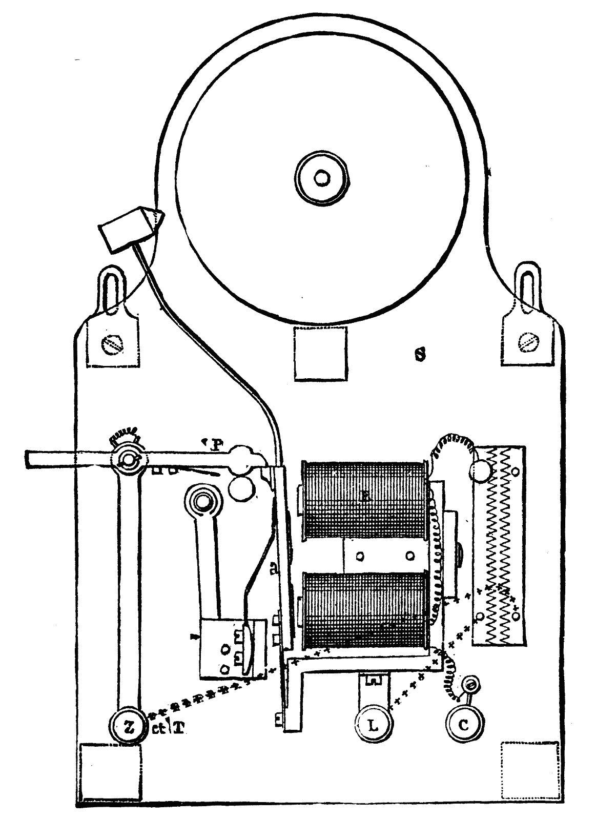
1. The Guggemos Apparatus.—This apparatus serves at once as a manipulator and receiver, and consists of an inner movement surmounted by a dial, over the face of which moves an index hand. Around the circumference of the dial there is arranged a series of circular cases, C, containing the messages to be received, and similar triangular cases, containing the messages to be forwarded, radiating from the center of the dial. Between each of these there is a button, b.
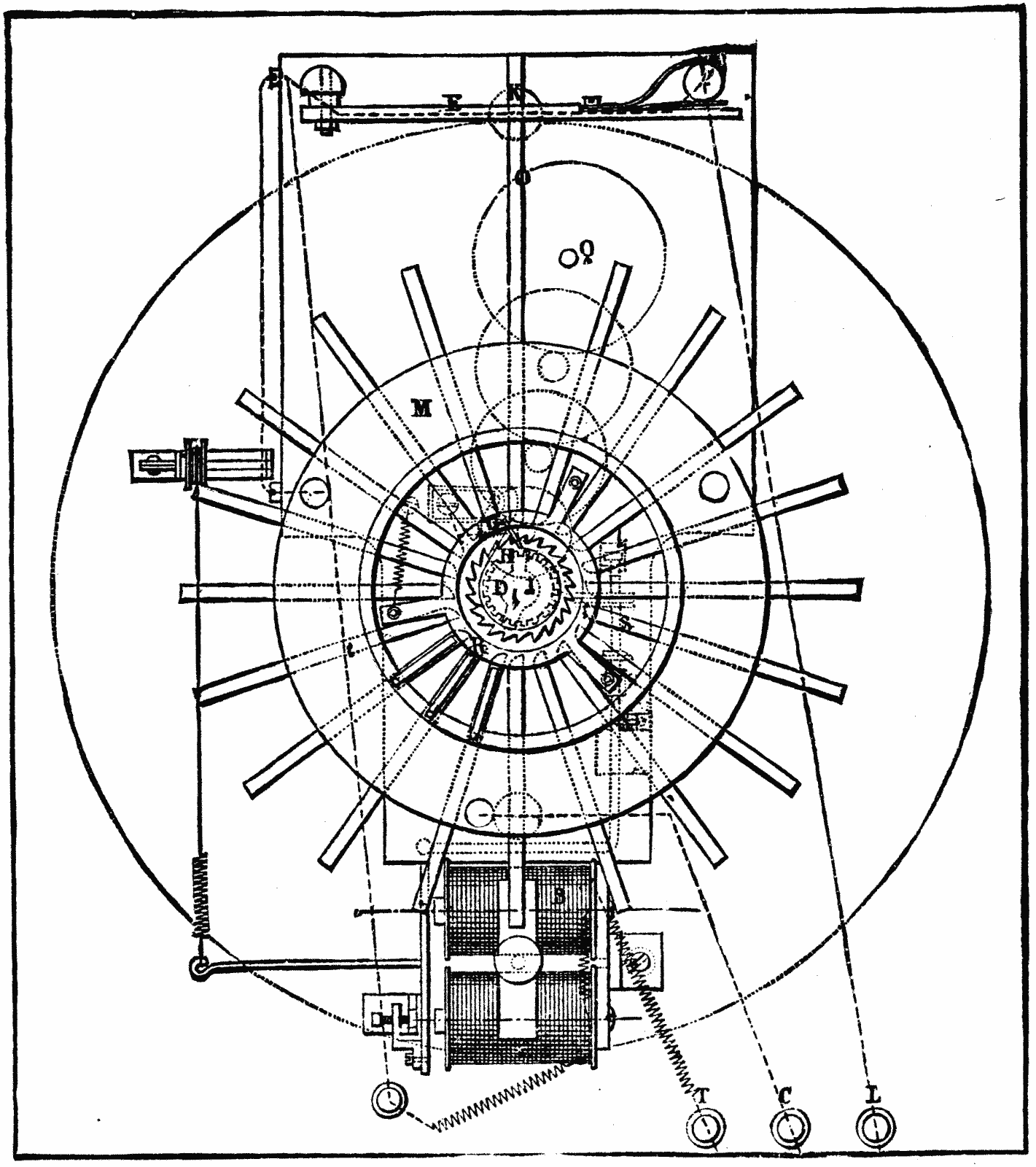
Fig. 13 represents the interior of an apparatus for twenty messages. It consists of a key-board, M, an electro-magnet, B, a clock-work movement, Q, an escapement, s, and an interrupter, F G.
When one of the buttons, b, is pressed, one of the levers of the key-board arrangement touches the disk, M, which is insulated from the other portions of the key-board, and the current then passes from the terminal C to M, and there bifurcating, one portion of it goes to the bobbins of the apparatus and thence to the earth, while the other goes to actuate the correspondence apparatus. The index-hands of the two apparatus thereupon begin their movement simultaneously, and only stop when the pressure is removed from the button and the current is consequently interrupted. H is a ratchet-wheel, which, like the key-board, is insulated from the rest of the apparatus. The button, K, located over each of the dials, serves to bring the index-needles back to their position under the cross shown in Fig. 12. The key, X, serves for winding up the clock-work movement.
The Annunciator Apparatus.—This apparatus, which performs the same role as the one just described, is simply an ingenious modification of the annunciator used in hotels, etc.
It consists of a wooden case, containing as many buttons as there are phrases to be exchanged. Over each button, b, there is a circular aperture, behind which drops the disk containing the phrase. Between the buttons and the apertures are rectangular plates, P, in which are inscribed the answers given by pressing on the button of the receiving tablet—a pressure which, at the same time, removes the corresponding disk from the aperture. Two disks located at the upper part carry these inscriptions: "Error, I repeat;" "Wait." The tablets on exhibition have eight disks, and can thus be used for exchanging six different phrases. In the interior, opposite each aperture, there is a Hughes magnet, between the arms of which there oscillates a vertical soft-iron rod, carrying a disk. The maneuver "is simple." By pressing upon a button there is sent into the bobbins of the magnet corresponding to this button a current which causes the disk to appear before one of the apertures, while at the same time an alarm begins to ring. The same maneuver performed by the agent at the receiving-post has the effect of causing the disk to disappear. The two contact springs in communication at each aperture with the alarm and the line are connected by a strip of ebonite, M, against the center of which presses the button.
Electrical Controllers for Water-Tanks.—The object of these apparatus is to warn the person in charge of a water-tank that the latter is full, and that he must stop the engine-pump; or, that the tank is empty, and that he must at once proceed to fill it. The Company of the North has on exhibition two such apparatus—one of them Lartigue's, and the other Vérité's.
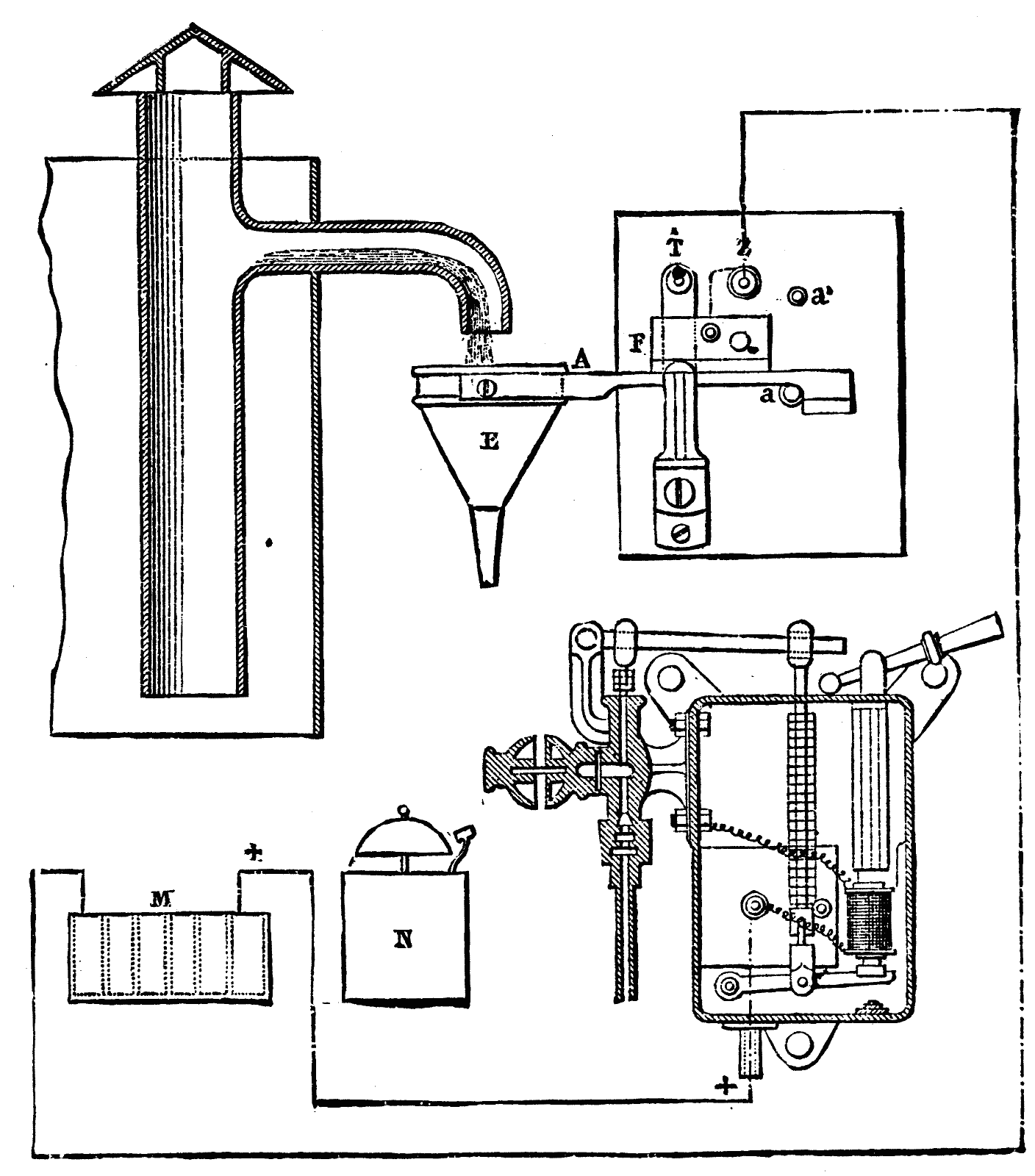
1. The Lartigue Controller (Fig. 15).—This apparatus consists of a long lever, A, which carries at one of its extremities a funnel, E, having a very narrow orifice and which is placed under the overflow pipe of the tank. The lever is kept normally in a horizontal position by a counterpoise; but, as soon as the overflow runs into the funnel, the weight of the water tilts the lever, and the mercurial commutator, F, closes the circuit of a pile, which actuates an alarm-bell located near the pump and engine. The two stops, a and a', limit the play of the lever.
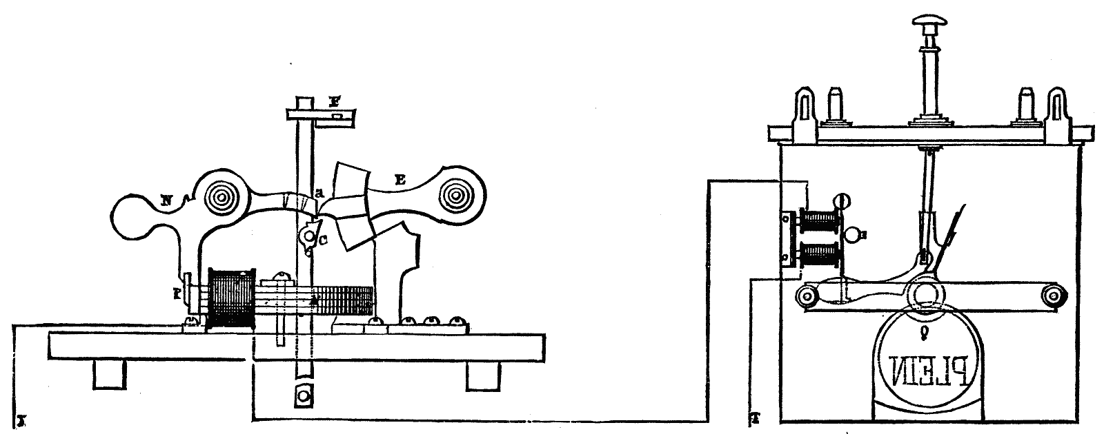
2. The Vérité Controller (Fig. 16).—This apparatus consists of a float, F, provided with a catch, C, calculated in such a way as to act only when the float has reached a certain definite height. At that moment it lifts the extremity of the weighted lever, E, which in falling back acts upon the extremity, a, of another lever, N, pivoted at the point, O. The piece, P, which is normally in contact with the magnet, A, being suddenly detached by this movement of the lever, N, the induced current which is then produced causes the display, near the pump, of a disk, Q, upon which is inscribed the word "Full." This is a signal to stop pumping.
Telephonic communication between the Opera and the Exhibition of Electricity is obtained by means of twenty conducting wires, which are divided between two halls hung with carpets to deaden external noises. We represent in the accompanying engraving one of these halls, and the one which is lighted by the Lane-Fox system of lamps. As may be seen, there are affixed against the hangings, all around the room, long mahogany boards, to which are fastened about twenty small tablets provided with hooks, from which are suspended the telephones. The latter are connected with the underground conductors by extensible wires which project from the wooden wainscot of which we have just spoken, so that it is very easy for the auditors to put the telephones to their ears.
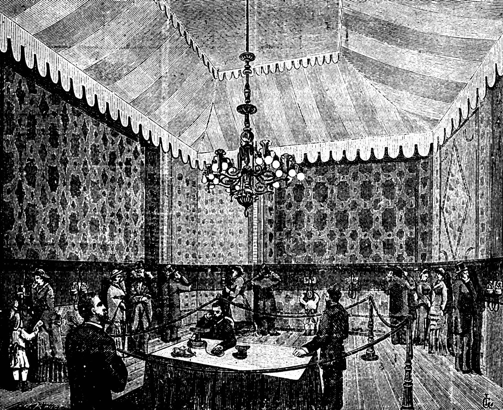
As the telephones are connected in series of eight with the same couple of microphone transmitters, and as each of these transmitting couples occupies a different position on the stage, it results that the effects are not the same at different points of each hall. Those telephones, for example, which correspond with the foot-lights of the theater are more affected by the sounds of the large instnuments of the orchestra than those which occupy the middle of the foot-lights; but, as an offset to this, the latter are affected by the voice of the prompter. In order to equalize the effects as much as possible, Mr. Ader has arranged it so that the two transmitters of each series shall be placed under conditions that are diametrically opposite. Thus, the transmitter at the end of the foot-lights, on the left side, corresponds with the transmitter of the series to the right, nearest to the middle of the stage; and the arrangement is the same, but in an inverse direction, for the transmitter at the end of the foot-lights to the right. But the series which produces the best effects is, as may be readily comprehended, that which corresponds with the transmitters occupying the middle of the right and left rows. These considerations easily explain the different opinions expressed by certain auditors in relation to the predominant sounds that they have heard, and why it is that some of them who have listened in different parts of the same hall have not had the same impressions. Naturally, the fault has beeen laid to the telephones; but, although these may vary in quality, it is more particularly to the arrangement of the transmitters on the stage that are to be attributed the differences that are noted.
As the Opera does not give representations every day, Mr. Ader has had the idea of occupying the attention of the public on Tuesday, Thursday, Saturday, and Sunday with the telephonic effects of flourishes of trumpets, which imitate pretty well the effects of French horns. These experiments have taken place in the hall in which is installed the little theater, and we must really say that in the effects produced French horns count for nothing.—La Lumiere Electrique.
When the voltaic arc plays between two metallic rheophores, of copper for instance, each formed of a U-tube traversed by a rapid current of cold water, and placed horizontally opposite each other, the following facts are observed: The luminous power of the arc is considerably weakened; it is reduced to a mere luminous point even when a current of 50 to 75 Bunsen elements of the large pattern is employed. The arc is very unstable and the least breath is sufficient to extinguish it. If a leaf of paper is placed above the arc at the distance of 0.004 to 0.005 meter a black point is produced in a few moments, which spreads and becomes a perforation, but the paper does not ignite. The arc consists of a luminous globule, moving between the two rheophores up and down and back again. The form of this globule, as well as its extreme mobility, causes it to resemble a drop of water in a spheroidal state. If we approach to the voltaic arc the south pole of a magnet the arc is attracted to such a degree that it leaves the rheophores and is extinguished. The same facts are observed in an intense form on presenting the north pole of a magnet to the arc. The quantity of ozone seems greater than when the arc is not refrigerated. It is to be noted that notwithstanding the refrigeration of the rheophores the flame of the arc is slightly green, proving that a portion of the copper is burning. It becomes a question whether the arc would be produced on taking as rheophores two tubes of platinum in which is caused to circulate, e.g., alcohol cooled to -30°.—D. Tommasi.
We herewith illustrate an exceedingly simple form of detecter, to show if the night watchmen perform their visits regularly and punctually. In the case, C, is a clockwork apparatus driving the axle, S, at the end of which is a worm which gears into the wheel of the drum, D. The rotation of D, thus obtained unrolls a strip of paper from the other drum, D. This paper passes over the poles of as many electro-magnets as there are points to be visited, and underneath the armatures of these electro-magnets. Each armature has a sharp point fixed on its under side, and when a current passing through the coils causes the attraction of the armature, this point perforates the paper. The places to be visited are connected electrically with the binding screws shown, and the watchman has merely to press a button to make the electric circuit complete. It has been found in practice that plain paper answers every purpose, as the clock giving an almost uniform motion enables the reader, after having seen the perforated slips once or twice, to determine fairly well the time which elapses between each pressure of the button.—The Engineer.
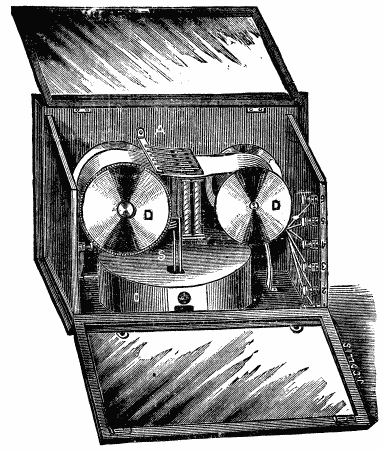
At a recent meeting of the London Physical Society, Mr. C. Vernon Boys read a paper on "Integrating Apparatus." After referring to his original "cart" machine for integrating, described at a former meeting of the society, he showed how he had been led to construct the new machine exhibited, in which a cylinder is caused to reciprocate longitudinally in contact with a disk, and give the integral by its rotation. Integrators were of three kinds: (1) radius machines; (2) cosine machines; (3) tangent machines. Sliding friction and inertia render the first two kinds unsuitable where there are delicate forces or rapid variation in the function to be integrated. Tangent machines depend on pure rolling, and the inertia and friction are inappreciable. They are, therefore, more practical than the other sort. It is to this class that Mr. Boys' machines belong. The author then described a theoretical tangent integrator depending on the mutual rolling of two smoke rings, and showed how the steering of a bicycle or wheelbarrow could be applied to integrate directly with a cylinder either the quotient or product of two functions. If the tangent wheel is turned through a right angle at starting, the machine will integrate reciprocals, or it can be made to integrate functions by an inverse process. If instead of a cylinder some other surface of evolution is employed as an integrating surface, then special integrations can be effected. He showed a polar planimeter in which the integrating surface is a sphere. A special use of these integrators is for finding the total work done by a fluid pressure reciprocating engine. The difference of pressure on the two sides of the piston determines the tangent of the inclination of the tangent wheel which runs on the integrating cylinder; while the motion of the latter is made to keep time with that of the piston. In this case the number of evolutions of the cylinder measures the total amount of work done by the engine. The disk cylinder integrator may also be applied to find the total amount of work transmitted by shafting or belting from one part of a factory to another. An electric current meter may be made by giving inclination to the disk, which is for this purpose made exceedingly small and delicate, by means of a heavy magnetic needle deflected by the current. This, like Edison's, is a direction meter; but a meter in which no regard is paid to the direction of the current can be made by help of an iron armature of such a shape that the force with which it is attracted to fill the space between the poles of an electro-magnet is inversely as its displacement. Then by resisting this motion by a spring or pendulum the movement is proportional to the current, and a tangent wheel actuated by this movement causes the reciprocating cylinder on which it runs to integrate the current strength. Mr. Boys exhibited two such electric energy meters, that is, machines which integrate the product of the current strength by the difference of potential between two points with respect to time. In these the main current is made to pass through a pair of concentric solenoids, and in the annular space between these is hung a solenoid, the upper half of which is wound in the opposite direction to the lower half. By the use of what Mr. Boys calls "induction traps" of iron, the magnetic force is confined to a small portion of the suspended solenoid, and by this means the force is independent of the position. The solenoid is hung to one end of a beam, and its motion is resisted by a pendulum weight, by which the energy meters may be regulated like clocks to give standard measure. The beam carries the tangent wheels, and the rotation of the cylinder gives the energy expanded in foot-pounds or other measures. The use of an equal number of turns in opposite directions on the movable solenoid causes the instrument to be uninfluenced by external magnetic forces. Mr. Boys showed on the screen an image of an electric arc, and by its side was a spot of light, whose position indicated the energy, and showed every flicker of the light and fluctuation of current in the arc. He showed on the screen that if the poles are brought too near the energy expended is less, though the current is stronger, and that if the poles are too far apart, though the electromotive force is greater the energy is less; so that the apparatus may be made to find the distance at which the greatest energy, and so the greatest heat and light, may be produced.
At the conclusion of the paper, Prof. W.G. Adams and Prof. G.C. Foster could not refrain from expressing their high admiration of the ingenious and able manner in which Mr. Boys had developed the subject.
A novelty in canal boats lies in Charles River, near the foot of Chestnut street, which is calculated to attract considerable attention. It is called a pneumatic canal boat and was built at Wiscasset, Me., as devised by the owner, Mr. R.H. Tucker, of Boston, who claims to hold patents for its design in England and the United States. The specimen shown on Charles River, which is designed to be used on canals without injuring the banks, is a simple structure, measuring sixty-two feet long and twenty wide. It is three feet in depth and draws seventeen inches of water. It is driven entirely by air, Root's blower No. 4 being used, the latter operated by an eight-horse-power engine. The air is forced down a central shaft to the bottom, where it is deflected, and, being confined between keels, passes backward and upward, escaping at the stern through an orifice nineteen feet wide, so as to form a sort of air wedge between the boat and the surface of the water. The force with which the air strikes the water is what propels it. The boat has a speed of four miles an hour, but requires a thirty-five-horsepower engine to develop its full capabilities. The patentee claims a great advantage in doing away with the heavy machinery of screws and side-wheels, and believes that the contrivance gives full results, in proportion to the power employed. It is also contrived for backing and steering by air propulsion. Owing to the slight disturbance which it causes to the water, it is thought to be very well adapted for work on canals without injury to the sides.—Boston Journal.
The veneer ceilings are considered as much superior to cloth as cloth was to the roof-ceiling. They are remarkably chaste, and so solid and substantial that but little decoration is necessary to produce a pleasing effect. The agreeable contrast between the natural grain of the wood and the deeper shade of the bands and mouldings is all that is necessary to harmonize with the other parts of the interiors of certain classes of cars—smoking and dining cars, for example. But in the case of parlor and dining-room cars, the decorations of these ceilings should be in keeping with the style of the cars, by giving such a character to the lines, curves, and colors, as will be suggestive of cheerfulness and life. While these head linings are deserving of the highest commendation as an important improvement upon previous ones, they are still open to some objections. One barrier to their general adoption is their increased cost. It is true that superior quality implies higher prices, but when the prices exceed so much those of cloth linings, it is difficult to induce road managers to increase expenses by introducing the new linings, when the great object is to reduce expenses. Another objection to wood linings is their liability to injury from heat and moisture, a liability which results from the way in which they are put together. A heated roof or a leak swells the veneering, and in many cases takes it off in strips. To obviate these objections, I have, during the past eighteen months, been experimenting with some materials that would be less affected by these causes, and at the same time make a handsome ceiling. About a year ago I fitted up one car in this way, and it has proved a success. The material used is heavy tar-board pressed into the form of the roof and strengthened by burlaps. It is then grained and decorated in the usual manner, and when finished has the same appearance as the veneers, will wear as well, and can be finished at much less cost.—D.D. Robertson.
The engravings herewith illustrate a new form of mixing or pugging machine for making mortar or any other similar material. It has been designed by Mr. R.R. Gubbins, more especially for mixing emery with agglutinating material for making emery wheels; and a machine is at work on this material in the manufactory of the Standard Emery Wheel Company, Greek Street, Soho. The machine is shown in perspective in Fig. 1 with the side door of the mixing box let down as it is when the box is being emptied; and in Fig. 2 it is shown in transverse section. The principle of the machine is the employment of disks fixed at an angle of about 45 deg. on shafts revolving in a mixing box, to which a slow reciprocating movement of short range is given.
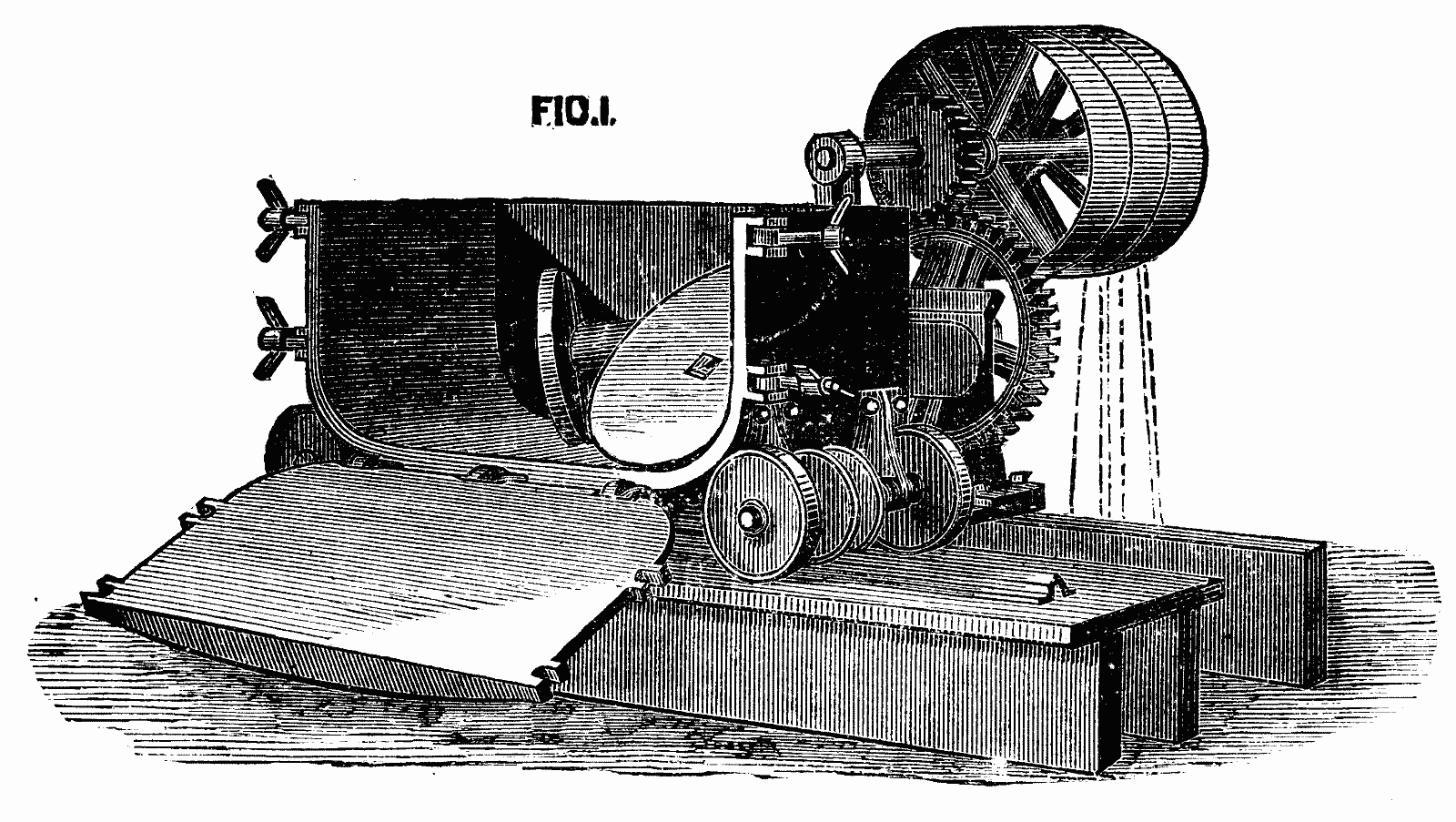
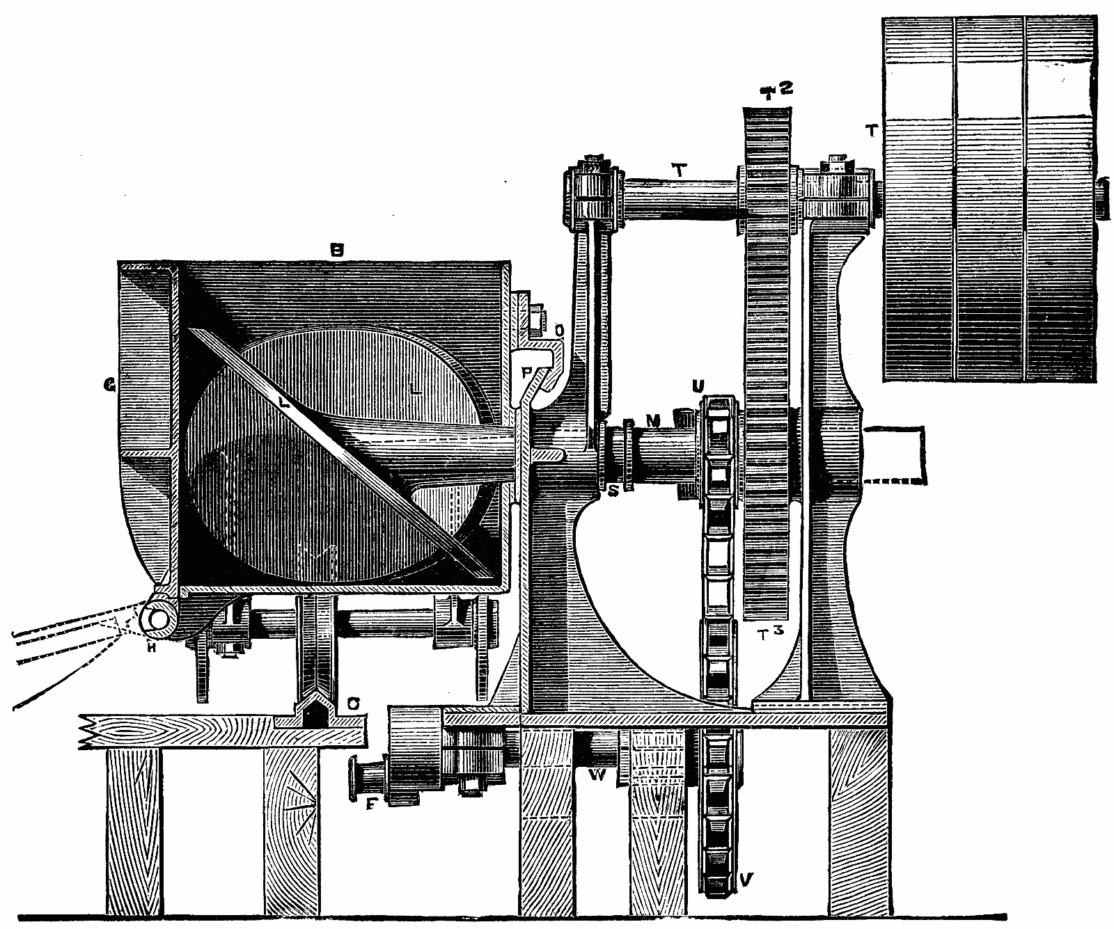
In our illustrations, C is a knife-edge rail, upon which run grooved wheels supporting the pugging box. To the axle of one grooved wheel a connecting rod from crank arm, F is attached to effect the to-and-fro motion of the mixing box, B. G is the door of the box, B, hinged at H, and secured by hinged pins carrying fly nuts. A cover and hopper and also a trap may be supplied to the box, B, for continuously feeding and discharging the material operated upon. L, L, are the pugging blades or discs on shafts, M. The shafts, M, pass through a slot in the box, B, and the packing of these shafts is effected by the face plate sliding and bearing against the face on the standard of the machine. P is a guide piece on the standard, against which bears and slides the piece, Q, bolted on to box, B, to support and guide the box, B, in its movement. The forked ends of a yoke engage with the collars, S, on the shafts, M, this yoke being set by a screw so that the shafts may be easily removed. The machine is driven from the pulleys and shaft, T, through gearing, T2 and T3, and by the Ewart's chain on the wheel and pinion, V and U.—The Engineer.
Previously, I described the method of tinning the bit, etc., with resin; but before this work on joints can be considered complete, I find it necessary to speak of tinning the ends of iron pipes, etc., which have within the last fifty years been much used in conjunction with leaden pipes. This is done as follows: Take some spirits of salts (otherwise known as hydrochloric acid, muriatic acid, hydrogen chloride, HCl), in a gallipot, and put as much sheet-zinc in it as the spirit will dissolve; you have then obtained chloride of zinc (ZnCl). A little care is required when making this, as the acid is decomposed and is spread about by the discharged hydrogen, and will rust anything made of iron or steel, such as tools, etc. It also readily absorbs ammoniacal gas, so that, in fact, sal ammoniac may also be dissolved in it, or sal ammoniac dissolved in water will answer the purpose of the chloride of zinc.
Having the killed spirits, as it is sometimes called, ready, file the end of your iron or bit and plunge this part into the spirits, then touch your dipped end with some fine solder, and dip it again and again into the spirits until you have a good tinned face upon your iron, etc.; next you require a spirit-brush.
You can make this by cutting a few bristles out of a broom or brush, push them into a short piece of compo tube, say ¼ in., and hammer up the end to hold the bristles; next cut the ends of the bristles to about 3/8 in. long, and the brush is ready for use.
Suppose you want to make a joint round a lead and iron pipe. First file the end of your iron pipe as far up as you would shave it if it were lead, and be sure to file it quite bright and free from grease; heat your soldering-iron; then, with your spirit-brush, paint the prepared end of your iron, and with your bit, rub over the pipe plenty of solder, until the pipe is properly tinned, not forgetting to use plenty of spirits; this done, you can put your joint together, and wipe in the usual manner. Caution.—Do not put too much heat on your iron pipe, either when tinning or making the joint, or the solder will not take or stand.
Figs. 38 and 38b. This tool I had better describe before proceeding to the method of bending. To make it take a piece of, say, ½ in. iron pipe, 3 ft. long, or the length required, bent a little at one end, as shown at A B in Fig. 38 and Fig. 38b. Tin the end about 2 in. up, make a hole with a small plumbing-iron in some sand, and place the tinned end of the iron pipe, B, into this hole; fill the hole up with good hot lead, and the dummy, after it has been rasped up a little, is ready for use. It will be found handy to have three or four different lengths, and bent to different angles, to suit your work. A straight one (Fig. 38b.) made to screw into an iron socket or length of gas-pipe, will be found very handy for getting dents out of long lengths of soil-pipe.
Before you begin bending solid pressed pipes always put the thickest part of your pipe at the back. Lead, in a good plumber's hands, may be twisted into every conceivable shape; but, as in all other trades, there is a right and a wrong way of doing everything, and there are many different methods, each having a right and wrong way, which I shall describe. I shall be pleased if my readers will adopt the style most suitable for their particular kind of work; of course I shall say which is the best for the class of work required.
For small pipes, such as from ½ in. to 1 in. "stout pipe," you may pull them round without trouble or danger; but for larger sizes, say, from 1¼ in. to 2 in., some little care is necessary, even in stout pipes.
Fig. 37 illustrates a badly made bend, and also shows how it comes together at the throat, X, and back, E; L is the enlarged section of X E, looking at the pipe endways. The cause of this contraction is pulling the bend too quickly, and too much at a time, without dressing in the sides at B B as follows: After you have pulled the pipe round until it just begins to flatten, take a soft dresser, or a piece of soft wood, and a hammer, and turn the pipe on its side as at Fig. 37; then strike the bulged part of the pipe from X B toward E, until it appears round like section K. Now pull your pipe round again as before, and keep working it until finished. If you find that it becomes smaller at the bend, take a long bolt and work the throat part out until you have it as required.
Fig. 39. This style of bending is much in use abroad, but not much practiced in London, though a splendid method of work.
It is a well known fact that, practically speaking, for such work, water is incompressible, but may be turned and twisted about to any shape, provided it is inclosed in a solid case—Fig. 39 is that case. The end, A, is stopped, and the stopcock, B, soldered into the other end. Now fill up this pipe quite full with warm water and shut the cock, take the end, A, and pull round the pipe, at the same time dressing the molecules of lead from the throat, C, toward D E, which will flow if properly worked.
You can hammer away as much as you please, but be quick about it, so that the water does not cool down, thereby contracting; in fact, you should open the cock now and then, and recharge it to make sure of this.
This is a very old method of bending lead pipes, and answers every purpose for long, easy bends. Proceed in this way: The length of the pipe to be 5 ft., fill and well ram this pipe solid with sand 2 ft. up, then have ready a metal-pot of very hot sand to fill the pipe one foot up, next fill the pipe up with more cold sand, ramming it as firmly as possible, stop the end and work it round as you did the water bend, but do not strike it too hard in one place, or you will find it give way and require to be dummied out again, or if you cannot get the dent out with the dummy send a ball through (see "Bending with Balls").
This style of work is much practiced on small pipes, such as 2 in. to 3 in., especially by London plumbers. Method: Suppose your pipe to be 2 in., then you require your ball or bobbin about 1/16 in. less than the pipe, so that it will run through the pipe freely. Now pull the pipe round until it just begins to flatten, as at Fig. 37, put the ball into the pipe, and with some short pieces of wood (say, 2 in. long by 1½ in. diameter) force the ball through the dented part of the pipe, or you may use several different-sized balls, as at A B C, Fig. 40, and ram them through the pipe with a short mandrel, as at D M. You will require to proceed very carefully about this ramming, or otherwise you will most likely drive the bobbins through the back at L K J. You must also watch the throat part, G H I, to keep it from kinking or buckling-up; dress this part from the throat toward the back, in order to get rid of the surplus in the throat.
Fig. 41 shows a method of bending with three balls, one of lead being used as a driver attached to a piece of twine. This is a country method, and very good, because the two balls are kept constantly to the work. First, put the two balls just where you require the bend, then pull the pipe slightly round; take the leaden ball and drop it on the ball, B, then turn the pipe the other end up and drop it on A, and do so until your bend is the required shape. You must be careful not to let your leaden ball touch the back of the pipe. Some use a piece of smaller leaden pipe run full of lead for the ball, C, and I do not think it at all a bad method, as you can get a much greater weight for giving the desired blow to your boxwood balls.
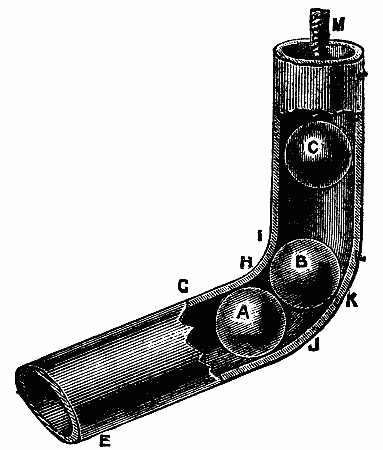
This is an excellent method of bending small pipes. Fig. 42 will almost describe itself. A is a brass or gun metal ball having a copper or wire rope running through it, and pulled through the flattened part of the pipe as shown. It will be quite as well to tack the bend down to the bench, as at B, when pulling the ball through; well dress the lead from front to back to thicken the back. I have seen some plumbers put an extra thickness of lead on the back before beginning to bend. Notice: nearly all solid pressed pipes are thicker on one side than the other (as before remarked), always place the thickest part at the back.
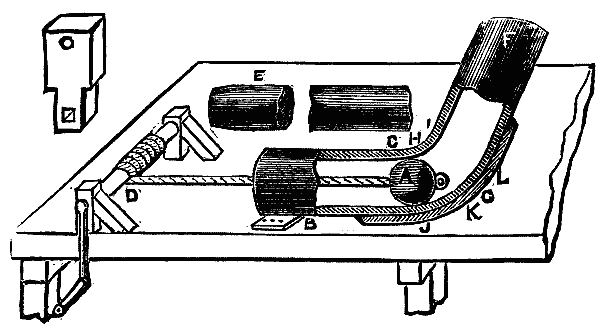
Fig 43. This is my own method of pipe-bending, and is very useful when properly handled with plenty of force, but requires great care and practice. You must have a union sweated on the end, A, Fig. 43, and the ball, B, to fit the pipe. The cup-leather, E, should have a plate fixed on the front to press the ball forward. Pull up the pipe as you please, and pump the ball through; it will take all the dents out, and that too very quickly.
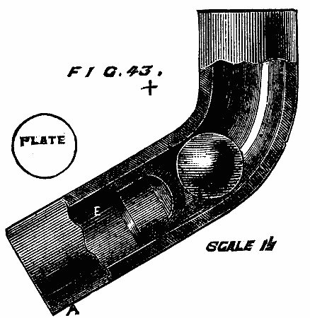
This method of bending is much practiced in the provinces, and, for anything I know to the contrary, is one of the best methods in use, as by it you are likely to get a good substance of metal on the back of the bend whether the plumber be a good or a bad workman. Proceed as follows: Cut the pipe down the center to suit the length of your bend, as shown at A B, Fig. 44. It will be quite as well if you first set out this bend on the bench, then you may measure round the back, as from C to L, to obtain the distance of the cut, which should always be three or four inches longer than the bend. You may also in this way obtain the correct length for the throat, G H I; here you will see that you have a quantity of lead to spare, i.e., from A to E, all of which has to be got rid of in uncut bends—some plumbers shift from front to back, but how many? Not one in twenty. After you have cut the pipe, open the throat part, bend out the sides, and pull this part round a little at a time, then with a dummy, Fig. 38, work the internal part of the throat outward to as nearly the shape as you can. Go carefully to work, and do not attempt to work up the sides, A D B, until your throat is nearly to the proper shape, after which you may do so with a small boxwood dresser or bossing-stick (It is not necessary to explain minutely what a bosser or dressing-stick is, as they can be bought at almost any lead-merchants—the dresser is shown at E, Fig. 1; the bossing-stick is somewhat similar, the only difference being that it has a rounded face instead of flat.) Keep the dummy up against the sides when truing it. If you have proceeded properly with this throat part, you will not require to work up the sides or edges, as in working the throat back the sides will come up by themselves. Next take the back, pull it round a little at a time, the dummy being held inside, with your dresser work the two edges and sides slowly round, and the back will follow. Never strike the back from the underside with the dummy. After you have made a dozen or two you will be able to make them as fast as you please, but do not hurry them at first, as the greater part of this work is only to be learned by patient application, perseverance, and practice.
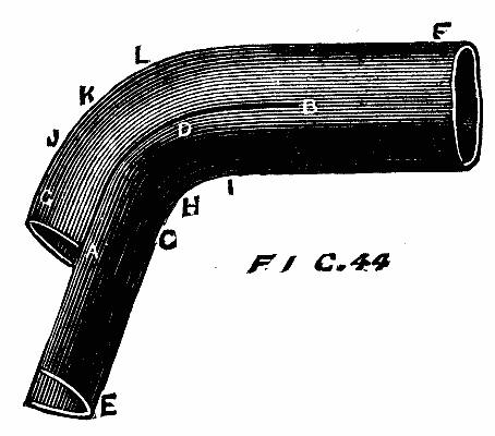
After you have made the bend it will require to be soldered, but before you can do this you must have the joint quite perfect and the edges true one with the other. A good bender will not require to touch his edges at all, but a novice will have to rasp and trim them up so that they come together. Having your edges true, soil them, take a gauge-hook, which may be described as a shave-hook with a gauge attached, and shave it about 1/8 in. each side; now solder it to look like the solder A, Fig. 45, which is done as follows: With some fine solder tack the joint at A D B, Fig. 44, put on some resin, and with a well-heated copper-bit drop some solder roughly on the point from B to A, then draw the bit over it again to float the solder, being especially careful not to let the joint open when coming off at A. Some plumbers think fit to begin here, but that is a matter of no importance. Do not forget that if your joint is not properly prepared, that is to say, true and even, it is sure to be a failure, and will have a "higgledy-piggledy" appearance. Some difference of opinion exists as to the best method of making these joints: one workman will make a good joint by drawing it while, on the other hand, another one will do it equally well by wiping it. Drawing will be fully explained in a part on pipe making. It may, however, be here mentioned that it is a method of making the joint by floating the solder along the joint with the ladle and plumbing-iron.
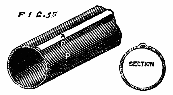
It is not uncommon for plumbers to make their bends with only one joint on the back.
In London, it is the favorite plan to make bends without cutting them. Fig. 46. It is done by taking a length of pipe, and, just where you require the bend, lay it (with the seam at the side) upon a pillow, made by tightly filling a sack with sand, wood shavings, or sawdust; have some shavings ready to hand and a good lath, also a short length of mandrel about 3 ft. long and about ½ in. smaller than the pipe, and a dummy as shown at A B, Fig. 56. Now, all being ready, put a few burning shavings into the throat of the bend, just to get heat enough to make it fizz, which you can judge by spitting on it. When this heat is acquired withdraw the fire, and let the laborer quickly place the end of the mandrel into the pipe, and pull the pipe up while you place a sack or anything else convenient across the throat of the bend, then pull the pipe up a little, just sufficient to dent it across the throat. Now, with a hot dummy, dummy out the dent, until it is round like the other part of the pipe. Keep at this until your bend is made, occasionally turning the pipe or its side and giving it a sharp blow on the side with the soft or hornbeam dresser; this is when the sides run out as in Fig. 37. Never strike the back part of the bend from inside with the dummy, but work the lead from the throat to the back with a view to thickening the back.
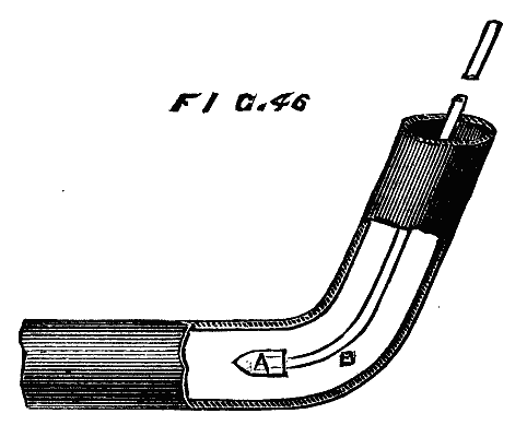
A set-off is nothing more than a double bend, as shown at Fig. 47, and made in much the same manner. D is the long end of the pipe. Always make this bend first and pull it up quite square, as it will be found to go a little back when pulling up the other bend; if you can make the two together so much the better, as you can then work the stuff from the throat of one bend into the back of the other. The different shaped dummies are also here shown: F a round-nosed dummy, G a double bent dummy, H a single bent, I straight, J hand-dummy, ABN a long bent dummy shown at Fig. 38.
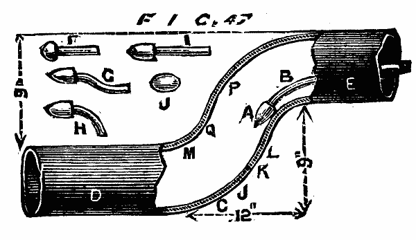
These can always be detected by examining them in their backs, as at Fig. 48; take a small dresser and tap the pipe a few times round ABD to test for the thickness. Strike it hard enough to just dent it; next strike the back part of the pipe, E, with the same force, and if it dents much more it is not an equally-made bend. I have seen some of these much-praised London-made bends that could be easily squeezed together by the pressure of the thumb and finger. N.B.—Care must be taken not to reduce or enlarge the size of the bore at the bend.
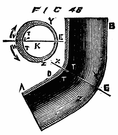
The fall given in bending lead pipes should be considered of quite as much importance as making the bends of equal thickness especially for pipes, as shown in Fig. 49. In this Fig. you have a drawing of a bad bend. From A to B there is no fall whatever, as also from B to C; such bending is frequently done and fixed in and about London, which is not only more work for the plumber, but next to useless for soil-pipes. Fig. 50 shows how this bend should be made with a good fall from A to J, also from M to N; the method of making these bends requires no further explanation. R, P, and K are the turnpins for opening the ends, the method of which will be explained in a future paragraph on "Preparing for Fixing."
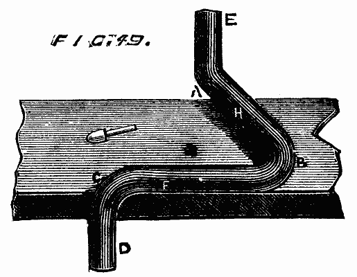
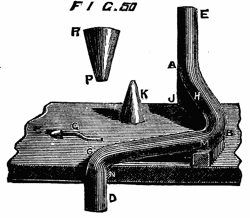
It will sometimes be found requisite to retard the flow of water when running through soil or other pipes, or to direct it to another course, or even to form a trap in the length of pipe. This has been done in many ways, but Figs. 51 and 52 represent the method that I, after mature consideration, think most preferable. There is nothing new about this style of bending, as it has been long in vogue with provincial plumbers, but more especially in Kent. For many years it has had a run as a sink and slop closet-trap. Mr. Baldwin Latham, in his "Sanitary Engineering," says it was introduced and has been used for the Surrey and Kent sewers from about 1848.
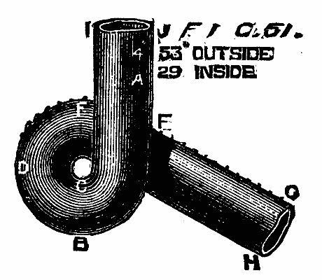
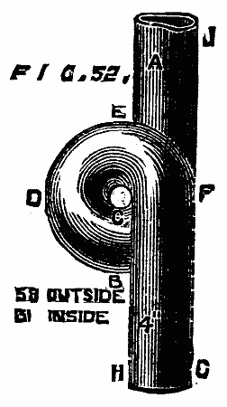
I have also noticed many of these traps in the Sanitary Exhibition at South Kensington, made by Graham and Fleming, plumbers, who deserve a medal for their perseverance and skill, not only for the excellence of their bends, but also for some other branches of the trade, such as joint-wiping, etc., which is unquestionably the best work sent into this Exhibition—in fact, quite equal to that which was shown at the Exhibition of 1862. I shall treat further of these bends in an article on Fixing, in a future part.
This is an American method of making lead bends. Fig. 53 shows a dummy made upon a bent steel rod, fixed into the bench. The method of working it is by first pulling up the bend, and to get out the dents, strike the rod of the snarling dummy, as shown at A, and the reaction gives a blow within the bend, throwing out the bend to any shape required. This method of working the dummy is also taken advantage of in working up embossed vases, etc.
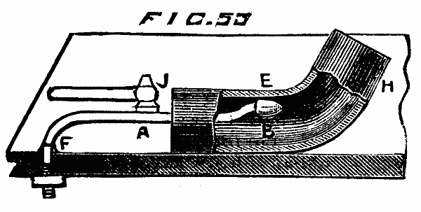
(To be continued)
From the London Building News.
The manufacture of fabrics having woofs of different colors requires the use of several shuttles and boxes containing the different colors at the extremity of the driver's travel, in which these boxes are adjusted alternately either by a rectilinear motion, or by a rotary one when the boxes are arranged upon a cylinder. The controlling mechanism of the shuttles by means of draught and tie machines constitutes, at present, the most perfect apparatus of this nature, because they allow of a choice of any shuttles whatever.
The apparatus constructed by the Grossenhainer Webstuhl und Maschinen Fabrik, of Grossenhain, and represented in the accompanying cut, is new as regards its general arrangement, although in its details it more or less resembles the analogous machines of Schönherr, Crompton, and Hartmann. The lifting of the shuttles is effected by two sectors, a1, a2, arranged on the two sides of the loom, and the rotary motion of which acts upon the box, c, by means of the lever, b, the box being caused to descend again by the spring, d. Parallel with the breast beam there is mounted an axle, e, and upon one of the extremities of this is fixed the sector, a1, while the other extremity carries two fixed disks, f1, f2, two loose disks, f3, f4, and the sector, a2, which is connected with the latter. The disks are kept in position by a brake, g. The pawls, h1 and h2, are supported on a lever, i, on a level with the disks, and are connected with the cam, l, by the spring, k. This cam revolves with the axle of the loom and thrusts the pawls against the disk. A draught and tie machine controls the action of the pawls on the disks in such a way that, by the revolution of the sectors, a1 and a2, the shuttle-boxes, I., II., III., are brought at the desired moment in the way of the driver. The pawls, h, are connected by wires with the bent levers, m, of the draught machine, which carry also the pawls, n. The upper position of the pawls, h, is limited by the direct resting of the levers, m, on the tappet, o, and the lower position by the resting of the pawls, n. The plates, p, held by the pattern, M, are set in motion horizontally by means of the eccentric, q, the crank, r, and the bent lever, s. The raised plates abut against the corresponding levers, m, and thus bring about the descent of the pawls, h, which are suspended from these levers. This position is maintained by the resting of the pawls, n, upon the tappet, o, until the lowering of the corresponding plate has set the pawl, n, free. The lever, m, then gives way to the action of the spring, t, and the pawl, h, rises again. The rotation of the cylinder which supports the design, M, is effected by the motion of the bent lever, s.
A meeting of ladies was held in this city recently to consider the possibilities of industrial art in furnishing occupation for women.
Mrs. Florence E. Cory, Principal of the Woman's Institute of Technical Design, which was recently established in this city, advanced the proposition that whatever could be done by man in decorative art could be done as well by women, and she made an earnest plea to her own sex to fit themselves by proper training to engage in remunerative industrial work. Mrs. Cory enjoys the distinction of being the first woman who ever attempted to make designs for carpets in this country. She said that four years ago, when she came to this city, there was no school at which was taught any kind of design as applied to industrial purposes, except at Cooper Union, where design was taught theoretically but not practically. During the past year or two, however, in many branches of industrial design women have been pressing to the front, and last year eighteen ladies were graduated from the Boston Institute of Technology. Most of these ladies are now working as designers for various manufacturers, eight are in print factories, designing for chintz and calico, two have become designers for oil-cloths, one is designing for a carpet company, and one for a china factory. Carpet designing, said Mrs. Cory, is especially fitted for women's work. It opens a wide field to them that is light, pleasant, and remunerative. The demand for good carpet designs far exceeds the supply, and American manufactures are sending to Europe, particularly England and France, for hundreds of thousands of dollars' worth of designs yearly. If the same quality of designs could be made in this country the manufacturers would gladly patronize home talent. One carpet firm alone pays $100,000 a year for its designing department, and of this sum several thousands of dollars go to foreign markets. More technical knowledge is required for carpet designing than for any other industrial design. It is necessary to have a fair knowledge of the looms, runnings of color, and manner of weaving. Hitherto this knowledge has been very difficult, if not impossible, for women to obtain. But now there are a few places where competent instruction in this branch of industrial art is given.
There are several kinds of work connected with this business that may be done at home by those who wish, and at very fair prices. The price of copying an ingrain design is from $3 to $6 per sheet. The price for an original design of the same size is from $10 to $20. For Brussels or tapestry sketches, which may be made at home, provided they are as good as the average sketch, the artists receive from $15 to $30. For moquettes, Axminsters, and the higher grades of carpets some artists are paid as high as $200. The average price, however, is from $25 to $100. These designs may all be made at home, carried to the manufacturer, submitted to his judgment, and if approved, will be purchased. After the purchase, if the manufacturer desires the artist to put the design upon the lines and the artist chooses to do so, the work may still be done at home, and the pay will range from $20 to $75 extra for each design so finished. The average length of time for making a design is, for ingrains, two per week; Brussels sketch, three per week; Brussels on the lines, one in two weeks; moquettes and Axminsters, one in two or three weeks, depending of course upon the elaborateness and size of the pattern. When the work is done at the designing-rooms, and the artist is required to give his or her time from 9 o'clock in the morning until 5 in the afternoon, the salaries run about as follows: For a good original ingrain designer, from $2,000 to $3,000 per year. A good Brussels and tapestry designer from $1,500 to $6,000 per year. Copyists and shaders, from $3 to $10 per week.
Mrs. R.A. Morse advocated the establishment of schools of industrial art, in which there would be special departments so that young girls might be trained to follow some practical calling. Mrs. Dr. French said that unskilled labor and incompetent workmen were the bane and disgrace of this country, and she thought that the field of industrial art was very inviting to women. She disparaged the custom of decorating chinaware and little fancy articles, and said that if the time thus wasted by women was applied to the study of practical designing those who persevered in the latter branch of industrial art might earn liberal wages. Miss Requa, of the Public School Department, explained that elementary lessons in drawing were taught in the public schools. Mme. Roch, who is thoroughly familiar with industrial and high art in both this country and in Europe, said that if the American people would apply themselves more carefully to the study of designing they could easily produce as good work as came from abroad. The beauties to be seen in American nature alone surpassed anything that she had ever witnessed in the old countries.
One of the most extensive establishments for the purpose is that of Messrs. Winter, in Vienna. They say to photographers in general: If you will send us a portrait, either negative or positive, we will produce you an enlargement on canvas worked up in monochrome. The success of their undertaking lies in the circumstance that they do not produce colored work—or, at any rate, it is exceptional on their part to do so—but devote their efforts to the production of an artistic portrait in brown or sepia. In this way they can make full use of the dark brown photograph itself; there is less necessity for tampering with the enlarged image, and natural blemishes in the model itself maybe softened and modified, without interfering much with the true lines of face and features. The monotone enlargements of Messrs. Winter, again, exquisitely as most of them are finished, do not appear to provoke the opposition of the painter; they do not cross his path, and hence he is more willing to do them justice. Many a would-be purchaser has been frightened out of his intention to buy an enlargement by the scornful utterance of an artist friend about "painted photographs," and in these days of cheap club portraits there is certainly much risk of good work falling into disrepute. But a well-finished portrait in monotone disarms the painter, and he is willing to concede that the picture has merit.
"We cannot use English canvas, or 'shirting,' as you call it," said one of our hosts; "it seems to contain so much fatty matter." The German material, on the other hand, would appear to be fit for photography as soon as it had been thoroughly worked in hot water and rinsed. Here, in this apartment, paved with red brick, we see several pieces of canvas drying. It is a large room, very clean, here and there a washing trough, and in one corner two or three large horizontal baths. The appearance is that of a wash-house, except that all the assistants are men, and not washerwomen; there is plenty of water everywhere, and the floor is well drained to allow of its running off. We are to be favored with a sight of the whole process, and this is the first operation.
Into one of the horizontal baths, measuring about 5 by 4 feet, is put the salting solution. It is a bath that can be rocked, or inclined in any direction, for its center rests upon a ball-and-socket joint. It is of papier mâché, the inside covered with white enamel. Formerly, only bromine salts were employed, but now the following formula is adopted:
| Bromide of potassium | 3 | parts. |
| Iodide of potassium | 1 | part. |
| Bromide of cadmium | 1 | " |
| Water | 240 | parts. |
Four assistants are required in the operation, and the same number when it comes to sensitizing and developing, all of which processes are commenced in the same way. The bath is tilted so that the liquid collects at one end, and near this end two assistants hold across the bath a stout glass rod; then the canvas is dipped into the liquid, and drawn out by two other assistants over the glass rod. In this way the canvas is thoroughly saturated, and, at the same time, drained of superfluous liquid.
The canvas is hung up to dry; but as sometime must elapse before this particular piece will be ready for sensitizing, we proceed with another canvas which is fit and proper for that process. The room, we should have mentioned, is provided with windows of yellow glass; but as there is plenty of light nevertheless, the fact hardly strikes one on entering. The sensitizing, with a solution of nitrate of silver, is conducted with a glass rod in the same way as before, the solution being thus compounded:
| Nitrate of silver | 4 | parts. |
| Citric acid | 1 | part. |
| Water | 140 | parts. |
Again the canvas is dried, and then comes its exposure.
This is done in a room adjoining. We lift a curtain and enter a space that reminds one of the underground regions of a theater. There are curtained partitions and wooden structures on every hand; dark murky corners combined with brilliant illumination. Messrs. Winter use the electric light for enlarging, a lamp of Siemens' driven by a six-horse power engine. The lamp is outside the enlarging room, and three large lenses, or condensers, on three sides of the light, permit the making of three enlargements at one end at the same time. (See Fig.)
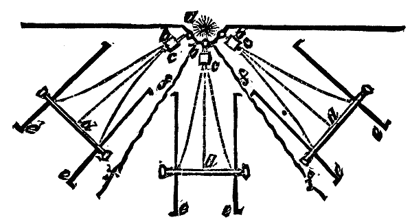
The condenser collects the rays, and these shine into a camera arrangement in which the small negative is contained. The enlarged image is then projected, magic lantern fashion, upon the screen, to which is fastened the sensitized canvas. The screen in question is upon a tramway—there are three tramways and three screens in all, as shown in our sketch—and for this reason it is easy to advance and retire the canvas, for the purpose of properly focusing it.
Even with the electric light now employed, it is necessary to expose a considerable time to secure a vigorous impression. From ten minutes to half an hour is the usual period, determined by the assistant, whose experienced eye is the only guide. We should estimate the distance of the cameras from the enlarging apparatus to be about fourteen or fifteen feet in the instance we saw, and when the canvas was taken down, a distinct outline of the image was visible on its surface.
By the way, we ought to mention that the canvas is in a decidedly limp state during these operations. It has just sufficient stiffness to keep smooth on the screen, and that is all; the treatment it has received appears to have imparted no increase of substance to it. Again it is brought into the red-brick washing apartment, and again treated in one of the white enameled baths as before. This time it is the developer that is contained in the bath, and the small limp tablecloth—for that is what it looks like—after being drawn over the glass rod, is put back into the bath, and the developing solution rocked to and fro over it. The whiteness of the bath lining assists one in forming a judgment of the image as it now gradually develops and grows stronger. Here is the formula of the developer:
| Pyrogallic acid | 10 | parts. |
| Citric acid | 45 | " |
| Water | 410 | " |
The developer—which, it will be noted, is very acid—is warmed before it is used, say to a temperature of 30° to 40° C.; nevertheless, the development does not proceed very quickly. As we watched, exactly eight minutes elapsed before Mr. Winter cried out sharply, "That will do." Immediately one of the assistants seizes the wet canvas, crumples it up without more ado, as if it were dirty linen, and takes it off to a wooden washing trough, where it is kneaded and washed in true washerwoman fashion. Water in plenty is sluiced over it, and after more vigorous manipulation still, it is passed from trough to trough until deemed sufficiently free from soluble salts to tone. The toning—done in the ordinary way with gold—removes any unpleasant redness the picture possesses, and then follows the fixing operation in hyposulphite. As canvas is more permeable than paper, these two last processes are quickly got through.
The final washing of the canvas is very thorough. Again it is treated with all the vigor with which a good laundry-maid attacks dirty linen, the canvas, in the end, being consigned to a regular washing-machine, in which it is systematically worked for some time.
When the canvas picture at last is finished, it presents a very rough appearance, by reason of the tiny fibers that stand erect all over the surface. To lay these, and also to improve the surface generally, the canvas is waxed, the fabric is stretched, and a semi-fluid mass rubbed into it, heat being used in the process, which not only gives brilliancy, but seems also to impart transparency to the shadows of the picture. The result is a pleasant finish, without vulgar glare or glaze, the high lights remaining beautifully pure and white.
Of course, the price of these canvas enlargements varies with the amount of artistic work subsequently put upon them; but the usual charge made by Messrs. Winter for a well-finished life-size portrait, three quarter length, is sixty florins, or about £5 sterling as the exchange now stands. Besides working for photographers, Messrs. Winter are reproducing a large number of classic paintings and cartoons by photography on canvas in this way (some of them almost absolutely untouched), and these, as may be supposed, are finding a very large sale among dealers. Such copies must necessarily be of considerable value to artists and collectors, and altogether it would seem that Messrs. Winter have hit upon a novel undertaking, which bids fair to make them a handsome return for the outlay (large as it undoubtedly has been) made upon their Vienna establishment.—Photo. News.
In previous communications I have given processes for detecting the adulteration of cane-sugar by starch-sugar. The adulteration of sugar-house sirups by starch glucose is still more extensively practiced than that of sugar, and a great portion of sirups sold by retailers in this market is adulterated with starch glucose. This form of adulteration may be very easily detected by the use of strong methylic alcohol, in which the alcoholometer of Tralles or of Gay Lussac will indicate about 93½°.
A straight sugar-house sirup when mixed with three times its volume of this strong methylic alcohol will dissolve by stirring, giving a very slight turbidity, which remains suspended; while sirups containing the usual admixture of starch sugar give a very turbid liquid, which separates, when left at rest, into two layers, the lower being a thick viscous deposit containing the glucose sirup.
Considerable quantities are sold of a thin sirup, of about 32° Baumé, in which the proportion of sugar to the impurities is greater than in common sugar-house molasses. When a sirup of this kind is stirred with three times its volume of methylic alcohol, a marked turbidity and deposition will take place, which consists of pure sugar. The crystals are hard and gritty. They adhere to the sides of the glass, and are deposited on the bottom. There is no resemblance between this precipitate and that due to starch sugar sirup.
It may not be useless to mention that if a straight sugar-house sirup of about 40° B. density is stirred with three times its volume of ethylic alcohol of about 93½° the sirup will not dissolve. Hence ethylic alcohol of this strength is not suitable for distinguishing a sirup mixed with starch glucose from a straight sugar-house sirup.
The presence of starch glucose in sugar-house molasses may be easily detected by the optical saccharometer when the sirup has the usual density of about 40° B., and when starch sugar has been added in the usual quantities.
For making the test the usual weight should be taken (16.35 grammes for Duboscq's saccharometer, and 26.048 grammes for Ventzke's instrument). The direct test should show a percentage of sugar not higher than the number of Baumé degrees indicating the density, and it may be from 2 to 3 per cent. lower. To understand this, we must refer to the composition of cane-sugar molasses of 40° B.:
| Sugar | 37.5 |
| Insoluble impurities | 37.5 |
| Water | 25 |
If the direct test should indicate 55 per cent. of sugar, and if the molasses were straight, the composition would be—
| Sugar | 55 |
| Soluble impurities | 20 |
| Water | 25 |
Now, a product of this composition would not be a clear sirup at 40° B., but a mixture of sirup and crystals. Therefore, if the product is a clear sirup at 40° B., and it tests 55 per cent., it cannot be straight.
The presence of starch glucose in sugar-house molasses may also be detected by the copper test. The possibility of applying this test, as well as those already indicated, rests on the fact that starch glucose is always added in very large quantities for the purposes of adulteration. A very small addition could not be satisfactorily detected.
The detection by the copper test rests on the observation that very nearly one-half of the soluble impurities in sugar-house molasses consists of glucose in the shape of inverted sugar. We have seen above that for a molasses of 40° B. the soluble impurities amount to about 37½ per cent. We may, then, lay down the rule: that the percentage of glucose shown by the copper test cannot, in a straight sugar-house molasses, be much greater than one-half of the number expressing the density in Baumé degrees. The reason is obvious from what has been said of the test by the optical saccharometer.
A Paper read before the American Chemical Society, September 2, 1881.
False Vermilion.—A curious case has been noticed in Germany, where a small cargo of vermilion was purchased, and, upon being analyzed, turned out to be red oxide of lead colored by eosine. This is an entirely novel sophistication. The eosine was separated from the oxide of lead by digesting the product for twenty-four hours in very strong alcohol. A much shorter time is sufficient to color the spirit enough to enable an expert chemist to detect the presence of this splendid organic coloring matter. Another kind of "vermilion" consists entirely of peroxide of iron, prepared especially to imitate the brilliant and costly sulphide of mercury, which it does very well, and is largely used in England, France, and America.
No body among the metals and the metalloids (silicium, titanium, tungsten, chromium, phosphorus, etc.) has occupied a more prominent position in modern metallurgy than manganese, and it is chiefly due to its great affinity for oxygen. When this substance was discovered, more than a century ago (1774), by the celebrated Swedish chemist and mineralogist, Gahn, by treating the black oxide of manganese in the crucible, no one would have thought that the new element, so delicate by itself, without any direct industrial use, would become, in the middle of the nineteenth century, one of the most powerful and necessary instruments for the success of the Bessemer process, as well for its deoxidizing properties as for the qualities which it imparts to steel, increasing its resistance, its durability, and its elasticity, as has been shown elsewhere.
Without entering into a complete history (for it is beyond the task which we have here assumed),1 it will not be without interest to recall how, when manganese was first obtained in a pure state, that it was supposed that it would remain simply an object of curiosity in the laboratory; but when its presence was proved in spiegeleisen and when it came to be considered an essential ingredient in the best German and English works for cutlery steel (where it is thrown into the crucible as the peroxide), then we find that its qualities become better and better appreciated; and it is surprising that no technologist ever devoted his attention to the production of manganese alloys.
It was not till after the investigations of Dr. Percy, Tamm, Prieger, and Bessemer, who employed crucibles for the production of these alloys, that Hendersen received the idea of utilizing it in the Siemens furnace. So important a compound could not remain unemployed. The works at Terre Noire produced, by the Martin furnace, for a number of years, ferro-manganese of 70 to 80 per cent. Shortly afterward, when competition in the market was established, the works at Carniola and at Carinthia, some English factories, and more especially the works at Saint-Louis, near Marseilles, of Terre Noire, of Montluçon, etc., successfully adopted the manufacture of ferro-manganese with the blast furnace, which is without doubt the method best adapted for the reduction of metallic oxides, as well in consideration of the reactions as from an economical point of view. Before very long it was possible to produce, by the blast furnace, alloys of 40, 60, 80, and even 86 per cent., in using the hot air apparatus of Siemens, Cowper, and Witwell, with the employment of good coke, and principally by calculating the charges for the fusion in such a manner as to obtain an extra basic and refractory slag.
Following in the same path, the Phœnix Co., of Ruhrort, sent, in 1880, to the Metallurgical Exposition of Dusseldorf, samples of ferro-manganese obtained in a blast furnace, with an extra basic slag in which the silica was almost entirely replaced by alumina. The works of L'Esperance, at Oberhausen, exhibited similar products, quite pure as to sulphur and phosphorus, and they had a double interest at the exhibition, in consideration of the agitation over the Thomas and Gilchrist process (see the discussions which were raised at the meeting of the Iron and Steel Institute). This process unfortunately requires for its prompt success the use of a very large quantity of spiegel or of ferro-manganese, in order to sufficiently carburize and deoxidize the burnt iron, which is the final product of the blowing.
The production of ferro-manganese by the blast furnace depends upon the following conditions.
1. A high temperature.
2. On a proper mixture of the iron ores and the manganese.
3. On the production of slag rich in bases.
These different conditions may be obtained with but slight variations at the different works, but the condition of a high temperature is one of the most important considerations, not only for the alloys of manganese, but equally as well for the alloys of iron, manganese, silicium, those of chromium, of tungsten, etc. It is also necessary to study the effects produced either in the crucible or in the blast furnace, and to examine the ores which for a long while have been regarded as not reducible.
The works of Terre Noire especially made at the same time, in the blast furnace, ferro-silicon with manganese, alloys which are daily becoming more important for the manufacture of steels tempered soft and half soft without blowing.
These alloys, rich in silicon, present the peculiarity of being poor in carbon, the amount of this latter element varying with the proportions of manganese. In addition to the alloys used in the iron and steel industry, we shall proceed to relate the recent progress obtained in the metallurgy of other materials (especially copper) by the use of cupro-manganese:
| Mn. per cent. | C. | Si. | S. | P. | ||
|---|---|---|---|---|---|---|
| A | 18 to 20 | 2 to 3 | 10 to 12 | Traces scarcely perceptible. | About 0.100. | Extra Quality for soft metals. |
| B | 15 to 18 | 3.00 | 10 to 8 | Medium Quality. | ||
| C | 15 to 10 | 3.25 | 8 to 6 | |||
| D | 5 to 10 | 3.50 | 4 to 6 | Ordinary for hard metals. |
The first alloys of manganese and copper were made in 1848, by Von Gersdorff; soon after Prof. Schrötter of Vienna made compounds containing 18 or 20 per cent. of manganese by reducing in a crucible the oxides of copper and manganese mixed with wood charcoal and exposing to a high heat.
These alloys were quite ductile, very hard, very tenacious, and capable of receiving a beautiful polish; their color varies from white to rose color, according to the respective proportions of the two bodies; they are particularly interesting on account of the results which were obtained by adding them to certain metallic fusions.
It is well known that in the fining of copper by oxidation there is left in the fined metal the suboxide of copper, which must then be removed by the refining process, using carbon to reduce the copper to its metallic state. M. Manhès, taking advantage of the greater affinity of manganese for oxygen, found that if this last element was introduced into the bath of copper during the operation of refining, the copper suboxide would be reduced and the copper obtained in its metallic condition. For this purpose during these last years real cupro-manganese has been prepared, occupying the same position to copper as the spiegel or the ferro-manganese does toward the manufacture of steel. M. Manhès used these same alloys for the fusion of bronze and brass, and recommended the following proportions:
| 3 | to | 4 | kilog. of | cupro-manganese | for 100 kilog. of | bronze. |
| 0.250 | to | 1 | do. | do. | do. | brass. |
| 0.150 | to | 1.2 | do. | do. | do. | copper. |
In every case the alloy is introduced at the moment of pouring, as is the case in the Bessemer or Martin process, taking care to cover the fusion with charcoal in order to prevent the contact with air, together with the use of some kind of a flux to aid in the scorification of the manganese.
According to M. Manhès a slight proportion of manganese added to bronze appears to increase its resistance and its ductility, as is shown in the following table, provided, however, that these different alloys have been subjected to the same operations from a physical point of view; that is, pouring, rolling, etc.
| Cu. | Sn. | Mn. | Weight of fracture. | Elongation | ||
|---|---|---|---|---|---|---|
| Ordinary Bronze | 90 | 10 | 20 kil. | 4.00 | ||
| Bronze with Manganese, | A, | 90 | 10 | 0.5 | 24 kil. | 15.00 |
| Do. | B, | 90 | 10 | 1.0 | 26 kil. | 20.00 |
The White Brass Co., of London, exhibited at Paris, in 1878, manganese bronzes of four grades of durability, destined for different uses and corresponding to about 20 to 25 kilos of the limit of elasticity, and 36 to 37 kilos of resistance to fracture; the number 0 is equivalent after rolling to a resistance to fracture of 46.5 kilos, and 20 to 25 per cent. of elongation.
Such results show beyond contradiction the great interest there is in economically producing alloys of copper, manganese, tin, zinc, etc. In addition, they may be added to metallic fusions, for deoxidizing and also to communicate to the commercial alloys (such as bronze, brass, etc.) the greatest degree of resistance and tenacity.
While many investigators have tried to form alloys of copper and manganese by combining them in the metallic state (that is to say, by the simultaneous reduction of their oxides), the Hensler Bros., of Dillenburg, have found it best to first prepare the metallic manganese and then to alloy it in proper proportions with other metals. Their method consisted of reducing the pure pyrolusite in large plumbago crucibles, in the presence of carbon and an extra basic flux; the operation was carried on in a strong coke fire, and at the end of about six hours the crude manganese is poured out, having the following composition:
| Manganese | 90 | to | 92 |
| Carbon | 6 | to | 6.5 |
| Iron | 0.5 | to | 1.5 |
| Silicon | 0.5 | to | 1.2 |
By refining, the manganese can be brought up to 94 to 95 per cent. of purity. It is from this casting of pure manganese that is obtained the substance used as a base for the alloys. This metal is white, crystalline, when exposed to the damp air slowly oxidizes, and readily combines with copper to form the cupro-manganese of the variety having the composition—
| Copper | 70 |
| Manganese | 30 |
Cast in ingots or in pigs it becomes an article of commerce which may be introduced in previously determined proportions into bronze, gun metal, bell metal, brass, etc. It may also be used, as we have already mentioned, for the refining of copper according to Manhès's process.
Tests made from this standpoint at the works of Mansfield have shown that the addition of 0.45 per cent. of cupro-manganese is sufficient to give tenacity to the copper, which, thus treated, will not contain more than 0.005 to 0.022 of oxygen, the excess passing off with the manganese into the scorias.
On the other hand, the addition of cupro-manganese is recommended, when it is desirable to cast thin pieces of the metal, such as tubes, caldrons, kitchen utensils, which formerly could only be obtained by beating and stamping.
The tenacity obtained for tubes of only three centimeters in diameter and 1.75 millimeters in thickness is such that they are able to withstand a pressure of 1,100 pounds to the square inch.
The manganese bronze, which we have previously referred to, and which is used by the White Brass Company of London, is an alloy of copper, with from one to ten per cent. of manganese; the highest qualities of resistance, ductility, tenacity, and durability are obtained with one to four per cent. of manganese, while with twelve per cent. the metal becomes too weak for industrial uses.
| Manganese bronze. | Copper. | Manganese. | Weight of fracture in kilos per square mm. | Elongation |
|---|---|---|---|---|
| A | 96.00 | 4.00 | 19.00 | 14.60 |
| B | 95.00 | 5.00 | 20.62 | 10.00 |
| C | 94.00 | 6.00 | 20.80 | 14.60 |
| D | 90.00 | 10.00 | 16.56 | 5.00 |
The preceding table gives some of the experimental results obtained with the testing machine at Friedrich-Wilhelmshütte on the crude cast ingots; the resistance is increased, as with copper, by rolling or hammering.
The manganese German silver consists of
| Copper | 70.00 |
| Manganese | 15.00 |
| Zinc | 15.00 |
But as this alloy often breaks in rolling, the preference is given to the following proportions:
| Copper | 80.00 |
| Manganese | 15.00 |
| Zinc | 5.00 |
This results in a white, ductile metal, which is easily worked and susceptible of receiving a beautiful polish, like the alloys of nickel, which it may in time completely replace.
The bronzes of manganese, tin, and zinc were perhaps the first upon which important investigations were made; they were obtained by adding to an alloy of copper, zinc, and tin (ordinary bronze) a definite quantity of the cupro-manganese of the type indicated above (Cu 70, Mn 30). By this means the resistance is increased fully nine per cent., probably in the same way as the copper, that is, by the deoxidizing effect of the manganese, as both the copper and the tin are always more or less oxidized in ordinary bronzes.
Manganese combines with tin just the same as it does with copper, and the proportion which is recommended as giving the highest resistances is three to six per cent. of cupro-manganese.
However, notwithstanding the use of cupro-manganese, the tin, as in ordinary bronzes, has a tendency to liquate in those portions of the mould which are the hottest, and which become solid the last, especially in the case of moulds having a great width.
From a series of experiments made at Isabelle Hütte, it has been found that the metal which has the greatest resisting qualities was obtained from
| Copper | 85.00 |
| Manganese | 6.00 |
| Zinc | 5.00 |
5 per cent. of cupro-manganese = manganese 1.00 remaining in the metal.
The best method of procedure is first to melt the copper in a crucible, and then to add the tin and the zinc; finally the cupro-manganese is added just at the moment of pouring, as in the Manhès process; then the reaction on the oxides is very effective, there is a boiling with scintillation similar to the action produced in the Bessemer and Martin process when ferro-manganese is added to the bath of steel.
The following are some of the results obtained from thirteen alloys obtained in this manner. These samples were taken direct from the casting and were tested with the machine at Friedrich-Wilhelms-hütte, and with the one at the shops of the Rhine Railroad. Their resistance was considerably increased, as with the other alloys, by rolling or hammering.
| Numbers. | Nature of mould. | Copper | Tin. | Zinc. | Cupro- manganese. |
Limit of elasticity in kilos per mm. |
Weight of fracture in kilos per mm. |
Elongation, percentage. |
|---|---|---|---|---|---|---|---|---|
| 1 | Sand | 85.00 | 6.00 | 5.00 | — | 11.30 | 16.00 | — |
| 2 | — | 85.00 | 6.00 | 5.00 | 4.00 | 13.00 | 16.10 | 2.00 |
| 3 | Cast. | 87.00 | 8.70 | 4.30 | 4.00 | — | 19.40 | — |
| 4 | — | 85.00 | 6.90 | 5.00 | 6.00 | — | 18.80 | 6.00 |
| 5 | — | 85.00 | 6.00 | 5.00 | 6.00 | — | 19.75 | 7.00 |
| 6 | — | 85.00 | 6.00 | 5.00 | 10.00 | — | 17.15 | 4.00 |
| 7 | Sand | 87.00 | 5.20 | 4.33 | 3.47 | — | 19.70 | 8.70 |
| 8 | — | 87.00 | 5.20 | 4.33 | 3.47 | — | 19.70 | 8.90 |
| 9 | — | 85.00 | 6.00 | 5.00 | 3.00 | 16.80 | 22.00 | — |
| 10 | — | 74.00 | 10.00 | 5.00 | 3.30 | 13.80 | 18.70 | — |
| 11 | — | 78.70 | 8.00 | (7.66 Pb) ( 8 Pb) | 3.30 | 13.80 | 20.70 | — |
| 12 | — | 82.00 | 9.80 | 4.90 | 3.30 | 14.75 | 19.75 | — |
| 13 | — | 86.20 | 16.50 | — | 3.30 | 14.30 | 24.70 | — |
The results of the tests of ductility which are here given, with reference to the cupro-manganese, manganese bronze, the alloys with zinc and tin, are taken from M.C. Hensler's very valuable communication to the Berlin Society for the Advancement of the Industrial Arts.
These various alloys, as well as the phosphorus bronze, of which we make no mention here, are at present very largely used in the manufacture of technical machines, as well as for supports, valves, stuffing-boxes, screws, bolts, etc., which require the properties of resistance and durability. They vastly surpass in these qualities the brass and like compounds which have been used hitherto for these purposes.—Bull. Soc. Chim., Paris, xxxvi. p. 184.
See Engineering, May 27, 1881
In a recent number of the Journal des Usines à Gaz appears a note by M. Chevalet, on the chemical and physical purification of gas, which was one of the papers submitted to the Société Technique de l'Industrie du Gaz en France at the last ordinary meeting. This communication is noticeable, apart from the author's conclusions, for the fact that the processes described were not designed originally for use in gas manufacture, but were first used to purify, or rather to remove the ammonia which is to be found in all factory chimneys, and especially in certain manufactories of bone-black, and in spirit distilleries. It is because of the success which attended M. Chevalet's treatment of factory smoke that he turned his attention to coal gas. The communication in which M. Chevalet's method is described deals first with chimney gases, in order to show the difficulties of the first class of work done by the author's process. Like coal gas, chimney gases contain in suspension solid particles, such as soot and ashes. Before washing these gases in a bath of sulphuric acid, in order to retain the ammonia, there were two problems to be solved. It was first of all necessary to cool the gases down to a point which should not exceed the boiling-point of the acid employed in washing; and then to remove the solid particles which would otherwise foul the acid. In carrying out this mechanical purification it was impossible, for two reasons, to make use of apparatus of the kind used in gas works; the first obstacle was the presence of solid particles carried forward by the gaseous currents, and the other difficulty was the volume of gas to be dealt with. In the example to which the author's attention was directed he had to purify 600 cubic meters of chimney gas per minute, or 36,000 cubic meters per hour, while the gas escaped from the flues at a temperature of from 400° to 500° C. (752° to 932° Fahr.), and a large quantity of cinders had frequently to be removed from the main chimney flues. After many trials a simple appliance was constructed which successfully cooled the gases and freed them from ashes. This consisted of a vertical screen, with bars three mm. apart, set in water. This screen divided the gases into thin sheets before traversing the water, and by thus washing and evaporating the water the gases were cooled, and threw down the soot and ashes, and these impurities fell to the bottom of the water bath. The gases after this process are divested of the greater part of any tarry impurities which they may have possessed, and are ready for the final purification, in which ammonia is extracted. This is effected by means of a series of shallow trays, covered with water or weak acid, and pierced with a number of fine holes, through which the gas is made to bubble. The washing apparatus is therefore strangely similar in principle to that designed by Mr G. Livesey. M. Chevalet states that this double process is applicable to gas works as well as to the purification of smoke, with the difference that for the latter purpose the washing trays are filled with acid for the retention of ammonia, while in the former application gas liquor or water is used. The arrangement is said to be a practical success.—Journal of Gas Lighting.
Differences obtained in the estimation of nitrogen in the above substances are frequently the source of much annoyance. The cause of these discrepancies is chiefly due to the lack of uniformity in the material, and from its not being in a sufficiently fine state during the combustion. The hair which is found in commerce for the manufacture of fertilizers, is generally mixed with sand and dust. Wool dust often contains old buttons, pieces of wood, shoe pegs, and all sorts of things. The flesh fertilizers are composed of light particles of flesh mixed with the heavier bone dust.
Even after taking all possible precautions to finely comminute these substances by mechanical means, still only imperfect results are obtained, for the impurities, that is to say, the sand, can never be so intimately mixed with the lighter particles that a sample of 0.5 to 0.8 gramme, such as is used in the determination of nitrogen, will correspond to the correct average contents. In substances such as dried blood, pulverization is very tedious. A very good method of overcoming these difficulties, and of obtaining from the most mixed substances a perfectly homogeneous mass, is that recommended by Grandeau1 of decomposing with sulphuric acid—a method which as yet does not seem to be generally known. From a large quantity of the substance to be examined, the coarse stones, etc., are removed by picking or sifting, and the prepared substance, or in cases where the impurities cannot be separated, the original substance, is treated with sulphuric acid; after it is decomposed, the acid is neutralized with calcium carbonate, and the nitrogen is determined in this mass.
In order to operate rapidly, it is best to use as little sulphuric acid as possible. If too much sulphuric acid is used, necessarily a large amount of calcium carbonate is essential to get it into proper condition for pulverizing. Under such circumstances the percentage of nitrogen becomes very low, and a slight error will become correspondingly high.
20 c.c. of concentrated sulphuric acid and 10 c.c. are sufficient for 30 to 40 grammes of material. After the substance and liquid have been thoroughly stirred in a porcelain dish, they are warmed on a water bath and continually stirred until the mass forms a homogeneous liquid. The sirupy liquid thus obtained is then mixed with 80 to 100 grammes of pulverized calcium carbonate (calcspar), dried for fifteen minutes at 40 to 60° C., and after standing for one to two hours the dish and its contents are weighed. From the total weight the weight of the dish is subtracted, which gives the weight of the calcium sulphate and the calcium carbonate, and the known weight of the wool dust, etc. This material is then intimately ground, and 2 to 3 grammes of it are taken for the determination of the nitrogen, which is then calculated for the original substance.
Although the given quantities of water and sulphuric acid hardly appear sufficient for such a large quantity of hair or wool, still in the course of a few minutes to a quarter of an hour, after continual stirring, there is obtained a liquid which, after the addition of the calcium carbonate, is readily converted into a pulverized mass. Frequently a smaller quantity of sulphuric acid will suffice, especially if the material is moist. The chief merit of this process is that in a short time a large quantity of material, having a uniform character, is obtained. Its use is, therefore, recommended for general employment.
When the coarser stones, etc., are weighed, and the purified portion decomposed, absolutely correct results are obtained, and in this way the awkward discrepancies from different analysts may be avoided.—Chemiker Zeitung, v. 7, p. 703.
Handbook d. Agrict. Chem. Analyst., p. 18.
The method which is here recommended originated with Dr. M. Buchner, and consists in preparing a concentrated solution of alcoholic caustic potash—one part caustic potash to three of 90 per cent. alcohol—and then boiling one to two grammes of the suspected wax in a small flask with the above solution. The liquid is poured into a glass cylinder to prevent solidification of the contents, and it is then placed for about one half hour in boiling water. With pure wax the solution remains clear white; when ceresine and paraffine are present, they will float on the surface of the alkali solution as an oily layer, and on cooling they will appear lighter in color than the saponified mass, and thus they may be quantitatively estimated. The author likewise gives a superficial method for the determination of the purity of beeswax. It depends on the formation of wax crystals when the fused wax solidifies. These crystals form on the surface on cooling, and are still visible after solidification when examining the surface from the side. The test succeeds best when the liquid wax is poured into a shallow tin mould After cooling another peculiar property of the wax becomes apparent. While the beeswax fills a smaller volume, that is, separates from the sides of the mould, the Japanese wax, without separating from the sides, becomes covered with cracks on cooling which have a depth corresponding to the thickness of the wax.—Neuste Erfindungen und Erfahrungen, viii., p. 430.
The manager of a well directed brewery, which was built according to the latest improvements and provided with ice-cooling arrangements, found that the alcoholic fermentation of lager beer did not advance with proper regularity. The beer did not clarify well, it remained turbid and had a tendency to assume a disagreeable odor and taste. Microscopic examination of the yeast, however, showed the same to be bottom yeast. After some time its action apparently diminished, or rather, the fermentation, which began well, ceased, and at the same time a white foam formed in the center of the vat. The manager observing this, again submitted it to microscopic examination. The instrument revealed a number of much smaller forms of fungi, similar to those of young yeast, and some which were excessively large, a variety never found in bottom yeast. Fully appreciating the microscopic examination, and aware of the danger which the spread of the fungi could cause, the manager resorted to all known means to retard its pernicious influence. Fresh yeast was employed, and the fermenting vats throughly cleaned, both inside and out, but the phenomena reappeared, showing that the transmission took place through the air. A microscopic examination of a gelatinous coating on the wall of the fermenting room further explained the matter. Beginning at the door of the ice cellar, the walls were covered with a gelatinous mass, which, even when placed beneath the microscope, showed no definite organic structure; however it contained numerous threads of fungi. Notwithstanding the precautions which were taken for cleanliness, these germs traveled from the ceiling through the air into the fermenting liquid and there produced a change, which would ultimately have caused the destruction of all the beer.
For a third time and by altogether different means, it was demonstrated that the air was the bearer of these germs. The whole atmosphere was infected, and a simple change of air was by no manner of means sufficient, as has already been shown. In addition, these observations throw considerable light on the means by which contagious diseases are spread, for often a room, a house, or the entire neighborhood appears to be infected. It must also be remembered how, in times of plague, large fires were resorted as to a method of purifying the air.
With the infinite distribution of germs, and as they are always present in all places where any organic portions of vegetable or animal matter are undergoing decomposition, it becomes, under certain circumstances, exceedingly difficult, and at times even impossible, to trace the direct effect of these minute germs. The organism is exposed to the destructive action of the most minute creation; several changes in this case give to them the direct effect of the acting germs. The investigation of the chemist does not extend beyond the chemical changes; nevertheless these phenomena are directly explained by the microscope, without which, in the present case, the discovery of the cause would have remained unknown.—Arch. der Pharm., 214, 158.
If two drops of phenic acid are diluted with three thousand to five thousand parts of water, a distinct blue color is produced by one drop of solution of perchloride of iron.
The addition of six or eight drops of glycerine entirely removes the color, and if any glycerine was present in the liquid the reaction does not take place at all. By this test the presence of 1 per cent. of glycerine can be detected. It may be applied to the analysis of wines, beers, etc., but when there is much sugar, extractive or coloring matter, the test can only be applied after evaporating, dissolving the residue in alcohol and ether, evaporating again, and then redissolving in water. Alkaline solutions must be first acidulated.—Pharm. Zeit. für Russ.
While the phanerogams or flowering plants annually contribute to the list of newly discovered alkaloids, with the exception of muscarine and amanitine, no alkaloid has as yet been definitely recognized among the cryptogams.
Karl Bödeker, of Göttingen, has opened the road in this direction, and gives in a paper sent to Liebig's Annalen der Chemie, August 15, 1881, the following account of an alkaloid, which, from the name of the plant in which it occurs, he calls lycopodine.
The plant yielding the alkaloid, Lycopodium complanatum, belongs to the group of angiospermous cryptogams. It is distributed throughout the whole of north and middle Europe, and contains the largest proportion of aluminum of any known plant. Its bitter taste led the author to suspect an alkaloid in it.
To prepare the alkaloid the dried plant is chopped up and twice exhausted with boiling alcohol of 90 per cent. The residue is squeezed out while hot, and the extract, after being allowed to settle awhile, is decanted off, and evaporated to a viscid consistency over a water bath. This is then repeatedly kneaded up with fresh quantities of lukewarm water until the washings cease to taste bitter, and to give a reddish brown coloration when treated with a strong aqueous solution of iodine. The several washings are collected and precipitated with basic lead acetate, the precipitate filtered off, and the lead in the filtrate removed by sulphureted hydrogen. The filtrate from the lead sulphide is evaporated down over a water bath, then made strongly alkaline with a solution of caustic soda, and repeatedly shaken up with fresh quantities of ether so long as the washings taste bitter and give a precipitate with iodine water. After distilling off the ether, the residue is treated with strong hydrochloric acid, the neutral or slightly acid solution filtered off from resinous particles, slowly evaporated to crystallization, and the crystals purified by repeated recrystallization. To prepare the pure base a very concentrated solution of this pure hydrochlorate is treated with an excess of a very concentrated solution of caustic soda, and pieces of caustic potash are added, whereupon the free alkaloid separates out at first as a colorless resinous stringy mass, which, however, upon standing, turns crystalline, forming monoclinic crystals similar to tartaric acid or glycocol. The crystals are rapidly washed with water, and dried between soft blotting paper.
Thus prepared, lycopodine has a composition which may be represented by the formula C32H52N2O3. It melts at 114° to 115° C. without loss of weight. It is tolerable soluble in water and in ether, and very soluble indeed in alcohol, chloroform, benzol, or amyl alcohol. Lycopodine has a very pure bitter taste.
The author has formed several salts of the base, all of a crystalline nature, and containing water of crystallization.
The hydrochlorate gives up a part of its water of crystallization at the ordinary temperature under a desiccator over sulphuric acid, and the whole of it upon heating.—Chemist and Druggist.
Some years ago, O. Hesse, when preparing chinamine from the renewed bark of Cinchona succirubra, found in the mother liquid a new alkaloid, which he then briefly designated as conchinamine. He has lately given his attention to the separation and preparation of this alkaloid, and gives in Liebig's Annalen der Chemie, August 31, 1881, the following description of it:
Preparation.—The alcoholic mother lye from chinamine is evaporated down and protractedly exhausted with boiling ligroine, whereby conchinamine and a small quantity of certain amorphous bases are dissolved out. Upon cooling the greater part of the amorphous bases precipitates out. The ligroine solution is then first treated with dilute acetic acid, and then with a dilute solution of caustic soda, whereupon a large quantity of a resinous precipitate is formed. This is kneaded up with lukewarm water to remove adherent soda, and then dissolved in hot alcohol. The alcoholic solution is saturated with nitric acid, which has been previously diluted with half its volume of water, and the whole set aside for a few days to crystallize. The crystals of conchinamine nitrate are purified by recrystallization from boiling water. On dissolving these pure crystals of the nitrate in hot alcohol of 60 per cent., and adding ammonia, absolute pure conchinamine separates out on cooling.
Composition.—Conchinamine may be represented by the formula C19H24N2O2, without water of crystallization.
Properties.—Conchinamine is easily soluble in hot alcohol of 60 per cent., and in ether and ligroine, from which solutions it crystallizes in quadrilateral shining prisms. It is extremely soluble in chloroform, but almost insoluble in water. It melts at 121° C., forming crystalline stars on cooling.
Salts.—The salts of conchinamine, like the base itself, have much in common with chinamine, but are, as a rule, more easily crystallizable. They are prepared by neutralizing an alcoholic solution of the base with the acid in question.—Chemist and Druggist.
The valuable properties of which chinoline has been found to be possessed have led to its admission as a therapeutic agent, and the discoverer of these properties, Jul. Donath, of Baja, in Hungary, in a paper sent to the Berichte der deutschen chemischen Gesellschaft, September 12, 1881, gives the following further details as to this interesting substance.
Antiseptic Properties.—Chinoline appears to be an excellent antiseptic. The author found that 100 grammes of a Bucholze's solution for the propagation of bacteria, charged with 0.20 g. of chinoline hydrochlorate, had remained perfectly clear and free from bacteria after standing forty-six days exposed to the air, while a similar solution, placed under the same conditions, without chinoline, had turned muddy and contained bacteria after only twelve days' standing.
Antizymotic Properties.—Chinoline, even in the proportion of 5 per cent., does not prevent alcoholic fermentation, while in as small a quantity as 0.20 per cent. it does not prevent lactic acid fermentation.
Physiological Effects.—The author gave a healthy man during several days various doses of chinoline tartrate, which in no way affected the individual operated on, nor was any trace of chinoline found in his urine. The author, therefore, considers that the base is oxidized by the blood to carbopyridinic acid, which is a still more powerful antiseptic than chinoline itself. Chinoline taken internally would, therefore, be a useful and safe agent in cases of internal putrid fungoid or other growth.
Chemical Reactions.—Chinoline yields very characteristic reactions with a number of chemical reagents, for a description of which we refer to the original paper.—Chemist and Druggist.
Dr. J. Schorm, of Vienna, the author of this paper, after remarking that in spite of the increase of the consumption of coniine, the methods hitherto in vogue for preparing it yielded an article which darkened on exposure to the air, and the salts of which crystallized but badly, gives the following method for preparing pure coniine and its salts:
A.—100 kilogrammes of hemlock seed are moistened with hot water, and after swelling up are treated with 4 kilogrammes of sodium carbonate previously dissolved in the requisite quantity of water (caustic alkalies cannot be used). The swollen seed is worked up uniformly with shovels, and then placed in an apparatus of 400 kilogrammes capacity, similar to that used in the distillation of ethereal oils, and charged with steam under a pressure of three atmospheres. Coniine distills over with the steam, the greater part separating out in the receiver as an oily stratum, while a part remains dissolved in the water. The riper the seeds, the greater is the percentage yield of oily coniine, and the sooner is the distillation ended. The distillate is neutralized with hydrochloric acid, and the whole evaporated to a weak sirupy consistence. When cool, this sirup yields successive crops of sal-ammoniac crystals, which latter are removed by shaking up the mass with twice its volume of strong alcohol, and filtering. This filtrate is freed from alcohol by evaporation over a water bath, the approximate quantity of a solution of caustic soda then added, and the whole shaken up with ether. The ethereal solution is then cooled down to a low temperature, whereby it is separated from conhydrine, which, being somewhat difficultly soluble in ether, crystallizes out.
B.—The bruised hemlock seed is treated in a vacuum extractor with water acidulated with acetic acid, and the extract evaporated in vacuo to a sirupy consistence. The sirup is treated with magnesia, and the coniine dissolved out by shaking up with ether.
The B method yields a less percentage of coniine than A, but of a better quality.
The solution of crude coniine in ether obtained by either of the above processes is evaporated over a water bath to remove the ether, mixed with dry potassium carbonate, and then submitted to fractional distillation from an air bath. The portion distilling over at 168° C. to 169° C. is pure coniine, and represents 60 per cent. of the crude coniine.
Coniine thus prepared is a colorless oily liquid, volatile at the ordinary temperature, and has a specific gravity of 0.886. At a temperature of 25°C it absorbs water, which it gives up again upon heating. It is soluble in 90 parts of water. It is not altered by light.
The author has formed a number of salts from coniine thus prepared, and finds them all crystallizable and unaffected by light.—Berichte der deutschen chemischen Gesellschaft.—Chem. and Druggist.
Since it has been shown by Professor Scheibler, of Berlin, that strontium is the most powerful medium of extraction in sugar refining, owing to its capacity of combining with three parts of saccharate, the idea suggests itself that the same medium might be successfully employed in the arts, and form a most interesting subject of experiment for the chemist.
Hitherto native strontianite, that is, the 90 to 95 per cent. pure carbonate of strontium (not the celestine which frequently is mistaken by the term strontianite), has not been worked systematically in mines, but what used to be brought to the market was an inferior stone collected in various parts of Germany, chiefly in Westphalia, where it is found on the surface of the fields. Little also has been collected in this manner, and necessarily the quality was subject to the greatest fluctuations.
By Dr. Scheibler's important discovery, a new era has begun in the matter of strontianite. Deposits of considerable importance have been opened in the Westphalian districts at a very great depth, and the supply of several 10,000 tons per annum seems to be secured, whereas only a short time ago it was not thought possible that more than a few hundred tons could in all be provided.—Chemist and Druggist.
A peculiar contagious disease, called frambœsia, or the yaws, has long been known to exist in Africa, the West Indies, and the northern parts of the British Islands. It is chronic in character, and is distinguished by the development of raspberry-like tumors of granulation tissue on different parts of the body.
A disease of a somewhat similar, but severer type, has for many years prevailed in Ceylon. Even less was known of this affection than of its supposed congener, until a recent careful report upon the subject by Mr. W.R. Kinsey, principal civil medical officer of Ceylon.
The disease in question is called "parangi," and is defined by Mr. Kinsey (British Medical Journal) as a specific disease, produced by such causes as lead to debilitation of the system; propagated by contagion, generally through an abrasion or sore, but sometimes by simple contact with a sound surface; marked by an ill-defined period of incubation, followed by certain premonitory symptoms referable to the general system, then by the evolution of successive crops of a characteristic eruption, which pass on in weakly subjects into unhealthy and spreading ulcers whose cicatrices are very prone to contraction; running a definite course; attacking all ages, and amenable to appropriate treatment.
The disease seems to develop especially in places where the water supply, which in Ceylon is kept in tanks, is insufficient or poor. The bad food, dirty habits, and generally unhygienic mode of life of the people, help on the action of the disease.
Parangi, when once developed, spreads generally by contagion from the discharges of the eruptions and ulcers. The natural secretions do not convey the poison. The disease may be inherited also.
In the clinical history of the disease there are, according to Mr. Kinsey, four stages. The first is that of incubation. It lasts from two weeks to two months. A sore will be found somewhere upon the body at this time, generally over some bony prominence. The second is the stage of invasion, and is characterized by the development of slight fever, malaise, dull pains in the joints. As this stage comes on the initial sore heals. This second stage lasts only from two to seven days, and ends with an eruption which ushers in the third stage. The eruption appears in successive crops, the first often showing itself on the face, the next on the body, and the last on the extremities. This eruptive stage of the disease continues for several weeks or months, and it ends either in convalescence or the onset of a train of sequelæ, which may prolong the disease for years.
Parangi may attack any one, though the poorly fed and housed are more susceptible. One attack seems to confer immunity from another.
Although some of the sequelæ of the disease are most painful, yet death does not often directly result from them, nor is parangi itself a fatal disease. Persons who have had parangi and passed safely through it, are not left in impaired health at all, but often live to an old age.
The similarity of the disease, in its clinical history, to syphilis, is striking. Mr. Kinsey, however, considers it, as we have stated, allied to, if not identical with frambœsia.—Medical Record.
So far back as 1849, Mr. Alexander Ure investigated the purgative properties of the oil of anda. The specimen with which the experiments were tried had not been freshly prepared, and had indeed been long regarded as a curiosity. Twelve ounces were alone available, and it was a yellowish oil, quite bright, about the consistence of oleum olivæ, devoid of smell, and free from the viscid qualities of castor oil. There was a small supply of anda fruits differing a good deal in appearance one from the other, but we are not aware whether these were utilized and the oil expressed; as far as our recollection serves, the subject was abandoned. It was known that the natives of Brazil used the seeds as an efficient purgative in doses of from one to three, and it was in contemplation to introduce this remedy into England, though it was by no means certain that under distinctly different climatic influences equally beneficial results might be expected. Mr. Ure determined, by actual experiment, to ascertain the value of the oil in his own hospital practice. He found that small doses were better than larger ones, and in several reported cases it appeared that twenty drops administered on sugar proved successful. Oil of anda-açu, or assu, therefore, would stand mid-way between ol. ricini and ol. crotonis. These researches seem to have been limited to the original sample, although the results obtained would appear to justify a more extended trial. M. Mello-Oliveira. of Rio Janeiro, has endeavored to bring the remedy into notice under the name of "Huile d'Anda-Assu," and possibly may not have been acquainted with the attempt to introduce it into English practice. He describes the anda as a fine tree (Johanesia princeps, Euphorbiaceæ), with numerous branches and persistent leaves, growing in different parts of Brazil, and known under the name of "coco purgatif." The fruit is quadrangular, bilocular, with two kernels, which on analysis yield an active principle for which the name "Johaneseine" is proposed. This is a substance sparingly soluble in water and alcohol, and insoluble in chloroform, benzine, ether, and bisulphide of carbon. Evidence derived from experiments with the sulphate of this principle did not give uniform results: one opinion being that, contrary to the view of many Brazilian physicians, this salt had no toxic effect on either men or animals. Local medical testimony, however, was entirely in favor of the oil. Dr. Torrès, professor at Rio Janeiro, using a dose of two teaspoonfuls, had been successful. Dr. Tazenda had obtained excellent results, and Dr. Castro, with a somewhat larger dose (3 ijss.), was even enthusiastic in its praise. It might, therefore, be desirable at a time when new remedies are so much in vogue, not to abandon altogether a Brazilian medicament the value of which is confirmed both by popular native use and by professional treatment. M. Mello-Oliveira comes to the conclusion that oleum anda assu (or açu) may be employed wherever castor oil is indicated, and with these distinct advantages: first, that its dose is considerably less; secondly, that it is free from disagreeable odor and pungent taste; and thirdly, being sufficiently fluid, it is not adherent to the mouth so as to render it nauseous to the patient. In this short abstract the spelling of the French original has been retained. As this therapeutic agent claimed attention thirty years ago, and has again been deemed worthy of notice in scientific journals, some of our enterprising pharmacists might be inclined to add it to the list of their commercial ventures.—Chemist and Druggist.
Mr. Jas. W. Parkinson gives in a recent number of the Confectioner's Journal the following useful recipes:
Stone a pound of bloom raisins; wash and clean a pound of Zante currants; mince finely a pound of beef suet; mix with this, in a large pan, a pound of stale bread crumbs and half a pound of sifted flour. Beat together in another pan six eggs, and mix with them half a pint of milk. Pour this over the suet and flour, and stir and beat the whole well together; then add the raisins, currants, and a seasoning of ground cinnamon, grated nutmeg, powdered ginger, and a little ground cloves, a teaspoonful of salt, one pound of sugar, and a glass of Jamaica rum. This pudding may now be boiled in a floured cloth or in an ornamental mould tied up in a cloth. In either way it requires long and constant boiling, six hours at least for one such as the above. Every pudding in a cloth should be boiled briskly, till finished, in plenty of water, in a large pot, so as to allow it to move about freely.
To take the boiled pudding out of the cloth without breaking it, dip it into cold water for a minute or two, then place it in a round bottomed basin that will just hold it, untie the cloth and lay bare the pudding down to the edge of the basin; then place upon it, upside down, the dish on which it is to be served, and invert the whole so that the pudding may rest on the dish; lastly, lift off the basin and remove the cloth. The use of the cold water is to chill and solidify the surface, so that it may part from the cloth smoothly.
Plum pudding may also be baked in a mould or pan, which must be well buttered inside before pouring the pudding into it. Two hours' boiling suffices.
Put into a saucepan two ounces of best butter and a tablespoonful of flour; mix these well together with a wooden spoon, and stir in half a pint of cold water and a little salt and pepper. Set this on the fire and stir constantly till nearly boiling; then add half a tumbler of Madeira wine, brandy, or Jamaica rum, fine sugar to the taste, and a little ground cinnamon or grated nutmeg. Make the sauce very hot, and serve over each portion of the pudding.
An excellent plum pudding is made as follows: Half a pound of flour, half a pound of grated bread crumbs, a pound of Zante currants, washed and picked; a pound of raisins, stoned; an ounce of mixed spices, such as cinnamon, mace, cloves, and nutmeg; an ounce of butter, two ounces of blanched almonds, cut small; six ounces of preserved citron and preserved orange peel, cut into small pieces; four eggs, a little salt, four ounces of fine sugar, and half a pint of brandy. Mix all these well together, adding sufficient milk to bring the mixture to a proper consistency. Boil in a floured cloth or mould for eight hours.
Into a gill of melted butter put an ounce of powdered sugar, a little grated nutmeg, two wine glasses of Madeira wine and one of Curacoa. Stir all well together, make very hot, and pour it over the pudding.
Separate the whites and yolks of a dozen fresh eggs. Put the yolks into a basin and beat them to a smooth cream with half a pound of finely pulverized sugar. Into this stir half a pint of brandy, and the same quantity of Jamaica rum; mix all well together and add three quarts of milk or cream, half a nutmeg (grated), and stir together. Beat the whites of the eggs to a stiff froth; stir lightly into them two or three ounces of the finest sugar powder, add this to the mixture, and dust powdered cinnamon over the top.
Beat up in a bowl half a dozen fresh eggs; add half a pound of pulverized sugar; stir well together, and pour in one quart or more of boiling water, about half a pint at a time, mixing well as you pour it in; when all is in, add two tumblers of best brandy and one of Jamaica rum.
The turkey is without doubt the most savory and finest flavored of all our domestic fowls, and is justly held in the highest estimation by the good livers in all countries where it is known. Singe, draw, and truss the turkey in the same manner as other fowls; then fill with a stuffing made of bread crumbs, butter, sweet herbs rubbed fine, moistened with eggs and seasoned with pepper, salt, and grated nutmeg. Sausage meat or a forced meat, made of boiled chicken meat, boiled ham grated fine, chopped oysters, roasted or boiled chestnuts rubbed fine, stewed mushrooms, or last but not the least in estimation, a dozen fine truffles cut into pieces and sauted in the best of butter, and added part to the stuffing and part to the sauce which is made from the drippings (made into a good brown gravy by the addition of a capful of cold water thickened with a little flour, with the giblets boiled and chopped fine in it). A turkey of ten pounds will require two and a half hours' roasting and frequent basting. Currant jelly, cranberry jelly, or cranberry sauce should always be on the table with roast turkey.
Some epicures say that the woodcock should never be drawn, but that they should be fastened to a small bird spit, and should be put to roast before a clear fire; a slice of toast, put in a pan below each bird, in order to catch the trail; baste them with melted butter; lay the toast on a hot dish, and the birds on the toast. They require from fifteen to twenty minutes to roast. Snipe are dressed in the same manner, but require less time to cook. My pet plan to cook woodcock is to draw the bird and split it down the back, and then to broil it, basting it with butter; chop up the intestines, season them with pepper and salt, and saute them on a frying pan with butter; lay the birds on toast upon a hot dish and pour the saute over them.
Select young fat ducks; pick them nicely, singe, and draw them carefully without washing them so as to preserve the blood and consequently the full flavor of the bird; then truss it and place it on the spit before a brisk fire, or in a pan in a hot oven for at least fifteen or twenty minutes; then serve it hot with its own gravy, which is formed by its own blood and juices, on a hot dish. It may also be a little less cooked, and then carved and placed on a chafing dish with red currant jelly, port wine, and a little butter.
A pheasant should have a clear, steady fire, but not a fierce one. The pheasant, being a rather dry bird, requires to be larded, or put a piece of beef or a rump steak into the inside of it before roasting.
In order to serve these birds in their most succulent state and finest flavor, let them hang in their feathers for a few days after being shot; then pluck, clean, and draw, and roast them in a quick oven or before a brisk fire; dredge and baste them well, and allow them twenty minutes to roast; serve them with gravy sauce and red currant jelly, or with a gravy sauce to which a chopped shallot and the juice of an orange has been added.
The following exquisite sauce is applicable to all wild fowl: Take one saltspoon of salt, half to two-thirds salt spoon of Cayenne, one dessert spoon lemon juice, one dessert spoon powdered sugar, two dessert spoons Harvey sauce, three dessert spoons port wine, well mixed and heated; score the bird and pour the sauce over it.
Cut a couple of rabbits into joints, fry these in a little fresh butter till they are of a light brown color; then put them into a stewpan, with a pint of water, two tablespoonfuls of lemon juice, the same of mushroom catchup, one of Worcester sauce, and a couple of burnt onions, a little Cayenne and salt; stew over a slow fire till perfectly done; then take out the meat, strain the gravy, and thicken it with a little flour if necessary; make it quite hot, and pour it over the rabbits.
Beat up the yolks of eight eggs, grate the yellow rinds from two oranges, add these to a quarter of a pound of finely powdered sugar, the same weight of fresh butter, three teaspoonfuls of orange-flower water, two glasses of sherry wine, two or three stale Naples biscuits or lady fingers, and a teacupful of cream. Line a dish with puff paste, pour in the ingredients, and bake for half an hour in a good oven.
A neck or breast of venison is rendered very savory by treating it as follows: Take off the skin and cut the meat off the bones into pieces of about an inch square; put these, with the bones, into a stewpan, cover them with veal or mutton broth, add two thirds of a teaspoon of powdered mace, half a dozen allspice, three shallots chopped fine, a teaspoonful of salt, a saltspoon of Cayenne, and a tumbler of port wine; stew over a slow fire until the meat is half done, then take it out and let the gravy remain on the fire ten or fifteen minutes longer. Line a good sized dish with pastry, arrange your meat on it, pour the gravy upon it through a sieve, adding the juice of a lemon; put on the top crust, and bake for a couple of hours in a slow oven.
Rub well into a round of beef a half pound of saltpeter, finely powdered. Next day mix half an ounce of cloves, half an ounce of black pepper, the same quantity of ground allspice, with half a pound of salt; wash and rub the beef in the brine for a fortnight, adding every other day a tablespoonful of salt. At the expiration of the fortnight, wipe the beef quite free from the brine, and stuff every interstice that you can find with equal portions of chopped parsley, and mixed sweet herbs in powder, seasoned with ground allspice, mace, salt, and Cayenne. Do not be sparing of this mixture. Put the round into a deep earthen pan, fill it with strong ale, and bake it in a very slow oven for eight hours, turning it in the liquor every two hours, and adding more ale if necessary. This is an excellent preparation to assist in the "keeping of the Christmas season."
Make a good strong broth from four pounds of veal and an equal quantity of shin of beef. Strain and skim off the fat when cold. Wash and stone three pounds and a half of raisins; wash and well dry the same weight of best Zante currants; take out the stones from two and a half pounds of French prunes; grate up the crumbs of two small loaves of wheat bread; squeeze the juice of eight oranges and four lemons; put these, with a teaspoonful of powdered cinnamon, a grated nutmeg, half a dozen cloves, and five pounds of sugar into your broth; stir well together, and then pour in three quarts of sherry. Set the vessel containing the mixture on a slow fire. When the ingredients are soft add six bottles of hock; stir the porridge well, and as soon as it boils it is fit for use.
Half a dozen of those fine pears called the "Bartlett" will make a small dish worthy the attention of any good Christian who has a sweet tooth in his head. Pare the fruit, cut out the cores, squeeze lemon juice over them, which will prevent their discoloration. Boil them gently in enough sirup to cover them till they become tender. Serve them cold, with Naples biscuit round the dish.
Table beer of a superior quality may be brewed in the following manner, a process well worth the attention of the gentleman, the mechanic, and the farmer, whereby the beer is altogether prevented from working out of the cask, and the fermentation conducted without any apparent admission of the external air. I have made the scale for one barrel, in order to make it more generally useful to the community at large; however the same proportions will answer for a greater or less quantity, only proportioning the materials and utensils. Take one peck of good malt, ground, one pound of hops, put them in twenty gallons of water, and boil them for half an hour; then run them into a hair-cloth bag or sieve, so as to keep back the hops and malt from the wort, which when cooled down to sixty-five degrees by Fahrenheit's thermometer, add to it two gallons of molasses, with one pint, or a little less, of good yeast. Mix these with your wort, and put the whole into a clean barrel, and fill it up with cold water to within six inches of the bung hole (this space is requisite to leave room for fermentation), bung down tight. If brewed for family use, would recommend putting in the cock at the same time, as it will prevent the necessity of disturbing the cask afterward. In one fortnight this beer may be drawn and will be found to improve to the last.
This inevitable Christmas luxury is vastly improved by being mixed some days before it is required for use; this gives the various ingredients time to amalgamate and blend.
Peel, core, and chop fine a pound of pippin apples, wash and clean a pound of Zante currants, stone one pound of bloom raisins, cut into small pieces a pound of citron, remove the skin and gristle from a pound and a half of cold roast or boiled beef, and carefully pick a pound of beef suet; chop these well together. Cut into small bits three-quarters of a pound of mixed candied orange and lemon peel; mix all these ingredients well together in a large earthen pan. Grate one nutmeg, half an ounce of powdered ginger, quarter of an ounce of ground cloves, quarter of an ounce of ground allspice and coriander seed mixed, and half an ounce of salt. Grate the yellow rind of three lemons, and squeeze the juice over two pounds of fine sugar. Put the grated yellow rind and all the other ingredients in a pan; mix well together, and over all pour one pint of brandy, one pint of sherry, and one pint of hard cider; stir well together, cover the pan closely, and when about to use the mince meat, take it from the bottom of the pan.
"What moistens the lip, and what brightens the eye?
What calls back the past like the rich pumpkin pie?"
Stew about two pounds of pumpkins, then add to it three-quarters of a pound of sugar, and the same quantity of butter, well worked together; stir these into the pumpkin and add a teaspoonful of powdered mace and grated nutmeg, and a little ground cinnamon; then add a gill of brandy, beat them well together, and stir in the yolks of eight well-beaten eggs. Line the pie plates with puff paste, fill them with the pumpkin mixture, grate a little nutmeg over the top, and bake.
Take three dozen lemons, chip off the yellow rinds, taking care that none of the white underlying pith is taken, as that would make the punch bitter, whereas the yellow portion of the rinds is that in which the flavor resides and in which the cells are placed containing the essential oil. Put this yellow rind into a punch bowl, add to it two pounds of lump sugar; stir the sugar and peel together with a wooden spoon or spatula for nearly half an hour, thereby extracting a greater quantity of the essential oil. Now add boiling water, and stir until the sugar is completely dissolved. Squeeze and strain the juice from the lemons and add it to the mixture; stir together and taste it; add more acid or more sugar, as required, and take care not to render it too watery. "Rich of the fruit and plenty of sweetness," is the maxim. Now measure the sherbet, and to every three quarts add a pint of cognac brandy and a pint of old Jamaica rum, the spirit being well stirred as poured in. This punch may be bottled and kept in a cool cellar; it will be found to improve with age.
The rump is the most applicable for this savory dish. Take six or eight pounds of it, and cut it into bits of a quarter of a pound each; chop a couple of onions very fine; grate one or two carrots; put these into a large stewpan with a quarter of a pound of fresh butter, or fresh and well clarified beef drippings; while this is warming, cover the pieces of beef with flour; put them into the pan and stir them for ten minutes, adding a little more flour by slow degrees, and taking great care that the meat does not burn. Pour in, a little at a time, a gallon of boiling water; then add a couple of drachms of ground allspice, one of black pepper, a couple of bay leaves, a pinch each of ground cloves and mace. Let all this stew on a slow fire, and very gently, for three hours and a quarter; ascertain with a fork if the meat be tender; if so, you may serve it in a tureen or deep dish. A well-dressed salad is the proper accompaniment of bœuf à la mode.
Make a bowl of punch according to the directions for brandy punch, only a little stronger. To every pint of punch add an ounce of gelatine dissolved in half a pint of water; pour this into the punch while quite hot, and then fill your moulds, taking care not to disturb it until the jelly is completely set. This preparation is a very agreeable refreshment, but should be used in moderation. The strength of the punch is so artfully concealed by its admixture with the gelatine that many persons, particularly of the softer sex, have been tempted to partake so plentifully of it as to render them somewhat unfit for waltzing or quadrilling after supper.
This somewhat inappropriately-named dish is made by removing the rind and cutting the fruit in slices crosswise and adding equal quantities of brandy and Madeira, in proportion to the quantity of fruit thus dressed, strewing a liberal allowance of finely-powdered sugar over all.
Put two quarts of cranberries into a large earthen pipkin, and cover them with water; place them on a moderate fire, and boil them until they are reduced to a soft pulp; then strain and press them through a hair sieve into an earthen or stone ware pan, and for each pint of liquid pulp allow one pound of pulverized sugar; mix the pulp and sugar together in a bright copper basin and boil, stirring constantly for ten or fifteen minutes, or until the mixture begins to coagulate upon the spatula; then remove it from the fire and fill your moulds; let them stand in a cool place to set. When wanted for use, turn it out of the mould in the same manner as other jellies.
For three gallons, peel the yellow rind from one and a half dozen fresh lemons, very thin, and steep the peelings for forty-eight hours in a gallon of brandy; then add the juice of the lemons, with five quarts of water, three pounds of loaf sugar, and two nutmegs grated; stir it till the sugar is completely dissolved, then pour in three quarts of new milk, boiling hot, and let it stand two hours, after which run it through a jelly bag till it is fine. This is fit for immediate use, but may be kept for years in bottles, and will be improved by age.
For this Christmas luxury take one pound of butter and one pound of pulverized sugar; beat them together to a cream, stir in one dozen eggs beaten to a froth, beat well together, and add one pound of sifted flour; continue the beating for ten minutes, then add and stir in three pounds of stoned raisins, three pounds of Zante currants, washed, cleaned, and dried, a pound and a half of citron sliced and cut into small pieces, three grated nutmegs, quarter of an ounce of powdered mace, half an ounce of powdered cinnamon, and half a teaspoonful of ground cloves; mix all well together; bake in a well-buttered pan in a slow oven for four hours and a half.
"If you have lips, prepare to smack them now."
—Shakspeare, slightly altered.
Take one and a half pounds of the best butter, and the same weight of pulverized sugar; beat them together to a cream; stir into this two dozen eggs, beaten to a froth; add one gill of old Jamaica rum; then add one and a half pounds of sifted flour. Stir and beat all well together, and add two pounds of finest bloom raisins, stoned; two pounds of Zante currants, washed, cleaned, and dried; one pound of preserved citron, sliced thinly and cut into small pieces; one pound of preserved French cherries, in halves; one pound of green gages, and one pound of preserved apricots, stoned and cut into small pieces; half a pound of preserved orange and lemon peel, mixed, and cut into small pieces; three grated nutmegs, half an ounce of ground mace, half an ounce of powdered cinnamon, and a quarter ounce of ground cloves. Mix all the ingredients well together, and bake in a well-buttered mould or pan, in a slow oven, for five and a half hours.
This cake is vastly improved by age. Those intended for the Christmas festivities should be made at or about the first of October; then put the cake into a round tin box, half an inch larger in diameter than the cake; then pour over it a bottle of the best brandy mixed with half a pint of pure lemon, raspberry, strawberry, or simple sirup, and one or more bottles of champagne. Now put on the lid of the box, and have it carefully soldered on, so as to make all perfectly air-tight. Put it away in your store-room, and let stand till Christmas, only reversing the box occasionally, in order that the liquors may permeate the cake thoroughly.
This heroic treatment causes the ingredients to amalgamate, and the flavors to harmonize and blend more freely; and when, on Christmas day, you bring out this hermit, after doing a three months' penance in a dark cell, it will come out rich, succulent, and unctuous; you will not only have a luxury, "fit to set before a king," or before the Empress of India, but fit to crown a feast of the very gods themselves, on high Olympus' top.
Take two or three fine white potatoes, raw; peel and chop them up very, very fine. Then chop up just as fine the breast of a good-sized boiled fowl; they should be chopped as fine as unboiled rice; mix the meat and the potatoes together, and dust a very little flour over them and a pinch or two of salt. Now put an ounce or so of the best butter into a frying pan, and when it is hot, put in the mixture, and stir constantly with a wooden spatula until they are fried to a nice golden color, then immediately serve on a hot plate.
Cold boiled ham grated fine, or boiled beef tongue chopped very fine, may be used instead of chicken, omitting the salt. A dozen or two of prime oysters, parboiled, drained, and chopped fine, mixed with the potatoes prepared as above, and fried, makes a most delicious lunch or supper dish. Try any of the above styles, and say no, if you can.
Professor Hind, of the British Nautical Almanac Office, recently sent an interesting letter to the London Times on the comet depicted in that famous piece of embroidery known as the Bayeux Tapestry. Probably no one of the great comets recorded in history has occasioned a more profound impression upon mankind in the superstitious ages than the celebrated body which appeared in the spring of the year 1066, and was regarded as the precursor of the invasion of England by William the Norman. As Pingre, the eminent cometographer, remarks, it forms the subject of an infinite number of relations in the European chronicles. The comet was first seen in China on April 2, 1066. It appeared in England about Easter Sunday, April 16, and disappeared about June 8. Professor Hind finds in ancient British and Chinese records abundant grounds for believing that this visitant was only an earlier appearance of Halley's great comet, and he traces back the appearances of this comet at its several perihelion passages to B.C. 12. The last appearance of Halley's comet was in 1835, and according to Pontecoulant's calculations, its next perihelion passage will take place May 24, 1910.
Some interesting information as to the way in which the human system is affected under the peculiar conditions of work in mines has been furnished by M. Fabre, from experiences connected with the coal mines of France. He finds that the deprivation of solar light causes a diminution in the pigment of the skin, and absence of sunburning, but there is no globular anæmia—that is, diminution in the number of globules in the blood. Internal maladies seem to be more rare. While there is no essential anæmia in the miners, the blood globules are often found smaller and paler than in normal conditions of life, this being due to respiration of noxious gases, especially where ventilation is difficult. The men who breathe too much the gases liberated on explosion of powder or dynamite suffer more than other miners from affections of the larynx, the bronchia, and the stomach. Ventilation sometimes works injury by its cooling effect.
By means of igneous fusion the authors have succeeded in reproducing two types of crystalline associations, which, in their mineralogical composition and the principal features of their structure, are analogous, if not identical with certain oligosideric meteorites. The only notable difference results from the habitual brecchoid state of the meteorites, which contrasts with state of quiet solidification of the artificial compounds.—F. Fouqué and Michel Lévy.
A catalogue, containing brief notices of many important scientific papers heretofore published in the Supplement, may be had gratis at this office.
Sent by mail, postage prepaid, to subscribers in any part of the United States or Canada. Six dollars a year, sent, prepaid, to any foreign country.
All the back numbers of The Supplement, from the commencement, January 1, 1876, can be had. Price, 10 cents each.
All the back volumes of The Supplement can likewise be supplied. Two volumes are issued yearly. Price of each volume, $2.50, stitched in paper, or $3.50, bound in stiff covers.
Combined Rates.—One copy of Scientific American and one copy of Scientific American Supplement, one year, postpaid, $7.00.
A liberal discount to booksellers, news agents, and canvassers.
MUNN & CO., Publishers,
37 Park Row, New York, N.Y.
In connection with the Scientific American, Messrs. Munn & Co. are Solicitors of American and Foreign Patents, have had 35 years' experience, and now have the largest establishment in the world. Patents are obtained on the best terms.
A special notice is made in the Scientific American of all Inventions patented through this Agency, with the name and residence of the Patentee. By the immense circulation thus given, public attention is directed to the merits of the new patent, and sales or introduction often easily effected.
Any person who has made a new discovery or invention can ascertain, free of charge, whether a patent can probably be obtained, by writing to Munn & Co.
We also send free our Hand Book about the Patent Laws, Patents, Caveats, Trade Marks, their costs, and how procured, with hints for procuring advances on inventions. Address
MUNN & CO., 37 Park Row, New York.
Branch Office, cor. F and 7th Sts., Washington, D.C.
End of the Project Gutenberg EBook of Scientific American Supplement, No.
315,  January 14, 1882, by Various

*** END OF THIS PROJECT GUTENBERG EBOOK SCIENTIFIC AMERICAN ***

***** This file should be named 18345-h.htm or 18345-h.zip *****
This and all associated files of various formats will be found in:
        http://www.gutenberg.org/1/8/3/4/18345/

Produced by Juliet Sutherland and the Online Distributed
Proofreading Team at www.pgdp.net


Updated editions will replace the previous one--the old editions
will be renamed.

Creating the works from public domain print editions means that no
one owns a United States copyright in these works, so the Foundation
(and you!) can copy and distribute it in the United States without
permission and without paying copyright royalties.  Special rules,
set forth in the General Terms of Use part of this license, apply to
copying and distributing Project Gutenberg-tm electronic works to
protect the PROJECT GUTENBERG-tm concept and trademark.  Project
Gutenberg is a registered trademark, and may not be used if you
charge for the eBooks, unless you receive specific permission.  If you
do not charge anything for copies of this eBook, complying with the
rules is very easy.  You may use this eBook for nearly any purpose
such as creation of derivative works, reports, performances and
research.  They may be modified and printed and given away--you may do
practically ANYTHING with public domain eBooks.  Redistribution is
subject to the trademark license, especially commercial
redistribution.


*** START: FULL LICENSE ***

THE FULL PROJECT GUTENBERG LICENSE
PLEASE READ THIS BEFORE YOU DISTRIBUTE OR USE THIS WORK

To protect the Project Gutenberg-tm mission of promoting the free
distribution of electronic works, by using or distributing this work
(or any other work associated in any way with the phrase "Project
Gutenberg"), you agree to comply with all the terms of the Full Project
Gutenberg-tm License (available with this file or online at
http://gutenberg.org/license).


Section 1.  General Terms of Use and Redistributing Project Gutenberg-tm
electronic works

1.A.  By reading or using any part of this Project Gutenberg-tm
electronic work, you indicate that you have read, understand, agree to
and accept all the terms of this license and intellectual property
(trademark/copyright) agreement.  If you do not agree to abide by all
the terms of this agreement, you must cease using and return or destroy
all copies of Project Gutenberg-tm electronic works in your possession.
If you paid a fee for obtaining a copy of or access to a Project
Gutenberg-tm electronic work and you do not agree to be bound by the
terms of this agreement, you may obtain a refund from the person or
entity to whom you paid the fee as set forth in paragraph 1.E.8.

1.B.  "Project Gutenberg" is a registered trademark.  It may only be
used on or associated in any way with an electronic work by people who
agree to be bound by the terms of this agreement.  There are a few
things that you can do with most Project Gutenberg-tm electronic works
even without complying with the full terms of this agreement.  See
paragraph 1.C below.  There are a lot of things you can do with Project
Gutenberg-tm electronic works if you follow the terms of this agreement
and help preserve free future access to Project Gutenberg-tm electronic
works.  See paragraph 1.E below.

1.C.  The Project Gutenberg Literary Archive Foundation ("the Foundation"
or PGLAF), owns a compilation copyright in the collection of Project
Gutenberg-tm electronic works.  Nearly all the individual works in the
collection are in the public domain in the United States.  If an
individual work is in the public domain in the United States and you are
located in the United States, we do not claim a right to prevent you from
copying, distributing, performing, displaying or creating derivative
works based on the work as long as all references to Project Gutenberg
are removed.  Of course, we hope that you will support the Project
Gutenberg-tm mission of promoting free access to electronic works by
freely sharing Project Gutenberg-tm works in compliance with the terms of
this agreement for keeping the Project Gutenberg-tm name associated with
the work.  You can easily comply with the terms of this agreement by
keeping this work in the same format with its attached full Project
Gutenberg-tm License when you share it without charge with others.

1.D.  The copyright laws of the place where you are located also govern
what you can do with this work.  Copyright laws in most countries are in
a constant state of change.  If you are outside the United States, check
the laws of your country in addition to the terms of this agreement
before downloading, copying, displaying, performing, distributing or
creating derivative works based on this work or any other Project
Gutenberg-tm work.  The Foundation makes no representations concerning
the copyright status of any work in any country outside the United
States.

1.E.  Unless you have removed all references to Project Gutenberg:

1.E.1.  The following sentence, with active links to, or other immediate
access to, the full Project Gutenberg-tm License must appear prominently
whenever any copy of a Project Gutenberg-tm work (any work on which the
phrase "Project Gutenberg" appears, or with which the phrase "Project
Gutenberg" is associated) is accessed, displayed, performed, viewed,
copied or distributed:

This eBook is for the use of anyone anywhere at no cost and with
almost no restrictions whatsoever.  You may copy it, give it away or
re-use it under the terms of the Project Gutenberg License included
with this eBook or online at www.gutenberg.org

1.E.2.  If an individual Project Gutenberg-tm electronic work is derived
from the public domain (does not contain a notice indicating that it is
posted with permission of the copyright holder), the work can be copied
and distributed to anyone in the United States without paying any fees
or charges.  If you are redistributing or providing access to a work
with the phrase "Project Gutenberg" associated with or appearing on the
work, you must comply either with the requirements of paragraphs 1.E.1
through 1.E.7 or obtain permission for the use of the work and the
Project Gutenberg-tm trademark as set forth in paragraphs 1.E.8 or
1.E.9.

1.E.3.  If an individual Project Gutenberg-tm electronic work is posted
with the permission of the copyright holder, your use and distribution
must comply with both paragraphs 1.E.1 through 1.E.7 and any additional
terms imposed by the copyright holder.  Additional terms will be linked
to the Project Gutenberg-tm License for all works posted with the
permission of the copyright holder found at the beginning of this work.

1.E.4.  Do not unlink or detach or remove the full Project Gutenberg-tm
License terms from this work, or any files containing a part of this
work or any other work associated with Project Gutenberg-tm.

1.E.5.  Do not copy, display, perform, distribute or redistribute this
electronic work, or any part of this electronic work, without
prominently displaying the sentence set forth in paragraph 1.E.1 with
active links or immediate access to the full terms of the Project
Gutenberg-tm License.

1.E.6.  You may convert to and distribute this work in any binary,
compressed, marked up, nonproprietary or proprietary form, including any
word processing or hypertext form.  However, if you provide access to or
distribute copies of a Project Gutenberg-tm work in a format other than
"Plain Vanilla ASCII" or other format used in the official version
posted on the official Project Gutenberg-tm web site (www.gutenberg.org),
you must, at no additional cost, fee or expense to the user, provide a
copy, a means of exporting a copy, or a means of obtaining a copy upon
request, of the work in its original "Plain Vanilla ASCII" or other
form.  Any alternate format must include the full Project Gutenberg-tm
License as specified in paragraph 1.E.1.

1.E.7.  Do not charge a fee for access to, viewing, displaying,
performing, copying or distributing any Project Gutenberg-tm works
unless you comply with paragraph 1.E.8 or 1.E.9.

1.E.8.  You may charge a reasonable fee for copies of or providing
access to or distributing Project Gutenberg-tm electronic works provided
that

- You pay a royalty fee of 20% of the gross profits you derive from
     the use of Project Gutenberg-tm works calculated using the method
     you already use to calculate your applicable taxes.  The fee is
     owed to the owner of the Project Gutenberg-tm trademark, but he
     has agreed to donate royalties under this paragraph to the
     Project Gutenberg Literary Archive Foundation.  Royalty payments
     must be paid within 60 days following each date on which you
     prepare (or are legally required to prepare) your periodic tax
     returns.  Royalty payments should be clearly marked as such and
     sent to the Project Gutenberg Literary Archive Foundation at the
     address specified in Section 4, "Information about donations to
     the Project Gutenberg Literary Archive Foundation."

- You provide a full refund of any money paid by a user who notifies
     you in writing (or by e-mail) within 30 days of receipt that s/he
     does not agree to the terms of the full Project Gutenberg-tm
     License.  You must require such a user to return or
     destroy all copies of the works possessed in a physical medium
     and discontinue all use of and all access to other copies of
     Project Gutenberg-tm works.

- You provide, in accordance with paragraph 1.F.3, a full refund of any
     money paid for a work or a replacement copy, if a defect in the
     electronic work is discovered and reported to you within 90 days
     of receipt of the work.

- You comply with all other terms of this agreement for free
     distribution of Project Gutenberg-tm works.

1.E.9.  If you wish to charge a fee or distribute a Project Gutenberg-tm
electronic work or group of works on different terms than are set
forth in this agreement, you must obtain permission in writing from
both the Project Gutenberg Literary Archive Foundation and Michael
Hart, the owner of the Project Gutenberg-tm trademark.  Contact the
Foundation as set forth in Section 3 below.

1.F.

1.F.1.  Project Gutenberg volunteers and employees expend considerable
effort to identify, do copyright research on, transcribe and proofread
public domain works in creating the Project Gutenberg-tm
collection.  Despite these efforts, Project Gutenberg-tm electronic
works, and the medium on which they may be stored, may contain
"Defects," such as, but not limited to, incomplete, inaccurate or
corrupt data, transcription errors, a copyright or other intellectual
property infringement, a defective or damaged disk or other medium, a
computer virus, or computer codes that damage or cannot be read by
your equipment.

1.F.2.  LIMITED WARRANTY, DISCLAIMER OF DAMAGES - Except for the "Right
of Replacement or Refund" described in paragraph 1.F.3, the Project
Gutenberg Literary Archive Foundation, the owner of the Project
Gutenberg-tm trademark, and any other party distributing a Project
Gutenberg-tm electronic work under this agreement, disclaim all
liability to you for damages, costs and expenses, including legal
fees.  YOU AGREE THAT YOU HAVE NO REMEDIES FOR NEGLIGENCE, STRICT
LIABILITY, BREACH OF WARRANTY OR BREACH OF CONTRACT EXCEPT THOSE
PROVIDED IN PARAGRAPH F3.  YOU AGREE THAT THE FOUNDATION, THE
TRADEMARK OWNER, AND ANY DISTRIBUTOR UNDER THIS AGREEMENT WILL NOT BE
LIABLE TO YOU FOR ACTUAL, DIRECT, INDIRECT, CONSEQUENTIAL, PUNITIVE OR
INCIDENTAL DAMAGES EVEN IF YOU GIVE NOTICE OF THE POSSIBILITY OF SUCH
DAMAGE.

1.F.3.  LIMITED RIGHT OF REPLACEMENT OR REFUND - If you discover a
defect in this electronic work within 90 days of receiving it, you can
receive a refund of the money (if any) you paid for it by sending a
written explanation to the person you received the work from.  If you
received the work on a physical medium, you must return the medium with
your written explanation.  The person or entity that provided you with
the defective work may elect to provide a replacement copy in lieu of a
refund.  If you received the work electronically, the person or entity
providing it to you may choose to give you a second opportunity to
receive the work electronically in lieu of a refund.  If the second copy
is also defective, you may demand a refund in writing without further
opportunities to fix the problem.

1.F.4.  Except for the limited right of replacement or refund set forth
in paragraph 1.F.3, this work is provided to you 'AS-IS' WITH NO OTHER
WARRANTIES OF ANY KIND, EXPRESS OR IMPLIED, INCLUDING BUT NOT LIMITED TO
WARRANTIES OF MERCHANTIBILITY OR FITNESS FOR ANY PURPOSE.

1.F.5.  Some states do not allow disclaimers of certain implied
warranties or the exclusion or limitation of certain types of damages.
If any disclaimer or limitation set forth in this agreement violates the
law of the state applicable to this agreement, the agreement shall be
interpreted to make the maximum disclaimer or limitation permitted by
the applicable state law.  The invalidity or unenforceability of any
provision of this agreement shall not void the remaining provisions.

1.F.6.  INDEMNITY - You agree to indemnify and hold the Foundation, the
trademark owner, any agent or employee of the Foundation, anyone
providing copies of Project Gutenberg-tm electronic works in accordance
with this agreement, and any volunteers associated with the production,
promotion and distribution of Project Gutenberg-tm electronic works,
harmless from all liability, costs and expenses, including legal fees,
that arise directly or indirectly from any of the following which you do
or cause to occur: (a) distribution of this or any Project Gutenberg-tm
work, (b) alteration, modification, or additions or deletions to any
Project Gutenberg-tm work, and (c) any Defect you cause.


Section  2.  Information about the Mission of Project Gutenberg-tm

Project Gutenberg-tm is synonymous with the free distribution of
electronic works in formats readable by the widest variety of computers
including obsolete, old, middle-aged and new computers.  It exists
because of the efforts of hundreds of volunteers and donations from
people in all walks of life.

Volunteers and financial support to provide volunteers with the
assistance they need, is critical to reaching Project Gutenberg-tm's
goals and ensuring that the Project Gutenberg-tm collection will
remain freely available for generations to come.  In 2001, the Project
Gutenberg Literary Archive Foundation was created to provide a secure
and permanent future for Project Gutenberg-tm and future generations.
To learn more about the Project Gutenberg Literary Archive Foundation
and how your efforts and donations can help, see Sections 3 and 4
and the Foundation web page at http://www.pglaf.org.


Section 3.  Information about the Project Gutenberg Literary Archive
Foundation

The Project Gutenberg Literary Archive Foundation is a non profit
501(c)(3) educational corporation organized under the laws of the
state of Mississippi and granted tax exempt status by the Internal
Revenue Service.  The Foundation's EIN or federal tax identification
number is 64-6221541.  Its 501(c)(3) letter is posted at
http://pglaf.org/fundraising.  Contributions to the Project Gutenberg
Literary Archive Foundation are tax deductible to the full extent
permitted by U.S. federal laws and your state's laws.

The Foundation's principal office is located at 4557 Melan Dr. S.
Fairbanks, AK, 99712., but its volunteers and employees are scattered
throughout numerous locations.  Its business office is located at
809 North 1500 West, Salt Lake City, UT 84116, (801) 596-1887, email
business@pglaf.org.  Email contact links and up to date contact
information can be found at the Foundation's web site and official
page at http://pglaf.org

For additional contact information:
     Dr. Gregory B. Newby
     Chief Executive and Director
     gbnewby@pglaf.org


Section 4.  Information about Donations to the Project Gutenberg
Literary Archive Foundation

Project Gutenberg-tm depends upon and cannot survive without wide
spread public support and donations to carry out its mission of
increasing the number of public domain and licensed works that can be
freely distributed in machine readable form accessible by the widest
array of equipment including outdated equipment.  Many small donations
($1 to $5,000) are particularly important to maintaining tax exempt
status with the IRS.

The Foundation is committed to complying with the laws regulating
charities and charitable donations in all 50 states of the United
States.  Compliance requirements are not uniform and it takes a
considerable effort, much paperwork and many fees to meet and keep up
with these requirements.  We do not solicit donations in locations
where we have not received written confirmation of compliance.  To
SEND DONATIONS or determine the status of compliance for any
particular state visit http://pglaf.org

While we cannot and do not solicit contributions from states where we
have not met the solicitation requirements, we know of no prohibition
against accepting unsolicited donations from donors in such states who
approach us with offers to donate.

International donations are gratefully accepted, but we cannot make
any statements concerning tax treatment of donations received from
outside the United States.  U.S. laws alone swamp our small staff.

Please check the Project Gutenberg Web pages for current donation
methods and addresses.  Donations are accepted in a number of other
ways including checks, online payments and credit card donations.
To donate, please visit: http://pglaf.org/donate


Section 5.  General Information About Project Gutenberg-tm electronic
works.

Professor Michael S. Hart is the originator of the Project Gutenberg-tm
concept of a library of electronic works that could be freely shared
with anyone.  For thirty years, he produced and distributed Project
Gutenberg-tm eBooks with only a loose network of volunteer support.


Project Gutenberg-tm eBooks are often created from several printed
editions, all of which are confirmed as Public Domain in the U.S.
unless a copyright notice is included.  Thus, we do not necessarily
keep eBooks in compliance with any particular paper edition.


Most people start at our Web site which has the main PG search facility:

     http://www.gutenberg.org

This Web site includes information about Project Gutenberg-tm,
including how to make donations to the Project Gutenberg Literary
Archive Foundation, how to help produce our new eBooks, and how to
subscribe to our email newsletter to hear about new eBooks.