Project Gutenberg's The Traveling Engineers' Association, by Anonymous

This eBook is for the use of anyone anywhere at no cost and with
almost no restrictions whatsoever.  You may copy it, give it away or
re-use it under the terms of the Project Gutenberg License included
with this eBook or online at www.gutenberg.org


Title: The Traveling Engineers' Association
       To Improve The Locomotive Engine Service of American Railroads

Author: Anonymous

Release Date: February 17, 2006 [EBook #17783]

Language: English

Character set encoding: ISO-8859-1

*** START OF THIS PROJECT GUTENBERG EBOOK THE TRAVELING ENGINEERS' ***


Produced by Roger Frank and the Online Distributed
Proofreading Team at http://www.pgdp.net
To Improve The Locomotive
Engine Service
of American Railroads
For Firemen for Promotion and New Men for Employment
:-:
Copyrighted by W. O. Thompson, March, 1911
Revised January, 1919
| PREFACE | 3 |
| EXAMINATION QUESTIONS: FIRST SERIES | 7 |
| AIR BRAKE QUESTIONS | 22 |
| EXAMINATION QUESTIONS: SECOND SERIES | 25 |
| AIR BRAKE QUESTIONS | 44 |
| OIL BURNING LOCOMOTIVES | 47 |
| MECHANICAL EXAMINATION: THIRD SERIES | 62 |
| COMPOUND LOCOMOTIVES | 98 |
| WALSCHAERT AND BAKER-PILLIOD VALVE GEARS | 113 |
| SOUTHERN VALVE GEAR | 119 |
| LUBRICATION | 120 |
| FEDERAL REGULATIONS | 126 |
| PYLE-NATIONAL ELECTRIC HEADLIGHT | 127 |
| SCHROEDER HEADLIGHT | 141 |
| "BUDA-ROSS" ELECTRIC HEADLIGHT | 143 |
| DUPLEX LOCOMOTIVE STOKER | 154 |
| AIR BRAKE QUESTIONS | 164 |
| INDEX | 245 |
It is the policy of railroads to employ firemen who will in time become competent locomotive engineers. This requires that a man should have at least a common school education, good habits and be in good physical condition. He should be alert, with good reasoning faculties and a man of sound judgment. Having these qualifications, advancement will come to those who are conscientious in discharging their duties and who devote some of their leisure hours to study.
As an aid to this end, and that the railroad companies may derive the highest efficiency from the man employed as a locomotive engineman, a code of questions is given him, and it is expected that the preparation necessary to correctly answer the questions will indicate how well he has progressed.
The list of questions is also intended as a guide to the matters on which he should be correctly informed, both during his term of service as a fireman and for future promotion to engineer.
When a man is first employed as a fireman he will be given a list of questions on which he will be examined at the end of the first year; having passed this examination successfully he will then be given the examination questions for the following year; [Pg 4]having passed this examination satisfactorily, he will be given a third and final set of examination questions on which he will be examined before being promoted to engineer. All these examinations will be both written and oral. The third year examination for promotion will be before the General Board of Examiners. At any of these examinations, if he fails to pass 80 per cent. of the questions asked, another trial, not less than two months and not more than six months later, will be given him to pass the same examination; if he fails to pass by a percentage of 80 per cent. he shall be dropped from the service.
Where the examinations consist of both air brake and machinery, the candidate must pass 80 per cent. in each to be successful.
Firemen passing the third and final series of questions will be promoted in the order of their seniority as firemen, except that those who pass on the first trials shall rank, when promoted, above those who passed on the second trials.
Engineers employed who have had service on other roads, will be required to pass the third series of questions before entering the service.
It is not expected that the man will pass these examinations without assistance, and in order that he will understand the use of locomotive and air brake appliances properly, he is expected to go to the Master Mechanic, General Foreman, Road Foreman or Traveling Engineer, also Air Brake Inspector or Instructor, or any other official, and ask them for [Pg 5]such information as may be required on any of the questions or on any points in connection with the work. He is not only invited, but also urged to do this, as the more knowledge of his business a man possesses, the better will be the results obtained. He will have ample time to study each set of questions; there is no doubt that with a reasonable amount of study each week, supplemented with close observation of the working of the locomotive, the information necessary to answer satisfactorily the entire list of questions can be easily mastered in the time given. In regard to breakdowns, it is advised that he carefully inspect each breakdown or disabled engine that comes to his notice, see where the parts have given way and in what manner the work of blocking up it done. It is not expected that all the breakdowns which may happen to a locomotive will occur on the engine that he is with; therefore it is good practice to observe how other men care for these breakdowns. In connection with these examinations the work done by the fireman during the year and how the work compares with that of other firemen in the same class of service will be carefully noted; his record as to the use of coal, supplies and attention to duty will be taken into consideration.
It is hoped that he will give everything in detail the consideration it merits and realize fully that it is by looking after the little things that a man succeeds. It should be borne in mind that by filling well the position he holds he becomes entitled to the confidence that makes better positions possible. It is[Pg 6] understood that those who conduct the examination may ask any question or questions bearing on any subject of this examination, in order to determine how well the persons being examined understands the subject. A mere memorized answer will not be sufficient. The full meaning of each answer must be understood.
1. Q. What do you consider essential for your success in regard to the use of fuel?
A. I deem it essential to my success to be as economical in the use of fuel and supplies as is consistent with the work to be performed, exercising good judgment in my work, harmonious co-operation with my engineer, and showing a willingness to learn and practice the best methods in my work.
2. Q. What are the fireman's duties on arrival at enginehouse previous to going out on a locomotive?
A. He is required to examine the bulletin board, guards on water and lubricator glasses; try gauge cocks to find true water level; then examine grates, ash-pan, flues and fire-box. Put fire in proper shape; see that a proper supply of firing tools, water, coal, oil and waste are provided, that all lamps and markers are filled, cleaned and in proper condition; and to perform such other duties as may be required by the engineer to assist him in getting the engine in readiness.
3. Q. What pressure is indicated by the steam gauge? What is meant by atmospheric pressure?
A. The pressure per square inch inside of the boiler. Atmospheric pressure is the pressure represented by the density of the atmosphere in pounds per square inch, which is at sea level 14.7 pounds.
4. Q. On what principle does a steam gauge work?
A. The steam gauge pointer is actuated by a flattened or bent round tube to straighten itself under[Pg 8] the pressure of steam against the water inside of tube. The gauge pointer receives movement from suitable mechanism connected with the tube.
5. Q. What is the source of power in a steam locomotive?
A. Heat is the source of power in all steam engines. It is necessary to have fuel and water. When fuel is burned, the water coming in contact with the hot sheets evaporates and becomes steam, which is then used in the cylinders to force the pistons back and forth.
6. Q. About what quantity of water should be evaporated in a locomotive boiler to the pound of coal?
A. From five to seven pounds of water. For example, one gallon of water weighs eight and one-third pounds, therefore 100 pounds of coal should evaporate from sixty to eighty-four gallons of water.
7. Q. What is steam, and how is it generated?
A. Steam is water in the condition of a vapor and is generated by heating the water above the boiling point.
8. Q. What is the purpose of the water gauge glass and gauge cocks?
A. To indicate the level of water in the boiler.
9. Q. What would indicate to you that the boiler connections of water gauge glasses were becoming clogged?
A. The up and down movement of the water in the glass would become slow and inactive, or it would not register correctly with the gauge cocks.[Pg 9]
10. Q. At what temperature does water boil?
A. At atmospheric pressure, which is 14.7 pounds at sea level, water boils at 212 degrees Fahrenheit; the temperature, however, increases as the pressure under which the water is boiled increases. At 200 pounds boiler pressure the temperature would be 388 degrees Fahrenheit.
11. Q. What is carbon?
A. Carbon forms the greatest part of all kinds of coal; the higher the per cent. of carbon, the higher the grade of coal.
12. Q. What is the composition of bituminous coal?
A. It is composed of carbon about 75 per cent. and many gaseous substances, as is shown by its burning with a large flame and much smoke. Anthracite, on the contrary, is nearly pure carbon and burns with a small flame.
13. Q. What is combustion?
A. Combustion or burning is a chemical process, it is the action of fire on inflammable substances and is the union of the oxygen in the air with the carbon in the fuel; this is called rapid combustion. Slow combustion is the decaying of wood or iron by the elements.
14. Q. Is air necessary for combustion?
A. Yes.
15. Q. About how many cubic feet of air is necessary for the combustion of a pound of coal in a locomotive fire-box?
A. About 300 cubic feet of air must pass through[Pg 10] the grates and fire for complete combustion of one pound of coal.
16. Q. Why must air be heated before combining with coal?
A. Air, like coal and its gases, must be heated before they will unite to form what is known as combustion and so as not to reduce the temperature of the fire-box below the igniting point of the gases.
17. Q. Why is it necessary to provide for combustion a supply of air through the fuel in the furnace?
A. In order to supply the oxygen necessary for combustion.
18. Q. What is the effect upon combustion if too little air is supplied? If too much air is supplied?
A. If too little air is supplied, combustion is not complete, and only one-third as much heat is obtained. If too much air is supplied, combustion is complete; but the excess air must be heated, resulting in a lower temperature. If twice the amount of air required for complete combustion be supplied, the temperature of the fire-box will be about one-half as high.
19. Q. Give a practical definition of the igniting temperature.
A. In all ordinary combustion there is a definite temperature, called the ignition or kindling temperature, to which combustible substance must be heated in order that it may unite with the gas in supporting the combustion. The burning substance must not only be heated up to the kindling temperature, but it must be kept as high as this temperature, or combustion will cease.[Pg 11]
20. Q. State why such temperature is necessary and at what place in the fire-box it is most required.
A. The center is the hottest part of the fire-box. There is a much lower temperature in the fire-box at the sides and end sheets, due to the water on the opposite sides of the sheets being of a lower temperature than the fire-box; therefore if we get as high a temperature as possible at the side and end sheets, we will increase the steam-making efficiency of the boiler. The gases which are liberated from the coal as soon as it becomes heated must attain a temperature of about 1,800 degrees Fahrenheit, known as the "temperature of ignition," before they will unite with air which must also be heated up to that point.
21. Q. How is draft created through the fire?
A. Exhaust steam escaping through the stack reduces the pressure in the smoke-box below the pressure of the atmosphere outside, therefore the air tends to force itself into the smoke-box through all openings; with everything in good condition, the easiest and largest passage for it is through the grates and other openings into the fire-box and from it through the tubes into the smoke-box and up the stack.
22. Q. Is smokeless firing practicable?
A. Yes, but it is necessary in order to obtain good results that boiler and fire-box be in good condition, coal broken to the proper firing size; then, with the hearty and intelligent co-operation of both engineer and fireman, smokeless firing is both economical and practicable.
23. Q. In what condition should the fire be in order that the best results may be obtained from the combustion of the coal?[Pg 12]
A. The fire should be as light as the work being done by the engine will permit, evenly distributed over the grates and free from clinkers.
24. Q. How should the blower be used?
A. A blower should be used very lightly, being careful not to draw too much air into the fire-box and through the flues, especially when fire is being cleaned or thin on grates.
25. Q. What is the result of opening the fire-door when the engine is working steam?
A. It will cause a cooling effect in the fire-box and is liable to start the flues leaking.
26. Q. What is the effect of putting too many scoops of coal on a bright fire? Is this a waste of fuel?
A. It has the effect of temporarily deadening and cooling the fire, causes emission of quantities of black smoke, as only a limited amount of gas can be burned in a fire-box at a time; all in excess of that amount escapes from the stack and is a waste of fuel.
27. Q. What effect has the fire upon a scoopful of coal when it is placed in the fire-box?
A. The heat from the fire drives the gases from the coal and they are ignited by the hot flame as they pass over the bright fire; the coke which is left burns where it is.
28. Q. In what condition should the fire be to consume these gases?
A. A bright white coke fire, almost incandescent.
29. Q. What is the temperature of the fire when in this condition?
A. It must not be less than 1,800 degrees Fahrenheit to consume the gases liberated from the coal,[Pg 13] and it only requires from 750 to 900 degrees Fahrenheit to burn the coke that remains on the grate; as coke burns from the outside, less heat is required to consume it.
30. Q. How can the fire be maintained in this condition?
A. By adding coal to the fire in small quantities, spreading it over the grate surface and no faster than it is burned.
31. Q. What is black smoke? Is it combustible?
A. Black smoke consists of small particles of carbon suspended in the gases of combustion and indicates incomplete combustion. Black smoke is not combustible, it is like lampblack and cannot be burned after having been produced. The production of it can be prevented by suitable arrangements and manipulation.
32. Q. Should the gas not burn in the fire-box, will it burn after it enters the flues? Why?
A. Gas will not burn only a short distance in the flues of a boiler, as the water absorbs the heat so quickly that the temperature of gas is lowered below the igniting point.
33. Q. What is the effect on the flow of air through the fire from opening the door? What on the burning of the gases? What on the flues and sheets of the fire-box?
A. When the furnace door is opened, the flow of air through the grate is stopped in proportion to the amount that passes through the door. The vacuum will be filled from the quickest source and the door is closer than some parts of the grate. The gases mix with the air from the door and pass out through[Pg 14] the flues; no combustion takes place, as the air is not hot enough to unite with the gas. The flues and sheets of the box will be caused to leak on account of the rapid contraction.
34. Q. Can the firing be done more effectively if the water level is observed closely?
A. Yes, in order to know how much water there is in the boiler and whether it is necessary to hurry the fire; if the boiler is full, it is possible to prevent the pops opening by delaying the fire.
35. Q. How should the fire and water be handled in starting from a terminal or other station?
A. The steam pressure should be near the maximum and there should be sufficient water in the boiler to last until such time as the fire is burning well so that the pressure will not be reduced when water is put into the boiler. There should be a moderately heavy bed of fire well burned and distributed evenly over the grates. After the fire is burning well, the injector should be started lightly; the feed being gradually increased so as not to cause any decrease of steam pressure.
36. Q. What is the purpose of a safety valve on a locomotive boiler? Why are more than one used?
A. A safety valve is used to limit the maximum pressure in the boiler by opening and allowing steam to escape. More than one safety valve are used as additional protection against excessive pressure; one is set at the maximum pressure and the others are set at two or three pounds above the maximum pressure.
37. Q. What is usually the reason for steam being wasted from the safety valve? What can be done to prevent this waste?[Pg 15]
A. Careless firing, careless running. Both engineer and fireman work in harmony to obtain the best results.
38. Q. What is the estimated waste of coal for each minute the safety valve is open?
A. About fifteen pounds. The estimated waste of steam when an engine pops equals every second all the heat obtained from a quarter pound of coal. Safety valves usually remain open about half a minute, resulting in the loss of about eight pounds of coal.
39. Q. What should be the condition of the fire on arriving at a station where a stop is to be made?
A. On approaching the station where a stop is to be made, firing should be stopped far enough back to allow the carbon gases to be consumed before the throttle is closed, so there will be little or no black smoke from the stack and yet have sufficient fire that it will not be necessary to feed the fire again if a short stop is to be made until the train is started and the engine cut back or nearly to the running cut-off.
40. Q. How should you build up the fire when at stations in order to avoid black smoke?
A. Put in small quantities of coal at a time, have the door slightly open and have the blower on lightly; good judgment must be exercised by the fireman.
41. Q. Why is it that if there is a thin fire with a hole in it the steam pressure will fall at once?
A. Because too much cold air is drawn into the fire-box and through the tubes, retarding combustion and cooling the fire-box and tubes.
42. Q. If the injector is to be used after throttle is shut off, how should the fire be maintained?
A. A sufficient quantity of coal should be placed[Pg 16] on the grates to maintain the maximum steam pressure and the blower used to keep the fire burning brightly.
43. Q. What would be the result of starting a heavy train or allowing drivers to slip with the fire too thin on the grates?
A. The fire would be pulled off the grates and into the tubes, leaving the fire bed full of holes and some of the fire remaining on the grates turned over. Large quantities of cold air would be drawn in, resulting in a rapid decrease of temperature and pressure. The tubes would possibly start leaking and the fire would be in such condition that it could not be built up properly in a long distance. Possibly the grates would become clogged up with green coal—an excellent opportunity for forming clinkers. In this condition, the engine would fail to make steam for the entire trip.
44. Q. Where should the coal, as a rule, be placed in the fire-box?
A. As a rule, more coal is burned along the sides and in the corners than in the middle of the grates; the fire should consequently be kept somewhat heavier along the sides and corners than in the middle.
45. Q. How is the fire affected by and what causes clinkers?
A. A clinker shuts off area of grate surface according to its size, and thereby shutting off that much of the air supply and interfering with proper combustion. Clinkers are caused by firing too heavy in spots, which prevents sufficient air passing up through these spots and allows the coal to run together, melting the ash, and sand; running a hoe or slash bar through[Pg 17] the fire will bring the points of melted sand together, thereby causing a clinker.
46. Q. How can you best avoid their formation and dispose of them?
A. Light firing and occasionally moving the grates lightly is the best preventive. When once formed, they should be removed if possible by firing around and burning them out.
47. Q. How can you explain the slower burning of the coke and how understand the proper manner of supplying fresh coal?
A. The gases of coal are lighter than air and will pass away whether consumed or not. The slow burning of the coke is due to the fact that it burns from the outside only. When a fire reaches a white or incandescent heat it indicates that the gases are burned and a fresh supply of coal should be added; this is to be done as light as the service performed by the engine will permit.
48. Q. When and for what purpose is the use of a rake on the fire bed allowable?
A. The rake should be used on the fire very seldom, because raking the fire bed tends to form clinkers, especially when the rake is plunged down through the fire to the grate. It may be used when necessary to rake the fire lightly when on the road for the purpose of breaking the crust, which may be found as a consequence of too heavy firing.
49. Q. Within what limits may steam pressure be allowed to vary, and why?
A. Pressure should not be allowed to vary more than five pounds from the maximum for the reason[Pg 18] that too much expansion and contraction will take place, which many times is the cause of flues leaking, cracked or broken side sheets and stay bolts.
50. Q. Has improper firing any tendency to cause the tubes to leak? How?
A. Yes; if the pressure is not regularly maintained, the fluctuations of temperature cause constant contraction and expansion to take place. If the fire is not carried level, but is carried heavy in some parts of the fire-box and light in others, holes will be worked in, cold air drawn through, lowering the temperature, chilling the tubes and causing leaks. Carrying the fire too heavy in some places, causes clinkers to form. If the door is open too long, too much cold air is drawn over the fire, causing the tubes to leak.
51. Q. What do you consider abuse of a boiler?
A. Careless or improperly supplying water to the boiler, improper firing or allowing steam to vary from high to low pressure, causing unnecessary expansion and contraction.
52. Q. Does the stopping up of flues affect the steaming capacity of the engine?
A. Yes; obstructed flues reduce the heating surface, reduce the steaming capacity of the engine, and, as a rule, result in causing the flues to leak. They also cause an increase of speed of the gases through the remaining flues and a poor steaming engine.
53. Q. What causes honeycomb over the flues?
A. Honeycomb on flues is usually caused by the draft through the fire picking up the sulphur and molten clay which is in a molten and sticky condition[Pg 19] in the fire; as it passes on its way to the stack, some of it strikes the flue-sheet and sticks or passes through the flues, clogging up the netting in the front end.
54. Q. How would you take care of a boiler with leaky tubes or fire-box, and why?
A. Keep a bright, clean fire, especially up next to the flue-sheet, and as even a pressure of steam as possible and not use the blower any stronger than is absolutely necessary.
55. Q. Why is it very important that coal should be broken so that it will not be larger than an ordinary sized apple before being put into the fire-box?
A. In order to get rapid and complete combustion, coal should be broken into small pieces; this aids combustion by exposing a larger surface to the flame and can be fired more economically and better results are obtained.
56. Q. Should rapid firing be practiced?
A. No; it should not be practiced for the same reason that heavy firing is wrong. A few moments should intervene between each shovelful to allow the fresh coal to get to burning and to maintain the high temperature in the fire-box.
57. Q. When and why should you wet the coal on the tender?
A. Coal should be wet for the purpose of cleanliness to keep dust from flying and because moderately wet coal gives out more heat for the reason that there is not so much fine coal drawn through the tubes. It should be wet as often as necessary to accomplish these purposes.[Pg 20]
58. Q. What are the advantages of a large grate surface?
A. Greater heating surface, lighter fire and more complete combustion are possible with the larger grate surface, because a larger amount is burning at one time at a slower rate of combustion.
59. Q. Why are grates made to shake, and how, when and where should they be shaken?
A. For the purpose of breaking any clinkers that might form and to shake out all refuse from the grates. The best time to shake grates is when throttle is closed, as there is no exhaust to carry the unconsumed gases and sulphur through the flues into the front end, which is liable to choke or clog up netting and cause a steam failure. Grates should not be shaken while passing over bridges, near lumber or hay yards or through prohibited territory.
60. Q. Do you understand that coal furnished represents money invested, and should be fired economically and not allowed to fall out of the gangway?
A. The fuel of locomotives is property and represents money invested the same as do buildings, rolling stock, etc.; careless or inefficient firemen who waste fuel destroy property as certainly as though cars or engines were smashed up. The coal should be carefully raked off the deck and in from the gangways; it should not be allowed to fall, as it is wasted and dangerous to people near the track. The deck should be kept clean for greater comfort and convenience.
61. Q. Is is objectionable to fill the tanks too full of coal or overflow tank at standpipes or water tanks?[Pg 21]
A. It is. Tanks filled too full of coal are dangerous and a great waste of coal, as the jar when running will cause a part of it to fall off; water overflowing from tanks results in washing away the ballast and in cold weather freezes over the tracks.
62. Q. What are the duties of a fireman on arrival at the terminal?
A. Different roads have different assigned duties for the firemen to perform. They should leave the cab, boiler head, oil cans and deck in a clean condition, boiler full of water, enough fire and steam, so that the hostler will not be required to put in fuel while the engine is in his charge; should know that throttle valve is securely closed, reverse lever in center of quadrant, cylinder cocks open, and if equipped with independent brake, it to be applied; in fact, it is an excellent opportunity for a mechanical officer to judge the ability of the fireman and future engineer.
63. Q. Is the engineer responsible for the fireman's conduct while on duty and for the manner in which the fireman's duties are performed?
A. He is. The fireman is under the direction of the engineer, and the fireman's duties are to be performed in accordance with the engineer's instructions.
64. Q. What is the duty of the superheater damper, and how does it operate?
A. The duty of the damper is to control the flow of gases through the large flues, thereby protecting the units which are contained therein from being overheated after throttle is closed. The position of damper when the engine is not working steam, is closed.[Pg 22]
65. Q. What will be the effect on the steaming of the engine if the damper does not open properly?
A. Engine will steam poorly for the reason that there will be no draft through the large flues. The steam will not be superheated because heated gases cannot come in contact with superheated units contained in the large flues.
66. Q. How may steam failure be avoided in case the damper fails to operate?
A. The counterweight may be tied up, thereby opening the damper.
1. Q. What is an air brake?
A. A brake operated by compressed air.
2. Q. How is this air compressed?
A. By an air compressor on the locomotive.
3. Q. Name the different parts of the air brake as applied to the locomotive.
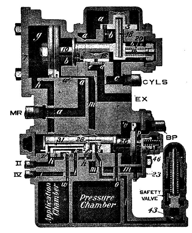
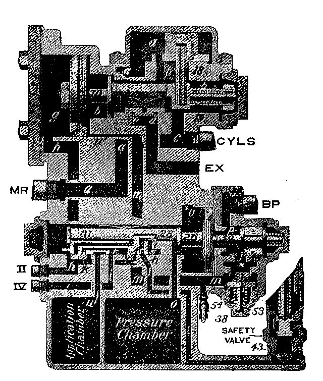
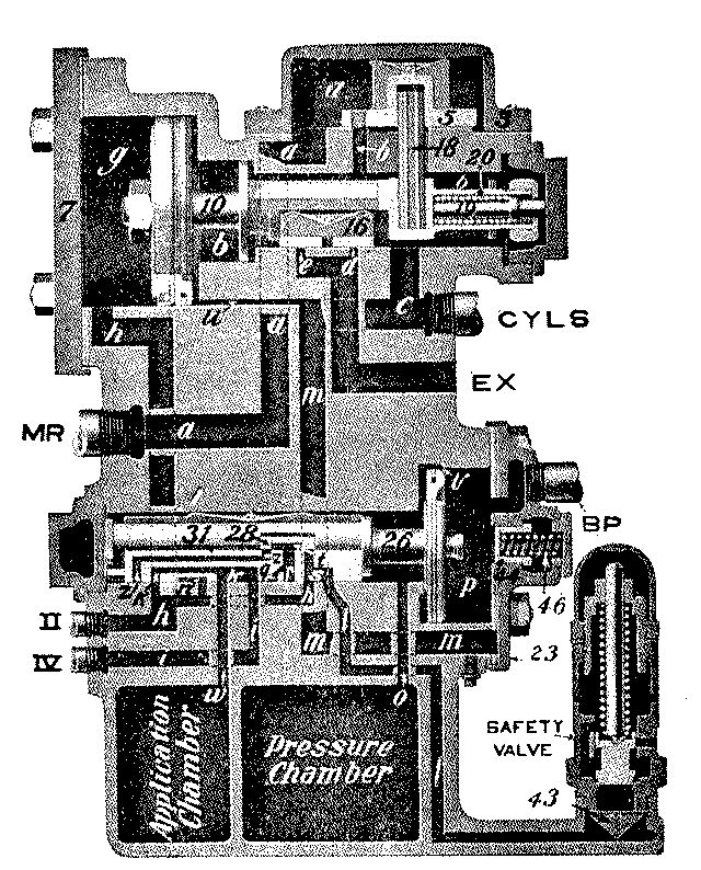
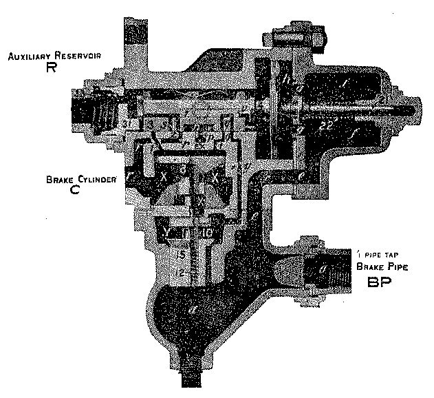
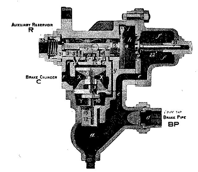
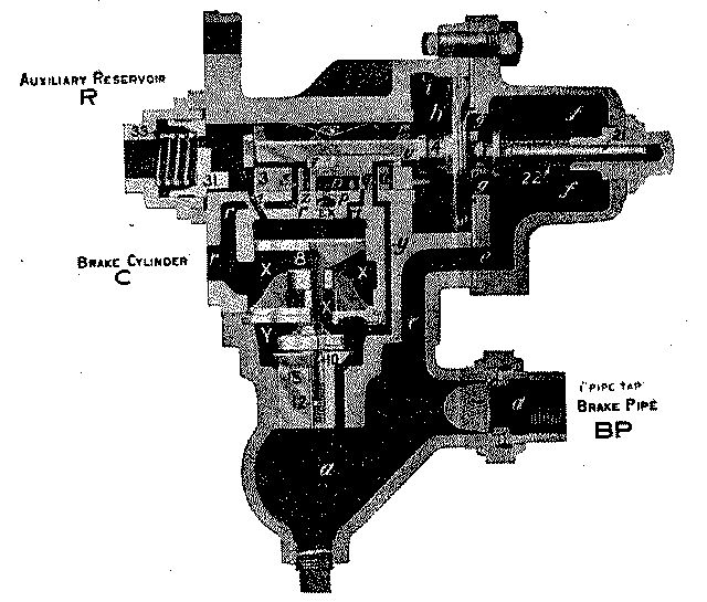
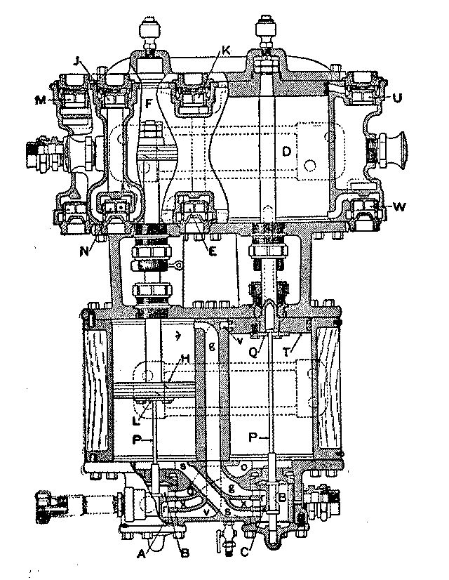
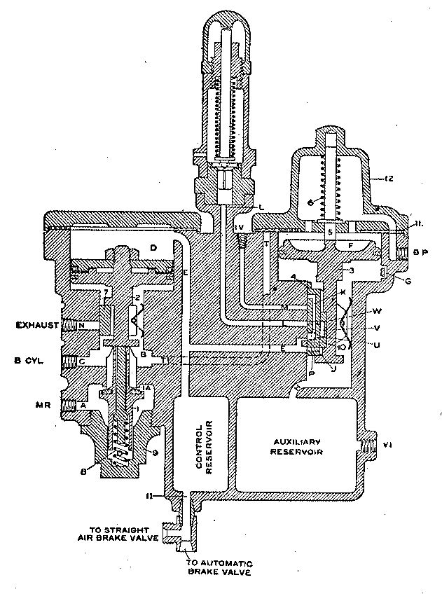
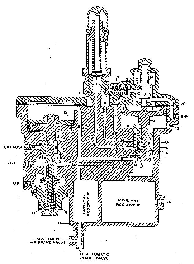
A. The air compressor, compressor governor, automatic and independent brake valves, distributing valve, triple valve, auxiliary reservoir, brake cylinders, main reservoir, air gauges, angle cocks, cut-out cocks and the necessary piping.
4. Q. What is the purpose of the main reservoir?
A. It is used for storing a large volume of air for the purpose of promptly charging and recharging the brakes. Where the engine is equipped with either the[Pg 23] E. T. or L. T. type of brakes, main reservoir air is used to supply the air to the brake cylinders on the locomotive.
5. Q. What other appliances use main reservoir air?
A. It is used in the operation of the power reverse gear, sand blower, bell ringer, water scoop, air signal, fire door, water sprinkler and other devices.
6. Q. What does the red hand on each of the air gauges indicate?
A. The red hand on the large gauge indicates main reservoir pressure; on the small gauge, brake cylinder pressure.
7. Q. What does the black hand on each of the air gauges indicate?
A. The black hand on the large gauge indicates the equalizing reservoir pressure; on the small gauge, brake pipe pressure.
8. Q. What pressure is usually carried in the main reservoir?
A. Ninety pounds in freight and 130 pounds in passenger service. But where freight engines are equipped with duplex compressor governor, the low pressure top is adjusted to ninety pounds and the high pressure top to 130 pounds.
9. Q. What pressure is usually carried in the brake pipe?
A. Seventy pounds in freight and 110 pounds in passenger service.
10. Q. What must the air pass through in flowing from the main reservoir to the brake pipe?
A. Through the automatic brake valve.[Pg 24]
11. Q. Name the different positions of the automatic brake valve.
A. Release, running, lap, service and emergency positions. The brake valve used with the E. T. and L. T. equipment has still another position known as holding position, which is located between running and lap positions.
12. Q. Name the different positions of the independent brake valve.
A. Release, running, lap, slow application and quick application positions.
13. Q. How many kinds of triple valves are there in use?
A. Two; plain and quick action.
14. Q. How is the automatic brake applied? How released?
A. The automatic brake is applied by a reduction of brake pipe pressure, and is released by restoring the brake pipe pressure.
15. Q. When the independent brake valve handle is placed in application position, are the train brakes affected?
A. No; only the brakes on the locomotive are applied.
16. Q. What controls the pressure in the main reservoir?
A. The compressor governor.
1. Q. What, in your opinion, is the best way to fire a locomotive?
A. To carry a nice, level fire on the grate, or it may be just a little heavier at the sides and front, so the air cannot come through it near the sheets as rapidly as in the center of the fire-box; always fire as light as consistent with the work required, endeavor to maintain a uniform steam pressure at all times, and avoid unnecessary black smoke and a waste of steam through the safety valves by the engine popping.
2. Q. What are the advantages of superheated steam over saturated steam in locomotive service?
A. Saving in water; saving in fuel; increased boiler capacity and a more powerful locomotive. Superheated steam does away entirely with all condensation in the cylinders, while saturated steam coming in contact with passages in cylinder saddle and walls of cylinders, is immediately cooled and in cooling, a part of it is changed back into water which affects the pressure and therefore its capacity to do work.
3. Q. How is the saving in water produced?
A. By the elimination of all cylinder condensation present in saturated steam locomotives and the increase in volume of a given weight of steam.
4. Q. How is the saving in coal accomplished?
A. Because there is less steam used to do the same amount of work, there is less water evaporated[Pg 26] and consequently less coal required to evaporate the water.
5. Q. How is the increased boiler capacity obtained?
A. A boiler will evaporate a certain amount of water into steam and if part of the steam is lost by condensation, only that remaining is available for running the engine. Superheating eliminates the losses, thereby increasing the available useful steam. Further, superheating increases the volume of a given weight of steam, thereby reducing the consumption of steam required to develop a certain power and consequently increases the capacity.
6. Q. How is a more powerful engine obtained?
A. By reason of the increased boiler capacity an engine may be worked farther down before a steam failure occurs.
7. Q. What type of fire tube superheater is in most general use in locomotive service?
A. The top header fire tube type, known as the "Schmidt Superheater." A system of units located in large flues through which the steam passes on its way from the dry pipe to the steam pipes, and a damper mechanism which controls the flow of gases through the large flues.
8. Q. Describe the construction and location of the header.
A. The header is a simple casting, divided by partition walls into saturated and superheated steam passages. It is located between the dry pipe and the steam pipes, the same as the nigger head in a saturated locomotive. The dry pipe is in communication with the saturated steam passages and the[Pg 27] steam pipes with the superheated steam passages and these are in communication with each other through the superheated units.
9. Q. Describe the construction of superheater units and their connection to the header.
A. The units are composed of four seamless steel pipes, connected by three return bends. Of the four pipes, two are straight and two are bent upward and connected to the header by means of a clamp and bolt; one end of the unit is in communication with the saturated steam passage and the other with the superheated steam passage in the header casting.
10. Q. Trace the flow of steam through the top header fire tube superheater.
A. When the engine throttle is open, saturated steam passes through the dry pipe into the saturated steam passage of the header casting. From this passage it enters one end of the unit, passing backward toward the fire-box, forward through one of the straight pipes and the front return bend, backward through the other straight pipe to the back return bend, and forward through the bent pipe and upward into the superheater steam passage of the header, from which it enters the steam pipes and is carried to the steam chest.
11. Q. What should be the position of throttle valve when running a superheater locomotive?
A. The engine should always be run with as wide open throttle as the conditions will permit, regulating the steam admission to the cylinders according to work to be performed.
12. Q. What should be the position of throttle while drifting?[Pg 28]
A. The throttle valve should be kept slightly open while drifting, so as to admit a small quantity of steam in valve chamber and cylinder above atmospheric pressure, to prevent the inrush of hot air and gases which destroy lubrication, also to prevent excessive wear to valve, cylinder and piston rod packing.
13. Q. How should the water be carried in boiler of superheater locomotives?
A. As low as the conditions will permit, because this practice reduces the tendency to work water over into the dry pipe and units, as the superheater locomotive will use one-third less water than the saturated locomotive.
14. Q. What care should be exercised in lubricating a superheater locomotive?
A. The supply of oil to steam chest should be watched very closely by the engineer, he to know that lubricator is feeding constantly and evenly over entire division, and according to work performed.
15. Q. Describe the general form of a locomotive boiler.
A. A locomotive boiler is cylindrical in form, it usually has a rectangular shaped fire-box at one end and a smoke-box at the other, and flues extend through the cylindrical part, and, like the fire-box, are surrounded by water.
16. Q. How does the wide fire-box type of boiler differ from the ordinary boiler, and what are its advantages?
A. The wide fire-box type of boiler is built so the fire-box is above the frame and extends out over the driving wheels. The advantages of this are to obtain[Pg 29] a larger grate area in the same length of fire-box and to give a slower rate of combustion per square foot of grate surface. The deep fire-box is limited in width to the distance between the frames, while the shallow fire-box sets on top of the frames and between the driving wheels.
17. Q. Why have two fire-box doors been placed in the large type of locomotive boilers?
A. For convenience of the fireman on account of the greater width of the fire-box, so that coal can easily be distributed to all parts of the fire-box.
18. Q. Describe a locomotive fire-box.
A. The modern form is a rectangular shaped structure located at the back end of the boiler. It has a door and is composed of two side sheets, a crown sheet, a back sheet and a flue sheet from which the flues extend to the smoke-box at the other end of the boiler.
19. Q. To what strains is a fire-box subjected?
A. To crushing strains and to those of unequal contraction and expansion.
20. Q. How are the sheets of a fire-box supported?
A. They are supported by staybolts screwed through the inside and outside sheets with their ends riveted over.
21. Q. In what manner is a crown sheet supported?
A. By crown bars or radial staybolts.
22. Q. What are the bad features about crown bars?[Pg 30]
A. They are hard to keep clean and frequently cause crown sheets to become mud burned.
23. Q. What are the advantages of radial stayed crown sheets?
A. They are easier to keep clean and cheaper to repair.
24. Q. How are the inside and outside sheets of a fire-box secured at the bottom?
A. They are riveted to a wrought iron ring called a mud-ring.
25. Q. Describe the ash-pan and its use.
A. It is a receptacle secured to the fire-box and usually provided with dampers to regulate the flow of air to the fire. It collects the ashes that drop from the fire-box and prevents them from setting fire to bridges or other property along the track. Engine-men must know that ash-pan slide and hopper bottoms are closed before leaving enginehouse.
26. Q. What is a "wagon-top" boiler?
A. It is a boiler that has the fire-box end made larger than the cylindrical part to provide more steam space.
27. Q. Why are boilers provided with steam domes?
A. To furnish more steam space and to obtain dryer steam and to provide a place for the safety valves, steam pipes, throttle valve and whistle.
28. Q. What must be the condition of a boiler to give the best results?[Pg 31]
A. It must have good circulation and be clean and free from mud or scale.
29. Q. What is meant by "circulation" in a boiler?
A. Free movement of the water, so that it may come in contact with the heating surface and after being converted into steam be immediately replaced by a fresh supply of water.
30. Q. What would be the effect if a "leg" of the fire-box became filled with mud?
A. There would be no water in contact with the fire-box sheets and they would quickly become overheated and mud-burned.
31. Q. What would be the result if the fire-box sheets became overheated?
A. They would be weakened and forced off the staybolts and an explosion would occur.
32. Q. Would it be advisable to put water into a boiler after the sheets had become bare and red hot?
A. No. The fire should be killed at once.
33. Q. What effect has the stoppage of a large number of flues?
A. The heating surface and draft are decreased by just that much area.
34. Q. Why are boiler checks placed so far away from the fire-box?
A. To introduce the water into the boiler at as great a distance from the fire-box as possible. This permits the water to become heated to a high tem[Pg 32]perature before it comes in contact with the fire-box and also improves circulation.
35. Q. What part of the boiler has the greatest pressure? Why?
A. The bottom, because it is subject to the weight of the water in addition to the steam pressure in the boiler.
36. Q. What are the advantages of the extension front end?
A. To provide room for suitable draft and spark appliances.
37. Q. What is the purpose of a netting in a smoke-box or front end?
A. To act as a crusher of all cinders and prevent large cinders from passing out of the front end to the atmosphere.
38. Q. What is the object of hollow staybolts?
A. To indicate when the staybolt is broken by the escape of steam through the small hole in the bolt.
39. Q. What will cause the engine to tear holes in the fire?
A. Working hard or slipping when the dampers are open and the door closed, or too thin a fire.
40. Q. Name the various adjustable appliances in the front end by which the draft may be regulated.
A. The exhaust nozzle, the diaphragm and the draft pipes or petticoat pipe.
41. Q. What object is there in having the exhaust steam go through the stack?[Pg 33]
A. To create a draft through the tubes and fire-box.
42. Q. How does this affect the fire?
A. The exhaust steam escaping through the stack tends to empty the smoke-box of gases and produces a partial vacuum there, atmospheric pressure then forces air through the grates and tubes to refill the smoke-box, and in this way the draft through the fire is established and maintained.
43. Q. Explain what adjustments can be made and the effect of each adjustment on the fire.
A. Larger or smaller nozzle tips cause less or greater draft on the fire; raising or lowering the draft pipes and diaphragm causes the engine to burn the fire more at the rear or front end of the fire-box; the size and position of the draft pipes increase the draft through the top or bottom flues; the latter adjustments should always be attempted before reducing the nozzle.
44. Q. What does it indicate when the exhaust issues strongest from one side of the stack?
A. The stack, exhaust pipe or petticoat pipe are out of plumb.
45. Q. What is the effect of leaky steam pipe joints inside the smoke-box?
A. The engine will not steam freely.
46. Q. What causes "pull" on the fire-box door?
A. The partial vacuum in the front end; when excessive it indicates dampers closed, fire clinkered or insufficient opening for the admission of air under the fire.[Pg 34]
47. Q. If upon opening the fire-box door you discover there what is commonly called a red fire, what might be the cause?
A. The grates may have become clogged with ashes or clinkers so that sufficient air could not pass through them to the fire.
48. Q. Is it not a waste of fuel to open the fire-box door to prevent pops from opening? How can this be prevented more economically?
A. Yes. This can usually be prevented by putting the heater into the tank, or putting on the injector, or by more careful firing.
49. Q. Describe the principle upon which the injector works.
A. The action of the injector is due first to the difference between "kinetic" or moving energy and "static" or standing energy; second, to the fact that steam at a pressure travels at a very high velocity and when placed in contact with a stream of water it is condensed into water, and at the same time it imparts enough velocity to the water to give it sufficient momentum to overcome a pressure even greater than the original pressure of the steam. By imparting this velocity to the water it gives it sufficient energy to throw open the check valves and enter the boiler against high pressure.
50. Q. What is the difference between a lifting and a non-lifting injector?
A. A lifting injector will create sufficient vacuum to raise the water from the level of the tank. The steam tubes in a non-lifting injector are different and it will not raise the water, but merely force it into[Pg 35] the boiler. A non-lifting injector must be placed below the level of the water in the tank so the water will flow to it by gravity.
51. Q. Will an injector work with a leak between the injector and tank? Why? Will it prime?
A. A lifting injector will not work if the leak is bad. It will not prime because the air admitted through the leak destroys the vacuum necessary to raise the water to the injector level. A non-lifting injector will work, as the water will escape from the pipe instead of air being drawn into it as with the lifting injector.
52. Q. If it primes well, but breaks when the steam is turned on wide, where would you look for the trouble?
A. Insufficient water supply due to tank valve partly closed, strainer stopped up or tank hose kinked, injector tubes out of line, limed up, or delivery tube cut, or wet steam from the throttle.
53. Q. If it would not prime, where would you expect to find the trouble?
A. Insufficient water supply, priming valve out of order, or with the lifting injector the trouble might be caused by a leak between the injector and tank.
54. Q. Will an injector prime if the boiler check leaks badly or if it is stuck up? If the injector throttle leaks badly?
A. No.
55. Q. If steam or water shows at the overflow pipe when the injector is not working, how can you[Pg 36] tell whether it comes from the boiler check or the injector throttle?
A. Close the main steam valve at the boiler, that will stop the leak if it comes from the injector throttle.
56. Q. Will an injector prime if primer valve leaks? Will that prevent its working?
A. It will prime, but not as readily as with priming valve in good condition. This will not prevent its working, but it may waste some water from the overflow.
57. Q. Will an injector work if air cannot get into the tank as fast as the water is taken out?
A. No.
58. Q. If you had to take down a tank hose, how would you stop the water from flowing out of the tank that has the syphon connections instead of the old-style tank valves?
A. Open the pet cock at the top of the syphon before taking the hose down.
59. Q. Is any more water used when the engine foams than when the water is solid?
A. Yes, very much more.
60. Q. How would you prevent injector feed pipes or tank hose from freezing in winter when not in use?
A. The steam valve should be slightly open to permit a slight circulation of steam through the feed and branch pipes. The heater cock should be closed[Pg 37] and the drip cock under the boiler check or on the branch pipe should be opened to insure a circulation of steam through the branch pipe.
61. Q. How would you prevent the overflow pipe from freezing with a lifting injector?
A. The overflow valve should be opened just enough to permit a little steam to escape through the overflow pipe to prevent it from freezing.
62. Q. Name the various parts of the injector.
A. The injector consists of a body supplied with a steam valve, a steam nozzle, a primer, a combining tube, a delivery tube, a line check valve, an overflow valve, a water valve, and a lifting injector has a lifting tube.
63. Q. What may be done if a combining tube is obstructed?
A. The steam valve bonnet may be removed and the obstruction forced out with a piece of stiff wire, or uncouple the delivery pipe from the injector and unscrew and remove the tubes; the obstruction can then be removed and the tubes replaced.
64. Q. How is the greatest injury done to a boiler when cleaning or knocking the fire?
A. By excessive use of the blower drawing cold air through the fire-box and flues.
65. Q. Why does putting a large quantity of cold water into a boiler when the throttle is closed cause the flues to leak? When is this most serious?
A. When steam is not being used there is not much circulation of water in the boiler, and the water[Pg 38] entering the boiler at about 150 degrees temperature is heavier than the water in the boiler. The cooler water will go to the bottom and reduce the temperature in that part of the boiler and causing the flues to contract in length as well as in diameter and this has a tendency to pull them out of the sheet. This will loosen them and cause them to leak. After the fire has been knocked this tendency is much greater, and for that reason cold water should not be put into a boiler after the fire has been knocked out. Always fill the boiler before the fire is knocked out.
66. Q. Is warm water in the tank of any advantage in making steam rapidly?
A. Yes; careful experiments have shown that a locomotive will generate one per cent. more steam for every eleven degrees that the tank water is heated; thus by heating the feed water in the tank from 39 degrees to 94 would effect a saving of five per cent.
67. Q. Then why not heat the feed water to the boiling point (212 degrees)?
A. If the feed water is heated much above 100 degrees it will not condense enough steam in the injector to cause it to work properly. Some injectors will work hotter water than others. It would also spoil the paint on the tank if heated to a much higher temperature.
68. Q. At 200 pounds pressure per square inch, what is the pressure per square foot on the sheets of a boiler?
A. About fifteen tons.
69. Q. What is the total pressure on the fire-box of a large locomotive?[Pg 39]
A. Over 3,000 tons.
70. Q. Give a practical definition of heating surface.
A. The heating surface of a boiler includes all parts of the boiler and tubes that are directly exposed to fire or heat from the fire and are surrounded by water.
71. Q. Should an engine be slipped to get water out of the cylinders or steam passages?
A. No; the water should be worked out by opening the cylinder cocks and starting the engine slowly.
72. Q. What does it indicate when the smoke trails back over the train and into the coaches after shutting off?
A. It indicates poor firing or a lack of understanding between the engineer and fireman in regard to where the engine was to be shut off.
73. Q. Before shaking grates or dumping the ash-pan, what should be observed?
A. That the engine is not passing over bridges or cattle guards, crossings, switches, interlocking fixtures, or in yards. Fire on the track should be extinguished promptly at places where ash-pans are cleaned.
74. Q. Which is easier and more satisfactory on a long run, to stop and clean the fire if necessary or to continue to the end of a long, hard trip with a dirty fire?
A. Stop and clean the fire if necessary. It will save fuel and labor during the remainder of the trip and may also save an engine failure.[Pg 40]
75. Q. Should you examine the flues to see if they are stopped up and leaking, and inspect the grate and grate rigging carefully before leaving the engine at a terminal?
A. Yes, so they can be reported if necessary. Clean flues and grates working well make a vast difference in the success of a fireman, and a great many engine failures could be avoided by keeping the flues and grates in proper condition.
76. Q. How should cab lamps, signal lamps, oil cans and lanterns be cared for?
A. They should be kept clean, free from leaks and always filled and ready for service before leaving terminals.
77. Q. About how many drops in a pint of valve oil when fed through a lubricator?
A. About 4,500 drops.
78. Q. Assuming that five drops per minute are fed to each of two valves and one drop per minute to the air pump, how many hours would be required to feed one pint of valve oil?
A. About eight hours.
79. Q. Assuming that the engine is running twenty-miles per hour, how many miles per pint would be run?
A. About 160 miles per pint.
80. Q. How many drops per minute should ordinarily be fed?
A. This will vary with the size of the locomotive and the work to be performed. On small yard engines[Pg 41] one drop per minute for each cylinder is usually sufficient and one drop for the air pump every two or three minutes. This depends on the condition of the pump and the service being performed. For large engines in slow freight service four to five drops per minute, and for large engines in heavy fast passenger service from five to seven drops per minute should be fed. Air pumps in freight service where the brake pipe is in moderately good condition can usually be run with one or two drops per minute when handling long trains of cars equipped with air brakes.
81. Q. Will any bad results ensue from filling the lubricator full of cold oil?
A. Yes; when the oil gets hot it will expand and may break the glass or bulge or burst the lubricator.
82. Q. If a sight feed gets stopped up, how could you clean it out?
A. Close the water valve and the regulating valves to the other feeds. Open drain cock and draw out a small quantity of water so as to bring the oil in top part of lubricator below the top end of oil pipe leading to feed arm, then open wide the regulating valve to feed that is stopped up and the pressure from the equalizing tube will force the obstruction out of the feed nozzle and up into the body of the lubricator. Next, close this regulating valve until the feed glass fills with water, then open water valve and start feeds.
83. Q. How would you clean out chokes?
A. First, shut off boiler pressure and condenser valve; next, remove feed valve bonnet, then open main throttle valve, when the steam from steam chest will blow back through the choke plug, clearing it of any obstruction.[Pg 42]
84. Q. What is superheated steam?
A. It is the saturated steam separated from the water from which it is generated with more heat added, increasing its temperature from 100 degrees to 250 degrees Fahrenheit above the saturated steam temperature.
85. Q. What is the advantage of superheating or increasing the temperature of the steam?
A. By increasing the temperature of the steam the volume of a given weight of steam is increased and all losses due to cylinder condensation are eliminated, which result in a reduced steam consumption, a saving in coal and water and increased boiler capacity.
86. Q. How is the increased temperature obtained by the use of the superheater?
A. By admitting the saturated steam into a partitioned receiver which has a number of 1½-inch pipes attached to it. These are located in and extend nearly the full length of the large flues, the steam having to pass through these 1½-inch pipes on its way back to the receiver, absorbs the heat from the gases passing through the large tubes, causing its temperature to rise, or in other words, become superheated.
87. Q. How much is the volume of steam increased by superheating?
A. For each 100 degrees of superheat added to saturated steam, at temperatures ordinarily used in locomotive practice, the volume of a given weight is increased roughly from sixteen to seventeen per cent.
88. Q. Why is the superheated steam so much[Pg 43] more economical on coal and water than the saturated steam?
A. Because for a given amount of water evaporated you can increase the volume of steam 33 per cent. by superheating. It is readily seen that the coal does not have to be burned if the steam used has 33 per cent. more volume for filling space, or in other words, only so much steam can be admitted to the cylinders for every movement of the valve, and what can not be used must remain in the boiler, so if the engine can not use all of the steam that the boiler is capable of generating, the saving must show in coal and water. If you can not use all of the steam you do not have to burn coal to make it.
89. Q. Which is the better practice, to close the feed valves or water valve while waiting on sidings, etc.?
A. Close the feed valves; the water valve may leak.
90. Q. How can you tell if equalizer tubes become stopped up or broken?
A. If they were stopped up the equalization would be destroyed, and when the steam-chest pressure was less than the boiler pressure the feed would work too fast, the oil would enter the feed glass in a stream instead of forming into drops. If they were broken, the lubricator could not be used. The auxiliary oilers would have to be used to lubricate the cylinders.
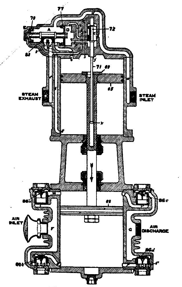
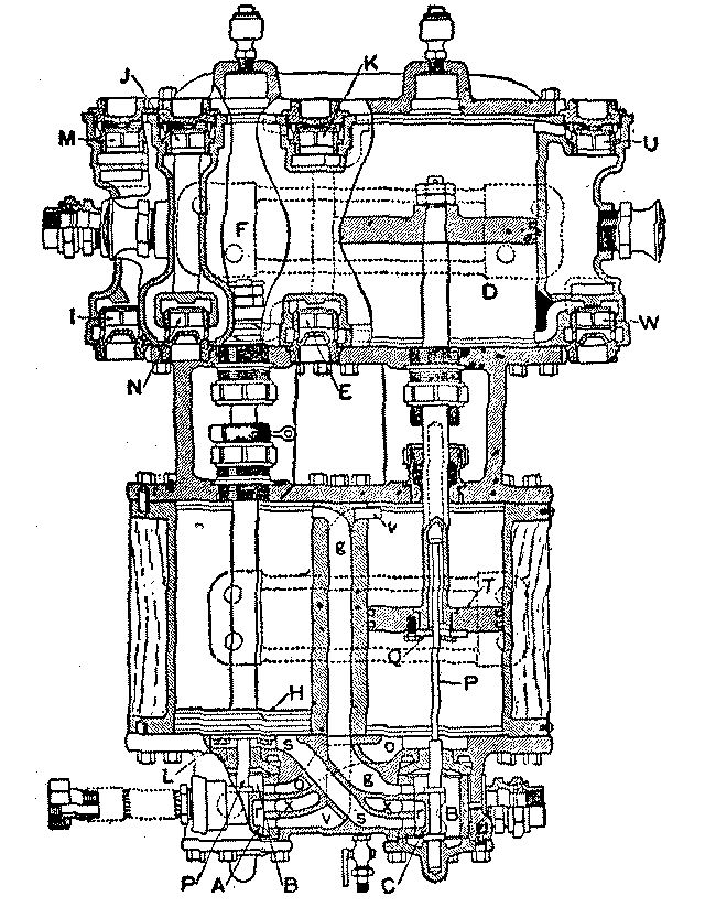
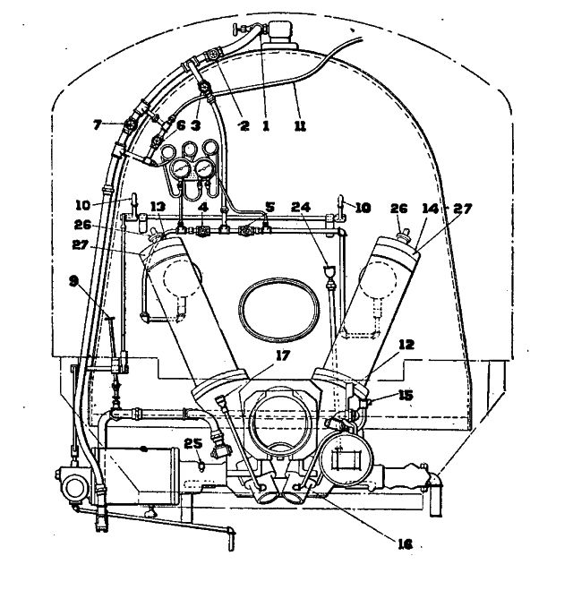
1. Q. Explain how an air compressor should be started.
A. A compressor should be started slowly, with the drain cocks open to allow the water of condensation to escape; and as no provision is made in the steam end to cushion the pistons at the end of their stroke, it should be allowed to work slowly until a pressure of thirty or forty pounds has accumulated in the main reservoir; the piston, having to work against this pressure, will be cushioned at the end of each stroke. After the compressor is warm, the drain cocks should be closed and the throttle opened sufficiently to run the compressor at the proper speed. The lubricator should then be started and allowed to feed freely until eight or ten drops have passed, when the feed should be reduced to an amount sufficient for proper lubrication.
2. Q. What kind of oil should be used to lubricate both the steam and air cylinders of the compressor?
A. Valve oil.
3. Q. Where does the main reservoir pressure begin and end?
A. Begins at the discharge valves in the compressor and ends at the engineer's brake valve.
4. Q. Where does the brake pipe pressure begin and end?
A. The brake pipe pressure begins at the feed valve and ends at the brake pipe side of the triple piston, conductor's valve and at the rear angle cock.[Pg 45]
5. Q. What is meant by excess pressure, and where is this pressure carried?
A. Excess pressure is carried in the main reservoir and is the pressure above that in the brake pipe.
6. Q. Why is excess pressure necessary?
A. To insure the prompt release of all brakes and quick recharge of the brake pipe and auxiliary reservoirs.
7. Q. How is the amount of excess pressure regulated?
A. By the compressor governor.
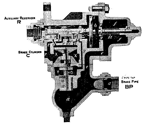
8. Q. Name the different parts of the air brake as applied to a car.
A. The triple valve, auxiliary reservoir, brake cylinder, brake pipe, angle cocks, cut-out cock, retaining valve, centrifugal dirt collector and strainer tee.
9. Q. What is the duty of the triple valve?
A. The triple valve has three duties to perform: Charge the auxiliary reservoir; apply the brake; and release the brake.
10. Q. What is the purpose of the auxiliary reservoir?
A. It is here that the air is stored that is admitted to the brake cylinder when the brake is applied; thus, each car carries its own brake power.
11. Q. What is the purpose of the brake cylinder?[Pg 46]
A. It is here where the power of the compressed air is converted into work by forcing the brake piston out, moving the brake levers, rods and brake beams, forcing the brake shoes against the wheels, applying the brake.
12. Q. What is the purpose of the brake pipe and angle cocks?
A. It is through the brake pipe that all brakes in the train are placed into communication with the brake valve on the locomotive; and through the brake pipe, air from the main reservoir flows to the triple valves and auxiliary reservoirs on the different cars. The angle cocks are for the purpose of opening and closing the ends of the brake pipe.
13. Q. What is the purpose of the cut-out cock?
A. To cut out any brake that is not in operating condition.
14. Q. How is a brake cut out?
A. By closing the cut-out cock in the cross-over pipe and bleeding the auxiliary reservoir.
15. Q. How would you bleed an auxiliary reservoir?
A. By holding open the release valve on the reservoir until all air has escaped.
16. Q. How would you bleed off a stuck brake?
A. By holding open the auxiliary release valve until the brake piston starts to move toward release position.
1. Q. What are the fireman's duties on arrival at the enginehouse previous to going out on an oil burning locomotive?
A. In addition to the duties usually performed on any engine, the fireman should observe the condition of draft pans and arch, observe the condition of burner and dampers; try the oil regulating valve; see that the burner is properly delivering fuel oil to the fire; see that the oil heaters are in working order; that the fuel oil is heated to proper temperature; and see that proper supplies of fuel oil, sand and water have been provided as well as the necessary tools for handling an oil fire.
2. Q. How warm should the oil be at all times in the tank.
A. Warm enough to flow freely at all times, usually about 112 degrees. This temperature is about that which the hand can bear on the outside of the tank.
3. Q. If the oil is too warm, what happens?
A. Many of the good qualities of the oil may be lost by keeping it too warm, and the burner is more difficult to operate and does not work as well when the oil is kept at too high a temperature. Should the oil be too warm, it will give off too much gas which would be liable to cause an explosion in the oil tank.
4. Q. What tools are necessary for firing purposes on an oil burning locomotive?
A. The tools necessary for firing an oil burning engine include sand horn, brick hook, and a small iron bar to be used in cleaning carbon from the mouth of the burner.[Pg 48]
5. Q. What is liable to happen if the heater valve is open too much?
A. If the heater valve is opened too much it would be liable to burst the heater hose as well as to heat the oil to a too high temperature and place an unnecessary strain on all the heater connections, causing them to leak.
6. Q. What should be done on approaching stations where additional supply of fuel oil is to be taken?
A. Shut off the fire, close safety and main oil valves, remove any lamps that are so close as to be unsafe when manhole cover is open.
7. Q. What care must be exercised in the use of lamps, torches or lanterns about oil tanks whether hot or cold?
A. Never permit oil lamps or oil torches to be carried within ten feet of the tank opening. Only incandescent lamps or pocket flash lights should be used around oil tank manhole when taking oil.
8. Q. How can oil in the tank be measured without taking a light to the manhole?
A. By inserting a measuring stick into oil in tank and taking stick to the light for reading.
9. Q. What precautions must be taken before entering tanks that have been used for oil to clean or make repairs?
A. Oil tanks, before being entered by workmen, should be thoroughly steamed and cooled before being entered. For safety they should be steamed from six to eight hours.
10. Q. How should the fire be lighted in an oil burning locomotive?[Pg 49]
A. First see that no one is working under the engine, that there is the proper amount of water in the boiler and that it will flow through the gauge cocks, that there is no accumulation of oil in the ash-pan or fire-box or existing leaks throughout. If there is no steam in the boiler, the steam connections can be made to the three-way cock at the smoke-arch that will answer for blower and atomizer. If there are twenty pounds of steam in the boiler, it can be operated with its own blower. If oil in the tank is too cold to flow into the burner readily, it must be heated. Open the front damper and put on the blower strong enough to create the necessary draft, open the atomizer valve long enough to blow out any water that might be in the steam pipe to the burner, then close the valve and throw a piece of burning waste in front of the burner and open the atomizer valve enough to carry oil to the burning waste and open the regulating valve slowly until the oil is known to be ignited. Watch the ignition through the hole in the fire-box door, then regulate the steam and oil supply to suit. Be sure that no oil is wasting below the burner or an explosion may result that will prove disastrous.
11. Q. Should the fire go out and it is desired to rekindle it while bricks are hot, is it safe to depend on the hot bricks to ignite the oil without the use of lighted waste?
A. No; depending upon the heat from the firebricks to re-light the fire is dangerous and forbidden.
12. Q. What is termed an atomizer, and what does it perform?
A. The atomizer is a casting containing two long ports with an extension lip; the upper port is for oil and the lower one for steam. The lip aids the steam in atomizing and spreading the oil, which, when prop[Pg 50]erly mingled with the air and ignited, will produce combustion. The atomizer is located just under the mud-ring and pointed a little upward, so the stream of oil and spray of steam would strike the opposite wall a few inches above the bottom if it would pass clear across the fire-box.
13. Q. In starting or closing the throttle of the locomotive, how should the fireman regulate the fire, in advance or after the action of the engineer?
A. In starting an oil burning engine the oil should gradually be brought up as the throttle is opened and the movement and amount of oil should be kept slightly in advance of the action of the engineer in order to prevent an inrush of cold air as the engine is working, which would result in injury to the fire-box and flues. When the throttle is to be closed, the fire should be reduced very slightly in advance of the closing of the throttle. This is to prevent the engine from popping off and black smoke drifting back over the train.
14. Q. Is it necessary that the engineer and fireman on an oil burning locomotive work in perfect harmony and advise each other of intended action at every change of conditions?
A. Yes; they should work in harmony with each other on any locomotive. The fireman should watch every move the engineer makes, and the engineer should advise the fireman of every intended change of the throttle, so he can operate his valves accordingly and save fuel and avoid black smoke.
15. Q. What is the effect of forcing the fire on an oil burning locomotive?
A. Forcing the fire is very hard on fire-box sheets and flues, and will cause them to leak. An even[Pg 51] temperature should be maintained in the fire-box of any locomotive.
16. Q. Is a careful regulation of steam and oil valves and dampers necessary to obtain the most economical results?
A. Yes; the fireman's oil valve should be opened just wide enough to permit a sufficient amount of oil to be fed to produce a good fire, but not wide enough to waste oil or produce a volume of black smoke.
17. Q. How can you judge whether the combustion is good or bad, so the valve may be regulated accordingly?
A. By the color of the fire in the fire-box. When it is a dull red color, the temperature is below 1,000 degrees and combustion is incomplete, dense black smoke will issue from the stack. If it is a bright red, the temperature will be about 1,800 degrees and combustion very good, and no black smoke will appear from the stack.
18. Q. How should the flues be cleaned from soot when running, and about how often is this necessary?
A. By placing a small quantity of sand in an elbow shaped funnel or horn, and by inserting same in an opening provided in fire door while engine is working hard, allowing the exhaust to draw the sand through the flues, thus cutting soot and gum from them in its passage and discharging it from the stack. It is necessary that the flues be cleaned of soot on leaving terminals or sidings where the engine has been at rest for any length of time, and also as often as found necessary to aid the engine in steaming. This depends to a great extent upon the degree of perfection with[Pg 52] which combustion is obtained. Attention should also be given flues just prior to entering points where engine is to be put in roundhouse or otherwise detained in order to leave the flues clean, as this will aid in putting engine under steam with little delay where the blower alone is to be relied on for draft.
19. Q. Is the injudicious use of the blower particularly injurious on an oil burning locomotive?
A. Yes; the injudicious use of a blower is injurious to any boiler. The cold air drawn through the fire-box is hard on the sheets and flues and will cause them to leak.
20. Q. Is the blower more injurious when a light smoke is emitting from the stack or when a dense black smoke is emitting?
A. It is most injurious when a light smoke is emitting.
21. Q. In drifting down long grades should the fire be shut off or burned lightly? Why?
A. The fire should be burned lightly and not permitted to get low enough to allow the fire-box to lose its temperature, as this will contract the flues and cause them to leak.
22. Q. How should the fire be handled when switching?
A. The fire must be regulated to meet the requirements of the work the engine is performing on each move and to protect against any possibility of the fire being drawn out by the exhaust.
23. Q. Would not some fuel be wasted in this way?[Pg 53]
A. Not necessarily. A waste of fuel can be avoided by close attention on the part of the fireman when switching as well as when running.
24. Q. How should the fire be handled when leaving stations?
A. It should be burning brightly and strong enough to prevent the draft from putting it out when the throttle is opened. And a little smoke should show up at the stack, which would indicate that the fire was being forced just a little ahead of the working of the engine.
25. Q. Which is desirable, to use as much or as little steam jet atomizer as possible?
A. It is desirable to use as little atomizer as will make engine show perfect combustion and economy.
26. Q. What is the result of too little steam jet atomizer when standing at stations or when the engine is working light?
A. The result of too little atomizer when standing at station or when engine is working lightly, will result in the oil not being carried far enough into the fire-box or arch and not properly atomized and the fire is liable to go out. The oil will drop from the mouth of the burner into the draft pan to the ground where it is very liable to start a fire under the engine.
27. Q. If too much steam jet atomizer is used with a light fire?
A. It will create a disagreeable gas, which will cause the fire to burn with a succession of light explosions and kicks, also a waste of steam, and which would reduce the fire-box temperature.
28. Q. When the fire kicks and smokes, what should be done?[Pg 54]
A. The atomizer should be adjusted. If this does not overcome the trouble, the heater should be put in service, for, possibly, the oil is too cold to flow freely. Another cause of the fire kicking and smoking results from water being mixed with the oil. If this is the case, it should be drained out of the oil tank immediately.
29. Q. How should the dampers be used on an oil burning locomotive?
A. They should be opened just enough to admit sufficient air to produce perfect combustion, but not enough to cool the fire-box. The dampers should be closed when the engine is drifting or when at rest and the fire is cut very low or is out entirely.
30. Q. About how much smoke do you consider an oil burning locomotive should make under adverse conditions, when the engine is steaming well, but is being crowded by the engineer?
A. Only a light smoke should show at the stack.
31. Q. What color is most desirable at peep holes in the fire-box?
A. A white color is most desirable.
32. Q. What will produce the bright red color?
A. Leaky steam pipes, side seams, flues and improper combustion will produce a ruddy color in the fire-box.
33. Q. How does water in the oil affect the fire?
A. Water in the oil will produce popping or kicking with the fire in the fire-box and at times the fire[Pg 55] will die down entirely and then flash up as the water disappears and the oil reaches the burner. The most noticeable result of water in the oil is the fact that the fire will get very low. It will almost go out entirely and then will suddenly flash up again as the oil appears. Water in the oil produces a very dangerous condition and should be prevented immediately by draining the water from the fuel oil tank.
34. Q. Do you consider it advisable to keep the burners clean, and how often?
A. When equipped with steam blow-out pipes, they should be blown out before commencing trip so that burners will distribute oil evenly to each side of fire-box.
35. Q. What position should burner be with reference to level and in line with center of fire-box?
A. It is very essential that burners be level and throw flames just to clear floor of arch in order to derive full benefit of heating surface, as the draft has a great tendency to elevate flames, at opposite end of the fire-box.
36. Q. Are you aware that in course of time the atomizer port will become worn too large and will discharge too large a volume of steam to properly atomize, and the remedy?
A. Yes; the lip or bushing should be closed to proper opening so that steam will be restricted at the nozzle and escape with a bursting effect to properly atomize the oil instead of flowing out in quantities against flash walls before it has time to ignite.
37. Q. What is the real object of having the fire-box lined with bricks, and will engine steam without them?[Pg 56]
A. Not so well as with the brick, the sheets being in contact with water are too cool to flash the oil readily and hence the use of what is called a "flash wall" built of fire brick and heated to a very high temperature aids combustion very materially.
38. Q. Do you consider it your duty to keep close inspection of brick work as to need of repairs, such as air entering between brick and side sheets?
A. Yes. To see that plaster is kept between the walls and sheets to keep cold air from being drawn in.
39. Q. Will engine steam if brick falls in front of burners or in path of flame and what may be done?
A. No. Remove them with the brick hook or rod by pulling them out through damper of draft pan.
40. Q. Where engine is equipped with an oil-reheater or oil line, do you consider it a help to engine's steaming qualities when used?
A. Yes; at all times this heater should be used.
41. Q. Why use second heater? Why not heat it to a high temperature in oil tank with oil heater?
A. Too much gas generating and boiling the oil continually destroys the higher qualities besides being hard to control the flow through regulation valve.
42. Q. Do you consider a vent hole in oil tank advisable, and why?
A. Yes; to allow any accumulation of gas to escape and to admit the air so that oil will flow freely.
43. Q. Do you inspect your oil pipes and report[Pg 57] all leaks? What other bad effect has a pipe leak aside from waste of oil?
A. Yes. It will cause oil to feed irregularly.
44. Q. Are you aware that keeping the flues clean is the greatest one thing that you can do in regard to fuel economy, and how often should they be cleaned?
A. Yes. At least every ten miles.
45. Q. Do you know that the engine should be working hard and at a speed not less than twenty miles per hour when sanding flues to avoid the sand falling to floor of the fire-box and accumulating in front of them?
A. Yes.
46. Q. Do you realize that on first closing throttle you should not adjust fire too low? Explain best method.
A. Yes. I would allow steam pressure to fall back some fifteen pounds before throttle is closed and on having closed same leave a good fire in box, allowing it to cool gradually to avoid leaky flues, broken staybolts, cracked sheets caused by sudden fall of temperature.
47. Q. How is the flow of oil controlled?
A. By the valves in tank and pipe connections.
48. Q. Name these valves, their location and purpose.
A. The safety valve controls the flow of oil from the fuel oil tank through an opening in bottom sheet of tank to the pipes leading to burner. This valve is[Pg 58] forced to its seat by a heavy spring and is held off its seat by a key in the upright rod extending above the top of tank. To this key a rope or chain is attached and also attached to the cab to cause the pin in rod to be pulled in case of a separation between engine and tank and allow the valve to be seated by its spring and avoid a waste of oil. The second or main oil valve is located in oil pipe under deck leading to burner. It is usually of the plug-cock pattern connected by bell crank and this connected to some part of the engine by chain, in which case it also acts as a safety valve in case of separation between engine and tender. In other cases it is connected by an operating rod extending above deck of tender where it can be operated by hand in case of safety valves failure to shut off the flow of oil. The third or firing valve is usually located between heater box and burner, and is provided with an upright rod extending into cab where it is provided with a handle or lever in position to be conveniently handled by fireman while seated in cab. This valve regulates the flow of oil desired to reach the fire.
49. Q. When shutting out fire which valve should be closed first? Why?
A. The safety valve. To allow the oil in pipes to be consumed and to see that this valve is in working order.
50. Q. Should safety valve fail to shut off the flow of oil in such cases would it be safe to rely on the firing valve to shut off the fire?
A. No. The main valve should then be closed.
51. Q. Should the firing valve be depended upon to shut off the fire at any time? Why?
A. No. From constant use they are frequently[Pg 59] leaking and the trouble is not detected while in use, and again there is always danger of the handle being moved by workmen or others about the cab.
52. Q. What is a heater box?
A. It is an apparatus having two passages, one for steam passing from boiler to heater pipes in tank and another passage for oil from tank before it is delivered to burner. In this manner the oil before reaching the burner is heated much higher than the temperature of that contained in tank.
53. Q. In the event of the heater pipes or connections becoming defective, how could the oil be heated in tank?
A. By closing the firing valve, closing the valve on heater pipe, and opening valve on heater box, the steam from heater throttle can be passed directly through the oil feed pipe to the fuel supply.
54. Q. In the event of an objectionable quantity of water in oil, how can it be removed?
A. In some instances the tanks are provided with drain pipes for this purpose, but in the absence of same, the feed hose or pipe between engine and tank can be disconnected and used as a drain to fuel oil tank.
55. Q. What effect has leaks between fuel tank and firing valve?
A. A waste of oil only.
56. Q. What effect has leaks between firing valve and burner?
A. In addition to a loss of oil while fire is burning low, and but little steam atomizer being used, it[Pg 60] interferes very materially with the engine's steaming by admitting air when using considerable steam atomizer. This causes a very irregular oil feed.
57. Q. What action of the fire would indicate leaks in pipes between firing valve and burner?
A. The fire-box will give off sounds similar to slight explosions, and the smoke at stack will indicate irregular fuel feeding.
58. Q. What would you consider the proper adjustment of burner?
A. That which will provide for the delivery of the oil from burner to flash wall without striking arch, side walls, or floor brick while doing so.
59. Q. In case it becomes necessary to fire up an oil burning engine with wood, what parts should be given particular attention?
A. The brick work. To see that same is not damaged or displaced while placing the wood in fire-box, also to protect by placing brick over that portion of burner extending into fire-box ahead of mud ring, or by so arranging the wood in fire-box as to prevent any great amount of heat from reaching the burner and melting nozzle of same.
60. Q. In case of sudden drop in steam pressure, what might be the cause?
A. Loose brick perhaps fallen in front of burner and obstructed the flow of oil. The petticoat pipe may be loose and out of line or the dampers may have fallen shut.
61. Q. In case brick have fallen in front of burner, how can they be removed?[Pg 61]
A. By a hook provided for that purpose. They can usually be forced out through the vent openings, but if this cannot be done, they should be thrown against the blast wall in order to get them as far as possible out of the course of the fuel feed.
62. Q. In case a petticoat pipe becomes deranged, what can be done?
A. In case it cannot be put back in proper position, it should be removed altogether. (Trips have been successfully completed in this manner.)
63. Q. Will a corroded burner mouth prevent the proper delivery of fuel to fire?
A. Yes.
64. Q. What causes the mouth of burner to corrode?
A. The asphaltum and sand contained in the oil.
65. Q. How can this be removed on the road?
A. By having a hook or rod provided with a point that can be inserted into mouth of burner.
66. Q. Why should a fuel oil tank not be filled to its holding capacity?
A. Because when heater is applied the oil would expand and overflow.
67. Q. In case of derailment or other accident that might cause the fireman to desert his position in cab, what should he do?
A. Pull key out of safety valve rod, thereby allowing oil feed from tank to be shut off.
1. Q. What are the duties of an engineman before attaching a locomotive to the train?
A. He should make a complete inspection of the locomotive, observing all important nuts and bolts, look for any signs of hot bearings on previous trip, see that the engine is equipped with necessary tools and supplies, test both of the injectors and the air brake equipment to be sure they are in good working order, see that headlight and signal lamps are in place and ready for service, observe water conditions in boiler, inspect the interior of the fire-box and see that the locomotive is properly lubricated.
2. Q. What tools should there be on the locomotive?
A. Such as are necessary to properly operate the locomotive, care for the machinery, disconnect and block up in case of breakdown and the necessary firing tools.
3. Q. What examination should be made after any repair work has been done on valve, brasses, etc.?
A. See that brasses are properly fitted, keys fastened and nuts made tight. If any repairs have been made on valves or valve gear, would see that the reverse lever could be moved freely and that all movable parts had been properly replaced; would also give especial attention with reference to lubrication of these parts.[Pg 63]
4. Q. What attention should be given to boiler attachments, such as gauge cocks, water glasses, etc.?
A. Would see that the gauge cocks can be opened to try the water and closed, so steam and water would not come out into cab. Observe the water glass and note if water is moving up and down in the glass, see that the steam valve at the top and water valve at bottom of glass could be opened and closed, and allow water and steam to circulate freely through the glass.
5. Q. What do you consider necessary to report on locomotive boilers?
A. Should report all defects on boiler and its attachments while engine is in engineer's charge.
6. Q. Trace the steam from the boiler through the cylinders to the atmosphere and explain how it transmits power.
A. Steam enters the throttle valve located in the highest part of the dome in order to get the driest steam, then passes through the standpipe and dry pipe out of the boiler to the steam pipe tee or nigger-head located in the front end, then through steam pipes to the steam chest. A steam valve in each steam chest distributes the steam so that it enters the cylinders at or just before the beginning of the stroke; pushing the piston to the end of its stroke; just before the piston reaches the end of the cylinder, the steam valve opens communication to the exhaust port through a cavity in its exhaust side, then through the exhaust pipes and tips up through the draft or petticoat pipe and stack to the atmosphere. When steam pushes the piston through the cylinder, its power is transmitted by the main rod to the main crank pin[Pg 64] which causes the wheels to revolve, thus moving the engine and its train.
7. Q. Why is it important that there be no holes through the smoke-box door or front end and none in smoke-box seams or joints?
A. So as to maintain as good a vacuum as possible in the smoke-box and prevent small amounts of air coming in through leaks which tend to heat and warp the smoke-box and its door.
8. Q. How should the locomotive be started to avoid jerks, and what train and other signals should be looked out for at the time of starting?
A. Place the reverse lever in full gear, open the throttle valve gradually so as to start the train one car at a time and easily. Look for signals ahead to show that the track is clear and switch is in correct position, then look for signals from the rear end that the train is all coming.
9. Q. Will an engine equipped with superheat units move as quickly as a saturated steam locomotive when throttle valve is first opened?
A. No.
10. Q. Why?
A. Because steam must first pass through superheat units before it enters the steam pipes leading to steam chest.
11. Q. In placing engine on the turntable, at water or stand pipes, or at other similar places, what must be done?
A. Close throttle valve sooner so that the steam confined in superheat units, pipes and steam chests, will have passed out to the atmosphere.[Pg 65]
12. Q. After a locomotive has been started, how can it be run most economically?
A. By regulating the supply of steam to the steam chest with the throttle and the point of cut-off with the reverse lever; so that no more steam be used than necessary to maintain the proper speed, whenever possible working the engine at short cut-off so as to use steam expansively.
13. Q. What is meant by working steam expansively?
A. Hooking the reverse lever up toward the center gives the valve a shorter travel and closes the live steam port when the piston has made only a part of its stroke. This cuts off the supply of live steam coming from the steam chest. The expansion of the steam already in the cylinder pushes the piston to the end of its stroke without the use of a full cylinder of live steam.
14. Q. How rapidly should water be supplied to the boiler?
A. No faster than it is evaporated into steam, unless just before a hard pull; or when shutting off with a heavy bright fire in the fire-box to prevent waste of steam at the pops.
15. Q. What is the difference between priming and foaming of a locomotive boiler?
A. Priming is caused by carrying the water too high in the boiler so that when the throttle valve is opened some of it passes over with the steam in the form of a spray. Foaming is caused by the water becoming dirty from animal or alkaline matter, so that heat makes it foam like soap suds. Muddy water or certain vegetable matters will also make a boiler foam.[Pg 66]
16. Q. What should you do in a case of foaming? What in a case of priming?
A. In a case of foaming, if possible, allow the boiler to cool off a little, increase the supply of feed water to prevent water getting too low, and whenever possible blow some of the dirty water out of the boiler, replacing it with clean water. In case of priming, shut off the supply of feed water until the water level drops to the proper height in the boiler.
17. Q. What danger is there when the water foams badly? When it primes badly?
A. There is danger of knocking out cylinder heads, cutting the valves, stalling on some grade or getting on some train's time because the engine cannot be worked to its proper power. When shutting off steam, the water is liable to drop below the crown sheet and thus risk burning the fire-box. When water primes badly, it is liable to break cylinder packing rings, knock out cylinder heads, break bolts in the steam chest and cut the valves. In such a case additional oil should be fed to the steam chest until the valves are properly lubricated.
18. Q. Suppose that with the water glass in good working order, immediately after closing the throttle the water disappeared from the water glass, what should be done?
A. Would open the throttle and endeavor to raise water until both injectors would put enough water into the boiler to make it entirely safe to close the throttle. If unable to raise the water level to the lower gauge cock would smother the fire or put it out entirely, if necessary, keeping both injectors working.[Pg 67]
19. Q. What work about a locomotive should be done by the engineman?
A. Inspection of the engine both before and after the trip. The engineer should do any necessary work on the engine after starting out on the trip to avoid breakdowns and insure getting over the road promptly. This means tightening up any important bolts that work loose on the trip and keeping parts from working out of position, adjusting wedges and rod keys.
20. Q. How should the work of setting up the wedges be done?
A. Place the engine on the upper quarter on the side with the loose wedge. Do not set the brake if brake shoe will push the driving box against the defective wedge, but block engine truck wheels so the engine cannot move, push the boxes against the shoe or dead wedge with a little steam, set the wedge up until it is a snug fit, then pull it down about one-sixteenth of an inch and fasten. Provision should be made for expansion of the box when it gets warm.
21. Q. How should rod brasses be keyed?
A. If properly fitted they should be keyed brass to brass; if not so fitted, they should be keyed on the large part of the pin so they will be free enough to run without heating and snug enough to run without pounding. Do not key them so tight at either end as to prevent the lateral motion of the brass on the pins.
22. Q. How should an engine be placed for the purpose of keying the rod brasses?
A. For the main rod, place the engine on the quarter or the top forward eighth, whichever place gives the largest diameter of the pin to key the brass[Pg 68] against. After keying up, test by moving the wheel to another position and see if brasses are free on the pin. For the side or parallel rods, always place the engine on the center for the side that is to be keyed.
23. Q. How should the side rods on a mogul or consolidation locomotive be keyed?
A. Place the engine on the center on that side, key up the brass on the main pin first, work each way toward the ends of the rods, being careful to keep them the proper length so they do not bind when passing either center. Be sure that wedges are properly set up before keying the side rods.
24. Q. What is the necessity for keeping the brasses keyed up properly?
A. If too tight, they will surely run hot; if too loose, they will pound and injure the brasses as well as endanger the safety of the straps and rod bolts. Very loose brasses can pound enough to get hot.
25. Q. What is meant by an engine out of tram? Out of quarter?
A. When corresponding wheels on opposite sides of the engine on different axes are not spaced equally apart; where the axle of any wheel is not at a right angle to the center line from front to rear of engine, so they do not run square on the rails, or where the space between the axle centers on opposite sides is not equal. This is sometimes indicated by unequal flange wear and should be reported at once. Wheels are out of quarter when the crank pin in one wheel is not exactly 90 degrees or one quarter of a turn from the pin in the wheels on the other end of the same axle. This is usually caused by slipping the engine with sand on one rail only and the condition of engine should be reported at once.[Pg 69]
26. Q. Describe a piston valve.
A. A piston valve is a cylindrical spool-shaped valve constructed with packing rings much the same as the steam piston that moves through the cylinder, except that a piston valve is double or composed of two pistons connected by center rod or spool working in a bushing of equal diameter. Steam and exhaust ports are cut through this bushing; steam ports to the cylinder and exhaust port to the exhaust pipe. There is also a steam port for live steam from the boiler. As the pressure on this valve is equal in both directions it is practically balanced.
27. Q. What is a balanced slide valve? How is it balanced, and why? For what purpose is the hole drilled through the top of the valve?
A. One in which the steam pressure on the top and bottom of the valve is nearly equalized. This is done by protecting a portion of the top of the valve from the steam pressure. It is usually balanced by strips held against the pressure or balance plate by one or more springs. This is done to prevent live steam from getting on top of valve and thus relieve the valve from the top pressure which would cause excessive friction between the bottom of the valve and its seat. The hole through the top is to allow any steam which might leak by the strips to pass into the exhaust, so pressure could not accumulate on the top of the valve, also to equalize the exhaust pressure between the top of the valve and exhaust cavity as well as to assist in lubricating the balance plate.
28. Q. What is meant by inside and outside admission valves?[Pg 70]
A. With an inside admission valve (usually a piston valve), the live steam comes between the piston valve heads, the outside end of the heads being connected with and exposed to exhaust pressure, it admits steam past the inside edges of the valves. An outside admission valve has the space between the ends connected to the exhaust and a space at the ends connected with the live steam. It admits steam past its outside edges. A piston valve can be either inside or outside admission, while a slide valve is always outside admission.
29. Q. What is the relative motion of the main piston and the steam valves for inside admission, and, on the other hand, for outside admission?
A. If the piston is in the front end of the cylinder, an inside admission valve must move forward in order to connect the inside of the valve with the front live steam port to admit steam against the piston. The outside end of the valve opens the exhaust port for the back end of the cylinder. In the same position of the piston an outside admission valve must move backwards to open the steam port or in the same direction as the steam piston when commencing its stroke.
30. Q. What is an Allen ported valve, and what is its object?
A. An Allen ported valve is an outside admission slide valve having an extra port from one end of the valve to the other, above the exhaust cavity and through the body of the valve. This extra port is calculated to admit steam through the valve at the same time that steam passes by the end of the valve into the same steam port, thus doubling the area of opening for live steam when the port is first opened.[Pg 71]
31. Q. What is the difference in the valve motion for outside admission valves and for inside admission valves?
A. An outside admission valve must be moved in the opposite direction to an inside admission valve in relation to the movement of the steam piston when beginning its stroke; therefore either the position of the eccentric or the position of the rocker arms in relation to the rocker shaft must be opposite for a change in these valves.
32. Q. What is a direct motion valve gear? What is an indirect motion valve gear?
A. A direct motion valve gear is one in which the valve moves in the same direction as the eccentric rod, that is doing the work, in many cases no rocker arm is used. In case a rocker arm is used, both arms point in the same direction like the letter U. An indirect motion valve gear is one in which the valve moves in an opposite direction to the eccentric rod doing the work. A rocker is used in which the arms point in opposite directions from the shaft connecting them. Owing to the design and construction of the Walschaert valve gear, it is a direct motion gear when the engine is running in one direction with the link block in the bottom of the link, an indirect motion when the engine is running in an opposite direction with the link block in the top of the link; usually direct motion when running forward.
33. Q. How can you detect the difference between a blow in valve or piston packing?
A. A blow from the valve is more constant and has a somewhat different sound, while a blow from cylinder or piston packing will blow stronger at the[Pg 72] beginning of the stroke and gradually decrease as the stroke is completed.
34. Q. How would you place engine to locate broken admission steam ring in piston valve?
A. Would place engine on quarter, reverse lever in center so as to cover ports, then open throttle; and the steam will blow out of cylinder cock at the end of cylinder where broken valve ring is located.
35. Q. How would you locate broken exhaust ring in piston valve?
A. Watch the cross-head when engine is working steam. As there will be three normal and one light exhausts, you can determine on which side of the engine the light exhaust takes place.
36. Q. What is meant by lead? What by line and line?
A. Lead is the amount of port opening for live steam to cylinder ahead or back of piston when the piston is on the dead center. If the steam edge of the valve is in line with the edge of the steam port when the piston is on the center, it is said to be line and line.
37. Q. What is meant by steam lap?
A. The distance that the valve overlaps the live steam edges of the steam ports when it is in the center of its travel over the seat. This distance is measured at one end only, although the valve laps equally at both ends.
38. Q. What is meant by exhaust lap? What by exhaust clearance?
A. Exhaust lap is the distance that the exhaust edge of the valve overlaps the exhaust edge of the[Pg 73] steam port when the valve is in central position. Exhaust clearance is the opening between the exhaust edge of the valve and the exhaust edge of the steam port with valve in central position. If the valve has neither exhaust lap or clearance it is said to be line and line.
39. Q. What is meant by release? What by compression?
A. Release is the point in the travel of the piston when the port is opened. Compression is the distance the piston travels after exhaust port closes before the live steam port opens. During this travel of the piston the exhaust port is closed so the moving piston compresses the steam left in the cylinder.
40. Q. With an indirect valve motion and outside admission valve, what would be the position of the eccentric relative to the crank pin on that side? What with a direct valve gear? What difference between outside admission valve and inside admission valve as to this position?
A. With an indirect valve motion and an outside admission valve, the go-ahead eccentric follows the crank pin with engine running ahead. Without any lap or lead it would be a quarter of a turn or 90 degrees behind the pin, but as all valves have lap and lead, the eccentric is advanced or placed toward the pin enough to move the valve the amount of the lap and lead. With a direct valve gear and an outside admission valve, the eccentric will be a quarter of a turn or 90 degrees ahead of the crank pin and advanced enough to move the valve the amount of the lap and lead. With an inside admission valve and an indirect valve motion, the eccentric will come the[Pg 74] same as for an outside admission valve and direct motion, or more than a quarter of a turn ahead of the pin. With an inside admission valve and direct motion, as piston valves are usually put up, the eccentric will follow the pin less than a quarter of a turn.
41. Q. What effect would be produced upon the lap and lead by changing the length of the eccentric rod?
A. Lap depends on the construction of the valve. A change of the eccentric rod would not effect it, but would widen the port opening at one end of the travel and reduce it at the other. It should be equal at both ends. Lead is controlled by the position of the eccentric on the axle and it must be equal at both ends. Changing the length of the eccentric rod from the proper one does not really affect the lead, because no proper measurement can be made until lead is equal at both ends. Therefore improper length of eccentric rods varies the port opening at the beginning of the stroke of the piston at both ends.
42. Q. Why are eccentric rods made adjustable?
A. In order to change their length to make adjustment of the valve gear not as easily made in other ways.
43. Q. Why is it necessary to keep the cylinders free from water?
A. In order to avoid damaging valves and cylinders, to insure perfect lubrication and obtain the most efficient service from the locomotive.
44. Q. Where is the piston rod packing located? Where cylinder packing?[Pg 75]
A. Piston rod packing is usually soft metallic rings located inside of a gland at the back end of cylinder and around the rod. Cylinder packing rings are usually cast iron, placed around the piston head and bearing against the walls of the cylinder.
45. Q. How are metallic packing rings on piston rods and valve stems held in place? What provisions are made for the uneven movements of the rod?
A. The packing rings fit into a vibrating cup or cone located inside the gland, being held therein by means of a spring as well as by the steam pressure. Provision is made for uneven movement of the rod by making the inside of the gland larger than the vibrating cup and using a ball-joint ring between the vibrating cup and gland.
46. Q. While running under steam and there is a failure of part of the locomotive which does not seem to prevent running at full speed, how would you proceed?
A. Keep the locomotive running if in your judgment it is safe. Try to ascertain what the injury is and be prepared at the next stop to do such work as the case demands, being careful to make the stop at such a place that the work can be done without interfering with the movements of main line trains.
47. Q. If one side of a locomotive is disabled, what would you do in a general way to make it possible to use steam on the other side?
A. Disconnect enough parts to allow for the turning of the wheels and for reversing of the opposite side without moving the valve on the disabled side.
48. Q. In case a locomotive in your care became disabled on the road, what would you do?[Pg 76]
A. First see that the train is protected. Next examine the locomotive and see what is necessary to do to move it and if possible the train. If unable to make repairs at once to bring the engine and train forward, would advise exact condition of engine and ask for help. In the meantime endeavor to move the train so as to give other trains the use of the main line.
49. Q. Suppose a wash-out plug blew out or a blow-off cock broke off or would not close, what should be done?
A. Kill the fire, get the train on a side track, if possible, and if unable to make repairs get the engine in condition to be towed in. In all cases with a disabled engine allow the train to drift to a siding, when possible, and stop between the switches so as to allow other trains to pass through siding.
50. Q. Can a locomotive boiler without steam pressure be filled by being towed by another engine? If towed, how filled?
A. Yes. Close all openings where air could enter the boiler. All relief valves, cylinder cocks, gauge cocks, the whistle valve and air pump steam valve should be closed. Place the reverse lever in full gear in the direction the engine is to be towed with water supply valve and injector throttle open. Use engine oil through auxiliary oil cups to oil valves and pistons. The movement of the pistons in the cylinders will pump the air out of the boiler and atmospheric pressure on water in the tank will force water into boiler when the engine is towed.
51. Q. What should be done if grates should be burned out or broken while on the road?
A. Pull the fire off the broken or burned grates, cover that section with any pieces of iron at hand[Pg 77] (fish-plates or angle-bars are very good), then level up the fire, clean ash-pan and proceed with full train.
52. Q. What precaution should be taken to prevent locomotive throwing fire?
A. The netting and smoke-arch should be kept in good condition; cinder slide and hand hole plates securely fastened, ash-pan clean and slide dampers for dumping ashes closed. Care should be exercised in working the engine, especially in the vicinity of stations or places where fire is liable to catch. Avoid working the engine hard so as to prevent throwing cinders.
53. Q. What shall be done with a badly leaking or bursted flue?
A. Plug it if possible with an iron or wooden plug. If in the fire-box end, a piece of scantling or post can be sharpened and driven into the flue from the fire-box door; it will then burn off up to where the water from the bursted flue keeps it wet. If a bottom flue, would cover it with ashes or green coal so that the leakage would not put out the balance of the fire. If able to maintain steam pressure, would then proceed with a full train.
54. Q. What should be done in case the throttle valve stem became disconnected while the valve is closed? If it became disconnected leaving valve open?
A. Would notify the train crew and Dispatcher and arrange to be towed in. With lubricator working, unless in very cold weather so there is danger of the water freezing in the cylinders or steam chest passages, would not disconnect. By taking out lubricator chokes and steam chest valves from the oil pipe, a[Pg 78] larger supply of steam could be got into the cylinders. If in to clear of other trains and practicable, would take up the dome cap and connect the throttle again. If disconnected and valve stuck open, would notify the train crew and Dispatcher, reduce steam pressure until the engine could be handled with reverse lever and brake, and proceed with such a train as the engine can handle.
55. Q. In case a valve yoke or stem became broken inside of steam chest, how can the breakage be located?
A. In this case the disabled valve is always pushed to the front end of the steam chest so that with a slide valve or outside admission piston valve the back port is open to live steam. When given steam, the engine will stop on the eighth, and when reversed will move over to the other eighth, being stopped there by the live steam in the back end of the cylinder having the disabled valve. Steam will blow from the back cylinder cock on the disabled side and cannot be changed by reversing the engine. If the valve is pushed far enough ahead to open the exhaust port, steam will blow through the exhaust so the engine cannot be moved. With an inside admission valve the forward steam port will be opened and steam will come out of the forward cylinder cock on the disabled side.
56. Q. After locating a breakage of this kind, how would you proceed to put the engine in safe running order?
A. Would move the valve to central position so as to cover both steam ports, if possible. This may be done by taking out the relief valve if on front side of[Pg 79] the steam chest and pushing valve back, or taking up the cover for a slide valve; or taking off front head for a piston valve. Disconnect the valve rod from rocker arm and block valve stem so it cannot blow out of the gland or let valve work back. Loosen cylinder head in order to provide for lubricating cylinder so as to leave the main rod up on the disabled side and proceed on one side. If unable to cover the open steam port it would be necessary to disconnect the main rod on the disabled side, blocking the piston at the proper end of the guides so live steam coming into the cylinder would not move it.
57. Q. If a slide valve is broken, what can be done to run the engine on one side?
A. Remove the steam chest cover, place a thin board between the valve and the steam passages in the seat, replace steam chest cover, disconnect valve rod, and if able to lubricate the cylinders leave up the main rod and proceed on one side.
58. Q. If one of the bolts connecting the two parts of a built-up link on Stephenson gear breaks or is lost, how would you proceed?
A. If temporary bolt cannot be supplied, take down the forward part of the link, disconnect and remove link block, fasten valve to cover ports, and proceed. If moving link will clear rocker arm or other parts of the machinery after link block is taken out, it will not be necessary to disconnect eccentrics.
59. Q. What should be done in case of link saddle pin breaking?
A. Remove the broken parts and block the disabled link in such a position that the entire train could be started, using a very short block above the link block in the link slot and a longer one below it.[Pg 80]
60. Q. With one link blocked up, what should be guarded against?
A. Reversing the engine or moving the tumbling shaft arm down so the link on the disabled side can strike it.
61. Q. How can it be known if an eccentric has slipped on the axle?
A. By the uneven exhaust of the engine and a thorough inspection to determine the cause.
62. Q. Having determined which eccentric has slipped, how should it be reset?
A. Place the engine on the center on disabled side and if a back-up eccentric has slipped, would place the reverse lever in full forward gear and mark the valve stem flush with the gland; then place the reverse lever in full back gear and move the slipped eccentric until the mark on the stem returns to its original position, taking notice that the throw of the eccentric is on the other side of the axle from the go-ahead eccentric used as a marker, and tighten up set-screws. To set a go-ahead eccentric, use the back-up one on that side for the marker. If the eccentric had been keyed on, would move the cam until the key-way in the axle came in line with the slot in the cam. Knowing the position of the eccentric in relation to the crank pin, an inspection would show where it belongs. The eccentrics are usually opposite the third spoke in the driving wheel from the pin, sometimes ahead of the pin, in other cases back of the pin, depending on whether it is an inside or outside admission valve, a go-ahead or back-up eccentric.
63. Q. What should be done in case of a broken eccentric strap or rod?[Pg 81]
A. For a go-ahead strap or rod take down all broken parts, disconnect valve rod, cover ports, and come in on one side. It is safer to take down also the back-up strap and rod on that side. If the back-up strap and rod is broken, it is possible to secure the bottom end of the link so it will not turn over, work the engine full stroke ahead, proceeding with full train until the main line is clear.
64. Q. How should the engine be disconnected if the lower rocker arm became broken? If link block pin?
A. Would remove broken parts; if moving link would strike anything connected with the rocker box or broken arm it would be necessary to take down both eccentric straps and rods. Block valve central over ports and come ahead on one side. If a link block pin was broken, it might be possible to put a bolt in there to do the work, otherwise block the valve on the center of its seat and if the link will not clear the lower end of the rocker arm take down the eccentric straps and rod. In any case where necessary to take off the eccentric rod always take off the strap also.
65. Q. For what breakdown is it necessary to take down the main rod? The side rod?
A. A broken main crank pin, broken main rod or strap, broken piston rod when near the middle of the rod, broken cross-head or guide, broken valve or seat when steam cannot be kept out of the cylinder. Side rods must come down for broken side rod, broken main pin, or broken side rod pin affecting that rod.
66. Q. If it is not necessary to take down the main rod of disabled side of the engine, how would you arrange to lubricate the cylinders?[Pg 82]
A. If cylinder and piston are in good shape and it is possible to block the valve to admit a small quantity of steam into the back end of the cylinder, oil from the lubricator will go through this opening and oil the piston rod and cylinder packing. If not possible to block the valve properly, cover the ports and oil the cylinder through the indicator plug openings or relief plug holes. If not possible to do this, slack off the bolts on the front cylinder head, wedge the head open so oil can be introduced. In some cases it may be necessary to take the head off; that however, allows dust and grit to enter the cylinder.
67. Q. What is the by-pass valve, and what is its duty?
A. By-pass valves are connected to the steam port leading to the cylinder. Its duty is to open when the engine is drifting with steam shut off, and close when working steam, to allow air to pass back and forth from opposite sides of the moving piston.
68. Q. What is a vacuum relief valve? What a cylinder relief valve?
A. A vacuum relief valve is usually located on the steam chest or the live steam passage to the chest and opens when steam is shut off and engine drifting, allowing atmospheric pressure to pass into the steam chest, closing when working steam. A cylinder relief valve is a pop valve screwed into the cylinder head and set at high enough pressure so it does not open in ordinary service, but will open to allow water to pass out when the exhaust port is closed by valves; or on compound engines when the pressure in the low-pressure cylinder gets too high.
69. Q. What would be considered a bad engine or tender truck wheel?[Pg 83]
A. One loose on axle; having bad flat spots; very sharp flanges; bad sand spots; cracks shelled out; or other defect that would make the wheel unsafe.
70. Q. What should be done if a tender truck wheel or axle should break?
A. Would place a piece of timber or rail across the tender, jack up the corner of the truck that is disabled chain it to the timber and fasten the timber at the other end to hold it so it would carry the disabled truck. If it is possible to slide the wheel or truck, place a tie across the rail and keep the wheel from turning, then slide it to a siding.
71. Q. What should be done if an engine truck wheel or axle should break?
A. Would block between the engine frame and truck frame over the good wheel on disabled side, swing the disabled corner of the truck to the engine frame with a chain. Look out when crossing frogs that disabled truck does not leave the track. With a broken flange, would block the wheel to prevent its turning and skid it to a siding.
72. Q. What should be done for a broken tender truck spring?
A. Jack the tender up to where it belongs and put a block in place of the broken spring.
73. Q. What should be done with a broken engine truck spring or equalizer?
A. For a broken spring, raise the front end of the engine and place blocks across the equalizers under the truck spring near the spring band. For a broken equalizer, block on top of engine truck boxes and under truck frame.[Pg 84]
74. Q. What should be done if a driving spring hanger or equalizer should break?
A. Would block between the driving box affected and under the frame over it, using hardwood block or piece of iron. Would also block the equalizer up to its proper position between the disabled end and the frame, or over the other end, as the type of spring rigging requires, to hold the equalizer level. For a broken equalizer, would block on top of all boxes affected, would raise the engine by running the proper driving wheels upon an incline or wedge to lift the engine while other boxes were blocked; a re-railing frog comes handy for this work.
75. Q. How can an engine be moved if the reverse lever or reach rod were caught at short cut-off by a broken spring or hanger?
A. By removing the pin at the forward end of reach rod, to free the tumbling shaft and allow it to be moved either forward or back to move the engine. A block should be placed over the link block to avoid damaging it when uncoupled, as well as to hold link in proper position to move the engine. This would allow the engine to be moved and clear the main line.
76. Q. How can the blowing of steam past cylinder packing, a valve or valve strip be distinguished or located?
A. Test for a leaky slide valve, place the engine on the quarter on the suspected side with the reverse lever in center notch; the valve should be in the middle of its travel and cover both ports. If steam blows through the open cylinder cocks on that side, the valve or seat are defective. A leaky balanced valve strip will allow steam to blow through the hole on top of the valve into the exhaust port in the seat[Pg 85] and very little steam will come out of the cylinder cock; in some cases with the valve barely opening a steam port to the exhaust, air will draw in at the cylinder cock. If there is a drip cock in the exhaust pipe under the saddle, the steam will blow out there. After testing for leaky valve, place the engine on about the forward bottom or top back eighth, block the wheels or set the brakes solid, put reverse lever in corner, open cylinder cocks and give the engine steam. If steam comes out of both cylinder cocks, and testing valve shows it is tight, then the packing is blowing. Cylinder packing should be tested with steam first on one side of the piston and then on the other.
77. Q. If engine should blow badly and be unable to start the train when on the right dead center, on which side would be the blow generally?
A. On the left side. If the side standing on the quarter cannot start the train, the trouble is usually there.
78. Q. If throttle were closed and steam came out of cylinder cocks, what might be the cause?
A. To test for this, first shut off steam connection to the lubricator; steam leaking into the cylinders can come from a leaky throttle or leaky dry pipe.
79. Q. Is it possible to distinguish between a leaky throttle and a leaky dry pipe?
A. Yes; a leaky throttle usually leaks steam at all times. A leaky dry pipe will leak both steam and water. It will show a stream of water at the cylinder cocks when the water level in the boiler is raised above the leak in the dry pipe.
80. Q. What effect have leaky steam pipes in the smoke-arch, and how should they be tested?[Pg 86]
A. Leaky steam pipes waste steam and very seriously affect the draft in the front end. A bad leak in the back part of the joint at the bottom will blow into the tubes and make the engine smoke at the door with throttle wide open while standing still. To test them, open the front door and cover the joint with fine cinders. When the engine is given steam, the cinders will blow away from the leak; to properly test them in the shop, water under heavy pressure should be used.
81. Q. How should the test for a leaky exhaust pipe joint, or a leaky nozzle joint be made?
A. About the only test that can be made on the road is to open the front end and reverse the engine with throttle partly opened, watching the suspected joint at the same time. For the bottom one with cinders around the joint, for the top one it can sometimes be detected by holding a torch near the joint.
82. Q. What should be done if a steam chest cracks?
A. Would loosen up the steam chest cover to free the sides, and wedge between the studs and walls of chest, crowding the broken parts together. A brake shoe key does this nicely. Would then tighten down on steam chest cover and proceed.
83. Q. What should be done if a steam chest breaks?
A. Would take off steam chest cover, place strips of boards over the steam inlets and block on top of them so that the steam chest cover would hold them in place and prevent live steam coming out of inlet. Would then make the necessary disconnection and proceed on one side.[Pg 87]
84. Q. If a link lifter or arm were broken, what should be done?
A. Take off the disabled parts, block between the top of the link and link block, having the disabled link blocked down very nearly in full strokes. For safety, both the top and bottom of the disabled link should have blocks in its slot; the good link would be held in place by the reverse lever and should under no consideration be dropped down any farther than the disabled link was.
85. Q. If the reverse lever or reach rod should break, what should be done?
A. If either breaks, place an iron bar or suitable piece of material across the top of both frames, securely fastening it in position, then fasten the arm of the tumbling shaft to the bar. This will require the engine to be worked at about half cut-off; handle such part of the train as the road conditions would permit.
86. Q. What should be done if the piston, piston rod, cross-head, main rod or crank pin are broken or bent?
A. If a piston should break, would remove broken parts, disconnect valve stem, clamp valve in central position, and if moving piston would not damage cylinder, leave main rod up and proceed. If a piston rod, cross-head, main rod or crank pin are broken or bent, would take down the main rod, block the valve and cross-head; if piston rod is broken off at the cross-head, leave main rod up.
87. Q. What should be done when there is a loose or lost cylinder key?
A. If the cylinder key is loose, it should be tightened up; if lost, something should be substituted. In[Pg 88] case nothing solid can be found to take the place of the key, the engine should be run in light to avoid further damage.
88. Q. What should be done if a safety valve spring or stud breaks?
A. The steam pressure should be reduced. With broken spring, screw the parts down solid or clamp the stem down. This can be done by laying a piece of scantling across the top of the valve, fastening each end to the hand rail on opposite sides of the engine in case of broken stud. Would then raise steam pressure and proceed. Care should be taken to see that the other safety valves relieve the steam pressure properly.
89. Q. How can an engine be brought in with a broken front end or stack?
A. By boarding up the front end to make it as near air tight as possible and using a barrel or a petticoat pipe in place of the stack, wiring it fast to the smoke-arch. Where a portion of the stack is inside the smoke-box the engine might steam without the barrel or petticoat pipe.
90. Q. What should be done if the frame is broken between the main driver and cylinder?
A. Either give up the train and come in light, or disconnect the engine on that side and come in with reduced tonnage, depending on how badly the engine pounds when working steam.
91. Q. If the frame is broken back of the main driver?
A. Do not disconnect and do not try to pull a heavy train; it is safer to come in with light tonnage.
92. Q. In case of broken side rods, what should be done?[Pg 89]
A. Take down the broken rod and corresponding rod on the other side of the engine.
93. Q. What can be done if the intermediate side rods were broken on a consolidation engine having the eccentric on the axle ahead of the main wheel?
A. In this case the engine must be towed in. It is possible when the main pin is broken, so that all rods on one side are taken off, to leave the rods up on the other side and move the engine with her own steam, but very few roads will allow this, because engineers will be inclined to leave the main rod up on the disabled side to prevent engine catching on the center. If main rod is left up on the disabled side, the wheels will surely slip and wreck the rods on the other side.
94. Q. Should one of the forward tire, main tire, intermediate tire, back tire, or a trailer tire break, what must be done to bring the engine up?
A. Would run the wheel of the broken tire on a block in order to raise the wheel clear of the rail and the box up in the driving box jaws. Remove the oil cellar and place a block between the driving journal and pedestal brace to carry the disabled wheel center clear of the rail. Would also block up on top of the box of the wheel ahead or back as the case might be, in order to take the weight from the disabled wheel. It might not be necessary to take off any of the rods, but would run the engine light to the shop, giving special attention to lubrication of the disabled wheel and using extra precaution in entering side tracks and passing over frogs and switches. With the tire of a back driver or trailer wheel broken, it is usually necessary to swing the rear end of the engine from the tender to keep the rear end on the track. With an[Pg 90] inside radial journal, box on the trailer axle; for a broken trailer tire, both trailer wheels must be blocked and swung clear of the rail.
95. Q. What is a good method of raising a wheel when jacks are not available?
A. By raising the wheel on a hardwood block or iron wedge; a re-railing frog comes very handy for this purpose.
96. Q. How can it be known when the wedges are set up too tight and the driving box sticks, and in what manner can they be pulled down?
A. If wedges are set up too tight, it causes the boxes to stick and the engine to ride rough. Inspection of the engine when moving will locate the disabled box; usually this gets hot at once and the wedges should be immediately pulled down. Loosen the jam nuts on the wedge bolts and back them down; if the wedge is stuck very tight it may be necessary to run one or more of the wheels over a block; or to loosen the pedestal, brace bolt and allow the jaws to spread to release the box.
97. Q. What are some of the various causes for pounds?
A. Wedges not properly adjusted, loose or worn driving box brasses, rod brasses not keyed or in need of reducing, loose side rod bushings or side rod connections, worn cross-heads, wrist pins, broken frame, loose cylinder key, loose piston on rod, or rod loose in cross-head, loose follower bolts or obstruction in the cylinder.
98. Q. How may a pound in driving boxes, wedges or rod brasses be located, and after locating what should be done?[Pg 91]
A. Place the engine at half stroke on side to be tested. Do not set brake when testing for loose wedges or defective boxes; set brake when testing for other pounds. Reverse engine from forward to back gear under steam, noting the movement of the axle in the boxes, the driving boxes between the wedges, rod brasses on the pins and movement of cross-head between the guides. If possible would adjust wedges or rod brasses at once and report repairs needed at the terminal.
99. Q. How locate loose follower bolts?
A. Shut off steam and allow engine to drift; there will be a pound in the cylinder when the loose follower bolt strikes a forward cylinder-head as the engine passes the forward center on that side; give engine steam while still moving and if the pound stops it is likely to be a loose or broken follower bolt. When working steam, the compression or pre-admission takes up the lost motion in the rod and connections, so the loose bolt does not strike the head; when shut off the piston travels the extra amount of this lost motion and the bolt strikes the head.
100. Q. When should cross-heads or guides be reported to be lined?
A. When there is excessive lost motion between the cross-head and the top and bottom guides, or between the cross-head and the guide at the sides, or when the piston rod is not central between the guides.
101. Q. When should driving box wedges be reported to be lined?
A. When they have been set up as far as possible and the boxes are still loose between the wedge and shoe. At this time would also report any excessive flange wear on any one particular tire.[Pg 92]
102. Q. When should rod brasses be reported to be reduced? When to be lined?
A. Rod brasses should be reported reduced when they are larger than the pins and are pounding and cannot be keyed up properly. They should be reported to be lined when the key has been drawn or driven to its full length and the brasses do not close together or are too loose in the strap lengthwise of the rod.
103. Q. When should lost motion between engine and tender be taken up?
A. When the lost motion becomes so great as to endanger the breaking of connections.
104. Q. How do you proceed to pack a driving box equipped with a grease cellar?
A. Remove the filling plate on the inside of the cellar. Pull down the indicators and follower plates, insert the grease between the follower plate and perforated plate; when full, replace the filling plate on the inside of the cellar and allow the spring and follower plate to force the grease through the perforated plate to the journal.
105. Q. Please explain the principle on which an injector works.
A. With a lifting injector the steam valve is opened a small amount to furnish steam for the priming or starting jet. This forces the air in the body of the injector and top end of suction pipe out through the overflow valve, producing a partial vacuum in the body of the injector. Atmospheric pressure in the tank then forces the water into the injector body. When it begins to come out through the overflow, a further movement of the steam valve opens the forcing valve wide, so a full supply of steam strikes the water[Pg 93] at a high velocity and at the same time condensing. This action of the steam gives the water sufficient velocity to overcome the boiler pressure and pass into the boiler.
106. Q. Explain the passage of steam from the boiler to the steam heat pipe.
A. Steam is admitted to the steam heat pipe, in which there is placed a reducing valve through which it passes at reduced pressure, into the steam heat pipe under the entire length of the train. The reducing valve is located in the cab close to the steam heat throttle.
107. Q. If the steam heat gauge shows proper pressure, but the steam heat pipe pressure appears to be low, what should be done?
A. If the steam heat gauge is showing the correct pressure, there is an obstruction in the pipe somewhere, most likely in the steam heat hose, and this should be looked for and remedied; if the gauge is correct, then it is the reducing valve that is at fault and this should be readjusted, as well as the gauge.
108. Q. What is the cause of failure with the second injector, and what should be done to obviate this failure?
A. Lack of attention and failure to use every day will allow joints to work loose and boiler check to fill up with mud and scale. It should be tested every day and worked regularly so as to keep it in good working order.
109. Q. If an injector stops working while on the road, what should you do?
A. Would first ascertain if sufficient water was in[Pg 94] the tender and tender valve open, and that water was cool enough in the tender so the injector would handle it. Would next see that no obstruction was in the feed pipe or strainer and that the feed pipe was free from leaks, and that the injector was getting a sufficient supply of steam. If the injector would not prime, would see whether overflow or heater valve could open wide, or if overflow pipe was obstructed. If suction pipe was very hot would blow water back into tank and let suction fill with cold water. If possible, examine for obstruction in the steam priming tube and water tubes. If it would prime and fail to deliver water to the boiler, would see that the delivery tube was not obstructed and then look for trouble at the boiler check. An obstruction in the tubes would stop the injector working at once, while wear of the tubes or filling up with scale would affect the injector gradually.
110. Q. What are the advantages of the combination boiler check and stop valve?
A. A combination boiler check is fitted with a valve similar to a globe valve and can be closed at will. Its advantage is that the boiler pressure can be shut off from the check and the valve repaired without cooling the boiler. This hand-operated valve can be closed to prevent the boiler water passing back in case the check valve sticks up and allows the boiler water to pass back to the injector when not working.
111. Q. How can a disconnected tank valve be opened without stopping?
A. Close the overflow or heater valve and turn steam back toward the tank; this will usually lift the valve from its seat or turn it around so it opens.[Pg 95]
112. Q. What comprises the steam heat equipment on a locomotive?
A. A globe valve throttle at the boiler, a reducing valve, a steam gauge connected to the steam heat pipe and the proper piping and hose connections.
113. Q. What pressure is carried in the steam heat pipe, and how is it controlled?
A. From twenty to sixty pounds in the train pipe, depending on the length of the train, and is controlled by the regulating valve.
114. Q. What would you do in case the regulating valve failed to operate?
A. In case the regulating valve would not admit sufficient steam to the train pipe, would take it apart and block the steam valve open. If the pressure ran up too high in the steam heat train pipe, would control it with the steam throttle at the boiler head.
115. Q. How does the steam heat reducing valve control the pressure?
A. The inlet valve for live steam is opened and closed by the movement of a metallic diaphragm in the valve which is opened by spring pressure on one side and closed by steam pressure on the other side. To regulate this pressure, stiffen the spring to carry more, weaken it to carry less by turning the handle connected to this spring either up or down.
116. Q. If steam heat gauge showed the required pressure and cars were not being heated properly, how would you proceed to locate the trouble?
A. First note where the hand on the steam heat gauge stands when steam is shut off; if it does not[Pg 96] drop back to zero see how much it lacks of this and note the rise of pressure shown by the gauge when steam is turned on. This is to test the gauge. If gauge is not correct, pay no attention to it, but send back steam enough to heat the train. Over sixty pounds will usually make the hose couplings on the cars rise up and leak at the joints.
117. Q. When engine is detached from the train, what precaution should you take to prevent freezing of the steam heat train pipe? What to prevent damage of steam heat hose?
A. Open steam throttle to allow a very little steam to pass into steam heat train pipe to prevent its freezing. If end of hose is liable to strike frogs or crossings, hang it up where it will be safe.
118. Q. What constitutes abuse of an engine?
A. Improper use of injector by filling boiler at a rapid rate when drifting or standing in a siding, unless you have a heavy bright fire to heat the injected water to the boiler temperature as fast as it comes into the boiler. Excessive use of the blower, especially with a light fire or when cleaning the fire. Improper attention to machinery, such as keeping parts not properly lubricated, rods not properly keyed, wedges not adjusted, carrying too much or too little water in the boiler, working water through the cylinders, allowing engine to slip unnecessarily, use of sand on one rail only or otherwise improperly; being careless in any way where care is required and not properly reporting the necessary work so it can be done promptly.
119. Q. How are accidents and breakdown best prevented?[Pg 97]
A. By inspection both at and after leaving terminals, frequently while on the road, keeping all parts properly adjusted, water in the boiler at the proper level and using good judgment in the handling of the engine and train. It is much better to use care and prevent accidents than to make repairs after they occur.
120. Q. What are the duties of an engineman when leaving his engine at the terminal?
A. Place her on the proper track to be turned over to the hostler, leave throttle closed securely, reverse lever in center notch, cylinder cocks open, and lubricator feeds to steam chest and cylinders closed. The boiler should be full of water and sufficient fire to maintain steam pressure until fire is knocked out. Call fireman's attention to anything of special importance. Inspect the engine very thoroughly, ascertain whether any tools or signals have been lost on the trip and make a full report of the condition of the entire locomotive.
121. Q. What is the most important bolt or nut on the locomotive?
A. The loose one. It should be cared for immediately.
122. Q. In reporting work on an engine, is it sufficient to do it in a general way, such as saying: "Injector won't work," "lubricator won't work," "engine won't steam," "engine blows," etc.? Or would you report each special defect so it could be located after the engine was put in roundhouse or on designated track whether it had steam pressure in boiler or not?
A. No. Report all defects noticed so plainly that they can be located by the repair man without un[Pg 98]necessary work and whether there is steam in the boiler or not at the time repairs are to be made. If the engine blows, make a test to locate the blow and report it correctly. Also report any unusual feature in the operation of the engine during the trip.
1. Q. Wherein do compound locomotives differ from ordinary or simple ones?
A. Simple engines take live steam from the boiler and after one expansion in a single cylinder it is exhausted to the atmosphere. A compound engine has two cylinders, sometimes one on each side of the locomotive; other types have four cylinders or two on each side of the locomotive. The live steam first passes into one cylinder, expanding down for a portion of its pressure, and then being allowed to pass into the second cylinder where it expands a second time, thus getting two expansions from each volume of live steam. Both simple and compound locomotives consist of two engines coupled to the same set of driving wheels. Balanced compounds have four sets of main rods and crank pins. Mallet compounds have two complete sets of engines under one boiler.
2. Q. Why is one cylinder on a compound locomotive called the high-pressure cylinder and the other one a low-pressure cylinder?
A. The high-pressure cylinder takes that name because it works live steam direct from the boiler at high pressure. The low-pressure cylinder receives the steam after the first expansion and works with a low[Pg 99] pressure. It is always larger than its companion high-pressure cylinder in order to get the same power from the low-pressure steam.
3. Q. In the Schenectady two-cylinder compound, what is the duty of the oil dash-pot?
A. It is intended to prevent the too rapid movement of the intercepting valve which might damage the valve or seat, and it is necessary that the dash-pot should be full of oil to make it work properly.
4. Q. Explain how a Schenectady two-cylinder compound may be operated as a simple engine.
A. To operate the compound as a simple engine, the separate exhaust valve is opened which will cause the intercepting valve to move and stay in position to allow the high-pressure cylinder to exhaust direct to the atmosphere and admits live steam at a reduced pressure to the low-pressure cylinder. This should be done when starting a train or when moving very slowly and about to stall on a grade. The engine should not be operated simple while running except when at low speed.
5. Q. Explain how a two-cylinder compound is changed from simple to compound.
A. Place the handle of the three-way cock or simpling valve in the cab so as to release the air from the cylinder of the separate exhaust valve. A coiled spring will then close this valve. This permits the exhaust steam of the high-pressure cylinder to accumulate in the receiver until sufficient pressure is obtained to force the intercepting valve into compounding position. This shuts off live steam from the low-pressure cylinder and allows exhaust steam[Pg 100] from the high-pressure cylinder to feed through the receiver into the low-pressure steam chest.
6. Q. How should a compound engine be lubricated?
A. One-third more oil should be fed to the high than the low-pressure cylinder, using more oil at high speed than at slow.
7. Q. Why feed more oil to high than to a low-pressure cylinder?
A. Because some of the oil from the high-pressure cylinder follows the steam into the low-pressure cylinder.
8. Q. How would you lubricate the valve of low-pressure cylinder if the oil feed became inoperative on that side?
A. Feed an increased quantity through the oil pipe to the intercepting valve. Shut the engine off occasionally and cut into simple position. Oil will then go direct from the intercepting valve into the low-pressure steam chest and cylinders. This would avoid going out on steam chest to oil by hand.
9. Q. How much water should be carried in the boiler of a compound locomotive?
A. A very moderate level, never allowing it to get so high that moist steam will pass through the cylinders, because for satisfactory service a compound engine should always have dry steam.
10. Q. How should a compound locomotive be started with a long train?
A. In simple position with cylinder cocks open.[Pg 101]
11. Q. When drifting what should be the position of the separate exhaust valve, the cylinder and port cocks?
A. Open position.
12. Q. What will cause two exhausts of air to blow from the three-way cock or simpling valve in the cab when the engine is being changed to compound?
A. A sticky exhaust valve. It does not move when air is first discharged. The second exhaust comes when it does move.
13. Q. What does steam blowing at the three-way cock indicate?
A. The separate exhaust valve not seating properly caused by stuck valves, a weak or broken spring, or the packing rings of separate exhaust valve leaking.
14. Q. What can be done if the engine will not operate compound when the air pressure on the separate exhaust valve is released by the three-way cock?
A. The separate exhaust valve has failed to close. Try jarring it with a hammer on the front side, near the exhaust valve. With a bad case, take the valve out, clean it and replace, if not broken.
15. Q. If the engine stands with high-pressure side on the dead center and will not move when given steam, where is the trouble, and what may be done to start the engine? Why?
A. The intercepting valve is stuck in compound position, so live steam cannot get to the low-pressure cylinder. In a case of this kind, close the throttle, open cylinder and port cocks; when all pressure is[Pg 102] relieved, use a bar to move forward the rod that works through the oil dash-pot, thus moving the valve to simple position and steam will pass to the low-pressure cylinder as soon as throttle is open. The engine will not start, because with the low-pressure piston on the quarter, steam must be admitted to its cylinder to start the engine.
16. Q. In the event of a breakdown, how should one disconnect?
A. The same as a simple engine with separate exhaust valve open, so engine will work simple instead of compound.
17. Q. What may be done to shut off steam pressure from the steam chest and low-pressure cylinder?
A. To shut off steam from the low-pressure chest, pull out the rod that runs through the dash-pot as far as possible and fasten it in this position. Then open the separate exhaust valve.
18. Q. Is it important that air be pumped up on a two-cylinder compound before the engine is moved? Why?
A. Yes. Because the separate exhaust valve is opened by air pressure and the engine cannot be simpled without sufficient pressure.
19. Q. How are the blows in a compound located?
A. The same as in a simple engine with the exception that any blow on the high-pressure side will not be heard when the separate exhaust valve is closed. A blow on the high-pressure side will increase the pressure in the low-pressure side, so relief valves will pop on low-pressure side when working compound with full throttle.[Pg 103]
20. Q. What should be done if high-pressure piston of a cross compound is broken off the rod, or if the high-pressure or low-pressure cylinder head is broken?
A. Cover the ports on that side, open separate exhaust valve and run in; use live steam in low-pressure cylinder only, for the broken piston. With broken cylinder head, would cover ports on that side. Open separate exhaust and run in with low-pressure side. Would not take down main rod, but would take out pop valves in both cylinder heads and see that the cylinder is properly oiled. For low-pressure head broken, would cover ports on that side, open separate exhaust valve and use high-pressure side; need not take down main rod, but would see that the cylinder is well oiled.
21. Q. In the event of separate exhaust valves failing to work when throttle is wide open, what can be done to assist in opening?
A. Ease throttle off very fine to reduce the receiver pressure; in a moment or two the separate exhaust valve should then move. If this did not work, would shut off entirely, even at the risk of stalling, as in that event the train could be started again with engine cut in simple.
22. Q. If a transmission bar on a cross compound is broken, what would you do for the right side? For the left side?
A. For right side would cover ports on that side, take out pop from cylinder head, open separate exhaust and run in with other cylinder. For left side, cover ports and fasten valve stem same as for right side. Would leave main rods up, keep separate exhaust open in both cases and see that cylinder is well oiled.[Pg 104]
23. Q. In the event of a cross compound beginning to jerk badly and cylinder head pops in low-pressure cylinder popping, where would you look for the trouble?
A. That either the high-pressure valve or piston packing was blowing live steam into the receiver and then into low-pressure steam chest. If possible would locate trouble and report accordingly.
24. Q. If during a trip you found the piston valve rings of a cross compound were broken, what would you do?
A. If nothing but rings were broken, would reduce boiler pressure about 25 per cent. and go on with my train if possible.
25. Q. If piston valve on cross compound was broken so it became necessary to remove it, what should you do?
A. Remove the broken piston valve, reduce boiler pressure to 100 pounds and proceed.
26. Q. What is the difference between a Vauclain four-cylinder compound, a four-cylinder tandem, a balanced and a Mallet compound in their arrangement of cylinders?
A. A Vauclain compound has two cylinders on each side, one above the other, and both piston rods connected to one cross-head. A four-cylinder tandem has four cylinders, the high pressure being ahead of the low pressure on each side, and both pistons connected to one piston rod and one cross-head. A balanced compound has four cylinders, the two high-pressure cylinders being between the frames, each having a main rod connected to a crank axle. The two low-pressure cylinders are located outside the[Pg 105] frame, each having a main rod and crank pin connected to the driving wheel center. A Mallet compound consists of two separate and independent engines, one fixed to the boiler, the other swinging from a center and sliding back and forth under the front end of the boiler. The rear engine works steam at high pressure; steam from this engine exhausts through a receiver pipe having flexible joints to the forward engine which works the steam at low pressure, then exhausts it to the front end and stack.
27. Q. How many main steam valves has each type?
A. The Vauclain has one valve on each side, distributing steam to the high and low-pressure cylinder on that side. The four-cylinder tandem has two valves on each side, one for each of the two cylinders. A Baldwin balanced compound has two valves the same as the Vauclain. The American balanced compound has four valves, one for each cylinder, the two valves for one side of the engine being connected to one valve rod. A Mallet compound has a separate valve for each cylinder the same as a simple locomotive.
28. Q. How do you test for blow in high and low-pressure cylinder packing for each type of compound engine?
A. Simple the engine if a cross compound, then make test the same as for a simple engine. For Vauclain four-cylinder compounds, test low pressure first. A blow past the low-pressure piston will show the same as on a simple engine; a blow past the high-pressure piston will make the engine stronger on that side when working a full throttle and the exhaust from the low-pressure cylinder will be heavier. To[Pg 106] test the valve on either side, cover the ports. Broken packing rings in the steam valve will show a blow in one position and be tight in another. For tandem compound, to test high-pressure piston packing, stand engine on the top quarter, lever in back gear, drivers blocked and starting valve closed; remove back indicator plug or open back cylinder cock of high-pressure cylinder. Steam coming from the back cylinder cock must get by the piston packing or by-pass or starting valve. Now put reverse lever ahead and try the other indicator plug or cylinder cock. If a leaky by-pass valve in the front end is the trouble, no steam will come through. To test the low-pressure piston packing, place the engine in the same position, lever in position to admit steam into the front end of high-pressure cylinder. Open starting valve, remove back indicator plug of low-pressure cylinder and give engine steam; if steam comes from the indicator plug opening or open back cylinder cock, either packing or by-pass is leaking. To determine which one, put reverse lever in another position, close back indicator plug and open forward one; if blow still continues, the packing rings are leaking or else both by-pass valves. Would then inspect the by-pass valves.
29. Q. How can the blow through sleeve packing between high and low-pressure cylinder of the tandem compound be located?
A. Place the engine as before on the top quarter, put reverse lever in forward gear, see that starting valve is closed, block the drivers or set the brakes solid and open the throttle. Until the engine moves, unless there is a leak, no steam can get into the front side of the low-pressure cylinder. Remove the indicator plug in front end of the low-pressure cylinder for this test.[Pg 107]
30. Q. How test for piston packing blow with balanced compound?
A. For a Baldwin balanced compound to test the high-pressure piston packing, place the engine with the outside main pin on that side of the engine on the bottom quarter, the reverse lever in the forward notch, starting valve closed, set the brakes solid or block the drivers, remove the indicator plug in the front end of either the high or low-pressure cylinder. With throttle open this will admit steam to the back end of high-pressure cylinder. Steam coming out of this plug opening, will indicate a leak past the piston or the high-pressure valve. If uncertain, next test the high-pressure valve by moving the reverse lever to the center notch. This should cover the ports and if the valve is tight the blow will stop. To test the low-pressure piston, place the engine in the same position with wheels blocked, starting valve open, back indicator plug out; when throttle is opened, the leaky packing will be shown by steam issuing from the plug opening. If uncertain, the valve can be tested by bringing reverse lever to the center of quadrant, which will spot valve over port and if it is tight the blow will stop. In any compound engine a blow past the high-pressure packing tends to increase the pressure in the low-pressure cylinder. A blow past the low-pressure packing can always be heard at the exhaust, and is usually on both forward and back strokes, while a blow past the by-pass valves or valve bushings occurs at a certain part of a complete revolution only.
31. Q. In case it was necessary to disconnect on one side of a compound engine, how would you cover ports and hold valves in position?
A. The easiest way is to clamp the valve stem to hold valve in mid position; this should cover all ports.[Pg 108] It may be necessary to take off head of piston valve chest and block in there.
32. Q. Is it a disadvantage to work a compound engine in short cut-off? Why?
A. Yes. If cut-off is too short the proper proportion of steam passing the throttle will not get to the low-pressure cylinder. The work should be divided between the two cylinders on same side.
33. Q. In what way do the Mallet or articulated compounds differ from other steam locomotives in the distribution of the steam?
A. Mallet compounds have two separate and complete engines under one boiler. The rear engine has a rigid connection to the back end of the boiler; this engine works boiler steam direct the same as a simple locomotive. Under the front end of the boiler is another engine so constructed that the entire front engine can move from side to side under the boiler, having a hinged connection at the front end of the rear engine to allow the locomotive to pass curves more easily. The front engine takes the exhaust steam from the rear engine through a flexible pipe or receiver and works it through a larger set of cylinders and thus compounds the steam. From the low-pressure cylinders the steam is exhausted to the atmosphere through the stack.
34. Q. How do you get the use of both engines when starting a train?
A. To get steam into the low-pressure cylinders before the high-pressure engine has exhausted, some types of the Mallet compound have a live steam pipe with a valve in the cab to admit boiler steam to the receiver pipe and thus get the use of the front engine[Pg 109] in starting a train. The American Locomotive Company articulated compounds have an intercepting valve similar to the one used in the Richmond cross compound, located between the exhaust passage of the rear engine and the flexible receiving pipe of the front one. This intercepting valve when in SIMPLE position, allows the high-pressure cylinders of the rear engine to exhaust directly to the stack instead of into the receiver, and feeds boiler steam at a reduced pressure into the receiver pipe for the low-pressure cylinders without giving any back pressure on the high-pressure pistons. This increases the power of the complete locomotive about 20 per cent. When in compound position, the intercepting valve cuts off the supply of live steam to the receiver pipe and forces the exhaust steam to go to the low-pressure engine ahead.
35. Q. How is the American articulated compound changed from compound to simple, and back to compound again?
A. To work the locomotive simple, place the handle of operating valve in the cab to point toward the rear. This admits steam against the piston that operates the emergency exhaust valve and opens it. Exhaust steam from the high-pressure engine can pass to the exhaust nozzle instead of to the low-pressure engine. The intercepting valve then moves over so that live steam reduced to 40 per cent. of boiler pressure goes through the receiver pipe to the low-pressure engine. To work compound, place the handle of the operating valve to point forward. This will exhaust the steam, holding the emergency exhaust valve open; a spring and the pressure of the steam exhausted from the rear engine will close the emergency exhaust valve and build up a pressure against[Pg 110] the intercepting valve that will open it so exhaust steam from the rear engine will go to the forward one and at the same movement close the reducing valve so no more live steam goes to the receiver.
36. Q. When is it necessary to use the operating valve to change the locomotive from compound to simple, or from simple to compound?
A. When giving the engines steam to start, the intercepting valve should automatically go to simple position until exhaust steam from the rear engine builds up a receiver pressure that shifts the valve to compound; if it does not, use the operating valve. When moving less than four miles an hour or when about to stall on a grade, set the engines working simple; changing to compound when the danger of stalling is over or the speed is more than four miles an hour. If there is no intercepting valve to furnish live steam to the forward engine, open the starting valve to admit live steam to the receiver pipe and low-pressure engine.
37. Q. If in starting the locomotive the forward engine does not take steam, what is the trouble?
A. The reducing valve may be stuck shut on account of being dirty or stuck on the stem of the intercepting valve. In case the reducing valve is stuck shut, the head of the dash-pot can be taken off and the valve worked back and forth to loosen it. The intercepting valve should be liberally oiled just before starting and occasionally during long runs to keep it free from sticking.
38. Q. Why does the Mallet compound have more power when working simple than compound?
A. If a starting valve is used to admit live steam[Pg 111] to the receiver pipe and thence to the low-pressure engine, this gives a higher pressure to the low-pressure cylinders. If an intercepting valve is used, the open emergency exhaust valve allows exhaust steam from the rear engine to go direct to the stack; this takes away the back pressure of the receiver steam from the high-pressure pistons, about 30 per cent. of the boiler pressure, and thus adds to the power of the rear engine. The reducing valve when feeding live steam gives about 40 per cent. of boiler pressure to the low-pressure engine instead of the 30 per cent. it gets from the receiver; the added power of both engines working simple is about 20 per cent. over the compound operation.
39. Q. What is the duty of the by-pass valves on the sides of the low-pressure cylinders? Should they be kept clean of gum and grit?
A. These valves are connected to the steam ports at each end of the cylinders and open to allow air and steam to pass from one end of the cylinder to the other; away from the moving piston when the engine is drifting. If not kept clean they may stick open; when working steam the engine will blow badly; if they stick shut the engine will pound when drifting.
40. Q. In what position should the reverse lever be when the steam is shut off and the engine drifting?
A. Below three-quarters of full gear, so the valves will have nearly full travel.
41. Q. Why should the power reversing gear of the Mallet compound always have its dash-pot cylinder full of oil?
A. To prevent the too rapid movement of the reverse gear piston and its damage.[Pg 112]
42. Q. In what position should the engines stand to test for blows in valves and piston packing?
A. Put the operating valve, or starting valve, in simple position. Spot the engine in the proper position and test each engine for blows the same as for a simple engine.
43. Q. What power is used with Ragonnet or Baldwin power reverse gear?
A. Air pressure.
44. Q. Can and should steam pressure be used?
A. Yes. However, steam should never be used except in an emergency when air is not available.
45. Q. What precaution should be taken regarding steam check and throttle?
A. That they are tight and check working properly, to insure that steam is kept from entering main reservoir, for if it should do so it would burn out the gaskets in the air brake equipment, allow moisture to accumulate, which would result in freezing and bursting of equipment as well as being dangerous.
46. Q. What would cause the gear to fail to hold links in intended cut-off, and allow them to raise and lower without operating valve in the cab being changed?
A. Leaks in main valve and piston packing.
1. Q. Give a brief explanation of the Walschaert valve gear.
A. The Walschaert gear has an eccentric crank attached to the end of the main pin on each side of the locomotive, with an eccentric rod from this pin to the connection at the bottom end of the link. This eccentric is located so it serves for both forward and back motion. The link swings on a center trunnion and cannot be moved up and down as the Stephenson link, but the link block can be moved from one end of the link to the other to reverse the engine; or part way toward the center of the link to change the cut-off. A radius rod connects the link block to the valve stem. There are two motions given to the valve stem, one from the link block which regulates the travel of the valve for the cut-off and reversing; the other motion is from a connection with the cross-head which gives the valve a positive motion to take care of the lap and lead. To give this motion there is used a combination lever or a lap and lead lever connected to a cross-head arm by the union link.
2. Q. Is the Walschaert gear direct or indirect?
A. It is direct when the link block is below the center of the link; it is indirect when the link block is above the center of the link.
3. Q. What are the principal differences in the location of the Stephenson and Walschaert gears, and what advantages does this give the Walschaert?
A. The Stephenson gear is placed between the main frames and employs two eccentrics, with straps and rods on each side of the locomotive; one for[Pg 114] forward and one for backward motion. The Walschaert gear is placed outside the driving wheels and frame, has but one eccentric, which is a simple arm connected to the outside end of the crank pin for both forward and back motion. The links are set above the wheels on a level with the steam chest, the combination lever next to the cross-head. This gives it an advantage of a better chance to inspect all parts, the eccentric connections are much lighter and direct, which makes them less liable to wear or breakdown, and the valve has a constant lead.
4. Q. How is the lead affected by movement of the reverse lever with the two gears?
A. With the Stephenson gear the lead increases as the reverse lever is hooked toward the center in both forward and back motion. With the Walschaert gear the lead is the same in all positions of the lever, so that the lever is used to reverse the engine or adjust the cut-off.
5. Q. In reversing, how do the two gears differ as to the movement of the link and link block?
A. With the Stephenson gear, when reversing, the link is raised and lowered, bringing the block which is not moved by the reverse lever under control of either the forward or back-up eccentric as is desired to move the engine the proper way. With the Walschaert gear the link is not moved by the reverse lever, but the link block is raised and lowered in the link; the position of the block above or below the center of the link controlling the direction of motion.
6. Q. What would you disconnect if the eccentric crank, eccentric rod, or the arm at the bottom of the link should break?[Pg 115]
A. Would remove the broken parts, disconnect the link lifter from the radius rod and block the link block in the center of the link; the combination lever would then move the valve twice the amount of its lap and lead, which would be sufficient to provide for lubricating the cylinder.
7. Q. If the main crank pin was broken?
A. Take down eccentric rod, eccentric crank, main rod and all connecting rods, block cross-head, disconnect from end of radius rod, chain it to running board and block steam valve to cover ports.
8. Q. Broken cross-head pin, main rod, strap or brasses?
A. Take down main rod, block cross-head, disconnect front end of radius rod and chain to running board and block the valve to cover ports.
9. Q. With a broken combination lever, union link or cross-head arms, what would you do?
A. Would disconnect the forward end of the radius rod and secure it to the running board with a small chain, wire or rope, remove all broken parts, take off the combination lever, even if not broken, secure the valve in its central position, loosen cylinder head to provide for lubrication, leave up main rod and proceed on one side. If valve was blocked to open rear port slightly, this would provide for lubrication and the cylinder head need not be loosened.
10. Q. If the radius rod on Walschaert gear is disabled, what should be done?
A. If broken in front of the link block, take off the broken part by disconnecting from combination lever, take down eccentric rod, fasten valve to cover[Pg 116] ports and proceed on one side. If broken back of the link block, block the link block in the desired position and proceed with both sides.
11. Q. What would you disconnect with a Walschaert gear if a valve yoke should break?
A. Disconnect the forward end of the radius rod, suspend it from running board, block the valve, provide for lubricating the piston and proceed.
12. Q. How proceed with a broken reach rod?
A. Remove the reach rod, block links on lower side to hold them in running position for proper direction. Unless radius rod lifters can be uncoupled, leave a little slack in the blocking.
13. Q. How can you tell without opening the steam chest if the valve covers the port with Stephenson gear? With Walschaert gear?
A. Place the rocker shaft vertical with Stephenson gear. Place the combination lever vertical with reverse lever in mid gear so the link block is in the center of Walschaert link.
14. Q. What is the Baker-Pilliod valve gear?
A. It is an outside gear with an eccentric crank, similar to the Walschaert gear, but without a reversing link. The motion is reversed by means of a reversing yoke instead of a link; the cut-off is changed in the same manner. It uses a combination lever connected with a union link to its cross-head arm. In case of breakdown remove the broken parts the same as described for Walschaert gear, blocking the reversing yoke, if necessary, in the proper position.[Pg 117]
15. Q. Is the Baker gear a direct or an indirect motion?
A. It is direct, going ahead for an inside admission and indirect backing up, and just the opposite for the outside admission type.
16. Q. What parts of the Baker gear take the place of the link which is used by the Stephenson or Walschaert motion?
A. The radius bars and reverse yoke.
17. Q. What relation to the main pin is the eccentric crank set to?
A. The eccentric crank always follows the main pin.
18. Q. Should the eccentric rod or eccentric crank break how is the engine put in condition to proceed?
A. The disabled side can have lap and lead travel and a port opening equal to the lead for all cut-offs. First block the bell crank by using a "U" bolt (which should be provided) in the holes placed in the gear frame for this purpose. Throwing reverse lever in mid-gear will help to get bell crank in position to block. Second, take down broken parts. Third, knock out back pin of short reach rod and throw reverse yoke in forward motion against gear frame.
19. Q. What is to be done should a gear connection rod break?
A. Do the same as for a broken eccentric or crank.
20. Q. What is to be done should the upper part of gear connection rod break?
A. If break is close to the middle pin, do the same as for a broken eccentric rod and also tie lower end[Pg 118] of gear connection rod to keep it from swinging. If break is near the top and below the jaw, first block the bell crank and wire the connection rod fast to radius bars. If break is through top jaw, do the same as for broken eccentric rod.
21. Q. What is to be done should a radius bar break?
A. Do the same as for broken eccentric rod.
22. Q. If the horizontal arm of bell crank should break?
A. Same as broken eccentric rod.
23. Q. What is to be done should the vertical arm or bell crank break?
A. Take down union link combination lever and valve rod, then block valve over ports by using set-screw in valve stem cross-head provided for that purpose.
24. Q. Should you break cross-head arm or union link, what would you do?
A. If rod be provided to secure lower end of the combination lever to guide yoke, remove broken parts and proceed with full train, working engine at long cut-off. Otherwise would remove broken parts, combination lever and valve rod, cover ports, and proceed on one side.
25. Q. What do you do if a union link should break?
A. Same as for a broken cross-head arm.
26. Q. What is to be done if a combination lever should break?[Pg 119]
A. Tie combination lever plumb, same as for a broken cross-head arm, if it is possible. If not possible, take down the combination lever and valve rod and cover the ports.
27. Q. What is to be done if a valve rod breaks?
A. Take down the broken parts and cover ports, leaving the rest of the gear intact.
28. Q. What is to be done if a reverse yoke breaks?
A. If lugs for holding reach rod breaks, block yoke securely at whatever cut-off you wish to work the engine and take down the short reach rod. If break is below the lugs, do the same as for broken eccentric rod.
29. Q. What do you do if reach rod should break?
A. If short reach rod breaks, block the yoke at cut-off desired and wire fast so it cannot move. If main reach rod breaks, block between tumbling shaft arm and cross-tie brace, wiring same securely.
30. Q. What is to be done if the engine breaks down other than valve gear?
A. In this case do the same as for any other valve.
1. Q. If the eccentric crank or eccentric rods fail?
A. Disconnect the eccentric rod from crank, radius hanger and transmission yoke, tie up the hanger and yoke, clamp valve central position and proceed.[Pg 120]
2. Q. If radius hanger fails?
A. Disconnect the hanger from rod and take down eccentric rod, clamp valve in central position and proceed.
3. Q. If transmission yoke fails?
A. Disconnect from the eccentric rod and clamp valve in central position and proceed.
4. Q. If horizontal arm of bell crank fails?
A. Disconnect the yoke from the eccentric rod, tie up to clear, clamp valve in central position and proceed.
5. Q. If vertical arm to bell crank breaks?
A. Clamp valve in central position and proceed. Take the broken arm down if necessary.
6. Q. If one auxiliary reach rod or reverse shaft arm fail?
A. Block both link blocks in same position of links, and in such a position as to give port opening enough to start train and control speed by throttle.
7. Q. If main reach rod, or middle arm to reverse shaft fail? If both auxiliary reach rods fail?
A. Block link blocks in full valve travel, controlling power and speed with the throttle.
1. Q. What produces friction, and what is the result of excessive friction?
A. Friction as considered in locomotive service is produced by one body being rubbed across the sur[Pg 121]face of another when they are held in contact by pressure, and the result of excessive friction is heat more or less intense and the destruction of the journal and its bearing or the roughening of the sliding surfaces.
2. Q. What is lubrication and its object?
A. The object of lubrication is to interpose a film of oil, grease or some lubricant between the two surfaces that will prevent these rubbing surfaces from coming into too intimate contact.
3. Q. What examinations should be made by the engineer to insure successful lubrication?
A. See that all oil holes are open, cups filled and in good working order, the packing in cellars evenly put in and in contact with the journal. That waste on top of driving or truck boxes is in proper shape, also that grease cups are filled, and the plugs and jam nuts in good shape, and that the grease cellars contain sufficient grease for the next trip.
4. Q. How should feeders of all oil cups be adjusted?
A. To feed as small a quantity of oil as possible and regularly to give perfect lubrication.
5. Q. Why is it bad practice to keep engine oil close to boiler in warm weather?
A. The oil is thinned to such a degree by the heat of the boiler that it runs off as soon as applied, and very often a hot bearing is the result.
6. Q. In what manner would you care for a hot bearing if discovered on the road?
A. Use as much time as available in cooling the[Pg 122] same, making sure that all moving parts are free and carefully lubricated before proceeding.
7. Q. What kind of oil should be used on hot bearings?
A. Use engine oil unless the temperature of bearing consumes it, when a small quantity of valve oil may be used while the bearing is warm enough to make this oil flow. The valve oil must be removed as soon as the bearing cools to prevent reheating.
8. Q. At completion of trip what is necessary?
A. Close all adjustable feeds and examine all lubricated parts by contact with the hand to determine that they are not above running temperature.
9. Q. How would you determine what boxes to report examined? Why not report all boxes examined?
A. By placing the hand on driving box, on hub of engine truck wheel and on top of tender truck boxes nearest the brass, and would not report them examined unless the temperature of same was above running heat. It is not necessary to report all boxes examined, because they do not all give trouble at the same time. If this report was made, it would appear that a proper inspection had not been made and would result in unnecessary work and waste of material.
10. Q. Why is it bad practice to disturb the packing on top of driving and engine truck boxes with spout of oil can when oiling engine?
A. This packing is put on top of boxes to assist in keeping dirt and dust out of oil holes, also to aid in gradual lubrication from the top. If this packing is disturbed it will permit dirt and grit to work into[Pg 123] oil holes and on the bearings as well as feed the oil away too rapidly.
11. Q. How do you adjust grease cups as applied to rods?
A. Screw down plug until you feel a slight resistance from the grease, stop when grease shows between brass and pin; this should be sufficient over the division.
12. Q. Is it usual for pins to run warm when using grease?
A. Yes; grease does not work properly until it gets warm enough to flow readily over the bearing.
13. Q. What effect does too much pressure produce?
A. Wastes grease and increases the friction until the surplus amount is worked out so the bearing runs free on its journal.
14. Q. Is it necessary to use oil with grease on crank pins?
A. No.
15. Q. When an engine is equipped with Elvin driving box lubricator, how can you tell whether a sufficient amount of lubricant is in the grease receptacle?
A. The indicator wire fastened to the bottom of the grease cellar indicates the amount of grease left in the cellar.
16. Q. Why should engine oil not be used on valves and cylinders?
A. Engine oil loses its lubricating qualities before it gets up to the temperature of the valves and cylinders when they are working steam.[Pg 124]
17. Q. At what temperature does engine oil lose its lubricating qualities? At what temperature for valve oil?
A. Engine oil begins to separate and give off gas at 345 degrees F. The temperature of steam at 120 pounds is 350 degrees F., while valve oil has a flash test of 520 degrees F. The temperature of steam at 235 pounds is 431 degrees F., much lower than the flash test of valve oil.
18. Q. How and by what means are valves, cylinders and the steam end of air pumps lubricated?
A. By a sight-feed hydrostatic lubricator.
19. Q. What is the principle on which a lubricator operates. How does the oil get from the cup to the steam chest?
A. The lubricator is located in the cab so there is a gradual descent in the oil pipe from the lubricator to the steam chest. Above the oil reservoir is a condenser that is kept filled with water condensed from steam fed from the boiler. The pressure of this water comes on the oil in the oil tank below it, forcing oil through the sight-feed valves; it then passes up by the sight-feed glasses to the oil pipe and steam chest. The use of the glasses is to make the drop of oil visible as it leaves the sight-feed nipple so the amount of oil fed can be regulated. Steam from the boiler fed to the lubricator at boiler pressure through the equalizing tubes balances the pressure which comes from the steam chest when the engine is working steam.
20. Q. How should the lubricator be filled?
A. First close all valves connected with the lubricator, open drain plug and remove filling plug, allow[Pg 125]ing water to escape until oil appears with it. Drain plug should then be closed. Fill the oil tank in the usual way, being careful not to overflow it; then replace filling plug. If the supply of oil is insufficient to fill the lubricator, water can be used to finish it, as the lubricator will begin feeding sooner when filled full.
21. Q. After filling lubricator, what should be done?
A. Open the steam throttle to the lubricator wide, then carefully open the water valve, but do not open the feeds until sure the chamber in the glass is filled with water.
22. Q. How long before leaving terminal should the feed valves be opened? Why?
A. About fifteen minutes; this time is necessary to allow oil to feed through the oil pipe and reach the steam chests.
23. Q. How many drops should be fed per minute?
A. From one to seven, timed by the watch, depending on conditions. Cylinders of large size require more oil than smaller ones.
24. Q. If lubricator feeds regularly when working steam and too rapidly after shutting off, what is the trouble?
A. The opening in the choke plug at the lubricator or through the steam valves at the steam chest is too large and should be reduced to the proper size by applying new chokes or valves.
25. Q. When valves appear dry while using steam and the lubricator is working all right, what would you do to relieve these conditions?[Pg 126]
A. Ease off throttle for a few seconds to reduce the steam chest pressure and drop the reverse lever a few notches to give the valve a longer travel; oil held in the pipes will then flow down.
For Inspection of Locomotive Boilers and Safety Appliances
1. Q. What is the purpose of the federal rules and regulations for inspection of locomotive boilers?
A. So that all railroads operating under the laws of the United States government, would be obliged to maintain their boilers in a safe working condition.
2. Q. What is the purpose of the quarterly and monthly interstate inspection cards placed in the cab of the locomotive?
A. So that the federal inspector or engineer may see that the locomotive boiler has received its monthly or quarterly inspection.
3. Q. What constitutes a safety appliance, as applied to a locomotive?
A. Any appliance that is placed on a locomotive for the purpose of protecting the employees from personal injury.
4. Q. Name some of the safety appliances found on a locomotive?
A. Shield for tubular glass lubricators, also shields for water glass, automatic couplers, with lever attachments, air brakes, etc.
5. Q. In what condition should safety appliances be maintained?[Pg 127]
A. They should be maintained in first class condition.
6. Q. What should be done in event of any of the safety appliances being damaged while engine is in service so as to render it unsafe?
A. Warn all employees whose duties require them to work around the locomotive of its unsafe condition, then make report to those in authority so that it may be taken out of service until repairs are made.
7. Q. What effort should be made on the part of the engineer to prevent persons using a safety appliance which he knows is damaged and unsafe?
A. He should use such precaution as in his judgment would protect from injury all persons who are on or around the locomotive.
8. Q. What is the duty of the engineer in event of his discovering a safety appliance which is in an unsafe condition when taking an engine from roundhouse territory?
A. He should report at once to the person in authority so that necessary repairs may be made before engine goes into service.
1. Q. Why are electric headlights applied to locomotives?
A. Electric headlights are applied to locomotives so that the engineer may have a clear view of the track for enough ahead of the train to enable him to protect the company's property in his charge.
2. Q. How far ahead of the engine should the arc headlight illuminate the track?[Pg 128]
A. Not less than from fifteen to twenty telegraph poles.
3. Q. State how you would focus the lamp.
A. First, would adjust back of the reflector so front edge of reflector will be parallel with front edge of case. Second, adjust the lamp to have point of copper electrode as near the center of reflector as possible with carbons as near the center of the chimney holes as you can set them. Third, have the locomotive on straight track. Now move the base of the lamp around until you get a parallel beam of white light straight down the center of the track, then tighten the lamp down.
4. Q. If the light throws shadows upon the track, is it properly focused?
A. No.
5. Q. If the light is properly focused, that is, if the rays are leaving the reflector in parallel lines, but the light does not strike the center of the track, what should be done?
A. When the light rays are thrown out in parallel lines and they do not strike the center of the track, it denotes that the headlight case is not set straight with the engine, and the entire case on base board must be shifted until the shaft of light strikes the track as desired.
6. Q. What can you do to insure a good and unfailing light for the entire trip?
A. By carefully inspecting the entire equipment before departing on each trip, and know that there are no wires with insulation charred or worn off, that all screws and connections are tight, commutator clean and brushes set in brush holder in proper man[Pg 129]ner. Carbon in lamp of sufficient length to complete trip, and that the carbon will feed through the clutch freely and rests central over the copper electrode. Copper electrode cleaned off, oil in both bearings and see that steam does not blow at stuffing box gland.
7. Q. What kind of oil and how much would you use in the bearings of the electric headlight equipment?
A. Would use the best grade of black or engine oil furnished for both bearings and only enough oil in oil cellar that the revolving loose oil ring may trail through the oil. When bearings are supplied with oil cups, use a heavy oil such as good engine or valve oil.
8. Q. Why should you not use valve oil in these bearings?
A. Valve oil cannot be used successfully in the main bearing because of its heavy body. Valve oil could not be carried up to shaft by the oil ring in cold weather, as the ring will not revolve.
9. Q. What is the most vital part of the dynamo?
A. The commutator.
10. Q. What care or attention should be given the commutator?
A. The commutator must be kept clean, free from dirt, and the mica must be kept filed a trifle below the surface of the copper bars.
11. Q. What kind of a bearing should the brush have on the commutator?
A. Brushes should be fitted to have a bearing with the same contour as the commutator.
12. Q. How are the brushes fitted?
A. Brushes are fitted by cutting a strip of No. 0 sandpaper about the width of the commutator surface[Pg 130] (have the dynamo idle), place the strips of sandpaper under the brush, then pull the sandpaper from left to right; continue this process until the brush has been fitted to a true smooth bearing. Then trim about one-eighth inch off of the front edge of the brush.
13. Q. Is it advisable to ever try to fit a brush with a file or knife?
A. Most emphatically no. You could not get a bearing across the brush no matter how hard you might try with either a file or a knife.
14. Q. Why is it important to clean the scale off of the point of the copper electrode each trip?
A. The scale on the copper electrode after it has cooled off is a non-conductor of current, and acts as a blind gasket between the carbon and the copper electrode. Unless this scale is removed, the current cannot pass between the points of carbon and electrode and you cannot, therefore, have a light. When the dynamo fields are compound wound, it is unnecessary to clean scale from copper electrode oftener than once a week, at which time copper electrode should be removed from holder and all scale cleaned off. (With compound wound dynamo fields the cab lamps will continue to burn when head-lamp is extinguished by lifting carbon by hand.)
15. Q. How should the copper electrode be trimmed at the point?
A. The copper electrode should have about one-eighth inch surface on the contact point.
16. Q. How far should the copper electrode project over the holder?
A. About one inch.
17. Q. Should the electrode be raised up to one and one-half inches, what might happen?
A. If the copper electrode was run at a point so[Pg 131] near the clutch, the intense heat of the arc might do damage to the top carbon holder and clutch.
18. Q. What regulation should be given to the tension spring No. 93 of the lamp, and why?
A. This tension spring, No. 93, should be regulated when the current is off the lamp and should be adjusted only tight enough to pull the magnet yoke up against the top stop lug on the side of lamp column.
19. Q. If this tension spring was tightened too tightly, what might happen?
A. At usual speed between stations, the movement of the engine would impart an added resistance against the pull of the solenoid by the tension spring, which would shorten up the arc and dim down the light.
20. Q. Is there anything else that could cause the light to dim down when the engine is running fast?
A. Yes; if the spring No. 92-A that hold the heel of the clutch should be too weak, the heel of the clutch would be forced up by the motion of the locomotive; this would release the carbon which would fall to the point of the copper electrode, causing the light to dim down, or, if the clutch should be used until the sharp edge that grips the carbon should have become worn smooth or round, the same would occur.
21. Q. If the light burns satisfactorily while the engine is in motion, but goes out when engine is stopped, where would you find the trouble?
A. This trouble is most always found to be caused by the tension spring No. 93 being too weak, though if the dash-pot plunger has become corroded until it sticks in the dash-pot, the light will act the same as if the tension spring were too weak.[Pg 132]
22. Q. If the dash-pot should be found stuck, would you put oil in it?
A. Coal oil could be used to clean and cut the dirt out of the pot and from off the plunger, but after the dash-pot and plunger have been cleaned, all oil must be wiped off, for oil would cause the plunger to stick as well as collect dirt.
23. Q. If the carbon of lamp should "jig or pound", what can be done to stop it?
A. If the carbons pound the electrode, it is evidence that the iron armature No. 64 may be too far out of the solenoid, or the speed of the turbine engine may be too slow. This trouble can be remedied by adding another link to the suspension link, which has one end connected to the magnet yoke, the other end being connected to the iron armature No. 64. If, however, when the arc is formed, it is found that the bottom end of iron armature No. 64 measures one-half inch from bottom of solenoid, the pounding is caused by the speed of turbine engine being too slow.
24. Q. If the copper electrode was fusing, how would you know it?
A. When the copper electrode is fused, a green light is always given off.
25. Q. What should be done when a green light is seen?
A. Immediately close off on the steam throttle until a white light re-appears.
26. Q. What is the cause of the fusing of the copper electrode?
A. Usually too high speed of the armature, although should you connect the wires up wrong that the current flowing from the dynamo to the lamp[Pg 133] should enter the lamp at the electrode instead of passing through the carbon first, you would get a green light and fuse the electrode.
27. Q. What arrangements have been made so that you cannot connect the wires wrong?
A. The positive binding posts, both at the dynamo and the lamp, have been provided with a much larger hole to receive the wire than has been made in the negative binding posts, and the ends of the positive wire should always be bent or doubled back, so that they will just enter the receptacle in the positive binding posts, but cannot be connected at the negative binding posts.
28. Q. Should the copper electrode and holder become fused until no longer serviceable while on the road, what would you do?
A. Would remove the damaged holder from the lamp and substitute either an iron bolt of sufficient length or a carbon, securing the improvised electrode in the bracket of lamp same as the electrode holder is held, only being sure that the end of the bolt or carbon comes up into the center of the reflector and did not rest on the base of reflector or lamp.
29. Q. What is the difference between a series wound equipment and a compound wound equipment, and what advantages are obtained from the use of the compound equipment.
A. With the series wound equipment, the incandescent cab lights burn only with the arc lamp, while with the compound machine the incandescent lamps are independent of the arc and can be used as desired.
30. Q. If you were running along with your light burning steadily and nicely, then suddenly the light[Pg 134] began to flash badly and kept it up, where would you look for the trouble?
A. Trouble would usually be found at one of the binding posts, where one of the binding post screws would be found loose.
31. Q. If you were running along with light burning satisfactorily and suddenly it went out, where would you be likely to find the trouble?
A. You would find that either the carbon had burned out, one of the lead wires had broken between the dynamo and the lamp, or one of the wires had gotten loose at the binding post and fallen out.
32. Q. If the light goes out while you are between stations, what course should an engineer pursue?
A. If the light goes out while you are between stations and an investigation cannot be made within a few minutes thereafter to determine the cause, the steam should be shut off from the turbine and the dynamo stopped until such time when the cause of failure can be determined.
33. Q. Why is it essential to shut off steam and stop the equipment?
A. For the reason that if the failure was due to a short circuit, damage might be done to the coils or armature by overheating.
34. Q. How does the equipment act when short-circuited?
A. When there is short circuit, the engine will labor heavily, run slow with a large volume of steam blowing at the exhaust, there will be no light shown either at the arc or cab lamps, and the carbon point and cab lights will only show a dull red or go entirely out.[Pg 135]
35. Q. How will the equipment act when the circuit is broken, either by a broken disconnected wire or a burned-out carbon?
A. With a broken circuit the engine will run noiselessly and fast with very little steam blowing at exhaust and no light will be seen at the arc or on cab lights.
36. Q. If the insulation on the cab wires is worn off until your two wires can come together either directly or through the medium of some metallic substance, what would occur?
A. A short circuit would result that would put out all of your lights.
37. Q. What should be done?
A. Wrap the exposed wire, if you can locate it, with a piece of waste, or if you cannot locate the short circuit, disconnect one of your cab wires from the dynamo. This would give you the benefit of the arc lamp and you can look for the trouble at your leisure.
38. Q. If the light goes out when steam drops back fifteen to twenty pounds, what is the trouble?
A. Either one of the governor valves is stuck shut, short bushing No. 18 in engine cab is worn badly, allowing wheel to drop away from the governor stand so steam passes around wheel to exhaust, or governor springs are too weak.
39. Q. In this case what should be done?
A. Report of the action of the dynamo should be made upon the work book at the terminal.[Pg 136]
40. Q. If clutch rod No. 78-B should break while on the road, what could be done to get use of the lamp?
A. A piece of wire could be used by fastening one end around the end of top lever No. 59, the other end being attached to clutch through eye.
41. Q. If you should lose the clothespin holder or top carbon clutch, what could be done to get the light?
A. Would fasten a wire around the carbon and top holder to keep carbon in line, being careful not to get the wire either too tight or too loose.
42. Q. If you should lose the iron armature No. 64 in solenoid, what could be done to get use of light?
A. Would use a common iron bolt and suspend same by wire in magnet.
43. Q. What would be the result if any of the levers of the lamp should bind?
A. All levers of the lamp must work absolutely free and must not drag, for if they are not perfectly free the carbon cannot feed properly.
Pyle-National Electric Incandescent Headlight
44. Q. What is meant by an incandescent headlight equipment?
A. A headlight having an electric incandescent lamp in the reflector in place of the usual oil or acetylene gas flame, and electric instead of oil cab lamps, the electricity being generated by a small combina[Pg 137]tion steam-turbine and electric generator. Suitable wiring distributes the electric current.
45. Q. In what manner does the incandescent headlight differ from the arc headlight?
A. It is not so powerful. An incandescent or bulb type of lamp takes the place of the arc lamp in the headlight reflector. The current being less than is required for an arc, is supplied by a smaller turbine.
46. Q. What type of incandescent lamp is used in the reflector?
A. A low voltage, gas filled bulb, containing a very compact or concentrated fillament.
47. Q. Why cannot a standard or house type of lamp be successfully used in the reflector?
A. Because the fillament or light-giving wire inside the bulb is not sufficiently compact or concentrated to reflect the light in the form of a beam. The voltage of the house lamp is also too high to be used on a locomotive installation.
48. Q. How is the lamp held in place in the reflector?
A. By the usual socket, into which the lamp screws. The socket is a part of the focusing device, one type of which holds the lamp in a horizontal position, while in the other the lamp is held vertically or upright.
49. Q. Before turning the steam into the turbine, what precautions should be observed?
A. The turbo-generator should be lubricated by a small amount of black or engine oil, placed in the cup on the turbine or steam end. On the generator end, the oil should be maintained within one-half inch of the top of the hinge-cover cup; using black oil.[Pg 138] The drainage of the steam end is cared for automatically by a three-eighth inch drain pipe without a valve. The pipe should be kept open.
50. Q. How do you proceed when you wish to use the light?
A. Open the globe valve in the steam pipe to the turbo-generator, at least two turns. The water-glass, steam and air gauge lamps in the cab, and the number indicator lamp in the headlight case should light up as soon as the turbo-generator reaches full speed. A double-throw knife switch in the cab controls the headlight. In one position the switch gives the full brilliancy of the headlight. The opposite or "dimmer" position reduces the brilliancy about one-half. When the switch bar is in neither position the headlight is entirely out, and only the number lamp is burning. The classification lamp, lubricator and order or reading lamp, are controlled by a small switch on the socket of each lamp.
51. Q. For what purpose is the dimmer, and how does it operate?
A. It is to reduce the intensity of the headlight when locomotive is in yards or around stations. It consists of a small resistance tube in the wiring circuit, and with the cab switch in dimmer position, a portion of the current is converted into heat instead of light.
52. Q. How is an incandescent headlight focussed?
A. By moving the lamp in its position in the reflector until the most brilliant and compact beam of light is obtained. If the beam does not strike the track centrally, or as high or low, the headlight case must be moved on its platform until the beam is properly directed. It is often necessary to raise the front[Pg 139] or back of the case by shimming between the case and its platform in order to direct the beam of light the proper distance ahead of the locomotive.
53. Q. What provision is made for moving or focussing the lamp in the reflector?
A. When the lamp is mounted horizontally there are thumb screws by which the lamp may be moved sidewise, up and down, and forward and backward. This mounting is called the "micrometer" device, because of the accuracy of adjustment. With the vertical mounting, a flat head thumb screw at the base of the lamp support releases the ball joint so that the lamp may be easily moved sidewise or forward and backward. To raise or lower the lamp, the thumb screw higher on the lamp stand must be loosened.
54. Q. What causes a "black spot" in the illumination ahead of the locomotive?
A. The lamp is out of focus, being too far ahead or back of the proper position in the reflector.
55. Q. How would you remedy the following possible defects?
A. (a) All lamps fail to burn. If turbine is not running the wrong steam valve in the cab may have been opened, or there may be a second valve, closed, in the steam pipe. The screen on the governor valve in the turbine may be clogged. Remove brass cap at top of turbine and unscrew screen or strainer-cap.
(b) Turbo-generator runs, but no lights. Wires may be "short-circuited" (crossed) which will cause brushes to spark badly, and turbo-generator to pull hard. The "short" can usually be found by an occa[Pg 140]sional sparking or smoke at the point of trouble. Separate and protect wires when short is found. The brushes may be "cocked up" as left by some repair man. Open the dynamo door and see that the brushes bear on the copper commutator. A wire may be loose at the dynamo binding posts (which may be seen when the dynamo door is open), or at the main switch in the cab. A main wire may have broken. (All locomotives are not equipped with fuse plugs.) A fuse plug may have become loose or burnt out. Replace with new fuse plugs or break an incandescent lamp and twist the leads in the base together, when the base may be screwed into the fuse plug socket, answering the purpose of a fuse plug, temporarily.
(c) Headlight fails to burn. Examine the wires between cab switch and head lamp for breaks or disconnections. Examine fuse plugs (which are sometimes in head lamp circuit only) and proceed as in (b) if trouble is found there. Headlight bulb may not be screwed in far enough to make contact in the socket, as the lock-sockets provided to prevent lamps loosening cause lamp to screw in hard. Lamp may have broken fillament. Replace with proper type of lamp or use a cab lamp.
(d) Lamps burn dim. Steam valve not open wide enough. Boiler pressure too low. Brushes sparking badly on commutator of dynamo—due to poor contact. Governor or steam-valve of turbine improperly adjusted.
(e) Lamps burn too brightly. Improper turbine regulation. Throttle the steam valve in cab until lamps are reduced to proper brilliancy. Report all irregularities on arriving at terminal.
1. Q. What is the speed of a Schroeder headlight dynamo?
A. About 2,800 revolutions per minute.
2. Q. How is the speed altered?
A. By a governor in the turbine.
3. Q. How would you proceed to change the speed of the governor?
A. Remove cover No. 3 and loosen lock nut No. 14 and turn nut No. 13 to the right to increase the speed and to the left to decrease it.
4. Q. What is a short circuit?
A. A connection between the positive and negative wires of the dynamo without any resistance between.
5. Q. How does the dynamo act when short-circuited?
A. It will run very slowly as it is under a heavy strain.
6. Q. What would be the result if left to run under that strain?
A. The armature or fields would burn out.
7. Q. What would you do if a short circuit developed while on the road?
A. Shut the steam off and remove the positive or right-hand wire of the cab circuit from the dynamo, start up and see if the headlight went to work properly; if not, replace the cab wire and remove the positive or left-hand wire and see if the cab lights burned properly. If such was the case, let it run, using the small incandescent light in the case for a headlight and report it at the roundhouse.[Pg 142]
8. Q. What is a volt?
A. The unit of pressure of electricity.
9. Q. What is an ampere?
A. The unit of quantity of electricity.
10. Q. What is the proper voltage of a Schroeder headlight?
A. About 28 volts.
11. Q. Can a person be injured by that voltage?
A. No.
12. Q. What is the proper amperage of a Schroeder headlight?
A. About 30.
13. Q. How often should the ball bearings be oiled?
A. About three times a week.
14. Q. How often should the governor be oiled?
A. Before leaving every trip.
15. Q. What kind of oil should be used?
A. Valve oil.
16. Q. Is it necessary to clean the electrode every trip?
A. No.
17. Q. Why?
A. The dynamo is provided with shunt fields which build up the current regardless of the arc light.
18. Q. What are the two causes of lamp burning green?
A. Speed too high, or wires to the lamp being reversed.[Pg 143]
19. Q. If the carbons burned away too fast, but otherwise the lamp appeared to be burning properly, where would you look for the trouble?
A. It would indicate that tripping spring No. 209 was too tight.
20. Q. If tripping spring No. 209 was being annealed from heat and sparks were noticed at the clutch, where would you look for the trouble?
A. Flexible wire No. 251 would be broken.
1. Q. What are the three essential elements in the "Buda-Ross" electric headlight equipment?
A. Steam turbine engine, dynamo directly connected on the same shaft, and self-focusing arc lamp.
2. Q. At what speed should the turbine run?
A. 2,800 revolutions per minute.
3. Q. How is the speed controlled?
A. By a centrifugal governing device.
4. Q. How does the steam enter the turbine?
A. Through a main valve which is perfectly balanced in all steam pressures directly and impinged on the buckets directly from a nozzle.
5. Q. About how much opening should this valve have?
A. About one-fourth of an inch.[Pg 144]
6. Q. Can the lift of this valve be changed?
A. Yes.
7. Q. How?
A. By adjusting the inner sleeve of the valve with a common monkey wrench after removing cap nut on top of turbine.
8. Q. Can this be done while the light is burning?
A. Yes.
9. Q. What is necessary to do this?
A. Take a monkey wrench and screw the inner sleeve down to the right to reduce the lift, and to the left to increase the lift. In reducing the lift you reduce the speed, and by increasing the lift you increase the speed.
10. Q. Is there any other method of setting speed?
A. Yes.
11. Q. How?
A. By removing oil box on the turbine cap and adjusting the nuts on the governor studs on the face of wheel.
12. Q. Is any provision made for operating the light with low pressure steam?
A. Yes.
13. Q. What?
A. An auxiliary valve is used which operates automatically at any predetermined pressure, which is adjusted by an adjusting stem at the bottom of the engine and which can also be adjusted while the light is burning.[Pg 145]
14. Q. What kind of oil should be used in the "Buda-Ross" bearings?
A. Cylinder or valve oil.
15. Q. What style of generator is used.
A. An iron-clad type with no outside magnetism.
16. Q. How many fields in this generator?
A. Two.
17. Q. What style field is used?
A. Compound wound.
18. Q. What kind of wire is used on these fields?
A. Deltabeston wire.
19. Q. Why is Deltabeston wire used in preference to cotton-covered wire?
A. So that it cannot be injured by short circuits, for if a short circuit occurs and afterwards is removed there is no danger done to the insulation on this make of wire.
20. Q. Where are the fields located?
A. One on each side of the dynamo.
21. Q. Why?
A. So that they cannot be injured by waste oil from the ball bearing, or by water or snow.
22. Q. How should ball bearing on dynamo end be lubricated?
A. By removing oil plug in frame just back of dynamo and introducing cylinder oil.[Pg 146]
23. Q. Is it necessary to remove the top carbon holder from the lamp to remove reflector from case?
A. No.
24. Q. Why not?
A. Because there is no top guide to the carbon, as the carbon is guided by the clutches.
25. Q. How many levers are there in the lamp?
A. Only one.
26. Q. What regulation should be given to top lever spring No. 308 on lamp?
A. Top lever spring No. 308 should be adjusted as loose as possible and not have light go out standing still.
27. Q. If this spring was tightened until the light burned steady when the locomotive was at rest, what might occur when engine was running high speed?
A. It might cause the light to dim down.
28. Q. Is there anything else that would cause the light to dim down when the engine is running fast?
A. If the clutches should be used until the sharp edge that grips the carbon have become worn smooth or round they would allow the carbon to feed too fast and the light would burn dim.
29. Q. If the light burns satisfactory while engine is in motion, but goes out when engine is stopped, where would you find the trouble?
A. This trouble is most always found to be caused by the top lever springs No. 308 being too weak; or, an imperfect carbon, though if the dash pot plunger[Pg 147] has become corroded until it sticks in the dash pot, the light will act the same as if the tension spring was too weak.
30. Q. Is it possible to apply the bottom electrode holder wrong?
A. No
31. Q. Why not?
A. For the reason that its support is on a center line with the electrode and the holder can be turned in any direction and the electrode is held central with the top carbon.
32. Q. What would you do if you had no bottom electrode holder?
A. Place a piece of 5/8-inch carbon in the hole through the bottom bracket having top end in focal point of reflector and tighten with set-screw; as this carbon would burn away the light would be raised and it would therefore be necessary to raise the carbon about every hour, as the carbon would burn away about one-half inch per hour.
GENERAL QUESTIONS AND ANSWERS ON ELECTRIC HEADLIGHTS
33. Q. Describe the passage of the current through the lamp and tell how arc light is formed?
A. It enters the lamp at the binding posts with the large hole, then to the top carbon holder, carbon, then into the electrode and holder; from there to the solenoid and back to the dynamo, leaving the lamp at the binding post with the small hole in it. The[Pg 148] magnetism from the current while passing through the solenoid attracts magnet in a downward motion, and it in turn, by the levers on the lamp, separate the carbon from the copper, thereby forming the arc.
34. Q. Why should sandpaper be used to smooth commutator instead of emery cloth?
A. In using emery paper a piece of emery might lodge in the grooves between the commutator segments, and being a conductor of electricity, causes short. Will also get embedded in the copper and cut the brushes. Sand will not do this.
35. Q. State how you would go about to focus a lamp?
A. (1) Would adjust back of reflector so front edge of reflector would be parallel with front edge of case. (2) Adjust lamp to have point of copper electrode as near the center of reflector as possible with carbons as near the center of chimney hole as you can set them. (3) Have the locomotive on straight track. Now move the base of the lamp around until you get a parallel beam of white light straight down the center of the track, then tighten lamp down.
36. Q. If the light throws shadows upon the track, is it properly focused?
A. No.
37. Q. If the light is properly focused, that is, if the rays are leaving the reflector in parallel lines, but the light does not strike the center of the track, what should be done?
A. When the light rays are thrown out in parallel lines and they do not strike the center of the track,[Pg 149] it denotes that the headlight case is not set straight with the engine, and the entire case on baseboard must be shifted until the shaft of light strikes the track as desired.
38. Q. What can you do to insure a good and unfailing light for the entire trip?
A. By carefully inspecting the entire equipment before departing on each trip and know that there are no wires with insulation chafed or worn off; that all screws and connections are tight; commutator clean; brushes set in brush holder in the proper manner; carbon in lamp of sufficient length to complete trip; copper electrode cleaned off and oil in both bearings.
39. Q. Why would you not fill the main oil cellar full of oil?
A. If you should fill the main oil cellar full of oil, the oil would run out of the overflow holes on the side and all over the equipment and locomotive and could do the dynamo no good but possibly harm.
40. Q. What is the most vital part of the dynamo?
A. The commutator.
41. Q. What care and attention should be given the commutator?
A. The commutator must be kept clean, free from dirt and grease; the mica must be kept filed down about one-sixty-fourth of an inch below the surface of the bars.
42. Q. How should you clean the commutator, and when?
A. The commutator should be cleaned before[Pg 150] starting out on each trip by using a piece of damp waste, rubbing the bars lengthwise, then wipe dry with clean dry piece of waste.
43. Q. What kind of a bearing should the brush have on the commutator?
A. Brushes should be fitted to have a bearing with the same contour as the commutator, with bearing covering no less than two of the commutator bars, nor more than three of the bars.
44. Q. How are the brushes fitted?
A. Brushes are fitted by cutting a strip of No. O sandpaper about the width of the commutator surface. (Have the dynamo idle.) Place the strip of sandpaper under the brush on the commutator with the rough side towards the brush, then pull the sandpaper from right to left; continue this process until the brush has been fitted to a true smooth bearing. Then trim about one-eighth of an inch off the front edge of the brush.
45. Q. Is it advisable to ever try to fit a brush up with a file or knife?
A. No.
46. Q. Why is it important to clean the scale off the point of the copper electrode each trip?
A. To allow the point of the carbon and the electrode to touch to form a circuit; this scale being a non-conductor of electricity and with it on, the current would not pass from the carbon to the electrode and holder.
47. Q. How should the copper electrode be trimmed at the point?[Pg 151]
A. Copper electrode should have about ¼-inch surface at contact point.
48. Q. How far should the copper electrode project above the holder?
A. One inch.
49. Q. Should the electrode be raised up to 1½ inches, what might happen?
A. If the copper electrode was run at a point so near the clutch, the intense heat of the arc might do damage to the top carbon holder and clutch.
50. Q. If the dash pot should be found stuck, would you put oil in it?
A. Coal oil should be used to clean and cut the dirt out of the pot and from off the plunger, but after the dash pot and plunger have been cleaned all oil should be wiped off of same, as the oil would cause the plunger to collect dirt and stick.
51. Q. If one carbon of lamp should "jig or pound", what can be done to stop it?
A. If the carbon jumps or pounds the electrode, it is evident that the iron armature is too far out of the solenoid, or the speed is too low.
52. Q. Does the pounding of the lamp occur with the old series wound machines or with the new compound wound machines?
A. The pounding of the lamp occurs with the new compound wound machines.
53. Q. If the copper electrode was fusing, how would you know it?
A. By the fact, when copper is fused a shaft of[Pg 152] green light will be thrown off instead of a shaft of white light.
54. Q. What should be done when a green light is seen?
A. Close the throttle to turbine engine, then open slowly until a white light re-appears.
55. Q. What is the cause of the copper electrode fusing?
A. The cause of the copper electrode fusing is due to too high speed of the generator, or having lead wires connected up wrong, allowing positive current to get into copper electrode first.
56. Q. What arrangements have been made so that you cannot connect your wires wrong?
A. The positive binding post both at the dynamo and lamp have been provided with a much larger hole to receive the wire than has been made in the negative binding post, and the ends of the positive wire should always be bent or doubled back so they will just enter the receptacle in the positive binding posts, but cannot be connected to the negative binding post.
57. Q. Should the copper electrode and holder become fused until no longer serviceable out on the road, what would you do?
A. Would remove the damaged holder from the lamp and substitute a carbon, securing the substituted electrode in the bracket of lamp same as the electrode holder is held. Be sure that the end of the carbon comes up to center of reflector and does not rest on base of reflector or lamp.[Pg 153]
58. Q. If you were running along with your light burning steady and nice, then suddenly the light began to flash badly and kept it up, where would you look for the trouble?
A. You would no doubt find one of the lead wires loose in binding post.
59. Q. If you were running along with light burning satisfactorily and suddenly your light went out, where would you be likely to find the trouble?
A. You would undoubtedly find carbon burned out, or a lead wire was broken off or out of the binding posts.
60. Q. If the light goes out while between stations, what course would an engineer pursue?
A. If investigation cannot be made within a few minutes thereafter to determine the cause, the steam should be shut off from the turbine engine until such time when cause of failure can be determined.
61. Q. Why is it essential to shut off steam and stop the equipment?
A. If failure was due to a short circuit, damage might be done to the armature or field coils by overheating.
62. Q. How does the equipment act when short circuited?
A. The engine will labor heavily and run slowly with a large volume of steam blowing at the exhaust, the carbon points and cab lights will only show a dull red light.
63. Q. How would you test for a broken circuit?
A. Would test for a broken circuit or open circuit: First, by placing a carbon across the binding posts at[Pg 154] dynamo. If the trouble was in the dynamo, no flash would be seen, but if dynamo was all right you would get a flash; this would indicate that the trouble was on towards the lamp. Second: Go to the lamp, place your carbon across binding posts. If wire was broken between dynamo and lamp you would not get a flash. If your wires were all right you would get a flash and you would find your trouble in the lamp. No doubt, it would be a burned-out carbon.
64. Q. How would you proceed to locate the point of trouble with a short circuit?
A. Would remove (1) one of the lead wires from the binding post at dynamo; if trouble was in dynamo you would not note any difference in action of speed. (2) Would disconnect one of the cab wires; if the trouble is in cab circuit, speed would increase and lamp would burn. (3) If trouble is not in cab circuit, would go to lamp, disconnect one of the main wires from binding post; if short circuit is in the wires between dynamo and lamp, there would be no change in speed of dynamo, but if the wires are O. K. the speed of engine would increase and your trouble would be in the lamp.
1. Q. Of what does the driving mechanism of a Duplex Locomotive Stoker consist?
A. It consists of a steam cylinder with reverse head and valve arrangement similar to the steam end of an eleven inch Westinghouse air pump.
2. Q. How is the power controlled?
A. The speed is variable, and by turning the valve controlling the engine steam inlet, can be made greater or less according to the amount of coal needed.[Pg 155]
3. Q. For ordinary operation, how much steam pressure is required?
A. About fifteen pounds, with piston strokes varying from 10 to 15 per minute.
4. Q. How can the duplex stoker driving engine be started, stopped, or reversed?
A. By means of operating and reversing rod, fastened to the back head and connected with the valve on reverse head of engine cylinder.
5. Q. How can the conveying screws be started, stopped, or reversed separately or together?
A. By ratchet and pawl arrangement controlling each.
6. Q. What practice should be followed in building up the fire before leaving a terminal?
A. Build up a light even fire by hand and do not bring stoker into use until the locomotive is working steam.
7. Q. How should the stoker be oiled and operated?
A. It should be thoroughly oiled before leaving the terminal, then see that operating rod on back head is in center or running position, open main jet line so they register about fifteen pounds on the jet steam gauge if coal is coarse, or ten pounds if coal is small. Next, the driving engine steam valve should be opened wide and the throttle valve opened just enough to supply the proper amount of coal to the fire-box.
8. Q. How is the distribution of coal over the grate area accomplished?
[Pg 156] A. By means of a low-pressure constant steam jet located in the back and bottom portion of each distributor elbow, as indicated by its individual pointer on steam gauge.
9. Q. By increasing the jet pressure, will more coal be carried to forward end of fire-box and against the flue-sheet?
A. Yes, it will, and by decreasing the jet pressure more coal will be fed at middle and back end of fire-box.
[Pg 157]10. Q. Can the fireman direct the even distribution of coal in the fire-box?
A. Yes; by changing position of the dividing rib located in the transfer hopper, and by moving the regulating lever to either side.
11. Q. Should the sliding plates at the bottom of the tank be closed before coal is put on tank?
A. Yes, so that screw conveyor will not become clogged and inoperative. Only one slide should be opened at a time and coal fed from tank as required.
12. Q. In case the stoker becomes clogged or it is desired to reverse it for any reason, what must be done?
A. The operating rod located on the back-head of the locomotive boiler—if the piston is making a power stroke—should be moved to its lower position, and if the piston is making a return stroke, it should be moved to its upper position. This moves a small valve in the auxiliary head, bolted to reverse head, and steam is admitted to opposite head of cylinder, causing the piston to change its direction. The return of the operating rod handle to a central position causes the driving engine to resume its normal operation.
13. Q. How can the fireman observe the condition of fire in fire-box?
A. The elbows are provided with peep valves with swinging covers through which the coal supply and condition of fire may be seen.
14. Q. Why are two gauges necessary?
[Pg 159]>A. The driving engine gauge on the left indicates the pressure of steam used by the driving engine. The one on the right has two indicators, the red indicator showing the steam pressure on the jet in left elbow, and the black indicator showing the pressure on the jet in the right elbow.
15. Q. When train is standing on siding for a short period, what should be done?
A. Shut stoker off by throwing operating rod on back head of locomotive boiler out of running position.
16. Q. When train is to stand for a long time or engine is left at terminal, what should be done?
A. The driving engine should be cut out entirely by closing main steam line inlet and main lubricator connection, and in winter time all drain cocks should be opened.
17. Q. If sufficient coal can not be supplied over front grates, what may be the cause?
A. Distributors may be warped and point too low, or steam jets may be plugged with pipe scale and not blowing freely.
18. Q. How would you start and operate stoker?
A. First open main valve No. 1 at steam turret. Valve 2 is then opened; this is the main valve in stoker steam line. Next open valve 3, which allows the steam to flow to the distributor jet line; open valves 4 and 5, which govern the pressure on the jets until ten pound pressure shows on the right-hand gauge. See valve 8 to the exhaust line is open, and valve 9 to the transfer hopper is closed.[Pg 160]
19. Q. How would you start the stoker engine?
A. Place operating lever 10 in horizontal or running position. Place conveyor reversing lever 12 in forward position. Open valve 6, which allows the steam to pass to the operating valve and starts stoker running. Valve 7 is to be used as an emergency valve only in case of clogging. Stoker should be run slowly at first. Do not feed too much coal and carry a light fire.
20. Q. How would you reverse conveyor screw in tank?
A. Lower handle 10 on operation rod on boiler head to bottom position. Move screw conveyor, reverse lever 12 back to rear or reverse position, raise handle 10 on operating rod to center position.
21. Q. How would you stop conveyor screw in tank?
A. Place conveyor reversing lever 12 in center position.
22. Q. How would you reverse right or left elevator screw?
A. Raise elevator pawl shifter 26 on top of the vertical shaft to upper position.
23. Q. How would you stop right or left elevator screw?
A. Raise elevator pawl shifter 26 on top of the elevator to middle position.
24. Q. How would you locate clogs in case the stoker stalls?[Pg 161]
A. First, shut off pressure to stoker engine cylinder by closing valve 6. Second, move operating valve lever 10 to its lowest position. Third, place tender conveyor reverse lever 12 in center. Fourth, place right elevator pawl shifter 26 in neutral position. Fifth, raise operating valve lever 10 to center position. Sixth, open valve 6 sufficiently to run left elevator to ascertain if it operates freely. Cut in right elevator by lowering pawl shifter 26, and if stoker stops, the obstruction is in the right elevator. If it continues to operate, then the obstruction is in the tank conveyor.
25. Q. How would you remove clogs?
A. Clogs in upright elevators usually occur at the bottom. Raise the door in the engine deck and remove the obstruction if in the elevator, reverse the elevator screw forcing the obstruction back down in transfer hopper. It may be a small mine spike lodged above this point, and by removing the nut at top of elevator casing and removing the door the obstruction can be easily removed.
26. Q. If the clog is in the tank conveyor, how would it be removed?
A. The clog will usually be found in the crushing zone. Reverse the tank conveyor screw, forcing the obstruction back, when it can be removed from the trough.
27. Q. How far should the conveyor screw be run backwards?
A. Not more than three revolutions.
[Pg 163]PARTS OF DUPLEX LOCOMOTIVE STOKER
1. Conveyor Trough.
2. Conveyor Screw.
3. Angle Ring.
4. Crusher.
5. Operating Head.
6. Driving Engine Cylinder.
7. Reverse Valve.
8. Piston Rod.
9. Transfer Hopper.
10. Left Elevator Casing.
11. Left Elevator Screw.
12. End of Elevator Screw Shaft.
13. Elevator Pawl Shifter.
14. Elevator Pawl Casing.
15. Distributors.
16. Left Distributor Elbow.
17. Right Distributor Elbow.
18. Dividing Rib.
19. Right Elevator Casing.
20. Oil Box.
21. Conveyor Reverse Lever.
22. Conveyor Oil Cups.
23. Rack Housing.
24. Rack.
25. Conveyor Pawl Casing.
26. Conveyor Screw Flexible Connection Sleeve.
27. Conveyor Screw Flexible Connection.
28. Conveyor Slide Support Roller.
29. Conveyor Slide Support.
30. Conveyor End Bearing and Gear Case.
31. Conveyor Screw Gear.
32. Conveyor Screw Driving Gear.
COMPRESSOR GOVERNOR
1. Q. When steam is first turned on, what must it pass through before entering the compressor?
A. The compressor governor.
2. Q. What does Fig. 1 represent?
A. This shows a sectional view of the SF compressor governor in open position.
3. Q. What is the duty of the compressor governor?
A. To automatically regulate the main reservoir pressure by controlling the steam to the compressor.
4. Q. How are the regulating portions of the governor designated?
A. The one having two pipe connections and a light regulating spring is known as the excess pressure head; the other, with a single pipe connection and heavy regulating spring, as the maximum pressure head.
5. Q. When does the excess pressure head control the flow of steam to the compressor?
A. When the automatic brake valve is in any one of its first three positions; namely, release, running and holding positions.
6. Q. With the automatic brake valve in release, running or holding position, what pressure is in chamber "f" above the diaphragm? In chamber "d" below the diaphragm?
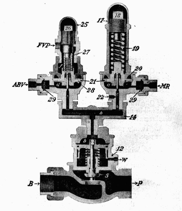
Fig. 1: The SF-4 Compressor Governor.
Connections: FVP, Feed Valve Pipe. ABV, Automatic Brake
Valve. MR, Main Reservoir. B, From Boiler. P, To Air Pump.
[Pg 166] A. Air, at feed valve pipe pressure, enters at the connection marked "FVP" and flows to chamber "f" above the diaphragm; this pressure acts in conjunction with the regulating spring 27 in creating the total pressure on the diaphragm. Air at main reservoir pressure flows through the automatic brake valve to the connection marked "ABV" to chamber "d" under the diaphragm.
7. Q. At what pressure is the regulating spring in the excess pressure head adjusted?
A. Usually twenty pounds.
8. Q. With the spring adjusted at twenty pounds, what will be the total pressure on the upper side of the diaphragm?
A. Twenty pounds, plus the pressure in the feed valve pipe.
9. Q. With the feed valve adjusted at seventy pounds, and the regulating spring at twenty pounds, what pressure will be had in the main reservoir when the governor stops the compressor?
A. Ninety pounds.
10. Q. Explain the operation of the governor in controlling the compressor when a main reservoir pressure of ninety pounds is reached.
A. When the main reservoir pressure in chamber "d" slightly exceeds the pressure on top of the diaphragm it will move upward, carrying the pin valve with it. The air in chamber "d" passes by the unseated pin valve through port "b" into chamber "b" above the governor piston, forcing it downward, seating the steam valve 5, thus shutting off the steam to the compressor.[Pg 167]
11. Q. How long will the governor remain in this position?
A. Until the main reservoir pressure falls below ninety pounds, when the combined spring and air pressure in chamber "f" will force the diaphragm 28 down, seating the pin valve. This shuts off the supply of air from chamber "d", and the air confined in chamber "b" will escape to the atmosphere through the vent port "c". The pressure now being removed from above the governor piston, the spring 9 aided by the steam pressure under the valve 5, will force the piston upward, unseating the steam valve 5, allowing steam to pass through the governor to the compressor.
12. Q. When the steam valve is seated, is steam entirely shut off from the compressor?
A. No; there is a small port drilled through the valve; its purpose is to maintain a circulation in the steam pipe and keep the compressor working slowly; thereby preventing condensation when the steam valve is closed.
13. Q. With the automatic brake valve in release, running, or holding position, does the maximum pressure head operate?
A. No; as during this time the main reservoir pressure is not sufficiently high to actuate its diaphragm.
14. Q. Where does the air come from that operates the maximum pressure head?
A. From the main reservoir direct. (See Fig. 1.)
15. Q. When does the maximum pressure head control the compressor?[Pg 168]
A. When the automatic brake valve is in either lap, service or emergency position, also when the main reservoir cut-out cock is closed.
16. Q. How is the pressure created on top of the diaphragm in the maximum pressure head?
A. By the regulating spring 19.
17. Q. What is the adjustment of this spring?
A. Spring 19 is adjusted to the maximum pressure desired in the main reservoir usually 130 pounds.
18. Q. Explain the operation of the governor when the main reservoir pressure exceeds the tension of the regulating spring 19.
A. When the pressure in chamber "a" exceeds the tension of the regulating spring 19, the diaphragm 20 is forced upward, unseating the pin valve, allowing air to flow from chamber "a" to chamber "b" above the governor piston, forcing it down, shutting off steam and stopping the compressor.
19. Q. How long will the governor remain in this position?
A. Until the main reservoir pressure in chamber "a" under the diaphragm becomes slightly less than the adjustment of the regulating spring 19, when the diaphragm 20 will move down, seating the pin valve, shutting off the flow of air from chamber "a" to chamber "b". The air entrapped above the governor piston will escape to the atmosphere through the relief port "c"; this will allow the governor piston to raise, unseating the steam valve 5, again allowing steam to pass through the governor to the compressor.
20. Q. Is the maximum pressure head cut out in any position of the automatic brake valve?[Pg 169]
A. No; as the air that operates this head comes direct from the main reservoir, therefore is not controlled by the brake valve.
21. Q. Is the excess pressure head cut out in any position of the brake valve?
A. Yes; as the air that operates this head comes through the automatic brake valve, and when the handle is moved beyond holding position, the port in the rotary valve seat, through which the air flows to chamber "d" is closed, thereby cutting out this head, leaving the compressor under the control of the maximum pressure head.
22. Q. What is the object of the duplex or double head governor?
A. By use of the duplex governor the main reservoir pressure may be controlled at two different predetermined pressures; as when running along the excess or low pressure head controls the compressor, at the low pressure—usually ninety pounds—this being sufficient to keep the brakes released and fully charged; whereas, in lap position, as following a brake application, the maximum or high pressure head controls the compressor at the maximum pressure used—generally 130 pounds—this for a prompt release and quick recharge of the brakes. From this it will be seen that the compressor has to work against the high pressure only during the time the brake is applied.
23. Q. In what position should the automatic brake valve handle be placed when adjusting the excess pressure head? The maximum pressure head?
A. Running position for the excess pressure head; lap position for the maximum pressure head.
24. Q. If, with the automatic brake valve handle in running position, the brake pipe and main reservoir[Pg 170] do not stand twenty pounds apart, where would you look for the trouble?
A. Would first learn if the maximum pressure head was properly adjusted, and if it were, would then look for the trouble in the adjustment of the regulating spring in the excess pressure head.
25. Q. What should be done?
A. The regulating spring should be properly adjusted.
26. Q. How should the adjustment of the regulating spring in either pressure head be made?
A. By removing the cap nut 25 or 17 and screwing the regulating nut 26 or 18 up or down as may be required.
DEFECTS OF THE GOVERNOR
27. Q. What would be the effect if one or both of the pin valves leaked?
A. Would cause a delay in opening of the steam valve after the pin valve had seated; and if air leaks by faster than it can escape through the relief port "c", pressure will accumulate in chamber "b" and force the governor piston downward, so as to partially or wholly close the steam valve 5.
28. Q. How can you tell if the pin valves leak?
A. Leakage past the pin valve in the maximum pressure head will cause a constant blow at the relief port in all positions of the brake valve; leakage past the pin valve in the excess pressure head will cause a blow in the first three positions of the brake valve only.
29. Q. What would be the effect if the relief port "c" stopped up?[Pg 171]
A. The compressor will not start promptly after the pin valve seats.
30. Q. What would be the effect if the drain port "W" were stopped up?
A. Steam leaking into the chamber under the governor piston will form a pressure and prevent the piston being forced downward to close the steam valve; the compressor will therefore continue to work until the main reservoir pressure is about equal to boiler pressure.
31. Q. If the pipe leading from the feed valve pipe to the excess pressure head of the governor breaks, what effect will it have on the compressor?
A. The compressor will stop when the main reservoir pressure reaches about forty-five pounds.
32. Q. If the pipe breaks, what should be done?
A. Plug the end toward the feed valve and put a blind gasket in the pipe leading from the automatic brake valve to the governor, at the connection marked ABV.
33. Q. If the pipe leading from the automatic brake valve to the governor breaks, what should be done?
A. Plug the pipe toward the brake valve; the compressor will now be controlled by the maximum pressure head.
34. Q. If the pipe leading from the main reservoir to the maximum head of the governor breaks, what should be done?
A. Plug the main reservoir end of the pipe. The excess pressure head will now control the compressor in the first three positions of the automatic brake valve handle, but will have no control after the handle is moved as far as lap position.[Pg 172]
PARASITE GOVERNOR
35. Q. What is the purpose of the parasite governor, and where is this governor located?
A. This governor is located in the pipe connection between the main reservoir and parasite reservoir, and its purpose is to control the flow of air from the main to the parasite reservoir.
36. Q. What is the purpose of the parasite reservoir?
A. It is here that air is stored for use in all air operated devices on the locomotive, except the brake.
37. Q. Explain the operation of the parasite governor.
A. The operation of this governor is much the same as the compressor governor, and differs only in that the supply valve is open when it is in its lower position.
38. Q. At what pressure is the regulating spring adjusted?
A. About fifteen pounds.
39. Q. What pressure is required in the main reservoir before air is admitted to the parasite reservoir?
A. At least fifteen pounds above that in the brake pipe.
40. Q. What pressure is obtained in the parasite reservoir?
A. The same as that in the main reservoir, when the main reservoir pressure is fifteen pounds greater than that in the brake pipe.
41. Q. What will prevent the charging of the parasite reservoir, and what should be done?[Pg 173]
A. This may be caused by the feed valve being improperly adjusted, sticking in open position or leakage of main reservoir air past the valve to the feed valve pipe and governor top.
WESTINGHOUSE 9½ OR 11-INCH COMPRESSOR
42. Q. What is the duty of the air compressor?
A. To furnish the compressed air used in the operation of the brakes, and all other air operated appliances on both locomotive and cars.
43. Q. Explain the operation of the steam end of the compressor.
A. When steam is turned on at the boiler it flows through the steam pipe and governor, entering the compressor at the steam enlet, then through the steam passage "a" to the reversing valve chamber "C" also to the main valve chamber "A" between the differential pistons 77 and 79. The area of the piston at the right being greater than the one at the left, the main valve is moved to the right, (See Fig. 2) admitting steam to port "b" which leads to the lower end of the steam cylinder; steam is now free to flow under the main piston, forcing it upward. When the piston has almost completed its upward stroke, the reversing plate 69 on top of the piston 65 engages a shoulder on the reversing rod 71, moving the rod and reversing valve 72 upward (See Fig. 3). The upward movement of the reversing valve closes the ports "f" and "h" and opens port "g"; thus permitting steam to enter the chamber at the right of the large piston 77, balancing the pressure on this piston, and the pressure acting on the right side of the small piston 79—the chamber at the left being open to the [Pg 174] exhaust—will force the main valve to the left.
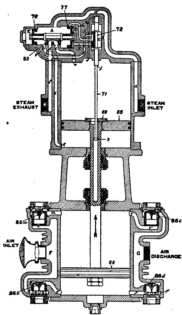
Fig. 2: Diagrammatic View, Up Stroke.
[Pg 175] When the main valve moves to the left, steam is admitted through port "c" to the upper end of the cylinder on top of the piston 65, forcing it downward. At the same time the lower end of the cylinder is connected through exhaust cavity "b" of the main valve to the exhaust port "d", allowing the steam below the piston to escape to the atmosphere.
44. Q. When the piston has about completed its downward stroke, what takes place?
A. The reversing plate 69 engages the button "k" on the end of the reversing rod 71 pulling the rod and the reversing valve down. This movement of the reversing valve closes port "g" and the cavity in the face of the valve connects ports "f" and "h", which allows the steam in chamber "D" at the right of the large differential piston to escape to the exhaust, thus allowing the main valve to move to the right, exhausting the steam from the top end of the cylinder, and at the same time admitting steam to the lower end, causing an upward stroke of the piston.
45. Q. Explain the operation of the air end of the compressor.
A. The movement of the steam piston 65 is imparted to the air piston 66 by means of the piston rod. When the air piston moves up, a partial vacuum is formed below it, and air from the atmosphere will enter through passage "F" thence through passage "n" to the under side of receiving valve 86b (see Fig. 2), lifting this valve from its seat, and will fill the cylinder with air at about atmosphere pressure.
[Pg 177] In the meantime the air above the piston, being compressed, will hold the upper receiving valve 86a to its seat, and when the pressure is slightly greater than that in the main reservoir, this pressure acting under the upper discharge valve 86c, will lift this valve from its seat and now the air will be free to flow through passage "G" to the main reservoir connection. On the down stroke the action is similar, air is taken in through the upper receiving valve 86a, while the air below the piston is being compressed and forced past the lower discharge valve 86d, to the main reservoir. (See Fig. 3.)
46. Q. What lift should the air valves have?
A. All valves should have a lift of three thirty-second of an inch.
47. Q. At what speed should the compressor be run to obtain the best results?
A. At 100 to 120 single strokes per minute.
48. Q. What kind of oil should be used in the air end of the compressor and on the swab?
A. Valve oil.
49. Q. How often should the air end of the compressor be oiled?
A. No fixed rule can be given as so much depends on the condition of the compressor, as well as the amount of work required; but in any case it should be used sparingly.
CROSS-COMPOUND COMPRESSOR
50. Q. What do Figures 4 and 5 represent?
A. These are diagramatic views of a cross-compound compressor.
51. Q. Why is this called a cross-compound compressor?
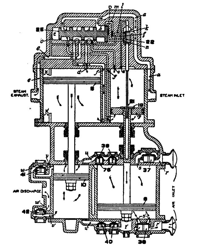
Fig. 4: Diagram of 8½" Cross-Compound Compressor.
High Pressure Steam (Low Pressure Air) Piston on Its Upward Stroke
A. Because both steam and air are compounded, that is, the steam is used the second time before it is exhausted to the atmosphere, while the air is com[Pg 179]pressed the second time before it is delivered to the main reservoir.
52. Q. How many cylinders have the cross-compound compressor?
A. Four; two steam cylinders and two air cylinders.
53. Q. What is the diameter of the different cylinders?
A. The high pressure steam cylinder is 8½ inches; the low pressure steam cylinder 14½ inches; the low pressure air cylinder 14½ inches; high pressure air cylinder 9 inches.
54. Q. Explain the valve gear of this compressor.
A. The valve gear is the same as that of the 9½ or 11 inch compressor, only that a piston valve is used to distribute the steam instead of a slide valve.
55. Q. Where does the steam come from that is used in the high pressure steam cylinder?
A. Direct from the boiler.
56. Q. Where does the steam come from that is used in the low pressure steam cylinder?
A. The steam after doing work in the high pressure steam cylinder is exhausted into the low pressure steam cylinder, where it becomes the working pressure of this cylinder.
57. Q. Explain the operation of this compressor.
A. When steam is first turned on, it enters the compressor at the steam inlet (see Fig. 4) and flows through passage "a" into the reversing valve chamber[Pg 180] "C" and on to chambers "b" and "y" against the inner faces of the differential pistons, causing the main valve to move to the right. In this position of the main valve, port "g" is open to chamber "b", thus admitting live steam to the lower end of the high pressure steam cylinder, causing an upward movement of the piston 7. When the piston 7 has nearly completed its up stroke, the reversing plate 18, which is attached to the top of this piston, comes in contact with a shoulder on the reversing rod 21, forcing it upward, carrying with it the reversing valve 22, the movement of which closes port "m", at the same time opens port "n", filling chamber "D" with live steam from chamber "C" and passage "a". This balances the pressure on the two sides of the large piston of the differential pistons, and the pressure acting against the inner side of the small piston causes the main valve to move to the left (see Fig. 5). The main valve moving to the left closes port "g" to the live steam and at the same time connects this port with port "f" leading to the lower end of the low pressure steam cylinder, causing an up stroke of the low pressure steam piston 8. In the meantime port "c", which leads to the upper end of the high pressure steam cylinder, is open to chamber "y", allowing live steam to flow down on top of the high pressure steam piston 7, forcing it downward. As the high pressure steam piston about completes its downward stroke, the reversing plate 18 engages the button on the lower end of the reversing rod 21, pulling the rod and reversing valve 22 down, closing port "n" and at the same time connecting port "m" and "l" through the exhaust cavity "q", thus allowing the steam in chamber "D" to escape to the exhaust. The pressure being removed from the outer face of the large differential piston, the main valve will again move to the right,[Pg 181] opening port "g", admitting live steam beneath the piston 7, and at the same time connecting the upper end of the high pressure steam cylinder through port "c", chamber "h" and port "d" to the upper end of the low pressure steam cylinder, causing a downward movement of the low pressure steam piston; the steam below this piston will now be free to escape to the exhaust through port "f", chamber "i" and port "e". Thus it will be seen that the steam used in the high pressure steam cylinder is live steam from the boiler, while the steam used in the low pressure steam cylinder is the exhaust steam from the high pressure steam cylinder.
58. Q. Explain the operation of the air end of the compressor.
A. As the low pressure air piston 9 moves up, a partial vacuum is created beneath it and air from the atmosphere enters the air inlet and passage "r" past the lower receiving valve 38 and fills the lower end of the cylinder with air at about atmospheric pressure (see Fig. 4). In the meantime the air above the piston being compressed will hold the upper receiving valve 37 to its seat, thus preventing a back-flow of air to the atmosphere; at the same time the upper intermediate discharge valves 39 are forced from their seats, allowing the air from the low pressure air cylinder to flow through passage "u" to the high pressure air cylinder, the piston of which is now moving downward. The air beneath the high pressure air piston 10 being compressed will hold the lower intermediate discharge valves 40 to their seats, thus preventing the air in the high pressure air cylinder flowing back to the low pressure air cylinder. When the pressure in the high pressure air cylinder becomes slightly greater than the main reservoir pressure, the[Pg 182] final discharge valve 42 will be forced from its seat and the air beneath the piston allowed to flow to the main reservoir through passage "w". On the opposite strokes of these pistons air is compressed in a similar manner, but the opposite air valves are used.
Fig. 5: Diagram of 8½" Cross-Compound Compressor.
The High Pressure Steam (Low Pressure Air) Piston on Its Downward Stroke
[Pg 183] 59. Q. How many valves are there in the air end of the compressor?
A. Ten; two upper and two lower receiving valves; two upper and two lower intermediate discharge valves; one upper and one lower final discharge valves.
60. Q. Are the air valves all the same size?
A. No; the receiving and final discharge valves are the same size and of the size used in the 11-inch compressor, while the intermediate valves are the same as used in the 9½-inch compressor. The receiving and final discharge valves are two inches in diameter, while the intermediate valves are one and one-half inches.
61. Q. What lift is given the different air valves?
A. All valves have 3/32-inch lift.
DEFECTS OF THE COMPRESSOR
62. Q. What are some of the common causes for the compressor stopping?
A. Lack of lubrication; bent, worn or broken reversing rod; loose or worn reversing plate; nuts on air end of piston rod coming off; defective compressor governor; and, in addition with the cross-compound compressor, final discharge valve broken or stuck open, or packing rings in main valve pistons breaking and catching in the steam ports.
63. Q. What will cause the piston to make an uneven stroke?[Pg 184]
A. This may be caused by a broken or stuck open air valve, or air valves not having proper lift. Where the piston short strokes, it is generally caused by over-lubrication of the steam end.
64. Q. What are some of the common causes for the compressor running hot?
A. The overheating of the compressor may be due to any one of the following causes: Running at high speed; working against high pressure; packing rings in air piston badly worn; air cylinder worn; defective air valves; air passages or air discharge pipe partially stopped up; leaky piston rod packing; lack of lubrication.
65. Q. What will cause the compressor to run slow?
A. This may be caused by leaky air piston packing rings; final discharge valves leaking, or air passages partially stopped up. A defective governor may also cause the compressor to run slow.
66. Q. What will cause the compressor to run very fast and heat, and not compress any air?
A. This may be caused by the strainer becoming clogged with ice or dirt, preventing air entering the cylinder.
67. Q. If, when steam is first turned on, the piston makes a stroke up and stops, where would you look for the trouble?
A. The shoulder on the reversing rod may be worn; the opening in the reversing plate too large to engage the shoulder on the reversing rod; loose reversing plate studs preventing the piston traveling far enough to reverse the compressor, or the main valve stuck in its position at the right.[Pg 185]
68. Q. If the piston makes a stroke up and a stroke down and stops, where is the trouble?
A. This may be caused by a loose reversing plate, or the button on the lower end of the reversing rod worn or broken off, or the nuts off the piston rod in the air end, or the main valve stuck in its position at the left.
69. Q. What will cause the piston to make a quick up stroke?
A. This may be caused by a broken or stuck open upper receiving or lower discharge valve.
70. Q. What will cause the piston to make a quick down stroke?
A. Lower receiving or upper discharge valve broken or stuck open.
71. Q. If a receiving valve breaks or sticks open, how may it be located?
A. The air will flow back to the atmosphere as the piston moves toward the defective valve and may be detected by holding the hand over the strainer.
72. Q. If a receiving valve in a cross-compound compressor breaks, what may be done?
A. Remove the broken valve, blocking the opening made by its removal, and as there are two upper and two lower receiving valves the compressor will now take air through the other valve.
73. Q. If an intermediate discharge valve breaks or sticks open, how may it be located?
A. No air will be taken in to that end of the compressor as the piston moves from the defective valve, and may be located by holding the hand over the strainer.[Pg 186]
74. Q. If an intermediate discharge valve breaks, what may be done?
A. Remove the broken valve, blocking the opening made by its removal, and as there are two upper and two lower intermediate discharge valves the air will now pass from the low pressure cylinder to the high pressure cylinder through the other valve.
75. Q. If a final discharge valve breaks, what effect will it have on the compressor?
A. Will cause the compressor to stop when the main reservoir pressure is in excess of forty pounds.
76. Q. How would you test for a defective final discharge valve?
A. To test for this defect, bleed the main reservoir pressure below forty pounds, and if the compressor starts it indicates a defective discharge valve.
77. Q. If a final discharge valve breaks, what may be done?
A. As the receiving valves and final discharge valves are the same size, the defective valve may be replaced by one of the receiving valves, blocking the opening made by the removal of the receiving valve.
78. Q. Where piston rod packing is blowing bad, what may be done to stop it?
A. This generally indicates lack of lubrication, and by cleaning and oiling the swab the trouble may be overcome. However, there are times when leakage by the packing is so great that the oil is blown off the swab as fast as it is applied, therefore is of no value in lubricating the parts. Where this condition exists, a little hard grease wrapped up in an old flag and tied around the piston rod will ensure its being lubricated.[Pg 187]
79. Q. If the compressor stops, how can you tell if the governor is responsible for the trouble?
A. By opening the drain cock in the steam passage between the governor and the compressor; if steam flows freely, the trouble is in the compressor; if not, it is in the governor.
80. Q. How may a compressor often be started when it stops?
A. By closing the steam throttle for a few seconds, then opening it quickly; if this does not start it, try tapping the main valve chamber. This will usually overcome the trouble where the compressor stops on account of lack of lubrication.
81. Q. What will cause a compressor to short-stroke or dance?
A. Too much oil in the steam end; bent reversing rod; or low steam pressure, as when the governor has almost shut off the steam.
ENGINEER'S BRAKE VALVE
82. Q. Name the different positions of the G-6 and H-6 brake valves.
A. Release, running, lap, service, and emergency position, with the G-6; release, running, holding, lap, service, and emergency positions, with the H-6.
83. Q. What is the purpose of release position?
A. To provide a large and direct opening from the main reservoir to the brake pipe, for the free flow of air, when charging and recharging the brakes.
84. Q. What pressure will be had in the brake pipe if the brake valve be left in release position?
A. Main reservoir pressure.[Pg 188]
85. Q. Can the locomotive brake be released by the automatic brake valve in release position, when using the H-6 valve?
A. No; as the port in the automatic brake valve to which the distributing valve release pipe is attached is blanked in this position of the valve.
86. Q. What is the purpose of running position, and when should it be used?
A. This is the proper position for the brake valve when the brakes are charged and not in use, also when it is desired to release the locomotive brake with this valve. In this position the brake pipe pressure is maintained at a predetermined amount by the feed valve, as all air that now enters the brake pipe must pass through the feed valve.
87. Q. What is the purpose of holding position?
A. To hold the locomotive brake applied while recharging the brakes. The charging of the brake pipe and equalizing reservoir is the same in holding as in running position.
88. Q. What is the purpose of lap position?
A. To hold both the locomotive and train brakes applied after an automatic application.
89. Q. What is the purpose of service position?
A. This position of the brake valve enables the engineer to make a gradual reduction of brake pipe pressure, thus causing a service application of the brakes.
90. Q. What is the purpose of emergency position?
A. In this position of the brake valve, the brake pipe is connected directly with the atmosphere through[Pg 189] the large ports in the valve, causing a sudden reduction of brake pipe pressure, this in turn causing the distributing valve on the engine and all operating triple valves on cars in the train to move to emergency position, thus insuring a quick and full application of the brake.
91. Q. How should the brake valve be handled when making an emergency application of the brake?
A. The valve should be placed in full emergency position and left there until the train stops, even though the danger may have disappeared.
DEFECTS OF THE BRAKE VALVE
92. Q. What will cause a constant blow at the brake pipe exhaust port, and what may be done to overcome it?
A. This indicates that the brake pipe exhaust valve is being held off its seat, due no doubt to dirt; tapping the side of the valve will sometimes stop the blow; if not, close the brake pipe cut-out cock and make a heavy service reduction; next, place the brake valve handle in release position. This will cause a strong blow at the exhaust port, which will invariably remove the trouble.
93. Q. If the pipe connecting the brake valve with the equalizing reservoir breaks, can both locomotive and train brakes be operated with the automatic brake valve?
A. Yes; by placing a blind gasket in the pipe connection at the brake valve and plugging the brake pipe exhaust port. To apply the brake, move the handle carefully toward emergency position, making a gradual reduction of brake pipe pressure through[Pg 190] the direct exhaust ports of the brake valve; when the desired reduction is made, the handle should be moved gradually back to lap position.
94. Q. What would be the effect if the handle were moved to lap quickly?
A. Would cause the release of the brakes on the head end of the train.
95. Q. What will cause air to blow at the brake pipe exhaust port when the handle is moved to lap position?
A. This is caused by a leak from the equalizing reservoir or its connections, which reduces the pressure in chamber "D" above the equalizing piston, allowing brake pipe pressure under the piston to force it up, unseating the brake pipe exhaust valve, permitting brake pipe air to flow to the atmosphere.
96. Q. What is the purpose of the equalizing reservoir?
A. The purpose of the equalizing reservoir is to furnish a larger volume of air above the equalizing piston than is found in chamber "D", thus to enable the engineer to make a graduated reduction of the pressure above the equalizing piston.
97. Q. What defect will cause the brake pipe and main reservoir pressure to equalize when the handle is in running position?
A. This may be caused by leakage past the rotary valve, defective body gasket, or leakage by the feed valve or its case gasket. To determine which part is at fault, close the cut-out cock under the brake valve[Pg 191] and move the handle to service position, exhausting all air from chamber "D" and the brake pipe; return the handle to lap position. Leakage of air past the rotary valve is generally into the brake pipe port which allows the air to come in under the equalizing piston, thus forcing it upward, unseating the brake pipe exhaust valve, allowing this air to escape to the atmosphere at the brake pipe exhaust port. Leakage past the body gasket allows air to enter chamber "D", above the equalizing piston, holding it in its lower position, keeping the brake pipe exhaust port closed, thereby preventing the escape of this air to the atmosphere. Since the capacity of the equalizing reservoir and chamber "D" is small, such a leak will cause the black hand to quickly move up to the position of the red hand. To determine if the leakage be in the feed valve or its gasket, recharge the brake pipe to some pressure below the adjustment of the feed valve, then place the handle in lap position. If the black hand on the air gauge remains stationary, it is fair to assume that the trouble is in the feed valve or its gasket, as in this position of the brake valve the feed valve is cut out.
98. Q. With the engine alone, the brake pipe pressure will equalize with that in the main reservoir, while when coupled to a train the pressure will remain at that for which the feed valve is adjusted; where is the trouble?
A. This is caused by light leakage of main reservoir air into the brake pipe, and may come past the rotary valve, body gasket, or feed valve, and with the lone engine is sufficient to raise the brake pipe pressure to that in the main reservoir; while, when coupled to a train, the brake pipe leakage of which is greater than this amount, this leakage will not be noticed.[Pg 192]
99. Q. What do Figures 6 and 7 represent?
A. These are diagrams of the B-6 feed valve in both open and closed positions.
100. Q. Name the different parts of the feed valve.
A. The valve consists of the following parts: 2, valve body; 3, pipe bracket; 5, cap nut; 6, piston spring; 7, piston spring tip; 8, supply valve piston; 9, supply valve; 10, supply valve spring; 11, regulating valve cap nut; 12, regulating valve; 13, regulating valve spring; 14, diaphragm; 15, diaphragm ring; 16, diaphragm spindle; 17, regulating spring; 18, spring box; 19 and 20, stop rings; 21, clamping screw; 22, hand wheel.
101. Q. Explain the operation of the feed valve.
A. The feed valve consists of two portions, the supply and regulating portions. The supply portion consists of a slide valve 9 and a piston 8 (see Fig. 6). The supply valve 9 opens and closes communication between the main reservoir and the feed valve pipe and is moved by the piston 8 which is operated by main reservoir air entering through passage "a" on one side or by the pressure of the spring 6 on the other side. The regulating portion consists of a brass diaphragm 14, on one side of which is the diaphragm spindle 16, held against the diaphragm by the regulating spring 17, and on the other side a regulating valve 12, held against the diaphragm or its seat, as the case may be, by the spring 13. Chamber "L" at the left of the diaphragm is open to the feed valve pipe through the passage "e" and "d". The feed valve is adjusted by turning the hand wheel 22 in or out, thus increasing or decreasing the pressure exerted by the spring on the diaphragm. The same results[Pg 193] are obtained in turning the hand wheel 22 as when turning the adjusting screw in the older types of feed valves.
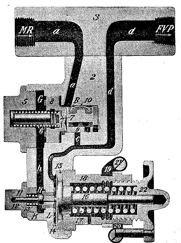
Fig 6: Diagram of B-6 Feed Valve, Closed.
Connections: MR, Main Reservoir Pipe; FVP, Feed Valve Pipe.
[Pg 194] Air from the main reservoir flowing through passage "a" into chamber "B" will force the piston 8 to the left against the tension of the spring 6; the piston in moving will take with it the supply valve 9, opening the supply port in the valve to port "c" in its seat as shown in Fig. 7. Main reservoir air will now be free to flow through passage "a", chamber "B", port "c" and passage "d" to the feed valve pipe. Air coming through port "c" also flows through passage "e" to chamber "L" at the left of the diaphragm 14, and this pressure tends toward forcing the diaphragm to the right; but the diaphragm being supported by the regulating spring 17, will remain in its position at the left, holding the regulating valve 12 off its seat, until the pressure in chamber "L" exceeds the tension of the regulating spring 17. Air, therefore, continues to flow from the main reservoir through a, B, c, d and e to the feed valve pipe and chamber "L", increasing the pressure, until the pressure on the diaphragm 14 overcomes the tension of the regulating spring 17, when the diaphragm will move to the right, allowing the spring 13 to force the regulating valve 12 to its seat, closing port "K". Chambers "G" and "H" are then no longer open to chamber "L" and the feed valve pipe, and these chambers being small, the pressure raises quickly to main reservoir pressure due to the leakage of air past the supply piston 8, which forms but a loose fit in its bushing. When the pressure in chamber "G" becomes nearly equal to that in chamber "B", the piston spring "6" forces the piston 8 and its slide valve 9 to closed position, which prevents further flow of air from the main reservoir to the feed valve pipe (see Fig. 6). The feed valve will remain in closed position until the pressure in chamber "L" is slightly reduced so that the pressure on the diaphragm 14 is no longer able to withstand the pressure of the regulating spring 17, which then forces the[Pg 195] diaphragm to the left, lifting the regulating valve 12 from its seat and again opening port "K" to chamber "L", thus dropping the pressure at the left of piston 8 below that of the main reservoir acting on the opposite side of the piston.
Main reservoir pressure then forces the supply piston and valve over into open position, as shown in Fig. 7, and allows a further flow of air through port "c" to the feed valve pipe to again raise its pressure to the adjustment of the feed valve, when the valve will again close.
102. Q. What is the duty of the feed valve?
A. To control and maintain a constant pressure in the brake pipe when the brake valve is in running or holding position.
103. Q. What defect in the feed valve will cause the brake pipe pressure to equalize with that in the main reservoir?
A. This may be caused by a defective feed valve case gasket, permitting main reservoir air to leak into the feed valve pipe, or leakage past the supply valve, or the regulating valve held from its seat, or the supply valve piston too tight a fit in its cylinder.
104. Q. If the brake pipe charges too slowly when nearing the maximum pressure, where is the trouble?
A. This may be caused by a loose-fitting supply valve piston 8, or the port past the regulating valve 12 partly stopped up.
105. Q. How should the feed valve be tested?
A. With the brakes released, and charged to the adjustment of the feed valve, create a brake pipe leak of from seven to ten pounds and note the black hand on the brake pipe gauge. The fluctuation of this hand will indicate the opening and closing of the feed valve, which should not permit a variation of over two pounds in brake pipe pressure; if it does, it indicates a dirty condition of the valve, and should be cleaned.[Pg 197]
106. Q. If the main reservoir pipe connection to the feed valve breaks, what should be done?
A. This will cause a loss of main reservoir air, and both ends of the pipe must be plugged. As no air now comes to the feed valve to charge the brake pipe in running or holding position of the brake valve, the handle must be carried in release position.
107. Q. What must be done if the pipe between the feed valve and automatic brake valve breaks?
A. Slack off on the regulating nut of the feed valve until all tension is removed from the regulating spring and plug the pipe toward the brake valve. To charge the brake pipe, the brake valve handle must be carried in release position.
108. Q. If the feed valve becomes defective so that it will not control brake pipe pressure, what may be done?
A. As the reducing valve used for the independent brake, and the feed valve are practically the same, they may be changed one for the other, the reducing valve taking the place of the feed valve.
INDEPENDENT BRAKE VALVE
109. Q. Name the different positions of the independent brake valve used with the E-T equipment.
A. Release, running, lap, slow-application position, quick-application position.
110. Q. What is the purpose of release position?
A. To release the locomotive brake when the automatic brake valve is in other than running position.
111. Q. What is the purpose of running position?[Pg 198]
A. This is the proper position for the brake valve when not in use, and to release the locomotive brake when the automatic brake valve is in running position.
112. Q. What is the purpose of lap position?
A. To hold the locomotive brake applied after an independent application.
113. Q. What is the purpose of slow-application position?
A. This position may be used when it is desired to make a light or gradual application of the brake, as in stretching or bunching the slack of a train.
114. Q. What is the purpose of quick-application position?
A. To apply the locomotive brake quickly, as in short switching.
115. Q. What brake cylinder pressure is usually developed with this brake?
A. About forty-five pounds.
DEAD ENGINE FEATURE
116. Q. What is the dead engine device?
A. The dead engine device is a pipe connection between the main reservoir and the brake pipe. In this pipe is found a combined strainer and check valve with a choke fitting and cut-out cock, which when open forms a connection between the brake pipe and the main reservoir.
117. Q. What is the purpose of this device?
A. To provide a means of charging the main reservoir of an engine whose compressor is inoperative.[Pg 199]
118. Q. What is the object of charging a main reservoir of an engine with a disabled compressor?
A. As the air used in the locomotive brake cylinders comes from the main reservoir, for the brakes to be operated on this engine it is necessary that its main reservoir be charged.
119. Q. With a 70-pound brake pipe pressure, what pressure should be had in the main reservoir when using this device?
A. About fifty pounds.
120. Q. When the dead engine feature is being used, in what position should the automatic and independent brake valves be carried?
A. Running position.
121. Q. What should be the position of the brake pipe cut-out cock below the brake valve?
A. It should be closed.
DISTRIBUTING VALVE
122. Q. What is the duty of the distributing valve?
A. To admit air from the main reservoir to the locomotive brake cylinders when applying the brake, to automatically maintain the brake cylinder pressure against leakage, to develop the proper brake cylinder pressure regardless of piston travel and to exhaust the air from the brake cylinders when releasing the brake.
123. Q. To what is the distributing valve attached?
A. To the distributing valve reservoir.
124. Q. How many chambers has the distributing valve reservoir?[Pg 200]
A. Two; pressure chamber and application chamber.
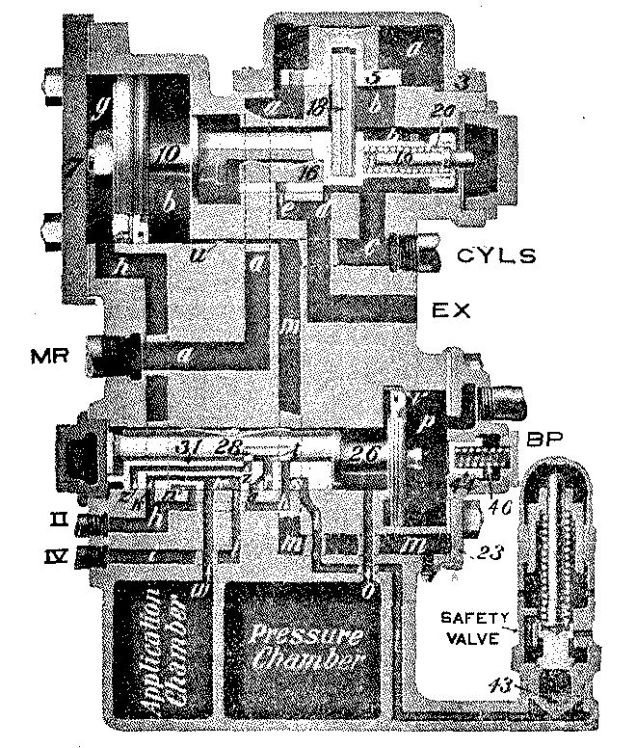
Fig. 8: Release, Automatic or Independent.
Connections: MR, Main Reservoir Pipe; IV, Distributing Valve Release Pipe;
II, Application Cylinder Pipe; CYLS, Brake Cylinder Pipe; BP, Brake Pipe.
125. Q. Name the different pipe connections to the distributing valve reservoir.
A. Referring to Fig. 8, the connection marked "MR" is the main reservoir supply pipe; "II", application cylinder pipe; "IV", distributing valve release pipe; "BP", brake pipe; "CYLS", brake cylinder pipe.
126. Q. To what do these different pipes connect?
A. The main reservoir supply pipe connects the distributing valve with the main reservoir pipe. The application cylinder pipe connects the application cylinder of the distributing valve with the independent and automatic brake valves. The distributing valve release pipe connects the application cylinder exhaust port in the distributing valve with the independent brake valve, and through it, when in running position, to the automatic brake valve. The brake cylinder pipe connects the distributing valve with the different brake cylinders on the locomotive. The brake pipe branch pipe connects the distributing valve with the brake pipe.
127. Q. Explain the operation of the distributing valve when making an automatic service application of the brake.
A. When the brakes are fully charged, the brake pipe and pressure chamber pressures are equal, and when a gradual reduction of brake pipe pressure is made it will be felt in chamber "p" at the right of the equalizing piston 26, creating a difference in pressure on the two sides of the piston, causing it to move to the right. The first movement of the piston closes the feed groove "v", also moves the graduating valve 28, uncovering the service port "z" in the equalizing slide valve 31; this movement of the piston also causes the shoulder on the end of its stem to engage[Pg 202] the equalizing slide valve, and the continued movement of the piston moves the valve to service position, in which port "z" connects with port "h" in the seat of the valve, as shown in Fig. 9. As the equalizing slide valve chamber is at all times connected to the pressure chamber, air can now flow from this chamber to both the application cylinder and chamber through ports "z" and "h", cavity "n" and port "w" until the pressure on the left or pressure chamber side of the equalizing piston 26 becomes slightly less than that in the brake pipe, when the piston and graduating valve will move to the left until the shoulder on the piston stem strikes the slide valve; this movement of the graduating valve closes the service port "z", thus closing the communication between the pressure chamber and application chamber and cylinder, also closing port "l" which leads to the safety valve. The distributing valve is now said to be in service lap position. (See Fig. 10.)
128. Q. Upon what does the pressure in the application chamber and cylinder depend when making a service application of the brake?
A. On the amount of brake pipe reduction; and as the relative volume of the pressure chamber and application cylinder and chamber is practically the same as that of an auxiliary reservoir and brake cylinder, it will be understood that one pound from the pressure chamber will make two and one-half pounds in the application chamber and cylinder; in other words, with the pressure chamber charged to seventy pounds and no pressure in the application chamber and cylinder, if they were connected and the pressure allowed to equalize it would do so at about fifty pounds; that is, twenty pounds from the pressure chamber will make fifty pounds in the application chamber and cylinder.
129. Q. How is the application piston 10 affected by the air pressure in the application cylinder "g"?
A. Pressure forming in this cylinder will force the piston to the right; the piston in moving will carry with it the exhaust valve 16, closing the exhaust ports "e" and "d", at the same time moving the application[Pg 204] valve 5, opening the supply port "b", allowing main reservoir air from chamber "a" to flow through ports "b" and "C" to the connection marked "CYLS", and on to the different brake cylinders of the locomotive until the pressure in the brake cylinders and at the right of the application piston becomes slightly greater than that in chamber "g" when the application piston and valve will move back to lap position as shown in Figures 9 and 10.
130. Q. With the application valve in lap position, if there be brake cylinder leakage, will the locomotive brake leak off?
A. No; any drop in brake cylinder pressure will be felt in chamber "b" at the right of the application piston 10, causing a difference in pressure on the two sides of the piston, thus allowing the pressure in the application cylinder to move the application piston and valve to the right, again opening the supply port "b" allowing a further flow of main reservoir air from chamber "a" to the brake cylinders until the pressure is again slightly greater than that in the application cylinder "g", when the application piston and valve will move back to lap position. Thus in this way air will be supplied to the brake cylinders of the locomotive, holding the brake applied regardless of leakage.
131. Q. What effect will piston travel have on the pressure developed in the brake cylinders?
A. None; as the pressure in the brake cylinders is entirely dependent on the pressure in the application cylinder, which is not affected by piston travel.
132. Q. Explain the movement of the parts in the distributing valve when the automatic brake valve is moved to release position, after an automatic application of the brake.[Pg 205]
A. In release position of the brake valve, air from the main reservoir flows direct to the brake pipe, causing a rise of pressure which is felt in chamber "p" on the right or brake pipe side of the equalizing piston 26; this increase of pressure will cause the piston to move toward the left, carrying the graduating valve 28 and slide valve 31 to release position.
This allows the air from the application chamber and cylinder to flow to the distributing valve release pipe "IV" and on through the independent brake valve to the automatic brake valve, where the port to which this pipe leads is blanked by the automatic rotary valve, thus preventing the air from leaving the application chamber and cylinder, holding the locomotive brake applied while the train brakes are being released. The movement of the parts, and the results obtained are the same where the release is made in holding position.
133. Q. Explain the movement of the parts in the distributing valve when the brake valve is moved to running position after having first been moved to release or holding position, following a brake application.
A. In this position of the brake valve the port to which the distributing valve release pipe is connected is open to the exhaust, thus allowing the air to escape from the application chamber and cylinder. The reduction of pressure in chamber "g", will allow the brake cylinder pressure in chamber "b" to force the application piston and its valves to release position, thus allowing the brake cylinder air to escape to the atmosphere, through the exhaust ports "e" and "d". (See Fig. 8.)
134. Q. Explain how an independent release of the locomotive brake is obtained after an automatic application has been made.
A. If the brakes have been applied throughout the train, by means of the automatic brake valve, and it is desired to release the locomotive brakes without releasing the train brakes, the handle of the independent brake valve is placed in release position. In this position of the independent brake valve, the application cylinder in the distributing valve is con[Pg 207]nected through the application cylinder pipe to the direct exhaust port of the independent brake valve; thus exhausting the air from the application cylinder, causing a release of the locomotive brake. This independent release of the locomotive brake does not cause the equalizing piston and its slide valve in the distributing valve to change their position.
135. Q. Explain what takes place when an automatic emergency application is made.
A. Any sudden reduction of brake pipe pressure is felt on the brake pipe side of the equalizing piston 26 and will cause it and the slide valve 31 to move to the extreme right, compressing the graduating spring 60. (See Fig. 11.) In this position pressure chamber air can flow to the application cylinder only as the application chamber is now cut off. This will cause a quick rise of pressure in the application cylinder, forcing the application piston and its valves to full application position, admitting main reservoir air to the brake cylinders and applying the brake. In emergency position of the automatic brake valve there is a small port in the rotary valve, called the blow-down timing port, through which main reservoir air is free to flow to the application cylinder "g" through the application cylinder pipe "II", causing a rise of pressure equal to the adjustment of the safety valve.
136. Q. At what pressure is the safety valve adjusted?
A. At sixty-eight pounds.
137. Q. What is the purpose of the quick action cap, and where is it located?
A. Its purpose is to assist the brake valve in venting brake pipe air when an emergency application[Pg 208] of the brake is made, and is located on the brake pipe side of the distributing valve in place of the plain cap. (See Figs. 8 and 11.)
138. Q. Explain the operation of the quick action cap.
A. In an emergency application, the equalizing piston 26 moves to the extreme right, the knob on the piston strikes the graduating stem 59, causing it to compress the graduating spring 46, and move the slide valve 48 to the right, opening port "j".
Brake pipe pressure in chamber "p" flows to chamber "X", pushes down check valve 53, and passes to the brake cylinders through port "m" in the cap and distributing valve body. When the brake cylinders and brake pipe pressures equalize, check valve 53 is forced to its seat by spring 54, thus preventing air in the brake cylinders from flowing back into the brake pipe. When a release of the brake occurs and piston 26 is moved back to its normal position, spring 46 forces graduating stem 59 and slide valve 48 back to release position.
139. Q. Explain the operation of the distributing valve when making an independent application of the brake.
A. When the independent brake valve handle is moved to application position, air is admitted from the reducing valve pipe through the application cylinder pipe to the application chamber and cylinder. Pressure forming in the application cylinder will move the application piston 10 to the right, carrying with it the exhaust valve 16 and the application valve 5, closing the exhaust port and opening the supply port, admitting main reservoir air from chamber "a" to the brake cylinders (see Fig. 12) until the pressure in the brake cylinders and chamber "b" slightly exceeds that in chamber "g", when the application piston 10 and valve 5 will move back to lap position. By moving the brake valve handle to either release or running position, the air is exhausted from the application cylinder and chamber, thus reducing the pressure in chamber "g", allowing the pressure in chamber "b" to force the piston to the left, carrying with it the exhaust valve 16, opening the exhaust ports "e" and "d", allowing the air from the brake cylinders to escape to the atmosphere, thus releasing the brake.[Pg 211]
DISTRIBUTING VALVE DEFECTS
140. Q. If the locomotive brake released with the automatic brake valve in lap position, where would you look for the trouble?
A. Would look for a leak in the application cylinder pipe or in the application cylinder cap gasket.
141. Q. If the brake remained applied in lap position, but released in release or holding position, where would you look for the trouble?
A. Would look for a leak in the distributing valve release pipe.
142. Q. If the distributing valve release pipe and application cylinder pipe were crossed, what would be the effect?
A. A brake application made by the automatic brake valve cannot be released by the independent brake valve.
143. Q. If the safety valve leaks, what will be the effect?
A. This may prevent the brake applying, and in an independent application if the brake does apply, it will release when the brake valve is returned to lap position.
BROKEN PIPES
144. Q. If the main reservoir supply pipe to the distributing valve breaks, what should be done?
A. Plug the pipe toward the main reservoir. The locomotive brake is lost, but if the distributing valve is equipped with a quick action cap, when an emergency application is made, the air coming from the brake pipe, through the quick action cap, will apply the locomotive brake.[Pg 212]
145. Q. If the application cylinder pipe breaks, what effect will it have on the locomotive brake?
A. The locomotive brake cannot be applied with either automatic or independent brake valve. By plugging the pipe toward the distributing valve the automatic brake will be restored.
146. Q. If the distributing valve release pipe breaks, what will be the effect?
A. The holding feature of the brake will be lost; that is, the locomotive brake will release when the automatic brake valve is moved to either release or holding position, the same as with the old G-6 equipment.
147. Q. If the release pipe is broken and not plugged, can the independent brake be applied?
A. Yes, by placing the brake valve handle in quick-application position the brake will apply, but there will be a waste of air through the broken pipe, and the brake will release when the brake valve is returned to lap position.
148. Q. If the brake cylinder pipe breaks, can the locomotive brake be applied?
A. This depends on where the pipe breaks; if between the cut-out cock and any one of the brake cylinders, close the cut-out cock to that cylinder, and the other cylinders may be used. But if the pipe breaks at the distributing valve, the locomotive brake will be lost.
149. Q. If the brake pipe connection to the distributing valve breaks, what should be done?
A. Plug the end from the brake pipe; the locomotive brake must now be released by placing the independent valve in release position.[Pg 213]
150. Q. If the brake pipe connection to the distributing valve breaks and is plugged, can the locomotive brake be operated?
A. The independent brake may be applied and released in the usual manner, but the automatic brake will be lost for service braking.
TYPE K TRIPLE VALVE
151. Q. On what is this type of triple valve designed to operate?
A. On freight equipment cars only.
152. Q. Explain the operation of the "K" triple valve.
A. When air is admitted to the brake pipe it is free to enter the triple at "a" (see Fig. 13) and flow through the passage "e" to chamber "f", thence through port "g" to chamber "h" in front of the triple valve piston 4. Pressure forming in chamber "h" will force the piston to the left until its packing ring uncovers the feed groove "i" in the bushing, thus creating a communication between chamber "h" and the slide valve chamber. Brake pipe air will now be free to flow past the piston to the slide valve chamber and out at "R" to the auxiliary reservoir. Air will continue to feed through the groove "i" until the auxiliary reservoir and brake pipe pressures are equal, and it is then we say that the brake is fully charged. Brake pipe air entering chamber "a" will lift the check valve 15, and charge chamber "Y" to brake pipe pressure. When a gradual reduction of brake pipe pressure is made, as in a service application of the brakes, the pressure being reduced in chamber "h", auxiliary reservoir pressure will move the piston 4 toward service position. (See Fig. 14.) The first movement of the piston closes the feed groove "i", thus closing communication between the auxiliary reservoir and the brake pipe, preventing a back-flow of air from the auxiliary to the brake pipe, and at the same time moving the graduating valve 7, opening the service port "Z" in the slide valve. The continued movement of the piston will move the slide valve until the service port "Z" registers with the brake cylinder port "r" in the valve seat, thus creating a communication between the auxiliary reservoir and the brake cylinder. Air will now flow from the auxiliary to the brake cylinder until the pressure on the auxiliary side of the piston 4 becomes slightly less than in the brake pipe, when the piston and the graduating valve 7 will move back just far enough to close the service port "Z", thus closing communication[Pg 215] between the auxiliary reservoir and the brake cylinder. At the same time, the first movement of the graduating valve connects the two ports "o" and "q" in the slide valve through the cavity "v" in the graduating valve, and the movement of the slide valve brings port "o" to register with port "y" in the slide valve seat, and port "q" with port "t". This permits the air in chamber "Y" to flow through port "y", "o", "v", "q", and "t", thence around the emergency piston 8, which fits loosely in its cylinder, to chamber "X" and the brake cylinder. When the pressure in chamber "Y" has reduced below the brake pipe pressure remaining in chamber "a", the check valve 15 is raised and allows brake pipe air to flow past the check valve and through the ports above mentioned to the brake cylinder.
The size of these ports are so proportioned that the flow of air from the brake pipe to the top of the emergency piston 8, is not sufficient to force the latter downward and thus cause an emergency application, but at the same time takes enough air from the brake pipe to cause a local reduction of brake pipe pressure at that point, thus assisting the brake valve in increasing the rapidity with which the brake pipe reduction travels through the train. The triple valve is now said to be in "Quick Service" position. (See Fig. 14.)
153. Q. Will the triple valve move to quick service position whenever a gradual reduction brake pipe reduction is made?
A. No; with short trains, the brake pipe volume being comparatively small, will reduce more rapidly for a certain reduction at the brake valve than with a long train. Therefore, with a short train, the brake pipe pressure reducing more quickly, the triple piston and its valves will move to "full service" position, as shown in Fig. 15. In this position the quick service port "y" is closed, so that no air flows from the brake pipe to the brake cylinder. Thus, when the brake pipe reduction is sufficiently rapid, there is no need for this quick service reduction, and the triple valve automatically cuts out this feature of the valve when not required.
154. Q. How long will the auxiliary reservoir air continue to flow to the brake cylinder?
A. Air will continue to flow to the brake cylinder until the pressure on the auxiliary side of the triple piston becomes slightly less than that on the brake pipe side, when the piston 4 and the graduating valve [Pg 217] 7 will move to the left until the shoulder on the piston stem strikes the slide valve. (See Fig. 16.) This movement has caused the graduating valve to close the service port "Z", thus cutting off any further flow of air from the auxiliary to the brake cylinder and also port "o", thus preventing any further flow of air from the brake pipe to the brake cylinder. The triple valve is now said to be in lap position.
155. Q. How is the triple valve affected by a further reduction of brake pipe pressure?
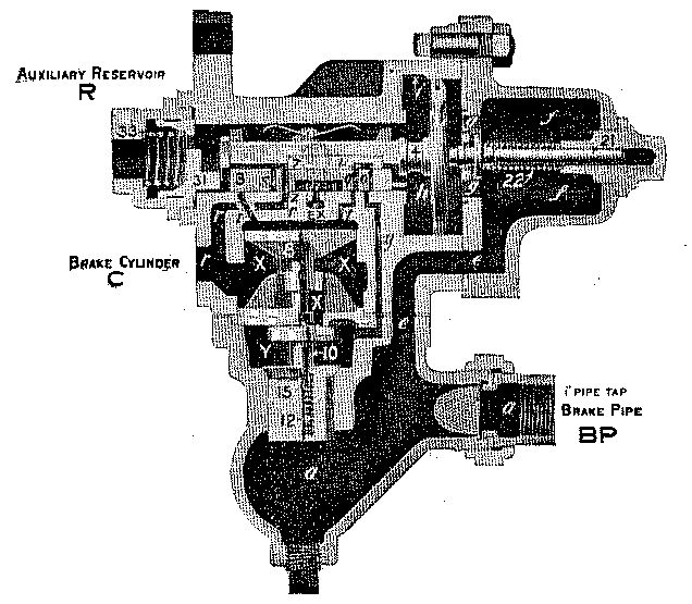
Fig. 15: Full Service Position.
A. A further reduction of brake pipe pressure will cause the triple piston 4 and the graduating valve [Pg 218]7 to again move to the right, opening ports "Z" and "o", allowing a further flow of brake pipe and auxiliary air to the brake cylinder. This may be continued until the auxiliary reservoir and brake cylinder pressures become equal, after which any further reduction of brake pipe pressure is only a waste of air. With seventy pounds brake pipe pressure, and eight-inch piston travel, a twenty-pound reduction will cause equalization at about fifty pounds.
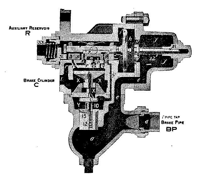
Fig. 16: Lap Position.
156. Q. Explain the operation of the triple valve in the release of the brake.
A. To release the brakes and recharge the auxiliary reservoirs, air is admitted through the brake valve[Pg 219] to the brake pipe. This increase of pressure on the brake pipe side of the triple valve piston 4 above that on the other side causes the piston and slide valve to move back to release position, which permits the air in the brake cylinder to flow to the atmosphere, through the exhaust port of the triple, thus releasing the brake. At the same time, air from the brake pipe flows through the feed groove "i" around the triple piston to the auxiliary reservoir, which is thus recharged. Now the "K" triple valve has two release positions: Full Release and Retarded Release. To which of these two positions the parts will move when the brakes are released, depends upon how the brake pipe pressure is increased. It is generally understood that those cars toward the head end of the train, receiving the air first, will have their brake pipe pressure raised more rapidly than those in the rear; thus the friction of the brake pipe causes the pressure to build up more rapidly in the chamber "h" of the triple valve toward the front end of the train than in those in the rear. As soon as the pressure is enough greater than the auxiliary reservoir pressure to overcome the friction of the piston, graduating valve and slide valve, all three are moved toward the left until the piston stem strikes the retarding stem 31, which is held in position by the retarding spring 33. Where the rate of increase of brake pipe pressure is slow, it will be impossible to raise the pressure in chamber "h" sufficiently to overcome the tension of the retarding spring 33, and the triple valve will remain in full release position, as shown in Fig. 13. Brake cylinder air will now be free to exhaust through port "r", large cavity "n" in the slide valve and port "p" leading to the atmosphere. If, however, the triple valve is near the head end of the train, and the brake pipe pressure builds up more rapidly than the auxiliary can recharge, an excess of pressure will be obtained in[Pg 220] chamber "h" over that in the auxiliary reservoir, and will cause the piston 4 to compress the retarding spring 33, and move the triple valve parts to retarded release position as shown in Fig. 17.
157. Q. What effect has retarded release position of the triple valve on the release of the brakes?
A. In this position of the triple valve, cavity "n" in the slide valve connects port "r" leading to the brake cylinder, with port "p" to the atmosphere, and the brake will release; but as the small "tail port" extension of cavity "n" is over exhaust port "p", the discharge of air from the brake cylinder is quite slow.
158. Q. What is the object of delaying the exhaust of the brake cylinder air?
A. In this way, the brakes on the front end of the train require a longer time to release than those on the rear. This feature is called retarded release, and although the triple valves near the locomotive commence to release before those in the rear, yet the exhaust of air from the brake cylinder is sufficiently slow to hold back the release of the brakes at the front end of the train long enough to insure a uniform release of the brakes on the train as a whole. This permits of releasing the brakes on very long trains at low speeds without danger of damaging train.
159. Q. What other desirable feature is found in this position of the triple valve?
A. In this position, the back of the piston is in contact with the end of the slide valve bush, and, as these two surfaces are ground to an accurate fit, the piston makes a tight "seal" on the end of the bush except at one point, where a feed groove is cut in the piston to allow air to pass around the end of the slide valve bush into chamber "R" and the auxiliary reservoir. This feed groove is much smaller than the feed groove "i" in the piston bush, so that when the triple valve piston is in Retarded Release position the recharge of the auxiliary reservoir takes place much more slowly than when it is in Full Release position, thus permitting a greater volume and pressure of air to flow toward the rear of the train.
160. Q. Explain the operation of the triple valve in emergency position.
A. When any sudden reduction of brake pipe pressure is made below that in the auxiliary reservoir, it will be felt in chamber "h" in front of piston 4 and cause this piston to move to the extreme right, as shown in Fig. 18. This movement of the parts will open port "t" in the slide valve seat and allow air from the auxiliary reservoir to flow to the top of the emergency piston 8, forcing the latter downward and opening emergency valve 10. The unseating of the emergency valve allows the air in chamber "Y" to escape to the brake cylinder, thus permitting brake pipe pressure in chamber "a" to lift the check valve 15 and flow to the brake cylinder through chambers "Y" and "X", until brake cylinder and brake pipe pressure nearly equalize, when the check valve is forced to its seat by the check valve spring 12, preventing the air in the cylinder from escaping back[Pg 223] into the brake pipe again. The emergency valve and piston will now return to their normal position. At the same time port "s" in the slide valve registers with port "r" in the slide valve seat, and allows air from the auxiliary reservoir to flow to the brake cylinder. This sudden discharge of brake pipe air into the brake cylinder has the effect on the next triple valve, which in turn vents brake pipe air that affects the following triple valve and so on throughout the train.
NEW YORK AIR BRAKE
AIR COMPRESSOR
161. Q. What do Figures 19 and 20 represent?
A. These are cross-sectional views of the New York compressor.
162. Q. Of what does the valve gear of this compressor consist?
A. Of two main valves, actuated by tappet rods which enter into the hollow piston rods, and are moved by tappet plates, which are fastened to the steam piston heads.
163. Q. How is the admission and exhaust of steam controlled?
A. The valve under the cylinder at the right controls the flow of steam to and from the cylinder at the left; while the valve under the cylinder at the left controls the flow of steam to and from the cylinder at the right.
164. Q. Explain the operation of the steam end of the compressor.
[Pg 225]A. Assuming both pistons are at the bottom of their cylinders, when the compressor throttle is opened, live steam will flow to both steam chests "B" (see Fig. 19), and through port "o" to the under side of the piston "T" and through port "g" to the upper side of piston "H". The steam under piston "T" will force it upward, and when it very nearly completes its stroke, the tappet plate "Q" will engage the button on the end of the tappet rod "P", moving the main valve "C" to its upper position. In this position the exhaust cavity "r" in the main valve connects port "g" with the exhaust port "X", thus allowing steam above the piston "H" to escape to the exhaust, at the same time steam is admitted through port "s" to the under side of piston "H", forcing it upward. As this piston very nearly completes its stroke, the tappet plate "L" (see Fig. 20) engages the button on the tappet rod "P", moving the main valve "A" to its upper position. Exhaust cavity "r" now connects port "o", which leads to the lower end of the cylinder at the right, with the exhaust port "X", thus allowing the steam under piston "T" to escape to the exhaust, at the same time steam is admitted through port "V" to the upper end of the cylinder at the right, on top of piston "T", forcing it downward; as it very nearly completes its stroke, the tappet plate "Q" engages the shoulder on the tappet rod "P", moving the main valve "C" to its lower position. The exhaust cavity "r" in the valve now connects port "s" with the exhaust port "X", allowing steam below piston "H" to escape to the exhaust, and at the same time steam is admitted to the top of this piston, forcing it down, thus completing a cycle of the compressor.
165. Q. Explain the operation of the air end of the compressor.
A. As the piston in the low pressure cylinder "D"[Pg 226] moves up (see Fig. 19), a partial vacuum is formed below it, and air flowing through the strainer passes downward through the air passage, then past the lower receiving valve "W" into the lower end of the cylinder, filling it with air at about atmospheric pressure. In the meantime the air that is being compressed above the piston holds the receiving valve "U" to its seat, and lifts the upper intermediate discharge valve "K" from its seat, allowing the air to pass from the low to the high pressure cylinder "F". The high pressure piston now moving up causes a partial vacuum to be formed below it, and air from the atmosphere flows past the lower receiving valve "N", filling this end of the cylinder with air at about atmospheric pressure. The air above the piston being compressed, holds the upper intermediate valve "K" and receiving valve "J" to their seats and lifts the upper final discharge valve "M", allowing the air to pass to the main reservoir. The action is the same on the down stroke, only air is compressed in the opposite end of the cylinders and the opposite air valves are used.
166. Q. What should be the lift of the different air valves?
A. In the No. 1 and No. 2 compressors all valves should have 1/16-inch lift; in the No. 5 and No. 6 all valves should have 3/16-inch lift.
167. Q. If a receiving valve to the low pressure air cylinder breaks or sticks open, what effect will it have on the compressor, and how may it be located?
A. No air will be compressed in the low pressure cylinder, as the piston moves toward the defective valve, and may be located by noting the movement of the low pressure piston, as it will be much quicker toward the defective valve than the opposite stroke. Air will blow back to the atmosphere as the piston[Pg 227] moves toward the defective valve, and may be detected by holding the hand over the strainer.
168. Q. If an intermediate discharge valve breaks or sticks open, what effect will it have on the compressor, and how may it be located?
A. If an intermediate discharge valve breaks or sticks open, no air will be compressed by that end of the compressor where is located the defective valve, as the air will simply flow back and forth from the high to the low pressure cylinders; no air will be taken in from the atmosphere through the strainer as the pistons move from the defective valve.
169. Q. If a final discharge valve breaks, what effect will it have on the compressor?
A. Main reservoir air will be free to return to the high pressure cylinder as the high pressure piston moves from the defective valve; therefore, no air will be taken in through the receiving valve of the high pressure air cylinder at the end where is located the defective valve. The low pressure piston will make a slow stroke toward the defective valve and a normal stroke from it; while the high pressure piston will make a slow stroke toward the defective valve and a quick stroke from it. Defective air valves may generally be located by noting the temperature of the valve chamber in which they are located.
170. Q. What will cause the compressor to run hot?
A. Running the compressor too fast; working against high pressure; air piston packing rings leaking; air cylinder worn; air passages or discharge pipe partially stopped up; air valves leaking; air valves stuck shut; or lack of lubrication.
171. Q. How should the air end of the compressor be oiled, and what grade of oil used?[Pg 228]
A. Oil should be used sparingly in the low pressure cylinder, but more is required in the high pressure cylinder, owing to higher temperature. A good quality of valve oil should be used.
172. Q. How is the steam end of the compressor affected by the use of too much oil?
A. This may cause the compressor to short stroke, and where the piston type of valve is used, may cause the compressor to stop.
L-T EQUIPMENT
AUTOMATIC CONTROL VALVE
173. Q. What is the duty of the control valve?
A. To admit air from the main reservoir to the locomotive brake cylinders when applying the brakes; to automatically maintain the brake cylinder pressure against leakage; to develop the proper brake cylinder pressure regardless of piston travel; and to exhaust the air from the brake cylinders when releasing the brake, in all automatic applications of the brake.
174. Q. Explain the operation of the control valve when making an automatic service application of the brake.
A. Air enters the control valve at the connection marked "BP" (Fig. 21), which leads to chamber "F" above the piston 3, forcing it down, uncovering the feed groove "G" in the bushing, allowing air to feed past the piston into the slide valve chamber, and then through port "H" to the auxiliary reservoir. The air will feed through in this manner until the auxiliary reservoir and brake pipe pressure equalize. When a gradual reduction of brake pipe pressure is made, it[Pg 230] will be felt in chamber "F", above piston 3, creating a difference in pressure on the two sides of the piston, which will cause it to move upward.
The first movement of the piston closes the feed groove "G", also moves the graduating valve 10, uncovering the service port "J" in the slide valve 4, and the continued movement of the piston moves the slide valve to service position, in which the service port "J" connects with port "E" in the valve seat. (See Fig. 22.) As the slide valve chamber and auxiliary reservoir are connected at all times, air can now flow from the auxiliary to the control cylinder "D" and control reservoir, through ports "H", "J" and "E", until the pressure on the lower or auxiliary side of piston 3 becomes slightly less than that in chamber "F" or brake pipe side, when the piston and graduating valve will move down until the shoulder on the piston strikes the slide valve; this movement of the graduating valve closes the service port "J", thus closing the communication between the auxiliary and control cylinder and reservoir, also closing port "W", which leads to the safety valve. (See Fig. 23.)
[Pg 232] 175. Q. How is piston 2 affected by the air pressure in the control cylinder "D"?
A. Pressure forming in this cylinder will force the piston downward. The piston in moving down will carry the exhaust valve 7 with it, closing the exhaust port "N" and moves the preliminary admission valve "1A" from its seat against the tension of spring 8, allowing the pressure in chamber "O" to pass to the brake cylinders, thus creating a balancing effect on valve 1, which allows it to be opened against main reservoir pressure, thus allowing main reservoir air to flow from chamber "A" to chamber "B" and the brake cylinders on the locomotive (see Fig. 22) until the pressure in the brake cylinders and chamber "B", below piston 2, becomes slightly greater than that in the control cylinder "D" when the piston will move up just far enough to allow the valves "1" and "1A" to be seated, or to lap position. (See Fig. 23.)
176. Q. With the control valve now in lap position, will the brake release on account of brake cylinder leakage?
A. Any drop in brake cylinder pressure will be felt in chamber "B" below the piston 2, causing a difference in pressure on the two sides of the piston, allowing the pressure in the control cylinder "D" to move the piston 2 down, unseating the admission valves, allowing a further flow of main reservoir air from chamber "A" to chamber "B" and the brake cylinders until the pressure is again slightly greater than that in the control cylinder "D", when the piston 2 will again move up, allowing the admission valves to close. Thus in this way air will be supplied to the brake cylinders of the locomotive, holding the brakes applied regardless of leakage.
177. Q. Explain the movement of the parts in the control valve, when the automatic brake valve is moved to release position, following an automatic application of the brake.
A. In release position of the brake valve, air from the main reservoir flows direct to the brake pipe, causing an increase of pressure, which is felt in chamber "F" on the upper side of piston 3; this increase of pressure will cause the piston to move down, carrying with it the graduating valve 10 and slide valve 4 to release position. This allows air from the control cylinder "D" and control reservoir to flow through the release pipe "IV" and on to the automatic brake valve, where the port to which this pipe leads is blanked by the automatic rotary valve, which prevents the air leaving the control cylinder and reservoir, thus holding the locomotive brake applied while the train brakes are being released. The movement of the parts are the same where the releaserelease is made in holding position.
[Pg 234] 178. Q. Explain the movements of the parts in the control valve when the automatic brake valve is moved to running position, after having first been moved to release or holding position.
A. In this position of the brake valve the port to which the release pipe "IV" is connected is open to the exhaust, thus allowing the air in the control cylinder and reservoir to escape to the atmosphere. The reduction of pressure in the control cylinder "D" below that in chamber "B" causes the control piston 2 to move up, carrying with it the exhaust valve 7 to release position, opening the exhaust port "N", thus allowing the air to return from the brake cylinders through ports "C" and "N" to the atmosphere, releasing the brake. (See Fig. 21.)
179. Q. Explain what takes place in the control valve when an automatic emergency application of the brake is made.
A. Any sudden reduction of brake pipe pressure will be felt on the brake pipe side of piston 3, and will cause it and the valve 4 to move to their extreme upper position, the knob on the piston striking the graduating stem 13, causing it to compress the spring 14, moving the emergency valve 15 upward, opening port "Q"; this allows brake pipe air to flow against valve 16, unseating it, then through port "T" to the brake cylinder. (See Fig. 24.) In the meantime auxiliary reservoir air can flow past the end of the slide valve through port "E" to the control cylinder "D" and control reservoir, forcing piston 2 downward unseating valves "I" and "IA", thus allowing main reservoir air to flow to the brake cylinders, applying the brake.
180. Q. At what pressure will the auxiliary reservoir and control reservoir equalize when using seventy pounds brake pipe pressure?
A. At about fifty pounds; however, with the automatic brake valve in emergency position, there is a small port in the rotary valve (called the blow-down[Pg 236] timing port) opened to the control reservoir pipe and control reservoir which allows main reservoir air to flow to the control reservoir and cylinder, raising the pressure to the adjustment of the safety valve.
181. Q. At what pressure is the safety valve adjusted?
A. At fifty pounds.
182. Q. What types of brake valve are used with this equipment?
A. The automatic brake valve is of the rotary valve type and is the same valve as used with the E-T equipment. The straight air brake valve is of the slide valve type. The control valve takes no part in the application or release of the straight air brake. What has been said of the H-6 brake valve used with the E-T equipment, applies to the automatic brake valve used with the L-T equipment.
BROKEN PIPES
183. Q. If the main reservoir supply pipe to the automatic control valve breaks, what should be done?
A. Plug the pipe toward the main reservoir. The locomotive brake cannot be applied in an automatic service application; but if the control valve be equipped with a quick action cap and an emergency application is made, the air vented from the brake pipe to the brake cylinder will apply the brake. The independent brake will not be affected.
184. Q. What will be the effect if the release pipe breaks?
A. The holding feature of the brake will be lost; that is, the brake will release when the automatic brake valve is returned to release or holding position.[Pg 238]
185. Q. If the brake cylinder pipe breaks, can the locomotive brake be applied with the automatic brake valve? With the independent brake valve?
A. This depends on where the pipe breaks; if between the cut-out cock and any one of the brake cylinders, close the cut-out cock to that cylinder, and the other cylinders may be used. But if the pipe breaks between the control valve and the double-throw check valve, the automatic brake is lost; if the break be between the independent brake valve and double-throw check valve, the independent brake is lost.
186. Q. If the brake cylinder pipe breaks and is not plugged, what must be done?
A. Close the cut-out cock in the main reservoir supply pipe, this to avoid the waste of air when a brake application is made on the train.
187. Q. If the brake pipe connection to the control valve breaks, what should be done?
A. Plug the end leading from the brake pipe; the automatic brake cannot be applied on the locomotive, but the independent brake will not be affected.
188. Q. If the control cylinder pipe breaks, what effect will it have and what must be done?
A. The locomotive brake cannot be applied with the automatic brake valve; by plugging the pipe, this feature of the brake will be restored, but the independent release feature will be lost.
189. Q. If any of the pipes here enumerated breaks, will it in any way affect an application of the independent brake?[Pg 239]
A. No; as the independent and automatic features are entirely separate from each other; that is, the automatic control valve is not brought into use when an independent application of the brake is made.
CONTROL VALVE DEFECTS
190. Q. If there is a blow at the control valve exhaust port when the brake is released, where would you look for the trouble?
A. This would indicate a leaky application valve, or a leak past the emergency valve.
191. Q. If there be a continuous blow at the control valve exhaust port when the brake is applied, where would you look for the trouble?
A. This would indicate leakage past the exhaust valve 7.
192. Q. If the locomotive brake released with the automatic brake valve in lap position, where is the trouble?
A. Would look for a leak in the control reservoir pipe or special release valve.
193. Q. If the brake remained applied in lap position, but released in release or holding position, where would you look for the trouble?
A. This would indicate a leak in the control valve release pipe.
MISCELLANEOUS
194. Q. What is meant by an application of the brake?
A. The first and all following reductions, until the brake is released.[Pg 240]
195. Q. How many applications of the brake should be made when making a stop with a passenger train, and why?
A. Two; the first a heavy one to reduce the speed quickly, and the second a light one to complete the stop; thereby preventing wheel sliding and shock to the train.
196. Q. How many applications of the brake should be made when making a stop with a long freight train?
A. One; this to prevent the possibility of causing damage to the train.
197. Q. Explain how a stop should be made with a freight train.
A. Probably no more difficult question to answer could be asked, as the service braking of a train must be governed by the condition surrounding it; meaning, relation of brake power to weight of train; rail condition; speed and grade. To prevent breaking in two and other damage, freight trains should be stopped with one brake application, which may consist of one or more reductions, up to full service. Generally speaking, the slack should be bunched before the brakes are applied, and this may best be done by gradually closing the throttle and allow the train to drift some little distance. The first reduction should not be less than five or more than eight pounds. The brakes should be applied as soon as possible after the slack has had time to run in, the object of this being to have the train slack adjusted while the brakes are least effective, due to the high speed and light brake cylinder pressure. It is at this time that damage may be done to the train; therefore, if the slack be kept bunched or stretched, as the case may be, the[Pg 241] possibility of train damage will be greatly reduced. To obtain this condition, complete the stop with as light a brake application as permissible. When the brake is first applied, the engineer should note if the tendency be for the train slack to bunch or stretch, and having learned that the train is inclined to stretch badly, he can keep the slack stretched by making the initial brake pipe reduction before shutting off steam, then shut off steam gradually as soon as the brake valve exhaust port closes, the object in working steam being to prevent the slack running in as the application is made, which in turn will prevent severe jerks due to the slack running out as the rear brakes become effective. Where the locomotive is equipped with an independent release feature, its brakes should be kept released while the train brakes are being applied.
198. Q. Is it considered good practice to attempt making an accurate stop with a freight train?
A. It may be said to be very poor judgment to attempt making an accurate stop with a freight train, such as a spot stop for coal or water or a close-up stop for a switch. Some engineers seem to think that it is a reflection on their judgment if an accurate stop is not made, but this is not so, due to the fact that no two trains brake alike, and the same train may not brake twice alike. Therefore, aim for a smooth stop, which means a safe stop, leaving accuracy out of the question until the time comes when you are handling a passenger train.
199. Q. What precaution should be taken after a stop is made on a heavy grade?
A. The air brakes should be released and a sufficient number of hand brakes applied to hold the[Pg 242] train. Never rely on the air brake to hold the train for any length of time.
200. Q. Why is it dangerous to repeatedly apply and release the brakes without giving time for the auxiliaries to fully recharge?
A. As time is required to charge the auxiliaries, the feed groove in the triple valve being small, if the brakes are repeatedly applied and released without giving time to recharge, the braking power will be lost.
201. Q. What benefits are derived from the use of the retaining valve?
A. By use of the retaining valve the brake is held applied while the triple valve is in release position and the auxiliary is being recharged; thereby assisting in retarding the movement of the train down grade, also keeps the train bunched and gives a higher brake power on the second application with the same reduction of brake pipe pressure.
202. Q. With a seventy-pound brake pipe pressure how much of a reduction is necessary to set the brakes in full, and why?
A. About twenty pounds. This will cause the auxiliary reservoir and brake cylinder pressures to equalize.
203. Q. What effect has piston travel on the pressure developed in the brake cylinder?
A. The longer the piston travel the greater the volume or space to be filled with air; therefore the lower the pressure.
204. Q. When should brakes be tested?
A. Brakes should be tested before leaving a terminal and after any change in the make-up of the[Pg 243] train, at all designated points, also, whenever the engineer is in doubt as to his having the control of all brakes.
205. Q. How should a terminal test of the brakes be made?
A. After the pressure is pumped up, a reduction of about ten pounds should be made and the length and force of the brake pipe exhaust should be noted, also the manner in which the exhaust closes; then a further reduction of ten pounds should be made and the brake held applied until signaled to release.
206. Q. If, when making a service application of the brake, the brake pipe exhaust closes suddenly and then begins to blow again, what does it indicate?
A. That the brakes, or at least part of them, have applied in quick action.
207. Q. What is meant by a running test, and when should this test be made?
A. A running test is made while the train is in motion, and steam is being used, when a sufficient reduction should be made to apply all brakes. After noting the efficiency of the brakes they should be released. Running tests should be made following all standing tests and at all other points on the road as required by the rules.
208. Q. When double-heading, which engineman should have full control of the brakes?
A. The head engineer; the cut-out cock under the brake valve on the second engine should be closed and the compressor allowed to run.
209. Q. How may the engineman assist the trainman in finding a bursted hose?[Pg 244]
A. After the train has come to a stop, the brake valve should be placed in running position; by so doing, air will be admitted to the brake pipe and cause a blow at the point where the hose is burst.
210. Q. If the locomotive brake creeps on with the automatic and independent brake valves in running position, where would you look for the trouble?
A. This is caused by the pressure chamber being overcharged or a non-sensitive feed valve allowing brake pipe pressure to vary, which in turn causes an automatic application of the brake.
211. Q. How often should the main reservoir be drained?
A. The main reservoir should be drained at the beginning of each trip.[Pg 245]
Air Brake Questions, First Series, 22
Air Brake Questions, Second Series, 44
Air Brake Questions, Third Series, 164
Compound Locomotives, 98
Examination Questions, First Series, 7
Examination Questions, Second Series, 25
Examination Questions, Third Series, Mechanical, 62
Federal Regulations, 126
Headlight, Pyle National, 127
Headlight, Schroeder, 141
Headlight, "Buda-Ross" Electric, 143
Lubrication, 120
Oil Burning Locomotives, 47
Preface, 3
Southern Valve Gear, 119
Stoker, Duplex, 154
Walschaert and Baker-Pilliod Valve Gears, 113
Punctuation normalized.
Section headings normalized.
Table of Contents added.
The remaining corrections made are indicated by dotted lines under the corrections. Scroll the mouse over the word and the original text will appear.
End of Project Gutenberg's The Traveling Engineers' Association, by Anonymous

*** END OF THIS PROJECT GUTENBERG EBOOK THE TRAVELING ENGINEERS' ***

***** This file should be named 17783-h.htm or 17783-h.zip *****
This and all associated files of various formats will be found in:
        http://www.gutenberg.org/1/7/7/8/17783/

Produced by Roger Frank and the Online Distributed
Proofreading Team at http://www.pgdp.net


Updated editions will replace the previous one--the old editions
will be renamed.

Creating the works from public domain print editions means that no
one owns a United States copyright in these works, so the Foundation
(and you!) can copy and distribute it in the United States without
permission and without paying copyright royalties.  Special rules,
set forth in the General Terms of Use part of this license, apply to
copying and distributing Project Gutenberg-tm electronic works to
protect the PROJECT GUTENBERG-tm concept and trademark.  Project
Gutenberg is a registered trademark, and may not be used if you
charge for the eBooks, unless you receive specific permission.  If you
do not charge anything for copies of this eBook, complying with the
rules is very easy.  You may use this eBook for nearly any purpose
such as creation of derivative works, reports, performances and
research.  They may be modified and printed and given away--you may do
practically ANYTHING with public domain eBooks.  Redistribution is
subject to the trademark license, especially commercial
redistribution.


*** START: FULL LICENSE ***

THE FULL PROJECT GUTENBERG LICENSE
PLEASE READ THIS BEFORE YOU DISTRIBUTE OR USE THIS WORK

To protect the Project Gutenberg-tm mission of promoting the free
distribution of electronic works, by using or distributing this work
(or any other work associated in any way with the phrase "Project
Gutenberg"), you agree to comply with all the terms of the Full Project
Gutenberg-tm License (available with this file or online at
http://gutenberg.org/license).


Section 1.  General Terms of Use and Redistributing Project Gutenberg-tm
electronic works

1.A.  By reading or using any part of this Project Gutenberg-tm
electronic work, you indicate that you have read, understand, agree to
and accept all the terms of this license and intellectual property
(trademark/copyright) agreement.  If you do not agree to abide by all
the terms of this agreement, you must cease using and return or destroy
all copies of Project Gutenberg-tm electronic works in your possession.
If you paid a fee for obtaining a copy of or access to a Project
Gutenberg-tm electronic work and you do not agree to be bound by the
terms of this agreement, you may obtain a refund from the person or
entity to whom you paid the fee as set forth in paragraph 1.E.8.

1.B.  "Project Gutenberg" is a registered trademark.  It may only be
used on or associated in any way with an electronic work by people who
agree to be bound by the terms of this agreement.  There are a few
things that you can do with most Project Gutenberg-tm electronic works
even without complying with the full terms of this agreement.  See
paragraph 1.C below.  There are a lot of things you can do with Project
Gutenberg-tm electronic works if you follow the terms of this agreement
and help preserve free future access to Project Gutenberg-tm electronic
works.  See paragraph 1.E below.

1.C.  The Project Gutenberg Literary Archive Foundation ("the Foundation"
or PGLAF), owns a compilation copyright in the collection of Project
Gutenberg-tm electronic works.  Nearly all the individual works in the
collection are in the public domain in the United States.  If an
individual work is in the public domain in the United States and you are
located in the United States, we do not claim a right to prevent you from
copying, distributing, performing, displaying or creating derivative
works based on the work as long as all references to Project Gutenberg
are removed.  Of course, we hope that you will support the Project
Gutenberg-tm mission of promoting free access to electronic works by
freely sharing Project Gutenberg-tm works in compliance with the terms of
this agreement for keeping the Project Gutenberg-tm name associated with
the work.  You can easily comply with the terms of this agreement by
keeping this work in the same format with its attached full Project
Gutenberg-tm License when you share it without charge with others.

1.D.  The copyright laws of the place where you are located also govern
what you can do with this work.  Copyright laws in most countries are in
a constant state of change.  If you are outside the United States, check
the laws of your country in addition to the terms of this agreement
before downloading, copying, displaying, performing, distributing or
creating derivative works based on this work or any other Project
Gutenberg-tm work.  The Foundation makes no representations concerning
the copyright status of any work in any country outside the United
States.

1.E.  Unless you have removed all references to Project Gutenberg:

1.E.1.  The following sentence, with active links to, or other immediate
access to, the full Project Gutenberg-tm License must appear prominently
whenever any copy of a Project Gutenberg-tm work (any work on which the
phrase "Project Gutenberg" appears, or with which the phrase "Project
Gutenberg" is associated) is accessed, displayed, performed, viewed,
copied or distributed:

This eBook is for the use of anyone anywhere at no cost and with
almost no restrictions whatsoever.  You may copy it, give it away or
re-use it under the terms of the Project Gutenberg License included
with this eBook or online at www.gutenberg.org

1.E.2.  If an individual Project Gutenberg-tm electronic work is derived
from the public domain (does not contain a notice indicating that it is
posted with permission of the copyright holder), the work can be copied
and distributed to anyone in the United States without paying any fees
or charges.  If you are redistributing or providing access to a work
with the phrase "Project Gutenberg" associated with or appearing on the
work, you must comply either with the requirements of paragraphs 1.E.1
through 1.E.7 or obtain permission for the use of the work and the
Project Gutenberg-tm trademark as set forth in paragraphs 1.E.8 or
1.E.9.

1.E.3.  If an individual Project Gutenberg-tm electronic work is posted
with the permission of the copyright holder, your use and distribution
must comply with both paragraphs 1.E.1 through 1.E.7 and any additional
terms imposed by the copyright holder.  Additional terms will be linked
to the Project Gutenberg-tm License for all works posted with the
permission of the copyright holder found at the beginning of this work.

1.E.4.  Do not unlink or detach or remove the full Project Gutenberg-tm
License terms from this work, or any files containing a part of this
work or any other work associated with Project Gutenberg-tm.

1.E.5.  Do not copy, display, perform, distribute or redistribute this
electronic work, or any part of this electronic work, without
prominently displaying the sentence set forth in paragraph 1.E.1 with
active links or immediate access to the full terms of the Project
Gutenberg-tm License.

1.E.6.  You may convert to and distribute this work in any binary,
compressed, marked up, nonproprietary or proprietary form, including any
word processing or hypertext form.  However, if you provide access to or
distribute copies of a Project Gutenberg-tm work in a format other than
"Plain Vanilla ASCII" or other format used in the official version
posted on the official Project Gutenberg-tm web site (www.gutenberg.org),
you must, at no additional cost, fee or expense to the user, provide a
copy, a means of exporting a copy, or a means of obtaining a copy upon
request, of the work in its original "Plain Vanilla ASCII" or other
form.  Any alternate format must include the full Project Gutenberg-tm
License as specified in paragraph 1.E.1.

1.E.7.  Do not charge a fee for access to, viewing, displaying,
performing, copying or distributing any Project Gutenberg-tm works
unless you comply with paragraph 1.E.8 or 1.E.9.

1.E.8.  You may charge a reasonable fee for copies of or providing
access to or distributing Project Gutenberg-tm electronic works provided
that

- You pay a royalty fee of 20% of the gross profits you derive from
     the use of Project Gutenberg-tm works calculated using the method
     you already use to calculate your applicable taxes.  The fee is
     owed to the owner of the Project Gutenberg-tm trademark, but he
     has agreed to donate royalties under this paragraph to the
     Project Gutenberg Literary Archive Foundation.  Royalty payments
     must be paid within 60 days following each date on which you
     prepare (or are legally required to prepare) your periodic tax
     returns.  Royalty payments should be clearly marked as such and
     sent to the Project Gutenberg Literary Archive Foundation at the
     address specified in Section 4, "Information about donations to
     the Project Gutenberg Literary Archive Foundation."

- You provide a full refund of any money paid by a user who notifies
     you in writing (or by e-mail) within 30 days of receipt that s/he
     does not agree to the terms of the full Project Gutenberg-tm
     License.  You must require such a user to return or
     destroy all copies of the works possessed in a physical medium
     and discontinue all use of and all access to other copies of
     Project Gutenberg-tm works.

- You provide, in accordance with paragraph 1.F.3, a full refund of any
     money paid for a work or a replacement copy, if a defect in the
     electronic work is discovered and reported to you within 90 days
     of receipt of the work.

- You comply with all other terms of this agreement for free
     distribution of Project Gutenberg-tm works.

1.E.9.  If you wish to charge a fee or distribute a Project Gutenberg-tm
electronic work or group of works on different terms than are set
forth in this agreement, you must obtain permission in writing from
both the Project Gutenberg Literary Archive Foundation and Michael
Hart, the owner of the Project Gutenberg-tm trademark.  Contact the
Foundation as set forth in Section 3 below.

1.F.

1.F.1.  Project Gutenberg volunteers and employees expend considerable
effort to identify, do copyright research on, transcribe and proofread
public domain works in creating the Project Gutenberg-tm
collection.  Despite these efforts, Project Gutenberg-tm electronic
works, and the medium on which they may be stored, may contain
"Defects," such as, but not limited to, incomplete, inaccurate or
corrupt data, transcription errors, a copyright or other intellectual
property infringement, a defective or damaged disk or other medium, a
computer virus, or computer codes that damage or cannot be read by
your equipment.

1.F.2.  LIMITED WARRANTY, DISCLAIMER OF DAMAGES - Except for the "Right
of Replacement or Refund" described in paragraph 1.F.3, the Project
Gutenberg Literary Archive Foundation, the owner of the Project
Gutenberg-tm trademark, and any other party distributing a Project
Gutenberg-tm electronic work under this agreement, disclaim all
liability to you for damages, costs and expenses, including legal
fees.  YOU AGREE THAT YOU HAVE NO REMEDIES FOR NEGLIGENCE, STRICT
LIABILITY, BREACH OF WARRANTY OR BREACH OF CONTRACT EXCEPT THOSE
PROVIDED IN PARAGRAPH F3.  YOU AGREE THAT THE FOUNDATION, THE
TRADEMARK OWNER, AND ANY DISTRIBUTOR UNDER THIS AGREEMENT WILL NOT BE
LIABLE TO YOU FOR ACTUAL, DIRECT, INDIRECT, CONSEQUENTIAL, PUNITIVE OR
INCIDENTAL DAMAGES EVEN IF YOU GIVE NOTICE OF THE POSSIBILITY OF SUCH
DAMAGE.

1.F.3.  LIMITED RIGHT OF REPLACEMENT OR REFUND - If you discover a
defect in this electronic work within 90 days of receiving it, you can
receive a refund of the money (if any) you paid for it by sending a
written explanation to the person you received the work from.  If you
received the work on a physical medium, you must return the medium with
your written explanation.  The person or entity that provided you with
the defective work may elect to provide a replacement copy in lieu of a
refund.  If you received the work electronically, the person or entity
providing it to you may choose to give you a second opportunity to
receive the work electronically in lieu of a refund.  If the second copy
is also defective, you may demand a refund in writing without further
opportunities to fix the problem.

1.F.4.  Except for the limited right of replacement or refund set forth
in paragraph 1.F.3, this work is provided to you 'AS-IS' WITH NO OTHER
WARRANTIES OF ANY KIND, EXPRESS OR IMPLIED, INCLUDING BUT NOT LIMITED TO
WARRANTIES OF MERCHANTIBILITY OR FITNESS FOR ANY PURPOSE.

1.F.5.  Some states do not allow disclaimers of certain implied
warranties or the exclusion or limitation of certain types of damages.
If any disclaimer or limitation set forth in this agreement violates the
law of the state applicable to this agreement, the agreement shall be
interpreted to make the maximum disclaimer or limitation permitted by
the applicable state law.  The invalidity or unenforceability of any
provision of this agreement shall not void the remaining provisions.

1.F.6.  INDEMNITY - You agree to indemnify and hold the Foundation, the
trademark owner, any agent or employee of the Foundation, anyone
providing copies of Project Gutenberg-tm electronic works in accordance
with this agreement, and any volunteers associated with the production,
promotion and distribution of Project Gutenberg-tm electronic works,
harmless from all liability, costs and expenses, including legal fees,
that arise directly or indirectly from any of the following which you do
or cause to occur: (a) distribution of this or any Project Gutenberg-tm
work, (b) alteration, modification, or additions or deletions to any
Project Gutenberg-tm work, and (c) any Defect you cause.


Section  2.  Information about the Mission of Project Gutenberg-tm

Project Gutenberg-tm is synonymous with the free distribution of
electronic works in formats readable by the widest variety of computers
including obsolete, old, middle-aged and new computers.  It exists
because of the efforts of hundreds of volunteers and donations from
people in all walks of life.

Volunteers and financial support to provide volunteers with the
assistance they need, is critical to reaching Project Gutenberg-tm's
goals and ensuring that the Project Gutenberg-tm collection will
remain freely available for generations to come.  In 2001, the Project
Gutenberg Literary Archive Foundation was created to provide a secure
and permanent future for Project Gutenberg-tm and future generations.
To learn more about the Project Gutenberg Literary Archive Foundation
and how your efforts and donations can help, see Sections 3 and 4
and the Foundation web page at http://www.pglaf.org.


Section 3.  Information about the Project Gutenberg Literary Archive
Foundation

The Project Gutenberg Literary Archive Foundation is a non profit
501(c)(3) educational corporation organized under the laws of the
state of Mississippi and granted tax exempt status by the Internal
Revenue Service.  The Foundation's EIN or federal tax identification
number is 64-6221541.  Its 501(c)(3) letter is posted at
http://pglaf.org/fundraising.  Contributions to the Project Gutenberg
Literary Archive Foundation are tax deductible to the full extent
permitted by U.S. federal laws and your state's laws.

The Foundation's principal office is located at 4557 Melan Dr. S.
Fairbanks, AK, 99712., but its volunteers and employees are scattered
throughout numerous locations.  Its business office is located at
809 North 1500 West, Salt Lake City, UT 84116, (801) 596-1887, email
business@pglaf.org.  Email contact links and up to date contact
information can be found at the Foundation's web site and official
page at http://pglaf.org

For additional contact information:
     Dr. Gregory B. Newby
     Chief Executive and Director
     gbnewby@pglaf.org


Section 4.  Information about Donations to the Project Gutenberg
Literary Archive Foundation

Project Gutenberg-tm depends upon and cannot survive without wide
spread public support and donations to carry out its mission of
increasing the number of public domain and licensed works that can be
freely distributed in machine readable form accessible by the widest
array of equipment including outdated equipment.  Many small donations
($1 to $5,000) are particularly important to maintaining tax exempt
status with the IRS.

The Foundation is committed to complying with the laws regulating
charities and charitable donations in all 50 states of the United
States.  Compliance requirements are not uniform and it takes a
considerable effort, much paperwork and many fees to meet and keep up
with these requirements.  We do not solicit donations in locations
where we have not received written confirmation of compliance.  To
SEND DONATIONS or determine the status of compliance for any
particular state visit http://pglaf.org

While we cannot and do not solicit contributions from states where we
have not met the solicitation requirements, we know of no prohibition
against accepting unsolicited donations from donors in such states who
approach us with offers to donate.

International donations are gratefully accepted, but we cannot make
any statements concerning tax treatment of donations received from
outside the United States.  U.S. laws alone swamp our small staff.

Please check the Project Gutenberg Web pages for current donation
methods and addresses.  Donations are accepted in a number of other
ways including checks, online payments and credit card donations.
To donate, please visit: http://pglaf.org/donate


Section 5.  General Information About Project Gutenberg-tm electronic
works.

Professor Michael S. Hart is the originator of the Project Gutenberg-tm
concept of a library of electronic works that could be freely shared
with anyone.  For thirty years, he produced and distributed Project
Gutenberg-tm eBooks with only a loose network of volunteer support.


Project Gutenberg-tm eBooks are often created from several printed
editions, all of which are confirmed as Public Domain in the U.S.
unless a copyright notice is included.  Thus, we do not necessarily
keep eBooks in compliance with any particular paper edition.


Most people start at our Web site which has the main PG search facility:

     http://www.gutenberg.org

This Web site includes information about Project Gutenberg-tm,
including how to make donations to the Project Gutenberg Literary
Archive Foundation, how to help produce our new eBooks, and how to
subscribe to our email newsletter to hear about new eBooks.