
The Project Gutenberg EBook of Scientific American Supplement, No. 794,
March 21, 1891, by Various

This eBook is for the use of anyone anywhere at no cost and with
almost no restrictions whatsoever.  You may copy it, give it away or
re-use it under the terms of the Project Gutenberg License included
with this eBook or online at www.gutenberg.org


Title: Scientific American Supplement, No. 794, March 21, 1891

Author: Various

Release Date: April 25, 2005 [EBook #15708]

Language: English

Character set encoding: ISO-8859-1

*** START OF THIS PROJECT GUTENBERG EBOOK SCIENTIFIC AMERICAN ***


Produced by Juliet Sutherland and the Online Distributed Proofreading
Team at www.pgdp.net.
We show in Fig. 1 a general view, and in Figs. 2 and 3 a side elevation and plan of an overhead steam traveling crane, which has been constructed by Mr. Thomas Smith, of Rodley, near Leeds, for use in a steel works, to lift, lower, and travel with loads up to 15 tons. For our engravings and description we are indebted to Industries. The crane is designed for hoisting and lowering while traveling transversely or longitudinally, and all the movements are readily controlled from the cage, which is placed at one end of and underneath the transverse beams, and from which the load can be readily seen. All the gear wheels are of steel and have double helical teeth; the shafts are also of steel, and the principal bearings are adjustable and bushed with hard gun metal. This crane has a separate pair of engines for each motion, which are supplied with steam by the multitubular boiler placed in the cage as shown. The hoisting motions consist of double purchase gearing, with grooved drum, treble best iron chain with block and hook, driven by one pair of 8 in. by 12 in. engines. The transverse traveling motion consists of gearing, chain, and carriage on four tram wheels, with grooved chain pulleys, driven by the second pair of 6 in. by 10 in. engines, and the longitudinal traveling motion driven by the other pair of 8 in. by 12 in. engines. The transverse beams are wrought iron riveted box girders, firmly secured to the end carriages, which are mounted on four double flanged steel-tired wheels, set to suit a 38 foot span.
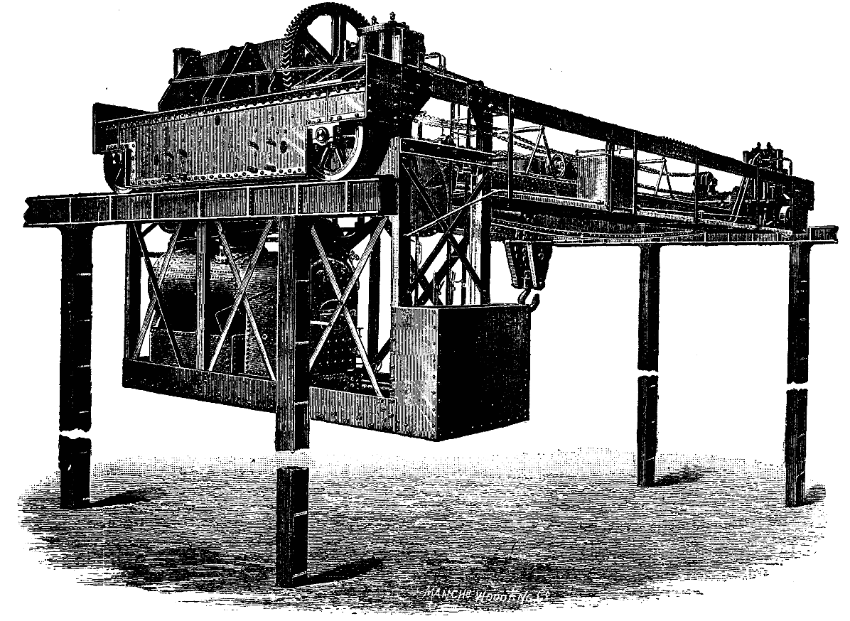
IMPROVED OVERHEAD TRAVELING CRANE.
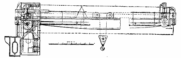
FIG. 2 SIDE ELEVATION.
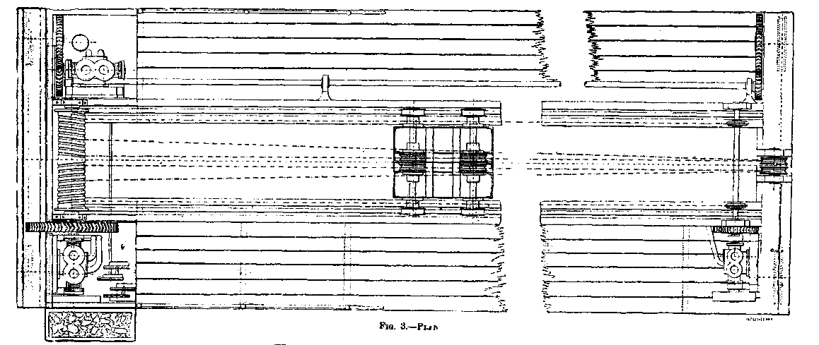
FIG. 3 PLAN.
It goes almost without saying that for any given service we want the best car wheel, and in general it is evident that this is the one best adapted to the efficient, safe and prompt movement of trains, to the necessary limitations improved by details of construction, and also the one most economical in maintenance and manufacture.
It is our aim this afternoon to look into this question in so far as the diameter of the wheel affects it, and in doing it we must consider what liability there is to breakage or derangement of the parts of the wheel, hot journals, bent axles, the effect of the weight of the wheel itself, and the effect upon the track and riding of the car, handling at wrecks and in the shop, the first cost of repairs, the mileage, methods of manufacture, the service for which the wheel is intended and the material of which it is made.
Confining ourselves to freight and passenger service, and to cast iron and steel wheels in the general acceptation of the term as being the most interesting, we know that cast iron is not as strong as wrought iron or steel, that the tendency of a rotating wheel to burst is directly proportional to its diameter, and that the difficulty of making a suitable and perfect casting increases with the diameter. Cast iron, therefore, would receive no attention if it were not for its far greater cheapness as compared to wrought iron or steel. This fact makes its use either wholly or in part very desirable for freight service, and even causes some roads in this country, notably the one with which I am connected, to find it profitable to develop and perfect the cast iron wheel for use in all but special cases.
Steel, on the other hand, notwithstanding its great cost, is coming more and more into favor, and has the great recommendations of strength and safety. It is also of such a nature that wheels tired with it run much further before being unfit for further service than those made of cast iron, and consequently renewals are less frequent. The inference would seem to be that a combination of steel and cast iron would effect the desirable safeness with the greatest cheapness; but up to the present this state of affairs has not yet been realized to the proper extent, because of the labor and cost necessary to accomplish this combination and the weakness involved in the manner of joining the two kinds of material together.
Taking up the consideration of the diameter of the wheel now, and allowing that on the score of economy cast iron must be used for wheels in freight service, we are led to reflect that here heavy loads are carried, and there is a growing tendency to increase them by letting the floor of the car down to a level with the draft timbers. All this makes it desirable to have the wheels strong and small to avoid bent axles and broken flanges, to enable us to build a strong truck, to reduce the dead weight of cars to a minimum, and have wrecks quickly cleared away. The time has not yet come when we have to consider seriously hot journals arising from high speed on freight trains, and a reasonable degree only of easy riding is required. The effect on the track is, however, a matter of moment. Judging from the above, I should say that no wheel larger than one 33 in. in diameter should be used under freight cars. Since experience in passenger service shows that larger cast iron wheels do not make greater mileage and cost more per 1,000 miles run, and that cast iron wheels smaller than 33 in., while sometimes costing less per 1,000 miles run, are more troublesome in the end, it is apparent that 33 in. is the best diameter for the wheels we have to use in freight service.
When we take up passenger service we come to a much more difficult and interesting part of the subject, for here we must consider it in all its bearings, and meet the complications that varying conditions of place and service impose. In consequence, I do not believe we can recommend one diameter for all passenger car wheels although such a state of simplicity would be most desirable. For instance, in a sandy country where competition is active, and consequently speed is high and maintained for a length of time without interruption, I would scarcely hesitate to recommend the use of cast iron for car wheels, because steel will wear out so rapidly in such a place that its use will be unsatisfactory. If then cast iron is used, we will find that we cannot make with it as large a wheel as we may determine is desirable when steel is used. And just to follow this line out to its close I will state here that we find that 36 in. seems to be the maximum satisfactory diameter for cast iron wheels, because this size does not give greater mileage than 33 in., costs more per 1,000 miles run, and seems to be nearer the limit for good foundry results. On the other hand, a 36 in. wheel rides well and gives immunity from hot boxes—a most fruitful source of annoyance in sandy districts. It is also easily applicable where all modern appliances under the car are found, including good brake rigging. In all passenger service, then, I would recommend 36 in. as the best diameter for cast iron wheels.
Next taking up steel wheels, a great deal might be said about the different makes and patterns, but as the diameter of wheels of this kind is not limited practically to any extent by the methods of manufacture, except as to the fastening of the wheel and tire together, we will note this point only. Tires might be so deeply cut into for the introduction of a retaining ring that a small wheel would be unduly weakened after a few turnings.
On the other hand, when centers and tires are held together by springing the former into the latter under pressure, it is possible that a tire of larger diameter might be overstrained. But allowing that the method of manufacture does not limit the diameter of a steel wheel as it does a cast iron one, the claim that the larger diameter is the best is open to debate at least, and, I believe, is proved to the contrary on several accounts. It is argued that increasing the diameter of a wheel increases its total mileage in proportion, or even more. Whether this be so or not, there are two other very objectionable features that come with an increase in diameter—the wheel becomes more costly and weighs more, without giving in all cases a proportionate return. We have to do more work in starting and stopping, and in lifting the large wheel over the hills, and when the diameter exceeds a certain figure we have to pay more per 1,000 miles run. I am very firmly convinced that the matter of dead weight should receive more attention than it does, with a view to reducing it. The weight of six pairs of 42 in. wheels and axles alone is 15,000 to 16,000 lb.
The matter of brakes is coming up for more attention in these days of high speed, heavy cars and crowded roads, and the total available braking power, which has hitherto been but partially taken advantage of, must be fully utilized. I refer to the fact that many of our wheels in six-wheel trucks have gone unbraked where they should not. As the height of cars and length of trucks cannot well be increased for obvious reasons, it is necessary to keep the size of the wheels within the limits that will enable us to get efficient brakes on all of them that carry any weight. This is not easy with a 42 in. wheel in a six-wheel truck, which is usually the kind that requires most adjustment and repairs after long runs. The Pullman Co. has recognized this fact, and is now replacing its 42 in. wheel with one 38 in. in diameter.
A 42 in. wheel with 4 in. journal has a greater leverage wherewith to overcome the resistance of journal friction than the 38 in. wheel with the same journal, and even more than the 36 in. and 33 in. wheels with 33/4 in. and 31/2 in. journals respectively, but the fact remains that the same amount of work has to be done in overcoming the friction in each case, and what may be gained in ease of starting with the large wheel is lost in time necessary to do it, and in the extra weight put into motion.
A large wheel increases the liability to bent axles in curving on account of greater leverage unless the size and weight of the axle are increased to correspond, and the wheel itself must be made stronger. A four or six wheel truck will not retain its squareness and dependent good riding qualities so well with 42 in. wheels as with 33 in. ones. Besides the brakes, the pipes for air and steam under the cars interfere with large wheels, and as a consequence of all this 42 in. wheels have been replaced by 36 in. ones to some extent in some places with satisfactory results. On one road in particular so strong is the inclination away from large wheels that 30 in. is advocated as the proper size for passenger cars.
On the other hand, there is no doubt a car wheel may be too small, for the tires of small wheels probably do not get as much working up under the rolls, and therefore are not as tough or homogeneous. Small wheels are more destructive to frogs and rail joints. They revolve faster at a given speed, and when below a certain size increase the liability to hot journals if carrying the weight they can bear without detriment to the rest of the wheel. Speed alone I am not willing to admit is the most prolific source of hot boxes. The weight per square inch upon the bearing is a very important factor. I have found by careful examination of a great many cars that the number of hot boxes bears a close relation to the weight per square inch on the journal and the character of lubrication, and is not so much affected by the size of wheel or speed. These observations were made upon 42 in., 36 in. and 33 in. wheels in the same trains. We find, furthermore, that while a 3-3/8 in. journal on a 33 in. wheel is apt to heat under our passenger coaches, a 33/4 in., even when worn 3-5/8 in., journal on a 36 in. wheel runs uniformly cool. In 1890 on one division there were about 180 hot boxes with the small wheel, against 29 with the larger one, with a preponderance of the latter size in service and cars of the same weight over them.
I do not know that there is any more tendency for a large wheel to slide than a small one under the action of the brakes, but large wheels wear out more brake shoes than small ones, if there is any difference in this particular.
My conclusions are that 42 in. is too large a diameter for steel wheels in ordinary passenger service, and that 36 in. is right. But as steel-tired wheels usually become 3 in. smaller in diameter before wearing out, the wheel should be about 38 in. in diameter when new. Such a wheel can be easily put under all passenger cars and will not have become too small when worn out. A great many roads are using 36 in. wheels, but when their tires have lost 3 in. diameter they have become 33 in. wheels, which I think too small.
There are many things I have left unsaid, and I am aware that some of the members of the club have had most satisfactory service with 42 in. wheels so far as exemption from all trouble is concerned, and others have never seen any reason for departing from the most used size of 33 in.
One more word about lightness. A wrought iron or cast steel center, 8 or 9 light spokes on a light rim inside a steel tire, makes the lightest wheel, and one that ought to be in this country, as it is elsewhere, the cheapest not made of cast iron.
[1]As I fear the title of my paper to our Society to-night contains two misstatements of fact in its three words, I must commence by correcting it. In the first place, the instrument to which I propose to draw your attention to-night is, in the narrow sense of the words, neither an integrator nor new. The name "integrator" has been especially applied to a class of instruments which measure off on a scale attached to them the magnitude of an area, arc, or other quantity. Such instruments do not, as a rule, represent their results graphically, and we may take, as characteristic examples of them, Amsler's planimeter and some of the sphere integrating machines.
An integrator which draws an absolute picture of the sum or integral is better termed an "integraph." The distinction is an important and valuable one, for while the integraph theoretically can do all the work of the integrator, the latter gives us in niggardly fashion one narrow answer, et præterea nil. The superiority of the integraph over the integrator cannot be better pointed out than by a concrete example. The integrator could determine by one process, the bending moment, from the shear curve, at any one chosen point of a beam; the integraph would, by an equally simple single process, gives us the bending moment at all points of the beam.
In the language of the mathematician, the integrator gives only that miserly result, a definite integral, but the integraph yields an indefinite integral, a picture of the result at all times or all points—a much greater boon in most mechanical and physical investigations. Members of our Society as students of University College have probably become acquainted with a process termed "drawing the sum curve from the primitive curve." Many have probably found this process somewhat wearisome; but this is not an unmixed evil, as the irksomeness of any manual process has more than once led to the invention of a valuable machine by the would-be idler. Thus our innate desire to take things easy is a real incentive to progress. It was some such desire as this on my part which led me, three years ago, to inquire whether a practical instrument had not been, or could not be, constructed to draw sum curves. Such an instrument is an integraph, and the one I have to describe to you to-night is the outcome of that inquiry. It is something better than my title, for it is an integraph, and not an integrator.
A NEW INTEGRATOR.
Before I turn to its claims to be considered new, I must first remind you of the importance of an instrument of this kind to the draughtsman. I put aside its purely mechanical applications, where it has been, or can be, attached to the indicators of steam engines, to dynamometers, dynamos, and a variety of other instruments where mechanical integration is of value. These lie entirely outside my field, and I propose only to refer to a few of the possible services of the integrator when used by hand, and not attached to a machine.
The simple finding of areas we may omit, as the planimeter will do that equally well. But of purely graphical processes which the integraph will undertake for us, I may mention the discovery of centroids, of moments of inertia (or second moments), of a scale of logarithms, of the real roots of cubic equations, and of equations of higher order (with, however, increasing labor). Further, the calculation of the cost of cutting and embanking for railways by the method of Bruckner & Culmann, the solution of a very considerable number of rather complex differential equations, various problems in the storage of water, and a great variety of statistical questions may all be completely dealt with, or very much simplified by aid of the integraph.
In graphical statics proper the integraph draws successively the curves of shear, bending moment slope, and deflection for simple beams; it does the like service for continuous beams, after certain analytical or graphical calculations have first been made; it can further lighten greatly the graphical work in the treatment of masonry arches and of metal ribs. In graphical hydrostatics it finds centers of pressure and gives a complete solution for the shear and bending moment, curves in ships, besides curves for their stability. In graphical dynamics the applications of the integraph seem still more numerous. It enables us to pass from curves of acceleration to curves of speed, and from curves of speed to curves of position. Applied to the curve of energy of either a particle or the index point of a rigid body, it enables us by the aid of easy auxiliary processes to ascertain speeds and curves of action. In a slightly altered form, that of "inverse summation," we can pass from curves of action to curves of position, and deal with a great range of resisted motions, the analysis of which still puzzles the pure mathematician; the variations of motion in flywheels, connecting rods, and innumerable other parts of mechanism, may all be calculated with much greater ease by the aid of an integraph. Shortly, it is the fundamental instrument of graphic dynamics.
It would be needless to further multiply the instances of its application; the questions we have rather to ask are: Can a practical instrument be made which will serve all these purposes? Has such an instrument been already put upon the market? If I have to answer these questions in the negative, it is rather a doubtful negative, for the instrument I have to show you to-night goes so far, and suggests so many modifications and possibilities, which would take it so much further, that it is very close to bringing the practical solution to the problem.
Let me here lay down the conditions which seem essential to a practical integraph. These are, I think, the following:
1. The price must be such that it is within the reach of the ordinary draughtsman's pocket. The Amsler's planimeter at £2 10s. or £3 may be said to satisfy this first condition. The price for the first complex integraph designed by Coradi was £24 to £30. The modified form in which I show it to-night is estimated to cost retail £14. Till an equally efficient instrument can be produced for £5 I shall not consider the price practical. If the error of its reading be not sensibly greater than that of a planimeter, it is certainly worth double the money.
2. The instrument must not be liable to get out of order by fair handling and a reasonable amount of wear and tear. I cannot speak at present with certainty as to how far our integraph satisfies this condition; it is rather too complex to quite win my confidence in this respect.
3. It must be capable of being used on the ordinary drawing board, and of having a fairly wide range on it, i.e., it must not be limited to working where the primitive is at one part only of the board.
This condition takes out of every day practical drawing use the integraph invented by Professors James and Sir William Thomson, in which the sum curve is drawn on a revolving cylinder. It is essential that the sum curve should be drawn on the board not far from the primitive, and that this sum curve can be summed once or twice again without difficulty. The time involved in drawing the four sum curves, for example, required in passing from the load curve to the deflection curve of a simple beam, if these curves were drawn on different pieces of paper and had to be shifted on and off cylinders, would probably be as long as the ordinary graphical processes. Coradi's integraph works on an ordinary drawing board, but since there are nearly 10 inches between the guide point and tracer, the sum curve is thrown 10 inches behind the primitive in each integration. Thus a double summation requires say 26 inches of board, and it is impossible to integrate thrice without reproducing the primitive. The fact that the primitive and sum curve are not plotted off on the same base is also troublesome for comparison, and involves scaling of a new base for each summation. I have endeavored to obviate this by always drawing the second sum curve on a thin piece of paper pinned to the board, which can then be moved back to the position of the first primitive. But this shifting, of course, involves additional labor, and is also a source of error.
I should like to see the trace and guide chariots on the same line of rails, one below the other, were this possible without producing the bad effect of a skew, pull or push.
4. The practical integraph must not have a greater maximum error than 2 per cent. The mathematical calculations, which are correct to five or six places of decimals, are only a source of danger to the practical calculator of stresses and strains. They tend to disguise the important fact that he cannot possibly know the properties of the material within 2 per cent. error, and therefore there is not only a waste of time, but a false feeling of accuracy engendered by human and mechanical calculation which is over-refined for technical purposes.
For comparative purposes I have measured the areas of circles of 1 inch, 2 inches, and 3 inches radius, the guide being taken round the circumference by means of a "control lineal," first with an ordinary Amsler's planimeter and then with the integraph. I have obtained the following results:
| By integraph. | ||||||
|---|---|---|---|---|---|---|
| Radius of circle. in. | Calculated areas. | By Planimeter. | Middle. p=2 in. | Upper end. p=2 in. | Middle. p=4 in. | Upper end. p=4 in. |
| 1 | 3.14159 | 3.140 | 3.140 | 3.138 | 3.120 | 3.120 |
| 2 | 12.56636 | 12.55 | 12.36* | 12.546 | 12.568 | 12.552 |
| 3 | 28.27431 | 28.24 | .. | .. | 28.280 | 28.288 |
* Cross bar had to be moved during tracing.
From this it follows that the error of the planimeter is less than 0.1 per cent. and that of the integraph about 0.5 per cent. Obviously we could make this error much less if we excluded small areas measured with large polar distances, or such polar distances that the cross bar must be shifted. Excluding such cases, we see that the accuracy of the integraph scarcely falls behind that of the planimeter and is quite efficient for practical purposes. It must be borne in mind that the above measurements were made with the "control lineal," an arrangement which carries the guide round a circle of the exact test area. In most cases the curve has to be followed by hand, and the error will be greater—greater probably for the integraph than for the planimeter, as the former is distinctly hard to guide well.
I think, then, we should be safe in saying that the error of the integraph is not likely to be greater and is probably less than 2 per cent., so that in this respect the instrument may be considered a practical one.
5. A further condition for a good integraph is that it should have a wide range of polar distances, and that it should be easily set at those distances.
One of the conditions I gave to the maker of the instrument was that it should be able to take all polar distances from one to ten half-inches. This condition he can scarcely be said to have fulfilled. With polar distances of 1/2 inch and 1 inch, the machine works unsatisfactorily, which indeed might have been foreseen from the construction of its sliding bars. It works best from 2.5 inches to 5 inches, and this is the range to which I think we ought to confine the present type of instrument. As the last conditions I may note that:
6. A practical integraph ought to be easy to read.
7. Draw a good clear curve.
The scale on the present instrument is very inconvenient, as it is often almost out of sight; the curve it draws, on the other hand, I consider very satisfactory, when the pencil is loaded, say, with a planimeter weight. On the whole, I think you will agree with me that this integraph goes a good way, if not the whole way, toward fulfilling the conditions of a practical instrument.
I next turn to its construction and the claim it has to be considered in any way new. Let me briefly remind our members of the process by which an element Q R of the sum curve (Fig. 1) corresponding to the point P on the primitive is drawn; P M being the mid-ordinate of L N, a horizontal element, P B is drawn perpendicular to any vertical line A B; and O A being a constant distance termed the base or "polar distance," Q R is drawn between the ordinates of L and W, parallel to O B. If P' be the point where P M meets Q R, we note the following relationship of P' to P.
1. If P moves along a horizontal line, O B remains unchanged, and, therefore, Q R or P' must move in the straight line Q R parallel to O B.
2. If P moves along a vertical line, P' does not change, but Q R turns round it, remaining parallel to O B.

FIG. 1, 2, 3.
Without taking the trouble, as I ought to have done, to inquire what previous investigations had achieved in this matter, I thought, three years ago, I could get an apparatus to save me the trouble of drawing sum curves, made somewhat after the following fashion.
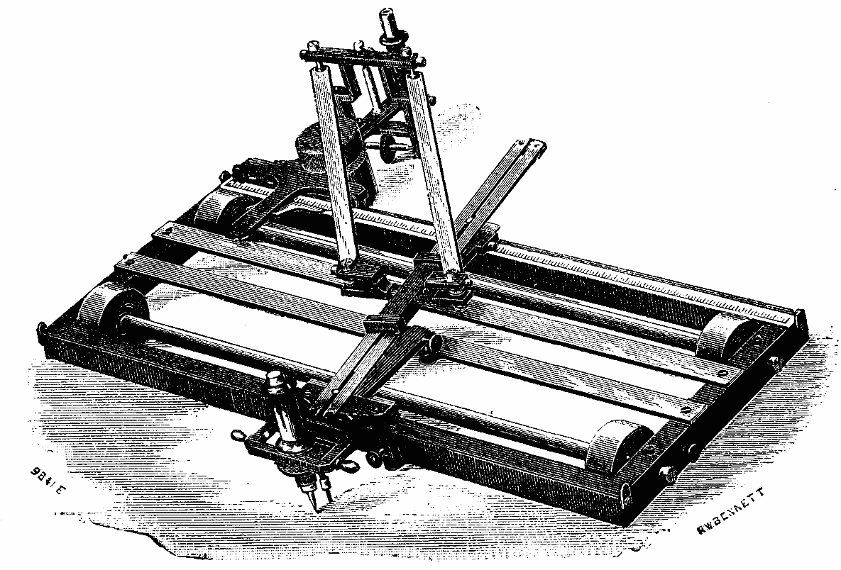
P (Fig. 2) is the guide or point to be taken round the primitive. It is attached to a block, D, which works along the bar, B C, which in its turn moves on the four wheels, e e f f, upon the frame R S U T fixed upon the drawing board. O A is fixed perpendicular to R U, and is such that O may be fixed at various points to determine the polar distance. O B D is a light bar passing freely through B and forming one side of a parallel ruler of two or more points, g g, h h, i i. Along i i is a slot and in this works a loaded block containing a wheel P', whose plane is always parallel to i i. This block also passes through a slot in D E, an arm at right angles to B C. A little consideration will show that P', if worked at all, would trace out the sum curve of P.
It was only when I showed the rough idea of this to Professor Kennedy, with the view of ascertaining what would be the amount of back-lash and friction, that I learned that Mr. Boys had already invented a very similar integrator. In his model the double parallel ruler is replaced by two endless strings and pulleys, and the bar, B C, by a T square.
Although this integrator was afterward made in a less crude form, I do not think it has ever been a practical instrument for the draughtsman. Shortly afterward I came across a work by Abdank-Abakanowicz, entitled "Les Integraphes," being a study of a "new kind of mechanical integrator."
The new kind of integrator was really only an independent version of Boys' instrument, but in many respects a great improvement. The real merit will ultimately belong to the scientific instrument maker who constructs an instrument reasonably cheap and capable of efficient practical service. Abdank-Abakanowicz's integrator however certainly went further in the practical direction than any previously constructed. The drawing board machines, it is true, of rather a complex nature, were actually exhibited to the Paris Academy, but no more have been made. The instrument before me was made by Coradi, of Zurich, on conditions laid down by me, namely, that the cost should not exceed £14, and that polar distances should range between one and ten half-inches. The first machine made by Coradi on these lines was, by a misunderstanding, sold in Germany, but the one I exhibit is the first, I believe, that has reached England, and to this extent I may, perhaps, be permitted to call it new. I look upon it rather as a suggestion upon which a still more practical instrument can be made in this country than as a perfect model. I believe there would be a wide sale for such an instrument were it once generally known to exist, and, what is more to work efficiently. It remains for me to point out in what the Abdank-Abakanowicz, or, rather, Coradi, integraph differs from Boys' instrument.
Two points deserve special attention. In the first place, the fixed frame is abolished, and the horizontal motion of P (Fig. 3), the guide point, is produced by putting the whole frame on friction rollers; in the second place, as a necessary result of the first change, the guide point carries about with it its own polar system, which renders the changes in length of "rays" much more manageable. f f, f' f' is a frame moving on four roughed wheels, e e e e, so that it can only move in the direction, f', which we may term horizontal. f f and f' f' are rails guiding the chariots, A and B, from f to f and from f' to f'. Of these chariots, A contains the guide point, P, to trace out the primitive with, and B the pencil, P', to draw the sum curve, i.e., the tracer. The chariot, B, like Boys' tracer, is heavily loaded. g g is a horizontal bar rigidly attached to the crossbars, q q and q' q', of the frame. On g g is a movable pivot, to which h, which determines the pole, k0 h being the polar distance. k0 is the position of a second point, k, on the chariot, A, when the guide point, P, is on the initial line, g g. l l is a bar with a long slot in it, in which work the pivots, h and k; this bar represents the "ray." A projecting arm k k' has been introduced to enable me to shorten the polar distance down to 2 in. and under by removing the pivot, k to k'. m m is a bar attached to the block, n, which runs on l l, so that m m is always perpendicular to l l. On the chariot, B, is another bar, m' m', capable of turning round the pivot, d, and always maintained parallel to m m by the rods, m m', m m'. Attached to m' m' is a wheel, w, whose axis is parallel to m' m'. This wheel, therefore, always moves perpendicular to m' m', and therefore to m m; hence it moves parallel to the ray, h k. A pencil, P', attached traces out the sum curve. If we wish to use the machine as an integrator, we have merely to measure the vertical distance traversed by P', or the distance B has run along f' f'. This is done by means of a scale on f f'. If k be brought down to k0, w runs parallel to g g, or P' traces out a horizontal straight line, which is thus the base line. If k be fixed as near as possible to k0, which is done by means of a screw in f f at k0, the chariot, B, can be run down f' f' as nearly opposite to k0 as can be guessed at; a horizontal line may then be drawn as base line, and the guide point, P, brought into this line by a clamping screw with which it is provided. The instrument is then ready for action. There is a brake on one of the roughed wheels to check or stop the motion of the integraph when required.
The instrument works best when the chariots, A and B, are about opposite to each other; when they are at opposite extremities of f f and f' f' respectively, the pull at P tends to produce a skewing couple. If the chariot, B, could be put upon f f and work, if needful, by a double parallelogram from m m, we should have, excepting the skew pull, some great practical advantages. We might throw the whole of the weight of the machine on the one pair of friction wheels, and replace the other pair by a single wheel, the portion q' f' f' q' of the machine virtually disappearing. Three wheels, of course, would be a real improvement. Further, we should have the sum curve and primitive drawn to the same base line, and the simplification in the number of parts ought largely to reduce the cost of the instrument.
To be able to perform "inverse summation" (which in the language of differential calculus is to find y as a function of x, when we are given y=f(dy/dx), and not dy/dx=f(x) as usual), we only want a means of making the plane of the wheel, w, parallel instead of perpendicular to m' m', and it is easy to design a modification in the construction which will allow of this change.
I hope the above description of the integraph may have made its construction and method of working sufficiently clear. Those of you who have a taste for mechanical work, and the necessary tools, might, I think, with some patience, construct a workable integraph. I expect the pivots would be the hardest part of the work. I hope, some day, myself to have another instrument made with a more readily changeable polar distance, with trace and guide points working in the same vertical, and a wheel permitting of inverse summation. If this project is ever carried out, I hope I may be permitted to communicate further particulars to our society.
[1]After some forty years of immersion in the waters of the pool of Echoschacht, not far from Hermannstadt, several human bodies have been brought to the surface in a state of perfect preservation.
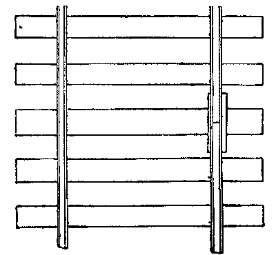
The usual dimensions of track spikes are 51/2 X 9.16 inches square, their weight about half a pound each. Their common defects are brittleness and imperfect points. In spiking track, the most important points to be attended to are the proper spacing of the ties and driving the spikes in such a manner that the ties shall be held in place at right angles to the track and the rails in true gauge; to insure the latter, the track gauge should always be used when spiking the gauge side, the rail being held to proper position by a lining bar. The gauge should be kept about 6 or 8 in. ahead of the tie being spiked and should not be lifted until the spikes are driven home; gauges should be tested regularly and every morning when they are to be used all day, so as to insure a true gauge all the time. The two inner spikes should be set on one side of the tie and the two outer spikes on the other, as indicated in the accompanying sketch. This prevents the tie from slewing around, and thus deranging the gauge of the track, as well as interfering with the proper spacing of the ties. The joints and centers should be spiked first, which will bring the rails to their proper position on the ties, which in turn will assist intermediate spiking. Each tie should be carefully gauged as spiked and, as before indicated, the ties with the broadest faces being selected for the joints.
In gauging ties it is very convenient to have measured off on the handles of the mauls in the hands of the forward spikers the distance from the outside of the rail to the end of the tie. This distance will then be gauged on the tie, when it will be lifted to the rail and securely spiked; the gauge is then used, and the loose rail held in place with the lining bar as previously indicated, loose gauge being given on curves, in accordance with directions of the engineer, the allowance for which is about 1/8 in. on a 2° curve, up to about 3/4 in. on a 12° curve.
This widening of the gauge should begin on the tangent, back of the P.C., the full amount of excess over true gauge being reached by the time the P.C. is reached and continue all the way around the curve, running from the P.T. in the same manner as back of the P.C.
The spikes should always be driven home straight and at right angles with the face of the ties. When the foreman in charge of the track-laying work sees a spiker, when the spike is nearly home, strike the spike head laterally, which is done to make it lie snugly to the rail, he should at once check such imperfect work and put the man who does it at other work. The foreman in charge of gang of spikers should be experienced in this branch of the work, and by weeding out imperfect workers, can soon get together a first-rate gang of spikers. But no trouble will be experienced from carelessly driven spikes, if the tie has the spike holes bored into it, before laying. This is considered good practice, but rather expensive.
For boring the holes quickly and accurately, a proper template should be made, by which the ties are marked for the borers, who should be provided with boring machines, by the use of which a hole, square with the face of the tie is bored. The boring machines should be so arranged as not to cut the hole beyond the required depth, which should be slightly less than the length of the spike. The diameter of the holes should be about 1-16 of an inch less than the thickness of the spike. This not only does away with the spike tearing its way through the timber and thus injuring its fiber to a great extent and causing it to be much more susceptible to rot, but it is said to increase the adhesion of the spike in hard wood ties at least 50 per cent. But in order that the best results may be obtained, the spike should be flattened on either side of the sloping point, which will generally prevent it leaving the hole.
The spikers should carefully avoid striking the rail with their mauls, as such carelessness often produces fracture, which sometimes causes the rail to break in two at such points, which is liable to produce derailment and serious accident. Spike mauls should weigh not less than nine nor more than ten pounds, and should be on straight handles, not less than 3 ft. long. After considerable use, the face of the maul will become somewhat rounded, and when this takes place it should be sent to the shop to be redressed. The last blow on the spike should be only sufficiently hard to cause its throat to fit snugly on the rail; a harder blow will often fracture the spike in such a manner as to cause the head in a short time to break off and leave the rail unsupported at that point. Foremen should not allow a spike to be pulled, especially in frosty weather, until it has been first struck a light blow to break the rust and loosen its hold in the wood. The filling of old spike holes with wooden plugs is bad practice, for the reason that they will cause the spike in a short time to slip from its place; to fill the holes with sand is much better, and spikes driven in holes so filled will hold much more firmly. The best form of spike I have seen is the curved safety railroad spike; this spike takes in the tie a position which enables it to resist the thrust of the rail against it much more effectually than the ordinary spike can possibly do. I have seen in good condition, one of these curved spikes which was said to have been driven eight times. The cost of the curved safety spike is more than that of the ordinary spike, but it is better made, holds the track better, and, I believe, is worth more than the difference asked for it.—J.A. Hall, on Construction and Maintenance of Track, before American Society of Civil Engineers.
The desperate war that has been waging between the gun and armor plate, ever since the period when protective plates were first applied to naval constructions, is familiar to all. In this conflict the advantage seems to lean toward the side of the gun, the power of penetration of which can be increased to almost indefinite limits, at least theoretically, while we quickly reach the extreme thicknesses of metal that can be practically employed for the protection of ships.
So, in recent times, researches have been making upon the efficacy of armor plating, no longer in its exaggeration of thickness, but in the intrinsic quality of the metal of which it is composed. Metallurgists have applied themselves to the work and have thus brought out various products, among which the plates called "compound," of Messrs. Cammell & Co., have obtained a great notoriety. These plates, formed of a true plating of steel upon a bed of soft iron, have been much in vogue in the English navy, and seemed as if they were to be adopted about everywhere.
The Creusot works alone, of all competitors, were able to fight against the general infatuation. Many comparative experiments had already demonstrated the superiority of the Creusot "all steel" plates over the Cammell plates, but Messrs. Schneider & Go. were not willing to stop here, and finally produced the new nickel steel plate, which is by far superior to their steel plates.
Some comparative trials of these various armor plates have recently been made by a military commission of the United States at the Annapolis proving grounds. Three plates, one a Cammell, the second a steel, and the third a nickel steel (the two last from Creusot), were here submitted to firing, under absolutely identical conditions.
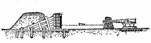
Our engravings show the proving grounds and the details of the arrangements adopted for backing the plates.
Of the three plates, the Cammell was the thickest (11 in.) The steel one was 103/4 in. in thickness, and the nickel steel 101/2 in. The last, therefore, was at a disadvantage with respect to the two others.
The plates were arranged tangentially to an arc of a circle whose center was occupied by the pivot of the gun, and consequently at right angles with the latter. The piece employed was a 6 in. gun, 35 calibers in length. The distance of its muzzle from the plates attacked was 28 ft.
The charge was 44 lb. of brown prismatic powder. The projectile was a 100 lb. Holtzer shell. Under these circumstances, the initial velocity was 2,074 ft. and the energy at the impact was 9,970,396 ft. lb.
A beginning was made by firing four shots at each plate in the bisectrix of the corners. Then the 6 in. gun was replaced by an 8 in. one, throwing a 209 lb. Firth projectile, with an energy at the impact of 20,795,000 ft. lb.
Each of the plates then received in its center a final blow from this projectile.
Our engraving represents the state of the plates after this last shot.
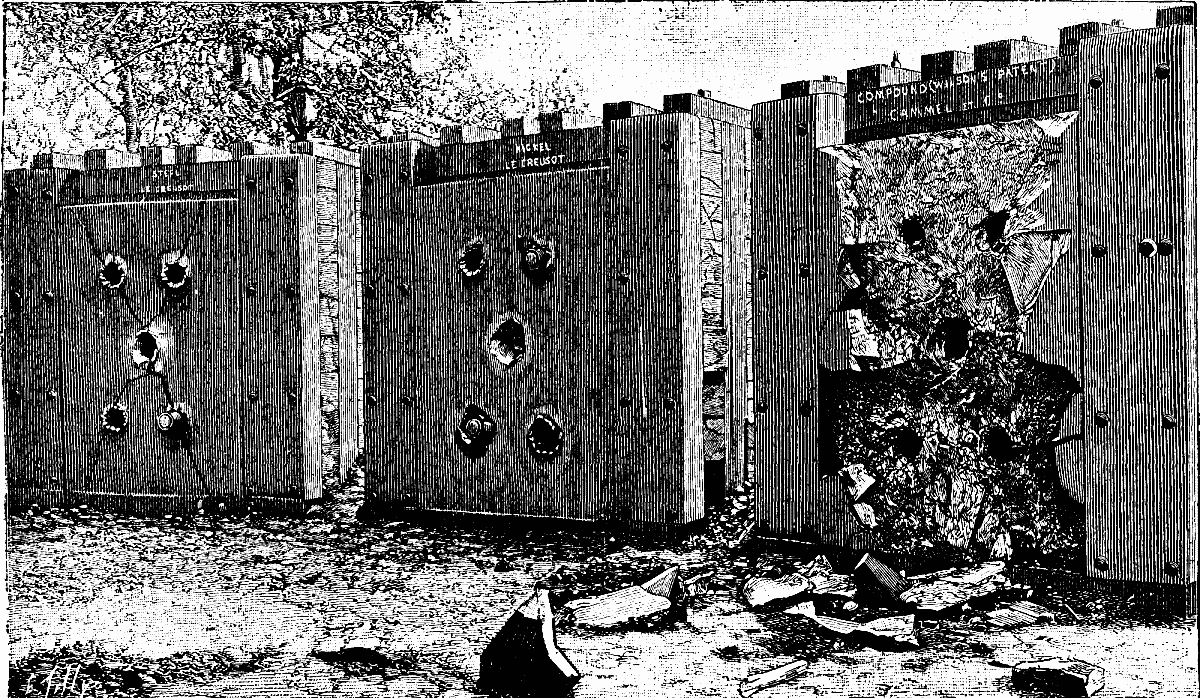
ARMORED PLATE TESTS AT ANNAPOLIS.
There is no need of being a great expert in questions of artillery to discover on what side the superiority is found, and to see that the Cammell plate, almost entirely in fragments, is absolutely incapable of protection, while its two competitors are still in a state to resist.
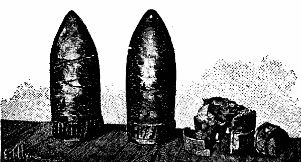
In one of our engravings may be seen, too, the state of the shells after each of the three shots.
The commission immediately and unanimously classified the three plates in the following order of superiority: (1) Nickel steel; (2) all steel; (3) compound.
This triumph of French industry merits mention so much the more in that it was obtained in a series of experiments made in a foreign country—that is to say, under indisputable conditions of impartiality.-L'Illustration.
In commencing my paper this evening I desire to call your attention to the fact that I am dealing with a subject which, though not theoretical, is still hardly practical, for as a matter of fact high explosives cannot be said to have yet been regularly used in warfare, and I hope you will pardon me if in consequence my statements appear in some respects unsatisfactory and my theories unsound. My subject, however, is no more obscure than future naval warfare generally. All civilized nations are spending millions of money for fighting purposes directly in opposition to the higher feelings of the better class of their inhabitants. The political atmosphere of Europe is the cause of this, but its consequence is the development of theoretical plans of ships which are no sooner commenced than the rapid march of mechanical, chemical, and electrical science shows them to be faulty in some particular feature, and others are laid down only to be superseded in their turn.
None of these crafts are obsolete (to use the popular expression of the day). All are theoretically better than any which have stood the test of battle; but each excels its predecessor in some particular feature. The use of high explosives is the direct cause of the very latest transformations in marine architecture, and is destined to work still greater changes; but it will require a war between the most civilized nations of the world, and a long war, to either confirm or condemn the many theoretical machines and methods of destruction that modern science has produced. I say a war between the most civilized nations, since it is only they that can supply the educated intellect that is necessary to both attack and defense. Under other circumstances false conclusions as to weapons and results are certain to be drawn.
At the bombardment of Alexandria, the English armorclads, with their rifled guns, were not nearly as efficient against the feeble chalk fortifications as our wooden ships would have been with smooth bore guns. On the other hand I saw on shore after the bombardment hundreds of torpedoes and miles of cable that the Egyptians did not understand how to use. The French war with China was equally unsatisfactory from a military point of view. The Chinese at Foochow were annihilated because the French opened fire first, and the only shell that penetrated a French ironclad was filled with lamp black instead of powder. The national riots that we are accustomed to hear of in South America are likewise of little instructive value; they buy their weapons of more civilized people, but there is always something fatally defective about the tactics pursued in using them. It may be said in general terms that in these days of extreme power in fighting machines, the greater the efficiency the less the simplicity and the more knowledge required in the care of the weapons. When powder was merely powder the advice of the old adage to "trust in God and keep your powder dry" was ample to maintain the efficiency of the powder for all purposes; but nowadays if you keep your powder dry you will burst your gun, and if you keep your gun-cotton dry you are liable to blow up your ship.
It is rather difficult to-day to define what high explosives are, in contradistinction to gunpowder. Thirty years ago we could say that powder was a mechanical mixture and the others were chemical compounds; but of late years this difference has disappeared.
The dynamical difference, however, still remains. Gunpowder in its most efficient form is a slow-burning composition, which exerts a relatively low pressure and continues it for a long time and to a great distance. High explosives, on the contrary, in their most efficient form, are extremely quick-burning substances, which exert an enormous pressure within a limited radius. Ordinary black gunpowder consists of a mechanical mixture of seventy-five per cent. of saltpeter, fifteen per cent of charcoal, and ten per cent. of sulphur. The most important of the high explosives are formed by the action of nitric acid upon organic substances or other hydrocarbons, the compound radical NO2 being substituted for a portion of the hydrogen in the substance. The bodies thus formed are in a condition of unstable equilibrium; but if well made from good material, they become stable in their instability, very much like Prince Rupert's drops, those little glass pellets which endure almost any amount of rough usage; but once cracked, fly into infinitesimal fragments.
The power exerted by these nitro-substitution products is due to the fact that they detonate, i.e., they are instantaneously converted into colorless gas at a very high temperature, and in addition they have almost no solid residue. Nitro-glycerine actually leaves none at all, while gunpowder leaves sixty-eight per cent. The first departure in gunpowder from the old-time constituents of black powder just mentioned was for the purpose of obtaining less pressure and slower combustion than could be produced by mere granulating or caking. This was accomplished by using underburned charcoal, together with sugar and about one and one-half per cent. of water. This is the brown powder most generally used at present and with satisfactory results; but the abstraction of its moisture increases its rapidity of combustion to a dangerous degree, besides which the underburned charcoal is itself unstable.
The next change demanded is smokelessness, and to accomplish it recourse is had to the high explosive field, mechanically mixing various substances with them to reduce and regulate their rapidity of action. Just now some form of gun-cotton is most in use mixed with nitrate of ammonia, camphor and other articles. The tendency of these mixtures is to absorb moisture, and the gun-cotton in them to decompose, and there is no smokeless powder which can to-day be considered successful. Such a powder, however, will undoubtedly be an accomplished fact in the near future. Military men seem to be a great deal at variance as to its value in the field, but there can be no doubt of its value for naval purposes; it is a necessity forced upon us by the development of torpedo warfare.
First came the simple torpedo, at the end of an ordinary boat's spar. Then came the special torpedo boat with its great speed, then the revolving cannon and rapid-fire gun to meet the torpedo boat. At present the possible rapidity of fire is much greater than can be utilized, on account of the smoke; hence the necessity of smokeless powder. Smokelessness is, however, principally a martial demand that has been made upon the science of explosives and has attracted public attention on that account. The commercial demands for various other properties have been much greater than the military, and between gunpowder near one end of the line in point of power and nitro-glycerine near the other, there are now over 350 different explosives manufactured, and most of these have been invented within the last twenty years.
The simplest application of high explosives in warfare is in connection with torpedoes, since within the same bulk a much more efficient substance can be obtained than gunpowder, and with reasonable care there is very little danger of premature explosions by reason of accidental shocks.
Torpedoes were made by the Chinese many years ago, they were tried in our war of independence, and also by the Russians during the Crimean war; but the first practical and successful use of them as a recognized weapon was during our war of secession, when thirty-seven vessels were either sunk or seriously injured by them. Gunpowder was used in these torpedoes, though it is stated that attempts were made to use other substances without success. Since that time all maritime nations have made a close study of the subject and have adopted various high explosives, according to the results of their experiments. In general terms it may be stated that explosive chemical compounds have been found more suitable than explosive mixtures, because of the uniformity of direction in which they exert their pressure, and from the fact that water does not injure them. Mixtures may be very powerful, but they are erratic and require tight cases. In the United States we use dynamite for harbor mines. It is composed of seventy-five per cent. nitro-glycerine and twenty-five per cent. silica; but blasting gelatine and forcite gelatine will probably be adopted, when they can be satisfactorily manufactured here, as they are more powerful. The former is composed of ninety-two per cent. of nitro-glycerine and eight per cent. of gun-cotton, and the latter of ninety-five per cent. of nitro-gelatine and five per cent. unnitrated cellulose.
For naval use we have adopted gun-cotton as being the most convenient. In Europe gun-cotton is generally used for both fixed mines and movable torpedoes; Russia, Austria, and Italy use blasting gelatine also.
In actual warfare but little experience has been had. Two Peruvian vessels were sunk by dynamite in the Chili-Peruvian war, one Turk by means of gun-cotton during the Turco-Russian war of 1877, and two Chinese by gun-cotton in the Franco-Chinese war of 1884.
In making experiments to determine the relative strength of the different explosives under water, very curious and puzzling results have been obtained. Nitro-glycerine being the simplest and most complete in its chemical decomposition, and apparently the most powerful in air, it was natural to suppose that it would be the same in submarine work, but it was found by Gen. Abbot, at Willets Point, after repeated experiments, as shown in his report of 1881, that it was not so powerful in its effect by twenty per cent. as dynamite No. 1, although the dynamite contained twenty-five per cent. of an absolutely inert substance. His idea was that it was too quick in its action, and, since water is slightly compressible, a minute fraction of time is required in the development of the full force of the explosive. Gen. Abbot's results for intensity of action per unit of weight of the most important substances is as follows:
| Blasting gelatine | 142 |
| Forcite gelatine | 133 |
| Dynamite No 1 | 100 |
| Gun-cotton, wet | 87 |
| Nitro-glycerine | 81 |
| Gunpowder | 20 to 50 |
Col. Bucknill, of the Royal Engineers, in his publication of 1888, gives the following:
| Blasting gelatine | 142 |
| Forcite gelatine | 133 |
| Dynamite No. 1 | 100 |
| Gun-cotton, dry | 100 |
| Gun-cotton, dry | 80 |
| Gunpowder | 25 |
In both tables dynamite No. 1 is assumed as the standard of comparison. Col. Bucknill states that his gun-cotton results differ from Gen. Abbot's, because he experimented with much larger quantities, viz., 500-pound charges. Gen. Abbot's experiments led him to believe that an instantaneous mean pressure of 6,500 pounds per square inch would give a fatal blow to the double bottom of a modern armorclad, and he developed a formula which gives this blow with blasting gelatine at the following distances under water, viz.:
| Pounds | |
|---|---|
| At 5 feet | 4 |
| At 10 feet | 17 |
| At 20 feet | 67 |
| At 30 feet | 160 |
| At 40 feet | 311 |
Col. Bucknill's experiments caused him to believe that a pressure of 12,000 pounds per square inch is required, and his formula, which is somewhat different from Abbot's, gives widely different results at close quarters, but they approach each other as the distance increases.
His results are as follows:
| Pounds | |
|---|---|
| At 5 feet | 231/2 |
| At 10 feet | 75 |
| At 20 feet | 177 |
| At 30 feet | 274 |
| At 40 feet | 369 |
Regarding the comparative effects of gunpowder and the high explosives, I think Gen. Abbot's estimate of a varying value for powder is more admissible than the fixed value assigned by Col. Bucknill. Gunpowder gives a push and detonating compounds a shock; as the quantities increase, the push reaches farther than the shock. According to Gen. Abbot, 100 pounds of dynamite No. 1 will have a destructive horizontal range of 16.3 feet, while the same amount of gunpowder will only have a range of 3.3 feet. Five hundred pounds of dynamite, however, will have a horizontal range of 35 feet, and 500 pounds of gunpowder will have 19.5 feet; the ratio has diminished from five to two. Whether 6,500 pounds or 12,000 pounds per square inch is necessary to crush the bottom of an armorclad will depend largely upon how far apart the frames of the ship are spaced and what other bracing is supplied, as well as many local circumstances. It is difficult to judge exactly of these matters. Some four years ago the Italian government adopted treble bottoms for their heaviest ships as a result of experiments with seventy-five pounds of gun-cotton (the charge of an ordinary Whitehead locomotive torpedo) against a caisson which was a fac-simile of a portion of the proposed ships. Only two of the bottoms were broken through, and when the space between the two inner bottoms was filled with coal, only the outer bottom was broken. According to the formulæ of either Abbot or Bucknill, there should have been a local pressure of at least 300,000 pounds per square inch on the outer skin, and yet judicious interior arrangements rendered it harmless to the target. It would not, however, be safe to conclude that the torpedo was thus vanquished; the immediate result was simply to create a demand for larger locomotive torpedoes for local application, and but little light was thrown upon the results which might be anticipated from a large mine at a greater distance, whose radius of explosive effect would embrace a larger portion of the ship, and especially if the ship were nearly over the torpedo. The local effect of a detonation is different from the transmitted shock. Experiments in England have shown that 500 pounds of gun-cotton at forty feet below any ship will sink her, and at a horizontal distance of 100 feet, damage to the interior pipes and machinery is to be expected.
The fact that the high explosives are so much heavier than gunpowder has an important bearing on the size of the containing case. Their sp. gr. is as follows:
| Pounds | |
|---|---|
| Nitro-glycerine | 1.6 |
| Blasting gelatine | 1.45 |
| Forcite gelatine | 1.51 |
| Dynamite No. 1 | 1.6 |
| Wet gun-cotton | 1.32 |
| Dry gun-cotton | 1.06 |
| Gunpowder | 0.9 |
Their relative efficiency under water per cubic foot, according to Bucknill, is as follows:
| Pounds | |
|---|---|
| Blasting gelatine | 1.38 |
| Forcite gelatine | 1.27 |
| Dynamite No. 1 | 1.00 |
| Dry gun-cotton | 0.66 |
| Wet gun-cotton | 0.66 |
| Gunpowder | 0.14 |
The wet gun-cotton has twenty-five per cent. of added water.
Mines for harbor defense are of two kinds—buoyant and ground. The buoyant are usually spherical, and contain from 400 to 500 pounds of explosive. They bring the charge near to the ship's bottom, but are difficult to manage in a tideway, and can be easily found by dragging. The ground mines can be made of any size and are not easily found by dragging, but are of little value in very deep water. They are either cylindrical or hemispherical in shape, and contain from 500 to 1,500 pounds of explosive in from thirty to eighty feet of water. Mines of any kind are exceedingly difficult to render efficient when the water is over 100 feet deep. On account of the tendency of all high explosives to detonate by influence or sympathy, and the liability of the cases to collapse by great exterior pressure, harbor mines are separated a certain distance, according as they are buoyant or ground, and according to the nature of the explosive.
Five hundred pounds buoyant gun-cotton mines require 320 feet spacing.
Five hundred pounds buoyant blasting gelatine mines require 450 feet spacing.
Six hundred pounds ground gun-cotton mines require 180 feet spacing.
Six hundred pounds ground blasting gelatine mines require 230 feet spacing.
Of torpedoes, other than those described, we have several modern varieties; submarine projectiles, submarine rockets, automobile and controllable locomotive torpedoes. The first two varieties, though feasible, are not developed and have not yet advanced beyond the experimental stage. Of the automobile, we have the Whitehead, Swartzkopf and Howell. The first two are propelled by means of compressed air and an engine; the last by the stored-up energy of a heavy fly-wheel. Generally speaking, they are cigar-shaped crafts, from 10 to 18 feet long and 15 to 17 inches in diameter, capable of carrying from 75 to 250 pounds of explosive at a rate of 25 to 30 knots for 400 yards, at any depth at which they may be set. Of the controllable locomotive torpedoes, the three representative types are the Patrick, Sims and Brennan. They are in general terms cigar boats, about 40 feet long and 2 feet in diameter, carrying charges of 400 pounds of explosive. The Patrick and Sims are maintained at a constant depth under water by means of a float. The Brennan has diving rudders like a Whitehead or a Howell. The Patrick is driven by means of carbonic acid gas through an engine, and is controlled by an electric wire from shore. The Sims is driven by electricity from a dynamo on shore through a cable to an electric engine in the torpedo. The Brennan is driven and controlled by means of two fine steel wires wound on reels in the torpedo, the reels being geared to the propeller shafts. The wires are led to corresponding reels on shore, and these are rapidly revolved by means of an engine. A brake on each shore reel controls the torpedo. The speed of all these torpedoes is about 19 knots, and their effective range one mile.
A Whitehead was successfully used in the Turco-Russian war of 1877. The Turkish vessel previously mentioned was sunk by one.
Blasting gelatine, dynamite and gun-cotton are capable of many applications to engineering purposes on shore in time of war, and in most cases they are better than powder. They received the serious attention of French engineers during the siege of Paris, and were employed in the various sorties which were made from the city, in throwing down walls, bursting guns, etc. An explosive for such purposes, and indeed for most military uses, should satisfy the following conditions:
(1) Very shattering in its effects.
(2) Insensible to shocks of projectiles.
(3) Plastic.
(4) Easy and safe to manipulate.
(5) Easy to insert a fuse.
(6) Great stability at all natural temperatures and when used in wet localities.
Neither blasting gelatine, dynamite nor gun-cotton fulfills all these conditions; but they satisfy many of them and are more powerful than other substances. For the destruction of walls, trees, rails, bridges, etc., it is simply necessary to attach to them small bags of explosive, which are ignited by means of blasters' fuse and a cap of fulminate of mercury, or by an electric fuse.
We now come to the application of high explosives to warfare in the shape of bursting charges for shells. This is the latest phase of the problem, and it is undoubtedly fraught with the most important consequences to both attack and defense. Difficult as it has been to obtain an exact estimate of the force of different explosives under water, the problem is far greater out of the water and under the ordinary conditions of shell fire; the principal obstacle being in the fact that it is physically impossible to control the force of large quantities in order to measure it, and small quantities give irregular results. Theoretically, the matter has been accomplished by Berthelot, the head of the French government "Commission of Explosives," by calculating the volume of gas produced, heat developed, etc.; and this method is excellent for obtaining a fair idea of the specific pressure of any new explosive that may be brought forward, and determining whether it is worth while to investigate it further; but the explosives differ so much from each other in point of sensitiveness, weight, physical condition, velocity of explosive wave, influence of temperature and humidity, that we cannot determine from mere theoretical considerations all that we would like to know. Various methods of arriving at comparative values have been tried, but the figures are very variable, as will be seen by the following tables. Berthelot's commission, some ten years ago, exploded ten to thirty grammes of each in 300 pound blocks of lead and measured the increased size of the hole thus made. The relative result was:
| No. 1 dynamite | 1.0 |
| Dry gun-cotton | 1.17 |
| Nitro-glycerine | 1.20 |
Powder blew out and could not be measured.
Mr. R.C. Williams, at the Boston Institute of Technology, in the winter of 1888 and 1889, tried the same method, but used six grammes in forty-five pound blocks of lead. He obtained a relative result of—
| No. 1 dynamite | 1.0 |
| Dry gun-cotton | 1.37 |
| Nitro-glycerine | 2.51 |
| Explosive gelatine | 2.57 |
| Forcite gelatine | 2.7 |
| Warm nitro-glycerine | 2.7 |
| Gunpowder | 0.1 |
The powder gave great trouble in this case, also, by blowing out.
M. Chalon, a French engineer, obtained some years ago, with a small mortar, firing a projectile of thirty kilos and using a charge of ten grammes of each explosives, the following ranges:
| Meters. | |
|---|---|
| Blasting powder | 2.6 |
| No. 1 dynamite | 31.4 |
| Forcite of 75 per cent. N.G. | 43.6 |
| Blasting gelatine | 45.0 |
Roux and Sarran obtained by experiments in bursting small bomb shells the following comparative strengths of ranges:
| Powder | 1.0 |
| Gun-cotton | 6.5 |
| Nitro-glycerine | 10.0 |
In actual blasting work the results vary altogether with the nature of the material encountered, and with the result that is desired to be accomplished, viz., throwing out, shattering, or mere displacement.
Chalon gives for quarrying:
| Powder | 1 |
| Dynamite No. 2, containing 50 per cent. nitro-glycerine | 3 |
For open blasting:
| Dynamite No. 3, containing 30 per cent. N.G. | 1.0 |
| Dynamite No. 1, containing 75 per cent. N.G. | 2.5 |
| Blasting gelatine | 3.5 |
| Dynamite No. 3, containing 30 per cent. N.G | 1 |
| Dynamite No. 1, containing 75 per cent. N.G | 3 |
| Explosive gelatine | 19 |
Finally Berthelot's theoretical calculations give a specific pressure of—
| Powder | 1 |
| Dynamite | 13 |
| Gun-cotton | 14 |
| Nitro-glycerine | 16 |
| Blasting gelatine | 17 |
It will be observed that the practical results vary largely from the theoretical values, but they seem to indicate that gun-cotton and No. 1 dynamite are very nearly equal to each other, and that in the nitro-glycerine compounds, except where gun-cotton is added, the force appears to be nearly in proportion to the nitro-glycerine contained. From the foregoing it seems fair to estimate roughly the values of bursting charges of shells as follows:
| Powder | 1 |
| Gun-cotton and dynamite | 6 to 10 |
| Nitro-glycerine | 13 to 15 |
| Blasting gelatine | 15 to 17 |
Attention has been turned in Europe for more than thirty years toward firing high explosives in shells; but it is only within very late years that results have been reached which are claimed as satisfactory, and it is exceedingly difficult to obtain reliable accounts even of these. Dynamite was fired in Sweden in 1867 in small quantities, and a few years later it was fired in France. But two difficulties soon presented themselves. If the quantity of nitro-glycerine in dynamite was small, it could be fired in ordinary shells, but the effect was no better than with gunpowder. If the dynamite was stronger in nitro-glycerine, it took but a small quantity to burst the gun.
As early as 1864, dry gun-cotton was safely fired in shells in small quantities, but when a sufficient quantity to fill the shell cavity was used, the gun burst. Some few years ago it was found that if the gun-cotton was either wet or soaked in paraffin, it could be fired with safety from powder guns in ordinary shells, provided the quantity was small in proportion to the total weight of the shell—say five or six per cent. But a new difficulty arises from the fact that it breaks the shell up into very small pieces, and it is an unsettled question among artillerists whether more damage is done to an enemy by breaking a shell into comparatively large pieces and dispersing them a long distance with a bursting charge of powder, which has a propulsive force, or by breaking it with a detonating compound into fine pieces, which are not driven nearly so far. When used against troops there is also the objection to the high explosive shell that it makes scarcely any smoke in bursting, and smoke at this point is useful to the artillerist in rectifying his aim.
In the matter of shells for piercing armor, however, there are no two opinions regarding the nature of the bursting charge. To pierce modern armor at all a shell must be made of forged steel, so thick that the capacity of the cavity for the bursting charge is reduced to one-fourth or one-fifth of what it is in the common shell; the result is that a charge of powder is frequently not powerful enough to burst the shell at all; it simply blows the plug out of the filling hole in the rear. In addition it is found that in passing through armor, the heat generated is so great that the powder is prematurely ignited.
If then we can fill the small cavity in the shell with an explosive which will not ignite prematurely, and yet will burst the shell properly after it has passed through the armor, the problem will be solved. Wet or paraffined gun-cotton can be made sluggish enough to satisfy the first condition; but at present the difficulty is to make it explode at all. The more sluggish the gun-cotton, the more powerful must be the fuse exploders to detonate it, and such exploders are themselves liable to premature ignition in passing through the armor.
The Italians and Germans claim to have accomplished the desired result up to a thickness of five inches of armor; gun-cotton and fuse both working well. But the English authorities say that no one has yet accomplished it. The Austrians claim to have succeeded in this direction within the last year with a new explosive called ecrastite (supposed to be blasting gelatine combined with sulphate or hydrochlorate of ammonia, and claimed to be one and one-half times as powerful as dynamite).
With a gun of 8.24 inches caliber and an armor-piercing shell weighing 206.6 pounds, containing a bursting charge of 15.88 pounds of ecrastite, they are said to have perforated two plates four inches thick, and entered a third four-inch plate where the shell exploded. There is a weak point in this account in the fact that the powder capacity of the shell is said to be 4.4 pounds.
This amount is approximately correct, judging from our own eight-inch armor-piercing shell, but if this is true, there could not have been more than nine pounds of ecrastite in the shell instead of sixteen, or else there is an exceedingly small proportion of blasting gelatine in ecrastite, and if that is the case it is not one and one-half times as powerful as dynamite. If it is weak stuff, it is probably insensitive, and even if it were strong, one swallow does not make a summer. The English fired quantities of blasting gelatine from a two-inch Nordenfeldt gun in 1884, but when they tried it in a seven-inch gun, in 1885, they burst the gun at once.
I have only analyzed this Austrian case, because the statement is taken from this year's annual report of the Office of Naval Intelligence, which is an excellent authority, and to illustrate the fact that of the thousands of accounts, which we see in foreign and domestic newspapers, concerning the successful use of high explosives in shells, fully ninety per cent. are totally unreliable. In many cases they are in the nature of a prospectus from the inventors of explosives or methods of firing, who are aware of the fact that it is almost impossible to dispute any statements that they may choose to make regarding the power of their new compounds, and thinking, as most of them do, that power alone is required.
Referring to the qualities that I have previously cited as being required in a high explosive for military purposes, it is sooner or later found that nearly all the novelties proposed lack some of the essentials and soon disappear from the advertising world only to be succeeded by others. The most common defect is lack of keeping qualities. They will either absorb moisture or will evaporate; or further chemical action will go on among the constituents, making them dangerously sensitive or completely inert, or they will separate mechanically according to their specific gravities.
For further clearness on the subject of the shell charges which have so far been discussed, the following table is added of weight and sizes of shells for United States naval guns, with their bursting charges of powder:
 6-inch com. cast steel shell 31/2 to 4 cal. long, wt. 100 lb., charge 6  lb.
 8  "       "          "         "          "        250     "      141/2 lb.
10  "       "          "         "          "        500     "      27   "
12  "       "          "         "          "        850     "      45   "
ARMOR-PIERCING FORGED STEEL SHELL.
  6-inch, 3 calibers long, weight 100 lb, charge 11/2 lb.
  8  "         "          "       250    "       3   "
 10  "         "          "       500    "       51/2  "
 12  "         "          "       850    "      11   "
The chief efficiency of small quantities of high explosives having reduced itself to the case of armor-piercing projectiles, it next became evident that there was an entirely new field for high explosives into which powder had entered but little, and this was the introduction of huge torpedo shells, which did nor rely for their efficiency upon the dispersion of the pieces of the shell, but upon the devastating force of the bursting charge itself upon everything within the radius of its explosive effect. It is in this field that we may look for the most remarkable results, and it is here that the absolute power of the explosive thrown is of the utmost importance, provided that it can be safely used. Attention was at once turned in Europe to the manufacture of large projectiles with great capacity for bursting charges, and it has resulted in the production of a class of shells 41/2 to 6 calibers long, with walls only O.4 of an inch thick. (If they are made thinner, they will swell and jam in the gun when fired.)
These shells are used in long guns up to 6 and 81/2 inches caliber, and in mortars up to 11.2 inches. They are made from disks of steel, 3 to 4 feet in diameter and 1 inch thick, and are forced into shape by hydraulic presses. The base is usually screwed in, but some of the German shell are made in two halves which screw together. The Italians were the first in this new field of investigation, but the Germans soon followed, and after trying various materials were at length reasonably successful with gun-cotton soaked in paraffin. Their 8.4 inch mortar shells of 5 calibers contain 42 pounds; those of 6 calibers contain 57 pounds; and the 11.2 inch mortar shells of 5 calibers contain 110 pounds.
The projectile velocity used with the mortars is about 800 f.s. The effect of these shells against ordinary masonry and earth fortifications is very great. The charge of forty-two pounds has broken through a masonry vault of three feet four inches thick, covered with two feet eight inches of cement and with three to five feet of earth over all. The shell containing fifty-seven pounds, at a range of two and one-half miles, broke through a similar vault covered with ten feet of earth; but with seventeen feet of earth the vault resisted. In 1883, experiments at Kummersdorf showed that a shell containing the fifty-seven pound charge would excavate in sand a crater sixteen feet in diameter and eight feet deep, with a capacity of twenty-two cubic yards. The Italians have had similar experiences; but it is notable that in both Germany and Italy several guns and mortars have burst. The velocity in the guns is not believed to exceed 1,200 to 1,300 f.s., and it is not thought that the quantity of gun-cotton is as great in the gun shells as in the mortars. I have lately been informed on good authority that the use of gun-cotton shells has been abandoned in the German navy as too dangerous.
The French, in their investigations in this field, found gun-cotton too inconvenient, and decided upon melenite. This substance has probably attracted more attention in the military world than all others combined, on account of the fabulous qualities that have been ascribed to it. Its composition was for a long time entirely a secret; but it is now thought to consist principally of picric acid, which is formed by the action of nitric acid upon phenol or phenyillic alcohol, a constituent of coal tar. The actual nature of melenite is not positively known, as the French government, after buying it from the inventor, Turpin, are said to have added other articles and improved it. This is probable, since French experiments in firing against a partially armored vessel, the Bellequense, developed an enormous destructive effect, while the English, who afterward bought it, conducted similar experiments against the Resistance, and obtained no better results than with powder. The proof that the Bellequense experiments were deemed of great value by the French lies in the fact that they immediately laid down a frigate—Dupuy de Lome—in which four-inch armor is used, not only on the side, but about the gun stations, to protect the men; this thickness having been found sufficient to keep out melenite shell. In most armorclads, the armor is very heavy about the vitals, but the guns are frequently much exposed.
The best authenticated composition for melenite consists of picric acid, gun cotton and gum arabic, and lately it is stated that the French have added cresilite to it. Cresilite is another product of coal tar. Melenite is normally only three times as strong as gunpowder; but it is said to owe its destructive qualities in shells to the powerful character of the exploder which ignites it. It has been known for some years that all explosives (including gunpowder) are capable of two orders of explosion according as they are merely ignited or excited by a weak fuse or as they are powerfully shocked by a more vigorous excitant. Fulminate of mercury has been found most serviceable for the latter purpose. With melenite the French have reproduced all the results that the Germans have effected with gun-cotton and have found that a shell containing 119 pounds of it will penetrate nearly ten feet of solid cement, but will not penetrate armored turrets six to eight inches thick. The French claim that melenite has an advantage over gun-cotton in not being so dangerous to handle and being insensible to shock or friction, and they have obtained a velocity of 1,300 f.s. with the 88 inch mortar and claim to have obtained 2,000 f.s. in long guns up to 62 inch caliber. However this may be, they are known to have had severe accidents at the manufactory at Belfort and at least one 56 inch gun was burst at the Bellequense experiments in firing a sixty-six pound shell containing twenty-eight pounds of melenite. The French are said to have large quantities of melenite shells in store, but they are not issued to service.
Probably one reason why we have so many conflicting yet positive accounts of great successes in Europe with torpedo shells is because each nation wishes its neighbors to think that it is prepared for all eventualities, and they are obliged to keep on hand large quantities of some explosive, whether they have confidence in it or not. Fortunately we are not so situated, but singularly enough what we have done in the field of high explosive projection has been accomplished by private enterprise, and we have attacked the problem at exactly the opposite point from which European nations have undertaken it. While they have assumed that the powder gun with its powerful and relatively irregular pressures was a necessity and have endeavored to modify the explosive to suit it, we have taken the explosive as we have found it, and have adapted the gun to the explosive. At present the prominent weapon in this new field is the pneumatic gun, but it is obvious that steam, carbonic acid gas, ammonia or any other moderate and regulatable pressure can be used as well as compressed air; it is merely a question of mechanical convenience.
In throwing small quantities of certain high explosives, powder guns can be used satisfactorily, but when large quantities are required, the mechanical system of guns possess numerous advantages. All the high explosives are subject to premature detonation by shock; each of them is supposed to have its own peculiar shock to which it is sensitive; but what this shock may be is at present unknown. We do know, however, that premature explosions in guns are more liable to occur when the charge in the shell is large than when it is small. This is due to the fact that when the gun is fired, the inertia of the charge in the shell is overcome by a pressure proportional to the mass and acceleration, which pressure is communicated to the shell charge by the rear surface of the cavity, and the pressure per unit of mass will vary inversely as this surface. If, then, the quantity of explosive in the shell forms a large proportion of the total weight of the shell, we approach in powder guns a condition of shock to it which is always dangerous and frequently fatal. The pressure behind the projectile varies from twelve to fifteen tons per square inch, but it is liable to rise to seventeen and eighteen tons, and in the present state of the manufacture of gunpowder we cannot in ordinary guns regulate it nearer than that. It is not a matter of so much importance so far as the guns are concerned, when using ordinary projectiles, as the gun will endure a pressure of from twenty-five to thirty tons per square inch; but with high explosives in the shell it is a vitally serious matter. From all I can learn regarding European practice, it appears that not only are the explosives made sluggish, but the quantity seldom exceeds thirty per cent. of the weight of the shell, and the velocities, notwithstanding, are kept very low. In the pneumatic gun the velocity is low also, but so is the pressure in the gun. The pressure in the firing reservoir is kept at the relatively low figure of 1,000 pounds per square inch or less, and the air is admitted to the chamber of the gun by a balance valve which cuts off just the quantity of air (within a very few pounds) that is required to make the shot. The gun is long, and advantage is taken of the expansion of the air. In no case can the pressure rise in the gun beyond that in the reservoir.
Up to the present time there have been no accidents in using the most powerful explosives in their natural state, and in quantities over fifty per cent. of the weight of the projectile. I have seen projectiles weighing 950 pounds, and containing 500 pounds of explosives (300 pounds of the blasting gelatine and 200 pounds of No. 1 dynamite) thrown nearly a mile and exploded after disappearing under water. According to Gen. Abbot's formula such a projectile would have sunk any armorclad floating within forty-seven feet of where it struck. Apparently there is no limit to the percentage of explosive that can be placed in the shell except the mechanical one of having the walls thick enough to prevent being crushed by the shock of discharge. In the large projectiles a transverse diaphragm is introduced to strengthen the walls and to subdivide the charge.
The development of the pneumatic gun has been attended with some other important discoveries, which may be of interest. It is well known that mortar fire is very inaccurate, except at fixed long distances, in consequence of the high angle, the slowness of flight of the projectile, the variability of the powder pressure, and the inability to change the elevation and the charge of powder rapidly. In the pneumatic gun, the complete control of the pressure remedies the most important of the mortar's defects and makes the fire accurate from long ranges down to within a few yards of the gun. It is obvious that the pressure can be usefully controlled in two ways: (1) by keeping the elevation of the gun fixed and using a valve that can be set to cut off any quantity of air, according to the range desired; (2) by keeping the pressure in the reservoir constant, and using a valve which will cut off the same quantity of air every time, changing the elevation of the gun according to the distance. Another important discovery consists in the application of subcalibered projectiles for obtaining increased range.
The gun is smooth-bored and a full-sized projectile is a cylinder with hemispherical ends, to the rear of which is attached a shaft having metal vanes placed at an angle, which causes the projectile to revolve round its longer axis during flight. A subcalibered projectile, however, being of less diameter than the bore of the gun, has the vanes on its exterior, and is held in the axis of the gun by means of gas checks which drop off as the projectile leaves the muzzle. The shock to the explosive is, of course, greater than in the full-sized projectile, but the increase can be calculated, and so far a dangerous limit has not been reached. From the fifteen-inch gun with a pressure of 1,000 pounds per square inch and a velocity of about 800 f.s., a range of 4,000 yards has been obtained at an elevation of 30° 20, with a ten-inch subcalibered projectile, about eight calibers long and weighing 500 pounds. This projectile will contain 220 pounds of blasting gelatine. With improved full-sized projectiles weighing 1,000 pounds, a range of 2,500 yards will doubtless be obtained.
At elevations below 15° these long projectiles are liable to ricochet, and what is now wanted is a projectile which will stay under water at all angles of fall and will run parallel to the surface like a locomotive torpedo. Such a projectile has yet to be invented; but I have seen a linked shell, which has been experimented with from a nine-inch powder gun, that partially meets this condition. It is made of several sections united by means of rope or electric wire in lengths of 100 to 150 feet. When fired all sections remain together for some distance; the rear section then first begins to separate; then the next, and so on. It is primarily intended to envelop an enemy's vessel, and to remedy the present uncertainty of elevation in a gun mounted in a pitching boat; but it is found that when it strikes the water in its lengthened out condition, it will neither dive nor ricochet, but will continue for some distance just under the surface until all momentum is lost, when it will sink. This projectile is at present crude, and has never been tried loaded, but it will probably be developed into something useful in time.
I have confined my remarks in the foregoing discussion principally to such methods of using high explosives in shells as have proved themselves successful beyond an experimental degree, and practically they reduce themselves to two, viz., using a sluggish explosive in small quantities from an ordinary powder gun, and using any explosive from a pneumatic or other mechanical gun. Naturally, the success of the latter method will soon induce the manufacture of powders having an abnormally low maximum pressure. There is undoubtedly a field for the use of such powders in connection with an air space in the gun to still further regulate the pressure; but nothing of this sort has yet been attempted. Many methods of padding the shell have been devised for reducing the shock in powder guns, but the variability of the powder pressure is too great to have yet rendered any such method successful. A method was patented by Gruson in Germany of filling a shell with the two harmless constituents of an explosive and having them unite and explode by means of a fulminate fuse on striking an object. He used for the constituents nitric acid and dinitro-benzine, and was quite successful; but the system has not met with favor, on account of the inconvenience. The explosive was about four times as powerful as gunpowder.
That the advantage of using the most powerful explosives is a real one can be easily shown. The eight inch pneumatic gun in New York harbor, with a projectile containing fifty pounds of blasting gelatine and five pounds of dynamite, easily sunk a schooner at 1,864 yards range from the torpedo effect of the shell falling alongside it.
This same shell, if filled with gunpowder, would have contained but twenty-five pounds, and have had but one-ninth the power.
The principal European nations are now building armored turrets sunk in enormous masses of cement, as a result of their experiences with gun-cotton and melenite. The fifteen inch pneumatic projectile, which I described as being capable of sinking an armorclad at forty-seven feet from where it struck, would have been capable of penetrating fifty feet of cement had it struck upon a fortification. It was not only a much larger quantity of high explosive than Europeans have experimented with, but the explosive itself is probably more than twice as strong as their gun-cotton and five or six times as strong as their melenite. In the plans of Gen. Brialmont, one of the most eminent of European engineers, he allows in his fortifications about ten feet of cement over casements, magazines, etc. It is evident that this is insufficient for dynamite shells such as I have described.
At Fort Wagner, a sand work built during our war, Gen. Gillmore estimated that he threw one pound of metal for every 3.27 pounds of sand removed. He fired over 122,230 pounds of metal, and one night's work would have repaired the damage. The new fifteen inch pneumatic shell will contain 600 pounds of blasting gelatine, and judging from the German experiments at Kummsdorf, which I have cited, one of these fifteen inch shells would throw out a prodigious quantity of sand; either 500 pounds to one of shell, or 2,000 pounds to one of shell, according as the estimate of Gen. Abbot or of Capt. Zalinski is used. The former considers that the radius of destructive effect increases as the square root of the charge; the latter that the area of destructive effect for this kind of work is directly proportional to the charge.
The effect of the high explosives upon horizontal armor is very great; but we have yet to learn how to make it shatter vertical armor. No fact about high explosives is more curious than this, and there is no theory to account for it satisfactorily. As previously stated, the French have found that four inches of vertical armor is ample to keep out the largest melenite shells, and experiments at Annapolis, in 1884, showed that masses of dynamite No. 1, weighing from seventy-five to 100 pounds, could be detonated with impunity when hung against a vertical target composed of a dozen one inch iron plates bolted together.
In conclusion, I may say that in this country we are prone to think that the perfection of the methods of throwing high explosives in shell is vastly in favor of an unprotected nation like ourselves, because we could easily make it very uncomfortable for any vessels that might attempt to bombard our sea coast cities.
This is true as far as it goes, but unfortunately the use of high explosives will not stop there. I lately had explained to me the details of a system which is certainly not impossible for damaging New York from the sea by means of dynamite balloons. The inventor simply proposed to take advantage of the sea breeze which blows toward New York every summer's afternoon and evening. Without ever coming in sight of land, he could locate his vessel in such a position that his balloons would float directly over the city and let fall a ton or two of dynamite by means of a clock work attachment. The inventor had all the minor details very plausibly worked out, such as locating by means of pilot balloons the air currents at the proper height for the large balloons, automatic arrangements for keeping the balloon at the proper height after it was let go from the vessel, and so on. His scheme is nothing but the idea of the drifting or current torpedo, which was so popular during our war, transferred to the upper air. An automatic flying machine would be one step farther than this inventor's idea, and would be an exact parallel in the air to the much dreaded locomotive water torpedo of to-day. There seems to be no limit to the possibilities of high explosives when intelligently applied to the warfare of the future, and the advantage will always be on the side of the nation that is best prepared to use them.
[1]It has long been a familiar fact that gypsum yields on baking a material which possesses the power of setting with water to a firm mass, this setting being accomplished much more quickly than is the case with mortar.
The explanation of the setting of plaster was first given by Lavoisier, who pointed out that gypsum is an hydrated salt, and that the set plaster is in fact gypsum reformed, the change brought about by baking being merely loss of water of crystallization. The beds of gypsum of most importance both formerly and at the present time in the plaster manufacture occur in the neighborhood of Paris in the lower tertiary formation. Different beds differ (1) in respect of character and quantity of admixed materials and (2) in the structure of the gypsum itself. With regard to the first point, some deposits contain a notable proportion of carbonate of lime, a fact which under certain circumstances may considerably influence the character of the plaster. In the matter of structure two principal varieties occur (1) granular and (2) fibrous. Further, hardness of the granular kind varies considerably. These differences of structure in the original material appear to exercise an influence on the properties of the plaster. Thus according to Payen the plaster formed from the granular variety sets more gradually than that derived from the fibrous, and forms a denser mass. The softer kinds of the granular gypsum are those principally used in the production of plaster for the moulds of potteries.
In the old fashioned process which is still employed for making the common kinds of plaster, the material is exposed to the direct action of flame. Large lumps are placed in the lower part of the furnace, above them smaller lumps, and, after the heating has been carried on for some time, finely divided material is filled in at the top. The outer portion of the larger lumps is always overburnt, and in the upper part of the furnace the presence of shining crystalline particles generally indicates the fact that some gypsum has remained unchanged. Provided that the amount of unburnt and overburnt material does not exceed about 30 per cent. of the total, the plaster is suitable for many applications.
It was early observed that set plaster could be revivified by a second baking, but attempts in this direction were not uniformly successful, it being found that the dehydrated substance in some cases refused to set with water. It behaved in fact similarly to the natural anhydrous calcium sulphate which is unaffected by water. These failures were found to be due to the employment of too high a temperature, and such plaster was termed dead burnt. Although this fact was ascertained long ago, yet ignorance of what had already been done has probably been the cause of many disappointments in attempts at revivification which have been made from time to time by persons unacquainted with the history of the subject.
The view generally adopted with regard to the theory of these processes is that plaster consists of anhydrous calcium sulphate, CaSO4,in a condition probably amorphous, different from that of natural crystallized CaSO4, known to mineralogists under the name of anhydrite. By the influence of a high temperature it appears probable that a molecular change is gradually induced with production of a crystalline structure, and probably an increase of specific gravity, resulting in the artificial reproduction of the mineral anhydrite. No determination appears to have been published of the specific gravity of plaster prepared by complete baking at a low temperature. The theory is, however, confirmed by the results obtained by workers on the subject of mineralogical synthesis, who have shown that the material which has been produced at high temperatures has the specific gravity and other physical properties of the mineral anhydrite.
It was formerly supposed that plaster prepared by baking at a temperature above 300 degrees loses completely its power of setting. Later observations, however, as those of Landrin, negative this view. Between 300 degrees and 400 degrees Landrin obtained plasters setting almost instantaneously when mixed with a small amount of water. When the temperature employed approached 400 degrees, the set plaster was softer, but the setting still took place quickly. These observations appear to show that the change to anhydrite is a very gradual process at temperatures below a red heat.
Reference has been made to the differences in (1) time of setting of plaster and (2) in hardness of the resulting material. Both of these properties are affected by the mode of baking. The hardest material is frequently obtained from the quick-setting plasters, but for certain purposes this rapidity in setting is of great practical inconvenience. Thus the moulder in pottery work must have leisure to fill in every detail of a design often complicated and intricate before the material with which he is working becomes intractable. Thus for many of the more refined purposes to which plaster is applied, extreme hardness in the set plaster is of less vital importance than a convenient period of setting. On the other hand, plasters which set very slowly give as a rule too soft a material, as well as being inconvenient in use. Plasters which hit off the happy medium are alone suitable for the work of the potter. The finer varieties of plaster prepared especially for use in potteries are obtained by a treatment which differs in many respects from that described above for the commoner kinds. In the first place, the direct contact of fuel or even flame is avoided, since this reduces some of the sulphate to sulphide of calcium, the presence of which is in many respects objectionable. Secondly, it is necessary that there should be a better control over the temperature, since, as has been seen, if the heating be carried too far the plaster, if not partially dead burnt, will set too quickly for the particular purpose to which it is to be put.
The arrangement employed in France is known as the four a boulanger, or baker's furnace. The temperature attained in the furnace itself never exceeds low redness. The material preferred is the softer kind of the granular variety of gypsum. This is put in in pieces of about 21/2 inches in thickness. After the baking several lumps are broken up and examined to see that there are no shining crystalline particles, which would indicate that some of the gypsum had remained unchanged. Before use the plaster is ground very fine. This point is of considerable practical importance. The consistency attained should be such that the material may be rubbed between the finger and thumb without any feeling of grittiness. Should there be particles of a size to be characterized as "grit," these will after use appear at the surface of the mould, with the result that the mould will have to be abandoned long before it is really worn out, i.e., before the details have lost their sharpness.
It is manifestly of considerable practical importance to understand the conditions which determine the time of the setting up of plaster. According to Payen, the rapidity of setting, provided the plaster has dehydrated at a temperature sufficiently low, depends entirely on the structure of gypsum employed. Thus, according to him, the fibrous kinds gives a plaster setting almost instantaneously. The water, he says, penetrates the material freely, setting takes places almost simultaneously throughout the mass. The hydration of each particle is accompanied by an expansion, and under the conditions specified, this expansion being unresisted takes place to the maximum extent, with the result of leaving cavities between the crystals, and producing a set plaster of less coherence and density. On the other hand, where granular crystalline gypsum has been used, setting begins at the surface of each group of crystals before the water has penetrated to the interior; the hydration is in consequence more gradual, and resistance being offered to the expansion of the inner parts, a harder and denser material is obtained. That this expansion contains an element of truth is indicated by the practice of employing the granular crystalline variety for the preparation of moulding plaster. The explanation appears, however, to be inadequate in several respects, especially in view of the fact that plasters for moulding are reduced to a fine state of division before use. It seems as if this treatment must, in great part at any rate, break up the crystalline aggregates.
In order to discover a more satisfactory explanation, let us examine the results of the chemical analysis of plasters used in commerce. One is struck by the large percentage of water they usually contain. Thus, four samples of ordinary plaster analyzed by Landrin have an average of 90.17 per cent. of CaSO4 and 7.5 per cent. of water, while two samples of best plaster contained 89.8 per cent. of CaSO4 and 7.93 per cent. of water. These numbers do not add up to 100, the difference being due to silica and other impurities of the original gypsum, amounting altogether to about 3 per cent.
It might be suggested that the reason why these plasters set more slowly than completely dehydrated plaster is owing simply to the fact that they contain, apparently, some unaltered gypsum, which serves to dilute the action. Were this so, a similar result, as far as time of setting is concerned, should be obtained with a plaster containing a corresponding quantity of dead-burnt material. This, however, is not found to be the case. The time of setting appears, then, to be connected in some special and peculiar manner with the retention of water by the burnt plaster.
The following explanation of this connection is offered, an explanation only tentative at present, owing to want of experimental data.
The following substances are known:
Gypsum, and set plaster, CaSO4 + 2 H2 O, containing 20.93 per cent. of water.
Plaster completely burned at moderate temperature, CaSO4, probably amorphous.
Anhydrite and dead-burned plaster, CaSO4, crystalline.
Selenitic deposit from boilers, 2 CaSO4 + H2 O, or CaSO4 + 1/2 H2 O, containing 6.2 per cent. of water.
The circumstance that the hot calcium sulphate can crystallize with 1/4 its normal amount of water indicates that for this proportion of water it has a greater attraction than for the other 3/4. Having a similar bearing is the fact that when burned at lower temperatures, gypsum only loses the last portions of water with extreme slowness.
Now, if it be the case that anhydrous calcium sulphate has a greater attraction for the first half molecule of water, then the operation of hydration will proceed very rapidly at first, more slowly afterward. Many such cases are known, e.g., that of copper sulphate. Conversely, if only 3/4 of the water of hydration be expelled during the baking of gypsum, the material obtained should hydrate itself more slowly. For our present purpose it will be convenient to recalculate the numbers given by Landrin (vide supra) so as to make the calcium sulphate and water add up to 100. This treatment of the numbers gives a mean result for the six analyses of 7.68 per cent. of water, the amounts not varying by more than 1 per cent.
It will be seen that the dehydration has never passed the composition corresponding to 2 CaSO4 + H2O; indeed, the material approximates more nearly to the composition 3 CaSO4 + H2O. It appears probable, therefore, that in the successful preparation of plaster the whole, or nearly the whole, of the gypsum is changed, but that this change does not result in the production of CaSO4, or of a mixture of CaSO4 and CaSO4 + 2 H2 O, but of a lower hydrate of calcium sulphate.
In the case of the analyses, given by Landrin, of fine plaster for potteries, the percentages of water (8.14 and 8.08) correspond closely to that of a hydrate, 3 CaSO4 + 2 H2O, which would contain 8.1 per cent. of water.
Some surprise may have been excited by the fact that the well known method of revivifying hydrated calcium sulphate has recently formed the subject of a patent (Eng. pat., No. 15,406).
The method described in the specification consists in reducing the materials (waste moulds, etc.) to small lumps, and baking between the temperatures of 95° and 300°. It is mentioned that the whole of the water must not be expelled. This is no doubt correct, but it must be effected by regulating the time of baking, since by prolonging the operation all the water of crystallization can be expelled far below 300°. To secure even baking the mass is kept stirred by mechanical stirrers, a necessary precaution, since the operation is to be carried out in an ordinary kiln. The process is stopped when a portion of the plaster is found to set in the required time, a method of regulation which will probably be found to work well in practice.—Chem. Trade Jour.
The amateur performer on the banjo, if he be of a mechanical turn, is often tempted to exercise his skill by making an instrument for himself; and the temptation is the greater because he can confine himself to the essentials. The excellence of a banjo in respect to power and tone depends mainly upon the rim and the neck, that is, supposing the parchment head to be of proper quality; but then the preparation of the heads is a business of itself, and the amateur is no more expected to make the head than to make the strings. So again, all the minor accessories, such as pegs and tail pieces, brackets and bridges, are kept in stock for his benefit, and he may justly claim all the credit if his efforts in connection with the two principal parts first mentioned result in the production of a superior instrument. Among these ready-made items is a "fret wire" of peculiar section, furnished with a flange ready for insertion into fine saw cuts across the neck, which much facilitates his work.
Of course, the correctness of the notes depends entirely upon the accuracy with which the frets are spaced, and the accompanying diagram exhibits a convenient method of determining the spaces by graphic means.
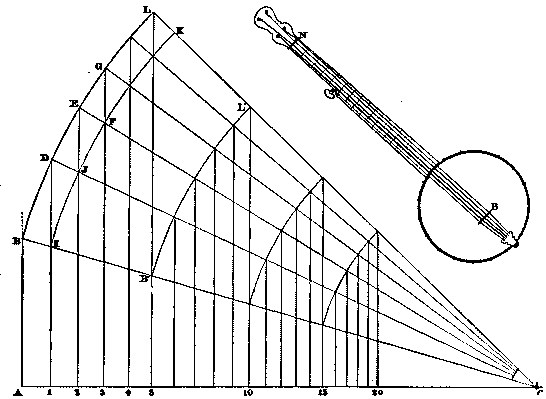
SPACING FOR BANJO FRETS.
It is to be understood that when the distance from the "nut," N, to the bridge, B, has been determined, the first fret is to be placed at 1/18 of that distance from the nut, the distance from the first to the second is to be 1/18 of the remainder, and so on. To determine these distances by computation, then, is a simple enough arithmetical exercise; but it is exceedingly tedious, since the denominators of the fractions involved increase with great rapidity; being successive powers of the comparatively large number 18, they soon become enormous.
In the large diagram, the distance, A C, on the horizontal line corresponds to the distance, N B, on the instrument. At A erect a vertical line, and mark upon it a point B such that B C shall be exactly eighteen times any convenient unit, B I. In the illustration B C is 26 inches, and B I is 11/2 inches, so that B C is 27 inches in length. About C as a center describe the arcs, B L, I K, and through I draw a vertical line, cutting B L in D; draw the radius D C, cutting the inner arc, I K, in J, through J draw another vertical, cutting B L in E, and so on.
In the triangles, A B C, 1 D C, 2 E C, we have B I = D J = E F = 1/18 of the hypotenuse in each case, therefore the bases, A C, 1 C, 2 C, are divided in the same proportion, as required, at the points 1, 2, 3. And we might extend the arcs, B L, I K, and repeat the above operation until all the frets were located. But should that be done, the diagram might become inconveniently large, and some of the intersections might not be reliably determined. In order to avoid this, the spacing of the outer arc may be stopped at any convenient division, as L. The vertical by which that point is determined cuts B C at B', and through B' a new arc, B' L', is described. Through the points in which this arc cuts the radial lines already drawn, a new series of verticals is passed, which will divide another portion of A C as required, and by repeating this process the spacing of the whole neck may be effected by a diagram of reasonable size.
Glove making is almost a century old in this country, having been begun in the neighborhood of Gloversville and Johnstown, N.Y., about 1803. Until 1862 the manufacture of gloves in Fulton County, although even then the chief manufacturing industry, was of comparatively small importance. Gloversville and Johnstown were then quiet villages of from three to four thousand people. The flourishing establishments of to-day, or such of them as then existed, were small and comparatively unimportant. In 1862 the stimulating influence of a high protective tariff showed itself in the increased business at Gloversville, Johnstown, and the adjoining hamlet, Kingsboro. These became at once the leading sources of supply for the home market gloves of a medium grade. The quality of the product has steadily improved, and the variety has been increased, until now American-made gloves are steadily driving out the foreign gloves. The skill of American glovers is equal to that of foreign glove makers, and in some respects—notably in the quality of the stitching, and, in some grades, the shape—the American gloves are the best. Foreign expert workmen have been drawn over here from the great glove centers of Europe, so that the greatest skill has been secured here. The annual value of the glove industry in Fulton County has reached about $7,000,000.
One hundred and seventy-five glove makers and 20,000 people in Fulton County draw their subsistence directly from glove making. Some of the firms have a business reaching from $100,000 to $500,000 yearly. The majority, however, have small shops, and do a small but profitable business. Most of the work in Fulton County, as abroad, is done at the homes of the workers. The streets of Gloversville and Johnstown are lined with pretty and tasteful homes, in which the hum of the sewing machine is constantly heard during the working hours of the day, but the workers are exceptionally fortunate in being able while earning good wages to enjoy all the comforts and surroundings of home, and in being practically their own masters and mistresses.
Before the leather can be cut and sewed into the handsome articles that are sold over the counters of the retail dry goods houses and furnishing goods stores as gloves, the skins from which they are made must be specially prepared. The two important points in this preparation are the removal of the albuminous portion of the skin and the retention and chemical changing of the gelatinous part, so that it shall become pliable, elastic, and resist decomposition.
There are various methods which produce these results, and they are technically known as tanning, alum dressing, oil dressing, and Indian dressing. Each method produces a leather distinctly different from that produced by any other. All the preliminary processes of these various methods are alike in principle, although they vary somewhat in detail. The object in all is to remove the hair from the hide, separate the fleshy and albuminous matter, and leave only the gelatinous, which alone is susceptible to the chemical action and can be transformed by it into leather.
When the skins are received in the factory they are thoroughly soaked to open out the texture and prepare them for the removal of the hair. Then the skins are placed in vats of lime water, where, for two or three weeks, the lime works into the flesh and albuminous matter, and loosens the hair. The skins having thus been properly softened, the dirty but picturesque operation of beaming for removing the hair ensues. Before each beamer, as the workman is called, is an inclined semi-cylindrical slab of wood covered with zinc. The skin is first spread upon this, and the broad, curved beam of the knife glides across it from end to end, scraping and removing all the loosened hair, the scarf skin, and the small portion of animal matter adhering to the skin.
After the unhairing, kid skins must be fermented in a drench of bran, whose purpose is to completely decompose the remaining albuminous matter, and also to remove all traces of the lime. The operation is extremely delicate. While the gelatine is not so sensitive to the decomposing action of the ferment, nevertheless great care is required to prevent overfermentation and resulting damage to the texture of the skin. It is impossible for even the most experienced to tell just how long the fermentation should continue. Sometimes the work is done in two or three hours, and sometimes it requires as many days. Incessant watchfulness both day and night is required to detect the critical moment. With the less delicate skins this bran bath is not necessary. Lime and acid solutions accomplish the same purpose. When the gelatine matter is all removed the skins are ready for the actual curative process.
Oil dressing or Indian dressing—which merely differ in application, but are founded upon the same principle—is the most simple method of curing skins. The principle of each is the soaking of the gelatine fibers of the skin with oil, the union of the latter and the gelatine appearing in the form of oxide, and resulting in the insoluble, undecomposable, pliant, and tough material known to the commercial world as leather. The first step in the oil dressing, after the skins have been duly soaked to render them porous and absorptive, is to cover them with fish oil and place them in the stocks or fulling machines—huge wooden hammers with notched faces working in iron cases—where they are beaten and turned, and subjected to a uniform pressure until the oil is gradually absorbed. After taking them out, hanging them up, and stretching them, the oil and fulling process is repeated according to the thickness of the skin, and until every part of it is full of oil. After this the skins are dried in a mild heat that causes the oxidization of the oil. This being completed, all the superfluous oil is removed by putting the skins in an alkali bath. Then the curing process is complete.
With the preparation of kid leather alum is the astringent curative agent. Its operation is accompanied by that of others whose purpose is to secure elasticity and pliability, and mainly to preserve that beautiful texture which makes kid leather superior to all others. These assistants in the process are eggs, flour, and salt. They are combined into what is called a custard. A proper quantity of the custard and a number of skins having been put together in a dash wheel, where they are thrown about for some time, the open pores of the skin absorb the custard freely, and become swelled by the chemical union of the custard and the skin. In trade parlance this swelling is known as "plumping." This having progressed satisfactorily, the skins are folded together with the fleshy side outward, and are dried by a gentle heat.
They are now cured, but they are yet hard and rough. Another objectionable feature is that they are of unequal thickness. Breaking and staking, as they are called, are now resorted to, to make the skins soft, pliable, and of even texture, removing the superfluous chemicals with which they become charged, and the stiffness by manipulating the fibers. Much trained skill and dexterity, especially in knee and arm staking, are required in the stretching, which is the essential feature of these operations. Breaking is first resorted to. The break beam, which is armed at each end with a knife edge, oscillates up and down. In a frame beneath it the operator stretches the dried and stiff skin. The break beam comes down upon the skin, stretches and softens it, and removes much surplus custard. The operator presents a new surface to each stroke of the break beam, and in a very short space of time the entire skin is rendered soft and pliable.
Further manipulation upon the arm or knee stake—of which a dull, semicircular knife blade, supported upon a suitable standard upon the floor or upon a beam about opposite the worker's elbow is the main feature—is required. The skin must be drawn across this knife blade with a considerable application of force so as to reduce the unduly thick parts, stretch the skin and secure a uniform thickness suitable for gloves. Much dexterity, especially in the case of fine skins, is required in this operation to avoid cutting or tearing. The operator places the fleshy side of the skin over the knife, grasps the two ends of the skin, and placing his knee upon it and slowly drawing the skin across the knife edge, he brings his weight to bear upon it. If the operator is skilled and experienced the skin yields quickly, when needed, to the strain applied and a uniform texture is secured. The operation of transforming the skin into leather is now finished, but age is necessary to secure perfect pliability and softness. The skins are, therefore, laid away to let the slow chemical operation going on within them be completed.
The visitor can now watch the further processes of manufacture by visiting the dye rooms. Skins which have already been aged are immersed in dye vats, where the delicate colors are imparted to them. The same care is not required in obtaining the ordinary range of dark colors, for these are "brushed" on, the skin being spread upon a glass slab and the dye being painted on with a brush. After they are dyed the skins are sometimes somewhat hard, and in some classes have to be staked again in order to restore their pliability. The finishing touches to a kid skin are secured by rubbing the grain side over with a size, which imparts a gloss. The experience of Gloversville manufacturers with "buck" gloves has enabled them to impart a special finish to a skin which is very popular under the title of "Mocha." This is the same as suede finish, which is produced in other countries by shaving off the grain side of the skin at an early stage of its progress. The Gloversville method is much better, however, and has more perfect results. Here the grain is removed, and the velvet finish secured by buffing the surface on an emery wheel. The surface of the leather is cut away in minute particles by this process, and the result is an exceedingly even and velvety texture, superior to that obtained by other methods. European manufacturers do not approach the Americans in this respect.
The leathermaker leaves off and the glovemaker begins.
A marble slab lies before the cutter on a table, and every particle of dirt or other inequality is removed before "doling." The skin is spread, flesh side up, upon the slab, and the cutter goes over it with a broad bladed chisel or knife, shaving down inequalities and removing all the porous portions. The dexterity with which this is done makes the operation appear extremely simple, but any but a skilled and experienced operative would almost surely cut through the skin. The most delicate part of the glovemaker's art, in which exact judgment is required, comes in preparing the "tranks" or slips, from which the separate gloves are cut. The trank must be so cut as to have just enough leather to make a glove of a certain size and number. The operation would be easy enough if the material were hard and stiff, and if the elasticity were uniform, but this is rarely the case.
To accomplish this operation the trank must be firmly stretched in one direction, and while so stretched a "redell" stamps the proper dimensions in the other direction, to which the leather is trimmed. Upon the nicety with which this operation is performed depends the question of whether the finished glove will stretch evenly or too much or too little in one direction or the other. After this the trank or outline of the glove must be cut out. In olden times of glove manufacture an outline was traced upon the leather and the pattern was cut with shears. Modern invention has produced dies and presses which are universally used. The steel die has the outline of a double glove, including the opening for the thumb piece. The die rests upon the bed of the press. Several tranks are laid upon it, the lever is drawn, and in a moment the blanks are cut out clean and smooth. The gussets, facings, etc., are cut from the waste leather in the thumb opening at the same operation. Similar dies are used in the cutting of the thumb pieces and fourchettes or strips forming the sides of the fingers.
The pieces now go to the great sewing rooms of the factory, where are long rows of busy sewing girls. If the manufacturer of years ago could revisit the scenes of his earthly toil, and wander through the sewing rooms of a modern factory, he would doubtless be greatly amazed at the sight presented there. In his day such a thing was unknown. The glove was then held in position by a hand clamp, while the sewing girl pushed the needle in and out, making an overseam. All this is done now in an infinitely more rapid manner by machine, and with resulting seams that are more regular and strong than those made by the hand sewer. The overseam sewers earn large wages, and their places are much coveted. Overlapping seams are produced on the pique machine, which is a most ingenious mechanism. The essential feature of this machine is a long steel finger with a shuttle and bobbin working within, and the finger of the glove is drawn upon this steel finger, permitting the seam to be sewn through and through. The visitor to the factory can see also the minor operations of embroidering, lining—in finished gloves—sewing the facing, sewing the buttonholes, putting on the buttons, and trimming with various kinds of thread. Before the gloves are ready for the boxes one more operation remains. The gloves are somewhat unsightly as they come from the sewers' hands, and must be made trim and neat. To secure these desirable results the gloves are taken to the "laying-off" room.
In this are long tables with a long row of brass hands projecting at an acute angle. These are filled with steam and are too hot to touch. These steam tables by ingenious devices are so arranged that it is impossible to burn the glove or stiffen the leather by too much heat, a common defect in ordinary methods. The operation of the "laying-off" room is finished with surprising quickness. Before each table stands an operator, who slips a glove over each frame, draws it down to shape, and after a moment's exposure to the warmth removes it, smooth, shapely, and ready for the box. The frames upon which the gloves are drawn are long and narrow for fine gloves and short and stubby for common ones. Then the glove is taken to the stock room, where there are endless shelves and bins to testify to the chief drawback to glove making, the necessity for innumerable patterns.—The Mercer.
The object of this invention is to produce a firm, solid, dust-resisting, and durable woven cloth, composed, preferably, entirely of cotton, but it may be of a cotton warp combined with a linen or other weft, and is particularly applicable for covering the seats and cushions of railway and other carriages, for upholstering purposes, for bed ticking, and for various other uses. To effect this object, a cotton warp and, preferably, a cotton weft also are employed, or a linen, worsted, or other weft may be used. Both the yarns for warp and weft may be either dull or polished, according to the appearance and finish of cloth desired. The fabric is woven in a plain loom, and the ends are drawn through say eight heald shafts, but four, sixteen, or thirty-two heald shafts might be employed. When eight heald shafts are employed, the warp is drawn as follows: The 1st warp end in the first heald shaft, the 2d warp end in the second heald shaft, and so on, the remaining six warp ends being drawn in, in consecutive order, through the remaining six heald shafts; the 9th warp end is drawn in through the first heald shaft, and so on, the drawing in of the other ends being repeated as above. The order of the shedding is as follows: 1st change. The 1st and 3d heald shafts fall, the rest remaining up. 2d change. The 5th and 7th shafts fall, and the 1st and 3d rise. 3d change. The 2d and 4th shafts fall, and the 5th and 7th rise. 4th change. The 6th and 8th shafts fall, and the 2d and 4th shafts rise. The result is that each weft thread, a, passes under six warp threads, b, and over two warp threads, in the manner illustrated by the accompanying diagram. In drawing in, when four heald shafts are employed, the 1st warp end is drawn in through the 1st heald shaft, the 2d through the 2d shaft, the 3d through the 1st, the 4th through the 2d, the 5th through the 3d, the 6th through the 4th, the 7th through the 3d, and 8th through the 4th shaft, and repeating with the 9th end through the 1st shaft. In shedding, the 1st heald shaft is lowered, then the 3d, then the 2d, and then 4th. The result, in this case, is still the same, viz., that each weft thread passes under six warp ends and over two warp ends. Although a cotton warp is spoken of in some cases, worsted or other yarn can be added to the cotton warp to obtain a variation in the pattern or design.—Jour. of Fabrics.
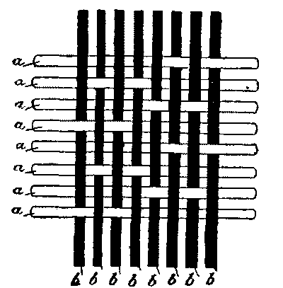
The object of this invention is to manufacture, in a cheap fabric, a closer imitation of Brussels carpets. As is well known, an ordinary Brussels carpet is made with a pattern on one side only, but according to this invention, it is intended to produce a pattern on both sides of the ingrain or pro-Brussels carpet, so that it will be reversible. In manufacturing a reversible carpet of this class according to the present invention, the pattern is formed by means of the warp and weft combined, and any suitable ingrain warp operated by the harness or jacquard of the loom may be used. In combination with ingrain warp, a fine catching or binding warp, operated by the gear or jacquard harness of the loom, is employed, such fine catching warp being used to bind the weft into the fabric, therefore, if the fabric be woven two-ply, the ingrain warps are thrown on both the under and upper surfaces of the fabric, as well as in between the weft, according to the pattern being woven, by which means four colors are shown on both sides of the fabric, two being produced by the weft, and two by the ingrain warps. More than four colors, however, can be produced upon each side by multiplying the number of colored wefts and warps employed. If the fabric woven be a three-ply, with the addition of the ingrain warps thrown on each face of the fabric, then five or more colors would be imparted to the carpet, as any number of colors can be used to form a given pattern, by planting or arranging the colors in the warp, and the remaining colors by the wefts, and so on. The ingrain warp thread, therefore, together with the weft, used as stated above, produces an effective pattern on both sides of the carpet; consequently, it becomes reversible, and this can be accomplished whether the carpet woven be two, three, or other number of ply. By reference to the accompanying sheets of drawings, this invention will be better understood. Fig. 1 is an enlarged cross section of an improved carpet, a three-ply, that is to say, it is a carpet wherein three shuttles are employed, each carrying a differently colored weft; a represents the weft threads which may be composed of any suitable fiber, b and c are cotton or other fine warp threads, which are employed for binding the weft together, while d and e represent the ingrain or woolen warp, where it will be seen that each ingrain warp, besides lying between the weft, is thrown on both sides of the fabric, for the purpose of forming figures thereon. It will, therefore, be seen that a carpet made according to Fig. 1 will show five colors—three colors produced by the weft and two colors produced by the ingrain warp. Fig. 2 represents a carpet made with two-ply, in which case only four colors will be produced, two by the weft and two by the ingrain warp. It is, consequently, obvious that a carpet made in the manner above described will have a corresponding pattern or figure on both its sides, allowing it to be used on both sides. Fig. 3 also shows a two-ply carpet, but, in this case, six colors are produced, i.e., two colors by the weft and four by the ingrain warp, marked d, d¹, e, and e¹, the warp being so manipulated by the harness as to make the carpet reversible, and having a corresponding pattern or figure on both sides.—Journal of Fabrics.
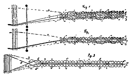
A modified aræometer has been recently patented by Aug. Eichhorn, in Dresden, Germany (Deutsches Reichs-Patent, No. 49,683), which will prove a great boon to chemists, distillers, physicians, etc., as it affords an easy means of determining the specific gravity of liquids, especially such of which only small quantities can be conveniently obtained.
With the ordinary aræometers, as hitherto constructed, a considerable quantity of the test fluid is required, and an elaborate calculation necessary for each determination. In the new aræo-picnometer these drawbacks are ingeniously avoided, so that the specific gravity of any liquid can be quickly and easily obtained with astonishing accuracy.
The new and important feature of this instrument consists in a glass bulb, c—see accompanying sketch—which is filled with the liquid whose gravity is to be determined. Thus, instead of floating the entire apparatus in the test fluid, only a very small quantity of the latter is required, an advantage which can hardly be overestimated, considering how difficult it is in many instances to procure the necessary supply.
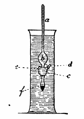
The glass bulb, c, when filled with the test fluid, is closed by means of an accurately fitting glass stopper, d, and the instrument is then placed in a glass cylinder filled with distilled water of 17.5 deg. temperature (Centigrade). The gravity is then at once shown on the divided scale in the tube, a. The lower bulb, f, contains some mercury; e is a small glass knob, which serves to maintain the balance, while b is an empty glass bulb (floater).
These instruments are admirably adapted for determining the gravity of alcohol, petroleum, benzine, and every kind of oil, also for testing beer, milk, vinegar, grape juice, lye, glycerine, urine, etc.
As the process is an exceedingly simple one and free from the drawbacks of the aræometer, we are justified in concluding that the aræo-picnometer will soon be in general use.
H. HENSOLDT, Ph.D.
Petrographical Laboratory, School of Mines, Columbia College.
Mr. Frank Livesey, in the concluding sentence of a paper read before the Southern District Association of Gas Managers and Engineers during the past month, on "A Ready Means of Enriching Coal Gas," speaking of enrichment by gasolene by the Maxim-Clarke process, said "it should, in many cases, take the place of cannel, to be replaced in its turn, probably, by a water gas carbureted to 20 or 25 candle power." And now, having fully reviewed the methods either in use or proposed for the enrichment of gas, we will pass on to this, the probable cannel of the future.
Discovered by Fontana, in 1780, and first worked by Ibbetson, in England, in 1824, water gas has added a voluminous chapter to the patent records of England, France, and America, no less than sixty patents being taken out between 1824 and 1858, in which the action of steam on incandescent carbon was the basis for the production of an inflammable gas.
Up to the latter date the attempts to make and utilize water gas all met with failure; but about this time the subject began to be taken up in America, and the principle of the regenerator, enunciated by Siemens in 1856, having been pressed into service in the water-gas generator under the name of fixing chambers or superheaters, we find water gas gradually approaching the successful development to which it has attained in the United States during the last ten years. Having now, by the aid of American skill, been brought into practical form, it is once more attempting to gain a foothold in Western Europe—the land of its birth.
When carbon is acted upon at high temperatures by steam, the first action which takes place is the decomposition of the water vapor, the hydrogen being liberated, while the oxygen unites with the carbon to form carbon dioxide:
| Carbon. | Water. |
| C + | 2H2O = CO2 + 4H2 |
And the carbon dioxide so produced interacts with more red-hot carbon, forming the lower oxide—carbon monoxide:
CO2 + C = 2CO
So that the completed reaction may be looked upon as yielding a mixture of equal volumes of hydrogen and carbon monoxide, both of them inflammable but non-luminous flames. This decomposition, however, is rarely completed, and a certain proportion of carbon dioxide is invariably to be found in the water gas, which, in practice, generally consists of a mixture of about this composition:
| WATER GAS. | |
|---|---|
| Hydrogen | 48.31 |
| Carbon monoxide | 35.93 |
| Carbon dioxide | 4.25 |
| Nitrogen | 8.75 |
| Methane | 1.05 |
| Sulphureted hydrogen | 1.20 |
| Oxygen | 0.51 |
| ——— | |
| 100.00 | |
The above is an analysis of water gas made from ordinary gas coke in a Van Steenbergh generator.
The ratio of carbon monoxide and carbon dioxide present entirely depends upon the temperature of the generator, and the kind of carbonaceous matter employed. With a hard, dense anthracite coal, for instance, it is quite possible to attain a temperature at which there is practically no carbon dioxide produced, while with an ordinary form of generator and a loose fuel like coke, a large proportion of carbon dioxide is generally to be found.
The sulphureted hydrogen in the analysis quoted is, of course, due to the high amount of sulphur to be found in the gas coke, and is practically absent from water gas made with anthracite, while the nitrogen is due to the method of manufacture, the coke being, in the first instance, raised to incandescence by an air blast, which leaves the generator and pipes full of a mixture of nitrogen and carbon monoxide (producer gas), which is carried over by the first portions of water gas into the holder. The water gas so made has no photometric value, its constituents being perfectly non-luminous, and attempts to use it as an illuminant have all taken the form of incandescent burners, in which thin mantles or combs of highly refractory metallic oxides have been heated to incandescence. In carbureted water gas this gas is only used as the carrier of illuminating hydrocarbon gases, made by decomposing various grades of hydrocarbon oils into permanent gases by heat.
Many forms of generator have been used in the United States for the production of water gas, which, after or during manufacture, is mixed with the vapors and permanent gases obtained by cracking various grades of paraffin oil, and "fixing" them by subjecting them to a high temperature; and in considering the subject of enrichment of coal gas by carbureted water gas, I shall be forced, by the limited time at my disposal, to confine myself to the most successful of these processes, or those which are already undergoing trial in this country.
In considering these methods, we find they can be divided into two classes:
1. Continuous processes, in which the heat necessary to bring about the interaction of the carbon and steam is obtained by performing the operation in retorts externally heated in a furnace; and
2. Intermittent processes, in which carbon is first heated to incandescence by an air blast, and then, the air blast being cut off, superheated steam is blown in until the temperature is reduced to a point at which the carbon begins to fail in its action, when the air is again admitted to bring the fuel up to the required temperature, the process consisting of alternate formation of producer gas with rise of temperature, and of water gas with lowering of the temperature.
Of the first class of generator, none, as far as I know, have as yet been practically successful, the nearest approach to this system being the "Meeze," in which fire clay retorts in an ordinary setting are employed. In the center of each retort is a pipe leading nearly to the rear end of the retort, and containing baffle plates. Through this a jet of superheated steam and hydrocarbon vapor is injected, and the mixture passes the length of the inner tube, and then back through the retort itself—which is also fitted with baffle plates—to the front of the retort, whence the fixed gases escape by the stand pipe to the hydraulic main, and the rich gas thus formed is used either to enrich coal gas or is mixed with water gas made in a separate generator. In some forms the water gas is passed with the oil through the retort. In such a process, the complete breaking down of some of the heavy hydrocarbons takes place, and the superheated steam, acting on the carbon so liberated, forms water gas which bears the lower hydrocarbons formed with it; but inasmuch as oil is not an economical source of carbon for the production of water gas, this would probably make the cost of production higher than necessary. This system has been extensively tried, and indeed used to a certain extent, but the results have not been altogether satisfactory, one of the troubles which have had to be contended with being choking of the retorts.
Of the intermittent processes, the one most in use in America is the "Lowe," in which the coke or anthracite is heated to incandescence in a generator lined with firebrick, by an air blast, the heated products of combustion as they leave the generator and enter the superheaters being supplied with more air, which causes the combustion of the carbon monoxide present in the producer gas, and heats up the firebrick "baffles" with which the superheater is filled. When the necessary temperature of fuel and superheater has been reached, the air blasts are cut off, and steam is blown through the generator, forming water gas, which meets the enriching oil at the top of the first superheater, called the 'carbureter,' and carries the vapors with it through the main superheater, where the "fixing" of the hydrocarbons takes place.
The chief advantage of this apparatus is that the enormous superheating space enables a lower temperature to be used for the "fixing." This does away, to a certain extent, with the too great breaking down of the hydrocarbons, and consequent deposition of carbon. This form of apparatus has just found its way to this country, and I describe it as being the one most used in the States, and the type upon which, practically, all water gas plant with superheaters has been founded.
The Springer apparatus, which is under trial by one of the large gas companies, differs from the Lowe merely in construction. In this apparatus the superheater is directly above the generator; and there is only one superheating chamber instead of two. The air blast is admitted at the bottom, and the producer gases heat the superheater in the usual way, and when the required temperature is reached, the steam is blown in at the top of the generator, and is made to pass through the incandescent fuel, the water gas being led from the bottom of the apparatus to the top, where it enters at the summit of the superheater, meets the oil, and passes down with it through the chamber, the finished gas escaping at the middle of the apparatus.
This same idea of making the air blast pass up through the fuel, while in the subsequent operation the steam passes down, is also to be found in the Loomis plant, and is a distinct advantage, as the fuel is at its hottest where the blast has entered, and, in order to keep down the percentage of carbon dioxide, it is important that the fuel through which the water gas last passes should be as hot as possible, to insure its reduction to carbon monoxide.
The Flannery apparatus is again but a slight modification
of the Lowe plant, the chief difference being
that, as the gas leaves the generator, the oil is fed into
it, and, with the gas, passes through a  -shaped retort
tube, which is arranged round three sides of the
top of the generator; and in this the oil is volatilized,
and passes, with the gas, to the bottom of the superheater,
in which the vapors are converted into permanent
gases.
-shaped retort
tube, which is arranged round three sides of the
top of the generator; and in this the oil is volatilized,
and passes, with the gas, to the bottom of the superheater,
in which the vapors are converted into permanent
gases.
The Van Steenbergh plant, with which I have been experimenting for some time, stands apart from all other forms of carbureted water gas plant, in that the upper layer of the fuel itself forms the superheater, and that no second part of any kind is needed for the fixation of the hydrocarbons, an arrangement which reduces the apparatus to the simplest form, and leaves no part which can choke or get out of order, an advantage which will not be underrated by any one who has had experience of these plants. While, however, this enormous advantage is gained, there is also the drawback that the apparatus is not fitted for use with crude oils of heavy specific gravity, such as can be dealt with in the big external superheaters of the Lowe class of water gas plant, but the lighter grades of oil must be used in it for carbureting purposes.
I am not sure in my own mind that this, which appears at first a disadvantage, is altogether one, as, in the first place, the lighter grades of oil, if judged by the amount of carbureting power which they have, are cheaper per candle power, added to the gas, than the crude oils, while their use entirely does away with the formation of pitch and carbon in the pipes and purifying apparatus—a factor of the greatest importance to the gas manufacturer.
The fact that light oils give a higher carburation per gallon than heavy crude oil is due to the fact that the latter have to be heated to a higher temperature to convert them into permanent gas, and this causes an over-cracking of the most valuable illuminating constituents; and this trouble cannot be avoided, as, if a lower temperature is employed, easily condensible vapors are the result, which, by their condensation in the pipes, give rise to much trouble.
The simplicity of the apparatus is a factor which causes a great saving of time and expense, as it reduces to a minimum the risk of stoppages for repairs, while the initial cost of the apparatus is, of course, low, and the expense of keeping in order practically nil.
When I first made the acquaintance of this form of plant, a few years ago, the promoters were confident that nothing could be used in it but American anthracite, of the kind they had been in the habit of using in America, and a light naphtha of about 0.689 specific gravity, known commercially as 76 deg Baume.
A few weeks' work with the apparatus, however, quickly showed that, with a slightly increased blow, and a rather higher column of fuel, gas coke could be used just as well as anthracite, and that by increasing the column of fuel, a lower grade of oil could be employed; so that during a considerable portion of the experimental work nothing but gas coke from the Horseferry Road Works and a petroleum of a specific gravity of about 0.709 were employed.
Having had control of the apparatus for several months, and, with the aid of a reliable assistant, having checked everything that went in and came out of the generator, I am in a position to state authoritatively that, using ordinary gas coke and a petroleum of specific gravity ranging from 0.689 to 0.709, 1,000 cubic feet of gas, having an illuminating power of twenty-two candles, can be made with an expenditure of 28 to 32 lb. of coke and 21/2 gallons of petroleum. The most important factors, i.e., the quantity of petroleum and the illuminating value of the gas, have also been checked and corroborated by Mr. Heisch and Mr. Leicester Greville.
| Total gas made = 8,700 cubic feet. | |
| Time taken: Blowing. | 1 hour. |
| Time taken: Making. | 50 minutes. |
| Fuel used: Gas coke. | 270 lb. = 31 lb. per 1,000 c.f. |
| Fuel used: Naphtha, sp. gr. 0.709. | 34 gals. = 2.7 gals. per 1,000 c.f. |
| Illuminating power of gas = 21.9 candles. | |
I must admit that these results far exceeded my expectations, although they only confirmed the figures claimed by the patentee; and there are not wanting indications that, when worked on a large scale and continuously, they might be even still further lowered, as it is impossible to obtain the most economical results when making less than 10,000 cubic feet of the gas, as the proper temperature of the walls of the generator are not obtained until after several makes; and it is only after about 8,000 cubic feet of gas has been made that the best conditions are fulfilled.
It will enable a sounder judgment to be formed of the working of the process if the complete experimental figures for a make of gas be taken.
| COMPOSITION OF THE GAS. | |
|---|---|
| Hydrogen. | 46.75 |
| Olefines. | 7.59 |
| Ethane. | 6.82 |
| Methane. | 11.27 |
| Carbon monoxide. | 11.65 |
| Carbon dioxide. | 0.50 |
| Oxygen. | 0.17 |
| Nitrogen. | 8.25 |
| ——— | |
| 100.00 | |
| UNPURIFIED GAS CONTAINED | |
|---|---|
| Carbon dioxide. | 2.32 per cent. |
| Sulphureted hydrogen. | 2.84 per cent. |
| Total sulphur per 100 cu. ft. | = 6.67 per cent |
| Ammonia. | nil |
| Bisulphide of carbon. | nil |
| Gas produced | Naphtha used | ||
| Gals. | Pts. | ||
| 1st. Make. | 3,600 cu. ft. | 10 | 7 |
| 2d. Make. | 2,800 cu. ft. | 7 | 6 |
| 3d. Make. | 2,300 cu. ft. | 5 | 3 |
| —— | — | — | |
| 8,700 | 24 | 0 | |
The last portion of the table shows the economy which arises as the whole apparatus gets properly heated. Thus the first make used 3 gallons naphtha per 1,000 cubic feet, the second 2 gallons 6 pints per 1,000 cubic feet, and the third 2 gallons 4 pints per 1,000 cubic feet, and it is, therefore, not unreasonable to suppose that in a continuous make these figures could be kept up, if not actually reduced still lower.
In introducing the oil it is not injected, but is simply allowed to flow in by gravity, at a point about half way up the column of fuel, the taps for its admission being placed at intervals around the circumference of the generator, and oil at first begins to flow down the inside wall of the generator, but being vaporized by the heat, the vapor is borne up by the rush of steam and water gas, and is cracked to a permanent gas in the upper layer of fuel. This I think is the secret of not being able to use heavier grades of oil, these being sufficiently non-volatile to trickle down the side into the fire box at the bottom, and so to escape volatilization. I have tried to steam-inject the oil, but have not found that it yields any better results.
One of the first things that strikes any one on seeing a make of gas by this system is the enormous rapidity of generation. Mr. Leicester Greville, who is chemist to the Commercial Gas Company, in reporting on the process, says, "The make of gas was at the rate of about 86,000 cubic feet in 24 hours. A remarkable result, taking into consideration the size of the apparatus." It is quite possible, with the small apparatus, to make 100,000 cubic feet in 24 hours; indeed the run for which the figures are given are over this estimate; and it must be borne in mind that this rapidity of make gives the gas manager complete control over any such sudden strains as result from fog or other unexpected demands on the gas-producing power of his works; while a still more important point is that it does away with the necessity of keeping an enormous bulk of gas ready to meet any such emergency, and so renders unnecessary the enormous gasholders, which add so much to the expense of a works, and take up so much room.
Perhaps the greatest objection to water gas in the public mind is the dread of its poisonous properties, due to the carbon monoxide which it contains; but if we come to consider the evidence before us on the increase of accidents due to this cause, we are struck by the poor case which the opponents of water gas are able to make out. No one can for a moment doubt the fact that carbon monoxide is one of the deadliest of poisons. It acts by diffusing through the air cells of the lungs, and forming, with the coloring matter of the blood corpuscles, a definite compound, which prevents them carrying on their normal function of taking up oxygen and distributing it throughout the body, to carry on that marvelous process of slow combustion which not only gives warmth to the body, but also removes the waste tissue used up by every action, be it voluntary or involuntary, and by hindering this, it at once stops life.
All researches on this subject point to the fact that something under one per cent. only of carbon monoxide in air renders it fatal to animal life, and this at first seems an insuperable objection to the use of water gas, and has, indeed, influenced the authorities in several towns, notably Paris, to forbid its introduction for domestic consumption. Let us, however, carefully examine the subject, and see, by the aid of actual figures, what the risk amounts to compared with the risks of ordinary coal gas.
Many experiments have been made with the view of determining the percentage of carbon monoxide in air which is fatal to human or, rather, animal life, and the most reliable as well as the latest results are those obtained by Dr. Stevenson, of Guy's Hospital, in consequence of the two deaths which took place at the Leeds forge from inhaling uncarbureted water gas containing 40 per cent. of carbon monoxide. He found that one per cent. visibly affected a mouse in one and a half minutes, and in one hour and three quarters killed it, while one-tenth of a per cent. was highly injurious. Let us, for the sake of argument, take this last figure 0.1 per cent. as being a fatal quantity, so as to be well within the mark.
In ordinary carbureted water gas as supplied by the superheater processes, such as the Lowe, Springer, etc., the usual percentage of carbon monoxide is 26 per cent., but in the Van Steenbergh gas—for certain chemical reasons to be discussed later on—it is generally about 18 per cent., and rarely rises to 20 per cent. An ordinary bedroom will be say 12 ft. X 15 ft. X 10 ft., and will therefore contain 1,800 cubic feet of air, and such a room would be lighted by a single bats-wing burner consuming not more than four cubic feet of gas per hour. Suppose now the inmate of that room retires to bed in such a condition of mental aberration that he prefers to blow out the gas rather than take the ordinary course of turning it off—a process, by the way, of putting out gas which is decidedly easier in theory than in practice, especially in his presumed mental condition—you would have in one hour the 1,800 cubic feet of gas in the room mixed with four fifths of a cubic foot of carbon monoxide—the carbureted water gas being supposed to contain 20 per cent.—or 0.04 per cent. In such a room, however, if the doors and windows were absolutely air tight, and there was no fireplace, diffusion through the walls would change the entire air once an hour, so that the percentage would not rise above 0.04; while in any ordinary room imperfect workmanship and an open chimney would change it four times in the hour, reducing the percentage to 0.01, a quantity which the most inveterate enemy of water gas could not claim would do more than produce a bad headache, an ailment quite as likely to have been caused by the same factor that brought about the blowing out of the gas.
Moreover, we are now talking about the use of carbureted water gas as an enricher of coal gas, and not as an illuminant to be consumed per se. and we may calculate that it would be probably used to enrich a 16-candle coal gas up to 17.5 candle power. To do this 25 per cent. of 22 candle power carbureted water gas would have to be mixed with it, and taking the percentage of carbon monoxide in London gas at 5 per cent.—a very fair average figure—and 18 per cent. as the amount present in the Van Steenbergh gas, we have 8.25 per cent. of carbon monoxide in the gas as sent out—a percentage hardly exceeding that which is found in the rich cannel gas supplied to such towns as Glasgow, where I am not aware of an unusual number of deaths occurring from carbon monoxide poisoning.
The carbureted water gas has a smell every bit as strong as coal gas, and a leak would be detected with equal facility by the nose; and I think you will agree with me that the cry raised against the use of carbureted water gas, for this reason, is one of the same character that hampered the introduction of coal gas itself at the commencement of this century.
We must now turn to the chemical actions which are taking place in the generator of the water gas plant, and these are more complex in the case of the Van Steenbergh plant than in those of the Lowe type, and, for that reason, yield a gas of more satisfactory composition.
Taking gas as made by the Lowe or Springer process, and contrasting it with the Van Steenbergh gas, we are at once struck by several marked differences.
In the first place the hydrogen is far higher and the marsh gas or methane lower in the Van Steenbergh than in the Lowe process, this being due to the sharper cracking that takes place in the short column of cherry red coke, as compared with the lower temperature employed for a longer space of time in the Lowe superheater. Next we notice a difference of 10 per cent. in the carbon monoxide, which is greatly reduced in the Steenbergh generator by the carbon monoxide and marsh gas reacting on each other as they pass over the red hot surface of coke with formation of acetylene, which adds to the illuminants, this action also reducing the quantity of marsh gas present.
| Lowe gas. | Van Steenbergh gas. | |
|---|---|---|
| Hydrogen | 27.14 | 46.75 |
| Marsh gas | 25.35 | 11.27 |
| Carbon monoxide | 26.84 | 18.65 |
| Illuminants. | 14.63 | 7.59 |
| Ethane | — | 6.82 |
| Carbon dioxide | 3.02 | 0.50 |
| Oxygen | 0.15 | 0.17 |
| Nitrogen. | 2.87 | 8.25 |
| —— | —— | |
| 100.00 | 100.00 |
In the illuminants, if we add the higher members of the methane series present to the olefines, we see they are about equal in each gas, while the low percentage of nitrogen in the Lowe gas is due to more careful working, and could easily be attained with the Van Steenbergh plant by allowing the first portion of water gas to wash out the producer gas before the hopper on top is closed.
The cracking of the naphtha by the red hot coke is undoubtedly a great advantage, for, as I have pointed out, the cracking of rushing petroleum is an exothermic reaction, so that the coke at the top of the generator gets hotter and hotter, and it is no unusual thing to see the coke at the beginning of the make cherry red at the bottom and dull red at the top, while at the end of the make it is almost black at the bottom and cherry red at the top, in this way attaining the same advantage in working that the Springer and Loomis do by their down blast, that is, having the fuel at its hottest where the gas finally leaves it, so as to reduce the quantity of carbon dioxide, and so lessen the expense of purification.
It will be well now to turn for a few moments to the gas obtained by cracking the light petroleum oils by themselves. The Russian and American petroleum differ so widely in composition that it was necessary to see in what way the gases obtained from them differed; and to do this, equal quantities of American naphtha and a Russian naphtha were cracked, by passing through an iron tube filled with coke, and in each case heated to a cherry red heat, the gases being measured, and then analyzed, with the following results:
| American. | Russian. | |
|---|---|---|
| No. of cubic feet per gallon. | 72 | 104 |
| —— | —— | |
| Hydrogen | 26.0 | 45.3 |
| Methane | 41.6 | 22.3 |
| Ethane | 12.5 | 13.9 |
| Olefines | 14.1 | 11.6 |
| Carbon monoxide | 3.3 | 3.5 |
| Carbon dioxide | 1.7 | 2.3 |
| Oxygen | 0.8 | 1.1 |
| Nitrogen | Nil. | Nil. |
| —— | —— | |
| 100.0 | l00.0 |
Showing that, if the Russian oil is a little lower in illuminants, it quite makes up by extra volume, but it seemed to me to deposit a much larger proportion of carbon.
Taking 21/2 gallons of American naphtha, it would give roughly 180 cubic feet of gas of the above composition, while the remaining gas would be the ordinary water gas. Taking the analysis of this as given, and calculating from it what would be the composition of a mixture of it with the naphtha gas, we obtain:
| Calculated. | Actual. | |
|---|---|---|
| Hydrogen | 47.09 | 42.09 |
| Methane | 5.48 | 11.27 |
| Olefines | 2.53 | 7.59 |
| Ethane | 2.17 | 6.32 |
| Carbon monoxide | 30.07 | 18.65 |
| Carbon dioxide | 3.78 | 2.32 |
| Oxygen | 0.56 | 0.17 |
| Nitrogen | 7.17 | 8.25 |
| Sulphureted hydrogen | 1.15 | 2.84 |
| —— | —— | |
| 100.00 | 100.00 |
Showing how great the effect is of the diluents in the water gas in preventing the overcracking of the hydrocarbons, as shown by the increase in the percentage of them present in the finished gas; while the enormous reduction in the amount of carbon monoxide present is due to the interaction between it and the paraffin hydrocarbons in the presence of red-hot carbon, a point which makes the Van Steenbergh apparatus enormously superior to any of the superheater forms of plant.
After all said and done, however, the reactions taking place, although they have an intense fascination for the chemist, are not the factors which the gas manager deems the most important, the cost of any given process being the test by which it must stand or fall; and it will be well now to consider, as far as it is possible, the expense of enriching coal gas by the various methods I have brought before you.
In order to be well above the prescribed limit of illuminating power at all parts of an extended service, the gas at the works must be sent out at an illuminating power of 17.5 candles and we may, I think, fairly take it that 16 candle coal gas, as made by the big London companies, costs, as nearly as can be, 1s. per 1,000 cubic feet in the holder, and the question we have now to solve is the cost of enriching it from 16 to 17.5 candle power. When this is done by cannel, the cost is 2.6 pence per candle power, so that the extra 11/2 would cost 4d. per 1,000.
Carbureting by the vapors of gasoline by the Maxim-Clarke process costs 13/4d. per 1,000, so that the extra candle power would mean an expenditure of 2.62d. Unfortunately I have no figures upon which to calculate the cost of producing such a gas by the Dinsmore process, but with the three important water gas enrichers we can deal.
Using Russian fuel oil, which can be obtained in bulk in London at 3d. per gallon, the proprietors of the Springer plant guarantee 51/2 candle power per 1,000 cubic feet of gas per gallon used, so that, to produce a 22 candle gas, 4 gallons would be used. The cost per 1,000 cubic feet may be roughly tabulated, as the coke used amounts to about 40 lb.
| s. | d. | |
| Oil | 1 | 0 |
| Coke | 0 | 3 |
| Labor and purification | 0 | 2 |
| Charge on plant | 0 | 1 |
| —————— | ||
| 1 | 6 | |
Twenty five per cent. of 12-candle gas when mixed with 75 per cent. of the 16-candle gas gives the required 17.5 candle gas, which would therefore cost 1s. 11/2d., or the enrichment would have cost 11/2d.
By the Lowe process, an increase of 5.3-candle power is guaranteed for the consumption of a gallon of the same oil, so that the cost would be a shade higher, all other factors remaining the same, while with the Van Steenbergh process both grade of oil and consumption of fuel vary from either of these processes. In order to obtain a thousand cubic feet of 22-candle gas, two and a half gallons of the lighter grade oil would be consumed, and I am informed that there is now no difficulty in obtaining oil of the right grade in London in bulk at 4d. per gallon, which would make the cost:
| s. | d. | |
| Two and a half gallons of oil | 0 | 10 |
| Thirty pounds of coke | 0 | 21/4 |
| Labor and purification | 0 | 2 |
| Charge on plant | 0 | 03/4 |
| —————— | ||
| 1 | 3 | |
And the enriched coal gas would, therefore, cost 1s. 3/4d. per thousand, the extra 11/2-candle power having been gained at an expense of 3/4d. or 1/2d. per candle.
Tabulating these results we have—Cost of enriching a 16-candle gas up to 17.5 candle power per 1,000 cubic feet by cannel coal, 4d.; by Maxim-Clarke process, 2-6/10d.; by Lowe or Springer water gas, 11/2d.; by Van Steenbergh water gas, 3/4d.
In reviewing this important subject, and bringing a wide range of experimental work to bear upon it, I have, as far as is possible, divested my mind of bias toward any particular process, and I can honestly claim that the fact of the Van Steenbergh process showing such great superiority is due to the force of carefully obtained experimental figures, corroborated by an experienced and widely known gas chemist, and by the chief gas examiner of the city.
In adopting any new method, the mind of the gas manager must to a great extent be influenced by the circumstances of the times, and the enormous importance of the labor question is a main factor at the present moment; with masters and men living in a strained condition which may at any moment break into open warfare, the adoption of such water gas processes would relieve the manager of a burden which is growing almost too heavy to be borne.
Combining, as such processes do, the maximum rate of production with the minimum amount of labor, they practically solve the labor question. Requiring only one-tenth the number of retort house hands that are at present employed, the carbureted water gas can be used for enrichment until troubles arise, and then the gas can be used pure and simple, with a hardly perceptible increase in expense, while the rapidity of make will also give the gas manager an important ally in the hour of fog, or in case of any other unexpected strain on his resources.
One of the first questions asked by the practical gas maker will be: "What guarantee can you give that as soon as we have erected plant, and got used to the new process of manufacture, a sudden rise in the price of oil will not take place, and leave us in worse plight than we were before?" and the only answer to this is that, as far as it is possible to judge anything, this event is not likely to take place in our time. A year ago the prospects of the oil trade looked black, as the output of American oil was in the hands of a powerful ring, who seemed likely also to obtain control of the Russian supplies; but, fortunately, this was averted, and, at the present moment, the Russian pipe lines are flooding the market with an abundant supply, which those best able to judge tell us is practically inexhaustible, so that prices may be expected to have a downward rather than an upward tendency. But even should a huge monopoly be created, I think I have found a source of light at home which will hold its own against any foreign illuminant in the market.
For a long time I have felt that in this country we had sources of light and power which only needed development, and the discovery of the right way to use them, in order to give an entirely new complexion to the question of carbureting; and now by the aid of the engineering skill and technical knowledge of Mr. Staveley, of Baghill, near Pontefract, I think it is found.
At three or four of the Scotch iron works the Furnace Gases Co. are paying a yearly rental for the right of collecting the smoke and gases from the blast furnaces. These are passed through several miles of wrought iron tubing, diminishing in size from 6 feet down to about 18 inches; and as the gases cool, so there is deposited a considerable yield of oil.
At Messrs. Dixon's, at Glasgow, which is the smallest of these installations, they pump and collect about 60,000,000 cubic feet of furnace gas per day; and recover, on an average, 25,000 gallons of furnace oils per week, using the residual gases, consisting chiefly of carbon monoxide, as fuel for distilling and other purposes, while a considerable yield of sulphate of ammonia is also obtained. In the same way a small percentage of the coke ovens are fitted with condensing gear, and produce a considerable yield of oil, for which, however, there is a very limited market, the chief use being for lucigen and other lamps of the same description, and for pickling timber for railway sleepers, etc.; the result being that, four years ago, it could be obtained in any quantity at 1/2d. per gallon, while since that it has been as high as 21/2d. a gallon, but is now about 2d., and shows a falling tendency. Make a market for this product, and the supply will be practically unlimited, as every blast furnace and coke oven in the kingdom will put up plant for the recovery of the oil, and as with the limited plant now at work it would be perfectly easy to obtain 4,000,000 or 5,000,000 gallons per annum, an extension of the recovery process would mean a supply sufficiently large to meet all demands.
Many gas managers have, from time to time, tried if they could not use some of their creosote for gas producing, but on heating it in retorts, etc., they have found the result has generally been a copious deposit of carbon, and a gas which has possessed little or no illuminating value. Now, the furnace and coke oven oils are in composition somewhat akin to the creosote oil, so that at first sight it does not seem a hopeful field for search after a good carbureter, but the furnace oils have several points in which they differ from the coal tar products. In the first place, they contain a certain percentage of paraffin oil, and in the next, do not contain much naphthalene, in which the coal tar oil is especially rich, and which would be a distinct drawback to their use.
The furnace oil as condensed contains about 30 to 50 per cent. of water, and in any case this has to be removed by distilling; and Mr. Staveley has patented a process by which the distillation is continued after the water has gone off, and by condensing in a fractionating column of special construction, he is able to remove all the paraffin oil, a considerable quantity of cresol, a small quantity of phenol, and about 10 per cent. of pyridine bases, leaving the remainder of the oil in a better condition, and more valuable for pickling timber, which is its chief use.
If the mixed oil so obtained, which we may call "phenoloid oil," is cracked by itself, no very striking result is obtained, the 40 percent. of paraffin present cracking in the usual way, and yielding a certain amount of illuminants, but if this oil be cracked in the presence of carbon, and be made to pass over and through a body of carbon heated to a dull red heat, then it is converted largely into benzene, the most valuable of the illuminants, and also being the one to which coal gas owes the largest proportion of its illuminating power, it is manifestly the right one to use in order to enrich it.
On cracking the phenoloid oil, the paraffins yield ethane, propane, and marsh gas, etc., in the usual way, while the phenol interacts with the carbon to form benzene—
| Phenol. | Benzene. | |
|---|---|---|
| C6H5HO + C | = | C6H6 + CO. |
And in the same way the cresol first breaks down to toluene in the presence of the carbon, and this in turn is broken down by the heat to benzene.
A great advantage of this oil is that the flashing point is 110, and so is well above the limit, thus doing away with the dangers and troubles inseparable from the storage of light naphtha in bulk.
In using this oil as an enricher, it must be cracked in the presence of carbon, and it is of the greatest importance that the temperature should not be too high, as the benzene is easily broken down to simpler hydrocarbons of far lower illuminating value. This fact is very clearly brought out by a series of experiments I have made, in which the phenoloid oil was cracked by passing it through an iron tube packed with coke and heated to various temperatures, the hydrocarbons being much more easily broken up under these conditions than if mixed with diluents, such as water gas:
| RESULTS OBTAINED ON CRACKING PHENOLOID OIL. | |||
|---|---|---|---|
| I. | II. | III. | |
| Temperature. | 600° C. | 800° C. | 1,000° C. |
| Volume of gas per gallon. | 41.6 c.f. | 76.8 c.f. | 121.6 c.f. |
| COMPOSITION OF THE GAS. | |||
| Hydrogen. | 34.0 | 36.0 | 37.0 |
| Methane. | 20.0 | 26.0 | 49.0 |
| Olefines. | 11.0 | 5.0 | Nil. |
| Ethane. | 16.0 | 9.0 | Nil. |
| Carbon monoxide. | 13.0 | 15.0 | 12.0 |
| Carbon dioxide. | 2.0 | 4.0 | 2.0 |
| Oxygen. | 2.0 | 1.0 | Nil. |
| Nitrogen. | 2.0 | 4.0 | Nil. |
This analysis shows that if the temperature is allowed to reach a cherry red, complete decomposition of the illuminating hydrocarbons is taking place, and a gas of practically no illuminating value results. The power of regulating the temperature and the body of carbon as a cracking medium in the Van Steenbergh water gas plant especially fits it for using this oil, and removes the objections which could have been urged against the lighter naphthas.
This oil is at present not in the market, but given a demand, it can be produced in four months, at the latest, in very large quantities, as the apparatus is very easy and cheap to erect, and the crude material can be plentifully obtained.
If this oil becomes, as I think it will, an important factor in the illumination of the future, it will mark as important an era in the history of our industries as any which the century has seen, as, by using it, you are giving smoke a commercial value, and this will do what the Society of Arts and the County Council have failed in—that is, to give us an improved atmosphere. If I were lecturing on an imaginary "Hygeia," I should point out that the smoke of London contains large quantities of these oils, and they, by coating the drops of mist on which they condense, give the fog that haunts our streets that peculiar richness which is so irritating and injurious to the system, and, further, by preventing the water from being again easily taken up by the air, prolong the duration of the fog. Make this oil a marketable commodity, and another twenty years will see London without a chimney; underground shafts will be run alongside the sewers; into these shafts by means of a down draught all the products of combustion from our fires will be sucked by local pumping stations, and the oil condensing in the tubes will serve in turn to illuminate our streets, instead of performing its former function of turning day into night and ruining our health; but as I am not at all sure of the engineering possibilities of such a scheme, I will leave its discovery to some other abler prophet than myself.
(To be continued.)
[1]It is only when theory and practice, study and experiment, go hand in hand that any true progress is made in the sciences. A head full of theory is of little value without practice, and although the student may apply himself with all his energies for years, his time will, to a great extent, have been spent in vain, unless he by experiment rivets the ideas he gains by his study.
In the study of electricity, for example, let the student try to remember the position a magnetic needle will take when placed below or above a conductor carrying a current which flows in a known direction. Without experiment there are nine chances of forgetting to one of remembering; but let the student try the experiment, and he will ever afterward be able to determine the direction in which the current is flowing by the position taken by the needle relative to the conductor.
In the matter of ampere turns, as another example, it is quite simple to assert that a ten ampere current carried once around a soft iron bar produces the same result as a one ampere current carried ten times around the bar, but how much more strongly is this fact stamped upon the memory when its truth is established by experiment?
Reading about a fact, or commiting to memory the literature of a subject, is desirable and even necessary, but knowledge of this character partakes more of the nature of faith than that gained by actual experience.
Let the reader learn first all that can be learned by the aid of this simple apparatus, then branch out to allied things, making each step as thorough as possible, and before long he will be congratulating himself on having gained at least an elementary knowledge of electricity.
Very little can be done in the way of electrical experiment without an electrical generator of some sort, and nothing at present known can excel a battery for this purpose. Although not the most desirable battery for all purposes, that shown in Fig. 1 is the most desirable for the amateur who desires a strong current for a short time. It is formed of two plates, a, of carbon arranged on opposite sides of an amalgamated plate, b, of zinc, and separated from the zinc by strips of wood. Bars of wood are placed outside of the carbon plates, and the four bars are fastened together by two common wood screws, thus clamping all the bars and the zinc and carbon plates securely in the position of use.
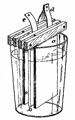
FIG. 1.—SIMPLE BATTERY.
Between the zinc plate and the wooden bar adjoining it is inserted a strip of copper, c, for leading away the current from the zinc pole of the battery, and between the carbon plates and the wooden bars is inserted a doubled strip of copper, d, forming a connection between the two carbon plates, and at the same time serving as a conductor for conveying away the current from the carbon pole of the battery. This element is to be plunged into a tumbler of sufficient depth to allow the wooden bars to rest on the upper edge of the tumbler, while the lower ends of the plates are one-half or three-quarters inch above the tumbler bottom.
In the tumbler is placed a solution consisting of two-thirds of a tumblerful of water, two ounces of bichromate of potash, and two ounces of sulphuric acid. The bichromate of potash should be dissolved first, then the acid should be slowly and carefully added. As the solution heats, it is well to prepare it in an earthen vessel, which is not liable to break. These materials should be used with great caution, as they are poisonous, and the solution is very corrosive, destroying almost everything with which it comes in contact. With proper care, however, there is no danger in using the solution. It gives off no poisonous vapors. Of course it is advisable to make the solution in quantities of a gallon or so when convenient.
The battery compound known as the C and C battery compound, sold in tin cans at most electric stores, is very convenient. It is only necessary to place two or three ounces of it in the tumbler and add the amount of water above mentioned, stirring the solution with a glass or rubber rod until the crystals are dissolved.
A caution is necessary here. If only a portion of the contents of the can are to be dissolved, it will be necessary to place the remainder in a glass or earthen jar, as it will absorb moisture and rapidly eat its way through the can.
The zinc plates should be amalgamated by plunging them into the bichromate solution, then sprinkling on a minute quantity of mercury, rubbing it about by means of a swab, until the entire exposed surface is covered with mercury.
In making electrical diagrams it is necessary to frequently
represent a battery. It requires too much
time to make a sketch or drawing of a battery. Besides
this, the drawing of any particular kind of
battery might be misleading. A sign representing
the galvanic battery has been universally
adopted. It consists of a long, thin mark or dash,
representing the carbon electrode, and a shorter,
thick mark representing the zinc electrode, thus:![]()
Where more cells are required, this
sign is repeated once for each cell, thus: 
The galvanometer
is represented thus:
By the use of the battery and a few articles such as may be found anywhere, in addition to the pieces shown in Fig. 2, all the experiments here described may be performed. As these pieces are shown half size in the diagrams, Fig. 2, and about full size in the perspective views, it will be unnecessary to give dimensions. The bobbins, A A, are wound with No. 24 double cotton-covered magnet wire, the terminals being soldered to eyes formed of pieces of spring wire bent so as to form helical coils of two turns each, with the ends inserted in holes drilled in heads of the spools. These coiled wires answer a good purpose in making electrical connections. The magnet frame, B, consisting of the cores and the yoke formed integrally of a single soft gray iron casting, is adapted to receive the bobbins, A A, to form an electro-magnet. The yoke of the magnet is provided with a thumb-screw, e, for securing the magnet to the motor frame, C. The latter is furnished with a base piece, f, a slotted standard for receiving the clamping screw, e, of the magnet, and the standards, g, in which is journaled the armature, h, on a wire extending through both the standards and the armature.
The armature, h, consists of an oblong rectangular soft iron frame having at one end a small pulley and at the other end an elliptical boss, i, which is arranged obliquely to form in conjunction with the spring, j, a circuit closer and opener, which closes the circuit twice during each revolution of the armature, just as one of its side bars is approaching the poles of the magnet and breaks it as the bar comes opposite the poles of the magnet.
The spring, j, is bent into a loop and its lower end is inserted in a wooden plug driven into a hole in the base piece, f.
In the upper part of Fig. 2 are shown two telegraph instruments less the bobbins. Each instrument (Fig. 14) consists of a wooden base, k, a right angled soft iron bar, l, having the central part of its upper end brought to an obtuse angle, an armature, m, fitted loosely to the angled end of the bar, a notched brass standard, n, for limiting the movement of the armature, a retractile spring for lifting the armature, a spring key, o, pivotally secured to the base by a common wood screw, and a contact point projecting from the base under the key.
Besides these there is a D shaped block, to answer as a frame to the galvanometer, a common pocket compass, E, fitted to a circular cavity in the top of the block, D, a permanent U magnet, F, a bundle of soft iron wires, G, and two copper strips, H.
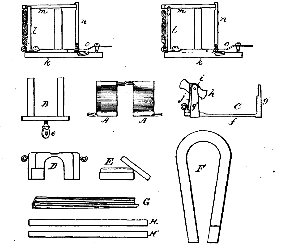
To illustrate the decomposition of water, connect the copper strips, H H, to the poles of the battery by means of wires, as shown in Fig. 3, and insert them in a tumbler of water acidulated with a few drops of sulphuric acid. Instantly bubbles will rise from the copper strips, showing that gas is being disengaged from the water. The strip connected with the carbon plate will disengage oxygen, while the strip connected with the zinc plate will disengage hydrogen.
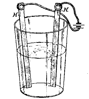
FIG. 3.—DECOMPOSITION OF WATER.
By connecting one of the coils, A, with the battery by means of the wires, the action of a helix or solenoid is shown. When so connected, the helix will draw up with itself a barrel pen, or any light iron or steel object. (See Fig. 4.) This is not a true solenoid, but it is generally known by that name. In a true solenoid one of the terminals is passed back through the center of the coil.
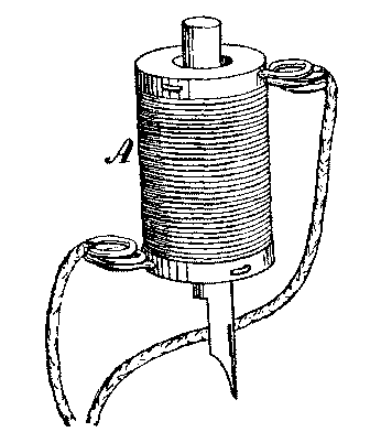
FIG. 4.—SOLENOID.
By inserting in the solenoid a knitting needle, or any bar of hardened or tempered steel, and sending a current through the coil, the steel will become permanently magnetized.
By placing the two coils, A, upon the magnet frame, B, and connecting one terminal of each with the battery, the remaining terminals being connected together, as shown in Fig. 5, an electromagnet is formed which will lift several pounds.
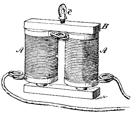
FIG. 5.—ELECTROMAGNET.
By placing the magnet thus formed upon the motor base, C, in front of the armature, h, as shown in Fig. 6, and connecting one terminal of the magnet with the battery and the other with the clamping screw, e, of the magnet, and by connecting the commutator spring, j, with the remaining pole of the battery, the motor will be made to rotate rapidly.
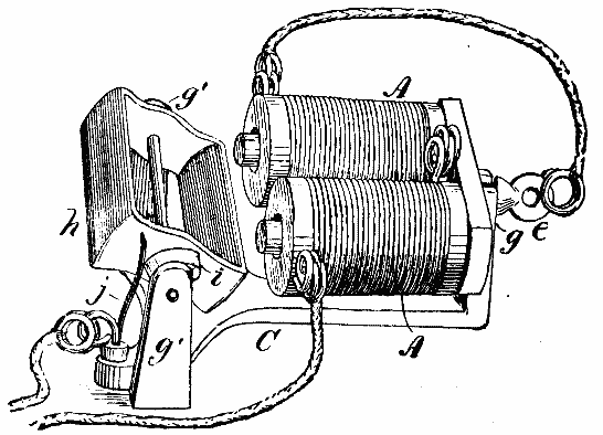
FIG. 6.—MOTOR.
By placing one end of the bar magnetized by the solenoid near the compass contained by the cabinet (Fig. 7) it will be seen that one end of the compass needle is attracted. When the opposite end of the bar is presented to the same end of the needle, that end of the needle will be repelled and the opposite one attracted, showing that like poles repel each other while unlike poles attract.
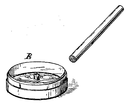
FIG. 7.—MAGNETIC EXPERIMENT.
By placing one of the coils, A, in the block, D, then placing in the cavity in the top of the block the compass, with the line marked N S arranged at right angles to the axis of the coil, a serviceable galvanometer will be formed (Fig. 8). By turning the galvanometer so that the needle will point north and south without the current passing, with N underneath one end of the needle, and then connecting the poles of the battery with the terminals of this galvanometer, a deflection of the compass needle will be produced, the direction of which depends upon the direction of the current.
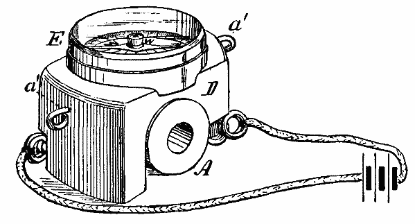
FIG. 8.—GALVANOMETER.
By placing the galvanometer in the circuit of the battery, as shown in Fig. 9, and noting the deflection of the needle, it will be ascertained that a certain amount of current is flowing. Now, by placing in the circuit, in addition to the galvanometer, the remaining coil of the magnet, thus introducing considerable resistance, the current will be diminished, as shown by a smaller deflection of the needle.
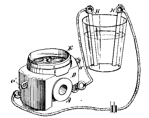
FIG. 9.—EFFECT OF RESISTANCE.
A very pretty and instructive experiment may be performed by arranging the apparatus as shown in Fig. 10, with the copper strips, H H, inserted in clean water and the galvanometer placed in the circuit. The deflection of the galvanometer needle will be very slight, showing that the resistance of clean water is considerable. A few drops of sulphuric acid or even vinegar will increase the conductivity of the water so as to produce a marked deflection of the galvanometer needle.
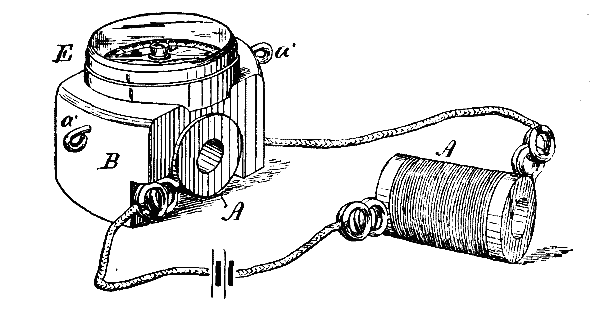
FIG. 10.—RESISTANCE OF FLUIDS.
Common salt added to the water will produce the same effect.
By placing one of the coils, A, on the magnet frame, B, and connecting it by the wires with the galvanometer, arranged as before described, and bringing the permanent magnet, F, suddenly against the poles of the magnet, as shown in Fig. 11, a current will be induced in the coil, which, in passing through the galvanometer, causes the needle to be deflected in one direction, and when the permanent magnet is suddenly removed from the electro-magnet, a current will be set up in the opposite direction, which will cause a deflection of the needle of the galvanometer in the opposite direction.
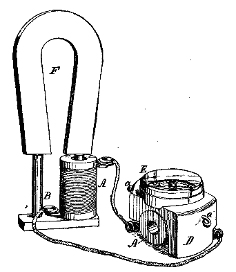
FIG. 11.—MAGNETO-ELECTRIC INDUCTION.
By placing both coils, A, upon the bundle of soft iron wires, G, connecting one of them with the terminals of the battery, as shown in Fig. 12, and holding the terminals of the other coil in the moistened thumb and fingers of the two hands, when the battery circuit is opened and closed by touching one of the wires to the battery, and removing it, a slight shock will be felt from the coil which is disconnected from the battery. By placing a coarse file in the circuit and drawing one of the terminals along the file the circuit will be rapidly interrupted. This shock is due to the current induced in the detached coil by the magnetism of the bundle of wires.
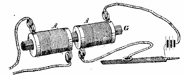
FIG. 12.—INDUCTION COIL.
An experiment showing the extra or self-induced current consists in arranging the motor as shown in Fig. 6, and connecting wire with each conductor leading from the battery to the motor, as shown in Fig. 13. If these wires are grasped one in each hand while the motors is in motion, a slight shock will be felt, providing the hands are moistened.
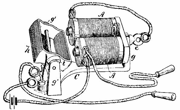
FIG. 13.—EXTRA CURRENT.
The cabinet contains material for two telegraph sounders and keys which will enable the user to establish a short telegraph line with a single cell of battery. The armature, m, may be lifted from its pivot so as to permit of slipping one of the coils, A, on to the round magnetic core of the sounder. The armature is then replaced, as shown in Fig. 14, and the small retractile spring at the rear of the instrument is arranged to draw down the shorter arm of the armature lever. One of the terminals of the coil, A, is connected with the turned up pivoted end of the telegraph key, o, on the same base. The other terminal is connected with one pole of the battery and the contact point of the key is connected with the other pole of the battery, as shown. By swinging the key laterally, so as to remove it from the contact point, it will be found that every touch of the key produces a movement of the sounder lever. To connect the two instruments together upon a line, it is only necessary to connect the two keys with one wire and the terminals of the two coils with another wire, cutting one of these wires and inserting the battery.
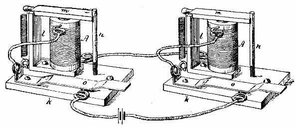
FIG. 14.—TELEGRAPH KEYS AND SOUNDER.
As soon as the operator ceases to work his instrument he should place the key in contact with the contact point, and cause it to remain there by slipping the end of the key under the head of the screw provided for that purpose. The other operator can then proceed to send his message.
Those who desire to practice telegraphy should learn the Morse telegraphic code.
By arranging the coil so as to form an electro-magnet, as before described, and holding the magnet under a plate of glass sprinkled with fine iron filings, as shown in Fig. 15, and then sending a current through the magnet, at the same time jarring the glass by striking it with a lead pencil, a magnetic figure will be formed which is sometimes called the magnetic spectrum. By connecting the terminals of the coils diagonally with each other, and connecting the remaining terminals with the battery, two like poles will be formed, and the magnetic figures will have an entirely different appearance, owing to the repulsion between the two like polarities. Different figures may be produced by using the solenoids without the iron cores.
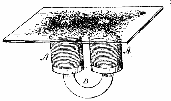
FIG. 15.—MAGNETIC FIGURES.
By removing the coil, A, from beneath the compass, E, and connecting the ends of the transverse wire, a' a', with the battery Fig. 16, then lifting the plates of the battery out of the solution and allowing the needle to come to rest, it will be found upon inserting the plates of the battery in the solution, very gradually, that the deflection of the needle will increase with the increase of plate surface submitted to the action of the battery fluid; and if, when the greatest deflection is reached, the coils or solenoids are introduced into the circuit, one after the other, it, will be found that each added coil diminishes the current, as will be shown by the diminished deflection of the needle.
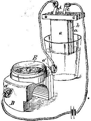
FIG. 16.—EXPERIMENT SHOWING THE CURRENT.
Take two small carbon rods, p p, if procurable, if not, use two ordinary nails, and connect them up in the circuit of the battery; lay them upon a thin box so that the rods or nails cross each other, as in Fig. 17; insert the electromagnet in the circuit; move the coils out a little beyond the ends of the cores, lay a thin iron plate over the ends of the coils, then jar the box upon which the bars, p p, are laid, or drop a pin upon it, or scratch it with a piece of paper, and the sound will be heard by placing the ear against the iron plate resting upon the coils of the magnet.
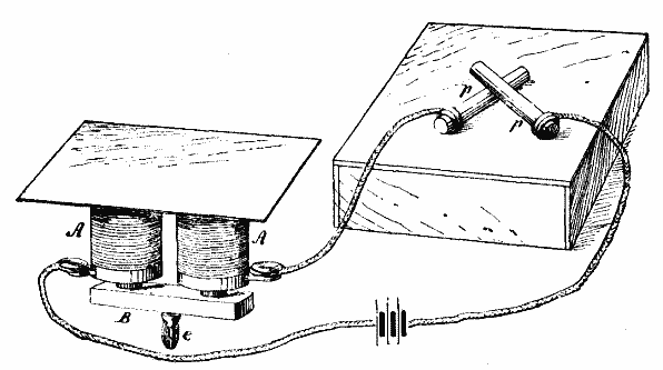
FIG. 17.—MICROPHONE AND TELEPHONE.
Dissolve an ounce of sulphate of copper in a half pint of water; add a few drops of sulphuric acid; connect with the zinc pole of the battery the object to be coppered. To the wire connected with the carbon attach a small plate of copper. Hang the object and the copper plate in the solution a short distance apart. A deposit of copper will be quickly formed.
With a piece of very fine platinum wire (No. 36 or 40), placed in the circuit of the battery, the heating effect of the current may be shown. A half inch of No. 36 platinum wire will serve for the experiment. If the battery is in good condition it will heat from 1/8 to 1/4 inch of the wire red hot. This is sufficient to light gas or an alcohol lamp, also to ignite powder or gun cotton.
A short piece of a watch hair spring, or a piece of very fine iron wire, if placed in the circuit will be made very hot.
Should the experimenter desire to go more deeply into the effects of the current, he will need a more powerful battery. The battery described has been made on a very simple plan, to enable the amateur to copy it without difficulty or great expense. There is no mystery about the battery. Any one can make it. All that is required is a plate of zinc, two plates of carbon, some strips of wood and copper, and two common wood screws for each cell. The tumblers may be had anywhere.
Although it is advisable to use insulated wire for making the electrical connections, bare wires may be used if care is taken in arranging them, so that they will not touch each other or other metallic objects which would complete the circuit.
It will be found convenient if the elements of the battery are arranged upon a frame of some sort, by means of which they may be raised or lowered all together, and supported at any desired height.
Arguing from the fact that oxygen gas, when subjected to the silent discharge, partially undergoes condensation into ozone, it seemed possible, says Mr. H.M. Vernon, in the Chemical News, that other elementary gases, as chlorine and bromine vapor, might undergo an analogous change when subjected to the same treatment. A glass tube, with a U-shaped index of fine bore glass tubing, was filled with purified and dried chlorine. After passing a current of the gas through the tube for some time, the end was sealed in the blowpipe flame. The tube was then warmed slightly, and a few bubbles of gas thus driven out. The end of the index tube dipped under strong sulphuric acid saturated with chlorine gas, so that, on cooling, a short column of the acid was drawn up. This served as an index for any changes of volume which might take place in the chlorine in the tube. A silent discharge of electricity was then passed. The volume of the gas was observed to increase slightly, but afterward it remained quite constant, even after the discharge had been passed for several hours. We may therefore conclude that no allotropic change takes place when chlorine gas is subjected to the silent discharge of electricity, the initial increase of volume being merely due to the heating effect the discharge has upon the gas. Into another similar tube, filled with chlorine, was introduced a small quantity of liquid bromine.
The tube thus contained chlorine saturated with bromine vapor. The silent discharge on being passed through this tube did not produce any different effect than for chlorine alone. So we may conclude that bromine vapor also does not undergo any allotropic condensation when subjected to the influence of a silent discharge of electricity. The fact that oxygen gas is capable of undergoing condensation while chlorine and bromine are not is easily explained. The oxygen atom, being divalent, is capable of uniting itself to two other atoms of oxygen or other elements, and thus with oxygen forming ozone. The atoms of chlorine and bromine, however, being only monovalent, have all their affinity satisfied when they are united to a single other atom of chlorine and bromine. It is not possible, therefore, that condensation can take place if the atoms remain monovalent. Hydrogen gas and iodine vapor are in a similar manner debarred from undergoing condensation. Mr. Vernon, therefore, comes to the conclusion that it is most improbable that any other element but oxygen will be found capable of undergoing molecular condensation when in the gaseous state and subjected to the silent discharge.
This is an improvement on the author's method of two years ago. The method is now applicable to compounds with which previously low results were obtained.
The substance is weighed into a small tube 24 mm. long and 11 mm. wide, and is then introduced into the decomposition flask, which contains 6 to 8 grms. of chromic acid, care being taken that the chromic acid does not come into contact with the substance under analysis. The decomposition flask is fitted with a thistle funnel, and is connected to the reversed condenser and apparatus shown in the figure. Fifty c.c. of concentrated sulphuric acid are run into the flask. During the whole of the operation a gentle current of air (free from carbon dioxide) is passed through the apparatus. The asbestos plate underneath the flask is then warmed, and thus the flask and contents are warmed by radiant heat from the plate alone until the sulphuric acid darkens. At this point, where decomposition of the organic substance begins, the flame is entirely removed. The carbon dioxide (with some carbon monoxide) passes through the condenser and then over a heated mixture of copper oxide and lead chromate contained in a tube 15 cm. long. The gas (CO2) then passes through a U-tube, in one limb of which is sulphuric acid, in the other glacial phosphoric acid.
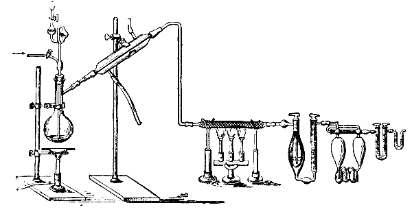
APPARATUS FOR THE ESTIMATION OF CARBON IN ORGANIC SUBSTANCES.
Thus dried it passes through weighed potash bulbs, after which is placed for safety a small tube containing soda lime and phosphoric acid. After the lapse of about twenty minutes, warming may be once more proceeded with in the same manner as before, and after about two and one-half hours the asbestos plate may be placed directly below the flask, and more strongly heated. The whole operation is very easily carried out, and needs no watching.
With substances containing halogens, it is advisable to place, after the copper oxide tube, a small washing flask containing potassium iodide solution.
The dahlia has held a prominent place among garden flowers for many years, and it has received new life in the acquisition of a section little expected by cultivators, but peculiarly welcome. This class is the outcome of much patient work on the part of Mr. T.W. Girdlestone, the well known secretary of the National Dahlia Society, who has for some time past devoted much time to the improvement of the single varieties. We had the pleasure a short time since of receiving a photograph of this dwarf section of dahlias from Messrs. J. Cheal & Sons, of Crawley, who have purchased the stock, and this we have had engraved, as it conveys an excellent idea of the height of the plant and the profusion with which the flowers are produced. The photograph was also of interest as containing a portrait of Mr. Girdlestone, which we are sure will be welcome to many of our readers. The plants of this race are very dwarf, not exceeding twelve inches in height, bushy, spreading and exceedingly free in flowering, the range of varieties being at present limited to twelve. The blooms are of medium size, and the colors are distinct and rich, more particularly the scarlet and crimson shades, which can be employed to immense advantage in the flower garden. The heavy formal show varieties are of little value for planting in trim beds and borders. Many of the decorative or cactus varieties are too coarse in growth to be of much value in the flower garden. Therefore, this Liliputian race should find favor with those who wish for showy and novel effects in the garden during the summer months.
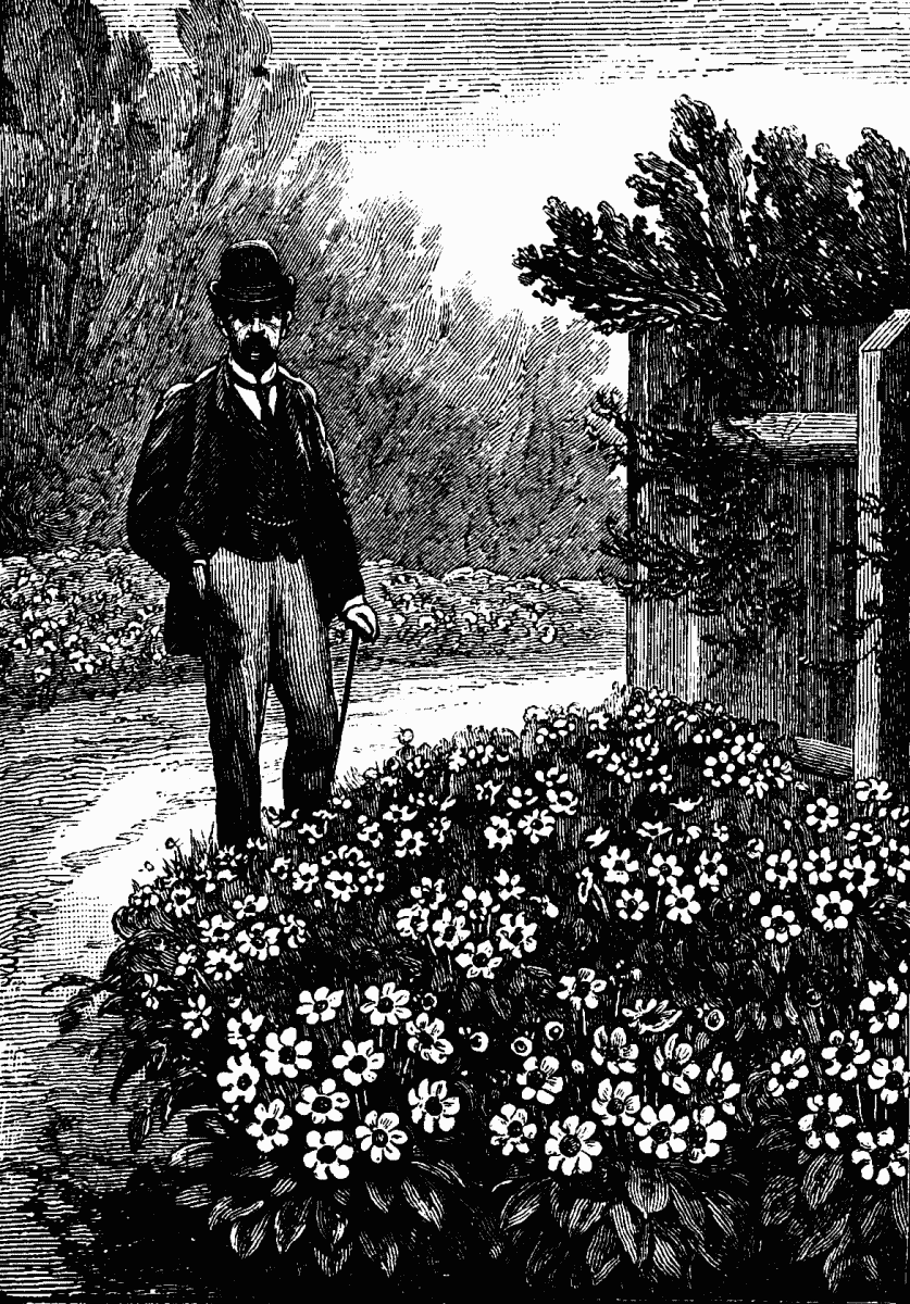
TOM THUMB SINGLE DAHLIAS.
There are no peculiarities of culture to contend with, and the unusually dwarf habit of the plants specially fits them for comparative small beds and borders. One good way would be to fill a single bed with one or more decided colors, as is now done with the tuberous begonia, for the reason that these dahlias have flowers similar in size to those of the tall-growing single varieties, and bear them on stiff stalks well above the stems. A mass of the crimson variety would produce a rich glow of color infinitely finer than a mixture of undecided hues. We anticipate a high degree of popularity for these dwarf single or Tom Thumb dahlias, and there is a possibility of double varieties equally dwarf which would be also welcome. The great fault of the majority of dahlias already in cultivation is the tall habit of the plants, but here we have dwarfness, a profusion of finely formed flowers, and varied and attractive colors.—The Gardeners' Magazine.
In the Proceedings of the New York Academy of Sciences an abstract is given of a paper on the above, read by Dr. Frederick Starr:
It is well known that a tribe may have peculiarities in speech, in manners, in arts, that distinguish it at once from its neighbors. The Haida carves slate as no other tribe does. The elegant blankets of mountain sheep wool from Chilcat are characteristic. The Hebrews tested the enemy with the word shibboleth, and found that he could only say sibboleth. A twist of the tongue in pronouncing a word is a small matter, but, small as it is, it may be perpetuated for ages.
Such a perpetuation of a tribal peculiarity has been aptly called an ethnic survival. Some of the advanced linguists of the present day are beginning to query whether the group of modern languages of the Aryan family are not examples of such ethnic survival; whether the differences between French and Italian and Spanish, Latin, Greek and Slavonic, are not due to the difficulty various ancient tribes found in learning to speak the same new and foreign language. To draw an example of ethnic survival from another field of science, consider the art of the French cave men. The archæologist finds in the caverns bones of various mammals, teeth of cave bear, and antlers of reindeer carved with animal figures. The art is good for a barbarous people, but it is certainly barbarian art. The range of designs is quite great: horses, bears, mammoths, reindeer, are among the figures. The people who did this work were an artistic people. To carve and represent animal forms was almost a mania with them. An ethnic impulse seems to have driven them on to such work, just as a similar impulse drives the Haida slate carver to-day; just as a similar impulse has driven the Bushman to cover the walls of his caves in South Africa with pictures whose boldness and fidelity are the amazement of all who see them.
We have, then, in the French cave dwellers a people who had a well defined art, and who, as art workers, were isolated and unlike all neighbors. An eminent English scientist believes that neither they nor their art are gone. There is a people who to-day lives much as a cave man of France lived so long ago, who hunts and fishes as he did, who dresses as he did, who builds houses in whose architecture some think they can see evidence of a cavern original, who above all still carves batons from ivory, and implements from bone, adorning them with skillfully cut figures of animals and scenes from the chase. This people is the Eskimo. If Dawkins' view is true, we have in the Eskimo carvings of to-day a true ethnic survival—an outcropping of the same passion which displayed itself in the mammoth carving of La Madelaine.
Scarcely anything in the range of American antiquities has caused more wonder and led to more discussion than the animal mounds of Wisconsin. We do not pretend to explain their purpose. Perhaps they were village guardians; perhaps tribal totems marking territorial limits; some may have been of use as game drives; some may even have served as fetich helpers in the hunt, like the prey gods of Zuñi. We may never know their full meaning. It is sufficient here for me to remind you what they are and where. They are nearly confined to a belt of moderate width stretching through Wisconsin and overlapping into Minnesota and Iowa. Within this area they occur by hundreds. Dr. Lapham published a great work on the effigy mounds in 1855, in which he gave the results of many accurate surveys and described many interesting localities. Since his time no one has paid so much attention to the effigies as Stephen D. Peet, editor of the American Antiquarian, whose articles have during this year been presented in book form. Mr. Peet has paid much attention to the kind of animals represented, and has, it seems to us, more nearly solved the question than any one else. He recognizes four classes of animals—land animals or quadruped mammals, always shown in profile; amphibians, always shown as sprawling, with all four feet represented; birds, recognized by their wings; and fishes, characterized by the absence of limbs of any kind. The land animals are subdivided into horned grazers and fur bearers. Of the many species he claims to find, it seems to us the most satisfactorily identified are the buffalo, moose, deer, or elk; the panther, bear, fox, wolf and squirrel; the lizard and turtle; the eagle, hawk, owl, goose and crane; and fishes. One or two man mounds are known, although most of those so-called are bird mounds—either the hawk or the owl. Sometimes, too, "composite mounds" are found. Nor are these mounds all that are found. Occasionally the same forms are found in intaglio, cut into the ground instead of being built above it, but just as carefully and artistically made. Notice, in addition to the form of these strange earth works, that they are so skillfully done that the attitude frequently suggests action or mood. Nor are they placed at random, but are more or less in harmony with their surroundings. Remember, too, their great number and their large size—a man 214 feet long, a beast 160 feet long, with a tail measuring 320 feet, a hawk 240 feet in expanse of wing.
They are unique. To be sure, there are in Ohio three effigies, in Georgia two, and in Dakota some bowlder mosaics in animal form. None of these, however, are like the Wisconsin type. The alligator and serpent of Ohio are different in location and structure from the Wisconsin mounds, and are of designs peculiar. The bird mound in the Newark circle is more like a Wisconsin effigy, but is associated with a type of works not found in the effigy region. The birds of Georgia are different in conception, in material, and in build. The mosaics of Dakota are simply outlines of loose bowlders.
It seems to us that the effigy builders of Wisconsin were a peculiar tribe, unlike their mound-building neighbors in Ohio or the South; that they were a people with a passion for representing animal figures. This passion worked itself out in these earth structures. That a single tribe should be thus isolated in so remarkable a custom is no more strange than that the Haida should carve slate or the Bushman draw his pictures on his cavern walls.
Who were the effigy builders? This is a question often asked and variously answered. Some writers would refer them to the Winnebagoes, or, if not to them directly, to some Dakota stock from which the Winnebagoes have descended.
Formerly I was a frequent visitor to the Sac and Fox Reservation in Iowa. About 400 of the tribe are left. To an unusual degree they retain the old dress, language, arts and dances. With them lived a few Winnebagoes. In general the lives of the two peoples are similar. Certain arts common to both of them particularly interested me. They are the making of sacks of barks and cords, and the weaving of bead bands for legs and arms, upon the ci-bo-hi-kan. Of the bark sacks there are several patterns, the simplest being made of splints of bark passing alternately over and under each other. Another kind, far more elaborate in construction, is before you. Yet more elaborate ones are made entirely of cords. The first of these I saw was in old Jennie Davenport's wikiup. It was of white and black cords, and the black ones were so manipulated as to form a pattern—a line of human figures stretching across the sack. Jennie would not sell it, as she said, "It is a Winnebago woman's sack; Fox woman not make that kind." I found afterward a large variety of these Winnebago sacks, and all were characterized by patterns of men, deer, turtles, or other animals. Not one Fox sack of such pattern was to be found, though many elaborate and beautiful geometrical designs were shown me.
The most beautiful work done on this reservation is the bead weaving on the ci-bo-hi-kan—woven work, not sewed, remember. In appearance the result is like the Iroquois wampum belts, but the management of the threads is dissimilar. The Sac and Fox patterns are frequently complex and beautiful, but always geometrical. We have seen hundreds of them, but none with life forms. The Winnebago belts, made in exactly the same way, frequently, if not always, present animals or birds or human beings.
This, it seems to us, is very curious. Here are people of two tribes living side by side, with the same mode of life and the same arts, but in their art designs so diverse. It is a case parallel to that of the old effigy builders, a people who have a passion for depicting animal forms—a passion not shared by their neighbors.
If this were the only evidence that the Winnebagoes built the effigy mounds, or that their ancestors did so, it would have no great weight. But the claim has been made already on other grounds. This being the case, we think that this adds something to the testimony, and we ask, Have we here an ethnic survival?
At the close of the paper Dr. Starr exhibited a number of fine specimens of Indian handiwork, including woven work, bags, belts, etc.
Dr. Newberry explained that these mounds were not sepulchral, like many others in the Ohio and Mississippi valleys. Geologically speaking, man is very recent. The early inhabitants of America may have originally come from the East, but, if so, they were cut off from that part of the world at a very early date. The development of the tribes in America was complete and far-reaching. Copper and lead mines were worked, the forests removed, and large tracts given over to the cultivation of corn, grain, etc. This was the mound age, and the constructions were certainly abandoned over one thousand years since. The Pueblo Indians now existing in Arizona and New Mexico took their origin from Central America, and spread as far north as Salt Lake, Utah, and south as far as Chili. Their structures were permanent stone buildings, many of which still exist in a good state of preservation.
Professor Munroe found rocks on the Ohio river, near the Pennsylvania line, inscribed with figures of men, horses and other animals. At low water these figures can be distinctly observed.
A proclamation by an eminent physician that he has discovered a specific cure for consumption in its most prevalent and insidious form, known as tuberculosis, might well create a deep and universal interest, since there are comparatively few of us that do not have this deadly enemy within the limits of our cousin kinship. And if German slaughter house statistics are to be taken as representative, no less than ten per cent. of our domesticated horned cattle are a prey to the same disease, though seldom discovered during life. This fact would suggest that tubercular consumption is still more prevalent in the human family than has yet been supposed, and that many carry it under the cover of other maladies.
But unfortunately for any hope for a specific remedy, the preponderance of evidence points to the fact that consumption is much more a product of individual habits and social and climatical conditions than a resultant of any one agency. Indeed, the causative evils may vary not only in their degree, but also in their number and order of action in the period of its evolution.
If it were hereditary in the sense that it is transmitted by the blood as a specific germ or virus, then the offspring of consumptives would have an attenuated form of the disease, which, by reasoning from analogy, ought to secure them exemption from any further danger along that line. Such, however, is not the case. But if we say a special fitness is inherited, then we can understand how the offspring of consumptives are prone to develop it, since they are not only born with hereditary qualifications, but not infrequently they are cradled amid the very agencies which fostered the evil in their parents, if, indeed, they were not primarily causative.
That the contribution of heredity to consumption is great is undoubtedly the case, and, more than any other factor, it would seem to have a directing power in the army of inducing evils. But the fact that the greater number of the offspring of consumptives escape the disease, even where the general family resemblance is quite pronounced, is readily explained by the difference in personal habits, the circumstances of different periods or the domestic regulations instituted by medical counsel. Also the fact that consumptives so frequently spring from neurotic parentage and the victims of dissipation, especially alcoholic, still farther goes to show that the hereditary element is essentially a reduced power of resistance to formative evils, and that as a negative condition it may hold the balance of power in focusing the forces. Thus, heredity, in disease, can be understood as in no sense implying a specific force, but rather an atonic or susceptible condition, varying in its precise character and producing a pars minoris resistentiæ—a special weakness in a special way.
That the germ bacillus does not originate consumption there can be no doubt, unless consumption is not to be regarded as a disease until it is full fledged, for otherwise the germ would be present in the earlier formations, as well as the later, which, according to good authority, is not the case. But that this parasite has a special affinity for consumptive tissue there is no question, and that it thrives therein with great rapidity, hastening retrogressive changes, is also to be granted. But, as yet, this is all we are entitled to believe.
We thus see that the lines of successful treatment must be both constitutional and local; that the constitutional cannot be specific, and the strictly local cannot be curative. The constitutional must be of a negative and positive character, having regard to the support of the healthy remnant, and which will require correction of any deficiency whatsoever in order to remove the morbid constitutional habit. The local will be cleansing of the affected organs from the germs and morbid products.
The evident selective affinity of Koch's lymph for tuberculous tissue may enable it, in certain cases, to effectually seal the arterial capillaries about the affected parts, owing to the intense vaso-motor disturbance produced. This would starve the germs, which, with the tubercular matter, may be expectorated through the moisture and motion of the lungs. In incipient cases the tubercles might be as readily absorbed as catgut ligature, and the germs, if any, fall to phagocytic prey. The Koch lymph is evidently not a poison to the germs, and probably has no other action on the affected organs than that of an irritant, having a selective affinity by virtue of the kinship with its contents. This theory of its action is supported by our common knowledge of the power of pyogenic agents to awaken old or slumbering inflammations, and the fact that septic fevers, such as small-pox, have been known to leave the consumptives with the last stages free from every symptom.
$2.50 a Year. Single Copies, 25 cts.
This is a Special Edition of the SCIENTIFIC AMERICAN, issued monthly—on the first day of the month. Each number contains about forty large quarto pages, equal to about two hundred ordinary book pages, forming, practically, a large and splendid Magazine Of Architecture, richly adorned with elegant plates in colors and with fine engravings, illustrating the most interesting examples of modern Architectural Construction and allied subjects.
A special feature is the presentation in each number of a variety of the latest and best plans for private residences, city and country, including those of very moderate cost as well as the more expensive. Drawings in perspective and in color are given, together with full Plans, Specifications, Costs, Bills of Estimate, and Sheets of Details.
No other building paper contains so many plans, details, and specifications regularly presented as the SCIENTIFIC AMERICAN. Hundreds of dwellings have already been erected on the various plans we have issued during the past year, and many others are in process of construction.
Architects, Builders, and Owners will find this work valuable in furnishing fresh and useful suggestions. All who contemplate building or improving homes, or erecting structures of any kind, have before them in this work an almost endless series of the latest and best examples from which to make selections, thus saving time and money.
Many other subjects, including Sewerage, Piping, Lighting, Warming, Ventilating, Decorating, Laying out of Grounds, etc., are illustrated. An extensive Compendium of Manufacturers' Announcements is also given, in which the most reliable and approved Building Materials, Goods, Machines, Tools, and Appliances are described and illustrated, with addresses of the makers, etc.
The fullness, richness, cheapness, and convenience of this work have won for it the Largest Circulation of any Architectural publication in the world.
A Catalogue of valuable books on Architecture, Building, Carpentry, Masonry, Heating, Warming, Lighting, Ventilation, and all branches of industry pertaining to the art of Building, is supplied free of charge, sent to any address.
MUNN & CO., Publishers,
361 Broadway, New York.
In connection with the publication of the BUILDING EDITION of the SCIENTIFIC AMERICAN, Messrs. Munn & Co. furnish plans and specifications for buildings of every kind, including Churches, Schools, Stores, Dwellings, Carriage Houses, Barns, etc.
In this work they are assisted by able and experienced architects. Full plans, details, and specifications for the various buildings illustrated in this paper can be supplied.
Those who contemplate building, or who wish to alter, improve, extend, or add to existing buildings, whether wings, porches, bay windows, or attic rooms, are invited to communicate with the undersigned. Our work extends to all parts of the country. Estimates, plans, and drawings promptly prepared. Terms moderate. Address
MUNN & CO., 361 BROADWAY, NEW YORK.
PUBLISHED WEEKLY.
Terms of Subscription, $5 a year.
Sent by mail, postage prepaid, to subscribers in any part of the United States or Canada. Six dollars a year, sent, prepaid, to any foreign country.
All the back numbers of THE SUPPLEMENT, from the commencement. January 1, 1876, can be had. Price, 10 cents each.
All the back volumes of THE SUPPLEMENT can likewise be supplied. Two volumes are issued yearly. Price of each volume, $2.50 stitched in paper, or $3.50 bound in stiff covers.
COMBINED RATES.—One copy of SCIENTIFIC AMERICAN and one copy of SCIENTIFIC AMERICAN SUPPLEMENT, one year, postpaid, $7.00.
A liberal discount to booksellers, news agents, and canvassers.
MUNN & CO., Publishers,
361 Broadway, New York, N.Y.
Contained in SCIENTIFIC AMERICAN SUPPLEMENT during the past ten years, sent free of charge to any address. MUNN & CO., 361 Broadway, New York.
Manufacturers, Agriculturists, Chemists, Engineers, Mechanics, Builders, men of leisure, and professional men, of all classes, need good books in the line of their respective callings. Our post office department permits the transmission of books through the mails at very small cost. A comprehensive catalogue of useful books by different authors, on more than fifty different subjects, has recently been published, for free circulation, at the office of this paper. Subjects classified with names of author. Persons desiring a copy have only to ask for it, and it will be mailed to them. Address,
MUNN & CO., 361 Broadway, New York.
In connection with the Scientific American, Messrs. MUNN & Co. are solicitors of American and Foreign Patents, have had 42 years' experience, and now have the largest establishment in the world. Patents are obtained on the best terms.
A special notice is made in the Scientific American of all inventions patented through this Agency, with the name and residence of the Patentee. By the immense circulation thus given, public attention is directed to the merits of the new patent, and sales or introduction often easily effected.
Any person who has made a new discovery or invention can ascertain, free of charge, whether a patent can probably be obtained, by writing to MUNN & Co.
We also send free our Hand Book about the Patent Laws, Patents, Caveats, Trade Marks, their costs and how procured. Address
MUNN & CO.,
361 Broadway, New York.
Branch Office, 622 and 624 F St., Washington, D.C.
End of the Project Gutenberg EBook of Scientific American Supplement, No.
794, March 21, 1891, by Various

*** END OF THIS PROJECT GUTENBERG EBOOK SCIENTIFIC AMERICAN ***

***** This file should be named 15708-h.htm or 15708-h.zip *****
This and all associated files of various formats will be found in:
        https://www.gutenberg.org/1/5/7/0/15708/

Produced by Juliet Sutherland and the Online Distributed Proofreading
Team at www.pgdp.net.


Updated editions will replace the previous one--the old editions
will be renamed.

Creating the works from public domain print editions means that no
one owns a United States copyright in these works, so the Foundation
(and you!) can copy and distribute it in the United States without
permission and without paying copyright royalties.  Special rules,
set forth in the General Terms of Use part of this license, apply to
copying and distributing Project Gutenberg-tm electronic works to
protect the PROJECT GUTENBERG-tm concept and trademark.  Project
Gutenberg is a registered trademark, and may not be used if you
charge for the eBooks, unless you receive specific permission.  If you
do not charge anything for copies of this eBook, complying with the
rules is very easy.  You may use this eBook for nearly any purpose
such as creation of derivative works, reports, performances and
research.  They may be modified and printed and given away--you may do
practically ANYTHING with public domain eBooks.  Redistribution is
subject to the trademark license, especially commercial
redistribution.


*** START: FULL LICENSE ***

THE FULL PROJECT GUTENBERG LICENSE
PLEASE READ THIS BEFORE YOU DISTRIBUTE OR USE THIS WORK

To protect the Project Gutenberg-tm mission of promoting the free
distribution of electronic works, by using or distributing this work
(or any other work associated in any way with the phrase "Project
Gutenberg"), you agree to comply with all the terms of the Full Project
Gutenberg-tm License (available with this file or online at
https://gutenberg.org/license).


Section 1.  General Terms of Use and Redistributing Project Gutenberg-tm
electronic works

1.A.  By reading or using any part of this Project Gutenberg-tm
electronic work, you indicate that you have read, understand, agree to
and accept all the terms of this license and intellectual property
(trademark/copyright) agreement.  If you do not agree to abide by all
the terms of this agreement, you must cease using and return or destroy
all copies of Project Gutenberg-tm electronic works in your possession.
If you paid a fee for obtaining a copy of or access to a Project
Gutenberg-tm electronic work and you do not agree to be bound by the
terms of this agreement, you may obtain a refund from the person or
entity to whom you paid the fee as set forth in paragraph 1.E.8.

1.B.  "Project Gutenberg" is a registered trademark.  It may only be
used on or associated in any way with an electronic work by people who
agree to be bound by the terms of this agreement.  There are a few
things that you can do with most Project Gutenberg-tm electronic works
even without complying with the full terms of this agreement.  See
paragraph 1.C below.  There are a lot of things you can do with Project
Gutenberg-tm electronic works if you follow the terms of this agreement
and help preserve free future access to Project Gutenberg-tm electronic
works.  See paragraph 1.E below.

1.C.  The Project Gutenberg Literary Archive Foundation ("the Foundation"
or PGLAF), owns a compilation copyright in the collection of Project
Gutenberg-tm electronic works.  Nearly all the individual works in the
collection are in the public domain in the United States.  If an
individual work is in the public domain in the United States and you are
located in the United States, we do not claim a right to prevent you from
copying, distributing, performing, displaying or creating derivative
works based on the work as long as all references to Project Gutenberg
are removed.  Of course, we hope that you will support the Project
Gutenberg-tm mission of promoting free access to electronic works by
freely sharing Project Gutenberg-tm works in compliance with the terms of
this agreement for keeping the Project Gutenberg-tm name associated with
the work.  You can easily comply with the terms of this agreement by
keeping this work in the same format with its attached full Project
Gutenberg-tm License when you share it without charge with others.

1.D.  The copyright laws of the place where you are located also govern
what you can do with this work.  Copyright laws in most countries are in
a constant state of change.  If you are outside the United States, check
the laws of your country in addition to the terms of this agreement
before downloading, copying, displaying, performing, distributing or
creating derivative works based on this work or any other Project
Gutenberg-tm work.  The Foundation makes no representations concerning
the copyright status of any work in any country outside the United
States.

1.E.  Unless you have removed all references to Project Gutenberg:

1.E.1.  The following sentence, with active links to, or other immediate
access to, the full Project Gutenberg-tm License must appear prominently
whenever any copy of a Project Gutenberg-tm work (any work on which the
phrase "Project Gutenberg" appears, or with which the phrase "Project
Gutenberg" is associated) is accessed, displayed, performed, viewed,
copied or distributed:

This eBook is for the use of anyone anywhere at no cost and with
almost no restrictions whatsoever.  You may copy it, give it away or
re-use it under the terms of the Project Gutenberg License included
with this eBook or online at www.gutenberg.org

1.E.2.  If an individual Project Gutenberg-tm electronic work is derived
from the public domain (does not contain a notice indicating that it is
posted with permission of the copyright holder), the work can be copied
and distributed to anyone in the United States without paying any fees
or charges.  If you are redistributing or providing access to a work
with the phrase "Project Gutenberg" associated with or appearing on the
work, you must comply either with the requirements of paragraphs 1.E.1
through 1.E.7 or obtain permission for the use of the work and the
Project Gutenberg-tm trademark as set forth in paragraphs 1.E.8 or
1.E.9.

1.E.3.  If an individual Project Gutenberg-tm electronic work is posted
with the permission of the copyright holder, your use and distribution
must comply with both paragraphs 1.E.1 through 1.E.7 and any additional
terms imposed by the copyright holder.  Additional terms will be linked
to the Project Gutenberg-tm License for all works posted with the
permission of the copyright holder found at the beginning of this work.

1.E.4.  Do not unlink or detach or remove the full Project Gutenberg-tm
License terms from this work, or any files containing a part of this
work or any other work associated with Project Gutenberg-tm.

1.E.5.  Do not copy, display, perform, distribute or redistribute this
electronic work, or any part of this electronic work, without
prominently displaying the sentence set forth in paragraph 1.E.1 with
active links or immediate access to the full terms of the Project
Gutenberg-tm License.

1.E.6.  You may convert to and distribute this work in any binary,
compressed, marked up, nonproprietary or proprietary form, including any
word processing or hypertext form.  However, if you provide access to or
distribute copies of a Project Gutenberg-tm work in a format other than
"Plain Vanilla ASCII" or other format used in the official version
posted on the official Project Gutenberg-tm web site (www.gutenberg.org),
you must, at no additional cost, fee or expense to the user, provide a
copy, a means of exporting a copy, or a means of obtaining a copy upon
request, of the work in its original "Plain Vanilla ASCII" or other
form.  Any alternate format must include the full Project Gutenberg-tm
License as specified in paragraph 1.E.1.

1.E.7.  Do not charge a fee for access to, viewing, displaying,
performing, copying or distributing any Project Gutenberg-tm works
unless you comply with paragraph 1.E.8 or 1.E.9.

1.E.8.  You may charge a reasonable fee for copies of or providing
access to or distributing Project Gutenberg-tm electronic works provided
that

- You pay a royalty fee of 20% of the gross profits you derive from
     the use of Project Gutenberg-tm works calculated using the method
     you already use to calculate your applicable taxes.  The fee is
     owed to the owner of the Project Gutenberg-tm trademark, but he
     has agreed to donate royalties under this paragraph to the
     Project Gutenberg Literary Archive Foundation.  Royalty payments
     must be paid within 60 days following each date on which you
     prepare (or are legally required to prepare) your periodic tax
     returns.  Royalty payments should be clearly marked as such and
     sent to the Project Gutenberg Literary Archive Foundation at the
     address specified in Section 4, "Information about donations to
     the Project Gutenberg Literary Archive Foundation."

- You provide a full refund of any money paid by a user who notifies
     you in writing (or by e-mail) within 30 days of receipt that s/he
     does not agree to the terms of the full Project Gutenberg-tm
     License.  You must require such a user to return or
     destroy all copies of the works possessed in a physical medium
     and discontinue all use of and all access to other copies of
     Project Gutenberg-tm works.

- You provide, in accordance with paragraph 1.F.3, a full refund of any
     money paid for a work or a replacement copy, if a defect in the
     electronic work is discovered and reported to you within 90 days
     of receipt of the work.

- You comply with all other terms of this agreement for free
     distribution of Project Gutenberg-tm works.

1.E.9.  If you wish to charge a fee or distribute a Project Gutenberg-tm
electronic work or group of works on different terms than are set
forth in this agreement, you must obtain permission in writing from
both the Project Gutenberg Literary Archive Foundation and Michael
Hart, the owner of the Project Gutenberg-tm trademark.  Contact the
Foundation as set forth in Section 3 below.

1.F.

1.F.1.  Project Gutenberg volunteers and employees expend considerable
effort to identify, do copyright research on, transcribe and proofread
public domain works in creating the Project Gutenberg-tm
collection.  Despite these efforts, Project Gutenberg-tm electronic
works, and the medium on which they may be stored, may contain
"Defects," such as, but not limited to, incomplete, inaccurate or
corrupt data, transcription errors, a copyright or other intellectual
property infringement, a defective or damaged disk or other medium, a
computer virus, or computer codes that damage or cannot be read by
your equipment.

1.F.2.  LIMITED WARRANTY, DISCLAIMER OF DAMAGES - Except for the "Right
of Replacement or Refund" described in paragraph 1.F.3, the Project
Gutenberg Literary Archive Foundation, the owner of the Project
Gutenberg-tm trademark, and any other party distributing a Project
Gutenberg-tm electronic work under this agreement, disclaim all
liability to you for damages, costs and expenses, including legal
fees.  YOU AGREE THAT YOU HAVE NO REMEDIES FOR NEGLIGENCE, STRICT
LIABILITY, BREACH OF WARRANTY OR BREACH OF CONTRACT EXCEPT THOSE
PROVIDED IN PARAGRAPH F3.  YOU AGREE THAT THE FOUNDATION, THE
TRADEMARK OWNER, AND ANY DISTRIBUTOR UNDER THIS AGREEMENT WILL NOT BE
LIABLE TO YOU FOR ACTUAL, DIRECT, INDIRECT, CONSEQUENTIAL, PUNITIVE OR
INCIDENTAL DAMAGES EVEN IF YOU GIVE NOTICE OF THE POSSIBILITY OF SUCH
DAMAGE.

1.F.3.  LIMITED RIGHT OF REPLACEMENT OR REFUND - If you discover a
defect in this electronic work within 90 days of receiving it, you can
receive a refund of the money (if any) you paid for it by sending a
written explanation to the person you received the work from.  If you
received the work on a physical medium, you must return the medium with
your written explanation.  The person or entity that provided you with
the defective work may elect to provide a replacement copy in lieu of a
refund.  If you received the work electronically, the person or entity
providing it to you may choose to give you a second opportunity to
receive the work electronically in lieu of a refund.  If the second copy
is also defective, you may demand a refund in writing without further
opportunities to fix the problem.

1.F.4.  Except for the limited right of replacement or refund set forth
in paragraph 1.F.3, this work is provided to you 'AS-IS' WITH NO OTHER
WARRANTIES OF ANY KIND, EXPRESS OR IMPLIED, INCLUDING BUT NOT LIMITED TO
WARRANTIES OF MERCHANTIBILITY OR FITNESS FOR ANY PURPOSE.

1.F.5.  Some states do not allow disclaimers of certain implied
warranties or the exclusion or limitation of certain types of damages.
If any disclaimer or limitation set forth in this agreement violates the
law of the state applicable to this agreement, the agreement shall be
interpreted to make the maximum disclaimer or limitation permitted by
the applicable state law.  The invalidity or unenforceability of any
provision of this agreement shall not void the remaining provisions.

1.F.6.  INDEMNITY - You agree to indemnify and hold the Foundation, the
trademark owner, any agent or employee of the Foundation, anyone
providing copies of Project Gutenberg-tm electronic works in accordance
with this agreement, and any volunteers associated with the production,
promotion and distribution of Project Gutenberg-tm electronic works,
harmless from all liability, costs and expenses, including legal fees,
that arise directly or indirectly from any of the following which you do
or cause to occur: (a) distribution of this or any Project Gutenberg-tm
work, (b) alteration, modification, or additions or deletions to any
Project Gutenberg-tm work, and (c) any Defect you cause.


Section  2.  Information about the Mission of Project Gutenberg-tm

Project Gutenberg-tm is synonymous with the free distribution of
electronic works in formats readable by the widest variety of computers
including obsolete, old, middle-aged and new computers.  It exists
because of the efforts of hundreds of volunteers and donations from
people in all walks of life.

Volunteers and financial support to provide volunteers with the
assistance they need, is critical to reaching Project Gutenberg-tm's
goals and ensuring that the Project Gutenberg-tm collection will
remain freely available for generations to come.  In 2001, the Project
Gutenberg Literary Archive Foundation was created to provide a secure
and permanent future for Project Gutenberg-tm and future generations.
To learn more about the Project Gutenberg Literary Archive Foundation
and how your efforts and donations can help, see Sections 3 and 4
and the Foundation web page at https://www.pglaf.org.


Section 3.  Information about the Project Gutenberg Literary Archive
Foundation

The Project Gutenberg Literary Archive Foundation is a non profit
501(c)(3) educational corporation organized under the laws of the
state of Mississippi and granted tax exempt status by the Internal
Revenue Service.  The Foundation's EIN or federal tax identification
number is 64-6221541.  Its 501(c)(3) letter is posted at
https://pglaf.org/fundraising.  Contributions to the Project Gutenberg
Literary Archive Foundation are tax deductible to the full extent
permitted by U.S. federal laws and your state's laws.

The Foundation's principal office is located at 4557 Melan Dr. S.
Fairbanks, AK, 99712., but its volunteers and employees are scattered
throughout numerous locations.  Its business office is located at
809 North 1500 West, Salt Lake City, UT 84116, (801) 596-1887, email
business@pglaf.org.  Email contact links and up to date contact
information can be found at the Foundation's web site and official
page at https://pglaf.org

For additional contact information:
     Dr. Gregory B. Newby
     Chief Executive and Director
     gbnewby@pglaf.org


Section 4.  Information about Donations to the Project Gutenberg
Literary Archive Foundation

Project Gutenberg-tm depends upon and cannot survive without wide
spread public support and donations to carry out its mission of
increasing the number of public domain and licensed works that can be
freely distributed in machine readable form accessible by the widest
array of equipment including outdated equipment.  Many small donations
($1 to $5,000) are particularly important to maintaining tax exempt
status with the IRS.

The Foundation is committed to complying with the laws regulating
charities and charitable donations in all 50 states of the United
States.  Compliance requirements are not uniform and it takes a
considerable effort, much paperwork and many fees to meet and keep up
with these requirements.  We do not solicit donations in locations
where we have not received written confirmation of compliance.  To
SEND DONATIONS or determine the status of compliance for any
particular state visit https://pglaf.org

While we cannot and do not solicit contributions from states where we
have not met the solicitation requirements, we know of no prohibition
against accepting unsolicited donations from donors in such states who
approach us with offers to donate.

International donations are gratefully accepted, but we cannot make
any statements concerning tax treatment of donations received from
outside the United States.  U.S. laws alone swamp our small staff.

Please check the Project Gutenberg Web pages for current donation
methods and addresses.  Donations are accepted in a number of other
ways including including checks, online payments and credit card
donations.  To donate, please visit: https://pglaf.org/donate


Section 5.  General Information About Project Gutenberg-tm electronic
works.

Professor Michael S. Hart was the originator of the Project Gutenberg-tm
concept of a library of electronic works that could be freely shared
with anyone.  For thirty years, he produced and distributed Project
Gutenberg-tm eBooks with only a loose network of volunteer support.


Project Gutenberg-tm eBooks are often created from several printed
editions, all of which are confirmed as Public Domain in the U.S.
unless a copyright notice is included.  Thus, we do not necessarily
keep eBooks in compliance with any particular paper edition.


Most people start at our Web site which has the main PG search facility:

     https://www.gutenberg.org

This Web site includes information about Project Gutenberg-tm,
including how to make donations to the Project Gutenberg Literary
Archive Foundation, how to help produce our new eBooks, and how to
subscribe to our email newsletter to hear about new eBooks.