The Project Gutenberg EBook of Cyclopedia of Telephony & Telegraphy Vol. 1
by Kempster Miller, George Patterson, Charles Thom, Robert Millikan,
Samuel McMeen

This eBook is for the use of anyone anywhere at no cost and with
almost no restrictions whatsoever.  You may copy it, give it away or
re-use it under the terms of the Project Gutenberg License included
with this eBook or online at www.gutenberg.org


Title: Cyclopedia of Telephony & Telegraphy Vol. 1
       A General Reference Work on Telephony, etc. etc.

Author: Kempster Miller
        George Patterson
        Charles Thom
        Robert Millikan
        Samuel McMeen

Release Date: April 14, 2005 [EBook #15617]

Language: English

Character set encoding: ISO-8859-1

*** START OF THIS PROJECT GUTENBERG EBOOK CYCLOPEDIA OF TELEPHONY 1 ***


Produced by Ronald Holder and the Online Distributed
Proofreading Team at https://www.pgdp.net.
A General Reference Work on
TELEPHONY, SUBSTATIONS, PARTY-LINE SYSTEMS, PROTECTION, MANUAL
SWITCHBOARDS, AUTOMATIC SYSTEMS, POWER PLANTS, SPECIAL
SERVICE FEATURES, CONSTRUCTION, ENGINEERING,
OPERATION, MAINTENANCE, TELEGRAPHY, WIRELESS
TELEGRAPHY AND TELEPHONY, ETC.
Prepared by a Corps of
TELEPHONE AND TELEGRAPH EXPERTS, AND ELECTRICAL ENGINEERS OF
THE HIGHEST PROFESSIONAL STANDING
Illustrated with over Two Thousand Engravings
F O U R V O L U M E S
CHICAGO
AMERICAN SCHOOL OF CORRESPONDENCE
1919
ToC
KEMPSTER B. MILLER. M.E.
Consulting Engineer and Telephone Expert
Of the Firm of McMeen and Miller, Electrical Engineers and Patent Experts, Chicago
American Institute of Electrical Engineers
Western Society of Engineers
GEORGE W. PATTERSON, S.B., Ph.D.
Head, Department of Electrical Engineering, University of Michigan
CHARLES THOM
Chief of Quadruplex Department, Western Union Main Office, New York City
ROBERT ANDREWS MILLIKAN, Ph.D.
Associate Professor of Physics, University of Chicago
Member, Executive Council, American Physical Society
SAMUEL G. McMEEN
Consulting Engineer and Telephone Expert
Of the Firm of McMeen and Miller, Electrical Engineers and Patent Experts, Chicago
American Institute of Electrical Engineers
Western Society of Engineers
LAWRENCE K. SAGER, S.B., M.P.L.
Patent Attorney and Electrical Expert
Formerly Assistant Examiner, U.S. Patent Office
GLENN M. HOBBS, Ph.D.
Secretary, American School of Correspondence
Formerly Instructor in Physics, University of Chicago
American Physical Society
CHARLES G. ASHLEY
Electrical Engineer and Expert in Wireless Telegraphy and Telephony
A. FREDERICK COLLINS
Editor, Collins Wireless Bulletin
Author of "Wireless Telegraphy, Its History, Theory, and Practice"
FRANCIS B. CROCKER, E.M., Ph.D.
Head, Department of Electrical Engineering, Columbia University
Past-President, American Institute of Electrical Engineers
MORTON ARENDT, E.E.
Instructor in Electrical Engineering, Columbia University, New York
EDWARD B. WAITE
Head, Instruction Department, American School of Correspondence
American Society of Mechanical Engineers
Western Society of Engineers
DAVID P. MORETON, B.S., E.E.
Associate Professor of Electrical Engineering, Armour Institute of Technology
American Institute of Electrical Engineers
LEIGH S. KEITH, B.S.
Managing Engineer with McMeen and Miller, Electrical Engineers and Patent Experts Chicago
Associate Member, American Institute of Electrical Engineers
JESSIE M. SHEPHERD, A.B.
Associate Editor, Textbook Department, American School of Correspondence
ERNEST L. WALLACE, B.S.
Assistant Examiner, United States Patent Office, Washington, D. C.
GEORGE R. METCALFE, M.E.
Editor, American Institute of Electrical Engineers
Formerly Head of Publication Department, Westinghouse Elec. & Mfg. Co.
J.P. SCHROETER
Graduate, Munich Technical School
Instructor in Electrical Engineering, American School of Correspondence
JAMES DIXON, E.E.
American Institute of Electrical Engineers
HARRIS C. TROW, S.B., Managing Editor
Editor-in-Chief, Textbook Department, American School of Correspondence
The editors have freely consulted the standard technical literature of America and Europe in the preparation of these volumes. They desire to express their indebtedness particularly to the following eminent authorities, whose well-known works should be in the library of every telephone and telegraph engineer.
Grateful acknowledgment is here made also for the invaluable co-operation of the foremost engineering firms and manufacturers in making these volumes thoroughly representative of the very best and latest practice in the transmission of intelligence, also for the valuable drawings, data, suggestions, criticisms, and other courtesies.
ARTHUR E. KENNELY, D.Sc.
Professor of Electrical Engineering, Harvard University.
Joint Author of "The Electric Telephone."
"The Electric Telegraph," "Alternating
Currents," "Arc Lighting," "Electric Heating,"
"Electric Motors," "Electric Railways,"
"Incandescent Lighting," etc.
HENRY SMITH CARHART, A.M., LL.D.
Professor of Physics and Director of the Physical Laboratory, University of Michigan.
Author of "Primary Batteries," "Elements of Physics,"
"University Physics," "Electrical
Measurements," "High School Physics," etc.
FRANCIS B. CROCKER, M.E., Ph.D.
Head of Department of Electrical Engineering, Columbia University, New York; Past-President,
American Institute of Electrical Engineers.
Author of "Electric Lighting;" Joint Author of "Management of Electrical Machinery."
HORATIO A. FOSTER
Consulting Engineer; Member of American Institute of Electrical Engineers; Member
of American Society of Mechanical Engineers.
Author of "Electrical Engineer's Pocket-Book."
WILLIAM S. FRANKLIN, M.S., D.Sc.
Professor of Physics, Lehigh University.
Joint Author of "The Elements of Electrical Engineering," "The Elements of Alternating
Currents."
LAMAR LYNDON, B.E., M.E.
Consulting Electrical Engineer; Associate Member of American Institute of Electrical
Engineers; Member, American Electro-Chemical Society.
Author of "Storage Battery Engineering."
ROBERT ANDREWS MILLIKAN, Ph.D.
Professor of Physics, University of Chicago.
Joint Author of "A First Course in Physics," "Electricity, Sound and Light," etc.
KEMPSTER B. MILLER, M.E.
Consulting Engineer and Telephone Expert; of the Firm of McMeen and Miller,
Electrical Engineers and Patent Experts, Chicago.
Author of "American Telephone Practice."
WILLIAM H. PREECE
Chief of the British Postal Telegraph.
Joint Author of "Telegraphy," "A Manual of Telephony," etc.—
LOUIS BELL, Ph.D.
Consulting Electrical Engineer; Lecturer on Power Transmission, Massachusetts Institute of Technology.
Author of "Electric Power Transmission," "Power Distribution for Electric Railways,"
"The Art of Illumination," "Wireless Telephony," etc.
OLIVER HEAVISIDE, F.R.S.
Author of "Electro-Magnetic Theory," "Electrical Papers," etc.
SILVANUS P. THOMPSON, D.Sc, B.A., F.R.S., F.R.A.S.
Principal and Professor of Physics in the City and Guilds of London Technical College.
Author of "Electricity and Magnetism," "Dynamo-Electric Machinery,"
"Polyphase Electric Currents and Alternate-Current Motors," "The Electromagnet," etc.
ANDREW GRAY, M.A., F.R.S.E.
Author of "Absolute Measurements in Electricity and Magnetism."
ALBERT CUSHING CREHORE, A.B., Ph.D.
Electrical Engineer; Assistant Professor of Physics, Dartmouth College; Formerly instructor
in Physics, Cornell University.
Author of "Synchronous and Other Multiple Telegraphs;" Joint Author of "Alternating
Currents."
J. J. THOMSON, D.Sc, LL.D., Ph.D., F.R.S.
Fellow of Trinity College, Cambridge University; Cavendish Professor of Experimental
Physics, Cambridge University.
Author of "The Conduction of Electricity through Gases," "Electricity and Matter."
FREDERICK BEDELL, Ph. D.
Professor of Applied Electricity, Cornell University.
Author of "The Principles of the Transformer;" Joint Author of "Alternating Currents."
DUGALD C. JACKSON, C.E.
Head of Department of Electrical Engineering, Massachusetts Institute of Technology;
Member, American Institute of Electrical Engineers, etc.
Author of "A Textbook on Electromagnetism and the Construction of Dynamos;"
Joint Author of "Alternating Currents and Alternating-Current Machinery."
MICHAEL IDVORSKY PUPIN, A.B., Sc.D., Ph.D.
Professor of Electro-Mechanics, Columbia University, New York.
Author of "Propagation of Long Electric Waves," and "Wave-Transmission over
Non-Uniform Cables and Long-Distance Air Lines."
FRANK BALDWIN JEWETT, A.B., Ph.D.
Transmission and Protection Engineer, with American Telephone & Telegraph Co.
Author of "Modern Telephone Cable," "Effect of Pressure on Insulation Resistance."
ARTHUR CROTCH
Formerly Lecturer on Telegraphy and Telephony at the Municipal Technical Schools,
Norwich, Eng.
Author of "Telegraphy and Telephony."
JAMES ERSKINE-MURRAY, D.Sc.
Fellow of the Royal Society of Edinburgh; Member of the Institution of Electrical
Engineers.
Author of "A Handbook of Wireless Telegraphy."
A.H. MCMILLAN, A.B., LL.B.
Author of "Telephone Law, A Manual on the Organization and Operation of Telephone Companies."
WILLIAM ESTY, S.B., M.A.
Head of Department of Electrical Engineering, Lehigh University.
Joint Author of "The Elements of Electrical Engineering."
GEORGE W. WILDER, Ph.D.
Formerly Professor of Telephone Engineering, Armour Institute of Technology.
Author of "Telephone Principles and Practice," "Simultaneous Telegraphy and Telephony,"
etc.
WILLIAM L. HOOPER, Ph.D.
Head of Department of Electrical Engineering, Tufts College.
Joint Author of "Electrical Problems for Engineering Students."
DAVID S. HULFISH
Technical Editor, The Nickelodeon; Telephone and Motion-Picture Expert; Solicitor of
Patents.
Author of "How to Read Telephone Circuit Diagrams."
J.A. FLEMING, M.A., D.Sc. (Lond.), F.R.S.
Professor of Electrical Engineering in University College, London;
Late Fellow and Scholar of St. John's College, Cambridge; Fellow of University College, London.
Author of "The Alternate-Current Transformer," "Radiotelegraphy and Radiotelephony,"
"Principles of Electric Wave Telegraphy," "Cantor Lectures on Electrical
Oscillations and Electric Waves," "Hertzian Wave Wireless Telegraphy," etc.
F.A.C. PERRINE, A.M., D.Sc.
Consulting Engineer: Formerly President, Stanley Electric Manufacturing Company;
Formerly Professor of Electrical Engineering, Leland Stanford, Jr. University.
Author of "Conductors for Electrical Distribution."
A. FREDERICK COLLINS
Editor, Collins Wireless Bulletin.
Author of "Wireless Telegraphy, Its History, Theory and Practice," "Manual of Wireless
Telegraphy," "Design and Construction of Induction Coils," etc.
SCHUYLER S. WHEELER, D.Sc.
President, Crocker-Wheeler Co.; Past-President, American Institute of Electrical Engineers.
Joint Author of "Management of Electrical Machinery."
CHARLES PROTEUS STEINMETZ
Consulting Engineer, with the General Electric Co.; Professor of Electrical Engineering, Union College.
Author of "The Theory and Calculation of Alternating-Current Phenomena," "Theoretical
Elements of Electrical Engineering", etc.
GEORGE W. PATTERSON, S.B., Ph.D.
Head of Department of Electrical Engineering, University of Michigan.
Joint Author of "Electrical Measurements."
WILLIAM MAVER, JR.
Ex-Electrician Baltimore and Ohio Telegraph Company; Member of the American Institute of Electrical Engineers.
Author of "American Telegraphy and Encyclopedia of the Telegraph," "Wireless Telegraphy."
JOHN PRICE JACKSON, M.E.
Professor of Electrical Engineering, Pennsylvania State College.
Joint Author of "Alternating Currents and Alternating-Current Machinery."
AUGUSTUS TREADWELL, JR., E.E.
Associate Member, American Institute of Electrical Engineers.
Author of "The Storage Battery, A Practical Treatise on Secondary Batteries."
EDWIN J. HOUSTON, Ph.D.
Professor of Physics, Franklin Institute, Pennsylvania; Joint Inventor of Thomson-Houston
System of Arc Lighting; Electrical Expert and Consulting Engineer.
Joint Author of "The Electric Telephone," "The Electric Telegraph," "Alternating
Currents," "Arc Lighting," "Electric Heating,"
"Electric Motors," "Electric Railways,"
"Incandescent Lighting," etc.
WILLIAM J. HOPKINS
Professor of Physics in the Drexel Institute of Art, Science, and Industry, Philadelphia.
Author of "Telephone Lines and their Properties."
ToC
![]() The present day development of the "talking wire" has annihilated both
time and space, and has enabled men thousands of miles apart to get
into almost instant communication. The user of the telephone and the
telegraph forgets the tremendousness of the feat in the simplicity of
its accomplishment; but the man who has made the feat possible knows
that its very simplicity is due to the complexity of the principles
and appliances involved; and he realizes his need of a practical,
working understanding of each principle and its application. The
Cyclopedia of Telephony and Telegraphy presents a comprehensive and
authoritative treatment of the whole art of the electrical
transmission of intelligence.
The present day development of the "talking wire" has annihilated both
time and space, and has enabled men thousands of miles apart to get
into almost instant communication. The user of the telephone and the
telegraph forgets the tremendousness of the feat in the simplicity of
its accomplishment; but the man who has made the feat possible knows
that its very simplicity is due to the complexity of the principles
and appliances involved; and he realizes his need of a practical,
working understanding of each principle and its application. The
Cyclopedia of Telephony and Telegraphy presents a comprehensive and
authoritative treatment of the whole art of the electrical
transmission of intelligence.
![]() The communication engineer—if so he may be called—requires a
knowledge both of the mechanism of his instruments and of the vagaries
of the current that makes them talk. He requires as well a knowledge
of plants and buildings, of office equipment, of poles and wires and
conduits, of office system and time-saving methods, for the
transmission of intelligence is a business as well as an art. And to
each of these subjects, and to all others pertinent, the Cyclopedia
gives proper space and treatment.
The communication engineer—if so he may be called—requires a
knowledge both of the mechanism of his instruments and of the vagaries
of the current that makes them talk. He requires as well a knowledge
of plants and buildings, of office equipment, of poles and wires and
conduits, of office system and time-saving methods, for the
transmission of intelligence is a business as well as an art. And to
each of these subjects, and to all others pertinent, the Cyclopedia
gives proper space and treatment.
![]() The sections on Telephony cover the installation, maintenance, and
operation of all standard types of telephone systems; they present
without prejudice the respective merits of manual and automatic
exchanges; and they give special attention to the prevention and
handling of operating "troubles." The sections on Telegraphy cover
both commercial service and train
Page 9
dispatching. Practical methods of
wireless communication—both by telephone and by telegraph—are
thoroughly treated.
The sections on Telephony cover the installation, maintenance, and
operation of all standard types of telephone systems; they present
without prejudice the respective merits of manual and automatic
exchanges; and they give special attention to the prevention and
handling of operating "troubles." The sections on Telegraphy cover
both commercial service and train
Page 9
dispatching. Practical methods of
wireless communication—both by telephone and by telegraph—are
thoroughly treated.
![]() The drawings, diagrams, and photographs incorporated into the
Cyclopedia have been prepared especially for this work; and their
instructive value is as great as that of the text itself. They have
been used to illustrate and illuminate the text, and not as a medium
around which to build the text. Both drawings and diagrams have been
simplified so far as is compatible with their correctness, with the
result that they tell their own story and always in the same language.
The drawings, diagrams, and photographs incorporated into the
Cyclopedia have been prepared especially for this work; and their
instructive value is as great as that of the text itself. They have
been used to illustrate and illuminate the text, and not as a medium
around which to build the text. Both drawings and diagrams have been
simplified so far as is compatible with their correctness, with the
result that they tell their own story and always in the same language.
![]() The Cyclopedia is a compilation of many of the most valuable
Instruction Papers of the American School of Correspondence, and the
method adopted in its preparation is that which this School has
developed and employed so successfully for many years. This method is
not an experiment, but has stood the severest of all tests—that of
practical use—which has demonstrated it to be the best yet devised
for the education of the busy, practical man.
The Cyclopedia is a compilation of many of the most valuable
Instruction Papers of the American School of Correspondence, and the
method adopted in its preparation is that which this School has
developed and employed so successfully for many years. This method is
not an experiment, but has stood the severest of all tests—that of
practical use—which has demonstrated it to be the best yet devised
for the education of the busy, practical man.
![]() In conclusion, grateful acknowledgment is due to the staff of authors
and collaborators, without whose hearty co-operation this work would
have been impossible.
In conclusion, grateful acknowledgment is due to the staff of authors
and collaborators, without whose hearty co-operation this work would
have been impossible.

Fundamental Principles By K. B. Miller and S. G. McMeen [A] Page 11
CHAPTER I—Acoustics—Characteristics of Sound—Loudness—Pitch—Vibration of Diaphragms—Timbre—Human Voice—Human Ear
CHAPTER II—Speech—Magneto Telephones—Loose-Contact Principle—Induction Coils
CHAPTER III—Simple Telephone Circuit—Capacity—Telephone Currents—Audible and Visible Signals
CHAPTER IV—Telephone
Lines—Conductors—Inductance—Insulation
Substation Equipment By K. B. Miller and S. G. McMeen Page 63
CHAPTER V—Transmitters—Variable Resistance—Materials—Single and Multiple Electrodes—Solid-Back Transmitter—Types of Transmitters—Electrodes—Packing—Acousticon Transmitter—Switchboard Transmitter
CHAPTER VI—Receivers—Types of Receivers—Operator's Receiver
CHAPTER VII—Primary Cells—Series and Multiple Connections—Types of Primary Cells
CHAPTER VIII—Magneto Signaling Apparatus—Battery Bell—Magneto Bell—Magneto Generator—Armature—Automatic Shunt—Polarized Ringer
CHAPTER IX—Hook Switch
CHAPTER X—Electromagnets—Impedance, Induction, and Repeating Coils
CHAPTER XI—Non-Inductive Resistance Devices—Differentially-Wound Unit
CHAPTER XII—Condensers—Materials
CHAPTER XIII—Current Supply to Transmitters—Local Battery—Common Battery—Diagrams of Common-Battery Systems
CHAPTER XIV—Telephone Sets: Magneto,
Series and Bridging, Common-Battery
Party-Line Systems By K. B. Miller and S. G. McMeen Page 227
CHAPTER XV—Non-Selective Party-Line Systems—Series and Bridging—Signal Code
CHAPTER XVI—Selective Party-Line Systems: Polarity, Harmonic, Step-by-Step, and Broken-Line
CHAPTER XVII—Lock-Out Party-Line
Systems: Poole, Step-by-Step, and Broken-Line
Protection By K. B. Miller and S. G. McMeen Page 287
CHAPTER XVII—Electrical Hazards
CHAPTER XIX—High Potentials—Air-Gap Arrester—Discharge across Gaps—Types of Arrester—Vacuum Arrester—Strong Currents—Fuses—Sneak Currents—Line Protection—Central-Office and Subscribers' Station Protectors—City Exchange Requirements—Electrolysis
Manual Switchboards By K. B. Miller and S. G. McMeen Page 317
CHAPTER XX—The Telephone Exchange—Subscribers', Trunk, and Toll Lines—Districts—Switchboards
CHAPTER XXI—Simple Magneto Switchboard—Operation—Commercial Types of Drops and Jacks—Manual vs. Automatic Restoration—Switchboard Plugs and Cords—Ringing and Listening Keys—Operator's Telephone Equipment—Circuits of Complete Switchboard—Night-Alarm Circuits—Grounded and Metallic Circuit Line—Cord Circuit—Switchboard Assembly
Review Questions Page 387
Index Page 401
[A] For professional standing of authors, see list of Authors and Collaborators at front of volume.
A TYPICAL SMALL MAGNETO SWITCHBOARD INSTALLATION
A TYPICAL CENTRAL OFFICE
FOR RURAL EXCHANGE
Line Protectors on Wall at Left.
OLD BRANCH-TERMINAL MULTIPLE BOARD, PARIS, FRANCE
No. 10 SERIES MULTIPLE SWITCHBOARD
Monarch Telephone Mfg. Co.
OPERATOR'S EQUIPMENT
Clement Automanual System
INTERIOR OF WAREHOUSE FOR TELEPHONE CONSTRUCTION MATERIAL
COMPRESSED AIR WAGON FOR PNEUMATIC DRILLING AND CHIPPING IN MANHOLES
SOUTH OFFICE OF HOME TELEPHONE COMPANY, SAN FRANCISCO
THE OPERATING ROOM OF THE EXCHANGE AT WEBB CITY, MISSOURI
A TYPICAL MEDIUM-SIZED MULTIPLE SWITCHBOARD EQUIPMENT
MAIN OFFICE, KEYSTONE TELEPHONE COMPANY, PHILADELPHIA, PA.
MAIN OFFICE, KANSAS CITY HOME TELEPHONE CO., KANSAS CITY, MO.
VENTILATING PLANT FOR LARGE TELEPHONE OFFICE BUILDING
OPERATING ROOM AT TOKYO, JAPAN
VIEW OF A LARGE FOREIGN MULTIPLE SWITCHBOARD
OLD SWITCHBOARD OF BELL EXCHANGE SERVING CHINATOWN, SAN FRANCISCO, CALIFORNIA
A SPECIALLY FORMED CABLE FOR KEY SHELF OF MONARCH SWITCHBOARD
INTRODUCTION
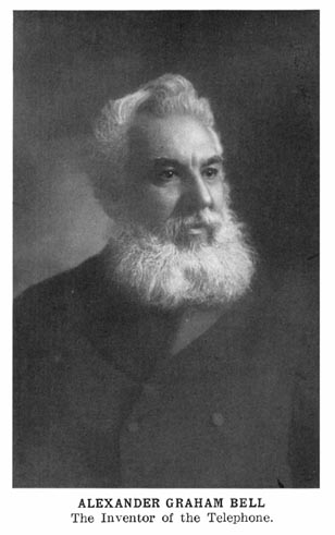
The telephone was invented in 1875 by Alexander Graham Bell, a resident of the United States, a native of Scotland, and by profession a teacher of deaf mutes in the art of vocal speech. In that year, Professor Bell was engaged in the experimental development of a system of multiplex telegraphy, based on the use of rapidly varying currents. During those experiments, he observed an iron reed to vibrate before an electromagnet as a result of another iron reed vibrating before a distant electromagnet connected to the nearer one by wires.
The telephone resulted from this observation with great promptness. In the instrument first made, sound vibrated a membrane diaphragm supporting a bit of iron near an electromagnet; a line joined this simple device of three elements to another like it; a battery in the line magnetized both electromagnet cores; the vibration of the iron in the sending device caused the current in the line to undulate and to vary the magnetism of the receiving device. The diaphragm of the latter was vibrated in consequence of the varying pull upon its bit of iron, and these vibrations reproduced the sound that vibrated the sending diaphragm.
The first public use of the electric telephone was at the Centennial Exposition in Philadelphia in 1876. It was there tested by many interested observers, among them Sir William Thomson, later Lord Kelvin, the eminent Scotch authority on matters of electrical communication. It was he who contributed so largely to the success of the early telegraph cable system between England and Page 12 America. Two of his comments which are characteristic are as follows:
To-day I have seen that which yesterday I should have deemed impossible. Soon lovers will whisper their secrets over an electric wire.
Who can but admire the hardihood of invention which devised such slight means to realize the mathematical conception that if electricity is to convey all the delicacies of sound which distinguish articulate speech, the strength of its current must vary continuously as nearly as may be in simple proportion to the velocity of a particle of the air engaged in constituting the sound.
Contrary to usual methods of improving a new art, the earliest improvement of the telephone simplified it. The diaphragms became thin iron disks, instead of membranes carrying iron; the electromagnet cores were made of permanently magnetized steel instead of temporarily magnetized soft iron, and the battery was omitted from the line. The undulatory current in a system of two such telephones joined by a line is produced in the sending telephone by the vibration of the iron diaphragm. The vibration of the diaphragm in the receiving telephone is produced by the undulatory current. Sound is produced by the vibration of the diaphragm of the receiving telephone.
Such a telephone is at once the simplest known form of electric generator or motor for alternating currents. It is capable of translating motion into current or current into motion through a wide range of frequencies. It is not known that there is any frequency of alternating current which it is not capable of producing and translating. It can produce and translate currents of greater complexity than any other existing electrical machine.
Though possessing these admirable qualities as an electrical machine, the simple electromagnetic telephone had not the ability to transmit speech loudly enough for all practical uses. Transmitters producing stronger telephonic currents were developed soon after the fundamental invention. Some forms of these were invented by Professor Bell himself. Other inventors contributed devices embodying the use of carbon as a resistance to be varied by the motions of the diaphragm. This general form of transmitting telephone has prevailed and at present is the standard type.
It is interesting to note that the earliest incandescent lamps, as Page 13 invented by Mr. Edison, had a resistance material composed of carbon, and that such a lamp retained its position as the most efficient small electric illuminant until the recent introduction of metal filament lamps. It is possible that some form of metal may be introduced as the resistance medium for telephone transmitters, and that such a change as has taken place in incandescent lamps may increase the efficiency of telephone transmitting devices.
At the time of the invention of the telephone, there were in existence two distinct types of telegraph, working in regular commercial service. In the more general type, many telegraph stations were connected to a line and whatever was telegraphed between two stations could be read by all the stations of that line. In the other and less general type, many lines, each having a single telegraph station, were centered in an office or "exchange," and at the desire of a user his line could be connected to another and later disconnected from it.
Both of these types of telegraph service were imitated at once in telephone practice. Lines carrying many telephones each, were established with great rapidity. Telephones actually displaced telegraphic apparatus in the exchange method of working in America. The fundamental principle on which telegraph or telephone exchanges operate, being that of placing any line in communication with any other in the system, gave to each line an ultimate scope so great as to make this form of communication more popular than any arrangement of telephones on a single line. Beginning in 1877, telephone exchanges were developed with great rapidity in all of the larger communities of the United States. Telegraph switching devices were utilized at the outset or were modified in such minor particulars as were necessary to fit them to the new task.
In its simplest form, a telephone system is, of course, a single line permanently joining two telephones. In its next simplest form, it is a line permanently joining more than two telephones. In its most useful form, it is a line joining a telephone to some means of connecting it at will to another.
A telephone exchange central office contains means for connecting lines at will in that useful way. The least complicated machine for that purpose is a switchboard to be operated by hand, having some way of letting the operator know that a connection is Page 14 wished and a way of making it. The customary way of connecting the lines always has been by means of flexible conductors fitted with plugs to be inserted in sockets. If the switchboard be small enough so that all the lines are within arm's reach of the operator, the whole process is individual, and may be said to be at its best and simplest. There are but few communities, however, in which the number of lines to be served and calls to be answered is small enough so that the entire traffic of the exchange can be handled by a single person. An obvious way, therefore, is to provide as many operators in a central office as may be required by the number of calls to be answered, and to terminate before each of the operators enough of the lines to bring enough work to keep that operator economically occupied. This presents the additional problem, how to connect a line terminating before one operator to a line normally terminating before another operator. The obvious answer is to provide lines from each operator's place of work to each other operator's place, connecting a calling line to some one of these lines which are local within the central office, and, in turn, connecting that chosen local line to the line which is called.
Such lines between operators have come to be known as trunk lines, because of the obvious analogy to trunk lines of railways between common centers, and such a system of telephone lines may be called a trunking system. Very good service has been given and can be given by such an arrangement of local trunks, but the growth in lines and in traffic has developed in most instances certain weaknesses which make it advisable to find speedier, more accurate, and more reliable means.
For the serving of a large traffic from a large number of lines, as is required in practically every city of the world, a very great contribution to the practical art was made by the development of the multiple switchboard. Such a switchboard is merely such a device as has been described for the simpler cases, with the further refinement that within reach of each operator in the central office appears every line which enters that office, and this without regard to what point in the switchboard the lines may terminate for the answering of calls. In other words, while each operator answers a certain subordinate group of the total number of lines, each operator may reach, for calling purposes, every line which enters that office. It Page 15 is probable that the invention and development of the multiple switchboard was the first great impetus toward the wide-spread use of telephone service.
Coincident with the development of the multiple switchboard for manually operated, central-office mechanisms was the beginning of the development of automatic apparatus under the control of the calling subscriber for finding and connecting with a called line. It is interesting to note the general trend of the early development of automatic apparatus in comparison with the development, to that time, of manual telephone apparatus.
While the manual apparatus on the one hand attempted to meet its problem by providing local trunks between the various operators of a central office, and failing of success in that, finally developed a means which placed all the lines of a central office within connecting reach of each operator, automatic telephony, beginning at that point, failed of success in attempting to bring each line in the central office within connecting reach of each connecting mechanism.
In other terms, the first automatic switching equipment consisted of a machine for each line, which machine was so organized as to be able to find and connect its calling line with any called line of the entire central-office group. It may be said that an attempt to develop this plan was the fundamental reason for the repeated failure of automatic apparatus to solve the problem it attacked. All that the earlier automatic system did was to prove more or less successfully that automatic apparatus had a right to exist, and that to demand of the subscriber that he manipulate from his station a distant machine to make the connection without human aid was not fallacious. When it had been recognized that the entire multiple switchboard idea could not be carried into automatic telephony with success, the first dawn of hope in that art may be said to have come.
Success in automatic telephony did come by the re-adoption of the trunking method. As adopted for automatic telephony, the method contemplates that the calling line shall be extended, link by link, until it finds itself lengthened and directed so as to be able to seize the called line in a very much smaller multiple than the total group of one office of the exchange.
A similar curious reversion has taken place in the development of telephone lines. The earliest telephone lines were merely telegraph Page 16 lines equipped with telephone instruments, and the earliest telegraph lines were planned by Professor Morse to be insulated wires laid in the earth. A lack of skill in preparing the wires for putting in the earth caused these early underground lines to be failures. At the urging of one of his associates, Professor Morse consented to place his earliest telegraph lines on poles in the air. Each such line originally consisted of two wires, one for the going and one for the returning current, as was then considered the action. Upon its being discovered that a single wire, using the earth as a return, would serve as a satisfactory telegraph line, such practice became universal. Upon the arrival of the telephone, all lines obviously were built in the same way, and until force of newer circumstances compelled it, the present metallic circuit without an earth connection did not come into general use.
The extraordinary growth of the number of telephone lines in a community and the development of other methods of electrical utilization, as well as the growth in the knowledge of telephony itself, ultimately forced the wires underground again. At the same time and for the same causes, a telephone line became one of two wires, so that it becomes again the counterpart of the earliest telegraph line of Professor Morse.
Another curious and interesting example of this reversion to type exists in the simple telephone receiver. An early improvement in telephone receivers after Professor Bell's original invention was to provide the necessary magnetism of the receiver core by making it of steel and permanently magnetizing it, whereas Professor Bell's instrument provided its magnetism by means of direct current flowing in the line. In later days the telephone receiver has returned almost to the original form in which Professor Bell produced it and this change has simplified other elements of telephone-exchange apparatus in a very interesting and gratifying way.
By reason of improvements in methods of line construction and apparatus arrangement, the radius of communication steadily has increased. Commercial speech now is possible between points several thousand miles apart, and there is no theoretical reason why communication might not be established between any two points on the earth's surface. The practical reasons of demand and cost may prevent so great an accomplishment as talking half around the earth. Page 17 So far as science is concerned there would seem to be no reason why this might not be done today, by the careful application of what already is known.
In the United States, telephone service from its beginning has been supplied to users by private enterprise. In other countries, it is supplied by means of governmentally-owned equipment. In general, it may be said that the adequacy and the amount, as well as the quality of telephone service, is best in countries where the service is provided by private enterprise.
Telephone systems in the United States were under the control of the Bell Telephone Company from the invention of the device in 1876 until 1893. The fundamental telephone patent expired in 1893. This opened the telephone art to the general public, because it no longer was necessary to secure telephones solely from the patent-holding company nor to pay royalty for the right to use them, if secured at all. Manufacturers of electrical apparatus generally then began to make and sell telephones and telephone apparatus, and operating companies, also independent of the Bell organization, began to install and use telephones. At the end of seventeen years of patent monopoly in the United States, there were in operation a little over 250,000 telephones. In the seventeen years since the expiration of the fundamental patent, independent telephone companies throughout the United States have installed and now have in daily successful use over 3,911,400 telephones. In other words, since its first beginnings, independent telephony has brought into continuous daily use nearly sixteen times as many telephones as were brought into use in the equal time of the complete monopoly of the Bell organization.
At the beginning of 1910, there were in service by the Bell organization about 3,633,900 telephones. These with the 3,911,400 independent telephones, make a total of 7,545,300, or about one-twelfth as many telephones as there are inhabitants of the United States. The influence of this development upon the lives of the people has been profound. Whether the influence has been wholly for good may not be so conclusively apparent. Lord Bacon has declared that, excepting only the alphabet and the art of printing, those inventions abridging distance are of the greatest service to mankind. If this be true, it may be said that Page 18 the invention of telephony deserves high place among the civilizing influences.
There is no industrial art in which the advancement of the times has been followed more closely by practical application than in telephony. Commercial speech by telephone is possible by means of currents which so far are practically unmeasurable. In other words, it is possible to speak clearly and satisfactorily over a line by means of currents which cannot be read, with certainty as to their amount, by any electrical measuring device so far known. In this regard, telephony is less well fortified than are any of the arts utilizing electrical power in larger quantities. The real wonder is that with so little knowledge of what takes place, particularly as to amount, those working in the art have been able to do as well as they have. When an exact knowledge of quantity is easily obtainable, very striking advances may be looked for.
The student of these phases of physical science and industrial art will do well to combine three processes: study of the words of others; personal experimentation; and digestive thought. The last mentioned is the process of profoundest value. On it finally depends mastery. It is not of so much importance how soon the concept shall finally be gained as that it is gained. A statement by another may seem lifeless and inert and the meaning of an observation may be obscure. Digestive thought is the only assimilative process. The whole art of telephony hangs on taking thought of things. Judge R.F. Taylor of Indiana said of Professor Bell, "It has been said that no man by taking thought may add a cubit to his stature, yet here is a man who, by taking thought, has added not cubits but miles to the lengths of men's tongues and ears."
In observations of many students, it is found that the notion of each must pass through a certain period of incubation before his private and personal knowledge of Ohm's law is hatched. Once hatched, however, it is his. By just such a process must come each principal addition to his stock of concepts. The periods may vary and practice in the uses of the mind may train it in alertness in its work. If time is required, time should be given, the object always being to keep thinking or re-reading or re-trying until the thought is wholly encompassed and possessed.
ToC
Page 19
Telephony is the art of reproducing at a distant point, usually by the agency of electricity, sounds produced at a sending point. In this art the elements of two general divisions of physical science are concerned, sound and electricity.
Sound is the effect of vibrations of matter upon the ear. The vibrations may be those of air or other matter. Various forms of matter transmit sound vibrations in varying degrees, at different specific speeds, and with different effects upon the vibrations. Any form of matter may serve as a transmitting medium for sound vibrations. Sound itself is an effect of sound vibrations upon the ear.
Propagation of Sound. Since human beings communicate with each other by means of speech and hearing through the air, it is with air that the acoustics of telephony principally is concerned. In air, sound vibrations consist of successive condensations and rarefactions tending to proceed outwardly from the source in all directions. The source is the center of a sphere of sound vibrations. Whatever may be the nature of the sounds or of the medium transmitting them, they consist of waves emitted by the source and observed by the ear. A sound wave is one complete condensation and rarefaction of the transmitting medium. It is produced by one complete vibration of the sound-producing thing.
Sound waves in air travel at a rate of about 1,090 feet per second. The rate of propagation of sound waves in other materials varies with the density of the material. For example, the speed of transmission is much greater in water than in air, and is much less in highly rarefied air than in air at ordinary density. The propagation of sound waves in a vacuum may be said not to take place at all.
Characteristics of Sound. Three qualities distinguish sound: loudness, pitch, and timbre. Page 20
Loudness. Loudness depends upon the violence of the effect upon the ear; sounds may be alike in their other qualities and differ in loudness, the louder sounds being produced by the stronger vibrations of the air or other medium at the ear. Other things being equal, the louder sound is produced by the source radiating the greater energy and so producing the greater degree of condensation and rarefaction of the medium.
Pitch. Pitch depends upon the frequency at which the sound waves strike the ear. Pitches are referred to as high or low as the frequency of waves reaching the ear are greater or fewer. Familiar low pitches are the left-hand strings of a piano; the larger ones of stringed instruments generally; bass voices; and large bells. Familiar high pitches are right-hand piano strings; smaller ones of other stringed instruments; soprano voices; small bells; and the voices of most birds and insects.
Doppler's Principle:—As pitch depends upon the frequency at which sound waves strike the ear, an object may emit sound waves at a constant frequency, yet may produce different pitches in ears differently situated. Such a case is not usual, but an example of it will serve a useful purpose in fixing certain facts as to pitch. Conceive two railroad trains to pass each other, running in opposite directions, the engine bells of both trains ringing. Passengers on each train will hear the bell of the other, first as a rising pitch, then as a falling one. Passengers on each train will hear the bell of their own train at a constant pitch.
The difference in the observations in such a case is due to relative positions between the ear and the source of the sound. As to the bell of their own train, the passengers are a fixed distance from it, whether the train moves or stands; as to the bell of the other train, the passengers first rapidly approach it, then pass it, then recede from it. The distances at which it is heard vary as the secants of a circle, the radius in this case being a length which is the closest approach of the ear to the bell.
If the bell have a constant intrinsic fundamental pitch of 200 waves per second (a wave-length of about 5.5 feet), it first will be heard at a pitch of about 200 waves per second. But this pitch rises rapidly, as if the bell were changing its own pitch, which bells do not do. The rising pitch is heard because the ear is rushing Page 21 down the wave-train, every instant nearer to the source. At a speed of 45 miles an hour, the pitch rises rapidly, about 12 vibrations per second. If the rate of approach between the ear and the bell were constant, the pitch of the bell would be heard at 212 waves per second. But suddenly the ear passes the bell, hears the pitch stop rising and begin to fall; and the tone drops 12 waves per second as it had risen. Such a circumflex is an excellent example of the bearing of wavelengths and frequencies upon pitch.
Vibration of Diaphragms:—Sound waves in air have the power to move other diaphragms than that of the ear. Sound waves constantly vibrate such diaphragms as panes of windows and the walls of houses. The recording diaphragm of a phonograph is a window pane bearing a stylus adapted to engrave a groove in a record blank. In the cylinder form of record, the groove varies in depth with the vibrations of the diaphragm. In the disk type of phonograph, the groove varies sidewise from its normal true spiral.
If the disk record be dusted with talcum powder, wiped, and examined with a magnifying glass, the waving spiral line may be seen. Its variations are the result of the blows struck upon the diaphragm by a train of sound waves.
In reproducing a phonograph record, increasing the speed of the record rotation causes the pitch to rise, because the blows upon the air are increased in frequency and the wave-lengths shortened. A transitory decrease in speed in recording will cause a transitory rise in pitch when that record is reproduced at uniform speed.
Timbre. Character of sound denotes that difference of effect produced upon the ear by sounds otherwise alike in pitch and loudness. This characteristic is called timbre. It is extraordinarily useful in human affairs, human voices being distinguished from each other by it, and a great part of the joy of music lying in it.
A bell, a stretched string, a reed, or other sound-producing body, emits a certain lowest possible tone when vibrated. This is called its fundamental tone. The pitch, loudness, and timbre of this tone depend upon various controlling causes. Usually this fundamental tone is accompanied by a number of others of higher pitch, blending with it to form the general tone of that object. These higher tones are called harmonics. The Germans call them overtones. They are always of a frequency which is some multiple of the fundamental Page 22 frequency. That is, the rate of vibration of a harmonic is 2, 3, 4, 5, or some other integral number, times as great as the fundamental itself. A tone having no harmonics is rare in nature and is not an attractive one. The tones of the human voice are rich in harmonics.
In any tone having a fundamental and harmonics (multiples), the wave-train consists of a complex series of condensations and rarefactions of the air or other transmitting medium. In the case of mere noises the train of vibrations is irregular and follows no definite order. This is the difference between vowel sounds and other musical tones on the one hand and all unmusical sounds (or noises) on the other.
Human Voice. Human beings communicate with each other in various ways. The chief method is by speech. Voice is sound vibration produced by the vocal cords, these being two ligaments in the larynx. The vocal cords in man are actuated by the air from the lungs. The size and tension of the vocal cords and the volume and the velocity of the air from the lungs control the tones of the voice. The more tightly the vocal cords be drawn, other things being equal, the higher will be the pitch of the sound; that is, the higher the frequency of vibration produced by the voice. The pitches of the human voice lie, in general, between the frequencies of 87 and 768 per second. These are the extremes of pitch, and it is not to be understood that any such range of pitch is utilized in ordinary speech. An average man speaks mostly between the fundamental frequencies of 85 and 160 per second. Many female speaking voices use fundamental frequencies between 150 and 320 vibrations per second. It is obvious from what has been said that in all cases these speaking fundamentals are accompanied by their multiples, giving complexity to the resulting wave-trains and character to the speaking voice.
Speech-sounds result from shocks given to the air by the organs of speech; these organs are principally the mouth cavity, the tongue, and the teeth. The vocal cords are voice-organs; that is, man only truly speaks, yet the lower animals have voice. Speech may be whispered, using no voice. Note the distinction between speech and voice, and the organs of both.
The speech of adults has a mean pitch lower than that of children; of adult males, lower than that of females. Page 23 There is no close analogue for the voice-organ in artificial mechanism, but the use of the lips in playing a bugle, trumpet, cornet, or trombone is a fairly close one. Here the lips, in contact with each other, are stretched across one end of a tube (the mouthpiece) while the air is blown between the lips by the lungs. A musical tone results; if the instrument be a bugle or a trumpet of fixed tube length, the pitch will be some one of several certain tones, depending on the tension on the lips. The loudness depends on the force of the blast of air; the character depends largely on the bugle.
Human Ear. The human ear, the organ of hearing in man, is a complex mechanism of three general parts, relative to sound waves: a wave-collecting part; a wave-observing part, and a wave-interpreting part.
The outer ear collects and reflects the waves inwardly to beat upon the tympanum, or ear drum, a membrane diaphragm. The uses of the rolls or convolutions of the outer ear are not conclusively known, but it is observed that when they are filled up evenly with a wax or its equivalent, the sense of direction of sound is impaired, and usually of loudness also.
The diaphragm of the ear vibrates when struck by sound waves, as does any other diaphragm. By means of bone and nerve mechanism, the vibration of the diaphragm finally is made known to the brain and is interpretable therein.
The human ear can appreciate and interpret sound waves at frequencies from 32 to about 32,000 vibrations per second. Below the lesser-number, the tendency is to appreciate the separate vibrations as separate sounds. Above the higher number, the vibrations are inaudible to the human ear. The most acute perception of sound differences lies at about 3,000 vibrations per second. It may be that the range of hearing of organisms other than man lies far above the range with which human beings are familiar. Some trained musicians are able to discriminate between two sounds as differing one from the other when the difference in frequency is less than one-thousandth of either number. Other ears are unable to detect a difference in two sounds when they differ by as much as one full step of the chromatic scale. Whatever faculty an individual may possess as to tone discrimination, it can be improved by training and practice.
ToC
Page 24
The art of telephony in its present form has for its problem so to relate two diaphragms and an electrical system that one diaphragm will respond to all the fundamental and harmonic vibrations beating upon it and cause the other to vibrate in exact consonance, producing just such vibrations, which beat upon an ear.
The art does not do all this today; it falls short of it in every phase. Many of the harmonics are lost in one or another stage of the process; new harmonics are inserted by the operations of the system itself and much of the volume originally available fails to reappear. The art, however, has been able to change commercial and social affairs in a profound degree.
Conversion from Sound Waves to Vibration of Diaphragm. However produced, by the voice or otherwise, sounds to be transmitted by telephone consist of vibrations of the air. These vibrations, upon reaching a diaphragm, cause it to move. The greatest amplitude of motion of a diaphragm is, or is wished to be, at its center, and its edge ordinarily is fixed. The diaphragm thus serves as a translating device, changing the energy carried by the molecules of the air into localized oscillations of the matter of the diaphragm. The waves of sound in the air advance; the vibrations of the molecules are localized. The agency of the air as a medium for sound transmission should be understood to be one in which its general volume has no need to move from place to place. What occurs is that the vibrations of the sound-producer cause alternate condensations and rarefactions of the air. Each molecule of the air concerned merely oscillates through a small amplitude, producing, by joint action, shells of waves, each traveling outward from the sound-producing center like rapidly growing coverings of a ball.
Conversion from Vibration to Voice Currents. Fig. 1 illustrates a simple machine adapted to translate motion of a diaphragm into Page 25 an alternating electrical current. The device is merely one form of magneto telephone chosen to illustrate the point of immediate conversion. 1 is a diaphragm adapted to vibrate in response to the sounds reaching it. 2 is a permanent magnet and 3 is its armature. The armature is in contact with one pole of the permanent magnet and nearly in contact with the other. The effort of the armature to touch the pole it nearly touches places the diaphragm under tension. The free arm of the magnet is surrounded by a coil 4, whose ends extend to form the line.
When sound vibrates the diaphragm, it vibrates the armature also, increasing and decreasing the distance from the free pole of the magnet. The lines of force threading the coil 4 are varied as the gap between the magnet and the armature is varied.
The result of varying the lines of force through the turns of the coil is to produce an electromotive force in them, and if a closed path is provided by the line, a current will flow. This current is an alternating one having a frequency the same as the sound causing it. As in speech the frequencies vary constantly, many pitches constituting even a single spoken word, so the alternating voice currents are of great varying complexity, and every fundamental frequency has its harmonics superposed.
Conversion from Voice Currents to Vibration. The best knowledge of the action of such a telephone as is shown in Fig. 1 leads to the conclusion that a half-cycle of alternating current is produced by an inward stroke of the diaphragm and a second half-cycle of alternating current by the succeeding outward stroke, these half-cycles flowing in opposite directions. Assume one complete cycle of current to pass through the line and also through another such device as in Fig. 1 and that the first half-cycle is of such direction as to increase the permanent magnetism of the core. The effort of this increase is to narrow the gap between the armature and pole piece. The diaphragm will throb inward during the half-cycle of current. The succeeding Page 26 half-cycle being of opposite direction will tend to oppose the magnetism of the core. In practice, the flow of opposing current never would be great enough wholly to nullify and reverse the magnetism of the core, so that the opposition results in a mere decrease, causing the armature's gap to increase and the diaphragm to respond by an outward blow.
Complete Cycle of Conversion. The cycle of actions thus is complete; one complete sound-wave in air has produced a cycle of motion in a diaphragm, a cycle of current in a line, a cycle of magnetic change in a core, a cycle of motion in another diaphragm, and a resulting wave of sound. It is to be observed that the chain of operation involves the expenditure of energy only by the speaker, the only function of any of the parts being that of translating this energy from one form to another. In every stage of these translations, there are losses; the devising of means of limiting these losses as greatly as possible is a problem of telephone engineering.
Magneto Telephones. The device in Fig. 1 is a practical magneto receiver and transmitter. It is chosen as best picturing the idea to be proposed. Fig. 2 illustrates a pair of magneto telephones of the early Bell type; 1-1 are diaphragms; 2-2 are permanent magnets with a free end of each brought as near as possible, without touching, to the diaphragm. Each magnet bears on its end nearest the diaphragm a winding of fine wire, the two ends of each of these windings being joined by means of a two-wire line. All that has been said concerning Fig. 1 is true also of the electrical and magnetic actions of the devices of Fig. 2. In the latter, the flux which threads the fine wire winding is disturbed by motions of the transmitting diaphragm. This disturbance of the flux creates electromotive forces in those windings. Similarly, a variation of the electromotive forces in the windings varies the pull of the permanent magnet of the receiving instrument upon its diaphragm.
Fig. 3 illustrates a similar arrangement, but it is to be understood that the cores about which the windings are carried in this case are of soft iron and not of hard magnetized steel. The necessary magnetism which constantly enables the cores to exert a pull upon the diaphragm is provided by the battery which is inserted serially in the line. Such an arrangement in action differs in no particular from that of Fig. 2, for the reason that it matters not at all whether the magnetism of the core be produced by electromagnetic or by permanently magnetic conditions. The arrangement of Fig. 3 is a fundamental counterpart of the original telephone of Professor Bell, and it is of particular interest in the present stage of the art for the reason that a tendency lately is shown to revert to the early type, abandoning the use of the permanent magnet.
The modifications which have been made in the original magneto telephone, practically as shown in Fig. 2, have been many. Thirty-five years' experimentation upon and daily use of the instrument has resulted in its refinement to a point where it is a most successful receiver and a most unsuccessful transmitter. Its use for the latter purpose may be said to be nothing. As a receiver, it is not only wholly satisfactory for commercial use in its regular function, but it is, in addition, one of the most sensitive electrical detecting devices known to the art.
Loose Contact Principle. Early experimenters upon Bell's device, all using in their first work the arrangement utilizing current from a battery in series with the line, noticed that sound was given out by disturbing loose contacts in the line circuit. This observation led to the arrangement of circuits in such a way that some imperfect contacts could be shaken by means of the diaphragm, and the resistance of the line circuit varied in this manner. An early and Page 28 interesting form of such imperfect contact transmitter device consisted merely of metal conductors laid loosely in contact. A simple example is that of three wire nails, the third lying across the other two, the two loose contacts thus formed being arranged in series with a battery, the line, and the receiving instrument. Such a device when slightly jarred, by the voice or other means, causes abrupt variation in the resistance of the line, and will transmit speech.
Early Conceptions. The conception of the possibility and desirability of transmitting speech by electricity may have occurred to many, long prior to its accomplishment. It is certain that one person, at least, had a clear idea of the general problem. In 1854, Charles Bourseul, a Frenchman, wrote: "I have asked myself, for example, if the spoken word itself could not be transmitted by electricity; in a word, if what was spoken in Vienna might not be heard in Paris? The thing is practicable in this way:
"Suppose that a man speaks near a movable disk sufficiently flexible to lose none of the vibrations of the voice; that this disk alternately makes and breaks the connection from a battery; you may have at a distance another disk which will simultaneously execute the same vibrations." The idea so expressed is weak in only one particular. This particular is shown by the words italicized by ourselves. It is impossible to transmit a complex series of waves by any simple series of makes and breaks. Philipp Reis, a German, devised the arrangement shown in Fig. 4 for the transmission of sound, letting the make and break of the contact between the diaphragm 1 and the point 2 interrupt the line circuit. His receiver took several forms, all electromagnetic. His success was limited to the transmission of musical sounds, and it is not believed that articulate speech ever was transmitted by such an arrangement.
It must be remembered that the art of telegraphy, particularly in America, was well established long before the invention of the Page 29 telephone, and that an arrangement of keys, relays, and a battery, as shown in Fig. 5, was well known to a great many persons. Attaching the armatures of the relays of such a line to diaphragms, as in Fig. 6, at any time after 1838, would have produced the telephone. "The hardihood of invention" to conceive such a change was the quality required.
Limitations of Magneto Transmitter. For reasons not finally established, the ability of the magneto telephone to produce large currents from large sounds is not equal to its ability to produce large sounds from large currents. As a receiving device, it is unexcelled, and but slight improvement has been made since its first invention. It is inadequate as a transmitter, and as early as 1876, Professor Bell exhibited other means than electromagnetic action for producing the varying currents as a consequence of diaphragm motion. Much other inventive effort was addressed to this problem, the aim of all being to send out more robust voice currents.
Other Methods of Producing Voice Currents. Some of these means are the variation of resistance in the path of direct current, variation in the pressure of the source of that current, and variation in the electrostatic capacity of some part of the circuit.
Page 30 Electrostatic Telephone. The latter method is principally that of Dolbear and Edison. Dolbear's thought is illustrated in Fig. 7. Two conducting plates are brought close together. One is free to vibrate as a diaphragm, while the other is fixed. The element 1 in Fig. 7 is merely a stud to hold rigid the plate it bears against. Each of two instruments connected by a line contains such a pair of plates, and a battery in the line keeps them charged to its potential. The two diaphragms of each instrument are kept drawn towards each other because their unlike charges attract each other. The vibration of one of the diaphragms changes the potential of the other pair; the degree of attraction thus is varied, so that vibration of the diaphragm and sound waves result.
Examples of this method of telephone transmission are more familiar to later practice in the form of condenser receivers. A condenser, in usual present practice, being a pair of closely adjacent conductors of considerable surface insulated from each other, a rapidly varying current actually may move one or both of the conductors. Ordinarily these are of thin sheet metal (foil) interleaved with an insulating material, such as paper or mica. Voice currents can vibrate the metal sheets in a degree to cause the condenser to speak. These condenser methods of telephony have not become commercial.
Variation of Electrical Pressure. Variation of the pressure of the source is a conceivable way of transmitting speech. To utilize it, would require that the vibrations of the diaphragm cause the electromotive force of a battery or machine to vary in harmony with the sound waves. So far as we are informed this method never has come into practical use.
Variation of Resistance. Variation of resistance proportional to the vibrations of the diaphragm is the method which has produced the present prevailing form of transmission. Professor Bell's Centennial exhibit contained a water-resistance transmitter. Dr. Elisha Gray Page 31 also devised one. In both, the diaphragm acted to increase and diminish the distance between two conductors immersed in water, lowering and raising the resistance of the line. It later was discovered by Edison that carbon possesses a peculiarly great property of varying its resistance under pressure. Professor David E. Hughes discovered that two conducting bodies, preferably of rather poor conductivity, when laid together so as to form a loose contact between them, possessed, in remarkable degree, the ability to vary the resistance of the path through them when subject to such vibrations as would alter the intimacy of contact. He thus discovered and formulated the principles of loose contact upon which the operation of all modern transmitters rests. Hughes' device was named by him a "microphone," indicating a magnification of sound or an ability to respond to and make audible minute sounds. It is shown in Fig. 8. Firmly attached to a board are two carbon blocks, shown in section in the figure. A rod of carbon with cone-shaped ends is supported loosely between the two blocks, conical depressions in the blocks receiving the ends of the rod. A battery and magneto receiver are connected in series with the device. Under certain conditions of contact, the arrangement is extraordinarily sensitive to small sounds and approaches an ability indicated by its name. Its practical usefulness has been not as a serviceable speech transmitter, but as a stimulus to the devising of transmitters using carbon in other ways. Variation of the resistance of metal conductors and of contact between metals has served to transmit voice currents, but no material approaches carbon in this property.
Carbon. Adaptability. The application of carbon to use in transmitters has taken many forms. They may be classified as those having a single contact and those having a plurality of contacts; in all cases, the intimacy of contact is varied by the diaphragm excursions. An example of the single-contact type is the Blake transmitter, long familiar in America. An example of the Page 32 multiple-contact type is the loose-carbon type universal now. Other types popular at other times and in particular places use solid rods or blocks of carbon having many points of contact, though not in a powdered or granular form. Fig. 9 shows an example of each of the general forms of transmitters.
The use of granular carbon as a transmitter material has extended greatly the radius of speech, and has been a principal contributing cause for the great spread of the telephone industry.
Superiority. The superiority of carbon over other resistance-varying materials for transmitters is well recognized, but the reason for it is not well known. Various theories have been proposed to explain why, for example, the resistance of a mass of carbon granules varies with the vibrations or compressions to which they are subjected.
Four principal theories respectively allege:
First, that change in pressure actually changes the specific resistance of carbon.
Second, that upon the surface of carbon bodies exists some gas in some form of attachment or combination, variations of pressure causing variations of resistance merely by reducing the thickness of this intervening gas.
Third, that the change of resistance is caused by variations in the length of electrical arcs between the particles.
Fourth, that change of pressure changes the area of contact, as is true of solids generally.
Page 33 One may take his choice. A solid carbon block or rod is not found to decrease its resistance by being subjected to pressure. The gas theory lacks experimental proof also. The existence of arcs between the granules never has been seen or otherwise observed under normal working conditions of a transmitter; when arcs surely are experimentally established between the granules the usefulness of the transmitter ceases. The final theory, that change of pressure changes area of surface contact, does not explain why other conductors than carbon are not good materials for transmitters. This, it may be noticed, is just what the theories set out to make clear.
There are many who feel that more experimental data is required before a conclusive and satisfactory theory can be set up. There is need of one, for a proper theory often points the way for effective advance in practice.
Carbon and magneto transmitters differ wholly in their methods of action. The magneto transmitter produces current; the carbon transmitter controls current. The former is an alternating-current generator; the latter is a rheostat. The magneto transmitter produces alternating current without input of any electricity at all; the carbon transmitter merely controls a direct current, supplied by an external source, and varies its amount without changing its direction.
The carbon transmitter, however, may be associated with other devices in a circuit in such a way as to transform direct currents into alternating ones, or it may be used merely to change constant direct currents into undulating ones, which never reverse direction, as alternating currents always do. These distinctions are important.
Limitations. A carbon transmitter being merely a resistance-varying device, its usefulness depends on how much its resistance can vary in response to motions of air molecules. A granular-carbon transmitter may vary between resistances of 5 to 50 ohms while transmitting a particular tone, having the lower resistance when its Page 34 diaphragm is driven inward. Conceive this transmitter to be in a line as shown in Fig. 10, the line, distant receiver, and battery together having a resistance of 1,000 ohms. The minimum resistance then is 1,005 ohms and the maximum 1,050 ohms. The variation is limited to about 4.5 per cent. The greater the resistance of the line and other elements than the transmitter, the less relative change the transmitter can produce, and the less loudly the distant receiver can speak.
Induction Coil. Mr. Edison realized this limitation to the use of the carbon transmitter direct in the line, and contributed the means of removing it. His method is to introduce an induction coil between the line and the transmitter, its function being to translate the variation of the direct current controlled by the transmitter into true alternating currents.
An induction coil is merely a transformer, and for the use under discussion consists of two insulated wires wound around an iron core. Change in the current carried by one of the windings produces a current in the other. If direct current be flowing in one of the windings, and remains constant, no current whatever is produced in the other. It is important to note that it is change, and change only, which produces that alternating current.
Fig. 11 shows an induction coil related to a carbon transmitter, a battery, and a receiver. Fig. 12 shows exactly the same arrangement, using conventional signs. The winding of the induction coil which is in series with the transmitter and the battery is called the primary winding; the other is called the secondary winding. In the arrangement of Figs. 11 and 12 the battery has no metallic connection with the line, so that it is called a local battery. The circuit containing the battery, transmitter, and primary winding of the induction coil is called the local circuit.
Page 35Let us observe what is the advantage of this arrangement over the case of Fig. 10. Using the same values of resistance in the transmitter and line, assume the local circuit apart from the transmitter to have a fixed resistance of 5 ohms. The limits of variations in the local circuit, therefore, are 10 and 55 ohms, thus making the maximum 5.5 times the minimum, or an increase of 450 per cent as against 4.5 per cent in the case of Fig. 10. The changes, therefore, are 100 times as great.
The relation between the windings of the induction coil in this practice are such that the secondary winding contains many more turns than the primary winding. Changes in the circuit of the primary winding produce potentials in the secondary winding correspondingly higher than the potentials producing them. These secondary potentials depend upon the ratio of turns in the two windings and therefore, within close limits, may be chosen as wished. High potentials in the secondary winding are admirably adapted to transmit currents in a high-resistance line, for exactly the same reason that long-distance power transmission meets with but one-quarter of one kind of loss when the sending potential is doubled, one-hundredth of that loss when it is raised tenfold, and similarly. The induction coil, therefore, serves the double purpose of a step-up transformer to limit line losses and a device for vastly increasing the range of change in the transmitter circuit.
Fig. 13 is offered to remind the student of the action of an induction coil or transformer in whose primary circuit a direct current is increased and decreased. An increase of current in the local winding produces an impulse of opposite direction in the turns of the secondary winding; a decrease of current in the local winding produces an impulse of the same direction in the turns of the secondary Page 36 winding. The key of Fig. 13 being closed, current flows upward in the primary winding as drawn in the figure, inducing a downward impulse of current in the secondary winding and its circuit as noted at the right of the figure. On the key being opened, current ceases in the primary circuit, inducing an upward impulse of current in the secondary winding and circuit as shown. During other than instants of opening and closing (changing) the local circuit, no current whatever flows in the secondary circuit.
It is by these means that telephone transmitters draw direct current from primary batteries and send high-potential alternating currents over lines; the same process produces what in Therapeutics are called "Faradic currents," and enables also a simple vibrating contact-maker to produce alternating currents for operating polarized ringers of telephone sets.
Detrimental Effects of Capacity. Electrostatic capacity plays an important part in the transmission of speech. Its presence between the wires of a line and between them and the earth causes one of the losses from which long-distance telephony suffers. Its presence in condensers assists in the solution of many circuit and apparatus problems.
A condenser is a device composed of two or more conductors insulated from each other by a medium called the dielectric. A pair of metal plates separated by glass, a pair of wires separated by air, or a pair of sheets of foil separated by paper or mica may constitute a condenser. The use of condensers as pieces of apparatus and the problems presented by electrostatic capacity in lines are discussed in other chapters.
Measurements of Telephone Currents. It has been recognized in all branches of engineering that a definite advance is possible only when quantitative data exists. The lack of reliable means of measuring Page 37 telephone currents has been a principal cause of the difficulty in solving many of its problems. It is only in very recent times that accurate and reliable means have been worked out for measuring the small currents which flow in telephone lines. These ways are of two general kinds: by thermal and by electromagnetic means.
Thermal Method. The thermal methods simply measure, in some way, the amount of heat which is produced by a received telephone current. When this current is allowed to pass through a conductor the effect of the heat generated in that conductor, is observed in one of three ways: by the expansion of the conductor, by its change in resistance, or by the production of an electromotive force in a thermo-electric couple heated by the conductor. Any one of these three ways can be used to get some idea of the amount of current which is received. None of them gives an accurate knowledge of the forms of the waves which cause the reproduction of speech in the telephone receiver.
Electromagnetic Method. An electromagnetic device adapted to tell something of the magnitude of the telephone current and also something of its form, i.e., something of its various increases and decreases and also of its changes in direction is the oscillograph. An oscillograph is composed of a magnetic field formed by direct currents or by a permanent magnet, a turn of wire under mechanical tension in that field, and a mirror borne by the turn of wire, adapted to reflect a beam of light to a photographic film or to a rotating mirror.
When a current is to be measured by the oscillograph, it is passed through the turn of wire in the magnetic field. While no current is passing, the wire does not move in the magnetic field and its mirror reflects a stationary beam of light. A photographic film moved in a direction normal to the axis of the turn of wire will have drawn Page 38 upon it a straight line by the beam of light. If the beam of light, however, is moved by a current, from side to side at right angles to this axis, it will draw a wavy line on the photographic film and this wavy line will picture the alternations of that current and the oscillations of the molecules of air which carried the originating sound. Fig. 14 is a photograph of nine different vowel sounds which have caused the oscillograph to take their pictures. They are copies of records made by Mr. Bela Gati, assisted by Mr. Tolnai. The measuring instrument consisted of an oscillograph of the type described, the transmitter being of the carbon type actuated by a 2-volt battery. The primary current was transformed by an induction coil of the ordinary type and the transformed current was sent through a non-inductive resistance of 3,000 ohms. No condensers were placed in the circuit. It will be seen that the integral values of the curves, starting from zero, are variable. The positive and the negative portions of the curves are not equal, so that the solution of the individual harmonic motion is difficult and laborious.
These photographs point out several facts very clearly. One is that the alternations of currents in the telephone line, like the motions of the molecules of air of the original sound, are highly complex and are not, as musical tones are, regular recurrences of equal vibrations. They show also that any vowel sound may be considered to be a regular recurrence of certain groups of vibrations of different amplitudes and of different frequencies.
ToC
Page 39
Electric calls or signals are of two kinds: audible and visible.
Audible Signals. Telegraph Sounder. The earliest electric signal was an audible one, being the telegraph sounder, or the Morse register considered apart from its registering function. Each telegraph sounder serves as an audible electric signal and is capable of signifying more than that the call is being made. Such a signal is operated by the making and breaking of current from a battery. An arrangement of this kind is shown in Fig. 15, in which pressure upon the key causes the current from the battery to energize the sounder and give one sharp audible rap of the lever upon the striking post.
Page 40 Vibrating Bell. The vibrating bell, so widely used as a door bell, is a device consequent to the telegraph. Its action is to give a series of blows on its gong when its key or push button closes the battery circuit. At the risk of describing a trite though not trivial thing, it may be said that when the contact 1 of Fig. 16 is closed, current from the battery energizes the armature 2, causing the latter to strike a blow on the gong and to break the line circuit as well, by opening the contact back of the armature. So de-energized, the armature falls back and the cycle is repeated until the button contact is released. A comparison of this action with that of the polarized ringer (to be described later) will be found of interest.
Magneto-Bell. The magneto-bell came into wide use with the spread of telephone service. Its two fundamental parts are an alternating-current generator and a polarized bell-ringing device. Each had its counterpart long before the invention of the telephone, though made familiar by the latter. The alternating-current generator of the magneto-bell consists of a rotatable armature composed of a coil of insulated wire and usually a core of soft iron, its rotation taking place in a magnetic field. This field is usually provided by a permanent magnet, hence the name "magneto-generator." The purist in terms may well say, however, that every form whatever of the dynamo-electric generator is a magneto-generator, as magnetism is one link in every such conversion of mechanical power into electricity. The terms magneto-electric, magneto-generator, etc., involving the term "magneto," have come to imply the presence of permanently magnetized steel as an element of the construction.
In its early form, the magneto-generator consisted of the arrangement shown in Fig. 17, wherein a permanent magnet can rotate on an axis before an electromagnet having soft iron cores and a winding. Reversals of magnetism produce current in alternately reversing half-cycles, one complete rotation of the magnet producing one such cycle. Obviously the result would be the same if the magnet were Page 41 stationary and the coils should rotate, which is the construction of more modern devices. The turning of the crank of a magneto-bell rotates the armature in the magnetic field by some form of gearing at a rate usually of the order of twenty turns per second, producing an alternating current of that frequency. This current is caused by an effective electromotive force which may be as great as 100 volts, produced immediately by the energy of the user. In an equipment using a magneto-telephone as both receiver and transmitter and a magneto-bell as its signal-sending machine, as was usual in 1877, it is interesting to note that the entire motive power for signals and speech transmission was supplied by the muscular tissues of the user—a case of working one's passage.
The alternating current from the generator is received and converted into sound by means of the polarized ringer, a device which is interesting as depending upon several of the electrical, mechanical, and magnetic actions which are the foundations of telephone engineering.
"Why the ringer rings" may be gathered from a study of Figs. 18 to 21. A permanent magnet will impart temporary magnetism to pieces of iron near it. In Fig. 18 two pieces of iron are so energized. The ends of these pieces which are nearest to the permanent magnet 1 are of the opposite polarity to the end they approach, the free ends being of opposite polarity. In the figure, these free ends are marked N, meaning they are of a polarity to point north if free to point at all. English-speaking persons call this north polarity. Similarly, as in Fig. 19, any arrangement of iron near a permanent magnet always will have free poles of the same polarity as the end of the permanent magnet nearest them.
A permanent magnet so related to iron forms part of a polarized ringer. So does an electromagnet composed of windings and Page 42 iron cores. Fig. 20 reminds us of the law of electromagnets. If current flows from the plus towards the minus side, with the windings as drawn, polarities will be induced as marked.
If, now, such an electromagnet, a permanent magnet, and a pivoted armature be related to a pair of gongs as shown in Fig. 21, a polarized ringer results. It should be noted that a permanent magnet has both its poles presented (though one of the poles is not actually attached) to two parts of the iron of the electro-magnet. The result is that the ends of the armature are of south polarity and those of the core are of north polarity. All the markings of Fig. 21 relate to the polarity produced by the permanent magnet. If, now, a current flow in the ringer winding from plus to minus, obviously the right-hand pole will be additively magnetized, the current tending to produce north magnetism there; also the left-hand pole will be subtractively magnetized, the current tending to produce south magnetism there. If the current be of a certain strength, relative to the certain ringer under study, magnetism in the left pole will be neutralized and that in the right pole doubled. Hence the armature will be attracted more by the right pole than by the left and will strike the right-hand gong. A reversal of current produces an opposite action, the left-hand gong being struck. The current ceasing, the armature remains where last thrown.
It is important to note that the strength of action depends upon the strength of the current up to a certain point only. That depends Page 43 upon the strength of the permanent magnet. Whenever the current is great enough just to neutralize the normal magnetism of one pole and to double that of the other, no increase in current will cause the device to ring any louder. This makes obvious the importance of a proper permanent magnetism and displays the fallacy of some effort to increase the output of various devices depending upon these principles. This discussion of magneto-electric signaling is introduced here because of a belief in its being fundamental. Chapter VIII treats of such a signaling in further detail.
Telephone Receiver. The telephone receiver itself serves a useful purpose as an audible signal. An interrupted or alternating current of proper frequency and amount will produce in it a musical tone which can be heard throughout a large room. This fact enables a telephone central office to signal a subscriber who has left his receiver off the switch hook, so that normal conditions may be restored.
Visible Signals. Electromagnetic Signal. Practical visual signals are of two general kinds: electromagnetic devices for moving a target or pointer, and incandescent lamps. The earliest and most widely used visible signal in telephone practice was the annunciator, having a shutter adapted to fall when the magnet is energized. Fig. 22 is such a signal. Shutter 1 is held by the catch 2 from dropping to the right by its own gravity. The name "gravity-drop" is thus obvious. Current energizing the core attracts the armature 3, lifts the catch 2, and the shutter falls. A simple modification of the gravity-drop produces the visible signal shown in Fig. 23. Energizing the core lifts a target so as to render it visible through an opening in the plate 1. A contrast of color between the plate and the target heightens the effect.
The gravity-drop is principally adapted to the magneto-bell system of signaling, where an alternating current is sent over the line to a central office by the operation of a bell crank at the subscriber's station, this current, lasting only as long as the crank is turned, energizes the drop, which may be restored by hand or otherwise and Page 44 will remain latched. The visible signal is better adapted to lines in which the signaling is done by means of direct current, as, for example, in systems where the removal of the receiver from the hook at the subscriber's station closes the line circuit, causing current to flow through the winding of the visible signal and so displaying it until the receiver has been hung upon the hook or the circuit opened by some operation at the central office. Visible signals of the magnetic type of Fig. 23 have been widely used in connection with common-battery systems, both for line signals and for supervisory purposes, indicating the state and the progress of the connection and conversation.
Electric-Lamp Signal. Incandescent electric lamps appeared in telephony as a considerable element about 1890. They are better than either form of mechanical visible signals because of three principal qualities: simplicity and ease of restoring them to normal as compared with drops; their compactness; and their greater prominence when displayed. Of the latter quality, one may say that they are more insistent, as they give out light instead of reflecting it, as do all other visible signals. In its best form, the lamp signal is mounted behind a hemispherical lens, either slightly clouded or cut in facets. This lens serves to distribute the rays of light from the lamp, with the result that the signal may be seen from a wide angle with the axis of the lens, as shown in Fig. 24. This is of particular advantage in connection with manual-switchboard connecting cords, as it enables the signals to be mounted close to and even among the cords, their great visible prominence when shining saving them from being hidden.
The influence of the lamp signal was one of the potent ones in the development of the type of multiple switchboard which is now universal as the mechanism of large manual exchanges. The Page first large trial of such an equipment was in 1896 in Worcester, Mass. No large and successful multiple switchboard with any other type of signal has been built since that time.
Any electric signal has upper and lower limits of current between which it is to be actuated. It must receive current enough to operate but not enough to become damaged by overheating. The magnetic types of visible signals have a wider range between these limits than have lamp signals. If current in a lamp is too little, its filament either will not glow at all or merely at a dull red, insufficient for a proper signal. If the current is too great, the filament is heated beyond its strength and parts at the weakest place.
This range between current limits in magnetic visible signals is great enough to enable them to be used direct in telephone lines, the operating current through the line and signal in series with a fixed voltage at the central office being not harmfully great when the entire line resistance is shunted out at or near the central office. The increase of current may be as great as ten times without damage to the winding of such a signal. In lamps, the safe margin is much less. The current which just gives a sufficient lighting of the signal may be about doubled with safety to the filament of the lamp. Consequently it is not feasible to place the lamp directly in series with long exposed lines. A short circuit of such a line near the central office will burn it out.
The qualities of electromagnets and lamps in these respects are used to advantage by the lamp signal arrangement shown in Fig. 25. A relay is in series with the line and provides a large range of sensibility. It is able to carry any current the central-office current source can pass through it. The local circuit of the relay includes the lamp. Energizing the relay lights the lamp, and the reverse; the lamp is thus isolated from danger and receives the current best adapted to its needs.
All lines are not long and when enclosed in cable or in well-insulated interior wire, may be only remotely in danger of being short-circuited. Such conditions exist in private-branch exchanges, which are groups of telephones, usually local to limited premises, Page 46 connected to a switchboard on those premises. Such a situation permits the omission of the line relay, the lamp being directly in the line. Fig. 26 shows the extreme simplicity of the arrangement, containing no moving parts or costly elements. Lamps for such service have improved greatly since the demand began to grow. The small bulk permitted by the need of compactness, the high filament resistance required for simplicity of the general power scheme of the system, and the need of considerable sturdiness in the completed thing have made the task a hard one. The practical result, however, is a signal lamp which is highly satisfactory.
The nature of carbon and certain earths being that their conductivity rises with the temperature and that of metals being that their conductivity falls with the temperature, has enabled the Nernst lamp to be successful. The same relation of properties has enabled incandescent-lamp signals to be connected direct to lines without relays, but compensated against too great a current by causing the resistance in series with the lamp to be increased inversely as the resistance of the filament. Employment of a "ballast" resistance in this way is referred to in Chapter XI. In Fig. 27 is shown its relation to a signal lamp directly in the line. 1 is the carbon-filament lamp; 2 is the ballast. The latter's conductor is fine iron wire in a vacuum. The resistance of the lamp falls as that of the ballast rises. Within certain limits, these changes balance each other, widening the range of allowable change in the total resistance of the line.
ToC
Page 47
The line is a path over which the telephone current passes from telephone to telephone. The term "telephone line circuit" is equivalent. "Line" and "line circuit" mean slightly different things to some persons, "line" meaning the out-of-doors portion of the line and "line circuit" meaning the indoor portion, composed of apparatus and associated wiring. Such shades of meaning are inevitable and serve useful purposes. The opening definition hereof is accurate.
A telephone line consists of two conductors. One of these conductors may be the earth; the other always is some conducting material other than the earth—almost universally it is of metal and in the form of a wire. A line using one wire and the earth as its pair of conductors has several defects, to be discussed later herein. Both conductors of a line may be wires, the earth serving as no part of the circuit, and this is the best practice. A line composed of one wire and the earth is called a grounded line; a line composed of two wires not needing the earth as a conductor is called a metallic circuit.
In the earliest telephone practice, all lines were grounded ones. The wires were of iron, supported by poles and insulated from them by glass, earthenware, or rubber insulators. For certain uses, such lines still represent good practice. For telegraph service, they represent the present standard practice.
Copper is a better conductor than iron, does not rust, and when drawn into wire in such a way as to have a sufficient tensile strength to support itself is the best available conductor for telephone lines. Only one metal surpasses it in any quality for the purpose: silver is a better conductor by 1 or 2 per cent. Copper is better than silver in strength and price.
In the open country, telephone lines consist of bare wires of copper, of iron, of steel, or of copper-covered steel supported on Page 48 insulators borne by poles. If the wires on the poles be many, cross-arms carry four to ten wires each and the insulators are mounted on pins in the cross-arms. If the wires on the poles be few, the insulators are mounted on brackets nailed to the poles. Wires so carried are called open wires.
In towns and cities where many wires are to be carried along the same route, the wires are reduced in size, insulated by a covering over each, and assembled into a group. Such a bundle of insulated wires is called a cable. It may be drawn into a duct in the earth and be called an underground cable; it may be laid on the bottom of the sea or other water and be called a submarine cable; or it may be suspended on poles and be called an aërial cable. In the most general practice each wire is insulated from all others by a wrapping of paper ribbon, which covering is only adequate when very dry. Cables formed of paper-insulated wires, therefore, are covered by a seamless, continuous lead sheath, no part of the paper insulation of the wires being exposed to the atmosphere during the cable's entire life in service. Telephone cables for certain uses are formed of wires insulated with such materials as soft rubber, gutta-percha, and cotton or jute saturated with mineral compounds. When insulated with rubber or gutta-percha, no continuous lead sheath is essential for insulation, as those materials, if continuous upon the wire, insulate even when the cable is immersed in water. Sheaths and other armors can assist in protecting these insulating materials from mechanical injury, and often are used for that purpose. The uses to which such cables are suitable in telephony are not many, as will be shown.
A wire supported on poles requires that it be large enough to support its own weight. The smaller the wire, the weaker it is, and with poles a given distance apart, the strength of the wire must be above a certain minimum. In regions where freezing occurs, wires in the open air can collect ice in winter and everywhere open wires are subject to wind pressure; for these reasons additional strength is required. Speaking generally, the practical and economical spacing of poles requires that wires, to be strong enough to meet the above conditions, shall have a diameter not less than .08 inch, if of hard-drawn copper, and .064 inch, if of iron or steel. The honor of developing ways of drawing copper wire with sufficient tensile strength for open-air uses belongs to Mr. Thomas B. Doolittle of Massachusetts.
Page 49Lines whose lengths are limited to a few miles do not require a conductivity as great as that of copper wire of .08-inch diameter. A wire of that size weighs approximately 100 pounds per mile. Less than 100 pounds of copper per mile of wire will not give strength enough for use on poles; but as little as 10 pounds per mile of wire gives the necessary conductivity for the lines of the thousands of telephone stations in towns and cities.
Open wires, being exposed to the elements, suffer damage from storms; their insulation is injured by contact with trees; they may make contact with electric power circuits, perhaps injuring apparatus, themselves, and persons; they endanger life and property by the possibility of falling; they and their cross-arm supports are less sightly than a more compact arrangement.
Grouping small wires of telephone lines into cables has, therefore, the advantage of allowing less copper to be used, of reducing the space required, of improving appearance, and of increasing safety. On the other hand, this same grouping introduces negative advantages as well as the foregoing positive ones. It is not possible to talk as far or as well over a line in an ordinary cable as over a line of two open wires. Long-distance telephone circuits, therefore, have not yet been placed in cables for lengths greater than 200 or 300 miles, and special treatment of cable circuits is required to talk through them for even 100 miles. One may talk 2,000 miles over open wires. The reasons for the superiority of the open wires have to do with position rather than material. Obviously it is possible to insulate and bury any wire which can be carried in the air. The differences in the properties of lines whose wires are differently situated with reference to each other and surrounding things are interesting and important.
A telephone line composed of two conductors always possesses four principal properties in some amount: (1) conductivity of the conductors; (2) electrostatic capacity between the conductors; (3) inductance of the circuit; (4) insulation of each conductor from other things.
Conductivity of Conductors. The conductivity of a wire depends upon its material, its cross-section, its length, and its temperature. Conductivity of a copper wire, for example, increases in direct ratio to its weight, in inverse ratio to its length, and its conductivity Page 50 falls as the temperature rises. Resistance is the reciprocal of conductivity and the properties, conductivity and resistance, are more often expressed in terms of resistance. The unit of the latter is the ohm; of the former the mho. A conductor having a resistance of 100 ohms has a conductivity of .01 mho. The exact correlative terms are resistance and conductance, resistivity and conductivity. The use of the terms as in the foregoing is in accordance with colloquial practice.
Current in a circuit having resistance only, varies inversely as the resistance. Electromotive force being a cause, and resistance a state, current is the result. The formula of this relation, Ohm's law, is
C = E ÷ RC being the current which results from E, the electromotive force, acting upon R, the resistance. The units are: of current, the ampere; of electromotive force, the volt; of resistance, the ohm.
As the conductivity or resistance of a line is the property of controlling importance in telegraphy, a similar relation was expected in early telephony. As the current in the telephone line varies rapidly, certain other properties of the line assume an importance they do not have in telegraphy in any such degree.
The importance that these properties assume is, that if they did not act and the resistance of the conductors alone limited speech, transmission would be possible direct from Europe to America over a pair of wires weighing 200 pounds per mile of wire, which is less than half the weight of the wire of the best long-distance land lines now in service. The distance from Europe to America is about twice as great as the present commercial radius by land lines of 435-pound wire. In other words, good speech is possible through a mere resistance twenty times greater than the resistance of the longest actual open-wire line it is possible to talk through. The talking ratio between a mere resistance and the resistance of a regular telephone cable is still greater.
Electrostatic Capacity. It is the possession of electrostatic capacity which enables the condenser, of which the Leyden jar is a good example, to be useful in a telephone line. The simplest form of a condenser is illustrated in Fig. 28, in which two conducting surfaces Page 51 are separated by an insulating material. The larger the surfaces, the closer they are together; and the higher the specific inductive capacity of the insulator, the greater the capacity of the device. An insulator used in this relation to two conducting surfaces is called the dielectric.
Two conventional signs are used to illustrate condensers, the upper one of Fig. 29 growing out of the original condenser of two metal plates, the lower one suggesting the thought of interleaved conductors of tin foil, as for many years was the practice in condenser construction.
With relation to this property, a telephone line is just as truly a condenser as is any other arrangement of conductors and insulators. Assume such a line to be open at the distant end and its wires to be well insulated from each other and the earth. Telegraphy through such a line by ordinary means would be impossible. All that the battery or other source could do would be to cause current to flow into the line for an infinitesimal time, raising the wires to its potential, after which no current would flow. But, by virtue of electrostatic capacity, the condition is much as shown in Fig. 30. The condensers which that figure shows bridged across the line from wire to wire are intended merely to fix in the mind that there is a path for the transfer of electrical energy from wire to wire.
A simple test will enable two of the results of a short-circuiting capacity to be appreciated. Conceive a very short line of two wires to connect two local battery telephones. Such a line possesses Page 52 negligible resistance, inductance, and shunt capacity. Its insulation is practically infinite. Let condensers be bridged across the line, one by one, while conversation goes on. The listening observer will notice that the sounds reaching his ear steadily grow less loud as the capacity across the line increases. The speaking observer will notice that the sounds he hears through the receiver in series with the line steadily grow louder as the capacity across the line increases. Fig. 31 illustrates the test.
The speaker's observation in this test shows that increasing the capacity across the line increased the amount of current entering it. The hearer's observation in this test shows that increasing the capacity across the line decreased the amount of energy turned into sound at his receiver.
The unit of electrostatic capacity is the farad. As this unit is inconveniently large, for practical applications the unit microfarad—millionth of a farad—is employed. If quantities are known in microfarads and are to be used in calculations in which the values of the capacity require to be farads, care should be taken to introduce the proper corrective factor.
The electrostatic capacity between the conductors of a telephone line depends upon their surface area, their length, their position, and the nature of the materials separating them from each other and from other things. For instance, in an open wire line of two wires, the electrostatic capacity depends upon the diameter of the wires, upon the length of the line, upon their distance apart, upon their distance above the earth, and upon the specific inductive capacity of the air. Air being so common an insulating medium, it is taken as a convenient material whose specific inductive capacity may be used as a basis of reference. Therefore, the specific inductive capacity of air is taken as unity. All solid matter has higher specific inductive capacity than air.
Page 53 The electrostatic capacity of two open wires .165 inch diameter, 1 ft. apart, and 30 ft. above the earth, is of the order of .009 microfarads per mile. This quantity would be higher if the wires were closer together; or nearer the earth; or if they were surrounded by a gas other than the air or hydrogen; or if the wires were insulated not by a gas but by any solid covering. As another example, a line composed of two wires of a diameter of .036 inch, if wrapped with paper and twisted into a pair as a part of a telephone-cable, has a mutual electrostatic capacity of approximately .08 microfarads per mile, this quantity being greater if the cable be more tightly compressed.
The use of paper as an insulator for wires in telephone cables is due to its low specific inductive capacity. This is because the insulation of the wires is so largely dry air. Rubber and similar insulating materials give capacities as great as twice that of dry paper.
The condenser or other capacity acts as an effective barrier to the steady flow of direct currents. Applying a fixed potential causes a mere rush of current to charge its surface to a definite degree, dependent upon the particular conditions. The condenser does not act as such a barrier to alternating currents, for it is possible to talk through a condenser by means of the alternating voice currents of telephony, or to pass through it alternating currents of much lower frequency. A condenser is used in series with a polarized ringer for the purpose of letting through alternating current for ringing the bell, and of preventing the flow of direct current.
The degree to which the condenser allows alternating currents to pass while stopping direct currents, depends on the capacity of the condenser and on the frequencies of alternating current. The larger the condenser capacity or the higher the frequency of the alternations, the greater will be the current passing through the circuit. The degree to which the current is opposed by the capacity is the reactance of that capacity for that frequency. The formula is
Capacity reactance = 1 ÷ C ω
wherein C is the capacity in farads and ω is 2 π n, or twice 3.1416 times the frequency.
All the foregoing leads to the generalization that the higher the frequency, the less the opposition of a capacity to an alternating Page 54 current. If the frequency be zero, the reactance is infinite, i.e., the circuit is open to direct current. If the frequency be infinite, the reactance is zero, i.e., the circuit is as if the condenser were replaced by a solid conductor of no resistance. Compare this statement with the correlative generalization which follows the next thought upon inductance.
Inductance of the Circuit. Inductance is the property of a circuit by which change of current in it tends to produce in itself and other conductors an electromotive force other than that which causes the current. Its unit is the henry. The inductance of a circuit is one henry when a change of one ampere per second produces an electromotive force of one volt. Induction between circuits occurs because the circuits possess inductance; it is called mutual induction. Induction within a circuit occurs because the circuit possesses inductance; it is called self-induction. Lenz' law says: In all cases of electromagnetic induction, the induced currents have such a direction that their reaction tends to stop the motion which produced them.
All conductors possess inductance, but straight wires used in lines have negligible inductance in most actual cases. All wires which are wound into coils, such as electromagnets, possess inductance in a greatly increased degree. A wire wound into a spiral, as indicated in Fig. 32, possesses much greater inductance than when drawn out straight. If iron be inserted into the spiral, as shown in Fig. 33, the inductance is still further increased. It is for the purpose of eliminating inductance that resistance coils are wound with double wires, so that current passing through such coils turns in one direction half the way and in the other direction the other half.
A simple test will enable the results of a series inductance in a line to be appreciated. Conceive a very short line of two wires to connect two local battery telephones. Such a line possesses negligible resistance, inductance, and shunt capacity. Its insulation is practically infinite. Let inductive coils such as electromagnets be inserted serially in the wires of the line one by one, while conversation goes on. Page 55 The listening observer will notice that the sounds reaching his ear steadily grow faint as the inductance in the line increases and the speaking observer will notice the same thing through the receiver in series with the line.
Both observations in this test show that the amount of current entering and emerging from the line decreased as the inductance increased. Compare this with the test with bridged capacity and the loading of lines described later herein, observing the curious beneficial result when both hurtful properties are present in a line. The test is illustrated in Fig. 34.
The degree in which any current is opposed by inductance is termed the reactance of that inductance. Its formula is
Inductive reactance = L ω
wherein L is the inductance in henrys and ω is 2 π n, or twice 3.1416 times the frequency. To distinguish the two kinds of reactance, that due to the capacity is called capacity reactance and that due to inductance is called inductive reactance.
All the foregoing leads to the generalization that the higher the frequency, the greater the opposition of an inductance to an alternating current. If the frequency be zero, the reactance is zero, i.e., the circuit conducts direct current as mere resistance. If the frequency be infinite, the reactance is infinite, i.e., the circuit is "open" to the alternating current and that current cannot pass through it. Compare this with the correlative generalization following the preceding thought upon capacity.
Capacity and inductance depend only on states of matter. Their reactances depend on states of matter and actions of energy.
In circuits having both resistance and capacity or resistance and inductance, both properties affect the passage of current. The joint Page 56 reaction is expressed in ohms and is called impedance. Its value is the square root of the sum of the squares of the resistance and reactance, or, Z being impedance,
and
the symbols meaning as before.
In words, these formulas mean that, knowing the frequency of the current and the capacity of a condenser, or the frequency of the current and the inductance of a circuit (a line or piece of apparatus), and in either case the resistance of the circuit, one may learn the impedance by calculation.
Insulation of Conductors. The fourth property of telephone lines, insulation of the conductors, usually is expressed in ohms as an insulation resistance. In practice, this property needs to be intrinsically high, and usually is measured by millions of ohms resistance from the wire of a line to its mate or to the earth. It is a convenience to employ a large unit. A million ohms, therefore, is called a megohm. In telephone cables, an insulation resistance of 500 megohms per mile at 60° Fahrenheit is the usual specification. So high an insulation resistance in a paper-insulated conductor is only attained by applying the lead sheath to the cable when its core is made practically anhydrous and kept so during the splicing and terminating of the cable.
Insulation resistance varies inversely as the length of the conductor. If a piece of cable 528 feet long has an insulation resistance of 6,750 megohms, a mile (ten times as much) of such cable, will have an insulation resistance of 675 megohms, or one-tenth as great.
Inductance vs. Capacity. The mutual capacity of a telephone line is greater as its wires are closer together. The self-induction of a telephone line is smaller as its wires are closer together. The electromotive force induced by the capacity of a line leads the impressed electromotive force by 90 degrees. The inductive electromotive force lags 90 degrees behind the impressed electromotive force. And so, in Page 57 general, the natures of these two properties are opposite. In a cable, the wires are so close together that their induction is negligible, while their capacity is so great as to limit commercial transmission through a cable having .06 microfarads per mile capacity and 94 ohms loop resistance per mile, to a distance of about 30 miles. In the case of open wires spaced 12 inches apart, the limit of commercial transmission is greater, not only because the wires are larger, but because the capacity is lower and the inductance higher.
Table I shows-the practical limiting conversation distance over uniform lines with present standard telephone apparatus.
TABLE I
Limiting Transmission Distances
| Size and Gauge of Wire | Limiting Distance |
| No. 8 B. W. G. copper | 900 miles |
| 10 B. W. G. copper | 700 miles |
| 10 B. & S. copper | 400 miles |
| 12 N. B. S. copper | 400 miles |
| 12 B. & S. copper | 240 miles |
| 14 N. B. S. copper | 240 miles |
| 8 B. W. G. iron | 135 miles |
| 10 B. W. G. iron | 120 miles |
| 12 B. W. G. iron | 90 miles |
| 16 B. & S. cable, copper | 40 miles |
| 19 B. & S. cable, copper | 30 miles |
| 22 B. & S. cable, copper | 20 miles |
In 1893, Oliver Heaviside proposed that the inductance of telephone
lines be increased above the amount natural for the inter-axial
spacing, with a view to counteracting the hurtful effects of the
capacity. His meaning was that the increased inductance—a harmful
quality in a circuit not having also a harmfully great capacity—would
act oppositely to the capacity, and if properly chosen and applied,
should decrease or eliminate distortion by making the line's effect on
fundamentals and harmonics more nearly uniform, and as well should
reduce the attenuation by neutralizing the action of the capacity in
dissipating energy.
There are two ways in which inductance might be introduced into a telephone line. As the capacity whose effects are to be neutralized Page 58 is distributed uniformly throughout the line, the counteracting inductance must also be distributed throughout the line. Mere increase of distance between two wires of the line very happily acts both to increase the inductance and to lower the capacity; unhappily for practical results, the increase of separation to bring the qualities into useful neutralizing relation is beyond practical limits. The wires would need to be so far above the earth and so far apart as to make the arrangement commercially impossible.
Practical results have been secured in increasing the distributed inductance by wrapping fine iron wire over each conductor of the line. Such a treatment increases the inductance and improves transmission.
The most marked success has come as a result of the studies of Professor Michael Idvorsky Pupin. He inserts inductances in series with the wires of the line, so adapting them to the constants of the circuit that attenuation and distortion are diminished in a gratifying degree. This method of counteracting the effects of a distributed capacity by the insertion of localized inductance requires not only that the requisite total amount of inductance be known, but that the proper subdivision and spacing of the local portions of that inductance be known. Professor Pupin's method is described in a paper entitled "Wave Transmission Over Non-uniform Cables and Long-Distance Air Lines," read by him at a meeting of the American Institute of Electrical Engineers in Philadelphia, May 19, 1900.
NOTE. United States Letters Patent were issued to Professor Pupin on June 19, 1900, upon his practical method of reducing attenuation of electrical waves. A paper upon "Propagation of Long Electric Waves" was read by Professor Pupin before the American Institute of Electrical Engineers on March 22, 1899, and appears in Vol. 15 of the Transactions of that society. The student will find these documents useful in his studies on the subject. He is referred also to "Electrical Papers" and "Electromagnetic Theory" of Oliver Heaviside.
Professor Pupin likens the transmission of electric waves over long-distance circuits to the transmission of mechanical waves over a string. Conceive an ordinary light string to be fixed at one end and shaken by the hand at the other; waves will pass over the string from the shaken to the fixed end. Certain reflections will occur from the fixed end. The amount of energy which can be sent in Page 59 this case from the shaken to the fixed point is small, but if the string be loaded by attaching bullets to it, uniformly throughout its length, it now may transmit much more energy to the fixed end.
The addition of inductance to a telephone line is analogous to the addition of bullets to the string, so that a telephone line is said to be loaded when inductances are inserted in it, and the inductances themselves are known as loading coils.
Fig. 35 shows the general relation of Pupin loading coils to the capacity of the line. The condensers of the figure are merely conventionals to represent the condenser which the line itself forms. The inductances of the figure are the actual loading coils.
The loading of open wires is not as successful in practice as is that of cables. The fundamental reason lies in the fact that two of the properties of open wires—insulation and capacity—vary with atmospheric change. The inserted inductance remaining constant, its benefits may become detriments when the other two "constants" change.
The loading of cable circuits is not subject to these defects. Such loading improves transmission; saves copper; permits the use of longer underground cables than are usable when not loaded; lowers maintenance costs by placing interurban cables underground; and permits submarine telephone cables to join places not otherwise able to speak with each other.
Underground long-distance lines now join or are joining Boston and New York, Philadelphia and New York, Milwaukee and Chicago. England and France are connected by a loaded submarine cable. There is no theoretical reason why Europe and America should not speak to each other.
The student wishing to determine for himself what are the effects of the properties of lines upon open or cable circuits will find most of the subject in the following equation. It tells the value of a in terms of the four properties, a being the attenuation constant of the line. Page 60 That is, the larger a is, the more the voice current is reduced in passing over the line. The equation is
The quantities are
R = Resistance in ohmsThe quantity S is a measure of the combined direct-current conductance (reciprocal of insulation resistance) and the apparent conductance due to dielectric hysteresis.
NOTE. An excellent paper, assisting such study, and of immediate practical value as helping the understanding of cables and their reasons, is that of Mr. Frank B. Jewett, presented at the Thousand Islands Convention of the American Institute of Electrical Engineers, July 1, 1909.
Chapter 43 treats cables in further detail. They form a most important part of telephone wire-plant practice, and their uses are becoming wider and more valuable.
Possible Ways of Improving Transmission. Practical ways of improving telephone transmission are of two kinds: to improve the lines and to improve the apparatus. The foregoing shows what are the qualities of lines and the ways they require to be treated. Apparatus treatment, in the present state of the art, is addressed largely to the reduction of losses. Theoretical considerations seem to show, however, that great advance in apparatus effectiveness still is possible. More powerful transmitters—and more faithful ones—more sensitive and accurate receivers, and more efficient translating devices surely are possible. Discovery may need to intervene, to enable invention to restimulate.
In both telegraphy and telephony, the longer the line the weaker the current which is received at the distant end. In both telegraphy and telephony, there is a length of line with a given kind and size of wire and method of construction over which it is just possible to send intelligible speech or intelligible signals. A repeater, in telegraphy, is a device in the form of a relay which is adapted to receive these highly attenuated signal impulses and to re-transmit them with fresh power over a new length of line. An arrangement of two such Page 61 relays makes it possible to telegraph both ways over a pair of lines united by such a repeater. It is practically possible to join up several such links of lines to repeating devices and, if need be, even submarine cables can be joined to land lines within practical limits. If it were necessary, it probably would be possible to telegraph around the world in this way.
If it were possible to imitate the telegraph repeater in telephony, attenuated voice currents might be caused to actuate it so as to send on those voice currents with renewed power over a length of line, section by section. Such a device has been sought for many years, and it once was quoted in the public press that a reward of one million dollars had been offered by Charles J. Glidden for a successful device of that kind. The records of the patent offices of the world show what effort has been made in that direction and many more devices have been invented than have been patented in all the countries together.
Like some other problems in telephony, this one seems simpler at first sight than it proves to be after more exhaustive study. It is possible for any amateur to produce at once a repeating device which will relay telephone circuits in one direction. It is required, however, that in practice the voice currents be relayed in both directions, and further, that the relay actually augment the energy which passes through it; that is, that it will send on a more powerful current than it receives. Most of the devices so far invented fail in one or the other of these particulars. Several ways have been shown of assembling repeating devices which will talk both ways, but not many assembling repeating devices have been shown that will talk both ways and augment in both directions.
Practical repeaters have been produced, however, and at least one type is in daily successful use. It is not conclusively shown even of it that it augments in the same degree all of the voice waves which reach it, or even that it augments some of them at all. Its action, however, is distinctly an improvement in commercial practice. It is the invention of Mr. Herbert E. Shreeve and is shown in Fig. 39. Page 62 Primarily it consists of a telephone receiver, of a particular type devised by Gundlach, associated with a granular carbon transmitter button. It is further associated with an arrangement of induction coils or repeating coils, the object of these being to accomplish the two-way action, that is, of speaking in both directions and of preventing reactive interference between the receiving and transmitting elements. The battery 1 energizes the field of the receiving element; the received line current varies that field; the resulting motion varies the resistance of the carbon button and transforms current from battery 2 into a new alternating line current.
By reactive interference is meant action whereby the transmitter element, in emitting a wave, affects its own controlling receiver element, thus setting up an action similar to that which occurs when the receiver of a telephone is held close to its transmitter and humming or singing ensues. No repeater is successful unless it is free from this reactive interference.
Enough has been accomplished by practical tests of the Shreeve device and others like it to show that the search for a method of relaying telephone voice currents is not looking for a pot of gold at the end of the rainbow. The most remarkable truth established by the success of repeaters of the Shreeve type is that a device embodying so large inertia of moving parts can succeed at all. If this mean anything, it is that a device in which inertia is absolutely eliminated might do very much better. Many of the methods already proposed by inventors attack the problem in this way and one of the most recent and most promising ways is that of Mr. J.B. Taylor, the circuit of whose telephone-relay patent is shown in Fig. 37. In it, 1 is an electromagnet energized by voice currents; its varying field varies an arc between the electrodes 2-2 and 3 in a vacuum tube. These fluctuations are transformed into line currents by the coil 4.
ToC
Page 63
Variable Resistance. As already pointed out in Chapter II, the variable-resistance method of producing current waves, corresponding to sound waves for telephonic transmission, is the one that lends itself most readily to practical purposes. Practically all telephone transmitters of today employ this variable-resistance principle. The reason for the adoption of this method instead of the other possible ones is that the devices acting on this principle are capable, with great simplicity of construction, of producing much more powerful results than the others. Their simplicity is such as to make them capable of being manufactured at low cost and of being used successfully by unskilled persons.
Materials. Of all the materials available for the variable-resistance element in telephone transmitters, carbon is by far the most suitable, and its use is well nigh universal. Sometimes one of the rarer metals, such as platinum or gold, is to be found in commercial transmitters as part of the resistance-varying device, but, even when this is so, it is always used in combination with carbon in some form or other. Most of the transmitters in use, however, depend solely upon carbon as the conductive material of the variable-resistance element.
Arrangement of Electrodes. Following the principles pointed out by Hughes, the transmitters of today always employ as their variable-resistance elements one or more loose contacts between one or more pairs of electrodes, which electrodes, as just stated, are usually of carbon. Always the arrangement is such that the sound waves will vary the intimacy of contact between the electrodes and, therefore, the resistance of the path through the electrodes.
A multitude of arrangements have been proposed and tried. Sometimes a single pair of electrodes has been employed having a single point of loose contact between them. These may be termed Page 64 single-contact transmitters. Sometimes the variable-resistance element has included a greater number of electrodes arranged in multiple, or in series, or in series-multiple, and these have been termed multiple-electrode transmitters, signifying a plurality of electrodes. A later development, an outgrowth of the multiple-electrode transmitter, makes use of a pair of principal electrodes, between which is included a mass of finely divided carbon in the form of granules or small spheres or pellets. These, regardless of the exact form of the carbon particles, are called granular-carbon transmitters.
Single Electrode. Blake. The most notable example of the single-contact transmitter is the once familiar Blake instrument. At one time this formed a part of the standard equipment of almost every telephone in the United States, and it was also largely used abroad. Probably no transmitter has ever exceeded it in clearness of articulation, but it was decidedly deficient in power in comparison with the modern transmitters. In this instrument, which is shown in Fig. 38, the variable-resistance contact was that between a carbon and a platinum electrode. The diaphragm 1 was of sheet iron mounted, as usual in later transmitters, in a soft rubber gasket 2. The whole diaphragm was mounted in a cast-iron ring 3, supported on the inside of the box containing the entire instrument. The front electrode 4 was mounted on a light spring 5, the upper end of which was supported Page 65 by a movable bar or lever 6, flexibly supported on a spring 7 secured to the casting which supported the diaphragm. The tension of this spring 5 was such as to cause the platinum point to press lightly away from the center of the diaphragm. The rear electrode was of carbon in the form of a small block 9, secured in a heavy brass button 10. The entire rear electrode structure was supported on a heavier spring 11 carried on the same lever as the spring 5. The tension of this latter spring was such as to press against the front electrode and, by its greater strength, press this against the center of the diaphragm. The adjustment of the instrument was secured by means of the screw 12, carried in a lug extending rearwardly from the diaphragm supporting casting, this screw, by its position, determining the strength with which the rear electrode pressed against the front electrode and that against the diaphragm. This instrument was ordinarily mounted in a wooden box together with the induction coil, which is shown in the upper portion of the figure.
The Blake transmitter has passed almost entirely out of use in this country, being superseded by the various forms of granular instruments, which, while much more powerful, are not perhaps capable of producing quite such clear and distinct articulation.
The great trouble with the single-contact transmitters, such as the Blake, was that it was impossible to pass enough current through the single point of contact to secure the desired power of transmission without overheating the contact. If too much current is sent through such transmitters, an undue amount of heat is generated at the point of contact and a vibration is set up which causes a peculiar humming or squealing sound which interferes with the transmission of other sounds.
Multiple Electrode. To remedy this difficulty the so-called multiple-electrode transmitter was brought out. This took a very great number of forms, of which the one shown in Fig. 39 is typical. The diaphragm shown at 1, in this particular form, was made of thin pine wood. On the rear side of this, suspended from a rod 3 carried in a bracket 4, were a number of carbon rods or pendants 5, loosely resting against a rod 2, carried on a bracket 6 also mounted on the rear of the diaphragm. The pivotal rod 3 and the rod 2, against which the pendants rested, were sometimes, like the pendant rods, made of carbon and sometimes of metal, such as brass. When Page 66 the diaphragm vibrated, the intimacy of contact between the pendant rod 5 and the rod 2 was altered, and thus the resistance of the path through all of the pendant rods in multiple was changed.
A multitude of forms of such transmitters came into use in the early eighties, and while they in some measure remedied the difficulty encountered with the Blake transmitter, i.e., of not being able to carry a sufficiently large current, they were all subject to the effects of extreme sensitiveness, and would rattle or break when called upon to transmit sounds of more than ordinary loudness. Furthermore, the presence of such large masses of material, which it was necessary to throw into vibration by the sound waves, was distinctly against this form of transmitter. The inertia of the moving parts was so great that clearness of articulation was interfered with.
Granular Carbon. The idea of employing a mass of granular carbon, supported between two electrodes, one of which vibrated with the sound waves and the other was stationary, was proposed by Henry Hunnings in the early eighties. While this idea forms the basis of all modern telephone transmitters, yet it did not prevent the almost universal adoption of the single-contact form of instrument during the next decade.
Western Electric Solid-Back Transmitter. In the early nineties, however, the granular-carbon transmitter came into its own with the advent and wide adoption of the transmitter designed by Anthony C. White, known as the White, or solid-back, transmitter. This has for many years been the standard instrument of the Bell companies operating throughout the United States, and has found large use abroad. A horizontal cross-section of this instrument is shown in Fig. 40, and a rear view of the working parts in Fig. 41. The working parts are all mounted on the front casting 1. This is supported in a cup 2, in turn supported on the lug 3, which is pivoted on the transmitter arm or other support. The front and rear electrodes of this instrument are formed of thin carbon disks shown in solid black. Page 67 The rear electrode, the larger one of these disks, is securely attached by solder to the face of a brass disk having a rearwardly projecting screw-threaded shank, which serves to hold it and the rear electrode in place in the bottom of a heavy brass cup 4. The front electrode is mounted on the rear face of a stud. Clamped against the head of this stud, by a screw-threaded clamping ring 7, is a mica washer, or disk 6. The center portion of this mica washer is therefore rigid with respect to the front electrode and partakes of its movements. The outer edge of this mica washer is similarly clamped against the front edge of the cup 4, a screw-threaded ring 9 serving to hold the edge of the mica rigidly against the front of the cup. The outer edge of this washer is, therefore, rigid with respect to the rear electrode, which is fixed. Whatever relative movement there is between the two electrodes must, therefore, be permitted by the flexing of the mica washer. This mica washer not only serves to maintain the electrodes in their normal relative positions, but also serves to close the chamber which contains the electrodes, and, therefore, to prevent the granular carbon, with which the space between the electrodes is filled, from falling out.
Page 68 The cup 4, containing the electrode chamber, is rigidly fastened with respect to the body of the transmitter by a rearwardly projecting shank held in a bridge piece 8 which is secured at its ends to the front block. The needed rigidity of the rear electrode is thus obtained and this is probably the reason for calling the instrument the solid-back. The front electrode, on the other hand, is fastened to the center of the diaphragm by means of a shank on the stud, which passes through a hole in the diaphragm and is clamped thereto by two small nuts. Against the rear face of the diaphragm of this transmitter there rest two damping springs. These are not shown in Fig. 40 but are in Fig. 41. They are secured at one end to the rear flange of the front casting 1, and bear with their other or free ends against the rear face of the diaphragm. The damping springs are prevented from coming into actual contact with the diaphragm by small insulating pads. The purpose of the damping springs is to reduce the sensitiveness of the diaphragm to extraneous sounds. As a result, the White transmitter does not pick up all of the sounds in its vicinity as readily as do the more sensitive transmitters, and thus the transmission is not interfered with by extraneous noises. On the other hand, the provision of these heavy damping springs makes it necessary that this transmitter shall be spoken into directly by the user.
The action of this transmitter is as follows: Sound waves are concentrated against the center of the diaphragm by the mouth-piece, which is of the familiar form. These waves impinge against the diaphragm, causing it to vibrate, and this, in turn, produces similar vibrations in the front electrode. The vibrations of the front electrode are permitted by the elasticity of the mica washer 6. The rear electrode is, however, held stationary within the heavy chambered block 4 and which in turn is held immovable by its rigid mounting. As a result, the front electrode Page 69 approaches and recedes from the rear electrode, thus compressing and decompressing the mass of granular carbon between them. As a result, the intimacy of contact between the electrode plates and the granules and also between the granules themselves is altered, and the resistance of the path from one electrode to the other through the mass of granules is varied.
New Western Electric Transmitter. The White transmitter was the prototype of a large number of others embodying the same features of having the rear electrode mounted in a stationary cup or chamber and the front electrode movable with the diaphragm, a washer of mica or other flexible insulating material serving to close the front of the electrode chamber and at the same time to permit the necessary vibration of the front electrode with the diaphragm.
One of these transmitters, embodying these same features but with modified details, is shown in Fig. 42, this being the new transmitter manufactured by the Western Electric Company. In this the bridge of the original White transmitter is dispensed with, the electrode chamber being supported by a pressed metal cup 1, which supports the chamber as a whole. The electrode cup, instead of being made of a solid block as in the White instrument, is composed of two portions, a cylindrical or tubular portion 2 and a back 3. The cylindrical portion is externally screw-threaded so as to engage an internal screw thread in a flanged opening in the center of the cup 1. By this means the electrode chamber is held in place in the cup 1, and by the same means Page 70 the mica washer 4 is clamped between the flange in this opening and the tubular portion 2 of the electrode chamber. The front electrode is carried, as in the White transmitter, on the mica washer and is rigidly attached to the center of the diaphragm so as to partake of the movement thereof. It will be seen, therefore, that this is essentially a White transmitter, but with a modified mounting for the electrode chamber.
A feature in this transmitter that is not found in the White transmitter is that both the front and the rear electrodes, in fact, the entire working portions of the transmitter, are insulated from the exposed metal parts of the instrument. This is accomplished by insulating the diaphragm and the supporting cup 1 from the transmitter front. The terminal 5 on the cup 1 forms the electrical connection for the rear electrode, while the terminal 6, which is mounted on but insulated from the cup 1 and is connected with the front electrode by a thin flexible connecting strip, forms the electrical connection for the front electrode.
Kellogg Transmitter. The transmitter of the Kellogg Switchboard and Supply Company, originally developed by Mr. W.W. Dean and modified by his successors in the Kellogg Company, is shown in Fig. 43. In this, the electrode chamber, instead of being mounted in a stationary and rigid position, as in the case of the White instrument, is mounted on, and, in fact, forms a part of the diaphragm. The electrode which is associated with the mica washer instead of moving with the diaphragm, as in the White instrument, is rigidly connected to a bridge so as to be as free as possible from all vibrations.
Referring to Fig. 43, which is a horizontal cross-section of the instrument, 1 indicates the diaphragm. This is of aluminum and it has in its center a forwardly deflected portion forming a chamber for the electrodes. The front electrode 2 of carbon is backed by a disk of brass and rigidly secured in the front of this chamber, as clearly indicated. The rear electrode 3, also of carbon, is backed by a disk of brass, and is clamped against the central portion of a mica disk by means of the enlarged head of stud 6. A nut 7, engaging the end of a screw-threaded shank from the back of the rear electrode, serves to bind these two parts together securely, clamping the mica washer between them. The outer edge of the mica washer is Page 71 clamped to the main diaphragm 1 by an aluminum ring and rivets, as clearly indicated. It is seen, therefore, that the diaphragm itself contains the electrode chamber as an integral part thereof. The entire structure of the diaphragm, the front and back electrodes, and the granular carbon within are permanently assembled in the factory and cannot be dissociated without destroying some of the parts. The rear electrode is held rigidly in place by the bridge 5 and the stud 6, this stud passing through a block 9 mounted on the bridge but insulated from it. The stud 6 is clamped in the block 9 by means of the set screw 8, so as to hold the rear electrode in proper position after this position has been determined.
In this transmitter, as in the transmitter shown in Fig. 42, all of the working parts are insulated from the exposed metal casing. The diaphragm is insulated from the front of the instrument by means of a washer 4 of impregnated cloth, as indicated. The rear electrode is insulated from the other portions of the instrument by means of the mica washer and by means of the insulation between the block 9 and the bridge 5. The terminal for the rear electrode is mounted on the block 9, while the terminal for the front electrode, shown at 10, is Page 72 mounted on, but insulated from, the bridge. This terminal 10 is connected with the diaphragm and therefore with the front electrode by means of a thin, flexible metallic connection. This transmitter is provided with damping springs similar to those of the White instrument.
It is claimed by advocates of this type of instrument that, in addition to the ordinary action due to the compression and decompression of the granular carbon between the electrodes, there exists another action due to the agitation of the granules as the chamber is caused to vibrate by the sound waves. In other words, in addition to the ordinary action, which may be termed the piston action between the electrodes, it is claimed that the general shaking-up effect of the granules when the chamber vibrates produces an added effect. Certain it is, however, that transmitters of this general type are very efficient and have proven their capability of giving satisfactory service through long periods of time.
Another interesting feature of this instrument as it is now manufactured is the use of a transmitter front that is struck up from sheet metal rather than the employment of a casting as has ordinarily been the practice. The formation of the supporting lug for the transmitter from the sheet metal which forms the rear casing or shell of the instrument is also an interesting feature.
Automatic Electric Company Transmitter. The transmitter of the Automatic Electric Company, of Chicago, shown in Fig. 44, is of the same general type as the one just discussed, in that the electrode chamber is mounted on and vibrates with the diaphragm instead of being rigidly supported on the bridge as in the case of the White or solid-back type of instrument. In this instrument the transmitter front 1 is struck up from sheet metal and contains a rearwardly projecting flange, carrying an internal screw thread. A heavy inner cup 2, together with the diaphragm 3, form an enclosure containing the electrode chamber. The diaphragm is, in this case, permanently secured at its edge to the periphery of the inner cup 2 by a band of metal 4 so formed as to embrace the edges of both the cup and the diaphragm and permanently lock them together. This inner chamber is held in place in the transmitter front 1 by means of a lock ring 5 externally screw-threaded to engage the internal screw-thread on the flange on the front. The electrode chamber proper is made in Page 73 the form of a cup, rigidly secured to the diaphragm so as to move therewith, as clearly indicated. The rear electrode is mounted on a screw-threaded stud carried in a block which is fitted to a close central opening in the cup 2.
This transmitter does not make use of a mica washer or diaphragm, but employs a felt washer which surrounds the shank of the rear electrode and serves to close and seal the carbon containing cup. By this means the granular carbon is retained in the chamber and the necessary flexibility or freedom of motion is permitted between the front and the rear electrodes. As in the Kellogg and the later Bell instruments, the entire working parts of this transmitter are insulated from the metal containing case, the inner chamber, formed by the cup 2 and the diaphragm 3, being insulated from the transmitter front and its locking ring by means of insulating washers, as shown.
Monarch Transmitter. The transmitter of the Monarch Telephone Manufacturing Company, shown in Fig. 45, differs from both the stationary-cup and the vibrating-cup types, although it has the characteristics of both. It might be said that it differs from each Page 74 of these two types of transmitters in that it has the characteristics of both.
This transmitter, it will be seen, has two flexible mica washers between the electrodes and the walls of the electrode cup. The front and the back electrodes are attached to the diaphragm and the bridge, respectively, by a method similar to that employed in the solid-back transmitters, while the carbon chamber itself is free to vibrate with the diaphragm as is characteristic of the Kellogg transmitter.
An aluminum diaphragm is employed, the circumferential edge of which is forwardly deflected to form a seat. The edge of the diaphragm rests against and is separated from the brass front by means of a one-piece gasket of specially treated linen. This forms an insulator which is not affected by heat or moisture. As in the transmitters previously described, the electrodes are firmly soldered to brass disks which have solid studs extending from their centers. In the case of both the front and the rear electrodes, a mica disk is placed over the supporting stud and held in place by a brass hub Page 75 which has a base of the same size as the electrode. The carbon-chamber wall consists of a brass ring to which are fastened the mica disks of the front and the back electrodes by means of brass collars clamped over the edge of the mica and around the rim of the brass ring forming the chamber.
Electrodes. The electrode plates of nearly all modern transmitters are of specially treated carbon. These are first copper-plated and soldered to their brass supporting disks. After this they are turned and ground so as to be truly circular in form and to present absolutely flat faces toward each other. These faces are then highly polished and the utmost effort is made to keep them absolutely clean. Great pains are taken to remove from the pores of the carbon, as well as from the surface, all of the acids or other chemicals that may have entered them during the process of electroplating them or of soldering them to the brass supporting disk. That the two electrodes, when mounted in a transmitter, should be parallel with each other, is an item of great importance as will be pointed out later.
In a few cases, as previously stated, gold or platinum has been substituted for the carbon electrodes in transmitters. These are capable of giving good results when used in connection with the proper form of granular carbon, but, on the whole, the tendency has been to abandon all forms of electrode material except carbon, and its use is now well nigh universal.
Preparation of Carbon. The granular carbon is prepared from carefully selected anthracite coal, which is specially treated by roasting or "re-carbonizing" and is then crushed to approximately the proper fineness. The crushed carbon is then screened with extreme care to eliminate all dust and to retain only granules of uniform size.
Packing. In the earlier forms of granular-carbon transmitters a great deal of trouble was experienced due to the so-called packing of the instrument. This, as the term indicates, was a trouble due to the tendency of the carbon granules to settle into a compact mass and thus not respond to the variable pressure. This was sometimes due to the presence of moisture in the electrode chamber; sometimes to the employment of granules of varying sizes, so that they would finally arrange themselves under the vibration of the diaphragm into a fairly compact mass; or sometimes, and more frequently, to the granules Page 76 in some way wedging the two electrodes apart and holding them at a greater distance from each other than their normal distance. The trouble due to moisture has been entirely eliminated by so sealing the granule chambers as to prevent the entrance of moisture. The trouble due to the lack of uniformity in size of the granules has been entirely eliminated by making them all of one size and by making them of sufficient hardness so that they would not break up into granules of smaller size. The trouble due to the settling of the granules and wedging the electrodes apart has been practically eliminated in well-designed instruments, by great mechanical nicety in manufacture.
Almost any transmitter may be packed by drawing the diaphragm forward so as to widely separate the electrodes. This allows the granules to settle to a lower level than they normally occupy and when the diaphragm is released and attempts to resume its normal position it is prevented from doing so by the mass of granules between. Transmitters of the early types could be packed by placing the lips against the mouthpiece and drawing in the breath. The slots now provided at the base of standard mouthpieces effectually prevent this.
In general it may be said that the packing difficulty has been almost entirely eliminated, not by the employment of remedial devices, such as those often proposed for stirring up the carbon, but by preventing the trouble by the design and manufacture of the instruments in such forms that they will not be subject to the evil.
Carrying Capacity. Obviously, the power of a transmitter is dependent on the amount of current that it may carry, as well as on the amount of variation that it may make in the resistance of the path through it. Granular carbon transmitters are capable of carrying much heavier current than the old Blake or other single or multiple electrode types. If forced to carry too much current, however, the same frying or sizzling sound is noticeable as in the earlier types. This is due to the heating of the electrodes and to small arcs that occur between the electrodes and the granules.
One way to increase the current-carrying capacity of a transmitter is to increase the area of its electrodes, but a limit is soon reached in this direction owing to the increased inertia of the moving electrode, which necessarily comes with its larger size.
The carrying capacity of transmitters may also be increased by Page 77 providing special means for carrying away the heat generated in the variable-resistance medium. Several schemes have been proposed for this. One is to employ unusually heavy metal for the electrode chamber, and this practice is best exemplified in the White solid-back instrument. It has also been proposed by others to water-jacket the electrode chamber, and also to keep it cool by placing it in close proximity to the relatively cool joints of a thermopile. Neither of these two latter schemes seems to be warranted in ordinary commercial practice.
Sensitiveness. In all the transmitters so far discussed damping springs of one form or another have been employed to reduce the sensitiveness of the instrument. For ordinary commercial use too great a degree of sensitiveness is a fault, as has already been pointed out. There are, however, certain adaptations of the telephone transmitter which make a maximum degree of sensitiveness desirable. One of these adaptations is found in the telephone equipments for assisting partially deaf people to hear. In these the transmitter is carried on some portion of the body of the deaf person, the receiver is strapped or otherwise held at his ear, and a battery for furnishing the current is carried in his pocket. It is not feasible, for this sort of use, that the sound which this transmitter is to reproduce shall always occur immediately in front of the transmitter. It more often occurs at a distance of several feet. For this reason the transmitter is made as sensitive as possible, and yet is so constructed that it will not be caused to produce too loud or unduly harsh sounds in response to a loud sound taking place immediately in front of it. Another adaptation of such highly sensitive transmitters is found in the special intercommunicating telephone systems for use between the various departments or desks in business offices. In these it is desirable that the transmitter shall be able to respond adequately to sounds occurring anywhere in a small-sized room, for instance.
Acousticon Transmitter. In Fig. 46 is shown a transmitter adapted for such use. This has been termed by its makers the acousticon transmitter. Like all the transmitters previously discussed, this is of the variable-resistance type, but it differs from them all in that it has no damping springs; in that carbon balls are substituted for carbon granules; and in that the diaphragm itself serves as the front electrode.
Page 78 This transmitter consists of a cup 1, into which is set a cylindrical block 2, in one face of which are a number of hemispherical recesses. The diaphragm 3 is made of thin carbon and is so placed in the transmitter as to cover the openings of the recesses in the carbon block, and lie close enough to the carbon block, without engaging it, to prevent the carbon particles from falling out. The diaphragm thus serves as the front electrode and the carbon block as the rear electrode. The recesses in the carbon block are about two-thirds filled with small carbon balls, which are about the size of fine sand. The front piece 4 of the transmitter is of sheet metal and serves to hold the diaphragm in place. To admit the sound waves it is provided with a circular opening opposite to and about the size of the rear electrode block. On this front piece are mounted the two terminals of the transmitter, connected respectively to the two electrodes, terminal 5 being insulated from the front piece and connected by a thin metal strip with the diaphragm, while terminal 6 is mounted directly on the front piece and connected through the cup 1 with the carbon block 2, or back electrode of the transmitter.
When this transmitter is used in connection with outfits for the deaf, it is placed in a hard rubber containing case, consisting of a hollow cylindrical piece 7, which has fastened to it a cover 8. This cover has a circular row of openings or holes near its outer edge, as shown at 9, through which the sound waves may pass to the chamber within, and thence find their way through the round hole in the center of the front plate 4 to the diaphragm 3. It is probable also that the front face of the cover 8 of the outer case vibrates, and in this way also causes sound waves to impinge against the diaphragm. This arrangement provides a large receiving surface for the sound waves, but, owing to the fact that the openings in the containing case are not opposite the opening in the transmitter proper, the sound waves do not impinge directly against the diaphragm. This peculiar arrangement is probably the result of an endeavor to prevent the transmitter from being too strongly actuated by violent Page 79 sounds close to it. Instruments of this kind are very sensitive and under proper conditions are readily responsive to words spoken in an ordinary tone ten feet away.
Switchboard Transmitter. Another special adaptation of the telephone transmitter is that for use of telephone operators at central-office switchboards. The requirements in this case are such that the operator must always be able to speak into the transmitter while seated before the switchboard, and yet allow both of her hands to be free for use. This was formerly accomplished by suspending an ordinary granular-carbon transmitter in front of the operator, but a later development has resulted in the adoption of the so-called breast transmitter, shown in Fig. 47. This is merely an ordinary granular-carbon transmitter mounted on a plate which is strapped on the breast of the operator, the transmitter being provided with a long curved mouthpiece which projects in such a manner as to lie just in front of the operator's lips. This device has the advantage of automatically following the operator in her movements. The breast transmitter shown in Fig. 47, is that of the Dean Electric Company.
Conventional Diagram. There are several common ways of illustrating transmitters in diagrams of circuits in which they are employed. The three most common ways are shown in Fig. 48. The one at the left is supposed to be a side view of an ordinary instrument, the one in the center a front view, and the one at the right to be merely a suggestive arrangement of the diaphragm and the rear electrode. The one at the right is best and perhaps most common; the center one is the poorest and least used.
ToC
Page 80
The telephone receiver is the device which translates the energy of the voice currents into the energy of corresponding sound waves. All telephone receivers today are of the electromagnetic type, the voice currents causing a varying magnetic pull on an armature or diaphragm, which in turn produces the sound waves corresponding to the undulations of the voice currents.
Early Receivers. The early forms of telephone receivers were of the single-pole type; that is, the type wherein but one pole of the electromagnet was presented to the diaphragm. The single-pole receiver that formed the companion piece to the old Blake transmitter and that was the standard of the Bell companies for many years, is shown in Fig. 49. While this has almost completely passed out of use, it may be profitably studied in order that a comparison may be made between certain features of its construction and those of the later forms of receivers.
The coil of this receiver was wound on a round iron core 2, flattened at one end to afford means for attaching the permanent magnet. The permanent magnet was of laminated construction, consisting of four hard steel bars 1, extending nearly the entire length of the receiver shell. These steel bars were all magnetized separately and placed with like poles together so as to form a single bar magnet. They were laid together in pairs so as to include between the pairs the flattened end of the pole piece 2 at one end and the flattened portion of the tail piece 3 at the other end. This whole magnet structure, including the core, the tail piece, and the permanently magnetized steel bars, was clamped together by screws as shown. The containing shell was of hard rubber consisting of three pieces, the barrel 4, the ear-piece 5, and the tail cap 6. The barrel and the ear piece engaged each other by means of a screw thread and served to clamp the diaphragm between them. The compound bar magnet Page 81 was held in place within the shell by means of a screw 7 passing through the hard rubber tail cap 6 and into the tail block 3 of the magnet. External binding posts mounted on the tail cap, as shown, were connected by heavy leading-in wires to the terminals of the electromagnet.
A casual consideration of the magnetic circuit of this instrument will show that it was inefficient, since the return path for the lines of force set up by the bar magnet was necessarily through a very long air path. Notwithstanding this, these receivers were capable of giving excellent articulation and were of marvelous delicacy of action. A very grave fault was that the magnet was supported in the shell at the end farthest removed from the diaphragm. As a result it was difficult to maintain a permanent adjustment between the pole piece and the diaphragm. One reason for this was that hard rubber and steel contract and expand under changes of temperature at very different rates, and therefore the distance between the pole piece and the diaphragm changed with changes of temperature. Another grave defect, brought about by this tying together of the permanent magnet and the shell which supported the diaphragm at the end farthest from the diaphragm, was that any mechanical shocks were thus given a good chance to alter the adjustment.
Modern Receivers. Receivers of today differ from this old single-pole receiver in two radical respects. In the first place, the modern receiver is of the bi-polar type, consisting essentially of a horseshoe magnet presenting both of its poles to the diaphragm. In the second place, the modern practice is to either support all of the working parts of the receiver, i.e., the magnet, the coils, and the diaphragm, by an inner metallic frame Page 82 entirely independent of the shell; or, if the shell is used as a part of the structure, to rigidly fasten the several parts close to the diaphragm rather than at the end farthest removed from the diaphragm.
Western Electric Receiver. The standard bi-polar receiver of the Western Electric Company, in use by practically all of the Bell operating companies throughout this country and in large use abroad, is shown in Fig. 50. In this the shell is of three pieces, consisting of the barrel 1, the ear cap 2, and the tail cap 3. The tail cap and the barrel are permanently fastened together to form substantially a single piece. Two permanently magnetized bar magnets 4-4 are employed, these being clamped together at their upper ends, as shown, so as to include the soft iron block 5 between them. The north pole of one of these magnets is clamped to the south pole of the other, so that in reality a horseshoe magnet is formed. At their lower ends, these two permanent magnets are clamped against the soft iron pole pieces 6-6, a threaded block 7 also being clamped rigidly between these pole pieces at this point. On the ends of the pole pieces the bobbins are wound. The whole magnet structure is secured within the shell 1 by means of a screw thread on the block 7 which engages a corresponding internal screw thread in the shell 1. As a result of this construction the whole magnet structure is bound rigidly to the shell structure at a point close to the diaphragm, comparatively speaking, and as a result of this close coupling, the relation between the diaphragm and the pole piece is very much more rigid and substantial than in the case where the magnet structure and the shell were secured together at the end farthest removed from the diaphragm.
Although this receiver shown in Fig. 50 is the standard in use Page 83 by the Bell companies throughout this country, its numbers running well into the millions, it cannot be said to be a strictly modern receiver, because of at least one rather antiquated feature. The binding posts, by which the circuit conductors are led to the coils of this instrument, are mounted on the outside of the receiver shell, as indicated, and are thus subject to danger of mechanical injury and they are also exposed to the touch of the user, so that he may, in case of the wires being charged to an abnormal potential, receive a shock. Probably a more serious feature than either one of these is that the terminals of the flexible cords which attach to these binding posts are attached outside of the receiver shell, and are therefore exposed to the wear and tear of use, rather than being protected as they should be within the shell. Notwithstanding this undesirable feature, this receiver is a very efficient one and is excellently constructed.
Kellogg Receiver. In Fig. 51 is shown a bi-polar receiver with internal or concealed binding posts. This particular receiver is typical of a large number of similar kinds and is manufactured by the Kellogg Switchboard and Supply Company. Two straight permanently magnetized bar magnets 1-1 are clamped together at their opposite ends so as to form a horseshoe magnet. At the end opposite the diaphragm these bars clamp between them a cylindrical piece of iron 2, so as to complete the magnetic circuit at the end. At the end nearest the diaphragm they clamp between them the ends of the soft iron pole pieces 3-3, and also a block of composite metal 4 having a large circular flange 4' which serves as a means for supporting the magnet structure within the shell. The screws by means of which the disk 4' is clamped to the shouldered seat in the shell do not enter the shell directly, but rather enter screw-threaded brass blocks which are moulded into the structure of the shell. It is seen from this construction that the diaphragm and the pole pieces and the magnet Page 84 structure itself are all rigidly secured together through the medium of the shell at a point as close as possible to the diaphragm.
Between the magnets 1-1 there is clamped an insulating block 5, to which are fastened the terminal plates 6, one on each side of the receiver. These terminal plates are thoroughly insulated from the magnets themselves and from all other metallic parts by means of sheets of fiber, as indicated by the heavy black lines. On these plates 6 are carried the binding posts for the receiver cord terminals. A long tongue extends from each of the plates 6 through a hole in the disk 4', into the coil chamber of the receiver, at which point the terminal of the magnet winding is secured to it. This tongue is insulated from the disk 4', where it passes through it, by means of insulating bushing, as shown. The other terminal of the magnet coils is brought out to the other plate 6 by means of a similar tongue on the other side.
In order that the receiver terminals proper may not be subjected to any strain in case the receiver is dropped and its weight caught on the receiver cord, a strain loop is formed as a continuation of the braided covering of the receiver cord, and this is tied to the permanent magnet structure, as shown. By making this strain loop short, it is obvious that whatever pull the cord receives will not be taken by the cord conductors leading to the binding posts or by the binding posts or the cord terminals themselves.
A number of other manufacturers have gone even a step further than this in securing permanency of adjustment between the receiver diaphragm and pole pieces. They have done this by not depending at all on the hard rubber shell as a part of the structure, but by enclosing the magnet coil in a cup of metal upon which the diaphragm is mounted, so that the permanency of relation between the diaphragm and the pole pieces is dependent only upon the metallic structure and not at all upon the less durable shell.
Direct-Current Receiver. Until about the middle of the year 1909, it was the universal practice to employ permanent magnets for giving the initial polarization to the magnet cores of telephone receivers. This is still done, and necessarily so, in receivers employed in connection with magneto telephones. In common-battery systems, however, where the direct transmitter current is fed from the central office to the local stations, it has been found that this current which Page 85 must flow at any rate through the line may be made to serve the additional purpose of energizing the receiver magnets so as to give them the necessary initial polarity. A type of receiver has come into wide use as a result, which is commonly called the direct-current receiver, deriving its name from the fact that it employs the direct current that is flowing in the common-battery line to magnetize the receiver cores. The Automatic Electric Company, of Chicago, was probably the first company to adopt this form of receiver as its standard type. Their receiver is shown in cross-section in Fig. 52, and a photograph of the same instrument partially disassembled is given in Fig. 53. The most noticeable thing about the construction of this receiver is the absence of permanent magnets. The entire working parts are contained within the brass cup 1, which serves not only as a container for the magnet, but also as a seat for the diaphragm. This receiver is therefore illustrative of the type mentioned above, wherein the relation between the diaphragm and the pole pieces is not dependent upon any connection through the shell.
The coil of this instrument consists of a single cylindrical spool 2, mounted on a cylindrical core. This bobbin lies within a soft iron-punching 3, the form of which is most clearly shown in Fig. 53, Page 86 and this punching affords a return path to the diaphragm for the lines of force set up in the magnet core. Obviously a magnetizing current passing through the winding of the coil will cause the end of the core toward the diaphragm to be polarized, say positively, while the end of the enclosing shell will be polarized in the other polarity, negatively. Both poles of the magnet are therefore presented to the diaphragm and the only air gap in the magnetic circuit is that between the diaphragm and these poles. The magnetic circuit is therefore one of great efficiency, since it consists almost entirely of iron, the only air gap being that across which the attraction of the diaphragm is to take place.
The action of this receiver will be understood when it is stated that in common-battery practice, as will be shown in later chapters, a steady current flows over the line for energizing the transmitter. On this current is superposed the incoming voice currents from a distant station. The steady current flowing in the line will, in the case of this receiver, pass through the magnet winding and establish a normal magnetic field in the same way as if a permanent magnet were employed. The superposed incoming voice currents will then be able to vary this magnetic field in exactly the same way as in the ordinary receiver.
An astonishing feature of this recent development of the so-called direct-current receiver is that it did not come into use until after about twenty years of common-battery practice. There is nothing new in the principles involved, as all of them were already understood and some of them were employed by Bell in his original telephone; in fact, the idea had been advanced time and again, and thrown aside as not being worth consideration. This is an illustration of a frequent occurrence in the development of almost any rapidly growing art. Ideas that are discarded as worthless in the early stages of the art are finally picked up and made use of. The reason for this is that in some cases the ideas come in advance of the art, or they are proposed before the art is ready to use them. In other cases the idea as originally proposed lacked some small but essential detail, or, as is more often the case, the experimenter in the early days did not have sufficient skill or knowledge to make it fit the requirements as he saw them.
Monarch Receiver. The receiver of the Automatic Electric Page 87 Company just discussed employs but a single electromagnet by which the initial magnetization of the cores and also the variable magnetization necessary for speech reproduction is secured. The problem of the direct-current receiver has been attacked in another way by Ernest E. Yaxley, of the Monarch Telephone Manufacturing Company, with the result shown in Fig. 54. The construction in this case is not unlike that of an ordinary permanent-magnet receiver, except that in the place of the permanent magnets two soft iron cores 1-1 are employed. On these are wound two long bobbins of insulated wire so that the direct current flowing over the telephone line will pass through these and magnetize the cores to the same degree and for the same purpose as in the case of permanent magnets. These soft iron magnet cores 1-1 continue to a point near the coil chamber, where they join the two soft iron pole pieces 2-2, upon which the ordinary voice-current coils are wound. The two long coils 4-4, which may be termed the direct-current coils, are of somewhat lower resistance than the two voice-current coils 3-3. They are, however, by virtue of their greater number of turns and the greater amount of iron that is included in their cores, of much higher impedance than the voice-current coils 3-3. These two sets of coils 4-4 and 3-3 are connected in multiple. As a result of their lower ohmic resistance the coils 4-4 will take a greater amount of the steady current which comes over the line, and therefore the greater proportion of the steady current will be employed in magnetizing the bar magnets. On account of their higher impedance to alternating currents, however, nearly all of the voice currents which are superposed on the steady currents, flowing in the line will pass through the voice-current coils 3-3, and, being near the diaphragm, these currents will so vary the steady magnetism in the cores 2-2 as to produce the necessary vibration of the diaphragm.
Page 88 This receiver, like the one of the Automatic Electric Company, does not rely on the shell in any respect to maintain the permanency of relation between the pole pieces and the diaphragm. The cup 5, which is of pressed brass, contains the voice-current coils and also acts as a seat for the diaphragm. The entire working parts of this receiver may be removed by merely unscrewing the ear piece from the hard rubber shell, thus permitting the whole works to be withdrawn in an obvious manner.
Dean Receiver. Of such decided novelty as to be almost revolutionary in character is the receiver recently put on the market by the Dean Electric Company and shown in Fig. 55. This receiver is of the direct-current type and employs but a single cylindrical bobbin of wire. The core of this bobbin and the return path for the magnetic lines of force set up in it are composed of soft iron punchings of substantially E shape. These punchings are laid together so as to form a laminated soft-iron field, the limbs of which are about square in cross-section. The coil is wound on the center portion of this E as a core, the core being, as stated, approximately square in cross-section. The general form of magnetic circuit in this instrument is therefore similar to that of the Automatic Electric Company's receiver, shown in Figs. 52 and 53, but the core is laminated instead of being solid as in that instrument.
The most unusual feature of this Dean receiver is that the use of hard rubber or composition does not enter into the formation of the shell, but instead a shell composed entirely of steel stampings has been substituted therefor. The main portion of this shell is the barrel 1. Great skill has evidently been exercised in the forming of this by the cold-drawn process, it presenting neither seams nor welds. The ear piece 2 is also formed of steel of about the same gauge as the barrel 1. Instead of screw-threading the steel parts, Page so that they would directly engage each other, the ingenious device has been employed of swaging a brass ring 3 in the barrel portion and a similar brass ring 4 in the ear cap portion, these two being slotted and keyed, as shown at 8, so as to prevent their turning in their respective seats. The ring 3 is provided with an external screw thread and the ring 4 with an internal screw thread, so that the receiver cap is screwed on to the barrel in the same way as in the ordinary rubber shell. By the employment of these brass screw-threaded rings, the rusting together of the parts so that they could not be separated when required—a difficulty heretofore encountered in steel construction of similar parts—has been remedied.
The entire working parts of this receiver are contained within the cup 5, the edge of which is flanged outwardly to afford a seat for the diaphragm. The diaphragm is locked in place on the shell by a screw-threaded ring 6, as is clearly indicated. A ring 7 of insulating material is seated within the enlarged portion of the barrel 1, and against this the flange of the cup 5 rests and is held in place by the cap 2 when it is screwed home. The working parts of this receiver partially disassembled are shown in Fig. 56, which gives a clear idea of some of the features not clearly illustrated in Fig. 55.
It cannot be denied that one of the principal items of maintenance of subscribers' station equipment has been due to the breakage of receiver shells. The users frequently allow their receiver to fall and strike heavily against the wall or floor, thus not only subjecting the cords to great strain, but sometimes cracking or entirely breaking the receiver shell. The innovation thus proposed by the Dean Company Page 90 of making the entire receiver shell of steel is of great interest. The shell, as will be seen, is entirely insulated from the circuit of the receiver so that no contact exists by which a user could receive a shock. The shell is enameled inside and out with a heavy black insulating enamel baked on, and said to be of great durability. How this enamel will wear remains to be seen. The insulation of the interior portions of the receiver is further guarded by providing a lining of fiber within the shell at all points where it seems possible that a cross could occur between some of the working parts and the metal of the shell. This type of receiver has not been on the market long enough to draw definite conclusions, based on experience in use, as to what its permanent performance will be.
Thus far in this chapter only those receivers which are commonly called hand receivers have been discussed. These are the receivers that are ordinarily employed by the general public.
Operator's Receiver. At the central office in telephone exchanges the operators are provided with receivers in order that they may communicate with the subscribers or with other operators. In order that they may have both of their hands free to set up and take down the connections and to perform all of the switching operations required, a special form of receiver is employed for this purpose, which is worn as a part of a head-gear and is commonly termed a head receiver. These are necessarily of very light construction, in Page 91 order not to be burdensome to the operators, and obviously they must be efficient. They are ordinarily held in place at the ear by a metallic head band fitting over the head of the operator.
Such a receiver is shown in cross-section in Fig. 57, and completely assembled with its head band in Fig. 58. Referring to Fig. 57 the shell 1 of the receiver is of aluminum and the magnets are formed of steel rings 2, cross-magnetized so as to present a north pole on one side of the ring and a south pole on the other. The two L-shaped pole pieces 3 are secured by screws to the poles of these ring magnets, and these pole pieces carry the magnet coils, as is clearly indicated. These poles are presented to a soft iron diaphragm in exactly the same way as in the larger hand receivers, the diaphragm being clamped in place by a hard rubber ear piece, as shown. The head bands are frequently of steel covered with leather. They have assumed numerous forms, but the general form shown in Fig. 58 is the one commonly adopted.
Conventional Symbols. The usual diagrammatic symbols for hand and head receivers are shown in Fig. 59. They are self-explanatory. The symbol at the left in this figure, showing the general outline of the receiver, is the one most commonly used where any sort of a receiver is to be indicated in a circuit diagram, but where it becomes desirable to indicate in the diagram the actual connections with the coil or coils of the receiver, the symbol shown at the right is to be preferred, and obviously it may be modified as to number of windings and form of core as desired.
ToC
Page 92
Galvani, an Italian physician, discovered, in 1786, that a current of electricity could be produced by chemical action. In 1800, Volta, a physicist, also an Italian, threw further light on Galvani's discovery and produced what we know as the voltaic, or galvanic, cell. In honor of these two discoverers we have the words volt, galvanic, and the various words and terms derived therefrom.
Simple Voltaic Cell. A very simple voltaic cell may be made by placing two plates, one of copper and one of zinc, in a glass vessel partly filled with dilute sulphuric acid, as shown in Fig. 60. When the two plates are not connected by a wire or other conductor, experiment shows that the copper plate bears a positive charge with respect to the zinc plate, and the zinc plate bears a negative charge with respect to the copper. When the two plates are connected by a wire, a current flows from the copper to the zinc plate through the metallic path of the wire, just as is to be expected when any conductor of relatively high electrical potential is joined to one of relatively low electrical potential. Ordinarily, when one charged body is connected to another of different potential, the resulting current is of but momentary duration, due to the redistribution of the charges and consequent equalization of potential. In the case of the simple cell, however, the current is continuous, showing that some action is maintaining the charges on the two plates and therefore maintaining the difference of potential between them. The energy of this current is derived from the chemical action of the acid on the zinc. The cell is in reality a sort of a zinc-burning furnace.
In the action of the cell, when the two plates are joined by a wire, it may be noticed that the zinc plate is consumed and that bubbles of hydrogen gas are formed on the surface of the copper plate.
Page 93 Theory. Just why or how chemical action in a voltaic cell results in the production of a negative charge on the consumed plate is not known. Modern theory has it that when an acid is diluted in water the molecules of the acid are split up or dissociated into two oppositely charged atoms, or groups of atoms, one bearing a positive charge and the other a negative charge of electricity. Such charged atoms or groups of atoms are called ions. This separation of the molecules of a chemical compound into positively and negatively charged ions is called dissociation.
Thus, in the simple cell under consideration the sulphuric acid, by dissociation, splits up into hydrogen ions bearing positive charges, and SO4 ions bearing negative charges. The solution as a whole is neutral in potential, having an equal number of equal and opposite charges.
It is known that when a metal is being dissolved by an acid, each atom of the metal which is torn off by the solution leaves the metal as a positively charged ion. The carrying away of positive charges from a hitherto neutral body leaves that body with a negative charge. Hence the zinc, or consumed plate, becomes negatively charged.
In the chemical attack of the sulphuric acid on the zinc, the positive hydrogen ions are liberated, due to the affinity of the negative SO4 ions for the positive zinc ions, this resulting in the formation of zinc sulphate in the solution. Now the solution itself becomes positively charged, due to the positive charges leaving the zinc plate with the zinc ions, and the free positively charged hydrogen ions liberated in the solution as just described are repelled to the copper plate, carrying their positive charges thereto. Hence the copper plate, or the unconsumed plate, becomes positively charged and also coated with hydrogen bubbles.
The plates or electrodes of a voltaic cell need not consist of zinc Page 94 and copper, nor need the fluid, called the electrolyte, be of sulphuric acid; any two dissimilar elements immersed in an electrolyte that attacks one of them more readily than the other will form a voltaic cell. In every such cell it will be found that one of the plates is consumed, and that on the other plate some element is deposited, this element being sometimes a gas and sometimes a solid. The plate which is consumed is always the negative plate, and the one on which the element is deposited is always the positive, the current through the connecting wire always being, therefore, from the unconsumed to the consumed plate. Thus, in the simple copper-zinc cell just considered, the zinc is consumed, the element hydrogen is deposited on the copper, and the current flow through the external circuit is from the copper to the zinc.
The positive charges, leaving the zinc, or consumed, plate, and passing through the electrolyte to the copper, or unconsumed, plate, constitute in effect a current of electricity flowing within the electrolyte. The current within the cell passes, therefore, from the zinc plate to the copper plate. The zinc is, therefore, said to be positive with respect to the copper.
Difference of Potential. The amount of electromotive force, that is generated between two dissimilar elements immersed in an electrolyte is different for different pairs of elements and for different electrolytes. For a given electrolyte each element bears a certain relation to another; i.e., they are either electro-positive or electro-negative relative to each other. In the following list a group of elements are arranged with respect to the potentials which they assume with respect to each other with dilute sulphuric acid as the electrolyte. The most electro-positive elements are at the top and the most electro-negative at the bottom.
| + | Sodium | Lead | Copper | |
| Magnesium | Iron | Silver | ||
| Zinc | Nickel | Gold | ||
| Cadmium | Bismuth | Platinum | ||
| Tin | Antimony | - | Graphite (Carbon) |
Any two elements selected from this list and immersed in dilute sulphuric acid will form a voltaic cell, the amount of difference of potential, or electromotive force, depending on the distance apart in this series of the two elements chosen. The current within the cell Page 95 will always flow from the one nearest the top of the list to the one nearest the bottom, i.e., from the most electro-positive to the most electro-negative; and, therefore, the current in the wire joining the two plates will flow from the one lowest down in the list to the one highest up.
From this series it is easy to see why zinc and copper, and also zinc and carbon, are often chosen as elements of voltaic cells. They are widely separated in the series and comparatively cheap.
This series may not be taken as correct for all electrolytes, for different electrolytes alter somewhat the order of the elements in the series. Thus, if two plates, one of iron and the other of copper, are immersed in dilute sulphuric acid, a current is set up which proceeds through the liquid from the iron to the copper; but, if the plates after being carefully washed are placed in a solution of potassium sulphide, a current is produced in the opposite direction. The copper is now the positive element.
Table II shows the electrical deportment of the principal metals in three different liquids. It is arranged like the preceding one, each metal being electro-positive to any one lower in the list.
TABLE II
Behavior of Metals in Different Electrolytes
| Caustic Potash | Hydrochloric Acid | Potassium Sulphide |
| + Zinc | + Zinc | + Zinc |
| Tin | Cadmium | Copper |
| Cadmium | Tin | Cadmium |
| Antimony | Lead | Tin |
| Lead | Iron | Silver |
| Bismuth | Copper | Antimony |
| Iron | Bismuth | Lead |
| Copper | Nickel | Bismuth |
| Nickel | Silver | Nickel |
| - Silver | - Antimony | - Iron |
It is important to remember that in all cells, no matter what elements or what electrolyte are used, the electrode which is consumed is the one that becomes negatively charged and its terminal, therefore, becomes the negative terminal or pole, while the electrode which is not consumed is the one that becomes positively charged, and its terminal is, therefore, the positive terminal or pole of the cell. However, Page 96 because the current in the electrolyte flows from the consumed plate to the unconsumed plate, the consumed plate is called the positive plate and the unconsumed, the negative. This is likely to become confusing, but if one remembers that the active plate is the positive plate, because it sends forth positive ions in the electrolyte, and, therefore, itself becomes negatively charged, one will have the proper basis always to determine the direction of the current flow, which is the important thing.
Polarization. If the simple cell already described have its terminals connected by a wire for some time, it will be found that the current rapidly weakens until it ceases to be manifest. This weakening results from two causes: first, the hydrogen gas which is liberated in the action of the cell is deposited in a layer on the copper plate, thereby covering the plate and reducing the area of contact with the liquid. This increases the internal resistance of the cell, since hydrogen is a non-conductor. Second, the plate so covered becomes in effect a hydrogen electrode, and hydrogen stands high as an electro-positive element. There is, therefore, actual reduction in the electromotive force of the cell, as well as an increase in internal resistance. This phenomenon is known as polarization, and in commercial cells means must be taken to prevent such action as far as possible.
The means by which polarization of cells is prevented or reduced in practice may be divided into three general classes:
First—mechanical means. If the hydrogen bubbles be simply brushed away from the surface of the electrode the resistance and the counter polarity which they cause will be diminished. The same result may be secured if air be blown into the solution through a tube, or if the liquid be kept agitated. If the surface of the electrode be roughened or covered with points, the bubbles collect more freely at the points and are more quickly carried away to the surface of the liquid. These means are, however, hardly practical except in cells for laboratory use.
Second—chemical means. If a highly oxidizing substance be added to the electrolyte, it will destroy the hydrogen bubbles by combining with them while they are in a nascent state, and this will prevent the increase in internal resistance and the opposing electromotive force. Such substances are bichromate of potash, nitric acid, and chlorine, and are largely used.
Third—electro-chemical means. Double cells, arranged to separate the elements and liquids by means of porous partitions or by gravity, may be so arranged that solid copper is liberated instead of hydrogen at a point where the current leaves the liquid, thereby entirely obviating polarization. This method also is largely used.
Page 97Local Action. When a simple cell stands idle, i.e., with its circuit open, small hydrogen bubbles may be noticed rising from the zinc electrode instead of from copper, as is the case where the circuit is closed. This is due to impurities in the zinc plate, such as particles of iron, tin, arsenic, carbon, etc. Each of these particles acts with the surrounding zinc just as might be expected of any pair of dissimilar elements opposed to each other in an electrolyte; in other words, they constitute small voltaic cells. Local currents, therefore, are generated, circulating between the two adjacent metals, and, as a result, the zinc plate and the electrolyte are needlessly wasted and the general condition of the cell is impaired. This is called local action.
Amalgamated Zincs. Local action might be prevented by the use of chemically pure zinc, but this, on account of its expense, cannot be employed commercially. Local action, however, may be overcome to a great extent by amalgamating the zinc, i.e., coating it with mercury. The iron particles or other impurities do not dissolve in the mercury, as does the zinc, but they float to the surface, whence the hydrogen bubbles which may form speedily carry them off, and, in other cases, the impurities fall to the bottom of the cell. As the zinc in the pasty amalgam dissolves in the acid, the film of mercury unites with fresh zinc, and so always presents a clear, bright, homogeneous surface to the action of the electrolyte.
The process of amalgamating the zinc may be performed by dipping it in a solution composed of
Nitric Acid 1 lb.
Muriatic Acid 2 lbs.
Mercury 8 oz.
The acids should be first mixed and then the mercury slowly added until dissolved. Clean the zinc with lye and then dip it in the solution for a second or two. Rinse in clean water and rub with a brush.
Another method of amalgamating zincs is to clean them by dipping them in dilute sulphuric acid and then in mercury, allowing the surplus to drain off.
Commercial zincs, for use in voltaic cells as now manufactured, Page 98 usually have about 4 per cent of mercury added to the molten zinc before casting into the form of plates or rods.
Series and Multiple Connections. When a number of voltaic cells are joined in series, the positive pole of one being connected to the negative pole of the next one, and so on throughout the series, the electromotive forces of all the cells are added, and the electromotive force of the group, therefore, becomes the sum of the electromotive forces of the component cells. The currents through all the cells in this case will be equal to that of one cell.
If the cells be joined in multiple, the positive poles all being connected by one wire and the negative poles by another, then the currents of all the cells will be added while the electromotive force of the combination remains the same as that of a single cell, assuming all the cells to be alike in electromotive force.
Obviously combinations of these two arrangements may be made, as by forming strings of cells connected in series, and connecting the strings in multiple or parallel.
The term battery is frequently applied to a single voltaic cell, but this term is more properly used to designate a plurality of cells joined together in series, or in multiple, or in series multiple so as to combine their actions in causing current to flow through an external circuit. We may therefore refer to a battery of so many cells. It has, however, become common, though technically improper, to refer to a single cell as a battery, so that the term battery, as indicating necessarily more than one cell, has largely lost its significance.
Cells may be of two types, primary and secondary.
Primary cells are those consisting of electrodes of dissimilar elements which, when placed in an electrolyte, become immediately ready for action.
Secondary cells, commonly called storage cells and accumulators, consist always of two inert plates of metal, or metallic oxide, immersed in an electrolyte which is incapable of acting on either of them until a current has first been passed through the electrolyte from one plate to the other. On the passage of a current in this way, the decomposition of the electrolyte is effected and the composition of the plates is so changed that one of them becomes electro-positive and the other electro-negative. The cell is then, when the charging current ceases, capable of acting as a voltaic cell.
Page 99 This chapter is devoted to the primary cell or battery alone.
Types of Primary Cells. Primary cells may be divided into two general classes: first, those adapted to furnish constant current; and second, those adapted to furnish only intermittent currents. The difference between cells in this respect rests largely in the means employed for preventing or lessening polarization. Obviously in a cell in which polarization is entirely prevented the current may be allowed to flow constantly until the cell is completely exhausted; that is, until the zinc is all eaten up or until the hydrogen is exhausted from the electrolyte or both. On the other hand some cells are so constituted that polarization takes place faster than the means intended to prevent it can act. In other words, the polarization gradually gains on the preventive means and so gradually reduces the current by increasing the resistance of the cell and lowering its electromotive force. In cells of this kind, however, the arrangement is such that if the cell is allowed to rest, that is, if the external circuit is opened, the depolarizing agency will gradually act to remove the hydrogen from the unattacked electrode and thus place the cell in good condition for use again.
Of these two types of primary cells the intermittent-current cell is of far greater use in telephony than the constant-current cell. This is because the use of primary batteries in telephony is, in the great majority of cases, intermittent, and for that reason a cell which will give a strong current for a few minutes and which after such use will regain practically all of its initial strength and be ready for use again, is more desirable than one which will give a weaker current continuously throughout a long period of time.
Since the cells which are adapted to give constant current are commonly used in connection with circuits that are continuously closed, they are called closed-circuit cells. The other cells, which are better adapted for intermittent current, are commonly used on circuits which stand open most of the time and are closed only occasionally when their current is desired. For this reason these are termed open-circuit cells.
Open-Circuit Cells. LeClanché Cell:—By far the most important primary cell for telephone work is the so-called LeClanché cell. This assumes a large variety of forms, but always employs zinc as the negatively charged element, carbon as the positively charged element, Page 100 and a solution of sal ammoniac as the electrolyte. This cell employs a chemical method of taking care of polarization, the depolarizing agent being peroxide of manganese, which is closely associated with the carbon element.
The original form of the LeClanché cell, a form in which it was very largely used up to within a short time ago, is shown in Fig. 61. In this the carbon element is placed within a cylindrical jar of porous clay, the walls of this jar being of such consistency as to allow moisture slowly to permeate through it. Within this porous cup, as it is called, a plate or disk of carbon is placed, and around this the depolarizing agent, consisting of black oxide of manganese. This is usually mixed with, broken carbon, so as to increase the effective area of the carbon element in contact with the depolarizing agent, and also to reduce the total internal resistance of the cell. The zinc electrode usually consisted merely in a rod of zinc, as shown, with a suitable terminal at its upper end.
The chemical action taking place within the LeClanché cell is, briefly, as follows: Sal ammoniac is chemically known as chloride of ammonium and is a combination of chlorine and ammonia. In the action which is assumed to accompany the passage of current in this cell, the sal ammoniac is decomposed, the chlorine leaving the ammonia to unite with an atom of the zinc plate, forming chloride of zinc and setting free ammonia and hydrogen. The ammonia is immediately dissolved in the water of the cell, and the hydrogen enters the porous cup and would speedily polarize the cell by adhering to the carbon plate but for the fact that it encounters the peroxide of manganese. This material is exceedingly rich in oxygen and it therefore readily gives up a part of its oxygen, which forms water by combination with the already liberated hydrogen and leaves what is termed a sesquioxide of manganese. This absorption or combination of the hydrogen prevents immediate polarization, but hydrogen is evolved during the operation of the cell more rapidly Page 101 than it can combine with the oxygen of the manganese, thereby leading to polarization more rapidly than the depolarizer can prevent it when the cell is heavily worked. When, however, the cell is left with its external circuit open for a time, depolarization ensues by the gradual combination of the hydrogen with the oxygen of the peroxide of manganese, and as a result the cell recuperates and in a short time attains its normal electromotive force.
The electromotive force of this cell when new is about 1.47 volts. The internal resistance of the cell of the type shown in Fig. 61 is approximately 1 ohm, ordinarily less rather than more.
A more recent form of LeClanché cell is shown in cross-section in Fig. 62. This uses practically the same materials and has the same chemical action as the old disk LeClanché cell shown in Fig. 61. It dispenses, however, with the porous cup and instead employs a carbon electrode, which in itself forms a cup for the depolarizing agent.
The carbon electrode is in the form of a corrugated hollow cylinder which engages by means of an internal screw thread a corresponding screw thread on the outer side of the carbon cover. Within this cylinder is contained a mixture of broken carbon and peroxide of manganese. The zinc electrode is in the form of a hollow cylinder almost surrounding the carbon electrode and separated therefrom by means of heavy rubber bands stretched around the carbon. The rod, forming the terminal of the zinc, passes through a porcelain bushing on the cover plate to obviate short circuits. This type of cell has an electromotive force of about 1.55 volts and recuperates very quickly after severe use. It also has considerably lower internal resistance than the type of LeClanché cell employing a porous cup, and, therefore, is capable of generating a considerably larger current.
Page 102 Cells of this general type have assumed a variety of forms. In some the carbon electrode, together with the broken carbon and peroxide of manganese, were packed into a canvas bag which was suspended in the electrolyte and usually surrounded by the zinc electrode. In other forms the carbon electrode has moulded with it the manganese depolarizer.
In order to prevent the salts within the cell from creeping over the edge of the containing glass jar and also over the upper portion of the carbon electrode, it is common practice to immerse the upper end of the carbon element and also the upper edge of the glass jar in hot paraffin.
In setting up the LeClanché cell, place not more than four ounces of white sal ammoniac in the jar, fill the jar one-third full of water, and stir until the sal ammoniac is all dissolved. Then put the carbon and zinc elements in place. A little water poured in the vent hole of the porous jar or carbon cylinder will tend to hasten the action.
An excess of sal ammoniac should not be used, as a saturated solution tends to deposit crystals on the zinc; on the other hand, the solution should not be allowed to become too weak, as in that case the chloride of zinc will form on the zinc. Both of these causes materially increase the resistance of the cell.
A great advantage of the LeClanché cell is that when not in use there is but little material waste. It contains no highly corrosive chemicals. Such cells require little attention, and the addition of water now and then to replace the loss due to evaporation is about all that is required until the elements become exhausted. They give a relatively high electromotive force and have a moderately low internal resistance, so that they are capable of giving rather large currents for short intervals of time. If properly made, they recuperate quickly after polarization due to heavy use.
Dry Cell. All the forms of cells so far considered may be quite properly termed wet cells because of the fact that a free liquid electrolyte is used. This term is employed in contradistinction to the later developed cell, commonly termed the dry cell. This term "dry cell" is in some respects a misnomer, since it is not dry and if it were dry it would not work. It is essential to the operation of these cells that they shall be moist within, and when such moisture is dissipated the cell is no longer usable, as there is no further useful chemical action.
Page 103 The dry cells are all of the LeClanché type, the liquid electrolyte of that type being replaced by a semi-solid substance that is capable of retaining moisture for a considerable period.
As in the ordinary wet LeClanché cell, the electrodes are of carbon and zinc, the zinc element being in the form of a cylindrical cup and forming the retaining vessel of the cell, while the carbon element is in the form of a rod or plate and occupies a central position with regard to the zinc, being held out of contact with the zinc, however, at all points.
A cross-section of an excellent form of dry cell is shown in Fig. 63. The outer casing is of zinc, formed in the shape of a cylindrical cup, and serves not only as the retaining vessel, but as the negatively charged electrode. The outer surface of the zinc is completely covered on its sides and bottom with heavy pasteboard so as to insulate it from bodies with which it may come in contact, and particularly from the zinc cups of other cells used in the same battery. The positively charged electrode is a carbon rod corrugated longitudinally, as shown, in order to obtain greater surface. This rod is held in the center of the zinc cup out of contact therewith, and the intervening space is filled with a mixture of peroxide of manganese, powdered carbon, and sal ammoniac. Several thicknesses of blotting paper constitute a lining for the inner portion of the zinc electrode and serve to prevent the manganese mixture from coming directly into contact therewith. The cell is sealed with pitch, which is placed on a layer of sand and sawdust mixed in about equal parts.
The electrolyte in such cells varies largely as to quantities and proportions of the materials employed in various types of cells, and Page 104 also varies in the method in which the elements are introduced into the container.
The following list and approximate proportions of material will serve as a fair example of the filling mixture in well-known types of cells.
| Manganese dioxide | 45 per cent |
| Carbon or graphite, or both | 45 per cent |
| Sal ammoniac | 7 per cent |
| Zinc chloride | 3 per cent |
Water is added to the above and a sufficient amount of mixture is taken for each cell to fill the zinc cup about seven-eighths full when the carbon is in place. The most suitable quantity of water depends upon the original dryness and fineness of material and upon the quality of the paper lining.
In some forms of dry batteries, starch or other paste is added to improve the contact of the electrolyte with the zinc and promote a more even distribution of action throughout the electrolyte. Mercury, too, is often added to effect amalgamation of the zinc.
As in the ordinary wet type of LeClanché cell, the purpose of the manganese is to act as a depolarizer; the carbon or graphite being added to give conductivity to the manganese and to form a large electrode surface. It is important that the sal ammoniac, which is the active agent of the cell, should be free from lumps in order to mix properly with the manganese and carbon.
A small local action takes place in the dry cell, caused by the dissimilar metals necessarily employed in soldering up the zinc cup and in soldering the terminal rod of zinc to the zinc cup proper. This action, however, is slight in the better grades of cells. As a result of this, and also of the gradual drying out of the moisture within the cell, these cells gradually deteriorate even when not in use—this is commonly called shelf-wear. Shelf-wear is much more serious in the very small sizes of dry cells than in the larger ones.
Dry cells are made in a large number of shapes and sizes. The most useful form, however, is the ordinary cylindrical type. These are made in sizes varying from one and one-half inches high and three-quarters inch in diameter to eight inches high and three and three-quarters inches in diameter. The most used and standard size of dry cell is of cylindrical form six inches high and two and three-quarters inches in diameter. The dry cell when new and in good Page 105 condition has an open-circuit voltage of from 1.5 to 1.6 volts. Perhaps 1.55 represents the usual average.
A cell of the two and three-quarters by six-inch size will give throughout its useful life probably thirty ampere hours as a maximum, but this varies greatly with the condition of use and the make of cell. Its effective voltage during its useful life averages about one volt, and if during this life it gives a total discharge of thirty ampere hours, the fair energy rating of the cell will be thirty watt-hours. This may not be taken as an accurate figure, however, as the watt-hour capacity of a cell depends very largely, not only on the make of the cell, but on the rate of its discharge.
An examination of Fig. 63 shows that the dry cell has all of the essential elements of the LeClanché cell. The materials of which the electrodes are made are the same and the porous cup of the disk LeClanché cell is represented in the dry cell by the blotting-paper cylinder, which separates the zinc from the carbon electrode. The positively charged electrode must not be considered as merely the carbon plate or rod alone, but rather the carbon rod with its surrounding mixture of peroxide of manganese and broken carbon. Such being the case, it is obvious that the separation between the electrodes is very small, while the surface presented by both electrodes is very large. As a result, the internal resistance of the cell is small and the current which it will give on a short circuit is correspondingly large. A good cell of the two and three-quarters by six-inch size will give eighteen or twenty amperes on short-circuit, when new.
As the action of the cell proceeds, zinc chloride and ammonia are formed, and there being insufficient water to dissolve the ammonia, there results the formation of double chlorides of zinc and ammonium. These double chlorides are less soluble than the chlorides and finally occupy the pores of the paper lining between the electrolyte and the zinc and greatly increase the internal resistance of the cell. This increase of resistance is further contributed to by the gradual drying out of the cell as its age increases.
Within the last few years dry batteries have been so perfected mechanically, chemically, and electrically that they have far greater outputs and better recuperative power than any of the other types of LeClanché batteries, while in point of convenience and economy, resulting from their small size and non-breakable, Page 106 non-spillable features and low cost, they leave no room for comparison.
Closed-Circuit Cells. Gravity-Cell:—Coming now to the consideration of closed-circuit or constant-current cells, the most important is the well-known gravity, or blue-stone, cell, devised by Daniell. It is largely used in telegraphy, and often in telephony in such cases as require a constantly flowing current of small quantity. Such a cell is shown in Fig. 64.
The elements of the gravity cell are electrodes of copper and zinc. The solution in which the copper plate is immersed is primarily a solution of copper sulphate, commonly known as blue-stone, in water. The zinc plate after the cell is in action is immersed in a solution of sulphate of zinc which is formed around it.
The glass jar is usually cylindrical, the standard sizes being 5 inches diameter and 7 inches deep; and also 6 inches diameter and 8 inches deep. The copper electrode is of sheet copper of the form shown, and it is partly covered with crystals of blue-stone or copper sulphate. Frequently, in later forms of cells, the copper electrode consists merely of a straight, thick, rectangular bar of copper laid horizontally, directly on top of the blue-stone crystals. In all cases a rubber-insulated wire is attached by riveting to the copper electrode, and passes up through the electrolyte to form the positive terminal.
The zinc is, as a rule, of crowfoot form, as shown, whence this cell derives the commonly applied name of crowfoot cell. This is essentially a two-fluid cell, for in its action zinc sulphate is formed, and this being lighter than copper sulphate rises to the top of the jar and surrounds the zinc. Gravity, therefore, serves to keep the two fluids separate.
In the action of the cell, when the external circuit is closed, sulphuric acid is formed which attacks the zinc to form sulphate of zinc Page 107 and to liberate hydrogen, which follows its tendency to attach itself to the copper plate. But in so doing the hydrogen necessarily passes through the solution of sulphate of copper surrounding the copper plate. The hydrogen immediately combines with the SO4 radical, forming therewith sulphuric acid, and liberating metallic copper. This sulphuric acid, being lighter than the copper sulphate, rises to the surface of the zinc and attacks the zinc, thus forming more sulphate of zinc. The metallic copper so formed is deposited on the copper plate, thereby keeping the surface bright and clean. Since hydrogen is thus diverted from the copper plate, polarization does not ensue.
The zinc sulphate being colorless, while the copper sulphate is of a dark blue color, the separating line of the two liquids is easily distinguishable. This line is called the blue line and care should be taken that it does not reach the zinc and cause a deposit of copper to be placed thereon.
As has been stated, these two liquids do not mix readily, but they will eventually mingle unless the action of the cell is sufficient to use up the copper sulphate as speedily as it is dissolved. Thus it will be seen that while the cell is free from polarization and local action, there is, nevertheless, a deteriorating effect if the cell is allowed to remain long on open circuit. Therefore, it should be used when a constant current is required.
Prevention of Creeping:—Much trouble has been experienced in gravity cells due to the creeping of the salts over the edge of the jar. Frequently the upper edges of the jars are coated by dipping in hot paraffin wax in the hope of preventing this. Sometimes oil is poured on top of the fluid in the jar to prevent the creeping of the salts and the evaporation of the electrolyte. The following account of experiments performed by Mr. William Reid, of Chicago, throws light on the relative advantages of these and other methods of preventing creeping.
The experiment was made with gravity cells having 5-inch by 7-inch glass jars. Four cells were made up and operated in a rather dry, warm place, although perhaps under no more severe local conditions than would be found in most telephone exchanges. Cell No. 1 was a plain cell as ordinarily used. Cell No. 2 had the top of the rim of the jar treated with paraffin wax by dipping the rim to about one inch in depth in melted paraffin wax. Cell No. 3 had melted paraffin wax poured over the surface of the liquid forming a seal Page 108 about 3/16 inch in thickness. After cooling, a few small holes were bored through the seal to let gases escape. Cell No. 4 had a layer of heavy paraffin oil nearly 1/2 inch in thickness (about 6 oz. being used) on top of the solutions.
These cells were all run on a load of .22 to .29 amperes for 15-1/2 hours per day for thirty days, after which the following results were noted:
(a) The plain cell, or cell No. 1, had to have 26 ounces of water added to it to replace that which had evaporated. The creeping of zinc sulphate salts was very bad.
(b) The waxed rim cell, or cell No. 2, evaporated 26 ounces of water and the creeping of zinc sulphate salts was not prevented by the waxed rim. The wax proved of no value.
(c) The wax sealed cell, or cell No. 3, showed practically no evaporation and only very slight creeping of zinc sulphate salts. The creeping of salts that took place was only around spots where the edges of the seal were loose from the jar.
(d) The paraffin oil sealed cell, or cell No. 4, showed no evaporation and no creeping of salts.
It was concluded by Mr. Reid from the above experiments that the wax applied to the rim of the jar is totally ineffective and has no merits. The wax seal loosens around the edges and does not totally prevent creeping of the zinc sulphate salts, although nearly so. The wax-sealed jar must have holes drilled in it to allow the gases to escape. The method is hardly commercial, as it is difficult to make a neat appearing cell, besides making it almost impossible to manipulate its contents. A coat of paraffin oil approximately 1/2 inch in thickness (about 6 ounces) gives perfect protection against evaporation and creeping of the zinc sulphate salts. The cell, having the paraffin-oil seal, had a very neat, clean appearance as compared with cells No. 1 and No. 2. It was found that the zinc could be drawn out through the oil, cleaned, and replaced with no appreciable effect on voltage or current.
Setting Up:—In setting up the battery the copper electrode is first unfolded to form a cross and placed in the bottom of the jar. Enough copper sulphate, or blue-stone crystals, is then dropped into the jar to almost cover the copper. The zinc crowfoot is then hung in place, occupying a position about 4 inches above the top of the copper. Clear water is then poured in sufficient to fill the jar within about an inch of the top.
If it is not required to use the cell at once, it may be placed on short circuit for a time and allowed to form its own zinc sulphate. The cell may, however, be made immediately available for use by Page 109 drawing about one-half pint of a solution of zinc sulphate from a cell already in use and pouring it into the jar, or, when this is not convenient, by putting into the liquid four or five ounces of pulverized sulphate of zinc, or by adding about ten drops of sulphuric acid. When the cell is in proper working condition, one-half inch in thickness of heavy paraffin oil of good quality may be added.
If the blue line gets too low, and if there is in the bottom of the cell a sufficient quantity of sulphate of copper, it may be raised by drawing off a portion of the zinc sulphate with a battery syringe and replacing this with water. If the blue line gets too high, it may be lowered by short-circuiting the cell for a time, or by the addition of more sulphate of zinc solution from another battery. If the copper sulphate becomes exhausted, it should be replenished by dropping in more crystals.
Care should be taken in cold weather to maintain the temperature of the battery above 65° or 70° Fahrenheit. If below this temperature, the internal resistance of a cell increases very rapidly, so much so that even at 50° Fahrenheit the action becomes very much impaired. This follows from the facts that the resistance of a liquid decreases as its temperature rises, and that chemical action is much slower at lower temperatures.
The gravity cell has a practically constant voltage of 1.08 volts. Its internal resistance is comparatively high, seldom falling below 1 ohm and often rising to 6 ohms. At best, therefore, it is only capable of producing about 1 ampere. The gravity cell is perhaps the most common type of cell wherein depolarization is affected by electro-chemical means.
Fuller Cell:—A form of cell that is adapted to very heavy open-circuit work and also closed-circuit work where heavier currents are required than can be supplied by the gravity battery is the Fuller. In this the electrodes are of zinc and carbon, respectively, the zinc usually being in the form of a heavy cone and placed within a porous cup. The electrolyte of the Fuller cell is known as electropoion fluid, and consists of a mixture of sodium or potassium bichromate, sulphuric acid, and water.
The various parts of the standard Fuller cell, as once largely employed by the various Bell operating companies, are shown in Fig. 65. In this the jar was made of flint glass, cylindrical in form, Page 110 six inches in diameter and eight inches deep. It is important that a good grade of glass be used for the jar in this cell, because, on account of the nature of the electrolyte, breakage is disastrous in the effects it may produce on adjacent property. The carbon plate is rectangular in form, about four inches wide, eight and three-quarters inches long, and one-quarter inch thick. The metal terminal at the top of the carbon block is of bronze, both it and the lock nuts and bolts being nickel-plated to minimize corrosion. The upper end of the carbon block is soaked in paraffin so hot as to drive all of the moisture out of the paraffin and out of the pores of the block itself.
The zinc, as is noted from the cut, is in the form of a truncated cone. It is about two and one-eighth inches in diameter at the base and two and one-half inches high. Cast into the zinc is a soft copper wire about No. 12 B. & S. gauge. This wire extends above the top of the jar so as to form a convenient terminal for the cell.
The porous cup is cylindrical in form, about three inches in diameter and seven inches deep. The wooden cover is of kiln-dried white wood thoroughly coated with two coats of asphalt paint. It is provided with a slot for the carbon and a hole for the copper wire extending to the zinc.
The electrolyte for this cell is made as follows:
Sodium bichromate 6 oz.
Sulphuric acid 17 oz.
Soft water 56 oz.
This solution is mixed by dissolving the bichromate of sodium in the water and then adding slowly the sulphuric acid. Potassium bichromate may be substituted for the sodium bichromate.
In setting up this cell, the amalgamated zinc is placed within the porous cup, in the bottom of which are about two teaspoonfuls of mercury, the latter serving to keep the zinc well amalgamated. The porous cup is then placed in the glass jar and a sufficient quantity of the electrolyte is placed in the outer jar to come within about one and one-half inches of the top of the porous cup. About two teaspoonfuls of salt are then placed in the porous cup and sufficient soft water added to bring the level of the liquid within the porous cup even with the level of the electrolyte in the jar surrounding the cup. The carbon is then placed through the slot in the cover, and Page 111 the wire from the zinc is passed through the hole in the cover provided for it, and the cover is allowed to fall in place. The cell is now ready for immediate use.
The action of this cell is as follows: The sulphuric acid attacks the zinc and forms zinc sulphate, liberating hydrogen. The hydrogen attempts to pass to the carbon plate as usual, but in so doing it meets with the oxygen of the chromic acid and forms water therewith. The remainder of the chromic acid combines with the sulphuric acid to form chromium sulphate.
The mercury placed in the bottom of the porous cup with the zinc keeps the zinc in a state of perpetual amalgamation. This it does by capillary action, as the mercury spreads over the entire surface of the zinc. The initial amalgamation, while not absolutely essential, helps in a measure this capillary action.
In another well-known type of the Fuller battery the carbon is a hollow cylinder, surrounding the porous cup. In this type the zinc usually took the form of a long bar having a cross-shaped section, the length of this bar being sufficient to extend the entire depth of the porous cup. This type of cell has the advantage of a somewhat lower internal resistance than the standard form just described.
Should the electrolyte become supersaturated by virtue of the battery being neglected or too heavily overworked, a set of secondary reactions will occur in the cell, resulting in the formation of the Page 112 yellow crystals upon the carbon. This seriously affects the e.m.f. of the cell and also its internal resistance. Should this occur, some of the solution should be withdrawn and dilute sulphuric acid inserted in its place and the crystals which have formed on the carbon should be carefully washed off. Should the solution lose its orange tint and turn blue, it indicates that more bichromate of potash or bichromate of sodium is needed. This cell gives an electromotive force of 2.1 volts and a very large current when it is in good condition, since its internal resistance is low.
The Fuller cell was once largely used for supplying current to telephone transmitters at subscribers' stations, where very heavy service was demanded, but the advent of the so-called common-battery systems, in some cases, and of the high-resistance transmitter, in other cases, has caused a great lessening in its use. This is fortunate as the cell is a "dirty" one to handle and is expensive to maintain.
The Fuller cell still warrants attention, however, as an available source of current, which may be found useful in certain cases of emergency work, and in supplying special but temporary needs for heavier current than the LeClanché or gravity cell can furnish.
Lalande Cell:—A type of cell, specially adapted to constant-current work, and sometimes used as a central source of current in very small common-battery exchanges is the so-called copper oxide, or Lalande cell, of which the Edison and the Gordon are types. In all of these the negatively charged element is of zinc, the positively charged element a mass of copper oxide, and the electrolyte a solution of caustic potash in water. In the Edison cell the copper oxide is in the form of a compressed slab which with its connecting copper support forms the electrode. In the Gordon and other cells of this type the copper oxide is contained loosely in a perforated cylinder of sheet copper. The copper oxide serves not only as an electrode, but also as a depolarizing agent, the liberated hydrogen in the electrolyte uniting with the oxygen of the copper oxide to form water, and leaving free metallic copper.
On open circuit the elements are not attacked, therefore there is no waste of material while the cell is not in use. This important feature, and the fact that the internal resistance is low, make this cell well adapted for all forms of heavy open-circuit work. The Page 113 fact that there is no polarizing action within the cell makes it further adaptable to heavy closed-circuit service.
These cells are intended to be so proportioned that all of their parts become exhausted at once so that when the cell fails, complete renewals are necessary. Therefore, there is never a question as to which of the elements should be renewed.
After the elements and solution are in place about one-fourth of an inch of heavy paraffin oil is poured upon the surface of the solution in order to prevent evaporation. This cell requires little attention and will maintain a constant e.m.f. of about two-thirds of a volt until completely exhausted. It is non-freezable at all ordinary temperatures. Its low voltage is its principal disadvantage.
Standard Cell. Chloride of Silver Cell:—The chloride of silver cell is largely used as a standard for testing purposes. Its compactness and portability and its freedom from local action make it particularly adaptable to use in portable testing outfits where constant electromotive force and very small currents are required.
A cross-section of one form of the cell is shown in Fig. 66. Its elements are a rod of chemically-pure zinc and a rod of chloride of silver immersed in a water solution of sal ammoniac. As ordinarily constructed, the glass jar or tube is usually about 2-1/2 inches long by 1 inch in diameter. After the solution is poured in and the elements are in place the glass tube is hermetically sealed with a plug of paraffin wax.
The e.m.f. of a cell of this type is 1.03 volts and the external resistance varies with the age of the cell, being about 4 ohms at first. Care should be taken not to short-circuit these cells, or use them in any but high-resistance circuits, as they have but little energy and become quickly exhausted if compelled to work in low-resistance circuits.
Page 114 Conventional Symbol. The conventional symbol for a cell, either of the primary or the secondary type, consists of a long thin line and a short heavy line side by side and parallel. A battery is represented by a number of pairs of such lines, as in Fig. 67. The two lines of each pair are supposed to represent the two electrodes of a cell. Where any significance is to be placed on the polarity of the cell or battery the long thin line is supposed to represent the positively charged plate and the short thick line the negatively charged plate. The number of pairs may indicate the number of cells in the battery. Frequently, however, a few pairs of such lines are employed merely for the purpose of indicating a battery without regard to its polarity or its number of cells.
In Fig. 67 the representation at A is that of a battery of a number of cells connected in parallel; that at B of a battery with the cells connected in series; and that at C of a battery with one of its poles grounded.
ToC
Page 115
Method of Signaling. The ordinary apparatus, by which speech is received telephonically, is not capable of making sufficiently loud sounds to attract the attention of people at a distance from the instrument. For this reason it is necessary to employ auxiliary apparatus for the purpose of signaling between stations. In central offices where an attendant is always on hand, the sense of sight is usually appealed to by the use of signals which give a visual indication, but in the case of telephone instruments for use by the public, the sense of hearing is appealed to by employing an audible rather than a visual signal.
Battery Bell. The ordinary vibrating or battery bell, such as is employed for door bells, is sometimes, though not often, employed in telephony. It derives its current from primary batteries or from any direct-current source. The reason why they are not employed to a greater extent in telephony is that telephone signals usually have to be sent over lines of considerable length and the voltage that would be required to furnish current to operate such bells over such lengths of line is higher than would ordinarily be found in the batteries commonly employed in telephone work. Besides this the make-and-break contacts on which the, ordinary battery bell depends for its operation are an objectionable feature from the standpoint of maintenance.
Magneto Bell. Fortunately, however, there has been developed a simpler type of electric bell, which operates on smaller currents, and which requires no make-and-break contacts whatever. This simpler form of bell is commonly known as the polarized, or magneto, bell or ringer. It requires for its operation, in its ordinary form, an alternating current, though in its modified forms it may be used with pulsating currents, that is, with periodically recurring impulses of current always in the same direction.
Page 116Magneto Generator. In the early days of telephony there was nearly always associated with each polarized bell a magneto generator for furnishing the proper kind of current to ring such bells. Each telephone was therefore equipped, in addition to the transmitter and receiver, with a signal-receiving device in the form of a polarized bell, and with a current generator by which the user was enabled to develop his own currents of suitable kind and voltage for ringing the bells of other stations.
Considering the signaling apparatus of the telephones alone, therefore, each telephone was equipped with a power plant for generating currents used by that station in signaling other stations, the prime mover being the muscles of the user applied to the turning of a crank on the side of the instrument; and also with a current-consuming device in the form of a polarized electromagnetic bell adapted to receive the currents generated at other stations and to convert a portion of their energy into audible signals.
The magneto generator is about the simplest type of dynamo-electric machine, and it depends upon the same principles of operation as the much larger generators, employed in electric-lighting and street-railway power plants, for instance. Instead of developing the necessary magnetic field by means of electromagnets, as in the case of the ordinary dynamo, the field of the magneto generator is developed by permanent magnets, usually of the horseshoe form. Hence the name magneto.
In order to concentrate the magnetic field within the space in which the armature revolves, pole pieces of iron are so arranged in connection with the poles of the permanent magnet as to afford a substantially cylindrical space in which the armature conductors may revolve and through which practically all the magnetic lines of force Page 117 set up by the permanent magnets will pass. In Fig. 68 there is shown, diagrammatically, a horseshoe magnet with such a pair of pole pieces, between which a loop of wire is adapted to rotate. The magnet 1 is of hardened steel and permanently magnetized. The pole pieces are shown at 2 and 3, each being of soft iron adapted to make good magnetic contact on its flat side with the inner flat surface of the bar magnet, and being bored out so as to form a cylindrical recess between them as indicated. The direction of the magnetic lines of force set up by the bar magnet through the interpolar space is indicated by the long horizontal arrows, this flow being from the north pole (N) to the south pole (S) of the magnet. At 4 there is shown a loop of wire supposed to revolve in the magnetic field of force on the axis 5-5.
Theory. In order to understand how currents will be generated in this loop of wire 4, it is only necessary to remember that if a conductor is so moved as to cut across magnetic lines of force, an electromotive force will be set up in the conductor which will tend to make the current flow through it. The magnitude of the electromotive force will depend on the rate at which the conductor cuts through the lines of force, or, in other words, on the number of lines of force that are cut through by the conductor in a given unit of time. Again, the direction of the electromotive force depends on the direction of the cutting, so that if the conductor be moved in one direction across the lines of force, the electromotive force and the current will be in one direction; while if it moves in the opposite direction across the lines of force, the electromotive force and the current will be in the reverse direction.
It is, evident that as the loop of wire 4 revolves in the field of force about the axis 5-5, the portions of the conductor parallel to the axis will cut through the lines of force, first in one direction and then in the other, thus producing electromotive forces therein, first in one direction and then in the other.
Referring now to Fig. 68, and supposing that the loop 4 is revolving in the direction of the curved arrow shown between the upper edges of the pole pieces, it will be evident that just as the loop stands in the vertical position, its horizontal members will be moving in a horizontal direction, parallel with the lines of force and, therefore, not cutting them at all. The electromotive force and the current will, therefore, be zero at this time.
Page 118As the loop advances toward the position shown in dotted lines, the upper portion of the loop that is parallel with the axis will begin to cut downwardly through the lines of force, and likewise the lower portion of the loop that is parallel with the axis will begin to cut upwardly through the lines of force. This will cause electromotive forces in opposite directions to be generated in these portions of the loop, and these will tend to aid each other in causing a current to circulate in the loop in the direction shown by the arrows associated with the dotted representation of the loop. It is evident that as the motion of the loop progresses, the rate of cutting the lines of force will increase and will be a maximum when the loop reaches a horizontal position, or at that time the two portions of the loop that are parallel with the axis will be traveling at right angles to the lines of force. At this point, therefore, the electromotive force and the current will be a maximum.
From this point until the loop again assumes a vertical position, the cutting of the lines of force will still be in the same direction, but at a constantly decreasing rate, until, finally, when the loop is vertical the movement of the parts of the loop that are parallel with the axis will be in the direction of the lines of force and, therefore, no cutting will take place. At this point, therefore, the electromotive force and the current in the loop again will be zero. We have seen, therefore, that in this half revolution of the loop from the time when it was in a vertical position to a time when it was again in a vertical position but upside down, the electromotive force varied from zero to a maximum and back to zero, and the current did the same.
It is easy to see that, as the loop moves through the next half revolution, an exactly similar rise and fall of electromotive force and current will take place; but this will be in the opposite direction, since that portion of the loop which was going down through the lines of force is now going up, and the portion which was previously going up is now going down.
The law concerning the generation of electromotive force and current in a conductor that is cutting through lines of magnetic force, may be stated in another way, when the conductor is bent into the form of a loop, as in the case under consideration: Thus, if the number of lines of force which pass through a conducting loop be varied, electromotive forces will be generated in the loop. This will be true Page 119 whether the number of lines passing through the loop be varied by moving the loop within the field of force or by varying the field of force itself. In any case, if the number of lines of force be increased, the current will flow in one way, and if it be diminished the current will flow in the other way. The amount of the current will depend, other things being equal, on the rate at which the lines of force through the loop are being varied, regardless of the method by which the variation is made to take place. One revolution of the loop, therefore, results in a complete cycle of alternating current consisting of one positive followed by one negative impulse.
The diagram of Fig. 68 is merely intended to illustrate the principle involved. In the practical construction of magneto generators more than one bar magnet is used, and, in addition, the conductors in the armature are so arranged as to include a great many loops of wire. Furthermore, the conductors in the armature are wound around an iron core so that the path through the armature loops or turns, may present such low reluctance to the passage of lines of force as to greatly increase the number of such lines and also to cause practically all of them to go through the loops in the armature conductor.
Armature. The iron upon which the armature conductors are wound is called the core. The core of an ordinary armature is shown in Fig. 69. This is usually made of soft gray cast iron, turned so as to form bearing surfaces at 1 and 2, upon which the entire armature may rotate, and also turned so that the surfaces 3 will be truly cylindrical with respect to the axis through the center of the shaft. The armature conductors are put on by winding the space between the two parallel faces 4 as full of insulated wire as space will admit. One end of the armature winding is soldered to the pin 5 and, therefore, makes contact with the frame of the generator, while the other end of the winding is soldered to the pin 6, which engages the stud 7, carried in an insulating bushing in a longitudinal hole in the end of the armature shaft. It is thus seen that the frame of the machine will form one terminal of the armature winding, while the insulated stud 7 will form the other terminal.
Page 120Another form of armature largely employed in recent magneto generators is illustrated in Fig. 70. In this the shaft on which the armature revolves does not form an integral part of the armature core but consists of two cylindrical studs 2 and 3 projecting from the centers of disks 4 and 5, which are screwed to the ends of the core 1. This H type of armature core, as it is called, while containing somewhat more parts than the simpler type shown in Fig. 69, possesses distinct advantages in the matter of winding. By virtue of its simpler form of winding space, it is easier to insulate and easier to wind, and furthermore, since the shaft does not run through the winding space, it is capable of holding a considerably greater number of turns of wire. The ends of the armature winding are connected, one directly to the frame and the other to an insulated pin, as is shown in the illustration.
The method commonly employed of associating the pole pieces with each other and with the permanent magnets is shown in Fig. 71. It is very important that the space in which the armature revolves shall be truly cylindrical, and that the bearings for the armature shall be so aligned as to make the axis of rotation of the armature coincide with the axis of the cylindrical surface of the Page 121 pole pieces. A rigid structure is, therefore, required and this is frequently secured, as shown in Fig. 71, by joining the two pole pieces 1 and 2 together by means of heavy brass rods 3 and 4, the rods being shouldered and their reduced ends passed through holes in flanges extending from the pole pieces, and riveted. The bearing plates in which the armature is journaled are then secured to the ends of these pole pieces, as will be shown in subsequent illustrations. This assures proper rigidity between the pole pieces and also between the pole pieces and the armature bearings.
The reason why this degree of rigidity is required is that it is necessary to work with very small air gaps between the armature core and its pole pieces and unless these generators are mechanically well made they are likely to alter their adjustment and thus allow the armature faces to scrape or rub against the pole pieces. In Fig. 71 one of the permanent horseshoe magnets is shown, its ends resting in grooves on the outer faces of the pole pieces and usually clamped thereto by means of heavy iron machine screws.
With this structure in mind, the theory of the magneto generator developed in connection with Fig. 68 may be carried a little further. When the armature lies in the position shown at the left of Fig. 71, so that the center position of the core is horizontal, a good path is afforded for the lines of force passing from one pole to the other. Practically all of these lines will pass through the iron of the core rather than through the air, and, therefore, practically all of them will pass through the convolutions of the armature winding.
When the armature has advanced, say 45 degrees, in its rotation in the direction of the curved arrow, the lower right-hand portion of the armature flange will still lie opposite the lower face of the right-hand pole piece and the upper left-hand portion of the armature flange will still lie opposite the upper face of the left-hand pole piece. As a result there will still be a good path for the lines of force through the iron of the core and comparatively little change in the number of lines passing through the armature winding. As the corners of the armature flange pass away from the corners of the pole pieces, however, there is a sudden change in condition which may be best understood by reference to the right-hand portion of Fig. 71. The lines of force now no longer find path through the center portion of the armature core—that lying at right angles to their direction of flow. Page 122 Two other paths are at this time provided through the now horizontal armature flanges which serve almost to connect the two pole pieces. The lines of force are thus shunted out of the path through the armature coils and there is a sudden decrease from a large number of lines through the turns of the winding to almost none. As the armature continues in its rotation the two paths through the flanges are broken, and the path through the center of the armature core and, therefore, through the coils themselves, is reëstablished.
As a result of this consideration it will be seen that in actual practice the change in the number of lines passing through the armature winding is not of the gradual nature that would be indicated by a consideration of Fig. 68 alone, but rather, is abrupt, as the corners of the armature flanges leave the corners of the pole pieces. This abrupt change produces a sudden rise in electromotive force just at these points in the rotation, and, therefore, the electromotive force and the current curves of these magneto generators is not usually of the smooth sine-wave type but rather of a form resembling the sine wave with distinct humps added to each half cycle.
As is to be expected from any two-pole alternating generator, there is one cycle of current for each revolution of the armature. Under ordinary conditions a person is able to turn the generator handle at the rate of about two hundred revolutions a minute, and as the ratio of gearing is about five to one, this results in about one thousand revolutions per minute of the generator, and, therefore, in a Page 123 current of about one thousand cycles per minute, this varying widely according to the person who is doing the turning.
The end plates which support the bearings for the armature are usually extended upwardly, as shown in Fig. 72, so as to afford bearings for the crank shaft. The crank shaft carries a large spur gear which meshes with a pinion in the end of the armature shaft, so that the user may cause the armature to revolve rapidly. The construction shown in Fig. 72 is typical of that of a modern magneto generator, it being understood that the permanent magnets are removed for clearness of illustration.
Fig. 73 is a view of a completely assembled generator such as is used for service requiring a comparatively heavy output. Other types of generators having two, three, or four permanent magnets instead of five, as shown in this figure, are also standard.
Referring again to Fig. 69, it will be remembered that one end of the armature winding shown diagrammatically in that figure, is terminated in the pin 5, while the other terminates in the pin 7. When the armature is assembled in the frame of the generator it is evident that the frame itself is in metallic connection with one end of the armature winding, since the pin 5 is in metallic contact with the armature casting and this is in contact with the frame of the generator through the bearings. The frame of the machine is, therefore, one terminal of the generator. When the generator is assembled a spring of one form or another always rests against the terminal pin 7 of the armature so as to form a terminal for the armature winding of such a Page 124 nature as to permit the armature to rotate freely. Such spring, therefore, forms the other terminal of the generator.
Automatic Shunt. Under nearly all conditions of practice it is desirable to have the generator automatically perform some switching function when it is operated. As an example, when the generator is connected so that its armature is in series in a telephone line, it is quite obvious that the presence of the resistance and the impedance of the armature winding would be objectionable if left in the circuit through which the voice currents had to pass. For this reason, what is termed an automatic shunt is employed on generators designed for series work; this shunt is so arranged that it will automatically shunt or short-circuit the armature winding when it is at rest and also break this shunt when the generator is operated, so as to allow the current to pass to line.
A simple and much-used arrangement for this purpose is shown in Fig. 74, where 1 is the armature; 2 is a wire leading from the frame of the generator and forming one terminal of the generator circuit; and 3 is a wire forming the other terminal of the generator circuit, this wire being attached to the spring 4, which rests against the center pin of the armature so as to make contact with the opposite end of the armature winding to that which is connected with the frame. The circuit through the armature may be traced from the terminal wire 2 through the frame; thence through the bearings to the armature 1 and through the pin to the right-hand side of the armature winding. Continuing the circuit through the winding itself, it passes to the center pin projecting from the left-hand end of the armature shaft; thence to the spring 4 which rests against this pin; and thence to the terminal wire 3.
Normally, this path is shunted by what is practically a short circuit, which may be traced from the terminal 2 through the frame Page 125 of the generator to the crank shaft 5; thence to the upper end of the spring 4 and out by the terminal wire 3. This is the condition which ordinarily exists and which results in the removal of the resistance and the impedance on the armature winding from any circuit in which the generator is placed, as long as the generator is not operated.
An arrangement is provided, however, whereby the crank shaft 5 will be withdrawn automatically from engaging with the upper end of the spring 4, thus breaking the shunt around the armature circuit, whenever the generator crank is turned. In order to accomplish this the crank shaft 5 is capable of partial rotation and of slight longitudinal movement within the hub of the large gear wheel. A spring 7 usually presses the crank shaft toward the left and into engagement with the spring 4. A pin 8 carried by the crank shaft, rests in a V-shaped notch in the end of the hub 6 and as a result, when the crank is turned the pin rides on the surface of this notch before the large gear wheel starts to turn, and thus moves the crank shaft 5 to the right and breaks the contact between it and the spring 4. Thus, as long as the generator is being operated, its armature is connected in the circuit of the line, but as soon as it becomes idle the armature is automatically short-circuited. Such devices as this are termed automatic shunts.
In still other cases it is desirable to have the generator circuit normally open so that it will not affect in any way the electrical characteristics of the line while the line is being used for talking. In this case the arrangement is made so that the generator will automatically be placed in proper circuit relation with the line when it is operated.
A common arrangement for doing this is shown in Fig. 75, wherein the spring 1 normally rests against the contact pin of the armature and forms one terminal of the armature circuit. The spring 2 is adapted to form the other terminal of the armature circuit but it is normally insulated from everything. The circuit of the generator is, therefore, open between the spring 2 and the shaft 3, Page 126 but as soon as the generator is operated the crank shaft is bodily moved to the left by means of the V-shaped notch in the driving collar 4 and is thus made to engage the spring 2. The circuit of the generator is then completed from the spring 1 through the armature pin to the armature winding; thence to the frame of the machine and through shaft 3 to the spring 2. Such devices as this are largely used in connection with so-called "bridging" telephones in which the generators and bells are adapted to be connected in multiple across the line.
A better arrangement for accomplishing the automatic switching on the part of the generator is to make no use of the crank shaft as a part of the conducting path as is the case in both Figs. 74 and 75, but to make the crank shaft, by its longitudinal movement, impart the necessary motion to a switch spring which, in turn, is made to engage or disengage a corresponding contact spring. An arrangement of this kind that is in common use is shown in Fig. 76. This needs no further explanation than to say that the crank shaft is provided on its end with an insulating stud 1, against which a switching spring 2 bears. This spring normally rests against another switch spring 3, but when the generator crank shaft moves to the right upon the turning of the crank, the spring 2 disengages spring 3 and engages spring 4, thus completing the circuit of the generator armature. It is seen that this operation accomplishes the breaking of one circuit and the making of another, a function that will be referred to later on in this work.
Pulsating Current. Sometimes it is desirable to have a generator capable of developing a pulsating current instead of an alternating current; that is, a current which will consist of impulses all in one direction rather than of impulses alternating in direction. It is obvious that this may be accomplished if the circuit of the generator be broken during each half revolution so that its circuit is completed only when current is being generated in one direction.
Page 127Such an arrangement is indicated diagrammatically in Fig. 77. Instead of having one terminal of the armature winding brought out through the frame of the generator as is ordinarily done, both terminals are brought out to a commuting device carried on the end of the armature shaft. Thus, one end of the loop representing the armature winding is shown connected directly to the armature pin 1, against which bears a spring 2, in the usual manner. The other end of the armature winding is carried directly to a disk 3, mounted on but insulated from the shaft and revolving therewith. One-half of the circumferential surface of this disk is of insulating material 4 and a spring 5 rests against this disk and bears alternately upon the conducting portion 3 or the insulating portion 4, according to the position of the armature in its revolution. It is obvious that when the generator armature is in the position shown the circuit through it is from the spring 2 to the pin 1; thence to one terminal of the armature loop; thence through the loop and back to the disk 3 and out by the spring 5. If, however, the armature were turned slightly, the spring 5 would rest on the insulating portion 4 and the circuit would be broken.
It is obvious that if the brush 5 is so disposed as to make contact with the disk 3 only during that portion of the revolution while positive current is being generated, the generator will produce positive pulsations of current, all the negative ones being cut out. If, on the other hand, the spring 5 may be made to bear on the opposite side of the disk, then it is evident that the positive impulses would all be cut out and the generator would develop only negative impulses. Such a generator is termed a "direct-current" generator or a "pulsating-current" generator.
The symbols for magneto or hand generators usually embody a simplified side view, showing the crank and the gears on one side Page 128 and the shunting or other switching device on the other. Thus in Fig. 78 are shown three such symbols, differing from each other only in the details of the switching device. The one at the left shows the simple shunt, adapted to short-circuit the generator at all times save when it is in operation. The one in the center shows the cut-in, of which another form is described in connection with Fig. 75; while the symbol at the right of Fig. 78 is of the make-and-break device, discussed in connection with Fig. 76. In such diagrammatic representations of generators it is usual to somewhat exaggerate the size of the switching springs, in order to make clear their action in respect to the circuit connections in which the generator is used.
Polarized Ringer. The polarized bell or ringer is, as has been stated, the device which is adapted to respond to the currents sent out by the magneto generator. In order that the alternately opposite currents may cause the armature to move alternately in opposite directions, these bells are polarized, i.e., given a definite magnetic set, so to speak; so the effect of the currents in the coils is not to create magnetism in normally neutral iron, but rather to alter the magnetism in iron already magnetized.
Western Electric Ringer. A typical form of polarized bell is shown in Fig. 79, this being the standard bell or ringer of the Western Electric Company. The two electromagnets are mounted side by side, as shown, by attaching their cores to a yoke piece 1 of soft iron. This yoke piece also carries the standards 2 upon which the gongs are mounted. The method of mounting is such that the standards may be adjusted slightly so as to bring the gongs closer to or farther from, the tapper.
The soft iron yoke piece 1 also carries two brass posts 3 which, in turn, carry another yoke 4 of brass. In this yoke 4 is pivoted, by means of trunnion screws, the armature 5, this extending on each side of the pivot so that its ends lie opposite the free poles of the electromagnets. From the center of the armature projects the tapper rod carrying the ball or striker which plays between the two gongs.
In order that the armature and cores may be normally polarized, a permanent magnet 6 is secured to the center of the yoke piece 1. This bends around back of the electromagnets and comes into close proximity to the armature 5. By this means one end of each of the electromagnet cores is given one polarity—say north—while the armature Page 129 is given the other polarity—say south. The two coils of the electromagnet are connected together in series in such a way that current in a given direction will act to produce a north pole in one of the free poles and a south pole in the other. If it be assumed that the permanent magnet maintains the armature normally of south polarity and that the current through the coils is of such direction as to make the left-hand core north and the right-hand core south, then it is evident that the left-hand end of the armature will be attracted and the right-hand end repelled. This will throw the tapper rod to the right and sound the right-hand bell. A reversal in current will obviously produce the opposite effect and cause the tapper to strike the left-hand bell.
An important feature in polarized bells is the adjustment between the armature and the pole pieces. This is secured in the Western Electric bell by means of the nuts 7, by which the yoke 4 is secured to the standards 3. By moving these nuts up or down on the standards the armature may be brought closer to or farther from the poles, and the device affords ready means for clamping the parts into any position to which they may have been adjusted.
Kellogg Ringer. Another typical ringer is that of the Kellogg Switchboard and Supply Company, shown in Fig. 80. This differs from that of the Western Electric Company mainly in the details by which the armature adjustment is obtained. The armature supporting yoke 1 is attached directly to the cores of the magnets, no supporting side rods being employed. Instead of providing means whereby the armature may be adjusted toward or from the poles, the Page 130 reverse practice is employed, that is, of making the poles themselves extensible. This is done by means of the iron screws 2 which form extensions of the cores and which may be made to approach or recede from the armature by turning them in such direction as to screw them in or out of the core ends.
Biased Bell. The pulsating-current generator has already been discussed and its principle of operation pointed out in connection with Fig. 77. The companion piece to this generator is the so-called biased ringer. This is really nothing but a common alternating-current polarized ringer with a light spring so arranged as to hold the armature normally in one of its extreme positions so that the tapper will rest against one of the gongs. Such a ringer is shown in Fig. 81 and needs no further explanation. It is obvious that if a current flows in the coils of such a ringer in a direction tending to move the tapper toward the left, then no sound will result because the tapper is already moved as far as it can be in that direction. If, however, currents in the opposite direction are caused to flow through the windings, then the electromagnetic attraction on the armature will overcome the pull of the spring and the tapper will move over and strike the right-hand gong. A cessation of the current will allow the spring to exert itself and throw the tapper back into engagement with the left-hand gong. A series of such pulsations in the proper direction will, therefore, cause the tapper to play between the two gongs and ring the bell as usual. A series of currents in a wrong direction will, however, produce no effect.
Page 131Conventional Symbols. In Fig. 82 are shown six conventional symbols of polarized bells. The three at the top, consisting merely of two circles representing the magnets in plan view, are perhaps to be preferred as they are well standardized, easy to draw, and rather suggestive. The three at the bottom, showing the ringer as a whole in side elevation, are somewhat more specific, but are objectionable in that they take more space and are not so easily drawn.
Symbols A or B may be used for designating any ordinary polarized ringer. Symbols C and D are interchangeably used to indicate a biased ringer. If the bell is designed to operate only on positive impulses, then the plus sign is placed opposite the symbol, while a minus sign so placed indicates that the bell is to be operated only by negative impulses.
Some specific types of ringers are designed to operate only on a given frequency of current. That is, they are so designed as to be responsive to currents having a frequency of sixty cycles per second, for instance, and to be unresponsive to currents of any other frequency. Either symbols E or F may be used to designate such ringers, and if it is desired to indicate the particular frequency of the ringer this is done by adding the proper numeral followed by a short reversed curve sign indicating frequency. Thus 50~ would indicate a frequency of fifty cycles per second.
ToC
Page 132
Purpose. In complete telephone instruments, comprising both talking and signaling apparatus, it is obviously desirable that the two sets of apparatus, for talking and signaling respectively, shall not be connected with the line at the same time. A certain switching device is, therefore, necessary in order that the signaling apparatus alone may be left operatively connected with the line while the instrument is not being used in the transmission of speech, and in order that the signaling apparatus may be cut out when the talking apparatus is brought into play.
In instruments employing batteries for the supply of transmitter current, another switching function is the closing of the battery circuit through the transmitter and the induction coil when the instrument is in use for talking, since to leave the battery circuit closed all the time would be an obvious waste of battery energy.
In the early forms of telephones these switching operations were performed by a manually operated switch, the position of which the user was obliged to change before and after each use of the telephone. The objection to this was not so much in the manual labor imposed on the user as in the tax on his memory. It was found to be practically a necessity to make this switching function automatic, principally because of the liability of the user to forget to move the switch to the proper position after using the telephone, resulting not only in the rapid waste of the battery elements but also in the inoperative condition of the signal-receiving bell. The solution of this problem, a vexing one at first, was found in the so-called automatic hook switch or switch hook, by which the circuits of the instrument were made automatically to assume their proper conditions by the mere act, on the part of the user, of removing the receiver from, or placing it upon, a conveniently arranged hook or fork projecting from the side of the telephone casing.
Page 133Automatic Operation. It may be taken as a fundamental principle in the design of any piece of telephone apparatus that is to be generally used by the public, that the necessary acts which a person must perform in order to use the device must, as far as possible, follow as a natural result from some other act which it is perfectly obvious to the user that he must perform. So in the case of the switch hook, the user of a telephone knows that he must take the receiver from its normal support and hold it to his ear; and likewise, when he is through with it, that he must dispose of it by hanging it upon a support obviously provided for that purpose.
In its usual form a forked hook is provided for supporting the receiver in a convenient place. This hook is at the free end of a pivoted lever, which is normally pressed upward by a spring when the receiver is not supported on it. When, however, the receiver is supported on it, the lever is depressed by its weight. The motion of the lever is mechanically imparted to the members of the switch proper, the contacts of which are usually enclosed so as to be out of reach of the user. This switch is so arranged that when the hook is depressed the circuits are held in such condition that the talking apparatus will be cut out, the battery circuit opened, and the signaling apparatus connected with the line. On the other hand, when the hook is in its raised position, the signaling apparatus is cut out, the talking apparatus switched into proper working relation with the line, and the battery circuit closed through the transmitter.
In the so-called common-battery telephones, where no magneto generator or local battery is included in the equipment at the subscriber's station, the mere raising of the hook serves another important function. It acts, not only to complete the circuit through the substation talking apparatus, but, by virtue of the closure of the line circuit, permits a current to flow over the line from the central-office battery which energizes a signal associated with the line at the central office. This use of the hook switch in the case of the common-battery telephone is a good illustration of the principle just laid down as to making all the functions which the subscriber has to perform depend, as far as possible, on acts which his common sense alone tells him he must do. Thus, in the common-battery telephone the subscriber has only to place the receiver at his ear and ask for what he wants. This operation automatically displays a signal at the central Page 134 office and he does nothing further until the operator inquires for the number that he wants. He has then nothing to do but wait until the called-for party responds, and after the conversation his own personal convenience demands that he shall dispose of the receiver in some way, so he hangs it up on the most convenient object, the hook switch, and thereby not only places the apparatus at his telephone in proper condition to receive another call, but also conveys to the central office the signal for disconnection.
Likewise in the case of telephones operating in connection with automatic exchanges, the hook switch performs a number of functions automatically, of which the subscriber has no conception; and while, in automatic telephones, there are more acts required of the user than in the manual, yet a study of these acts will show that they all follow in a way naturally suggested to the user, so that he need have but the barest fundamental knowledge in order to properly make use of the instrument. In all cases, in properly designed apparatus, the arrangement is such that the failure of the subscriber to do a certain required act will do no damage to the apparatus or to the system, and, therefore, will inconvenience only himself.
Design. The hook switch is in reality a two-position switch, and while at present it is a simple affair, yet its development to its high state of perfection has been slow, and its imperfections in the past have been the cause of much annoyance.
Several important points must be borne in mind in the design of the hook switch. The spring provided to lift the hook must be sufficiently strong to accomplish this purpose and yet must not be strong enough to prevent the weight of the receiver from moving the switch to its other position. The movement of this spring must be somewhat limited in order that it will not break when used a great many times, and also it must be of such material and shape that it will not lose its elasticity with use. The shape and material of the restoring spring are, of course, determined to a considerable extent by the length of the lever arm which acts on the spring, and on the space which is available for the spring.
The various contacts by which the circuit changes are brought about upon the movement of the hook-switch lever usually take the form of springs of German silver or phosphor-bronze, hard rolled so as to have the necessary resiliency, and these are usually tipped with Page 135 platinum at the points of contact so as to assure the necessary character of surface at the points where the electric circuits are made or broken. A slight sliding movement between each pair of contacts as they are brought together is considered desirable, in that it tends to rub off any dirt that may have accumulated, yet this sliding movement should not be great, as the surfaces will then cut each other and, therefore, reduce the life of the switch.
Contact Material. On account of the high cost of platinum, much experimental work has been done to find a substitute metal suitable for the contact points in hook switches and similar uses in the manufacture of telephone apparatus. Platinum is unquestionably the best known material, on account of its non-corrosive and heat-resisting qualities. Hard silver is the next best and is found in some first-class apparatus. The various cheap alloys intended as substitutes for platinum or silver in contact points may be dismissed as worthless, so far as the writers' somewhat extensive investigations have shown.
In the more recent forms of hook switches, the switch lever itself does not form a part of the electrical circuit, but serves merely as the means by which the springs that are concerned in the switching functions are moved into their alternate cooperative relations. One advantage in thus insulating the switch lever from the current-carrying portions of the apparatus and circuits is that, since it necessarily projects from the box or cabinet, it is thus liable to come in contact with the person of the user. By insulating it, all liability of the user receiving shocks by contact with it is eliminated.
Wall Telephone Hooks. Kellogg. A typical form of hook switch, as employed in the ordinary wall telephone sets, is shown in Fig. 83, this being the standard hook of the Kellogg Switchboard and Supply Company. In this the lever 1 is pivoted at the point 3 in a bracket 5 that forms the base of all the working parts and the means of securing the entire hook switch to the box or framework of the telephone. This switch lever is normally pressed upward by a spring 2, mounted on the bracket 5, and engaging the under side of the hook lever at the point 4. Attached to the lever arm 1 is an insulated pin 6. The contact springs by which the various electrical circuits are made and broken are shown at 7, 8, 9, 10, and 11, these being mounted in one group with insulated bushings between them; the entire group is secured by machine screws to a lug projecting horizontally Page 136 from the bracket 5. The center spring 9 is provided with a forked extension which embraces the pin 6 on the hook lever. It is obvious that an up-and-down motion of the hook lever will move the long spring 9 in such manner as to cause electrical contact either between it and the two upper springs 7 and 8, or between it and the two lower springs 10 and 11. The hook is shown in its raised position, which is the position required for talking. When lowered the two springs 7 and 8 are disengaged from the long spring 9 and from each other, and the three springs 9, 10, and 11 are brought into electrical engagement, thus establishing the necessary signaling conditions.
The right-hand ends of the contact springs are shown projecting beyond the insulating supports. This is for the purpose of facilitating making electrical joints between these springs and the various wires which lead from them. These projecting ends are commonly referred to as ears, and are usually provided with holes or notches into which the connecting wire is fastened by soldering.
Western Electric. Fig. 84 shows the type of hook switch quite extensively employed by the Western Electric Company in wall telephone sets where the space is somewhat limited and a compact arrangement is desired. It will readily be seen that the principle on which this hook switch operates is similar to that employed in Fig. 83, although the mechanical arrangement of the parts differs radically. The hook lever 1 is pivoted at 3 on a bracket 2, which serves to support all the other parts of the switch. The contact springs are shown at 4, 5, and 6, and this latter spring 6 is so designed as to make it serve as an actuating spring for the hook. This is accomplished by having the curved end of this spring press against the lug 7 of the hook and thus tend to raise the hook when it is relieved of the weight of the receiver. The two shorter springs 8 and 9 have no electrical function but merely serve as supports against which the springs 4 and 5 may rest, when the receiver is on the Page 137 hook, these springs 4 and 5 being given a light normal tension toward the stop springs 8 and 9. It is obvious that in the particular arrangement of the springs in this switch no contacts are closed when the receiver is on the hook.
Concerning this latter feature, it will be noted that the particular form of Kellogg hook switch, shown in Fig. 83, makes two contacts and breaks two when it is raised. Similarly the Western Electric Company's makes two contacts but does not break any when raised. From such considerations it is customary to speak of a hook such as that shown in Fig. 83 as having two make and two break contacts, and such a hook as that shown in Fig. 84 as having two make contacts.
It will be seen from either of these switches that the modification of the spring arrangement, so as to make them include a varying number of make-and-break contacts, is a simple matter, and switches of almost any type are readily modified in this respect.
Dean. In Fig. 85 is shown a decidedly unique hook switch for wall telephone sets which forms the standard equipment of the Dean Electric Company. The hook lever 1 is pivoted at 2, an auxiliary Page 138 lever 3 also being pivoted at the same point. The auxiliary lever 3 carries at its rear end a slotted lug 4, which engages the long contact spring 5, and serves to move it up and down so as to engage and disengage the spring 6, these two springs being mounted on a base lug extending from the base plate 7, upon which the entire hook-switch mechanism is mounted. The curved spring 8, also mounted on this same base, engages the auxiliary lever 3 at the point 9 and normally serves to press this up so as to maintain the contact springs 5 in engagement with contact spring 6. The switch springs are moved entirely by the auxiliary lever 3, but in order that this lever 3 may be moved as required by the hook lever 1, this lever is provided with a notched lug 10 on its lower side, which notch is engaged by a forwardly projecting lug 11 that is integral with the auxiliary lever 3. The switch lever may be bodily removed from the remaining parts of the hook switch by depressing the lug 11 with the finger, so that it disengages the notch in lug 10, and then drawing the hook lever out of engagement with the pivot stud 2, as shown in the lower portion of the figure. It will be noted that the pivotal end of the hook lever is made with a slot instead of a hole as is the customary practice.
The advantage of being able to remove the hook switch bodily from the other portions arises mainly in connection with the shipment or transportation of instruments. The projecting hooks cause the instruments to take up more room and thus make larger packing boxes necessary than would otherwise be used. Moreover, in handling the telephones in store houses or transporting them to the places where they are to be used, the projecting hook switch is particularly liable to become damaged. It is for convenience under such conditions that the Dean hook switch is made so that the switch lever may be removed bodily and placed, for instance, inside the telephone box for transportation.
Desk-Stand Hooks. The problem of hook-switch design for portable desk telephones, while presenting the same general characteristics, differs in the details of construction on account of the necessarily restricted space available for the switch contacts in the desk telephone.
Western Electric. In Fig. 86 is shown an excellent example of hook-switch design as applied to the requirements of the ordinary portable desk set. This figure is a cross-sectional view of the Page 139 base and standard of a familiar type of desk telephone. The base itself is of stamped metal construction, as indicated, and the standard which supports the transmitter and the switch hook for the receiver is composed of a black enameled or nickel-plated brass tube 1, attached to the base by a screw-threaded joint, as shown. The switch lever 2 is pivoted at 3 in a brass plug 4, closing the upper end of the tube forming the standard. This brass plug supports also the transmitter, which is not shown in this figure. Attached to the plug 4 by the screw 5 is a heavy strip 6, which reaches down through the tube to the base plate of the standard and is held therein by a screw 7. The plug 4, carrying with it the switch-hook lever 2 and the brass strip 6, may be lifted bodily out of the standard 1 by taking out the screw 7 which holds the strip 6 in place, as is clearly indicated. On the strip 6 there is mounted the group of switch springs by which the circuit changes of the instrument are brought about when the hook is raised or lowered. The spring 8 is longer than the others, and projects upwardly far enough to engage the lug on the switch-hook lever 2. This spring, which is so bent as to close the contacts at the right when not prevented by the switch lever, also serves as an actuating spring to raise the lever 2 when the receiver is removed from it. This spring, when the receiver is removed from the hook, engages the two springs at the right, as shown, or when the receiver is placed on the hook, breaks contact with the two right-hand springs and makes contact respectively with the left-hand spring and also with the contact 9 which forms the transmitter terminal.
It is seen from an inspection of this switch hook that it has two make and two break contacts. The various contact springs are connected with the several binding posts shown, these forming the Page 140 connectors for the flexible cord conductors leading into the base and up through the standard of the desk stand. By means of the conductors in this cord the circuits are led to the other parts of the instrument, such as the induction coil, call bell, and generator, if there is one, which, in the case of the Western Electric Company's desk set, are all mounted separately from the portable desk stand proper.
This hook switch is accessible in an easy manner and yet not subject to the tampering of idle or mischievous persons. By taking out the screw 7 the entire hook switch may be lifted out of the tube forming the standard, the cords leading to the various binding posts being slid along through the tube. By this means the connections to the hook switch, as well as the contact of the switch itself, are readily inspected or repaired by those whose duty it is to perform such operations.
Kellogg. In Fig. 87 is shown a sectional view of the desk-stand hook switch of the Kellogg Switchboard and Supply Company. In this it will be seen that instead of placing the switch-hook springs within the standard or tube, as in the case of the Western Electric Company, they are mounted in the base where they are readily accessible by merely taking off the base plate from the bottom of the stand. The hook lever operates on the long spring of the group of switch springs by means of a toggle joint in an obvious manner. This switch spring itself serves by its own strength to raise the hook lever when released from the weight of the receiver.
In this switch, the hook lever, and in fact the entire exposed metal portions of the instrument, are insulated from all of the contact springs and, therefore, there is little liability of shocks on the part of the person using the instrument.
Page 141Conventional Symbols. The hook switch plays a very important part in the operation of telephone circuits; for this reason readily understood conventional symbols, by which they may be conveniently represented in drawings of circuits, are desirable. In Fig. 88 are shown several symbols such as would apply to almost any circuit, regardless of the actual mechanical details of the particular hook switch which happened to be employed. Thus diagram A in Fig. 88 shows a hook switch having a single make contact and this diagram might be used to refer to the hook switch of the Dean Electric Company shown in Fig. 85, in which only a single contact is made when the receiver is removed, and none is made when it is on the hook. Similarly, diagram B might be used to represent the hook switch of the Kellogg Company, shown in Fig. 83, the arrangement being for two make and two break contacts. Likewise diagram C might be used to represent the hook switch of the Western Electric Company, shown in Fig. 84, which, as before stated, has two make contacts only. Diagram D shows another modification in which contacts made by the hook switch, when the receiver is removed, control two separate circuits. Assuming that the solid black portion represents insulation, it is obvious that the contacts are divided into two groups, one insulated from the other.
Page 142ToC
Page 143
Electromagnet. The physical thing which we call an electromagnet, consisting of a coil or helix of wire, the turns of which are insulated from each other, and within which is usually included an iron core, is by far the most useful of all the so-called translating devices employed in telephony. In performing the ordinary functions of an electromagnet it translates the energy of an electrical current into the energy of mechanical motion. An almost equally important function is the converse of this, that is, the translation of the energy of mechanical motion into that of an electrical current. In addition to these primary functions which underlie the art of telephony, the electromagnetic coil or helix serves a wide field of usefulness in cases where no mechanical motion is involved. As impedance coils, they serve to exert important influences on the flow of currents in circuits, and as induction coils, they serve to translate the energy of a current flowing in one circuit into the energy of a current flowing in another circuit, the translation usually, but not always, being accompanied by a change in voltage.
When a current flows through the convolutions of an ordinary helix, the helix will exhibit the properties of a magnet even though the substance forming the core of the helix is of non-magnetic material, such as air, or wood, or brass. If, however, a mass of iron, such as a rod or a bundle of soft iron wires, for instance, is substituted as a core, the magnetic properties will be enormously increased. The reason for this is, that a given magnetizing force will set up in iron a vastly greater number of lines of magnetic force than in air or in any other non-magnetic material.
Magnetizing Force. The magnetizing force of a given helix is that force which tends to drive magnetic lines of force through the magnetic circuit interlinked with the helix. It is called magnetomotive force and is analogous to electromotive force, that is, the force which tends to drive an electric current through a circuit.
Page 144The magnetizing force of a given helix depends on the product of the current strength and the number of turns of wire in the helix. Thus, when the current strength is measured in amperes, this magnetizing force is expressed as ampere-turns, being the product of the number of amperes flowing by the number of turns. The magnetizing force exerted by a given current, therefore, is independent of anything except the number of turns, and the material within the core or the shape of the core has no effect upon it.
Magnetic Flux. The total magnetization resulting from a magnetizing force is called the magnetic flux, and is analogous to current. The intensity of a magnetic flux is expressed by the number of magnetic lines of force in a square centimeter or square inch.
While the magnetomotive force or magnetizing force of a given helix is independent of the material of the core, the flux which it sets up is largely dependent on the material and shape of the core—not only upon this but on the material that lies in the return path for the flux outside of the core. We may say, therefore, that the amount of flux set up by a given current in a given coil or helix is dependent on the material in the magnetic path or magnetic circuit, and on the shape and length of that circuit. If the magnetic circuit be of air or brass or wood or any other non-magnetic material, the amount of flux set up by a given magnetizing force will be relatively small, while it will be very much greater if the magnetic circuit be composed in part or wholly of iron or steel, which are highly magnetic substances.
Permeability. The quality of material, which permits of a given magnetizing force setting up a greater or less number of lines of force within it, is called its permeability. More accurately, the permeability is the ratio existing between the amount of magnetization and the magnetizing force which produces such magnetization.
The permeability of a substance is usually represented by the Greek letter µ (pronounced mu). The intensity of the magnetizing force is commonly symbolized by H, and since the permeability of air is always taken as unity, we may express the intensity of magnetizing force by the number of lines of force per square centimeter which it sets up in air.
Now, if the space on which the given magnetizing force H were acting were filled with iron instead of air, then, owing to the greater permeability of iron, there would be set up a very much greater number Page 145 of lines of force per square centimeter, and this number of lines of force per square centimeter in the iron is the measure of the magnetization produced and is commonly expressed by the letter B.
From this we have
µ = B ÷ H
Thus, when we say that the permeability of a given specimen of wrought iron under given conditions is 2,000, we mean that 2,000 times as many lines of force would be induced in a unit cross-section of this sample as would be induced by the same magnetizing force in a corresponding unit cross-section of air. Evidently for air B = H, hence µ becomes unity.
The permeability of air is always a constant. This means that whether the magnetic density of the lines of force through the air be great or small the number of lines will always be proportional to the magnetizing force. Unfortunately for easy calculations in electromagnetic work, however, this is not true of the permeability of iron. For small magnetic densities the permeability is very great, but for large densities, that is, under conditions where the number of lines of force existing in the iron is great, the permeability becomes smaller, and an increase in the magnetizing force does not produce a corresponding increase in the total flux through the iron.
Magnetization Curves. This quality of iron is best shown by the curves of Fig. 89, which illustrate the degree of magnetization set up in various kinds of iron by different magnetizing forces. In these curves the ordinates represent the total magnetization B, while the abscissas represent the magnetizing force H. It is seen from an inspection of these curves that as the magnetizing force H increases, the intensity of flux also increases, but at a gradually lessening rate, indicating a reduction in permeability at the higher densities. These curves are also instructive as showing the great differences that exist between the permeability of the different kinds of iron; and also as showing how, when the magnetizing force becomes very great, the iron approaches what is called saturation, that is, a point at which the further increase in magnetizing force will result in no further magnetization of the core.
Page 146From the data of the curves of Fig. 89, which are commonly called magnetization curves, it is easy to determine other data from which so-called permeability curves may be plotted. In permeability curves the total magnetization of the given pieces of iron are plotted as abscissas, while the corresponding permeabilities are plotted as ordinates.
Direction of Lines of Force. The lines of force set up within the core of a helix always have a certain direction. This direction always depends upon the direction of the flow of current around the core. An easy way to remember the direction is to consider the helix as grasped in the right hand with the fingers partially encircling it and the thumb pointing along its axis. Then, if the current through the convolutions of the helix be in the direction in which the fingers of the hand are pointed around the helix, the magnetic lines of force will proceed through the core of the helix along the direction in which the thumb is pointed.
In the case of a simple bar electromagnet, such as is shown in Fig. 90, the lines of force emerging from one end of the bar must pass back through the air to the other end of the bar, as indicated by dotted Page 147 lines and arrows. The path followed by the magnetic lines of force is called the magnetic circuit, and, therefore, the magnetic circuit of the magnet shown in Fig. 90 is composed partly of iron and partly of air. From what has been said concerning the relative permeability of air and of iron, it will be obvious that the presence of such a long air path in the magnetic circuit will greatly reduce the number of lines of force that a given magnetizing force can set up. The presence of an air gap in a magnetic circuit has much the same effect on the total flow of lines of force as the presence of a piece of bad conductor in a circuit composed otherwise of good conductor, in the case of the flow of electric current.
Reluctance. As the property which opposes the flow of electric current in an electrical circuit is called resistance, so the property which opposes the flow of magnetic lines of force in a magnetic circuit is called reluctance. In the case of the electric circuit, the resistance is the reciprocal of the conductivity; in the case of the magnetic circuit, the reluctance is the reciprocal of the permeability. As in the case of an electrical circuit, the amount of flow of current is equal to the electromotive force divided by the resistance; so in a magnetic circuit, the magnetic flux is equal to the magnetizing force or magnetomotive force divided by the reluctance.
Types of Low-Reluctance Circuits. As the pull of an electromagnet upon its armature depends on the total number of lines of force passing from the core to the armature—that is, on the total flux—and as the total flux depends for a given magnetizing force on the reluctance of the magnetic circuit, it is obvious that the design of the electromagnetic circuit is of great importance in influencing the action of the magnet. Obviously, anything that will reduce the amount of air or other non-magnetic material that is in the magnetic circuit will tend to reduce the reluctance, and, therefore, to increase the total magnetization resulting from a given magnetizing force.
Horseshoe Form. One of the easiest and most common ways of reducing reluctance in a circuit is to bend the ordinary bar electromagnet Page 148 into horseshoe form. In order to make clear the direction of current flow, attention is called to Fig. 91. This is intended to represent a simple bar of iron with a winding of one direction throughout its length. The gap in the middle of the bar, which divides the winding into two parts, is intended merely to mark the fact that the winding need not cover the whole length of the bar and still will be able to magnetize the bar when the current passes through it. In Fig. 92 a similar bar is shown with similar winding upon it, but bent into U-form, exactly as if it had been grasped in the hand and bent without further change. The magnetic polarity of the two ends of the bar remain the same as before for the same direction of current, and it is obvious that the portion of the magnetic circuit which extends through air has been very greatly shortened by the bending. As a result, the magnetic reluctance of the circuit has been greatly decreased and the strength of the magnet correspondingly increased.
If the armature of the electromagnet shown in Fig. 92 is long enough to extend entirely across the air gap from the south to the north pole, then the air gap in the magnetic circuit is still further shortened, and is now represented only by the small gap between the ends of the armature and the ends of the core. Such a magnet, with an armature closely approaching the poles, is called a closed-circuit magnet, since Page 149 the only gap in the iron of the magnetic circuit is that across which the magnet pulls in attracting its armature.
In Fig. 93 is shown the electrical and magnetic counterpart of Fig. 92. The fact that the magnetic circuit is not a single iron bar but is made up of two cores and one backpiece rigidly secured together, has no bearing upon the principle, but only shows that a modification of construction is possible. In the construction of Fig. 93 the armature 1 is shown as being pulled directly against the two cores 2 and 3, these two cores being joined by a yoke 4, which, like the armature and the core, is of magnetic material. The path of the lines of force is indicated by dotted lines. This is a very important form of electromagnet and is largely used in telephony.
Iron-Clad Form. Another way of forming a closed-circuit magnet that is widely used in telephony is to enclose the helix or winding in a shell of magnetic material which joins the core at one end. This construction results in what is known as the tubular or iron-clad electromagnet, which is shown in section and in end view in Fig. 94. In this the core 1 is a straight bar of iron and it lies centrally within a cylindrical shell 2, also of iron. The bar is usually held in place within the shell by a screw, as shown. The lines of force set up in the core by the current flowing through the coil, pass to the center of the bottom of the iron shell and thence return through the metal of the shell, through the air gap between the edges of the shell and the armature, and then concentrate at the center of the armature and pass back to the end of the core. This is a highly efficient form of closed-circuit magnet, since the magnetic circuit is of low reluctance.
Such forms of magnets are frequently used where it is necessary to mount a large number of them closely together and where it is desired that the current flowing in one magnet shall produce no inductive effect in the coils of the adjacent magnets. The reason why mutual induction between adjacent magnets is obviated in the case Page 150 of the iron-clad or tubular magnet is that practically all stray field is eliminated, since the return path for the magnetic lines is so completely provided for by the presence of the iron shell.
Special Horseshoe Form. In Fig. 95 is shown a type of relay commonly employed in telephone circuits. The purpose of illustrating it in this chapter is not to discuss relays, but rather to show an adaptation of an electromagnet wherein low reluctance of the magnetic circuit is secured by providing a return leg for the magnetic lines developed in the core, thus forming in effect a horseshoe magnet with a winding on one of its limbs only. To the end of the core 1 there is secured an L-shaped piece of soft iron 2. This extends upwardly and then forwardly throughout the entire length of the magnet core. An L-shaped armature 3 rests on the front edge of the piece 2 so that a slight rocking motion will be permitted on the "knife-edge" bearing thus afforded. It is seen from the dotted lines that the magnetic circuit is almost a closed one. The only gap is that between the lower end of the armature 3 and the front end of the core. When the coil is energized, this gap is closed by the attraction of the armature. As a result, the rearwardly projecting end of the armature 3 is raised and this raises the spring 4 and causes it to break the normally existing contact with the spring 5 and to establish another contact with the spring 6. Thus the energy developed within the coil of the magnet is made to move certain parts which in turn operate the switching devices to produce changes in electrical circuits. These relays and other adaptations of the electromagnet will be discussed more fully later on.
There are almost numberless forms of electromagnets, but we have illustrated here examples of the principal types employed in telephony, and the modifications of these types will be readily understood in view of the general principles laid down.
Page 151Direction of Armature Motion. It may be said in general that the armature of an electromagnet always moves or tends to move, when the coil is energized, in such a way as to reduce the reluctance of the magnetic circuit through the coil. Thus, in all of the forms of electromagnets discussed, the armature, when attracted, moves in such a direction as to shorten the air gap and to introduce the iron of the armature as much as possible into the path of the magnetic lines, thus reducing the reluctance. In the case of a solenoid type of electromagnet, or the coil and plunger type, which is a better name than solenoid, the coil, when energized, acts in effect to suck the iron core or plunger within itself so as to include more and more of the iron within the most densely occupied portion of the magnetic circuit.
Differential Electromagnet. Frequently in telephony, the electromagnets are provided with more than one winding. One purpose of the double-wound electromagnet is to produce the so-called differential action between the two windings, i.e., making one of the windings develop magnetization in the opposite direction from that of the other, so that the two will neutralize each other, or at least exert different and opposite influences. The principle of the differential electromagnet may be illustrated in connection with Fig. 96. Here two wires 1 and 2 are shown wrapped in the same direction about an iron core, the ends of the wire being joined together at 3. Obviously, if one of these windings only is employed and a current sent through it, as by connecting the terminals of a battery with the points 4 and 3, for instance, the core will be magnetized as in an ordinary magnet. Likewise, the core will be energized if a current be sent from 5 to 3. Assuming that the two windings are of equal resistance and number of turns, the effects so produced, when either the coil 1 or the coil 2 is energized, will be equal. If the battery be connected between the terminals 4 and 5 with the positive pole, say, at 5, then the current will proceed through the winding 2 and tend to generate magnetism Page 152 in the core in the direction of the arrow. After traversing the winding 2, however, it will then begin to traverse the other winding 1 and will pass around the core in the opposite direction throughout the length of that winding. This will tend to set up magnetism in the core in the opposite direction to that indicated by the arrow. Since the two currents are equal and also the number of turns in each winding, it is obvious that the two magnetizing influences will be exactly equal and opposite and no magnetic effect will be produced. Such a winding, as is shown in Fig. 96, where the two wires are laid on side by side, is called a parallel differential winding.
Another way of winding magnets differentially is to put one winding on one end of the core and the other winding on the other end of the core and connect these so as to cause the currents through them to flow around the core in opposite directions. Such a construction is shown in Fig. 97 and is called a tandem differential winding. The tandem arrangement, while often good enough for practical purposes, cannot result in the complete neutralization of magnetic effect. This is true because of the leakage of some of the lines of force from intermediate points in the length of the core through the air, resulting in some of the lines passing through more of the turns of one coil than of the other. Complete neutralization can only be attained by first twisting the two wires together with a uniform lay and then winding them simultaneously on the core.
Mechanical Details. We will now consider the actual mechanical construction of the electromagnet. This is a very important feature of telephone work, because, not only must the proper electrical and magnetic effects be produced, but also the whole structure of the magnet must be such that it will not easily get out of order and not be affected by moisture, heat, careless handling, or other adverse conditions.
Page 153The most usual form of magnet construction employed in telephony is shown in Fig. 98. On the core, which is of soft Norway iron, usually cylindrical in form, are forced two washers of either fiber or hard rubber. Fiber is ordinarily to be preferred because it is tougher and less liable to breakage. Around the core, between the two heads, are then wrapped several layers of paper or specially prepared cloth in order that the wire forming the winding may be thoroughly insulated from the core. One end of the wire is then passed through a hole in one of the spool heads or washers, near the core, and the wire is then wound on in layers. Sometimes a thickness of paper is placed around each layer of wire in order to further guard against the breaking down of the insulation between layers. When the last layer is wound on, the end of the wire is passed out through a hole in the head, thus leaving both ends projecting.
Magnet Wire. The wire used in winding magnets is, of course, an important part of the electromagnet. It is always necessary that the adjacent turns of the wire be insulated from each other so that the current shall be forced to pass around the core through all the length of wire in each turn rather than allowing it to take the shorter and easier path from one turn to the next, as would be the case if the turns were not insulated. For this purpose the wire is usually covered with a coating of some insulating material. There are, however, methods of winding magnet coils with bare wire and taking care of the insulation between the turns in another way, as will be pointed out.
Insulated wire for the purpose of winding magnet coils is termed magnet wire. Copper is the material almost universally employed for the conductor. Its high conductivity, great ductility, and low cost are the factors which make it superior to all other metals. However, in special cases, where exceedingly high conductivity is required with a limited winding space, silver wire is sometimes employed, and on the other hand, where very high resistance is desired within a limited winding space, either iron or German silver or some other high-resistance alloy is used.
Page 154Wire Gauges. Wire for electrical purposes is drawn to a number of different standard gauges. Each of the so-called wire gauges consists of a series of graded sizes of wire, ranging from approximately one-half an inch in diameter down to about the fineness of a lady's hair. In certain branches of telephone work, such as line construction, the existence of the several wire gauges or standards is very likely to lead to confusion. Fortunately, however, so far as magnet wire is concerned, the so-called Brown and Sharpe, or American, wire gauge is almost universally employed in this country. The abbreviations for this gauge are B.&S. or A.W.G.
TABLE III
Copper Wire Table
Giving weights, lengths, and resistances of wire @ 68° F., of Matthiessen's Standard Conductivity.
| A.W.G. B.&S. | DIAMETER Mils | AREA Circular Mils | RESISTANCE | LENGTH | WEIGHT | |||
| Ohms per Pound | Ohms Per Foot | Feet per Pound | Feet per Ohm | Pounds per Foot | Pounds per Ohm | |||
| 0000 | 460. | 211,600. | 0.00007639 | 0.0000489 | 1.561 | 20,440. | 0.6405 | 13,090. |
| 000 | 409.6 | 167,800. | 0.0001215 | 0.0000617 | 1.969 | 16,210. | 0.5080 | 8,232. |
| 00 | 364.8 | 133,100. | 0.0001931 | 0.0000778 | 2.482 | 12,850. | 0.4028 | 5,177. |
| 0 | 324.9 | 105,500. | 0.0003071 | 0.0000981 | 3.130 | 10,190. | 0.3195 | 3,256. |
| 1 | 289.3 | 83,690. | 0.0004883 | 0.0001237 | 3.947 | 8,083. | 0.2533 | 2,048. |
| 2 | 257.6 | 66,370. | 0.0007765 | 0.0001560 | 4.977 | 6,410. | 0.2009 | 1,288. |
| 3 | 229.4 | 52,630. | 0.001235 | 0.0001967 | 6.276 | 5,084. | 0.1593 | 810.0 |
| 4 | 204.3 | 41,740. | 0.001963 | 0.0002480 | 7.914 | 4,031. | 0.1264 | 509.4 |
| 5 | 181.9 | 33,100. | 0.003122 | 0.0003128 | 9.980 | 3,197. | 0.1002 | 320.4 |
| 6 | 162.0 | 26,250. | 0.004963 | 0.0003944 | 12.58 | 2,535. | 0.07946 | 201.5 |
| 7 | 144.3 | 20,820. | 0.007892 | 0.0004973 | 15.87 | 2,011. | 0.06302 | 126.7 |
| 8 | 128.5 | 16,510. | 0.01255 | 0.0006271 | 20.01 | 1,595. | 0.04998 | 79.69 |
| 9 | 114.4 | 13,090. | 0.01995 | 0.0007908 | 25.23 | 1,265. | 0.03963 | 50.12 |
| 10 | 101.9 | 10,380. | 0.03173 | 0.0009273 | 31.82 | 1,003. | 0.03143 | 31.52 |
| 11 | 90.74 | 8,234. | 0.05045 | 0.001257 | 40.12 | 795.3 | 0.02493 | 19.82 |
| 12 | 80.81 | 6,530. | 0.08022 | 0.001586 | 50.59 | 630.7 | 0.01977 | 12.47 |
| 13 | 71.96 | 5,178. | 0.1276 | 0.001999 | 63.79 | 500.1 | 0.01568 | 7.840 |
| 14 | 64.08 | 4,107. | 0.2028 | 0.002521 | 80.44 | 396.6 | 0.01243 | 4.931 |
| 15 | 57.07 | 3,257. | 0.3225 | 0.003179 | 101.4 | 314.5 | 0.009858 | 3.101 |
| 16 | 50.82 | 2,583. | 0.5128 | 0.004009 | 127.9 | 249.4 | 0.007818 | 1.950 |
| 17 | 45.26 | 2,048. | 0.8153 | 0.005055 | 161.3 | 197.8 | 0.006200 | 1.226 |
| 18 | 40.30 | 1,624. | 1.296 | 0.006374 | 203.4 | 156.9 | 0.004917 | 0.7713 |
| 19 | 35.89 | 1,288. | 2.061 | 0.008038 | 256.5 | 124.4 | 0.003899 | 0.4851 |
| 20 | 31.96 | 1,022. | 3.278 | 0.01014 | 323.4 | 98.66 | 0.003092 | 0.3051 |
| 21 | 28.46 | 810.1 | 5.212 | 0.01278 | 407.8 | 78.24 | 0.002452 | 0.1919 |
| 22 | 25.35 | 642.4 | 8.287 | 0.01612 | 514.2 | 62.05 | 0.001945 | 0.1207 |
| 23 | 22.57 | 509.5 | 13.18 | 0.02032 | 648.4 | 49.21 | 0.001542 | 0.07589 |
| 24 | 20.10 | 404.0 | 20.95 | 0.02563 | 817.6 | 39.02 | 0.001223 | 0.04773 |
| 25 | 17.90 | 320.4 | 33.32 | 0.03231 | 1,031. | 30.95 | 0.0009699 | 0.03002 |
| 26 | 15.94 | 254.1 | 52.97 | 0.04075 | 1,300. | 24.54 | 0.0007692 | 0.1187 |
| 27 | 14.2 | 201.5 | 84.23 | 0.05138 | 1,639. | 19.46 | 0.0006100 | 0.01888 |
| 28 | 12.64 | 159.8 | 133.9 | 0.06479 | 2,067. | 15.43 | 0.0004837 | 0.007466 |
| 29 | 11.26 | 126.7 | 213.0 | 0.08170 | 2,607. | 12.24 | 0.0003836 | 0.004696 |
| 30 | 10.03 | 100.5 | 338.6 | 0.1030 | 3,287. | 9.707 | 0.0003042 | 0.002953 |
| 31 | 8.928 | 79.70 | 538.4 | 0.1299 | 4,145. | 7.698 | 0.0002413 | 0.001857 |
| 32 | 7.950 | 63.21 | 856.2 | 0.1638 | 5,227. | 6.105 | 0.0001913 | 0.001168 |
| 33 | 7.080 | 50.13 | 1,361. | 0.2066 | 6,591. | 4.841 | 0.0001517 | 0.0007346 |
| 34 | 6.305 | 39.75 | 2,165. | 0.2605 | 8,311. | 3.839 | 0.0001203 | 0.0004620 |
| 35 | 5.615 | 31.52 | 3,441. | 0.3284 | 10,480. | 3.045 | 0.00009543 | 0.0002905 |
| 36 | 5.0 | 25.0 | 5,473. | 0.4142 | 13,210. | 2.414 | 0.00007568 | 0.0001827 |
| 37 | 4.453 | 19.83 | 8,702. | 0.5222 | 16,660. | 1.915 | 0.00006001 | 0.0001149 |
| 38 | 3.965 | 15.72 | 13,870. | 0.6585 | 21,010. | 1.519 | 0.00004759 | 0.00007210 |
| 39 | 3.531 | 12.47 | 22,000. | 0.8304 | 26,500. | 1.204 | 0.00003774 | 0.00004545 |
| 40 | 3.145 | 9.888 | 34,980. | 1.047 | 33,410. | 0.9550 | 0.00002993 | 0.00002858 |
Page 155
In the Brown and Sharpe gauge the sizes, beginning with the largest, are numbered 0000, 000, 00, 0, 1, 2, and so on up to 40. Sizes larger than about No. 16 B.&S. gauge are seldom used as magnet wire in telephony, but for the purpose of making the list complete, Table III is given, including all of the sizes of the B.&S. gauge.
In Table III there is given for each gauge number the diameter of the wire in mils (thousandths of an inch); the cross-sectional area in circular mils (a unit area equal to that of a circle having a diameter of one one-thousandth of an inch); the resistance of the wire in various units of length and weight; the length of the wire in terms of resistance and of weight; and the weight of the wire in terms of its length and resistance.
It is to be understood that in Table III the wire referred to is bare wire and is of pure copper. It is not commercially practicable to use absolutely pure copper, and the ordinary magnet wire has a conductivity equal to about 98 per cent of that of pure copper. The figures given in this table are sufficiently accurate for all ordinary practical purposes.
Silk and Cotton Insulation. The insulating material usually employed for covering magnet wire is of silk or cotton. Of these, silk is by far the better material for all ordinary purposes, since it has a much higher insulating property than cotton, and is very much thinner. Cotton, however, is largely employed, particularly in the larger sizes of magnet wire. Both of these materials possess the disadvantage of being hygroscopic, that is, of readily absorbing moisture. This disadvantage is overcome in many cases by saturating the coil after it is wound in some melted insulating compound, such as wax or varnish or asphaltum, which will solidify on cooling. Where the coils are to be so saturated the best practice is to place them in a vacuum chamber and exhaust the air, after which the hot insulating compound is admitted and is thus drawn into the innermost recesses of the winding space.
Silk-insulated wire, as regularly produced, has either one or two Page 156 layers of silk. This is referred to commercially as single silk wire or as double silk wire. The single silk has a single layer of silk fibers wrapped about it, while the double silk has a double layer, the two layers being put on in reverse direction. The same holds true of cotton insulated wire. Frequently, also, there is a combination of the two, consisting of a single or a double wrapping of silk next to the wire with an outer wrapping of cotton. Where this is done the cotton serves principally as a mechanical protection for the silk, the principal insulating properties residing in the silk.
Enamel. A later development in the insulation of magnet wire has resulted in the so-called enamel wire. In this, instead of coating the wire with some fibrous material such as silk or cotton, the wire is heated and run through a bath of fluid insulating material or liquid enamel, which adheres to the wire in a very thin coating. The wire is then run through baking ovens, so that the enamel is baked on. This process is repeated several times so that a number of these thin layers of the enamel are laid on and baked in succession.
The characteristics sought in good enamel insulation for magnet wire may be thus briefly set forth: It is desirable for the insulation to possess the highest insulating qualities; to have a glossy, flawless surface; to be hard without being brittle; to adhere tenaciously and stand all reasonable handling without cracking or flaking; to have a coefficient of elasticity greater than the wire itself; to withstand high temperatures; to be moisture-proof and inert to corrosive agencies; and not to "dry out" or become brittle over a long period of time.
Space Utilization. The utilization of the winding space in an electromagnet is an important factor in design, since obviously the copper or other conductor is the only part of the winding that is effective in setting up magnetizing force. The space occupied by the insulation is, in this sense, waste space. An ideally perfect winding may be conceived as one in which the space is all occupied by wire; and this would necessarily involve the conception of wire of square cross-section and insulation of infinite thinness. In such a winding there would be no waste of space and a maximum amount of metal employed as a conductor. Of course, such a condition is not possible to attain and in practice some insulating material must be introduced between the layers of wire and between the adjacent Page 157 convolutions of wire. The ratio of the space occupied by the conductor to the total space occupied by the winding, that is, by the conductor and the insulation, is called the coefficient of space utilization of the coil. For the ideal coil just conceived the coefficient of space utilization would be 1. Ordinarily the coefficient of space utilization is greater for coarse wire than for fine wire, since obviously the ratio of the diameter of the wire to the thickness of the insulation increases as the size of the wire grows larger.
The chief advantage of enamel insulation for magnet wire is its thinness, and the high coefficient of space utilization which may be secured by its use. In good enamel wire the insulation will average about one-quarter the thickness of the standard single silk insulation, and the dielectric strength is equal or greater. Where economy of winding space is desirable the advantages of this may readily be seen. For instance, in a given coil wound with No. 36 single silk wire about one-half of the winding space is taken up with the insulation, whereas when the same coil is wound with No. 36 enameled wire only about one-fifth of the winding space is taken up by the insulation. Thus the coefficient of space utilization is increased from .50 to .80. The practical result of this is that, in the case of any given winding space where No. 36 wire is used, about 60 per cent more turns can be put on with enameled wire than with single silk insulation, and of course this ratio greatly increases when the comparison is made with double silk insulation or with cotton insulation. Again, where it is desired to reduce the winding space and keep the same number of turns, an equal number of turns may be had with a corresponding reduction of winding space where enameled wire is used in place of silk or cotton.
In the matter of heat-resisting properties the enameled wire possesses a great advantage over silk and cotton. Cotton or silk insulation will char at about 260° Fahrenheit, while good enameled wire will stand 400° to 500° Fahrenheit without deterioration of the insulation. It is in the matter of liability to injury in rough or careless handling, or in winding coils having irregular shapes, that enamel wire is decidedly inferior to silk or cotton-covered wire. It is likely to be damaged if it is allowed to strike against the sharp corners of the magnet spool during winding, or run over the edge of a hard surface while it is being fed on to the spool. Coils having other than Page 158 round cores, or having sharp corners on their spool heads, should not ordinarily be wound with enamel wire.
The dielectric strength of enamel insulation is much greater than that of either silk or cotton insulation of equal thickness. This is a distinct advantage and frequently a combination of the two kinds of insulation results in a superior wire. If wire insulated with enamel is given a single wrapping of silk or of cotton, the insulating and dielectric properties of the enamel is secured, while the presence of the silk and cotton affords not only an additional safeguard against bare spots in the enamel but also a certain degree of mechanical protection to the enamel.
Winding Methods. In winding a coil, the spool, after being properly prepared, is placed upon a spindle which may be made to revolve rapidly. Ordinarily the wire is guided on by hand; sometimes, however, machinery is used, the wire being run over a tool which moves to and fro along the length of the spool, just fast enough to lay the wire on at the proper rate. The movement of this tool is much the same as that of the tool in a screw cutting lathe.
Unless high voltages are to be encountered, it is ordinarily not necessary to separate the layers of wire with paper, in the case of silk-or cotton-insulated magnet wire; although where especially high insulation resistance is needed this is often done. It is necessary to separate the successive layers of a magnet that is wound with enamel wire, by sheets of paper or thin oiled cloth.
In Fig. 99 is shown a method, that has been used with some success, of winding magnets with bare wire. In this the various adjacent turns are separated from each other by a fine thread of silk or cotton wound on beside the wire. Each layer of wire and thread as it is placed on the core is completely insulated from the subsequent layer by a layer of paper. This is essentially a machine-wound coil, and machines for winding it have been so perfected that several coils are wound simultaneously, the paper being fed in automatically at the end of each layer.
Page 159Another method of winding the bare wire omits the silk thread and depends on the permanent positioning of the wire as it is placed on the coil, due to the slight sinking into the layer of paper on which it is wound. In this case the feed of the wire at each turn of the spool is slightly greater than the diameter of the wire, so that a small distance will be left between each pair of adjacent turns.
Upon the completion of the winding of a coil, regardless of what method is used, it is customary to place a layer of bookbinders' cloth over the coil so as to afford a certain mechanical protection for the insulated wire.
Winding Terminals. The matter of bringing out the terminal ends of the winding is one that has received a great deal of attention in the construction of electromagnets and coils for various purposes. Where the winding is of fine wire, it is always well to reinforce its ends by a short piece of larger wire. Where this is done the larger wire is given several turns around the body of the coil, so that the finer wire with which it connects may be relieved of all strain which may be exerted upon it from the protruding ends of the wire. Great care is necessary in the bringing out of the inner terminal—i.e., the terminal which connects with the inner layer—that the terminal wire shall not come in contact with any of the subsequent layers that are wound on.
Where economy of space is necessary, a convenient method of terminating the winding of the coil consists in fastening rigid terminals to the spool head. This, in the case of a fiber spool head, may be done by driving heavy metal terminals into the fiber. The connections of the two wires leading from the winding are then made with these heavy rigid terminals by means of solder. A coil having such terminals is shown in its finished condition in Fig. 100.
Winding Data. The two things principally affecting the manufacture of electromagnets for telephone purposes are the number of turns in a winding and the resistance of the wound wire. The latter governs the amount of current which may flow through the coil with a given difference of potential at its end, while the former control the amount of magnetism produced in the core by the current flowing. While a coil is being wound, it is a simple matter to count the turns by any simple form of revolution counter. When the coil has been completed it is a simple matter to measure its resistance. But it is not so simple to determine in advance how many turns of a given size wire may be placed on a given spool, and still less simple to know what the resistance of the wire on that spool will be when the desired turns shall have been wound.
Page 160TABLE IV
Winding Data for Insulated Wires—Silk and Cotton Covering
| A.W.G. B & S | 20 | 21 | 22 | 23 | 24 | 25 | 26 |
| DIAMETER Mils | 31.961 | 28.462 | 25.347 | 22.571 | 20.100 | 17.900 | 15.940 |
| AREA Circular Mils | 1021.20 | 810.10 | 642.70 | 509.45 | 404.01 | 320.40 | 254.01 |
| DIAMETER OVER INSULATION |
|||||||
| Single Cotton | 37.861 | 34.362 | 31.247 | 28.471 | 26.000 | 23.800 | 21.840 |
| Double Cotton | 42.161 | 38.662 | 35.547 | 32.771 | 30.300 | 28.100 | 26.140 |
| Single Silk | 34.261 | 30.762 | 27.647 | 24.871 | 22.401 | 20.200 | 18.240 |
| Double Silk | 36.161 | 32.662 | 29.547 | 26.771 | 24.300 | 22.100 | 20.140 |
| TURNS PER LINEAR INCH |
|||||||
| Single Cotton | 25.7 | 28.3 | 31.0 | 34.4 | 36.9 | 38.0 | 42.0 |
| Double Cotton | 22.5 | 24.5 | 26.7 | 28.97 | 31.35 | 33.92 | 36.29 |
| Single Silk | 27.70 | 30.97 | 34.39 | 38.19 | 42.37 | 47.02 | 52.06 |
| Double Silk | 26.22 | 29.07 | 32.11 | 35.53 | 39.14 | 42.94 | 46.81 |
| TURNS PER SQUARE INCH |
|||||||
| Single Cotton | 660.5 | 800.9 | 961.0 | 1183.0 | 1321.6 | 1444.0 | 1764.0 |
| Double Cotton | 506.3 | 600.2 | 712.9 | 839.2 | 982.8 | 1150.8 | 1317.0 |
| Single Silk | 767.3 | 959.1 | 1182.7 | 1458.5 | 1795.2 | 2210.9 | 2710.3 |
| Double Silk | 687.5 | 845.0 | 1031.0 | 1262.4 | 1532.0 | 1843.8 | 2191.2 |
| OHMS PER CUBIC INCH |
|||||||
| Single Cotton | .646 | .981 | 1.502 | 2.359 | 3.528 | 5.831 | 6.941 |
| Double Cotton | .533 | .795 | 1.188 | 1.772 | 2.595 | 3.802 | 5.552 |
| Single Silk | .801 | 1.261 | 1.956 | 3.049 | 4.739 | 7.489 | 9.031 |
| A.W.G. B & S | 27 | 28 | 29 | 30 | 31 | 32 | 33 |
| DIAMETER Mils | 14.195 | 12.641 | 11.257 | 10.025 | 8.928 | 7.950 | 7.080 |
| AREA Circular Mils | 201.50 | 159.79 | 126.72 | 100.50 | 79.71 | 63.20 | 50.13 |
| DIAMETER OVER INSULATION |
|||||||
| Single Cotton | 20.095 | 18.541 | 17.157 | 15.925 | 14.828 | 13.850 | 12.980 |
| Double Cotton | 24.395 | 22.841 | 21.457 | 20.225 | 19.128 | 18.150 | 17.280 |
| Single Silk | 16.495 | 14.941 | 13.557 | 12.325 | 11.228 | 10.250 | 9.380 |
| Double Silk | 18.395 | 16.841 | 15.457 | 14.225 | 13.128 | 12.150 | 11.280 |
| TURNS PER LINEAR INCH |
|||||||
| Single Cotton | 48.0 | 53.0 | 56.5 | 59.66 | 64.125 | 68.600 | 73.050 |
| Double Cotton | 38.95 | 41.61 | 44.27 | 46.93 | 49.78 | 52.34 | 55.10 |
| Single Silk | 57.67 | 63.36 | 70.11 | 77.14 | 84.64 | 92.72 | 101.65 |
| Double Silk | 51.59 | 56.43 | 61.56 | 66.79 | 72.39 | 78.19 | 84.17 |
| TURNS PER SQUARE INCH |
|||||||
| Single Cotton | 2304.0 | 2809.9 | 3192.3 | 3359.2 | 4112.2 | 4692.5 | 5333.5 |
| Double Cotton | 1517.2 | 1731.0 | 1959.9 | 2202.5 | 2478.0 | 2739.5 | 3036.1 |
| Single Silk | 3326.0 | 4014.5 | 4915.5 | 5950.2 | 7164.0 | 8597.5 | 10332.0 |
| Double Silk | 2661.6 | 3184.5 | 3789.8 | 4461.0 | 5240.0 | 6114.0 | 7085.0 |
| OHMS PER CUBIC INCH |
|||||||
| Single Cotton | 10.814 | 17.617 | 25.500 | 34.800 | 48.5 | 73.8 | 104.5 |
| Double Cotton | 8.078 | 11.54 | 16.47 | 23.43 | 32.83 | 46.19 | 64.30 |
| Single Silk | 13.92 | 26.86 | 41.29 | 62.98 | 95.70 | 144.70 | 217.8 |
| A.W.G. B & S | 34 | 35 | 36 | 37 | 38 | 39 | 40 |
| DIAMETER Mils | 6.304 | 5.614 | 5.000 | 4.453 | 3.965 | 3.531 | 3.144 |
| AREA Circular Mils | 39.74 | 31.52 | 25.00 | 19.83 | 15.72 | 12.47 | 9.89 |
| DIAMETER OVER INSULATION |
|||||||
| Single Cotton | 12.204 | 11.514 | 1090.0 | 10.353 | 9.865 | 9.431 | 9.044 |
| Double Cotton | 16.504 | 15.814 | 15.200 | 14.653 | 14.165 | 13.731 | 13.344 |
| Single Silk | 8.504 | 7.914 | 7.300 | 6.753 | 6.265 | 5.831 | 5.344 |
| Double Silk | 10.504 | 9.814 | 9.200 | 8.653 | 8.165 | 7.731 | 7.344 |
| TURNS PER LINEAR INCH |
|||||||
| Single Cotton | 77.900 | 82.600 | 87.100 | 91.870 | 95.000 | 100.700 | 106.000 |
| Double Cotton | 57.57 | 60.04 | 62.51 | 64.70 | 66.80 | 68.80 | 71.20 |
| Single Silk | 112.11 | 119.7 | 130.15 | 140.6 | 151.05 | 163.04 | 177.65 |
| Double Silk | 90.44 | 96.90 | 103.55 | 110.20 | 116.85 | 122.55 | 129.20 |
| TURNS PER SQUARE INCH |
|||||||
| Single Cotton | 6068.5 | 6773.3 | 7586.5 | 8440.0 | 9025.0 | 10140.5 | 11236.0 |
| Double Cotton | 3314.2 | 3605.0 | 3907.5 | 4186.1 | 4462.2 | 4733.6 | 5069.8 |
| Single Silk | 8179.5 | 9389.5 | 16940.0 | 19770.0 | 22820.0 | 26700.0 | 31559.0 |
| Double Silk | 8179.5 | 9389.5 | 10772.0 | 12145.0 | 13665.0 | 15018.0 | 16692.0 |
| OHMS PER CUBIC INCH |
|||||||
| Single Cotton | 151.4 | 202.0 | 298.8 | 418.0 | 567.0 | 811.0 | 1113.0 |
| Double Cotton | 70.58 | 125.9 | 166.3 | 225.6 | 305.5 | 409.8 | 545.5 |
| Single Silk | 342.1 | 489.0 | 721.1 | 1062.0 | 1557.0 | 2266.0 | 3400.0 |
Page 161
If the length and the depth of the winding space of the coil as well as the diameter of the core are known, it is not difficult to determine how much bare copper wire of a given size may be wound on it, but it is more difficult to know these facts concerning copper wire which has been covered with cotton or silk. Yet something may be done, and tables have been prepared for standard wire sizes with definite thicknesses of silk and cotton insulation. As a result of facts collected from a large number of actually wound coils, the number of turns per linear inch and per square inch of B.&S. gauge wires from No. 20 to No. 40 have been tabulated, and these, supplemented by a tabulation of the number of ohms per cubic inch of winding space for wires of three different kinds of insulation, are given in Table IV.
Bearing in mind that the calculations of Table IV are all based upon the "diameter over insulation," which it states at the outset for each of four different kinds of covering, it is evident what is meant by "turns per linear inch." The columns referring to "turns per square inch" mean the number of turns, the ends of which would be exposed in one square inch if the wound coil were cut in a plane passing through the axis of the core. Knowing the distance between the head, and the depth to which the coil is to be wound, it is easy to select a size of wire which will give the required number of turns in the provided space. It is to be noted that the depth of winding space is one-half of the difference between the core diameter and the complete diameter of the wound coil. The resistance of the entire volume of wound wire may be determined in advance by knowing the total cubic contents of the winding space and multiplying this by the ohms per cubic inch of the selected wire; that is, one must multiply in inches the distance between the heads of the spool by the difference between the squares of the diameters of the core and the winding space, and this in turn by .7854. This result, times the ohms Page 162 per cubic inch, as given in the table, gives the resistance of the winding.
There is a considerable variation in the method of applying silk insulation to the finer wires, and it is in the finer sizes that the errors, if any, pile up most rapidly. Yet the table throughout is based on data taken from many samples of actual coil winding by the present process of winding small coils. It should be said further that the table does not take into account the placing of any layers of paper between the successive layers of the wires. This table has been compared with many examples and has been used in calculating windings in advance, and is found to be as close an approximation as is afforded by any of the formulas on the subject, and with the further advantage that it is not so cumbersome to apply.
Winding Calculations. In experimental work, involving the winding of coils, it is frequently necessary to try one winding to determine its effect in a given circuit arrangement, and from the knowledge so gained to substitute another just fitted to the conditions. It is in such a substitution that the table is of most value. Assume a case in which are required a spool and core of a given size with a winding of, say No. 25 single silk-covered wire, of a resistance of 50 ohms. Assume also that the circuit regulations required that this spool should be rewound so as to have a resistance of, say 1,000 ohms. What size single silk-covered wire shall be used? Manifestly, the winding space remains the same, or nearly so. The resistance is to be increased from 50 to 1,000 ohms, or twenty times its first value. Therefore, the wire to be used must show in the table twenty times as many ohms per cubic inch as are shown in No. 25, the known first size. This amount would be twenty times 7.489, which is 149.8, but there is no size giving this exact resistance. No. 32, however, is very nearly of that resistance and if wound to exactly the same depth would give about 970 ohms. A few turns more would provide the additional thirty ohms.
Similarly, in a coil known to possess a certain number of turns, the table will give the size to be selected for rewinding to a greater or smaller number of turns. In this case, as in the case of substituting a winding of different resistance, it is unnecessary to measure and calculate upon the dimensions of the spool and core. Assume a spool wound with No. 30 double silk-covered wire, which requires Page 163 to be wound with a size to double the number of turns. The exact size to do this would have 8922. turns per square inch and would be between No. 34 and No. 35. A choice of these two wires may be made, using an increased winding depth with the smaller wire and a shallower winding depth for the larger wire.
Impedance Coils. In telephony electromagnets frequently serve, as already stated, to perform other functions than the producing of motion by attracting or releasing their armatures. They are required to act as impedance coils to present a barrier to the passage of alternating or other rapidly fluctuating currents, and at the same time to allow the comparatively free passage of steady currents. Where it is desired that an electromagnet coil shall possess high impedance, it is usual to employ a laminated instead of a solid core. This is done by building up a core of suitable size by laying together thin sheets of soft iron, or by forming a bundle of soft iron wires. The use of laminated cores is for the purpose of preventing eddy currents, which, if allowed to flow, would not only be wasteful of energy but would also tend to defeat the desired high impedance. Sometimes in iron-clad impedance coils, the iron shell is slotted longitudinally to break up the flow of eddy currents in the shell.
Frequently electromagnetic coils have only the function of offering impedance, where no requirements exist for converting any part of the electric energy into mechanical work. Where this is the case, such coils are termed impedance, or retardation, or choke coils, since they are employed to impede or to retard or to choke back the flow of rapidly varying current. The distinction, therefore, between an impedance coil and the coil of an ordinary electromagnet is one of function, since structurally they may be the same, and the same principles of design and construction apply largely to each.
Number of Turns. It should be remembered that an impedance coil obstructs the passage of fluctuating current, not so much by ohmic resistance as by offering an opposing or counter-electromotive force. Other things being equal, the counter-electromotive force of self-induction increases directly as the number of turns on a coil and directly as the number of lines of force threading the coil, and this latter factor depends also on the reluctance of the magnetic circuit. Therefore, to secure high impedance we need many Page 164 turns or low reluctance, or both. Often, owing to requirements for direct-current carrying capacity and limitations of space, a very large number of turns is not permissible, in which case sufficiently high impedance to such rapid fluctuations as those of voice currents may be had by employing a magnetic circuit of very low reluctance, usually a completely closed circuit.
Kind of Iron. An important factor in the design of impedance coils is the grade of iron used in the magnetic circuit. Obviously, it should be of the highest permeability and, furthermore, there should be ample cross-section of core to prevent even an approach to saturation. The iron should, if possible, be worked at that density of magnetization at which it has the highest permeability in order to obtain the maximum impedance effects.
Types. Open-Circuit:—Where very feeble currents are being dealt with, and particularly where there is no flow of direct current, an open magnetic circuit is much used. An impedance coil having an open magnetic circuit is shown in section in Fig. 101, Fig. 102 showing its external appearance and illustrating particularly the method of bringing out the terminals of the winding.
Closed-Circuit:—A type of retardation coil which is largely used in systems of simultaneous telegraphy and telephony, known as composite systems, is shown in Fig. 103. In the construction of this coil the core is made of a bundle of fine iron wires first bent into U-shape, and then after the coils are in place, the free ends of the core are brought together to form a closed magnetic circuit. The coils have a large number of turns of rather Page 165 coarse wire. The conditions surrounding the use of this coil are those which require very high impedance and rather large current-carrying capacity, and fortunately the added requirement, that it shall be placed in a very small space, does not exist.
Toroidal:—Another type of retardation coil, called the toroidal type due to the fact that its core is a torus formed by winding a continuous length of fine iron wire, is shown in diagram in Fig. 104. The two windings of this coil may be connected in series to form in effect a single winding, or it may be used as a "split-winding" coil, the two windings being in series but having some other element, such as a battery, connected between them in the circuit. Evidently such a coil, however connected, is well adapted for high impedance, on account of the low reluctance of its core.
This coil is usually mounted on a base-board, the coil being enclosed in a protecting iron case, as shown in Fig. 105. The terminal wires of both windings of each coil are brought out to terminal punchings on one end of the base-board to facilitate the making of the necessary circuit connections.
The usual diagrammatic symbol for an impedance coil is shown in Fig. 106. This is the same as for an ordinary bar magnet, except that the parallel lines through the core may be taken as indicating that the core is laminated, thus conveying the idea of high impedance. The symbol of Fig. 104 is a good one for the toroidal type of impedance coil.
Induction Coil. An induction coil consists of two or more windings of wire interlinked by a common magnetic circuit. In an induction coil having two windings, any change in the strength of the current flowing in one of the windings, called the primary, will cause corresponding changes in the magnetic flux threading the magnetic circuit, and, therefore, changes in flux through the Page 166 other winding, called the secondary. This, by the laws of electromagnetic induction, will produce corresponding electromotive forces in the secondary winding and, therefore, corresponding currents in that winding if its circuit be closed.
Current and Voltage Ratios. In a well-designed induction coil the energy in the secondary, i.e., the induced current, is for all practical purposes equal to that of the primary current, yet the values of the voltage and the amperage of the induced current may vary widely from the values of the voltage and the amperage of the primary current. With simple periodic currents, such as the commercial alternating lighting currents, the ratio between the voltage in the primary and that in the secondary will be equal to the ratio of the number of turns in the primary to the number of turns in the secondary. Since the energy in the two circuits will be practically the same, it follows that the ratio between the current in the primary and that in the secondary will be equal to the ratio of the number of turns in the secondary to the number of turns in the primary. In telephony, where the currents are not simple periodic currents, and where the variations in current strength take place at different rates, such a law as that just stated does not hold for all cases; but it may be stated in general that the induced currents will be of higher voltage and smaller current strength than those of the primary in all coils where the secondary winding has a greater number of turns than the primary, and vice versâ.
Functions. The function of the induction coil in telephony is, therefore, mainly one of transformation, that is, either of stepping up the voltage of a current, or in other cases stepping it down. The induction coil, however, does serve another purpose in cases where no change in voltage and current strength is desired, that is, it serves as a means for electrically separating two circuits so far as any conductive relation exists, and yet of allowing the free transmission by induction from one of these circuits to the other. This is a function that in telephony is scarcely of less importance than the purely transforming function.
Design. Induction coils, as employed in telephony, may be divided into two general types: first, those having an open magnetic circuit; and, second, those having a closed magnetic circuit. In the design of either type it is important that the core should be Page 167 thoroughly laminated, and this is done usually by forming it of a bundle of soft Swedish or Norway iron wire about .02 of an inch in diameter. The diameter and the length of the coil, and the relation between the number of turns in the primary and in the secondary, and the mechanical construction of the coil, are all matters which are subject to very wide variation in practice. While the proper relationship of these factors is of great importance, yet they may not be readily determined except by actual experiment with various coils, owing to the extreme complexity of the action which takes place in them and to the difficulty of obtaining fundamental data as to the existing facts. It may be stated, therefore, that the design of induction coils is nearly always carried out by "cut-and-try" methods, bringing to bear, of course, such scientific and practical knowledge as the experimenter may possess.
Use and Advantage. The use and advantages of the induction coil in so-called local-battery telephone sets have already been explained in previous chapters. Such induction coils are nearly always of the open magnetic circuit type, consisting of a long, straight core comprised of a bundle of small annealed iron wires, on which is wound a primary of comparatively coarse wire and having a small number of turns, and over which is wound a secondary of comparatively fine wire and having a very much larger number of turns. A view of such a coil mounted on a base is shown in Fig. 107, and a sectional view of a similar coil is shown in Fig. 108. The method of bringing out the winding terminals is clearly indicated in this figure, the terminal wires 2 and 4 being those of the primary winding and 1 and 3 those of the secondary winding. It is customary to bring out these wires and attach them by solder to suitable Page 168 terminal clips. In the case of the coil shown in Fig. 108 these clips are mounted on the wooden heads of the coil, while in the design shown in Fig. 107 they are mounted on the base, as is clearly indicated.
Repeating Coil. The so-called repeating coil used in telephony is really nothing but an induction coil. It is used in a variety of ways and usually has for its purpose the inductive association of two circuits that are conductively separated. Usually the repeating coil has a one to one ratio of turns, that is, there are the same number of turns in the primary as in the secondary. However, this is not always the case, since sometimes they are made to have an unequal number of turns, in which case they are called step-up or step-down repeating coils, according to whether the primary has a smaller or a greater number of turns than the secondary. Repeating coils are almost universally of the closed magnetic circuit type.
Ringing and Talking Considerations. Since repeating coils often serve to connect two telephones, it follows that it is sometimes necessary to ring through them as well as talk through them. By this is meant that it is necessary that the coil shall be so designed as to be capable of transforming the heavy ringing currents as well as the very much smaller telephone or voice currents. Ringing currents ordinarily have a frequency ranging from about 16 to 75 cycles per second, while voice currents have frequencies ranging from a few hundred up to perhaps ten thousand per second. Ordinarily, therefore, the best form of repeating coil for transforming voice currents is not the best for transforming the heavy ringing currents and vice versâ. If the comparatively heavy ringing currents alone were to be considered, the repeating coil might well be of heavy construction with a large amount of iron in its magnetic circuit. On the other hand, for carrying voice currents alone it is usually made with a small amount of iron and with small windings, in order to prevent waste of energy in the core, and to give a high degree of responsiveness with the least amount of distortion of wave form, so that the voice currents will retain as far as possible their original characteristics. When, therefore, a coil is required to carry both ringing and talking currents, a compromise must be effected.
Types. The form of repeating coil largely used for both ringing and talking through is shown in Fig. 109. This coil comprises a Page 169 soft iron core made up of a bundle of wires about .02 inch in diameter, the ends of which are left of sufficient length to be bent back around the windings after they are in place and thus form a completely closed magnetic path for the core. The windings of this particular coil are four in number, and contain about 2,400 turns each, and have a resistance of about 60 ohms. In this coil, when connected for local battery work, the windings are connected in pairs in series, thus forming effectively two windings having about 120 ohms resistance each. The whole coil is enclosed in a protecting case of iron. The terminals are brought out to suitable clips on the wooden base, as shown. An external perspective view of this coil is shown in Fig. 110. By bringing out each terminal of each winding, eight in all, as shown in this figure, great latitude of connection is provided for, since the windings may be connected in circuit in any desirable way, either by connecting them together in pairs to form virtually a primary and a secondary, or, as is frequently the case, to split the primary and the secondary, connecting a battery between each pair of windings.
Page 170Fig. 111 illustrates in section a commercial type of coil designed for talking through only. This coil is provided with four windings of 1,357 turns each, and when used for local battery work the coils are connected in pairs in series, thus giving a resistance of about 190 ohms in each half of the repeating coil. The core of this coil consists of a bundle of soft iron wires, and the shell which forms the return path for the magnetic lines is of very soft sheet iron. This shell is drawn into cup shape and its open end is closed, after the coil is inserted, by the insertion of a soft iron head, as indicated. As in the case of the coil shown in Figs. 109 and 110, eight terminals are brought out on this coil, thus providing the necessary flexibility of connection.
Still another type of repeating coil is illustrated in diagram in Fig. 112, and in view in Fig. 113. This coil, like the impedance coil shown in Fig. 104, comprises a core made up of a bundle of soft iron wires wound into the form of a ring. It is usually provided with two primary windings placed opposite each other upon the core, and with two secondary windings, one over each primary. In practice these two primary windings are connected in one circuit and the two secondaries in another. This is the standard repeating coil now used by the Bell companies in their common-battery cord circuits.
Page 171Conventional Symbols. The ordinary symbol for the induction coil used in local battery work is shown in Fig. 114. This consists merely of a pair of parallel zig-zag lines. The primary winding is usually indicated by a heavy line having a fewer number of zig-zags, and the secondary by a finer line having a greater number of zig-zags. In this way the fact that the primary is of large wire and of comparatively few turns is indicated. This diagrammatic symbol may be modified to suit almost any conditions, and where a tertiary as well as a secondary winding is provided it may be shown by merely adding another zig-zag line.
The repeating coil is indicated symbolically in the two diagrams of Fig. 115. Where there is no necessity for indicating the internal connections of the coil, the symbol shown in the left of this figure is usually employed. Where, however, the coil consists of four windings rather than two and the method of connecting them is to be indicated, the symbol at the right hand is employed. In Fig. 116 another way of indicating a four-winding repeating coil or induction coil is shown. Sometimes such windings may be combined by connection to form merely a primary and a secondary winding, and in other cases the four windings all act separately, in which case one may be considered the primary and the others, respectively, the secondary, tertiary, and quaternary.
Where the toroidal type of repeating coil is employed, the diagram of Fig. 112, already referred to, is a good symbolic representation.
ToC
Page 172
It is often desired to introduce simple ohmic resistance into telephone circuits, in order to limit the current flow, or to create specific differences of potential at given points in the circuit.
Temperature Coefficient. The design or selection of resistance devices for various purposes frequently involves the consideration of the effect of temperature on the resistance of the conductor employed. The resistance of conductors is subject to change by changes in temperature. While nearly all metals show an increase, carbon shows a decrease in its resistance when heated.
The temperature coefficient of a conductor is a factor by which the resistance of the conductor at a given temperature must be multiplied in order to determine the change in resistance of that conductor brought about by a rise in temperature of one degree.
TABLE V
Temperature Coefficients
| Pure Metals | Temperature Coefficients | |
| Centigrade | Fahrenheit | |
| Silver (annealed) | 0.00400 | 0.00222 |
| Copper (annealed) | 0.00428 | 0.00242 |
| Gold (99.9%) | 0.00377 | 0.00210 |
| Aluminum (99%) | 0.00423 | 0.00235 |
| Zinc | 0.00406 | 0.00226 |
| Platinum (annealed) | 0.00247 | 0.00137 |
| Iron | 0.00625 | 0.00347 |
| Nickel | 0.0062 | 0.00345 |
| Tin | 0.00440 | 0.00245 |
| Lead | 0.00411 | 0.00228 |
| Antimony | 0.00389 | 0.00216 |
| Mercury | 0.00072 | 0.00044 |
| Bismuth | 0.00354 | 0.00197 |
Page 173
Positive and Negative Coefficients. Those conductors, in which a rise in temperature produces an increase in resistance, are said to have positive temperature coefficients, while those in which a rise in temperature produces a lowering of resistance are said to have negative temperature coefficients.
The temperature coefficients of pure metals are always positive and for some of the more familiar metals, have values, according to Foster, as in Table V.
Iron, it will be noticed, has the highest temperature coefficient of all. Carbon, on the other hand, has a large negative coefficient, as proved by the fact that the filament of an ordinary incandescent lamp has nearly twice the resistance when cold as when heated to full candle-power.
Certain alloys have been produced which have very low temperature coefficients, and these are of value in producing resistance units which have practically the same resistance for all ordinary temperatures. Some of these alloys also have very high resistance as compared with copper and are of value in enabling one to obtain a high resistance in small space.
One of the most valuable resistance wires is of an alloy known as German silver. The so-called eighteen per cent alloy has approximately 18.3 times the resistance of copper and a temperature coefficient of .00016 per degree Fahrenheit. The thirty per cent alloy has approximately 28 times the resistance of copper and a temperature coefficient of .00024 per degree Fahrenheit.
For facilitating the design of resistance coils of German silver wire, Tables VI and VII are given, containing information as to length, resistance, and weight of the eighteen per cent and the thirty per cent alloys, respectively, for all sizes of wire smaller than No. 20 B. & S. gauge.
Special resistance alloys may be obtained having temperature coefficients as low as .000003 per degree Fahrenheit. Other alloys of nickel and steel are adapted for use where the wire must carry heavy currents and be raised to comparatively high temperatures thereby; for such use non-corrosive properties are specially to be desired. Such wire may be obtained having a resistance of about fifty times that of copper.
Page 174TABLE VI
18 Per Cent German Silver Wire
| No. B. & S. Gauge |
Diameter Inches |
Weight Pounds per Foot |
Length Feet per Pound |
Resistance Ohms per Foot |
| 21 | .02846 | .002389 | 418.6 | .2333 |
| 22 | .02535 | .001894 | 527.9 | .2941 |
| 23 | .02257 | .001502 | 665.8 | .3710 |
| 24 | .02010 | .001191 | 839.5 | .4678 |
| 25 | .01790 | .0009449 | 1058. | .5899 |
| 26 | .01594 | .0007493 | 1335. | .7438 |
| 27 | .01419 | .0005943 | 1683. | .9386 |
| 28 | .01264 | .0004711 | 2123. | 1.183 |
| 29 | .01126 | .0003735 | 2677. | 1.491 |
| 30 | .01003 | .0002962 | 3376. | 1.879 |
| 31 | .008928 | .0002350 | 4255. | 2.371 |
| 32 | .007950 | .0001864 | 5366. | 2.990 |
| 33 | .007080 | .0001478 | 6766. | 3.771 |
| 34 | .006304 | .0001172 | 8532. | 4.756 |
| 35 | .005614 | .00009295 | 10758. | 5.997 |
| 36 | .005000 | .00007369 | 13569. | 7.560 |
| 37 | .004453 | .00005845 | 17108. | 9.532 |
| 38 | .003965 | .00004636 | 21569. | 12.02 |
| 39 | .003531 | .00003675 | 27209. | 15.16 |
| 40 | .003145 | .00002917 | 34282. | 19.11 |
Page 175
TABLE VII
30 Per Cent German Silver Wire
| No. B. & S. Gauge |
Diameter Inches |
Weight Pounds per Foot |
Length Feet per Pound |
Resistance Ohms per Foot |
| 21 | .02846 | .002405 | 415.8 | .3581 |
| 22 | .02535 | .001907 | 524.4 | .4513 |
| 23 | .02257 | .001512 | 661.3 | .5693 |
| 24 | .02010 | .001199 | 833.9 | .7178 |
| 25 | .01790 | .0009513 | 1051. | .9051 |
| 26 | .01594 | .0007544 | 1326. | 1.141 |
| 27 | .01419 | .0005983 | 1671. | 1.440 |
| 28 | .01264 | .0004743 | 2108. | 1.815 |
| 29 | .01126 | .0003761 | 2659. | 2.287 |
| 30 | .01003 | .0002982 | 3353. | 2.883 |
| 31 | .008928 | .0002366 | 4227. | 3.638 |
| 32 | .007950 | .0001876 | 5330. | 4.588 |
| 33 | .007080 | .0001488 | 6721. | 5.786 |
| 34 | .006304 | .0001180 | 8475. | 7.297 |
| 35 | .005614 | .00009358 | 10686. | 9.201 |
| 36 | .005000 | .00007419 | 13478. | 11.60 |
| 37 | .004453 | .00005885 | 16994. | 14.63 |
| 38 | .003965 | .00004668 | 21424. | 18.45 |
| 39 | .003531 | .00003700 | 27026. | 23.26 |
| 40 | .003145 | .00002937 | 34053. | 29.32 |
Inductive Neutrality. Where the resistance unit is required to be strictly non-inductive, and is to be in the form of a coil, special designs must be employed to give the desired inductive neutrality.
Provisions Against Heating. In cases where a considerable amount of heat is to be generated in the resistance, due to the necessity of carrying large currents, special precautions must be taken as to the heat-resisting properties of the structure, and also as to the provision of sufficient radiating surface or its equivalent to provide for the dissipation of the heat generated.
Types. Mica Card Unit. One of the most common resistance coils used in practice is shown in Fig. 117. This comprises a coil of fine, bare German silver wire wound on a card of mica, the windings being so spaced that the loops are not in contact with each other. The winding is protected by two cards of mica and the whole is bound in place by metal strips, to which the ends of the winding are attached. Binding posts are provided on the extended portions of the terminals to assist in mounting the resistance on a supporting frame, and the posts terminate in soldering terminals by which the resistance is connected into the circuit.
Differentially-Wound Unit. Another type of resistance coil is that in which the winding is placed upon an insulating core of heat-resisting material and wound so as to overcome inductive effects. In order to accomplish this, the wire to be bound on the core is doubled back on itself at its middle portion to form two strands, and these are wound simultaneously on the core, thus forming two spirals of equal number of turns. The current in traversing the entire coil must flow through one spiral in one direction with relation to the core, and in the opposite direction in the other spiral, thereby nullifying the inductive effects of one spiral by those of the other. This is called a non-inductive winding and is in reality an example of differential winding.
Page 176Lamp Filament. An excellent type of non-inductive resistance is the ordinary carbon-filament incandescent lamp. This is used largely in the circuits of batteries, generators, and other sources of supply to prevent overload in case of short circuits on the line. These are cheap, durable, have large current-carrying capacities, and are not likely to set things afire when overheated. An additional advantage incident to their use for this purpose is that an overload on a circuit in which they are placed is visibly indicated by the glowing of the lamp.
Obviously, the carbon-filament incandescent lamp, when used as a resistance, has, on account of the negative temperature coefficient of carbon, the property of presenting the highest resistance to the circuit when carrying no current, and of presenting a lower and lower resistance as the current and consequent heating increases. For some conditions of practice this is not to be desired, and the opposite characteristic of presenting low resistance to small currents and comparatively high resistance to large currents would best meet the conditions of practice.
Page 177Iron-Wire Ballast. Claude D. Enochs took advantage of the very high positive temperature coefficient of iron to produce a resistance device having these characteristics. His arrangement possesses the compactness of the carbon-filament lamp and is shown in Fig. 118. The resistance element proper is an iron wire, wound on a central stem of glass, and this is included in an exhausted bulb so as to avoid oxidation. Such a resistance is comparatively low when cold, but when traversed by currents sufficient to heat it considerably will offer a very large increase of resistance to oppose the further increase of current. In a sense, it is a self-adjusting resistance, tending towards the equalization of the flow of current in the circuit in which it is placed.
ToC
Page 178
Charge. A conducting body insulated from all other bodies will receive and hold a certain amount of electricity (a charge), if subjected to an electrical potential. Thus, referring to Fig. 119, if a metal plate, insulated from other bodies, be connected with, say, the positive pole of a battery, the negative pole of which is grounded, a current will flow into the plate until the plate is raised to the same potential as that of the battery pole to which it is connected. The amount of electricity that will flow into the plate will depend, other things being equal, on the potential of the source from which it is charged; in fact, it is proportional to the potential of the source from which it is charged. This amount of electricity is a measure of the capacity of the plate, just as the amount of water that a bath-tub will hold is a measure of the capacity of the bath-tub.
Capacity. Instead of measuring the amount of electricity by the quart or pound, as in the case of material things, the unit of electrical quantity is the coulomb. The unit of capacity of an insulated conductor is the farad, and a given insulated conductor is said to have unit capacity, that is, the capacity of one farad, when it will receive a charge of one coulomb of electricity at a potential of one volt.
Referring to Fig. 119, the potential of the negative terminal of the battery may be said to be zero, since it is connected to the earth. If the battery shown be supposed to have exactly one volt potential, then the plate would be said to have the capacity of one farad if one coulomb of electricity flowed from the battery to the plate before the plate was raised to the same potential as that of the positive pole, that is, to a potential of one volt above the potential of the earth; it being assumed that the plate was also at zero potential before the connection was made. Another conception of this quantity may be had by remembering that a coulomb is such a quantity of current as will result from one ampere flowing one second.
Page 179The capacity of a conductor depends, among other things, on its area. If the plate of Fig. 119 should be made twice as large in area, other things remaining the same, it would have twice the capacity. But there are other factors governing the capacity of a conductor. Consider the diagram of Fig. 120, which is supposed to represent two such plates as are shown in Fig. 119, placed opposite each other and connected respectively with the positive and the negative poles of the battery. When the connection between the plates and the battery is made, the two plates become charged to a difference of potential equal to the electromotive force of the battery. In order to obtain these charges, assume that the plates were each at zero potential before the connection was made; then current flows from the battery into the plates until they each assume the potential of the corresponding battery terminal. If the two plates be brought closer together, it will be found that more current will now flow into each of them, although the difference of potential between the two plates must obviously remain the same, since each of them is still connected to the battery.
Theory. Due to the proximity of the plates, the positive electricity on plate A is drawn by the negative charge on plate B towards plate B, and likewise the negative electricity on plate B is drawn to the side towards plate A by the positive charge on that plate. These two charges so drawn towards each other will, so to speak, bind each other, and they are referred to as bound charges. The charge on the right-hand side of plate A and on the left-hand side of plate B will, however, be free charges, since there is nothing to attract them, and these are, therefore, neutralized by a further flow of electricity from the battery to the plate.
Obviously, the closer together the plates are the stronger will be the attractive influence of the two charges on each other. From this Page 180 it follows that in the case of plate A, when the two plates are being moved closer together, more positive electricity will flow into plate A to neutralize the increasing free negative charges on the right-hand side of the plate. As the plates are moved closer together still, a new distribution of charges will take place, resulting in more positive electricity flowing into plate A and more negative electricity flowing into plate B. The closer proximity of the plates, therefore, increases the capacity of the plates for holding charges, due to the increased inductive action across the dielectric separating the plates.
Condenser Defined. A condenser is a device consisting of two adjacent plates of conducting material, separated by an insulating material, called a dielectric. The purpose is to increase by the proximity of the plates, each to the other, the amount of electricity which each plate will receive and hold when subjected to a given potential.
Dielectric. We have already seen that the capacity of a condenser depends upon the area of its plates, and also upon their distance apart. There is still another factor on which the capacity of a condenser depends, i.e., on the character of the insulating medium separating its plates. The inductive action which takes place between a charged conductor and other conductors nearby it, as between plate A and plate B of Fig. 120, is called electrostatic induction, and it plays an important part in telephony. It is found that the ability of a given charged conductor to induce charges on other neighboring conductors varies largely with the insulating medium or dielectric that separates them. This quality of a dielectric, by which it enables inductive action to take place between two separated conductors, is called inductive capacity. Usually this quality of dielectrics is measured in terms of the same quality in dry air, this being taken as unity. When so expressed, it is termed specific inductive capacity. To be more accurate the specific inductive capacity of a dielectric is the ratio between the capacity of a condenser having that substance as a dielectric, to the capacity of the same condenser using dry air at zero degrees Centigrade and at a pressure of 14.7 pounds per square inch as the dielectric. To illustrate, if two condensers having plates of equal size and equal distance apart are constructed, one using air as the dielectric Page 181 and the other using hard crown glass as the dielectric, the one using glass will have a capacity of 6.96 times that of the one using air. From this we say that crown glass has a specific inductive capacity of 6.96.
Various authorities differ rather widely as to the specific inductive capacity of many common substances. The values given in Table VIII have been chosen from the Smithsonian Physical Tables.
TABLE VIII
Specific Inductive Capacities
| Dielectric | Referred to Air as 1 |
| Vacuum | .99941 |
| Hydrogen | .99967 |
| Carbonic Acid | 1.00036 |
| Dry Paper | 1.25 to 1.75 |
| Paraffin | 1.95 to 2.32 |
| Ebonite | 1.9 to 3.48 |
| Sulphur | 2.24 to 3.90 |
| Shellac | 2.95 to 3.73 |
| Gutta-percha | 3.3 to 4.9 |
| Plate Glass | 3.31 to 7.5 |
| Porcelain | 4.38 |
| Mica | 4.6 to 8.0 |
| Gutta-percha | 3.3 to 4.9 |
| Glass—Light Flint | 6.61 |
| Glass—Hard Crown | 6.96 |
| Selenium | 10.2 |
This data is interesting as showing the wide divergence in specific inductive capacities of various materials, and also showing the wide divergence in different observations of the same material. Undoubtedly, this latter is due mainly to the fact that various materials differ largely in themselves, as in the case of paraffin, for instance, which exhibits widely different specific inductive capacities according to the difference in rapidity with which it is cooled in changing from a liquid to a solid state.
We see then that the capacity of a condenser varies as the area of its plates, as the specific inductive capacity of the dielectric employed, and also inversely as the distance between the plates.
Obviously, therefore, in making a condenser of large capacity, it is important to have as large an area of the plate as possible; to Page 182 have them as close together as possible; to have the dielectric a good insulating medium so that there will be practically no leakage between the plates; and to have the dielectric of as high a specific inductive capacity as economy and suitability of material in other respects will permit.
Dielectric Materials. Mica. Of all dielectrics mica is the most suitable for condensers, since it has very high insulation resistance and also high specific inductive capacity, and furthermore may be obtained in very thin sheets. High-grade condensers, such as are used for measurements and standardization purposes, usually have mica for the dielectric.
Dry Paper. The demands of telephonic practice are, however, such as to require condensers of very cheap construction with large capacity in a small space. For this purpose thin bond paper, saturated with paraffin, has been found to be the best dielectric. The conductors in condensers are almost always of tinfoil, this being an ideal material on account of its cheapness and its thinness. Before telephony made such urgent demands for a cheap compact condenser, the customary way of making them was to lay up alternate sheets of dielectric material, either of oiled paper or mica and tinfoil, the sheets of tinfoil being cut somewhat smaller than the sheets of dielectric material in order that the proper insulation might be secured at the edges. After a sufficient number of such plates were built up the alternate sheets of tinfoil were connected together to form one composite plate of the condenser, while the other sheets were similarly connected together to form the other plate. Obviously, in this way a very large area of plates could be secured with a minimum degree of separation.
Page 183There has been developed for use in telephony, however, and its use has since extended into other arts requiring condensers, what is called the rolled condenser. This is formed by rolling together in a flat roll four sheets of thin bond paper, 1, 2, 3, and 4, and two somewhat narrower strips of tinfoil, 5 and 6, Fig. 121. The strips of tinfoil and paper are fed on to the roll in continuous lengths and in such manner that two sheets of paper will lie between the two strips of tinfoil in all cases. Thin sheet metal terminals 7 and 8 are rolled into the condenser as it is being wound, and as these project beyond the edges of the paper they form convenient terminals for the condenser after it is finished. After it is rolled, the roll is boiled in hot paraffin so as to thoroughly impregnate it and expel all moisture. It is then squeezed in a press and allowed to cool while under pressure. In this way the surplus paraffin is expelled and the plates are brought very close together. It then appears as in Fig. 122. The condenser is now sealed in a metallic case, usually rectangular in form, and presents the appearance shown in Fig. 123.
A later method of condenser making which has not yet been thoroughly proven in practice, but which bids fair to produce good results, varies from the method just described in that a paper is used which in itself is coated with a very thin conducting material. This conducting material is of metallic nature and in reality forms a part of the paper. To form a condenser of this the sheets are merely rolled together and then boiled in paraffin and compressed as before.
Sizes. The condensers ordinarily used in telephone practice range in capacity from about 1/4 microfarad to 2 microfarads. When larger capacities than 2 microfarads are desired, they may be obtained by connecting several of the smaller size condensers in multiple. Table IX gives the capacity, shape, and dimensions of a variety of condensers selected from those regularly on the market.
Page 184TABLE IX
Condenser Data
| Capacity | Shape | Dimensions in Inches | ||
| Height | Width | Thickness | ||
| 2 m. f. | Rectangular | 9–1/6 | 4–3/4 | 11/16 |
| 1 m. f. | " | 9–1/6 | 4–3/4 | 11/16 |
| 1 m. f. | " | 4–3/4 | 2–3/32 | 13/16 |
| 1/2 m. f. | " | 2–3/4 | 1–1/4 | 3/4 |
| 1 m. f. | " | 4–13/16 | 2–1/32 | 25/32 |
| 1/2 m. f. | " | 4–3/4 | 2–3/32 | 13/16 |
| 3/10 m. f. | " | 4–3/4 | 2–3/32 | 13/16 |
| 1 m. f. | " | 2–3/4 | 3 | 1 |
Conventional Symbols. The conventional symbols usually employed to represent condensers in telephone diagrams are shown in Fig. 124. These all convey the idea of the adjacent conducting plates separated by insulating material.
Functions. Obviously, when placed in a circuit a condenser offers a complete barrier to the flow of direct current, since no conducting path exists between its terminals, the dielectric offering a very high insulation resistance. If, however, the condenser is connected across the terminals of a source of alternating current, this current flows first in one direction and then in the other, the electromotive force in the circuit increasing from zero to a maximum in one direction, and then decreasing back to zero and to a maximum in the other direction, and so on. With a condenser connected so as to be subjected to such alternating electromotive forces, as the electromotive force begins to rise the electromotive force at the condenser terminals will also rise and a current will, therefore, flow into the condenser. When the electromotive force reaches its maximum, the condenser will have received its full charge for that potential, and the current flow into it will cease. When the electromotive force begins to fall, the condenser can no longer retain Page 185 its charge and a current will, therefore, flow out of it. Apparently, therefore, there is a flow of current through the condenser the same as if it were a conductor.
Means for Assorting Currents. In conclusion, it is obvious that the telephone engineer has within his reach in the various coils—whether non-inductive or inductive, or whether having one or several windings—and in the condenser, a variety of tools by which he may achieve a great many useful ends in his circuit work. Obviously, the condenser affords a means for transmitting voice currents or fluctuating currents, and for excluding steady currents. Likewise the impedance coil affords a means for readily transmitting steady currents but practically excluding voice currents or fluctuating currents. By the use of these very simple devices it is possible to sift out the voice currents from a circuit containing both steady and fluctuating currents, or it is possible in the same manner to sift out the steady currents and to leave the voice currents alone to traverse the circuit.
Great use is made in the design of telephone circuits of the fact that the electromagnets, which accomplish the useful mechanical results in causing the movement of parts, possess the quality of impedance. Thus, the magnets which operate various signaling relays at the central office are often used also as impedance coils in portions of the circuit through which it is desired to have only steady currents pass. If, on the other hand, it is necessary to place a relay magnet, having considerable impedance, directly in a talking circuit, the bad effects of this on the voice currents may be eliminated by shunting this coil with a condenser, or with a comparatively high non-inductive resistance. The voice currents will flow around the high impedance of the relay coil through the condenser or resistance, while the steady currents, which are the ones which must be depended upon to operate the relay, are still forced in whole or in part to pass through the relay coil where they belong.
In a similar way the induction coil affords a means for keeping two circuits completely isolated so far as the direct flow of current between them is concerned, and yet of readily transmitting, by electromagnetic induction, currents from one of these circuits to the other. Here is a means of isolation so far as direct current is concerned, with complete communication for alternating current.
ToC
Page 186
The methods by which current is supplied to the transmitter of a telephone for energizing it, may be classified under two divisions: first, those where the battery or other source of current is located at the station with the transmitter which it supplies; and second, those where the battery or other source of current is located at a distant point from the transmitter, the battery in such cases serving as a common source of current for the supply of transmitters at a number of stations.
The advantages of putting the transmitter and the battery which supplies it with current in a local circuit with the primary of an induction coil, and placing the secondary of the induction coil in the line, have already been pointed out but may be briefly summarized as follows: When the transmitter is placed directly in the line circuit and the line is of considerable length, the current which passes through the transmitter is necessarily rather small unless a battery of high potential is used; and, furthermore, the total change in resistance which the transmitter is capable of producing is but a small proportion of the total resistance of the line, and, therefore, the current changes produced by the transmitter are relatively small. On the other hand, when the transmitter is placed in a local circuit with the battery, this circuit may be of small resistance and the current relatively large, even though supplied by a low-voltage battery; so that the transmitter is capable of producing relatively large changes in a relatively large current.
To draw a comparison between these two general classes of transmitter current supply, a number of cases will be considered in connection with the following figures, in each of which two stations connected by a telephone line are shown. Brief reference to the local battery method of supplying current will be made in order to make this chapter contain, as far as possible, all of the commonly used methods of current supply to transmitters.
Page 187Local Battery. In Fig. 125 two stations are shown connected by a grounded line wire. The transmitter of each station is included in a low-resistance primary circuit including a battery and the primary winding of an induction coil, the relation between the primary circuits and the line circuits being established by the inductive action between the primary and the secondary windings of induction coils, the secondary in each case being in the line circuits with the receivers.
Fig. 126 shows exactly the same arrangement but with a metallic circuit rather than a grounded circuit. The student should become accustomed to the replacing of one of the line wires of a metallic circuit by the earth, and to the method, employed in Figs. 125 and 126, of indicating a grounded circuit as distinguished from a metallic circuit.
In Fig. 127 is shown a slight modification of the circuit shown in Fig. 126, which consists of connecting one end of the primary winding to one end of the secondary winding of the induction coil, thus linking together the primary circuit and the line circuit, a portion of each of these circuits being common to a short piece of the local wiring. There is no difference whatever in the action of the circuits shown in Figs. 126 and 127, the latter being shown merely Page 188 for the purpose of bringing out this fact. It is very common, particularly in local-battery circuits, to connect one end of the primary and the secondary windings, as by doing so it is often possible to save a contact point in the hook switch and also to simplify the wiring.
The advantages to be gained by employing a local battery at each subscriber's station associated with the transmitter in the primary circuit of an induction coil are attended by certain disadvantages from a commercial standpoint. The primary battery is not an economical way to generate electric energy. In all its commercial forms it involves the consumption of zinc and zinc is an expensive fuel. The actual amount of current in watts required by a telephone is small, however, and this disadvantage due to the inexpensive method of generating current would not in itself be of great importance. A more serious objection to the use of local batteries at subscribers' stations appears when the subject is considered from the standpoint of maintenance. Batteries, whether of the so-called "dry" or "wet" type, gradually deteriorate, even when not used, and in cases where the telephone is used many times a day the deterioration is comparatively rapid. This makes necessary the occasional renewals of the batteries with the attendant expense for new batteries or new material, and of labor and transportation in visiting the station. The labor item becomes more serious when the stations are scattered in a sparsely settled community, in which case the visiting of the stations, even for the performance of a task that would require but a few minutes' time, may consume some hours on the part of the employes in getting there and back.
Common Battery. Advantages. It would be more economical if all of the current for the subscribers' transmitters could be supplied from a single comparatively efficient generating source instead of Page 189 from a multitude of inefficient small sources scattered throughout the community served by the exchange. The advantage of such centralization lies not only in more economic generating means, but also in having the common source of current located at one place, where it may be cared for with a minimum amount of expense. Such considerations have resulted in the so-called "common-battery system," wherein the current for all the subscribers' transmitters is furnished from a source located at the central office.
Where such a method of supplying current is practiced, the result has also been, in nearly all cases, the doing away with the subscriber's magneto generators, relying on the central-office source of current to furnish the energy for enabling the subscriber to signal the operator. Such systems, therefore, concentrate all of the sources of energy at the central office and for that reason they are frequently referred to as central-energy systems.
NOTE. In this chapter the central-energy or common-battery system will be considered only in so far as the supply of current for energizing the subscribers' transmitters is concerned, the discussion of the action of signaling being reserved for subsequent chapters.
Series Battery. If but a single pair of lines had to be considered, the arrangement shown in Fig. 128 might be employed. In this the battery is located at the central office and placed in series with the two grounded lines leading from the central office to the two subscribers' stations. The voltage of this battery is made sufficient to furnish the required current over the resistance of the entire line circuit with its included instruments. Obviously, changes in resistance in the transmitter at Station A will affect the flow of current in the entire line and the fluctuations resulting from the vibration of the transmitter diaphragm will, therefore, reproduce these sounds in the receiver at Station B, as well as in that at Station A.
An exactly similar arrangement applied to a metallic circuit is shown in Fig. 129. In thus placing the battery in series in the circuit Page 190 between the two stations, as shown in Figs. 128 and 129, it is obvious that the transmitter at each station is compelled to vary the resistance of the entire circuit comprising the two lines in series, in order to affect the receiver at distant stations. This is in effect making the transmitter circuit twice as long as is necessary, as will be shown in the subsequent systems considered. Furthermore, the placing of the battery in series in the circuit of the two combined lines does not lend itself readily to the supply of current from a common source to more than a single pair of lines.
Series Substation Circuit. The arrangement at the substations—consisting in placing the transmitter and the receiver in series in the line circuit, as shown in Figs. 128 and 129—is the simplest possible one, and has been used to a considerable extent, but it has been subject to the serious objection, where receivers having permanent magnets were used, of making it necessary to so connect the receiver in the line circuit that the steady current from the battery would not set up a magnetization in the cores of the receiver in such a direction as to neutralize or oppose the magnetization of the permanent magnets. As long as the current flowed through the receiver coils in such a direction as to supplement the magnetization of the permanent magnets, no harm was usually done, but when the current flowed through the receiver coils in such a way as to neutralize or oppose the magnetizing force of the permanent magnets, the action of the receiver was greatly interfered with. As a result, it was necessary to always connect the receivers in the line circuit in a certain way, and this operation was called poling.
In order to obviate the necessity for poling and also to bring about other desirable features, it has been, until recently, almost universal practice to so arrange the receiver that it would be in the Page 191 circuit of the voice currents passing over the line, but would not be traversed by direct currents, this condition being brought about by various arrangements of condensers, impedance coils, or induction coils, as will be shown later. During the year 1909, however, the adoption by several concerns of the so-called "direct-current" receiver has made it necessary for the direct current to flow through the receiver coils in order to give the proper magnetization to the receiver cores, and this has brought about a return to the very simple form of substation circuit, which includes the receiver and the transmitter directly in the circuit of the line. This illustrates well an occurrence that is frequently observed by those who have opportunity to watch closely the development of an art. At one time the conditions will be such as to call for complicated arrangements, and for years the aim of inventors will be to perfect these arrangements; then, after they are perfected, adopted, and standardized, a new idea, or a slight alteration in the practice in some other respect, will demand a return to the first principles and wipe out the necessity for the things that have been so arduously striven for.
Bridging Battery with Repeating Coil. As pointed out, the placing of the battery in series in the line circuit in the central office is not desirable, and, so far as we are aware, has never been extensively used. The universal practice, therefore, is to place it in a bridge path across the line circuit, and a number of arrangements employing this basic idea are in wide use. In Fig. 130 is shown the standard arrangement of the Western Electric Company, employed by practically all the Bell operating companies. In this the battery at the central office is connected in the middle of the two sides of a repeating coil so that the current from the battery is fed out to the two connected lines in multiple.
Page 192Referring to the middle portion of this figure showing the central-office apparatus, 1 and 2 may be considered as the two halves of one side of a repeating coil divided so that the battery may be cut into their circuit. Likewise, 3 and 4 may be considered as the two halves of the other side of the repeating coil similarly divided for the same purpose. The windings of this repeating coil are ordinarily alike; that is, 1 and 2 combined have the same resistance, number of turns, and impedance as 3 and 4 combined. The two sides of this coil are alternately used as primary and secondary, 1 and 2 forming the primary when Station A is talking, and 3 and 4, the secondary; and vice versâ when Station B is talking.
As will be seen, the current flowing from the positive pole of the battery will divide and flow through the windings 2 and 4; thence over the upper limb of each line, through the transmitter at each station, and back over the lower limbs of the line, through the windings 1 and 3, where the two paths reunite and pass to the negative pole of the battery. It is evident that when neither transmitter is being used the current flowing through both lines will be a steady current and that, therefore, neither line will have an inductive effect on the other. When, however, the transmitter at Station A is used the variations in the resistance caused by it will cause undulations in the current. These undulations, passing through the windings 1 and 2 of the repeating coil, will cause, by electromagnetic induction, alternating currents to flow in the windings 3 and 4, and these alternating currents will be superimposed on the steady currents flowing in that line and will affect the receiver at Station B, as will be pointed out. The reverse conditions exist when Station B is talking.
Bell Substation Arrangement. The substation circuits at the stations in Fig. 130 are illustrative of one of the commonly employed methods of preventing the steady current from the battery from flowing through the receiver coil. This particular arrangement is that employed by the common-battery instruments of the various Bell companies. Considering the action at Station B, it is evident that the steady current will pass through the transmitter and through the secondary winding of the induction coil, and that as long as this current is steady no current will flow through the telephone receiver. The receiver, transmitter, and primary Page 193 winding of the induction coil are, however, included in a local circuit with the condenser. The presence of the condenser precludes the possibility of direct current flowing in this path. Considering Station A as a receiving station, it is evident that the voice currents coming to the station over the line will pass through the secondary winding and will induce alternating currents in the primary winding which will circulate through the local circuit containing the receiver and the condenser, and thus actuate the receiver. The considerations are not so simple when the station is being treated as a transmitting station. Under this condition the steady current passes through the transmitter in an obvious manner. It is clear that if the local circuit containing the receiver did not exist, the circuit would be operative as a transmitting circuit because the transmitter would produce fluctuations in the steady current flowing in the line and thus be able to affect the distant station. The transmitter, therefore, has a direct action on the currents flowing in the line by the variation in resistance which it produces in the line circuit. There is, however, a subsidiary action in this circuit. Obviously, there is a drop of potential across the transmitter terminals due to the flow of steady current. This means that the upper terminal of the condenser will be charged to the same potential as the upper terminal of the transmitter, while the lower terminal of the condenser will be of the same potential as the lower terminal of the transmitter. When, now, the transmitter varies its resistance, a variation in the potential across its terminals will occur; and as a result, a variation in potential across the terminals of the condenser will occur, and this means that alternating currents will flow through the primary winding of the induction coil. The transmitter, therefore, by its action, causes alternating currents to flow through the primary of this induction coil and it causes, by direct action on the circuit of the line, fluctuations in the steady current flowing in the line. The alternating currents flowing in the primary of the coil induce currents in the secondary of the coil which supplement and augment the fluctuations produced by the direct action of the transmitter. This circuit may be looked at, therefore, in the light of combining the direct action which the transmitter produces in the current in the line with the action which the transmitter produces in the local circuit containing the primary of the induction coil, this action being Page 194 repeated in the line circuit through the secondary of the induction coil.
The receiver in this circuit is placed in the local circuit, and is thus not traversed by the steady currents flowing in the line. There is thus no necessity for poling it. This circuit is very efficient, but is subject to the objection of producing a heavy side tone in the receiver of the transmitting station. By "side tone" is meant the noises which are produced in the receiver at a station by virtue of the action of the transmitter at that station. Side tone is objectionable for several reasons: first, it is sometimes annoying to the subscriber; second, and of more importance, the subscriber who is talking, hearing a very loud noise in his own receiver, unconsciously assumes that he is talking too loud and, therefore, lowers his voice, sometimes to such an extent that it will not properly reach the distant station.
Bridging Battery with Impedance Coils. The method of feeding current to the line from the common battery, shown in Fig. 130, is called the "split repeating-coil" method. As distinguished from this is the impedance-coil method which is shown in Fig. 131. In this the battery is bridged across the circuit of the combined lines in series with two impedance coils, 1 and 2, one on each side of the battery. The steady currents from the battery find ready path through these impedance coils which are of comparatively low ohmic resistance, and the current divides and passes in multiple over the circuits of the two lines. Voice currents, however, originating at either one of the stations, will not pass through the shunt across the line at the central office on account of the high impedance offered by these coils, and as a result they are compelled to pass on to the distant station and affect the receiver there, as desired.
This impedance-coil method seems to present the advantage Page 195 of greater simplicity over the repeating-coil method shown in Fig. 130, and so far as talking efficiency is concerned, there is little to choose between the two. The repeating-coil method, however, has the advantage over this impedance-coil method, because by it the two lines are practically divided except by the inductive connection between the two windings, and as a result an unbalanced condition of one of the connected lines is not as likely to produce an unbalanced condition in the other as where the two lines are connected straight through, as with the impedance-coil method. The substation arrangement of Fig. 131 is the same as that of Fig. 130.
Double Battery with Impedance Coils. A modification of the impedance-coil method is used in all of the central-office work of the Kellogg Switchboard and Supply Company. This employs a combination of impedance coils and condensers, and in effect isolates the lines conductively from each other as completely as the repeating-coil method. It is characteristic of all the Kellogg common-battery systems that they employ two batteries instead of one, one of these being connected in all cases with the calling line of a pair of connected lines and the other in all cases with the called line. As shown in Fig. 132, the left-hand battery is connected with the line leading to Station A through the impedance coils 1 and 2. Likewise, the right-hand battery is connected to the line of Station B through the impedance coils 3 and 4. These four impedance coils are wound on separate cores and do not have any inductive relation whatsoever with each other. Condensers 5 and 6 are employed to completely isolate the lines conductively. Current from the left-hand battery, therefore, passes only to Station A, and current from the right-hand battery to Station B. Page 196 Whenever the transmitter at Station A is actuated the undulations of current which it produces in the line cause a varying difference of potential across the outside terminals of the two impedance coils 1 and 2. This means that the two left-hand terminals of condensers 5 and 6 are subjected to a varying difference of potential and these, of course, by electrostatic induction, cause the right-hand terminals of these condensers to be subject to a correspondingly varying difference of potential. From this it follows that alternating currents will be impressed upon the right-hand line and these will affect the receiver at Station B.
A rough way of expressing the action of this circuit is to consider it in the same light as that of the impedance-coil circuit shown in Fig. 131, and to consider that the voice currents originating in one line are prevented from passing through the bridge paths at the central office on account of the impedance, and are, therefore, forced to continue on the line, being allowed to pass readily by the condensers in series between the two lines.
Kellogg Substation Arrangement. An interesting form of substation circuit which is employed by the Kellogg Company in all of its common-battery telephones is shown in Fig. 132. In passing, it may be well to state that almost any of the substation circuits shown in this chapter are capable of working with any of the central-office circuits. The different ones are shown for the purpose of giving a knowledge of the various substation circuits that are employed, and, as far as possible, to associate them with the particular central-office arrangements with which they are commonly used.
In this Kellogg substation arrangement the line circuit passes first through the transmitter and then divides, one branch passing through an impedance coil 7 and the other through the receiver and the condenser 8, in series. The steady current from the central-office battery finds ready path through the transmitter and the impedance coil, but is prevented from passing through the receiver by the barrier set up by the condenser 8. Voice currents, however, coming over the line to the station, find ready path through the receiver and the condenser but are barred from passing through the impedance coil by virtue of its high impedance.
In considering the action of the station as a transmitting station, the variations set up by the transmitter pass through the condenser Page 197 and the receiver at the same station, while the steady current which supplies the transmitter passes through the impedance coil. Impedance coils used for this purpose are made of low ohmic resistance but of a comparatively great number of turns, and, therefore, present a good path for steady currents and a difficult path for voice currents. This divided circuit arrangement employed by the Kellogg Company is one of the very simple ways of eliminating direct currents from the receiver path, at the same time allowing the free passage of voice currents.
Dean Substation Arrangement. In marked contrast to the scheme for keeping steady current out of the receiver circuit employed by the Kellogg Company, is that shown in Fig. 133, which has been largely used by the Dean Electric Company, of Elyria, Ohio. The central-office arrangement in this case is that using the split repeating coil, which needs no further description. The substation arrangement, however, is unique and is a beautiful example of what can be done in the way of preventing a flow of current through a path without in any way insulating that path or placing any barrier in the way of the current. It is an example of the prevention of the direct flow of current through the receiver by so arranging the circuits that there will always be an equal potential on each side of it, and, therefore, no tendency for current to flow through it.
In this substation arrangement four coils of wire—1, 2, 3, and 4—are so arranged as to be connected in the circuit of the line, two in series and two in multiple. The current flowing from the battery at the central office, after passing through the transmitter, divides between the two paths containing, respectively, the coils 1 and 3 and the coils 2 and 4. The receiver is connected between the junction of the coils 2 and 4 and that of 1 and 3. The resistances of Page 198 the coils are so chosen that the drop of potential through the coil 2 will be equal to that through the coil 1, and likewise that through the coil 4 will be equal to that through the coil 3. As a result, the receiver will be connected between two points of equal potential, and no direct current will flow through it. How, then, do voice currents find their way through the receiver, as they evidently must, if the circuit is to fulfill any useful function? The coils 2 and 3 are made to have high impedance, while 1 and 4 are so wound as to be non-inductive and, therefore, offer no impedance save that of their ohmic resistance. What is true, therefore, of direct currents does not hold for voice currents, and as a result, the voice currents, instead of taking the divided path which the direct currents pursued, are debarred from the coils 2 and 3 by their high impedance and thus pass through the non-inductive coil 1, the receiver, and the non-inductive coil 4.
This circuit employs a Wheatstone-bridge arrangement, adjusted to a state of balance with respect to direct currents, such currents being excluded from the receiver, not because the receiver circuit is in any sense opaque to such direct currents, but because there is no difference of potential between the terminals of the receiver circuit, and, therefore, no tendency for current to flow through the receiver. In order that fluctuating currents may not, for the same reason, be caused to pass by, rather than through, the receiver circuit, the diametrically-opposed arms of the Wheatstone bridge are made to possess, in large degree, self-induction, thereby giving these two arms a high impedance to fluctuating currents. The conditions which exist for direct currents do not, therefore, exist for fluctuating currents, and it is this distinction which allows alternating currents to pass through the receiver and at the same time excludes direct currents therefrom.
In practice, the coils 1, 2, 3, and 4 of the Dean substation circuit are wound on the same core, but coils 1 and 4—the non-inductive ones—are wound by doubling the wire back on itself so as to neutralize their self-induction.
Stromberg-Carlson. Another modification of the central-office arrangement and also of the subscribers' station circuits, is shown in Fig. 134, this being a simplified representation of the circuits commonly employed by the Stromberg-Carlson Telephone Page 199 Manufacturing Company. The battery feed at the central office differs only from that shown in Fig. 132, in that a single battery rather than two batteries is used, the current being supplied to one of the lines through the impedance coils 1 and 2, and to the other line through the impedance coils 3 and 4; condensers 5 and 6 serve conductively to isolate the two lines. At the subscriber's station the line circuit passes through the secondary of an induction coil and the transmitter. The receiver is kept entirely in a local circuit so that there is no tendency for direct current to flow through it, but it is receptive to voice currents through the electromagnetic induction between the primary and the secondary of the induction coil.
North. Another arrangement of central-office battery feed is employed by the North Electric Company, and is shown in Fig. 135. In this two batteries are used which supply current respectively to the two connected lines, condensers being employed to conductively isolate the lines. This differs from the Kellogg arrangement shown in Fig. 132 in that the two coils 1 and 2 are wound on the same core, while the coils 3 and 4 are wound together upon another core. In this case, in order that the inductive action of one of the coils may not neutralize that of the other coil on the same core, the two coils are wound in such relative direction Page 200 that their magnetizing influence will always be cumulative rather than differential.
The central-office arrangements discussed in Figs. 130 to 135, inclusive, are those which are in principal use in commercial practice in common-battery exchanges.
Current Supply over Limbs of Line in Parallel. As indicating further interesting possibilities in the method of supplying current from a common source to a number of substations, several other systems will be briefly referred to as being of interest, although these have not gone into wide commercial use. The system shown in Fig. 136 is one proposed by Dean in the early days of common-battery working, and this arrangement was put into actual service and gave satisfactory results, but was afterwards supplanted by the Bell equipment operating under the system shown in Fig. 130, which became standardized by that company. In this the current from the common battery at the central office is not fed over the two line wires in series, but in multiple, using a ground return from the subscriber's station to the central office. Across the metallic circuit formed by two connected lines there is bridged, at the central office, an impedance coil 1, and between the center point of this impedance coil and the ground is connected the common battery. At the subscriber's station is placed an impedance coil 2, also bridged across the two limbs of the line, and between the center point of this impedance coil and the ground is connected the transmitter, which is shunted by the primary winding of an induction coil. Connected between the two limbs of the line at the substation there is also the receiver and the secondary of an induction coil in series.
The action of this circuit at first seems a little complex, but if taken step by step may readily be understood. The transmitter supply Page 201 circuit may be traced from the central-office battery through the two halves of the impedance coil 1 in multiple; thence over the two limbs of the line in multiple to Station A, for instance; thence in multiple through the two halves of impedance coil 2, to the center point of that coil; thence through the two paths offered respectively by the primary of the induction coil and by the transmitter; then to ground and back to the other pole of the central-office battery. By this circuit the transmitter at the substation is supplied with current.
Variations in the resistance of the transmitter when in action, cause complementary variations in the supply current flowing through the primary of the induction coil. These variations induce similar alternating currents in the secondary of this coil, which is in series in the line circuit. The currents, so induced in this secondary, flow in series through one side of the line to the distant station; thence through the secondary and the receiver at that station to the other side of the line and back through that side of the line to the receiver. These currents are not permitted to pass through the bridged paths across the metallic circuit that are offered by the impedance coils 1 and 2, because they are voice currents and are, therefore, debarred from these paths by virtue of the impedance.
An objection to this form of current supply and to other similar forms, wherein the transmitter current is fed over the two sides of the line in multiple with a ground return, is that the ground-return circuit formed by the two sides of the line in multiple is subject to inductive disturbances from other lines in the same way as an ordinary grounded line is subject to inductive disturbance. The current-supply circuit is thus subject to external disturbances and such disturbances find their way into the metallic circuit and, therefore, Page 202 through the instruments by means of the electromagnetic induction between the primary and the secondary coils at the substations.
Another interesting method of current supply from a central-office battery is shown in Fig. 137. This, like the circuit just considered, feeds the energy to the subscriber's station over the two sides of the line in multiple with a ground return. In this case, however, a local circuit is provided at the substation, in which is placed a storage battery 1 and the primary 2 of an induction coil, together with the transmitter. The idea in this is that the current supply from the central office will pass through the storage battery and charge it. Upon the use of the transmitter, this storage battery acts to supply current to the local circuit containing the transmitter and the primary coil 2 in exactly the same manner as in a local battery system. The fluctuating current so produced by the action of the transmitter in this local circuit acts on the secondary winding 3 of the induction coil, and produces therein alternating currents which pass to the central office and are in turn repeated to the distant station.
Supply Many Lines from Common Source. We come now to the consideration of the arrangement by which a single battery may be made to supply current at the central office to a large number of pairs of connected lines simultaneously. Up to this point in this discussion it has been shown only how each battery served a single pair of connected lines and no others.
Repeating Coil:—In Fig. 138 is shown how a single battery supplies current simultaneously to four different pairs of lines, the lines of each pair being connected for conversation. It is seen that the pairs of lines shown in this figure are arranged in each case in accordance with the system shown in Fig. 130. Let us inquire why it is that, although all of these four pairs of lines are connected with a common source of energy and are, therefore, all conductively joined, the stations will be able to communicate in pairs without interference between the pairs. In other words, why is it that voice currents originating at Station A will pass only to the receiver at Station B and not to the receivers at Station C or Station H, for instance? The reason is that separate supply conductors lead from the points such as 1 and 2 at the junctions of the repeating-coil windings on each pair of circuits to the battery terminals, and the resistance Page 203 and impedance of the battery itself and of the common leads to it are so small that although the feeble voice currents originating in the pair of lines connecting Station A and Station B pass through the battery, they are not able to alter the potential of the battery in any appreciable degree. As a result, therefore, the supply wires leading from the common-battery terminals to the points 7 and 8, for instance, cannot be subjected to any variations in potential by virtue of currents flowing through the battery from the points 1 and 2 of the lines joining Station A and Station B.
Page 204Retardation Coil—Single Battery:—In Fig. 139 is shown in similar manner the current supply from a single battery to four different pairs of lines, the battery being associated with the lines by the combined impedance coil and condenser method, which was specifically dealt with in connection with Fig. 133. The reasons why there will be no interference between the conversations carried on in the various pairs of connected lines in this case are the same as those just considered in connection with the system shown in Fig. 138. The impedance coils in this case serve to keep the telephone currents confined to their respective pairs of lines in which they originate, and this same consideration applies to the system of Fig. 138, for each of the separate repeating-coil windings of Fig. 138 is in itself an impedance coil with respect to such currents as might leak away from one pair of lines on to another.
Retardation Coil—Double Battery:—The arrangement of feeding a number of pairs of lines according to the Kellogg two-battery system is indicated in Fig. 140, which needs no further explanation in view of the description of the preceding figures. It is interesting to note in this case that the left-hand battery serves only the left-hand lines and the right-hand battery only the right-hand lines. As this is worked out in practice, the left-hand battery is always connected to those lines which originate a call and the right-hand battery always to those lines that are called for. The energy supplied to a calling line is always, therefore, from a different source than that which supplies a called line.
Page 205Current Supply from Distant Point. Sometimes it is convenient to supply current to a group of lines centering at a certain point from a source of current located at a distant point. This is often the case in the so-called private branch exchange, where a Page 206 given business house or other institution is provided with its own switchboard for interconnecting the lines leading to the various telephones of that concern or institution among themselves, and also for connecting them with lines leading to the city exchange. It is not always easy or convenient to maintain at such private switchboards a separate battery for supplying the current needed by the local exchange.
In such cases the arrangement shown in Fig. 141 is sometimes employed. This shows two pairs of lines connected by the impedance-coil system with common terminals 1 and 2, between which ordinarily the common battery would be connected. Instead of putting a battery between these terminals, however, at the local exchange, a condenser of large capacity is connected between them and from these terminals circuit wires 3 and 4 are led to a battery of suitable voltage at a distant central office. The condenser in this case is used to afford a short-circuit path for the voice currents that leak from one side of one pair of lines to the other, through the impedance coils bridged across the line. In this way the effect of the necessarily high resistance in the common leads 3 and 4, leading to the storage battery, is overcome and the tendency to cross-talk between the various pairs of connected lines is eliminated. Frequently, instead of employing this arrangement, a storage battery of small capacity will be connected between the terminals 1 and 2, instead of the condenser, and these will be charged over the wires 3 and 4 from a source of current at a distant point.
A consideration of the various methods of supplying current from a common source to a number of lines will show that it is essential that the resistance of the battery itself be very low. It is also necessary that the resistance and the impedance of the common leads from the battery to the point of distribution to the various pairs of lines be very low, in order that the voice currents which flow through them, by virtue of the conversations going on in the different pairs of lines, shall not produce any appreciable alteration in the difference of potential between the battery terminals.
ToC
Page 207
We have considered what may be called the elemental parts of a complete telephone; that is, the receiver, transmitter, hook switch, battery, generator, call bell, condenser, and the various kinds of coils which go to make up the apparatus by which one is enabled to transmit and receive speech and signals. We will now consider the grouping of these various elements into a complete working organization known as a telephone.
Before considering the various types it is well to state that the term telephone is often rather loosely used. We sometimes hear the receiver proper called a telephone or a hand telephone. Since this was the original speaking telephone, there is some reason for so calling the receiver. The modern custom more often applies the term telephone to the complete organization of talking and signaling apparatus, together with the associated wiring and cabinet or standard on which it is mounted. The name telephone set is perhaps to be preferred to the word telephone, since it tends to avoid misunderstanding as to exactly what is meant. Frequently, also, the telephone or telephone set is referred to as a subscriber's station equipment, indicating the equipment that is to be found at a subscriber's station. This, as applying to a telephone alone, is not proper, since the subscriber's station equipment includes more than a telephone. It includes the local wiring within the premises of the subscriber and also the lightning arrester and other protective devices, if such exist.
To avoid confusion, therefore, the collection of talking and signaling apparatus with its wiring and containing cabinet or standard will be referred to in this work as a telephone or telephone set. The receiver will, as a rule, be designated as such, rather than as a telephone. The term subscriber's station equipment will refer to the complete equipment at a subscriber's station, and will include the telephone set, the interior wiring, and the protective devices, Page 208 together with any other apparatus that may be associated with the telephone line and be located within the subscriber's premises.
Classification of Sets. Telephones may be classified under two general headings, magneto telephones and common-battery telephones, according to the character of the systems in which they are adapted to work.
Magneto Telephone. The term magneto telephone, as it was originally employed in telephony, referred to the type of instrument now known as a receiver, particularly when this was used also as a transmitter. As the use of this instrument as a transmitter has practically ceased, the term magneto telephone has lost its significance as applying to the receiver, and, since many telephones are equipped with magneto generators for calling purposes, the term magneto telephone has, by common consent, come to be used to designate any telephone including, as a part of its equipment, a magneto generator. Magneto telephones usually, also, include local batteries for furnishing the transmitter with current, and this has led to these telephones being frequently called local battery telephones. However, a local battery telephone is not necessarily a magneto telephone and vice versâ, since sometimes magneto telephones have no local batteries and sometimes local battery telephones have no magnetos. Nearly all of the telephones which are equipped with magneto generators are, however, also equipped with local batteries for talking purposes, and, therefore, the terms magneto telephone and local battery telephone usually refer to the same thing.
Common-Battery Telephone. Common-battery telephones, on the other hand, are those which have no local battery and no magneto generator, all the current for both talking and signaling being furnished from a common source of current at the central office.
Wall and Desk Telephones. Again we may classify telephones or telephone sets in accordance with the manner in which their various parts are associated with each other for use, regardless of what parts are contained in the set. We may refer to all sets adapted to be mounted on a wall or partition as wall telephones, and to all in which the receiver, transmitter, and hook are provided with a standard of their own to enable them to rest on any flat surface, such as a desk or table, as desk telephones. These latter are also referred to as portable telephones and as portable desk telephones.
Page 209In general, magneto or local battery telephones differ from common-battery telephones in their component parts, the difference residing principally in the fact that the magneto telephone always has a magneto generator and usually a local battery, while the common-battery telephone has no local source of current whatever. On the other hand, the differences between wall telephones and desk telephones are principally structural, and obviously either of these types of telephones may be for common-battery or magneto work. The same component parts go to make up a desk telephone as a wall telephone, provided the two instruments are adapted for the same class of service, but the difference between the two lies in the structural features by which these same parts are associated with each other and protected from exposure.
Magneto-Telephone Sets. Wall. In Fig. 142 is shown a familiar type of wall set. The containing box includes within it all of the working parts of the apparatus except that which is necessarily left outside in order to be within the reach of the user. Fig. 143 shows the same set with the door open. This gives a good idea of the ordinary arrangement of the apparatus within. It is seen that the polarized bell or ringer has its working parts mounted on the inside of the door or cover of the box, the tapper projecting through Page 210 so as to play between the gongs on the outside. Likewise the transmitter arm, which supports the transmitter and allows its adjustment up and down to accommodate itself to the height of the user, is mounted on the front of the door, and the conductors leading to it may be seen fastened to the rear of the door in Fig. 143.
In some wall sets the wires leading to the bell and transmitter are connected to the wiring of the rest of the set through the hinges of the door, thus allowing the door to be opened and closed repeatedly without breaking off the wires. In order to always insure positive electrical contact between the stationary and movable parts of the hinge a small wire is wound around the hinge pin, one end being soldered to the stationary part and the other end to the movable part of the hinge. In other forms of wall set the wires to the bell and the transmitter lead directly from the stationary portion of the cabinet to the back of the door, the wires being left long enough to have sufficient flexibility to allow the door to be opened and closed without injuring the wires.
At the upper portion of the box there is mounted the hook switch, this being, in this case, of the short lever type. The lever of the hook projects through the side of the box so as to make the hook available as a support for the receiver. Immediately at the right of the hook switch is mounted the induction coil, and immediately below this the generator, its crank handle projecting through the right-hand side of the box so as to be available for use there. The generator is usually mounted on a transverse shelf across the middle of the cabinet, this shelf serving to form a compartment below it in which the dry battery of two or three cells is placed.
The wall telephone-set cabinets have assumed a multitude of forms. When wet cells rather than dry cells were ordinarily employed, as was the case up to about the year 1895, the magneto generator, polarized bell, and hook switch were usually mounted in a rectangular box placed at the top of a long backboard. Immediately below this on the backboard was mounted the transmitter arm, and sometimes the base of this included the induction coil. Below this was the battery box, this being a large affair usually adapted to accommodate two and sometimes three ordinary LeClanché cells side by side.
Page 211The dry cell has almost completely replaced the wet cell in this country, and as a result, the general type of wall set as shown in Figs. 142 and 143, has gradually replaced the old wet-cell type, which was more cumbrous and unsightly. It is usual on wall sets to provide some sort of a shelf, as indicated in Fig. 142, for the convenience of the user in making notes and memoranda.
Desk. In the magneto desk-telephone sets, the so-called desk stand, containing the transmitter, the receiver, and the hook switch, with the standard upon which they are mounted, is shown in Fig. 144. This desk stand evidently does not comprise the complete equipment for a magneto desk-telephone set, since the generator, polarized bell, and battery are lacking. The generator and bell are usually mounted together in a box, either on the under side of the desk of the user or on the wall within easy reach of his chair. Connections are made between the apparatus in the desk stand proper and the battery, generator, and bell by means of flexible conducting cords, these carrying a plurality of conductors, as required by the particular circuit of the telephone in question. Such a complete magneto desk-telephone set is shown in Fig. 145, this being one of the types manufactured by the Stromberg-Carlson Manufacturing Company.
A great variety of arrangements of the various parts of magneto desk-telephone apparatus is employed in practice. Sometimes, as shown in Fig. 145, the magneto bell box is equipped with binding posts for terminating all of the conductors in the cord, the line wires also running to some of these binding posts.
In the magneto-telephone set illustrated the box is made large enough to accommodate only the generator and call bell, and the batteries are mounted elsewhere, as in a drawer of the desk, while in other cases there is no other equipment but that shown in the cut, Page 212 the batteries being mounted within the magneto bell box itself. In still other cases, the polarized bell is contained in one box, the generator in another, the batteries in the drawer of the desk, the induction coil being mounted either in the base of the desk stand, in the bell box, or in the generator box. In such cases all of the circuits of the various scattered parts are wired to a terminal strip, located at some convenient point, this strip containing terminals for all the wires leading from the various parts and for the line wires themselves. By combining the various wires on the terminals of this terminal strip, the complete circuits of the telephone are built up. In still other cases the induction coil is mounted on the terminal strip and separate wires or sets of wires are run to the polarized bell and generator, to the desk stand itself, and to the batteries. These various arrangements are subject largely to the desire or personal ideas of the manufacturer or user. All of them work on the same principle so far as the operation of the talking and signaling circuits is concerned.
Circuits of Magneto-Telephone Sets. Magneto telephones, whether of the wall or desk type, may be divided into two general classes, series and bridging, according to whether the magnet of the bell is included in series or bridge relation with the telephone line when the hook is down.
Series. In the so-called series telephone line, where several telephones are placed in series in a single line circuit, the employment of the series type of telephone results in all of the telephone bells being in series in the line circuit. This means that the voice currents originating in the telephones that are in use at a given time must pass in series through the magnets of the bells of the stations that are not in use. In order that these magnets, through which the voice currents must pass, may interfere to as small a degree as possible Page 213 with the voice currents, it is common to employ low-resistance magnets in series telephones, these magnets being wound with comparatively few turns and on rather short cores so that the impedance will be as small as possible. Likewise, since the generators are required to ring all of the bells in series, they need not have a large current output, but must have sufficient voltage to ring through all of the bells in series and through the resistance of the line. For this reason the generators are usually of the three-bar type and sometimes have only two bars.
In Fig. 146 are shown, in simplified form, the circuits of an ordinary series telephone. The receiver in this is shown as being removed from the hook and thus the talking apparatus is brought into play. The line wires 1 and 2 connect respectively to the binding posts 3 and 4 which form the terminals of the instrument. When the hook is up, the circuit between the binding posts 3 and 4 includes the receiver and the secondary winding of the induction coil, together with one of the upper contacts 5 of the switch hook and the hook lever itself. This completes the circuit for receiving speech. The hook switch is provided with another upper contact 6, between which and the contact 5 is connected the local circuit containing the transmitter, the battery, and the primary of the induction coil in series. The primary and the secondary windings are connected together at one end and connected with the switch contact 5, as shown. It is thus seen that when the hook is up the circuit through the receiver is automatically closed and also the local circuit containing the primary, the battery, and the transmitter. Thus, all the conditions for transmitting and receiving speech are fulfilled.
When the hook is down, however, the receiving and transmitting circuits are broken, but another circuit is completed by the engagement of the hook-switch lever with the lower hook contact 7. Between this contact and one side of the line is connected the polarized ringer and the generator. With the hook down, therefore, the circuit may be traced from the line wire 1 to binding post 3, Page 214 thence through the generator shunt to the call bell, and thence through the lower switching contact 7 to the binding post 4 and line wire 2. The generator shunt, as already described in Chapter VIII, normally keeps the generator shunted out of circuit. When, however, the generator is operated the shunt is broken, which allows the armature of the generator to come into the circuit in series with the winding of the polarized bell. The normal shunting of the generator armature from the circuit of the line is advantageous in several ways. In the first place, the impedance of the generator winding is normally cut out of the circuit so that in the case of a line with several stations the talking or voice currents do not have to flow through the generator armatures at the stations which are not in use. Again, the normal shunting of the generator tends to save the generator armature from injury by lightning.
The more complete circuits of a series magneto telephone are shown in Fig. 147. In this the line binding posts are shown as 1 and 2. At the bottom of the telephone cabinet are four other binding posts marked 3, 4, 5, and 6. Of these 3 and 4 serve for the receiver terminals and 5 and 6 for the transmitter and battery terminals. The circuits of this diagram will be found to be essentially the same as those of Fig. 146, except that they are shown in greater detail. This particular type of circuit is one commonly employed where the generator, ringer, hook switch, and induction coil are all mounted in a so-called magneto bell box at the top of the instrument, and where the transmitter is mounted on an arm just below this box, and the battery in a separate compartment below the transmitter. The only wiring that has to be done between the bell box and the other parts of the instrument in assembling the complete telephone is to Page 215 connect the receiver to the binding posts 3 and 4 and to connect the battery and transmitter circuit to the binding posts 5 and 6.
Bridging. In other cases, where several telephones are placed on a single-line circuit, the bells are arranged in multiple across the line. For this reason their magnets are wound with a very great number of turns and consequently to a high resistance. In order to further increase the impedance, the cores are made long and heavy. Since the generators on these lines must be capable of giving out a sufficient volume of current to divide up between all of the bells in multiple, it follows that these generators must have a large current output, and at the same time a sufficient voltage to ring the bells at the farthest end of the line. Such instruments are commonly called bridging instruments, on account of the method of connecting their bells across the circuit of the line.
The fundamental characteristic of the bridging telephone is that it contains three possible bridge paths across the line wires. The first of these bridge paths is through the talking apparatus, the second through the generator, and the third through the ringer. This is shown in simplified form in Fig. 148. The talking apparatus is associated with the two upper contacts of the hook switch in the usual manner and needs no further description. The generator is the second separate bridge path, normally open, but adapted to be closed when the generator is operated, this automatic closure being performed by the movement of the crank shaft. The third bridge contains the polarized bell, and this, as a rule, is permanently closed. Sometimes, however, the arrangement is such that the bell path is normally closed through the switch which is operated by the generator crank shaft, and this path is automatically broken when the generator is operated, at which time, also, the generator path is automatically closed. This arrangement brings about the result that the generator never can ring its own bell, because its switch always operates to cut out the bell at its own station just before the generator itself is cut into the circuit.
Page 216In Fig. 149 is shown the complete circuit of a bridging telephone. The circuit given in this figure is for a local-battery wall set similar in type to that shown in Figs. 142 and 143. A simplified diagrammatic arrangement is shown in the lower left-hand corner of this figure, and from a consideration of this it will be seen that the bell circuit across the line is normally completed through the two right-hand normally closed contacts of the switch on the generator. When, however, the generator is operated these two contacts are made to disengage each other while the long spring of the generator switch engages the left-hand spring and thus brings the generator itself into the circuit.
Of the three binding posts, 1, 2, and 3, at the top of Fig. 149, 1 and 2 are for connecting with the line wires, while 8 is for a ground connection, acting in conjunction with the lightning arrester mounted at the top of the telephone and indicated at 4 in Fig. 149. This has no function in talking or ringing, and will be referred to more fully in Chapter XIX. Suffice it to say at this point that these arresters usually consist of two conducting bodies, one connected permanently to each of the line binding posts, and a third conducting body connected to the ground binding post. These three conducting bodies are in close proximity but carefully insulated from each other; the idea being that when the line wires are struck by lightning or subjected otherwise to a dangerous potential, the charge on the line will jump across the space between the conducting bodies and pass harmlessly to ground.
NOTE. The student should practice making simplified diagrams from actual wiring diagrams. The difference between the two is that one is laid out for ease in understanding it, while the other is laid out to show the actual course of the wires as installed.
If the large detailed circuit of Fig. 149 be compared with the small theoretical circuit in the same figure, the various conducting Page 217 paths will be found to be the same. Such a simplified circuit does more to enable one to grasp the fundamental scheme of a complex circuit than much description, since it shows at a glance the general arrangement. The more detailed circuits are, however, necessary to show the actual paths followed by the wiring.
The circuits of desk stands do not differ from those of wall sets in any material degree, except as may be necessitated by the fact that the various parts of the telephone set are not all mounted in the same cabinet or on the same standard. To provide for the necessary relative movement between the desk stand and the other portions of the set, flexible conductors are run from the desk stand itself to the stationary portions of the equipment, such as the battery and the parts contained in the generator and bell box.
In Fig. 150 is shown the circuit of the Stromberg-Carlson magneto desk-telephone set, illustrated in Fig. 145. This diagram needs no explanation in view of what has already been said. The conductors, leading from the desk-stand group of apparatus to the bell-box group of apparatus, are grouped together in a flexible cord, as shown in Fig. 145, and are connected respectively to the various binding posts or contact points within the desk stand at one end and at the base of the bell box at the other end. These flexible conductors are insulated individually and covered by a common braided covering. They usually are individualized by having a colored thread woven into their insulating braid, so that it is an easy matter to identify the two ends of the same conductor at either end of the flexible cord or cable.
Common-Battery Telephone Sets. Owing to the fact that common-battery telephones contain no sources of current, they are usually somewhat simpler than the magneto type. The component Page 218 parts of a common-battery telephone, whether of the wall or desk type, are the transmitter, receiver, hook switch, polarized bell, condenser, and sometimes an induction coil. The purpose of the condenser is to prevent direct or steady currents from passing through the windings of the ringer while the ringer is connected across the circuit of the line during the time when the telephone is not in use. The requirements of common-battery signaling demand that the ringer shall be connected with the line so as to be receptive of a call at any time while the telephone is not in use. The requirements also demand that no conducting path shall normally exist between the two sides of the line. These two apparently contradictory requirements are met by placing a condenser in series with the ringer so that the ringer will be in a path that will readily transmit the alternating ringing currents sent out from the central-office generator, while at the same time the condenser will afford a complete bar to the passage of steady Page 219 currents. Sometimes the condenser is also used as a portion of the talking apparatus, as will be pointed out.
Wall. In Figs. 151 and 152 are given two views of a characteristic form of common-battery wall-telephone set, made by the Stromberg-Carlson Manufacturing Company. The common-battery wall set has usually taken this general form. In it the transmitter is mounted on an adjustable arm at the top of the backboard, while the box containing the bell and all working parts of the instrument is placed below the transmitter, the top of the box affording a shelf for writing purposes. In Fig. 151 are shown the hook switch and the receiver; just below these may be seen the magnets of the polarized bell, back of which is shown a rectangular box containing the condenser. Immediately in front of the ringer magnets is the induction coil.
In Fig. 153 are shown the details of the circuit of this instrument. This figure also includes a simplified circuit arrangement from which the principles involved may be more readily understood. It is seen that the primary of the induction coil and the transmitter are included in series across the line. The secondary of the induction coil, in series with the receiver, is connected also across the line in series with a condenser and the transmitter.
Hotel. Sometimes, in order to economize space, the shelf of common-battery wall sets is omitted and the entire apparatus mounted in a small rectangular box, the front of which carries the transmitter mounted on the short arm or on no arm at all. Such instruments are commonly termed hotel sets, because of the fact that their use was first confined largely to the rooms in hotels. Later, however, these instruments have become very popular in general use, particularly in residences. Sometimes the boxes or cabinets of these sets are made of wood, but of recent years the tendency has been growing to make them of pressed steel. The steel box is usually Page 220 finished in black enamel, baked on, the color being sometimes varied to match the color of the surrounding woodwork. In Figs. 154 and 155 are shown two views of a common-battery hotel set manufactured by the Dean Electric Company.
Such sets are extremely neat in appearance and have the advantage of taking up little room on the wall and the commercial advantage of being light and compact for shipping purposes. A possible disadvantage of this type of instrument is the somewhat crowded condition which necessarily follows from the placing of all the parts in so confined a space. This interferes somewhat with the accessibility of the various parts, but great ingenuity has been manifested in making the parts readily get-at-able in case of necessity for repairs or alterations.
Desk. The common-battery desk telephone presents a somewhat simpler problem than the magneto desk telephone for the reason that the generator and local battery, the two most bulky parts of a magneto telephone, do not have to be provided for. Some companies, in manufacturing desk stands for common-battery purposes, Page 221 mount the condenser and the induction coil or impedance coil, or whatever device is used in connection with the talking circuit, in the base of the desk stand itself, and mount the polarized ringer and the condenser used for ringing purposes in a separate Page 222 bell box adapted to be mounted on the wall or some portion of the desk. Other companies mount only the transmitter, receiver, and hook switch on the desk stand proper and put the condenser or induction coil, or other device associated with the talking circuit, in the bell box. There is little to choose between the two general practices. The number of conducting strands in the flexible cord is somewhat dependent on the arrangement of the circuit employed.
The Kellogg Switchboard and Supply Company is one which places all the parts, except the polarized ringer and the associated condenser, in the desk stand itself. In Fig. 156 is shown a bottom view of the desk stand with the bottom plate removed. In the upper portion of the circle of the base is shown a small condenser which is placed in the talking circuit in series with the receiver. In the right-hand portion of the circle of the base is shown a small impedance coil, which is placed in series with the transmitter but in shunt relation with the condenser and the receiver.
In Figs. 157 and 158 are shown two views of the type of bell box employed by the Kellogg Company in connection with the common-battery Page 223 desk sets, this box being of pressed-steel construction and having a removable lid, as shown in Fig. 158, by which the working parts of the ringer are made readily accessible, as are also the terminals for the cord leading from the desk stand and for the wires of the line circuit. The condenser that is placed in series with the ringer is also mounted in this same box. By employing two condensers, one in the bell box large enough to transmit ringing currents and the other in the base of the desk stand large enough only to transmit voice currents, a duplication of condensers is involved, but it has the corresponding advantages of requiring only two strands to the flexible cord leading from the bell box to the desk stand proper.
A form of desk-telephone set that is used largely abroad, but that has found very little use in this country, is shown in Fig. 159. In this the transmitter and the receiver are permanently attached together, the receiver being of the watch-case variety and so positioned relatively to the transmitter that when the receiver is held at the ear, the mouthpiece of the transmitter will be just in front of the Page 224 lips of the user. In order to maintain the transmitter in a vertical position during use, this necessitates the use of a curved mouthpiece as shown. This transmitter and receiver so combined is commonly called, in this country, the microtelephone set, although there seems to be no logical reason for this name. The combined transmitter and receiver, instead of being supported on an ordinary form of hook switch, are supported on a forked bracket as shown, this bracket serving to operate the switch springs which are held in one position when the bracket is subjected to the weight of the microtelephone, and in the alternate position when relieved therefrom. This particular microtelephone set is the product of the L.M. Ericsson Telephone Manufacturing Company, of Buffalo, New York. The circuits of such sets do not differ materially from those of the ordinary desk telephone set.
Circuits of Common-Battery Telephone Sets. The complete circuits of the Kellogg desk-stand arrangement are shown in Fig. 160, the desk-stand parts being shown at the left and the bell-box Page 225 parts at the right. As is seen, but two conductors extend from the former to the latter. A simplified theoretical sketch is also shown in the upper right-hand corner of this figure.
The details of the common-battery telephone circuits of the Dean Electric Company are shown in Fig. 161. This involves the use of the balanced Wheatstone bridge. The only other thing about this circuit that needs description, in view of what has previously been said about it, is that the polarized bell is placed in series with a condenser so that the two sides of the circuit may be insulated from each other while the telephone is not in use, and yet permit the passage of ringing current through the bell.
The use of the so-called direct-current receiver has brought about a great simplification in the common-battery telephone circuits of several of the manufacturing companies. By this use the transmitter and the receiver are placed in series across the line, this path being normally opened by the hook-switch contacts. The polarized bell and condenser are placed in another bridge path across the line, this path not being affected by the hook-switch contacts. All that there is to such a complete common-battery telephone set, therefore, is a receiver, transmitter, hook switch, bell, condenser, and cabinet, or other support.
The extreme simplicity of the circuits of such a set is illustrated in Fig. 162, which shows how the Monarch Telephone Manufacturing Company connect up the various parts of their telephone set, using the direct-current receiver already described in connection with Fig. 54.
Page 226ToC
Page 227
A party line is a line that is for the joint use of several stations. It is, therefore, a line that connects a central office with two or more subscribers' stations, or where no central office is involved, a line that connects three or more isolated stations with each other. The distinguishing feature of a party line, therefore, is that it serves more than two stations, counting the central office, if there is one, as a station.
Strictly speaking, the term party line should be used in contradistinction to the term private line. Companies operating telephone exchanges, however, frequently lease their wires to individuals for private use, with no central-office switchboard connections, and such lines are, by common usage, referred to as "private lines." Such lines may be used to connect two or more isolated stations. A private line, in the parlance of telephone exchange working, may, therefore, be a party line, as inconsistent as this may seem.
A telephone line that is connected with an exchange is an exchange line, and it is a party line if it has more than one station on it. It is an individual line or a single party line if it has but a single station on it. A line which has no central-office connection is called an "isolated line," and it is a party line if it has more than two stations on it.
The problem of mere speech transmission on party lines is comparatively easy, being scarcely more complex than that involved in private or single party lines. This is not true, however, of the problem of signaling the various stations. This is because the line is for the common use of all its patrons or subscribers, as they are termed, and the necessity therefore exists that the person sending a signal, whether operator or subscriber, shall be able in some way to inform a person at the desired station that the call is Page 228 intended for that station. There are two general ways of accomplishing this purpose.
(1) The first and simplest of these ways is to make no provision for ringing any one bell on the line to the exclusion of the others, and thus allow all bells to ring at once whenever any station on the line is wanted. Where this is done, in order to prevent all stations from answering, it is necessary, in some way, to convey to the desired station the information that the call is intended for that station, and to all of the other stations the information that the call is not intended for them. This is done on such lines by what is called "code ringing," the code consisting of various combinations of long and short rings.
(2) The other and more complex way is to arrange for selective ringing, so that the person sending the call may ring the bell at the station desired, allowing the bells at all the other stations to remain quiet.
These two general classes of party-line systems may, therefore, be termed "non-selective" and "selective" systems. Non-selective party lines are largely used both on lines having connection with a central office, and through the central office the privilege of connection with other lines, and on isolated lines having no central-office connection. The greatest field of usefulness of non-selective lines is in rural districts and in connection with exchanges in serving rather sparsely settled districts where the cost of individual lines or even lines serving but a few subscribers, is prohibitive.
Non-selective telephone party lines most often employ magneto telephones. The early forms of party lines employed the ordinary series magneto telephone, the bells being of low resistance and comparatively low impedance, while the generators were provided with automatic shunting devices, so that their resistance would normally be removed from the circuit of the line.
Page 229Series Systems. The general arrangement of a series party line employing a ground return is shown in Fig. 163. In this three ordinary series instruments are connected together in series, the end stations being grounded, in order to afford a return path for the ringing and voice currents.
In Fig. 164 there is shown a metallic-circuit series line on which five ordinary series telephones are placed in series. In this no ground is employed, the return being through a line wire, thus making the circuit entirely metallic.
The limitations of the ordinary series party line may be best understood by reference to Fig. 165, in which the circuits of three series telephones are shown connected with a single line. The receiver of Station A is represented as being on its hook, while the receivers of Stations B and C are removed from their hooks, as when the subscribers at those two stations are carrying on a conversation. The hook switches of Stations B and C being in raised positions, the generators and ringers of those stations are cut out of the circuit, and only the telephone apparatus proper is included, but the hook Page 230 switch of Station A being depressed by the weight of its receiver, includes the ringer of that station in circuit, and through this ringer, therefore, the voice currents of Stations B and C must pass.
The generator of Station A is not in the circuit of voice currents, however, because of the automatic shunt with which the generator is provided, as described in Chapter VIII.
A slight consideration of the series system as shown in this figure, indicates that the voice currents of any two stations that are in use, must pass (as indicated by the heavy lines) through the ringers of all the stations that are not in use; and when a great number of stations are placed upon a single line, as has been frequently the case, the impedance offered by these ringers becomes a serious barrier to the passage of the voice currents. This defect in the series party line is fundamental, as it is obvious that the ringers must be left in the circuit of the stations which are not in use, in order that those stations may always be in such condition as to be able to receive a call.
This defect may in some measure be reduced by making the ringers of low impedance. This is the general practice with series telephones, the ringers ordinarily having short cores and a comparatively small number of turns, the resistance being as a rule about 80 ohms.
Bridging Systems. Very much better than the series plan of party-line connections, is the arrangement by which the instruments are placed in bridges across the line, such lines being commonly known as bridged or bridging lines. This was first strongly advocated and put into wide practical use by J.J. Carty, now the Chief Engineer of the American Telephone and Telegraph Company.
A simple illustration of a bridging telephone line is shown in Fig. 166, where the three telephones shown are each connected in a bridge path from the line wire to ground, a type known as a "grounded bridging line." Its use is very common in rural districts.
A better arrangement is shown in Fig. 167, which represents a metallic-circuit bridging line, three telephone instruments being shown in parallel or bridge paths across the two line wires.
The actual circuit arrangements of a bridging party line are better shown in Fig. 168. There are three stations and it will be seen Page 231 that at each station there are three possible bridges, or bridge paths, across the two limbs of the line. The first of these bridges is controlled by the hook switch and is normally open. When the hook is raised, however, this path is closed through the receiver and secondary of the induction coil, the primary circuit being also closed so as to include the battery and transmitter. This constitutes an ordinary local-battery talking set.
A second bridge at each station is led through the ringer or call-bell, and this, in most bridging telephones, is permanently closed, the continuity of this path between the two limbs of the line not being affected either by the hook switch or by the automatic switch in connection with the generator.
Page 232A third bridge path at each station is led through the generator. This, as indicated, is normally open, but the automatic cut-in switch of the generator serves, when the generator is operated, to close its path across the line, so that it may send its currents to the line and ring the bells of all the stations.
When any generator is operated, its current divides and passes over the line wires and through all of the ringers in multiple. It is seen, therefore, that the requirements for a bridging generator are that it shall be capable of generating a large current, sufficient when divided up amongst all the bells to ring each of them; and that it shall be capable of producing a sufficient voltage to send the required current not only to the near-by stations, but to the stations at the distant end of the line.
It might seem at first that the bridging system avoided one difficulty only to encounter another. It clearly avoids the difficulty of the series system in that the voice currents, in order to reach distant stations, do not have to pass through all of the bells of the idle stations in series. There is, however, presented at each station a leakage path through the bell bridged across the line, through which it would appear the voice currents might leak uselessly from one side of the line to the other and not pass on in sufficient volume to the distant station. This difficulty is, however, more apparent than real. It is found that, by making the ringers of high impedance, the leakage of voice currents through them from one side of the line to the other is practically negligible.
It is obvious that in a heavily loaded bridged line, the bell at the home station, that is at the station from which the call is being sent, will take slightly more than its share of the current, and it is also obvious that the ringing of the home bell performs no useful function. The plan is frequently adopted, therefore, of having the operation of the generator serve to cut its own bell out of the circuit. The arrangement by which this is done is clearly shown in Fig. 169. The circuit of the bell is normally complete across the line, while the circuit of the generator is normally open. When, however, the generator crank is turned these conditions are reversed, the bell circuit being broken and the generator circuit closed, so as to allow its current all to pass the line. This feature of having the local bell remain silent upon the operation of its own generator is Page 233 also of advantage because other parties at the same station are not disturbed by the ringing of the bell when a call is being made by that station.
A difficulty encountered on non-selective bridging party lines, which at first seems amusing rather than serious, but which nevertheless is often a vexatious trouble, is that due to the propensity of some people to "listen in" on the line on hearing calls intended for other than their own stations. People whose ethical standards would not permit them to listen at, or peep through, a keyhole, often engage in this telephonic eavesdropping.
Frequently, not only one but many subscribers will respond to a call intended for others and will listen to the ensuing conversation. This is disadvantageous in several respects: It destroys the privacy of conversation between any two parties; it subjects the local batteries to an unnecessary and useless drain; and it greatly impairs the ringing efficiency of the line. The reason for this interference with ringing is that the presence of the low-resistance receivers across the line allows the current sent out by any of the generators to pass in large measure through the receivers, thus depriving the ringers, which are of comparatively high resistance and impedance, of the energy necessary to operate them. As a result of this it is frequently impossible for one party to repeat the call for another because, during the interval between the first and second call, a number of parties remove their receivers from their hooks in order to listen. Ring-off or clearing-out signals are likewise interfered with.
A partial remedy for this interference with ringing, due to eavesdropping, is to introduce a low-capacity condenser into the receiver circuit at each station, as shown in Fig. 169. This does not seriously interfere with the speech transmission since the condensers will readily transmit the high-frequency voice currents. Such condensers, however, have not sufficient capacity to enable them readily to transmit the low-frequency ringing currents and Page 234 hence these are forced, in large measure, to pass through the bells for which they are intended rather than leaking through the low-resistance receiver paths.
The best condenser for this use is of about 1/2-microfarad capacity, which is ample for voice-transmitting purposes, while it serves to effectively bar the major portion of the generator currents. A higher capacity condenser would carry the generator currents much more readily and thus defeat the purpose for which it was intended.
In order that the requisite impedance may be given to the ringers employed for bridging party lines, it is customary to make the cores rather long and of somewhat larger diameter than in series ringers and at the same time to wind the coils with rather fine wire so as to secure the requisite number of turns. Bridging bells are ordinarily wound to a resistance of 1,000 or 1,600 ohms, these two figures having become standard practice. It is not, however, the high resistance so much as the high impedance that is striven for in bridging bells; it is the number of turns that is of principal importance.
As has already been stated, the generators used for bridging lines are made capable of giving a greater current output than is necessary in series instruments, and for this purpose they are usually provided with at least four, and usually five, bar magnets. The armature is made correspondingly long and is wound, as a rule, with about No. 33 wire.
Sometimes where a bridged party line terminates in a central-office switchboard it is desired to so operate the line that the subscribers shall not be able to call up each other, but shall, instead, be able to signal only the central-office operator, who, in turn, will be enabled to call the party desired, designating his station by a suitable code ring. One common way to do this is to use biased bells instead of the ordinary polarized bells. In order that the bells may not be rung by the subscribers' generators, these generators are made of the direct-current type and these are so associated with the line that the currents which they send out will be in the wrong direction to actuate the bells. On the other hand, the central-office generator is of direct-current type and is associated with the line in the right direction to energize the bells. Thus any subscriber on the line may call the central office by merely turning his generator Page 235 crank, which action will not ring the bells of the subscribers on the line. The operator will then be able to receive the call and in turn send out currents of the proper direction to ring all the bells and, by code, call the desired party to the telephone.
Signal Code. The code by which stations are designated on non-selective party lines usually consists in combinations of long and short rings similar to the dots and dashes in the Morse code. Thus, one short ring may indicate Station No. 1; two short rings Station No. 2; and so on up to, say, five short rings, indicating Station No. 5. It is not good practice to employ more than five successive short rings because of the confusion which often arises in people's minds as to the number of rings that they hear. When, therefore, the number of stations to be rung by code exceeds five, it is better to employ combinations of long and short rings, and a good way is to adopt a partial decimal system, omitting the numbers higher than five in each ten, and employing long rings to indicate the tens digits and short rings to indicate the units digit, Table X.
TABLE X
Signal Code
| Station Number | Ring | Station Number | Ring |
| 1 | 1 short | 12 | 1 long, 2 short |
| 2 | 2 short | 13 | 1 long, 3 short |
| 3 | 3 short | 14 | 1 long, 4 short |
| 4 | 4 short | 15 | 1 long, 5 short |
| 5 | 5 short | 21 | 2 long, 1 short |
| 11 | 1 long, 1 short | 22 | 2 long, 2 short |
Other arrangements are often employed and by almost any of them a great variety of readily distinguishable signals may be secured. The patrons of such lines learn to distinguish, with comparatively few errors, between the calls intended for them and those intended for others, but frequently they do not observe the distinction, as has already been pointed out.
Limitations. With good telephones the limit as to the number of stations that it is possible to operate upon a single line is usually due more to limitations in ringing than in talking. As the number of stations is increased indefinitely a condition will be reached at Page 236 which the generators will not be able to generate sufficient current to ring all of the bells, and this condition is likely to occur before the talking efficiency is seriously impaired by the number of bridges across the line.
Neither of these considerations, however, should determine the maximum number of stations to be placed on a line. The proper limit as to the number of stations is not the number that can be rung by a single generator, or the number with which it is possible to transmit speech properly, but rather the number of stations that may be employed without causing undue interference between the various parties who may desire to use the line. Overloaded party lines cause much annoyance, not only for the reason that the subscribers are often not able to use the line when they want it, but also, in non-selective lines, because of the incessant ringing of the bells, and the liability of confusion in the interpretation of the signaling code, which of course becomes more complex as the number of stations increases.
The amount of business that is done over a telephone line is usually referred to as the "traffic." It will be understood, however, in considering party-line working that the number of calls per day or per hour, or per shorter unit, is not the true measure of the traffic and, therefore, not the true measure of the amount of possible interference between the various subscribers on the line.
An almost equally great factor is the average length of the conversation. In city lines, that is, in lines in city exchanges, the conversation is usually short and averages perhaps two minutes in duration. In country lines, however, serving people in rural districts, who have poor facilities for seeing each other, particularly during the winter time, the conversations will average very much longer. In rural communities the people often do much of their visiting by telephone, and conversations of half an hour in length are not unusual. It is obvious that under such conditions a party line having a great many stations will be subject to very grave interference between the parties, people desiring to use the line for business purposes often being compelled to wait an undue time before they may secure the use of the line.
It is obvious, therefore, that the amount of traffic on the line, whether due to many short conversations or to a comparatively few Page 237 long ones, is the main factor that should determine the number of stations that, economically, may be placed on a line. The facilities also for building lines enter as a factor in this respect, since it is obvious that in comparatively poor communities the money may not be forthcoming to build as many lines as are needed to properly take care of the traffic. A compromise is, therefore, often necessary, and the only rule that may be safely laid down is to place as few parties on a given line as conditions will admit.
No definite limit may be set to apply to all conditions but it may be safely stated that under ordinary circumstances no more than ten stations should be placed on a non-selective line. Twenty stations are, however, common, and sometimes forty and even fifty have been connected to a single line. In such cases the confusion which results, even if the talking and the ringing efficiency are tolerable, makes the service over such overloaded lines unsatisfactory to all concerned.
ToC
Page 238
The problem which confronts one in the production of a system of selective ringing on party lines is that of causing the bell of any chosen one of the several parties on a circuit to respond to a signal sent out from the central office without sounding any of the other bells. This, of course, must be accomplished without interfering with the regular functions of the telephone line and apparatus. By this is meant that the subscribers must be able to call the central office and to signal for disconnection when desired, and also that the association of the selective-signaling devices with the line shall not interfere with the transmission of speech over the line. A great many ways of accomplishing selective ringing on party lines have been proposed, and a large number of them have been used. All of these ways may be classified under four different classes according to the underlying principle involved.
Classification. (1) Polarity systems are so called because they depend for their operation on the use of bells or other responsive devices so polarized that they will respond to one direction of current only. These bells or other devices are so arranged in connection with the line that the one to be rung will be traversed by current in the proper direction to actuate it, while all of the others will either not be traversed by any current at all, or by current in the wrong direction to cause their operation.
(2) The harmonic systems have for their underlying principle the fact that a pendulum or elastic reed, so supported as to be capable of vibrating freely, will have one particular rate of vibration which it may easily be made to assume. This pendulum or reed is placed under the influence of an electromagnet associated with the line, and owing to the fact that it will vibrate easily at one particular rate of vibration and with extreme difficulty at any other rate, it is clear that for current impulses of a frequency corresponding to its Page 239 natural rate the reed will take up the vibration, while for other frequencies it will fail to respond.
Selection on party lines by means of this system is provided for by tuning all of the reeds on the line at different rates of vibration and is accomplished by sending out on the line ringing currents of proper frequency to ring the desired bell. The current-generating devices for ringing these bells are capable of sending out different frequencies corresponding respectively to the rates of vibration of each of the vibrating reed tongues. To select any one station, therefore, the current frequency corresponding to the rate of vibration of the reed tongue at that station is sent and this, being out of tune with the reed tongues at all of the other stations, operates the tongue of the desired station, but fails to operate those at all of the other stations.
(3) In the step-by-step system the bells on the line are normally not in operative relation with the line and the bell of the desired party on the line is made responsive by sending over the line a certain number of impulses preliminary to ringing it. These impulses move step-by-step mechanisms at each of the stations in unison, the arrangement being such that the bells at the several stations are each made operative after the sending of a certain number of preliminary impulses, this number being different for all the stations.
(4) The broken-line systems are new in telephony and for certain fields of work look promising. In these the line circuit is normally broken up into sections, the first section terminating at the first station out from the central office, the second section at the second station, and so on. When the line is in its normal or inactive condition only the bell at the first station is so connected with the line circuit as to enable it to be rung, the line being open beyond. Sending a single preliminary impulse will, however, operate a switching device so as to disconnect the bell at the first station and to connect the line through to the second station. This may be carried out, by sending the proper number of preliminary impulses, so as to build up the line circuit to the desired station, after which the sending of the ringing current will cause the bell to ring at that station only.
Polarity Method. The polarity method of selective signaling on party lines is probably the most extensively used. The standard Page 240 selective system of the American Telephone and Telegraph Company operates on this principle.
Two-Party Line. It is obvious that selection may be had between two parties on a single metallic-circuit line without the use of biased bells or current of different polarities. Thus, one limb of a metallic circuit may be used as one grounded line to ring the bell at one of the stations, and the other limb of the metallic circuit may be used as another grounded line to ring the bell of the other station; and the two limbs may be used together as a metallic circuit for talking purposes as usual.
This is shown in Fig. 170, where the ringing keys at the central office are diagrammatically shown in the left-hand portion of the figure as K1 and K2. The operation of these keys will be more fully pointed out in a subsequent chapter, but a correct understanding will be had if it be remembered that the circuits are normally maintained by these keys in the position shown. When, however, either one of the keys is operated, the two long springs may be considered as pressed apart so as to disengage the normal contacts between the springs and to engage the two outer contacts, with which they are shown in the cut to be disengaged. The two outer contacts are connected respectively to an ordinary alternating-current ringing generator and to ground, but the connection is reversed on the two keys.
At Station A the ordinary talking set is shown in simplified form, consisting merely of a receiver, transmitter, and hook switch in a single bridge circuit across the line. An ordinary polarized bell is shown connected in series with a condenser between the lower limb of the line and ground. At Station B the same talking circuit Page 241 is shown, but the polarized bell and condenser are bridged between the upper limb of the line and ground.
If the operator desires to call Station A, she will press key K1 which will ground the upper side of the line and connect the lower side of the line with the generator G1, and this, obviously, will cause the bell at Station A to ring. The bell at Station B will not ring because it is not in the circuit. If, on the other hand, the operator desires to ring the bell at Station B, she will depress key K2, which will allow the current from generator G2 to pass over the upper side of the line through the bell and condenser at Station B and return by the path through the ground. The object of grounding the opposite sides of the keys at the central office is to prevent cross-ringing, that is, ringing the wrong bell. Were the keys not grounded this might occur when a ringing current was being sent out while the receiver at one of the stations was off its hook; the ringing current from, say, generator G1 then passing not only through the bell at Station A as intended, but also through the bell at Station B by way of the bridge path through the receiver that happened to be connected across the line. With the ringing keys grounded as shown, it is obvious that this will not occur, since the path for the ringing current through the wrong bell will always be shunted by a direct path to ground on the same side of the line.
In such a two-party-line selective system the two generators G1 and G2 may be the same generator and may be of the ordinary alternating-current type. The bells likewise may be of the ordinary alternating-current type.
The two-party selective line just described virtually employs two separate circuits for ringing. Now each of these circuits alone may be employed to accomplish selective ringing between two stations by using two biased bells oppositely polarized, and employing pulsating ringing currents of one direction or the other according to which bell it is desired to ring. One side of a circuit so equipped is shown in Fig. 171. In this the two biased bells are at Station A and Station B, these being bridged to ground in each case and adapted to respond only to positive and negative impulses respectively. At the central office the two keys K1 and K2 are shown. A single alternating-current generator G is shown, having its brush 1 grounded and brush 2 connected to a commutator disk 3 mounted on the Page 242 generator shaft so as to revolve therewith. One-half of the periphery of this disk is of insulating material so that the brushes 4 and 5, which bear against the disk, will be alternately connected with the disk and, therefore, with the brush 2 of the generator. Now the brush 2, being one terminal of an alternating-current machine, is alternately positive and negative, and the arrangement of the commutator is such that the disk, which is always at the potential of the brush 2, will be connected to the brush 5 only while it is positively charged and with the brush 4 only while it is negatively charged. As a result, brush 5 has a succession of positive impulses and brush 4 a succession of negative ones. Obviously, therefore, when key K1 is depressed only the bell at Station A will be rung, and likewise the depression of key K2 will result only in the ringing of the bell at Station B.
Four-Party Line. From the two foregoing two-party line systems it is evident that a four-party line system may be readily obtained, that is, by employing two oppositely polarized biased bells on each side of the metallic circuit. The selection of any of the four bells may be obtained, choosing between the pairs connected, respectively, with the two limbs of the line, by choosing the limb on which the current is to be sent, and choosing between the two bells of the pair on that side of the line by choosing which polarity of current to send.
Such a four-party line system is shown in Fig. 172. In this the generators are not shown, but the wires leading from the four keys are shown marked plus or minus, according to the terminal of the generator to which they are supposed to be connected. Likewise the two bells connected with the lower side of the line are marked positive and negative, as are the two bells connected with the upper Page 243 side of the line. From the foregoing description of Figs. 170 and 171, it is clear that if key K1 is pressed the bell at Station A will be rung, and that bell only, since the bells at Station C and Station D are not in the circuit and the positive current sent over the lower side of the line is not of the proper polarity to ring the bell at Station B.
The system shown in Fig. 172 is subject to one rather grave defect. In subsequent chapters it will be pointed out that in common-battery systems the display of the line signal at the central office is affected by any one of the subscribers merely taking his receiver off its hook and thus establishing a connection between the two limbs of the metallic circuit. Such common-battery systems should have the two limbs of the line, normally, entirely insulated from each other. It is seen that this is not the case in the system just described, since there is a conducting path from one limb of the line through the two bells on that side to ground, and thence through the other pair of bells to the other limb of the line. This means that unless the resistance of the bell windings is made very high, the path of the signaling circuit will be of sufficiently low resistance to actuate the line signal at the central office.
It is not feasible to overcome this objection by the use of condensers in series with the bells, as was done in the system shown in Fig. 170, since the bells are necessarily biased and such bells, as may readily be seen, will not work properly through condensers, since the placing of a condenser in their circuit means that the current which passes through the bell is alternating rather than pulsating, although the original source may have been of pulsating nature only.
Page 244The remedy for this difficulty, therefore, has been to place in series with each bell a very high non-inductive resistance of about 15,000 or 20,000 ohms, and also to make the windings of the bells of comparatively high resistance, usually about 2,500 ohms. Even with this precaution there is a considerable leakage of the central-office battery current from one side of the line to the other through the two paths to ground in series. This method of selective signaling has, therefore, been more frequently used with magneto systems. An endeavor to apply this principle to common-battery systems without the objections noted above has led to the adoption of a modification, wherein a relay at each station normally holds the ground connection open. This is shown in Fig. 173 and is the standard four-party line ringing circuit employed by the American Telephone and Telegraph Company and their licensees.
In this system the biased bells are normally disconnected from the line, and, therefore, the leakage path through them from one side of the line to the other does not exist. At each station there is a relay winding adapted to be operated by the ringing current bridged across the line in series with a condenser. As a result, when ringing current is sent out on the line all of the relays, i.e., one at each station, are energized and attract their armatures. This establishes the connection of all the bells to line and really brings about temporarily a condition equivalent to that of Fig. 172. As a result, the sending of a positive current on the lower line with a ground return will cause the operation of the bell at Station A. It will not ring the bell at Station B because of the wrong polarity. It will not ring the bells of Station C and Station D because they are in the circuit between the other side of the line and ground. As soon as the ringing current ceases all of the relays release their armatures and disconnect all the bells from the line.
Page 245By this very simple device the trouble, due to marginal working of the line signal, is done away with, since normally there is no leakage from one side of the line to the other on account of the presence of the condensers in the bridge at each station.
In Fig. 174, the more complete connections of the central-office ringing keys are shown, by means of which the proper positive or negative ringing currents are sent to line in the proper way to cause the ringing of any one of the four bells on a party line of either of the types shown in Figs. 172 and 173.
In this the generator G and its commutator disk 3, with the various brushes, 1, 2, 4, and 5, are arranged in the same manner as is shown in Fig. 171. It is evident from what has been said that wire 6 leading from generator brush 2 and commutator disk 3 will carry alternating potential; that wire 7 will carry positive pulsations of potential; and that wire 8 will carry negative pulsations of potential. There are five keys in the set illustrated in Fig. 174, of which four, viz, K1, K2, K3, and K4, are connected in the same manner as diagrammatically indicated in Figs. 172 and 173, and will, obviously, serve to send the proper current over the proper limb of the line to ring one of the bells. Key K5, the fifth one in the set, is added so as to enable the operator to ring an ordinary unbiased bell on a single party line when connection is made with such line. As the two outside contacts of this key are connected respectively to the two brushes of the alternating-current dynamo G, it is clear that it will impress an alternating current on the line when its contacts are closed.
Circuits of Two-Party Line Telephones. In Fig. 175 is shown in detail the wiring of the telephone set usually employed in connection with the party-line selective-ringing system illustrated in Fig. 170. In the wiring of this set and the two following, it must be borne in mind that the portion of the circuit used during conversation Page 246 might be wired in a number of ways without affecting the principle of selective ringing employed; however, the circuits shown are those most commonly employed with the respective selective ringing systems which they are intended to illustrate. In connecting the circuits of this telephone instrument to the line, the two line conductors are connected to binding posts 1 and 2 and a ground connection is made to binding post 3. In practice, in order to avoid the necessity of changing the permanent wiring of the telephone set in connecting it as an A or B Station (Fig. 170), the line conductors are connected to the binding posts in reverse order at the two stations; that is, for Station A the upper conductor, Fig. 170, is connected to binding post 1 and the lower conductor to binding post 2, while at Station B the upper conductor is connected to binding post 2 and the lower conductor to binding post 1. The permanent wiring of this telephone set is the same as that frequently used for a set connected to a line having only one station, the proper ringing circuit being made by the method of connecting up the binding posts. For example, if this telephone set were to be used on a single station line, the binding posts 1 and 2 would be connected to the two conductors of the line as before, while binding post 3 would be connected to post 1 instead of being grounded.
Circuits of Four-Party-Line Telephones. The wiring of the telephone set used with the system illustrated in Fig. 172 is shown in detail in Fig. 176. The wiring of this set is arranged for local battery or magneto working, as this method of selective ringing is more frequently employed with magneto systems, on account of the objectionable features which arise when applied to common-battery systems. In this figure the line conductors are connected to binding posts 1 and 2, and a ground connection is made to binding Page 247 post 3. In order that all sets may be wired alike and yet permit the instrument to be connected for any one of the various stations, the bell is not permanently wired to any portion of the circuit but has flexible connections which will allow of the set being properly connected for any desired station. The terminals of the bell are connected to binding posts 9 and 10, to which are connected flexible conductors terminating in terminals 7 and 8. These terminals may be connected to the binding posts 4, 5, and 6 in the proper manner to connect the set as an A, B, C, or D station, as required. For example, in connecting the set for Station A, Fig. 172, terminal 7 is connected to binding post 6 and 8 to 5. For connecting the set for Station B terminal 7 is connected to binding post 5 and 8 to 6. For connecting the set for Station C terminal 7 is connected to binding post 6 and 8 to 4. For connecting the set for Station D terminal 7 is connected to binding post 4 and 8 to 6.
The detailed wiring of the telephone set employed in connection with the system illustrated in Fig. 173 is shown in Fig. 177. The wiring of this set is arranged for a common-battery system, inasmuch as this arrangement of signaling circuit is more especially adapted for common-battery working. However, this arrangement is frequently Page 248 adapted to magneto systems as even with magneto systems a permanent ground connection at a subscriber's station is objectionable inasmuch as it increases the difficulty of determining the existence or location of an accidental ground on one of the line conductors. The wiring of this set is also arranged so that one standard type of wiring may be employed and yet allow any telephone set to be connected as an A, B, C, or D station.
Harmonic Method. Principles. To best understand the principle of operation of the harmonic party-line signaling systems, it is to be remembered that a flexible reed, mounted rigidly at one end and having its other end free to vibrate, will, like a violin string, have a certain natural period of vibration; that is, if it be started in vibration, as by snapping it with the fingers, it will take up a certain rate of vibration which will continue at a uniform rate until the vibration ceases altogether. Such a reed will be most easily thrown into vibration by a series of impulses having a frequency corresponding exactly to the natural rate of vibration of the reed itself; it may be thrown into vibration by very slight impulses if they occur at exactly the proper times.
It is familiar to all that a person pushing another in a swing may cause a considerable amplitude of vibration with the exertion of but a small amount of force, if he will so time his pushes as to conform exactly to the natural rate of vibration of the swing. It is of course possible, however, to make the swing take up other rates of vibrations by the application of sufficient force. As another example, consider a clock pendulum beating seconds. By gentle blows furnished by the escapement at exactly the proper times, the heavy pendulum is kept in motion. However, if a person grasps the pendulum weight and shakes it, it may be made to vibrate at almost any desired rate, dependent on the strength and agility of the individual.
The conclusion is, therefore, that a reed or pendulum may be made to start and vibrate easily by the application of impulses at proper intervals, and only with great difficulty by the application of impulses at other than the proper intervals; and these facts form the basis on which harmonic-ringing systems rest.
The father of harmonic ringing in telephony was Jacob B. Currier, an undertaker of Lowell, Mass. His harmonic bells were Page 249 placed in series in the telephone line, and were considerably used in New England in commercial practice in the early eighties. Somewhat later James A. Lighthipe of San Francisco independently invented a harmonic-ringing system, which was put in successful commercial use at Sacramento and a few other smaller California towns. Lighthipe polarized his bells and bridged them across the line in series with condensers, as in modern practice, and save for some crudities in design, his apparatus closely resembled, both in principle and construction, some of that in successful use today.
Lighthipe's system went out of use and was almost forgotten, when about 1903, Wm. W. Dean again independently redeveloped the harmonic system, and produced a bell astonishingly like that of Lighthipe, but of more refined design, thus starting the development which has resulted in the present wide use of this system.
The signal-receiving device in harmonic-ringing systems takes the form of a ringer, having its armature and striker mounted on a rather stiff spring rather than on trunnions. By this means the moving parts of the bell constitute in effect a reed tongue, which has a natural rate of vibration at which it may easily be made to vibrate with sufficient amplitude to strike the gongs. The harmonic ringer differs from the ordinary polarized bell or ringer, therefore, in that its armature will vibrate most easily at one particular rate, while the armature of the ordinary ringer is almost indifferent, between rather wide limits, as to the rate at which it vibrates.
As a rule harmonic party-line systems are limited to four stations on a line. The frequencies employed are usually 16-2/3, 33-1/3, 50, and 66-2/3 cycles per second, this corresponding to 1,000, 2,000, 3,000, and 4,000 cycles per minute. The reason why this particular set of frequencies was chosen is that they represent approximately the range of desirable frequencies, and that the first ringing-current machines in such systems were made by mounting the armatures of four different generators on a single shaft, these having, respectively, two poles, four poles, six poles, and eight poles each. The two-pole generator gave one cycle per revolution, the four-pole two, the six-pole three, and the eight-pole four, so that by running the shaft of the machine at exactly 1,000 revolutions per minute the frequencies before mentioned were attained. This range of frequencies having Page 250 proved about right for general practice and the early ringers all having been attuned so as to operate on this basis, the practice of adhering to these numbers of vibrations has been kept up with one exception by all the manufacturers who make this type of ringer.
Tuning. The process of adjusting the armature of a ringer to a certain rate of vibration is called tuning, and it is customary to refer to a ringer as being tuned to a certain rate of vibration, just as it is customary to refer to a violin string as being tuned to a certain pitch or rate of vibration.
The physical difference between the ringers of the various frequencies consists mainly in the size of the weights at the end of the vibrating reed, that is, of the weights which form the tapper for the bell. The low-frequency ringers have the largest weights and the high-frequency the smallest, of course. The ringers are roughly tuned to the desired frequencies by merely placing on the tapper rod the desired weight and then a more refined tuning is given them by slightly altering the positions of the weights on the tapper rod. To make the reed have a slightly lower natural rate of vibration, the weight is moved further from the stationary end of the reed, while to give it a slightly higher natural rate of vibration the weight is moved toward the stationary. In this way very nice adjustments may be made, and the aim of the various factories manufacturing these bells is to make the adjustment permanent so that it will never have to be altered by the operating companies. Several years of experience with these bells has shown that when once properly assembled they maintain the same rate of vibration with great constancy.
There are two general methods of operating harmonic bells. One of these may be called the in-tune system and the other the under-tune system. The under-tune system was the first employed.
Under-Tune System. The early workers in the field of harmonic-selective signaling discovered that when the tapper of the reed struck against gongs the natural rate of vibration of the reed was changed, or more properly, the reed was made to have a different rate of vibration from its natural rate. This was caused by the fact that the elasticity of the gongs proved another factor in the Page 251 set of conditions causing the reeds to take up a certain rate of vibration, and the effect of this added factor was always to accelerate the rate of vibration which the reed had when it was not striking the gongs. The rebound of the hammer from the gongs tended, in other words, to accelerate the rate of vibration, which, as might be expected, caused a serious difficulty in the practical operation of the bells. To illustrate: If a reed were to have a natural rate of vibration, when not striking the gongs, of 50 per second and a current of 50 cycles per second were impressed on the line, the reed would take up this rate of vibration easily, but when a sufficient amplitude of vibration was attained to cause the tapper to strike the gongs, the reed would be thrown out of tune, on account of the tendency of the gongs to make the reed vibrate at a higher rate. This caused irregular ringing and was frequently sufficient to make the bells cease ringing altogether or to ring in an entirely unsatisfactory manner.
In order to provide for this difficulty the early bells of Currier and Lighthipe were made on what has since been called the "under-tuned" principle. The first bells of the Kellogg Switchboard and Supply Company, developed by Dean, were based on this idea as their cardinal principle. The reeds were all given a natural rate of vibration, when not striking the gongs, somewhat below that of the current frequencies to be employed; and yet not sufficiently below the corresponding current frequency to make the bell so far out of tune that the current frequency would not be able to start it. This was done so that when the tapper began to strike the gongs the tapper would be accelerated and brought practically into tune with the current frequency, and the ringing would continue regularly as long as the current flowed. It will be seen that the under-tuned system was, therefore, one involving some difficulty in starting in order to provide for proper regularity while actually ringing.
Ringers of this kind were always made with but a single gong, it being found difficult to secure uniformity of ringing and uniformity of adjustment when two gongs were employed. Although no ringers of this type are being made at present, yet a large number of them are in use and they will consequently be described. Their action is interesting in throwing better light on the more improved types, if for no other reason.
Page 252Figs. 178 and 179 show, respectively, side and front views of the original Kellogg bell. The entire mechanism is self-contained, all parts being mounted on the base plate 1. The electromagnet is of the two-coil type, and is supported on the brackets 2 and 3. The bracket 2 is of iron so as to afford a magnetic yoke for the field of the electromagnet, while the bracket 3 is of brass so as not to short-circuit the magnetic lines across the air-gap. The reed tongue—consisting of the steel spring 5, the soft-iron armature pieces 6, the auxiliary spring 7, and the tapper ball 8, all of which are riveted together, as shown in Fig. 178—constitutes the only moving part of the bell. The steel spring 5 is rigidly mounted in the clamping piece 9 at the upper part of the bracket 3, and the reed tongue is permitted to vibrate only by the flexibility of this spring. The auxiliary spring 7 is much lighter than the spring 5 and has for its purpose the provision of a certain small amount of flexibility between the tapper ball and the more rigid portion of the armature formed by the iron strips 6-6. The front ends of the magnet pole pieces extend through the bracket 3 and are there provided with square soft-iron pole pieces 10 set at right angles to the magnet cores so as to form a rather narrow air-gap in which the armature may vibrate.
The cores of the magnet and also the reed tongue are polarized by means of the L-shaped bar magnet 4, mounted on the iron yoke 2 at one end in such manner that its other end will lie quite close to the end of the spring 5, which, being of steel, will afford a path for the lines of force to the armature proper. We see, therefore, that the two magnet cores are, by this permanent magnet, given one polarity, while the reed tongue itself is given the other polarity, this being exactly the condition that has already been described in connection with the regular polarized bell or ringer.
The electromagnetic action by which this reed tongue is made to vibrate is, therefore, exactly the same as that of an ordinary polarized ringer, but the difference between the two is that, in this Page 253 harmonic ringer, the reed tongue will respond only to one particular rate of vibrations, while the regular polarized ringer will respond to almost any.
As shown in Fig. 178, the tapper ball strikes on the inside surface of the single gong. The function of the auxiliary spring 7 between the ball and the main portion of the armature is to allow some resilience between the ball and the balance of the armature so as to counteract in some measure the accelerating influence of the gong on the armature. In these bells, as already stated, the natural rate of vibration of the reed tongue was made somewhat lower than the rate at which the bell was to be operated, so that the reed tongue had to be started by a current slightly out of tune with it, and then, as the tapper struck the gong, the acceleration due to the gong would bring the vibration of the reed tongue, as modified by the gong, into tune with the current that was operating it. In ether words, in this system the ringing currents that were applied to the line had frequencies corresponding to what may be called the operative rates of vibration of the reed tongues, which operative rates of vibration were in each case the resultant of the natural pitch of the reed as modified by the action of the bell gong when struck.
In-Tune System. The more modern method of tuning is to make the natural rate of vibration of the reed tongue, that is, the rate at which it naturally vibrates when not striking the gongs, such as to accurately correspond to the rate of vibration at which the bells are to be operated—that is, the natural rate of vibration of the reed tongues is made the same as the operative rate. Thus the bells are attuned for easy starting, a great advantage over the under-tuned system. In the under-tuned system, the reeds being out of tune in starting require heavier starting current, and this is obviously conducive to cross-ringing, that is, to the response of bells to other than the intended frequency.
Page 254Again, easy starting is desirable because when the armature is at rest, or in very slight vibration, it is at a maximum distance from the poles of the electromagnet, and, therefore, subject to the weakest influence of the poles. A current, therefore, which is strong enough to start the vibration, will be strong enough to keep the bell ringing properly.
When with this "in-tune" mode of operation, the armature is thrown into sufficiently wide vibration to cause the tapper to strike the gong, the gong may tend to accelerate the vibration of the reed tongue, but the current impulses through the electromagnet coils continue at precisely the same rates as before. Under this condition of vibration, when the reed tongue has an amplitude of vibration wide enough to cause the tapper to strike the gongs, the ends of the armature come closest to the pole pieces, so that the pole pieces have their maximum magnetic effect on the armature, with the result that even if the accelerating tendency of the gongs were considerable, the comparatively large magnetic attractive impulses occurring at the same rate as the natural rate of vibration of the reed tongue, serve wholly to prevent any actual acceleration of the reed tongue. The magnetic attractions upon the ends of the armature, continuing at the initial rate, serve, therefore, as a check to offset any accelerating Page 255 tendency which the striking of the gong may have upon the vibrating reed tongue.
It is obvious, therefore, that in the "in-tune" system the electromagnetic effect on the armature should, when the armature is closest to the pole pieces, be of such an overpowering nature as to prevent whatever accelerating tendency the gongs may have from throwing the armature out of its "stride" in step with the current. For this reason it is usual in this type to so adjust the armature that its ends will actually strike against the pole pieces of the electromagnet when thrown into vibration. Sufficient flexibility is given to the tapper rod to allow it to continue slightly beyond the point at which it would be brought to rest by the striking of the armature ends against the pole pieces and thus exert a whipping action so as to allow the ball to continue in its movement far enough to strike against the gongs. The rebound of the gong is then taken up by the elasticity of the tapper rod, which returns to an unflexed position, and at about this time the pole piece releases the armature so that it may swing over in the other direction to cause the tapper to strike the other gong.
The construction of the "in-tune" harmonic ringer employed by the Dean Electric Company, of Elyria, Ohio, is illustrated in Figs. 180, 181, and 182. It will be seen from Fig. 180 that the general arrangement of the magnet and armature is the same as that of the ordinary polarized ringer; the essential difference is that the armature is spring-mounted instead of pivoted. The armature and the tapper rod normally stand in the normal central position with reference to the pole pieces of the magnet and the gongs. Fig. 181 shows the complete vibrating parts of four ringers, adapted, respectively, to the four different frequencies of the system. The assembled armature, tapper rod, and tapper are all riveted together and are non-adjustable. All of the adjustment that is done upon them Page 256 is done in the factory and is accomplished, first, by choosing the proper size of weight, and second, by forcing this weight into the proper position on the tapper rod to give exactly the rate of vibration that is desired.
An interesting feature of this Dean harmonic ringer is the gong adjustment. As will be seen, the gongs are mounted on posts which are carried on levers pivoted to the ringer frame. These levers have at their outer end a curved rack provided with gear teeth adapted to engage a worm or screw thread mounted on the ringer frame. Obviously, by turning this worm screw in one direction or the other, the gongs are moved slightly toward or from the armature or tapper. This affords a very delicate means of adjusting the gongs, and at the same time one which has no tendency to work loose or to get out of adjustment.
In Fig. 183 is shown a drawing of the "in-tune" harmonic ringer manufactured by the Kellogg Switchboard and Supply Company. This differs in no essential respect from that of the Dean Company, except in the gong Page 257 adjustment, this latter being affected by a screw passing through a nut in the gong post, as clearly indicated.
In both the Kellogg and the Dean in-tune ringers, on account of the comparative stiffness of the armature springs and on account of the normal position of the armature with maximum air gaps and consequent minimum magnetic pull, the armature will practically not be affected unless the energizing current is accurately attuned to its own natural rate. When the proper current is thrown on to the line, the ball will be thrown into violent vibration, and the ends of the armature brought into actual contact with the pole pieces, which are of bare iron and shielded in no way. The armature in this position is very strongly attracted and comes to a sudden stop on the pole pieces. The gongs are so adjusted that the tapper ball will have to spring about one thirty-second of an inch in order to hit them. The armature is held against the pole piece while the tapper ball is engaged in striking the gong and in partially returning therefrom, and so strong is the pull of the pole piece on the armature in this position that the accelerating influence of the gong has no effect in accelerating the rate of vibration of the reed.
Circuits. In Fig. 184 are shown in simplified form the circuits of a four-station harmonic party line. It is seen that at the central office there are four ringing keys, adapted, respectively, to impress on the line ringing currents of four different frequencies. At the four stations on the line, lettered A, B, C, and D, there are four harmonic bells tuned accordingly. At Station A there is shown the talking apparatus employing the Wheatstone bridge arrangement. The talking apparatus at all of the other stations is exactly the same, but is omitted for the sake of simplicity. A condenser is placed in series Page 258 with each of the bells in order that there may be no direct-current path from one side of the line to the other when all of the receivers are on their hooks at the several stations.
In Fig. 185 is shown exactly the same arrangement, with the exception that the talking apparatus illustrated in detail at Station A is that of the Kellogg Switchboard and Supply Company. Otherwise the circuits of the Dean and the Kellogg Company, and in fact of all the other companies manufacturing harmonic ringing systems, are the same.
Advantages. A great advantage of the harmonic party-line system is the simplicity of the apparatus at the subscriber's station. The harmonic bell is scarcely more complex than the ordinary polarized ringer, and the only difference between the harmonic-ringing telephone and the ordinary telephone is in the ringer itself. The absence of all relays and other mechanism and also the absence of the necessity for ground connections at the telephone are all points in favor of the harmonic system.
Limitations. As already stated, the harmonic systems of the various companies, with one exception, are limited to four frequencies. The exception is in the case of the North Electric Company, which sometimes employs four and sometimes five frequencies and thus gets a selection between five stations. In the four-party North system, the frequencies, unlike those in the Dean and Kellogg systems, wherein the higher frequencies are multiples of the lower, are arranged so as to be proportional to the whole numbers 5, 7, 9, and 11, which, of course, have no common denominator. The frequencies thus employed in the North system are, in cycles per second, 30.3, 42.4, 54.5, and 66.7. In the five-party system, the frequency of 16.7 is arbitrarily added.
Page 259While all of the commercial harmonic systems on the market are limited to four or five frequencies, it does not follow that a greater number than four or five stations may not be selectively rung. Double these numbers may be placed on a party line and selectively actuated, if the first set of four or five is bridged across the line and the second set of four or five is connected between one limb of the line and ground. The first set of these is selectively rung, as already described, by sending the ringing currents over the metallic circuit, while the second set may be likewise selectively rung by sending the ringing currents over one limb of the line with a ground return. This method is frequently employed with success on country lines, where it is desired to place a greater number of instruments on a line than four or five.
Step-by-Step Method. A very large number of step-by-step systems have been proposed and reduced to practice, but as yet they have not met with great success in commercial telephone work, and are nowhere near as commonly used as are the polarity and harmonic systems.
Principles. An idea of the general features of the step-by-step systems may be had by conceiving at each station on the line a ratchet wheel, having a pawl adapted to drive it one step at a time, this pawl being associated with the armature of an electromagnet which receives current impulses from the line circuit. There is thus one of these driving magnets at each station, each bridged across the line so that when a single impulse of current is sent out from the central office all of the ratchet wheels will be moved one step. Another impulse will move all of the ratchet wheels another step, and so on throughout any desired number of impulses. The ratchet wheels, therefore, are all stepped in unison.
Let us further conceive that all of these ratchet wheels are provided with a notch or a hole or a projection, alike in all respects at all stations save in the position which this notch or hole or projection occupies on the wheel. The thing to get clear in this part of the conception is that all of these notches, holes, or projections are alike on all of the wheels, but they occupy a different position on the wheel for each one of the stations.
Consider further that the bell circuit at each of the stations is normally open, but that in each case it is adapted to be closed when Page 260 the notch, hole, or projection is brought to a certain point by the revolution of the wheel.
Let us conceive further that this distinguishing notch, hole, or projection is so arranged on the wheel of the first station as to close the bell circuit when one impulse has been sent, that that on the second station will close the bell circuit after the second impulse has been sent, and so on throughout the entire number of stations. It will, therefore, be apparent that the bell circuits at the various stations will, as the wheels are rotated in unison, be closed one after the other. In order to call a given station, therefore, it is only necessary to rotate all of the wheels in unison, by sending out the proper stepping impulses until they all occupy such a position that the one at the desired station is in such position as to close the bell circuit at that station. Since all of the notches, holes, or projections are arranged to close the bell circuits at their respective stations at different times, it follows that when the bell circuit at the desired station is closed those at all of the other stations will be open. If, therefore, after the proper number of stepping impulses has been sent to the line to close the bell circuit of the desired station, ringing current be applied to the line, it is obvious that the bell of that one station will be rung to the exclusion of all others. It is, of course, necessary that provision be made whereby the magnets which furnish the energy for stepping the wheels will not be energized by the ringing current. This is accomplished in one of several ways, the most common of which is to have the stepping magnets polarized or biased in one direction and the bells at the various stations oppositely biased, so that the ringing current will not affect the stepping magnet and the stepping current will not affect the ringer magnets.
After a conversation is finished, the line may be restored to its normal position in one of several ways. Usually so-called release magnets are employed, for operating on the releasing device at each station. These, when energized, will withdraw the holding pawls from the ratchets and allow them all to return to their normal positions. Sometimes these release magnets are operated by a long impulse of current, being made too sluggish in their action to respond to the quick-stepping impulses; sometimes the release magnets are tapped from one limb of the line to ground, so as not to be affected Page 261 by the stepping or ringing currents sent over the metallic circuit; and sometimes other expedients are used for obtaining the release of the ratchets at the proper time, a large amount of ingenuity having been spent to this end.
As practically all step-by-step party-line systems in commercial use have also certain other features intended to assure privacy of conversation to the users, and, therefore, come under the general heading of lock-out party-line systems, the discussion of commercial examples of these systems will be left for the next chapter, which is devoted to such lock-out systems.
Broken-Line Method. The broken-line system, like the step-by-step system, is also essentially a lock-out system and for that reason only its general features, by which the selective ringing is accomplished, will be dealt with here.
Principles. In this system there are no tuned bells, no positively and negatively polarized bells bridged to ground on each side of the line, and no step-by-step devices in the ordinary sense, by which selective signaling has ordinarily been accomplished on party lines. Instead of this, each instrument on the line is exclusively brought into operative relation with the line, and then removed from such operative relation until the subscriber wanted is connected, at which time all of the other instruments are locked out and the line is not encumbered by any bridge circuits at any of the instruments that are not engaged in the conversation. Furthermore, in the selecting of a subscriber or the ringing of his bell there is no splitting up of current among the magnets at the various stations as in ordinary practice, but the operating current goes straight to the station desired and to that station alone where its entire strength is available for performing its proper work.
In order to make the system clear it may be stated at the outset that one side of the metallic circuit line is continued as in ordinary practice, passing through all of the stations as a continuous conductor. The other side of the line, however, is divided into sections, its continuity being broken at each of the subscriber's stations. Fig. 186 is intended to show in the simplest possible way how the circuit of the line may be extended from station to station in such manner that only the ringer of one station is in circuit at a time. The two sides of the line are shown in this figure, and it will Page 262 be seen that limb L extends from the central office on the left to the last station on the right without a break. The limb R, however, extends to the first station, at which point it is cut off from the extension Rx by the open contacts of a switch. For the purpose of simplicity this switch is shown as an ordinary hand switch, but as a matter of fact it is a part of a relay, the operating coil of which is shown at 6, just above it, in series with the ringer.
Obviously, if a proper ringing current is sent over the metallic circuit from the central office, only the bell at Station A will operate, since the bells at the other stations are not in the circuit. If by any means the switch lever 2 at Station A were moved out of engagement with contact 1 and into engagement with contact 3, it is obvious that the bell of Station A would no longer be in circuit, but the limb R of the line would be continued to the extension Rx and the bell of Station B would be in circuit. Any current then sent over the circuit of the line from the central office would ring the bell of this station. In Fig. 187 the switches of both Station A and Station B have been thus operated, and Station C is thus placed in circuit. Inspection of this figure will show that the bells of Station A, Station B, and Station D are all cut out of circuit, and that, therefore, no current from the central office can affect them. This general scheme of selection is a new-comer in the field, and for certain classes of work it is of undoubted promise.
ToC
Page 263
The party-line problem in rural districts is somewhat different from that within urban limits. In the latter cases, owing to the closer grouping of the subscribers, it is not now generally considered desirable, even from the standpoint of economy, to place more than four subscribers on a single line. For such a line selective ringing is simple, both from the standpoint of apparatus and operation; and moreover owing to the small number of stations on a line, and the small amount of traffic to and from such subscribers as usually take party-line service, the interference between parties on the same line is not a very serious matter.
For rural districts, particularly those tributary to small towns, these conditions do not exist. Owing to the remoteness of the stations from each other it is not feasible from the standpoint of line cost to limit the number of stations to four. A much greater number of stations is employed and the confusion resulting is distressing not only to the subscribers themselves but also to the management of the company. There exists then the need of a party-line system which will give the limited user in rural districts a service, at least approaching that which he would get if served by an individual line.
The principal investment necessary to provide facilities for telephone service is that required to produce the telephone line. In many cases the cost of instruments and apparatus is small in comparison with the cost of the line. By far the greater number of subscribers in rural districts are those who use their instruments a comparatively small number of times a day, and to maintain an expensive telephone line for the exclusive use of one such subscriber who will use it but a few minutes each day is on its face an economic waste. As a result, where individual line service is practiced exclusively Page 264 one of two things must be true: either the average subscriber pays more for his service than he should, or else the operating company sells the service for less than it costs, or at best for an insufficient profit. Both of these conditions are unnatural and cannot be permanent.
The party-line method of giving service, by which a single line is made to serve a number of subscribers, offers a solution to this difficulty, but the ordinary non-selective or even selective party line has many undesirable features if the attempt is made to place on it such a large number of stations as is considered economically necessary in rural work. These undesirable features work to the detriment of both the user of the telephone and the operating company.
Many attempts have been made to overcome these disadvantages of the party line in sparsely settled communities, by producing what are commonly called lock-out systems. These, as their name implies, employ such an arrangement of parts that when the line is in use by any two parties, all other parties are locked out from the circuit and cannot gain access to it until the parties who are using it are through. System after system for accomplishing this purpose has been announced but for the most part these have involved such a degree of complexity and have introduced so many undesirable features as to seriously affect the smooth operation of the system and the reliability of the service.
We believe, however, in spite of numerous failures, that the lock-out selective-signaling party line has a real field of usefulness and that operating companies as well as manufacturing companies are beginning to appreciate this need, and as a result that the relief of the rural subscriber from the almost intolerable service he has often had to endure is at hand. A few of the most promising lock-out party-line systems now before the public will, therefore, be described in some detail.
Poole System. The Poole system is a lock-out system pure and simple, its devices being in the nature of a lock-out attachment for selective-signaling lines, either of the polarity or of the harmonic type wherein common-battery transmission is employed. It will be here described as employed in connection with an ordinary harmonic-ringing system.
Page 265In Fig. 188 there is shown a four-station party line equipped with Poole lock-out devices, it being assumed that the ringers at each station are harmonic and that the keys at the central office are the ordinary keys adapted to impress the proper frequency on the line for ringing any one of the stations. In addition to the ordinary talking and ringing apparatus at each subscriber's station, there is a relay of special form and also a push-button key.
Each of the relays has two windings, one of high resistance and the other of low resistance. Remembering that the system to which this device is applied is always a common-battery system, and that, therefore, the normal condition of the line will be one in which there is a difference of potential between the two limbs, it will be evident that whenever any subscriber on a line that is not in use raises his receiver from its hook, a circuit will be established from the upper contact of the hook through the lever of the hook to the high-resistance winding 1 of the relay and thence to the other side of the line by way of wire 6. This will result in current passing through the high-resistance winding of the relay and the relay will pull up its armature. As soon as it does so it establishes two other circuits by the closure of the relay armature against the contacts 4 and 5.
The closing of the contact 4 establishes a circuit from the upper side of the line through the upper contact of the switch hook, thence through the contacts of the push button 3, thence through the low-resistance winding 2 of the relay to the terminal 4, thence through the relay armature and the transmitter to the lower side of the line. This low-resistance path across the line serves to hold the relay armature attracted and also to furnish current to the transmitter for talking. The establishment of this low-resistance path across Page 266 the line does another important thing, however; it practically short-circuits the line with respect to all the high-resistance relay windings, and thus prevents any of the other high-resistance relay windings from receiving enough current to actuate them, should the subscriber at any other station remove his receiver from the hook in an attempt to listen in or to make a call while the line is in use. As a subscriber can only establish the proper conditions for talking and listening by the attraction of this relay armature at his station, it is obvious that unless he can cause the pulling up of his relay armature he can not place himself in communication with the line.
The second thing that is accomplished by the pulling up of the relay armature is the closure of the contacts 5, and that completes the talking circuit through the condenser and receiver across the line in an obvious fashion. The result of this arrangement is that it is the first party who raises his receiver from its hook who is enabled to successfully establish a connection with the line, all subsequent efforts, by other subscribers, failing to do so because of the fact that the line is short-circuited by the path through the low-resistance winding and the transmitter of the station that is already connected with the line.
A little target is moved by the action of the relay so that a visual indication is given to the subscriber in making a call to show whether or not he is successful in getting the use of the line. If the relay operates and he secures control of the line, the target indicates the fact by its movement, while if someone else is using the line and the relay does not operate, the target, by its failure to move, indicates that fact.
When one party desires to converse with another on the same line, he depresses the button 3 at his station until after the called party has been rung and has responded. This holds the circuit of his low-resistance winding open, and thus prevents the lock-out from becoming effective until the called party is connected with the line. The relay armature of the calling party does not fall back with the establishment of the low-resistance path at the called station, because, even though shunted, it still receives sufficient current to hold its armature in its attracted position. After the called party has responded, the button at the calling station is released and both low-resistance holding coils act in multiple.
Page 267No induction coil is used in this system and the impedance of the holding coil is such that incoming voice currents flow through the condenser and the receiver, which, by reference to the figure, will be seen to be in shunt with the holding coil. The holding coil is in series with the local transmitter, thus making a circuit similar to that of the Kellogg common-battery talking circuit already discussed.
A possible defect in the use of this system is one that has been common to a great many other lock-out systems, depending for their operation on the same general plan of action. This appears when the instruments are used on a comparatively long line. Since the locking-out of all the instruments that are not in use by the one that is in use depends on the low-resistance shunt that is placed across the line by the instrument that is in use, it is obvious that, in the case of a long line, the resistance of the line wire will enter into the problem in such a way as to tend to defeat the locking-out function in some cases. Thus, where the first instrument to use the line is at the remote end of the line, the shunting effect that this instrument can exert with respect to another instrument near the central office is that due to the resistance of the line plus the resistance of the holding coil at the end instrument. The resistance of the line wire may be so high as to still allow a sufficient current to flow through the high-resistance coil at the nearer station to allow its operation, even though the more remote instrument is already in use.
Coming now to a consideration of the complete selective-signaling lock-out systems, wherein the selection of the party and the locking out of the others are both inherent features, a single example of the step-by-step, and of the broken-line selective lock-out systems will be discussed.
Step-by-Step System. The so-called K.B. system, manufactured by the Dayton Telephone Lock-out Manufacturing Company of Dayton, Ohio, operates on the step-by-step principle. The essential feature of the subscriber's telephone equipment in this system is the step-by-step actuating mechanism which performs also the functions of a relay. This device consists of an electromagnet having two cores, with a permanent polarizing magnet therebetween, the arrangement in this respect being the same as in an ordinary polarized bell. The armature of this magnet works Page 268 a rocker arm, which, besides stepping the selector segment around, also, under certain conditions, closes the bell circuit and the talking circuit, as will be described.
Referring first to Fig. 189, which shows in simplified form a four-station K.B. lock-out line, the electromagnet is shown at 1 and the rocker arm at 2. The ratchet 3 in this case is not a complete wheel but rather a segment thereof, and it is provided with a series of notches of different depths. It is obvious that the depth of the notches will determine the degree of movement which the upper end of the rocker arm may have toward the left, this being dependent on the extent to which the pawl 6 is permitted to enter into the segment. The first or normal notch, i.e., the top notch, is always of such a depth that it will allow the rocker-arm lever 2 to engage the contact lever 4, but will not permit the rocker arm to swing far enough to the left to cause that contact to engage the bell contact 5. As will be shown later, the condition for the talking circuit to be closed is that the rocker arm 2 shall rest against the contact 4; and from this we see that the normal notch of each of the segments 3 is of such a depth as to allow the talking circuit at each station to be closed. The next notch, i.e., the second one in each disk, is always shallow, as are all of the other notches except one. A deep notch is placed on each disk anywhere from the third to the next to the last on the segment. This deep notch is called the selective notch, and it is the one that allows of contact being made with the ringer circuit of that station when the pawl 6 drops into it. The position of this notch differs on all of the segments on a line, and obviously, therefore, the ringer circuit at any station may be closed to the exclusion of all the others by stepping all of Page 269 the segments in unison until the deep notch on the segment of the desired station lies opposite to the pawl 6, which will permit the rocker arm 2 to swing so far to the left as to close not only the circuit between 2 and 4, but also between 2, 4, and 5. In this position the talking and the ringing circuits are both closed.
The position of the deepest notch, i.e., the selective notch, on the circumference of the segment at any station depends upon the number of that station; thus, the segment of Station 4 will have a deep notch in the sixth position; the segment for Station 9 will have a deep notch in the eleventh position; the segment for any station will have a deep notch in the position corresponding to the number of that station plus two.
From what has been said, therefore, it is evident that the first, or normal, notch on each segment is of such a depth as to allow the moving pawl 6 to fall to such a depth in the segment as to permit the rocker arm 2 to close the talking circuit only. All of the other notches, except one, are comparatively shallow, and while they permit the moving pawl 6 under the influence of the rocker arm 2 to move the segment 3, yet they do not permit the rocker arm 2 to move so far to the left as to close even the talking circuit. The exception is the deep notch, or selective notch, which is of such depth as to permit the pawl 6 to fall so far into the segment as to allow the rocker arm 2 to close both the talking and the ringing circuits. Besides the moving pawl 6 there is a detent pawl 7. This always holds the segment 3 in the position to which it has been last moved by the moving pawl 6.
The actuating magnet 1, as has been stated, is polarized and when energized by currents in one direction, the rocker arm moves the pawl 6 so as to step the segment one notch. When this relay is energized by current in the opposite direction, the operation is such that both the moving pawl 6 and the detent pawl 7 will be pulled away from the segment, thus allowing the segment to return to its normal position by gravity. This is accomplished by the following mechanism: An armature stop is pivoted upon the face of the rocker arm so as to swing in a plane parallel to the pole faces of the relay, and is adapted, when the relay is actuated by selective impulses of one polarity, to be pulled towards one of the pole faces where it acts, through impact with a plate attached to the pole face Page 270 of the relay, as a limiting means for the motion of the rocker arm when the rocker arm is actuated by the magnet. When, however, the relay is energized by current in the opposite direction, as on a releasing impulse, the armature stop swings upon its pivot towards the opposite pole face, in which position the lug on the end of the armature stop registers with a hole in the plate on the relay, thus allowing the full motion of the rocker arm when it is attracted by the magnet. This motion of the rocker arm withdraws the detent pawl from engagement with the segment as well as the moving pawl, and thereby permits the segment to return to its normal position. As will be seen from Fig. 189, each of the relay magnets 1 is permanently bridged across the two limbs of the line.
Each station is provided with a push button, not shown, by means of which the subscriber who makes a call may prevent the rocker arm of his instrument from being actuated while selective impulses are being sent over the line. The purpose of this is to enable one party to make a call for another on the same line, depressing his push button while the operator is selecting and ringing the called party. The segment at his own station, therefore, remains in its normal position, in which position, as we have already seen, his talking circuit is closed; all of the other segments are, however, stepped up until the ringing and talking circuits of the desired station are in proper position, at which time ringing current is sent over the line. The segments in Fig. 189, except at Station C, are shown as having been stepped up to the sixth position, which corresponds to the ringing position of the fourth station, or Station D. The condition shown in this figure corresponds to that in which the subscriber at Station C originated the call and pressed his button, thus retaining his own segment in its normal position so that the talking circuits would be established with Station D.
When the line is in normal position any subscriber may call central by his magneto generator, not shown in Fig. 189, which will operate the drop at central, but will not operate any of the subscribers' bells, because all bell circuits are normally open. When a subscriber desires connection with another line, the operator sends an impulse back on the line which steps up and locks out all instruments except that of the calling subscriber.
Page 271A complete K.B. lock-out telephone is shown in Fig. 190. This is the type of instrument that is usually furnished when new equipment is ordered. If, however, it is desired to use the K.B. system in connection with telephones of the ordinary bridging type that are already in service, the lock-out and selective mechanism, which is shown on the upper inner face of the door in Fig. 190, is furnished separately in a box that may be mounted close to the regular telephone and connected thereto by suitable wires, as shown in Fig. 191. It is seen that this instrument employs a local battery for talking and also a magneto generator for calling the central office.
Page 272The central-office equipment consists of a dial connected with an impulse wheel, together with suitable keys by which the various circuits may be manipulated. This dial and its associated mechanism may be mounted in the regular switchboard cabinet, or it may be furnished in a separate box and mounted alongside of the cabinet in either of the positions shown at 1 or 2 of Fig. 192.
In order to send the proper number of impulses to the line to call a given party, the operator places her finger in the hole in the dial that bears the number corresponding to the station wanted and rotates the dial until the finger is brought into engagement with the fixed stop shown at the bottom of the dial in Fig. 192. The dial is then allowed to return by the action of a spring to its normal position, and in doing so it operates a switch within the box to make and break the battery circuit the proper number of times.
Operation. A complete description of the operation may now be had in connection with Fig. 193, which is similar to Fig. 189, but contains the details of the calling arrangement at the central office and also of the talking circuits at the various subscribers' stations.
Referring to the central-office apparatus the usual ringing key is shown, the inside contacts of which lead to the listening key and to the operator's telephone set as in ordinary switchboard practice. Between the outside contact of this ringing key and the ringing generator there is interposed a pair of contact springs 8-8 and another pair 9-9. The contact springs 8 are adapted to be moved backward and forward by the impulse wheel which is directly controlled by the dial under the manipulation of the operator. When these springs 8 are in their normal position, the ringing circuit is continued through the release-key springs 9 to the ringing generator. These springs 8 occupy their normal position only when the dial is in its normal position, this being due to the notch 10 in the contact wheel. At all other times, i.e., while the impulse wheel is out Page 273 of its normal position, the springs 8-8 are either depressed so as to engage the lower battery contacts, or else held in an intermediate position so as to engage neither the battery contacts nor the generator contacts.
When it is desired to call a given station, the operator pulls the subscriber's number on the dial and holds the ringing key closed, allowing the dial to return to normal. This connects the impulse battery to the subscriber's line as many times as is required to move the subscriber's sectors to the proper position, and in such direction as to cause the stepping movement of the various relays. As the impulse wheel comes to its normal position, the springs 8, associated with it, again engage their upper contacts, by virtue of the notch 10 Page 274 in the impulse wheel, and this establishes the connection between the ringing generator and the subscriber's line, the ringing key being still held closed. The pulling of the transmitter dial and holding the ringing key closed, therefore, not only sends the stepping impulses to line, but also follows it by the ringing current. The sending of five impulses to line moves all of the sectors to the sixth notch, and this corresponds to the position necessary to make the fourth station operative. Such a condition is shown in Fig. 193, it being assumed that the subscriber at Station C originated the call and pressed his own button so as to prevent his sector from being moved out of its normal position. As a result of this, the talking circuit at Station C is left closed, and the talking and the ringing circuit of Station D, the called station, are closed, while both the talking and the ringing circuits of all the other stations are left open. Station D may, therefore, be rung and may communicate with Station C, while all of the other stations on the line are locked out, because of the fact that both their talking and ringing circuits are left open.
When conversation is ended, the operator is notified by the usual clearing-out signal, and she then depresses the release button, which brings the springs 9 out of engagement with the generator contact but into engagement with the battery contact in such relation as to send a battery current on the line in the reverse direction from that sent out by the impulse wheel. This sends current through all of the relays in such direction as to withdraw both the moving and the holding pawls from the segments and thus allow all of the segments to return to their normal positions. Of course, in thus establishing the release current, it is necessary for the operator to depress the ringing key as well as the release key.
Page 275A one-half microfarad condenser is placed in the receiver circuit at each station so that the line will not be tied up should some subscriber inadvertently leave his receiver off its hook. This permits the passage of voice currents, but not of the direct currents used in stepping the relays or in releasing them.
The circuit of Fig. 193 is somewhat simplified from that in actual practice, and it should be remembered that the hook switch, which is not shown in this figure, controls in the usual way the continuity of the receiver and the transmitter circuits as well as of the generator circuits, the generator being attached to the line as in an ordinary telephone.
Broken-Line System. The broken-line method of accomplishing selective signaling and locking-out on telephone party lines is due to Homer Roberts and his associates.
To understand just how the principles illustrated in Figs. 186 and 187 are put into effect, it will be necessary to understand the latching relay shown diagrammatically in its two possible positions in Fig. 194, and in perspective in Fig. 195. Referring to Fig. 194, the left-hand cut of which shows the line relay in its normal position, it is seen that the framework of the device resembles that of an ordinary polarized ringer. Under the influence of current in one direction flowing through the left-hand coil, the armature of this device depresses the hard rubber stud 4, and the springs 1, 2, and 3 are forced downwardly until the spring 2 has passed under the latch carried on the spring 5. When the operating current through the coil 6 ceases, the pressure of the armature on the spring 1 is relieved, allowing this spring to resume its normal position and spring 3 to engage with spring 2. The spring 2 cannot rise, since it is held by the latch 5, and the condition shown in the right-hand cut of Fig. 194 exists. It will be seen that the spring 2 has in this operation carried out just the same function as the switch lever performed Page 276 as described in connection with Figs. 186 and 187. An analysis of this action will show that the normal contact between the springs 1 and 2, which contact controls the circuit through the relay coil and the bell, is not broken until the coil 6 is de-energized, which means that the magnet is effective until it has accomplished its work. It is impossible, therefore, for this relay to cut itself out of circuit before it has caused the spring 2 to engage under the latch 5. If current of the proper direction were sent through the coil 7 of the relay, the opposite end of the armature would be pulled down and the hard rubber stud at the left-hand end of the armature would bear against the bent portion of the spring 5 in such manner as to cause the latch of this spring to release the spring 2 and thus allow the relay to assume its normal, or unlatched, position.
A good idea of the mechanical construction of this relay may be obtained from Fig. 195. The entire selecting function of the Roberts system is performed by this simple piece of apparatus at each station.
The diagram of Fig. 196 shows, in simplified form, a four-station line, the circuits being given more in detail than in the diagrams of Chapter XVI.
Page 277It will be noticed that the ringer and the relay coil 6 at the first station are bridged across the sides of the line leading to the central office. In like manner the bell and the relay magnets are bridged across the two limbs of the line leading into each succeeding station, but this bridge at each of the stations beyond Station A is ineffective because the line extension Rx is open at the next station nearest the central office.
In order to ring Station A it is only necessary to send out ringing current from the central office. This current is in such direction as not to cause the operation of the relay, although it passes through the coil 6. If, on the other hand, it is desired to ring Station B, a preliminary impulse would be sent over the metallic circuit from the central office, which impulse would be of such direction as to operate the relay at Station A, but not to operate the bell at that station. The operation of the relay at Station A causes the spring 2 of this relay to engage the spring 3, thus extending the line on to the second station. After the spring 2 at Station A has been forced into contact with the spring 3, it is caught by the latch of the spring 5 and held mechanically. When the impulse from the central office ceases, the spring 1 resumes its normal position, thus breaking the bridge circuit through the bell at that station. It is apparent now that the action of coil 6 at Station A has made the relay powerless to perform any further action, and at the same time the line has been extended on to the second station. A second similar impulse from the central office will cause the relay at Station B to extend the line on to Station C, and at the same time break the circuit through the operating coil and the bell at Station B. In this way any station may be picked out by sending the proper number of impulses to operate the line relays of all the stations between the station desired Page 278 and the central office, and having picked out a station it is only necessary to send out ringing current, which current is in such direction as to ring the bell but not to operate the relay magnet at that station.
In Fig. 197, a four-station line, such as is shown in Fig. 196, is illustrated, but the condition shown in this is that existing when two preliminary impulses have been sent over the line, which caused the line relays at Station A and Station B to be operated. The bell at Station C is, therefore, the only one susceptible to ringing current from the central office.
Since only one bell and one relay are in circuit at any one time, it is obvious that all of the current that passes over the line is effective in operating a single bell or relay only. There is no splitting up of the current among a large number of bells as in the bridging system of operating step-by-step devices, which method sometimes so greatly reduces the effective current for each bell that it is with great difficulty made to respond. All the energy available is applied directly to the piece of apparatus at the time it is being operated. This has a tendency toward greater surety of action, and the adjustment of the various pieces of apparatus may be made with less delicacy than is required where many pieces of apparatus, each having considerable work to do, must necessarily be operated in multiple.
The method of unlatching the relays has been briefly referred to. After a connection has been established with a station in the manner already described, the operator may clear the line when it is proper to do so by sending impulses of such a nature as to cause the line relays of the stations beyond the one chosen to operate, thus Page 279 continuing the circuit to the end of the line. The operation of the line relay at the last station brings into circuit the coil 8, Figs. 196 and 197, of a grounding device. This is similar to the line relay, but it holds its operating spring in a normally latched position so as to maintain the two limbs of the line disconnected from the ground. The next impulse following over the metallic circuit passes through the coil 8 and causes the operation of this grounding device which, by becoming unlatched, grounds the limb L of the line through the coil 8. This temporary ground at the end of the line makes it possible to send an unlocking or restoring current from the central office over the limb L, which current passes through all of the unlocking coils 7, shown in Figs. 194, 196, and 197, thus causing the simultaneous unlocking of all of the line relays and the restoration of the line to its normal condition, as shown in Fig. 196.
As has been stated, the windings 7 on the line relays are the unlatching windings. In Figs. 196 and 197, for the purpose of simplicity, these windings are not shown connected, but as a matter of fact each of them is included in series in the continuous limb L of the line. This would introduce a highly objectionable feature from the standpoint of talking over the line were it not for the balancing coils 7', each wound on the same core as the corresponding winding 7, and each included in series in the limb R of the line, and in such direction as to be differential thereto with respect to currents passing in series over the two limbs of the line.
The windings 7 are the true unlocking windings, while the windings 7' have no other function than to neutralize the inductive effects of these unlocking windings necessarily placed in series in the talking circuit. All of these windings are of low ohmic resistance, a construction which, as has previously been noted, brings about the desired effect without introducing any Page 280 self-induction in the line, and without producing any appreciable effect upon the transmission. A study of Fig. 198 will make clear the connections of these unlocking and balancing windings at each station.
The statement of operation so far given discloses the general method of building up the line in sections in order to choose any party and of again breaking it up into sections when the conversation is finished. It has been stated that the same operation which selects the party wanted also serves to give that party the use of the line and to lock the others off. That this is true will be understood when it is stated that the ringer is of such construction that when operated to ring the subscriber wanted, it also operates to unlatch a set of springs similar to those shown in Fig. 194, this unlatching causing the proper connection of the subscriber's talking circuit across the limbs of the line, and also closing the local circuit through his transmitter. The very first motion of the bell armature performs this unlatching operation after which the bell behaves exactly as an ordinary polarized biased ringer.
The construction of this ringer is interesting and is shown in its two possible positions in Fig. 199. The group of springs carried on its frame is entirely independent of the movement of the armature during the ringing operation. With reversed currents, however, the armature is moved in the opposite direction from that necessary to ring the bells, and this causes the latching of the springs into their normal position. In order that this device may perform Page 281 the double function of ringer and relay the tapper rod of the bell is hinged on the armature so as to partake of the movements of the armature in one direction only. This has been called by the inventor and engineers of the Roberts system a broken-back ringer, a name suggestive of the movable relation between the armature and the tapper rod. The construction of the ringer is of the same nature as that of the standard polarized ringer universally employed, but a hinge action between the armature and the tapper rod, of such nature as to make the tapper partake positively of the movements of the armature in one direction, but to remain perfectly quiescent when the armature moves in the other direction, is provided.
How this broken-back ringer controls the talking and the locking-out conditions may best be understood in connection with Fig. 200. The ringer springs are normally latched at all stations. Under these conditions the receiver is short-circuited by the engagement of springs 10 and 11, the receiver circuit is open between springs 10 and 12, and the local-battery circuit is open between springs 9 and 12. The subscribers whose ringers are latched are, therefore, locked out in more ways than one.
When the bell is rung, the first stroke it makes unlatches the springs, which assume the position shown in the right-hand cut of Fig. 199, and this, it will be seen from Fig. 200, establishes proper conditions for enabling the subscriber to transmit and to receive speech.
The hook switch breaks both transmitter and receiver circuits when down and in raising it establishes a momentary circuit between the ground and the limb L of the line, both upper and lower hook contacts engaging the hook lever simultaneously during the rising of the hook.
The mechanism at the central office by which selection of the Page 282 proper station is made in a rapid manner is shown in Fig. 201. It has already been stated that the selection of the proper subscriber is brought about by the sending of a predetermined number of impulses from the central office, these impulses passing in one direction only and over the metallic circuit. After the proper party has been reached, the ringing current is put on in the reverse direction.
The operator establishes the number of impulses to be sent by placing the pointer opposite the number on the dial corresponding to the station wanted. The ratchet wheel is stepped around automatically by each impulse of current from an ordinary pole changer such as is employed in ringing biased bells. When the required number of impulses has been sent, a projection, carried on a group of springs, drops into a notch on the drum of the selector shaft, which operation instantly stops the selecting current impulses and at the same time throws on the ringing current which consists of impulses in the reverse direction. So rapidly does this device operate that it will readily follow the impulses of an ordinary pole changer, even when this is adjusted to its maximum rate of vibration.
Operation. Space will not permit a full discussion of the details of the central-office selective apparatus, but a general resumé of the operation of the system may now be given, with the aid of Fig. 202, which shows a four-station line with the circuits of three of the stations somewhat simplified. In this figure Station Page 283 A, Station B, and Station D are shown in their locked-out positions, A and B having been passed by the selection and ringing of Station C, while Station D is inoperative because it was not reached in the selection and the line is still broken at Station C. Station C, therefore, has possession of the line.
When the subscriber at Station C raised his receiver in order to call central, a "flash" contact was made as the hook moved up, which momentarily grounded the limb L of the line. (See Fig. 200.) This "flash" contact is produced by the arrangement of the hook which assures that the lower contact shall, by virtue of its flexibility, follow up the hook lever until the hook lever engages the upper contact, after which the lower contact breaks. This results in the momentary connection of both the upper and the lower contacts of the hook with the lever, and, therefore, the momentary grounding of the limb L of the line. This limb always being continuous serves, when this "flash" contact is made, to actuate the line signal at the central office.
Since, however, all parties on the line are normally locked out of talking circuits, some means must be provided whereby the operator may place the signaling party in talking connection and leave all the other instruments on the line in their normally locked-out position. In fact, the operator must be able automatically to pick out the station that signaled in, and operate the ringer to unlatch the springs controlling the talking circuit of that station. Accordingly the operator sends impulses on the line, from a grounded battery, which are in the direction to operate the line relays and to continue the line circuit to the station calling. When, after a sufficient number of impulses, this current reaches that station it finds a path Page 284 to ground from the limb L. This path is made possible by the fact that the subscriber's receiver is off its hook at that station. In order to understand just how this ground connection is made, it must be remembered that each of the ringer magnets is energized with each selecting impulse, but in such a direction as not to ring the bells, it being understood that all of the ringer mechanisms are normally latched. When the selecting impulse for Station C arrives, it passes through the ringer and the selecting relay coils at that station and starts to operate the remainder of the ringers sufficiently to cause the spring 12 to engage the spring 13. This establishes the ground connection from the limb L of the line, the circuit being traced through limb L through the upper contact of the switch, thence through springs 12 and 13 to ground, and this, before the line relay has time to latch, operates the quick-acting relay at the central office, which acts to cut off further impulses, and thus automatically stops at the calling station. Ringing current in the opposite direction is then sent to line; this unlatches the ringer springs and places the calling subscriber in talking circuit. When the operator has communicated with the calling subscriber, and found, for example, that another party on another similar line is desired, she turns the dial pointer on the selector to the number corresponding to the called-for party's number on that line, and presses the signal key. Pressing this key causes impulses to "run down the line," selecting the proper party and ringing his bell in the manner already described. The connection between the two parties is then established, and no one else can in any possible way, except by permission of the operator, obtain access to the line.
It is obvious that some means must be provided for restoring the selecting relays to normal after a conversation is finished. By referring to Fig. 194 it will be seen that the upper end of the latch spring 5 is bent over in such a manner that when the armature is attracted by current flowing through the coil 7, the knob on the left-hand end of the armature on rising engages with the bent cam surface and forces back the latch, permitting spring 2 to return to its normal position.
To restore the line the operator sends out sufficient additional selective impulses to extend the circuit to the end of the line, and thus brings the grounder into circuit. The winding of the grounder is Page 285 connected in such a manner that the next passing impulse throws off its latch, permitting the long spring to contact with the ground spring. The operator now sends a grounded impulse over the continuous limb L of the line which passes through the restoring coils 7 at all the stations and through the right-hand coil of the grounding device to ground. The selecting relays are, therefore, simultaneously restored to normal. The grounder is also energized and restored to its normal position by the same current.
If a party in calling finds that his own line is busy and he cannot get central, he may leave his receiver off its hook. When the party who is using the line hangs up his receiver the fact that another party desires a connection is automatically indicated to the operator, who then locks out the instrument of the party who has just finished conversation and passes his station by. When the operator again throws the key, the waiting subscriber is automatically selected in the same manner as was the first party. If there are no subscribers waiting for service, the stop relay at central will not operate until the grounder end of the line is unlatched, the selecting relays being then restored automatically to normal.
The circuits are so organized that at all times whether the line is busy or not, the movement up and down of the switch hook, at any sub-station, operates a signal before the operator. Such a movement, when made slowly and repeatedly, indicates to the operator that the subscriber has an emergency call and she may use her judgment as to taking the line away from the parties who are using it, and finding out what the emergency call is for. If the operator finds that the subscriber has misused this privilege of making the emergency call, she may restore the connection to the parties previously engaged in conversation.
One of the salient points of this Roberts system is that the operator always has control of the line. A subscriber is not able even to use his own battery till permitted to do so. A subscriber who leaves his receiver off its hook in order that he may be signaled by the operator when the line is free, causes no deterioration of the local battery because the battery circuit is held open by the switch contacts carried on the ringer. It cannot be denied, however, that this system is complicated, and that it has other faults. For instance, as described herein, both sides of the line must be looped into each Page 286 subscriber's station, thus requiring four drop, or service, wires instead of two. It is possible to overcome this objection by placing the line relays on the pole in a suitably protected casing, in which case it is sufficient to run but two drop wires from the nearer line to station. There are undoubtedly other objections to this system, and yet with all its faults it is of great interest, and although radical in many respects, it teaches lessons of undoubted value.
ToC
Page 287
All telephone systems are exposed to certain electrical hazards. When these hazards become actively operative as causes, harmful results ensue. The harmful results are of two kinds: those causing damage to property and those causing damage to persons. The damage to persons may be so serious as to result in death. Damage to property may destroy the usefulness of a piece of apparatus or of some portion of the wire plant. Or the property damage may initiate itself as a harm to apparatus or wiring and may result in greater and extending damage by starting a fire.
Electrical currents which endanger life and property may be furnished by natural or artificial causes. Natural electricity which does such damage usually displays itself as lightning. In rare cases, currents tending to flow over grounded lines because of extraordinary differences of potential between sections of the earth's surface have damaged apparatus in such lines, or only have been prevented from causing such damage by the operation of protective devices.
Telegraph and telephone systems have been threatened by natural electrical hazards since the beginning of the arts and by artificial electrical hazards since the development of electric light and power systems. At the present time, contrary to the general supposition, it is in the artificial, and not in the natural electrical hazards that the greater variety and degree of danger lies.
Of the ways in which artificial electricity may injure a telephone system, the entrance of current from an external electrical power system is a greater menace than an abnormal flow of current from a source belonging to the telephone system itself. Yet modern practice provides opportunities for a telephone system to inflict damage upon itself in that way. Telephone engineering designs need to provide means for protecting all parts of a system against damage, from external ("foreign") as well as internal ("domestic") Page 288 hazards, and to cause this protection to be inclusive enough to protect persons against injury and property from damage by any form of overheating or electrolytic action.
A part of a telephone system for which there is even a remote possibility of contact with an external source of electrical power, whether natural or artificial, is said to be exposed to electrical hazard. The degree or character of possible contact or other interference often is referred to in relative terms of exposure. The same terms are used concerning inductive relations between circuits. The whole tendency of design, particularly of wire plants, is to arrange the circuits in such a way as to limit the exposure as greatly as possible, the intent being to produce a condition in which all parts of the system will be unexposed to hazards.
Methods of design are not yet sufficiently advanced for any plant to be formed of circuits wholly unexposed, so that protective means are required to safeguard apparatus and circuits in case the hazard, however remote, becomes operative.
Lightning discharges between the clouds and earth frequently charge open wires to potentials sufficiently high to damage apparatus; and less frequently, to destroy the wires of the lines themselves. Lightning discharges between clouds frequently induce charges in lines sufficient to damage apparatus connected with the lines. Heavy rushes of current in lines, from lightning causes, occasionally induce damaging currents in adjacent lines not sufficiently exposed to the original cause to have been injured without this induction. The lightning hazard is least where the most lines are exposed. In a small city with all of the lines formed of exposed wires and all of them used as grounded circuits, a single lightning discharge may damage many switchboard signals and telephone ringers if there be but 100 or 200 lines, while the damage might have been nothing had there been 800 to 1,000 lines in the same area.
Means of protecting lines and apparatus against damage by lightning are little more elaborate than in the earliest days of telegraph working. They are adequate for the almost entire protection of life and of apparatus.
Power circuits are classified by the rules of various governing bodies as high-potential and low-potential circuits. The classification of the National Board of Fire Underwriters in the United States Page 289 defines low-potential circuits as having pressures below 550 volts; high-potential circuits as having pressures from 550 to 3,500 volts, and extra high-potential circuits as having pressures above 3,500 volts. Pressures of 100,000 volts are becoming more common. Where power is valuable and the distance over which it is to be transmitted is great, such high voltages are justified by the economics of the power problem. They are a great hazard to telephone systems, however. An unprotected telephone system meeting such a hazard by contact will endanger life and property with great certainty. A very common form of distribution for lighting and power purposes is the three-wire system having a grounded neutral wire, the maximum potential above the earth being about 115 volts.
Telephone lines and apparatus are subject to damage by any power circuit whether of high or low potential. The cause of property damage in all cases is the flow of current. Personal damage, if it be death from shock, ordinarily is the result of a high potential between two parts of the body. The best knowledge indicates that death uniformly results from shock to the heart. It is believed that death has occurred from shock due to pressure as low as 100 volts. The critical minimum voltage which can not cause death is not known. A good rule is never willingly to subject another person to personal contact with any electrical pressure whatever.
Electricity can produce actions of four principal kinds: physiological, thermal, chemical, and magnetic. Viewing electricity as establishing hazards, the physiological action may injure or kill living things; the thermal action may produce heat enough to melt metals, to char things which can be burned, or to cause them actually to burn, perhaps with a fire which can spread; the chemical action may destroy property values by changing the state of metals, as by dissolving them from a solid state where they are needed into a state of solution where they are not needed; the magnetic action introduces no direct hazard. The greatest hazard to which property values are exposed is the electro-thermal action; that is, the same useful properties by which electric lighting and electric heating thrive may produce heat where it is not wanted and in an amount greater than can safely be borne.
The tendency of design is to make all apparatus capable of carrying without overheating any current to which voltage within Page 290 the telephone system may subject it, and to provide the system so designed with specific devices adapted to isolate it from currents originating without. Apparatus which is designed in this way, adapted not only to carry its own normal working currents but to carry the current which would result if a given piece of apparatus were connected directly across the maximum pressure within the telephone system itself, is said to be self-protecting. Apparatus amply able to carry its maximum working current but likely to be overheated, to be injured, or perhaps to destroy itself and set fire to other things if subjected to the maximum pressure within the system, is not self-protecting apparatus.
To make all electrical devices self-protecting by surrounding them with special arrangements for warding off abnormal currents from external sources, is not as simple as might appear. A lamp, for example, which can bear the entire pressure of a central-office battery, is not suitable for direct use in a line several miles long because it would not give a practical signal in series with that line and with the telephone set, as it is required to do. A lamp suitable for use in series with such a line and a telephone set would burn out by current from its own normal source if the line should become short-circuited in or near the central office. The ballast referred to in the chapter on "Signals" was designed for the very purpose of providing rapidly-rising resistance to offset the tendency toward rapidly-rising current which could burn out the lamp.
As another example, a very small direct-current electric motor can be turned on at a snap switch and will gain speed quickly enough so that its armature winding will not be overheated. A larger motor of that kind can not be started safely without introducing resistance into the armature circuit on starting, and cutting it out gradually as the armature gains speed. Such a motor could be made self-protecting by having the armature winding of much larger wire than really is required for mere running, choosing its size great enough to carry the large starting current without overheating itself and its insulation. It is better, and for long has been standard practice, to use starting boxes, frankly admitting that such motors are not self-protecting until started, though they are self-protecting while running at normal speeds. Such a motor, once started, may be overloaded so as to be slowed down. So much more current now Page 291 can pass through the armature that its winding is again in danger. Overload circuit-breakers are provided for the very purpose of taking motors out of circuit in cases where, once up to speed, they are mechanically brought down again and into danger. Such a circuit-breaker is a device for protecting against an internal hazard; that is, internal to the power system of which the motor is a part.
Another example: In certain situations, apparatus intended to operate under impulses of large current may be capable of carrying its normal impulses successfully but incapable of carrying currents from the same pressure continuously. Protective means may be provided for detaching such apparatus from the circuit whenever the period in which the current acts is not short enough to insure safety. This is cited as a case wherein a current, normal in amount but abnormal in duration, becomes a hazard.
The last mentioned example of damage from internal hazards brings us to the law of the electrical generation of heat. The greater the current or the greater the resistance of the conductor heated or the longer the time, the greater will he the heat generated in that conductor. But this generated heat varies directly as the resistance and as the time and as the square of the current, that is, the law is
Heat generated = C2Rt
in which C = the current; R=the resistance of the conductor; and t = the time.
It is obvious that a protective device, such as an overload circuit-breaker for a motor, or a protector for telephone apparatus, needs to operate more quickly for a large current than for a small one, and this is just what all well-designed protective devices are intended to do. The general problem which these heating hazards present with relation to telephone apparatus and circuits is: To cause all parts of the telephone system to be made so as to carry successfully all currents which may flow in them because of any internal or external pressure, or to supplement them by devices which will stop or divert currents which could overheat them.
Electrolytic hazards depend not on the heating effects of currents but on their chemical effects. The same natural law which enables primary and secondary batteries to be useful provides a hazard which menaces telephone-cable sheaths and other conductors. Page 292 When a current leaves a metal in contact with an electrolyte, the metal tends to dissolve into the electrolyte. In the processes of electroplating and electrotyping, current enters the bath at the anode, passes from the anode through the solution to the cathode, removing metal from the former and depositing it upon the latter. In a primary battery using zinc as the positive element and the negative terminal, current is caused to pass, within the cell, from the zinc to the negative element and zinc is dissolved. Following the same law, any pipe buried in the earth may serve to carry current from one region to another. As single-trolley traction systems with positive trolley wires constantly are sending large currents through the earth toward their power stations, such a pipe may be of positive potential with relation to moist earth at some point in its length. Current leaving it at such a point may cause its metal to dissolve enough to destroy the usefulness of the pipe for its intended purpose.
Lead-sheathed telephone cables in the earth are particularly exposed to such damage by electrolysis. The reasons are that such cables often are long, have a good conductor as the sheath-metal, and that metal dissolves readily in the presence of most aqueous solutions when electrolytic differences of potential exist. The length of the cables enables them to connect between points of considerable difference of potential. It is lack of this length which prevents electrolytic damage to masses of structural metal in the earth.
Electrical power is supplied to single-trolley railroads principally in the form of direct current. Usually all the trolley wires of a city are so connected to the generating units as to be positive to the rails. This causes current to flow from the cars toward the power stations, the return path being made up jointly of the rails, the earth itself, actual return wires which may supplement the rails, and also all other conducting things in the earth, these being principally lead-covered cables and other pipes. These conditions establish definite areas in which the currents tend to leave the cables and pipes, i.e., in which the latter are positive to other things. These positive areas usually are much smaller than the negative areas, that is, the regions in which currents tend to enter the cables form a larger total than the regions in which the currents tend to leave the cables. Page 293 These facts simplify the ways in which the cables may be protected against damage by direct currents leaving them and also they reduce the amount, complication, and cost of applying the corrective and preventive measures.
All electric roads do not use direct current. Certain simplifications in the use of single-phase alternating currents in traction motors have increased the number of roads using a system of alternating-current power supply. Where alternating current is used, the electrolytic conditions are different and a new problem is set, for, as the current flows in recurrently different directions, an area which at one instant is positive to others, is changed the next instant into a negative area. The protective means, therefore, must be adapted to the changed requirements.
ToC
Page 294
Any of the heating hazards described in the foregoing chapter may cause currents which will damage apparatus. All devices for the protection of apparatus from such damage, operate either to stop the flow of the dangerous current, or to send that flow over some other path.
Protection Against High Potentials. Lightning is the most nearly universal hazard. All open wires are exposed to it in some degree. Damaging currents from lightning are caused by extraordinarily high potentials. Furthermore, a lightning discharge is oscillatory; that is, alternating, and of very high frequency. Drops, ringers, receivers, and other devices subject to lightning damage suffer by having their windings burned by the discharge. The impedance these windings offer to the high frequency of lightning oscillations is great. The impedance of a few turns of heavy wire may be negligible to alternating currents of ordinary frequencies because the resistance of the wire is low, its inductance small, and the frequency finite. On the other hand, the impedance of such a coil to a lightning discharge is much higher, due to the very high frequency of the discharge.
Were it not for the extremely high pressure of lightning discharges, their high frequency of oscillation would enable ordinary coils to be self-protecting against them. But a discharge of electricity can take place through the air or other insulating medium if its pressure be high enough. A pressure of 70,000 volts can strike across a gap in air of one inch, and lower pressures can strike across smaller distances. When lightning encounters an impedance, the discharge seldom takes place through the entire winding, as an ordinary current would flow, usually striking across whatever short paths may exist. Very often these paths are across the insulation between the outer turns of a coil. It is not unusual for a lightning Page 295 discharge to plow its way across the outer layer of a wound spool, melting the copper of the turns as it goes. Often the discharge will take place from inner turns directly to the core of the magnet. This is more likely when the core is grounded.
Air-Gap Arrester. The tendency of a winding to oppose lightning discharges and the ease with which such discharge may strike across insulating gaps, points the way to protection against them. Such devices consist of two conductors separated by an air space or other insulator and are variously known as lightning arresters, spark gaps, open-space cutouts, or air-gap arresters. The conductors between which the gap exists may be both of metal, may be one of metal and one of carbon, or both of carbon. One combination consists of carbon and mercury, a liquid metal. The space between the conductors may be filled with either air or solid matter, or it may be a vacuum. Speaking generally, the conductors are separated by some insulator. Two conductors separated by an insulator form a condenser. The insulator of an open-space arrester often is called the dielectric.
Discharge Across Gaps:—Electrical discharges across a given distance occur at lower potentials if the discharge be between points than if between smooth surfaces. Arresters, therefore, are provided with points. Fig. 203 shows a device known as a "saw-tooth" arrester because of its metal plates being provided with teeth. Such an arrester brings a ground connection close to plates connected with the line and is adapted to protect apparatus either connected across a metallic circuit or in series with a single wire circuit.
Fig. 201 shows another form of metal plate air-gap arrester having the further possibility of a discharge taking place from one line wire to the other. Inserting a plug in the hole between the two line plates connects the line wires directly together at the arrester. This practice was designed for use with series lines, the plug short-circuiting the telephone set when in place.
A defect of most ordinary types of metal air-gap lightning arresters is that heavy discharges tend to melt the teeth or edges of the Page 296 plates and often to weld them together, requiring special attention to re-establish the necessary gap.
Advantages of Carbon:—Solid carbon is found to be a much better material than metal for the reasons that a discharge will not melt it and that its surface is composed of multitudes of points from which discharges take place more readily than from metals.
Carbon arresters now are widely used in the general form shown in Fig. 205. A carbon block connected with a wire of the line is separated from a carbon block connected to ground by some form of insulating separator. Mica is widely used as such a separator, and holes of some form in a mica slip enable the discharge to strike freely from block to block, while preventing the blocks from touching each other. Celluloid with many holes is used as a separator between carbon blocks. Silk and various special compositions also have their uses.
Dust Between Carbons:—Discharges between the carbon blocks tend to throw off particles of carbon from them. The separation between the blocks being small—from .005 to .015 inch—the carbon particles may lodge in the air-gap, on the edges of the separator, or otherwise, so as to leave a conducting path between the two blocks. Slight moisture on the separator may help to collect this dust, thus placing a ground on that wire of the line. This ground may be of very high resistance, but is probably one of many such—one at each arrester connected to the line. In special forms of carbon arresters an attempt has been made to limit Page 297 this danger of grounding by the deposit of carbon dust. The object of the U-shaped separator of Fig. 206 is to enable the arrester to be mounted so that this opening in the separator is downward, in the hope that loosened carbon particles may fall out of the space between the blocks. The deposit of carbon on the inside edges of the U-shaped separator often is so fine and clings so tightly as not to fall out. The separator projects beyond the blocks so as to avoid the collection of carbon on the outer edges.
Commercial Types:—Fig. 207 is a commercial form of the arrangement shown in Fig. 205 and is one of the many forms made by the American Electric Fuse Company. Line wires are attached to outside binding posts shown in the figure and the ground wire to the metal binding post at the front. The carbon blocks with their separator slide between clips and a ground plate. The air-gap is determined by the thickness of the separator between the carbon blocks.
The Roberts carbon arrester is designed with particular reference to the disposal of carbon dust and is termed self-cleaning for that reason. The arrangement of carbons and dielectric in this device is shown in Fig. 208; mica is cemented to the line carbon and is large enough to provide a projecting margin all around. The spark gap is not uniform over the entire surface of the block but is made wedge-shaped by grinding away the line carbon as shown. It is claimed that a continuous arcing fills the wedge-shaped chamber with heated air or gas, converting the whole of the space into a field of low resistance to ground, and that this gas in expanding drives out every particle of carbon that may be thrown off. It seems obvious that the wedge-shaped space offers greater freedom for carbon dust to fall out than in the case of the parallel arrangement of the block faces.
Page 298An outdoor arrester for metallic circuits, designed by F.B. Cook, is shown in Fig. 209. The device is adapted to mount on a pole or elsewhere and to be covered by a protecting cap. The carbons are large and are separated by a special compound intended to assist the self-cleaning feature. The three carbons being grouped together as a unit, the device has the ability to care for discharges from one terminal to either of the others direct, without having to pass through two gaps. In this particular, the arrangement is the same as that of Fig. 204.
A form of Western Electric arrester particularly adapted for outside use on railway lines is shown with its cover in Fig. 210.
The Kellogg Company regularly equips its magneto telephones with air-gap arresters of the type shown in Fig. 211. The two line plates are semicircular and of metal. The ground plate is of carbon, Page 299 circular in form, covering both line plates with a mica separator. This is mounted on the back board of the telephone and permanently wired to the line and ground binding posts.
Vacuum Arresters:—All of the carbon arresters so far mentioned depend on the discharge taking place through air. A given pressure will discharge further in a fairly good vacuum than in air. The National Electric Specialty Company mounts three conductors in a vacuum of the incandescent lamp type, Fig. 212. A greater separation and less likelihood of short-circuiting can be provided in this way. Either carbon or metal plates are adapted for use in such vacuum devices. The plates may be further apart for a given discharge pressure if the surfaces are of carbon.
Introduction of Impedance:—It has been noted that the existence of impedance tends to choke back the passage of lightning discharge through a coil. Fig. 213 suggests the relation between such an impedance and air-gap arrester. If the coil shown therein be considered an arrangement of conductors having inductance, it will be seen that a favorable place Page 300 for an air-gap arrester is between that impedance and the line. This fact is made known in practice by frequent damage to aërial cables by electricity brought into them over long open wires, the discharge taking place at the first turn or bend in the aërial cable; this discharge often damages both core and sheath. It is well to have such bends as near the end of the cable as possible, and turns or goosenecks at entrances to terminals have that advantage.
This same principle is utilized in some forms of arresters, such as the one shown in Fig. 214, which provides an impedance of its own directly in the arrester element. In this device an insulating base carries a grounded carbon rod and two impedance coils. The impedance coils are wound on insulating rods, which hold them near, but not touching, the ground carbon. The coils are arranged so that they may be turned when discharges roughen the surfaces of the wires.
Metallic Electrodes:—Copper or other metal blocks with roughened surfaces separated by an insulating slip may be substituted for the carbon blocks of most of the arresters previously described. Metal blocks lack the advantage of carbon in that the latter allows discharges at lower potentials for a given separation, but they have the advantage that a conducting dust is not thrown off from them.
Provision Against Continuous Arc:—For the purpose of short-circuiting an arc, a globule of low-melting alloy may be placed in one carbon block of an arrester. This feature is not essential in an arrester intended solely to divert lightning discharges. Its purpose Page 301 is to provide an immediate path to ground if an arc arising from artificial electricity has been maintained between the blocks long enough to melt the globule. Fig. 215 is a plan and section of the Western Electric Company's arrester used as the high potential element in conjunction with others for abnormal currents and sneak currents; the latter are currents too small to operate air-gap arresters or substantial fuses.
Protection Against Strong Currents. Fuses. A fuse is a metal conductor of lower carrying capacity than the circuit with which it is in series at the time it is required to operate. Fuses in use in electrical circuits generally are composed of some alloy of lead, which melts at a reasonably low temperature. Alloys of lead have lower conductivity than copper. A small copper wire, however, may fuse at the same volume of current as a larger lead alloy wire.
Proper Functions:—A fuse is not a good lightning arrester. As lightning damage is caused by current and as it is current which destroys a fuse, a lightning discharge can open a circuit over which it passes by melting the fuse metal. But lightning may destroy a fuse and at the same discharge destroy apparatus in series with the fuse. There are two reasons for this: One is that lightning discharges act very quickly and may have destroyed apparatus before heating the fuse enough to melt it; the other reason is that when a fuse is operated with enough current even to vaporize it, the vapor serves as a conducting path for an instant after being formed. This conducting path may be of high resistance and still allow currents to flow through it, because of the extremely high pressure of the lightning discharge. A comprehensive protective system may include fuses, but it is not to be expected that they always will arrest lightning or even assist other things in arresting lightning. They should be considered as of no value for that purpose. Furthermore, fuses are best adapted to be a part of a general protective system when they do all that they must do in stopping abnormal currents and yet withstand lightning discharges which may pass through them. Other things being equal, that system of protection is best in which all lightning discharges are arrested by gap arresters and in which no fuses ever are operated by lightning discharges.
Mica Fuse:—A convenient and widely used form of fuse is that shown in Fig. 216. A mica slip has metal terminals at its ends Page 302 and a fuse wire joins these terminals. The fuse is inserted in the circuit by clamping the terminals under screws or sliding them between clips as in Figs. 217 and 218. Advantages of this method of fuse mounting for protecting circuits needing small currents are that the fuse wire can be seen, the fuses are readily replaced when blown, and their mountings may be made compact. As elements of a comprehensive protective system, however, the ordinary types of mica-slip fuses are objectionable because too short, and because they have no means of their own for extinguishing an arc which may follow the blowing of the fuses. As protectors for use in distributing low potential currents from central-office power plants they are admirable. By simple means, they may be made to announce audibly or visibly that they have operated.
Enclosed Fuses:—If a fuse wire within an insulating tube be made to connect metal caps on that tube and the space around the tube be filled with a non-conducting powder, the gases of the vaporized fuse metal will be absorbed more quickly than when formed without such imbedding in a powder. The filling of such a tubular fuse also muffles the explosion which occurs when the fuse is vaporized.
Page 303Fuses of the enclosed type, with or without filling, are widely used in power circuits generally and are recommended by fire insurance bodies. Fig. 219 illustrates an arrester having a fuse of the enclosed type, this example being that of the H. W. Johns-Manville Company.
In telephony it is frequently necessary to mount a large number of fuses or other protective devices together in a restricted space. In Fig. 220 a group of Western Electric tubular fuses, so mounted, is shown. These fuses have ordinarily a carrying capacity of 6 or 7 amperes. It is not expected that this arrester will blow because 6 or 7 amperes of abnormal currents are flowing through it and the apparatus to be protected. What is intended is that the fuse shall withstand lightning discharges and when a foreign current passes through it, other apparatus will increase that current enough to blow the fuse. It will be noticed that the fuses of Fig. 220 are open at the upper end, which is the end connected to the exposed wire of the line The fuses are closed at the lower end, which is the end connected to the apparatus. When the fuse blows, its discharge is somewhat muffled by the lining of the tube, but enough explosion remains so that the heated gases, in driving outward, tend to break the arc which is established through the vaporized metal.
A pair of Cook tubular fuses in an individual mounting is shown in Fig. 221. Fuses of this type are not open at one end like a gun, but opportunity for the heated gases to escape exists at the caps. The tubes are made of wood, of lava, or of porcelain.
Fig. 222 is another tubular fuse, the section showing the arrangement Page 304 of asbestos lining which serves the two purposes of muffling the sound of the discharge and absorbing and cooling the resulting gases.
Air-Gap vs. Fuse Arresters. It is hoped that the student grasps clearly the distinction between the purposes of air-gap and fuse arresters. The air-gap arrester acts in response to high voltages, either of lightning or of high-tension power circuits. The fuse acts in response to a certain current value flowing through it and this minimum current in well-designed protectors for telephone lines is not very small. Usually it is several times larger than the maximum current apparatus in the line can safely carry. Fuses can be made so delicate as to operate on the very smallest current which could injure apparatus and the earlier protective systems depended on such an arrangement. The difficulty with such delicate fuses is that they are not robust enough to be reliable, and, worse still, they change their carrying capacity with age and are not uniform in operation in different surroundings and at different temperatures. They are also sensitive to lightning discharges, which they have no power to stop or to divert.
Protection Against Sneak Currents. For these reasons, a system containing fuses and air-gap arresters only, does not protect against abnormal currents which are continuous and small, though large enough to injure apparatus because continuous. These currents have come to be known as sneak currents, a term more descriptive than elegant. Sneak currents though small, may, when allowed to flow for a long time through the winding of an electromagnet for instance, develop enough heat to char or injure the insulation. They are the more dangerous because insidious.
Page 305Sneak-Current Arresters. As typical of sneak-current arresters, Fig. 223 shows the principle, though not the exact form, of an arrester once widely used in telephone and signal lines. The normal path from the line to the apparatus is through a small coil of fine wire imbedded in sealing wax. A spring forms a branch path from the line and has a tension which would cause it to bear against the ground contact if it were allowed to do so. It is prevented from touching that contact normally by a string between itself and a rigid support. The string is cut at its middle and the knotted ends as thus cut are imbedded in the sealing wax which contains the coil.
A small current through the little coil will warm the wax enough to allow the string to part. The spring then will ground the line. Even so simple an apparatus as this operates with considerable accuracy. All currents below a certain critical amount may flow through the heating coil indefinitely, the heat being radiated rapidly enough to keep the wax from softening and the string from parting. All currents above this critical amount will operate the arrester; the larger the current, the shorter the time of operating. It will be remembered that the law of these heating effects is that the heat generated = C2Rt, so that if a certain current operates the arrester in, say 40 seconds, twice as great a current should operate the arrester in 10 seconds. In other words, the time of operation varies inversely as the square of the current and inversely as the resistance. To make the arrester more sensitive for a given current—i.e., to operate in a shorter time—one would increase the resistance of the coil in the wax either by using more turns or finer wire, or by making the wire of a metal having higher specific resistance.
The present standard sneak-current arrester embodies the two elements of the devices of Fig. 223: a resistance material to transform the dangerous sneak current into localized heat; and a fusible material softened by this heat to release some switching mechanism.
Page 306The resistance material is either a resistance wire or a bit of carbon, the latter being the better material, although both are good. The fusible material is some alloy melting at a low temperature. Lead, tin, bismuth, and cadmium can be combined in such proportions as will enable the alloy to melt at temperatures from 140° to 180° F. Such an alloy is a solder which, at ordinary temperatures, is firm enough to resist the force of powerful springs; yet it will melt so as to be entirely fluid at a temperature much less than that of boiling water.
Heat Coil. Fig. 224 shows a practical way of bringing the heating and to-be-heated elements together. A copper spool is wound with resistance wire. A metal pin is soldered in the bore of the spool by an easily melting alloy. When current heats the spool enough, the pin may slide or turn in the spool. It may slide or turn in many ways and this happily enables many types of arresters to result. For example, the pin may pull out, or push in, or push through, or rotate like a shaft in a bearing, or the spool may turn on it like a hub on an axle. Messrs. Hayes, Rolfe, Cook, McBerty, Kaisling, and many other inventors have utilized these combinations and motions in the production of sneak-current arresters. All of them depend on one action: the softening of a low-melting alloy by heat generated in a resistance.
When a heat coil is associated with the proper switching springs, it becomes a sneak-current arrester. The switching springs always are arranged to ground the line wire. In some arresters, the line wire is cut off from the wire leading toward the apparatus by the same movement which grounds it. In others, the line is not broken at all, but merely grounded. Each method has its advantages.
Complete Line Protection. Fig. 225 shows the entire scheme of protectors in an exposed line and their relation to apparatus in the central-office equipment and at the subscriber's telephone. The central-office equipment contains heat coils, springs, and carbon arresters. At some point between the central office and the subscriber's premises, each wire contains a fuse. At the subscriber's premises each wire contains other fuses and these are associated with carbon arresters. The figure shows a central battery equipment, Page 307 in which the ringer of the telephone is in series with a condenser. A sneak-current arrester is not required at the subscriber's station with such equipment.
Assume the line to meet an electrical hazard at the point X. If this be lightning, it will discharge to ground at the central office or at the subscriber's instrument or at both through the carbon arresters connected to that side of the line. If it be a high potential from a power circuit and of more than 350 volts, it will strike an arc at the carbon arrester connected to that wire of the line in the central office or at the subscriber's telephone or at both, if the separation of the carbons in those arresters is .005 inch or less. If the carbon arresters are separated by celluloid, it will burn away and allow the carbons to come together, extinguishing the arc. If they are separated by mica and one of the carbons is equipped with a globule of low-melting alloy, the heat of the arc will melt this, short-circuiting the gap and extinguishing the arc. The passage of current to ground at the arrester, however, will be over a path containing nothing but wire and the arrester. The resulting current, therefore, may be very large. The voltage at the arrester having been 350 volts or more, in order to establish the arc, short-circuiting the gap will make the current 7 amperes or more, unless the applied voltage miraculously falls to 50 volts or less. The current through the fuse being more than 7 amperes, it will blow promptly, opening the line and isolating the apparatus. It will be noted that this explanation applies to equipment at either end of the line, as the fuse lies between the point of contact and the carbon arrester.
Assume, on the other hand, that the contact is made at the point Y. The central-office carbon arrester will operate, grounding the line and increasing the amount of current flowing. There being Page 308 no fuse to blow, a worse thing will befall, in the overheating of the line wire and the probable starting of a fire in the central office. It is obvious, therefore, that a fuse must be located between the carbon arrester and any part of the line which is subject to contact with a potential which can give an abnormal current when the carbon arrester acts.
Assume, as a third case, that the contact at the point X either is with a low foreign potential or is so poor a contact that the difference of potential across the gap of the carbon arrester is lower than its arcing point. Current will tend to flow by the carbon arrester without operating it, but such a current must pass through the winding of the heat coil if it is to enter the apparatus. The sneak current may be large enough to overheat the apparatus if allowed to flow long enough, but before it has flowed long enough it will have warmed the heat-coil winding enough to soften its fusible alloy and to release springs which ground the line, just as did the carbon arrester in the case last assumed. Again the current will become large and will blow the fuse which lies between the sneak-current arrester and the point of contact with the source of foreign current. In this case, also, contact at the point Y would have operated mechanism to ground the line at the central office, and, no fuse interposing, the wiring would have been overheated.
Exposed and Unexposed Wiring. Underground cables, cables formed of rubber insulated wires, and interior wiring which is properly done, all may be considered to be wiring which is unexposed, that is, not exposed to foreign high potentials, discharges, sneak, or abnormal currents. All other wiring, such as bare wires, aërial cables, etc., should be considered as exposed to such hazards and a fuse should exist in each wire between its exposed portion and the central office or subscriber's instrument. The rule of action, therefore, becomes:
The proper position of the fuse is between exposed and unexposed wiring.
It may appear to the student that wires in an aërial cable with a lead sheath—that sheath being either grounded or ungrounded—are not exposed to electrical hazards; in the case of the grounded sheath, this would presume that a contact between the cable and a high potential wire would result merely in the foreign currents going to Page 309 ground through the cable sheath, the arc burning off the high-potential wire and allowing the contact to clear itself by the falling of the wire. If the assumption be that the sheath is not grounded, then the student may say that no current at all would flow from the high-potential wire.
Both assumptions are wrong. In the case of the grounded sheath, the current flows to it at the contact with the high-potential wire; the lead sheath is melted, arcs strike to the wires within, and currents are led directly to the central office and to subscribers' premises. In the case of the ungrounded sheath, the latter charges at once through all its length to the voltage of the high-potential wire; at some point, a wire within the cable is close enough to the sheath for an arc to strike across, and the trouble begins. All the wires in the cable are endangered if the cross be with a wire of the primary circuit of a high-tension transmission line. Any series arc-light circuit is a high-potential menace. Even a 450-volt trolley wire or feeder can burn a lead-covered cable entirely in two in a few seconds. The authors have seen this done by the wayward trolley pole of a street car, one side of the pole touching the trolley wire and the extreme end just touching the telephone cable.
The answer lies in the foregoing rule. Place the fuse between the wires which can and the wires which can not get into contact with high potentials. In application, the rule has some flexibility. In the case of a cable which is aërial as soon as it leaves the central office, place the fuses in the central office; in a cable wholly underground, from central office to subscriber—as, for example, the feed for an office building—use no fuses at all; in a cable which leaves the central office underground and becomes aërial, fuse the wires just where they change from underground to aërial. The several branches of an underground cable into aërial ones should be fused as they branch.
Wires properly installed in subscribers' premises are considered unexposed. The position of the fuse thus is at or near the point of entrance of the wires into that building if the wires of the subscriber's line outside the premises are exposed, as determined by the definitions given. If the line is unexposed, by those definitions, no protector is required. If one is indicated, it should be used, as compliance with the best-known practice is a clear duty. Less than Page 310 what is known to be best is not honest practice in a matter which involves life, limb, and indefinite degrees of property values.
Protectors in central-battery subscribers' equipments need no sneak-current arresters, as the condenser reduces that hazard to a negligible amount. Magneto subscribers' equipments usually lack condensers in ringer circuits, though they may have them in talking circuits on party lines. The ringer circuit is the only path through the telephone set for about 98 per cent of the time. Sneak-current arresters, therefore, should be a part of subscribers' station protectors in magneto equipment, except in such rural districts as may have no lighting or power wires. When sneak-current arresters are so used the arrangement of the parts then is the same as in the central-office portion of Fig. 225.
Types of Central-Office Protectors. A form of combined heat coil and air-gap arrester, widely used by Bell companies for central-office protection, is shown in Fig. 226. The two inner springs form the terminals for the two limbs of the metallic-circuit line, while the two outside springs are terminals for the continuation of the line leading to the switchboard. The heat coils, one on each side, are supported between the inner and outer springs. High-tension currents jump to ground through the air-gap arrester, while sneak currents permit the pin of the heat coil to slide within the sleeve, thus grounding the outside line and the line to the switchboard.
Self-Soldering Heat Coils. Another form designed by Kaisling and manufactured by the American Electric Fuse Company is shown in Fig. 227. In this the pin in the heat coil projects unequally from the ends of the coil, and under the action of a sneak current the melting of the solder which holds it allows the outer spring to push the pin through the coil until it presses the line spring against Page 311 the ground plate and at the same time opens the path to the switchboard. When the heat-coil pin assumes this new position it cools off, due to the cessation of the current, and resolders itself, and need only be turned end for end by the attendant to be reset. Many are the variations that have been made on this self-soldering idea, and there has been much controversy as to its desirability. It is certainly a feature of convenience.
Instead of using a wire-wound resistance element in heat-coil construction some manufacturers employ a mass of high-resistance material, interposed in the path of the current. The Kellogg Company has long employed for its sneak-current arrester a short graphite rod, which forms the resistance element. The ends of this rod are electroplated with copper to which the brass terminal heads are soldered. These heads afford means for making the connection with the proper retaining springs.
Another central-office protector, which uses a mass of special metal composition for its heat producing element is that designed by Frank B. Cook and shown in Fig. 228. In this the carbon blocks are cylindrical in form and specially treated to make them "self-cleaning." Instead of employing a self-soldering feature in the sneak-current arrester of this device, Cook provides for electrically resoldering them after operation, a clip being designed for Page 312 holding the elements in proper position and passing a battery current through them to remelt the solder.
In small magneto exchanges it is not uncommon to employ combined fuse and air-gap arresters for central-office line protection, the fuses being of the mica-mounted type already referred to. A group of such arresters, as manufactured by the Dean Electric Company, is shown in Fig. 229.
Types of Subscribers' Station Protectors. Figs. 230 and 231 show types of subscribers' station protectors adapted to the requirements of central-battery and magneto systems. These, as has been said, should be mounted at or near the point of entrance of the subscriber's line into the premises, if the line is exposed outside of the premises. It is possible to arrange the fuses so that they will be safe and suitable for their purposes if they are mounted out-of-doors near the point of entrance to the premises. The sneak-current arrester, if one exists, and the carbon arrester also, must be mounted inside of the premises or in a protecting case, if outside, on account of the necessity of shielding both of these devices from the weather. Speaking generally, the wider practice is to put all the elements of the subscriber's station protector inside of the house. It is nearer to the ideal arrangement of conditions if the protector be placed immediately at the point of entrance of the outside wires into the building.
Page 313Ribbon Fuses. A point of interest with relation to tubular fuses is that in some of the best types of such fuses, the resistance material is not in the form of a round wire but in the form of a flat ribbon. This arrangement disposes the necessary amount of fusible metal in a form to give the greatest amount of surface, while a round wire offers the least surface for a given weight of metal—a circle encloses its area with less periphery than any other figure. The reason for giving the fuse the largest possible surface area is to decrease the likelihood of the fuse being ruptured by lightning. The fact that such fuses do withstand lightning discharges much more thoroughly than round fuses of the same rating is an interesting proof of the oscillating nature of lightning discharges, for the density of the current of those discharges is greater on and near the surface of the conductor than within the metal and, therefore, flattening the fuse increases its carrying capacity for high-frequency currents, without appreciably changing its carrying capacity for direct currents. The reason its capacity for direct currents is increased at Page 314 all by flattening it, is that the surface for the radiation of heat is increased. However, when enclosed in a tube, radiation of heat is limited, so that for direct currents the carrying capacity of fuses varies closely with the area of cross-section.
City-Exchange Requirements. The foregoing has set down the requirements of good practice in an average city-exchange system. Nothing short of the general arrangement shown in Fig. 225 meets the usual assortment of hazards of such an exchange. It is good modern practice to distribute lines by means of cables, supplemented in part by short insulated drop wires twisted in pairs. Absence of bare wires reduces electrical hazards enormously. Nevertheless, hazards remain.
Though no less than the spirit of this plan of protection should be followed, additional hazards may exist, which may require additional elements of protection. At the end of a cable, either aërial or underground, long open wires may extend into the open country as rural or long-distance circuits. If these be longer than a mile or two, in most regions they will be subjected to lightning discharges. These may be subjected to high-potential contacts as well.
If a specific case of such exposure indicates that the cables may be in danger, the long open lines then are equipped with additional air-gap arresters at the point of junction of those open lines with the cable. Practice varies as to the type. Maintenance charges are increased if carbon arresters separated .005 inch are used, because of the cost of sending to the end of the long cable to clear the blocks from carbon dust after each slight discharge. Roughened metal blocks do not become grounded as readily as do carbon blocks. The occasions of visit to the arresters, therefore, usually follow actual heavy discharges through them.
The recommendations and the practice of the American Telephone and Telegraph Company differ on this point, while the practice of other companies varies with the temperaments of the engineers. The American Company specifies copper-block arresters where long country lines enter cables, if those lines are exposed to lightning discharges only. The exposed line is called long if more than one-half mile in length. If it is exposed to high-potential hazards, carbon blocks are specified instead of copper. Other specifications of that company have called for the use of copper-block arresters on lines exposed to hazards above 2,500 volts.
Page 315The freedom of metal-block arresters from dust troubles gives them a large economical advantage over carbon. For similar separations, the ratio of striking voltages between carbon blocks and metal blocks respectively is as 7 to 16. In certain regions of the Pacific Coast where the lightning hazard is negligible and the high tension hazard is great, metal-block arresters at the outer ends of cables give acceptable protection.
High winds which drive snow or dust against bare wires of a long line, create upon or place upon those wires a charge of static electricity which makes its way from the line in such ways as it can. Usually it discharges across arresters and when this discharge takes place, the line is disturbed in its balance and loud noises are heard in the telephones upon it.
A telephone line which for a long distance is near a high-tension transmission line may have electrostatic or electromagnetic potentials, or both, induced upon it. If the line be balanced in its properties, including balance by transposition of its wires, the electrostatic induction may neutralize itself. The electromagnetic induction still may disturb it.
Drainage Coils. The device shown in Fig. 232, which amounts merely to an inductive leak to earth, is intended to cure both the snowstorm and electromagnetic induction difficulties. It is required that its impedance be high enough to keep voice-current losses low, while being low enough to drain the line effectively of the disturbing charges. Such devices are termed "drainage coils."
Electrolysis. The means of protection against the danger due to chemical action, set forth in the preceding chapter, form such a distinct phase of the subject of guarding property against electrical hazards as to warrant treatment in a separate chapter devoted to the subject of electrolysis.
Page 316ToC
Page 317
Up to this point only those classes of telephone service which could be given between two or more stations on a single line have been considered. Very soon after the practical conception of the telephone, came the conception of the telephone exchange; that is, the conception of centering a number of lines at a common point and there terminating them in apparatus to facilitate their interconnection, so that any subscriber on any line could talk with any subscriber on any other line.
The complete equipment of lines, telephone instruments, and switching facilities by which the telephone stations of the community are given telephone service is called a telephone exchange.
The building where a group of telephone lines center for interconnection is called a central office, and its telephonic equipment the central-office equipment. The terms telephone office and telephone exchange are frequently confused. Although a telephone office building may be properly referred to as a telephone exchange building, it is hardly proper to refer to the telephone office as a telephone exchange, as is frequently done. In modern parlance the telephone exchange refers not only to the central office and its equipment but to the lines and instruments connected therewith as well; furthermore, a telephone exchange may embrace a number of telephone offices that are interconnected by means of so-called trunk lines for permitting the communication of subscribers whose lines terminate in one office with those subscribers whose lines terminate in any other office.
Since a given telephone exchange may contain one or more central offices, it is proper to distinguish between them by referring to an exchange which contains but a single central office as a single office exchange, and to an exchange which contains a plurality of central offices as a multi-office exchange.
Page 318In telephone exchange working, three classes of lines are dealt with—subscribers' lines, trunk lines, and toll lines.
Subscribers' Lines. The term subscriber is commonly applied to the patron of the telephone service. His station is, therefore, referred to as a subscriber's station, and the telephone equipment at any subscriber's station is referred to as a subscriber's station equipment. Likewise, a line leading from a central office to one or more subscribers' stations is called a subscriber's line. A subscriber's line may, as has been shown in a previous chapter, be an individual line if it serves but one station, or a party line if it serves to connect more than one station with the central office.
Trunk Lines. A trunk line is a line which is not devoted to the service of any particular subscriber, but which may form a connecting link between any one of a group of subscribers' lines which terminate in one place and any one of a group of subscribers' lines which terminate in another place. If the two groups of subscribers' lines terminate in the same building or in the same switchboard, so that the trunk line forming the connecting link between them is entirely within the central-office building, it is called a local trunk line, or a local trunk. If, on the other hand, the trunk line is for connecting groups of subscribers' lines which terminate in different central offices, it is called an inter-office trunk.
Toll Lines. A toll line is a telephone line for the use of which a special fee or toll is charged; that is, a fee that is not included in the charges made to the subscriber for his regular local exchange service. Toll lines extend from one exchange district to another, more or less remote, and they are commonly termed local toll and long-distance toll lines according to the degree of remoteness. A toll line, whether local or long-distance, may be looked upon in the nature of an inter-exchange trunk.
Districts. The district in a given community which is served by a single central office is called an office district. Likewise, the district which is served by a complete exchange is called an exchange district. An exchange district may, therefore, consist of a number of central-office districts, just as an exchange may comprise a number of central offices. To illustrate, the entire area served by the exchange of the Chicago Telephone Company in Chicago, embracing the entire city and some of its suburbs, is the Chicago Page 319 exchange district. The area served by one of the central offices, such as the Hyde Park office, the Oakland office, the Harrison office, or any of the others, is an office district.
Switchboards. The apparatus at the central office by which the telephone lines are connected for conversation and afterwards disconnected, and by which the various other functions necessary to the giving of complete telephone service are performed, is called a switchboard. This may be simple in the case of small exchanges, or of vast complexity in the case of the larger exchanges.
Sometimes the switchboards are of such nature as to require the presence of operators, usually girls, to connect and disconnect the line and perform the other necessary functions, and such switchboards, whether large or small, are termed manual.
Sometimes the switchboards are of such a nature as not to require the presence of operators, the various functions of connection, disconnection, and signaling being performed by the aid of special forms of apparatus which are under the control of the subscriber who makes the call. Such switchboards are termed automatic.
Of recent years there has appeared another class of switchboards, employing in some measure the features of the automatic and in some measure those of the manual switchboard. These boards are commonly referred to as semi-automatic switchboards, presumably because they are supposed to be half automatic and half manual.
Manual. Manual switchboards may be subdivided into two classes according to the method of distributing energy for talking purposes. Thus we may have magneto switchboards, which are those capable of serving lines equipped with magneto telephones, local batteries being used for talking purposes. On the other hand, we may have common-battery switchboards, adapted to connect lines employing common-battery telephones in which all the current for both talking and signaling is furnished from the central office. In still another way we may classify manual switchboards if the method of distributing the energy for talking and signaling purposes is ignored. Thus, entirely irrespective of whether the switchboards are adapted to serve common-battery or local-battery lines, we may have non-multiple switchboards and multiple switchboards.
Page 320The term multiple switchboard is applied to that class of switchboards in which the connection terminals or jacks for all the lines are repeated at intervals along the face of the switchboard, so that each operator may have within her reach a terminal for each line and may thus be able to complete by herself any connection between two lines terminating in the switchboard.
The term non-multiple switchboard is applied to that class of boards where the provision for repeating the line terminals at intervals along the face of the board is not employed, but where, as a consequence, each line has but a single terminal on the face of the board. Non-multiple switchboards have their main use in small exchanges where not more than a few hundred lines terminate. Where such is the case, it is an easy matter to handle all the traffic by one, two, or three operators, and as all of these operators may reach all over the face of the switchboard, there is no need for giving any line any more than one connection terminal. Such boards may be called simple switchboards.
There is another type of non-multiple switchboard adaptable for use in larger exchanges than the simple switchboard. A correct idea of the fundamental principle involved in these may be had by imagining a row of simple switchboards each containing terminals or jacks for its own group of lines. In order to provide for the connection of a line in one of these simple switchboards with a line in another one, out of reach of the operator at the first, short connecting lines extending between the two switchboards are provided, these being called transfer or trunk lines. In order that connections may be made between any two of the simple boards, a group of transfer lines is run from each board to every other one.
In such switchboards an operator at one of the boards or positions may complete the connection herself between any two lines terminating at her own board. If, however, the line called for terminates at another one of the boards, the operator makes use of the transfer or trunk line extending to that board, and the operator at this latter board completes the connection, so that the two subscribers' lines are connected through the trunk or transfer line. A distinguishing feature, therefore, in the operation of so-called transfer switchboards, is that an operator can not always complete a connection herself, the connection frequently requiring the attention of two operators.
Page 321Transfer systems are not now largely used, the multiple switchboard having almost entirely supplanted them in manual exchanges of such size as to be beyond the limitation of the simple switchboard. At multi-office manual exchanges, however, where there are a number of multiple switchboards employed at various central offices, the same sort of a requirement exists as that which was met by the provision of trunk lines between the various simple switchboards in a transfer system. Obviously, the lines in one central office must be connected to those of another in order to give universal service in the community in which the exchange operates. For this purpose inter-office trunk lines are used, the arrangement being such that when an operator at one office receives a call for a subscriber in another office, she will proceed to connect the calling subscriber's line, not directly with the line of the called subscriber because that particular line is not within her reach, but rather with a trunk line leading to the office in which the called-for subscriber's line terminates; having done this she will then inform an operator at that second office of the connection desired, usually by means of a so-called order-wire circuit. The connection between the trunk line so used and the line of the called-for subscriber will then be completed by the connecting link or trunk line extending between the two offices.
In such cases the multiple switchboard at each office is divided into two portions, termed respectively the A board and the B board. Each of these boards, with the exception that will be pointed out in a subsequent chapter, is provided with a full complement of multiple jacks for all of the lines entering that office. At the A board are located operators, called A operators, who answer all the calls from the subscribers whose lines terminate in that office. In the case of calls for lines in that same office, they complete the connection themselves without the assistance of the other operators. On the other hand, the calls for lines in another office are handled through trunk lines leading to that other office, as before described, and these trunk lines always terminate in the B board at that office. The B operators are, therefore, those operators who receive the calls over trunk lines and complete the connection with the line of the subscriber desired.
To define these terms more specifically, an A board is a multiple Page 322 switchboard in which the subscriber's lines of a given office district terminate. For this reason the A board is frequently referred to as a subscribers' board, and the operators who work at these boards and who answer the calls of the subscribers are called A operators or subscribers' operators. B boards are switchboards in which terminate the incoming ends of the trunk lines leading from other offices in the same exchange. These boards are frequently called incoming trunk boards, or merely trunk boards, and the operators who work at them and who receive the directions from the A operators at the other boards are called B operators, or incoming trunk operators.
The circuits which are confined wholly to the use of operators and over which the instructions from one operator to another are sent, as in the case of the A operator giving an order for a connection to a B operator at another switchboard, are designated call circuits or order wire circuits.
Sometimes trunk lines are so arranged that connections may be originated at either of their ends. In other cases they are so arranged that one group of trunk lines connecting two offices is for the traffic in one direction only, while another group leading between the same two offices is for handling only the traffic in the other direction. Trunk lines are called one-way or two-way trunks, according to whether they handle the traffic in one direction or in two. A trunking system, where the same trunks handle traffic both ways, is called a single-track system; and, on the other hand, a system in which there are two groups of trunks, one handling traffic in one direction and the other in the other, is called a double-track system. This nomenclature is obviously borrowed from railroad practice.
There is still another class of manual switchboards called the toll board of which it will be necessary to treat. Telephone calls made by one person for another within the limits of the same exchange district are usually charged for either by a flat rate per month, or by a certain charge for each call. This is usually regardless of the duration of the conversation following the call. On the other hand, where a call is made by one party for another outside of the limits of the exchange district and, therefore, in some other exchange district, a charge is usually made, based on the time that the connecting long-distance line is employed. Such calls and Page 323 their ensuing conversations are charged for at a very much higher rate than the purely local calls, this rate depending on the distance between the stations involved. The making up of connections between a long-distance and a local line is usually done by means of operators other than those employed in handling the local calls, who work either by means of special equipment located on the local board, or by means of a separate board. Such equipments for handling long-distance or toll traffic are commonly termed toll switchboards.
They differ from local boards (a) in that they are arranged for a very much smaller number of lines; (b) in that they have facilities by which the toll operator may make up the connections with a minimum amount of labor on the part of the assisting local operators; and (c) in that they have facilities for recording the identification of the parties and timing the conversations taking place over the toll lines, so that the proper charge may be made to the proper subscriber.
ToC
Page 324
Definitions. As already stated those switchboards which are adapted to work in conjunction with magneto telephones are called magneto switchboards. The signals on such switchboards are electromagnetic devices capable of responding to the currents of the magneto generators at the subscribers' stations. Since, as a rule, magneto telephones are equipped with local batteries, it follows that the magneto switchboard does not need to be arranged for supplying the subscribers' stations with talking current. This fact is accountable for magneto switchboards often being referred to as local-battery switchboards, in contradistinction to common-battery switchboards which are equipped so as to supply the connected subscribers' stations with talking current.
The term simple as applied in the headings of this and the next chapter, is employed to designate switchboards adapted for so small a number of lines that they may be served by a single or a very small group of operators; each line is provided with but a single connection terminal and all of them, without special provision, are placed directly within the reach of the operator, or operators if there are more than one. This distinction will be more apparent under the discussion of transfer and multiple switchboards.
Mode of Operation. The cycle of operation of any simple manual switchboard may be briefly outlined as follows: The subscriber desiring a connection transmits a signal to the central office, the operator seeing the signal makes connection with the calling line and places herself in telephonic communication with the calling subscriber to receive his orders; the operator then completes the connection with the line of the called subscriber and sends ringing current out on that line so as to ring the bell of that subscriber; the two subscribers then converse over the connected lines and when the conversation is finished either one or both of them may send a signal Page 325 to the central office for disconnection, this signal being called a clearing-out signal; upon receipt of the clearing-out signal, the operator disconnects the two lines and restores all of the central-office apparatus involved in the connection to its normal position.
Component Parts. Before considering further the operation of manual switchboards it will be well to refer briefly to the component pieces of apparatus which go to make up a switchboard.
Line Signal. The line signal in magneto switchboards is practically always in the form of an electromagnetic annunciator or drop. It consists in an electromagnet adapted to be included in the line circuit, its armature controlling a latch, which serves to hold the drop or shutter or target in its raised position when the magnet is not energized, and to release the drop or shutter or target so as to permit the display of the signal when the magnet is energized. The symbolic representation of such an electromagnetic drop is shown in Fig. 233.
Jacks and Plugs. Each line is also provided with a connection terminal in the form of a switch socket. This assumes many forms, but always consists in a cylindrical opening behind which are arranged one or more spring contacts. The opening forms a receptacle for plugs which have one or more metallic terminals for the conductors in the flexible cord in which the plug terminates. The arrangement is such that when a plug is inserted into a jack the contacts on the plug will register with certain of the contacts in the jack and thus continue the line conductors, which terminate in the jack contacts, to the cord conductors, which terminate in the plug contacts. Usually also when a plug is inserted certain of the spring contacts in the jack are made to engage with or disengage other contacts in the jack so as to make or break auxiliary circuits.
A simple form of spring jack is shown in section in Fig. 234. In Fig. 235 is shown a sectional view of a plug adapted to co-operate Page 326 with the jack of Fig. 234. In Fig. 236 the plug is shown inserted into the jack. The cylindrical portion of the jack is commonly called the sleeve or thimble and it usually forms one of the main terminals of the jack; the spring, forming the other principal terminal, is called the tip spring, since it engages the tip of the plug. The tip spring usually rests on another contact which may be termed the anvil. When the plug is inserted into the jack as shown in Fig. 236, the tip spring is raised from contact with this anvil and thus breaks the circuit leading through it. It will be understood that spring jacks are not limited to three contacts such as shown in these figures nor are plugs limited to two contacts. Sometimes the plugs have three, and even more, contacts, and frequently the jacks corresponding to such plugs have not only a contact spring adapted to register with each of the contacts of the plug, but several other auxiliary contacts also, which will be made or broken according to whether the plug is inserted or withdrawn from the jack. Symbolic representations of plugs and jacks are shown in Fig. 237. These are employed in diagrammatic representations of circuits and are supposed to represent the essential elements of the plugs and jacks in such a way as to be suggestive of their operation. It will be understood that such symbols may be greatly modified to express the various peculiarities of the plugs and jacks which they represent.
Page 327Keys. Other important elements of manual switchboards are ringing and listening keys. These are the devices by means of which the operator may switch the central-office generator or her telephone set into or out of the circuit of the connected lines. The details of a simple ringing and listening key are shown in Fig. 238. This consists of two groups of springs, one of four and one of six, the springs in each group being insulated from each other at their points of mounting. Two of these springs 1 and 2 in one group—the ringing group—are longer than the others, and act as movable levers engaging the inner pair of springs 3 and 4 when in their normal positions, and the outer pair 5 and 6 when forced into their alternate positions. Movement is imparted to these springs by the action of a cam which is mounted on a lever, manipulated by the operator. When this lever is moved in one direction the cam presses the two springs 1 and 2 apart, thus causing them to disengage the springs 3 and 4 and to engage the springs 5 and 6.
The springs of the other group constitute the switching element of the listening key and are very similar in their action to those of the ringing key, differing in the fact that they have no inner pair of springs such as 3 and 4. The two long springs 7 and 8, therefore, normally do not rest against anything, but when the key lever is pressed, so as to force the cam between them, they are made to engage the two outer springs 9 and 10.
The design and construction of ringing and listening keys assume many different forms. In general, however, they are adapted Page 328 to do exactly the same sort of switching operations as that of which the device of Fig. 238 is capable. Easily understood symbols of ringing and listening keys are shown in Fig. 239; the cam member which operates on the two long springs is usually omitted for ease of illustration. It will be understood in considering these symbols, therefore, that the two long curved springs usually rest against a pair of inner contacts in case of the ringing key or against nothing at all in case of the listening key, and that when the key is operated the two springs are assumed to be spread apart so as to engage the outer pair of contacts with which they are respectively normally disconnected.
Line and Cord Equipments. The parts of the switchboard that are individual to the subscriber's line are termed the line equipment; this, in the case of a magneto switchboard, consists of the line drop and the jack together with the associated wiring necessary to connect them properly in the line circuit. The parts of the switchboard that are associated with a connecting link—consisting of a pair of plugs and associated cords with their ringing and listening keys and clearing-out drop—are referred to as a cord equipment. The circuit of a complete pair of cords and plugs with their associated apparatus is called a cord circuit. In order that there may be a number of simultaneous connections between different pairs of lines terminating in a switchboard, a number of cord circuits are provided, this number depending on the amount of traffic at the busiest time of the day.
Operator's Equipment. A part of the equipment that is not individual to the lines or to the cord circuits, but which may, as occasion requires, be associated with any of them is called the operator's equipment. This consists of the operator's transmitter and receiver, induction coil, and battery connections together with the wiring and other associated parts necessary to co-ordinate them with the rest of the apparatus. Still another part of the equipment that is not individual to the lines nor to the cord circuits is the calling-current generator. This may be common to the entire office or a separate one may be provided for each operator's position.
Operation in Detail. With these general statements in mind we may take up in some detail the various operations of a telephone system wherein the lines center in a magneto switchboard. This Page 329 may best be done by considering the circuits involved, without special regard to the details of the apparatus.
The series of figures showing the cycle of operations of the magneto switchboard about to be discussed are typical of this type of switchboard almost regardless of make. The apparatus is in each case represented symbolically, the representations indicating type rather than any particular kind of apparatus within the general class to which it belongs.
Normal Condition of Line. In Fig. 240 is shown the circuit of an ordinary magneto line. The subscriber's sub-station apparatus, shown at the left, consists of the ordinary bridging telephone but might with equal propriety be indicated as a series telephone. The subscriber's station is shown connected with the central office by the two limbs of a metallic-circuit line. One limb of the line terminates in the spring 1 of the jack, and the other limb in the sleeve or thimble 2 of the jack. The spring 1 normally rests on the third contact or anvil 3 in the jack, its construction being such that when a plug is inserted this spring will be raised by the plug so as to break contact with the anvil 3. It is understood, of course, that the plug associated with this jack has two contacts, referred to respectively as the tip and the sleeve; the tip makes contact with the tip spring 1 and the sleeve with the sleeve or thimble 2.
The drop or line signal is permanently connected between the jack sleeve and the anvil 3. As a result, the drop is normally bridged across the circuit of the line so as to be in a receptive condition to signaling current sent out by the subscriber. It is evident, however, that when the plug is inserted into the jack this connection between the line and the drop will be broken.
Page 330In this normal condition of the line, therefore, the drop stands ready at the central office to receive the signal from the subscriber and the generator at the sub-station stands ready to be bridged across the circuit of the line as soon as the subscriber turns its handle. Similarly the ringer—the call-receiving device at the sub-station—is permanently bridged across the line so as to be responsive to any signal that may be sent out from the central office in order to call the subscriber. The subscriber's talking apparatus is, in this normal condition of the line, cut out of the circuit by the switch hook.
Subscriber Calling. Fig. 241 shows the condition of the line when the subscriber at the sub-station is making a call. In turning his generator the two springs which control the connection of the generator with the line are brought into engagement with each other so that the generator currents may pass out over the line. The condition at the central office is the same as that of Fig. 240 except that the drop is shown with its shutter fallen so as to indicate a call.
Operator Answering. The next step is for the operator to answer the call and this is shown in Fig. 242. The subscriber has released the handle of his generator and the generator has, therefore, been automatically cut out of the circuit. He also has removed his receiver from its hook, thus bringing his talking apparatus into the line circuit. The operator on the other hand has inserted one of the plugs Pa into the jack. This action has resulted in the breaking of the circuit through the drop by the raising of the spring 1 from the anvil 3, and also in the continuance of the line circuit through the conductors of the cord circuits. Thus, the upper limb of the line is continued by means of the engagement of the tip spring 1 with the tip 4 of the plug to the conducting strand 6 of the cord circuit; likewise Page 331 the lower limb of the line is continued by the engagement of the thimble 2 of the jack with the sleeve contact 5 of the plug Pa to the strand 7 of the cord circuit. The operator has also closed her listening key L.K. In doing so she has brought the springs 8 and 9 into engagement with the anvils 10 and 11 and has thus bridged her head telephone receiver with the secondary of her induction coil across the two strands 6 and 7 of the cord. Associated with the secondary winding of her receiver is a primary circuit containing a transmitter, battery, and the primary of the induction coil. It will be seen that the conditions are now such as to permit the subscriber at the calling station to converse with the operator and this conversation consists in the familiar "Number Please" on the part of the operator and the response of the subscriber giving the number of the line that is desired. Neither the plug Pc, nor the ringing key R.K., shown in Fig. 242, is used in this operation. The clearing-out drop C.O. is bridged permanently across the strands 6-7 of the cord, but is without function at this time; the fact that it is wound to a high resistance and impedance prevents its having a harmful effect on the transmission.
It may be stated at this point that the two plugs of an associated pair are commonly referred to as the answering and calling plugs. The answering plug is the one which the operator always uses in answering a call as just described in connection with Fig. 242. The calling plug is the one which she next uses in connecting with the line of the called subscriber. It lies idle during the answering of a call and is only brought into play after the order of the calling subscriber has been given, in which case it is used in establishing connection with the called subscriber.
Page 332 Operator Calling. We may now consider how the operator calls the called subscriber. The condition existing for this operation is shown in Fig. 243. The operator after receiving the order from the calling subscriber inserts the calling plug Pc into the jack of the line of the called station. This act at once connects the limbs of the line with the strands 6 and 7 of the cord circuit, and also cuts out the line drop of the called station, as already explained. The operator is shown in this figure as having opened her listening key L.K. and closed her ringing key R.K. As a result, ringing current from the central-office generator will flow out over the two ringing key springs 12 and 13 to the tip and sleeve contacts of the calling plug Pc, then to the tip spring 1 and the sleeve or thimble 2 of the jack, and then to the two sides of the metallic-circuit line to the sub-station and through the bell there. This causes the ringing of the called subscriber's bell, after which the operator releases the ringing key and thereby allows the two springs 12 and 13 of that key to again engage their normal contacts 14 and 15, thus making the two strands 6 and 7 of the cord circuit continuous from the contacts of the answering Page 333 plug Pa to the contacts of the calling plug Pc. This establishes the condition at the central office for conversation between the two subscribers.
Subscribers Conversing. The only other thing necessary to establish a complete set of talking conditions between the two subscribers is for the called subscriber to remove his receiver from its hook, which he does as soon as he responds to the call. The conditions for conversation between the two subscribers are shown in Fig. 244. It is seen that the two limbs of the calling line are connected respectively to the two limbs of the called line by the two strands of the cord circuit, both the operator's receiver and the central-office generator being cut out by the listening and ringing keys, respectively. Likewise the two line drops are cut out of circuit and the only thing left associated with the circuit at the central office is the clearing-out drop C. O., which remains bridged across the cord circuit. This, like the two ringers at the respective connected stations, which also remain bridged across the circuit when bridging instruments are used, is of such high resistance and impedance that it offers practically no path to the rapidly fluctuating voice currents to leak from one side of the line circuit to the other. Fluctuating currents generated by the transmitter at the calling station, for instance, are converted by means of the induction coil into alternating currents flowing in the secondary of the induction coil at that station. Considering a momentary current as passing up through the secondary winding of the induction Page 334 coil at the calling station, it passes through the receiver of that station through the upper limb of the line to the spring 1 of the line jack belonging to that line at the central office; thence through the tip 4 of the answering plug to the conductor 6 of the cord; thence through the pair of contacts 14 and 12 forming one side of the ringing key to the tip 4 of the calling plug; thence to the tip spring 1 of the jack of the called subscriber's line; thence over the upper limb of his line through his receiver and through the secondary of the induction to one of the upper switch-hook contacts; thence through the hook lever to the lower side of the line, back to the central office and through the sleeve contact 2 of the jack and the sleeve contact 5 of the plug; thence through the other ringing key contacts 13 and 15; thence through the strand 7 of the cord to the sleeve contact 5 and the sleeve contact 2 of the answering plug and jack, respectively; thence through the lower limb of the calling subscriber's line to the hook lever at his station; thence through one of the upper contacts of this hook to the secondary of the induction coil, from which point the current started.
Obviously, when the called subscriber is talking to the calling subscriber the same path is followed. It will be seen that at any time the operator may press her listening key L.K., bridge her telephone set across the circuit of the two connected lines, and listen to the conversation or converse with either of the subscribers in case of necessity.
Page 335Clearing Out. At the close of the conversation, either one or both of the subscribers may send a clearing-out signal by turning their generators after hanging up their receivers. This condition is shown in Fig. 245. The apparatus at the central office remains in exactly the same position during conversation as that of Fig. 244, except that the clearing-out drop shutter is shown as having fallen. The two subscribers are shown as having hung up their receivers, thus cutting out their talking apparatus, and as operating their generators for the purpose of sending the clearing-out signals. In response to this act the operator pulls down both the calling and the answering plug, thus restoring them to their normal seats, and bringing both lines to the normal condition as shown in Fig. 240. The line drops are again brought into operative relation with their respective lines so as to be receptive to subsequent calls and the calling generators at the sub-stations are removed from the bridge circuits across the line by the opening of the automatic switch contacts associated with those generators.
Essentials of Operation. The foregoing sequence of operations while described particularly with respect to magneto switchboards is, with certain modifications, typical of the operation of nearly all manual switchboards. In the more advanced types of manual switchboards, certain of the functions described are sometimes done automatically, and certain other functions, not necessary in connection with the simple switchboard, are added. The essential mode of operation, however, remains the same in practically all manual switchboards, and for this reason the student should thoroughly familiarize himself with the operation and circuits of the simple switchboard as a foundation for the more complex and consequently more-difficult-to-understand switchboards that will be described later on.
Commercial Types of Drops and Jacks. Early Drops. Coming now to the commercial types of switchboard apparatus, the first subject that presents itself is that of magneto line signals or drops. The very early forms of switchboard drops had, in most cases, two-coil magnets, the cores of which were connected at their forward ends by an iron yoke and the armature of which was pivoted opposite the rear end of the two cores. To the armature was attached Page 336 a latch rod which projected forwardly to the front of the device and was there adapted to engage the upper edge of the hinged shutter, so as to hold it in its raised or undisplayed position when the armature was unattracted. Such a drop, of Western Electric manufacture, is shown in Fig. 246.
Liability to Cross-Talk:—This type of drop is suitable for use only on small switchboards where space is not an important consideration, and even then only when the drop is entirely cut out of the circuit during conversation. The reason for this latter requirement will be obvious when it is considered that there is no magnetic shield around the winding of the magnet and no means for preventing the stray field set up by the talking currents in one of the magnets from affecting by induction the windings of adjacent magnets contained in other talking circuits. Unless the drops are entirely cut out of the talking circuit, therefore, they are very likely to produce cross-talk between adjacent circuits. Furthermore, such form of drop is obviously not economical of space, two coils placed side by side consuming practically twice as much room as in the case of later drops wherein single magnet coils have been made to answer the purpose.
Tubular Drops. In the case of line drops, which usually can readily be cut out of the circuit during conversation, this cross-talk feature is not serious, but sometimes the line drops, and always the clearing-out drops must be left in connection with the talking circuit. On account of economy in space and also on account of this cross-talk feature, there has come into existence the so-called tubular or iron-clad drop, one of which is shown in section in Fig. 247. This was developed a good many years ago by Mr. E.P. Warner of the Western Electric Company, and has since, with modifications, become standard with practically all the manufacturing companies. In this there is but a single bobbin, and this is enclosed in a shell of soft Norway iron, which is closed at its front end and joined to the end of the core as indicated, so as to form a complete return magnetic Page 337 path for the lines of force generated in the coil. The rear end of the shell and core are both cut off in the same plane and the armature is made in such form as to practically close this end of the shell. The armature carries a latch rod extending the entire length of the shell to the front portion of the structure, where it engages the upper edge of the pivoted shutter; this, when released by the latch upon the attraction of the armature, falls so as to display a target behind it.
These drops may be mounted individually on the face of the switchboard, but it is more usual to mount them in strips of five or ten. A strip of five drops, as manufactured by the Kellogg Switchboard and Supply Company, is shown in Fig. 248. The front strip on which these drops are mounted is usually of brass or steel, copper plated, and is sufficiently heavy to provide a rigid support for the entire group of drops that are mounted on it. This construction greatly facilitates the assembling of the switchboard and also serves to economize space—obviously, the thing to economize on the face of a switchboard is space as defined by vertical and horizontal dimensions. These tubular drops, having but one coil, are readily Page 338 mounted on 1-inch centers, both vertically and horizontally. Sometimes even smaller dimensions than this are secured. The greatest advantage of this form of construction, however, is in the absolute freedom from cross-talk between two adjacent drops. So completely is the magnetic field of force kept within the material of the shell, that there is practically no stray field and two such drops may be included in two different talking circuits and the drops mounted immediately adjacent to each other without producing any cross-talk whatever.
Night Alarm. Switchboard drops in falling make but little noise, and during the day time, while the operator is supposed to be needed continually at the board, the visual signal which they display is sufficient to attract her attention. In small exchanges, however, it is frequently not practicable to keep an operator at the switchboard at night or during other comparatively idle periods, and yet calls that do arrive during such periods must be attended to. For this reason some other than a visual signal is necessary, and this need is met by the so-called night-alarm attachment. This is merely an arrangement by which the shutter in falling closes a pair of contacts and thus completes the circuit of an ordinary vibrating bell or buzzer which will sound until the shutter is restored to its normal position. Such contacts are shown in Fig. 249 at 1 and 2. Night-alarm contacts have assumed a variety of forms, some of which will be referred to in the discussion of other types of drops and jacks.
Jack Mounting. Jacks, like drops, though frequently individually mounted are more often mounted in strips. An individually mounted jack is shown in Fig. 250, and a strip of ten jacks in Fig. 251. In such a strip of jacks, the strips supporting the metallic parts of the various Page 339 jacks are usually of hard rubber reinforced by brass so as to give sufficient strength. Various forms of supports for these strips are used by different manufacturers, the means for fastening them in the switchboard frame usually consisting of brass lugs on the end of the jack strip adapted to be engaged by screws entering the stationary portion of the iron framework; or sometimes pins are fixed in the framework, and the jack is held in place by nuts engaging screw-threaded ends on such pins.
Methods of Associating Jacks and Drops. There are two general methods of arranging the drops and jacks in a switchboard. One of these is to place all of the jacks in a group together at the lower portion of the panel in front of the operator and all of the drops together in another group above the group of jacks. The other way is to locate each jack in immediate proximity to the drop belonging to the same line so that the operator's attention will always be called immediately to the jack into which she must insert her plug in response to the display of a drop. This latter practice has several advantages over the former. Where the drops are all mounted in one group and the jacks in another, an operator seeing a drop fall must make mental note of it and pick Page 340 out the corresponding jack in the group of jacks. On the other hand, where the jacks and drops are mounted immediately adjacent to each other, the falling of a drop attracts the attention of the operator to the corresponding jack without further mental effort on her part.
The immediate association of the drops and jacks has another advantage—it makes possible such a mechanical relation between the drop and its associated jack that the act of inserting the plug into the jack in making the connection will automatically and mechanically restore the drop to its raised position. Such drops are termed self-restoring drops, and, since a drop and jack are often made structurally a unitary piece of apparatus, they are frequently called combined drops and jacks.
Manual vs. Automatic Restoration.. There has been much difference of opinion on the question of manual versus automatic restoration of drops. Some have contended that there is no advantage in having the drops restored automatically, claiming that the operator has plenty of time to restore the drops by hand while receiving the order from the calling subscriber or performing some of her other work. Those who think this way have claimed that the only place where an automatically restored drop is really desirable is where, on account of the lack of space on the front of the switchboard, the drops are placed on such a portion of the board as to be not readily reached by the operator. This resulted in the electrically restored drop, mention of which will be made later.
Others have contended that even though the drop is mounted within easy reach of the operator, it is advantageous that the operator should be relieved of the burden of restoring it, claiming that even though there are times in the regular performance of the operator's duties when she may without interfering with other work restore the drops manually, such requirement results in a double use of her attention and in a useless strain on her which might better be devoted to the actual making of connections.
Until recently the various Bell operating companies have adhered, in their small exchange work, to the manual restoring method, while most of the so-called independent operating companies have adhered to the automatic self-restoring drops.
Page 341Methods of Automatic Restoration. Two general methods present themselves for bringing about the automatic restoration of the drop. First, the mechanical method, which is accomplished by having some moving part of the jack or of the plug as it enters the jack force the drop mechanically into its restored position. This usually means the mounting of the drop and the corresponding jack in juxtaposition, and this, in turn, has usually resulted in the unitary structure containing both the drop and the jack. Second, the electrical method wherein the plug in entering the jack controls a restoring circuit, which includes a battery or other source of energy and a restoring coil on the drop, the result being that the insertion of the plug into the jack closes this auxiliary circuit and thus energizes the restoring magnet, the armature of which pulls the shutter back into its restored position. This practice has been followed by Bell operating companies whenever conditions require the drop to be mounted out of easy reach of the operator; not otherwise.
Mechanical—Direct Contact with Plug. One widely used method of mechanical restoration of drops, once employed by the Western Telephone Construction Company with considerable success, was to hang the shutter in such position that it would fall immediately in front of the jack so that the operator in order to reach the jack with the plug would have to push the plug directly against the shutter and thus restore it to its normal or raised position. In this construction the coil of the drop magnet was mounted directly behind the jack, the latch rod controlled by the armature reaching forward, parallel with the jack, to the shutter, which, as stated, was hung in front of the jack. This resulted in a most compact arrangement so far as the space utilization on the front of the board was concerned and such combined drops and jacks were mounted on about 1-inch centers, so that a bank of one hundred combined drops and jacks occupied a space only a little over 10 inches square.
A modification of this scheme, as used by the American Electric Telephone Company, was to mount the drop immediately over the jack so that its shutter, when down, occupied a position almost in front of, but above, the jack opening. The plug was provided with a collar, which, as it entered the jack, engaged a cam on the base Page 342 of the shutter and forced the latter mechanically into its raised position.
Neither of these methods of restoring—i.e., by direct contact between the shutter or part of it and the plug or part of it—is now as widely used as formerly. It has been found that there is no real need in magneto switchboards for the very great compactness which the hanging of the shutter directly in front of the drop resulted in, and the tendency in later years has been to make the combined drops and jacks more substantial in construction at the expense of some space on the face of the switchboard.
Kellogg Type:—A very widely used scheme of mechanical restoration is that employed in the Miller drop and jack manufactured by the Kellogg Switchboard and Supply Company, the principles of which may be understood in connection with Fig. 252. In this figure views of one of these combined drops and jacks in three different positions are shown. The jack is composed of the framework B and the hollow screw A, the latter forming the sleeve or thimble of the jack and being externally screw-threaded so as to engage and bind in place the front end of the framework B. The jack is mounted on the lower part of the brass mounting strip C but insulated therefrom. The tip spring of the jack is bent down as usual to engage the tip of the plug, as better shown in the lower cut of Fig. 252, and then continues in an extension D, which passes through a hole in the mounting plate C. This tip spring in its normal position rests against another spring as shown, which latter spring forms one terminal of the drop winding.
Page 343The drop or annunciator is of tubular form, and the shutter is so arranged on the front of the mounting strip C as to fall directly above the extension D of the tip spring. As a result, when the plug is inserted into the jack, the upward motion of the tip spring forces the drop into its restored position, as indicated in the lower cut of the figure. These drops and jacks are usually mounted in banks of five, as shown in Fig. 253.
Western Electric Type:—The combined drop and jack of the Western Electric Company recently put on the market to meet the demands of the independent trade, differs from others principally in that it employs a spherical drop or target instead of the ordinary flat shutter. This piece of apparatus is shown in its three possible positions in Fig. 254. The shutter or target normally displays a black surface through a hole in the mounting plate. The sphere forming the target is out of balance, and when the latch is withdrawn from it by the action of the electromagnet it falls into the position shown in the middle cut of Fig. 254, thus displaying a red instead of a black surface to the view of the operator. When the operator plugs in, the plug engages the lower part of an S-shaped lever which acts on the pivoted sphere to restore it to its normal position. A perspective view of one of these combined line signals and jacks is shown in Fig. 255.
Page 344A feature that is made much of in recently designed drops and jacks for magneto service is that which provides for the ready removal of the drop coil, from the rest of the structure, for repair. The drop and jack of the Western Electric Company, just described, embodies this feature, a single screw being so arranged that its removal will permit the withdrawal of the coil without disturbing any of the other parts or connections. The coil windings terminate in two projections on the front head of the spool, and these register with spring clips on the inside of the shell so that the proper connections for the coil are automatically made by the mere insertion of the coil into the shell.
Dean Type:—The combined drop and jack of the Dean Electric Company is illustrated in Figs. 256 and 257. The two perspective views show the general features of the drop and jack and the method by which the magnet coil may be withdrawn from the shell. As will be seen the magnet is wound on a hollow core which slides over the iron core, the latter remaining permanently fixed in the shell, even though the coil be withdrawn.
Fig. 258 shows the structural details of the jack employed in this combination and it will be seen that the restoring spring for the drop is not the tip spring itself, but another spring located above and insulated from it and mechanically connected therewith. Page 345
Monarch Type:—Still another combined drop and jack is that of the Monarch Telephone Manufacturing Company of Chicago, shown in sectional view in Fig. 259. This differs from the usual type in that the armature is mounted on the front end of the electromagnet, its latch arm retaining the shutter in its normal position when raised, and releasing it when depressed by the attraction of the armature. As is shown, there is within the core of the magnet an adjustable spiral spring which presses forward against the armature and which spring is compressed by the attraction of the armature of the magnet. The night-alarm contact is clearly shown immediately below the strip which supports the drop, this consisting of a spring adapted to be engaged by a lug on the shutter and pressed upwardly against a stationary contact when the shutter falls. The method of Page 346 restoration of the shutter in this case is by means of an auxiliary spring bent up so as to engage the shutter and restore it when the spring is raised by the insertion of a plug into the jack.
Code Signaling. On bridging party lines, where the subscribers sometimes call other subscribers on the same line and sometimes call the switchboard so as to obtain a connection with another line, it is not always easy for the operator at the switchboard to distinguish whether the call is for her or for some other party on the line. On such lines, of course, code ringing is used and in most cases the operator's only way of distinguishing between calls for her and those for some sub-station parties on the line is by listening to the rattling noise which the drop armature makes. In the case of the Monarch drop the adjustable spring tension on the armature is intended to provide for such an adjustment as will permit the armature to give a satisfactory buzz in response to the alternating ringing currents, whether the line be long or short.
The Monarch Company provides in another way for code signaling at the switchboard. In some cases there is a special attachment, shown in Fig. 260, by means of which the code signals are repeated on the night-alarm bell. This is in the nature of a special Page 347 attachment placed on the drop, which consists of a light, flat spring attached to the armature and forming one side of a local circuit. The other side of the circuit terminates in a fixture which is mounted on the drop frame and is provided with a screw, having a platinum point forming the other contact point; this allows of considerable adjustment. At the point where the screw comes in contact with the spring there is a platinum rivet. When an operator is not always in attendance, this code-signaling attachment has some advantages over the drop as a signal interpreter, in that it permits the code signals to be heard from a distance. Of course, the addition of spring contacts to the drop armature tends to complicate the structure and perhaps to cut down the sensitiveness of the drop, which are offsetting disadvantages.
For really long lines, this code signaling by means of the drop is best provided for by employing a combined drop and ringer, although in this case whatever advantages are secured by the mechanical restoration of the shutter upon plugging in are lost. Such a device as manufactured by the Dean Electric Company is shown in Fig. 261. In this the ordinary polarized ringer is used, but in addition the tapper rod carries a latch which, when vibrated by the ringing of the bell, releases a shutter and causes it to fall, thus giving a visual as well as an audible signal.
Electrical. Coming now to the electrical restoration of drop shutters, reference is made to Fig. 262, which shows in side section the electrical restoring drop employed by the Bell companies and manufactured by the Western Electric Company. In this the coil 1 is a line coil, and it operates on the armature 2 to raise the latch lever Page 348 3 in just the same manner as in the ordinary tubular drop. The latch lever 3 acts, however, to release another armature 4 instead of a shutter. This armature 4 is pivoted at its lower end at the opposite end of the device from the armature 2 and, by falling outwardly when released, it serves to raise the light shutter 5. The restoring coil of this device is shown at 6, and when energized it attracts the armature 4 so as to pull it back under the catch of the latch lever 3 and also so as to allow the shutter 5 to fall into its normal position. The method of closing the restoring circuit is by placing coil 6 in circuit with a local battery and with a pair of contacts in the jack, which latter contacts are normally open but are bridged across by the plug when it enters the jack, thus energizing the restoring coil and restoring the shutter.
A perspective view of this Western Electric electrical restoring drop is shown in Fig. 263, a more complete mention being made of this feature under the discussion of magneto multiple switchboards, wherein it found its chief use. It is mentioned here to round out the methods that have been employed for accomplishing the automatic restoration of shutters by the insertion of the plug.
Switchboard Plugs. A switchboard plug such as is commonly used in simple magneto switchboards is shown in Fig. 264 and also in Fig. 235. The tip contact is usually of brass and is connected Page 349 to a slender steel rod which runs through the center of the plug and terminates near the rear end of the plug in a connector for the tip conductor of the cord. This central core of steel is carefully insulated from the outer shell of the plug by means of hard rubber bushings, the parts being forced tightly together. The outer shell, of course, forms the other conductor of the plug, called the sleeve contact. A handle of tough fiber tubing is fitted over the rear end of the plug and this also serves to close the opening formed by cutting away a portion of the plug shell, thus exposing the connector for the tip conductor.
Cord Attachment. The rear end of the plug shell is usually bored out just about the size of the outer covering of the switchboard cord, and it is provided with a coarse internal screw thread, as shown. The cord is attached by screwing it tightly into this screw-threaded chamber, the screw threads in the brass being sufficiently coarse and of sufficiently small internal diameter to afford a very secure mechanical connection between the outer braiding of the cord and the plug. The connection between the tip conductor of the cord and the tip of the plug is made by a small machine screw connection as shown, while the connection between the sleeve conductor of the plug and the sleeve conductor of the cord is made by bending back the latter over the outer braiding of the cord before it is screwed into the shank of the plug. This results in the close electrical contact between the sleeve conductor of the cord and the inner metal surface of the shank of the plug.
Switchboard Cords. A great deal of ingenuity has been exerted toward the end of producing a reliable and durable switchboard cord. While great improvement has resulted, the fact remains that the cords of manual switchboards are today probably the most troublesome element, and they need constant attention and repairs. While no two manufacturers build their cords exactly alike, descriptions of a few commonly used and successful cords may be here given.
Page 350Concentric Conductors. In one the core is made from a double strand of strong lock stitch twine, over which is placed a linen braid. Then the tip conductor, which is of stranded copper tinsel, is braided on. This is then covered with two layers of tussah silk, laid in reverse wrappings, then there is a heavy cotton braid, and over the latter a linen braid. The sleeve conductor, which is also of copper tinsel, is then braided over the structure so formed, after which two reverse wrappings of tussah silk are served on, and this is covered by a cotton braid and this in turn by a heavy linen or polished cotton braid. The plug end of the cord is reinforced for a length of from 12 to 18 inches by another braiding of linen or polished cotton, and the whole cord is treated with melted beeswax to make it moisture-proof and durable.
Steel Spiral Conductors. In another cord that has found much favor the two conductors are formed mainly by two concentric spiral wrappings of steel wire, the conductivity being reinforced by adjacent braidings of tinsel. The structure of such a cord is well shown in Fig. 265. Beginning at the right, the different elements shown are, in the order named, a strand of lock stitch twine, a linen braiding, into the strands of which are intermingled tinsel strands, the inner spiral steel wrapping, a braiding of tussah silk, a linen braiding, a loose tinsel braiding, the outer conductor of round spiral steel, a cotton braid, and an outside linen or polished cotton braid. The inner tinsel braiding and the inner spiral together form the tip conductor while the outer braiding and spiral together form the sleeve conductor. The cord is reinforced at the plug end for a length of about 14 inches by another braiding of linen. The tinsel used is, in each case, for the purpose of cutting down the resistance of the main steel conductor. These wrappings of steel wire forming the tip and sleeve conductors respectively, have the advantage of affording great flexibility, and also of making it certain that whatever strain the cord is subjected to will fall on the insulated braiding rather Page 351 than on the spiral steel which has in itself no power to resist tensile strains.
Parallel Tinsel Conductors. Another standard two-conductor switchboard cord is manufactured as follows: One conductor is of very heavy copper tinsel insulated with one wrapping of sea island cotton, which prevents broken ends of the tinsel or knots from piercing through and short-circuiting with the other conductor. Over this is placed one braid of tussah silk and an outer braid of cotton. This combines high insulation with considerable strength. The other conductor is of copper tinsel, not insulated, and this is laid parallel to the thrice insulated conductor already described. Around these two conductors is placed an armor of spring brass wire in spiral form, and over this a close, stout braid of glazed cotton. This like the others is reinforced by an extra braid at the plug end.
Ringing and Listening Keys. The general principles of the ringing key have already been referred to. Ringing keys are of two general types, one having horizontal springs and the other vertical.
Horizontal Spring Type. Various Bell operating companies have generally adhered to the horizontal spring type except in individual and four-party-line keys. The construction of a Western Electric Company horizontal spring key is shown in Fig. 266. In this particular key, as illustrated, there are two cam levers Page 352 operating upon three sets of springs. The cam lever at the left operates the ordinary ringing and listening set of springs according to whether it is pushed one way or the other. In ringing on single-party lines the cam lever at the left is the one to be used; while on two-party lines the lever at the left serves to ring the first party and the ringing key at the right the second party.
In order that the operator may have an indication as to which station on a two-party line she has called, a small target 1 carried on a lever 2 is provided. This target may display a black or a white field, according to which of its positions it occupies. The lever 2 is connected by the links 3 and 4 with the two key levers and the target is thus moved into one position or the other, according to which lever was last thrown into ringing position.
It will be noticed that the springs are mounted horizontally and on edge. This on-edge feature has the advantage of permitting ready inspection of the contacts and of avoiding the liability of dust gathering between the contacts. As will be seen, at the lower end of each switch lever there is a roller of insulating material which serves as a wedge, when forced between the two long springs of any set, to force them apart and into engagement with their respective outer springs.
Vertical Spring Type. The other type of ringing and listening key employing vertical springs is almost universally used by the various independent manufacturing companies. A good example of this is shown in Fig. 267, which shows partly in elevation and partly in section a double key of the Monarch Company. The operation of this is obvious from its mode of construction. The right-hand set of springs of the right-hand key in this cut are the springs of the listening key, while the left-hand set of the right-hand key are those of Page 353 the calling-plug ringing key. The left-hand set of the left-hand key may be those of a ring-back key on the answering plug, while the right-hand set of the left-hand key may be for any special purpose. It is obvious that these groups of springs may be grouped in different combinations or omitted in part, as required. This same general form of key is also manufactured by the Kellogg Company and the Dean Company, that of the Kellogg Company being illustrated in perspective, Fig. 268. The keys of this general type have the same advantages as those of the horizontal on-edge arrangement with respect to the gathering of dust, and while perhaps the contacts are not so readily get-at-able for inspection, yet they have the advantage of being somewhat more simple, and of taking up less horizontal space on the key shelf.
Party-Line Ringing Keys. For party-line ringing the key matter becomes somewhat more complicated. Usually the arrangement is such that in connection with each calling plug there are a number of keys, each arranged with respect to the circuits of the plug so as to send out the proper combination and direction of current, if the polarity system is used; or the proper frequency of current if the harmonic system is used; or the proper number of impulses if the step-by-step or broken-line system is used. The number of different kinds of arrangements and combinations is legion, and we will here illustrate only an example of a four-party line ringing key adapted for harmonic ringing. A Kellogg party-line Page 354 listening and ringing key is shown in Fig. 269. In this, besides the regular listening key, are shown four push-button keys, each adapted, when depressed, to break the connection back of the key, and at the same time connect the proper calling generator with the calling plug.
Self-Indicating Keys. A complication that has given a good deal of trouble in the matter of party-line ringing is due to the fact that it is sometimes necessary to ring a second or a third time on a party-line connection, because the party called may not respond the first time. The operator is not always able to remember which one of the four keys associated with the plug connected with the desired party she has pressed on the first occasion and, therefore, when it becomes necessary to ring again, she may ring the wrong party. This is provided for in a very ingenious way in the key shown in Fig. 269, by making the arrangement such that after a given key has been depressed to its full extent in ringing, and then released, it does not come quite back to its normal position but remains slightly depressed. This always serves as an indication to the operator, therefore, as to which key she depressed last, and in the case of a re-ring, she merely presses the key that is already down a little way. On the next call if she is required to press another one of the four keys, the one which remained down a slight distance on the last call will be released and the one that is fully depressed will be the one that remains down as an indication.
Such keys, where the key that was last used leaves an indication to that effect, are called indicating ringing keys. In other forms the indication is given by causing the key lever to move a little target which remains exposed until some other key in the same set is moved. The key shown in Fig. 266 is an example of this type.
NOTE. The matter of automatic ringing and other special forms of ringing will be referred to and discussed at their proper places in this work, but at this point they are not pertinent as they are not employed in simple switchboards.
Operator's Telephone Equipment. Little need be said concerning the matter of the operator's talking apparatus, i.e., the operator's transmitter and receiver, since as transmitters and receivers they are practically the same as those in ordinary use for other purposes. The watch-case receiver is nearly always employed for Page 355 operators' purposes on account of its lightness and compactness. It is used in connection with a head band so as to be held continually at the operator's ear, allowing both of her hands to be free.
The transmitter used by operators does not in itself differ from the transmitters employed by subscribers, but the methods by which it is supported differ, two general practices being followed. One of these is to suspend the transmitter by flexible conducting cords so as to be adjustable in a vertical direction. A good illustration of this is given in Fig. 270. The other method, and one that is coming into more and more favor, is to mount the transmitter on a light bracket suspended by a flexible band from the neck of the operator, a breast plate being furnished so that the transmitter will rest on her breast and be at all times within proper position to receive her speech. To facilitate this, a long curved mouthpiece is commonly employed, as shown clearly in Fig. 47.
Cut-in Jack. It is common to terminate that portion of the apparatus which is worn on the operator's person—that is, the receiver only if the suspended type of transmitter is employed, and the receiver and transmitter if the breast plate type of transmitter is employed—in a plug, and a flexible cord connecting the plug terminates Page 356 with the apparatus. The portions of the operator's talking circuit that are located permanently in the switchboard cabinet are in such cases terminated in a jack, called an operator's cut-in jack. This is usually mounted on the front rail of the switchboard cabinet just below the key shelf. Such a cut-in jack is shown in Fig. 271 and it is merely a specialized form of spring jack adapted to receive the short, stout plug in which the operator's transmitter, or transmitter and receiver, terminate. By this arrangement the operator is enabled readily to connect or disconnect her talking apparatus, which is worn on her person, whenever she comes to the board for work or leaves it at the end of her work. A complete operator's telephone set, or that portion that is carried on the person of the operator, together with the cut-in plug, is shown in Fig. 272.
Circuits of Complete Switchboard. We may now discuss the circuits of a complete simple magneto switchboard. The one shown in Fig. 273 is typical. Before going into the details of this, it is well to inform the student that this general form of circuit representation is one that is commonly employed in showing the complete circuits of any switchboard. Ordinarily two subscribers' lines are shown, these connecting their respective subscribers' stations with two different line equipments at the central office. The jacks and signals of these line equipments are turned around so as to face each other, in order to clearly represent how the connection between them Page 357 may be made by means of the cord circuit. The elements of the cord circuit are also spread out, so that the various parts occupy relative positions which they do not assume at all in practice. In other words it must be remembered that, in circuit diagrams, the relative positions of the parts are sacrificed in order to make clear the circuit connections. However, this does not mean that it is often not possible to so locate the pieces of apparatus that they will in a certain way indicate relative positions, as may be seen in the case of the drop and jack in Fig. 273, the drop being shown immediately above the jack, which is the position in which these parts are located in practice.
Little need be said concerning this circuit in view of what has already been said in connection with Figs. 240 to 245. It will be seen in the particular sub-station circuit here represented, that the talking apparatus is arranged in the usual manner and that the ringer and generator are so arranged that when the generator is operated the ringer will be cut out of circuit, while the generator will be placed across the circuit; while, when the generator is idle, the ringer is bridged across the circuit and the generator is cut out.
The line terminates in each case in the tip and sleeve contacts Page 358 of the jack, and in the normal condition of the jack the line drop is bridged across the line. The arrangement by which the drop is restored and at the same time cut out of circuit when the operator plugs in the jack, is obvious from the diagrammatic illustration. The cord circuit is the same as that already discussed, with the exception that two ringing keys are provided, one in connection with the calling plug, as is universal practice, and the other in connection with the answering plug as is sometimes practiced in order that the operator may, when occasion requires, ring back the calling subscriber without the necessity of changing the plug in the jack. The outer contacts of these two ringing keys are connected to the terminals of the ringing generator and, when either key is operated, the connection between the plug, on which the ringing is to be done, and the rest of the cord circuit will be broken, while the generator will be connected with the terminals of the plug. The listening key and talking apparatus need no further explanation, it being obvious that when the key is operated the subscriber's telephone set will be bridged across the cord circuit and, therefore, connected with either or both of the talking subscribers.
Night-Alarm Circuits. The circuit of Fig. 273, while referred to as a complete circuit, is not quite that. The night-alarm circuit is not shown. In order to clearly indicate how a single battery and bell, or buzzer, may serve in connecting a number of line drops, reference is made to Fig. 274 which shows the connection between three different line drops and the night-alarm circuit. The night-alarm apparatus consists in the battery 1 and the buzzer, or bell, 2. A switch 3 adapted to be manually operated is connected in the circuit with the battery and the buzzer so as to open this circuit when the night alarm is not needed, thus making it inoperative. During the portions of the day when the operator is needed constantly at Page 359 the board it is customary to leave this switch 3 open, but during the night period when she is not required constantly at the board this switch is closed so that an audible signal will be given whenever a drop falls. The night-alarm contact 4 on each of the drops will be closed whenever a shutter falls, and as the two members of this contact, in the case of each drop, are connected respectively with the two sides of the night-alarm circuit, any one shutter falling will complete the necessary conditions for causing the buzzer to sound, assuming of course that the switch 3 is closed.
Night Alarm with Relay. A good deal of trouble has been caused in the past by uncertainty in the closure of the night-alarm circuit at the drop contact. Some of the companies have employed the form of circuit shown in Fig. 275 to overcome this. Instead of the night-alarm buzzer being placed directly in the circuit that is closed by the drop, a relay 5 and a high-voltage battery 6 are placed in this circuit. The buzzer and the battery for operating it are placed in a local circuit controlled by this relay. It will be seen by reference to Fig. 275 that when the shutter falls, it will, by closing the contact 4, complete the circuit from the battery 6 through the relay 5—assuming switch 3 to be closed—and thus cause the operation of the relay. The relay, in turn, by pulling up its armature, will close the circuit of the buzzer 2 through the battery 7 and cause the buzzer to sound.
The advantage of this method over the direct method of operating the buzzer is that any imperfection in the night-alarm contact at the drop is much less likely to prevent the flow of current of the high-voltage battery 6 than of the low-voltage battery 1, shown in connection with Fig. 274. This is because the higher voltage is much more likely to break down any very thin bit of insulation, such as might be caused by a minute particle of dust or oxide between contacts that are supposed to be closed by the falling of the shutter. It has been common to employ for battery 6 a dry-cell battery Page 360 giving about 20 or 24 volts, and for the operation of the buzzer itself, a similar battery of about two cells giving approximately 3 volts.
Night-Alarm Contacts. The night-alarm contact 4 of the drop shown diagrammatically in Figs. 274 and 275 would, if taken literally, indicate that the shutter itself actually forms one terminal of the circuit and the contact against which it falls, the other. This has not been found to be a reliable way of closing the night-alarm contacts and this method is indicated in these figures and in other figures in this work merely as a convenient way of representing the matter diagrammatically. As a matter of fact the night-alarm contacts are ordinarily closed by having the shutter fall against one spring, which is thereby pressed into engagement with another spring or contact, as shown in Fig. 249. This method employs the shutter only as a means for mechanically causing the one spring to press against the other, the shutter itself forming no part of the circuit. The reason why it is not a good plan to have the shutter itself act as one terminal of the circuit is that this necessitates the circuit connections being led to the shutter through the trunnions on which the shutter is pivoted. This is bad because, obviously, the shutter must be loosely supported on its trunnions in order to give it sufficiently free movement, and, as is well known, loose connections are not conducive to good electrical contacts.
Grounded-and Metallic-Circuit Lines. When grounded circuits were the rule rather than the exception, many of the switchboards were particularly adapted for their use and could not be used with metallic-circuit lines. These grounded-circuit switchboards provided but a single contact in the jack and a single contact on the plug, the cords having but a single strand reaching from one plug to the other. The ringing keys and listening keys were likewise single-contact keys rather than double. The clearing-out drop and the operator's talking circuit and the ringing generator were connected between the single strand of the cord and the ground as was required.
The grounded-circuit switchboard has practically passed out of existence, and while a few of them may be in use, they are not manufactured at present. The reason for this is that while many grounded circuits are still in use, there are very few places where there are Page 361 not some metallic-circuit lines, and while the grounded-circuit switchboard will not serve for metallic-circuit lines, the metallic-circuit switchboard will serve equally well for either metallic-circuit or grounded lines, and will interconnect them with equal facility. This fact will be made clear by a consideration of Figs. 276, 277, and 278.
Connection between Two Similar Lines. In Fig. 276 a common magneto cord circuit is shown connecting two metallic-circuit lines; in Fig. 277 the same cord circuit is shown connecting two grounded lines. In this case the line wire 1 of the left-hand line is, when the plugs are inserted, continued to the tip of the answering plug, thence through the tip strand of the cord circuit to the tip of the calling plug, then to the tip spring of the right-hand jack and out to the single conductor of that line. The entire sleeve portion of the cord circuit becomes grounded as soon as the plugs are inserted in the jacks of such a line. Hence, we see that the sleeve contacts of the plug and the sleeve conductor of the cord are connected to ground through the permanent ground connection of the sleeve conductors of the jack as soon as the plug is inserted into the jack. Thus, when the cord circuit of a metallic-circuit switchboard is used to connect two grounded circuits together, the tip strand of the cord is the connecting link between the two conductors, while the sleeve strand of the cord merely Page 362 serves to ground one side of the clearing-out drop and one side each of the operator's telephone set and the ringing generator when their respective keys are operated.
Connection between Dissimilar Lines. Fig. 278 shows how the same cord circuit and the same arrangement of line equipment may be used for connecting a grounded line to a metallic-circuit line. The metallic circuit line is shown on the left and the grounded line on the right. When the two plugs are inserted into the respective jacks of this figure, the right-hand conductor of the metallic circuit shown on the left will be continued through the tip strand of the cord circuit to the line conductor of the grounded line shown on the right. The left-hand conductor of the metallic-circuit line will be connected to ground because it will be continued through the sleeve strand of the cord circuit to the sleeve contact of the calling plug and thence to the sleeve contact of the jack of the grounded line, which sleeve contact is shown to be grounded. The talking circuit between the two connected lines in this case may be traced as follows: From the subscriber's station at the left through the right-hand limb of the metallic-circuit line, through the tip contact and tip conductor of the cord circuit, to the single limb of the grounded-circuit line, thence to the sub-station of that line and through the talking apparatus there to ground. The return path from the right-hand station is by way of ground to the ground connection at the central office, thence to the sleeve contact of the grounded line jack, through the sleeve conductor of the cord circuit, to the sleeve contact of the metallic-circuit line jack, and thence by the left-hand limb of the metallic-circuit line to the subscriber's station.
A better way of connecting a metallic-circuit line to a grounded line is by the use of a special cord circuit involving a repeating coil, such a connection being shown in Fig. 279. The cord circuit in this case differs in no respect from those already shown except Page 363 that a repeating coil is associated with it in such a way as to conductively divide the answering side from the calling side. Obviously, whatever currents come over the line connected with the answering plug will pass through the windings 1 and 2 of this coil and will induce corresponding currents in the windings 3 and 4, which latter currents will pass out over the circuit of the line connected with the calling plug. When a grounded circuit is connected to a metallic circuit in this manner, no ground is thrown onto the metallic circuit. The balance of the metallic circuit is, therefore, maintained.
To ground one side of a metallic circuit frequently so unbalances it as to cause it to become noisy, that is, to have currents flowing in it, by induction or from other causes, other than the currents which are supposed to be there for the purpose of conveying speech.
Convertible Cord Circuits. The consideration of Fig. 279 brings us to the subject of so-called convertible cord circuits. Some switchboards, serving a mixture of metallic and grounded lines, are provided with cord circuits which may be converted at will by the operator from the ordinary type shown in Fig. 276 to the type shown in Fig. 279. The advantage of this will be obvious from the following consideration. When a call originates on any line, either grounded or metallic, the operator does not know which kind of a line is to be called for. She, therefore, plugs into this line with any one of her answering plugs and completes the connection in the usual way. If the call is for the same kind of a circuit as that over which the call originated, she places the converting key in such a position as will connect the conductors of the cord circuit straight through; while if the connection is for a different kind of a line than that on which the call originated she throws the converting key into such a position Page 364 as to include the repeating coil. A study of Fig. 280 will show that when the converting key, which is commonly referred to as the repeating-coil key, is in one position, the cord conductors will be cut straight through, the repeating coil being left open in both its windings; and when it is thrown to its other position, the connection between the answering and calling sides of the cord circuit will be severed and the repeating coil inserted so as to bring about the same effects and circuit arrangements as are shown in Fig. 279.
Cord-Circuit Considerations. Simple Bridging Drop Type. The matter of cord circuits in magneto switchboards is deserving of much attention. So far as talking requirements are concerned, the ordinary form of cord circuit with a clearing-out drop bridged across the two strands is adequate for nearly all conditions except those where a grounded-and a metallic-circuit line are connected together, in which case the inclusion of a repeating coil has some advantages.
From the standpoint of signaling, however, this type of cord circuit has some disadvantages under certain conditions. In order to simplify the discussion of this and other cord-circuit matters, reference will be made to some diagrams from which the ringing and listening keys and talking apparatus have been entirely omitted. In Fig. 281 the regular bridging type of clearing-out drop-cord circuit is shown, this being the type already discussed as standard. For ordinary practice it is all right. Certain difficulties are experienced with it, however, where lines of various lengths and various types of sub-station apparatus are connected. For instance, if a long Page 365 bridging line be connected with one end of this cord circuit and a short line having a low-resistance series ringer be connected with the other end, then a station on the long line may have some difficulty in throwing the clearing-out drop, because of the low-resistance shunt that is placed around it through the short line and the low-resistance ringer. In other words, the clearing-out drop is shunted by a comparatively low-resistance line and ringer and the feeble currents arriving from a distant station over the long line are not sufficient to operate the drop thus handicapped. The advent of the various forms of party-line selective signaling and the use of such systems in connection with magneto switchboards has brought in another difficulty that sometimes manifests itself with this type of cord circuit. If two ordinary magneto telephones are connected to the two ends of this cord circuit, it is obvious that when one of the subscribers has hung up his receiver and the other subscriber rings off, the bell of the other subscriber will very likely be rung even though the clearing-out drop operates properly; it would be better in any event not to have this other subscriber's bell rung, for he may understand it to be a recall to his telephone. When, however, a party line is connected through such a cord circuit to an ordinary line having bridging instruments, for instance, the difficulty due to ringing off becomes even greater. When the subscriber on the magneto line operates his generator to give the clearing-out signal, he is very likely to ring some of the bells on the other line and this, of course, is an undesirable thing. This may happen even in the case of harmonic bells on the party line, since it is possible that the subscriber on the magneto line in turning his generator will, at some phase of the operation, strike just the proper frequency to ring some one of the bells on the harmonic party line. It is obvious, therefore, that there is a real need for a cord circuit that will prevent through ringing.
One way of eliminating the through-ringing difficulty in the type of cord circuit shown in Fig. 281 would be to use such a very low-wound clearing-out drop that it would practically short-circuit the line with respect to ringing currents and prevent them from passing on to the other line. This, however, is not a good thing to do, since a winding sufficiently low to shunt the effective ringing current would also be too low for good telephone transmission.
Series Drop Type. Another type of cord circuit that was largely used by the Stromberg-Carlson Telephone Manufacturing Company at one time is shown in Fig. 282. In this the clearing-out drop was not bridged but was placed in series in the tip side of the line and was shunted by a condenser. The resistance of the clearing-out drop was 1,000 ohms and the capacity of the condenser was 2 microfarads. It is obvious that this way of connecting the clearing-out drop was subject to the ringing-through difficulty, since the circuit through which the clearing-out current necessarily passed included the telephone instrument of the line that was not sending the clearing-out signal. This form was also objectionable because it was necessary for the subscriber to ring through the combined resistance of two lines, and in case the other line happened to be open, no clearing-out signal would be received. While this circuit, therefore, was perhaps not quite so likely as the other to tie up the subscriber, that is, to leave him connected without the ability to send a clearing-out signal, yet it was sure to ring through, for the clearing-out drop could not be thrown without the current passing through the other subscriber's station.
Non-Ring-Through Type. An early attempt at a non-ring-through cord is shown in Fig. 283, this having once been standard with the Dean Electric Company. It made use of two condensers of 1 microfarad each, one in each side of the cord circuit. The clearing-out drop was of 500 ohms resistance and was connected from the answering side of the tip conductor to the calling side of the sleeve conductor. In this way whatever clearing-out current reached the central office passed through at least one of the condensers and the clearing-out drop. In order for the clearing-out current to pass on Page 367 beyond the central office it was necessary for it to pass through the two condensers in series. This arrangement had the advantage of giving a positive ring-off, regardless of the condition of the connected line. Obviously, even if the line was short-circuited, the ringing currents from the other line would still be forced through the clearing-out drop on account of the high effective resistance of the 1-microfarad condenser connected in series with the short-circuited line. Also the clearing-out signal would be properly received if the connected line were open, since the clearing-out drop would still be directly across the cord circuit. This arrangement also largely prevented through ringing, since the currents would pass through the 1-microfarad condenser and the 500-ohm drop more readily than through the two condensers connected in series.
In Fig. 284 is shown the non-ring-through arrangement of cord circuit adopted by the Monarch Company. In this system the clearing-out drop has two windings, either of which will operate the armature. The two windings are bridged across the cord circuit, with a 1/2-microfarad condenser in series in the tip strand between the two winding connections. While the low-capacity condenser will allow the high-frequency talking current to pass readily without affecting it to any appreciable extent, it offers a high resistance to a low-frequency ringing current, thus preventing it from passing out on a connected line and forcing it through one of the windings of the coil. There is a tendency to transformer action in this arrangement, one of the windings serving as a primary and the other as a secondary, but this has not prevented the device from being highly successful.
A modification of this arrangement is shown in Fig. 285, wherein a double-wound clearing-out drop is used, and a 1/2-microfarad condenser is placed in series in each side of the cord circuit between the winding connections of the clearing-out drop. This circuit should give a positive ring-off under all conditions and should prevent through ringing except as it may be provided by the transformer action between the two windings on the same core.
Page 368Another rather ingenious method of securing a positive ring-off and yet of preventing in a certain degree the undesirable ringing-through feature is shown in the cord circuit, Fig. 286. In this two non-inductive coils 1 and 2 are shown connected in series in the tip and sleeve strands of the coils, respectively. Between the neutral point of these two non-inductive windings is connected the clearing-out drop circuit. Voice currents find ready path through these non-inductive windings because of the fact that, being non-inductive, they present only their straight ohmic resistance. The impedance of the clearing-out drop prevents the windings being shunted across the two sides of the cord circuit. With this circuit a positive ring-off is assured even though the line connected with the one sending the clearing-out signal is short-circuited or open. If it is short-circuited, the shunt around the clearing-out drop will still have the resistance of two of the non-inductive windings included in it, and thus the drop will never be short-circuited by a very low-resistance path. Obviously, an open circuit in the line will not prevent the clearing-out signal being received. While this is an ingenious scheme, it is not one to be highly recommended since the non-inductive windings, in order to be effective so far as signaling is concerned, must be of considerable resistance and this resistance is in series in the talking circuit. Even non-inductive resistance is to be avoided in the talking circuit when it is of considerable magnitude and where there are other ways of solving the problem.
Double Clearing-out Type. Some people prefer two clearing-out drops in each cord circuit, so arranged that the one will be responsive to currents sent from the line with which the answering plug is connected and the other responsive only to currents sent from Page 369 the line with which the calling plug is connected. Such a scheme, shown in Fig. 287, is sometimes employed by the Dean, the Monarch, and the Kellogg companies. Two 500-ohm clearing-out drops of ordinary construction are bridged across the cord circuit and in each side of the cord circuit there is included between the drop connections a 1-microfarad condenser. Ringing currents originating on the line with which the answering plug is connected will pass through the clearing-out drop, which is across that side of the cord circuit, without having to pass through any condensers. In order to reach the other clearing-out drop the ringing current must pass through the two 1-microfarad condensers in series, this making in effect only 1/2-microfarad. As is well known, a 1/2-microfarad condenser not only transmits voice currents with ease but also offers a very high apparent resistance to ringing currents. With the double clearing-out drop system the operator is enabled to tell which subscriber is ringing off. If both shutters fall she knows that both subscribers have sent clearing-out signals and she, therefore, pulls down the connection without the usual precaution of listening to see whether one of the subscribers may be waiting for another connection. This double clearing-out system is analogous to the complete double-lamp supervision that will be referred to more fully in connection with common-battery circuits. There is not the need for double supervision in magneto work, however, that there is in common-battery work because of the fact that in magneto work the subscribers frequently fail to remember to ring off, this act being entirely voluntary on their part, while in common-battery work, the clearing-out signal is given automatically by the subscriber when he hangs up his receiver, thus accomplishing the desired end without the necessity of thoughtfulness on his part.
Another form of double clearing-out cord circuit is shown in Fig. 288. In this the calling and the answering plugs are separated by repeating coils, a condenser of 1-microfarad capacity being inserted between each pair of windings on the two ends of the circuit. Page 370 The clearing-out drops are placed across the calling and answering cords in the usual manner. The condenser in this case prevents the drop being short-circuited with respect to ringing currents and yet permits the voice currents to flow readily through it. The high impedance of the drop forces the voice currents to take the path through the repeating coil rather than through the drop. This circuit has the advantage of a repeating-coil cord circuit in permitting the connection of metallic and grounded lines without causing the unbalancing of the metallic circuits by the connection to them of the grounded circuits.
Recently there has been a growing tendency on the part of some manufacturers to control their clearing-out signals by means of relays associated with cord circuits, these signals sometimes being ordinary clearing-out drops and sometimes incandescent lamps.
In Fig. 289 is shown the cord circuit sometimes used by the L.M. Ericsson Telephone Manufacturing Company. A high-wound relay is normally placed across the cord and this, besides having a high-resistance and impedance winding has a low-resistance locking winding so arranged that when the relay pulls up its armature it will close a local circuit including this locking winding and local battery. When once pulled up the relay will, therefore, stay up Page 371 due to the energizing of this locking coil. Another contact operated by the relay closes the circuit of a low-wound clearing-out drop placed across the line, thus bridging it across the line. The condition of high impedance is maintained across the cord circuit normally while the subscribers are talking; but when either of them rings off, the high-wound relay pulls up and locks, thus completing the circuit of the clearing-out drop across the cords. The subsequent impulses sent from the subscribers' generators operate this drop. The relay is restored or unlocked and the clearing-out drop disconnected from the cord circuit by means of a key which opens the locking circuit of the relay. This key is really a part of the listening key and serves to open this locking circuit whenever the listening key is operated. The clearing-out drop is also automatically restored by the action of the listening key, this connection being mechanical rather than electrical.
Recall Lamp:—The Monarch Company sometimes furnishes what it terms a recall lamp in connection with the clearing-out drops on its magneto switchboards. The circuit arrangement is shown in Fig. 290, wherein the drop is the regular double-wound clearing-out drop like that of Fig. 284. The armature carries a contact spring adapted to close the local circuit of a lamp whenever it is attracted. The object of this is to give the subscriber, whose line still remains connected by a cord circuit, opportunity to recall the central office if the operator has not restored the clearing-out drop.
Lamp-Signal Type. There has been a tendency on the part of some manufacturing companies to advocate, instead of drop signals, incandescent lamp signals for the cord circuits, and sometimes for the line circuits on magneto boards. In most cases this may be looked upon as a "frill." Where line lamps instead of drops have been used on magneto switchboards, it has been the practice to employ, instead of a drop, a locking relay associated with each lamp, which was so arranged that when the relay was energized by the magneto current Page 372 from the subscriber's station, it would pull up and lock, thus closing the lamp circuit.
The local circuit, or locking circuit, which included the lamp was carried through a pair of contacts in the corresponding jacks so arranged that when the plug was inserted in answer to the call, this locking lamp circuit would be open, thereby extinguishing the lamp and also unlocking the relay. There seems to be absolutely no good reason why lamp signals should be substituted for mechanical drops in magneto switchboards. There is no need for the economy in space which the lamp signal affords, and the complications brought in by the locking relays, and the requirements for maintaining a local battery suitable for energizing the lamps are not warranted for ordinary cases.
In Fig. 291 is shown a cord circuit, adaptable to magneto switchboards, provided with double lamp signals instead of clearing-out drops. Two high-wound locking relays are bridged across the line, the cord strands being divided by 1-microfarad condensers. When the high-wound coil of either relay is energized by the magneto current from the subscriber's station, the relay pulls up and closes a locking circuit including a battery and a coil 2, the contact 3 of the locking relay, and also the contact 4 of a restoring key. This circuit may be traced from the ground through battery, coil 2, contact 3 controlled by the relay, and contact 4 controlled by the restoring key, and back to ground. In multiple with the locking coil 2 is the lamp, which is illuminated, therefore, whenever the locking circuit is closed. Pressure on the restoring key breaks the locking circuit of either of the lamps, thereby putting out the lamp and at the same time restoring the locking relay to its normal position.
Page 373Lamps vs. Drops in Cord Circuits. So much has been said and written about the advantages of incandescent lamps as signals in switchboards and about the merits of the common-battery method of supplying current to the subscribers, that there has been a tendency for people in charge of the operation of small exchanges to substitute the lamp for the drop in a magneto switchboard in order to give the general appearance of common-battery operations. There has also been a tendency to employ the common-battery system of operation in many places where magneto service should have been used, a mistake which has now been realized and corrected. In places where the simple magneto switchboard is the thing to use, the simpler it is the better, and the employment of locking relays and lamp signals and the complications which they carry with them, is not warranted.
Switchboard Assembly. The assembly of all the parts of a simple magneto switchboard into a complete whole deserves final consideration. The structure in which the various parts are mounted, referred to as the cabinet, is usually of wood.
Functions of Cabinet. The purpose of the cabinet is not only to form a support for the various pieces of apparatus but also to protect them from dust and mechanical injury, and to hold those parts that must be manipulated by the operator in such relation that they may be most convenient for use, and thus best adapted for carrying out their various functions. Other points to be provided for in the design of the cabinet and the arrangement of the various parts within are: that all the apparatus that is in any way liable to get out of order may be readily accessible for inspection and repairs; and that provision shall be made whereby the wiring of these various pieces of apparatus may be done in a systematic and simple way so as to minimize the danger of crossed, grounded, or open circuits, and so as to provide for ready repair in case any of these injuries do occur.
Wall-Type Switchboards. The simplest form of switchboard is that for serving small communities in rural districts. Ordinarily the telephone industry in such a community begins by a group of farmers along a certain road building a line connecting the houses of several of them and installing their own instruments. This line is liable to be extended to some store at the village or settlement, Page 374 thus affording communication between these farmers and the center of their community. Later on those residing on other roads do the same thing and connect their lines to the same store or central point. Then it is that some form of switchboard is established, and perhaps the storekeeper's daughter or wife is paid a small fee for attendance.
A switchboard well-adapted for this class of service where the number of lines is small, is shown in Fig. 292. In this the operator's talking apparatus and her calling apparatus are embodied in an ordinary magneto wall telephone. The switchboard proper is mounted alongside of this, and the two line binding posts of the telephone are connected by a pair of wires to terminals of the operator's plug, which plug is shown hanging from the left-hand portion of the switchboard. The various lines centering at this point terminate in the combined drops and jacks on the switchboard, of which there are 20 shown in this illustration. Beside the operator's plug there are a number of pairs of plugs shown hanging from the switchboard cabinet. These are connected straight through in pairs, Page 375 there being no clearing-out drops or keys associated with them in the arrangement. Each line shown is provided with an extra jack, the purpose of which will be presently understood.
The method of operation is as follows: When a subscriber on a certain line desires to get connection through the switchboard he turns his generator and throws the drop. The operator in order to communicate with him inserts the plug in which her telephone terminates into the jack, and removes her receiver from its hook. Having learned that it is for a certain subscriber on another line, she withdraws her plug from the jack of the calling line and inserts it into the jack of the called line, then, hanging up her receiver, she turns the generator crank in accordance with the proper code to call that subscriber. When that subscriber responds she connects the two lines by inserting the two plugs of a pair into their respective jacks, and the subscribers are thus placed in communication. The extra jack associated with each line is merely an open jack having its terminals connected respectively with the two sides of the line. Whenever an operator desires to listen in on two connected lines she does so by inserting the operator's plug into one of these extra jacks of the connected lines, and she may thus find out whether the subscribers are through talking or whether either one of them desires another connection. The drops in such switchboards are commonly high wound and left permanently bridged across the line so as to serve as clearing-out drops. The usual night-alarm attachment is provided, the buzzer being shown at the upper right-hand portion of the cabinet.
Another type of switchboard commonly employed for this kind Page 376 of service is shown in Fig. 293, in which the telephone and the switchboard cabinet are combined. The operation of this board is practically the same as that of Fig. 292, although it has manually-restored drops instead of self-restoring drops; the difference between these two types, however, is not material for this class of service. For such work the operator has ample time to attend to the restoring of the drop and the only possible advantage in the combined drop-and-jack for this class of work is that it prevents the operator from forgetting to restore the drops. However, she is not likely to do this with the night-alarm circuit in operation, since the buzzer or bell would continue to ring as long as the drop was down.
Upright Type Switchboard. By far the most common type of magneto switchboard is the so-called upright type, wherein the drops Page 377 and jacks are mounted on the face of upright panels rising from a horizontal shelf, which shelf contains the plugs, the keys, and any other apparatus which the operator must manipulate. Front and rear views of such a switchboard, as manufactured by the Kellogg Company, are shown in Figs. 294 and 295. This particular board is provided with fifty combined drops and jacks and, therefore, equipped for fifty subscribers' lines. The drops and jacks are mounted in strips of five, and arranged in two panels. The clearing-out drops, of which there are ten, are arranged at the bottom of the two panels in a single row and may be seen immediately above the switchboard plugs. There are ten pairs of cords and plugs with their associated ringing and listening keys, the plugs being Page 378 mounted on the rear portion of the shelf, while the ringing and listening keys are mounted on the hinged portion of the shelf in front of the plugs.
Page 379A better idea of the arrangement of drops, jacks, plugs, and keys may be had from an illustration of a Dean magneto switchboard shown in Fig. 296. The clearing-out drops and the arrangement of the plugs and keys are clearly shown. The portion of the switchboard on which the plugs are mounted is always immovable, the plugs being provided with seats through which holes are bored of sufficient size to permit the switchboard cord to pass beneath the shelf. When one of these plugs is raised, the cord is pulled up through this hole thus allowing the plug to be placed in any of the jacks.
The key arrangement shown in this particular cut is instructive. It will be noticed that the right-hand five pairs of plugs are provided with ordinary ringing and listening keys, while the left-hand five are provided with party-line ringing keys and listening keys. The listening key in each case is the one in the rear and is alike for all of the cord pairs. The right-hand five ringing keys are so arranged that pressing the lever to the rear will ring on the answering cord, while pressing it toward the front will cause ringing current to flow on the calling plug. In the left-hand five pairs of cords shown in this cut, the pressure of any one of the keys causes a ringing current of a certain frequency to flow on the calling cord, this frequency depending upon which one of the keys is pressed.
An excellent idea of the grouping of the various pieces of apparatus in a complete simple magneto switchboard may be had from Fig. 297. While the arrangement here shown is applicable particularly to the apparatus of the Dean Electric Company, the structure indicated is none-the-less generally instructive, since it represents good practice in this respect. In this drawing the stationary plug shelf with the plug seat is clearly shown and also the hinged key shelf. The hinge of the key shelf is an important feature and is universally found in all switchboards of this general type. The key shelf may be raised and thus expose all of the wiring leading to Page 380 the keys, as well as the various contacts of the keys themselves, to inspection.
As will be seen, the switchboard cords leading from the plugs extend down to a point near the bottom of the cabinet where they pass through pulley weights and then up to a stationary cord rack. On this cord rack are provided terminals for the various conductors in the cord, and it is at this point that the cord conductors join the other wires leading to the other portions of the apparatus as required. A good form of cord weight is shown in Fig. 298; and obviously the function of these weights is to keep the cords taut at all times and to prevent their tangling.
Page 381The drawing, Fig. 297, also gives a good idea of the method of mounting the hand generator that is ordinarily employed with such magneto switchboards. The shaft of the generator is merely continued out to the front of the key shelf where the usual crank is provided, by means of which the operator is able to generate the necessary ringing current. Beside the hand generator at each operator's position, it is quite common in magneto boards, of other than the smallest sizes, to employ some form of ringing generator, either a power-driven generator or a pole changer driven by battery current for furnishing ringing current without effort on the part of the operator.
Page 382Switchboards as shown in Figs. 294 and 295, are called single-position switchboards because they afford room for a single operator. Ordinarily for this class of work a single operator may handle from one to two hundred lines, although of course this depends on the amount of traffic on the line, and this, in turn, depends on the character of the subscribers served, and also on the average number of stations on a line. Another single-position switchboard is shown in Figs. 299 and 300, being a front and rear view of the simple magneto switchboard of the Western Electric Company, which is Page 383 provided with the target signals of that company rather than the usual form of drop.
Where a switchboard must accommodate more lines than can be handled by a single operator, the cabinet is made wider so as to afford room for more than one operator to be seated before it. Sometimes this is accomplished by building the cabinet wider, or by putting two such switchboard sections as are shown in Figs. 294 or 299 side by side. A two-position switchboard section is shown in front and rear views in Figs. 301 and 302.
Page 384Sectional Switchboards. The problem of providing for growth in a switchboard is very much the same as that which confronts one in buying a bookcase for his library. The Western Electric Company has met this problem, for very small rural exchanges, in much the same way that the sectional bookcase manufacturers have provided for the possible increase in bookcase capacity. Like the sectional bookcase, this sectional switchboard may start with the smallest of equipment—a single sectional unit—and may be added to vertically as the requirements increase, the original equipment being usable in its more extended surroundings.
This line of switchboards is illustrated in Figs. 303 to 306. The beginning may be made with either a wall type or an upright type of switchboard, the former being mounted on brackets secured to the wall, and the latter on a table. A good idea of the wall type is shown in Fig. 303. Three different kinds of sectional units are involved in this: first, the unit which includes the cords, plugs, clearing-out drops, listening jacks, operator's telephone set and generator; second, the unit containing the line equipment, including a strip of ten magneto line signals and their corresponding jacks; third, the Page 385 finishing top, which includes no equipment except the support for the operator's talking apparatus.
The first of the units in Fig. 303 forms the foundation on which the others are built. Two of the line-equipment units are shown; these provide for a total of twenty lines. The top rests on the upper line-equipment unit, and when it becomes necessary to add one or more line-equipment units as the switchboard grows, this top is merely taken off, the other line-equipment units put in place on top of those already existing, and the top replaced. The wall type of sectional switchboard is so arranged that the entire structure may be swung out from the wall, as indicated in Fig. 304, exposing all of the apparatus and wiring for inspection. Each of the sectional units is provided with a separate door, as indicated, so that the rear door equipment is added to automatically as the sections are added. In the embodiment of the sectional switchboard idea shown in these two figures just referred to, no ringing and listening keys are provided, Page 386 but the operator's telephone and generator terminate in a special plug—the left-hand one shown in Fig. 303—and when the operator desires to converse with the connected subscribers, she does so by inserting the operator's plug into one of the jacks immediately below the clearing-out drop corresponding to the pair of plugs used in making the connection. The arrangement in this case is exactly the same in principle as that described in Fig. 292. The operator's generator is so arranged in connection with this left-hand operator's plug that the turning of the generator crank automatically switches the operator's telephone set off and switches the generator on, just the same as a switch hook may do in a subscriber's series telephone.
The upright type of sectional switchboard is shown in Figs. 305 and 306, which need no explanation in view of the foregoing, except to say that, in the particular instrument illustrated, ringing and listening keys are provided instead of the jack-and-plug arrangement of the wall type. In this case also, the top section carries an arm for supporting a swinging transmitter instead of the hook support for the combined transmitter and receiver.
ToC
Page 388 Page 389
REVIEW QUESTIONS
ON THE SUBJECT OF TELEPHONY
PAGES 11—62
1. When was the telephone invented and by whom?
2. State the velocity of sound in air. Is it higher in air than in a denser medium?
3. State and define the characteristics of sound.
4. Make sketch of Bell's original magneto telephone without permanent magnets.
5. Describe and sketch Hughes' microphone.
6. Which is, at present, the best material for varying the resistance in transmitters?
7. Give the fundamental differences between the magneto transmitter and the carbon transmitter.
8. What is the function of the induction coil in the telephone circuit?
9. Describe and sketch the different kinds of visible signals.
10. What should be the diameter of hard drawn copper wire in order to allow economical spacing of poles?
11. State the four principal properties of a telephone line.
12. If in testing a line the capacity is changed what are the results found on the receiver and transmitter end?
13. Why is paper used as an insulator of telephone cables?
14. How does a conductor behave in connection with direct current and how with alternating current?
15. What influence has inductance on the telephone?
16. Define impedance and give the formula for it.
17. What is the usual specification for insulation of resistance in telephone cables?
18. If 750 feet of cable have an insulation resistance of 9,135 Page 390 megohms, how great is the insulation resistance for 7 miles and 1,744 feet of cable?
19. What is the practical limiting conversation distance for No. 10 B. and S. wire?
20. Describe Professor Pupin's method of inserting inductance into the telephone line.
21. What does mho denote?
22. Why are Pupin's coils not so successful on open wires?
23. What is a repeater?
24. Define reactive interference.
25. State the frequencies of the pitches of the human voice.
26. What is the office of a diaphragm in a telephone apparatus?
27. What transmitter material has greatly increased the ranges of speech?
28. Describe the different methods of measurements of telephone circuits.
29. What are the two kinds of electric calls?
30. How many conductors has a telephone line?
31. Give formula for capacity reactance and the meaning of the symbols.
32. Which American cities are joined by underground lines at present?
33. State the two practical ways of improving telephone transmission.
REVIEW QUESTIONS
ON THE SUBJECT OF TELEPHONY
PAGES 63—141
1. On what general principle are most of the telephone transmitters of today constructed?
2. Make sketch of the new Western Electric transmitter and describe its working.
3. Make sketch and describe the Kellogg transmitter.
4. What troubles were encountered in the earlier forms of granular carbon transmitters and how were they overcome?
5. What limits the current-carrying capacity of the transmitter? How may this capacity be increased?
6. State in what kind of transmitters a maximum degree of sensitiveness is desirable.
7. Show the conventional symbols for transmitters.
8. Describe a telephone receiver.
9. Sketch a Western Electric receiver and point out its deficiencies.
10. Make a diagram of the Kellogg receiver.
11. Describe the direct-current receiver of the Automatic Electric Company.
12. Describe and sketch the Dean receiver.
13. Show the conventional symbols of a receiver.
14. Describe exactly how, in a cell composed of a tin and a silver plate with dilute sulphuric acid as electrolyte, the current inside and outside of the cell will flow.
15. Describe the phenomenon of polarization.
16. What is local action of a cell? How may it be prevented?
17. Into how many classes may cells be divided? Which class is most used in telephony?
Page 39218. Describe the LeClanché cell.
19. Sketch and describe an excellent form of dry cell.
20. Show the conventional symbols for batteries.
21. Sketch and describe the generator shunt switch and the generator cut-in switch.
22. How may a pulsating current be derived from a magneto generator?
23. Show conventional symbols for magneto generators.
24. Sketch and describe the Western Electric polarized bell.
25. Give conventional ringer symbols.
26. What is the purpose of the hook switch?
27. Make sketch and give description of Kellogg's long lever hook switch.
28. Describe and sketch the Western Electric short lever hook switch.
29. Point out the principal difference between the desk stand hook switches of the Western Electric Company and of the Kellogg Switchboard and Supply Company.
30. Give conventional symbols of hook switches.
REVIEW QUESTIONS
ON THE SUBJECT OF TELEPHONY
PAGES 143—225
1. Describe an electromagnet and its function in telephony.
2. Sketch an iron-clad electromagnet.
3. What is a differential electromagnet? Sketch and describe one type.
4. State the desirable characteristics of good enamel insulation for magnet wire.
5. If you have a coil of No. 23 double cotton B. and S. wire of 115 ohms resistance and you have to rewind it for 1,070 ohms resistance with double cotton wire, what number of wire would you take? Show calculation.
NOTE. No. 23 d. c wire has res. 1.772 ohms per cubic inch; for the core, 115 ohms. There are required in the coil 1,070 ohms, that is, 9.3 times as much. 1.772 x 9.3 = 16.47 ohms, which must be the resistance per cu. in. This resistance gives, according to Table IV, No. 29 wire.
6. What is an impedance coil? State how it differs from an electromagnet coil.
7. Describe the different kinds of impedance coils.
8. Give symbol of impedance coil.
9. What are the principal parts of an induction coil?
10. What is the function of an induction coil in telephony?
11. What is a repeating coil and how does it differ from an induction coil?
12. Give conventional symbols of induction coils and repeating coils.
13. Enumerate the different types of non-inductive resistance devices and give a short description of each.
Page 39414. Define condenser.
15. What is the meaning of the word dielectrics?
16. State what you understand by the specific inductive capacity of a dielectric.
17. Upon what factors does the capacity of a condenser depend?
18. What is the usual capacity of condensers in telephone practice?
19. Give conventional condenser symbols.
20. By what two methods may the current be supplied to a telephone transmitter?
21. Make sketch of local-battery stations with metallic circuit.
22. Sketch common-battery circuit in series with two lines.
23. State the objections against the preceding arrangement.
24. Make sketch of the standard arrangement of the Western Electric Company in bridging the common battery with repeating coils.
25. Sketch the arrangement of bridging the battery with impedance coils and state the purpose of the coils.
26. Make diagram of a common-source current supply for many lines with repeating coils and point out the travel of the voice currents.
27. Name the different parts which comprise a telephone set.
28. What is a magneto telephone?
29. Make diagram of the circuit of a series magneto set with receiver on the hook and explain how the different currents are flowing.
30. Show diagram of the Stromberg-Carlson magneto desk telephone circuit and describe its working.
31. Give sketch of the Stromberg-Carlson common-battery wall set circuit.
32. Describe briefly the microtelephone set.
33. Make sketch of the Monarch common-battery wall set.
REVIEW QUESTIONS
ON THE SUBJECT OF TELEPHONY
PAGES 227—286
1. What is a party line?
2. What is usually understood by private lines?
3. What problem is there to overcome in connection with party lines?
4. State the two general classes of party-line systems.
5. Point out the defects of the series system.
6. Make sketch of a metallic bridging line and show the circuit for the voice currents.
7. What is a signal code?
8. Give classification of selective party-line systems with short definitions.
9. Describe the principle of selection by polarity and make sketch illustrating this principle.
10. Make diagram of the circuit of a four-party station with relay.
11. Describe the process of tuning in the harmonic system.
12. What is the difference between the under-tune and in-tune systems?
13. Sketch circuit of Kellogg's harmonic system.
14. Illustrate the principle of a broken-line system by a sketch.
15. In what particulars does the party-line system in rural districts differ from that within urban limits?
16. Describe and sketch Pool's lock-out system.
17. Make diagram of the K.B. lock-out system.
18. What is the object of the ratchet in this system?
19. Make diagram of simplified circuits of Roberts system.
Page 39620. Sketch and describe Roberts latching key and connections.
21. Sketch circuits of bridging station for non-selective party line.
22. How would you arrange the signal code for six stations on a non-selective party line?
23. What is the limit of number of stations on a non-selective party line under ordinary circumstances?
24. State the objections against the party polarity system as shown in Fig. 172.
25. What are the advantages of the harmonic party-line system?
26. To how many frequencies is the harmonic system usually limited?
27. What can you say about the commercial success of the step-by-step method?
28. State the principles of a lock-out party line.
29. For what purpose is a condenser placed in the receiver circuit of each station in the K.B. lock-out system?
30. How are the selecting relays in Roberts line restored to their normal position after a conversation is finished?
31. What are the objections against the Roberts system?
REVIEW QUESTIONS
ON THE SUBJECT OF TELEPHONY
PAGES 287—315
1. What are electrical hazards?
2. When is the lightning hazard least?
3. What actions can electricity produce? Which involves the greater hazard to the value of property?
4. When is a piece of apparatus called "self-protecting"?
5. Why must a protector for telephone apparatus work more quickly for a large current than for a small one?
6. State the general problem which heating hazards present with relation to telephone apparatus.
7. What is the most nearly universal electrical hazard?
8. Sketch and describe the saw-tooth lightning arrester.
9. Make diagram of the carbon-block arrester and state its advantages.
10. Describe a vacuum arrester.
11. Explain the reason for placing an impedance in connection with the lightning arrester.
12. What is the purpose of the globule of low-melting alloy in the Western Electric Company's arrester?
13. Why are not fuses good lightning arresters?
14. What is the proper function of a fuse?
15. Make sketch of a mica slip fuse.
16. Define sneak currents.
17. Make a diagram of a sneak-current arrester and describe its principles and working.
18. Describe a heat coil.
19. Sketch a complete line protection.
Page 39820. Where is the proper position of the fuse?
21. Which wires are considered exposed and which unexposed?
22. Why is it not necessary to install sneak-current arresters in central-battery subscribers' stations?
23. Sketch and describe the action of a combined sneak-current and air-gap arrester, as widely used by Bell companies.
24. Describe the self-soldering heat-coil arrester.
25. What is the purpose of ribbon fuses?
26. What is a drainage coil?
REVIEW QUESTIONS
ON THE SUBJECT OF TELEPHONY
PAGES 317—386
1. What is a central office?
2. What are (a) subscriber's lines? (b) Trunk lines? (c) Toll lines?
3. For what purpose is the switchboard?
4. Give short descriptions of the different classes of switchboards.
5. How are manual switchboards subdivided? Describe briefly the different types.
6. Define A and B boards.
7. What is a call circuit?
8. What kind of calls are handled on a toll switchboard?
9. Give drop symbol and describe its principles.
10. What is a jack?
11. Make a sketch of a plug inserted into a jack.
12. Give jack and plug symbols.
13. What are ringing and listening keys?
14. Show symbols for ringing and listening keys.
15. State the parts of which a cord equipment consists.
16. Show step by step the various operations of a telephone system wherein the lines center in a magneto switchboard. Make all the necessary diagrams and give brief descriptions to show that you understand each operation.
17. On what principle does a drop with night-alarm contact operate?
18. What is the advantage of associating jacks and drops?
Page 40019. Describe the mechanical restoration as employed in the Miller drop and jack.
20. Describe the electrical restoration of drop shutters as manufactured by the Western Electric Company.
21. What complications arise in ringing of party lines and how are they overcome?
22. Give diagram of the complete circuit of a simple magneto switchboard.
23. Sketch night-alarm circuit with relay.
24. What is a convertible cord circuit?
25. State what disadvantages may be encountered under certain conditions with a bridging drop-cord circuit.
26. Are lamps in cord circuits to be advocated on magneto switchboards?
27. What is the function of the cabinet?
28. Give cross-section of upright switchboard as used in the magneto system.
29. What is the purpose of a sectional switchboard?
30. Give a short description of the essential parts of a sectional switchboard.
Page 401
ToC Page 402
Page 403
INDEX
A
Acousticon transmitter 77
Acoustics 19
characteristics of sound 19
loudness 20
pitch 20
timbre 21
human ear 23
human voice 22
propagation of sound 19
Air-gap vs. fuse arresters 304
Amalgamated zincs 97
Arrester separators 296
Audible signals 39
magneto bell 40
telegraph sounder 39
telephone receiver 43
vibrating bell 40
Automatic Electric Company
direct-current receiver 85
transmitter 72
Automatic shunt 124
B
Bar electromagnet 148
Battery bell 115
Battery symbols 114
Blake single electrode 64
Brazed bell 130
Broken-back ringer 280
Broken-line method of selective signaling 261, 275
C
Capacity reactance 55
Carbon 31
adaptability 31
limitations 33
preparation of 75
superiority 32
Carbon air-gap arrester 300
Carbon-block arrester 296
Carrying capacity of transmitter 76
Central-office protectors 310
Characteristics of sound 19
loudness 20
pitch 20
timbre 21
Chloride of silver cell 113
Closed-circuit cells 106
Closed-circuit impedance coil 164
Common-battery telephone sets 217
Condensers 178
capacity 178
charge 178
conventional symbols 184
definition of 180
dielectric 180
dielectric materials 182
functions 184
means for assorting current 185
sizes 183
theory 179
Conductivity of conductors 49
Conductors, conductivity of 49
Conventional symbols 91
Cook
air-gap arrester 298
arrester 311
arrester for magneto stations 313
Crowfoot cell 106
Current supply to transmitters 186
common battery 188
advantages 188
bell substation arrangement 192
bridging battery with impedance coils 194
bridging battery with repeating coil 191
Page 404
current supply from distant point 204
current supply over limbs of line in parallel 200
Dean substation arrangement 197
double battery with impedance coil 195
Kellogg substation arrangement 198
North Electric Company system 199
series battery 189
series substation arrangement 190
Stromberg-Carlson system 198
supply many lines from common source 202
repeating coil 202
retardation coil 204
local battery 187
D
Dean
drop and jack 344
receiver 88
wall telephone hook 137
Desk stand hooks 138
Kellogg 140
Western Electric 138
Dielectric 180
Dielectric materials 182
dry paper 182
mica 182
Differential electromagnet 151
Direct-current receiver 84
Drainage coils 315
E
Electric lamp signal 44
Electrical hazards 287
Electrical reproduction of speech 24
carbon 31
conversion from sound waves to vibration of diaphragm 21
conversion from vibration to voice currents 24
conversion from voice currents to vibration 25
cycle of conversion 26
detrimental effects of capacity 36
early conceptions 28
electrostatic telephone 30
induction coil 34
limitations of magneto transmitter 29
loose contact principle 27
magneto telephone 26
measurements of telephone currents 36
variation of electrical pressure 30
variation of resistance 30
Electrical signals 39
audible 39
magneto-bell 40
telegraph sounder 39
telephone receiver 43
vibrating bell 40
visible 43
electric lamp signal 44
electromagnetic signal 43
Electrodes 75
arrangement of 63
carbon preparation 75
multiple 65
single 64
Electrolysis 315
Electromagnetic method of measuring telephone currents 37
Electromagnetic signal 43
Electromagnets and inductive coils 143, 171
conventional symbols 171
differential electromagnet 151
direction of armature motion 151
direction of lines of force 146
electromagnets 143
low-resistance circuits 147
horseshoe form 147
iron-clad form 149
special horseshoe form 150
impedance coils 163
kind of iron 164
number of turns 103
types
closed-circuit 164
open-circuit 164
toroidal 165
induction coil 165
current and voltage ratios 166
design 166
Page 405
functions 166
use and advantage 167
magnet wire 153
enamel 156
silk and cotton insulation 155
space utilization 156
wire gauges 154
magnetic flux 144
magnetization curves 145
magnetizing force 143
mechanical details 152
permeability 144
reluctance 147
repeating coil 168
winding methods 158
winding calculations 162
winding data 159
winding terminals 159
Electrostatic capacity 50
unit of 52
Electrostatic telephone 30
Enamel 156
F
Five-bar generator 123
Fuller cell 109
G
Galvani 92
Generator armature 119
Generator cut-in switch 125
Generator shunt switch 124
Generator symbols 127
Granular carbon 66
Gravity cell 106
H
Hand receivers 90
Harmonic method of selective signaling 248
advantages 258
circuits 257
in-tune system 253
limitations 258
principles 248
tuning 250
under-tune system 250
Head receivers 90
Heat coil 306
Holtzer-Cabot arrester 300
Hook switch 132
automatic operation 133
contact material 135
design 134
desk stand hooks 138
Kellogg 140
Western Electric 138
purpose 132
symbols 141
wall telephone hooks 135
Dean 137
Kellogg 135
Western Electric 136
Horseshoe electromagnet 148
Human ear 23
Human voice 22
I
Impedance coils 163
kind of iron 164
number of turns 163
symbols of 165
types
closed-circuit 164
open-circuit 164
toroidal 165
Inductance vs. capacity 56
Induction coil 34, 165
current and voltage ratios 166
design 166
functions 166
use and advantage 167
Inductive neutrality 174
Inductive reactance 55
Insulation of conductors 56
Introduction to telephony 11
Iron-clad electromagnet 149
Iron wire ballast 177
K
Kellogg
air-gap arrester 299
desk stand hook 140
drop and jack 342
receiver 83
ringer 129
transmitter 70
wall telephone hook 135
L
Lalande cell 112
Lamp filament 176
Le Clanché cell 99
Lenz law 54
Line signals 325
Lines of force, direction of 146
Loading coils 59
Lock-out party-line systems 263
broken-line method 275
operation 282
Poole system 264
step-by-step system 267
Loudness of sound 20
Low-reluctance circuits 147
horseshoe form 147
iron-clad form 149
M
Magnetic flux 144
Magnetization curves 145
Magnetizing force 143
Magneto bell 40, 115
Magneto operator 116
Magneto signaling apparatus 115
armature 119
automatic shunt 124
battery bell 115
generator symbols 127
magneto bell 115
magneto generator 116
method of signaling 115
polarized ringer 128
pulsating current 126
ringer symbols 131
theory 117
Magneto switchboard 324
automatic restoration 341
mechanical 341
Dean type 344
Kellogg type 342
Monarch type 345
Western Electric type 313
circuits of complete switchboard 356
code signaling 346
commercial types of drops and jacks 335
early drops 335
jack mounting 338
manual vs. automatic restoration 340
methods of associating 339
night alarm 338
tubular drops 336
component parts 325
jacks and plugs 325
keys 327
line and cord equipments 328
line signal 325
operators' equipment 328
cord-circuit considerations 364
double clearing-out type 368
lamp-signal type 371
non-ring through type 366
series drop type 366
simple bridging drop type 364
definitions 324
electrical restoration 347
grounded and metallic-circuit lines 360
mode of operation 324
night-alarm circuits 358
operation in detail 328
clearing out 335
essentials of operation 335
normal condition of line 329
operator answering 330
operator calling 332
subscriber calling 330
subscribers conversing 333
operator's telephone equipment 354
cut-in jack 355
ringing and listening keys 351
horizontal spring type 351
party-line ringing keys 353
self-indicating keys 354
vertical spring type 352
switchboard assembly 373
functions of cabinet 373
sectional switchboards 384
upright type of switchboard 376
wall type switchboard 373
switchboard cords 349
concentric conductors 350
parallel tinsel conductors 351
steel spiral conductors 350
Page 407
switchboard plugs 348
Magneto telephone 26
Magneto telephone sets 209
Mica card resistance 174
Mica slip fuse 302
Microtelephone set 223
Monarch drop and jack 345
Monarch receiver 86
Monarch transmitter 73
Multiple electrode 65
Mutual induction 54
N
Non-inductive resistance devices 172
inductive neutrality 174
provisions against heating 174
temperature coefficient 172
types
differentially-wound unit 175
iron wire ballast 177
lamp filament 176
mica card unit 174
Non-selective party-line systems 227
bridging 230
limitations 235
series 229
signal code 233
O
Open-circuit cells 99
Open-circuit impedance coil 164
Operator's receiver 90
P
Packing of transmitters 75
Permeability 144
Pitch 20
Doppler's principle 20
vibration of diaphragms 21
Polarity method of selective signaling 239
Polarization of cells 96
Polarized ringer 41, 128
brazed bell 130
Kellogg 129
Western Electric 128
Poole lock-out system 264
Primary cells 92
conventional symbol 114
series and multiple connections 98
simple voltaic 92
types of
closed-circuit 106
Fuller 109
gravity 106
Lalande 112
prevention of creeping 106
setting up 108
open-circuit 99
Le Clanché 99
standard 113
chloride of silver 113
Propagation of sound 19
Protective means 294
against high potentials 294
air-gap arrester 295
advantages of carbon 296
commercial types 297
continuous arcs 300
discharge across gaps 295
dust between carbons 296
introduction of impedance 299
metallic electrodes 300
vacuum arresters 299
against sneak currents 304
heat coil 306
sneak-current arresters 305
against strong currents 301
fuses 301
enclosed 302
mica 301
proper functions 301
central-office protectors 310
self-soldering heat coils 310
sneak-current and air-gap arrester 310
city exchange requirements 314
complete line protection 306
electrolysis 315
subscribers' station protectors 312
ribbon fuses 313
Pulsating-current commutator 127
R
Receivers 80
Dean 88
direct-current 84
early 80
Kellogg 83
Page 408
modern 81
Monarch 86
operator's 90
single-pole 81
symbols 91
Western Electric 82
Reluctance 147
Repeating coil 168
Ribbon fuses 313
Ringer symbols 131
Ringing and listening key 327
Robert's latching relay 276
Robert's self-cleansing arrester 297
Rolled condenser 182
S
Saw-tooth arrester 296
Selective party-line systems 238
broken-line method 261
classification
broken-line systems 239
harmonic systems 238
polarity systems 238
step-by-step systems 239
harmonic method 248
polarity method 239
step-by-step method 259
Self-induction 54
Signal code 235
Signaling, method of 115
Silk and cotton insulation 155
Single electrode 64
Single-pole receiver 81
Sneak-current arresters 305
Solid-back transmitter 66
Sound
characteristics of 19
loudness 20
pitch 20
timbre 21
Standard cell 113
Step-by-step lock-out system 67
Step-by-step method of selective signaling 259
Subscribers' station protectors 312
Switchboard cords 349
Switchboard plugs 348
Switchboard transmitter 79
Symbols
battery 114
condenser 184
generator 127
hook switch 141
impedance coil 165
induction coil 171
receiver 91
repeating coil 171
ringer 131
ringing and listening key 327
transmitter 79
T
Table
condenser data 184
copper wire 151
German silver wire — 18 per cent 174
German silver wire — 30 per cent 175
metals, behavior of, in different electrolysis 95
signal code 235
specific inductive capacities 181
temperature coefficients 172
transmission distances, limiting 57
winding data for insulating wires 160
Tandem differential electromagnet 152
Telegraph sounder 30
Telephone currents, measurements of 36
electromagnetic method 37
thermal method 37
Telephone exchange, features of 317
districts 318
subscribers' lines 318
switchboards 319
toll lines 318
trunk lines 318
Telephone lines 47
conductivity of conductors 49
electrostatic capacity 50
inductance of circuit 54
inductance vs. capacity 56
insulation of conductors 56
transmission 60
Telephone sets 207
classification of 208
common-battery telephone 208
magneto telephone 208
wall and desk telephones 208
common-battery 217
Page 409
desk 220
hotel 219
wall 219
magneto 209
circuits of
bridging 215
series 212
desk 211
wall 209
Temperature coefficients 172
Thermal method of measuring telephone currents 37
Timbre 21
Toroidal impedance coil 165
Toroidal repeating coil 170
Transmission, ways of improving 60
Transmitters 63
acousticon 77
Automatic Electric Company 72
carrying capacity 76
conventional diagram 79
electrode 75
arrangement of 63
multiple 65
single 64
granular carbon 66
Kellogg 70
materials 63
Monarch 73
packing 75
sensitiveness 77
switchboard 79
symbols 79
variable resistance 63
Western Electric solid-back 66
U
Under-tuned ringer 252
V
Vacuum arrester 299
Variable resistance 63
Vibrating bell 40
Visible signals 43
electric lamp 44
electromagnetic 43
Volta 92
Voltaic cell 92
amalgamated zincs 97
difference of potential 94
local action 96
polarization 96
theory 93
W
Wall telephone hooks 135
Dean 137
Kellogg 135
Western Electric 136
Western Electric
air-gap arrester 298
desk stand hook 138
drop and jack 343
receiver 82
ringer 128
solid-back transmitter 66
station arrester 313
wall telephone hook 136
White transmitter 66
Wire gauges 154
End of the Project Gutenberg EBook of Cyclopedia of Telephony & Telegraphy
Vol. 1, by Kempster Miller, George Patterson, Charles Thom, Robert Millikan,
Samuel McMeen

*** END OF THIS PROJECT GUTENBERG EBOOK CYCLOPEDIA OF TELEPHONY 1 ***

***** This file should be named 15617-h.htm or 15617-h.zip *****
This and all associated files of various formats will be found in:
        https://www.gutenberg.org/1/5/6/1/15617/

Produced by Ronald Holder and the Online Distributed
Proofreading Team at https://www.pgdp.net.


Updated editions will replace the previous one--the old editions
will be renamed.

Creating the works from public domain print editions means that no
one owns a United States copyright in these works, so the Foundation
(and you!) can copy and distribute it in the United States without
permission and without paying copyright royalties.  Special rules,
set forth in the General Terms of Use part of this license, apply to
copying and distributing Project Gutenberg-tm electronic works to
protect the PROJECT GUTENBERG-tm concept and trademark.  Project
Gutenberg is a registered trademark, and may not be used if you
charge for the eBooks, unless you receive specific permission.  If you
do not charge anything for copies of this eBook, complying with the
rules is very easy.  You may use this eBook for nearly any purpose
such as creation of derivative works, reports, performances and
research.  They may be modified and printed and given away--you may do
practically ANYTHING with public domain eBooks.  Redistribution is
subject to the trademark license, especially commercial
redistribution.


*** START: FULL LICENSE ***

THE FULL PROJECT GUTENBERG LICENSE
PLEASE READ THIS BEFORE YOU DISTRIBUTE OR USE THIS WORK

To protect the Project Gutenberg-tm mission of promoting the free
distribution of electronic works, by using or distributing this work
(or any other work associated in any way with the phrase "Project
Gutenberg"), you agree to comply with all the terms of the Full Project
Gutenberg-tm License (available with this file or online at
https://gutenberg.org/license).


Section 1.  General Terms of Use and Redistributing Project Gutenberg-tm
electronic works

1.A.  By reading or using any part of this Project Gutenberg-tm
electronic work, you indicate that you have read, understand, agree to
and accept all the terms of this license and intellectual property
(trademark/copyright) agreement.  If you do not agree to abide by all
the terms of this agreement, you must cease using and return or destroy
all copies of Project Gutenberg-tm electronic works in your possession.
If you paid a fee for obtaining a copy of or access to a Project
Gutenberg-tm electronic work and you do not agree to be bound by the
terms of this agreement, you may obtain a refund from the person or
entity to whom you paid the fee as set forth in paragraph 1.E.8.

1.B.  "Project Gutenberg" is a registered trademark.  It may only be
used on or associated in any way with an electronic work by people who
agree to be bound by the terms of this agreement.  There are a few
things that you can do with most Project Gutenberg-tm electronic works
even without complying with the full terms of this agreement.  See
paragraph 1.C below.  There are a lot of things you can do with Project
Gutenberg-tm electronic works if you follow the terms of this agreement
and help preserve free future access to Project Gutenberg-tm electronic
works.  See paragraph 1.E below.

1.C.  The Project Gutenberg Literary Archive Foundation ("the Foundation"
or PGLAF), owns a compilation copyright in the collection of Project
Gutenberg-tm electronic works.  Nearly all the individual works in the
collection are in the public domain in the United States.  If an
individual work is in the public domain in the United States and you are
located in the United States, we do not claim a right to prevent you from
copying, distributing, performing, displaying or creating derivative
works based on the work as long as all references to Project Gutenberg
are removed.  Of course, we hope that you will support the Project
Gutenberg-tm mission of promoting free access to electronic works by
freely sharing Project Gutenberg-tm works in compliance with the terms of
this agreement for keeping the Project Gutenberg-tm name associated with
the work.  You can easily comply with the terms of this agreement by
keeping this work in the same format with its attached full Project
Gutenberg-tm License when you share it without charge with others.

1.D.  The copyright laws of the place where you are located also govern
what you can do with this work.  Copyright laws in most countries are in
a constant state of change.  If you are outside the United States, check
the laws of your country in addition to the terms of this agreement
before downloading, copying, displaying, performing, distributing or
creating derivative works based on this work or any other Project
Gutenberg-tm work.  The Foundation makes no representations concerning
the copyright status of any work in any country outside the United
States.

1.E.  Unless you have removed all references to Project Gutenberg:

1.E.1.  The following sentence, with active links to, or other immediate
access to, the full Project Gutenberg-tm License must appear prominently
whenever any copy of a Project Gutenberg-tm work (any work on which the
phrase "Project Gutenberg" appears, or with which the phrase "Project
Gutenberg" is associated) is accessed, displayed, performed, viewed,
copied or distributed:

This eBook is for the use of anyone anywhere at no cost and with
almost no restrictions whatsoever.  You may copy it, give it away or
re-use it under the terms of the Project Gutenberg License included
with this eBook or online at www.gutenberg.org

1.E.2.  If an individual Project Gutenberg-tm electronic work is derived
from the public domain (does not contain a notice indicating that it is
posted with permission of the copyright holder), the work can be copied
and distributed to anyone in the United States without paying any fees
or charges.  If you are redistributing or providing access to a work
with the phrase "Project Gutenberg" associated with or appearing on the
work, you must comply either with the requirements of paragraphs 1.E.1
through 1.E.7 or obtain permission for the use of the work and the
Project Gutenberg-tm trademark as set forth in paragraphs 1.E.8 or
1.E.9.

1.E.3.  If an individual Project Gutenberg-tm electronic work is posted
with the permission of the copyright holder, your use and distribution
must comply with both paragraphs 1.E.1 through 1.E.7 and any additional
terms imposed by the copyright holder.  Additional terms will be linked
to the Project Gutenberg-tm License for all works posted with the
permission of the copyright holder found at the beginning of this work.

1.E.4.  Do not unlink or detach or remove the full Project Gutenberg-tm
License terms from this work, or any files containing a part of this
work or any other work associated with Project Gutenberg-tm.

1.E.5.  Do not copy, display, perform, distribute or redistribute this
electronic work, or any part of this electronic work, without
prominently displaying the sentence set forth in paragraph 1.E.1 with
active links or immediate access to the full terms of the Project
Gutenberg-tm License.

1.E.6.  You may convert to and distribute this work in any binary,
compressed, marked up, nonproprietary or proprietary form, including any
word processing or hypertext form.  However, if you provide access to or
distribute copies of a Project Gutenberg-tm work in a format other than
"Plain Vanilla ASCII" or other format used in the official version
posted on the official Project Gutenberg-tm web site (www.gutenberg.org),
you must, at no additional cost, fee or expense to the user, provide a
copy, a means of exporting a copy, or a means of obtaining a copy upon
request, of the work in its original "Plain Vanilla ASCII" or other
form.  Any alternate format must include the full Project Gutenberg-tm
License as specified in paragraph 1.E.1.

1.E.7.  Do not charge a fee for access to, viewing, displaying,
performing, copying or distributing any Project Gutenberg-tm works
unless you comply with paragraph 1.E.8 or 1.E.9.

1.E.8.  You may charge a reasonable fee for copies of or providing
access to or distributing Project Gutenberg-tm electronic works provided
that

- You pay a royalty fee of 20% of the gross profits you derive from
     the use of Project Gutenberg-tm works calculated using the method
     you already use to calculate your applicable taxes.  The fee is
     owed to the owner of the Project Gutenberg-tm trademark, but he
     has agreed to donate royalties under this paragraph to the
     Project Gutenberg Literary Archive Foundation.  Royalty payments
     must be paid within 60 days following each date on which you
     prepare (or are legally required to prepare) your periodic tax
     returns.  Royalty payments should be clearly marked as such and
     sent to the Project Gutenberg Literary Archive Foundation at the
     address specified in Section 4, "Information about donations to
     the Project Gutenberg Literary Archive Foundation."

- You provide a full refund of any money paid by a user who notifies
     you in writing (or by e-mail) within 30 days of receipt that s/he
     does not agree to the terms of the full Project Gutenberg-tm
     License.  You must require such a user to return or
     destroy all copies of the works possessed in a physical medium
     and discontinue all use of and all access to other copies of
     Project Gutenberg-tm works.

- You provide, in accordance with paragraph 1.F.3, a full refund of any
     money paid for a work or a replacement copy, if a defect in the
     electronic work is discovered and reported to you within 90 days
     of receipt of the work.

- You comply with all other terms of this agreement for free
     distribution of Project Gutenberg-tm works.

1.E.9.  If you wish to charge a fee or distribute a Project Gutenberg-tm
electronic work or group of works on different terms than are set
forth in this agreement, you must obtain permission in writing from
both the Project Gutenberg Literary Archive Foundation and Michael
Hart, the owner of the Project Gutenberg-tm trademark.  Contact the
Foundation as set forth in Section 3 below.

1.F.

1.F.1.  Project Gutenberg volunteers and employees expend considerable
effort to identify, do copyright research on, transcribe and proofread
public domain works in creating the Project Gutenberg-tm
collection.  Despite these efforts, Project Gutenberg-tm electronic
works, and the medium on which they may be stored, may contain
"Defects," such as, but not limited to, incomplete, inaccurate or
corrupt data, transcription errors, a copyright or other intellectual
property infringement, a defective or damaged disk or other medium, a
computer virus, or computer codes that damage or cannot be read by
your equipment.

1.F.2.  LIMITED WARRANTY, DISCLAIMER OF DAMAGES - Except for the "Right
of Replacement or Refund" described in paragraph 1.F.3, the Project
Gutenberg Literary Archive Foundation, the owner of the Project
Gutenberg-tm trademark, and any other party distributing a Project
Gutenberg-tm electronic work under this agreement, disclaim all
liability to you for damages, costs and expenses, including legal
fees.  YOU AGREE THAT YOU HAVE NO REMEDIES FOR NEGLIGENCE, STRICT
LIABILITY, BREACH OF WARRANTY OR BREACH OF CONTRACT EXCEPT THOSE
PROVIDED IN PARAGRAPH F3.  YOU AGREE THAT THE FOUNDATION, THE
TRADEMARK OWNER, AND ANY DISTRIBUTOR UNDER THIS AGREEMENT WILL NOT BE
LIABLE TO YOU FOR ACTUAL, DIRECT, INDIRECT, CONSEQUENTIAL, PUNITIVE OR
INCIDENTAL DAMAGES EVEN IF YOU GIVE NOTICE OF THE POSSIBILITY OF SUCH
DAMAGE.

1.F.3.  LIMITED RIGHT OF REPLACEMENT OR REFUND - If you discover a
defect in this electronic work within 90 days of receiving it, you can
receive a refund of the money (if any) you paid for it by sending a
written explanation to the person you received the work from.  If you
received the work on a physical medium, you must return the medium with
your written explanation.  The person or entity that provided you with
the defective work may elect to provide a replacement copy in lieu of a
refund.  If you received the work electronically, the person or entity
providing it to you may choose to give you a second opportunity to
receive the work electronically in lieu of a refund.  If the second copy
is also defective, you may demand a refund in writing without further
opportunities to fix the problem.

1.F.4.  Except for the limited right of replacement or refund set forth
in paragraph 1.F.3, this work is provided to you 'AS-IS', WITH NO OTHER
WARRANTIES OF ANY KIND, EXPRESS OR IMPLIED, INCLUDING BUT NOT LIMITED TO
WARRANTIES OF MERCHANTIBILITY OR FITNESS FOR ANY PURPOSE.

1.F.5.  Some states do not allow disclaimers of certain implied
warranties or the exclusion or limitation of certain types of damages.
If any disclaimer or limitation set forth in this agreement violates the
law of the state applicable to this agreement, the agreement shall be
interpreted to make the maximum disclaimer or limitation permitted by
the applicable state law.  The invalidity or unenforceability of any
provision of this agreement shall not void the remaining provisions.

1.F.6.  INDEMNITY - You agree to indemnify and hold the Foundation, the
trademark owner, any agent or employee of the Foundation, anyone
providing copies of Project Gutenberg-tm electronic works in accordance
with this agreement, and any volunteers associated with the production,
promotion and distribution of Project Gutenberg-tm electronic works,
harmless from all liability, costs and expenses, including legal fees,
that arise directly or indirectly from any of the following which you do
or cause to occur: (a) distribution of this or any Project Gutenberg-tm
work, (b) alteration, modification, or additions or deletions to any
Project Gutenberg-tm work, and (c) any Defect you cause.


Section  2.  Information about the Mission of Project Gutenberg-tm

Project Gutenberg-tm is synonymous with the free distribution of
electronic works in formats readable by the widest variety of computers
including obsolete, old, middle-aged and new computers.  It exists
because of the efforts of hundreds of volunteers and donations from
people in all walks of life.

Volunteers and financial support to provide volunteers with the
assistance they need, is critical to reaching Project Gutenberg-tm's
goals and ensuring that the Project Gutenberg-tm collection will
remain freely available for generations to come.  In 2001, the Project
Gutenberg Literary Archive Foundation was created to provide a secure
and permanent future for Project Gutenberg-tm and future generations.
To learn more about the Project Gutenberg Literary Archive Foundation
and how your efforts and donations can help, see Sections 3 and 4
and the Foundation web page at https://www.pglaf.org.


Section 3.  Information about the Project Gutenberg Literary Archive
Foundation

The Project Gutenberg Literary Archive Foundation is a non profit
501(c)(3) educational corporation organized under the laws of the
state of Mississippi and granted tax exempt status by the Internal
Revenue Service.  The Foundation's EIN or federal tax identification
number is 64-6221541.  Its 501(c)(3) letter is posted at
https://pglaf.org/fundraising.  Contributions to the Project Gutenberg
Literary Archive Foundation are tax deductible to the full extent
permitted by U.S. federal laws and your state's laws.

The Foundation's principal office is located at 4557 Melan Dr. S.
Fairbanks, AK, 99712., but its volunteers and employees are scattered
throughout numerous locations.  Its business office is located at
809 North 1500 West, Salt Lake City, UT 84116, (801) 596-1887, email
business@pglaf.org.  Email contact links and up to date contact
information can be found at the Foundation's web site and official
page at https://pglaf.org

For additional contact information:
     Dr. Gregory B. Newby
     Chief Executive and Director
     gbnewby@pglaf.org

Section 4.  Information about Donations to the Project Gutenberg
Literary Archive Foundation

Project Gutenberg-tm depends upon and cannot survive without wide
spread public support and donations to carry out its mission of
increasing the number of public domain and licensed works that can be
freely distributed in machine readable form accessible by the widest
array of equipment including outdated equipment.  Many small donations
($1 to $5,000) are particularly important to maintaining tax exempt
status with the IRS.

The Foundation is committed to complying with the laws regulating
charities and charitable donations in all 50 states of the United
States.  Compliance requirements are not uniform and it takes a
considerable effort, much paperwork and many fees to meet and keep up
with these requirements.  We do not solicit donations in locations
where we have not received written confirmation of compliance.  To
SEND DONATIONS or determine the status of compliance for any
particular state visit https://pglaf.org

While we cannot and do not solicit contributions from states where we
have not met the solicitation requirements, we know of no prohibition
against accepting unsolicited donations from donors in such states who
approach us with offers to donate.

International donations are gratefully accepted, but we cannot make
any statements concerning tax treatment of donations received from
outside the United States.  U.S. laws alone swamp our small staff.

Please check the Project Gutenberg Web pages for current donation
methods and addresses.  Donations are accepted in a number of other
ways including including checks, online payments and credit card
donations.  To donate, please visit: https://pglaf.org/donate


Section 5.  General Information About Project Gutenberg-tm electronic
works.

Professor Michael S. Hart was the originator of the Project Gutenberg-tm
concept of a library of electronic works that could be freely shared
with anyone.  For thirty years, he produced and distributed Project
Gutenberg-tm eBooks with only a loose network of volunteer support.

Project Gutenberg-tm eBooks are often created from several printed
editions, all of which are confirmed as Public Domain in the U.S.
unless a copyright notice is included.  Thus, we do not necessarily
keep eBooks in compliance with any particular paper edition.

Most people start at our Web site which has the main PG search facility:

     https://www.gutenberg.org

This Web site includes information about Project Gutenberg-tm,
including how to make donations to the Project Gutenberg Literary
Archive Foundation, how to help produce our new eBooks, and how to
subscribe to our email newsletter to hear about new eBooks.

*** END: FULL LICENSE ***


")

")


