This viaduct is built over a rocky ravine on the railway from Port Alfred to Grahamstown, at a height of about 200 ft. from the bottom. Its length is 480 ft. 6 in., and the width of the platform is 15 ft., the gauge of the railway being 3 ft. 6 in. The central span of the viaduct is an arch of 220 ft. span between abutments, and about 90 ft. height; the remainder of the space on each side is divided into two spans by an iron pier at a distance of 68 ft. from the retaining wall. These piers are 36 ft. 2 in. high, and carry girders 144 ft. long, balanced each on a pivot in the center. One end of these girders is secured to the retaining walls by means of horizontal and vertical anchorages, while the other end rests in a sliding bearing on the top flange of the arch.
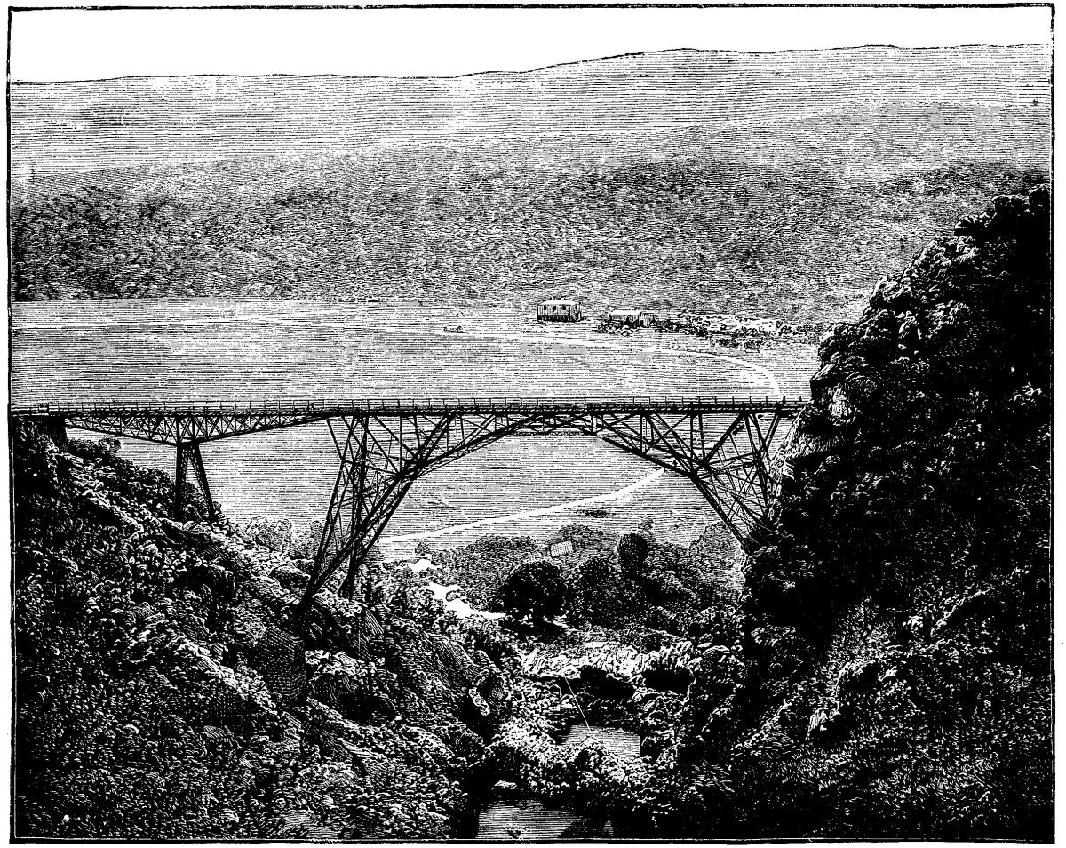
BRIDGE OVER THE BLAAUW KRANTZ RAVINE, CAPE COLONY.
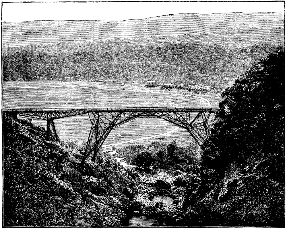
BRIDGE OVER THE BLAAUW KRANTZ RAVINE, CAPE COLONY.
In designing the structure the following points had to be considered: (1) That, on account of the great height above the ground, and on account of the high price of timber at the site, the structure could be easily erected without the use of scaffolding supporting it as a whole. (2) That, on account of the high freights to Port Alfred, the quantity of iron in the structure should be as small as possible. (3) That the single parts of the principal span should be easy to lift, and that there should be as few of them as possible. For this latter reason most of them were made in lengths of 20 ft. and more. The question of economy of material presented itself as a comparison between a few standard types, viz., the girder bridge of small independent spans; the cantilever bridge, or the continuous girder bridge in three large spans; the single girder bridge with one large span and several small spans; and the arch with small girder spans on each side. The suspension bridge was left out of question as inadmissible. A girder bridge with small independent spans on rocker piers would probably have been the most economical, even taking into account the great height of the piers near the middle of the ravine, but there would have been some difficulty in holding those piers in position until they could be secured to the girders at the top; and, moreover, such a structure would have been strikingly out of harmony with the character of the site. On the other hand, a cantilever or continuous girder bridge in three spans—although such structures have been erected in similar localities—could not enter into comparison of simple economy of material, because such a design would entirely disregard the anomaly that the greater part of the structure, viz., the side spans, being necessarily constructed to carry across a large space, would be too near the ground to justify the omission of further supports. The question was, therefore, narrowed to a comparison between the present arch and a central independent girder of the same span, including the piers on which it rests. The small side spans could obviously be left out in each case. The comparison was made with a view not only to arrive at a decision in this particular case, but also of answering the question of the economy of the arch more generally. The following table contains the weights of geometrically similar structures of three different spans, of which the second is the one here described. The so-called theoretical weight is that which the structure would have if no part required stiffening, leaving out also all connections and all wind bracing. The moving load is taken at one ton per foot lineal, and the strain on the iron at an average of four tons per square inch. The proportion of the girder is taken at 1 in 8.
| Span in Feet. | Theoretical Weight. | Total Weight. | ||
|---|---|---|---|---|
| Arch. | Girder. | Arch. | Girder. | |
| 100 | 0.0724 | 0.1663 | 0.1866 | 0.2443 |
| 220 | 0.1659 | 0.4109 | 0.4476 | 0.7462 |
| 300 | 0.2414 | 0.6445 | 0.6464 | 1.2588 |
| <------------Tons per foot lineal.-------------> | ||||
It can be seen from these results that the economical advantage of the arch increases with the span. In small arches this advantage would not be large enough to counterbalance the greater cost of manufacture; but in the arch of 220 ft. span the advantage is already very marked. If the table were continued, it would show that the girder, even if the platform were artificially widened, would become impossible at a point where the arch can still be made without difficulty. The calculations leading to the above results would occupy too much space to make it desirable on this occasion to produce them. Our two views are from photographs.—The Engineer.
Commander Gallwey lately delivered an interesting lecture on the use of torpedoes in war before the royal U.S. Institution, London, discussed H.M.S. Polyphemus, and urged as arguments in her favor: 1. That she has very high speed, combined with fair maneuvering powers. 2. That she can discharge her torpedoes with certainty either ahead or on the beam when proceeding at full speed. 3. That her crew and weapons of defense are protected by the most perfect of all armor possible, namely, 10 ft. of water. 4. That she only presents a mark of 4 ft. above the water line.
Then, he asked, with what weapon is the ironclad going to vanquish these torpedo rams? Guns cannot hit her when moving at speed; she is proof against machine guns, and, being smaller, handier, and faster than most ironclads, should have a better chance with her ram, the more especially as it is provided with a weapon which has been scores of times discharged with certainty at 300 yards. The ironclad, he answered, must use torpedoes, and then he maintained that the speed and handiness of the Polyphemus would enable her to place herself in positions where she could use her own torpedo to advantage, and be less likely to be hit herself. He then called attention to the necessity for well-protected conning towers in these ships, and prophesied that if a submarine ship, armed with torpedoes, be ever built, she will be the most formidable antagonist an ironclad ever had; and the nearer the special torpedo ship approaches this desideratum the better she will be.
A recent trial of a smoke rocket for testing drains, described by Mr. Cosmo Jones in the Journal of the Society of Arts, is deserving of interest. The one fixed upon is 10 in. long, 2½ in. in diameter, and with the composition "charged rather hard," so as to burn for ten minutes. This gives the engineer time to light the fuse, insert the rocket in the drain, insert a plug behind it, and walk through the house to see if the smoke escapes into it at any point, finishing on the roof, where he finds the smoke issuing in volumes from the ventilating pipes. The house experimented upon had three ventilating pipes, and the smoke issued in dense masses from each of them, but did not escape anywhere into the house, showing that the pipes were sound. If the engineer wishes to increase the severity of the test, he throws a wet cloth over the top of the ventilating pipe, and so gets a slight pressure of smoke inside it.
In earlier days of mechanics, before the work of the great Scottish engineer, James Watt, the crude steam engines of the time were known as "fire engines," not in the sense in which we now apply the term to machines for the extinguishing of fires, but as indicating the source from which the power was derived, motive power engines deriving their vitality and strength from fire. The modern name—steam engine—to some extent is a misleading one, distracting the mind from the source of power to the medium which conveys the power. Similarly the name "Gas Engine" masks the fact of the motors so called being really fire or heat engines.
The gas engine is more emphatically a "fire engine" than ever the steam engine has been. In it the fire is not tamed or diluted by indirect contact with water, but it is used direct; the fire, instead of being kept to the boiler room, is introduced direct into the motor cylinder of the engine. This at first sight looks very absurd and impracticable; difficulties at once become apparent of so overwhelming a nature that the problem seems almost an impossible one; yet this is what has been successfully accomplished in the gas engine. Engineers accustomed to the construction of steam engines would not many years ago have considered any one proposing such a thing as having taken leave of his senses.
The late Sir William Siemens worked for many years on combustion engines, some of his patents on this subject dating back to 1860. In the course of a conversation I had with him on the subject of his earlier patents, I asked him why he had entitled one of those patents "steam engine improvements" when it was wholly concerned with a gas engine using hydrogen and air in the motive cylinder, the combustion of the hydrogen taking place in the motive cylinder. He answered me that in 1860 he did not care to entitle his patent gas or combustion engine simply because engineers at that time would have thought him mad.
Notwithstanding this widespread incredulity among engineers, and the apparent novelty of the gas engine idea, fire or combustion engines have been proposed long, long ago. The first Newcomen steam engine ever set to work was used by a Mr. Back, of Wolverhampton, in the year 1711. Thirty-one years before this time, in Paris—year 1680—Huyghens presented a memoir to the Academy of Sciences describing a method of utilizing the expansive force of gunpowder. This engineer is notable as being the very first to propose the use of a cylinder and piston, as well as the first combustion engine of a practical kind.
The engine consists of a vertical open topped cylinder, in which works a piston; the piston is connected by a chain passing over a pulley above it to a heavy weight; the upstroke is accomplished by the descent of the weight, which pulls the piston to the top of the cylinder; gunpowder placed in a tray at the bottom of the cylinder is now ignited, and expels the air with which the cylinder is filled through a shifting valve, and, after the products of combustion have cooled, a partial vacuum takes place and the atmospheric pressure forces down the piston to the bottom of its stroke, during which work may be obtained.
On the board I have made a sketch of this engine. Some years previous to Huyghens' proposal, the Abbe Hautefeuille (1678) proposed a gunpowder engine without piston for pumping water. It is similar to Savery's steam engine, but using the pressure of the explosion instead of the pressure of steam. This engine, however, had no piston, and was only applicable as a pump. The Savery principle still survives in the action of the well-known pulsometer steam pump.
Denys Papin, the pupil and assistant of Huyghens, continued experimenting upon the production of motive power, and in 1690 published a description of his attempts at Leipzig, entitled "A New Method of Securing Cheaply Motive Power of Considerable Magnitude."
He mentions the gunpowder engine, and states that "until now all experiments have been unsuccessful; and after the combustion of the exploded powder there always remains in the cylinder one-fifth of its volume of air."
For the explosion of the gunpowder he substituted the generation and condensation of steam, heating the bottom of his cylinder by a fire; a small quantity of water contained in it was vaporized, and then on removing the fire the steam condensed and the piston was forced down. This was substantially the Newcomen steam engine, but without the separate boiler.
Papin died about the year 1710, a disappointed man, about the same time as Newcomen. Thomas Newcomen, ironmonger and blacksmith, of Dartmouth, England, had first succeeded in getting his engine to work. The hard fight to wrest from nature a manageable motive power and to harness fire for industrial use was continued by this clever blacksmith, and he succeeded when the more profound but less constructively skillful philosophers had failed.
The success of the steam method and the fight necessary to perfect it to the utmost absorbed the energy of most able engineers—Beighton, John Smeaton—accomplishing much in applying and perfecting it before the appearance of James Watt upon the scene.
It is interesting to note that in England alone over 2,000 horse power of Newcomen engines were at work before Watt commenced his series of magnificent inventions; he commenced experimenting on a Newcomen engine model in 1759 at Glasgow University, and in 1774 came to Birmingham, entered into partnership with Boulton, and 1781 we find his beautiful double acting beam condensing engine in successful work.
From that time until now the steam engine has steadily advanced, increasing in economy of fuel from 10 lb. of coal per horse power per hour to about 1¾ lb. per horse power per hour, which is the best result of to-day's steam engine practice. This result, according to the highest authorities, is so near to the theoretical result possible from a steam engine that further improvement cannot now be looked for. Simultaneously with the development of the steam engine, inventors continued to struggle with the direct acting combustion or gas engine, often without any definite understanding of why they should attempt such apparent impossibilities, but always by their experiments and repeated failures increasing knowledge, and forming a firm road upon which those following them traveled to success.
In 1791 John Barber obtained a patent for an engine producing inflammable gas, mixing it with air, igniting it, and allowing the current so produced to impinge upon a reaction wheel, producing motion similar to the well known Aelopile, which I have at work upon the table. About this time, Murdoch (Jas. Watt's assistant at Birmingham) was busy introducing coal gas into use for lighting; in 1792 Boulton and Watt's works were lighted up with coal gas. From this time many gas engines were proposed, and the more impracticable combustion of gunpowder received less attention.
In 1794 Thomas Mead obtained a patent for an engine using the internal combustion of gas; the description is not a clear one, his ideas seem confused.
In the same year Robert Street obtained a patent for an engine which is not unlike some now in use. The bottom of a cylinder, containing a piston, is heated by a fire, a few drops of spirits of turpentine are introduced and evaporated by the heat, the piston is drawn up, and air entering mixes with the inflammable vapor. A light is applied at a touch hole, and the explosion drives up the piston, which, working on a lever, forces down the piston of a pump for pumping water. Robt. Street adds to his description a note: "The quantity of spirits of tar or turpentine to be made use of is always proportional to the confined space, in general about 10 drops to a cubic foot." This engine is quite a workable one, although the arrangements described are very crude.
The first gas engine that was actually at work for some years; and was applied to a variety of purposes, was Samuel Buren's. His patent was granted in 1823, and in 1826 he built a locomotive carriage with which he made several experimental runs in London; he also propelled a vessel with it upon the Thames, and fitted up a large engine for pumping purposes. A company was formed to introduce his engine, but it proved too wasteful of fuel, and the company went into voluntary liquidation. Like almost all engines of this time, the combustion of gas and air was used to produce a vacuum, the piston being driven by atmospheric pressure.
Buren's locomotive carriage was thus in action three years before the great trial in 1829, from which George Stephenson emerged victorious with his wonderful engine "The Rocket." To those curious in the matter, I may mention that S. Buren's patents are dated 1823, No. 4,874, and 1826, No. 5,350.
From this time on, a continuous series of gas engine patents appear, 20 engines being patented between 1826 and 1860, which is the next date worthy of particular mention.
In this year, 1860, the famous "Lenoir" engine appeared. The use of high pressure steam engines had long been common, and Lenoir's engine was analogous to the high pressure engine, as Buren's was to the condensing engine. It created a very general interest, and many engines were constructed and used in France, England, and America; it resembled very much in external appearance an ordinary high pressure horizontal steam engine, and it was double acting.
During the following six years, other 20 British patents were granted, and the gas engine passed from the state of a troublesome toy to a practicable and widely useful machine.
From 1791 to the end of 1866, in all 46 British patents were granted for gas engines, and in these patents are to be found the principles upon which the gas engines of to-day are constructed, many years elapsing before experience enough was gained to turn the proposals of the older inventors to practical account.
The most important of these patents are:
| No. | Year. | ||
|---|---|---|---|
| Robert Street | 1,983 | 1794 | Direct-acting engine. |
| Samuel Buren | 4,874 | 1823 | Vacuum engine. |
| Samuel Buren | 5,350 | 1826 | Vacuum engine. |
| W.L. Wright | 6,525 | 1833 | Direct-acting engine. |
| Wm. Barnett | 7,615 | 1838 | Compression first proposed. |
| Barsante & Matteucci | 1,072 | 1854 | Rack & clutch engine. |
| Drake | 562 | 1855 | Direct-acting engine. |
| Lenoir | 335 | 1860 | D.I. engine, electric ignition. |
| C.W. Siemens | 2,074 | 1860 | Compression, constant pressure. |
| Hugon | 2,902 | 1860 | Platinum ignition. |
| Millein | 1,840 | 1861 | Compression, both constant vol. and pressure. |
| F.H. Wenham | 1,873 | 1864 | Free piston. |
| Hugon | 986 | 1865 | Flame ignition. |
| Otto and Langen | 434 | 1866 | Rack and clutch, flame ignition. |
Leaving for the present the history of the gas engine, which brings us to a stage comparable to the state of the steam engine during the Newcomen's time, it will be advisable to give some consideration to the principles concerned in the economical and efficient working of gas engines, in order to understand the more recent developments.
It has been seen that gunpowder was the explosive used to produce a vacuum in Huyghens' engine, and that it was abandoned in favor of gas by Buren in 1823. The reason of departure is very obvious: a gunpowder explosion and a gaseous explosion differ in very important practical points.
Gunpowder being a solid substance is capable of being packed into a very small space; the gas evolved by its decomposition is so great in volume that, even in the absence of any evolution of heat, a very high pressure would result. One cubic inch of gunpowder confined in a space of one cubic inch would cause a pressure by the gas it contains alone of 15,000 lb. per square inch; if the heating effect be allowed for, pressures of four times that amount, or 60,000 lb. per square inch, are easily accounted for. These pressures are far too high for use in any engine, and the bare possibility of getting such pressure by accident put gunpowder quite outside the purpose of the engineer, quite apart from any question of comparative cost. In a proper mixture of inflammable gas and air is found an exceedingly safe explosive, perfectly manageable and quite incapable of producing pressures in any sense dangerous to a properly constructed engine.
The pressure produced by the explosion of any mixture of gas and air is strictly determined and limited, whereas the pressure produced by the explosion of gunpowder depends greatly upon the relation between the volume of the gunpowder and the space in which it is confined.
Engines of the "Lenoir" type are the simplest in idea and construction; in them a mixture of gas and air is made in the cylinder during the first half of the piston stroke, air being taken from the atmosphere and drawn into the cylinder by the forward movement of the piston. At the same time gas entering by a number of holes, and streaming into the air to form an explosive mixture, the movement of a valve cuts off the supply, and brings the igniting arrangement into action. The pressure produced by the explosion acting upon the piston makes it complete its stroke, when the exhaust valve opens exactly as in the steam engine. The Lenoir and Hugon engines, the earlier forms of this type, were double acting, receiving two impulses for every revolution of the crank, the impulse differing from that in a high pressure steam engine in commencing at half stroke.
The Lenoir igniting arrangement was complicated and troublesome. I have it upon the table; the mixture was ignited at the proper time by the electric spark produced from a primary battery and Ruhmkorff coil.
The Hugon engine was an advance in this respect, using a flame ignited, and securing greater certainty of action in a comparatively simple manner.
It is really a modification of Barnett's lighting cock described in his patent of 1838.
Other difficulties were found in using these engines; the pistons became exceedingly hot. In the case of the Lenoir larger engines, it sometimes became red hot, and caused complete ruin of the cylinder by scoring and cutting up. Hugon to prevent this injected some water.
In the all important question of economy, these engines were found grievously wanting, Lenoir consuming 95 cubic feet per I.H.P. per hour; Hugon consuming 85 cubic feet per I.H.P. per hour.
The surviving engines of this type are only used for very small powers, from one to four man power, or ⅛ to ½ horse, the most widely known of this kind being the "Bischoff," which is very largely used; its consumption of gas is even greater than the Lenoir, being 110 cubic feet per horse power per hour, as tested with a half-horse engine at a late exhibition of gas apparatus at Stockport.
So large a consumption of gas prevented these engines coming into extended use for engines of moderate power, and led inventors to work to obtain better results. The force generated by the explosion of a mixture of gas and air is very short lived, and if it is to be fully utilized must be used quickly; a high pressure is produced, but it very quickly disappears.
The quicker the piston moves after the maximum pressure is reached, the less will be the loss of heat to the sides of the cylinder. The flame which fills the cylinder and causes the increase of pressure rapidly loses heat, and the pressure falls.
The idea of using a free piston was proposed as a remedy; it was thought that a piston connected to a crank in the ordinary manner could not move fast enough to utilize the pressure before it was lost. Many inventors proposed to perform work upon a piston free from any direct connection with the crank or shaft of the engine; the explosion after attaining its maximum pressure expends its force in giving velocity to a piston; the velocity so acquired carries it on against atmospheric pressure until the energy is all absorbed, and a vacuum or deficit of pressure exists in the cylinder instead of an excess of pressure. The return stroke is accomplished by the atmospheric pressure, and the work is now done upon the engine shaft on the return only. The method of connecting on the return stroke while leaving the piston free on the out stroke varies, but in many engines the principle was the same.
Barsante and Matteucci, year 1857, British patent No. 1,625, describe the first engine of this kind, but Messrs. Otto and Langen were the first to successfully overcome all difficulties and make a marketable engine of it. Their patent was dated 1866, No. 434. To distinguish it from Otto's later patents, it may be called the rack and clutch engine.
The economy obtained by this engine was a great advance upon the Lenoir. According to a test by Prof. Tresca, at the Paris Exhibition of 1867, the gas consumed was 44 cubic feet per indicated horse power per hour. According to tests I have made myself in Manchester with a two horse power engine, Otto and Langen's free piston engine consumes 40 cubic feet per I.H.P. per hour. This is less than one-half of the gas used by the Hugon engine for one horse power.
The igniting arrangement is a very good modification of Barnett's lighting cock, which I have explained already, but a slide valve is used instead of a cock.
Other engines carried out the same principle in a different manner, including Gilles' engine, but they were not commercially so successful as the Otto and Langen. Mr. F.H. Wenham's engine was of this type, and was working in England, Mr. Wenham informed me, in 1866, his patent being taken out in 1864.
The great objection to this kind of engine is the irregularity and great noise in working; this was so great as to prevent engines from being made larger than three horse power. The engine, however, did good work, and was largely used from 1866 until the end of 1876, when Mr. Otto produced his famous engine, now known as "The Otto Silent Gas Engine." In this engine great economy is attained without the objectionable free piston by a method proposed first by Burnett, 1838, and also by a Frenchman, Millein, in 1861; this method is compression before ignition. Other inventors also described very clearly the advantages to be expected from compression, but none were able to make it commercially successful till Mr. Otto. To him belongs the great credit of inventing a cycle of operations capable of realizing compression in a simple manner.
Starting from the same point as inventors did to produce the free piston engine—namely, that the more quickly the explosive force is utilized, the less will be the loss, and the greater the power produced from a quantity of burning gas—it is evident that if any method can be discovered to increase the pressure upon the piston without increasing the temperature of the flame causing this pressure, then a great gain will result, and the engine will convert more of the heat given to it into work. This is exactly what is done by compression before ignition. Suppose we take a mixture of gas and air of such proportions as to cause when exploded, or rather ignited (because explosion is too strong a term), a pressure of 45 lb. above atmosphere, or 60 lb. per square inch absolute pressure. Then this mixture, if compressed to half volume before igniting and kept at constant temperature, would give, when ignited, a pressure of 120 lb. total, or 105 lb. above atmosphere, and this without any increase of the temperature of the flame.
The effect of compression is to make a small piston do the work of a large one, and convert more heat into work by lessening the loss of heat through the walls of the cylinder. In addition to this advantage, greater expansions are made possible, and therefore greatly increase economy.
The Otto engine must be so familiar in appearance to all of you, that I need hardly trouble you with details of its external appearance. I shall briefly describe its action. Its strong points and its weak points are alike caused by its cycle. One cylinder and piston suffices to carry out its whole action. Its cycle is: First outstroke, gas and air sucked into the cylinder; first instroke, gas and air compressed into space; second outstroke, impulse due to ignition; second instroke, discharge of exhausted gases. When working at full power, it gets one impulse for every two revolutions; this seems to be a retrograde movement, but, notwithstanding, the advantages obtained are very great. The igniting arrangement is in the main similar to that used on the rack and clutch engine. The engine has been exceedingly successful, and is very economical. The Otto compression engine consumes 21 cubic feet of gas per I.H.P. per hour, and runs with great smoothness.
In 1876 I commenced my work upon gas engines, and very soon concluded that the compression system was the true line to proceed upon. It took me two years to produce a workable engine. My efforts have always been directed toward producing an engine giving at least one impulse every revolution and, if possible, to start without hand labor, just as a steam engine does. My first gas engine was running in 1878, and patented and exhibited in 1879. It was first exhibited at the Kilburn Royal Agricultural Society's show.
This engine was self-starting, gave an ignition at every revolution, and ignited without external flame. It consisted of two cylinders, a motor, and a compressing pump, with a small intermediate reservoir. Suitable valves introduced the mixture of gas and air into the pump, and passed it when compressed from the reservoir to the motor cylinder. The igniting arrangement consisted of a platinum cage firmly fixed in a valve port; this cage was heated in the first instance by a flame of gas and air mixed; it became white hot in a few seconds, and then the engine was started by opening a valve.
The platinum was kept hot by the heat derived from the successive ignitions, and, the engine once started, no further external flame was required. I have here one of these platinum cages which has been in use. Finding this method not well suited for small engines, I produced the engine which is at present in the market under my name.
The cycle is different, and is designed for greater simplicity and the avoidance of back ignitions. It also consists of two cylinders, motor cylinder and the displace or charging cylinder. There is no intermediate reservoir. The displace crank leads the motor by a right angle, and takes into it the mixed charge of gas and air, in some cases taking air alone during the latter part of its stroke.
The motor on the outstroke crosses V-shaped parts about from one-sixth to one-seventh from the out end, the displacer charge now passing into the motor cylinder, displacing the exhaust gases by these ports and filling the cylinder and the space at the end of it with the explosive mixture. The introduction of some air in advance of the charge serves the double purpose of cooling down the exhaust gases and preventing direct contact of the inflammable mixture with flame which may linger in the cylinder from the previous stroke. The instroke of the motor compresses the charge into the conical space at the end of the cylinder, and, when fully compressed, ignition is effected by means of the slide I have upon the table.
This system of ignition has been found very reliable, and capable of acting as often as 400 times per minute, which the Otto ignite is quite incapable of doing. By this cycle the advantages of compression are gained and one step nearer to the steam engine is attained, that is, an impulse is given for every revolution of the engine.
As a consequence, I am able with my engine to give a greater amount of power for a comparatively small weight. In addition to this, I have introduced a method of self-starting; in this I believe I was the first—about 100 of my engines are now using self-starting.
The largest single engine I have yet made indicates 30 H.P. The consumption of gas in Glasgow is: Clerk engine consumes in Glasgow 18 cubic feet per I.H.P. per hour; Clerk engine consumes in Manchester 22 cubic feet per I.H.P. per hour. So far as I know, the Otto engine and my own are the only compression engines which have as yet made any success in the market. Other engines are being continually prepared, gas engine patents being taken out just now at the rate of 60 per annum, but none of them have been able as yet to get beyond the experimental stage. The reason is simply the great experience necessary to produce these machines, which seem so very simple; but to the inexperienced inventor the subject fairly bristles with pitfalls.
I have here sections of some of the earlier engines, including Dr. Siemens' and Messrs. Simon and Beechy. Although interesting and containing many good points, these have not been practically successful.
The Simon engine is an adaptation of the well-known American petroleum motor, the Brayton, the only difference consisting in the use of steam as well as flame.
Dr. Siemens worked for some twenty years on gas engines, but he aimed rather high at first to attain even moderate success. Had he lived, I doubt not but that he would have succeeded in introducing them for large powers. In 1882 he informed me that he had in hand a set of gas engines of some hundreds of horse power for use on board ship, to be supplied with gas from one of his gas producers modified to suit the altered conditions.
Summarizing the ground over which we have passed, we find the origin of the gas engine in the minds of the same men as were first to propose the steam engine, Huyghens and Papin, 1680 and 1690. Greater mechanical difficulties and ignorance of the nature of explosives caused the abandonment of the internal combustion idea, and the mechanical difficulties with steam being less, the steam engine became successful, and triumphed over its rival. The knowledge and skill gained in the construction of steam engines made it possible once again to attack the more difficult problem, and simultaneously with the introduction and perfecting of the steam engine, the gas engine idea became more and more possible, the practicable stage commencing with Lenoir and continuing with Hugon, Millein, Otto and Langen, F.H. Wenham, then Otto and Clerk. In 1860, 95 cubic feet of gas produced one horse power for an hour; in 1867, 40 cubic feet accomplished the same thing; and now (1885) we can get one horse power for an hour for from 15 to 20 cubic feet of gas, depending on the size of the engine used.
Considered as a heat engine, the gas engine is now twice as efficient as the very best modern steam engine. It is true the fuel used at present is more expensive than coal, and for large powers the steam engine is the best because of this. But the way is clearing to change this. Gas engines as at present, if supplied with producer gas, produced direct from coal without leaving any coke, as is done in the Siemens, the Wilson, and the Dawson producers, will give power at one-half the cost of steam power. They will use ⅞ of a pound of coal per horse power per hour, instead of 1¾ lb., as is done in the best steam engines. The only producer that makes gas for gas engines at present is the Dawson, and in it anthracite is used, because of the difficulty of getting rid of the tar coming from the Siemens and Wilson producers, using any ordinary slack.
When this difficulty has been overcome, and that it will be overcome there can be no manner of doubt, gas engines will rapidly displace the steam engine, because a gas engine with a gas producer, producing gas from any ordinary coal with the same ease as steam is produced from a boiler, will be much safer, and will use one-half the fuel of the very best steam engines for equal power. The first cost also will not be greater than that of steam. The engine itself will be more expensive than a steam engine of equal power, but the gas producer will be less expensive than the boiler at present. Perfect as the gas engine now is, considered as a machine for converting heat into work, the possibility of great development is not yet exhausted. Its economy may be increased two or even three fold; in this lies the brilliant future before it. The steam engine is nearly as perfect as it can be made; it approaches very nearly the possibility of its theory. Its defect does not lie in its mechanism, but in the very properties of water and steam itself. The loss of heat which takes place in converting liquid water into gaseous steam is so great that by far the greater portion of the heat given out by the fuel passes away either in the condenser or the exhaust of a steam engine; but a small proportion of the heat is converted into work.
The very best steam engines convert about 11 per cent. of the heat given them into useful work, the remaining 89 per cent. being wasted, principally in the exhaust of the engine.
Gas engines now convert 20 per cent. of the heat given to them into work, and very probably will, in a few years more, convert 60 per cent. into useful work. The conclusion, then, is irresistible that, when engineers have gained greater experience with gas engines and gas producers, they will displace steam engines entirely for every use—mills, locomotives, and ships.
[1]During the winter of 1881 and 1882, the contract was let to Messrs. Langdon, Sheppard & Co., of Minneapolis, to construct during the working season of the latter year, or prior to January 1, 1883, 500 miles of railroad on the western extension of the above company; the contract being for the grading, bridging, track-laying, and surfacing, also including the laying of the necessary depot sidings and their grading. The idea that any such amount of road could be built in that country in that time was looked upon by the writer hereof, as well as by railroad men generally, as a huge joke, perpetrated to gull the Canadians. At the time the contract was let, the Canadian Pacific Railway was in operation to Brandon, the crossing of the Assiniboine River, 132 miles west of Winnipeg. The track was laid, however, to a point about 50 miles west of this, and the grading done generally in an unfinished state for thirty miles further. This was the condition of things when the contract was entered into to build 500 miles—the east end of the 500-mile contract being at Station 4,660 (Station 0 being at Brandon) and extending west to a few miles beyond the Saskatchewan River.
The spring of 1882 opened in the most unpromising manner for railroad operations, being the wettest ever known in that country. Traffic over the St. Paul, Minneapolis & Manitoba Railroad, between St. Paul and Winnipeg, was entirely suspended from April 15 to the 28th, owing to the floods on the Red River at St. Vincent and Emerson, a serious blow to an early start, as on this single track depended the transportation of all supplies, men, timber, and contractors' plant, together with all track materials (except ties), all of these things having to come from or through St. Paul and Minneapolis. The writer hereof was appointed a division engineer, and reported at Winnipeg the 15th of April, getting through on the last train before the St. Vincent flood. No sooner was the line open from St. Paul to Winnipeg than the cotillon opened between Winnipeg and Brandon, with a succession of washouts that defied and defeated all efforts to get trains over, so it was not until the fifth day of May that I left Winnipeg to take charge of the second division of 30 miles.
By extremely "dizzy" speed I was landed at the end of the track, 180 miles from Winnipeg, on the evening of the 9th (4 days). My outfit consisted of three assistant engineers and the necessary paraphernalia for three complete camps, 30 days' provisions (which turned out to be about 20), 11 carts and ponies, the latter being extremely poor after a winter's diet on buffalo grass and no grain. On the 18th day of May I had my division organized and camps in running order. The country was literally under water, dry ground being the exception, and I look upon the feat of getting across the country at all as the engineering triumph of my life.
On May 20 a genuine blizzard set in, lasting 24 hours, snowed five inches, and froze the sloughs over with half an inch of ice, a decidedly interesting event to the writer, as he was 18 miles from the nearest wood, therefore lay in his blankets and ate hard tack. I stabled my ponies in the cook tent, and after they had literally eaten of the sod inside the tent, I divided my floor with them.
On 28th day of May I saw the first contractor, who broke ground at station 7,150. On the 1st of June I was relieved from this division, and ordered to take the next, 50 miles west. On the 13th day of June ground was broken on this division, at station 8,070, or only about 62 miles west of the east end of the 500-mile contract. It looked at this time as though they might build 150 miles, but not more. But from this time on very rapid progress was made. On July 17 the track reached station 7,000, making however up to this time but about 50 miles of track-laying, including that laid on the old grade; but large forces were put on to surfacing, and the track already laid was put in excellent condition for getting material to the front. The weather from this until the freezing-up was all that could be desired. Work ceased about the 1st of January, 1883, for the season, and the final estimate for the work was as follows: 6,103,986 cubic yards earth excavation, 2,395,750 feet B.M. timber in bridges and the culverts, 85,708 lineal feet piling, 435 miles of track-laying. This work was all done in 182 working days, including stormy ones, when little, if anything, could be done, making a daily average of 33,548 yards excavation, 13,150 feet B.M. timber, 471 feet piling, 2-38/100 miles track-laying. We never had an accurate force report made of the whole line, but roughly there were employed 5,000 men and 1,700 teams.
The admirable organization of the contractors was something wonderful. The grading work was practically all done by sub-contractors, Messrs. Langdon, Sheppard & Co. confining themselves to putting in the supplies and doing the bridge work, surfacing, and track-laying. The grading forces were scattered along about 150 miles ahead of the track and supply stores, established about 50 miles apart, and in no case were sub-contractors expected to haul supplies over 100 miles. If I remember rightly, there were four trains of about forty wagons each, hauling supplies from the end of track to the stores.
As can be readily seen, the vital point of the whole work, and the problem to solve, was food for men and horses. 1,700 bushels of oats every day and 15,000 pounds of provisions, Sundays and all, for an entire season, which at the beginning of the work had to come about 170 miles by rail, and then be taken from 50 to 150 miles by teams across a wilderness, is on the face of it considerable of an undertaking, to say nothing about hauling the pile-drivers, piles, and bridge-timber there. To keep from delaying the track, sidings 1,500 feet long were graded, about 7 miles apart. A side-track crew, together with an engine, four flats, and caboose, were always in readiness; and as soon as a siding was reached, in five hours the switches would be in, and the next day it would be surfaced and all in working order, when the operating department would fill it with track material and supplies. From the head of the siding to the end of the track the ground was in hands of track-laying engine, never going back of the last siding for supplies or material, and my recollection is that there were but six hours' delay to the track from lack of material the whole season, at any rate up to some time in November. The track-laying crew was equal to 4 miles per day, and in the month of August 92 miles of track were laid. The ties were cut on the line of the road about 100 miles east of Winnipeg, so the shortest distance any ties were hauled was 270 miles; the actual daily burden of the single track from Winnipeg west was 24 cars steel, 24 cars ties, aside from the transportation of grain and provisions, bridge material, and lumber for station houses. The station buildings were kept right up by the company itself, and a depot built with rooms for the agent every 15 miles, or at every second siding. The importance of keeping the buildings up with the track was impressed on the mind of the superintendent of this branch, and, as a satire, he telegraphed asking permission to haul his stuff ahead of the track by teams, he being on the track-layers' heels with his stations and tanks the whole season. The telegraph line was also built, and kept right up to the end of the track, three or four miles being the furthest they were at any time behind.
It might be supposed that work done so rapidly would not be well done, but it is the best built prairie road I know of on this continent. It is built almost entirely free from cuts, and the work is at least 20 per cent. heavier than would ordinarily be made across the same country in the States, on account of snow. 2,640 ties were laid to the mile, and the track ballasting kept well up with the laying; so well, in fact, and so well done, that as 100 mile sections were completed schedule trains were put on 20 miles an hour, and the operating department had nothing to do but make a time table; the road was built by the construction department before the operating department was asked to take it. The engineering was organized in divisions of 30 miles each, and as each was finished the parties moved ahead again to the front, the engineers usually finding men sitting on their shovels waiting for the work to be laid out for them. It was as much as the locating parties could do to keep out of the way of the construction. The roadbed was built 14 ft. wide in embankment and 20 in the very few cuts there were, there being no cuts of any moment except through the Coteaus and the Saskatchewan crossing, and these have since been widened out on account of snow, so that the road can be operated the year round and the bucking-snow account cut no figure in the operating expenses.
The country is a virgin desert. From Winnipeg to the Pacific Ocean there are a few places that might attain to the dignity of an oasis—at Brandon, Portage la Prairie, etc.—but it is generally what I should call worthless; 100 miles to wood and 100 feet to water was the general experience west of the Moose jaw, and the months of June, July, and August are the only three in the year that it is safe to bet you will not have sleighing. I burned wood and used stakes that were hauled by carts 85 miles, and none any nearer. It is a matter of some pride that both the engineering and the construction were done by what our Canadian neighbors kindly termed "Yankee importations." However, there was one thing that in the building of this road was in marked contrast to any other Pacific road ever constructed, that is, there was no lawlessness, no whisky, and not even a knock-down fight that I ever heard of the whole season, and even in the midst of 12,000 Indians, all armed with Winchester rifles and plenty of ammunition, not one of the locating or construction parties ever had a military escort, nor were any depredations ever committed, except the running off of a few horses, which were usually recovered; and I think there were but two fatal accidents during the season, one man killed on the Grand Coule Bridge, and another from being kicked by a horse.
The track was all laid from one end, and in no case were rails hauled ahead by teams. Two iron cars were used, the empty returning one being turned up beside the track to let the loaded one by.
The feat in rapid construction accomplished by this company will never be duplicated, done as it was by a reckless expenditure of money, the orders to the engineers being to get there regardless of expense and horse-flesh; if you killed a horse by hard driving, his harness would fit another, and there was no scrutiny bestowed on vouchers when the work was done; and I must pay the tribute to the company to say that everything that money would buy was sent to make the engineers comfortable. It was bad enough at best, and the Chief Engineer (J.C. James) rightly considered that any expense bestowed on the engineering part of the work was a good investment.
In the accompanying illustration, we present to our readers a mammoth excavator, built by the Osgood Dredge Company of Albany, N.Y., for the Pacific Guano Company of California, for uncovering their phosphate deposits on Chisholm Island, South Colombia.
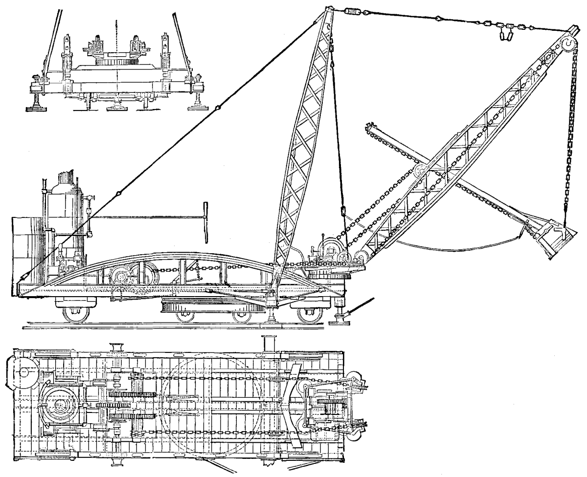
THE OSGOOD MAMMOTH EXCAVATOR.
In order to bring out more clearly the principal problem involved in the construction of this machine, we shall state first the proposed method of its operation. This is as follows, viz.: The excavator is to dig a trench thirty feet wide, down to the phosphate rock, and the entire length of the bed—about one quarter of a mile—dumping the earth of the first cut to one side. The phosphate is taken out behind the excavator. On reaching the end of the bed, the excavator is reversed and starts back, making a second cut thirty feet wide, and dumping now into the cut from which the phosphate has just been removed. In this way the entire bed is traversed, the excavator turning over the earth in great furrows thirty feet wide, and giving an opportunity to simultaneously get out all the phosphate.
As will be seen, the main problem presented was to turn the car around at each end of the cut in a very limited space. To accomplish this, the car is mounted on a fixed axle at each end and on a truck under its center of gravity; this is somewhat forward of the geometrical center of the car. The frame of the truck is circular, thirteen feet in diameter, made of I beams curved to shape. The circle carries a track, on which a ring of coned rollers revolves, which in turn supports the car. By pulling out the track from under both ends of the car, the whole weight is balanced on this central turntable truck, thus admitting of the car being turned, end for end, within its own length. This method of turning the car, and the size of the machine, are the principal features.
The car is 40' × 13', with arched truss sides. The track is seven feet gauge, the spread between tracks 20 feet, the height of the A frame 38 feet, length of boom 40 feet, swinging in a circle of 30 feet radius, and through two-thirds of the entire circle. It has a steel dipper of 46 cubic feet capacity, 1 inch steel chains, 10" × 12" double cylinder hoisting engine, and 6¼" × 8" double cylinder reversible crowding engine. The drums are fitted with friction clutches. Owing to the great distance at which the dipper is handled, its size is reduced, and because it swings on the arc of so large a circle the capacity of this machine is only one-half of that of the No. 1 excavator built by the Osgood Dredge Company. Nevertheless it will do the work of from 75 to 100 men, since its capacity is from 800 to 1,000 cubic yards per day, the amount of rock uncovered depending, of course, upon the depth of earth overlying it. The excavator will dump 30 feet from the center line of the car, and 26 feet above the track, which is laid on the rock. Total weight about fifty tons. The crew required for its operation consists of 1 engineer, 1 fireman, 1 craneman, and 4 to 5 pit men to tend jacks, move track, etc.
In the illustration the boiler connections are omitted, also the housing for the protection of the crew. The design is characterized by the evident care which has been bestowed upon securing simplicity and durability.—American Engineer.
At a recent meeting of the Engineers' Club of Philadelphia, Mr. John C. Trautwine, Jr., exhibited and described drawings of a large land dredge built by the Osgood Dredge Co., of Albany, New York, for the Pacific Guano Co., to be used in removing 8 to 15 feet of material from the phosphate rock at Bull River, S.C.
The more prominent features of the machine are the car-body, the water tank, boiler and engine, the A frame (so-called from its slight resemblance to the letter A), the boom, the dipper-handle; and the dipper, drawings of which were shown and described in detail.
Before the excavation is begun, the forward end of the car (the end nearest the dipper) is lifted clear of the track by means of 3 screw-jacks. When the machine has excavated as far in advance of itself as the length of the boom and that of the dipper-handle will permit, say about 8 feet, the car is again lowered to the track, the screw-jacks removed, and the car is moved forward about 8 feet by winding the rope upon the drum, the other end of the rope being attached to any suitable fixed object near the line of the track. The forward end of the car is then again lifted by means of the 3 screw-jacks, and the digging is resumed. The machine cuts a channel from 25 to 35 feet wide, and deposits all the dirt upon one side. If necessary, it can dump earth about 25 feet above the track. The miners follow in the wake of the machine, getting out the phosphate as fast as it is uncovered. When the machine reaches the end of the field it is lowered to the track and the screw-jacks are removed. Shoes or skids are then placed upon the track, and the wheels of the turntable are run up on them. This lifts the end wheels clear of the track, so that the car and machine rest entirely upon the turntable. By now blocking the turntable wheels and winding up only one of the ropes, the car body and the machine are swung around end for end. The digging is then resumed in the opposite direction, the temporary track, upon which the machine travels, being shifted to one side, so that the second channel is made alongside of the first. The earth removed in cutting this second channel is dumped into the first channel, the phosphate (as stated above) having been first removed.
The dipper is of plate steel, and holds 1¾ cubic yards of earth when even full.
The machine is manned by an engineer, a fireman, and a dipper-tender, besides which from five to ten laborers are required. These look after the track, etc.
On several of the large rivers on the Continent, with rapid currents, cable towage has been introduced in addition to the older methods of transporting merchandise by sailing and steam boats or by towage with screw or paddle tugs. A chain or wire rope is laid on the bottom of the river bed, fixed to anchors at the ends and passed over a chain pulley driven by the steam engine and guided by pulleys on the steam tug, the tug lifting it out of the water at the bow and dropping it over the stern and winding itself with the barges attached to it along the chain, the latter being utilized as a rule only for the up journey, while down the river the tugs are propelled by paddles or screws, and can tow a sufficient number of barges with the assistance of the current. The system has been found advantageous, as, although the power required for drawing the barges and tugs against the current is of course the same in all cases, the slip and waste of power by screws and paddles is avoided. The size of the screws or paddles is also limited by the nature of the river and its traffic, and with cable towage a larger number of barges can be hauled, while the progress made is definite and there is no drifting back, as occurs with paddle or screw tugs when they have temporarily to slow or stop their engines on account of passing vessels. Several streams, as the Elbe, Rhine, and Rhone, have now such cables laid for long distances in those parts of the rivers where the traffic is sufficient to warrant the adoption of the system. While this has been introduced only during the last 16 or 18 years, a similar method of transporting merchandise has been in use in Russia on the river Volga for upward of 40 years. Navigation on this river is interrupted for about half the year by the ice, and the traffic is of larger amount only during part of the summer, while the length of the river itself is very great, so that laying down permanent cables would not pay; while, on the other hand, the current is so strong that towage of some sort must be resorted to for the transport of large quantities. The problem has been solved by the introduction of the capstan navigation or towage.
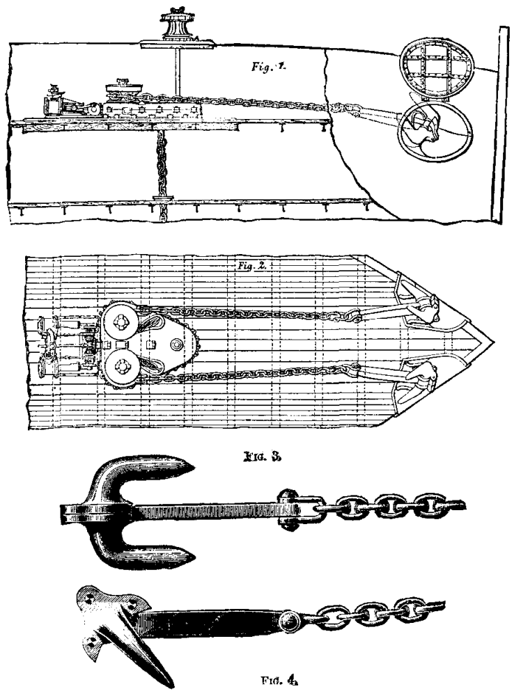
CAPSTAN NAVIGATION ON THE VOLGA.
There are two kinds of capstans in use, one actuated by horse-power and the other by steam engines. A horse capstan boat carries according to size 150 to 200 horses, which are stabled in the hold. On deck a number of horse gears are arranged at which the horses work. The power of the separate gears is transmitted to a main shaft, which is connected to the drums that wind on the rope. The horses work under an awning to protect them from the burning sunshine, and are changed every three hours. Eight and sometimes ten horses work at each horse gear. The horses are changed without interruption of the work, the gears being disengaged from the main shaft in rotation and the horses taken out and put in while the gear is standing. The horses are bought at the place of departure in the south of Russia and resold at the destination, usually Nishny-Novgorod, at a fair profit, the capstan boat carrying fodder and provender for the attendants. The capstan is accompanied by a steam launch which carries the anchor and hawser forward in advance of the capstan. The latter has a diameter of as much as 5 in., and is two to three miles in length. The anchor is dropped by the tug and the hawser carried back to the capstan, where it is attached to one of the rope drums, and the boat with the barges attached to it towed along by the horse gears described above winding on the hawser. The advance continues without interruption day and night, the launch taking a second anchor and hawser forward and dropping the anchor in advance of the first by a hawser's length, so that when the capstan has wound up the first hawser it finds a second one ready for attachment to the rope drum. The launch receives the first hawser, picks up the anchor, and passes the capstan to drop it again in advance of the anchor previously placed, and carries the hawser back to the capstan, and so on. A capstan tows twelve or more barges, placed in twos or threes beside and close behind each other, with a load of a million pounds, or about 16,000 to 17,000 tons. From Astrachan and the mouth of the Kama the capstans make during the season from the beginning of May to the end of July in the most favorable case two journeys to the fair of Nishny-Novgorod; after this time no more journeys are made, as the freights are wanting. At the end of the up-stream journey the horses are sold, as mentioned before, and the capstan towed down stream by the steam launch to Astrachan or the Kama mouth, where meanwhile a fresh lot of barges has been loaded and got ready, a new supply of horses is bought, and the operation repeated.
Besides these horse capstans there are steam capstans which are less complicated and have condensing steam engines of about 100 horse power, the power being transmitted by gearing to the rope drum. The rope drum shaft projects on both sides beyond the boards of the boat, and for the return journey paddle wheels, are put on to assist the launch in towing the clumsy and big capstan boat down the river. The steam capstans tow considerably larger masses of goods than the horse capstans and also travel somewhat quicker, so that the launch has scarcely sufficient time to drop and raise the anchors and also to make double the journey. We do not doubt that this system of towage might with suitable modifications be advantageously employed on the large rivers in America and elsewhere for the slow transport of large quantities of raw materials and other bulky merchandise, a low speed being, as is well known, much more economical than a high speed, as many of the resistances increase as the square and even higher powers of the velocity.
The larger ships in the navy, and some of the more recent small ones, such as the new cruisers of the Phaeton class, are fitted with powerful steam winches of a type made by Messrs. Belliss and Co. These are used for lifting the pinnaces and torpedo boats.
We give an illustration of one of these winches. The cylinders are 6 in. in diameter and 10 in. stroke. The barrel is grooved for wire rope, and is safe to raise the second class steel torpedo boats, weighing nearly 12 tons as lifted. The worm gearing is very carefully cut, so that the work can be done quietly and safely. With machinery of this kind a boat is soon put into the water, and as an arrangement is fitted for filling the boat's boilers with hot water from the ship's boilers, the small craft can be under way in a very short time from the order being given.
Mr. White is fitting compound engines with outside condensers to boats as small as 21 ft. long, and we give a view of a pair of compound engines of a new design, which Messrs. Belliss are making for the boats of this class. The cylinders are 4 in. and 7 in. in diameter by 5 in. stroke. The general arrangement is well shown in the engraving. On a trial recently made, a 25 ft. cutter with this type of engines reached a speed of 7.4 knots.
About three years ago the late Controller of the Navy, Admiral Sir W. Houston Stewart, wished to ascertain the relative consumption of fuel in various classes of small vessels. An order was accordingly sent to Portsmouth, and a series of trials were made. From the official reports of these we extract the information contained in tables F and G, and we think the details cannot fail to be of interest to our readers. The run around the island was made in company with other boats, without stopping, and observations were taken every half hour. The power given out by the engines was fairly constant throughout. The distance covered was 56 knots, and the total amount of fuel consumed, including that required for raising steam, was 1,218 lb. of coal and 84 lb. of wood. The time taken in raising steam to 60 lb. pressure was forty-three minutes. The rate of consumption of fuel is of course not the lowest that could be obtained, as a speed of over 10 knots is higher than that at which the machinery could be worked most economically.
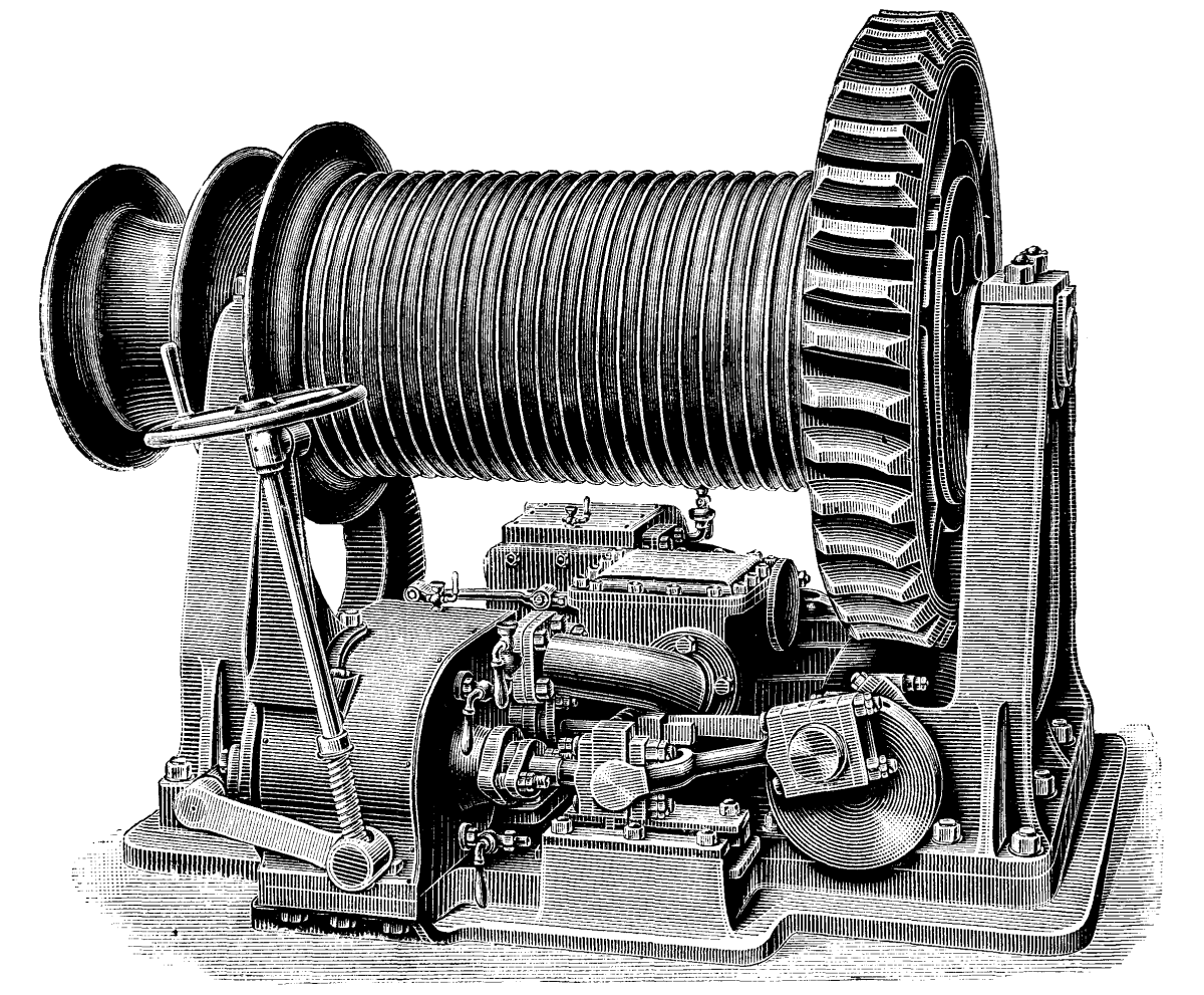
STEAM WINCH FOR HOISTING AND LOWERING PINNACLES AND TORPEDO BOATS.
The trials afterward made to find the best results that could be obtained in fuel consumption were rather spoiled by the roughness of the weather on the day they were made. The same boat was run for 10 miles around the measured mile buoys in Stokes Bay. The following are some of the results recorded:
| Table F.—Report of Trials of Engines of H.M. 48 ft. Twin Screw Steam Pinnace, No. 110. | |||
|---|---|---|---|
| Date | August 4, 1881. | ||
| Where tried | Round the Isle of Wight | ||
| Draught of water | Forward | 3 ft. ½ in. | |
| Aft | 3 ft. 6½ in. | ||
| Average boiler pressure | 104.81 lb. | ||
| Average pressure in receivers | Starboard | 16.27 lb. | |
| Port | 16.54 lb. | ||
| Mean air pressure in stokehold | 1.4 in. water. | ||
| Vacuum in condenser, average | 26.72 in. | ||
| Weather barometer | 30.37 in. | ||
| Revolutions per minute | Starboard | 240.75 | |
| Port | 251.95 | ||
| Mean pressure in cylinders | Starboard | High | 45.33 lb. |
| Low | 16.16 lb. | ||
| Port | High | 43.16 lb. | |
| Low | 15.3 lb. | ||
| Indicated horse-power | Starboard | High | 18.20 lb. |
| Low | 16.32 lb. | ||
| Port | High | 18.13 lb. | |
| Low | 16.17 lb. | ||
| Collective Total | 68.82 lb. | ||
| Speed by log | 10.18 knots. | ||
| Force of wind | One. | ||
| Sea | Smooth. | ||
| Quantity of coal on board | 1 ton. | ||
| Description | Nixon's navigation. | ||
| Consumption per indicated horse-power per hour | 4.17 lb. | ||
| Time under way | 5 hrs. 30 min. | ||
| Table G.—Report of Trial of Engines of H.M. 48 ft. Steam Pinnace No. 110. | |||
|---|---|---|---|
| When tried | August 3, 1881. | ||
| Where tried | Stokes Bay. | ||
| Draught | Forward | 3 ft. 1 in. | |
| Aft | 3 ft. 3¼ in. | ||
| Average boiler pressure | 55.52 lb. | ||
| Vacuum | 25.12 in. | ||
| Weather barometer | 30.35 in. | ||
| Revolutions per minute | starboard | 165.54 | |
| port | 161.55 | ||
| Indicated horse-power[2] | Starboard | High | 5.05 |
| Low | 5.53 | ||
| Port | High | 3.75 | |
| Low | 4.02 | ||
| Collective Total | 18.35 | ||
| Speed of vessel by log (approximate) | 7.404 | ||
| Wind | Force | 4 to 5 | |
| Direction | Bow and Quarter. | ||
| State of sea | Rough. | ||
In connection with this subject it may perhaps be of interest to give particulars of a French and American steam launch; these we extract from the United States official report before mentioned.
| Steam Launch of the French Steamer Mouche. | |
|---|---|
| Length on low water level | 27 ft. 10½ in. |
| Breadth | 5 ft. 11 in. |
| Depth to rabbet of keel | 3 ft. 3⅓ in. |
| Draught of water aft | 2 ft. 1½ in. |
| Weight of hull and fittings | 2,646 lb. |
| Weight of machinery with water in boiler | 3,473 lb. |
The boat is built of wood, and coppered. The engine consists of one non-condensing cylinder, 7½ in. in diameter and 5.9 in. stroke. The boiler has 4.3 square feet of grate surface. The screw is 21⅔ in. in diameter by 43.3 in, pitch. The speed is 7 knots per hour obtained with 245 revolutions per minute, the slip being 19.7 per cent. of the speed.
The United States navy steam cutters built at the Philadelphia navy yard are of the following dimensions:
| Length | 27 ft. 7½ in. |
| Breadth | 7 ft. 10 in. |
| Depth to rabbet of keel | 3 ft. 11¾ in. |
| Displacement (to two feet above rabbet of keel) | 5.96 tons. |
| Weight of hull and fittings | 4,675 lb. |
| Weight of engine | 1,240 lb. |
| Weight of boiler | 3,112 lb. |
| Weight of water in boiler and tanks | 2,696 lb. |
The engine has a single cylinder 8 in. in diameter and 8 in. stroke of piston. The screw is four bladed, 4 in. long and 31 in. in diameter by 45 in. pitch. The following is the performance at draught of water 2 feet above rabbet of keel:
| Boiler pressure | 90 lb. |
| Revolutions | 353 |
| Speed | 7.8 knots. |
| Indicated horse power. | 53 |
These boats are of 1870 type, but may be taken as typical of a large number of steam cutters in the United States navy. The naval authorities have, however, been lately engaged in extensive experiments with compound condensing engines in small boats, and the results have proved so conclusively the advantages of the latter system that it will doubtless be largely adopted in future.—Engineer.
[2]The illustrations we give represent an expansion trap by Mr. Hyde, and made by Mr. S. Farron, Ashton-under-Lyne. The general appearance of this arrangement is as in Fig. 1 or Fig. 3, the center view, Fig. 2, showing what is the cardinal feature of the trap, viz., that it contains a collector for silt, sand, or sediment which is not, as in most other traps, carried out through the valve with the efflux of water. The escape valve also is made very large, so that while the trap may be made short, or, in other words, the expansion pipe may not be long, a tolerably large area of outlet is obtained with the short lift due to the small movement of the expansion pipe.
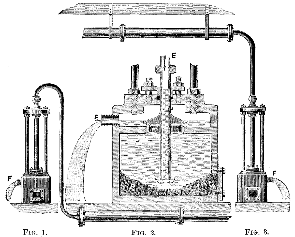
IMPROVED STEAM TRAP.
The object of a steam trap is for the removal of water of condensation without allowing the escape of steam from drying apparatus and steam pipes used for heating, power, or other purposes. One of the plans employed is by an expansion pipe having a valve fixed to its end, so that when the pipe shortens from being cooler, due to the presence of the water, the valve opens and allows the escape of the water until the steam comes to the trap, which, being hotter, lengthens the pipe and closes the valve. Now with this kind of trap, and, in fact, with any variety of trap, we understand that it has been frequently the experience of the user to find his contrivance inoperative because the silt or sand that may be present in the pipes has been carried to the valve and lodged there by the water, causing it to stick, and with expansion traps not to close properly or to work abnormally some way or other. The putting of these contrivances to rights involves a certain amount of trouble, which is completely obviated by the arrangement shown in the annexed engravings, which is certainly a simple, strong, and substantial article. The foot of the trap is made of cast iron, the seat of the valve being of gun metal, let into the diaphragm, cast inside the hollow cylinder. The valve, D, is also of gun metal, and passing to outside through a stuffing box is connected to the central expansion pipe by a nut at E. The valve is set by two brass nuts at the top, so as to be just tight when steam hot; if, then, from the presence of water the trap is cooled, the pipe contracts and the water escapes. A mud door is provided, by which the mud can be removed as required. The silt or dirt that may be in the pipes is carried to the trap by the water, and is deposited in the cavity, as shown, the water rises, and when the valve, D, opens escapes at the pipe, F, and may be allowed to run to waste. A pipe is not shown attached to F, but needless to say one may be connected and led anywhere, provided the steam pressure is sufficient. For this purpose the stuffing-box is provided; it is really not required if the water runs to waste, as is represented in the engraving. To give our readers some idea of the dimensions of the valve, we may say that the smallest size of trap has 1 in. expansion pipe and a valve 3 in. diameter, the next size 1¼ in. expansion pipe and a valve 4½ in. diameter, and the largest size has a pipe 1½ in. and a valve 6 in. diameter. Altogether, the contrivance has some important practical advantages to recommend it.—Mech. World.
In our study of the exact methods of measurement in use to-day, in the various branches of scientific investigation, we should not forget that it has been a plant of very slow growth, and it is interesting indeed to glance along the pathway of the past to see how step by step our micron of to-day has been evolved from the cubit, the hand's breadth, the span, and, if you please, the barleycorn of our schoolboy days. It would also be a pleasant task to investigate the properties of the gnomon of the Chinese, Egyptians, and Peruvians, the scarphie of Eratosthenes, the astrolabe of Hipparchus, the parallactic rules of Ptolemy, Regimontanus Purbach, and Walther, the sextants and quadrants of Tycho Brahe, and the modifications of these various instruments, the invention and use of which, from century to century, bringing us at last to the telescopic age, or the days of Lippershay, Jannsen, and Galileo.
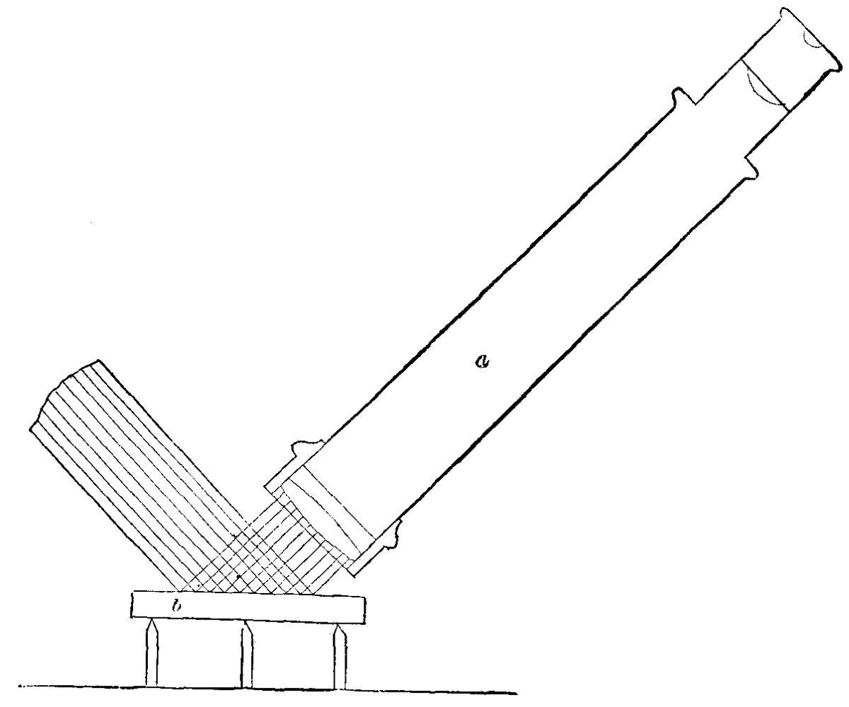
FIG. 1.
It would also be a most pleasant task to follow the evolution of our subject in the new era of investigation ushered in by the invention of that marvelous instrument, the telescope, followed closely by the work of Kepler, Scheiner, Cassini, Huyghens, Newton, Digges, Nonius, Vernier, Hall, Dollond, Herschel, Short, Bird, Ramsden, Troughton, Smeaton, Fraunhofer, and a host of others, each of whom has contributed a noble share in the elimination of sources of error, until to-day we are satisfied only with units of measurement of the most exact and refined nature. Although it would be pleasant to review the work of these past masters, it is beyond the scope of the present paper, and even now I can only hope to call your attention to one phase of this important subject. For a number of years I have been practically interested in the subject of the production of plane and curved surfaces particularly for optical purposes, i.e., in the production of such surfaces free if possible from all traces of error, and it will be pleasant to me if I shall be able to add to the interest of this association by giving you some of my own practical experience; and may I trust that it will be an incentive to all engaged in kindred work to do that work well?
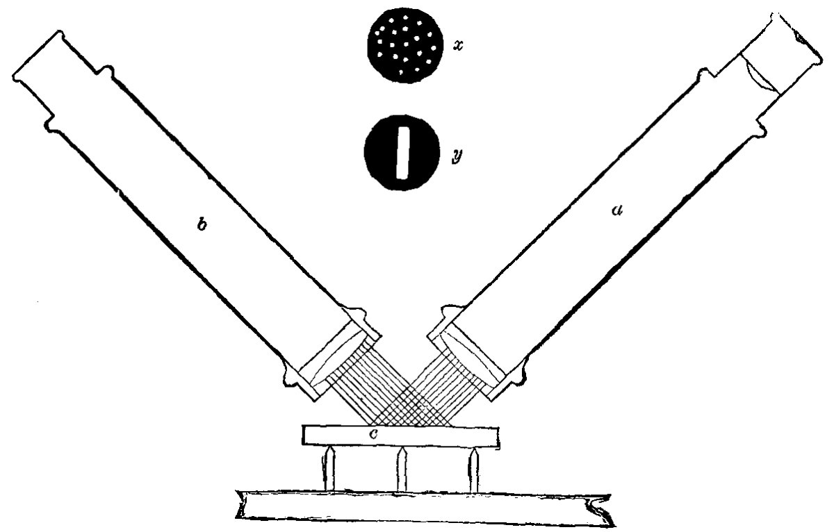
FIG. 2.
In the production of a perfectly plane surface, there are many difficulties to contend with, and it will not be possible in the limits of this paper to discuss the methods of eliminating errors when found; but I must content myself with giving a description of various methods of detecting existing errors in the surfaces that are being worked, whether, for instance, it be an error of concavity, convexity, periodic or local error.
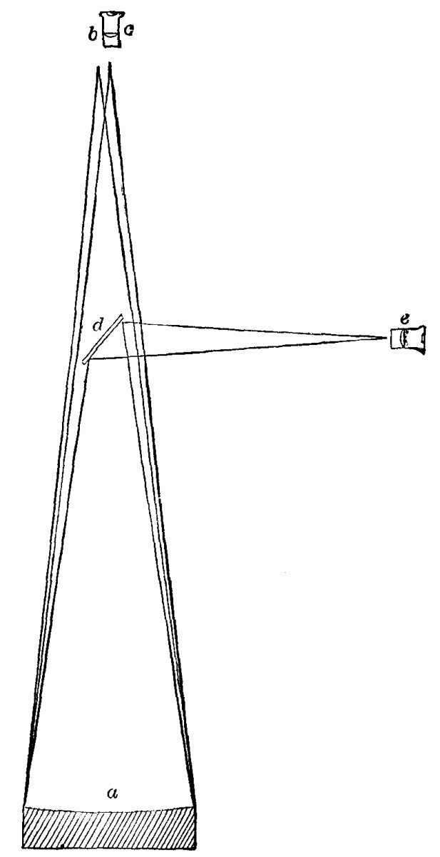
FIG. 3
A very excellent method was devised by the celebrated Rosse, which is frequently used at the present time; and those eminent workers, the Clarks of Cambridge, use a modification of the Rosse method which in their hands is productive of the very highest results. The device is very simple, consisting of a telescope (a, Fig. 1) in which aberrations have been well corrected, so that the focal plane of the objective is as sharp as possible. This telescope is first directed to a distant object, preferably a celestial one, and focused for parallel rays. The surface, b, to be tested is now placed so that the reflected image of the same object, whatever it may be, can be observed by the same telescope. It is evident that if the surface be a true plane, its action upon the beam of light that comes from the object will be simply to change its direction, but not disturb or change it any other way, hence the reflected image of the object should be seen by the telescope, a, without in any way changing the original focus. If, however, the supposed plane surface proves to be convex, the image will not be sharply defined in the telescope until the eyepiece is moved away from the object glass; while if the converse is the case, and the supposed plane is concave, the eyepiece must now be moved toward the objective in order to obtain a sharp image, and the amount of convexity or concavity may be known by the change in the focal plane. If the surface has periodic or irregular errors, no sharp image can be obtained, no matter how much the eyepiece may be moved in or out.
FIG. 4
This test may be made still more delicate by using the observing telescope, a, at as low an angle as possible, thereby bringing out with still greater effect any error that may exist in the surface under examination, and is the plan generally used by Alvan Clark & Sons. Another and very excellent method is that illustrated in Fig. 2, in which a second telescope, b, is introduced. In place of the eyepiece of this second telescope, a diaphragm is introduced in which a number of small holes are drilled, as in Fig. 2, x, or a slit is cut similar to the slit used in a spectroscope as shown at y, same figure. The telescope, a, is now focused very accurately on a celestial or other very distant object, and the focus marked. The object glass of the telescope, b, is now placed against and "square" with the object glass of telescope a, and on looking through telescope a an image of the diaphragm with its holes or the slit is seen. This diaphragm must now be moved until a sharp image is seen in telescope a. The two telescopes are now mounted as in Fig. 2, and the plate to be tested placed in front of the two telescopes as at c. It is evident, as in the former case, that if the surface is a true plane, the reflected image of the holes or slit thrown upon it by the telescope, b, will be seen sharply defined in the telescope, a.
FIG. 5.
If any error of convexity exists in the plate, the focal plane is disturbed, and the eyepiece must be moved out. If the plate is concave, it must be moved in to obtain a sharp image. Irregular errors in the plate or surface will produce a blurred or indistinct image, and, as in the first instance, no amount of focusing will help matters. These methods are both good, but are not satisfactory in the highest degree, and two or three important factors bar the way to the very best results. One is that the aberrations of the telescopes must be perfectly corrected, a very difficult matter of itself, and requiring the highest skill of the optician. Another, the fact that the human eye will accommodate itself to small distances when setting the focus of the observing telescope. I have frequently made experiments to find out how much this accommodation was in my own case, and found it to amount to as much as 1/40 of an inch. This is no doubt partly the fault of the telescopes themselves, but unless the eye is rigorously educated in this work, it is apt to accommodate itself to a small amount, and will invariably do so if there is a preconceived notion or bias in the direction of the accommodation.

FIG. 6.
Talking with Prof. C.A. Young a few months since on this subject, he remarked that he noticed that the eye grew more exact in its demands as it grew older, in regard to the focal point. A third and very serious objection to the second method is caused by diffraction from the edges of the holes or the slit. Let me explain this briefly. When light falls upon a slit, such as we have here, it is turned out of its course; as the slit has two edges, and the light that falls on either side is deflected both right and left, the rays that cross from the right side of the slit toward the left, and from the left side of the slit toward the right, produce interference of the wave lengths, and when perfect interference occurs, dark lines are seen. You can have a very pretty illustration of this by cutting a fine slit in a card and holding it several inches from the eye, when the dark lines caused by a total extinction of the light by interference may be seen.
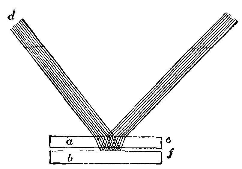
FIG. 7.
If now you look toward the edge of a gas or lamp flame; you will see a series of colored bands, that bring out the phenomenon of partial interference. This experiment shows the difficulty in obtaining a perfect focus of the holes or the slit in the diaphragm, as the interference fringes are always more or less annoying. Notwithstanding these defects of the two systems I have mentioned, in the hands of the practical workman they are productive of very good results, and very many excellent surfaces have been made by their use, and we are not justified in ignoring them, because they are the stepping stones to lead us on to better ones. In my early work Dr. Draper suggested a very excellent plan for testing a flat surface, which I briefly describe. It is a well known truth that, if an artificial star is placed in the exact center of curvature of a truly spherical mirror, and an eyepiece be used to examine the image close beside the source of light, the star will be sharply defined, and will bear very high magnification. If the eyepiece is now drawn toward the observer, the star disk begins to expand; and if the mirror be a truly spherical one, the expanded disk will be equally illuminated, except the outer edge, which usually shows two or more light and dark rings, due to diffraction, as already explained.

FIG. 8.
Now if we push the eyepiece toward the mirror the same distance on the opposite side of the true focal plane, precisely the same appearance will be noted in the expanded star disk. If we now place our plane surface any where in the path of the rays from the great mirror, we should have identically the same phenomena repeated. Of course it is presumed, and is necessary, that the plane mirror shall be much less in area than the spherical mirror, else the beam of light from the artificial star will be shut off, yet I may here say that any one part of a truly spherical mirror will act just as well as the whole surface, there being of course a loss of light according to the area of the mirror shut off.
This principle is illustrated in Fig. 3, where a is the spherical mirror, b the source of light, c the eyepiece as used when the plane is not interposed, d the plane introduced into the path at an angle of 45° to the central beam, and e the position of eyepiece when used the with the plane. When the plane is not in the way, the converging beam goes back to the eyepiece, c. When the plane, d, is introduced, the beam is turned at a right angle, and if it is a perfect surface, not only does the focal plane remain exactly of the same length, but the expanded star disks, are similar on either side of the focal plane.
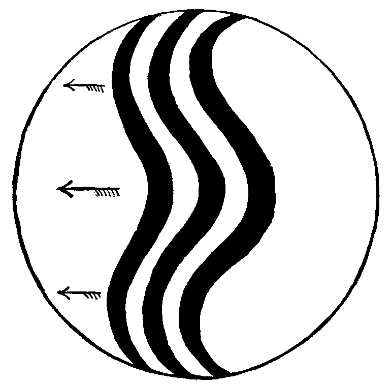
FIG. 9.
I might go on to elaborate this method, to show how it may be made still more exact, but as it will come under the discussion of spherical surfaces, I will leave it for the present. Unfortunately for this process, it demands a large truly spherical surface, which is just as difficult of attainment as any form of regular surface. We come now to an instrument that does not depend upon optical means for detecting errors of surface, namely, the spherometer, which as the name would indicate means sphere measure, but it is about as well adapted for plane as it is for spherical work, and Prof. Harkness has been, using one for some time past in determining the errors of the plane mirrors used in the transit of Venus photographic instruments. At the meeting of the American Association of Science in Philadelphia, there was quite a discussion as to the relative merits of the spherometer test and another form which I shall presently mention, Prof. Harkness claiming that he could, by the use of the spherometer, detect errors bordering closely on one five-hundred-thousandth of an inch. Some physicists express doubt on this, but Prof. Harkness has no doubt worked with very sensitive instruments, and over very small areas at one time.
I have not had occasion to use this instrument in my own work, as a more simple, delicate, and efficient method was at my command, but for one measurement of convex surfaces I know of nothing that can take its place. I will briefly describe the method of using it.
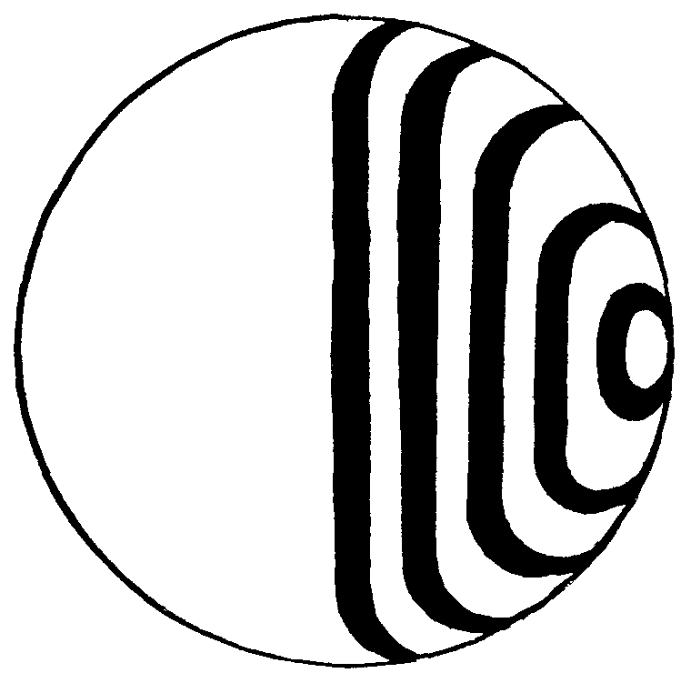
FIG. 10.
The usual form of the instrument is shown in Fig. 4; a is a steel screw working in the nut of the stout tripod frame, b; c c c are three legs with carefully prepared points; d is a divided standard to read the whole number of revolutions of the screw, a, the edge of which also serves the purpose of a pointer to read off the division on the top of the milled head, e. Still further refinement may be had by placing a vernier here. To measure a plane or curved surface with this instrument, a perfect plane or perfect spherical surface of known radius must be used to determine the zero point of the division. Taking for granted that we have this standard plate, the spherometer is placed upon it, and the readings of the divided head and indicator, d, noted when the point of the screw, a, just touches the surface, f. Herein, however, lies the great difficulty in using this instrument, i.e., to know the exact instant of contact of the point of screw, a, on the surface, f. Many devices have been added to the spherometer to make it as sensitive as possible, such as the contact level, the electric contact, and the compound lever contact. The latter is probably the best, and is made essentially as in Fig. 5.
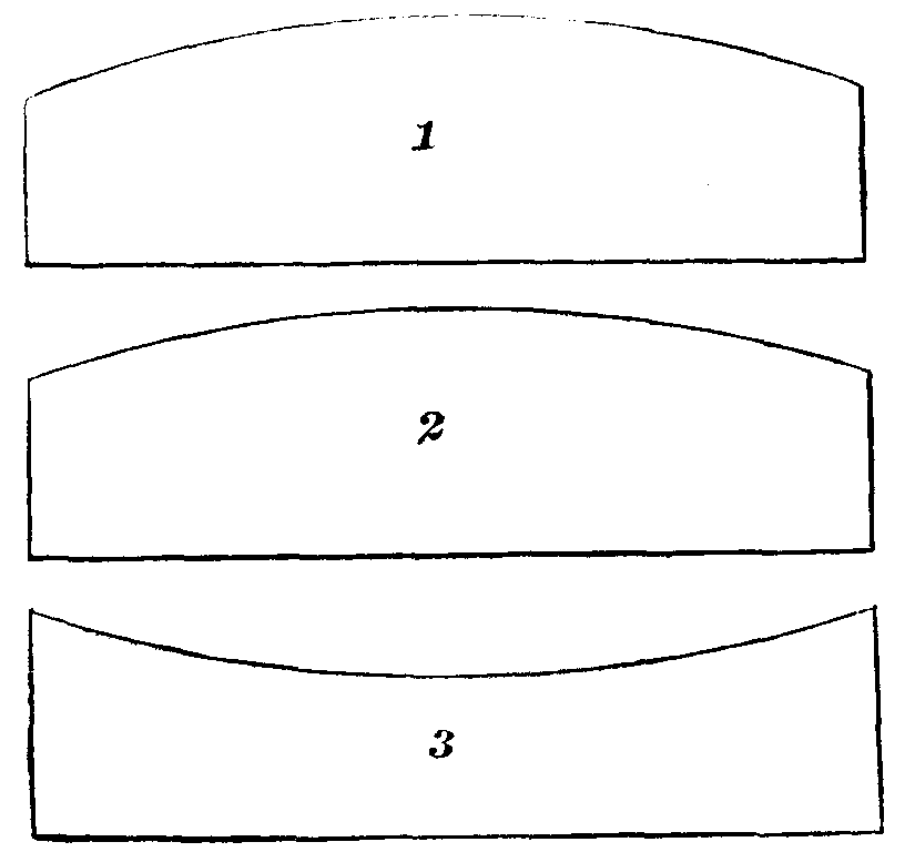
FIG. 11.
I am indebted for this plan to Dr. Alfred Mayer. As in the previous figure, a is the screw; this screw is bored out, and a central steel pin turned to fit resting on a shoulder at c. The end of d projects below the screw, a, and the end, e, projects above the milled head, and the knife edge or pivot point rests against the lever, f, which in turn rests against the long lever, g, the point, h, of which moves along the division at j. It is evident that if the point of the pin just touches the plate, no movement of the index lever, g, will be seen; but if any pressure be applied, the lever will move through a multiplied arc, owing to the short fulcri of the two levers. Notwithstanding all these precautions, we must also take into account the flexure of the material, the elasticity of the points of contact, and other idiosyncrasies, and you can readily see that practice alone in an instrument so delicate will bring about the very best results. Dr. Alfred Mayer's method of getting over the great difficulty of knowing when all four points are in contact is quite simple. The standard plate is set on the box, g, Fig. 4, which acts as a resonater. The screw, a, is brought down until it touches the plate. When the pressure of the screw is enough to lift off either or all of the legs, and the plate is gently tapped with the finger, a rattle is heard, which is the tell-tale of imperfect contact of all the points. The screw is now reversed gently and slowly until the moment the rattle ceases, and then the reading is taken. Here the sense of hearing is brought into play. This is also the case when the electric contact is used. This is so arranged that the instant of touching of the point of screw, a, completes the electric circuit, in which an electromagnet of short thick wire is placed. At the moment of contact, or perhaps a little before contact, the bell rings, and the turning of the screw must be instantly stopped. Here are several elements that must be remembered. First, it takes time to set the bell ringing, time for the sound to pass to the ear, time for the sensation to be carried to the brain, time for the brain to send word to the hand to cease turning the screw, and, if you please, it takes time for the hand to stop. You may say, of what use are such refinements? I may reply, what use is there in trying to do anything the very best it can be done? If our investigation of nature's profound mysteries can be partially solved with good instrumental means, what is the result if we have better ones placed in our hands, and what, we ask, if the best are given to the physicist? We have only to compare the telescope of Galileo, the prism of Newton, the pile of Volta, and what was done with them, to the marvelous work of the telescope, spectroscope, and dynamo of to-day. But I must proceed. It will be recognized that in working with the spherometer, only the points in actual contact can be measured at one time, for you may see by Fig. 6 that the four points, a a a a, may all be normal to a true plane, and yet errors of depression, as at e, or elevation, as at b, exist between them, so that the instrument must be used over every available part of the surface if it is to be tested rigorously. As to how exact this method is I cannot say from actual experience, as in my work I have had recourse to other methods that I shall describe. I have already quoted you the words of Prof. Harkness. Dr. Hastings, whose practical as well as theoretical knowledge is of the most critical character, tells me that he considers it quite easy to measure to 1/80000 of an inch with the ordinary form of instrument. Here is a very fine spherometer that Dr. Hastings works with from time to time, and which he calls his standard spherometer. It is delicately made, its screw being 50 to the inch, or more exactly 0.01998 inch, or within 2/100000 of being 1/50 of an inch pitch. The principal screw has a point which is itself an independent screw, that was put in to investigate the errors of the main screw, but it was found that the error of this screw was not as much as the 0.00001 of an inch. The head is divided into two hundred parts, and by estimation can be read to 1/100000 of an inch. Its constants are known, and it may be understood that it would not do to handle it very roughly. I could dwell here longer on this fascinating subject, but must haste. I may add that if this spherometer is placed on a plate of glass and exact contact obtained, and then removed, and the hand held over the plate without touching it, the difference in the temperature of the glass and that of the hand would be sufficient to distort the surface enough to be readily recognized by the spherometer when replaced. Any one desiring to investigate this subject further will find it fully discussed in that splendid series of papers by Dr. Alfred Mayer on the minute measurements of modern science published in SCIENTIFIC AMERICAN SUPPLEMENTS, to which I was indebted years ago for most valuable information, as well as to most encouraging words from Prof. Thurston, whom you all so well and favorably know. I now invite your attention to the method for testing the flat surfaces on which Prof. Rowland rules the beautiful diffraction gratings now so well known over the scientific world, as also other plane surfaces for heliostats, etc., etc. I am now approaching the border land of what may be called the abstruse in science, in which I humbly acknowledge it would take a vast volume to contain all I don't know; yet I hope to make plain to you this most beautiful and accurate method, and for fear I may forget to give due credit, I will say that I am indebted to Dr. Hastings for it, with whom it was an original discovery, though he told me he afterward found it had been in use by Steinheil, the celebrated optician of Munich. The principle was discovered by the immortal Newton, and it shows how much can be made of the ordinary phenomena seen in our every-day life when placed in the hands of the investigator. We have all seen the beautiful play of colors on the soap bubble, or when the drop of oil spreads over the surface of the water. Place a lens of long curvature on a piece of plane polished glass, and, looking at it obliquely, a black central spot is seen with rings of various width and color surrounding it. If the lens is a true curve, and the glass beneath it a true plane, these rings of color will be perfectly concentric and arranged in regular decreasing intervals. This apparatus is known as Newton's color glass, because he not only measured the phenomena, but established the laws of the appearances presented. I will now endeavor to explain the general principle by which this phenomenon is utilized in the testing of plane surfaces. Suppose that we place on the lower plate, lenses of constantly increasing curvature until that curvature becomes nil, or in other words a true plane. The rings of color will constantly increase in width as the curvature of the lens increases, until at last one color alone is seen over the whole surface, provided, however, the same angle of observation be maintained, and provided further that the film of air between the glasses is of absolutely the same relative thickness throughout. I say the film of air, for I presume that it would be utterly impossible to exclude particles of dust so that absolute contact could take place. Early physicists maintained that absolute molecular contact was impossible, and that the central separation of the glasses in Newton's experiment was 1/250,000 of an inch, but Sir Wm. Thomson has shown that the separation is caused by shreds or particles of dust. However, if this separation is equal throughout, we have the phenomena as described; but if the dust particles are thicker under one side than the other, our phenomena will change to broad parallel bands as in Fig. 8, the broader the bands the nearer the absolute parallelism of the plates. In Fig. 7 let a and b represent the two plates we are testing. Rays of white light, c, falling upon the upper surface of plate a, are partially reflected off in the direction of rays d, but as these rays do not concern us now, I have not sketched them. Part of the light passes on through the upper plate, where it is bent out of its course somewhat, and, falling upon the lower surface of the upper plate, some of this light is again reflected toward the eye at d. As some of the light passes through the upper plate, and, passing through the film of air between the plates, falling on the upper surface of the lower one, this in turn is reflected; but as the light that falls on this surface has had to traverse the film of air twice, it is retarded by a certain number of half or whole wave-lengths, and the beautiful phenomena of interference take place, some of the colors of white light being obliterated, while others come to the eye. When the position of the eye changes, the color is seen to change. I have not time to dwell further on this part of my subject, which is discussed in most advanced works on physics, and especially well described in Dr. Eugene Lommel's work on "The Nature of Light." I remarked that if the two surfaces were perfectly plane, there would be one color seen, or else colors of the first or second order would arrange themselves in broad parallel bands, but this would also take place in plates of slight curvature, for the requirement is, as I said, a film of air of equal thickness throughout. You can see at once that this condition could be obtained in a perfect convex surface fitting a perfect concave of the same radius. Fortunately we have a check to guard against this error. To produce a perfect plane, three surfaces must be worked together, unless we have a true plane to commence with; but to make this true plane by this method we must work three together, and if each one comes up to the demands of this most rigorous test, we may rest assured that we have attained a degree of accuracy almost beyond human conception. Let me illustrate. Suppose we have plates 1, 2, and 3, Fig. 11. Suppose 1 and 2 to be accurately convex and 3 accurately concave, of the same radius. Now it is evident that 3 will exactly fit 1 and 2, and that 1 and 2 will separately fit No. 3, but when 1 and 2 are placed together, they will only touch in the center, and there is no possible way to make three plates coincide when they are alternately tested upon one another than to make perfect planes out of them. As it is difficult to see the colors well on metal surfaces, a one-colored light is used, such as the sodium flame, which gives to the eye in our test, dark and bright bands instead of colored ones. When these plates are worked and tested upon one another until they all present the same appearance, one may be reserved for a test plate for future use. Here is a small test plate made by the celebrated Steinheil, and here two made by myself, and I may be pardoned in saying that I was much gratified to find the coincidence so nearly perfect that the limiting error is much less than 0.00001 of an inch. My assistant, with but a few months' experience, has made quite as accurate plates. It is necessary of course to have a glass plate to test the metal plates, as the upper plate must be transparent. So far we have been dealing with perfect surfaces. Let us now see what shall occur in surfaces that are not plane. Suppose we now have our perfect test plate, and it is laid on a plate that has a compound error, say depressed at center and edge and high between these points. If this error is regular, the central bands arrange themselves as in Fig. 9. You may now ask, how are we to know what sort of surface we have? A ready solution is at hand. The bands always travel in the direction of the thickest film of air, hence on lowering the eye, if the convex edge of the bands travel in the direction of the arrow, we are absolutely certain that that part of the surface being tested is convex, while if, as in the central part of the bands, the concave edges advance, we know that part is hollow or too low. Furthermore, any small error will be rigorously detected, with astonishing clearness, and one of the grandest qualities of this test is the absence of "personal equation;" for, given a perfect test plate, it won't lie, neither will it exaggerate. I say, won't lie, but I must guard this by saying that the plates must coincide absolutely in temperature, and the touch of the finger, the heat of the hand, or any disturbance whatever will vitiate the results of this lovely process; but more of that at a future time. If our surface is plane to within a short distance of the edge, and is there overcorrected, or convex, the test shows it, as in Fig. 10. If the whole surface is regularly convex, then concentric rings of a breadth determined by the approach to a perfect plane are seen. If concave, a similar phenomenon is exhibited, except in the case of the convex, the broader rings are near the center, while in the concave they are nearer the edge. In lowering the eye while observing the plates, the rings of the convex plate will advance outward, those of the concave inward. It may be asked by the mechanician, Can this method be used for testing our surface plates? I answer that I have found the scraped surface of iron bright enough to test by sodium light. My assistant in the machine work scraped three 8 inch plates that were tested by this method and found to be very excellent, though it must be evident that a single cut of the scraper would change the spot over which it passed so much as to entirely change the appearance there, but I found I could use the test to get the general outline of the surface under process of correction. These iron plates, I would say, are simply used for preliminary formation of polishers. I may have something to say on the question of surface plates in the future, as I have made some interesting studies on the subject. I must now bring this paper to a close, although I had intended including some interesting studies of curved surfaces. There is, however, matter enough in that subject of itself, especially when we connect it with the idiosyncrasies of the material we have to deal with, a vital part of the subject that I have not touched upon in the present paper. You may now inquire, How critical is this "color test"? To answer this I fear I shall trench upon forbidden grounds, but I call to my help the words of one of our best American physicists, and I quote from a letter in which he says by combined calculation and experiment I have found the limiting error for white light to be 1/50000000 of an inch, and for Na or sodium light about fifty times greater, or less than 1/800000 of an inch. Dr. Alfred Mayer estimated and demonstrated by actual experiment that the smallest black spot on a white ground visible to the naked eye is about 1/800 of an inch at the distance of normal vision, namely, 10 inches, and that a line, which of course has the element of extension, 1/5000 of an inch in thickness could be seen. In our delicate "color test" we may decrease the diameter of our black spot a thousand times and still its perception is possible by the aid of our monochromatic light, and we may diminish our line ten thousand times, yet find it just perceivable on the border land of our test by white light. Do not presume I am so foolish as to even think that the human hand, directed by the human brain, can ever work the material at his command to such a high standard of exactness. No; from the very nature of the material we have to work with, we are forbidden even to hope for such an achievement; and could it be possible that, through some stroke of good fortune, we could attain this high ideal, it would be but for a moment, as from the very nature of our environment it would be but an ignis fatuus. There is, however, to the earnest mind a delight in having a high model of excellence, for as our model is so will our work approximate; and although we may go on approximating our ideal forever, we can never hope to reach that which has been set for us by the great Master Workman.
[3]In carrying out a series of photometrical experiments lately, I found that it was a matter of considerable difficulty to keep the flames of the standard candles always at their proper distance from the light to be measured, because the wick was continually changing its position (of course carrying the flame with it), and thus practically lengthening or shortening the scale of the photometer, according as the flame was carried nearer to or farther from the light at the other end of the scale. In order, therefore, to obtain a correct idea of the extent to which this variation of the position of the wick might influence the readings of the photometer scale, I took a continuous number of photographs of the flame of a candle while it was burning in a room quite free from draught; no other person being in it during the experiment except a photographer, who placed sensitive dry plates in a firmly fixed camera, and changed them after an exposure of 30 seconds. In doing this he was careful to keep close to the camera, and disturb the air of the room as little as possible. In front of the candle a plumb-line was suspended, and remained immovable over its center during the whole operation. The candle was allowed to get itself into a normal state of burning, and then the wick was aligned, as shown in the photographs Nos. 1 and 2, after which it was left to itself.
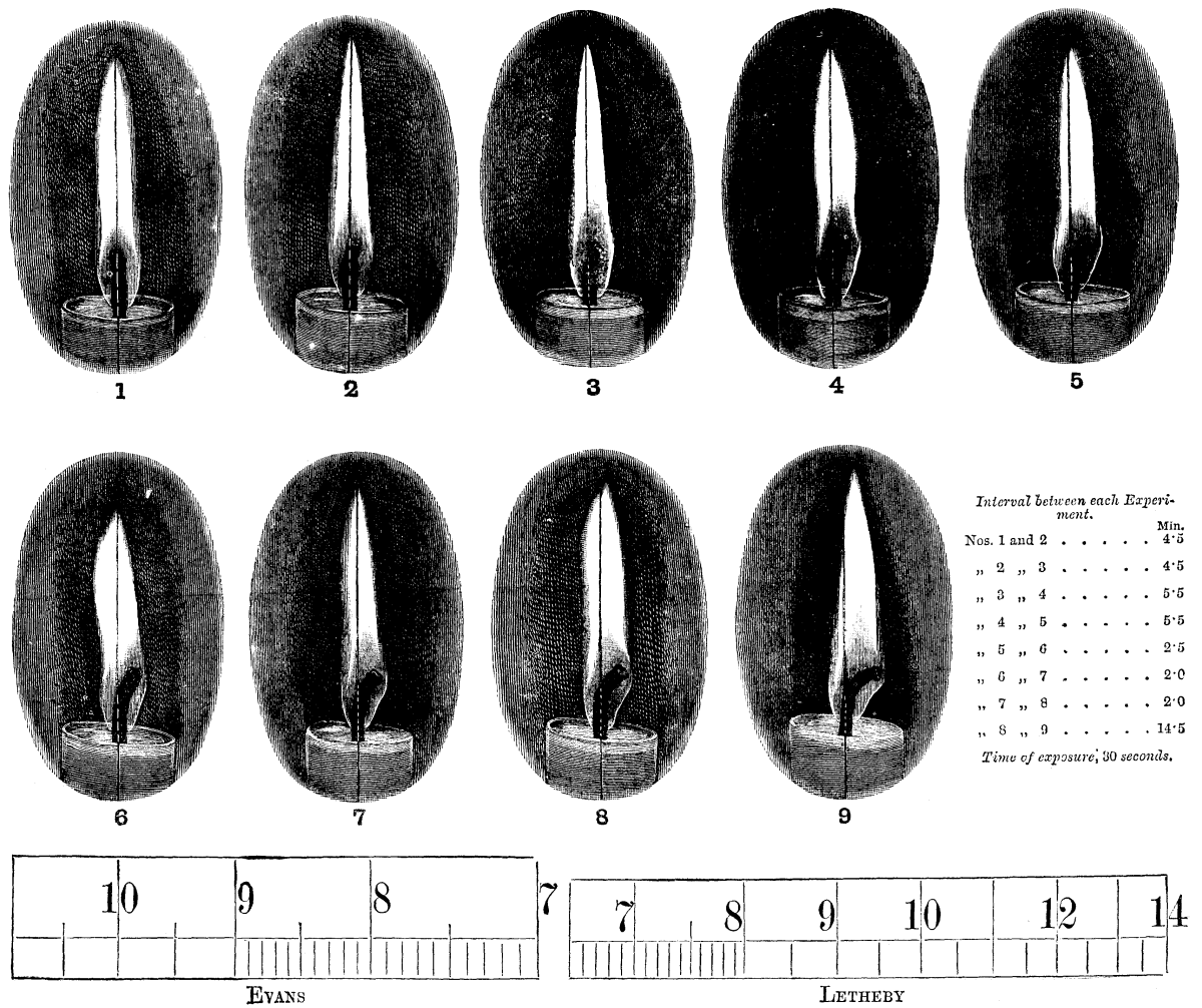
VARIATION IN PHOTOMETRICAL STANDARDS.
With these photographs (represented in the cuts) I beg to hand you full-sized drawings of the scales of a 100 inch Evans and a 60 inch Letheby photometer, in order to give your readers an opportunity of estimating for themselves the effect which such variations from the true distance between the standard light and that to be measured, as shown in this series of photographs, must exercise on photometrical observations made by the aid of either of the instruments named.
W. SUGG.
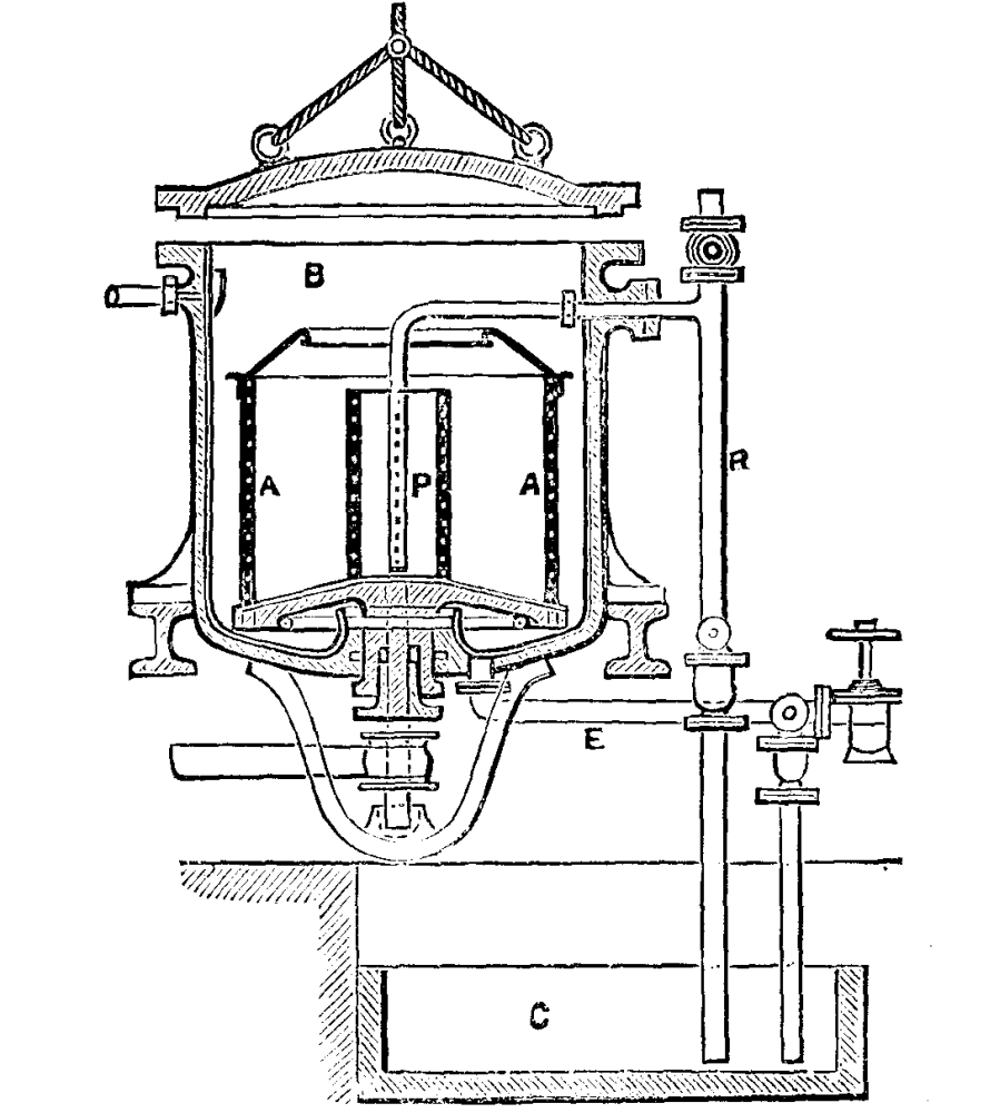
Many attempts have been made to facilitate the penetration of textile fabrics by the dyeing and bleaching solutions, with which they require to be treated, by carrying out the treatment in vacuo, i.e., in such apparatus as shall allow of the air being withdrawn. The apparatus shown in the annexed engraving—Austrian Pat. Jan. 15, 1884—although not essentially different from those already in use, embodies, the Journal of the Society of Chemical Industry says, some important improvements in detail. It consists of a drum A, the sides of which are constructed of stout netting, carried on a vertical axis working through a stuffing-box, which is fitted in the bottom of the outer or containing vessel or keir B. The air can be exhausted from B by means of an air pump. A contains a central division P, also constructed of netting, into which is inserted the extremity of the tube R, after being twice bent at a right angle. P is also in direct connection with the efflux tube E, E and R serving to convey the dye or bleach solutions to and from the reservoir C. The combination of the rotary motion communicated to A, which contains the goods to be dyed or bleached, with the very thorough penetration and circulation of the liquids effected by means of the vacuum established in B, is found to be eminently favorable to the rapidity and evenness of the dye or bleach.
The operation of moulding presents numerous advantages over other methods of shaping porcelain, for by this process we avoid irregularities of form, twisting, and visible seams, and can manufacture thin pieces, as well as pieces of large dimensions, of a purity of form that it is impossible to obtain otherwise.
The method of moulding small objects has been described with sufficient detail in technical works, but such is not the case with regard to large ones, and for this reason it will be of interest to quote some practical observations from a note that has been sent me by Mr. Constantine Renard, who, for several years, has had the superintendence of the moulding rooms of the Sevres works.
The process of moulding consists in pouring porcelain paste, thinned with water, into very dry plaster moulds. This mixture gradually hardens against the porous sides with which it is in contact, and, when the thickness of the hardened layer is judged sufficient, the mould is emptied by inverting it. The excess of the liquid paste is thus eliminated, while the thicker parts remain adherent to the plaster. Shortly afterward, the absorption of the water continuing, the paste so shrinks in drying as to allow the object to detach itself from the mould. As may be seen, nothing is simpler when it concerns pieces of small dimensions; but the same is not the case when we have to mould a large one. In this case we cannot get rid of the liquid paste by turning the mould upside down, because of the latter's size, and, on another hand, it is necessary to take special precautions against the subsidence of the paste. Recourse is therefore had to another method. In the first place, an aperture is formed in the lower part of the mould through which the liquid may flow at the desired moment. Afterward, in order to prevent the solidified but still slightly soft paste from settling under its own weight at this moment, it is supported by directing a current of compressed air into the mould, or, through atmospheric pressure, by forming a vacuum in the metallic jacket in which the mould is inclosed.
The history and description of these processes have been several times given, and I shall therefore not dwell upon them, but shall at once proceed to make known the new points that Mr. Renard has communicated to me.
The first point to which it is well to direct the manufacturer's attention is the preparation of the plaster moulds. When it concerns an object of large dimensions, of a vase a yard in height, for example, the moulder is obliged to cut the form or core horizontally into three parts, each of which is moulded separately. To this effect, it is placed upon a core frame and surrounded with a cylinder of sheet zinc. The workman pours the plaster into the space between the latter and the core, and, while doing so, must stir the mass very rapidly with a stick, so that at the moment the plaster sets, it shall be as homogeneous as possible. In spite of such precautions, it is impossible to prevent the densest parts of the plaster from depositing first, through the action of gravity. These will naturally precipitate upon the table or upon the slanting sides of the core, and the mould will therefore present great inequalities as regards porosity. Since this defect exists in each of the pieces that have been prepared in succession, it will be seen that when they come to be superposed for the moulding of the piece, the mould as a whole will be formed of zones of different porosities, which will absorb water from the paste unequally. Farther along we shall see the inconveniences that result from this, and the manner of avoiding them.
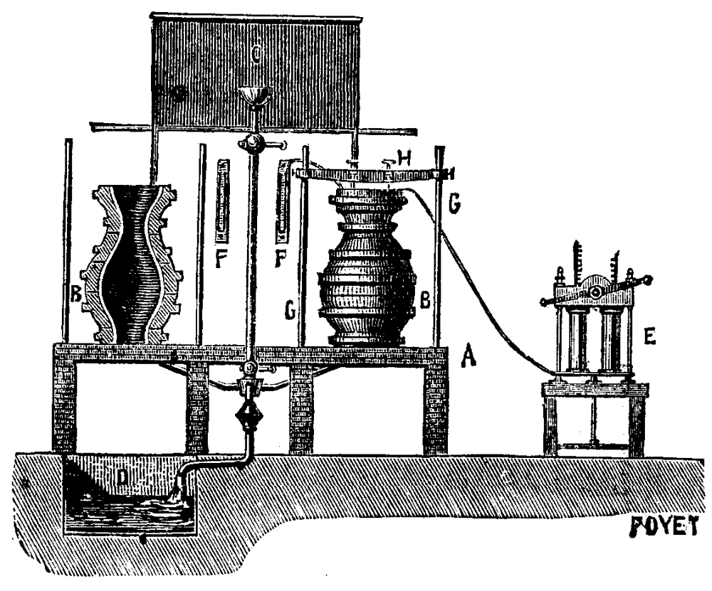
FIG. 1
The mould, when finished, is dried in a stove. Under such circumstances it often happens that there forms upon the surface of the plaster a hard crust which, although it is of no importance as regards the outside of the mould, is prejudicial to the interior because it considerably diminishes its absorbing power. This trouble may be avoided by coating the surfaces that it is necessary to preserve with clear liquid paste; but Mr. Renard advises that the mould be closed hermetically, so that the interior shall be kept from contact with warm air. In this way it is possible to prevent the plaster from hardening, as a result of too quick a desiccation. I now come to the operation of moulding. In the very first place, it is necessary to examine whether it is well to adopt the arrangement by pressure of air or by vacuum. The form of the objects will determine the choice. A very open piece, like a bowl, must be moulded by vacuum, on account of the difficulty of holding the closing disk in place if it be of very large dimensions. The same is the case with large vases of wood form. On the contrary, an elongated piece tapering from above is more easily moulded by pressure of the air, as are also ovoid vessels 16 to 20 inches in height. In any case it must not be forgotten that the operation by vacuum should be preferred every time the form of the objects is adapted to it, because this process permits of following and directing the drying, while with pressure it is impossible to see anything when once the apparatus is closed.
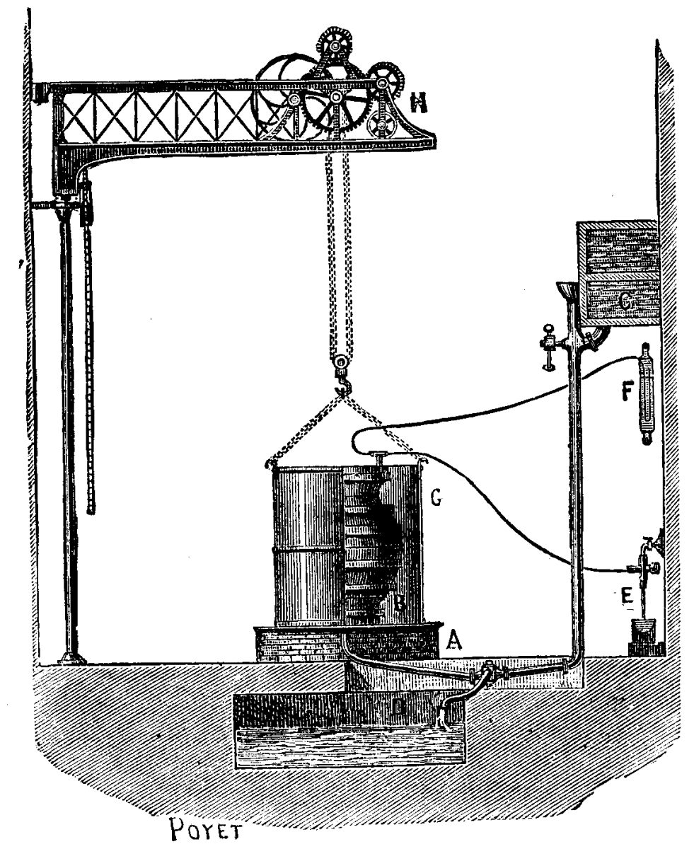
FIG. 2.
Moulding by Pressure of the Air.—The plaster mould having been put in place upon the mould board, and the liquid paste having been long and thoroughly stirred in order to make it homogeneous, and get rid of the air bubbles, we open the cock that puts the paste reservoir in communication with the lower part of the mould, care having been taken beforehand to pour a few pints of water into the bottom of the mould. The paste in ascending pushes this water ahead of it, and this slightly wets the plaster and makes the paste rise regularly. When the mould is entirely filled, the paste is still allowed to flow until it slightly exceeds the upper level, and, spreading out over the entire thickness of the plaster, forms a sort of thick flange. The absorption of the liquid begins almost immediately, and, consequently, the level lowers. A new quantity of paste is introduced, and we continue thus, in regulating its flow so as to keep the mould always full. This operation is prolonged until the layer is judged to be sufficiently thick, this depending upon the dimensions, form, or construction of the vessel. The operation may take from one to five hours.
The desired thickness having been obtained, it becomes a question of allowing the paste to descend and at the same time to support the piece by air pressure. The flange spoken of above is quickly cut, and the paste is made to rise again for the last time, in order to form a new flange, but one that this time will be extremely thin; then a perforated disk designed for forming the top joint, and acting as a conduit for the air, is placed upon the mould. This disk is fastened down with a screw press, and when the apparatus is thus arranged the eduction cock is opened, and the air pump maneuvered.
If the flange did not exist, the air would enter between the mould and the piece at the first strokes of the piston, and the piece would be inevitably broken. Its object, then, is to form a hermetical joint, although it must at the same time present but a slight resistance, since, as soon as the liquid paste has flowed out, the piece begins to shrink, and it is necessary that at the first movement downward it shall be able to disengage itself, since it would otherwise crack.
As soon as the piece begins to detach itself from the mould the air enters the apparatus, and the pressure gauge connected with the air pump begins to lower. It is then necessary, without a moment's loss of time, to remove the screw press, the disk, and the upper part of the mould itself, in order to facilitate as much as possible the contraction of the piece. Finally, an hour or an hour and a half later, it is necessary to remove the lower part of the mould, this being done in supporting the entire affair by the middle. The piece and what remains of the mould are, in reality, suspended in the air. All these preparations are designed to prevent cracking.
Moulding by Vacuum.—The operation by vacuum follows the same phases as those just described. It is well, in order to have a very even surface, not to form a vacuum until about three hours after the paste has been made to ascend. Without such a precaution the imperfections in the mould will be shown on the surface of the object by undulations that are irremediable.
The first flange or vein must be preserved, and it is cut off at the moment the piece is detached.
Moulding by vacuum, aside from the advantages noted above, permits of giving the pieces a greater thickness than is obtained in the pressure process. According to Mr. Renard, when it is desired to exceed one inch at the base of the piece (the maximum thickness usually obtained), the operation is as follows: The piece is moulded normally, and it is supported by a vacuum; but, at the moment at which, under ordinary circumstances, it would be detached, the paste is made to ascend a second time, when the first layer (already thick and dry) acts as a sort of supplementary mould, and permits of increasing the thickness by about ⅖ of an inch. The piece is held, as at first, by vacuum, and the paste is introduced again until the desired thickness is obtained.
Whatever be the care taken, accidents are frequent in both processes. They are due, in general, to the irregular contraction of the pieces, caused by a want of homogeneousness in the plaster of the moulds. In fact, as the absorption of the water does not proceed regularly over the entire surface of the piece, zones of dry paste are found in contact with others that are still soft, and hence the formation of folds, and finally the cracking and breaking of the piece. The joints of the moulds are also a cause of frequent loss, on account of the marks that they leave, and that injure the beauty of the form as well as the purity of the profile.
Mr. Renard has devised a remedy for all such inconveniences. He takes unglazed muslin, cuts it into strips, and, before beginning operations, fixes it with a little liquid paste to the interior of the mould. This light fabric in no wise prevents the absorption of the water, and so the operation goes on as usual; but, at the moment of contraction, the piece of porcelain being, so to speak, supported by the muslin, comes put of the mould more easily and with extreme regularity. Under such circumstances all trace of the joint disappears, the imperfections in the mould are unattended with danger, and the largest pieces are moulded with entire safety. In a word, we have here a very important improvement in the process of moulding. The use of muslin is to be recommended, not only in the manufacture of vases, but also in the difficult preparation of large porcelain plates. It is likewise advantageous in the moulding of certain pieces of sculpture that are not very delicate, and, finally, it is very useful when we have to do with a damaged mould, which, instead of being repaired with plaster, can be fixed with well ground wet sand covered with a strip of muslin.
Drying of the Moulded Pieces.—When the moulded pieces become of a proper consistency in the mould, they are exposed to the air and then taken to the drying room. But, as with plaster, the surface of the paste dries very quickly, and this inconvenience (which amounts to nothing in pieces that are to be polished) is very great in pieces that carry ornaments in relief, since the finishing of these is much more difficult, the hardened paste works badly, and frequently flakes off. In order to remedy this inconvenience, it suffices to dust the places to be preserved with powdered dry paste.—Revue Industrielle.
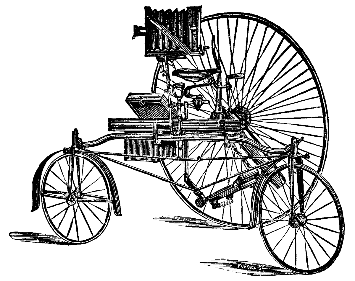
A PHOTO-TRICYCLE APPARATUS.
This consists of a portable folding camera, with screw focusing arrangement, swing back, and an adapter frame placed in the position of the focus screen, allowing the dark slide to be inserted so as to give the horizontal or vertical position to the dry plate when in the camera. To the front and base-board a brass swiveled side bar, made collapsible by means of a center slot, is attached by hinges, and this renders the camera rigid when open or secure when closed. The base-board is supported on a brass plate within which is inserted a ball-and-socket (or universal joint in a new form), permitting the camera to be tilted to any necessary angle, and fixed in such position at will. The whole apparatus is mounted upon a brass telescopic draw-stand, which, by means of clamps, is attached to the steering handle or other convenient part of the tricycle, preferably the form made by Messrs. Rudge & Co., of Coventry, represented in the cut.—Photo. News.
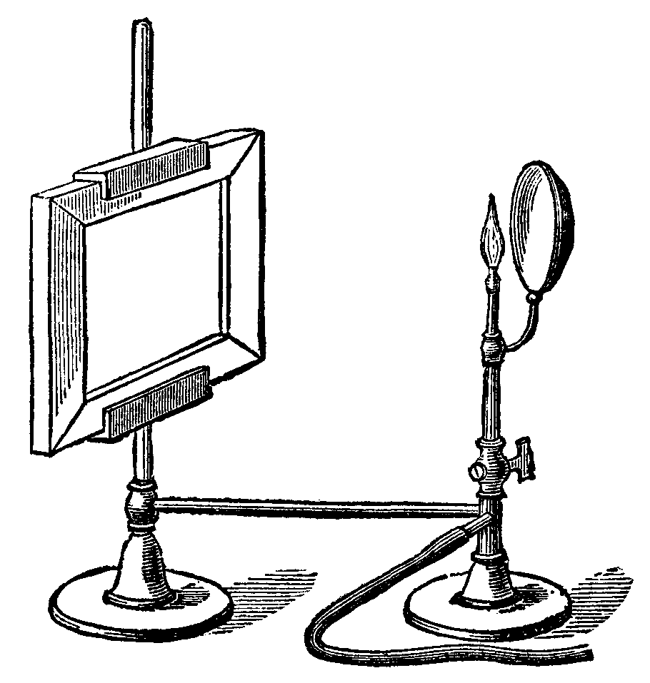
A printing frame is placed in the carrier, and exposed to the light of a gas burner kept at a fixed distance, behind which is a spherical reflector. The same frame may be used for other purposes.-Photographic News.
A selenium actinometer has been described in the Comptes Rendus in a communication from M. Morize, of Rio de Janeiro. The instrument is used to measure the actinic power of sunlight when the sun is at various altitudes; but the same principle is applicable to other light sources. The sensitive part of the apparatus consists of a cylinder formed of 38 disks of copper, isolated from each other by as many disks of mica. The latter being of smaller diameter than the copper disks, the annular spaces between the two are filled with selenium, by the simple process of rubbing a stick of this substance over the edges, and afterward gently warming. The selenium then presents a grayish appearance, and is ready for use. Connection is made by conductors, on opposite sides, with the odd and even numbers of the disks, which diminishes the resistance of the selenium. The cylinder thus formed is insulated by glass supports in the inside of a vacuum tube, for the purpose of preserving it from the disturbing influence of dark rays. The whole is placed upon a stand, and shielded from reflected light, but fully exposed to that which is to be measured for actinic intensity. If now a constant current of electricity is passed through the apparatus, as indicated by a galvanometer, the variations of the latter will show the effect produced upon the selenium. A scale must be prepared, with the zero point at the greatest possible resistance of the selenium, which corresponds with absolute darkness. The greatest effect of the light would be to annul the resistance of the selenium. Consequently, the cylinder must be withdrawn from the circuit to represent this effect; and the maximum deviation of the galvanometer is then to be observed, and marked 100. By dividing the range of the galvanometer thus obtained into 100 equal parts, the requisite actinometric scale will be established. In practice, the Clamond battery is used to supply the constant current required.
During the last few years, or rather decades of years, it has become rather a trite saying that to advance far in any branch of physical research a fair proficiency in no inconsiderable number of the sister sciences is an absolute necessity. But if this is true in general, none, I think, will question the assertion that a proficient in any of the physical sciences must be fairly conversant with photography as a science, or at least as an art. If we take for example a science which has of late years made rapid strides both in Europe and America, the science of astronomy, we shall not have far to go to find convincing proof that a great portion of the best work that is being done by its votaries is effected by the aid of photography. One eminent astronomer has quite lately gone so far as to declare that we no longer require observers of the heavens, but that their place can be better supplied by the gelatine plate of the photographer; and his words have been echoed by others not less able than himself. "Abolish the observer, and substitute the sensitive plate," is a sensational form of expressing the revolution in observational astronomy that is taking place under our eyes; but, although it suggests a vast amount of truth, it might leave upon the mind an exaggerated impression inimical to the best interests of science.
The award of the highest distinction in astronomy, the gold medal of the Royal Astronomical Society, two years in succession, to those who have been most successful in celestial photography is no doubtful sign of the great value attached to such work. Last year it was Mr. Common who received the highest testimony of the merit due to his splendid photographs of the nebula of Orion; and this year Dr. Huggins, who has drawn much attention to celestial photography, by his successful attempts to picture the solar corona in full daylight, has received a similar acknowledgment of his labors in photographing the spectra of stars and comets and nebulæ.
An adequate idea of the progress astronomy is now making by aid of photography can only be formed by a comprehensive view of all that is being at present attempted; but a rapid glance at some of the work may prepare the way for a more thorough investigation. A few years since, the astronomers who had advanced their science by aid of photography were few in number, and their results are soon enumerated. Some good pictures of the solar corona taken during solar eclipses, a series or two of sun-spot photographs, and a very limited number of successful attempts made upon the moon, and planets, and star clusters, were all the fruits of their labors. But now each month we learn of some new and efficient laborer in this field, which gives promise of so rich a harvest.
Each day the sun is photographed at Greenwich, at South Kensington, in India, and at the Physical Observatory of Potsdam, and thus a sure record is obtained of all the spots upon its surface, which may serve for the study of the periodicity of its changes, and for their probable connection with the important phenomena of terrestrial magnetism and meteorology. In France the splendid sun-pictures obtained by Dr. Janssen at the Physical Observatory of Meudon have thrown into the shade all other attempts at a photographic study of the most delicate features of the solar surface.
Dr. Huggins has shown that it is possible to obtain a daily photographic record of the solar prominences, and only lately he has secured results that justified a special expedition to the Alps to photograph the sun's corona, and he has now moved the Admiralty to grant a subsidy to Dr. Gill, the government astronomer at the Cape, by aid of which Mr. Woods can carry on the experiments that were so encouraging last summer in Switzerland.
We may, then, reasonably hope to obtain before long a daily picture of the sun and a photographic record of its prominences, and even of a certain portion of the solar corona; but the precious moments of each solar eclipse will always be invaluable for picturing those wondrous details in the corona that are now shown us by photography, and which can be obtained by photography alone.
Again, how very much is to be learnt in solar physics from the marvelous photographs of the sun's spectrum exhibited last summer by Professor Rowland; photographs that show as many as one hundred and fifty lines between H and K, and which he is still laboring to improve! The extension, too, of the visible solar spectrum into the ultra-violet by Corun, Mascart, and others, adds much to our knowledge of the sun; while the photographs of Abney in the ultrared increase our information in a direction less expected and certainly less easy of attainment. Both these extensions we find most ably utilized in the recent discussion of the very interesting photographs of the spectra of the prominences and of the corona taken during the total eclipse of May 18, 1882; and the photographic results of this eclipse afford ample proof that we can not only obtain pictures of the corona by photography that it would be impossible otherwise to procure, but also that in a few seconds information concerning the nature of the solar atmosphere may be furnished by photography that it would otherwise take centuries to accumulate, even under the most favorable circumstances.
The advantages to be gained by accurate photographs of the moon and planets, that will permit great enlargements, are too obvious to call for lengthened notice in such a rapid sketch as the present; for it is principally in the observation of details that the eye cannot grasp with the required delicacy, or with sufficient rapidity, that photography is so essential for rapid and sure progress.
Like the sketches of a solar eclipse, the drawings that are made of comets, and still more of nebulæ, even by the most accomplished artists, are all, to say the least, open to doubt in their delicate details. And the truth of this is so obvious, that it is the expressed opinion of an able astronomer that a single photograph of the nebula of Orion, taken by Mr. Common, would be of more value to posterity than the collective drawings of this interesting object so carefully made by Rosse, Bond, Secchi, and so many others.
Another most important branch of astronomy, that is receiving very great attention at present, is the mapping of the starry heavens; and herein photography will perhaps do its best work for the astronomer. The trial star map by the brothers Henry, of a portion of the Milky Way, which they felt unable to observe satisfactorily by the ordinary methods, is so near absolute perfection that it alone proves the immense superiority of the photographic method in the formation of star maps. Fortunately this subject, which is as vast as it is fundamental, is being taken up vigorously. The Henries are producing a special lens for the work; Mr. Grubb is constructing a special Cassgrain reflector for Mr. Roberts of Maghull; and the Admiralty have instructed Mr. Woods to make this part of his work at the Cape Observatory, under the able direction of Dr. Gill. Besides star maps, clusters, too, and special portions of the heavens are being photographed by the Rev. T.E. Espin, of West Kirby; and such pictures will be of the greatest value, not only in fixing the position at a given date, but also aiding in the determination of magnitude, color, variability, proper motion, and even of the orbits of double and multiple stars, and the possible discovery of new planets and telescopic comets.
Such are some of the many branches of astronomy that are receiving the most valuable aid at present from photography; but the very value of the gift that is bestowed should make exaggeration an impossibility. Photography can well afford to be generous, but it must first be just, in its estimate of the work that has still to be done in astronomy independently of its aid; and although the older science points with just pride to what is being done for her by her younger sister, still she must not forget that now, as in the future, she must depend largely for her progress, not only on the skill of the photographer and the mathematician, but also on the trained eye and ear and hand of her own indefatigable observers.—S.J. Perry, S.J., F.R.S., in Br. Jour. of Photography.
The mineral sediment that generally sticks to the sides of steam boilers, and the presence of which is fraught with the utmost danger, resulting in many instances in great injury to life and property, besides eating away the substance of the iron plate, was referred to in a paper lately read by M. Jeannolle before the Paris Academy of Sciences, in which the author described a new method for keeping boilers clean. This method is as follows:
The inside of a steam boiler is placed, by means of piles of a certain power, in reciprocal communication, the current passing at one end through positive, and at the other through negative, wires. In incrusted steam boilers, at a temperature ranging from 212° to 300° Fahr., and a pressure of from 30 to 90 lb. to the square inch, the current thus engendered decomposes the accumulated salts, and precipitates them, from which they may easily be removed, either by means of a special siphon or by means of some other mechanical process. When boilers are free from fur, and where it is intended to keep them free from such, a continuous current may be set up, by means of which the sedimentary salts may be decomposed, and a precipitate produced in a pulverized form, which can be removed with equal facility.
From a series of minute experiments made by M. Jeannolle, it appears that in order to render the various actions of electricity, perfect, it is necessary to coat either with red lead or with pulverized iron, or with any other conductor of electricity, an operation which must be repeated whenever the boiler is emptied with a view to cleaning out. The above system Is being advantageously applied in Calais for removing the incrustations of boilers. The two poles of a battery of ten to twelve Bunsen elements are applied to the ends of the boilers, and after thirty to forty hours the deposits fall from the sides to the bottom. When a boiler has been thus cleared, the formation of new deposits may be prevented by applying a much less energetic current under the same conditions.

SUGGESTIONS IN DECORATIVE ART.—ALPHABET DESIGNED BY GODFREY SYKES.
Among the many designs which have been issued by the South Kensington Museum authorities is the alphabet which we have illustrated here to-day. The letters appear frequently among the decorations of the museum buildings, especially in the refreshment rooms and the Ceramic gallery, where long inscriptions in glazed terra cotta form ornamental friezes. The alphabet has also been engraved to several sizes, and is used for the initial letters in the various official books and art publications relating to the museum, which are published by the Science and Art Department.—Building News.
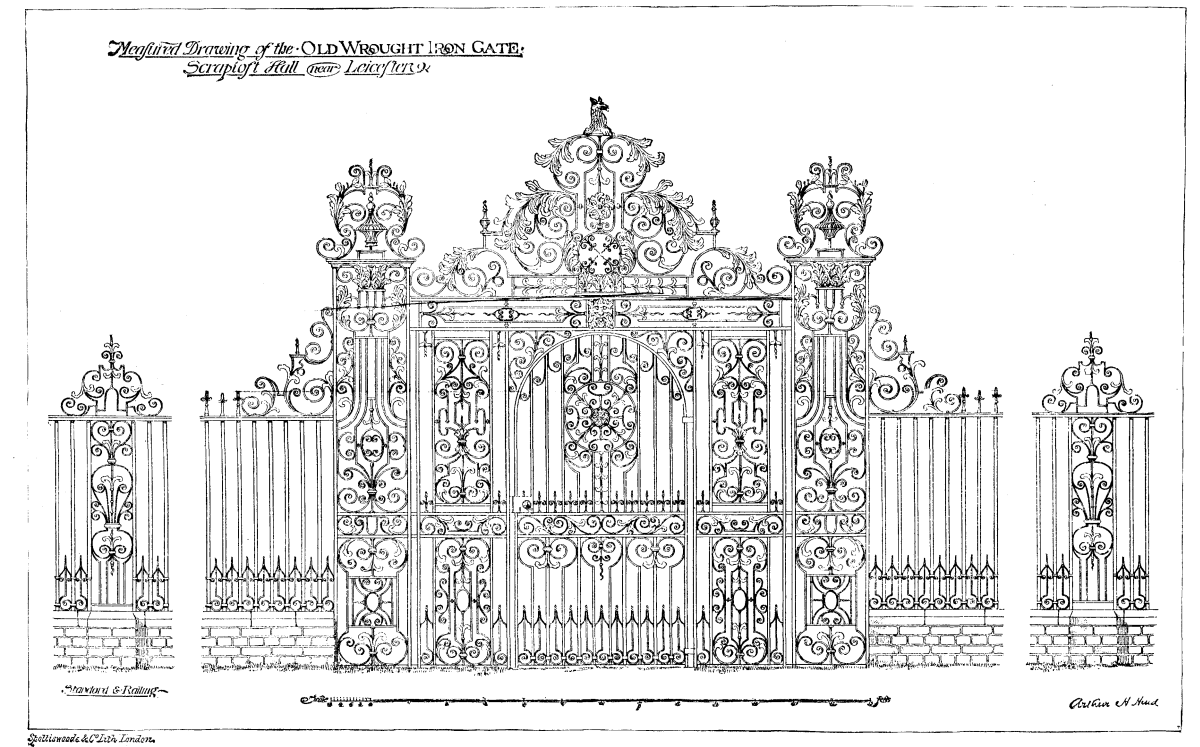
OLD WROUGHT IRON GATE
This gate forms the entrance to Scraptoft Hall, a building of the eighteenth century, now the seat of Captain Barclay, and which stands at about five miles from Leicester, England.—The Architect.
I am unable to tell you what is generally considered the best practice, for I am not sure there are any definitely established rules; therefore I can only explain my ways of doing such work, which, though I try to make as complete and at the same time as simple as possible, I know to be far from perfect.
Plumbing and drainage work has grown up unconsciously with my landscape gardening, and not finding any texts or practice that seemed wholly satisfactory, I have been forced to devise new arrangements from time to time, according to the requirements of the case in hand.
To give all the details of house plumbing this evening, or any one evening, would be impossible, for lack of time, and not worth while even if there was time, as much of it would prove matter of little or no interest. I will confine my remarks, therefore, to certain elements of the work where my practice differs, I believe, essentially from that of most engineers, and where perhaps my experience, if of no assistance to other members of the Society, may excite their friendly criticism in such a way as to help me.
There are two kinds of country places that I am liable to be called upon to prescribe for:
First. A new place where nothing has been arranged.
Second. An old place where the occupants have been troubled either by their outside arrangements or by fixtures or pipes within.
Under the first head let us suppose a small tract of perhaps two acres of land in some inland town, where the family intends to live but six months in the year, though they are liable to reside there the whole twelve.
There are no sewers and no public water. The soil is a stiff, retentive clay, rather wet in spring. The desire is expressed to have plumbing and drainage that shall be as inexpensive as possible, but that shall be entirely safe.
In considering the arrangements inside the house, I find myself in the same predicament as the French surgeon, a specialist upon setting the bones of the arm, who, when a patient was brought him with his right arm broke, expressed his sorrow at being unable to be of assistance, as his specialty was the left arm.
I have endeavored to post myself thoroughly upon house plumbing, but confess to only knowing partially about the wastes; the supplies I do not feel competent to pass upon.
One class of annoyance caused by plumbing, perhaps the principal one, is due to the soil pipe or some of its fittings.
Second quality of iron, poor hanging, insufficient calking, careless mechanics, putty, cement, rag, or paper joints—all these and a dozen other things are liable to be sources of trouble. Subordinate wastes are apt to be annoying, occasionally, too, to a less extent.
The mechanical work can always be superintended, and within certain limits may be made secure and tight; not so easy, however, with the materials.
There is seldom a valid excuse for ever making waste pipes, within a building, of anything but metal.
Earthen tile is frequently used; also, to a limited extent, brick, stone, and wood; twice I have found canvas—all these, however, are inferior, and should never be accepted or specified. The writer believes that at the present time, hereabouts, lead and iron are more used for wastes than any other materials, and are found the most satisfactory on the whole.
One or two arrangements, relative to the wastes, I have made use of that are not, so far as known, in general use, and that may not be the best, though they have served me many good turns, and I have not succeeded in devising any better.
Soil pipe, as it is usually put in, is apt to be of cast iron, four inches in diameter, and is known in the market as "heavy" or "extra heavy." For some years the tar-coated or black enameled pipe has been the favorite, as being the more reliable, the writer in common with others making use of the same freely, until one day a cracked elbow, tar coated, was detected. Since that time plain, untarred pipe has been specified, and subjected to the so-called kerosene test, which consists of swabbing out each pipe with kerosene or oil and then allowing it to stand for a few hours. A moment's thought will convince any one that when a pipe is asphalted or tar coated it is very difficult to detect either sand holes or small cracks, and the difficulty of proper calking is increased, as lead does not cling so well to the tar as to plain iron.
At present, the kerosene test, so far as the writer is concerned, is a misnomer, because raw linseed oil is used exclusively as giving more satisfactory results, and being less troublesome to apply.
I have here a length of the ordinary "heavy 4" commercial soil pipe, plain, and selected at random. Yesterday noon I had it oiled at my office, in order to be ready for to-night, and you see, by the chalk marks I have made, just where the leaks were and their area. I may say here that a sound pipe of this caliber and standard weight is the exception rather than the rule, and it was selected for this experiment merely to try and show the reaction a little better than the heavier pipe might.
Experiments of this nature I have carried along for the past two years, and I am glad to say that, since I began, the quality of the soil pipe furnished by the dealers for my work seems appreciably better than at first. Whether the poorer pipe is still made and sold to other customers I have no means of knowing; probably it is, however.
A large quantity of the pipe is now being tested at my suggestion by the Superintendent of Construction of the Johns Hopkins Hospital, at Baltimore. I have not yet heard the results from him, but doubtless they will be interesting. A brief summary of the results may be of some interest.
The different makers of soil pipe generally used by plumbers hereabouts are:
Mott & Company, Abendroth, Blakslee, Dighton, Phillips & Weeden, and Bartlett, Hayward & Co.
On 4" extra heavy pipe my results have been as follows:
| Percentage passed as good, single hub. | 60 per ct. to 70 per ct. |
| Percentage passed as good, double. | 20 per ct. to 80 per ct. |
| Percentage passed special castings, including Y's and T's. | 60 per ct. |
5" pipe extra heavy:
| Percentage passed as good, single hub. | 25 per ct. to 35 per ct. |
| Percentage passed as good, double. | No record. |
| Percentage special castings, including Y's and T's. | 60 per ct. |
It has been stated to me by dealers that the tar coating does away with the necessity of any such test as the oil; while I am not prepared to acknowledge or deny the statement, it is well known that much poor pipe is tar-coated and sold in the market as good, and when coated it is almost impossible to detect any but very defective work.
The price customers are obliged to pay for soil pipe, either "heavy" or "extra heavy," is very high indeed, even taking off the discounts, and amounts (as I figure it) to $70 per long ton for 4" pipe. The present rate for the best water pipe of the same caliber is about $38 (now $29) per long ton, and the additional charge for soil pipe should guarantee the very best iron in the market, though it appears to be rarely furnished.
It is asserted that all soil pipe is tested to a 50-pound water pressure. I beg leave to question the absolute truth of this, unless it be acknowledged that pipe is sold indiscriminately, whether it bears the test or not, for more than once I have found a single length of soil pipe (5 feet) that could not bear the pressure of a column of water of its own height without leaking.
Having obtained a satisfactory lot of soil pipe and fittings, the next trouble comes with the lead calking. Unfortunately, it is frequently found that very shallow joints are made instead of deep ones, and hard lead used instead of soft. My rule is, soft lead, two runnings and two calkings. By soft lead I mean pig lead, and by hard lead I mean old pipe and scrap lead that may have been melted a dozen times. Incidentally it may be remarked that it is quite difficult to calk a tight joint on the heavy pipe; the process will crack the hub.
The fixtures used in a house are of minor importance—there are dozens of good patterns of every class. If they are carefully put in, and provided with suitable traps placed just as close to the fixture as possible, the result will usually be satisfactory.
Very few instances occur where traps are placed as close to the fixtures they serve as they might be, and yet a very short length of untrapped pipe, when fouled, will sometimes smell dreadfully. A set bowl with trap two feet away may become in time a great nuisance if not properly used. A case in point where the fixture was used both as a bowl and a urinal was in a few months exceedingly offensive—a fact largely (though not wholly) due to its double service.
I have never met two sanitarians who agreed upon the same water-closets, bowls, faucets, traps, etc.
Of course, the soil pipe will be carried, of full size, through the roof, and sufficiently high to clear all windows.
Avoid multiplicity of fixtures or pipes; cut off all fixtures not used at least twice a week, lest their traps dry out; have all plumbing as simple as possible, and try and get it all located so that outside air can be got directly into all closets and bath-rooms. As far as possible, set your fixtures in glass rather than tiles or wood. Carry the lower end of the main drain at least five feet beyond the cellar walls of the building, of cast iron.
Let us now look at the outside work. The main drain (carrying everything except the kitchen and pantry sinks) goes through a ventilated running trap. An indirect fresh air inlet is provided on the house side of the trap (example), to prevent annoyance from puffing or pumping, or, better still, a pipe corresponding to the soil pipe is carried up on the outside of the house.
The running trap ventilator should be of the same diameter as the main drain (4 inch), and serve as a main drain vent also. Carry this pipe on the outside of the house as high as the top of the chimney.
A grease-trap should be provided for the kitchen and pantry sinks. Formerly my custom was to put in brick receptacles; it is now to put in Portland cement traps (Henderson pattern), though perhaps I may succeed in devising a cast-iron one that will answer better. The brick ones were occasionally heaved by the frost, and cracked; the Portland cement ones answer better, and when thoroughly painted with red lead do not soak an appreciable quantity of sewage to be offensive, but are too high priced ($28 each). I have made one or two patterns for cast-iron ones, but none as yet that I feel satisfied with.
Beyond the running trap an Akron pipe should convey the sewage to a tank or cesspool.
Our supposable case is the second most difficult to take care of. The worst would be ledge. We have to contend with, however, hard, wet, impervious clay.
The best way undoubtedly is to underdrain the land, and then to distribute the sewage on the principle of intermittent downward filtration. This is rather expensive, and a customer is rarely willing to pay the bills for the same. I should always advise it as the best; but where not allowed to do so, I have had fair success with shallow French drains connecting with the tank or cesspool.
Siphon tanks, such as are advised by many sanitarians, that were used first in this country, I believe, by Mr. Waring, I have not been very successful with. Obstructions get into the siphon and stop it up, or it gets choked with grease. I prefer a tight tank, provided with a tell-tale, and that is to be opened either by a valve operated by hand, or that is arranged with a standing overflow like a bath tub, and that can be raised and secured by a hook.
[4]Thus saith the poet, and forthwith turns the world over into the hands of the cook. And into what better hands could you fall? To you, my fat, jolly, four-meals-a-day friend, Mr. Gourmand, but more especially to you, my somber, lean, dyspeptic, two-meals-a-day friend, Mr. Grumbler, the cook is indeed a valuable friend. The cook wields a scepter that is only second in power to that of love; and even love has become soured through the evil instrumentality of the good-looking or bad-cooking cook. This is no jest, it is a very sad fact.
Now, the question arises, how can the cook preserve the health of her patrons, maintain happiness in the family, and yet not throw the gourmands into bankruptcy? Very simple, I assure you.
When one arrives at adult age, he should have learned by experience what articles of food do, and what articles of food do not, agree with him, and to shun the latter, no matter how daintily served or how tempting the circumstances. The man who knows that pates de foie gras, or the livers of abnormally fattened geese, disagree with him, and still eats them, is not to be pitied when all the horrors of dyspepsia overtake him.
The cooking of any article of food has evidently much, very much, to do with its digestibility. It is not the purpose of this paper to teach cooking, but merely to give some general hints as to the best as well as the simplest methods of preparing staple articles of food. The same articles of food can and should be prepared differently on each day of the week. Changes of diet are too likely to be underestimated. By constant change the digestive organs in the average person are prevented from having that repulsion of food which, to a greater or less extent, is likely to result from a sameness of diet continued for a long time.
We often hear from our scientific men that this or that article of food is excellent for muscle, another for brain, another for bone, etc., etc. Now, stubborn facts are like stone walls, against which theories often butt out their beauty and their power. It is well known to almost every one nowadays that well-cooked food, whether it be potatoes, meat and bread, fish, or anything else worthy the name of food, will well maintain, indefinitely, either the philosopher or the hodcarrier.
Many of you know, and all of you ought to know, that the principal ingredients of nearly all our foods are starch and albumen. Starch is the principal nutritive ingredient of vegetables and breadstuffs. Albumen is the principal ingredient of meats, eggs, milk, and other animal derivatives.
Starch never enters the system as starch, but must first be converted into sugar either in the body or out of it. The process of this transformation of starch into sugar is beautifully exemplified in certain plants, such as the beet, the so-called sugar cane, and other growths. The young plant is, to a great extent, composed of starch; as the plant grows older, a substance is produced which is called diastase. Through the influence of this diastase the starch is converted into a peculiar non-crystallizable substance called dextrine, and as the plant matures, this dextrine is transformed into crystallizable sugar.
"Dextrine is a substance that can be produced from starch by the action of dilute acids, alkalies, and malt extract, and by roasting it at a temperature between 284° and 330° F., till it is of a light brown color, and has the odor of overbaked bread."
A simple form of dextrine may be found in the brown crust of bread—that sweetish substance that gives the crust its agreeable flavor. Pure dextrine is an insipid, odorless, yellowish-white, translucent substance, which dissolves in water almost as readily as sugar. As stated above, it is easily converted into dextrose, or glucose, as it is usually named.
This glucose is often sold under the name of sugar, and is the same against which so many of the newspapers waged such a war a year or two ago. These critics were evidently, for the most part, persons who knew little about the subject. Glucose, if free from sulphuric acid or other chemicals, is as harmless as any other form of sugar. Most of our candies contain more or less of it, and are in every way as satisfactory as when manufactured wholly from other sugars.
It is, therefore, self-evident that, as sugar is a necessary article of food, the process which aids the transformation of our starchy foods must necessarily aid digestion. Do not understand me to say by this that, if all our starchy foods were converted into sugar, their digestion would thereby be completed. As I stated a moment ago, this sweet food, if taken into the stomach day after day, would soon cause that particular organ to rebel against this sameness of diet. In order the more clearly to illustrate this point, I will briefly show you how some of the every-day articles of food can be each day differently prepared, and thus be rendered more palatable, and, as a consequence, more digestible; for it is a demonstrated fact that savory foods are far more easily digested than the same foods unsavored.
The art of serving and arranging dishes for the table is an accomplishment in itself. It is very reasonable that all things that go to make up beauty and harmony at the dinner table should add their full quota to the appetite, and, I was about to say, "to the digestion;" but will qualify the statement by saying, to the digestion if the appetite be not porcine.
Our commonest article of food is the potato. Let us see how potatoes—which contain only twenty per cent. of starch, as against eighty-eight per cent. in rice, and sixty-six per cent. in wheat flour—can be prepared as just mentioned. We will look for a moment at the manner in which they are usually served by the average cook:
1, boiled with their jackets on; 2, roasted in the embers; 3, roasted with meat; 4, fried; 5, mashed; 6, salad.
1. Potatoes boiled in their jackets are excellent if properly prepared. But there's the rub. The trouble is, they are too often allowed to boil slowly and too long, and thus become water-soaked, soggy, and solid, and proportionately indigestible. They should be put over a brisk fire, and kept at a brisk boil till done; then drain off the water, sprinkle a little salt over them, and return to the fire a moment to dry thoroughly, when you will find them bursting with their white, mealy contents.
2. Roasted potatoes are general favorites, and very digestible. A more agreeable flavor is imparted to them if roasted in hot embers (wood fire), care being used to keep them covered with the hot embers.
3. Fried potatoes, as they are very generally served, are almost as digestible as rocks, but not so tempting in all their grease-dripping beauty as the latter. Many of you have doubtless seen the potatoes neatly sliced and dumped into a frying pan full of hot lard, where they were permitted to sink or float, and soak and sob for about a half hour or more. When served, they presented the picturesque spectacle of miniature potato islands floating at liberty in a sea of yellow grease. Now, if any of you can relish and digest such a mess as that, I would advise you to leave this clime, and eat tallow candles with the Esquimaux.
If you are fond of fried potatoes, cook them in this way:
Take what boiled potatoes are left from breakfast or dinner; when cold, remove the jackets, and cut into thin slices, season with salt, pepper, and a little Cayenne; have ready a hot frying pan, with enough meat drippings or sweet lard to cover the bottom; put in the potatoes and fry a rich brown, stirring constantly with a knife to prevent burning. Serve very hot.
4. Mashed potatoes will be discussed further on.
5. Potato salads are appetizing and piquant, because they are usually made up with strong condiments, onions, etc. They are, therefore, not very digestible in themselves. Nevertheless, they are so palatable that we cannot easily dispense with them; but, after eating them, if you expect to have inward peace, either split wood, walk eight and a half miles, or take some other light exercise.
More palatable, and proportionately digestible, are the following methods of cooking this useful vegetable:
1, Saratoga potatoes; 2, a la maitre d'hotel; 3, potato croquettes; 4, potatoes and cream; 5, a la Lyonnaise.
1. For Saratogas, pare and slice your potatoes as thin as possible, dropping them into cold water in which is dissolved a tiny piece of alum to make them crisp. Let them remain in the water for an hour or longer. Drain, and wipe perfectly dry with a tea towel. Have ready a quantity of boiling lard. Drop them in, and fry a delicate brown. Drain all grease from them, sprinkle with salt, and serve. Here, in the crisp slices, you will have the much desired dextrine. Or, in other words, your potato is already half digested. Eat three or four potatoes prepared thus, and you feel no inconvenience; but how would you feel did you devour three soggy, water-soaked boiled potatoes?
2. For a la maitre d'hotel, pare the potatoes, cut into pieces half an inch wide, and the length of the potato; drop into cold water until wanted (an hour or so); then drain, and fry in boiling lard. Just as they begin to brown take them out with a skimmer; let them slightly cool; then put back, and fry a rich brown. This makes them puff up, and very attractive.
3. For croquettes, take finely mashed potatoes, and mix with salt, pepper, and butter, and sweet milk or cream enough to moisten thoroughly. Mix with this one well-beaten egg, and form into small balls, taking care to have them smooth. Have ready one plate with a beaten egg upon it, and another with cracker crumbs. Dip each ball into the egg, and then into the crumbs, and brown nicely. Lay the croquettes on brown paper first, to get rid of any superfluous grease, then serve on a napkin.
4. Potatoes and cream are prepared by mincing cold boiled potatoes fine, putting them in a spider with a little melted butter in it, and letting them fry slightly, keeping them well covered. Add a very small piece of fresh butter, season with pepper and salt, and pour over them cream or rich milk. Let them boil up once, and serve. This is a very nice dish, and may be safely taken into delicate stomachs.
5. A la Lyonnaise is prepared as follows: Take five cold potatoes, one onion, butter, salt, and pepper. Slice the onion finely, and fry it in butter until it begins to take color; add the sliced potatoes, salt and pepper to taste, and keep shaking the saucepan until they are somewhat browned. Serve hot.
A few random remarks about the preparation of albuminous foods. If the albumen in food is hardened by prolonged cooking, it is rendered less instead of more digestible. Therefore, the so-called well-cooked meats are really badly-cooked meats. Meats should be only half done, or rare. To do this properly, it is necessary to cook with a quick fire. Steaks should be broiled, not fried. I am in accord with a well-known orator, who said, recently, that "the person who fries a steak should be arrested for cruelty to humanity." Some few meats should always be well cooked before eating.[6]
The same law holds good with eggs as with meats. A hard-boiled egg is only fit for the stomach of an ostrich; it was never intended by nature to adorn the human stomach. There are very many ways of preparing eggs—by frying, baking, poaching, shirring, etc. I will only describe briefly a few simple methods of making omelets.
In making this elegant dish, never use more than three eggs to an omelet. Plain omelet: Separate the whites and yolks; add a teaspoonful of water to the whites, and beat to a stiff froth; add to the yolks a teaspoonful of water, and beat until light; then season with salt, and about two tablespoonfuls of cream or rich milk. Have your spider very hot; turn your whites and yolks together, and stir lightly to mix them; place a bit of butter in the spider, and immediately pour in your eggs. When set (which takes from ten to twenty seconds, and be careful that it does not brown too much), fold together in a half moon, remove it, sprinkle with powdered sugar, and serve on a hot plate. It should be eaten immediately.
Fruit omelets are made by placing preserved fruits or jellies between the folds. Baked omelets are prepared as above, with the addition of placing in the oven and allowing to brown slightly.
French omelet is prepared in this way: Take a half cup of boiling milk with a half teaspoonful of butter melted in it; pour this over one-half cup of bread crumbs (light bread); add salt, pepper, and the yolks of three eggs beaten very light; mix thoroughly; and lastly, add the whites whipped to a stiff froth. Stir lightly, and fry in butter. When nearly done, fold together in a half moon, and serve immediately.
And thus we might continue ad infinitum, but, as was stated before, it is not my object to instruct you in special cooking, but to illustrate in this manner how much easier it is, to both the cook and your stomachs, to prepare healthful dishes than to do the reverse.
[5]The Monitor de la Salud contains in a recent number the results of some experiments lately made by E. Jessen on the time required for the digestion of certain kinds of food. The stomach of the person on whom the experiments were made was emptied by means of a pump; 100 grammes, equal to 1,544 grains, or about 2⅔ ounces, of meat, finely chopped and mixed with three times the quantity of water, were introduced. The experiment was considered ended when the matter, on removal by the pump, was found to contain no muscular fibre.
It will be remembered that the gramme weighs nearly 15½ grains, and the cubic centigramme is equal to 1 gramme. The 2⅔ ounces of meat were therefore mixed with nearly eight ounces of water, before being introduced into the stomach.
The results were as follows:
| Beef, raw, and finely chopped. | 2 hours. |
| Beef, half cooked. | 2½ hours. |
| Beef, well cooked. | 3 hours. |
| Beef, slightly roasted. | 3 hours. |
| Beef, well roasted. | 4 hours. |
| Mutton, raw. | 2 hours. |
| Veal. | 2½ hours. |
| Pork. | 3 hours. |
The digestibility of milk was examined in the same way. The quantity used was regulated so that the nitrogen should be the same as in the 100 grammes of beef.
| 602 cubic centimeters, nearly sixteen ounces, of cow's milk, not boiled, required. | 3½ hours |
| 602 cubic centimeters, boiled. | 4 hours |
| 602 sour. | 3½ hours |
| 675 skimmed. | 3½ hours |
| 656 goat's milk, not boiled. | 3½ hours |
A Scientific institution or bureau operating under government authority can be controlled by statute and by superior administrative authority but to a limited extent. These operations are practically carried on by specialists, and they can be controlled only in their financial operations and in the general purposes for which investigations are made. Their methods of investigation are their own—originate with themselves, and are carried out by themselves. But in relation to the scientific operations of such a government institution, there is an unofficial authority which, though not immediately felt, ultimately steps in to approve or condemn, viz., the body of scientific men of the country; and though their authority is not exercised antecedently and at every stage of the work, yet it is so potent that no national scientific institution can grow and prosper without their approval, but must sooner or later fall and perish unless sustained by their strong influence.
As director of the Geological Survey, I deeply realize that I owe allegiance to the scientific men of the country, and for this reason I desire to present to the National Academy of Sciences the organization and plan of operations of the Survey.
Sound geologic research is based on geography. Without a good topographic map geology cannot even be thoroughly studied, and the publication of the results of geologic investigation is very imperfect without a good map; but with a good map thorough investigation and simple, intelligible publication become possible. Impelled by these considerations, the Survey is making a topographic map of the United States. The geographic basis of this map is a trigonometric survey by which datum points are established throughout the country; that is, base-lines are measured and a triangulation extended therefrom. This trigonometric work is executed on a scale only sufficiently refined for map-making purposes, and will not be directly useful for geodetic purposes in determining the figure of the earth. The hypsometric work is based upon the railroad levels of the country. Throughout the greater part of the country, there is a system of railroad lines, constituting a net-work. The levels or profiles of these roads have been established with reasonable accuracy, and as they cross each other at a multiplicity of points, a system of checks is afforded, so that the railroad surface of the country can be determined therefrom with all the accuracy necessary for the most refined and elaborate topographic maps. From such a hypsometric basis the reliefs for the whole country are determined, by running lines of levels, by trigonometric construction, and in mountainous regions by barometric observation.
The primary triangulation having been made, the topography is executed by a variety of methods, adapted to the peculiar conditions found in various portions of the country. To a large extent the plane-table is used. In the hands of the topographers of the Geological Survey, the plane-table is not simply a portable draughting table for the field; it is practically an instrument of triangulation, and all minor positions of the details of topography are determined through its use by trigonometric construction.
The scale on which the map is made is variable. In some portions of the prairie region, and in the region of the great plains, the topography and the geology alike are simple, and maps on a comparatively small scale are sufficient for practical purposes. For these districts it is proposed to construct the sheets of the map on a scale of 1-250,000, or about four miles to the inch. In the mountain regions of the West the geology is more complex, and the topography more intricate; but to a large extent these regions are uninhabited, and to a more limited extent uninhabitable. It would therefore not be wise to make a topographic or geologic survey of the country on an excessively elaborate plan. Over much of this area the sheets of the map will also be constructed on a scale of 1-250,000, but in special districts that scale will be increased to 1-125,000, and in the case of important mining districts charts will be constructed on a much larger scale. In the eastern portion of the United States two scales are adopted. In the less densely populated country a scale of 1-125,000 is used; in the more densely populated regions a scale of 1-62,500 is adopted, or about one mile to the inch. But throughout the country a few special districts of great importance, because of complex geologic structure, dense population, or other condition, will require charts on still larger scales. The area of the United States, exclusive of Alaska, is about three million square miles, and a map of the United States, constructed on the plan set forth above, will require not less than 2,600 sheets. It may ultimately prove to require more than that, from the fact that the areas to be surveyed on the larger scale have not been fully determined. Besides the number of sheets in the general map of the United States, there will be several hundred special maps on large scales, as above described.
Such is a brief outline of the plan so far as it has been developed at the present time. In this connection it should be stated that the map of the United States can be completed, with the present organization of the Geological Survey, in about 24 years; but it is greatly to be desired that the time for its completion may be materially diminished by increasing the topographic force of the Geological Survey. We ought to have a good topographic map of the United States by the year 1900. About one-fifth of the whole area of the United States, exclusive of Alaska, has been completed on the above plan. This includes all geographic work done in the United States under the auspices of the General Government and under the auspices of State Governments. The map herewith shows those areas that have been surveyed by various organizations on such a scale and in such a manner that the work has been accepted as sufficient for the purposes of the Survey.
Much other work has been done, but not with sufficient refinement and accuracy to be of present value, though such work subserved its purpose in its time. An examination of the map will show that the triangulation of the various organizations is already largely in advance of the topography. The map of the United States will be a great atlas divided into sheets as above indicated. In all of those areas where the survey is on a scale of 1-250,000, a page of the atlas will present an area of one degree in longitude and one degree in latitude. Where the scale is 1-125,000, a page of the atlas-sheet will represent one-fourth of a degree. Where the scale is 1-62,500, the atlas-sheet will represent one-sixteenth of a degree. The degree sheet will be designated by two numbers—one representing latitude, the other longitude. Where the sheets represent fractional degrees, they will be labeled with the same numbers, with the addition of the description of the proper fractional part.
The organization, as at present established, executing this work, is as follows: First, an astronomic and computing division, the officers of which are engaged in determining the geographic coordinates of certain primary points. Second, a triangulation corps engaged in extending a system of triangulation over various portions of the country from measured base-lines. Third, a topographic corps, organized into twenty-seven parties, scattered over various portions of the United States. Such, in brief outline, is the plan for the map of the United States, and the organization by which it is to be made. Mr. Henry Gannett is the Chief Geographer.
Before giving the outline of the plan for the general geologic survey, it will be better to explain the accessory plans and organizations. There are in the Survey, as at present organized, the following paleontologic laboratories:
1. A laboratory of vertebrate paleontology for formations other than the Quaternary. In connection with this laboratory there is a corps of paleontologists. Professor O.C. Marsh is in charge.
2. There is a laboratory of invertebrate paleontology of Quaternary age, with a corps of paleontologists, Mr. Wm. H. Dall being in charge.
3. There is a laboratory of invertebrate paleontology of Cenozoic and Mesozoic age, with a corps of paleontologists. Dr. C.A. White is in charge.
4. There is a laboratory of invertebrate paleontology of Paleozoic age, with a corps of paleontologists. Mr. C.D. Walcott is in charge.
5. There is a laboratory of fossil botany, with a corps of paleobotanists, Mr. Lester F. Ward being in charge.
The paleontologists and paleobotanists connected with the laboratories above described, study and discuss in reports the fossils collected by the general geologists in the field. They also supplement the work of the field geologists by making special collections in important districts and at critical horizons; but the paleontologists are not held responsible for areal and structural geology on the one hand, and the geologists are not held responsible for paleontology on the other hand. In addition to the large number of paleontologists on the regular work of the Geological Survey, as above described, several paleontologists are engaged from time to time to make special studies.
There is a chemic laboratory attached to the Survey, with a large corps of chemists engaged in a great variety of researches relating to the constitution of waters, minerals, ores, and rocks. A part of the work of this corps is to study the methods of metamorphism and the paragenesis of minerals, and in this connection the chemists do work in the field; but to a large extent they are occupied with the study of the materials collected by the field geologists. Professor F.W. Clarke is in charge of this department.
There is a physical laboratory in the Survey, with a small corps of men engaged in certain physical researches of prime importance to geologic philosophy. These researches are experimental, and relate to the effect of temperatures, pressures, etc., on rocks. This laboratory is under the charge of the chief chemist.
There is a lithologic laboratory in the Survey, with a large corps of lithologists engaged in the microscopic study of rocks. These lithologists are field geologists, who examine the collections made by themselves.
There is in the Survey a division of mining statistics, with a large corps of men engaged in statistic work, the results of which are published in an annual report entitled "Mineral Resources." Mr. Albert Williams, Jr., is the Chief Statistician of the Survey.
There is in the Survey a division organized for the purpose of preparing illustrations for paleontologic and geologic reports. Mr. W.H. Holmes is in charge of this division. Illustrations will not hereafter be used for embellishment, but will be strictly confined to the illustration of the text and the presentation of such facts as can be best exhibited by figures and diagrams. All illustrations will, as far as possible, be produced by relief methods, such as wood-engraving, photo-engraving, etc. As large numbers of the reports of the Survey are published, this plan is demanded for economic reasons; but there is another consideration believed to be of still greater importance; illustrations made on stone cannot be used after the first edition, as they deteriorate somewhat by time, and it is customary to use the same lithographic stone for various purposes from time to time. The illustrations made for the reports of the Survey, if on relief-plates that can be cheaply electrotyped, can be used again when needed. This is especially desirable in paleontology, where previously published figures can be introduced for comparative purposes. There are two methods of studying the extinct life of the globe. Fossils are indices of geological formations, and must be grouped by formations to subserve the purpose of geologists. Fossils also have their biologic relations, and should be studied and arranged in biologic groups. Under the plan adopted by the Survey, the illustrations can be used over and over again for such purposes when needed, as reproduction can be made at the small cost of electrotyping. These same illustrations can be used by the public at large in scientific periodicals, text-books, etc. All the illustrations made by the Geological Survey are held for the public to be used in this manner.
The library of the Survey now contains more than 25,000 volumes, and is rapidly growing by means of exchanges. It is found necessary to purchase but few books. The librarian, Mr. C.C. Darwin, has a corps of assistants engaged in bibliographic work. It is proposed to prepare a catalogue of American and foreign publications upon American geology, which is to be a general authors' catalogue. In addition to this, it is proposed to publish bibliographies proper of special subjects constituting integral parts of the science of geology.
The publications of the Survey are in three series: Annual Reports, Bulletins, and Monographs. The Annual Report constitutes a part of the Report of the Secretary of the Interior for each year, but is a distinct volume. This contains a brief summary of the purposes, plans, and operations of the Survey, prepared by the Director, and short administrative reports from the chiefs of divisions, the whole followed by scientific papers. These papers are selected as being those of most general interest, the object being to make the Annual Report a somewhat popular account of the doings of the Survey, that it may be widely read by the intelligent people of the country. Of this 5,650 copies are published as a part of the Secretary's report, and are distributed by the Secretary of the Interior, Senators, and Members of the House of Representatives; and an extra edition is annually ordered of 15,000 copies, distributed by the Survey and members of the Senate and House of Representatives. Four annual reports have been published; the fifth is now in the hands of the printer.
The Bulletins of the Survey are short papers, and through them somewhat speedy publication is attained. Each bulletin is devoted to some specific topic, in order that the material ultimately published in the bulletins can be classified in any manner desired by scientific men. Nine bulletins have been published, and seven are in press. The bulletins already published vary in size from 5 to 325 pages each; they are sold at the cost of press-work and paper, and vary in price from five to twenty cents each; 4,900 copies of each bulletin are published; 1,900 are distributed by Congress, 3,000 are held for sale and exchange by the Geological Survey.
The Monographs of the Survey are quarto volumes. By this method of publication the more important and elaborate papers are given to the public. Six monographs, with two atlases, have been issued; five monographs, with two atlases, are in press; 1,900 copies of each monograph are distributed by Congress; 3,000 are held for sale and exchange by the Survey at the cost of press-work, paper, and binding. They vary in price from $1.05 to $11.
The chiefs of divisions supervise the publications that originate in their several corps. The general editorial supervision is exercised by the Chief Clerk of the Survey, Mr. James C. Pilling.
In organizing the general geologic work, it became necessary, first, to consider what had already been done in various portions of the United States; and for this purpose the compilation of a general geologic map of the United States was begun, together with a Thesaurus of American formations. In addition to this the bibliographic work previously described was initiated, so that the literature relating to American geology should be readily accessible to the workers in the Survey. At this point it became necessary to consider the best methods of apportioning the work; that is, the best methods of dividing the geologic work into parts to be assigned to the different corps of observers. A strictly geographic apportionment was not deemed wise, from the fact that an unscientific division of labor would result, and the same classes of problems would to a large extent be relegated to the several corps operating in field and in the laboratory. It was thought best to divide the work, as far as possible, by subject-matter rather than by territorial areas; yet to some extent the two methods of division will coincide. There are in the Survey at present:
First, a division of glacial geology, and Prof. T.C. Chamberlin, formerly State Geologist of Wisconsin is at its head, with a strong corps of assistants. There is an important field for which definite provision has not yet been made, namely, the study of the loess that constitutes the bluff formations of the Mississippi River and its tributaries. But as this loess proves to be intimately associated with the glacial formations of the same region, it is probable that it will eventually be relegated to the glacial division. Perhaps the division may eventually grow to such an extent that its field of operations will include the whole Quaternary geology.
Second, a division of volcanic geology is organized, and Capt. Clarence E. Dutton, of the Ordnance Corps of the Army, is placed in charge, also with a strong corps of assistants.
Third and fourth, two divisions have been organized to prosecute work on the archæan rocks, embracing within their field not only all rocks of archæan age, but all metamorphic crystalline schists, of whatever age they may be found. The first division has for its chief Prof. Raphael Pumpelly, assisted by a corps of geologists, and the field of his work is the crystalline schists of the Appalachian region, or eastern portion of the United States, extending from northern New England to Georgia. He will also include in his studies certain paleozoic formations which are immediately connected with the crystalline schists and involved in their orographic structure.
The second division for the study of this class of rocks is in charge of Prof. Roland D. Irving, with a corps of geologists, and his field of operation is in the Lake Superior region. It is not proposed at present to undertake the study of the crystalline schists of the Rocky Mountain region.
Fifth, another division has been organized for the study of the areal, structural, and historical geology of the Appalachian region, extending from the Atlantic, westward, to the zone which separates the mountain region from the great valley of the Mississippi. Mr. G.K. Gilbert has charge of this work, and has a large corps of assistants.
Sixth, it seemed desirable, partly for scientific reasons and partly for administrative reasons, that a thorough topographic and geologic survey should be made of the Yellowstone Park, and Mr. Arnold Hague is in charge of the work, with a corps of assistants. When it is completed, his field will be expanded so as to include a large part of the Rocky Mountain region, but the extent of the field is not yet determined.
It will thus be seen that the general geologic work relating to those areas where the terranes are composed of fossiliferous formations is very imperfectly and incompletely organized. The reason for this is twofold: First, the work cannot be performed very successfully until the maps are made; second, the Geological Survey is necessarily diverting much of its force to the construction of maps, and cannot with present appropriations expand the geologic corps so as to extend systematic work in the field over the entire country.
Under the organic law of the Geological Survey, investigations in economic geology are restricted to those States and Territories in which there are public lands; the extension of the work into the eastern portion of the United States included only that part relating to general geology. Two mining divisions are organized. One, in charge of Mr. George F. Becker, with headquarters at San Francisco, California, is at the present time engaged in the study of the quicksilver districts of California. The other, under charge of Mr. S.F. Emmons, with headquarters at Denver, Colorado, is engaged in studying various mining districts in that State, including silver, gold, iron, and coal areas. Each division has a corps of assistants. The lignite coals of the upper Missouri, also, are under investigation by Mr. Bailey Willis, with a corps of assistants.
The employes on the Geological Survey at the close of September, 1884, were as follows:
Appointed by the President, by and with the advice and consent of the Senate (Director), 1.
Appointed by the Secretary of the Interior, on the recommendation of the Director of the Survey, 134.
Employed by the chiefs of parties in the field, 148.
Three classes of appointments are made on the Survey. The statute provides that "the scientific employes of the Geological Survey shall be selected by the Director, subject to the approval of the Secretary of the Interior, exclusively for their qualifications as professional experts." The provisions of this statute apply to all those cases where scientific men are employed who have established a reputation, and in asking for their appointment the Director specifically states his reasons, setting forth the work in which the person is to be employed, together with his qualifications, especially enumerating and characterizing his published works. On such recommendations appointments are invariably made. Young men who have not established a reputation in scientific research are selected through the agency of the Civil Service Commission on special examination, the papers for which are prepared in the Geological Survey. About one-half of the employes, however, are temporary, being engaged for services lasting for a few days or a few months only, largely in the field, and coming under two classes: Skilled laborers and common laborers. Such persons are employed by the Director or by the heads of divisions, and are discharged from the service when no longer needed. It will be seen that the Director is responsible for the selection of the employes, directly for those whom he recommends for appointment, and indirectly for those selected by the Civil Service Commission, as he permanently retains in the work. If, then, improper persons are employed, it is wholly the Director's fault.
The appropriations made for the Geological Survey for the fiscal year ending June 30, 1885, aggregate the sum of $504,040. This sum does not include the amount appropriated for ethnologic researches—$40,000. Nor are the expenses for engraving and printing paid for from the above appropriations, but from appropriations made for the work under the direction of the public printer. It is estimated that the amount needed for engraving and printing for the same fiscal year will exceed $200,000.
The United States Geological Survey is on friendly relations with the various State Surveys. Between the Government Survey and the State Survey of New York, there is direct co-operation. The State Survey of Pennsylvania has rendered valuable assistance to the Government Survey, and negotiations have been entered into for closer relations and more thorough co-operation. The State Surveys of North Carolina, Kentucky, and Alabama are also co-operating with the Government Survey, and the director of the Government Survey is doing all within his power to revive State Surveys. The field for geologic research in the United States is of great magnitude, and the best results can be accomplished only by the labors of many scientific men engaged for a long term of years. For this reason it is believed that surveys should be established in all of the States and Territories. There is work enough for all, and the establishment of local surveys would greatly assist the general work prosecuted under the auspices of the government, and prevent it from falling into perfunctory channels. Its vigor and health will doubtless be promoted by all thorough local research.
It may be of interest to scientific men to know that the Director finds that in presenting the general results, interests, and needs of the Survey to Congress, and to Committees of Congress, a thorough appreciation of the value of scientific research is shown by the statesmen of the country. Questions relating to immediately economic values are asked, as they should be; but questions relating to sound administration, wise methods of investigation, and important scientific results are vigorously urged, and the principle is recognized that all sound scientific research conduces to the welfare of the people, not only by increasing knowledge, but ultimately by affecting all the industries of the people.
[7]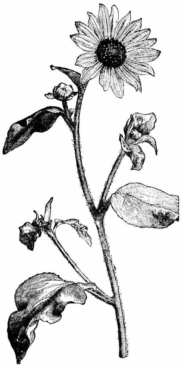
FLOWER OF HELIANTHUS ARGOPHYLLUS.
The genus Helianthus is almost entirely North-American, and for the distinction and limitation of its species we are indebted to the labor of Dr. Asa Gray, now universally recognized as the highest authority on North American plants. In the recently published second part of his "Synoptical Flora of North America" he has described thirty-nine species, six of which are annual. The synonyms and cross-naming adopted by previous authors have led to much confusion, which probably will not now be altogether cleared up, for Dr. Gray warns us that the characters of some of the species are variable, especially in cultivation. It may be added that some at least of the species readily form hybrids. There is always more or less difficulty with a variable genus in making garden plants fit wild specific types, but in the following notes I have described no kinds which I have not myself cultivated, selecting the best forms and giving them the names assigned severally by Dr. Gray to the species to which our garden plants seem to come nearest.

HELIANTHUS ARGOPHYLLUS, SHOWING HABIT OF GROWTH.
Helianthus multiflorus, or, according to Asa Gray, speaking botanically, H. decapetalus hort. var. multiflorus, is mentioned first, because it is the subject of the colored illustration. The name multiflorus is established by long usage, and perhaps was originally given in contrast to the few-flowered habit of H. annuus, for the type of the species is more floriferous than the variety of which Asa Gray says that it is "known only in cultivation from early times, must have been derived from decapetalus," a statement which gardeners would hardly have accepted on less indisputable authority, as they will all think the habit and appearance of the two plants widely different. The variety multiflorus has several forms; the commonest form is double, the disk being filled with ligules much shorter than those of the ray flowers, after the form of many daisy-like composites. In this double form the day flowers are often wanting. It is common also on old plants in poor soils to see double and single flowers from the same root. In the single forms the size of the flowers varies, the difference being due to cultivation as often as to kind. I have obtained by far the finest flowers by the following treatment: In early spring, when the young shoots are about an inch high, cut some off, each with a portion of young root, and plant them singly in deep rich soil, and a sheltered but not shaded situation. By August each will have made a large bush, branching out from one stalk at the base, with from thirty to forty flowers open at a time, each 5 inches across. The same plants if well dressed produce good flowers the second season, but after that the stalks become crowded, and the flowers degenerate. The same treatment suits most of the perennial sunflowers. The following kinds are mentioned in the order in which they occur in Asa Gray's book:
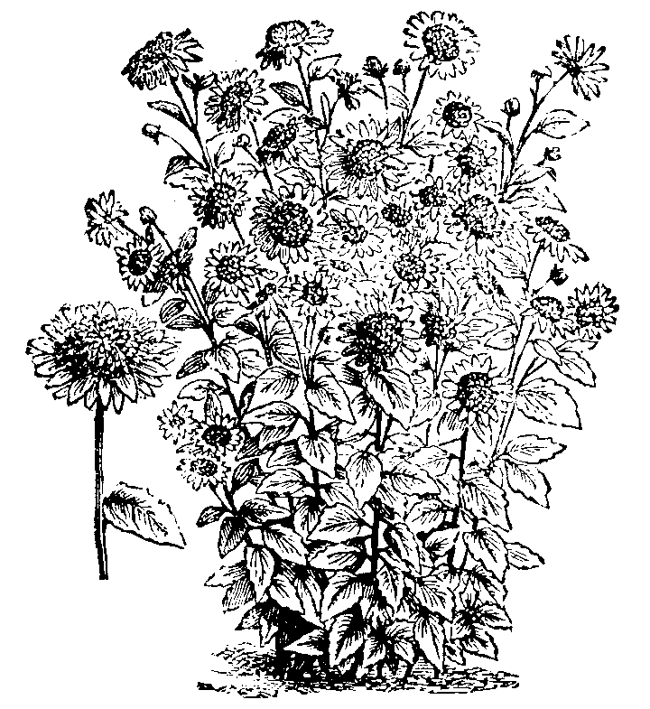
HELIANTHUS MULTIFLORUS, SHOWING HABIT OF GROWTH.
H. argophyllus (white-leaved, not argyrophyllus, silver-leaved, as written in some catalogues).—An annual with woolly leaves, neater and less coarse than H. annuus, with which it is said soon to degenerate in gardens if grown together with it.
H. annuus.—The well known sunflower in endless varieties, one of the most elegant having pale lemon-colored flowers; these, too, liable to pass into the common type if grown in the same garden.
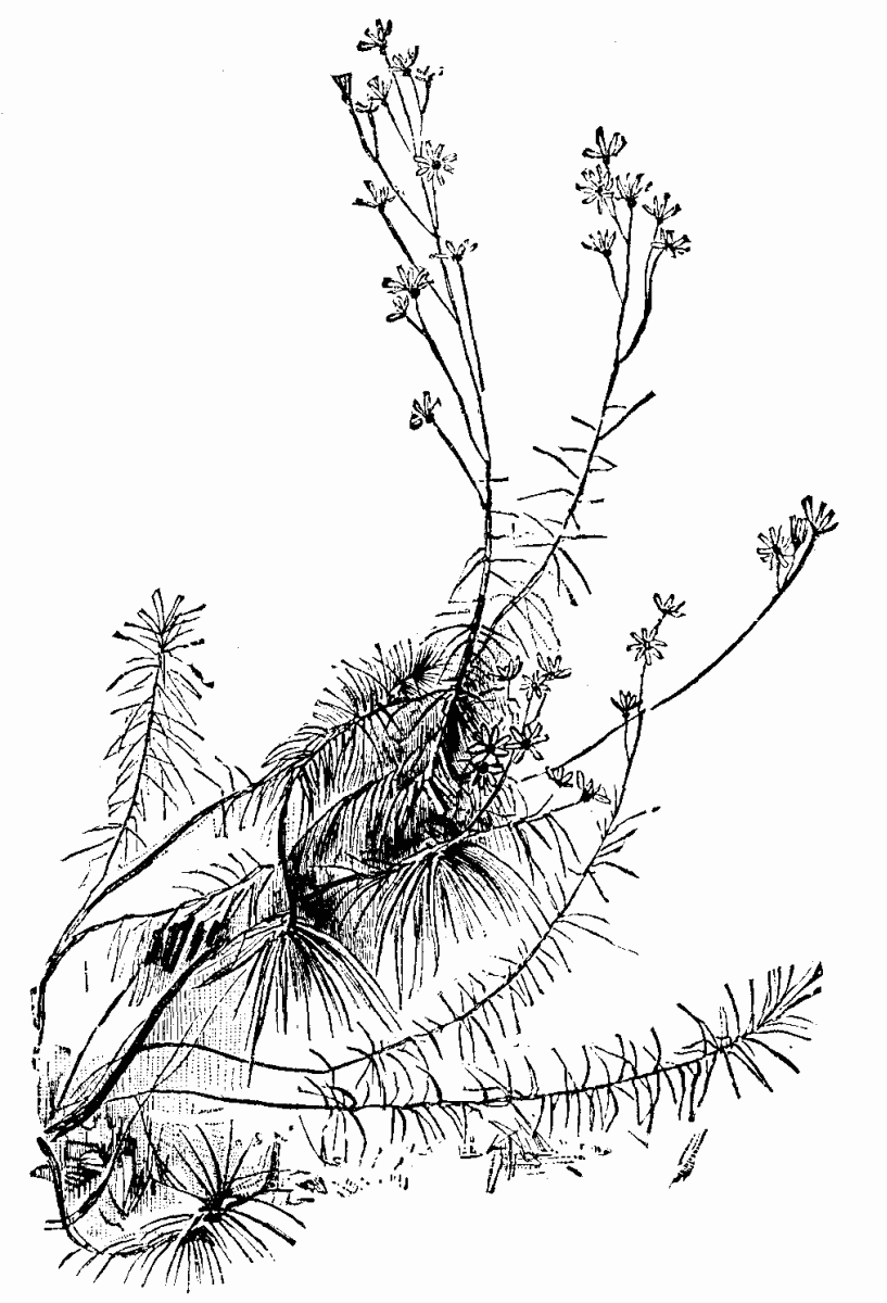
HELIANTHUS ORGYALIS, SHOWING HABIT OF GROWTH IN AUTUMN.
H. debilis var. cucumerifolius.—I have never seen the typical species, but the variety was introduced a few years ago by Mr. W. Thompson, of Ipswich, from whose seed I have grown it. It becomes 4 feet or 5 feet high, with irregularly toothed deltoid leaves and spotted stalks, making a widely branched bush and bearing well-shaped golden flowers more than 3 inches across, with black disks. It crosses with any perennial sunflower that grows near it, simulating their flowers in an annual form. I had a very fine cross with it and H. annuus, but the flowers of this produced no good seed.
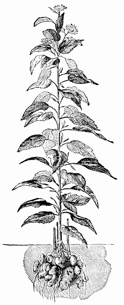
JERUSALEM ARTICHOKE (HELIANTHUS TUBEROSUS).
H. orgyalis (the fathom-high sunflower).—The name is far within the true measure, which is often 9 feet or 10 feet. A very distinct species, increasing very slowly at the root and throwing all its growing efforts upward. The long linear ribbon leaves, often exceeding a foot, spreading in wavy masses round the tall stem, which has a palm-like tuft of them at the summit, are a more ornamental feature than the flowers, which are moderate in size and come late in the axils of the upper leaves.
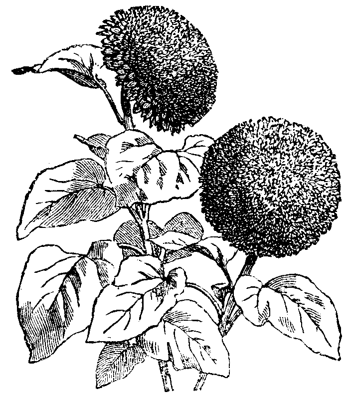
HELIANTHUS ANNUUS GLOBULUS FISTULOSUS.
H. angustifolius.—A neat and elegant species, which I first raised from seed sent by Mr. W. Thompson, of Ipswich. It has a very branching habit quite from the base like a well-grown bush of the common wallflower. The flowers are abundant, about 2½ inches across, with a black disk. The plant, though a true herb, never comes up in my garden with more than one stalk each year.

HELIANTHUS RIGIDUS (SYN. HARPALIUM RIGIDUM).
H. rigidus is well known as the best of the perennial sunflowers, and has many synonyms, the commonest Harpalium rigidum. It need not be described, but one or two things about it may be noted. The shoots, which come up a yard or more from last year's stalk, may be transplanted as soon as they appear without injury to the flowering, but if put back to the old center, the soil, which should be deep and light, ought to be enriched. The species is variable, and improved forms may be expected, as it produces seed in England. The number of ray flowers is often very large. I have one form which has several rows of them, nearly hiding the disk. A variety is figured in Botanical Magazine, tab. 2,668, under the name of H. atro-rubens. Another comes in the same series, tab. 2,020, as H. diffusus. Other synonyms are H. missuricus and H. missouriensis. Its native range extends across North America in longitude, and covers many degrees of latitude. It likes a dry soil. In wet soil and wet seasons the flower-stalk is apt to wither in the middle, and the bud falls over and perishes prematurely.
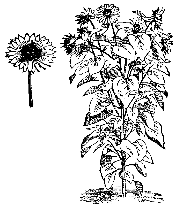
COMMON SUNFLOWER (H. ANNUUS) SHOWING HABIT OF GROWTH.
H. Lætiflorus.—Under this name we grow in England a tall, much-branched, late flowering kind, with smooth and very stout and stiff stalks, sometimes black, sometimes green. It increases at the base of the stalks; it makes close growth, and shows little disposition to run at the root. The flowers are rather small, not more than 9 inches across, but so durable and so well displayed by the numerous spreading branches as to make the plant very useful for late decoration. I own that I cannot identify this plant with the lætiflorus of Asa Gray, which he tells us resembles tall forms of H. rigidus, with rough stalks, and bears flowers with numerous rays 1½ inches long.

FLOWER OF HELIANTHUS ANNUUS.
H. occidentalis.—Recently introduced by Mr. W. Thompson, of Ipswich, who gave me the plant two years ago. It is a neat species, growing about 2 feet high, well branched, and producing at the end of July abundance of flowers about 2 inches across. The lower leaves are small and broad, with long stalks, ovate in form.

HELIANTHUS MULTIFLORUS FL-PL.
H. mollis, so called from the soft white down with which the leaves are covered, grows about 4 feet high. Leaves large, ovate, and sessile; growth of the plant upright, with hardly any branches; flowers pale yellow, about 3 inches across, not very ornamental. Cultivated at Kew, whence I had it.
H. giganteus grows 10 feet high; stem much branched and disposed to curve. Flowers about 2½ inches across, produced abundantly in August; rays narrow and pointed, cupped, with the ends turning outward; leaves lanceolate and sessile; rootstock creeping, forming tuberous thickenings at the base of the stems, which Asa Gray tells us were "the Indian potato of the Assiniboine tribe," mentioned by Douglas, who called the plant H. tuberosus.

FULL SIZED FLOWER OF HELIANTHUS MULTIFLORUS.
H. maximiliani.—Half the height of the last, which it resembles, but the stem is stouter, the leaves larger, as are also the flowers, which are produced later. It is not so floriferous and ornamental as the last.
H. lævigatus.—Smooth stalked, very distinct, does not spread at the roots, which are composed of finer fibers than those of most of the genus; stalks slender and black, growing closely together, branched near the summit, 5 feet high; leaves narrowly lanceolate and acute; flowers plentiful and about 2 inches across; rays few, and disk small.
We are warned that the following species are "difficult of extrication," either confluent or mixed by intercrossing.
H. doronicoides.—I place this the third in merit among perennial sunflowers, H. rigidus and H. multiflorus being first and second. It is 6 feet or 7 feet high, upright in growth, with many stalks. Flowers 3½ inches across, produced from the end of July to the end of September, bright golden yellow; leaves large, ovate, tapering from the middle to both ends; stalk leaves sessile and nearly connate, that is, clasping the stalk by their opposite base. The plant spreads rapidly by running rootstocks, and ripens seed in abundance. Figured as H. pubescens in Botanical Magazine, tab. 2,778.
H. divaricatus resembles the last, but is inferior, being a smaller plant in all parts, especially in the flowers, which come out a month later. The cauline leaves are stalked and diverge widely, which habit gives its name to the plant. A casual observer would hardly notice the difference between this species and the last, but when grown together the superiority of doronicoides as a garden plant is at once evident.
H. strumosus.—Fully 6 feet high; growth upright; rootstock less spreading than the last two; leaves on very short stalks, broadest at the base, ovate tapering by a long narrow point; flower disk narrow, but rays large and orange-yellow; flowers showy, 3 inches across; they come out late in August. I had this plant from Kew. The shape of the leaves would have led me rather to refer it to H. trachelifolius, a closely allied species.
H. decapetalus.—Five feet high; flowers from end of July; makes a dense forest of weak, slender stalks, much branched at the top; spreads fast; leaves serrate, oblong-ovate, rather large; flowers abundant, pale yellow, about 2 inches across; rays nearly always more than ten, in spite of the name.
H. tuberosus.—The well-known Jerusalem artichoke; not a plant grown for ornament, being too coarse and late in flowering, but several things in its history may be mentioned, as Dr. Asa Gray has spent labor and study over it. It is believed to have been cultivated by the natives before the discovery of America, and the edible tubers are thought to be a development of cultivation. Forms of it without tuberous roots are found wild, but whether indigenous to the place or degenerate from cultivation was for long uncertain. Several species of Helianthus have a tendency to produce similar fleshy tubers at the top of the roots. Dr. Gray used to refer the origin of this species to H. doronicoides, but it is now believed by him to be a distinct species, though one of which it is difficult to identify with certainty the typical form.
I omitted to say that the word Helianthus is Greek for sunflower. After several years' careful observation, I believe the notion that the flowers keep their face to the sun is quite a delusion.
Edge Hall. C. WOLLEY DOD.
A QUICK FILTER.—The Druggists Circular recommends chamois skin, free from thin places; cut it of the desired size; wash it in a weak solution of sal soda, or any alkali, to remove the grease, and rinse thoroughly in cold water before using.
Tinctures, elixirs, sirups, and even mucilages are filtered rapidly. A pint of the thickest sirup will run through in four or five minutes. By washing thoroughly after each time of using, it will last a long time.
The group of fuchsias shown in our engraving represents a collection of nine specimens raised and exhibited by that well known cultivator, Mr. James Lye, of Clyffe Hall Gardens, Market Lavington, at an exhibition held in Bath in September last, and which received the first prize in the premier class for that number of plants. For many years past Mr. Lye has exhibited fuchsias at exhibitions held at Bath, Trowbridge, Devizes, Calne, Chippenham, and elsewhere; on all occasions staging specimens of a high order of merit; but the plants appearing in our illustration were universally regarded as the best he had ever placed in an exhibition tent. So much were the committee of the Bath show pleased with the specimens that they engaged the services of a photographer to make a picture of them on the spot; but after being two hours making the attempt, no satisfactory result occurred. After the plants were taken back to Clyffe Hall, they were photographed as seen in the illustration. Some idea of their height and dimensions can be realized by a comparison with the stature of Mr. Lye, who is standing by his plants, and who is of average height. It should be mentioned that previous to being photographed they had traveled by road from Market Lavington to Bath and back, a distance of 52 miles, in addition to having been exhibited two days. They returned to their home apparently little the worse for wear, which immunity from harm is no doubt owing to the admirable system of tying adopted by Mr. Lye. It is sometimes said that the act of trying in the flowering shoots in this manner gives the plants a somewhat severely formal appearance, but there is an abundance of healthy foliage and a wonderful profusion of finely developed flowers, showing the most careful and painstaking cultivation. It is only those who are privileged to see these unrivaled plants who can appreciate them at their proper worth.
It has been stated already that the varieties figured are all of Mr. Lye's own raising, which facts attests to the value of his seedlings, many of which he has produced. Four of these are dark varieties, viz., Bountiful, Charming, Elegance, and the Hon. Mrs. Hay—the latter one of the oldest, but one of the freest, and scarcely without an equal for its great freedom of bloom. The remaining five are light varieties, viz., Lye's Favorite, Harriet Lye, Star of Wilts, Pink Perfection, and Beauty of the West.
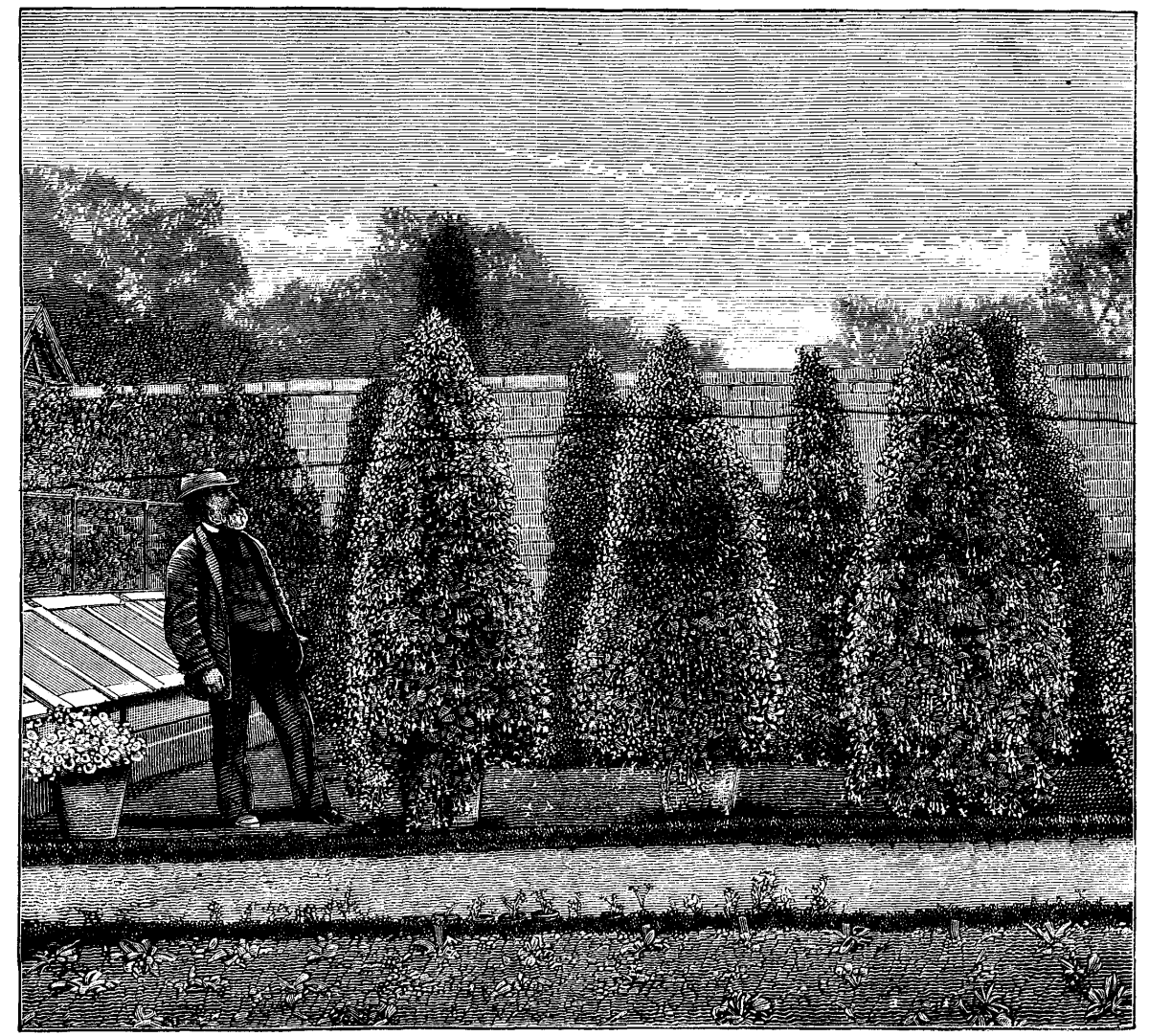
MR. LYE'S FUSCHIAS.
The specimens figured average from two to five years of age. It is really marvelous what Mr. Lye can do with a fuchsia in two years; and lest it might be supposed that he has plenty of glass accommodation, and can keep his plants under glass continuously, it is due to him it should be stated that he is very deficient in house accommodation, having but two small houses, in one of which (an old house) he winters his plants and brings them on until he can place them with safety in the open air in early summer. His method of treating the specimens as set forth in his own words may prove helpful to some of our readers: "After the plants have done flowering, say about the third week in October, I cut them back into the shape best fitted to form symmetrical specimens, and keep them dry for a week or ten days, to check the bleeding of sap which follows; after that I give a little water just to start them into growth, so as to make shoots about three-quarters of an inch in length, in order to keep the old wood active and living. I keep them in a cold house, and give but very little water until the first or second week in February, when I shake the old soil from the roots, and re-pot them into a fresh compost made up of three parts good loam, one part well decomposed manure, and one part leaf-mould and peat, with a good bit of silver or sea sand to keep it open. In order to make large specimens, they are shifted as soon as the pots are filled with roots. About the first week in June I place them out of doors on a border somewhat sheltered, and syringe the plants freely every day during hot weather to keep the foliage clean and healthy. I top them back till about seven or eight weeks before I want to show them, according to the requirements of the variety, as some of them require it to be done more freely than others. I give them liquid manure, using what I get from the cows, which with some soot is put into a tub, and allowed to stand a week or ten days before using, and I give them a good dose once a week as they show signs of flowering."
In order to preserve his plants from the effects of hail and very heavy rains, a rough framework is erected, and over this is stretched some floral shading, which can be readily removed when required; it also serves the purpose of shading the plants from the sun in very hot and scorching weather.
During his career as an exhibitor of fuchsias Mr. Lye has taken nearly one hundred first prizes—a measure of success which fully justifies the bestowal of the title of being the Champion Fuchsia Grower of his day.—R.D. in The Gardeners' Chronicle.
A catalogue, containing brief notices of many important scientific papers heretofore published in the SUPPLEMENT, may be had gratis at this office.
Sent by mail, postage prepaid, to subscribers in any part of the United States or Canada. Six dollars a year, sent, prepaid, to any foreign country.
All the back numbers of THE SUPPLEMENT, from the commencement, January 1, 1876, can be had. Price, 10 cents each.
All the back volumes of THE SUPPLEMENT can likewise be supplied. Two volumes are issued yearly. Price of each volume, $2.50, stitched in paper, or $3.50, bound in stiff covers.
COMBINED RATES—One copy of SCIENTIFIC AMERICAN and one copy of SCIENTIFIC AMERICAN SUPPLEMENT, one year, postpaid, $7.00.
A liberal discount to booksellers, news agents, and canvassers.
MUNN & CO., Publishers,
361 Broadway, New York, N.Y.
In connection with the Scientific American, Messrs. MUNN & Co. are Solicitors of American and Foreign Patents, have had 40 years' experience, and now have the largest establishment in the world. Patents are obtained on the best terms.
A special notice is made in the Scientific American of all Inventions patented through this Agency, with the name and residence of the Patentee. By the immense circulation thus given, public attention is directed to the merits of the new patent, and sales or introduction often easily effected.
Any person who has made a new discovery or invention can ascertain, free of charge, whether a patent can probably be obtained, by writing to MUNN & Co.
We also send free our Hand Book about the Patent Laws, Patents, Caveats. Trade Marks, their costs, and how procured. Address
MUNN & CO., 361 Broadway, New York.
Branch Office, cor. F and 7th Sts., Washington, D.C.